 |
|
Fig. 1: Power, Ground, Antenna and Data Communication |
2016-2018
Chevrolet Volt
Service Manual
SPECIFICATIONS
FASTENER SPECIFICATIONS
|
Reusable Threaded Fastener Tightening Specifications | |||||||||||||||||||||||||
| |||||||||||||||||||||||||
SCHEMATIC WIRING DIAGRAMS
RADIO/NAVIGATION SYSTEM WIRING SCHEMATICS
Power, Ground, Antenna and Data Communication
|
|
Fig. 1: Power, Ground, Antenna and Data Communication |
Amplifier Inputs (UQA)

Fig. 2: Amplifier Inputs (UQA)
Courtesy of GENERAL MOTORS COMPANY
Auxiliary Audio Input
 |
|
Fig. 3: Auxiliary Audio Input Courtesy of GENERAL MOTORS COMPANY |
Info Display
 |
|
Fig. 4: Info Display Courtesy of GENERAL MOTORS COMPANY |
Speakers (UQA)
 |
|
Fig. 5: Speakers (UQA) Courtesy of GENERAL MOTORS COMPANY |
Speakers (UZ6)
 |
|
Fig. 6: Speakers (UZ6) Courtesy of GENERAL MOTORS COMPANY |
ONSTAR/TELEMATICS WIRING SCHEMATICS
OnStar Schematics
 |
|
Fig. 7: OnStar Schematics Courtesy of GENERAL MOTORS COMPANY |
CELLULAR TELEPHONE WIRING SCHEMATICS
Cellular Telephone Microphone (-UE1)
 |
|
Fig. 8: Cellular Telephone Microphone (-UE1) |
DIAGNOSTIC INFORMATION AND PROCEDURES
DTC B0997: AUXILIARY ELECTRONIC CONTROL UNIT PERFORMANCE
Diagnostic Instructions
• Perform the Diagnostic System Check - Vehicle prior to using this diagnostic procedure.
• Review Strategy Based Diagnosis for an overview of the diagnostic approach.
• Refer to Diagnostic Procedure Instructions to provide an overview of each diagnostic category.
DTC Descriptor
Auxiliary Electronic Control Unit Performance Incorrect Component Installed
Auxiliary Electronic Control Unit Performance Internal Electronic Failure
Circuit/System Description
The info display module monitors itself for internal failures and reports its condition to the Human Machine
Interface Control Module when requested. The info display also reports electronic identification information when
requested.
Conditions for Running DTC
• Ignition is ON or in the ACC position
• The system voltage is 9-16 V
• DTC B101E is not set as current in the Human Machine Interface Control Module
• The test is run once during Human Machine Interface Control Module wake up
Conditions for Setting the DTC
The Info Display Module has reported identification information that differs from the information calibrated in the
Human Machine Interface Control Module.
The Info Display Module reports an internal malfunction.
Action Taken When DTC Sets
The Human Machine Interface Control Module will set the DTC and the Info Display Module will have limited or no
functionality.
Conditions for Clearing the DTC
The Human Machine Interface Control Module detects a compatible Info Display Module with no internal
malfunctions reported.
Reference Information
Schematic Reference
Connector End View Reference
Description and Operation
Electrical Information Reference
Circuit Testing
Connector Repairs
Testing for Intermittent Conditions and Poor Connections
Wiring Repairs
Scan Tool Reference
Control Module References for scan tool information
Circuit/System Verification
1. Vehicle in Service Mode, Infotainment system ON.
2. Verify DTC B101E is not set
• If DTC B101E is set
Refer to Diagnostic Trouble Code (DTC) List - Vehicle .
• If DTC B101E is not set
3. Verify DTC B0997 is not set
Replace the P17 Info Display Module.
4. All OK
Repair Instructions
Perform the Diagnostic Repair Verification after completing the repair.
Refer to Radio Control Assembly Replacement
DTC B1024: CIRCUIT BOARD TEMPERATURE SENSOR ABOVE MAXIMUM THRESHOLD (AUDIO
AMPLIFIER)
Diagnostic Instructions
• Perform the Diagnostic System Check - Vehicle prior to using this diagnostic procedure.
• Review Strategy Based Diagnosis for an overview of the diagnostic approach.
• Refer to Diagnostic Procedure Instructions to provide an overview of each diagnostic category.
DTC Descriptor
Circuit Board Temperature Sensor Above Maximum Threshold
Circuit/System Description
The audio amplifier monitors the internal circuitry for excessive temperature. When the amplifier senses an internal
circuitry temperature greater than 95A°C (203A°F), the amplifier will set DTC B1024 11 and shut down until the
internal circuitry cools below 90A°C (194A°F). No external circuit diagnosis is involved.
Conditions for Running the DTC
• Radio ON.
• Battery voltage must be between 9-16 volts.
Conditions for Setting the DTC
The audio amplifier detects an over-heat condition greater than 95A°C (203A°F) of the internal amplifier circuitry.
Action Taken When the DTC Sets
The audio amplifier will shut down and all speakers will be inoperative.
Conditions for Clearing the DTC
• The condition responsible for setting the DTC no longer exists.
• A history DTC will clear once 100 consecutive malfunction-free ignition cycles have occurred.
Diagnostic Aids
Extended use or extremely high volume especially in warm weather conditions may cause this DTC to set. Under
these conditions it may be normal for this DTC to set to prevent permanent damage to the audio amplifier circuitry.
Reference Information
Schematic Reference
Connector End View Reference
Description and Operation
Electrical Information Reference
Circuit Testing
Connector Repairs
Testing for Intermittent Conditions and Poor Connections
Wiring Repairs
Scan Tool Reference
Control Module References for scan tool information
Circuit/System Verification
NOTE: Allow the vehicle cabin to cool if the temperature inside the vehicle is excessive
before proceeding with this diagnostic procedure.
1. Verify the DTC sets outside of the Conditions for Running and Setting. Since most occurrences of this DTC
are caused by extreme vehicle cabin temperatures due to ambient conditions, review with the customer the
conditions under which the DTC set.
• If the DTC sets within the Conditions for Running and Setting.
The system is operating as designed, All OK.
2. Using the scan tool, clear the DTC.
3. Verify the DTC does not set while operating the infotainment system under the conditions the customer
experienced the concern.
Replace the T3 Audio Amplifier
4. All OK.
Repair Instructions
Perform the Diagnostic Repair Verification after completing the diagnostic procedure.
Refer to Control Module References for audio amplifier replacement, setup, and programming
DTC B1024: CIRCUIT BOARD TEMPERATURE SENSOR THRESHOLD
Diagnostic Instructions
• Perform the Diagnostic System Check - Vehicle prior to using this diagnostic procedure.
• Review Strategy Based Diagnosis for an overview of the diagnostic approach.
• Refer to Diagnostic Procedure Instructions to provide an overview of each diagnostic category.
DTC Descriptor
Circuit Board Temperature Sensor Below Minimum Threshold
Circuit Board Temperature Sensor Above Maximum Threshold
Circuit/System Description
The human machine interface control module monitors the internal circuitry for excessive temperature. When a
temperature outside of the range is detected, the module sets the DTC and limits its operation to avoid damage.
Conditions for Running the DTC
• Ignition On/Vehicle in Service Mode.
• The system voltage is 9-16 V
• The test is run once per second when the infotainment system is operating
Conditions for Setting the DTC
The module senses an internal temperature less than -40A°C (-40A°F).
The module senses an internal temperature greater than 69A°C (156A°F).
Action Taken When the DTC Sets
• The human machine interface control module sets the DTC.
• A message is displayed indicating that the system performance is being impacted by the excessive temperature
condition.
• The module stops communicating on the MOST Bus network, but does not interrupt communication on the
network.
• The infotainment system and the Info Display Module will have limited or no functionality.
• Components or other subsystems that interface with the infotainment system may have limited or no
functionality.
Conditions for Clearing the DTC
• The internal temperature is between -40A°C (-40A°F) and 69A°C (156A°F).
• A history DTC will clear once 100 consecutive malfunction-free ignition cycles have occurred.
Diagnostic Aids
Under certain conditions it may be normal for this DTC to set to prevent permanent damage to the module.
Reference Information
Schematic Reference
Connector End View Reference
Description and Operation
Electrical Information Reference
Circuit Testing
Connector Repairs
Testing for Intermittent Conditions and Poor Connections
Wiring Repairs
Scan Tool Reference
Control Module References for scan tool information
Circuit/System Verification
NOTE: Allow the vehicle cabin to cool if the temperature inside the vehicle is excessive
before proceeding with this diagnostic procedure.
1. Verify the DTC sets outside of the Conditions for Running and Setting. Since most occurrences of this DTC
are caused by extreme vehicle cabin temperatures due to ambient conditions, review with the customer the
conditions under which the DTC set.
The system is operating as designed, All OK.
2. Using the scan tool, clear the DTC.
3. Verify the DTC does not set while operating the infotainment system under the conditions the customer
experienced the concern.
Replace the K74 Human Machine Interface Control Module
4. All OK.
Repair Instructions
Perform the Diagnostic Repair Verification after completing the repair.
Refer to Control Module References for human machine interface control module replacement, programming, and
setup.
DTC B1025-B1135: AUDIO OUTPUT CIRCUITS
Diagnostic Instructions
• Perform the Diagnostic System Check - Vehicle prior to using this diagnostic procedure.
• Review Strategy Based Diagnosis for an overview of the diagnostic approach.
• Refer to Diagnostic Procedure Instructions to provide an overview of each diagnostic category.
DTC Descriptors
Audio Output 1 Circuit
Audio Output 2 Circuit
Audio Output 3 Circuit
Audio Output 5 Circuit
Audio Output 6 Circuit
DTC B1085
Audio Output 7 Circuit
For symptom byte information refer to Symptom Byte List .
|
Diagnostic Fault Information | |||||||||||||||||||||||||||||||||||
| |||||||||||||||||||||||||||||||||||
|
Circuit/System Description |
The Media Oriented Systems Transport (MOST) is a high-speed multimedia network technology. The serial MOST
bus uses a ring topology and synchronous data communication to transmit audio, video, data and control information
between any devices attached.
The audio amplifier is a participant on the MOST network. The audio amplifier receives audio inputs and control
information from the MOST bus.
Each of the audio output channel circuits (+) and (-), at the audio amplifier have a DC bias voltage that is
approximately one half of the battery voltage. When using a DMM, each of the audio output channel circuits will
measure approximately 6.5 V DC. The audio being played on the system is produced by a varying AC voltage that is
centered around the DC bias voltage on the same circuit. The AC voltage is what causes the speaker cone to move
and produce sound.
Diagnostic Aids
• Improper speaker mounting or loose trim may cause an audible buzz or distortion. Inspect the appropriate
speaker and the surrounding interior trim for proper and secure mounting.
The EL-50334-6 Audio System Diagnostic CD contains audio tracks that can be used to duplicate and isolate
such concerns. Tracks 11 and 12 contain audio sweep tones for testing for speaker and grill rattles.
If the speaker or surrounding interior trim is found to be loose or improperly secured, correctly secure the item.
• The test tones on the CD may be copied to a USB drive or other device to use during testing.
• Some audio output circuits are connected to more than one speaker, dependant on vehicle equipment. It may
be necessary to disconnect one or more speakers during testing of some circuits.
Conditions for Running the DTC
NOTE: DTC B1325 must not be set as current for the amplifier to run any of the following
tests.
The test is run initially upon amplifier wake-up, and periodically every one second after amplifier operation begins.
The test is run initially upon amplifier wake-up, and periodically every one second after amplifier operation begins.
The test is run once during amplifier wake-up.
Conditions for Setting the DTC
A short to voltage is detected on the specified (+) or (-) signal circuit
A short to ground is detected on the specified (+) or (-) signal circuit
An open is detected on the specified (+) or (-) signal circuit
Action Taken When the DTC Sets
The amplifier mutes the output channel and no sound is present from the speaker(s) that have a current circuit fault.
Conditions for Clearing the DTC
• The condition for setting the DTC is no longer present.
• A history DTC will clear once 50 consecutive malfunction-free ignition cycles have occurred.
Reference Information
Schematic Reference
Connector End View Reference
Electrical Information Reference
Circuit Testing
• Connector Repairs
Testing for Intermittent Conditions and Poor Connections
Wiring Repairs
Scan Tool Reference
Special Tools
EL-50334-50 USB Cable and Adapter Kit
Circuit/System Verification
1. Ignition ON, infotainment system ON, mute OFF.
2. Verify clear audio is heard from each speaker, adjusting fade and balance controls to test each speaker
individually.
Refer to Circuit/System Testing.
3. All OK.
Circuit/System Testing
NOTE: Some circuits supply audio signals to more than one speaker. It may be
necessary to disconnect all speakers on the affected audio circuit when
performing circuit tests.
1. Ignition OFF, disconnect the harness connector at the appropriate P19 Speaker. Ignition ON, infotainment
system ON, mute OFF.
2. Test for 5 - 7 V between the appropriate signal circuit terminals listed below and ground.
• Front door, tweeter, rear door and subwoofer speakers audio (-) circuit terminal 1
• Front door, tweeter, rear door and subwoofer speakers audio (+) circuit terminal 2
1. Ignition OFF, disconnect the X1 and X2 harness connectors at the T3 Audio Amplifier.
2. Test for infinite resistance between the signal circuit and ground.
• If less than infinite resistance, repair the short to ground on the circuit.
• If infinite resistance
3. Test for less than 2 Q in the signal circuit end to end.
• If 2 Q or greater, repair the open/high resistance in the circuit.
• If less than 2 Q, replace the T3 Audio Amplifier.
1. Ignition OFF, disconnect the X1 and X2 harness connectors at the T3 Audio Amplifier. Ignition ON.
2. Test for less than 1 V between the signal circuit and ground.
• If 1 V or greater, repair the short to voltage on the circuit.
• If less than 1 V, replace the T3 Audio Amplifier.
3. Test or replace the P19 Speaker.
Repair Instructions
Perform the Diagnostic Repair Verification after completing the repair.
• Refer to Control Module References for audio amplifier replacement, programming, and setup.
DTC B124B: USB 1 CIRCUIT
Diagnostic Instructions
• Perform the Diagnostic System Check - Vehicle prior to using this diagnostic procedure.
• Review Strategy Based Diagnosis for an overview of the diagnostic approach.
• Refer to Diagnostic Procedure Instructions to provide an overview of each diagnostic category.
DTC Descriptor
USB 1 Circuit
For symptom byte information refer to Symptom Byte List .
|
Diagnostic Fault Information | |||||||||||||||||||||||||
| |||||||||||||||||||||||||
|
Circuit/System Description | |||||||||||||||||||||||||
The infotainment system has a USB port and a Auxiliary Audio Input Jack located in the center console. The
receptacle assembly receives fused battery voltage and ground from the harness to power the internal hub device as
well as providing additional amperage to power USB devices.
The internal hub device interfaces directly with the human machine interface control module via a standard USB
cable. A Mini type USB connector is used to connect the human machine interface control module and the USB
receptacle. Standard USB male to female connections are typically used for connecting USB cables together where
an in-line connection is required. An in-line cable connection is typically found between the console and I/P harness.
When a portable audio playback device is connected to the 3.5 mm (1/8 in.) auxiliary audio input jack an internal
switch opens the detection signal circuit within the hub. The HMI detects the device and AUX becomes available as
an audio source. Audio signals from the device are converted from analog to digital, these signals are then sent to the
HMI from the auxiliary input jack via USB.
USB Port
The USB port allows connectivity to the infotainment system from portable media players or a USB storage device
(memory stick/flash drive). When a device is connected to the USB port, the system detects the device and switches
to USB as the audio source. Once connected, the device can be controlled from the radio controls.
Not all portable media player devices or file types are compatible. Refer to the owner's manual for information on
USB devices, control, and operation.
Conditions for Running the DTC
• Ignition On/Vehicle in Service Mode.
• The system voltage is 9-16 V
• The infotainment system is ON
• The test is run once per second when the infotainment system is operating
Conditions for Setting the DTC
The human machine interface control module detects an excessive current condition on the USB 5 V circuit.
The human machine interface control module does not detect the vehicle hub device.
The human machine interface control module detects an additional hub device attached to the vehicle USB port.
Action Taken When the DTC Sets
The USB port is inoperative while the DTC is current.
Conditions for Clearing the DTC
• The condition for setting the DTC is no longer present.
• A history DTC will clear once 50 consecutive malfunction-free ignition cycles have occurred.
Diagnostic Aids
• This DTC may be set due to the connection of an incompatible or faulty USB device.
Reference Information
Schematic Reference
Connector End View Reference
Description and Operation
Radio/Audio System Description and Operation
Electrical Information Reference
Circuit Testing
Connector Repairs
Testing for Intermittent Conditions and Poor Connections
Wiring Repairs
Scan Tool Reference
Control Module References for scan tool information
Special Tools
• EL-50334-20 Multi-Media Interface Tester (MIT)
• EL-50334-50 USB Cable and Adapter Kit
• EL-50334-14 Infotainment Test Cable
Circuit/System Verification
1. Verify DTC B124B is not set. Since occurrences of this DTC can be caused by an incompatible or faulty USB
device, review with the customer the conditions under which their concern occurred.
Refer to Circuit/System Testing.
2. Ignition On/Vehicle in Service Mode. Infotainment system ON.
3. Connect the EL-50334-20 Multi-Media Interface Tester (MIT) to the X83 Auxiliary Audio Input USB port and
select the USB test mode.
4. Verify the audio from the EL-50334-20 Multi-Media Interface Tester (MIT) is heard through the infotainment
system while operating the system to play audio from the test tool.
Refer to Circuit/System Testing
5. Verify the infotainment system can be switched to AUX as the audio source with the EL-50334-20 Multi-
Media Interface Tester (MIT) connected to the auxiliary audio input jack.
• If the infotainment system can not be switched to AUX as the audio source
Refer to Circuit/System Testing
6. Verify the audio from the EL-50334-20 Multi-Media Interface Tester (MIT) is heard through the vehicle
infotainment system while operating the test tool to begin audio playback.
Refer to Circuit/System Testing
7. All OK
Circuit/System Testing
1. Ignition OFF, disconnect the X1 harness connector at the X83 Auxiliary Audio Input.
2. Test for less than 10 Q between the ground circuit terminal 4 and ground.
• If 10 fi or greater
1. Ignition OFF.
2. Test for less than 2 Q in the ground circuit end to end.
• If 2 Q or greater, repair the open/high resistance in the circuit.
• If less than 2 Q, repair the open/high resistance in the ground connection.
3. Verify that a test lamp illuminates between the B+ circuit terminal 6 and ground.
• If the test lamp does not illuminate
1. Ignition OFF, remove the test lamp.
2. Test for less than 2 Q in the B+ circuit end to end.
• If 2 Q or greater, repair the open/high resistance in the circuit.
• If the test lamp illuminates
4. Verify the USB cable is properly connected at all components and in-line connections, and there is no damage
to the cable or connections.
• If connection problems or cable damage is noted.
Perform the appropriate repair or replacement to correct any issues.
5. Connect the X1 harness connector at the X83 Auxiliary Audio Input.
6. Disconnect the vehicle USB cable X3 harness connector at the K74 Human Machine Interface Control Module
and the X83 Auxiliary Audio Input Adapter.
7. Connect the EL-50334-14 Infotainment Test Cable and the EL-50334-2 Type-A Female to Mini-B Male Cable
together. Connect the assembled test cable to the K74 Human Machine Interface Control Module and the X83
Auxiliary Audio Input.
8. Ignition On/Vehicle in Service Mode. Infotainment system ON.
9. Connect the EL-50334-20 Multi-Media Interface Tester (MIT) to the X83 Auxiliary Audio Input USB port and
select the USB test mode.
10. Verify the audio from the EL-50334-20 Multi-Media Interface Tester (MIT) is heard through the infotainment
system while operating the system to play audio from the test tool.
1. Replace the X83 Auxiliary Audio Input Adapter. Connect all harness connectors.
2. Connect the EL-50334-20 Multi-Media Interface Tester (MIT) to the X83 Auxiliary Audio Input USB
port and select the USB test mode.
3. Verify the audio from the EL-50334-20 Multi-Media Interface Tester (MIT) is heard through the
infotainment system while operating the system to play audio from the test tool.
• If audio is not heard from the test tool, replace the K74 Human Machine Interface Control
Module.
11. Connect the EL-50334-20 Multi-Media Interface Tester (MIT) to the X83 Auxiliary Audio Input AUX port
and select the AUX test mode.
12. Verify the audio from the EL-50334-20 Multi-Media Interface Tester (MIT) is heard through the infotainment
system while operating the system to play audio from the test tool.
1. Replace the X83 Auxiliary Audio Input Adapter. Connect all harness connectors.
13. Replace the vehicle USB cable between the K74 Human Machine Interface Control Module and the X83
Auxiliary Audio Input Adapter.
Repair Instructions
Perform the Diagnostic Repair Verification after completing the repair.
• Refer to Control Module References for human machine interface control module replacement,
programming, and setup.
DTC B124F: UNIVERSAL SERIAL BUS (USB) PROGRAMMING
Diagnostic Instructions
• Perform the Diagnostic System Check - Vehicle prior to using this diagnostic procedure.
• Review Strategy Based Diagnosis for an overview of the diagnostic approach.
• Refer to Diagnostic Procedure Instructions to provide an overview of each diagnostic category.
DTC Descriptor
Universal Serial Bus (USB) Programming
For symptom byte information, refer to Symptom Byte List .
Circuit/System Description
Certain devices in the entertainment system must be programmed with specific software and other information to
operate correctly. This DTC is the result of an unsuccessful USB programming event of the device. The symptom
byte information is for engineering reference only. No external circuit diagnosis is involved
Conditions for Running the DTC
Once upon each USB Programming Event.
Conditions for Setting the DTC
The programming event was incomplete, or completed with errors.
Action Taken When the DTC Sets
The entertainment system has limited or no functionality.
Conditions for Clearing the DTC
The programming event completes successfully.
Circuit/System Verification
1. Vehicle in Service Mode.
2. Verify DTC B124F is not set.
1. Program the device that set the DTC.
2. Verify the DTC does not set.
• If DTC is set, replace the device that set the DTC.
• If the DTC is not set
3. All OK.
3. All OK
Repair Instructions
Perform the Diagnostic Repair Verification after completing the repair.
Refer to Control Module References for device replacement, programming, and setup.
DTC B125A: ANTENNA SIGNAL CIRCUIT
Diagnostic Instructions
• Perform the Diagnostic System Check - Vehicle prior to using this diagnostic procedure.
• Review Strategy Based Diagnosis for an overview of the diagnostic approach.
• Refer to Diagnostic Procedure Instructions to provide an overview of each diagnostic category.
DTC Descriptors
Antenna Signal Circuit Short to Ground
Antenna Signal Circuit Open Circuit
Antenna Signal Circuit Short to Battery
|
Diagnostic Fault Information | |||||
|
| ||||||||||
|
Circuit/System Description |
The radio antenna for AM and FM radio reception is connected to the radio with a coaxial cable.
Conditions for Running the DTC
• Ignition ON/Vehicle in Service Mode.
• Battery voltage must be between 9 - 16 V
Conditions for Setting the DTC
The radio detects a short to ground in the antenna signal circuit center conductor.
The radio detects an open in the antenna signal circuit center conductor.
The radio detects a short to battery in the antenna signal circuit center conductor.
Action Taken When the DTC Sets
Radio reception may be poor or not available.
Conditions for Clearing the DTC
• The condition responsible for setting the DTC no longer exists.
• A history DTC will clears after 50 consecutive malfunction-free ignition cycles have occurred.
Diagnostic Aids
Poor AM and FM radio reception is dependent on multiple influences, some of which may not be vehicle related.
Areas which have high RF traffic or block the signal path may cause a degradation in radio reception. Radio
reception may also be influenced by items within the vehicle, but are not part of the radio system. Such examples are
aftermarket electrical accessories or other items which may generate noise in the vehicle electrical system.
Reference Information
Schematic Reference
Connector End View Reference
Description and Operation
Electrical Information Reference
Circuit Testing
Connector Repairs
Testing for Intermittent Conditions and Poor Connections
Wiring Repairs
Scan Tool Reference
Control Module References for scan tool information
Circuit/System Verification
1. Inspect the antenna for proper mounting or physical damage.
• If damage is found
Repair or replace as necessary
2. Ignition ON/Vehicle in Service Mode, A11 Radio ON.
3. Verify station reception is normal when tuned to several known good AM and FM stations.
• If AM or FM reception is poor.
Refer to Circuit/System Testing
4. All OK.
Circuit/System Testing
1. Ignition OFF/Vehicle OFF, disconnect the radio antenna coax cable from the A11 Radio and from the T2RR
Antenna - Roof Rear.
2. Verify the antenna coax cable passes the coax cable component test. Refer to Component Testing.
• If the coax cable does not pass the test
Replace the antenna coax cable
3. Connect the antenna coax cable to the T2RR Antenna - Roof Rear.
4. Test for infinite resistance between the coax cable center terminal and the coax cable outer shield at the radio
end of the coax cable.
Replace the radio antenna base.
5. Test for less than 10 Q between the coax cable outer shield and ground at the radio end of the coax cable.
1. Clean the mounting surface of the radio antenna base.
2. Connect the antenna coax cable to the T2RR Antenna - Roof Rear.
3. Test for less than 10 Q between the coax cable outer shield and ground at the radio end of the coax
cable.
• If 10 Q or greater, replace the antenna base.
• If less than 10 Q, connect all harness connectors. Verify station reception is normal when tuned to
several known good AM and FM stations. If AM or FM reception concerns are still present,
replace the A11 Radio.
6. Test or replace the A11 Radio.
Component Testing
CAUTION: Refer to Test Probe Caution .
NOTE: Before testing the coax cable, check the cable exterior for being pinched, cut,
damaged, or having loose connections at the components, which can cause
reception issues.
To prevent false reading when testing the center coax terminals, use care not to
ground the test probe on the outer housing/shield.
1. Ignition OFF/Vehicle OFF, disconnect the coax cable at both components.
2. Test for less than 5 Q between coax cable center terminal end to end.
• If 5 fi or greater
Replace the coax cable
3. Test for less than 5 Q between the coax cable outer shield end to end.
• If 5 fi or greater
Replace the coax cable
4. Test for infinite resistance between the coax cable center terminal and the coax cable outer shield.
Replace the coax cable
5. All OK
Repair Instructions
Perform the Diagnostic Repair Verification after completing the diagnostic procedure.
• Refer to Control Module References for radio replacement, programming, and setup.
DTC B125C: SATELLITE ANTENNA CIRCUIT
Diagnostic Instructions
• Perform the Diagnostic System Check - Vehicle prior to using this diagnostic procedure.
• Review Strategy Based Diagnosis for an overview of the diagnostic approach.
• Refer to Diagnostic Procedure Instructions to provide an overview of each diagnostic category.
DTC Descriptors
Satellite Antenna Circuit Short to Battery
Satellite Antenna Circuit Short to Ground
Satellite Antenna Circuit Open
Circuit/System Description
The digital radio receiver, located inside the radio, receives digital radio information from the digital radio antenna
located on the outside of the vehicle. The digital radio receiver is connected to the digital radio antenna via a shielded
coax cable. The digital radio antenna contains an amplifier which is powered by the radio through the coax cable.
Conditions for Running the DTC
This DTC is run every 300 milliseconds.
Conditions for Setting the DTC
The radio detects a circuit fault in the digital radio antenna.
Action Taken When the DTC Sets
The radio displays No XM Signal or Check Antenna.
Conditions for Clearing the DTC
• A current DTC clears when the condition for setting the DTC is no longer present.
• A history DTC clears after 100 malfunction-free ignition cycles.
Diagnostic Aids
The digital radio antenna requires a clear line of sight to the sky to operate properly. Reception may be limited,
intermittent, or unavailable inside structures.
Reference Information
Schematic Reference
Connector End View Reference
Description and Operation
Electrical Information Reference
Circuit Testing
Connector Repairs
Testing for Intermittent Conditions and Poor Connections
Wiring Repairs
Special Tools
EL-48028 Digital Radio Test Antenna
Circuit/System Verification
1. With the vehicle outside in an area with an unobstructed view of the southern sky, tune to XM.
2. Verify DTC B125C is not set as current and the No XM Signal message is not displayed on the radio.
• If DTC B125C is set as current or the No XM Signal message is displayed.
Refer to Circuit/System Testing.
3. All OK.
Circuit/System Testing
1. Ignition OFF/Vehicle OFF, disconnect the digital radio antenna coax cable from the A11 Radio. Connect the
EL-48028 Digital Radio Test Antenna to the radio and place on the roof of the vehicle.
2. Ignition ON/Vehicle in Service Mode, radio tuned to XM channel 1.
3. Verify DTC B125C is not set as current and XM reception is improved.
• If DTC B125C is set as current or XM reception is not improved
Replace the A11 Radio.
4. Ignition OFF/Vehicle OFF, disconnect the digital radio antenna coax cable from the T2RR Antenna - Roof
Rear.
5. Verify the digital radio antenna coax cable passes the coax cable component test. Refer to Component Testing.
• If the coax cable does not pass the test
Replace the antenna coax cable
• If the coax cable passes the test
6. Test or replace the T2RR Antenna - Roof Rear.
Component Testing
CAUTION: Refer to Test Probe Caution .
NOTE: Before testing the coax cable, check the cable exterior for being pinched, cut,
damaged, or having loose connections at the components, which can cause
reception issues.
To prevent false reading when testing the center coax terminals, use care not to
ground the test probe on the outer housing/shield.
Coax Cable Test
1. Ignition OFF/Vehicle OFF, disconnect the coax cable at both components.
2. Test for less than 5 Q between coax cable center terminal end to end.
• If 5 fi or greater
Replace the coax cable
• If less than 5 fi
3. Test for less than 5 Q between the coax cable outer shield end to end.
• If 5 fi or greater
Replace the coax cable
• If less than 5 fi
4. Test for infinite resistance between the coax cable center terminal and the coax cable outer shield.
• If less than infinite resistance
Replace the coax cable
• If infinite resistance
5. All OK
Repair Instructions
Perform the Diagnostic Repair Verification after completing the repair.
• Refer to High Frequency Antenna Replacement
• Refer to Control Module References for radio replacement, programming, and setup.
DTC B1271: THEFT PROTECTION ACTIVE
Diagnostic Instructions
• Perform the Diagnostic System Check - Vehicle prior to using this diagnostic procedure.
• Review Strategy Based Diagnosis for an overview of the diagnostic approach.
• Refer to Diagnostic Procedure Instructions to provide an overview of each diagnostic category.
DTC Descriptor
Theft Protection Active
Circuit/System Description
When the radio is initially installed in the vehicle, the radio receives VIN information via serial data. The radio stores
a portion of the VIN and compares this sequence to the VIN information received each time the radio powers on. The
VIN in the radio is a single one-time learn.
The radio theft deterrent system is intended to disable or limit radio functionality if incorrect vehicle information is
received by the radio. The radio disables functionality if the VIN information received by the radio does not match
the VIN information that has been learned by the radio. This DTC is generated by the module when the Theft
Protection is activated.
Conditions for Running the DTC
This DTC test runs when the radio changes from OFF to ON.
Conditions for Setting the DTC
The radio has learned a correct VIN sequence and the VIN information received via serial data does NOT match the
learned VIN sequence.
Action Taken When the DTC Sets
The radio may be disabled or have limited functionality. The radio display will indicate that theft protection is active.
Conditions for Clearing the DTC
The radio receives the correct VIN information via serial data.
Diagnostic Aids
A possible cause of incorrect VIN info could be the radio was originally installed in another vehicle.
Reference Information
Schematic Reference
Connector End View Reference
Description and Operation
Electrical Information Reference
Circuit Testing
Connector Repairs
Scan Tool Reference
Control Module References for scan tool information
Circuit/System Verification
1. Vehicle in Service Mode, radio ON.
2. Verify DTC B1271 is not set.
Replace the A11 Radio.
3. All OK.
Repair Instructions
Perform the Diagnostic Repair Verification after completing the repair.
Refer to Control Module References for radio replacement, programming, and setup.
DTC B127E: FRONT VIDEO DISPLAY OUTPUT SIGNAL
Diagnostic Instructions
• Perform the Diagnostic System Check - Vehicle prior to using this diagnostic procedure.
• Review Strategy Based Diagnosis for an overview of the diagnostic approach.
• Refer to Diagnostic Procedure Instructions to provide an overview of each diagnostic category.
DTC Descriptor
Front Video Display Output Signal
Circuit/System Description
The infotainment display and controls are a separate component from the radio, combined into an assembly. The
assembly is supplied battery voltage and ground from the vehicle harness. The human machine interface control
module communicates digital video data for on-screen display through a dedicated cable containing the LVDS data
circuits.
Control information, touch communications and dimming level for the display are communicated via a LIN serial
data circuit to the human machine interface control module.
If the human machine interface control module detects the display is not responding to the output on the LVDS
circuits, the human machine interface control module sets the DTC.
Conditions for Running the DTC
• Ignition is ON or in the ACC position
• The system voltage is 9-16 V
• The infotainment system is ON
• The test is continuously when the infotainment system is operating
Conditions for Setting the DTC
The human machine interface control module detects the display is not responding to the output on the LVDS
circuits.
Action Taken When the DTC Sets
• The human machine interface control module sets this DTC
• No images are shown on the Info Display Module
Conditions for Clearing the DTC
• The human machine interface control module detects a properly synced digital video signal.
• A history DTC will clear once 50 consecutive malfunction-free ignition cycles have occurred.
Reference Information
Schematic Reference
Connector End View Reference
Description and Operation
Electrical Information Reference
Circuit Testing
Connector Repairs
Testing for Intermittent Conditions and Poor Connections
Wiring Repairs
Scan Tool Reference
Control Module References for scan tool information
Special Tools
• EL-50334-2 Type A female to Mini B male USB Cable
• EL-50334-14 Infotainment Test Cable
Circuit/System Testing
1. Vehicle OFF/Ignition OFF.
2. Verify the LVDS interface cable is properly connected at the P17 Info Display Module and the K74 Human
Machine Interface Control Module connections and there is no damage to the cable or connections.
3. Ignition ON/Vehicle in Service Mode, infotainment system ON.
4. Verify the P17 Info Display Module does not display an image.
• If the P17 Info Display Module displays an image.
All OK.
5. Vehicle OFF/Ignition OFF.
6. Disconnect the LVDS interface cable from the P17 Info Display Module.
7. Connect the EL-50334-2 Type A female to Mini B male USB Cable to the P17 Info Display Module. Connect
the EL-50334-14 Infotainment Test Cable to the adapter.
8. Disconnect the LVDS interface cable from the K74 Human Machine Interface Control Module. Connect the
EL-50334-14 Infotainment Test cable to the K74 Human Machine Interface Module.
9. Ignition ON/Vehicle in Service Mode, infotainment system ON.
10. Verify the P17 Info Display Module displays an image.
• If the P17 Info Display Module does not display an image
1. Replace the P17 Info Display Module. Connect all harness connectors.
2. Ignition ON/Vehicle in Service Mode, infotainment system ON.
3. Verify the P17 Info Display Module displays an image.
• If the P17 Info Display Module still does not display an image, replace the K74 Human Machine
Interface Control Module.
• If the P17 Info Display Module displays an image.
4. All OK.
• If the P17 Info Display Module displays an image.
11. Replace the vehicle LVDS interface cable from the P17 Info Display Module to the K74 Human Machine
Interface Module.
Repair Instructions
Perform the Diagnostic Repair Verification after completing the repair.
• Refer to Control Module References for human machine interface control module replacement,
programming, and setup.
DTC B12A8: OPTICAL MEDIA DRIVE THEFT LOCKED
Diagnostic Instructions
• Perform the Diagnostic System Check - Vehicle prior to using this diagnostic procedure.
• Review Strategy Based Diagnosis for an overview of the diagnostic approach.
• Refer to Diagnostic Procedure Instructions to provide an overview of each diagnostic category.
DTC Descriptor
Optical Media Drive Theft Locked
Circuit/System Description
When the Media Disc Player is initially installed in the vehicle, it receives VIN information via serial data. The
Media Disc Player stores a portion of the VIN and compares this sequence to the VIN information received each
time the Media Disc Player powers on. The VIN in the Media Disc Player is a single one-time learn.
The Media Disc Player theft deterrent system is intended to disable or limit Media Disc Player functionality if
incorrect vehicle information is received by the Media Disc Player. The Media Disc Player disables functionality if
the VIN information received by the Media Disc Player does not match the VIN information that has been learned by
the Media Disc Player. This DTC is generated by the module when the Theft Protection is activated.
Conditions for Running the DTC
This test runs once per second while the Media Disc Player is being accessed.
Conditions for Setting the DTC
The Media Disc Player has learned a correct VIN sequence and the VIN information received via serial data does
NOT match the learned VIN sequence.
Action Taken When the DTC Sets
The Media Disc Player may be disabled or have limited functionality.
Conditions for Clearing the DTC
The Media Disc Player receives the correct VIN information via serial data.
Diagnostic Aids
A possible cause of incorrect VIN information could be the Media Disc Player was originally installed in another
vehicle.
Reference Information
Schematic Reference
Connector End View Reference
Description and Operation
Electrical Information Reference
Circuit Testing
Connector Repairs
Scan Tool Reference
Control Module References for scan tool information
Circuit/System Verification
1. Vehicle in Service Mode.
2. Verify DTC B12A8 is not set.
Replace the A33 Media Disc Player.
3. All OK.
Repair Instructions
Perform the Diagnostic Repair Verification after completing the repair.
Refer to Control Module References for media disc player replacement, programming, and setup.
DTC B1446 OR B1447: BACKUP POWER SOURCE
Diagnostic Instructions
• Perform the Diagnostic System Check - Vehicle prior to using this diagnostic procedure.
• Review Strategy Based Diagnosis for an overview of the diagnostic approach.
• Refer to Diagnostic Procedure Instructions to provide an overview of each diagnostic category.
DTC Descriptors
Replace Backup Power Source Below Minimum Threshold
Backup Power Source Open Circuit
For symptom byte information refer to Symptom Byte List
|
Diagnostic Fault Information | |||||||||||||||
| |||||||||||||||
|
Circuit/System Description |
The backup power source provides voltage to the telematics communication interface control module, to be able to
successfully place a call in the event of a main battery disconnect during a collision event.
Conditions for Running the DTC
• Ignition On/Vehicle in Service Mode.
• System voltage is between 9.5 and 15.5 V.
• DTC B1447 is not set.
• Ignition On/Vehicle in Service Mode.
• System voltage is between 9.5 and 15.5 V.
• The above conditions are present for greater than 10 s.
Conditions for Setting the DTC
The telematics communication interface control module detects that the backup power source voltage has dropped
below the minimum threshold value.
The telematics communication interface control module detects no voltage from the backup power source.
Action Taken When the DTC Sets
The OnStarA® status LED turns red.
• The OnStarA® status LED turns red.
• The telematics communication interface control module will be unable to place a call in the event of a main
battery disconnect during a collision event.
Conditions for Clearing the DTC
• A current DTC B1446 will clear when the telematics communication interface control module detects the
voltage of the backup power source is above the minimum threshold value.
• A current DTC B1447 will clear when the telematics communication interface control module detects voltage
from the backup power source.
• A history DTC clears after 50 malfunction-free ignition cycles.
Diagnostic Aids
• Shorting the backup power source positive voltage circuit to the backup power source ground circuit or chassis
ground will activate the internal circuit protection of the backup power source, rendering the backup power
source inoperative.
• DTC B1447 may set if the K73 Telematics Communication Interface Control Module has been incorrectly
disconnected or serviced. When disconnecting the K73 Telematics Communication Interface Control Module,
disconnect the harness connector X1 at the K73 Telematics Communication Interface Control Module prior to
disconnecting any other harness connectors. This will ensure the backup power source is preserved when
voltage is removed from the K73 Telematics Communication Interface Control Module.
Reference Information
Schematic Reference
Connector End View Reference
Description and Operation
Electrical Information Reference
Testing for Intermittent Conditions and Poor Connections
Circuit Testing
Wiring Repairs
Connector Repairs
Circuit/System Testing
1. Ignition OFF/Vehicle OFF and all vehicle systems OFF, disconnect the X1 harness connector at the K73
Telematics Communication Interface Control Module. It may take up to 2 minutes for all vehicle systems to
power down.
2. Test for greater than 12.3 V between the B+ circuit terminal 14 and the low reference circuit terminal 13.
1. Disconnect the C3 Telematics Communication Interface Control Module Battery.
2. Test for infinite resistance between the circuits listed below and ground.
• B+ circuit terminal 14
• Low reference circuit terminal 13.
• If less than infinite resistance, repair the short to ground in the circuit.
• If infinite resistance.
3. Test for less than 2 Q in the circuits end to end.
• If 2 Q or greater, repair the open/high resistance in the circuit.
• If less than 2 Q, replace the C3 Telematics Communication Interface Control Module Battery.
• If greater than 12.3 V
3. Replace the K73 Telematics Communication Interface Control Module.
Repair Instructions
Perform the Diagnostic Repair Verification after completing the repair.
• Refer to Control Module References for telematics communication interface control module replacement,
programming and setup.
DTC B2455: CELLULAR PHONE MICROPHONE CIRCUIT
Diagnostic Instructions
• Perform the Diagnostic System Check - Vehicle prior to using this diagnostic procedure.
• Review Strategy Based Diagnosis for an overview of the diagnostic approach.
• Refer to Diagnostic Procedure Instructions to provide an overview of each diagnostic category.
DTC Descriptors
Cellular Phone Microphone Circuit Short to Ground
DTC B2455 04
Cellular Phone Microphone Circuit Open
|
Diagnostic Fault Information | |||||||||||||||
| |||||||||||||||
|
Circuit/System Description |
The telematics communication interface control module provides the cellular phone microphone with a supplied
voltage on the cellular phone microphone high signal circuit. When the microphone is in use, voice data from the
user is sent back to the telematics communication interface control module on the microphone low signal circuit.
Conditions for Running the DTC
• The Vehicle must be ON or in Service Mode.
• The system voltage is at least 9.5 V and no more than 15.5 V.
• All the above conditions are present for greater than 10 s.
Conditions for Setting the DTC
The telematics communication interface control module detects a short to ground in the cellular phone microphone
signal circuit for 10 s or greater.
The following conditions will set this DTC:
• The telematics communication interface control module detects an open/high resistance in the cellular phone
microphone signal circuit for 10 s or greater.
• The telematics communication interface control module detects an open/high resistance in the low signal
circuit for 10 s or greater.
Action Taken When the DTC Sets
• The OnStarA® status LED turns red.
• The telematics communication interface control module will not receive a signal from the cellular phone
microphone.
• Calls can be placed but the caller cannot be heard.
Conditions for Clearing the DTC
• The condition responsible for setting the DTC no longer exists.
• A history DTC will clear once 50 consecutive malfunction-free ignition cycles have occurred.
Reference Information
Schematic Reference
Connector End View Reference
Description and Operation
Electrical Information Reference
Circuit Testing
Connector Repairs
Testing for Intermittent Conditions and Poor Connections
Wiring Repairs
Scan Tool Reference
Control Module References for scan tool information
Circuit/System Testing
1. Ignition OFF/Vehicle OFF, disconnect the harness connector at the B24 cellular phone microphone, Ignition
ON/Vehicle in Service Mode.
2. Test for 8.0-10.5 V between the signal circuit terminal B and ground.
1. Ignition OFF/Vehicle OFF, disconnect the X2 harness connector at the K73 telematics communication
interface control module.
2. Test for infinite resistance between the signal circuit and ground.
• If less than infinite resistance, repair the short to ground in the circuit.
• If infinite resistance
3. Test for less than 2 Q in the signal circuit end to end.
• If 2 Q or greater, repair the open/high resistance in the circuit.
• If less than 2 Q, replace the vehicle K73 Telematics Communication Interface Control Module.
• If greater than 10.5 V
1. Ignition OFF/Vehicle OFF, disconnect the X2 harness connector at the K73 telematics communication
interface control module, Ignition ON/Vehicle in Service Mode.
2. Test for less than 1 V between the signal circuit and ground.
• If 1 V or greater, repair the short to voltage on the circuit.
• If less than 1 V, replace the K73 Telematics Communication Interface Control Module.
3. Test for less than 1 V between the signal circuit terminal A and ground.
• If greater than 1 V
1. Ignition OFF/Vehicle OFF, disconnect the X2 harness connector at the K73 telematics communication
interface control module, Ignition ON/Vehicle in Service Mode.
2. Test for less than 1 V between the signal circuit and ground.
• If 1 V or greater, repair the short to voltage in the circuit.
• If less than 1 V, repair the K73 Telematics Communication Interface Control Module.
4. Test for greater than 8 V between the signal circuit terminal B and the signal circuit terminal A.
1. Ignition OFF/Vehicle OFF, disconnect the connector X2 at the K73 telematics communication interface
control module.
2. Test for infinite resistance between the low signal circuit and ground.
• If less than infinite resistance, repair the short to ground in the circuit.
• If infinite resistance
3. Test for less than 2 Q in the signal circuit end to end.
• If 2 Q or greater, repair the open/high resistance in the circuit.
• If less than 2 Q, replace the vehicle K73 Telematics Communication Interface Control Module.
• If greater than 8 V
5. Test or replace the B24 Cellular Phone Microphone.
Repair Instructions
Perform the Diagnostic Repair Verification after completing the repair.
• Refer to Control Module References for telematics communication interface control module replacement,
programming and setup.
DTC B2462: GLOBAL POSITIONING SYSTEM
Diagnostic Instructions
• Perform the Diagnostic System Check - Vehicle prior to using this diagnostic procedure.
• Review Strategy Based Diagnosis for an overview of the diagnostic approach.
• Refer to Diagnostic Procedure Instructions to provide an overview of each diagnostic category.
DTC Descriptors
Global Positioning System Short to Ground
Global Positioning System Open
Circuit/System Description
The navigation antenna is connected to the Telematics Communication Interface Control Module. The module
supplies 5 V to the antenna to power the internal amplifier through the center conductor of the antenna coax cable.
When the vehicle is equipped with the optional navigation system, a Navigation Antenna Signal Splitter is installed
to distribute the navigation signal to both the Telematics Communication Interface Control Module and the Human
Machine Interface Control Module. The Human Machine Interface Control Module supplies 5 V through the coax
cable to power the Navigation Antenna Signal Splitter.
Conditions for Running the DTC
• Radio On.
• System voltage is greater than 9 V and less than 16 V
• The navigation system/telematics communication interface control module tests the GPS antenna every 10 s.
Conditions for Setting the DTC
The Telematics Communication Interface Control Module or Human Machine Interface Control Module detects a
short to ground on the GPS antenna signal circuit.
The Telematics Communication Interface Control Module or Human Machine Interface Control Module detects a
open/high resistance on the GPS antenna signal circuit.
Action Taken When the DTC Sets
• The Telematics Communication Interface Control Module or Human Machine Interface Control Module uses
the last reported position and the vehicle speed signal to calculate the vehicle position.
• Route guidance may be inaccurate.
• Turn by turn navigation may be inaccurate or inoperative.
Conditions for Clearing the DTC
• The condition responsible for setting the DTC no longer exists.
• A history DTC will clear once 50 consecutive malfunction - free ignition cycles have occurred.
Diagnostic Aids
• The scan tool Telematics Communication Interface Control Module GPS signal parameter will display a Yes or
No dependent upon whether or not the module sees an increment of the seconds transmitted by GPS signals to
the Telematics Communication Interface Control Module. Upon entering this screen, the GPS signal title will
initially display Yes, regardless of the presence of time increment, for at least 2 seconds, while the algorithm in
the scan tool determines the status of the clock. If increment is found, Yes is continually displayed. If the clock
remains static, No is displayed. The scan tool looks for increment every second, regardless of current display.
• Inaccurate or aged GPS position concerns which are no longer present may have been due to the temporary
loss of GPS signal reception by the vehicle. Conditions such as tunnels or parking structures will restrict the
cellular phone and navigation antenna from a clear view of the satellites in the sky and may have caused this
temporary data loss.
• The GPS requires a clear line of sight to the sky to operate properly. In most cases the GPS will not have
reception near tall buildings or inside structures.
Reference Information
Schematic Reference
Connector End View Reference
Description and Operation
Electrical Information Reference
Circuit Testing
Connector Repairs
Testing for Intermittent Conditions and Poor Connections
Wiring Repairs
Scan Tool Reference
Control Module References for scan tool information
Special Tools
EL-49903 OnStar Antenna Diagnostic Tool Kit
Circuit/System Verification
NOTE: The following verification requires the vehicle to be outside with an unobstructed
view of the southern sky. Allow 5 minutes after turning the ignition ON for the
vehicle to acquire the GPS satellites signal.
1. Ignition ON/vehicle in Service Mode.
2. Verify that DTC B2462 is not set in the Telematics Communication Interface Control Module.
• If DTC B2462 is set in the Telematics Communication Interface Control Module and the vehicle is
not equipped with a navigation system
Refer to Circuit/System Testing Without Navigation System.
Refer to Circuit/System Testing With Navigation System.
3. Verify an OnStar advisor can locate the vehicle after performing a blue button press.
• If the advisor can not locate the vehicle and the vehicle is not equipped with a navigation system
Refer to Circuit/System Testing Without Navigation System
Refer to Circuit/System Testing With Navigation System.
4. Verify DTC B2462 is not set in the Human Machine Interface Control Module.
Refer to Circuit/System Testing With Navigation System - Step 9.
5. Verify that the NO GPS symbol/message is not displayed on the radio display.
• If the NO GPS symbol/message is displayed
Refer to Circuit/System Testing With Navigation System - Step 9.
6. All OK.
Circuit/System Testing
without Navigation System
NOTE: You must perform the Circuit/System Verification before proceeding with
Circuit/System Testing.
1. Ignition OFF/vehicle OFF, disconnect the GPS and cellular coax cable connector at the K73 Telematics
Communication Interface Control Module.
2. Attach both leads of the EL-49903-1 OnStar test antenna to the EL-49903-5 combiner. Using the EL-49903-6
coax cable attach the grey connector to the combiner and the brown connector to the K73 Telematics
Communication Interface Control Module. Place the test antenna on the roof of the vehicle, ignition ON.
3. Verify DTC B2462 is not set or that the OnStar advisor can locate the vehicle.
Replace the K73 Telematics Communication Interface Control Module.
4. Test the coax cable between the K73 Telematics Communication Interface Control Module and the T2RR
Antenna - Roof Rear. Refer to component testing.
• If the coax cable does not pass the test
Replace the coax cable.
5. Test or replace the T2RR Antenna - Roof Rear.
with Navigation System
NOTE: You must perform the Circuit/System Verification before proceeding with
Circuit/System Testing.
1. Ignition OFF/vehicle OFF, disconnect the T2RR Antenna - Roof Rear coax cable at the T15 Navigation
Antenna Signal Splitter.
2. Attach both leads of the EL-49903-1 OnStar test antenna to the EL-49903-5 combiner. Using the EL-49903-7
coax cable attach one grey connector to the combiner and the other grey connector to the T15 Navigation
Antenna Signal Splitter. Place the test antenna on the roof of the vehicle, ignition ON.
3. Verify DTC B2462 is not set or that the OnStar advisor can locate the vehicle.
1. Test the coax cable between the T15 Navigation Antenna Signal Splitter and the T2RR Antenna - Roof
Rear. Refer to Component Testing.
• If the coax cable does not pass the test
Replace the coax cable.
• If the coax cable passes the test
2. Replace the T2RR Antenna - Roof Rear.
4. Ignition OFF/vehicle OFF, disconnect the GPS and cellular coax cable connector at the K73 Telematics
Communication Interface Control Module.
5. Attach both leads of the EL-49903-1 OnStar test antenna to the EL-49903-5 combiner. Using the EL-49903-6
coax cable attach the grey connector to the combiner and the brown connector to the K73 Telematics
Communication Interface Control Module. Place the test antenna on the roof of the vehicle, ignition ON.
6. Verify DTC B2462 is not set or that the OnStar advisor can locate the vehicle.
Replace the K73 Telematics Communication Interface Control Module.
7. Ignition OFF/vehicle OFF.
8. Test the coax cable between the T15 Navigation Antenna Signal Splitter and the K73 Telematics
Communication Interface Control Module. Refer to Component Testing.
• If the coax cable does not pass the test.
Replace the coax cable.
9. Ignition OFF/vehicle OFF, disconnect the blue GPS coax cable connector at the K74 Human Machine
Interface Control Module.
10. Attach the EL-49903-1 OnStar test antenna blue connector to the K74 Human Machine Interface Control
Module and place the test antenna on the roof of the vehicle.
11. Ignition ON/vehicle in Service Mode.
12. Verify DTC B2462 is not set or that the NO GPS symbol/message is not displayed on the radio.
• If DTC B2462 is set or the NO GPS symbol/message is displayed
Replace the K74 Human Machine Interface Control Module
13. Ignition OFF/vehicle OFF.
14. Test the coax cable between the T15 Navigation Antenna Signal Splitter and the K74 Human Machine
Interface Control Module. Refer to Component Testing.
• If the coax cable does not pass the test.
Replace the coax cable.
15. Test or replace the T15 Navigation Antenna Signal Splitter.
Component Testing
CAUTION: Refer to Test Probe Caution .
|
NOTE: |
|
1. Ignition OFF/vehicle OFF, disconnect the coax cable at both components.
2. Test for less than 5 Q between the coax cable center terminal end to end.
• If 5 fi or greater
Replace the coax cable.
• If less than 5 fi
3. Test for greater than 5 Q between the coax cable outer shield end to end.
Replace the coax cable.
4. Test for infinite resistance between the coax cable center terminal and the coax cable outer shield.
Replace the coax cable.
5. All OK.
Repair Instructions
Perform the Diagnostic Repair Verification after completing the repair.
• Refer to Control Module References for Human Machine Interface control module or Telematics
Communication Interface Control Module replacement, programming, and setup.
Diagnostic Instructions
• Perform the Diagnostic System Check - Vehicle prior to using this diagnostic procedure.
• Review Strategy Based Diagnosis for an overview of the diagnostic approach.
• Refer to Diagnostic Procedure Instructions to provide an overview of each diagnostic category.
DTC Descriptors
Cellular Phone Antenna Circuit Malfunction Short to Ground
Cellular Phone Antenna Circuit Malfunction Open Circuit
Circuit/System Description
The primary cellular phone antenna element is connected to the telematics communication interface control module
(violet connector) via a shielded coaxial cable. Cellular communication takes place on both the primary cellular
antenna signal circuit and the GPS/secondary cellular antenna signal circuit. This diagnostic only applies to the
primary cellular antenna signal circuit. Internal to the antenna on the cellular antenna signal circuit resistance is used
to apply a load, which the telematics communication interface control module uses to detect the presence of the
antenna.
Conditions for Running the DTC
• Ignition in the RUN or ACC position.
• System voltage is between 9.5 V and 15.5 V
• The above conditions are present for greater than 1 s.
Conditions for Setting the DTC
The telematics communication interface control module detects a short to ground on the primary cellular antenna
signal circuit.
• The telematics communication interface control module detects an open or high resistance on the primary
cellular antenna signal circuit.
• The above conditions are present for greater than 1 s.
Action Taken When the DTC Sets
The OnStarA® status LED turns red.
Conditions for Clearing the DTC
• The telematics communication interface control module detects the presence of a cellular antenna.
• A history DTC clears after 50 malfunction-free ignition cycles.
Reference Information
Schematic Reference
Connector End View Reference
Description and Operation
Electrical Information Reference
Circuit Testing
Connector Repairs
Testing for Intermittent Conditions and Poor Connections
Wiring Repairs
Scan Tool Reference
Control Module References for scan tool information
Special Tools
EL-49903-1 Test Antenna Navn-Cell Comn
|
Circuit/System Testing | ||
|
1. Ignition OFF/Vehicle OFF and all vehicle systems OFF, disconnect the violet primary cellular coax cable
connector at the K73 Telematics Communication Interface Control Module. It may take up to 2 min for all
vehicle systems to power down.
2. Using the EL-49903-1 Test Antenna Navn-Cell Comn connect the violet coax cable to the K73 Telematics
Communication Interface Control Module. Place the test antenna on the roof of the vehicle, ignition
ON/vehicle in Service Mode.
3. Verify the DTC does not set or a call can be completed to the OnStar Call Center while operating the vehicle
within the conditions for running the DTC.
• If the DTC sets or a call can not be completed to the OnStar Call Center
Replace the K73 Telematics Communications Interface Control Module.
4. Ignition OFF/Vehicle OFF.
5. Disconnect the EL-49903-1 Test Antenna Navn-Cell Comn from the K73 Telematics Communication
Interface Control Module
6. Test the coax cable. Refer to Component Testing.
• If the coax cable does not pass the test
Replace the coax cable.
7. Test or replace the T2RR Antenna - Roof Rear.
Component Testing
CAUTION: Refer to Test Probe Caution
|
NOTE: |
|
1. Test for less than 5 Q between the coax cable center terminal end to end.
• If 5 fi or greater
Replace the coax cable.
2. Test for greater than 5 Q between the coax cable outer shield end to end.
Replace the coax cable.
3. Test for infinite resistance between the coax cable center terminal and the coax cable outer shield.
Replace the coax cable.
4. All OK.
Repair Instructions
Perform the Diagnostic Repair Verification after completing the repair procedure.
• Refer to Control Module References for telematics communication interface control module replacement,
setup, and programming
Diagnostic Instructions
• Perform the Diagnostic System Check - Vehicle prior to using this diagnostic procedure.
• Review Strategy Based Diagnosis for an overview of the diagnostic approach.
• Refer to Diagnostic Procedure Instructions to provide an overview of each diagnostic category.
DTC Descriptors
Cellular Phone Select Service Switch Open
Cellular Phone Select Service Switch Protection Time-out
Cellular Phone Select Service Switch Range/Performance
|
Diagnostic Fault Information | ||||||||||
|
| |||||||||||||||
|
Circuit/System Description |
The OnStarA® button assembly consists of 3 buttons: Call/Answer, OnStarA® Call Center, and OnStarA®
Emergency. The telematics communication interface control module supplies the OnStarA® button assembly with 10
V via the 10 V reference circuit. Each of the buttons, when pressed, completes the circuit across a resistor allowing a
specific voltage to be returned to the telematics communication interface control module over the keypad signal
circuit. Depending upon the voltage range returned, the telematics communication interface control module is able to
identify which button has been pressed.
Conditions for Running the DTC
• Vehicle in Service Mode/Ignition ON.
• Battery voltage must be between 9 - 16 V
Conditions for Setting the DTC
The telematics communication interface control module detects an open/high resistance on the keypad supply
voltage circuit.
The telematics communication interface control module detects a valid signal on the keypad signal circuit for longer
than 15 s. If one of the OnStarA® buttons is held or stuck for 15 s or greater, the telematics communication interface
control module will set this DTC.
Action Taken When the DTC Sets
• The OnStarA® status LED turns red.
• No calls can be placed.
• The telematics communication interface control module will ignore all inputs from the OnStarA® button
assembly.
Conditions for Clearing the DTC
• The condition responsible for setting the DTC no longer exists.
• A history DTC will clear once 50 consecutive malfunction-free ignition cycles have occurred.
Diagnostic Aids
After any repair is made to the 10 V reference circuit or button signal circuit the fuse to the telematics
communication interface control module must be removed for 30 s to reset the control module. Failure to do so could
result in incorrect diagnosis.
Reference Information
Schematic Reference
Connector End View Reference
Description and Operation
Electrical Information Reference
Circuit Testing
Connector Repairs
Testing for Intermittent Conditions and Poor Connections
Wiring Repairs
Scan Tool Reference
Control Module References for scan tool information
Circuit/System Testing
NOTE:
• 10 V reference circuit measurement may vary with vehicle battery voltage.
• Test for voltage range with vehicle battery measuring at a minimum of 11.5 V
1. Vehicle OFF/Ignition OFF and all vehicle systems OFF, disconnect the harness connector at the S48B
Multifunction Switch - Overhead Console. It may take up to 2 min for all vehicle systems to power down.
2. Test for less than 10 Q between the ground circuit terminal 5 and ground.
• If 10 fi or greater
1. Vehicle OFF/Ignition OFF.
2. Test for less than 2 Q in the ground circuit end to end.
• If 2 Q or greater, repair the open/high resistance in the circuit.
• If less than 2 Q, repair the open/high resistance in the ground connection.
3. Vehicle in Service Mode/Ignition ON.
4. Test for 8.0 - 10.5 V between the 10 V reference circuit terminal 16 and ground.
1. Vehicle OFF/Ignition OFF, disconnect the harness connector at the K73 Telematics Communication
Interface Control Module.
2. Test for infinite resistance between the 10 V reference circuit and ground.
• If less than infinite resistance, repair the short to ground on the circuit.
• If infinite resistance
3. Test for less than 2 Q in the 10 V reference circuit end to end.
• If 2 Q or greater, repair the open/high resistance in the circuit.
• If less than 2 Q, replace the K73 Telematics Communication Interface Control Module.
• If greater than 10.5 V
1. Vehicle OFF/Ignition OFF, disconnect the harness connector at the K73 Telematics Communication
Interface Control Module, vehicle in Service Mode/Ignition ON.
2. Test for less than 1 V between the 10 V reference circuit and ground.
• If 1 V or greater, repair the short to voltage on the circuit.
• If less than 1 V, replace the K73 Telematics Communication Interface Control Module.
5. Vehicle OFF/Ignition OFF.
6. Test for 500 - 900 Q between the signal circuit terminal 17 and ground.
1. Disconnect the X1 harness connector at the K73 Telematics Communication Interface Control Module.
2. Test for infinite resistance between the signal circuit and ground.
• If less than infinite resistance, repair the short to ground on the circuit.
• If infinite resistance, replace the K73 Telematics Communication Interface Control Module.
• If greater than 900 fi
1. Disconnect the X1 harness connector at the K73 Telematics Communication Interface Control Module,
vehicle in Service Mode/Ignition ON.
2. Test for less than 1 V between the signal circuit and ground.
• If 1 V or greater, repair the short to voltage on the circuit.
• If less than 1 V
3. Vehicle OFF.
4. Test for less than 2 Q in the signal circuit end to end.
• If 2 Q or greater, repair the open/high resistance in the circuit.
• If less than 2 Q, replace the K73 Telematics Communication Interface Control Module.
7. Test or replace the S48B Multifunction Switch - Overhead Console.
Repair Instructions
Perform the Diagnostic Repair Verification after completing the repair.
• Refer to Control Module References for telematics communication interface control module replacement,
programming and setup.
SYMPTOMS - CELLULAR COMMUNICATION
NOTE: The following steps must be completed before using the symptom table.
1. Perform the Diagnostic System Check - Vehicle before using the Symptom Tables in order to verify that all of
the following are true:
• There are no DTCs set.
• The control modules can communicate via the serial data link.
2. Review the system operation in order to familiarize yourself with the system functions. Refer to OnStar
Description and Operation.
Visual/Physical Inspection
• Inspect for aftermarket devices which could affect the operation of the Radio/Audio System. Refer to
Checking Aftermarket Accessories .
• Inspect for easily accessible or visible system components for obvious damage or conditions which could
cause the symptom.
Intermittent
Faulty electrical connections or wiring may be the cause of intermittent conditions. Refer to Testing for
Intermittent Conditions and Poor Connections .
Symptom List
Refer to a symptom diagnostic procedure from the following list in order to diagnose the symptom:
Bluetooth Malfunction
No Global Positioning System (GPS) Reception
OnStar Microphone Malfunction
OnStar Audio Malfunction
OnStar Button LED Malfunction
OnStar Call Center Remote Function Requests Malfunction
OnStar Button Malfunction
Unable to Contact OnStar Call Center
OnStar Voice Recognition Malfunction
OnStar Steering Wheel Control Functions Malfunction
IMPORTANT: The following steps must be completed before using the symptom table.
1. Perform the Diagnostic System Check - Vehicle before using the Symptom Tables in order to verify that all of
the following are true:
• There are no DTCs set.
• The control modules can communicate via the serial data link.
2. Review the system operation in order to familiarize yourself with the system functions. Refer to Radio/Audio
System Description and Operation.
Visual/Physical Inspection
• Inspect for aftermarket devices which could affect the operation of the Radio/Audio System. Refer to
Checking Aftermarket Accessories .
• Inspect for easily accessible or visible system components for obvious damage or conditions which could
cause the symptom.
Intermittent
Faulty electrical connections or wiring may be the cause of intermittent conditions. Refer to Testing for
Intermittent Conditions and Poor Connections .
Symptom List
Refer to a symptom diagnostic procedure from the following list in order to diagnose the symptom:
Application Malfunction
Auxiliary Audio Input Malfunction
Bluetooth Malfunction
Digital Radio Poor or No Reception
Navigation System - Voice Recognition Malfunction
No Global Positioning System (GPS) Reception
Radio Poor Reception
Speaker Malfunction
APPLICATION MALFUNCTION
Diagnostic Instructions
• Perform the Diagnostic System Check - Vehicle prior to using this diagnostic procedure.
• Review Strategy Based Diagnosis for an overview of the diagnostic approach.
• Refer to Diagnostic Procedure Instructions to provide an overview of each diagnostic category.
Circuit/System Description
The term application refers to any piece of software that works on a system (hardware) that is being operated by it's
own software. Applications are typically small software programs which uses the hardware to perform a specific
task, as opposed to operating the entire system.
Diagnostic Aids
• For an application to be used, it must be installed on both the vehicle infotainment system and a compatible
mobile device.
• The application must work correctly on the device to work with the vehicle infotainment system.
• The user may be required to log-in to the application on the mobile device before using the application from
the vehicle controls.
• Applications use the mobile device and connection to a service provider to operate. Connection quality issues,
or service provider data transmission issues can give the appearance of a vehicle malfunction.
• The device must be connected to the system. this may be done wirelessly via BluetoothA®, or via the vehicle
USB port.
When a mobile device is connected via BluetoothA®, some or all of the device controls may be unavailable
from the radio controls. This varies dependant upon the device being used. Refer to the vehicle owners
manual, supplements, and the device manufacturers information for information on devices, control, and
operation.
Refer to the device manufacturers information for the preferred connection method.
• The device must be unlocked, and any additional applications should be closed.
• If the device has any sound enhancement features such as noise reduction or echo control, these features
should be turned off.
• A low battery condition in the mobile device may not allow the device to connect to the system, or can create
communication issues with the device. Verify the device battery state of charge and re-charge or replace as
needed.
• If a 'Please See Device' or similar type error message is displayed, this may indicate the device has lost it's
connection to the vehicle, or the device has lost it's external data connection.
• If a cable is used for connection, attempt to connect the device using a different cable; cables can deteriorate
over time or become damaged.
Reference Information
Schematic Reference
Connector End View Reference
Description and Operation
Electrical Information Reference
Circuit Testing
Connector Repairs
Testing for Intermittent Conditions and Poor Connections
Wiring Repairs
Scan Tool Reference
Control Module References for scan tool information
Circuit/System Verification
1. Verify the application is installed on the mobile device and is up to date.
• If the application is not installed or is not up to date.
Install or update the application on the device.
2. Verify the application operates correctly on the mobile device.
• If the application is not operating correctly on the mobile device.
Refer to the application website
3. Verify the radio calibrations are current.
Reprogram the radio and re-evaluate the concern.
4. Verify the application is installed on the radio and is up to date.
• If the application is not installed or is not up to date.
Install or update the application on the radio.
5. Vehicle in Service Mode, radio ON, connect the mobile device to the infotainment system. Refer to the owners
manual for information on the preferred connection method for the device.
• If the mobile device cannot connect to the vehicle infotainment system.
• If unable to connect via Bluetooth, refer to Bluetooth Malfunction.
• If unable to connect via USB, refer to Auxiliary Audio Input Malfunction.
• If the mobile device connects to the vehicle infotainment system.
6. Launch the application.
7. Verify the applications operates properly with the vehicle infotainment system.
• If the application does not function properly
Refer to diagnostic aids.
8. All OK.
Repair Instructions
Perform the Diagnostic Repair Verification after completing the diagnostic procedure.
Refer to Control Module References for radio replacement, setup, and programming
AUXILIARY AUDIO INPUT MALFUNCTION
Diagnostic Instructions
• Perform the Diagnostic System Check - Vehicle prior to using this diagnostic procedure.
• Review Strategy Based Diagnosis for an overview of the diagnostic approach.
• Refer to Diagnostic Procedure Instructions to provide an overview of each diagnostic category.
DTC Descriptor
USB 1 Circuit
For symptom byte information refer to Symptom Byte List .
Diagnostic Fault Information
| Circuit | Short to | Open/High | Short to | Signal |
| |||||||||||||||||||||||||
|
Circuit/System Description | |||||||||||||||||||||||||
The infotainment system has a USB port and a Auxiliary Audio Input Jack located in the center console. The
receptacle assembly receives fused battery voltage and ground from the harness to power the internal hub device as
well as providing additional amperage to power USB devices.
The internal hub device interfaces directly with the human machine interface control module via a standard USB
cable. A Mini type USB connector is used to connect the human machine interface control module and the USB
receptacle. Standard USB male to female connections are typically used for connecting USB cables together where
an in-line connection is required. An in-line cable connection is typically found between the console and I/P harness.
When a portable audio playback device is connected to the 3.5 mm (1/8 in.) auxiliary audio input jack an internal
switch opens the detection signal circuit within the hub. The HMI detects the device and AUX becomes available as
an audio source. Audio signals from the device are converted from analog to digital, these signals are then sent to the
HMI from the auxiliary input jack via USB.
The USB port allows connectivity to the infotainment system from portable media players or a USB storage device
(memory stick/flash drive). When a device is connected to the USB port, the system detects the device and switches
to USB as the audio source. Once connected, the device can be controlled from the radio controls.
Not all portable media player devices or file types are compatible. Refer to the owner's manual for information on
USB devices, control, and operation.
Conditions for Running the DTC
• Ignition On/Vehicle in Service Mode.
• The system voltage is 9-16 V
• The infotainment system is ON
• The test is run once per second when the infotainment system is operating
Conditions for Setting the DTC
The human machine interface control module detects an excessive current condition on the USB 5 V circuit.
The human machine interface control module does not detect the vehicle hub device.
B124B 11
The human machine interface control module detects an additional hub device attached to the vehicle USB port.
Action Taken When the DTC Sets
The USB port is inoperative while the DTC is current.
Conditions for Clearing the DTC
• The condition for setting the DTC is no longer present.
• A history DTC will clear once 50 consecutive malfunction-free ignition cycles have occurred.
Diagnostic Aids
• This DTC may be set due to the connection of an incompatible or faulty USB device.
Reference Information
Schematic Reference
Connector End View Reference
Description and Operation
Electrical Information Reference
Circuit Testing
Connector Repairs
Testing for Intermittent Conditions and Poor Connections
Wiring Repairs
Scan Tool Reference
Control Module References for scan tool information
Special Tools
• EL-50334-20 Multi-Media Interface Tester (MIT)
• EL-50334-50 USB Cable and Adapter Kit
• EL-50334-14 Infotainment Test Cable
Circuit/System Verification
1. Verify DTC B124B is not set. Since occurrences of this DTC can be caused by an incompatible or faulty USB
device, review with the customer the conditions under which their concern occurred.
Refer to Circuit/System Testing.
2. Ignition On/Vehicle in Service Mode. Infotainment system ON.
3. Connect the EL-50334-20 Multi-Media Interface Tester (MIT) to the X83 Auxiliary Audio Input USB port and
select the USB test mode.
4. Verify the audio from the EL-50334-20 Multi-Media Interface Tester (MIT) is heard through the infotainment
system while operating the system to play audio from the test tool.
Refer to Circuit/System Testing
5. Verify the infotainment system can be switched to AUX as the audio source with the EL-50334-20 Multi-
Media Interface Tester (MIT) connected to the auxiliary audio input jack.
• If the infotainment system can not be switched to AUX as the audio source
Refer to Circuit/System Testing
6. Verify the audio from the EL-50334-20 Multi-Media Interface Tester (MIT) is heard through the vehicle
infotainment system while operating the test tool to begin audio playback.
Refer to Circuit/System Testing
7. All OK
Circuit/System Testing
1. Ignition OFF, disconnect the X1 harness connector at the X83 Auxiliary Audio Input.
2. Test for less than 10 Q between the ground circuit terminal 4 and ground.
• If 10 fi or greater
1. Ignition OFF.
2. Test for less than 2 Q in the ground circuit end to end.
• If 2 Q or greater, repair the open/high resistance in the circuit.
• If less than 2 Q, repair the open/high resistance in the ground connection.
3. Verify that a test lamp illuminates between the B+ circuit terminal 6 and ground.
• If the test lamp does not illuminate
1. Ignition OFF, remove the test lamp.
2. Test for less than 2 Q in the B+ circuit end to end.
• If 2 Q or greater, repair the open/high resistance in the circuit.
• If the test lamp illuminates
4. Verify the USB cable is properly connected at all components and in-line connections, and there is no damage
to the cable or connections.
• If connection problems or cable damage is noted.
Perform the appropriate repair or replacement to correct any issues.
• If no connection problems or cable damage is noted.
5. Connect the X1 harness connector at the X83 Auxiliary Audio Input.
6. Disconnect the vehicle USB cable X3 harness connector at the K74 Human Machine Interface Control Module
and the X83 Auxiliary Audio Input Adapter.
7. Connect the EL-50334-14 Infotainment Test Cable and the EL-50334-2 Type-A Female to Mini-B Male Cable
together. Connect the assembled test cable to the K74 Human Machine Interface Control Module and the X83
Auxiliary Audio Input.
8. Ignition On/Vehicle in Service Mode. Infotainment system ON.
9. Connect the EL-50334-20 Multi-Media Interface Tester (MIT) to the X83 Auxiliary Audio Input USB port and
select the USB test mode.
10. Verify the audio from the EL-50334-20 Multi-Media Interface Tester (MIT) is heard through the infotainment
system while operating the system to play audio from the test tool.
• If audio is not heard from the test tool
1. Replace the X83 Auxiliary Audio Input Adapter. Connect all harness connectors.
2. Connect the EL-50334-20 Multi-Media Interface Tester (MIT) to the X83 Auxiliary Audio Input USB
port and select the USB test mode.
3. Verify the audio from the EL-50334-20 Multi-Media Interface Tester (MIT) is heard through the
infotainment system while operating the system to play audio from the test tool.
• If audio is not heard from the test tool, replace the K74 Human Machine Interface Control
Module.
• If audio is heard from the test tool
11. Connect the EL-50334-20 Multi-Media Interface Tester (MIT) to the X83 Auxiliary Audio Input AUX port
and select the AUX test mode.
12. Verify the audio from the EL-50334-20 Multi-Media Interface Tester (MIT) is heard through the infotainment
system while operating the system to play audio from the test tool.
• If audio is not heard from the test tool
1. Replace the X83 Auxiliary Audio Input Adapter. Connect all harness connectors.
• If audio is heard from the test tool.
13. Replace the vehicle USB cable between the K74 Human Machine Interface Control Module and the X83
Auxiliary Audio Input Adapter.
Repair Instructions
Perform the Diagnostic Repair Verification after completing the repair.
• Refer to Audio Disc Player and USB Receptacle Replacement
• Refer to Control Module References for human machine interface control module replacement,
programming, and setup.
BLUETOOTH MALFUNCTION
Diagnostic Instructions
• Perform the Diagnostic System Check - Vehicle prior to using this diagnostic procedure.
• Review Strategy Based Diagnosis for an overview of the diagnostic approach.
• Refer to Diagnostic Procedure Instructions to provide an overview of each diagnostic category.
Circuit/System Description
BluetoothA® wireless technology is a short-range communications technology intended to replace the cables
connecting portable and/or fixed devices while maintaining high levels of security. The operating range of the signal
is approximately 30 feet.
The available features and functions are determined by the type of device and the software within the devices being
used. For a feature or function to operate, it must be supported in both devices.
The BluetoothA® hardware is internal to the radio. The radio supports streaming of data (music, voice, information)
from cellular phones and other mobile devices that support those features. The radio may also be capable of
interfacing with cellular phones for hands-free features.
Refer to the vehicle owners manual, supplements, and the device manufacturers information for information on
devices, control, operation. and pairing instructions.
Diagnostic Aids
• Verify the mobile device is properly configured for the feature being used. Refer to the device manufacturers
information.
• Verify the function/feature that is being used is supported by the mobile device.
• The device must be paired to the radio to use the available BluetoothA® feature(s). The pairing process must
only be performed once for each device, unless that device's information is deleted.
• The system can store pairing information for multiple devices, but can only be actively connected to one at any
given time.
Reference Information
Schematic Reference
Connector End View Reference
Description and Operation
Electrical Information Reference
Circuit Testing
Connector Repairs
• Testing for Intermittent Conditions and Poor Connections
Wiring Repairs
Scan Tool Reference
Control Module References for scan tool information
Special Tools
EL-50334-20 Multi-Media Interface Tester (MIT)
Circuit/System Verification
1. Verify no DTCs are present.
• If any DTCs are present
Refer to Diagnostic Trouble Code (DTC) List - Vehicle .
• If no DTCs are present
2. Verify the radio calibrations are current.
• If the radio calibrations are not current
Reprogram the radio and re-evaluate the concern.
• If no update calibrations are available
NOTE: The MIT tool can be used to test either cellular phone or streaming audio
functions. Refer to the tool instructions, and perform the appropriate test(s)
related to the customers concern in the following steps.
3. Vehicle in Service Mode, infotainment system ON.
4. Verify the infotainment system successfully pairs with the MIT tool.
• If the infotainment system does not successfully pair with the MIT tool.
Replace the A11 radio.
• If the infotainment system successfully pairs with the MIT tool.
5. Verify the infotainment system successfully completes the desired feature test using the MIT tool.
• If the feature test is not successful
Replace the A11 radio.
• If the feature test is successful
6. All OK. Refer to Diagnostic Aids.
Repair Instructions
Perform the Diagnostic Repair Verification after completing the repair.
Refer to Control Module References for radio replacement, programming, and setup.
DIGITAL RADIO POOR OR NO RECEPTION
Diagnostic Instructions
• Perform the Diagnostic System Check - Vehicle prior to using this diagnostic procedure.
• Review Strategy Based Diagnosis for an overview of the diagnostic approach.
• Refer to Diagnostic Procedure Instructions to provide an overview of each diagnostic category.
DTC Descriptors
Satellite Antenna Circuit Short to Battery
Satellite Antenna Circuit Short to Ground
Satellite Antenna Circuit Open
Circuit/System Description
The digital radio receiver, located inside the radio, receives digital radio information from the digital radio antenna
located on the outside of the vehicle. The digital radio receiver is connected to the digital radio antenna via a shielded
coax cable. The digital radio antenna contains an amplifier which is powered by the radio through the coax cable.
Conditions for Running the DTC
This DTC is run every 300 milliseconds.
Conditions for Setting the DTC
The radio detects a circuit fault in the digital radio antenna.
Action Taken When the DTC Sets
The radio displays No XM Signal or Check Antenna.
Conditions for Clearing the DTC
• A current DTC clears when the condition for setting the DTC is no longer present.
• A history DTC clears after 100 malfunction-free ignition cycles.
Diagnostic Aids
The digital radio antenna requires a clear line of sight to the sky to operate properly. Reception may be limited,
intermittent, or unavailable inside structures.
Reference Information
Schematic Reference
Connector End View Reference
Description and Operation
Electrical Information Reference
Circuit Testing
Connector Repairs
Testing for Intermittent Conditions and Poor Connections
Wiring Repairs
Special Tools
EL-48028 Digital Radio Test Antenna
Circuit/System Verification
1. With the vehicle outside in an area with an unobstructed view of the southern sky, tune to XM.
2. Verify DTC B125C is not set as current and the No XM Signal message is not displayed on the radio.
• If DTC B125C is set as current or the No XM Signal message is displayed.
Refer to Circuit/System Testing.
3. All OK.
Circuit/System Testing
1. Ignition OFF/Vehicle OFF, disconnect the digital radio antenna coax cable from the A11 Radio. Connect the
EL-48028 Digital Radio Test Antenna to the radio and place on the roof of the vehicle.
2. Ignition ON/Vehicle in Service Mode, radio tuned to XM channel 1.
3. Verify DTC B125C is not set as current and XM reception is improved.
• If DTC B125C is set as current or XM reception is not improved
Replace the A11 Radio.
4. Ignition OFF/Vehicle OFF, disconnect the digital radio antenna coax cable from the T2RR Antenna - Roof
Rear.
5. Verify the digital radio antenna coax cable passes the coax cable component test. Refer to Component Testing.
• If the coax cable does not pass the test
Replace the antenna coax cable
6. Test or replace the T2RR Antenna - Roof Rear.
Component Testing
CAUTION: Refer to Test Probe Caution .
NOTE: Before testing the coax cable, check the cable exterior for being pinched, cut,
damaged, or having loose connections at the components, which can cause
reception issues.
To prevent false reading when testing the center coax terminals, use care not to
ground the test probe on the outer housing/shield.
1. Ignition OFF/Vehicle OFF, disconnect the coax cable at both components.
2. Test for less than 5 Q between coax cable center terminal end to end.
Replace the coax cable
3. Test for less than 5 Q between the coax cable outer shield end to end.
Replace the coax cable
4. Test for infinite resistance between the coax cable center terminal and the coax cable outer shield.
Replace the coax cable
5. All OK
Repair Instructions
Perform the Diagnostic Repair Verification after completing the repair.
• Refer to Control Module References for radio replacement, programming, and setup.
Diagnostic Instructions
• Perform the Diagnostic System Check - Vehicle prior to using this diagnostic procedure.
• Review Strategy Based Diagnosis for an overview of the diagnostic approach.
• Refer to Diagnostic Procedure Instructions to provide an overview of each diagnostic category.
|
Diagnostic Fault Information | ||||||||||
|
| |||||||||||||||||||||||||
|
Circuit/System Description | |||||||||||||||||||||||||
The telematics communication interface control module provides the Cellular Phone Microphone with a supplied
voltage on the cellular phone microphone signal circuit. When the cellular phone microphone is in use, voice data
from the user is sent back to the telematics communication interface control module on the signal circuit.
Reference Information
Schematic Reference
Connector End View Reference
Description and Operation
Electrical Information Reference
Circuit Testing
Connector Repairs
Testing for Intermittent Conditions and Poor Connections
Wiring Repairs
Scan Tool Reference
Control Module References for scan tool information
Circuit/System Verification
NOTE: It is necessary to have the vehicle in a quiet, open outside area where a cellular call
can be successfully placed and GPS data can be received from satellites.
1. Vehicle in Service Mode.
2. Verify that DTC B2455 is not set.
• If DTC B2455 is set
Refer to DTC B2455.
3. Verify that a successful OnStar voice command can be made.
• If your voice can not be heard clearly
Refer to Circuit/System Testing - Microphone Malfunction.
4. Verify that your voice is heard clearly by the OnStar Call Center after completing a blue button press.
• If your voice can not be heard clearly
Refer to Circuit/System Testing - Cellular Telephone Voice Malfunction.
5. All OK.
Circuit/System Testing
1. Vehicle OFF, disconnect the harness connector at the B24 Cellular Phone Microphone, vehicle in Service
Mode.
2. Test for 8.0-10.5 V between the signal circuit terminal B and ground.
1. Vehicle OFF, disconnect the X2 harness connector at the K73 Telematics Communication Interface
Control Module.
2. Test for infinite resistance between the signal circuit and ground.
• If less than infinite resistance, repair the short to ground in the circuit.
• If infinite resistance
3. Test for less than 2 Q in the signal circuit end to end.
• If 2 Q or greater, repair the open/high resistance in the circuit.
• If less than 2 Q, replace the vehicle K73 Telematics Communication Interface Control Module.
• If greater than 10.5 V
1. Vehicle OFF, disconnect the X2 harness connector at the K73 Telematics Communication Interface
Control Module, vehicle in Service Mode.
2. Test for less than 1 V between the signal circuit and ground.
• If 1 V or greater, repair the short to voltage on the circuit.
• If less than 1 V, replace the K73 Telematics Communication Interface Control Module.
3. Test for less than 1 V between the signal circuit terminal A and ground.
• If greater than 1 V
1. Vehicle OFF, disconnect the X2 harness connector at the K73 Telematics Communication Interface
Control Module, vehicle in Service Mode.
2. Test for less than 1 V between the signal circuit and ground.
• If 1 V or greater, repair the short to voltage in the circuit.
• If less than 1 V, repair the K73 Telematics Communication Interface Control Module.
4. Test for greater than 8 V between the signal circuit terminal B and the signal circuit terminal A.
1. Vehicle OFF, disconnect the X2 harness connector at the K73 Telematics Communication Interface
Control Module.
2. Test for infinite resistance between the signal circuit and ground.
• If less than infinite resistance, repair the short to ground in the circuit.
• If infinite resistance
3. Test for less than 2 Q in the signal circuit end to end.
• If 2 Q or greater, repair the open/high resistance in the circuit.
• If less than 2 Q, replace the vehicle K73 Telematics Communication Interface Control Module.
• If greater than 9 V
5. Test or replace the B24 Cellular Phone Microphone.
1. Vehicle OFF and vehicle systems OFF, disconnect the X2 harness connector at the K73 Telematics
Communication Interface Control Module and the X4 harness connector at the A11 Radio, vehicle in Service
Mode.
2. Test for less than 1 V between the signal circuits listed below and ground.
• K73 Telematics Communication Interface Control Module signal circuit Terminal 6
• K73 Telematics Communication Interface Control Module signal circuit Terminal 12
• If greater than 1 V
Repair the short to voltage in the circuit.
3. Vehicle OFF.
4. Test for infinite resistance between the signal circuits listed below and ground.
• K73 Telematics Communication Interface Control Module signal circuit Terminal 6
• K73 Telematics Communication Interface Control Module signal circuit Terminal 12
Repair the short to ground on the circuit.
5. Test for less than 2 Q in the signal circuits listed below end to end.
• K73 Telematics Communication Interface Control Module signal circuit Terminal 6
• K73 Telematics Communication Interface Control Module signal circuit Terminal 12
• If 2 fi or greater
Repair the open/high resistance in the circuit.
6. Replace the K73 Telematics Communication Interface Control Module.
7. Verify that your voice is heard clearly by the OnStar Call Center after completing a blue button press.
Replace the A11 Radio.
8. All OK.
Repair Instructions
Perform the Diagnostic Repair Verification after completing the repair procedure.
• Refer to Control Module References for telematics communication interface control module replacement,
programming, and setup
Diagnostic Instructions
• Perform the Diagnostic System Check - Vehicle prior to using this diagnostic procedure.
• Review Strategy Based Diagnosis for an overview of the diagnostic approach.
• Refer to Diagnostic Procedure Instructions to provide an overview of each diagnostic category.
|
Diagnostic Fault Information | ||||||||||||||||||||
| ||||||||||||||||||||
|
Circuit/System Description | ||||||||||||||||||||
When voice recognition for the navigation equipped infotainment system is started, voice signals from the cellular
phone microphone are passed through the telematics communication interface control module to the radio via the
voice recognition audio circuits.
Diagnostic Aids
• Refer to the Navigation System Owners Manual for voice recognition use and commands.
• Navigation voice commands are not available until the OK button has been selected.
• If the radio is off, the only commands available will be Hands Free and Help.
• When the system recognizes the command the system will either perform the function or ask to confirm the
choice by clearly saying "yes" or "no".
• If experiencing difficulty with the system recognizing a command, confirm that the command is correct.
• Background noise such as a climate control fan positioned on high, open windows, or very loud outside noises,
can cause voice commands to be misunderstood.
Reference Information
Schematic Reference
Connector End View Reference
Description and Operation
Electrical Information Reference
Circuit Testing
Connector Repairs
Testing for Intermittent Conditions and Poor Connections
Wiring Repairs
Scan Tool Reference
Control Module References for scan tool information
Circuit/System Verification
1. Verify the OnStarA® voice recognition system is operating normally.
• If the OnStarA® voice recognition system is not operating normally.
Refer to OnStar Voice Recognition Malfunction.
• If the OnStarA® voice recognition system is operating normally.
2. Vehicle in Service Mode, radio ON.
NOTE: Refer to the Navigation System Owners Manual for voice recognition use and
commands.
3. Begin voice recognition for the radio and clearly speak one of the available commands.
4. Verify the infotainment system responds correctly to the command.
• If the infotainment system does not respond correctly to the command.
1. Clearly speak a different command.
2. Verify the infotainment system responds correctly to the command.
• If the infotainment system does not respond correctly to any commands, refer to Circuit/System
Testing.
• If the infotainment system responds correctly to the command.
3. Refer to the navigation system owners manual for hints on speaking commands.
• If the infotainment system responds correctly to the command.
5. All OK
Circuit/System Testing
1. Vehicle OFF, disconnect the X2 harness connector at the K73 Telematics Communication Interface Control
Module Control Module and the X4 harness connector at the A11 Radio.
2. Vehicle in Service Mode.
3. Test for less than 1 V between the signal circuits listed below and ground:
• voice recognition signal circuit A11 Radio X4 terminal 6
• voice recognition low reference circuit A11 Radio X4 terminal 16
• If 1 V greater
Repair the short to voltage on the circuit.
4. Vehicle OFF.
5. Test for infinite resistance between the circuits listed below and ground:
• voice recognition signal circuit A11 Radio X4 terminal 6
• voice recognition low reference circuit A11 Radio X4 terminal 16
Repair the short to ground on the circuit.
6. Test for less than 5 Q between the terminals listed below:
• A11 Radio X4 terminal 6 and the K73 Telematics Communication Interface Control Module Control
Module X2 terminal 6
• A11 Radio X4 terminal 16 and the K73 Telematics Communication Interface Control Module Control
Module X2 terminal 12
• If 5 fi greater
Repair the open/high resistance in the circuit.
7. Replace the A11 Radio. Connect all harness connectors.
NOTE: Refer to the Navigation System Owners Manual for voice recognition use and
commands.
8. Begin voice recognition for the radio and clearly speak one of the available commands.
9. Verify the infotainment system responds correctly to the command.
• If the infotainment system does not respond correctly to the command
1. Clearly speak a different command.
2. Verify the infotainment system responds correctly to the command.
• If the infotainment system does not respond correctly to any commands, replace the K73
Telematics Communication Interface Control Module.
10. All OK
Repair Instructions
Perform the Diagnostic Repair Verification after completing the repair.
Refer to Control Module References for radio or telematics communication interface control module replacement,
programming, and setup.
ONSTAR AUDIO MALFUNCTION
Diagnostic Instructions
• Perform the Diagnostic System Check - Vehicle prior to using this diagnostic procedure.
• Review Strategy Based Diagnosis for an overview of the diagnostic approach.
• Refer to Diagnostic Procedure Instructions to provide an overview of each diagnostic category.
|
Diagnostic Fault Information | ||||||||||||||||||||
| ||||||||||||||||||||
|
Circuit/System Description | ||||||||||||||||||||
When an OnStarA® keypress is made, a serial data message is sent to the audio system to mute all radio functions
and output OnStarA® originated audio. After the audio system is muted, the telematics communication interface
control module transmits signals to the audio system on the audio signal and audio common circuits.
Reference Information
Schematic Reference
Connector End View Reference
Description and Operation
Electrical Information Reference
• Circuit Testing
Connector Repairs
Testing for Intermittent Conditions and Poor Connections
Scan Tool Reference
Control Module References for scan tool information
Circuit/System Verification
1. Vehicle in Service Mode, radio ON.
2. Verify that audio is heard clearly through all speaker channels when tuning radio to a known good station.
• If audio is not heard clearly
Refer to Speaker Malfunction
• If audio is heard clearly
3. Verify that the Connecting to OnStarA® message is heard clearly through the audio system when the
OnStarA® blue button is pressed.
• If OnStar message is noisy or distorted
Refer to Circuit/System Testing
4. All OK.
Circuit/System Testing
1. Vehicle OFF, disconnect the X1 harness connector at the A11 Radio and the X2 harness connector at the K73
Telematics Communication Interface Control Module, vehicle in Service Mode.
2. Test for less than 1 V between the signal circuit terminals listed below and ground:
• K73 Telematics Communication Interface Control Module signal circuit terminal 1 X2
• K73 Telematics Communication Interface Control Module signal circuit terminal 2 X2
• If 1 V or greater
Repair the short to voltage on the circuit.
3. Vehicle OFF.
4. Test for infinite resistance between the signal circuits listed below and ground:
• K73 Telematics Communication Interface Control Module signal circuit terminal 1 X2
• K73 Telematics Communication Interface Control Module signal circuit terminal 2 X2
Repair the short to ground on the circuit.
5. Test for less than 2 Q between the signal circuit terminals listed below:
• K73 Telematics Communication Interface Control Module signal circuit terminal 1 X2 and the A11
Radio signal circuit terminal 20 X1
• K73 Telematics Communication Interface Control Module signal circuit terminal 2 X2 and the A11
Radio signal circuit terminal 19 X1
• If 2 fi or greater
Repair the open/high resistance in the circuit.
6. Replace the K73 Telematics Communication Interface Control Module.
7. Verify that the Connecting to OnStarA® message is heard clearly through the audio system when the
OnStarA® blue button is pressed.
• If audio is not heard clearly
Replace the A11 Radio.
8. All OK.
Repair Instructions
Perform the Diagnostic Repair Verification after completing the repair.
Refer to Control Module References for module replacement, programming, and setup.
NO GLOBAL POSITIONING SYSTEM (GPS) RECEPTION
Diagnostic Instructions
• Perform the Diagnostic System Check - Vehicle prior to using this diagnostic procedure.
• Review Strategy Based Diagnosis for an overview of the diagnostic approach.
• Refer to Diagnostic Procedure Instructions to provide an overview of each diagnostic category.
DTC Descriptors
Global Positioning System Short to Ground
Global Positioning System Open
Circuit/System Description
The navigation antenna is connected to the Telematics Communication Interface Control Module. The module
supplies 5 V to the antenna to power the internal amplifier through the center conductor of the antenna coax cable.
When the vehicle is equipped with the optional navigation system, a Navigation Antenna Signal Splitter is installed
to distribute the navigation signal to both the Telematics Communication Interface Control Module and the Human
Machine Interface Control Module. The Human Machine Interface Control Module supplies 5 V through the coax
cable to power the Navigation Antenna Signal Splitter.
Conditions for Running the DTC
• Radio On.
• System voltage is greater than 9 V and less than 16 V
• The navigation system/telematics communication interface control module tests the GPS antenna every 10 s.
Conditions for Setting the DTC
The Telematics Communication Interface Control Module or Human Machine Interface Control Module detects a
short to ground on the GPS antenna signal circuit.
The Telematics Communication Interface Control Module or Human Machine Interface Control Module detects a
open/high resistance on the GPS antenna signal circuit.
Action Taken When the DTC Sets
• The Telematics Communication Interface Control Module or Human Machine Interface Control Module uses
the last reported position and the vehicle speed signal to calculate the vehicle position.
• Route guidance may be inaccurate.
• Turn by turn navigation may be inaccurate or inoperative.
Conditions for Clearing the DTC
• The condition responsible for setting the DTC no longer exists.
• A history DTC will clear once 50 consecutive malfunction - free ignition cycles have occurred.
Diagnostic Aids
• The scan tool Telematics Communication Interface Control Module GPS signal parameter will display a Yes or
No dependent upon whether or not the module sees an increment of the seconds transmitted by GPS signals to
the Telematics Communication Interface Control Module. Upon entering this screen, the GPS signal title will
initially display Yes, regardless of the presence of time increment, for at least 2 seconds, while the algorithm in
the scan tool determines the status of the clock. If increment is found, Yes is continually displayed. If the clock
remains static, No is displayed. The scan tool looks for increment every second, regardless of current display.
• Inaccurate or aged GPS position concerns which are no longer present may have been due to the temporary
loss of GPS signal reception by the vehicle. Conditions such as tunnels or parking structures will restrict the
cellular phone and navigation antenna from a clear view of the satellites in the sky and may have caused this
temporary data loss.
• The GPS requires a clear line of sight to the sky to operate properly. In most cases the GPS will not have
reception near tall buildings or inside structures.
Reference Information
Schematic Reference
Connector End View Reference
COMPONENT CONNECTOR END VIEWS - INDEX
Description and Operation
OnStar Description and Operation
Radio/Audio System Description and Operation
Electrical Information Reference
Circuit Testing
Connector Repairs
Testing for Intermittent Conditions and Poor Connections
Wiring Repairs
Scan Tool Reference
Control Module References for scan tool information
Special Tools
EL-49903 OnStar Antenna Diagnostic Tool Kit
Circuit/System Verification
NOTE: The following verification requires the vehicle to be outside with an unobstructed
view of the southern sky. Allow 5 minutes after turning the ignition ON for the
vehicle to acquire the GPS satellites signal.
1. Ignition ON/vehicle in Service Mode.
2. Verify that DTC B2462 is not set in the Telematics Communication Interface Control Module.
• If DTC B2462 is set in the Telematics Communication Interface Control Module and the vehicle is
not equipped with a navigation system
Refer to Circuit/System Testing Without Navigation System.
• If DTC B2462 is set in the Telematics Communication Interface Control Module and the vehicle is
equipped with a navigation system
Refer to Circuit/System Testing With Navigation System.
• If DTC B2462 is not set in the Telematics Communication Interface Control Module
3. Verify an OnStar advisor can locate the vehicle after performing a blue button press.
• If the advisor can not locate the vehicle and the vehicle is not equipped with a navigation system
Refer to Circuit/System Testing Without Navigation System
• If the advisor can not locate the vehicle and the vehicle is equipped with a navigation system
Refer to Circuit/System Testing With Navigation System.
• If the advisor can locate the vehicle
4. Verify DTC B2462 is not set in the Human Machine Interface Control Module.
• If DTC B2462 is set in the Human Machine Interface Control Module
Refer to Circuit/System Testing With Navigation System - Step 9.
5. Verify that the NO GPS symbol/message is not displayed on the radio display.
• If the NO GPS symbol/message is displayed
Refer to Circuit/System Testing With Navigation System - Step 9.
6. All OK.
Circuit/System Testing
without Navigation System
NOTE: You must perform the Circuit/System Verification before proceeding with
Circuit/System Testing.
1. Ignition OFF/vehicle OFF, disconnect the GPS and cellular coax cable connector at the K73 Telematics
Communication Interface Control Module.
2. Attach both leads of the EL-49903-1 OnStar test antenna to the EL-49903-5 combiner. Using the EL-49903-6
coax cable attach the grey connector to the combiner and the brown connector to the K73 Telematics
Communication Interface Control Module. Place the test antenna on the roof of the vehicle, ignition ON.
3. Verify DTC B2462 is not set or that the OnStar advisor can locate the vehicle.
Replace the K73 Telematics Communication Interface Control Module.
4. Test the coax cable between the K73 Telematics Communication Interface Control Module and the T2RR
Antenna - Roof Rear. Refer to component testing.
• If the coax cable does not pass the test
Replace the coax cable.
5. Test or replace the T2RR Antenna - Roof Rear.
with Navigation System
NOTE: You must perform the Circuit/System Verification before proceeding with
Circuit/System Testing.
1. Ignition OFF/vehicle OFF, disconnect the T2RR Antenna - Roof Rear coax cable at the T15 Navigation
Antenna Signal Splitter.
2. Attach both leads of the EL-49903-1 OnStar test antenna to the EL-49903-5 combiner. Using the EL-49903-7
coax cable attach one grey connector to the combiner and the other grey connector to the T15 Navigation
Antenna Signal Splitter. Place the test antenna on the roof of the vehicle, ignition ON.
3. Verify DTC B2462 is not set or that the OnStar advisor can locate the vehicle.
1. Test the coax cable between the T15 Navigation Antenna Signal Splitter and the T2RR Antenna - Roof
Rear. Refer to Component Testing.
• If the coax cable does not pass the test
Replace the coax cable.
• If the coax cable passes the test
2. Replace the T2RR Antenna - Roof Rear.
4. Ignition OFF/vehicle OFF, disconnect the GPS and cellular coax cable connector at the K73 Telematics
Communication Interface Control Module.
5. Attach both leads of the EL-49903-1 OnStar test antenna to the EL-49903-5 combiner. Using the EL-49903-6
coax cable attach the grey connector to the combiner and the brown connector to the K73 Telematics
Communication Interface Control Module. Place the test antenna on the roof of the vehicle, ignition ON.
6. Verify DTC B2462 is not set or that the OnStar advisor can locate the vehicle.
Replace the K73 Telematics Communication Interface Control Module.
7. Ignition OFF/vehicle OFF.
8. Test the coax cable between the T15 Navigation Antenna Signal Splitter and the K73 Telematics
Communication Interface Control Module. Refer to Component Testing.
• If the coax cable does not pass the test.
Replace the coax cable.
9. Ignition OFF/vehicle OFF, disconnect the blue GPS coax cable connector at the K74 Human Machine
Interface Control Module.
10. Attach the EL-49903-1 OnStar test antenna blue connector to the K74 Human Machine Interface Control
Module and place the test antenna on the roof of the vehicle.
11. Ignition ON/vehicle in Service Mode.
12. Verify DTC B2462 is not set or that the NO GPS symbol/message is not displayed on the radio.
• If DTC B2462 is set or the NO GPS symbol/message is displayed
Replace the K74 Human Machine Interface Control Module
13. Ignition OFF/vehicle OFF.
14. Test the coax cable between the T15 Navigation Antenna Signal Splitter and the K74 Human Machine
Interface Control Module. Refer to Component Testing.
• If the coax cable does not pass the test.
Replace the coax cable.
• If the coax cable passes the test.
15. Test or replace the T15 Navigation Antenna Signal Splitter.
Component Testing
CAUTION: Refer to Test Probe Caution .
|
NOTE: |
|
Coax Cable Test
1. Ignition OFF/vehicle OFF, disconnect the coax cable at both components.
2. Test for less than 5 Q between the coax cable center terminal end to end.
• If 5 fi or greater
Replace the coax cable.
• If less than 5 fi
3. Test for greater than 5 Q between the coax cable outer shield end to end.
• If 5 fi or greater
Replace the coax cable.
• If less than 5 fi
4. Test for infinite resistance between the coax cable center terminal and the coax cable outer shield.
• If less than infinite resistance
Replace the coax cable.
• If infinite resistance
5. All OK.
Repair Instructions
Perform the Diagnostic Repair Verification after completing the repair.
• Refer to High Frequency Antenna Replacement
• Refer to Control Module References for Human Machine Interface control module or Telematics
Communication Interface Control Module replacement, programming, and setup.
ONSTAR BUTTON LED MALFUNCTION
Diagnostic Instructions
• Perform the Diagnostic System Check - Vehicle prior to using this diagnostic procedure.
• Review Strategy Based Diagnosis for an overview of the diagnostic approach.
• Refer to Diagnostic Procedure Instructions to provide an overview of each diagnostic category.
|
Diagnostic Fault Information | ||||||||||||||||||||||||||||||
| ||||||||||||||||||||||||||||||
|
Circuit Description | ||||||||||||||||||||||||||||||
The OnStarA® status LEDs are located with the OnStar buttons. The green LED is illuminated when the system is
ON and operating normally. When the green LED is green and flashing, it is an indication that a call is in progress.
When the red LED is illuminated, a system malfunction is present. In the event there is a system malfunction and the
OnStarA® system is still able to make a call, the LED will flash red during the call. The OnStarA® LEDs are
controlled by the telematics communication interface control module via the keypad green LED signal circuit and the
keypad red LED signal circuit.
Reference Information
Schematic Reference
Connector End View Reference
Description and Operation
Electrical Information Reference
Circuit Testing
Connector Repairs
Testing for Intermittent Conditions and Poor Connections
Wiring Repairs
Scan Tool Reference
Control Module References for scan tool information
Circuit/System Verification
NOTE:
If the green LED is off with the ignition ON and the LED does not function
when commanded with the scan tool, contact the OnStar Center to confirm the
vehicle has a current subscription.
1. Vehicle in Service Mode/Ignition ON.
2. Verify no DTCs are set.
• If any DTCs are set
Refer to Diagnostic Trouble Code (DTC) List - Vehicle
• If no DTCs are set
3. Verify that the green LED turns ON and OFF when commanding the Green Indicator ON and OFF with a scan
tool.
• If the green LED does not turn ON and OFF
Refer to Circuit/System Testing - Green LED Test
4. Verify that the red LED turns ON and OFF when commanding the Red Indicator ON and OFF with a scan tool.
Refer to Circuit/System Testing - Red LED Test
5. All OK.
Circuit/System Testing
1. Vehicle OFF/Ignition OFF, and all vehicle systems OFF, disconnect the harness connector at the S48B
Multifunction Switch - Overhead Console. It may take up to 2 min for all vehicle systems to power down.
Doors closed, courtesy lamps OFF.
2. Test for less than 10 Q between the ground circuit terminal 5 and ground.
• If 10 fi or greater
1. Vehicle OFF/Ignition OFF.
2. Test for less than 2 Q in the ground circuit end to end.
• If 2 Q or greater, repair the open/high resistance in the circuit.
• If less than 2 Q, repair the open/high resistance in the ground connection.
3. Vehicle in Service Mode/Ignition ON.
4. Test for less than 1 V between the control circuit terminal 15 and ground while commanding the Green
Indicator OFF with a scan tool.
• If 1 V or greater
1. Vehicle OFF/Ignition OFF, disconnect the X1 harness connector at the K73 Telematics Communication
Interface Control Module, vehicle in Service Mode/Ignition ON.
2. Test for less than 1 V between the control circuit terminal 15 and ground.
• If 1 V or greater, repair the short to voltage on the circuit.
• If less than 1 V, replace the K73 Telematics Communication Interface Control Module.
5. Test for greater than 8 V between the control circuit terminal 15 and ground while commanding the Green
Indicator ON with a scan tool.
1. Vehicle OFF/Ignition OFF, disconnect the X1 harness connector at the K73 Telematics Communication
Interface Control Module.
2. Test for infinite resistance between the control circuit terminal 15 and ground.
• If less than infinite resistance, repair the short to ground on the circuit.
• If infinite resistance
3. Test for less than 2 Q in the control circuit end to end.
• If 2 Q or greater, repair the open/high resistance in the circuit.
• If less than 2 Q, replace the K73 Telematics Communication Interface Control Module.
• If greater than 8 V
6. Test or replace the S48B Multifunction Switch - Overhead Console.
1. Vehicle OFF/Ignition OFF, and all vehicle systems OFF, disconnect the harness connector at the S48B
Multifunction Switch - Overhead Console. It may take up to 2 min for all vehicle systems to power down.
Doors closed, courtesy lamps OFF.
2. Test for less than 10 Q between the ground circuit terminal 5 and ground.
• If 10 fi or greater
1. Vehicle OFF/Ignition OFF.
2. Test for less than 2 Q in the ground circuit end to end.
• If 2 Q or greater, repair the open/high resistance in the circuit.
• If less than 2 Q, repair the open/high resistance in the ground connection.
3. Vehicle in Service Mode/Ignition ON.
4. Test for less than 1 V between the control circuit terminal 14 and ground while commanding the Red Indicator
OFF with a scan tool.
• If 1 V or greater
1. Vehicle OFF/Ignition OFF, disconnect the X1 harness connector at the K73 Telematics Communication
Interface Control Module, vehicle in Service Mode/Ignition ON.
2. Test for less than 1 V between the control circuit terminal 14 and ground.
• If 1 V or greater, repair the short to voltage on the circuit.
• If less than 1 V, replace the K73 Telematics Communication Interface Control Module.
5. Test for greater than 8 V between the control circuit terminal 14 and ground while commanding the Red
Indicator ON with a scan tool.
1. Vehicle OFF/Ignition OFF, disconnect the X1 harness connector at the K73 Telematics Communication
Interface Control Module.
2. Test for infinite resistance between the control circuit terminal 14 and ground.
• If less than infinite resistance, repair the short to ground on the circuit.
• If infinite resistance
3. Test for less than 2 Q in the control circuit end to end.
• If 2 Q or greater, repair the open/high resistance in the circuit.
• If less than 2 Q, replace the K73 Telematics Communication Interface Control Module.
6. Test or replace the S48B Multifunction Switch - Overhead Console.
Repair Instructions
Perform the Diagnostic Repair Verification after completing the repair procedure.
• Refer to Control Module References for control module replacement, programming and setup
Diagnostic Instructions
• Perform the Diagnostic System Check - Vehicle prior to using this diagnostic procedure.
• Review Strategy Based Diagnosis for an overview of the diagnostic approach.
• Refer to Diagnostic Procedure Instructions to provide an overview of each diagnostic category.
Circuit/System Description
The telematics communication interface control module has the capability of commanding the horn, initiating door
lock/unlock, or operating the exterior lamps using the serial data circuits. These functions are commanded by the
OnStarA® Call Center per a customer request.
Diagnostic Aids
The customer concern may have been due to a lack of cellular service in a given area, or a failure in the National
Cellular Network infrastructure that has since been corrected.
Reference Information
Schematic Reference
Connector End View Reference
Description and Operation
Electrical Information Reference
Circuit Testing
Connector Repairs
Testing for Intermittent Conditions and Poor Connections
Wiring Repairs
Scan Tool Reference
Control Module References for scan tool information
|
Circuit/System Verification | ||
|
1. Vehicle in Service Mode.
2. Verify that the horn, lights, and the door locks on the vehicle operate properly.
• If an applicable vehicle system does not operate properly
Refer to Diagnostic System Check - Vehicle .
• If all applicable vehicle systems operate properly
3. Verify that a call can be successfully placed to the OnStar Call Center by pressing the blue OnStar button.
• If unable to contact the OnStarA® call center
Refer to Unable to Contact OnStar Call Center
• If able to contact the OnStar Call Center
4. Verify with the OnStar advisor that all remote functions (door locks, lights, and horn) work.
• If the remote functions do not operate when requested
Replace the K73 telematics communication interface control module
• If the remote functions operate when requested
5. All OK.
Repair Instructions
Perform the Diagnostic Repair Verification after completing the repair.
Refer to Control Module References for telematics communication interface control module replacement,
programming and setup.
ONSTAR BUTTON MALFUNCTION
Diagnostic Instructions
• Perform the Diagnostic System Check - Vehicle prior to using this diagnostic procedure.
• Review Strategy Based Diagnosis for an overview of the diagnostic approach.
• Refer to Diagnostic Procedure Instructions to provide an overview of each diagnostic category.
|
Diagnostic Fault Information | ||||||||||||||||||||
| ||||||||||||||||||||
|
Circuit/System Description |
The OnStarA® button assembly consists of 3 buttons, Call/Answer, OnStarA® Call Center, and OnStarA®
Emergency. The telematics communication interface control module supplies the OnStarA® button assembly with 10
V via the keypad supply voltage circuit. Each of the buttons, when pressed, completes the circuit across a resistor
allowing a specific voltage to be returned to the telematics communication interface control module over the keypad
signal circuit. Depending upon the voltage range returned, the telematics communication interface control module is
able to identify which button has been activated.
Reference Information
Schematic Reference
Connector End View Reference
Electrical Information Reference
Circuit Testing
Connector Repairs
Testing for Intermittent Conditions and Poor Connections
Wiring Repairs
Scan Tool Reference
Control Module References for scan tool information
Circuit/System Verification
NOTE: Contact the OnStarA® Call Center first before pressing the emergency button in
order to notify them of the test.
1. Vehicle in Service Mode.
2. Verify no DTCs are set.
• If any DTCs are set
3. Verify that each OnStarA® button operates normally by pressing each button individually.
• If none of the buttons operate normally
Refer to Circuit System Testing.
Test or replace the S48B Multifunction Switch - Overhead Console.
4. All OK.
Circuit/System Testing
1. Vehicle OFF and all vehicle systems OFF, disconnect the harness connector at the S48B Multifunction Switch
- Overhead Console. It may take up to 2 min for all vehicle systems to power down.
2. Test for less than 10 Q between the ground circuit terminal 5 and ground.
• If 10 fi or greater
1. Vehicle OFF.
2. Test for less than 2 Q in the ground circuit end to end.
• If 2 Q or greater, repair the open/high resistance in the circuit.
• If less than 2 Q, repair the open/high resistance in the ground connection.
3. Vehicle in Service Mode.
4. Test for 8.0 - 10.5 V between the 10 V reference circuit terminal 16 and ground.
1. Vehicle OFF, disconnect the harness connector at the K73 Telematics Communication Interface Control
Module.
2. Test for infinite resistance between the 10 V reference circuit and ground.
• If less than infinite resistance, repair the short to ground on the circuit.
• If infinite resistance
3. Test for less than 2 Q in the 10 V reference circuit end to end.
• If 2 Q or greater, repair the open/high resistance in the circuit.
• If less than 2 Q, replace the K73 Telematics Communication Interface Control Module.
• If greater than 10.5 V
1. Vehicle OFF, disconnect the harness connector at the K73 Telematics Communication Interface Control
Module, vehicle in Service Mode.
2. Test for less than 1 V between the 10 V reference circuit and ground.
• If 1 V or greater, repair the short to voltage on the circuit.
• If less than 1 V, replace the K73 Telematics Communication Interface Control Module.
• If between 8.0 - 10.5 V
5. Vehicle OFF.
6. Test for 500 - 900 Q between the signal circuit terminal 17 and ground.
1. Disconnect the X1 harness connector at the K73 Telematics Communication Interface Control Module.
2. Test for infinite resistance between the signal circuit and ground.
• If less than infinite resistance, repair the short to ground on the circuit.
• If infinite resistance, replace the K73 Telematics Communication Interface Control Module.
1. Disconnect the X1 harness connector at the K73 Telematics Communication Interface Control Module,
vehicle in Service Mode.
2. Test for less than 1 V between the signal circuit and ground.
• If 1 V or greater, repair the short to voltage on the circuit.
• If less than 1 V
3. Vehicle OFF.
4. Test for less than 2 Q in the signal circuit end to end.
• If 2 Q or greater, repair the open/high resistance in the circuit.
• If less than 2 Q, replace the K73 Telematics Communication Interface Control Module.
7. Test or replace the S48B Multifunction Switch - Overhead Console.
Repair Instructions
Perform the Diagnostic Repair Verification after completing the repair procedure.
• Refer to Control Module References for control module replacement, programming and setup
Some vehicles equipped with the OnStarA® system have the capability of accessing voice mailboxes and other
automated phone systems by means of the steering wheel controls, while the OnStarA® Personal Calling feature is
in use. If the "Talk" or "Mute" button (depending upon the vehicle) on the steering wheel controls is depressed
during an OnStarA® Personal Calling call, the telematics communication interface control module receives the
message on the serial data bus from either the radio or body control module. This message is interpreted as a request
to turn any spoken numbers into dual tone multi-frequency tones to be delivered over the airwaves to the phone
system the user is communicating with. Complete instructions for operation of these features can be found in the
information provided to the customer with the OnStarA® system.
The steering wheel controls are a resistor network that consist of multiple momentary contact switches and a series
of resistors. The switches and resistor network are arranged so that each switch has a different resistance value.
When a switch is pressed, a voltage drop occurs in the resistor network, which produces a specific voltage value
unique to the switch selected, to be interpreted by either the radio or BCM. In the event the OnStarA® steering
wheel control functions are inoperative, technicians should refer to Steering Wheel Controls Malfunction , to begin
diagnosis of the steering wheel control concern.
Diagnostic Instructions
• Perform the Diagnostic System Check - Vehicle prior to using this diagnostic procedure.
• Review Strategy Based Diagnosis for an overview of the diagnostic approach.
• Refer to Diagnostic Procedure Instructions to provide an overview of each diagnostic category.
DTC Descriptors
Antenna Signal Circuit Short to Ground
Antenna Signal Circuit Open Circuit
Antenna Signal Circuit Short to Battery
|
Diagnostic Fault Information | ||||||||||
| ||||||||||
|
Circuit/System Description |
The radio antenna for AM and FM radio reception is connected to the radio with a coaxial cable.
Conditions for Running the DTC
• Ignition ON/Vehicle in Service Mode.
• Battery voltage must be between 9 - 16 V
Conditions for Setting the DTC
The radio detects a short to ground in the antenna signal circuit center conductor.
The radio detects an open in the antenna signal circuit center conductor.
The radio detects a short to battery in the antenna signal circuit center conductor.
Action Taken When the DTC Sets
Radio reception may be poor or not available.
Conditions for Clearing the DTC
• The condition responsible for setting the DTC no longer exists.
• A history DTC will clears after 50 consecutive malfunction-free ignition cycles have occurred.
Diagnostic Aids
Poor AM and FM radio reception is dependent on multiple influences, some of which may not be vehicle related.
Areas which have high RF traffic or block the signal path may cause a degradation in radio reception. Radio
reception may also be influenced by items within the vehicle, but are not part of the radio system. Such examples are
aftermarket electrical accessories or other items which may generate noise in the vehicle electrical system.
Reference Information
Schematic Reference
Connector End View Reference
Description and Operation
Electrical Information Reference
Circuit Testing
Connector Repairs
Testing for Intermittent Conditions and Poor Connections
Wiring Repairs
Scan Tool Reference
Control Module References for scan tool information
Circuit/System Verification
1. Inspect the antenna for proper mounting or physical damage.
• If damage is found
Repair or replace as necessary
2. Ignition ON/Vehicle in Service Mode, A11 Radio ON.
3. Verify station reception is normal when tuned to several known good AM and FM stations.
• If AM or FM reception is poor.
Refer to Circuit/System Testing
4. All OK.
Circuit/System Testing
1. Ignition OFF/Vehicle OFF, disconnect the radio antenna coax cable from the A11 Radio and from the T2RR
Antenna - Roof Rear.
2. Verify the antenna coax cable passes the coax cable component test. Refer to Component Testing.
• If the coax cable does not pass the test
Replace the antenna coax cable
3. Connect the antenna coax cable to the T2RR Antenna - Roof Rear.
4. Test for infinite resistance between the coax cable center terminal and the coax cable outer shield at the radio
end of the coax cable.
Replace the radio antenna base.
5. Test for less than 10 Q between the coax cable outer shield and ground at the radio end of the coax cable.
• If 10 fi or greater
1. Clean the mounting surface of the radio antenna base.
2. Connect the antenna coax cable to the T2RR Antenna - Roof Rear.
3. Test for less than 10 Q between the coax cable outer shield and ground at the radio end of the coax
cable.
• If 10 Q or greater, replace the antenna base.
• If less than 10 Q, connect all harness connectors. Verify station reception is normal when tuned to
several known good AM and FM stations. If AM or FM reception concerns are still present,
replace the A11 Radio.
6. Test or replace the A11 Radio.
Component Testing
CAUTION: Refer to Test Probe Caution .
NOTE: Before testing the coax cable, check the cable exterior for being pinched, cut,
damaged, or having loose connections at the components, which can cause
reception issues.
To prevent false reading when testing the center coax terminals, use care not to
ground the test probe on the outer housing/shield.
1. Ignition OFF/Vehicle OFF, disconnect the coax cable at both components.
2. Test for less than 5 Q between coax cable center terminal end to end.
• If 5 fi or greater
Replace the coax cable
3. Test for less than 5 fi between the coax cable outer shield end to end.
• If 5 fi or greater
Replace the coax cable
4. Test for infinite resistance between the coax cable center terminal and the coax cable outer shield.
Replace the coax cable
5. All OK
Repair Instructions
Perform the Diagnostic Repair Verification after completing the diagnostic procedure.
• Refer to Control Module References for radio replacement, programming, and setup.
SPEAKER REPLACEMENT REFERENCE
|
Component |
Repair Instruction |
|
Front Center Speaker |
Radio Front Center Speaker Replacement |
|
Front Tweeter Speakers |
Radio Front Speaker Replacement |
|
Front Door Speakers |
Radio Front Side Door Speaker Replacement |
|
Rear Door Speakers |
Radio Rear Side Door Speaker Replacement |
|
Rear Subwoofer |
Radio Rear Compartment Speaker Replacement |
SPEAKER MALFUNCTION
Diagnostic Instructions
• Perform the Diagnostic System Check - Vehicle prior to using this diagnostic procedure.
• Review Strategy Based Diagnosis for an overview of the diagnostic approach.
• Refer to Diagnostic Procedure Instructions to provide an overview of each diagnostic category.
|
Diagnostic Fault Information | |||||||||||||||||||||||||
|
| |||||||||||||||||||||||||||||||||||||||||||||||||||||||
|
Circuit/System Description | |||||||||||||||||||||||||||||||||||||||||||||||||||||||
Each of the audio output channel circuits (+) and (-), at the radio and audio amplifier (if equipped) have a DC bias
voltage that is approximately one half of battery voltage. When using a DMM, each of the audio output channel
circuits will measure approximately 6.5 V DC. The audio being played on the system is produced by a varying AC
voltage that is centered around the DC bias voltage on the same circuit. The AC voltage is what causes the speaker
cone to move and produce sound. The frequency (Hz) of the AC voltage signal is directly related to the frequency of
the input (audio source playing) to the audio system. Both the DC bias voltage and the AC voltage signals are needed
for the audio system to properly produce sound.
Diagnostic Aids
• Improper speaker mounting or loose trim may cause an audible buzz or distortion. Inspect the appropriate
speaker and the surrounding interior trim for proper and secure mounting.
The EL-50334-6 Audio System Diagnostic CD contains audio tracks that can be used to duplicate and isolate
such concerns. Tracks 11 and 12 contain audio sweep tones for testing for speaker and grill rattles.
If the speaker or surrounding interior trim is found to be loose or improperly secured, correctly secure the item.
• When equipped with an amplifier, it is possible for some individual circuit faults to affect more than one
speakers operation. Perform diagnostic tests in the sequence listed to avoid misdiagnosis.
• The amplifier control circuit will measure less than 1 V when the mute function is OFF, and approximately 8
V DC when at full mute. When mute is active, the radio stops sending the varying AC voltage to the
amplifier/speakers.
Reference Information
Schematic Reference
Connector End View Reference
Description and Operation
Electrical Information Reference
Circuit Testing
Connector Repairs
Testing for Intermittent Conditions and Poor Connections
Wiring Repairs
Scan Tool Reference
Control Module References for scan tool information
Special Tools
EL-50334-50 USB Cable and Adapter Kit
Circuit/System Verification
Radio ON, Mute OFF, verify clear audio is heard from each audio speaker.
• If audio is inoperative from all speakers, replace the radio.
• If audio is inoperative from one or more, but not all, speakers or the audio emitted from the speakers is not
clear, refer to Speaker Circuit Malfunction - without Amplifier.
Radio ON, Mute OFF, verify clear audio is heard from each audio speaker.
• If audio is not heard from all speakers, or the audio emitted from the speakers is not clear, refer to Speaker
Circuit Malfunction- with Amplifier.
Circuit/System Testing
Speaker Malfunction - without Amplifier
NOTE: In the following tests, audio signal frequencies (Hz) will be tested. To prevent
misdiagnosis, the door chime must be OFF during testing. Ensure the driver
door latch is closed during testing.
1. Vehicle OFF, disconnect the harness connector at the appropriate P19 Speaker. Vehicle in Service Mode, radio
ON, mute OFF.
2. Test for 5 - 7 V between each audio signal circuit terminal 1 and terminal 2 and ground.
1. Vehicle OFF, disconnect the X1 harness connector at the A11 Radio.
2. Test for infinite resistance between the signal circuit and ground.
• If less than infinite resistance, repair the short to ground on the circuit.
• If infinite resistance
3. Test for less than 2 Q in the signal circuit end to end.
• If 2 Q or greater, repair the open/high resistance in the circuit.
• If less than 2 Q, replace the A11 Radio.
• If greater than 7 V
1. Vehicle OFF, disconnect the X1 harness connector at the A11 Radio. Vehicle in Service Mode.
2. Test for less than 1 V between the signal circuit and ground.
• If 1 V or greater, repair the short to voltage on the circuit.
• If less than 1 V, replace the A11 Radio.
3. Insert the EL-50334-6 Audio Test CD from the EL-50334-50 USB cable and adapter kit. Play track number
three (50 Hz bass test tone) from the test CD.
4. Test for 49 - 51 Hz AC between each signal circuit terminal 1 and terminal 2 and ground.
Replace the A11 Radio.
5. Test or replace the P19 Speaker.
1. Vehicle OFF, disconnect the X1 harness connector at the T3 Audio Amplifier.
2. Test for less than 10 Q between the ground circuit terminal 8 and ground.
• If 10 fi or greater
1. Vehicle OFF.
2. Test for less than 2 Q in the ground circuit end to end.
• If 2 Q or greater, repair the open/high resistance in the circuit.
• If less than 2 Q, repair the open/high resistance in the ground connection.
3. Verify that a test lamp illuminates between the B+ circuit terminal 4 and ground.
• If the test lamp does not illuminate and the circuit fuse is good
1. Vehicle OFF.
2. Test for less than 2 Q in the B+ circuit end to end.
• If 2 Q or greater, repair the open/high resistance in the circuit.
• If less than 2 Q, refer to Power Mode Mismatch .
• If the test lamp does not illuminate and the circuit fuse is open
1. Vehicle OFF.
2. Test for infinite resistance between the B+ circuit and ground.
• If less than infinite resistance, repair the short to ground on the circuit.
• If infinite resistance, replace the T3 Audio Amplifier.
4. Disconnect the X2 harness connector at the T3 Audio Amplifier.
5. Verify a test lamp does not illuminate between the control circuit terminal 14 and ground.
• If the test lamp illuminates
1. Disconnect the X1 harness at the A11 Radio.
2. Verify a test lamp does not illuminate between the control circuit and ground.
• If the test lamp illuminates, repair the short to voltage on the circuit.
• If the test lamp does not illuminate, replace the A11 Radio.
• If the test lamp does not illuminate
6. Vehicle in Service Mode, A11 Radio ON.
7. Verify a test lamp illuminates between the control circuit terminal 14 and ground.
• If the test lamp does not illuminate
1. Vehicle OFF. Disconnect the X1 harness at the A11 Radio.
2. Test for less than 2 Q in the control circuit end to end.
• If 2 Q or greater, repair the open/high resistance in the circuit.
• If less than 2 Q, replace the A11 Radio.
• If the test lamp illuminates
8. Radio ON, mute ON.
9. Test for 7.5 - 8.5 V between the control circuit terminal 12 and ground.
• If greater than 8.5 V
1. Vehicle OFF, disconnect the X1 harness connector at the A11 Radio. Vehicle in Service Mode.
2. Test for less than 1 V between the control circuit and ground.
• If 1 V or greater, repair the short to voltage on the circuit.
• If less than 1 V, replace the A11 Radio.
1. Vehicle OFF, disconnect the X1 harness connector at the A11 Radio.
2. Test for infinite resistance between the control circuit and ground.
• If less than infinite resistance, repair the short to ground on the circuit.
• If infinite resistance
3. Test for less than 2 Q in the signal circuit end to end.
• If 2 Q or greater, repair the open/high resistance in the circuit.
• If less than 2 Q, replace the A11 Radio.
10. Radio ON, mute OFF.
11. Test for less than 1 V between the control circuit terminal 12 and ground.
• If greater than 1 V
Replace the A11 Radio.
12. Vehicle OFF, disconnect the X3 harness connector at the T3 Audio Amplifier.
13. Vehicle in Service Mode, A11 Radio ON.
14. Test for 5 - 7 V between the signal circuit terminals listed below and ground:
• Left front low level audio signal (+) terminal 14
• Left front low level audio signal (-) terminal 6
• Right front low level audio signal (+) terminal 5
• Right front low level audio signal (-) terminal 13
• Left rear low level audio signal (+) terminal 12
• Left rear low level audio signal (-) terminal 4
• Right rear low level audio signal (+) terminal 3
• Right rear low level audio signal (-) terminal 11
1. Vehicle OFF, disconnect the X1 harness connector at the A11 Radio.
2. Test for infinite resistance between the signal circuit and ground.
• If less than infinite resistance, repair the short to ground on the circuit.
• If infinite resistance
3. Test for less than 2 Q in the signal circuit end to end.
• If 2 Q or greater, repair the open/high resistance in the circuit.
• If less than 2 Q, replace the A11 Radio.
• If greater than 7 V
1. Vehicle OFF, disconnect the X1 harness connector at the A11 Radio. Vehicle in Service Mode.
2. Test for less than 1 V between the signal circuit and ground.
• If 1 V or greater, repair the short to voltage on the circuit.
• If less than 1 V, replace the A11 Radio.
15. Insert the EL - 50334 - 6 Audio Test CD from the EL-50334-50 USB cable and adapter kit. Play track number
three (50 Hz bass test tone) from the test CD.
16. Test for 49 - 51 Hz AC between the audio signal circuit terminals listed below and ground:
• Left front low level audio signal (+) terminal 14
• Left front low level audio signal (-) terminal 6
• Right front low level audio signal (+) terminal 5
• Right front low level audio signal (-) terminal 13
• Left rear low level audio signal (+) terminal 12
• Left rear low level audio signal (-) terminal 4
• Right rear low level audio signal (+) terminal 3
• Right rear low level audio signal (-) terminal 11
Replace the A11 Radio.
17. Vehicle OFF, connect all harness connectors.
18. Disconnect the harness connector at the appropriate P19 Speaker. Vehicle in Service Mode, A11 Radio ON.
19. Test for 5 - 7 V between the appropriate signal circuit terminals listed below and ground:
• Door speaker or tweeter speaker signal (+): terminal 2
• Door speaker or tweeter speaker signal (-): terminal 1
• Subwoofer speaker signal (+) terminal B
• Subwoofer speaker signal (-) terminal A
1. Vehicle OFF, disconnect the X3 harness connector at the T3 Audio Amplifier.
2. Test for infinite resistance between the signal circuit and ground.
• If less than infinite resistance, repair the short to ground on the circuit.
• If infinite resistance
3. Test for less than 2 Q in the signal circuit end to end.
• If 2 Q or greater, repair the open/high resistance in the circuit.
• If less than 2 Q, replace the T3 Audio Amplifier.
• If greater than 7 V
1. Vehicle OFF, disconnect the X3 harness connector at the T3 Audio Amplifier. Vehicle in Service Mode.
2. Test for less than 1 V between the signal circuit and ground.
• If 1 V or greater, repair the short to voltage on the circuit.
• If less than 1 V, replace the T3 Audio Amplifier.
• If between 5 - 7 V
NOTE: In the following tests, audio signal frequencies (Hz) will be tested. To prevent
misdiagnosis, the door chime must be OFF during testing. Ensure the driver
door latch is closed during testing.
20. Mute OFF, play track number three (50 Hz bass test tone) from the test CD.
21. Test for 49 - 51 Hz AC between the appropriate signal circuit terminals listed below and ground:
• Door speaker or tweeter speaker signal (+): terminal 2
• Door speaker or tweeter speaker signal (-): terminal 1
• Subwoofer speaker signal (+) terminal B
• Subwoofer speaker signal (-) terminal A
Replace the T3 Audio Amplifier.
22. Test or replace the P19 Speaker.
Repair Instructions
Perform the Diagnostic Repair Verification after completing the repair.
• Refer to Control Module References for amplifier or radio replacement, programming and setup
UNABLE TO CONTACT ONSTAR CALL CENTER
Diagnostic Instructions
• Perform the Diagnostic System Check - Vehicle prior to using this diagnostic procedure.
• Review Strategy Based Diagnosis for an overview of the diagnostic approach.
• Refer to Diagnostic Procedure Instructions to provide an overview of each diagnostic category.
DTC Descriptors
Cellular Phone Antenna Circuit Malfunction Short to Ground
Cellular Phone Antenna Circuit Malfunction Open Circuit
Circuit/System Description
The primary cellular phone antenna element is connected to the telematics communication interface control module
(violet connector) via a shielded coaxial cable. Cellular communication takes place on both the primary cellular
antenna signal circuit and the GPS/secondary cellular antenna signal circuit. This diagnostic only applies to the
primary cellular antenna signal circuit. Internal to the antenna on the cellular antenna signal circuit resistance is used
to apply a load, which the telematics communication interface control module uses to detect the presence of the
antenna.
Conditions for Running the DTC
• Ignition in the RUN or ACC position.
• System voltage is between 9.5 V and 15.5 V
• The above conditions are present for greater than 1 s.
Conditions for Setting the DTC
The telematics communication interface control module detects a short to ground on the primary cellular antenna
signal circuit.
• The telematics communication interface control module detects an open or high resistance on the primary
cellular antenna signal circuit.
• The above conditions are present for greater than 1 s.
Action Taken When the DTC Sets
The OnStarA® status LED turns red.
Conditions for Clearing the DTC
• The telematics communication interface control module detects the presence of a cellular antenna.
• A history DTC clears after 50 malfunction-free ignition cycles.
Reference Information
Schematic Reference
Connector End View Reference
Description and Operation
Electrical Information Reference
Circuit Testing
Connector Repairs
Testing for Intermittent Conditions and Poor Connections
Wiring Repairs
Scan Tool Reference
Control Module References for scan tool information
Special Tools
EL-49903-1 Test Antenna Navn-Cell Comn
|
Circuit/System Testing | ||
|
1. Ignition OFF/Vehicle OFF and all vehicle systems OFF, disconnect the violet primary cellular coax cable
connector at the K73 Telematics Communication Interface Control Module. It may take up to 2 min for all
vehicle systems to power down.
2. Using the EL-49903-1 Test Antenna Navn-Cell Comn connect the violet coax cable to the K73 Telematics
Communication Interface Control Module. Place the test antenna on the roof of the vehicle, ignition
ON/vehicle in Service Mode.
3. Verify the DTC does not set or a call can be completed to the OnStar Call Center while operating the vehicle
within the conditions for running the DTC.
• If the DTC sets or a call can not be completed to the OnStar Call Center
Replace the K73 Telematics Communications Interface Control Module.
• If the DTC does not set or a call can be completed to the OnStar Call Center
4. Ignition OFF/Vehicle OFF.
5. Disconnect the EL-49903-1 Test Antenna Navn-Cell Comn from the K73 Telematics Communication
Interface Control Module
6. Test the coax cable. Refer to Component Testing.
• If the coax cable does not pass the test
Replace the coax cable.
• If the coax cable passes the test
7. Test or replace the T2RR Antenna - Roof Rear.
Component Testing
CAUTION: Refer to Test Probe Caution
|
NOTE: |
|
Coax Cable Test
1. Test for less than 5 Q between the coax cable center terminal end to end.
• If 5 fi or greater
Replace the coax cable.
• If less than 5 fi
2. Test for greater than 5 Q between the coax cable outer shield end to end.
• If 5 fi or greater
Replace the coax cable.
• If less than 5 fi
3. Test for infinite resistance between the coax cable center terminal and the coax cable outer shield.
• If less than infinite resistance
Replace the coax cable.
• If infinite resistance
4. All OK.
Repair Instructions
Perform the Diagnostic Repair Verification after completing the repair procedure.
• Refer to High Frequency Antenna Replacement
• Refer to Control Module References for telematics communication interface control module replacement,
setup, and programming
ONSTAR VOICE RECOGNITION MALFUNCTION
Diagnostic Instructions
• Perform the Diagnostic System Check - Vehicle prior to using this diagnostic procedure.
• Review Strategy Based Diagnosis for an overview of the diagnostic approach.
• Refer to Diagnostic Procedure Instructions to provide an overview of each diagnostic category.
Circuit/System Description
The telematics communication interface control module is capable of interpreting voice commands received over the
cellular microphone circuits. Speech recognition allows the user to speak to one computer in the vehicle, and one
reached over the cellular communication network. The module attempts to understand the users command, and
responds by speaking back, or by taking the appropriate action, e.g. dialing the phone.
Reference Information
Schematic Reference
Connector End View Reference
Description and Operation
Electrical Information Reference
Circuit Testing
Connector Repairs
Testing for Intermittent Conditions and Poor Connections
Wiring Repairs
|
Circuit/System Verification | ||
|
1. Vehicle in Service Mode.
2. Verify that your voice is heard clearly by the OnStar Call center.
• If your voice can not be heard clearly
Refer to OnStar Microphone Malfunction
3. Verify that the system responds appropriately to all voice commands by pressing the voice command button
and attempting to operate the system using multiple voice commands.
Replace the K73 Telematics Communication Interface Control Module
Refer to OnStar Description and Operation for tips on proper pronunciation
4. All OK.
Repair Instructions
Perform the Diagnostic Repair Verification after completing the repair procedure.
Refer to Control Module References for telematics communication interface control module replacement,
programming and setup
Diagnostic Instructions
• Perform the Diagnostic System Check - Vehicle prior to using this diagnostic procedure.
• Review Strategy Based Diagnosis for an overview of the diagnostic approach.
• Refer to Diagnostic Procedure Instructions to provide an overview of each diagnostic category.
|
Diagnostic Fault Information | ||||||||||||||||||||
| ||||||||||||||||||||
|
Circuit/System Description | ||||||||||||||||||||
When voice recognition for the infotainment system is started, voice signals from the cellular phone microphone are
passed through the telematics communication interface control module to the Human Machine Interface Control
Module via the voice recognition audio circuits.
Diagnostic Aids
• Refer to the Owners Manual and/or the Navigation System Owners Manual for voice recognition use and
commands.
• When the system recognizes the command the system will either perform the function or ask to confirm the
choice by clearly saying "yes" or "no".
• If experiencing difficulty with the system recognizing a command, confirm that the command is correct.
• Background noise such as a climate control fan positioned on high, open windows, or very loud outside noises,
can cause voice commands to be misunderstood.
Reference Information
Schematic Reference
Connector End View Reference
Description and Operation
Electrical Information Reference
Circuit Testing
Connector Repairs
Testing for Intermittent Conditions and Poor Connections
Wiring Repairs
Scan Tool Reference
Control Module References for scan tool information
Circuit/System Verification
1. Verify the OnStarA® voice recognition system is operating normally.
• If the OnStarA® voice recognition system is not operating normally.
Refer to OnStar Voice Recognition Malfunction.
• If the OnStarA® voice recognition system is operating normally.
2. Vehicle in Service Mode, infotainment system ON.
NOTE: Refer to the Owners Manual and/or the Navigation System Owners Manual for
voice recognition use and commands.
3. Begin voice recognition for the infotainment system and clearly speak one of the available commands.
4. Verify the infotainment system responds correctly to the command.
• If the infotainment system does not respond correctly to the command.
1. Clearly speak a different command.
2. Verify the infotainment system responds correctly to the command.
• If the infotainment system does not respond correctly to any commands, refer to Circuit/System
Testing.
• If the infotainment system responds correctly to the command.
3. Refer to the Owners Manual and/or the Navigation System Owners Manual for hints on speaking
commands.
• If the infotainment system responds correctly to the command.
5. All OK
Circuit/System Testing
1. Vehicle OFF, disconnect the X1 harness connector at the K74 Human Machine Interface Control Module.
2. Test for less than 10 Q between the low reference circuit terminal 2 and ground.
• If 10 fi or greater
1. Vehicle OFF, disconnect the X2 harness connector at the K73 Telematics Communication Interface
Control Module.
2. Test for less than 2 Q in the low reference circuit end to end.
• If 2 Q or greater, repair the open/high resistance in the circuit.
• If less than 2 Q, replace the K73 Telematics Communication Interface Control Module.
3. Vehicle OFF, disconnect the X2 harness connector at the K73 Telematics Communication Interface Control
Module. Vehicle in Service Mode.
4. Test for less than 1 V between the signal circuit terminal listed below and ground.
• Voice recognition audio signal terminal 6
• Voice recognition audio low reference terminal 12
• If 1 V greater
Repair the short to voltage on the circuit.
5. Vehicle OFF.
6. Test for infinite resistance between the signal circuits listed below and ground:
• Voice recognition audio signal terminal 6
• Voice recognition audio low reference terminal 12
Repair the short to ground on the circuit.
7. Test for less than 5 Q between the terminals listed below:
• K74 Human Machine Interface Control Module signal circuit terminal 1 X1 and the K73 Telematics
Communication Interface Control Module signal circuit terminal 6 X2
• K74 Human Machine Interface Control Module low reference circuit terminal 2 X1 and the K73
Telematics Communication Interface Control Module low reference circuit terminal 12 X2
• If 5 fi greater
Repair the open/high resistance in the circuit.
8. Replace the K74 Human Machine Interface Control Module. Connect all harness connectors.
NOTE: Refer to the Owners Manual and/or the Navigation System Owners Manual for
voice recognition use and commands.
9. Begin voice recognition for the infotainment system and clearly speak one of the available commands.
10. Verify the infotainment system responds correctly to the command.
1. Clearly speak a different command.
2. Verify the infotainment system responds correctly to the command.
• If the infotainment system does not respond correctly to any commands, replace the K73
Telematics Communication Interface Control Module.
11. All OK
Repair Instructions
Perform the Diagnostic Repair Verification after completing the repair.
Refer to Control Module References for Human Machine Interface Control Module or Telematics Communication
Interface Control replacement, programming and setup.
REPAIR INSTRUCTIONS
 |
|
Fig. 9: Mobile Telephone Microphone Courtesy of GENERAL MOTORS COMPANY |
|
Callout |
Component Name |
| ||||||
|
MOBILE TELEPHONE ANTENNA CABLE REPLACEMENT | ||||||
 |
|
Fig. 10: Mobile Telephone Antenna Cable |
| ||||||
|
HUMAN MACHINE INTERFACE CONTROL MODULE REPLACEMENT | ||||||
 |
|
Fig. 11: Human Machine Interface Control Module |
| ||||||
|
COMMUNICATION INTERFACE MODULE REPLACEMENT | ||||||
 |
|
Fig. 12: Communication Interface Module |
| ||||||
|
COMMUNICATION INTERFACE MODULE BATTERY REPLACEMENT |
 |
|
Fig. 13: Communication Interface Module Battery |
| ||||||
|
COMMUNICATION INTERFACE MODULE BRACKET REPLACEMENT | ||||||
 |
|
Fig. 14: Communication Interface Module Bracket |
| ||||||||
|
RADIO REPLACEMENT | ||||||||
 |
|
Fig. 15: Radio Courtesy of GENERAL MOTORS COMPANY |
| ||||||
|
RADIO CONTROL ASSEMBLY REPLACEMENT | ||||||
 |
|
Fig. 16: Radio Control Assembly Courtesy of GENERAL MOTORS COMPANY |
| ||||||||
|
AUDIO DISC PLAYER AND USB RECEPTACLE REPLACEMENT | ||||||||
 |
|
Fig. 17: Audio Disc Player And USB Receptacle |
| ||||||
|
RADIO SPEAKER AMPLIFIER REPLACEMENT | ||||||
 |
|
Fig. 18: Radio Speaker Amplifier Courtesy of GENERAL MOTORS COMPANY |
| ||||||||
|
NAVIGATION SIGNAL SPLITTER REPLACEMENT | ||||||||
 |
|
Fig. 19: Navigation Signal Splitter Courtesy of GENERAL MOTORS COMPANY |
| ||||||
|
TELEVISION ANTENNA CABLE REPLACEMENT | ||||||
 |
|
Fig. 20: Television Antenna Cable Courtesy of GENERAL MOTORS COMPANY |
| ||||||||
|
MOBILE TELEPHONE ANTENNA COAXIAL CABLE REPLACEMENT | ||||||||
 |
|
Fig. 21: Mobile Telephone Antenna Coaxial Cable |
| ||||||
|
RADIO ANTENNA CABLE REPLACEMENT | ||||||
 |
|
Fig. 22: Radio Antenna Cable Courtesy of GENERAL MOTORS COMPANY |
| ||||||
|
NAVIGATION ANTENNA COAXIAL CABLE REPLACEMENT (INLINE TO ONSTAR TO SPLITTER) | ||||||
 |
|
Fig. 23: Navigation Antenna Coaxial Cable (Inline To Onstar To Splitter) |
| ||||||
|
NAVIGATION ANTENNA COAXIAL CABLE REPLACEMENT (ONSTAR TO SPLITTER) | ||||||
 |
|
Fig. 24: Navigation Antenna Coaxial Cable (Onstar To Splitter) |
| ||||||
|
NAVIGATION ANTENNA COAXIAL CABLE REPLACEMENT (SPLITTER TO HMI) | ||||||
 |
|
Fig. 25: Navigation Antenna Coaxial Cable (Splitter To HMI) |
| ||||||
|
RADIO FRONT CENTER SPEAKER REPLACEMENT | ||||||
 |
|
Fig. 26: Radio Front Center Speaker Courtesy of GENERAL MOTORS COMPANY |
| ||||||||
|
RADIO FRONT SPEAKER REPLACEMENT | ||||||||
 |
|
Fig. 27: Radio Front Speaker Courtesy of GENERAL MOTORS COMPANY |
| ||||||||
|
HIGH FREQUENCY ANTENNA REPLACEMENT | ||||||||
 |
|
Fig. 28: High Frequency Antenna Courtesy of GENERAL MOTORS COMPANY |
| ||||||||
|
RADIO FRONT SIDE DOOR SPEAKER REPLACEMENT | ||||||||
 |
|
Fig. 29: Radio Front Side Door Speaker Courtesy of GENERAL MOTORS COMPANY |
| ||||||||
|
RADIO CONTROL SWITCH REPLACEMENT - STEERING WHEEL (LEFT SIDE REAR) | ||||||||
 |
|
Fig. 30: Radio Control Switch - Steering Wheel (Left Side Rear) |
| ||||||||
|
RADIO CONTROL SWITCH REPLACEMENT - STEERING WHEEL (RIGHT SIDE REAR) | ||||||||
 |
|
Fig. 31: Radio Control Switch - Steering Wheel (Right Side Rear) |
| ||||||||||
|
RADIO CONTROL SWITCH REPLACEMENT - STEERING WHEEL (RIGHT SIDE FRONT) | ||||||||||

Fig. 32: Radio Control Switch - Steering Wheel (Right Side Front)
Courtesy of GENERAL MOTORS COMPANY
|
Callout |
Component Name |
|
Preliminary Procedure Remove Steering Wheel Spoke Cover. Refer to Steering Wheel Spoke Cover Replacement | |
|
1 |
Radio Control Switch Bolt (Qty: 2) CAUTION: Refer to Caution . Tighten 1.5 N.m (13 lb in) |
|
2 |
Radio Control Switch - Right Side Front Procedure Remove the radio control switch from the steering wheel spoke cover. |
RADIO CONTROL SWITCH REPLACEMENT - STEERING WHEEL (LEFT SIDE LOWER)
Removal Procedure
1. Remove Steering Wheel Spoke Cover. Refer to Steering Wheel Spoke Cover Replacement
 |
|
Fig. 33: Steering Wheel Spoke Lower Cover |
2. Remove Steering Wheel Spoke Lower Cover (1)
1. Use a flat bladed plastic tool to remove.
2. Disconnect the electrical connector.
 |
|
Fig. 34: Radio Control Switch And Bolts Courtesy of GENERAL MOTORS COMPANY |
3. Remove Radio Control Switch Bolts (1) (Qty: 2)
4. Remove Radio Control Switch - Left Side Lower (2) @ Steering Wheel Spoke Lower Cover
Installation Procedure
 |
|
Fig. 35: Radio Control Switch And Bolts Courtesy of GENERAL MOTORS COMPANY |
1. Install Radio Control Switch - Left Side Lower (2) @ Steering Wheel Spoke Lower Cover
CAUTION: Refer to Fastener Caution .
2. Install and tighten Radio Control Switch Bolts (1) (Qty: 2) to 1.5 N.m (13 lb in)
 |
|
Fig. 36: Steering Wheel Spoke Lower Cover Courtesy of GENERAL MOTORS COMPANY |
3. Install Steering Wheel Spoke Lower Cover (1)
4. Install Steering Wheel Spoke Cover. Refer to Steering Wheel Spoke Cover Replacement
RADIO REAR SIDE DOOR SPEAKER REPLACEMENT
 |
|
Fig. 37: Radio Rear Side Door Speaker Courtesy of GENERAL MOTORS COMPANY |
| ||||||||
|
RADIO REAR COMPARTMENT SPEAKER REPLACEMENT | ||||||||
 |
|
Fig. 38: Radio Rear Compartment Speaker |
|
Callout |
Component Name |
|
Preliminary Procedure Remove Quarter Lower Rear Trim Panel (Right Side). Refer to Quarter Lower Rear Trim Panel Replacement (Right Side) | |
|
1 |
Radio Rear Compartment Speaker Fastener (Qty: 3) CAUTION: Refer to Caution . Tighten 6 N.m (53 lb in) |
|
2 |
Radio Rear Compartment Speaker Procedure
|
DESCRIPTION AND OPERATION
This OnStarA® system consists of the following components:
• Telematics communication interface control module
• OnStarA® three button assembly
• Microphone
• Cellular antenna
• Navigation antenna
• BluetoothA® antenna (If equipped)
• Back up battery (If equipped)
• WiFi Hotspot (If equipped)
• TTY (Teletypewriter)
This system also interfaces with the factory installed vehicle audio system.
|
1 C3 ■ Telematics Communication I Interface "I B24 ■ Cellular 1 Phone I Microphone 1 S51 I Telematics 1 Button I Assembly 1 T4G ■ Cellular ’ Phone. I Navigation. |
 |
 |
I Telematics I Interface Control Module |
Fig. 39: OnStar System Block Diagram
Courtesy of GENERAL MOTORS COMPANY
Callout
Component Name
| ||||||||||||||||||
|
Telematics Communication Interface Control Module |
The OnStar Generation 10 system uses Global System for Mobile Communication (GSM) to communicate data and
voice signals over the national cellular network. The module may also have the ability to act as a Wireless Local
Area Network (WLAN) Wi-Fi hotspot similar to a home wireless router. The module houses an internal WLAN
antenna enabling hotspot connectivity and streaming high speed media to the entertainment system. The module also
may enable Teletypewriter (TTY) and be capable of Bluetooth communication utilizing an internal antenna. The
module is capable of up to 4G LTE speeds and houses 2 technology systems, one to process Global Positioning
System (GPS) data, and another for cellular information. The module sends and receives all cellular communications
over two cellular antennas and cellular antenna coax cables.
The OnStar Gen 10 system has two antenna inputs, a primary cellular signal and a combined GPS/secondary cellular
signal. The OnStarA® system uses the United States Global Positioning System (GPS) signals to provide location on
demand. GPS is a space-based satellite navigation system that provides location and time information in all weather
conditions, anywhere on or near Earth where there is an unobstructed line of sight to four or more GPS satellites.
The module also has the capability of activating certain features such as, the horn, remote starting, initiating door
lock/unlock, or activating the exterior lamps using the serial data circuits. These functions can be commanded by the
OnStarA® Call Center per a customer request or mobile device app depending on vehicle and customer subscription.
Dedicated circuits are used to connect the telematics communication interface control module to a microphone, the
button assembly, radio, and if equipped the Back Up Battery (BUB). The telematics communication interface control
module communicates with the rest of the vehicle over the serial data bus.
Power is provided by a dedicated, fused B+ circuit. Ground is provided through the vehicle wiring harness attached
to the module. The power mode state is determined by the telematics communication interface control module
through serial data messaging.
OnStarA® Three Button Assembly
• The OnStarA® button assembly may be part of the rearview mirror, or a separate, stand alone unit. The button
assembly is comprised of 3 buttons or 3 capacitive touch buttons and status LED's or an error indicator. The
buttons are defined as follows:
• The answer/end button, which is black with a white phone icon or a white driver figure seated with voice
signals near its face, allows the user to answer and end calls or initiate speech recognition.
• The blue OnStarA® call center button, which displays the OnStarA® logo, allows the user to connect to
the OnStarA® call center.
• The emergency button, which displays white letters "SOS" with red background, sends a high priority
emergency call to the OnStarA® call center when pressed.
If the LED does not illuminate, this may indicate that the customers OnStarA® subscription is not active or has
expired. Push the blue OnStar button to connect to an advisor who can then verify the account status.
The telematics communication interface control module supplies 10 volts to the OnStarA® button assembly on the
keypad supply voltage circuit. When pressed, each button completes a circuit across a resistor allowing a specific
voltage to be returned to the telematics communication interface control module on the keypad signal circuit.
Depending upon the voltage range returned the telematics communication interface control module is able to identify
which button has been pressed.
The OnStarA® status LED or error indicator is located near the buttons. The LED is green when the system is ON
and operating normally. When any indicator is illuminated and flashing, it is an indication that a call is in progress.
When the LED is red, this indicates a system malfunction is present. In the event there is a system malfunction and
the OnStarA® system is still able to make a call, the LED will flash red during the call.
Each LED or error indicator is controlled by either the telematics communication interface control module over
dedicated LED signal circuits or by low speed GMLAN serial data depending on the inside rearview mirror option.
Ground for the LED is provided by the wiring harness attached to the button assembly.
Secondary OnStarA® Controls
Some vehicles may have an additional button that when pushed can engage the OnStarA® system. The button may
be a symbol of a face with sound waves, or may say MUTE, or be a symbol of a radio speaker with a slash through
it.
By engaging the OnStarA® system with this feature, the user can interact with the system by use of voice
commands. A complete list of these commands is supplied in the information provided to the customer. If the
information is not available for reference, at any command prompt the user can say "HELP" and the telematics
communication interface control module will return an audible list of available commands.
OnStarA® Microphone
The cellular microphone can be part of the rearview mirror assembly, or a stand-alone unit in the headliner or roof
console. In either case, the telematics communication interface control module supplies approximately 10V to the
microphone on the cellular microphone signal circuit. The microphone modifies the 10V depending on the volume
and voice being detected. A cellular microphone low reference circuit or a drain wire provides a ground for the
microphone. The microphone signal circuits pass through the telematics communication interface control module to
support entertainment voice recognition.
Cellular and GPS Antennas
The combination antenna will have any of the following antenna elements when equipped with OnStar:
• Primary cellular element
• Secondary cellular element
• GPS element
• Digital radio element
• AM/FM element
The Gen 10 OnStarA® system uses 2 cellular antenna elements to send and receive cellular data, the primary cellular
element and the secondary cellular element. The primary cellular signal is carried by a coax cable that connects the
antenna directly to the telematics communication interface control module. Details of the secondary cellular signal
are further described below.
The GPS antenna element is used to collect the signals of the orbiting GPS satellites. Within the antenna is housed a
low noise amplifier that allows for a more broad and precise reception of this data. Also housed within the antenna is
circuitry to combine the GPS signal and the secondary cellular signal. Without navigation, the combination
GPS/secondary cellular signal is carried by a coax cable that connects directly to the telematics communication
interface control module. The cable also provides a path for DC current for powering the antenna. With navigation,
the combination GPS/secondary cellular signal is carried by a coax cable that connects to the navigation signal
splitter. The splitter supplies the GPS signal to the navigation/entertainment system and the GPS/cellular signal to the
telematics communication interface control module.
The digital radio element collects digital radio signals from two satellites and where necessary terrestrial repeaters.
The digital radio signal is carried by a coax cable and connected to the digital radio receiver. Refer to Radio/Audio
System Description and Operation for further details.
The radio signal is sent from a broadcast station and is then received by the AM/FM radio antenna element. The
AM/FM radio signal is carried by a coax cable and is connected to the radio. Refer to Radio/Audio System
Description and Operation for further details.
OnStarA® RemoteLink
OnStarA® RemoteLink is a mobile app to link mobile devices to a vehicle for limited diagnostics and feature
controls. After downloading the app and registering the device, vehicle owners with an eligible vehicle can use their
mobile devices to access real-time data from their vehicle and perform specific commands remotely.
All communication between the app and the vehicle is powered by OnStar'sA® advanced connected vehicle
technology. An active OnStarA® account as well as a valid OnStarA® username and password are required to use
the app. The remote commands must be enabled by logging into the user's OnStarA® account prior to using the app.
Refer to the owners manual for available vehicle data and control features.
Compass Heading
The telematics communication interface module has a compass feature to calculate vehicle direction which is
displayed via the instrument panel cluster or designated display. The compass heading is determined by dead
reckoning until the GPS 3d fix is established. The dead reckoning is accomplished by using the yaw rate sensors and
wheel ticks to determine heading changes from a GPS known heading. The GPS 3d fix heading is determined by the
deferential of two locations. If "CAL" is displayed on the Instrument Panel Cluster or designated display refer to the
owners manual for steps to calibrate the compass.
BluetoothA® (If Equipped)
BluetoothA® wireless technology is a short-range communications technology intended to replace the cables
connecting portable and/or fixed devices while maintaining high levels of security. Only vehicles with steering wheel
controls will have BluetoothA® functionality. In order to utilize the vehicle's BluetoothA® system, a BluetoothA®
equipped cellular phone is required.
The BluetoothA® antenna is internal to the telematics communication interface control module, radio or human
machine interface module and is used to send and receive signals from a BluetoothA® enabled cellular phone. The
available features and functions are determined by the software within the device being used and the telematics
communication interface control module. The operating range of the signal from the vehicle is approximately 30
feet. Note that the operating range is dependent upon the cellular phone being used and battery level of the phone.
With BluetoothA® technology customers can experience hands-free calling as their BluetoothA® capable cellular
phones are wirelessly connected to the vehicle. It will allow customers to place and receive calls using the steering
wheel controls and voice recognition. The vehicle audio system will allow you to listen to your call through the
vehicle speakers and adjust volume through steering wheel or radio controls.
Not all BluetoothA® cellular phones are guaranteed to work with the vehicle's BluetoothA® system. Based on the
cellular phone's service provider and the manufacturer's implementation of BluetoothA®, not all phones support all
available BluetoothA® functionality. BluetoothA® enabled cellular phones will be tested for vehicle compatibility
and a feature compatibility list will be provided via the GM BluetoothA® website: http://www.gm.com/vc/bluetooth/
BluetoothA® Features Supported
The following is a list of features supported by the BluetoothA® system. Note that not all devices will support all of
the listed functions.
• Automatic reconnection - highest priority phone will automatically be connected to vehicle when vehicle
ignition is on
• Hands-free dialing- via digits, redial, name tags (phone number saved to a nametag via voice recognition)
• Answering a call
• Ending a call
• Mute a Call
• Rejecting a call - ignore an incoming call
• Call Waiting
• Three-way Calling - initiated from hands-free system
• Send Number During a Call - this is used when calling a menu-driven phone system
• Transfer a Call - transfer call from vehicle to cellular phone and visa versa
• Voice Pass-Thru - allow access to the voice recognition commands on the cellular phone
Pairing a BluetoothA® Cellular Phone to the Vehicle
In order to use hands-free calling, the cellular phone must be paired to the vehicle. Up to five devices can be paired
to the vehicle at one time, but only one can be connected at any given time. To pair a phone, the customer must know
how to operate the BluetoothA® functionality of their phone. The pairing process must only be done one time for
each phone, unless that phone's information is deleted. The system will always generate a password and will provide
that password if the device you are pairing does not support Secure Simple Pairing (SSP). If the device being paired
does support SSP the system will not provide the password and automatically pair the device. For safety reasons, the
pairing process is disabled while the vehicle is moving.
Once the BluetoothA® cellular phone has been paired with vehicle, it will automatically connect to the vehicle when
the ignition is on and the device is on. When more than one paired phone is in the vehicle, the phone with the highest
priority will be connected. If the cellular phone is in use while getting into the vehicle, the phone can be switched to
hands-free mode with the press of a button. In addition, a call in progress can be transferred from the vehicle hands-
free mode to the phone to continue the call as the customer exits the vehicle.
Complete pairing instructions are provided in the Vehicle Owners Manual.
Back-up Battery (If Equipped)
NOTE: Do not disconnect the main vehicle battery or remove the OnStarA® fuse with the
ignition key in any position other than OFF. Disconnecting power to the OnStarA®
module in any way while the ignition is ON or with retained accessory power
activated may cause activation of the OnStarA® Back-Up Battery. This action is per
design as the back-up battery is designed to provide power to the telematics
communication interface control module so an emergency notification call can be
made after an event where the main battery is disabled. Once the Back-Up Battery is
activated it will stay on until the power is restored back to the telematics
communication interface control module. The telematics communication interface
control module naturally chooses the main supply voltage as it's default supply, but
if the main supply is removed or lost for any reason the OnStarA® module will use
the Back-Up Battery as a power supply as long as the default supply can not be
detected. The back-up battery is not rechargeable and once discharged below 9.5
volts the back-up battery must be replaced.
Certain OnStarA® equipped vehicles may also be equipped with a back-up battery. The back-up battery is a non-
rechargeable, lithium battery intended to provide an auxiliary power source for the telematics communication
interface control module in the event where power from the main vehicle battery is lost.
The back-up battery is intended to have a limited life span of approximately 4 years and is designed to maintain an
open circuit voltage between 16 V and 9 V throughout this period. This allows the battery to power the basic
functions of the telematics communication interface control module for least one 200 second (5 minute) call at the
end of the 4 year span, should the main vehicle battery be lost. In the case of a vehicle losing vehicle battery power,
OnStar will switch over to the backup battery based on an internal algorithm. It will look for an air-bag deploy, or
near-deploy, messages from the SDM. If there are no messages the OnStar module will stay wake for a few minutes
longer and monitor the buttons in the mirror. If not pressed, the modules will power down and shut off completely.
The back-up battery is connected to the telematics communication interface control module through the back-up
battery positive voltage circuit and back-up battery ground circuit and is protected from a short circuit by means of
an internal fuse. In the event the back-up battery, battery positive voltage circuit is shorted to the back-up battery
ground circuit or chassis ground, the fuse will open and render the back-up battery permanently inoperable. The
status of the back-up battery and its associated wiring is monitored by the telematics communication interface
control module.
WiFi Hotspot
The telematics communication interface control module acts as a Wireless Local Area Network (WLAN) WiFi
hotspot router and uses direct 4G LTE connectivity to the internet. It has the ability to connect up to 7 devices at one
time. A data plan is required and when purchased, a security default password is established. There are several ways
to change the SSID or password, by placing a call to the OnStar Call Center, by using the Gen 10 mobile app or
through the scan tool.
The system utilizes a secure autoconnect feature between the telematics communication interface control module and
the radio/HMI. No user interaction is required, it is always available and ready to connect to a dedicated in car
device. The ignition must be in Run, Accessory or RAP for WiFi to operate.
Audio System Interface
When the OnStarA® requires audio output, a serial data message is sent to the audio system to mute all radio
functions and transmit OnStarA® originated audio. The OnStarA® audio is transmitted to the vehicle audio system
by a dedicated signal circuit and a low reference circuit.
The audio system will mute and an audible ring will be heard though the speakers if the vehicle receives a call with
the radio ON.
On some vehicles, the HVAC blower speed may be reduced when the OnStarA® system is active to aid in reducing
interior noise. When the system is no longer active, the blower speed will return to its previous setting.
OnStarA® Sleep Cycle
The OnStarA® system uses a unique sleep cycle to allow the system to receive cellular calls while the ignition is in
the OFF position and retained accessory power mode has ended. This cycle enables the telematics communication
interface control module to perform remote functions, such as door unlock, as commanded over the air by the
OnStarA® Call Center, and to continue to maintain an acceptable level of battery electrical drain.
The OnStarA® system uses 4 states of readiness, depending upon the type of cellular market the vehicle is in when
the ignition is put into the OFF state:
• High power
• Low power
• Sleep
• Digital standby
The high power state is in effect whenever the ignition is in the ON or RUN position, or retained accessory power is
enabled, and the OnStarA® system is sending or receiving calls or when the system is performing a remote function.
The low power state is in effect when the OnStarA® system is idle with the ignition in the ON or RUN position, or
with retained accessory power enabled.
The sleep state is entered after the vehicle has been shut off and the retained accessory power has timed out while in
an analog cellular area. At a predetermined time recorded within the telematics communication interface control
module, the system re-enters the low power state to listen for a call from the OnStarA® Call Center for 1 minute.
After this interval, the system will again return to the sleep state for 9 minutes. If a call is sent during the 1 minute
interval, the OnStarA® system will receive the call and immediately go into the high power mode to perform any
requested functions. If no call is received during the 1 minute interval, the system will go back into the sleep mode
for another 9 minutes. This process will continue for up to 48 hours, after which the OnStarA® system will turn off
until the ignition is turned to the ON or RUN position.
The digital standby power state is entered after the vehicle has been shut off and the retained accessory power has
timed out while in a digital cellular area. When in digital standby mode, the OnStarA® module is able to perform all
remote functions as commanded by an OnStarA® advisor at any time, for a continuous 120 hours. After 120 hours,
the OnStarA® module will go into sleep mode until a wake up signal from the vehicle is seen by the telematics
communication interface control module. If the OnStar module loses the digital cellular signal it will revert to analog
mode and follow the standard sleep state (9 minutes OFF, 1 minute standby) based on the time of the GPS signals,
this will continue until a digital cellular signal is again received.
If the OnStarA® system loses battery power while the system is in a standby or sleep mode, the system will remain
OFF until battery power is restored and the ignition is turned to the ON or RUN position.
Features
The hands free, OnStarA® personal calling cellular phone feature is an additional feature of the OnStarA® system.
This feature is embedded within the telematics communication interface control module; however it must be
activated by an OnStarA® advisor. OnStarA® personal calling operates similar to most hand held cellular phones in
that the availability for its usage is based on minutes or units. The customer must have a current OnStarA®
subscription, as this feature cannot be utilized without it. To use OnStarA® personal calling, the customer must also
purchase units (minutes) as outlined in the owners guide provided with the OnStarA® system. Units begin to deplete,
1 unit is equal to 1 minute, as the customer makes outbound phone calls, answers inbound phone calls, or while
connected to the OnStarA® virtual advisor. In addition, units may also have an expiration date, depending upon the
type of units purchased.
Customers have the ability to store telephone numbers within the module, referenced by a nametag for the
convenience of frequently dialed numbers. After storing a nametag, the user can dial this number by initiating the
OnStarA® personal calling feature, speaking the word "call," and repeating the nametag assigned.
Turn by Turn Navigation allows the driver to contact OnStarA® to obtain directions for driving from a current
location to a desired location. The Turn by Turn Navigation system stores your planned route and continually checks
your position along that route, when you deviate from the planned route, the system will recognize this and prompt
the driver with verbal prompts for how to proceed. The driver then responds verbally to direct the system to continue
the current routing or to recalculate the route because of a missed turn.
The Advisor Record Feature allows the user to store any information given during a call with an OnStarA® Advisor.
Recording is activated by pressing the blue OnStar button during a call; pressing the button a second time stops the
recording. The stored information can be played back by pressing the phone button on the three button assembly and
using the voice command "Advisor Playback".
Teletypewriter (TTY) Users
OnStar has the ability to communicate to deaf, hard-of-hearing, or speech-impaired customers while in the vehicle.
The available dealer-installed TTY system can provide in-vehicle access to all of the OnStar services, except Virtual
Advisor and OnStar Turn-by-Turn Navigation.
Deactivated OnStarA® Accounts
In the event a customer has not renewed their OnStarA® account after expiration or the account was never activated,
OnStarA® will make a discrete cellular call to the vehicle to deactivate the OnStarA® system. Before taking this
action, customers are notified that the OnStarA® system in their vehicle will be deactivated unless they elect to
renew the account. After the OnStarA® account has been deactivated, customers will experience the following:
• The OnStarA® status LED will not illuminate.
• The OnStarA® system will NOT attempt to connect to the OnStarA® Call Center in the event of a collision or
if the vehicle's front air bags deploy for any other reason.
• An emergency button press will play a demo message indicating the service has been deactivated.
• An OnStarA® Call Center button press will connect the customer with a dedicated sales team who can sell an
OnStarA® subscription and reactivate the vehicle. Depending on the type of OnStarA® hardware in the
vehicle, the customer may first hear a demonstration message stating there is no current OnStarA®
subscription for the vehicle, and directing the customer what to do to activate services.
• OnStarA® personal calling will not be available, as this feature requires the customer to have a current
OnStarA® account. Attempts to use this feature may result in cellular connection failure messages and the
inability to connect to the number dialed.
Certain vehicles that have never had an active OnStarA® account, or that have been deactivated, may be unable to
establish a connection with the OnStarA® Call Center. When normal published diagnostic procedures do not indicate
a possible cause for the no connect concern, the vehicle may have been deactivated. For deactivated vehicles, a no
connect response should be considered normal operation. Further diagnosis and subsequent repair is only necessary
should the customer elect to become an active OnStarA® subscriber or renew the account subscription.
OnStarA® Cellular, GPS, and Diagnostic Limitations
The proper operation of the OnStarA® System is dependent on several elements outside the components integrated
into the vehicle. These include the National Cellular Network Infrastructure, the cellular telephone carriers within the
network, and the GPS.
The cellular operation of the OnStarA® system may be inhibited by factors such as the users range from an analog or
digital cellular tower, the state of the cellular carrier's equipment, and the location where the call is placed. Making
an OnStarA® key press in areas that lack sufficient cellular coverage or have a temporary equipment failure will
result in either the inability of a call to complete with a data transfer or the complete inability to connect to the
OnStarA® Call Center. The OnStarA® system may also experience connection issues if the identification numbers
for the module, station identification number, electronic serial number or manufacturers electronic ID, are not
recognized by the cellular carriers local signal receiving towers.
The satellites that orbit earth providing the OnStar system with GPS data have almost no failures associated with
them. In the event of a no GPS concern, the failure will likely lie with the inability of the system to gain GPS signals
because of its location, i.e. in a parking structure, hardware failure, or being mistaken with an OnStarA® call which
has reached the Call Center without vehicle data.
During diagnostic testing of the OnStarA® system, the technician should ensure the vehicle is located in an area that
has a clear unobstructed view of the open sky, and preferably, an area where analog or digital cellular calls have been
successfully placed. These areas can be found by successfully making an OnStarA® keypress in a known good
OnStarA® equipped vehicle and confirming success with the OnStarA® Call Center advisor. Such places can be
used as a permanent reference for future OnStarA® testing.
Mobile Identification Number and Mobile Directory Number
The telematics communication interface control module utilizes 2 numbers for cellular device identification, call
routing and connection, a mobile identification number and a mobile directory number. The mobile identification
number represents the number used by the cellular carrier for call routing purposes while the mobile directory
number represents the number dialed to reach the cellular device.
Operation of the OnStarA® Speech Recognition Systems
OnStarA® users communicate with 2 speech recognition systems. Speech recognition allows the user to speak to one
computer in the vehicle, and one reached over a phone line. The computer tries to understand the users command,
and responds by speaking back, or by taking the appropriate action, e.g. dialing the phone.
• Personal Calling uses a speech recognition system that resides in the vehicle. When the user presses the phone
button, the system states, Ready, and listens for the user's command. The user can speak commands to control
the hands-free phone.
• Virtual advisor is a remote speech recognition system that the caller can access by making a phone call. The
user connects to virtual advisor by requesting it during personal calling use. The user is then transferred to the
virtual advisor server and talks to it via a cellular connection.
The OnStarA® speech recognition systems use speech technology that is designed to understand a wide range of
American English speakers. Although there is no one right way to speak English, the system will work best when
users try to modify their pronunciation should they encounter difficulty. Users who do not obtain good results are
advised to try the tips and workarounds found in the Infotainment System Manual or the Owners Manual.
The entertainment system on this vehicle may have several different configurations available to it. To determine the
specific configuration of the vehicle, please see the Service Parts ID Label, and refer to RPO Code List .
Each item in the list below represents topics covered in detail below.
• Radio Circuit Operation
• Information Display and Controls
• Antenna System
• Radio Reception
• Speaker Operation
• Audio Amplifier (If equipped)
• Theft Deterrent
• Auxiliary Audio Input Jack (If equipped)
• USB Port (If equipped)
• BluetoothA® (UP9) (if equipped)
• Applications (if equipped)
• Navigation System Components and Features (if equipped)
• OnStarA® (if equipped)
• Steering Wheel Controls (If equipped)
• Auto Volume Control
Radio Circuit Operation
The radio does not use a discrete ignition feed circuit for power moding. The power mode master provides the
system power mode to the radio via serial data messages. The power mode master determines the system power
mode by processing power mode information from ignition switch inputs. Serial data power modes supported by the
radio are OFF, ACCESSORY, RUN, and CRANK REQUEST.
The vehicle harness provides a ground for the radio circuits. The radio may also be case grounded.
The radio communicates with other modules via serial data.
Each of the audio output channel circuits (+) and (-), at the radio have a DC bias voltage that is approximately one
half of battery voltage. The audio being played on the system is produced by a varying AC voltage that is centered
around the DC bias voltage on the same circuit. The AC voltage is what causes the speaker cone to move and
produce sound. The frequency (Hz) of the AC voltage signal is directly related to the frequency of the input (audio
source playing) to the audio system. Both the DC bias voltage and the AC voltage signals are needed for the audio
system to properly produce sound.
The remote enable circuit is a discrete 12 V signal supplied to infotainment system components when the radio is
producing audio, needs the front display on, needs video entertainment system components on, or needs to produce
chimes. This signal is used to control the power state of the components. There is no output on radio the remote
enable circuit when the vehicle is in the CRANK powermode, this is to minimize current consumption from the
attached modules and also to avoid audio pops during crank events.
|
Information Display and Controls |
 |
|
Fig. 40: Navigation Radio Communications Flow Diagram |
|
Callout |
Component Name |
|
1 |
Radio/HVAC Controls |
|
2 |
Info Display Module |
|
3 |
Radio |
|
4 |
HVAC Control Module |
|
5 |
Data Link Connector |
|
a |
GMLAN |
|
b |
Local Interconnect Network |
|
c |
CAN Graphical Interface |
|
d |
Digital Video |
|
e |
Touch Screen Serial Data |
The info display module has continuous power and ground. When the radio is on, a discrete 12 V signal is supplied
on the remote enable circuit to the color display module. This signal is used to control the power state of the module,
which is active when the signal is high and inactive when the signal is low.
The info display module receives digital video data from the radio for on-screen display information through a
dedicated video cable. The radio communicates with the info display module over the touch screen serial data
circuits for touch screen inputs and backlighting dimming level.
The radio controls communicate radio control inputs directly to the radio through the CAN Graphical Interface (CGI)
data circuits. After receiving the message the radio will perform the requested function. Messages communicated
between the radio and the radio/HVAC controls include the following:
• Button presses/knob rotations
• Commands for the state of indicators
• Radio control back-lighting
The HVAC controls are a separate component from the radio controls. HVAC data for controls and status indicators
is communicated between the HVAC controls and the HVAC control module with a separate LIN serial data circuit.
HVAC status screen information from the HVAC control module is transmitted to the radio on the GMLAN serial
data circuit. The radio then displays the desired screen information on the info display using the video data circuits.
Antenna System
The multi-band antenna is located on the roof of the vehicle. This type of antenna may be used with the AM/FM
radio, but is primarily for OnStarA® cellular and GPS signals and the XM™ Satellite Radio Service System, if the
vehicle has these features. Keep this antenna clear of snow and ice build up for clear reception. If the vehicle has a
sunroof, the performance of the system may be affected if the sunroof is open. Loading items onto the roof of the
vehicle can interfere with the performance of the system, ensure the multi-band antenna is not obstructed.
The radio provides battery voltage to the AM/FM amplifier in the antenna base using the center conductor of the
antenna coaxial cable. When a 12 V signal is seen by the amplifier, both AM and FM signals are amplified.
Radio Reception
The radio signal is sent from a broadcast station and is then received by an antenna. The strength of the signal
received depends on the following:
• The power output (wattage) of the broadcasting station
• The location of the vehicle (or receiver) relative to the broadcast tower.
• Height of the broadcast antenna
• Height of the receiving antenna
• Obstacles between the tower and the receiver
• Atmospheric conditions
• What band (AM or FM) the station is broadcasting
• Type of antenna and the ground plane
The XM satellite receiver is integrated into the radio. XM satellite radio provides digital radio reception. The XM
signal is broadcast from two satellites and, where necessary, terrestrial repeaters. The high power satellites allow the
antenna to receive the XM signal even when foliage and other partial obstructions block the antennas view of the
satellite. Terrestrial repeaters are used in dense urban areas. These repeaters will receive the satellite signal and re-
broadcast them at much higher power levels in order to ensure reception in areas with densely packed tall buildings.
A service fee is required in order to receive the XM service.
Radio Data System (RDS)
The RDS feature is available only on FM stations that broadcast RDS information. This system relies upon receiving
specific information from these stations and only works when the information is available. While the radio is tuned
to an FM-RDS station, the station name or call letters display. RDS data is carried in what is known as a "subcarrier".
A subcarrier is a frequency that the FM broadcaster is authorized to use to send data that is not audible in the main
audio program.
RDS functions will only work with FM broadcast stations that are broadcasting RDS data. Not all FM Broadcast
stations broadcast RDS data or offer all of the RDS services.
The information displayed is dependent upon the information broadcast by the particular station. The information
may vary greatly between stations. RDS functions may not work properly when reception is weak, reception is of
poor quality, or RDS is not implemented properly by the FM Broadcaster. In some cases, a radio station broadcasting
incorrect information may cause the RDS features of the radio to appear to work improperly.
With RDS, the radio can do the following:
• Display text information such as: station identification, type of programming, and general information (artist
and song title, station messages, call in phone numbers, etc.).
• Seek to stations broadcasting the selected type of programming
• Receive announcements concerning local and national emergencies
• Receive alert warnings of local or national emergencies. When an alert announcement comes on the current
radio station, ALERT! displays. You will hear the announcement, even if the volume is low or a CD is playing.
If a CD is playing, play stops during the announcement. Alert announcements cannot be turned off. ALERT! is
not affected by tests of the emergency broadcast system. This feature is not supported by all RDS stations.
Speaker Operation
Speakers turn electrical energy into mechanical energy to move air, using a permanent magnet and an electromagnet.
The electromagnet is energized when the radio or amplifier (if equipped) delivers current to the voice coil on the
speaker. The voice coil will form a north and south pole that will cause the voice coil and the speaker cone to move
in relation to the permanent magnet. The current delivered to the speaker is rapidly changing alternating current
(A/C). This causes the speaker cone to move in two directions producing sound.
Audio Amplifier (If equipped)
A fused battery voltage circuit provides the main amplifier power. A switched 12 V output from the radio is used to
control the power - state of the amplifier. To respond quickly to audio input and control signals, the amplifier is ON
in all vehicle power modes except OFF and CRANK Request. The internal amplifier bridges are fully powered and
unmuted when the amplifier receives the switched 12 V input.
The purpose of the amplifier is to increase the power of a voltage or current signal. The output signal of an amplifier
may consist of the same frequencies as the input signal or it may consist of only a portion of the frequencies as in the
case of a subwoofer or midrange speaker. The radio creates a low level stereo audio output signal, which is sent at
the user-defined volume level to the audio amplifier. The audio amplifier amplifies the signal and sends it to the
appropriate speakers. Each of the audio output channel circuits (+) and (-), from the amplifier have a DC bias voltage
that is approximately one half of battery voltage. The audio being played on the system is produced by a varying AC
voltage that is centered around the DC bias voltage on the same circuit. The AC voltage is what causes the speaker
cone to move and produce sound. The frequency (Hz) of the AC voltage signal is directly related to the frequency of
the input (audio source playing) to the audio system. Both the DC bias voltage and the AC voltage signals are needed
for the audio system to properly produce sound.
Theft Deterrent
The radio theft deterrent system is intended to disable or limit radio functionality if incorrect vehicle information is
received by the radio. The radio disables functionality if the VIN information received by the radio does not match
the VIN information that has been learned by the radio. The radio receives this information via serial data. A possible
cause of incorrect VIN info could be the radio was originally installed in another vehicle.
The radio has the following theft operating modes as part of the theft deterrent system:
• Normal Mode: The radio has learned a correct VIN sequence and the VIN information received via serial data
matches the learned VIN sequence. In this mode the radio has full functionality.
• No VIN Mode: The radio has not received or learned a correct VIN sequence. In this mode the radio has
limited functionality.
• Theft Detected Mode: The radio has learned a correct VIN sequence and the VIN information received via
serial data does NOT match the learned VIN sequence. In this mode the radio may be disabled or have limited
functionality. The radio display will indicate that theft protection is active.
Auxiliary Audio Input Jack (If equipped)
The infotainment system may have a 3.5 mm (1/8 in.) auxiliary audio input jack located in the center console. The
auxiliary audio input jack may interface directly with the radio, or be connected to the infotainment system via a
Multimedia Player Interface Module. When a portable audio playback device is connected to the auxiliary jack, an
internal switch detects the connection and the radio will switch to AUX as the audio source. Audio signals from the
device are sent to the radio from the auxiliary jack via the left, right, and common audio signal circuits.
• When a device is first connected to the 3.5 mm (1/8 in.) input jack the infotainment system automatically
switches to that device. If an auxiliary device has already been connected, press the AUX or CD/AUX button
to select the device.
• Playback of an audio device that is connected to the 3.5 mm jack can only be controlled using the controls on
the device.
• The volume control on the device may need to be adjusted to ensure sufficient playback volume through the
infotainment system.
USB Port (If Equipped)
The infotainment system may have a USB connector located in the center console. The USB connector may interface
directly with the radio, or be connected to the infotainment system via a Multimedia Player Interface Module. The
USB connector supports both USB standards 1.1 and 2.0.
USB Supported Devices:
• USB Flash Sticks (Thumb Drives)
• Portable USB Hard Drives
• Portable Digital Media Players (iPODA®, ZUNEA®, etc)
Depending on the USB device, some devices may not be recognized, or some features/functions may not be able to
be controlled with the radio controls. USB HUB devices are not supported.
BluetoothA® (If Equipped)
BluetoothA® wireless technology is a short-range communications technology intended to replace the cables
connecting portable and/or fixed devices while maintaining high levels of security. The operating range of the signal
is approximately 30 feet.
The available features and functions are determined by the type of device and the software within the devices being
used. For a feature or function to operate, it must be supported in both devices.
The first connection between devices is established through a process called pairing. In order to pair two devices, a
password (passkey) has to be exchanged between the two devices. One device will generate the password, the other
device accepts the password to complete the process. Once the devices are paired, future connections between the
devices will occur automatically when the devices are on and within range of each other.
The BluetoothA® hardware is internal to the radio. The radio supports streaming of data (music, voice, information)
from cellular phones and other mobile devices that support those features. The radio may also be capable of
interfacing with cellular phones for hands-free features.
• The device must be paired to the radio to use the available BluetoothA® feature(s). The pairing process must
only be performed once for each device, unless that device's information is deleted.
• Up to five devices can be paired to the system, but only one can be connected at any given time.
• Streaming Audio allows playing music from the mobile device wirelessly. Music stored on the mobile device
can be viewed and controlled from the display.
• To stream audio from a mobile device, the device must be unlocked, and any additional applications should be
closed.
Refer to the vehicle owners manual, supplements, and the device manufacturers information for pairing instructions.
Applications (If equipped)
When the system is equipped with BluetoothA®, the system may be capable of using applications, commonly
referred to as apps.
The term application refers to any piece of software that works on a system (hardware) that is being operated by it's
own software. Applications are typically small software programs which uses the hardware to perform a specific
task, as opposed to operating the entire system.
• For an application to be used, it must be installed on both the vehicle infotainment system and a compatible
mobile device.
• The device must be connected to the system. this may be done wirelessly via BluetoothA®, or via the vehicle
USB port. Refer to the device manufacturers information for the proper connection method.
• When the device is connected, the application on the radio is used to remotely access and control the
application on the mobile device.
• The application must work correctly on the device to work with the vehicle infotainment system.
• The user may be required to log-in to the application on the mobile device before using the application from
the vehicle controls.
• Using applications will use the device's data plan.
• The device must be unlocked, and any additional applications should be closed.
Refer to the owner's manual and supplements for information on mobile devices, control, and operation.
Navigation System Components and Features (if equipped)
The navigation system, if equipped, provides the following:
• Connection to the global positioning system (GPS) antenna, which provides the vehicle position information.
• Route guidance with verbal prompts to the operator.
• Map data for navigation and map route guidance, stored on the internal hard drive.
• Traffic and weather information for display on the navigation system map (with active subscription, where
available).
The global positioning system (GPS) antenna is part of the multi-band antenna located on the roof of the vehicle. The
GPS antenna is used to collect the signals of the orbiting GPS satellites. Within the antenna is housed a low noise
amplifier that allows for a more broad and precise reception of this data. The GPS antenna amplifier is powered
through the coaxial cable.
The antenna is connected to the navigation radio through a signal splitter. The signal splitter is a component for
dividing the navigation signal into two paths without any transmission loss. This allows the use of a single GPS
antenna to provide a signal to both the navigation radio and the telematics communication interface module.
The map will display the route to the selected destination. Voice prompts alert the operator of upcoming events
(turns) and arrivals at the destination. The navigation system will automatically recalculate if the route is not
followed. The navigation radio uses data received from the global positioning system (GPS) satellites, the vehicle
speed signal. and serial data information to accurately display the current position of the vehicle.
The map database provides point of interest information. Points of interests are locations that are frequently visited.
Points of interest can be can be displayed on the map or set as a destination. The following are some of the available
Points of interests:
• Gas Station
• Restaurant
• College
• Police Station
XM NavTraffic™ is a subscription based service that enhances the navigation system with live traffic information.
The service provides information on traffic conditions such as traffic speed, accidents, disabled vehicles,
construction and road closings.
The integrated XM satellite radio receives the information. When Traffic Information is turned ON in the
configuration menu, the available information will be displayed on the map screen.
The traffic information can vary based upon coverage in the area, and coverage is not available in all areas. No
information will be displayed if coverage is not available, if there is no traffic information for the area, or if there is
no subscription to receive the information.
A subscription fee is required in order to receive the XM NavTraffic™ service. No traffic data will be displayed
without a current subscription.
XM NavWeather™ is a subscription based service that transmits weather information to the integrated XM satellite
radio. Real time information such as current and future weather and road conditions, atmospheric conditions, and
National Weather Service warnings is provided, as well as 3 day forecasts for some cities. Received information is
available to be displayed on the Weather Info screen.
A subscription fee is required in order to receive the XM NavWeather™ service. No weather data will be displayed
without a current subscription.
OnStarA® (If equipped)
When OnStar is activated, a serial data message is sent to the radio that activates a software program. When the
software begins its process, the fade goes to the front, Bass and Treble are set to the mid range, the outputs are mono,
and the audio source is OnStar. OnStar takes priority over any other audio source. All of these actions are preset
values stored in the radio.
For additional OnStar information, refer to OnStar Description and Operation.
Steering Wheel Controls (If equipped)
Some audio functions are available using the steering wheel controls. The steering wheel controls duplicate the
function of the primary controls available on the radio.
For additional information on steering wheel controls, refer to Steering Wheel Controls Description and
Operation .
Auto Volume Control
With auto volume control, the audio system will adjust automatically to make up for road and wind noise as you
drive, by increasing the volume as vehicle speed increases. To use auto volume control, set the volume at the desired
level, and then select either Low, Medium, or High. To turn auto volume control off, select the Off screen button.
SPECIAL TOOLS AND EQUIPMENT
SPECIAL TOOLS
|
Illustration |
Tool Number/Description |
 |
EL-50334-20 |
|
Illustration |
Tool |
|
EL-50334-50 |
|
Illustration |
Tool |
|
EL-48028 |
|
Illustration |
Tool |
|
У 0^^ |
EL-49903-1 Test Antenna, Navn- |
 |
EL-49903-2 |
 |
EL-49903-3A |
 |
EL-50334-12 |
 |
EL-50334-13 |
 |
EL-50334-14 |
|
Illustration |
Tool |
|
EL-50334-15 Video Bypass Cable |
SPECIAL TOOLS (MIT TOOL INSTRUCTIONS)
Bluetooth Pairing for Vehicles with Radio RPO: UF7
Either reset the pin code on the radio to 0000, or go under Device Info on the radio and see what the pin code is (to
enter it later on the MIT).
1. Turn the BT discoverable ON in the radio Bluetooth settings.
2. Press Pair Device on radio (DO NOT PRESS SEARCH BLUETOOTH DEVICES ON THE RADIO).
3. Press the Pair button on the MIT.
4. When the three LED lights begin flashing on the MIT, enter the pin code (either 0000 if you reset it to that or
what the radio pin code was).
5. MIT will then automatically connect with the radio and should show "MIT Connected" message.
Make test call and the audio streaming test.
Holden Radio Bluetooth Pairing Instructions
1. Using the radio controls, place the radio into "Discoverable Mode".
2. Place the MIT into Bluetooth mode by pressing TEST SELECTOR until the Bluetooth LED is illuminated.
3. With the MIT in Bluetooth mode Press and Release the #1 button (the Bluetooth LED will begin to slowly
blink).
4. Now Press and release the PAIR/CALL button on the MIT (the Bluetooth LED will begin to blink a little
faster).
5. On the radio Enter the PASSKEY when prompted: (press "0000" then Press "OK").
6. The MIT and radio will PAIR and CONNECT (the Bluetooth LED will be Fast Flashing).
7. Use as regular MIT at this point.
For all other Radios
1. Verify connection of the MIT to the USB port.
2. Press and release the TEST SELECTOR button until the Bluetooth LED illuminates.
3. Disable all other Bluetooth devices present in the vehicle (ie. cell phones, laptops, etc.).
1. Use the vehicle controls to place the radio into Bluetooth Pairing mode. The vehicle will prompt you with a
security code.
2. Press and release the PAIR/CALL button. The Bluetooth LED will blink slowly while preparing to have a
security code entered.
3. Wait for the all three LEDs to blink confirming it is ready to have the security code entered.
4. Enter the code with the MIT keypad and hit ENTER.
5. The Bluetooth LED will blink slowly while pairing/bonding and move to a quick flash once paired/bonded.
The vehicle should confirm pairing/bonding is complete.
1. Confirm pairing/bonding is complete - the Bluetooth LED will be in a quick flash mode.
2. On some radios the MIT automatically begins streaming audio via A2DP. The audio playback will confirm
that the Bluetooth connection using streaming and the audio is working correctly.
3. On other radios you will need to select Bluetooth Audio from the Source menu to verify Audio Streaming.
4. Audio playback confirms that the Bluetooth connection using Streaming Audio is working correctly.
5. Placing a test call will temporarily stop the streaming audio function, but upon disconnection of that test call,
the streaming audio from the MIT will resume.
1. Confirm pairing/bonding is complete - the Bluetooth LED will be in a quick flash mode. If the vehicle is
equipped with streaming audio, and the radio is set to play a Bluetooth audio file, the streaming audio
playback will be audible.
2. Press and release PAIR/CALL button to place a test call. Streaming audio will be temporarily turned off.
3. Use the vehicle controls to answer the call.
NOTE: If the call is not answered within several rings, the MIT's audio files will not
transmit, even though an active call is occurring.
4. Audio playback confirms that the Bluetooth connectivity is working correctly.
NOTE: The MIT will remain paired/bonded when the call is ended by the vehicle. To re-
test the call function, place the MIT in Bluetooth mode and press and release
the Pair button to reconnect. When testing is completed, delete MIT from the
audio system before returning the vehicle to the customer.
5. Use the vehicle controls to end the call. If applicable, streaming audio will resume.
1. Verify connection of the MIT as stated above.
2. Press and release the TEST SELECTOR button until the MIT AUX LED illuminates.
3. Use the vehicle controls to put the audio system into Audio (Line-In) mode.
4. Audio playback confirms that the audio input is working correctly.
1. Verify connection of the MIT as stated above.
2. Press and release the TEST SELECTOR button until the MIT USB LED illuminates.
3. Use the vehicle controls to put the audio system into USB mode.
NOTE: Volume levels may vary dependent upon vehicle audio system.
4. Audio playback confirms that the USB is working correctly.
Troubleshooting Guide
If the MIT unit is still not working properly after following the below troubleshooting, the unit is malfunctioning and
should be repaired or replaced.
• Verify the MIT is powered on correctly as indicated by the green Power LED.
• If Power LED is not illuminated, verify USB power source is working properly.
• If USB power adapter is being used to power the MIT, check and, if necessary, replace the fuse in adapter.
• Verify Aux/Line-In test cable is inserted properly into the vehicle audio input jack. Verify the MIT is in
Aux/Line-In mode as indicated by the red AUX LED.
• Verify the vehicle audio system is in Auxiliary or Line-in mode. Verify the vehicle audio system volume is
turned up and not in mute mode.
• Verify MIT is in USB mode as indicated by the red USB LED. Verify the vehicle audio system is in USB
mode.
• Verify the vehicle audio system volume is turned up and not in mute mode.
• Delete previous devices stored in the device list of the radio and the pair the MIT
• Remove USB cable, and then reconnect to reset the MIT. Carefully follow the bonding instructions for the
correct Passkey procedure.
• Verify the MIT is paired with the vehicle. This is indicated by the quick flashing Bluetooth LED.
• Audio system should have indicated the MIT is bonded.
Article GUID: A00884689
ACCESSORIES & EQUIPMENT
Cruise Control - Volt
SPECIFICATIONS
FASTENER SPECIFICATIONS
|
Reusable Threaded Fastener Tightening Specifications_______________ | |||||||
| |||||||
SCHEMATIC WIRING DIAGRAMS
CRUISE CONTROL WIRING SCHEMATICS

Fig. 1: Cruise Control
Courtesy of GENERAL MOTORS COMPANY
DIAGNOSTIC INFORMATION AND PROCEDURES
DTC P0571: CRUISE CONTROL BRAKE SWITCH CIRCUIT
Diagnostic Instructions
• Perform the Diagnostic System Check - Vehicle prior to using this diagnostic procedure.
• Review Strategy Based Diagnosis for an overview of the diagnostic approach.
• Refer to Diagnostic Procedure Instructions to provide an overview of each diagnostic category.
DTC Descriptor
Cruise Control Brake Switch Circuit
Circuit/System Description
The engine control module (ECM) monitors the brake pedal position sensor. When the brake pedal is applied,
the ECM detects a predetermined voltage signal. The ECM sends a serial data message to the body control
module (BCM) indicating the status of the stop lamps.
This diagnostic test functions on the assumption that a sudden decrease in vehicle speed is caused by a brake
pedal application. When the ECM detects that there is a 4.2 km/h (2.6 mph) or greater decrease in vehicle speed
within 0.25 s without a transition of the stop lamp switch, the ECM sets DTC P0571.
Conditions for Running the DTC
• The engine speed is greater than 700 RPM.
• The traction control system or the antilock brake system are not active and have not malfunctioned.
• The vehicle speed is greater than 48 km/h (30 mph).
• The diagnostic will disable when the wheel speed is less than 16 km/h (10 mph).
Conditions for Setting the DTC
The BCM detects either a low voltage signal on the stop lamp switch signal circuit when the serial data message
from the ECM indicates the brakes are applied, or a high voltage signal on the stop lamp switch signal circuit
when the serial data message from the ECM indicates the brakes are not applied.
Actions Taken When the DTC Sets
• The cruise control system is disabled.
• The malfunction indicator lamp (MIL) will not illuminate.
Conditions for Clearing the DTC
• The condition responsible for setting the DTC no longer exists.
• A history DTC will clear after 40 malfunction-free ignition cycles have occurred.
Reference Information
Schematic Reference
Connector End View Reference
Description and Operation
Electrical Information Reference
Circuit Testing
Connector Repairs
Testing for Intermittent Conditions and Poor Connections
Wiring Repairs
Scan Tool Reference
Control Module References for scan tool information
Circuit/System Verification
1. Verify that the stop lamps operate properly and that no B22 Brake Pedal Position Sensor related DTCs are
set.
• If brake pedal position sensor related DTCs are set
Refer to Diagnostic Trouble Code (DTC) List - Vehicle
• If no brake pedal position sensor related DTCs are set
2. Verify that no DTCs are set, except DTC P0571.
• If any other DTC is set, except DTC P0571
Refer to Diagnostic Trouble Code (DTC) List - Vehicle .
• If only DTC P0571 is set
3. Replace the K20 Engine Control Module.
4. Verify DTC P0571 does not set when operating the vehicle within the conditions for running the DTC.
Replace the K9 Body Control Module.
5. All OK.
Repair Instructions
Perform the Diagnostic Repair Verification after completing the repair.
Refer to Control Module References for BCM or ECM replacement, programming and setup.
DTC P0572 OR P0573: BRAKE SWITCH CIRCUIT 1 LOW/HIGH VOLTAGE
Diagnostic Instructions
• Perform the Diagnostic System Check - Vehicle prior to using this diagnostic procedure.
• Review Strategy Based Diagnosis for an overview of the diagnostic approach.
• Refer to Diagnostic Procedure Instructions to provide an overview of each diagnostic category.
DTC Descriptors
Brake Switch Circuit 1 Low Voltage
DTC P0573
Brake Switch Circuit 1 High Voltage
|
Diagnostic Fault Information | ||||||||||
| ||||||||||
|
Circuit/System Description |
The brake pedal position sensor signal circuit is a B+ input from the body control module (BCM) to the engine
control module (ECM). The BCM and ECM monitor the brake pedal position sensor signal circuit to detect
when the brake pedal has been applied. When the brake pedal is applied, the BCM supplies B+ on the stop lamp
signal circuit and also sends a serial data message to the ECM indicating that the brake pedal has been applied.
Conditions for Running the DTC
• The engine is running.
• Battery voltage is greater than 11.5 V.
• Brakes applied.
Conditions for Setting the DTC
This DTC will set when the ECM detects a short to ground or an open on the discrete brake signal circuit when
the serial data message from the BCM indicates the brakes are applied. This diagnostic will run when the serial
data message and the voltage signal on the brake switch signal circuit do not match for 8 out 10 times, and the
condition is present for greater than 2 s.
This DTC will set when the ECM detects a short to voltage on the discrete brake signal circuit when the serial
data message from the BCM indicates the brakes are not applied. This diagnostic will run when the serial data
message and the voltage signal on the brake switch signal circuit do not match for 8 out 10 times, and the
condition is present for greater than 2 s.
Actions Taken When the DTC Sets
• The malfunction indicator lamp (MIL) will not illuminate.
• The cruise control system is disabled.
Conditions for Clearing the DTC
• The condition responsible for setting the DTC no longer exists.
• A history DTC will clear after 40 malfunction-free ignition cycles have occurred.
Reference Information
Schematic Reference
Connector End View Reference
Description and Operation
Electrical Information Reference
Circuit Testing
Connector Repairs
Testing for Intermittent Conditions and Poor Connections
Wiring Repairs
Scan Tool Reference
Control Module References for scan tool information
Circuit/System Verification
1. Ignition On/Vehicle in Service Mode.
2. Verify that the stop lamps operate properly and that no B22 Brake Pedal Position Sensor related DTCs are
set.
• If brake pedal position sensor related DTCs are set
Refer to Diagnostic Trouble Code (DTC) List - Vehicle
• If no brake pedal position sensor related DTCs are set
3. Refer to Circuit/System Testing.
Circuit/System Testing
NOTE: All components may need to be disconnected on the cruise control brake signal
circuit to isolate a short to voltage, short to ground or an open/high resistance
condition. Use the schematic to identify the proper brake signal terminal (circuit
6311) at the K20 Engine Control Module.
1. Ignition/Vehicle Off, disconnect the harness connector at the K20 Engine Control Module, Ignition
On/Vehicle in Service Mode.
2. Connect a test lamp between the signal circuit terminal and ground.
3. Verify the test lamp turns ON and OFF when pressing and releasing the brake pedal.
• If the test lamp is always OFF
1. Ignition/Vehicle Off, disconnect the harness connector at the K9 Body Control Module.
2. Test for infinite resistance between the signal circuit and ground.
• If not infinite resistance, repair the short to ground on the circuit.
• If infinite resistance.
3. Test for less than 2 Q in the signal circuit end to end.
• If 2 Q or greater, repair the open/high resistance in the circuit.
• If less than 2 Q, replace the K9 Body Control Module.
• If the test lamp is always ON
1. Ignition/Vehicle Off, disconnect the harness connector at the K9 Body Control Module, Ignition
On/Vehicle in Service Mode.
2. Test for less than 1 V between the signal circuit and ground.
• If 1 V or greater, repair the source of voltage on the circuit.
• If less than 1 V replace the K9 Body Control Module.
• If the test lamp turns ON and OFF
4. Replace the K20 Engine Control Module.
Repair Instructions
Perform the Diagnostic Repair Verification after completing the repair.
Refer to Control Module References for control module replacement, programming, and setup.
DTC P0575: CRUISE CONTROL SWITCH SIGNAL MESSAGE COUNTER INCORRECT
Diagnostic Instructions
• Perform the Diagnostic System Check - Vehicle prior to using this diagnostic procedure.
• Review Strategy Based Diagnosis for an overview of the diagnostic approach.
• Refer to Diagnostic Procedure Instructions to provide an overview of each diagnostic category.
DTC Descriptor
Cruise Control Switch Signal Message Counter Incorrect
Circuit/System Description
When a cruise control function switch is activated, the body control module (BCM) detects a predetermined
voltage. The BCM sends a serial data message to the engine control module (ECM) indicating the function that
has been requested.
Conditions for Running the DTC
• The ignition is ON.
• The vehicle speed is greater than 40 km/h (25 MPH) and the cruise control is engaged.
Conditions for Setting the DTC
• The ECM receives an invalid cruise control switch status serial data message from the BCM.
• This diagnostic runs continuously.
Actions Taken When the DTC Sets
DTC P0575 is a type C DTC.
Conditions for Clearing the DTC
DTC P0575 is a type C DTC.
Reference Information
Schematic Reference
Connector End View Reference
Description and Operation
Electrical Information Reference
Circuit Testing
Connector Repairs
DTC Type Reference
Scan Tool Reference
Control Module References for scan tool information
Circuit/System Verification
1. Verify that no DTCs are set, except DTC P0575.
• If any other DTC is set, except DTC P0575
Refer to Diagnostic Trouble Code (DTC) List - Vehicle .
• If only DTC P0575 is set
2. Replace the K9 Body Control Module.
3. Verify DTC P0575 does not set when operating the vehicle within the Conditions for Running the DTC.
Replace the K20 Engine Control Module.
4. All OK.
Repair Instructions
Perform the Diagnostic Repair Verification after completing the repair.
Refer to Control Module References for BCM or ECM replacement, programming, and setup.
DTC P0703: BRAKE SWITCH SIGNAL MESSAGE COUNTER INCORRECT
Diagnostic Instructions
• Perform the Diagnostic System Check - Vehicle prior to using this diagnostic procedure.
• Review Strategy Based Diagnosis for an overview of the diagnostic approach.
• Refer to Diagnostic Procedure Instructions to provide an overview of each diagnostic category.
DTC Descriptor
Brake Switch Signal Message Counter Incorrect
Circuit/System Description
The body control module (BCM) monitors the brake pedal position sensor. When the brake pedal is applied, the
BCM detects a predetermined voltage signal. The BCM sends a serial data message to the engine control
module (ECM) indicating the status of the stop lamps.
Conditions for Running the DTC
The engine is ON.
Conditions for Setting the DTC
• The ECM receives an invalid brake pedal status serial data message from the BCM.
• This diagnostic runs continuously.
Actions Taken When the DTC Sets
• The malfunction indicator lamp (MIL) will not illuminate.
• The cruise control system is disabled.
Conditions for Clearing the DTC
• The condition responsible for setting the DTC no longer exists.
• A history DTC will clear after 40 malfunction-free ignition cycles have occurred.
Reference Information
Schematic Reference
Connector End View Reference
Description and Operation
Electrical Information Reference
Circuit Testing
Connector Repairs
Testing for Intermittent Conditions and Poor Connections
Wiring Repairs
Scan Tool Reference
Control Module References for scan tool information
Circuit/System Verification
1. Verify that no DTCs are set, except DTC P0703.
• If any other DTC is set, except DTC P0703
2. Replace the K9 Body Control Module.
3. Verify DTC P0703 does not set when operating the vehicle within the conditions for running the DTC.
Replace the K20 Engine Control Module.
4. All OK.
Repair Instructions
Perform the Diagnostic Repair Verification after completing the repair.
Refer to Control Module References for BCM or ECM replacement, programming, and setup.
DTC P158A: CRUISE CONTROL CALIBRATION INCORRECT
Diagnostic Instructions
• Perform the Diagnostic System Check - Vehicle prior to using this diagnostic procedure.
• Review Strategy Based Diagnosis for an overview of the diagnostic approach.
• Refer to Diagnostic Procedure Instructions to provide an overview of each diagnostic category.
DTC Descriptor
Cruise Control Calibration Incorrect
Circuit/System Description
The type of cruise control system the vehicle has is programmed into the body control module and the engine
control module. If this information is not the same in both modules DTC P158A will set.
Conditions for Running the DTC
This diagnostic runs continuously.
Conditions for Setting the DTC
The type of cruise control system programmed into the body control module does not match what is
programmed into the engine control module.
Actions Taken When the DTC Sets
DTC P158A is a Type C DTC.
Conditions for Clearing the DTC
DTC P158A is a Type C DTC.
Reference Information
Schematic Reference
Connector End View Reference
Description and Operation
Electrical Information Reference
Circuit Testing
Connector Repairs
Testing for Intermittent Conditions and Poor Connections
Wiring Repairs
DTC Type Reference
Scan Tool Reference
Control Module References for scan tool information
Circuit/System Verification
1. Verify that no DTCs are set, except DTC P158A.
• If any other DTC is set, except DTC P158A
Refer to Diagnostic Trouble Code (DTC) List - Vehicle .
• If only DTC P158A is set
2. Reprogram the K9 Body Control Module and the K20 Engine Control Module one after the other. Do not
place the Ignition On/Vehicle in Service Mode between each programming event.
3. Verify DTC P158A does not set when operating the vehicle within the conditions for running the DTC.
4. All OK.
Repair Instructions
Perform the Diagnostic Repair Verification after completing the repair.
Refer to Control Module References for control module replacement, programming, and setup.
SYMPTOMS - CRUISE CONTROL
NOTE: The following steps must be completed before using the symptom tables.
1. Before using the symptom diagnostic table, perform the Diagnostic System Check - Vehicle in order to
verify the following conditions:
• There are no DTCs set.
• The module can communicate via the serial data.
2. Review the system operation in order to understand the system functions. Refer to Cruise Control
Description and Operation.
Visual/Physical Inspection
• Inspect for aftermarket devices which can affect the operation of the Cruise Control System. Refer to
Checking Aftermarket Accessories .
• Inspect the accessible system components or the visible system components for obvious damage or for
obvious conditions which can cause the symptom.
Intermittent
Faulty electrical connections or wiring may be the cause of intermittent conditions. Refer to Testing for
Intermittent Conditions and Poor Connections .
Symptom List
Refer to a symptom diagnostic procedure from the following list in order to diagnose the symptom:
Cruise Control Malfunction - DTC B3794, P0564, P0565, P0567, P0568, P056C, P0580, P0581,
P155A-P155C, or P162C
Cruise Control Indicator Malfunction
CRUISE CONTROL INDICATOR MALFUNCTION
Diagnostic Instructions
• Perform the Diagnostic System Check - Vehicle prior to using this diagnostic procedure.
• Review Strategy Based Diagnosis for an overview of the diagnostic approach.
• Refer to Diagnostic Procedure Instructions to provide an overview of each diagnostic category.
Circuit/System Description
The instrument cluster illuminates the cruise control engaged indicator based on serial data messages received
from the engine control module (ECM). The indicator is commanded ON when the cruise control system is
controlling vehicle speed, and turned OFF with the system disengaged.
Reference Information
Schematic Reference
Cruise Control Schematics
Connector End View Reference
COMPONENT CONNECTOR END VIEWS - INDEX
Description and Operation
Cruise Control Description and Operation
Electrical Information Reference
Circuit Testing
Connector Repairs
Testing for Intermittent Conditions and Poor Connections
Wiring Repairs
Scan Tool Reference
Control Module References for scan tool information
Circuit/System Verification
1. Verify the cruise control indicator turns ON and OFF when commanding the All Indicators ON and OFF
with a scan tool.
• If the indicator does not turn ON and OFF
Replace the P16 Instrument Cluster.
• If the indicator turns ON and OFF
2. All OK.
Repair Instructions
Perform the Diagnostic Repair Verification after completing the repair.
Refer to Control Module References for instrument cluster replacement, programming and setup.
CRUISE CONTROL MALFUNCTION - DTC B3794, P0564, P0565, P0567, P0568, P056C, P0580,
P0581, P155A-P155C, OR P162C
Diagnostic Instructions
• Perform the Diagnostic System Check - Vehicle prior to using this diagnostic procedure.
• Review Strategy Based Diagnosis for an overview of the diagnostic approach.
• Refer to Diagnostic Procedure Instructions to provide an overview of each diagnostic category.
DTC Descriptors
DTC B3794
Cruise Control Function Request Circuit
Cruise Control Multifunction Switch Circuit
Cruise Control Switch Circuit
Cruise Control Resume Switch Circuit
Cruise Control Set Switch Circuit
Cruise Control Cancel Switch Circuit
Cruise Control Multifunction Switch Circuit Low Voltage
Cruise Control Multifunction Switch Circuit High Voltage
Cruise Control Switch State Undetermined
Cruise Control Set/Coast Switch 2 Circuit
Cruise Control Resume/Acceleration Switch 2 Circuit
Vehicle Speed Limiting/Warning Switch Circuit
For symptom byte information, refer to Symptom Byte List .
|
Diagnostic Fault Information | ||||||||||
|
| |||||||||||||||
|
Circuit/System Description | |||||||||||||||
The cruise control switch is an input to the body control module (BCM). The BCM monitors the cruise control
on/off, set/coast, resume/accelerate and cancel switches via the cruise control switch signal circuit in order to
detect when the driver has requested to perform a cruise control function. The BCM detects a specific voltage
signal on the cruise control switch signal circuit when a switch is applied. The engine control module (ECM)
receives the requested cruise control switch function from the BCM via a serial data message.
Conditions for Running the DTC
• The cruise control switch is ON.
• Ignition On/Vehicle in Service Mode
Conditions for Setting the DTC
The BCM detects an invalid voltage signal on the cruise control switch signal circuit for 1 s.
Stuck switch for either Resume/Accel or Set/Coast button for 60 s.
• The BCM detects an invalid voltage signal on the cruise control switch signal circuit for greater than 2 s
and sends a serial data message to the ECM. The ECM sets these DTCs when the message is received.
• The ECM runs this diagnostic continuously.
• The ECM detects an invalid voltage signal on the cruise control switch signal circuit.
• The above condition is present for greater than 2 s.
• The ECM runs this diagnostic continuously.
The ECM is unable to determine the state of the cruise control switch.
The ECM is unable to determine the state of the vehicle speed limiting switch.
Actions Taken When the DTC Sets
• The malfunction indicator lamp (MIL) will not illuminate.
• The cruise control system is disabled.
DTCs P0564, P0565, P0567, P0568, P056C, P0580, P0581, P155A and P162C are type C DTCs
Conditions for Clearing the DTC
• The condition responsible for setting the DTC no longer exists.
• A history DTC will clear after 40 malfunction-free ignition cycles have occurred.
DTCs P0564, P0565, P0567, P0568, P056C, P0580, P0581, P155A and P162C are type C DTCs.
Reference Information
Schematic Reference
Connector End View Reference
Description and Operation
Electrical Information Reference
Circuit Testing
Connector Repairs
Testing for Intermittent Conditions and Poor Connections
Wiring Repairs
Scan Tool Reference
Control Module References for scan tool information
Circuit/System Verification
1. Ignition On/Vehicle in Service Mode.
2. Verify that the stop lamps operate properly and that no B22 Brake Pedal Position Sensor related DTCs are
set.
• If brake pedal position sensor related DTCs are set
Refer to Diagnostic Trouble Code (DTC) List - Vehicle
• If no brake pedal position sensor related DTCs are set
3. Verify the scan tool K9 Body Control Module Cruise Control Switch Status parameter changes between
Off and On, Resume and Set when switching between each position on the cruise control switch.
• If the parameter does not change
Refer to Circuit/System Testing.
• If the parameter changes
4. Verify that no conditions that may inhibit cruise control operation are present. Refer to the K20 Engine
Control Module scan tool data list Cruise Control Inhibit Reason parameter. Refer to the Cruise Control
Description and Operation for a list of inhibit reasons.
• If the cruise control system has a reason why it is inhibited
Repair the condition that is causing the inhibit reason.
• If the cruise control system does not have any reasons why it may be inhibited
5. Verify that no cruise control related DTCs are set.
• If any cruise control related DTCs are set
Refer to Circuit/System Testing.
• If no cruise control related DTCs are set
6. All OK.
|
Circuit/System Testing | ||
|
1. Ignition/Vehicle Off, disconnect the harness connector at the S70L Steering Wheel Controls Switch-Left,
Ignition On/Vehicle in Service Mode.
2. Verify a test lamp illuminates between the ignition circuit and ground.
• If the test lamp does not illuminate
1. Ignition/Vehicle Off, disconnect the harness connector at the K9 Body Control Module.
2. Test for greater than 100 Q between the ignition circuit and ground.
• If 100 Q or less, repair the short to ground on the circuit.
• If greater than 100 Q
3. Test for less than 2 Q in the ignition circuit end to end.
• If 2 Q or greater, repair the open/high resistance in the circuit.
• If less than 2 Q, test or replace the K9 Body Control Module.
• If the test lamp illuminates
3. Verify the scan tool K9 Body Control Module Cruise Control Switch Status parameter is Open/Short to
Ground or Undetermined State.
• If not Open/Short to Ground or Undetermined State
1. Ignition/Vehicle Off, disconnect the harness connector at the K9 Body Control Module,
Ignition/Vehicle On.
2. Test for less than 1 V between the signal circuit and ground.
• If 1 V or greater, repair the short to voltage on the circuit.
• If less than 1 V, replace the K9 Body Control Module.
• If Open/Short to Ground or Undetermined State
4. Install a 3 A fused jumper wire between the signal circuit and the ignition circuit.
5. Verify the scan tool K9 Body Control Module Cruise Control Switch Status parameter is Short to Battery
or Undetermined State.
• If not Short to Battery or Undetermined State
1. Ignition/Vehicle Off, disconnect the harness connector at the K9 Body Control Module.
2. Test for infinite resistance between the signal circuit and ground.
• If less than infinite resistance, repair the short to ground on the circuit.
• If infinite resistance
3. Test for less than 2 Q in the signal circuit end to end.
• If 2 Q or greater, repair the open/high resistance in the circuit.
• If less than 2 Q, replace the K9 Body Control Module.
• If Short to Battery or Undetermined State
6. Test or replace the S70L Steering Wheel Controls Switch-Left.
Repair Instructions
Perform the Diagnostic Repair Verification after completing the repair.
Refer to Control Module References for control module replacement, programming and setup.
REPAIR INSTRUCTIONS
CRUISE CONTROL SWITCH REPLACEMENT

Fig. 2: Cruise Control Switch
|
Courtesy of GENERAL MOTORS COMPANY | ||||||||
| ||||||||
DESCRIPTION AND OPERATION
CRUISE CONTROL DESCRIPTION AND OPERATION

Switch - |
Wheel
|
Callout |
Component Name |
|
K20 |
K20 Engine Control Module |
|
S70L |
S70L Steering Wheel Controls Switch - Left |
|
P16 |
P16 Instrument Cluster |
|
K9 |
K9 Body Control Module |
Cruise control is a speed control system that maintains a desired vehicle speed under normal driving conditions
at speeds above 40 km/h (25 mph). Steep grades may cause variations in the selected vehicle speeds.
The following are the main components of the Cruise Control System:
• The accelerator pedal
• The brake pedal position (BPP) sensor
• The body control module (BCM)
• The cruise on/off switch
• The cruise control cancel switch
• The + RES switch (equivalent to resume/accelerate switch)
• The - SET switch (equivalent to set/coast switch)
• The engine control module (ECM)
• The throttle actuator control (TAC) motor (gasoline engines only)
• The vehicle speed sensor
The body control module (BCM) monitors the signal circuit of the cruise control switches, which are located on
the steering wheel. The BCM relays the cruise control switch status to the engine control module (ECM) via the
serial data circuit. The ECM uses the status of the cruise control switch to determine when to capture and
maintain the vehicle speed. The ECM monitors the vehicle speed signal circuit in order to determine the desired
vehicle speed.
Voltage is supplied to the cruise control switch via the steering wheel control switch reference voltage circuit
supplied by the BCM. The cruise control function switches are arranged in a resistive ladder design, with each
cruise control function switch having a different resistance value. The BCM detects a specific voltage value that
is associated with the cruise control function switch being activated. The BCM sends a serial data message to
the ECM indicating that the on/off switch is active. Similarly, when the normally open + RES switch or the
normally open - SET switch are pressed, the switch closes and the BCM detects the predetermined voltage
signal on the cruise control resume/accel and set/coast switch signal circuit. The BCM sends a serial data
message to the ECM indicating that the + RES switch or the - SET switch is active.
Cruise Control Engaged
The Cruise Control System will engage and adjust vehicle speeds, based on the activation of the following
cruise control switches, which are located on the steering wheel:
• On/Off
• + RES
• - SET
To engage the Cruise Control System, ensure that the vehicle speed is above 40.2 km/h (25 mph), turn the cruise
On/Off switch ON and momentarily press the - SET switch. The ECM will engage the Cruise Control System
and record the vehicle speed. The ECM sends a serial data message to the instrument panel cluster (IPC) in
order to illuminate the Cruise Engaged indicator in the IPC. Refer to the vehicle owner's manual for the location
and operation of the cruise control On/Off indicators and driver information center (DIC) messages.
Pressing the accelerator pedal while the Cruise Control System is engaged, allows the driver to override the
Cruise Control System in order to accelerate the vehicle beyond the current set vehicle speed. When the
accelerator pedal is released, the vehicle will decelerate and resume the current set vehicle speed.
The driver can also override the current set vehicle speed via the - SET switch and the + RES switch. When the
Cruise Control System is engaged, pressing and holding the - SET switch will allow the vehicle to decelerate
from the current set vehicle speed without deactivating the Cruise Control System. When the - SET switch is
released, the ECM will record the vehicle speed and maintain the vehicle speed as the new set vehicle speed.
When the Cruise Control System is engaged, momentarily pressing the - SET switch will allow the vehicle to
decelerate at a vehicle specific calibratable increment, commonly 1 km/h or 1 mph, each time that the - SET is
momentarily pressed, with a minimum vehicle speed of 38 km/h (24 mph). Refer to the vehicle Owner's Manual
for more information.
Pressing and holding the + RES switch, when the Cruise Control System is engaged, will allow the vehicle to
accelerate to a greater vehicle speed than the current set vehicle speed. When the + RES switch is released, the
ECM will record the vehicle speed and maintain the vehicle speed as the new set vehicle speed. When the
Cruise Control System is engaged, momentarily pressing the + RES switch will allow the vehicle to accelerate
at a vehicle specific calibratable increment, commonly 1 km/h or 1 mph, each time that the + RES switch is
momentarily pressed. Momentarily activating the + RES switch will recall the previous vehicle speed, after the
cruise control system has been disengaged by pressing the brake pedal, or CANCEL switch. Refer to the vehicle
Owner's Manual for more information.
Cruise Control Disengaged
The engine control module (ECM) disengages the cruise control operation based on the signals from the
following switches:
• The brake pedal position (BPP) sensor
• The On/Off switch
• The cruise control cancel switch
The Cruise Control System will disengage when the brake pedal is applied. The body control module (BCM)
monitors the BPP sensor via the BPP sensor signal circuit as the voltage signal increases while the pedal is
further applied. The ECM monitors the BPP signal through a discrete input and a serial data message signal
from the BCM indicating the brake status. When either signal indicates the brake pedal is applied, the ECM will
disengage the cruise control system.
The Cruise Control System will also disengage when the cruise control on/off switch is switched OFF, or the
cruise control cancel switch is activated. The body control module (BCM) determines when the cruise control
cancel switch is activated. When the normally open cancel switch is closed, the BCM detects the predetermined
voltage signal on the cruise control function switch circuit. The vehicle speed stored in the memory of the
engine control module will be erased when the cruise control On/Off switch is turned OFF, or the ignition
switch is turned OFF. The BCM sends a serial data message to the ECM in order to disengage the cruise control
system. When the Cruise Control System has been disengaged, the ECM sends a serial message to the
instrument panel cluster (IPC) in order to turn OFF the Cruise Engaged indicator.
Every time the Cruise Control System is disengaged, the ECM will keep track of the reason for system
disengagement. The last 8 disengagement reasons will be recorded within the ECM memory. The scan tool will
display the last 8 Cruise Disengage History parameters, in which one out of approximately 50 possible reasons
will be displayed in each of these 8 parameters. For the disengagement reason to be displayed within the scan
tool parameter the Cruise Control System is active and disengagement is requested.
When engagement of the system is requested but an engagement inhibit is present, the most recent inhibit
reason is recorded in the ECM history. The scan tool will display the most recent inhibit reason, in which one
out of approximately 50 possible reasons will be displayed.
Cruise Control Inhibited
The engine control module (ECM) inhibits the cruise control operation when any of the following conditions
exist:
• The ECM has not detected a brake pedal activation from the body control module (BCM) this ignition
cycle.
• A Cruise Control System DTC has been set.
• The vehicle speed is less than 38.6 km/h (24 mph).
• The vehicle speed is too high.
• The vehicle is in PARK, REVERSE, NEUTRAL, or 1st gear.
• The engine RPM is low.
• The engine RPM is high.
• The system voltage is not between 9 volts and 16 volts.
• The Antilock Brake System (ABS)/Traction Control System (TCS) is active for more than a calibratable
time (typically 0.3 to 0.7 seconds).
Cruise Control Inhibit Reasons
This is a general list of inhibit reasons. Not every inhibit reason is applicable to all vehicles. Refer to the scan
tool inhibit reason list for the last 8 reasons that have been recorded during the current ignition cycle.
|
Scan Tool Name |
Description |
Long Description |
|
Acceleration Rate too High |
High acceleration |
The vehicle acceleration rate is too |
|
Acceleration Time |
Rate limiting fault |
Cruise torque request rate limiting |
|
Adaptive Cruise Control |
Adaptive cruise control option |
The cruise control type (adaptive |
|
Antilock Braking System |
Antilock Braking System Active |
The antilock braking system was |
|
Automatic Braking Engine |
Automatic braking engine torque |
An engine control module to electronic |
|
Automatic Braking Malfunction |
Brake system malfunction |
The electronic brake control module |
|
Axle Torque Serial |
Axle Torque Serial |
The adaptive cruise control is being |
|
Battery Voltage Too High |
Voltage above high voltage |
The ignition voltage is too high at the |
|
Battery Voltage Too Low |
Voltage below low voltage |
The ignition voltage is low at the |
|
Brake Pedal Applied |
Brake pedal apply |
The brake pedal was applied. |
|
Scan Tool Name |
Description |
Long Description |
|
Brake Pedal Not Initialized |
Brake before cruise |
The brake pedal has not been seen as |
|
Brake Pedal Position |
Brake pedal position signal |
A brake pedal apply circuit fault has |
|
Brake Pedal Position Signal |
DTC P0703 is active or |
A serial data fault is active or |
|
Brake Pedal Pressure Detected |
Brake pedal driver applied |
A brake pedal apply has been detected |
|
Brake Pedal Released Position |
Brake apply sensor home |
The brake pedal position sensor |
|
Brake System Malfunction |
Adaptive cruise control |
Adaptive cruise control automatic |
|
Calculated Torque |
Calculated engine torque |
The engine torque calculation is |
|
Clutch Pedal Applied |
Clutch switch active |
The clutch pedal was applied. |
|
Coast Below Minimum Speed |
Coast below low speed inhibit |
The Set/Coast switch was depressed |
|
Coast Mode |
Coast disengage |
Cruise control is in coast mode with |
|
Control Function Active |
DLC override |
A scan tool is plugged into the Data |
|
Control Module Memory |
Memory failure |
A control module memory failure has |
|
Control Module Processor |
Processor integrity fault (random |
An engine control module software |
|
Crawl Mode Active |
Crawl Mode Active |
Crawl mode is active and inhibiting |
|
Cruise Control Cancel Switch |
Cancel switch active |
The cruise control cancel switch was |
|
Scan Tool Name |
Description |
Long Description |
|
Cruise Control Software |
Sequence of completion checks |
A cruise control software execution |
|
Cruise Control Switch Inactive |
On/Off switch in Off state |
The cruise control On/Off switch is |
|
Cruise Control Switch Invalid |
Analog cruise switch input out of |
The cruise control switch voltage |
|
Cruise Control Switch Serial |
Serial data fault (cruise switch |
The cruise control switch serial data |
|
Deceleration Rate Too High |
High deceleration |
The vehicle deceleration rate is too |
|
Diagnostic Trouble Code |
Malfunction in PCM/ECM (DTC |
A DTC is active or in history that |
|
Distance Sensing Cruise |
Distance Sensing Cruise Control |
Adaptive cruise control is being |
|
Distance Sensing Cruise |
Distance Sensing Cruise Control |
Adaptive cruise control is being |
|
Distance Sensing Cruise |
Serial data fault for adaptive |
A distance sensing cruise control |
|
Distance Sensing Cruise |
Distance sensing cruise control |
The distance sensing cruise control |
|
Distance Sensing Cruise |
Distance Sensing Cruise Control |
Adaptive cruise control is being |
|
Distance Sensing Cruise |
Distance Sensing Cruise Control |
Adaptive cruise control is being |
|
Distance Sensing Cruise |
Distance Sensing Cruise Control |
Adaptive cruise control is being |
|
Driven Wheel Speed Higher |
Driven wheel speed greater |
The driven wheel speed is greater than |
|
Engine Control Module |
PCM/ECM inhibit (RAM |
Engine control module internal |
|
Scan Tool Name |
Description |
Long Description |
|
Engine Control Module (ECM) |
ECM running reset |
An engine control module running |
|
Engine Overspeed Protection |
Injectors disabled (engine |
Engine RPM limiter active with fuel |
|
Engine Overtemperature |
Engine metal overtemp active |
The engine is over temperature. The |
|
Engine Run Time |
Engine run time not elapsed |
The engine has not been running long |
|
Engine Speed |
Engine speed too low or too high |
The engine RPM is too low (near stall) |
|
Excessive Accelerator Position |
Pedal greater than cruise |
The driver has overridden cruise |
|
1st Gear |
First Gear |
Transmission is engaged in 1st gear. |
|
Gear Change without Applied |
Manual transmission out of gear |
Manual transmission shifted to Neutral |
|
Hill Descent Control Active |
Hill Descent Control System |
The hill descent control system has |
|
Hill Descent Control Serial |
Hill Descent Control Serial |
An electronic brake control module |
|
Hybrid/EV System |
Hybrid Cruise Disengage |
Cruise control is inhibited on hybrid |
|
Illegal Mode |
Illegal cruise mode |
The cruise control mode is incorrect |
|
Lane Center Control Serial |
Lane Center Control Serial |
Adaptive cruise control is being |
|
Non Driven Wheel Speed |
Non-driven wheel speed greater |
The non driven wheel speed is greater |
|
None |
None |
This disengagement reason may be |
|
Park Brake Applied |
Park brake switch signal active |
The parking brake is applied. |
|
Power Take-Off Active |
Power Take Off active |
The Power Take Off (PTO) system is |
|
Rear Axle in Low Range |
Rear axle in low |
The rear axle is in low range. |
|
Scan Tool Name |
Description |
Long Description |
|
Set/Coast and Resume/Accelerate Switches Active Simultaneously |
SET and RESUME switches |
The Set/Coast and Resume/Accelerate |
|
Set/Coast Switch Active With |
Over schedule tap-down |
The Set/Coast switch is selected, |
|
Speed Limiting/Warning System On |
Speed limiter/warning On/Off |
Driver has turned on the Speed |
|
Throttle Actuator Control |
Electronic throttle control |
The electronic throttle control system |
|
Traction Control Active |
Traction control active |
The traction control system was active. |
|
Traction Control System |
Traction Control System |
A fault is present in the traction control |
|
Traction Control System Off |
Traction Control System Off |
The traction control system has been |
|
Transfer Case in 4WD Low |
Transfer case in 4WD Low |
The transfer case is in low range. |
|
Transmission Gear Ratio |
Transmission gear fault |
A transmission DTC is active or in |
|
Transmission Not in Forward |
Transmission in neutral, reverse |
The transmission gear selector is not in |
|
Vehicle Overspeed Protection |
MPH limited fuel (vehicle |
The vehicle overspeed protection is |
|
Vehicle Speed Higher Than Set |
Over schedule |
Vehicle speed has exceeded driver |
|
Vehicle Speed Lower Than Set |
Under schedule |
The vehicle speed is below cruise |
|
Vehicle Speed Too High |
Vehicle speed exceeds high |
Vehicle speed has exceeded maximum |
|
Vehicle Speed Too Low |
Vehicle speed drops below low |
Vehicle speed dropped below the |
|
Scan Tool Name |
Description |
Long Description |
|
torque may contribute to this | ||
|
Vehicle Stability System Active |
Vehicle stability control active |
The vehicle stability control system |
|
Vehicle Stability System |
Vehicle Stability System |
A fault has been detected in the vehicle |
|
Vehicle Stability System Off |
Vehicle Stability System Off |
The vehicle stability control system |
Article GUID: A00884711
ACCESSORIES & EQUIPMENT
DESCRIPTION AND OPERATION
The body control system consists of the body control module (BCM), communications, and various input and
outputs. Some inputs, outputs and messages require other modules to interact with the BCM. The BCM also has
discrete input and output terminals to control the vehicle's body functions. The BCM is wired to the high speed
GMLAN serial data bus, low speed GMLAN serial data bus and Multiple LIN buses and acts as a gateway
between them.
Power Mode Master
This vehicle body control module (BCM) functions as the power mode master (PMM). The ignition switch is a
low current switch with multiple discrete ignition switch signals to the PMM for determining the power mode
that will be sent over the serial data circuits to the other modules that need this information; the PMM will
activate relays and other direct outputs of the PMM as needed. Refer to Power Mode Description and
Operation for a complete description of power mode functions.
Gateway
The body control module (BCM) in this vehicle functions as a gateway or translator. The purpose of the
gateway is to translate serial data messages between the GMLAN high speed bus and the GMLAN low speed
bus for communication between the various modules. The gateway will interact with each network according to
that network's transmission protocol.
All communication between the BCM and a scan tool is on the high speed GMLAN serial data circuits. A lost
communication DTC typically is set in modules other than the module with a communication failure.
Body Control
The various body control module (BCM) input and output circuits are illustrated in the corresponding functional
areas on the BCM electrical schematics. Refer to the Body Control System Schematics for more detailed
information.
DATA LINK COMMUNICATIONS DESCRIPTION AND OPERATION
NOTE: This is an overview of different serial data buses used by GM control modules
to communicate with each others. Use schematics to find out which serial data
buses are configured for a specific vehicle.
Circuit Description
There are many components in a vehicle that rely on information from other sources, transmit information to
other sources, or both. Serial data communication networks provide a reliable, cost effective, way for various
components of the vehicle to "talk" to one another and share information.
GM uses a number of different communication buses to insure the timely and efficient exchange of information
between control modules. When compared to each other, some of these buses are different in nature as far as
speed, signal characteristics, and behavior. An example of this is the High Speed GMLAN and Low Speed
GMLAN buses.
On the other hand, when other buses are compared to each other they have similar characteristics and simply
operate in parallel. In this case they are used to group together components which have high interaction.
Examples are the High Speed GMLAN, Powertrain Expansion, and Chassis Expansion buses. This allows them
to communicate with each other on a bus with reduced message congestion insuring faster and the more timely
exchange of information than if all vehicle control modules were on a single bus.
The majority of information that exists within a given network generally stays local; however some information
will have to be shared on other networks. Control modules designated as Gateway's perform the function of
transferring information between the various buses. A Gateway module is connected to at least 2 buses and will
interact with each network according to its message strategy and transmission models.
GMLAN provides the capability for a receiving control module to monitor message transmissions from other
control modules in order to determine if messages of interest are not being received. The primary purpose is to
allow reasonable default values to be substituted for the information no longer being received. Additionally, a
control module may set a Diagnostic Trouble Code to indicate that the control module it is expecting
information from is no longer communicating.
High Speed GMLAN Circuit Description
A High Speed GMLAN Bus is used where data needs to be exchanged at a high enough rate to minimize the
delay between the occurrence of a change in sensor value and the reception of this information by a control
device using the information to adjust vehicle system performance.
The High Speed GMLAN serial data network consists of two twisted wires. One signal circuit is identified as
GMLAN-High and the other signal circuit is identified as GMLAN-Low. At each end of the data bus there is a
120 Q termination resistor between the GMLAN-High and GMLAN-Low circuits.
Data symbols (1's and 0's) are transmitted sequentially at a rate of 500 Kbit/s. The data to be transmitted over
the bus is represented by the voltage difference between the GMLAN-High signal voltage and the GMLAN-
Low signal voltage.
When the two wire bus is at rest the GMLAN-High and GMLAN-Low signal circuits are not being driven and
this represents a logic "1". In this state both signal circuits are at the same voltage of 2.5 V. The differential
voltage is approximately 0 V.
When a logic "0" is to be transmitted, the GMLAN-High signal circuit is driven higher to about 3.5 V and the
GMLAN-Low circuit is driven lower to about 1.5 V. The differential voltage becomes approximately 2.0 (+/-
0.5) V.
Chassis High Speed GMLAN Circuit Description
The GMLAN Chassis Expansion Bus is basically a copy of the High Speed GMLAN Bus except that its use is
reserved for chassis components. This implementation splits message congestion between two parallel buses
helping to insure timely message transmission and reception. Sometimes communication is required between
the Chassis Expansion Bus and the primary High Speed GMLAN Bus. This is accomplished by using the K17
Electronic Brake Control Module (EBCM) as the Gateway module. Since the High Speed GMLAN Chassis
Expansion Bus and primary High Speed GMLAN Bus operate in the same manner, the diagnostics for each are
similar.
Powertrain High Speed GMLAN Circuit Description
The GMLAN Powertrain Expansion Bus is basically a copy of the High Speed GMLAN Bus except that its use
is reserved for Hybrid powertrain components or Diesel powertrain components in some cases. The bus is
optional based upon feature content. Sometimes communication is required between the Powertrain Expansion
Bus and the primary High Speed GMLAN Bus. This is accomplished by using the K20 Engine Control Module
(ECM) as the Gateway module. Since the High Speed GMLAN Powertrain Expansion Bus and the primary
High Speed GMLAN Bus operate in the same manner, the diagnostics for each are similar.
All diagnostic information is available only through the primary high speed GMLAN bus.
High Voltage Energy Management High Speed GMLAN Circuit Description
The GMLAN High Voltage Energy Management Bus is basically a copy of the High Speed GMLAN Bus
except that its use is reserved for Hybrid charging components of an electric vehicle. Sometimes
communication is required between the Low Speed GMLAN Bus and the High Voltage Energy Management
Bus. This is accomplished by using the K114B Hybrid Powertrain Control Module 2 as the Gateway module.
Since the High Speed GMLAN High Voltage Energy Management Bus and primary High Speed GMLAN Bus
operate in the same manner, the diagnostics for each are similar.
All diagnostic information is available only through the primary high speed GMLAN bus.
Object High Speed GMLAN Circuit Description
The GMLAN Object Bus is basically a copy of the High Speed GMLAN Bus except that its use is reserved for
the enhanced safety system. This implementation is used to isolate the heavy communication among the
enhanced safety system devices from the other vehicle buses, reducing congestion. The K124 Active Safety
Control Module is connected to the Object Bus as well as the Primary High Speed GMLAN Bus, the Chassis
Expansion Bus, and the Low Speed GMLAN Bus. The K124 Active Safety Control Module acts as a Gateway
module for all required communication between the Object Bus devices and devices on these other vehicle
buses. The GMLAN Object Bus operates in the same manner as the Chassis Expansion and Primary High Speed
buses and so the diagnostics are similar. The Object Bus is physically partitioned into a Front Object Bus and a
Rear Object Bus with each partition having its own communication enable circuit to activate the partition, but
functional operation of both is identical. The Front Object Bus standard devices are the K124 Active Safety
Control Module, the K109 Frontview Camera Module, and the B233B Radar Sensor Module - Long Range. The
Front Object Bus optional devices are the B233LF Radar Sensor Module - Short Range Left Front and the
B233RF Radar Sensor Module - Short Range Right Front. The Rear Object Bus is optional and when present
will have the K124 Active Safety Control Module and B233R Radar Sensor Module - Short Range Rear on the
bus, and optionally the Radar Sensor Module - Short Range Right Rear. All Object Bus components are
powered by the K124 Active Safety Control Module via the communication enable circuits, except the K109
Frontview Camera Module which is powered directly by battery.
Media Oriented Systems Transport (MOST) Circuit Description
The MOST Infotainment network is a dedicated high speed multimedia streaming data bus independent from
GMLAN. The MOST bus will be configured in a physical hardwired loop with each device within the bus sends
and receives data on an assigned MOST addresses in a set order. Each device on the MOST bus will be required
to have twisted pair copper wires (2 transmit TX, 2 receive RX, and 1 electronic control line which is a 12 V
wakeup signal line). The A11 Radio is the MOST Master and will monitor the bus for vehicle configuration,
Infotainment data messages and errors on the bus. The MOST initialization consists of a short 100 ms low
voltage pulse on the electronic control line (or MOST control line) connected to all devices contained on the
MOST ring. When the MOST devices receive this wakeup message, they will respond with a generic device
response. Once these initial responses on the MOST bus are reported successfully without error to the A11
Radio, the next responses will report the MOST device addresses, their functionality requirements and
capabilities within. The A11 Radio will learn this information and also record the address node sequence on the
MOST bus at this point. This node address list will now be stored within the A11 Radio as the MOST bus
configuration (called "Last Working MOST ID of Node 1 - 9" on scan tool data display).
When MOST receive, transmit, or control line faults are detected, transmit/receive messages will not be
received as expected from the wakeup request. The A11 Radio and the K74 Human Machine Interface Control
Module will then perform diagnostics to isolate these MOST faults. If the MOST control line is shorted low to 0
V for excess amount of time, the A11 Radio will set a U2098 DTC and K74 Human Machine Interface Control
Module will set a U0029 02 DTC. At this point the MOST bus will be unable to communicate until the shorted
MOST control line is repaired.
Once the shorted MOST control line diagnostics pass, the A11 Radio will attempt to resend the initial short
pulse attempts up to 3 times on the MOST control line. If the expected responses are not received, the A11
Radio continues into a failure mode setting a U0028 DTC and will continue on to send 300 ms long pulses
while DTC U0028 is current, which will enable the furthest upstream transmitting device to become the
surrogate MOST Master in this MOST fault/diagnostic mode. When the A11 Radio receives this new MOST
Master identity, the surrogate MOST master device can be identified based on scan tool data parameter
"Surrogate MOST Master Node Upstream Position". The scan tool and schematics will be used to determine the
MOST bus configuration and direction by utilizing the "Last Working MOST ID of Node 1 - 9" parameters
from the A11 Radio data display. When a fault is present, it will indicate the newly enabled "Surrogate MOST
Master Node Upstream Position" to the A11 Radio. This will assist in determining the location of the MOST
device/bus/control fault. The MOST device and circuits upstream from the surrogate MOST master device,
transmit, receive, or control lines will be the suspect areas for diagnostics at this point. These faults can be
associated with any of the MOST transmit, receive, or control line twisted copper wires or possibly an internal
device fault.
DTC U0028 will take approximately 10 s for diagnostics to set in the A11 Radio with an active fault condition.
With the latest software, the A11 Radio will report the Surrogate MOST Master Node Upstream Position value
when DTC U0028 is stored in history. When there is no MOST bus fault, this value is None. The U0028 DTC
state and the Number of MOST Communication Breaks parameter must be used with the Surrogate MOST
Master Node Upstream Position parameter for a successful diagnosis. This is used to help capture surrogate
information on intermittent fault conditions. The Number of MOST Communication Breaks counter will
increment each time the MOST bus state transitions from Normal Operation (Lock status) to Off State (Unlock
status) and will accumulate from 0-65535. After the Number of MOST Communication Breaks counter
increments 10 times, DTC U0028 will be set. It is important to clear DTC U0028 and reset the Surrogate MOST
Master Node Upstream Position value to None after a successful repair. The Surrogate MOST Master Node
Upstream Position value can be reset to None by disconnecting the A11 Radio power, disconnecting battery
cables, or 50 ignition power down cycles. This will also reset the Number of MOST Communication Breaks
counter to 0.
The K74 Human Machine Interface Control Module will set a U0029 00 DTC when it diagnoses a MOST bus
not communicating properly after one attempt. When the DTC U0029 00 is set by the K74 Human Machine
Interface Control Module without the corresponding DTC U0028 from the A11 Radio, it will be an indication
of an intermittent wiring/device condition. The A11 Radio may also set a U0029 7F DTC if there is an
intermittent wiring/device condition.
Low Speed GMLAN Circuit Description
Low Speed GMLAN Bus is used in applications where a high data rate is not required which allows for the use
of less complex components. It is typically used for operator controlled functions where the response time
requirements are slower than those required for dynamic vehicle control.
The Low Speed GMLAN Serial Data Network consists of a single wire, ground referenced bus with high side
voltage drive. During on road vehicle operation data symbols (1's and 0's) are transmitted sequentially at the
normal rate of 33.3 Kbit/s. For component programming only, a special high speed data mode of 83.3 Kbit/s
may be used.
Unlike the high speed dual wire networks, the single wire low speed network does not use terminating resistors
at either end of the network.
The data symbols to be transmitted over the bus are represented by different voltage signals on the bus. When
the Low Speed GMLAN Bus is at rest and is not being driven, there is a low signal voltage of approximately
0.2 V. This represents a logic "1". When a logic "0" is to be transmitted, the signal voltage is driven higher to
around 4.0 V or higher.
Local Interconnect Network (LIN) Circuit Description
The Local Interconnect Network (LIN) Bus consists of a single wire with a transmission rate of 10.417 Kbit/s.
This bus is used to exchange information between a master control module and other smart devices which
provide supporting functionality. This type of configuration does not require the capacity or speed of either a
High Speed GMLAN Bus or Low Speed GMLAN Bus and is thus relatively simpler.
The data symbols (1's and 0's) to be transmitted are represented by different voltage levels on the
communication bus. When the LIN Bus is at rest and is not being driven, the signal is in a high voltage state of
approximately Vbatt. This represents a logic "1". When a logic "0" is to be transmitted, the signal voltage is
driven low to about ground (0.0 V).
Communication Enable Circuit Description
Control modules on GMLAN high speed type networks enable or disable communication based on the voltage
level of this circuit. When the circuit voltage is high (around 12 V), communications are enabled. When the
circuit is low, communications are disabled.
Data Link Connector (DLC)
The data link connector (DLC) is a standardized 16-cavity connector. Connector design and location is dictated
by an industry wide standard, and is required to provide the following:
• Terminal 1: Low speed GMLAN communications terminal
• Terminal 2: Class 2 communications terminal
• Terminal 3: Object high speed GMLAN serial bus (+) terminal
• Terminal 4: Scan tool power ground terminal
• Terminal 5: Common signal ground terminal
• Terminal 6: High speed GMLAN serial data bus (+) terminal
• Terminal 7: Keyword communications terminal
• Terminal 11: Object high speed GMLAN serial bus (-) terminal
• Terminal 12: Chassis high speed GMLAN serial bus (+) terminal
• Terminal 13: Chassis high speed GMLAN serial bus (-) terminal
• Terminal 14: High speed GMLAN serial data bus (-) terminal
• Terminal 16: Scan tool power, battery positive voltage terminal
Serial Data Reference
The scan tool communicates over the various buses on the vehicle. When a scan tool is installed on a vehicle,
the scan tool will try to communicate with every control module that could be optioned into the vehicle. If an
option is not installed on the vehicle, the scan tool will display No Comm (or Not Connected) for that optional
control module. In order to avert misdiagnoses of No Communication with a specific control module, refer to
Data Link References for a list of control modules and the buses they communicate with. Use schematics and
specific vehicle build RPO codes to determine optional control modules.
Article GUID: A00884674
Data Communications - Diagnostic Information and Procedures - Volt
DIAGNOSTIC INFORMATION AND PROCEDURES
This list includes all Data Communications related U-code DTCs in alphanumeric order with descriptors for all
devices. Not all DTCs listed will be applicable to all vehicles.
|
For symptom byte information, refer to Symptom Byte List . | |||||||||||||||||||||||||||||||||||||||||||||||||||||||||
|
|
DTC |
DTC Descriptor |
|
U010C |
Lost Communication with Turbocharger Boost Control Module |
|
U010E |
Lost Communication with Reductant Sensor Module |
|
U010F |
Lost Communication with Air Conditioning Control Module |
|
U0111 |
Lost Communication with Battery Energy Control Module |
|
U0112 |
Lost Communication with Battery Energy Control Module |
|
U0114 |
Lost Communication with Four Wheel Drive Clutch Control Module |
|
U0115 |
Lost Communication with Engine Control Module B |
|
U0117 |
Lost Communication With Power Take-Off Control Module |
|
U0121 |
Lost Communication With Electronic Brake Control Module |
|
U0122 |
Lost Communication With Vehicle Stability Control Module |
|
U0123 |
Lost Communication with Yaw Rate Sensor Module |
|
U0125 |
Lost Communication With Multi-Axis Acceleration Sensor Module |
|
U0126 |
Lost Communication With Steering Wheel Angle Sensor Module |
|
U0128 |
Lost Communication With Park Brake Control Module |
|
U0129 |
Lost Communication with Brake System Control Module |
|
U012A |
Lost Communication With Chassis Control Module |
|
U0130 |
Lost Communication With Power Steering Control Module |
|
U0131 |
Lost Communication With Power Steering Control Module |
|
U0132 |
Lost Communication With Suspension Control Module |
|
U0133 |
Lost Communication With Air Suspension Control Module |
|
U0134 |
Lost Communication with Power Steering Control Module - Rear |
|
U0136 |
Lost Communication With Differential Control Module - Rear |
|
U0137 |
Lost Communication with Trailer Brake Control Module |
|
U0139 |
Lost Communication With Suspension Control Module 2 |
|
U0140 |
Lost Communication With Body Control Module |
|
U0146 |
Lost Communication with Serial Data Gateway Module |
|
U0151 |
Lost Communication With Inflatable Restraint Sensing and Diagnostic Module |
|
U0154 |
Lost Communication with Passenger Presence Module |
|
U0155 |
Lost Communication With Instrument Cluster |
|
U0158 |
Lost Communication With Head-Up Display |
|
U0159 |
Lost Communication With Parking Assist Control Module |
|
U0160 |
Lost Communication With Chime Alarm Control Module |
|
U0164 |
Lost Communication with HVAC Control Module |
|
U0166 |
Lost Communication with Auxiliary Heater Control Module |
|
U0167 |
Lost Communication with Immobilizer Control Module |
|
U0168 |
Lost Communication With Keyless Entry Control Module |
|
U016B |
Lost Communication with Electric A/C Compressor Control Module |
|
U0170 |
Lost Communication with Passenger Presence Detection Sensor Module |
|
U017E |
Lost Communication with Seat Belt Retractor Motor Module |
|
U0181 |
Lost Communication with Automatic Headlamp Leveling Control Module |
|
U0182 |
Lost Communication With Lighting Control Module - Front |
|
DTC |
DTC Descriptor |
|
U0184 |
Lost Communication With Radio |
|
U0186 |
Lost Communication With Speaker Amplifier Module |
|
U0196 |
Lost Communication With Rear Audio Control Module |
|
U0191 |
Lost Communication With Television |
|
U0193 |
Lost Communication With Digital Radio Receiver Control Module |
|
U0197 |
Lost Communication With Telephone Control Module |
|
U0198 |
Lost Communication with Telematics Communication Interface Control Module |
|
U019E |
Lost Communication With Transmission Range Control Module |
|
U01A0 |
Lost Communication with Hybrid/EV Battery Interface Control Module 1 |
|
U01A1 |
Lost Communication with Hybrid/EV Battery Interface Control Module 2 |
|
U01A2 |
Lost Communication with Hybrid/EV Battery Interface Control Module 3 |
|
U01A3 |
Lost Communication with Hybrid/EV Battery Interface Control Module 4 |
|
U01A4 |
Lost Communication with Hybrid/EV Battery Interface Control Module 5 |
|
U01A5 |
Lost Communication with Hybrid/EV Battery Interface Control Module 6 |
|
U01A6 |
Lost Communication with Hybrid/EV Battery Interface Control Module 7 |
|
U01A7 |
Lost Communication with Hybrid/EV Battery Interface Control Module 8 |
|
U01B0 |
Lost Communication with Battery Monitor Module |
|
U01B4 |
Lost Communication with Brake System Control Module 2 |
|
U0201 |
Lost Communication with Passenger Door Switch Panel Control Module |
|
U0203 |
Lost Communication With Left Rear Door Switch Panel Control Module |
|
U0204 |
Lost Communication With Right Rear Door Switch Panel Control Module |
|
U0207 |
Lost Communication With Moveable Roof Control Module |
|
U0208 |
Lost Communication with Seat Memory Control Module |
|
U0209 |
Lost Communication With Front Seat Heating Control Module |
|
U0210 |
Lost Communication With Rear Seat Heating Control Module |
|
U0230 |
Lost Communication With Liftgate Control Module |
|
U0231 |
Lost Communication with Rain Sensor Module |
|
U0232 |
Lost Communication with Side Object Detection Control Module - Left |
|
U0233 |
Lost Communication with Side Object Detection Control Module - Right |
|
U0236 |
Lost Communication With Steering Column Lock Module |
|
U0237 |
Lost Communication With Multimedia Player Interface Module |
|
U023A |
Lost Communication With Vehicle Direction Camera Control Module (without |
|
Lost Communication With Active Safety Control Module 1 (with UGN) | |
|
U023B |
Lost Communication with Active Safety Control Module 2 |
|
U023C |
Lost Communication with Night Vision Camera Control Module |
|
U0241 |
Lost Communication With Left Headlamp High Beam Control Module |
|
U0242 |
Lost Communication With Right Headlamp High Beam Control Module |
|
U0248 |
Lost Communication with Remote Accessory Module |
|
U0249 |
Lost Communication with Rear Seat Entertainment Control Module |
|
U0250 |
Lost Communication with Impact Classification System Module |
|
DTC |
DTC Descriptor |
|
U0252 |
Lost Communication With Trailer Interface Control Module |
|
U0253 |
Lost Communication with Accessory Protocol Interface Module |
|
U0254 |
Lost Communication With Remote Start Module |
|
U0255 |
Lost Communication With Info Display Module |
|
U0256 |
Lost Communication With Infotainment Faceplate Control Module |
|
U0257 |
Lost Communication With Info Display Module/Infotainment Faceplate Control |
|
U0259 |
Lost Communication with Special Purpose Vehicle Control Module |
|
U025B |
Lost Communication with Special Purpose Vehicle Control Module "C" |
|
U025C |
Lost Communication with Special Purpose Vehicle Control Module "D" |
|
U0264 |
Lost Communication With Camera Module - Rear |
|
U0265 |
Lost Communication with Left Front Short Range Radar Sensor Module |
|
U0266 |
Lost Communication with Night Vision Camera |
|
U0268 |
Lost Communication with Right Front Short Range Radar Sensor Module |
|
U0269 |
Lost Communication with Front Long Range Object Sensor |
|
U026A |
Lost Communication with Frontview Camera Module |
|
U026B |
Lost Communication with Rear Short Range Object Sensor |
|
Lost Communication with Left Rear Short Range Radar Sensor Module | |
|
U026C |
Lost Communication with Right Rear Short Range Radar Sensor Module |
|
U026D |
Lost Communication with Rear Middle Short Range Radar Sensor Module |
|
U0284 |
Lost Communication with Active Grille Air Shutter 1 Motor Module |
|
U0285 |
Lost Communication with Active Grille Air Shutter 2 Motor Module |
|
U0293 |
Lost Communication with Hybrid/EV Powertrain Control Module |
|
U0298 |
Lost Communication with DC/DC Converter Control Module |
|
U029D |
Lost Communication with NOx Sensor 1 Module |
|
U029E |
Lost Communication with NOx Sensor 2 Module |
|
U02A3 |
Lost Communication With Particulate Matter Sensor Module |
|
U0301 |
Software Incompatibility with Engine Control Module |
|
U0302 |
Software Incompatibility with Transmission Control Module |
|
U0305 |
Software Incompatibility With Cruise Control Module |
|
U0315 |
Software Incompatibility with Electronic Brake Control Module |
|
U031C |
Software Incompatibility With Brake System Control Module 2 |
|
U0401 |
Invalid Data Received From Engine Control Module |
|
U0402 |
Invalid Data Received From Transmission Control Module |
|
U0403 |
Invalid Data Received From Transfer Case Control Module |
|
U0405 |
Invalid Data Received From Cruise Control Module |
|
U0414 |
Invalid Data Received From Four Wheel Drive Clutch Control Module |
|
U0415 |
Invalid Data Received From Electronic Brake Control Module |
|
U0416 |
Invalid Data Received From Vehicle Dynamics Control Module |
|
U0417 |
Invalid Data Received From Park Brake Control Module |
|
U0418 |
Invalid Data Received From Brake System Control Module |
|
DTC |
DTC Descriptor |
|
U0420 |
Invalid Data Received From Power Steering Control Module |
|
U0421 |
Invalid Data Received From Suspension Control Module |
|
U0422 |
Invalid Data Received From Body Control Module |
|
U0423 |
Invalid Data Received From Instrument Cluster |
|
U0424 |
Invalid Data Received From HVAC Control Module |
|
U0428 |
Invalid Data Received From Steering Wheel Angle Sensor Module |
|
U042B |
Invalid Data Received From Chassis Control Module |
|
U0431 |
Invalid Data Received From Body Control Module "A" |
|
U0432 |
Invalid Data Received From Multi-axis Acceleration Sensor Module |
|
U0437 |
Invalid Data Received From Differential Control Module - Rear |
|
U0438 |
Invalid Data Received From Trailer Brake Control Module |
|
U0447 |
Invalid Data Received from Central Gateway Module |
|
U0452 |
Invalid Data Received From Inflatable Restraint Sensing and Diagnostic Module |
|
U045A |
Invalid Data Received From Parking Assist Control Module "A" |
|
U0465 |
Invalid Data Received From Power Take-Off Control Module |
|
U0499 |
Invalid Data Received From Telematics Communication Interface Control Module |
|
U0513 |
Invalid Data Received From Yaw Rate Sensor Module |
|
U053B |
Invalid Data Received From Active Safety Control Module 1 |
|
U053C |
Invalid Data Received From Active Safety Control Module 2 |
|
U056B |
Invalid Data Received From Frontview Camera Module |
|
U0594 |
Invalid Data Received From Hybrid/EV Powertrain Control Module |
|
U063E |
Lost Communication with Exhaust Heat Exchanger Exhaust Bypass Valve |
|
U0656 |
Lost Communication with Turbocharger Boost Control Position Sensor |
|
U0657 |
Lost Communication with Turbocharger/Supercharger Bypass Valve "A" Position |
|
U1032 |
Lost Communication with Vehicle Dynamic Sensor 1 |
|
U1033 |
Lost Communication with Vehicle Dynamic Sensor 2 |
|
U1067 |
Lost Communication with Digital Map Control Module |
|
U1069 |
Lost Communication with Driver Monitoring System Control Module |
|
U106A |
Lost Communication with Multifunction Energy Storage Capacitor Control |
|
U106B |
Lost Communication with Multifunction Battery Isolator Control Module |
|
U1112 |
Lost Communication with Left Headlamp Leveling Device |
|
U1113 |
Lost Communication with Right Headlamp Leveling Device |
|
U1114 |
Lost Communication with Left Headlamp Vertical Motor |
|
U1115 |
Lost Communication with Right Headlamp Vertical Motor |
|
U1343 |
Chassis Control Module LIN Bus 1 |
|
U1345 |
Engine Control Module LIN Bus 1 |
|
U1347 |
Engine Control Module LIN Bus 3 |
|
U1359 |
Lost Communication with Transmission Range Indicator |
|
U135A |
Lost Communication with Shift to Park Range Actuator |
|
DTC |
DTC Descriptor |
|
U135B |
Lost Communication with Sunload Sensor |
|
U135C |
Lost Communication with Start-Stop Capacitor Control Module |
|
U135D |
Lost Communication with Transmission Control Module on Chassis Control Module LIN Bus 2 |
|
U135E |
Lost Communication with Transmission Control Module on Engine Control |
|
U1501 |
LIN Bus |
|
U1502 |
LIN Bus |
|
U1505 |
LIN Bus |
|
U1509 |
LIN Bus |
|
A26 HVAC Controls / P17 Info Display Module Lost Communication with K33 | |
|
U150E |
LIN Bus |
|
A22 Radio Controls / P17 Info Display Module Lost Communication with A11 | |
|
U150F |
LIN Bus |
|
A22 Radio Controls / P17 Info Display Module Lost Communication with K74 | |
|
K161 Vehicle Performance Data Recorder Lost Communication with K74 Human | |
|
U1510 |
A11 Radio Lost Communication with A20 Radio/HVAC Control / P17 Info |
|
K9 Body Control Module Lost Communication with B67 Ultrasonic Intrusion | |
|
K20 Engine Control Module Lost Communication with M96 Active Grille Air | |
|
K33 HVAC Control Module Lost Communication with A26 HVAC Controls / A20 | |
|
K33 HVAC Control Module Lost Communication with A34 HVAC Controls - | |
|
K39 Liftgate Control Module Lost Communication with K171 Hands-Free Liftgate | |
|
P16 Instrument Cluster Lost Communication with S70D Steering Wheel Controls | |
|
U1511 |
K20 Engine Control Module Lost Communication with M60B Active Grille Air |
|
K26 Headlamp Control Module / K28 Headlamp Leveling Control Module Lost | |
|
K40 Seat Memory Control Module Lost Communication with K99 Steering | |
|
K183 UHF Short Range Low Energy Remote Control Access Transceiver Lost |
|
DTC |
DTC Descriptor |
|
U1512 |
K26 Headlamp Control Module / K28 Headlamp Leveling Control Module Lost |
|
K124B Active Safety Control Module 2 Lost Communication with K187 Steering | |
|
K183 UHF Short Range Low Energy Remote Control Access Transceiver Lost | |
|
U1513 |
K26 Headlamp Control Module / K28 Headlamp Leveling Control Module Lost |
|
K183 UHF Short Range Low Energy Remote Control Access Transceiver Lost | |
|
U1514 |
K26 Headlamp Control Module / K28 Headlamp Leveling Control Module Lost |
|
K33 HVAC Control Module Lost Communication with A34 HVAC Controls - | |
|
K183 UHF Short Range Low Energy Remote Control Access Transceiver Lost | |
|
U1515 |
K9 Body Control Module Lost Communication with M75 Windshield Wiper |
|
K183 UHF Short Range Low Energy Remote Control Access Transceiver Lost | |
|
U1516 |
K9 Body Control Module Lost Communication with B110 Battery Sensor Module |
|
U1517 |
K9 Body Control Module Lost Communication with K62 Sunroof Sunshade Motor |
|
U1518 |
P16 Instrument Cluster Lost Communication with K78 Head-Up Display Module / |
|
U1519 |
K40 Seat Memory Control Module Lost Communication with S52 Outside |
|
K40 Seat Memory Control Module Lost Communication with K96 Mirror Control | |
|
U151A |
K9 Body Control Module Lost Communication with B117 Rain Sensor / B177 |
|
U151B |
K9 Body Control Module Lost Communication with K61 Sunroof Control Module |
|
K40 Seat Memory Control Module Lost Communication with S79P Window | |
|
U151C |
K33 HVAC Control Module Lost Communication with A34 HVAC Controls - |
|
DTC |
DTC Descriptor |
|
U151F |
A11 Radio Lost Communication with A20 Radio/HVAC Controls / A22 Radio |
|
U1520 |
K9 Body Control Module Lost Communication with P4 Security Siren / P25 Power |
|
K33 HVAC Control Module Lost Communication with M6CR Air Temperature | |
|
K40D Seat Memory Control Module - Driver Lost Communication with K134D | |
|
K40P Seat Memory Control Module - Passenger Lost Communication with K134P | |
|
U1521 |
K9 Body Control Module Lost Communication with S48E Multifunction Switch - |
|
K26 Headlamp Control Module / K28 Headlamp Leveling Control Module Lost | |
|
U1522 |
K9 Body Control Module Lost Communication with K65 Tire Pressure Indicator |
|
K26 Headlamp Control Module / K28 Headlamp Leveling Control Module Lost | |
|
K33 HVAC Control Module Lost Communication with M6UR Air Temperature | |
|
U1523 |
K26 Headlamp Control Module / K28 Headlamp Leveling Control Module Lost |
|
U1524 |
K9 Body Control Module Lost Communication with K29 Seat Heating Control |
|
K26 Headlamp Control Module / K28 Headlamp Leveling Control Module Lost | |
|
K33 HVAC Control Module Lost Communication with K10 Coolant Heater | |
|
U1525 |
K33 HVAC Control Module Lost Communication with K10 Coolant Heater |
|
U1526 |
K9 Body Control Module Lost Communication with K29R Seat Heating Control |
|
U1528 |
K33 HVAC Control Module Lost Communication with M37B Mode Door |
|
K40D Seat Memory Control Module - Driver Lost Communication with S64D | |
|
K40P Seat Memory Control Module - Passenger Lost Communication with S64P | |
|
U152A |
K33 HVAC Control Module Lost Communication with M6UL Air Temperature |
|
U152B |
K33 HVAC Control Module Lost Communication with K32 Steering Wheel |
|
DTC |
DTC Descriptor |
|
U152C |
K9 Body Control Module Lost Communication with K18 Compass Module on |
|
U152D |
K9 Body Control Module Lost Communication with P2 Transmission Shift Lever K33 HVAC Control Module Lost Communication with V1 Air Ionizer on LIN Bus |
|
U1530 |
K9 Body Control Module Lost Communication with M35P Window Motor |
|
U1531 |
K26 Headlamp Control Module / K28 Headlamp Leveling Control Module Lost |
|
U1532 |
K26 Headlamp Control Module / K28 Headlamp Leveling Control Module Lost |
|
U1534 |
K9 Body Control Module Lost Communication with M74D Window Motor - |
|
U1538 |
K9 Body Control Module Lost Communication with S79D Window Switch - |
|
U153A |
K9 Body Control Module Lost Communication with S79P Window Switch - |
|
U1540 |
K9 Body Control Module Lost Communication with M74RR Window Motor - |
|
U1544 |
K9 Body Control Module Lost Communication with M74LR Window Motor - Left |
|
U1548 |
K9 Body Control Module Lost Communication with S79LR Window Switch - Left |
|
U1549 |
K9 Body Control Module Lost Communication with M45 Rear Wiper Motor on |
|
U154A |
K9 Body Control Module Lost Communication with S79RR Window Switch - |
|
U154B |
K9 Body Control Module Lost Communication with K49 Rear Seat Control |
|
U1550 |
K9 Body Control Module Lost Communication with S31D Seat Heating and |
|
U1551 |
K9 Body Control Module Lost Communication with K33 HVAC Control Module |
|
U1555 |
K9 Body Control Module Lost Communication with S100LR Seat Heating/Venting |
|
U1556 |
K38 Chassis Control Module Lost Communication with K133 Trailer Brake Power |
|
U1558 |
K9 Body Control Module Lost Communication with S31P Seat Heating and |
|
U1559 |
K9 Body Control Module Lost Communication with K183 Short Range Remote |
|
U155D |
K9 Body Control Module Lost Communication with S100RR Seat |
|
DTC |
DTC Descriptor |
|
U156D |
K38 Chassis Control Module Lost Communication with S3 Transmission Shift |
|
U15E1 |
A11 Radio Lost Communication with A26 HVAC Controls / P17 Info Display |
|
U15F0 |
K74 Human Machine Interface Control Module Lost Communication with P17 |
|
A11 Radio Lost Communication with A20 Radio/HVAC Controls / A22 Radio | |
|
U15F1 |
K74 Human Machine Interface Control Module Lost Communication with K188 |
|
U15F3 |
K74 Human Machine Interface Control Module Lost Communication with K31 |
|
U1653 |
Chassis Systems High Speed Communication Enable Circuit |
|
U1725 |
Left Headlamp High Beam Control Module Lost Communication with Left |
|
U1726 |
Right Headlamp High Beam Control Module Lost Communication with Right |
|
U1727 |
Right Headlamp High Beam Control Module Lost Communication with Right |
|
U1728 |
Left Headlamp High Beam Control Module Lost Communication with Left |
|
U1729 |
Right High Beam Control Module Lost Communication with Right Headlamp |
|
U172A |
Left High Beam Control Module Lost Communication with Left Headlamp |
|
U1793 |
14V Power Module Lost Communication with Hybrid/EV Powertrain Control |
|
U1795 |
14V Power Module Powertrain Expansion Communication Bus Off |
|
U179A |
Lost Communication with Hybrid/EV Powertrain Control Module 2 |
|
U179C |
Lost Communication with One or More Hybrid/EV Battery Interface Control |
|
U179D |
Lost Communication with Brake System Control Module 2 on Chassis Expansion |
|
U1803 |
Lost Communication with Hybrid/EV Powertrain Control Module 2 |
|
U1804 |
Lost Communication with Inside Rearview Mirror Control Module |
|
U1806 |
Battery Energy Control Module High Voltage Energy Management CAN Bus Off |
|
U1807 |
Battery Charger Control Module High Voltage Energy Management CAN Bus Off |
|
U180A |
Electric A/C Compressor Control Module High Speed CAN Bus Off |
|
U180B |
Battery Energy Control Module High Speed CAN Bus Off |
|
U180C |
Battery Charger Control Module High Speed CAN Bus Off |
|
U180D |
Electronic Brake Control Module Chassis Expansion CAN Bus Off |
|
U1811 |
Battery Energy Control Module Powertrain Expansion CAN Bus Off |
|
U1814 |
Powertrain Wake-Up Communication Circuit |
|
DTC |
DTC Descriptor |
|
U1815 |
Lost Communication with Drive Motor Control Module 1 on Bus B |
|
U1816 |
Lost Communication with Drive Motor Control Module B on Bus B |
|
U1817 |
Lost Communication with Hybrid/EV Powertrain Control Module on Powertrain |
|
U1818 |
Lost Communication with Engine Control Module on Powertrain Expansion |
|
U1821 |
Lost Communication with 14V Power Module on Powertrain Expansion |
|
U1826 |
Lost Communication with Multi-Axis Acceleration Sensor Module on Powertrain |
|
U1827 |
Lost Communication with Steering Angle Sensor Module on Powertrain |
|
U182A |
Hybrid/EV Powertrain Control Module Lost Communication with Battery Energy |
|
U182D |
Lost Communication with Hybrid/EV Powertrain Control Module 2 on Powertrain |
|
U182E |
Drive Motor Control Module 1 Lost Communication with Hybrid/EV Powertrain |
|
U182F |
Drive Motor Control Module 2 Lost Communication with Hybrid/EV Powertrain |
|
U1831 |
Drive Motor Control Module 1 Lost Communication with Hybrid/EV Powertrain |
|
U1833 |
Lost Communication with Electronic Brake Control Module on Chassis Expansion |
|
U1838 |
Lost Communication with Battery Charger Control Module on High Voltage |
|
U1839 |
Auxiliary Transmission Fluid Pump Control Module Lost Communication with |
|
U183A |
Lost Communication with Telematics Communication Interface Control Module |
|
U183B |
Auxiliary Transmission Fluid Pump Control Module Lost Communication with |
|
U183C |
Auxiliary Transmission Fluid Pump Control Module Lost Communication with |
|
U183E |
Lost Communication with Telematics Communication Interface Control Module |
|
U1844 |
Battery Energy Control Module Lost Communication with Hybrid/EV Powertrain |
|
U1845 |
Drive Motor Control Module 1 Lost Communication with Hybrid/EV Powertrain |
|
U1846 |
Drive Motor Control Module 2 Lost Communication with Hybrid/EV Powertrain |
|
DTC |
DTC Descriptor |
|
U1847 |
Drive Motor Control Module 1 Lost Communication with Battery Energy Control |
|
U1849 |
Drive Motor Control Module 1 Lost Communication with Transmission Control |
|
U184A |
Lost Communication with Body Control Module on Low Speed CAN Bus |
|
U184B |
Lost Communication with Remote Heater and Air Conditioning Control Module |
|
U184C |
Lost Communication with Instrument Cluster on Low Speed CAN Bus |
|
U184D |
Lost Communication with Radio on Low Speed CAN Bus |
|
U184E |
Lost Communication with Inflatable Restraint Sensing and Diagnostic Module on |
|
U184F |
Electric A/C Compressor Control Module Lost Communication with Engine |
|
U1850 |
Drive Motor Control Module 2 Lost Communication with Transmission Control |
|
U1858 |
Electronic Brake Control Module Lost Communication with Hybrid/EV |
|
U185A |
Lost Communication with Battery Energy Control Module on High Voltage Energy |
|
U185B |
Battery Energy Control Module Lost Communication with Hybrid/EV Powertrain |
|
U185C |
Battery Charger Control Module Lost Communication with Hybrid/EV Powertrain |
|
U185D |
Fuel Injector Control Module Lost Communication with Engine Control Module |
|
U185E |
Fuel Injector Control Module Lost Communication with Body Control Module |
|
U1860 |
Electric A/C Compressor Control Module Lost Communication with Hybrid/EV |
|
U1861 |
Battery Charger Control Module Lost Communication with Engine Control |
|
U186A |
Electronic Brake Control Module Lost Communication with Engine Control |
|
U186B |
Electronic Brake Control Module Lost Communication with Transmission Control |
|
U1875 |
Drive Motor Control Module 1 Lost Communication with Battery Energy Control |
|
U1876 |
Drive Motor Control Module 1 Lost Communication with Engine Control Module |
|
U1879 |
Drive Motor Control Module 2 Lost Communication with Engine Control Module |
|
U1885 |
Battery Energy Control Module Lost Communication with Hybrid/EV Powertrain |
|
U1886 |
Battery Energy Control Module Lost Communication with Engine Control Module |
|
U1888 |
Hybrid/EV Powertrain Control Module Lost Communication with Battery Energy |
|
DTC |
DTC Descriptor |
|
U18A1 |
Lost Communication with Coolant Temperature Control Module on High Voltage |
|
U18A2 |
Lost Communication with Fuel Pump Driver Control Module |
|
U18A3 |
Lost Communication with Human Machine Interface Control Module |
|
U18A4 |
Lost Communication with Hybrid/EV Battery DC Charging Communications |
|
U18A5 |
Lost Communication with Fuel Injector Control Module on Powertrain Expansion |
|
U18A6 |
Lost Communication with Right Object Detection Control Module on Dedicated |
|
U18A7 |
Lost Communication with Power Supply Transformer on Powertrain Expansion |
|
U18A9 |
Lost Communication With Transmission Range Control Module on Chassis |
|
U18AA |
Transmission Range Control Module Lost Communication with Engine Control |
|
U18AB |
Transmission Range Control Module Lost Communication with Chassis Control |
|
U18AC |
Transmission Range Control Module Lost Communication with Chassis Control |
|
U18AD |
Transmission Range Control Module Lost Communication with Electronic Brake |
|
U18AE |
Lost Communication with Infotainment Control Touchpad on Dedicated Bus 1 |
|
U18AF |
Lost Communications With Telematics Communications Interface Control Module |
|
U18B0 |
Lost Communications With Instrument Cluster on Ethernet Bus |
|
U18B1 |
Lost Communications With Audio Amplifier on Ethernet Bus |
|
U18B2 |
Lost Communication with Rear Audio Control Module on Ethernet Bus |
|
U18B3 |
Lost Communications With Navigation Control Module on Ethernet Bus |
|
U18B4 |
Lost Communication with Radio on Ethernet Bus |
|
U18B5 |
Lost Communication With Hybrid Powertrain Control Module on Chassis |
|
U18B6 |
Lost Communication with Active Safety Control Module 1 on Chassis Expansion |
|
U18B7 |
Lost Communication with Active Safety Control Module 2 on Chassis Expansion |
|
U18B8 |
Lost Communication with Body Control Module on High Speed CAN Bus |
|
U18B9 |
Primary High Speed CAN Bus Subnet Configuration List |
|
U18BA |
Lost Communication with Power Steering Control Module on High Speed CAN |
|
U18BB |
Lost Communication with Power Steering Control Module on Chassis Expansion |
|
U18BF |
Secondary High Speed CAN Bus Subnet Configuration List |
|
DTC |
DTC Descriptor |
|
U18C0 |
Lost Communication with Suspension Control Module on High Speed CAN Bus |
|
U18C1 |
Lost Communication with Suspension Control Module on Chassis Expansion CAN |
|
U18C2 |
Lost Communication with Frontview Camera Module on Flexray Bus |
|
U18C3 |
Lost Communication with Video Processing Control Module on High Speed CAN |
|
U18C4 |
Lost Communication with Video Processing Control Module on Low Speed CAN |
|
U18C5 |
Lost Communication with Electronic Brake Control Module on High Speed CAN |
|
U18CA |
Lost Communication with Active Safety Control Module 1 on Flexray Bus |
|
U18CB |
Lost Communication with Active Safety Control Module 2 on Flexray Bus |
|
U18CC |
Transmission Range Control Module Lost Communication with ECM on |
|
U18CF |
Lost Communication with Active Safety Control Module 1 on High Speed CAN |
|
U18D0 |
Lost Communication with Active Safety Control Module 2 on High Speed CAN |
|
U18D1 |
Lost Communication with Transmission Range Control Module on Powertrain |
|
U18D2 |
Lost Communication with Transmission Range Selector Control Module on |
|
U18D3 |
Lost Communication with Transmission Range Selector Control Module on |
|
U1900 |
Lost Communication With Speech to Text Interface Module |
|
U1901 |
Lost Communication with Infotainment Multifunction Switch Module |
|
U2098 |
MOST Communication Enable Circuit |
|
U2099 |
High Speed Communication Enable Circuit |
|
U209E |
Object Detection Control Module High Speed Communication Enable Circuit 1 |
|
U209F |
Object Detection Control Module High Speed Communication Enable Circuit 2 |
|
U2100 |
CAN Bus Communication |
|
U2101 |
CAN Bus Maximum List of Control Modules |
|
U2103 |
Fewer Controllers On Bus Than Programmed |
|
U2105 |
Lost Communication with Engine Control Module |
|
U2106 |
Lost Communication with Transmission Control Module |
|
U2107 |
Lost Communication with Body Control Module |
|
U2108 |
Lost Communication with Electronic Brake Control Module |
|
U2125 |
Lost Communication with Telematic Unit |
|
U2127 |
Lost Communication with Front HVAC Control Module |
|
U2139 |
Lost Communication with Column Integration Module |
|
U2144 |
Lost Communication with Distance Sensing Cruise Control Module |
|
U216A |
Lost Communication with Front Object Detection Control Module |
|
DTC |
DTC Descriptor |
|
U216B |
Lost Communication with Rear Object Detection Control Module |
|
U2176 |
Lost Communication with Power Take-Off Control Module |
|
U2178 |
Lost Communication With Trailer Interface Control Module |
|
U2400 |
Fuel Injector Control Module High Speed CAN Bus Off |
|
U2401 |
Battery Energy Control Module Dedicated Bus 1 Off |
|
U2409 |
Transmission Range Control Module High Speed CAN Bus Off |
|
U240A |
Transmission Range Control Module Chassis Expansion CAN Bus Off |
|
U240B |
Radio Dedicated Bus Off |
|
U240D |
Transmission Range Selector Control Module Powertrain Expansion CAN Bus Off |
|
U240E |
Transmission Range Selector Control Module Powertrain Sensor CAN Bus Off |
|
U240F |
Transmission Range Control Module Lost Communication with EBCM on High |
|
U2410 |
Transmission Range Control Module Lost Communication with BCM on High |
|
U2411 |
Transmission Range Control Module Powertrain Expansion CAN Bus Off |
|
U2412 |
Reductant Control Module Powertrain Sensor Bus Off |
|
U2501 |
Invalid Data Received From Hybrid/EV Powertrain Control Module 2 |
|
U2502 |
Invalid Data Received From Electronic Brake Control Module on Chassis |
|
U2503 |
Invalid Data Received From Object Detection Control Module |
|
U2504 |
Invalid Data Received From Trailer Brake Driver Control Module |
|
U2505 |
Invalid Data Received from Human Machine Interface Control Module on MOST |
|
U2506 |
Invalid Data Received From Dual Battery Control Module |
|
U2507 |
Invalid Data Received from Instrument Cluster on MOST Bus |
|
U2508 |
Invalid Data Received from Audio Amplifier on MOST Bus |
|
U250B |
Invalid Data Received from Active Safety Control Module 1 on Chassis Expansion |
|
U250C |
Invalid Data Received from Active Safety Control Module 2 on Chassis Expansion |
|
U250D |
Invalid Data Received from Transmission Control Module on Chassis Control Module LIN Bus 2 |
|
U250E |
Invalid Data Received from Vehicle Dynamic Sensor 1 |
|
U250F |
Invalid Data Received from Vehicle Dynamic Sensor 2 |
|
U2510 |
Invalid Data Received from Multifunction Energy Storage Capacitor Control |
|
U2511 |
Invalid Data Received from Digital Map Control Module |
|
U2512 |
Invalid Data Received from Video Processing Control Module |
|
U2513 |
Invalid Data Received from Driver Monitoring System Control Module |
|
U2520 |
Invalid Data Received from Active Safety Control Module 1 on High Speed CAN |
|
DTC |
DTC Descriptor |
|
U2602 |
Battery Energy Control Module Lost Communication with Hybrid/EV Powertrain |
|
U2603 |
Battery Energy Control Module Lost Communication with Hybrid/EV Battery |
|
U2604 |
Battery Energy Control Module Lost Communication with Hybrid/EV Battery |
|
U2605 |
Battery Energy Control Module Lost Communication with Hybrid/EV Battery |
|
U2606 |
Battery Energy Control Module Lost Communication with Hybrid/EV Battery |
|
U2608 |
Electric A/C Compressor Control Module Lost Communication with Hybrid/EV |
|
U2609 |
Battery Charger Control Module Lost Communication with Hybrid/EV Powertrain |
|
U2611 |
Auxiliary Transmission Fluid Pump Control Module Lost Communication with |
|
U2612 |
Battery Charger Control Module Lost Communication with Hybrid/EV Powertrain |
|
U2613 |
Drive Motor 1 Control Module Lost Communication with Hybrid/EV Powertrain |
|
U2614 |
Drive Motor 2 Control Module Lost Communication with Hybrid/EV Powertrain |
|
U2615 |
Auxiliary Transmission Fluid Pump Control Module Lost Communication with |
|
U2616 |
Fuel Pump Driver Control Module Lost Communication with ECM |
|
U2617 |
Battery Energy Control Module Lost Communication with Hybrid/EV Battery |
|
U2618 |
Battery Energy Control Module Lost Communication with Hybrid/EV Battery |
|
U2619 |
Battery Energy Control Module Lost Communication with Hybrid/EV Battery |
|
U2620 |
Battery Energy Control Module Lost Communication with Hybrid/EV Battery |
|
U2621 |
Battery Energy Control Module Lost Communication with Hybrid/EV Battery |
|
U2622 |
Battery Energy Control Module Lost Communication with Hybrid/EV Battery |
|
U2623 |
Battery Energy Control Module Lost Communication with Hybrid/EV Battery |
|
U2624 |
Battery Energy Control Module Lost Communication with Hybrid/EV Battery |
|
U2625 |
Battery Energy Control Module Lost Communication with Hybrid/EV Battery |
|
DTC |
DTC Descriptor |
|
U2626 |
Reductant Control Module Lost Communication With Engine Control Module on |
|
U2627 |
Reductant Control Module Lost Communication with Reductant Level Sensor |
|
U2628 |
Reductant Control Module Lost Communication with Reductant Concentration |
|
U2629 |
Reductant Control Module Lost Communication with Reductant Tank Temperature |
|
U2630 |
Reductant Control Module Lost Communication with Reductant Tank Temperature |
|
U2631 |
Reductant Control Module Lost Communication with Reductant Pressure Sensor |
|
U3000 |
Control Module |
|
U3001 |
Control Module Improper Shutdown Performance |
|
U3012 |
Control Module Improper Wake-up Perfomance |
DTC B1000: ELECTRONIC CONTROL UNIT
Diagnostic Instructions
• Perform the Diagnostic System Check - Vehicle prior to using this diagnostic procedure.
• Review Strategy Based Diagnosis for an overview of the diagnostic approach.
Diagnostic Procedure Instructions provides an overview of each diagnostic category.
DTC Descriptor
Electronic Control Unit
For symptom byte information, refer to Symptom Byte List .
Circuit/System Description
The internal fault detection is handled inside the device. The symptom byte information is for engineering
reference only. No external circuit diagnosis is involved.
Conditions for Running the DTC
The device runs the program to detect an internal fault when power up is commanded. The only requirements
are voltage and ground. This program runs even if the voltage is out of the valid operating range.
Conditions for Setting the DTC
The device has detected an internal malfunction.
Action Taken When the DTC Sets
The device refuses all additional inputs.
Conditions for Clearing the DTC
• A current DTC clears when the malfunction is no longer present.
• A history DTC clears when the device ignition cycle counter reaches the reset threshold of 50, without a
repeat of the malfunction.
Diagnostic Aids
• This DTC may be stored as a history DTC without affecting the operation of the device.
• If stored only as a history DTC and not retrieved as a current DTC, do not replace the device.
• If this DTC is retrieved as both a current and history DTC, replace the device that set the DTC.
Reference Information
Schematic Reference
Connector End View Reference
Description and Operation
Electrical Information Reference
Circuit Testing
Connector Repairs
Testing for Intermittent Conditions and Poor Connections
Wiring Repairs
Scan Tool Reference
Control Module References for scan tool information
Circuit/System Verification
1. Vehicle in Service Mode.
2. Verify DTC B1000 is not set.
Replace the device that set the DTC.
3. All OK
Repair Instructions
Perform the Diagnostic Repair Verification after completing the repair.
Control Module References for device replacement, programming and setup
DTC B1001: OPTION CONFIGURATION
Diagnostic Instructions
• Perform the Diagnostic System Check - Vehicle prior to using this diagnostic procedure.
• Review Strategy Based Diagnosis for an overview of the diagnostic approach.
Diagnostic Procedure Instructions provides an overview of each diagnostic category.
DTC Descriptor
Option Configuration
For symptom byte information, refer to Symptom Byte List .
Circuit/System Description
Some devices must be configured with serial numbers, vehicle options, or other information. If a device was not
properly configured after installation that device may set DTC B1001. The symptom byte information is for
engineering reference only. No external circuit diagnosis is involved.
Conditions for Running the DTC
Battery voltage is between 9 - 16 V and data link communications operate normally.
Conditions for Setting the DTC
The device is not configured properly.
Conditions for Clearing the DTC
• A current DTC clears when the malfunction is no longer present.
• A history DTC clears when the device ignition cycle counter reaches the reset threshold, without a repeat
of the malfunction.
Reference Information
Schematic Reference
Connector End View Reference
Description and Operation
Electrical Information Reference
Circuit Testing
Connector Repairs
Testing for Intermittent Conditions and Poor Connections
Wiring Repairs
Scan Tool Reference
Control Module References for scan tool information
Circuit/System Verification
1. Vehicle in Service Mode.
2. Verify DTC B1001 is not set.
1. Program the device that set the DTC.
2. Verify the DTC does not set.
• If the DTC sets, replace the device that set the DTC.
• If the DTC does not set
3. All OK.
3. All OK
Repair Instructions
Perform the Diagnostic Repair Verification after completing the repair.
Control Module References for device replacement, programming and setup
DTC B1016: VEHICLE IDENTIFICATION NUMBER INFORMATION NOT PROGRAMMED
Diagnostic Instructions
• Perform the Diagnostic System Check - Vehicle prior to using this diagnostic procedure.
• Review Strategy Based Diagnosis for an overview of the diagnostic approach.
Diagnostic Procedure Instructions provides an overview of each diagnostic category.
DTC Descriptor
Vehicle Identification Number Information Not Programmed
For symptom byte information, refer to Symptom Byte List .
Circuit/System Description
The device performs a self test and vehicle identification number (VIN) verification. This DTC indicates that a
VIN is not programmed or that the device has an internal fault. The internal fault detection is handled inside the
device, no external circuits are involved.
Conditions for Running the DTC
The only requirements are voltage and ground.
Conditions for Setting the DTC
The device has detected that the VIN is not programmed.
Conditions for Clearing the DTC
• The condition for setting the DTC is no longer present.
• The history DTC will clear after 50 fault-free ignition cycles.
• The DTC can be cleared using a scan tool.
Reference Information
Schematic Reference
Connector End View Reference
Description and Operation
Electrical Information Reference
Circuit Testing
Connector Repairs
Testing for Intermittent Conditions and Poor Connections
Wiring Repairs
Scan Tool Reference
Control Module References for scan tool information
Circuit/System Verification
1. Vehicle in Service Mode.
2. Verify DTC B1016 is not set.
• If DTC B1016 is set
1. Program the device that set the DTC.
2. Verify the DTC does not set.
• If the DTC sets, replace the device that set the DTC.
• If the DTC does not set
3. All OK.
3. All OK
Repair Instructions
Perform the Diagnostic Repair Verification after completing the repair.
Control Module References for device replacement, programming and setup
DTC B101D: ELECTRONIC CONTROL UNIT HARDWARE
Diagnostic Instructions
• Perform the Diagnostic System Check - Vehicle prior to using this diagnostic procedure.
• Review Strategy Based Diagnosis for an overview of the diagnostic approach.
Diagnostic Procedure Instructions provides an overview of each diagnostic category.
DTC Descriptor
Electronic Control Unit Hardware
For symptom byte information, refer to Symptom Byte List .
Circuit/System Description
The internal fault detection is handled inside the device. The symptom byte information is for engineering
reference only. No external circuit diagnosis is involved.
Conditions for Running the DTC
• The device runs the program to detect an internal fault when power up is commanded. The only
requirements are voltage and ground. This program runs even if the voltage is out of the valid operating
range.
• The keyless entry control module will set this DTC with symptom byte 39 when the keyless entry control
module antenna is activated.
Conditions for Setting the DTC
The device has detected an internal malfunction.
Action Taken When the DTC Sets
The device refuses all additional inputs.
Conditions for Clearing the DTC
• A current DTC clears when the malfunction is no longer present.
• A history DTC clears when the device ignition cycle counter reaches the reset threshold of 50, without a
repeat of the malfunction.
Diagnostic Aids
• This DTC may be stored as a history DTC without affecting the operation of the device.
• Do not replace a device based only on DTC B101D being set in history with the exception of the
following devices:
• K36 Inflatable Restraint Sensing and Diagnostic Module
• K85 Passenger Presence Module
• If DTC B101D is set as current, replace the appropriate device.
Reference Information
Schematic Reference
Connector End View Reference
Description and Operation
Electrical Information Reference
Circuit Testing
Connector Repairs
Testing for Intermittent Conditions and Poor Connections
Wiring Repairs
Scan Tool Reference
Control Module References for scan tool information
Circuit/System Verification
1. Vehicle in Service Mode.
2. Verify DTC B101D is not set.
• If DTC B101D is set with symptom byte 43
1. Program the device that set the DTC.
2. Verify the DTC does not set.
• If the DTC sets, replace the device that set the DTC.
• If the DTC does not set
3. All OK.
Replace the device that set the DTC.
3. All OK
Repair Instructions
Perform the Diagnostic Repair Verification after completing the repair.
Control Module References for device replacement, programming and setup
Diagnostic Instructions
• Perform the Diagnostic System Check - Vehicle prior to using this diagnostic procedure.
• Review Strategy Based Diagnosis for an overview of the diagnostic approach.
Diagnostic Procedure Instructions provides an overview of each diagnostic category.
DTC Descriptor
Electronic Control Unit Software
For symptom byte information, refer to Symptom Byte List .
Circuit/System Description
Some devices must be configured with specific software, serial numbers, vehicle options, or other information.
If a device was not properly configured after installation that device may set DTC B101E. The symptom byte
information is for engineering reference only. No external circuit diagnosis is involved.
Conditions for Running the DTC
Battery voltage is between 9 - 16 V and data link communications operate normally.
Conditions for Setting the DTC
The device is not configured properly.
Conditions for Clearing the DTC
• A current DTC clears when the malfunction is no longer present.
• A history DTC clears when the device ignition cycle counter reaches the reset threshold, without a repeat
of the malfunction.
Reference Information
Schematic Reference
Data Communication Schematics
Control Module References
Connector End View Reference
COMPONENT CONNECTOR END VIEWS - INDEX
Description and Operation
Data Link Communications Description and Operation
Electrical Information Reference
Circuit Testing
Connector Repairs
Testing for Intermittent Conditions and Poor Connections
Wiring Repairs
Scan Tool Reference
Control Module References for scan tool information
Circuit/System Verification
1. Vehicle in Service Mode.
2. Verify DTC B101E is not set.
• If DTC B101E is set
1. Program the device that set the DTC.
2. Verify the DTC does not set.
• If the DTC sets, replace the device that set the DTC.
• If the DTC does not set
3. All OK.
• If DTC B101E is not set
3. All OK
Repair Instructions
Perform the Diagnostic Repair Verification after completing the repair.
Control Module References for device replacement, programming and setup
DTC C056D: ELECTRONIC CONTROL UNIT HARDWARE
Diagnostic Instructions
• Perform the Diagnostic System Check - Vehicle prior to using this diagnostic procedure.
• Review Strategy Based Diagnosis for an overview of the diagnostic approach.
Diagnostic Procedure Instructions provides an overview of each diagnostic category.
DTC Descriptor
Electronic Control Unit Hardware
For symptom byte information, refer to Symptom Byte List .
Circuit/System Description
The internal fault detection is handled inside the device. The symptom byte information is for engineering
reference only. No external circuit diagnosis is involved.
Conditions for Running the DTC
The device runs the program to detect an internal fault when power up is commanded. The only requirements
are voltage and ground. This program runs even if the voltage is out of the valid operating range.
Conditions for Setting the DTC
The device has detected an internal malfunction.
Action Taken When the DTC Sets
The device refuses all additional inputs.
Conditions for Clearing the DTC
• A current DTC clears when the malfunction is no longer present.
• A history DTC clears when the device ignition cycle counter reaches the reset threshold of 50, without a
repeat of the malfunction.
Diagnostic Aids
• This DTC may be stored as a history DTC without affecting the operation of the device.
• If stored only as a history DTC and not retrieved as a current DTC, do not replace the device.
• If this DTC is retrieved as both a current and history DTC, replace the device that set the DTC.
Reference Information
Schematic Reference
Connector End View Reference
COMPONENT CONNECTOR END VIEWS - INDEX
Description and Operation
Electrical Information Reference
Circuit Testing
Connector Repairs
Testing for Intermittent Conditions and Poor Connections
Wiring Repairs
Scan Tool Reference
Control Module References for scan tool information
Circuit/System Verification
1. Vehicle in Service Mode.
2. Verify DTC C056D is not set.
• If DTC C056D is set in a device that can be programmed
1. Program the device that set the DTC.
2. Verify the DTC does not set.
• If the DTC sets, replace the device that set the DTC.
• If the DTC does not set
3. All OK.
• If DTC C056D is set in a device that cannot be programmed
Replace the device that set the DTC.
3. All OK
Repair Instructions
Perform the Diagnostic Repair Verification after completing the repair.
Control Module References for device replacement, programming and setup
DTC C056E: ELECTRONIC CONTROL UNIT SOFTWARE
Diagnostic Instructions
• Perform the Diagnostic System Check - Vehicle prior to using this diagnostic procedure.
• Review Strategy Based Diagnosis for an overview of the diagnostic approach.
• Diagnostic Procedure Instructions provides an overview of each diagnostic category.
DTC Descriptor
Electronic Control Unit Software
For symptom byte information, refer to Symptom Byte List .
Circuit/System Description
Some devices must be configured with specific software, serial numbers, vehicle options, or other information.
If a device was not properly configured after installation that device may set DTC C056E. The symptom byte
information is for engineering reference only. No external circuit diagnosis is involved.
Conditions for Running the DTC
Battery voltage is between 9 - 16 V and data link communications operate normally.
Conditions for Setting the DTC
The device is not configured properly.
Conditions for Clearing the DTC
• A current DTC clears when the malfunction is no longer present.
• A history DTC clears when the device ignition cycle counter reaches the reset threshold, without a repeat
of the malfunction.
Reference Information
Schematic Reference
Connector End View Reference
Description and Operation
Electrical Information Reference
Circuit Testing
Connector Repairs
Testing for Intermittent Conditions and Poor Connections
Wiring Repairs
Scan Tool References
Control Module References for scan tool information
Circuit/System Verification
1. Vehicle in Service Mode.
2. Verify DTC C056E is not set.
1. Program the device that set the DTC.
2. Verify the DTC does not set.
• If the DTC sets, replace the device that set the DTC.
• If the DTC does not set
3. All OK.
3. All OK
Repair Instructions
Perform the Diagnostic Repair Verification after completing the repair.
Control Module References for device replacement, programming and setup
DTC P0601-P0607, P060A-P060C, P062F, P16E9-P16F0, OR P262B: CONTROL MODULE
Diagnostic Instructions
• Perform the Diagnostic System Check - Vehicle prior to using this diagnostic procedure.
• Review Strategy Based Diagnosis for an overview of the diagnostic approach.
Diagnostic Procedure Instructions provides an overview of each diagnostic category.
DTC Descriptor
Control Module Read Only Memory Performance
Control Module Not Programmed
Control Module Long Term Memory Reset
Control Module Random Access Memory Performance
Control Module Programming Read Only Memory Performance
DTC P0606
Control Module Processor Performance
Control Module Performance
Control Module Monitoring Processor Performance
Control Module Analog to Digital Converter Performance
Control Module Main Processor Performance
Control Module Long Term Memory Performance
Control Module Serial Peripheral Interface Bus 2
Control Module Serial Peripheral Interface Bus 3
Control Module Serial Peripheral Interface Bus 4
Control Module Serial Peripheral Interface Bus 5
Control Module Serial Peripheral Interface Bus 6
Control Module Serial Peripheral Interface Bus 7
Control Module Serial Peripheral Interface Bus 8
Control Module Serial Peripheral Interface Bus 1
Control Module Power Off Timer Performance
For symptom byte information, refer to Symptom Byte List .
Circuit/System Description
This diagnostic applies to internal microprocessor integrity conditions within the device. This diagnostic also
addresses if the device is not programmed. The device monitors its ability to read and write to the memory. It
also monitors a timing function. No external circuits are involved.
Conditions for Running the DTC
• Vehicle ON.
• The system voltage is greater than 9.5 V.
Conditions for Setting the DTC
The device detects an internal malfunction or incomplete programming.
Action Taken When the DTC Sets
• DTCs P0601 - P0607, P060A - P060C, and P16E9 - P16F0 are Type A DTCs.
• DTC P062F is a Type C DTCs.
• DTC P262B is a Type B DTC.
• The high voltage contactor relays may open.
Conditions for Clearing the DTC
• DTCs P0601 - P0607, P060A - P060C, and P16E9 - P16F0 are Type A DTCs.
• DTC P062F is a Type C DTCs.
• DTC P262B is a Type B DTC.
Diagnostic Aids
• The DTC P0606 may set in Hybrid/EV Powertrain Control Module 2 due to other faults. Do not replace
the Hybrid/EV Powertrain Control Module 2 until other DTCs are diagnosed first.
• The DTC P0606 can falsely set in Hybrid/EV Powertrain Control Module 2 when the 12 V battery has
been disconnected/re-connected or if the 12 V battery has been overcharged (over 18 V). In this case, do
the following. If this DTC becomes history, use scan tool to clear this DTC. No further action is required:
• Vehicle OFF and all vehicle systems off. It may take up to 2 minutes for all vehicle systems to
power down.
• Vehicle ON, verify that DTC P0606 is in history and contactors close. (If DTC P0606 remains
current and contactors do not close, repeat the above step again).
• Use scan tool to clear the DTC to turn off the malfunction indicator lamp (MIL).
• If stored only as a history DTC and not retrieved as a current DTC, do not replace the device.
Reference Information
Schematic Reference
Data Communication Schematics
Connector End View Reference
COMPONENT CONNECTOR END VIEWS - INDEX
Description and Operation
Data Link Communications Description and Operation
Electrical Information Reference
Circuit Testing
Connector Repairs
Testing for Intermittent Conditions and Poor Connections
Wiring Repairs
DTC Type Reference
Powertrain Diagnostic Trouble Code (DTC) Type Definitions
Scan Tool References
Control Module References for scan tool information
Circuit/System Verification
NOTE: The DTC P0606 can falsely set in K114B Hybrid/EV Powertrain Control Module 2
when disconnecting the 12 V battery. See Diagnostic Aids section for more
information.
1. Vehicle in Service Mode.
2. Verify DTC P0606 is not set.
• If DTC P0606 is set with other DTCs set
Diagnose all other DTCs first. Refer to Diagnostic Trouble Code (DTC) List - Vehicle .
• If DTC P0606 is set without other DTCs set
Replace the device that set the DTC.
• If DTC P0606 is not set
3. Verify DTC P0602 is not set.
• If DTC P0602 is set
1. Program the device that set the DTC.
2. Verify the DTC does not set.
• If the DTC sets, replace the device that set the DTC.
• If the DTC does not set
3. All OK.
4. Verify DTC P0601, P0603, P0604, P0605, P0607, P060A, P060B, P060C, P062F, P16E9, P16EA,
P16EB, P16EC, P16ED, P16EE, P16EF, P16F0, or P262B is not set.
Replace the device that set the DTC.
5. All OK
Repair Instructions
Perform the Diagnostic Repair Verification after completing the repair.
Control Module References for device replacement, programming and setup
Diagnostic Instructions
• Perform the Diagnostic System Check - Vehicle prior to using this diagnostic procedure.
• Review Strategy Based Diagnosis for an overview of the diagnostic approach.
Diagnostic Procedure Instructions provides an overview of each diagnostic category.
DTC Descriptor
Control Module Wake-Up Circuit Performance
For symptom byte information, refer to Symptom Byte List .
|
Diagnostic Fault Information | |||||||||||||||
| |||||||||||||||
|
Circuit/System Description | |||||||||||||||
The accessory wake up serial data 2 circuit is energized by the K114B Hybrid/EV Powertrain Control Module 2
to immediately activate other devices connected to this circuit when the K9 Body Control Module signals the
K114B Hybrid/EV Powertrain Control Module 2 that serial data is required.
Depending on the option content, devices that may receive the wake up signal are as follows:
• K1 14 V Power Module
• T18 Battery Charger
• K16 Battery Energy Control Module
• K17 Electronic Brake Control Module
• G1 A/C Compressor
• K71 Transmission Control Module / T12 Automatic Transmission Assembly
• K20 Engine Control Module
• K114A Hybrid/EV Powertrain Control Module 1 / T6 Power Inverter Module
Conditions for Running the DTC
• The system voltage is between 9 - 16 V.
• The vehicle power mode master requires serial data communication to occur.
• The K114B Hybrid/EV Powertrain Control Module 2 attempts to wake up the devices connected to its
control module output wake up circuit.
• Circuit check runs continuously.
Conditions for Setting the DTC
• The K114B Hybrid/EV Powertrain Control Module 2 detects a fault in the control module output wake up
circuit.
• A circuit fault exists for greater than 6 s.
Action Taken When the DTC Sets
• The DTC P06E4 is a type A DTC.
• The devices is never signaled. Therefore, the specific subsystems will not function.
• The vehicle will not start while the circuit is shorted to ground.
• The malfunction indicator lamp (MIL) will illuminate, along with several DIC messages.
Conditions for Clearing the DTC
• The DTC P06E4 is a type A DTC.
• A current DTC clears when the malfunction is no longer present.
• A history DTC clears when the device ignition cycle counter reaches the reset threshold of 50, without a
repeat of the malfunction.
Diagnostic Aids
Short to ground will also set multiple no communication codes for high speed GMLAN devices.
Reference Information
Schematic Reference
Data Communication Schematics
Control Module References
Connector End View Reference
COMPONENT CONNECTOR END VIEWS - INDEX
Description and Operation
Data Link Communications Description and Operation
Electrical Information Reference
Circuit Testing
Connector Repairs
Testing for Intermittent Conditions and Poor Connections
Wiring Repairs
Scan Tool Reference
Control Module References for scan tool information
Special Tools
EL-48900 HEV Safety Kit
For equivalent regional tools, refer to Special Tools .
Circuit/System Verification
1. Verify that DTC U0073, U0074, U0077, U0078, U007A, U1814, U2099, B097B, B1325, B1330, B1370,
B1380, B1424, B1428, B1440, B1441, B1451, B1517, C0800, C0899, C12E1, P0560, or P0562 is not
set.
• If any of the DTCs are set
Refer to Diagnostic Trouble Code (DTC) List - Vehicle .
• If none of the DTCs are set
2. Refer to Circuit/System Testing.
Circuit/System Testing
WARNING: Always perform the High Voltage Disabling procedure prior to servicing any
High Voltage component or connection. Personal Protection Equipment (PPE)
and proper procedures must be followed.
The High Voltage Disabling procedure includes the following steps:
• Identify how to disable high voltage.
• Identify how to test for the presence of high voltage.
• Identify condition under which high voltage is always present and
personal protection equipment (PPE) and proper procedures must be
followed.
Before working on any high voltage system, be sure to wear the following
Personal Protection Equipment:
• Safety glasses with appropriate side shields when within 15 meters (50
feet) of the vehicle, either indoors or outdoors.
• Certified and up-to-date Class "0" Insulation gloves rated at 1000V with
leather protectors.
• Visually and functionally inspect the gloves before use.
• Wear the Insulation gloves with leather protectors at all times when
working with the high voltage battery assembly, whether the system
is energized or not.
Failure to follow the procedures may result in serious injury or death.
NOTE: Use the schematic to determine which devices are on the K114B Hybrid/EV
Powertrain Control Module 2 terminal 69 X2 accessory wake up serial data 2
circuit. Use the connector end view to identify the B+, ignition, and accessory
wake up serial data 2 circuit terminals for each of those devices.
1. Vehicle OFF, disconnect the X2 harness connector at the K114B Hybrid/EV Powertrain Control Module
2.
2. Vehicle in Service Mode.
3. Verify that a test lamp illuminates between the accessory wake up serial data circuit terminal 67 X2 and
ground.
• If the test lamp does not illuminate
1. Vehicle OFF and all vehicle systems OFF, remove the test lamp, disconnect the X4 harness
connector at the K9 Body Control Module.
2. Test for greater than 100 fi between the K114B Hybrid/EV Powertrain Control Module 2 wake up
circuit terminal 67 X2 and ground.
• If 100 fi or less, repair the short to ground in the accessory wake up serial data circuit.
• If greater than 100 fi
3. Test for less than 2 fi between the K114B Hybrid/EV Powertrain Control Module 2 wake up circuit
terminal 67 X2 and the K9 Body Control Module wake up circuit terminal 22 X4.
• If 2 fi or greater, repair the open/high resistance in the accessory wake up serial data circuit.
• If less than 2 fi
4. Replace the K9 Body Control Module.
• If the test lamp illuminates
4. Vehicle OFF, remove the test lamp, all access doors closed, all vehicle systems OFF, and all keys at least
3 m (9.8 ft) away from vehicle. It may take up to 2 min for all vehicle systems to power down.
5. Test for greater than 100 fi, but less than infinite resistance, between the accessory wake up serial data 2
circuit terminal 69 X2 and ground.
Refer to Testing the Accessory Wake Up Serial Data 2 Circuits for a Short to Ground.
Test for an open/high resistance in the accessory wake up serial data 2 circuit.
6. Vehicle in Service Mode.
7. Verify that a test lamp illuminates between each B+ circuit terminal and ground.
• If the test lamp does not illuminate and the circuit fuse is good
1. Vehicle OFF, remove the test lamp.
2. Test for less than 2 Q in the B+ circuit end to end.
• If 2 Q or greater, repair the open/high resistance in the circuit.
• If less than 2 Q, verify the fuse is not open and there is voltage at the fuse.
• If the test lamp does not illuminate and the circuit fuse is open
1. Vehicle OFF, remove the test lamp.
2. Test for infinite resistance between the B+ circuit and ground.
• If less than infinite resistance, repair the short to ground on the circuit.
• If infinite resistance, replace the K114B Hybrid/EV Powertrain Control Module 2.
• If the test lamp illuminates
8. Vehicle in Service Mode.
9. Verify that a test lamp illuminates between each ignition circuit terminal and ground.
• If the test lamp does not illuminate and the circuit fuse is good
1. Vehicle OFF, remove the test lamp.
2. Test for less than 2 Q in the ignition circuit end to end.
• If 2 Q or greater, repair the open/high resistance in the circuit.
• If less than 2 Q, verify the fuse is OK and there is voltage at the fuse.
• If the test lamp does not illuminate and the circuit fuse is open
1. Vehicle OFF, remove the test lamp.
2. Test for infinite resistance between the ignition circuit and ground.
• If less than infinite resistance, repair the short to ground on the circuit.
• If infinite resistance, replace the K114B Hybrid/EV Powertrain Control Module 2.
• If the test lamp illuminates
10. Replace the K114B Hybrid/EV Powertrain Control Module 2.
1. Perform the High Voltage Disabling procedure before proceeding with this diagnostic. Refer to High
Voltage Disabling .
2. Reconnect the 12 V battery.
3. Vehicle OFF, all access doors closed, all vehicle systems OFF, and all keys at least 3 m (9.8 ft) away from
vehicle. Disconnect the harness connectors at an easily accessible device that shares the K114B
Hybrid/EV Powertrain Control Module 2 terminal 69 X2 accessory wake up serial data 2 circuit. It may
take up to 2 min for all vehicle systems to power down.
4. Test for less than 100 Q between the K114B Hybrid/EV Powertrain Control Module 2 accessory wake up
serial data 2 circuit terminal 69 X2 and ground.
Replace the device that was just disconnected.
5. Repeat step 3 until all devices on the K114B Hybrid/EV Powertrain Control Module 2 accessory wake up
serial data 2 circuit terminal 69 X2 have been disconnected.
6. Repair the short to ground on the accessory wake up serial data 2 circuit.
Repair Instructions
Perform the Diagnostic Repair Verification after completing the repair.
Control Module References for device replacement, programming and setup.
Diagnostic Instructions
• Perform the Diagnostic System Check - Vehicle prior to using this diagnostic procedure.
• Review Strategy Based Diagnosis for an overview of the diagnostic approach.
Diagnostic Procedure Instructions provides an overview of each diagnostic category.
DTC Descriptors
Battery Energy Control Module Performance
Battery Energy Control Module Long Term Memory Performance
Battery Energy Control Module Random Access Memory
Battery Energy Control Module Read Only Memory
For symptom byte information, refer to Symptom Byte List .
Circuit/System Description
The Battery Energy Control Module will diagnose its own systems and determine when a fault condition is
present. Diagnostics and system status is communicated from the Battery Energy Control Module to the
Hybrid/EV Powertrain Control Module 2 through serial data. The Hybrid/EV Powertrain Control Module 2 is
the host controller for diagnostic trouble code (DTC) information.
This diagnostic applies to internal microprocessor integrity conditions within the Battery Energy Control
Module. This fault is internal to the Battery Energy Control Module and no external circuits are involved.
Conditions for Running the DTC
• The Battery Energy Control Module is awake and communicating.
• The system voltage is at least 9 V.
Conditions for Setting the DTC
The Battery Energy Control Module has detected an internal malfunction.
Action Taken When the DTC Sets
• DTCs P0A1F, P1A01, P1A05, and P1A06 are type A DTCs.
• Vehicle goes to reduced battery power mode. After vehicle is turned off, vehicle will not return to
propulsion active mode.
Conditions for Clearing the DTC
DTCs P0A1F, P1A01, P1A05, and P1A06 are type A DTCs.
Diagnostic Aids
If stored only as a history DTC and not retrieved as a current DTC, do not replace the device.
Reference Information
Schematic Reference
Connector End View Reference
Description and Operation
Electrical Information Reference
Circuit Testing
Connector Repairs
Testing for Intermittent Conditions and Poor Connections
Wiring Repairs
DTC Type Reference
Powertrain Diagnostic Trouble Code (DTC) Type Definitions
Scan Tool References
Control Module References for scan tool information
Circuit/System Verification
WARNING: Always perform the High Voltage Disabling procedure prior to servicing any
High Voltage component or connection. Personal Protection Equipment (PPE)
and proper procedures must be followed.
The High Voltage Disabling procedure includes the following steps:
• Identify how to disable high voltage.
• Identify how to test for the presence of high voltage.
• Identify condition under which high voltage is always present and
personal protection equipment (PPE) and proper procedures must be
followed.
Before working on any high voltage system, be sure to wear the following
Personal Protection Equipment:
• Safety glasses with appropriate side shields when within 15 meters (50
feet) of the vehicle, either indoors or outdoors.
• Certified and up-to-date Class "0" Insulation gloves rated at 1000V with
leather protectors.
• Visually and functionally inspect the gloves before use.
• Wear the Insulation gloves with leather protectors at all times when
working with the high voltage battery assembly, whether the system
is energized or not.
Failure to follow the procedures may result in serious injury or death.
1. Vehicle in Service Mode.
NOTE: If the power is interrupted at exactly the time the K16 Battery Energy
Control Module is writing to its memory, it may set a false P1A01 DTC.
2. Verify that DTC P1A01 is not set.
• If DTC P1A01 is set
1. Vehicle OFF and all vehicle systems OFF. It may take up to 2 min for all vehicle systems to power
down.
2. Vehicle in Service Mode.
3. Verify that the DTC does not set.
• If the DTC sets, replace the K16 Battery Energy Control Module.
• If the DTC does not set
4. All OK.
• If DTC P1A01 is not set
3. Verify that DTC P0A1F, P1A05, or P1A06 is not set.
Replace the K16 Battery Energy Control Module.
4. All OK
Repair Instructions
Perform the Diagnostic Repair Verification after completing the repair.
Control Module References for device replacement, programming and setup
Diagnostic Instructions
• Perform the Diagnostic System Check - Vehicle prior to using this diagnostic procedure.
• Review Strategy Based Diagnosis for an overview of the diagnostic approach.
Diagnostic Procedure Instructions provides an overview of each diagnostic category.
DTC Descriptor
Electric A/C Compressor Control Module Wake-Up Circuit Performance
For symptom byte information, refer to Symptom Byte List .
|
Diagnostic Fault Information | |||||||||||||||
| |||||||||||||||
|
Circuit/System Description | |||||||||||||||
The accessory wake up serial data 2 circuit is energized by the K114B Hybrid/EV Powertrain Control Module 2
to immediately activate the G1 A/C Compressor connected to this circuit when the body control module signals
the K114B Hybrid/EV Powertrain Control Module 2 that serial data is required.
Conditions for Running the DTC
• The system voltage is greater than 10.25 V.
• The G1 A/C Compressor is awake.
• Vehicle ON.
• The G1 A/C Compressor receives serial data message from K114B Hybrid/EV Powertrain Control
Module 2 and "Propulsion System Active" is TRUE for 500 ms continuously.
Conditions for Setting the DTC
The G1 A/C Compressor detects a fault in the wake up circuit.
Action Taken When the DTC Sets
DTC P16B7 is a type B DTC.
Conditions for Clearing the DTC
DTC P16B7 is a type B DTC.
Diagnostic Aids
Short to ground may set multiple no communication codes for high speed GMLAN devices.
Reference Information
Schematic Reference
Connector End View Reference
Description and Operation
Electrical Information Reference
Circuit Testing
Connector Repairs
Testing for Intermittent Conditions and Poor Connections
Wiring Repairs
Scan Tool Reference
Control Module References for scan tool information
Circuit/System Verification
1. Vehicle in Service Mode.
2. Verify DTC P06E4 is not set.
• If DTC P06E4 is set
3. Refer to Circuit/System Testing.
Circuit/System Testing
NOTE: Use the schematics and connector end views to identify the device's accessory
wake up serial data 2 circuit terminals.
1. Vehicle OFF, all access doors closed, all vehicle systems OFF, and all keys at least 3 m (9.8 ft) away from
vehicle. Disconnect the X1 harness connector at the G1 A/C Compressor. It may take up to 2 min for all
vehicle systems to power down.
2. Vehicle in Service Mode.
3. Verify that a test lamp illuminates between the accessory wake up serial data 2 circuit terminal 2 X1 and
ground.
1. Vehicle OFF and all vehicle systems OFF, remove the test lamp, disconnect the X2 harness
connector at the K114B Hybrid/EV Powertrain Control Module 2.
2. Test for less than 2 Q between the G1 A/C Compressor wake up circuit terminal 2 X1 and the
K114B Hybrid/EV Powertrain Control Module 2 wake up circuit terminal 43 X2.
• If 2 Q or greater, repair the open/high resistance in the accessory wake up serial data 2
circuit.
• If less than 2 Q
3. Vehicle in Service Mode.
4. Verify that a test lamp illuminates between the K114B Hybrid/EV Powertrain Control Module 2
accessory wake up serial data circuit terminal 67 X2 and ground.
• If the test lamp does not illuminate, test the accessory wake up serial data circuit for a short
to ground or an open/high resistance. If the circuit tests normal, replace the K9 Body Control
Module.
• If the test lamp illuminates
5. Replace the K114B Hybrid/EV Powertrain Control Module 2.
4. Test or replace the G1 A/C Compressor.
Repair Instructions
Perform the Diagnostic Repair Verification after completing the repair.
Control Module References for device replacement, programming and setup
Diagnostic Instructions
• Perform the Diagnostic System Check - Vehicle prior to using this diagnostic procedure.
• Review Strategy Based Diagnosis for an overview of the diagnostic approach.
Diagnostic Procedure Instructions provides an overview of each diagnostic category.
DTC Descriptors
Electric A/C Compressor Control Module Random Access Memory Performance
Electric A/C Compressor Control Module Read Only Memory Performance
Electric A/C Compressor Control Module Long Term Memory Performance
For symptom byte information, refer to Symptom Byte List .
Circuit/System Description
The A/C Compressor will diagnose its own systems and determine when a fault condition is present. This
diagnostic applies to internal microprocessor integrity conditions within the A/C compressor. This fault is
internal to the A/C compressor and no external circuits are involved.
Conditions for Running the DTC
• System voltage is greater than 10.25 V.
• The device is awake and communicating.
Conditions for Setting the DTC
The device has detected an internal malfunction.
Action Taken When the DTC Sets
DTCs P16B8, P16B9, and P16BA are type A DTCs.
Conditions for Clearing the DTC
• DTCs P16B8, P16B9, and P16BA are type A DTCs.
• After the vehicle has been OFF for a sufficient amount of time to allow the devices to enter a sleep mode,
the devices will re-enable the output on the following ignition cycle and the DTC will become history.
Circuit/System Verification
1. Vehicle in Service Mode.
2. Verify that DTC P16B8, P16B9, or P16BA is not set.
• If any of the DTCs are set
Replace the G1 A/C Compressor.
3. All OK
Repair Instructions
Perform the Diagnostic Repair Verification after completing the repair.
Control Module References for device replacement, programming and setup
DTC P1E8E-P1E91, P1E94-P1E97, P1E9A-P1E9D, P1EA0-P1EA3, P1F06-P1F09, P1FAC-P1FC2,
P1FCF-P1FD4, P1FF3, P3031-P3034, P3037, P303C-P303F, OR P3042: HYBRID/EV BATTERY
INTERFACE CONTROL MODULE
Diagnostic Instructions
• Perform the Diagnostic System Check - Vehicle prior to using this diagnostic procedure.
• Review Strategy Based Diagnosis for an overview of the diagnostic approach.
Diagnostic Procedure Instructions provides an overview of each diagnostic category.
DTC Descriptors
Hybrid/EV Battery Interface Control Module 1 Performance
Hybrid/EV Battery Interface Control Module 1 Random Access Memory Performance
Hybrid/EV Battery Interface Control Module 1 Read Only Memory Performance
Hybrid/EV Battery Interface Control Module 1 Long Term Memory Performance
Hybrid/EV Battery Interface Control Module 2 Performance
Hybrid/EV Battery Interface Control Module 2 Random Access Memory Performance
Hybrid/EV Battery Interface Control Module 2 Read Only Memory Performance
Hybrid/EV Battery Interface Control Module 2 Long Term Memory Performance
Hybrid/EV Battery Interface Control Module 3 Performance
Hybrid/EV Battery Interface Control Module 3 Random Access Memory Performance
Hybrid/EV Battery Interface Control Module 3 Read Only Memory Performance
Hybrid/EV Battery Interface Control Module 3 Long Term Memory Performance
Hybrid/EV Battery Interface Control Module 4 Performance
Hybrid/EV Battery Interface Control Module 4 Random Access Memory Performance
Hybrid/EV Battery Interface Control Module 4 Read Only Memory Performance
Hybrid/EV Battery Interface Control Module 4 Long Term Memory Performance
Hybrid/EV Battery Interface Control Module 1 Processor Performance
Hybrid/EV Battery Interface Control Module 2 Processor Performance
Hybrid/EV Battery Interface Control Module 3 Processor Performance
Hybrid/EV Battery Interface Control Module 4 Processor Performance
Hybrid/EV Battery Interface Control Module 5 Read Only Memory Performance
DTC P1FAD
Hybrid/EV Battery Interface Control Module 7 Read Only Memory Performance
Hybrid/EV Battery Interface Control Module 8 Read Only Memory Performance
Hybrid/EV Battery Interface Control Module 9 Read Only Memory Performance
Hybrid/EV Battery Interface Control Module 10 Read Only Memory Performance
Hybrid/EV Battery Interface Control Module 5 Random Access Memory Performance
Hybrid/EV Battery Interface Control Module 6 Random Access Memory Performance
Hybrid/EV Battery Interface Control Module 7 Random Access Memory Performance
Hybrid/EV Battery Interface Control Module 8 Random Access Memory Performance
Hybrid/EV Battery Interface Control Module 9 Random Access Memory Performance
Hybrid/EV Battery Interface Control Module 10 Random Access Memory Performance
Hybrid/EV Battery Interface Control Module 5 Long Term Memory Performance
Hybrid/EV Battery Interface Control Module 6 Long Term Memory Performance
Hybrid/EV Battery Interface Control Module 7 Long Term Memory Performance
Hybrid/EV Battery Interface Control Module 8 Long Term Memory Performance
Hybrid/EV Battery Interface Control Module 9 Long Term Memory Performance
Hybrid/EV Battery Interface Control Module 10 Long Term Memory Performance
Hybrid/EV Battery Interface Control Module 5 Performance
Hybrid/EV Battery Interface Control Module 6 Performance
Hybrid/EV Battery Interface Control Module 7 Performance
Hybrid/EV Battery Interface Control Module 8 Performance
Hybrid/EV Battery Interface Control Module 9 Performance
Hybrid/EV Battery Interface Control Module 10 Performance
Hybrid/EV Battery Interface Control Module 5 Processor Performance
Hybrid/EV Battery Interface Control Module 6 Processor Performance
Hybrid/EV Battery Interface Control Module 7 Processor Performance
Hybrid/EV Battery Interface Control Module 8 Processor Performance
Hybrid/EV Battery Interface Control Module 9 Processor Performance
DTC P1FD4
Hybrid/EV Battery Interface Control Module 10 Processor Performance
Hybrid/EV Battery Interface Control Module 6 Read Only Memory Performance
Hybrid/EV Battery Interface Control Module 11 Read Only Memory
Hybrid/EV Battery Interface Control Module 11 Random Access Memory
Hybrid/EV Battery Interface Control Module 11 Long Term Memory Performance
Hybrid/EV Battery Interface Control Module 11 Performance
Hybrid/EV Battery Interface Control Module 11 Processor Performance
Hybrid/EV Battery Interface Control Module 12 Read Only Memory
Hybrid/EV Battery Interface Control Module 12 Random Access Memory
Hybrid/EV Battery Interface Control Module 12 Long Term Memory Performance
Hybrid/EV Battery Interface Control Module 12 Performance
Hybrid/EV Battery Interface Control Module 12 Processor Performance
For symptom byte information, refer to Symptom Byte List .
Circuit/System Description
The Hybrid/EV Battery Interface Control Modules will diagnose their own systems and determine when a fault
condition is present. This diagnostic applies to internal microprocessor integrity conditions within the
Hybrid/EV Battery Interface Control Modules. This fault is internal to the Hybrid/EV Battery Interface Control
Modules and no external circuits are involved.
Conditions for Running the DTC
• The device is awake.
• The system voltage is at least 9 V.
• DTC U2603 - U2606 or U2617 - U2624 is not set.
Conditions for Setting the DTC
The device has detected an internal malfunction.
Action Taken When the DTC Sets
DTCs P1E8E - P1E91, P1E94 - P1E97, P1E9A - P1E9D, P1EA0 - P1EA3, P1F06 - P1F09, P1FAC - P1FC2,
P1FCF - P1FD4, P1FF3, P3031 - P3034, P3037, P303C - P303F, and P3042 are type A DTCs.
Conditions for Clearing the DTC
DTCs P1E8E - P1E91, P1E94 - P1E97, P1E9A - P1E9D, P1EA0 - P1EA3, P1F06 - P1F09, P1FAC - P1FC2,
P1FCF - P1FD4, P1FF3, P3031 - P3034, P3037, P303C - P303F, and P3042 are type A DTCs.
Diagnostic Aids
• The Hybrid/EV Battery Interface Control Modules 1 - 12 are all internal to the Battery Energy Control
Module.
• If stored only as a history DTC and not retrieved as a current DTC, do not replace the device.
Reference Information
Schematic Reference
Connector End View Reference
Description and Operation
Electrical Information Reference
Circuit Testing
Connector Repairs
Testing for Intermittent Conditions and Poor Connections
• Wiring Repairs
DTC Type Reference
Powertrain Diagnostic Trouble Code (DTC) Type Definitions
Scan Tool References
Control Module References for scan tool information
Circuit/System Verification
WARNING: Always perform the High Voltage Disabling procedure prior to servicing any
High Voltage component or connection. Personal Protection Equipment (PPE)
and proper procedures must be followed.
The High Voltage Disabling procedure includes the following steps:
• Identify how to disable high voltage.
• Identify how to test for the presence of high voltage.
• Identify condition under which high voltage is always present and
personal protection equipment (PPE) and proper procedures must be
followed.
Before working on any high voltage system, be sure to wear the following
Personal Protection Equipment:
• Safety glasses with appropriate side shields when within 15 meters (50
feet) of the vehicle, either indoors or outdoors.
• Certified and up-to-date Class "0" Insulation gloves rated at 1000V with
leather protectors.
• Visually and functionally inspect the gloves before use.
• Wear the Insulation gloves with leather protectors at all times when
working with the high voltage battery assembly, whether the system
is energized or not.
Failure to follow the procedures may result in serious injury or death.
1. Vehicle in Service Mode.
2. Verify that DTC P1E8E - P1E91, P1E94 - P1E97, P1E9A - P1E9D, P1EA0 - P1EA3, P1F06 - P1F09,
P1FAC - P1FC2, P1FCF - P1FD4, P1FF3, P3031 - P3034, P3037, P303C - P303F, or P3042 is not set.
• If any of the DTCs are set
Replace the K16 Battery Energy Control Module.
• If none of the DTCs are set
3. All OK
Repair Instructions
Perform the Diagnostic Repair Verification after completing the repair.
Control Module References for device replacement, programming and setup
DTC P1EB1: HYBRID/EV BATTERY INTERFACE CONTROL MODULE SOFTWARE
INCOMPATIBLE
Diagnostic Instructions
• Perform the Diagnostic System Check - Vehicle prior to using this diagnostic procedure.
• Review Strategy Based Diagnosis for an overview of the diagnostic approach.
Diagnostic Procedure Instructions provides an overview of each diagnostic category.
DTC Descriptor
Hybrid/EV Battery Interface Control Module Software Incompatible
For symptom byte information, refer to Symptom Byte List .
Circuit/System Description
This is the software incompatibility issue between the Hybrid/EV Battery Interface Control Modules and the
Battery Energy Control Module. No external circuits are involved.
Conditions for Running the DTC
• Vehicle ON.
• The system voltage is at least 9 V.
• DTC U2401, U2603, U2604, U2605, or U2606 is not set.
Conditions for Setting the DTC
• Any one of the Hybrid/EV Battery Interface Control Module software revision does not match.
• Battery Energy Control Module software and Hybrid/EV Battery Interface Control Module software are
incompatible.
Action Taken When the DTC Sets
• Slave data that are incompatible with the Battery Energy Control Module software is set to Invalid, 0 V
and -40A°C (-40A°F).
• DTC P1EB1 is a type A DTC.
Conditions for Clearing the DTC
DTC P1EB1 is a type A DTC.
Diagnostic Aids
If stored only as a history DTC and not retrieved as a current DTC, do not replace the device.
Circuit/System Verification
WARNING: Always perform the High Voltage Disabling procedure prior to servicing any
High Voltage component or connection. Personal Protection Equipment (PPE)
and proper procedures must be followed.
The High Voltage Disabling procedure includes the following steps:
• Identify how to disable high voltage.
• Identify how to test for the presence of high voltage.
• Identify condition under which high voltage is always present and
personal protection equipment (PPE) and proper procedures must be
followed.
Before working on any high voltage system, be sure to wear the following
Personal Protection Equipment:
• Safety glasses with appropriate side shields when within 15 meters (50
feet) of the vehicle, either indoors or outdoors.
• Certified and up-to-date Class "0" Insulation gloves rated at 1000V with
leather protectors.
• Visually and functionally inspect the gloves before use.
• Wear the Insulation gloves with leather protectors at all times when
working with the high voltage battery assembly, whether the system
is energized or not.
Failure to follow the procedures may result in serious injury or death.
1. Vehicle in Service Mode.
2. Verify DTC P1EB1 is not set.
• If DTC P1EB1 is set
1. Program the K16 Battery Energy Control Module.
2. Verify the DTC does not set.
• If the DTC sets without other DTCs set, replace the K16 Battery Energy Control Module.
• If the DTC sets along with any of the DTCs P1EB2, P1EB3, P1EB4, or P1EB5 set, refer to
DTC P1EB2-P1EB5, P1FA6-P1FAB, P3030, or P303B.
• If the DTC does not set
3. All OK.
• If DTC P1EB1 is not set
3. All OK
Repair Instructions
Perform the Diagnostic Repair Verification after completing the repair.
Control Module References for device replacement, programming and setup
DTC P1EB2-P1EB5, P1FA6-P1FAB, P3030, OR P303B: HYBRID/EV BATTERY INTERFACE
CONTROL MODULE
Diagnostic Instructions
• Perform the Diagnostic System Check - Vehicle prior to using this diagnostic procedure.
• Review Strategy Based Diagnosis for an overview of the diagnostic approach.
Diagnostic Procedure Instructions provides an overview of each diagnostic category.
DTC Descriptors
Hybrid/EV Battery Interface Control Module 1 Not Programmed
Hybrid/EV Battery Interface Control Module 2 Not Programmed
Hybrid/EV Battery Interface Control Module 3 Not Programmed
Hybrid/EV Battery Interface Control Module 4 Not Programmed
Hybrid/EV Battery Interface Control Module 5 Not Programmed
Hybrid/EV Battery Interface Control Module 6 Not Programmed
Hybrid/EV Battery Interface Control Module 7 Not Programmed
Hybrid/EV Battery Interface Control Module 8 Not Programmed
Hybrid/EV Battery Interface Control Module 9 Not Programmed
Hybrid/EV Battery Interface Control Module 10 Not Programmed
Hybrid/EV Battery Interface Control Module 11 Not Programmed
Hybrid/EV Battery Interface Control Module 12 Not Programmed
For symptom byte information, refer to Symptom Byte List .
Circuit/System Description
When the Battery Energy Control Module is flash programmed, the Hybrid/EV Battery Interface Control
Module operating software and calibrations are provided to the Battery Energy Control Module. The Hybrid/EV
Battery Interface Control Module software and calibrations are then loaded to each of the Hybrid/EV Battery
Interface Control Modules from the Battery Energy Control Module. This operation is automatic and requires
no operator action. At this point, if any of the Hybrid/EV Battery Interface Control Modules are not
programmed correctly, the appropriate DTC is set. This fault is internal to the Hybrid/EV Battery Interface
Control Modules and no external circuits are involved.
Conditions for Running the DTC
• The Battery Energy Control Module is awake and communicating.
• The system voltage is at least 9 V.
Conditions for Setting the DTC
The Hybrid/EV Battery Interface Control Module is not programmed correctly.
Action Taken When the DTC Sets
DTCs P1EB2, P1EB3, P1EB4, P1EB5, P1FA6, P1FA7, P1FA8, P1FA9, P1FAA, P1FAB, P3030, and P303B are
type A DTCs.
Conditions for Clearing the DTC
• The Hybrid/EV Battery Interface Control Module is programmed correctly.
• DTCs P1EB2, P1EB3, P1EB4, P1EB5, P1FA6, P1FA7, P1FA8, P1FA9, P1FAA, P1FAB, P3030, and
P303B are type A DTCs.
Diagnostic Aids
The Hybrid/EV Battery Interface Control Modules 1 - 12 are all internal to the Battery Energy Control Module.
Reference Information
Schematic Reference
Connector End View Reference
Description and Operation
Data Link Communications Description and Operation
Electrical Information Reference
Circuit Testing
Connector Repairs
Testing for Intermittent Conditions and Poor Connections
Wiring Repairs
DTC Type Reference
Powertrain Diagnostic Trouble Code (DTC) Type Definitions
Scan Tool References
Control Module References for scan tool information
Circuit/System Verification
WARNING: Always perform the High Voltage Disabling procedure prior to servicing any
High Voltage component or connection. Personal Protection Equipment (PPE)
and proper procedures must be followed.
The High Voltage Disabling procedure includes the following steps:
• Identify how to disable high voltage.
• Identify how to test for the presence of high voltage.
• Identify condition under which high voltage is always present and
personal protection equipment (PPE) and proper procedures must be
followed.
Before working on any high voltage system, be sure to wear the following
Personal Protection Equipment:
• Safety glasses with appropriate side shields when within 15 meters (50
feet) of the vehicle, either indoors or outdoors.
• Certified and up-to-date Class "0" Insulation gloves rated at 1000V with
leather protectors.
• Visually and functionally inspect the gloves before use.
• Wear the Insulation gloves with leather protectors at all times when
working with the high voltage battery assembly, whether the system
is energized or not.
Failure to follow the procedures may result in serious injury or death.
1. Vehicle in Service Mode.
2. Verify DTC P1EB2, P1EB3, P1EB4, P1EB5, P1FA6, P1FA7, P1FA8, P1FA9, P1FAA, P1FAB, P3030, or
P303B is not set.
1. Program the K16 Battery Energy Control Module.
2. Verify the DTC does not set.
• If the DTC sets, replace the K16 Battery Energy Control Module.
• If the DTC does not set
3. All OK.
3. All OK
Repair Instructions
Perform the Diagnostic Repair Verification after completing the repair.
Control Module References for device replacement, programming and setup
DTC P1EB9: HIGH VOLTAGE ENERGY MANAGEMENT COMMUNICATION BUS ENABLE
CIRCUIT
Diagnostic Instructions
• Perform the Diagnostic System Check - Vehicle prior to using this diagnostic procedure.
• Review Strategy Based Diagnosis for an overview of the diagnostic approach.
Diagnostic Procedure Instructions provides an overview of each diagnostic category.
DTC Descriptor
High Voltage Energy Management Communication Bus Enable Circuit
For symptom byte information, refer to Symptom Byte List .
|
Diagnostic Fault Information | |||||||||||||||
| |||||||||||||||
|
Circuit/System Description | |||||||||||||||
The Hybrid/EV Powertrain Control Module 2 activates the high voltage energy management communication
enable circuit when the vehicle is on. This circuit wakes up the devices for high voltage energy bus
communication.
Conditions for Running the DTC
• The system voltage is between 9 - 16 V.
• The vehicle power mode master requires serial data communication to occur.
Conditions for Setting the DTC
The Hybrid/EV Powertrain Control Module 2 detects a fault in the high voltage energy management
communication enable circuit.
Action Taken When the DTC Sets
DTC P1EB9 is a type A DTC.
Conditions for Clearing the DTC
DTC P1EB9 is a type A DTC.
Diagnostic Aids
Short to ground will also set multiple no communication codes for devices on high voltage energy serial data
bus.
Reference Information
Schematic Reference
Connector End View Reference
Description and Operation
Electrical Information Reference
Circuit Testing
Connector Repairs
Testing for Intermittent Conditions and Poor Connections
Wiring Repairs
Scan Tool Reference
Control Module References for scan tool information
Special Tools
EL-48900 HEV Safety Kit
For equivalent regional tools, refer to Special Tools .
Circuit/System Testing
WARNING: Always perform the High Voltage Disabling procedure prior to servicing any
High Voltage component or connection. Personal Protection Equipment (PPE)
and proper procedures must be followed.
The High Voltage Disabling procedure includes the following steps:
• Identify how to disable high voltage.
• Identify how to test for the presence of high voltage.
• Identify condition under which high voltage is always present and
personal protection equipment (PPE) and proper procedures must be
followed.
Before working on any high voltage system, be sure to wear the following
Personal Protection Equipment:
• Safety glasses with appropriate side shields when within 15 meters (50
feet) of the vehicle, either indoors or outdoors.
• Certified and up-to-date Class "0" Insulation gloves rated at 1000V with
leather protectors.
• Visually and functionally inspect the gloves before use.
• Wear the Insulation gloves with leather protectors at all times when
working with the high voltage battery assembly, whether the system
is energized or not.
Failure to follow the procedures may result in serious injury or death.
NOTE: Use the schematics to determine which devices are on the K114B Hybrid/EV
Powertrain Control Module 2 terminal 65 X2 high voltage energy management
communication enable circuit. Use the connector end views to identify the B+,
ignition, and high voltage energy management communication enable circuit
terminals for each of those devices.
1. Vehicle OFF, all access doors closed, all vehicle systems OFF, and all keys at least 3 m (9.8 ft) away from
vehicle. Disconnect the X2 harness connector at the K114B Hybrid/EV Powertrain Control Module 2. It
may take up to 2 min for all vehicle systems to power down.
2. Test for greater than 100 fi, but less than infinite resistance, between the high voltage energy management
communication enable circuit terminal 65 X2 and ground.
• If 100 fi or less
Refer to Testing the High Voltage Energy Management Communication Enable Circuits for a Short
to Ground.
• If infinite resistance
Test for an open/high resistance in the high voltage energy management communication enable
circuit.
3. Vehicle in Service Mode.
4. Verify that a test lamp illuminates between each B+ circuit terminal and ground.
• If the test lamp does not illuminate and the circuit fuse is good
1. Vehicle OFF.
2. Test for less than 2 Q in the B+ circuit end to end.
• If 2 Q or greater, repair the open/high resistance in the circuit.
• If less than 2 Q, verify the fuse is not open and there is voltage at the fuse.
• If the test lamp does not illuminate and the circuit fuse is open
1. Vehicle OFF.
2. Test for infinite resistance between the B+ circuit and ground.
• If less than infinite resistance, repair the short to ground on the circuit.
• If infinite resistance, replace the K114B Hybrid/EV Powertrain Control Module 2.
• If the test lamp illuminates
5. Verify that a test lamp illuminates between each ignition circuit terminal and ground.
• If the test lamp does not illuminate and the circuit fuse is good
1. Vehicle OFF.
2. Test for less than 2 Q in the ignition circuit end to end.
• If 2 Q or greater, repair the open/high resistance in the circuit.
• If less than 2 Q, verify the fuse is OK and there is voltage at the fuse.
• If the test lamp does not illuminate and the circuit fuse is open
1. Vehicle OFF.
2. Test for infinite resistance between the ignition circuit and ground.
• If less than infinite resistance, repair the short to ground on the circuit.
• If infinite resistance, replace the K114B Hybrid/EV Powertrain Control Module 2.
• If the test lamp illuminates
6. Replace the K114B Hybrid/EV Powertrain Control Module 2.
1. Perform the High Voltage Disabling procedure. Refer to High Voltage Disabling .
2. Reconnect the 12 V battery.
3. Vehicle OFF, all access doors closed, all vehicle systems OFF, and all keys at least 3 m (9.8 ft) away from
vehicle. Disconnect the harness connector at an easily accessible device that shares the K114B Hybrid/EV
Powertrain Control Module 2 terminal 65 X2 high voltage energy management communication enable
circuit. It may take up to 2 min for all vehicle systems to power down.
4. Test for less than 100 Q between the K114B Hybrid/EV Powertrain Control Module 2 high voltage
energy management communication enable circuit terminal 65 X2 and ground.
• If 100 Q or greater
Replace the device that was just disconnected.
5. Repeat step 3 until all devices on the K114B Hybrid/EV Powertrain Control Module 2 high voltage
energy management communication enable circuit terminal 65 X2 have been disconnected.
6. Repair the short to ground on the high voltage energy management communication enable circuit.
Repair Instructions
Perform the Diagnostic Repair Verification after completing the repair.
Control Module References for device replacement, programming and setup.
DTC P1EB9: HIGH VOLTAGE ENERGY MANAGEMENT COMMUNICATION BUS ENABLE
CIRCUIT
Diagnostic Instructions
• Perform the Diagnostic System Check - Vehicle prior to using this diagnostic procedure.
• Review Strategy Based Diagnosis for an overview of the diagnostic approach.
Diagnostic Procedure Instructions provides an overview of each diagnostic category.
DTC Descriptors
Battery Energy Control Module High Voltage Energy Management Communication Bus Enable Circuit
Low Voltage
For symptom byte information, refer to Symptom Byte List .
|
Diagnostic Fault Information | ||||||||||
| ||||||||||
|
Circuit/System Description |
The Hybrid/EV Powertrain Control Module 2 activates the high voltage energy management communication
enable circuit when the vehicle is on. The high voltage energy management communication enable circuit
wakes up the Battery Energy Control Module for serial data communication.
The Battery Energy Control Module compares the high voltage energy management communication enable
hardwire signal with a Hybrid/EV Powertrain Control Module 2 serial data message indicating that the high
voltage energy management communication enable signal is active. If the high voltage energy management
communication enable hardwire signal is low when the serial data message indicates it should be high, then
DTC P1EC1 is set.
Conditions for Running the DTC
• The device is awake and communicating.
• The system voltage is at least 9 V.
• DTCs U2602, U180B, P1A0C, or P1A07 is not set.
Conditions for Setting the DTC
The ignition voltage on the high voltage energy management communication enable circuit is less than 5 V.
Action Taken When the DTC Sets
DTCs P1EC1 and P1EC2 are type A DTCs.
Conditions for Clearing the DTC
The ignition voltage on the high voltage energy management communication enable circuit is at least 5 V for 10
s.
DTCs P1EC1 and P1EC2 are type A DTCs.
Diagnostic Aids
Short to ground will also set multiple no communication codes for devices on high voltage management serial
data bus.
Reference Information
Schematic Reference
Connector End View Reference
Description and Operation
Electrical Information Reference
Circuit Testing
• Connector Repairs
Testing for Intermittent Conditions and Poor Connections
Wiring Repairs
Scan Tool Reference
Control Module References for scan tool information
Special Tools
• EL-48900 HEV Safety Kit
• EL-50211 Low Voltage Jumper Harness Extension
For equivalent regional tools, refer to Special Tools .
Circuit/System Verification
1. Vehicle in Service Mode.
2. Verify that DTC P1EB9 or U185B is not set.
• If any of the DTCs are set
Refer to Diagnostic Trouble Code (DTC) List - Vehicle .
• If none of the DTCs are set
3. Refer to Circuit/System Testing.
Circuit/System Testing
WARNING: Always perform the High Voltage Disabling procedure prior to servicing any
High Voltage component or connection. Personal Protection Equipment (PPE)
and proper procedures must be followed.
The High Voltage Disabling procedure includes the following steps:
• Identify how to disable high voltage.
• Identify how to test for the presence of high voltage.
• Identify condition under which high voltage is always present and
personal protection equipment (PPE) and proper procedures must be
followed.
Before working on any high voltage system, be sure to wear the following
Personal Protection Equipment:
• Safety glasses with appropriate side shields when within 15 meters (50
feet) of the vehicle, either indoors or outdoors.
• Certified and up-to-date Class "0" Insulation gloves rated at 1000V with
leather protectors.
• Visually and functionally inspect the gloves before use.
• Wear the Insulation gloves with leather protectors at all times when
working with the high voltage battery assembly, whether the system
is energized or not.
Failure to follow the procedures may result in serious injury or death.
NOTE:
Use the schematics and connector end views to identify the devices' high
voltage energy management communication enable circuit terminals.
1. Vehicle OFF, disconnect the X357 harness connector at the A4 Hybrid/EV Battery Pack.
2. Vehicle in Service Mode.
3. Verify that a test lamp illuminates between the high voltage energy management communication enable
circuit terminal 5 X357 and ground.
• If the test lamp does not illuminate
1. Vehicle OFF, disconnect the X2 harness connector at the K114B Hybrid/EV Powertrain Control
Module 2.
2. Test for infinite resistance between the high voltage energy management communication enable
circuit terminal 5 X357 at the A4 Hybrid/EV Battery Pack and ground.
• If less than infinite resistance, repair the short to ground on the circuit.
• If infinite resistance
3. Test for less than 2 fi in the high voltage energy management communication enable circuit end to
end between the A4 Hybrid/EV Battery Pack terminal 5 X357 and the K114B Hybrid/EV
Powertrain Control Module 2 terminal 65 X2.
• If greater than 2 fi, repair the open/high resistance in the circuit.
• If less than 2 fi, replace the K114B Hybrid/EV Powertrain Control Module 2.
• If the test lamp illuminates
4. Vehicle OFF, connect the X357 harness connector at the A4 Hybrid/EV Battery Pack.
5. Perform the High Voltage Disabling procedure before proceeding with this diagnostic. Refer to High
Voltage Disabling .
6. Reconnect the 12 V battery.
7. Vehicle OFF, connect the EL-50211 low voltage jumper harness extension.
8. Disconnect the X8 harness connector at the K16 Battery Energy Control Module.
9. Vehicle in Service Mode.
10. Verify that a test lamp illuminates between the high voltage energy management communication enable
circuit terminal 10 X8 at K16 Battery Energy Control Module and ground.
• If the test lamp does not illuminate
Repair the open/high resistance in the circuit.
11. Replace the K16 Battery Energy Control Module.
Repair Instructions
Perform the Diagnostic Repair Verification after completing the repair.
Control Module References for device replacement, programming and setup
DTC U0020: LOW SPEED CAN BUS
Diagnostic Instructions
• Perform the Diagnostic System Check - Vehicle prior to using this diagnostic procedure.
• Review Strategy Based Diagnosis for an overview of the diagnostic approach.
Diagnostic Procedure Instructions provides an overview of each diagnostic category.
DTC Descriptors
Low Speed CAN Bus
For symptom byte information, refer to Symptom Byte List .
Circuit/System Description
Devices connected to the GMLAN serial data circuits monitor for serial data communications during normal
vehicle operation. Operating information and commands are exchanged among the devices. The devices have
programmed information about what messages are needed to be exchanged on the serial data circuits. The
messages are also supervised and some periodic messages are used by the receiver device as an availability
indication of the transmitter device.
Conditions for Running the DTCs
• Supply voltage to the devices is in the normal operating range.
• The vehicle power mode requires serial data communication to occur.
• The DTC U2100 does not have a current status.
Conditions for Setting the DTC
A supervised periodic message that includes the transmitter device availability has not been received.
Action Taken When the DTCs Sets
The device uses a default value for the missing parameter.
Conditions for Clearing the DTC
• A current DTC clears when the malfunction is no longer present.
• A history DTC clears when the device ignition cycle counter reaches the reset threshold, without a repeat
of the malfunction.
Circuit/System Verification
Diagnosis of this DTC is accomplished via the symptom or an additional DTC. Refer to Scan Tool Does Not
Communicate with Low Speed GMLAN Device , or Diagnostic Trouble Code (DTC) List - Vehicle .
DTC U0028: MOST BUS
Diagnostic Instructions
• Perform the Diagnostic System Check - Vehicle prior to using this diagnostic procedure.
• Review Strategy Based Diagnosis for an overview of the diagnostic approach.
Diagnostic Procedure Instructions provides an overview of each diagnostic category.
DTC Descriptor
MOST Bus
For symptom byte information, refer to Symptom Byte List .
|
Diagnostic Fault Information | |||||||||||||||||||||||||||||||||||
| |||||||||||||||||||||||||||||||||||
|
Circuit/System Description |
The Media Oriented Systems Transport (MOST) bus consists of a physical ring in which multimedia devices
share audio, video and infotainment system control data. Each device on the MOST bus transmits and receives
data via the MOST Bus Serial Data (+/- transmit/receive) circuits. The MOST bus diagnostic master is the
Radio. The MOST control circuit is connected to each device on the MOST bus. Each device provides a 12 V
signal on the MOST control circuit. The Radio initiates communication on the MOST bus at Vehicle "On" by
toggling the MOST control circuit low for 100 ms. Once each device recognizes the wakeup signal from the
Radio on the MOST control circuit, they will respond to the Radio on the MOST bus to indicate no faults are
present and normal communications will commence.
Conditions for Running the DTC
• The system voltage is between 9 - 16 V.
• The vehicle is ON.
Conditions for Setting the DTC
A fault occurs on transmit, receive, electronic control lines, or internal device failure.
Action Taken When the DTC Sets
• Some or all of the infotainment system audio and displays may be inoperative.
• While a current U0028 is set, the Radio will continually send 400 ms low pulses on the MOST control
circuit every 2.5 s. This is a Ring Break Diagnostic indication to the devices on the ring to report a
Surrogate Master Upstream Position Node.
Conditions for Clearing the DTC
The MOST initialization is successful without errors and the MOST bus resumes normal communications.
Diagnostic Aids
• The EL-51578 MOST Bus Diagnostic Tool Kit when utilized will cause false GMLAN DTC's to be set as
a result, along with loss of bypassed MOST device infotainment functionality. These DTC's and missing
functionality should be ignored unless the system is completely assembled and a DTC or symptom is
present during the repair verification steps.
• To troubleshoot the intermittent condition, manipulate or wiggle MOST wiring harness and observe the
Radio's DTC U0028 status and the Radio scan tool Number of MOST Communication Breaks parameter
value.
• If the issue still exists after performing all verification and test steps in this diagnostic procedure, bypass
each MOST device individually on the MOST bus (except the Radio) while monitoring DTC U0028
status. If DTC U0028 remains current after each MOST device has been bypassed, disconnect the Radio
MOST harness connector. The entire MOST ring can now be tested with all MOST devices (except the
Radio) bypassed to determine if any circuit faults exist.
• The Radio's DTC U0028 will be set current with all MOST devices bypassed.
Reference Information
Schematic Reference
Connector End View Reference
Description and Operation
Electrical Information Reference
• Circuit Testing
Connector Repairs
Testing for Intermittent Conditions and Poor Connections
Scan Tool Reference
Control Module References for scan tool information
Special Tools
EL-51578 MOST Bus Diagnostic Tool Kit
For equivalent regional tools, refer to Special Tools .
Circuit/System Verification
1. Vehicle in Service Mode. Radio ON.
2. If equipped, verify that the A33 Media Disc Player is operative by inserting or ejecting a disk.
• If the disk can not be inserted or ejected
Test the power, ground, and serial data circuits of the A33 Media Disc Player for an open/high
resistance.
3. Verify that the scan tool communicates with each MOST device, except the A33 Media Disc Player.
• If any MOST device does not communicate with the scan tool
Refer to DTC U0100-U02FF to diagnose power, ground, and serial data circuits of that MOST
device.
4. Verify that DTC U2098 or DTC U0029 02 is not set.
• If any of the DTCs are set
Refer to DTC U2098 .
• If none of the DTCs are set
5. Verify that DTC U0028 is not set.
1. Using the scan tool, select the MOST Bus Diagnostic Starting Point function from A11 Radio
Control Functions menu.
2. Determine the fault location from A11 Radio scan tool Control Functions, MOST Bus Diagnostic
Starting Point. Reference Node Locations of MOST Bus Communication Break parameter value.
3. Refer to Circuit/System Testing.
6. Refer to Repair Verification.
Circuit/System Testing
NOTE: You must perform Circuit/System Verification before proceeding with
Circuit/System Testing.
NOTE: Use the Radio scan tool, schematics and specific vehicle build RPO codes to
determine optional devices and to identify the following:
• The MOST bus ring configuration
• Each MOST device's MOST control and serial data circuit terminals
NOTE: If the A11 Radio is the first node position in the "Node Locations of MOST
Bus Communication Break" range, proceed to step 8.
1. Vehicle OFF, disconnect the harness connector containing the MOST circuits at the MOST device at the
first Node position reported by Node Locations of MOST Bus Communication Break parameter value.
2. Connect the appropriate connector from the EL-51578 MOST Bus Diagnostic Tool Kit to the harness
connector of the MOST device to bypass this MOST device.
3. Vehicle in Service Mode.
NOTE: MOST control (ECL) voltage will toggle from 9 - 13 V to 0 V while DTC
U0028 is current.
4. Test for 9 - 13 V between the ECL connector from the EL-51578 MOST Bus Diagnostic Tool Kit and
ground.
1. Vehicle OFF and all vehicle systems OFF, disconnect the harness connectors at the A11 Radio.
2. Disconnect the EL-51578 MOST Bus Diagnostic Tool Kit from the harness connector of the first
Node location MOST device.
3. Test for less than 2 Q in the MOST control circuit end to end between the MOST device that was
just disconnected and the A11 Radio.
• If 2 Q or greater, repair the open/high resistance in the circuit.
• If less than 2 Q, replace the A11 Radio.
• If greater than 13 V
1. Vehicle OFF, disconnect the harness connectors at the A11 Radio.
2. Disconnect the EL-51578 MOST Bus Diagnostic Tool Kit from the harness connector of the first
Node location MOST device, Vehicle in Service Mode.
3. Test for less than 1 V between the MOST control circuit and ground.
• If 1 V or greater, repair the short to voltage in the circuit.
• If less than 1 V, replace the A11 Radio.
5. Verify that DTC U0028 status remains current.
• If the status of DTC U0028 changes from current to history
Replace the disconnected MOST device.
6. Vehicle OFF, disconnect the EL-51578 MOST Bus Diagnostic Tool Kit from the harness connector of the
first Node location MOST device.
7. Reconnect the harness connector containing the MOST circuits at the first Node location MOST device.
NOTE: If the A11 Radio is the last node position in the "Node Locations of MOST
Bus Communication Break" range, disconnect the harness connector
containing MOST circuits at the A11 Radio and proceed to step 13.
8. Disconnect the harness connector containing the MOST circuits at the last Node location MOST device
of the fault location identified by Node Locations of MOST Bus Communication Break parameter value.
9. Connect the appropriate connector from the EL-51578 MOST Bus Diagnostic Tool Kit to the harness
connector of the last Node location MOST device to bypass this MOST device.
10. Vehicle in Service Mode.
11. Verify that DTC U0028 status remains current.
• If the status of DTC U0028 changes from current to history
Replace the disconnected MOST device.
12. Vehicle OFF, disconnect the EL-51578 MOST Bus Diagnostic Tool Kit from the harness connector of the
last Node location MOST device.
13. Disconnect the harness connector containing the MOST circuits at the first Node location MOST device.
The following tests will be performed on the MOST serial data circuits between the two MOST devices
that are disconnected.
14. Vehicle in Service Mode.
15. Test for less than 1 V between each MOST serial data circuit and ground.
• If any serial data circuits are 1 V or greater
Repair the short to voltage in the circuit.
16. Vehicle OFF, all access doors closed, and all vehicle systems OFF.
17. Test for infinite resistance between each MOST serial data circuit and ground.
• If any serial data circuits are less than infinite resistance
Repair the short to ground in the circuit.
18. Test for infinite resistance between each pair of the MOST serial data circuits.
• If any pair of serial data circuits are less than infinite resistance
Repair the short between the circuits.
• If each pair of serial data circuits are infinite resistance
19. Test for less than 2 Q in each MOST serial data circuit end to end.
Repair the open/high resistance in the circuit between the two MOST devices.
20. Replace the A11 Radio.
21. Vehicle in Service Mode. Radio ON.
22. Verify that DTC U0028 does not set.
Refer to Diagnostic Aids.
23. All OK.
Repair Instructions
Perform the Repair Verification after completing the repair.
Control Module References for device replacement, programming and setup
Repair Verification
1. Vehicle OFF, all access doors closed, all vehicle systems OFF, and all keys at least 3 m (9.8 ft) away from
vehicle. It may take up to 2 min for all vehicle systems to power down.
2. Install any components or connectors that have been removed or replaced during diagnosis.
3. Vehicle in Service Mode.
4. Clear the DTCs.
5. Verify the A11 Radio scan tool Surrogate MOST Master Node Upstream Position parameter value is
None.
Disconnect the A11 Radio power or the battery cables for 1 min to reset this value to None.
6. All OK.
Diagnostic Instructions
• Perform the Diagnostic System Check - Vehicle prior to using this diagnostic procedure.
• Review Strategy Based Diagnosis for an overview of the diagnostic approach.
Diagnostic Procedure Instructions provides an overview of each diagnostic category.
DTC Descriptor
MOST Bus Performance
For symptom byte information, refer to Symptom Byte List .
Circuit/System Description
The Media Oriented Systems Transport (MOST) bus master device shall set DTC U0029 when the MOST bus
interruptions lasts long enough to interrupt MOST communication and functions, but not long enough to break
the MOST bus ring.
Conditions for Running the DTC
• The system voltage is between 9 - 16 V.
• The vehicle is ON.
• The Radio is ON.
Conditions for Setting the DTC
A current DTC sets when MOST bus communication has been interrupted more than 10 times during the
monitoring cycle period.
Action Taken When the DTC Sets
Some or all of the infotainment system may be inoperative for brief periods of time.
Conditions for Clearing the DTC
A current DTC is cleared when MOST bus communication interruptions are no longer detected and the Number
of MOST Communication Breaks counter remains at 0.
Diagnostic Aids
This is an intermittent connection detection DTC. All MOST device connectors should be checked for poor
connections on both MOST bus circuits.
Reference Information
Schematic Reference
Connector End View Reference
Description and Operation
Data Link Communications Description and Operation
Electrical Information Reference
Circuit Testing
Connector Repairs
Testing for Intermittent Conditions and Poor Connections
Wiring Repairs
Scan Tool Reference
Control Module References for scan tool information
Circuit/System Verification
1. Vehicle in Service Mode. Radio ON.
2. Verify that DTC U0029 is not set with symptom byte 02.
• If DTC U0029 is set with symptom byte 02
Refer to DTC U2098 .
• If DTC U0029 is set with other symptom bytes except 02
3. Verify that DTC U0028 is set.
• If the DTC is set
Refer to DTC U0028.
• If the DTC is not set
4. Refer to Testing for Intermittent Conditions and Poor Connections to test for an intermittent
condition.
Repair Instructions
Perform the Diagnostic Repair Verification after completing the repair.
Serial Data Circuit Wiring Repairs
Control Module References for device replacement, programming and setup
DTC U0073 OR U2100: CONTROL MODULE COMMUNICATION BUS A OFF/CAN BUS
COMMUNICATION
Diagnostic Instructions
• Perform the Diagnostic System Check - Vehicle prior to using this diagnostic procedure.
• Review Strategy Based Diagnosis for an overview of the diagnostic approach.
Diagnostic Procedure Instructions provides an overview of each diagnostic category.
DTC Descriptors
DTC U0073
Control Module Communication Bus A Off
CAN Bus Communication
For symptom byte information, refer to Symptom Byte List .
Circuit/System Description
The serial data circuits are used to communicate information between the devices. The serial data circuits also
connect directly to the data link connector (DLC).
Conditions for Running the DTCs
• Supply voltage to the devices is in the normal operating range.
• The vehicle power mode requires serial data communications.
Conditions for Setting the DTC
The device setting the DTC has attempted to establish communications on the serial data circuits more than 3
times in 5 s.
Action Taken When the DTCs Sets
• The device suspends all message transmission.
• The device uses default values for all parameters received on the serial data circuits.
• In the transmission control module, DTC U0073 will cause the transmission to go into default gears.
• In the engine control module and transmission control module, DTC U0073 will cause the malfunction
indicator lamp (MIL) to illuminate.
• If equipped with eAssist, DTC U0073 in the hybrid powertrain control module is a type B DTC and will
cause the malfunction indicator lamp to illuminate and result in the engine operating in conventional
engine mode and will maintain 14 V module operation.
• The device inhibits the setting of all other communication DTCs.
Conditions for Clearing the DTC
• The engine control module or transmission control module turns OFF the MIL after 4 consecutive
ignition cycles that the diagnostic runs and does not fail.
• If equipped with eAssist, the hybrid powertrain control module turns off the MIL after the diagnostic runs
and does not fail during subsequent ignition cycles. Normal operation will resume 5 s after subsequent
ignition cycle.
• A current DTC clears when the malfunction is no longer present.
• A history DTC clears when the device ignition cycle counter reaches the reset threshold of 50, without a
repeat of the malfunction.
Circuit/System Verification
1. Refer to Data Link References to determine which serial data communication system is used for a
specific device.
2. This DTC may not be retrieved with a current status. Diagnosis is accomplished using the symptom.
Refer to Symptoms - Data Communications .
DTC U0074: CONTROL MODULE COMMUNICATION POWERTRAIN EXPANSION CAN BUS
OFF
Diagnostic Instructions
• Perform the Diagnostic System Check - Vehicle prior to using this diagnostic procedure.
• Review Strategy Based Diagnosis for an overview of the diagnostic approach.
Diagnostic Procedure Instructions provides an overview of each diagnostic category.
DTC Descriptor
Control Module Communication Powertrain Expansion CAN Bus Off
For symptom byte information, refer to Symptom Byte List .
|
Diagnostic Fault Information | ||||||||||||||||||||
| ||||||||||||||||||||
|
Circuit/System Description | ||||||||||||||||||||
The serial data is transmitted on two twisted wires that allow speeds up to 500 Kb/s. The twisted pair is
terminated with two 120 Q resistors, one is internal to the engine control module (ECM) and the other can be a
separate resistor in a connector assembly or in another device. The resistors are used as the load for the
powertrain high speed GMLAN bus during normal vehicle operation. The powertrain high speed GMLAN is a
differential bus. The powertrain high speed GMLAN serial data bus (+) and powertrain high speed GMLAN
serial data (-) are driven to opposite extremes from a rest or idle level of approximately 2.5 V. Driving the lines
to their extremes, adds 1 V to the powertrain high speed GMLAN serial data bus (+) circuit and subtracts 1 V
from the powertrain high speed GMLAN serial data bus (-) circuit. If serial data is lost, devices will set a no
communication code against the non-communicating device. Note that a loss of serial data DTC does not
represent a failure of the device that set it.
Conditions for Running the DTC
The system voltage is between 9 - 16 V.
Conditions for Setting the DTC
The device setting the DTC has attempted to establish communications on the powertrain high speed GMLAN
serial data circuits more than 3 times.
Action Taken When the DTC Sets
• The device suspends all message transmission.
• The MIL and battery indicators will illuminate, along with several DIC messages.
• DTC U0074 is a type A DTC.
Conditions for Clearing the DTC
• A current DTC clears when the malfunction is no longer present.
• A history DTC clears when the device ignition cycle counter reaches the reset threshold, without a repeat
of the malfunction.
• DTC U0074 is a type A DTC.
Diagnostic Aids
• Sometimes, while diagnosing a specific customer concern or after a repair, you may notice a history U
code present. However, there is no associated "current" or "active" status. Loss of communication U
codes such as these can set for a variety of reasons. Many times, they are transparent to the vehicle
operator and technician, and/or have no associated symptoms. Eventually, they will erase themselves
automatically after a number of fault-free ignition cycles. This condition would most likely be attributed
to one of these scenarios:
• A device on the data communication circuit was disconnected while the communication circuit is
awake.
• Power to one or more devices was interrupted during diagnosis.
• A low battery condition was present, so some devices stop communicating when battery voltage
drops below a certain threshold.
• Battery power was restored to the vehicle and devices on the communication circuit did not all re-
initialize at the same time.
• If a loss of communication U code appears in history for no apparent reason, it is most likely
associated with one of the scenarios above. These are all temporary conditions and should never be
interpreted as an intermittent fault, causing you to replace a part.
• Do not replace a device reporting a U code. The U code identifies which device needs to be diagnosed for
a communication issue.
• Communication may be available between the device and the scan tool with one or more GMLAN serial
data systems inoperative. This condition is due to the device using multiple GMLAN busses.
• The engine will not start when there is a total malfunction of the powertrain high speed GMLAN serial
data bus.
• Use Data Link References to determine which devices connect to the powertrain high speed GMLAN
serial data bus.
Reference Information
Schematic Reference
Data Communication Schematics
Control Module References
Connector End View Reference
COMPONENT CONNECTOR END VIEWS - INDEX
Description and Operation
Data Link Communications Description and Operation
Electrical Information Reference
Circuit Testing
Connector Repairs
Testing for Intermittent Conditions and Poor Connections
Wiring Repairs
Scan Tool Reference
Control Module References for scan tool information
Circuit/System Testing
NOTE: Some devices with an internal terminating resistor have a loop in the harness
that connects the internal terminating resistor to the serial data circuit. When
wired this way, test these loop circuits for the appropriate failure mode short to
voltage, short to ground, or open/high resistance prior to replacing the device
for each of the following tests.
Each device may need to be disconnected to isolate a circuit fault. Use the
schematics and connector end views to identify the following:
• Powertrain high speed GMLAN devices and terminating resistors the
vehicle is equipped with
• Device locations on the powertrain high speed GMLAN serial data circuits
• Each device's ground, B+, ignition, and powertrain high speed GMLAN
serial data circuit terminals
1. Refer to Data Link References to determine which devices are on the powertrain expansion bus.
2. Vehicle OFF, all access doors closed, all vehicle systems OFF, and all keys at least 3 m (9.8 ft) away from
vehicle. It may take up to 2 min for all vehicle systems to power down. Disconnect the harness connectors
containing the powertrain high speed GMLAN serial data circuits at an easily accessible device that is not
communicating.
3. Vehicle in Service Mode.
4. Test for less than 4.5 V between each powertrain high speed GMLAN serial data circuit at the device that
was just disconnected and ground.
Refer to Testing the Serial Data Circuits for a Short to Voltage.
5. Vehicle OFF, all access doors closed, all vehicle systems OFF, and all keys at least 3 m (9.8 ft) away from
vehicle. It may take up to 2 min for all vehicle systems to power down.
6. Test for greater than 100 fi between each powertrain high speed GMLAN serial data circuit at the device
that was just disconnected and ground.
Refer to Testing the Serial Data Circuits for a Short to Ground.
7. Test for 110 - 130 fi between each pair of the powertrain high speed GMLAN serial data circuits at the
device that was just disconnected.
Refer to Testing the Serial Data Circuits for a Short between the Circuits.
Refer to Testing the Serial Data Circuits for an Open/High Resistance.
8. Refer to Testing the Device Circuits.
1. Vehicle OFF, disconnect the harness connectors with the powertrain high speed GMLAN serial data
circuits at another device, in the direction of the circuit shorted to voltage, Vehicle in Service Mode.
2. Test for greater than 4.5 V between each serial data circuit at the device connector that was just
disconnected and ground.
1. Vehicle OFF, all access doors closed, all vehicle systems OFF, and all keys at least 3 m (9.8 ft)
away from vehicle. It may take up to 2 min for all vehicle systems to power down.
2. Test for less than 10 fi between each of the device's ground circuit terminals and ground.
• If 10 fi or greater, repair the open/high resistance in the circuit.
• If less than 10 fi, replace the device that was disconnected.
3. Repeat step 1 until one of the following conditions are isolated:
• A short to voltage on the serial data circuit between two devices or splice packs, if equipped.
• A short to voltage on the serial data circuit between a device and a terminating resistor.
1. Vehicle OFF, all access doors closed, all vehicle systems OFF, and all keys at least 3 m (9.8 ft) away from
vehicle. It may take up to 2 min for all vehicle systems to power down.
2. Disconnect the harness connectors containing the powertrain high speed GMLAN serial data circuits at
another device, in the direction of the circuit shorted to ground.
3. Test for greater than 100 fi between each serial data circuit at the device connector that was just
disconnected and ground.
• If all serial data circuits are 100 fi or greater
Replace the device that was disconnected.
4. Repeat step 2 until one of the following conditions are isolated:
• A short to ground on the serial data circuit between two devices or splice packs, if equipped.
• A short to ground on the serial data circuit between a device and a terminating resistor.
1. Vehicle OFF, all access doors closed, all vehicle systems OFF, and all keys at least 3 m (9.8 ft) away from
vehicle. It may take up to 2 min for all vehicle systems to power down.
2. Connect the harness connectors at the device that was previously disconnected.
3. Disconnect the harness connectors containing the powertrain high speed GMLAN serial data circuits at
another device, in the direction of the circuit shorted together.
4. Test for greater than 110 fi between each pair of serial data circuits at the device connector that was just
disconnected.
• If each pair of serial data circuits is 110 fi or greater
Replace the device that was disconnected.
5. Repeat step 2 until one of the following conditions are isolated:
• Serial data circuits shorted together between two devices or splice packs, if equipped.
• Serial data circuits shorted together between a device and a terminating resistor.
• A shorted terminating resistor.
1. Vehicle OFF, all access doors closed, all vehicle systems OFF, and all keys at least 3 m (9.8 ft) away from
vehicle. It may take up to 2 min for all vehicle systems to power down.
2. Connect the harness connectors at the device that was previously disconnected.
3. Disconnect the harness connectors containing the powertrain high speed GMLAN serial data circuits at
another device, in the direction of the circuit with the open/high resistance.
4. Test for less than 130 fi between each pair of serial data circuits at the device connector that was just
disconnected.
• If each pair of serial data circuits is 130 fi or less
Replace the device that was disconnected.
5. Repeat step 2 until one of the following conditions are isolated:
• An open/high resistance on the serial data circuit between two devices or splice packs, if equipped.
• An open/high resistance on the serial data circuit between a device and a terminating resistor.
• An open/high resistance terminating resistor.
1. Vehicle OFF, all access doors closed, all vehicle systems OFF, and all keys at least 3 m (9.8 ft) away from
vehicle. It may take up to 2 min for all vehicle systems to power down.
2. Test for less than 10 Q between each ground circuit terminal at the device that was just disconnected and
ground.
• If 10 Q or greater
1. Vehicle OFF.
2. Test for less than 2 Q in the ground circuit end to end.
• If 2 Q or greater, repair the open/high resistance in the circuit.
• If less than 2 Q, repair the open/high resistance in the ground connection.
3. If equipped, verify a test lamp illuminates between each B+ circuit terminal and ground.
• If the test lamp does not illuminate and the circuit fuse is good
1. Vehicle OFF, remove the test lamp.
2. Test for less than 2 Q in the B+ circuit end to end.
• If 2 Q or greater, repair the open/high resistance in the circuit.
• If less than 2 Q, verify the fuse is not open and there is voltage at the fuse.
• If the test lamp does not illuminate and the circuit fuse is open
1. Vehicle OFF, remove the test lamp.
2. Test for infinite resistance between the B+ circuit and ground.
• If less than infinite resistance, repair the short to ground on the circuit.
• If infinite resistance, replace the disconnected device.
• If the test lamp illuminates
4. Vehicle in Service Mode.
5. If equipped, verify a test lamp illuminates between each ignition circuit terminal, which has a fuse in the
circuit, and ground.
• If the test lamp does not illuminate and the circuit fuse is good
1. Vehicle OFF, remove the test lamp.
2. Test for less than 2 Q in the ignition circuit end to end.
• If 2 Q or greater, repair the open/high resistance in the circuit.
• If less than 2 Q, verify the fuse is OK and there is voltage at the fuse.
1. Vehicle OFF, remove the test lamp.
2. Test for infinite resistance between the ignition circuit and ground.
• If less than infinite resistance, repair the short to ground on the circuit.
• If infinite resistance, replace the disconnected device.
• If the test lamp illuminates
6. If equipped, verify a test lamp illuminates between each ignition circuit terminal, which is controlled by a
control module, and ground.
• If the test lamp does not illuminate
1. Vehicle OFF, remove the test lamp, disconnect the harness connectors at the control module that
controls the ignition circuit.
2. Test for infinite resistance between the ignition circuit and ground.
• If less than infinite resistance, repair the short to ground on the circuit.
• If infinite resistance
3. Test for less than 2 fi in the ignition circuit end to end.
• If 2 fi or greater, repair the open/high resistance in the circuit.
• If less than 2 fi, replace the control module that controls the ignition circuit.
• If the test lamp illuminates
7. Replace the device that was disconnected.
Repair Instructions
Perform the Diagnostic Repair Verification after completing the repair.
Control Module References for device replacement, programming and setup
DTC U0075: CONTROL MODULE COMMUNICATION OBJECT DETECTION CAN BUS OFF
Diagnostic Instructions
• Perform the Diagnostic System Check - Vehicle prior to using this diagnostic procedure.
• Review Strategy Based Diagnosis for an overview of the diagnostic approach.
Diagnostic Procedure Instructions provides an overview of each diagnostic category.
DTC Descriptor
Control Module Communication Object Detection CAN Bus Off
|
Diagnostic Fault Information | |||||
|
| |||||||||||||||||||||||||
|
Circuit/System Description | |||||||||||||||||||||||||
The devices connected to the object high speed GMLAN serial data circuits monitor for serial data
communications during normal vehicle operation. Operating information and commands are exchanged among
the devices when the ignition switch is in any position other than OFF. The object high speed GMLAN serial
data bus uses terminating resistors that are in parallel with the object high speed GMLAN (+) and (-) circuits.
Conditions for Running the DTC
The system voltage is between 9 - 16 V.
Conditions for Setting the DTC
A supervised periodic message that includes the transmitter device availability has not been received.
Action Taken When the DTC Sets
Specific subsystems will not function.
Conditions for Clearing the DTC
• A current DTC clears when the malfunction is no longer present.
• A history DTC clears when the device ignition cycle counter reaches the reset threshold of 50, without a
repeat of the malfunction.
Diagnostic Aids
• Use the Data Link References to identify the object detection high speed GMLAN devices.
• Sometimes, while diagnosing a specific customer concern or after a repair, you may notice a history U
code present. However, there is no associated "current" or "active" status. Loss of communication U
codes such as these can set for a variety of reasons. Many times, they are transparent to the vehicle
operator and technician, and/or have no associated symptoms. Eventually, they will erase themselves
automatically after a number of fault-free ignition cycles. This condition would most likely be attributed
to one of these scenarios:
• A device on the data communication circuit was disconnected while the communication circuit is
awake.
• Power to one or more devices was interrupted during diagnosis.
• A low battery condition was present, so some devices stop communicating when battery voltage
drops below a certain threshold.
• Battery power was restored to the vehicle and devices on the communication circuit did not all re-
initialize at the same time.
• If a loss of communication U code appears in history for no apparent reason, it is most likely
associated with one of the scenarios above. These are all temporary conditions and should never be
interpreted as an intermittent fault, causing you to replace a part.
• Do not replace a device reporting a U code. The U code identifies which device needs to be diagnosed for
a communication issue.
• Communication may be available between some devices and the scan tool with the object high speed
GMLAN serial data system inoperative. This condition is due to those devices using multiple serial data
communication systems.
• An open in the DLC ground circuit terminal 5 will allow the scan tool to operate but not communicate
with the vehicle.
• Technicians may find various Local Area Network (LAN) communication Diagnostic Trouble Codes
(DTC).
• Some devices may not have internal protection for specific voltage outputs and may open a battery
positive voltage or ignition voltage source fuse. If a voltage input fuse is open and no short is found in
that circuit, ensure that no device output voltage circuit is shorted to ground before replacing the device.
Reference Information
Schematic Reference
Connector End View Reference
Description and Operation
Electrical Information Reference
Circuit Testing
Connector Repairs
Testing for Intermittent Conditions and Poor Connections
Wiring Repairs
Scan Tool Reference
Control Module References for scan tool information
Circuit/System Verification
1. Ignition ON/Vehicle In Service Mode.
2. Verify two or more devices are not communicating on the object high speed GMLAN serial data circuit.
Refer to Data Link References to determine how many devices should be communicating on this bus.
• If only one device is not communicating
Refer to Circuit/System Testing - Testing the Device Circuits.
3. Ignition/Vehicle OFF, all access doors closed, all vehicle systems OFF, and all keys at least 3 m (9.8 ft)
away from vehicle. It may take up to 2 min for all vehicle systems to power down. Disconnect the scan
tool from the X84 Data Link Connector. The following tests will be done at the X84 Data Link
Connector.
4. Test for less than 10 Q between the ground circuit terminal 5 and ground.
• If 10 Q or greater
1. Ignition/Vehicle OFF.
2. Test for less than 2 Q in the ground circuit end to end.
• If 2 Q or greater, repair the open/high resistance in the circuit.
• If less than 2 Q, repair the open/high resistance in the ground connection.
5. Ignition ON/Vehicle In Service Mode.
6. Test for less than 4.5 V between the serial data circuits listed below and ground:
• Terminal 3
• Terminal 11
• If 4.5 V or greater
Refer to Circuit/System Testing - Testing the Serial Data Circuits for a Short to Voltage.
7. Ignition/Vehicle OFF, all access doors closed, all vehicle systems OFF, and all keys at least 3 m (9.8 ft)
away from vehicle. It may take up to 2 min for all vehicle systems to power down.
8. Test for greater than 100 Q between the serial data circuits listed below and ground:
Refer to Circuit/System Testing - Testing the Serial Data Circuits for a Short to Ground.
9. Test for 50 - 70 Q between the serial data circuit terminals 3 and 11.
Refer to Circuit/System Testing - Testing the Serial Data Circuits for a Short between the Circuits.
There may be a third terminating resistor between the serial data circuits. This can happen if the
incorrect device is installed. Some devices are available with and without the terminating resistors
installed to reduce the need of terminating resistors in the wiring harness. Refer to Circuit/System
Testing - Testing the Serial Data Circuits for a Short between the Circuits.
Refer to Circuit/System Testing - Testing the Serial Data Circuits for an Open/High Resistance.
Repair the open/high resistance in the circuit between the X84 Data Link Connector and the first
splice/device in the serial data circuit.
10. Refer to Circuit/System Testing - Testing the Device Circuits.
Circuit/System Testing
NOTE: Some devices with an internal terminating resistor have a loop in the harness
that connects the internal terminating resistor to the serial data circuit. When
wired this way, test these loop circuits for the appropriate failure mode short to
voltage, short to ground, or open/high resistance prior to replacing the device
for each of the following tests. Each device may need to be disconnected to
isolate a circuit fault. Use the schematics and connector end views to identify
the following:
• Object high speed GMLAN devices and terminating resistors the vehicle is
equipped with
• Device locations on the object high speed GMLAN serial data circuits
• Each device's ground, B+, ignition, and object high speed GMLAN serial
data circuit terminals
NOTE: Circuit/System Verification must be performed before proceeding with
Circuit/System Testing.
1. Ignition/Vehicle OFF, disconnect the harness connectors with the object high speed GMLAN serial data
circuits at an easily accessible device, ignition ON/Vehicle In Service Mode.
2. Test for greater than 4.5 V between each serial data circuit at the device connector that was just
disconnected and ground.
1. Ignition/Vehicle OFF, all access doors closed, all vehicle systems OFF, and all keys at least 3 m
(9.8 ft) away from vehicle. It may take up to 2 min for all vehicle systems to power down.
2. Test for less than 10 Q between each of the device's ground circuit terminals and ground.
• If 10 Q or greater, repair the open/high resistance in the circuit.
• If less than 10 Q, replace the device that was disconnected.
• If any serial data circuit is greater than 4.5 V
3. Ignition/Vehicle OFF, disconnect the harness connectors with the object high speed GMLAN serial data
circuits at another device, in the direction of the circuit shorted to voltage, ignition ON/Vehicle In Service
Mode.
4. Test for greater than 4.5 V between each serial data circuit at the device connector that was just
disconnected and ground.
1. Ignition/Vehicle OFF, all access doors closed, all vehicle systems OFF, and all keys at least 3 m
(9.8 ft) away from vehicle. It may take up to 2 min for all vehicle systems to power down.
2. Test for less than 10 Q between each of the device's ground circuit terminals and ground.
• If 10 Q or greater, repair the open/high resistance in the circuit.
• If less than 10 Q, replace the device that was disconnected.
• If any serial data circuit is greater than 4.5 V
5. Repeat step 3 until one of the following conditions are isolated:
• A short to voltage on the serial data circuit between two devices or splice packs, if equipped.
• A short to voltage on the serial data circuit between a device and a terminating resistor.
1. Ignition/Vehicle OFF, all access doors closed, all vehicle systems OFF, and all keys at least 3 m (9.8 ft)
away from vehicle. It may take up to 2 min for all vehicle systems to power down. Disconnect the harness
connectors with the object high speed GMLAN serial data circuits at an easily accessible device.
2. Test for greater than 100 Q between each object high speed GMLAN serial data circuit at the device
connector that was just disconnected and ground.
• If each serial data circuit is 100 Q or greater
Replace the device that was disconnected.
3. Disconnect the harness connectors with the object high speed GMLAN serial data circuits at another
device, in the direction of the circuit shorted to ground.
4. Test for greater than 100 Q between each object high speed GMLAN serial data circuit at the device
connector that was just disconnected and ground.
• If both serial data circuits are 100 Q or greater
Replace the device that was disconnected.
5. Repeat step 3 until one of the following conditions are isolated:
• A short to ground on the serial data circuit between two devices or splice packs, if equipped.
• A short to ground on the serial data circuit between a device and a terminating resistor.
• A short to ground on the serial data circuit between the X84 Data Link Connector and the first
device or splice pack.
1. Ignition/Vehicle OFF, all access doors closed, all vehicle systems OFF, and all keys at least 3 m (9.8 ft)
away from vehicle. It may take up to 2 min for all vehicle systems to power down. Disconnect the harness
connectors with the object high speed GMLAN serial data circuits at an easily accessible device that is
not communicating.
2. Test for greater than 110 fi between each pair of object high speed GMLAN serial data circuits at the
device connector that was just disconnected.
• If each pair of serial data circuits is 110 fi or greater
Replace the device that was disconnected.
3. Connect the harness connectors at the device that was disconnected.
4. Disconnect the harness connectors with the object high speed GMLAN serial data circuits at another
device, in the direction of the circuit shorted together.
5. Test for greater than 110 fi between each pair of object high speed GMLAN serial data circuits at the
device connector that was just disconnected.
• If each pair of serial data circuits is 110 fi or greater
Replace the device that was disconnected.
6. Repeat step 3 until one of the following conditions are isolated:
• Serial data circuits shorted together between two devices or splice packs, if equipped.
• Serial data circuits shorted together between a device and a terminating resistor.
• Serial data circuits shorted together between the X84 Data Link Connector and the first device or
splice pack.
• A shorted terminating resistor.
1. Ignition/Vehicle OFF, all access doors closed, all vehicle systems OFF, and all keys at least 3 m (9.8 ft)
away from vehicle. It may take up to 2 min for all vehicle systems to power down. Disconnect the harness
connectors with the object high speed GMLAN serial data circuits at an easily accessible device that is
not communicating.
2. Test for less than 130 fi between each pair of object high speed GMLAN serial data circuits at the device
connector that was just disconnected.
• If each pair of serial data circuits is 130 fi or less
Replace the device that was disconnected.
3. Connect the harness connectors at the device that was disconnected.
4. Disconnect the harness connectors with the object high speed GMLAN serial data circuits at another
device, in the direction of the circuit with the open/high resistance.
5. Test for less than 130 fi between each pair of object high speed GMLAN serial data circuits at the device
connector that was just disconnected.
• If each pair of serial data circuits is 130 fi or less
Replace the device that was disconnected.
6. Repeat step 3 until one of the following conditions are isolated:
• An open/high resistance on the serial data circuit between two devices or splice packs, if equipped.
• An open/high resistance on the serial data circuit between a device and a terminating resistor.
• An open/high resistance terminating resistor.
1. Ignition/Vehicle OFF, all access doors closed, all vehicle systems OFF, and all keys at least 3 m (9.8 ft)
away from vehicle. It may take up to 2 min for all vehicle systems to power down. Disconnect the harness
connectors at an easily accessible device that is not communicating.
2. Test for less than 10 fi between each ground circuit terminal and ground.
• If 10 fi or greater
1. Ignition/Vehicle OFF.
2. Test for less than 2 fi in the ground circuit end to end.
• If 2 fi or greater, repair the open/high resistance in the circuit.
• If less than 2 fi, repair the open/high resistance in the ground connection.
3. Ignition ON/Vehicle In Service Mode.
4. If equipped, verify a test lamp illuminates between each B+ circuit terminal and ground.
• If the test lamp does not illuminate and the circuit fuse is good
1. Ignition/Vehicle OFF, remove the test lamp.
2. Test for less than 2 fi in the B+ circuit end to end.
• If 2 fi or greater, repair the open/high resistance in the circuit.
• If less than 2 fi, verify the fuse is not open and there is voltage at the fuse.
• If the test lamp does not illuminate and the circuit fuse is open
1. Ignition/Vehicle OFF, remove the test lamp.
2. Test for infinite resistance between the B+ circuit and ground.
• If less than infinite resistance, repair the short to ground on the circuit.
• If infinite resistance, replace the disconnected device.
• If the test lamp illuminates
5. If equipped, verify a test lamp illuminates between each ignition circuit terminal, which has a fuse in the
circuit, and ground.
• If the test lamp does not illuminate and the circuit fuse is good
1. Ignition/Vehicle OFF, remove the test lamp.
2. Test for less than 2 Q in the ignition circuit end to end.
• If 2 Q or greater, repair the open/high resistance in the circuit.
• If less than 2 Q, verify the fuse is OK and there is voltage at the fuse.
• If the test lamp does not illuminate and the circuit fuse is open
1. Ignition/Vehicle OFF, remove the test lamp.
2. Test for infinite resistance between the ignition circuit and ground.
• If less than infinite resistance, repair the short to ground on the circuit.
• If infinite resistance, replace the disconnected device.
• If the test lamp illuminates
6. If equipped, verify a test lamp illuminates between each ignition circuit terminal, which is controlled by a
control module, and ground.
• If the test lamp does not illuminate
1. Ignition/Vehicle OFF, remove the test lamp, disconnect the harness connectors at the control
module that controls the ignition circuit.
2. Test for infinite resistance between the ignition circuit and ground.
• If less than infinite resistance, repair the short to ground on the circuit.
• If infinite resistance
3. Test for less than 2 Q in the ignition circuit end to end.
• If 2 Q or greater, repair the open/high resistance in the circuit.
• If less than 2 Q, replace the control module that controls the ignition circuit.
• If the test lamp illuminates
7. Ignition/Vehicle OFF, all access doors closed, all vehicle systems OFF, and all keys at least 3 m (9.8 ft)
away from vehicle. It may take up to 2 min for all vehicle systems to power down.
8. Test for less than 2 Q in each object high speed GMLAN serial data circuit end to end between the device
harness connector and the appropriate X84 Data Link Connector terminals listed below.
• X84 Data Link Connector terminal 3
• X84 Data Link Connector terminal 11
• If 2 Q or greater
Repair the open/high resistance in the serial data circuit.
9. Replace the device that was disconnected.
Repair Instructions
Perform the Diagnostic Repair Verification after completing the repair.
Control Module References for device replacement, programming and setup
DTC U0077: CONTROL MODULE COMMUNICATION CHASSIS EXPANSION CAN BUS OFF
Diagnostic Instructions
• Perform the Diagnostic System Check - Vehicle prior to using this diagnostic procedure.
• Review Strategy Based Diagnosis for an overview of the diagnostic approach.
Diagnostic Procedure Instructions provides an overview of each diagnostic category.
DTC Descriptor
Control Module Communication Chassis Expansion CAN Bus Off
For symptom byte information, refer to Symptom Byte List .
|
Diagnostic Fault Information | |||||||||||||||||||||||||
| |||||||||||||||||||||||||
|
Circuit/System Description | |||||||||||||||||||||||||
The GMLAN high speed chassis expansion bus functions the same as the GMLAN high speed bus, and the two
buses operate in parallel. The expansion chassis bus was added to reduce message congestion on the primary
high speed bus. Since the GMLAN high speed chassis bus and primary GMLAN high speed bus operate in the
same manner, the diagnostics for each are the same.
The chassis high speed GMLAN serial data circuits also connect directly to the Data Link Connector (DLC).
Conditions for Running the DTC
The system voltage is between 9 - 16 V.
Conditions for Setting the DTC
The device setting the DTC has attempted to establish communications on the chassis high speed GMLAN
serial data circuits more than 3 times.
Action Taken When the DTC Sets
• The device suspends all message transmission.
• The device uses default values for all parameters received on the serial data circuits.
• The device inhibits the setting of all other communication DTCs.
• DTC U0077 is a type A DTC.
Conditions for Clearing the DTC
• A current DTC clears when the malfunction is no longer present.
• A history DTC clears when the device ignition cycle counter reaches the reset threshold, without a repeat
of the malfunction.
• DTC U0077 is a type A DTC.
Diagnostic Aids
• Sometimes, while diagnosing a specific customer concern or after a repair, you may notice a history U
code present. However, there is no associated "current" or "active" status. Loss of communication U
codes such as these can set for a variety of reasons. Many times, they are transparent to the vehicle
operator and technician, and/or have no associated symptoms. Eventually, they will erase themselves
automatically after a number of fault-free ignition cycles. This condition would most likely be attributed
to one of these scenarios:
• A device on the data communication circuit was disconnected while the communication circuit is
awake.
• Power to one or more devices was interrupted during diagnosis.
• A low battery condition was present, so some devices stop communicating when battery voltage
drops below a certain threshold.
• Battery power was restored to the vehicle and devices on the communication circuit did not all re-
initialize at the same time.
• If a loss of communication U code appears in history for no apparent reason, it is most likely
associated with one of the scenarios above. These are all temporary conditions and should never be
interpreted as an intermittent fault, causing you to replace a part.
• A device may have a U code stored in history that does not require any repairs. Issues with late or
corrupted messages between devices can be temporary with no apparent symptom or complaint; this does
not mean the device is faulty. Do not replace a device based only on a history U code.
• Do not replace a device reporting a U code. The U code identifies which device needs to be diagnosed for
a communication issue.
• Communication may be available between the device and the scan tool with one or more GMLAN serial
data systems inoperative. This condition is due to the device using multiple GMLAN busses.
• Use Data Link References to determine what GMLAN serial data communications the non
communicating device uses.
• The device may not have internal protection for specific control circuits and may open a B+ or ignition
fuse. If a fuse is open and the B+ or ignition circuit is not shorted to ground, ensure none of the control
circuits are shorted to ground before replacing the non communicating device.
Reference Information
Schematic Reference
Connector End View Reference
Description and Operation
Electrical Information Reference
Circuit Testing
Connector Repairs
Testing for Intermittent Conditions and Poor Connections
Wiring Repairs
Scan Tool Reference
Control Module References for scan tool information
Circuit/System Verification
1. Vehicle in Service Mode.
2. Verify two or more devices are not communicating on the chassis high speed GMLAN serial data circuit.
Refer to Data Link References to determine how many devices should be communicating on the bus.
• If only one device is not communicating
Refer to Circuit/System Testing - Testing the Device Circuits.
3. Vehicle OFF, all access doors closed, all vehicle systems OFF, and all keys at least 3 m (9.8 ft) away from
vehicle. It may take up to 2 min for all vehicle systems to power down. Disconnect the scan tool from the
X84 Data Link Connector. The following tests will be done at the X84 Data Link Connector.
4. Test for less than 10 fi between the ground circuit terminal 5 and ground.
• If 10 fi or greater
1. Vehicle OFF.
2. Test for less than 2 fi in the ground circuit end to end.
• If 2 fi or greater, repair the open/high resistance in the circuit.
• If less than 2 fi, repair the open/high resistance in the ground connection.
5. Vehicle in Service Mode.
6. Test for less than 4.5 V between the serial data circuits listed below and ground.
• Terminal 12
• Terminal 13
• If 4.5 V or greater
Refer to Circuit/System Testing - Testing the Serial Data Circuits for a Short to Voltage.
7. Vehicle OFF, all access doors closed, all vehicle systems OFF, and all keys at least 3 m (9.8 ft) away from
vehicle. It may take up to 2 min for all vehicle systems to power down.
8. Test for greater than 100 fi between the serial data circuits listed below and ground.
Refer to Circuit/System Testing - Testing the Serial Data Circuits for a Short to Ground.
9. Test for 50 - 70 fi between the serial data circuit terminals 12 and 13.
Refer to Circuit/System Testing - Testing the Serial Data Circuits for a Short between the Circuits.
There may be a third terminating resistor between the serial data circuits. This can happen if the
incorrect device is installed. Some devices are available with and without the terminating resistors
installed to reduce the need of terminating resistors in the wiring harness. Refer to Circuit/System
Testing - Testing the Serial Data Circuits for a Short between the Circuits.
Refer to Circuit/System Testing - Testing the Serial Data Circuits for an Open/High Resistance.
Repair the open/high resistance in the circuit between the X84 Data Link Connector and the first
splice/device in the serial data circuit.
10. Refer to Circuit/System Testing - Testing the Device Circuits.
Circuit/System Testing
NOTE: Some devices with an internal terminating resistor have a loop in the harness
that connects the internal terminating resistor to the serial data circuit. When
wired this way, test these loop circuits for the appropriate failure mode short to
voltage, short to ground, or open/high resistance prior to replacing the device
for each of the following tests.
Each device may need to be disconnected to isolate a circuit fault. Use the
schematics and connector end views to identify the following:
• Chassis high speed GMLAN devices the vehicle is equipped with
• Chassis high speed GMLAN serial data circuit terminating resistors
• Device locations on the chassis high speed GMLAN serial data circuits
• Each device's ground, B+, ignition, and chassis high speed GMLAN serial
data circuit terminals
1. Vehicle OFF, disconnect the harness connectors with the chassis high speed GMLAN serial data circuits
at an easily accessible device, Vehicle in Service Mode.
2. Test for greater than 4.5 V between each serial data circuit at the device connector that was just
disconnected and ground.
1. Vehicle OFF, all access doors closed, all vehicle systems OFF, and all keys at least 3 m (9.8 ft)
away from vehicle. It may take up to 2 min for all vehicle systems to power down.
2. Test for less than 10 Q between each of the device's ground circuit terminals and ground.
• If 10 Q or greater, repair the open/high resistance in the circuit.
• If less than 10 Q, replace the device that was disconnected.
• If any serial data circuit is greater than 4.5 V
3. Vehicle OFF, disconnect the harness connectors with the chassis high speed GMLAN serial data circuits
at another device, in the direction of the circuit shorted to voltage, Vehicle in Service Mode.
4. Test for greater than 4.5 V between each serial data circuit at the device connector that was just
disconnected and ground.
1. Vehicle OFF, all access doors closed, all vehicle systems OFF, and all keys at least 3 m (9.8 ft)
away from vehicle. It may take up to 2 min for all vehicle systems to power down.
2. Test for less than 10 Q between each of the device's ground circuit terminals and ground.
• If 10 Q or greater, repair the open/high resistance in the circuit.
• If less than 10 Q, replace the device that was disconnected.
• If any serial data circuit is greater than 4.5 V
5. Repeat step 3 until one of the following conditions are isolated:
• A short to voltage on the serial data circuit between two devices or splice packs, if equipped.
• A short to voltage on the serial data circuit between a device and a terminating resistor.
1. Vehicle OFF, all access doors closed, all vehicle systems OFF, and all keys at least 3 m (9.8 ft) away from
vehicle. It may take up to 2 min for all vehicle systems to power down.
2. Disconnect the harness connectors with the chassis high speed GMLAN serial data circuits at an easily
accessible device.
3. Test for greater than 100 Q between each serial data circuit at the device connector that was just
disconnected and ground.
• If each serial data circuit is 100 Q or greater
Replace the device that was disconnected.
4. Disconnect the harness connectors with the chassis high speed GMLAN serial data circuits at another
device, in the direction of the circuit shorted to ground.
5. Test for greater than 100 Q between each serial data circuit at the device connector that was just
disconnected and ground.
• If both serial data circuits are 100 Q or greater
Replace the device that was disconnected.
6. Repeat step 4 until one of the following conditions are isolated:
• A short to ground on the serial data circuit between two devices or splice packs, if equipped.
• A short to ground on the serial data circuit between a device and a terminating resistor.
• A short to ground on the serial data circuit between the X84 Data Link Connector and the first
device or splice pack.
1. Vehicle OFF, all access doors closed, all vehicle systems OFF, and all keys at least 3 m (9.8 ft) away from
vehicle. It may take up to 2 min for all vehicle systems to power down.
2. Disconnect the harness connectors with the chassis high speed GMLAN serial data circuits at an easily
accessible device that is not communicating.
3. Test for greater than 110 Q between each pair of serial data circuits at the device connector that was just
disconnected.
• If each pair of serial data circuits is 110 Q or greater
Replace the device that was disconnected.
4. Connect the harness connectors at the device that was disconnected.
5. Disconnect the harness connectors with the chassis high speed GMLAN serial data circuits at another
device, in the direction of the circuit shorted together.
6. Test for greater than 110 Q between each pair of serial data circuits at the device connector that was just
disconnected.
• If each pair of serial data circuits is 110 Q or greater
Replace the device that was disconnected.
• If any pair of serial data circuits is less than 110 Q
7. Repeat step 4 until one of the following conditions are isolated:
• Serial data circuits shorted together between two devices or splice packs, if equipped.
• Serial data circuits shorted together between a device and a terminating resistor.
• Serial data circuits shorted together between the X84 Data Link Connector and the first device or
splice pack.
• A shorted terminating resistor.
1. Vehicle OFF, all access doors closed, all vehicle systems OFF, and all keys at least 3 m (9.8 ft) away from
vehicle. It may take up to 2 min for all vehicle systems to power down.
2. Disconnect the harness connectors with the chassis high speed GMLAN serial data circuits at an easily
accessible device that is not communicating.
3. Test for less than 130 Q between each pair of serial data circuits at the device connector that was just
disconnected.
• If each pair of serial data circuit is 130 Q or less
Replace the device that was disconnected.
4. Connect the harness connectors at the device that was disconnected.
5. Disconnect the harness connectors with the chassis high speed GMLAN serial data circuits at another
device, in the direction of the circuit with the open/high resistance.
6. Test for less than 130 Q between each pair of serial data circuits at the device connector that was just
disconnected.
• If each pair of serial data circuits is 130 Q or less
Replace the device that was disconnected.
7. Repeat step 4 until one of the following conditions are isolated:
• An open/high resistance on the serial data circuit between two devices or splice packs, if equipped.
• An open/high resistance on the serial data circuit between a device and a terminating resistor.
• An open/high resistance terminating resistor.
1. Vehicle OFF, all access doors closed, all vehicle systems OFF, and all keys at least 3 m (9.8 ft) away from
vehicle. It may take up to 2 min for all vehicle systems to power down.
2. Disconnect the harness connectors at an easily accessible device that is not communicating.
3. Test for less than 10 Q between each ground circuit terminal and ground.
• If 10 Q or greater
1. Vehicle OFF.
2. Test for less than 2 Q in the ground circuit end to end.
• If 2 Q or greater, repair the open/high resistance in the circuit.
• If less than 2 Q, repair the open/high resistance in the ground connection.
4. Vehicle in Service Mode
5. If equipped, verify a test lamp illuminates between each B+ circuit terminal and ground.
• If the test lamp does not illuminate and the circuit fuse is good
1. Vehicle OFF, remove the test lamp.
2. Test for less than 2 Q in the B+ circuit end to end.
• If 2 Q or greater, repair the open/high resistance in the circuit.
• If less than 2 Q, verify the fuse is not open and there is voltage at the fuse.
• If the test lamp does not illuminate and the circuit fuse is open
1. Vehicle OFF, remove the test lamp.
2. Test for infinite resistance between the B+ circuit and ground.
• If less than infinite resistance, repair the short to ground on the circuit.
• If infinite resistance, replace the disconnected device.
• If the test lamp illuminates
6. Vehicle in Service Mode.
7. If equipped, verify a test lamp illuminates between each ignition circuit terminal, which has a fuse in the
circuit, and ground.
• If the test lamp does not illuminate and the circuit fuse is good
1. Vehicle OFF, remove the test lamp.
2. Test for less than 2 Q in the ignition circuit end to end.
• If 2 Q or greater, repair the open/high resistance in the circuit.
• If less than 2 Q, verify the fuse is OK and there is voltage at the fuse.
• If the test lamp does not illuminate and the circuit fuse is open
1. Vehicle OFF, remove the test lamp.
2. Test for infinite resistance between the ignition circuit and ground.
• If less than infinite resistance, repair the short to ground on the circuit.
• If infinite resistance, replace the disconnected device.
• If the test lamp illuminates
8. Vehicle in Service Mode
9. If equipped, verify a test lamp illuminates between each ignition circuit terminal, which is controlled by a
control module, and ground.
• If the test lamp does not illuminate
1. Vehicle OFF, remove the test lamp, disconnect the harness connectors at the control module that
controls the ignition circuit.
2. Test for infinite resistance between the ignition circuit and ground.
• If less than infinite resistance, repair the short to ground on the circuit.
• If infinite resistance
3. Test for less than 2 Q in the ignition circuit end to end.
• If 2 Q or greater, repair the open/high resistance in the circuit.
• If less than 2 Q, replace the control module that controls the ignition circuit.
10. Vehicle OFF, all access doors closed, all vehicle systems OFF, and all keys at least 3 m (9.8 ft) away from
vehicle. It may take up to 2 min for all vehicle systems to power down.
11. Test for less than 130 Q between each pair of chassis high speed GMLAN serial data circuits at the device
connector that was just disconnected.
Repair the open/high resistance in the serial data circuits between the disconnected device and the
circuit splice in the serial data circuits.
12. Replace the device that was disconnected.
Repair Instructions
Perform the Diagnostic Repair Verification after completing the repair.
Control Module References for device replacement, programming and setup
Diagnostic Instructions
• Perform the Diagnostic System Check - Vehicle prior to using this diagnostic procedure.
• Review Strategy Based Diagnosis for an overview of the diagnostic approach.
Diagnostic Procedure Instructions provides an overview of each diagnostic category.
DTC Descriptor
Control Module Communication Low Speed CAN Bus Off
For symptom byte information, refer to Symptom Byte List .
Circuit/System Description
The low speed GMLAN serial data bus is used to communicate information between the devices. The serial
data is transmitted over a single wire to the appropriate devices. The low speed GMLAN serial data circuits also
connect directly to the data link connector (DLC).
Conditions for Running the DTC
• Supply voltage to the devices are in the normal operating range.
• The vehicle power mode requires serial data communications.
Conditions for Setting the DTC
The device setting the DTC has attempted to establish communications on the serial data circuits more than 3
times in 5 seconds.
Action Taken When the DTC Sets
• The device suspends all message transmission.
• The device uses default values for all parameters received on the serial data circuits.
• The device inhibits the setting of all other communication DTCs.
Conditions for Clearing the DTC
• A current DTC clears when the malfunction is no longer present.
• A history DTC clears when the device ignition cycle counter reaches the reset threshold of 50, without a
repeat of the malfunction.
Circuit/System Verification
1. Vehicle in Service Mode.
2. Verify DTC U0078 is not set.
• If DTC U0078 is set
Refer to Scan Tool Does Not Communicate with Low Speed GMLAN Device .
• If DTC U0078 is not set
3. All OK
DTC U007A: CONTROL MODULE COMMUNICATION HIGH VOLTAGE ENERGY
MANAGEMENT CAN BUS OFF
Diagnostic Instructions
• Perform the Diagnostic System Check - Vehicle prior to using this diagnostic procedure.
• Review Strategy Based Diagnosis for an overview of the diagnostic approach.
Diagnostic Procedure Instructions provides an overview of each diagnostic category.
DTC Descriptor
Control Module Communication High Voltage Energy Management CAN Bus Off
For symptom byte information, refer to Symptom Byte List .
|
Diagnostic Fault Information | ||||||||||
|
| ||||||||||||||||||||
|
Circuit/System Description | ||||||||||||||||||||
Devices connected to the high voltage energy management high speed GMLAN serial data circuits monitor for
serial data communications during normal vehicle operation. Operating information and commands are
exchanged among the devices when the vehicle is on. The high voltage energy management high speed
GMLAN serial data bus uses a terminating resistor that is in parallel with the high voltage energy management
high speed GMLAN (+) and (-) circuits.
Conditions for Running the DTC
The system voltage is between 9 - 16 V.
Conditions for Setting the DTC
The device setting the DTC has attempted to establish communications on the high voltage energy management
high speed GMLAN serial data circuits more than 3 times.
Action Taken When the DTC Sets
• The device suspends all message transmission.
• The device uses default values for all parameters received on the serial data circuits.
• The device inhibits the setting of all other communication DTCs.
Conditions for Clearing the DTC
• A current DTC clears when the malfunction is no longer present.
• A history DTC clears when the device ignition cycle counter reaches the reset threshold, without a repeat
of the malfunction.
Diagnostic Aids
• Sometimes, while diagnosing a specific customer concern or after a repair, you may notice a history U
code present. However, there is no associated "current" or "active" status. Loss of communication U
codes such as these can set for a variety of reasons. Many times, they are transparent to the vehicle
operator and technician, and/or have no associated symptoms. Eventually, they will erase themselves
automatically after a number of fault-free ignition cycles. This condition would most likely be attributed
to one of these scenarios:
• A device on the data communication circuit was disconnected while the communication circuit is
awake.
• Power to one or more devices was interrupted during diagnosis.
• A low battery condition was present, so some devices stop communicating when battery voltage
drops below a certain threshold.
• Battery power was restored to the vehicle and devices on the communication circuit did not all re-
initialize at the same time.
• If a loss of communication U code appears in history for no apparent reason, it is most likely
associated with one of the scenarios above. These are all temporary conditions and should never be
interpreted as an intermittent fault, causing you to replace a part.
• Do not replace a device reporting a U code. The U code identifies which device needs to be diagnosed for
a communication issue.
• Communication may be available between the device and the scan tool with one or more GMLAN serial
data systems inoperative. This condition is due to the device using multiple GMLAN busses.
• The engine may not start when there is a total malfunction of the high voltage energy management high
speed GMLAN serial data bus.
• Use Data Link References to determine which devices connect to the high voltage energy management
high speed GMLAN serial data bus.
Reference Information
Schematic Reference
Connector End View Reference
Description and Operation
Electrical Information Reference
Circuit Testing
Connector Repairs
Testing for Intermittent Conditions and Poor Connections
Wiring Repairs
Scan Tool Reference
Control Module References for scan tool information
Special Tools
EL-48900 HEV Safety Kit
For equivalent regional tools, refer to Special Tools .
Circuit/System Testing
WARNING: Always perform the High Voltage Disabling procedure prior to servicing any
High Voltage component or connection. Personal Protection Equipment (PPE)
and proper procedures must be followed.
The High Voltage Disabling procedure includes the following steps:
• Identify how to disable high voltage.
• Identify how to test for the presence of high voltage.
• Identify condition under which high voltage is always present and
personal protection equipment (PPE) and proper procedures must be
followed.
Before working on any high voltage system, be sure to wear the following
Personal Protection Equipment:
• Safety glasses with appropriate side shields when within 15 meters (50
feet) of the vehicle, either indoors or outdoors.
• Certified and up-to-date Class "0" Insulation gloves rated at 1000V with
leather protectors.
• Visually and functionally inspect the gloves before use.
• Wear the Insulation gloves with leather protectors at all times when
working with the high voltage battery assembly, whether the system
is energized or not.
Failure to follow the procedures may result in serious injury or death.
NOTE: Some devices with an internal terminating resistor have a loop in the harness
that connects the internal terminating resistor to the serial data circuit. When
wired this way, test these loop circuits for the appropriate failure mode short to
voltage, short to ground, or open/high resistance prior to replacing the device
for each of the following tests.
Each device may need to be disconnected to isolate a circuit fault. Use the
schematics and connector end views to identify the following:
• High voltage energy management high speed GMLAN devices and
terminating resistors the vehicle is equipped with
• Device locations on the high voltage energy management high speed
GMLAN serial data circuits
• Each device's ground, B+, ignition, and high voltage energy management
high speed GMLAN serial data circuit terminals
1. Perform the High Voltage Disabling procedure before proceeding with this diagnostic. Refer to High
Voltage Disabling .
2. Reconnect the 12 V battery after performing the high voltage disabling procedure.
3. Refer to Data Link References to determine which devices are on the high voltage energy management
expansion bus.
4. Vehicle OFF, all access doors closed, all vehicle systems OFF, and all keys at least 3 m (9.8 ft) away from
vehicle. It may take up to 2 min for all vehicle systems to power down. Disconnect the harness connectors
containing the high voltage energy management high speed GMLAN serial data circuits at an easily
accessible device that is not communicating.
5. Vehicle in Service Mode.
6. Test for less than 4.5 V between each high voltage energy management high speed GMLAN serial data
circuit at the device that was just disconnected and ground.
• If any serial data circuit is 4.5 V or greater
Refer to Testing the Serial Data Circuits for a Short to Voltage.
7. Vehicle OFF, all access doors closed, all vehicle systems OFF, and all keys at least 3 m (9.8 ft) away from
vehicle. It may take up to 2 min for all vehicle systems to power down.
8. Test for greater than 100 Q between each high voltage energy management high speed GMLAN serial
data circuit at the device that was just disconnected and ground.
• If any serial data circuit is 100 Q or less
Refer to Testing the Serial Data Circuits for a Short to Ground.
9. Test for 110 - 130 Q between each pair of the high voltage energy management high speed GMLAN
serial data circuits at the device that was just disconnected.
Refer to Testing the Serial Data Circuits for a Short between the Circuits.
Refer to Testing the Serial Data Circuits for an Open/High Resistance.
10. Refer to Testing the Device Circuits.
1. Vehicle OFF, disconnect the harness connectors containing the high voltage energy management high
speed GMLAN serial data circuits at another device, in the direction of the circuit shorted to voltage,
Vehicle in Service Mode.
2. Test for greater than 4.5 V between each serial data circuit at the device connector that was just
disconnected and ground.
1. Vehicle OFF, all access doors closed, all vehicle systems OFF, and all keys at least 3 m (9.8 ft)
away from vehicle. It may take up to 2 min for all vehicle systems to power down.
2. Test for less than 10 Q between each of the device's ground circuit terminals and ground.
• If 10 Q or greater, repair the open/high resistance in the circuit.
• If less than 10 Q, replace the device that was disconnected.
• If any serial data circuit is greater than 4.5 V
3. Repeat step 1 until one of the following conditions are isolated:
• A short to voltage on the serial data circuit between two devices or splice packs, if equipped.
• A short to voltage on the serial data circuit between a device and a terminating resistor.
1. Vehicle OFF, all access doors closed, all vehicle systems OFF, and all keys at least 3 m (9.8 ft) away from
vehicle. It may take up to 2 min for all vehicle systems to power down.
2. Disconnect the harness connectors containing the high voltage energy management high speed GMLAN
serial data circuits at another device, in the direction of the circuit shorted to ground.
3. Test for greater than 100 Q between each serial data circuit at the device connector that was just
disconnected and ground.
• If all serial data circuits are 100 Q or greater
Replace the device that was disconnected.
4. Repeat step 2 until one of the following conditions are isolated:
• A short to ground on the serial data circuit between two devices or splice packs, if equipped.
• A short to ground on the serial data circuit between a device and a terminating resistor.
1. Vehicle OFF, all access doors closed, all vehicle systems OFF, and all keys at least 3 m (9.8 ft) away from
vehicle. It may take up to 2 min for all vehicle systems to power down.
2. Connect the harness connectors at the device that was previously disconnected.
3. Disconnect the harness connectors containing the high voltage energy management high speed GMLAN
serial data circuits at another device, in the direction of the circuit shorted together.
4. Test for greater than 110 Q between each pair of serial data circuits at the device connector that was just
disconnected.
• If each pair of serial data circuits is 110 Q or greater
Replace the device that was disconnected.
5. Repeat step 2 until one of the following conditions are isolated:
• Serial data circuits shorted together between two devices or splice packs, if equipped.
• Serial data circuits shorted together between a device and a terminating resistor.
• A shorted terminating resistor.
1. Vehicle OFF, all access doors closed, all vehicle systems OFF, and all keys at least 3 m (9.8 ft) away from
vehicle. It may take up to 2 min for all vehicle systems to power down.
2. Connect the harness connectors at the device that was previously disconnected.
3. Disconnect the harness connectors containing the high voltage energy management high speed GMLAN
serial data circuits at another device, in the direction of the circuit with the open/high resistance.
4. Test for less than 130 fi between each pair of serial data circuits at the device connector that was just
disconnected.
• If each pair of serial data circuits is 130 fi or less
Replace the device that was disconnected.
5. Repeat step 2 until one of the following conditions are isolated:
• An open/high resistance on the serial data circuit between two devices or splice packs, if equipped.
• An open/high resistance on the serial data circuit between a device and a terminating resistor.
• An open/high resistance terminating resistor.
1. Vehicle OFF, all access doors closed, all vehicle systems OFF, and all keys at least 3 m (9.8 ft) away from
vehicle. It may take up to 2 min for all vehicle systems to power down.
2. Test for less than 10 fi between each ground circuit terminal at the device that was just disconnected and
ground.
• If 10 fi or greater
1. Vehicle OFF.
2. Test for less than 2 fi in the ground circuit end to end.
• If 2 fi or greater, repair the open/high resistance in the circuit.
• If less than 2 fi, repair the open/high resistance in the ground connection.
3. If equipped, verify a test lamp illuminates between each B+ circuit terminal and ground.
• If the test lamp does not illuminate and the circuit fuse is good
1. Vehicle OFF, remove the test lamp.
2. Test for less than 2 fi in the B+ circuit end to end.
• If 2 fi or greater, repair the open/high resistance in the circuit.
• If less than 2 fi, verify the fuse is not open and there is voltage at the fuse.
• If the test lamp does not illuminate and the circuit fuse is open
1. Vehicle OFF, remove the test lamp.
2. Test for infinite resistance between the B+ circuit and ground.
• If less than infinite resistance, repair the short to ground on the circuit.
• If infinite resistance, replace the disconnected device.
4. Vehicle in Service Mode.
5. If equipped, verify a test lamp illuminates between each ignition circuit terminal, which has a fuse in the
circuit, and ground.
• If the test lamp does not illuminate and the circuit fuse is good
1. Vehicle OFF, remove the test lamp.
2. Test for less than 2 Q in the ignition circuit end to end.
• If 2 Q or greater, repair the open/high resistance in the circuit.
• If less than 2 Q, verify the fuse is OK and there is voltage at the fuse.
• If the test lamp does not illuminate and the circuit fuse is open
1. Vehicle OFF, remove the test lamp.
2. Test for infinite resistance between the ignition circuit and ground.
• If less than infinite resistance, repair the short to ground on the circuit.
• If infinite resistance, replace the disconnected device.
• If the test lamp illuminates
6. If equipped, verify a test lamp illuminates between each ignition circuit terminal, which is controlled by a
control module, and ground.
• If the test lamp does not illuminate
1. Vehicle OFF, remove the test lamp, disconnect the harness connectors at the control module that
controls the ignition circuit.
2. Test for infinite resistance between the ignition circuit and ground.
• If less than infinite resistance, repair the short to ground on the circuit.
• If infinite resistance
3. Test for less than 2 Q in the ignition circuit end to end.
• If 2 Q or greater, repair the open/high resistance in the circuit.
• If less than 2 Q, replace the control module that controls the ignition circuit.
• If the test lamp illuminates
7. Replace the device that was disconnected.
Repair Instructions
Perform the Diagnostic Repair Verification after completing the repair.
Control Module References for device replacement, programming and setup
DTC U0100-U02FF: CONTROL MODULE U CODE LIST
Diagnostic Instructions
• Perform the Diagnostic System Check - Vehicle prior to using this diagnostic procedure.
• Review Strategy Based Diagnosis for an overview of the diagnostic approach.
Diagnostic Procedure Instructions provides an overview of each diagnostic category.
DTC Descriptor
For device DTC descriptors, refer to Control Module U Code List.
|
Diagnostic Fault Information | ||||||||||||||||||||||||||||||||||||||||||||||||||||||||||||||||||||||
| ||||||||||||||||||||||||||||||||||||||||||||||||||||||||||||||||||||||
|
Circuit/System Description | ||||||||||||||||||||||||||||||||||||||||||||||||||||||||||||||||||||||
The serial data circuit is the means by which the devices in the vehicle communicate with each other. Once the
scan tool is connected to the serial data circuit through the Data Link Connector (DLC) on the driver side, the
scan tool can be used to monitor each device for diagnostic purposes and to check for diagnostic trouble codes
(DTCs). The Auxiliary Data Connector on the passenger side is used for expansion buses. When the vehicle is
on, each device communicating on the serial data circuit sends a state of health message to ensure that the
device is operating properly. When a device stops communicating on the serial data circuit, for example if the
device loses power or ground, the state of health message it normally sends on the serial data circuit disappears.
Other devices on the serial data circuit, which expect to receive that state of health message, detect its absence;
those devices in turn set a DTC associated with the loss of state of health of the non-communicating device. The
DTC is unique to the device which is not communicating and one or more devices may set the same exact code.
A loss of serial data communications DTC does not represent a failure of the devices that contain the stored
DTC.
Conditions for Running the DTC
The system voltage is between 9 - 16 V.
Conditions for Setting the DTC
A supervised periodic message that includes the transmitter device availability has not been received.
Action Taken When the DTC Sets
• Specific subsystems will not function.
• DTC U0100 in the Transmission Control Module will cause the transmission to go into default gears.
• Both DTC U0100 in the Transmission Control Module and DTC U0101 in the Engine Control Module
will cause the malfunction indicator lamp (MIL) to illuminate.
Conditions for Clearing the DTC
• The Engine Control Module or Transmission Control Module turns OFF the MIL after 4 consecutive
ignition cycles that the diagnostic runs and does not fail.
• A current DTC clears when the malfunction is no longer present.
• A history DTC clears when the device ignition cycle counter reaches the reset threshold of 50, without a
repeat of the malfunction.
Diagnostic Aids
• Sometimes, while diagnosing a specific customer concern or after a repair, you may notice a history U
code present. However, there is no associated "current" or "active" status. Loss of communication U
codes such as these can set for a variety of reasons. Many times, they are transparent to the vehicle
operator and technician, and/or have no associated symptoms. Eventually, they will erase themselves
automatically after a number of fault-free ignition cycles. This condition would most likely be attributed
to one of these scenarios:
• A device on the data communication circuit was disconnected while the communication circuit is
awake.
• Power to one or more devices was interrupted during diagnosis.
• A low battery condition was present, so some devices stop communicating when battery voltage
drops below a certain threshold.
• Battery power was restored to the vehicle and devices on the communication circuit did not all re-
initialize at the same time.
• If a loss of communication U code appears in history for no apparent reason, it is most likely
associated with one of the scenarios above. These are all temporary conditions and should never be
interpreted as an intermittent fault, causing you to replace a part.
• A device may have a U code stored in history that does not require any repairs. Issues with late or
corrupted messages between devices can be temporary with no apparent symptom or complaint; this does
not mean the device is faulty. Do not replace a device based only on a history U code.
• Do not replace a device reporting a U code. The U code identifies which device needs to be diagnosed for
a communication issue.
• Communication may be available between some devices and the scan tool with either the low or high
speed GMLAN serial data system inoperative. This condition is due to those devices using multiple serial
data communication systems.
• Use Data Link References to determine what serial data communications the device uses.
• Some devices may not have internal protection for specific control circuits and may open a B+ or ignition
fuse. If a fuse is open and the B+ or ignition circuit is not shorted to ground, ensure none of the control
circuits are shorted to ground before replacing the device.
• Some intermittent communication concerns may be caused by fretting corrosion on the serial data circuit
terminals. Inspect all connectors at the device that set the communication DTC, the device that the
communication DTC was set against, and any inline harness connectors between the two devices. Do not
replace a device based only on fretting corrosion. Refer to bulletin 09-06-03-004 for assistance with the
diagnosis and repair of this condition, if applicable.
• This diagnostic can be used for any device that is not communicating, regardless of the type of serial data
circuit it is connected to, providing the vehicle is equipped with the device.
Reference Information
Schematic Reference
Connector End View Reference
Description and Operation
Electrical Information Reference
Circuit Testing
Connector Repairs
Testing for Intermittent Conditions and Poor Connections
Wiring Repairs
Scan Tool Reference
Control Module References for scan tool information
Special Tools
EL-48900 HEV Safety Kit
Circuit/System Verification
1. Determine the device that is not communicating. Refer to Control Module U Code List.
2. Verify that DTC U0073, U0074, U0075, U0077, U0078, U007A, P06E4, P1EB9, U1814, U2099, B1325,
B1330, B1370, B1380, B1424, B1428, B1440, B1441, B1517, C0800, C0899, C12E1, P0560, or P0562
is not set.
• If any of the DTCs are set
Refer to Diagnostic Trouble Code (DTC) List - Vehicle .
• If none of the DTCs are set
3. Refer to Circuit/System Testing.
Circuit/System Testing
WARNING: Always perform the High Voltage Disabling procedure prior to servicing any
High Voltage component or connection. Personal Protection Equipment (PPE)
and proper procedures must be followed.
The High Voltage Disabling procedure includes the following steps:
• Identify how to disable high voltage.
• Identify how to test for the presence of high voltage.
• Identify condition under which high voltage is always present and
personal protection equipment (PPE) and proper procedures must be
followed.
Before working on any high voltage system, be sure to wear the following
Personal Protection Equipment:
• Safety glasses with appropriate side shields when within 15 meters (50
feet) of the vehicle, either indoors or outdoors.
• Certified and up-to-date Class "0" Insulation gloves rated at 1000V with
leather protectors.
• Visually and functionally inspect the gloves before use.
• Wear the Insulation gloves with leather protectors at all times when
working with the high voltage battery assembly, whether the system
is energized or not.
Failure to follow the procedures may result in serious injury or death.
NOTE: Use the schematics and connector end views to identify the device's ground,
B+, ignition, accessory wake up serial data, serial data communication enable,
accessory wake up serial data 2, high voltage energy management
communication enable, and serial data circuit terminals.
1. Using the High Voltage Device Chart below, verify that the non-communicating device is not a high
voltage device. If the device is a high voltage device, perform the High Voltage Disabling procedure
before proceeding with this diagnostic. Refer to High Voltage Disabling .
2. If high voltage disabling is required, reconnect the 12 V battery after performing the high voltage
disabling procedure.
3. Vehicle OFF, all access doors closed, all vehicle systems OFF, and all keys at least 3 m (9.8 ft) away from
vehicle. It may take up to 2 min for all vehicle systems to power down. Disconnect all the harness
connectors at the device that is not communicating.
4. Test for less than 10 fi between each ground circuit terminal and ground.
• If 10 fi or greater
1. Vehicle OFF.
2. Test for less than 2 fi in the ground circuit end to end.
• If 2 fi or greater, repair the open/high resistance in the circuit.
• If less than 2 fi, repair the open/high resistance in the ground connection.
5. Vehicle in Service Mode.
6. If equipped, verify a test lamp illuminates between each B+ circuit terminal and ground.
• If the test lamp does not illuminate and the circuit fuse is good
1. Vehicle OFF, remove the test lamp.
2. Test for less than 2 fi in the B+ circuit end to end.
• If 2 fi or greater, repair the open/high resistance in the circuit.
• If less than 2 fi, verify the fuse is not open and there is voltage at the fuse.
• If the test lamp does not illuminate and the circuit fuse is open
1. Vehicle OFF, remove the test lamp.
2. Test for infinite resistance between the B+ circuit and ground.
• If less than infinite resistance, repair the short to ground on the circuit.
• If infinite resistance, replace the disconnected device.
• If the test lamp illuminates
7. If equipped, verify a test lamp illuminates between each ignition circuit terminal and ground.
• If the test lamp does not illuminate and the circuit fuse is good
1. Vehicle OFF, remove the test lamp.
2. Test for less than 2 fi in the ignition circuit end to end.
• If 2 fi or greater, repair the open/high resistance in the circuit.
• If less than 2 fi, verify the fuse is OK and there is voltage at the fuse.
• If the test lamp does not illuminate and the circuit fuse is open
1. Vehicle OFF, remove the test lamp.
2. Test for infinite resistance between the ignition circuit and ground.
• If less than infinite resistance, repair the short to ground on the circuit.
• If infinite resistance, replace the disconnected device.
8. If equipped, verify a test lamp illuminates between each ignition circuit terminal, which is controlled by a
control module, and ground.
• If the test lamp does not illuminate
1. Vehicle OFF, remove the test lamp, disconnect the harness connectors at the control module that
controls the ignition circuit.
2. Test for infinite resistance between the ignition circuit and ground.
• If less than infinite resistance, repair the short to ground on the circuit.
• If infinite resistance
3. Test for less than 2 Q in the ignition circuit end to end.
• If 2 Q or greater, repair the open/high resistance in the circuit.
• If less than 2 Q, replace the control module that controls the ignition circuit.
• If the test lamp illuminates
9. Test for less than 4.5 V between each GMLAN serial data circuit terminal and ground.
• If 4.5 V or greater between a low speed GMLAN serial data circuit and ground
Refer to Scan Tool Does Not Communicate with Low Speed GMLAN Device to test for a short
to voltage.
• If 4.5 V or greater between a high speed GMLAN serial data circuit and ground
Refer to Scan Tool Does Not Communicate with High Speed GMLAN Device to test for a short
to voltage.
10. Vehicle OFF, all access doors closed, all vehicle systems OFF, and all keys at least 3 m (9.8 ft) away from
vehicle. It may take up to 2 min for all vehicle systems to power down.
11. Test for greater than 100 Q between each GMLAN serial data circuit terminal and ground.
• If 100 Q or less between a low speed GMLAN serial data circuit and ground
Refer to Scan Tool Does Not Communicate with Low Speed GMLAN Device to test for a short
to ground.
• If 100 Q or less between a high speed GMLAN serial data circuit and ground
Refer to Scan Tool Does Not Communicate with High Speed GMLAN Device to test for a short
to ground.
12. Test for less than 2 Q in each of the serial data circuits end to end between the device harness connector
and the appropriate X84 Data Link Connector terminals listed below:
• X84 DLC low speed GMLAN serial data circuit terminal 1
• X84 DLC high speed GMLAN serial data circuit terminal 6 or 14
• X84 DLC object high speed GMLAN serial data circuit terminal 3 or 11
• X84 DLC chassis high speed GMLAN serial data circuit terminal 12 or 13
• If 2 Q or greater
Repair the open/high resistance in the serial data circuit between the non communicating device
and the device setting the DTC or a serial data splice pack.
• If less than 2 Q
NOTE: The following test step is only applicable to a high speed GMLAN device
with 2 pairs of serial data circuits or a high speed GMLAN device with an
internal terminating resistor.
13. Test for 110 - 130 Q between each pair of high speed GMLAN serial data circuits.
Refer to Scan Tool Does Not Communicate with High Speed GMLAN Device to test for a short
to ground or a short between the serial data circuits.
Refer to Scan Tool Does Not Communicate with High Speed GMLAN Device to test for an
open/high resistance in the serial data circuit.
14. Replace the device that is not communicating.
|
High Voltage Device Chart | ||||||
| ||||||
|
Repair Instructions |
Perform the Diagnostic Repair Verification after completing the repair.
Control Module References for device replacement, programming and setup
DTC U0300-U0336: CONTROL MODULE U CODE LIST
Diagnostic Instructions
• Perform the Diagnostic System Check - Vehicle prior to using this diagnostic procedure.
• Review Strategy Based Diagnosis for an overview of the diagnostic approach.
Diagnostic Procedure Instructions provides an overview of each diagnostic category.
DTC Descriptor
Refer to Control Module U Code List.
Circuit/System Description
Some devices must be configured with specific software, serial numbers, vehicle options, or other information.
If a device was not properly configured after installation that device may set the appropriate communication
DTCs. No external circuit diagnosis is involved.
Conditions for Running the DTC
Battery voltage is between 9 - 16 V and data link communications operate normally.
Conditions for Setting the DTC
The device is not configured properly.
Conditions for Clearing the DTC
• A current DTC clears when the malfunction is no longer present.
• A history DTC clears when the device ignition cycle counter reaches the reset threshold, without a repeat
of the malfunction.
Reference Information
Schematic Reference
Connector End View Reference
Description and Operation
Electrical Information Reference
Circuit Testing
Connector Repairs
Testing for Intermittent Conditions and Poor Connections
Wiring Repairs
Scan Tool Reference
Control Module References for scan tool information
Circuit/System Verification
1. Vehicle in Service Mode.
2. Verify DTC U0300-U0336 is not set.
1. Program the device specified by the DTC descriptor.
2. Verify the DTC does not set.
• If the DTC sets, replace the device specified by the DTC descriptor.
• If the DTC does not set
3. All OK.
3. All OK
Repair Instructions
Perform the Diagnostic Repair Verification after completing the repair.
Control Module References for device replacement, programming and setup
DTC U0400-U05FF: CONTROL MODULE U CODE LIST
Diagnostic Instructions
• Perform the Diagnostic System Check - Vehicle prior to using this diagnostic procedure.
• Review Strategy Based Diagnosis for an overview of the diagnostic approach.
Diagnostic Procedure Instructions provides an overview of each diagnostic category.
DTC Descriptor
Refer to Control Module U Code List.
Circuit/System Description
Some devices are constantly receiving information from other devices through serial data communication
network. The invalid data code will be set when a receiving device detects a discrepancy in information it
receives from another device causing its integrity to be questioned. The symptom byte listed in the DTC
Descriptor is for engineering reference only. No external circuit diagnosis is involved.
Conditions for Running the DTC
Battery voltage is between 9 - 16 V and data link communications operate normally.
Conditions for Setting the DTC
The device is not configured properly.
Conditions for Clearing the DTC
• A current DTC clears when the malfunction is no longer present.
• A history DTC clears when the device ignition cycle counter reaches the reset threshold, without a repeat
of the malfunction.
Reference Information
Schematic Reference
Data Communication Schematics
Control Module References
Connector End View Reference
COMPONENT CONNECTOR END VIEWS - INDEX
Description and Operation
Data Link Communications Description and Operation
Electrical Information Reference
Circuit Testing
Connector Repairs
Testing for Intermittent Conditions and Poor Connections
Wiring Repairs
Scan Tool Reference
Control Module References for scan tool information
Circuit/System Verification
1. Engine running for 10 seconds.
2. Vehicle in Service Mode.
3. Verify DTC U0400-U05FF is not set.
• If DTC U0400-U05FF is set along with other DTCs set
Diagnose all other DTCs first. Refer to Diagnostic Trouble Code (DTC) List - Vehicle .
• If DTC U0400-U05FF is set without other DTCs set
1. Program the device specified by the DTC descriptor.
2. Verify the DTC does not set.
• If the DTC sets, replace the appropriate device.
• If the DTC does not set
3. All OK.
• If DTC U0400-U05FF is not set
4. All OK
Repair Instructions
Perform the Diagnostic Repair Verification after completing the repair.
Control Module References for device replacement, programming and setup
DTC U1340-U135F: CONTROL MODULE U CODE LIST
Diagnostic Instructions
• Perform the Diagnostic System Check - Vehicle prior to using this diagnostic procedure.
• Review Strategy Based Diagnosis for an overview of the diagnostic approach.
Diagnostic Procedure Instructions provides an overview of each diagnostic category.
DTC Descriptor
For device DTC descriptors, refer to Control Module U Code List.
|
Diagnostic Fault Information | |||||||||||||||||||||||||
| |||||||||||||||||||||||||
|
Circuit/System Description |
The Local Interconnect Network (LIN) Bus consists of a single wire with a transmission rate of 10.417 Kbit/s.
The serial data is transmitted over a LIN circuit between a master control module and other LIN devices within
a particular subsystem. If serial data communication is lost between any of the LIN devices on the LIN bus
network, the master control module will set a no communication code against the non-communicating LIN
device.
Conditions for Running the DTC
The system voltage is between 9 - 16 V.
Conditions for Setting the DTC
A supervised periodic message that includes the transmitter device availability has not been received.
Action Taken When the DTC Sets
Specific subsystems will not function.
Conditions for Clearing the DTC
• A current DTC clears when the malfunction is no longer present.
• A history DTC clears when the device ignition cycle counter reaches the reset threshold of 50, without a
repeat of the malfunction.
Diagnostic Aids
• Sometimes, while diagnosing a specific customer concern or after a repair, you may notice a history U
code present. However, there is no associated "current" or "active" status. Loss of communication U
codes such as these can set for a variety of reasons. Many times, they are transparent to the vehicle
operator and technician, and/or have no associated symptoms. Eventually, they will erase themselves
automatically after a number of fault-free ignition cycles. This condition would most likely be attributed
to one of these scenarios:
• A device on the data communication circuit was disconnected while the communication circuit is
awake.
• Power to one or more devices was interrupted during diagnosis.
• A low battery condition was present, so some devices stop communicating when battery voltage
drops below a certain threshold.
• Battery power was restored to the vehicle and devices on the communication circuit did not all re-
initialize at the same time.
• If a loss of communication U code appears in history for no apparent reason, it is most likely
associated with one of the scenarios above. These are all temporary conditions and should never be
interpreted as an intermittent fault, causing you to replace a part.
• A device may have a U code stored in history that does not require any repairs. Issues with late or
corrupted messages between devices can be temporary with no apparent symptom or complaint; this does
not mean the device is faulty. Do not replace a device based only on a history U code.
• Do not replace a device reporting a U code. The U code identifies which device needs to be diagnosed for
a communication issue.
• Some devices may not have internal protection for specific control circuits and may open a B+ or ignition
fuse. If a fuse is open and the B+ or ignition circuit is not shorted to ground, ensure none of the control
circuits are shorted to ground before replacing the device.
• An open in the LIN bus serial data circuit between the splice pack and a LIN device will only affect that
specific LIN device. This type of failure will set a loss of communication DTC for each LIN device
affected and the other LIN devices will still communicate.
• This diagnostic procedure can be used to diagnose the common LIN DTCs: U1340, U1341, U1342,
U1343, U1344, U1345, U1346, U1347, U1348, U1349, U134A, U134B, U134C, U134D, U134E, U134F,
U1350, U1351, U1352, U1353, U1354, U1355, U1356, U1357, U1358, U1359, U135A, U135B, U135C,
U135D, U135E, and U135F.
Reference Information
Schematic Reference
Connector End View Reference
Description and Operation
Data Link Communications Description and Operation
Electrical Information Reference
Circuit Testing
Connector Repairs
Testing for Intermittent Conditions and Poor Connections
Wiring Repairs
Scan Tool Reference
Control Module References for scan tool information
Circuit/System Verification
1. Determine the LIN device that is not communicating. Refer to Control Module U Code List.
2. Vehicle in Service Mode.
3. Verify that DTC B1325, B1330, B1370, B1380, B1424, B1440, B1441, B1517, C0800, C0899, C12E1,
P0560, or P0562 is not set.
• If any of the DTCs are set
Refer to Diagnostic Trouble Code (DTC) List - Vehicle .
• If none of the DTCs are set
4. Verify that DTC U0100 - U02FF is not set.
• If any of the DTCs are set
Refer to DTC U0100-U02FF.
• If none of the DTCs are set
5. Refer to Circuit/System Testing.
Circuit/System Testing
NOTE: Use the schematics to determine the master control module and all LIN devices
on the same LIN serial data circuit. Use the connector end views to identify the
B+, ignition, ground, and LIN serial data circuit terminals for each of those
devices.
1. Vehicle OFF, all access doors closed, all vehicle systems OFF, and all keys at least 3 m (9.8 ft) away from
vehicle. It may take up to 2 min for all vehicle systems to power down. Disconnect the harness connector
at a LIN device that is not communicating.
2. Test for less than 10 fi between each ground circuit terminal and ground.
• If 10 fi or greater
1. Vehicle OFF.
2. Test for less than 2 fi in the ground circuit end to end.
• If 2 fi or greater, repair the open/high resistance in the circuit.
• If less than 2 fi, repair the open/high resistance in the ground connection.
3. Vehicle in Service Mode.
4. If equipped, verify a test lamp illuminates between each B+ circuit terminal and ground.
• If the test lamp does not illuminate and the circuit fuse is good
1. Vehicle OFF, remove the test lamp.
2. Test for less than 2 Q in the B+ circuit end to end.
• If 2 Q or greater, repair the open/high resistance in the circuit.
• If less than 2 Q, verify the fuse is not open and there is voltage at the fuse.
• If the test lamp does not illuminate and the circuit fuse is open
1. Vehicle OFF, remove the test lamp.
2. Test for infinite resistance between the B+ circuit and ground.
• If less than infinite resistance, repair the short to ground on the circuit.
• If infinite resistance, replace the disconnected LIN device.
• If the test lamp illuminates
5. If equipped, verify a test lamp illuminates between each ignition circuit terminal and ground.
• If the test lamp does not illuminate and the circuit fuse is good
1. Vehicle OFF, remove the test lamp.
2. Test for less than 2 Q in the ignition circuit end to end.
• If 2 Q or greater, repair the open/high resistance in the circuit.
• If less than 2 Q, verify the fuse is OK and there is voltage at the fuse.
• If the test lamp does not illuminate and the circuit fuse is open
1. Vehicle OFF, remove the test lamp.
2. Test for infinite resistance between the ignition circuit and ground.
• If less than infinite resistance, repair the short to ground on the circuit.
• If infinite resistance, replace the disconnected LIN device.
• If the test lamp illuminates
6. If equipped, verify a test lamp illuminates between each ignition circuit terminal, which is controlled by a
control module, and ground.
• If the test lamp does not illuminate
1. Vehicle OFF, remove the test lamp, disconnect the harness connectors at the control module that
controls the ignition circuit.
2. Test for infinite resistance between the ignition circuit and ground.
• If less than infinite resistance, repair the short to ground on the circuit.
• If infinite resistance
3. Test for less than 2 Q in the ignition circuit end to end.
• If 2 Q or greater, repair the open/high resistance in the circuit.
• If less than 2 Q, replace the control module that controls the ignition circuit.
• If the test lamp illuminates
NOTE: For accurate voltage reading, disconnect the battery charger prior to
performing the following test step.
7. Test for 2 - 12 V between the LIN serial data circuit terminal and ground.
1. Vehicle OFF, disconnect the harness connector at the control module setting the DTC and all LIN
devices that share the same LIN serial data circuit.
2. Test for infinite resistance between the serial data circuit and ground.
• If less than infinite resistance, repair the short to ground on the circuit.
• If infinite resistance
3. Test for less than 2 Q in the serial data circuit end to end.
• If 2 Q or greater, repair the open/high resistance in the circuit.
• If less than 2 Q
4. Reconnect the control module that set the DTC, Vehicle in Service Mode.
5. Test for 2 - 12 V between the LIN serial data circuit terminal and ground.
• If less than 2 V, replace the control module setting the DTC.
• If greater than 2 V, replace the LIN device that causes a current DTC to set when connected.
1. Vehicle OFF, disconnect the harness connector at the control module setting the DTC and all LIN
devices that share the same LIN serial data circuit.
2. Vehicle in Service Mode.
3. Test for less than 1 V between the serial data circuit and ground.
• If 1 V or greater, repair the short to voltage on the circuit.
• If less than 1 V
4. Vehicle OFF, reconnect the control module that set the DTC, Vehicle in Service Mode.
5. Test for 2 - 12 V between the LIN serial data circuit terminal and ground.
• If greater than 12 V, replace the control module setting the DTC.
• If less than 12 V, replace the LIN device that causes a current DTC to set when connected.
8. Replace the disconnected LIN device.
Repair Instructions
Perform the Diagnostic Repair Verification after completing the repair.
Control Module References for device replacement, programming and setup
Diagnostic Instructions
• Perform the Diagnostic System Check - Vehicle prior to using this diagnostic procedure.
• Review Strategy Based Diagnosis for an overview of the diagnostic approach.
Diagnostic Procedure Instructions provides an overview of each diagnostic category.
DTC Descriptor
For device DTC descriptors, refer to Control Module U Code List.
|
Diagnostic Fault Information | |||||||||||||||||||||||||
| |||||||||||||||||||||||||
|
Circuit/System Description |
The serial data is transmitted over a Local Interconnect Network (LIN) single wire network circuit bus between
a master control module and other LIN devices within a particular subsystem. If serial data communication is
lost between any of the LIN devices on the LIN bus network, a no communication code against the non-
communicating LIN device will be set. A master control module is the one that reports the non communication
code. A loss of serial data communications DTC does not represent a failure of the master control module that
set it.
Conditions for Running the DTC
The system voltage is between 9 - 16 V.
Conditions for Setting the DTC
A supervised periodic message that includes the transmitter device availability has not been received.
Action Taken When the DTC Sets
Specific subsystems will not function.
Conditions for Clearing the DTC
• A current DTC clears when the malfunction is no longer present.
• A history DTC clears when the device ignition cycle counter reaches the reset threshold of 50, without a
repeat of the malfunction.
Diagnostic Aids
• Sometimes, while diagnosing a specific customer concern or after a repair, you may notice a history U
code present. However, there is no associated "current" or "active" status. Loss of communication U
codes such as these can set for a variety of reasons. Many times, they are transparent to the vehicle
operator and technician, and/or have no associated symptoms. Eventually, they will erase themselves
automatically after a number of fault-free ignition cycles. This condition would most likely be attributed
to one of these scenarios:
• A device on the data communication circuit was disconnected while the communication circuit is
awake.
• Power to one or more devices was interrupted during diagnosis.
• A low battery condition was present, so some devices stop communicating when battery voltage
drops below a certain threshold.
• Battery power was restored to the vehicle and devices on the communication circuit did not all re-
initialize at the same time.
• If a loss of communication U code appears in history for no apparent reason, it is most likely
associated with one of the scenarios above. These are all temporary conditions and should never be
interpreted as an intermittent fault, causing you to replace a part.
• A device may have a U code stored in history that does not require any repairs. Issues with late or
corrupted messages between devices can be temporary with no apparent symptom or complaint; this does
not mean the device is faulty. Do not replace a device based only on a history U code.
• Do not replace a device reporting a U code. The U code identifies which device needs to be diagnosed for
a communication issue.
• Communication will be available between the master control module and the scan tool if there is a loss of
communications with any of the other LIN devices on the LIN bus network.
• Some devices may not have internal protection for specific control circuits and may open a B+ or ignition
fuse. If a fuse is open and the B+ or ignition circuit is not shorted to ground, ensure none of the control
circuits are shorted to ground before replacing the device.
• Some intermittent communication concerns may be caused by fretting corrosion on the serial data circuit
terminals. Inspect all connectors at the device that set the communication DTC, the device that the
communication DTC was set against, and any inline harness connectors between the two devices. Do not
replace a device based only on fretting corrosion. Refer to bulletin 09-06-03-004 for assistance with the
diagnosis and repair of this condition, if applicable.
• An open in the LIN bus serial data circuit between the splice pack and a LIN device will only affect that
specific LIN device. This type of failure will set a loss of communication DTC for each LIN device
affected and the other LIN devices will still communicate.
• This diagnostic procedure can be used to diagnose the common LIN DTCs: U1500, U1501, U1502,
U1503, U1504, U1505, U1506, U1507, U1508, U1509, U150E, U150F, U1510, U1511, U1512, U1513,
U1514, U1515, U1516, U1517, U1518, U1519, U151A, U151B, U151C, U1520, U1521, U1522, U1523,
U1524, U1526, U1528, U152C, U152D, U1530, U1531, U1532, U1534, U1538, U153A, U1540, U1544,
U1548, U1549, U154A, U154B, U1550, U1556, U1558, U15E1, U15E3, U15F0, and other DTCs within
the U1500 - U15FF range.
Reference Information
Schematic Reference
Connector End View Reference
COMPONENT CONNECTOR END VIEWS - INDEX
Description and Operation
Electrical Information Reference
Circuit Testing
Connector Repairs
Testing for Intermittent Conditions and Poor Connections
Wiring Repairs
Scan Tool Reference
Control Module References for scan tool information
Circuit/System Testing
NOTE: Use the schematics to determine the master control module and all LIN devices
on the same LIN serial data circuit. Use the connector end view to identify the
B+, ignition, ground, and LIN serial data circuit terminals for each of those
devices.
1. Vehicle OFF, all access doors closed, all vehicle systems OFF, and all keys at least 3 m (9.8 ft) away from
vehicle. It may take up to 2 min for all vehicle systems to power down. Disconnect the harness connector
at a LIN device that is not communicating.
2. Test for less than 10 fi between each ground circuit terminal and ground.
• If 10 fi or greater
1. Vehicle OFF.
2. Test for less than 2 fi in the ground circuit end to end.
• If 2 fi or greater, repair the open/high resistance in the circuit.
• If less than 2 fi, repair the open/high resistance in the ground connection.
3. Vehicle in Service Mode.
4. Verify a test lamp illuminates between each B+ circuit terminal and ground, if equipped.
• If the test lamp does not illuminate and the circuit fuse is good
1. Vehicle OFF, remove the test lamp.
2. Test for less than 2 fi in the B+ circuit end to end.
• If 2 fi or greater, repair the open/high resistance in the circuit.
• If less than 2 fi, verify the fuse is not open and there is voltage at the fuse.
• If the test lamp does not illuminate and the circuit fuse is open
1. Vehicle OFF, remove the test lamp.
2. Test for infinite resistance between the B+ circuit and ground.
• If less than infinite resistance, repair the short to ground on the circuit.
• If infinite resistance, replace the disconnected LIN device.
• If the test lamp illuminates
5. Verify a test lamp illuminates between each ignition circuit terminal and ground, if equipped.
• If the test lamp does not illuminate and the circuit fuse is good
1. Vehicle OFF, remove the test lamp.
2. Test for less than 2 Q in the ignition circuit end to end.
• If 2 Q or greater, repair the open/high resistance in the circuit.
• If less than 2 Q, verify the fuse is OK and there is voltage at the fuse.
• If the test lamp does not illuminate and the circuit fuse is open
1. Vehicle OFF, remove the test lamp.
2. Test for infinite resistance between the ignition circuit and ground.
• If less than infinite resistance, repair the short to ground on the circuit.
• If infinite resistance, replace the disconnected LIN device.
• If the test lamp illuminates
6. Verify a test lamp illuminates between each ignition circuit terminal, which is controlled by a control
module, and ground, if equipped.
• If the test lamp does not illuminate
1. Vehicle OFF, remove the test lamp, disconnect the harness connectors at the control module that
controls the ignition circuit.
2. Test for infinite resistance between the ignition circuit and ground.
• If less than infinite resistance, repair the short to ground on the circuit.
• If infinite resistance
3. Test for less than 2 Q in the ignition circuit end to end.
• If 2 Q or greater, repair the open/high resistance in the circuit.
• If less than 2 Q, replace the control module that controls the ignition circuit.
• If the test lamp illuminates
NOTE: For accurate voltage reading, disconnect the battery charger prior to
performing the following test step.
7. Test for 2 - 12 V between the LIN serial data circuit terminal and ground.
• If less than 2 V
1. Vehicle OFF, disconnect the harness connector at the control module setting the DTC and all LIN
devices that share the same LIN serial data circuit.
2. Test for infinite resistance between the serial data circuit and ground.
• If less than infinite resistance, repair the short to ground on the circuit.
• If infinite resistance
3. Test for less than 2 Q in the serial data circuit end to end.
• If 2 Q or greater, repair the open/high resistance in the circuit.
• If less than 2 Q
4. Reconnect the control module that set the DTC, Vehicle in Service Mode.
5. Test for 2 - 12 V between the LIN serial data circuit terminal and ground.
• If less than 2 V, replace the control module setting the DTC.
• If greater than 2 V, replace the LIN device that causes a current DTC to set when connected.
1. Vehicle OFF, disconnect the harness connector at the control module setting the DTC and all LIN
devices that share the same LIN serial data circuit.
2. Vehicle in Service Mode.
3. Test for less than 1 V between the serial data circuit and ground.
• If 1 V or greater, repair the short to voltage on the circuit.
• If less than 1 V
4. Vehicle OFF, reconnect the control module that set the DTC, Vehicle in Service Mode.
5. Test for 2 - 12 V between the LIN serial data circuit terminal and ground.
• If greater than 12 V, replace the control module setting the DTC.
• If less than 12 V, replace the LIN device that causes a current DTC to set when connected.
8. Replace the disconnected LIN device.
Repair Instructions
Perform the Diagnostic Repair Verification after completing the repair.
Control Module References for device replacement, programming and setup
Diagnostic Instructions
• Perform the Diagnostic System Check - Vehicle prior to using this diagnostic procedure.
• Review Strategy Based Diagnosis for an overview of the diagnostic approach.
Diagnostic Procedure Instructions provides an overview of each diagnostic category.
DTC Descriptor
Lost Communication with Hybrid Powertrain Control Module 2
For symptom byte information, refer to Symptom Byte List .
|
Diagnostic Fault Information | |||||||||||||||
|
| |||||||||||||||||||||||||||||||||||||||||||||||||||||||
|
Circuit/System Description | |||||||||||||||||||||||||||||||||||||||||||||||||||||||
The serial data circuit is the means by which the devices in the vehicle communicate with each other. Once the
scan tool is connected to the serial data circuit through the Data Link Connector (DLC), the scan tool can be
used to monitor each device for diagnostic purposes and to check for diagnostic trouble codes (DTC). When the
vehicle is on, each device communicating on the serial data circuit sends a state of health message to ensure that
the device is operating properly. When a device stops communicating on the serial data circuit, for example if
the device loses power or ground, the state of health message it normally sends on the serial data circuit
disappears. Other devices on the serial data circuit, which expect to receive that state of health message, detect
its absence; those devices in turn set a DTC associated with the loss of state of health of the non communicating
device. A loss of serial data communications DTC does not represent a failure of the devices that contain the
stored DTC.
Conditions for Running the DTC
The system voltage is between 9 - 16 V.
Conditions for Setting the DTC
A supervised periodic message that includes the transmitter device availability has not been received.
Action Taken When the DTC Sets
DTC U179A is a type A DTC.
Conditions for Clearing the DTC
DTC U179A is a type A DTC.
Diagnostic Aids
• Sometimes, while diagnosing a specific customer concern or after a repair, you may notice a history U
code present. However, there is no associated "current" or "active" status. Loss of communication U
codes such as these can set for a variety of reasons. Many times, they are transparent to the vehicle
operator and technician, and/or have no associated symptoms. Eventually, they will erase themselves
automatically after a number of fault-free ignition cycles. This condition would most likely be attributed
to one of these scenarios:
• A device on the data communication circuit was disconnected while the communication circuit is
awake.
• Power to one or more devices was interrupted during diagnosis.
• A low battery condition was present, so some devices stop communicating when battery voltage
drops below a certain threshold.
• Battery power was restored to the vehicle and devices on the communication circuit did not all re-
initialize at the same time.
• If a loss of communication U code appears in history for no apparent reason, it is most likely
associated with one of the scenarios above. These are all temporary conditions and should never be
interpreted as an intermittent fault, causing you to replace a part.
• A device may have a U code stored in history that does not require any repairs. Issues with late or
corrupted messages between devices can be temporary with no apparent symptom or complaint; this does
not mean the device is faulty. Do not replace a device based only on a history U code.
• Do not replace a device reporting a U code. The U code identifies which device needs to be diagnosed for
a communication issue.
• Communication may be available between the device and the scan tool with one or more GMLAN serial
data systems inoperative. This condition is due to the device using multiple GMLAN busses.
• Use Data Link References to determine what GMLAN serial data communications the non
communicating device uses.
• The device may not have internal protection for specific control circuits and may open a B+ or ignition
fuse. If a fuse is open and the B+ or ignition circuit is not shorted to ground, ensure none of the control
circuits are shorted to ground before replacing the non communicating device.
Reference Information
Schematic Reference
Connector End View Reference
Description and Operation
Data Link Communications Description and Operation
Electrical Information Reference
Circuit Testing
Connector Repairs
Testing for Intermittent Conditions and Poor Connections
Wiring Repairs
Scan Tool Reference
Control Module References for scan tool information
Circuit/System Verification
1. Vehicle in Service Mode.
2. Verify that DTC U0073, U0074, U0077, U0078, U007A, U1814, U2099, B1325, B1330, B1370, B1380,
B1424, B1428, B1440, B1441, B1517, C0800, C0899, C12E1, P0560, or P0562 is not set.
• If any of the DTCs are set
Refer to Diagnostic Trouble Code (DTC) List - Vehicle .
• If none of the DTCs are set
3. Refer to Circuit/System Testing.
Circuit/System Testing
NOTE: Use the schematics and connector end views to identify the device's ground,
B+, ignition, accessory wake up serial data, and serial data circuit terminals.
1. Vehicle OFF, all access doors closed, all vehicle systems OFF, and all keys at least 3 m (9.8 ft) away from
vehicle. Disconnect the harness connectors at the K114B Hybrid/EV Powertrain Control Module 2. It
may take up to 2 min for all vehicle systems to power down.
2. Test for less than 10 Q between each ground circuit terminal and ground.
• If 10 Q or greater
1. Vehicle OFF.
2. Test for less than 2 Q in the ground circuit end to end.
• If 2 Q or greater, repair the open/high resistance in the circuit.
• If less than 2 Q, repair the open/high resistance in the ground connection.
3. Vehicle in Service Mode.
4. If equipped, verify a test lamp illuminates between each B+ circuit terminal and ground.
• If the test lamp does not illuminate and the circuit fuse is good
1. Vehicle OFF.
2. Test for less than 2 Q in the B+ circuit end to end.
• If 2 Q or greater, repair the open/high resistance in the circuit.
• If less than 2 Q, verify the fuse is not open and there is voltage at the fuse.
1. Vehicle OFF.
2. Test for infinite resistance between the B+ circuit and ground.
• If less than infinite resistance, repair the short to ground on the circuit.
• If infinite resistance, replace the K114B Hybrid/EV Powertrain Control Module 2.
• If the test lamp illuminates
5. Vehicle in Service Mode.
6. If equipped, verify a test lamp illuminates between each ignition circuit terminal and ground.
• If the test lamp does not illuminate and the circuit fuse is good
1. Vehicle OFF.
2. Test for less than 2 fi in the ignition circuit end to end.
• If 2 fi or greater, repair the open/high resistance in the circuit.
• If less than 2 fi, verify the fuse is OK and there is voltage at the fuse.
• If the test lamp does not illuminate and the circuit fuse is open
1. Vehicle OFF.
2. Test for infinite resistance between the ignition circuit and ground.
• If less than infinite resistance, repair the short to ground on the circuit.
• If infinite resistance, replace the K114B Hybrid/EV Powertrain Control Module 2.
• If the test lamp illuminates
7. Vehicle in Service Mode.
8. If equipped, verify a test lamp illuminates between the accessory wakeup serial data circuit terminal and
ground.
• If the test lamp does not illuminate
1. Vehicle OFF, disconnect the harness connectors at the K9 Body Control Module.
2. Test for infinite resistance between the accessory wakeup serial data circuit and ground.
• If less than infinite resistance, repair the short to ground on the circuit.
• If infinite resistance
3. Test for less than 2 fi in the accessory wakeup serial data circuit end to end.
• If 2 fi or greater, repair the open/high resistance in the circuit.
• If less than 2 fi, replace the K9 Body Control Module.
• If the test lamp illuminates
9. Vehicle OFF, all access doors closed, all vehicle systems OFF, and all keys at least 3 m (9.8 ft) away from
vehicle. Disconnect the harness connectors at the device setting the DTC. It may take up to 2 min for all
vehicle systems to power down.
10. Test for less than 2 fi in each serial data circuits end to end between the K114B Hybrid/EV Powertrain
Control Module 2 and the device setting the DTC.
• If 2 fi or greater
Repair the open/high resistance in the serial data circuit.
11. Replace the K114B Hybrid/EV Powertrain Control Module 2.
Repair Instructions
Perform the Diagnostic Repair Verification after completing the repair.
Control Module References for device replacement, programming and setup
DTC U179D: LOST COMMUNICATION WITH BRAKE SYSTEM CONTROL MODULE 2 ON
CHASSIS EXPANSION BUS
Diagnostic Instructions
• Perform the Diagnostic System Check - Vehicle prior to using this diagnostic procedure.
• Review Strategy Based Diagnosis for an overview of the diagnostic approach.
Diagnostic Procedure Instructions provides an overview of each diagnostic category.
DTC Descriptor
Lost Communication with Brake System Control Module 2 on Chassis Expansion Bus
For symptom byte information, refer to Symptom Byte List .
|
Diagnostic Fault Information | ||||||||||||||||||||||||||||||||||||||||
| ||||||||||||||||||||||||||||||||||||||||
|
Circuit/System Description | ||||||||||||||||||||||||||||||||||||||||
Devices connected to the serial data circuits monitor for serial data communications during normal vehicle
operation. Operating information and commands are exchanged among the devices. The devices have
prerecorded information about what messages are needed to be exchanged on the serial data circuits, for each
virtual network. The messages are supervised and also, some periodic messages are used by the receiver device
as an availability indication of the transmitter device. Each message contains the identification number of the
transmitter device.
Conditions for Running the DTC
The system voltage is between 9 - 16 V.
Conditions for Setting the DTC
A supervised periodic message that includes the transmitter device availability has not been received.
Action Taken When the DTC Sets
• A driver information center message and/or a warning indicator may be displayed.
• The device is never signaled. Therefore, the specific subsystems will not function.
Conditions for Clearing the DTC
• A current DTC clears when the malfunction is no longer present.
• A history DTC clears when the device ignition cycle counter reaches the reset threshold of 50, without a
repeat of the malfunction.
Diagnostic Aids
• Sometimes, while diagnosing a specific customer concern or after a repair, you may notice a history U
code present. However, there is no associated "current" or "active" status. Loss of communication U
codes such as these can set for a variety of reasons. Many times, they are transparent to the vehicle
operator and technician, and/or have no associated symptoms. Eventually, they will erase themselves
automatically after a number of fault-free ignition cycles. This condition would most likely be attributed
to one of these scenarios:
• A device on the data communication circuit was disconnected while the communication circuit is
awake.
• Power to one or more devices was interrupted during diagnosis.
• A low battery condition was present, so some devices stop communicating when battery voltage
drops below a certain threshold.
• Battery power was restored to the vehicle and devices on the communication circuit did not all re-
initialize at the same time.
• If a loss of communication U code appears in history for no apparent reason, it is most likely
associated with one of the scenarios above. These are all temporary conditions and should never be
interpreted as an intermittent fault, causing you to replace a part.
• A device may have a U code stored in history that does not require any repairs. Issues with late or
corrupted messages between devices can be temporary with no apparent symptom or complaint; this does
not mean the device is faulty. Do not replace a device based only on a history U code.
• Do not replace a device reporting a U code. The U code identifies which device needs to be diagnosed for
a communication issue.
• Communication may be available between the device and the scan tool with one or more GMLAN serial
data systems inoperative. This condition is due to the device using multiple GMLAN busses.
• Use Data Link References to determine what GMLAN serial data communications the non
communicating device uses.
• The device may not have internal protection for specific control circuits and may open a B+ or ignition
fuse. If a fuse is open and the B+ or ignition circuit is not shorted to ground, ensure none of the control
circuits are shorted to ground before replacing the non communicating device.
Reference Information
Schematic Reference
Connector End View Reference
Description and Operation
Electrical Information Reference
Circuit Testing
Connector Repairs
Testing for Intermittent Conditions and Poor Connections
Wiring Repairs
Scan Tool Reference
Control Module References for scan tool information
Circuit/System Verification
1. Ignition ON/Vehicle in Service Mode.
2. Verify that DTC U0073, U0074, U0077, U0078, U007A, P06E4, P1EB9, U1814, U2099, B1325, B1330,
B1370, B1380, B1424, B1428, B1440, B1441, B1517, C0800, C0899, C12E1, P0560, or P0562 is not
set.
• If any of the DTCs are set
Refer to Diagnostic Trouble Code (DTC) List - Vehicle .
• If none of the DTCs are set
3. Refer to Circuit/System Testing.
Circuit/System Testing
NOTE: Use the schematics and connector end views to identify the device's ground,
B+, ignition, accessory wake up serial data 2, and serial data circuit terminals.
1. Ignition/Vehicle OFF, all access doors closed, all vehicle systems OFF, and all keys at least 3 m (9.8 ft)
away from vehicle. Disconnect the harness connectors at the K177 Brake Booster Control Module. It may
take up to 2 min for all vehicle systems to power down.
2. Test for less than 10 Q between each ground circuit terminal and ground.
• If 10 Q or greater
1. Ignition/Vehicle OFF.
2. Test for less than 2 Q in the ground circuit end to end.
• If 2 Q or greater, repair the open/high resistance in the circuit.
• If less than 2 Q, repair the open/high resistance in the ground connection.
3. Ignition ON/Vehicle in Service Mode.
4. If equipped, verify a test lamp illuminates between each B+ circuit terminal and ground.
• If the test lamp does not illuminate and the circuit fuse is good
1. Ignition/Vehicle OFF, remove the test lamp.
2. Test for less than 2 Q in the B+ circuit end to end.
• If 2 Q or greater, repair the open/high resistance in the circuit.
• If less than 2 Q, verify the fuse is not open and there is voltage at the fuse.
• If the test lamp does not illuminate and the circuit fuse is open
1. Ignition/Vehicle OFF, remove the test lamp.
2. Test for infinite resistance between the B+ circuit and ground.
• If less than infinite resistance, repair the short to ground on the circuit.
• If infinite resistance, replace the K177 Brake Booster Control Module.
• If the test lamp illuminates
5. If equipped, verify a test lamp illuminates between each ignition circuit terminal and ground.
• If the test lamp does not illuminate and the circuit fuse is good
1. Ignition/Vehicle OFF, remove the test lamp.
2. Test for less than 2 Q in the ignition circuit end to end.
• If 2 Q or greater, repair the open/high resistance in the circuit.
• If less than 2 Q, verify the fuse is OK and there is voltage at the fuse.
• If the test lamp does not illuminate and the circuit fuse is open
1. Ignition/Vehicle OFF, remove the test lamp.
2. Test for infinite resistance between the ignition circuit and ground.
• If less than infinite resistance, repair the short to ground on the circuit.
• If infinite resistance, replace the K177 Brake Booster Control Module.
• If the test lamp illuminates
6. If equipped, verify a test lamp illuminates between the accessory wakeup serial data 2 circuit terminal and
ground.
• If the test lamp does not illuminate
1. Ignition/Vehicle OFF, remove the test lamp, disconnect the harness connectors at the K114B
Hybrid/EV Powertrain Control Module 2.
2. Test for infinite resistance between the accessory wakeup serial data 2 circuit and ground.
• If less than infinite resistance, repair the short to ground on the circuit.
• If infinite resistance
3. Test for less than 2 Q in the accessory wakeup serial data 2 circuit end to end.
• If 2 Q or greater, repair the open/high resistance in the circuit.
• If less than 2 Q, replace the K114B Hybrid/EV Powertrain Control Module 2.
7. Ignition/Vehicle OFF, all access doors closed, all vehicle systems OFF, and all keys at least 3 m (9.8 ft)
away from vehicle. Disconnect the harness connectors at the device setting the DTC. It may take up to 2
min for all vehicle systems to power down.
8. Test for less than 2 Q in each Chassis high speed GMLAN serial data circuits end to end between the
K177 Brake Booster Control Module and the device setting the DTC.
Repair the open/high resistance in the serial data circuit.
9. Replace the K177 Brake Booster Control Module.
Repair Instructions
Perform the Diagnostic Repair Verification after completing the repair.
Control Module References for device replacement, programming and setup
Diagnostic Instructions
• Perform the Diagnostic System Check - Vehicle prior to using this diagnostic procedure.
• Review Strategy Based Diagnosis for an overview of the diagnostic approach.
Diagnostic Procedure Instructions provides an overview of each diagnostic category.
DTC Descriptor
Lost Communication with Hybrid Powertrain Control Module 2
For symptom byte information, refer to Symptom Byte List .
|
Diagnostic Fault Information | |||||||||||||||
|
| |||||||||||||||||||||||||||||||||||||||||||||||||||||||
|
Circuit/System Description | |||||||||||||||||||||||||||||||||||||||||||||||||||||||
The serial data circuit is the means by which the devices in the vehicle communicate with each other. Once the
scan tool is connected to the serial data circuit through the Data Link Connector (DLC), the scan tool can be
used to monitor each device for diagnostic purposes and to check for diagnostic trouble codes (DTC). When the
vehicle is on, each device communicating on the serial data circuit sends a state of health message to ensure that
the device is operating properly. When a device stops communicating on the serial data circuit, for example if
the device loses power or ground, the state of health message it normally sends on the serial data circuit
disappears. Other devices on the serial data circuit, which expect to receive that state of health message, detect
its absence; those devices in turn set a DTC associated with the loss of state of health of the non communicating
device. A loss of serial data communications DTC does not represent a failure of the devices that contain the
stored DTC.
Conditions for Running the DTC
The system voltage is between 9 - 16 V.
Conditions for Setting the DTC
A supervised periodic message that includes the transmitter device availability has not been received.
Action Taken When the DTC Sets
The device is never signaled. Therefore, the specific subsystems will not function.
Conditions for Clearing the DTC
• A current DTC clears when the malfunction is no longer present.
• A history DTC clears when the device ignition cycle counter reaches the reset threshold of 50, without a
repeat of the malfunction.
Diagnostic Aids
• Sometimes, while diagnosing a specific customer concern or after a repair, you may notice a history U
code present. However, there is no associated "current" or "active" status. Loss of communication U
codes such as these can set for a variety of reasons. Many times, they are transparent to the vehicle
operator and technician, and/or have no associated symptoms. Eventually, they will erase themselves
automatically after a number of fault-free ignition cycles. This condition would most likely be attributed
to one of these scenarios:
• A device on the data communication circuit was disconnected while the communication circuit is
awake.
• Power to one or more devices was interrupted during diagnosis.
• A low battery condition was present, so some devices stop communicating when battery voltage
drops below a certain threshold.
• Battery power was restored to the vehicle and devices on the communication circuit did not all re-
initialize at the same time.
• If a loss of communication U code appears in history for no apparent reason, it is most likely
associated with one of the scenarios above. These are all temporary conditions and should never be
interpreted as an intermittent fault, causing you to replace a part.
• A device may have a U code stored in history that does not require any repairs. Issues with late or
corrupted messages between devices can be temporary with no apparent symptom or complaint; this does
not mean the device is faulty. Do not replace a device based only on a history U code.
• Do not replace a device reporting a U code. The U code identifies which device needs to be diagnosed for
a communication issue.
• Communication may be available between the device and the scan tool with one or more GMLAN serial
data systems inoperative. This condition is due to the device using multiple GMLAN busses.
• Use Data Link References to determine what GMLAN serial data communications the non
communicating device uses.
• The device may not have internal protection for specific control circuits and may open a B+ or ignition
fuse. If a fuse is open and the B+ or ignition circuit is not shorted to ground, ensure none of the control
circuits are shorted to ground before replacing the non communicating device.
Reference Information
Schematic Reference
Connector End View Reference
COMPONENT CONNECTOR END VIEWS - INDEX
Description and Operation
Electrical Information Reference
Circuit Testing
Connector Repairs
Testing for Intermittent Conditions and Poor Connections
Wiring Repairs
Scan Tool Reference
Control Module References for scan tool information
Circuit/System Verification
1. Vehicle in Service Mode.
2. Verify that DTC U0073, U0074, U0077, U0078, U007A, U1814, U2099, B1325, B1330, B1370, B1380,
B1424, B1428, B1440, B1441, B1517, C0800, C0899, C12E1, P0560, or P0562 is not set.
• If any of the DTCs are set
Refer to Diagnostic Trouble Code (DTC) List - Vehicle .
• If none of the DTCs are set
3. Refer to Circuit/System Testing.
Circuit/System Testing
NOTE: Use the schematics and connector end views to identify the device's ground,
B+, ignition, accessory wake up serial data, and serial data circuit terminals.
1. Vehicle OFF, all access doors closed, all vehicle systems OFF, and all keys at least 3 m (9.8 ft) away from
vehicle. Disconnect the harness connectors at the K114B Hybrid/EV Powertrain Control Module 2. It
may take up to 2 min for all vehicle systems to power down.
2. Test for less than 10 fi between each ground circuit terminal and ground.
• If 10 fi or greater
1. Vehicle OFF.
2. Test for less than 2 fi in the ground circuit end to end.
• If 2 fi or greater, repair the open/high resistance in the circuit.
• If less than 2 fi, repair the open/high resistance in the ground connection.
3. Vehicle in Service Mode.
4. If equipped, verify a test lamp illuminates between each B+ circuit terminal and ground.
• If the test lamp does not illuminate and the circuit fuse is good
1. Vehicle OFF.
2. Test for less than 2 Q in the B+ circuit end to end.
• If 2 Q or greater, repair the open/high resistance in the circuit.
• If less than 2 Q, verify the fuse is not open and there is voltage at the fuse.
• If the test lamp does not illuminate and the circuit fuse is open
1. Vehicle OFF.
2. Test for infinite resistance between the B+ circuit and ground.
• If less than infinite resistance, repair the short to ground on the circuit.
• If infinite resistance, replace the K114B Hybrid/EV Powertrain Control Module 2.
• If the test lamp illuminates
5. Vehicle in Service Mode.
6. If equipped, verify a test lamp illuminates between each ignition circuit terminal and ground.
• If the test lamp does not illuminate and the circuit fuse is good
1. Vehicle OFF.
2. Test for less than 2 Q in the ignition circuit end to end.
• If 2 Q or greater, repair the open/high resistance in the circuit.
• If less than 2 Q, verify the fuse is OK and there is voltage at the fuse.
• If the test lamp does not illuminate and the circuit fuse is open
1. Vehicle OFF.
2. Test for infinite resistance between the ignition circuit and ground.
• If less than infinite resistance, repair the short to ground on the circuit.
• If infinite resistance, replace the K114B Hybrid/EV Powertrain Control Module 2.
• If the test lamp illuminates
7. Vehicle in Service Mode.
8. If equipped, verify a test lamp illuminates between the accessory wakeup serial data circuit terminal and
ground.
• If the test lamp does not illuminate
1. Vehicle OFF, disconnect the harness connectors at the K9 Body Control Module.
2. Test for infinite resistance between the accessory wakeup serial data circuit and ground.
• If less than infinite resistance, repair the short to ground on the circuit.
• If infinite resistance
3. Test for less than 2 Q in the accessory wakeup serial data circuit end to end.
• If 2 Q or greater, repair the open/high resistance in the circuit.
• If less than 2 Q, replace the K9 Body Control Module.
• If the test lamp illuminates
9. Vehicle OFF, all access doors closed, all vehicle systems OFF, and all keys at least 3 m (9.8 ft) away from
vehicle. Disconnect the harness connectors at the device setting the DTC. It may take up to 2 min for all
vehicle systems to power down.
10. Test for less than 2 Q in each serial data circuits end to end between the K114B Hybrid/EV Powertrain
Control Module 2 and the device setting the DTC.
Repair the open/high resistance in the serial data circuit.
11. Replace the K114B Hybrid/EV Powertrain Control Module 2.
Repair Instructions
Perform the Diagnostic Repair Verification after completing the repair.
Control Module References for device replacement, programming and setup
DTC U1806: BATTERY ENERGY CONTROL MODULE HIGH VOLTAGE ENERGY
MANAGEMENT CAN BUS OFF
Diagnostic Instructions
• Perform the Diagnostic System Check - Vehicle prior to using this diagnostic procedure.
• Review Strategy Based Diagnosis for an overview of the diagnostic approach.
Diagnostic Procedure Instructions provides an overview of each diagnostic category.
DTC Descriptor
Battery Energy Control Module High Voltage Energy Management CAN Bus Off
For symptom byte information, refer to Symptom Byte List .
Circuit/System Description
The high voltage energy management high speed GMLAN serial data circuits are serial data buses used to
communicate information between the Hybrid Powertrain Control Module 2, the Battery Energy Control
Module, and the Battery Charger. If this serial data system is inoperative the devices will not communicate with
each other on this bus, but they still communicate with the scan tool through high speed GMLAN bus.
The scan tool does not communicate with devices through the high voltage energy management high speed
GMLAN bus. The high voltage energy high speed GMLAN serial data circuits connect directly to the auxiliary
data connector and do not connect with the scan tool.
Conditions for Running the DTC
• Vehicle ON.
• The system voltage is at least 9 V.
Conditions for Setting the DTC
The device setting the DTC has attempted to establish communications on the serial data circuits for more than
1.4 seconds without success.
Action Taken When the DTC Sets
The DTC U1806 is a type B DTC.
Conditions for Clearing the DTC
The DTC U1806 is a type B DTC.
Circuit/System Verification
1. Vehicle in Service Mode.
2. Verify DTC U1806 is not set.
Refer to DTC U007A.
3. All OK
DTC U180B: BATTERY ENERGY CONTROL MODULE HIGH SPEED CAN BUS OFF
Diagnostic Instructions
• Perform the Diagnostic System Check - Vehicle prior to using this diagnostic procedure.
• Review Strategy Based Diagnosis for an overview of the diagnostic approach.
Diagnostic Procedure Instructions provides an overview of each diagnostic category.
DTC Descriptor
Battery Energy Control Module High Speed CAN Bus Off
For symptom byte information, refer to Symptom Byte List .
Circuit/System Description
The high speed GMLAN serial data circuits are serial data buses used to communicate information between the
devices. The high speed GMLAN serial data circuits connect directly to the data link connector (DLC) for
programming purposes.
This diagnostic is used to check the high speed GMLAN communication bus status.
Conditions for Running the DTC
• Vehicle ON.
• The system voltage is at least 9 V.
Conditions for Setting the DTC
The device setting the DTC has attempted to establish communications on the serial data circuits for more than
1.4 seconds without success.
Action Taken When the DTC Sets
The DTC U180B is a type B DTC.
Conditions for Clearing the DTC
The DTC U180B is a type B DTC.
Circuit/System Verification
1. Vehicle in Service Mode.
2. Verify DTC U180B is not set.
3. All OK
Diagnostic Instructions
• Perform the Diagnostic System Check - Vehicle prior to using this diagnostic procedure.
• Review Strategy Based Diagnosis for an overview of the diagnostic approach.
Diagnostic Procedure Instructions provides an overview of each diagnostic category.
DTC Descriptor
Powertrain Wake-Up Communication Circuit
For symptom byte information, refer to Symptom Byte List .
|
Diagnostic Fault Information | |||||||||||||||
| |||||||||||||||
|
Circuit/System Description | |||||||||||||||
The body control module activates the ignition circuit, when the ignition key is in ACC, ON or START. The
ignition circuit wakes up the devices for serial data bus communication.
Conditions for Running the DTC
• The system voltage is between 9 - 16 V.
• The vehicle power mode master requires serial data communication to occur.
Conditions for Setting the DTC
The body control module senses a short to ground on the ignition circuit.
Action Taken When the DTC Sets
• The output command is turned off while the malfunction is present.
• The devices use a default value for the missing parameters until the next ignition cycle.
• The device(s) is never signaled. Therefore, the specific subsystem(s) will not function.
• The vehicle will not start while the circuit is shorted to ground.
Conditions for Clearing the DTC
• A current DTC clears when the malfunction is no longer present.
• A history DTC clears when the device ignition cycle counter reaches the reset threshold of 50, without a
repeat of the malfunction.
Reference Information
Schematic Reference
Connector End View Reference
Description and Operation
Electrical Information Reference
Circuit Testing
Connector Repairs
Testing for Intermittent Conditions and Poor Connections
Wiring Repairs
Scan Tool Reference
Control Module References for scan tool information
Circuit/System Testing
NOTE: Use the schematics to determine which devices are on the K9 body control
module's ignition circuit terminal 22 X4. Use the connector end view to identify
the ignition circuit terminal for each of those devices.
1. Vehicle OFF, disconnect the harness connector at an easily accessible device that shares the K9 body
control module's ignition circuit terminal 22 X4. Vehicle in Service Mode.
2. Verify that the DTC U1814 remains current.
• If the DTC becomes history
Replace the device that was just disconnected.
3. With the prior devices disconnected, repeat steps 1 and 2 for each device on the ignition circuit except the
K9 body control module.
4. Vehicle OFF, disconnect the X4 harness connector at the K9 body control module.
5. Test for infinite resistance between the ignition circuit terminal 22 X4 at the K9 body control module and
ground.
Repair the short to ground on the circuit.
6. Replace the K9 body control module.
Repair Instructions
Perform the Diagnostic Repair Verification after completing the repair.
Control Module References for device replacement, programming and setup
Article GUID: A00884665
Data Communications - Diagnostic Information and Procedures - Volt
DIAGNOSTIC INFORMATION AND PROCEDURES
DTC U1817: LOST COMMUNICATION WITH HYBRID POWERTRAIN CONTROL MODULE ON
POWERTRAIN EXPANSION CAN BUS
Diagnostic Instructions
• Perform the Diagnostic System Check - Vehicle prior to using this diagnostic procedure.
• Review Strategy Based Diagnosis for an overview of the diagnostic approach.
Diagnostic Procedure Instructions provides an overview of each diagnostic category.
DTC Descriptor
Lost Communication with Hybrid Powertrain Control Module on Powertrain Expansion CAN Bus
For symptom byte information, refer to Symptom Byte List .
|
Diagnostic Fault Information | ||||||||||||||||||||||||||||||||||||||||
| ||||||||||||||||||||||||||||||||||||||||
|
Circuit/System Description | ||||||||||||||||||||||||||||||||||||||||
Devices connected to the powertrain high speed GMLAN serial data circuits monitor for serial data
communications during normal vehicle operation. Operating information and commands are exchanged among
the devices. The devices have prerecorded information about what messages are needed to be exchanged on the
serial data circuits, for each virtual network. The messages are supervised and also, some periodic messages are
used by the receiver device as an availability indication of the transmitter device. Each message contains the
identification number of the transmitter device.
The Motor Control Modules and the Hybrid Powertrain Control Module 1 are all internal to the Power Inverter
Module. All circuits to the Hybrid Powertrain Control Module 1 are also internal to the Power Inverter Module
and replaced as a single component.
Communication diagnostics for the serial data, including device power and ground as well as the wakeup
circuits for Motor Control Modules and the Hybrid Powertrain Control Module 1 are all diagnosed from
external sources only to the Power Inverter Module connector because any circuit fault condition within the
Power Inverter Module will cause a complete replacement.
Conditions for Running the DTC
• The system voltage is more than 10 V.
• The vehicle power mode master requires serial data communication to occur from this specific device.
Conditions for Setting the DTC
A supervised periodic message that includes the transmitter device availability has not been received.
Action Taken When the DTC Sets
DTC U1817 is a type A DTC.
Conditions for Clearing the DTC
DTC U1817 is a type A DTC.
Diagnostic Aids
• Sometimes, while diagnosing a specific customer concern or after a repair, you may notice a history
U-code present. However, there is no associated "current" or "active" status. Loss-of- communication
U-codes such as these can set for a variety of reasons. Many times, they are transparent to the vehicle
operator and technician, and/or have no associated symptoms. Eventually, they will erase themselves
automatically after a number of fault-free ignition cycles. This condition would most likely be attributed
to one of these scenarios:
• A device on the data communication circuit was disconnected while the communication circuit is
awake.
• Power to one or more devices was interrupted during diagnosis.
• A low battery condition was present, so some devices stop communicating when battery voltage
drops below a certain threshold.
• Battery power was restored to the vehicle and devices on the communication circuit did not all re-
initialize at the same time.
• If a loss-of-communication U-code appears in history for no apparent reason, it is most likely
associated with one of the scenarios above. These are all temporary conditions and should never be
interpreted as an intermittent fault, causing you to replace a part.
• A device may have a U-code stored in history that does not require any repairs. Issues with late or
corrupted messages between devices can be temporary with no apparent symptom or complaint; this does
not mean the device is faulty. Do not replace a device based only on a history U-code.
• Do not replace a device reporting a U-code. The U-code identifies which device needs to be diagnosed for
a communication issue.
• Communication may be available between the device and the scan tool with one or more GMLAN serial
data systems inoperative. This condition is due to the device using multiple GMLAN busses.
• Use Data Link References to determine what GMLAN serial data communications the non
communicating device uses.
• The device may not have internal protection for specific control circuits and may open a B+ or ignition
fuse. If a fuse is open and the B+ or ignition circuit is not shorted to ground, ensure none of the control
circuits are shorted to ground before replacing the non communicating device.
Reference Information
Schematic Reference
Connector End View Reference
Description and Operation
Electrical Information Reference
Circuit Testing
Connector Repairs
Testing for Intermittent Conditions and Poor Connections
Wiring Repairs
Scan Tool Reference
Control Module References for scan tool information
Circuit/System Verification
1. Vehicle in Service Mode.
2. Verify that DTC U0293 is not set.
• If DTC U0293 is set
Refer to DTC U0100-U02FF .
• If DTC U0293 is not set
3. Verify that DTC U0073, U0074, U0077, U0078, U007A, P06E4, P1EB9, U1814, U2099, B1325, B1330,
B1370, B1380, B1424, B1428, B1440, B1441, B1517, C0800, C0899, C12E1, P0560, or P0562 is not
set.
• If any of the DTCs are set
Refer to Diagnostic Trouble Code (DTC) List - Vehicle .
4. Verify that DTCs U1818, U1821, and U182D are not set.
• If all of the DTCs are set together
Refer to DTC U0074 .
• If all of the DTCs are not set together
5. Refer to Circuit/System Testing.
Circuit/System Testing
NOTE: Use the schematics and connector end views to identify the device's ground,
B+, ignition, accessory wake up serial data 2, and serial data circuit terminals.
1. Vehicle OFF, all access doors closed, all vehicle systems OFF, and all keys at least 3 meters (9.8 feet)
away from vehicle. Disconnect the X1 and X2 harness connectors at the T6 Power Inverter Module. It
may take up to 2 minutes for all vehicle systems to power down.
2. Test for less than 10 fi between the T6 Power Inverter Module case and ground.
• If 10 fi or greater
Check the ground connection and ground strap for the open/high resistance.
3. Vehicle in Service Mode.
4. If equipped, verify a test lamp illuminates between each B+ circuit terminal and ground.
• If the test lamp does not illuminate and the circuit fuse is good
1. Vehicle OFF.
2. Test for less than 2 fi in the B+ circuit end to end.
• If 2 fi or greater, repair the open/high resistance in the circuit.
• If less than 2 fi, verify the fuse is not open and there is voltage at the fuse.
• If the test lamp does not illuminate and the circuit fuse is open
1. Vehicle OFF.
2. Test for infinite resistance between the B+ circuit and ground.
• If less than infinite resistance, repair the short to ground on the circuit.
• If infinite resistance, replace the T6 Power Inverter Module.
• If the test lamp illuminates
5. Vehicle in Service Mode.
6. If equipped, verify a test lamp illuminates between each ignition circuit terminal and ground.
• If the test lamp does not illuminate and the circuit fuse is good
1. Vehicle OFF.
2. Test for less than 2 fi in the ignition circuit end to end.
• If 2 fi or greater, repair the open/high resistance in the circuit.
• If less than 2 fi, verify the fuse is OK and there is voltage at the fuse.
1. Vehicle OFF.
2. Test for infinite resistance between the ignition circuit and ground.
• If less than infinite resistance, repair the short to ground on the circuit.
• If infinite resistance, replace the T6 Power Inverter Module.
• If the test lamp illuminates
7. Vehicle in Service Mode.
8. If equipped, verify a test lamp illuminates between the accessory wakeup serial data 2 circuit terminal and
ground.
• If the test lamp does not illuminate
1. Vehicle OFF, disconnect the harness connectors at the K114B Hybrid/EV Powertrain Control
Module 2.
2. Test for infinite resistance between the accessory wakeup serial data 2 circuit and ground.
• If less than infinite resistance, repair the short to ground on the circuit.
• If infinite resistance
3. Test for less than 2 fi in the accessory wakeup serial data 2 circuit end to end.
• If 2 fi or greater, repair the open/high resistance in the circuit.
• If less than 2 fi, replace the K114B Hybrid/EV Powertrain Control Module 2.
• If the test lamp illuminates
9. Vehicle OFF, all access doors closed, all vehicle systems OFF, and all keys at least 3 meters (9.8 feet)
away from vehicle. Disconnect the harness connectors at the device setting the DTC. It may take up to 2
minutes for all vehicle systems to power down.
10. Test for less than 2 fi in each of the powertrain high speed GMLAN serial data circuits end to end
between the T6 Power Inverter Module and the device setting the DTC.
• If 2 fi or greater
Repair the open/high resistance in the serial data circuit.
11. Replace the T6 Power Inverter Module.
Repair Instructions
Perform the Diagnostic Repair Verification after completing the repair.
Control Module References for device replacement, programming and setup
DTC U1818: LOST COMMUNICATION WITH ENGINE CONTROL MODULE ON POWERTRAIN
EXPANSION COMMUNICATION BUS
Diagnostic Instructions
• Perform the Diagnostic System Check - Vehicle prior to using this diagnostic procedure.
• Review Strategy Based Diagnosis for an overview of the diagnostic approach.
Diagnostic Procedure Instructions provides an overview of each diagnostic category.
DTC Descriptor
Lost Communication with Engine Control Module on Powertrain Expansion Communication Bus
For symptom byte information, refer to Symptom Byte List .
|
Diagnostic Fault Information | ||||||||||||||||||||||||||||||||||||||||
| ||||||||||||||||||||||||||||||||||||||||
|
Circuit/System Description | ||||||||||||||||||||||||||||||||||||||||
Devices connected to the serial data circuits monitor for serial data communications during normal vehicle
operation. Operating information and commands are exchanged among the devices. The devices have
prerecorded information about what messages are needed to be exchanged on the serial data circuits, for each
virtual network. The messages are supervised and also, some periodic messages are used by the receiver device
as an availability indication of the transmitter device. Each message contains the identification number of the
transmitter device.
Conditions for Running the DTC
• The system voltage is at least 10 V.
• The vehicle power mode master requires serial data communication to occur from this specific device.
Conditions for Setting the DTC
A supervised periodic message that includes the transmitter device availability has not been received.
Action Taken When the DTC Sets
DTC U1818 is a type A DTC.
Conditions for Clearing the DTC
DTC U1818 is a type A DTC.
Diagnostic Aids
• Sometimes, while diagnosing a specific customer concern or after a repair, you may notice a history
U-code present. However, there is no associated "current" or "active" status. Loss-of- communication
U-codes such as these can set for a variety of reasons. Many times, they are transparent to the vehicle
operator and technician, and/or have no associated symptoms. Eventually, they will erase themselves
automatically after a number of fault-free ignition cycles. This condition would most likely be attributed
to one of these scenarios:
• A device on the data communication circuit was disconnected while the communication circuit is
awake.
• Power to one or more devices was interrupted during diagnosis.
• A low battery condition was present, so some devices stop communicating when battery voltage
drops below a certain threshold.
• Battery power was restored to the vehicle and devices on the communication circuit did not all re-
initialize at the same time.
• If a loss-of-communication U-code appears in history for no apparent reason, it is most likely
associated with one of the scenarios above. These are all temporary conditions and should never be
interpreted as an intermittent fault, causing you to replace a part.
• A device may have a U-code stored in history that does not require any repairs. Issues with late or
corrupted messages between devices can be temporary with no apparent symptom or complaint; this does
not mean the device is faulty. Do not replace a device based only on a history U-code.
• Do not replace a device reporting a U-code. The U-code identifies which device needs to be diagnosed for
a communication issue.
• Communication may be available between the device and the scan tool with one or more GMLAN serial
data systems inoperative. This condition is due to the device using multiple GMLAN busses.
• Use Data Link References to determine what GMLAN serial data communications the non
communicating device uses.
• The device may not have internal protection for specific control circuits and may open a B+ or ignition
fuse. If a fuse is open and the B+ or ignition circuit is not shorted to ground, ensure none of the control
circuits are shorted to ground before replacing the non communicating device.
Reference Information
Schematic Reference
Connector End View Reference
Description and Operation
Electrical Information Reference
Circuit Testing
Connector Repairs
Testing for Intermittent Conditions and Poor Connections
Wiring Repairs
Scan Tool Reference
Control Module References for scan tool information
Circuit/System Verification
1. Vehicle in Service Mode.
2. Verify that DTC U0100 is not set.
• If DTC U0100 is set
Refer to DTC U0100-U02FF .
• If DTC U0100 is not set
3. Verify that DTC U0073, U0074, U0077, U0078, U007A, P06E4, P1EB9, U1814, U2099, B1325, B1330,
B1370, B1380, B1424, B1428, B1440, B1441, B1517, C0800, C0899, C12E1, P0560, or P0562 is not
set.
• If any of the DTCs are set
Refer to Diagnostic Trouble Code (DTC) List - Vehicle .
• If none of the DTCs are set
4. Verify that DTCs U1817, U1821, and U182D are not set.
• If all of the DTCs are set together
Refer to DTC U0074 .
• If all of the DTCs are not set together
5. Refer to Circuit/System Testing.
Circuit/System Testing
NOTE: Use the schematics and connector end views to identify the device's ground,
B+, ignition, accessory wake up serial data 2, and serial data circuit terminals.
1. Vehicle OFF, all access doors closed, all vehicle systems OFF, and all keys at least 3 meters (9.8 feet)
away from vehicle. Disconnect the harness connectors at the K20 Engine Control Module. It may take up
to 2 minutes for all vehicle systems to power down.
2. Test for less than 10 Q between each ground circuit terminal and ground.
• If 10 Q or greater
1. Vehicle OFF.
2. Test for less than 2 Q in the ground circuit end to end.
• If 2 Q or greater, repair the open/high resistance in the circuit.
• If less than 2 Q, repair the open/high resistance in the ground connection.
3. Vehicle in Service Mode.
4. If equipped, verify a test lamp illuminates between each B+ circuit terminal and ground.
• If the test lamp does not illuminate and the circuit fuse is good
1. Vehicle OFF.
2. Test for less than 2 Q in the B+ circuit end to end.
• If 2 Q or greater, repair the open/high resistance in the circuit.
• If less than 2 Q, verify the fuse is not open and there is voltage at the fuse.
• If the test lamp does not illuminate and the circuit fuse is open
1. Vehicle OFF.
2. Test for infinite resistance between the B+ circuit and ground.
• If less than infinite resistance, repair the short to ground on the circuit.
• If infinite resistance, replace the K20 Engine Control Module.
• If the test lamp illuminates
5. Vehicle in Service Mode.
6. If equipped, verify a test lamp illuminates between each ignition circuit terminal and ground.
• If the test lamp does not illuminate and the circuit fuse is good
1. Vehicle OFF.
2. Test for less than 2 Q in the ignition circuit end to end.
• If 2 Q or greater, repair the open/high resistance in the circuit.
• If less than 2 Q, verify the fuse is OK and there is voltage at the fuse.
• If the test lamp does not illuminate and the circuit fuse is open
1. Vehicle OFF.
2. Test for infinite resistance between the ignition circuit and ground.
• If less than infinite resistance, repair the short to ground on the circuit.
• If infinite resistance, replace the K20 Engine Control Module.
• If the test lamp illuminates
7. Vehicle in Service Mode.
8. If equipped, verify a test lamp illuminates between the accessory wakeup serial data 2 circuit terminal and
ground.
• If the test lamp does not illuminate
1. Vehicle OFF, disconnect the harness connectors at the K114B Hybrid/EV Powertrain Control
Module 2.
2. Test for infinite resistance between the accessory wakeup serial data 2 circuit and ground.
• If less than infinite resistance, repair the short to ground on the circuit.
• If infinite resistance
3. Test for less than 2 Q in the accessory wakeup serial data 2 circuit end to end.
• If 2 Q or greater, repair the open/high resistance in the circuit.
• If less than 2 Q, replace the K114B Hybrid/EV Powertrain Control Module 2.
9. Vehicle OFF, all access doors closed, all vehicle systems OFF, and all keys at least 3 meters (9.8 feet)
away from vehicle. Disconnect the harness connectors at the device setting the DTC. It may take up to 2
minutes for all vehicle systems to power down.
10. Test for less than 2 Q in each of the powertrain high speed GMLAN serial data circuits end to end
between the K20 Engine Control Module and the device setting the DTC.
Repair the open/high resistance in the serial data circuit.
11. Replace the K20 Engine Control Module.
Repair Instructions
Perform the Diagnostic Repair Verification after completing the repair.
Control Module References for device replacement, programming and setup
Diagnostic Instructions
• Perform the Diagnostic System Check - Vehicle prior to using this diagnostic procedure.
• Review Strategy Based Diagnosis for an overview of the diagnostic approach.
Diagnostic Procedure Instructions provides an overview of each diagnostic category.
DTC Descriptor
Lost Communication with Hybrid Powertrain Control Module 2 on Powertrain Expansion
Communication Bus
For symptom byte information, refer to Symptom Byte List .
|
Diagnostic Fault Information | ||||||||||||||||||||
|
| |||||||||||||||||||||||||
|
Circuit/System Description | |||||||||||||||||||||||||
The serial data circuit is the means by which the devices in the vehicle communicate with each other. Once the
scan tool is connected to the serial data circuit through the data link connector (DLC), the scan tool can be used
to monitor each device for diagnostic purposes and to check for diagnostic trouble codes (DTC). When the
vehicle is on, each device communicating on the serial data circuit sends a state of health message to ensure that
the device is operating properly. When a device stops communicating on the serial data circuit, for example if
the device loses power or ground, the state of health message it normally sends on the serial data circuit
disappears. Other devices on the serial data circuit, which expect to receive that state of health message, detect
its absence; those devices in turn set a DTC associated with the loss of state of health of the non communicating
device. A loss of serial data communications DTC does not represent a failure of the devices that contain the
stored DTC.
Conditions for Running the DTC
The system voltage is at least 11 V.
Conditions for Setting the DTC
A supervised periodic message that includes the transmitter device availability has not been received for 10
seconds.
Action Taken When the DTC Sets
The DTC U182D is a type B DTC.
Conditions for Clearing the DTC
The DTC U182D is a type B DTC.
Diagnostic Aids
• Sometimes, while diagnosing a specific customer concern or after a repair, you may notice a history
U-code present. However, there is no associated "current" or "active" status. Loss-of- communication
U-codes such as these can set for a variety of reasons. Many times, they are transparent to the vehicle
operator and technician, and/or have no associated symptoms. Eventually, they will erase themselves
automatically after a number of fault-free ignition cycles. This condition would most likely be attributed
to one of these scenarios:
• A device on the data communication circuit was disconnected while the communication circuit is
awake.
• Power to one or more devices was interrupted during diagnosis.
• A low battery condition was present, so some devices stop communicating when battery voltage
drops below a certain threshold.
• Battery power was restored to the vehicle and devices on the communication circuit did not all re-
initialize at the same time.
• If a loss-of-communication U-code appears in history for no apparent reason, it is most likely
associated with one of the scenarios above. These are all temporary conditions and should never be
interpreted as an intermittent fault, causing you to replace a part.
• A device may have a U-code stored in history that does not require any repairs. Issues with late or
corrupted messages between devices can be temporary with no apparent symptom or complaint; this does
not mean the device is faulty. Do not replace a device based only on a history U-code.
• Do not replace a device reporting a U-code. The U-code identifies which device needs to be diagnosed for
a communication issue.
• Communication may be available between the device and the scan tool with one or more GMLAN serial
data systems inoperative. This condition is due to the device using multiple GMLAN busses.
• Use Data Link References to determine what GMLAN serial data communications the non
communicating device uses.
• The device may not have internal protection for specific control circuits and may open a B+ or ignition
fuse. If a fuse is open and the B+ or ignition circuit is not shorted to ground, ensure none of the control
circuits are shorted to ground before replacing the non communicating device.
Reference Information
Schematic Reference
Connector End View Reference
Description and Operation
Electrical Information Reference
Circuit Testing
Connector Repairs
Testing for Intermittent Conditions and Poor Connections
Wiring Repairs
Scan Tool Reference
Control Module References for scan tool information
Circuit/System Verification
1. Vehicle in Service Mode.
2. Verify that DTC U0073, U0074, U0077, U0078, U007A, P06E4, P1EB9, U1814, U2099, B1325, B1330,
B1370, B1380, B1424, B1428, B1440, B1441, B1517, C0800, C0899, C12E1, P0560, or P0562 is not
set.
• If any of the DTCs are set
Refer to Diagnostic Trouble Code (DTC) List - Vehicle .
• If none of the DTCs are set
3. Verify that DTCs U1817, U1818, and U1821 are not set.
• If all of the DTCs are set together
Refer to DTC U0074 .
• If all of the DTCs are not set together
4. Refer to Circuit/System Testing.
Circuit/System Testing
NOTE: Use the schematics and connector end views to identify the device's ground,
B+, ignition, accessory wake up serial data, and serial data circuit terminals.
1. Vehicle OFF, all access doors closed, all vehicle systems OFF, and all keys at least 3 meters (9.8 feet)
away from vehicle. Disconnect the harness connectors at the K114B Hybrid/EV Powertrain Control
Module 2. It may take up to 2 minutes for all vehicle systems to power down.
2. Test for less than 10 fi between each ground circuit terminal and ground.
• If 10 fi or greater
1. Vehicle OFF.
2. Test for less than 2 fi in the ground circuit end to end.
• If 2 fi or greater, repair the open/high resistance in the circuit.
• If less than 2 fi, repair the open/high resistance in the ground connection.
3. Vehicle in Service Mode.
4. If equipped, verify a test lamp illuminates between each B+ circuit terminal and ground.
• If the test lamp does not illuminate and the circuit fuse is good
1. Vehicle OFF.
2. Test for less than 2 fi in the B+ circuit end to end.
• If 2 fi or greater, repair the open/high resistance in the circuit.
• If less than 2 fi, verify the fuse is not open and there is voltage at the fuse.
• If the test lamp does not illuminate and the circuit fuse is open
1. Vehicle OFF.
2. Test for infinite resistance between the B+ circuit and ground.
• If less than infinite resistance, repair the short to ground on the circuit.
• If infinite resistance, replace the K114B Hybrid/EV Powertrain Control Module 2.
• If the test lamp illuminates
5. Vehicle in Service Mode.
6. If equipped, verify a test lamp illuminates between each ignition circuit terminal and ground.
• If the test lamp does not illuminate and the circuit fuse is good
1. Vehicle OFF.
2. Test for less than 2 Q in the ignition circuit end to end.
• If 2 Q or greater, repair the open/high resistance in the circuit.
• If less than 2 Q, verify the fuse is OK and there is voltage at the fuse.
• If the test lamp does not illuminate and the circuit fuse is open
1. Vehicle OFF.
2. Test for infinite resistance between the ignition circuit and ground.
• If less than infinite resistance, repair the short to ground on the circuit.
• If infinite resistance, replace the K114B Hybrid/EV Powertrain Control Module 2.
• If the test lamp illuminates
7. Vehicle in Service Mode.
8. If equipped, verify a test lamp illuminates between the accessory wakeup serial data circuit terminal and
ground.
• If the test lamp does not illuminate
1. Vehicle OFF, disconnect the harness connectors at the K9 Body Control Module.
2. Test for infinite resistance between the accessory wakeup serial data circuit and ground.
• If less than infinite resistance, repair the short to ground on the circuit.
• If infinite resistance
3. Test for less than 2 Q in the accessory wakeup serial data circuit end to end.
• If 2 Q or greater, repair the open/high resistance in the circuit.
• If less than 2 Q, replace the K9 Body Control Module.
• If the test lamp illuminates
9. Vehicle OFF, all access doors closed, all vehicle systems OFF, and all keys at least 3 meters (9.8 feet)
away from vehicle. Disconnect the harness connectors at the device setting the DTC. It may take up to 2
minutes for all vehicle systems to power down.
10. Test for less than 2 Q in each powertrain high speed GMLAN serial data circuits end to end between the
K114B Hybrid/EV Powertrain Control Module 2 and the device setting the DTC.
• If 2 Q or greater
Repair the open/high resistance in the serial data circuit.
11. Replace the K114B Hybrid/EV Powertrain Control Module 2.
Repair Instructions
Perform the Diagnostic Repair Verification after completing the repair.
Control Module References for device replacement, programming and setup
DTC U182E OR U182F: DRIVE MOTOR CONTROL MODULE LOST COMMUNICATION WITH
HYBRID PCM 2 ON POWERTRAIN EXPANSION COMMUNICATION BUS
Diagnostic Instructions
• Perform the Diagnostic System Check - Vehicle prior to using this diagnostic procedure.
• Review Strategy Based Diagnosis for an overview of the diagnostic approach.
Diagnostic Procedure Instructions provides an overview of each diagnostic category.
DTC Descriptors
Drive Motor Control Module 1 Lost Communication with Hybrid Powertrain Control Module 2 on
Powertrain Expansion Communication Bus
Drive Motor Control Module 2 Lost Communication with Hybrid Powertrain Control Module 2 on
Powertrain Expansion Communication Bus
For symptom byte information, refer to Symptom Byte List .
|
Diagnostic Fault Information | ||||||||||||||||||||||||||||||||||||||||
| ||||||||||||||||||||||||||||||||||||||||
|
Circuit/System Description | ||||||||||||||||||||||||||||||||||||||||
The serial data circuit is the means by which the devices in the vehicle communicate with each other. Once the
scan tool is connected to the serial data circuit through the data link connector (DLC), the scan tool can be used
to monitor each device for diagnostic purposes and to check for diagnostic trouble codes (DTC). When the
vehicle is on, each device communicating on the serial data circuit sends a state of health message to ensure that
the device is operating properly. When a device stops communicating on the serial data circuit, for example if
the device loses power or ground, the state of health message it normally sends on the serial data circuit
disappears. Other devices on the serial data circuit, which expect to receive that state of health message, detect
its absence; those devices in turn set a DTC associated with the loss of state of health of the non communicating
device. A loss of serial data communications DTC does not represent a failure of the devices that contain the
stored DTC.
Conditions for Running the DTC
The system voltage is at least 10 V.
Conditions for Setting the DTC
A supervised periodic message that includes the transmitter device availability has not been received.
Action Taken When the DTC Sets
The DTCs U182E and U182F are type B DTCs.
Conditions for Clearing the DTC
The DTCs U182E and U182F are type B DTCs.
Diagnostic Aids
• Sometimes, while diagnosing a specific customer concern or after a repair, you may notice a history
U-code present. However, there is no associated "current" or "active" status. Loss-of- communication
U-codes such as these can set for a variety of reasons. Many times, they are transparent to the vehicle
operator and technician, and/or have no associated symptoms. Eventually, they will erase themselves
automatically after a number of fault-free ignition cycles. This condition would most likely be attributed
to one of these scenarios:
• A device on the data communication circuit was disconnected while the communication circuit is
awake.
• Power to one or more devices was interrupted during diagnosis.
• A low battery condition was present, so some devices stop communicating when battery voltage
drops below a certain threshold.
• Battery power was restored to the vehicle and devices on the communication circuit did not all re-
initialize at the same time.
• If a loss-of-communication U-code appears in history for no apparent reason, it is most likely
associated with one of the scenarios above. These are all temporary conditions and should never be
interpreted as an intermittent fault, causing you to replace a part.
• A device may have a U-code stored in history that does not require any repairs. Issues with late or
corrupted messages between devices can be temporary with no apparent symptom or complaint; this does
not mean the device is faulty. Do not replace a device based only on a history U-code.
• Do not replace a device reporting a U-code. The U-code identifies which device needs to be diagnosed for
a communication issue.
• Communication may be available between the device and the scan tool with one or more GMLAN serial
data systems inoperative. This condition is due to the device using multiple GMLAN busses.
• Use Data Link References to determine what GMLAN serial data communications the non
communicating device uses.
• The device may not have internal protection for specific control circuits and may open a B+ or ignition
fuse. If a fuse is open and the B+ or ignition circuit is not shorted to ground, ensure none of the control
circuits are shorted to ground before replacing the non communicating device.
Reference Information
Schematic Reference
Connector End View Reference
Description and Operation
Electrical Information Reference
Circuit Testing
Connector Repairs
Testing for Intermittent Conditions and Poor Connections
Wiring Repairs
Scan Tool Reference
Control Module References for scan tool information
Circuit/System Verification
1. Vehicle in Service Mode.
2. Verify that DTC U0073, U0074, U0077, U0078, U007A, U1814, U2099, B1325, B1330, B1370, B1380,
B1424, B1428, B1440, B1441, B1517, C0800, C0899, C12E1, P0560, or P0562 is not set.
• If any of the DTCs are set
Refer to Diagnostic Trouble Code (DTC) List - Vehicle .
• If none of the DTCs are set
3. Refer to Circuit/System Testing.
Circuit/System Testing
NOTE: Use the schematics and connector end views to identify the device's ground,
B+, ignition, accessory wake up serial data, and serial data circuit terminals.
1. Vehicle OFF, all access doors closed, all vehicle systems OFF, and all keys at least 3 meters (9.8 feet)
away from vehicle. Disconnect the harness connectors at the K114B Hybrid/EV Powertrain Control
Module 2. It may take up to 2 minutes for all vehicle systems to power down.
2. Test for less than 10 fi between each ground circuit terminal and ground.
• If 10 fi or greater
1. Vehicle OFF.
2. Test for less than 2 fi in the ground circuit end to end.
• If 2 fi or greater, repair the open/high resistance in the circuit.
• If less than 2 fi, repair the open/high resistance in the ground connection.
3. Vehicle in Service Mode.
4. If equipped, verify a test lamp illuminates between each B+ circuit terminal and ground.
• If the test lamp does not illuminate and the circuit fuse is good
1. Vehicle OFF.
2. Test for less than 2 fi in the B+ circuit end to end.
• If 2 fi or greater, repair the open/high resistance in the circuit.
• If less than 2 fi, verify the fuse is not open and there is voltage at the fuse.
• If the test lamp does not illuminate and the circuit fuse is open
1. Vehicle OFF.
2. Test for infinite resistance between the B+ circuit and ground.
• If less than infinite resistance, repair the short to ground on the circuit.
• If infinite resistance, replace the K114B Hybrid/EV Powertrain Control Module 2.
• If the test lamp illuminates
5. Vehicle in Service Mode.
6. If equipped, verify a test lamp illuminates between each ignition circuit terminal and ground.
• If the test lamp does not illuminate and the circuit fuse is good
1. Vehicle OFF.
2. Test for less than 2 fi in the ignition circuit end to end.
• If 2 fi or greater, repair the open/high resistance in the circuit.
• If less than 2 fi, verify the fuse is OK and there is voltage at the fuse.
• If the test lamp does not illuminate and the circuit fuse is open
1. Vehicle OFF.
2. Test for infinite resistance between the ignition circuit and ground.
• If less than infinite resistance, repair the short to ground on the circuit.
• If infinite resistance, replace the K114B Hybrid/EV Powertrain Control Module 2.
• If the test lamp illuminates
7. Vehicle in Service Mode.
8. If equipped, verify a test lamp illuminates between the accessory wakeup serial data circuit terminal and
ground.
1. Vehicle OFF, disconnect the harness connectors at the K9 Body Control Module.
2. Test for infinite resistance between the accessory wakeup serial data circuit and ground.
• If less than infinite resistance, repair the short to ground on the circuit.
• If infinite resistance
3. Test for less than 2 Q in the accessory wakeup serial data circuit end to end.
• If 2 Q or greater, repair the open/high resistance in the circuit.
• If less than 2 Q, replace the K9 Body Control Module.
9. Vehicle OFF, all access doors closed, all vehicle systems OFF, and all keys at least 3 meters (9.8 feet)
away from vehicle. Disconnect the X1 harness connector at the T6 Power Inverter Module. It may take up
to 2 minutes for all vehicle systems to power down.
10. Test for less than 2 Q in each powertrain high speed GMLAN serial data circuits end to end between the
K114B Hybrid/EV Powertrain Control Module 2 and the T6 Power Inverter Module.
Repair the open/high resistance in the serial data circuit.
11. Replace the K114B Hybrid/EV Powertrain Control Module 2.
Repair Instructions
Perform the Diagnostic Repair Verification after completing the repair.
Control Module References for device replacement, programming and setup
Diagnostic Instructions
• Perform the Diagnostic System Check - Vehicle prior to using this diagnostic procedure.
• Review Strategy Based Diagnosis for an overview of the diagnostic approach.
Diagnostic Procedure Instructions provides an overview of each diagnostic category.
DTC Descriptor
Lost Communication with Electronic Brake Control Module on Chassis Expansion CAN Bus
For symptom byte information, refer to Symptom Byte List .
|
Diagnostic Fault Information | ||||||||||||||||||||||||||||||||||||||||
| ||||||||||||||||||||||||||||||||||||||||
|
Circuit/System Description | ||||||||||||||||||||||||||||||||||||||||
Devices connected to the serial data circuits monitor for serial data communications during normal vehicle
operation. Operating information and commands are exchanged among the devices. The devices have
prerecorded information about what messages are needed to be exchanged on the serial data circuits, for each
virtual network. The messages are supervised and also, some periodic messages are used by the receiver device
as an availability indication of the transmitter device. Each message contains the identification number of the
transmitter device.
Conditions for Running the DTC
The system voltage is at least 10 V.
Conditions for Setting the DTC
A supervised periodic message that includes the transmitter device availability has not been received.
Action Taken When the DTC Sets
• A driver information center message and/or a warning indicator may be displayed.
• The DTC U1833 is a type B DTC.
Conditions for Clearing the DTC
The DTC U1833 is a type B DTC.
Diagnostic Aids
• Sometimes, while diagnosing a specific customer concern or after a repair, you may notice a history U
code present. However, there is no associated "current" or "active" status. Loss of communication U
codes such as these can set for a variety of reasons. Many times, they are transparent to the vehicle
operator and technician, and/or have no associated symptoms. Eventually, they will erase themselves
automatically after a number of fault-free ignition cycles. This condition would most likely be attributed
to one of these scenarios:
• A device on the data communication circuit was disconnected while the communication circuit is
awake.
• Power to one or more devices was interrupted during diagnosis.
• A low battery condition was present, so some devices stop communicating when battery voltage
drops below a certain threshold.
• Battery power was restored to the vehicle and devices on the communication circuit did not all re-
initialize at the same time.
• If a loss of communication U code appears in history for no apparent reason, it is most likely
associated with one of the scenarios above. These are all temporary conditions and should never be
interpreted as an intermittent fault, causing you to replace a part.
• A device may have a U code stored in history that does not require any repairs. Issues with late or
corrupted messages between devices can be temporary with no apparent symptom or complaint; this does
not mean the device is faulty. Do not replace a device based only on a history U code.
• Do not replace a device reporting a U code. The U code identifies which device needs to be diagnosed for
a communication issue.
• Communication may be available between the device and the scan tool with one or more GMLAN serial
data systems inoperative. This condition is due to the device using multiple GMLAN busses.
• Use Data Link References to determine what GMLAN serial data communications the non
communicating device uses.
• The device may not have internal protection for specific control circuits and may open a B+ or ignition
fuse. If a fuse is open and the B+ or ignition circuit is not shorted to ground, ensure none of the control
circuits are shorted to ground before replacing the non communicating device.
Reference Information
Schematic Reference
Connector End View Reference
Description and Operation
Electrical Information Reference
Circuit Testing
Connector Repairs
Testing for Intermittent Conditions and Poor Connections
Wiring Repairs
Scan Tool Reference
Control Module References for scan tool information
Circuit/System Verification
1. Vehicle in Service Mode.
2. Verify that DTC U0121 or U0129 is not set.
• If any of the DTCs are set
Refer to DTC U0100-U02FF .
• If none of the DTCs are set
3. Verify that DTC U0073, U0074, U0077, U0078, U007A, P06E4, P1EB9, U1814, U2099, B1325, B1330,
B1370, B1380, B1424, B1428, B1440, B1441, B1517, C0800, C0899, C12E1, P0560, or P0562 is not
set.
• If any of the DTCs are set
Refer to Diagnostic Trouble Code (DTC) List - Vehicle .
• If none of the DTCs are set
4. Refer to Circuit/System Testing.
Circuit/System Testing
NOTE: Use the schematics and connector end views to identify the device's ground,
B+, ignition, accessory wake up serial data 2, and serial data circuit terminals.
1. Vehicle OFF, all access doors closed, all vehicle systems OFF, and all keys at least 3 m (9.8 ft) away from
vehicle. Disconnect the harness connectors at the K17 Electronic Brake Control Module. It may take up
to 2 min for all vehicle systems to power down.
2. Test for less than 10 Q between each ground circuit terminal and ground.
• If 10 Q or greater
1. Vehicle OFF.
2. Test for less than 2 Q in the ground circuit end to end.
• If 2 Q or greater, repair the open/high resistance in the circuit.
• If less than 2 Q, repair the open/high resistance in the ground connection.
3. Vehicle in Service Mode.
4. If equipped, verify a test lamp illuminates between each B+ circuit terminal and ground.
• If the test lamp does not illuminate and the circuit fuse is good
1. Vehicle OFF.
2. Test for less than 2 fi in the B+ circuit end to end.
• If 2 fi or greater, repair the open/high resistance in the circuit.
• If less than 2 fi, verify the fuse is not open and there is voltage at the fuse.
• If the test lamp does not illuminate and the circuit fuse is open
1. Vehicle OFF.
2. Test for infinite resistance between the B+ circuit and ground.
• If less than infinite resistance, repair the short to ground on the circuit.
• If infinite resistance, replace the K17 Electronic Brake Control Module.
• If the test lamp illuminates
5. Vehicle in Service Mode.
6. If equipped, verify a test lamp illuminates between each ignition circuit terminal and ground.
• If the test lamp does not illuminate and the circuit fuse is good
1. Vehicle OFF.
2. Test for less than 2 fi in the ignition circuit end to end.
• If 2 fi or greater, repair the open/high resistance in the circuit.
• If less than 2 fi, verify the fuse is OK and there is voltage at the fuse.
• If the test lamp does not illuminate and the circuit fuse is open
1. Vehicle OFF.
2. Test for infinite resistance between the ignition circuit and ground.
• If less than infinite resistance, repair the short to ground on the circuit.
• If infinite resistance, replace the K17 Electronic Brake Control Module.
• If the test lamp illuminates
7. Vehicle in Service Mode.
8. If equipped, verify a test lamp illuminates between the accessory wakeup serial data 2 circuit terminal and
ground.
• If the test lamp does not illuminate
1. Vehicle OFF, disconnect the harness connectors at the K114B Hybrid/EV Powertrain Control
Module 2.
2. Test for infinite resistance between the accessory wakeup serial data 2 circuit and ground.
• If less than infinite resistance, repair the short to ground on the circuit.
• If infinite resistance
3. Test for less than 2 fi in the accessory wakeup serial data 2 circuit end to end.
• If 2 fi or greater, repair the open/high resistance in the circuit.
• If less than 2 fi, replace the K114B Hybrid/EV Powertrain Control Module 2.
• If the test lamp illuminates
9. Vehicle OFF, all access doors closed, all vehicle systems OFF, and all keys at least 3 m (9.8 ft) away from
vehicle. Disconnect the harness connectors at the device setting the DTC. It may take up to 2 min for all
vehicle systems to power down.
10. Test for less than 2 Q in each Chassis high speed GMLAN serial data circuits end to end between the K17
Electronic Brake Control Module and the device setting the DTC.
Repair the open/high resistance in the serial data circuit.
11. Replace the K17 Electronic Brake Control Module.
Repair Instructions
Perform the Diagnostic Repair Verification after completing the repair.
Control Module References for device replacement, programming and setup
Diagnostic Instructions
• Perform the Diagnostic System Check - Vehicle prior to using this diagnostic procedure.
• Review Strategy Based Diagnosis for an overview of the diagnostic approach.
Diagnostic Procedure Instructions provides an overview of each diagnostic category.
DTC Descriptor
Lost Communication with Telematics Communication Interface Control Module on Low Speed CAN Bus
For symptom byte information, refer to Symptom Byte List .
|
Diagnostic Fault Information | |||||||||||||||||||||||||||||||||||
| |||||||||||||||||||||||||||||||||||
|
Circuit/System Description | |||||||||||||||||||||||||||||||||||
The serial data circuit is the means by which the devices in the vehicle communicate with each other. Once the
scan tool is connected to the serial data circuit through the Data Link Connector (DLC), the scan tool can be
used to monitor each device for diagnostic purposes and to check for diagnostic trouble codes (DTCs). When
the vehicle is ON, each device communicating on the serial data circuit sends a state of health message to
ensure that the device is operating properly. When a device stops communicating on the serial data circuit, for
example if the device loses power or ground, the state of health message it normally sends on the serial data
circuit disappears. Other devices on the serial data circuit, which expect to receive that state of health message,
detect its absence; those devices in turn set a DTC associated with the loss of state of health of the non
communicating device. A loss of serial data communications DTC does not represent a failure of the devices
that contain the stored DTC.
Conditions for Running the DTC
The system voltage is between 9 - 16 V.
Conditions for Setting the DTC
A supervised periodic message that includes the transmitter device availability has not been received.
Action Taken When the DTC Sets
The device is never signaled. Therefore, the specific subsystems will not function.
Conditions for Clearing the DTC
• A current DTC clears when the malfunction is no longer present.
• A history DTC clears when the device ignition cycle counter reaches the reset threshold of 50, without a
repeat of the malfunction.
Diagnostic Aids
• Sometimes, while diagnosing a specific customer concern or after a repair, you may notice a history U
code present. However, there is no associated "current" or "active" status. Loss of communication U
codes such as these can set for a variety of reasons. Many times, they are transparent to the vehicle
operator and technician, and/or have no associated symptoms. Eventually, they will erase themselves
automatically after a number of fault-free ignition cycles. This condition would most likely be attributed
to one of these scenarios:
• A device on the data communication circuit was disconnected while the communication circuit is
awake.
• Power to one or more devices was interrupted during diagnosis.
• A low battery condition was present, so some devices stop communicating when battery voltage
drops below a certain threshold.
• Battery power was restored to the vehicle and devices on the communication circuit did not all re-
initialize at the same time.
• If a loss of communication U code appears in history for no apparent reason, it is most likely
associated with one of the scenarios above. These are all temporary conditions and should never be
interpreted as an intermittent fault, causing you to replace a part.
• A device may have a U code stored in history that does not require any repairs. Issues with late or
corrupted messages between devices can be temporary with no apparent symptom or complaint; this does
not mean the device is faulty. Do not replace a device based only on a history U code.
• Do not replace a device reporting a U code. The U code identifies which device needs to be diagnosed for
a communication issue.
• Communication may be available between the device and the scan tool with one or more GMLAN serial
data systems inoperative. This condition is due to the device using multiple GMLAN busses.
• Use Data Link References to determine what GMLAN serial data communications the non
communicating device uses.
• The device may not have internal protection for specific control circuits and may open a B+ or ignition
fuse. If a fuse is open and the B+ or ignition circuit is not shorted to ground, ensure none of the control
circuits are shorted to ground before replacing the non communicating device.
Reference Information
Schematic Reference
Connector End View Reference
Description and Operation
Electrical Information Reference
Circuit Testing
Connector Repairs
Testing for Intermittent Conditions and Poor Connections
Wiring Repairs
Scan Tool Reference
Control Module References for scan tool information
Circuit/System Verification
1. Vehicle in Service Mode.
2. Verify that DTC U0198 is not set.
• If DTC U0198 is set
Refer to DTC U0100-U02FF .
• If DTC U0198 is not set
3. Verify that DTC U0073, U0074, U0077, U0078, U007A, P06E4, P1EB9, U1814, U2099, B1325, B1330,
B1370, B1380, B1424, B1428, B1440, B1441, B1517, C0800, C0899, C12E1, P0560, or P0562 is not
set.
• If any of the DTCs are set
Refer to Diagnostic Trouble Code (DTC) List - Vehicle .
• If none of the DTCs are set
4. Refer to Circuit/System Testing.
Circuit/System Testing
NOTE: Use the schematics and connector end views to identify the device's ground,
B+, ignition, serial data communication enable, and serial data circuit terminals.
1. Vehicle OFF, all access doors closed, all vehicle systems OFF, and all keys at least 3 m (9.8 ft) away from
vehicle. Disconnect the harness connectors at the K73 Telematics Communication Interface Control
Module. It may take up to 2 min for all vehicle systems to power down.
2. Test for less than 10 fi between each ground circuit terminal and ground.
• If 10 fi or greater
1. Vehicle OFF.
2. Test for less than 2 fi in the ground circuit end to end.
• If 2 fi or greater, repair the open/high resistance in the circuit.
• If less than 2 fi, repair the open/high resistance in the ground connection.
3. Vehicle in Service Mode.
4. If equipped, verify a test lamp illuminates between each B+ circuit terminal and ground.
• If the test lamp does not illuminate and the circuit fuse is good
1. Vehicle OFF.
2. Test for less than 2 fi in the B+ circuit end to end.
• If 2 fi or greater, repair the open/high resistance in the circuit.
• If less than 2 fi, verify the fuse is not open and there is voltage at the fuse.
• If the test lamp does not illuminate and the circuit fuse is open
1. Vehicle OFF.
2. Test for infinite resistance between the B+ circuit and ground.
• If less than infinite resistance, repair the short to ground on the circuit.
• If infinite resistance, replace the K73 Telematics Communication Interface Control Module.
• If the test lamp illuminates
5. Vehicle in Service Mode.
6. If equipped, verify a test lamp illuminates between each ignition circuit terminal and ground.
• If the test lamp does not illuminate and the circuit fuse is good
1. Vehicle OFF.
2. Test for less than 2 fi in the ignition circuit end to end.
• If 2 fi or greater, repair the open/high resistance in the circuit.
• If less than 2 Q, verify the fuse is OK and there is voltage at the fuse.
• If the test lamp does not illuminate and the circuit fuse is open
1. Vehicle OFF.
2. Test for infinite resistance between the ignition circuit and ground.
• If less than infinite resistance, repair the short to ground on the circuit.
• If infinite resistance, replace the K73 Telematics Communication Interface Control Module.
• If the test lamp illuminates
7. Vehicle in Service Mode.
8. If equipped, verify a test lamp illuminates between the serial data communication enable circuit terminal
and ground.
• If the test lamp does not illuminate
1. Vehicle OFF, disconnect the harness connectors at the K9 Body Control Module.
2. Test for infinite resistance between the serial data communication enable circuit and ground.
• If less than infinite resistance, repair the short to ground on the circuit.
• If infinite resistance
3. Test for less than 2 Q in the serial data communication enable circuit end to end.
• If 2 Q or greater, repair the open/high resistance in the circuit.
• If less than 2 Q, replace the K9 Body Control Module.
• If the test lamp illuminates
9. Vehicle OFF, all access doors closed, all vehicle systems OFF, and all keys at least 3 m (9.8 ft) away from
vehicle. Disconnect the harness connectors at the device setting the DTC. It may take up to 2 min for all
vehicle systems to power down.
10. Test for less than 2 Q in the low speed GMLAN serial data circuits end to end between the K73
Telematics Communication Interface Control Module and the device setting the DTC.
• If 2 О or greater
Repair the open/high resistance in the serial data circuit.
11. Replace the K73 Telematics Communication Interface Control Module.
Repair Instructions
Perform the Diagnostic Repair Verification after completing the repair.
Control Module References for device replacement, programming and setup
DTC U1845 OR U1846: DRIVE MOTOR CONTROL MODULE LOST COMMUNICATION WITH
HYBRID POWERTRAIN CONTROL MODULE
Diagnostic Instructions
• Perform the Diagnostic System Check - Vehicle prior to using this diagnostic procedure.
• Review Strategy Based Diagnosis for an overview of the diagnostic approach.
Diagnostic Procedure Instructions provides an overview of each diagnostic category.
DTC Descriptors
Drive Motor Control Module 1 Lost Communication with Hybrid Powertrain Control Module
Drive Motor Control Module 2 Lost Communication with Hybrid Powertrain Control Module
For symptom byte information, refer to Symptom Byte List .
Circuit/System Description
The Motor Control Modules and the Hybrid Powertrain Control Module 1 are all internal to the Power Inverter
Module. The Motor Control Modules communicate only with the Hybrid Powertrain Control Module 1 with the
Hybrid Powertrain Control Module 1 sending out diagnostic trouble code information to other devices regarding
the Motor Control Modules. All circuits to the Hybrid Powertrain Control Module 1 and Motor Control
Modules are also internal to the Power Inverter Module and replaced as a single component.
Communication diagnostics for the serial data, including device power and ground as well as the wakeup
circuits for Motor Control Modules and the Hybrid Powertrain Control Module 1 are all diagnosed from
external sources only to the Power Inverter Module connector because any circuit fault condition within the
Power Inverter Module will cause a complete replacement.
Conditions for Running the DTC
• The system voltage is more than 10 V.
• The vehicle power mode master requires serial data communication to occur from this specific device.
Conditions for Setting the DTC
A supervised periodic message that includes the transmitter device availability has not been received.
Action Taken When the DTC Sets
The device is never signaled. Therefore, the specific subsystems will not function.
Conditions for Clearing the DTC
• A current DTC clears when the malfunction is no longer present.
• A history DTC clears when the device ignition cycle counter reaches the reset threshold of 50, without a
repeat of the malfunction.
Diagnostic Aids
• Sometimes, while diagnosing a specific customer concern or after a repair, you may notice a history
U-code present. However, there is no associated "current" or "active" status. Loss-of- communication
U-codes such as these can set for a variety of reasons. Many times, they are transparent to the vehicle
operator and technician, and/or have no associated symptoms. Eventually, they will erase themselves
automatically after a number of fault-free ignition cycles. This condition would most likely be attributed
to one of these scenarios:
• A device on the data communication circuit was disconnected while the communication circuit is
awake.
• Power to one or more devices was interrupted during diagnosis.
• A low battery condition was present, so some devices stop communicating when battery voltage
drops below a certain threshold.
• Battery power was restored to the vehicle and devices on the communication circuit did not all re-
initialize at the same time.
• If a loss-of-communication U-code appears in history for no apparent reason, it is most likely
associated with one of the scenarios above. These are all temporary conditions and should never be
interpreted as an intermittent fault, causing you to replace a part.
• A device may have a U-code stored in history that does not require any repairs. Issues with late or
corrupted messages between devices can be temporary with no apparent symptom or complaint; this does
not mean the device is faulty. Do not replace a device based only on a history U-code.
• The device may not have internal protection for specific control circuits and may open a B+ or ignition
fuse. If a fuse is open and the B+ or ignition circuit is not shorted to ground, ensure none of the control
circuits are shorted to ground before replacing the non communicating device.
• If DTC U1845 or U1846 is only set current in the Hybrid Powertrain Control Module 1, the Power
Inverter Module must be replaced due to all circuits between the Hybrid Powertrain Control Module 1
and Motor Control Modules being internal to the Power Inverter Module.
Reference Information
Schematic Reference
Connector End View Reference
Description and Operation
Electrical Information Reference
Circuit Testing
Connector Repairs
Testing for Intermittent Conditions and Poor Connections
• Wiring Repairs
Scan Tool Reference
Circuit/System Verification
1. Vehicle in Service Mode.
2. Verify that DTC U0293 is not set.
3. Verify that DTC U1845 or U1846 is not set current only in the K114A Hybrid Powertrain Control Module
1.
Replace the T6 Power Inverter Module.
4. All OK.
Repair Instructions
Perform the Diagnostic Repair Verification after completing the repair.
Control Module References for device replacement, programming and setup
Diagnostic Instructions
• Perform the Diagnostic System Check - Vehicle prior to using this diagnostic procedure.
• Review Strategy Based Diagnosis for an overview of the diagnostic approach.
Diagnostic Procedure Instructions provides an overview of each diagnostic category.
DTC Descriptor
Lost Communication with Body Control Module on Low Speed CAN Bus
For symptom byte information, refer to Symptom Byte List .
|
Diagnostic Fault Information | |||||||||||||||
|
| ||||||||||||||||||||
|
Circuit/System Description | ||||||||||||||||||||
The serial data circuit is the means by which the devices in the vehicle communicate with each other. Once the
scan tool is connected to the serial data circuit through the data link connector (DLC), the scan tool can be used
to monitor each device for diagnostic purposes and to check for diagnostic trouble codes (DTCs). When the
vehicle is ON, each device communicating on the serial data circuit sends a state of health message to ensure
that the device is operating properly. When a device stops communicating on the serial data circuit, for example
if the device loses power or ground, the state of health message it normally sends on the serial data circuit
disappears. Other devices on the serial data circuit, which expect to receive that state of health message, detect
its absence; those devices in turn set a DTC associated with the loss of state of health of the non communicating
device. A loss of serial data communications DTC does not represent a failure of the devices that contain the
stored DTC.
Conditions for Running the DTC
The system voltage is between 9 - 16 V.
Conditions for Setting the DTC
A supervised periodic message that includes the transmitter device availability has not been received.
Action Taken When the DTC Sets
The device is never signaled. Therefore, the specific subsystems will not function.
Conditions for Clearing the DTC
• A current DTC clears when the malfunction is no longer present.
• A history DTC clears when the device ignition cycle counter reaches the reset threshold of 50, without a
repeat of the malfunction.
Diagnostic Aids
• Sometimes, while diagnosing a specific customer concern or after a repair, you may notice a history
U-code present. However, there is no associated "current" or "active" status. Loss-of- communication
U-codes such as these can set for a variety of reasons. Many times, they are transparent to the vehicle
operator and technician, and/or have no associated symptoms. Eventually, they will erase themselves
automatically after a number of fault-free ignition cycles. This condition would most likely be attributed
to one of these scenarios:
• A device on the data communication circuit was disconnected while the communication circuit is
awake.
• Power to one or more devices was interrupted during diagnosis.
• A low battery condition was present, so some devices stop communicating when battery voltage
drops below a certain threshold.
• Battery power was restored to the vehicle and devices on the communication circuit did not all re-
initialize at the same time.
• If a loss-of-communication U-code appears in history for no apparent reason, it is most likely
associated with one of the scenarios above. These are all temporary conditions and should never be
interpreted as an intermittent fault, causing you to replace a part.
• A device may have a U-code stored in history that does not require any repairs. Issues with late or
corrupted messages between devices can be temporary with no apparent symptom or complaint; this does
not mean the device is faulty. Do not replace a device based only on a history U-code.
• Do not replace a device reporting a U-code. The U-code identifies which device needs to be diagnosed for
a communication issue.
• Communication may be available between the device and the scan tool with one or more GMLAN serial
data systems inoperative. This condition is due to the device using multiple GMLAN busses.
• Use Data Link References to determine what GMLAN serial data communications the non
communicating device uses.
• The device may not have internal protection for specific control circuits and may open a B+ or ignition
fuse. If a fuse is open and the B+ or ignition circuit is not shorted to ground, ensure none of the control
circuits are shorted to ground before replacing the non communicating device.
Reference Information
Schematic Reference
Connector End View Reference
Description and Operation
Electrical Information Reference
Circuit Testing
Connector Repairs
Testing for Intermittent Conditions and Poor Connections
Wiring Repairs
Scan Tool Reference
Control Module References for scan tool information
Circuit/System Verification
1. Vehicle in Service Mode.
2. Verify that DTC U0140 is not set.
• If DTC U0140 is set
Refer to DTC U0100-U02FF .
• If DTC U0140 is not set
3. Verify that DTC U0073, U0078, B1325, B1330, B1370, B1380, B1424, B1428, B1440, B1441, B1517,
C0800, C0899, C12E1, P0560, or P0562 is not set.
• If any of the DTCs are set
Refer to Diagnostic Trouble Code (DTC) List - Vehicle .
• If none of the DTCs are set
4. Refer to Circuit/System Testing.
Circuit/System Testing
NOTE: Use the schematics and connector end views to identify the device's ground,
B+, ignition, and serial data circuit terminals.
1. Vehicle OFF, all access doors closed, all vehicle systems OFF, and all keys at least 3 meters (9.8 feet)
away from vehicle. Disconnect the harness connectors at the K9 Body Control Module. It may take up to
2 minutes for all vehicle systems to power down.
2. Test for less than 10 fi between each ground circuit terminal and ground.
• If 10 fi or greater
1. Vehicle OFF.
2. Test for less than 2 fi in the ground circuit end to end.
• If 2 fi or greater, repair the open/high resistance in the circuit.
• If less than 2 fi, repair the open/high resistance in the ground connection.
3. Vehicle in Service Mode.
4. If equipped, verify a test lamp illuminates between each B+ circuit terminal and ground.
• If the test lamp does not illuminate and the circuit fuse is good
1. Vehicle OFF.
2. Test for less than 2 fi in the B+ circuit end to end.
• If 2 fi or greater, repair the open/high resistance in the circuit.
• If less than 2 fi, verify the fuse is not open and there is voltage at the fuse.
• If the test lamp does not illuminate and the circuit fuse is open
1. Vehicle OFF.
2. Test for infinite resistance between the B+ circuit and ground.
• If less than infinite resistance, repair the short to ground on the circuit.
• If infinite resistance, replace the K9 Body Control Module.
• If the test lamp illuminates
5. Vehicle in Service Mode.
6. If equipped, verify a test lamp illuminates between each ignition circuit terminal and ground.
• If the test lamp does not illuminate and the circuit fuse is good
1. Vehicle OFF.
2. Test for less than 2 Q in the ignition circuit end to end.
• If 2 Q or greater, repair the open/high resistance in the circuit.
• If less than 2 Q, verify the fuse is OK and there is voltage at the fuse.
• If the test lamp does not illuminate and the circuit fuse is open
1. Vehicle OFF.
2. Test for infinite resistance between the ignition circuit and ground.
• If less than infinite resistance, repair the short to ground on the circuit.
• If infinite resistance, replace the K9 Body Control Module.
• If the test lamp illuminates
7. Vehicle OFF, all access doors closed, all vehicle systems OFF, and all keys at least 3 meters (9.8 feet)
away from vehicle. Disconnect the harness connectors at the device setting the DTC. It may take up to 2
minutes for all vehicle systems to power down.
8. Test for less than 2 Q in the low speed GMLAN serial data circuits end to end between the K9 Body
Control Module and the device setting the DTC.
• If 2 Q or greater
Repair the open/high resistance in the serial data circuit.
9. Replace the K9 Body Control Module.
Repair Instructions
Perform the Diagnostic Repair Verification after completing the repair.
Control Module References for device replacement, programming and setup
DTC U184B: LOST COMMUNICATION WITH REMOTE HEATER AND AIR CONDITIONING
CONTROL MODULE ON LOW SPEED CAN BUS
Diagnostic Instructions
• Perform the Diagnostic System Check - Vehicle prior to using this diagnostic procedure.
• Review Strategy Based Diagnosis for an overview of the diagnostic approach.
Diagnostic Procedure Instructions provides an overview of each diagnostic category.
DTC Descriptor
Lost Communication with Remote Heater and Air Conditioning Control Module on Low Speed CAN Bus
For symptom byte information, refer to Symptom Byte List .
|
Diagnostic Fault Information | ||||||||||||||||||||||||||||||
| ||||||||||||||||||||||||||||||
|
Circuit/System Description | ||||||||||||||||||||||||||||||
The serial data circuit is the means by which the devices in the vehicle communicate with each other. Once the
scan tool is connected to the serial data circuit through the data link connector (DLC), the scan tool can be used
to monitor each device for diagnostic purposes and to check for diagnostic trouble codes (DTCs). When the
vehicle is ON, each device communicating on the serial data circuit sends a state of health message to ensure
that the device is operating properly. When a device stops communicating on the serial data circuit, for example
if the device loses power or ground, the state of health message it normally sends on the serial data circuit
disappears. Other devices on the serial data circuit, which expect to receive that state of health message, detect
its absence; those devices in turn set a DTC associated with the loss of state of health of the non communicating
device. A loss of serial data communications DTC does not represent a failure of the devices that contain the
stored DTC.
Conditions for Running the DTC
The system voltage is between 9 - 16 V.
Conditions for Setting the DTC
A supervised periodic message that includes the transmitter device availability has not been received.
Action Taken When the DTC Sets
The device is never signaled. Therefore, the specific subsystems will not function.
Conditions for Clearing the DTC
• A current DTC clears when the malfunction is no longer present.
• A history DTC clears when the device ignition cycle counter reaches the reset threshold of 50, without a
repeat of the malfunction.
Diagnostic Aids
• Sometimes, while diagnosing a specific customer concern or after a repair, you may notice a history
U-code present. However, there is no associated "current" or "active" status. Loss-of- communication
U-codes such as these can set for a variety of reasons. Many times, they are transparent to the vehicle
operator and technician, and/or have no associated symptoms. Eventually, they will erase themselves
automatically after a number of fault-free ignition cycles. This condition would most likely be attributed
to one of these scenarios:
• A device on the data communication circuit was disconnected while the communication circuit is
awake.
• Power to one or more devices was interrupted during diagnosis.
• A low battery condition was present, so some devices stop communicating when battery voltage
drops below a certain threshold.
• Battery power was restored to the vehicle and devices on the communication circuit did not all re-
initialize at the same time.
• If a loss-of-communication U-code appears in history for no apparent reason, it is most likely
associated with one of the scenarios above. These are all temporary conditions and should never be
interpreted as an intermittent fault, causing you to replace a part.
• A device may have a U-code stored in history that does not require any repairs. Issues with late or
corrupted messages between devices can be temporary with no apparent symptom or complaint; this does
not mean the device is faulty. Do not replace a device based only on a history U-code.
• Do not replace a device reporting a U-code. The U-code identifies which device needs to be diagnosed for
a communication issue.
• Communication may be available between the device and the scan tool with one or more GMLAN serial
data systems inoperative. This condition is due to the device using multiple GMLAN busses.
• Use Data Link References to determine what GMLAN serial data communications the non
communicating device uses.
• The device may not have internal protection for specific control circuits and may open a B+ or ignition
fuse. If a fuse is open and the B+ or ignition circuit is not shorted to ground, ensure none of the control
circuits are shorted to ground before replacing the non communicating device.
Reference Information
Schematic Reference
Connector End View Reference
Description and Operation
Electrical Information Reference
Circuit Testing
Connector Repairs
Testing for Intermittent Conditions and Poor Connections
Wiring Repairs
Scan Tool Reference
Control Module References for scan tool information
Circuit/System Verification
1. Vehicle in Service Mode.
2. Verify that DTC U0164 is not set.
• If DTC U0164 is set
Refer to DTC U0100-U02FF .
• If DTC U0164 is not set
3. Verify that DTC U0073, U0078, B1325, B1330, B1370, B1380, B1424, B1428, B1440, B1441, B1517,
C0800, C0899, C12E1, P0560, or P0562 is not set.
• If any of the DTCs are set
Refer to Diagnostic Trouble Code (DTC) List - Vehicle .
• If none of the DTCs are set
4. Refer to Circuit/System Testing.
Circuit/System Testing
NOTE: Use the schematics and connector end views to identify the device's ground,
B+, ignition, and serial data circuit terminals.
1. Vehicle OFF, all access doors closed, all vehicle systems OFF, and all keys at least 3 meters (9.8 feet)
away from vehicle. Disconnect the harness connectors at the K33 HVAC Control Module. It may take up
to 2 minutes for all vehicle systems to power down.
2. Test for less than 10 Q between each ground circuit terminal and ground.
• If 10 Q or greater
1. Vehicle OFF.
2. Test for less than 2 Q in the ground circuit end to end.
• If 2 Q or greater, repair the open/high resistance in the circuit.
• If less than 2 Q, repair the open/high resistance in the ground connection.
• If less than 10 Q
3. Vehicle in Service Mode.
4. If equipped, verify a test lamp illuminates between each B+ circuit terminal and ground.
• If the test lamp does not illuminate and the circuit fuse is good
1. Vehicle OFF.
2. Test for less than 2 Q in the B+ circuit end to end.
• If 2 Q or greater, repair the open/high resistance in the circuit.
• If less than 2 Q, verify the fuse is not open and there is voltage at the fuse.
• If the test lamp does not illuminate and the circuit fuse is open
1. Vehicle OFF.
2. Test for infinite resistance between the B+ circuit and ground.
• If less than infinite resistance, repair the short to ground on the circuit.
• If infinite resistance, replace the K33 HVAC Control Module.
• If the test lamp illuminates
5. Vehicle in Service Mode.
6. If equipped, verify a test lamp illuminates between each ignition circuit terminal and ground.
• If the test lamp does not illuminate and the circuit fuse is good
1. Vehicle OFF.
2. Test for less than 2 Q in the ignition circuit end to end.
• If 2 Q or greater, repair the open/high resistance in the circuit.
• If less than 2 Q, verify the fuse is OK and there is voltage at the fuse.
• If the test lamp does not illuminate and the circuit fuse is open
1. Vehicle OFF.
2. Test for infinite resistance between the ignition circuit and ground.
• If less than infinite resistance, repair the short to ground on the circuit.
• If infinite resistance, replace the K33 HVAC Control Module.
• If the test lamp illuminates
7. Vehicle OFF, all access doors closed, all vehicle systems OFF, and all keys at least 3 meters (9.8 feet)
away from vehicle. Disconnect the harness connectors at the device setting the DTC. It may take up to 2
minutes for all vehicle systems to power down.
8. Test for less than 2 Q in the low speed GMLAN serial data circuits end to end between the K33 HVAC
Control Module and the device setting the DTC.
• If 2 Q or greater
Repair the open/high resistance in the serial data circuit.
9. Replace the K33 HVAC Control Module.
Repair Instructions
Perform the Diagnostic Repair Verification after completing the repair.
Control Module References for device replacement, programming and setup
DTC U184C: LOST COMMUNICATION WITH INSTRUMENT CLUSTER ON LOW SPEED CAN
BUS
Diagnostic Instructions
• Perform the Diagnostic System Check - Vehicle prior to using this diagnostic procedure.
• Review Strategy Based Diagnosis for an overview of the diagnostic approach.
Diagnostic Procedure Instructions provides an overview of each diagnostic category.
DTC Descriptor
Lost Communication with Instrument Cluster on Low Speed CAN Bus
For symptom byte information, refer to Symptom Byte List .
|
Diagnostic Fault Information | ||||||||||||||||||||||||||||||
| ||||||||||||||||||||||||||||||
|
Circuit/System Description | ||||||||||||||||||||||||||||||
The serial data circuit is the means by which the devices in the vehicle communicate with each other. Once the
scan tool is connected to the serial data circuit through the data link connector (DLC), the scan tool can be used
to monitor each device for diagnostic purposes and to check for diagnostic trouble codes (DTCs). When the
vehicle is ON, each device communicating on the serial data circuit sends a state of health message to ensure
that the device is operating properly. When a device stops communicating on the serial data circuit, for example
if the device loses power or ground, the state of health message it normally sends on the serial data circuit
disappears. Other devices on the serial data circuit, which expect to receive that state of health message, detect
its absence; those devices in turn set a DTC associated with the loss of state of health of the non communicating
device. A loss of serial data communications DTC does not represent a failure of the devices that contain the
stored DTC.
Conditions for Running the DTC
The system voltage is between 9 - 16 V.
Conditions for Setting the DTC
A supervised periodic message that includes the transmitter device availability has not been received.
Action Taken When the DTC Sets
The device is never signaled. Therefore, the specific subsystems will not function.
Conditions for Clearing the DTC
• A current DTC clears when the malfunction is no longer present.
• A history DTC clears when the device ignition cycle counter reaches the reset threshold of 50, without a
repeat of the malfunction.
Diagnostic Aids
• Sometimes, while diagnosing a specific customer concern or after a repair, you may notice a history
U-code present. However, there is no associated "current" or "active" status. Loss-of- communication
U-codes such as these can set for a variety of reasons. Many times, they are transparent to the vehicle
operator and technician, and/or have no associated symptoms. Eventually, they will erase themselves
automatically after a number of fault-free ignition cycles. This condition would most likely be attributed
to one of these scenarios:
• A device on the data communication circuit was disconnected while the communication circuit is
awake.
• Power to one or more devices was interrupted during diagnosis.
• A low battery condition was present, so some devices stop communicating when battery voltage
drops below a certain threshold.
• Battery power was restored to the vehicle and devices on the communication circuit did not all re-
initialize at the same time.
• If a loss-of-communication U-code appears in history for no apparent reason, it is most likely
associated with one of the scenarios above. These are all temporary conditions and should never be
interpreted as an intermittent fault, causing you to replace a part.
• A device may have a U-code stored in history that does not require any repairs. Issues with late or
corrupted messages between devices can be temporary with no apparent symptom or complaint; this does
not mean the device is faulty. Do not replace a device based only on a history U-code.
• Do not replace a device reporting a U-code. The U-code identifies which device needs to be diagnosed for
a communication issue.
• Communication may be available between the device and the scan tool with one or more GMLAN serial
data systems inoperative. This condition is due to the device using multiple GMLAN busses.
• Use Data Link References to determine what GMLAN serial data communications the non
communicating device uses.
• The device may not have internal protection for specific control circuits and may open a B+ or ignition
fuse. If a fuse is open and the B+ or ignition circuit is not shorted to ground, ensure none of the control
circuits are shorted to ground before replacing the non communicating device.
Reference Information
Schematic Reference
Connector End View Reference
COMPONENT CONNECTOR END VIEWS - INDEX
Description and Operation
Electrical Information Reference
Circuit Testing
Connector Repairs
Testing for Intermittent Conditions and Poor Connections
Wiring Repairs
Scan Tool Reference
Control Module References for scan tool information
Circuit/System Verification
1. Vehicle in Service Mode.
2. Verify that DTC U0155 is not set.
• If DTC U0155 is set
Refer to DTC U0100-U02FF .
• If DTC U0155 is not set
3. Verify that DTC U0073, U0078, B1325, B1330, B1370, B1380, B1424, B1428, B1440, B1441, B1517,
C0800, C0899, C12E1, P0560, or P0562 is not set.
• If any of the DTCs are set
Refer to Diagnostic Trouble Code (DTC) List - Vehicle .
• If none of the DTCs are set
4. Refer to Circuit/System Testing.
Circuit/System Testing
NOTE: Use the schematics and connector end views to identify the device's ground,
B+, ignition, and serial data circuit terminals.
1. Vehicle OFF, all access doors closed, all vehicle systems OFF, and all keys at least 3 meters (9.8 feet)
away from vehicle. Disconnect the harness connectors at the P16 Instrument Cluster. It may take up to 2
minutes for all vehicle systems to power down.
2. Test for less than 10 fi between each ground circuit terminal and ground.
• If 10 fi or greater
1. Vehicle OFF.
2. Test for less than 2 fi in the ground circuit end to end.
• If 2 fi or greater, repair the open/high resistance in the circuit.
• If less than 2 fi, repair the open/high resistance in the ground connection.
3. Vehicle in Service Mode.
4. If equipped, verify a test lamp illuminates between each B+ circuit terminal and ground.
• If the test lamp does not illuminate and the circuit fuse is good
1. Vehicle OFF.
2. Test for less than 2 Q in the B+ circuit end to end.
• If 2 Q or greater, repair the open/high resistance in the circuit.
• If less than 2 Q, verify the fuse is not open and there is voltage at the fuse.
• If the test lamp does not illuminate and the circuit fuse is open
1. Vehicle OFF.
2. Test for infinite resistance between the B+ circuit and ground.
• If less than infinite resistance, repair the short to ground on the circuit.
• If infinite resistance, replace the P16 Instrument Cluster.
• If the test lamp illuminates
5. Vehicle in Service Mode.
6. If equipped, verify a test lamp illuminates between each ignition circuit terminal and ground.
• If the test lamp does not illuminate and the circuit fuse is good
1. Vehicle OFF.
2. Test for less than 2 Q in the ignition circuit end to end.
• If 2 Q or greater, repair the open/high resistance in the circuit.
• If less than 2 Q, verify the fuse is OK and there is voltage at the fuse.
• If the test lamp does not illuminate and the circuit fuse is open
1. Vehicle OFF.
2. Test for infinite resistance between the ignition circuit and ground.
• If less than infinite resistance, repair the short to ground on the circuit.
• If infinite resistance, replace the P16 Instrument Cluster.
• If the test lamp illuminates
7. Vehicle OFF, all access doors closed, all vehicle systems OFF, and all keys at least 3 meters (9.8 feet)
away from vehicle. Disconnect the harness connectors at the device setting the DTC. It may take up to 2
minutes for all vehicle systems to power down.
8. Test for less than 2 Q in the low speed GMLAN serial data circuits end to end between the P16
Instrument Cluster and the device setting the DTC.
• If 2 Q or greater
Repair the open/high resistance in the serial data circuit.
9. Replace the P16 Instrument Cluster.
Repair Instructions
Perform the Diagnostic Repair Verification after completing the repair.
Control Module References for device replacement, programming and setup
DTC U184D: LOST COMMUNICATION WITH RADIO ON LOW SPEED CAN BUS
Diagnostic Instructions
• Perform the Diagnostic System Check - Vehicle prior to using this diagnostic procedure.
• Review Strategy Based Diagnosis for an overview of the diagnostic approach.
Diagnostic Procedure Instructions provides an overview of each diagnostic category.
DTC Descriptor
Lost Communication with Radio on Low Speed CAN Bus
For symptom byte information, refer to Symptom Byte List .
|
Diagnostic Fault Information | ||||||||||||||||||||||||||||||
| ||||||||||||||||||||||||||||||
|
Circuit/System Description | ||||||||||||||||||||||||||||||
The serial data circuit is the means by which the devices in the vehicle communicate with each other. Once the
scan tool is connected to the serial data circuit through the data link connector (DLC), the scan tool can be used
to monitor each device for diagnostic purposes and to check for diagnostic trouble codes (DTCs). When the
vehicle is ON, each device communicating on the serial data circuit sends a state of health message to ensure
that the device is operating properly. When a device stops communicating on the serial data circuit, for example
if the device loses power or ground, the state of health message it normally sends on the serial data circuit
disappears. Other devices on the serial data circuit, which expect to receive that state of health message, detect
its absence; those devices in turn set a DTC associated with the loss of state of health of the non communicating
device. A loss of serial data communications DTC does not represent a failure of the devices that contain the
stored DTC.
Conditions for Running the DTC
The system voltage is between 9 - 16 V.
Conditions for Setting the DTC
A supervised periodic message that includes the transmitter device availability has not been received.
Action Taken When the DTC Sets
The device is never signaled. Therefore, the specific subsystems will not function.
Conditions for Clearing the DTC
• A current DTC clears when the malfunction is no longer present.
• A history DTC clears when the device ignition cycle counter reaches the reset threshold of 50, without a
repeat of the malfunction.
Diagnostic Aids
• Sometimes, while diagnosing a specific customer concern or after a repair, you may notice a history
U-code present. However, there is no associated "current" or "active" status. Loss-of- communication
U-codes such as these can set for a variety of reasons. Many times, they are transparent to the vehicle
operator and technician, and/or have no associated symptoms. Eventually, they will erase themselves
automatically after a number of fault-free ignition cycles. This condition would most likely be attributed
to one of these scenarios:
• A device on the data communication circuit was disconnected while the communication circuit is
awake.
• Power to one or more devices was interrupted during diagnosis.
• A low battery condition was present, so some devices stop communicating when battery voltage
drops below a certain threshold.
• Battery power was restored to the vehicle and devices on the communication circuit did not all re-
initialize at the same time.
• If a loss-of-communication U-code appears in history for no apparent reason, it is most likely
associated with one of the scenarios above. These are all temporary conditions and should never be
interpreted as an intermittent fault, causing you to replace a part.
• A device may have a U-code stored in history that does not require any repairs. Issues with late or
corrupted messages between devices can be temporary with no apparent symptom or complaint; this does
not mean the device is faulty. Do not replace a device based only on a history U-code.
• Do not replace a device reporting a U-code. The U-code identifies which device needs to be diagnosed for
a communication issue.
• Communication may be available between the device and the scan tool with one or more GMLAN serial
data systems inoperative. This condition is due to the device using multiple GMLAN busses.
• Use Data Link References to determine what GMLAN serial data communications the non
communicating device uses.
• The device may not have internal protection for specific control circuits and may open a B+ or ignition
fuse. If a fuse is open and the B+ or ignition circuit is not shorted to ground, ensure none of the control
circuits are shorted to ground before replacing the non communicating device.
Reference Information
Schematic Reference
Connector End View Reference
Description and Operation
Electrical Information Reference
Circuit Testing
Connector Repairs
Testing for Intermittent Conditions and Poor Connections
Wiring Repairs
Scan Tool Reference
Control Module References for scan tool information
Circuit/System Verification
1. Vehicle in Service Mode.
2. Verify that DTC U0184 is not set.
• If DTC U0184 is set
Refer to DTC U0100-U02FF .
• If DTC U0184 is not set
3. Verify that DTC U0073, U0078, B1325, B1330, B1370, B1380, B1424, B1428, B1440, B1441, B1517,
C0800, C0899, C12E1, P0560, or P0562 is not set.
• If any of the DTCs are set
Refer to Diagnostic Trouble Code (DTC) List - Vehicle .
• If none of the DTCs are set
4. Refer to Circuit/System Testing.
Circuit/System Testing
NOTE: Use the schematics and connector end views to identify the device's ground,
B+, ignition, and serial data circuit terminals.
1. Vehicle OFF, all access doors closed, all vehicle systems OFF, and all keys at least 3 meters (9.8 feet)
away from vehicle. Disconnect the harness connectors at the A11 Radio. It may take up to 2 minutes for
all vehicle systems to power down.
2. Test for less than 10 fi between each ground circuit terminal and ground.
• If 10 Q or greater
1. Vehicle OFF.
2. Test for less than 2 fi in the ground circuit end to end.
• If 2 fi or greater, repair the open/high resistance in the circuit.
• If less than 2 fi, repair the open/high resistance in the ground connection.
• If less than 10 Q
3. Vehicle in Service Mode.
4. If equipped, verify a test lamp illuminates between each B+ circuit terminal and ground.
• If the test lamp does not illuminate and the circuit fuse is good
1. Vehicle OFF.
2. Test for less than 2 fi in the B+ circuit end to end.
• If 2 fi or greater, repair the open/high resistance in the circuit.
• If less than 2 fi, verify the fuse is not open and there is voltage at the fuse.
• If the test lamp does not illuminate and the circuit fuse is open
1. Vehicle OFF.
2. Test for infinite resistance between the B+ circuit and ground.
• If less than infinite resistance, repair the short to ground on the circuit.
• If infinite resistance, replace the A11 Radio.
• If the test lamp illuminates
5. Vehicle in Service Mode.
6. If equipped, verify a test lamp illuminates between each ignition circuit terminal and ground.
• If the test lamp does not illuminate and the circuit fuse is good
1. Vehicle OFF.
2. Test for less than 2 fi in the ignition circuit end to end.
• If 2 fi or greater, repair the open/high resistance in the circuit.
• If less than 2 fi, verify the fuse is OK and there is voltage at the fuse.
• If the test lamp does not illuminate and the circuit fuse is open
1. Vehicle OFF.
2. Test for infinite resistance between the ignition circuit and ground.
• If less than infinite resistance, repair the short to ground on the circuit.
• If infinite resistance, replace the A11 Radio.
• If the test lamp illuminates
7. Vehicle OFF, all access doors closed, all vehicle systems OFF, and all keys at least 3 meters (9.8 feet)
away from vehicle. Disconnect the harness connectors at the device setting the DTC. It may take up to 2
minutes for all vehicle systems to power down.
8. Test for less than 2 fi in the low speed GMLAN serial data circuits end to end between the A11 Radio and
the device setting the DTC.
• If 2 Q or greater
Repair the open/high resistance in the serial data circuit.
9. Replace the A11 Radio.
Repair Instructions
Perform the Diagnostic Repair Verification after completing the repair.
Control Module References for device replacement, programming and setup
DTC U184E: LOST COMMUNICATION WITH INFLATABLE RESTRAINT SENSING AND
DIAGNOSTIC MODULE ON LOW SPEED CAN BUS
Diagnostic Instructions
• Perform the Diagnostic System Check - Vehicle prior to using this diagnostic procedure.
• Review Strategy Based Diagnosis for an overview of the diagnostic approach.
Diagnostic Procedure Instructions provides an overview of each diagnostic category.
DTC Descriptor
Lost Communication with Inflatable Restraint Sensing and Diagnostic Module on Low Speed CAN Bus
For symptom byte information, refer to Symptom Byte List .
|
Diagnostic Fault Information | ||||||||||||||||||||||||||||||
| ||||||||||||||||||||||||||||||
|
Circuit/System Description | ||||||||||||||||||||||||||||||
The serial data circuit is the means by which the devices in the vehicle communicate with each other. Once the
scan tool is connected to the serial data circuit through the data link connector (DLC), the scan tool can be used
to monitor each device for diagnostic purposes and to check for diagnostic trouble codes (DTCs). When the
vehicle is ON, each device communicating on the serial data circuit sends a state of health message to ensure
that the device is operating properly. When a device stops communicating on the serial data circuit, for example
if the device loses power or ground, the state of health message it normally sends on the serial data circuit
disappears. Other devices on the serial data circuit, which expect to receive that state of health message, detect
its absence; those devices in turn set a DTC associated with the loss of state of health of the non communicating
device. A loss of serial data communications DTC does not represent a failure of the devices that contain the
stored DTC.
Conditions for Running the DTC
The system voltage is between 9 - 16 V.
Conditions for Setting the DTC
A supervised periodic message that includes the transmitter device availability has not been received.
Action Taken When the DTC Sets
The device is never signaled. Therefore, the specific subsystems will not function.
Conditions for Clearing the DTC
• A current DTC clears when the malfunction is no longer present.
• A history DTC clears when the device ignition cycle counter reaches the reset threshold of 50, without a
repeat of the malfunction.
Diagnostic Aids
• Sometimes, while diagnosing a specific customer concern or after a repair, you may notice a history
U-code present. However, there is no associated "current" or "active" status. Loss-of- communication
U-codes such as these can set for a variety of reasons. Many times, they are transparent to the vehicle
operator and technician, and/or have no associated symptoms. Eventually, they will erase themselves
automatically after a number of fault-free ignition cycles. This condition would most likely be attributed
to one of these scenarios:
• A device on the data communication circuit was disconnected while the communication circuit is
awake.
• Power to one or more devices was interrupted during diagnosis.
• A low battery condition was present, so some devices stop communicating when battery voltage
drops below a certain threshold.
• Battery power was restored to the vehicle and devices on the communication circuit did not all re-
initialize at the same time.
• If a loss-of-communication U-code appears in history for no apparent reason, it is most likely
associated with one of the scenarios above. These are all temporary conditions and should never be
interpreted as an intermittent fault, causing you to replace a part.
• A device may have a U-code stored in history that does not require any repairs. Issues with late or
corrupted messages between devices can be temporary with no apparent symptom or complaint; this does
not mean the device is faulty. Do not replace a device based only on a history U-code.
• Do not replace a device reporting a U-code. The U-code identifies which device needs to be diagnosed for
a communication issue.
• Communication may be available between the device and the scan tool with one or more GMLAN serial
data systems inoperative. This condition is due to the device using multiple GMLAN busses.
• Use Data Link References to determine what GMLAN serial data communications the non
communicating device uses.
• The device may not have internal protection for specific control circuits and may open a B+ or ignition
fuse. If a fuse is open and the B+ or ignition circuit is not shorted to ground, ensure none of the control
circuits are shorted to ground before replacing the non communicating device.
Reference Information
Schematic Reference
Connector End View Reference
Description and Operation
Electrical Information Reference
Circuit Testing
Connector Repairs
Testing for Intermittent Conditions and Poor Connections
Wiring Repairs
Scan Tool Reference
Control Module References for scan tool information
Circuit/System Verification
1. Vehicle in Service Mode.
2. Verify that DTC U0151 is not set.
• If DTC U0151 is set
Refer to DTC U0100-U02FF .
• If DTC U0151 is not set
3. Verify that DTC U0073, U0078, B1325, B1330, B1370, B1380, B1424, B1428, B1440, B1441, B1517,
C0800, C0899, C12E1, P0560, or P0562 is not set.
• If any of the DTCs are set
Refer to Diagnostic Trouble Code (DTC) List - Vehicle .
• If none of the DTCs are set
4. Refer to Circuit/System Testing.
Circuit/System Testing
NOTE: Use the schematics and connector end views to identify the device's ground,
B+, ignition, and serial data circuit terminals.
1. Vehicle OFF, all access doors closed, all vehicle systems OFF, and all keys at least 3 meters (9.8 feet)
away from vehicle. Disconnect the harness connectors at the K36 Inflatable Restraint Sensing and
Diagnostic Module. It may take up to 2 minutes for all vehicle systems to power down.
2. Test for less than 10 fi between each ground circuit terminal and ground.
• If 10 fi or greater
1. Vehicle OFF.
2. Test for less than 2 fi in the ground circuit end to end.
• If 2 fi or greater, repair the open/high resistance in the circuit.
• If less than 2 fi, repair the open/high resistance in the ground connection.
3. Vehicle in Service Mode.
4. If equipped, verify a test lamp illuminates between each B+ circuit terminal and ground.
• If the test lamp does not illuminate and the circuit fuse is good
1. Vehicle OFF.
2. Test for less than 2 fi in the B+ circuit end to end.
• If 2 fi or greater, repair the open/high resistance in the circuit.
• If less than 2 fi, verify the fuse is not open and there is voltage at the fuse.
• If the test lamp does not illuminate and the circuit fuse is open
1. Vehicle OFF.
2. Test for infinite resistance between the B+ circuit and ground.
• If less than infinite resistance, repair the short to ground on the circuit.
• If infinite resistance, replace the K36 Inflatable Restraint Sensing and Diagnostic Module.
• If the test lamp illuminates
5. Vehicle in Service Mode.
6. If equipped, verify a test lamp illuminates between each ignition circuit terminal and ground.
• If the test lamp does not illuminate and the circuit fuse is good
1. Vehicle OFF.
2. Test for less than 2 fi in the ignition circuit end to end.
• If 2 fi or greater, repair the open/high resistance in the circuit.
• If less than 2 fi, verify the fuse is OK and there is voltage at the fuse.
• If the test lamp does not illuminate and the circuit fuse is open
1. Vehicle OFF.
2. Test for infinite resistance between the ignition circuit and ground.
• If less than infinite resistance, repair the short to ground on the circuit.
• If infinite resistance, replace the K36 Inflatable Restraint Sensing and Diagnostic Module.
• If the test lamp illuminates
7. Vehicle OFF, all access doors closed, all vehicle systems OFF, and all keys at least 3 meters (9.8 feet)
away from vehicle. Disconnect the harness connectors at the device setting the DTC. It may take up to 2
minutes for all vehicle systems to power down.
8. Test for less than 2 fi in the low speed GMLAN serial data circuits end to end between the K36 Inflatable
Restraint Sensing and Diagnostic Module and the device setting the DTC.
Repair the open/high resistance in the serial data circuit.
9. Replace the K36 Inflatable Restraint Sensing and Diagnostic Module.
Repair Instructions
Perform the Diagnostic Repair Verification after completing the repair.
Control Module References for device replacement, programming and setup
Diagnostic Instructions
• Perform the Diagnostic System Check - Vehicle prior to using this diagnostic procedure.
• Review Strategy Based Diagnosis for an overview of the diagnostic approach.
Diagnostic Procedure Instructions provides an overview of each diagnostic category.
DTC Descriptor
Lost Communication with Battery Energy Control Module on High Voltage Energy Management CAN
Bus
For symptom byte information, refer to Symptom Byte List .
|
Diagnostic Fault Information | ||||||||||||||||||||||||||||||
|
| |||||||||||||||||||||||||
|
Circuit/System Description | |||||||||||||||||||||||||
Devices connected to the serial data circuits monitor for serial data communications during normal vehicle
operation. Operating information and commands are exchanged among the devices. The devices have
prerecorded information about what messages are needed to be exchanged on the serial data circuits, for each
virtual network. The messages are supervised and also, some periodic messages are used by the receiver device
as an availability indication of the transmitter device. Each message contains the identification number of the
transmitter device.
Conditions for Running the DTC
The system voltage is more than 10 V.
Conditions for Setting the DTC
A supervised periodic message that includes the transmitter device availability has not been received for more
than 500 ms.
Action Taken When the DTC Sets
DTC U185A is a type A DTC.
Conditions for Clearing the DTC
DTC U185A is a type A DTC.
Diagnostic Aids
• Sometimes, while diagnosing a specific customer concern or after a repair, you may notice a history U
code present. However, there is no associated "current" or "active" status. Loss of communication U
codes such as these can set for a variety of reasons. Many times, they are transparent to the vehicle
operator and technician, and/or have no associated symptoms. Eventually, they will erase themselves
automatically after a number of fault-free ignition cycles. This condition would most likely be attributed
to one of these scenarios:
• A device on the data communication circuit was disconnected while the communication circuit is
awake.
• Power to one or more devices was interrupted during diagnosis.
• A low battery condition was present, so some devices stop communicating when battery voltage
drops below a certain threshold.
• Battery power was restored to the vehicle and devices on the communication circuit did not all re-
initialize at the same time.
• If a loss of communication U code appears in history for no apparent reason, it is most likely
associated with one of the scenarios above. These are all temporary conditions and should never be
interpreted as an intermittent fault, causing you to replace a part.
• A device may have a U code stored in history that does not require any repairs. Issues with late or
corrupted messages between devices can be temporary with no apparent symptom or complaint; this does
not mean the device is faulty. Do not replace a device based only on a history U code.
• Do not replace a device reporting a U code. The U code identifies which device needs to be diagnosed for
a communication issue.
• Communication may be available between the device and the scan tool with one or more GMLAN serial
data systems inoperative. This condition is due to the device using multiple GMLAN busses.
• Use Data Link References to determine what GMLAN serial data communications the non
communicating device uses.
• The device may not have internal protection for specific control circuits and may open a B+ or ignition
fuse. If a fuse is open and the B+ or ignition circuit is not shorted to ground, ensure none of the control
circuits are shorted to ground before replacing the non communicating device.
Reference Information
Schematic Reference
Data Communication Schematics
Hybrid/EV Energy Storage Schematics
Control Module References
Connector End View Reference
Description and Operation
Electrical Information Reference
Circuit Testing
Connector Repairs
Testing for Intermittent Conditions and Poor Connections
Wiring Repairs
Scan Tool Reference
Control Module References for scan tool information
Special Tools
• EL-48900 HEV Safety Kit
• EL-50211 Low Voltage Jumper Harness Extension
For equivalent regional tools, refer to Special Tools .
Circuit/System Verification
1. Vehicle in Service Mode.
2. Verify that DTC U0111 is not set.
• If DTC U0111 is set
Refer to DTC U0100-U02FF .
• If DTC U0111 is not set
3. Verify that DTC U0073, U0074, U0077, U0078, U007A, P06E4, P1EB9, U1814, U2099, B1325, B1330,
B1370, B1380, B1424, B1428, B1440, B1441, B1517, C0800, C0899, C12E1, P0560, or P0562 is not
set.
• If any of the DTCs are set
Refer to Diagnostic Trouble Code (DTC) List - Vehicle .
• If none of the DTCs are set
4. Refer to Circuit/System Testing.
Circuit/System Testing
WARNING: Always perform the High Voltage Disabling procedure prior to servicing any
High Voltage component or connection. Personal Protection Equipment (PPE)
and proper procedures must be followed.
The High Voltage Disabling procedure includes the following steps:
• Identify how to disable high voltage.
• Identify how to test for the presence of high voltage.
• Identify condition under which high voltage is always present and
personal protection equipment (PPE) and proper procedures must be
followed.
Before working on any high voltage system, be sure to wear the following
Personal Protection Equipment:
• Safety glasses with appropriate side shields when within 15 meters (50
feet) of the vehicle, either indoors or outdoors.
• Certified and up-to-date Class "0" Insulation gloves rated at 1000V with
leather protectors.
• Visually and functionally inspect the gloves before use.
• Wear the Insulation gloves with leather protectors at all times when
working with the high voltage battery assembly, whether the system
is energized or not.
Failure to follow the procedures may result in serious injury or death.
NOTE: Use the schematics and connector end views to identify the device's ground,
B+, ignition, accessory wake up serial data 2, high voltage energy management
communication enable, and serial data circuit terminals.
1. Vehicle OFF, all access doors closed, all vehicle systems OFF, and all keys at least 3 m (9.8 ft) away from
vehicle. It may take up to 2 min for all vehicle systems to power down. Disconnect the X357 and X358
harness connectors at the A4 Hybrid/EV Battery Pack.
2. Test for less than 10 Q between each ground circuit terminal and ground.
• If 10 Q or greater
1. Vehicle OFF.
2. Test for less than 2 Q in the ground circuit end to end.
• If 2 Q or greater, repair the open/high resistance in the circuit.
• If less than 2 Q, repair the open/high resistance in the ground connection.
3. Vehicle in Service Mode.
4. If equipped, verify a test lamp illuminates between each B+ circuit terminal and ground.
• If the test lamp does not illuminate and the circuit fuse is good
1. Vehicle OFF.
2. Test for less than 2 Q in the B+ circuit end to end.
• If 2 Q or greater, repair the open/high resistance in the circuit.
• If less than 2 Q, verify the fuse is not open and there is voltage at the fuse.
• If the test lamp does not illuminate and the circuit fuse is open
1. Vehicle OFF.
2. Test for infinite resistance between the B+ circuit and ground.
• If less than infinite resistance, repair the short to ground on the circuit.
• If infinite resistance, replace the K16 Battery Energy Control Module.
• If the test lamp illuminates
5. If equipped, verify a test lamp illuminates between each ignition circuit terminal and ground.
• If the test lamp does not illuminate and the circuit fuse is good
1. Vehicle OFF.
2. Test for less than 2 Q in the ignition circuit end to end.
• If 2 Q or greater, repair the open/high resistance in the circuit.
• If less than 2 Q, verify the fuse is OK and there is voltage at the fuse.
• If the test lamp does not illuminate and the circuit fuse is open
1. Vehicle OFF.
2. Test for infinite resistance between the ignition circuit and ground.
• If less than infinite resistance, repair the short to ground on the circuit.
• If infinite resistance, replace the K16 Battery Energy Control Module.
• If the test lamp illuminates
6. If equipped, verify a test lamp illuminates between the accessory wakeup serial data 2 circuit terminal and
ground.
• If the test lamp does not illuminate
1. Vehicle OFF, disconnect the X2 harness connector at the K114B Hybrid/EV Powertrain Control
Module 2.
2. Test for infinite resistance between the accessory wakeup serial data 2 circuit and ground.
• If less than infinite resistance, repair the short to ground on the circuit.
• If infinite resistance
3. Test for less than 2 Q in the accessory wakeup serial data 2 circuit end to end.
• If 2 Q or greater, repair the open/high resistance in the circuit.
• If less than 2 Q, replace the K114B Hybrid/EV Powertrain Control Module 2.
• If the test lamp illuminates
7. If equipped, verify a test lamp illuminates between the high voltage energy management communication
enable circuit terminal and ground.
• If the test lamp does not illuminate
1. Vehicle OFF, disconnect the X2 harness connector at the K114B Hybrid/EV Powertrain Control
Module 2.
2. Test for infinite resistance between the high voltage energy management communication enable
circuit and ground.
• If less than infinite resistance, repair the short to ground on the circuit.
• If infinite resistance
3. Test for less than 2 Q in the high voltage energy management communication enable circuit end to
end.
• If 2 Q or greater, repair the open/high resistance in the circuit.
• If less than 2 Q, replace the K114B Hybrid/EV Powertrain Control Module 2.
• If the test lamp illuminates
8. Vehicle OFF, all access doors closed, all vehicle systems OFF, and all keys at least 3 m (9.8 ft) away from
vehicle. It may take up to 2 min for all vehicle systems to power down. Disconnect the harness connectors
at the device setting the DTC.
9. Test for less than 2 Q in each high voltage energy management high speed GMLAN serial data circuits
end to end between the A4 Hybrid/EV Battery Pack and the device setting the DTC.
• If 2 Q or greater
Repair the open/high resistance in the serial data circuit.
10. Vehicle OFF, reconnect the X357 and X358 harness connectors at the A4 Hybrid/EV Battery Pack.
11. Perform the High Voltage Disabling procedure before proceeding with this diagnostic. Refer to High
12. Reconnect the 12 V battery.
13. Vehicle OFF, connect the EL-50211 low voltage jumper harness extension.
14. Disconnect the X8 harness connector at the K16 Battery Energy Control Module.
15. Test for less than 10 fi between each ground circuit terminal and ground.
• If 10 fi or greater
Repair the open/high resistance in the circuit.
16. Vehicle in Service Mode.
17. If equipped, verify a test lamp illuminates between each B+ circuit terminal and ground.
• If the test lamp does not illuminate
Repair the short to ground or the open/high resistance in the circuit.
18. If equipped, verify a test lamp illuminates between each ignition circuit terminal and ground.
• If the test lamp does not illuminate
Repair the short to ground or the open/high resistance in the circuit.
19. If equipped, verify a test lamp illuminates between the accessory wakeup serial data 2 circuit terminal and
ground.
• If the test lamp does not illuminate
Repair the short to ground or the open/high resistance in the circuit.
20. If equipped, verify a test lamp illuminates between the high voltage energy management communication
enable circuit terminal and ground.
• If the test lamp does not illuminate
Repair the short to ground or the open/high resistance in the circuit.
21. Vehicle OFF, all access doors closed, all vehicle systems OFF, and all keys at least 3 m (9.8 ft) away from
vehicle. It may take up to 2 min for all vehicle systems to power down. Disconnect the X357 harness
connector at the A4 Hybrid/EV Battery Pack.
22. Test for less than 2 fi in each high voltage energy management high speed GMLAN serial data circuits
end to end between the K16 Battery Energy Control Module and the A4 Hybrid/EV Battery Pack.
• If 2 fi or greater
Repair the open/high resistance in the circuit.
23. Replace the K16 Battery Energy Control Module.
Repair Instructions
Perform the Diagnostic Repair Verification after completing the repair.
Control Module References for device replacement, programming and setup
DTC U185B: BATTERY ENERGY CONTROL MODULE LOST COMMUNICATION WITH
HYBRID/EV POWERTRAIN CONTROL MODULE 2 ON HIGH VOLTAGE ENERGY
MANAGEMENT CAN BUS
Diagnostic Instructions
• Perform the Diagnostic System Check - Vehicle prior to using this diagnostic procedure.
• Review Strategy Based Diagnosis for an overview of the diagnostic approach.
Diagnostic Procedure Instructions provides an overview of each diagnostic category.
DTC Descriptor
Battery Energy Control Module Lost Communication with Hybrid/EV Powertrain Control Module 2 on
High Voltage Energy Management CAN Bus
For symptom byte information, refer to Symptom Byte List .
|
Diagnostic Fault Information | ||||||||||||||||||||||||||||||||||||||||
| ||||||||||||||||||||||||||||||||||||||||
|
Circuit/System Description | ||||||||||||||||||||||||||||||||||||||||
Devices connected to the serial data circuits monitor for serial data communications during normal vehicle
operation. Operating information and commands are exchanged among the devices. The devices have
prerecorded information about what messages are needed to be exchanged on the serial data circuits, for each
virtual network. The messages are supervised and also, some periodic messages are used by the receiver device
as an availability indication of the transmitter device. Each message contains the identification number of the
transmitter device.
This diagnostic is used to check the loss of communication with the Hybrid/EV Powertrain Control Module 2
on high voltage energy management high speed GMLAN bus. The Battery Energy Control Module supervises a
periodic serial data message to check the communication status of the Hybrid/EV Powertrain Control Module 2.
If this message is not received within 1 s, this DTC is set.
Conditions for Running the DTC
• The device is awake and communicating.
• The system voltage is at least 9 V.
Conditions for Setting the DTC
A supervised periodic message that includes the transmitter device availability has not been received within 1 s.
Action Taken When the DTC Sets
• No Cell Balancing function. However, cell balancing switch diagnostics still run.
• DTC U185B is a type B DTC.
Conditions for Clearing the DTC
DTC U185B is a type B DTC.
Diagnostic Aids
• Sometimes, while diagnosing a specific customer concern or after a repair, you may notice a history U
code present. However, there is no associated "current" or "active" status. Loss of communication U
codes such as these can set for a variety of reasons. Many times, they are transparent to the vehicle
operator and technician, and/or have no associated symptoms. Eventually, they will erase themselves
automatically after a number of fault-free ignition cycles. This condition would most likely be attributed
to one of these scenarios:
• A device on the data communication circuit was disconnected while the communication circuit is
awake.
• Power to one or more devices was interrupted during diagnosis.
• A low battery condition was present, so some devices stop communicating when battery voltage
drops below a certain threshold.
• Battery power was restored to the vehicle and devices on the communication circuit did not all re-
initialize at the same time.
• If a loss of communication U code appears in history for no apparent reason, it is most likely
associated with one of the scenarios above. These are all temporary conditions and should never be
interpreted as an intermittent fault, causing you to replace a part.
• A device may have a U code stored in history that does not require any repairs. Issues with late or
corrupted messages between devices can be temporary with no apparent symptom or complaint; this does
not mean the device is faulty. Do not replace a device based only on a history U code.
• Do not replace a device reporting a U code. The U code identifies which device needs to be diagnosed for
a communication issue.
• Communication may be available between the device and the scan tool with one or more GMLAN serial
data systems inoperative. This condition is due to the device using multiple GMLAN busses.
• Use Data Link References to determine what GMLAN serial data communications the non
communicating device uses.
• The device may not have internal protection for specific control circuits and may open a B+ or ignition
fuse. If a fuse is open and the B+ or ignition circuit is not shorted to ground, ensure none of the control
circuits are shorted to ground before replacing the non communicating device.
Reference Information
Schematic Reference
Connector End View Reference
Description and Operation
Electrical Information Reference
Circuit Testing
Connector Repairs
Testing for Intermittent Conditions and Poor Connections
Wiring Repairs
Scan Tool Reference
Control Module References for scan tool information
Special Tools
EL-48900 HEV Safety Kit
For equivalent regional tools, refer to Special Tools .
Circuit/System Verification
1. Vehicle in Service Mode.
2. Verify that DTC U0073, U0074, U0078, U007A, U1814, B1325, B1330, B1370, B1380, B1424, B1428,
B1440, B1441, B1517, C0800, C0899, C12E1, P0560, or P0562 is not set.
• If any of the DTCs are set
Refer to Diagnostic Trouble Code (DTC) List - Vehicle .
• If none of the DTCs are set
3. Refer to Circuit/System Testing.
Circuit/System Testing
WARNING: Always perform the High Voltage Disabling procedure prior to servicing any
High Voltage component or connection. Personal Protection Equipment (PPE)
and proper procedures must be followed.
The High Voltage Disabling procedure includes the following steps:
• Identify how to disable high voltage.
• Identify how to test for the presence of high voltage.
• Identify condition under which high voltage is always present and
personal protection equipment (PPE) and proper procedures must be
followed.
Before working on any high voltage system, be sure to wear the following
Personal Protection Equipment:
• Safety glasses with appropriate side shields when within 15 meters (50
feet) of the vehicle, either indoors or outdoors.
• Certified and up-to-date Class "0" Insulation gloves rated at 1000V with
leather protectors.
• Visually and functionally inspect the gloves before use.
• Wear the Insulation gloves with leather protectors at all times when
working with the high voltage battery assembly, whether the system
is energized or not.
Failure to follow the procedures may result in serious injury or death.
NOTE: Use the schematics and connector end views to identify the device's ground,
B+, ignition, accessory wake up serial data, and serial data circuit terminals.
1. Vehicle OFF, all access doors closed, all vehicle systems OFF, and all keys at least 3 m (9.8 ft) away from
vehicle. It may take up to 2 min for all vehicle systems to power down. Disconnect the harness connectors
at the K114B Hybrid/EV Powertrain Control Module 2.
2. Test for less than 10 fi between each ground circuit terminal and ground.
• If 10 fi or greater
1. Vehicle OFF.
2. Test for less than 2 fi in the ground circuit end to end.
• If 2 fi or greater, repair the open/high resistance in the circuit.
• If less than 2 fi, repair the open/high resistance in the ground connection.
• If less than 10 fi
3. Vehicle in Service Mode.
4. If equipped, verify a test lamp illuminates between each B+ circuit terminal and ground.
• If the test lamp does not illuminate and the circuit fuse is good
1. Vehicle OFF.
2. Test for less than 2 Q in the B+ circuit end to end.
• If 2 Q or greater, repair the open/high resistance in the circuit.
• If less than 2 Q, verify the fuse is not open and there is voltage at the fuse.
• If the test lamp does not illuminate and the circuit fuse is open
1. Vehicle OFF.
2. Test for infinite resistance between the B+ circuit and ground.
• If less than infinite resistance, repair the short to ground on the circuit.
• If infinite resistance, replace the K114B Hybrid/EV Powertrain Control Module 2.
• If the test lamp illuminates
5. If equipped, verify a test lamp illuminates between each ignition circuit terminal and ground.
• If the test lamp does not illuminate and the circuit fuse is good
1. Vehicle OFF.
2. Test for less than 2 Q in the ignition circuit end to end.
• If 2 Q or greater, repair the open/high resistance in the circuit.
• If less than 2 Q, verify the fuse is OK and there is voltage at the fuse.
• If the test lamp does not illuminate and the circuit fuse is open
1. Vehicle OFF.
2. Test for infinite resistance between the ignition circuit and ground.
• If less than infinite resistance, repair the short to ground on the circuit.
• If infinite resistance, replace the K114B Hybrid/EV Powertrain Control Module 2.
• If the test lamp illuminates
6. If equipped, verify a test lamp illuminates between the accessory wakeup serial data circuit terminal and
ground.
• If the test lamp does not illuminate
1. Vehicle OFF, disconnect the harness connectors at the K9 Body Control Module.
2. Test for infinite resistance between the accessory wakeup serial data circuit and ground.
• If less than infinite resistance, repair the short to ground on the circuit.
• If infinite resistance
3. Test for less than 2 Q in the accessory wakeup serial data circuit end to end.
• If 2 Q or greater, repair the open/high resistance in the circuit.
• If less than 2 Q, replace the K9 Body Control Module.
• If the test lamp illuminates
7. Vehicle OFF, all access doors closed, all vehicle systems OFF, and all keys at least 3 m (9.8 ft) away from
vehicle. It may take up to 2 min for all vehicle systems to power down. Disconnect the X357 harness
connector at the A4 Hybrid/EV Battery Pack.
8. Test for less than 2 Q in each high voltage energy management high speed GMLAN serial data circuits
end to end between the K114B Hybrid/EV Powertrain Control Module 2 and the A4 Hybrid/EV Battery
Pack.
Repair the open/high resistance in the serial data circuit.
9. Vehicle OFF, disable the high voltage system. Refer to High Voltage Disabling .
10. Reconnect the 12 V battery.
11. Vehicle OFF, all access doors closed, all vehicle systems OFF, and all keys at least 3 m (9.8 ft) away from
vehicle. It may take up to 2 min for all vehicle systems to power down. Disconnect the X8 harness
connector at the K16 Battery Energy Control Module.
12. Test for less than 2 Q in each high voltage energy management high speed GMLAN serial data circuits
end to end between the A4 Hybrid/EV Battery Pack and the K16 Battery Energy Control Module.
Repair the open/high resistance in the serial data circuit.
13. Replace the K114B Hybrid/EV Powertrain Control Module 2.
Repair Instructions
Perform the Diagnostic Repair Verification after completing the repair.
Control Module References for device replacement, programming and setup
Diagnostic Instructions
• Perform the Diagnostic System Check - Vehicle prior to using this diagnostic procedure.
• Review Strategy Based Diagnosis for an overview of the diagnostic approach.
Diagnostic Procedure Instructions provides an overview of each diagnostic category.
DTC Descriptor
Electric A/C Compressor Control Module Lost Communication with Hybrid Powertrain Control Module
2
For symptom byte information, refer to Symptom Byte List .
Diagnostic Fault Information
| ||||||||||||||||||||||||||||||||||||||||
|
Circuit/System Description | ||||||||||||||||||||||||||||||||||||||||
Devices connected to the serial data circuits monitor for serial data communications during normal vehicle
operation. Operating information and commands are exchanged among the devices. The devices have
prerecorded information about what messages are needed to be exchanged on the serial data circuits, for each
virtual network. The messages are supervised and also, some periodic messages are used by the receiver device
as an availability indication of the transmitter device. Each message contains the identification number of the
transmitter device.
Conditions for Running the DTC
The system voltage is greater than 10.25 V.
Conditions for Setting the DTC
The A/C Compressor is not able to receive the serial data message from the Hybrid Powertrain Control Module
2 for 3 seconds.
Action Taken When the DTC Sets
The DTC U1860 is a type B DTC.
Conditions for Clearing the DTC
The DTC U1860 is a type B DTC.
Diagnostic Aids
• Sometimes, while diagnosing a specific customer concern or after a repair, you may notice a history
U-code present. However, there is no associated "current" or "active" status. Loss-of- communication
U-codes such as these can set for a variety of reasons. Many times, they are transparent to the vehicle
operator and technician, and/or have no associated symptoms. Eventually, they will erase themselves
automatically after a number of fault-free ignition cycles. This condition would most likely be attributed
to one of these scenarios:
• A device on the data communication circuit was disconnected while the communication circuit is
awake.
• Power to one or more devices was interrupted during diagnosis.
• A low battery condition was present, so some devices stop communicating when battery voltage
drops below a certain threshold.
• Battery power was restored to the vehicle and devices on the communication circuit did not all re-
initialize at the same time.
• If a loss-of-communication U-code appears in history for no apparent reason, it is most likely
associated with one of the scenarios above. These are all temporary conditions and should never be
interpreted as an intermittent fault, causing you to replace a part.
• A device may have a U-code stored in history that does not require any repairs. Issues with late or
corrupted messages between devices can be temporary with no apparent symptom or complaint; this does
not mean the device is faulty. Do not replace a device based only on a history U-code.
• Do not replace a device reporting a U-code. The U-code identifies which device needs to be diagnosed for
a communication issue.
• Communication may be available between the device and the scan tool with one or more GMLAN serial
data systems inoperative. This condition is due to the device using multiple GMLAN busses.
• Use Data Link References to determine what GMLAN serial data communications the non
communicating device uses.
• The device may not have internal protection for specific control circuits and may open a B+ or ignition
fuse. If a fuse is open and the B+ or ignition circuit is not shorted to ground, ensure none of the control
circuits are shorted to ground before replacing the non communicating device.
Reference Information
Schematic Reference
Connector End View Reference
Description and Operation
Electrical Information Reference
Circuit Testing
Connector Repairs
Testing for Intermittent Conditions and Poor Connections
Wiring Repairs
Scan Tool Reference
Control Module References for scan tool information
Circuit/System Verification
1. Vehicle in Service Mode.
2. Verify that DTC U0073, U0074, U0078, U007A, U1814, B1325, B1330, B1370, B1380, B1424, B1428,
B1440, B1441, B1517, C0800, C0899, C12E1, P0560, or P0562 is not set.
• If any of the DTCs are set
Refer to Diagnostic Trouble Code (DTC) List - Vehicle .
• If none of the DTCs are set
3. Refer to Circuit/System Testing.
Circuit/System Testing
NOTE: Use the schematics and connector end views to identify the device's ground,
B+, ignition, accessory wake up serial data, and serial data circuit terminals.
1. Vehicle OFF, all access doors closed, all vehicle systems OFF, and all keys at least 3 meters (9.8 feet)
away from vehicle. Disconnect the harness connectors at the K114B Hybrid/EV Powertrain Control
Module 2. It may take up to 2 minutes for all vehicle systems to power down.
2. Test for less than 10 fi between each ground circuit terminal and ground.
• If 10 fi or greater
1. Vehicle OFF.
2. Test for less than 2 fi in the ground circuit end to end.
• If 2 fi or greater, repair the open/high resistance in the circuit.
• If less than 2 fi, repair the open/high resistance in the ground connection.
3. Vehicle in Service Mode.
4. If equipped, verify a test lamp illuminates between each B+ circuit terminal and ground.
• If the test lamp does not illuminate and the circuit fuse is good
1. Vehicle OFF.
2. Test for less than 2 fi in the B+ circuit end to end.
• If 2 fi or greater, repair the open/high resistance in the circuit.
• If less than 2 fi, verify the fuse is not open and there is voltage at the fuse.
• If the test lamp does not illuminate and the circuit fuse is open
1. Vehicle OFF.
2. Test for infinite resistance between the B+ circuit and ground.
• If less than infinite resistance, repair the short to ground on the circuit.
• If infinite resistance, replace the K114B Hybrid/EV Powertrain Control Module 2.
• If the test lamp illuminates
5. Vehicle in Service Mode.
6. If equipped, verify a test lamp illuminates between each ignition circuit terminal and ground.
• If the test lamp does not illuminate and the circuit fuse is good
1. Vehicle OFF.
2. Test for less than 2 Q in the ignition circuit end to end.
• If 2 Q or greater, repair the open/high resistance in the circuit.
• If less than 2 Q, verify the fuse is OK and there is voltage at the fuse.
• If the test lamp does not illuminate and the circuit fuse is open
1. Vehicle OFF.
2. Test for infinite resistance between the ignition circuit and ground.
• If less than infinite resistance, repair the short to ground on the circuit.
• If infinite resistance, replace the K114B Hybrid/EV Powertrain Control Module 2.
• If the test lamp illuminates
7. Vehicle in Service Mode.
8. If equipped, verify a test lamp illuminates between the accessory wakeup serial data circuit terminal and
ground.
• If the test lamp does not illuminate
1. Vehicle OFF, disconnect the harness connectors at the K9 Body Control Module.
2. Test for infinite resistance between the accessory wakeup serial data circuit and ground.
• If less than infinite resistance, repair the short to ground on the circuit.
• If infinite resistance
3. Test for less than 2 Q in the accessory wakeup serial data circuit end to end.
• If 2 Q or greater, repair the open/high resistance in the circuit.
• If less than 2 Q, replace the K9 Body Control Module.
• If the test lamp illuminates
9. Vehicle OFF, all access doors closed, all vehicle systems OFF, and all keys at least 3 meters (9.8 feet)
away from vehicle. Disconnect the X1 harness connector at the G1 A/C Compressor. It may take up to 2
minutes for all vehicle systems to power down.
10. Test for less than 2 Q in each serial data circuits end to end between the K114B Hybrid/EV Powertrain
Control Module 2 and the G1 A/C Compressor.
• If 2 Q or greater
Repair the open/high resistance in the serial data circuit.
11. Replace the K114B Hybrid/EV Powertrain Control Module 2.
Repair Instructions
Perform the Diagnostic Repair Verification after completing the repair.
Control Module References for device replacement, programming and setup
DTC U1876: DRIVE MOTOR CONTROL MODULE 1 LOST COMMUNICATION WITH ENGINE
CONTROL MODULE
Diagnostic Instructions
• Perform the Diagnostic System Check - Vehicle prior to using this diagnostic procedure.
• Review Strategy Based Diagnosis for an overview of the diagnostic approach.
Diagnostic Procedure Instructions provides an overview of each diagnostic category.
DTC Descriptor
Drive Motor Control Module 1 Lost Communication with Engine Control Module
For symptom byte information, refer to Symptom Byte List .
|
Diagnostic Fault Information | ||||||||||||||||||||||||||||||||||||||||||||||||||
| ||||||||||||||||||||||||||||||||||||||||||||||||||
|
Circuit/System Description | ||||||||||||||||||||||||||||||||||||||||||||||||||
Devices connected to the serial data circuits monitor for serial data communications during normal vehicle
operation. Operating information and commands are exchanged among the devices. The devices have
prerecorded information about what messages are needed to be exchanged on the serial data circuits, for each
virtual network. The messages are supervised and also, some periodic messages are used by the receiver device
as an availability indication of the transmitter device. Each message contains the identification number of the
transmitter device.
Conditions for Running the DTC
• The system voltage is greater than 9.5 V.
• The vehicle power mode master requires serial data communication to occur from this specific device.
Conditions for Setting the DTC
A supervised periodic message that includes the transmitter device availability has not been received.
Action Taken When the DTC Sets
The DTC U1876 is a type B DTC.
Conditions for Clearing the DTC
The DTC U1876 is a type B DTC.
Diagnostic Aids
• Sometimes, while diagnosing a specific customer concern or after a repair, you may notice a history
U-code present. However, there is no associated "current" or "active" status. Loss-of- communication
U-codes such as these can set for a variety of reasons. Many times, they are transparent to the vehicle
operator and technician, and/or have no associated symptoms. Eventually, they will erase themselves
automatically after a number of fault-free ignition cycles. This condition would most likely be attributed
to one of these scenarios:
• A device on the data communication circuit was disconnected while the communication circuit is
awake.
• Power to one or more devices was interrupted during diagnosis.
• A low battery condition was present, so some devices stop communicating when battery voltage
drops below a certain threshold.
• Battery power was restored to the vehicle and devices on the communication circuit did not all re-
initialize at the same time.
• If a loss-of-communication U-code appears in history for no apparent reason, it is most likely
associated with one of the scenarios above. These are all temporary conditions and should never be
interpreted as an intermittent fault, causing you to replace a part.
• A device may have a U-code stored in history that does not require any repairs. Issues with late or
corrupted messages between devices can be temporary with no apparent symptom or complaint; this does
not mean the device is faulty. Do not replace a device based only on a history U-code.
• Do not replace a device reporting a U-code. The U-code identifies which device needs to be diagnosed for
a communication issue.
• Communication may be available between the device and the scan tool with one or more GMLAN serial
data systems inoperative. This condition is due to the device using multiple GMLAN busses.
• Use Data Link References to determine what GMLAN serial data communications the non
communicating device uses.
• The device may not have internal protection for specific control circuits and may open a B+ or ignition
fuse. If a fuse is open and the B+ or ignition circuit is not shorted to ground, ensure none of the control
circuits are shorted to ground before replacing the non communicating device.
Reference Information
Schematic Reference
Connector End View Reference
Description and Operation
Electrical Information Reference
Circuit Testing
Connector Repairs
Testing for Intermittent Conditions and Poor Connections
Wiring Repairs
Scan Tool Reference
Control Module References for scan tool information
Circuit/System Verification
1. Vehicle in Service Mode.
2. Verify that DTC U0100 is not set.
• If DTC U0100 is set
Refer to DTC U0100-U02FF .
• If DTC U0100 is not set
3. Verify that DTC U0073, U0074, U0077, U0078, U007A, P06E4, P1EB9, U1814, U2099, B1325, B1330,
B1370, B1380, B1424, B1428, B1440, B1441, B1517, C0800, C0899, C12E1, P0560, or P0562 is not
set.
• If any of the DTCs are set
Refer to Diagnostic Trouble Code (DTC) List - Vehicle .
• If none of the DTCs are set
4. Refer to Circuit/System Testing.
Circuit/System Testing
NOTE: Use the schematics and connector end views to identify the device's ground,
B+, ignition, accessory wake up serial data 2, and serial data circuit terminals.
1. Vehicle OFF, all access doors closed, all vehicle systems OFF, and all keys at least 3 meters (9.8 feet)
away from vehicle. Disconnect the harness connectors at the K20 Engine Control Module. It may take up
to 2 minutes for all vehicle systems to power down.
2. Test for less than 10 Q between each ground circuit terminal and ground.
• If 10 О or greater
1. Vehicle OFF.
2. Test for less than 2 Q in the ground circuit end to end.
• If 2 Q or greater, repair the open/high resistance in the circuit.
• If less than 2 Q, repair the open/high resistance in the ground connection.
3. Vehicle in Service Mode.
4. If equipped, verify a test lamp illuminates between each B+ circuit terminal and ground.
• If the test lamp does not illuminate and the circuit fuse is good
1. Vehicle OFF.
2. Test for less than 2 Q in the B+ circuit end to end.
• If 2 Q or greater, repair the open/high resistance in the circuit.
• If less than 2 Q, verify the fuse is not open and there is voltage at the fuse.
• If the test lamp does not illuminate and the circuit fuse is open
1. Vehicle OFF.
2. Test for infinite resistance between the B+ circuit and ground.
• If less than infinite resistance, repair the short to ground on the circuit.
• If infinite resistance, replace the K20 Engine Control Module.
• If the test lamp illuminates
5. Vehicle in Service Mode.
6. If equipped, verify a test lamp illuminates between each ignition circuit terminal and ground.
• If the test lamp does not illuminate and the circuit fuse is good
1. Vehicle OFF.
2. Test for less than 2 Q in the ignition circuit end to end.
• If 2 Q or greater, repair the open/high resistance in the circuit.
• If less than 2 Q, verify the fuse is OK and there is voltage at the fuse.
• If the test lamp does not illuminate and the circuit fuse is open
1. Vehicle OFF.
2. Test for infinite resistance between the ignition circuit and ground.
• If less than infinite resistance, repair the short to ground on the circuit.
• If infinite resistance, replace the K20 Engine Control Module.
• If the test lamp illuminates
7. Vehicle in Service Mode.
8. If equipped, verify a test lamp illuminates between the accessory wakeup serial data 2 circuit terminal and
ground.
• If the test lamp does not illuminate
1. Vehicle OFF, disconnect the harness connectors at the K114B Hybrid/EV Powertrain Control
Module 2.
2. Test for infinite resistance between the accessory wakeup serial data 2 circuit and ground.
• If less than infinite resistance, repair the short to ground on the circuit.
• If infinite resistance
3. Test for less than 2 Q in the accessory wakeup serial data 2 circuit end to end.
• If 2 Q or greater, repair the open/high resistance in the circuit.
• If less than 2 Q, replace the K114B Hybrid/EV Powertrain Control Module 2.
9. Vehicle OFF, all access doors closed, all vehicle systems OFF, and all keys at least 3 meters (9.8 feet)
away from vehicle. Disconnect the X1 harness connector at the T6 Power Inverter Module. It may take up
to 2 minutes for all vehicle systems to power down.
10. Test for less than 2 Q in each serial data circuits end to end between the K20 Engine Control Module and
the T6 Power Inverter Module.
Repair the open/high resistance in the serial data circuit.
11. Replace the K20 Engine Control Module.
Repair Instructions
Perform the Diagnostic Repair Verification after completing the repair.
Control Module References for device replacement, programming and setup
Diagnostic Instructions
• Perform the Diagnostic System Check - Vehicle prior to using this diagnostic procedure.
• Review Strategy Based Diagnosis for an overview of the diagnostic approach.
Diagnostic Procedure Instructions provides an overview of each diagnostic category.
DTC Descriptor
Drive Motor Control Module 2 Lost Communication with Engine Control Module
For symptom byte information, refer to Symptom Byte List .
|
Diagnostic Fault Information | |||||||||||||||||||||||||
|
| ||||||||||||||||||||||||||||||
|
Circuit/System Description | ||||||||||||||||||||||||||||||
Devices connected to the serial data circuits monitor for serial data communications during normal vehicle
operation. Operating information and commands are exchanged among the devices. The devices have
prerecorded information about what messages are needed to be exchanged on the serial data circuits, for each
virtual network. The messages are supervised and also, some periodic messages are used by the receiver device
as an availability indication of the transmitter device. Each message contains the identification number of the
transmitter device.
Conditions for Running the DTC
• The system voltage is greater than 9.5 V.
• The vehicle power mode master requires serial data communication to occur from this specific device.
Conditions for Setting the DTC
A supervised periodic message that includes the transmitter device availability has not been received.
Action Taken When the DTC Sets
The DTC U1879 is a type B DTC.
Conditions for Clearing the DTC
The DTC U1879 is a type B DTC.
Diagnostic Aids
• Sometimes, while diagnosing a specific customer concern or after a repair, you may notice a history
U-code present. However, there is no associated "current" or "active" status. Loss-of- communication
U-codes such as these can set for a variety of reasons. Many times, they are transparent to the vehicle
operator and technician, and/or have no associated symptoms. Eventually, they will erase themselves
automatically after a number of fault-free ignition cycles. This condition would most likely be attributed
to one of these scenarios:
• A device on the data communication circuit was disconnected while the communication circuit is
awake.
• Power to one or more devices was interrupted during diagnosis.
• A low battery condition was present, so some devices stop communicating when battery voltage
drops below a certain threshold.
• Battery power was restored to the vehicle and devices on the communication circuit did not all re-
initialize at the same time.
• If a loss-of-communication U-code appears in history for no apparent reason, it is most likely
associated with one of the scenarios above. These are all temporary conditions and should never be
interpreted as an intermittent fault, causing you to replace a part.
• A device may have a U-code stored in history that does not require any repairs. Issues with late or
corrupted messages between devices can be temporary with no apparent symptom or complaint; this does
not mean the device is faulty. Do not replace a device based only on a history U-code.
• Do not replace a device reporting a U-code. The U-code identifies which device needs to be diagnosed for
a communication issue.
• Communication may be available between the device and the scan tool with one or more GMLAN serial
data systems inoperative. This condition is due to the device using multiple GMLAN busses.
• Use Data Link References to determine what GMLAN serial data communications the non
communicating device uses.
• The device may not have internal protection for specific control circuits and may open a B+ or ignition
fuse. If a fuse is open and the B+ or ignition circuit is not shorted to ground, ensure none of the control
circuits are shorted to ground before replacing the non communicating device.
Reference Information
Schematic Reference
Connector End View Reference
Description and Operation
Electrical Information Reference
Circuit Testing
Connector Repairs
Testing for Intermittent Conditions and Poor Connections
Wiring Repairs
Scan Tool Reference
Control Module References for scan tool information
Circuit/System Verification
1. Vehicle in Service Mode.
2. Verify that DTC U0100 is not set.
• If DTC U0100 is set
Refer to DTC U0100-U02FF .
• If DTC U0100 is not set
3. Verify that DTC U0073, U0074, U0077, U0078, U007A, P06E4, P1EB9, U1814, U2099, B1325, B1330,
B1370, B1380, B1424, B1428, B1440, B1441, B1517, C0800, C0899, C12E1, P0560, or P0562 is not
set.
• If any of the DTCs are set
Refer to Diagnostic Trouble Code (DTC) List - Vehicle .
• If none of the DTCs are set
4. Refer to Circuit/System Testing.
Circuit/System Testing
NOTE: Use the schematics and connector end views to identify the device's ground,
B+, ignition, accessory wake up serial data 2, and serial data circuit terminals.
1. Vehicle OFF, all access doors closed, all vehicle systems OFF, and all keys at least 3 meters (9.8 feet)
away from vehicle. Disconnect the harness connectors at the K20 Engine Control Module. It may take up
to 2 minutes for all vehicle systems to power down.
2. Test for less than 10 fi between each ground circuit terminal and ground.
• If 10 fi or greater
1. Vehicle OFF.
2. Test for less than 2 fi in the ground circuit end to end.
• If 2 fi or greater, repair the open/high resistance in the circuit.
• If less than 2 fi, repair the open/high resistance in the ground connection.
3. Vehicle in Service Mode.
4. If equipped, verify a test lamp illuminates between each B+ circuit terminal and ground.
• If the test lamp does not illuminate and the circuit fuse is good
1. Vehicle OFF.
2. Test for less than 2 fi in the B+ circuit end to end.
• If 2 fi or greater, repair the open/high resistance in the circuit.
• If less than 2 fi, verify the fuse is not open and there is voltage at the fuse.
• If the test lamp does not illuminate and the circuit fuse is open
1. Vehicle OFF.
2. Test for infinite resistance between the B+ circuit and ground.
• If less than infinite resistance, repair the short to ground on the circuit.
• If infinite resistance, replace the K20 Engine Control Module.
5. Vehicle in Service Mode.
6. If equipped, verify a test lamp illuminates between each ignition circuit terminal and ground.
• If the test lamp does not illuminate and the circuit fuse is good
1. Vehicle OFF.
2. Test for less than 2 Q in the ignition circuit end to end.
• If 2 Q or greater, repair the open/high resistance in the circuit.
• If less than 2 Q, verify the fuse is OK and there is voltage at the fuse.
• If the test lamp does not illuminate and the circuit fuse is open
1. Vehicle OFF.
2. Test for infinite resistance between the ignition circuit and ground.
• If less than infinite resistance, repair the short to ground on the circuit.
• If infinite resistance, replace the K20 Engine Control Module.
• If the test lamp illuminates
7. Vehicle in Service Mode.
8. If equipped, verify a test lamp illuminates between the accessory wakeup serial data 2 circuit terminal and
ground.
• If the test lamp does not illuminate
1. Vehicle OFF, disconnect the harness connectors at the K114B Hybrid/EV Powertrain Control
Module 2.
2. Test for infinite resistance between the accessory wakeup serial data 2 circuit and ground.
• If less than infinite resistance, repair the short to ground on the circuit.
• If infinite resistance
3. Test for less than 2 Q in the accessory wakeup serial data 2 circuit end to end.
• If 2 Q or greater, repair the open/high resistance in the circuit.
• If less than 2 Q, replace the K114B Hybrid/EV Powertrain Control Module 2.
• If the test lamp illuminates
9. Vehicle OFF, all access doors closed, all vehicle systems OFF, and all keys at least 3 meters (9.8 feet)
away from vehicle. Disconnect the X1 harness connector at the T6 Power Inverter Module. It may take up
to 2 minutes for all vehicle systems to power down.
10. Test for less than 2 Q in each serial data circuits end to end between the K20 Engine Control Module and
the T6 Power Inverter Module.
• If 2 Q or greater
Repair the open/high resistance in the serial data circuit.
11. Replace the K20 Engine Control Module.
Repair Instructions
Perform the Diagnostic Repair Verification after completing the repair.
Control Module References for device replacement, programming and setup
DTC U1885: BATTERY ENERGY CONTROL MODULE LOST COMMUNICATION WITH
HYBRID/EV POWERTRAIN CONTROL MODULE
Diagnostic Instructions
• Perform the Diagnostic System Check - Vehicle prior to using this diagnostic procedure.
• Review Strategy Based Diagnosis for an overview of the diagnostic approach.
Diagnostic Procedure Instructions provides an overview of each diagnostic category.
DTC Descriptor
Battery Energy Control Module Lost Communication with Hybrid/EV Powertrain Control Module
For symptom byte information, refer to Symptom Byte List .
|
Diagnostic Fault Information | ||||||||||||||||||||||||||||||||||||||||
| ||||||||||||||||||||||||||||||||||||||||
|
Circuit/System Description | ||||||||||||||||||||||||||||||||||||||||
Devices connected to the serial data circuits monitor for serial data communications during normal vehicle
operation. Operating information and commands are exchanged among the devices. The devices have
prerecorded information about what messages are needed to be exchanged on the serial data circuits, for each
virtual network. The messages are supervised and also, some periodic messages are used by the receiver device
as an availability indication of the transmitter device. Each message contains the identification number of the
transmitter device.
This diagnostic is used to check the loss of communication with Hybrid/EV Powertrain Control Module 1 on
high speed GMLAN bus. The Battery Energy Control Module supervises a periodic serial data message to
check the communication status of the Hybrid/EV Powertrain Control Module 1. If this message is not received
within 3 s, then this DTC is set.
Conditions for Running the DTC
• Vehicle ON.
• The system voltage is at least 9 V.
• The DTC U180B is not set.
Conditions for Setting the DTC
A supervised periodic message that includes the transmitter device availability has not been received within 3 s.
Action Taken When the DTC Sets
The DTC U1885 is a type B DTC.
Conditions for Clearing the DTC
The DTC U1885 is a type B DTC.
Diagnostic Aids
• Sometimes, while diagnosing a specific customer concern or after a repair, you may notice a history U
code present. However, there is no associated "current" or "active" status. Loss of communication U
codes such as these can set for a variety of reasons. Many times, they are transparent to the vehicle
operator and technician, and/or have no associated symptoms. Eventually, they will erase themselves
automatically after a number of fault-free ignition cycles. This condition would most likely be attributed
to one of these scenarios:
• A device on the data communication circuit was disconnected while the communication circuit is
awake.
• Power to one or more devices was interrupted during diagnosis.
• A low battery condition was present, so some devices stop communicating when battery voltage
drops below a certain threshold.
• Battery power was restored to the vehicle and devices on the communication circuit did not all re-
initialize at the same time.
• If a loss of communication U code appears in history for no apparent reason, it is most likely
associated with one of the scenarios above. These are all temporary conditions and should never be
interpreted as an intermittent fault, causing you to replace a part.
• A device may have a U code stored in history that does not require any repairs. Issues with late or
corrupted messages between devices can be temporary with no apparent symptom or complaint; this does
not mean the device is faulty. Do not replace a device based only on a history U code.
• Do not replace a device reporting a U code. The U code identifies which device needs to be diagnosed for
a communication issue.
• Communication may be available between the device and the scan tool with one or more GMLAN serial
data systems inoperative. This condition is due to the device using multiple GMLAN busses.
• Use Data Link References to determine what GMLAN serial data communications the non
communicating device uses.
• The device may not have internal protection for specific control circuits and may open a B+ or ignition
fuse. If a fuse is open and the B+ or ignition circuit is not shorted to ground, ensure none of the control
circuits are shorted to ground before replacing the non communicating device.
Reference Information
Schematic Reference
Connector End View Reference
Description and Operation
Electrical Information Reference
Circuit Testing
Connector Repairs
Testing for Intermittent Conditions and Poor Connections
Wiring Repairs
Scan Tool Reference
Control Module References for scan tool information
Special Tools
EL-48900 HEV Safety Kit
For equivalent regional tools, refer to Special Tools .
Circuit/System Verification
1. Vehicle in Service Mode.
2. Verify that DTC U0293 is not set.
• If DTC U0293 is set
Refer to DTC U0100-U02FF .
• If DTC U0293 is not set
3. Verify that DTC U0073, U0074, U0077, U0078, U007A, P06E4, P1EB9, U1814, U2099, B1325, B1330,
B1370, B1380, B1424, B1428, B1440, B1441, B1517, C0800, C0899, C12E1, P0560, or P0562 is not
set.
• If any of the DTCs are set
Refer to Diagnostic Trouble Code (DTC) List - Vehicle .
• If none of the DTCs are set
4. Refer to Circuit/System Testing.
Circuit/System Testing
WARNING: Always perform the High Voltage Disabling procedure prior to servicing any
High Voltage component or connection. Personal Protection Equipment (PPE)
and proper procedures must be followed.
The High Voltage Disabling procedure includes the following steps:
• Identify how to disable high voltage.
• Identify how to test for the presence of high voltage.
• Identify condition under which high voltage is always present and
personal protection equipment (PPE) and proper procedures must be
followed.
Before working on any high voltage system, be sure to wear the following
Personal Protection Equipment:
• Safety glasses with appropriate side shields when within 15 meters (50
feet) of the vehicle, either indoors or outdoors.
• Certified and up-to-date Class "0" Insulation gloves rated at 1000V with
leather protectors.
• Visually and functionally inspect the gloves before use.
• Wear the Insulation gloves with leather protectors at all times when
working with the high voltage battery assembly, whether the system
is energized or not.
Failure to follow the procedures may result in serious injury or death.
NOTE: Use the schematics and connector end views to identify the device's ground,
B+, ignition, accessory wake up serial data 2, and serial data circuit terminals.
1. Vehicle OFF, all access doors closed, all vehicle systems OFF, and all keys at least 3 m (9.8 ft) away from
vehicle. Disconnect the X1 harness connector at the T6 Power Inverter Module. It may take up to 2 min
for all vehicle systems to power down.
2. Test for less than 10 fi between the ground circuit terminal (or T6 Power Inverter Module case) and
ground.
• If 10 fi or greater
Check the ground connection and ground strap for the open/high resistance.
• If less than 10 fi
3. Vehicle in Service Mode.
4. If equipped, verify a test lamp illuminates between each B+ circuit terminal and ground.
1. Vehicle OFF.
2. Test for less than 2 fi in the B+ circuit end to end.
• If 2 fi or greater, repair the open/high resistance in the circuit.
• If less than 2 fi, verify the fuse is not open and there is voltage at the fuse.
• If the test lamp does not illuminate and the circuit fuse is open
1. Vehicle OFF.
2. Test for infinite resistance between the B+ circuit and ground.
• If less than infinite resistance, repair the short to ground on the circuit.
• If infinite resistance, replace the T6 Power Inverter Module.
• If the test lamp illuminates
5. If equipped, verify a test lamp illuminates between each ignition circuit terminal and ground.
• If the test lamp does not illuminate and the circuit fuse is good
1. Vehicle OFF.
2. Test for less than 2 fi in the ignition circuit end to end.
• If 2 fi or greater, repair the open/high resistance in the circuit.
• If less than 2 fi, verify the fuse is OK and there is voltage at the fuse.
• If the test lamp does not illuminate and the circuit fuse is open
1. Vehicle OFF.
2. Test for infinite resistance between the ignition circuit and ground.
• If less than infinite resistance, repair the short to ground on the circuit.
• If infinite resistance, replace the T6 Power Inverter Module.
• If the test lamp illuminates
6. If equipped, verify a test lamp illuminates between the accessory wakeup serial data 2 circuit terminal and
ground.
• If the test lamp does not illuminate
1. Vehicle OFF, disconnect the harness connectors at the K114B Hybrid/EV Powertrain Control
Module 2.
2. Test for infinite resistance between the accessory wakeup serial data 2 circuit and ground.
• If less than infinite resistance, repair the short to ground on the circuit.
• If infinite resistance
3. Test for less than 2 fi in the accessory wakeup serial data 2 circuit end to end.
• If 2 fi or greater, repair the open/high resistance in the circuit.
• If less than 2 fi, replace the K114B Hybrid/EV Powertrain Control Module 2.
• If the test lamp illuminates
7. Vehicle OFF, all access doors closed, all vehicle systems OFF, and all keys at least 3 m (9.8 ft) away from
vehicle. Disconnect the X357 and X358 harness connectors at the A4 Hybrid/EV Battery Pack. It may
take up to 2 min for all vehicle systems to power down.
8. Test for less than 2 fi in each high speed GMLAN serial data circuits end to end between the T6 Power
Inverter Module and the A4 Hybrid/EV Battery Pack.
Repair the open/high resistance in the serial data circuit.
9. Vehicle OFF, disable the high voltage system. Refer to High Voltage Disabling .
10. Reconnect the 12 V battery.
11. Vehicle OFF, all access doors closed, all vehicle systems OFF, and all keys at least 3 m (9.8 ft) away from
vehicle. Disconnect the X8 harness connector at the K16 Battery Energy Control Module. It may take up
to 2 min for all vehicle systems to power down.
12. Test for less than 2 Q in each high speed GMLAN serial data circuits end to end between the A4
Hybrid/EV Battery Pack and the K16 Battery Energy Control Module.
Repair the open/high resistance in the serial data circuit.
13. Replace the T6 Power Inverter Module.
Repair Instructions
Perform the Diagnostic Repair Verification after completing the repair.
Control Module References for device replacement, programming and setup
Diagnostic Instructions
• Perform the Diagnostic System Check - Vehicle prior to using this diagnostic procedure.
• Review Strategy Based Diagnosis for an overview of the diagnostic approach.
Diagnostic Procedure Instructions provides an overview of each diagnostic category.
DTC Descriptors
Lost Communication with Fuel Pump Driver Control Module
For symptom byte information, refer to Symptom Byte List .
|
Diagnostic Fault Information | ||||||||||
|
| |||||||||||||||||||||||||||||||||||
|
Circuit/System Description | |||||||||||||||||||||||||||||||||||
Devices connected to the serial data circuits monitor for serial data communications during normal vehicle
operation. Operating information and commands are exchanged among the devices. The devices have
prerecorded information about what messages are needed to be exchanged on the serial data circuits, for each
virtual network. The messages are supervised and also, some periodic messages are used by the receiver device
as an availability indication of the transmitter device. Each message contains the identification number of the
transmitter device.
Conditions for Running the DTC
The system voltage is between 9 - 16 V.
Conditions for Setting the DTC
A supervised periodic message that includes the transmitter device availability has not been received.
Action Taken When the DTC Sets
Specific subsystems will not function.
Conditions for Clearing the DTC
• A current DTC clears when the malfunction is no longer present.
• A history DTC clears when the device ignition cycle counter reaches the reset threshold of 50, without a
repeat of the malfunction.
Diagnostic Aids
• Sometimes, while diagnosing a specific customer concern or after a repair, you may notice a history U
code present. However, there is no associated "current" or "active" status. Loss of communication U
codes such as these can set for a variety of reasons. Many times, they are transparent to the vehicle
operator and technician, and/or have no associated symptoms. Eventually, they will erase themselves
automatically after a number of fault-free ignition cycles. This condition would most likely be attributed
to one of these scenarios:
• A device on the data communication circuit was disconnected while the communication circuit is
awake.
• Power to one or more devices was interrupted during diagnosis.
• A low battery condition was present, so some devices stop communicating when battery voltage
drops below a certain threshold.
• Battery power was restored to the vehicle and devices on the communication circuit did not all re-
initialize at the same time.
• If a loss of communication U code appears in history for no apparent reason, it is most likely
associated with one of the scenarios above. These are all temporary conditions and should never be
interpreted as an intermittent fault, causing you to replace a part.
• A device may have a U code stored in history that does not require any repairs. Issues with late or
corrupted messages between devices can be temporary with no apparent symptom or complaint; this does
not mean the device is faulty. Do not replace a device based only on a history U code.
• Do not replace a device reporting a U code. The U code identifies which device needs to be diagnosed for
a communication issue.
• Communication may be available between the device and the scan tool with one or more GMLAN serial
data systems inoperative. This condition is due to the device using multiple GMLAN busses.
• Use Data Link References to determine what GMLAN serial data communications the non
communicating device uses.
• The device may not have internal protection for specific control circuits and may open a B+ or ignition
fuse. If a fuse is open and the B+ or ignition circuit is not shorted to ground, ensure none of the control
circuits are shorted to ground before replacing the non communicating device.
Reference Information
Schematic Reference
Connector End View Reference
Description and Operation
Electrical Information Reference
Circuit Testing
Connector Repairs
Testing for Intermittent Conditions and Poor Connections
• Wiring Repairs
Scan Tool Reference
Control Module References for scan tool information
Circuit/System Verification
1. Vehicle in Service Mode.
2. Verify that DTC U0073, U0074, U0075, U0077, U0078, U2100, U1814, U2099, B1325, B1330, B1370,
B1380, B1424, B1428, B1440, B1441, B1517, C0800, C0899, C12E1, P0560, or P0562 is not set.
• If any of the DTCs are set
Refer to Diagnostic Trouble Code (DTC) List - Vehicle .
• If none of the DTCs are set
3. Refer to Circuit/System Testing.
Circuit/System Testing
NOTE: Use the schematics and connector end views to identify the device's ground,
B+, ignition, accessory wake up serial data 2, and serial data circuit terminals.
1. Vehicle OFF, all access doors closed, all vehicle systems OFF, and all keys at least 3 m (9.8 ft) away from
vehicle. It may take up to 2 min for all vehicle systems to power down. Disconnect the harness connectors
at the K111 Fuel Pump Driver Control Module.
2. Test for less than 10 fi between each ground circuit terminal and ground.
• If 10 fi or greater
1. Vehicle OFF.
2. Test for less than 2 fi in the ground circuit end to end.
• If 2 fi or greater, repair the open/high resistance in the circuit.
• If less than 2 fi, repair the open/high resistance in the ground connection.
3. Vehicle in Service Mode.
4. If equipped, verify a test lamp illuminates between each B+ circuit terminal and ground.
• If the test lamp does not illuminate and the circuit fuse is good
1. Vehicle OFF, remove the test lamp.
2. Test for less than 2 fi in the B+ circuit end to end.
• If 2 fi or greater, repair the open/high resistance in the circuit.
• If less than 2 fi, verify the fuse is not open and there is voltage at the fuse.
• If the test lamp does not illuminate and the circuit fuse is open
1. Vehicle OFF, remove the test lamp.
2. Test for infinite resistance between the B+ circuit and ground.
• If less than infinite resistance, repair the short to ground on the circuit.
• If infinite resistance, replace the K111 Fuel Pump Driver Control Module.
• If the test lamp illuminates
5. Vehicle in Service Mode.
6. If equipped, verify a test lamp illuminates between each ignition circuit terminal and ground.
1. Vehicle OFF, remove the test lamp.
2. Test for less than 2 fi in the ignition circuit end to end.
• If 2 fi or greater, repair the open/high resistance in the circuit.
• If less than 2 fi, verify the fuse is OK and there is voltage at the fuse.
• If the test lamp does not illuminate and the circuit fuse is open
1. Vehicle OFF, remove the test lamp.
2. Test for infinite resistance between the ignition circuit and ground.
• If less than infinite resistance, repair the short to ground on the circuit.
• If infinite resistance, replace the K111 Fuel Pump Driver Control Module.
• If the test lamp illuminates
7. Vehicle in Service Mode.
8. If equipped, verify a test lamp illuminates between the accessory wakeup serial data 2 circuit terminal and
ground.
• If the test lamp does not illuminate
1. Vehicle OFF, remove the test lamp, disconnect the harness connectors at the K114B Hybrid/EV
Powertrain Control Module 2.
2. Test for infinite resistance between the accessory wakeup serial data 2 circuit and ground.
• If less than infinite resistance, repair the short to ground on the circuit.
• If infinite resistance
3. Test for less than 2 fi in the accessory wakeup serial data 2 circuit end to end.
• If 2 fi or greater, repair the open/high resistance in the circuit.
• If less than 2 fi, replace the K114B Hybrid/EV Powertrain Control Module 2.
• If the test lamp illuminates
9. Vehicle OFF, all access doors closed, all vehicle systems OFF, and all keys at least 3 m (9.8 ft) away from
vehicle. It may take up to 2 min for all vehicle systems to power down. Disconnect the harness connectors
at the device setting the DTC.
10. Test for less than 2 fi in each serial data circuits end to end between the K111 Fuel Pump Driver Control
Module and the device setting the DTC.
• If 2 fi or greater
Repair the open/high resistance in the serial data circuit.
11. Replace the K111 Fuel Pump Driver Control Module.
Repair Instructions
Perform the Diagnostic Repair Verification after completing the repair.
Control Module References for device replacement, programming and setup
DTC U18B5: LOST COMMUNICATION WITH HYBRID POWERTRAIN CONTROL MODULE ON
CHASSIS EXPANSION CAN BUS
Diagnostic Instructions
• Perform the Diagnostic System Check - Vehicle prior to using this diagnostic procedure.
• Review Strategy Based Diagnosis for an overview of the diagnostic approach.
Diagnostic Procedure Instructions provides an overview of each diagnostic category.
DTC Descriptor
Lost Communication With Hybrid Powertrain Control Module on Chassis Expansion CAN Bus
For symptom byte information, refer to Symptom Byte List .
|
Diagnostic Fault Information | ||||||||||||||||||||||||||||||||||||||||
| ||||||||||||||||||||||||||||||||||||||||
|
Circuit/System Description | ||||||||||||||||||||||||||||||||||||||||
Devices connected to the Chassis high speed GMLAN serial data circuits monitor for serial data
communications during normal vehicle operation. Operating information and commands are exchanged among
the devices. The devices have prerecorded information about what messages are needed to be exchanged on the
serial data circuits, for each virtual network. The messages are supervised and also, some periodic messages are
used by the receiver device as an availability indication of the transmitter device. Each message contains the
identification number of the transmitter device.
The Motor Control Modules and the Hybrid Powertrain Control Module 1 are all internal to the Power Inverter
Module. Communication diagnostics for the serial data, including device power and ground as well as the
wakeup circuits for Motor Control Modules and the Hybrid Powertrain Control Module 1 are all diagnosed
from external sources only to the Power Inverter Module connector because any circuit fault condition within
the Power Inverter Module will cause a complete replacement.
Conditions for Running the DTC
The system voltage is between 9 - 16 V.
Conditions for Setting the DTC
A supervised periodic message that includes the transmitter device availability has not been received.
Action Taken When the DTC Sets
The device is never signaled. Therefore, the specific subsystems will not function.
Conditions for Clearing the DTC
• A current DTC clears when the malfunction is no longer present.
• A history DTC clears when the device ignition cycle counter reaches the reset threshold of 50, without a
repeat of the malfunction.
Diagnostic Aids
• Sometimes, while diagnosing a specific customer concern or after a repair, you may notice a history U
code present. However, there is no associated "current" or "active" status. Loss of communication U
codes such as these can set for a variety of reasons. Many times, they are transparent to the vehicle
operator and technician, and/or have no associated symptoms. Eventually, they will erase themselves
automatically after a number of fault-free ignition cycles. This condition would most likely be attributed
to one of these scenarios:
• A device on the data communication circuit was disconnected while the communication circuit is
awake.
• Power to one or more devices was interrupted during diagnosis.
• A low battery condition was present, so some devices stop communicating when battery voltage
drops below a certain threshold.
• Battery power was restored to the vehicle and devices on the communication circuit did not all re-
initialize at the same time.
• If a loss of communication U code appears in history for no apparent reason, it is most likely
associated with one of the scenarios above. These are all temporary conditions and should never be
interpreted as an intermittent fault, causing you to replace a part.
• A device may have a U code stored in history that does not require any repairs. Issues with late or
corrupted messages between devices can be temporary with no apparent symptom or complaint; this does
not mean the device is faulty. Do not replace a device based only on a history U code.
• Do not replace a device reporting a U code. The U code identifies which device needs to be diagnosed for
a communication issue.
• Communication may be available between the device and the scan tool with one or more GMLAN serial
data systems inoperative. This condition is due to the device using multiple GMLAN busses.
• Use Data Link References to determine what GMLAN serial data communications the non
communicating device uses.
• The device may not have internal protection for specific control circuits and may open a B+ or ignition
fuse. If a fuse is open and the B+ or ignition circuit is not shorted to ground, ensure none of the control
circuits are shorted to ground before replacing the non communicating device.
Reference Information
Schematic Reference
Data Communication Schematics
Control Module References
Connector End View Reference
COMPONENT CONNECTOR END VIEWS - INDEX
Description and Operation
Data Link Communications Description and Operation
Electrical Information Reference
Circuit Testing
Connector Repairs
Testing for Intermittent Conditions and Poor Connections
Wiring Repairs
Scan Tool Reference
Control Module References for scan tool information
Circuit/System Verification
1. Ignition ON/Vehicle in Service Mode.
2. Verify that DTC U0293 is not set.
• If DTC U0293 is set
Refer to DTC U0100-U02FF .
• If DTC U0293 is not set
3. Verify that DTC U0073, U0074, U0077, U0078, U007A, P06E4, P1EB9, U1814, U2099, B1325, B1330,
B1370, B1380, B1424, B1428, B1440, B1441, B1517, C0800, C0899, C12E1, P0560, or P0562 is not
set.
• If any of the DTCs are set
Refer to Diagnostic Trouble Code (DTC) List - Vehicle .
• If none of the DTCs are set
4. Refer to Circuit/System Testing.
Circuit/System Testing
NOTE: Use the schematics and connector end views to identify the device's ground,
B+, ignition, accessory wake up serial data 2, and serial data circuit terminals.
1. Ignition/Vehicle OFF, all access doors closed, all vehicle systems OFF, and all keys at least 3 m (9.8 ft)
away from vehicle. Disconnect the X1 and X2 harness connectors at the T6 Power Inverter Module. It
may take up to 2 min for all vehicle systems to power down.
2. Test for less than 10 fi between each ground circuit terminal (or module case) and ground.
• If 10 fi or greater
1. Ignition/Vehicle OFF.
2. Test for less than 2 fi in the ground circuit end to end.
• If 2 fi or greater, repair the open/high resistance in the ground circuit or ground strap.
• If less than 2 fi, repair the open/high resistance in the ground connection.
3. Ignition ON/Vehicle in Service Mode.
4. If equipped, verify a test lamp illuminates between each B+ circuit terminal and ground.
• If the test lamp does not illuminate and the circuit fuse is good
1. Ignition/Vehicle OFF, remove the test lamp.
2. Test for less than 2 fi in the B+ circuit end to end.
• If 2 fi or greater, repair the open/high resistance in the circuit.
• If less than 2 fi, verify the fuse is not open and there is voltage at the fuse.
• If the test lamp does not illuminate and the circuit fuse is open
1. Ignition/Vehicle OFF, remove the test lamp.
2. Test for infinite resistance between the B+ circuit and ground.
• If less than infinite resistance, repair the short to ground on the circuit.
• If infinite resistance, replace the T6 Power Inverter Module.
• If the test lamp illuminates
5. If equipped, verify a test lamp illuminates between each ignition circuit terminal and ground.
• If the test lamp does not illuminate and the circuit fuse is good
1. Ignition/Vehicle OFF, remove the test lamp.
2. Test for less than 2 fi in the ignition circuit end to end.
• If 2 fi or greater, repair the open/high resistance in the circuit.
• If less than 2 fi, verify the fuse is OK and there is voltage at the fuse.
• If the test lamp does not illuminate and the circuit fuse is open
1. Ignition/Vehicle OFF, remove the test lamp.
2. Test for infinite resistance between the ignition circuit and ground.
• If less than infinite resistance, repair the short to ground on the circuit.
• If infinite resistance, replace the T6 Power Inverter Module.
• If the test lamp illuminates
6. If equipped, verify a test lamp illuminates between the accessory wakeup serial data 2 circuit terminal and
ground.
• If the test lamp does not illuminate
1. Ignition/Vehicle OFF, remove the test lamp, disconnect the harness connectors at the K114B
Hybrid/EV Powertrain Control Module 2.
2. Test for infinite resistance between the accessory wakeup serial data 2 circuit and ground.
• If less than infinite resistance, repair the short to ground on the circuit.
• If infinite resistance
3. Test for less than 2 Q in the accessory wakeup serial data 2 circuit end to end.
• If 2 Q or greater, repair the open/high resistance in the circuit.
• If less than 2 Q, replace the K114B Hybrid/EV Powertrain Control Module 2.
7. Ignition/Vehicle OFF, all access doors closed, all vehicle systems OFF, and all keys at least 3 m (9.8 ft)
away from vehicle. Disconnect the harness connectors at the device setting the DTC. It may take up to 2
min for all vehicle systems to power down.
8. Test for less than 2 Q in each of the Chassis high speed GMLAN serial data circuits end to end between
the T6 Power Inverter Module and the device setting the DTC.
Repair the open/high resistance in the serial data circuit.
9. Replace the T6 Power Inverter Module.
Repair Instructions
Perform the Diagnostic Repair Verification after completing the repair.
Control Module References for device replacement, programming and setup
Diagnostic Instructions
• Perform the Diagnostic System Check - Vehicle prior to using this diagnostic procedure.
• Review Strategy Based Diagnosis for an overview of the diagnostic approach.
Diagnostic Procedure Instructions provides an overview of each diagnostic category.
DTC Descriptor
Primary High Speed CAN Bus Subnet Configuration List
Secondary High Speed CAN Bus Subnet Configuration List
For symptom byte information, refer to Symptom Byte List .
Circuit/System Description
The devices on the high speed GMLAN serial data bus and the chassis high speed GMLAN serial data bus must
be programmed with software that specifically identifies the correct type and quantity of devices on the bus
based on RPO configuration. If a device was not properly configured after installation, the appropriate U Code
may be set for that device. No external circuit diagnosis is involved.
Conditions for Running the DTC
• Voltage supplied to the device is in the normal operating voltage range.
• The vehicle power mode requires serial data communication to occur.
Conditions for Setting the DTC
• The device is not configured properly.
• The device recognises a programming error.
• CAN-Bus configuration is invalid
Conditions for Clearing the DTC
• A current DTC clears when the malfunction is no longer present.
• A history DTC clears when the device ignition cycle counter reaches the reset threshold, without a repeat
of the malfunction.
Reference Information
Schematic Reference
Connector End View Reference
Description and Operation
Electrical Information Reference
Circuit Testing
Connector Repairs
Testing for Intermittent Conditions and Poor Connections
Wiring Repairs
Scan Tool Reference
Control Module References for scan tool information
Circuit/System Verification
1. Vehicle in Service Mode.
2. Verify DTC U18B9-U18BF is not set.
1. Program the device that set the DTC.
2. Vehicle OFF, remove the scan tool, open and close the driver door. Wait 60 seconds. Vehicle in
Service Mode.
3. Verify the DTC does not set.
• If the DTC sets, replace the appropriate device.
• If the DTC does not set
4. All OK.
3. All OK
Repair Instructions
Perform the Diagnostic Repair Verification after completing the repair.
Control Module References for device replacement, programming and setup
Diagnostic Instructions
• Perform the Diagnostic System Check - Vehicle prior to using this diagnostic procedure.
• Review Strategy Based Diagnosis for an overview of the diagnostic approach.
Diagnostic Procedure Instructions provides an overview of each diagnostic category.
DTC Descriptor
MOST Communication Enable Circuit Malfunction
MOST Communication Enable Circuit Short to Ground
|
Diagnostic Fault Information | ||||||||||
|
| ||||||||||
|
Circuit/System Description |
When the vehicle is ON, the A11 Radio initializes the Media Oriented Systems Transport (MOST) bus by
sending a short 100 ms low voltage pulse on the electronic control line (or MOST control line) connected to all
MOST devices contained on the MOST ring. When MOST receive, transmit, or control line faults are detected,
transmit/receive messages will not received as expected from the wakeup request. The A11 Radio and the K74
Human Machine Interface Control Module will then perform diagnostics to isolate these MOST faults. If the
MOST control line is shorted low to 0 V for excess amount of time, the A11 Radio will set a U2098 DTC and
K74 Human Machine Interface Control Module will set a U0029 02 DTC. At this point the MOST bus will be
unable to communicate until the shorted MOST control line is repaired.
Conditions for Running the DTC
• The system voltage is between 9 - 16 V.
• The vehicle is ON.
• The Radio is ON.
Conditions for Setting the DTC
• The Radio senses a short to ground on the MOST control circuit.
• A current DTC is set when a MOST control circuit initialization is invoked and the circuit is detected to
be pulled low (0 V) for longer than 1 s.
Action Taken When the DTC Sets
Many or all entertainment components may not function properly.
Conditions for Clearing the DTC
The DTC current status is cleared upon a successful MOST control circuit initialization occurs and the circuit is
no longer pulled low.
Reference Information
Schematic Reference
Connector End View Reference
Description and Operation
Data Link Communications Description and Operation
Electrical Information Reference
Circuit Testing
Connector Repairs
Testing for Intermittent Conditions and Poor Connections
Wiring Repairs
Scan Tool Reference
Control Module References for scan tool information
Circuit/System Testing
NOTE: Use the schematics to determine which MOST devices are on the A11 Radio's
MOST control circuit 7 X2. Use the connector end views to identify the MOST
control circuit terminal for each of those MOST devices.
1. Vehicle OFF, disconnect the harness connectors at an easily accessible MOST device that shares the A11
Radio's MOST control circuit 7 X2. Vehicle in Service Mode.
2. Verify that the DTC U2098 or DTC U0029 02 remains current.
• If the DTC becomes history
Replace the MOST device that was just disconnected.
3. With the prior devices disconnected, repeat steps 1 and 2 for each MOST device on the MOST control
circuit except the A11 Radio.
4. Vehicle OFF, disconnect the X2 harness connector at the A11 Radio.
5. Test for infinite resistance between the MOST control circuit terminal 7 X2 at the A11 Radio and ground.
Repair the short to ground on the circuit.
6. Replace the A11 Radio.
Repair Instructions
Perform the Diagnostic Repair Verification after completing the repair.
Control Module References for device replacement, programming and setup
DTC U2099: HIGH SPEED COMMUNICATION ENABLE CIRCUIT
Diagnostic Instructions
• Perform the Diagnostic System Check - Vehicle prior to using this diagnostic procedure.
• Review Strategy Based Diagnosis for an overview of the diagnostic approach.
Diagnostic Procedure Instructions provides an overview of each diagnostic category.
DTC Descriptor
High Speed Communication Enable Circuit
For symptom byte information, refer to Symptom Byte List .
|
Diagnostic Fault Information | |||||||||||||||
| |||||||||||||||
|
Circuit/System Description | |||||||||||||||
The body control module activates the ignition circuit, when the ignition key is in ACC, ON or START. The
ignition circuit wakes up the devices for serial data bus communication.
Conditions for Running the DTC
• The system voltage is between 9 - 16 V.
• The vehicle power mode master requires serial data communication to occur.
Conditions for Setting the DTC
The body control module senses a short to ground on the ignition circuit.
Action Taken When the DTC Sets
• The output command is turned off while the malfunction is present.
• The devices use a default value for the missing parameters until the next ignition cycle.
• The device(s) is never signaled. Therefore, the specific subsystem(s) will not function.
• The vehicle will not start while the circuit is shorted to ground.
Conditions for Clearing the DTC
• A current DTC clears when the malfunction is no longer present.
• A history DTC clears when the device ignition cycle counter reaches the reset threshold of 50, without a
repeat of the malfunction.
Reference Information
Schematic Reference
Data Communication Schematics
Connector End View Reference
Description and Operation
Electrical Information Reference
Circuit Testing
Connector Repairs
Testing for Intermittent Conditions and Poor Connections
Wiring Repairs
Scan Tool Reference
Control Module References for scan tool information
Circuit/System Testing
NOTE: Use the schematics to determine which devices are on the K9 body control
module's ignition circuit terminal 23 X4. Use the connector end view to identify
the ignition circuit terminal for each of those devices.
1. Vehicle OFF, disconnect the harness connector at an easily accessible device that shares the K9 body
control module's ignition circuit terminal 23 X4. Vehicle in Service Mode.
2. Verify that the DTC U2099 remains current.
• If the DTC becomes history
Replace the device that was just disconnected.
3. With the prior devices disconnected, repeat steps 1 and 2 for each device on the ignition circuit except the
K9 body control module.
4. Vehicle OFF, disconnect the X4 harness connector at the K9 body control module.
5. Test for infinite resistance between the ignition circuit terminal 23 X4 at the K9 body control module and
ground.
Repair the short to ground on the circuit.
6. Replace the K9 body control module.
Repair Instructions
Perform the Diagnostic Repair Verification after completing the repair.
Control Module References for device replacement, programming and setup
DTC U2160-U2231: CONTROL MODULE U CODE LIST
Diagnostic Instructions
• Perform the Diagnostic System Check - Vehicle prior to using this diagnostic procedure.
• Review Strategy Based Diagnosis for an overview of the diagnostic approach.
Diagnostic Procedure Instructions provides an overview of each diagnostic category.
DTC Descriptor
For device DTC descriptors, refer to Control Module U Code List .
|
Diagnostic Fault Information | ||||||||||||||||||||||||||||||||||||||||||||||||||||||||||||
| ||||||||||||||||||||||||||||||||||||||||||||||||||||||||||||
|
Circuit/System Description | ||||||||||||||||||||||||||||||||||||||||||||||||||||||||||||
Devices connected to the serial data circuits monitor for serial data communications during normal vehicle
operation. Operating information and commands are exchanged among the devices. The devices have
prerecorded information about what messages are needed to be exchanged on the serial data circuits, for each
virtual network. The messages are supervised and also, some periodic messages are used by the receiver device
as an availability indication of the transmitter device. Each message contains the identification number of the
transmitter device. A loss of serial data communications DTC does not represent a failure of the devices that
contain the stored code.
Conditions for Running the DTC
The system voltage is between 9 - 16 V.
Conditions for Setting the DTC
A supervised periodic message that includes the transmitter device availability has not been received.
Action Taken When the DTC Sets
Specific subsystems will not function.
Conditions for Clearing the DTC
• A current DTC clears when the malfunction is no longer present.
• A history DTC clears when the device ignition cycle counter reaches the reset threshold of 50, without a
repeat of the malfunction.
Diagnostic Aids
• Sometimes, while diagnosing a specific customer concern or after a repair, you may notice a history U
code present. However, there is no associated "current" or "active" status. Loss of communication U
codes such as these can set for a variety of reasons. Many times, they are transparent to the vehicle
operator and technician, and/or have no associated symptoms. Eventually, they will erase themselves
automatically after a number of fault-free ignition cycles. This condition would most likely be attributed
to one of these scenarios:
• A device on the data communication circuit was disconnected while the communication circuit is
awake.
• Power to one or more devices was interrupted during diagnosis.
• A low battery condition was present, so some devices stop communicating when battery voltage
drops below a certain threshold.
• Battery power was restored to the vehicle and devices on the communication circuit did not all re-
initialize at the same time.
• If a loss of communication U code appears in history for no apparent reason, it is most likely
associated with one of the scenarios above. These are all temporary conditions and should never be
interpreted as an intermittent fault, causing you to replace a part.
• A device may have a U code stored in history that does not require any repairs. Issues with late or
corrupted messages between devices can be temporary with no apparent symptom or complaint; this does
not mean the device is faulty. Do not replace a device based only on a history U code.
• Do not replace a device reporting a U code. The U code identifies which device needs to be diagnosed for
a communication issue.
• Communication may be available between the device and the scan tool with one or more GMLAN serial
data systems inoperative. This condition is due to the device using multiple GMLAN busses.
• Use Data Link References to determine what GMLAN serial data communications the non
communicating device uses.
• The device may not have internal protection for specific control circuits and may open a B+ or ignition
fuse. If a fuse is open and the B+ or ignition circuit is not shorted to ground, ensure none of the control
circuits are shorted to ground before replacing the non communicating device.
• This diagnostic procedure can be used to diagnose the common no communication DTCs: U216A,
U216B, and other DTCs within U2160 - U2231 range.
Reference Information
Schematic Reference
Connector End View Reference
Description and Operation
Electrical Information Reference
Circuit Testing
Connector Repairs
Testing for Intermittent Conditions and Poor Connections
Wiring Repairs
Scan Tool Reference
Control Module References for scan tool information
Circuit/System Verification
1. Determine the device that is not communicating. Refer to Control Module U Code List .
2. Vehicle in Service Mode.
3. Verify that DTC U0073, U0074, U0077, U0078, U007A, P06E4, P1EB9, U1814, U2099, B1325, B1330,
B1370, B1380, B1424, B1428, B1440, B1441, B1517, C0800, C0899, C12E1, P0560, or P0562 is not
set.
• If any of the DTCs are set
Refer to Diagnostic Trouble Code (DTC) List - Vehicle .
• If none of the DTCs are set
4. Refer to Circuit/System Testing.
Circuit/System Testing
NOTE: Use the schematics and connector end views to identify the device's ground,
B+, ignition, accessory wake up serial data 2, and serial data circuit terminals.
1. Vehicle OFF, all access doors closed, all vehicle systems OFF, and all keys at least 3 m (9.8 ft) away from
vehicle. It may take up to 2 min for all vehicle systems to power down. Disconnect all the harness
connectors at the device that is not communicating.
2. Test for less than 10 Q between each ground circuit terminal and ground.
• If 10 Q or greater
1. Vehicle OFF.
2. Test for less than 2 Q in the ground circuit end to end.
• If 2 Q or greater, repair the open/high resistance in the circuit.
• If less than 2 Q, repair the open/high resistance in the ground connection.
3. Vehicle in Service Mode.
4. If equipped, verify a test lamp illuminates between each B+ circuit terminal and ground.
• If the test lamp does not illuminate and the circuit fuse is good
1. Vehicle OFF, remove the test lamp.
2. Test for less than 2 Q in the B+ circuit end to end.
• If 2 Q or greater, repair the open/high resistance in the circuit.
• If less than 2 Q, verify the fuse is not open and there is voltage at the fuse.
• If the test lamp does not illuminate and the circuit fuse is open
1. Vehicle OFF, remove the test lamp.
2. Test for infinite resistance between the B+ circuit and ground.
• If less than infinite resistance, repair the short to ground on the circuit.
• If infinite resistance, replace the disconnected device.
• If the test lamp illuminates
5. Vehicle in Service Mode.
6. If equipped, verify a test lamp illuminates between each ignition circuit terminal and ground.
• If the test lamp does not illuminate and the circuit fuse is good
1. Vehicle OFF, remove the test lamp.
2. Test for less than 2 Q in the ignition circuit end to end.
• If 2 Q or greater, repair the open/high resistance in the circuit.
• If less than 2 Q, verify the fuse is OK and there is voltage at the fuse.
• If the test lamp does not illuminate and the circuit fuse is open
1. Vehicle OFF, remove the test lamp.
2. Test for infinite resistance between the ignition circuit and ground.
• If less than infinite resistance, repair the short to ground on the circuit.
• If infinite resistance, replace the disconnected device.
7. Vehicle in Service Mode.
8. If equipped, verify a test lamp illuminates between each ignition circuit terminal, which is controlled by a
control module, and ground.
• If the test lamp does not illuminate
1. Vehicle OFF, remove the test lamp, disconnect the harness connectors at the control module that
controls the ignition circuit.
2. Test for infinite resistance between the ignition circuit and ground.
• If less than infinite resistance, repair the short to ground on the circuit.
• If infinite resistance
3. Test for less than 2 Q in the ignition circuit end to end.
• If 2 Q or greater, repair the open/high resistance in the circuit.
• If less than 2 Q, replace the control module that controls the ignition circuit.
• If the test lamp illuminates
NOTE: This test step is only applicable to a low speed GMLAN device.
9. Test for less than 4.5 V between each low speed GMLAN serial data circuit terminal and ground.
• If 4.5 V or greater
Refer to Scan Tool Does Not Communicate with Low Speed GMLAN Device to test for a short
to voltage in the serial data circuit.
10. Vehicle OFF, all access doors closed, all vehicle systems OFF, and all keys at least 3 m (9.8 ft) away from
vehicle. It may take up to 2 min for all vehicle systems to power down.
11. Test for less than 2 Q in each of the serial data circuits end to end between the device harness connector
and the appropriate X84 Data Link Connector terminals listed below.
• Low speed GMLAN serial data circuit terminal 1
• High speed GMLAN serial data circuit terminal 6 or 14
• Chassis high speed GMLAN serial data circuit terminal 12 or 13
• Object high speed GMLAN serial data circuit terminal 3 or 11
• If 2 Q or greater
Repair the open/high resistance in the serial data circuit between the non communicating device
and the device setting the DTC or a serial data splice pack.
• If less than 2 Q
NOTE: The following test step is only applicable to a high speed GMLAN device
with 2 pairs of serial data circuits or a high speed GMLAN device with an
internal terminating resistor.
12. Test for 110 - 130 Q between each pair of high speed GMLAN serial data circuits.
Refer to Scan Tool Does Not Communicate with High Speed GMLAN Device to test for a short
to ground or a short between the serial data circuits.
Refer to Scan Tool Does Not Communicate with High Speed GMLAN Device to test for an
open/high resistance in the serial data circuit.
13. Replace the device that is not communicating.
Repair Instructions
Perform the Diagnostic Repair Verification after completing the repair.
Control Module References for device replacement, programming and setup
DTC U2401: BATTERY ENERGY CONTROL MODULE DEDICATED BUS 1 OFF
Diagnostic Instructions
• Perform the Diagnostic System Check - Vehicle prior to using this diagnostic procedure.
• Review Strategy Based Diagnosis for an overview of the diagnostic approach.
Diagnostic Procedure Instructions provides an overview of each diagnostic category.
DTC Descriptor
Battery Energy Control Module Dedicated Bus 1 Off
For symptom byte information, refer to Symptom Byte List .
Circuit/System Description
The Battery Energy Control Module dedicated bus is a communication bus used to communicate between the
Battery Energy Control Module and the Hybrid/EV Battery Interface Control Modules inside the Hybrid/EV
Battery Pack assembly. The Battery Energy Control Module dedicated bus does not communicate with the scan
tool.
Conditions for Running the DTC
• Vehicle ON.
• The system voltage is between 9 - 16 V.
Conditions for Setting the DTC
The device setting the DTC has received too many transmit errors on the Battery Energy Control Module
dedicated serial data circuits.
Action Taken When the DTC Sets
DTC U2401 is a type A DTC.
Conditions for Clearing the DTC
• DTC U2401 is a type A DTC.
• No bus off status.
Diagnostic Aids
The Hybrid/EV Battery Interface Control Modules 1 - 12 are all internal to the Battery Energy Control Module.
Reference Information
Schematic Reference
Data Communication Schematics
Hybrid/EV Energy Storage Schematics
Control Module References
Connector End View Reference
COMPONENT CONNECTOR END VIEWS - INDEX
Description and Operation
Data Link Communications Description and Operation
Electrical Information Reference
Circuit Testing
Connector Repairs
Testing for Intermittent Conditions and Poor Connections
Wiring Repairs
Scan Tool Reference
Control Module References for scan tool information
Special Tools
EL-48900 HEV Safety Kit
For equivalent regional tools, refer to Special Tools .
Circuit/System Verification
WARNING: Always perform the High Voltage Disabling procedure prior to servicing any
High Voltage component or connection. Personal Protection Equipment (PPE)
and proper procedures must be followed.
The High Voltage Disabling procedure includes the following steps:
• Identify how to disable high voltage.
• Identify how to test for the presence of high voltage.
• Identify condition under which high voltage is always present and
personal protection equipment (PPE) and proper procedures must be
followed.
Before working on any high voltage system, be sure to wear the following
Personal Protection Equipment:
• Safety glasses with appropriate side shields when within 15 meters (50
feet) of the vehicle, either indoors or outdoors.
• Certified and up-to-date Class "0" Insulation gloves rated at 1000V with
leather protectors.
• Visually and functionally inspect the gloves before use.
• Wear the Insulation gloves with leather protectors at all times when
working with the high voltage battery assembly, whether the system
is energized or not.
Failure to follow the procedures may result in serious injury or death.
1. Vehicle in Service Mode.
2. Verify each scan tool Hybrid/EV Battery 1 - 96 parameters are between 3.45 - 4.05 V and all readings are
within 0.03 V of each other.
• If not between 3.45 - 4.05 V or not within 0.03 V of each other
Refer to DTC P0B3B-P0BBB, P1B16-P1B2D, P1B45-P1BFE, P1E01-P1E06, or P1E4C-P1E8B
.
• If between 3.45 - 4.05 V and within 0.03 V of each other
3. Verify that DTC U2401 is not set.
• If the DTC is set
Replace the K16 Battery Energy Control Module.
• If the DTC is not set
4. All OK.
Repair Instructions
Perform the Diagnostic Repair Verification after completing the repair.
Control Module References for device replacement, programming and setup
DTC U2602: BATTERY ENERGY CONTROL MODULE LOST COMMUNICATION WITH
HYBRID/EV POWERTRAIN CONTROL MODULE 2
Diagnostic Instructions
• Perform the Diagnostic System Check - Vehicle prior to using this diagnostic procedure.
• Review Strategy Based Diagnosis for an overview of the diagnostic approach.
Diagnostic Procedure Instructions provides an overview of each diagnostic category.
DTC Descriptor
Battery Energy Control Module Lost Communication with Hybrid/EV Powertrain Control Module 2
For symptom byte information, refer to Symptom Byte List .
|
Diagnostic Fault Information | ||||||||||||||||||||||||||||||||||||||||
| ||||||||||||||||||||||||||||||||||||||||
|
Circuit/System Description | ||||||||||||||||||||||||||||||||||||||||
Devices connected to the serial data circuits monitor for serial data communications during normal vehicle
operation. Operating information and commands are exchanged among the devices. The devices have
prerecorded information about what messages are needed to be exchanged on the serial data circuits, for each
virtual network. The messages are supervised and also, some periodic messages are used by the receiver device
as an availability indication of the transmitter device. Each message contains the identification number of the
transmitter device.
This diagnostic is used to check the loss of communication with the Hybrid/EV Powertrain Control Module 2
on high speed GMLAN bus. The Battery Energy Control Module supervises a periodic serial data message to
check the communication status of the Hybrid/EV Powertrain Control Module 2. If this message is not received
within 400 ms, the Battery Energy Control Module increases its fail count. When this fail count is over X Cal
Value (7) during Y Cal Value (10 samples), the diagnostic status of this code is set to Failed and transmitted
over high voltage energy high speed GMLAN bus to the Hybrid/EV Powertrain Control Module 2.
Conditions for Running the DTC
• Vehicle ON.
• The system voltage is at least 9 V.
• The DTC U180B is not set.
Conditions for Setting the DTC
A supervised periodic message that includes the transmitter device availability has not been received within 400
ms.
Action Taken When the DTC Sets
The DTC U2602 is a type B DTC.
Conditions for Clearing the DTC
The DTC U2602 is a type B DTC.
Diagnostic Aids
• Sometimes, while diagnosing a specific customer concern or after a repair, you may notice a history U
code present. However, there is no associated "current" or "active" status. Loss of communication U
codes such as these can set for a variety of reasons. Many times, they are transparent to the vehicle
operator and technician, and/or have no associated symptoms. Eventually, they will erase themselves
automatically after a number of fault-free ignition cycles. This condition would most likely be attributed
to one of these scenarios:
• A device on the data communication circuit was disconnected while the communication circuit is
awake.
• Power to one or more devices was interrupted during diagnosis.
• A low battery condition was present, so some devices stop communicating when battery voltage
drops below a certain threshold.
• Battery power was restored to the vehicle and devices on the communication circuit did not all re-
initialize at the same time.
• If a loss of communication U code appears in history for no apparent reason, it is most likely
associated with one of the scenarios above. These are all temporary conditions and should never be
interpreted as an intermittent fault, causing you to replace a part.
• A device may have a U code stored in history that does not require any repairs. Issues with late or
corrupted messages between devices can be temporary with no apparent symptom or complaint; this does
not mean the device is faulty. Do not replace a device based only on a history U code.
• Do not replace a device reporting a U code. The U code identifies which device needs to be diagnosed for
a communication issue.
• Communication may be available between the device and the scan tool with one or more GMLAN serial
data systems inoperative. This condition is due to the device using multiple GMLAN busses.
• Use Data Link References to determine what GMLAN serial data communications the non
communicating device uses.
• The device may not have internal protection for specific control circuits and may open a B+ or ignition
fuse. If a fuse is open and the B+ or ignition circuit is not shorted to ground, ensure none of the control
circuits are shorted to ground before replacing the non communicating device.
Reference Information
Schematic Reference
Data Communication Schematics
Control Module References
Connector End View Reference
COMPONENT CONNECTOR END VIEWS - INDEX
Description and Operation
Data Link Communications Description and Operation
Electrical Information Reference
Circuit Testing
Connector Repairs
Testing for Intermittent Conditions and Poor Connections
Wiring Repairs
Scan Tool Reference
Control Module References for scan tool information
Special Tools
EL-48900 HEV Safety Kit
For equivalent regional tools, refer to Special Tools .
Circuit/System Verification
1. Vehicle in Service Mode.
2. Verify that DTC U0073, U0074, U0078, U007A, U1814, B1325, B1330, B1370, B1380, B1424, B1428,
B1440, B1441, B1517, C0800, C0899, C12E1, P0560, or P0562 is not set.
• If any of the DTCs are set
Refer to Diagnostic Trouble Code (DTC) List - Vehicle .
• If none of the DTCs are set
3. Refer to Circuit/System Testing.
Circuit/System Testing
WARNING: Always perform the High Voltage Disabling procedure prior to servicing any
High Voltage component or connection. Personal Protection Equipment (PPE)
and proper procedures must be followed.
The High Voltage Disabling procedure includes the following steps:
• Identify how to disable high voltage.
• Identify how to test for the presence of high voltage.
• Identify condition under which high voltage is always present and
personal protection equipment (PPE) and proper procedures must be
followed.
Before working on any high voltage system, be sure to wear the following
Personal Protection Equipment:
• Safety glasses with appropriate side shields when within 15 meters (50
feet) of the vehicle, either indoors or outdoors.
• Certified and up-to-date Class "0" Insulation gloves rated at 1000V with
leather protectors.
• Visually and functionally inspect the gloves before use.
• Wear the Insulation gloves with leather protectors at all times when
working with the high voltage battery assembly, whether the system
is energized or not.
Failure to follow the procedures may result in serious injury or death.
NOTE: Use the schematics and connector end views to identify the device's ground,
B+, ignition, accessory wake up serial data, and serial data circuit terminals.
1. Vehicle OFF, all access doors closed, all vehicle systems OFF, and all keys at least 3 m (9.8 ft) away from
vehicle. Disconnect the harness connectors at the K114B Hybrid/EV Powertrain Control Module 2. It
may take up to 2 min for all vehicle systems to power down.
2. Test for less than 10 Q between each ground circuit terminal and ground.
• If 10 Q or greater
1. Vehicle OFF.
2. Test for less than 2 Q in the ground circuit end to end.
• If 2 Q or greater, repair the open/high resistance in the circuit.
• If less than 2 Q, repair the open/high resistance in the ground connection.
• If less than 10 Q
3. Vehicle in Service Mode.
4. If equipped, verify a test lamp illuminates between each B+ circuit terminal and ground.
• If the test lamp does not illuminate and the circuit fuse is good
1. Vehicle OFF.
2. Test for less than 2 Q in the B+ circuit end to end.
• If 2 Q or greater, repair the open/high resistance in the circuit.
• If less than 2 Q, verify the fuse is not open and there is voltage at the fuse.
• If the test lamp does not illuminate and the circuit fuse is open
1. Vehicle OFF.
2. Test for infinite resistance between the B+ circuit and ground.
• If less than infinite resistance, repair the short to ground on the circuit.
• If infinite resistance, replace the K114B Hybrid/EV Powertrain Control Module 2.
• If the test lamp illuminates
5. Vehicle in Service Mode.
6. If equipped, verify a test lamp illuminates between each ignition circuit terminal and ground.
• If the test lamp does not illuminate and the circuit fuse is good
1. Vehicle OFF.
2. Test for less than 2 fi in the ignition circuit end to end.
• If 2 fi or greater, repair the open/high resistance in the circuit.
• If less than 2 fi, verify the fuse is OK and there is voltage at the fuse.
• If the test lamp does not illuminate and the circuit fuse is open
1. Vehicle OFF.
2. Test for infinite resistance between the ignition circuit and ground.
• If less than infinite resistance, repair the short to ground on the circuit.
• If infinite resistance, replace the K114B Hybrid/EV Powertrain Control Module 2.
• If the test lamp illuminates
7. Vehicle in Service Mode.
8. If equipped, verify a test lamp illuminates between the accessory wakeup serial data circuit terminal and
ground.
• If the test lamp does not illuminate
1. Vehicle OFF, disconnect the harness connectors at the K9 Body Control Module.
2. Test for infinite resistance between the accessory wakeup serial data circuit and ground.
• If less than infinite resistance, repair the short to ground on the circuit.
• If infinite resistance
3. Test for less than 2 fi in the accessory wakeup serial data circuit end to end.
• If 2 fi or greater, repair the open/high resistance in the circuit.
• If less than 2 fi, replace the K9 Body Control Module.
• If the test lamp illuminates
9. Vehicle OFF, all access doors closed, all vehicle systems OFF, and all keys at least 3 m (9.8 ft) away from
vehicle. Disconnect the X357 and X358 harness connectors at the A4 Hybrid/EV Battery Pack. It may
take up to 2 min for all vehicle systems to power down.
10. Test for less than 2 fi in each serial data circuits end to end between the K114B Hybrid/EV Powertrain
Control Module 2 and the A4 Hybrid/EV Battery Pack.
• If 2 fi or greater
Repair the open/high resistance in the serial data circuit.
• If less than 2 fi
11. Vehicle OFF, disable the high voltage system. Refer to High Voltage Disabling .
12. Reconnect the 12 V battery.
13. Vehicle OFF, all access doors closed, all vehicle systems OFF, and all keys at least 3 m (9.8 ft) away from
vehicle. Disconnect the X8 harness connector at the K16 Battery Energy Control Module. It may take up
to 2 min for all vehicle systems to power down.
14. Test for less than 2 Q in each serial data circuits end to end between the A4 Hybrid/EV Battery Pack and
the K16 Battery Energy Control Module.
Repair the open/high resistance in the serial data circuit.
15. Replace the K114B Hybrid/EV Powertrain Control Module 2.
Repair Instructions
Perform the Diagnostic Repair Verification after completing the repair.
Control Module References for device replacement, programming and setup
Diagnostic Instructions
• Perform the Diagnostic System Check - Vehicle prior to using this diagnostic procedure.
• Review Strategy Based Diagnosis for an overview of the diagnostic approach.
Diagnostic Procedure Instructions provides an overview of each diagnostic category.
DTC Descriptor
Battery Energy Control Module Lost Communication with Hybrid/EV Battery Interface Control Module
1
Battery Energy Control Module Lost Communication with Hybrid/EV Battery Interface Control Module
2
Battery Energy Control Module Lost Communication with Hybrid/EV Battery Interface Control Module
3
Battery Energy Control Module Lost Communication with Hybrid/EV Battery Interface Control Module
Battery Energy Control Module Lost Communication with Hybrid/EV Battery Interface Control Module
5
Battery Energy Control Module Lost Communication with Hybrid/EV Battery Interface Control Module
6
Battery Energy Control Module Lost Communication with Hybrid/EV Battery Interface Control Module
7
Battery Energy Control Module Lost Communication with Hybrid/EV Battery Interface Control Module
8
Battery Energy Control Module Lost Communication with Hybrid/EV Battery Interface Control Module
9
Battery Energy Control Module Lost Communication with Hybrid/EV Battery Interface Control Module
10
Battery Energy Control Module Lost Communication with Hybrid/EV Battery Interface Control Module
11
Battery Energy Control Module Lost Communication with Hybrid/EV Battery Interface Control Module
12
For symptom byte information, refer to Symptom Byte List .
Circuit/System Description
Devices connected to the serial data circuits monitor for serial data communications during normal vehicle
operation. Operating information and commands are exchanged among the devices. The devices have
prerecorded information about what messages are needed to be exchanged on the serial data circuits, for each
virtual network. The messages are supervised and also, some periodic messages are used by the receiver device
as an availability indication of the transmitter device. Each message contains the identification number of the
transmitter device.
The scan tool does not communicate the Hybrid/EV Battery Interface Control Modules 1 - 12 on Battery
Energy Control Module dedicated bus.
Conditions for Running the DTC
• The device is awake and communicating.
• The system voltage is between 9 - 16 V.
Conditions for Setting the DTC
There is no temperature report message from Hybrid/EV Battery Interface Control Modules 1 - 12 to Battery
Energy Control Module within 4 s.
Action Taken When the DTC Sets
The DTC U2603, U2604, U2605, U2606, U2617, U2618, U2619, U2620, U2621, U2622, U2623, and U2624
are type A DTCs.
Conditions for Clearing the DTC
The DTC U2603, U2604, U2605, U2606, U2617, U2618, U2619, U2620, U2621, U2622, U2623, and U2624
are type A DTCs.
Diagnostic Aids
The Hybrid/EV Battery Interface Control Modules 1 - 12 are all internal to the Battery Energy Control Module.
Reference Information
Schematic Reference
Data Communication Schematics
Hybrid/EV Energy Storage Schematics
Control Module References
Connector End View Reference
Description and Operation
Electrical Information Reference
Circuit Testing
• Connector Repairs
Testing for Intermittent Conditions and Poor Connections
Wiring Repairs
Scan Tool Reference
Control Module References for scan tool information
Special Tools
EL-48900 HEV Safety Kit
For equivalent regional tools, refer to Special Tools .
Circuit/System Verification
WARNING: Always perform the High Voltage Disabling procedure prior to servicing any
High Voltage component or connection. Personal Protection Equipment (PPE)
and proper procedures must be followed.
The High Voltage Disabling procedure includes the following steps:
• Identify how to disable high voltage.
• Identify how to test for the presence of high voltage.
• Identify condition under which high voltage is always present and
personal protection equipment (PPE) and proper procedures must be
followed.
Before working on any high voltage system, be sure to wear the following
Personal Protection Equipment:
• Safety glasses with appropriate side shields when within 15 meters (50
feet) of the vehicle, either indoors or outdoors.
• Certified and up-to-date Class "0" Insulation gloves rated at 1000V with
leather protectors.
• Visually and functionally inspect the gloves before use.
• Wear the Insulation gloves with leather protectors at all times when
working with the high voltage battery assembly, whether the system
is energized or not.
Failure to follow the procedures may result in serious injury or death.
1. Vehicle in Service Mode.
2. Verify that DTC U2401 is not set.
• If the DTC is set
Refer to DTC U2401.
• If the DTC is not set
3. Verify each scan tool Hybrid/EV Battery 1 - 96 parameters are between 3.45 - 4.05 V and all readings are
within 0.03 V of each other.
• If not between 3.45 - 4.05 V or not within 0.03 V of each other
Refer to DTC P0B3B-P0BBB, P1B16-P1B2D, P1B45-P1BFE, P1E01-P1E06, or P1E4C-P1E8B
4. Verify that DTC U2603, U2604, U2605, U2606, U2617, U2618, U2619, U2620, U2621, U2622, U2623,
or U2624 is not set.
• If any of the DTCs are set
Replace the K16 Battery Energy Control Module.
5. All OK.
Repair Instructions
Perform the Diagnostic Repair Verification after completing the repair.
Control Module References for device replacement, programming and setup
DTC U2616: FUEL PUMP DRIVER CONTROL MODULE LOST COMMUNICATION WITH ECM
Diagnostic Instructions
• Perform the Diagnostic System Check - Vehicle prior to using this diagnostic procedure.
• Review Strategy Based Diagnosis for an overview of the diagnostic approach.
Diagnostic Procedure Instructions provides an overview of each diagnostic category.
DTC Descriptors
Fuel Pump Driver Control Module Lost Communication with ECM
For symptom byte information, refer to Symptom Byte List .
|
Diagnostic Fault Information | ||||||||||||||||||||||||||||||
|
| |||||||||||||||
|
Circuit/System Description | |||||||||||||||
Devices connected to the serial data circuits monitor for serial data communications during normal vehicle
operation. Operating information and commands are exchanged among the devices. The devices have
prerecorded information about what messages are needed to be exchanged on the serial data circuits, for each
virtual network. The messages are supervised and also, some periodic messages are used by the receiver device
as an availability indication of the transmitter device. Each message contains the identification number of the
transmitter device.
Conditions for Running the DTC
The system voltage is between 9 - 16 V.
Conditions for Setting the DTC
A supervised periodic message that includes the transmitter device availability has not been received.
Action Taken When the DTC Sets
Specific subsystems will not function.
Conditions for Clearing the DTC
• A current DTC clears when the malfunction is no longer present.
• A history DTC clears when the device ignition cycle counter reaches the reset threshold of 50, without a
repeat of the malfunction.
Diagnostic Aids
• Sometimes, while diagnosing a specific customer concern or after a repair, you may notice a history U
code present. However, there is no associated "current" or "active" status. Loss of communication U
codes such as these can set for a variety of reasons. Many times, they are transparent to the vehicle
operator and technician, and/or have no associated symptoms. Eventually, they will erase themselves
automatically after a number of fault-free ignition cycles. This condition would most likely be attributed
to one of these scenarios:
• A device on the data communication circuit was disconnected while the communication circuit is
awake.
• Power to one or more devices was interrupted during diagnosis.
• A low battery condition was present, so some devices stop communicating when battery voltage
drops below a certain threshold.
• Battery power was restored to the vehicle and devices on the communication circuit did not all re-
initialize at the same time.
• If a loss of communication U code appears in history for no apparent reason, it is most likely
associated with one of the scenarios above. These are all temporary conditions and should never be
interpreted as an intermittent fault, causing you to replace a part.
• A device may have a U code stored in history that does not require any repairs. Issues with late or
corrupted messages between devices can be temporary with no apparent symptom or complaint; this does
not mean the device is faulty. Do not replace a device based only on a history U code.
• Do not replace a device reporting a U code. The U code identifies which device needs to be diagnosed for
a communication issue.
• Communication may be available between the device and the scan tool with one or more GMLAN serial
data systems inoperative. This condition is due to the device using multiple GMLAN busses.
• Use Data Link References to determine what GMLAN serial data communications the non
communicating device uses.
• The device may not have internal protection for specific control circuits and may open a B+ or ignition
fuse. If a fuse is open and the B+ or ignition circuit is not shorted to ground, ensure none of the control
circuits are shorted to ground before replacing the non communicating device.
Reference Information
Schematic Reference
Connector End View Reference
Description and Operation
Electrical Information Reference
Circuit Testing
Connector Repairs
Testing for Intermittent Conditions and Poor Connections
Wiring Repairs
Scan Tool Reference
Control Module References for scan tool information
Circuit/System Verification
1. Vehicle in Service Mode.
2. Verify that DTC U0073, U0074, U0075, U0077, U0078, U2100, U1814, U2099, B1325, B1330, B1370,
B1380, B1424, B1428, B1440, B1441, B1517, C0800, C0899, C12E1, P0560, or P0562 is not set.
• If any of the DTCs are set
Refer to Diagnostic Trouble Code (DTC) List - Vehicle .
3. Refer to Circuit/System Testing.
Circuit/System Testing
NOTE: Use the schematics and connector end views to identify the device's ground,
B+, ignition, accessory wake up serial data 2, and serial data circuit terminals.
1. Vehicle OFF, all access doors closed, all vehicle systems OFF, and all keys at least 3 m (9.8 ft) away from
vehicle. It may take up to 2 min for all vehicle systems to power down. Disconnect the harness connectors
at the K20 Engine Control Module.
2. Test for less than 10 Q between each ground circuit terminal and ground.
• If 10 Q or greater
1. Vehicle OFF.
2. Test for less than 2 Q in the ground circuit end to end.
• If 2 Q or greater, repair the open/high resistance in the circuit.
• If less than 2 Q, repair the open/high resistance in the ground connection.
3. Vehicle in Service Mode.
4. If equipped, verify a test lamp illuminates between each B+ circuit terminal and ground.
• If the test lamp does not illuminate and the circuit fuse is good
1. Vehicle OFF, remove the test lamp.
2. Test for less than 2 Q in the B+ circuit end to end.
• If 2 Q or greater, repair the open/high resistance in the circuit.
• If less than 2 Q, verify the fuse is not open and there is voltage at the fuse.
• If the test lamp does not illuminate and the circuit fuse is open
1. Vehicle OFF, remove the test lamp.
2. Test for infinite resistance between the B+ circuit and ground.
• If less than infinite resistance, repair the short to ground on the circuit.
• If infinite resistance, replace the K20 Engine Control Module.
• If the test lamp illuminates
5. Vehicle in Service Mode.
6. If equipped, verify a test lamp illuminates between each ignition circuit terminal and ground.
• If the test lamp does not illuminate and the circuit fuse is good
1. Vehicle OFF, remove the test lamp.
2. Test for less than 2 Q in the ignition circuit end to end.
• If 2 Q or greater, repair the open/high resistance in the circuit.
• If less than 2 Q, verify the fuse is OK and there is voltage at the fuse.
• If the test lamp does not illuminate and the circuit fuse is open
1. Vehicle OFF, remove the test lamp.
2. Test for infinite resistance between the ignition circuit and ground.
• If less than infinite resistance, repair the short to ground on the circuit.
• If infinite resistance, replace the K20 Engine Control Module.
• If the test lamp illuminates
7. Vehicle in Service Mode.
8. If equipped, verify a test lamp illuminates between the accessory wakeup serial data 2 circuit terminal and
ground.
• If the test lamp does not illuminate
1. Vehicle OFF, remove the test lamp, disconnect the harness connectors at the K114B Hybrid/EV
Powertrain Control Module 2.
2. Test for infinite resistance between the accessory wakeup serial data 2 circuit and ground.
• If less than infinite resistance, repair the short to ground on the circuit.
• If infinite resistance
3. Test for less than 2 Q in the accessory wakeup serial data 2 circuit end to end.
• If 2 Q or greater, repair the open/high resistance in the circuit.
• If less than 2 Q, replace the K114B Hybrid/EV Powertrain Control Module 2.
• If the test lamp illuminates
9. Vehicle OFF, all access doors closed, all vehicle systems OFF, and all keys at least 3 m (9.8 ft) away from
vehicle. It may take up to 2 min for all vehicle systems to power down. Disconnect the harness connectors
at the K111 Fuel Pump Driver Control Module.
10. Test for less than 2 Q in each serial data circuits end to end between the K20 Engine Control Module and
the K111 Fuel Pump Driver Control Module.
• If 2 Q or greater
Repair the open/high resistance in the serial data circuit.
11. Replace the K20 Engine Control Module.
Repair Instructions
Perform the Diagnostic Repair Verification after completing the repair.
Control Module References for device replacement, programming and setup
DTC U3000: CONTROL MODULE
Diagnostic Instructions
• Perform the Diagnostic System Check - Vehicle prior to using this diagnostic procedure.
• Review Strategy Based Diagnosis for an overview of the diagnostic approach.
Diagnostic Procedure Instructions provides an overview of each diagnostic category.
DTC Descriptor
Control Module
For symptom byte information, refer to Symptom Byte List .
Circuit/System Description
The internal fault detection is handled inside the device. The symptom byte information is for engineering
reference only. No external circuit diagnosis is involved.
Conditions for Running the DTC
The device runs the program to detect an internal fault when power up is commanded. The only requirements
are voltage and ground.
Conditions for Setting the DTC
The device has detected an internal malfunction.
Action Taken When the DTC Sets
The device refuses all additional inputs.
Conditions for Clearing the DTC
• A current DTC clears when the malfunction is no longer present.
• A history DTC clears when the device ignition cycle counter reaches the reset threshold of 50, without a
repeat of the malfunction.
Diagnostic Aids
• This DTC may be stored as a history DTC without affecting the operation of the device.
• If stored only as a history DTC and not retrieved as a current DTC, do not replace the device.
Reference Information
Schematic Reference
Connector End View Reference
Description and Operation
Electrical Information Reference
Circuit Testing
Scan Tool Reference
Circuit/System Verification
1. Vehicle in Service Mode.
2. Verify DTC U3000 is not set.
1. Program the device that set the DTC.
2. Verify the DTC does not set.
• If the DTC sets, replace the device that set the DTC.
• If the DTC does not set
3. All OK.
Replace the device that set the DTC.
3. All OK
Repair Instructions
Perform the Diagnostic Repair Verification after completing the repair.
Control Module References for device replacement, programming and setup
Diagnostic Instructions
• Perform the Diagnostic System Check - Vehicle prior to using this diagnostic procedure.
• Review Strategy Based Diagnosis for an overview of the diagnostic approach.
Diagnostic Procedure Instructions provides an overview of each diagnostic category.
DTC Descriptor
Control Module Improper Wake-up Perfomance
For symptom byte information, refer to Symptom Byte List .
Circuit/System Description
The internal fault detection is handled inside the device. The symptom byte information is for engineering
reference only. No external circuit diagnosis is involved.
Conditions for Running the DTC
The device runs the program to detect an internal fault when power up is commanded. The only requirements
are voltage and ground.
Conditions for Setting the DTC
The device has detected an internal malfunction.
Action Taken When the DTC Sets
The device refuses all additional inputs.
Conditions for Clearing the DTC
• A current DTC clears when the malfunction is no longer present.
• A history DTC clears when the device ignition cycle counter reaches the reset threshold of 50, without a
repeat of the malfunction.
Diagnostic Aids
• This DTC may be stored as a history DTC without affecting the operation of the device.
• If stored only as a history DTC and not retrieved as a current DTC, do not replace the device.
Reference Information
Schematic Reference
Connector End View Reference
Description and Operation
Electrical Information Reference
Circuit Testing
Connector Repairs
Testing for Intermittent Conditions and Poor Connections
• Wiring Repairs
Scan Tool Reference
Control Module References for scan tool information
Circuit/System Verification
1. Vehicle in Service Mode.
2. Verify DTC U3012 is not set.
Replace the device that set the DTC.
3. All OK
Repair Instructions
Perform the Diagnostic Repair Verification after completing the repair.
Control Module References for device replacement, programming and setup
SYMPTOMS - DATA COMMUNICATIONS
NOTE: The following steps must be completed before using the symptom tables.
1. Perform the Diagnostic System Check - Vehicle before using the symptom tables in order to verify that
all of the following are true:
• There are no Diagnostic Trouble Codes (DTC) set.
• The devices can communicate via the serial data links.
2. Review the system operation in order to familiarize yourself with the system functions. Refer to Data
Link Communications Description and Operation .
Visual/Physical Inspection
• Inspect for aftermarket devices which could affect the operation of the systems. Refer to Checking
Aftermarket Accessories .
• Inspect the easily accessible or visible system components for obvious damage or conditions which could
cause the symptom.
Intermittent
Faulty electrical connections or wiring may be the cause of intermittent conditions. Refer to Testing for
Intermittent Conditions and Poor Connections .
Symptom List
Refer to a symptom diagnostic procedure from the following list in order to diagnose the symptom:
• Scan Tool Does Not Power Up
Scan Tool Does Not Communicate with High Speed GMLAN Device
Scan Tool Does Not Communicate with Low Speed GMLAN Device
SCAN TOOL DOES NOT POWER UP
Diagnostic Instructions
• Perform the Diagnostic System Check - Vehicle prior to using this diagnostic procedure.
• Review Strategy Based Diagnosis for an overview of the diagnostic approach.
Diagnostic Procedure Instructions provides an overview of each diagnostic category.
|
Diagnostic Fault Information | ||||||||||||||||||||
| ||||||||||||||||||||
|
Circuit/System Description | ||||||||||||||||||||
The data link connector (DLC) is a standardized 16 cavity connector. Connector design and location is dictated
by an industry wide standard, and is required to provide the following:
• Scan tool B+ voltage at terminal 16
• Scan tool ground at terminal 4
• Common ground at terminal 5
Diagnostic Aids
• The scan tool will power up with the vehicle OFF. Some devices however, will not communicate unless
the vehicle is ON and the power mode master device sends the appropriate power mode message.
• If the B+ circuit, ground circuits, and connections of the data link connector are functioning properly, the
malfunction must be due to the scan tool.
Reference Information
Schematic Reference
Connector End View Reference
Description and Operation
Electrical Information Reference
Circuit Testing
Connector Repairs
Testing for Intermittent Conditions and Poor Connections
Wiring Repairs
Scan Tool Reference
Control Module References for scan tool information
Circuit/System Testing
1. Vehicle OFF, all access doors closed, all vehicle systems OFF, and all keys at least 3 meters (9.8 feet)
away from vehicle. It may take up to 2 minutes for all vehicle systems to power down.
2. Test for less than 2 Q between each of the X84 data link connector ground circuit terminals listed below
and ground.
• Ground circuit terminal 4
• Ground circuit terminal 5
• If 2 Q or greater
1. Vehicle OFF.
2. Test for less than 2 Q in the ground circuit end to end.
• If 2 Q or greater, repair the open/high resistance in the circuit.
• If less than 2 Q, repair the open/high resistance in the ground connection.
3. Vehicle in Service Mode.
4. Verify a test lamp illuminates between the B+ circuit terminal 16 at the X84 data link connector and
ground.
• If the test lamp does not illuminate and the circuit fuse is good
1. Vehicle OFF.
2. Test for less than 2 Q in the B+ circuit end to end.
• If 2 Q or greater, repair the open/high resistance in the circuit.
• If less than 2 Q, verify the fuse is not open and there is voltage at the fuse.
• If the test lamp does not illuminate and the circuit fuse is open
1. Vehicle OFF.
2. Test for infinite resistance between the B+ circuit and ground.
• If less than infinite resistance, repair the short to ground on the circuit.
• If the test lamp illuminates
5. Refer to the scan tool user guide.
SCAN TOOL DOES NOT COMMUNICATE WITH HIGH SPEED GMLAN DEVICE
Diagnostic Instructions
• Perform the Diagnostic System Check - Vehicle prior to using this diagnostic procedure.
• Review Strategy Based Diagnosis for an overview of the diagnostic approach.
Diagnostic Procedure Instructions provides an overview of each diagnostic category.
|
Diagnostic Fault Information | |||||||||||||||||||||||||
| |||||||||||||||||||||||||
|
Circuit/System Description | |||||||||||||||||||||||||
The serial data is transmitted on two twisted wires that allow speeds up to 500 Kb/s. The twisted pair is
terminated with two 120 Q resistors, one is internal to the engine control module (ECM) and the other can be a
separate resistor in a connector assembly or in another device. The resistors are used as the load for the High
Speed GMLAN bus during normal vehicle operation. The high speed GMLAN is a differential bus. The high
speed GMLAN serial data bus (+) and high speed GMLAN serial data (-) are driven to opposite extremes from
a rest or idle level of approximately 2.5 V. Driving the lines to their extremes, adds 1 V to the high speed
GMLAN serial data bus (+) circuit and subtracts 1 V from the high speed GMLAN serial data bus (-) circuit. If
serial data is lost, devices will set a no communication code against the non-communicating device. Note that a
loss of serial data DTC does not represent a failure of the device that set it.
Diagnostic Aids
• Sometimes, while diagnosing a specific customer concern or after a repair, you may notice a history
U-code present. However, there is no associated "current" or "active" status. Loss-of-communication
U-codes such as these can set for a variety of reasons. Many times, they are transparent to the vehicle
operator and technician, and/or have no associated symptoms. Eventually, they will erase themselves
automatically after a number of fault-free ignition cycles. This condition would most likely be attributed
to one of these scenarios:
• A device on the data communication circuit was disconnected while the communication circuit is
awake.
• Power to one or more devices was interrupted during diagnosis.
• A low battery condition was present, so some devices stop communicating when battery voltage
drops below a certain threshold.
• Battery power was restored to the vehicle and devices on the communication circuit did not all re-
initialize at the same time.
• If a loss-of-communication U-code appears in history for no apparent reason, it is most likely
associated with one of the scenarios above. These are all temporary conditions and should never be
interpreted as an intermittent fault, causing you to replace a part.
• Do not replace a device reporting a U code. The U code identifies which device needs to be diagnosed for
a communication issue.
• Communication may be available between some devices and the scan tool with the high speed GMLAN
serial data system inoperative. This condition is due to those devices using multiple serial data
communication systems.
• An open in the DLC ground circuit terminal 5 will allow the scan tool to operate but not communicate
with the vehicle.
• The engine will not start when there is a total malfunction of the high speed GMLAN serial data bus.
• Technicians may find various Local Area Network (LAN) communication Diagnostic Trouble Codes
(DTC) and no low speed GMLAN communications with the scan tool.
• These conditions may be caused by the installation of an aftermarket navigation radio module (see
bulletins). Some customers may comment of one or more of the following concerns:
• Vehicle will not crank
• Vehicle cranks but will not start
• Vehicle stability enhancement system warning lights and messages
• PRNDL gear indicator position errors
Reference Information
Schematic Reference
Connector End View Reference
Description and Operation
Electrical Information Reference
Circuit Testing
Connector Repairs
Testing for Intermittent Conditions and Poor Connections
Wiring Repairs
Scan Tool Reference
Control Module References for scan tool information
Circuit/System Verification
1. Vehicle in Service Mode.
2. Verify two or more devices are not communicating on the high speed GMLAN serial data circuit. Refer to
Data Link References to determine how many devices should be communicating on the bus.
• If only one device is not communicating
Refer to Circuit/System Testing - Testing the Device Circuits.
3. Vehicle OFF, all access doors closed, all vehicle systems OFF, and all keys at least 3 meters (9.8 feet)
away from vehicle. Disconnect the scan tool from the X84 data link connector. The following tests will be
done at the X84 data link connector. It may take up to 2 minutes for all vehicle systems to power down.
4. Test for less than 10 fi between the ground circuit terminal 5 and ground.
• If 10 fi or greater
1. Vehicle OFF.
2. Test for less than 2 fi in the ground circuit end to end.
• If 2 fi or greater, repair the open/high resistance in the circuit.
• If less than 2 fi, repair the open/high resistance in the ground connection.
5. Vehicle in Service Mode.
6. Test for less than 4.5 V between the serial data circuits listed below and ground.
• Terminal 6
• Terminal 14
• If 4.5 V or greater
Refer to Circuit/System Testing - Testing the Serial Data Circuits for a Short to Voltage.
7. Vehicle OFF, all access doors closed, all vehicle systems OFF, and all keys at least 3 meters (9.8 feet)
away from vehicle. It may take up to 2 minutes for all vehicle systems to power down.
8. Test for greater than 100 fi between the serial data circuits listed below and ground.
Refer to Circuit/System Testing - Testing the Serial Data Circuits for a Short to Ground.
9. Test for 50 - 70 fi between the serial data circuit terminals 6 and 14.
Refer to Circuit/System Testing - Testing the Serial Data Circuits for a Short between the Circuits.
There may be a third terminating resistor between the serial data circuits. This can happen if the
incorrect device is installed. Some devices are available with and without the terminating resistors
installed to reduce the need of terminating resistors in the wiring harness. Refer to Circuit/System
Testing - Testing the Serial Data Circuits for a Short between the Circuits.
Refer to Circuit/System Testing - Testing the Serial Data Circuits for an Open/High Resistance.
Repair the open/high resistance in the circuit between the X84 data link connector and the first
splice/device in the serial data circuit.
10. Refer to Circuit/System Testing - Testing the Device Circuits.
Circuit/System Testing
NOTE: Some devices with an internal terminating resistor have a loop in the harness
that connects the internal terminating resistor to the serial data circuit. When
wired this way, test these loop circuits for the appropriate failure mode short to
voltage, short to ground, or open/high resistance prior to replacing the device
for each of the following tests.
Each device may need to be disconnected to isolate a circuit fault. Use the
schematics and connector end views to identify the following:
• High speed GMLAN devices the vehicle is equipped with
• High speed GMLAN serial data circuit terminating resistors
• Device locations on the high speed GMLAN serial data circuits
• Each device's ground, B+, ignition, and high speed GMLAN serial data
circuit terminals
1. Vehicle OFF, disconnect the harness connectors with the high speed GMLAN serial data circuits at an
easily accessible device, Vehicle in Service Mode.
2. Test for greater than 4.5 V between each serial data circuit at the device connector that was just
disconnected and ground.
1. Vehicle OFF.
2. Test for less than 10 Q between each of the device's ground circuit terminals and ground.
• If 10 Q or greater, repair the open/high resistance in the circuit.
• If less than 10 Q, replace the device that was disconnected.
• If any serial data circuit is greater than 4.5 V
3. Vehicle OFF, disconnect the harness connectors with the high speed GMLAN serial data circuits at
another device, in the direction of the circuit shorted to voltage, Vehicle in Service Mode.
4. Test for greater than 4.5 V between each serial data circuit at the device connector that was just
disconnected and ground.
1. Vehicle OFF.
2. Test for less than 10 Q between each of the device's ground circuit terminals and ground.
• If 10 Q or greater, repair the open/high resistance in the circuit.
• If less than 10 Q, replace the device that was disconnected.
• If any serial data circuit is greater than 4.5 V
5. Repeat step 3 until one of the following conditions are isolated:
• A short to voltage on the serial data circuit between two devices or splice packs, if equipped.
• A short to voltage on the serial data circuit between a device and a terminating resistor.
1. Vehicle OFF, all access doors closed, all vehicle systems OFF, and all keys at least 3 meters (9.8 feet)
away from vehicle. It may take up to 2 minutes for all vehicle systems to power down.
2. Disconnect the harness connectors with the high speed GMLAN serial data circuits at an easily accessible
device.
3. Test for greater than 100 Q between each serial data circuit at the device connector that was just
disconnected and ground.
• If each serial data circuit is 100 Q or greater
Replace the device that was disconnected.
4. Disconnect the harness connectors with the high speed GMLAN serial data circuits at another device, in
the direction of the circuit shorted to ground.
5. Test for greater than 100 Q between each serial data circuit at the device connector that was just
disconnected and ground.
• If both serial data circuits are 100 Q or greater
Replace the device that was disconnected.
6. Repeat step 4 until one of the following conditions are isolated:
• A short to ground on the serial data circuit between two devices or splice packs, if equipped.
• A short to ground on the serial data circuit between a device and a terminating resistor.
• A short to ground on the serial data circuit between the X84 data link connector and the first device
or splice pack.
1. Vehicle OFF, all access doors closed, all vehicle systems OFF, and all keys at least 3 meters (9.8 feet)
away from vehicle. It may take up to 2 minutes for all vehicle systems to power down.
2. Disconnect the harness connectors with the high speed GMLAN serial data circuits at an easily accessible
device that is not communicating.
3. Test for greater than 110 Q between each pair of serial data circuits at the device connector that was just
disconnected.
• If each pair of serial data circuits is 110 Q or greater
Replace the device that was disconnected.
4. Connect the harness connectors at the device that was disconnected.
5. Disconnect the harness connectors with the high speed GMLAN serial data circuits at another device, in
the direction of the circuit shorted together.
6. Test for greater than 110 Q between each pair of serial data circuits at the device connector that was just
disconnected.
• If each pair of serial data circuits is 110 Q or greater
Replace the device that was disconnected.
7. Repeat step 4 until one of the following conditions are isolated:
• Serial data circuits shorted together between two devices or splice packs, if equipped.
• Serial data circuits shorted together between a device and a terminating resistor.
• Serial data circuits shorted together between the X84 data link connector and the first device or
splice pack.
• A shorted terminating resistor.
1. Vehicle OFF, all access doors closed, all vehicle systems OFF, and all keys at least 3 meters (9.8 feet)
away from vehicle. It may take up to 2 minutes for all vehicle systems to power down.
2. Disconnect the harness connectors with the high speed GMLAN serial data circuits at an easily accessible
device that is not communicating.
3. Test for less than 130 Q between each pair of serial data circuits at the device connector that was just
disconnected.
• If each pair of serial data circuits is 130 Q or less
Replace the device that was disconnected.
4. Connect the harness connectors at the device that was disconnected.
5. Disconnect the harness connectors with the high speed GMLAN serial data circuits at another device, in
the direction of the circuit with the open/high resistance.
6. Test for less than 130 Q between each pair of serial data circuits at the device connector that was just
disconnected.
• If each pair of serial data circuits is 130 Q or less
Replace the device that was disconnected.
7. Repeat step 4 until one of the following conditions are isolated:
• An open/high resistance on the serial data circuit between two devices or splice packs, if equipped.
• An open/high resistance on the serial data circuit between a device and a terminating resistor.
• An open/high resistance terminating resistor.
1. Vehicle OFF, all access doors closed, all vehicle systems OFF, and all keys at least 3 meters (9.8 feet)
away from vehicle. It may take up to 2 minutes for all vehicle systems to power down.
2. Disconnect the harness connectors at an easily accessible device that is not communicating.
3. Test for less than 10 Q between each ground circuit terminal and ground.
• If 10 Q or greater
1. Vehicle OFF.
2. Test for less than 2 Q in the ground circuit end to end.
• If 2 Q or greater, repair the open/high resistance in the circuit.
• If less than 2 Q, repair the open/high resistance in the ground connection.
4. Vehicle in Service Mode
5. If equipped, verify a test lamp illuminates between each B+ circuit terminal and ground.
• If the test lamp does not illuminate and the circuit fuse is good
1. Vehicle OFF.
2. Test for less than 2 Q in the B+ circuit end to end.
• If 2 Q or greater, repair the open/high resistance in the circuit.
• If less than 2 Q, verify the fuse is not open and there is voltage at the fuse.
• If the test lamp does not illuminate and the circuit fuse is open
1. Vehicle OFF.
2. Test for infinite resistance between the B+ circuit and ground.
• If less than infinite resistance, repair the short to ground on the circuit.
• If infinite resistance, replace the disconnected device.
• If the test lamp illuminates
6. Vehicle in Service Mode.
7. If equipped, verify a test lamp illuminates between each ignition circuit terminal, which has a fuse in the
circuit, and ground.
• If the test lamp does not illuminate and the circuit fuse is good
1. Vehicle OFF.
2. Test for less than 2 Q in the ignition circuit end to end.
• If 2 Q or greater, repair the open/high resistance in the circuit.
• If less than 2 Q, verify the fuse is OK and there is voltage at the fuse.
• If the test lamp does not illuminate and the circuit fuse is open
1. Vehicle OFF.
2. Test for infinite resistance between the ignition circuit and ground.
• If less than infinite resistance, repair the short to ground on the circuit.
• If infinite resistance, replace the disconnected device.
• If the test lamp illuminates
8. Vehicle in Service Mode
9. If equipped, verify a test lamp illuminates between each ignition circuit terminal, which is controlled by a
control module, and ground.
• If the test lamp does not illuminate
1. Vehicle OFF, disconnect the harness connectors at the control module that controls the ignition
circuit.
2. Test for infinite resistance between the ignition circuit and ground.
• If less than infinite resistance, repair the short to ground on the circuit.
• If infinite resistance
3. Test for less than 2 Q in the ignition circuit end to end.
• If 2 Q or greater, repair the open/high resistance in the circuit.
• If less than 2 Q, replace the control module that controls the ignition circuit.
• If the test lamp illuminates
10. Vehicle OFF, all access doors closed, all vehicle systems OFF, and all keys at least 3 meters (9.8 feet)
away from vehicle. It may take up to 2 minutes for all vehicle systems to power down.
11. Test for less than 130 Q between each pair of high speed GMLAN serial data circuits at the device
connector that was just disconnected.
• If any pair of serial data circuits is greater than 130 О
Repair the open/high resistance in the serial data circuits between the disconnected device and the
circuit splice in the serial data circuits.
12. Replace the device that was disconnected.
Repair Instructions
Perform the Diagnostic Repair Verification after completing the repair.
Control Module References for device replacement, programming and setup
SCAN TOOL DOES NOT COMMUNICATE WITH LOW SPEED GMLAN DEVICE
Diagnostic Instructions
• Perform the Diagnostic System Check - Vehicle prior to using this diagnostic procedure.
• Review Strategy Based Diagnosis for an overview of the diagnostic approach.
Diagnostic Procedure Instructions provides an overview of each diagnostic category.
|
Diagnostic Fault Information | ||||||||||||||||||||
| ||||||||||||||||||||
|
Circuit/System Description | ||||||||||||||||||||
The serial data is transmitted over a single wire to the appropriate devices. The transmission speed for GMLAN
low speed is up to 83.33 Kbit/s. Under normal vehicle operating conditions, the speed of the bus is 33.33 Kbit/s.
The devices toggle the serial data circuit between 0 - 5 V during normal communications. To wake the devices
connected to the low speed GMLAN serial data circuit, a voltage wake up pulse of 10 V is sent out. If serial
data is lost, devices will set a no communication code against the non-communicating device. A loss of serial
data communications DTC does not represent a failure of the device that set it.
Diagnostic Aids
• Sometimes, while diagnosing a specific customer concern or after a repair, you may notice a history U
code present. However, there is no associated "current" or "active" status. Loss of communication U
codes such as these can set for a variety of reasons. Many times, they are transparent to the vehicle
operator and technician, and/or have no associated symptoms. Eventually, they will erase themselves
automatically after a number of fault-free ignition cycles. This condition would most likely be attributed
to one of these scenarios:
• A device on the data communication circuit was disconnected while the communication circuit is
awake.
• Power to one or more devices was interrupted during diagnosis
• A low battery condition was present, so some devices stop communicating when battery voltage
drops below a certain threshold.
• Battery power was restored to the vehicle and devices on the communication circuit did not all re-
initialize at the same time.
• If a loss of communication U code appears in history for no apparent reason, it is most likely
associated with one of the scenarios above. These are all temporary conditions and should never be
interpreted as an intermittent fault, causing you to replace a part.
• Do not replace a device reporting a U code. The U code identifies which device needs to be diagnosed for
a communication issue.
• Communication may be available between the device and the scan tool with the low speed GMLAN serial
data system inoperative. This condition is due to the device using both the high and low speed GMLAN
systems.
• An open in the low speed GMLAN serial data circuit between the splice pack and a device will only
affect that specific device. This type of failure will set a loss of communication DTC for each device
affected, and the other devices will still communicate.
• An open in the Data Link Connector ground circuit terminal 5 will allow the scan tool to operate but not
communicate with the vehicle.
• The engine may not start when there is a total malfunction of the low speed GMLAN serial data circuit.
• Technicians may find various Local Area Network (LAN) communication Diagnostic Trouble Codes
(DTC) and no low speed LAN communications with the scan tool.
• These conditions may be caused by the installation of an aftermarket navigation radio device (see
bulletins). Some customers may comment of one or more of the following concerns:
• Vehicle will not crank
• Vehicle cranks but will not start
• Vehicle stability enhancement system warning lights and messages
• PRNDL gear indicator position errors
Reference Information
Schematic Reference
Connector End View Reference
Description and Operation
Electrical Information Reference
Circuit Testing
Connector Repairs
Testing for Intermittent Conditions and Poor Connections
Wiring Repairs
Scan Tool Reference
Control Module References for scan tool information
Circuit/System Verification
NOTE: Use the schematic to identify the following:
• Devices the vehicle is equipped with
• Device and splice pack locations on the low speed GMLAN serial data
circuit
• The low speed GMLAN serial data circuit terminals for each device or
splice pack
1. Attempt to communicate with all devices on the low speed GMLAN serial data circuit. Refer to Data
Link References.
2. Verify which devices are communicating on the low speed GMLAN serial data circuit.
• If only one device is not communicating
Diagnose that device only. Refer to DTC U0100-U02FF .
Refer to Circuit/System Testing - Testing the Serial Data Circuit for an Open/High Resistance.
3. Vehicle OFF, all access doors closed, all vehicle systems OFF, all keys at least 3 m (9.8 ft) away from
vehicle. It may take up to 2 min for all vehicle systems to power down. Disconnect the scan tool from the
X84 Data Link Connector. The following tests will be done at the X84 Data Link Connector.
4. Test for less than 10 Q between the ground circuit terminal 5 and ground.
• If 10 Q or greater
1. Vehicle OFF.
2. Test for less than 2 Q in the ground circuit end to end.
• If 2 Q or greater, repair the open/high resistance in the circuit.
• If less than 2 Q, repair the open/high resistance in the ground connection.
5. Vehicle in Service Mode.
6. Test for less than 4.5 V between the serial data circuit terminal 1 and ground.
• If 4.5 V or greater
Refer to Circuit/System Testing - Testing the Serial Data Circuits for a Short to Voltage.
7. Vehicle OFF, all access doors closed, all vehicle systems OFF, all keys at least 3 m (9.8 ft) away from
vehicle. It may take up to 2 min for all vehicle systems to power down.
8. Test for greater than 100 Q between the serial data circuit terminal 1 and ground.
Refer to Circuit/System Testing - Testing the Serial Data Circuits for a Short to Ground.
9. Disconnect the appropriate harness connector at the first splice pack closest in the circuit to the X84 Data
Link Connector.
10. Test for less than 2 Q between the X84 Data Link Connector's serial data circuit terminal 1 and the splice
pack harness connector's serial data input terminal.
Repair the open/high resistance in the serial data circuit.
11. Replace the splice pack.
Circuit/System Testing
1. Vehicle OFF, disconnect the appropriate harness connectors at all low speed GMLAN serial data splice
packs, Vehicle in Service Mode.
2. Test for less than 4.5 V between the serial data circuit terminal 1 at the X84 Data Link Connector and
ground.
• If 4.5 V or greater
Repair the short to voltage on the serial data circuit.
3. Test for less than 4.5 V between each low speed GMLAN serial data circuit at a splice pack and ground.
• If any serial data circuit is greater than 4.5 V
1. Vehicle OFF, disconnect all devices on the failed serial data circuit, Vehicle in Service Mode.
2. Test for less than 1 V between each section of the failed serial data circuit and ground.
• If 1 V or greater, repair the short to voltage in the circuit.
• If less than 1 V
3. Vehicle OFF, connect the splice pack and connect the first device on the failed serial data circuit,
Vehicle in Service Mode.
4. Verify the scan tool communicates or not with the low speed GMLAN serial data circuit.
• If the scan tool does not communicate, replace the device that was just connected.
• If the scan tool communicates and there are more devices to connect, connect the next device
and repeat step 3.4.
• If the scan tool communicates and there are no more devices to connect
5. All OK.
4. All OK.
1. Vehicle OFF, all access doors closed, all vehicle systems OFF, all keys at least 3 m (9.8 ft) away from
vehicle. It may take up to 2 min for all vehicle systems to power down. Disconnect the appropriate
harness connectors at all low speed GMLAN serial data splice packs.
2. Test for infinite resistance between the serial data circuit terminal 1 at the X84 Data Link Connector and
ground.
• If less than infinite resistance
Repair the short to ground on the serial data circuit.
3. Test for greater than 100 Q between each low speed GMLAN serial data circuit at a splice pack and
ground.
• If any serial data circuit is 100 Q or less
1. Disconnect all devices on the failed serial data circuit.
2. Test for infinite resistance between each section of the failed serial data circuit and ground.
• If less than infinite resistance, repair the short to ground in the circuit.
• If infinite resistance
3. Connect the splice pack and connect the first device on the failed serial data circuit, Vehicle in
Service Mode.
4. Verify the scan tool communicates or not with the low speed GMLAN serial data circuit.
• If the scan tool does not communicate, replace the device that was just connected.
• If the scan tool communicates and there are more devices to connect, connect the next device
and repeat step 3.4.
• If the scan tool communicates and there are no more devices to connect
5. All OK.
• If all serial data circuits are greater than 100 Q
4. All OK.
1. Vehicle OFF and all vehicle systems OFF, disconnect the splice pack containing the devices that are not
communicating on the low speed GMLAN serial data circuit.
2. Test for less than 2 Q between the X84 Data Link Connector terminal 1 and the disconnected splice pack.
• If 2 Q or greater
Repair the open/high resistance in the serial data circuit.
3. Disconnect all devices on the failed serial data circuit.
4. Test for less than 2 Q between each section of the failed serial data circuit end to end.
• If 2 Q or greater
Repair the open/high resistance in the serial data circuit.
5. Connect the splice pack and connect the first device on the failed serial data circuit, Vehicle in Service
Mode.
6. Verify if the device communicates or not with the scan tool.
Replace the device.
Connect the next device on the failed serial data circuit and repeat step 6.
7. All OK.
Repair Instructions
Perform the Diagnostic Repair Verification after completing the repair.
Control Module References for device replacement, programming and setup
This table identifies which serial data link that a particular module uses for in-vehicle data transmission. Some
modules may use more than one data link to communicate. Some modules may have multiple communication
circuits passing through them without actively communicating on that data link. This table is used to assist in
correcting a communication malfunction. For the description and operation of these serial data communication
circuits refer to Data Link Communications Description and Operation .
|
Code |
Device |
Data Link Type |
Diagnostic Procedure |
|
Schematic Reference: Data Communication Schematics | |||
|
A11 |
Radio |
|
|
|
A26 |
HVAC Controls |
Network (LIN) |
|
|
B174 |
Frontview Camera |
|
|
|
B218L |
Side Object Sensor |
Low Speed GMLAN |
Scan Tool Does Not |
|
Code |
Device |
Data Link Type |
Diagnostic Procedure |
|
Schematic Reference: Data Communication Schematics | |||
|
B218R |
Side Object Sensor |
Low Speed GMLAN |
Scan Tool Does Not |
|
B233B |
Radar Sensor Module - |
Object High Speed GMLAN |
DTC U0075 |
|
B284 |
Vehicle Dynamic Sensor |
Chassis Expansion Bus |
DTC U0077 |
|
B305 |
Ambient Light/Sunload |
Local Interconnect Network |
DTC U1500-U15FF |
|
G1 |
A/C Compressor |
High Speed GMLAN |
Scan Tool Does Not |
|
K9 |
Body Control Module |
|
|
|
K10 |
Coolant Heater Control |
Local Interconnect Network |
DTC U1500-U15FF |
|
K16 |
Battery Energy Control |
|
|
|
K17 |
Electronic Brake Control |
|
|
|
K20 |
Engine Control Module |
Bus |
|
|
K29F |
Seat Heating Control |
Local Interconnect Network |
DTC U1500-U15FF |
|
K29R |
Seat Heating Control |
Local Interconnect Network |
DTC U1500-U15FF |
|
Code |
Device |
Data Link Type |
Diagnostic Procedure |
|
Schematic Reference: Data Communication Schematics | |||
|
K33 |
HVAC Control Module |
|
|
|
K36 |
Inflatable Restraint |
|
|
|
K43 |
Power Steering Control |
|
|
|
K73 |
Telematics Communication Interface Control Module |
|
|
|
K74 |
Human Machine Interface Control Module |
|
|
|
K84 |
Keyless Entry Control |
Low Speed GMLAN |
Scan Tool Does Not |
|
K85 |
Passenger Presence |
Low Speed GMLAN |
Scan Tool Does Not |
|
K111 |
Fuel Pump Driver Control |
Powertrain Expansion Bus |
DTC U0074 |
|
K114A / T6 |
Hybrid/EV Powertrain |
Bus |
|
|
Code |
Device |
Data Link Type |
Diagnostic Procedure |
|
Schematic Reference: Data Communication Schematics | |||
|
K114B |
Hybrid/EV Powertrain |
|
|
|
K124 |
Active Safety Control |
|
|
|
K132 |
Pedestrian Alert Sound |
High Speed GMLAN |
Scan Tool Does Not |
|
K177 |
Brake Booster Control |
|
|
|
K182 |
Parking Assist Control |
|
|
|
M74D |
Window Motor - Driver |
Local Interconnect Network |
DTC U1500-U15FF |
|
M75 |
Windshield Wiper Motor |
Local Interconnect Network |
DTC U1500-U15FF |
|
P2 |
Transmission Shift Lever |
Local Interconnect Network |
DTC U1500-U15FF |
|
P16 |
Instrument Cluster |
|
|
ACCESSORIES & EQUIPMENT
Data Communications - Repair Instructions - Volt
REPAIR INSTRUCTIONS
BODY CONTROL MODULE REPLACEMENT
 |
|
Fig. 1: Body Control Module Courtesy of GENERAL MOTORS COMPANY |
| ||||||||
|
HYBRID POWERTRAIN CONTROL MODULE 2 REPLACEMENT | ||||||||
 |
|
Fig. 2: Hybrid Powertrain Control Module 2 |
|
Callout |
Component Name |
|
Preliminary Procedures 1. Battery Negative Cable Disconnection and Connection | |
| |
|
1 |
Hybrid Powertrain Control Module 2 Bracket Bolts (Qty: 2) CAUTION: Fastener Tighten 9 N.m (80 lb in) |
|
2 |
Hybrid Powertrain Control Module 2 Procedure
|
ACCESSORIES & EQUIPMENT
SCHEMATIC WIRING DIAGRAMS
DATA COMMUNICATION WIRING SCHEMATICS
Communications Enable
 |
|
Fig. 1: Communications Enable |
Courtesy of GENERAL MOTORS COMPANY
Serial Data Wake-Up
 |
|
Fig. 2: Serial Data Wake-Up Courtesy of GENERAL MOTORS COMPANY |
High Voltage Management and Powertrain Expansion Busses
 |
|
Fig. 3: High Voltage Management and Powertrain Expansion Busses |
High Speed GMLAN
 |
|
Fig. 4: High Speed GMLAN Courtesy of GENERAL MOTORS COMPANY |
Low Speed CAN
 |
|
Fig. 5: Low Speed CAN Courtesy of GENERAL MOTORS COMPANY |
Chassis Expansion Bus
 |
|
Fig. 6: Chassis Expansion Bus Courtesy of GENERAL MOTORS COMPANY |
Linear Interconnect Network (LIN)
 |
|
Fig. 7: Linear Interconnect Network (LIN) |
MOST Bus and Communication Enable
 |
|
Fig. 8: MOST Bus and Communication Enable |
Object High Speed GMLAN (UGN)
 |
|
Fig. 9: Object High Speed GMLAN (UGN) |
BODY CONTROL SYSTEM WIRING SCHEMATICS
Power, Ground and Data Communication
 |
|
Fig. 10: Power, Ground and Data Communication |
Subsystem References (1 of 3)


Fig. 11: Subsystem References (1 of 3)
Courtesy of GENERAL MOTORS COMPANY
Subsystem References (2 of 3)
 |
|
Fig. 12: Subsystem References (2 of 3) Courtesy of GENERAL MOTORS COMPANY |
Subsystem References (3 of 3)
 |
|
Fig. 13: Subsystem References (3 of 3) Courtesy of GENERAL MOTORS COMPANY |
Article GUID: A00884636
Data Communications - Special Tools and Equipment - Special Tools - Volt
SPECIAL TOOLS AND EQUIPMENT
SPECIAL TOOLS
Illustration

Tool
Number/Description
EL - 51578
MOST Bus
Diagnostic Tool Kit
 |
EL - 51578 - 1 |
 |
EL - 51578 - 2 12 - Pin Gray Header |
 |
EL - 51578 - 3 32 - Pin Gray Header |
|
Illustration |
Tool |
|
EL - 51578 - 4 16 - Pin Brown |
 |
EL - 51578 - 5 |
 |
EL - 51578 - 6 |
Article GUID: A00884731
Data Communications - Specifications - Fastener Specifications - Volt
SPECIFICATIONS
FASTENER SPECIFICATIONS
Reusable Threaded Fastener Tightening Specifications
NOTE:
All fasteners
listed in this
table can be
reused after
removal.
|
Application |
Specification |
|
Hybrid Powertrain Control Module 2 Bracket Bolt |
9 N.m (80 lb in) |
Article GUID: A00884708
ACCESSORIES & EQUIPMENT
Wiring Systems and Power Management - Diagnostic Information and Procedures - Volt
DTC B097B: POWER MODE START SWITCH CIRCUIT (1 OF 2)
Diagnostic Instructions
• Perform the Diagnostic System Check - Vehicle prior to using this diagnostic procedure.
• Review Strategy Based Diagnosis for an overview of the diagnostic approach.
Diagnostic Procedure Instructions provides an overview of each diagnostic category.
DTC Descriptors
Power Mode Start Switch Circuit
For symptom byte information refer to Symptom Byte List
|
Diagnostic Fault Information | ||||||||||||||||||||||||||||||
| ||||||||||||||||||||||||||||||
|
Circuit/System Description | ||||||||||||||||||||||||||||||
The vehicle ON/OFF switch has a single LED that indicate the vehicle power mode. When the vehicle is in the
off mode, the LED is not illuminated. Pressing and holding the vehicle ON/OFF switch up to 10 s, without the
brake pedal applied, will enter the Vehicle Service Mode and the blue LED will illuminate. With the vehicle
OFF and the brake pedal applied, pressing the vehicle ON/OFF switch once, the vehicle will enter the Vehicle
ON mode and the blue LED will illuminate.
The vehicle ON/OFF switch contains two individual switches that provides redundant switch inputs to both the
body control module (BCM) and the keyless entry control module. The BCM supplies the vehicle ON/OFF
switch a constant B+ signal. The BCM monitors this signal to determine if the switch is released or pressed.
When the vehicle ON/OFF switch is not pressed, voltage on the signal circuit is pulled down through two
resistors in the switch. When the vehicle ON/OFF switch is pressed, voltage on the signal circuit is pulled down
through only one resistor, changing the voltage seen at the BCM and indicating that the vehicle ON/OFF switch
is pressed.
The keyless entry control module monitors voltage on the switch in the same manner as the BCM, but monitors
the s switch located in the vehicle ON/OFF switch. The keyless entry control module also controls the backup
power for the ignition run relay through the control circuit by applying voltage to the ignition voltage circuit.
This circuit is a pass-thru in the BCM and will energize the ignition circuit when the vehicle is in Service Mode,
the vehicle is ON, or when a remote start is requested.
Conditions for Running the DTC
Control module voltage is 9 - 16 V.
Conditions for Setting the DTC
• The voltage seen at the BCM monitored switch does not match the voltage seen at the keyless entry
control module monitored switch.
• The above condition exists for more than 1 s
• The control module detects a short to ground in the vehicle ON/OFF switch signal circuit
• The above condition exists for more than 1 s
• The control module detects an open in the vehicle ON/OFF switch signal circuit
• The above condition exists for more than 1 s
• The control module detects an open in the vehicle ON/OFF switch signal circuit
• The above condition exists for more than 1 s
• The control module detects a change in the ignition mode without observing a switch press
• The above condition occurs 4 consecutive times
• The control module detects a continuously closed vehicle ON/OFF switch
• The above condition exists for more than 1 min
Action Taken When the DTC Sets
No action is taken.
Conditions for Clearing the DTC
• A current DTC clears when the malfunction is no longer present.
• A history DTC clears after 40 consecutive module ignition cycles without a repeat of the malfunction.
Reference Information
Schematic Reference
Connector End View Reference
Description and Operation
Electrical Information Reference
Circuit Testing
Connector Repairs
Testing for Intermittent Conditions and Poor Connections
Wiring Repairs
Scan Tool Reference
Control Module References for scan tool information
Circuit/System Verification
1. Verify DTC B097B 61 is not set.
Test or replace the S83 Vehicle On/Off Switch.
2. Refer to Circuit/System Testing.
Circuit/System Testing
1. Vehicle OFF and all vehicle systems OFF, disconnect the harness connector at the S83 Vehicle On/Off
Switch. It may take up to 2 min for all vehicle systems to power down.
2. Test for less than 10 fi between the ground circuit terminal 4 and ground.
• If 10 fi or greater
1. Test for less than 2 fi in the ground circuit end to end.
• If 2 fi or greater, repair the open/high resistance in the circuit.
• If less than 2 fi, repair the open/high resistance in the ground connection.
3. Test for less than 10 Q between the low reference circuit terminal 7 and ground.
• If 10 Q or greater
1. Test for less than 2 Q in the ground circuit end to end.
• If 2 Q or greater, repair the open/high resistance in the circuit.
• If less than 2 Q, replace the K84 Keyless Entry Control Module.
4. Connect the S83 Vehicle On/Off Switch, Vehicle in Service Mode.
5. Disconnect the S83 Vehicle On/Off Switch.
6. Verify the scan tool K9 Body Control Module Push Button Ignition Switch Voltage parameter is greater
than 11 V.
1. Connect the S83 Vehicle On/Off Switch.
2. Vehicle OFF, disconnect the X2 harness connector at the K9 Body Control Module and S83 Vehicle
On/Off Switch.
3. Test for infinite resistance between the signal circuit terminal 6 and ground.
• If less than infinite resistance, repair the short to ground on the circuit.
• If infinite resistance, replace the K9 Body Control Module.
• If greater than 11 V
7. Install a 3 A fused jumper wire between the signal circuit terminal 6 and ground.
8. Verify the scan tool K9 Body Control Module Push Button Ignition Switch Voltage parameter is less than
1 V.
• If 1 V or greater
1. Disconnect the harness connector at the K9 Body Control Module.
2. Test for less than 1 V between the signal circuit and ground.
• If 1 V or greater, repair the short to voltage on the circuit.
• If less than 1 V
3. Test for less than 2 Q in signal circuit end to end.
• If 2 Q or greater, repair the open/high resistance in the circuit.
• If less than 2 Q, replace the K9 Body Control Module.
9. Connect the harness connector at the S83 Vehicle On/Off Switch.
10. Verify the scan tool K9 Body Control Module Push Button Ignition Switch Voltage parameter is 8 - 10 V,
with the S83 Vehicle On/Off Switch released.
Test or replace the S83 Vehicle On/Off Switch.
11. Verify the scan tool K9 Body Control Module Push Button Ignition Switch Voltage parameter is 4 - 7 V,
with the S83 Vehicle On/Off Switch pressed.
Test or replace the S83 Vehicle On/Off Switch.
12. Disconnect the X1 harness connector at the K84 Keyless Entry Control Module.
13. Test for infinite resistance between the signal circuit terminal 11 and ground.
Repair the short to ground on the circuit.
14. Vehicle in Service Mode.
15. Test for less than 1 V between the signal circuit terminal 11 and ground.
• If 1 V or greater
Repair the short to voltage on the circuit.
16. Test for 4.5 - 5.5 k Q between the signal circuit terminal 11 and the low reference circuit terminal 12, with
the S83 Vehicle On/Off Switch released.
1. Vehicle OFF, disconnect the harness connector at the S83 Vehicle On/Off Switch.
2. Test for less than 2 Q in the signal circuit end to end.
• If 2 Q or greater, repair the open/high resistance in the circuit.
• If less than 2 Q, test or replace the S83 Vehicle On/Off Switch.
17. Test for 1 - 1.5 k Q between the signal circuit terminal 11 and the low reference circuit terminal 12, with
the S83 Vehicle On/Off Switch pressed.
Test or replace the S83 Vehicle On/Off Switch.
18. Replace the K84 Keyless Entry Control Module.
Component Testing
1. Vehicle OFF, disconnect the harness connector at the S83 Vehicle ON/OFF Switch.
2. Test for 4.5 - 5.5 k Q between the terminal listed below with the S83 Vehicle ON/OFF Switch released:
• Signal terminal 6 and ground terminal 4
• Signal terminal 3 and low reference terminal 7
Replace the S83 Vehicle On/Off Switch.
3. Test for 1 - 1.5k Q between the terminals listed below with the S83 Vehicle On/Off Switch pressed, :
• Signal terminal 6 and ground terminal 4
• Signal terminal 3 and low reference terminal 7
Replace the S83 Vehicle On/Off Switch.
4. All OK.
Repair Instructions
Perform the Diagnostic Repair Verification after completing the repair.
Control Module References for the appropriate control module replacement, programming and setup.
DTC B097B: POWER MODE START SWITCH CIRCUIT (2 OF 2)
Diagnostic Instructions
• Perform the Diagnostic System Check - Vehicle prior to using this diagnostic procedure.
• Review Strategy Based Diagnosis for an overview of the diagnostic approach.
Diagnostic Procedure Instructions provides an overview of each diagnostic category.
DTC Descriptors
Power Mode Start Switch Circuit
For symptom byte information refer to Symptom Byte List
|
Diagnostic Fault Information | ||||||||||||||||||||||||||||||
| ||||||||||||||||||||||||||||||
Circuit/System Description
The vehicle ON/OFF switch has a single LED that indicate the vehicle power mode. When the vehicle is in the
off mode, the LED is not illuminated. Pressing and holding the vehicle ON/OFF switch up to 10 s, without the
brake pedal applied, will enter the Vehicle Service Mode and the blue LED will illuminate. With the vehicle
OFF and the brake pedal applied, pressing the vehicle ON/OFF switch once, the vehicle will enter the Vehicle
ON mode and the blue LED will illuminate.
The vehicle ON/OFF switch contains two individual switches that provides redundant switch inputs to both the
body control module (BCM) and the keyless entry control module. The BCM supplies the vehicle ON/OFF
switch a constant B+ signal. The BCM monitors this signal to determine if the switch is released or pressed.
When the vehicle ON/OFF switch is not pressed, voltage on the signal circuit is pulled down through two
resistors in the switch. When the vehicle ON/OFF switch is pressed, voltage on the signal circuit is pulled down
through only one resistor, changing the voltage seen at the BCM and indicating that the vehicle ON/OFF switch
is pressed.
The keyless entry control module monitors voltage on the switch in the same manner as the BCM, but monitors
the s switch located in the vehicle ON/OFF switch. The keyless entry control module also controls the backup
power for the ignition run relay through the control circuit by applying voltage to the ignition voltage circuit.
This circuit is a pass-thru in the BCM and will energize the ignition circuit when the vehicle is in Service Mode,
the vehicle is ON, or when a remote start is requested.
Conditions for Running the DTC
Control module voltage is 9 - 16 V.
Conditions for Setting the DTC
• The voltage seen at the BCM monitored switch does not match the voltage seen at the keyless entry
control module monitored switch.
• The above condition exists for more than 1 s
• The control module detects a short to ground in the vehicle ON/OFF switch signal circuit
• The above condition exists for more than 1 s
• The control module detects an open in the vehicle ON/OFF switch signal circuit
• The above condition exists for more than 1 s
• The control module detects an open in the vehicle ON/OFF switch signal circuit
• The above condition exists for more than 1 s
B097B 08
• The control module detects a change in the ignition mode without observing a switch press
• The above condition occurs 4 consecutive times
• The control module detects a continuously closed vehicle ON/OFF switch
• The above condition exists for more than 1 min
Action Taken When the DTC Sets
No action is taken.
Conditions for Clearing the DTC
• A current DTC clears when the malfunction is no longer present.
• A history DTC clears after 40 consecutive module ignition cycles without a repeat of the malfunction.
Reference Information
Schematic Reference
Connector End View Reference
Description and Operation
Electrical Information Reference
Circuit Testing
Connector Repairs
Testing for Intermittent Conditions and Poor Connections
Wiring Repairs
Scan Tool Reference
Control Module References for scan tool information
Circuit/System Verification
1. Verify DTC B097B 61 is not set.
Test or replace the S83 Vehicle On/Off Switch.
2. Refer to Circuit/System Testing.
Circuit/System Testing
1. Vehicle OFF and all vehicle systems OFF, disconnect the harness connector at the S83 Vehicle On/Off
Switch. It may take up to 2 min for all vehicle systems to power down.
2. Test for less than 10 fi between the ground circuit terminal 4 and ground.
• If 10 fi or greater
1. Test for less than 2 fi in the ground circuit end to end.
• If 2 fi or greater, repair the open/high resistance in the circuit.
• If less than 2 fi, repair the open/high resistance in the ground connection.
3. Test for less than 10 fi between the low reference circuit terminal 7 and ground.
• If 10 fi or greater
1. Test for less than 2 fi in the ground circuit end to end.
• If 2 fi or greater, repair the open/high resistance in the circuit.
• If less than 2 fi, replace the K84 Keyless Entry Control Module.
4. Connect the S83 Vehicle On/Off Switch, Vehicle in Service Mode.
5. Disconnect the S83 Vehicle On/Off Switch.
6. Verify the scan tool K9 Body Control Module Push Button Ignition Switch Voltage parameter is greater
than 11 V.
1. Connect the S83 Vehicle On/Off Switch.
2. Vehicle OFF, disconnect the X2 harness connector at the K9 Body Control Module and S83 Vehicle
On/Off Switch.
3. Test for infinite resistance between the signal circuit terminal 6 and ground.
• If less than infinite resistance, repair the short to ground on the circuit.
• If infinite resistance, replace the K9 Body Control Module.
• If greater than 11 V
7. Install a 3 A fused jumper wire between the signal circuit terminal 6 and ground.
8. Verify the scan tool K9 Body Control Module Push Button Ignition Switch Voltage parameter is less than
1 V.
• If 1 V or greater
1. Disconnect the harness connector at the K9 Body Control Module.
2. Test for less than 1 V between the signal circuit and ground.
• If 1 V or greater, repair the short to voltage on the circuit.
• If less than 1 V
3. Test for less than 2 fi in signal circuit end to end.
• If 2 Q or greater, repair the open/high resistance in the circuit.
• If less than 2 Q, replace the K9 Body Control Module.
9. Verify the scan tool K84 Keyless Entry Control Module Push Button Ignition Switch Voltage parameter is
greater than 11 V.
1. Connect the S83 Vehicle On/Off Switch.
2. Vehicle OFF, disconnect the X1 harness connector at the K84 Keyless Entry Control Module and
S83 Vehicle On/Off Switch.
3. Test for infinite resistance between the signal circuit terminal 3 and ground.
• If less than infinite resistance, repair the short to ground on the circuit.
• If infinite resistance, replace the K84 Keyless Entry Control Module.
• If greater than 11 V
10. Install a 3 A fused jumper wire between the signal circuit terminal 3 and ground.
11. Verify the scan tool K84 Keyless Entry Control Module Push Button Ignition Switch Voltage parameter is
less than 1 V.
• If 1 V or greater
1. Disconnect the X1 harness connector at the K84 Keyless Entry Control Module.
2. Test for less than 1 V between the signal circuit and ground.
• If 1 V or greater, repair the short to voltage on the circuit.
• If less than 1 V
3. Test for less than 2 Q in signal circuit end to end.
• If 2 Q or greater, repair the open/high resistance in the circuit.
• If less than 2 Q, replace the K84 Keyless Entry Control Module.
12. Test or replace the S83 Vehicle On/Off Switch
Component Testing
1. Vehicle OFF, disconnect the harness connector at the S83 Vehicle ON/OFF Switch.
2. Test for 4.5 - 5.5 k Q between the terminal listed below with the S83 Vehicle ON/OFF Switch released:
• Signal terminal 6 and ground terminal 4
• Signal terminal 3 and low reference terminal 7
Replace the S83 Vehicle On/Off Switch.
3. Test for 1 - 1.5k Q between the terminals listed below with the S83 Vehicle On/Off Switch pressed, :
• Signal terminal 6 and ground terminal 4
• Signal terminal 3 and low reference terminal 7
Replace the S83 Vehicle On/Off Switch.
4. All OK.
Repair Instructions
Perform the Diagnostic Repair Verification after completing the repair.
Control Module References for control module replacement, programming and setup.
DTC B097C: POWER MODE RUN/CRANK INDICATOR CIRCUIT SHORT TO GROUND
Diagnostic Instructions
• Perform the Diagnostic System Check - Vehicle prior to using this diagnostic procedure.
• Review Strategy Based Diagnosis for an overview of the diagnostic approach.
Diagnostic Procedure Instructions provides an overview of each diagnostic category.
DTC Descriptor
Power Mode Run/Crank Indicator Circuit Short to Ground
|
Diagnostic Fault Information | ||||||||||||||||||||
| ||||||||||||||||||||
|
Circuit/System Description | ||||||||||||||||||||
The vehicle ON/OFF switch has a single LED that indicates the vehicle power mode. When the vehicle is in the
OFF mode, the LED is not illuminated. Pressing and holding the vehicle ON/OFF switch up to 10 s, without the
brake pedal applied, will enter the Vehicle Service Mode and the blue LED will illuminate. With the vehicle
OFF and the brake pedal applied, pressing the vehicle ON/OFF switch once, the vehicle will enter the Vehicle
ON mode and the blue LED will illuminate.
Conditions for Running the DTC
Control module voltage is 9 - 16 V
Conditions for Setting the DTC
• The BCM detects a short to ground in the control circuit.
• The above condition exists for more than 1 min.
Action Taken When the DTC Sets
The BCM disables the control output.
Conditions for Clearing the DTC
• A current DTC clears when the malfunction is no longer present.
• A history DTC clears when the module power mode cycle counter reaches 40, without a repeat of the
malfunction.
Reference Information
Schematic Reference
Connector End View Reference
Description and Operation
Electrical Information Reference
Circuit Testing
Connector Repairs
Testing for Intermittent Conditions and Poor Connections
Wiring Repairs
Scan Tool Reference
Control Module References for scan tool information
Circuit/System Verification
1. Verify the blue LED illuminates when the S83 Vehicle On/Off Switch is pressed and held up to 10 s, with
the brake pedal released.
Refer to Circuit/System Testing.
2. All OK.
Circuit/System Testing
1. Vehicle OFF and all vehicle systems OFF, disconnect the harness connector at the S83 Vehicle On/Off
Switch. It may take up to 2 min for all vehicle systems to power down.
2. Test for less than 10 fi between the low reference circuit terminal 4 and ground.
• If 10 fi or greater
1. Vehicle OFF.
2. Test for less than 2 fi in the ground circuit end to end.
• If 2 fi or greater, repair the open/high resistance in the circuit.
• If less than 2 fi, repair the open/high resistance in the ground connection.
3. Test for less than 1 V between the control circuit terminal 5 and ground.
• If 1 V of greater
1. Vehicle OFF, disconnect the harness connector at the K9 Body Control Module, Vehicle in Service
Mode.
2. Test for less than 1 V between the control circuit and ground.
4. Vehicle OFF, connect the harness connector at the S83 Vehicle On/Off Switch.
5. Vehicle in Service Mode, disconnect the harness connector at the S83 Vehicle On/Off Switch.
6. Verify a test lamp illuminates between the control circuit terminal 5 and ground.
• If the test lamp does not illuminate
1. Vehicle OFF, disconnect the harness connector at the K9 Body Control Module.
2. Test for infinite resistance between the control circuit and ground.
• If less than infinite resistance, repair the short to ground on the circuit.
• If infinite resistance
3. Test for less than 2 fi in the control circuit end to end.
• If 2 fi or greater, repair the open/high resistance in the circuit.
• If less than 2 fi, replace the K9 Body Control Module.
• If the test lamp illuminates
7. Test or replace the S83 Vehicle On/Off Switch.
Component Testing
1. Vehicle OFF, disconnect the harness at the S83 Vehicle On/Off Switch.
2. Connect a jumper wire between the S83 Vehicle On/Off Switch terminal 4 and ground.
3. Connect a 3 A fused jumper wire between the S83 Vehicle On/Off Switch terminal 5 and B+.
4. Verify the blue LED illuminates.
Replace the S83 Vehicle On/Off Switch.
5. All OK.
Repair Instructions
Perform the Diagnostic Repair Verification after completing the repair.
Control Module References for the body control module replacement, programming and setup.
DTC B1370: CONTROL MODULE IGNITION ON AND START CIRCUIT (INSTRUMENT
CLUSTER)
Diagnostic Instructions
• Perform the Diagnostic System Check - Vehicle prior to using this diagnostic procedure.
• Review Strategy Based Diagnosis for an overview of the diagnostic approach.
Diagnostic Procedure Instructions provides an overview of each diagnostic category.
DTC Descriptors
Control Module Ignition On and Start Circuit
For symptom byte information refer to Symptom Byte List
|
Diagnostic Fault Information | ||||||||||
| ||||||||||
|
Circuit/System Description |
The vehicle power mode master is the body control module (BCM). The vehicle ON/OFF switch contains two
individual switches that provides redundant switch inputs to both the body control module (BCM) and the
keyless entry control module. The BCM monitors this signal to determine if the switch is released or pressed.
When the vehicle ON/OFF switch is not pressed, voltage on the signal circuit is pulled down through two
resistors in the switch. When the vehicle ON/OFF switch is pressed, voltage on the signal circuit is pulled down
through only one resistor, changing the voltage seen at the BCM and indicating that the vehicle ON/OFF switch
is pressed. The power mode master will activate relays and other direct outputs of the power mode master as
needed according to the calculated power mode.
The keyless entry control module monitors voltage on the switch is the same manner as the BCM, but monitors
the second switch located in the vehicle ON/OFF switch.
Conditions for Running the DTC
Vehicle ON.
Vehicle ON, or Vehicle in Service Mode.
Conditions for Setting the DTC
Ignition circuit is shorted to voltage.
• Ignition circuit is open.
• Ignition circuit is shorted to ground.
Action Taken When the DTC Sets
The Instrument Cluster still functions except the malfunction indicator light is always off.
Conditions for Clearing the DTC
• The condition responsible for setting the DTC no longer exists.
• A history DTC will clear once 50 consecutive malfunction-free Vehicle On/Off cycles have occurred.
Reference Information
Schematic Reference
Connector End View Reference
Description and Operation
Electrical Information Reference
Circuit Testing
Connector Repairs
• Testing for Intermittent Conditions and Poor Connections
Wiring Repairs
Scan Tool Reference
Control Module References for scan tool information
Circuit/System Verification
1. Verify that DTC B144B is not set.
• If DTC B144B is set
Refer to Diagnostic Trouble Code (DTC) List - Vehicle .
• If DTC B144B is not set
2. Refer to Circuit/System Testing.
Circuit/System Testing
1. Vehicle OFF, disconnect the harness connector at the P16 Instrument Cluster.
2. Verify that a test lamp does not illuminate between the ignition circuit terminal 8 and ground.
• If the test lamp illuminates
Repair the short to voltage on the ignition circuit.
3. Vehicle in Service Mode.
4. Verify that a test lamp illuminates between the ignition terminal 8 and ground.
• If the test lamp does not illuminate and the Ignition fuse is good
1. Vehicle OFF, remove the test lamp.
2. Test for less than 2 fi in the ignition circuit end to end.
• If 2 fi or greater, repair the open/high resistance in the circuit.
• If less than 2 fi, refer to Power Mode Mismatch.
• If the test lamp does not illuminate and the Ignition fuse is open
1. Vehicle OFF, remove the test lamp.
2. Test for infinite resistance between the ignition circuit and ground.
• If less than infinite resistance, repair the short to ground on the circuit.
• If infinite resistance, replace the P16 Instrument Cluster.
• If the test lamp illuminates
5. Replace the P16 Instrument Cluster.
Repair Instructions
Perform the Diagnostic Repair Verification after completing the repair.
Control Module References for control module replacement, programming and setup.
DTC B144A: RUN POWER RELAY CIRCUIT
Diagnostic Instructions
• Perform the Diagnostic System Check - Vehicle prior to using this diagnostic procedure.
• Review Strategy Based Diagnosis for an overview of the diagnostic approach.
Diagnostic Procedure Instructions provides an overview of each diagnostic category.
DTC Descriptor
Run Power Relay Circuit
For symptom byte information refer to Symptom Byte List
|
Diagnostic Fault Information | ||||||||||
| ||||||||||
|
Circuit/System Description |
The body control module (BCM) feeds the ignition circuit by applying voltage when the vehicle is in Vehicle in
Service Mode or Vehicle ON mode.
Conditions for Running the DTC
• The system voltage is between 9 - 16 V.
• The DTC can only run when the output is activated.
Conditions for Setting the DTC
The BCM detects a short to ground in the ignition circuit.
Action Taken When the DTC Sets
The module output driver will be shut down and not supply voltage to the ignition circuit.
Conditions for Clearing the DTC
• The current DTC will clear when the module request for the output is removed or the malfunction is no
longer present.
• A history DTC clears when the module ignition cycle counter reaches the reset threshold of 50, without a
repeat of the malfunction.
Reference Information
Schematic Reference
Connector End View Reference
COMPONENT CONNECTOR END VIEWS - INDEX
Description and Operation
Electrical Information Reference
Circuit Testing
Connector Repairs
Testing for Intermittent Conditions and Poor Connections
Wiring Repairs
Scan Tool Reference
Control Module References for scan tool information
Circuit/System Testing
1. Vehicle OFF, disconnect the X2 harness connector at the K33 HVAC control module.
2. Connect a test lamp between the ignition circuit terminal 9 and ground.
3. Verify the test lamp turns ON and OFF when cycling the S83 vehicle ON/OFF switch between Vehicle in
Service Mode and Vehicle OFF.
• If the test lamp is always OFF
1. Vehicle OFF, remove the test lamp.
2. Test for infinite resistance between the ignition circuit and ground.
• If less than infinite resistance, repair the short to ground on the circuit.
• If infinite resistance
3. Test for less than 2 Q in the ignition circuit end to end.
• If 2 Q or greater, repair the open/high resistance in the circuit.
• If less than 2 Q, replace the K9 Body Control Module.
• If the test lamp is always ON
1. Vehicle OFF, remove the test lamp.
2. Test for less than 1 V between the ignition circuit and ground.
• If 1 V or greater, repair the short to voltage on the circuit.
• If less than 1 V, replace the K9 Body Control Module.
• If the test lamp turns ON and OFF
4. Test or replace the K33 HVAC control module.
Repair Instructions
Perform the Diagnostic Repair Verification after completing the repair.
• Control Module References for body control module and HVAC control module replacement,
programming and setup.
DTC B144B: RUN/CRANK POWER RELAY CIRCUIT
Diagnostic Instructions
• Perform the Diagnostic System Check - Vehicle prior to using this diagnostic procedure.
• Review Strategy Based Diagnosis for an overview of the diagnostic approach.
Diagnostic Procedure Instructions provides an overview of each diagnostic category.
DTC Descriptors
Run/Crank Power Relay Circuit
For symptom byte information refer to Symptom Byte List
|
Diagnostic Fault Information | ||||||||||||||||||||
| ||||||||||||||||||||
|
Circuit/System Description | ||||||||||||||||||||
The body control module (BCM) controls the ignition main relay through the control circuit by applying voltage
to the ignition main relay coil control circuit. The ignition main relay is energized when the vehicle is in Service
Mode, the vehicle is ON, or when a remote start is requested. This is part of the BCM's primary function in
controlling the vehicle power mode.
The keyless entry control module controls the backup power for the ignition main relay through the control
circuit by applying voltage to the ignition circuit. This circuit is a pass-thru in the BCM and will energize the
ignition circuit when the vehicle is in Service Mode, the vehicle is ON, or when a remote start is requested.
Conditions for Running the DTC
System voltage is greater than 9 V
Conditions for Setting the DTC
The ignition output is not active and a short to battery is detected 3 consecutive times on the ignition voltage
circuit
A short to ground is detected on the ignition main relay coil control circuit
The ignition output is active and a short to ground is detected 3 consecutive times on the ignition voltage circuit
The ignition output is not active and an open is detected 20 consecutive times on the ignition voltage circuit
Action Taken When the DTC Sets
No action is taken
The ignition relay is deactivated when the fault is set. After 100 ms, the ignition main relay will be activated. If
the fault is still set, the relay will be deactivated. The ignition main relay will again be activated after 100 ms. If
this also results in a fault, the ignition main relay will be deactivated until a new ignition request is received.
Conditions for Clearing the DTC
• The current DTC will clear when the malfunction is no longer present and an ignition request is received.
• A history DTC will clear after 40 malfunction-free ignition cycles.
Diagnostic Aids
A short to voltage on the ignition main relay coil control will cause the engine to remain running after the
vehicle mode is changed to OFF.
Reference Information
Schematic Reference
Connector End View Reference
Description and Operation
Electrical Information Reference
Circuit Testing
Connector Repairs
• Relay Replacement (Attached to Wire Harness) Relay Replacement (Within an Electrical Center)
Testing for Intermittent Conditions and Poor Connections
Wiring Repairs
Scan Tool Reference
Control Module References for scan tool information
Circuit/System Verification
1. Vehicle in Service Mode.
2. Verify the KR73 Ignition Main Relay clicks ON and OFF when commanding the Run/Crank Relay On
and Off with a scan tool.
• If the KR73 Ignition Main Relay does not click ON and OFF
Refer to Circuit/System Testing.
3. All OK.
Circuit/System Testing
1. Vehicle OFF, disconnect the X3 harness connector at the K9 Body Control Module.
2. Test for less than 1 V between the ignition circuit terminal 6 and ground.
• If 1 V or greater
Repair the short to voltage on the circuit.
3. Vehicle in Service Mode.
4. Verify a test lamp illuminates between the ignition circuit terminal 6 and ground.
• If the test lamp does not illuminate
1. Vehicle OFF, remove the test lamp.
2. Test for infinite resistance between the ignition circuit and ground.
• If less than infinite resistance, repair the short to ground on the circuit.
• If infinite resistance.
3. Test for less than 2 Q in the ignition circuit end to end.
• If 2 Q or greater, repair the open/high resistance in the circuit.
• If less than 2 Q, replace the K84 Keyless Entry Control Module.
• If the test lamp illuminates
5. Vehicle OFF, connect the X3 harness connector at the K9 Body Control Module.
6. Vehicle OFF and all vehicle systems OFF, disconnect the KR73 Ignition Main Relay. It may take up to 2
min for all vehicle systems to power down.
7. Test for less than 10 Q between the ground circuit terminal 1 and ground.
• If 10 Q or greater
1. Vehicle OFF.
2. Test for less than 2 Q in the ground circuit end to end.
• If 2 Q or greater, repair the open/high resistance in the circuit.
• If less than 2 Q, repair the open/high resistance in the ground connection.
8. Connect a test lamp between the control circuit terminal 2 and the ground circuit terminal 1.
9. Verify the test lamp turns ON and OFF when commanding the Run/Crank Relay On and Off with a scan
tool.
• If the test lamp is always OFF
1. Vehicle OFF, remove the test lamp, disconnect the harness connector at the K9 Body Control
Module.
2. Test for infinite resistance between the control circuit and ground.
• If less than infinite resistance, repair the short to ground on the circuit.
• If infinite resistance.
3. Test for less than 2 Q in the control circuit end to end.
• If 2 Q or greater, repair the open/high resistance in the circuit.
• If less than 2 Q, replace the K9 Body Control Module.
• If the test lamp is always ON
1. Vehicle OFF, remove the test lamp, disconnect the harness connector at the K9 Body Control
Module, Vehicle in Service Mode.
2. Test for less than 1 V between the control circuit and ground.
• If 1 V or greater, repair the short to voltage on the circuit.
• If less than 1 V, replace the K9 Body Control Module.
• If the test lamp turns ON and OFF
10. Test or replace the KR73 Ignition Main Relay.
Repair Instructions
Perform the Diagnostic Repair Verification after completing the repair.
Control Module References for control module replacement, programming and setup.
DTC B1451: ACCESSORY POWER CIRCUIT
Diagnostic Instructions
• Perform the Diagnostic System Check - Vehicle prior to using this diagnostic procedure.
• Review Strategy Based Diagnosis for an overview of the diagnostic approach.
Diagnostic Procedure Instructions provides an overview of each diagnostic category.
DTC Descriptors
Accessory Power Circuit
For symptom byte information refer to Symptom Byte List
Diagnostic Fault Information
| ||||||||||
|
Circuit/System Description |
The keyless entry control module provides backup controls for the ignition power circuit, through the control
circuit, by applying voltage to the circuit. The ignition power circuit is energized when the vehicle power mode
is in Vehicle ON or Vehicle in Service Mode.
Conditions for Running the DTC
• Vehicle power mode is Vehicle OFF
• Module is awake
• DTC B1451 not already set
• System voltage between 6 and 16 V
• Vehicle power mode is Vehicle ON or Vehicle in Service Mode
• Module is awake
• The DTC is only run when the output is active
• DTC B1451 is not already set
• System voltage between 6 and 16 V
Conditions for Setting the DTC
Ignition output is not active and a short to battery is detected 3 consecutive times.
Ignition output is active and a short to ground is detected 3 consecutive times.
Ignition output is not active and an open circuit is detected 20 consecutive times.
Action Taken When the DTC Sets
The ignition output is deactivated when a short to ground is detected. After 100 ms the output is activated again.
This happens 3 times and then the output is deactivated until a new Vehicle ON or Vehicle in Service Mode
request is received.
B1451 01, B1451 04
No action is taken.
Conditions for Clearing the DTC
• The current DTC will clear when the malfunction is no longer present during a DTC check.
• A history DTC clears when the module power mode cycle counter reaches the reset threshold of 40,
without a repeat of the malfunction.
Diagnostic Aids
• A short to voltage in the ignition control circuit will keep the vehicle modules awake, which can drain the
vehicle's battery.
• A short to ground in the extension of this circuit through the body control module can back feed to the
keyless entry control module. Check for a short to ground on the ignition circuit on the other side of the
ignition pass thru, in the body control module, before replacing the body control module.
Reference Information
Schematic Reference
Connector End View Reference
Description and Operation
Electrical Information Reference
Circuit Testing
Connector Repairs
Testing for Intermittent Conditions and Poor Connections
Wiring Repairs
Scan Tool Reference
Control Module References for scan tool information
Circuit/System Verification
1. Verify DTC U1814 is not set.
• If DTC U1814 is set
Refer to Diagnostic Trouble Code (DTC) List - Vehicle .
• If DTC U1814 is not set
2. Refer to Circuit/System Testing.
Circuit/System Testing
1. Vehicle in Service Mode, disconnect the X2 harness connector at the K84 Keyless Entry Control Module.
2. Verify that a test lamp illuminates between B+ circuit terminal 5 and ground.
• If the test lamp does not illuminate and the circuit fuse is good
1. Vehicle OFF, remove the test lamp.
2. Test for less than 2 Q in the B+ circuit end to end.
• If 2 Q or greater, repair the open/high resistance in the circuit.
• If less than 2 Q, verify the fuse is not open and there is voltage at the fuse.
• If the test lamp does not illuminate and the circuit fuse is open
1. Vehicle OFF, remove the test lamp.
2. Test for infinite resistance between the ignition circuit and ground.
• If less than infinite resistance, repair the short to ground on the circuit.
• If infinite resistance, replace the K84 Keyless Entry Control Module.
• If the test lamp illuminates
3. Vehicle OFF, connect the X2 harness connector at the K84 Keyless Entry Control Module and disconnect
the X3 harness connector at the K9 Body Control Module.
4. Test for less than 1 V between the ignition circuit terminal 5 and ground.
• If 1 V or greater
Repair the short to voltage on the circuit.
5. Vehicle in Service Mode.
6. Verify a test lamp illuminates between the ignition circuit terminal 5 and ground.
• If the test lamp does not illuminate
1. Vehicle OFF. remove the test lamp.
2. Test for infinite resistance between the ignition circuit and ground.
• If less than infinite resistance, repair the short to ground on the circuit.
• If infinite resistance.
3. Test for less than 2 Q in the ignition circuit end to end.
• If 2 Q or greater, repair the open/high resistance in the circuit.
• If less than 2 Q, replace the K84 Keyless Entry Control Module.
• If the test lamp illuminates
7. Replace the K9 Body Control Module.
Repair Instructions
Perform the Diagnostic Repair Verification after completing the repair.
Control Module References for the body control module and keyless entry control module replacement,
programming and setup.
DTC B305E: INTERRUPTIBLE RAP RELAY CIRCUIT
Diagnostic Instructions
• Perform the Diagnostic System Check - Vehicle prior to using this diagnostic procedure.
• Review Strategy Based Diagnosis for an overview of the diagnostic approach.
Diagnostic Procedure Instructions provides an overview of each diagnostic category.
DTC Descriptor
Interruptible RAP Relay Circuit
For symptom byte information refer to Symptom Byte List
|
Diagnostic Fault Information | ||||||||||
| ||||||||||
|
Circuit/System Description |
The keyless entry control module controls the retained accessory power relay through the control circuit by
applying voltage to the interruptible retained accessory power relay coil control circuit. The retained accessory
power relay is energized when the ignition is in the Vehicle In Service Mode or the Vehicle On mode. The relay
is also energized for approximately 10 min after shutting the vehicle OFF, providing no door is opened
Conditions for Running the DTC
• System voltage is greater than 6 V.
• The DTC can only set when the output is actively being requested by the module.
Conditions for Setting the DTC
The ignition output is not active and a short to battery is detected 3 consecutive times on the ignition voltage
circuit.
The ignition output is active and a short to ground is detected on the ignition voltage circuit.
The ignition output is active and an open or short to battery is detected on the ignition voltage circuit.
Action Taken When the DTC Sets
No action is taken.
The module output driver will be shut down and not supply voltage to the circuit.
Conditions for Clearing the DTC
• The current DTC will clear when the malfunction is no longer present and the ignition output is active.
• A history DTC clears when the module ignition cycle counter reaches the reset threshold of 50, without a
repeat of the malfunction.
Reference Information
Schematic Reference
Connector End View Reference
Description and Operation
Electrical Information Reference
Circuit Testing
Connector Repairs
Testing for Intermittent Conditions and Poor Connections
Wiring Repairs
Scan Tool Reference
Control Module References for scan tool information
Circuit/System Verification
1. Vehicle in Service Mode.
2. Verify the KR76 Retained Accessory Power Relay clicks ON and OFF when cycling the S83 vehicle
ON/OFF switch between Vehicle in Service Mode and Vehicle OFF with the door open.
• If the KR76 Retained Accessory Power Relay does not click ON and OFF
Refer to Circuit/System Testing.
• If the KR76 Retained Accessory Power Relay clicks ON and OFF
3. All OK.
Circuit/System Testing
1. Vehicle OFF and all vehicle systems OFF, disconnect the KR76 Retained Accessory Power Relay. It may
take up to 2 min for all vehicle systems to power down.
2. Test for less than 10 Q between the ground circuit terminal 85 and ground.
• If 10 Q or greater
1. Vehicle OFF.
2. Test for less than 2 Q in the ground circuit end to end.
• If 2 Q or greater, repair the open/high resistance in the circuit.
• If less than 2 Q, repair the open/high resistance in the ground connection.
3. Vehicle in Service Mode, connect a test lamp between the control circuit terminal 86 and ground circuit
terminal 85.
4. Verify the test lamp turns ON and OFF when cycling the S83 vehicle ON/OFF switch between Vehicle in
Service Mode and Vehicle OFF with the door open.
• If the test lamp is always OFF
1. Vehicle OFF, remove the test lamp, disconnect the harness connector at the K84 Keyless Entry
Control Module.
2. Test for infinite resistance between the control circuit and ground.
• If less than infinite resistance, repair the short to ground on the circuit.
• If infinite resistance
3. Test for less than 2 Q in the control circuit end to end.
• If 2 Q or greater, repair the open/high resistance in the circuit.
• If less than 2 Q, replace the K84 Keyless Entry Control Module.
• If the test lamp is always ON
1. Vehicle OFF, remove the test lamp, disconnect the harness connector at the K84 Keyless Entry
Control Module, Vehicle in Service Mode.
2. Test for less than 1 V between the control circuit and ground.
• If 1 V or greater, repair the short to voltage on the circuit.
• If less than 1 V, replace the K84 Keyless Entry Control Module.
• If the test lamp turns ON and OFF
5. Test or replace the KR76 Retained Accessory Power Relay.
Repair Instructions
Perform the Diagnostic Repair Verification after completing the repair.
Control Module References for control module replacement, programming and setup.
DTC P15B9 OR P15BA: ELECTRIC A/C COMPRESSOR CONTROL MODULE IGNITION
ON/START SWITCH CIRCUIT VOLTAGE
Diagnostic Instructions
• Perform the Diagnostic System Check - Vehicle prior to using this diagnostic procedure.
• Review Strategy Based Diagnosis for an overview of the diagnostic approach.
Diagnostic Procedure Instructions provides an overview of each diagnostic category.
DTC Descriptors
Electric A/C Compressor Control Module Ignition On/Start Switch Circuit Low Voltage
Electric A/C Compressor Control Module Ignition On/Start Switch Circuit High Voltage
|
Diagnostic Fault Information | ||||||||||
| ||||||||||
|
Circuit/System Description |
The body control module (BCM) controls the ignition main relay by applying voltage to the run/crank coil
control circuit. The ignition circuit is energized when the vehicle power mode is Vehicle ON or Vehicle in
Service Mode. The hybrid powertrain control module 2 receives the power mode status from the A/C
compressor over serial data and compares this status to its own internal power mode status.
Conditions for Running the DTC
• Vehicle power mode is Vehicle ON or Vehicle in Service Mode.
• Hybrid powertrain control module 2 is awake.
• DTC's P2534, P2535, or U016B is not set.
• System voltage greater than 10.2 V.
• Vehicle power mode is Vehicle OFF.
• Hybrid powertrain control module 2 is awake.
• DTC's P2534, P2535, or U016B is not set.
• System voltage greater than 10.2 V.
Conditions for Setting the DTC
• Vehicle power mode is Vehicle ON or Vehicle in Service Mode.
• Hybrid powertrain control module 2 ignition input is active.
• A/C compressor ignition input is not active for more than 2 s.
• Vehicle power mode is Vehicle OFF.
• Hybrid powertrain control module 2 is awake.
• Hybrid powertrain control module 2 ignition input is not active.
• A/C compressor ignition input is active for more than 2 s
Action Taken When the DTC Sets
DTCs P15B9 and P15BA are type B DTCs.
Conditions for Clearing the DTC
DTCs P15B9 and P15BA, are type B DTCs.
Diagnostic Aids
A short to voltage in the ignition circuit will keep the vehicle modules awake, which can drain the vehicle's
battery.
Reference Information
Schematic Reference
Connector End View Reference
Description and Operation
Electrical Information Reference
Circuit Testing
• Connector Repairs
Testing for Intermittent Conditions and Poor Connections
Wiring Repairs
DTC Type Reference
Powertrain Diagnostic Trouble Code (DTC) Type Definitions
Scan Tool Reference
Control Module References for scan tool information
Circuit/System Verification
1. Verify DTC B144B is not set.
• If the DTC is set
Refer to DTC B144B.
• If the DTC is not set
2. Refer to Circuit/System Testing.
Circuit/System Testing
WARNING: Always perform the High Voltage Disabling procedure prior to servicing any
High Voltage component or connection. Personal Protection Equipment (PPE)
and proper procedures must be followed.
The High Voltage Disabling procedure includes the following steps:
• Identify how to disable high voltage.
• Identify how to test for the presence of high voltage.
• Identify condition under which high voltage is always present and
personal protection equipment (PPE) and proper procedures must be
followed.
Before working on any high voltage system, be sure to wear the following
Personal Protection Equipment:
• Safety glasses with appropriate side shields when within 15 meters (50
feet) of the vehicle, either indoors or outdoors.
• Certified and up-to-date Class "0" Insulation gloves rated at 1000V with
leather protectors.
• Visually and functionally inspect the gloves before use.
• Wear the Insulation gloves with leather protectors at all times when
working with the high voltage battery assembly, whether the system
is energized or not.
Failure to follow the procedures may result in serious injury or death.
1. Vehicle OFF, disconnect the X1 harness connector at the G1 A/C Compressor.
2. Verify that a test lamp does not illuminate between the ignition circuit terminal 3 and ground.
• If the test lamp illuminates
Repair the short to voltage on the ignition circuit.
3. Vehicle in Service Mode
4. Verify a test lamp illuminates between the ignition circuit terminal 3 and ground.
1. Vehicle OFF.
2. Test for less than 2 Q in the ignition circuit end to end.
• If 2 Q or greater, repair the open/high resistance in the circuit.
• If less than 2 Q, refer to Power Mode Mismatch.
1. Vehicle OFF, disconnect the harness connector at the G1 A/C Compressor and all devices that share
the same ignition circuit.
2. Test for infinite resistance between the ignition circuit terminal 3 and ground.
• If less than infinite resistance, repair the short to ground on the circuit.
• If infinite resistance.
3. Connect each of the devices one at a time and test for greater than 10 Q between the ignition circuit
terminal 3 and ground.
• If 10 Q or less, disconnect the appropriate device and retest to verify if the short is in the
circuit or the component.
• If greater than 10 Q replace the appropriate device.
5. Replace the G1 A/C Compressor.
Repair Instructions
Perform the Diagnostic Repair Verification after completing the repair.
Control Module References for control module replacement, programming and setup.
Diagnostic Instructions
• Perform the Diagnostic System Check - Vehicle prior to using this diagnostic procedure.
• Review Strategy Based Diagnosis for an overview of the diagnostic approach.
Diagnostic Procedure Instructions provides an overview of each diagnostic category.
DTC Descriptors
Battery Energy Control Module Ignition On/Start Switch Circuit Low Voltage
Battery Energy Control Module Ignition On/Start Switch Circuit High Voltage
|
Diagnostic Fault Information | ||||||||||
| ||||||||||
|
Circuit/System Description |
The body control module (BCM) controls the ignition main relay through the control circuit by applying voltage
to the run/crank coil control circuit. The ignition circuit is energized when the vehicle power mode is Vehicle
ON or Vehicle in Service Mode.
Conditions for Running the DTC
• Hybrid powertrain control module 2 is awake.
• Vehicle power mode is Vehicle ON or Vehicle in Service Mode.
• Battery energy control module is awake.
• System voltage greater than 9 V.
• Hybrid powertrain control module 2 is awake.
• Vehicle power mode is Vehicle OFF.
• Battery energy control module is awake.
• System voltage greater than 9 V.
Conditions for Setting the DTC
• Hybrid powertrain control module 2 is awake.
• Ignition input is active and not above 5 V.
• Hybrid powertrain control module 2 is awake.
• Ignition input is not active and not below 5 V.
Action Taken When the DTC Sets
DTCs P1A5E and P1A5F are type B DTCs.
Conditions for Clearing the DTC
P1A5E, P1A5F
DTCs P1A5E and P1A5F are type B DTCs.
Diagnostic Aids
A short to voltage in the ignition circuit will keep the vehicle modules awake, which can drain the vehicle's
battery.
Reference Information
Schematic Reference
Power Distribution Schematics
Connector End View Reference
COMPONENT CONNECTOR END VIEWS - INDEX
Description and Operation
Power Mode Description and Operation
Electrical Information Reference
Circuit Testing
Connector Repairs
Testing for Intermittent Conditions and Poor Connections
Wiring Repairs
DTC Type Reference
Powertrain Diagnostic Trouble Code (DTC) Type Definitions
Scan Tool Reference
Control Module References for scan tool information
Circuit/System Verification
1. Verify DTC B144B is not set.
• If the DTC is set
Refer to DTC B144B.
• If the DTC is not set
2. Refer to Circuit/System Testing.
Circuit/System Testing
WARNING: Always perform the High Voltage Disabling procedure prior to servicing any
High Voltage component or connection. Personal Protection Equipment (PPE)
and proper procedures must be followed.
The High Voltage Disabling procedure includes the following steps:
• Identify how to disable high voltage.
• Identify how to test for the presence of high voltage.
• Identify condition under which high voltage is always present and
personal protection equipment (PPE) and proper procedures must be
followed.
Before working on any high voltage system, be sure to wear the following
Personal Protection Equipment:
• Safety glasses with appropriate side shields when within 15 meters (50
feet) of the vehicle, either indoors or outdoors.
• Certified and up-to-date Class "0" Insulation gloves rated at 1000V with
leather protectors.
• Visually and functionally inspect the gloves before use.
• Wear the Insulation gloves with leather protectors at all times when
working with the high voltage battery assembly, whether the system
is energized or not.
Failure to follow the procedures may result in serious injury or death.
1. Vehicle OFF, disable the high voltage at the A4 Hybrid/EV Battery Pack. Refer to High Voltage
Disabling
2. Connect the 12 V battery, disconnect the X358 harness connector at the A4 Hybrid/EV Battery Pack.
3. Verify that a test lamp does not illuminate between the ignition circuit terminal 4 and ground.
• If the test lamp illuminates
Repair the short to voltage on the ignition circuit.
• If the test lamp does not illuminate
4. Vehicle in Service Mode
5. Verify a test lamp illuminates between the ignition circuit terminal 4 and ground.
• If the test lamp does not illuminate and the circuit fuse is good
1. Vehicle OFF.
2. Test for less than 2 Q in the ignition circuit end to end.
• If 2 Q or greater, repair the open/high resistance in the circuit.
• If less than 2 Q, refer to Power Mode Mismatch.
• If the test lamp does not illuminate and the circuit fuse is open
1. Vehicle OFF, disconnect the harness connector at all devices that share the same ignition circuit.
2. Test for infinite resistance between the ignition circuit terminal 4 and ground.
• If less than infinite resistance, repair the short to ground on the circuit.
• If infinite resistance.
3. Vehicle OFF, remove the A4 Hybrid/EV Battery Pack cover. Refer to High Voltage Battery Cover
Replacement
4. Connect the EL-50211 low voltage jumper harness extension.
5. Disconnect the X8 harness connector at the K16 Battery Energy Control Module.
6. Test for infinite resistance between the ignition circuit terminal 9 and ground.
• If less than infinite resistance, repair the short to ground on the circuit.
• If infinite resistance.
7. Connect each of the devices that share the same ignition circuit one at a time and test for greater
than 100 fi between the ignition circuit terminal 9 and ground.
• If 100 fi or less, disconnect the appropriate device and retest to verify if the short is in the
circuit or the component.
• If greater than 100 fi replace the appropriate device.
• If the test lamp illuminates
6. Vehicle OFF, remove the A4 Hybrid/EV Battery Pack cover. Refer to High Voltage Battery Cover
Replacement
7. Connect the EL-50211 low voltage jumper harness extension.
8. Disconnect the X8 harness connector at the K16 Battery Energy Control Module.
9. Verify that a test lamp does not illuminate between the ignition circuit terminal 9 and ground.
• If the test lamp illuminates
Repair the short to voltage on the ignition circuit.
10. Vehicle in Service Mode
11. Verify a test lamp illuminates between the ignition circuit terminal 9 and ground.
• If the test lamp does not illuminate.
1. Vehicle OFF.
2. Test for less than 2 fi in the ignition circuit end to end.
• If 2 fi or greater, repair the open/high resistance in the circuit.
• If the test lamp illuminates
12. Replace the K16 Battery Energy Control Module.
Repair Instructions
Perform the Diagnostic Repair Verification after completing the repair.
Control Module References for control module replacement, programming and setup.
DTC P1A60: BATTERY ENERGY CONTROL MODULE IGNITION ACCESSORY SWITCH
CIRCUIT LOW VOLTAGE
Diagnostic Instructions
• Perform the Diagnostic System Check - Vehicle prior to using this diagnostic procedure.
• Review Strategy Based Diagnosis for an overview of the diagnostic approach.
Diagnostic Procedure Instructions provides an overview of each diagnostic category.
DTC Descriptors
Battery Energy Control Module Ignition Accessory Switch Circuit Low Voltage
|
Diagnostic Fault Information | ||||||||||
| ||||||||||
|
Circuit/System Description |
The hybrid powertrain control module 2 sends the serial data wake-up power mode status in a serial data
message to the battery energy control module. The hybrid powertrain control module 2 also powers up the serial
data wake-up circuit to the battery energy control module when the vehicle power mode is Vehicle ON or
Vehicle in Service Mode.
Conditions for Running the DTC
• Vehicle power mode is Vehicle ON or Vehicle in Service Mode
• Battery energy control module is awake
• System voltage greater than 9 V
Conditions for Setting the DTC
Ignition input is active, and 500 ms after the ignition input transitions high, a voltage below 5 V is detected 3
consecutive times
Action Taken When the DTC Sets
DTC P1A60 is a type B DTC.
Conditions for Clearing the DTC
DTC P1A60 is a type B DTC.
Diagnostic Aids
A short to voltage in the serial data wake-up circuit will keep the vehicle bus awake, which can drain the
vehicle's battery.
Reference Information
Schematic Reference
Data Communication Schematics
Connector End View Reference
COMPONENT CONNECTOR END VIEWS - INDEX
Description and Operation
Power Mode Description and Operation
Electrical Information Reference
Circuit Testing
Connector Repairs
Testing for Intermittent Conditions and Poor Connections
Wiring Repairs
DTC Type Reference
Powertrain Diagnostic Trouble Code (DTC) Type Definitions
Scan Tool Reference
Control Module References for scan tool information
Circuit/System Verification
1. Verify DTC U1814, U2099, or P06E4 is not set.
• If any of the DTCs are set
Refer to Diagnostic Trouble Code (DTC) List - Vehicle .
• If none of the DTCs are set
2. Refer to Circuit/System Testing.
Circuit/System Testing
WARNING: Always perform the High Voltage Disabling procedure prior to servicing any
High Voltage component or connection. Personal Protection Equipment (PPE)
and proper procedures must be followed.
The High Voltage Disabling procedure includes the following steps:
• Identify how to disable high voltage.
• Identify how to test for the presence of high voltage.
• Identify condition under which high voltage is always present and
personal protection equipment (PPE) and proper procedures must be
followed.
Before working on any high voltage system, be sure to wear the following
Personal Protection Equipment:
• Safety glasses with appropriate side shields when within 15 meters (50
feet) of the vehicle, either indoors or outdoors.
• Certified and up-to-date Class "0" Insulation gloves rated at 1000V with
leather protectors.
• Visually and functionally inspect the gloves before use.
• Wear the Insulation gloves with leather protectors at all times when
working with the high voltage battery assembly, whether the system
is energized or not.
Failure to follow the procedures may result in serious injury or death.
1. Vehicle OFF, disable the high voltage at the A4 Hybrid/EV Battery Pack. Refer to High Voltage
Disabling
2. Connect the 12 V battery, disconnect the X357 harness connector at the A4 Hybrid/EV Battery Pack.
3. Connect a test lamp between the serial data wake-up circuit terminal 5 and ground.
4. Verify the test lamp turns ON and OFF when cycling the S39 Ignition Mode Switch between Vehicle in
Service Mode and Vehicle OFF.
• If the test lamp is always OFF
1. Vehicle OFF, disconnect the harness connector at the K114B Hybrid/EV Powertrain Control
Module 2.
2. Test for less than 2 fi in the serial data wake-up circuit end to end.
• If 2 fi or greater, repair the open/high resistance in the circuit.
• If less than 2 fi, replace the K114B Hybrid/EV Powertrain Control Module 2.
• If the test lamp is always ON
1. Vehicle OFF, disconnect the harness connector at the K114B Hybrid/EV Powertrain Control
Module 2.
2. Test for less than 1 V between the ignition circuit and ground.
• If 1 V or greater, repair the short to voltage on the circuit.
• If less than 1 V, replace the K114B Hybrid/EV Powertrain Control Module 2.
• If the test lamp turns ON and OFF
5. Vehicle OFF, remove the A4 Hybrid/EV Battery Pack cover. Refer to High Voltage Battery Cover
Replacement
6. Connect the EL-50211 low voltage jumper harness extension.
7. Disconnect the X8 harness connector at the K16 Battery Energy Control Module.
8. Connect a test lamp between the serial data wake-up circuit terminal 3 and ground.
9. Verify the test lamp turns ON and OFF when cycling the S39 Ignition Mode Switch between Vehicle in
Service Mode and Vehicle OFF.
• If the test lamp is always OFF
1. Vehicle OFF, disconnect the EL-50211 low voltage jumper harness extension.
2. Test for less than 2 fi in the serial data wake-up circuit end to end.
• If 2 Q or greater, repair the open/high resistance in the circuit.
1. Vehicle OFF, disconnect the EL-50211 low voltage jumper harness extension.
2. Test for less than 1 V between the ignition circuit and ground.
• If 1 V or greater, repair the short to voltage on the circuit.
10. Replace the K16 Battery Energy Control Module.
Repair Instructions
Perform the Diagnostic Repair Verification after completing the repair.
Control Module References for control module replacement, programming and setup,
Diagnostic Instructions
• Perform the Diagnostic System Check - Vehicle prior to using this diagnostic procedure.
• Review Strategy Based Diagnosis for an overview of the diagnostic approach.
Diagnostic Procedure Instructions provides an overview of each diagnostic category.
DTC Descriptors
Ignition On/Start Switch Circuit Low Voltage
Ignition On/Start Switch Circuit High Voltage
|
Diagnostic Fault Information | ||||||||||
| ||||||||||
|
Circuit/System Description |
The body control module (BCM) controls the ignition relay through the control circuit by applying voltage to
the circuit. The ignition circuit is energized when the vehicle power mode is Vehicle ON or Vehicle in Service
Mode.
Conditions for Running the DTC
The control module is awake.
Conditions for Setting the DTC
The control module detects 2 V or less on the ignition voltage circuit.
The control module detects greater than 5 V or greater on the ignition voltage circuit, with the ignition turned
OFF.
Action Taken When the DTC Sets
DTCs P2534 and P2535 are type A DTCs.
Conditions for Clearing the DTC
DTCs P2534 and P2535 are type A DTCs.
Diagnostic Aids
A short to voltage in the ignition circuit will keep the vehicle modules awake, which can drain the vehicle's
battery.
Reference Information
Schematic Reference
Connector End View Reference
Description and Operation
Electrical Information Reference
Circuit Testing
Connector Repairs
Testing for Intermittent Conditions and Poor Connections
Wiring Repairs
DTC Type Reference
Powertrain Diagnostic Trouble Code (DTC) Type Definitions
Scan Tool Reference
Control Module References for scan tool information
Circuit/System Verification
1. Verify DTC B144B is not set.
• If the DTC is set
Refer to DTC B144B.
• If the DTC is not set
2. Refer to Circuit/System Testing.
Circuit/System Testing
For European Regions
WARNING: High voltage enabling and disabling shall be only performed by High Voltage
Qualified Technicians. The procedures for high voltage enabling/disabling can
be found in the service instructions and must be strictly followed at all times.
The usage of the Protocol High Voltage Disabling / Enabling is mandatory. The
High Voltage Qualified Technician is responsible for the adherence to the
manufacturer's service instructions as well as current national legal
regulations.
Failure to follow the procedures exactly as written may result in serious injury
or death.
Questions regarding training can be answered by your national training center.
WARNING: Any hybrid/EV battery pack replacement shall be performed by High Voltage
Qualified Technicians only. The replacement procedure can be found in the
service instruction and must be strictly followed at all times. The High Voltage
Qualified Technician is responsible for adherence to the manufacturer's service
instructions as well as current national legal regulations. If the hybrid/EV
battery pack needs to be replaced contact the Technical Assistance Centre for
further instructions prior removal of the battery pack.
For Non-European Regions
WARNING: Always perform the High Voltage Disabling procedure prior to servicing any
High Voltage component or connection. Personal Protection Equipment (PPE)
and proper procedures must be followed.
The High Voltage Disabling procedure includes the following steps:
• Identify how to disable high voltage.
• Identify how to test for the presence of high voltage.
• Identify condition under which high voltage is always present and
personal protection equipment (PPE) and proper procedures must be
followed.
Before working on any high voltage system, be sure to wear the following
Personal Protection Equipment:
• Safety glasses with appropriate side shields when within 15 meters (50
feet) of the vehicle, either indoors or outdoors.
• Certified and up-to-date Class "0" Insulation gloves rated at 1000V with
leather protectors.
• Visually and functionally inspect the gloves before use.
• Wear the Insulation gloves with leather protectors at all times when
working with the high voltage battery assembly, whether the system
is energized or not.
Failure to follow the procedures may result in serious injury or death.
1. Vehicle OFF and all vehicle systems off, disconnect the harness connector at the control module setting
the DTC.
2. Verify that a test lamp does not illuminate between the ignition circuit and ground.
• If the test lamp illuminates
Repair the short to voltage on the ignition circuit.
• If the test lamp does not illuminate
3. Vehicle in Service Mode.
4. Verify a test lamp illuminates between the ignition circuit and ground.
• If the test lamp does not illuminate and the circuit fuse is good
1. Vehicle OFF, remove the test lamp.
2. Test for less than 2 Q in the ignition circuit end to end.
• If 2 Q or greater, repair the open/high resistance in the circuit.
• If less than 2 Q, refer to Power Mode Mismatch
• If the test lamp does not illuminate and the circuit fuse is open
1. Vehicle OFF, remove the test lamp.
2. Test for infinite resistance between the ignition circuit and ground.
• If less than infinite resistance, repair the short to ground on the circuit.
• If infinite resistance, replace the control module setting the DTC.
• If the test lamp illuminates
5. Replace the control module setting the DTC.
Repair Instructions
Perform the Diagnostic Repair Verification after completing the repair.
Control Module References for the appropriate control module replacement, programming and setup.
DTC P2537: IGNITION ACCESSORY SWITCH CIRCUIT LOW VOLTAGE
Diagnostic Instructions
• Perform the Diagnostic System Check - Vehicle prior to using this diagnostic procedure.
• Review Strategy Based Diagnosis for an overview of the diagnostic approach.
Diagnostic Procedure Instructions provides an overview of each diagnostic category.
DTC Descriptors
Ignition Accessory Switch Circuit Low Voltage
|
Diagnostic Fault Information | ||||||||||
| ||||||||||
|
Circuit/System Description |
The control module continuously monitors the voltage on the ignition accessory circuit every 0.1s. Higher or
lower than normal voltage may cause erratic vehicle operation.
Conditions for Running the DTC
Propulsion system is active for.5 s.
Conditions for Setting the DTC
The device detects the accessory voltage circuit is open for 0.1 s.
Action Taken When the DTC Sets
P2537 is a Type B DTC.
Conditions for Clearing the DTC
P2537 is a Type B DTC.
Diagnostic Aids
Short to ground may set multiple no communication codes for high speed GMLAN devices.
Reference Information
Schematic Reference
Data Communication Schematics
Connector End View Reference
COMPONENT CONNECTOR END VIEWS - INDEX
Description and Operation
Power Mode Description and Operation
Electrical Information Reference
Circuit Testing
Connector Repairs
Testing for Intermittent Conditions and Poor Connections
Wiring Repairs
DTC Type Reference
Powertrain Diagnostic Trouble Code (DTC) Type Definitions
Scan Tool Reference
Control Module References for scan tool information
Circuit/System Verification
1. Verify DTC U1814, U2099, or P06E4 is not set.
• If any of the DTCs are set
Refer to Diagnostic Trouble Code (DTC) List - Vehicle .
• If none of the DTCs are set
2. Refer to Circuit/System Testing.
Circuit/System Testing
WARNING: Always perform the High Voltage Disabling procedure prior to servicing any
High Voltage component or connection. Personal Protection Equipment (PPE)
and proper procedures must be followed.
The High Voltage Disabling procedure includes the following steps:
• Identify how to disable high voltage.
• Identify how to test for the presence of high voltage.
• Identify condition under which high voltage is always present and
personal protection equipment (PPE) and proper procedures must be
followed.
Before working on any high voltage system, be sure to wear the following
Personal Protection Equipment:
• Safety glasses with appropriate side shields when within 15 meters (50
feet) of the vehicle, either indoors or outdoors.
• Certified and up-to-date Class "0" Insulation gloves rated at 1000V with
leather protectors.
• Visually and functionally inspect the gloves before use.
• Wear the Insulation gloves with leather protectors at all times when
working with the high voltage battery assembly, whether the system
is energized or not.
Failure to follow the procedures may result in serious injury or death.
1. Vehicle OFF, disconnect the X2 harness connector at the K114B Hybrid/EV Powertrain Control Module
2.
2. Vehicle in Service Mode.
3. Verify a test lamp illuminates between the accessory wake up serial data circuit terminal 67 and ground.
• If the test lamp does not illuminate.
1. Ignition OFF remove the test lamp, disconnect the X4 connector at the K9 Body Control Module.
2. Test for less than 2 Q on the ignition circuit end to end.
• If 2 Q or greater, repair the open/high resistance in the circuit.
• If less than 2 Q, replace the K9 Body Control Module.
• If the test lamp illuminates
4. Replace the K114B Hybrid/EV Powertrain Control Module 2.
1. Vehicle OFF and all vehicle systems off, disconnect the X1 harness connector at the K20 Engine Control
Module.
2. Vehicle in Service Mode.
3. Verify a test lamp illuminates between the Accessory Wake up Serial Data 2 circuit terminal 13 and
ground.
• If the test lamp does not illuminate
1. Vehicle OFF, remove the test lamp, disconnect the harness connector at the KR114B Hybrid/EV
Powertrain Control Module 2.
2. Test for less than 2 Q on the Accessory Wake up Serial Data 2 circuit end to end.
• If 2 Q or greater, repair the open/high resistance in the circuit.
• If less than 2 Q, replace the KR114B Hybrid/EV Powertrain Control Module 2.
4. Replace the control module setting the K20 Engine Control Module.
Repair Instructions
Perform the Diagnostic Repair Verification after completing the repair.
Control Module References for control module replacement, programming and setup,
SYMPTOMS - WIRING SYSTEMS
NOTE: The following steps must be completed before using the symptom tables.
1. Perform the Diagnostic System Check - Vehicle before using the symptom tables in order to verify that
all of the following are true:
• There are no DTCs set.
• The control modules can communicate via the serial data links.
2. Review the system operation in order to familiarize yourself with the system functions. Refer to:
Power Mode Description and Operation
Retained Accessory Power Description and Operation
Visual/Physical Inspection
• Inspect for aftermarket devices which could affect the operation of the systems. Refer to Checking
Aftermarket Accessories.
• Inspect the easily accessible or visible system components for obvious damage or conditions which could
cause the symptom.
Intermittent
Faulty electrical connections or wiring may be the cause of intermittent conditions. Refer to Testing for
Intermittent Conditions and Poor Connections.
Symptom List
Refer to a symptom diagnostic procedure from the following list in order to diagnose the symptom:
Power Mode Mismatch
Retained Accessory Power Malfunction
Vehicle ON/OFF Switch Indicator Malfunction
Vehicle Will Not Change Power Mode
IGNITION CAN/CANNOT BE TURNED OFF WITH TRANSMISSION IN ANY GEAR
Diagnostic Instructions
• Perform the Diagnostic System Check - Vehicle prior to using this diagnostic procedure.
• Review Strategy Based Diagnosis for an overview of the diagnostic approach.
Diagnostic Procedure Instructions provides an overview of each diagnostic category
|
Diagnostic Fault Information | ||||||||||||||||||||
| ||||||||||||||||||||
|
Circuit/System Description | ||||||||||||||||||||
The electronic park lock system purpose is to prevent the ignition from being switched to the OFF position
when the transmission shift lever is in any position other than Park and the vehicle may still be moving. The
electronic park lock system incorporates the park position switch that located in the shift lock control switch.
When the transmission shift lever is in Park, the park position switch closes and the BCM allows the ignition to
be turned OFF.
If the vehicle is not in Park, the ignition will turn to ACC/ACCESSORY and display the message SHIFT TO
PARK in the Driver Information Center. When the vehicle is shifted into Park, the ignition system will switch to
OFF.
Diagnostic Aids
Verify that the transmission shift selector indicator matches the position of the gear shift lever while selecting
between the Park, Reverse, Drive and Low positions.
Reference Information
Schematic Reference
Connector End View Reference
Description and Operation
Electrical Information Reference
Circuit Testing
Connector Repairs
• Testing for Intermittent Conditions and Poor Connections
Wiring Repairs
Circuit/System Verification
1. Vehicle in Service Mode.
2. Verify the scan tool Body Control Module In Park Switch Status parameter changes between On and Off
when shifting the S3 Transmission Shift Lever in and out of Park.
• If the parameter does not change
Refer to Circuit/System Testing.
3. All OK.
Circuit/System Testing
1. Vehicle OFF and all vehicle systems OFF, disconnect the harness connector at the S3 Transmission Shift
Lever. It may take up to 2 min for all vehicle systems to power down.
2. Test for less than 10 fi between the ground circuit terminal 2 and ground.
• If 10 fi or greater
1. Vehicle OFF.
2. Test for less than 2 fi in the ground circuit end to end.
• If 2 fi or greater, repair the open/high resistance in the circuit.
• If less than 2 fi, repair the open/high resistance in the ground connection.
3. Vehicle in Service Mode.
4. Verify the scan tool Body Control Module In Park Switch Status parameter is Off.
1. Vehicle OFF, disconnect the harness connector at the K9 Body Control Module.
2. Test for infinite resistance between the signal circuit terminal 6 and ground.
• If less than infinite resistance, repair the short to ground on the circuit.
• If infinite resistance, replace the K9 Body Control Module.
5. Install a 3 A fused jumper wire between the signal circuit terminal 6 and the ground circuit terminal 2.
6. Verify the scan tool Body Control Module In Park Switch Status parameter is On.
1. Vehicle OFF, remove the jumper wire, disconnect the harness connector at the K9 Body Control
Module, Vehicle in Service Mode.
2. Test for less than 1 V between the signal circuit and ground.
• If 1 V or greater, repair the short to voltage on the circuit.
• If less than 1 V
3. Test for less than 2 fi in the signal circuit end to end.
• If 2 fi or greater, repair the open/high resistance in the circuit.
• If less than 2 fi, replace the K9 Body Control Module.
• If On
7. Test or replace the S3 Transmission Shift Lever.
Repair Instructions
Perform the Diagnostic Repair Verification after completing the repair.
Control Module References for the appropriate control module replacement, programming, and setup.
POWER MODE MISMATCH
Diagnostic Instructions
• Perform the Diagnostic System Check - Vehicle prior to using this diagnostic procedure.
• Review Strategy Based Diagnosis for an overview of the diagnostic approach.
Diagnostic Procedure Instructions provides an overview of each diagnostic category.
Circuit/System Description
The body control module (BCM) controls the ignition main relay by applying voltage to the run/crank relay coil
control circuit. The ignition main relay is energized when the vehicle is in Service Mode, the vehicle is ON, or
when a remote start is requested.
The keyless entry control module controls the retained accessory power relay by applying voltage to the
interruptible retained accessory power relay coil control circuit. The retained accessory power relay is energized
during all power modes, except OFF-awake. The relay is also energized for approximately 10 min after shutting
the vehicle OFF providing, no door is opened and during transmitter authentication. The keyless entry control
module will deactivate components that may cause radio frequency (RF) interference when the vehicle on/off
switch is pressed which may result in NO REMOTE DETECTED displayed on the driver information center.
The engine control module (ECM) controls the engine controls ignition relay by applying voltage to the engine
controls relay control circuit.
Reference Information
Schematic Reference
Connector End View Reference
Description and Operation
Electrical Information Reference
Circuit Testing
Connector Repairs
Relay Replacement (Attached to Wire Harness) Relay Replacement (Within an Electrical Center)
Testing for Intermittent Conditions and Poor Connections
Wiring Repairs
Scan Tool Reference
Control Module References for scan tool information
Circuit/System Verification
NOTE: Use schematics to determine which ignition relay supplies the ignition feed for
the appropriate devices. Use the connector end view to identify the ignition
circuit terminal for each of those devices.
1. Vehicle in Service Mode.
2. Verify that the appropriate devices controlled by the KR73 Ignition Main Relay turn ON and OFF when
commanding the Run/Crank Relay On and Off with a scan tool.
• If the devices do not turn ON and OFF
Refer to Circuit/System Testing - Diagnostic A.
• If the devices turn ON and OFF
3. Verify that the appropriate devices controlled by the KR75 Engine Controls Ignition Relay turn ON and
OFF when cycling the between Vehicle in Service Mode and Vehicle OFF.
• If the devices do not turn ON and OFF
Refer to Circuit/System Testing - Diagnostic B.
• If the devices turn ON and OFF
4. Verify that the appropriate devices controlled by the KR76 Retained Accessory Power Relay turn ON and
OFF when cycling the between Vehicle in Service Mode and Vehicle OFF.
• If the devices do not turn ON and OFF
Refer to Circuit/System Testing - Diagnostic C.
• If the devices turn ON and OFF
5. All OK.
Circuit/System Testing
WARNING: High voltage enabling and disabling shall be only performed by High Voltage
Qualified Technicians. The procedures for high voltage enabling/disabling can
be found in the service instructions and must be strictly followed at all times.
The usage of the Protocol High Voltage Disabling / Enabling is mandatory. The
High Voltage Qualified Technician is responsible for the adherence to the
manufacturer's service instructions as well as current national legal
regulations.
Failure to follow the procedures exactly as written may result in serious injury
or death.
Questions regarding training can be answered by your national training centre.
WARNING: Any hybrid/EV battery pack replacement shall be performed by High Voltage
Qualified Technicians only. The replacement procedure can be found in the
service instruction and must be strictly followed at all times. The High Voltage
Qualified Technician is responsible for adherence to the manufacturer's service
instructions as well as current national legal regulations. If the hybrid/EV
battery pack needs to be replaced contact the Technical Assistance Centre for
further instructions prior removal of the battery pack.
1. Vehicle OFF and all vehicle systems OFF, disconnect the KR73 Ignition Main Relay. It may take up to 2
min for all vehicle systems to power down.
2. Test for less than 10 fi between the ground circuit terminal 1 and ground.
• If 10 fi or greater
1. Vehicle OFF.
2. Test for less than 2 fi in the ground circuit end to end.
• If 2 fi or greater, repair the open/high resistance in the circuit.
• If less than 2 fi, repair the open/high resistance in the ground connection.
3. Vehicle in Service Mode.
4. Verify a test lamp illuminates between the B+ circuit terminal 3 and ground.
• If the test lamp does not illuminate
Replace the X50A Fuse Block - Underhood
5. Connect a test lamp between the control circuit terminal 2 and the ground circuit terminal 1.
6. Verify the test lamp turns ON and OFF when commanding the Run/Crank Relay On and Off with a scan
tool.
• If the test lamp is always OFF
1. Vehicle OFF, remove the test lamp, disconnect the harness connector at the K9 Body Control
Module.
2. Test for infinite resistance between the control circuit and ground.
• If less than infinite resistance, repair the short to ground on the circuit.
• If infinite resistance.
3. Test for less than 2 fi in the control circuit end to end.
• If 2 fi or greater, repair the open/high resistance in the circuit.
• If less than 2 fi, replace the K9 Body Control Module.
1. Vehicle OFF, remove the test lamp, disconnect the harness connector at the K9 Body Control
Module, Vehicle in Service Mode.
2. Test for less than 1 V between the control circuit and ground.
• If 1 V or greater, repair the short to voltage on the circuit.
• If less than 1 V, replace the K9 Body Control Module.
• If the test lamp turns ON and OFF
7. Verify that a test lamp does not illuminate between the ignition circuit terminal 5 and ground.
• If the test lamp illuminates
Repair the short to voltage on the ignition circuit.
8. Vehicle in Service Mode, connect a 40 A fused jumper wire between the B+ circuit terminal 3 and the
ignition circuits listed below.
• Ignition circuit terminal 4
• Ignition circuit terminal 5
9. Verify the device is activated.
1. Vehicle OFF, disconnect the harness connector at the device.
2. Test for infinite resistance between the ignition circuit and ground.
• If less than infinite resistance, repair the short to ground on the circuit.
• If infinite resistance
3. Test for less than 2 Q in the ignition circuit end to end.
• If 2 Q or greater, repair the open/high resistance in the circuit.
• If less than 2 Q, replace the device.
10. Test or replace the KR73 Ignition Main Relay.
1. Vehicle OFF and all vehicle systems OFF, disconnect the KR75 Engine Controls Ignition Relay, Vehicle
in Service Mode.
2. Verify a test lamp illuminates between the B+ circuit terminal 1 and ground.
• If the test lamp does not illuminate
Replace the X50A Fuse Block - Underhood
3. Verify a test lamp illuminates between the B+ circuit terminal 3 and ground.
• If the test lamp does not illuminate
Replace the X50A Fuse Block - Underhood
4. Connect a test lamp between the B+ circuit terminal 1 and the control circuit terminal 2.
5. Verify the test lamp turns ON and OFF when cycling the S83 vehicle ON/OFF switch between Vehicle in
Service Mode and Vehicle OFF.
• If the test lamp is always OFF
1. Vehicle OFF, remove the test lamp, disconnect the harness connector at the K20 engine control
module, Vehicle in Service Mode.
2. Test for less than 1 V between the control circuit and ground.
• If 1 V or greater, repair the short to voltage on the circuit.
• If less than 1 V
3. Vehicle OFF.
4. Test for less than 2 fi in the control circuit end to end.
• If 2 fi or greater, repair the open/high resistance in the circuit.
• If less than 2 fi, replace the K20 engine control module.
• If the test lamp is always ON
1. Vehicle OFF, remove the test lamp, disconnect the harness connector at the K20 engine control
module.
2. Test for infinite resistance between the control circuit and ground.
• If less than infinite resistance, repair the short to ground on the circuit.
• If infinite resistance, replace the K20 engine control module.
• If the test lamp turns ON and OFF
6. Verify that a test lamp does not illuminate between the ignition circuit terminal 5 and ground.
• If the test lamp illuminates
Repair the short to voltage on the ignition circuit.
7. Vehicle in Service Mode, connect a 40 A fused jumper wire between the B+ circuit terminal 3 and the
ignition circuit terminal 5.
8. Verify device is activated.
1. Vehicle OFF, disconnect the harness connector at the device.
2. Test for infinite resistance between the ignition circuit terminal 87 and ground.
• If less than infinite resistance, repair the short to ground on the circuit.
• If infinite resistance
3. Test for less than 2 fi in the ignition circuit end to end.
• If 2 fi or greater, repair the open/high resistance in the circuit.
• If less than 2 fi, replace the device.
9. Test or replace the KR75 Engine Controls Ignition Relay.
1. Vehicle OFF and all vehicle systems OFF, disconnect the KR76 Retained Accessory Power Relay. It may
take up to 2 min for all vehicle systems to power down.
2. Test for less than 10 fi between the ground circuit terminal 85 and ground.
• If 10 fi or greater
1. Vehicle OFF.
2. Test for less than 2 fi in the ground circuit end to end.
• If 2 fi or greater, repair the open/high resistance in the circuit.
• If less than 2 fi, repair the open/high resistance in the ground connection.
3. Vehicle in Service Mode.
4. Verify a test lamp illuminates between the B+ circuit terminal 30 and ground.
• If the test lamp does not illuminate
Replace the X51A Fuse Block - Instrument Panel
5. Connect a test lamp between the control circuit terminal 86 and the ground circuit terminal 85.
6. Verify the test lamp turns ON and OFF when cycling the between Vehicle in Service Mode and Vehicle
OFF.
• If the test lamp is always OFF
1. Vehicle OFF, remove the test lamp, disconnect the harness connector at the K84 Keyless Entry
Control Module.
2. Test for infinite resistance between the control circuit and ground.
• If less than infinite resistance, repair the short to ground on the circuit.
• If infinite resistance.
3. Test for less than 2 fi in the control circuit end to end.
• If 2 fi or greater, repair the open/high resistance in the circuit.
• If less than 2 fi, replace the K84 Keyless Entry Control Module.
• If the test lamp is always ON
1. Vehicle OFF, remove the test lamp, disconnect the harness connector at the K84 Keyless Entry
Control Module, Vehicle in Service Mode.
2. Test for less than 1 V between the control circuit and ground.
• If 1 V or greater, repair the short to voltage on the circuit.
• If less than 1 V, replace the K84 Keyless Entry Control Module.
• If the test lamp turns ON and OFF
7. Verify that a test lamp does not illuminate between the ignition circuit terminal 87 and ground.
• If the test lamp illuminates
Repair the short to voltage on the ignition circuit.
8. Vehicle in Service Mode, connect a 40 A fused jumper wire between the B+ circuit terminal 30 and the
ignition circuit terminal 87.
9. Verify device is activated.
1. Vehicle OFF, disconnect the harness connector at the device.
2. Test for infinite resistance between the ignition circuit and ground.
• If less than infinite resistance, repair the short to ground on the circuit.
• If infinite resistance
3. Test for less than 2 Q in the ignition circuit end to end.
• If 2 Q or greater, repair the open/high resistance in the circuit.
• If less than 2 Q, replace the device.
10. Test or replace the KR76 Retained Accessory Power Relay.
Component Testing
1. Vehicle OFF, disconnect the appropriate relay.
2. Test for 70 - 150 Q between terminals (85 or 1) and (86 or 2).
• If less than 70 or greater than 150 Q
Replace the relay.
3. Test for infinite resistance between the terminals listed below:
• (30 or 3) and (86 or 2)
• (30 or 3) and (87 or 5)
• (30 or 3) and (85 or 1)
• (85 or 1) and (87 or 5)
• (86 or 2) and (87 or 5)
Replace the relay.
4. Install a 3 A fused jumper wire between relay terminal (85 or 1) and 12 V. Install a jumper wire between
relay terminal (86 or 2) and ground.
5. Test for less than 5.0 Q between terminals (30 or 3) and (87 or 5).
• If 5.0 Q or greater
Replace the relay.
6. All OK
Repair Instructions
Perform the Diagnostic Repair Verification after completing the repair.
Control Module References for control module replacement, programming and setup.
RETAINED ACCESSORY POWER MALFUNCTION
Diagnostic Instructions
• Perform the Diagnostic System Check - Vehicle prior to using this diagnostic procedure.
• Review Strategy Based Diagnosis for an overview of the diagnostic approach.
Diagnostic Procedure Instructions provides an overview of each diagnostic category.
|
Diagnostic Fault Information | |||||||||||||||||||||||||||||||||||
| |||||||||||||||||||||||||||||||||||
|
Circuit/System Description | |||||||||||||||||||||||||||||||||||
The keyless entry control module controls the retained accessory power relay by applying voltage to the
interruptible retained accessory power relay coil control circuit. The retained accessory power relay is energized
during all power modes, except OFF-awake. The relay is also energized for approximately 10 min after shutting
the vehicle OFF providing, no door is opened and during transmitter authentication. The keyless entry control
module will deactivate components that may cause radio frequency (RF) interference when the vehicle on/off
switch is pressed which may result in NO REMOTE DETECTED displayed on the driver information center.
Reference Information
Schematic Reference
Connector End View Reference
COMPONENT CONNECTOR END VIEWS - INDEX
Description and Operation
Electrical Information Reference
Circuit Testing
Connector Repairs
Relay Replacement (Attached to Wire Harness) Relay Replacement (Within an Electrical Center)
Testing for Intermittent Conditions and Poor Connections
Wiring Repairs
Scan Tool Reference
Control Module References for scan tool information
Circuit/System Verification
NOTE: Use schematics to determine which devices are controlled by the KR76
Retained Accessory Power Relay. Use the connector end view to identify the
ignition circuit terminal for each of those devices.
1. Ignition ON.
2. Verify the appropriate devices controlled by the KR76 Retained Accessory Power Relay turn ON and
OFF when cycling the S83 vehicle ON/OFF switch between Vehicle in Service Mode and Vehicle OFF
with the door open.
Refer to Circuit/System Testing
3. All OK.
Circuit/System Testing
1. Vehicle OFF and all vehicle systems OFF, disconnect the KR76 Retained Accessory Power Relay. It may
take up to 2 min for all vehicle systems to power down.
2. Test for less than 10 fi between the ground circuit terminal 85 and ground.
• If 10 fi or greater
1. Vehicle OFF.
2. Test for less than 2 fi in the ground circuit end to end.
• If 2 fi or greater, repair the open/high resistance in the circuit.
• If less than 2 fi, repair the open/high resistance in the ground connection.
3. Vehicle in Service Mode.
4. Verify a test lamp illuminates between the B+ circuit terminal 30 and ground.
Replace the X51A Fuse Block - Instrument Panel
5. Connect a test lamp between the control circuit terminal 86 and the ground circuit terminal 85.
6. Verify the test lamp turns ON and OFF when cycling the S83 vehicle ON/OFF switch between Vehicle in
Service Mode and Vehicle OFF with the door open.
• If the test lamp is always OFF
1. Vehicle OFF, remove the test lamp, disconnect the harness connector at the K84 Keyless Entry
Control Module.
2. Test for infinite resistance between the control circuit and ground.
• If less than infinite resistance, repair the short to ground on the circuit.
• If infinite resistance.
3. Test for less than 2 Q in the control circuit end to end.
• If 2 Q or greater, repair the open/high resistance in the circuit.
• If less than 2 Q, replace the K84 Keyless Entry Control Module.
• If the test lamp is always ON
1. Vehicle OFF, remove the test lamp, disconnect the harness connector at the K84 Keyless Entry
Control Module, Vehicle in Service Mode.
2. Test for less than 1 V between the ignition circuit and ground.
• If 1 V or greater, repair the short to voltage on the circuit.
• If less than 1 V, replace the K84 Keyless Entry Control Module.
• If the test lamp turns ON and OFF
7. Connect the KR76 Retained Accessory Power Relay.
8. Disconnect the appropriate X80 Accessory Power Receptacle or T22 Mobile Device Wireless Charger
Module.
9. Vehicle OFF.
10. Verify that a test lamp does not illuminate between each of the ignition circuits listed below and ground.
• X80H Accessory Power Receptacle - Center Console - Ignition circuit terminal A
• X80L Accessory Power Receptacle - Center Console Rear - Ignition circuit terminal A
• T22 Mobile Device Wireless Charger Module - Ignition circuit terminal 1
• If the test lamp illuminates
Repair the short to voltage on the ignition circuit.
11. Vehicle in Service Mode.
12. Verify that a test lamp illuminates between each of the ignition circuits listed below and ground.
• X80H Accessory Power Receptacle - Center Console - Ignition circuit terminal A
• X80L Accessory Power Receptacle - Center Console Rear - Ignition circuit terminal A
• T22 Mobile Device Wireless Charger Module - Ignition circuit terminal 1
• If the test lamp does not illuminate and the circuit breaker or fuse is good
1. Vehicle OFF, remove the test lamp.
2. Test for less than 2 Q in the ignition circuit end to end.
• If 2 Q or greater, repair the open/high resistance in the circuit.
• If less than 2 Q, test or replace the K84 Keyless Entry Control Module.
• If the test lamp does not illuminate and the circuit breaker or fuse is open
1. Vehicle OFF, remove the test lamp.
2. Test for infinite resistance between the ignition circuit and ground.
• If less than infinite resistance, repair the short to ground on the circuit.
• If infinite resistance, test or replace the appropriate X80 Accessory Power Receptacle or T22
Mobile Device Wireless Charger Module.
• If the test lamp illuminates
13. Test or replace the appropriate X80 Accessory Power Receptacle or T22 Mobile Device Wireless Charger
Module.
Component Testing
1. Vehicle OFF, disconnect the KR76 Retained Accessory Power Relay.
2. Test for 70 - 150 Q between terminals 85 and 86.
• If less than 70 or greater than 150 Q
Replace the relay.
3. Test for infinite resistance between the following terminals:
Replace the relay.
4. Test for less than 5.0 Q between terminals 30 and 87.
• If 5.0 Q or greater
Replace the relay.
5. Install a 3 A fused jumper wire between relay terminal 41 and 12 V. Install a jumper wire between relay
terminal 40 and ground.
6. Test for less than 5.0 Q between terminals 30 and 87.
Replace the relay.
7. All OK
Repair Instructions
Perform the Diagnostic Repair Verification after completing the repair.
Control Module References for control module replacement, programming and setup.
Diagnostic Instructions
• Perform the Diagnostic System Check - Vehicle prior to using this diagnostic procedure.
• Review Strategy Based Diagnosis for an overview of the diagnostic approach.
Diagnostic Procedure Instructions provides an overview of each diagnostic category.
|
Diagnostic Fault Information | ||||||||||||||||||||
| ||||||||||||||||||||
|
Circuit/System Description | ||||||||||||||||||||
The vehicle ON/OFF switch has a single LED that indicates the vehicle power mode. When the vehicle is in the
OFF mode, the LED is not illuminated. Pressing and holding the vehicle ON/OFF switch for at least 5 s,
without the brake pedal applied, will enter the Vehicle Service Mode and the blue LED will illuminate. With the
vehicle OFF and the brake pedal applied, pressing the vehicle ON/OFF switch once, the vehicle will enter the
Vehicle ON mode and the blue LED will illuminate.
The vehicle ON/OFF switch contains two individual switches that provides redundant switch inputs to both the
body control module (BCM) and the keyless entry control module. The BCM supplies the vehicle ON/OFF
switch a constant B+ signal. The BCM monitors this signal to determine if the switch is released or pressed.
When the vehicle ON/OFF switch is not pressed, voltage on the signal circuit is pulled down through two
resistors in the switch. When the vehicle ON/OFF switch is pressed, voltage on the signal circuit is pulled down
through only one resistor, changing the voltage seen at the BCM and indicating that the vehicle ON/OFF switch
is pressed.
The keyless entry control module monitors voltage on the switch is the same manner as the BCM, but monitors
the second switch located in the vehicle ON/OFF switch.
Reference Information
Schematic Reference
Connector End View Reference
Description and Operation
Electrical Information Reference
Circuit Testing
Connector Repairs
Testing for Intermittent Conditions and Poor Connections
Wiring Repairs
Scan Tool Reference
Control Module References for scan tool information
Circuit/System Verification
1. Verify the blue LED illuminates when the S83 Vehicle ON/OFF Switch is pressed and held for at least 5
s, with the brake pedal released.
Refer to Circuit/System Testing.
2. All OK.
Circuit/System Testing
1. Vehicle OFF and all vehicle systems OFF, disconnect the harness connector at the S83 Vehicle ON/OFF
Switch. It may take up to 2 min for all vehicle systems to power down.
2. Test for less than 10 fi between the low reference circuit terminal 4 and ground.
• If 10 fi or greater
1. Vehicle OFF.
2. Test for less than 2 fi in the ground circuit end to end.
• If 2 fi or greater, repair the open/high resistance in the circuit.
• If less than 2 fi, repair the open/high resistance in the ground connection.
3. Test for less than 1 V between the control circuit terminal 5 and ground.
• If 1 V of greater
1. Vehicle OFF, disconnect the harness connector at the K9 Body Control Module, Vehicle in Service
Mode.
2. Test for less than 1 V between the control circuit and ground.
• If 1 V or greater, repair the short to voltage on the circuit.
• If less than 1 V
3. Test for less than 2 Q in control circuit end to end.
• If 2 Q or greater, repair the open/high resistance in the circuit.
• If less than 2 Q, replace the K9 Body Control Module.
4. Vehicle OFF, connect the harness connector at the S83 Vehicle ON/OFF Switch.
5. Vehicle in Service Mode, disconnect the harness connector at the S83 Vehicle ON/OFF Switch.
6. Verify a test lamp illuminates between the control circuit terminal 5 and ground.
• If the test lamp does not illuminate
1. Vehicle OFF, remove the test lamp, disconnect the harness connector at the K9 Body Control
Module.
2. Test for infinite resistance between the control circuit and ground.
• If less than infinite resistance, repair the short to ground on the circuit.
• If infinite resistance
3. Test for less than 2 Q in the control circuit end to end.
• If 2 Q or greater, repair the open/high resistance in the circuit.
• If less than 2 Q, replace the K9 Body Control Module.
• If the test lamp illuminates
7. Test or replace the S83 Vehicle ON/OFF Switch.
Component Testing
1. Vehicle OFF, disconnect the harness at the S83 Vehicle ON/OFF Switch.
2. Connect a jumper wire between the S83 Vehicle ON/OFF Switch terminal 4 and ground.
3. Connect a 3 A fused jumper wire between the S83 Vehicle ON/OFF Switch terminal 5 and B+.
4. Verify the blue LED illuminates.
Replace the S83 vehicle ON/OFF switch.
5. All OK.
Repair Instructions
Perform the Diagnostic Repair Verification after completing the repair.
Control Module References for the body control module replacement, programming and setup.
VEHICLE WILL NOT CHANGE POWER MODE
Diagnostic Instructions
• Perform the Diagnostic System Check - Vehicle prior to using this diagnostic procedure.
• Review Strategy Based Diagnosis for an overview of the diagnostic approach.
Diagnostic Procedure Instructions provides an overview of each diagnostic category.
|
Diagnostic Fault Information | ||||||||||||||||||||||||||||||
| ||||||||||||||||||||||||||||||
|
Circuit/System Description | ||||||||||||||||||||||||||||||
The vehicle ON/OFF switch has a single LED that indicate the vehicle power mode. When the vehicle is in the
off mode, the LED is not illuminated. Pressing and holding the vehicle ON/OFF switch for up to 10 s, without
the brake pedal applied, will enter the Vehicle Service Mode and the blue LED will illuminate. With the vehicle
OFF and the brake pedal applied, pressing the vehicle ON/OFF switch once, the vehicle will enter the Vehicle
ON mode and the blue LED will illuminate.
The vehicle ON/OFF switch contains 2 individual switches that provides redundant switch inputs to both the
body control module (BCM) and the keyless entry control module. The BCM supplies the vehicle ON/OFF
switch a constant B+ signal. The BCM monitors this signal to determine if the switch is released or pressed.
When the vehicle ON/OFF switch is not pressed, voltage on the signal circuit is pulled down through 2 resistors
in the switch. When the vehicle ON/OFF switch is pressed, voltage on the signal circuit is pulled down through
only one resistor, changing the voltage seen at the BCM and indicating that the vehicle ON/OFF switch is
pressed.
The keyless entry control module monitors voltage on the switch is the same manner as the BCM, but monitors
the second switch located in the vehicle ON/OFF switch. The keyless entry control module also controls the
backup power for the ignition run relay through the control circuit by applying voltage to the ignition voltage
circuit. This circuit is a pass-thru in the BCM and will energize the ignition circuit when the vehicle is in
Service Mode, the vehicle is ON, or when a remote start is requested.
Reference Information
Schematic Reference
Connector End View Reference
Description and Operation
Electrical Information Reference
Circuit Testing
Connector Repairs
Testing for Intermittent Conditions and Poor Connections
Wiring Repairs
Scan Tool Reference
Control Module References for scan tool information
Circuit/System Verification
1. Verify DTC B097B 08 or B097B 61 is not set.
Test or replace the S83 Vehicle On/Off Switch.
2. Verify the blue LED illuminates when the S83 Vehicle On/Off Switch is pressed and held for up to 10 s,
with the brake pedal released.
Refer to Circuit/System Testing.
3. All OK.
Circuit/System Testing
1. Vehicle OFF and all vehicle systems OFF, disconnect the harness connector at the S83 Vehicle On/Off
Switch. It may take up to 2 min for all vehicle systems to power down.
2. Test for less than 10 fi between the ground circuit terminal 4 and ground.
• If 10 fi or greater
1. Test for less than 2 Q in the ground circuit end to end.
• If 2 Q or greater, repair the open/high resistance in the circuit.
• If less than 2 Q, repair the open/high resistance in the ground connection.
3. Test for less than 10 Q between the low reference circuit terminal 7 and ground.
• If 10 Q or greater
1. Test for less than 2 Q in the ground circuit end to end.
• If 2 Q or greater, repair the open/high resistance in the circuit.
• If less than 2 Q, replace the K84 Keyless Entry Control Module.
4. Connect the S83 Vehicle On/Off Switch, Vehicle in Service Mode.
5. Disconnect the S83 Vehicle On/Off Switch.
6. Verify the scan tool K9 Body Control Module Push Button Ignition Switch Voltage parameter is greater
than 11 V.
1. Connect the S83 Vehicle On/Off Switch.
2. Vehicle OFF, disconnect the X2 harness connector at the K9 Body Control Module and S83 Vehicle
On/Off Switch.
3. Test for infinite resistance between the signal circuit terminal 6 and ground.
• If less than infinite resistance, repair the short to ground on the circuit.
• If infinite resistance, replace the K9 Body Control Module.
• If greater than 11 V
7. Install a 3 A fused jumper wire between the signal circuit terminal 6 and ground.
8. Verify the scan tool K9 Body Control Module Push Button Ignition Switch Voltage parameter is less than
1 V.
• If 1 V or greater
1. Disconnect the harness connector at the K9 Body Control Module.
2. Test for less than 1 V between the signal circuit and ground.
• If 1 V or greater, repair the short to voltage on the circuit.
• If less than 1 V
3. Test for less than 2 Q in signal circuit end to end.
• If 2 Q or greater, repair the open/high resistance in the circuit.
• If less than 2 Q, replace the K9 Body Control Module.
9. Connect the harness connector at the S83 Vehicle On/Off Switch.
10. Verify the scan tool K9 Body Control Module Push Button Ignition Switch Voltage parameter is 8 - 10 V,
with the S83 Vehicle On/Off Switch released.
• If not between 8 - 10 V
Test or replace the S83 Vehicle On/Off Switch.
11. Verify the scan tool K9 Body Control Module Push Button Ignition Switch Voltage parameter is 4 - 7 V,
with the S83 Vehicle On/Off Switch pressed.
Test or replace the S83 Vehicle On/Off Switch.
12. Disconnect the X1 harness connector at the K84 Keyless Entry Control Module.
13. Test for infinite resistance between the signal circuit terminal 11 and ground.
Repair the short to ground on the circuit.
14. Vehicle in Service Mode.
15. Test for less than 1 V between the signal circuit terminal 11 and ground.
• If 1 V or greater
Repair the short to voltage on the circuit.
16. Test for 4.5 - 5.5 k Q between the signal circuit terminal 11 and the low reference circuit terminal 12, with
the S83 Vehicle On/Off Switch released.
1. Vehicle OFF, disconnect the harness connector at the S83 Vehicle On/Off Switch.
2. Test for less than 2 Q in the signal circuit end to end.
• If 2 Q or greater, repair the open/high resistance in the circuit.
• If less than 2 Q, test or replace the S83 Vehicle On/Off Switch.
17. Test for 1 - 1.5 k Q between the signal circuit terminal 11 and the low reference circuit terminal 12, with
the S83 Vehicle On/Off Switch pressed.
Test or replace the S83 Vehicle On/Off Switch.
18. Replace the K84 Keyless Entry Control Module.
Component Testing
1. Vehicle OFF, disconnect the harness connector at the S83 vehicle ON/OFF switch.
2. With the S83 vehicle ON/OFF switch released, test for 4.5 - 5.5 kQ between the terminal listed below:
• Signal terminal 6 and ground terminal 4
• Signal terminal 3 and low reference terminal 7
Replace the S83 Vehicle On/Off Switch.
3. With the S83 Vehicle On/Off Switch pressed, test for 1 - 1.5k Q between the terminals listed below:
• Signal terminal 6 and ground terminal 4
• Signal terminal 3 and low reference terminal 7
Replace the S83 Vehicle On/Off Switch.
4. All OK.
Repair Instructions
Perform the Diagnostic Repair Verification after completing the repair.
Control Module References for the appropriate control module replacement, programming and setup.
GENERAL ELECTRICAL DIAGNOSIS
Basic Knowledge Required
Without a basic knowledge of electricity, it will be difficult to use the diagnostic procedures contained in the
service manual. You should understand the basic theory of electricity, and know the meaning of voltage (V),
current (A), and resistance (Q). You should also be able to read and understand a wiring diagram, as well as
understand what happens in a circuit with an open or a shorted wire.
CHECKING AFTERMARKET ACCESSORIES
WARNING: Refer to SIR Warning .
Do not connect aftermarket accessories into the SIR circuits, all such circuits are indicated on circuit diagrams
with the SIR symbol.
Always check for aftermarket accessories (non-OEM) as the first step in diagnosing electrical problems. If the
vehicle is so equipped, disconnect the system to verify that these add-on accessories are not the cause of the
problems.
Possible causes of vehicle problems related to aftermarket accessories include:
• Power feeds connected to points other than the battery
• Antenna location
• Transceiver wiring located too close to vehicle electronic modules or wiring
• Poor shielding or poor connectors on antenna feed line
• Check for recent service bulletins detailing installation guidelines for aftermarket accessories.
CIRCUIT TESTING
The Circuit Testing section contains the following diagnostic testing information. Using this information along
with the diagnostic procedures will identify the cause of the electrical malfunction.
Using Connector Test Adapters
Probing Electrical Connectors
Troubleshooting with a Digital Multimeter
Troubleshooting with a Test Lamp
Using Fused Jumper Wires
Measuring Voltage
Measuring Voltage Drop
Measuring Frequency
Testing Ground and Low Reference Circuits
Testing for Continuity
Testing for Short to Ground
Testing for a Short to Voltage
Testing for Intermittent Conditions and Poor Connections
Inducing Intermittent Fault Conditions
Testing for Electrical Intermittents
Scan Tool Snapshot Procedure
Circuit Protection - Fuses
Circuit Protection - Circuit Breakers
Circuit Protection - Fusible Links
USING CONNECTOR TEST ADAPTERS
Special Tools
EL-35616 Terminal Test Probe Kit
For equivalent regional tools, refer to Special Tools .
WARNING: This procedure should not be performed on high voltage circuits. Performing
this procedure on high voltage circuits may result in serious injury or death.
CAUTION: Do not insert test equipment probes (DMM etc.) into any connector or fuse
block terminal. The diameter of the test probes will deform most terminals. A
deformed terminal will cause a poor connection, which will result in a system
failure. Always use the J-35616-F GM Approved Terminal Release Tool Kit in
order to front probe terminals. Do not use paper clips or other substitutes to
probe terminals.
When using the J-35616-F GM Approved Terminal Release Tool Kit, ensure the
terminal test adapter choice is the correct size for the connector terminal. Do
not visually choose the terminal test adapter because some connector terminal
cavities may appear larger than the actual terminal in the cavity. Using a larger
terminal test adapter will damage the terminal. Refer to the J-35616-F GM
Approved Terminal Release Tool Kit label on the inside of the J-35616-F GM
Approved Terminal Release Tool Kit for the correct adapter along with the
connector end view for terminal size.
PROBING ELECTRICAL CONNECTORS
Special Tools
EL-35616 Terminal Test Probe Kit
For equivalent regional tools, refer to Special Tools .
WARNING: This procedure should not be performed on high voltage circuits. Performing
this procedure on high voltage circuits may result in serious injury or death.
NOTE: Always be sure to reinstall the connector position assurance (CPA) and terminal
position assurance (TPA) when reconnecting connectors or replacing terminals.
Front probe
Disconnect the connector and probe the terminals from the mating side (front) of the connector.
CAUTION: Refer to Test Probe Caution .
NOTE: When probing female 0.64 terminals, it is important to use the correct adapter.
There have been some revisions to the test adapter for 0.64 terminals. The
proper adapter for 0.64 terminals is the J-35616-64B which has a gold terminal
and a black wire between the base and tip. Failure to use the proper test
adapter may result in damage to the terminal being tested and improper
diagnosis.
NOTE: The proper adapter for probing the terminals for fuses, relays, or diodes in an
electrical center is J-35616-35. Using any other tool or adapter may damage the
terminal being tested.
|
Refer to the following table as a guide in selecting the correct test adapter for front probing connectors: | ||||||
|
| ||||||||||||||||||||||||||||||||||||||||||||||||||||||||||||||||||||||
|
Backprobe |
|
NOTE: |
|
• Backprobing can be a source of damage to connector terminals. Use care
in order to avoid deforming the terminal, either by forcing the test probe
too far into the cavity or by using too large of a test probe.
• After backprobing any connector, inspect for terminal damage. If terminal
damage is suspected, test for proper terminal contact.
Do not disconnect the connector and probe the terminals from the harness side (back) of the connector.
TROUBLESHOOTING WITH A DIGITAL MULTIMETER
Special Tools
EL-39200 Digital Multimeter (DMM)
For equivalent regional tools, refer to Special Tools .
WARNING: High voltage circuits should only be tested using a digital multimeter (DMM)
and test leads with at least a CAT III rating, such as the J 39200-A Digital
Multimeter. Failure to follow the procedures may result in serious injury or
death.
CAUTION: Refer to Test Probe Caution .
Digital Multimeter (DMM) Basic Requirements
Service information is validated using digital multimeters that meet or exceed the following requirements.
Using a multimeter that does not meet these basic requirements may give inaccurate readings which could lead
to an incorrect diagnosis.
1. Four digits displayed
2. Voltage, current, resistance, frequency, diode test settings, and min-max function
3. Display positive and negative values
1. Have at least 10 M fi input impedance
2. Test a DC voltage range of 0.1 - 1000 V.
3. Test an AC voltage range of 0.1 - 1000 V.
1. Test a DC current range of 0.1 pA - 10 A.
2. Test an AC current range of 0.1 pA - 10 A.
Test a resistance range of 0.1 fi - 40 Mfi and displays infinite for a value greater than 40 M fi (O.L. (Over-
load))
Test for a frequency range of 0.5 HZ - 199 K HZ
1. Apply at least 2 mA when performing the diode bias test
2. Display the break over voltage drop (0 - 3 V) of a forward biased diode
3. Display infinite (O.L. (Over-load)) when a diode is reverse biased
1. Can update at a 25 ms sample rate
2. Saves and displays minimum and maximum values
NOTE: Circuits which include any solid state control modules, such as the engine
control module (ECM), should only be tested with a 10 megohm or higher
impedance digital multimeter such as the EL-39200.
The DMM instruction manual is a good source of information and should be read thoroughly upon receipt of the
DMM as well as kept on hand for future reference.
A DMM should be used instead of a test lamp in order to test for voltage in high impedance circuits. While a
test lamp shows whether voltage is present if the impedance is low enough, a DMM indicates how much
voltage is present. In other words, if there is not enough current, the test lamp will not illuminate even though
voltage is present.
The ohmmeter function on a DMM shows how much resistance exists between 2 points along a circuit. Low
resistance in a circuit means good continuity.
NOTE: Disconnect the power feed from the suspect circuit when measuring resistance
with a DMM. This prevents incorrect readings. DMMs apply such a small voltage
to measure resistance that the presence of voltages can upset a resistance
reading.
Diodes and solid state components in a circuit can cause a DMM to display a false reading. To find out if a
component is affecting a measurement take a reading once, then reverse the leads and take a second reading. If
the readings differ the solid state component is affecting the measurement.
Following are examples of the various methods of connecting the DMM to the circuit to be tested:
• Probe both ends of the connector and either hold the leads in place while manipulating the connector or
tape the leads to the harness for continuous monitoring while you perform other operations or test driving.
Refer to Probing Electrical Connectors.
• Disconnect the harness at both ends of the suspected circuit where it connects either to a component or to
other harnesses.
• If the system that is being diagnosed has a specified pinout or breakout box, it may be used in order to
simplify connecting the DMM to the circuit or for testing multiple circuits quickly.
TROUBLESHOOTING WITH A TEST LAMP
EL-35616-200 Test Light - Probe Kit
For equivalent regional tools, refer to Special Tools .
WARNING: This procedure should not be performed on high voltage circuits. Performing
this procedure on high voltage circuits may result in serious injury or death.
CAUTION: Refer to Test Probe Caution .
A test lamp can simply and quickly test a low impedance circuit for voltage. A digital multimeter (DMM)
should be used instead of a test lamp in order to test for voltage in high impedance circuits. While a test lamp
shows whether voltage is present if the impedance is low enough, a DMM indicates how much voltage is
present. In other words, if there is not enough current, the test lamp will not illuminate even though voltage is
present.
The EL-35616-200 kit is Micro-Pack compatible and comprised of a 12 V light bulb with an attached pair of
leads.
To properly operate this tool use the following procedures.
When testing for voltage:
1. Attach one lead to ground.
2. Touch the other lead to various points along the circuit where voltage should be present.
3. When the bulb illuminates, there is voltage at the point being tested.
When testing for ground:
1. Attach one lead to battery positive voltage.
2. Touch the other lead to various points along the circuit where ground should be present.
3. When the bulb illuminates, there is ground at the point being tested.
USING FUSED JUMPER WIRES
EL 35616-20F Fused Jumper Wire
For equivalent regional tools, refer to Special Tools .
NOTE: A fused jumper may not protect solid state components from being damaged.
 |
|
Fig. 1: Fused Jumper Wire Courtesy of GENERAL MOTORS COMPANY |
The EL 35616-20F Fused Jumper Wire includes banana jack connectors that provide adaptation to most
connectors without damage. This fused jumper wire is supplied with a 20 A fuse which may not be suitable for
some circuits. Do not use a fuse with a higher rating than the fuse that protects the circuit being tested.
MEASURING VOLTAGE
Special Tools
EL-39200 Digital Multimeter (DMM)
For equivalent regional tools, refer to Special Tools .
WARNING: Before working on any high voltage system, be sure to wear the following
Personal Protection Equipment:
• Safety glasses with appropriate side shields when within 50 feet of the
vehicle, either indoors or outdoors
• Certified and up-to-date Class "0" Insulation gloves rated at 1000V with
leather protectors
• Visually and functionally inspect the gloves before use.
• Wear the Insulation gloves at all times when working with the high
voltage battery assembly, whether the system is energized or not.
Failure to follow the procedure exactly as written may result in serious injury or
death.
CAUTION: Refer to Test Probe Caution .
The following procedure measures the voltage at a selected point in a circuit.
1. Disconnect the electrical harness connector for the circuit being tested, if necessary.
2. Enable the circuit and/or system being tested. Use the following methods:
• Vehicle power mode to Vehicle in Service Mode or Vehicle On.
• Turn ON the circuit and/or system with a scan tool in Output Controls.
• Turn ON the switch for the circuit and/or system being tested.
3. Select the V (AC) or V (DC) position on the digital multimeter (DMM).
4. Connect the positive lead of the DMM to the point of the circuit to be tested.
5. Connect the negative lead of the DMM to a good ground.
6. The DMM displays the voltage measured at that point.
MEASURING VOLTAGE DROP
EL - 39200 Digital Multimeter (DMM)
For equivalent regional tools, refer to Special Tools .
CAUTION: Refer to Test Probe Caution .
The following procedure determines the difference in voltage potential between 2 points.
 |
|
Fig. 2: Measuring Voltage Drop Courtesy of GENERAL MOTORS COMPANY |
1. Set the Digital Multimeter (DMM) to the V (DC) position.
2. Connect the positive lead of the DMM to one point of the circuit to be tested.
3. Connect the negative lead of the DMM to the other point of the circuit.
4. Operate the circuit.
5. The DMM displays the difference in voltage between the 2 points.
MEASURING FREQUENCY
EL - 39200 Digital Multimeter (DMM)
For equivalent regional tools, refer to Special Tools .
CAUTION: Refer to Test Probe Caution .
The following procedure determines the frequency of a signal.
NOTE: Connecting the Digital Multimeter (DMM) to the circuit before pressing the Hz
button will allow the DMM to autorange to an appropriate range.
1. Apply power to the circuit.
2. Set the DMM to the V (AC) position.
3. Connect the positive lead of the DMM to the circuit to be tested.
4. Connect the negative lead of the DMM to a good ground.
5. Set to Hz on the DMM.
6. The DMM will display the frequency measured.
Because a test lamp can light with up to 200 Q in a ground or low reference circuit they are not recommended
to be used for this type of test. A low impedance test lamp can light and indicate the circuit is good when there
is as much as 20 - 30 Q present, while a high impedance test lamp can light with up to 200 Q present in the
circuit. This is why the Digital Multi-Meter (DMM) is used when validating a ground or low reference circuit
continuity.
When using the DMM there are many vehicle conditions that can affect the ground and low reference continuity
testing. If these conditions are not met, a ground or low reference circuit test can fail on a good circuit. This
may cause longer diagnosis time and incorrect component replacement.
Any current flow through a ground or low reference circuit, while being tested, will skew the DMM continuity
reading, or display a reading higher than when there is no current flowing. Performing a ground or low
reference circuit continuity test, in reference to the vehicles battery negative terminal, will have the highest risk
of failing a good ground or low reference circuit test than any other ground reference point. The best ground test
points would be a control module housing (if the control modules housing is metal and grounded), door jamb
striker (if attached to metal), under dash metal frame work, engine block, or body ground studs (other than
where the negative battery cable is attached).
A typical DMM ground or low reference circuit continuity reading can be as high as 100 Q with the vehicle
power mode in Vehicle ON or Vehicle in Service Mode, and drop to 15 - 25 Q after switching the vehicle off.
The reading will drop below 10 Q after 30 - 40 s, then below 5 Q after 60 s. Once the vehicle completely goes
to sleep (generally 3-10 min) the reading will drop below 0.3 Q.
The following list of conditions may need to be met to ensure a valid continuity reading on a ground or low
reference circuit:
• Vehicle off
• Transmitter out of range of the vehicle
• Retained Accessory Power off (open and close the driver door after vehicle off)
• Battery charger set at a 2 A or less charge rate
• Scan tool not communicating with any vehicle control module (in some cases it may need to be
disconnected from the DLC)
• All entry doors closed
• Headlamps off(auto headlamps disabled)
• Any delay lighting off
• HVAC after blow off
• Any accessory that can work when the vehicle power mode is Vehicle OFF
• Wait up to 60 s (after all other listed conditions are met)
Locking the doors with a remote transmitter can greatly reduce the time to achieve a valid ground or low
reference continuity test result.
There are some low reference circuits that use a driver to isolate the circuit while the ignition is off. This is done
in most cases for accidental reverse battery connections or reverse polarity jump starting. When this driver is
present, the ignition will need to be on to validate the circuit.
TESTING FOR CONTINUITY
Special Tools
EL-39200 Digital Multimeter (DMM)
For equivalent regional tools, refer to Special Tools .
WARNING: This procedure should not be performed on high voltage circuits. Performing
this procedure on high voltage circuits may result in serious injury or death.
CAUTION: Refer to Test Probe Caution .
The following procedures verify good continuity in a circuit.
With a Digital Multimeter (DMM)
1. Set the DMM to the Q position.
2. Disconnect the power feed (i.e. fuse, control module) from the suspect circuit.
3. Disconnect the load.
4. Select the MIN MAX function on the DMM.
5. Connect one lead of the DMM to one end of the circuit to be tested.
6. Connect the other lead of the DMM to the other end of the circuit.
7. If the DMM displays low or no resistance, the circuit has good continuity.
With a Test Lamp
NOTE: Only use the test lamp procedure on low impedance power and ground circuits.
1. Remove the power feed (i.e. fuse, control module) from the suspect circuit.
2. Disconnect the load.
3. Connect one lead of the test lamp to one end of the circuit to be tested.
4. Connect the other lead of the test lamp to battery positive voltage.
5. Connect the other end of the circuit to ground.
6. If the test lamp illuminates (full intensity), then the circuit has good continuity.
TESTING FOR SHORT TO GROUND
WARNING: This procedure should not be performed on high voltage circuits. Performing
this procedure on high voltage circuits may result in serious injury or death.
CAUTION: Refer to Test Probe Caution .
The following procedures test for a short to ground in a circuit.
With a Digital Multimeter (DMM)
1. Remove the power feed (i.e. fuse, control module) from the suspect circuit.
2. Disconnect the load.
3. Set the rotary dial of the DMM to the fi position.
4. Connect one lead of the DMM to one end of the circuit to be tested.
5. Connect the other lead of the DMM to a good ground.
6. If the DMM does NOT display infinite resistance (OL), there is a short to ground in the circuit.
With a Test Lamp
1. Remove the power feed (i.e. fuse, control module) from the suspect circuit.
2. Disconnect the load.
3. Connect one lead of the test lamp to battery positive voltage.
4. Connect the other lead of the test lamp to one end of the circuit to be tested.
5. If the test lamp illuminates, there is a short to ground in the circuit.
Fuse Powering Several Loads
1. Review the system schematic and locate the fuse that is open.
2. Open the first connector or switch leading from the fuse to each load.
3. Connect a DMM across the fuse terminals (be sure that the fuse is powered).
• When the DMM displays voltage the short is in the wiring leading to the first connector or switch.
• If the DMM does not display voltage refer to the next step.
4. Close each connector or switch until the DMM displays voltage in order to find which circuit is shorted.
TESTING FOR A SHORT TO VOLTAGE
EL-39200 Digital Multimeter (DMM)
For equivalent regional tools, refer to Special Tools .
WARNING: This procedure should not be performed on high voltage circuits. Performing
this procedure on high voltage circuits may result in serious injury or death.
CAUTION: Refer to Test Probe Caution .
The following procedure tests for a short to voltage in a circuit.
1. Remove the power feed (i.e. fuse, control module) from the suspect circuit.
2. Disconnect the load.
3. Set the digital multimeter (DMM) to the V (DC) position.
4. Connect the positive lead of the DMM to one end of the circuit to be tested.
5. Connect the negative lead of the DMM to a good ground.
6. Switch the vehicle power mode to Vehicle in Service Mode and operate all accessories.
7. If the voltage measured is greater than 1 V, there is a short to voltage in the circuit.
TESTING FOR INTERMITTENT CONDITIONS AND POOR CONNECTIONS
EL-35616 Terminal Test Probe Kit
For equivalent regional tools, refer to Special Tools .
WARNING: This procedure should not be performed on high voltage circuits. Performing
this procedure on high voltage circuits may result in serious injury or death.
When the condition is not currently present, but is indicated in DTC history, the cause may be intermittent. An
intermittent may also be the cause when there is a customer complaint, but the symptom cannot be duplicated.
Refer to the Symptom Table of the system that is suspect of causing the condition before trying to locate an
intermittent condition.
Most intermittent conditions are caused by faulty electrical connections or wiring. Inspect for the following
items:
• Wiring broken inside the insulation
• Poor connection between the male and female terminal at a connector
• Poor terminal to wire connection - Some conditions which fall under this description are poor crimps,
poor solder joints, crimping over the wire insulation rather than the wire itself, and corrosion in the wire
to terminal contact area, etc.
• Pierced or damaged insulation can allow moisture to enter the wiring causing corrosion. The conductor
can corrode inside the insulation, with little visible evidence. Look for swollen and stiff sections of wire
in the suspect circuits.
• Wiring which has been pinched, cut, or its insulation rubbed through may cause an intermittent open or
short as the bare area touches other wiring or parts of the vehicle.
• Wiring that comes in contact with hot or exhaust components
• Refer to Inducing Intermittent Fault Conditions in order to duplicate the conditions required, in order
to verify the customer concern.
• Refer to Testing for Electrical Intermittents for test procedures to detect intermittent open, high
resistance, short to ground, and short to voltage conditions.
• Refer to Scan Tool Snapshot Procedure for advanced intermittent diagnosis and Vehicle Data Recorder
operation.
Testing for Terminal Fretting
Some intermittent conditions can be caused by wire terminal fretting corrosion. Fretting corrosion is a build-up
of insulating, oxidized wear debris that can form when there is a small motion between electrical contacts. The
oxidized wear debris can pile up enough at the electrical contact spots that the electrical resistance across the
connection increases. Movement between the contacting surfaces as small as 10 to 100 microns can cause
fretting. To put this in perspective, a sheet of paper is about 100 microns thick, so fretting motion is small and
hard to see. Vibration and thermal expansion/contraction are the main sources that create fretting motion. Since
vehicles vibrate and can experience large temperature swings, they are a good source for fretting motion. Tin,
copper, nickel, and iron surfaces are all susceptible to fretting corrosion. Fretting corrosion can be difficult to
see but it looks like small, dark smudges on the terminals contact surface.
To correct a fretting condition disconnect the suspect connector and add dielectric grease / lubricant (Nyogel
760G or equivalent, meeting GM specification 9986087) to both sides of the connector terminals. Then
reconnect the connector and wipe away any excess lubricant. This will correct the additional terminal contact
resistance due to the terminal fretting corrosion.
Testing for Proper Terminal Contact
It is important to test terminal contact at the component and any inline connectors before replacing a suspect
component. Mating terminals must be inspected to ensure good terminal contact. A poor connection between
the male and female terminal at a connector may be the result of contamination or deformation.
Contamination may be caused by the connector halves being improperly connected. A missing or damaged
connector seal, damage to the connector itself, or exposing the terminals to moisture and dirt can also cause
contamination. Contamination, usually in the underhood or underbody connectors, leads to terminal corrosion,
causing an open circuit or intermittently open circuit.
Deformation is caused by probing the mating side of a connector terminal without the proper adapter. Always
use the EL-35616 kit when probing connectors. Other causes of terminal deformation are improperly joining
the connector halves, or repeatedly separating and joining the connector halves. Deformation, usually to the
female terminal contact tang, can result in poor terminal contact causing an open or intermittently open circuit.
It is very important to use the correct test adapter when testing for proper terminal contact of fuses and relays in
a bussed electrical center (BEC). Use EL-35616 kit to test for proper terminal contact. Failure to use EL-35616
kit can result in improper diagnosis of the bussed electrical center.
Follow the procedure below in order to test terminal contact:
1. Separate the connector halves.
2. Visually inspect the connector halves for contamination. Contamination may result in a white or green
build-up within the connector body or between terminals. This causes high terminal resistance,
intermittent contact, or an open circuit. An underhood or underbody connector that shows signs of
contamination should be replaced in its entirety: terminals, seals, and connector body.
3. Using an equivalent male terminal/terminated lead, verify that the retention force is significantly different
between a known good terminal and the suspect terminal. Replace the female terminal in question.
There are no serviceable parts for flat wire connectors on the harness side or the component side.
Follow the procedure below in order to test terminal contact:
1. Remove the component in question.
2. Visually inspect each side of the connector for signs of contamination. Avoid touching either side of the
connector as oil from your skin may be a source of contamination as well.
3. Visually inspect the terminal bearing surfaces of the flat wire circuits for splits, cracks, or other
imperfections that could cause poor terminal contact. Visually inspect the component side connector to
ensure that all of the terminals are uniform and free of damage or deformation.
4. Insert the appropriate adapter from the on the flat wire harness connector in order to test the circuit in
question.
Control Module/Component Voltage and Grounds
Poor voltage or ground connections can cause widely varying symptoms.
• Test all control module voltage supply circuits. Many vehicles have multiple circuits supplying voltage to
a control module. Other components in the system may have separate voltage supply circuits that may
also need to be tested. Inspect connections at the module/component connectors, fuses, and any
intermediate connections between the voltage source and the module/component. A test lamp or a DMM
may indicate that voltage is present, but neither tests the ability of the circuit to carry sufficient current.
Operate the component to test the ability of the circuit to carry sufficient current. Refer to Circuit
Testing, and Power Distribution Schematics .
• Test all control module ground and system ground circuits. The control module may have multiple ground
circuits. Other components in the system may have separate grounds that may also need to be tested.
Inspect grounds for clean and tight connections at the grounding point. Inspect the connections at the
component and in splice packs, where applicable. Operate the component to test the ability of the circuit
to carry sufficient current. Refer to Circuit Testing, and Ground Distribution Schematics .
Temperature Sensitivity
• An intermittent condition may occur when a component/connection reaches normal operating
temperature. The condition may occur only when the component/connection is cold, or only when the
component/connection is hot.
• Freeze Frame, Failure Records, Snapshot, or Vehicle Data Recorder data may help with this type of
intermittent condition, where applicable.
• If the intermittent is related to heat, review the data for a relationship with the following:
• High ambient temperatures
• Underhood/engine generated heat
• Circuit generated heat due to a poor connection, or high electrical load
• Higher than normal load conditions, towing, etc.
• If the intermittent is related to cold, review the data for the following:
• Low ambient temperatures - In extremely low temperatures, ice may form in a connection or
component. Inspect for water intrusion.
• The condition only occurs on a cold start.
• The condition goes away when the vehicle warms up.
• Information from the customer may help to determine if the trouble follows a pattern that is temperature
related.
• If temperature is suspected of causing an intermittent fault condition, attempt to duplicate the condition.
Refer to Inducing Intermittent Fault Conditions in order to duplicate the conditions required.
Electromagnetic Interference and Electrical Noise
Some electrical components/circuits are sensitive to electromagnetic interference (EMI) or other types of
electrical noise. Inspect for the following conditions:
• A mis-routed harness that is too close to high voltage/high current devices such as secondary ignition
components, motors, generator, etc. - These components may induce electrical noise on a circuit that
could interfere with normal circuit operation.
• Electrical system interference caused by a malfunctioning relay, or a control module driven solenoid or
switch - These conditions can cause a sharp electrical surge. Normally, the condition will occur when the
malfunctioning component is operating.
• Improper installation of non-factory or aftermarket add on accessories such as lights, 2-way radios,
amplifiers, electric motors, remote starters, alarm systems, cell phones, etc. - These accessories may
create interference in other circuits while operating and the interference would disappear when the
accessory is not operating. Refer to Checking Aftermarket Accessories.
• Test for an open diode across the A/C compressor clutch and for other open diodes. Some relays may
contain a clamping diode.
• The generator may be allowing AC noise into the electrical system.
Incorrect Control Module
• There are only a few situations where reprogramming a control module is appropriate:
• A new service control module is installed.
• A control module from another vehicle is installed.
• Revised software/calibration files have been released for this vehicle.
NOTE: DO NOT re-program the control module with the SAME
software/calibration files that are already present in the control module.
This is not an effective repair for any type of concern.
• Verify that the control module contains the correct software/calibration. If incorrect programming is
found, reprogram the control module with the most current software/calibration. Refer to Control
Module References for replacement, setup, and programming.
INDUCING INTERMITTENT FAULT CONDITIONS
Special Tools
EL-25070 Heat Gun
For equivalent regional tools, refer to Special Tools .
WARNING: Before working on any high voltage system, be sure to wear the following
Personal Protection Equipment:
• Safety glasses with appropriate side shields when within 50 feet of the
vehicle, either indoors or outdoors
• Certified and up-to-date Class "0" Insulation gloves rated at 1000V with
leather protectors
• Visually and functionally inspect the gloves before use.
• Wear the Insulation gloves at all times when working with the high
voltage battery assembly, whether the system is energized or not.
Failure to follow the procedure exactly as written may result in serious injury or
death.
Many intermittent open or shorted circuits are affected by harness/connector movement that is caused by
vibration, torque, bumps/rough pavement, etc. In order to duplicate the customer's concern, it may be necessary
to manipulate the wiring harness if the malfunction appears to be vibration related. Manipulation of a circuit can
consist of a wide variety of actions, including:
• Wiggling the harness
• Disconnecting a connector and reconnecting
• Stressing the mechanical connection of a connector
• Pulling on the harness or wire in order to identify a separation/break inside the insulation
• Relocating a harness or wires
All these actions should be performed with some goal in mind. For instance, with a scan tool connected,
wiggling the wires may uncover a faulty input to the control module. The snapshot option would be appropriate
here. Refer to Scan Tool Snapshot Procedure. Another option is, with the component commanded ON and
OFF by the scan tool, to move related connectors and wiring and observe the component operation. With the
vehicle ON, move related connectors and wiring while monitoring vehicle operation. If harness or connector
movement affects the data displayed, component/system operation, or vehicle operation, inspect and repair the
harness/connections as necessary.
You may need to load the vehicle in order to duplicate the concern. This may require the use of weights, floor
jacks, jackstands, frame machines, etc. In these cases you are attempting to duplicate the concern by
manipulating the suspension or frame. This method is useful in finding harnesses that are too short and their
connectors pull apart enough to cause a poor connection. A DMM set to the Min/Max mode and connected to
the suspect circuit while testing can yield desirable results. Refer to Testing for Electrical Intermittents.
Certainly, using the senses of sight, smell, and hearing while manipulating the circuit can provide good results
as well.
There may be instances where circuit manipulation alone will not meet the required criteria for the fault
condition to appear. In such cases it may be necessary to expose the suspect circuit to other conditions while
manipulating the harness. Such conditions would include high moisture conditions, along with exceptionally
high or low temperatures. The following discusses how to expose the circuit to these kinds of conditions.
High Temperature Conditions
If the complaint tends to be heat related, you can simulate the condition using the EL-25070 heat gun.
Using the heat gun, you can heat up the suspected area or component. Manipulate the harnesses under high
temperature conditions while monitoring the scan tool or DMM to locate the fault condition.
The high temperature condition may be achieved simply by test driving the vehicle at normal operating
temperature. If a heat gun is unavailable, consider this option to enhance your diagnosis. This option does not
allow for the same control, however.
Low Temperature Conditions
Depending on the nature of the fault condition, placing a fan in front of the vehicle while the vehicle is in the
shade can have the desired effect.
If this is unsuccessful, use local cooling treatments such as ice or a venturi type nozzle (one that provides hot or
cold air). This type of tool is capable of producing air stream temperatures down to -18A°C (0A°F) from one
end and +71A°C (160A°F) from the other. This is ideally suited for localized cooling needs. In addition, circuit
cooling spray can be used to cool down a component or circuit.
Once the vehicle, component, or harness has been sufficiently cooled, manipulate the harness or components in
an effort to duplicate the concern.
Duplicating Failure Conditions
• If none of the previous tests are successful, attempt to duplicate and/or capture the failure conditions.
• Freeze Frame/Failure Records data, where applicable, contains the conditions that were present when the
DTC set.
1. Review and record Freeze Frame/Failure Records data.
2. Clear the DTCs using the scan tool.
3. Switch the vehicle power mode to Vehicle Off and wait 15 seconds.
4. Operate the vehicle under the same conditions that were noted in Freeze Frame/Failure Records
data, as closely as possible. The vehicle must also be operating within the Conditions for Running
the DTC. Refer to Conditions for Running the DTC in the supporting text if a DTC is being
diagnosed.
5. Monitor DTC Status for the DTC being tested. The scan tool will indicate Ran, when the enabling
conditions have been satisfied long enough for the DTC to run. The scan tool will also indicate
whether the DTC passed or failed.
• An alternate method is to drive the vehicle with the DMM connected to a suspected circuit. An abnormal
reading on the DMM when the concern occurs, may help you locate the concern.
TESTING FOR ELECTRICAL INTERMITTENTS
Special Tools
EL-39200 Digital Multimeter (DMM)
For equivalent regional tools, refer to Special Tools .
WARNING: This procedure should not be performed on high voltage circuits. Performing
this procedure on high voltage circuits may result in serious injury or death.
Perform the following procedures while wiggling the harness from side to side. Continue this at convenient
points (about 6 inches apart) while watching the test equipment.
Testing for Short to Ground
Testing for Continuity
Testing for a Short to Voltage
If the fault is not identified, perform the procedure below using the MIN MAX feature on the EL-39200 DMM.
This feature allows you to manipulate the circuit without having to watch the DMM. The DMM will generate
an audible tone when a change is detected.
NOTE: The DMM must be used in order to perform the following procedure since the
DMM can monitor current, resistance or voltage while recording the minimum
(MIN), and maximum (MAX) values measured.
1. Connect the DMM to both sides of a suspected connector (still connected), or from one end of a
suspected circuit to the other. Refer to Troubleshooting with a Digital Multimeter for information on
connecting the DMM to the circuit.
2. Set the rotary dial of the DMM to the V (AC) or V (DC) position.
3. Press the range button of the DMM in order to select the desired voltage range.
NOTE: The 100 ms RECORD mode is the length of time an input must stay at a
new value in order to record the full change.
4. Select the MIN MAX function of the DMM. The DMM displays the 100 ms RECORD and emits an
audible tone (beep).
5. Simulate the condition that is potentially causing the intermittent connection, either by wiggling the
connections or the wiring, test driving, or performing other operations. Refer to Inducing Intermittent
Fault Conditions.
6. Listen for the audible Min Max Alert which indicates that a new minimum or maximum value has been
recorded.
7. Press the MIN MAX button until the MAX value is displayed and note the value.
8. Press the MIN MAX button until the MIN value is displayed and note the value.
9. Determine the difference between the MIN and MAX values.
• If the variation between the recorded MIN and MAX voltage values is 1 V or greater an
intermittent open or high resistance condition exists. Repair the condition as necessary.
• If the variation between the recorded MIN and MAX voltage values is less than 1 V an intermittent
open or high resistance condition does not exist.
SCAN TOOL SNAPSHOT PROCEDURE
Reviewing Stored Data in Global Diagnostic System (GDS)
A snapshot is a recording of what a control module on the vehicle was receiving for information while the
snapshot is being made. A snapshot is used to analyze the data during the time a vehicle condition is current. In
GDS 2 there is not a traditional snapshot as there has been in the past. GDS 2 saves all past VIN and diagnostic
data for future viewing. GDS 2 automatically records data whenever the user views Module Diagnostics,
Vehicle Diagnostics and/or Systems Diagnostics. Module Diagnostics includes DTC Data, Identification
Information, Data Display, Control Functions and Configuration/Reset Functions. Vehicle Diagnostics includes
Vehicle Wide DTCs. Systems Diagnostics includes Inspection/Maintenance Status and Inspection/Maintenance
Information.
The Review Stored Data function allows viewing and playing of previously recorded vehicle data. This
information can be used in analysis of vehicle problems and detection of trigger error conditions. The graph
function can be used to compare multiple parameters to see if a component is functioning properly. Recorded
sessions can be selected for viewing by the following two methods:
• From the Home Page, click on Review Stored Data. In the Review Stored Data page, highlight a vehicle
in the Sessions screen located in the upper pane and highlight the desired Stored Data in the lower pane,
then click the Review button.
• The user can view stored data without ending a current on-vehicle diagnostic session by clicking the
Vehicle Menu button (when active) or Back button until the Session Manager is displayed in the menu.
This is used when a user is viewing live data and wants the quickest way to review the data. Click on the
Session Manager button. Highlight the desired Stored Data in the lower pane and click the Review button.
The following information can be selected in the tabs at the top of the screen:
• Graphical Data Display - Allows a detailed review of parameter data. The buttons on the right side
modify the graph data
• Diagnostic Data Display - Displays incoming information from the file. The current value of the
parameters is displayed on the screen.
• Line Graph - Allows selected locked parameters to be graphed with parameters overlaid for data
comparison. The current value of the parameters is displayed on the screen. Use the buttons on the right
side to modify the graph data.
• Bookmarks - If bookmarks are present, this displays the Type, Description and Time of automatic and
manually generated bookmarks.
• System Information - Displays the GDS 2 Software Version and MDI Serial Number used when the
session was recorded.
• Selected Vehicle Configuration - Displays vehicle identifiers, such as transmission type, for the vehicle
selected on the Stored Data Review screen in the Sessions field.
• RPO - Displays vehicle build information.
On the Graphical Data Display tab there are multiple selections at the top of the page. The selections available
are:
• Create Report - Opens and internet browser page where a data display report can be printed or saved for
future reference.
• Unit Switch - Toggles graph units between English and metric.
• Lock - When a parameter is selected, clicking the lock button locks a selected parameter for viewing in
the Line Graph tab. In the Line Graph tab, locked parameters are isolated and overlaid for data
comparison.
• Up Arrow - Click the up arrow to move a highlighted parameter up a position on the list.
• Down Arrow - Click the down arrow to move a highlighted parameter down a position on the list.
• Save As - This selection is available in the Graphical Data Display and Diagnostic Data Display tabs.
This allows the user to export the graph data to a worksheet for in depth analysis and to timestamp data.
To review the session there are buttons at the bottom of the window to control the cursor. From left to right the
buttons are:
• Insert Bookmark - This button allows the user to insert bookmarks anywhere along the timeline. This
provision allows the user to record notes regarding the inserted bookmark.
• Return Bookmark - This button moves the cursor to the previous bookmark.
• Back - This button moves the cursor back 1 frame.
• Timeline Slider Control - This allows the user to slide and select any position on the Timeline required.
• Forward - This button moves the cursor forward 1 frame.
• Forward Bookmark - This button moves the cursor forward 1 bookmark.
• Bookmarks - Allows the user to toggle bookmark visibility ON and OFF.
The vertical side bar on the right side of the screen in the Graphical Data Display and Line Graph tabs toggles
the Graphical Selection Panel from hidden to visible. The graphical preference selections available are:
• Reset - Resets the graph display back to the initial standard GDS 2 setting.
• Grid Line Toggle - This toggle reverses the current state of showing or removing grid lines.
• Hash Mark Toggle - This toggle reverses the current state of showing or removing data acquisition points
or hash marks.
• Horizontal Graph Compression - Compresses the scale of the graph horizontally.
• Horizontal Graph Expansion - Expands the scale of the graph horizontally.
• Vertical Graph Compression - Compresses the scale of the graph vertically.
• Vertical Graph Expansion - Expands the scale of the graph vertically.
• Move Centerline of Graph Up - Moves the centerline of the graph up incrementally.
• Move Centerline of Graph Down - Moves the centerline of the graph down incrementally.
CIRCUIT PROTECTION - FUSES
EL - 39200 Digital Multimeter (DMM)
For equivalent regional tools, refer to Special Tools .

The fuse is the most common method of an automotive wiring circuit protection. Whenever there is an
excessive amount of current flowing through a circuit the fusible element will melt and create an open or
incomplete circuit. Fuses are a one time protection device and must be replaced each time the circuit is
overloaded. To determine if a fuse is open, remove the suspected fuse and examine if the element in the fuse is
broken (2). If not broken (1), also check for continuity using a Digital Multimeter (DMM) or a continuity tester.
If the element is broken or continuity is suspect, replace the fuse with one of equal current rating.
|
Fuse Types | ||||||||||||||||||||||||||||||||||||||||||||||||||||||||||
| ||||||||||||||||||||||||||||||||||||||||||||||||||||||||||
|
CIRCUIT PROTECTION - CIRCUIT BREAKERS | ||||||||||||||||||||||||||||||||||||||||||||||||||||||||||
A circuit breaker is a protective device that is designed to open the circuit when a current load is in excess of the
rated breaker capacity. If there is a short or other type of overload condition in the circuit, the excessive current
will open the circuit between the circuit breaker terminals. Two types of circuit breakers are used.
This type opens when excessive current passes through it for a period of time. It closes again after a few
seconds, and if the cause of the high current is still present, it will open again. The circuit breaker will
continue to cycle open and closed until the condition causing the high current is removed.
This type greatly increases its resistance when excessive current passes through it. The excessive current
heats the PTC device, as the device heats its resistance increases. Eventually the resistance gets so high
that the circuit is effectively open. Unlike the ordinary circuit breaker the PTC unit will not reset until the
circuit is opened, by removing the voltage from its terminals. Once the voltage is removed the circuit
breaker will re-close within a second or 2.
CIRCUIT PROTECTION - FUSIBLE LINKS
EL - 39200 Digital Multimeter (DMM)
For equivalent regional tools, refer to Special Tools .
NOTE: When repairing a fusible link, fusible links cut longer than 225 mm
(approximately 9 in) will not provide sufficient overload protection.
Fusible link is wire designed to melt and break continuity when excessive current is applied. It is often located
between or near the battery and starter or electrical center. Use a continuity tester or a Digital Multimeter
(DMM) at each end of the wire containing the fusible link in order to determine if it is broken. If broken, it must
be replaced with fusible link of the same gauge size.
The Wiring Repairs section contains the following types of wiring repair information. Using these elements
together will make wiring repair faster and easier:
Flat Wire Repairs
Serial Data Circuit Wiring Repairs
High Temperature Wiring Repairs
Heated Oxygen Sensor Wiring Repairs
Wire to Wire Repair
Splicing Inline Harness Diodes
Splicing Twisted or Shielded Cable
SIR/SRS Wiring Repairs
Connector Repairs contains a list of all connector repairs. The connector repairs are listed by the connector
manufacturer and then by connector type. If the technician cannot identify the manufacturer of the connector,
refer to Identifying Connectors below. Knowing the connector manufacturer will assist in finding the correct
connector repair from the following list:
Connector Position Assurance Locks
Terminal Position Assurance Locks
AFL/EPC Connectors
Bosch Connectors (BSK) Bosch Connectors (0.64) Bosch Connectors (2.8 JPT) Bosch Connectors
(ECM)
Delphi Connectors (Weather Pack) Delphi Connectors (Push To Seat) Delphi Connectors (Pull To
Seat) Delphi Connectors (Micro-Pack 100W) Delphi Connectors (Micro.64) Delphi Connectors (12-
Way) Delphi Connectors (Steering Gear)
FCI Connectors (Lever Lock) FCI Connectors (SIR)
FEP Connectors (Steering Gear)
JST Connectors
Kostal Connectors (Glow Plug Control Module) Kostal Connectors (Transmission)
Molex Connectors (Lever Lock) Molex Connectors (SIR)
Sumitomo Connectors
Tyco/AMP Connectors (CM 42-Way) Tyco/AMP Connectors (Sensor) Tyco/AMP Connectors (0.25
Cap) Tyco/AMP Connectors (43-Way) Tyco/AMP Connectors (Door Module) Tyco/AMP
Connectors (Seat) Tyco/AMP Connectors (102-Way Inline) Tyco/AMP Connectors (SIR)
Yazaki Connectors (2-Way) Yazaki Connectors (16-Way)
Repairing Connector Terminals (Terminated Lead Repair) Repairing Connector Terminals
(Terminal Repair)
Connector Anatomy
 |
|
Fig. 4: Identifying Typical Connector Components |
| ||||||||||||||||||||||||
|
Identifying Connectors |
Knowing the connector manufacturer is helpful when trying to locating the correct connector repair procedure.
There are many different connector designs used on GM vehicles and it is sometimes difficult to identify the
connector manufacturer. The information in this document should help with the identification of connector
manufactures.
The following connector manufacturers make most of the connectors found in GM vehicles:
• AFL/EPC (Alcoa Fujikura Ltd./Engineered Plastics Components)
• Bosch
• Delphi
• FCI (Framatome Connectors International)
• JAE (Japan Aviation Electronics)
• JST (Japan Solderless Terminals)
• Kostal
• Molex
• Sumitomo
• Tyco/AMP
• Yazaki
Identifying the manufacturer of a connector is often difficult. When trying to determine the manufacturer of a
connector, look for specific identifying marks that are unique to that connector supplier. Most of these identify
marks are hard to find or see. Check the connector carefully and refer to the information below for pictures and
descriptions of connector identification markings.

• Most of AFL's connectors have EPC on their connector body. Some of the smaller connectors will not
have any markings on them.
 |
|
Fig. 6: View Of Bosch Identification On Connector Body Courtesy of GENERAL MOTORS COMPANY |
• In some cases Bosch will actually be printed on the connector. If Bosch does not appear on the connector,
look for the Bosch logo. The Bosch logo is a circle with a blunted arrow inside. This logo can appear
anywhere on the connector and is often very small.

• In some cases Delphi will actually be printed on the connector. If Delphi is not printed on the connector,
look for PED. In both cases there is no specific orientation for Delphi or PED and they can appear
anywhere on the connector.
 |
|
Fig. 8: View Of FCI Identification On Connector Body Courtesy of GENERAL MOTORS COMPANY |
• FCI connectors may have the FCI logo on their connectors. The logo is the letters FCI with an "A" above
it.

 |
|
Fig. 9: View Of JAF Identification On Connector Body |
• JAE connector have JAE in small letters on their connectors.
 |
|
Fig. 10: View Of JST Identification On Connector Body Courtesy of GENERAL MOTORS COMPANY |
• JST connectors have JST in small letters on their connectors, similar to that above. The location of the
logo will vary with the connector size and style.
 |
|
Fig. 11: View Of Kostel Connector Identifier Courtesy of GENERAL MOTORS COMPANY |
• Kostel has an "LK" with a circle around it. These connector are usually used as a transmissions
connection.


Fig. 12: View Of Molex Identification On Connector Body
Courtesy of GENERAL MOTORS COMPANY
 |
|
Fig. 13: View Of Sumitono Identification On Connector Body |
• Most Molex connectors will have the Molex logo on the dresscover of the connector. In some cases the
connectors may have MX followed by another letter. The third letter indicates where the connector was
made. A connector with MXD is a Molex connector made in Detroit.
Sumitomo has a unique symbol on their connector and possibly a part number. The symbol is similar to
that of a diamond lying on its side, similar to that shown. The logo could appear anywhere but the most
common place is at the wire side of the housing.
• Tyco/AMP has many different and unique connector designs. Some may or may not have identifiable
marks on them.
 |
|
Fig. 14: View Of Yazaki Identification On Connector Body |
• Yazaki has a wedge or arrow shape, similar to that shown.
Article GUID: A00884641
ACCESSORIES & EQUIPMENT
Displays and Gauges - Volt
SPECIFICATIONS
|
AMBIENT AIR TEMPERATURE SENSOR RESISTANCE | |||||||||||||||||||||||||||||||||||||||||||||||||||||||||||||||||
| |||||||||||||||||||||||||||||||||||||||||||||||||||||||||||||||||
SCHEMATIC WIRING DIAGRAMS
INSTRUMENT CLUSTER WIRING SCHEMATICS
Power, Ground, Data Communication and Indicators
 |
|
Fig. 1: Power, Ground, Data Communication and Indicators |
Driver Information Center
 |
|
Fig. 2: Driver Information Center Courtesy of GENERAL MOTORS COMPANY |
DRIVER INFORMATION SYSTEM WIRING SCHEMATICS
Shift Lever Position Indicator
 |
|
Fig. 3: Shift Lever Position Indicator Courtesy of GENERAL MOTORS COMPANY |
AUDIBLE WARNINGS WIRING SCHEMATICS
Audible Warning
 |
|
Fig. 4: Audible Warning Courtesy of GENERAL MOTORS COMPANY |
DIAGNOSTIC INFORMATION AND PROCEDURES
DTC B0158: AMBIENT AIR TEMPERATURE SENSOR CIRCUIT
Diagnostic Instructions
• Perform the Diagnostic System Check - Vehicle prior to using this diagnostic procedure.
• Review Strategy Based Diagnosis for an overview of the diagnostic approach.
• Refer to Diagnostic Procedure Instructions to provide an overview of each diagnostic category.
DTC Descriptors
DTC B0158 02
Ambient Air Temperature Sensor Circuit Short to Ground
DTC B0158 05
Ambient Air Temperature Sensor Circuit High Voltage/Open
Diagnostic Fault Information
Short to
Open/High
Short to
Signal
Circuit
| |||||||||||||||
|
Circuit/System Description |
The Hybrid Powertrain Control Module 2 monitors the ambient air temperature sensor with a low reference
circuit and 5 V signal circuit. The Hybrid Powertrain Control Module 2 monitors the voltage drop across the
sensor, which is proportional to temperature. When the ambient air temperatures are cold, the resistance of the
sensor is high and the voltage signals are high. When the ambient air temperatures are hot, the resistance of the
sensors is low and the voltage signals are low. The Hybrid Powertrain Control Module 2 sends the ambient air
temperature signal to the Instrument Cluster via serial data. The Instrument Cluster displays the temperature on
the driver information center.
Conditions for Running the DTC
The system voltage is between 9 - 16 V.
Conditions for Setting the DTC
The instrument cluster detects the sensor signal circuit is more than 88A°C (190A°F).
The instrument cluster detects the sensor signal circuit is less than -40A°C (-40A°F).
Action Taken When the DTC Sets
The Instrument Cluster uses a default air temperature value for further calculations. The driver information
center displays no ambient air temperature information.
Conditions for Clearing the DTC
The DTC will become history if the instrument cluster no longer detects a malfunction.
Reference Information
Schematic Reference
Connector End View Reference
Description and Operation
Instrument Cluster Description and Operation
Driver Information Center (DIC) Description and Operation
Electrical Information Reference
Circuit Testing
Connector Repairs
Testing for Intermittent Conditions and Poor Connections
Wiring Repairs
Scan Tool Reference
Control Module References for scan tool information
Circuit/System Verification
1. Vehicle in Service Mode.
2. Verify no other Instrument Cluster or Hybrid Powertrain Control Module 2 DTCs are present.
• If other DTCs are present
Refer to Diagnostic Trouble Code (DTC) List - Vehicle
• If no other DTCs are present
3. Verify the Instrument Cluster scan tool Ambient Air Temperature parameter between -40A°C (-40A°F) to
+88A°C (+190A°F) and changes with air temperature changes.
• If parameter is not between -40A°C (-40A°F) to +88A°C (+190A°F) or does not change with
air temperature changes
Replace the P16 Instrument Cluster.
4. Verify the Hybrid Powertrain Control Module 2 scan tool Ambient Air Temperature parameter between
-40A°C (-40A°F) to +88A°C (+190A°F) and changes with air temperature changes.
• If parameter is not between -40A°C (-40A°F) to +88A°C (+190A°F) or changes with air
temperature changes
Refer to Circuit/System Testing.
5. All OK.
Circuit/System Testing
NOTE: Circuit/System Verification must be performed before proceeding with
Circuit/System Testing.
1. Vehicle OFF and all vehicle systems OFF, disconnect the harness connector at the B9 Ambient Air
Temperature Sensor. It may take up to 2 minutes for all vehicle systems to power down.
2. Test for less than 10 Q between the low reference circuit terminal B and ground.
1. Disconnect the harness connector at the K114B Hybrid/EV Powertrain Control Module 2.
2. Test for less than 2 fi in the low reference circuit end to end.
• If 2 fi or greater, repair the open/high resistance in the circuit.
• If less than 2 fi, replace the K114B Hybrid/EV Powertrain Control Module 2.
3. Vehicle in Service Mode.
4. Test for less than 1 V between the low reference circuit terminal B and ground.
• If 1 V or greater
Repair the short to voltage on the circuit.
5. Verify the scan tool Ambient Air Temperature parameter is greater than 98%.
1. Vehicle OFF, disconnect the harness connector at the K114B Hybrid/EV Powertrain Control
Module 2.
2. Test for infinite resistance between the signal circuit and ground.
• If less than infinite resistance, repair the short to ground on the circuit.
• If infinite resistance, replace the K114B Hybrid/EV Powertrain Control Module 2.
• If greater than 98%
6. Install a 3 A fused jumper wire between the signal circuit terminal A and the low reference circuit
terminal B.
7. Verify the scan tool Ambient Air Temperature parameter is less than 8%.
• If 8% or greater
1. Vehicle OFF, disconnect the harness connector at the K114B Hybrid/EV Powertrain Control
Module 2, vehicle in Service Mode.
2. Test for less than 1 V between the signal circuit and ground.
• If 1 V or greater, repair the short to voltage on the circuit.
• If less than 1 V
3. Test for less than 2 fi in the signal circuit end to end.
• If 2 fi or greater, repair the open/high resistance in the circuit.
• If less than 2 fi, replace the K114B Hybrid/EV Powertrain Control Module 2.
8. Test or replace the B9 Ambient Air Temperature Sensor.
Component Testing
1. Test the B9 Ambient Air Temperature Sensor by varying the sensor temperature while monitoring the
sensor resistance.
Replace the B9 Ambient Air Temperature Sensor.
3. All OK.
Repair Instructions
Perform the Diagnostic Repair Verification after completing the repair.
• Refer to Control Module References for module replacement, programming, and setup
DTC B0550: ODOMETER CIRCUIT GENERAL MEMORY MALFUNCTION
Diagnostic Instructions
• Perform the Diagnostic System Check - Vehicle prior to using this diagnostic procedure.
• Review Strategy Based Diagnosis for an overview of the diagnostic approach.
• Refer to Diagnostic Procedure Instructions to provide an overview of each diagnostic category.
DTC Descriptor
Odometer Circuit General Memory Malfunction
Circuit/System Description
The instrument cluster is equipped with odometers that indicate the distance traveled by the vehicle. One type of
odometer is the season odometer where the traveled distance can not be reset by the driver. This information is
also stored in the body control module (BCM). In addition to storing the season odometer value for the vehicle,
the instrument cluster and the BCM store the VIN. Software checks are performed to ensure these modules, and
their stored season odometer information, can not be moved or transferred between different vehicles.
Conditions for Running the DTC
The vehicle is ON.
Conditions for Setting the DTC
The BCM has detected an internal memory malfunction.
Action Taken When the DTC Sets
DTC B0550 32 is stored in the BCM memory.
Conditions for Clearing the DTC
The BCM no longer detects a malfunction.
Reference Information
Schematic Reference
Connector End View Reference
Description and Operation
Electrical Information Reference
Circuit Testing
Connector Repairs
Testing for Intermittent Conditions and Poor Connections
Wiring Repairs
Scan Tool Reference
Control Module References for scan tool information
Circuit/System Verification
1. Vehicle in Service Mode.
2. Verify DTC B0550 32 is not set.
1. Program the K9 Body Control Module.
2. Verify the DTC does not set.
• If the DTC sets, replace the K9 Body Control Module
• If the DTC does not set
3. All OK.
3. All OK
Repair Instructions
Perform the Diagnostic Repair Verification after completing the repair.
Refer to Control Module References for BCM replacement, programming and setup
DTC B071F: TRANSMISSION RANGE INDICATOR INTERNAL MALFUNCTION
Diagnostic Instructions
• Perform the Diagnostic System Check - Vehicle prior to using this diagnostic procedure.
• Review Strategy Based Diagnosis for an overview of the diagnostic approach.
• Refer to Diagnostic Procedure Instructions to provide an overview of each diagnostic category.
DTC Descriptor
Transmission Range Indicator Internal Malfunction
Circuit/System Description
The transmission shift lever position indicator is located on the center console and indicates the current
transmission shift lever position. The transmission shift lever position indicator receives power and ground and
is controlled by the body control module (BCM) via serial data.
Conditions for Running the DTC
The ignition is ON.
Conditions for Setting the DTC
The BCM has detected an internal malfunction in the transmission shift lever position indicator.
Action Taken When the DTC Sets
No action is taken.
Conditions for Clearing the DTC
The DTC will become history if the BCM no longer detects a malfunction.
Reference Information
Schematic Reference
Connector End View Reference
Description and Operation
Electrical Information Reference
Circuit Testing
Connector Repairs
Testing for Intermittent Conditions and Poor Connections
• Wiring Repairs
Scan Tool Reference
Control Module References for scan tool information
Circuit/System Verification
1. Ignition ON.
2. Verify DTC B071F 39 is not set.
Replace the P2 Transmission Shift Lever Position Indicator.
3. All OK.
Repair Instructions
Perform the Diagnostic Repair Verification after completing the repair.
Refer to Transmission Control Replacement (With Base) Transmission Control Replacement (Without
Base)
DTC B124F: MOST PROGRAMMING FAILURE
Diagnostic Instructions
• Perform the Diagnostic System Check - Vehicle prior to using this diagnostic procedure.
• Review Strategy Based Diagnosis for an overview of the diagnostic approach.
• Refer to Diagnostic Procedure Instructions to provide an overview of each diagnostic category.
DTC Descriptor
MOST Programming Failure Files Not Available
MOST Programming Failure Not Programmed
MOST Programming Failure Security Access Not Activated
MOST Programming Failure Security Checksum Error
Circuit/System Description
The instrument cluster can communicate with other devices on a Media Oriented Systems Transport (MOST)
protocol and through the USB port. Software checks are performed to ensure the internal MOST circuitry is
operating properly.
Conditions for Running the DTC
The Vehicle is ON or in Service Mode.
Conditions for Setting the DTC
The Instrument Cluster has detected an internal memory malfunction.
Action Taken When the DTC Sets
The DTC is stored in the Instrument Cluster memory.
Conditions for Clearing the DTC
The Instrument Cluster no longer detects a malfunction.
Reference Information
Schematic Reference
Connector End View Reference
Description and Operation
Electrical Information Reference
Circuit Testing
Connector Repairs
Testing for Intermittent Conditions and Poor Connections
Wiring Repairs
Scan Tool Reference
Control Module References for scan tool information
Circuit/System Verification
1. Vehicle in Service Mode.
2. Verify DTC B124F is not set.
1. Program the P16 Instrument Cluster.
2. Verify the DTC is not set.
• If the DTC is set, replace P16 Instrument Cluster.
• If the DTC is not set
3. All OK.
3. All OK
Repair Instructions
Perform the Diagnostic Repair Verification after completing the repair.
Refer to Control Module References for Instrument Cluster replacement, programming and setup
DTC P0071-P0074: AMBIENT AIR TEMPERATURE SENSOR
Diagnostic Instructions
• Perform the Diagnostic System Check - Vehicle prior to using this diagnostic procedure.
• Review Strategy Based Diagnosis for an overview of the diagnostic approach.
• Refer to Diagnostic Procedure Instructions to provide an overview of each diagnostic category.
DTC Descriptors
Ambient Air Temperature Sensor Performance
Ambient Air Temperature Sensor Circuit Low Voltage
Ambient Air Temperature Sensor Circuit High Voltage
Ambient Air Temperature Sensor Circuit Intermittent
|
Diagnostic Fault Information | |||||||||||||||
| |||||||||||||||
|
Circuit/System Description |
The ambient air temperature sensor is located behind the grille. The Hybrid/EV Powertrain Control Module 2
monitors the ambient air temperature sensor utilizing a low reference circuit and signal circuit. The Hybrid/EV
Powertrain Control Module 2 monitors the voltage drop across the sensor, which is inversely proportional to
temperature. When the ambient air temperature is cold, the resistance of the sensor is high. When the ambient
air temperature is warm, the resistance of the sensor is low. The Hybrid/EV Powertrain Control Module 2
converts the voltage value to a temperature value. The Hybrid/EV Powertrain Control Module 2 also sends the
temperature value to other control modules via serial data.
Conditions for Running the DTC
• Ignition ON/Vehicle in Service Mode
• The 12 V battery voltage is greater than or equal to 10.2 V.
Conditions for Setting the DTC
During the first 20 s of run time after the 1 hour soaking period, the difference between the outside air
temperature and the A/C High Pressure Switch Signal is greater than 30A°C (86A°F).
The Hybrid/EV Powertrain Control Module 2 detects the sensor signal is more than 60A°C (140A°F).
The Hybrid/EV Powertrain Control Module 2 detects the sensor signal is less than -40A°C (-40A°F).
The Hybrid/EV Powertrain Control Module 2 detects an unrealistic signal variance.
Action Taken When the DTC Sets
• DTC P0071 - P0074 are type B DTCs.
Conditions for Clearing the DTC
The DTC will become history if the ECM no longer detects a malfunction.
Reference Information
Schematic Reference
Connector End View Reference
Description and Operation
Electrical Information Reference
Circuit Testing
Connector Repairs
DTC Type Reference
Scan Tool Reference
Control Module References for scan tool information
Circuit/System Verification
1. Vehicle in Service Mode.
2. Verify the scan tool Hybrid/EV Powertrain Control Module 2 Ambient Air Temperature parameter is
between -40A°C (-40A°F) and +60A°C (+140A°F) and changes with air temperature changes.
• If not between -40A°C (-40A°F) and +60A°C (+140A°F) or changes with air temperature
changes
Refer to Circuit/System Testing.
3. All OK.
Circuit/System Testing
NOTE: Circuit/System Verification must be performed before proceeding with
Circuit/System Testing.
1. Vehicle OFF and all vehicle systems OFF, disconnect the harness connector at the B9 Ambient Air
Temperature Sensor. It may take up to 2 min for all vehicle systems to power down.
2. Test for less than 10 Q between the low reference circuit terminal B (or 2) and ground.
• If 10 Q or greater
1. Vehicle OFF, disconnect the X1 harness connector at the K114B Hybrid/EV Powertrain Control
Module 2.
2. Test for less than 2 Q in the low reference circuit end to end.
• If 2 Q or greater, repair the open/high resistance in the circuit.
• If less than 2 Q, replace the K114B Hybrid/EV Powertrain Control Module 2.
3. Vehicle in Service Mode.
4. Verify the Hybrid/EV Powertrain Control Module 2 scan tool Ambient Air Temperature parameter is less
than -39A°C (-38A°F).
• If -39A°C (-38A°F) or greater
1. Vehicle OFF, disconnect the X1 harness connector at the K114B Hybrid/EV Powertrain Control
Module 2.
2. Test for infinite resistance between the signal circuit terminal A (or 1) and ground.
• If less than infinite resistance, repair the short to ground on the circuit.
• If infinite resistance, replace the K114B Hybrid/EV Powertrain Control Module 2.
• If less than -39A°C (-38A°F)
5. Install a 3 A fused jumper wire between the signal circuit terminal A (or 1) and the low reference circuit
terminal B (or 2).
6. Verify the Hybrid/EV Powertrain Control Module 2 scan tool Ambient Air Temperature parameter is
57A°C (+135A°F) or greater.
• If less than 57A°C (+135A°F)
1. Vehicle OFF, remove the jumper wire and disconnect the X1 harness connector at the K114B
Hybrid/EV Powertrain Control Module 2, vehicle in Service Mode.
2. Test for less than 1 V between the signal circuit and ground.
• If 1 V or greater, repair the short to voltage on the circuit.
• If less than 1 V
3. Vehicle OFF.
4. Test for less than 2 fi in the signal circuit end to end.
• If 2 fi or greater, repair the open/high resistance in the circuit.
• If less than 2 fi, replace the K114B Hybrid/EV Powertrain Control Module 2.
• If 57A°C (135A°F) or greater
7. Test or replace the B9 Ambient Air Temperature Sensor.
Repair Instructions
Perform the Diagnostic Repair Verification after completing the repair.
• Refer to Control Module References for control module replacement, programming and setup
DTC P0461-P0464: FUEL LEVEL SENSOR
Diagnostic Instructions
• Perform the Diagnostic System Check - Vehicle prior to using this diagnostic procedure.
• Review Strategy Based Diagnosis for an overview of the diagnostic approach.
• Refer to Diagnostic Procedure Instructions to provide an overview of each diagnostic category.
DTC Descriptors
Fuel Level Sensor Performance
Fuel Level Sensor Circuit Low Voltage
Fuel Level Sensor Circuit High Voltage
Fuel Level Sensor Circuit Intermittent
|
Diagnostic Fault Information | ||||||||||||||||||||
| ||||||||||||||||||||
|
Circuit/System Description | ||||||||||||||||||||
The fuel level sensor changes resistance based on fuel level. The engine control module (ECM) monitors the
signal circuit of the fuel level sensor in order to determine the fuel level. When the fuel tank is full, the
resistances of the fuel level sensor is low and the ECM senses a low signal voltage on the signal circuit of the
fuel level sensor. When the fuel tank is empty, the resistance of the fuel level sensor is high and the ECM senses
a high signal voltage. The ECM uses the signal circuit of the fuel level sensor in order to calculate the
percentage of remaining fuel in the tank. The ECM sends the fuel level percentage via High Speed CAN-Bus to
the body control module (BCM). The BCM then sends the fuel level percentage via Low Speed CAN-Bus to the
instrument cluster in order to control the fuel gauge. When the fuel level falls below approximately 11% the
instrument cluster illuminates the low fuel level indicator.
Conditions for Running the DTC
• The engine is running
• The system voltage is between 11 - 16 V
Conditions for Setting the DTC
The ECM detects a change in fuel level of less than a specified amount (typically 3 - 10 L or 0.8 - 2.6 gal) over
a specified driving distance (typically 240 - 320 km or 150 - 200 miles).
• The signal voltage is less than 0.25 V.
• The above conditions must be met for 5 seconds.
• The signal voltage is greater than 4.7 V.
• The above conditions must be met for 5 seconds.
• The fuel level change is greater than 10%.
• The above conditions must be met for 30 seconds.
• DTC P0464 runs and fails 2 out of 3 test cycles.
Action Taken When the DTC Sets
• P0461, P0462, P0463, and P0464 are Type B DTCs
• The fuel gauge defaults to empty
• The low fuel indicator illuminates
Conditions for Clearing the DTC
• P0461, P0462, P0463, and P0464 are Type B DTCs
• The DTC becomes history when the conditions for setting the DTC are no longer present.
• The history DTC clears after 40 malfunction-free warm-up cycles.
Reference Information
Schematic Reference
Connector End View Reference
Description and Operation
Electrical Information Reference
Circuit Testing
Connector Repairs
Testing for Intermittent Conditions and Poor Connections
Wiring Repairs
DTC Type Reference
Scan Tool Reference
Control Module References for scan tool information
Circuit/System Verification
1. Vehicle in Service Mode.
2. Verify the scan tool Fuel Remaining in Tank parameter is between 5 - 95% and varies with fuel level.
• If not between 5 - 95% or does not vary with fuel level
Refer to Circuit/System Testing
3. Verify that all fuel level gauge segments illuminate when performing the scan tool Driver Information
Center Segments control function.
• If any fuel level gauge segments do not illuminate
Replace the P16 instrument cluster
4. All OK.
Circuit/System Testing
NOTE: Circuit/System Verification must be performed before proceeding with
Circuit/System Testing.
1. Vehicle OFF, disconnect the harness connector at the B46 fuel level sensor.
2. Test for less than 10 Q between the low reference circuit terminal 6 and ground.
• If 10 Q or greater
1. Vehicle OFF, disconnect the harness connector at the K20 Engine Control Module.
2. Test for less than 2 Q in the low reference circuit end to end.
• If 2 Q or greater, repair the open/high resistance in the circuit.
• If less than 2 Q, replace the K20 Engine Control Module.
3. Vehicle in Service Mode, test for 4.8 - 5.2 V between the signal circuit terminal 5 and ground.
1. Vehicle OFF, disconnect the harness connector at the K20 Engine Control Module.
2. Test for infinite resistance between the signal circuit and ground.
• If less than infinite resistance, repair the short to ground on the circuit.
• If infinite resistance
3. Test for less than 2 Q in the signal circuit end to end.
• If 2 Q or greater, repair the open/high resistance in the circuit.
• If less than 2 Q, replace the K20 Engine Control Module.
• If greater than 5.2 V
1. Vehicle OFF, disconnect the harness connector at the K20 Engine Control Module, Vehicle in
Service Mode.
2. Test for less than 1 V between the signal circuit and ground.
• If 1 V or greater, repair the short to voltage on the circuit.
• If less than 1 V, replace the K20 Engine Control Module.
4. Test or replace the B46 fuel level sensor.
Component Testing
1. Vehicle OFF, remove the fuel level sender.
2. Sweep the fuel level sensor through its full range of motion while measuring resistance between the
signal terminal 5 and the low reference terminal 6.
3. Test for a minimum resistance value of 37-43 fi and a maximum value of 245-255 fi without any spikes
or dropouts.
Replace the fuel level sensor.
4. All OK.
Repair Instructions
Perform the Diagnostic Repair Verification after completing the repair.
• Refer to Control Module References for control module replacement, programming and setup
Diagnostic Instructions
• Perform the Diagnostic System Check - Vehicle prior to using this diagnostic procedure.
• Review Strategy Based Diagnosis for an overview of the diagnostic approach.
• Refer to Diagnostic Procedure Instructions to provide an overview of each diagnostic category.
DTC Descriptors
Engine Oil Pressure Sensor Performance
Engine Oil Pressure Sensor Circuit Low Voltage.
Engine Oil Pressure Sensor Circuit High Voltage
Diagnostic Fault Information
| ||||||||||||||||||||||||||||||
|
Circuit/System Description | ||||||||||||||||||||||||||||||
The engine oil pressure sensor changes voltage based on the engine oil pressure. The engine oil pressure sensor
is a 3-wire sensor comprising of the signal circuit, the low reference circuit and the 5 V reference circuit. The
engine control module (ECM) supplies 5 V to the engine oil pressure sensor via the 5 V reference circuit and
provides ground via the low reference circuit. The ECM monitors the signal circuit of the engine oil pressure
sensor to determine if the engine oil pressure sensor voltage is within the normal operating range of
approximately 1 - 4 V. When the engine oil pressure is high, the engine oil pressure sensor voltage is high and
the ECM senses a high signal voltage. When the engine oil pressure is low, the engine oil pressure sensor
voltage is low and the ECM senses a low signal voltage. The ECM sends the engine oil pressure information to
the instrument cluster via serial data. The instrument cluster will illuminate or display the engine oil pressure
indicator when the engine oil pressure is low.
Conditions for Running the DTC
The engine is running.
Conditions for Setting the DTC
• The ECM detects that measured oil pressure is at least 47 kPa (6.8 psi) less than or 50 kPa (7.3 psi) higher
than the predicted oil pressure.
• The engine oil pressure is outside of a calculated working range determined by engine speed and
temperature.
• The above condition is present for greater than 10 s.
• The ECM detects that the engine oil pressure sensor signal circuit is less than 0.2 V.
• The above condition is present for greater than 10 s.
• The ECM detects that the engine oil pressure sensor signal circuit is greater than 4.8 V.
• The above condition is present for greater than 10 s.
Action Taken When the DTC Sets
• The ECM records the operating conditions at the time the diagnostics test fails. The ECM displays this
information in the Failure Records on the scan tool.
• The instrument cluster illuminates the engine oil pressure indicator.
Conditions for Clearing the DTC
• The DTC becomes history when the conditions for setting the DTC are no longer present.
• The history DTC clears after 40 malfunction-free warm-up cycles.
Diagnostic Aids
DTC P0521 can set if engine oil pressure is outside the calculated engine oil pressure model stored in the engine
control module. This can be an indication of mechanical engine issues causing lower than expected engine oil
pressure.
Reference Information
Schematic Reference
Connector End View Reference
Description and Operation
Electrical Information Reference
Circuit Testing
Connector Repairs
Testing for Intermittent Conditions and Poor Connections
Wiring Repairs
Scan Tool Reference
Control Module References for scan tool information
Circuit/System Verification
1. Ignition ON.
2. Verify the scan tool Engine Oil Pressure Sensor parameter is 0 psi (0 kPa).
• If not 0 psi (0 kPa)
Refer to Circuit/System Testing.
3. Engine running.
4. Verify actual engine oil pressure is within specified range. Refer to Oil Pressure Diagnosis and Testing in
Displays and Gauges Component Replacement Reference.
5. Verify the scan tool Engine Oil Pressure parameter is within specified range.
• If not within specified range
Refer to Circuit/System Testing.
6. All OK.
Circuit/System Testing
NOTE: Circuit/System Verification must be performed before proceeding with
Circuit/System Testing.
1. Ignition OFF and all vehicle systems OFF, disconnect the harness connector at the B37B Engine Oil
Pressure Sensor. It may take up to 2 min for all vehicle systems to power down.
2. Test for less than 10 Q between the low reference circuit terminal 2 and ground.
• If 10 Q or greater
1. Ignition OFF, disconnect the harness connector at the K20 Engine Control Module.
2. Test for less than 2 Q in the low reference circuit end to end.
• If 2 Q or greater, repair the open/high resistance in the circuit.
• If less than 2 Q, replace the K20 Engine Control Module.
3. Ignition ON.
4. Test for 4.8 - 5.2 V between the 5 V reference circuit terminal 3 and ground.
1. Ignition OFF, disconnect the harness connector at the K20 Engine Control Module.
2. Test for infinite resistance between the 5 V reference circuit and ground.
• If less than infinite resistance, repair the short to ground on the circuit.
• If infinite resistance
3. Test for less than 2 Q in the 5 V reference circuit end to end.
• If 2 Q or greater, repair the open/high resistance in the circuit.
• If less than 2 Q, replace the K20 Engine Control Module.
• If greater than 5.2 V
1. Ignition OFF, disconnect the harness connector at the K20 Engine Control Module, ignition ON.
2. Test for less than 1 V between the 5 V reference circuit and ground.
• If 1 V or greater, repair the short to voltage on the circuit.
• If less than 1 V, replace the K20 Engine Control Module.
5. Verify the scan tool Engine Oil Pressure parameter is less than 35 kPa (5 psi).
1. Ignition OFF, disconnect the harness connector at the K20 Engine Control Module, ignition ON.
2. Test for less than 1 V between the signal circuit terminal 1 and ground.
• If 1 V or greater, repair the short to voltage on the circuit.
• If less than 1 V, replace the K20 Engine Control Module.
• If below 35 kPa (5 psi)
6. Install a 3 A fused jumper wire between the signal circuit terminal 1 and the 5 V reference circuit
terminal 3.
7. Engine running.
8. Verify the scan tool Engine Oil Pressure parameter is greater than 800 kPa (116 psi).
• If 800 kPa (116 psi) or less
1. Ignition OFF, disconnect the harness connector at the K20 Engine Control Module.
2. Test for infinite resistance between the signal circuit terminal 1 and ground.
• If less than infinite resistance, repair the short to ground on the circuit.
• If infinite resistance
3. Test for less than 2 fi in the signal circuit end to end.
• If 2 fi or greater, repair the open/high resistance in the circuit.
• If less than 2 fi, replace the K20 Engine Control Module.
• If greater than 800 kPa (116 psi)
9. Test or replace the B37B Engine Oil Pressure Sensor.
Repair Instructions
Perform the Diagnostic Repair Verification after completing the repair.
• Refer to Control Module References for control module replacement, programming and setup
|
DISPLAYS AND GAUGES COMPONENT REPLACEMENT REFERENCE | ||||||||||||||
| ||||||||||||||
|
SYMPTOMS - DISPLAYS AND GAUGES |
NOTE: The following steps must be completed before using the symptom diagnostic
tables.
1. Before using the symptom diagnostic tables, perform the Diagnostic System Check - Vehicle .
2. Review the system operation in order to understand the system functions. Refer to the following
description and operations:
Instrument Cluster Description and Operation
Indicator/Warning Message Description and Operation
Driver Information Center (DIC) Description and Operation
Audible Warnings Description and Operation
Visual/Physical Inspection
• Inspect for aftermarket devices which can affect the operation of the instrument panel cluster or the
audible warning systems. Refer to Checking Aftermarket Accessories .
• Inspect the accessible system components or the visible system components for obvious damage or for
obvious conditions which can cause the symptom.
• Inspect for the proper fluid levels.
Intermittent
Faulty electrical connections or wiring may be the cause of intermittent conditions. Refer to Testing for
Intermittent Conditions and Poor Connections .
Symptom List
Refer to a symptom diagnostic procedure from the following list in order to diagnose the symptom:
Gauges and Odometer
Instrument Cluster Display Malfunction
Instrument Cluster Gauges Malfunction
Fuel Gauge Malfunction
Speedometer and/or Odometer Malfunction
Outside Air Temperature Display Malfunction
Audible Warnings
Chime Malfunction
CHIME MALFUNCTION
Diagnostic Instructions
• Perform the Diagnostic System Check - Vehicle prior to using this diagnostic procedure.
• Review Strategy Based Diagnosis for an overview of the diagnostic approach.
• Refer to Diagnostic Procedure Instructions to provide an overview of each diagnostic category.
Circuit/System Description
The radio generates the audible warnings. The instrument cluster, the body control module (BCM), the
inflatable restraint sensing and diagnostic module (SDM) or the object alarm module request audible warnings
via Low Speed CAN-Bus signals.
Reference Information
Schematic Reference
Audible Warnings Schematics
Connector End View Reference
COMPONENT CONNECTOR END VIEWS - INDEX
Description and Operation
Audible Warnings Description and Operation
Electrical Information Reference
Circuit Testing
Connector Repairs
Testing for Intermittent Conditions and Poor Connections
Wiring Repairs
Scan Tool Reference
Control Module References for scan tool information
Circuit/System Verification
NOTE: Before performing this diagnostics, make sure no indicators are illuminated
after the instrument cluster performs a lamp test. If any indicators are
illuminated after the bulb test, perform the indicator diagnostics before this
diagnostics.
1. Vehicle in Service Mode.
2. Verify all the radio speakers operate by adjust the radio balance and fade to each speaker.
• If any speaker does not operate properly
Refer to Speaker Malfunction .
• If the speakers operate properly
3. Verify the scan tool Driver Seat Belt Status and Passenger Seat Belt Status parameters are Buckled when
both front seat belts are buckled.
• If not Buckled
Refer to Seat Belt Indicator Malfunction - Driver .
4. Verify the scan tool Headlamp On Switch parameter is Inactive when the headlamps are OFF.
• If not Inactive
Refer to Headlamps Malfunction .
• If Inactive
5. Verify the scan tool Park Lamps Switch parameter is Inactive when the park lamp switch is OFF.
• If not Inactive
Refer to Park, License, and/or Tail Lamps Malfunction .
• If Inactive
6. Verify the scan tool Left Turn Signal Switch and Right Turn Signal Switch parameters are Inactive while
the turn signal switch is OFF.
• If not Inactive
Refer to Turn Signal Lamps and/or Indicators Malfunction .
• If Inactive
7. Verify the scan tool Park Brake Switch parameter is Inactive when the park brake is OFF.
• If not Inactive
Refer to Park Brake System Diagnosis .
• If Inactive
8. Verify that all scan tool parameters listed below are Inactive when all the doors are closed.
• Driver Door Ajar Switch
• Passenger Door Ajar Switch
• Left Rear Door Ajar Switch
• Right Rear Door Ajar Switch
• If not Inactive
Refer to Door Ajar Indicator Malfunction .
• If Inactive
9. All OK
Repair Instructions
Perform the Diagnostic Repair Verification after completing the repair.
Refer to Control Module References for BCM or Radio replacement, programming and setup
FUEL GAUGE MALFUNCTION
Diagnostic Instructions
• Perform the Diagnostic System Check - Vehicle prior to using this diagnostic procedure.
• Review Strategy Based Diagnosis for an overview of the diagnostic approach.
• Refer to Diagnostic Procedure Instructions to provide an overview of each diagnostic category.
DTC Descriptors
Fuel Level Sensor Performance
Fuel Level Sensor Circuit Low Voltage
Fuel Level Sensor Circuit High Voltage
Fuel Level Sensor Circuit Intermittent
|
Diagnostic Fault Information | ||||||||||||||||||||
| ||||||||||||||||||||
|
Circuit/System Description | ||||||||||||||||||||
The fuel level sensor changes resistance based on fuel level. The engine control module (ECM) monitors the
signal circuit of the fuel level sensor in order to determine the fuel level. When the fuel tank is full, the
resistances of the fuel level sensor is low and the ECM senses a low signal voltage on the signal circuit of the
fuel level sensor. When the fuel tank is empty, the resistance of the fuel level sensor is high and the ECM senses
a high signal voltage. The ECM uses the signal circuit of the fuel level sensor in order to calculate the
percentage of remaining fuel in the tank. The ECM sends the fuel level percentage via High Speed CAN-Bus to
the body control module (BCM). The BCM then sends the fuel level percentage via Low Speed CAN-Bus to the
instrument cluster in order to control the fuel gauge. When the fuel level falls below approximately 11% the
instrument cluster illuminates the low fuel level indicator.
Conditions for Running the DTC
• The engine is running
• The system voltage is between 11 - 16 V
Conditions for Setting the DTC
P0461 00
The ECM detects a change in fuel level of less than a specified amount (typically 3 - 10 L or 0.8 - 2.6 gal) over
a specified driving distance (typically 240 - 320 km or 150 - 200 miles).
• The signal voltage is less than 0.25 V.
• The above conditions must be met for 5 seconds.
• The signal voltage is greater than 4.7 V.
• The above conditions must be met for 5 seconds.
• The fuel level change is greater than 10%.
• The above conditions must be met for 30 seconds.
• DTC P0464 runs and fails 2 out of 3 test cycles.
Action Taken When the DTC Sets
• P0461, P0462, P0463, and P0464 are Type B DTCs
• The fuel gauge defaults to empty
• The low fuel indicator illuminates
Conditions for Clearing the DTC
• P0461, P0462, P0463, and P0464 are Type B DTCs
• The DTC becomes history when the conditions for setting the DTC are no longer present.
• The history DTC clears after 40 malfunction-free warm-up cycles.
Reference Information
Schematic Reference
Connector End View Reference
Description and Operation
Electrical Information Reference
Circuit Testing
Connector Repairs
DTC Type Reference
Scan Tool Reference
Control Module References for scan tool information
Circuit/System Verification
1. Vehicle in Service Mode.
2. Verify the scan tool Fuel Remaining in Tank parameter is between 5 - 95% and varies with fuel level.
• If not between 5 - 95% or does not vary with fuel level
Refer to Circuit/System Testing
3. Verify that all fuel level gauge segments illuminate when performing the scan tool Driver Information
Center Segments control function.
• If any fuel level gauge segments do not illuminate
Replace the P16 instrument cluster
4. All OK.
Circuit/System Testing
NOTE: Circuit/System Verification must be performed before proceeding with
Circuit/System Testing.
1. Vehicle OFF, disconnect the harness connector at the B46 fuel level sensor.
2. Test for less than 10 fi between the low reference circuit terminal 6 and ground.
• If 10 fi or greater
1. Vehicle OFF, disconnect the harness connector at the K20 Engine Control Module.
2. Test for less than 2 fi in the low reference circuit end to end.
• If 2 fi or greater, repair the open/high resistance in the circuit.
• If less than 2 fi, replace the K20 Engine Control Module.
3. Vehicle in Service Mode, test for 4.8 - 5.2 V between the signal circuit terminal 5 and ground.
1. Vehicle OFF, disconnect the harness connector at the K20 Engine Control Module.
2. Test for infinite resistance between the signal circuit and ground.
• If less than infinite resistance, repair the short to ground on the circuit.
• If infinite resistance
3. Test for less than 2 Q in the signal circuit end to end.
• If 2 Q or greater, repair the open/high resistance in the circuit.
• If less than 2 Q, replace the K20 Engine Control Module.
1. Vehicle OFF, disconnect the harness connector at the K20 Engine Control Module, Vehicle in
Service Mode.
2. Test for less than 1 V between the signal circuit and ground.
• If 1 V or greater, repair the short to voltage on the circuit.
• If less than 1 V, replace the K20 Engine Control Module.
4. Test or replace the B46 fuel level sensor.
Component Testing
1. Vehicle OFF, remove the fuel level sender.
2. Sweep the fuel level sensor through its full range of motion while measuring resistance between the
signal terminal 5 and the low reference terminal 6.
3. Test for a minimum resistance value of 37-43 Q and a maximum value of 245-255 Q without any spikes
or dropouts.
Replace the fuel level sensor.
4. All OK.
Repair Instructions
Perform the Diagnostic Repair Verification after completing the repair.
• Refer to Control Module References for control module replacement, programming and setup
Diagnostic Instructions
• Perform the Diagnostic System Check - Vehicle prior to using this diagnostic procedure.
• Review Strategy Based Diagnosis for an overview of the diagnostic approach.
• Refer to Diagnostic Procedure Instructions to provide an overview of each diagnostic category.
Circuit/System Description
The instrument cluster displays the engine coolant temperature, fuel level, vehicle speed and the engine speed
based on the information from the engine control module (ECM). The ECM sends information via serial data to
the body control module (BCM). The BCM then sends the information via serial data to the instrument cluster
to display the engine coolant temperature, fuel level, the engine speed, the vehicle speed and the distance
travelled, either in kilometers or miles, based on the vehicle requirements.
Reference Information
Schematic Reference
Connector End View Reference
Description and Operation
Electrical Information Reference
Circuit Testing
Connector Repairs
Testing for Intermittent Conditions and Poor Connections
Wiring Repairs
Scan Tool Reference
Control Module References for scan tool information
Circuit/System Verification
1. Vehicle in Service Mode.
2. Verify all gauge segments illuminate when performing the Driver Information Center Segments test with
the scan tool.
• If any gauge segments do not illuminate
Replace the P16 instrument cluster
3. Drive the vehicle.
4. Verify the gauge values match the values on the scan tool.
Reprogram the P16 Instrument Cluster.
1. Drive the vehicle.
2. Verify the gauge values match the values on the scan tool.
• If the values do not match
Replace the P16 Instrument Cluster.
5. Replace the K20 Engine Control Module.
Repair Instructions
Perform the Diagnostic Repair Verification after completing the repair.
Refer to Control Module References for Instrument Custer or ECM replacement, programming and setup
INSTRUMENT CLUSTER DISPLAY MALFUNCTION
Diagnostic Instructions
• Perform the Diagnostic System Check - Vehicle prior to using this diagnostic procedure.
• Review Strategy Based Diagnosis for an overview of the diagnostic approach.
• Refer to Diagnostic Procedure Instructions to provide an overview of each diagnostic category.
Circuit/System Description
The instrument cluster displays the engine coolant temperature, fuel level, vehicle speed and the engine speed
based on the information from the engine control module (ECM). The ECM sends information via serial data to
the body control module (BCM). The BCM then sends the information via serial data to the instrument cluster
to display the engine coolant temperature, fuel level, the engine speed, the vehicle speed and the distance
travelled, either in kilometers or miles, based on the vehicle requirements.
Reference Information
Schematic Reference
Connector End View Reference
Description and Operation
Electrical Information Reference
Circuit Testing
Connector Repairs
• Testing for Intermittent Conditions and Poor Connections
Wiring Repairs
Scan Tool Reference
Circuit/System Verification
1. Vehicle in Service Mode.
2. Verify all gauge segments illuminate when performing the Instrument Cluster Initialization test with the
scan tool.
Replace the P16 Instrument Cluster.
3. Verify all segments illuminate White, Blue, Green, Red, Black and Off when performing the Driver
Information Center Segments test with the scan tool.
Replace the P16 Instrument Cluster.
4. All OK.
Repair Instructions
Perform the Diagnostic Repair Verification after completing the repair.
Refer to Control Module References for Instrument Cluster replacement, programming and setup
Diagnostic Instructions
• Perform the Diagnostic System Check - Vehicle prior to using this diagnostic procedure.
• Review Strategy Based Diagnosis for an overview of the diagnostic approach.
• Refer to Diagnostic Procedure Instructions to provide an overview of each diagnostic category.
DTC Descriptors
Ambient Air Temperature Sensor Performance
Ambient Air Temperature Sensor Circuit Low Voltage
Ambient Air Temperature Sensor Circuit High Voltage
Ambient Air Temperature Sensor Circuit Intermittent
|
Diagnostic Fault Information | |||||||||||||||
| |||||||||||||||
|
Circuit/System Description |
The ambient air temperature sensor is located behind the grille. The Hybrid/EV Powertrain Control Module 2
monitors the ambient air temperature sensor utilizing a low reference circuit and signal circuit. The Hybrid/EV
Powertrain Control Module 2 monitors the voltage drop across the sensor, which is inversely proportional to
temperature. When the ambient air temperature is cold, the resistance of the sensor is high. When the ambient
air temperature is warm, the resistance of the sensor is low. The Hybrid/EV Powertrain Control Module 2
converts the voltage value to a temperature value. The Hybrid/EV Powertrain Control Module 2 also sends the
temperature value to other control modules via serial data.
Conditions for Running the DTC
• Ignition ON/Vehicle in Service Mode
• The 12 V battery voltage is greater than or equal to 10.2 V.
Conditions for Setting the DTC
During the first 20 s of run time after the 1 hour soaking period, the difference between the outside air
temperature and the A/C High Pressure Switch Signal is greater than 30A°C (86A°F).
The Hybrid/EV Powertrain Control Module 2 detects the sensor signal is more than 60A°C (140A°F).
The Hybrid/EV Powertrain Control Module 2 detects the sensor signal is less than -40A°C (-40A°F).
The Hybrid/EV Powertrain Control Module 2 detects an unrealistic signal variance.
Action Taken When the DTC Sets
• DTC P0071 - P0074 are type B DTCs.
Conditions for Clearing the DTC
The DTC will become history if the ECM no longer detects a malfunction.
Reference Information
Schematic Reference
Connector End View Reference
Description and Operation
Electrical Information Reference
Circuit Testing
Connector Repairs
Testing for Intermittent Conditions and Poor Connections
Wiring Repairs
DTC Type Reference
Scan Tool Reference
Control Module References for scan tool information
Circuit/System Verification
1. Vehicle in Service Mode.
2. Verify the scan tool Hybrid/EV Powertrain Control Module 2 Ambient Air Temperature parameter is
between -40A°C (-40A°F) and +60A°C (+140A°F) and changes with air temperature changes.
• If not between -40A°C (-40A°F) and +60A°C (+140A°F) or changes with air temperature
changes
Refer to Circuit/System Testing.
3. All OK.
Circuit/System Testing
NOTE: Circuit/System Verification must be performed before proceeding with
Circuit/System Testing.
1. Vehicle OFF and all vehicle systems OFF, disconnect the harness connector at the B9 Ambient Air
Temperature Sensor. It may take up to 2 min for all vehicle systems to power down.
2. Test for less than 10 Q between the low reference circuit terminal B (or 2) and ground.
1. Vehicle OFF, disconnect the X1 harness connector at the K114B Hybrid/EV Powertrain Control
Module 2.
2. Test for less than 2 fi in the low reference circuit end to end.
• If 2 fi or greater, repair the open/high resistance in the circuit.
• If less than 2 fi, replace the K114B Hybrid/EV Powertrain Control Module 2.
3. Vehicle in Service Mode.
4. Verify the Hybrid/EV Powertrain Control Module 2 scan tool Ambient Air Temperature parameter is less
than -39A°C (-38A°F).
• If -39A°C (-38A°F) or greater
1. Vehicle OFF, disconnect the X1 harness connector at the K114B Hybrid/EV Powertrain Control
Module 2.
2. Test for infinite resistance between the signal circuit terminal A (or 1) and ground.
• If less than infinite resistance, repair the short to ground on the circuit.
• If infinite resistance, replace the K114B Hybrid/EV Powertrain Control Module 2.
• If less than -39A°C (-38A°F)
5. Install a 3 A fused jumper wire between the signal circuit terminal A (or 1) and the low reference circuit
terminal B (or 2).
6. Verify the Hybrid/EV Powertrain Control Module 2 scan tool Ambient Air Temperature parameter is
57A°C (+135A°F) or greater.
• If less than 57A°C (+135A°F)
1. Vehicle OFF, remove the jumper wire and disconnect the X1 harness connector at the K114B
Hybrid/EV Powertrain Control Module 2, vehicle in Service Mode.
2. Test for less than 1 V between the signal circuit and ground.
• If 1 V or greater, repair the short to voltage on the circuit.
• If less than 1 V
3. Vehicle OFF.
4. Test for less than 2 fi in the signal circuit end to end.
• If 2 fi or greater, repair the open/high resistance in the circuit.
• If less than 2 fi, replace the K114B Hybrid/EV Powertrain Control Module 2.
• If 57A°C (135A°F) or greater
7. Test or replace the B9 Ambient Air Temperature Sensor.
Repair Instructions
Perform the Diagnostic Repair Verification after completing the repair.
• Refer to Control Module References for control module replacement, programming and setup
SPEEDOMETER AND/OR ODOMETER MALFUNCTION
Diagnostic Instructions
• Perform the Diagnostic System Check - Vehicle prior to using this diagnostic procedure.
• Review Strategy Based Diagnosis for an overview of the diagnostic approach.
• Refer to Diagnostic Procedure Instructions to provide an overview of each diagnostic category.
Circuit/System Description
The instrument cluster displays the engine coolant temperature, fuel level, vehicle speed and the engine speed
based on the information from the engine control module (ECM). The ECM sends information via serial data to
the body control module (BCM). The BCM then sends the information via serial data to the instrument cluster
to display the engine coolant temperature, fuel level, the engine speed, the vehicle speed and the distance
travelled, either in kilometers or miles, based on the vehicle requirements. The instrument cluster will display
dashes when its VIN does not match the VIN received from the BCM.
Diagnostic Aids
If the VIN mismatch is corrected the odometer will once again be displayed in the instrument cluster. If the
vehicle is driven for a calibrated distance with a VIN mismatch, it will cause the instrument cluster odometer to
enter into an error mode and lock itself. When this occurs the dashes will remain on the display even after
correcting the VIN mismatch. The vehicle odometer status data display on the scan tool can be used to identify
a locked odometer. The only way to unlock the instrument cluster (clear the dashes from the display) is to
perform an SPS programming event. Failure to follow the diagnostic and programming procedures may result in
either an improper odometer value or a module replacement.
Reference Information
Schematic Reference
Connector End View Reference
Description and Operation
Electrical Information Reference
Circuit Testing
Connector Repairs
Testing for Intermittent Conditions and Poor Connections
Wiring Repairs
Scan Tool Reference
Control Module References for scan tool information
Circuit/System Verification
1. Vehicle in Service Mode.
2. Verify all gauge segments illuminate when performing the Driver Information Center Segments test with
the scan tool.
• If any gauge segments do not illuminate
Replace the P16 instrument cluster
• If all gauge segments illuminate
3. Drive the vehicle.
4. Verify the displayed Instrument Cluster speedometer value matches the vehicle speed parameter on the
scan tool.
• If the values do not match
Replace the P16 Instrument Cluster.
• If the values match
5. Verify the odometer display and the displayed distance counts up while driving the vehicle.
• If the odometer displays only "-" (dashes)
Refer to Circuit/System Testing.
• If the odometer display does not count up
Replace the P16 Instrument Cluster.
• If speedometer sweeps and displays the correct value, and the odometer display counts up
6. All OK.
|
Circuit/System Testing | ||
|
Correcting VIN mismatch: Instrument Cluster is Showing "-" (Dashes) odometer is still unlocked
1. Verify the scan tool Odometer Status parameter is Unlocked.
• If the reading is Locked
Refer to correcting VIN mismatch - odometer locked.
2. Verify the scan tool BCM VIN parameter matches the vehicle's VIN placard.
Reprogram the BCM, then proceed to Step 3.
3. Verify the scan tool Instrument Cluster VIN parameter matches the vehicle's VIN placard.
Reprogram the instrument cluster. Then proceed with step 4.
4. Vehicle in Service Mode.
5. Verify the instrument cluster is displaying the correct value.
• If the instrument cluster is still displaying "-" (dashes)
Replace the P16 Instrument Cluster.
6. All OK.
1. Verify the scan tool Odometer Status parameter is Locked.
• If the reading is Unlocked
Refer to Correcting VIN mismatch - odometer unlocked.
2. Verify the scan tool Instrument Cluster VIN parameter matches the vehicle's VIN placard.
Reprogram the Instrument Cluster. Then proceed with step 3.
3. Perform the BCM setup procedure in SPS.
4. Vehicle in Service Mode.
5. Verify the instrument cluster is displaying the correct value.
• If the instrument cluster is still displaying "-" (dashes)
Replace the P16 Instrument Cluster.
6. All OK.
Repair Instructions
Perform the Diagnostic Repair Verification after completing the repair.
Refer to Control Module References for control module replacement, programming and setup
REPAIR INSTRUCTIONS
AMBIENT AIR TEMPERATURE SENSOR REPLACEMENT
 |
|
Fig. 5: Ambient Air Temperature Sensor Courtesy of GENERAL MOTORS COMPANY |
| ||||||
|
INSTRUMENT CLUSTER REPLACEMENT | ||||||
 |
|
Fig. 6: Instrument Cluster |
|
Courtesy of GENERAL MOTORS COMPANY | ||||||||
| ||||||||
DESCRIPTION AND OPERATION
The audible warnings alert the driver of a system concern or a critical vehicle condition. The radio generates the
audible warnings through the speakers. The radio receives audible warning requests via the serial data circuit. If
the radio receives multiple audible warning requests, the warning with the highest priority sounds first. On
vehicles without a radio, a chime module generates the audible warnings and receives audible warning requests
via the serial data circuit. Either the radio or the chime module is the chime producer. The following lists the
audible warning sounds:
1. Single pulse gong
2. Multiple pulse gong
3. Single pulse beep
4. Multiple pulse beep
5. Click
6. Clack
Auto Stop Mode
The chime producer activates when the vehicle comes to a stop and the driver or passenger door is opened as
requested by the body control module.
Fasten Safety Belt Warning
The chime producer activates the fasten safety belt audible warning as requested by the body control module
(BCM). The BCM sends a serial data message to the chime producer indicating the chime as a multiple gong.
The fasten safety belt warning sounds and the fasten safety belt indicator illuminates when the following occurs:
• The ignition switch transitions to ON.
• The inflatable restraint sensing and diagnostic module (SDM) detects that the drivers seat belt is not
buckled and the signal is low. The SDM sends a serial data message to the BCM indicating the seat belt
status. The instrument cluster receives a serial data message from the BCM indicating the driver seat belt
status.
If the seat belt is buckled when the ignition is turned ON, the chime does not sound. If the seat belt is buckled
while the chime is sounding, the chime stops. If the seat belt is unbuckled after the initial transition to ON, the
chime does not sound.
Lights On Warning
The chime producer activates the lights on warning as requested by the BCM. The BCM sends a serial data
message to the chime producer indicating the chime as a multiple gong. The lights on warning sounds when the
following occurs:
• The ignition is OFF.
• The BCM determines that the driver door is open and the signal circuit is low.
• The BCM determines that the headlamp switch is in the park or head position.
Brake Warning
The chime producer activates the brake audible warning as requested by multiple control modules. The BCM,
electronic brake control module or the parking brake control module sends a serial data message to the chime
producer indicating the chime as a multiple gong. The brake warning sounds and the BRAKE indicator
illuminates when the following occurs:
• The ignition is ON.
• The vehicle speed is greater than 8 km/h (4.9 mph). The instrument cluster receives a serial data message
from the engine control module (ECM) indicating the vehicle speed.
• The BCM determines that the parking brake is engaged and the signal circuit is low.
• The brake fluid is low.
Door Ajar Warning
The chime producer activates the door ajar audible warning as requested by the BCM. The BCM sends a serial
data message to the chime producer indicating the chime frequency of a medium rate and continuous duration.
The door ajar warning sounds and the appropriate door ajar indicator illuminates in the driver information
center when the following occurs:
• The BCM determines that a door (driver door, passenger door, left rear door, right rear door) is open and
the signal circuit is low. The instrument cluster also receives a serial data message from the BCM
indicating the door ajar status.
• The vehicle is not in PARK. The BCM receives a serial data message from the ECM/BCM indicating the
gear position.
Object Detection
The chime producer activates the object detection audible warning as requested by the object alarm module.
When an object is within the measuring range of the sensor, the ultrasonic pulse is reflected and is received by
the sending or a neighboring sensor. The sensor converts this signal into a voltage signal and sends this signal to
the object alarm module. The object alarm module evaluates the received sensor signals. As soon as an object is
within the measuring range, the object alarm module sends a message via CAN-Bus to the chime producer in
order to give out the acoustic distance signal. The measuring range is between 30 - 120 cm (11.81 - 47.24 in).
From a distance of 120 cm (47.24 in), the acoustic signal is active. The frequency of the beep sound increases
with decreasing distance. From a distance less than 30 cm (11.81 in), the sound becomes continuous.
Additional Warnings
The following warnings have an associated instrument cluster indicator or driver information center message:
• Turn Signal Indicators - The chime producer activates the audible warning as requested by the BCM. The
chime produces two different chimes, one when the turn signal turns off and another when the turn signal
turns on.
• Vehicle Overspeed Message - The chime producer activates the audible warning as requested by the
BCM. The BCM sends a serial data message to the chime producer.
• Fuel Level Low Message - The chime producer activates the audible warning as requested by the BCM.
The BCM sends a serial data message to the chime producer.
• Oil Pressure Indicator - The chime producer activates the audible warning as requested by the BCM. The
BCM sends a serial data message to the chime producer.
• Park Assist Fault Clean Rear Bumper Message - The chime producer activates the audible warning as
requested by the BCM. The BCM sends a serial data message to the chime producer.
• Tire Pressure Low Indicator - The chime producer activates the audible warning as requested by the
BCM. The BCM sends a serial data message to the chime producer.
Refer to Indicator/Warning Message Description and Operation.
The Driver Information Center display is in the instrument cluster. The Driver Information Center displays
information about the vehicle. It also displays warning messages if a system problem is detected. For more
information on Indicators and Warning messages, refer to Indicator/Warning Message Description and
Operation.
There are 3 switch functions for the driver information center:
• CONFIG: Press to select either the Simple or Enhanced instrument cluster configuration display.
• BACK: Press to return to the previous screen, exit a screen, or return to the main menu. Press BACK to
minimize the DIC menu display.
• SELECT: Press the center of the knob to select the highlighted item. Turn the knob to scroll through the
menu items.
Menu
Turn the SELECT knob to scroll through the possible menus. Press the center of the SELECT knob when a
menu is highlighted to enter that menu. The possible Driver Information Center menu's are:
• Trip A
• Trip B
• Oil Life
• Tire Pressure
• Vehicle Messages
• Units
• Tutorial Mode
Trip A and Trip B
The trip displays show fuel used, average fuel economy, and distance traveled since the last trip reset.
Reset the trip data by pressing and holding the SELECT button when either Trip A or Trip B is displayed.
Oil Life
This displays the percentage of remaining oil life. The lower the percentage, the closer the vehicle is to needing
an oil change.
When the oil life is depleted, the CHANGE ENGINE OIL SOON message displays. Change the oil as soon as
possible.
The oil life must be reset after each oil change. Avoid accidental resetting of the Engine Oil Life System. It
cannot be reset accurately until the next oil change. To reset the Engine Oil Life System, refer to GM Oil Life
System Resetting GM Oil Life System Resetting (With Scan Tool) . The system is reset when 100%
displays.
Outside Air Temperature
The outside air temperature can be accessed through the driver information center Trip/Fuel switch function.
The driver information center shows the outside air temperature as a damped value. The time and rate of the
temperature update is based on an algorithm in the instrument cluster. Factors such as last temperature reading,
current temperature reading, length of time the vehicle was off, current vehicle speed, and the distance driven
effect when the displayed temperature is updated. To get the vehicle to display the most accurate temperature
faster, drive the vehicle. Constant moving traffic will update the display to the correct temperature more quickly
than stop and go traffic.
Tire Pressure
The display will show a vehicle with the approximate pressures of all four tires. Tire pressure is displayed in
either kilopascal (kPa) or in pounds per square inch (psi).
If a low or high tire pressure is detected, a message is displayed advising to check the tire pressure in the
specified tire.
Vehicle Messages
Turn the SELECT knob to scroll through any active warning messages. Press SELECT to review the messages.
Units
Turn the SELECT knob to change the unit display to METRIC or US when the display is active. Press SELECT
to confirm the setting. This will change the displays on the cluster and DIC to either metric or English (US)
measurements.
Tutorial Mode
Select this menu item to view a screen that explains some of the unique features of the cluster.
Language
The driver information center is capable of displaying in different languages, corresponding to the radio
language settings. The instrument cluster receives a GMLAN message with language information from the
radio. This message is only sent one time, after a new language is selected. To set the language, see the owners
manual.
INDICATORWARNING MESSAGE DESCRIPTION AND OPERATION
Indicator LIGHT ON
Refer to the owner's manual for the descriptions and explanations of all indicator lights.
For diagnosis and repair information related to an indicator light, refer to the System Diagnosis and the
Description of Operation that the message relates to.
Message Displayed
Refer to the owner's manual for descriptions and explanations of all messages displayed.
For diagnosis and repair information related to a displayed message, refer to the System Diagnosis and the
Description of Operation that the message relates to.
CHANGE TIMING BELT MESSAGE
The Instrument Cluster monitors the odometer mileage to determine when timing belt (if equipped) replacement
may be necessary. After the vehicle has accumulated approximately 100,000 miles (160,000 kilometers), the
Instrument Cluster may display the CHANGE TIMING BELT message. After the engine timing belt has been
replaced, reset the CHANGE TIMING BELT message by locating and removing the fuses that supply power to
the Instrument Cluster for two minutes.
Transmission Shift Lever Position Indicator
The Transmission Shift Lever Position Indicator (if equipped) is located on the center console and indicates the
current transmission shift lever position. The Transmission Shift Lever Position Indicator receives power and
ground and is controlled by the Body Control Module (BCM) via serial data. The Transmission Control Module
determines transmission shift lever position based on signals from the Transmission Internal Mode Switch and
sends the shift lever position information to the BCM via serial data.
INSTRUMENT CLUSTER DESCRIPTION AND OPERATION
Displays Test
The instrument cluster displays a preview of information that includes electric range, charging, odometer, and
battery status. This happens when the driver door is first opened, and following the welcome animation before
starting the vehicle.
A CHARGING OVERRIDE/INTERRUPTION OCCURRED message may display on the lower left of the
screen to indicate that a charging override or interruption has occurred due to:
• Override of charging settings by vehicle owner via OnStar.
• Unintended interruption of AC power at the vehicle's charge port.
• Interruption of charging by the utility company via OnStar as authorized by vehicle owner.
Refer to the owners manual for a complete list of vehicle charging status screen messages.
Indicators and Warning Messages
Refer to Indicator/Warning Message Description and Operation.
Battery and Driver Efficiency Gauges
Refer to the owner's manual for descriptions and explanations of Battery and Driver Efficiency Gauges.
Fuel Level Gauge
The instrument cluster displays the fuel level based on the information from the ECM. The ECM converts the
data from the fuel level sensors to a fuel level signal. The ECM sends the fuel level signal via a High Speed
CAN-Bus signal to the BCM. The BCM then sends the information via a Low Speed CAN-Bus signal to the
instrument cluster to display the fuel level. If the fuel level falls under 11% the instrument cluster switches on
the low fuel level indicator. The fuel gauge defaults to empty if:
• The ECM detects a malfunction in the fuel level sensor circuit.
• The BCM detects a loss of serial data communications with the ECM.
• The instrument cluster detects a loss of serial data communications with the BCM.
Speedometer
The instrument cluster displays the vehicle speed based on the information from the ECM. The ECM sends the
vehicle speed information via a High Speed CAN-Bus signal to the BCM. The BCM then sends the vehicle
speed information via a Low Speed CAN-Bus signal to the instrument cluster in order to display the vehicle
speed, either in kilometers or miles, based on the vehicle requirements. The speedometer defaults to 0 km/h (0
MPH) if:
• The BCM detects a loss of serial data communications with the ECM.
• The instrument cluster detects a loss of serial data communications with the BCM.
Odometer
The instrument cluster displays the vehicle odometer in the driver information center. The ECM send a distance
rolling count message on GMLAN to the body control module (BCM). The BCM uses this information to
calculate the vehicle odometer. This odometer value is then sent to the instrument cluster on GMLAN. The
instrument cluster does not calculate the odometer. The odometer displays miles or kilometers as selected in the
Units menu.
The odometer value is stored in multiple modules. The instrument cluster is a secondary storage module for the
odometer, while the BCM is the primary storage and accumulator.
In addition to storing the odometer value for the vehicle, the instrument cluster and the BCM store the VIN.
Software checks are performed to ensure these modules, and their stored odometer information, can not be
move or transferred between different vehicles.
If the VINs do not match, the instrument cluster will go into an error mode and display "—" (dashes). If the
VIN mismatch exists over a calibrated distance, the instrument cluster will "lock" the odometer display and
only show dashes, even if the VIN mismatch is subsequently correct. The only way to clear or "unlock" the
instrument cluster is to perform a BCM programming event using SPS.
Compass
The vehicle may have a compass display on the Driver Information Center. The compass receives its heading
and other information from the Global Positioning System (GPS) antenna. If applicable, the GPS antenna is
located with the telematics communication interface control module.
Driver Information Center Display
In the lower middle of the instrument cluster, an additional display is installed. Its task is to give additional
information, such as an odometer or error codes. This part of the instrument cluster is available in 4 different
variants, mostly depending on the assembled engine. For further information refer to Driver Information
Center (DIC) Description and Operation.
Article GUID: A00884718
ACCESSORIES & EQUIPMENT
SPECIFICATIONS
FASTENER SPECIFICATIONS
|
Reusable Threaded Fastener Tightening Specifications | |||||||||||||||||||||||
| |||||||||||||||||||||||
SCHEMATIC WIRING DIAGRAMS
MOVEABLE WINDOW WIRING SCHEMATICS
Driver
Passenger
 |
|
Fig. 1: Driver Courtesy of GENERAL MOTORS COMPANY |
 |
|
Fig. 2: Passenger |
Courtesy of GENERAL MOTORS COMPANY
Rear

Fig. 3: Rear
Courtesy of GENERAL MOTORS COMPANY
DEFOGGER WIRING SCHEMATICS
Defogger
 |
|
Fig. 4: Defogger Courtesy of GENERAL MOTORS COMPANY |
DIAGNOSTIC INFORMATION AND PROCEDURES
DTC B0283: REAR DEFOGGER CIRCUIT
Diagnostic Instructions
• Perform the Diagnostic System Check prior to using this diagnostic procedure: Diagnostic System Check -
Vehicle
• Review the description of Strategy Based Diagnosis: Strategy Based Diagnosis
• An overview of each diagnostic category can be found here: Diagnostic Procedure Instructions
DTC Descriptor
DTC B0283
Rear Defogger Circuit
Symptom Byte Information: Symptom Byte List
|
Diagnostic Fault Information | |||||||||||||||
|
Circuit/System Description
For an overview of the component/system, refer to: Rear Window Defogger Description and Operation
|
Circuit |
Description |
|
Control - Relay Coil |
The output circuit is switched to 12 V to activate the |
|
Ground - Relay Coil |
Chassis Ground |
| ||||||
|
Conditions for Running the DTC |
Ignition - On/Vehicle - In Service Mode
Conditions for Setting the DTC
• B0283 02 Control Circuit = Short to Ground
• B0283 05 Control Circuit = Open or Short to Battery
Actions Taken When the DTC Sets
• B0283 02 E18 Rear Defogger Grid = Disabled
• B0283 05 E18 Rear Defogger Grid = Disabled or Always On
Conditions for Clearing the DTC
• A current DTC will clear when the diagnostic runs and passes.
• A history DTC will clear after 50 consecutive malfunction-free ignition cycles.
Reference Information
Schematic Reference
Connector End View Reference
Component View Reference
Electrical Information Reference
Circuit Testing
Connector Repairs
Relay Replacement (Attached to Wire Harness) Relay Replacement (Within an Electrical Center)
Testing for Intermittent Conditions and Poor Connections
Wiring Repairs
Scan Tool Reference
Control Module References
Circuit/System Verification
1. Ignition - On/Vehicle - In Service Mode
2. Perform the scan tool control function: Rear Defogger - On and Off
Verify the component turns On and Off: E18 Rear Defogger Grid
Refer to: Circuit/System Testing
3. All OK.
Circuit/System Testing
NOTE: It may take up to 2 min for all vehicle systems to power down before an
accurate ground or low reference circuit continuity test can be performed.
1. Ignition/Vehicle & All vehicle systems - Off
2. Remove the component: KR5 Rear Defogger Relay
3. Test for less than 10 ohms between the test points: Ground circuit terminal 85 & Ground
• If 10 ohms or greater
1. Disconnect Ground Connection
2. Test for less than 2 ohms between the test points: Ground circuit terminal 85 & Ground Connection
• If 2 ohms or greater - Repair the open/high resistance in the circuit.
• If less than 2 ohms - Repair the open/high resistance in the ground connection.
4. Connect a test lamp between the test points: Control circuit terminal 86 & Ground circuit terminal 85
5. Ignition - On/Vehicle - In Service Mode
6. Perform the scan tool control function: Rear Defogger - On and Off
Verify the test lamp turns On and Off.
1. Ignition/Vehicle - Off & Remove - Test lamp
2. Disconnect the electrical connector: K33 HVAC Control Module
3. Test for infinite resistance between the test points: Control circuit terminal 86 @ Relay Socket &
Ground
• If less than infinite resistance - Repair the short to ground on the circuit.
• If infinite resistance
4. Test for less than 2 ohms between the test points: Control circuit terminal 86 @ Relay Socket &
Terminal 19 X2 @ Control module harness
• If 2 ohms or greater - Repair the open/high resistance in the circuit.
• If less than 2 ohms - Replace the component: K33 HVAC Control Module
• If the test lamp is always On
1. Ignition/Vehicle - Off & Remove - Test lamp
2. Disconnect the electrical connector: K33 HVAC Control Module
3. Ignition - On/Vehicle - In Service Mode
4. Test for less than 1 V between the test points: Control circuit terminal 86 @ Relay Socket & Ground
• If 1 V or greater - Repair the short to voltage on the circuit.
• If less than 1 V - Replace the component: K33 HVAC Control Module
• If the test lamp turns On and Off
7. Test or replace the component: KR5 Rear Defogger Relay
Component Testing
1. Ignition/Vehicle - Off
2. Remove the component: KR5 Rear Defogger Relay
3. Test for 70 to 110 ohms between the test points: Component terminal 85 & 86
Replace the component: KR5 Rear Defogger Relay
4. Test for infinite resistance between the test points:
• Component terminal 30 & 85
• Component terminal 30 & 86
• Component terminal 30 & 87
• Component terminal 85 & 87
Replace the component: KR5 Rear Defogger Relay
5. Connect a 3 A fused jumper wire between the test points: Component terminal 86 & 12 V
Connect a jumper wire between the test points: Component terminal 85 & Ground
6. Test for less than 2 ohms between the test points: Component terminal 30 & 87
• If 2 ohms or greater
Replace the component: KR5 Rear Defogger Relay
7. All OK.
Repair Instructions
Perform the Diagnostic Repair Verification after completing the repair: Diagnostic Repair Verification
• For control module replacement, programming, and setup refer to: Control Module References
DTC B316B, B317A, B318A, OR B319A: WINDOW SWITCHES
Diagnostic Instructions
• Perform the Diagnostic System Check prior to using this diagnostic procedure: Diagnostic System Check -
Vehicle
• Review the description of Strategy Based Diagnosis: Strategy Based Diagnosis
• An overview of each diagnostic category can be found here: Diagnostic Procedure Instructions
DTC Descriptor
Driver Window Switch
Passenger Window Switch
Left Rear Window Switch
Right Rear Window Switch
Symptom Byte Information: Symptom Byte List
|
Diagnostic Fault Information | ||||||||||||||||||||
|
1. Driver Left Front Window Switch - Down = Inoperative
2. Driver Left Front Window Switch - Up = Inoperative
| ||||||||||
|
Circuit/System Description | ||||||||||
|
For an overview of the component/system, refer to: Power Windows Description and Operation | ||||||||||||||||||||||||||||||||
|
|
Component |
Description |
|
S146 Window/Outside Rearview Mirror Switch - Driver |
The S146 sends a serial data message to the K9 indicating the |
|
M74D Window Motor - Driver |
|
|
S79P Window Switch - Passenger |
The switch has a normally open contact. |
|
M74P Window Motor - Passenger |
An electric DC motor. |
|
S79LR Window Switch - Left Rear |
The switch has a normally open contact. |
|
M74LR Window Motor - Left Rear |
An electric DC motor. |
| ||||||||
|
Conditions for Running the DTC |
Ignition - On/Vehicle - In Service Mode
Conditions for Setting the DTC
• Control module K9 detects: Right Front Window Switch @ S146 Window/Outside Rearview Mirror Switch -
Driver = Switch Stuck - For greater than 60 s
• Control module K9 detects: Left Rear Window Switch @ S146 Window/Outside Rearview Mirror Switch -
Driver = Switch Stuck - For greater than 60 s
• Control module K9 detects: Right Rear Window Switch @ S146 Window/Outside Rearview Mirror Switch -
Driver = Switch Stuck - For greater than 60 s
• Control module K9 detects: Signal - Down @ M74D Window Motor - Driver = Short to Ground - For greater
than 60 s
• Control module K9 detects: Signal - Up @ M74D Window Motor - Driver = Short to Ground - For greater
than 60 s
Control module K9 detects: S146 Window/Outside Rearview Mirror Switch - Driver = Signal Erratic
Control module K9 detects: S79P Window Switch - Passenger = Switch Stuck - For greater than 60 s
Control module K9 detects: S79LR Window Switch - Left Rear = Switch Stuck - For greater than 60 s
Control module K9 detects: S79RR Window Switch - Right Rear = Switch Stuck - For greater than 60 s
Actions Taken When the DTC Sets
Window Switch - Malfunction
Conditions for Clearing the DTC
• A current DTC will clear when the diagnostic runs and passes.
• A history DTC will clear after 50 consecutive malfunction-free ignition cycles.
If set as a current DTC - Replace the component: S146 Window/Outside Rearview Mirror Switch - Driver
Reference Information
Schematic Reference
Connector End View Reference
Component View Reference
Electrical Information Reference
Circuit Testing
Connector Repairs
Testing for Intermittent Conditions and Poor Connections
Wiring Repairs
Scan Tool Reference
Control Module References
Circuit/System Verification
1. Ignition - On/Vehicle - In Service Mode
2. S146 Window/Outside Rearview Mirror Switch - Driver - Driver Left Front Window Switch - Not Pressed
Verify the scan tool parameter:
• Driver Window Main Control Down Switch = Inactive
• Driver Window Main Control Up Switch = Inactive
• Driver Window Main Control Express Switch = Inactive
• If not the specified state
Refer to: Circuit/System Testing
3. S146 Window/Outside Rearview Mirror Switch - Driver - No Button Pressed
Verify the scan tool parameter:
• Left Rear Window Main Control Down Switch = Inactive
• Left Rear Window Main Control Express Switch = Inactive
• Left Rear Window Main Control Up Switch = Inactive
• Right Rear Window Main Control Down Switch = Inactive
• Right Rear Window Main Control Express Switch = Inactive
• Right Rear Window Main Control Up Switch = Inactive
• Front Passenger Window Main Control Down Switch = Inactive
• Front Passenger Window Main Control Express Switch = Inactive
• Front Passenger Window Main Control Up Switch = Inactive
• If not the specified state
Test or replace the component: S146 Window/Outside Rearview Mirror Switch - Driver
4. Operate the component: S146 Window/Outside Rearview Mirror Switch - Driver - Driver Left Front Window
Switch - Pressed & Pulled
Verify the scan tool parameter:
• Driver Window Main Control Down Switch = Active
• Driver Window Main Control Up Switch = Active
• Driver Window Main Control Express Switch = Active
• If not the specified state
Refer to: Circuit/System Testing
5. Operate the component: S146 Window/Outside Rearview Mirror Switch - Driver - Left Rear Window Switch -
Pressed & Pulled
Verify the scan tool parameter:
• Left Rear Window Main Control Down Switch = Active
• Left Rear Window Main Control Express Switch = Active
• Left Rear Window Main Control Up Switch = Active
• If not the specified state
Test or replace the component: S146 Window/Outside Rearview Mirror Switch - Driver
6. Operate the component: S146 Window/Outside Rearview Mirror Switch - Driver - Right Rear Window Switch
- Pressed & Pulled
Verify the scan tool parameter:
• Right Rear Window Main Control Down Switch = Active
• Right Rear Window Main Control Express Switch = Active
• Right Rear Window Main Control Up Switch = Active
• If not the specified state
Test or replace the component: S146 Window/Outside Rearview Mirror Switch - Driver
7. Operate the component: S146 Window/Outside Rearview Mirror Switch - Driver - Right Front Window
Switch - Pressed & Pulled
Verify the scan tool parameter:
• Front Passenger Window Main Control Down Switch = Active
• Front Passenger Window Main Control Express Switch = Active
• Front Passenger Window Main Control Up Switch = Active
• If not the specified state
Test or replace the component: S146 Window/Outside Rearview Mirror Switch - Driver
8. S79P Window Switch - Passenger - Not Pressed
Verify the scan tool parameter: Passenger Window Switch at Door = Inactive
Test or replace the component: S79P Window Switch - Passenger
9. Operate the component: S79P Window Switch - Passenger - Pressed & Pulled
Verify the scan tool parameter:
• Passenger Window Switch at Door = Up
• Passenger Window Switch at Door = Down
• Passenger Window Switch at Door = Express Down
• If not the specified state
Test or replace the component: S79P Window Switch - Passenger
10. S79LR Window Switch - Left Rear - Not Pressed
Verify the scan tool parameter: Left Rear Window Switch at Door = Inactive
Test or replace the component: S79LR Window Switch - Left Rear
11. Operate the component: S79LR Window Switch - Left Rear - Pressed & Pulled
Verify the scan tool parameter:
• Left Rear Window Switch at Door = Up
• Left Rear Window Switch at Door = Down
• Left Rear Window Switch at Door = Express Down
• If not the specified state
Test or replace the component: S79LR Window Switch - Left Rear
12. S79RR Window Switch - Right Rear - Not Pressed
Verify the scan tool parameter: Right Rear Window Switch at Door = Inactive
Test or replace the component: S79RR Window Switch - Right Rear
13. Operate the component: S79RR Window Switch - Right Rear - Pressed & Pulled
Verify the scan tool parameter:
• Right Rear Window Switch at Door = Up
• Right Rear Window Switch at Door = Down
• Right Rear Window Switch at Door = Express Down
• If not the specified state
Test or replace the component: S79RR Window Switch - Right Rear
14. All OK.
Circuit/System Testing
NOTE: It may take up to 2 min for all vehicle systems to power down before an
accurate ground or low reference circuit continuity test can be performed.
1. Ignition/Vehicle & All vehicle systems - Off
2. Disconnect the electrical connector: S146 Window/Outside Rearview Mirror Switch - Driver
3. Test for less than 10 ohms between the test points: Ground circuit terminal 24 & Ground
• If 10 ohms or greater
1. Disconnect Ground Connection
2. Test for less than 2 ohms between the test points: Ground circuit terminal 24 @ Component harness &
Ground Connection
• If 2 ohms or greater - Repair the open/high resistance in the circuit.
• If less than 2 ohms - Repair the open/high resistance in the ground connection.
4. Ignition - On/Vehicle - In Service Mode
5. Verify a test lamp turns On between the test points: B+ circuit terminal 23 & Ground
1. Ignition/Vehicle - Off & Remove - Test lamp
• If 2 ohms or greater - Repair the open/high resistance in the circuit.
• If less than 2 ohms - Verify the fuse is OK and there is voltage at the fuse.
• If the test lamp does not turn On and the circuit fuse is open
1. Ignition/Vehicle - Off & Remove - Test lamp
2. Test for infinite resistance between the test points: B+ circuit terminal 23 & Ground
• If less than infinite resistance - Repair the short to ground on the circuit.
• If infinite resistance - Replace the component: S146 Window/Outside Rearview Mirror Switch -
Driver
• If the test lamp turns On
6. Verify the scan tool parameter: Driver Window Main Control Down Switch = Inactive
• If not the specified state
1. Ignition/Vehicle - Off
2. Disconnect the electrical connector: M74D Window Motor - Driver
3. Test for infinite resistance between the test points: Signal circuit terminal 1 @ Component harness &
Ground
• If less than infinite resistance - Repair the short to ground on the circuit.
• If infinite resistance - Replace the component: M74D Window Motor - Driver
• If the specified state
7. Momentarily connect a 3 A fused jumper wire between the test points: Signal circuit terminal 1 & Ground
circuit terminal 24
Verify the scan tool parameter: Driver Window Main Control Down Switch = Active
1. Ignition/Vehicle - Off & Remove - Jumper wire(s)
2. Disconnect the electrical connector: M74D Window Motor - Driver
3. Ignition - On/Vehicle - In Service Mode
4. Test for less than 1 V between the test points: Signal circuit terminal 1 @ Component harness & Ground
• If 1 V or greater - Repair the short to voltage on the circuit.
• If less than 1 V
5. Ignition/Vehicle - Off
6. Test for less than 2 ohms between the test points: Signal circuit terminal 1 @ Component harness &
Signal circuit terminal 7 @ M74D Window Motor - Driver
• If 2 ohms or greater - Repair the open/high resistance in the circuit.
• If less than 2 ohms - Replace the component: M74D Window Motor - Driver
• If the specified state
8. Verify the scan tool parameter: Driver Window Main Control Up Switch = Inactive
• If not the specified state
1. Ignition/Vehicle - Off
2. Disconnect the electrical connector: M74D Window Motor - Driver
3. Test for infinite resistance between the test points: Signal circuit terminal 11 @ Component harness &
Ground
• If less than infinite resistance - Repair the short to ground on the circuit.
• If infinite resistance - Replace the component: M74D Window Motor - Driver
• If the specified state
9. Momentarily connect a 3 A fused jumper wire between the test points: Signal circuit terminal 11 & Ground
circuit terminal 24
Verify the scan tool parameter: Driver Window Main Control Up Switch = Active
1. Ignition/Vehicle - Off & Remove - Jumper wire(s)
2. Disconnect the electrical connector: M74D Window Motor - Driver
3. Ignition - On/Vehicle - In Service Mode
4. Test for less than 1 V between the test points: Signal circuit terminal 11 @ Component harness &
Ground
• If 1 V or greater - Repair the short to voltage on the circuit.
• If less than 1 V
5. Ignition/Vehicle - Off
6. Test for less than 2 ohms between the test points: Signal circuit terminal 11 @ Component harness &
Signal circuit terminal 3 @ M74D Window Motor - Driver
• If 2 ohms or greater - Repair the open/high resistance in the circuit.
• If less than 2 ohms - Replace the component: M74D Window Motor - Driver
• If the specified state
10. Test for greater than 10 V between the test points: Signal circuit terminal 5 @ Component harness & Ground
1. Ignition/Vehicle - Off
2. Disconnect the electrical connector: M74D Window Motor - Driver
3. Test for infinite resistance between the test points: Signal circuit terminal 5 @ Component harness &
Ground
• If less than infinite resistance - Repair the short to ground on the circuit.
• If less than infinite resistance
1. Ignition/Vehicle - Off
2. Test for less than 2 ohms between the test points: Signal circuit terminal 5 @ Component harness &
Signal circuit terminal 5 @ M74D Window Motor - Driver
• If 2 ohms or greater - Repair the open/high resistance in the circuit.
• If less than 2 ohms - Replace the component: M74D Window Motor - Driver
• If the specified state
11. Test or replace the component: S146 Window/Outside Rearview Mirror Switch - Driver
Repair Instructions
Perform the Diagnostic Repair Verification after completing the repair: Diagnostic Repair Verification
• Refer to Front Side Door Window Switch Replacement (Right Side)
• Refer to Front Side Door Window Control Switch Replacement
• Refer to Rear Side Door Window Switch Replacement
• Refer to Front Side Door Window Regulator Replacement
• Refer to Rear Side Door Window Regulator Replacement
DTC B3205: DRIVER WINDOW MOTOR
Diagnostic Instructions
• Perform the Diagnostic System Check prior to using this diagnostic procedure: Diagnostic System Check -
Vehicle
• Review the description of Strategy Based Diagnosis: Strategy Based Diagnosis
• An overview of each diagnostic category can be found here: Diagnostic Procedure Instructions
DTC Descriptor
Driver Window Motor
Symptom Byte Information: Symptom Byte List
Circuit/System Description
For an overview of the component/system, refer to: Power Windows Description and Operation
|
Circuit |
Description |
|
B+ - M74D Window Motor - Driver |
Supplied from a fuse. |
|
Ground |
Chassis Ground |
| ||||
|
Conditions for Running the DTC |
Ignition - On/Vehicle - In Service Mode
Conditions for Setting the DTC
M74D Window Motor - Driver = Incompatible Hardware or Equipment
M74D Window Motor - Driver = Internal Malfunction
B3205 42
Calibration Update = Failed
• Battery - Disconnected/Replaced
• Front Side Door Wiring Harness - Disconnected
• M74D Window Motor - Driver - Disconnected
Actions Taken When the DTC Sets
M74D Window Motor - Driver = Inoperative
• Window Express Up System Not Initialized
• Driver Information Display = Open, then Close Driver Window
Conditions for Clearing the DTC
M74D Window Motor - Driver - Replaced - A current DTC can be cleared after the procedure is performed.
M74D Window Motor - Driver - Replaced - A current DTC can be cleared after the procedure is performed.
M74D Window Motor - Driver - Normalized - A current DTC can be cleared after the procedure is performed.
Reference Information
Schematic Reference
Connector End View Reference
Component View Reference
Electrical Information Reference
Circuit Testing
• Connector Repairs
Testing for Intermittent Conditions and Poor Connections
Wiring Repairs
Scan Tool Reference
Control Module References
Circuit/System Verification
1. Ignition - On/Vehicle - In Service Mode
2. Perform the scan tool control function: Driver Window Motor - Up & Down
Verify the component works as specified: M74D Window Motor - Driver = Up & Down
Test or replace the component: M74D Window Motor - Driver
3. Perform the scan tool control function: Driver Window Motor - Down
4. Operate the component: S146 Window/Outside Rearview Mirror Switch - Driver - Pulled = Up & Release
Verify the component works as specified: M74D Window Motor - Driver = Express Up
• If not the specified state
Use the following procedure: Window Motor Programming - Express Function
• If the specified state
5. Ignition/Vehicle & All vehicle systems - Off - For greater than 2 min
6. Ignition - On/Vehicle - In Service Mode
7. Perform the scan tool control function: Driver Window Motor - Down
8. Operate the component: S146 Window/Outside Rearview Mirror Switch - Driver - Pulled = Up & Release
Verify the component works as specified: M74D Window Motor - Driver = Express Up
Test or replace the component: M74D Window Motor - Driver.
9. All OK.
Repair Instructions
Perform the Diagnostic Repair Verification after completing the repair: Diagnostic Repair Verification
Refer to Front Side Door Window Regulator Replacement
SYMPTOMS - FIXED AND MOVEABLE WINDOWS
1. Perform the Diagnostic System Check - Vehicle before using the symptom tables in order to verify that all of
the following are true:
• There are no DTCs set.
• The control modules can communicate via the serial data link.
2. Review the power window system operation or rear window defogger system operation in order to familiarize
yourself with the system functions. Refer to the following:
Rear Window Defogger Description and Operation
Power Windows Description and Operation
Visual/Physical Inspection
• Inspect for aftermarket devices which could affect the operation of the rear window defogger. Refer to
Checking Aftermarket Accessories .
• Inspect the easily accessible or visible system components for obvious damage or conditions which could
cause the symptom.
|
Intermittent | ||
|
Poor electrical connections or wiring cause most intermittent conditions. Perform a careful visual/physical check for
the following conditions:
• Poor mating of the connector halves or a terminal not fully seated in the connector body
• An improperly formed or damaged terminal
• Reform or replace connector terminals in the problem circuit in order to ensure proper contact tension.
• Poor terminal to wire connection requires removing the terminal from the connector body in order to perform
the check.
Use a scan tool in order to help detect intermittent conditions. The scan tool has several features that can be used to
locate an intermittent condition. The snapshot feature can capture and store data parameters within the scan tool
when the malfunction occurs. This information can then be reviewed in order to see what caused the malfunction.
Symptom List
Refer to a symptom diagnostic procedure from the following list in order to diagnose the symptom:
Rear Window Defogger Malfunction
• Power Windows Malfunction
REAR WINDOW DEFOGGER MALFUNCTION
Diagnostic Instructions
• Perform the Diagnostic System Check prior to using this diagnostic procedure: Diagnostic System Check -
Vehicle
• Review the description of Strategy Based Diagnosis: Strategy Based Diagnosis
• An overview of each diagnostic category can be found here: Diagnostic Procedure Instructions
|
Diagnostic Fault Information | |||||||||||||||||||||||||||||||||||
| |||||||||||||||||||||||||||||||||||
|
Circuit/System Description | |||||||||||||||||||||||||||||||||||
|
For an overview of the component/system, refer to: Rear Window Defogger Description and Operation | ||||||||||||
|
| ||||||||||
|
Reference Information |
Schematic Reference
Connector End View Reference
Component View Reference
Electrical Information Reference
Circuit Testing
Connector Repairs
Relay Replacement (Attached to Wire Harness) Relay Replacement (Within an Electrical Center)
Testing for Intermittent Conditions and Poor Connections
Wiring Repairs
Scan Tool Reference
Control Module References
Circuit/System Verification
1. Ignition - On/Vehicle - In Service Mode
2. Operate the component: Rear Defogger Switch - Pressed
Verify the scan tool parameter: Rear Defogger Switch = Off & On
Replace the component: A26 HVAC Controls
3. Perform the scan tool control function: Rear Defogger - On and Off
Verify the component turns On and Off: E18 Rear Defogger Grid
Refer to: Circuit/System Testing
4. Operate the component: Rear Defogger Switch - Pressed
5. Verify the component turns On and Off: Rear Defogger Indicator
• If the component does not turn On and Off
Replace the component: A26 HVAC Controls
6. All OK.
Circuit/System Testing
NOTE: It may take up to 2 min for all vehicle systems to power down before an
accurate ground or low reference circuit continuity test can be performed.
1. Ignition/Vehicle & All vehicle systems - Off
2. Remove the component: KR5 Rear Defogger Relay
3. Test for less than 10 ohms between the test points: Ground circuit terminal 85 & Ground
• If 10 ohms or greater
1. Disconnect Ground Connection
2. Test for less than 2 ohms between the test points: Ground circuit terminal 85 & Ground Connection
• If 2 ohms or greater - Repair the open/high resistance in the circuit.
• If less than 2 ohms - Repair the open/high resistance in the ground connection.
4. Connect a test lamp between the test points: Control circuit terminal 86 & Ground circuit terminal 85
5. Ignition - On/Vehicle - In Service Mode
6. Perform the scan tool control function: Rear Defogger - On and Off
Verify the test lamp turns On and Off.
1. Ignition/Vehicle - Off & Remove - Test lamp
2. Disconnect the electrical connector: X2 @ K33 HVAC Control Module
3. Test for infinite resistance between the test points: Control circuit terminal 86 @ Relay Socket &
Ground
• If less than infinite resistance - Repair the short to ground on the circuit.
• If infinite resistance
4. Test for less than 2 ohms between the test points: Control circuit terminal 86 @ Relay Socket &
Terminal 19 X2 @ Control module harness
• If 2 ohms or greater - Repair the open/high resistance in the circuit.
• If less than 2 ohms - Replace the component: K33 HVAC Control Module
• If the test lamp is always On
1. Ignition/Vehicle - Off & Remove - Test lamp
2. Disconnect the electrical connector: K33 HVAC Control Module
3. Ignition - On/Vehicle - In Service Mode
4. Test for less than 1 V between the test points: Control circuit terminal 86 @ Relay Socket & Ground
• If 1 V or greater - Repair the short to voltage on the circuit.
• If less than 1 V - Replace the component: K33 HVAC Control Module
• If the test lamp turns On and Off
7. Verify a test lamp turns On between the test points: B+ circuit terminal 30 & Ground
1. Ignition/Vehicle - Off & Remove - Test lamp
2. Test for less than 2 ohms between the test points: B+ circuit terminal 30 @ Relay Socket & Output
terminal @ Fuse
• If 2 ohms or greater - Repair the open/high resistance in the circuit.
• If less than 2 ohms - Verify the fuse is OK and there is voltage at the fuse.
• If the test lamp does not turn On and the circuit fuse is open
1. Ignition/Vehicle - Off & Remove - Test lamp
2. Test for infinite resistance between the test points: B+ circuit terminal 30 & Ground
• If less than infinite resistance - Repair the short to ground on the circuit.
• If infinite resistance
3. Disconnect the electrical connector: X1 & X2 @ E18 Rear Defogger Grid
4. Test for infinite resistance between the test points: Control circuit terminal 87 @ Relay Socket &
Ground
• If less than infinite resistance - Repair the short to ground on the circuit.
• If infinite resistance
5. Replace the component: Fuse
6. Install the component: KR5 Rear Defogger Relay
7. Connect a test lamp between the test points: Control circuit terminal 1 X1 & Ground circuit terminal 1
X2
8. Ignition - On/Vehicle - In Service Mode
9. Perform the scan tool control function: Rear Defogger - On and Off
Verify the test lamp turns On and Off.
• If the test lamp does not turn On and Off - Test or replace the component: KR5 Rear Defogger
Relay
• If the test lamp turns On and Off - Test or replace the component: E18 Rear Defogger Grid
• If the test lamp turns On
8. Momentarily connect a 40 A fused jumper wire between the test points: B+ circuit terminal 30 & Control
circuit terminal 87
Verify the component does not turn On and Off when connecting and disconnecting the jumper wire: E18 Rear
Defogger Grid
Test or replace the component: KR5 Rear Defogger Relay
9. Ignition/Vehicle & All vehicle systems - Off
10. Install the component: KR5 Rear Defogger Relay
11. Disconnect the electrical connector: X1 & X2 @ E18 Rear Defogger Grid
12. Test for less than 10 ohms between the test points: Ground circuit terminal 1 X2 & Ground
1. Disconnect Ground Connection
2. Test for less than 2 ohms between the test points: Ground circuit terminal 1 X2 @ Component harness &
Ground Connection
• If 2 ohms or greater - Repair the open/high resistance in the circuit.
• If less than 2 ohms - Repair the open/high resistance in the ground connection.
13. Connect a test lamp between the test points: Control circuit terminal 1 X1 & Ground circuit terminal 1 X2
14. Ignition - On/Vehicle - In Service Mode
15. Perform the scan tool control function: Rear Defogger - On and Off
Verify the test lamp turns On and Off.
Repair the open/high resistance in the circuit: Control circuit
Repair the short to voltage on the circuit: Control circuit
16. Test or replace the component: E18 Rear Defogger Grid
Component Testing
1. Ignition/Vehicle - Off
2. Remove the component: KR5 Rear Defogger Relay
3. Test for 70 to 110 ohms between the test points: Component terminal 85 & Component terminal 86
Replace the component: KR5 Rear Defogger Relay
4. Test for infinite resistance between the test points:
• Component terminal 30 & 85
• Component terminal 30 & 86
• Component terminal 30 & 87
• Component terminal 85 & 87
Replace the component: KR5 Rear Defogger Relay
5. Connect a 3 A fused jumper wire between the test points: Component terminal 86 & 12 V
Connect a jumper wire between the test points: Component terminal 85 & Ground
6. Test for less than 2 ohms between the test points: Component terminal 30 & Component terminal 87
Replace the component: KR5 Rear Defogger Relay
7. All OK.
Repair Instructions
Perform the Diagnostic Repair Verification after completing the repair: Diagnostic Repair Verification
• For control module replacement, programming, and setup refer to: Control Module References
Diagnostic Instructions
• Perform the Diagnostic System Check prior to using this diagnostic procedure: Diagnostic System Check -
Vehicle
• Review the description of Strategy Based Diagnosis: Strategy Based Diagnosis
• An overview of each diagnostic category can be found here: Diagnostic Procedure Instructions
|
Diagnostic Fault Information | ||||||||||||||||||||||||||||||||||||||||
|
| ||||||||||||||||||||||||||||||||||||||||||||||||||||||||||||||||||||||||||||||||
|
Circuit/System Description | ||||||||||||||||||||||||||||||||||||||||||||||||||||||||||||||||||||||||||||||||
|
For an overview of the component/system, refer to: Power Windows Description and Operation | ||||||||||
|
|
Circuit |
Description |
|
Power Window Switch Driver Down Signal |
The output circuit is switched to ground to activate the |
|
Power Window Switch Driver Express Signal |
The output circuit is switched to ground to activate the |
|
Power Window Switch Driver Up Signal |
The output circuit is switched to ground to activate the |
|
Power Window Motor Passenger Down |
The output circuit is switched from ground to 12 V to activate |
|
Power Window Motor Passenger Up Control |
The output circuit is switched from ground to 12 V to activate |
|
Power Window Motor Left Rear Up Control |
The output circuit is switched from ground to 12 V to activate |
|
Power Window Motor Left Rear Down |
The output circuit is switched from ground to 12 V to activate |
|
Power Window Motor Right Rear Up Control |
The output circuit is switched from ground to 12 V to activate |
|
Power Window Motor Right Rear Down |
The output circuit is switched from ground to 12 V to activate |
|
Ground |
Chassis Ground |
| ||||||||||||||||||||
|
Diagnostic Aids |
M74D Window Motor - Driver - Window Express Up System Not Initialized
• Battery - Disconnected/Replaced
• Front Side Door Wiring Harness - Disconnected
• M74 Window Motor - Disconnected
M74D Window Motor - Driver - Normalized - Window Motor Programming - Express Function
Reference Information
Schematic Reference
Connector End View Reference
Component View Reference
Electrical Information Reference
Circuit Testing
Connector Repairs
Testing for Intermittent Conditions and Poor Connections
Wiring Repairs
Scan Tool Reference
Control Module References
Circuit/System Verification
1. Ignition - On/Vehicle - In Service Mode
2. Perform the scan tool control function: Driver Window Motor - Up & Down
Verify the component operates in both directions: M74D Window Motor - Driver
Refer to: Circuit/System Testing - Test 1
3. Operate the component: Driver Left Front Window Switch - Pressed & Pulled
Verify the component works as specified: M74D Window Motor - Driver = Up/Express Up/Down/Express
Down
Refer to: Circuit/System Testing - Test 2
4. S146 Window/Outside Rearview Mirror Switch - Driver - Not Pressed
Verify the scan tool parameter:
• Left Rear Window Main Control Down Switch = Inactive
• Left Rear Window Main Control Express Switch = Inactive
• Left Rear Window Main Control Up Switch = Inactive
• Right Rear Window Main Control Down Switch = Inactive
• Right Rear Window Main Control Express Switch = Inactive
• Right Rear Window Main Control Up Switch = Inactive
• Front Passenger Window Main Control Down Switch = Inactive
• Front Passenger Window Main Control Express Switch = Inactive
• Front Passenger Window Main Control Up Switch = Inactive
• If not the specified state
Test or replace the component: S146 Window/Outside Rearview Mirror Switch - Driver
5. Operate the component: S146 Window/Outside Rearview Mirror Switch - Driver-Left Rear Window Switch -
Pressed & Pulled
Verify the scan tool parameter:
• Left Rear Window Main Control Down Switch = Active
• Left Rear Window Main Control Express Switch = Active
• Left Rear Window Main Control Up Switch = Active
• If not the specified state
Test or replace the component: S146 Window/Outside Rearview Mirror Switch - Driver
6. Operate the component: S146 Window/Outside Rearview Mirror Switch - Driver-Right Rear Window Switch -
Pressed & Pulled
Verify the scan tool parameter:
• Right Rear Window Main Control Down Switch = Active
• Right Rear Window Main Control Express Switch = Active
• Right Rear Window Main Control Up Switch = Active
• If not the specified state
Test or replace the component: S146 Window/Outside Rearview Mirror Switch - Driver
7. Operate the component: S146 Window/Outside Rearview Mirror Switch - Driver-Right Front Window Switch
- Pressed & Pulled
Verify the scan tool parameter:
• Front Passenger Window Main Control Down Switch = Active
• Front Passenger Window Main Control Express Switch = Active
• Front Passenger Window Main Control Up Switch = Active
• If not the specified state
Test or replace the component: S146 Window/Outside Rearview Mirror Switch - Driver
8. Perform the scan tool control function: Passenger Window Motor - Up & Down
Verify the component works as specified: M74P Window Motor - Passenger = Up & Down
Refer to: Circuit/System Testing - Test 3
9. Perform the scan tool control function: Left Rear Window Motor - Up & Down
Verify the component works as specified: M74LR Window Motor - Left Rear = Up & Down
Refer to: Circuit/System Testing - Test 3
10. Perform the scan tool control function: Right Rear Window Motor - Up & Down
Verify the component works as specified: M74RR Window Motor - Right Rear = Up & Down
Refer to: Circuit/System Testing - Test 3
11. All OK.
Circuit/System Testing
Test 1
NOTE: It may take up to 2 min for all vehicle systems to power down before an
accurate ground or low reference circuit continuity test can be performed.
1. Ignition/Vehicle & All vehicle systems - Off
2. Disconnect the electrical connector: M74D Window Motor - Driver
3. Test for less than 10 ohms between the test points: Ground circuit terminal 1 & Ground
• If 10 ohms or greater
1. Disconnect Ground Connection
2. Test for less than 2 ohms between the test points: Ground circuit terminal 1 @ Component harness &
Ground Connection
• If 2 ohms or greater - Repair the open/high resistance in the circuit.
• If less than 2 ohms - Repair the open/high resistance in the ground connection.
4. Ignition - On/Vehicle - In Service Mode
5. Verify a test lamp turns On between the test points: B+ circuit terminal 2 & Ground
• If the test lamp does not turn On and the circuit fuse is OK
1. Ignition/Vehicle - Off & Remove - Test lamp
2. Test for less than 2 ohms between the test points: M74D Window Motor - Driver B+ circuit terminal 2
@ Output terminal @ F28UA Fuse
• If 2 ohms or greater - Repair the open/high resistance in the circuit.
• If less than 2 ohms - Verify the fuse is OK and there is voltage at the fuse.
• If the test lamp does not turn On and the circuit fuse is open
1. Ignition/Vehicle - Off & Remove - Test lamp
2. Test for infinite resistance between the test points: B+ circuit terminal 2 & Ground
• If less than infinite resistance - Repair the short to ground on the circuit.
• If infinite resistance - Replace the component: M74D Window Motor - Driver
• If the test lamp turns On
6. Test or replace the component: M74D Window Motor - Driver
Test 2
NOTE: It may take up to 2 min for all vehicle systems to power down before an
accurate ground or low reference circuit continuity test can be performed.
1. Ignition/Vehicle & All vehicle systems - Off
2. Disconnect the electrical connector: S146 Window/Outside Rearview Mirror Switch - Driver
3. Test for less than 10 ohms between the test points: Ground circuit terminal 24 & Ground
• If 10 ohms or greater
1. Disconnect Ground Connection
2. Test for less than 2 ohms between the test points: Ground circuit terminal 24 @ Component harness &
Ground Connection
• If 2 ohms or greater - Repair the open/high resistance in the circuit.
• If less than 2 ohms - Repair the open/high resistance in the ground connection.
• If less than 10 ohms
4. Ignition - On/Vehicle - In Service Mode
5. Verify a test lamp turns On between the test points: B+ circuit terminal 23 & Ground
• If the test lamp does not turn On and the circuit fuse is OK
1. Ignition/Vehicle - Off & Remove - Test lamp
• If 2 ohms or greater - Repair the open/high resistance in the circuit.
• If less than 2 ohms - Verify the fuse is OK and there is voltage at the fuse.
• If the test lamp does not turn On and the circuit fuse is open
1. Ignition/Vehicle - Off & Remove - Test lamp
2. Test for infinite resistance between the test points: B+ circuit terminal 23 & Ground
• If less than infinite resistance - Repair the short to ground on the circuit.
• If infinite resistance - Replace the component: S146 Window/Outside Rearview Mirror Switch -
Driver
• If the test lamp turns On
6. Verify the scan tool parameter: Driver Window Main Control Down Switch = Inactive
• If not the specified state
1. Ignition/Vehicle - Off
2. Disconnect the electrical connector: M74D Window Motor - Driver
3. Test for infinite resistance between the test points: Signal circuit terminal 1 @ Component harness &
Ground
• If less than infinite resistance - Repair the short to ground on the circuit.
• If infinite resistance - Replace the component: M74D Window Motor - Driver
• If the specified state
7. Momentarily connect a 3 A fused jumper wire between the test points: Signal circuit terminal 1 & Ground
circuit terminal 24
Verify the scan tool parameter: Driver Window Main Control Down Switch = Active
1. Ignition/Vehicle - Off & Remove - Jumper wire(s)
2. Disconnect the electrical connector: M74D Window Motor - Driver
3. Ignition - On/Vehicle - In Service Mode
4. Test for less than 1 V between the test points: Signal circuit terminal 1 @ Component harness & Ground
• If 1 V or greater - Repair the short to voltage on the circuit.
• If less than 1 V
5. Ignition/Vehicle - Off
6. Test for less than 2 ohms between the test points: Signal circuit terminal 1 @ Component harness &
Terminal 7 @ M74D Window Motor - Driver
• If 2 ohms or greater - Repair the open/high resistance in the circuit.
• If less than 2 ohms - Replace the component: M74D Window Motor - Driver
• If the specified state
8. Verify the scan tool parameter: Driver Window Main Control Up Switch = Inactive
• If not the specified state
1. Ignition/Vehicle - Off
2. Disconnect the electrical connector: M74D Window Motor - Driver
3. Test for infinite resistance between the test points: Signal circuit terminal 11 @ Component harness &
Ground
• If less than infinite resistance - Repair the short to ground on the circuit.
• If infinite resistance - Replace the component: M74D Window Motor - Driver
• If the specified state
9. Momentarily connect a 3 A fused jumper wire between the test points: Signal circuit terminal 11 & Ground
circuit terminal 24
Verify the scan tool parameter: Driver Window Main Control Up Switch = Active
1. Ignition/Vehicle - Off & Remove - Jumper wire(s)
2. Disconnect the electrical connector: M74D Window Motor - Driver
3. Ignition - On/Vehicle - In Service Mode
4. Test for less than 1 V between the test points: Signal circuit terminal 11 @ Component harness &
Ground
• If 1 V or greater - Repair the short to voltage on the circuit.
• If less than 1 V
5. Ignition/Vehicle - Off
6. Test for less than 2 ohms between the test points: Signal circuit terminal 11 @ Component harness &
Terminal 3 @ M74D Window Motor - Driver
• If 2 ohms or greater - Repair the open/high resistance in the circuit.
• If less than 2 ohms - Replace the component: M74D Window Motor - Driver
• If the specified state
10. Test for greater than 10 V between the test points: Signal circuit terminal 5 @ Component harness & Ground
1. Ignition/Vehicle - Off
2. Disconnect the electrical connector: M35D Window Motor Module - Driver
3. Test for infinite resistance between the test points: Signal circuit terminal 5 @ Component harness &
Ground
• If less than infinite resistance - Repair the short to ground on the circuit.
• If less than infinite resistance
1. Ignition/Vehicle - Off
2. Test for less than 2 ohms between the test points: Signal circuit terminal 5 @ Component harness &
Signal circuit terminal 5 @ M3 5D Window Motor Module - Driver
• If 2 ohms or greater - Repair the open/high resistance in the circuit.
• If less than 2 ohms - Replace the component: M35D Window Motor Module - Driver
• If greater than 10 V
11. Test or replace the component: S146 Window/Outside Rearview Mirror Switch - Driver
Test 3
NOTE: It may take up to 2 min for all vehicle systems to power down before an
accurate ground or low reference circuit continuity test can be performed.
1. Ignition/Vehicle & All vehicle systems - Off
2. Disconnect the appropriate electrical connector: S79P Window Switch - Passenger/S79LR Window Switch -
Left Rear/S79RR Window Switch - Right Rear
3. Test for less than 10 ohms between the test points: Ground circuit terminal 7 & Ground
• If 10 ohms or greater
1. Disconnect Ground Connection
2. Test for less than 2 ohms between the test points: Ground circuit terminal 7 @ Component harness &
Ground Connection
• If 2 ohms or greater - Repair the open/high resistance in the circuit.
• If less than 2 ohms - Repair the open/high resistance in the ground connection.
4. Ignition - On/Vehicle - In Service Mode
5. Verify a test lamp turns On between the test points: B+ circuit terminal 8 & Ground
• If the test lamp does not turn On and the circuit fuse is OK
1. Ignition/Vehicle - Off & Remove - Test lamp
• If 2 ohms or greater - Repair the open/high resistance in the circuit.
• If less than 2 ohms - Verify the fuse is OK and there is voltage at the fuse.
• If the test lamp does not turn On and the circuit fuse is open
1. Ignition/Vehicle - Off & Remove - Test lamp
2. Test for infinite resistance between the test points: B+ circuit terminal 8 & Ground
• If less than infinite resistance - Repair the short to ground on the circuit.
• If infinite resistance - Replace the component: S79 Window Switch
• If the test lamp turns On
6. Ignition/Vehicle - Off
7. Connect the electrical connector: S79 Window Switch
8. Disconnect the electrical connector: M74 Window Motor
9. Connect a test lamp between the test points: Control circuit terminal 1 & Control circuit terminal 2
10. Ignition - On/Vehicle - In Service Mode
11. Perform the scan tool control function: Window Motor
Verify the test lamp state:
Window Motor - Stop = Test lamp Off
Window Motor - Up = Test lamp On
Window Motor - Down = Test lamp On
1. Ignition/Vehicle - Off & Remove - Test lamp
2. Disconnect the electrical connector: S79 Window Switch
3. Ignition - On/Vehicle - In Service Mode
4. Test for less than 1 V between the test points:
• Control circuit terminal 1 @ Component harness & Ground
• Control circuit terminal 2 @ Component harness & Ground
• If 1 V or greater - Repair the short to voltage on the circuit.
• If less than 1 V
5. Ignition/Vehicle - Off
6. Test for infinite resistance between the test points:
• Control circuit terminal 1 @ Component harness & Ground
• Control circuit terminal 2 @ Component harness & Ground
• If less than infinite resistance - Repair the short to ground on the circuit.
• If infinite resistance
7. Test for less than 2 ohms between the test points:
• Control circuit terminal 1 @ Component harness & Control circuit terminal 10 @ S79 Window
Switch
• Control circuit terminal 2 @ Component harness & Control circuit terminal 9 @ S79 Window
Switch
• If 2 ohms or greater - Repair the open/high resistance in the circuit.
• If less than 2 ohms - Replace the component: S79 Window Switch
• If the specified state
12. Test or replace the component: M74 Window Motor
Component Testing
1. Ignition/Vehicle - Off
2. Disconnect the appropriate electrical connector:
• M74P Window Motor - Passenger
• M74LR Window Motor - Left Rear
• M74RR Window Motor - Right Rear
3. Connect a 25 A fused jumper wire between the test points: Control terminal 1 & B+
CAUTION: Complete the testing as quickly as possible in order to prevent overheating
and damaging the component.
4. Momentarily connect a jumper wire between the test points: Control terminal 2 & Ground
Reverse the jumper wires 2 times between the terminals.
Verify the component works as specified: M74 Window Motor = Up & Down
Replace the component:
• M74P Window Motor - Passenger
• M74LR Window Motor - Left Rear
• M74RR Window Motor - Right Rear
• If the specified state
5. All OK.
Repair Instructions
Perform the Diagnostic Repair Verification after completing the repair: Diagnostic Repair Verification
• Refer to Front Side Door Window Switch Replacement (Right Side)
• Refer to Front Side Door Window Control Switch Replacement
• Refer to Rear Side Door Window Switch Replacement
• Refer to Front Side Door Window Regulator Replacement
• Refer to Rear Side Door Window Regulator Replacement
SIDE DOOR WINDOW MECHANICAL DIAGNOSIS
|
Cause |
Correction |
|
DEFINITION: A mechanical condition that requires a correction for proper operation of the side door Refer to Symptoms - Fixed and Moveable Windows prior to beginning this table. | |
|
Intermittent Operation |
Check proper glass alignment/attachment and door seal installation. |
|
Check switch and switch bezel to see if sticking. | |
|
Check wire harness for pinched/shorted wire. | |
|
THIS STEP APPLIES TO ALL TWO PIN MOTOR CONNECTORS | |
|
Glass Binds |
Check proper glass alignment/attachment. |
|
Check for defective seal and/or proper seal installation. | |
|
Check for debris in glass run channel. | |
|
Check for glass run channel position. | |
|
Regulator/Glass Rattles |
Check for loose fasteners and retorque if required. |
|
Check that the glass is in the channel and reinstall if not positioned | |
|
Noisy Operation |
Check for other components in the glass path such as wire harness, impact |
|
Check for proper glass alignment/attachment and door seal installation. | |
|
Windnoise |
Check seals, mirror patch, and glass alignment. |
|
False glass reversal, the glass goes |
Check seals, reinitialize the glass and/or realign the glass. |
|
Check for debris in the glass run channel. | |
REPAIR INSTRUCTIONS
WINDSHIELD REPLACEMENT
• BO-24402-A Glass Sealant Remover (Cold Knife)
• BO-39032 Stationary Glass Removal Tool
• Use an adhesive that is approved by GM
For equivalent regional tools, refer to Special Tools
CAUTION: To avoid breakage of the windshield, protect the surrounding area of the part
which you are removing or installing.
NOTE: Before cutting out a stationary window, apply a double layer of masking tape
around the perimeter of the painted surfaces and the interior trim.
1. Open the hood.
2. Remove Windshield Wiper Arm. Refer to Windshield Wiper Arm Replacement
3. Remove Dash Upper Extension Panel Opening Cover. Refer to Dash Upper Extension Panel Opening Cover
Replacement
4. Remove Inside Rearview Mirror. Refer to Inside Rearview Mirror Replacement
5. Remove Front View Camera. Refer to Front View Camera Replacement
6. Disconnect the rain sensor connector, if equipped.
WARNING: If broken glass falls into the defroster outlets, it can be blown into the
passenger compartment and cause personal injury.
7. Cover to protect the following parts from broken glass:
• Upper dash pad
• Defroster outlets and A/C outlets
• Seats and carpeting
 |
|
Fig. 5: Separating Urethane Adhesive From Window Courtesy of GENERAL MOTORS COMPANY |
WA RNING: Refer to Glass and Sheet Metal Handling Warning
NOTE: Keep the cutting edge of the tool against the window. Use care Not to damage
the window corner retainers. If the window retainers get cut off when removing
the window it will be necessary to tape the window in place until cured.
8. This will allow the urethane adhesive to be separated from the window.
• Leave a base of urethane on the pinchweld flange.
• The only suitable lubrication is clear water.
• BO-24402-A Glass Sealant Remover (Cold Knife)
• BO-39032 Stationary Glass Removal Tool
 |
|
Fig. 6: Separating Bottom Of Window Courtesy of GENERAL MOTORS COMPANY |
9. Remove the bottom of the windshield from the urethane adhesive using a long utility knife or similar tool.
Keep the cutting edge of the utility knife against the glass. Do this from inside the vehicle.
 |
|
Fig. 7: Windshield Courtesy of GENERAL MOTORS COMPANY |
10. Remove the windshield (1) from the vehicle with an assistant, place the window on a clean soft surface.
 |
|
Fig. 8: Lower Windshield Molding Courtesy of GENERAL MOTORS COMPANY |
11. Remove the molding (1) from the lower edge of the old windshield if the new windshield is not equipped.
Installation Procedure
2. Install Dash Upper Extension Panel Opening Cover. Refer to Dash Upper Extension Panel Opening Cover
Replacement
3. Install Windshield Wiper Arm. Refer to Windshield Wiper Arm Replacement
4. Install Inside Rearview Mirror. Refer to Inside Rearview Mirror Replacement
5. Install Front View Camera. Refer to Front View Camera Replacement
6. Connect the rain sensor connector, if equipped.
7. Remove the double layer of masking tape around the perimeter of the painted surfaces and the interior trim.
8. Close the hood.
Causes of Slow Moving Window
 |
|
Fig. 9: Internal Detail For Front Door Window Adjustment |
WARNING: Disconnect the power window switch when working inside the door. When
operated, the Express Up/Down Feature allows the door window to move very
quickly, without stopping, which could cause personal injury.
NOTE: Owners may comment that the windows operate slowly when going up or
down.
1. Listed below are conditions that may cause a slow moving window.
• The window run channel outboard lip at the rearview mirror is rolled over or the window run channel
outboard lip at the rear of door frame (2).
• The window is not seated in the run channel.
• The window is misaligned in the opening.
• The regulator is misaligned causing misalignment of the window.
• Inspect the power window motor for being loose.
2. After inspecting the conditions above, do the following:
Remove the front door trim panel.
3. Remove the water deflector.
4. Ensure that the window guide is fully seated and clipped.
5. Ensure that the window is fully seated into the window guide run channel.
6. Inspect the window for equal distance between the front and rear run channels.
Adjustment Procedure
1. Inspect for the following conditions before making adjustments.
• Using a flat-bladed tool, straighten the run channel lip by pulling it out to its correct position.
• Use a flat-bladed tool to push the run channel rearward to seat it in the door frame.
• Inspect the window guide retainer to window for the proper alignment to the slots in the window.
• Inspect the window to be straight up and down position.
 |
|
Fig. 10: Window Regulator Fastener Removal/Installation Sequence |
• Loosen the nuts that attach the window regulator (1) to the inner door panel, in the specified sequence
(2, 3, 4).
CAUTION: Refer to Fastener Caution .
2. Tighten the nuts that attach the front side door window regulator (1) to the inner door panel in the specified
sequence (2, 3, 4) to 10 N.m (89 lb in).
3. Inspect the window for proper operation.
4. Install the water deflector.
5. Install the front door trim panel.
FRONT SIDE DOOR WINDOW REPLACEMENT
 |
|
Fig. 11: Front Side Door Window Courtesy of GENERAL MOTORS COMPANY |
Callout Component Name
WARNING:
Refer to
Express
Window
Down
Warning .
CAUTION:
When
removing
glass from
the vehicle,
apply tape to
corners of
glass and
adjacent
surfaces to
help prevent
paint
damage.
Preliminary Procedures
1. Remove Front Side Door Armrest Bracket. Refer to Front Side Door Armrest Bracket Replacement
2. Remove Front Side Door Window Garnish Molding. Refer to Front Side Door Window Garnish
|
Callout |
Component Name |
|
Molding Replacement
Retainer Replacement | |
|
1 |
Front Side Door Window Regulator Guide Procedure
|
|
2 |
Front Side Door Window Inspect the window for proper operation before installing the door trim panel. |
REAR SIDE DOOR WINDOW ADJUSTMENT
Causes of Slow Moving Window
NOTE: Owners may comment that the windows operate slowly when going up or
down.
1. Listed below are conditions that may cause a slow moving window:
• The window run channel outboard lip at the rear of door frame.
• The window is not seated in the run channel.
• The window is misaligned in the opening.
• The regulator is misaligned causing misalignment of the window.
2. After inspecting the conditions above, do the following:
1. Remove the rear door trim panel.
2. Remove the water deflector.
3. Ensure that the window guide is fully seated and clipped.
Ensure that the window is fully seated in the window guide run channel.
4. Inspect the window for equal distance between the front and rear run channels.
5. Inspect the power window motor for being loose.
6. Inspect the window for alignment.
Adjustment Procedure
1. Remove the rear side door trim panel.
 |
|
Fig. 12: Window Regulator And Fasteners With Removal/Installation Sequence |
2. Inspect for the following conditions before making adjustments:
• Using a flat-bladed tool, straighten the run channel lip by pulling it out to its correct position.
• Use a flat-bladed tool to push the run channel rearward to seat it in the door frame.
• Inspect the window guide channel to window fasteners to ensure that they are in the proper slots and the
window is not tilted forward.
• Inspect the window to be straight up and down position.
• Loosen the nuts that attach the window regulator (1) to the inner door panel, in the specified sequence
(2, 3, 4).
CAUTION: Refer to Fastener Caution .
3. Loosen the nuts that attach the rear side door window regulator (1) to the inner door panel in the specified
sequence (2, 3, 4).
Tighten the fasteners to 10 N.m (89 lb in).
4. Inspect the window for proper operation.
5. Install the water deflector.
6. Install the rear door trim panel.
REAR SIDE DOOR WINDOW REPLACEMENT
 |
|
Fig. 13: Rear Side Door Window Courtesy of GENERAL MOTORS COMPANY |
Callout Component Name
WARNING:
Refer to
Express
Window
Down
Warning .
CAUTION:
When
removing
glass from
the vehicle,
apply tape to
corners of
glass and
adjacent
surfaces to
help prevent
paint
|
Callout |
Component Name |
|
damage. Preliminary
Replac
Brack
Strip R
Rear R |
Procedures e Rear Side Door Window Weatherstrip. Refer to Rear Side Door Window Weatherstrip e Rear Side Door Armrest Pull Cup Bracket. Refer to Rear Side Door Armrest Pull Cup *t Replacement e Rear Side Door Window Inner Sealing Strip. Refer to Rear Side Door Window Inner Sealing |
|
Replacement e the water deflector. e Rear Side Door Window Channel Rear Retainer. Refer to Rear Side Door Window Channel Retainer Replacement | |
|
1 |
Rear Side Door Window Regulator Retainer CAUTION: Refer to Caution . Procedure
|
|
2 |
Rear Side Door Window Inspect the window for proper operation before install the door trim panel. |
REAR WINDOW REPLACEMENT
Special Tools
• BO-24402-A Glass Sealant Remover (Cold Knife)
• BO-39032 Stationary Glass Removal Tool
• Use an adhesive that is approved by GM
For equivalent regional tools, refer to Special Tools
Removal Procedure
WA RNING: Refer to Cracked Window Warning
NOTE: Before cutting out a stationary window, apply a double layer of masking tape
around the perimeter of the painted surfaces and the interior trim.
1. Open the liftgate.
2. Remove Liftgate Lower Trim Finish Panel. Refer to Liftgate Lower Trim Finish Panel Replacement
3. Disconnect the electrical connectors.
4. Cover the following parts to protect from broken glass:
• Seats
• Carpeting
WA RNING: Refer to Glass and Sheet Metal Handling Warning
5. Using a utility knife, carefully cut the lace (1) from the sides and the top edge of the window to access the
urethane adhesive bead, if equipped.

Fig. 14: Separating Urethane Adhesive From Window
Courtesy of GENERAL MOTORS COMPANY
NOTE: Keep the cutting edge of the tool against the window. Use care Not to damage
the window corner retainers. If the window retainers get cut off when removing
the window it will be necessary to tape the window in place until cured.
6. Remove the window from the urethane adhesive.
• Leave a base of urethane approximately 2 mm (0.078 in) on the pinch-weld flange.
• The only suitable lubrication is clear water.
• BO-24402-A Glass Sealant Remover (Cold Knife)
• BO-39032 Stationary Glass Removal Tool
NOTE: Keep the cutting edge of the knife/tool against the window. Do this from inside
the vehicle.
7. If necessary, use a long utility knife or similar tool to remove the bottom corners of the window from the
urethane adhesive.
 |
|
Fig. 15: Window Courtesy of GENERAL MOTORS COMPANY |
8. With an assistant, remove the window (1) from the vehicle, place the window on a clean soft surface.
Installation Procedure
2. Connect the electrical connectors.
3. Install Liftgate Lower Trim Finish Panel. Refer to Liftgate Lower Trim Finish Panel Replacement
4. Remove the double layer of masking tape around the perimeter of the painted surfaces and the interior trim.
5. Close the liftgate.
 |
|
Fig. 16: Front Side Door Window Frame Rear Applique |
|
Callout |
Component Name |
|
Preliminary Procedures
NOTE: | |
| ||||||||
|
REAR SIDE DOOR WINDOW FRAME FRONT APPLIQUE REPLACEMENT |

Fig. 17: Rear Side Door Window Frame Front Applique
Courtesy of GENERAL MOTORS COMPANY
Callout Component Name
Preliminary Procedures
1. Remove Rear Side Door Window Belt Reveal Molding. Refer to Rear Side Door Window Belt Reveal
Molding Replacement
2. Remove Rear Side Door Window Inner Sealing Strip. Refer to Rear Side Door Window Inner Sealing
Strip Replacement
3. Remove Rear Side Door Window Upper Reveal Molding. Refer to Rear Side Door Window Upper
Reveal Molding Replacement
4. Remove Rear Side Door Window Weatherstrip. Refer to Rear Side Door Window Weatherstrip
Replacement
NOTE:
It is not
necessary to
completely
remove the
weatherstrip.
Reposition
the upper
front edge of
the rear side
door
weatherstrip.
Rear Side Door Window Frame Applique Upper Screw
CAUTION:
Refer to
Fastener
Caution .
Tighten
2.5 N.m (22 lb in)_________________________________________________
Rear Side Door Window Frame Front Applique Outer Screw (Qty: 2)
CAUTION:
Refer to
Fastener
Caution .
Tighten
2.5 N.m (22 lb in)
| ||||
|
FRONT SIDE DOOR WINDOW CONTROL SWITCH REPLACEMENT |
 |
|
Fig. 18: Front Side Door Window Control Switch |
| ||||||||
|
FRONT SIDE DOOR WINDOW SWITCH REPLACEMENT (RIGHT SIDE) | ||||||||
 |
|
Fig. 19: Front Side Door Window Switch (Right Side) |
| ||||||
|
REAR SIDE DOOR WINDOW SWITCH REPLACEMENT | ||||||
 |
|
Fig. 20: Rear Side Door Window Switch Courtesy of GENERAL MOTORS COMPANY |
| ||||||
|
FRONT SIDE DOOR WINDOW REGULATOR REPLACEMENT | ||||||
 |
|
Fig. 21: Front Side Door Window Regulator |
|
Callout |
Component Name |
|
WARNING: Preliminary Procedure Release the window from the regulator and tape the window to the upper door frame | |
|
Callout |
Component Name |
|
1 |
Front Side Door Window Regulator Nut (Qty: 5) CAUTION: Refer to Caution . Tighten 11 N.m (97 lb in) |
|
2 |
Front Side Door Window Regulator Procedure
|
WINDOW MOTOR PROGRAMMING - EXPRESS FUNCTION
Window Motor Normalized Procedure
A window motor that has not been normalized will no longer perform the express up and express down functions,
this may occur during the following conditions:
• When a window motor has been disconnected
• When a door harness has been disconnected
• When the battery has been disconnected or replaced
NOTE: When DTC B3205 4B & 3210 4B are set, the following warnings will be displayed on
the driver information center:
Open, then Close Driver Window
Open, then Close Passenger Window
These warnings will clear once the windows have been "Normalized" and the
respective DTC will clear.
To normalize the window motor, follow these steps:
NOTE: The doors must be completely closed prior to normalizing the windows, a door
that is open or ajar may cause the power window to function abnormally or to
become inoperative while performing the normalizing procedure. If this occurs,
verify that the door is completely closed then repeat the normalizing
procedure.
1. Vehicle in Service Mode.
2. Starting with the window completely UP, press and hold the power window switch until the window is fully
open and continue holding the switch down for approximately 5 seconds after the window is completely open.
3. Pull the power window switch up until the window is fully closed and continue holding the switch up for
approximately 5 seconds after the window is completely closed.
The window should now be normalized and the window should perform the express up and express down functions.
Window Motor Relearn Procedure
A relearn procedure may need to be performed for any Local Interconnect Network (LIN) window motor for the
following conditions:
• When the window glass is out of alignment
• When the window glass has been replaced
• When the door has been replaced
• When the window regulator has been replaced
NOTE: Prior to performing the relearn procedure the vehicle must have all 4 wheels
properly inflated and mounted, the vehicle must be sitting on a level surface and all
doors must be completely closed.
To relearn the window motor, follow these steps:
1. Vehicle in Service Mode.
2. With a scan tool, select Module Diagnosis, Body Control Module, Configuration/Reset Functions and then
select the appropriate Clear Window Learn Values for the window motor requiring the relearn procedure.
3. After the learn procedure, exit the scan tool learn procedure completely, the power window cannot be
normalized and will not function until you exit the program.
4. Starting with the window completely UP, press and hold the power window switch until the window is fully
open and continue holding the switch down for approximately 5 seconds after the window is completely open.
5. Pull the power window switch up until the window is fully closed and continue holding the switch up for
approximately 5 seconds after the window is completely closed.
The window is now reprogrammed.
REAR SIDE DOOR WINDOW REGULATOR REPLACEMENT
 |
|
Fig. 22: Rear Side Door Window Regulator |
Callout Component Name
WARNING:
Disconnect
the power
window
switch when
working
inside the
door. When
operated,
the Express
Up/Down
Feature
allows the
door window
to move very
quickly,
without
stopping,
which could
cause
personal
injury.
Preliminary Procedure
| ||||||||
|
FRONT SIDE DOOR WINDOW CHANNEL RETAINER REPLACEMENT | ||||||||

Fig. 23: Front Side Door Window Channel Retainer
Courtesy of GENERAL MOTORS COMPANY
| ||||||||
|
REAR SIDE DOOR WINDOW CHANNEL REAR RETAINER REPLACEMENT | ||||||||
 |
|
Fig. 24: Rear Side Door Window Channel Rear Retainer |
|
Callout |
Component Name |
|
Preliminary Procedures
| |
|
1 |
Rear Side Door Window Channel Rear Retainer Bolt (Qty: 2) CAUTION: Refer to Caution . Procedure Remove the bolts from the rear side door window channel rear retainer. Tighten 11 N.m (97 lb in) |
|
2 |
Rear Side Door Window Channel Rear Retainer Procedure
|
FRONT SIDE DOOR WINDOW INNER SEALING STRIP REPLACEMENT
Removal Procedure
1. Remove Front Side Door Window Garnish Molding. Refer to Front Side Door Window Garnish Molding
Replacement
2. Lower the window.
 |
|
Fig. 25: Front Side Door Window Inner Sealing Strip |
3. Pull up on the front side door window inner sealing strip (1) to remove from door.
Installation Procedure
 |
|
Fig. 26: Front Side Door Window Inner Sealing Strip |
1. Push down on the front side door window inner sealing strip (1) to install onto the door.
NOTE: Inspect the window for proper operation before installing the door trim.
2. Install Front Side Door Window Garnish Molding. Refer to Front Side Door Window Garnish Molding
Replacement
REAR SIDE DOOR WINDOW UPPER REVEAL MOLDING REPLACEMENT
 |
|
Fig. 27: Rear Side Door Window Upper Reveal Molding |
| ||||||
|
REAR SIDE DOOR WINDOW BELT REVEAL MOLDING REPLACEMENT | ||||||


Fig. 28: Rear Side Door Window Belt Reveal Molding
Courtesy of GENERAL MOTORS COMPANY
| ||||||
|
FRONT SIDE DOOR WINDOW BELT REVEAL MOLDING REPLACEMENT | ||||||
 |
|
Fig. 29: Front Side Door Window Belt Reveal Molding |
| ||||||
|
FRONT SIDE DOOR WINDOW UPPER REVEAL MOLDING REPLACEMENT | ||||||
 |
|
Fig. 30: Front Side Door Window Upper Reveal Molding |
| ||||||
|
REAR SIDE DOOR WINDOW INNER SEALING STRIP REPLACEMENT | ||||||
 |
|
Fig. 31: Rear Side Door Window Inner Sealing Strip |
| ||||||
|
FRONT SIDE DOOR WINDOW WEATHERSTRIP REPLACEMENT | ||||||

Fig. 32: Front Side Door Window Weatherstrip
Courtesy of GENERAL MOTORS COMPANY
| ||||||
|
REAR SIDE DOOR WINDOW WEATHERSTRIP REPLACEMENT | ||||||
 |
|
Fig. 33: Rear Side Door Window Weatherstrip |
| ||||||||||
|
ADHESIVE INSTALLATION OF WINDSHIELDS | ||||||||||
WARNING: Refer to Glass and Sheet Metal Handling Warning .
1. Use a urethane adhesive systems which meet GM Specification GM 3651G.
2. Remove all but approximately 2 mm (3/64 in) of the existing bead of urethane adhesive from the pinch-weld
flange.
3. Remove all mounds or loose pieces of urethane adhesive from the pinch-weld area.
4. If the original window is being reused, remove all but a thin film of the existing urethane adhesive from the
window surface by using a clean utility knife or razor blade scraper.
5. Inspect for any of the following problems in order to help prevent future breakage of the window:
• The flange of the window opening
• High weld
• Solder spots
• Hardened sealer
• Any other obstruction or irregularity in the pinch-weld flange
NOTE: If corrosion of the pinch-weld flange is present or if sheet metal repairs or
replacements are required, the pinch-weld flange must be refinished in order
to restore the bonding area strength. If paint repairs are required, mask the
flange bonding area prior to applying the color coat in order to provide a clean
primer only surface. Materials such as BASF DE15A®, DuPont 2610A®,
Sherwin-Williams PSE 4600 and NP70A® and Martin-Semour 5120 and 5130A®
PPG DP90LF SPIES/HECKER 3688/8590 - 3688/5150 - 4070/5090 STANDOX
11158/13320 - 14653/14980 products are approved for this application.
6. After repairing the opening as indicated, perform the following steps:
1. Remove all traces of broken glass from the outer cowl panel, seats, floor, and defroster ducts.
2. Clean around the edge of the inside surface of the window with a 50/50 mixture of isopropyl alcohol and
water by volume on a dampened lint free cloth.
WARNING: Refer to Window Retention Warning .
7. Verify all primers and urethane adhesive are within expiration dates.
 |
|
Fig. 34: Applying Pinch-Weld Primer Courtesy of GENERAL MOTORS COMPANY |
WARNING: Failure to prep the area prior to the application of primer may cause
insufficient bonding of urethane adhesive. Insufficient bonding of urethane
adhesive may allow unrestrained occupants to be ejected from the vehicle
resulting in personal injury.
NOTE: Do not apply the black primer to the existing bead of the urethane adhesive on
the pinch-weld flange. Apply the primer only to nicks, scratches, or the primed
surfaces.
8. Shake the pinch-weld primer black for at least 1 minute.
9. Use a new dauber in order to apply the primer to the surface of the pinch-weld flange (1).
10. Allow the pinch-weld primer to dry for approximately 10 minutes.
 |
|
Fig. 35: Dry Fitting Window Courtesy of GENERAL MOTORS COMPANY |
11. With the aid of an assistant, dry fit the window (1) to the opening in order to determine the correct position.
 |
|
Fig. 36: Ensuring Proper Windshield Fit Courtesy of GENERAL MOTORS COMPANY |
12. Ensure the window (1) locator pins are positioned into the locator slots in the pinch-weld flange.
 |
|
Fig. 37: Marking Location Of Window In Opening |
13. Use masking tape in order to mark the locations (1) of the window (2) in the opening.
14. Cut the masking tape in the center and remove the window from the opening.
15. Place the window on a clean soft surface.
Install the lower windshield molding.
 |
|
Fig. 38: Applying Glass Prep Courtesy of GENERAL MOTORS COMPANY |
NOTE: Use care when applying glass prep clear on the window. This primer dries
almost instantly, and may stain the viewing area of the window if not applied
evenly.
16. Use a new dauber in order to apply glass prep clear to the area approximately 18 mm (0.71 in) around the
entire perimeter of the window inner surface.
Immediately wipe the glass primed area using a clean, lint-free cloth.
 |
|
Fig. 39: Applying Glass Prep Courtesy of GENERAL MOTORS COMPANY |
17. Apply a second coat of the glass prep clear to the same area of the glass.

Fig. 40: Applying Glass Primer
Courtesy of GENERAL MOTORS COMPANY
NOTE: The glass primer black is effective up to 8 hours after applying it to the glass.
The primed surface of the glass must be kept clean.
18. Shake the glass primer black for at least 1 minute.
19. Use a new dauber in order to apply the glass primer black to the same areas (2) that glass prep clear was
applied.
20. Allow the glass primer to dry for approximately 10 minutes.
 |
|
Fig. 41: Modified Applicator Nozzle Courtesy of GENERAL MOTORS COMPANY |
21. Cut the applicator nozzle in order to provide a bead of 12.7 mm (1/2 in) wide and 12.7 mm (1/2 in) high.
 |
|
Fig. 42: Applying Continuous Bead Of Urethane Adhesive Courtesy of GENERAL MOTORS COMPANY |
22. Use a cartridge-type caulking gun in order to apply a smooth, continuous bead of urethane adhesive.
 |
|
Fig. 43: Applying Urethane Adhesive To Inner Surface Of Window |
23. Use the edge of the window as a guide for the nozzle in order to apply the urethane adhesive (1) to the inner
surface of the window (3).
 |
|
Fig. 44: Windshield Placement Courtesy of GENERAL MOTORS COMPANY |
24. With the aid of an assistant, place the window (1) in the opening.
 |
|
Fig. 45: Aligning Tape Lines On Window To Body |
25. Align the masking tape (1) lines on the window (2) and the body.

Fig. 46: Pressing Window Into Place
Courtesy of GENERAL MOTORS COMPANY
NOTE: To prevent damage to the window due to objects impacting an exposed edge,
upon installation, the window must rest 1 mm (0.04 in) below the surface of the
sheet metal.
26. Press firmly around the entire periphery of the windshield in order to wet-out the urethane bead.
27. Tape the window to the body in order to minimize movement until the urethane adhesive cures.
 |
|
Fig. 47: Cleaning Excess Urethane Adhesive From Body |
28. Clean any excess urethane adhesive from the body.

Fig. 48: Performing Water Hose Test
Courtesy of GENERAL MOTORS COMPANY
NOTE: Do not direct a hard stream of high pressure water to the freshly applied
urethane adhesive.
29. Use a soft spray of warm water in order to immediately water test the window.
30. Inspect the window for leaks.
31. If any leaks are found, use a plastic paddle in order to apply extra urethane adhesive at the leak point.
32. Retest the window for leaks.
WARNING: Insufficient curing of urethane adhesive may allow unrestrained occupants to
be ejected from the vehicle resulting in personal injury.
• For the moisture-curing type of urethane adhesive, allow a minimum of 6
hours at 21A°C (70A°F) or greater and with at least 30 percent relative
humidity. Allow at least 24 hours for the complete curing of the urethane
adhesive.
• For the chemical-curing type of urethane adhesive, allow a minimum of 1
hour.
Do NOT physically disturb the repair area until after these minimum times have
elapsed.
33. Maintain the following conditions in order to properly cure the urethane adhesive:
• Partially lower a door window in order to prevent pressure buildups when closing doors before the
urethane adhesive cures.
• Do not drive the vehicle until the urethane adhesive is cured. Refer to the above curing times.
• Do not use compressed air in order to dry the urethane adhesive.
34. Complete the window installation.
ADHESIVE INSTALLATION OF LIFTGATE WINDOWS
WARNING: Refer to Glass and Sheet Metal Handling Warning .
1. Use a urethane adhesive systems which meet GM Specification GM 3651G.
2. Remove all but approximately 2 mm (3/64 in) of the existing bead of urethane adhesive from the pinch-weld
flange.
3. Remove all mounds or loose pieces of urethane adhesive from the pinch-weld area.
4. If the original window is being reused, remove all but a thin film of the existing urethane adhesive from the
window surface by using a clean utility knife or razor blade scraper.
5. Inspect for any of the following problems in order to help prevent future breakage of the window:
• The flange of the window opening
• High weld
• Solder spots
• Hardened sealer
• Any other obstruction or irregularity in the pinchweld flange
NOTE: If corrosion of the pinch-weld flange is present or if sheet metal repairs or
replacements are required, the pinch-weld flange must be refinished in order
to restore the bonding area strength. If paint repairs are required, mask the
flange bonding area prior to applying the color coat in order to provide a clean
primer only surface. Materials such as BASF DE15A®, DuPont 2610A®,
Sherwin-Williams PSE 4600 and NP70A® and Martin-Semour 5120 and 5130A®
PPG DP90LF SPIES/HECKER 3688/8590 - 3688/5150 - 4070/5090 STANDOX
11158/13320 - 14653/14980 products are approved for this application.
6. After repairing the opening as indicated, perform the following steps:
1. Remove all traces of broken glass from the outer cowl panel, seats, floor and defroster ducts.
2. Clean around the edge of the inside surface of the window with a 50/50 mixture of isopropyl alcohol and
water by volume on a dampened lint free cloth.
WARNING: Refer to Window Retention Warning .
7. Verify all primers and urethane adhesive are within expiration dates.
WARNING: Failure to prep the area prior to the application of primer may cause
insufficient bonding of urethane adhesive. Insufficient bonding of urethane
adhesive may allow unrestrained occupants to be ejected from the vehicle
resulting in personal injury.
NOTE: Do not apply the black primer to the existing bead of the urethane adhesive on
the pinch-weld flange. Apply the primer only to nicks, scratches or the primed
surfaces.
8. Shake the pinch-weld primer black for at least 1 minute.
9. Use a new dauber in order to apply the primer to the surface of the pinch-weld flange.
10. Allow the pinch-weld primer to dry for approximately 10 minutes.
11. With the aid of an assistant, dry fit the window (1) to the opening in order to determine the correct position.
 |
|
Fig. 49: Liftgate Window Courtesy of GENERAL MOTORS COMPANY |
12. Ensure the window (1) locator pins are positioned into the locator slots in the pinch-weld flange.
13. Use masking tape in order to mark the locations (1) of the window (2) in the opening.
14. Cut the masking tape in the center and remove the window from the opening.
15. Place the window on a clean soft surface.
 |
|
Fig. 50: Applying Glass Prep Courtesy of GENERAL MOTORS COMPANY |
NOTE: Use care when applying glass prep clear on the window. This primer dries
almost instantly, and may stain the viewing area of the window if not applied
evenly.
16. Use a new dauber in order to apply glass prep clear to the area approximately 18 mm (0.71 in) around the
entire perimeter of the window inner surface.
Immediately wipe the glass primed area using a clean, lint-free cloth.
 |
|
Fig. 51: Applying Glass Prep Courtesy of GENERAL MOTORS COMPANY |
17. Apply a second coat of the glass prep clear to the same area of the glass.

Fig. 52: Applying Glass Primer
Courtesy of GENERAL MOTORS COMPANY
NOTE: The glass primer black is effective up to 8 hours after applying it to the glass.
The primed surface of the glass must be kept clean.
18. Shake the glass primer black for at least 1 minute.
19. Use a new dauber in order to apply the glass primer black to the same areas (2) that glass prep clear was
applied.
20. Allow the glass primer to dry for approximately 10 minutes.
 |
|
Fig. 53: Modified Applicator Nozzle Courtesy of GENERAL MOTORS COMPANY |
21. Cut the applicator nozzle in order to provide a bead of 12.7 mm (1/2 in) wide and 12.7 mm (1/2 in) high.
 |
|
Fig. 54: Applying Continuous Bead Of Urethane Adhesive Courtesy of GENERAL MOTORS COMPANY |
22. Use a cartridge-type caulking gun in order to apply a smooth, continuous bead of urethane adhesive.
 |
|
Fig. 55: Applying Urethane Adhesive To Inner Surface Of Window |
23. Use the edge of the window as a guide for the nozzle in order to apply the urethane adhesive (1) to the inner
surface of the window (3).
24. With the aid of an assistant, place the window locator pins into the slots in the liftgate.

Fig. 56: Pressing Window Into Place
Courtesy of GENERAL MOTORS COMPANY
NOTE: To prevent damage to the window due to objects impacting an exposed edge,
upon installation, the window must rest 1 mm (0.040 in) below the surface of
the sheet metal.
25. Press firmly around the entire periphery of the window in order to wet-out the urethane bead.
26. Tape the window to the body in order to minimize movement until the urethane adhesive cures.
 |
|
Fig. 57: Cleaning Excess Urethane Adhesive From Body |
27. Clean any excess urethane adhesive from the body.

Fig. 58: Performing Water Hose Test
Courtesy of GENERAL MOTORS COMPANY
NOTE: Do not direct a hard stream of high pressure water to the freshly applied
urethane adhesive.
28. Use a soft spray of warm water in order to immediately water test the window.
29. Inspect the window for leaks.
30. If any leaks are found, use a plastic paddle in order to apply extra urethane adhesive at the leak point.
31. Retest the window for leaks.
WARNING: Insufficient curing of urethane adhesive may allow unrestrained occupants to
be ejected from the vehicle resulting in personal injury.
• For the moisture-curing type of urethane adhesive, allow a minimum of 6
hours at 21A°C (70A°F) or greater and with at least 30 percent relative
humidity. Allow at least 24 hours for the complete curing of the urethane
adhesive.
• For the chemical-curing type of urethane adhesive, allow a minimum of 1
hour.
Do NOT physically disturb the repair area until after these minimum times have
elapsed.
32. Maintain the following conditions in order to properly cure the urethane adhesive:
• Partially lower a door window in order to prevent pressure buildups when closing doors before the
urethane adhesive cures.
• Do not drive the vehicle until the urethane adhesive is cured. Refer to the above curing times.
• Do not use compressed air in order to dry the urethane adhesive.
33. Complete the window installation.
DESCRIPTION AND OPERATION
FULL-CUT METHOD DESCRIPTION
|
NOTE: |
|
Use only the full cut method, also known in the field as full strip method, when installing windows.
This method includes the following:
• The replacement of a majority of the urethane adhesive bead. Remove all but approximately 2 mm (3/64 in) of
the existing bead of urethane adhesive from the pinch-weld flange.
• Apply pinch-weld primer to any exposed painted areas on the pinch-weld flange.
No mounds or loose pieces of urethane adhesive should remain on the pinch-weld flange. Do not remove all traces of
urethane adhesive.
POWER WINDOWS DESCRIPTION AND OPERATION
Power Windows System Components
The power window system consists of the following components:
• Driver window/outside rearview mirror switch
• Passenger window switch
• Left rear window switch
• Right rear window switch
• Right rear door latch
• Left rear door latch
• Window motors in each of the doors
• 25A Fuse
• Body control module (BCM)
Driver Express Up and Express Down Power Window Motor
The driver door contains a window motor is smart motor that will detect excessive resistance while performing the
express up function and automatically reverse direction to prevent injury to any occupants that may become trapped
between the closing window and the door frame. The automatic reverse safety feature can be overridden by pulling
and holding the window switch.
The logic circuit within the window motor monitors the up, down and express signal circuits which are normally
equal to B+ voltage. When a switch is used on the driver window/outside rearview mirror switch, the contacts close
causing a voltage drop within the appropriate signal circuit. The driver window motor will detect the voltage drop
and will command the window to move in the direction requested.
Passenger, Left Rear and Right Rear Express Down Window Motors
For the passenger, right rear and left rear doors, when their window switch is pressed in the down position, battery
positive voltage is applied to their respective window motor control circuit and ground to the other window motor
control circuit causing that window to open. When the individual window switch is pulled in the up position, voltage
and ground is applied to the window motor in the opposite direction causing that window to close. The return path to
ground is supplied through the inactive control circuit being normally grounded through the window switch.
Each passenger and rear window switch communicates to the BCM by a serial data circuit. When the driver wishes
to control the passenger, left rear or right rear window, the driver will use the appropriate switch on the driver
window/outside rearview mirror switch. When this switch is used, a serial data message is sent to the BCM
requesting a window motor command, the BCM will then send a serial data message to the appropriate door window
switch which will then command that window to move in the direction requested.
Lockout Switch Feature
The driver window/outside rearview mirror switch contains a window lockout switch, when the driver presses the
window lockout switch, a serial data message is sent to the BCM which will send a disable command to the rear
window switches, the rear window switches will then ignore all functions when a passenger uses the rear window
switch. The rear window motor commands will still function normally when the driver uses the appropriate switches
on the driver window/outside rearview mirror switch.
REAR WINDOW DEFOGGER DESCRIPTION AND OPERATION
Rear Window Defogger System Components
The rear window defogger system consists of the following components:
• HVAC Control Module
• HVAC Controls Switch Assembly
• Rear Defogger Relay
• Rear Defogger Grid
• Driver Outside Rearview Mirror
• Passenger Outside Rearview Mirror
• 40A Fuse
|
S34 HVAC Controls Switch Assembly |
 |
1 E17D
■ Outside
Rearview
I Mirror
j Glass •
Dover
1 E18
■ Rear
Defogger
I Grid
Ч E17P
■ Outside
Rearview
I Mirror
j Glass -
Passenger
Fig. 59: S34-K33-X50A Defogger Block Diagram
Courtesy of GENERAL MOTORS COMPANY
| ||||||||||||
|
Rear Window Defogger Operation |
The rear defog control system utilizes a single zone backlight design, driven with a single relay configuration.
Additionally, up to two outside rear view mirrors can be heated if required. A switch for the customer to control the
system is provided within the HVAC controls switch assembly. Also included in the HVAC controls switch assembly
is an indicator to inform the customer with the current state of the system. The system is only operational when the
vehicle is ON/RUN.
Pressing the heated rear window switch causes the HVAC controls switch assembly to send a serial data message to
the HVAC control module requesting rear window defog operation. The HVAC control module upon receipt of the
serial data message will provide voltage to the coil side of the rear defogger relay, this will energize the relay causing
the relay switch contacts to close allowing B+ voltage to flow through the rear defogger grid control circuit to the
rear defogger grid.
When the rear heated rear window switch is pressed and the vehicle is ON/RUN, the rear window defogger grid will
activate and will turn off automatically depending upon the vehicle speed (refer to owner's manual for rear window
defogger operation cycles)
Heated Mirrors
The heated mirrors are also controlled through the rear defogger relay. Whenever the rear window defogger is turned
on battery voltage is supplied to the mirror heater elements through the left and right mirror heater element control
circuits.
Most stationary windows, specifically windshields, are retained to the body with adhesive which adheres the window
to the body, increasing structural integrity. The reinstallation of the windows with adhesive requires complete
replacement of the adhesive bead, and is known as the full cut method. All stationary windows must use a adhesive
systems which meet GM Specification GMW-15672.
For replacement of any adhesive-installed window, use the full cut method only.
Use an adhesive that is approved by GM, Specification GMW-15672.
Use these materials based on specific manufacturer. Do NOT intermix primers or adhesives from one manufacturer
to another.
Always follow the system manufacturers instructions for application, handling, and curing.
SPECIAL TOOLS AND EQUIPMENT
SPECIAL TOOLS
|
Illustration |
Tool Number/Description |
|
Illustration |
Tool |
|
BO-24402-A J-24402-A |
|
Illustration |
Tool |
|
THE A Equalizerj6x\<K\ |
BO-39032 J-39032 Stationary Glass |
 |
BO-39040 J-39040 Quarter Window |
Article GUID: A00884692
ACCESSORIES & EQUIPMENT
Horns - Volt
SPECIFICATIONS
FASTENER SPECIFICATIONS
|
Reusable Threaded Fastener Tightening Specifications | |||||||
| |||||||
SCHEMATIC WIRING DIAGRAMS
HORN WIRING SCHEMATICS
Horns

Fig. 1: Horns
Courtesy of GENERAL MOTORS COMPANY
DIAGNOSTIC INFORMATION AND PROCEDURES
DTC B010E: PEDESTRIAN FRIENDLY ALERT AUDIO OUTPUT CIRCUIT
Diagnostic Instructions
• Perform the Diagnostic System Check prior to using this diagnostic procedure: Diagnostic System Check
- Vehicle
• Review the description of Strategy Based Diagnosis:Strategy Based Diagnosis
• An overview of each diagnostic category can be found here:Diagnostic Procedure Instructions
DTC Descriptor
Pedestrian Friendly Alert Audio Output Circuit
Symptom Byte Information: Symptom Byte List
|
Diagnostic Fault Information | ||||||||||||||||||||
| ||||||||||||||||||||
|
Circuit/System Description | ||||||||||||||||||||
|
For an overview of the component/system, refer to:Pedestrian Alert Description and Operation | ||||||
|
|
Component |
Description |
|
P48 Pedestrian Alert Sound Speaker |
Each of the speaker output [+] and [-] circuits has a DC bias |
| ||||||
|
Conditions for Running the DTC |
Ignition - On / Vehicle - In Service Mode & Transmission in Drive
Conditions for Setting the DTC
• B010E 1B - Control Circuit=Signal Cross Coupled
• B010E 04 - Control Circuit=Open/High Resistance
Actions Taken When the DTC Sets
Pedestrian Alert Sound System=Inoperative
Conditions for Clearing the DTC
• A current DTC will clear when the diagnostic runs and passes.
• A history DTC will clear after 50 consecutive malfunction-free ignition cycles.
Reference Information
Schematic Reference
Connector End View Reference
Component View Reference
Electrical Information Reference
Circuit Testing
Connector Repairs
Testing for Intermittent Conditions and Poor Connections
Wiring Repairs
Scan Tool Reference
Control Module References
Circuit/System Verification
1. Ignition - On / Vehicle - In Service Mode & Transmission in Drive
2. Verify the component is activated:P48 Pedestrian Alert Sound Speaker
• If the component does not produce a sound
Refer to: Circuit/System Testing
3. All OK.
Circuit/System Testing
1. Ignition/Vehicle - Off
2. Disconnect the electrical connector:P48 Pedestrian Alert Sound Speaker
3. Test for less than 10 ohms between the test points:Low Reference terminal 1 & Ground
• If 10 ohms or greater
1. Disconnect the electrical connector:K132 Pedestrian Alert Sound Control Module
2. Test for less than 2 ohms between the test points:Low Reference terminal 1 @Component harness
& Terminal 2 @Control module harness
• If 2 ohms or greater - Repair the open/high resistance in the circuit.
• If less than 2 ohms - Replace the component:K132 Pedestrian Alert Sound Control Module
4. Ignition - On / Vehicle - In Service Mode & Transmission in Drive
5. Test for 5 to 7 V between the test points:Control circuit terminal 2 & Ground
1. Ignition/Vehicle - Off
2. Disconnect the electrical connector:K132 Pedestrian Alert Sound Control Module
3. Test for infinite resistance between the test points:Control circuit terminal 2 @Component harness
& Ground
• If less than infinite resistance - Repair the short to ground on the circuit.
• If infinite resistance
4. Test for less than 2 ohms between the test points:Control circuit terminal 9 @Component harness &
Terminal 2 @Control module harness
• If 2 ohms or greater - Repair the open/high resistance in the circuit.
• If less than 2 ohms - Replace the component:K132 Pedestrian Alert Sound Control Module
• If greater than 7 V
1. Ignition/Vehicle - Off
2. Disconnect the electrical connector:K132 Pedestrian Alert Sound Control Module
3. Ignition - On / Vehicle - In Service Mode
4. Test for less than 1 V between the test points:Control circuit terminal 2 @Component harness &
Ground
• If 1 V or greater - Repair the short to voltage on the circuit.
• If less than 1 V - Replace the component:K132 Pedestrian Alert Sound Control Module
6. Test or replace the component:P48 Pedestrian Alert Sound Speaker
Repair Instructions
Perform the Diagnostic Repair Verification after completing the repair: Diagnostic Repair Verification
• For control module replacement, programming, and setup refer to: Control Module References
DTC B274E OR B274F: LOW NOTE HORN RELAY CONTROL CIRCUIT
Diagnostic Instructions
• Perform the Diagnostic System Check prior to using this diagnostic procedure: Diagnostic System Check
- Vehicle
• Review the description of Strategy Based Diagnosis:Strategy Based Diagnosis
• An overview of each diagnostic category can be found here:Diagnostic Procedure Instructions
DTC Descriptor
Low Note Horn Relay Control Circuit
Symptom Byte Information: Symptom Byte List
|
Diagnostic Fault Information | |||||||||||||||
| |||||||||||||||
|
Circuit/System Description | |||||||||||||||
For an overview of the component/system, refer to:Horns System Description and Operation
|
Circuit |
Description |
|
Control - Relay Coil |
The output circuit is switched to ground to activate the |
|
Component |
Description |
|
X50A Fuse Block - Underhood |
The fuse block houses various fuses and relays. |
|
K9 Body Control Module |
The module controls various vehicle functions like lighting, |
Conditions for Running the DTC
KR3 Horn Relay - The component is commanded On.
Conditions for Setting the DTC
Control Circuit=Short to Voltage
Actions Taken When the DTC Sets
Horn Relay Command - Inoperative
Conditions for Clearing the DTC
• A current DTC will clear when the diagnostic runs and passes.
• A history DTC will clear after 50 consecutive malfunction-free ignition cycles.
Reference Information
Schematic Reference
Connector End View Reference
Component View Reference
Electrical Information Reference
Circuit Testing
Connector Repairs
Testing for Intermittent Conditions and Poor Connections
Wiring Repairs
Scan Tool Reference
Control Module References
Circuit/System Verification
1. Ignition - On / Vehicle - In Service Mode
2. Perform the scan tool control function:Horn Relay - On and Off
Verify the component turns On and Off:P12 Horn
• Refer to: Circuit/System Testing
3. All OK.
Circuit/System Testing
1. Ignition/Vehicle - Off
2. Disconnect the electrical connector:K9 Body Control Module
3. Ignition - On / Vehicle - In Service Mode
4. Momentarily connect a 3 A fused jumper wire between the test points:Control circuit terminal 19 X5 &
Ground
Verify the component turns On and Off when connecting and disconnecting the jumper wire:P12 Horn
1. Ignition/Vehicle - Off & Remove - Jumper wire(s)
2. Disconnect the electrical connector: X2@X50A Fuse Block - Underhood
3. Ignition - On / Vehicle - In Service Mode
4. Test for less than 1 V between the test points:Control circuit terminal 19 X5 @Control module
harness & Ground
• If 1 V or greater - Repair the short to voltage on the circuit.
• If less than 1 V
5. Ignition/Vehicle - Off
6. Test for infinite resistance between the test points:Control circuit terminal 19 X5@Control module
harness & Ground
• If less than infinite resistance - Repair the short to ground on the circuit.
• If infinite resistance
7. Test for less than 2 ohms between the test points:Control circuit terminal 19 X5 @Control module
harness & Control circuit terminal 51 X2@Fuse Block Harness
• If 2 ohms or greater - Repair the open/high resistance in the circuit.
• If less than 2 ohms - Test or replace the component:X50A Fuse Block - Underhood
5. Replace the component:K9 Body Control Module
Repair Instructions
Perform the Diagnostic Repair Verification after completing the repair: Diagnostic Repair Verification
• For control module replacement, programming, and setup refer to: Control Module References
1. Perform the Diagnostic System Check - Vehicle before using the symptom tables in order to verify that
all of the following are true:
• There are no DTCs set.
• The control modules can communicate via the serial data link.
2. Review the horn operation or pedestrian alert sound system operation in order to familiarize yourself with
the system functions. Refer to the following:
Horns System Description and Operation
Pedestrian Alert Description and Operation
Visual/Physical Inspection
• Inspect for aftermarket devices which could affect the operation of the rear window defogger. Refer to
Checking Aftermarket Accessories .
• Inspect the easily accessible or visible system components for obvious damage or conditions which could
cause the symptom.
|
Intermittent | ||
|
Poor electrical connections or wiring cause most intermittent conditions. Perform a careful visual/physical
check for the following conditions:
• Poor mating of the connector halves or a terminal not fully seated in the connector body
• An improperly formed or damaged terminal
• Reform or replace connector terminals in the problem circuit in order to ensure proper contact tension.
• Poor terminal to wire connection requires removing the terminal from the connector body in order to
perform the check.
Use a scan tool in order to help detect intermittent conditions. The scan tool has several features that can be
used to locate an intermittent condition. The snapshot feature can capture and store data parameters within the
scan tool when the malfunction occurs. This information can then be reviewed in order to see what caused the
malfunction.
Symptom List
Refer to a symptom diagnostic procedure from the following list in order to diagnose the symptom:
Horns Malfunction
Pedestrian Alert System Malfunction
HORNS MALFUNCTION
Diagnostic Instructions
• Perform the Diagnostic System Check prior to using this diagnostic procedure: Diagnostic System Check
- Vehicle
• Review the description of Strategy Based Diagnosis:Strategy Based Diagnosis
• An overview of each diagnostic category can be found here:Diagnostic Procedure Instructions
|
Diagnostic Fault Information | |||||||||||||||||||||||||||||||||||||||||||||
| |||||||||||||||||||||||||||||||||||||||||||||
|
Circuit/System Description |
|
For an overview of the component/system, refer to: Horns System Description and Operation | ||||||||||||||||
|
|
Component |
Description |
|
P12 Horn |
The horn has an electromagnet which pulls a diaphragm |
| ||||||||||
|
Diagnostic Aids |
Rotate the steering wheel while pressing the horn pad to identify intermittent and poor connections within the
steering column.
If the horn produces only a weak noise, inspect the following:
• Debris or water in the horn.
• Incorrect MountingRefer to: Fastener Specifications.
• Debris on the component.
• Vehicle components that vibrate while the horn is sounding.
Reference Information
Schematic Reference
Connector End View Reference
Component View Reference
Electrical Information Reference
Circuit Testing
Connector Repairs
Testing for Intermittent Conditions and Poor Connections
Wiring Repairs
Scan Tool Reference
Control Module References
Circuit/System Verification
1. Verify the scan tool parameter:Horn Switch=Inactive
• If not the specified state
Refer to: Circuit/System Testing - Test 1
2. Operate the component:S33 Horn Switch - Pressed
Verify the scan tool parameter:Horn Switch=Active
Refer to: Circuit/System Testing - Test 1
3. Perform the scan tool control function:Horn Relay Command - On and Off
Verify the component turns On and Off:P12 Horn & The horn should emit a clear and even tone.
Refer to: Circuit/System Testing - Test 2
• Refer to: Circuit/System Testing - Test 3
• If the component turns On and Off & If no abnormal noise is present
4. All OK.
Circuit/System Testing
Test 1
NOTE: It may take up to 2 min for all vehicle systems to power down before an
accurate ground or low reference circuit continuity test can be performed.
1. Ignition/Vehicle & All vehicle systems - Off
2. Disconnect the electrical connector: X1& X2@S33 Horn Switch
3. Test for less than 10 ohms between the test points:Ground circuit terminal X2 & Ground
• If 10 ohms or greater
1. Ground Connection - Disconnect
2. Test for less than 2 ohms between the test points:Ground circuit terminal A X2 @Component
harness & Ground Connection
• If 2 ohms or greater - Repair the open/high resistance in the circuit.
• If less than 2 ohms - Repair the open/high resistance in the ground connection.
4. Ignition - On / Vehicle - In Service Mode
5. Verify the scan tool parameter:Horn Switch=Inactive
• If not the specified state
1. Ignition/Vehicle - Off
2. Disconnect the electrical connector: X3 @K9 Body Control Module
3. Test for infinite resistance between the test points:Signal circuit terminal A X1@Component
harness & Ground
• If less than infinite resistance - Repair the short to ground on the circuit.
• If infinite resistance - Replace the component:K9 Body Control Module
• If the specified state
6. Connect a 3 A fused jumper wire between the test points:Signal circuit terminal A X1 & Ground circuit
terminal A X2
7. Verify the scan tool parameter:Horn Switch=Active
• If not the specified state
1. Ignition/Vehicle - Off & Remove - Jumper wire(s)
2. Disconnect the electrical connector: X3 @K9 Body Control Module
3. Ignition - On / Vehicle - In Service Mode
4. Test for less than 1 V between the test points:Signal circuit terminal A X1 @Component harness &
Ground
• If 1 V or greater - Repair the short to voltage on the circuit.
• If less than 1 V
5. Ignition/Vehicle - Off
6. Test for less than 2 ohms between the test points:Signal circuit terminal A X1 @Component
harness & Terminal 18 X3 @Control module harness
• If 2 ohms or greater - Repair the open/high resistance in the circuit.
• If less than 2 ohms - Replace the component:K9 Body Control Module
• If the specified state
8. Test or replace the component:S33 Horn Switch
Test 2
NOTE: It may take up to 2 min for all vehicle systems to power down before an
accurate ground or low reference circuit continuity test can be performed.
1. Ignition/Vehicle & All vehicle systems - Off
2. Disconnect the electrical connector:P12 Horn
3. Test for less than 1 ohms between the test points:Ground circuit terminal 1 & Ground
• If 1 ohms or greater
1. Ground Connection - Disconnect
2. Test for less than 1 ohms between the test points:Ground circuit terminal 1 & Ground Connection
• If 1 ohms or greater - Repair the open/high resistance in the circuit.
• If less than 1 ohms
4. Connect a test lamp between the test points:Control circuit terminal 2 & Ground circuit terminal 1
5. Ignition - On / Vehicle - In Service Mode
6. Perform the scan tool control function:Horn Relay Command - On and Off
Verify the test lamp does not turn On and Off.
Test or replace the component:P12 Horn
7. Ignition/Vehicle - Off
8. Connect the electrical connector:P12 Horn
9. Disconnect the electrical connector: X1@X50A Fuse Block - Underhood
10. Ignition - On / Vehicle - In Service Mode
11. Momentarily connect a 15 A fused jumper wire between the test points:Control circuit terminal 59 X1 &
B+
Verify the component turns On and Off when connecting and disconnecting the jumper wire:P12 Horn
1. Ignition/Vehicle - Off & Remove - Jumper wire(s)
2. Disconnect the electrical connector:P12 Horn
3. Ignition - On / Vehicle - In Service Mode
4. Test for less than 1 V between the test points:Control circuit terminal 2 @Component harness &
Ground
• If 1 V or greater - Repair the short to voltage on the circuit.
• If less than 1 V
5. Ignition/Vehicle - Off
6. Test for infinite resistance between the test points:Control circuit terminal 2 @Component harness
& Ground
• If less than infinite resistance - Repair the short to ground on the circuit.
• If infinite resistance
7. Test for less than 2 ohms between the test points:Control circuit terminal 2 @Component harness &
Control circuit terminal 59 X1 @Fuse Block Harness
• If 2 ohms or greater - Repair the open/high resistance in the circuit.
• If less than 2 ohms - Test or replace the component:P12 Horn
• If the component turns On and Off
12. Connect the electrical connector: X1 @X50A Fuse Block - Underhood
13. Disconnect the electrical connector: X5 @K9 Body Control Module
14. Ignition - On / Vehicle - In Service Mode
15. Momentarily connect a 3 A fused jumper wire between the test points:Control circuit terminal 19 X5&
B+
Verify the component turns On and Off when connecting and disconnecting the jumper wire:P12 Horn
1. Ignition/Vehicle - Off & Remove - Jumper wire(s)
2. Disconnect the electrical connector:X2@X50A Fuse Block - Underhood
3. Ignition - On / Vehicle - In Service Mode
4. Test for less than 1 V between the test points:Control circuit terminal 19 X5 @Control module
harness & Ground
• If 1 V or greater - Repair the short to voltage on the circuit.
• If less than 1 V
5. Ignition/Vehicle - Off
6. Test for infinite resistance between the test points:Control circuit terminal 19 X5 @Control module
harness & Ground
• If less than infinite resistance - Repair the short to ground on the circuit.
• If infinite resistance
7. Test for less than 2 ohms between the test points:Control circuit terminal 19 X5 @Control module
harness & Terminal 51 X2 @Fuse Block Harness
• If 2 ohms or greater - Repair the open/high resistance in the circuit.
• If less than 2 ohms - Test or replace the component:X50A Fuse Block - Underhood
• If the component turns On and Off
16. Replace the component:K9 Body Control Module
Test 3
NOTE: It may take up to 2 min for all vehicle systems to power down before an
accurate ground or low reference circuit continuity test can be performed.
1. Ignition/Vehicle & All vehicle systems - Off
2. Disconnect the electrical connector:P12 Horn
3. Test for less than 1 ohms between the test points:Ground circuit terminal 1 & Ground
• If 1 ohms or greater
1. Ground Connection - Disconnect
2. Test for less than 1 ohms between the test points:Ground circuit terminal 1 & Ground Connection
4. Disconnect the electrical connector: X1 @X50A Fuse Block - Underhood
5. Test for less than 1 ohms between the test points:Control circuit terminal 2 @Component harness &
Control circuit terminal 59 X1 @Fuse Block Harness
• If 1 ohms or greater - Repair the open/high resistance in the circuit.
• If less than 1 ohms
6. Test or replace the component:P12 Horn
Component Testing
1. Ignition/Vehicle - Off
2. Disconnect the electrical connector:P12 Horn
3. Connect a jumper wire between the test points:Ground terminal 1 & Ground
4. Momentarily connect a 15 A fused jumper wire between the test points:Control terminal 2 & 12 V
Verify the component turns On and Off when connecting and disconnecting the jumper wire:P12 Horn
Replace the component:P12 Horn
5. All OK.
1. Ignition/Vehicle - Off
2. Disconnect the electrical connector: X1 & X2 @S33 Horn Switch
3. Test for infinite resistance between the test points:Signal terminal X1 & Ground terminal A X2 - Switch
Not Pressed
Replace the component:S33 Horn Switch
4. Test for less than 3 ohms between the test points:Signal terminal A X1 & Ground terminal A X2 - Switch
- Pressed
Replace the component:S33 Horn Switch
5. All OK.
Repair Instructions
Perform the Diagnostic Repair Verification after completing the repair: Diagnostic Repair Verification
• For control module replacement, programming, and setup refer to: Control Module References
Diagnostic Instructions
• Perform the Diagnostic System Check prior to using this diagnostic procedure: Diagnostic System Check
• Review the description of Strategy Based Diagnosis:Strategy Based Diagnosis
• An overview of each diagnostic category can be found here:Diagnostic Procedure Instructions
|
Diagnostic Fault Information | |||||||||||||||||||||||||||||||||||
|
| ||||||||||||||||||||||||||||||
|
Circuit/System Description | ||||||||||||||||||||||||||||||
|
For an overview of the component/system, refer to:Pedestrian Alert Description and Operation | ||||||||||
|
| ||||||
|
Reference Information |
Schematic Reference
Connector End View Reference
COMPONENT CONNECTOR END VIEWS - INDEX
Component View Reference
Electrical Information Reference
Circuit Testing
Connector Repairs
Testing for Intermittent Conditions and Poor Connections
Wiring Repairs
Scan Tool Reference
Control Module References
Circuit/System Verification
1. Ignition - On / Vehicle - In Service Mode & Transmission in Drive
2. Verify the component is activated:P48 Pedestrian Alert Sound Speaker
• If the component does not produce a sound
Refer to: Circuit/System Testing
3. All OK.
Circuit/System Testing
NOTE: It may take up to 2 min for all vehicle systems to power down before an
accurate ground or low reference circuit continuity test can be performed.
1. Ignition/Vehicle & All vehicle systems - Off
2. Disconnect the electrical connector:K132 Pedestrian Alert Sound Control Module
3. Test for less than 10 ohms between the test points:Ground circuit terminal 3 & Ground
• If 10 ohms or greater
1. Disconnect the ground connection: G302
2. Test for less than 2 ohms between the test points:Ground circuit terminal 3 & Terminal G302
• If 2 ohms or greater - Repair the open/high resistance in the circuit.
• If less than 2 ohms - Repair the open/high resistance in the ground connection.
4. Ignition - On / Vehicle - In Service Mode
5. Verify a test lamp turns On between the test points:B+ circuit terminal 10 & Ground
• If the test lamp does not turn On and the circuit fuse is OK
1. Ignition/Vehicle - Off & Remove - Test lamp
2. Test for less than 2 ohms between the test points: B+ circuit terminal 10 & Output terminal @
F9UA Fuse
• If 2 ohms or greater - Repair the open/high resistance in the circuit.
• If less than 2 ohms - Verify the fuse is OK and there is voltage at the fuse.
• If the test lamp does not turn On and the circuit fuse is open
1. Ignition/Vehicle - Off & Remove - Test lamp
2. Test for infinite resistance between the test points: B+ circuit terminal 10 & Ground
• If less than infinite resistance - Repair the short to ground on the circuit.
• If infinite resistance - Replace the component:K132 Pedestrian Alert Sound Control Module
• If the test lamp turns On
6. Ignition/Vehicle - Off
7. Connect the electrical connector:K132 Pedestrian Alert Sound Control Module
8. Disconnect the electrical connector:P48 Pedestrian Alert Sound Speaker
9. Test for less than 10 ohms between the test points:Low Reference terminal 2 & Ground
• If 10 ohms or greater
1. Disconnect the electrical connector:K132 Pedestrian Alert Sound Control Module
2. Test for less than 2 ohms between the test points:Low Reference terminal 2 @Component harness
& Terminal 8 @Control module harness
• If 2 ohms or greater - Repair the open/high resistance in the circuit.
• If less than 2 ohms - Replace the component:K132 Pedestrian Alert Sound Control Module
10. Ignition - On / Vehicle - In Service Mode & Transmission in Drive
11. Test for 5 to 7 V between the test points:Control circuit terminal 1 & Ground
1. Ignition/Vehicle - Off
2. Disconnect the electrical connector:K132 Pedestrian Alert Sound Control Module
3. Test for infinite resistance between the test points:Control circuit terminal 1 @Component harness
& Ground
• If less than infinite resistance - Repair the short to ground on the circuit.
• If infinite resistance
4. Test for less than 2 ohms between the test points:Control circuit terminal 1 @Component harness &
Terminal 9 @Control module harness
• If 2 ohms or greater - Repair the open/high resistance in the circuit.
• If less than 2 ohms - Replace the component:K132 Pedestrian Alert Sound Control Module
• If greater than 7 V
1. Ignition/Vehicle - Off
2. Disconnect the electrical connector:K132 Pedestrian Alert Sound Control Module
3. Ignition - On / Vehicle - In Service Mode
4. Test for less than 1 V between the test points:Control circuit terminal 1 @Component harness &
Ground
• If 1 V or greater - Repair the short to voltage on the circuit.
• If less than 1 V - Replace the component:K132 Pedestrian Alert Sound Control Module
• If between 5 and 7 V
12. Test or replace the component:P48 Pedestrian Alert Sound Speaker
Repair Instructions
Perform the Diagnostic Repair Verification after completing the repair: Diagnostic Repair Verification
Pedestrian Sound Alert Speaker Replacement
• For control module replacement, programming, and setup refer to: Control Module References
REPAIR INSTRUCTIONS
WIRE TO WIRE REPAIR - HORNS
Special Tools
• EL-38125-10 Splice Sleeve Crimping Tool (non GMNA)
• J-38125-5A Ultra Torch Special Tool
• J-38125-8 Splice Sleeve Crimping Tool (GMNA)
For equivalent regional tools, refer to Special Tools .
WARNING: In order to reduce the risk of personal injury, loss of high voltage isolation to
ground and higher system impedance, do not attempt to repair any HV wiring,
connector, or terminal that is damaged. High voltage coaxial type cables are not
repairable. Never attempt to repair a coaxial type cable. The entire
cable/harness or component must be replaced. In order to maintain system
integrity and personal safety, never attempt to repair any high voltage wiring,
cables, or terminals. Performing this procedure on high voltage circuits may
result in serious injury or death.
NOTE: If the wiring harness internal to the transmission is damaged, the wiring
harness must be replaced. The use of splice sleeves in an attempt to repair the
internal transmission wires, connectors, or terminals could result in
performance issues.
NOTE: Do not splice wires in Door Harness Grommets.
NOTE: The DuraSeal splice sleeves have the following 2 critical features:
• A special heat shrink sleeve environmentally seals the splice. The heat
shrink sleeve contains a sealing adhesive inside.
• A cross hatched (knurled) core crimp provides the necessary low
resistance contact integrity for these sensitive, low energy circuits.
Use only DuraSeal splice sleeves to form a one-to-one splice on all types of insulation except high voltage and
specialty cables. Use DuraSeal splice sleeves where there are special requirements such as moisture sealing.
Follow the instructions below in order to splice copper wire using DuraSeal splice sleeves.
|
Splice Sleeve Selection | ||||||||||||||||||
| ||||||||||||||||||
NOTE: You must perform the following procedures in the listed order. Repeat the
procedure if any wire strands are damaged. You must obtain a clean strip
with all of the wire strands intact.
1. Open the harness by removing any tape:
• Use a sewing seam ripper, available from sewing supply stores, in order to cut open the harness in
order to avoid wire insulation damage.
• Use the DuraSeal splice sleeves on all types of insulation except Tefzel and coaxial.
• Do not use the crimp and DuraSeal splice sleeve to form a splice with more than 2 wires coming
together.
2. Cut as little wire off the harness as possible. You may need the extra length of wire in order to change the
location of a splice.
Adjust splice locations so that each splice is at least 40 mm (1.5 in) away from the other splices, harness
branches, or connectors.
3. Strip the insulation:
• When adding a length of wire to the existing harness, use the same size wire as the original wire.
• Perform one of the following items in order to find the correct wire size:
• Find the wire on the schematic and convert to regional wiring gauge size.
• If you are unsure of the wire size, begin with the largest opening in the wire stripper and
work down until achieving a clean strip of the insulation.
• Strip approximately 5.0 mm (0.20 in) of insulation from each wire to be spliced.
• Do not nick or cut any of the strands. Inspect the stripped wire for nicks or cut strands.
• If the wire is damaged, repeat this procedure after removing the damaged section.
4. For high temperature wiring, slide a section of high temperature SCT1 shrink tubing down the length of
wire to be spliced. Ensure that the shrink tubing will not interfere with the splice procedure.
5. Select the proper DuraSeal splice sleeve according to the wire size. Refer to the above table at the
beginning of the repair procedure for the color coding of the DuraSeal splice sleeves and the crimp tool
nests.
 |
|
Fig. 2: Splice Sleeve Crimping Tool With 4 Crimp Nests |
6. The EL-38125-10 splice sleeve crimping tool has four crimp nests. The largest crimp nest (4) is used for
crimping 10 and 12 gauge wires. The second largest crimp nest (3) is used for crimping 14 and 16 gauge
wires. The third largest crimp nest (2) is used for crimping 18 and 20 gauge wires. The smallest crimp
nest (1) is used for crimping 22 to 26 gauge wires. The crimp nests are referenced in the table (farther
above) under the crimp tool nest color.
 |
|
Fig. 3: Splice Sleeve Crimping Tool With 3 Crimp Nests |
7. The J-38125-8 splice sleeve crimping tool has three crimp nests. The largest crimp nest (3) is used for
crimping 10 and 12 gauge wires. The second largest crimp nest (2) is used for crimping 14 and 16 gauge
wires. The smallest crimp nest (1) is used for crimping 18 to 20 gauge wires. The crimp nests are
referenced in the table (farther above) under the crimp tool nest color.
8. Use the splice sleeve crimp tool in order to position the DuraSeal splice sleeve in the proper color nest of
the splice sleeve crimp tool. For the four crimp nest tool, use the three largest crimp nests to crimp the
splice sleeves. For the three crimp nest tool, use all three crimp nests to crimp the splice sleeves. Use the
four and three crimp tool diagrams (above) and the table (farther above) to match the splice sleeve with
the correct crimp nest. The crimp tool diagram callout numbers match the numbers in the table (under
crimp tool nest color).

9. Place the DuraSeal splice sleeve in the nest. Ensure that the crimp falls midway between the end of the
barrel and the stop. The sleeve has a stop (3) in the middle of the barrel (2) in order to prevent the wire (1)
from going further. Close the hand crimper handles slightly in order to firmly hold the DuraSeal splice
sleeve in the proper nest.
 |
|
Fig. 5: Crimped Duraseal Splice Sleeve Courtesy of GENERAL MOTORS COMPANY |
10. Insert the wire into the splice sleeve barrel until the wire hits the barrel stop. Refer to Folded-Over Wire
Repair for splicing wires of 0.35 mm or less (22, 24, 26 gauge sizes) and for splicing wires of different
gauges.
11. Tightly close the handles of the crimp tool until the crimper handles open when released.
The crimper handles will not open until you apply the proper amount of pressure to the DuraSeal splice
sleeve. Repeat steps 4 and 6 for the opposite end of the splice.
 |
|
Fig. 6: Crimped Duraseal Splice Sleeve |
12. Using the heat torch, apply heat to the crimped area of the barrel.
13. Start in the middle and gradually move the heat barrel to the open ends of the tubing:
• The tubing will shrink completely as the heat is moved along the insulation.
• A small amount of sealant will come out of the end of the tubing when sufficient shrinkage is
achieved.
Weatherpack™ Wiring Repair
NOTE: Some replacement pigtail connectors may be delivered without the terminated
leads installed into the connector. For Weatherpack™ connectors, all
terminated leads included in the package should to be installed into the
connector. If the connector end view shows that a terminal is not occupied, the
extra terminated lead(s) need to be installed and the end(s) sealed using a
DuraSeal splice sleeve and taped back into the harness.
1. Insert the wire into the splice sleeve barrel until the wire hits the barrel stop. Refer to Folded-Over Wire
Repair for splicing wires of 0.35 mm or less (22, 24, 26 gauge sizes) and for splicing wires of different
gauges.
 |
|
Fig. 7: Tightly Close Handles Of Crimp Tool |
2. Tightly close the handles of the crimp tool until the crimper handles open when released.
The crimper handles will not open until you apply the proper amount of pressure to the DuraSeal splice
sleeve. Holding the DuraSEAL with one hand gently tug on the wire to ensure it is crimped in the
DuraSeal.
3. Using the heat torch, apply heat to the crimped area of the barrel.
 |
|
Fig. 8: Heat To Crimped Area Of Barrel Courtesy of GENERAL MOTORS COMPANY |
4. Start in the middle and gradually move the heat barrel to the open ends of the tubing:
• The tubing will shrink completely as the heat is moved along the insulation.
• A small amount of sealant will come out of the end of the tubing when sufficient shrinkage is
achieved.

5. Tape the extra terminated lead(s) back into the harness.
High Temperature Wiring Repairs
Use the following procedures to perform high temperature wiring repairs:
1. Center the high temperature SCT1 shrink tube over the DuraSeal splice sleeve.
2. Using the heat torch, apply heat to the high temperature heat shrink tubing.
3. Gradually move the heat from the center to the open end of the tubing:
• The tubing will shrink completely as the heat is moved along the insulation.
• A small amount of sealant will come out of the end of the tubing when sufficient shrinkage is
achieved.
4. Replace any reflective tape and clips that may have been removed during the repair.
CONNECTOR RECONNECTION - HORNS
EL-35616 Terminal Test Probe Kit
For equivalent regional tools, refer to Special Tools .
When the condition is not currently present, but is indicated in DTC history, the cause may be intermittent. An
intermittent may also be the cause when there is a customer complaint, but the symptom cannot be duplicated.
Refer to the Symptom Table of the system that is suspect of causing the condition before trying to locate an
intermittent condition.
Most intermittent conditions are caused by faulty electrical connections or wiring. Inspect for the following
items:
• Loose, corroded, or painted terminal stud/fastener
• Wiring broken inside the insulation
• Poor connection between the male and female terminal at a connector
• A terminal not seated all the way into the connector body
• Poor terminal to wire connection - Some conditions which fall under this description are poor crimps,
poor solder joints, crimping over the wire insulation rather than the wire itself, and corrosion in the wire
to terminal contact area, etc.
• Pierced or damaged insulation can allow moisture to enter the wiring causing corrosion. The conductor
can corrode inside the insulation, with little visible evidence. Look for swollen and stiff sections of wire
in the suspect circuits.
• Wiring which has been pinched, cut, or its insulation rubbed through may cause an intermittent open or
short as the bare area touches other wiring or parts of the vehicle.
• Wiring that comes in contact with hot or exhaust components
• Refer to Inducing Intermittent Fault Conditions in order to duplicate the conditions required, in order
to verify the customer concern.
• Refer to Testing for Electrical Intermittents for test procedures to detect intermittent open, high
resistance, short to ground, and short to voltage conditions.
• Refer to Scan Tool Snapshot Procedure for advanced intermittent diagnosis and Vehicle Data Recorder
operation.
Testing for Terminal Fretting
Some intermittent conditions can be caused by wire terminal fretting corrosion. Fretting corrosion is a build-up
of insulating, oxidized wear debris that can form when there is a small motion between electrical contacts. The
oxidized wear debris can pile up enough at the electrical contact spots that the electrical resistance across the
connection increases. Movement between the contacting surfaces as small as 10 to 100 microns can cause
fretting. To put this in perspective, a sheet of paper is about 100 microns thick, so fretting motion is small and
hard to see. Vibration and thermal expansion/contraction are the main sources that create fretting motion. Since
vehicles vibrate and can experience large temperature swings, they are a good source for fretting motion. Tin,
copper, nickel, and iron surfaces are all susceptible to fretting corrosion. Fretting corrosion can be difficult to
see but it looks like small, dark smudges on the terminals contact surface.
To correct a fretting condition disconnect the suspect connector and add dielectric grease / lubricant (Nyogel
760G or equivalent, meeting GM specification 9986087) to both sides of the connector terminals. Then
reconnect the connector and wipe away any excess lubricant. This will correct the additional terminal contact
resistance due to the terminal fretting corrosion.
Testing for Proper Terminal Contact
It is important to test terminal contact at the component and any inline connectors before replacing a suspect
component. Mating terminals must be inspected to ensure good terminal contact. A poor connection between
the male and female terminal at a connector may be the result of contamination or deformation.
Contamination may be caused by the connector halves being improperly connected. A missing or damaged
connector seal, damage to the connector itself, or exposing the terminals to moisture and dirt can also cause
contamination. Contamination, usually in the underhood or underbody connectors, leads to terminal corrosion,
causing an open circuit or intermittently open circuit.
Deformation is caused by probing the mating side of a connector terminal without the proper adapter. Always
use the EL-35616 kit when probing connectors. Other causes of terminal deformation are improperly joining
the connector halves, or repeatedly separating and joining the connector halves. Deformation, usually to the
female terminal contact tang, can result in poor terminal contact causing an open or intermittently open circuit.
It is very important to use the correct test adapter when testing for proper terminal contact of fuses and relays in
a bussed electrical center. Use the EL-35616 kit to test for proper terminal contact. Failure to use the EL-35616
kit can result in improper diagnosis of the bussed electrical center.
Follow the procedure below in order to test terminal contact:
1. Separate the connector halves.
2. Visually inspect the connector halves for contamination. Contamination may result in a white or green
build-up within the connector body or between terminals. This causes high terminal resistance,
intermittent contact, or an open circuit. An underhood or underbody connector that shows signs of
contamination should be replaced in its entirety: terminals, seals, and connector body.
3. Using an equivalent male terminal/terminated lead, verify that the retention force is significantly different
between a known good terminal and the suspect terminal. Replace the female terminal in question.
There are no serviceable parts for flat wire connectors on the harness side or the component side.
Follow the procedure below in order to test terminal contact:
1. Remove the component in question.
2. Visually inspect each side of the connector for signs of contamination. Avoid touching either side of the
connector as oil from your skin may be a source of contamination as well.
3. Visually inspect the terminal bearing surfaces of the flat wire circuits for splits, cracks, or other
imperfections that could cause poor terminal contact. Visually inspect the component side connector to
ensure that all of the terminals are uniform and free of damage or deformation.
4. Insert the appropriate adapter into the flat wire harness connector in order to test the circuit in question.
Control Module/Component Voltage and Grounds
Poor voltage or ground connections can cause widely varying symptoms.
• Test all control module voltage supply circuits. Many vehicles have multiple circuits supplying voltage to
a control module. Other components in the system may have separate voltage supply circuits that may
also need to be tested. Inspect connections at the module/component connectors, fuses, and any
intermediate connections between the voltage source and the module/component. A test lamp or a DMM
may indicate that voltage is present, but neither tests the ability of the circuit to carry sufficient current.
Operate the component to test the ability of the circuit to carry sufficient current. Refer to Circuit Testing
, and Power Distribution Schematics .
• Test all control module ground and system ground circuits. The control module may have multiple ground
circuits. Other components in the system may have separate grounds that may also need to be tested.
Inspect grounds for clean and tight connections at the grounding point (screw or stud). Inspect the
connections at the component and in splice packs, where applicable. Operate the component to test the
ability of the circuit to carry sufficient current. Refer to Circuit Testing , and Ground Distribution
Schematics .
Temperature Sensitivity
• An intermittent condition may occur when a component/connection reaches normal operating
temperature. The condition may occur only when the component/connection is cold, or only when the
component/connection is hot.
• Freeze Frame, Failure Records, Snapshot, or Vehicle Data Recorder data may help with this type of
intermittent condition, where applicable.
• If the intermittent is related to heat, review the data for a relationship with the following:
• High ambient temperatures
• Underhood/engine generated heat
• Circuit generated heat due to a poor connection, or high electrical load
• Higher than normal load conditions, towing, etc.
• If the intermittent is related to cold, review the data for the following:
• Low ambient temperatures - In extremely low temperatures, ice may form in a connection or
component. Inspect for water intrusion.
• The condition only occurs on a cold start.
• The condition goes away when the vehicle warms up.
• Information from the customer may help to determine if the trouble follows a pattern that is temperature
related.
• If temperature is suspected of causing an intermittent fault condition, attempt to duplicate the condition.
Refer to Inducing Intermittent Fault Conditions in order to duplicate the conditions required.
Electromagnetic Interference and Electrical Noise
Some electrical components/circuits are sensitive to electromagnetic interference or other types of electrical
noise. Inspect for the following conditions:
• A mis-routed harness that is too close to high voltage/high current devices such as secondary ignition
components, motors, generator etc. - These components may induce electrical noise on a circuit that could
interfere with normal circuit operation.
• Electrical system interference caused by a malfunctioning relay, or a control module driven solenoid or
switch - These conditions can cause a sharp electrical surge. Normally, the condition will occur when the
malfunctioning component is operating.
• Installation of non-factory or aftermarket add on accessories such as lights, 2-way radios, amplifiers,
electric motors, remote starters, alarm systems, cell phones, etc. - These accessories may create
interference in other circuits while operating and the interference would disappear when the accessory is
not operating. Refer to Checking Aftermarket Accessories .
• Test for an open diode across the A/C compressor clutch and for other open diodes. Some relays may
contain a clamping diode.
• The generator may be allowing AC noise into the electrical system.
Incorrect Control Module
• There are only a few situations where reprogramming a control module is appropriate:
• A new service control module is installed.
• A control module from another vehicle is installed.
• Revised software/calibration files have been released for this vehicle.
NOTE: DO NOT re-program the control module with the SAME
software/calibration files that are already present in the control module.
This is not an effective repair for any type of concern.
• Verify that the control module contains the correct software/calibration. If incorrect programming is
found, reprogram the control module with the most current software/calibration. Refer to Control
Module References for replacement, setup, and programming.
HORN REPLACEMENT
 |
|
Fig. 10: Horn Courtesy of GENERAL MOTORS COMPANY |
| ||||||||
|
STEERING WHEEL HORN CONTACT REPLACEMENT | ||||||||
 |
|
Fig. 11: Steering Wheel Horn Contact Courtesy of GENERAL MOTORS COMPANY |
| ||||||
|
PEDESTRIAN SOUND ALERT MODULE REPLACEMENT | ||||||
 |
|
Fig. 12: Pedestrian Sound Alert Module |
Callout Component Name
Preliminary Procedure
Reposition the right side front seat to gain access to the module. Driver or Passenger Seat Removal and
Installation
NOTE:
It is not
necessary to
remove the
seat from
the vehicle.
Pedestrian Sound Alert Module Bracket Bolt
CAUTION:
Refer to
1 Fastener
Caution .
Tighten
9 N.m (80 lb in)
| ||||||
|
PEDESTRIAN SOUND ALERT SPEAKER REPLACEMENT |
 |
|
Fig. 13: Pedestrian Sound Alert Speaker Courtesy of GENERAL MOTORS COMPANY |
|
Callout |
Component Name |
|
Preliminary Procedure Front Bumper Fascia Removal and Installation | |
|
1 |
Pedestrian Sound Alert Speaker Bolt CAUTION: Refer to Caution . |
|
Callout |
Component Name |
|
Tighten 2.5 N.m (22 lb in) | |
|
2 |
Pedestrian Sound Alert Speaker Procedure Disconnect the electrical connector. |
DESCRIPTION AND OPERATION
HORNS SYSTEM DESCRIPTION AND OPERATION
System Description
The horn system consists of the following components:
• HORN fuse
• Underhood fuse block (contains PCB horn relay)
• Horn switch
• Horn-low note
• Horn-high note
• Body control module (BCM)
|
1 К73 I Telematics I Interface |
 |
Fig. 14: Horns System Block Diagram
Courtesy of GENERAL MOTORS COMPANY
| ||||||||||||||||
|
System Operation |
The vehicle horn system is activated under the following conditions:
• When the horn switch is depressed
• The BCM commands the horns ON under any of the following conditions:
• When the content theft deterrent system detects a vehicle intrusion - For further information refer to
Theft Systems Description and Operation .
• When the panic button is depressed on the remote control door lock transmitter - For further
information refer to Keyless Entry System Description and Operation .
• When the keyless entry system is used to lock the vehicle, a horn chirp may sound to notify the
driver that the vehicle has been locked. The notification feature may be enabled or disabled through
personalization. For further information refer to Keyless Entry System Description and
Operation .
• When the OnStarA® system is used to sound the horns if equipped - For further information, refer
to OnStar Description and Operation .
Circuit Operation
Battery positive voltage is applied at all times to the horn relay coil and the horn relay switch. Pressing either of
the horn switches applies ground to the horn relay control circuit. The BCM may also apply ground to the horn
relay control circuit as described above. When the horn relay control circuit is grounded, the horn relay is
energized and battery positive voltage is applied to the horns through the horn control circuit. The horns sound
as long as ground is applied to the horn relay control circuit.
Electric vehicles present a situation for visually impaired pedestrians who cannot hear an approaching electric
vehicle, the pedestrian alert module creates sounds from a dedicated speaker to alert a visually impaired
pedestrian, in a non-startling manner.
• Emit sound from 0 to 12 MPH (20 KM/H)
• Fade in and out control for the sound ON and OFF
• Change the pitch of the sound dependent of vehicle speed
Article GUID: A00884702
ACCESSORIES & EQUIPMENT
Immobilizer - Volt
SPECIFICATIONS
FASTENER SPECIFICATIONS
|
Reusable Threaded Fastener Tightening Specifications | |||||||
| |||||||
SCHEMATIC WIRING DIAGRAMS
IMMOBILIZER WIRING SCHEMATICS
Immobilizer

Fig. 1: Immobilizer
Courtesy of GENERAL MOTORS COMPANY
DIAGNOSTIC INFORMATION AND PROCEDURES
DTC B2955: SECURITY SENSOR DATA CIRCUIT MALFUNCTION
Diagnostic Instructions
• Perform the Diagnostic System Check - Vehicle prior to using this diagnostic procedure.
• Review Strategy Based Diagnosis for an overview of the diagnostic approach.
• Refer to Diagnostic Procedure Instructions to provide an overview of each diagnostic category.
DTC Descriptor
Security Sensor Data Circuit Malfunction
For symptom byte information, refer to Symptom Byte List .
|
Diagnostic Fault Information | ||||||||||||||||||||
| ||||||||||||||||||||
|
Circuit/System Description |
When a keyless entry transmitter is inserted into the transmitter pocket/slot and the ignition mode switch is
pressed, the transponder embedded in the transmitter is energized by the immobilizer antenna exciter coil. The
transponder transmits a signal to the body control module (BCM). The BCM then compares this value to a
value stored in memory. If the value is correct, the BCM will send the prerelease password via the serial data
circuit to the engine control module (ECM). If the learned key code does not match or a transponder value is not
received, the BCM will send the start disable password to the ECM.
Conditions for Running the DTC
Vehicle is ON or in Service Mode.
Conditions for Setting the DTC
The BCM detects a circuit fault on the immobilizer antenna circuits.
Action Taken When the DTC Sets
• Vehicle starting will be disabled.
• The security indicator in the instrument cluster will be illuminated. A service message will be displayed
in the driver information center.
Conditions for Clearing the DTC
• A current DTC will be cleared when the condition for setting the DTC are no longer present.
• A history DTC will be cleared after 100 malfunction-free power mode cycles.
Reference Information
Schematic Reference
Connector End View Reference
Description and Operation
Electrical Information Reference
Circuit Testing
Connector Repairs
Testing for Intermittent Conditions and Poor Connections
Wiring Repairs
Scan Tool Reference
Control Module References for scan tool information
Circuit/System Testing
1. Vehicle OFF and all vehicle systems OFF, disconnect the harness connector at the K89 Immobilizer
Control Module. It may take up to 2 min for all vehicle systems to power down.
2. Verify a test lamp illuminates between the low reference circuit terminal 1 and B+.
• If the test lamp does not illuminate
1. Vehicle OFF, disconnect the harness connector at the K9 Body Control Module.
2. Test for less than 2 fi in the low reference circuit end to end.
• If 2 fi or greater, repair the open/high resistance in the circuit.
• If less than 2 fi, replace the K9 Body Control Module.
• If the test lamp illuminates
3. Vehicle in Service Mode.
NOTE: In some instances, the K9 Body Control Module may only apply voltage for
3 s immediately after the ignition mode switch is pressed. It may be
necessary to monitor the DMM while pressing the ignition mode switch to
observe the voltage.
4. Test for greater than 9 V between the ignition circuit terminal 3 and ground.
1. Vehicle OFF, disconnect the harness connector at the K9 Body Control Module.
2. Test for infinite resistance between the ignition circuit and ground.
• If less than infinite resistance, repair the short to ground on the circuit.
• If infinite resistance
3. Test for less than 2 Q in the ignition circuit end to end.
• If 2 Q or greater, repair the open/high resistance in the circuit.
• If less than 2 Q, replace the K9 Body Control Module.
• If greater than 9 V
5. Vehicle in Service Mode.
6. Test for 12 - 13 V between the serial data circuit terminal 2 and ground.
1. Vehicle OFF, disconnect the harness connector at the K9 Body Control Module.
2. Test for infinite resistance between the serial data circuit and ground.
• If less than infinite resistance, repair the short to ground on the circuit.
• If infinite resistance
3. Test for less than 2 Q in the serial data circuit end to end.
• If 2 Q or greater, repair the open/high resistance in the circuit.
• If less than 2 Q, replace the K9 Body Control Module.
• If greater than 13 V
1. Vehicle OFF, disconnect the harness connector at the K9 Body Control Module, vehicle ON.
2. Test for less than 1 V between the signal circuit and ground.
• If 1 V or greater, repair the short to voltage on the circuit.
• If less than 1 V, replace the K9 Body Control Module.
7. Replace the K89 Immobilizer Control Module.
8. Verify DTC B2955 is not set.
Replace the K9 Body Control Module.
9. All OK.
Repair Instructions
Perform the Diagnostic Repair Verification after completing the repair.
Refer to Control Module References for body control module or immobilizer control module replacement,
programming, and setup
DTC B302A: MOBILE TELEPHONE COMMUNICATIONS INTERFACE REQUESTED
IMMOBILIZATION
Diagnostic Instructions
• Perform the Diagnostic System Check - Vehicle prior to using this diagnostic procedure.
• Review Strategy Based Diagnosis for an overview of the diagnostic approach.
• Refer to Diagnostic Procedure Instructions to provide an overview of each diagnostic category.
DTC Descriptor
Mobile Telephone Communications Interface Requested Immobilization
For symptom byte information, refer to Symptom Byte List .
Circuit/System Description
As part of the vehicle telematics enhanced services, a request may be sent to the body control module (BCM) to
disable vehicle starting. If a valid message is received by the BCM requesting that starting be disabled, the start
enable message will not be sent to the engine control module (ECM).
Conditions for Running the DTC
The BCM continuously monitors for this DTC.
Conditions for Setting the DTC
A start disable message has been received from the telematics module.
Action Taken When the DTC Sets
Vehicle starting will be suspended and the security indicator will be illuminated.
Conditions for Clearing the DTC
• A current DTC will clear when the telematics start disable request is no longer received.
• A history DTC will clear after 100 ignition cycles in which the telematic start disable request is not seen.
Diagnostic Aids
• DTC B302A is only an indicator that a start disable request has been received from the vehicle telematics
system and does not indicate a fault in the immobilizer or telematics system.
• To remove the start disable request, the vehicle account must be updated with the OnStar stolen vehicle
team. This will require that a law enforcement agency or the customer contact OnStar to indicate that the
vehicle has been successfully and safely recovered.
• If the OnStar system has been disabled or damage during a theft attempt, the system will not be able to
communicate and the start disable request will not be removed. OnStar must be functioning properly for
the start disable request to be removed.
Reference Information
Schematic Reference
Connector End View Reference
Description and Operation
Electrical Information Reference
Circuit Testing
Connector Repairs
Testing for Intermittent Conditions and Poor Connections
Wiring Repairs
Scan Tool Reference
Control Module References for scan tool information
Circuit/System Verification
1. Verify the OnStar system is not damaged and is operating properly, with no DTCs set.
• If the OnStar system is damaged, inoperative, or any OnStar DTCs are set
These concerns must be corrected before the start disable can be removed.
2. Press the blue OnStar button and ask the advisor to be transferred to the stolen vehicle team to verify the
vehicle account has been updated.
3. Verify that OnStar is aware the vehicle has been recovered and that the vehicle account has been updated.
Contact the customer and advise them that for security purposes, they must contact OnStar and the
law enforcement agency to update the vehicle account.
4. Once the vehicle account has been updated and the start disable request has been removed, DTC B302A
will transition to a history DTC. Clear the history DTC.
DTC B3031: SECURITY CONTROLLER IN LEARN MODE
Diagnostic Instructions
• Perform the Diagnostic System Check - Vehicle prior to using this diagnostic procedure.
• Review Strategy Based Diagnosis for an overview of the diagnostic approach.
• Refer to Diagnostic Procedure Instructions to provide an overview of each diagnostic category.
DTC Descriptor
Security Controller In Learn Mode
For symptom byte information, refer to Symptom Byte List .
Circuit/System Description
When learning a coded key, the body control module (BCM) is placed in learn mode. DTC B3031 will set
automatically as an indicator that the system is in learn mode and not as a fault indicator. On some model year
vehicles the instructions for adding keys includes the direction to always use two learned keys. This DTC will
set if that direction is not followed. If only one learned key is available then Replacing Keys must be performed.
Once the coded key is learned, learn mode will be exited and the DTC cleared. If the BCM does not exit learn
mode, DTC B3031 will remain current and indicate a fault. The instrument cluster security indicator will
illuminate and the driver information center will display a message.
Conditions for Running the DTC
The immobilizer system is the learn coded keys state.
Conditions for Setting the DTC
The DTC will set any time the BCM enters the learn coded keys state.
Action Taken When the DTC Sets
The security indicator will illuminate. The driver information center will display a message.
Conditions for Clearing the DTC
• A current DTC B3031 will be cleared upon the successful exit of learn mode.
• A history DTC will be cleared after 100 malfunction-free ignition cycles.
Reference Information
Schematic Reference
Connector End View Reference
Description and Operation
Electrical Information Reference
Circuit Testing
Connector Repairs
Testing for Intermittent Conditions and Poor Connections
Wiring Repairs
Scan Tool Reference
Control Module References for scan tool information
Circuit/System Verification
1. Verify all available keys are correct for the vehicle. This can be accomplished by comparing the part
number that is laser etched on the key to the part number listed in the parts catalog.
NOTE: On some model year vehicles two learned keys are required to add
additional keys. If only one learned key is used, this DTC will set. If only
one learned key is available then Replacing Keys must be performed.
• If a key is not correct
Replace the key
• If all keys are correct
2. Verify the scan tool Immobilizer data displays two or more keys learned to the vehicle.
• If not
Add one additional key
• If two or more keys are learned to the vehicle
3. Perform the Replacing Keys procedure. Refer to Key with Integrated Transmitter Programming.
4. Verify the K9 Body Control Module learns the vehicle key and exits the learn coded key state. The scan
tool Master Keys Learned parameter should increment to 1.
• If the K9 Body Control Module does not exit the learn coded key state after the programming
attempt
Replace the K9 Body Control Module
• If the K9 Body Control Module exits the learn coded key state after the programming
attempt
5. All OK.
Repair Instructions
Perform the Diagnostic Repair Verification after completing the repair.
Refer to Control Module References for body control module replacement, programming, and setup.
DTC B3055: NO TRANSPONDER MODULATION OR NO TRANSPONDER
Diagnostic Instructions
• Perform the Diagnostic System Check - Vehicle prior to using this diagnostic procedure.
• Review Strategy Based Diagnosis for an overview of the diagnostic approach.
• Refer to Diagnostic Procedure Instructions to provide an overview of each diagnostic category.
DTC Descriptor
No Transponder Modulation or No Transponder
For symptom byte information, refer to Symptom Byte List .
Circuit/System Description
When a vehicle key is inserted into the key slot and the vehicle on/off switch is pressed, the transponder
embedded in the head of the key is energized by the exciter coils. The energized transponder transmits a signal
that contains its unique value, which is received by the body control module (BCM). The BCM then compares
this value to a value stored in memory. If the value is not correct, the BCM disables engine start.
Conditions for Running the DTC
Vehicle is ON or in Service Mode.
Conditions for Setting the DTC
The BCM is unable to measure the key transponder value.
Action Taken When the DTC Sets
• Vehicle starting will be disabled.
• The security indicator will illuminate. A service message will be displayed in the driver information
center.
Conditions for Clearing the DTC
• A current DTC will be cleared when the BCM detects a valid transponder value from the key.
• A history DTC will be cleared after 100 malfunction-free power mode cycles.
Diagnostic Aids
• Because DTC B3055 may be caused by a malfunctioning vehicle key, it is necessary to have all available
keys at the time of diagnosis. A possible scenario would be a customer leaving the vehicle with a spare
key during the service visit, but the key which they use everyday, not the spare key, is the cause of the
DTC. Not having all available keys in this instance would result in the customer concern not being
duplicate or a misdiagnosis.
• Ensure that the immobilizer control module is properly installed and fully seated. An audible and/or
tactile click will indicate that the immobilizer control module is fully seated. To ensure proper
transponder communication, the key must be in a specific location in relation to the immobilizer control
module. If the immobilizer control module is not fully seated, transponder communication may not occur
and DTC B3055 will set.
Reference Information
Schematic Reference
Connector End View Reference
Description and Operation
Electrical Information Reference
Circuit Testing
Connector Repairs
Testing for Intermittent Conditions and Poor Connections
Wiring Repairs
Scan Tool Reference
Control Module References for scan tool information
Circuit/System Verification
1. Vehicle in Service Mode.
2. Verify that DTC B1370, B1380, or B1441 is not set.
• If any of the DTCs are set
Refer to Diagnostic Trouble Code (DTC) List - Vehicle .
• If none of the DTCs are set
3. Verify all available keys are correct for the vehicle.
• If a key is not correct
Replace the key
4. Remove the battery from each of the available vehicle keys.
5. Verify that DTC B3055 does not set while attempting to start the vehicle which each available key. To
start the vehicle with the key battery removed, the key must be placed in the key slot.
• If DTC B3055 sets when attempting to start the vehicle with only one of the available keys
Replace the appropriate key.
Replace the K89 Immobilizer Control Module.
6. All OK.
Repair Instructions
Perform the Diagnostic Repair Verification after completing the repair.
Refer to Control Module References for immobilizer control module replacement, programming, and setup
DTC B305C: IMMOBILIZER TRANSPONDER OF WRONG TYPE PROGRAMMED
Diagnostic Instructions
• Perform the Diagnostic System Check - Vehicle prior to using this diagnostic procedure.
• Review Strategy Based Diagnosis for an overview of the diagnostic approach.
• Refer to Diagnostic Procedure Instructions to provide an overview of each diagnostic category.
DTC Descriptor
Immobilizer Transponder of Wrong Type Programmed
For symptom byte information, refer to Symptom Byte List .
Circuit/System Description
When a vehicle key/keyless entry transmitter is inserted into the key slot/transmitter pocket and the vehicle
on/off switch is pressed, the transponder embedded in the key/transmitter is energized by the immobilizer
antenna exciter coil. The transponder transmits a signal to the body control module (BCM). The BCM then
compares this value to a value stored in memory. If the value is correct, the BCM will send the prerelease
password via the serial data circuit to the engine control module (ECM). If the learned key code does not match
or a transponder value is not received, the BCM will send the start disable password to the ECM.
Conditions for Running the DTC
• Battery voltage is greater than 9 volts
• Transponder authentication has occurred
Conditions for Setting the DTC
• The programed transponder type does not match the equipped system on the vehicle.
• A transponder used for vehicles without BTM and/or ATH/ATS has been programmed to a vehicle with
BTM and/or ATH/ATS.
• A transponder used for vehicles with BTM and/or ATH/ATS has been programmed to a vehicle without
BTM and/or ATH/ATS.
Action Taken When the DTC Sets
No action is taken.
Conditions for Clearing the DTC
• A current DTC will be cleared when the BCM detects a programed transponder type that matches the
equipped system on the vehicle.
• A history DTC will be cleared after 100 malfunction-free power mode cycles.
Reference Information
Schematic Reference
Connector End View Reference
Description and Operation
Electrical Information Reference
Circuit Testing
Connector Repairs
Testing for Intermittent Conditions and Poor Connections
Wiring Repairs
Scan Tool Reference
Control Module References for scan tool information
Circuit/System Verification
1. Using each vehicle key, attempt to put the vehicle in Service Mode.
2. Verify DTC B305C does not set after each attempt to put the vehicle in Service Mode.
Replace the appropriate key or keyless entry transmitter.
3. All OK.
DTC B3060: UNPROGRAMMED TRANSPONDER IDENTIFICATION CODE RECEIVED
Diagnostic Instructions
• Perform the Diagnostic System Check - Vehicle prior to using this diagnostic procedure.
• Review Strategy Based Diagnosis for an overview of the diagnostic approach.
• Refer to Diagnostic Procedure Instructions to provide an overview of each diagnostic category.
DTC Descriptor
Unprogrammed Transponder Identification Code Received
For symptom byte information, refer to Symptom Byte List .
Circuit/System Description
When a vehicle key is inserted into the key slot and the vehicle on/off switch is pressed, the transponder
embedded in the head of the key is energized by the exciter coils. The energized transponder transmits a signal
that contains its unique value, which is received by the body control module (BCM). The BCM then compares
this value to a value stored in memory. If the value is not correct, the BCM disables engine start.
Conditions for Running the DTC
Vehicle is ON or in Service Mode.
Conditions for Setting the DTC
The transponder value measured by the BCM is incorrect or not learned to the vehicle.
Action Taken When the DTC Sets
• Vehicle starting will be disabled.
• The security indicator in the instrument cluster will be illuminated. The driver information center will
display a service message.
Conditions for Clearing the DTC
• A current DTC will be cleared when the BCM detects a valid transponder value from the key.
• A history DTC will be cleared after 100 malfunction-free power mode cycles or when a scan tool is used
to clear DTCs.
Reference Information
Schematic Reference
Connector End View Reference
Description and Operation
Immobilizer Description and Operation
Electrical Information Reference
Circuit Testing
Connector Repairs
Testing for Intermittent Conditions and Poor Connections
Wiring Repairs
Scan Tool Reference
Control Module References for scan tool information
Circuit/System Verification
1. Perform the Vehicle Key Relearn procedure. Refer to Key with Integrated Transmitter Programming.
2. Verify the scan tool Key Part Number parameter reads a Key Part Number when turning the vehicle ON
with each key.
• If a Key Part Number is not read
Replace the appropriate key.
3. All OK.
Repair Instructions
Perform the Diagnostic Repair Verification after completing the repair.
Refer to Key with Integrated Transmitter Programming
DTC B3899: INCORRECT IMMOBILIZER IDENTIFIER RECEIVED
Diagnostic Instructions
• Perform the Diagnostic System Check - Vehicle prior to using this diagnostic procedure.
• Review Strategy Based Diagnosis for an overview of the diagnostic approach.
• Refer to Diagnostic Procedure Instructions to provide an overview of each diagnostic category.
DTC Descriptor
Incorrect Immobilizer Identifier Received
For symptom byte information, refer to Symptom Byte List .
Circuit/System Description
When certain modules are programmed and configured during installation, the module learns a specific
environment identifier which is unique to the vehicle. The environment identifier is used to prevent the
swapping modules between vehicles. The body control module (BCM) is the keeper of the environment
identifier. The instrument cluster, electronic brake control module, HVAC control module, inflatable restraint
sensing and diagnostic module, engine control module (ECM), and steering column lock module (if equipped)
each learn the environment identifier during their configuration process. During vehicle operation, the BCM
sends the immobilizer identifier as a challenge and each module responds to the challenge by sending the
environment identifier back to the BCM. If the BCM sends an incorrect immobilizer identifier or a specific
number of incorrect environment identifiers are received, vehicle starting is disabled.
Conditions for Running the DTC
Ignition is in the ACCESSORY or RUN position.
Conditions for Setting the DTC
The control module's environment identifier does not match the environment identifier stored by the BCM.
Action Taken When the DTC Sets
• The security indicator in the instrument cluster will illuminate.
• Vehicle starting will be disabled.
Conditions for Clearing the DTC
A current DTC will be cleared when the module learns a correct environment identifier.
Reference Information
Schematic Reference
Connector End View Reference
Description and Operation
Electrical Information Reference
Circuit Testing
Connector Repairs
Testing for Intermittent Conditions and Poor Connections
Wiring Repairs
Scan Tool Reference
Control Module References for scan tool information
Circuit/System Verification
1. Perform the Programming and Setup procedure for the control module that set DTC B3899.
NOTE:
When performing the following step, Immobilizer System Component
Programming, the module may also need to be reset by using the SPS
function Prepare For Removal.
2. Perform the Immobilizer System Component Programming. Refer to Immobilizer System Component
Programming.
3. Verify DTC B3899 does not set after programming.
Replace the control module that set the DTC.
4. All OK.
Repair Instructions
Perform the Diagnostic Repair Verification after completing the repair.
Refer to Control Module References for lock module replacement, programming, and setup.
Diagnostic Instructions
• Perform the Diagnostic System Check - Vehicle prior to using this diagnostic procedure.
• Review Strategy Based Diagnosis for an overview of the diagnostic approach.
• Refer to Diagnostic Procedure Instructions to provide an overview of each diagnostic category.
DTC Descriptor
Environment Identification
For symptom byte information, refer to Symptom Byte List .
Circuit/System Description
When certain modules are programmed and configured during installation, the module learns a specific
environment identifier which is unique to the vehicle. The environment identifier is used to prevent the
swapping modules between vehicles. The body control module (BCM) is the keeper of the environment
identifier. The Instrument Cluster, Electronic Brake Control Module, HVAC Control Module, Inflatable
Restraint Sensing and Diagnostic Module, engine control module (ECM), and Steering Column Lock Module
(if equipped) each learn the environment identifier during their configuration process. During vehicle operation,
the BCM sends the immobilizer identifier as a challenge and each module responds to the challenge by sending
the environment identifier back to the BCM. If the BCM sends an incorrect immobilizer identifier or a specific
number of incorrect environment identifiers are received, vehicle starting is disabled.
Conditions for Running the DTC
Ignition is in the ACCESSORY or RUN position.
Conditions for Setting the DTC
An incorrect immobilizer identifier was broadcast by the BCM.
Action Taken When the DTC Sets
• The security indicator in the instrument cluster will illuminate.
• Vehicle starting will be disabled.
Conditions for Clearing the DTC
A current DTC will be cleared when the BCM broadcasts a correct immobilizer identifier.
Diagnostic Aids
If BCM programming is not completed after BCM replacement, the immobilizer identifier will not be learned.
If DTC B389A sets immediately after the replacement and programming of a BCM, perform the programming
procedure again.
Reference Information
Schematic Reference
Connector End View Reference
Description and Operation
Electrical Information Reference
Circuit Testing
Connector Repairs
Testing for Intermittent Conditions and Poor Connections
Wiring Repairs
Scan Tool Reference
Control Module References for scan tool information
Circuit/System Verification
1. Verify DTC B389A did not set immediately following the replacement and programming of the K9 Body
Control Module.
• If the DTC set immediately after the replacement and programming of the K9 Body Control
The immobilizer learn procedure was not properly completed. Perform the BCM immobilizer learn
using the body control module IMMO Function with Existing Transponder or Remote Key in SPS.
Refer to Immobilizer System Component Programming.
2. Verify DTC B3902 is not set in any of the control modules listed below:
• K20 Engine Control Module
• K36 Inflatable Restraint Sensing and Diagnostic Module
• K17 Electronic Brake Control Module
• K33 HVAC Control Module
• P16 Instrument Cluster
• K60 Steering Column Lock Module (if equipped)
• If DTC B3902 is set in any of the modules
Refer to DTC B3902.
3. Perform the K9 Body Control Module immobilizer learn using body control module IMMO Function
with Existing Transponder or Remote Key in SPS. Refer to Immobilizer System Component
Programming.
4. Verify DTC B389A does not set after programming.
• If the DTC sets after programming
Replace the K9 Body Control Module.
5. All OK.
Repair Instructions
Perform the Diagnostic Repair Verification after completing the repair.
Refer to Control Module References for body control module replacement, programming, and setup.
DTC B3902: INCORRECT IMMOBILIZER IDENTIFIER RECEIVED
Diagnostic Instructions
• Perform the Diagnostic System Check - Vehicle prior to using this diagnostic procedure.
• Review Strategy Based Diagnosis for an overview of the diagnostic approach.
• Refer to Diagnostic Procedure Instructions to provide an overview of each diagnostic category.
DTC Descriptor
Incorrect Immobilizer Identifier Received
For symptom byte information, refer to Symptom Byte List .
Circuit/System Description
When certain modules are programmed and configured during installation, the module learns a specific
environment identifier which is unique to the vehicle. The environment identifier is used to prevent the
swapping modules between vehicles. The body control module (BCM) is the keeper of the environment
identifier. The instrument cluster, electronic brake control module, HVAC control module, inflatable restraint
sensing and diagnostic module, engine control module (ECM), and steering column lock module (if equipped)
each learn the environment identifier during their configuration process. During vehicle operation, the BCM
sends the immobilizer identifier as a challenge and each module responds to the challenge by sending the
environment identifier back to the BCM. If the BCM sends an incorrect immobilizer identifier or a specific
number of incorrect environment identifiers are received, vehicle starting is disabled.
Conditions for Running the DTC
Ignition is in the ACCESSORY or RUN position.
Conditions for Setting the DTC
The control module's environment identifier does not match the environment identifier stored by the BCM.
Action Taken When the DTC Sets
• The security indicator in the instrument cluster will illuminate.
• Vehicle starting will be disabled.
Conditions for Clearing the DTC
A current DTC will be cleared when the module learns a correct environment identifier.
Reference Information
Schematic Reference
Connector End View Reference
Description and Operation
Electrical Information Reference
Circuit Testing
Scan Tool Reference
Circuit/System Verification
1. Perform the Programming and Setup procedure for the control module that set DTC B3902.
NOTE: When performing the following step, Immobilizer System Component
Programming, the module may also need to be reset by using the SPS
function Prepare For Removal.
2. Perform the Immobilizer System Component Programming Immobilizer System Component
Programming.
3. Verify DTC B3902 does not set after programming.
Replace the control module that set the DTC.
4. All OK.
Repair Instructions
Perform the Diagnostic Repair Verification after completing the repair.
Refer to Control Module References for instrument cluster, electronic brake control module, HVAC control
module, inflatable restraint sensing and diagnostic module, engine control module, or steering column lock
module replacement, programming, and setup.
Diagnostic Instructions
• Perform the Diagnostic System Check - Vehicle prior to using this diagnostic procedure.
• Review Strategy Based Diagnosis for an overview of the diagnostic approach.
• Refer to Diagnostic Procedure Instructions to provide an overview of each diagnostic category.
DTC Descriptor
Incorrect Environmental Identifier Received From Inflatable Restraint Sensing and Diagnostic Module
Incorrect Environmental Identifier Received From HVAC Control Module
Incorrect Environmental Identifier Received From Instrument Cluster
Incorrect Environmental Identifier Received From Electronic Brake Control Module
Incorrect Environmental Identifier Received From Telematics Communication Interface Control Module
For symptom byte information, refer to Symptom Byte List .
Circuit/System Description
When certain modules are programmed and configured during installation, the module learns a specific
environment identifier which is unique to the vehicle. The environment identifier is used to prevent the
swapping of control modules between vehicles. The body control module (BCM) is the keeper of the
environment identifier. The instrument cluster, electronic brake control module, HVAC control module,
inflatable restraint sensing and diagnostic module, and telematics communication interface control module each
learn the environment identifier during their configuration process. During vehicle operation, the BCM sends
the immobilizer identifier as a challenge and each module responds to the challenge by sending the environment
identifier back to the BCM. If the BCM sends an incorrect immobilizer identifier or a specific number of
incorrect environment identifiers are received, vehicle starting is disabled.
Conditions for Running the DTC
Ignition is in the ACCESSORY or RUN position.
Conditions for Setting the DTC
The control module's environment identifier does not match the environment identifier stored by the BCM.
Action Taken When the DTC Sets
• The security indicator in the instrument cluster will illuminate.
• Vehicle starting will be disabled.
Conditions for Clearing the DTC
A current DTC will be cleared when the module learns a correct environment identifier.
Reference Information
Schematic Reference
Connector End View Reference
Description and Operation
Electrical Information Reference
Circuit Testing
Connector Repairs
Testing for Intermittent Conditions and Poor Connections
Wiring Repairs
Scan Tool Reference
Control Module References for scan tool information
Circuit/System Verification
1. Perform the Programming and Setup procedure for the control module that set the DTC.
2. Verify the DTC does not set after programming.
• If the DTC sets after programming
Replace the control module that set the DTC.
3. All OK.
Repair Instructions
Perform the Diagnostic Repair Verification after completing the repair.
Refer to Control Module References for instrument cluster, electronic brake control module, HVAC control
module, inflatable restraint sensing and diagnostic module, or telematics communication interface control
module replacement, programming, and setup.
DTC B3935: TRANSPONDER AUTHENTICATION
Diagnostic Instructions
• Perform the Diagnostic System Check - Vehicle prior to using this diagnostic procedure.
• Review Strategy Based Diagnosis for an overview of the diagnostic approach.
• Refer to Diagnostic Procedure Instructions to provide an overview of each diagnostic category.
DTC Descriptor
Transponder Authentication
For symptom byte information, refer to Symptom Byte List .
Circuit/System Description
When a vehicle key is inserted into the key slot and the vehicle on/off switch is pressed, the transponder
embedded in the head of the key is energized by the exciter coils surrounding the key slot. The energized
transponder transmits a signal that contains its unique value, which is received by the body control module
(BCM). The BCM then compares this value to a value stored in memory. If the value is not correct, the BCM
disables engine start.
Conditions for Running the DTC
• Vehicle is ON or in Service Mode.
• A valid transponder value has been read.
Conditions for Setting the DTC
• The transponder value is valid and matches the value stored in the BCM memory.
• The transponder calculation of the challenge from the BCM does not match the BCM calculation.
Action Taken When the DTC Sets
• Vehicle starting will be disabled.
• The security indicator will illuminate. The driver information center will display a service message.
Conditions for Clearing the DTC
• A current DTC will be cleared when a valid transponder value has been read and authenticated.
• A history DTC will be cleared after 100 malfunction-free power mode cycles.
Reference Information
Schematic Reference
Connector End View Reference
Description and Operation
Electrical Information Reference
Circuit Testing
• Connector Repairs
Testing for Intermittent Conditions and Poor Connections
Wiring Repairs
Scan Tool Reference
Control Module References for scan tool information
Circuit/System Verification
1. Replace the suspected inoperative or malfunctioning key.
2. Verify DTC B3935 is not set as current.
Replace the K9 Body Control Module.
3. All OK.
Repair Instructions
Perform the Diagnostic Repair Verification after completing the repair.
Refer to Control Module References for body control module replacement, programming, and setup
DTC B3976: UNCONFIGURED TRANSPONDER
Diagnostic Instructions
• Perform the Diagnostic System Check - Vehicle prior to using this diagnostic procedure.
• Review Strategy Based Diagnosis for an overview of the diagnostic approach.
• Refer to Diagnostic Procedure Instructions to provide an overview of each diagnostic category.
DTC Descriptor
Unconfigured Transponder
For symptom byte information, refer to Symptom Byte List .
Circuit/System Description
When a vehicle key is inserted into the key slot and the vehicle on/off switch is pressed, the transponder
embedded in the head of the key is energized by the exciter coils surrounding the key slot. The energized
transponder transmits a signal that contains its unique value, which is received by the body control module
(BCM). The BCM then compares this value to a value stored in memory. If the value is not correct, the BCM
disables engine start.
Conditions for Running the DTC
• Vehicle is ON or in Service Mode.
• The BCM is in the learn coded key state.
Conditions for Setting the DTC
The BCM has determined the current key is not configured as a proper vehicle key.
Action Taken When the DTC Sets
• Vehicle starting will be disabled.
• The security indicator in the instrument cluster will be illuminated. A service message will be displayed
in the driver information center.
Conditions for Clearing the DTC
• A current DTC will be cleared when the BCM detects a properly configured vehicle key.
• A history DTC will be cleared after 100 malfunction-free power mode cycles or when a scan tool is used
to clear DTCs.
Reference Information
Schematic Reference
Connector End View Reference
Description and Operation
Electrical Information Reference
Circuit Testing
Connector Repairs
Testing for Intermittent Conditions and Poor Connections
Wiring Repairs
Scan Tool Reference
Control Module References for scan tool information
Circuit/System Verification
1. Verify the engine starts with each available key.
• If the engine does not start with a key
Replace the key.
2. All OK.
Repair Instructions
DTC B3978-B3982: INCORRECT ENVIRONMENTAL IDENTIFIER RECEIVED
Diagnostic Instructions
• Perform the Diagnostic System Check - Vehicle prior to using this diagnostic procedure.
• Review Strategy Based Diagnosis for an overview of the diagnostic approach.
• Refer to Diagnostic Procedure Instructions to provide an overview of each diagnostic category.
DTC Descriptor
Incorrect Environmental Identifier Received From Inflatable Restraint Sensing and Diagnostic Module
Incorrect Environmental Identifier Received From HVAC Control Module
Incorrect Environmental Identifier Received From Instrument Cluster
Incorrect Environmental Identifier Received From Electronic Brake Control Module
Incorrect Environmental Identifier Received From Telematics Communication Interface Control Module
For symptom byte information, refer to Symptom Byte List .
Circuit/System Description
When certain modules are programmed and configured during installation, the module learns a specific
environment identifier which is unique to the vehicle. The environment identifier is used to prevent the
swapping of control modules between vehicles. The body control module (BCM) is the keeper of the
environment identifier. The instrument cluster, electronic brake control module, HVAC control module,
inflatable restraint sensing and diagnostic Module, and telematics communication interface control module each
learn the environment identifier during their configuration process. During vehicle operation, the BCM sends
the immobilizer identifier as a challenge and each module responds to the challenge by sending the environment
identifier back to the BCM. If the BCM sends an incorrect immobilizer identifier or a specific number of
incorrect environment identifiers are received, vehicle starting is disabled.
Conditions for Running the DTC
Ignition is in the ACCESSORY or RUN position.
Conditions for Setting the DTC
An incorrect environment identifier was received by the BCM.
Action Taken When the DTC Sets
• The security indicator in the instrument cluster will illuminate.
• Vehicle starting will be disabled.
Conditions for Clearing the DTC
A current DTC will be cleared when the module learns a correct environment identifier and it is received by the
BCM.
Reference Information
Schematic Reference
Connector End View Reference
Description and Operation
Electrical Information Reference
Circuit Testing
Connector Repairs
Testing for Intermittent Conditions and Poor Connections
Wiring Repairs
Scan Tool Reference
Control Module References for scan tool information
Circuit/System Verification
1. Perform the Programming and Setup procedure for the control module that set the DTC.
2. Verify the DTC does not set after programming.
• If the DTC sets after programming
Replace the control module that set the DTC.
3. All OK.
Repair Instructions
Perform the Diagnostic Repair Verification after completing the repair.
Refer to Control Module References for instrument cluster, electronic brake control module, HVAC control
module, inflatable restraint sensing and diagnostic Module, or telematics communication interface control
module replacement, programming, and setup.
DTC B3984: DEVICE 1 ENVIRONMENT IDENTIFIER NOT PROGRAMMABLE
Diagnostic Instructions
• Perform the Diagnostic System Check - Vehicle prior to using this diagnostic procedure.
• Review Strategy Based Diagnosis for an overview of the diagnostic approach.
• Refer to Diagnostic Procedure Instructions to provide an overview of each diagnostic category.
DTC Descriptor
Device 1 Environment Identifier Not Programmable
For symptom byte information, refer to Symptom Byte List .
Circuit/System Description
When certain modules are programmed and configured during installation, the module learns a specific
environment identifier which is unique to the vehicle. The environment identifier is used to prevent the
swapping modules between vehicles. The body control module (BCM) is the keeper of the environment
identifier. The instrument cluster, electronic brake control module, HVAC control module, inflatable restraint
sensing and diagnostic module, engine control module (ECM), and steering column lock module (if equipped)
each learn the environment identifier during their configuration process. During vehicle operation, the BCM
sends the immobilizer identifier as a challenge and each module responds to the challenge by sending the
environment identifier back to the BCM. If the BCM sends an incorrect immobilizer identifier or a specific
number of incorrect environment identifiers are received, vehicle starting is disabled.
Conditions for Running the DTC
Ignition is in the ACCESSORY or RUN position.
Conditions for Setting the DTC
An incorrect environment identifier is programmed or no environment identifier is programmed.
Action Taken When the DTC Sets
• The security indicator in the instrument cluster will illuminate.
• Vehicle starting will be disabled.
Conditions for Clearing the DTC
A current DTC will be cleared when the module learns a correct environment identifier.
Reference Information
Schematic Reference
Connector End View Reference
Description and Operation
Electrical Information Reference
Circuit Testing
Connector Repairs
Testing for Intermittent Conditions and Poor Connections
Wiring Repairs
Scan Tool Reference
Control Module References for scan tool information
Circuit/System Verification
1. Perform the Programming and Setup procedure for the control module that set DTC B3984.
2. Verify DTC B3984 does not set after programming.
• If the DTC sets after programming
Replace the control module that set the DTC.
3. All OK.
Repair Instructions
Perform the Diagnostic Repair Verification after completing the repair.
Refer to Control Module References for instrument cluster, electronic brake control module, HVAC control
module, inflatable restraint sensing and diagnostic module, engine control module, and steering column lock
module replacement, programming, and setup.
DTC P0513: IMMOBILIZER KEY INCORRECT
Diagnostic Instructions
• Perform the Diagnostic System Check - Vehicle prior to using this diagnostic procedure.
• Review Strategy Based Diagnosis for an overview of the diagnostic approach.
• Refer to Diagnostic Procedure Instructions to provide an overview of each diagnostic category.
DTC Descriptor
Immobilizer Key Incorrect
Circuit/System Description
The body control module (BCM) sends the pre - release information to the hybrid/EV powertrain control
module 1 via the serial data circuit. The hybrid/EV powertrain control module 1 then sends a challenge to the
BCM. Both the hybrid/EV powertrain control module 1 and BCM perform a calculation on this challenge. The
engine control module (ECM) also monitors this challenge and calculates it's own result. If the calculated
response from the BCM equals the calculation performed by the hybrid/EV powertrain control module 1 and
ECM, the hybrid/EV powertrain control module 1 and ECM will allow vehicle propulsion.
Conditions for Running the DTC
Vehicle is ON or in Service Mode.
Conditions for Setting the DTC
The calculated response from the BCM does not equal the calculation performed by the hybrid/EV powertrain
control module 1.
The calculated response from the BCM does not equal the calculation performed by the ECM.
Action Taken When the DTC Sets
• The security indicator in the instrument cluster will illuminate.
• Vehicle propulsion will be disabled.
Conditions for Clearing the DTC
• A current DTC P0513 will be cleared when a valid calculation is received.
• A history DTC will be cleared after 40 malfunction-free power mode cycles or when a scan tool is used to
clear DTCs.
Diagnostic Aids
The key referenced in the DTC descriptor does not refer to the vehicle key. In this case, key is referring to the
challenge response.
Reference Information
Schematic Reference
Connector End View Reference
COMPONENT CONNECTOR END VIEWS - INDEX
Description and Operation
Immobilizer Description and Operation
Electrical Information Reference
Circuit Testing
Connector Repairs
Testing for Intermittent Conditions and Poor Connections
Wiring Repairs
Scan Tool Reference
Control Module References for scan tool information
Circuit/System Verification
1. Verify there are no immobilizer DTCs set in the K9 Body Control Module.
• If any immobilizer DTCs are set in the K9 Body Control Module
Refer to Diagnostic Trouble Code (DTC) List - Vehicle .
• If no immobilizer DTCs are set in the K9 Body Control Module
2. Perform the K9 Body Control Module immobilizer learn using the Body Control Module IMMO
Function with Existing Transponder or Remote Key in SPS. Refer to Immobilizer System Component
Programming.
3. Verify the K9 Body Control Module successfully completes the learn procedure and DTC P0513 is not
set.
• If the K9 Body Control Module does not successfully learn or DTC P0513 is set
Perform the appropriate immobilizer learn using the IMMO Learn in SPS. Refer to Immobilizer
System Component Programming.
• If the K9 Body Control Module successfully completes the learn and DTC P0513 is not set
4. All OK
DTC P0633: IMMOBILIZER KEY NOT PROGRAMMED
Diagnostic Instructions
• Perform the Diagnostic System Check - Vehicle prior to using this diagnostic procedure.
• Review Strategy Based Diagnosis for an overview of the diagnostic approach.
• Refer to Diagnostic Procedure Instructions to provide an overview of each diagnostic category.
DTC Descriptor
DTC P0633
Immobilizer Key Not Programmed
Circuit/System Description
When learning the immobilizer data, as well as the challenge and response sequence, the engine control module
(ECM) is placed in learn mode. DTC P0633 will set automatically as an indicator that the system is in learn
mode and not as a fault indicator. Once the immobilizer data and challenge/response are learned, learn mode
will be exited when the engine is successfully started. If the ECM does not exit learn mode, DTC P0633 will
remain current and indicate a fault.
Conditions for Running the DTC
The ECM is in learn mode.
Conditions for Setting the DTC
DTC P0633 will set any time the ECM enters learn mode.
Action Taken When the DTC Sets
The security indicator in the instrument cluster will illuminate.
Conditions for Clearing the DTC
• A current DTC will be cleared upon a successful engine start after exit of learn mode.
• A history DTC will be cleared after 100 malfunction-free ignition cycles.
Reference Information
Schematic Reference
Connector End View Reference
Description and Operation
Electrical Information Reference
Circuit Testing
Connector Repairs
Testing for Intermittent Conditions and Poor Connections
Wiring Repairs
Scan Tool Reference
Control Module References for scan tool information
Circuit/System Verification
NOTE: DTC P0633 will clear upon a successful engine start. Any malfunction that will
cause a no-start condition will prevent DTC P0633 from clearing. Prior to
diagnosing DTC P0633, ensure that all power moding and engine control
systems are operating properly and all conditions that may cause a no-start
have been corrected. Do not replace the K20 Engine Control Module. Replacing
the K20 Engine Control Module will not correct the no-start condition.
1. Verify there are no immobilizer DTCs set in the K9 Body Control Module.
2. Perform the K20 Engine Control Module immobilizer learn using the engine control module IMMO
Learn in SPS. Refer to Immobilizer System Component Programming.
3. Verify the engine starts after the K20 Engine Control Module completes the learn procedure.
An undiagnosed no-start condition exists. Refer to the appropriate subsection and diagnostic to
correct the no-start condition.
4. All OK.
Diagnostic Instructions
• Perform the Diagnostic System Check - Vehicle prior to using this diagnostic procedure.
• Review Strategy Based Diagnosis for an overview of the diagnostic approach.
• Refer to Diagnostic Procedure Instructions to provide an overview of each diagnostic category.
DTC Descriptor
Remote Vehicle Speed Limiting Signal Message Counter Incorrect
Circuit/System Description
When a remote slow-down request is sent from OnStar, the vehicle communication interface control module
sends a serial data message to the engine control module (ECM) indicating that reduced vehicle speed has been
requested. Once the request is active, the ECM begins reducing engine torque to match the requested vehicle
speed and the REDUCED ENGINE POWER message is displayed.
Conditions for Running the DTC
• The engine run time is greater than 5 s
• A remote slow-down request is sent from OnStar
Conditions for Setting the DTC
• The VIN embedded in the slow-down request does not match the VIN stored in the ECM.
• The rolling code counter embedded in the slow-down request does not increment for ten consecutive
messages.
Action Taken When the DTC Sets
• ECM ignores all reduced vehicle speed request messages from the vehicle communication interface
module.
• The ECM stores DTC P162B in history.
Conditions for Clearing the DTC
• The condition responsible for setting the DTC no longer exists.
• A history DTC will clear after 40 malfunction-free ignition cycles have occurred.
Reference Information
Schematic Reference
Connector End View Reference
Description and Operation
Electrical Information Reference
Circuit Testing
Connector Repairs
Testing for Intermittent Conditions and Poor Connections
Wiring Repairs
Scan Tool Reference
Control Module References for scan tool information
Circuit/System Verification
1. Verify the vehicle is equipped with OnStar (RPO UE1) and DTC P162B is set
• If the vehicle is not equipped with OnStar (RPO UE1) and DTC P162B is set
Replace the ECM.
2. Perform the Remote Vehicle Speed Limiting Reset procedure with the scan tool.
3. Verify DTC P162B is not set.
1. Reprogram the ECM. Refer to Control Module References .
2. Verify the DTC does not set while operating the vehicle within the Conditions for Running the
DTC.
• If the DTC sets, replace the ECM. If the DTC continues to set after ECM replacement,
replace the vehicle communication interface module.
• If the DTC does not set
3. All OK.
4. All OK.
Repair Instructions
Perform the Diagnostic Repair Verification after completing the repair.
Refer to Control Module References for telematics communication interface control module or engine control
module replacement, programming, and setup
DTC P1631: IMMOBILIZER FUEL ENABLE SIGNAL NOT CORRECT
Diagnostic Instructions
• Perform the Diagnostic System Check - Vehicle prior to using this diagnostic procedure.
• Review Strategy Based Diagnosis for an overview of the diagnostic approach.
• Refer to Diagnostic Procedure Instructions to provide an overview of each diagnostic category.
DTC Descriptor
Immobilizer Fuel Enable Signal Not Correct
Circuit/System Description
The body control module (BCM) sends the pre - release information to the hybrid/EV powertrain control
module 1 via the serial data circuit. The hybrid/EV powertrain control module 1 then sends a challenge to the
BCM. Both the hybrid/EV powertrain control module 1 and BCM perform a calculation on this challenge. The
engine control module (ECM) also monitors this challenge and calculates it's own result. If the calculated
response from the BCM equals the calculation performed by the hybrid/EV powertrain control module 1 and
ECM, the hybrid/EV powertrain control module 1 and ECM will allow vehicle propulsion.
Conditions for Running the DTC
Vehicle is ON or in Service Mode.
Conditions for Setting the DTC
The hybrid/EV powertrain control module 1 receives incorrect immobilizer data from the BCM.
The ECM receives incorrect immobilizer data from the BCM.
Action Taken When the DTC Sets
• The security indicator in the instrument cluster will illuminate.
• Vehicle starting will be disabled.
Conditions for Clearing the DTC
• A current DTC P1631 will be cleared when correct immobilizer data is received.
• A history DTC will be cleared after 40 malfunction-free power mode cycles or when a scan tool is used to
clear DTCs.
Reference Information
Schematic Reference
Connector End View Reference
Description and Operation
Electrical Information Reference
Circuit Testing
Connector Repairs
Testing for Intermittent Conditions and Poor Connections
Wiring Repairs
Scan Tool Reference
Control Module References for scan tool information
Circuit/System Verification
1. Verify there are no immobilizer DTCs set in the K9 Body Control Module.
• If any immobilizer DTCs are set in the K9 Body Control Module
2. Perform the K9 Body Control Module immobilizer learn using the Body Control Module IMMO
Function with Existing Transponder or Remote Key in SPS. Refer to Immobilizer System Component
Programming.
3. Verify the K9 Body Control Module successfully completes the learn procedure and DTC P1631 is not
set.
Perform the appropriate immobilizer learn using the IMMO Learn in SPS. Refer to Immobilizer
System Component Programming.
4. All OK
Diagnostic Instructions
• Perform the Diagnostic System Check - Vehicle prior to using this diagnostic procedure.
• Review Strategy Based Diagnosis for an overview of the diagnostic approach.
• Refer to Diagnostic Procedure Instructions to provide an overview of each diagnostic category.
DTC Descriptor
Immobilizer Security Code Not Programmed
Circuit/System Description
When learning the security code, as well as the challenge and response sequence, the engine control module
(ECM) is placed in learn mode. Once the security code and challenge/response are learned, learn mode will be
exited when the engine is successfully started.
Conditions for Running the DTC
The ECM is in learn mode.
Conditions for Setting the DTC
The ECM has not learned a security code.
Action Taken When the DTC Sets
The security indicator in the instrument cluster will illuminate.
Conditions for Clearing the DTC
• A current DTC will be cleared upon a successful engine start after exit of learn mode.
Reference Information
Schematic Reference
Connector End View Reference
Description and Operation
Electrical Information Reference
Circuit Testing
Connector Repairs
Testing for Intermittent Conditions and Poor Connections
Wiring Repairs
Scan Tool Reference
Control Module References
Circuit/System Verification
1. Verify there are no immobilizer DTCs set in the K9 Body Control Module.
• If any immobilizer DTCs are set in the K9 Body Control Module
Refer to Diagnostic Trouble Code (DTC) List - Vehicle .
• If no immobilizer DTCs are set in the K9 Body Control Module
2. Perform the K20 Engine Control Module immobilizer learn using the engine control module IMMO
Learn in SPS. Refer to Immobilizer System Component Programming.
3. Verify the engine starts after the K20 Engine Control Module completes the learn procedure.
• If the engine does not start
Replace the K20 Engine Control Module.
4. All OK.
Repair Instructions
Perform the Diagnostic Repair Verification after completing the repair.
Refer to Control Module References for engine control module replacement, programming, and setup.
IMPORTANT: The following steps must be completed before using the symptom tables.
1. Perform the Diagnostic System Check - Vehicle before using the symptom tables in order to verify that
all of the following are true:
• There are no DTCs set.
• The control modules can communicate via the serial data links.
2. Review the system operation in order to familiarize yourself with the system functions. Refer to
Immobilizer Description and Operation.
Visual/Physical Inspection
• Inspect for aftermarket devices which could affect the operation of the systems. Refer to Checking
Aftermarket Accessories .
• Inspect the easily accessible or visible system components for obvious damage or conditions which could
cause the symptom.
Intermittent
Faulty electrical connections or wiring may be the cause of intermittent conditions. Refer to Testing for
Intermittent Conditions and Poor Connections .
Symptom List
Refer to OnStar Stolen Vehicle Slowdown Active to diagnose the symptom.
ONSTAR STOLEN VEHICLE SLOWDOWN ACTIVE
Diagnostic Instructions
NOTE: This procedure is not used in Brazil.
• Perform the Diagnostic System Check - Vehicle prior to using this diagnostic procedure.
• Review Strategy Based Diagnosis for an overview of the diagnostic approach.
• Refer to Diagnostic Procedure Instructions to provide an overview of each diagnostic category.
Circuit/System Description
When a remote slow-down request is sent from OnStar, the Telematics Communication Interface Control
Module sends a serial data message to the engine control module (ECM) indicating that reduced vehicle speed
has been requested. Once the request is active, the ECM begins reducing engine torque to match requested
vehicle speed and the REDUCED ENGINE POWER message is displayed.
Reference Information
Schematic Reference
OnStar/Telematics Schematics
Connector End View Reference
Description and Operation
Electrical Information Reference
Circuit Testing
Connector Repairs
Testing for Intermittent Conditions and Poor Connections
Wiring Repairs
Scan Tool Reference
Control Module References for scan tool information
Circuit/System Verification
1. Verify the vehicle is not in the OnStar initiated Stolen Vehicle Slowdown mode. This can be
accomplished by verifying the scan tool Telematics Enhanced Service Immobilization parameter is No.
• If the scan tool Telematics Enhanced Service Immobilization parameter is Yes
1. Perform the Remote Vehicle Speed Limiting Reset procedure with the scan tool.
2. Press the blue OnStar button and inform the advisor that you need to be transferred to the stolen
vehicle team to update the vehicle account.
• If the scan tool BCM Telematics Enhanced Service Immobilization parameter is No
2. All OK.
REPAIR INSTRUCTIONS
THEFT DETERRENT MODULE REPLACEMENT
 |
|
Fig. 2: Theft Deterrent Module |
|
Courtesy of GENERAL MOTORS COMPANY | ||||||||
| ||||||||
This procedure will learn the immobilizer function. If the battery voltage is low, charge the battery before
proceeding with the learn. If the body control module (BCM), power inverter module (PIM), or engine control
module (ECM) have been replaced, they must be programmed before performing this learn procedure.
Depending on the immobilizer function being learned or the component replaced, different learn functions are
required to be performed. These learn functions are as follows:
|
Function name on SPS |
Function description: |
When the function |
Notes: |
|
Body Control Module |
The BCM will relearn the |
The BCM has been |
- |
|
Body Control Module |
The BCM will relearn the |
The BCM has been |
- |
|
Engine Control Module |
The ECM and PIM will |
The ECM or PIM has |
- |
|
Engine Control Module, |
The ECM, PIM, and BCM |
The ECM, PIM, and |
Because both the ECM |
|
Program Transponder or |
A new vehicle key will |
A new vehicle key is |
This function may not be |
|
Program Transponder or |
All existing vehicle keys |
All vehicle keys are |
This procedure may be |
1. Connect a scan tool to the vehicle and access SPS.
2. Vehicle in Service Mode, engine OFF.
3. Ensure that all power consuming devices are turned OFF on the vehicle.
4. Select SPS application and follow the on-screen instructions.
5. Select Reprogram ECU.
6. Select IMMO Immobilizer Learn - Setup.
7. Select the appropriate programming function based on the component that was replaced or is being
programmed. Refer to the table at the top of this document for assistance in choosing the correct
programming function.
NOTE:
• At multiple times during the learn procedure, SPS will instruct you to
turn the vehicle to Service Mode. Make sure the vehicle is actually in
the Service Mode before continuing on the SPS terminal. If the
vehicle is not in the Service Mode, the learn procedure will fail.
• The transmitter slot is located in the bottom of the center console
storage compartment. The rubber mat lining the bottom of the
compartment needs to be removed to access the slot.
8. Follow the on-screen instructions.
NOTE:
If the programming does not complete or hangs during the programming
operation, refer to Unable to Complete Programming below.
9. After programming all keys "Programming Complete" is displayed.
10. Press and hold the vehicle ON/OFF switch for 15 s.
11. Press the lock and unlock button on each transmitter that was programmed. This will awaken each
transmitter and allow passive and active keyless entry functions to be established.
12. With a scan tool, clear any DTCs.
13. Verify each key is operating properly. Operate each of the keyless entry functions using the buttons on the
transmitter and then start the vehicle. When verifying operation, make sure that no other keys are near the
vehicle.
Unable to Complete Programming
When attempting to program immobilizer components, various conditions may prevent the programming
operation from completing. These conditions may be caused by normal system operation, a system malfunction,
or an external influence. Common symptoms of a incomplete programming is receiving an error message during
the attempt or having the SPS application become unresponsive.
• DTCs are set in the body control module (BCM)
The immobilizer system is a function of the BCM software. If immobilizer DTCs are set in the BCM,
such as DTC B2955, a fault has been identified in the immobilizer system. If this is not corrected before
attempting to program components, the programming may not complete. Correct all immobilizer DTCs
before attempting to program any immobilizer components.
• The key has been programmed to another vehicle or is not the correct type for the vehicle
A key can only be programmed to a single vehicle. Once a key is programming to a vehicle, it is paired
for the life of the key. The key can be learned to the same vehicle again and again, but it is not able to be
programmed to a different vehicle.
Many vehicle are available with both a base keyless entry system and an optional passive entry system.
These keys typically look identical but cannot be substituted for one another. To verify the key is correct,
compare the part number that is etched on the key to the part number identified in the parts catalog. The
key should be correct for the system installed in the vehicle.
• The theft deterrent module is not properly secured or the key is not properly positioned in the pocket/slot.
A theft deterrent module that is not fully seated or is otherwise not properly secured may prevent a
coupling between the transponder located in the key and the theft deterrent module. Being out of place by
as little as 1 mm may prevent programming from completing. Make sure the theft deterrent module is
properly installed and fully seated in it's clip.
The key shank must be fully extended so that the entire key shank fits into the programming slot.
To determine if the theft deterrent module is properly secured, remove the battery from the key and place
the key into the pocket/slot. Attempt to change the vehicle mode by pressing the vehicle ON/OFF switch.
The vehicle should change modes. If the NO REMOTE DETECTED message is displayed on the DIC,
the theft deterrent module may not be properly secured.
• External interference is interrupting the programming operation
External RF interference and EMI may interrupt the low frequency coupling between the key and theft
deterrent module. This interference may come from many different locations. Devices plugged into the
vehicle power outlets such as cell phone chargers, laptop computers, GPS devices, etc. may cause
interference. Vehicle location may also cause interference. Locations near airports and military
installations may causer interference. Remove all customer installed devices and, if necessary, move the
vehicle if interference is suspected.
Keys can be programming in various ways using the procedures outlined below. Using the Replacing Keys
procedures will first erase all the known keys from the vehicle. Any existing keys and any new keys will then
be programmed. This procedure should be used any time a key is required to be unlearned or erased from a
vehicle. If a new key is being learned to a vehicle to replace a damaged, inoperative, or stolen key, the
Replacing Keys procedure must be used. This ensures that the old key cannot be used to access or start the
vehicle after programming.
The Adding Keys procedure does not erase any keys prior to programming. The procedure will simply program
the key into the next available slot. The Adding Keys procedure should only be used when adding an additional
key to the vehicle. The Adding Keys procedure should never be used to program a key to a vehicle that is
having a key replaced, regardless of the cause for the replacement.
|
Replacing Keys (Without SPS) | ||
|
additional key only partially learned as it must remain in the key pocket
during the procedure.
• This procedure will only learn the vehicle key information. This procedure
will not learn any immobilizer information between the body control
module (BCM) and engine control module (ECM).
• This procedure may be used with or without existing learned keys being
present. If existing keys are present, keep the keys away from the vicinity
of the vehicle. Failure to keep learned keys away from the vehicle will
result in the learn changing to the Adding Keys procedure.
• The keys to be learned must duplicate the mechanical cut of the current
key.
1. Insert the mechanical key of the new key into the key lock cylinder located on the outside of the driver
door and turn the key to the unlock position five times within ten seconds. The Driver Information Center
(DIC) will display Remote Learn Pending, Please Wait.
2. After ten minutes, the DIC will display Press Engine Start Button To Learn. Press the vehicle ON/OFF
switch. The DIC will again display Remote Learn Pending, Please Wait.
3. Repeat Step 2 two additional times, for a total of thirty minutes. All previously known keys have now
been unlearned. Remaining keys can be relearned during the next steps. The DIC display will now display
Ready For Remote # 1.
NOTE:
The key slot is located on the bottom of the center console storage
compartment. The rubber mat lining the bottom of the compartment needs
to be removed to access the slot.
4. Remove the rubber mat in the instrument panel storage compartment. Extend the key blade on the new
key and insert the key into the key slot.
NOTE:
If the programming does not complete or hangs during the programming
operation, refer to Unable to Complete Programming below.
5. Press the vehicle ON/OFF switch. When the key is learned the DIC will indicate that it is ready to
program the next key.
6. Remove the key from the key pocket and press the unlock button. To program additional keys, repeat
Steps 4 through 6.
7. When all additional keys are programmed, press and hold the vehicle ON/OFF switch for 5 seconds to
exit programming mode.
Replacing Keys (With SPS)
NOTE:
• This procedure will unlearn all previously learned keys. All keys that are to
be programmed must be with the vehicle.
• This procedure may be used with or without existing learned keys being
present.
• A total of seven keys maybe be learned to a single vehicle with one
additional key only partially learned as it must remain in the key pocket
during the procedure.
• This procedure will only learn the vehicle key information. This procedure
will not learn any immobilizer information between the body control
module (BCM) and engine control module (ECM).
• If the battery voltage is low, charge the battery before continuing with the
procedure.
1. Connect a scan tool to the vehicle and access SPS.
2. Ensure that all power consuming devices are turned OFF on the vehicle.
3. Select the SPS application and follow the on-screen instructions.
4. Select Reprogram ECU.
5. Select IMMO Immobilizer Learn - Setup.
6. Select the Program Transponder or Remote Key (Delete) function.
| ||
|
7. Follow the on-screen instructions. |
NOTE: If the programming does not complete or hangs during the programming
operation, refer to Unable to Complete Programming below.
8. After programming all keys, Programming Complete, is displayed.
9. Press and hold the vehicle ON/OFF switch for 15 seconds.
10. Press the lock and unlock button on each key that was programmed. This will awaken each key and allow
passive and active keyless entry functions to be established.
11. With a scan tool, clear any DTCs.
12. Verify each key is operating properly. Operate each of the keyless entry functions using the buttons on the
key and then start the vehicle. When verifying operation, make sure that no other keys are near the
vehicle.
Adding Keys (Without SPS)
NOTE:
• To initiate, this procedure requires that 2 learned keys be available.
• A total of seven keys maybe be learned to a single vehicle with one
additional key only partially learned as it must remain in the key pocket
during the procedure.
• This procedure adds keys only. The procedure does not erase previously
learned keys.
• The keys to be learned must duplicate the mechanical cut of the current
key.
1. Place the recognized keys in the vehicle cupholder.
2. Insert the mechanical key of the new key into the key lock cylinder located on the outside of the driver
door and turn the key to the unlock position five times within ten seconds. The Driver Information Center
(DIC) will display Ready For Remote #2, 3, 4 or 5.
NOTE:
The key slot is located on the bottom of the center console storage
compartment. The rubber mat lining the bottom of the compartment needs
to be removed to access the slot.
3. Remove the rubber mat in the instrument panel storage compartment. Extend the key blade on the new
key and insert the key into the key slot.
NOTE:
If the programming does not complete or hangs during the programming
operation, refer to Unable to Complete Programming below.
4. Press and hold the vehicle ON/OFF switch for two seconds. When the key is programmed, the DIC will
show that it is ready to program the next key.
5. Remove the key from the slot and press the unlock button. To program additional keys, repeat Steps 3
through 5.
6. When all additional keys are programmed, press and hold the vehicle ON/OFF switch for 10 seconds to
exit programming mode.
Adding Keys (With SPS)
NOTE:
• This procedure may be used with or without existing learned keys being
present.
• A total of seven keys maybe be learned to a single vehicle with one
additional key only partially learned as it must remain in the key pocket
during the procedure.
• This procedure will only learn the vehicle key information. This procedure
will not learn any immobilizer information between the body control
module (BCM) and engine control module (ECM).
• If the battery voltage is low, charge the battery before continuing with the
procedure.
1. Connect a scan tool to the vehicle and access SPS.
2. Ensure that all power consuming devices are turned OFF on the vehicle.
3. Select the SPS application and follow the on-screen instructions.
4. Select Reprogram ECU.
5. Select IMMO Immobilizer Learn - Setup.
|
NOTE: |
|
7. Follow the on-screen instructions.
NOTE: If the programming does not complete or hangs during the programming
operation, refer to Unable to Complete Programming below.
8. After programming all keys, Programming Complete, is displayed.
9. Press and hold the vehicle ON/OFF switch for 15 seconds.
10. Press the lock and unlock button on each key that was programmed. This will awaken each key and allow
passive and active keyless entry functions to be established.
11. With a scan tool, clear any DTCs.
12. Verify each key is operating properly. Operate each of the keyless entry functions using the buttons on the
key and then start the vehicle. When verifying operation, make sure that no other keys are near the
vehicle.
Unable to Complete Programming
When attempting to program immobilizer components, various conditions may prevent the programming
operation from completing. These conditions may be caused by normal system operation, a system malfunction,
or an external influence. Common symptoms of a incomplete programming is receiving an error message during
the attempt or having the SPS application become unresponsive.
• DTCs are set in the body control module (BCM)
The immobilizer system is a function of the BCM software. If immobilizer DTCs are set in the BCM,
such as DTC B2955, a fault has been identified in the immobilizer system. If this is not corrected before
attempting to program components, the programming may not complete. Correct all immobilizer DTCs
before attempting to program any immobilizer components.
• The key has been programmed to another vehicle or is not the correct type for the vehicle
A key can only be programmed to a single vehicle. Once a key is programming to a vehicle, it is paired
for the life of the key. The key can be learned to the same vehicle again and again, but it is not able to be
programmed to a different vehicle.
Many vehicle are available with both a base keyless entry system and an optional passive entry system.
These keys typically look identical but cannot be substituted for one another. To verify the key is correct,
compare the part number that is etched on the key to the part number identified in the parts catalog. The
key should be correct for the system installed in the vehicle.
• The theft deterrent module is not properly secured or the key is not properly positioned in the pocket/slot.
A theft deterrent module that is not fully seated or is otherwise not properly secured may prevent a
coupling between the transponder located in the key and the theft deterrent module. Being out of place by
as little as 1 mm may prevent programming from completing. Make sure the theft deterrent module is
properly installed and fully seated in it's clip.
The key shank must be fully extended so that the entire key shank fits into the programming slot.
To determine if the theft deterrent module is properly secured, remove the battery from the key and place
the key into the pocket/slot. Attempt to change the vehicle mode by pressing the vehicle ON/OFF switch.
The vehicle should change modes. If the NO REMOTE DETECTED message is displayed on the DIC,
the theft deterrent module may not be properly secured.
• External interference is interrupting the programming operation
External RF interference and EMI may interrupt the low frequency coupling between the key and theft
deterrent module. This interference may come from many different locations. Devices plugged into the
vehicle power outlets such as cell phone chargers, laptop computers, GPS devices, etc. may cause
interference. Vehicle location may also cause interference. Locations near airports and military
installations may causer interference. Remove all customer installed devices and, if necessary, move the
vehicle if interference is suspected.
DESCRIPTION AND OPERATION
IMMOBILIZER DESCRIPTION AND OPERATION
|
1 К84 |
 |
1 P16
| Instrument
1 Cluster
1 К20
■ Engine
Control
I Module
1 K77
■ Remote
Control
I Door Lock
■ Receiver
1 K89
■ Immobilizer
Control
I Module
The immobilizer system functions are provided by the keyless entry control module, remote control door lock
receiver, body control module (BCM), hybrid/EV powertrain control module 1, and engine control module
(ECM), as well as any modules which store and report the environment identifier. The keyless start system use
low frequency antennas in three different locations on the vehicle to determine the location of the transmitter.
Multiple antenna are used to ensure complete coverage of the vehicle interior and rear compartment.
When the vehicle ON/OFF switch is pressed, the low frequency antennas emit a challenge to the keyless entry
transmitter. The transmitter receives this challenge and emits it's response as an RF message. The transmitter
transmits a signal that contains its unique value, which is received by the BCM through the remote control door
lock receiver. The BCM then compares this value to a value stored in memory. The BCM also monitors various
modules to determine if the stored environment identifiers match.
If both the environment identifier and the value received from the transponder match, the BCM will send the
prerelease password via serial data to the hybrid/EV powertrain control module 1. If the encrypted code's
unique value is incorrect or the environment identifier does not match, the BCM will send the fuel disable
message to the hybrid/EV powertrain control module 1.
When the hybrid/EV powertrain control module 1 receives the BCM prerelease password, the hybrid/EV
powertrain control module 1 will challenge the password. The hybrid/EV powertrain control module 1 sends
this challenge to the BCM via serial data. Both the hybrid/EV powertrain control module 1 and BCM perform a
calculation on this challenge. Additionally, the ECM will also monitor this challenge and calculate it's own
response. If the BCM calculated response to the challenge equals the calculation performed by the hybrid/EV
powertrain control module 1 and ECM, the hybrid/EV powertrain control module 1 and ECM will allow vehicle
propulsion.
If RF communication is interrupted, a "No Remote Detected" message will be displayed on the DIC. In these
cases, the extended transmitter key blade can be placed in the transmitter slot located in the upper instrument
panel storage compartment, under the rubber mat. The immobilizer antenna coil is located directly beneath the
transmitter slot. Placing the transmitter in the pocket will create a low powered coupling between the transmitter
and immobilizer antenna, allowing communications to occur and enabling vehicle starting.
The components of the theft system are as follows:
• BCM
• Hybrid/EV powertrain control module 1
• ECM
• Immobilizer antenna
• Ignition key or keyless entry transmitter
• Security indicator
• Various modules which store and report the environment identifier
Body Control Module (BCM)
The immobilizer system is an integral part of the BCM and is controlled internally within the BCM. The BCM
can learn up to 8 keys (transponder values).
The BCM uses the following inputs:
• Environment identifier exchange with various modules
• Encrypted code from the vehicle key, received by the immobilizer antenna
The BCM uses the following outputs:
• Prerelease password communication with ECM
• Challenge/response with ECM
When the vehicle ON/OFF switch is pressed, the low frequency antennas emit a challenge to the keyless entry
transmitter. The transmitter receives this challenge and emits it's response as an RF message. The transmitter
transmits a signal that contains its unique value, which is received by the BCM through the remote control door
lock receiver. The BCM then compares this value to a value stored in memory. The BCM then performs one of
the following functions:
• If the encrypted code value matches the values stored in the BCM memory, the BCM will send the
prerelease password to the ECM via serial data.
• If the encrypted code unique value does not match the value stored in the BCM, the BCM will send the
start disable message to the ECM via serial data.
• If the BCM is unable to measure the ignition key encrypted code value, the BCM will not send any
messages to the ECM.
Hybrid/EV Powertrain Control Module 1
When the hybrid/EV powertrain control module 1 receives the BCM prerelease password, the hybrid/EV
powertrain control module 1 will challenge the password. The hybrid/EV powertrain control module 1 sends
this challenge to the BCM via the serial data circuit. Both the hybrid/EV powertrain control module 1 and BCM
perform a calculation on this challenge. If the calculated response from the BCM equals the calculation
performed by the hybrid/EV powertrain control module 1, the hybrid/EV powertrain control module 1 will
allow vehicle propulsion.
The hybrid/EV powertrain control module 1 will disable vehicle propulsion if any of the following
immobilization conditions occur:
• The prerelease password is invalid.
• The start disable password is sent by the BCM.
• No passwords are received. There is no communication with the BCM.
• The BCM calculated response to the challenge does not equal the calculation performed by the hybrid/EV
powertrain control module 1.
Engine Control Module (ECM)
The ECM functions in the immobilizer system as a type of slave device. It does not general the password
challenge, but it does monitor the challenge and response messages between the BCM and hybrid/EV
powertrain control module 1. The ECM will calculate it's own result to the challenge. If the ECM response does
not equal the BCM response, the ECM may also disable vehicle propulsion. To allow vehicle propulsion, the
response from the BCM, ECM, and hybrid/EV powertrain control module 1 must all match.
The ECM will disable vehicle propulsion if any of the following immobilization conditions occur:
• The start disable password is sent by the BCM.
• No passwords are received. There is no communication with the BCM or hybrid/EV powertrain control
module 1.
• The BCM calculated response to the challenge does not equal the calculation performed by the ECM.
Immobilizer Antenna
The immobilizer antenna contains an immobilizer coil. The coil passively powers the transponder located in the
ignition key when the key is in the transmitter slot. When powered, the key transmits its unique value to the
immobilizer antenna, which is then relayed to the BCM via a LIN serial data circuit. The immobilizer antenna
also receives B+ and ground from the BCM.
The immobilizer antenna is used to:
1. Learn keys
2. To start vehicle with or without RF interference
3. To start vehicle when key battery is dead
Keyless Entry Transmitter
Each keyless entry transmitter contains a transponder with a unique encrypted value. The transponder's
encrypted value is fixed and unable to be changed. The immobilizer system uses the transponder value to
determine if a valid transmitter is being used to start the vehicle.
Environment Identifier
Various modules throughout the vehicle learn a specific environment identifier during the module programming
process. The environment identifier is learned by each individual module and matches the environment
identifier stored in the BCM. Prior to starting after a battery disconnect, each of the modules which store a
environment identifier will compare their identifier to that of the identifier stored in the BCM. If all the
identifiers match, the engine starting process will continue. If the environment identifiers do not match, engine
starting will be disabled.
Security Indicator
The BCM will command the instrument panel cluster to illuminate the security indicator when the vehicle is in
Service Mode to indicate a fault has occurred within the immobilizer system and when the engine starting is
disabled.
Certain vehicles equipped with OnStarA® now have an additional feature that allows for remote limiting of the
vehicle's speed. This OnStarA® feature is called Stolen Vehicle Slow-Down and is now part of the OnStarA®
Stolen Vehicle Assistance service. This feature, when used in conjunction with local law enforcement and strict
guidelines at the OnStarA® Call Center, will slow the vehicle by interacting with the engine control system.
When the engine control system receives a valid request from the OnStarA® telematics communications
interface module, it will enter into a reduced engine power/vehicle speed limiting mode, which will decelerate
the vehicle. Once the request is active the engine control module begins reducing engine torque to match
requested vehicle speed and a REDUCED ENGINE POWER indication is displayed. No DTCs will be set
during this process.
Article GUID: A00884720
ACCESSORIES & EQUIPMENT
SPECIFICATIONS
FASTENER SPECIFICATIONS
|
Reusable Threaded Fastener Tightening Specifications | |||||||||||||||||||||||||||||||||||||||||||||||||||||
| |||||||||||||||||||||||||||||||||||||||||||||||||||||
|
NOTE: All fasteners | |
|
Application |
Specification |
|
Metric (English) | |
|
Wiring Harness Ground Nut |
2.5 N.m (22 lb in) |
REPAIR INSTRUCTIONS
INSTRUMENT PANEL LOWER TRIM PANEL INSULATOR REPLACEMENT
 |
|
Fig. 1: Instrument Panel Lower Trim Panel Insulator |
Callout
Component Name
WARNING:
Refer to SIR
Warning .
Preliminary Procedure SIR Disabling and Enabling
Instrument Panel Lower Trim Panel Bolt
| ||||||||
|
INSTRUMENT PANEL SWITCH TRIM PLATE REPLACEMENT |
 |
|
Fig. 2: Instrument Panel Switch Trim Plate |
|
Callout |
Component Name |
|
Preliminary Procedure Instrument Panel Knee Bolster Replacement | |
|
1 |
Instrument Panel Switch Trim Plate Bolt (Qty: 2) CAUTION: Refer to Caution . |
| ||||||
|
INSTRUMENT PANEL EXTENSION REPLACEMENT |
 |
|
Fig. 3: Instrument Panel Extension Courtesy of GENERAL MOTORS COMPANY |
|
Callout |
Component Name |
|
Preliminary Procedure Windshield Garnish Molding Replacement | |
|
1 |
Instrument Panel Extension Procedure
|
| ||||
|
INSTRUMENT PANEL KNEE BOLSTER REPLACEMENT |
 |
|
Fig. 4: Instrument Panel Compartment Courtesy of GENERAL MOTORS COMPANY |
|
Callout |
Component Name |
|
Preliminary Procedure
| |
|
1 |
Instrument Panel Knee Bolster Bolt (Qty: 3) CAUTION: Refer to Caution . Tighten 2.5 N.m (22 lb in) |
| ||||
|
INSTRUMENT PANEL TRIM PLATE APPLIQUE REPLACEMENT - RIGHT SIDE |
Removal Procedure
 |
|
Fig. 5: Instrument Panel Compartment Courtesy of GENERAL MOTORS COMPANY |
1. Remove Instrument Panel Compartment (2)Instrument Panel Compartment Replacement
 |
|
Fig. 6: Instrument Panel Outer Air Outlet |
2. Depress the three tabs on the instrument panel outer air outlet (1) from behind the instrument panel to
properly release the outlet.

3. Remove Instrument Panel Bolt (1)
4. Remove Instrument Panel Trim Plate Applique - Right Side (2)
5. Use a flat bladed plastic tool to remove.
 |
|
Fig. 8: Instrument Panel Outer Air Outlet |
6. Release the plastic retaining tabs to separate the instrument panel outer air outlet (1) from the instrument
panel trim plate applique (2).
7. Transfer components as necessary.
Installation Procedure
 |
|
Fig. 9: Instrument Panel Outer Air Outlet Courtesy of GENERAL MOTORS COMPANY |
1. Install the instrument panel outer air outlet (1) to the instrument panel trim plate applique (2).

Fig. 10: Instrument Panel Bolt
Courtesy of GENERAL MOTORS COMPANY
2. Install Instrument Panel Trim Plate Applique - Right Side (2)
CAUTION: Refer to Fastener Caution .
3. Install Instrument Panel Bolt (1) and tighten 2.5 N.m (22 lb in)
 |
|
Fig. 11: Instrument Panel Compartment Courtesy of GENERAL MOTORS COMPANY |
4. Install Instrument Panel Compartment (2) Instrument Panel Compartment Replacement
INSTRUMENT PANEL TRIM PLATE APPLIQUE REPLACEMENT - LEFT SIDE
Removal Procedure
 |
|
Fig. 12: Instrument Panel Compartment Courtesy of GENERAL MOTORS COMPANY |
1. Remove Instrument Panel Knee Bolster (2)Instrument Panel Knee Bolster Replacement
 |
|
Fig. 13: Instrument Panel Switch Trim Plate |
2. Remove Instrument Panel Switch Trim Plate (2)Instrument Panel Switch Trim Plate Replacement
 |
|
Fig. 14: Instrument Panel Outer Air Outlet |
3. Depress the three tabs on the instrument panel outer air outlet (1) from behind the instrument panel to
properly release the outlet.

4. Remove Instrument Panel Bolt (1)
5. Remove Instrument Panel Outer Air Outlet - Left Side (2)
6. Use a flat bladed plastic tool to remove.
 |
|
Fig. 16: Instrument Panel Outer Air Outlet |
7. Release the plastic retaining tabs to separate the instrument panel outer air outlet (1) from the instrument
panel trim plate applique (2).
8. Transfer components as necessary.
Installation Procedure
 |
|
Fig. 17: Instrument Panel Outer Air Outlet Courtesy of GENERAL MOTORS COMPANY |
1. Install the instrument panel outer air outlet (1) to the instrument panel trim plate applique (2).
 |
|
Fig. 18: Instrument Panel Bolt Courtesy of GENERAL MOTORS COMPANY |
2. Install Instrument Panel Outer Air Outlet - Left Side (2)
CAUTION: Refer to Fastener Caution .
3. Install Instrument Panel Bolt (1) and tighten 2.5 N.m (22 lb in)
 |
|
Fig. 19: Instrument Panel Switch Trim Plate |
4. Install Instrument Panel Switch Trim Plate (2) Instrument Panel Switch Trim Plate Replacement

Fig. 20: Instrument Panel Compartment
Courtesy of GENERAL MOTORS COMPANY
5. Install Instrument Panel Knee Bolster (2)Instrument Panel Knee Bolster Replacement
FORWARD COLLISION ALERT DISPLAY BEZEL REPLACEMENT
 |
|
Fig. 21: Forward Collision Alert Display Bezel |
| ||||||
|
INSTRUMENT PANEL FUSE BLOCK ACCESS HOLE COVER REPLACEMENT | ||||||
 |
|
Fig. 22: Instrument Panel Fuse Block Access Hole Cover |
| ||||
|
INSTRUMENT PANEL CLUSTER TRIM PLATE REPLACEMENT |
 |
|
Fig. 23: Instrument Panel Cluster Trim Plate |
Callout Component Name
NOTE:
The
instrument
panel cluster
trim plate
and the
steering
column
upper trim
cover must
be removed
as an
assembly,
do not
attempt to
separate.
Preliminary Procedure
1. SIR Disabling and Enabling
2. Instrument Panel Trim Plate Applique Replacement - Left Side
3. Instrument Panel Center Air Outlet Replacement
INSTRUMENT PANEL OUTER TRIM COVER REPLACEMENT
 |
|
Fig. 24: Instrument Panel Outer Trim Cover |
| ||||||
|
INSTRUMENT PANEL LOWER CENTER TRIM PANEL REPLACEMENT (UPPER) |
 |
|
Fig. 25: Instrument Panel Lower Center Trim Panel (Upper) |
| ||||
|
INSTRUMENT PANEL LOWER CENTER TRIM PANEL REPLACEMENT (LOWER) |
 |
|
Fig. 26: Instrument Panel Lower Center Trim Panel |
| ||||||
|
INSTRUMENT PANEL COMPARTMENT REPLACEMENT | ||||||
 |
|
Fig. 27: Instrument Panel Compartment Courtesy of GENERAL MOTORS COMPANY |
| ||||||||
|
INSTRUMENT PANEL COMPARTMENT DOOR DAMPENER REPLACEMENT | ||||||||
 |
|
Fig. 28: Instrument Panel Compartment Door Dampener |
| ||||||
|
INSTRUMENT PANEL AIRBAG LOWER BRACKET REPLACEMENT (PASSENGER SIDE) | ||||||
 |
|
Fig. 29: Instrument Panel Airbag Lower Bracket (Passenger Side) |
|
Callout |
Component Name |
|
Preliminary Procedure
| |
|
1 |
Instrument Panel Lower Airbag Nut (Qty: 2) CAUTION: Refer to Caution . Tighten 9 N.m (80 lb in) |
|
2 |
Instrument Panel Airbag Lower Bracket |
INSTRUMENT PANEL AIRBAG LOWER BRACKET REPLACEMENT (DRIVER SIDE)
Removal Procedure
WARNING: Refer to SIR Inflator Module Handling and Storage Warning .
WARNING: Refer to SIR Warning .
1. Disable the SIR system. SIR Disabling and Enabling
 |
|
Fig. 30: Instrument Panel Knee Bolster Bolt |
2. Remove Instrument Panel Knee Bolster Bolt (1)
3. Remove Instrument Panel Lower Airbag Nut (2)
 |
|
Fig. 31: Instrument Panel Lower Airbag - Driver Side |
NOTE: The bracket may disassembly with the airbag.
4. Disconnect the electrical connector.
5. Remove Instrument Panel Lower Airbag - Driver Side (1)
 |
|
Fig. 32: Panel Airbag Lower Bracket Courtesy of GENERAL MOTORS COMPANY |
6. Remove Instrument Panel Airbag Lower Bracket (1)
Installation Procedure
 |
|
Fig. 33: Panel Airbag Lower Bracket Courtesy of GENERAL MOTORS COMPANY |
1. Install Instrument Panel Airbag Lower Bracket (1)
 |
|
Fig. 34: Instrument Panel Lower Airbag - Driver Side |
2. Connect the electrical connector.
3. Install Instrument Panel Lower Airbag - Driver Side (1)
 |
|
Fig. 35: Instrument Panel Knee Bolster Bolt |
CAUTION: Refer to Fastener Caution .
4. Install Instrument Panel Lower Airbag Nut (2) and tighten 9 N.m (80 lb in)
5. Install Instrument Panel Knee Bolster Bolt (1) and tighten 2.5 N.m (22 lb in)
6. Enable the SIR System. SIR Disabling and Enabling
INSTRUMENT PANEL ASSEMBLY REPLACEMENT
Removal Procedure
1. Disable the SIR system. SIR Disabling and Enabling
 |
|
Fig. 36: Steering Column Courtesy of GENERAL MOTORS COMPANY |
2. Remove Steering Column Replacement (1)
 |
|
Fig. 37: Front Floor Console Courtesy of GENERAL MOTORS COMPANY |
3. Remove Front Floor Console Replacement(3)
 |
|
Fig. 38: Instrument Panel Lower Center Trim Panel |
4. Remove Instrument Panel Lower Center Trim Panel Replacement (Upper)Instrument Panel Lower
Center Trim Panel Replacement (Lower)(1)

Fig. 39: Instrument Cluster
Courtesy of GENERAL MOTORS COMPANY
5. Remove Instrument Cluster Replacement (2)
 |
|
Fig. 40: Radio Front Speaker Courtesy of GENERAL MOTORS COMPANY |
6. Remove Radio Front Speaker Replacement (2)
 |
|
Fig. 41: Radio Front Center Speaker Courtesy of GENERAL MOTORS COMPANY |
7. Remove Radio Front Center Speaker Replacement (2)

Fig. 42: Human Machine Interface Control Module
Courtesy of GENERAL MOTORS COMPANY
8. Remove Human Machine Interface Control Module Replacement (1)
 |
|
Fig. 43: Heater and Air Conditioning Remote Control |
9. Remove Heater and Air Conditioning Remote Control Replacement (1)
 |
|
Fig. 44: Forward Collision Alert Display Courtesy of GENERAL MOTORS COMPANY |
10. Remove Forward Collision Alert Display Replacement (2)

Fig. 45: Instrument Panel Bolt
Courtesy of GENERAL MOTORS COMPANY
11. Remove Instrument Panel Bolt (1)
 |
|
Fig. 46: Instrument Panel Bolt Courtesy of GENERAL MOTORS COMPANY |
12. Remove Instrument Panel Bolt (1)
 |
|
Fig. 47: Instrument Panel Bolt |
Courtesy of GENERAL MOTORS COMPANY
13. Remove Instrument Panel Bolt (1)

14. Remove Instrument Panel Airbag Bolt (1)
15. Disconnect the electrical connector.
 |
|
Fig. 49: Instrument Panel Carrier Assembly |
16. Note the location and routing of the instrument panel wiring harness prior to removal to ensure proper
installation.
17. Disconnect the wiring harness from the instrument panel carrier.
18. With the aid of an assistant, remove the instrument panel carrier assembly from the vehicle.(1)
19. Transfer components as necessary.
Installation Procedure
 |
|
Fig. 50: Instrument Panel Carrier Assembly |
1. With the aid of an assistant, position the instrument carrier in the vehicle.(l)
2. Reposition the instrument panel wiring harness into the vehicle position as was noted in the removal and
connect the fasteners securing the instrument panel wiring harness to the instrument carrier.
 |
|
Fig. 51: Instrument Panel Airbag Bolt Courtesy of GENERAL MOTORS COMPANY |
CAUTION: Refer to Fastener Caution .
3. Install Instrument Panel Airbag Bolt (1) and tighten 9 N.m (7 lb ft)
4. Connect the electrical connector.
 |
|
Fig. 52: Instrument Panel Bolt Courtesy of GENERAL MOTORS COMPANY |
5. Install Instrument Panel Bolt (1) and tighten 2.5 N.m (22 lb in)

6. Install Instrument Panel Bolt (1) and tighten 2.5 N.m (22 lb in)
 |
|
Fig. 54: Instrument Panel Bolt |
Courtesy of GENERAL MOTORS COMPANY
7. Install Instrument Panel Bolt (1) and tighten 2.5 N.m (22 lb in)
 |
|
Fig. 55: Forward Collision Alert Display Courtesy of GENERAL MOTORS COMPANY |
8. Install Forward Collision Alert Display Replacement (2)

Fig. 56: Heater and Air Conditioning Remote Control
Courtesy of GENERAL MOTORS COMPANY
9. Install Heater and Air Conditioning Remote Control Replacement (1)
 |
|
Fig. 57: Human Machine Interface Control Module |
10. Install Human Machine Interface Control Module Replacement (1)
 |
|
Fig. 58: Radio Front Speaker Courtesy of GENERAL MOTORS COMPANY |
11. Install Radio Front Speaker Replacement (2)

Fig. 59: Radio Front Center Speaker
Courtesy of GENERAL MOTORS COMPANY
12. Install Radio Front Center Speaker Replacement (2)
 |
|
Fig. 60: Instrument Cluster |
Courtesy of GENERAL MOTORS COMPANY
13. Install Instrument Cluster Replacement (2)
 |
|
Fig. 61: Instrument Panel Lower Center Trim Panel |
14. Install Instrument Panel Lower Center Trim Panel Replacement (Upper)Instrument Panel Lower
Center Trim Panel Replacement (Lower) (1)

Fig. 62: Front Floor Console
Courtesy of GENERAL MOTORS COMPANY
15. Install Front Floor Console Replacement (3)
 |
|
Fig. 63: Steering Column Courtesy of GENERAL MOTORS COMPANY |
16. Install Steering Column Replacement (1)
17. Enable the SIR System. SIR Disabling and Enabling
INSTRUMENT PANEL TIE BAR REPLACEMENT
Removal Procedure
1. Remove Instrument Panel Assembly Replacement
 |
|
Fig. 64: Instrument Panel Lower Trim Panel Insulator Courtesy of GENERAL MOTORS COMPANY |
2. Remove Instrument Panel Lower Trim Panel Insulator Replacement (3)

Fig. 65: Instrument Panel Lower Airbag - Passenger Side
Courtesy of GENERAL MOTORS COMPANY
3. Remove Instrument Panel Lower Airbag Replacement - Passenger Side (2)
 |
|
Fig. 66: Front Side Door Sill Trim Plate Courtesy of GENERAL MOTORS COMPANY |
4. Remove Front Side Door Sill Trim Plate Replacement (1)
 |
|
Fig. 67: Communication Interface Module Bracket Courtesy of GENERAL MOTORS COMPANY |
5. Remove Communication Interface Module Bracket Replacement (2)

Fig. 68: Front Side Door
Courtesy of GENERAL MOTORS COMPANY
6. Remove Front Side Door Replacement (4)
 |
|
Fig. 69: Windshield Wiper System Module |
7. Remove Windshield Wiper System Module Replacement (2)
 |
|
Fig. 70: Instrument Panel Upper Bolt Courtesy of GENERAL MOTORS COMPANY |
8. Remove Instrument Panel Upper Bolt (1)

9. Remove Body Hinge Pillar Outer Panel Hole Plug (1)
10. Remove Instrument Panel Bolt (2)
 |
|
Fig. 72: Body Hinge Pillar Outer Panel Hole Plug And Bolt |
11. Remove Body Hinge Pillar Outer Panel Hole Plug (1)
12. Remove Instrument Panel Bolt (2)
 |
|
Fig. 73: Data Link Connector And Bolt |
13. Remove Data Link Connector Bolt (1)
14. Reposition away Data Link Connector (2)

15. Use a suitable tool to release the Instrument Panel Wiring Harness Junction Block (1) from the Instrument
Panel Tie Bar and position out of the way.
 |
|
Fig. 75: Wiring Harness Ground Nut Courtesy of GENERAL MOTORS COMPANY |
16. Remove Wiring Harness Ground Nut (1)
 |
|
Fig. 76: Brake Pedal Bolt Courtesy of GENERAL MOTORS COMPANY |
17. Remove Brake Pedal Bolt (1)

Fig. 77: Heater and Air Conditioning Evaporator and Blower Module Nut
Courtesy of GENERAL MOTORS COMPANY
18. Remove Heater and Air Conditioning Evaporator and Blower Module Nut (1)
 |
|
Fig. 78: Heater and Air Conditioning Evaporator Module Bolt |
19. Remove Heater and Air Conditioning Evaporator Module Bolt (1)
 |
|
Fig. 79: Instrument Panel Tie Bar Brace Bolt |
20. Remove Instrument Panel Tie Bar Brace Bolt (1)

Fig. 80: Wiring Harness Ground Nut
Courtesy of GENERAL MOTORS COMPANY
21. Remove Wiring Harness Ground Nut (1)
 |
|
Fig. 81: Heater and Air Conditioning Evaporator and Blower Module Bolt |
22. Remove Heater and Air Conditioning Evaporator and Blower Module Bolt (1)
 |
|
Fig. 82: Instrument Panel Tie Bar Reinforcement Bolt |
23. Remove Instrument Panel Tie Bar Reinforcement Bolt (1)
24. Note the location and routing of the instrument panel wiring harness prior to removal to ensure proper
installation.
25. Support the HVAC module in order to prevent damage.
26. With the aid of an assistant, remove the instrument panel tie bar assembly from the vehicle.(2)
27. Transfer components as necessary.
Installation Procedure
1. With the aid of an assistant, position the instrument panel tie bar assembly into the vehicle.
2. Install the instrument panel wiring harness assembly to the position noted in the removal procedure.
 |
|
Fig. 83: Instrument Panel Tie Bar Reinforcement Bolt |
CAUTION: Refer to Fastener Caution .
3. Install Instrument Panel Tie Bar (2)
4. Install Instrument Panel Tie Bar Reinforcement Bolt (1) and tighten 22 N.m (16 lb ft)
 |
|
Fig. 84: Heater and Air Conditioning Evaporator and Blower Module Bolt |
5. Install Heater and Air Conditioning Evaporator and Blower Module Bolt (1) and tighten 5 N.m (44 lb in)

 |
ii |
|
Fig. 86: Instrument Panel Tie Bar Brace Bolt | |
7. Install Instrument Panel Tie Bar Brace Bolt (1) and tighten 22 N.m (16 lb ft)
 |
|
Fig. 87: Heater and Air Conditioning Evaporator Module Bolt |
8. Install Heater and Air Conditioning Evaporator Module Bolt (1) and tighten 5 N.m (44 lb in)

9. Install Heater and Air Conditioning Evaporator and Blower Module Nut (1) and tighten 5 N.m (44 lb in)
 |
|
Fig. 89: Brake Pedal Bolt Courtesy of GENERAL MOTORS COMPANY |
10. Install Brake Pedal Bolt (1) and tighten 22 N.m (16 lb ft)
 |
|
Fig. 90: Wiring Harness Ground Nut Courtesy of GENERAL MOTORS COMPANY |
11. Install Wiring Harness Ground Nut (1) and tighten 2.5 N.m (22 lb in)

12. Install the Instrument Panel Wiring Harness Junction Block (1) to the Instrument Panel Tie Bar.
 |
|
Fig. 92: Data Link Connector And Bolt |
13. Install Data Link Connector (2)
14. Install Data Link Connector Bolt (1) and tighten 2.5 N.m (22 lb in)
 |
|
Fig. 93: Body Hinge Pillar Outer Panel Hole Plug And Bolt |
15. Install Instrument Panel Bolt (2) and tighten 22 N.m (16 lb ft)
16. Install Body Hinge Pillar Outer Panel Hole Plug (1)

17. Install Instrument Panel Bolt (2) and tighten 22 N.m (16 lb ft)
18. Install Body Hinge Pillar Outer Panel Hole Plug (1)
 |
|
Fig. 95: Instrument Panel Upper Bolt Courtesy of GENERAL MOTORS COMPANY |
19. Install Instrument Panel Upper Bolt (1) and tighten 22 N.m (16 lb ft)
 |
|
Fig. 96: Windshield Wiper System Module |
20. Install Windshield Wiper System Module Replacement (2)

Fig. 97: Front Side Door
Courtesy of GENERAL MOTORS COMPANY
21. Install Front Side Door Replacement (4)
 |
|
Fig. 98: Communication Interface Module Bracket Courtesy of GENERAL MOTORS COMPANY |
22. Install Communication Interface Module Bracket Replacement (2)
 |
|
Fig. 99: Front Side Door Sill Trim Plate Courtesy of GENERAL MOTORS COMPANY |
23. Install Front Side Door Sill Trim Plate Replacement (1)

Fig. 100: Instrument Panel Lower Airbag - Passenger Side
Courtesy of GENERAL MOTORS COMPANY
24. Install Instrument Panel Lower Airbag Replacement - Passenger Side (2)
 |
|
Fig. 101: Instrument Panel Lower Trim Panel Insulator |
25. Install Instrument Panel Lower Trim Panel Insulator Replacement (3)
26. Install Instrument Panel Assembly Replacement
INSTRUMENT PANEL TIE BAR BRACE REPLACEMENT

Fig. 102: Instrument Panel Tie Bar Brace
Courtesy of GENERAL MOTORS COMPANY
| ||||||||||||||
|
WIRE TO WIRE REPAIR - INSTRUMENT PANEL AND CONSOLE | ||||||||||||||
Special Tools
• EL-38125-10 Splice Sleeve Crimping Tool (non GMNA)
• J-38125-5A Ultra Torch Special Tool
• J-38125-8 Splice Sleeve Crimping Tool (GMNA)
For equivalent regional tools, refer to Special Tools .
WARNING: In order to reduce the risk of personal injury, loss of high voltage isolation to
ground and higher system impedance, do not attempt to repair any HV wiring,
connector, or terminal that is damaged. High voltage coaxial type cables are not
repairable. Never attempt to repair a coaxial type cable. The entire
cable/harness or component must be replaced. In order to maintain system
integrity and personal safety, never attempt to repair any high voltage wiring,
cables, or terminals. Performing this procedure on high voltage circuits may
result in serious injury or death.
NOTE: If the wiring harness internal to the transmission is damaged, the wiring
harness must be replaced. The use of splice sleeves in an attempt to repair the
internal transmission wires, connectors, or terminals could result in
performance issues.
NOTE: Do not splice wires in Door Harness Grommets.
NOTE: The DuraSeal splice sleeves have the following 2 critical features:
• A special heat shrink sleeve environmentally seals the splice. The heat
shrink sleeve contains a sealing adhesive inside.
• A cross hatched (knurled) core crimp provides the necessary low
resistance contact integrity for these sensitive, low energy circuits.
Use only DuraSeal splice sleeves to form a one-to-one splice on all types of insulation except high voltage and
specialty cables. Use DuraSeal splice sleeves where there are special requirements such as moisture sealing.
Follow the instructions below in order to splice copper wire using DuraSeal splice sleeves.
|
Splice Sleeve Selection | ||||||||||||||||||
| ||||||||||||||||||
NOTE: You must perform the following procedures in the listed order. Repeat the
procedure if any wire strands are damaged. You must obtain a clean strip
with all of the wire strands intact.
1. Open the harness by removing any tape:
• Use a sewing seam ripper, available from sewing supply stores, in order to cut open the harness in
order to avoid wire insulation damage.
• Use the DuraSeal splice sleeves on all types of insulation except Tefzel and coaxial.
• Do not use the crimp and DuraSeal splice sleeve to form a splice with more than 2 wires coming
together.
2. Cut as little wire off the harness as possible. You may need the extra length of wire in order to change the
location of a splice.
Adjust splice locations so that each splice is at least 40 mm (1.5 in) away from the other splices, harness
branches, or connectors.
3. Strip the insulation:
• When adding a length of wire to the existing harness, use the same size wire as the original wire.
• Perform one of the following items in order to find the correct wire size:
• Find the wire on the schematic and convert to regional wiring gauge size.
• If you are unsure of the wire size, begin with the largest opening in the wire stripper and
work down until achieving a clean strip of the insulation.
• Strip approximately 5.0 mm (0.20 in) of insulation from each wire to be spliced.
• Do not nick or cut any of the strands. Inspect the stripped wire for nicks or cut strands.
• If the wire is damaged, repeat this procedure after removing the damaged section.
4. For high temperature wiring, slide a section of high temperature SCT1 shrink tubing down the length of
wire to be spliced. Ensure that the shrink tubing will not interfere with the splice procedure.
5. Select the proper DuraSeal splice sleeve according to the wire size. Refer to the above table at the
beginning of the repair procedure for the color coding of the DuraSeal splice sleeves and the crimp tool
nests.
 |
|
Fig. 103: Splice Sleeve Crimping Tool With 4 Crimp Nests |
6. The EL-38125-10 splice sleeve crimping tool has four crimp nests. The largest crimp nest (4) is used for
crimping 10 and 12 gauge wires. The second largest crimp nest (3) is used for crimping 14 and 16 gauge
wires. The third largest crimp nest (2) is used for crimping 18 and 20 gauge wires. The smallest crimp
nest (1) is used for crimping 22 to 26 gauge wires. The crimp nests are referenced in the table (farther
above) under the crimp tool nest color.
 |
|
Fig. 104: Splice Sleeve Crimping Tool With 3 Crimp Nests |
7. The J-38125-8 splice sleeve crimping tool has three crimp nests. The largest crimp nest (3) is used for
crimping 10 and 12 gauge wires. The second largest crimp nest (2) is used for crimping 14 and 16 gauge
wires. The smallest crimp nest (1) is used for crimping 18 to 20 gauge wires. The crimp nests are
referenced in the table (farther above) under the crimp tool nest color.
8. Use the splice sleeve crimp tool in order to position the DuraSeal splice sleeve in the proper color nest of
the splice sleeve crimp tool. For the four crimp nest tool, use the three largest crimp nests to crimp the
splice sleeves. For the three crimp nest tool, use all three crimp nests to crimp the splice sleeves. Use the
four and three crimp tool diagrams (above) and the table (farther above) to match the splice sleeve with
the correct crimp nest. The crimp tool diagram callout numbers match the numbers in the table (under
crimp tool nest color).

9. Place the DuraSeal splice sleeve in the nest. Ensure that the crimp falls midway between the end of the
barrel and the stop. The sleeve has a stop (3) in the middle of the barrel (2) in order to prevent the wire (1)
from going further. Close the hand crimper handles slightly in order to firmly hold the DuraSeal splice
sleeve in the proper nest.
 |
|
Fig. 106: Crimped Duraseal Splice Sleeve Courtesy of GENERAL MOTORS COMPANY |
10. Insert the wire into the splice sleeve barrel until the wire hits the barrel stop. Refer to Folded-Over Wire
Repair for splicing wires of 0.35 mm or less (22, 24, 26 gauge sizes) and for splicing wires of different
gauges.
11. Tightly close the handles of the crimp tool until the crimper handles open when released.
The crimper handles will not open until you apply the proper amount of pressure to the DuraSeal splice
sleeve. Repeat steps 4 and 6 for the opposite end of the splice.
 |
|
Fig. 107: Crimped Duraseal Splice Sleeve Courtesy of GENERAL MOTORS COMPANY |
12. Using the heat torch, apply heat to the crimped area of the barrel.
13. Start in the middle and gradually move the heat barrel to the open ends of the tubing:
• The tubing will shrink completely as the heat is moved along the insulation.
• A small amount of sealant will come out of the end of the tubing when sufficient shrinkage is
achieved.
Weatherpack™ Wiring Repair
NOTE: Some replacement pigtail connectors may be delivered without the terminated
leads installed into the connector. For Weatherpack™ connectors, all
terminated leads included in the package should to be installed into the
connector. If the connector end view shows that a terminal is not occupied, the
extra terminated lead(s) need to be installed and the end(s) sealed using a
DuraSeal splice sleeve and taped back into the harness.
1. Insert the wire into the splice sleeve barrel until the wire hits the barrel stop. Refer to Folded-Over Wire
Repair for splicing wires of 0.35 mm or less (22, 24, 26 gauge sizes) and for splicing wires of different
gauges.
 |
|
Fig. 108: Tightly Close Handles Of Crimp Tool |
2. Tightly close the handles of the crimp tool until the crimper handles open when released.
The crimper handles will not open until you apply the proper amount of pressure to the DuraSeal splice
sleeve. Holding the DuraSEAL with one hand gently tug on the wire to ensure it is crimped in the
DuraSeal.
3. Using the heat torch, apply heat to the crimped area of the barrel.
 |
|
Fig. 109: Heat To Crimped Area Of Barrel |
4. Start in the middle and gradually move the heat barrel to the open ends of the tubing:
• The tubing will shrink completely as the heat is moved along the insulation.
• A small amount of sealant will come out of the end of the tubing when sufficient shrinkage is
achieved.

5. Tape the extra terminated lead(s) back into the harness.
High Temperature Wiring Repairs
Use the following procedures to perform high temperature wiring repairs:
1. Center the high temperature SCT1 shrink tube over the DuraSeal splice sleeve.
2. Using the heat torch, apply heat to the high temperature heat shrink tubing.
3. Gradually move the heat from the center to the open end of the tubing:
• The tubing will shrink completely as the heat is moved along the insulation.
• A small amount of sealant will come out of the end of the tubing when sufficient shrinkage is
achieved.
4. Replace any reflective tape and clips that may have been removed during the repair.
CONNECTOR RECONNECTION - INSTRUMENT PANEL AND CONSOLE
EL-35616 Terminal Test Probe Kit
For equivalent regional tools, refer to Special Tools .
When the condition is not currently present, but is indicated in DTC history, the cause may be intermittent. An
intermittent may also be the cause when there is a customer complaint, but the symptom cannot be duplicated.
Refer to the Symptom Table of the system that is suspect of causing the condition before trying to locate an
intermittent condition.
Most intermittent conditions are caused by faulty electrical connections or wiring. Inspect for the following
items:
• Loose, corroded, or painted terminal stud/fastener
• Wiring broken inside the insulation
• Poor connection between the male and female terminal at a connector
• A terminal not seated all the way into the connector body
• Poor terminal to wire connection - Some conditions which fall under this description are poor crimps,
poor solder joints, crimping over the wire insulation rather than the wire itself, and corrosion in the wire
to terminal contact area, etc.
• Pierced or damaged insulation can allow moisture to enter the wiring causing corrosion. The conductor
can corrode inside the insulation, with little visible evidence. Look for swollen and stiff sections of wire
in the suspect circuits.
• Wiring which has been pinched, cut, or its insulation rubbed through may cause an intermittent open or
short as the bare area touches other wiring or parts of the vehicle.
• Wiring that comes in contact with hot or exhaust components
• Refer to Inducing Intermittent Fault Conditions in order to duplicate the conditions required, in order
to verify the customer concern.
• Refer to Testing for Electrical Intermittents for test procedures to detect intermittent open, high
resistance, short to ground, and short to voltage conditions.
• Refer to Scan Tool Snapshot Procedure for advanced intermittent diagnosis and Vehicle Data Recorder
operation.
Testing for Terminal Fretting
Some intermittent conditions can be caused by wire terminal fretting corrosion. Fretting corrosion is a build-up
of insulating, oxidized wear debris that can form when there is a small motion between electrical contacts. The
oxidized wear debris can pile up enough at the electrical contact spots that the electrical resistance across the
connection increases. Movement between the contacting surfaces as small as 10 to 100 microns can cause
fretting. To put this in perspective, a sheet of paper is about 100 microns thick, so fretting motion is small and
hard to see. Vibration and thermal expansion/contraction are the main sources that create fretting motion. Since
vehicles vibrate and can experience large temperature swings, they are a good source for fretting motion. Tin,
copper, nickel, and iron surfaces are all susceptible to fretting corrosion. Fretting corrosion can be difficult to
see but it looks like small, dark smudges on the terminals contact surface.
To correct a fretting condition disconnect the suspect connector and add dielectric grease / lubricant (Nyogel
760G or equivalent, meeting GM specification 9986087) to both sides of the connector terminals. Then
reconnect the connector and wipe away any excess lubricant. This will correct the additional terminal contact
resistance due to the terminal fretting corrosion.
Testing for Proper Terminal Contact
It is important to test terminal contact at the component and any inline connectors before replacing a suspect
component. Mating terminals must be inspected to ensure good terminal contact. A poor connection between
the male and female terminal at a connector may be the result of contamination or deformation.
Contamination may be caused by the connector halves being improperly connected. A missing or damaged
connector seal, damage to the connector itself, or exposing the terminals to moisture and dirt can also cause
contamination. Contamination, usually in the underhood or underbody connectors, leads to terminal corrosion,
causing an open circuit or intermittently open circuit.
Deformation is caused by probing the mating side of a connector terminal without the proper adapter. Always
use the EL-35616 kit when probing connectors. Other causes of terminal deformation are improperly joining
the connector halves, or repeatedly separating and joining the connector halves. Deformation, usually to the
female terminal contact tang, can result in poor terminal contact causing an open or intermittently open circuit.
It is very important to use the correct test adapter when testing for proper terminal contact of fuses and relays in
a bussed electrical center. Use the EL-35616 kit to test for proper terminal contact. Failure to use the EL-35616
kit can result in improper diagnosis of the bussed electrical center.
Follow the procedure below in order to test terminal contact:
1. Separate the connector halves.
2. Visually inspect the connector halves for contamination. Contamination may result in a white or green
build-up within the connector body or between terminals. This causes high terminal resistance,
intermittent contact, or an open circuit. An underhood or underbody connector that shows signs of
contamination should be replaced in its entirety: terminals, seals, and connector body.
3. Using an equivalent male terminal/terminated lead, verify that the retention force is significantly different
between a known good terminal and the suspect terminal. Replace the female terminal in question.
There are no serviceable parts for flat wire connectors on the harness side or the component side.
Follow the procedure below in order to test terminal contact:
1. Remove the component in question.
2. Visually inspect each side of the connector for signs of contamination. Avoid touching either side of the
connector as oil from your skin may be a source of contamination as well.
3. Visually inspect the terminal bearing surfaces of the flat wire circuits for splits, cracks, or other
imperfections that could cause poor terminal contact. Visually inspect the component side connector to
ensure that all of the terminals are uniform and free of damage or deformation.
4. Insert the appropriate adapter into the flat wire harness connector in order to test the circuit in question.
Control Module/Component Voltage and Grounds
Poor voltage or ground connections can cause widely varying symptoms.
• Test all control module voltage supply circuits. Many vehicles have multiple circuits supplying voltage to
a control module. Other components in the system may have separate voltage supply circuits that may
also need to be tested. Inspect connections at the module/component connectors, fuses, and any
intermediate connections between the voltage source and the module/component. A test lamp or a DMM
may indicate that voltage is present, but neither tests the ability of the circuit to carry sufficient current.
Operate the component to test the ability of the circuit to carry sufficient current. Refer to Circuit Testing
, and Power Distribution Schematics .
• Test all control module ground and system ground circuits. The control module may have multiple ground
circuits. Other components in the system may have separate grounds that may also need to be tested.
Inspect grounds for clean and tight connections at the grounding point (screw or stud). Inspect the
connections at the component and in splice packs, where applicable. Operate the component to test the
ability of the circuit to carry sufficient current. Refer to Circuit Testing , and Ground Distribution
Schematics .
Temperature Sensitivity
• An intermittent condition may occur when a component/connection reaches normal operating
temperature. The condition may occur only when the component/connection is cold, or only when the
component/connection is hot.
• Freeze Frame, Failure Records, Snapshot, or Vehicle Data Recorder data may help with this type of
intermittent condition, where applicable.
• If the intermittent is related to heat, review the data for a relationship with the following:
• High ambient temperatures
• Underhood/engine generated heat
• Circuit generated heat due to a poor connection, or high electrical load
• Higher than normal load conditions, towing, etc.
• If the intermittent is related to cold, review the data for the following:
• Low ambient temperatures - In extremely low temperatures, ice may form in a connection or
component. Inspect for water intrusion.
• The condition only occurs on a cold start.
• The condition goes away when the vehicle warms up.
• Information from the customer may help to determine if the trouble follows a pattern that is temperature
related.
• If temperature is suspected of causing an intermittent fault condition, attempt to duplicate the condition.
Refer to Inducing Intermittent Fault Conditions in order to duplicate the conditions required.
Electromagnetic Interference and Electrical Noise
Some electrical components/circuits are sensitive to electromagnetic interference or other types of electrical
noise. Inspect for the following conditions:
• A mis-routed harness that is too close to high voltage/high current devices such as secondary ignition
components, motors, generator etc. - These components may induce electrical noise on a circuit that could
interfere with normal circuit operation.
• Electrical system interference caused by a malfunctioning relay, or a control module driven solenoid or
switch - These conditions can cause a sharp electrical surge. Normally, the condition will occur when the
malfunctioning component is operating.
• Installation of non-factory or aftermarket add on accessories such as lights, 2-way radios, amplifiers,
electric motors, remote starters, alarm systems, cell phones, etc. - These accessories may create
interference in other circuits while operating and the interference would disappear when the accessory is
not operating. Refer to Checking Aftermarket Accessories .
• Test for an open diode across the A/C compressor clutch and for other open diodes. Some relays may
contain a clamping diode.
• The generator may be allowing AC noise into the electrical system.
Incorrect Control Module
• There are only a few situations where reprogramming a control module is appropriate:
• A new service control module is installed.
• A control module from another vehicle is installed.
• Revised software/calibration files have been released for this vehicle.
NOTE: DO NOT re-program the control module with the SAME
software/calibration files that are already present in the control module.
This is not an effective repair for any type of concern.
• Verify that the control module contains the correct software/calibration. If incorrect programming is
found, reprogram the control module with the most current software/calibration. Refer to Control
Module References for replacement, setup, and programming.
FRONT FLOOR CONSOLE COMPARTMENT DIVIDER REPLACEMENT
 |
|
Fig. 111: Front Floor Console Compartment Divider |
Callout
Component Name
Front Floor Console Compartment Divider
Procedure
Use a flat bladed plastic trim tool.
FRONT FLOOR CONSOLE FRONT COMPARTMENT LINER REPLACEMENT
 |
|
Fig. 112: Front Floor Console Front Compartment Liner |
Callout
Component Name
Front Floor Console Front Compartment Liner
FRONT FLOOR CONSOLE CUP HOLDER LINER REPLACEMENT
 |
|
Fig. 113: Front Floor Console Cup Holder Liner |
Callout
Component Name
Front Floor Console Cup Holder Liner (Qty: 2)
FRONT FLOOR CONSOLE REAR CUP HOLDER REPLACEMENT
 |
|
Fig. 114: Front Floor Console Rear Cup Holder |
| ||||||||
|
FRONT FLOOR CONSOLE COMPARTMENT LINER REPLACEMENT | ||||||||
 |
|
Fig. 115: Front Floor Console Compartment Liner |
| ||||
|
FRONT FLOOR CONSOLE CENTER COMPARTMENT LINER REPLACEMENT |
 |
|
Fig. 116: Front Floor Console Center Compartment Liner |
Callout
Component Name
Front Floor Console Center Compartment Liner
FRONT FLOOR CONSOLE ACCESSORY TRIM PLATE REPLACEMENT
 |
|
Fig. 117: Front Floor Console Accessory Trim Plate |
| ||||||
|
FRONT FLOOR CONSOLE EXTENSION PANEL REPLACEMENT - RIGHT SIDE | ||||||
 |
|
Fig. 118: Front Floor Console Extension Panel - Right Side |
| ||||||
|
FRONT FLOOR CONSOLE EXTENSION PANEL REPLACEMENT - LEFT SIDE | ||||||
 |
|
Fig. 119: Front Floor Console Extension Panel - Left Side |
| ||||||||
|
FRONT FLOOR CONSOLE REPLACEMENT | ||||||||
 |
|
Fig. 120: Front Floor Console Courtesy of GENERAL MOTORS COMPANY |
|
Callout |
Component Name |
|
Preliminary Procedure
| |
| |
|
1 |
Front Floor Console Retainer Bolt (Qty: 2) CAUTION: Refer to Caution . Tighten 9 N.m (80 lb in) |
|
2 |
Front Floor Console Bracket Bolt (Qty: 4) Tighten 9 N.m (80 lb in) |
| ||||
|
FRONT FLOOR LOWER CONSOLE REPLACEMENT |
 |
|
Fig. 121: Front Floor Lower Console Courtesy of GENERAL MOTORS COMPANY |
Callout
Component Name
Preliminary Procedure
1. Front Floor Console Armrest Replacement
2. Front Floor Console Accessory Trim Plate Replacement
3. Front Floor Console Compartment Divider Replacement
Front Floor Lower Console
Procedure
1
1. Use a plastic trim tool if necessary.
| ||||
|
FRONT FLOOR REAR CONSOLE SIDE TRIM PANEL REPLACEMENT - LEFT SIDE |
 |
|
Fig. 122: Front Floor Rear Console Side Trim Panel - Left Side |
|
Callout |
Component Name |
|
Preliminary Procedure
| |
|
1 |
Front Floor Console Rear Cover Bolt CAUTION: Refer to Caution . Tighten 1 N.m (9 lb in) |
| ||||
|
FRONT FLOOR REAR CONSOLE SIDE TRIM PANEL REPLACEMENT - RIGHT SIDE |
 |
|
Fig. 123: Front Floor Rear Console Side Trim Panel - Right Side |
Callout
Component Name
Preliminary Procedure
1. Front Floor Lower Console Replacement
2. Front Floor Console Extension Panel Replacement - Right Side
| ||||||
|
FRONT FLOOR CONSOLE ARMREST LATCH REPLACEMENT |
 |
|
Fig. 124: Front Floor Console Armrest Latch |
Callout
Front Floor Console Armrest Bolt (Qty: 6)
|
Callout |
Component Name |
|
CAUTION: 2 N.m (18 lb in) | |
|
2 |
Front Floor Console Armrest |
|
3 |
Front Floor Console Armrest Latch Procedure Release the retaining tab. |
FRONT FLOOR CONSOLE ARMREST REPLACEMENT
Removal Procedure
1. Remove Front Floor Console Rear Cup Holder Replacement
 |
|
Fig. 125: Front Floor Console Armrest Hinge Washer |
2. Use a suitable tool to release the Front Floor Console Armrest Clip Hinge Retention (1) from the Hinge
Pin.
3. Remove Front Floor Console Armrest Hinge Washer (2)
4. Position the front seat as needed to access the Front Floor Console Armrest Hinge Pin.
 |
|
Fig. 126: Front Floor Rear Console Side Trim Panel |
5. Release the lower clips of the front floor rear console side trim panel (1) to allow the door hinge pin to be
to removed. Careful not to damage the tabs on the top of the panel and the forward hidden fastener.
 |
|
Fig. 127: Front Floor Console Compartment Door Hinge Pin |
6. Remove Front Floor Console Compartment Door Hinge Pin (1) @Armrest Assembly
 |
|
Fig. 128: Front Floor Console Armrest Hinge |
7. Use a suitable tool to release the ends of the Front Floor Console Armrest Hinge (1) from the Hinge Arm.
 |
|
Fig. 129: Front Floor Console Armrest Courtesy of GENERAL MOTORS COMPANY |
8. Remove Front Floor Console Armrest (1) @Front Floor Console Assembly
Installation Procedure
 |
|
Fig. 130: Front Floor Console Armrest Courtesy of GENERAL MOTORS COMPANY |
1. Install Front Floor Console Armrest (1) @Front Floor Console Assembly
 |
|
Fig. 131: Front Floor Console Armrest Hinge |
2. Attach the ends of the Front Floor Console Armrest Hinge (1) to the Hinge Arm.
 |
|
Fig. 132: Front Floor Console Compartment Door Hinge Pin |
3. Install Front Floor Console Compartment Door Hinge Pin (1) @ Armrest Assembly
 |
|
Fig. 133: Front Floor Rear Console Side Trim Panel |
4. Install Front Floor Rear Console Side Trim Panel - Right Side (1)
 |
|
Fig. 134: Front Floor Console Armrest Hinge Washer |
5. Install Front Floor Console Armrest Hinge Washer (2)
6. Install Front Floor Console Armrest Clip Hinge Retention (1) @Hinge Pin
7. Install Front Floor Console Rear Cup Holder Replacement
FRONT FLOOR CONSOLE ARMREST HINGE REPLACEMENT
Removal Procedure
1. Remove Front Floor Console Rear Cup Holder Replacement
 |
|
Fig. 135: Front Floor Console Armrest Hinge Washer |
2. Use a suitable tool to release the Front Floor Console Armrest Clip Hinge Retention (1) from the Hinge
Pin.
3. Remove Front Floor Console Armrest Hinge Washer (2)
4. Position the front seat as needed to access the Front Floor Console Armrest Hinge Pin.
 |
|
Fig. 136: Front Floor Rear Console Side Trim Panel |
5. Release the lower clips of the front floor rear console side trim panel (1) to allow the door hinge pin to be
to removed. Careful not to damage the tabs on the top of the panel and the forward hidden fastener.
 |
|
Fig. 137: Front Floor Console Compartment Door Hinge Pin |
6. Remove Front Floor Console Compartment Door Hinge Pin (1) @Armrest Assembly
 |
|
Fig. 138: Front Floor Console Armrest Hinge |
7. Use a suitable tool to release the ends of the Front Floor Console Armrest Hinge (1) from the Hinge Arm.
 |
|
Fig. 139: Front Floor Console Armrest Courtesy of GENERAL MOTORS COMPANY |
8. Remove Front Floor Console Armrest (1) @Front Floor Console Assembly
 |
|
Fig. 140: Front Floor Console Armrest Hinge |
9. Remove Front Floor Console Armrest Hinge (1) @ Hinge Arm
Installation Procedure
 |
|
Fig. 141: Front Floor Console Armrest Hinge Courtesy of GENERAL MOTORS COMPANY |
1. Install Front Floor Console Armrest Hinge (1) @ Hinge Arm
 |
|
Fig. 142: Front Floor Console Armrest Courtesy of GENERAL MOTORS COMPANY |
2. Install Front Floor Console Armrest (1) @Front Floor Console Assembly
 |
|
Fig. 143: Front Floor Console Armrest Hinge |
3. Attach the ends of the Front Floor Console Armrest Hinge (1) to the Hinge Arm.
 |
|
Fig. 144: Front Floor Console Compartment Door Hinge Pin |
4. Install Front Floor Console Compartment Door Hinge Pin (1) @ Armrest Assembly
 |
|
Fig. 145: Front Floor Rear Console Side Trim Panel |
5. Install Front Floor Rear Console Side Trim Panel - Right Side (1)
 |
|
Fig. 146: Front Floor Console Armrest Hinge Washer |
6. Install Front Floor Console Armrest Hinge Washer (2)
7. Install Front Floor Console Armrest Clip Hinge Retention (1) @Hinge Pin
8. Install Front Floor Console Rear Cup Holder Replacement
FRONT FLOOR CONSOLE APPLIQUE REPLACEMENT - RIGHT SIDE
 |
|
Fig. 147: Front Floor Console Applique - Right Side |
Callout
Component Name
Front Floor Console Applique - Right Side
Procedure
Use a flat bladed plastic trim tool.
FRONT FLOOR CONSOLE APPLIQUE REPLACEMENT - LEFT SIDE
 |
|
Fig. 148: Front Floor Console Applique - Left Side |
Callout
Component Name
Front Floor Console Applique - Left Side
Procedure
Use a flat bladed plastic trim tool.
ROOF CONSOLE REPLACEMENT
 |
|
Fig. 149: Roof Console Courtesy of GENERAL MOTORS COMPANY |
|
Callout |
Component Name |
|
1 |
Roof Console Procedure
|
Article GUID: A00884647
ACCESSORIES & EQUIPMENT
Mirrors - Volt
SPECIFICATIONS
FASTENER SPECIFICATIONS
|
Reusable Threaded Fastener Tightening Specifications_______________ | |||||||||||
| |||||||||||
|
ADHESIVES, FLUIDS, LUBRICANTS, AND SEALERS | ||||||||||
| ||||||||||
SCHEMATIC WIRING DIAGRAMS
INSIDE REARVIEW MIRROR WIRING SCHEMATICS
Inside Rearview Mirror (DD8)
 |
|
Fig. 1: Inside Rearview Mirror (DD8) Courtesy of GENERAL MOTORS COMPANY |
OUTSIDE REARVIEW MIRROR WIRING SCHEMATICS
Directional Controls and Motors
 |
|
Fig. 2: Directional Controls and Motors |
Mirror Heaters (DLW)
 |
|
Fig. 3: Mirror Heaters (DLW) Courtesy of GENERAL MOTORS COMPANY |
DIAGNOSTIC INFORMATION AND PROCEDURES
SYMPTOMS - MIRRORS
NOTE: The following steps must be completed before using the symptom tables.
1. Perform the Diagnostic System Check - Vehicle before using the Symptom Tables in order to verify that
all of the following are true:
• There are no DTCs set.
• The control modules can communicate via the serial data link.
2. Review the system operation in order to familiarize yourself with the system functions. Refer to Outside
Mirror Description and Operation, and Automatic Day-Night Mirror Description and Operation.
Visual/Physical Inspection
• Inspect for aftermarket devices which could affect the operation of the system. Refer to Checking
Aftermarket Accessories .
• Inspect the easily accessible or visible system components for obvious damage or conditions which could
cause the symptom.
Intermittent
Faulty electrical connections or wiring may be the cause of intermittent conditions. Refer to Testing for
Intermittent Conditions and Poor Connections .
Symptom List
Refer to a symptom diagnostic procedure from the following list in order to diagnose the symptom:
Heated Mirrors Malfunction
Power Mirror Malfunction
Automatic Day-Night Mirrors Malfunction
HEATED MIRRORS MALFUNCTION
Diagnostic Instructions
• Perform the Diagnostic System Check - Vehicle prior to using this diagnostic procedure.
• Review Strategy Based Diagnosis for an overview of the diagnostic approach.
• Refer to Diagnostic Procedure Instructions to provide an overview of each diagnostic category.
|
Diagnostic Fault Information | |||||||||||||||||||||||||||||||||||||||||||||
| |||||||||||||||||||||||||||||||||||||||||||||
|
Circuit/System Description | |||||||||||||||||||||||||||||||||||||||||||||
The outside rearview mirror heater relay supplies voltage to the outside rearview mirror heater elements based
on the current state of the rear window defogger. The relay supplies B+ through the driver/passenger mirror
heating element control circuit when a request is seen.
Reference Information
Schematic Reference
Outside Rearview Mirror Schematics
Connector End View Reference
Description and Operation
Electrical Information Reference
Circuit Testing
Connector Repairs
Testing for Intermittent Conditions and Poor Connections
Wiring Repairs
Scan Tool Reference
Control Module References for scan tool information.
Circuit/System Verification
1. Vehicle in Service Mode.
2. Verify the E18 Rear Defogger Grid turns ON and OFF when commanding the Rear Defogger On and Off
with a scan tool.
• If the E18 Rear Defogger Grid does not turn ON or OFF
Refer to Rear Window Defogger Malfunction .
• If the E18 Rear Defogger Grid turns ON and OFF
3. Verify the mirror glass of the A9A Outside Rearview Mirror-Driver and the A9B Outside Rearview
Mirror-Passenger become warm when commanding the Rear Defogger On with a scan tool.
• If the mirror glass of the A9A Outside Rearview Mirror-Driver and the A9B Outside
Rearview Mirror-Passenger do not become warm
Refer to Circuit/System Testing.
4. All OK.
Circuit/System Testing
1. Vehicle OFF and all vehicle systems OFF, disconnect the harness connector at the appropriate A9 Outside
Rearview Mirror. It may take up to 2 minutes for all vehicle systems to power down.
2. Test for less than 10 Q between the ground circuit terminal 7 and ground.
• If 10 О or greater
1. Vehicle OFF.
2. Test for less than 2 fi in the ground circuit end to end.
• If 2 fi or greater, repair the open/high resistance in the circuit.
• If less than 2 fi, repair the open/high resistance in the ground connection.
3. Vehicle in Service Mode, connect a test lamp between the control circuit terminal 1 and the ground circuit
terminal 7.
4. Verify the test lamp turns ON and OFF when commanding the Rear Defogger On and Off with a scan
tool.
• If the test lamp is always OFF
1. Vehicle OFF, remove the test lamp, disconnect the harness connector at the X50A Fuse Block-
Underhood.
2. Test for infinite resistance between the control circuit and ground.
• If less than infinite resistance, repair the short to ground on the circuit.
• If infinite resistance
3. Test for less than 2 fi in the control circuit end to end.
• If 2 fi or greater, repair the open/high resistance in the circuit.
• If less than 2 fi, replace the A9 Outside Rearview Mirror.
• If the test lamp is always ON
1. Vehicle OFF, remove the test lamp, disconnect the harness connector at the X50A Fuse Block-
Underhood, Vehicle in Service Mode.
2. Test for less than 1 V between the control circuit and ground.
• If 1 V or greater, repair the short to voltage on the circuit.
• If less than 1 V, replace the X50A Fuse Block-Underhood
• If the test lamp turns ON and OFF
5. Test or replace the A9 Outside Rearview Mirror.
Repair Instructions
Perform the Diagnostic Repair Verification after completing the repair.
• Refer to Control Module References for control module replacement, programming and setup
AUTOMATIC DAY-NIGHT MIRRORS MALFUNCTION
Diagnostic Instructions
• Perform the Diagnostic System Check - Vehicle prior to using this diagnostic procedure.
• Review Strategy Based Diagnosis for an overview of the diagnostic approach
• Refer to Diagnostic Procedure Instructions to provide an overview of each diagnostic category
|
Diagnostic Fault Information | |||||||||||||||||||||||||
| |||||||||||||||||||||||||
|
Circuit/System Description | |||||||||||||||||||||||||
The inside rearview mirror uses 2 photocell sensors. One sensor is the rear light sensor, located on the face side
of the mirror, facing the rear of the vehicle. The rear light sensor is used to determine light conditions present at
the mirror face. The other sensor is the front light sensor, located on the backside of the mirror, facing the front
of the vehicle. The front light sensor is used to determine the exterior light conditions at the front of the vehicle.
With a low exterior light condition detected by the front light sensor and a high light condition from the rear
light sensor, the inside rearview mirror will automatically darken the face of the inside rearview mirror.
With the gear selector lever in the REVERSE position, backup lamp control voltage is supplied as an input to
the inside rearview mirror. The mirror monitors this input to disable the automatic day-night feature. This
allows the driver to see objects in the mirror clearly when backing up, regardless of the rear light sensor status.
Reference Information
Schematic Reference
Connector End View Reference
Description and Operation
Electrical Information Reference
Circuit Testing
Connector Repairs
Testing for Intermittent Conditions and Poor Connections
Wiring Repairs
Scan Tool Reference
Control Module References for scan tool information
Circuit/System Verification
1. Vehicle ON.
2. Cover the rear window with a blanket or other suitable item.
3. Verify the A10 Inside Rearview Mirror face dims when shining a bright light into the rear light sensor
Refer to Circuit/System Testing - Inside Review Mirror Dimming Inoperative
4. Verify the A10 Inside Rearview Mirror face transitions from dim to bright while commanding the Backup
Lamps Active and Inactive with a scan tool.
• If the A10 Inside Rearview Mirror does not transition between dim and bright.
Refer to Circuit/System Testing - Day-Night Disable Malfunction
5. All OK.
Circuit/System Testing
1. Vehicle OFF, disconnect the harness connector at the A10 Inside Rearview Mirror. It may take up to 2
minutes for all vehicle systems to power down.
2. Test for less than 10 Q between the ground circuit terminal 5 and ground.
• If 10 Q or greater
1. Vehicle OFF.
2. Test for less than 2 Q in the ground circuit end to end.
• If 2 Q or greater, repair the open/high resistance in the circuit.
• If less than 2 Q, repair the open/high resistance in the ground connection.
3. Vehicle in Service Mode.
4. Verify a test lamp illuminates between the B+ circuit terminal 2 and ground.
• If the test lamp does not illuminate and the circuit fuse is good
1. Vehicle OFF.
2. Test for less than 2 Q in the B+ circuit end to end.
• If 2 Q or greater, repair the open/high resistance in the circuit.
• If less than 2 Q, verify the fuse is not open and there is voltage at the fuse.
• If the test lamp does not illuminate and the circuit fuse is open
1. Vehicle OFF.
2. Test for infinite resistance between the B+ circuit and ground.
• If less than infinite resistance, repair the short to ground on the circuit.
• If infinite resistance, replace the A10 Inside Rearview Mirror.
• If the test lamp illuminates
5. Replace the A10 Inside Rearview Mirror.
1. Vehicle OFF, disconnect the harness connector at the A10 Inside Rearview Mirror.
2. Connect a test lamp between the control circuit terminal 1 and ground
3. Vehicle in Service Mode, verify the test lamp turns ON and OFF while commanding the Backup Lamps
Active and Inactive with a scan tool.
1. Vehicle OFF, remove the test lamp, disconnect the harness connector at the K9 Body Control
Module.
2. Test for infinite resistance between the control circuit and ground.
• If less than infinite resistance, repair the short to ground on the circuit.
• If infinite resistance
3. Test for less than 2 fi in the control circuit end to end.
• If 2 fi or greater, repair the open/high resistance in the circuit.
• If less than 2 fi, refer to Backup Lamps Malfunction .
1. Vehicle OFF, remove the test lamp, disconnect the harness connector at the K9 Body Control
Module, Vehicle in Service Mode.
2. Test for less than 1 V between the control circuit and ground.
• If 1 V or greater, repair the short to voltage on the circuit.
• If less than 1 V, refer to Backup Lamps Malfunction
4. Replace the A10 Inside Rearview Mirror.
Repair Instructions
Perform the Diagnostic Repair Verification after completing the repair.
Diagnostic Instructions
• Perform the Diagnostic System Check - Vehicle prior to using this diagnostic procedure.
• Review Strategy Based Diagnosis for an overview of the diagnostic approach.
• Refer to Diagnostic Procedure Instructions to provide an overview of each diagnostic category.
|
Diagnostic Fault Information | ||||||||||
|
| ||||||||||||||||||||||||||||||||||||||||
|
Circuit/System Description | ||||||||||||||||||||||||||||||||||||||||
The outside rearview mirror switch controls the outside rearview mirrors based on the position of the mirror
selector switch and which movement position is selected. The outside rearview mirror switch has four positions:
up, down, left, and right. B+ is applied to the switch from the power mirror fuse and when a movement position
switch is selected, voltage is sent to the commanded mirror via a mirror control circuit. The opposite mirror
control circuit acts as a ground circuit for the bi-directional mirror motor. Ground is the applied through the
switch.
Reference Information
Schematic Reference
Connector End View Reference
Description and Operation
Electrical Information Reference
Circuit Testing
Connector Repairs
Testing for Intermittent Conditions and Poor Connections
Wiring Repairs
Circuit/System Verification
1. Vehicle in Service Mode.
2. Verify the mirror glass of the A9A Outside Rearview Mirror-Driver and the A9B Outside Rearview
Mirror-Passenger move UP, DOWN, LEFT and RIGHT with the S146 Window/Outside Rearview Mirror
Switch-Driver.
• If both outside mirror glasses do not move
Refer to Circuit/System Testing - Both Outside Rearview Mirrors Inoperative.
Refer to Circuit/System Testing - Driver Outside Mirror Movement Malfunction.
Refer to Circuit/System Testing - Passenger Outside Mirror Movement Malfunction.
3. All OK.
Circuit/System Testing
1. Vehicle OFF, disconnect the harness connector at the S146 Window/Outside Rearview Mirror Switch-
Driver. It may take up to 2 minutes for all vehicle systems to power down.
2. Test for less than 10 fi between the ground circuit terminal 24 and ground.
• If 10 fi or greater
1. Vehicle OFF.
2. Test for less than 2 fi in the ground circuit end to end.
• If 2 fi or greater, repair the open/high resistance in the circuit.
• If less than 2 fi, repair the open/high resistance in the ground connection.
3. Verify a test lamp illuminates between the B+ circuit terminal 23 and ground.
• If the test lamp does not illuminate and the circuit fuse is good
1. Vehicle OFF.
2. Test for less than 2 fi in the B+ circuit end to end.
• If 2 fi or greater, repair the open/high resistance in the circuit.
• If less than 2 fi, verify the fuse is not open and there is voltage at the fuse.
• If the test lamp does not illuminate and the circuit fuse is open
1. Vehicle OFF.
2. Test for infinite resistance between the B+ circuit and ground.
• If less than infinite resistance, repair the short to ground on the circuit.
• If infinite resistance
3. Test for infinite resistance between each of the control circuit terminals listed below and ground:
• Control circuit terminal 2
• Control circuit terminal 3
• Control circuit terminal 4
• Control circuit terminal 6
• Control circuit terminal 7
• Control circuit terminal 8
• If less than infinite resistance, repair the short to ground on the circuit.
• If infinite resistance, replace the S146 Window/Outside Rearview Mirror Switch-Driver.
• If the test lamp illuminates
4. Test or replace the S146 Window/Outside Rearview Mirror Switch-Driver.
1. Vehicle OFF, disconnect the harness connector at the M77D Outside Rearview Mirror Motor-Driver.
Vehicle in Service Mode
2. Connect a test lamp between the control circuit terminal 2 and control circuit terminal 3.
3. Verify the test lamp turns ON when commanding the UP and DOWN states with the S146
Window/Outside Rearview Mirror Switch-Driver.
• If the test lamp remains OFF during either of the commands
1. Vehicle OFF, remove the test lamp, disconnect the harness connector at the S146 Window/Outside
Rearview Mirror Switch-Driver.
2. Test for infinite resistance between each control circuit and ground.
• If less than infinite resistance, repair the short to ground on the circuit.
• If infinite resistance
3. Test for less than 2 Q in each control circuit end to end.
• If 2 Q or greater, repair the open/high resistance in the circuit.
• If less than 2 Q, test or replace the S146 Window/Outside Rearview Mirror Switch-Driver.
• If the test lamp is always ON
1. Vehicle OFF, remove the test lamp, disconnect the harness connector at the S146 Window/Outside
Rearview Mirror Switch-Driver, Vehicle in Service Mode.
2. Test for less than 1 V between each control circuit and ground.
• If 1 V or greater, repair the short to voltage on the circuit.
• If less than 1 V, test or replace the S146 Window/Outside Rearview Mirror Switch-Driver
• If the test lamp turns ON during each of the commands
4. Connect a test lamp between the control circuit terminal 1 and control circuit terminal 2.
5. Verify the test lamp turns ON when commanding the LEFT and RIGHT states with the S146
Window/Outside Rearview Mirror Switch-Driver.
• If the test lamp remains OFF during either of the commands
1. Vehicle OFF, remove the test lamp, disconnect the harness connector at the S146 Window/Outside
Rearview Mirror Switch-Driver.
2. Test for infinite resistance between each control circuit and ground.
• If less than infinite resistance, repair the short to ground on the circuit.
• If infinite resistance
3. Test for less than 2 Q in each control circuit end to end.
• If 2 Q or greater, repair the open/high resistance in the circuit.
• If less than 2 Q, test or replace the S146 Window/Outside Rearview Mirror Switch-Driver.
• If the test lamp is always ON
1. Vehicle OFF, remove the test lamp, disconnect the harness connector at the S146 Window/Outside
Rearview Mirror Switch-Driver, Vehicle in Service Mode.
2. Test for less than 1 V between each control circuit and ground.
• If 1 V or greater, repair the short to voltage on the circuit.
• If less than 1 V, test or replace the S146 Window/Outside Rearview Mirror Switch-Driver
• If the test lamp turns ON during each of the commands
6. Test or replace the M77D Outside Rearview Mirror Motor-Driver.
1. Vehicle OFF, disconnect the harness connector at the M77P Outside Rearview Mirror Motor-Passenger.
Vehicle in Service Mode
2. Connect a test lamp between the control circuit terminal 2 and control circuit terminal 3.
3. Verify the test lamp turns ON when commanding the UP and DOWN states with the S146
Window/Outside Rearview Mirror Switch-Driver.
• If the test lamp remains OFF during either of the commands
1. Vehicle OFF, remove the test lamp, disconnect the harness connector at the S146 Window/Outside
Rearview Mirror Switch-Driver.
2. Test for infinite resistance between each control circuit and ground.
• If less than infinite resistance, repair the short to ground on the circuit.
• If infinite resistance
3. Test for less than 2 Q in each control circuit end to end.
• If 2 Q or greater, repair the open/high resistance in the circuit.
• If less than 2 Q, test or replace the S146 Window/Outside Rearview Mirror Switch-Driver.
• If the test lamp is always ON
1. Vehicle OFF, remove the test lamp, disconnect the harness connector at the S146 Window/Outside
Rearview Mirror Switch-Driver, Vehicle in Service Mode.
2. Test for less than 1 V between each control circuit and ground.
• If 1 V or greater, repair the short to voltage on the circuit.
• If less than 1 V, test or replace the S146 Window/Outside Rearview Mirror Switch-Driver
• If the test lamp turns ON during each of the commands
4. Connect a test lamp between the control circuit terminal 1 and control circuit terminal 2.
5. Verify the test lamp turns ON when commanding the LEFT and RIGHT states with the S146
Window/Outside Rearview Mirror Switch-Driver.
1. Vehicle OFF, remove the test lamp, disconnect the harness connector at the S146 Window/Outside
Rearview Mirror Switch-Driver.
2. Test for infinite resistance between each control circuit and ground.
• If less than infinite resistance, repair the short to ground on the circuit.
• If infinite resistance
3. Test for less than 2 fi in each control circuit end to end.
• If 2 fi or greater, repair the open/high resistance in the circuit.
• If less than 2 fi, test or replace the S146 Window/Outside Rearview Mirror Switch-Driver.
1. Vehicle OFF, remove the test lamp, disconnect the harness connector at the S146 Window/Outside
Rearview Mirror Switch-Driver, Vehicle in Service Mode.
2. Test for less than 1 V between each control circuit and ground.
• If 1 V or greater, repair the short to voltage on the circuit.
• If less than 1 V, test or replace the S146 Window/Outside Rearview Mirror Switch-Driver
6. Test or replace the M77P Outside Rearview Mirror Motor-Passenger.
Repair Instructions
Perform the Diagnostic Repair Verification after completing the repair.
REPAIR INSTRUCTIONS
 |
|
Fig. 4: Outside Rearview Mirror |
Courtesy of GENERAL MOTORS COMPANY
Callout
Component Name
WARNING:
Refer to
Glass and
Sheet Metal
Handling
Warning .
Preliminary Procedure
• Remove Front Side Door Window Garnish Molding. Refer to Front Side Door Window Garnish
Molding Replacement
• Remove Front Side Door Window Upper Reveal Molding. Refer to Front Side Door Window
Upper Reveal Molding Replacement
|
1 |
Plug Procedure Remove the plug that covers the lower front mirror bolt. |
|
2 |
Outside Rearview Mirror Bolt (Qty: 3) CAUTION: |
| ||||||
|
OUTSIDE REARVIEW MIRROR GASKET REPLACEMENT |

Fig. 5: Outside Rearview Mirror Gasket
Courtesy of GENERAL MOTORS COMPANY
| ||||||
|
OUTSIDE REARVIEW MIRROR HOUSING UPPER COVER REPLACEMENT | ||||||
 |
|
Fig. 6: Outside Rearview Mirror Housing Upper Cover |
| ||||||
|
OUTSIDE REARVIEW MIRROR INNER ACTUATOR REPLACEMENT | ||||||
 |
|
Fig. 7: Outside Rearview Mirror Inner Actuator |
| ||
|
Preliminary Procedure Remove Outside Rearview Mirror Glass. Refer to Outside Rearview Mirror Glass Replacement |
| ||||
|
OUTSIDE REARVIEW MIRROR GLASS REPLACEMENT |
|
1 |
 |
Fig. 8: Outside Rearview Mirror Glass
Courtesy of GENERAL MOTORS COMPANY
|
Callout |
Component Name |
|
Outside Rearview Mirror Glass WARNING: Approved | |
|
1 |
procedure to Procedure
|
| ||||
|
INSIDE REARVIEW MIRROR REPLACEMENT |
 |
|
Fig. 9: Inside Rearview Mirror |
|
Courtesy of GENERAL MOTORS COMPANY | ||||||
| ||||||
|
Callout |
Component Name |
|
Procedure
Tighten 1.8 N.m (16 lb in) | |
|
2 |
Inside Rearview Mirror |
DESCRIPTION AND OPERATION
AUTOMATIC DAY-NIGHT MIRROR DESCRIPTION AND OPERATION
Inside Rearview Mirror with the Automatic Day-Night Feature System Operation
The inside rearview mirror uses 2 photocell sensors. One sensor is the headlight sensor, located on the face side
of the mirror. The headlight sensor is used to determine light conditions present at the mirror face. The other
sensor is the ambient light sensor, located on the rear of the mirror or windshield side. The ambient light sensor
is used to determine the exterior light conditions. With a low exterior light condition detected, and a high light
condition from behind of the car, at the headlight sensor, the inside rearview mirror will automatically darken
the face of the mirror.
In the daytime, the mirror is in a normal state because of the high exterior light condition that is indicated by the
ambient light sensor. With the gear selector lever in the REVERSE position, backup lamp supply voltage is
supplied as an input to the inside rearview mirror. The mirror monitors this input to disable the automatic day-
night feature. This allows the driver to see objects in the mirror clearly when backing up, even during the night.
OUTSIDE MIRROR DESCRIPTION AND OPERATION
Power Mirror System Components
The power mirror system consists of the following components:
• Outside rearview mirror switch
• Mirror selector switch
• Driver outside rearview mirror
• Passenger outside rearview mirror
Each of the outside rearview mirror contains two motors. The vertical motor operates the mirror in the up and
down directions, and the horizontal motor operates the mirror in the left and right directions.
4 S52
I Outside
Rearview
I Mirror
. Switch
Ч А9А
| Outside
Rearview
I Mirror -
• Driver
1 A9B
■ Outside
Rearview
I Mirror -
j Passenger
Fig. 10: Power Mirror System Block Diagram (Without A45)
Courtesy of GENERAL MOTORS COMPANY
| ||||||||
|
Power Mirror System Controls |
The outside rearview mirror switch is a four position directional switch: Up, Down, Left and Right.
The mirror select switch is a three position switch: left, neutral/fold, and right.
Power Mirror System Operation
The outside rearview mirror switch receives battery voltage from the underhood fuse block The power mirror
switch also receives a constant ground.
The four positions of the direction switch have dual switch contacts. Each of the contacts are connected to
opposing sides of the appropriate power mirror motors through the selector switch. The selector switch
completes these circuits depending on the position of the selector switch, L or R.
If the selector switch is placed in the L position and the up switch is pressed, battery voltage will be supplied to
the left outside rearview mirror vertical motor through the left mirror motor vertical control circuit and ground
through the left mirror motor common control circuit. If the down switch is pressed, battery voltage will be
supplied to the left outside rearview mirror vertical motor through the left mirror motor common control circuit
and ground through the left mirror motor vertical control circuit.
The remainder of the mirror functions operate in the same manner as described above. Placing the power mirror
switch in opposing positions, left/right or up/down, will reverse the polarity to the mirror motor, reversing the
direction of movement.
Heated Mirrors (If Equipped)
The heated mirrors are controlled through the rear defog relay. Whenever the rear window defogger is turned on
battery voltage is supplied to the mirror heater elements through the left and right mirror heater element control
circuits.
Article GUID: A00884712
ACCESSORIES & EQUIPMENT
Object Detection and Pedestrian Protection - Volt
SPECIFICATIONS
FASTENER SPECIFICATIONS
Reusable Threaded Fastener Tightening Specifications
NOTE:
All fasteners
listed in this
table can be
reused after
removal.
|
Application |
Specification |
|
Forward Collision Alert Display Bolt |
2.5 N.m (22 lb in) |
|
Forward Range Radar Sensor Fastener |
6 N.m (53 lb in) |
|
Parking Assist Control Module Nut |
5 N.m (44 lb in) |
|
Pedestrian Sound Alert Speaker Bolt |
2.5 N.m (22 lb in) |
SCHEMATIC WIRING DIAGRAMS
OBJECT DETECTION WIRING SCHEMATICS
Front Park Assist (UFQ)
 |
|
Fig. 1: Front Park Assist (UFQ) Courtesy of GENERAL MOTORS COMPANY |
Rear Park Assist (UFQ)


Fig. 2: Rear Park Assist (UFQ)
Courtesy of GENERAL MOTORS COMPANY
Rearview Camera
 |
|
Fig. 3: Rearview Camera Courtesy of GENERAL MOTORS COMPANY |
Comprehensive Safety - Camera and Module Power, Ground, and Controls (UEU/UHX/-UGN)
 |
|
Fig. 4: Comprehensive Safety - Camera and Module Power, Ground, and Controls (UEU/UHX/-UGN) |
Side Object Detection (UKC)
 |
|
Fig. 5: Side Object Detection (UKC) Courtesy of GENERAL MOTORS COMPANY |
Comprehensive Safety - Camera and Module Power, Ground and Controls (UEU/UHX/UGN)
 |
|
Fig. 6: Comprehensive Safety - Camera and Module Power, Ground and Controls (UEU/UHX/UGN) |
Comprehensive Safety - Serial Data Camera, Module and Long Range Radar (UEU/UHX/UGN)


Fig. 7: Comprehensive Safety - Serial Data Camera, Module and Long Range Radar (UEU/UHX/UGN)
Courtesy of GENERAL MOTORS COMPANY
DIAGNOSTIC INFORMATION AND PROCEDURES
DTC B094B OR B094C: LEFT SIDE OBJECT DETECTION CONTROL MODULE/RIGHT SIDE
OBJECT DETECTION CONTROL MODULE
Diagnostic Instructions
• Perform the Diagnostic System Check - Vehicle prior to using this diagnostic procedure.
• Review Strategy Based Diagnosis for an overview of the diagnostic approach.
• Refer to Diagnostic Procedure Instructions to provide an overview of each diagnostic category.
DTC Descriptor
DTC B094B 00
Left Side Object Detection Control Module - Malfunction
DTC B094B 08
Left Side Object Detection Control Module - Performance - Signal Invalid
DTC B094B 45
Left Side Object Detection Control Module - High Temperature
Left Side Object Detection Control Module - Performance
Right Side Object Detection Control Module - Malfunction
Right Side Object Detection Control Module - Performance - Signal Invalid
Right Side Object Detection Control Module - Variant Not Programmed
Right Side Object Detection Control Module - High Temperature
Right Side Object Detection Control Module - Performance
Circuit/System Description
The side object sensor - left or side object sensor - right can set this code if the module determines there is a
fault due to the reason listed in the symptom byte.
Conditions for Running the DTC
Ignition ON.
Conditions for Setting the DTC
The control module has detected a malfunction.
Action Taken When the DTC Sets
• The Side Blind Zone and Rear Cross Traffic Alert Systems will not function.
• The driver information center will display "Service Side Detection System".
Conditions for Clearing the DTC
• A current DTC clears when the malfunction is no longer present.
• A history DTC clears when the control module ignition cycle counter reaches the reset threshold of 50,
without a repeat of the malfunction.
Diagnostic Aids
If DTC B094B 58 or B094C 58 is set, check for anything that can interfere with the radar signal. Verify area in
front of radar is clean of mud, ice, snow, etc. Also verify the fascia panels in front of the radar are damage-free
and not obstructed by any add-on accessories such as emblems, etc.
Reference Information
Schematic Reference
Connector End View Reference
Description and Operation
Electrical Information Reference
Circuit Testing
Connector Repairs
Testing for Intermittent Conditions and Poor Connections
Wiring Repairs
Scan Tool Reference
Control Module References for scan tool information
Circuit/System Verification
1. Vehicle ON.
2. Verify that B094B 45 or B094C 45 is not set.
1. Program the appropriate B94 Side Object Sensor.
2. Verify the DTC does not set.
• If the DTC sets, replace the appropriate B94 Side Object Sensor.
• If the DTC does not set
3. All OK.
3. Verify that B094B 00, B094C 00, B094B 08, B094C 08, B094B 54 or B094C 54 is not set.
Replace the appropriate B94 Side Object Sensor.
• If the DTC is not set
4. Verify that B094B 58 or B094C 58 is not set.
Verify the area in front of the sensor is clean, unobstructed, and damage-free.
• If not clean, unobstructed, and damage-free, clean or repair as necessary.
• If clean, unobstructed, and damage-free, replace the appropriate B94 Side Object Sensor.
5. All OK.
Repair Instructions
Perform the Diagnostic Repair Verification after completing the repair.
Refer to Control Module References for control module replacement, programming, and setup
DTC B0954, B0955, B0956, OR B0957: PARKING ASSIST FRONT SENSOR CIRCUITS
Diagnostic Instructions
• Perform the Diagnostic System Check - Vehicle prior to using this diagnostic procedure.
• Review Strategy Based Diagnosis for an overview of the diagnostic approach.
• Refer to Diagnostic Procedure Instructions to provide an overview of each diagnostic category.
DTC Descriptors
Parking Assist Front Sensor Left Corner Circuit
Parking Assist Front Sensor Left Middle Circuit
Parking Assist Front Sensor Right Middle Circuit
Parking Assist Front Sensor Right Corner Circuit
For symptom byte information, refer to Symptom Byte List .
|
Diagnostic Fault Information | ||||||||||
|
| |||||||||||||||||||||||||||||||||||
|
Circuit/System Description |
The object sensors are 3-wire sensors that are used to determine the distance between the vehicle and an object
of interest. The parking assist control module supplies 9 V to the object sensors via the 9 V reference circuit and
provides ground via the low reference circuit. The parking assist control module triggers the sensors in a
sequential loop. After each sensor transmits, the parking assist control module uses the sensor echo received
through the signal circuit to calculate the distance and position of an object.
Conditions for Running the DTC
• Vehicle ON
• The park assist is activated. The activation takes place through putting in the reverse gear or through
operating the park assist switch.
Conditions for Setting the DTC
The parking assist control module has detected the voltage at the sensor circuit is greater than 11.5 V or the
object sensor is not grounded.
The parking assist control module has detected the voltage at the sensor circuit is less than 0.5 V.
The parking assist control module has received an invalid signal.
The object sensor determines no change in the position of an object while the vehicle is in motion.
The parking assist control module determines the wrong sensor type is installed.
Action Taken When the DTC Sets
• The parking assist is disabled.
• The driver information center displays SERVICE PARK ASSIST.
Conditions for Clearing the DTC
The condition for setting the DTC is no longer present.
Reference Information
Schematic Reference
Connector End View Reference
Description and Operation
Electrical Information Reference
Circuit Testing
Connector Repairs
Testing for Intermittent Conditions and Poor Connections
Wiring Repairs
Scan Tool Reference
Control Module References for scan tool information
Circuit/System Verification
1. Vehicle ON.
2. Verify that DTC B1405 is not set.
• If the DTC is set
Refer to DTC B1405
• If the DTC is not set
3. Verify that DTC B0954 01, B0955 01, B0956 01, B0957 01 B0954 21, B0955 21, B0956 21 or B0957 21
is not set.
1. Verify the B78 Front Object Sensors are not contaminated with snow, mud, dirt, slush, or ice.
• If contaminated, clean sensor.
• If there is no contamination
2. Refer to Circuit/System Testing.
4. Verify that DTC B0954 3A, B0955 3A, B0956 3A or B0957 3A is not set.
Replace the B78 Front Object Sensor with the correct sensor type.
5. Vehicle ON, transmission in REVERSE.
6. Verify the scan tool Parking Assist System Status parameter displays Enabled.
• If the Parking Assist System displays Disabled
Refer to Circuit/System Testing.
7. All OK.
Circuit/System Testing
1. Vehicle OFF, scan tool disconnected, disconnect the harness at the appropriate B78 Front Object Sensor.
It may take up to 2 min for all vehicle systems to power down.
2. Test for less than 10 fi between the low reference circuit terminal 2 and ground.
• If 10 fi or greater
1. Vehicle OFF, disconnect the harness connector X3 at the K182 Parking Assist Control Module.
2. Test for less than 2 fi in the low reference circuit end to end.
• If 2 fi or greater, repair the open/high resistance in the circuit.
• If less than 2 fi replace the K182 Parking Assist Control Module.
3. Vehicle ON.
4. Test for 7.5 - 10.5 V between the 9 V reference circuit terminal 1 and ground.
1. Vehicle OFF, disconnect the harness connector at the K182 Parking Assist Control Module.
2. Test for infinite resistance between the 9 V reference circuit and ground.
• If less than infinite resistance, repair the short to ground on the circuit.
• If infinite resistance
3. Test for less than 2 Q in the 9 V reference circuit end to end.
• If 2 Q or greater, repair the open/high resistance in the circuit.
• If less than 2 Q, replace the K182 Parking Assist Control Module.
1. Vehicle OFF, disconnect the harness connector at the K182 Parking Assist Control Module, Vehicle
ON.
2. Test for less than 1 V between the 9 V reference circuit and ground.
• If 1 V or greater, repair the short to voltage on the circuit.
• If less than 1 V, replace the K182 Parking Assist Control Module.
5. Test for 7.5 - 9.5 V between the signal circuit terminal 2 and ground.
1. Vehicle OFF, disconnect the harness connector at the K182 Parking Assist Control Module.
2. Test for infinite resistance between the signal circuit and ground.
• If less than infinite resistance, repair the short to ground on the circuit.
• If infinite resistance
3. Test for less than 2 Q in the signal circuit end to end.
• If 2 Q or greater, repair the open/high resistance in the circuit.
• If less than 2 Q, replace the K182 Parking Assist Control Module.
1. Vehicle OFF, disconnect the harness connector at the K182 Parking Assist Control Module, Vehicle
ON.
2. Test for less than 1 V between the signal circuit and ground.
• If 1 V or greater, repair the short to voltage on the circuit.
• If less than 1 V, replace the K182 Parking Assist Control Module.
6. All OK.
Repair Instructions
Perform the Diagnostic Repair Verification after completing the repair.
• Refer to Control Module References for parking assist control module replacement, programming and
setup
Diagnostic Instructions
• Perform the Diagnostic System Check - Vehicle prior to using this diagnostic procedure.
• Review Strategy Based Diagnosis for an overview of the diagnostic approach.
• Refer to Diagnostic Procedure Instructions to provide an overview of each diagnostic category.
DTC Descriptors
Parking Assist Rear Sensor Left Corner Circuit
Parking Assist Rear Sensor Left Middle Circuit
Parking Assist Rear Sensor Right Middle Circuit
Parking Assist Rear Sensor Right Corner Circuit
For symptom byte information, refer to Symptom Byte List .
|
Diagnostic Fault Information | |||||||||||||||||||||||||||||||||||
|
| ||||||||||
|
Circuit/System Description |
The parking assist sensors are 3-wire sensors that are used to determine the distance between the vehicle and an
object of interest. The Parking Assist Control Module supplies 9 V to the parking assist sensors via the 9 V
reference circuit and provides ground via the low reference circuit. The Parking Assist Control Module triggers
the sensors in a sequential loop. After each sensor transmits, the Parking Assist Control Module uses the sensor
echo received through the signal circuit to calculate the distance and position of an object.
Conditions for Running the DTC
• Ignition ON/Vehicle in Service Mode
• The parking assist is activated. The activation takes place through putting the vehicle in reverse.
Conditions for Setting the DTC
The Parking Assist Control Module has detected the voltage at the sensor circuit is greater than 11.5 V or the
object sensor is not grounded.
The Parking Assist Control Module has detected sensor circuit is shorted to ground.
The Parking Assist Control Module has detected the voltage at the sensor circuit is less than 0.5 V.
The Parking Assist Control Module has received an invalid signal.
The Parking Assist Control Module has received an invalid signal.
The object sensor determines no change in the position of an object while the vehicle is in motion.
The Parking Assist Control Module determines the wrong sensor type is installed.
The Parking Assist Control Module determines the sensor failed a self test.
Action Taken When the DTC Sets
• The parking assist is disabled.
• The driver information center displays "Park Assist Temporarily Unavailable" or "Service Park Assist".
Conditions for Clearing the DTC
The condition for setting the DTC is no longer present.
Reference Information
Schematic Reference
Object Detection Schematics
Connector End View Reference
COMPONENT CONNECTOR END VIEWS - INDEX
Description and Operation
Parking Assist Description and Operation (with Rear Park Assist, UD7)Parking Assist Description and
Operation (with Front and Rear Park Assist, UFQ)Parking Assist Description and Operation (with
Parallel Parking or Automatic Parking Assist)
Electrical Information Reference
Circuit Testing
Connector Repairs
Testing for Intermittent Conditions and Poor Connections
Wiring Repairs
Scan Tool Reference
Control Module References for scan tool information
Circuit/System Verification
1. Ignition On/Vehicle in Service Mode.
2. Verify that DTC B1405 is not set.
• If the DTC is set
Refer to DTC B1405
• If the DTC is not set
3. Verify that DTC B0958 3A, DTC B0958 3B, B0959 3A, B0959 3B, B0960 3A, B0960 3B, B0961 3A or
B0961 3B is not set.
• If the DTC is set
Replace the B306 Parking Assist Sensor.
4. Verify that DTC B0958, B0959, B0960, or B0961 is not set.
1. Check the B306 Parking Assist Sensor for contamination with snow, mud, dirt, slush, or ice.
• If contaminated, clean sensor.
• If there is no contamination
2. Refer to Circuit/System Testing.
5. Ignition On/Vehicle ON, transmission in R.
6. Verify the scan tool Parking Assist System Status parameter displays Enabled.
• If the Parking Assist System displays Disabled
Refer to Circuit/System Testing.
7. All OK.
Circuit/System Testing
1. Ignition OFF/Vehicle OFF, scan tool disconnected, disconnect the harness at the appropriate B306
Parking Assist Sensor. It may take up to 2 minutes for all vehicle systems to power down.
2. Test for less than 10 fi between the low reference circuit terminal 3 and ground.
• If 10 fi or greater
1. Ignition OFF/Vehicle OFF, disconnect the harness connector X2 at the K182 Parking Assist Control
Module.
2. Test for less than 2 fi in the low reference circuit end to end.
• If 2 fi or greater, repair the open/high resistance in the circuit.
• If less than 2 fi replace the K182 Parking Assist Control Module.
3. Ignition On/Vehicle in Service Mode.
4. Test for 7.8 - 10.2 V between the 9 V reference circuit terminal 1 and ground.
1. Ignition OFF/Vehicle OFF, disconnect the X2 harness connector at the K182 Parking Assist Control
Module.
2. Test for infinite resistance between the 9 V reference circuit and ground.
• If less than infinite resistance, repair the short to ground on the circuit.
• If infinite resistance
3. Test for less than 2 fi in the 9 V reference circuit end to end.
• If 2 fi or greater, repair the open/high resistance in the circuit.
• If less than 2 fi, replace the K182 Parking Assist Control Module.
• If greater than 10.2 V
1. Ignition OFF/Vehicle OFF, disconnect the X2 harness connector at the K182 Parking Assist Control
Module.
2. Test for less than 1 V between the 9 V reference circuit and ground.
• If 1 V or greater, repair the short to voltage on the circuit.
• If less than 1 V, replace the K182 Parking Assist Control Module.
5. Test for 7 - 12.0 V between the signal circuit terminal 2 and ground.
1. Ignition OFF/Vehicle OFF, disconnect the X2 harness connector at the K182 Parking Assist Control
Module.
2. Test for infinite resistance between the signal circuit and ground.
• If less than infinite resistance, repair the short to ground on the circuit.
• If infinite resistance
3. Test for less than 2 fi in the signal circuit end to end.
• If 2 fi or greater, repair the open/high resistance in the circuit.
• If less than 2 fi, replace the K182 Parking Assist Control Module.
1. Ignition OFF/Vehicle OFF, disconnect the X2 harness connector at the K182 Parking Assist Control
Module, ignition ON/Vehicle in Service Mode.
2. Test for less than 1 V between the signal circuit and ground.
• If 1 V or greater, repair the short to voltage on the circuit.
• If less than 1 V, replace the K182 Parking Assist Control Module.
6. Test or replace the appropriate B306 Parking Assist Sensor.
Repair Instructions
Perform the Diagnostic Repair Verification after completing the repair.
• Refer to Control Module References for control module replacement, programming and setup.
Diagnostic Instructions
• Perform the Diagnostic System Check - Vehicle prior to using this diagnostic procedure.
• Review Strategy Based Diagnosis for an overview of the diagnostic approach.
• Refer to Diagnostic Procedure Instructions to provide an overview of each diagnostic category.
DTC Descriptor
Parking Assist On/Off Switch Circuit
Parking Assist On/Off Switch Indicator Circuit
|
Diagnostic Fault Information | ||||||||||||||||||||||||||||||
| ||||||||||||||||||||||||||||||
|
Circuit/System Description | ||||||||||||||||||||||||||||||
The parking assist can be activated/deactivated by pressing the parking assist switch. By engaging the reverse
gear the parking assist can also be activated. By subsequently pressing the parking assist switch the parking
assist can be disabled again.
The indicator in the parking assist switch shows the status of the parking assist. If the lamp is ON, the parking
assist is activated.
Conditions for Running the DTC
• Ignition ON
• The parking assist is activated. The activation takes place by putting in the reverse gear or by pressing the
parking assist switch.
Conditions for Setting the DTC
The parking assist control module has detected a short to ground.
The parking assist control module has detected a short to battery.
The parking assist control module has detected a short to ground or open.
Action Taken When the DTC Sets
• The parking assist is disabled.
• The driver information center displays SERVICE PARK ASSIST.
Conditions for Clearing the DTC
The condition for setting the DTC is no longer present.
Reference Information
Schematic Reference
Connector End View Reference
Description and Operation
Parking Assist Description and Operation (with Parallel Parking or Automatic Parking Assist)Parking
Assist Description and Operation (with Rear Park Assist, UD7)Parking Assist Description and Operation
(with Front and Rear Park Assist, UFQ)
Electrical Information Reference
Circuit Testing
Connector Repairs
Testing for Intermittent Conditions and Poor Connections
Wiring Repairs
Scan Tool Reference
Control Module References for scan tool information
Circuit/System Verification
1. Vehicle ON.
2. Verify that DTC B0967 02 is not set.
Refer to Parking Assist Switch Malfunction.
3. Verify that DTC B0968 01 or B0968 06 is not set.
Refer to Parking Assist Switch Indicator Malfunction.
4. Activate and deactivate the parking assist switch and verify the scan tool Park Assist Switch parameter
changes between Active and Inactive.
Refer to Circuit/System Testing.
5. All OK.
Circuit/System Testing
1. Vehicle OFF, disconnect the harness connector at the S48D Multifunction Switch 2 - Instrument Panel. It
may take up to 2 min for all vehicle systems to power down.
2. Test for less than 1.6 - 3.6 V between the control circuit terminal 6 and ground.
1. Ignition OFF, disconnect the harness connector at the K9 Body Control Module.
2. Test for infinite resistance between the control circuit and ground.
• If less than infinite resistance, repair the short to ground on the circuit.
• If infinite resistance
3. Test for less than 2 fi in the control circuit end to end.
• If 2 fi or greater, repair the open or high resistance in the circuit.
• If less than 2 fi, refer to Interior Backlighting Malfunction .
• If greater than 3.6 V
1. Ignition OFF, disconnect the harness connector at the K9 Body Control Module, ignition on.
2. Test for less than 1 V between the control circuit and ground.
• If 1 V or greater, repair the short to voltage on the circuit.
• If less than 1 V, refer to Interior Backlighting Malfunction .
• If between 1.6 - 3.6 V
3. Connect a test lamp between the control circuit terminal 7 and signal circuit terminal 6.
4. Verify the test lamp turns On and Off when commanding the Parking Assist Switch On and Off with a
scan tool.
• If the test lamp is always OFF
1. Vehicle OFF, disconnect the harness connector at the K182 Parking Assist Control Module, Vehicle
ON.
2. Test for less than 1 V between the control circuit and ground.
• If 1 V or greater, repair the short to voltage on the circuit
• If less than 1 V
3. Test for less than 2 fi in the control circuit end to end.
• If 2 fi or greater, repair the open or high resistance in the circuit.
• If less than 2 fi, replace the K182 Parking Assist Control Module.
• If the test lamp is always ON
1. Vehicle OFF, disconnect the harness connector at the K182 Parking Assist Control Module.
2. Test for infinite resistance between the control circuit and ground.
• If less than infinite resistance, repair the short to ground on the circuit
• If infinite resistance, replace the K182 Parking Assist Control Module.
• If the test lamp turns ON and OFF
5. All OK.
1. Ignition OFF and all vehicle systems OFF, disconnect the harness connector at the S48D Multifunction
Switch 2 - Instrument Panel. It may take up to 2 minutes for all vehicle systems to power down.
2. Test for less than 10 fi between the ground circuit terminal 10 and ground.
• If 10 fi or greater
1. Ignition OFF.
2. Test for less than 2 fi in the ground circuit end to end.
• If 2 fi or greater, repair the open/high resistance in the circuit
• If less than 2 fi, repair the open/high resistance in the ground connection.
3. Ignition ON.
4. Verify the scan tool Park Assist Switch parameter is Inactive.
1. Ignition OFF, disconnect the harness connector X1 at the K182 Parking Assist Control Module.
2. Test for infinite resistance between the signal circuit terminal 2 and ground.
• If less than infinite resistance, repair the short to ground on the circuit.
• If infinite resistance, replace the K182 Parking Assist Control Module.
5. Install a 3 A fused jumper wire between the signal circuit terminal 2 and ground.
6. Verify the scan tool Park Assist Switch parameter is Active.
1. Ignition OFF, disconnect the harness connector X1 at the K182 Parking Assist Control Module,
ignition ON.
2. Test for less than 1 V between the signal circuit and ground.
• If 1 V or greater, repair the short to voltage on the circuit.
• If less than 1 V.
3. Test for less than 2 fi in the signal circuit end to end.
• If 2 fi or greater, repair the open/high resistance in the circuit.
• If less than 2 fi, replace the K182 Parking Assist Control Module.
7. Test or replace the S48D Multifunction Switch 2 - Instrument Panel.
Repair Instructions
Perform the Diagnostic Repair Verification after completing the repair.
• Refer to Control Module References for control module replacement, programming and setup.
DTC B096B: PARKING ASSIST SWITCH PARALLEL PARKING CIRCUIT
Diagnostic Instructions
• Perform the Diagnostic System Check - Vehicle prior to using this diagnostic procedure.
• Review Strategy Based Diagnosis for an overview of the diagnostic approach.
• Refer to Diagnostic Procedure Instructions to provide an overview of each diagnostic category.
DTC Descriptor
Parking Assist Switch Parallel Parking Circuit
For symptom byte information, refer to Symptom Byte List .
|
Diagnostic Fault Information | ||||||||||||||||||||
| ||||||||||||||||||||
|
Circuit/System Description | ||||||||||||||||||||
The parallel parking assist can be activated/deactivated by pressing the parallel parking assist switch.
Conditions for Running the DTC
• Vehicle ON
• The parallel parking assist is activated. The activation takes place through pressing the parallel parking
assist switch.
Conditions for Setting the DTC
The parking assist control module has detected a short to ground.
Action Taken When the DTC Sets
• The parallel parking assist is disabled.
• An indicator in the driver information center shows the parking assistance is not available.
Conditions for Clearing the DTC
The condition for setting the DTC is no longer present.
Reference Information
Schematic Reference
Connector End View Reference
Description and Operation
Electrical Information Reference
Circuit Testing
Connector Repairs
Testing for Intermittent Conditions and Poor Connections
Wiring Repairs
Scan Tool Reference
Control Module References for scan tool information
Circuit/System Testing
1. Vehicle OFF and all vehicle systems OFF, disconnect the harness connector at the S48D Multifunction
Switch 2 - Instrument Panel. It may take up to 2 min for all vehicle systems to power down.
2. Test for less than 10 fi between the ground circuit terminal 10 and ground.
• If 10 fi or greater
1. Vehicle OFF.
2. Test for less than 2 fi in the ground circuit end to end.
• If 2 fi or greater, repair the open/high resistance in the ground circuit.
• If less than 2 fi, repair the open/high resistance in the ground connection.
3. Vehicle ON.
4. Verify the scan tool Advanced Parking Assist Switch parameter is Inactive.
1. Vehicle OFF, disconnect the harness connector at the K182 Parking Assist Control Module.
2. Test for infinite resistance between the S48D Multifunction Switch 2 - Instrument Panel signal
circuit terminal 1 and ground.
• If less than infinite resistance, repair the short to ground on the circuit.
• If infinite resistance, replace the K182 Parking Assist Control Module.
5. Install a 3 A fused jumper wire between the signal circuit terminal 1 and ground.
6. Verify the scan tool Advanced Parking Assist Switch parameter is Active.
1. Vehicle OFF, disconnect the harness connector at the K182 Parking Assist Control Module, vehicle
ON.
2. Test for less than 1 V between the S48D Multifunction Switch 2 - Instrument Panel signal circuit
terminal 1 and ground.
• If 1 V or greater, repair the short to voltage on the circuit.
• If less than 1 V.
3. Test for less than 2 Q in the signal circuit end to end.
• If 2 Q or greater, repair the open/high resistance in the circuit.
• If less than 2 Q, replace the K182 Parking Assist Control Module.
7. Test or replace the S48D Multifunction Switch 2 - Instrument Panel.
Repair Instructions
Perform the Diagnostic Repair Verification after completing the repair.
• Refer to Control Module References for control module replacement, programming and setup.
DTC B096C OR B096D: PARKING ASSIST SIDE SENSOR FRONT CIRCUITS
Diagnostic Instructions
• Perform the Diagnostic System Check - Vehicle prior to using this diagnostic procedure.
• Review Strategy Based Diagnosis for an overview of the diagnostic approach.
• Refer to Diagnostic Procedure Instructions to provide an overview of each diagnostic category.
DTC Descriptors
Parking Assist Side Sensor Left Front Circuit
Parking Assist Side Sensor Right Front Circuit
For symptom byte information, refer to Symptom Byte List .
|
Diagnostic Fault Information | |||||
|
| |||||||||||||||||||||||||
|
Circuit/System Description |
The object sensors are 3-wire sensors that are used to determine the distance between the vehicle and an object
of interest. The parking assist control module supplies 9 V to the object sensors via the 9 V reference circuit and
provides ground via the low reference circuit. The parking assist control module triggers the sensors in a
sequential loop. After each sensor transmits, the parking assist control module uses the sensor echo received
though the signal circuit to calculate the distance and position of an object.
Conditions for Running the DTC
• Vehicle in Service Mode
• The parallel parking assist is activated. The activation takes place through operating the parallel parking
assist switch.
Conditions for Setting the DTC
The parking assist control module has detected the voltage at the sensor circuit is too high.
The parking assist control module has detected the voltage at the sensor circuit is too low.
The parking assist control module has received an invalid signal.
The object sensor determines no change in the position of an object while the vehicle is in motion.
The parking assist control module determines the wrong sensor type is installed.
Action Taken When the DTC Sets
• The parallel parking assist is disabled.
• An indicator in the driver information center shows the parking assistance is not available.
Conditions for Clearing the DTC
The condition for setting the DTC is no longer present.
Reference Information
Schematic Reference
Connector End View Reference
Description and Operation
Parking Assist Description and Operation (with Rear Park Assist, UD7)Parking Assist Description and
Operation (with Front and Rear Park Assist, UFQ)Parking Assist Description and Operation (with
Parallel Parking or Automatic Parking Assist)
Electrical Information Reference
Circuit Testing
Connector Repairs
Testing for Intermittent Conditions and Poor Connections
Wiring Repairs
Scan Tool Reference
Control Module References for scan tool information
Circuit/System Verification
1. Vehicle in Service Mode.
2. Verify that DTC B1405 is not present.
3. Verify that DTC B096C 01 or B096D 01 is not present.
Check the appropriate sensor for contamination with mud, ice or snow. If no contamination is
diagnosed, refer to Circuit/System Testing.
4. Verify that DTC B096C 3A or B096D 3A is not present.
Replace the appropriate sensor with a sensor by correct sensor type.
5. Verify that DTC B096C 21 or B096D 21 is not present.
Check the appropriate sensor for contamination with mud, ice or snow. If no contamination is
diagnosed, replace the appropriate sensor.
6. All OK.
Circuit/System Testing
1. Vehicle OFF for 30 s, disconnect the harness connector at the appropriate B94 Side Object Sensor - Front.
It may take up to 2 min for all vehicle systems to power down.
2. Test for less than 10 Q between the low reference circuit terminal 3 and ground.
1. Vehicle OFF, disconnect the harness connector at the K182 Parking Assist Control Module.
2. Test for less than 2 Q in the low reference circuit end to end.
• If 2 Q or greater, repair the open/high resistance in the circuit.
• If less than 2 Q, replace the K182 Parking Assist Control Module.
3. Vehicle in Service Mode, engine running.
4. Test for 7.5 - 10.5 V between the 9 V reference circuit terminal 1 and ground.
1. Vehicle OFF, disconnect the harness connector at the K182 Parking Assist Control Module.
2. Test for infinite resistance between the 9 V reference circuit and ground.
• If less than infinite resistance, repair the short to ground on the circuit.
• If infinite resistance
3. Test for less than 2 Q in the 9 V reference circuit end to end.
• If 2 Q or greater, repair the open/high resistance in the circuit.
• If less than 2 Q, replace the K182 Parking Assist Control Module.
1. Vehicle OFF, disconnect the harness connector at the K182 Parking Assist Control Module, Vehicle
in Service Mode.
2. Test for less than 1 V between the 9 V reference circuit and ground.
• If 1 V or greater, repair the short to voltage on the circuit.
• If less than 1 V, replace the K182 Parking Assist Control Module.
5. Test for 7.5 - 9.5 V between the signal circuit terminal 2 and ground.
1. Vehicle OFF, disconnect the harness connector at the K182 Parking Assist Control Module.
2. Test for infinite resistance between the signal circuit and ground.
• If less than infinite resistance, repair the short to ground on the circuit.
• If infinite resistance
3. Test for less than 2 Q in the signal circuit end to end.
• If 2 Q or greater, repair the open/high resistance in the circuit.
• If less than 2 Q, replace the K182 Parking Assist Control Module.
1. Vehicle OFF, disconnect the harness connector at the K182 Parking Assist Control Module, Vehicle
in Service Mode.
2. Test for less than 1 V between the signal circuit and ground.
• If 1 V or greater, repair the short to voltage on the circuit.
• If less than 1 V, replace the K182 Parking Assist Control Module
6. Test or replace the appropriate B94 Side Object Sensor - Front.
Repair Instructions
Perform the Diagnostic Repair Verification after completing the repair.
• Refer to Control Module References for control module replacement, programming and setup.
Diagnostic Instructions
• Perform the Diagnostic System Check - Vehicle prior to using this diagnostic procedure.
• Review Strategy Based Diagnosis for an overview of the diagnostic approach.
• Refer to Diagnostic Procedure Instructions to provide an overview of each diagnostic category.
DTC Descriptor
Vehicle Direction Camera Indicator Circuit Short to Battery
Vehicle Direction Camera Indicator Circuit Low Voltage/Open
|
Diagnostic Fault Information | |||||||||||||||
| |||||||||||||||
|
Circuit/System Description |
The lane departure warning is enabled and disabled through a switch located in the left steering wheel controls
switch. When enabled, the frontview camera module will illuminate the indicator located in the switch.
Conditions for Running the DTC
Ignition ON.
Conditions for Setting the DTC
The frontview camera module has detected a short to battery or open/high resistance in the control circuit.
Action Taken When the DTC Sets
• Lane departure warning is disabled.
• SERVICE FRONT CAMERA is displayed on the driver information center.
Conditions for Clearing the DTC
The condition for setting the DTC is no longer present.
Reference Information
Schematic Reference
Connector End View Reference
Description and Operation
Electrical Information Reference
Circuit Testing
Connector Repairs
Testing for Intermittent Conditions and Poor Connections
Wiring Repairs
Scan Tool Reference
Control Module References for scan tool information
Circuit/System Verification
1. Ignition ON.
2. Verify that DTC B356A is not set.
Refer to DTC B356A.
3. Verify the lane departure warning indicator turns ON and OFF while pressing and releasing the lane
departure warning switch.
Refer to Circuit/System Testing.
4. All OK.
Circuit/System Testing
1. Ignition OFF, disconnect the harness connector at the S70L Steering Wheel Controls Switch - Left,
ignition ON.
NOTE: Verify interior lighting dimming is turned all the way up.
2. Test for 6.2 - 12.0 V between the dimming control circuit terminal 4 and ground.
1. Ignition OFF, disconnect the harness connector at the K9 Body Control Module.
2. Test for infinite resistance between the control circuit and ground.
• If less than infinite resistance, repair the short to ground on the circuit.
• If infinite resistance
3. Test for less than 2 Q in the control circuit end to end.
• If 2 Q or greater, repair the open/high resistance in the circuit.
• If less than 2 Q, refer to Interior Backlighting Malfunction .
• If greater than 12.0 V
1. Ignition OFF, disconnect the harness connector at the K9 Body Control Module, ignition ON.
2. Test for less than 1 V between the control circuit and ground.
• If 1 V or greater, repair the short to voltage on the circuit.
• If less than 1 V, refer to Interior Backlighting Malfunction .
• If between 6.2 - 12.0 V
3. Connect a test lamp between the control circuit terminal 5 and B+.
4. Verify the test lamp turns ON and OFF when commanding the Lane Departure Warning Indicator
parameter ON and OFF with a scan tool.
• If the test lamp is always OFF
1. Ignition OFF, disconnect the harness connector at the K109 Frontview Camera Module, ignition
ON.
2. Test for less than 1 V between the control circuit and ground.
• If 1 V or greater, repair the short to voltage on the circuit.
• If less than 1 V
3. Ignition OFF.
4. Test for less than 2 Q in the control circuit end to end.
• If 2 Q or greater, repair the open/high resistance in the circuit.
• If less than 2 Q, replace the K109 Frontview Camera Module.
• If the test lamp is always ON
1. Ignition OFF, disconnect the harness connector at the K109 Frontview Camera Module.
2. Test for infinite resistance between the control circuit and ground.
• If less than infinite resistance, repair the short to ground on the circuit.
• If infinite resistance, replace the K109 Frontview Camera Module.
• If the test lamp turns ON and OFF
5. Test or replace the S70L Steering Wheel Controls Switch - Left.
Repair Instructions
Perform the Diagnostic Repair Verification after completing the repair.
• Refer to Cruise Control Switch Replacement - Steering Wheel Controls Switch - Left replacement.
• Refer to Control Module References for control module replacement, programming and setup.
DTC B1011: SYSTEM DISABLED INFORMATION STORED
Diagnostic Instructions
• Perform the Diagnostic System Check - Vehicle prior to using this diagnostic procedure.
• Review Strategy Based Diagnosis for an overview of the diagnostic approach.
• Refer to Diagnostic Procedure Instructions to provide an overview of each diagnostic category.
DTC Descriptor
System Disabled Information Stored
Circuit/System Description
The front view camera module permanently monitors the serial data bus for error messages. When a
malfunction is detected by the front view camera module, the system will be disabled and an error message will
be stored in the front view camera module disable history buffer which is used to store information about the
front camera features that are disabled.
Conditions for Running the DTC
• Ignition ON
• Front view camera enabled
Conditions for Setting the DTC
The front view camera module detects a malfunction.
Action Taken When the DTC Sets
• The front view camera module is disabled.
• The front view camera module disable history buffer stores information why the system was disabled.
Conditions for Clearing the DTC
The condition for setting the DTC is no longer present.
Diagnostic Aids
The front view camera module disable history buffers are used to store information about the front view camera
module features that are disabled. The Buffers will only update if the disable condition changes.
Example: If the data received from the steering wheel angle sensor is Invalid across many ignition cycles then it
will only appear in 1 history buffer and not all history buffers. If this condition is the current reason why the
front view camera module is disabled then it will be set in front view camera module disable history buffer 1. If
a new reason occurs, such as vehicle speed validity is invalid, then the invalid steering wheel angle sensor fault
will shift into disable history buffer 2 and vehicle speed validity invalid will be in disable history buffer 1. Since
there are only 4 disable history buffers, the invalid steering wheel angle sensor will age out if 4 other disable
reasons occur since the last invalid steering wheel angle sensor event occurred. Front view camera module
disable history buffer 1 contains the current reason that one of the front view camera module features is
disabled.
The front view camera module disable history buffers can display the following values:
• Lane Departure Warning Indicator Malfunction
• Lane Departure Warning Switch Malfunction
• Camera Obstructed
• Accelerator Pedal Position Out of Range
• Driven Wheel Speed Signal Invalid
• Non-Driven Wheel Speed Signal Invalid
• Brake Pedal Moderate Travel Signal Invalid
• Brake Pedal Initial Travel Position Achieved
• Lost Communication with Steering Wheel Angle Sensor Module
• Invalid Data Received From Steering Wheel Angle Sensor Module
• Forward Collision Alert Switch Malfunction
• Clutch Pedal Position (CPP) Sensor Performance
• Clutch Pedal Position (CPP) Sensor Performance
• Transmission Gear Engaged
• Acceleration Sensor Longitudinal Signal
• Invalid Data Received From Yaw Rate Sensor Module
• Power Mode Controlled by Backup Device
• System Power Mode
• Overvoltage
• Undervoltage
• Undefined
Reference Information
Schematic Reference
Connector End View Reference
Description and Operation
Electrical Information Reference
Circuit Testing
Connector Repairs
Testing for Intermittent Conditions and Poor Connections
• Wiring Repairs
Scan Tool Reference
Control Module References for scan tool information
Circuit/System Verification
1. Verify no DTC is set.
• If a DTC is present, diagnose this first. Refer to Diagnostic Trouble Code (DTC) List - Vehicle .
2. Verify the scan tool Vehicle Direction Camera System parameter is NORMAL.
• If not the specified value, refer to Lane Departure Warning System Malfunction, and Forward
Collision Alert System Malfunction.
3. Verify the scan tool Vehicle Direction Camera Calibration Status parameter is CALIBRATED.
• If not the specified value, calibrate the K109 Frontview Camera Module. Refer to Front View
Camera Module Learn.
Circuit/System Testing
NOTE: Perform the Circuit/System Verification before proceeding with the
Circuit/System Testing.
1. Verify the scan tool Front View Camera Module Disable History displays no current malfunction. Refer
to Diagnostic Aids.
• If a current malfunction is displayed, diagnose the system that sets the malfunction.
2. If no malfunction is displayed in the Front View Camera Module Disable History, refer to Lane
Departure Warning System Malfunction, and Forward Collision Alert System Malfunction.
Repair Instructions
Perform the Diagnostic Repair Verification after completing the repair.
Refer to Control Module References for front view camera module programming and setup
DTC B1015: VEHICLE IDENTIFICATION NUMBER INFORMATION
Diagnostic Instructions
• Perform the Diagnostic System Check - Vehicle prior to using this diagnostic procedure.
• Review Strategy Based Diagnosis for an overview of the diagnostic approach.
• Refer to Diagnostic Procedure Instructions to provide an overview of each diagnostic category.
DTC Descriptor
Vehicle Identification Number Information
For symptom byte information, refer to Symptom Byte List .
Circuit/System Description
When the ignition is turned ON, the advanced parking assist control module and the frontview camera module
receive the vehicle identification number (VIN) from the body control module (BCM). The modules will
compare the VIN received to the VIN stored in memory.
Conditions for Running the DTC
Ignition voltage is between 9 - 16 V.
Conditions for Setting the DTC
The stored VIN does not match the received VIN.
Action Taken When the DTC Sets
• The parking assist system or the lane departure warning system is disabled.
• The driver information center may display a system service message.
Conditions for Clearing the DTC
The stored VIN matches the VIN stored in the body control module.
Reference Information
Schematic Reference
Connector End View Reference
Description and Operation
Electrical Information Reference
Circuit Testing
Connector Repairs
Testing for Intermittent Conditions and Poor Connections
Wiring Repairs
Scan Tool Reference
Control Module References for scan tool information
Circuit/System Verification
1. Ignition ON.
2. Verify that DTC B1015 is not set.
1. Program the control module that set the DTC.
2. Verify that DTC B1015 is not set.
• If the DTC is set, replace the control module that set the DTC.
• If the DTC is not set
3. All OK
3. All OK
Repair Instructions
Perform the Diagnostic Repair Verification after completing the repair
Refer to Control Module References for control module replacement, programming, and setup.
DTC B101D: ELECTRONIC CONTROL UNIT HARDWARE (DTC SET IN K109 FRONTVIEW
CAMERA MODULE)
Diagnostic Instructions
• Perform the Diagnostic System Check - Vehicle prior to using this diagnostic procedure.
• Review Strategy Based Diagnosis for an overview of the diagnostic approach.
• Refer to Diagnostic Procedure Instructions to provide an overview of each diagnostic category.
DTC Descriptor
Electronic Control Unit Hardware
Electronic Control Unit Hardware Performance Internal Communications Failure
For symptom byte information, refer to Symptom Byte List
Circuit/System Description
The internal fault detection is handled inside the device. The symptom byte information is for engineering
reference only. No external circuit diagnosis is involved.
Conditions for Running the DTC
Ignition ON.
Conditions for Setting the DTC
The frontview camera module has detected an internal malfunction
The frontview camera module has detected a software malfunction
Action Taken When the DTC Sets
• Lane departure warning is disabled
• SERVICE LANE DEPARTURE SYSTEM is displayed on the DIC.
Conditions for Clearing the DTC
• The condition responsible for setting the DTC no longer exists.
• A history DTC will clear once 100 consecutive malfunction-free ignition cycles have occurred.
Reference Information
Schematic Reference
Connector End View Reference
Description and Operation
Electrical Information Reference
Circuit Testing
Connector Repairs
Testing for Intermittent Conditions and Poor Connections
Wiring Repairs
Scan Tool Reference
Control Module References for scan tool information
Circuit/System Verification
1. Verify that DTC B101D symptom byte 3C is not set as current.
• If DTC B101D symptom byte 3C is set as current
Reprogram the K109 Frontview Camera Module
2. Verify that DTC B101D is not set as current.
Replace the K109 Frontview Camera Module
3. All OK.
Repair Instructions
Perform the Diagnostic Repair Verification after completing the repair.
Refer to Control Module References for control module replacement, setup, and programming
DTC B127B: REARVIEW CAMERA INPUT SIGNAL CIRCUIT MISSING REFERENCE
Diagnostic Instructions
• Perform the Diagnostic System Check - Vehicle prior to using this diagnostic procedure.
• Review Strategy Based Diagnosis for an overview of the diagnostic approach.
• Refer to Diagnostic Procedure Instructions to provide an overview of each diagnostic category.
DTC Descriptors
Rearview Camera Input Signal Circuit Missing Reference
|
Diagnostic Fault Information | ||||||||||||||||||||||||||||||||||||||||
| ||||||||||||||||||||||||||||||||||||||||
|
Circuit/System Description | ||||||||||||||||||||||||||||||||||||||||
When the vehicle is placed in reverse with the engine running, a video signal is sent from the rearview camera
to the human machine interface control module. If the human machine interface control module does not see a
signal from the camera it will set B127B 2B and display "Service Rear Vision System". The rearview camera is
powered with ignition voltage and does not have a reverse signal circuit.
Conditions for Running the DTC
The vehicle must be in reverse with the engine running.
Conditions for Setting the DTC
Signal from the rearview camera not received by the Human Interface Machine Control Module for 2.5 s.
Action Taken When the DTC Sets
• The human machine interface control module commands the driver information center to display "Service
Rear Vision System".
• The human machine interface control module stores the DTC in memory.
Conditions for Clearing the DTC
• The condition responsible for setting the DTC no longer exists.
• A history DTC will clear once 40 malfunction-free ignition cycles have occurred.
Diagnostic Aids
A poor video image can be caused by ice, snow, and mud buildup on the lens of the rearview camera. Also,
extreme lighting conditions can affect performance, such as operating in the dark or with bright sunlight shining
on the camera. Extreme high or low temperatures can also affect the image quality. An open in the shield of the
video signal circuit can also cause a distorted screen.
Terminal fretting or incorrectly seated connectors can cause a poor image displayed condition. Check the circuit
terminals for fretting or incorrectly seated connector. If the condition is intermittent or cannot be duplicated,
disconnect the connectors and add Nyogel lubricant 760G. This procedure will correct the high resistance
condition due to terminal fretting corrosion.
Reference Information
Schematic Reference
Connector End View Reference
Description and Operation
Electrical Information Reference
Circuit Testing
Connector Repairs
Testing for Intermittent Conditions and Poor Connections
Wiring Repairs
Scan Tool Reference
Control Module References for scan tool information
Circuit/System Verification
NOTE: If the condition is intermittent or cannot be duplicated, disconnect the
connectors and add Nyogel lubricant 760G. This procedure will correct the high
resistance condition due to terminal fretting corrosion.
1. Vehicle ON.
2. Verify that DTC B2545 is not set.
• If the DTC is set
Refer to DTC B2545 .
• If the DTC is not set
3. Verify the rearview camera has no debris on the lens and that the bezel and bezel seal are not damaged.
Clean the lens. If the lens, bezel, or bezel seal are damaged, replace as necessary.
4. Vehicle ON, transmission in R.
5. Verify the backup lamps are illuminated.
• If the backup lamps are not illuminated
Refer to Backup Lamps Malfunction .
• If the backup lamps are illuminated
6. Verify a clear rear vision image is displayed on the P17 Info Display Module.
• If a clear image is not displayed
Refer to Circuit/System Testing.
7. All OK.
Circuit/System Testing
NOTE:
• Circuit/System Verification must be performed before Circuit/System
Testing.
• Under normal operating conditions the Human Interface Machine Control
Module will become very hot. The module should be allowed to cool down
prior to removal for any service procedure.
1. Vehicle OFF, disconnect the harness connector at the B87 Rearview Camera. It may take up to 2 min for
all vehicle systems to power down.
2. Test for less than 10 Q between the ground circuit terminal 4 and ground.
• If 10 Q or greater
1. Vehicle OFF.
2. Test for less than 2 Q in the ground circuit end to end.
• If 2 Q or greater, repair the open/high resistance in the circuit.
• If less than 2 Q, repair the open/high resistance in the ground connection.
3. Vehicle ON.
4. Verify a test lamp illuminates between the ignition circuit terminal 5 and ground.
• If the test lamp does not illuminate and the circuit fuse is good
1. Vehicle OFF.
2. Test for less than 2 Q in the ignition circuit end to end.
• If 2 Q or greater, repair the open/high resistance in the circuit.
• If less than 2 Q, verify the fuse is OK and there is voltage at the fuse. Refer to Power Mode
Mismatch .
• If the test lamp does not illuminate and the circuit fuse is open
1. Vehicle OFF.
2. Test for infinite resistance between the ignition circuit and ground.
• If less than infinite resistance, repair the short to ground on the circuit.
• If infinite resistance, replace the B87 Rearview Camera.
• If the test lamp illuminates
5. Vehicle OFF, disconnect the X2 harness connector at the K74 Human Machine Interface Control Module,
vehicle ON.
6. Test for less than 1 V between the signal circuit terminal listed below and ground:
• B87 Rearview Camera signal (+) circuit terminal 5
• B87 Rearview Camera signal (-) circuit terminal 6
• If 1 V or greater
Repair the short to voltage on the circuit.
7. Test for infinite resistance between the signal circuit terminal listed below and ground:
• B87 Rearview Camera signal (+) circuit terminal 5
• B87 Rearview Camera signal (-) circuit terminal 6
Repair the short to ground on the circuit.
8. Test for less than 2 Q in the signal (+) circuit end to end.
• If 2 Q or greater
Repair the open/high resistance in the circuit.
9. Test for less than 2 Q in the signal (-) circuit end to end.
Test the signal circuit for an open/high resistance.
10. Replace the B87 Rearview Camera.
11. Vehicle ON, transmission in R,
12. Verify a clear rear vision image is displayed on the P17 Info Display Module.
Replace the K74 Human Machine Interface Control Module.
13. All OK.
Repair Instructions
Perform the Diagnostic Repair Verification after completing the repair.
• Refer to Control Module References for control module replacement, programming and setup.
Diagnostic Instructions
• Perform the Diagnostic System Check - Vehicle prior to using this diagnostic procedure.
• Review Strategy Based Diagnosis for an overview of the diagnostic approach.
• Refer to Diagnostic Procedure Instructions to provide an overview of each diagnostic category.
DTC Descriptors
Control Module Voltage Reference Output 2 Circuit Short to Ground
Control Module Voltage Reference Output 2 Circuit Low Voltage
Control Module Voltage Reference Output 2 Circuit High Voltage
|
Diagnostic Fault Information | ||||||||||
|
| |||||||||||||||
|
Circuit/System Description |
The object sensors are 3-wire sensors that are used to determine the distance between the vehicle and an object
of interest. The parking assist control module supplies 9 V to the object sensors via the object sensor supply
voltage circuit and provides ground via the object sensor low reference circuit. The parking assist control
module triggers the sensors in a sequential loop. After each sensor transmits, the parking assist control module
uses the sensor echo received through the object sensor signal circuit to calculate the distance and position of an
object.
Conditions for Running the DTC
• Ignition ON
• Transmission in REVERSE
Conditions for Setting the DTC
The parking assist control module has detected the object sensor supply voltage circuit is shorted to ground.
The parking assist control module has detected the object sensor supply voltage circuit is low.
The parking assist control module has detected the object sensor supply voltage circuit is high.
Action Taken When the DTC Sets
• The parking assist is disabled.
• The driver information center displays SERVICE PARK ASSIST.
Conditions for Clearing the DTC
The condition for setting the DTC is no longer present.
Reference Information
Schematic Reference
Connector End View Reference
Description and Operation
Parking Assist Description and Operation (with Rear Park Assist, UD7)Parking Assist Description and
Operation (with Front and Rear Park Assist, UFQ)Parking Assist Description and Operation (with
Parallel Parking or Automatic Parking Assist)
Electrical Information Reference
Circuit Testing
Connector Repairs
Testing for Intermittent Conditions and Poor Connections
Wiring Repairs
Scan Tool Reference
Control Module References for scan tool information
Circuit/System Testing
1. Ignition OFF, disconnect the X2 and X3 harness connectors at the K41 Front and Rear Parking Assist
Control Module.
2. Test for infinite resistance between the 12 V reference circuit terminal 4 X2 and ground.
1. Ignition OFF, disconnect the harness connector at each of the B78 Rear Object Sensors.
2. Test for infinite resistance between the 12 V reference circuit and ground.
• If less than infinite resistance, repair the short to ground on the circuit.
• If less than 2 fi, replace the appropriate B78 Rear Object Sensor.
3. Test for infinite resistance between the 12 V reference circuit terminal 1 X3 and ground.
1. Ignition OFF, disconnect the harness connector at each of the B78 Front Object Sensors.
2. Test for infinite resistance between the 12 V reference circuit and ground.
• If less than infinite resistance, repair the short to ground on the circuit.
• If less than 2 fi, replace the appropriate B78 Front Object Sensor.
4. Ignition ON.
5. Test for less than 1 V between the 12 V reference circuit terminal 4 X2 and ground.
1. Ignition OFF, disconnect the harness connector at each of the B78 Rear Object Sensors.
2. Test for less than 1 V between the 12 V reference circuit and ground.
• If greater than 1 V, repair the short to voltage on the circuit.
• If less than 1 V, replace the appropriate B78 Front Object Sensor.
6. Test for less than 1 V between the 12 V reference circuit terminal 1 X3 and ground.
1. Ignition OFF, disconnect the harness connector at each of the B78 Front Object Sensors.
2. Test for less than 1 V between the 12 V reference circuit and ground.
• If greater than 1 V, repair the short to voltage on the circuit.
• If less than 1 V, replace the appropriate B78 Front Object Sensor.
7. Connect the X2 and X3 harness connector at the K41 Front and Rear Parking Assist Control Module,
ignition ON.
8. Verify DTC B1405 is not set.
1. Ignition OFF, disconnect the harness connector at each of the B78 Object Sensors.
2. Verify DTC B1405 is not set.
• If DTC B1405 is set
Replace the K41 Front and Rear Parking Assist Control Module.
• If DTC B1405 is not set.
3. Verify the DTC B1405 does not set while connecting the harness connector at each B78 Object
Sensor, one at a time.
• If DTC B1405 does set
Replace the B78 Object Sensor that was connected immediately before DTC B1405.
• If DTC B1405 does not set.
9. All OK.
10. All OK.
Repair Instructions
Perform the Diagnostic Repair Verification after completing the repair.
• Refer to Control Module References for control module replacement, programming and setup
DTC B356A: VEHICLE DIRECTION WARNING SWITCH CIRCUIT SHORT TO GROUND
Diagnostic Instructions
• Perform the Diagnostic System Check - Vehicle prior to using this diagnostic procedure.
• Review Strategy Based Diagnosis for an overview of the diagnostic approach.
• Refer to Diagnostic Procedure Instructions to provide an overview of each diagnostic category.
DTC Descriptors
Vehicle Direction Warning Switch Circuit Short to Ground
|
Diagnostic Fault Information | ||||||||||||||||||||
| ||||||||||||||||||||
|
Circuit/System Description | ||||||||||||||||||||
The Vehicle Direction Warning Switch DTC detects a short to ground on the circuit that contains the lane
departure warning and forward collision setting switches. The lane departure warning feature is enabled and
disabled through the lane departure switch located in the left steering wheel controls switch. When enabled, the
frontview camera module will illuminate the indicator located in the switch. The forward collision alert distance
is adjustable using the forward collision switch located in the left steering wheel controls switch. The setting is
shown in the driver information center.
Conditions for Running the DTC
Ignition ON
Conditions for Setting the DTC
The frontview camera module has detected a short to ground for more than 10 s.
Action Taken When the DTC Sets
• Lane departure and forward collision warning features are disabled.
• Service Front Camera is displayed on the driver information center.
Conditions for Clearing the DTC
The condition for setting the DTC is no longer present.
Reference Information
Schematic Reference
Connector End View Reference
Description and Operation
Electrical Information Reference
Circuit Testing
Connector Repairs
Testing for Intermittent Conditions and Poor Connections
Wiring Repairs
Scan Tool Reference
Control Module References for scan tool information
Circuit/System Verification
1. Ignition ON.
2. Verify the scan tool Lane Departure Warning Switch Status parameter while pressing and releasing the
lane departure warning switch. The parameter should change between Open and Closed.
• If the parameter does not change
Refer to Circuit/System Testing.
3. Verify the driver information center displays and adjusts forward collision alert setting while repeatedly
pressing and releasing the forward collision switch. The setting should change cycle between far,
medium, near, and off.
• If the display does not change
Refer to Circuit/System Testing.
4. All OK.
Circuit/System Testing
1. Ignition OFF, remove the ignition key, open the driver door, disconnect the scan tool, all vehicle systems
OFF, this may take up to 2 min. Disconnect the harness connector at the S70L Steering Wheel Controls
Switch - Left.
2. Test for less than 10 Q between the ground circuit terminal 7 and ground.
• If 10 Q or greater
1. Test for less than 2 Q in the ground circuit end to end.
• If 2 Q or greater, repair the open/high resistance in the circuit.
• If less than 2 Q, repair the open/high resistance in the ground connection.
3. Ignition ON.
4. Verify the scan tool Lane Departure Warning Switch Status parameter is Open.
• If not Open
1. Ignition OFF, disconnect the harness connector at the K109 Frontview Camera Module.
2. Test for infinite resistance between the signal circuit terminal 2 at the S70L Steering Wheel
Controls Switch - Left and ground.
• If less than infinite resistance, repair the short to ground on the circuit.
• If infinite resistance, replace the K109 Frontview Camera Module.
• If Open
5. Reconnect the harness at S70L Steering Wheel Controls Switch - Left. Ignition ON.
6. Verify the scan tool Lane Departure Warning Switch Status parameter while pressing and releasing the
vehicle direction warning switch. The parameter should change between Open and Closed.
• If the parameter does not change
Test or replace the S70L Steering Wheel Controls Switch - Left.
7. All OK.
Component Test
1. Ignition OFF, disconnect the harness connector at the S70L Steering Wheel Controls Switch - Left.
2. Test for infinite resistance between the control circuit terminal 2 and ground circuit terminal 7.
Replace the S70L Steering Wheel Controls Switch - Left.
3. Test for 1.0k - 1.5k Q between the control circuit terminal 2 and ground circuit terminal 7 while pressing
forward collision alert switch.
Replace the S70L Steering Wheel Controls Switch - Left.
• If between 1.0k - 1.5k Q
4. Test for 3.8k - 5.8k Q between the control circuit terminal 2 and ground circuit terminal 7 while pressing
lane departure warning switch.
Replace the S70L Steering Wheel Controls Switch - Left.
5. All OK.
Repair Instructions
Perform the Diagnostic Repair Verification after completing the repair.
• Refer to Cruise Control Switch Replacement - Steering Wheel Controls Switch - Left replacement.
• Refer to Control Module References for module replacement, programming and setup.
DTC B390C: LONG RANGE RADAR SENSOR MODULE
Diagnostic Instructions
• Perform the Diagnostic System Check - Vehicle prior to using this diagnostic procedure.
• Review Strategy Based Diagnosis for an overview of the diagnostic approach.
• Refer to Diagnostic Procedure Instructions to provide an overview of each diagnostic category.
DTC Descriptor
Long Range Radar Sensor Module
Circuit/System Description
After replacement, the radar sensor module - long range must complete an alignment procedure. The alignment
procedure can be completed by driving the vehicle for approximately 30 min.
Conditions for Running the DTC
• Module alignment procedure started.
• Vehicle operating on the road.
Conditions for Setting the DTC
The radar sensor module - long range was unable to complete alignment process within approximately 30 min
of drive time.
Action Taken When the DTC Sets
• The radar sensor module - long range is disabled.
• Any systems that rely on data from the radar sensor module - long range are disabled.
• A service message may be displayed on the driver information center.
Conditions for Clearing the DTC
The radar sensor module - long range is successfully aligned.
Diagnostic Aids
The radar sensor module - long range must be securely mounted. Verify it is secured properly in it's mount.
Reference Information
Schematic Reference
Connector End View Reference
Description and Operation
Electrical Information Reference
Circuit Testing
Connector Repairs
Testing for Intermittent Conditions and Poor Connections
Wiring Repairs
Scan Tool Reference
Control Module References for scan tool information
Circuit/System Verification
1. Ignition ON.
2. Verify DTC B390C is not set
• If the DTC is set
1. Perform the Radar Sensor Module - Long Range Learn procedure.
2. Verify DTC B390C is not set after the calibration procedure has been completed.
• If the DTC is set after calibration, replace the B233B Radar Sensor Module - Long Range.
• If the DTC is not set after calibration
3. All OK.
3. All OK.
Repair Instructions
Perform the Diagnostic Repair Verification after completing the repair.
Refer to Control Module References for radar sensor module - long range replacement, programming, and
setup.
DTC B390D: FRONTVIEW CAMERA MODULE INCORRECT MOUNTING
Diagnostic Instructions
• Perform the Diagnostic System Check - Vehicle prior to using this diagnostic procedure.
• Review Strategy Based Diagnosis for an overview of the diagnostic approach.
• Refer to Diagnostic Procedure Instructions to provide an overview of each diagnostic category.
DTC Descriptor
Frontview Camera Module Incorrect Mounting
Circuit/System Description
The frontview camera module has determined that it is not properly mounted.
Conditions for Running the DTC
Vehicle operating on the road.
Conditions for Setting the DTC
The frontview camera module was unable to see the road ahead.
Action Taken When the DTC Sets
• The frontview camera module is disabled.
• The Active Safety System is disabled.
• Service Driver Assist is displayed on the driver information center and/or heads up display.
Conditions for Clearing the DTC
The frontview camera module is successfully aligned.
Diagnostic Aids
• The frontview camera module needs to be securely mounted. Verify it is secured properly in it's mount.
• The frontview camera module needs to have a clear field of vision to the road ahead. Check for anything
that can impair the camera's vision.
Reference Information
Schematic Reference
Connector End View Reference
COMPONENT CONNECTOR END VIEWS - INDEX
Description and Operation
Forward Collision Alert Description and Operation
Electrical Information Reference
Circuit Testing
Connector Repairs
Testing for Intermittent Conditions and Poor Connections
Wiring Repairs
Scan Tool Reference
Control Module References for scan tool information
Circuit/System Verification
1. Ignition ON.
2. Verify there are no DTCs set, except for DTC B101E 4B in the B233B Radar Sensor Module - Long Rage
or K109 Frontview Camera Module.
• If other DTCs are set
Refer to Diagnostic Trouble Code (DTC) List - Vehicle .
• If no other DTCs are set
NOTE: Before conducting alignment, verify that the K109 Frontview Camera
Module will not have difficulty seeing the lines on the road. If the view of
the K109 Frontview Camera Module is blocked with mud, dirt, snow, ice, or
slush, if the windshield is damaged, or if weather limits visibility, such as
while driving in fog, rain, or snow conditions, the calibration procedure
may not be able to be completed.
3. Perform the calibration procedure. Refer to Front View Camera Module Learn.
4. Verify DTC B390D 66 is not set
• If DTC B390D 66 is set
Replace and calibrate the K109 Frontview Camera Module.
• If DTC B390D 66 is not set
5. All OK.
Repair Instructions
Perform the Diagnostic Repair Verification after completing the repair.
Refer to Control Module References for frontview camera module replacement, programming, and setup.
DTC P15F6: FRONT OBJECT DETECTION CONTROL MODULE TORQUE REQUEST SIGNAL
MESSAGE COUNTER INCORRECT
Diagnostic Instructions
• Perform the Diagnostic System Check - Vehicle prior to using this diagnostic procedure.
• Review Strategy Based Diagnosis for an overview of the diagnostic approach.
• Refer to Diagnostic Procedure Instructions to provide an overview of each diagnostic category.
DTC Descriptors
Front Object Detection Control Module Torque Request Signal Message Counter Incorrect
Circuit/System Description
The Frontview Camera Module communicates with the Engine Control Module (ECM), requesting engine
speed or torque reduction as necessary.
Conditions for Running the DTC
Engine running.
Conditions for Setting the DTC
The ECM detects that the engine speed and torque modification messages from the Frontview Camera Module
are either corrupted or intermittently missing.
Action Taken When the DTC Sets
• The Frontview Camera Module sends a serial data message to display the appropriate indicator message
• The Frontview Camera Module features are unavailable.
Conditions for Clearing the DTC
• The condition for the DTC is no longer present.
• The engine control module clears the history DTC when a current DTC is not detected in 40 consecutive
drive cycles.
Diagnostic Aid
This is an informational DTC set by the engine control module. It is set to provide an indication that the
Frontview Camera Module will not be able to perform as intended. Diagnose any other DTCs first. During
normal diagnostic and/or repair verification technicians may find that a "Service Driver Assist System" message
may be displayed by the Frontview Camera Module. Do not replace the Frontview Camera Module for this
condition.
If the Service Driver Assist System message is displayed with no DTCs set, perform the following steps:
1. Remove the key from the ignition, open and close the driver's door to turn off retained accessory power,
and wait 60 s.
2. Ignition ON, if the Service Driver Assist message is still present, operate the vehicle at speeds greater
than 15 km/h (10 mph) to complete the self test. The Frontview Camera Module should request the
message to turn off.
3. If the telltales remain on with no DTCs set after the drive cycle, disconnect the battery for at least 60 s,
then reconnect the battery.
4. Operate the vehicle at speeds greater than 40 km/h (25 mph), the Frontview Camera Module should
request all indicators to turn off.
Reference Information
Schematic Reference
Connector End View Reference
Description and Operation
Electrical Information Reference
Circuit Testing
Connector Repairs
Testing for Intermittent Conditions and Poor Connections
Wiring Repairs
Scan Tool Reference
Control Module References for scan tool information
Circuit/System Verification
NOTE: • DTC P15F6 is an informational DTC.
• Diagnose all other K20 Engine Control Module DTCs prior to DTC P15F6.
1. Verify there are no other DTCs set in the K20 Engine Control Module and that there are no
communication DTCs set in the vehicle.
• If any DTCs are set
Refer to Diagnostic Trouble Code (DTC) List - Vehicle
• If no DTCs are set
2. Clear DTCs and operate the vehicle in the conditions that the customer experienced.
3. Verify DTC P15F6 does not set.
Replace K109 Frontview Camera Module
4. All OK.
Repair Instructions
Perform the Diagnostic Repair Verification after completing the repair.
Refer to Control Module References for control module replacement, programming, and setup.
SYMPTOMS - OBJECT DETECTION
NOTE: The following steps must be completed before using the symptom tables:
1. Perform the Diagnostic System Check - Vehicle before using the Symptom Tables in order to verify that
all of the following are true:
• There are no DTCs set.
• The control module can communicate via the serial data link.
2. Review the system operation in order to familiarize yourself with the system functions. Refer to:
Cross Traffic Alert Description and Operation
Forward Collision Alert Description and Operation
Lane Departure Warning Description and Operation
Parking Assist Description and Operation (with Rear Park Assist, UD7)Parking Assist
Description and Operation (with Front and Rear Park Assist, UFQ)Parking Assist
Description and Operation (with Parallel Parking or Automatic Parking Assist)
Rear Vision Camera Description and Operation
Side Blind Zone Alert Description and Operation
Visual/Physical Inspection
• Inspect for aftermarket devices which may affect the operation of the system. Refer to Checking
Aftermarket Accessories .
• Inspect the easily accessible or visible system components for obvious damage or conditions which may
cause the symptom.
• This system can use various sensors that need to be clean in order to function properly. Make sure to
check the following sensors for obstructions:
• Parking assist sensors located in the rear bumper cover
Intermittent
Faulty electrical connections or wiring may be the cause of intermittent conditions. Refer to Testing for
Intermittent Conditions and Poor Connections .
Symptom List
Forward Collision Alert System Malfunction
Lane Departure Warning System Malfunction
Parking Assist System Malfunction
Rear Vision Camera System Malfunction
Rear Cross Traffic Alert System Malfunction
Side Blind Zone Alert System Malfunction
FORWARD COLLISION ALERT SYSTEM MALFUNCTION
Diagnostic Instructions
• Perform the Diagnostic System Check - Vehicle prior to using this diagnostic procedure.
• Review Strategy Based Diagnosis for an overview of the diagnostic approach.
• Refer to Diagnostic Procedure Instructions to provide an overview of each diagnostic category.
DTC Descriptor
Vehicle Direction Camera Indicator Circuit Short to Battery
Vehicle Direction Camera Indicator Circuit Low Voltage/Open
|
Diagnostic Fault Information | |||||||||||||||
| |||||||||||||||
|
Circuit/System Description |
The lane departure warning is enabled and disabled through a switch located in the left steering wheel controls
switch. When enabled, the frontview camera module will illuminate the indicator located in the switch.
Conditions for Running the DTC
Ignition ON.
Conditions for Setting the DTC
The frontview camera module has detected a short to battery or open/high resistance in the control circuit.
Action Taken When the DTC Sets
• Lane departure warning is disabled.
• SERVICE FRONT CAMERA is displayed on the driver information center.
Conditions for Clearing the DTC
The condition for setting the DTC is no longer present.
Reference Information
Schematic Reference
Connector End View Reference
Description and Operation
Electrical Information Reference
Circuit Testing
Connector Repairs
Testing for Intermittent Conditions and Poor Connections
Wiring Repairs
Scan Tool Reference
Control Module References for scan tool information
Circuit/System Verification
1. Ignition ON.
2. Verify that DTC B356A is not set.
Refer to DTC B356A.
3. Verify the lane departure warning indicator turns ON and OFF while pressing and releasing the lane
departure warning switch.
Refer to Circuit/System Testing.
4. All OK.
Circuit/System Testing
1. Ignition OFF, disconnect the harness connector at the S70L Steering Wheel Controls Switch - Left,
ignition ON.
NOTE: Verify interior lighting dimming is turned all the way up.
2. Test for 6.2 - 12.0 V between the dimming control circuit terminal 4 and ground.
1. Ignition OFF, disconnect the harness connector at the K9 Body Control Module.
2. Test for infinite resistance between the control circuit and ground.
• If less than infinite resistance, repair the short to ground on the circuit.
• If infinite resistance
3. Test for less than 2 fi in the control circuit end to end.
• If 2 fi or greater, repair the open/high resistance in the circuit.
• If less than 2 fi, refer to Interior Backlighting Malfunction .
• If greater than 12.0 V
1. Ignition OFF, disconnect the harness connector at the K9 Body Control Module, ignition ON.
2. Test for less than 1 V between the control circuit and ground.
• If 1 V or greater, repair the short to voltage on the circuit.
• If less than 1 V, refer to Interior Backlighting Malfunction .
• If between 6.2 - 12.0 V
3. Connect a test lamp between the control circuit terminal 5 and B+.
4. Verify the test lamp turns ON and OFF when commanding the Lane Departure Warning Indicator
parameter ON and OFF with a scan tool.
• If the test lamp is always OFF
1. Ignition OFF, disconnect the harness connector at the K109 Frontview Camera Module, ignition
ON.
2. Test for less than 1 V between the control circuit and ground.
• If 1 V or greater, repair the short to voltage on the circuit.
• If less than 1 V
3. Ignition OFF.
4. Test for less than 2 fi in the control circuit end to end.
• If 2 fi or greater, repair the open/high resistance in the circuit.
• If less than 2 fi, replace the K109 Frontview Camera Module.
• If the test lamp is always ON
1. Ignition OFF, disconnect the harness connector at the K109 Frontview Camera Module.
2. Test for infinite resistance between the control circuit and ground.
• If less than infinite resistance, repair the short to ground on the circuit.
• If infinite resistance, replace the K109 Frontview Camera Module.
• If the test lamp turns ON and OFF
5. Test or replace the S70L Steering Wheel Controls Switch - Left.
Repair Instructions
Perform the Diagnostic Repair Verification after completing the repair.
• Refer to Cruise Control Switch Replacement - Steering Wheel Controls Switch - Left replacement.
• Refer to Control Module References for control module replacement, programming and setup.
PARKING ASSIST SYSTEM MALFUNCTION
Diagnostic Instructions
• Perform the Diagnostic System Check - Vehicle prior to using this diagnostic procedure.
• Review Strategy Based Diagnosis for an overview of the diagnostic approach.
• Refer to Diagnostic Procedure Instructions to provide an overview of each diagnostic category.
Circuit/System Description
The ultrasonic parking assist system is designed to identify and notify the driver of an object in the vehicle's
path when moving reverse at speeds of less than 8 km/h (5 MPH). The distance and location of the object is
determined by four object sensors, located in the rear bumper. The parking assist system will notify the driver
using an audible signal through the radio.
|
Diagnostic Fault Information | ||||||||||||||||||||||||||||||
| ||||||||||||||||||||||||||||||
|
Circuit/System Description | ||||||||||||||||||||||||||||||
The parking assist system is enabled and disabled through the parking assist switch. When enabled, the parking
assist indicator will illuminate.
The switch and indicator are connected to the front and rear parking assist control module. The front and rear
parking assist control module supplies a reference voltage to the parking assist switch. When the switch is
pressed, the signal circuit is grounded. The front and rear parking assist control module can control the park
assist indicator by grounding the control circuit to illuminate the LED which indicates that the system is
enabled.
The front and rear parking assist control module supplies a reference voltage and a low reference to the object
sensors. The sensors will return a signal based on the reflections from objects within range of the sensors.
When an object is detected, the front and rear parking assist control module will send serial data to the radio to
provide an audible alert.
Diagnostic Aids
The following is a brief description of potential causes for a disable condition which may aid in diagnosis:
• Manual Disable - The parking assist system has been disabled through the parking assist switch or audio
system personalization menu.
• Hitch/Object Attached - The front and rear parking assist control module is detecting an object that is
attached to the vehicle. Common items such as a hitch receiver, trailer, or a bicycle rack may cause this
concern. Additionally, damage to the rear of the vehicle or a misaligned sensor may cause this concern. If
the vehicle is damaged in a manner that causes the sensor to detect the bumper itself, the front and rear
parking assist control module will interpret this as an attached object and disable the system. Carefully
inspect the bumper, bumper mounting surface, and sensor retainers before continuing with normal
diagnosis. After the detected cause has been addressed the vehicle must be driven at speed greater than 40
km/h (25 mph).
• Reverse Overspeed - The vehicle is travelling too fast in reverse at speeds of greater than 8 km/h (5 mph).
• Inhibit - The front and rear parking assist control module has lost or received invalid GMLAN signal(s).
• Sensor Disturbance - An outside interference is causing sensor movement. Such interference may be
caused a heavy pounding, like that of a nearby jackhammer, or large changes in pressure, such as a large
truck air brakes.
• Sensor Ring Time - If the sensor fails its own diagnostic initialization the front and rear parking assist
control module will set this error. After the detected cause has been addressed the vehicle must be driven
at speed greater than 40 km/h (25 mph). The following is a list of reasons this cause may have set:
• One or more of the sensors may be blocked by snow, mud, ice, or other debris. This might happen
after going through a car wash in cold weather.
• Silicone insulator surrounding sensor maybe missing, cut, or twisted.
• Improperly installed sensor, sensor maybe be crooked due to a tight wire harness.
• One or more of the sensors may be scratched or the paint maybe chipped.
• Excessive paint thickness on a sensor may cause an excessive sensor ring time. When replacing or
refinishing a sensor, do not apply an excessive amount of paint or clear coat.
Reference Information
Schematic Reference
Connector End View Reference
Description and Operation
Parking Assist Description and Operation (with Rear Park Assist, UD7)Parking Assist Description and
Operation (with Front and Rear Park Assist, UFQ)Parking Assist Description and Operation (with
Parallel Parking or Automatic Parking Assist)
Electrical Information Reference
Circuit Testing
Connector Repairs
Testing for Intermittent Conditions and Poor Connections
Wiring Repairs
Scan Tool Reference
Control Module References for scan tool information
Circuit/System Verification
1. Vehicle ON.
2. Verify the Parking Assist Control Module Parking Assist Switch scan tool parameter changes between
Active and Inactive while pressing and releasing the parking assist switch.
• If the parameter does not change between Active and Inactive
Refer to Circuit/System Testing - Parking Assist Switch Circuit Malfunction.
3. Verify the parking assist switch indicator turns On and Off while commanding the Parking Assist Control
Module Parking Assist Switch LED On and Off with a scan tool.
Refer to Circuit/System Testing - Parking Assist Switch Indicator Circuit Malfunction.
4. Transmission in R.
5. Verify the Parking Assist Control Module Calculated Transmission Range scan tool parameter is Reverse.
• If the parameter is not Reverse
Refer to Backup Lamps Malfunction .
• If the parameter is Reverse
6. Transmission in R.
7. Verify the scan tool Parking Assist System Status parameter displays Enabled.
• If the parameter is not Enabled
Refer to Diagnostic Aids to determine the cause.
8. Vehicle ON, transmission in R for 5 s, then transmission in Drive, no objects near the front or rear of
vehicle, verify there are no beeping tones for park assist.
• If there are park assist beeping tones
Inspect the front park assist senors for proper installation and verify they are clean of debris.
9. Vehicle ON, transmission in R, no objects near the front or rear of vehicle, verify there are no beeping
tones for park assist.
• If there are park assist beeping tones
Inspect the rear park assist senors for proper installation and verify they are clean of debris.
10. All OK.
Circuit/System Testing
1. Vehicle OFF, disconnect the harness connector at the S48E Multifunction Switch - Center Console. It
may take up to 2 minutes for all vehicle systems to power down.
2. Test for less than 10 fi between the ground circuit terminal 1 and ground.
• If 10 fi or greater
1. Vehicle OFF.
2. Test for less than 2 fi in the ground circuit end to end.
• If 2 fi or greater, repair the open/high resistance in the circuit.
• If less than 2 fi, repair the open/high resistance in the ground connection.
3. Vehicle ON.
4. Verify the scan tool Parking Assist Switch Status parameter is inactive.
1. Vehicle OFF, disconnect the harness connector at the K41 Front and Rear Parking Assist Control
Module.
2. Test for infinite resistance between the control circuit terminal 5 and ground.
• If less than infinite resistance, repair the short to ground on the circuit.
• If infinite resistance, replace the K41 Front and Rear Parking Assist Control Module.
5. Test for less than 1 V between the control circuit terminal 5 and ground.
• If 1 V or greater
Repair the short to voltage on the circuit.
6. Connect a test lamp between the control circuit terminal 6 and the ground circuit terminal 1.
7. Verify that a test lamp turns On and Off when Commanding the Parking Assist Switch On and Off with a
scan tool.
• If the test lamp is always OFF
1. Vehicle OFF, disconnect the harness connector at the K41 Front and Rear Parking Assist Control
Module
2. Test for infinite resistance between the control circuit and ground.
• If less than infinite resistance, repair the short to ground in the circuit.
• If infinite resistance
3. Test for less than 2 Q in the control circuit end to end.
• If 2 Q or greater, repair the open/high resistance in the circuit.
• If less than 2 Q, replace the K41 Front and Rear Parking Assist Control Module.
• If the test lamp is always ON
1. Vehicle OFF, disconnect the harness connector at the K41 Front and Rear Parking Assist Control
Module, vehicle in Service Mode.
2. Test for less than 1 V between the control circuit and ground.
• If 1 V or greater, repair the short to voltage on the circuit.
• If less than 1 V, replace the K41 Front and Rear Parking Assist Control Module
• If the test lamp turns ON and OFF
8. All OK.
1. Vehicle OFF, disconnect the harness connector at the S48E Multifunction Switch - Center Console,
vehicle in Service Mode.
2. Test for greater than 11 V between terminal 6 and ground.
Test the voltage circuit for a short to ground or an open/high resistance.
3. Command the Park Assist Switch LED output control ON with the scan tool. Test for greater than 11 V
between the control circuit terminal 6 and the ground circuit terminal 1.
Test the signal circuit for an open/high resistance.
4. Command the Park Assist Switch Indicator Off with the scan tool.
5. Test for less than 1 V between the terminal 6 and ground.
• If 1 V or greater
Test the signal circuit for a short to voltage.
6. If all circuits test normal, replace the S48E Multifunction Switch - Center Console.
Repair Instructions
Perform the Diagnostic Repair Verification after completing the repair.
• Refer to Control Module References for control module replacement, programming and setup
Diagnostic Instructions
• Perform the Diagnostic System Check - Vehicle prior to using this diagnostic procedure.
• Review Strategy Based Diagnosis for an overview of the diagnostic approach.
• Refer to Diagnostic Procedure Instructions to provide an overview of each diagnostic category.
|
Diagnostic Fault Information | ||||||||||||||||||||||||||||||||||||||||
| ||||||||||||||||||||||||||||||||||||||||
|
Circuit/System Description | ||||||||||||||||||||||||||||||||||||||||
The parallel parking assist is activated/deactivated by pressing the parking assist switch at speeds below 30
km/h (18 mph). The activated parallel parking assist then searches for an appropriate parking spot. If a spot is
detected, feedback is given to the driver through the indicator in the driver information center. The driver
accepts the decision by stopping the vehicle. The system calculates the optimal path into the parking lot and will
then guide the vehicle into the chosen spot by taking over the steering control from the driver. The driver only
needs to shift gears, brake and accelerate following the instructions given on the driver information center.
The system consists of the 8 parking assist sensors from the normal parking assist located in the front and rear
bumper, and two additional parallel parking assist sensors on the side of the vehicle. The additional parallel
parking assist sensors are used to measure the parking lot size. The parallel parking assist system uses the 8
parking assist sensors to identify objects in the vehicle's path when moving into the parking lot.
Diagnostic Aids
The following is a brief description of potential causes which may aid in diagnosis:
• Possible disengagement reasons:
• Steering input by driver. The driver must not interfere with the steering function during a parking
maneuver.
• Vehicle speed. The vehicle is travelling at speeds of greater than 10 km/h (6 MPH) while
performing a parking maneuver.
• Electronic stability control or anti-lock brakes are activated.
• Failure within the system - check for DTCs.
• Manual Disable - The parking assist system has been disabled through the parking assist switch or audio
system personalization menu.
• Hitch/Object Attached - The parking assist control module is detecting an object that is attached to the
vehicle. Common items such as a hitch receiver, trailer, or a bicycle rack may cause this concern.
Additionally, damage to the rear of the vehicle or a misaligned sensor may cause this concern. If the
vehicle is damaged in a manner that causes the sensor to detect the bumper itself, the parking assist
control module will interpret this as an attached object and disable the system. Carefully inspect the
bumper, bumper mounting surface, and sensor retainers before continuing with normal diagnosis. After
the detected cause has been addressed the vehicle must be driven at speed greater than 40 km/h (25
MPH).
• Sensor Disturbance - An outside interference is causing sensor movement. Such interference may be
caused a heavy pounding, like that of a nearby jackhammer, or large changes in pressure, such as a large
truck's air brakes.
• Sensor Ring Time - If the sensor fails its own diagnostic initialization the parking assist control module
will set this error. After the detected cause has been addressed the vehicle must be driven at speed greater
than 40 km/h (25 MPH). The following is a list of reasons this cause may have set:
• One or more of the sensors may be blocked by snow, mud, ice, or other debris. This might happen
after going through a car wash in cold weather.
• Silicone insulator surrounding sensor maybe missing, cut, or twisted.
• Improperly installed sensor, sensor maybe be crooked due to a tight wire harness.
• One or more of the sensors may be scratched or the paint maybe chipped.
• Excessive paint thickness on a sensor may cause an excessive sensor ring time. When replacing or
refinishing a sensor, do not apply an excessive amount of paint or clear coat.
Reference Information
Schematic Reference
Object Detection Schematics
Connector End View Reference
COMPONENT CONNECTOR END VIEWS - INDEX
Description and Operation
Parking Assist Description and Operation (with Parallel Parking or Automatic Parking Assist)
Electrical Information Reference
Circuit Testing
Connector Repairs
Testing for Intermittent Conditions and Poor Connections
Wiring Repairs
Scan Tool Reference
Control Module References for scan tool information
Circuit/System Verification
1. Verify the correct operation of the parking assist system.
• If the parking assist system malfunctions
Refer to Parking Assist System Malfunction.
• If the parking assist system functions properly
2. Vehicle ON.
3. Verify the scan tool Advanced Parking Assist Switch parameter changes between Active and Inactive
while pressing and releasing the parallel parking assist switch.
• If the parameter does not change
Refer to Circuit/System Testing.
• If the parameter changes
NOTE: After completing the next step the vehicle might need to be driven in the
forward direction at speed greater than 40 km/h (25 MPH).
4. Verify the scan tool Park Assist System Status parameter is Enable.
• If the parameter is not Enable
Refer to Diagnostic Aids to determine the cause of the inhibit.
• If the parameter is Enable
5. All OK.
Circuit/System Testing
1. Vehicle in Service Mode.
2. Disconnect the harness connector at the S48E Multifunction Switch - Center Console.
3. Verify the scan tool Advanced Parking Assist Switch parameter is Inactive.
1. Vehicle OFF, disconnect the X1 harness connector at the K41 Front and Rear Parking Assist
Control Module.
2. Test for infinite resistance between the S48E Multifunction Switch - Center Console signal circuit
terminal 7 and ground.
• If less than infinite resistance, repair the short to ground on the circuit.
• If infinite resistance, replace the K41 Front and Rear Parking Assist Control Module.
4. Install a 3 A fused jumper wire between the signal circuit terminal 7 and ground terminal 1.
5. Verify the scan tool Advanced Parking Assist Switch parameter Active.
1. Vehicle OFF, disconnect the harness connector at the K41 Front and Rear Parking Assist Control
Module, vehicle in Service Mode.
2. Test for less than 1 V between the S48E Multifunction Switch - Center Console signal circuit
terminal 7 and ground.
• If 1 V or greater, repair the short to voltage on the circuit.
• If less than 1 V
3. Vehicle OFF
4. Test for less than 2 fi in the signal circuit end to end.
• If 2 fi or greater, repair the open/high resistance in the circuit.
• If less than 2 fi, replace the K41 Front and Rear Parking Assist Control Module.
6. Test or replace the S48E Multifunction Switch - Center Console.
Repair Instructions
Perform the Diagnostic Repair Verification after completing the diagnostic procedure.
• Refer to Vehicle Stability Control System Switch Replacement for S48E Multifunction Switch - Center
Console replacement
• Refer to Control Module References for control module replacement, programming and setup.
REAR CROSS TRAFFIC ALERT SYSTEM MALFUNCTION
Diagnostic Instructions
• Perform the Diagnostic System Check - Vehicle prior to using this diagnostic procedure.
• Review Strategy Based Diagnosis for an overview of the diagnostic approach.
• Refer to Diagnostic Procedure Instructions to provide an overview of each diagnostic category.
|
Diagnostic Fault Information | ||||||||||||||||||||||||||||||||||||||||||||||||||
| ||||||||||||||||||||||||||||||||||||||||||||||||||
|
Circuit/System Description | ||||||||||||||||||||||||||||||||||||||||||||||||||
The side object sensor modules are located on each side of the vehicle behind the rear fascia and are not directly
visible from outside the vehicle. The sensors use radar to determine the presence of objects nearby. When an
object is detected in the rear cross traffic zone, the module will send out a signal through serial data
communication to turn on the visual icons on the rear vision camera screen and also audio chime notification for
the appropriate side. Each sensor is supplied B+ and ground. The right sensor receives an additional ground.
Both sensors communicate independently on the serial data line. The serial data enters the left sensor in a pass-
thru configuration, that connects to the right sensor. The scan tool is able to individually communicate with each
sensor.
Diagnostic Aids
• The rear cross traffic alert system uses the same side blind zone sensors so a malfunction may affect
either or both systems.
• The conditions for disabling the rear cross traffic alert system are captured by DTCs. The drivers
information center will display Service Side Detection System if one of the sensors has failed.
• The rear cross traffic system can be disabled if any off the following occur:
• The driver has selected the Off mode through vehicle personalization menus. The selected mode is
retained over ignition cycles. A driver information center message stating that the Rear Cross
Traffic System Alert Off shall be displayed.
• There is a loss of serial data communication with a sensor or between modules.
• A blockage condition exists (i.e. mud/snow buildup in front of the sensor). A driver information
message stating that the side detection system is temporarily unavailable will be displayed. The rear
cross traffic system transitions back to the normal operating state when the blockage is removed.
Bumper sticks, fascia damage, labels, and heavy rain storms may also cause this condition. The
blockage determination is performed with the vehicle in a drive gear.
• The rear cross traffic alert system will read the GPS latitude and longitude on the serial data bus
and calculate if the vehicle is within a Radio Astronomy zone. These zones are located in Europe
and Japan and require the sensors to be turned off. The "Side Detection System Unavailable"
message will be displayed to the driver when this occurs.
• Because the sensors are identical, they may be swapped from one side of the vehicle to the other in an
attempt to isolate a concern. Sensors should NOT be swapped from one vehicle to another.
• The rear cross traffic alert system is designed to ignore stationary objects; however, the system may
occasionally detect pedestrians, shopping carts, or other objects. This is normal system operation and
does not require service.
• The rear cross traffic alert system may indicate an object if a trailer is attached to the vehicle, or a bicycle
or object is extending out to either side of the vehicle. The system may also temporarily disable the
system and display the "Side Detection System Unavailable" message.
Reference Information
Schematic Reference
Connector End View Reference
Description and Operation
Electrical Information Reference
Circuit Testing
Connector Repairs
Testing for Intermittent Conditions and Poor Connections
Wiring Repairs
Scan Tool Reference
Control Module References for scan tool information
Circuit/System Verification
1. Vehicle ON.
2. Verify the scan tool can communicate with the right side object sensor.
• If the scan tool can not communicate with the right side object sensor
Refer to Circuit/System Testing - Right Side Object Sensor Malfunction.
3. Verify the scan tool can communicate with the left side object sensor.
• If the scan tool can not communicate with the left side object sensor
Refer to Circuit/System Testing - Left Side Object Sensor Malfunction.
4. Verify that the rear cross traffic indicators alerts turn ON and then turn OFF when commanding the
Object Detection Alert Indicators ON and OFF with a scan tool.
1. Verify the system is enabled.
• If disabled, refer to diagnostic aids for cause of disable.
• If enabled, test or replace the radio.
5. All OK.
Circuit/System Testing
1. Vehicle OFF and all vehicle systems OFF. It may take up to 2 minutes for all vehicle systems to power
down. Disconnect the harness connector at the Side Object Sensor - Left.
2. Test for less than 10 Q between ground circuit terminal 8 and ground.
• If 10 О or greater
1. Vehicle OFF.
2. Test for less than 2 Q in the ground circuit end to end.
• If 2 Q or greater, repair the open/high resistance in the circuit.
• If less than 2 Q, repair the open/high resistance in the ground connection.
3. Verify a test lamp illuminates between the B+ circuit terminal 5 and ground.
• If the test lamp does not illuminate and the circuit fuse is good
1. Vehicle Off.
2. Test for less than 2 Q in the B+ circuit end to end.
• If 2 Q or greater, repair the open/high resistance in the circuit.
• If less than 2 Q, verify the fuse is not open and there is voltage at the fuse.
• If the test lamp does not illuminate and the circuit fuse is open
1. Vehicle OFF.
2. Test for infinite resistance between the B+ circuit and ground.
• If less than infinite resistance, repair the short to ground on the circuit.
• If infinite resistance, replace the Side Object Sensor - Left.
• If the test lamp illuminates
4. Vehicle OFF and all vehicle systems OFF. It may take up to 2 minutes for all vehicle systems to power
down.
5. Test for less than 2 Q in each of the serial data circuits end to end between the control module harness
connector terminal 2 and the DLC terminal 1.
• If 2 О or greater
Repair the open/high resistance in the circuit.
6. Replace Side Object Sensor - Left.
1. Vehicle OFF and all vehicle systems OFF. It may take up to 2 minutes for all vehicle systems to power
down. Disconnect the harness connector at the Side Object Sensor - Right.
2. Test for less than 10 Q between the following ground circuit terminals and ground.
• Terminal 3
• Terminal 8
• If 10 О or greater
1. Vehicle OFF.
2. Test for less than 2 Q in the ground circuit end to end.
• If 2 Q or greater, repair the open/high resistance in the circuit.
• If less than 2 Q, repair the open/high resistance in the ground connection.
3. Verify a test lamp illuminates between the B+ circuit terminal 5 and ground.
• If the test lamp does not illuminate and the circuit fuse is good
1. Vehicle Off.
2. Test for less than 2 Q in the B+ circuit end to end.
• If 2 Q or greater, repair the open/high resistance in the circuit.
• If less than 2 Q, verify the fuse is not open and there is voltage at the fuse.
• If the test lamp does not illuminate and the circuit fuse is open
1. Vehicle OFF.
2. Test for infinite resistance between the B+ circuit and ground.
• If less than infinite resistance, repair the short to ground on the circuit.
• If infinite resistance, replace the Side Object Sensor - Right.
• If the test lamp illuminates
4. Vehicle OFF and all vehicle systems OFF. It may take up to 2 minutes for all vehicle systems to power
down.
5. Test for less than 2 Q in each of the serial data circuits end to end between the control module harness
connector terminal 7 and the DLC terminal 1.
• If 2 О or greater
Repair the open/high resistance in the circuit.
6. Replace Side Object Sensor - Right.
Repair Instructions
Perform the Diagnostic Repair Verification after completing the diagnostic procedure.
Refer to Control Module References control module replacement, programming and setup
REAR VISION CAMERA SYSTEM MALFUNCTION
Diagnostic Instructions
• Perform the Diagnostic System Check - Vehicle prior to using this diagnostic procedure.
• Review Strategy Based Diagnosis for an overview of the diagnostic approach.
• Refer to Diagnostic Procedure Instructions to provide an overview of each diagnostic category.
|
Diagnostic Fault Information | |||||||||||||||||||||||||||||||||||
| |||||||||||||||||||||||||||||||||||
|
Circuit/System Description | |||||||||||||||||||||||||||||||||||
When the transmission is placed into REVERSE, a serial message is sent to the K74 Human Machine Interface
Control Module indicating that camera operation is requested. Ignition voltage and ground are supplied to the
rearview camera. The rearview camera sends video information to the radio through a video signal + and a
video signal - circuit. A grounded shielding also wraps the video signal circuits to reduce electronic interference
which may degrade the video signal and cause a distorted or otherwise degraded image.
Diagnostic Aids
A poor video image can be caused by ice, snow, and mud buildup on the lens of the rearview camera. Also,
extreme lighting conditions can affect performance, such as operating in the dark or with bright sunlight shining
on the camera. Extreme high or low temperatures can also affect the image quality. An open in the shield of the
video signal circuit can also cause a distorted screen.
Terminal fretting or incorrectly seated connectors can cause a poor image displayed condition. Check the circuit
terminals for fretting or incorrectly seated connector. If the condition is intermittent or cannot be duplicated,
disconnect the connectors and add Nyogel lubricant 760G. This procedure will correct the high resistance
condition due to terminal fretting corrosion.
Reference Information
Schematic Reference
Object Detection Schematics
Connector End View Reference
COMPONENT CONNECTOR END VIEWS - INDEX
Description and Operation
Rear Vision Camera Description and Operation
Electrical Information Reference
Circuit Testing
Connector Repairs
Testing for Intermittent Conditions and Poor Connections
Wiring Repairs
Scan Tool Reference
Control Module References for scan tool information
Circuit/System Verification
NOTE: If the condition is intermittent or cannot be duplicated, disconnect the
connectors and add Nyogel lubricant 760G. This procedure will correct the high
resistance condition due to terminal fretting corrosion.
1. Vehicle in Service Mode.
2. Verify that DTC B2545 is not set.
• If the DTC is set
Refer to DTC B2545 .
• If the DTC is not set
3. Verify the rearview camera there is no debris on the lens and that the bezel or bezel seal is not damaged.
• If debris are found on the lens
Clean the lens. If the lens, bezel, or bezel seal are damaged, replace as necessary.
• If no debris on the lens
4. Vehicle ON, transmission in REVERSE.
5. Verify the backup lamps are On.
• If the backup lamps are not ON
6. Engine running, transmission in REVERSE.
7. Verify a clear rear vision image is displayed on the radio.
• If a clear image is not displayed
Refer to Circuit/System Testing.
8. All OK.
Circuit/System Testing
NOTE: Circuit/System Verification must be performed before Circuit/System Testing.
1. Vehicle OFF, disconnect the harness connector at the B87 Rearview Camera. It may take up to 2 min for
all vehicle systems to power down.
2. Test for less than 10 fi between the ground circuit terminal 4 and ground.
• If 10 fi or greater
Test for less than 2 fi in the ground circuit end to end.
• If 2 fi or greater, repair the open/high resistance in the circuit.
• If less than 2 fi, repair the open/high resistance in the ground connection.
3. Vehicle in Service Mode.
4. Verify a test lamp illuminates between the ignition circuit terminal 5 and ground.
• If the test lamp does not illuminate and the circuit fuse is good
1. Vehicle OFF.
2. Test for less than 2 fi in the ignition circuit end to end.
• If 2 fi or greater, repair the open/high resistance in the circuit.
• If less than 2 fi, verify the fuse is OK and there is voltage at the fuse.
• If the test lamp does not illuminate and the circuit fuse is open
1. Vehicle OFF.
2. Test for infinite resistance between the ignition circuit and ground.
• If less than infinite resistance, repair the short to ground on the circuit.
• If infinite resistance, test or replace the KR74 Ignition Run Relay.
• If the test lamp illuminates
5. Vehicle OFF, disconnect the X2 harness connector at the K74 Human Machine Interface Module, Vehicle
in Service Mode.
6. Test for less than 1 V between the signal circuit terminal listed below and ground:
• Signal (+) circuit terminal 5 at the B87 Rearview Camera.
• Signal (-) circuit terminal 6 at the B87 Rearview Camera.
• If 1 V or greater
Repair the short to voltage on the circuit.
7. Test for infinite resistance between the signal circuit terminal listed below and ground:
• Signal (+) circuit terminal 5 at the B87 Rearview Camera.
• Signal (-) circuit terminal 6 at the B87 Rearview Camera.
Repair the short to ground on the circuit.
8. Test for less than 2 Q in the signal (+) circuit end to end.
• If 2 Q or greater
Repair the open/high resistance in the circuit.
9. Test for less than 2 Q in the signal (-) circuit end to end.
• If 2 Q or greater
Test the signal circuit for an open/high resistance.
10. Replace the B87 Rearview Camera.
11. Engine running, transmission in REVERSE, verify a clear rear vision image is displayed on the A11
Radio.
• If a clear rear vision image is not displayed on the A11 Radio
Replace the K74 Human Machine Interface Module.
12. All Ok.
Repair Instructions
Perform the Diagnostic Repair Verification after completing the repair.
• Refer to Control Module References for control module replacement, programming and setup
SIDE BLIND ZONE ALERT SYSTEM MALFUNCTION
Diagnostic Instructions
• Perform the Diagnostic System Check - Vehicle prior to using this diagnostic procedure.
• Review Strategy Based Diagnosis for an overview of the diagnostic approach.
• Refer to Diagnostic Procedure Instructions to provide an overview of each diagnostic category.
|
Diagnostic Fault Information | |||||||||||||||||||||||||
| |||||||||||||||||||||||||
|
Circuit/System Description |
The side blind zone alert system detects and reports objects on either side of the vehicle, within a specified blind
spot zone. The system alerts with a visual indicator placed on each side rear view mirror, to the presence of
objects that may not be visible in the inside rearview mirror and outside rearview mirrors. Although this system
is intended to help drivers avoid lane change crashes, it does not replace driver vision and therefore should be
considered a lane change aid. Even with the side blind zone system, the driver must check carefully for objects
outside of the reporting zone (e.g., a fast approaching vehicle) before changing lanes. In the event that the
system senses a malfunction through its diagnostic routines, the system will be disabled and the driver will be
visually notified.
When the system detects a vehicle in the side blind zone while driving forward, independent if passing a vehicle
or being passed, an amber warning symbol will light up in the appropriate outside mirror. This indicates that it
may be unsafe to change lanes. If the driver then activates the turn signal, the amber warning symbol starts
flashing as an extra warning not to change lanes.
Side blind zone alert is active when the vehicle is out of park or the parking brake is off on manual transmission
vehicles and from speeds of 10 km/h (6.2 MPH) up to 140 km/h (87 MPH). Driving faster deactivates the
system, indicated by dimly lighting the warning symbols in the mirrors. Driving under this speed again will turn
off the warning symbols. If then a vehicle is detected in the blind zone, the warning symbols will turn on
normally on the appropriate side. When the vehicle is started, both outside mirror displays will briefly come on
to indicate that the system is operating.
Diagnostic Aids
• The conditions for disabling the side blind zone alert system are captured by DTCs. The drivers
information center will display Service Side Detection System if one of the sensors has failed.
• The side blind zone system can be disabled if any off the following occur:
• The driver has selected the Off mode through vehicle personalization menus. The selected mode is
retained over ignition cycles. A driver information center message stating that the side blind zone
system is off shall be displayed and the outside mirror indicators will be OFF.
• There is a loss of serial data communication with a sensor or between modules.
• A blockage condition exists (i.e. mud/snow buildup in front of the sensor). A driver information
message stating that the side detection system is temporarily unavailable will be displayed. The rear
cross traffic system transitions back to the normal operating state when the blockage is removed.
Bumper sticks, fascia damage, labels, and heavy rain storms may also cause this condition. The
blockage determination is performed with the vehicle in a drive gear.
• The side blind zone alert system will read the GPS latitude and longitude on the serial data bus and
calculate if the vehicle is within a Radio Astronomy zone. These zones are located in Europe and
Japan and require the sensors to be turned off. The "Side Detection System Unavailable" message
will be displayed to the driver when this occurs.
• Because the sensors are identical, they may be swapped from one side of the vehicle to the other in an
attempt to isolate a concern. Sensors should NOT be swapped from one vehicle to another.
• The side blind zone system is designed to ignore stationary objects; however, the system may
occasionally detect guard rails, signs, trees, shrubs, or other stationary objects as an object in the blind
zone. This is normal system operation and does not require service.
• The side blind zone system may indicate an object in the blind zone if a trailer is attached to the vehicle,
or a bicycle or object is extending out to either side of the vehicle. The system may also temporarily
disable the system and display the "Side Detection System Unavailable" message.
Reference Information
Schematic Reference
Connector End View Reference
Description and Operation
Electrical Information Reference
Circuit Testing
Connector Repairs
Testing for Intermittent Conditions and Poor Connections
Wiring Repairs
Scan Tool Reference
Control Module References for scan tool information
Circuit/System Verification
1. Vehicle ON.
2. Verify the scan tool can communicate with the left side object sensor.
• If the scan tool can not communicate with the left side object sensor
Refer to Circuit/System Testing - Left Side Object Sensor Malfunction.
• If the scan tool can communicate with the left side object sensor
3. Verify the scan tool can communicate with the right side object sensor.
• If the scan tool can not communicate with the right side object sensor
Refer to Circuit/System Testing - Right Side Object Sensor Malfunction.
4. Vehicle OFF, vehicle ON.
5. Verify that the side blind zone alert system indicator located in the appropriate outside rearview mirror
turns ON and OFF when commanding the appropriate Object Detection Alert Indicator On and Off with a
scan tool.
Refer to Circuit/System Testing - Side Object Indicator Malfunction.
6. All OK.
Circuit/System Testing
1. Vehicle OFF and all vehicle systems OFF. Disconnect the harness connector at the B218L Side Object
Sensor Module - Left. It may take up to 2 min for all vehicle systems to power down.
2. Test for less than 10 fi between ground circuit terminal 8 and ground.
• If 10 fi or greater
1. Vehicle OFF.
2. Test for less than 2 fi in the ground circuit end to end.
• If 2 fi or greater, repair the open/high resistance in the circuit.
• If less than 2 fi, repair the open/high resistance in the ground connection.
3. Verify a test lamp illuminates between the B+ circuit terminal 5 and ground.
• If the test lamp does not illuminate and the circuit fuse is good
1. Vehicle Off.
2. Test for less than 2 fi in the B+ circuit end to end.
• If 2 fi or greater, repair the open/high resistance in the circuit.
• If less than 2 fi, verify the fuse is not open and there is voltage at the fuse.
• If the test lamp does not illuminate and the circuit fuse is open
1. Vehicle OFF.
2. Test for infinite resistance between the B+ circuit and ground.
• If less than infinite resistance, repair the short to ground on the circuit.
• If infinite resistance, replace the B218L Side Object Sensor Module - Left.
• If the test lamp illuminates
4. Vehicle OFF and all vehicle systems OFF. Disconnect the It may take up to 2 minutes for all vehicle
systems to power down.
5. Test for less than 2 Q between the serial data circuit terminal 2 and the DLC terminal 1.
• If 2 Q or greater
Repair the open/high resistance in the circuit.
6. Replace B218L Side Object Sensor Module - Left.
1. Vehicle OFF and all vehicle systems OFF. Disconnect the harness connector at the B218R Side Object
Sensor Module - Right. It may take up to 2 min for all vehicle systems to power down.
2. Test for less than 10 Q between the following ground circuit terminals and ground.
• Terminal 3
• Terminal 8
• If 10 Q or greater
1. Vehicle OFF.
2. Test for less than 2 Q in the ground circuit end to end.
• If 2 Q or greater, repair the open/high resistance in the circuit.
• If less than 2 Q, repair the open/high resistance in the ground connection.
3. Verify a test lamp illuminates between the B+ circuit terminal 5 and ground.
• If the test lamp does not illuminate and the circuit fuse is good
1. Vehicle Off.
2. Test for less than 2 Q in the B+ circuit end to end.
• If 2 Q or greater, repair the open/high resistance in the circuit.
• If less than 2 Q, verify the fuse is not open and there is voltage at the fuse.
• If the test lamp does not illuminate and the circuit fuse is open
1. Vehicle OFF.
2. Test for infinite resistance between the B+ circuit and ground.
• If less than infinite resistance, repair the short to ground on the circuit.
• If infinite resistance, replace the B218R Side Object Sensor Module - Right.
• If the test lamp illuminates
4. Vehicle OFF and all vehicle systems OFF. It may take up to 2 min for all vehicle systems to power down.
5. Test for less than 2 Q between the serial data circuit terminal 7 and the DLC terminal 1.
• If 2 Q or greater
Repair the open/high resistance in the circuit.
6. Replace B218R Side Object Sensor Module - Right.
1. Vehicle OFF and all vehicle systems OFF, disconnect the harness connector for the appropriate A9
Outside Rearview Mirror. It may take up to 2 min for all vehicle systems to power down.
• X510 - Driver Door Harness to Outside Rearview Mirror
• X610 - Passenger Door Harness to Outside Rearview Mirror
2. Test for less than 10 fi between the ground circuit terminal 11 and ground.
• If 10 fi or greater
1. Vehicle OFF.
2. Test for less than 2 fi in the ground circuit end to end.
• If 2 fi or greater, repair the open/high resistance in the circuit.
• If less than 2 fi, repair the open/high resistance in the ground connection.
3. Vehicle ON, connect a test lamp between the control circuit terminal 15 and the ground circuit terminal
11.
4. Verify the test lamp turns ON and OFF when commanding the Object Detection Alert Indicators ON and
OFF with a scan tool.
• If the test lamp is always OFF
1. Vehicle OFF, disconnect the harness connector at the appropriate B218 Side Object Sensor Module.
2. Test for infinite resistance between the control circuit and ground.
• If less than infinite resistance, repair the short to ground on the circuit.
• If infinite resistance
3. Test for less than 2 fi in the control circuit end to end.
• If 2 fi or greater, repair the open/high resistance in the circuit.
• If less than 2 fi, replace the B218 Side Object Sensor Module.
• If the test lamp is always ON
1. Vehicle OFF, disconnect the harness connector at the B218 Side Object Sensor Module, Vehicle
ON.
2. Test for less than 1 V between the control circuit and ground.
• If 1 V or greater, repair the short to voltage on the circuit.
• If less than 1 V, replace the B218 Side Object Sensor Module.
• If the test lamp turns ON and OFF
5. Test or replace the appropriate E17 Outside Rearview Mirror Glass.
Repair Instructions
Perform the Diagnostic Repair Verification after completing the repair.
• Refer to Control Module References for control module replacement, programming and setup.
LANE DEPARTURE WARNING SYSTEM MALFUNCTION
Diagnostic Instructions
• Perform the Diagnostic System Check - Vehicle prior to using this diagnostic procedure.
• Review Strategy Based Diagnosis for an overview of the diagnostic approach.
• Refer to Diagnostic Procedure Instructions to provide an overview of each diagnostic category.
|
Diagnostic Fault Information | ||||||||||||||||||||||||||||||
| ||||||||||||||||||||||||||||||
|
Circuit/System Description | ||||||||||||||||||||||||||||||
The lane departure warning system is enabled and disabled through the lane departure switch. When enabled,
the lane departure warning indicator will illuminate. The switch and indicator are connected to the Frontview
Camera Module. The Frontview Camera module supplies a reference voltage to the lane departure switch.
When the switch is pressed, the signal circuit is grounded. When enabled, the Frontview Camera Module will
illuminate the indicator located in the switch when lane departure warning system is enabled.
When the system is operating and can detect the lane markings, the Frontview Camera Module will request via
serial data communications that the instrument cluster illuminates the green lane departure ready-to-assist
indicator. If the Frontview Camera Module detects that the vehicle unintentionally crosses a lane marking
without the turn signal being used, the module will request the vehicle direction display to flash the amber lane
departure warning indicator. An audible warning will also sound three times when the amber lane departure
warning indicator in the vehicle direction display is flashing.
Diagnostic Aids
Certain factors will affect the operation of the lane departure warning system. When the system is operating
properly, the green lane departure warning indicator will illuminate on the instrument cluster. This indicates that
all of the required operating conditions to permit lane departure warning have been met. The green lane
departure warning indicator will not appear when the system is having difficulty seeing the lines on the road or
if the view of the front view camera is blocked with mud, dirt, snow, ice, or slush, if the windshield is damaged,
or when weather limits visibility, such as while driving in fog, rain, or snow conditions. This is normal
operation, the vehicle does not need service. Additionally, lane departure warnings may occasionally occur in a
properly operating vehicle due to tar marks, shadows, cracks in the road, or other road imperfections. This is
normal system operation and the vehicle does not require service. The driver information center may also
display Lane Departure System Unavailable due to the temporary conditions listed above.
The driver information center may also display LANE DEPARTURE WARNING SYSTEM UNAVAILABLE
when the front camera module and bracket assembly is not properly installed. It may be helpful to verify the
correct installation of the front camera and bracket assembly. Calibrate the front camera module after repair.
Refer to Front View Camera Module Learn
Additionally, the Front View Camera Disable History can give useful hints about what affected the operation of
the lane departure warning system. For the Front View Camera Disable History, refer to DTC B1011.
Reference Information
Schematic Reference
Connector End View Reference
Description and Operation
Electrical Information Reference
Circuit Testing
Connector Repairs
Testing for Intermittent Conditions and Poor Connections
Wiring Repairs
Scan Tool Reference
Control Module References for scan tool information
Circuit/System Verification
NOTE: Refer to Diagnostic Aids before performing Circuit/System Verification.
1. Ignition ON.
2. Verify the K43 Power Steering Control Module (if equipped) and the K17 Electronic Brake Control
Module do not have any DTCs set.
• If any DTC is set
Refer to Diagnostic Trouble Code (DTC) List - Vehicle .
• If the DTC is not set
3. Verify that DTC B356A is not set.
• If the DTC is set
Refer to DTC B356A.
4. Verify that DTC B0987 is not set.
Refer to DTC B0987.
5. Verify that DTC B1011 is not set.
Refer to DTC B1011.
6. Verify the scan tool Frontview Camera Disable History 1 parameter does not have a current Malfunction
• If the parameter is Malfunction
Refer to Diagnostic Aids.
7. Verify the scan tool Frontview Camera System Status parameter is Normal.
• If the parameter is Undefined or Malfunction
Refer to Diagnostic Aids.
8. Verify the scan tool Lane Departure Warning Switch Status parameter changes between Open and Closed
while pressing and releasing the lane departure warning switch.
• If the parameter does not change between Open and Closed
Refer to Lane Departure Warning Switch Malfunction in Circuit/System Testing.
9. Verify the scan tool Lane Departure Warning Switch indicator turns on and off while pressing and
releasing the lane departure warning switch.
Refer to Lane Departure Warning Switch Indicator Malfunction in Circuit/System Testing.
10. Verify the area of the K109 Frontview Camera Module for contamination.
Clean the windshield.
• If it does not need to be cleaned
11. All OK.
Circuit/System Testing
1. Ignition OFF, disconnect the harness connector at the S70L Steering Wheel Controls Switch - Left. It may
take up to 2 minutes for all vehicle systems to power down.
2. Test for less than 5 Q between the S70L Steering Wheel Controls Switch - Left ground circuit terminal 7
and ground.
• If 5 Q or greater
1. Test for less than 2 Q in the ground circuit end to end.
• If 2 Q or greater, repair the open/high resistance in the circuit.
• If less than 2 Q, repair the open/high resistance in the ground connection.
3. Ignition ON.
4. Verify the scan tool Lane Departure Warning Switch Status parameter is Open.
• If not Open
1. Ignition OFF. Disconnect the K109 Frontview Camera Module.
2. Test for infinite resistance between the S70L Steering Wheel Controls Switch - Left signal circuit
terminal 2 and ground.
• If less than infinite resistance, repair the short to ground on the circuit.
• If infinite resistance, replace the K109 Frontview Camera Module.
• If Open
5. Install a 3 A fused jumper wire between the signal circuit terminal 2 and the ground circuit terminal 7.
6. Verify DTC B356A 02 sets.
1. Ignition OFF, remove the jumper wire, disconnect the harness connector at the K109 Frontview
Camera Module, ignition ON.
2. Test for less than 1 V between the signal circuit and ground.
• If 1 V or greater, repair the short to voltage on the circuit.
• If less than 1 V
3. Test for less than 2 Q in the signal circuit end to end.
• If 2 Q or greater, repair the open/high resistance in the circuit.
• If less than 2 Q, replace the K109 Frontview Camera Module.
7. Test or replace the S70L Steering Wheel Controls Switch - Left.
1. Ignition OFF, disconnect the harness connector at the S70L Steering Wheel Controls Switch - Left,
ignition ON.
NOTE: Verify interior lighting dimming is turned all the way up.
2. Test for 6.2 - 12.0 V between the dimming control circuit terminal 4 and ground.
1. Ignition OFF, disconnect the harness connector at the K9 Body Control Module.
2. Test for infinite resistance between the control circuit and ground.
• If less than infinite resistance, repair the short to ground on the circuit.
• If infinite resistance
3. Test for less than 2 Q in the control circuit end to end.
• If 2 Q or greater, repair the open/high resistance in the circuit.
• If less than 2 Q, refer to Interior Backlighting Malfunction .
• If greater than 12.0 V
1. Ignition OFF, disconnect the harness connector at the K9 Body Control Module, ignition ON.
2. Test for less than 1 V between the control circuit and ground.
• If 1 V or greater, repair the short to voltage on the circuit.
• If less than 1 V, refer to Interior Backlighting Malfunction .
• If between 6.2 - 12.0 V
3. Connect a test lamp between the control circuit terminal 5 and the control voltage circuit terminal 4.
4. Verify the test lamp turns ON and OFF when commanding the Lane Departure Warning Indicator
parameter ON and OFF with a scan tool.
• If the test lamp is always OFF
1. Ignition OFF, disconnect the harness connector at the K109 Frontview Camera Module, ignition
ON.
2. Test for less than 1 V between the control circuit and ground.
• If 1 V or greater, repair the short to voltage on the circuit.
• If less than 1 V
3. Ignition OFF.
4. Test for less than 2 Q in the control circuit end to end.
• If 2 Q or greater, repair the open/high resistance in the circuit.
• If less than 2 Q, replace the S70L Steering Wheel Controls Switch - Left.
• If the test lamp is always ON
1. Ignition OFF, disconnect the harness connector at the K109 Frontview Camera Module.
2. Test for infinite resistance between the control circuit and ground.
• If less than infinite resistance, repair the short to ground on the circuit.
• If infinite resistance, replace the K109 Frontview Camera Module.
• If the test lamp turns ON and OFF
5. Test or replace the S70L Steering Wheel Controls Switch - Left.
Repair Instructions
Perform the Diagnostic Repair Verification after completing the repair.
• Refer to Cruise Control Switch Replacement - Steering Wheel Controls Switch - Left replacement.
• Refer to Control Module References for Frontview Camera Module replacement, programming and
setup.
REPAIR INSTRUCTIONS
FORWARD RANGE RADAR SENSOR REPLACEMENT
 |
|
Fig. 8: Forward Range Radar Sensor Courtesy of GENERAL MOTORS COMPANY |
|
Callout |
Component Name |
|
Preliminary Procedure Remove Front Bumper Fascia. Refer to Front Bumper Fascia Removal and Installation | |
|
1 |
Forward Range Radar Sensor Fastener (Qty: 3) CAUTION: Refer to Caution . Tighten 6 N.m (53 lb in) |
| ||||||
|
ACTIVE SAFETY CONTROL MODULE REPLACEMENT |
 |
|
Fig. 9: Active Safety Control Module Courtesy of GENERAL MOTORS COMPANY |
|
Callout |
Component Name |
|
Preliminary Procedure Remove Quarter Lower Rear Trim Panel (Left Side). Refer to Quarter Lower Rear Trim Panel Replacement (Left Side) | |
|
1 |
Active Safety Control Module Procedure
|
| ||||
|
FORWARD COLLISION ALERT DISPLAY REPLACEMENT |
 |
|
Fig. 10: Forward Collision Alert Display Courtesy of GENERAL MOTORS COMPANY |
|
Callout |
Component Name |
|
Preliminary Procedure Remove Instrument Panel Extension. Refer to Instrument Panel Extension Replacement | |
|
1 |
Forward Collision Alert Display Bolt (Qty: 2) CAUTION: Refer to Caution . Tighten 2.5 N.m (22 lb in) |
|
2 |
Forward Collision Alert Display Procedure Disconnect the electrical connector. |
PARKING ASSIST CONTROL MODULE REPLACEMENT
 |
|
Fig. 11: Parking Assist Control Module Courtesy of GENERAL MOTORS COMPANY |
|
Callout |
Component Name |
|
Preliminary Procedure Remove Quarter Lower Rear Trim Panel (Left Side). Refer to Quarter Lower Rear Trim Panel Replacement (Left Side) | |
|
1 |
Parking Assist Control Module Nut CAUTION: Refer to Caution . Tighten 5 N.m (44 lb in) |
|
2 |
Parking Assist Control Module Retainer |
|
3 |
Parking Assist Control Module Procedure
|
| ||||
|
ADVANCED PARKING ASSIST ALARM SENSOR REPLACEMENT |
 |
|
Fig. 12: Advance Parking Assist Alarm Sensor |
|
Callout |
Component Name |
|
Preliminary Procedure Remove Front Bumper Fascia Energy Absorber. Refer to Front Bumper Fascia Energy Absorber Replacement | |
|
1 |
Advance Parking Assist Alarm Sensor Procedure
NOTE: Do not |
| ||||
|
SIDE OBJECT SENSING ALERT MODULE REPLACEMENT |
 |
|
Fig. 13: Side Object Sensing Alert Module |
|
Callout |
Component Name |
|
Preliminary Procedure Remove Rear Bumper Fascia. Refer to Rear Bumper Fascia Removal and Installation | |
|
1 |
Side Object Sensing Alert Module Procedure
|
REAR PARKING ASSIST ALARM SENSOR REPLACEMENT
 |
|
Fig. 14: Rear Parking Assist Alarm Sensor |
|
Callout |
Component Name |
|
Preliminary Procedure Remove Rear Bumper Energy Absorber. Refer to Rear Bumper Energy Absorber Replacement | |
|
1 |
Rear Parking Assist Alarm Sensor Procedure
NOTE: Do not Excess paint |
| ||||||
|
FRONT VIEW CAMERA REPLACEMENT |
 |
|
Fig. 15: Front View Driver Information Camera |
| ||||||
|
REARVIEW DRIVER INFORMATION CAMERA REPLACEMENT | ||||||
 |
|
Fig. 16: Rearview Driver Information Camera |
|
Callout |
Component Name |
|
Preliminary Procedures
| |
|
1 |
Rearview Driver Information Camera Procedure Release the plastic retaining tabs. |
FRONT VIEW CAMERA MODULE LEARN
Calibration
For North American SPS users, Calibration MAY NOT start automatically and will need to be initiated with
GDS2. For European SPS users, Calibration MAY start automatically and will not need to be initiated with
GDS2.
The calibration process for the front view camera system is necessary when a front view camera module is
replaced by a new one. This process is required when only replacing the windshield and the front view camera
module has been mounted again properly. This process shall be completed within 3 - 5 minutes when the ideal
driving conditions are met. If conditions are not met correct, the front view camera module shall continuously
run the service point calibration until successfully completed. This process shall work across ignition cycles and
shall not be required to be re-initialized at start up. If the Lane Departure Warning Switch is pressed during
calibration, the indictor will flash momentarily and then stay out - this is normal operation.
To calibrate the front camera, operate the vehicle in the following conditions until the calibration is complete:
• Clean windshield.
• Avoid lane changes.
• Maintain vehicle speeds between 56 - 90 km/h (35 - 56 MPH).
• Ensure the road contains visible references (well defined lane markings, curbs, etc.).
1. Apply the parking brake.
2. Place the transmission in Park (if applicable)
3. Install scan tool
4. Navigate to the module diagnostics menu
5. Select Frontview Camera Module
6. Select Configuration/Reset Functions menu Item
7. Select the Frontview Camera Learn procedure and follow the directions displayed on the screen.
8. Drive the vehicle to complete calibration.
Once the procedure is complete, the amber indicator will turn off . Shortly after the green ready to assist
light should turn on as long as all conditions are met for normal operation. The system is then ready to assist.
If Slow to Calibrate
One or more of the following conditions may increase the length of time required to complete the self-
calibration procedure:
• Heavy traffic
• Stop and go traffic
• Mountain roads
• Curves in roadway
• Poor contrast lane markings
• Botts' Dots type lane markings
• Operating the vehicle speed is greater than 90 km/h (56 MPH)
• Driving through snow or fog, or driving directly into the sun
• Camera not properly installed. Verify it is snapped into tabs and is secure. Refer to Front View Camera
Replacement.
No Calibration
Conditions that will prevent completion of the self-calibration procedure:
• Dirty windshield glass or obstruction on windshield
• Operating the vehicle with speed less than 56 km/h (35 MPH)
• No visible lane markings
• Severe weather where lane markings cannot be seen
• Camera not properly installed. Verify it is snapped into tabs and is secure. Refer to Front View Camera
Replacement.
PARKING ASSIST SENSOR LEARN CALIBRATION
Calibration
The calibration process for the Parking Assist system is necessary when a parking assist sensor has been
replaced or improperly learned.
To calibrate the Parking Assist sensors:
NOTE: Parking Assist Sensors should be at or near room temperature
1. Select Parking Assist Sensor Learn in the scan tool
2. Operate the vehicle in the following conditions until the calibration is complete:
• Nothing is within 50 cm of the parking assist sensors
• Ensure the parking assist sensors are clean
3. Vehicle OFF, scan tool disconnected, all doors closed, all accessories OFF, open and close driver door. It
may take up to 2 min for all vehicle systems to power down.
4. Verify Parking Assist system is operating correctly and there are no DTCs set.
No Calibration
Conditions that will prevent completion of the self-calibration procedure:
• Dirty or contaminated obstruction on the parking assist sensor
• Objects are within 50 cm of the parking assist sensors
Repair Instructions
Perform the Diagnostic Repair Verification after completing the repair.
Refer to Control Module References for control module replacement, programming and setup
RADAR SENSOR MODULE - LONG RANGE LEARN
NOTE: "Adaptive Cruise Temporarily Unavailable" service message may be displayed if
this calibration procedure has to be performed. The radar may have become
misaligned.
After replacing and programming the Long Range Radar Sensor Module, it is necessary to perform a calibration
procedure to align the radar. This is indicated to the technician by DTC B101E 4B. Calibration is performed
while driving the vehicle with the scantool connected. Calibration is initialized using a scantool and the scantool
must remain connected until calibration is complete. During this time the "Service Driver Assist" service
message will be displayed. Once the procedure is complete, the service message will turn off and normal
operation will resume.
Calibration is not required if the existing module was reprogrammed only. Calibration needs to be conducted if
the module was replaced or removed and re-secured.
If calibration is not successful, it could be due to improper driving environment, module and bracket assembly
bent out of position or incorrect module mounting. A typical driving environment is usually sufficient to
calibrate the module within 10 - 30 minutes. The module needs to be mounting properly in the bracket and
aimed straight ahead within +/- 3 degrees.
Calibration Procedure
1. Verify no other DTCs except for B101E 4B Electronic Control Unit Software are present.
• If other DTCs are present
Refer to service information and repair as necessary.
2. Prior to driving the vehicle make sure the surface in front of the radar (vehicle emblem) is clean. Also
verify the mounting area is not damaged and allows the module to face the intended direction.
3. Prepare scantool to be mobile for Long Range Radar Calibration driving phase. The scantool needs to
stay connected during the driving phase of the calibration.
4. Engine running.
5. Initiate calibration using Long Range Radar Sensor Module Learn in the scantool. The driver information
display will display "Service Driver Assist" message during calibration.
NOTE: Do not back out of screen or press any other buttons until the calibration
is complete.
6. Drive the vehicle within the following conditions for 10 - 30 minutes or until calibration is complete. The
"Service Driver Assist" message will turn off when calibration is complete.
• Drive at speeds greater than 56 kph (35 mph)
• Minimize tight curves
• Avoid extreme acceleration or deceleration
• Follow one or multiple vehicles. (typical vehicle traffic is sufficient, but vehicles 30 - 50 m (100 -
165 ft) away are most effective at decreasing the calibration time)
• Drive in an environment that has stationary objects on the side of the road (street signs, guard rails,
mail boxes, fences, etc)
7. Verify proper calibration by observing that the "Service Driver Assist" message turns off within 10 - 30
minutes of normal driving.
• If "Service Driver Assist" message fails to turn off
1. Verify correct operating conditions were met
• If incorrect driving environment, refer to If Slow to Calibrate and repeat calibration
procedure following recommended operating conditions.
• If correct driving environment
2. Verify DTC B390C 66 Incorrect Mounting is not set
• If B390C 66 is set
Refer to DTC B390C.
• If B390C 66 is not set
• If "Service Driver Assist" message turns off
8. Drive at speeds greater than 40 kph (25 mph) and verify engagement of Adaptive Cruise Control (cruise
control icon will change from white to green)
• If Adaptive Cruise Control will not engage
Check vehicle for DTCs and correct as required.
9. All OK.
If Slow to Calibrate
The ideal calibration condition is driving on a freeway or two lane road with medium traffic. One or more of the
following conditions may increase the length of time required to complete the self-calibration procedure:
• Heavy traffic - following too close behind vehicles for long periods (more than 40 min)
• Stop and go or very slow traffic
• Mountain roads
• Constant sharp curves in roadway
• No traffic - if no traffic is available, may need to add vehicle ahead to support calibration
• Limited or no stationary structures on side of the road - need structures such as street signs, guard rails,
mail boxes, parked cars, etc.
• Driving in tunnels
DESCRIPTION AND OPERATION
The ultrasonic parking assist system is designed to identify and notify the driver of an object in the vehicles
path when reversing at speeds of less than 8 km/h (5 MPH). The distance and location of the object is
determined by 4 object sensors located in the rear bumper. The parking assist system will notify the driver using
an audible beep signal through the radio rear speakers.
The parking assist system is made up of the following components:
• Parking assist control module
• Rear object alarm sensors
The parking assist control module provides an 8 V reference and a low reference to the four object alarm
sensors. The parking assist control module receives individual signals from each of the four sensors and
determines the location and distance of an object based on these inputs. When an object is detected, the parking
assist control module will send a data message via CAN-Bus to the radio requesting an audible alert.
The object alarm sensors are located in the rear bumper of the vehicle. The sensors are used to determine the
distance between an object and the bumper. Each sensor emits an ultrasonic frequency which is reflected off any
object located behind the vehicle. These reflections are received by the sensors. The time difference between the
emission of the frequency and when the reflection is received is known as sensor echo time, it is used to
determine the distance to the object. The sensors report this information to the parking assist control module.
Rear Parking Assist Operation
When the vehicle is first placed into reverse there will be one audible beep through the rear speakers, to indicate
that the system is working. If rear speakers are inoperable no audible signals will occur.
When backing up at speed of less than 8 km/h (5 MPH), the system is constantly monitoring for object of
interest located behind the vehicle. The rear parking assist system can detect objects greater than 7.6 cm (3 in)
wide and 25.4 cm (10 in) tall. The system cannot detect objects below the bumper, underneath the vehicle. If an
object is detected within 2.5 m (8 ft) there will be a audible beep notification out of both rear speakers based
upon the distance to the object. As the vehicle gets closer to an object, the time between the beeps become
shorter.
If the vehicle stops in a range zone the beeping will stop after 5 s. When the distance between the object and the
vehicle changes, beeping will start again.
If the rear parking assist system detects a malfunction the single audible beep will not chime when put into
reverse along with a DTC being stored. The object alarm module will send a serial data message to the
instrument panel cluster to display the SERVICE PARK ASSIST message on the driver information center.
Parking Assist System Driver Information Center Messages
The driver information center displays SERVICE PARK ASSIST when the parking assist control module
detects a malfunction in the rear parking assist system and the system is disabled. The driver information center
also displays SERVICE PARK ASSIST when a loss of communication occurs with the parking assist control
module.
The PARK ASSIST OFF message is displayed in the driver information center when the parking assist system
is disabled due to conditions that disable or inhibit the system. The parking assist control module requests the
driver information center display PARK ASSIST OFF when it detects that one of the following conditions:
• The rear parking assist system is manually disabled by the vehicle operator through the audio system
personalization menu.
• The park brake is applied or not fully released.
• An object is attached to the rear of the vehicle, such as a trailer, bicycle rack, trailer hitch receiver, or tow
bar. Also, an object extending beyond a lowered endgate will disable the system.
• The parking assist sensors are covered by snow, mud, dirt or ice.
• The vehicle bumper is damaged.
• Excessive paint thickness on a replacement parking assist sensor.
• The parking assist sensors are disrupted by vibrations, like those caused by a large nearby vehicle or from
heavy equipment such as a jackhammer.
The parking assist system is designed to identify and notify the driver of an object in the vehicle path when
moving forward or reversing at speeds of less than 8 km/h (5 MPH). The distance and location of the object is
determined by 8 object sensors: 4 located in the rear bumper and 4 located in the front bumper. The parking
assist system will notify the driver using an audible beep signal through the radio.
The parking assist system is made up of the following components:
• Advanced parking assist control module
• Front object alarm sensors
• Rear object alarm sensors
• Parking assist switch
• Parking assist switch indicator
The advanced parking assist control module provides a reference voltage and a low reference to the 8 object
alarm sensors. The advanced parking assist control module receives individual signals from each of the 8
sensors and determines the location and distance of an object based on these inputs. When an object is detected,
the advanced parking assist control module will send a data message via CAN-Bus to the radio requesting an
audible alert.
The object alarm sensors are located in the front and rear bumpers of the vehicle. The sensors are used to
determine the distance between an object and the bumper. Each sensor emits an ultrasonic frequency which is
reflected off any object located in front of or behind the vehicle. These reflections are received by the sensors.
The time difference between the emission of the frequency and when the reflection is received is known as
sensor echo time, it is used to determine the distance to the object. The sensors report this information to the
advanced parking assist control module.
The parking assist can be activated and deactivated by pressing the parking assist switch. By engaging the
reverse gear the parking assist can also be activated. By subsequently pressing the parking assist switch the
parking assist can be disabled again.
The indicator in the parking assist switch shows the status of the parking assist. If the lamp is ON, the parking
assist is activated.
Parking Assist Operation
When an object is within the measuring range of the sensor, the ultrasonic pulse is reflected and is received by
the sending or a neighboring sensor. The sensor converts this signal into a voltage signal and sends this signal to
the parking assist control module. The advanced parking assist control module evaluates the received sensor
signals. As soon as an object is within the measuring range, the advanced parking assist control module sends a
message via CAN-Bus to the radio in order to give out the acoustic distance signal.
The parking assist system can detect objects greater than 7.6 cm (3 in) wide and 25.4 cm (10 in) tall. The system
cannot detect objects below the bumper, underneath the vehicle. If an object is detected, one of the following
will occur:
• The measuring range of the front object alarm sensors is between 30 - 120 cm (11.8 - 47.2 in). From a
distance of 120 cm (47.2 in), the acoustic signal is active. The frequency of the beep sound increases with
decreasing distance. From a distance less than 30 cm (11.8 in), the sound becomes continuous.
• The measuring range of the rear object alarm sensors is between 30 - 250 cm (11.8 - 98.4 in). From a
distance of 250 cm (98.4 in), the acoustic signal is active. The frequency of the beep sound increases with
decreasing distance. From a distance less than 30 cm (11.8 in), the sound becomes continuous.
The parking assist can be activated and deactivated by pressing the parking assist switch. When REVERSE gear
is selected, park assist automatically is engaged for both front and rear sensors. When the vehicle is put into
DRIVE from REVERSE the front assist sensors will be active up to speeds of 8 km/h (5 MPH) to assist with
parking maneuvers. Once the vehicle is above 8 km/h (5 MPH) the front sensors are disabled and will not be re-
enabled until either REVERSE gear is selected or the parking assist switch is pressed to activate the system.
Once the parking assist switch is pressed during a key cycle the front sensors become active at speeds under 8
km/h (5 MPH). If the park assist switch is pressed again in the same key cycle the message "Park Assist Off"
will be displayed in the driver information center if the vehicle speed is under 8 km/h (5 MPH) and front
sensors detect an object within 120 cm (47.2 in). The LED indicator on the parking assist switch provides the
ON/OFF state of the system. If the indicator is ON, the system is active and ready to assist.
The advanced parking assist control module carries out a self test and monitors the sensors for electrical and
mechanical faults. Monitored is the power supply of each sensor and the sensor signals, which need to alter
when the vehicle moves. If this is not the case, the sensor is acoustically blocked or faulty. Mud, ice and snow
may cause obstruction of the function of the sensors. Besides that the advanced parking assist control module
checks whether the correct type of sensor is installed. If any of these tests fails, a DTC with corresponding
symptom is set, the parking assist is deactivated and the parking assist indicator in the instrument panel cluster
is activated.
Parking Assist System Driver Information Center Messages
The driver information center displays SERVICE PARK ASSIST when the advanced parking assist control
module detects a malfunction in the parking assist system and the system is disabled. The driver information
center also displays SERVICE PARK ASSIST when a loss of communication occurs with the advanced parking
assist control module.
The PARK ASSIST OFF message is displayed in the driver information center when the parking assist system
is disabled due to conditions that disable or inhibit the system. The advanced parking assist control module
requests the driver information center display PARK ASSIST OFF when it detects that one of the following
conditions:
• The parking assist system is manually disabled using the parking assist switch.
• An object is attached to the rear of the vehicle, such as a trailer, bicycle rack, trailer hitch receiver, or tow
bar. Also, an object extending beyond a lowered tailgate will disable the system.
• The parking assist sensors are covered by snow, mud, dirt, slush, or ice.
• The vehicle bumper is damaged.
• Excessive paint thickness on a replacement parking assist sensor.
• The parking assist sensors are disrupted by vibrations, like those caused by a large nearby vehicle or from
heavy equipment such as a jackhammer.
PARKING ASSIST DESCRIPTION AND OPERATION (WITH PARALLEL PARKING OR
AUTOMATIC PARKING ASSIST)
NOTE: The parallel parking assist system can steer the vehicle automatically. Be aware
that, in some unlikely situations, the vehicle steering wheel and wheels/tires
may move without warning. Please be especially aware of situations when
vehicle front tires are lifted above the ground on a vehicle hoist as the wheels
could move without warning. Please exercise special care if any work is
performed with the vehicle running and in gear while elevated on a hoist.
In addition to the 8 ultrasonic sensors used for front and rear park assist, the parallel parking assist system uses,
additional sensors located on the front fascia and/or two additional sensors located on the rear fascia. These
sensors face toward the side of the vehicle and are used to aid the driver in positioning the vehicle in a parallel
parking maneuver.
NOTE: Any malfunction in the Parking Assist system may disable parallel parking.
Parallel parking will NOT operate if the Parking Assist system is disabled.
Parallel Parking Assist Components
The parking assist system is made up of the following components:
• Parking assist control module
• Front parking assist sensors
• Rear parking assist sensors
• Parking assist side sensors
• Parallel Parking assist switch
• Parking assist switch indicator (if equipped)
The parking assist control module provides a reference voltage and a low reference to the parking assist sensors.
The parking assist control module receives individual signals from each of the sensors and determines the
location and distance of an object based on these inputs. When an object is detected, the parking assist control
module will send a serial data message to the radio requesting an audible alert or to the memory seat module for
a haptic alert (if equipped). Refer to the owner's manual for more information on Vehicle Personalization.
The parking assist sensors are located in the bumpers of the vehicle. The sensors are used to determine the
distance between an object and the bumper. Each sensor emits an ultrasonic frequency which is reflected off any
object located in front of or behind the vehicle. These reflections are received by the sensors. The time
difference between the emission of the frequency and when the reflection is received is known as sensor ring
time, it is used to determine the distance to the object. The sensors report this information to the parking assist
control module. The parking assist sensors detect object to approximately 2.5 m (8 ft). The parking assist side
sensors (located on the side of the vehicle) detect objects to approximately 4.5 m (15 ft).
The parking assist can be enabled and disabled by pressing the parking assist switch. By engaging the reverse
gear the parking assist can be activated. By pressing the parking assist switch the parking assist can be disabled
again.
The indicator in the parking assist switch shows the status of the parking assist. If the indicator is ON, the
parking assist is enabled.
The parallel parking assist can be activated and deactivated by pressing the parallel parking assist switch.
Parking Assist Operation
For traditional parking assist operation, refer to Parking Assist description and operation
Parallel Parking Assist Operation
The parallel parking assist system aids the driver when attempting a parallel parking maneuver. The parking
assist control module uses the parallel parking assist sensors located in the front fascia, along with the front and
rear parking assist sensors, to guide the driver into a parking space.
The parallel parking assist switch is used to initiate the parallel parking assist system when traveling at speeds
below approximately 30 km/h (18 mph) (refer to owners manual for exact speed). While driving along a row of
vehicles in which the driver wishes to parallel park, the parallel parking assist switch is pressed. This will
enable the parallel parking assist system and the parking assist control module will begin seeking potential
parking spots using the parallel parking assist sensor.
When a parking spot of suitable size is found, the parking assist control module will display a stop message on
the driver information center. The driver accepts the decision by stopping the vehicle. The system calculates the
optimal path into the parking lot and will then guide the vehicle into the chosen spot by taking over the steering
control from the driver. The driver only needs to shift gears, brake and accelerate following the instructions
given on the driver information center. Once in the spot, the parking assist control module uses the front and
rear park assist sensors to center the vehicle in the parking spot.
If the parallel parking assist system is unable to complete a parallel parking maneuver, a message indicating that
the maneuver has been aborted will be displayed on the driver information center.
Parking Assist System Driver Information Center Messages
The driver information center displays SERVICE PARK ASSIST when the parking assist control module
detects a malfunction in the parking assist system and the system is disabled. The driver information center also
displays SERVICE PARK ASSIST when a loss of communication occurs with the parking assist control
module.
The PARK ASSIST OFF message is displayed in the driver information center when the parking assist system
is disabled due to conditions that disable or inhibit the system. The parking assist control module requests the
driver information center display PARK ASSIST OFF when it detects that one of the following conditions:
• The parking assist system is manually disabled using the park assist switch.
• An object is attached to the vehicle which is interfering with the park assist system field of view. Example
items are a trailer, bicycle rack, trailer hitch receiver, tow bar, aftermarket front license plate frame, or a
bent front license plate.
• The parking assist sensors are covered by snow, mud, dirt or ice.
• The vehicle bumper is damaged.
• Excessive paint thickness on a replacement parking assist sensor.
• The parking assist sensors are disrupted by vibrations, like those caused by a large nearby vehicle or from
heavy equipment such as a jackhammer.
The lane departure warning system is a convenience feature of the front view camera that issues a warning
when the system detects that the vehicle has unintentionally crossed a lane marking. The front view camera is
located behind the windshield, looking out at the road ahead and detecting any lane markings. When the vehicle
unintentionally leaves a detected lane, a visual and audible alert is given to the driver.
The lane departure warning system is made up of the following components:
• Front view camera module
• Lane departure warning switch
• Instrument cluster/Vehicle Direction Display
• Radio
The camera detects visual queues such as lane markings. When it is determined that the vehicle has
unintentionally moved outside of the lane, a visual and audible warning is given to the driver. The front view
camera module receives an input from the lane departure warning switch and controls the lane departure
warning switch indicator output. The front view camera module also communicates via serial data with the
instrument cluster and radio to request visual and audible alerts.
The lane departure warning switch provides an input to the front view camera module to turn the lane departure
warning system ON and OFF. The front view camera module provides a signal voltage to the normally open
momentary switch. When the switch is pressed, the signal circuit is pulled to ground, indicating to the front
view camera module that the system has been requested to turn ON or OFF. The lane departure warning switch
also contains the lane departure warning switch indicator, which is controlled by the front view camera module
to indicate the ON and OFF status of the lane departure warning system. When the system has been enabled by
the lane departure warning switch, the front view camera module applies ground to the switch indicator and
illuminates the LED. The location of the lane departure warning switch can vary with different vehicles. For the
exact location please refer to the user's manual.
The vehicle direction display contains green and amber lane departure warning indicators. These indicate to the
driver the current status of the lane departure warning system and are controlled via serial data by the front view
camera module. When the vehicle speed is above 56 km/h (35 MPH) and the system has detected the required
lane markings and is ready to assist, the green indicator will be illuminated on the vehicle direction display. If
the vehicle has unintentionally left the lane, the amber indicator will flash.
The radio controls the audible alert for the lane departure warning. If the vehicle has unintentionally left the
lane, the radio will command three beeps as an audible alert to the driver.
Lane Departure Warning Operation
System operation can be describe by the following modes:
• Off State: The system has been turned off by the driver, using the lane departure warning switch. The lane
departure warning indicator will not be illuminated.
• Not Ready To Assist: The system is enabled and the lane departure warning indicator is illuminated, but
not ready to assist when any of the following conditions is true:
• Vehicle speed is less than 56 km/h (35 MPH). The system is designed to function at speeds greater
than 56 km/h (35 MPH).
• The system cannot detect lane markings. This may be because there are no lane markings, as on a
country road or that the lane markings cannot be determined due to snow, rain, or other driving
conditions.
• The windshield area in front of the camera or the camera lens is blocked by fog, dirt, damage to the
windshield or other elements that may prevent the camera from detecting lane markings.
• Ready To Assist: The system is enabled and ready to warn of the unintentional lane crossing. The system
is ready to assist when the green lane departure warning indicator is illuminated on the vehicle direction
display.
• When one of the following conditions are met, the system will not give alerts:
• The correct turn signal is activated. An activated turn signal is interpreted as an intentional lane
crossing.
• The operator makes an intentional steering maneuver.
• The operator makes an intentional accelerating maneuver.
• The operator makes an intentional braking maneuver.
• Lane crossing alert consists of the following:
• Three chimes are activated through the radio.
• The amber lane departure warning indicator will flash.
Lane Departure Warning System Driver Information Center Messages
The front view camera module can command the driver information center to display the various messages to
alert the driver of a system concern or status information. For detailed information about the possible messages
please refer to the user's manual.
LANE KEEP ASSIST DESCRIPTION AND OPERATION
NOTE:
• The Lane Keep Assist system DOES NOT continuously steer the vehicle
• The Lane Keep Assist system replaces Lane Departure Warning System
• Lane Departure Warning will have more alerts than Lane Keep Assist
(visual, audible, and haptic warning)
The system assists driver to keep vehicle in-lane by providing a steering push back to the vehicle when an
unintended lane departure is detected. See the user's manual for more detailed information on vehicle
personalization.
The lane keep assist system is made up of the following components:
• Front view camera module
• Lane Keep Assist switch/control indicator
• Instrument cluster/Vehicle Direction Display
• Radio
• Safety Alert Seat (if equipped)
• Yaw rate sensor
• Electric power steering
The camera detects visual queues such as lane markings. When it is determined that the vehicle has
unintentionally moved outside of the lane, visual, and audible or haptic warning is given to the driver. The front
view camera module receives an input from the lane keep assist switch and controls the lane keep assist switch
indicator output. The front view camera module also communicates via serial data with the instrument cluster,
radio, and memory seat module to request visual, and audible or haptic alerts.
Lane Keep Assist Switch
The lane keep assist switch provides an input to the front view camera module to turn the lane keep assist
system ON and OFF. The front view camera module provides a signal voltage to the normally open momentary
switch. When the switch is pressed, the signal circuit is pulled to ground, indicating to the front view camera
module that the system has been requested to turn ON or OFF. The lane keep assist switch also contains the lane
keep assist switch indicator, which is controlled by the front view camera module to indicate the ON and OFF
status of the lane keep assist system. When the system has been enabled by the lane keep assist switch, the front
view camera module applies ground to the switch indicator and illuminates the LED. The location of the lane
keep assist switch can vary with different vehicles. For the exact location please refer to the user's manual.
The vehicle direction display contains green and amber lane keep assist indicators. These indicate to the driver
the current status of the lane keep assist system and are controlled via serial data by the front view camera
module. When the vehicle speed is above 56 km/h (35 MPH) and the system has detected the required lane
markings and is ready to assist, the green indicator will be illuminated on the vehicle direction display. If the
vehicle has unintentionally left the lane, the amber indicator will flash.
The radio controls the audible alert for the lane keep assist. If the vehicle has unintentionally left the lane, the
radio will command three beeps as an audible alert to the driver.
The memory seat module controls the haptic alert provided by the seats. If the vehicle has unintentionally left
the lane, and the Electric Power Steering determines the corrective action requires an above threshold amount of
effort, the memory seat module will command three pulses to the left or right side of the seat, depending on the
lane departure direction.
The steering intervention is based on the forward looking sensor outputs, such as lateral offset of the vehicle,
relative yaw angle and time to line crossing. Over that, other vehicle dynamics signals are needed, e.g. velocity,
steering angle, yaw rate for the purpose of a driver suppression.
The electric power steering uses a torque sensor to detect driver inputs and relays that information to the
frontview camera module. The electric power steering is used to provide steering push back.
Lane Keep Assist Operation
There is two stages of warning/intervention for the driver: The first stage is the steering push back, if the lane
keep assist system detects that the vehicle will cross the lane marking despite it is intervening, a second stage
warning shall be issued. The second stage warning is a chime or a haptic seat vibration, if equipped with haptic
seats. If a haptic seat vibration is used as stage 2 warning, the vibration shall take place on the side of the seat,
where the lane departure happened.
System operation can be described by the following modes:
• Off State: The system has been turned off by the driver using the lane keep assist switch. The lane keep
assist indicator will not be illuminated.
• Not Ready To Assist: The system is enabled and the lane keep assist indicator is illuminated, but not
ready to assist when any of the following conditions is true:
• Vehicle speed is less than 37 MPH (60 km/h). The system is designed to function at speeds greater
than 37 MPH (60 km/h).
• The system cannot detect lane markings. This may be because there are no lane markings, as on a
country road or that the lane markings cannot be determined due to snow, rain, or other driving
conditions.
• The windshield area in front of the camera or the camera lens is blocked by fog, dirt, damage to the
windshield or other elements that may prevent the camera from detecting lane markings.
• Ready To Assist: The system is enabled and ready to warn of the unintentional lane crossing. The system
is ready to assist when the green lane keep assist indicator is illuminated on the vehicle direction display.
• When one of the following conditions are met, the system will not give alerts:
• The correct turn signal is activated. An activated turn signal is interpreted as an intentional lane
crossing.
• The operator makes an intentional steering maneuver.
• The operator makes an intentional accelerating maneuver.
• The operator makes an intentional braking maneuver.
• Lane crossing alert consists of the following:
• The amber lane keep assist indicator will flash.
• "push-back" steering torque input (or nudge) from Electric Power Steering to help prevent a lane
departure
• Three chimes are activated through the radio.
• or if equipped , three pulses to the left or right side of the seat.
Lane Keep Assist System Driver Information Center Messages
The front view camera module can command the driver information center to display the various messages to
alert the driver of a system concern or status information. For detailed information about the possible messages
please refer to the user's manual.
The rear cross traffic alert system is designed to provide enhanced customer visibility while backing up by
providing warnings to the driver on impending rear cross traffic. The rear cross traffic alert system is designed
to detect and track objects of interest within a specified coverage zone behind the vehicle. The system is
designed to alert the driver, with a visual display and either an audible sound or a haptic w, to the presence of
objects of interest that may cause a collision with the host vehicle. Although the system is intended to assist
drivers in backing up, it does not replace driver's vision. The driver is responsible to check carefully for objects
outside of the coverage zone (e.g., a fast approaching vehicle) for a safe backing maneuver. In the event that the
system senses a malfunction through its diagnostic functions, the system will be disabled and the driver will be
visually notified.
Rear Cross Traffic Alert System Components
The side blind zone alert system is made up of the following components:
• Left side object sensor module (also used for side blind zone alert)
• Right side object sensor module (also used for side blind zone alert)
• Visual Display Icons located on the rear vision display screen
• Audio System chime or Haptic Seat notification
The side object sensor modules are located on each side of the vehicle behind the rear fascia and are not directly
visible from outside the vehicle. The sensors use radar to determine the presence of objects nearby. When an
object is detected in the rear cross traffic zone, the module will send out a signal through serial data
communication to turn on the visual icons and also audio chime notification. Each sensor is supplied B+ and
ground. The right sensor receives an additional ground. Both sensors communicate independently on the serial
data line. The serial data enters the left sensor in a pass-thru configuration, that connects to the right sensor. The
scan tool is able to individually communicate with each sensor.
The rear cross traffic alert system visual alert display consists of two visual icons, one on each side of the
display screen of the rear vision camera, that are used to alert the driver on rear cross traffic from each side of
the host vehicle respectively.
Rear Cross Traffic Alert Operation
The rear cross traffic alert system is designed to detect objects of interest as small as a 125cc motorcycle with
rider. The detection zone extends approximately 30 m (99 ft) from the rear corner of the car and covers an area
from behind the vehicle to 125 degrees towards the front at a height of 0.45 m (1.5 ft) to 2 m (6.5 ft) above
ground. The system operates when vehicle speed is 10 kph (6 mph) or less and is designed to detect objects
moving at speeds up to 36 kph (22 mph).
When the vehicle is backing up, the side object sensors receive energy that is reflected from external objects and
determine if the objects are objects of interest or not. The system may at times detect pedestrians, shopping
carts, or similar moving objects. This is normal and should not be considered as a false alert or problem with the
system. The rear cross traffic alert system will estimate vehicle travel trajectory and use the information in
conjunction with object travel trajectory information to determine if there is a potential collision between the
vehicle and the object of interest. The rear cross traffic alert function will only alert on objects of interest that
pose a potential collision with the host vehicle. The system is not designed to provide an alert to objects that
have no potential collision with vehicle. In addition, the system will not alert to stationary objects such as signs,
parked cars, etc.
Rear Cross Traffic Alert Driver Information Center Messages
This message indicates that the system has been disabled through the driver information center. Refer to the
vehicle owners manual for instructions on how to set personalization options on the driver information center.
This message indicates that the system requires service. Since the sensors are also used for side blind zone alert,
this feature will also be inoperative.
This message indicates that the system has been temporarily disabled because the sensor is blocked or can
otherwise not accurately detect vehicles or objects. Such instances may be mud, dirt, snow, ice, or slush build-
up on the rear fascia, heavy rainfall, excessive road spray, fascia damage or stickers.
The rear cross traffic alert system will read the GPS latitude and longitude on the serial data bus and calculate if
the vehicle is within a Radio Astronomy zone. These zones are located in Europe and Japan and require the
sensors to be turned off. The "Side Detection System Unavailable" message will be displayed to the driver when
this occurs.
|
I A9B I Outside I Mirror - I Passenger I B218R ■ Side Object I Module - i Right |
 |
|
■ Side Object 1 Sensor I Module - Left A9A | Outside I Mirror - I Driver |
Fig. 17: Side Blind Zone Alert System Block Diagram
Courtesy of GENERAL MOTORS COMPANY
|
Callout |
Component Name |
|
B218R |
B218R Side Object Sensor Module - Right |
|
A9B |
A9B Outside Rearview Mirror - Passenger |
|
A11 |
A11 Radio |
|
B218L |
B218L Side Object Sensor Module - Left |
|
A9A |
A9A Outside Rearview Mirror - Driver |
|
K40 |
K40 Seat Memory Control Module |
|
P45LR |
Seat Haptic Movement Motor - Driver Left Rear |
|
P45RR |
Seat Haptic Movement Motor - Driver Right Rear |
NOTE: Not all items in block diagram may apply to specific vehicle. Refer to
schematics for specific vehicle wiring diagrams.
Description and Operation
The side blind zone alert system shall detect and report "objects of interest" on either side of the vehicle, within
a specified "blind spot" zone. The system is designed to alert the driver, with a visual display placed on the side
view mirror, to the presence of objects of interest that may not be visible in the inside rearview mirror and
outside rear view mirrors. Although this system is intended to help drivers avoid lane change crashes, it does
not replace driver vision and therefore should be considered a lane change aid. Even with the side blind zone
alert system, the driver must check carefully for objects outside of the reporting zone (e.g., a fast approaching
vehicle) before changing lanes. In the event that the system senses a malfunction through its diagnostic routines,
the system will be disabled and the driver will be visually notified.
When the system detects a vehicle in the side blind zone while driving forward, an amber warning symbol will
light up in the appropriate outside mirror. This indicates that it may be unsafe to change lanes. If the driver then
activates the turn signal, the amber warning symbol starts flashing as an extra warning not to change lanes.
Side blind zone alert is active when the vehicle is out of park or the parking brake is off on manual transmission
vehicles and at speeds up to approximately 140 km/h (87 MPH). If a vehicle is detected in the blind zone, the
warning symbols will turn illuminate on the appropriate side. When the vehicle is started, both outside mirror
displays will briefly come on to indicate that the system is operating. The warning symbols will vary brightness
based on the ambient light conditions.
Side Blind Zone Alert System Components
The side blind zone alert system is made up of the following components:
• Left side object sensor module (also used for rear cross traffic alert)
• Right side object sensor module (also used for rear cross traffic alert)
• Driver outside rearview mirror
• Passenger outside rearview mirror
Side Object Sensor Modules
The side object sensor modules are located on each side of the vehicle behind the rear fascia and are not directly
visible from outside the vehicle. The sensors use radar to determine the presence of objects nearby. When an
object is detected in the side blind zone, the side object sensor module supplies voltage to illuminate the visual
indicator on the appropriate side rear view mirror. Each sensor is supplied B+ and ground. The right sensor
receives an additional ground. Both sensors communicate independently on the serial data line. The serial data
enters the left sensor in a pass-thru configuration, that connects to the right sensor. The scan tool is able to
individually communicate with each sensor.
The outside rearview mirrors contain an icon that is backlit with high intensity, amber-colored LED's located on
the mirror surface. The display brightness adapts to day/night conditions. The side blind zone alert indicator
icon in the left or right outside rearview mirror is illuminated if the left or right side object sensor module
detects a vehicle in the side blind zone to inform the driver that there is a vehicle driving in the blind spot zone.
Side Blind Zone Alert Operation
When the vehicle is started, both outside mirror displays will briefly come on to indicate that the system is
operating. The system is designed to detect objects of interest as small as a 125cc motorcycle with rider. The
detection zone starts at the outside rearview mirror and extends out to 3.5 m (11 ft) at the back corner of the
vehicle and 3 m (10 ft) behind the vehicle at a height of 0.5 m (1.5 ft) to 2.0 m (6 ft) above the ground. The
system may light up an indicator due to guardrails, signs, trees, shrubs, and other non-moving objects. This is
normal system operation; the vehicle does not need service.
When the system detects a vehicle in the side blind zone while driving forward, independent if passing a vehicle
or being passed, an amber warning symbol will light up in the appropriate outside mirror. This indicates that it
may be unsafe to change lanes. If the driver then activates the turn signal, the amber warning symbol starts
flashing as an extra warning not to change lanes.
Foul weather may affect the operation of the side blind zone system. Occasional missed alerts can occur under
normal circumstances and will increase in wet conditions. The number of missed alerts will increase with
increased rainfall or road spray. Heavy rainfall, as well as mud, dirt, snow, ice, or slush build-up on the rear
fascia, can completely disable the system.
If the vehicle is towing a trailer or has an object such as a bicycle rack attached to the rear of the vehicle, the
side blind zone system may not function properly and the indicators may illuminate intermittently or remain
illuminated all the time.
Side Blind Zone Alert Driver Information Center Messages
This message indicates that the system has been disabled through the driver information center. Refer to the
vehicle owners manual for instructions on how to set personalization options on the driver information center.
This message indicates that the system requires service. When the message is displayed, the indicators will
remain illuminated at all times, notifying the driver that the side blind zone system should not be relied upon
when changing lanes. Since the sensors are also used for rear cross traffic alert, this feature will also be
inoperative.
This message indicates that the system has been temporarily disabled because the sensor is blocked or can
otherwise not accurately detect vehicles or objects. Such instances may be mud, dirt, snow, ice, or slush build-
up on the rear fascia, heavy rainfall, excessive road spray, fascia damage or stickers.
The rear cross traffic alert system will read the GPS latitude and longitude on the serial data bus and calculate if
the vehicle is within a Radio Astronomy zone. These zones are located in Europe and Japan and require the
sensors to be turned off. The "Side Detection System Unavailable" message will be displayed to the driver when
this occurs.
The forward collision alert system is a convenience feature of the frontview camera module that issues a
warning to the driver when a potential collision risk exists. The frontview camera module is located behind the
windshield, looking toward the roadway ahead and detecting vehicles within a distance of approximately 60
meters (197 ft). The forward collision alert system is always active and operates at speeds above 40 kph (25
mph).
When the frontview camera module detects a vehicle in the path ahead, the green vehicle ahead indicator in the
vehicle direction display is illuminated. When following a vehicle ahead too closely, the amber collision alert
indicator will illuminate and stay on until the following distance is increased. The green vehicle ahead indicator
will then be illuminated again. When approaching another vehicle too rapidly, the collision alert symbol will
flash in the vehicle direction display and an audible alert sounds. The forward collision alert sensitivity can be
adjusted using the forward collision alert switch in the left steering wheel controls.
When the system detects a vehicle ahead in your path that is traveling in the same direction that you may be
about to crash into, it can provide a boost to braking or automatically brake the vehicle. This can help avoid or
lessen the severity of crashes when driving in a forward gear. Depending on the situation, the vehicle may
automatically brake moderately or hard. This front automatic braking can only occur if a vehicle is detected.
The system works when driving in a forward gear between 5 mph (8 km/h) and 37 mph (60 km/h). It can detect
vehicles up to approximately 197 ft (60 m).
Forward collision does not provide a warning to help avoid a crash unless it detects a vehicle. Forward collision
alert may not detect a vehicle ahead if the frontview camera module is blocked by dirt, snow, or ice, or if the
windshield is damaged. It may also not detect a vehicle on winding or hilly roads, or in conditions that can limit
visibility such as fog, rain, or snow, or if the headlamps or windshield are not cleaned or in proper condition.
Ensure the windshield, headlamps, and frontview camera module are clean and in good repair. In some cases the
forward collision alert system may provide unnecessary alerts for turning vehicles, vehicles in other lanes,
objects that are not vehicles, or shadows. These alerts are normal operation and the vehicle does not need
service.
The forward collision alert system is made up of the following components:
• Frontview camera module
• Forward collision alert switch
• Instrument cluster/Vehicle direction display
• Infotainment system
The frontview camera module detects vehicles in front of the host vehicle. The frontview camera module
communicates via serial data to the instrument cluster to illuminate the appropriate indicators in the vehicle
direction display. The frontview camera module also communicates via serial data with the driver information
center to display messages and the radio to request audible alerts.
The forward collision alert switch provides an input to the frontview camera module to select between four alert
timing sensitivity settings. These setting will change the sensitivity for both the following too closely and
forward collision alert indicators. In addition to the sensitivity setting, the alert distance will change based upon
vehicle speed. The frontview camera module provides a signal voltage to the normally open switch. When the
switch is pressed, the signal circuit is pulled to ground through a resistor, indicating to the frontview camera
module that the system has been requested to change the alert timing sensitivity. The first button press shows
the current alert timing setting on the driver information center. With every button press, the alert timing
sensitivity is changed. The current alert timing setting will be maintained until it is changed. The preset alert
timing setting is displayed in the top line of the driver information center. The position of the forward collision
alert switch can vary with different vehicles. For the exact position please refer to the owner's manual.
The vehicle direction display contains the indicators for the collision alert system and are controlled by the
instrument cluster via serial data messages from the frontview camera module. The green vehicle ahead
indicator indicates to the driver that the frontview camera module system has detected a vehicle in the driving
path ahead. The amber collision alert indicator will illuminated continuously if the system determines that the
vehicle ahead is too close. When approaching another vehicle too rapidly, the red collision alert symbol will
flash.
The infotainment system controls the audible alert for the forward collision alert system and is activated via
serial data from the frontview camera module. If the host vehicle is approaching another vehicle too rapidly, the
infotainment system will command an audible alert to the driver.
Forward Collision Alert System Driver Information Center Messages
The frontview camera module can command the driver information center to display the various messages to
alert the driver of a system concern or status information. For detailed information about the possible messages
please refer to the owner's manual.
• FORWARD COLLISION ALERT OFF
• SERVICE FRONT CAMERA
ACTIVE SAFETY SYSTEM DESCRIPTION AND OPERATION
The forward collision alert system is a convenience feature of the frontview camera module that issues a
warning to the driver when a potential collision risk exists. The frontview camera module is located behind the
windshield, looking out at the road ahead and detecting vehicles directly ahead. When the system detects a
vehicle in the path ahead, the green vehicle ahead indicator is illuminated on the instrument cluster. When
approaching another vehicle too rapidly, the collision alert symbol will flash in the head-up display (if
equipped) or a series of red collision alert indicators will flash. An audible alert sound will simultaneously
sound or the safety alert seat will provide haptic feedback. The visual alert cannot be changed, but the driver
can select between audible or haptic alerts in the vehicle personalization menus. The forward collision alert
system can also be turned on or off through the vehicle personalization menus. See the vehicle owner manual
for more detailed information on vehicle personalization.
Forward collision alert does not provide a warning to help avoid a crash, unless it detects a vehicle. Forward
collision alert may not detect a vehicle ahead if the frontview camera module is blocked by dirt, snow, or ice, or
if the windshield is damaged. It may also not detect a vehicle on winding or hilly roads, or in conditions that can
limit visibility such as fog, rain, or snow, or if the headlamps or windshield are not cleaned or in proper
condition. Keep the windshield, headlamps, and frontview camera module clean and in good repair.
Forward collision alert may provide unnecessary alerts for turning vehicles, vehicles in other lanes, objects that
are not vehicles, or shadows. These alerts are normal operation and the vehicle does not need service.
The forward collision alert system is made up of the following components:
• Frontview camera module
• Forward collision alert switch
• Instrument cluster
• Collision alert indicators (without UV6)
• Head-up display (with UV6)
• Infotainment system
• Safety alert seat, if equipped
The active emergency braking systems includes the intelligent brake assist system and the automatic collision
preparation system. The intelligent brake assist and the automatic collision preparation systems are designed
provide a boost to braking or automatically brake the vehicle to help avoid or lessen the severity of crashes
when driving in a forward gear.
Intelligent brake assist is designed to pre-fill the brake hydraulic system to reduce system response time and
increase pressure when quickly applying the brakes. Using the frontview camera module and the distance
sensing cruise control module, the system monitors the approach speed and distance to a vehicle ahead. If the
Intelligent brake assist system determines a collision risk exists, it will begin preparations to the brake hydraulic
system. When active, minor brake pedal pulsations or pedal movement may occur and this should be considered
normal. Intelligent brake assist will resort to normal braking operation after an intelligent brake assist even has
occurred when the brake pedal is released.
When driving in a forward gear at speeds 9 kph (5 mph), the automatic collision preparation system uses the
frontview camera module and distance sensing cruise control module to determine if an imminent collision risk
exists. If the brakes have not been applied, the system will automatically apply the brakes in an effort to
mitigate the collision or reduce collision damage. The system has a detection range of approximately 60 m (197
ft) and will only function when a vehicle is detected, as indicated by the green vehicle ahead indicator is
illuminated on the instrument cluster.
Automatic collision preparation is not a substitute for normal vehicle braking and should not be relied on to
brake the vehicle. Automatic collision preparation may not detect a vehicle ahead if the frontview camera
module or distance sensing cruise control module is blocked by dirt, snow, or ice, or if the windshield is
damaged. It may also not detect a vehicle on winding or hilly roads, or in conditions that can limit visibility
such as fog, rain, or snow, or if the headlamps or windshield are not cleaned or in proper condition. Keep the
windshield, headlamps, distance sensing cruise control module, and frontview camera module clean and in good
repair.
The active emergency braking system are made up of the following components:
• Frontview camera module
• Distance sensing cruise control module
• Electronic brake control module
The frontview camera module detects vehicles in front of the vehicle. The frontview camera module
communicates with the instrument cluster via serial data to illuminate the appropriate amber or green vehicle
ahead indicator, collision alert symbol will flash in the head-up display, or collision alert indicators. The
frontview camera module also communicates via serial data with the infotainment system and memory seat
module to request audible or haptic alerts.
The frontview camera module works in conjunction with the distance sensing cruise control module to track
vehicles ahead and determine if a collision risk exists. If a collision risk exists, the active emergency braking
systems will be activated to reduce collision damage.
The distance sensing cruise control module works in conjunction with the frontview camera module to track
vehicles ahead and determine if a collision risk exists. If a collision risk exists, the active emergency braking
systems will be activated to reduce collision damage.
The electronic brake control module is used by the active emergency braking system to pre-fill and prepare for
braking by the intelligent brake assist and actively brake the vehicle by the automatic collision preparation
system.
The forward collision alert switch provides an input to the frontview camera module to select the alert timing
sensitivity when approaching another vehicle too rapidly. The forward collision alert switch is part of the
steering wheel controls switch - left and provides inputs to the body control module (BCM), which then
communicates with the frontview camera module via serial data.
The BCM applies a reference voltage and monitors a low signal voltage from the normally open switch. When
the switch is pressed, the signal circuit is pulled low through a specific series of resistors, indicating that the
system has been requested to change the alert timing sensitivity. The first button press will show the current
alert timing setting on the driver information center. With every subsequent button press, the alert timing
sensitivity is changed.
The instrument cluster communicates via serial data with the frontview camera module and will illuminate the
amber or green vehicle ahead indicator as requested by the frontview camera module. The instrument cluster
also controls the head-up display or the collision alert indicators.
The collision alert indicators are a series of red LEDs that will flash when approaching another vehicle too
rapidly. The collision alert indicators are located in the upper instrument panel area and reflect off the
windshield when illuminated.
The collision alert indicators receive power and ground and are discretely controlled by the instrument cluster
through a pair of low control circuits. When requested by the frontview camera module, the instrument panel
will pulse the low control circuits, flashing the LEDs as a visual alert that another vehicle is being approached
too rapidly.
The instrument cluster controls the head-up display via serial data. The instrument cluster will command the
head-up display to flash the collision alert indicator as a visual alert when approaching another vehicle too
rapidly as requested by the frontview camera module.
The infotainment system controls the audible alerts for the forward collision alert system. If the host vehicle is
approaching another vehicle too rapidly, the frontview camera module will command the infotainment system
issue an audible alert to the driver.
The memory seat module controls the haptic alert provided by the seats. If the vehicle is approaching another
vehicle too quickly, the frontview camera module will command the memory seat module to pulse both sides of
the seat.
REAR VISION CAMERA DESCRIPTION AND OPERATION
Rear Vision Camera System Operation
The rear vision camera system consists of a video camera/module located at the rear of the vehicle and the
infotainment display.
When the transmission is placed into REVERSE, a 12 volt signal is sent to the rear vision camera by the body
control module (BCM). This signal indicates to the camera that the vehicle is in reverse and image display is
requested. The rear vision camera receives ignition voltage and a constant ground to power the camera. Video
signal + and video signal - circuits carry the video image from the rear vision camera to the infotainment
display. Additionally, the video signal circuits are shielded to prevent any interference which may lead to a loss
of video signal resolution and a degraded video image. The shield is provided a ground path by the rear vision
camera.
The following conditions may cause a degraded rear vision camera image:
• Ice, snow, or mud has built up on the rear vision camera
• Dark conditions
• Extreme light conditions, such as glare from the sun or the headlights of another vehicle
• Damage to the rear of the vehicle
• Extreme high temperatures or extreme temperature changes
If a malfunction is detected in the system, Service Rear Vision Camera may be displayed on the infotainment
display as an indicator to the customer that a problem exists that requires service.
Article GUID: A00884657
ACCESSORIES & EQUIPMENT
Power Seats - Volt
REPAIR INSTRUCTIONS
WIRE TO WIRE REPAIR - SEATS
Special Tools
• EL-38125-10 Splice Sleeve Crimping Tool (non GMNA)
• J-38125-5A Ultra Torch Special Tool
• J-38125-8 Splice Sleeve Crimping Tool (GMNA)
For equivalent regional tools, refer to Special Tools .
WARNING: In order to reduce the risk of personal injury, loss of high voltage isolation to
ground and higher system impedance, do not attempt to repair any HV wiring,
connector, or terminal that is damaged. High voltage coaxial type cables are not
repairable. Never attempt to repair a coaxial type cable. The entire
cable/harness or component must be replaced. In order to maintain system
integrity and personal safety, never attempt to repair any high voltage wiring,
cables, or terminals. Performing this procedure on high voltage circuits may
result in serious injury or death.
NOTE: If the wiring harness internal to the transmission is damaged, the wiring
harness must be replaced. The use of splice sleeves in an attempt to repair the
internal transmission wires, connectors, or terminals could result in
performance issues.
NOTE: Do not splice wires in Door Harness Grommets.
NOTE: The DuraSeal splice sleeves have the following 2 critical features:
• A special heat shrink sleeve environmentally seals the splice. The heat
shrink sleeve contains a sealing adhesive inside.
• A cross hatched (knurled) core crimp provides the necessary low
resistance contact integrity for these sensitive, low energy circuits.
|
Use only DuraSeal splice sleeves to form a one-to-one splice on all types of insulation except high voltage and Splice Sleeve Selection | ||||||
| ||||||
|
Splice Sleeve Color |
Crimp Tool Nest Color |
Wire Gauge mm2 / | |
|
3 Crimp Nests |
4 Crimp Nests | ||
|
Salmon (Yellow-Pink) |
Red (1) or Red/Green (1) |
Red (2) |
0.22 - 0.8/(18 - 26) |
|
Blue 19168447 |
Blue (2) |
Blue (3) |
1.0 - 2.0/(14 - 16) |
|
Yellow |
Yellow (3) |
Yellow (4) |
3.0 - 5.0/(10 - 12) |
NOTE: You must perform the following procedures in the listed order. Repeat the
procedure if any wire strands are damaged. You must obtain a clean strip
with all of the wire strands intact.
1. Open the harness by removing any tape:
• Use a sewing seam ripper, available from sewing supply stores, in order to cut open the harness in
order to avoid wire insulation damage.
• Use the DuraSeal splice sleeves on all types of insulation except Tefzel and coaxial.
• Do not use the crimp and DuraSeal splice sleeve to form a splice with more than 2 wires coming
together.
2. Cut as little wire off the harness as possible. You may need the extra length of wire in order to change the
location of a splice.
Adjust splice locations so that each splice is at least 40 mm (1.5 in) away from the other splices, harness
branches, or connectors.
3. Strip the insulation:
• When adding a length of wire to the existing harness, use the same size wire as the original wire.
• Perform one of the following items in order to find the correct wire size:
• Find the wire on the schematic and convert to regional wiring gauge size.
• If you are unsure of the wire size, begin with the largest opening in the wire stripper and
work down until achieving a clean strip of the insulation.
• Strip approximately 5.0 mm (0.20 in) of insulation from each wire to be spliced.
• Do not nick or cut any of the strands. Inspect the stripped wire for nicks or cut strands.
• If the wire is damaged, repeat this procedure after removing the damaged section.
4. For high temperature wiring, slide a section of high temperature SCT1 shrink tubing down the length of
wire to be spliced. Ensure that the shrink tubing will not interfere with the splice procedure.
5. Select the proper DuraSeal splice sleeve according to the wire size. Refer to the above table at the
beginning of the repair procedure for the color coding of the DuraSeal splice sleeves and the crimp tool
nests.
 |
|
Fig. 1: Splice Sleeve Crimping Tool With 4 Crimp Nests |
6. The EL-38125-10 splice sleeve crimping tool has four crimp nests. The largest crimp nest (4) is used for
crimping 10 and 12 gauge wires. The second largest crimp nest (3) is used for crimping 14 and 16 gauge
wires. The third largest crimp nest (2) is used for crimping 18 and 20 gauge wires. The smallest crimp
nest (1) is used for crimping 22 to 26 gauge wires. The crimp nests are referenced in the table (farther
above) under the crimp tool nest color.
 |
|
Fig. 2: Splice Sleeve Crimping Tool With 3 Crimp Nests |
7. The J-38125-8 splice sleeve crimping tool has three crimp nests. The largest crimp nest (3) is used for
crimping 10 and 12 gauge wires. The second largest crimp nest (2) is used for crimping 14 and 16 gauge
wires. The smallest crimp nest (1) is used for crimping 18 to 20 gauge wires. The crimp nests are
referenced in the table (farther above) under the crimp tool nest color.
8. Use the splice sleeve crimp tool in order to position the DuraSeal splice sleeve in the proper color nest of
the splice sleeve crimp tool. For the four crimp nest tool, use the three largest crimp nests to crimp the
splice sleeves. For the three crimp nest tool, use all three crimp nests to crimp the splice sleeves. Use the
four and three crimp tool diagrams (above) and the table (farther above) to match the splice sleeve with
the correct crimp nest. The crimp tool diagram callout numbers match the numbers in the table (under
crimp tool nest color).

9. Place the DuraSeal splice sleeve in the nest. Ensure that the crimp falls midway between the end of the
barrel and the stop. The sleeve has a stop (3) in the middle of the barrel (2) in order to prevent the wire (1)
from going further. Close the hand crimper handles slightly in order to firmly hold the DuraSeal splice
sleeve in the proper nest.
 |
|
Fig. 4: Crimped Duraseal Splice Sleeve Courtesy of GENERAL MOTORS COMPANY |
10. Insert the wire into the splice sleeve barrel until the wire hits the barrel stop. Refer to Folded-Over Wire
Repair for splicing wires of 0.35 mm or less (22, 24, 26 gauge sizes) and for splicing wires of different
gauges.
11. Tightly close the handles of the crimp tool until the crimper handles open when released.
The crimper handles will not open until you apply the proper amount of pressure to the DuraSeal splice
sleeve. Repeat steps 4 and 6 for the opposite end of the splice.
 |
|
Fig. 5: Crimped Duraseal Splice Sleeve |
12. Using the heat torch, apply heat to the crimped area of the barrel.
13. Start in the middle and gradually move the heat barrel to the open ends of the tubing:
• The tubing will shrink completely as the heat is moved along the insulation.
• A small amount of sealant will come out of the end of the tubing when sufficient shrinkage is
achieved.
Weatherpack™ Wiring Repair
NOTE: Some replacement pigtail connectors may be delivered without the terminated
leads installed into the connector. For Weatherpack™ connectors, all
terminated leads included in the package should to be installed into the
connector. If the connector end view shows that a terminal is not occupied, the
extra terminated lead(s) need to be installed and the end(s) sealed using a
DuraSeal splice sleeve and taped back into the harness.
1. Insert the wire into the splice sleeve barrel until the wire hits the barrel stop. Refer to Folded-Over Wire
Repair for splicing wires of 0.35 mm or less (22, 24, 26 gauge sizes) and for splicing wires of different
gauges.
 |
|
Fig. 6: Tightly Close Handles Of Crimp Tool |
2. Tightly close the handles of the crimp tool until the crimper handles open when released.
The crimper handles will not open until you apply the proper amount of pressure to the DuraSeal splice
sleeve. Holding the DuraSEAL with one hand gently tug on the wire to ensure it is crimped in the
DuraSeal.
3. Using the heat torch, apply heat to the crimped area of the barrel.
 |
|
Fig. 7: Heat To Crimped Area Of Barrel Courtesy of GENERAL MOTORS COMPANY |
4. Start in the middle and gradually move the heat barrel to the open ends of the tubing:
• The tubing will shrink completely as the heat is moved along the insulation.
• A small amount of sealant will come out of the end of the tubing when sufficient shrinkage is
achieved.

5. Tape the extra terminated lead(s) back into the harness.
High Temperature Wiring Repairs
Use the following procedures to perform high temperature wiring repairs:
1. Center the high temperature SCT1 shrink tube over the DuraSeal splice sleeve.
2. Using the heat torch, apply heat to the high temperature heat shrink tubing.
3. Gradually move the heat from the center to the open end of the tubing:
• The tubing will shrink completely as the heat is moved along the insulation.
• A small amount of sealant will come out of the end of the tubing when sufficient shrinkage is
achieved.
4. Replace any reflective tape and clips that may have been removed during the repair.
CONNECTOR RECONNECTION - SEATS
EL-35616 Terminal Test Probe Kit
For equivalent regional tools, refer to Special Tools .
When the condition is not currently present, but is indicated in DTC history, the cause may be intermittent. An
intermittent may also be the cause when there is a customer complaint, but the symptom cannot be duplicated.
Refer to the Symptom Table of the system that is suspect of causing the condition before trying to locate an
intermittent condition.
Most intermittent conditions are caused by faulty electrical connections or wiring. Inspect for the following
items:
• Loose, corroded, or painted terminal stud/fastener
• Wiring broken inside the insulation
• Poor connection between the male and female terminal at a connector
• A terminal not seated all the way into the connector body
• Poor terminal to wire connection - Some conditions which fall under this description are poor crimps,
poor solder joints, crimping over the wire insulation rather than the wire itself, and corrosion in the wire
to terminal contact area, etc.
• Pierced or damaged insulation can allow moisture to enter the wiring causing corrosion. The conductor
can corrode inside the insulation, with little visible evidence. Look for swollen and stiff sections of wire
in the suspect circuits.
• Wiring which has been pinched, cut, or its insulation rubbed through may cause an intermittent open or
short as the bare area touches other wiring or parts of the vehicle.
• Wiring that comes in contact with hot or exhaust components
• Refer to Inducing Intermittent Fault Conditions in order to duplicate the conditions required, in order
to verify the customer concern.
• Refer to Testing for Electrical Intermittents for test procedures to detect intermittent open, high
resistance, short to ground, and short to voltage conditions.
• Refer to Scan Tool Snapshot Procedure for advanced intermittent diagnosis and Vehicle Data Recorder
operation.
Testing for Terminal Fretting
Some intermittent conditions can be caused by wire terminal fretting corrosion. Fretting corrosion is a build-up
of insulating, oxidized wear debris that can form when there is a small motion between electrical contacts. The
oxidized wear debris can pile up enough at the electrical contact spots that the electrical resistance across the
connection increases. Movement between the contacting surfaces as small as 10 to 100 microns can cause
fretting. To put this in perspective, a sheet of paper is about 100 microns thick, so fretting motion is small and
hard to see. Vibration and thermal expansion/contraction are the main sources that create fretting motion. Since
vehicles vibrate and can experience large temperature swings, they are a good source for fretting motion. Tin,
copper, nickel, and iron surfaces are all susceptible to fretting corrosion. Fretting corrosion can be difficult to
see but it looks like small, dark smudges on the terminals contact surface.
To correct a fretting condition disconnect the suspect connector and add dielectric grease / lubricant (Nyogel
760G or equivalent, meeting GM specification 9986087) to both sides of the connector terminals. Then
reconnect the connector and wipe away any excess lubricant. This will correct the additional terminal contact
resistance due to the terminal fretting corrosion.
Testing for Proper Terminal Contact
It is important to test terminal contact at the component and any inline connectors before replacing a suspect
component. Mating terminals must be inspected to ensure good terminal contact. A poor connection between
the male and female terminal at a connector may be the result of contamination or deformation.
Contamination may be caused by the connector halves being improperly connected. A missing or damaged
connector seal, damage to the connector itself, or exposing the terminals to moisture and dirt can also cause
contamination. Contamination, usually in the underhood or underbody connectors, leads to terminal corrosion,
causing an open circuit or intermittently open circuit.
Deformation is caused by probing the mating side of a connector terminal without the proper adapter. Always
use the EL-35616 kit when probing connectors. Other causes of terminal deformation are improperly joining
the connector halves, or repeatedly separating and joining the connector halves. Deformation, usually to the
female terminal contact tang, can result in poor terminal contact causing an open or intermittently open circuit.
It is very important to use the correct test adapter when testing for proper terminal contact of fuses and relays in
a bussed electrical center. Use the EL-35616 kit to test for proper terminal contact. Failure to use the EL-35616
kit can result in improper diagnosis of the bussed electrical center.
Follow the procedure below in order to test terminal contact:
1. Separate the connector halves.
2. Visually inspect the connector halves for contamination. Contamination may result in a white or green
build-up within the connector body or between terminals. This causes high terminal resistance,
intermittent contact, or an open circuit. An underhood or underbody connector that shows signs of
contamination should be replaced in its entirety: terminals, seals, and connector body.
3. Using an equivalent male terminal/terminated lead, verify that the retention force is significantly different
between a known good terminal and the suspect terminal. Replace the female terminal in question.
There are no serviceable parts for flat wire connectors on the harness side or the component side.
Follow the procedure below in order to test terminal contact:
1. Remove the component in question.
2. Visually inspect each side of the connector for signs of contamination. Avoid touching either side of the
connector as oil from your skin may be a source of contamination as well.
3. Visually inspect the terminal bearing surfaces of the flat wire circuits for splits, cracks, or other
imperfections that could cause poor terminal contact. Visually inspect the component side connector to
ensure that all of the terminals are uniform and free of damage or deformation.
4. Insert the appropriate adapter into the flat wire harness connector in order to test the circuit in question.
Control Module/Component Voltage and Grounds
Poor voltage or ground connections can cause widely varying symptoms.
• Test all control module voltage supply circuits. Many vehicles have multiple circuits supplying voltage to
a control module. Other components in the system may have separate voltage supply circuits that may
also need to be tested. Inspect connections at the module/component connectors, fuses, and any
intermediate connections between the voltage source and the module/component. A test lamp or a DMM
may indicate that voltage is present, but neither tests the ability of the circuit to carry sufficient current.
Operate the component to test the ability of the circuit to carry sufficient current. Refer to Circuit Testing
, and Power Distribution Schematics .
• Test all control module ground and system ground circuits. The control module may have multiple ground
circuits. Other components in the system may have separate grounds that may also need to be tested.
Inspect grounds for clean and tight connections at the grounding point (screw or stud). Inspect the
connections at the component and in splice packs, where applicable. Operate the component to test the
ability of the circuit to carry sufficient current. Refer to Circuit Testing , and Ground Distribution
Schematics .
Temperature Sensitivity
• An intermittent condition may occur when a component/connection reaches normal operating
temperature. The condition may occur only when the component/connection is cold, or only when the
component/connection is hot.
• Freeze Frame, Failure Records, Snapshot, or Vehicle Data Recorder data may help with this type of
intermittent condition, where applicable.
• If the intermittent is related to heat, review the data for a relationship with the following:
• High ambient temperatures
• Underhood/engine generated heat
• Circuit generated heat due to a poor connection, or high electrical load
• Higher than normal load conditions, towing, etc.
• If the intermittent is related to cold, review the data for the following:
• Low ambient temperatures - In extremely low temperatures, ice may form in a connection or
component. Inspect for water intrusion.
• The condition only occurs on a cold start.
• The condition goes away when the vehicle warms up.
• Information from the customer may help to determine if the trouble follows a pattern that is temperature
related.
• If temperature is suspected of causing an intermittent fault condition, attempt to duplicate the condition.
Refer to Inducing Intermittent Fault Conditions in order to duplicate the conditions required.
Electromagnetic Interference and Electrical Noise
Some electrical components/circuits are sensitive to electromagnetic interference or other types of electrical
noise. Inspect for the following conditions:
• A mis-routed harness that is too close to high voltage/high current devices such as secondary ignition
components, motors, generator etc. - These components may induce electrical noise on a circuit that could
interfere with normal circuit operation.
• Electrical system interference caused by a malfunctioning relay, or a control module driven solenoid or
switch - These conditions can cause a sharp electrical surge. Normally, the condition will occur when the
malfunctioning component is operating.
• Installation of non-factory or aftermarket add on accessories such as lights, 2-way radios, amplifiers,
electric motors, remote starters, alarm systems, cell phones, etc. - These accessories may create
interference in other circuits while operating and the interference would disappear when the accessory is
not operating. Refer to Checking Aftermarket Accessories .
• Test for an open diode across the A/C compressor clutch and for other open diodes. Some relays may
contain a clamping diode.
• The generator may be allowing AC noise into the electrical system.
Incorrect Control Module
• There are only a few situations where reprogramming a control module is appropriate:
• A new service control module is installed.
• A control module from another vehicle is installed.
• Revised software/calibration files have been released for this vehicle.
NOTE: DO NOT re-program the control module with the SAME
software/calibration files that are already present in the control module.
This is not an effective repair for any type of concern.
• Verify that the control module contains the correct software/calibration. If incorrect programming is
found, reprogram the control module with the most current software/calibration. Refer to Control
Module References for replacement, setup, and programming.
FRONT SEAT WIRING HARNESS REPLACEMENT

Fig. 9: Front Seat Wiring Harness
Courtesy of GENERAL MOTORS COMPANY
Callout Component Name
WARNING:
Refer to SIR
Warning .
Preliminary Procedures
1. Disable the SIR system. Refer to SIR Disabling and Enabling .
2. Remove the driver or passenger seat. Refer to Driver or Passenger Seat Removal and
Installation .
Front Seat Wiring Harness
NOTE:
Typical
wiring
harness
shown,
individual
harness may
be different
due to
option
|
Callout |
Component Name |
|
content. |
Article GUID: A00884751
ACCESSORIES & EQUIPMENT
Programming and Setup - Volt
DIAGNOSTIC INFORMATION AND PROCEDURES
CONTROL MODULE REFERENCES
Reference Information
Data Link References
Diagnostic System Check - Vehicle
Diagnostic Trouble Code (DTC) List - Vehicle
Symptoms - Vehicle
|
Code |
Control Module/Scan |
Schematic |
Repair Instruction |
Programming and |
|
A11 |
Radio Scan Tool |
Radio/Navigation |
Radio Replacement |
Radio Programming |
|
Information |
System Schematics |
and Setup | ||
|
B218L/R |
Side Object Sensor |
Object Detection |
Side Object Sensing |
Side Object Sensor |
|
Module Scan Tool |
Alert Module | |||
|
Schematics |
Programming and | |||
|
Information |
Replacement | |||
|
Setup | ||||
|
E54 |
Hybrid/EV Battery Pack |
Hybrid/EV Cooling |
Heater Coolant |
Coolant Heater Control Module |
|
Schematics |
Heater Replacement |
Programming and | ||
|
Setup | ||||
|
G1 |
A/C Compressor |
HVAC Schematics |
Air Conditioning |
Air Conditioning |
|
Battery Cooling |
Module | |||
|
Compressor Replacement |
Programming and | |||
|
K1 |
14 Volt Power Module |
Starting and Charging |
Accessory DC Power |
14 Volt Power Module Accessory DC Power |
|
Control Module |
Control Module | |||
|
K9 |
Body Control Module |
Body Control System |
Body Control |
Body Control |
|
Scan Tool Information |
Schematics |
Module Replacement |
Programming and | |
|
Setup | ||||
|
K16 |
Battery Energy |
Hybrid/EV Energy |
Battery Energy |
Battery Energy Control Module |
|
Control Module Scan |
Control Module | |||
|
Storage Schematics |
Programming and | |||
|
Tool Information |
Replacement | |||
|
Setup | ||||
|
K17 |
Electronic Brake |
Antilock Brake System |
Electronic Brake |
Electronic Brake |
|
Control Module Scan |
Control Module |
Control Module | ||
|
Tool Information |
Replacement |
Programming and |
|
Code |
Control Module/Scan Tool Information |
Schematic |
Repair Instruction |
Programming and |
|
Setup | ||||
|
K20 |
K20 Engine Control |
Engine Controls |
Engine Control |
K20 Engine Control |
|
Schematics |
Module Replacement |
Programming and | ||
|
Setup | ||||
|
K29 |
Driver Seat and |
Heated/Cooled Seat |
Front Seat Heater Replacement |
Seat Heating Control |
|
Schematics |
Programming and | |||
|
Setup | ||||
|
K29R |
Rear Seat Heater Control Module |
Heated/Cooled Seat |
Rear Seat Heater Control Module |
Rear Seat Heater Control Module |
|
Schematics |
Programming and | |||
|
Setup | ||||
|
K33 |
Heating, Ventilation |
HVAC Schematics |
Heater and Air |
HVAC Control |
|
and Air Conditioning |
Module | |||
|
Control Module Scan |
Programming and | |||
|
Control Replacement | ||||
|
Tool Information |
Setup | |||
|
K36 |
Inflatable Restraint Module Scan Tool |
SIR Schematics |
Airbag Sensing and |
Inflatable Restraint Sensing and |
|
Replacement |
Programming and | |||
|
K41 |
Parking Assist Control |
Object Detection |
Parking Assist |
Parking Assist Control Module |
|
Module Scan Tool |
Control Module | |||
|
Schematics |
Programming and | |||
|
Information |
Replacement | |||
|
Setup | ||||
|
K43 |
Power Steering |
Power Steering |
Electric Belt Drive |
Power Steering |
|
Schematics |
Steering Gear |
Programming and | ||
|
Replacement |
Setup | |||
|
K73 |
Telematics Communication |
OnStar/Telematics |
Communication |
Telematics Communication Interface Control Module Programming and Setup (with |
|
Interface Control |
Interface Module | |||
|
Schematics |
UKF)Telematics | |||
|
Module Scan Tool |
Replacement | |||
|
Communication | ||||
|
Information | ||||
|
K74 |
Human Machine Interface Control |
Radio/Navigation |
Human Machine |
Human Machine Interface Control Module Programming and |
|
Module Scan Tool |
System Schematics | |||
|
Information | ||||
|
Code |
Control Module/Scan |
Schematic |
Repair Instruction |
Programming and |
|
Setup | ||||
|
K77 |
Remote Control Door |
Remote Function |
Remote Control |
Remote Control |
|
Schematics |
Programming and | |||
|
Setup | ||||
|
K84 |
Keyless Entry Control |
Remote Function |
Keyless Entry Control Module |
Keyless Entry Control Module |
|
Schematics |
Programming and | |||
|
Setup | ||||
|
K85 |
Inflatable Restraint |
SIR Schematics |
Airbag Front Passenger Presence |
Passenger Presence |
|
Passenger Presence |
System | |||
|
System Scan Tool |
Programming and | |||
|
Module Replacement | ||||
|
Information |
Setup | |||
|
K89 |
Immobilizer Control |
Immobilizer |
Theft Deterrent |
Immobilizer Control |
|
Schematics |
Module Replacement |
Programming and | ||
|
Setup | ||||
|
K109 |
Front View Camera Module |
Object Detection |
Front View Camera |
Front View Camera |
|
Schematics |
Replacement |
Programming and | ||
|
Setup | ||||
|
K111 |
Fuel Pump Power |
Engine Controls |
Fuel Pump Power |
Fuel Pump Power |
|
Control Module Scan |
Control Module | |||
|
Schematics |
Programming and | |||
|
Tool Information |
Replacement | |||
|
Setup | ||||
|
K114B |
Hybrid Powertrain |
Hybrid/EV Cooling |
Hybrid Powertrain |
Hybrid Powertrain |
|
Control Module 2 Scan |
or Hybrid/EV Energy |
Control Module 2 | ||
|
Tool Information |
Replacement | |||
|
Storage Schematics | ||||
|
K132 |
Pedestrian Alert |
Horn Schematics |
Pedestrian Sound |
Pedestrian Alert |
|
Sound Control Module |
Alert Module |
Module | ||
|
Scan Tool Information |
Replacement |
Programming and | ||
|
Setup | ||||
|
K177 |
Brake Booster Control |
Hydraulic Brake |
Power Brake Master |
Brake Booster |
|
Cylinder Booster |
Control Module | |||
|
Schematics |
Assembly |
Programming and | ||
|
Replacement |
Setup | |||
|
P16 |
Instrument Cluster |
Instrument Cluster |
Instrument Cluster |
Instrument Cluster |
|
Scan Tool Information |
Schematics |
Replacement | ||
|
T3 |
Audio Amplifier |
Radio/Navigation |
Radio Speaker |
Audio Amplifier Setup |
| |||||||||||||||||||||
|
REPAIR INSTRUCTIONS |
K20 ENGINE CONTROL MODULE: PROGRAMMING AND SETUP
Special Tools
EL-49642 SPS Programming Support Tool
|
For equivalent regional tools, refer to Special Tools. | ||
|
the Inspection/Maintenance (I/M) system status indicators to NO.
• Note the engine oil life remaining percentage.
Replace and Program Control Module
To program a replacement K20 Engine Control Module (ECM), perform the following procedure:
1. Install EL-49642 SPS programming support tool.
2. Access the Service Programming System (SPS) and follow the on-screen instructions.
3. Before removing the old control module, perform the SPS function Prepare Control Module for Removal, if
available.
NOTE: The Prepare Control Module for Removal function can only be performed when
communication with the old control module is still possible.
4. Replace the ECM.
5. Perform one of the following SPS Programming functions:
NOTE: If both controller options below are listed, select K20/K71 Engine and
Transmission Control Modules.
• K20/K71 Engine and Transmission Control Modules and follow the on-screen instructions.
• K20 Engine Control Module and follow on-screen instructions.
6. Clear the DTCs after completing the Programming procedure.
7. If equipped, Perform the SPS function Immobilizer Learn and follow the on-screen instructions. Refer to
Immobilizer System Component Programming .
8. Perform the following SPS function:
1. Setup
NOTE: If both controller options below are listed, select K20 Engine Control
Module.
• K20/K71 Engine and Transmission Control Modules and follow the on-screen instructions.
• K20 Engine Control Module and follow on-screen instructions.
2. Configuration - If applicable
9. Clear DTCs.
Reprogram Control Module
To reprogram an existing K20 Engine Control Module, perform the following procedure:
1. Install EL-49642 SPS programming support tool.
2. Access the Service Programming System (SPS) and follow the on-screen instructions.
3. Perform one of the following SPS Programming functions:
NOTE: If both controller options below are listed, select K20/K71 Engine and
Transmission Control Modules.
• K20/K71 Engine and Transmission Control Modules and follow the on-screen instructions.
• K20 Engine Control Module and follow on-screen instructions.
4. Clear DTCs after completing the Programming procedure.
NOTE: If vehicle fails to start during Configuration and Setup, perform the SPS
Function Immobilizer Learn and follow the on-screen instructions.
5. Perform the following SPS function:
1. Setup
NOTE: If both controller options below are listed, select K20 Engine Control
Module.
• K20/K71 Engine and Transmission Control Modules and follow the on-screen instructions.
• K20 Engine Control Module and follow on-screen instructions.
2. Configuration - If applicable
6. Clear DTCs.
Unsuccessful Programming Recovery
If programming a control module is not successful, perform the following procedure:
1. Verify the control module, data link connector and programming tool connections are secure and the tool
software is up to date.
2. Ignition - On/Vehicle - In Service Mode
3. Perform one of the following SPS Programming functions:
NOTE: If both controller options below are listed, select K20/K71 Engine and
Transmission Control Modules.
• K20/K71 Engine and Transmission Control Modules and follow the on-screen instructions.
• K20 Engine Control Module and follow on-screen instructions.
4. Verify the control module programming is successful.
• If the programming is not successful
1. Ignition/Vehicle - Off - For greater than 1 min
2. Ignition - On/Vehicle - In Service Mode
3. Perform one of the following SPS Programming functions:
NOTE: If both controller options below are listed, select K20/K71 Engine and
Transmission Control Modules.
• K20/K71 Engine and Transmission Control Modules and follow the on-screen instructions.
• K20 Engine Control Module and follow on-screen instructions.
• If the programming is not successful, replace the appropriate component: K20 Engine Control
Module or K71 Transmission Control Module
• If the programming is successful
4. All OK.
• If the programming is successful
5. All OK.
Repair Instructions
Perform the Diagnostic Repair Verification after completing the repair.
Refer to Control Module References for ECM replacement, programming and setup
ACCESSORY DC POWER CONTROL MODULE PROGRAMMING AND SETUP
This device requires no programming or setup.
|
ACTIVE SAFETY CONTROL MODULE PROGRAMMING AND SETUP | ||
| ||
|
Replace and Program Active Safety Control Module or Reprogram Active Safety Control Module |
To program a replacement or an existing active safety control module, perform the following procedure:
1. Access the Service Programming System (SPS) and follow the on-screen instructions.
2. On the SPS Supported Controllers screen, select Active Safety Control Module - Programming and follow the
on-screen instructions.
3. At the end of programming, choose the "Clear All DTCs" function on the SPS screen.
Unsuccessful Programming Recovery
In the event of an interrupted or unsuccessful programming event, perform the following steps:
1. Ignition ON. Ensure the active safety control module, DLC and programming tool connections are secure and
the SPS software is up to date.
2. Verify the active safety control module can be reprogrammed.
• If the active safety control module cannot be reprogrammed
1. Ignition OFF for one minute, ignition ON.
2. Verify the active safety control module can be reprogrammed.
• If the active safety control module cannot be reprogrammed, replace the K124 Active Safety
Control Module.
• If the active safety control module can be reprogrammed.
3. All OK.
• If the active safety control module can be reprogrammed
3. All OK.
|
AIR CONDITIONING COMPRESSOR CONTROL MODULE PROGRAMMING AND SETUP | ||
| ||
|
Reference Information |
Special Tools
EL-49642 SPS Programming Support Tool
For equivalent regional tools, refer to Special Tools.
Replace and Program Control Module or Reprogram Control Module
To program a replacement or an existing control module, perform the following procedure:
1. Access the Service Programming System (SPS) and follow the on-screen instructions.
2. On the SPS Supported Controllers screen, select Electric A/C Compressor Control Module - Programming and
follow the on-screen instructions.
3. At the end of programming, choose the "Clear All DTCs" function on the SPS screen.
Unsuccessful Programming Recovery
In the event of an interrupted or unsuccessful programming event, perform the following steps:
1. Vehicle in Service Mode. Ensure the control module, DLC and programming tool connections are secure and
the SPS software is up to date.
2. Verify the control module can be reprogrammed.
• If the control module cannot be reprogrammed
1. Vehicle OFF for one minute, vehicle in Service Mode.
2. Verify the control module can be reprogrammed.
• If the control module cannot be reprogrammed, replace the control module.
• If the control module can be reprogrammed.
3. All OK.
• If the control module can be reprogrammed
3. All OK.
Repair Instructions
Perform the Diagnostic Repair Verification after completing the repair.
Refer to Control Module References for control module replacement, programming and setup
|
AUDIO AMPLIFIER PROGRAMMING AND SETUP | ||
|
Diagnostic Aids
During programming you may be required to select multiple calibrations dependent upon vehicle equipment. Have
the vehicle build/RPO information available during the following procedure to ensure the correct calibrations are
selected.
Reference Information
Special Tools
EL-49642 SPS Programming Support Tool
For equivalent regional tools, refer to Special Tools.
Replace and Program Control Module or Reprogram Control Module
To program a replacement or an existing control module, perform the following procedure:
1. Install the EL-49642 SPS Programming Support Tool.
2. Access the Service Programming System (SPS) and follow the on-screen instructions.
3. On the SPS Supported Controllers screen, select T3 Audio Amplifier - Programming and follow the on-screen
instructions.
4. At the end of programming, choose the "Clear DTCs" function on the SPS screen.
Unsuccessful Programming Recovery
In the event of an interrupted or unsuccessful programming event, perform the following steps:
1. Vehicle in Service Mode. Ensure the control module, DLC and programming tool connections are secure and
the SPS software is up to date.
2. Verify the control module can be reprogrammed.
• If the control module cannot be reprogrammed
1. Vehicle OFF for one minute, ignition ON.
2. Verify the control module can be reprogrammed.
• If the control module cannot be reprogrammed, replace the control module.
• If the control module can be reprogrammed.
3. All OK.
• If the control module can be reprogrammed
3. All OK.
This device requires no programming or setup.
BATTERY ENERGY CONTROL MODULE PROGRAMMING AND SETUP
|
NOTE: |
• DO NOT program a control module unless directed to by a service procedure |
• Ensure the programming tool is equipped with the latest software and is
securely connected to the data link connector. If there is an interruption during
programming, programming failure or ECU damage may occur.
• Stable battery voltage is critical during programming. Any fluctuation, spiking,
over voltage or loss of voltage will interrupt programming. Install the EL-49642
SPS Programming Support Tool to maintain system voltage. If not available,
connect a fully charged 12 V jumper or booster pack disconnected from the AC
voltage supply. DO NOT connect a battery charger.
• Turn OFF or disable systems that may put a load on the vehicles battery such
as; interior lights, exterior lights (including daytime running lights), HVAC,
radio, etc.
• During the programming procedure, follow the SPS prompts for the correct
ignition switch position.
• Clear DTCs after programming is complete. Clearing powertrain DTCs will set
the Inspection/Maintenance (I/M) system status indicators to NO.
Replace and Program ECU or Reprogram ECU
To program a replacement or an existing ECU, perform the following procedure:
1. Install EL-49642 SPS programming support tool.
2. Access the Service Programming System (SPS) and follow the on-screen instructions.
3. On the SPS Supported Controllers screen, select Battery Energy Control Module - Programming and follow
the on-screen instructions.
4. At the end of programming, choose the "Clear All DTCs" function on the SPS screen.
Unsuccessful Programming Recovery
In the event of an interrupted or unsuccessful programming event, perform the following steps:
1. DO NOT turn the Vehicle OFF. Ensure that all ECU, DLC and programming tool connections are secure and
the TIS terminal operating software is up to date.
2. Attempt to reprogram the ECU.
3. If the ECU can still not be programmed, turn the Vehicle OFF for at least one minute.
4. Turn the Vehicle in Service Mode and attempt to reprogram the ECU. The ECU should program.
• If the ECU still cannot be programmed, replace the ECU.
|
BODY CONTROL MODULE PROGRAMMING AND SETUP | ||
|
over voltage or loss of voltage will interrupt programming. When required
install the EL-49642 SPS Programming Support Tool to maintain system
voltage. If not available, connect a fully charged 12 V jumper or booster pack
disconnected from the AC voltage supply. DO NOT connect a battery charger.
• Turn OFF or disable systems that may put a load on the vehicles battery such
as; interior lights, exterior lights (including daytime running lights), HVAC,
radio, etc.
• During the programming procedure, follow the SPS prompts for the correct
ignition switch position.
• Clear DTCs after programming is complete. Clearing powertrain DTCs will set
the Inspection/Maintenance (I/M) system status indicators to NO.
Reference Information
Special Tools
• EL-49642 SPS Programming Support Tool
• EL-46079 Tire Pressure Monitor Diagnostic Tool or EL-50448 Tire Pressure Monitor Sensor Activation Tool
For equivalent regional tools, refer to Special Tools.
Replace and Program Control Module
To program a replacement K9 Body Control Module (BCM), perform the following procedure:
1. Install EL-49642 SPS programming support tool.
NOTE: Make sure the vehicle ignition switch state is in appropriate position for the
following step.
• For Key Ignition System, begin with the ignition in the RUN position.
• For Push Button Start System, begin with the vehicle in vehicle OFF
power mode. The Service Programming System will power mode the
vehicle.
2. Access the Service Programming System (SPS) and follow the on-screen instructions.
3. On the SPS Supported Controllers screen, select K9 Body Control Module - Programming and follow the on-
screen instructions.
4. Perform the following for the appropriate ignition type prior to proceeding with the next step:
• Key Ignition System: Key in the ignition and any additional keys must be away from the vehicle at least
3 m.
• Push Button Start System: Keyless entry transmitter must be in the programming pocket. Refer to the
owner manual for the exact pocket location. All additional transmitters must be away from the vehicle at
least 3 m.
NOTE: The following programming step may take between 10 - 12 min and progress
will appear to have stopped during this process. This is a normal security
timer response and a restart should not be performed. If the DTC B389A set
immediately after programming a replacement BCM, the Immobilizer Learn
procedure was not properly completed. The Immobilizer Learn procedure
needs to be performed again.
5. On the SPS Supported Controllers screen, select Z1 Immobilizer Learn. On the next screen, select Body
Control Module IMMO Learn with Existing Transponder or Remote Key and follow the on-screen
instructions. When Immobilizer Learn is complete, press the Unlock button on the keyless entry transmitter to
allow the keyless entry transmitter to exit the Immobilizer Learn mode.
NOTE: When performing the Tire Pressure Monitor Sensor Learn during BCM setup,
the EL-46079 tire pressure monitor diagnostic tool must be used to activate
each tire pressure sensor for vehicles with UJM.
• For Key Ignition System, begin with the ignition in the RUN position.
• For Push Button Start System, begin with the vehicle in vehicle ON power
mode.
6. On the SPS Supported Controllers screen, select K9 Body Control Module - Setup (or K9 Body Control
Module - Configuration & Setup) and follow the on-screen instructions.
7. Check the driver information center display for additional messages regarding further calibration instructions.
If there are no additional driver information center instructions present, programming is complete.
8. At the end of programming, choose the "Clear DTCs" function on the SPS screen.
9. If ABS, Traction Control and/or Stabilitrak indicators are ON and DTC C0161 is set in the K17 Electronic
Brake Control Module after performing BCM programming and setup, do the following:
1. Disconnect the scan tool from the X84 Data Link Connector.
2. Ignition/Vehicle OFF, all access doors closed, all vehicle systems OFF, and all keys at least 3 m (9.8 ft)
away from the vehicle. It may take up to 2 min to power down.
3. Ignition ON/Vehicle In Service Mode, verify DTC C0161 is in history. If not, repeat the above step to
make sure the vehicle is in sleep mode.
4. Use the scan tool to clear the DTCs.
Reprogram Control Module
To program an existing K9 Body Control Module, perform the following procedure:
1. Install EL-49642 SPS programming support tool.
NOTE: Make sure the vehicle ignition switch state is in appropriate position for the
following step.
• For Key Ignition System, begin with the ignition in the RUN position.
• For Push Button Start System, begin with the vehicle in vehicle ON power
mode.
2. Access the Service Programming System (SPS) and follow the on-screen instructions.
3. On the SPS Supported Controllers screen, select K9 Body Control Module - Programming and follow the on-
screen instructions.
NOTE: When performing the Tire Pressure Monitor Sensor Learn during BCM setup,
the EL-46079 tire pressure monitor diagnostic tool must be used to activate
each tire pressure sensor for vehicles with UJM.
4. On the SPS Supported Controllers screen, select K9 Body Control Module - Setup (or K9 Body Control
Module - Configuration & Setup) and follow the on-screen instructions.
5. Check the driver information center display for additional messages regarding further calibration instructions.
If there are no additional driver information center instructions present, programming is complete.
6. At the end of programming, choose the "Clear DTCs" function on the SPS screen.
7. If ABS, Traction Control and/or Stabilitrak indicators are ON and DTC C0161 is set in the K17 Electronic
Brake Control Module after performing BCM programming and setup, do the following:
1. Disconnect the scan tool from the X84 Data Link Connector.
2. Ignition/Vehicle OFF, all access doors closed, all vehicle systems OFF, and all keys at least 3 m (9.8 ft)
away from the vehicle. It may take up to 2 min to power down.
3. Ignition ON/Vehicle In Service Mode, verify DTC C0161 is in history. If not, repeat the above step to
make sure the vehicle is in sleep mode.
4. Use the scan tool to clear the DTCs.
Unsuccessful Programming Recovery
In the event of an interrupted or unsuccessful programming event, perform the following steps:
1. Ignition ON/Vehicle In Service Mode. Ensure the control module, DLC and programming tool connections are
secure and the SPS software is up to date.
2. Verify the control module can be reprogrammed.
1. Ignition/Vehicle OFF for one minute, ignition ON/Vehicle In Service Mode.
2. Verify the control module can be reprogrammed.
• If the control module cannot be reprogrammed, replace the control module.
• If the control module can be reprogrammed.
3. All OK.
3. All OK.
Repair Instructions
Perform the Diagnostic Repair Verification after completing the repair.
Refer to Control Module References for Control Module replacement, programming and setup
|
NOTE: |
|
programming, programming failure or control module damage may occur.
• Stable battery voltage is critical during programming. Any fluctuation, spiking,
over voltage or loss of voltage will interrupt programming. When required
install the EL-49642 SPS Programming Support Tool to maintain system
voltage. If not available, connect a fully charged 12 V jumper or booster pack
disconnected from the AC voltage supply. DO NOT connect a battery charger.
• Turn OFF or disable systems that may put a load on the vehicles battery such
as; interior lights, exterior lights (including daytime running lights), HVAC,
radio, etc.
• During the programming procedure, follow the SPS prompts for the correct
ignition switch position.
• Clear DTCs after programming is complete. Clearing powertrain DTCs will set
the Inspection/Maintenance (I/M) system status indicators to NO.
Replace and Program Control Module or Reprogram Control Module
1. Install EL-49642 SPS Programming Support Tool.
2. Access the Service Programming System (SPS) and follow the on-screen instructions.
3. On the SPS Supported Controllers screen, select Brake Booster Control Module - Programming and follow the
on-screen instructions.
4. At the end of programming, choose the "Clear All DTCs" function on the SPS screen.
Unsuccessful Programming Recovery
In the event of an interrupted or unsuccessful programming event, perform the following steps:
1. Ignition ON. Ensure the control module, DLC and programming tool connections are secure and the SPS
software is up to date.
2. Verify the control module can be reprogrammed.
• If the control module cannot be reprogrammed
1. Ignition OFF for one minute, ignition ON.
2. Verify the control module can be reprogrammed.
• If the control module cannot be reprogrammed, replace the control module.
• If the control module can be reprogrammed.
3. All OK.
• If the control module can be reprogrammed
3. All OK.
Repair Instructions
Perform the Diagnostic Repair Verification after completing the repair.
Refer to Control Module References for Control Module replacement, programming and setup
COOLANT HEATER CONTROL MODULE PROGRAMMING AND SETUP
Replace and Program Control Module or Reprogram Control Module
This control module does not require SPS programming or any setup procedures.
DRIVE MOTOR POWER INVERTER MODULE PROGRAMMING AND SETUP
Special Tools
EL-49642 SPS Programming Support Tool
|
For equivalent regional tools, refer to Special Tools. | ||
| ||
|
Replace and Program ECU or Reprogram ECU |
To program a replacement or an existing ECU, perform the following procedure:
1. Install EL-49642 SPS programming support tool.
2. Access the Service Programming System (SPS) and follow the on-screen instructions.
3. On the SPS Supported Controllers screen, select Power Inverter Module - Programming and follow the on-
screen instructions.
4. On the SPS Supported Controllers screen, select Immobilizer Learn - Setup and follow the on-screen
instructions.
5. At the end of programming, choose the "Clear All DTCs" function on the SPS screen.
Power Inverter Module - MCVM Operations
To program a replacement or an existing ECU, perform the following procedure:
1. Install EL-49642 SPS programming support tool.
2. Access the Service Programming System (SPS) and follow the on-screen instructions.
3. On the SPS Supported Controllers screen, select Power Inverter Module MCVM Operations and follow the
on-screen instructions. Refer to Solenoid Valve Characterization Reprogramming for additional
information.
4. At the end of programming, choose the "Clear All DTCs" function on the SPS screen.
Unsuccessful Programming Recovery
In the event of an interrupted or unsuccessful programming event, perform the following steps:
1. DO NOT turn the vehicle OFF. Ensure that all ECU, DLC and programming tool connections are secure and
the TIS terminal operating software is up to date.
2. Attempt to reprogram the ECU.
3. If the ECU can still not be programmed, turn the vehicle OFF for at least 1 minute.
4. Turn the vehicle ON and attempt to reprogram the ECU. The ECU should program.
• If the ECU still cannot be programmed, replace the ECU.
|
ELECTRONIC BRAKE CONTROL MODULE PROGRAMMING AND SETUP | ||
| ||
|
Reference Information |
Special Tools
EL-49642 SPS Programming Support Tool
Replace and Program Control Module or Reprogram Control Module
To program a replacement or an existing control module, perform the following procedure:
1. Install EL-49642 SPS Programming Support Tool.
2. Access the Service Programming System (SPS) and follow the on-screen instructions.
3. On the SPS Supported Controllers screen, select K17 Electronic Brake Control Module - Programming and
follow the on-screen instructions.
4. On the SPS Supported Controllers screen, select K17 Electronic Brake Control Module - Setup while
following the on-screen instructions.
5. At the end of programming, choose the "Clear All DTCs" function on the SPS screen.
Unsuccessful Programming Recovery
In the event of an interrupted or unsuccessful programming event, perform the following steps:
1. Ignition ON. Ensure the control module, DLC and programming tool connections are secure and the SPS
software is up to date.
2. Verify the control module can be reprogrammed.
• If the control module cannot be reprogrammed
1. Ignition OFF for one minute, ignition ON.
2. Verify the control module can be reprogrammed.
• If the control module cannot be reprogrammed, replace the control module.
• If the control module can be reprogrammed.
3. All OK.
• If the control module can be reprogrammed
3. All OK.
Repair Instructions
Perform the Diagnostic Repair Verification after completing the repair.
Refer to Control Module References for Control Module replacement, programming and setup
FRONT VIEW CAMERA MODULE PROGRAMMING AND SETUP
|
NOTE: |
|
the Inspection/Maintenance (I/M) system status indicators to NO.
• If the windshield was replaced, the Frontview camera module must be
calibrated.
• If the Frontview camera module was removed and reinstalled, no action is
necessary.
Following Replacement of Windshield
Do not reprogram the frontview camera module when only the windshield is replaced, unless directed by a service
procedure, or a service bulletin.
The K109 Frontview Camera Module must be calibrated, refer to Front View Camera Module Learn .
Front View Camera Module Replacement
If the Front View Camera Module needs to be replaced, the following procedures must be performed:
1. Connect a scan tool to the vehicle and access Service Programming System (SPS).
2. Perform the SPS function Front View Camera Module - Programming and follow the on-screen instructions.
3. Clear DTCs after completing the programming procedure.
4. Following programming, the module will require calibration. Refer to Front View Camera Module Learn .
Front View Camera Module Reprogramming
Do not reprogram the Front View Camera Module, unless directed by a service procedure, or a service bulletin.
1. Connect a scan tool to the vehicle and access Service Programming System (SPS).
2. Perform the SPS function Front View Camera Module - Programming and follow the on-screen instructions.
3. Clear DTCs after completing the programming procedure.
4. Following programming, the module will require calibration. Refer to Front View Camera Module Learn .
FUEL PUMP POWER CONTROL MODULE PROGRAMMING AND SETUP
Replace and Program ECU or Reprogram ECU
This ECU does not require SPS programming or any setup procedures.
GARAGE DOOR OPENER PROGRAMMING AND SETUP
Replace and Program ECU or Reprogram ECU
This ECU does not require SPS programming but does require the following setup procedures after a new ECU is
installed:
The customer must learn the device they wish to control. This must be done at the device (garage door opener,
electric gate, etc.) and cannot be performed at a dealership. Refer to the vehicle owner's manual for programming
instructions.
This device does not require programming or setup.
|
HUMAN MACHINE INTERFACE CONTROL MODULE PROGRAMMING AND SETUP | ||
| ||
|
Diagnostic Aids |
• During programming you may be required to select multiple calibrations dependent upon vehicle equipment.
Have the vehicle build/RPO information available during the following procedure to ensure the correct
calibrations are selected.
• Dependent upon the current software level of the module, or the release of updates, USB programming may
not be required when replacing/reprogramming the control module. If USB files for the application are not
available via SPS, or have not been received from General Motors in another manner of distribution, the USB
update process will not need to be performed.
Reference Information
Special Tools
EL-49642 SPS Programming Support Tool
For equivalent regional tools, refer to Special Tools.
Replace and Program Control Module
To program a replacement control module, perform the following procedure:
NOTE: The vehicle must remain in PARK during the programming procedure.
1. Install the EL-49642 SPS Programming Support Tool.
2. Access the Service Programming System (SPS) and follow the on-screen instructions.
3. On the SPS Supported Controllers screen, select K74 Human Machine Interface Control Module -
|
Programming and follow the on-screen instructions. | ||
|
4. Connect a USB drive to the computer.
5. Access the Service Programming System (SPS) and follow the on-screen instructions.
6. On the SPS Supported Controllers screen, select K74 Human Machine Interface Control Module - USB File
Transfer.
|
NOTE: |
|
7. Upon completion of the file transfer, remove the USB drive from the computer.
8. Vehicle in Service Mode, infotainment system ON.
9. Connect the USB drive to the USB port in the vehicle.
10. The infotainment system will recognize that update files are available. Follow the infotainment display on-
screen instructions and select Update when prompted. Programming will take several minutes.
11. Upon completion of programming, remove the USB drive. Follow the infotainment display on-screen
instructions.
12. At the end of programming, choose the "Clear DTCs" function on the SPS screen.
13. Vehicle OFF, Retained Accessory Power (RAP) OFF, remove the key fob from range of the vehicle, and let the
vehicle sit for five minutes. Retest system operation to verify the repair.
Reprogram Control Module
To program an existing control module, perform the following procedure:
NOTE: The vehicle must remain in PARK during the programming procedure.
|
1. Install the EL-49642 SPS Programming Support Tool. | ||
|
2. Connect a USB drive to the computer.
3. Access the Service Programming System (SPS) and follow the on-screen instructions.
4. On the SPS Supported Controllers screen, select K74 Human Machine Interface Control Module - USB File
Transfer.
|
NOTE: |
|
5. Upon completion of the file transfer, remove the USB drive from the computer.
6. Vehicle in Service Mode, infotainment system ON.
7. Connect the USB drive to the USB port in the vehicle.
8. The infotainment system will recognize that update files are available. Follow the infotainment display on-
screen instructions and select Update when prompted. Programming will take several minutes.
9. Upon completion of programming, remove the USB drive. Follow the infotainment display on-screen
instructions.
10. Access the Service Programming System (SPS) and follow the on-screen instructions.
11. On the SPS Supported Controllers screen, select K74 Human Machine Interface Control Module -
Programming and follow the on-screen instructions.
12. At the end of programming, choose the "Clear DTCs" function on the SPS screen.
13. Vehicle OFF, Retained Accessory Power (RAP) OFF, remove the key fob from range of the vehicle, and let the
vehicle sit for five minutes. Retest system operation to verify the repair.
Unsuccessful Programming Recovery
In the event of an interrupted or unsuccessful programming event, perform the following steps:
NOTE: If USB programming was interrupted, a 5 minute recovery time period may be
necessary before the software will reinitialize. Wait 3 minutes with the vehicle
OFF, all access doors closed, and all vehicle systems OFF. Upon restarting the
USB portion of the programming, the display will show a countdown timer for
up to 5 minutes before proceeding with the USB File Transfer.
1. Vehicle in Service Mode. Ensure the control module, DLC and programming tool connections are secure and
the SPS software is up to date.
2. Verify the control module can be reprogrammed.
• If the control module cannot be reprogrammed
1. Vehicle OFF, all access doors closed, all vehicle systems OFF for one minute, Vehicle in Service Mode.
2. Verify the control module can be reprogrammed.
• If the control module cannot be reprogrammed, replace the control module.
• If the control module can be reprogrammed.
3. All OK.
• If the control module can be reprogrammed
3. All OK.
HVAC CONTROL MODULE PROGRAMMING AND SETUP
Diagnostic Instructions
• Perform the Diagnostic System Check prior to using this diagnostic procedure: Diagnostic System Check -
Vehicle
• Review the description of Strategy Based Diagnosis: Strategy Based Diagnosis
|
NOTE: |
|
securely connected to the data link connector. If there is an interruption during
programming, programming failure or control module damage may occur.
• Stable battery voltage is critical during programming. Any fluctuation, spiking,
over voltage or loss of voltage will interrupt programming. When required
install the below mentioned special tool to maintain system voltage. If not
available, connect a fully charged 12 V jumper or booster pack disconnected
from the AC voltage supply.
• Turn Off or disable systems that may put a load on the vehicle's battery. For
example, interior lights, daytime running lights, HVAC, and radio.
• During the programming procedure, follow the Service Programming System
(SPS) prompts for the correct ignition switch position.
• Clear DTCs after programming is complete. Clearing powertrain DTCs will set
the Inspection/Maintenance (I/M) system status indicators to No.
Reference Information
Special Tools
EL-49642 SPS Programming Support Tool
For equivalent regional tools, refer to Special Tools.
Programming an Existing or New Control Module
To program an existing or new control module, perform the following procedure:
1. Install the special tool: EL-49642 SPS Programming Support Tool
2. Ignition - On/Vehicle - In Service Mode
3. Access SPS and follow the on-screen instructions for the control module: K33 HVAC Control Module
4. Perform the SPS function: Programming
Unsuccessful Programming Recovery
If programming a control module is not successful, perform the following procedure:
1. Verify the control module, data link connector and programming tool connections are secure and the tool
software is up to date.
2. Ignition - On/Vehicle - In Service Mode
3. Perform the SPS function: Programming
Verify the control module programming is successful.
• If the programming is not successful
1. Ignition/Vehicle - Off - For greater than 1 min
2. Ignition - On/Vehicle - In Service Mode
3. Perform the SPS function: Programming
• If the programming is not successful - Replace the component: K33 HVAC Control Module
• If the programming is successful
4. All OK.
• If the programming is successful
4. All OK.
Repair Instructions
Perform the Diagnostic Repair Verification after completing the repair: Diagnostic Repair Verification
For control module replacement, programming, and setup refer to: Control Module References
HVAC CONTROLS PROGRAMMING AND SETUP
Diagnostic Instructions
| ||
| ||
|
Programming an Existing or New Control Module |
This control module does not require SPS programming or any setup procedures.
Repair Instructions
Perform the Diagnostic Repair Verification after completing the repair: Diagnostic Repair Verification
For control module replacement, programming, and setup refer to: Control Module References
|
HYBRID POWERTRAIN CONTROL MODULE 2 PROGRAMMING AND SETUP | ||
|
or a service bulletin. If the control module is not properly configured with the
correct calibration software, the control module will not control all of the
vehicle features properly.
• Ensure the programming tool is equipped with the latest software and is
securely connected to the data link connector. If there is an interruption during
programming, programming failure or control module damage may occur.
• Stable battery voltage is critical during programming. Any fluctuation, spiking,
over voltage or loss of voltage will interrupt programming. When required
install the EL-49642 SPS Programming Support Tool to maintain system
voltage. If not available, connect a fully charged 12 V jumper or booster pack
disconnected from the AC voltage supply. DO NOT connect a battery charger.
• Turn OFF or disable systems that may put a load on the vehicles battery such
as; interior lights, exterior lights (including daytime running lights), HVAC,
radio, etc.
• During the programming procedure, follow the SPS prompts for the correct
ignition switch position.
• Clear DTCs after programming is complete. Clearing powertrain DTCs will set
the Inspection/Maintenance (I/M) system status indicators to NO.
Reference Information
Special Tools
EL-49642 SPS Programming Support Tool
For equivalent regional tools, refer to Special Tools.
Replace and Program Control Module
To program a replacement control module, perform the following procedure:
CAUTION: DO NOT program the hybrid powertrain control module 2 with the drive motor
battery charger cable connected to the vehicle. Charging while programming
may result in damage to the High Voltage Battery Disconnect Relays.
1. Install EL-49642 SPS programming support tool.
2. Access the Service Programming System (SPS) and follow the on-screen instructions.
3. On the SPS Supported Controllers screen, select Hybrid Powertrain Control Module 2 - Programming and
follow the on-screen instructions.
4. At the end of programming, choose the "Clear All DTCs"
5. With a scan tool, perform the Hybrid/EV Battery Pack Capacity Learn and follow the on-screen
instructions.
6. With a scan tool, select the Passenger Compartment Heater Coolant Control Solenoid Valve Learn Procedure
and follow the on-screen instructions.
7. With a scan tool, perform the Clear Secured High Voltage DTCs and follow the on-screen instructions.
8. With a scan tool, Clear All DTCs.
9. With a scan tool, select Hybrid/EV Battery Pack Charging Adaptive Learn Reset in the Hybrid Powertrain
Control Module 2 Reset Functions menu and follow the on-screen instructions.
Reprogram Control Module
To program an existing control module, perform the following procedure:
CAUTION: DO NOT program the hybrid powertrain control module 2 with the drive motor
battery charger cable connected to the vehicle. Charging while programming
may result in damage to the High Voltage Battery Disconnect Relays.
1. Install EL-49642 SPS programming support tool.
2. Access the Service Programming System (SPS) and follow the on-screen instructions.
3. On the SPS Supported Controllers screen, select Hybrid Powertrain Control Module 2 - Programming and
follow the on-screen instructions.
4. At the end of programming, choose the "Clear All DTCs"
Unsuccessful Programming Recovery
In the event of an interrupted or unsuccessful programming event, perform the following steps:
1. Ignition ON. Ensure the control module, DLC and programming tool connections are secure and the SPS
software is up to date.
2. Verify the control module can be reprogrammed.
1. Ignition OFF for one minute, ignition ON.
2. Verify the control module can be reprogrammed.
• If the control module cannot be reprogrammed, replace the control module.
• If the control module can be reprogrammed.
3. All OK.
3. All OK.
Repair Instructions
Perform the Diagnostic Repair Verification after completing the repair.
Refer to Control Module References for hybrid/EV powertrain control module 2 replacement, programming and
setup.
Replace and Program ECU or Reprogram ECU
This ECU does not require SPS programming or any setup procedures.
Special Tools
EL-49642 SPS Programming Support Tool
For equivalent regional tools, refer to Special Tools.
| ||
|
Diagnostic Aids |
The air bag indicator light may remain ON after the body control module (BCM), or SDM is replaced, and during the
programming procedure for the BCM until after the procedure is completed. When installing a new SDM, there may
be several DTCs set prior to programming. Once programmed, these DTCs should be history and can be cleared.
Replace and Program ECU or Reprogram ECU
To program a replacement or an existing Inflatable Restraint Sensing and Diagnostic Module, perform the following
procedure:
1. Access the Service Programming System (SPS) and follow the on-screen instructions.
2. On the SPS Supported Controllers screen, select K36 Inflatable Restraint Sensing and Diagnostic Module -
Programming and Setup and follow the on-screen instructions.
3. At the end of programming, choose the "Clear All DTCs" function on the SPS screen.
Unsuccessful Programming Recovery
NOTE: GMNA Regions: When SPS failure message E4489 occurs during programming or
calibration, do not call TCSC immediately. Record at which point the failure
occurred before it displayed the E4489 message. When this occurs, proceed to
GDS2. Download the appropriate vehicle configuration and select the Inflatable
Restraint Sensing and Diagnostic Module. Under Identification Information, look at
parameters: Software Module 1 Identifier and Software Module 2 Identifier. If either
of these are populated with a value of 1 or more, replace the Inflatable Restraint
Sensing and Diagnostic Module. Record these parameter values on the back of the
job card.
Non GMNA Regions: When SPS displays message indicating that programming may
| ||
|
In the event of an interrupted or unsuccessful programming event, perform the following steps: |
1. DO NOT turn the vehicle OFF. Ensure that all ECU, DLC and programming tool connections are secure and
the TIS terminal operating software is up to date.
2. Attempt to reprogram the ECU.
3. If the ECU can still not be programmed, turn the vehicle OFF for at least one minute.
4. Vehicle in Service Mode, attempt to reprogram the ECU. The ECU should program.
• If the ECU still cannot be programmed, replace the ECU.
|
INSTRUMENT CLUSTER PROGRAMMING AND SETUP | ||
| ||
|
Replace and Program ECU or Reprogram ECU |
To program a replacement or an existing ECU, perform the following procedure:
1. Install EL-49642 SPS programming support tool.
2. Access the Service Programming System (SPS) and follow the on-screen instructions.
3. On the SPS Supported Controllers screen, select Instrument Cluster - Prepare Control Module for
Programming and follow the on-screen instructions.
4. On the SPS Supported Controllers screen, select Instrument Cluster - Programming and follow the on-screen
instructions.
5. On the SPS Supported Controllers screen, select Instrument Cluster - Setup and Configuration and follow the
on-screen instructions.
6. At the end of programming, choose the "Clear All DTCs" function on the SPS screen.
Unsuccessful Programming Recovery
In the event of an interrupted or unsuccessful programming event, perform the following steps:
1. DO NOT turn the vehicle OFF. Ensure that all ECU, DLC and programming tool connections are secure and
the TIS terminal operating software is up to date.
2. Attempt to reprogram the ECU.
3. If the ECU can still not be programmed, turn the vehicle OFF for at least one minute.
4. Vehicle in Service Mode, attempt to reprogram the ECU. The ECU should program.
• If the ECU still cannot be programmed, replace the ECU.
KEYLESS ENTRY CONTROL MODULE PROGRAMMING AND SETUP
Special Tools
EL-49642 SPS Programming Support Tool
For equivalent regional tools, refer to Special Tools.
| ||
|
Replace and Program ECU or Reprogram ECU |
To program a replacement or an existing ECU, perform the following procedure:
1. Install EL-49642 SPS programming support tool.
2. Access the Service Programming System (SPS) and follow the on-screen instructions.
3. On the SPS Supported Controllers screen, select Keyless Entry Control Module - Programming and follow the
on-screen instructions.
4. At the end of programming, choose the "Clear All DTCs" function on the SPS screen.
Unsuccessful Programming Recovery
In the event of an interrupted or unsuccessful programming event, perform the following steps:
1. DO NOT turn the vehicle OFF. Ensure that all ECU, DLC and programming tool connections are secure and
the TIS terminal operating software is up to date.
2. Attempt to reprogram the ECU.
3. If the ECU can still not be programmed, turn the vehicle OFF for at least one minute.
4. Turn the vehicle to Service Mode and attempt to reprogram the ECU. The ECU should program.
• If the ECU still cannot be programmed, replace the ECU.
|
RADAR SENSOR MODULE - LONG RANGE PROGRAMMING AND SETUP | ||
| ||
|
Replace and Program Radar Sensor Module - Long Range or Reprogram Radar Sensor Module - Long Range |
To program a replacement or an existing Long Range Radar Sensor Module, perform the following procedure:
1. Access the Service Programming System (SPS) and follow the on-screen instructions.
2. On the SPS Supported Controllers screen, select B233B Radar Sensor Module - Long Range - Programming
and follow the on-screen instructions.
3. Ignition OFF and all vehicle systems OFF. It may take up to 2 minutes for all vehicle systems to power down.
4. Following programming, the module alignment must be calibrated.
Refer to Radar Sensor Module - Long Range Learn .
Unsuccessful Programming Recovery
In the event of an interrupted or unsuccessful programming event, perform the following steps:
1. Ignition ON. Ensure the control module, DLC and programming tool connections are secure and the SPS
software is up to date.
2. Verify the control module can be reprogrammed.
• If the control module cannot be reprogrammed
1. Ignition OFF for one minute, ignition ON.
2. Verify the control module can be reprogrammed.
• If the control module cannot be reprogrammed, replace the control module.
• If the control module can be reprogrammed.
3. All OK.
• If the control module can be reprogrammed
3. All OK.
Repair Instructions
Perform the Diagnostic Repair Verification after completing the repair.
Refer to Control Module References for radar sensor module - long range replacement, programming and setup.
|
PARKING ASSIST CONTROL MODULE PROGRAMMING AND SETUP | ||
| ||
|
Sensor Replacement |
Following Parking Assist Sensor replacement, the sensors must be calibrated. Refer to Parking Assist Sensor Learn
Calibration .
Replace and Program Control Module
To program a replacement control module, perform the following procedure:
1. Access the Service Programming System (SPS) and follow the on-screen instructions.
2. On the SPS Supported Controllers screen, select K182 Parking Assist Control Module - Programming and
follow the on-screen instructions.
3. On the SPS Supported Controllers screen, select K182 Parking Assist Control Module - Configuration and
follow the on-screen instructions.
4. At the end of programming, choose the "Clear All DTCs" function on the SPS screen.
5. Following Parking Assist Control Module replacement, the sensors must be calibrated. Refer to Parking
Assist Sensor Learn Calibration .
Reprogram Control Module
Do not reprogram the parking assist control module, unless directed by a service procedure, or a service bulletin.
To reprogram an existing control module, perform the following procedure:
1. Access the Service Programming System (SPS) and follow the on-screen instructions.
2. On the SPS Supported Controllers screen, select K182 Parking Assist Control Module - Programming and
follow the on-screen instructions.
3. At the end of programming, choose the "Clear All DTCs" function on the SPS screen.
Unsuccessful Programming Recovery
In the event of an interrupted or unsuccessful programming event, perform the following steps:
1. Ignition ON. Ensure the K182 Parking Assist Control Module, DLC and programming tool connections are
secure and the SPS software is up to date.
2. Verify the parking assist control module can be reprogrammed.
• If the K182 Parking Assist Control Module cannot be reprogrammed
1. Ignition OFF for one minute, ignition ON.
2. Verify the parking assist control module can be reprogrammed.
• If the K182 Parking Assist Control Module cannot be reprogrammed, replace the parking assist
control module.
• If the K182 Parking Assist Control Module can be reprogrammed.
3. All OK.
• If the K182 Parking Assist Control Module can be reprogrammed
3. All OK.
Repair Instructions
Perform the Diagnostic Repair Verification after completing the repair.
Refer to Control Module References for control module replacement, programming and setup
When the passenger presence system is replaced or serviced, perform the rezeroing procedure for the passenger
presence system. Refer to Passenger Presence System Rezeroing for the rezeroing procedure.
|
PEDESTRIAN ALERT SOUND CONTROL MODULE PROGRAMMING AND SETUP | ||
| ||
|
Reference Information |
Special Tools
EL-49642 SPS Programming Support Tool
Replace and Program ECU
To program a replacement control module, perform the following procedure:
1. Install EL-49642 SPS Programming Support Tool.
2. Access the Service Programming System (SPS) and follow the on-screen instructions.
3. On the SPS Supported Controllers screen, select K132 Pedestrian Alert Sound Control Module - Configuration
and follow the on-screen instructions.
4. At the end of programming, choose the "Clear All DTCs" function on the SPS screen.
Reprogram ECU
To reprogram an existing control module, perform the following procedure:
1. Install EL-49642 SPS Programming Support Tool.
2. Access the Service Programming System (SPS) and follow the on-screen instructions.
3. On the SPS Supported Controllers screen, select K132 Pedestrian Alert Sound Control Module - Configuration
and follow the on-screen instructions.
4. At the end of programming, choose the "Clear All DTCs" function on the SPS screen.
Repair Instructions
Perform the Diagnostic Repair Verification after completing the repair.
Refer to Control Module References for pedestrian alert sound control module replacement, programming and
setup
The following service procedures require either a programming or a setup event performed for a complete repair.
The electronic power steering control module is part of the power steering assist motor assembly and is
electronically paired with the steering gear's sensors.
• If the complete steering gear INCLUDING the assist motor assembly was replaced, or for reprogramming of
an existing power steering system WITHOUT replacement, refer to the POWER STEERING CONTROL
MODULE REPROGRAMMING instructions in this article.
• If ONLY the Power Steering Assist Motor assembly is replaced, follow the POWER STEERING CONTROL
MODULE REPLACEMENT instructions.
Replace and Program Control Module
NOTE: During the procedures listed below, critical data is retrieved from vehicle
components and stored in the scan tool computer's hard drive. This data is needed
during the programming and setup sequences.
Ensure the same scan tool is used and capable of reading, storing, and writing the
vehicle's system data.
1. Access the Service Programming System (SPS) and follow the on-screen instructions.
2. Replace the Power Steering Assist Motor containing the Power Steering Control Module. Refer to Electric
Belt Drive Rack and Pinion Steering Gear Replacement .
3. With the Power Steering Assist Motor replaced and reconnected, on the SPS Supported Controllers screen,
select Electronic Power Steering - Programming and follow the on-screen instructions.
4. On the SPS Supported Controllers screen, select Electronic Power Steering - Configuration & Setup and
follow the on-screen instructions.
5. Ignition OFF and all vehicle systems OFF. It may take up to 2 minutes for all vehicle systems to power down.
6. Ignition ON.
7. At the end of programming, choose the "Clear All DTCs" function on the SPS screen.
Power Steering Control Module Reprogramming
Do not program or reprogram the electronic power steering control module unless directed by a service procedure or
a service bulletin.
NOTE: This procedure applies to reprogramming of the existing steering gear or the initial
programming if the complete steering gear assembly including the assist motor was
replaced. If only the power steering control module is replaced, follow the Power
Steering Control Module Replacement instructions above.
1. Access the Service Programming System (SPS) and follow the on-screen instructions.
2. On the SPS Supported Controllers screen, select Electronic Power Steering - Programming and follow the on-
screen instructions.
3. On the SPS Supported Controllers screen, select Electronic Power Steering - Configuration & Setup and
follow the on-screen instructions.
4. Ignition OFF and all vehicle systems OFF. It may take up to 2 minutes for all vehicle systems to power down.
5. Ignition ON.
6. At the end of programming, choose the "Clear All DTCs" function on the SPS screen.
Steering Angle Sensor Centering and Software Endstop Learning
For the steering angle sensor centering and software endstop learning, refer to Power Steering Control Module
Calibration .
Unsuccessful Programming Recovery
In the event of an interrupted or unsuccessful programming event, perform the following steps:
1. Ignition ON. Ensure the control module, DLC and programming tool connections are secure and the SPS
software is up to date.
2. Verify the control module can be reprogrammed.
• If the control module cannot be reprogrammed
1. Ignition OFF for one minute, ignition ON.
2. Verify the control module can be reprogrammed.
• If the control module cannot be reprogrammed, replace the control module.
• If the control module can be reprogrammed.
3. All OK.
• If the control module can be reprogrammed
3. All OK.
RADIO CONTROL PROGRAMMING AND SETUP
Replace and Program ECU or Reprogram ECU
This ECU does not require SPS programming or any setup procedures.
RADIO PROGRAMMING AND SETUP
|
NOTE: |
|
• Turn OFF or disable systems that may put a load on the vehicles battery such
as; interior lights, exterior lights (including daytime running lights), HVAC,
radio, etc.
• During the programming procedure, follow the SPS prompts for the correct
ignition switch position.
• Clear DTCs after programming is complete. Clearing powertrain DTCs will set
the Inspection/Maintenance (I/M) system status indicators to NO.
Diagnostic Aids
• If programming of the control module is being performed at the direction of a bulletin or PI, follow the
instructions provided in that document.
• During audio system programming you may be required to select multiple calibrations dependent upon vehicle
equipment. Have the vehicle build/RPO information available during the following procedure to ensure the
correct calibrations are selected.
• Dependant upon vehicle equipment, the current software level of the module, or the release of updates, USB
programming may not be required when replacing/reprogramming the control module. If USB files for the
application are not available via SPS, or have not been received from General Motors in another manner of
distribution, the USB update process will not need to be performed.
• The length of time for the USB programming to complete will vary depending on the number and size of the
files in the update.
• All data will be erased from the USB device BEFORE the calibration is downloaded onto the device. To
ensure important information is NOT erased, always verify that NO information is stored on the device
BEFORE beginning the calibration download. If required, transfer important files to another storage device
BEFORE beginning the calibration download.
• The XM satellite radio (if equipped) is integrated into the radio. If XM was activated in the previous radio, the
replacement radio will require additional activation steps after programming to transfer customer subscription
information.
Reference Information
Special Tools
• EL-49642 SPS Programming Support Tool
• USB 2.0 flash drive with a minimum capacity of 4 GB.
For equivalent regional tools, refer to Special Tools.
Replace and Program Control Module
To program a replacement control module, perform the following procedure:
1. Install the EL-49642 SPS Programming Support Tool.
2. Access the Service Programming System (SPS) and follow the on-screen instructions.
3. On the SPS Supported Controllers screen, select A11 Radio - Programming, and follow the on-screen
instructions.
4. When programming is complete, access the Service Programming System (SPS) and follow the on-screen
instructions.
|
5. Connect a USB drive to the computer. | ||
|
6. On the SPS Supported Controllers screen, select A11 Radio - USB File Transfer, and follow the on-screen
instructions.
|
NOTE: |
|
7. Upon completion of the file transfer, remove the USB drive from the computer.
8. Vehicle in Service Mode, radio ON.
9. Connect the USB drive to the USB port in the vehicle.
10. Using the radio controls, select the following: Config>Radio Settings>Software Versions Menu>Update Radio
Software. Follow the infotainment display on-screen instructions and select Update when prompted.
Programming will take several minutes.
11. When programming is complete, remove the USB device from the vehicle USB port.
12. Access the Service Programming System (SPS) and follow the on-screen instructions.
13. On the SPS Supported Controllers screen, select A11 Radio - Programming, and follow the on-screen
instructions.
14. At the end of programming, choose the "Clear DTCs" function on the SPS screen.
Reprogram Control Module
To reprogram an existing control module, perform the following procedure:
1. Install the EL-49642 SPS Programming Support Tool.
2. Connect a USB drive to the computer.
NOTE: If using a pre-configured USB drive supplied by General Motors, proceed to
step 6.
3. Access the Service Programming System (SPS) and follow the on-screen instructions.
4. On the SPS Supported Controllers screen, select A11 Radio - USB File Transfer, and follow the on-screen
instructions.
NOTE:
• If there are no files available for USB transfer via SPS, proceed to step 11.
• All existing files on the USB drive will be erased when the new files are
copied.
5. Upon completion of the file transfer, remove the USB drive from the computer.
6. Vehicle in Service Mode, radio ON.
7. Connect the USB drive to the USB port in the vehicle.
8. Using the radio controls, select the following: Config>Radio Settings>Software Versions Menu>Update Radio
Software. Follow the infotainment display on-screen instructions and select Update when prompted.
Programming will take several minutes.
9. When programming is complete, remove the USB device from the vehicle USB port.
10. Access the Service Programming System (SPS) and follow the on-screen instructions.
11. On the SPS Supported Controllers screen, select A11 Radio - Programming, and follow the on-screen
instructions.
12. At the end of programming, choose the "Clear DTCs" function on the SPS screen.
XM Activation (If Equipped)
IMPORTANT:
After replacement of an XM receiver, call XM radio to deactivate the receiver that has been removed
from the vehicle.
1. Turn the radio ON, tune to the XM channel 0, and record the radio ID. The radio ID will be needed for
activation of the receiver.
2. From the USA, Call XM radio at 1-800-556-3600 to activate the receiver. From Canada, call 1-877-438-9677.
3. Park the vehicle outside in an area with an unobstructed view of the southern sky.
4. Leave the vehicle outside with the ignition switch in the ACC position and the radio on for 30 minutes to
activate XM service.
5. Once activated, the radio will receive the remaining XM channels.
Unsuccessful Programming Recovery
In the event of an interrupted or unsuccessful programming event, perform the following steps:
1. Vehicle in Service Mode. Ensure the control module, DLC and programming tool connections are secure and
the SPS software is up to date.
2. Verify the control module can be reprogrammed.
1. Vehicle OFF for one minute, ignition ON.
2. Verify the control module can be reprogrammed.
• If the control module cannot be reprogrammed, replace the control module.
• If the control module can be reprogrammed.
3. All OK.
3. All OK.
This device does not require programming or setup.
Diagnostic Aids
The remote control door lock receiver only functions as an antenna, receiving the signals sent by the keyless entry
transmitter and forwarding them to the body control module (BCM). The keyless entry software is contained wholly
within the BCM.
Replace and Program ECU or Reprogram ECU
This ECU does not require SPS programming or any setup procedures.
SIDE OBJECT SENSOR MODULE PROGRAMMING AND SETUP
| ||
|
Replace and Program ECU or Reprogram ECU |
To program a replacement or an existing ECU, perform the following procedure:
1. Access the Service Programming System (SPS) and follow the on-screen instructions.
2. On the SPS Supported Controllers screen, select B218R Right Side Object Sensor Module or B218L Left Side
Object Detection - Programming and follow the on-screen instructions.
3. At the end of programming, choose the "Clear DTCs" function on the SPS screen.
Unsuccessful Programming Recovery
In the event of an interrupted or unsuccessful programming event, perform the following steps:
1. DO NOT turn the ignition OFF. Ensure that all ECU, DLC and programming tool connections are secure and
the TIS terminal operating software is up to date.
2. Attempt to reprogram the ECU.
3. If the ECU can still not be programmed, turn the ignition OFF for at least one minute.
4. Turn the ignition ON and attempt to reprogram the ECU. The ECU should program.
• If the ECU still cannot be programmed, replace the ECU.
TELEMATICS COMMUNICATION INTERFACE CONTROL MODULE PROGRAMMING AND SETUP
(WITH UKF)
Special Tools
EL-49642 SPS Programming Support Tool
For equivalent regional tools, refer to Special Tools.
Each of the following service procedures require programming or setup procedures to be performed on the telematics
communication interface control module.
|
Communication Interface Module Replacement | ||
| ||
|
|
TELEMATICS COMMUNICATION INTERFACE CONTROL MODULE PROGRAMMING AND SETUP | ||
| ||
|
Diagnostic Aids |
• Before beginning any programming first determine which Generation of the Telematics Communication
Interface Control Module you are working with. One way to accomplish this is by using a scan tool. The
Telematics Communication Interface Control Module Generation will be listed under the Selected Vehicle
Configuration section, in addition the Generation (9 or 10) can be determined from the Module ID data table.
Additional programming steps may be necessary depending on the generation of the module.
• It is critical to use the service replacement Communication Interface Module only in the vehicle for which it
was ordered.
• Failure to perform the following procedures will result in a red LED, DTC(s) being set, and limited or
incomplete OnStarA® services.
• An OnStarA® button press to the OnStarA® call center is required to complete the procedure.
• To fully activate an OnStarA® module, both the setup and activation request procedures must be completed on
all vehicles with and without an active OnStarA® subscription to insure the unit has been setup properly for
the vehicle it has been installed into and also to update the OnStarA® with the correct unit information.
• To initialize the Turn-by-Turn feature, the vehicle must first be driven In open sky condition at speeds greater
than 10 mph (16 kph) or more for a minimum of 5 miles (8 km), and perform at least 2 left and 2 right 90
degree turns coming to complete stops prior to each turn.
• On vehicles up fitted with TTY capabilities, it is necessary to perform a power cycle of the OnStarA®
Interface Module (OTIM), and toggle the TTY mode after completing the Communication Interface Module
installation and setup procedures.
Reference Information
Special Tools
EL-49642 SPS Programming Support Tool
For equivalent regional tools, refer to Special Tools.
Replace and Program Control Module or Reprogram Control Module
To program a replacement or an existing control module, perform the following procedure:
1. Install EL-49642 SPS programming support tool.
2. Access the Service Programming System (SPS) and follow the on-screen instructions.
|
NOTE: |
|
3. In the SPS Supported Controllers screen, select Telematics Communication Interface Control Module
Programming and Service Activation and follow the on-screen instructions.
4. At the end of programming, choose the "Clear All DTCs" function on the SPS screen.
5. After Telematics Communication Interface Control Module Programming and Service Activation, if the
vehicle is equipped with RPO VV4, on the Supported Controllers screen select 'OnStar WiFi Enable (Gen 10
only) Programming' and follow the on-screen instructions.
6. Press the OnStarA® Blue Button to call OnStarA® and have the system activated. If the customer refused
OnStarA® services (terms and conditions) and the vehicle is equipped with RPO VV4 have the OnStarA®
consultant turn off the WiFi demo message that occurs after every ignition on event.
Unsuccessful Programming Recovery
In the event of an interrupted or unsuccessful programming event, perform the following steps:
1. Ignition ON. Ensure the control module, DLC and programming tool connections are secure and the SPS
software is up to date.
2. Verify the control module can be reprogrammed.
• If the control module cannot be reprogrammed
1. Ignition OFF for one minute, ignition ON.
2. Verify the control module can be reprogrammed.
• If the control module cannot be reprogrammed, replace the control module.
• If the control module can be reprogrammed.
3. All OK.
• If the control module can be reprogrammed
3. All OK.
SPECIAL TOOLS AND EQUIPMENT
SPECIAL TOOLS
|
Illustration |
Tool Number/Description |
 |
EL 46079 |
|
Illustration |
Tool |
|
( • j EL-5044S 1 0rangp Д OEC-T5 _JJ |
EL 50448 Tire Pressure |

EL 49642
EL 50113
Europe - Use
recommended
equivalent workshop
equipment
SPS Programming
Support Tool
Article GUID: A00884642
ACCESSORIES & EQUIPMENT
Remote Functions - Volt
SCHEMATIC WIRING DIAGRAMS
REMOTE FUNCTION WIRING SCHEMATICS
Keyless Entry
 |
|
Fig. 1: Keyless Entry Courtesy of GENERAL MOTORS COMPANY |
Passive Start
 |
|
Fig. 2: Passive Start |
Courtesy of GENERAL MOTORS COMPANY
DIAGNOSTIC INFORMATION AND PROCEDURES
DTC B305D: CHALLENGE ACTIVE CIRCUIT
Diagnostic Instructions
• Perform the Diagnostic System Check - Vehicle prior to using this diagnostic procedure.
• Review Strategy Based Diagnosis for an overview of the diagnostic approach.
• Refer to Diagnostic Procedure Instructions to provide an overview of each diagnostic category.
DTC Descriptors
DTC B305D
Challenge Active Circuit
For symptom byte information refer to Symptom Byte List
|
Diagnostic Fault Information | ||||||||||
|
Circuit/System Description
The body control module (BCM) communicates with the remote control door lock receiver through the keyless
entry challenge active circuit. The challenge active signal is activated by the keyless entry control module and
sent to the BCM when active communication between the vehicle and the keyless entry transmitter is initiated.
Conditions for Running the DTC
• System voltage between 9 - 16 V
• Signal output activated by the keyless entry control module
Conditions for Setting the DTC
A short to voltage is detected on the challenge active circuit.
A short to ground is detected on the challenge active circuit.
Action Taken When the DTC Sets
No action is taken.
Conditions for Clearing the DTC
• The current DTC will clear when the malfunction is no longer present.
• A history DTC will clear after 50 malfunction-free ignition cycles.
Reference Information
Schematic Reference
Connector End View Reference
Description and Operation
Electrical Information Reference
Circuit Testing
• Connector Repairs
Testing for Intermittent Conditions and Poor Connections
Wiring Repairs
Control Module References for scan tool information
Circuit/System Testing
1. Ignition OFF and all vehicle systems OFF, disconnect the KR76 Retained Accessory Power Relay. It may
take up to 2 min for all vehicle systems to power down.
2. Test for less than 10 fi between the ground circuit terminal 3 and ground.
• If 10 fi or greater
1. Ignition OFF.
2. Test for less than 2 fi in the ground circuit end to end.
• If 2 fi or greater, repair the open/high resistance in the circuit.
• If less than 2 fi, repair the open/high resistance in the ground connection.
3. Ignition ON, connect a test lamp between the control circuit terminal 5 and ground circuit terminal 3.
4. Verify the test lamp turns ON and OFF when switching the ignition ON and OFF.
• If the test lamp is always OFF
1. Ignition OFF, remove the test lamp, disconnect the harness connector at the K84 Keyless Entry
Control Module.
2. Test for infinite resistance between the control circuit and ground.
• If less than infinite resistance, repair the short to ground on the circuit.
• If infinite resistance
3. Test for less than 2 fi in the control circuit end to end.
• If 2 fi or greater, repair the open/high resistance in the circuit.
• If less than 2 fi, replace the K84 Keyless Entry Control Module.
• If the test lamp is always ON
1. Ignition OFF, remove the test lamp, disconnect the harness connector at the K84 Keyless Entry
Control Module, ignition ON.
2. Test for less than 1 V between the control circuit and ground.
• If 1 V or greater, repair the short to voltage on the circuit.
• If less than 1 V, replace the K84 Keyless Entry Control Module.
• If the test lamp turns ON and OFF
5. Test or replace the KR76 Retained Accessory Power Relay.
Repair Instructions
Perform the Diagnostic Repair Verification after completing the repair.
• Refer to Control Module References for keyless entry control module replacement, programming and
setup.
DTC B3101: KEYLESS ENTRY DATA LINK CIRCUIT
Diagnostic Instructions
• Perform the Diagnostic System Check - Vehicle prior to using this diagnostic procedure.
• Review Strategy Based Diagnosis for an overview of the diagnostic approach.
• Refer to Diagnostic Procedure Instructions to provide an overview of each diagnostic category.
DTC Descriptor
Keyless Entry Data Link Circuit
For symptom byte information, refer to Symptom Byte List .
|
Diagnostic Fault Information | |||||||||||||||||||||||||
| |||||||||||||||||||||||||
|
Circuit/System Description |
The body control module (BCM) communicates with the remote control door lock receiver through the keyless
entry serial data circuits. When any button on the keyless entry transmitter is pressed, the transmitter sends a
signal to the remote control door lock receiver. The remote control door lock receiver sends a function request
to the BCM, depending on which button is pressed on the transmitter. The BCM receives the message and
performs the appropriate function.
Conditions for Running the DTC
A button is pressed on the keyless entry transmitter.
Conditions for Setting the DTC
No response is received from the remote control door lock receiver after the BCM requests information from or
sends configuration commands to the remote control door lock receiver.
Action Taken When the DTC Sets
In the case of power loss, the remote control door lock receiver is disabled for 65 s. Otherwise no action is
taken.
Conditions for Clearing the DTC
• A current DTC will clear when the fault is no longer present.
• A history DTC will clear after 40 consecutive power mode cycles without a fault present.
Reference Information
Schematic Reference
Component Connector End Views
Description and Operation
Electrical Information Reference
Circuit Testing
Connector Repairs
Testing for Intermittent Conditions and Poor Connections
Wiring Repairs
Scan Tool Reference
Control Module References for scan tool information
Circuit/System Testing
1. Vehicle OFF and all vehicle systems OFF, disconnect the harness connector at the K77 Remote Control
Door Lock Receiver. It may take up to 2 min for all vehicle systems to power down.
2. Test for less than 30 fi between the low reference circuit terminal 1 and ground.
• If 30 fi or greater
1. Vehicle OFF, disconnect the harness connector at the K9 Body Control Module.
2. Test for less than 2 fi in the low reference circuit end to end.
• If 2 fi or greater, repair the open/high resistance in the circuit.
• If less than 2 fi, replace the K9 Body Control Module.
3. Vehicle in Service Mode.
4. Test for greater than 11.5 V between the B+ circuit terminal 4 and ground.
1. Vehicle OFF, disconnect the harness connector at the K9 Body Control Module.
2. Test for infinite resistance between the B+ circuit and ground.
• If less than infinite resistance, repair the short to ground on the circuit.
• If Infinite resistance.
3. Test for less than 2 fi in the B+ circuit end to end.
• If 2 fi or greater, repair the open/high resistance in the circuit.
• If less than 2 Q, replace the K9 Body Control Module.
• If greater than 11.5 V
5. Test for 3 - 6 V between the serial data circuit terminal 2 and ground.
1. Vehicle OFF, disconnect the harness connector at the K9 Body Control Module.
2. Test for infinite resistance between the serial data circuit and ground.
• If less than infinite resistance, repair the short to ground on the circuit.
• If infinite resistance
3. Test for less than 2 Q in the serial data circuit end to end.
• If 2 Q or greater, repair the open/high resistance in the circuit.
• If less than 2 Q, replace the K9 Body Control Module.
• If greater than 6 V
1. Vehicle OFF, disconnect the harness connector at the K9 Body Control Module, Vehicle in Service
Mode.
2. Test for less than 1 V between the serial data circuit and ground.
• If 1 V or greater, repair the short to voltage on the circuit.
• If less than 1 V, replace the K9 Body Control Module.
6. Vehicle OFF, disconnect the X1 and X2 harness connectors at the, Vehicle in Service Mode.
7. Test for less than 1 V between the K9 Body Control Module serial data circuit terminal 26 X1 and
ground.
• If 1 V or greater
Repair the short to voltage on the circuit.
8. Vehicle OFF.
9. Test for infinite resistance between the K9 Body Control Module serial data circuit terminal 26 X1 and
ground.
Repair the short to ground on the circuit.
10. Test for less than 2 Q between the K9 Body Control Module serial data circuit terminal 26 X1 and the
K77 Remote Control Door Lock Receiver serial data circuit terminal 3.
• If 2 Q or greater
Repair the open/high resistance in the circuit.
11. Replace the K77 Remote Control Door Lock Receiver.
12. Verify DTC B3101 is not set as current.
Replace the K9 Body Control Module.
13. All OK.
Repair Instructions
Perform the Diagnostic Repair Verification after completing the repair.
Refer to Control Module References for body control module or remote control door lock receiver
replacement, programming, and setup
DTC B3105: KEYLESS ENTRY TRANSMITTERS
Diagnostic Instructions
• Perform the Diagnostic System Check - Vehicle prior to using this diagnostic procedure.
• Review Strategy Based Diagnosis for an overview of the diagnostic approach.
• Refer to Diagnostic Procedure Instructions to provide an overview of each diagnostic category.
DTC Descriptor
Keyless Entry Transmitters
For symptom byte information, refer to Symptom Byte List .
Circuit/System Description
The body control module monitors the number of keyless entry transmitters programmed. Until at least one
transmitter is programmed, the body control module determines a malfunction condition exists.
Conditions for Running the DTC
The body control module has been set up without transmitters being programmed.
Conditions for Setting the DTC
No keyless entry transmitter programmed to the body control module.
Action Taken When the DTC Sets
The keyless entry system is inoperative.
Conditions for Clearing the DTC
A current DTC is cleared when at least one transmitter has been programmed to the body control module.
Reference Information
Schematic Reference
Remote Function Schematics
Connector End View Reference
COMPONENT CONNECTOR END VIEWS - INDEX
Description and Operation
Keyless Entry System Description and Operation
Electrical Information Reference
Circuit Testing
Connector Repairs
Testing for Intermittent Conditions and Poor Connections
Wiring Repairs
Scan Tool Reference
Control Module References for scan tool information
Circuit/System Verification
1. Verify that the transmitter is a correct transmitter for the vehicle. This can be accomplished by comparing
the part number printed on the transmitter to the appropriate part number in the parts catalog.
• If the transmitter is incorrect
Replace the transmitter.
• If the transmitter is correct
2. Program the transmitter. Refer to Key with Integrated Transmitter Programming .
3. Verify the transmitter has successfully completed the programming procedure.
• If the transmitter does not program successfully
Replace the transmitter.
• If the transmitter programs successfully
4. All OK.
Repair Instructions
Perform the Diagnostic Repair Verification after completing the repair.
Refer to Key with Integrated Transmitter Programming
DTC B3106: KEYLESS ENTRY DATA LINK
Diagnostic Instructions
• Perform the Diagnostic System Check - Vehicle prior to using this diagnostic procedure.
• Review Strategy Based Diagnosis for an overview of the diagnostic approach.
• Refer to Diagnostic Procedure Instructions to provide an overview of each diagnostic category.
DTC Descriptor
Keyless Entry Data Link
For symptom byte information, refer to Symptom Byte List .
Circuit/System Description
The body control module (BCM) communicates with the remote control door lock receiver through the keyless
entry serial data circuits. When any button on the keyless entry transmitter is pressed, the transmitter sends a
signal to the remote control door lock receiver. The remote control door lock receiver sends a function request
to the BCM, depending on which button is pressed on the transmitter. The BCM receives the message and
performs the appropriate function.
Conditions for Running the DTC
A keyless entry transmitter button is pressed.
Conditions for Setting the DTC
The transmitter that is sending a signal to the remote control door lock receiver is different from those
transmitters stored in the BCM.
Action Taken When the DTC Sets
No action is taken.
Conditions for Clearing the DTC
• A current DTC will clear when the fault is no longer present and the ignition mode switch is cycled.
• A history DTC will clear after 40 consecutive power mode cycles without a fault present.
Reference Information
Schematic Reference
Component Connector End Views
Description and Operation
Keyless Entry System Description and Operation
Electrical Information Reference
Circuit Testing
Connector Repairs
Testing for Intermittent Conditions and Poor Connections
Wiring Repairs
Scan Tool Reference
Control Module References for scan tool information
Circuit/System Verification
1. With a valid and learned transmitter, press a button on the transmitter.
2. Verify that DTC B3106 is not set.
Replace the K77 Remote Control Door Lock Receiver.
3. All OK.
Repair Instructions
Perform the Diagnostic Repair Verification after completing the repair.
Control Module References for remote control door lock receiver replacement, programming, and setup
DTC B3109-B3113: KEYLESS ENTRY TRANSMITTER (1-5) BATTERY
Diagnostic Instructions
• Perform the Diagnostic System Check - Vehicle prior to using this diagnostic procedure.
• Review Strategy Based Diagnosis for an overview of the diagnostic approach.
• Refer to Diagnostic Procedure Instructions to provide an overview of each diagnostic category.
DTC Descriptors
Keyless Entry Transmitter 1 Battery
Keyless Entry Transmitter 2 Battery
Keyless Entry Transmitter 3 Battery
DTC B3112
Keyless Entry Transmitter 4 Battery
Keyless Entry Transmitter 5 Battery
For symptom byte information, refer to Symptom Byte List .
Circuit/System Description
With each press of a keyless entry transmitter button, a message containing the current battery state of the
transmitter is sent to the remote control door lock receiver, along with the commanded keyless entry function.
The remote control door lock receiver sends this to the body control module to perform the requested function.
Conditions for Running the DTC
A keyless transmitter button is pressed.
Conditions for Setting the DTC
Three consecutive low battery signals are received from the same transmitter.
Action Taken When the DTC Sets
The keyless entry system is inoperative.
Conditions for Clearing the DTC
The DTC is cleared when a normal transmitter voltage signal is received from the transmitter that set the DTC.
Reference Information
Schematic Reference
Connector End View Reference
Description and Operation
Electrical Information Reference
Circuit Testing
Connector Repairs
Testing for Intermittent Conditions and Poor Connections
Wiring Repairs
Scan Tool Reference
Control Module References for scan tool information
Circuit/System Verification
1. Verify none of the DTCs listed below are set:
• DTC B3109
• DTC B3110
• DTC B3111
• DTC B3112
• DTC B3113
• If any of the DTCs are set
1. Replace the battery in the appropriate keyless entry transmitter and operate the transmitter three
consecutive times.
2. Verify the DTC does not set.
• If the DTC sets, replace the keyless entry transmitter.
• If the DTC does not set
3. All OK.
2. All OK.
DTC B310D-B310F: KEYLESS ENTRY TRANSMITTER (6-8) BATTERY
Diagnostic Instructions
• Perform the Diagnostic System Check - Vehicle prior to using this diagnostic procedure.
• Review Strategy Based Diagnosis for an overview of the diagnostic approach.
• Refer to Diagnostic Procedure Instructions to provide an overview of each diagnostic category.
DTC Descriptors
Keyless Entry Transmitter 6 Battery
Keyless Entry Transmitter 7 Battery
Keyless Entry Transmitter 8 Battery
For symptom byte information, refer to Symptom Byte List .
Circuit/System Description
With each press of a keyless entry transmitter button, a message containing the current battery state of the
transmitter is sent to the remote control door lock receiver, along with the commanded keyless entry function.
The remote control door lock receiver sends this to the body control module to perform the requested function.
Conditions for Running the DTC
A keyless transmitter button is pressed.
Conditions for Setting the DTC
Three consecutive low battery signals are received from the same transmitter.
Action Taken When the DTC Sets
The keyless entry system is inoperative.
Conditions for Clearing the DTC
The DTC is cleared when a normal transmitter voltage signal is received from the transmitter that set the DTC.
Reference Information
Schematic Reference
Connector End View Reference
Description and Operation
Electrical Information Reference
Circuit Testing
Connector Repairs
Testing for Intermittent Conditions and Poor Connections
Wiring Repairs
Scan Tool Reference
Control Module References for scan tool information
Circuit/System Verification
1. Verify none of the DTCs listed below are set:
• DTC B310D
• DTC B310E
• DTC B310F
• If any of the DTCs are set
1. Replace the battery in the appropriate keyless entry transmitter and operate the transmitter three
consecutive times.
2. Verify the DTC does not set.
• If the DTC sets, replace the keyless entry transmitter.
• If the DTC does not set
3. All OK.
2. All OK.
DTC B3119: KEYLESS ENTRY ANTENNA 1
Diagnostic Instructions
• Perform the Diagnostic System Check - Vehicle prior to using this diagnostic procedure.
• Review Strategy Based Diagnosis for an overview of the diagnostic approach.
• Refer to Diagnostic Procedure Instructions to provide an overview of each diagnostic category.
DTC Descriptors
Keyless Entry Antenna 1 Short to Ground
Keyless Entry Antenna 1 High Voltage/Open
|
Diagnostic Fault Information | |||||||||||||||
| |||||||||||||||
|
Circuit/System Description |
The driver door handle antenna is located in the driver door handle assembly and is used to establish low
frequency communications with the keyless entry transmitter. As a vehicle with locked doors is approached
with a keyless entry transmitter and the exterior door handle button is pressed, the Keyless Entry Control
Module communicates with the driver door handle keyless entry antenna.
Conditions for Running the DTC
The exterior door handle button is pressed in the driver door handle within 15 minutes of last door closing.
Conditions for Setting the DTC
B3119 02
The Keyless Entry Control Module detects a short to ground on the driver door keyless entry antenna signal
circuit.
The Keyless Entry Control Module detects a short to voltage or an open on the driver door keyless entry
antenna signal circuit.
Action Taken When the DTC Sets
Doors will not unlock/lock when a exterior door handle button is pressed.
Conditions for Clearing the DTC
• A current DTC will clear when the conditions for setting the DTC are no longer present.
• A history DTC will clear after 40 malfunction-free ignition cycles.
Reference Information
Schematic Reference
Connector End View Reference
Description and Operation
Electrical Information Reference
Circuit Testing
Connector Repairs
Testing for Intermittent Conditions and Poor Connections
Wiring Repairs
Scan Tool Reference
Control Module References for scan tool information
Circuit/System Verification
1. Vehicle in Service Mode.
2. Verify that DTC B3122, B3123, or B3124 is not set.
• If any of the DTCs are set
Refer to Diagnostic Trouble Code (DTC) List - Vehicle .
• If none of the DTCs are set
3. Refer to Circuit/System Testing.
Circuit/System Testing
1. Vehicle OFF, disconnect the harness connector at the T10C Keyless Entry Antenna - Driver Door Handle,
Vehicle in Service Mode.
2. Test for less than 1 V between the signal circuit terminal 2 and ground.
• If 1 V or greater
1. Vehicle OFF, disconnect the harness connector at the K84 Keyless Entry Control Module, Vehicle
in Service Mode.
2. Test for less than 1 V between the signal circuit and ground.
• If 1 V or greater, repair the short to voltage on the circuit.
• If less than 1 V, replace the K84 Keyless Entry Control Module.
• If less than 1 V
NOTE: When using the MIN MAX function, autorange on the DMM may not
function properly. To ensure accurate test results, turn off autorange and
manually set the DMM range to 000.0 V.
3. Vehicle OFF, install a DMM between the signal circuit terminal 2 and ground. Set the DMM to capture
DC voltage using the MIN MAX function.
4. Lock the vehicle doors using the keyless entry transmitter. Activate the antenna by pressing the exterior
door handle button.
5. Verify the MAX voltage captured by the DMM is greater than 1 V.
1. Vehicle OFF, disconnect the harness connector at the K84 Keyless Entry Control Module.
2. Test for infinite resistance between the signal circuit and ground.
• If less than infinite resistance, repair the short to ground on the circuit.
• If infinite resistance
3. Test for less than 2 Q in the signal circuit end to end.
• If 2 Q or greater, repair the open/high resistance in the circuit.
• If less than 2 Q, replace the K84 Keyless Entry Control Module.
• If greater than 1 V
6. Test for less than 1 V between the low reference circuit terminal 4 and ground.
• If 1 V or greater
1. Vehicle OFF, disconnect the harness connector at the K84 Keyless Entry Control Module, Vehicle
in Service Mode.
2. Test for less than 1 V between the low reference circuit and ground.
• If 1 V or greater, repair the short to voltage on the circuit.
• If less than 1 V, replace the K84 Keyless Entry Control Module.
• If less than 1 V
NOTE:
When using the MIN MAX function, autorange on the DMM may not
function properly. To ensure accurate test results, turn off autorange and
manually set the DMM range to 000.0 V.
7. Install a DMM between the signal circuit terminal 2 and the low reference circuit terminal 4. Set the
DMM to capture DC voltage using the MIN MAX function.
8. Lock the vehicle doors using the keyless entry transmitter. Activate the antenna by pressing the exterior
door handle button.
9. Verify the MAX voltage captured by the DMM is greater than 1 V.
1. Vehicle OFF, disconnect the harness connector at the K84 Keyless Entry Control Module.
2. Test for less than 2 fi in the low reference circuit end to end.
• If 2 fi or greater, repair the open/high resistance in the circuit.
• If less than 2 fi, replace the K84 Keyless Entry Control Module.
10. Replace the T10C Keyless Entry Antenna - Driver Door Handle.
11. Lock the vehicle doors using the keyless entry transmitter. Activate the antenna by pressing the exterior
door handle button.
12. Verify DTC B3119 is not set as current.
Replace the K84 Keyless Entry Control Module.
13. All OK.
Repair Instructions
Perform the Diagnostic Repair Verification after completing the repair.
• Refer to Control Module References for replacement, programming, and setup
Diagnostic Instructions
• Perform the Diagnostic System Check - Vehicle prior to using this diagnostic procedure.
• Review Strategy Based Diagnosis for an overview of the diagnostic approach.
• Refer to Diagnostic Procedure Instructions to provide an overview of each diagnostic category.
DTC Descriptors
Keyless Entry Antenna 2 Short to Ground
Keyless Entry Antenna 2 High Voltage/Open
|
Diagnostic Fault Information | |||||||||||||||
| |||||||||||||||
|
Circuit/System Description |
The passenger front door handle antenna is located in the passenger front door handle assembly and is used to
establish low frequency communications with the keyless entry transmitter. As a vehicle with locked doors is
approached with a keyless entry transmitter and the exterior door handle button is pressed, the Keyless Entry
Control Module communicates with the passenger front door handle keyless entry antenna.
Conditions for Running the DTC
The exterior door handle button is pressed in the passenger front door handle is within 15 minutes of the last
change of door ajar status for any door.
Conditions for Setting the DTC
The Keyless Entry Control Module detects a short to ground on the passenger front door keyless entry antenna
signal circuit.
The Keyless Entry Control Module detects a short to B+ or an open on the passenger front door keyless entry
antenna signal circuit.
Action Taken When the DTC Sets
Doors will not unlock/lock when the exterior door handle button is pressed.
Conditions for Clearing the DTC
• A current DTC will clear when the conditions for setting the DTC are no longer present.
• A history DTC will clear after 40 malfunction-free ignition cycles.
Reference Information
Schematic Reference
Connector End View Reference
Description and Operation
Electrical Information Reference
Circuit Testing
Connector Repairs
Testing for Intermittent Conditions and Poor Connections
Wiring Repairs
Scan Tool Reference
Control Module References for scan tool information
Circuit/System Verification
1. Vehicle in Service Mode.
2. Verify that DTC B3122, B3123, or B3124 is not set.
• If any of the DTCs are set
Refer to Diagnostic Trouble Code (DTC) List - Vehicle .
• If none of the DTCs are set
3. Refer to Circuit/System Testing.
Circuit/System Testing
1. Vehicle OFF, disconnect the harness connector at the T10D Keyless Entry Antenna Passenger Door
Handle, Vehicle in Service Mode.
2. Test for less than 1 V between the signal circuit terminal 2 and ground.
• If 1 V or greater
1. Vehicle OFF, disconnect the harness connector at the K84 Keyless Entry Control Module, Vehicle
in Service Mode.
2. Test for less than 1 V between the signal circuit and ground.
• If 1 V or greater, repair the short to voltage on the circuit.
• If less than 1 V, replace the K84 Keyless Entry Control Module.
• If less than 1 V
NOTE: When using the MIN MAX function, autorange on the DMM may not
function properly. To ensure accurate test results, turn off autorange and
manually set the DMM range to 000.0 V.
3. Vehicle OFF, install a DMM between the signal circuit terminal 2 and ground. Set the DMM to capture
DC voltage using the MIN MAX function.
4. Lock the vehicle doors using the keyless entry transmitter. Activate the antenna by pressing the exterior
door handle button.
5. Verify the MAX voltage captured by the DMM is greater than 1 V.
1. Vehicle OFF, disconnect the harness connector at the K84 Keyless Entry Control Module.
2. Test for infinite resistance between the signal circuit and ground.
• If less than infinite resistance, repair the short to ground on the circuit.
• If infinite resistance
3. Test for less than 2 Q in the signal circuit end to end.
• If 2 Q or greater, repair the open/high resistance in the circuit.
• If less than 2 Q, replace the K84 Keyless Entry Control Module.
• If greater than 1 V
6. Test for less than 1 V between the low reference circuit terminal 4 and ground.
• If 1 V or greater
1. Vehicle OFF, disconnect the harness connector at the K84 Keyless Entry Control Module, Vehicle
in Service Mode.
2. Test for less than 1 V between the low reference circuit and ground.
• If 1 V or greater, repair the short to voltage on the circuit.
• If less than 1 V, replace the K84 Keyless Entry Control Module.
• If less than 1 V
NOTE: When using the MIN MAX function, autorange on the DMM may not
function properly. To ensure accurate test results, turn off autorange and
manually set the DMM range to 000.0 V.
7. Install a DMM between the signal circuit terminal 2 and the low reference circuit terminal 4. Set the
DMM to capture DC voltage using the MIN MAX function.
8. Lock the vehicle doors using the keyless entry transmitter. Activate the antenna by pressing the exterior
door handle button.
9. Verify the MAX voltage captured by the DMM is greater than 1 V.
1. Vehicle OFF, disconnect the harness connector at the K84 Keyless Entry Control Module.
2. Test for less than 2 Q in the low reference circuit end to end.
• If 2 Q or greater, repair the open/high resistance in the circuit.
• If less than 2 Q, replace the K84 Keyless Entry Control Module.
• If greater than 1 V
10. Replace the T10D Keyless Entry Antenna Passenger Door Handle.
11. Lock the vehicle doors using the keyless entry transmitter. Activate the antenna by pressing the exterior
door handle button.
12. Verify DTC B3120 is not set as current.
Replace the K84 Keyless Entry Control Module.
13. All OK.
Repair Instructions
Perform the Diagnostic Repair Verification after completing the repair.
• Refer to Control Module References for replacement, programming, and setup
DTC B3121: KEYLESS ENTRY ANTENNA 3
Diagnostic Instructions
• Perform the Diagnostic System Check - Vehicle prior to using this diagnostic procedure.
• Review Strategy Based Diagnosis for an overview of the diagnostic approach.
• Refer to Diagnostic Procedure Instructions to provide an overview of each diagnostic category.
DTC Descriptors
Keyless Entry Antenna 3
For symptom byte information, refer to Symptom Byte List .
|
Diagnostic Fault Information | |||||||||||||||
| |||||||||||||||
|
Circuit/System Description |
The rear fascia antenna is located in the rear fascia assembly and is used to establish low frequency
communications with the keyless entry transmitter. As a vehicle with locked doors is approached with a keyless
entry transmitter and the exterior rear closure touch pad is pressed, the keyless entry control module
communicates with the rear fascia keyless entry antenna.
Conditions for Running the DTC
• The rear closure touch pad is pressed.
• The scan tool activates a device control function to simulate the above action.
Conditions for Setting the DTC
The keyless entry control module detects a short to ground on the rear fascia keyless entry antenna signal
circuit.
The keyless entry control module detects a short to B+ or an open on the rear fascia keyless entry antenna signal
circuit.
Action Taken When the DTC Sets
Rear closure will not open when rear closure touch pad is pressed.
Conditions for Clearing the DTC
• A current DTC will clear when the conditions for setting the DTC are no longer present.
• A history DTC will clear after 40 malfunction-free ignition cycles.
Reference Information
Schematic Reference
Connector End View Reference
Description and Operation
Electrical Information Reference
Circuit Testing
Connector Repairs
Testing for Intermittent Conditions and Poor Connections
Wiring Repairs
Scan Tool Reference
Control Module References for scan tool information
Circuit/System Verification
1. Ignition ON.
2. Verify that DTC B3122, B3123, or B3124 is not set.
• If any of the DTCs are set
Refer to Diagnostic Trouble Code (DTC) List - Vehicle .
• If none of the DTCs are set
3. Refer to Circuit/System Testing.
Circuit/System Testing
1. Ignition OFF, disconnect the harness connector at the T10G Keyless Entry Antenna - Rear Fascia,
ignition ON.
2. Test for less than 1 V between the signal circuit terminal 1 and ground.
• If 1 V or greater
1. Ignition OFF, disconnect the harness connector at the K84 Keyless Entry Control Module, ignition
ON.
2. Test for less than 1 V between the signal circuit and ground.
• If 1 V or greater, repair the short to voltage on the circuit.
• If less than 1 V, replace the K84 Keyless Entry Control Module.
• If less than 1 V
NOTE: When using the MIN MAX function, autorange on the DMM may not
function properly. To ensure accurate test results, turn off autorange and
manually set the DMM range to 000.0 V.
3. Ignition OFF, install a DMM between the signal circuit terminal 1 and ground. Set the DMM to capture
DC voltage using the MIN MAX function. Turn off autorange and manually set the DMM range to 000.0
V.
4. Lock the vehicle doors using the keyless entry transmitter. Activate the antenna by pressing the rear
closure touch pad.
5. Verify the MAX voltage captured by the DMM is greater than 1 V.
1. Ignition OFF, disconnect the harness connector at the K84 Keyless Entry Control Module.
2. Test for infinite resistance between the signal circuit and ground.
• If less than infinite resistance, repair the short to ground on the circuit.
• If infinite resistance
3. Test for less than 2 fi in the signal circuit end to end.
• If 2 fi or greater, repair the open/high resistance in the circuit.
• If less than 2 fi, replace the K84 Keyless Entry Control Module.
• If greater than 1 V
6. Test for less than 1 V between the low reference circuit terminal 2 and ground.
• If 1 V or greater
1. Ignition OFF, disconnect the harness connector at the K84 Keyless Entry Control Module, ignition
ON.
2. Test for less than 1 V between the low reference circuit and ground.
• If 1 V or greater, repair the short to voltage on the circuit.
• If less than 1 V, replace the K84 Keyless Entry Control Module.
• If less than 1 V
NOTE: When using the MIN MAX function, autorange on the DMM may not
function properly. To ensure accurate test results, turn off autorange and
manually set the DMM range to 000.0 V.
7. Install a DMM between the signal circuit terminal 1 and the low reference circuit terminal 2. Set the
DMM to capture DC voltage using the MIN MAX function. Turn off autorange and manually set the
DMM range to 000.0 V.
8. Lock the vehicle doors using the keyless entry transmitter. Activate the antenna by pressing the rear
closure touch pad.
9. Verify the MAX voltage captured by the DMM is greater than 1 V.
1. Ignition OFF, disconnect the harness connector at the K84 Keyless Entry Control Module.
2. Test for infinite resistance between the low reference circuit and ground.
• If less than infinite resistance, repair the short to ground on the circuit.
• If infinite resistance
3. Test for less than 2 fi in the low reference circuit end to end.
• If 2 fi or greater, repair the open/high resistance in the circuit.
• If less than 2 fi, replace the K84 Keyless Entry Control Module.
• If greater than 1 V
10. Replace the T10G Keyless Entry Antenna - Rear Fascia.
11. Lock the vehicle doors using the keyless entry transmitter. Activate the antenna by pressing the rear
closure touch pad.
12. Verify DTC B3121 is not set.
Replace the K84 Keyless Entry Control Module.
13. All OK.
Repair Instructions
Perform the Diagnostic Repair Verification after completing the repair.
• Refer to Control Module References for keyless entry control module replacement, programming, and
setup
DTC B3122: KEYLESS ENTRY ANTENNA 4
Diagnostic Instructions
• Perform the Diagnostic System Check - Vehicle prior to using this diagnostic procedure.
• Review Strategy Based Diagnosis for an overview of the diagnostic approach.
• Refer to Diagnostic Procedure Instructions to provide an overview of each diagnostic category.
DTC Descriptors
Keyless Entry Antenna 4
For symptom byte information, refer to Symptom Byte List .
|
Diagnostic Fault Information | |||||||||||||||
| |||||||||||||||
|
Circuit/System Description |
The front center console antenna is located in front of the center console assembly and is used to establish low
frequency communications with the keyless entry transmitter. When the driver attempts to change the ignition
status of the vehicle, the keyless entry control module communicates with the front center console antenna.
Conditions for Running the DTC
Pressing the ignition mode switch.
Conditions for Setting the DTC
The keyless entry control module detects a short to ground on the front center console keyless entry antenna
signal circuit.
The keyless entry control module detects a short to B+ or an open on the front center console keyless entry
antenna signal circuit.
Action Taken When the DTC Sets
Vehicle will not detect the transmitter in some locations inside the vehicle. If the transmitter is not detected then
vehicle will not change ignition modes when ignition mode switch is pressed.
Conditions for Clearing the DTC
• A current DTC will clear when the conditions for setting the DTC are no longer present.
• A history DTC will clear after 40 malfunction-free ignition cycles.
Reference Information
Schematic Reference
Connector End View Reference
Description and Operation
Electrical Information Reference
Circuit Testing
Connector Repairs
Testing for Intermittent Conditions and Poor Connections
Wiring Repairs
Scan Tool Reference
Control Module References for scan tool information
Circuit/System Testing
1. Ignition OFF, disconnect the harness connector at the T10J Keyless Entry Antenna - Center Console
Front, ignition ON.
2. Test for less than 1 V between the signal circuit terminal 1 and ground.
• If 1 V or greater
1. Ignition OFF, disconnect the harness connector at the K84 Keyless Entry Control Module, ignition
ON.
2. Test for less than 1 V between the signal circuit and ground.
• If 1 V or greater, repair the short to voltage on the circuit.
• If less than 1 V, replace the K84 Keyless Entry Control Module.
• If less than 1 V
NOTE: When using the MIN MAX function, autorange on the DMM may not
function properly. To ensure accurate test results, turn off autorange and
manually set the DMM range to 000.0 V.
3. Ignition OFF, install a DMM between the signal circuit terminal 1 and ground. Set the DMM to capture
DC voltage using the MIN MAX function. Turn off autorange and manually set the DMM range to 000.0
V.
4. Activate the antenna by pressing the ignition mode switch.
5. Verify the MAX voltage captured by the DMM is greater than 1 V.
1. Ignition OFF, disconnect the harness connector at the K84 Keyless Entry Control Module.
2. Test for infinite resistance between the signal circuit and ground.
• If less than infinite resistance, repair the short to ground on the circuit.
• If infinite resistance
3. Test for less than 2 Q in the signal circuit end to end.
• If 2 Q or greater, repair the open/high resistance in the circuit.
• If less than 2 Q, replace the K84 Keyless Entry Control Module.
• If greater than 1 V
6. Test for less than 1 V between the low reference circuit terminal 2 and ground.
• If 1 V or greater
1. Ignition OFF, disconnect the harness connector at the K84 Keyless Entry Control Module, ignition
ON.
2. Test for less than 1 V between the low reference circuit and ground.
• If 1 V or greater, repair the short to voltage on the circuit.
• If less than 1 V, replace the K84 Keyless Entry Control Module.
• If less than 1 V
NOTE: When using the MIN MAX function, autorange on the DMM may not
function properly. To ensure accurate test results, turn off autorange and
manually set the DMM range to 000.0 V.
7. Install a DMM between the signal circuit terminal 1 and the low reference circuit terminal 2. Set the
DMM to capture DC voltage using the MIN MAX function. Turn off autorange and manually set the
DMM range to 000.0 V.
8. Activate the antenna by pressing the ignition mode switch.
9. Verify the MAX voltage captured by the DMM is greater than 1 V.
1. Ignition OFF, disconnect the harness connector at the K84 Keyless Entry Control Module.
2. Test for infinite resistance between the low reference circuit and ground.
• If less than infinite resistance, repair the short to ground on the circuit.
• If infinite resistance
3. Test for less than 2 Q in the low reference circuit end to end.
• If 2 Q or greater, repair the open/high resistance in the circuit.
• If less than 2 Q, replace the K84 Keyless Entry Control Module.
• If greater than 1 V
10. Replace the T10J Keyless Entry Antenna - Center Console Front.
11. Activate the antenna by pressing the ignition mode switch.
12. Verify DTC B3122 is not set.
Replace the K84 Keyless Entry Control Module.
13. All OK.
Repair Instructions
Perform the Diagnostic Repair Verification after completing the repair.
• Refer to Control Module References for keyless entry control module replacement, programming, and
setup
DTC B3123: KEYLESS ENTRY ANTENNA 5
Diagnostic Instructions
• Perform the Diagnostic System Check - Vehicle prior to using this diagnostic procedure.
• Review Strategy Based Diagnosis for an overview of the diagnostic approach.
• Refer to Diagnostic Procedure Instructions to provide an overview of each diagnostic category.
DTC Descriptors
Keyless Entry Antenna 5
For symptom byte information, refer to Symptom Byte List .
|
Diagnostic Fault Information | |||||||||||||||
| |||||||||||||||
|
Circuit/System Description |
The rear center console antenna is located in rear of the center console assembly and is used to establish low
frequency communications with the keyless entry transmitter. When the driver attempts to change the ignition
status of the vehicle, the keyless entry control module communicates with the rear center console antenna.
Conditions for Running the DTC
Pressing the ignition mode switch.
Conditions for Setting the DTC
The keyless entry control module detects a short to ground on the rear center console keyless entry antenna
signal circuit.
The keyless entry control module detects a short to B+ or an open on the rear center console keyless entry
antenna signal circuit.
Action Taken When the DTC Sets
Vehicle will not detect the transmitter in some locations inside the vehicle. If the transmitter is not detected then
vehicle will not change ignition modes when ignition mode switch is pressed. The exterior door handle buttons
will not operate the keyless entry system.
Conditions for Clearing the DTC
• A current DTC will clear when the conditions for setting the DTC are no longer present.
• A history DTC will clear after 40 malfunction-free ignition cycles.
Reference Information
Schematic Reference
Connector End View Reference
Description and Operation
Electrical Information Reference
Circuit Testing
Connector Repairs
Testing for Intermittent Conditions and Poor Connections
Wiring Repairs
Scan Tool Reference
Control Module References for scan tool information
Circuit/System Testing
1. Ignition OFF, disconnect the harness connector at the T10K Keyless Entry Antenna - Center Console
Rear, ignition ON.
2. Test for less than 1 V between the signal circuit terminal 1 and ground.
• If 1 V or greater
1. Ignition OFF, disconnect the harness connector at the K84 Keyless Entry Control Module, ignition
ON.
2. Test for less than 1 V between the signal circuit and ground.
• If 1 V or greater, repair the short to voltage on the circuit.
• If less than 1 V, replace the K84 Keyless Entry Control Module.
• If less than 1 V
NOTE: When using the MIN MAX function, autorange on the DMM may not
function properly. To ensure accurate test results, turn off autorange and
manually set the DMM range to 000.0 V.
3. Ignition OFF, install a DMM between the signal circuit terminal 1 and ground. Set the DMM to capture
DC voltage using the MIN MAX function. Turn off autorange and manually set the DMM range to 000.0
V.
4. Activate the antenna by pressing the ignition mode switch.
5. Verify the MAX voltage captured by the DMM is greater than 1 V.
1. Ignition OFF, disconnect the harness connector at the K84 Keyless Entry Control Module.
2. Test for infinite resistance between the signal circuit and ground.
• If less than infinite resistance, repair the short to ground on the circuit.
• If infinite resistance
3. Test for less than 2 fi in the signal circuit end to end.
• If 2 fi or greater, repair the open/high resistance in the circuit.
• If less than 2 fi, replace the K84 Keyless Entry Control Module.
• If greater than 1 V
6. Test for less than 1 V between the low reference circuit terminal 2 and ground.
• If 1 V or greater
1. Ignition OFF, disconnect the harness connector at the K84 Keyless Entry Control Module, ignition
ON.
2. Test for less than 1 V between the low reference circuit and ground.
• If 1 V or greater, repair the short to voltage on the circuit.
• If less than 1 V, replace the K84 Keyless Entry Control Module.
• If less than 1 V
NOTE: When using the MIN MAX function, autorange on the DMM may not
function properly. To ensure accurate test results, turn off autorange and
manually set the DMM range to 000.0 V.
7. Install a DMM between the signal circuit terminal 1 and the low reference circuit terminal 2. Set the
DMM to capture DC voltage using the MIN MAX function. Turn off autorange and manually set the
DMM range to 000.0 V.
8. Activate the antenna by pressing the ignition mode switch.
9. Verify the MAX voltage captured by the DMM is greater than 1 V.
1. Ignition OFF, disconnect the harness connector at the K84 Keyless Entry Control Module.
2. Test for infinite resistance between the low reference circuit and ground.
• If less than infinite resistance, repair the short to ground on the circuit.
• If infinite resistance
3. Test for less than 2 fi in the low reference circuit end to end.
• If 2 fi or greater, repair the open/high resistance in the circuit.
• If less than 2 fi, replace the K84 Keyless Entry Control Module.
10. Replace the T10K Keyless Entry Antenna - Center Console Rear.
11. Activate the antenna by pressing the ignition mode switch.
12. Verify DTC B3123 is not set.
Replace the K84 Keyless Entry Control Module.
13. All OK.
Repair Instructions
Perform the Diagnostic Repair Verification after completing the repair.
• Refer to Control Module References for keyless entry control module replacement, programming, and
setup
Diagnostic Instructions
• Perform the Diagnostic System Check - Vehicle prior to using this diagnostic procedure.
• Review Strategy Based Diagnosis for an overview of the diagnostic approach.
• Refer to Diagnostic Procedure Instructions to provide an overview of each diagnostic category.
DTC Descriptors
Keyless Entry Antenna 6 Short to Ground
Keyless Entry Antenna 6 High Voltage/Open
For symptom byte information, refer to Symptom Byte List .
|
Diagnostic Fault Information | |||||||||||||||
| |||||||||||||||
|
Circuit/System Description |
The rear compartment antenna is located on the rear compartment floor near the seat back, centered, and is used
to establish low frequency communications with the keyless entry transmitter. When the driver attempts to
change the ignition status of the vehicle, the keyless entry control module communicates with the rear
compartment antenna.
Diagnostic Aids
• Objects in the trunk may block the reception of the rear mounted antennas. Verify the trunk is free of
large metal objects before performing any diagnostics.
• The keyless entry transmitter must be properly located within the range of an antenna.
Conditions for Running the DTC
Pressing the ignition mode switch.
Conditions for Setting the DTC
The keyless entry control module detects a short to ground on the rear compartment keyless entry antenna
signal circuit.
The keyless entry control module detects a short to B+ or an open on the rear compartment keyless entry
antenna signal circuit.
Action Taken When the DTC Sets
Vehicle will not detect the transmitter in some locations inside the vehicle. If the transmitter is not detected then
vehicle will not change ignition modes when ignition mode switch is pressed.
Conditions for Clearing the DTC
• A current DTC will clear when the conditions for setting the DTC are no longer present.
• A history DTC will clear after 40 malfunction-free ignition cycles.
Reference Information
Schematic Reference
Connector End View Reference
Description and Operation
Electrical Information Reference
Circuit Testing
Connector Repairs
Testing for Intermittent Conditions and Poor Connections
Wiring Repairs
Scan Tool Reference
Control Module References for scan tool information
Circuit/System Testing
1. Ignition OFF, disconnect the harness connector at the T10E Keyless Entry Antenna - Rear Compartment,
ignition ON.
2. Test for less than 1 V between the signal circuit terminal 1 and ground.
• If 1 V or greater
1. Ignition OFF, disconnect the harness connector at the K84 Keyless Entry Control Module, ignition
ON.
2. Test for less than 1 V between the signal circuit and ground.
• If 1 V or greater, repair the short to voltage on the circuit.
• If less than 1 V, replace the K84 Keyless Entry Control Module.
• If less than 1 V
NOTE: When using the MIN MAX function, autorange on the DMM may not
function properly. To ensure accurate test results, turn off autorange and
manually set the DMM range to 000.0 V.
3. Ignition OFF, install a DMM between the signal circuit terminal 1 and ground. Set the DMM to capture
DC voltage using the MIN MAX function. Turn off autorange and manually set the DMM range to 000.0
V.
4. Activate the antenna by pressing the ignition mode switch.
5. Verify the MAX voltage captured by the DMM is greater than 1 V.
1. Ignition OFF, disconnect the harness connector at the K84 Keyless Entry Control Module.
2. Test for infinite resistance between the signal circuit and ground.
• If less than infinite resistance, repair the short to ground on the circuit.
• If infinite resistance
3. Test for less than 2 Q in the signal circuit end to end.
• If 2 Q or greater, repair the open/high resistance in the circuit.
• If less than 2 Q, replace the K84 Keyless Entry Control Module.
• If greater than 1 V
6. Test for less than 1 V between the low reference circuit terminal 2 and ground.
• If 1 V or greater
1. Ignition OFF, disconnect the harness connector at the K84 Keyless Entry Control Module, ignition
ON.
2. Test for less than 1 V between the low reference circuit and ground.
• If 1 V or greater, repair the short to voltage on the circuit.
• If less than 1 V, replace the K84 Keyless Entry Control Module.
• If less than 1 V
NOTE: When using the MIN MAX function, autorange on the DMM may not
function properly. To ensure accurate test results, turn off autorange and
manually set the DMM range to 000.0 V.
7. Install a DMM between the signal circuit terminal 1 and the low reference circuit terminal 2. Set the
DMM to capture DC voltage using the MIN MAX function. Turn off autorange and manually set the
DMM range to 000.0 V.
8. Activate the antenna by pressing the ignition mode switch.
9. Verify the MAX voltage captured by the DMM is greater than 1 V.
1. Ignition OFF, disconnect the harness connector at the K84 Keyless Entry Control Module.
2. Test for infinite resistance between the low reference circuit and ground.
• If less than infinite resistance, repair the short to ground on the circuit.
• If infinite resistance
3. Test for less than 2 Q in the low reference circuit end to end.
• If 2 Q or greater, repair the open/high resistance in the circuit.
• If less than 2 Q, replace the K84 Keyless Entry Control Module.
• If greater than 1 V
10. Replace the T10E Keyless Entry Antenna - Rear Compartment.
11. Activate the antenna by pressing the ignition mode switch.
12. Verify DTC B3124 is not set.
Replace the K84 Keyless Entry Control Module.
13. All OK.
Repair Instructions
Perform the Diagnostic Repair Verification after completing the repair.
• Refer to Control Module References for keyless entry control module replacement, programming, and
setup
SYMPTOMS - REMOTE FUNCTIONS
NOTE: The following steps must be completed before using the symptom tables.
1. Perform Diagnostic System Check - Vehicle before using the Symptom Tables in order to verify that all
of the following are true:
• There are no DTCs set.
• The control modules can communicate via the serial data link.
2. Review the system operation in order to familiarize yourself with the system functions. Refer to Keyless
Entry System Description and Operation.
Visual/Physical Inspection
• Inspect for aftermarket devices which could affect the operation of the Keyless Entry System. Refer to
Checking Aftermarket Accessories .
• Inspect the easily accessible or visible system components for obvious damage or conditions which could
cause the symptom.
Intermittent
Faulty electrical connections, wiring, terminals, connectors, poor voltage and ground connections, temperature
sensitivity, electromagnetic interference, electrical noise and/or incorrect control module installed may be the
cause of intermittent conditions. Refer to Testing for Intermittent Conditions and Poor Connections .
Symptom List
Refer to a symptom diagnostic procedure from the following list in order to diagnose the symptom:
Garage Door Opener Malfunction
No Remote Detected
• Keyless Entry System Malfunction (Active)Keyless Entry System Malfunction (Passive)
Remote Vehicle Start Malfunction
GARAGE DOOR OPENER MALFUNCTION
Diagnostic Instructions
• Perform the Diagnostic System Check - Vehicle prior to using this diagnostic procedure.
• Review Strategy Based Diagnosis for an overview of the diagnostic approach.
• Refer to Diagnostic Procedure Instructions to provide an overview of each diagnostic category.
|
Diagnostic Fault Information | ||||||||||||||||||||
| ||||||||||||||||||||
|
Circuit/System Description | ||||||||||||||||||||
The universal home remote is a transmitter operating between 288 and 434 MHz. The universal home remote
has three buttons that may be programmed for individual transmitter/receiver combinations to control up to
three garage doors, security gates, lighting systems, etc. Each button represents a unique transmitter code
section, which operates independently of the other buttons, and may be considered a separate transmitter.
Reference Information
Schematic Reference
Connector End View Reference
Description and Operation
Electrical Information Reference
Circuit Testing
Connector Repairs
Testing for Intermittent Conditions and Poor Connections
Wiring Repairs
Special Tools
EL-41540 Universal Home Remote Tester
Circuit/System Testing
1. Vehicle OFF, disconnect the harness connector at the S25 Garage Door Opener.
2. Test for less than 10 Q between the ground circuit terminal 3 and ground.
• If 10 Q or greater
Test for less than 2 Q in the ground circuit end to end.
• If 2 Q or greater, repair the open/high resistance in the circuit.
• If less than 2 Q, repair the open/high resistance in the ground connection.
• If less than 10 Q
3. Vehicle in Service Mode.
4. Verify that a test lamp illuminates between the B+ circuit terminal 1 and ground.
• If the test lamp does not illuminate and the circuit fuse is good
1. Vehicle OFF.
2. Test for less than 2 Q in the B+ circuit end to end.
• If 2 Q or greater, repair the open/high resistance in the circuit.
• If less than 2 Q, verify the fuse is not open and there is voltage at the fuse.
• If the test lamp does not illuminate and the circuit fuse is open
1. Vehicle OFF.
2. Test for infinite resistance between the B+ circuit and ground.
• If less than infinite resistance, repair the short to ground on the circuit.
• If infinite resistance, replace the S25 Garage Door Opener.
• If the test lamp illuminates
5. Verify the LED on the S25 Garage Door Opener illuminates or flashes when each button on the S25
Garage Door Opener is pressed.
• If the LED does not illuminate or flash when each button is pressed
Replace the S25 Garage Door Opener.
• If the LED illuminates or flashes when each button is pressed
NOTE: This step will clear any learned transmitters from the S25 Garage Door
Opener. This will require reprogramming by the customer to reestablish
universal home remote functionality.
6. Press and hold the two outer buttons on the S25 Garage Door Opener for greater than 30 seconds. The
LED on the S25 Garage Door Opener will illuminate for 20 seconds, then begin to flash quickly for
another 10 seconds. When the LED stops flashing, the system has been cleared and placed into default
mode.
7. Place the EL-41540 Universal Home Remote Tester so that it is adjacent to the S25 Garage Door Opener.
8. Verify the appropriate EL-41540 Universal Home Remote Tester Indicator Lights illuminate when each
button on S25 Garage Door Opener the is pressed, one at a time.
• If the if tester does not respond to each button press
Replace the S25 Garage Door Opener.
• If the if tester responds to each button press
9. Using the Hand Held Transmitter from the EL-41540 Universal Home Remote Tester kit, program a
single button on the S25 Garage Door Opener. Refer to the instructions provided with the EL-41540
Universal Home Remote Tester for programming instructions.
NOTE: When performing step 9, press the button that was programmed in step 8.
10. Verify the Programmed indicator on the EL-41540 Universal Home Remote Tester illuminates when the
programmed button on the S25 Garage Door Opener is pressed.
Replace the S25 Garage Door Opener.
11. Instruct the customer to program the S25 Garage Door Opener. Refer to the vehicle owners manual. If
further malfunction occurs, a possible rolling code or incompatibility with the S25 Garage Door Opener
will prevent programming.
Repair Instructions
Perform the Diagnostic Repair Verification after completing the repair.
Refer to Control Module References for Garage Door Opener replacement, programming, and setup
Diagnostic Instructions
• Perform the Diagnostic System Check - Vehicle prior to using this diagnostic procedure.
• Review Strategy Based Diagnosis for an overview of the diagnostic approach.
• Refer to Diagnostic Procedure Instructions to provide an overview of each diagnostic category.
|
Diagnostic Fault Information | |||||||||||||||||||||||||||||||||||
| |||||||||||||||||||||||||||||||||||
|
Circuit/System Description |
When a transmitter authentication is requested, the front console, rear console, and rear compartment antennas
simultaneously broadcast a challenge within the passenger compartment to the transmitter. If the response from
the transmitter via radio frequency (RF) is a valid response, the body control module (BCM) determines there is
a transmitter within the vehicle. If no response is received, the BCM determines that no transmitter is in the
vehicle, and NO REMOTE DETECTED will be displayed on the DIC.
Diagnostic Aids
A low transmitter battery or radio frequency (RF) interference from aftermarket devices such as 2-way radios,
power inverters, cellular phone chargers, computers, 12 V power outlet USB converters, etc. may cause a
system malfunction. High RF traffic areas, such as gas stations which use pay-at-the-pump RF transponders,
may also cause interference that could lead to a malfunction.
Conditions caused by external influences such are these are considered to be normal. Following this diagnostic
will not diagnose an RF interference condition. If RF interference is suspected, question the customer about the
conditions or location where the NO REMOTE DETECTED condition occurs.
Reference Information
Schematic Reference
Connector End View Reference
Description and Operation
Electrical Information Reference
Circuit Testing
Connector Repairs
Testing for Intermittent Conditions and Poor Connections
Wiring Repairs
Scan Tool Reference
Control Module References for scan tool information
Circuit/System Verification
NOTE: This condition may be caused by low vehicle battery voltage. If the battery is
not sufficiently charged (above 10 volts), the system will have difficulties
detecting the transmitter and the NO REMOTE DETECTED message will be
displayed. Correct the low battery voltage condition to eliminate this condition.
1. Verify that DTC B3119, B3120, B3121, B3122, B3123, or B3124 is not set.
• If any of the DTCs are set
Refer to Diagnostic Trouble Code (DTC) List - Vehicle .
• If none of the DTCs are set
2. Lock the vehicle using the keyless entry transmitter.
3. Verify that each door unlocks and opens by approaching the vehicle with a valid transmitter and operating
their respective exterior door handle button.
• If both doors do not unlock/unlatch and open
Refer to Keyless Entry System Malfunction (Active)Keyless Entry System Malfunction
(Passive).
4. Verify the vehicle starts with the transmitter located in the key pocket/slot.
• If the vehicle does not start
Perform the Remote Control Door Lock and Theft Deterrent Transmitter Programming
procedure.
5. Verify the NO REMOTE DETECTED message is not displayed on the DIC while attempting to start the
vehicle, placing the keyless entry transmitter in various locations within the vehicle interior at each start
attempt. The vehicle should start.
• If the NO REMOTE DETECTED message is displayed at any time
Refer to Circuit/System Testing.
6. Inspect for any sources of RF interference such as cell phone chargers, power supplies, etc. that would
interrupt transmitter and antenna communication. If inspection does not reveal any items causing RF
interference, discuss with the customer the conditions or location where the NO REMOTE DETECTED
condition occurs. Discuss any devices that are normally kept in the vehicle, such as a laptop or cell phone
charger, which may have been removed when the vehicle was brought in for service. It may be necessary
to explain to the customer how RF interference degrades the performance of the system.
Circuit/System Testing
NOTE: To determine the appropriate T10 Keyless Entry Antenna to disconnect
and diagnose, place the transmitter in various location within the vehicle's
interior and attempt to start. The location of the transmitter when the NO
REMOTE DETECTED message occurs will correspond with the T10
Keyless Entry Antenna that requires diagnosis.
1. Ignition OFF, disconnect the harness connector at the appropriate T10 Keyless Entry Antenna, ignition
ON.
2. Test for less than 1 V between the signal circuit terminal 1 and ground.
• If 1 V or greater
1. Ignition OFF, disconnect the harness connector at the K84 Keyless Entry Control Module, ignition
ON.
2. Test for less than 1 V between the signal circuit and ground.
• If 1 V or greater, repair the short to voltage on the circuit.
• If less than 1 V, replace the K84 Keyless Entry Control Module.
• If less than 1 V
NOTE: When using the MIN MAX function, autorange on the DMM may not
function properly. To ensure accurate test results, turn off autorange and
manually set the DMM range to 000.0 V.
3. Ignition OFF, install a DMM between the signal circuit terminal 1 and ground. Set the DMM to capture
DC voltage using the MIN MAX function.
4. Activate the antenna by pressing the ignition mode switch.
5. Verify the MAX voltage captured by the DMM is greater than 1 V.
• If 1 V or less
1. Ignition OFF, disconnect the harness connector at the K84 Keyless Entry Control Module.
2. Test for infinite resistance between the signal circuit and ground.
• If less than infinite resistance, repair the short to ground on the circuit.
• If infinite resistance
3. Test for less than 2 Q in the signal circuit end to end.
• If 2 Q or greater, repair the open/high resistance in the circuit.
• If less than 2 Q, replace the K84 Keyless Entry Control Module.
• If greater than 1 V
6. Test for less than 1 V between the low reference circuit terminal 2 and ground.
• If 1 V or greater
1. Ignition OFF, disconnect the harness connector at the K84 Keyless Entry Control Module, ignition
ON.
2. Test for less than 1 V between the low reference circuit and ground.
• If 1 V or greater, repair the short to voltage on the circuit.
• If less than 1 V, replace the K84 Keyless Entry Control Module.
• If less than 1 V
NOTE: When using the MIN MAX function, autorange on the DMM may not
function properly. To ensure accurate test results, turn off autorange and
manually set the DMM range to 000.0 V.
7. Install a DMM between the signal circuit terminal 1 and the low reference circuit terminal 2. Set the
DMM to capture DC voltage using the MIN MAX function.
8. Activate the antenna by pressing the ignition mode switch.
9. Verify the MAX voltage captured by the DMM is greater than 1 V.
1. Ignition OFF, disconnect the harness connector at the K84 Keyless Entry Control Module.
2. Test for infinite resistance between the low reference circuit and ground.
• If less than infinite resistance, repair the short to ground on the circuit.
• If infinite resistance
3. Test for less than 2 fi in the low reference circuit end to end.
• If 2 fi or greater, repair the open/high resistance in the circuit.
• If less than 2 fi, replace the K84 Keyless Entry Control Module.
10. Replace the appropriate T10 Keyless Entry Antenna.
11. Activate the antenna by pressing the ignition mode switch.
12. Verify the NO REMOTE DETECTED message is not displayed and the vehicle starts.
Replace the K84 Keyless Entry Control Module.
13. All OK.
Repair Instructions
Perform the Diagnostic Repair Verification after completing the repair.
• Refer to Control Module References for module replacement, programming, and setup
Diagnostic Instructions
• Perform the Diagnostic System Check - Vehicle prior to using this diagnostic procedure.
• Review Strategy Based Diagnosis for an overview of the diagnostic approach.
• Refer to Diagnostic Procedure Instructions to provide an overview of each diagnostic category.
Circuit/System Description
The keyless entry will unlock the vehicle doors or open the rear compartment when a corresponding button on
the keyless entry transmitter is pressed. This is accomplished by the keyless entry transmitter sending a radio
frequency to the remote control door lock receiver, which then sends the signal to the body control module
(BCM). The BCM interprets the signal and activates the requested function. A low transmitter battery or radio
frequency (RF) interference from aftermarket devices such as 2-way radios, power inverters, cellular phone
chargers, computers, etc. may cause a system malfunction. High RF traffic areas, such as gas stations which use
pay-at-the-pump RF transponders, may also cause interference that could lead to a malfunction.
Diagnostic Aids
• Unwanted or inadvertent door lock/unlock activation may be requested by the OnStarA® Remote Link
app. It is possible that a customer may be unaware of account usage, result in an unwanted or phantom
door lock/unlock. If normal system diagnosis does results in an inability to verify the customer's concern,
contact Technical Assistance Center (TAC).
• If available, the EL 43241 Keyless Entry Tester may be used to diagnose a low transmitter battery or a
malfunctioning transmitter. To test, place the transmitter on the test pad of the EL 43241 and press each
transmitter button one at a time, holding each button for three seconds. If the green light on the tester does
not illuminate and a tone does not sound, first replace the transmitter battery and retest. If the malfunction
continues after replacing the transmitter battery, replace the transmitter.
• When using the EL 43241 Keyless Entry Tester, first inspect the keyless entry transmitter part number to
determine that it is the correct model for the vehicle. An incorrect part number transmitter may pass the
test, but it will not activate the keyless entry system.
Reference Information
Schematic Reference
Connector End View Reference
Description and Operation
Electrical Information Reference
Circuit Testing
Connector Repairs
Testing for Intermittent Conditions and Poor Connections
Wiring Repairs
Scan Tool Reference
Control Module References for scan tool information
Special Tools
J 43241 Keyless Entry Tester
Circuit/System Testing
1. Verify that the vehicle key is correct for the vehicle. This can be accomplished by comparing the part
number printed on the key to the appropriate part number in the parts catalog.
• If the key is incorrect
Replace the vehicle key.
2. Operate the transmitter while observing the appropriate scan tool Key Fob Function parameter for the
appropriate transmitter.
3. Verify the scan tool Key Fob Function parameter corresponds with the function selected on the
transmitter.
• If the Key Fob Function parameter does not correspond with the transmitter selection
NOTE: Before replacing the transmitter, inspect the transmitter battery
contacts for any corrosion or damage. If no corrosion or damage is
found, replace the transmitter battery and retest before replacing the
transmitter.
1. Replace the transmitter.
2. Operate the transmitter while observing the appropriate scan tool Key Fob Function parameter for
the appropriate transmitter.
3. Verify the scan tool Key Fob Function parameter correspond with the function selected on the
transmitter.
• If the Key Fob Function parameter does not correspond with the transmitter selection, replace
the K9 Body Control Module.
• If the Key Fob Function parameter corresponds with the transmitter selection
4. All OK.
• If the Key Fob Function parameter corresponds with the transmitter selection
4. All OK.
Repair Instructions
Perform the Diagnostic Repair Verification after completing the repair.
• Refer to Control Module References for body control module replacement, programming, and setup
KEYLESS ENTRY SYSTEM MALFUNCTION (PASSIVE)
Diagnostic Instructions
• Perform the Diagnostic System Check - Vehicle prior to using this diagnostic procedure.
• Review Strategy Based Diagnosis for an overview of the diagnostic approach.
• Refer to Diagnostic Procedure Instructions to provide an overview of each diagnostic category.
Circuit/System Description
The keyless entry antennas are used as short range low frequency transmitters. As a locked vehicle is
approached with a keyless entry transmitter and a exterior door handle button/rear closure touch pad is pressed,
the keyless entry antenna broadcasts a challenge to the transmitter in an approximate 1 meter range. If the
response from the transmitter via radio frequency (RF) is valid, the door/rear closure will be passively unlocked
allowing access to the vehicle. A low transmitter battery or radio frequency (RF) interference from aftermarket
devices such as 2-way radios, power inverters, cellular phone chargers, computers, etc. may cause a system
malfunction. High RF traffic areas, such as gas stations which use pay-at-the-pump RF transponders, may also
cause interference that could lead to a malfunction.
Diagnostic Aids
Unwanted or inadvertent door lock/unlock activation may be requested by the OnStarA® Remote Link app. It is
possible that a customer may be unaware of account usage, result in an unwanted or phantom door lock/unlock.
If normal system diagnosis does results in an inability to verify the customer's concern, contact Technical
Assistance Center (TAC).
Reference Information
Schematic Reference
Connector End View Reference
Description and Operation
Electrical Information Reference
Circuit Testing
Connector Repairs
Testing for Intermittent Conditions and Poor Connections
Wiring Repairs
Scan Tool Reference
Control Module References for scan tool information
Circuit/System Verification
1. Vehicle in Service Mode.
2. Verify that DTC B3119, B3120, or B3121 is not set.
• If any of the DTCs are set
Refer to Diagnostic Trouble Code (DTC) List - Vehicle .
• If none of the DTCs are set
3. Verify that the transmitter is a correct transmitter for the vehicle. This can be accomplished by comparing
the part number printed on the transmitter to the appropriate part number in the parts catalog.
• If the transmitter is incorrect
Replace the transmitter.
4. Verify the scan tool Exterior Driver Door Handle Switch, Exterior Passenger Door Handle Switch, and
Trunk Lid Exterior Unlatch Switch parameters change between Active and Inactive while operating their
respective exterior door handle button/rear closure touch pad.
• If any of the parameters does change
Refer to Exterior Door Handle Switch Malfunction .
• If all of the parameters change
5. Lock the vehicle using the keyless entry transmitter.
6. Verify that each door and rear compartment unlocks and opens by approaching the vehicle with a valid
transmitter and operating their respective exterior door handle button/rear closure touch pad.
• If both doors and the rear compartment do not unlock/unlatch and open
Refer to Passive Transmitter Malfunction.
Refer to Antenna Circuit Malfunction.
7. All OK.
Circuit/System Testing
1. Lock the vehicle using the keyless entry transmitter.
2. Verify that each door and rear compartment unlocks and opens by approaching the vehicle with a valid
transmitter and operating their respective exterior door handle button/rear closure touch pad.
• If both doors and the rear compartment do not unlock/unlatch and open
1. Replace the transmitter battery.
2. Lock the vehicle using the keyless entry transmitter.
3. Verify that each door and rear compartment unlocks and opens by approaching the vehicle with a
valid transmitter and operating their respective exterior door handle button/rear closure touch pad.
• If both doors and the rear compartment do not unlock/unlatch and open, replace the
transmitter.
• If both doors and the rear compartment unlock/unlatch and open
4. All OK.
• If both doors and the rear compartment unlock/unlatch and open
3. The concern may be caused by temporary RF interference. Discuss the conditions in which the concern
occurs with the customer. RF interference from aftermarket devices such as 2-way radios, power
inverters, cellular phone chargers, computers, etc. may cause a system malfunction. High RF traffic areas,
such as gas stations which use pay-at-the-pump RF transponders, may also cause interference that could
lead to a malfunction.
1. Vehicle OFF, disconnect the harness connector at the inoperative T10 Keyless Entry Antenna, Vehicle in
Service Mode.
2. Test for less than 1 V between the signal circuit terminal 1 and ground.
• If 1 V or greater
1. Vehicle OFF, disconnect the harness connector at the K84 Keyless Entry Control Module, Vehicle
in Service Mode.
2. Test for less than 1 V between the signal circuit and ground.
• If 1 V or greater, repair the short to voltage on the circuit.
• If less than 1 V, replace the K84 Keyless Entry Control Module.
• If less than 1 V
NOTE: When using the MIN MAX function, autorange on the DMM may not
function properly. To ensure accurate test results, turn off autorange and
manually set the DMM range to 000.0 V.
3. Vehicle OFF, install a DMM between the signal circuit terminal 1 and ground. Set the DMM to capture
DC voltage using the MIN MAX function.
4. Lock the vehicle doors using the keyless entry transmitter. Activate the antenna by operating the
appropriate exterior door handle button/rear closure touch pad.
5. Verify the MAX voltage captured by the DMM is greater than 1 V.
1. Vehicle OFF, disconnect the harness connector at the K84 Keyless Entry Control Module.
2. Test for infinite resistance between the signal circuit and ground.
• If less than infinite resistance, repair the short to ground on the circuit.
• If infinite resistance
3. Test for less than 2 Q in the signal circuit end to end.
• If 2 Q or greater, repair the open/high resistance in the circuit.
• If less than 2 Q, replace the K84 Keyless Entry Control Module.
• If greater than 1 V
6. Test for less than 1 V between the low reference circuit terminal 2 and ground.
• If 1 V or greater
1. Vehicle OFF, disconnect the harness connector at the K84 Keyless Entry Control Module, Vehicle
in Service Mode.
2. Test for less than 1 V between the low reference circuit and ground.
• If 1 V or greater, repair the short to voltage on the circuit.
• If less than 1 V, replace the K84 Keyless Entry Control Module.
• If less than 1 V
NOTE: When using the MIN MAX function, autorange on the DMM may not
function properly. To ensure accurate test results, turn off autorange and
manually set the DMM range to 000.0 V.
7. Install a DMM between the signal circuit terminal 1 and the low reference circuit terminal 2. Set the
DMM to capture DC voltage using the MIN MAX function.
8. Lock the vehicle doors using the keyless entry transmitter. Activate the antenna by operating the
appropriate exterior door handle button/rear closure touch pad.
9. Verify the MAX voltage captured by the DMM is greater than 1 V.
1. Vehicle OFF, disconnect the harness connector at the K84 Keyless Entry Control Module.
2. Test for less than 2 Q in the low reference circuit end to end.
• If 2 Q or greater, repair the open/high resistance in the circuit.
• If less than 2 Q, replace the K84 Keyless Entry Control Module.
10. Replace the appropriate T10 Keyless Entry Antenna.
11. Lock the vehicle doors using the keyless entry transmitter. Activate the antenna by operating the
appropriate exterior door handle button/rear closure touch pad.
12. Verify that the door/rear compartment unlocks and opens when the release handle/touch pad is operated.
Replace the K84 Keyless Entry Control Module.
13. All OK.
Repair Instructions
Perform the Diagnostic Repair Verification after completing the repair.
• Refer to Control Module References for replacement, programming, and setup
Diagnostic Instructions
• Perform the Diagnostic System Check - Vehicle prior to using this diagnostic procedure.
• Review Strategy Based Diagnosis for an overview of each diagnostic approach.
• Refer to Diagnostic Procedure Instructions to provide an overview of each diagnostic category.
Circuit/System Description
Remote start begins as an radio frequency message received by the Body Control Module (BCM) from a
keyless entry transmitter. The BCM monitors system conditions such as content theft deterrent, hood ajar status,
and body DTCs to determine if a remote start event will occur. If conditions are determined to be acceptable,
the remote start message is sent to the Engine Control Module (ECM). The ECM monitors system conditions
such as engine control parameters and the immobilizer system to determine if engine starting will be allowed. If
conditions are acceptable, the ECM will activate the appropriate vehicle systems.
Diagnostic Aids
• The scan tool Body Control Module Remote Vehicle Start Disable History 1 Data and Remote Vehicle
Start Disable History 2 Data lists can be used to help isolate an intermittent malfunction with remote
vehicle starting. These data lists identify the status of various items that may disable remote vehicle
starting during the past two remote vehicle start attempts. Any parameters that does not equal the
expected result required for remote vehicle starting should be diagnosed in their respective subsection.
• Unwanted or inadvertent door lock/unlock activation may be requested by the OnStarA® Remote Link
app. It is possible that a customer may be unaware of account usage, result in an unwanted or phantom
door lock/unlock. If normal system diagnosis does results in an inability to verify the customer's concern,
contact Technical Assistance Center (TAC).
• A remote start event will not always start the vehicle engine. If the high voltage battery state of charge is
sufficient to operate the vehicle systems or the vehicle is plugged in and the ambient air temperature is
above -3A°C (26A°F), the engine will not start. This temperature is adjustable through vehicle
personalization.
• If the vehicle has a current vehicle DTC that illuminates the malfunction indicator lamp, the cause of the
DTC must be diagnosed before proceeding with the remote start malfunction diagnostic.
Reference Information
Schematic Reference
Connector End View Reference
Description and Operation
Electrical Information Reference
Circuit Testing
Connector Repairs
Testing for Intermittent Conditions and Poor Connections
Wiring Repairs
Scan Tool Reference
Control Module References for scan tool information
Circuit/System Verification
1. Verify the scan tool Body Control Module Push Button Ignition Switch parameter changes between
Active and Inactive when pressing and releasing the S38 Vehicle On/Off Switch.
• If the parameter does not change
Refer to Vehicle Will Not Change Power Mode .
• If the parameter changes
2. Verify that remote vehicle start is enabled through vehicle personalization.
• If remote vehicle start is not enabled through vehicle personalization
Use vehicle personalization to turn on remote vehicle start functionality. Refer to the vehicle
owners manual.
3. Verify that the keyless entry functions operate with all available keyless entry transmitters.
• If the keyless entry functions do not operate properly
Refer to Keyless Entry System Malfunction (Active)Keyless Entry System Malfunction
(Passive).
4. Verify none of the conditions that prevent remote starting operation exist on the vehicle. Refer to Keyless
Entry System Description and Operation
• If any of the conditions are present
Refer to the appropriate subsection in which the failure occurred or address the condition.
5. All OK.
REPAIR INSTRUCTIONS
LOW FREQUENCY INSTRUMENT PANEL ANTENNA REPLACEMENT
 |
|
Fig. 3: Low Frequency Instrument Panel Antenna |
| ||||||
|
LOW FREQUENCY CONSOLE ANTENNA REPLACEMENT | ||||||
 |
|
Fig. 4: Low Frequency Console Antenna Courtesy of GENERAL MOTORS COMPANY |
| ||||||
|
LOW FREQUENCY REAR COMPARTMENT ANTENNA REPLACEMENT | ||||||
 |
|
Fig. 5: Low Frequency Rear Compartment Antenna |
| ||||||
|
LOW FREQUENCY REAR BUMPER ANTENNA REPLACEMENT | ||||||
 |
|
Fig. 6: Low Frequency Rear Bumper Antenna |
| ||||||
|
KEYLESS ENTRY CONTROL MODULE REPLACEMENT | ||||||
 |
|
Fig. 7: Keyless Entry Control Module Courtesy of GENERAL MOTORS COMPANY |
| ||||||
|
REMOTE CONTROL DOOR LOCK RECEIVER REPLACEMENT | ||||||
 |
|
Fig. 8: Remote Control Door Lock Receiver |
|
Callout |
Component Name |
|
Preliminary Procedure Remove the left side body lock pillar upper trim panel. Refer to Body Lock Pillar Upper Trim Panel Replacement | |
|
1 |
Remote Control Door Lock Receiver Procedure
|
REMOTE CONTROL DOOR LOCK AND THEFT DETERRENT TRANSMITTER PROGRAMMING
Programming Transmitters
Transmitters can be programming in various ways using the procedures outlined below. Using the Replacing
Transmitters procedures will first erase all the known transmitters from the vehicle. Any existing transmitters
and any new transmitters will then be programmed. This procedure should be used any time a transmitter is
required to be unlearned or erased from a vehicle. If a new transmitter is being learned to a vehicle to replace a
damaged, inoperative, or stolen transmitter, the Replacing Transmitters procedure must be used. This ensures
that the old transmitter cannot be used to access or start the vehicle after programming.
The Adding Transmitters procedure does not erase any transmitters prior to programming. The procedure will
simply program the transmitter into the next available slot. The Adding Transmitters procedure should only be
used when adding an additional transmitter to the vehicle. The Adding Keys procedure should never be used to
program a transmitter to a vehicle that is having a transmitter replaced, regardless of the cause for the
replacement.
|
Replacing Transmitters (Without SPS) | ||
|
1. Insert the mechanical key of the new transmitter into the key lock cylinder located on the outside of the
driver door and turn the key to the unlock position five times within ten seconds. The driver information
center will display Remote Learn Pending, Please Wait.
2. After ten minutes, the driver information center will display Press Engine Start Button To Learn. Press the
ignition mode switch. The driver information center will again display Remote Learn Pending, Please
Wait.
3. Repeat Step 2 two additional times, for a total of thirty minutes. All previously known transmitters have
now been unlearned. Remaining transmitters can be relearned during the next steps. The driver
information center display will now display Ready For Remote # 1.
NOTE: The transmitter pocket is located inside the center console storage area,
near the front of the storage compartment. If a large keyring prevents the
transmitter from being placed fully into the pocket, remove the keyring and
place the transmitter in the pocket. Failure to lay the transmitter fully into
the pocket may result in an inability to program.
4. Place the new transmitter into the transmitter pocket.
5. Press and release the ignition mode switch. When the transmitter is learned, the driver information center
will indicate that it is ready to program the next transmitter.
6. Remove the transmitter from the transmitter pocket and press the unlock button. To program additional
transmitters, repeat Steps 4 through 6.
7. When all additional transmitters are programmed, press and hold the ignition mode switch for 15 seconds
to exit programming mode.
8. Verify each transmitter and key is operating properly. Operate each of the keyless entry functions using
the buttons on the transmitter. On vehicles with a keyed ignition switch, verify the mechanical key by
starting the vehicle using the ignition switch. When verifying operation, make sure that no other
transmitters are near the vehicle.
|
Replacing Transmitters (With SPS) | ||
| ||
|
| ||
|
7. Follow the on-screen instructions. |
8. After programming all transmitters, Programming Complete, is displayed.
9. Press and hold the ignition mode switch for 15 seconds.
10. Press the lock and unlock button on each transmitter that was programmed. This will awaken each
transmitter and allow passive and active keyless entry functions to be established.
11. With a scan tool, clear any DTCs.
12. Verify each transmitter and key is operating properly. Operate each of the keyless entry functions using
the buttons on the transmitter. On vehicles with a keyed ignition switch, verify the mechanical key by
starting the vehicle using the ignition switch. When verifying operation, make sure that no other
transmitters are near the vehicle.
|
Adding Transmitters (Without SPS) | ||
|
1. Place the recognized transmitter(s) in the vehicle cupholder.
2. Insert the mechanical key of the new transmitter into the key lock cylinder located on the outside of the
driver door and turn the key to the unlock position five times within ten seconds. The driver information
center will display Ready For Remote #2, 3, 4, etc.
NOTE: The transmitter pocket is located inside the center console storage area,
near the front of the storage compartment. If a large keyring prevents the
transmitter from being placed fully into the pocket, remove the keyring and
place the transmitter in the pocket. Failure to lay the transmitter fully into
the pocket may result in an inability to program.
3. Place the new transmitter into the transmitter pocket.
4. Press and release the ignition mode switch. When the transmitter is learned, the driver information center
will indicate that it is ready to program the next transmitter.
5. Remove the transmitter from the transmitter pocket and press the transmitter unlock button. To program
additional transmitters, repeat Steps 3 through 5.
6. When all additional transmitters are programmed, press and hold the ignition mode switch for 15 seconds
to exit programming mode.
7. Verify each transmitter and key is operating properly. Operate each of the keyless entry functions using
the buttons on the transmitter. On vehicles with a keyed ignition switch, verify the mechanical key by
starting the vehicle using the ignition switch. When verifying operation, make sure that no other
transmitters are near the vehicle.
Adding Transmitters (With SPS)
| ||
|
| ||
|
DESCRIPTION AND OPERATION
The garage door opener is fixed and rolling code capable. Rolling code is a system that allows the code that the
customers receiver receives from the garage door opener to change every time the garage door opener is used
within operating range of the receiver. Rolling code programming requires the customer to push a learn/program
button on the garage door opener receiver at their home. This button is usually located on the receiver unit
under a cover (light cover) on one end of the unit. The customer must follow the garage door opener
manufacturers instructions to program/learn the receiver to accept the Universal Home Remote System as an
authorized opener for their unit. When the receiver and the garage door opener are initially programmed
together, a code is established and a new code is created for every new transmission. The software in the
receiver recognizes the garage door opener and accepts the new code.
The garage door opener is compatible with most, but not all types and brands of transmitters.
The garage door opener is a transmitter operating between 288 - 434 MHz. The power and range of the
transmitter is limited to comply with laws governing the generation of radio frequency interference. The
transmitter is programmed by the user to accept the signal generated by the user's transmitters.
The garage door opener has 3 buttons that may be programmed for individual transmitter/receiver combinations
to control up to 3 garage door openers, security gates, lighting systems, etc. Each button represents a transmitter
code section of the transmitter, which operates separately from any other button, and may be considered a
separate transmitter. Operation consists of simply pressing a button to activate the corresponding transmitter.
NOTE: Do not use the garage door opener (GDO) with any garage door opener that
does not have the stop and reverse safety feature. This includes any garage
door opener model manufactured before April 1, 1982.
KEYLESS ENTRY SYSTEM DESCRIPTION AND OPERATION
 |
|
Fig. 9: Keyless Entry System Block Diagram |
| ||||||||||||||||||||||||||||||||
|
Keyless Entry System Description and Operation - Active | ||||||||||||||||||||||||||||||||
The keyless entry system is a vehicle entry device. The keyless entry system is used in conjunction with the
door locks to unlock the vehicle. Keyless entry will lock/unlock the vehicle doors or open the rear compartment
lid when a corresponding button on the keyless entry transmitter is pressed. This is accomplished by the
transmitter sending a radio frequency to the remote control door lock receiver antenna that has a direct link to
the body control module (BCM). The BCM interprets the signal and activates the requested function or requests
the appropriate control module to activate the function via a serial data message. A low transmitter battery or
radio frequency interference from aftermarket devices, such as 2-way radios, power inverters, computers, etc.,
may cause a system malfunction. High radio frequency traffic areas, such as gas stations that use pay-at-the-
pump radio frequency transponders, may also cause interference that could lead to a malfunction. Keyless entry
allows you to operate the following features:
• Door lock/unlock
• Remote start
• Charge port door release
• Illuminated entry lamps
• Panic alarm/vehicle locator
• Remote vehicle start
Passive keyless entry allows entry to a locked vehicle without pressing any buttons on the keyless entry
transmitter. You must only have the transmitter with you. The passive entry system use low frequency antennas
in several different areas on the vehicle to determine the location of the transmitter. When passively opening a
locked door or the rear compartment, you must have a programmed transmitter with you in your pocket, purse,
or briefcase.
When an exterior door handle button is pressed or the rear compartment touch pad is pressed, the low frequency
antenna sends out a challenge to the keyless entry transmitter. Because of the low frequency, communication
range is limited. The antenna will emit the challenge in a one meter range. The transmitter must be within this
range to receive the challenge. The transmitter receives this challenge and emits it's response as an RF message,
which is received by the remote control door lock receiver. If the response is correct, the door or rear
compartment will unlock and open.
As a customer convenience feature, the keyless entry system will notify the driver if the transmitter has been
left in the vehicle after exiting by chirping the vehicle horn three times. This may be turned off using vehicle
personalization. Also, if the transmitter is left in the vehicle after the central door lock switch has been used to
lock the vehicle, the driver door will remain unlocked after exiting the vehicle. This is intended to prevent
locking the transmitter in the vehicle and being unable to access it.
The keyless start portion of the keyless entry system allows vehicle starting, having only the transmitter as your
key. The keyless start system uses low frequency antennas in three different locations on the vehicle to
determine the location of the transmitter. Multiple antennas are used to ensure complete coverage of the vehicle
interior and rear compartment. When using the keyless start system, a programmed transmitter must be in the
vehicle's interior, such as the driver's pocket, purse, or briefcase.
When the ignition mode switch is pressed, the low frequency antennas emit a challenge to the keyless entry
transmitter. The transmitter receives this challenge and emits it's response as an RF message, which is received
by the remote control door lock receiver. If the response is correct, vehicle starting will be allowed. If RF
communication is interrupted, a "No Remote Detected" message will be displayed on the DIC. In these cases,
the extended transmitter key blade can be placed in the transmitter slot located in the upper instrument panel
storage compartment, under the rubber mat. The immobilizer antenna coil is located directly beneath the
transmitter slot. Placing the extended key blade in the slot will create a low powered coupling between the
transmitter and immobilizer antenna, allowing communications to occur and enabling vehicle starting.
The keyless entry system has the following components:
• Vehicle key with integrated keyless entry transmitter
• Driver and front passenger door antennas (part of the door handle assembly)
• Driver and front passenger door handle switches (part of the door handle assembly)
• Rear fascia antenna
• Front instrument panel console antenna
• Center console antenna
• Rear compartment antenna
• Body control module (BCM)
• Keyless entry control module
• Immobilizer antenna coil
• Remote control door lock receiver
Keyless Entry Transmitters
The keyless entry transmitters are used to lock and unlock the vehicle door while away from the immediate are
of the vehicle. Keyless entry functions may work at up to 20 m (65 ft) from the vehicle. The keyless entry
transmitter is an integral part of the vehicle key.
Door Antenna
The keyless entry door antennas are used to transmit low frequency communications to the keyless entry
transmitters.
The keyless entry door antennas are located in the left front and right front exterior door handle bracket. The
antennas are serviced as part of the door handle assembly. The antennas are controlled by the keyless entry
control module. When the exterior door handle button is pressed, the respective antenna will send out a
challenge to the keyless entry transmitter, which begins the passive entry communications.
Rear Fascia Antenna
The rear fascia antenna is used to transmit low frequency communication to the keyless entry transmitters for
entry to rear compartment.
The rear fascia antenna is located behind the rear fascia. The antenna is controlled by the keyless entry control
module. When the rear compartment touch pad is pressed, the antenna sends out a challenge to the keyless entry
transmitter, which begins the passive entry communications.
Front Console Passive (Instrument Panel) Antenna
This antenna is located in the lower instrument panel near the front of the center console.
The front console antenna is used for vehicle starting functions. When the ignition mode switch is pressed, the
antenna is energized or "pinged". This emits a low frequency challenge signal that is received by the keyless
entry transmitter. The transmitter will then reply to this challenge with a response and, if correct, vehicle
starting will occur.
Center Console Antenna
This antenna is located in the rear of the center console.
The rear console antenna is used for vehicle starting functions. When the ignition mode switch is pressed, the
antenna is energized or "pinged". This emits a low frequency challenge signal that is received by the keyless
entry transmitter. The transmitter will then reply to this challenge with a response and, if correct, vehicle
starting will occur.
Rear Compartment Antenna
This antenna is located in the center of the rear compartment metal floor pan, near the seatback.
The rear compartment antenna is used for vehicle starting functions. When the ignition mode switch is pressed,
the antenna is energized or "pinged". This emits a low frequency challenge signal that is received by the keyless
entry transmitter. The transmitter will then reply to this challenge with a response and, if correct, vehicle
starting will occur.
Remote Control Door Lock Receiver
The remote control door lock receiver is located on the vehicle windshield, directly in front of the inside
rearview mirror.
The remote control door lock receiver is control by and directly communicates with the body control module
(BCM). When the transmitter receives a low frequency challenge from an antenna, it responds with an RF
message. This RF message is received by the remote control door lock receiver and communicated to the BCM.
If the RF message is a valid response to the low frequency challenge, vehicle access or starting will be allowed.
Immobilizer Antenna Coil Assembly
The keyless entry immobilizer coil assembly is located in the upper instrument panel, directly beneath the upper
instrument panel storage compartment. If the transmitter battery is dead, weak, or the RF signal is being
interrupted, the extended transmitter key blade can be placed in the transmitter slot located in the upper
instrument panel storage compartment, under the rubber mat, to create a low powered coupling between the
transmitter and immobilizer antenna, allowing communications to occur and enabling vehicle starting.
The immobilizer antenna coil is controlled by the BCM. The immobilizer control module is also active when
learning vehicle keys.
Keyless Entry Control Module
The keyless entry control module is a multi-function module which performs the following keyless entry system
functions:
• Activating vehicle antennas for passive keyless entry functions
• Activating vehicle antennas for keyless start functions
• Backup control for the ECM accessory wakeup and the run/crank relay
• If equipped, controls the electronic steering column lock
• Receiver of the exterior door handle switch inputs and door open switch (not the door ajar switch)
• Ignition mode switch monitoring
OnStarA® Remote Link (if equipped)
A vehicle operator may have the ability to perform some of the keyless entry functions using applications on
personal devices such as but not limited to smart phones. A condition may appear as if there is a malfunction in
the vehicle. If it is suspected that this may be the case contact Technical Assistance if a condition cannot be
determined through normal vehicle diagnostics.
Body Control Module (BCM)
The BCM is a multi-function module that performs the following functions:
• Receive and authenticate active transmitter and keyless start signals from the remote control door lock
receiver
• Determines the functionality requested by the transmitter signal
• Performs the function requested by the transmitter signal
Unlock Driver Door Only - Active
Momentarily press the transmitter UNLOCK button to perform the following functions:
• Unlock only the driver door
• Illuminate the interior lamps for a determined length of time or until the ignition mode switch is pressed
• Flash the exterior lights, if enabled through personalization
• Disarm the content theft deterrent system
• Deactivate the content theft deterrent system when in the alarm mode
Unlock All Doors - Second Operation - Active
Momentarily press the transmitter UNLOCK button a second time, within 5 seconds of the first press, to
perform the following function:
Unlock the remaining doors and rear compartment
Unlock Driver Door Only - Passive
If enabled through personalization, approach the driver door with a valid keyless entry transmitter and press the
door handle button to perform the following functions:
• Unlock and open only the driver door when door handle is operated
• Disarm the content theft deterrent system, if equipped
• Deactivate the content theft deterrent system when in the alarm mode
Unlock All Doors - Passive
Approach any non driver door (front or rear) or, if enabled through personalization, the driver door with a valid
keyless entry transmitter and press the door handle button to perform the following functions:
• Unlock all vehicle doors and rear compartment
• Disarm the content theft deterrent system, if equipped
• Deactivate the content theft deterrent system when in the alarm mode
Lock All Doors - Active
Press the transmitter LOCK button to perform the following functions:
• Lock all vehicle doors
• Immediately turn off the interior lamps
• Flash the exterior lights, if enabled through personalization
• Chirp the horn, if enabled through personalization
• Arm the content theft deterrent system
Lock All Doors - Passive
Exit the vehicle (with vehicle off) with the keyless entry transmitter to automatically perform the following
functions, if equipped.
• Lock all vehicle doors and rear compartment after a delay
• Flash the exterior lights, if enabled through personalization
• Chirp horn, if enabled through personalization
• Arm the content theft deterrent system
When all doors are closed, they can also be locked from the exterior by pressing the door handle button while
having a valid transmitter within range.
If more than one keyless entry transmitter is within a vehicle and the keyless entry system detects that one or
more transmitters have been left in the vehicle after vehicle is locked, any transmitter left within the vehicle will
be temporarily deactivated until:
• A button on the deactivated transmitter is pressed (will only activate the transmitter whose button is
pressed)
• A passive unlock of vehicle occurs
• Change in power mode occurs
Rear Compartment Release - Passive
Approach the rear of the vehicle with a valid keyless entry transmitter. Press the trunk release touch pad. The
trunk will open.
Vehicle Locator/Panic Alarm/Active
A single press of the panic button performs the following functions. Some functions may be dependent on
personalization settings:
• Pulses the horn three times
• Flashes the exterior lamps three times
A press and hold of the panic button performs the following functions:
• Pulses the horn and flashes the parking lamps for 30 second or until the following conditions occur:
• The panic button is pressed
• The ignition mode switch is pressed with a valid key in the vehicle
Remote Start
The remote vehicle start function allows engine starting while not in the vehicle. It also allows the vehicle
HVAC system and other vehicle systems to enable, providing a comfortable vehicle upon entry. The remote
vehicle start sequence begins by pressing and releasing the lock button and then pressing and holding the
remote vehicle start buttons on the keyless entry transmitter. The turn signal lamps will illuminate to indicate
the vehicle has received the remote start request. Each time a remote vehicle start is performed, the vehicle
doors are locked, however they may then be unlocked/locked with the transmitter at any time. Only the first and
second vehicle transmitters are able to control the remote vehicle start function. Any additional remote
transmitters programmed to the vehicle will perform all other remote functions. Once activated, the engine is
allowed to run for 10 minutes. The remote vehicle start time may be extended by an additional 10 minutes by
again pressing and releasing the lock button and then pressing and holding the remote vehicle start buttons on
the transmitter. This feature is called a remote vehicle start continue and allows a maximum of 20 minutes of
engine running. If the remote vehicle start continue is performed at 7 minutes into the initial 10 minute time-out,
a total of 17 minutes of engine running would occur. The remote vehicle start event may be suspended at any
time by pressing only the remote vehicle start button on the transmitter or by entering the vehicle and turning
ON the hazard lamps.
In between ignition cycles, only two remote start events may occur or be attempted. Once two events or
attempts have been made, future remote start events will be suspended until the vehicle is operated using the
ignition mode switch.
Enable/Disable Remote Start
Using the driver information center, remote start may be enabled or disabled as a part of vehicle personalization.
Refer to the vehicle owners manual for more information.
Remote Start System Disabled
If any of the conditions listed below occur, a remote start event may be aborted or canceled:
• Vehicle is in valet mode
• Vehicle doors are ajar
• Rear compartment lid is ajar
• The hood is open
• The doors are not locked
• The hazard switch is ON
• Vehicle power mode is incorrect
• Vehicle speed is greater than 0
• Transmission is not in P
• Excessive engine coolant temperature
• Low oil pressure
• The malfunction indicator lamp (MIL) is commanded ON
• The low fuel level indicator lamp is commanded ON
• Engine crank time is greater than 30 seconds
• Excessive engine speed
• Accelerator pedal position too high
• Remote start timer equals 0
• Immobilizer system indicates a theft attempt
• Vehicle propulsion system fault conditions
• High voltage battery fault conditions
Keyless Entry Personalization
Vehicle lock/unlock functions and remote start settings may be personalized for the vehicle. For functional
descriptions and programming instructions, refer to the vehicle owners manual.
Replace Battery in Remote Key Message
A REPLACE BATTERY IN REMOTE KEY message may be seen on the driver information center when the
transmitter's battery voltage has been lower than 2.16 volts for three consecutive ignition cycles.
SPECIAL TOOLS AND EQUIPMENT
|
SPECIAL TOOLS | ||||
|
Article GUID: A00884706
ACCESSORIES & EQUIPMENT
SPECIFICATIONS
FASTENER SPECIFICATIONS
|
Reusable Threaded Fastener Tightening Specifications | |||||||||||||||||||||||||||||||
| |||||||||||||||||||||||||||||||
DIAGNOSTIC INFORMATION AND PROCEDURES
|
SEAT - HARD TO MOVE FORWARD AND REARWARD | ||||||||||||||||
|
the same
time.
| ||
|
SEATS - ADJUSTER TRACK LOCKS AHEAD OF OTHER TRACK |
|
Condition |
Action |
NOTE:
Replace all
seat
adjusters as
an assembly.
Replace
both sides at
the same
time.
|
The adjusters are out of time. |
Remove and reinstall the front bucket seat. Refer to Driver or |
REPAIR INSTRUCTIONS
DRIVER OR PASSENGER SEAT REMOVAL AND INSTALLATION
 |
|
Fig. 1: Driver or Passenger Seat Courtesy of GENERAL MOTORS COMPANY |
|
Callout |
Component Name |
|
WARNING: Refer to SIR Preliminary Procedures
| |
|
1 |
Driver or Passenger Seat Bolt (Qty: 4) CAUTION: Refer to Caution . Procedure Adjust the seat to the full forward position to gain access to the rear bolts. Tighten 45 N.m (33 lb ft) |
| ||||
|
DRIVER OR PASSENGER SEAT INNER ADJUSTER FRONT FINISH COVER REPLACEMENT |
 |
|
Fig. 2: Driver or Passenger Seat Inner Adjuster Front Finish Cover |
Callout Component Name
Preliminary Procedure
Remove Driver or Passenger Seat. Refer to Driver or Passenger Seat Removal and Installation
Driver or Passenger Seat Inner Adjuster Front Finish Cover Fastener (Qty: 2)
CAUTION:
Refer to
1 Fastener
Caution .
Tighten
|
Callout |
Component Name |
|
2.5 N.m (22 lb in) Driver or Passenger Seat Inner Adjuster Front Finish Cover | |
|
2 |
Procedure Use a suitable tool to separate the seat inner adjuster front finish cover. |
DRIVER OR PASSENGER SEAT ADJUSTER VERTICAL ACTUATOR HANDLE REPLACEMENT
 |
|
Fig. 3: Driver or Passenger Seat Adjuster Vertical Actuator Handle |
|
Callout |
Component Name |
|
Preliminary Procedure Remove Driver or Passenger Seat Adjuster Handle. Refer to Driver or Passenger Seat Adjuster Handle | |
|
Replacement | |
|
1 |
Front Seat Vertical Actuator Handle Cap |
|
2 |
Front Seat Vertical Actuator Handle Fastener (Qty: 2) CAUTION: Refer to Caution . Tighten 2.5 N.m (22 lb in) |
Driver or Passenger Seat Vertical Actuator Handle
DRIVER OR PASSENGER SEAT ADJUSTER HANDLE REPLACEMENT
 |
|
Fig. 4: Driver or Passenger Seat Adjuster Handle |
| ||||||||
|
DRIVER OR PASSENGER SEAT HEAD RESTRAINT REPLACEMENT |
|
3 |
 |
|
Fig. 5: Driver or Passenger Seat Head Restraint |
| ||||||||
|
FRONT SEAT BELT ANCHOR PLATE TENSIONER COVER REPLACEMENT |
 |
|
Fig. 6: Front Seat Belt Anchor Plate Tensioner Cover |
| ||||||
|
DRIVER OR PASSENGER SEAT CUSHION FRAME REPLACEMENT |
 |
|
Fig. 7: Driver or Passenger Seat Cushion Frame |
Callout Component Name
WARNING:
Refer to SIR
Warning .
Preliminary Procedures
1. Remove Driver or Passenger Seat. Refer to Driver or Passenger Seat Removal and Installation
2. Remove Front Seat Belt Anchor Plate Tensioner. Refer to Front Seat Belt Anchor Plate
Tensioner Replacement
3. Remove Front Seat Belt Buckle. Refer to Front Seat Belt Buckle Replacement
4. Remove Front Seat Cushion Cover and Pad. Refer to Front Seat Cushion Cover and Pad
Replacement
Driver or Passenger Seat Back Cushion Frame Bolt (Qty: 4)
CAUTION:
Refer to
1 Fastener
Caution .
| ||||||
|
FRONT SEAT CUSHION PAD SUPPORT REPLACEMENT |

Fig. 8: Front Seat Cushion Pad Support
Courtesy of GENERAL MOTORS COMPANY
|
Callout |
Component Name |
|
WARNING: Refer to SIR Warning . Preliminary Procedure Remove Front Seat Cushion Cover and Pad. Refer to Front Seat Cushion Cover and Pad Replacement | |
|
1 |
Front Seat Cushion Pad Support Procedure Disconnect and reposition harness as necessary. |
FRONT SEAT CUSHION OUTER FINISH COVER REPLACEMENT
 |
|
Fig. 9: Front Seat Cushion Outer Finish Cover |
| ||||||||
|
FRONT SEAT CUSHION COVER AND PAD REPLACEMENT | ||||||||
 |
|
Fig. 10: Front Seat Cushion Cover and Pad Courtesy of GENERAL MOTORS COMPANY |
Callout Component Name
WARNING:
Refer to SIR
Warning .
2. Remove Driver or Passenger Seat Inner Adjuster Front Finish Cover. Refer to Driver or Passenger
Seat Inner Adjuster Front Finish Cover Replacement
3. Remove Front Seat Cushion Outer Finish Cover. Refer to Front Seat Cushion Outer Finish
Cover Replacement
Front Seat Cushion Cover
1. Disengage the J-channel retainers from the seat cushion frame.
1 2. Disconnect the electrical connectors that attach to the seat cushion, if equipped.
3. Remove the seat cushion cover and pad from the seat cushion frame as an assembly.
4. Remove the hog rings and separate the seat cushion cover from the seat cushion pad
by pulling the cover away from the pad.
| ||||||||
|
FRONT SEAT BACK CUSHION PAD SUPPORT REPLACEMENT |
 |
|
Fig. 11: Front Seat Back Cushion Pad Support |
| ||||||
|
DRIVER OR PASSENGER SEAT BACK COVER AND PAD REPLACEMENT | ||||||
 |
|
Fig. 12: Driver or Passenger Seat Back Cover and Pad |
Callout Component Name
WARNING:
Refer to SIR
Warning .
WARNING:
Do not repair
or replace
the seat
stitching or
seams in the
seat back
trim cover
with an
internal
mounted
seat side
airbag
module.
Replace the
complete
seat back
trim cover
Callout
Component Name
from the
OEM. Non-
OEM seat
stitching
may cause
improper
airbag
deployment
which could
result in
personal
injury.
2. Remove Driver or Passenger Seat Inner Adjuster Front Finish Cover. Refer to Driver or Passenger
Seat Inner Adjuster Front Finish Cover Replacement
3. Remove Front Seat Cushion Outer Finish Cover. Refer to Front Seat Cushion Outer Finish
Cover Replacement
4. Remove Driver or Passenger Seat Head Restraint. Refer to Driver or Passenger Seat Head
Restraint Replacement
Driver or Passenger Seat Back Cushion Cover
1 “g.g. .« r.a...... and ... a, d. ..... of ... _ ba. ... fr.
the seat back cushion frame.
2. Disconnect the electrical connector that is attached to the seat back cushion, if
equipped.
Front Seat Back Cushion Pad
1. Remove the hog rings.
2. Separate the seat cover from the seat cushion pad by pulling the cover away from the
pad.
2
3. Transfer the seat heater, if equipped.
NOTE:
Seat back
cover can be
damaged
upon
| ||||
|
DRIVER OR PASSENGER SEAT BACK CUSHION PAD WIRE REPLACEMENT |

Fig. 13: Driver or Passenger Seat Back Cushion Pad Wire
Courtesy of GENERAL MOTORS COMPANY
| ||||||||
|
DRIVER OR PASSENGER SEAT BACK CUSHION FRAME REPLACEMENT |
 |
|
Fig. 14: Driver or Passenger Seat Back Cushion Frame |
|
Callout |
Component Name |
|
WARNING: Refer to SIR Preliminary Procedures
Cover and Pad Replacement | |
|
1 |
Driver or Passenger Seat Back Cushion Frame Bolt (Qty: 4) CAUTION: Refer to Caution . Tighten 35 N.m (26 lb ft) |
| ||||
|
REAR SEAT ARMREST REPLACEMENT |
 |
|
Fig. 15: Rear Seat Armrest Courtesy of GENERAL MOTORS COMPANY |
|
Callout |
Component Name |
|
1 |
Rear Seat Armrest Cushion Cover |
|
2 |
Rear Seat Armrest Fastener (Qty: 2) CAUTION: Refer to Tighten 3 N.m (27 lb in) |
| ||||
|
REAR SEAT ARMREST BRACKET REPLACEMENT |
 |
|
Fig. 16: Rear Seat Armrest Bracket Courtesy of GENERAL MOTORS COMPANY |
|
Callout |
Component Name |
|
Preliminary Procedure Remove Rear Seat Back Cushion Cover and Pad. Refer to Rear Seat Back Cushion Cover and Pad Replacement (40%)Rear Seat Back Cushion Cover and Pad Replacement (60%) | |
|
1 |
Rear Seat Armrest Bracket Fastener (Qty: 2) CAUTION: Refer to Caution . Tighten 3 N.m (27 lb in) |
|
2 |
Rear Seat Armrest Bracket |
REAR SEAT HEAD RESTRAINT REPLACEMENT
 |
|
Fig. 17: Rear Seat Head Restraint Courtesy of GENERAL MOTORS COMPANY |
| ||||
|
REAR SEAT HEAD RESTRAINT GUIDE REPLACEMENT |
 |
|
Fig. 18: Rear Seat Head Restraint Guide |
Callout
Remove Rear Seat Head Restraint. Refer to Rear Seat Head Restraint Replacement
Rear Seat Head Restraint Guide (Qty: 2)
1 Using a suitable flat-bladed tool, slide the tool on the inside of the guide until it finds the
slot. Then push the tool forward pulling the guide tab inward, while pulling upward to
remove the guide from the seat back frame.
 |
|
Fig. 19: Rear Seat Back Bolster |
|
Courtesy of GENERAL MOTORS COMPANY | ||||||||
| ||||||||
|
REAR SEAT CUSHION COVER AND PAD REPLACEMENT | ||||||||
 |
|
Fig. 20: Rear Seat Cushion Cover and Pad |
| ||||||||||
|
REAR SEAT CUSHION REMOVAL AND INSTALLATION | ||||||||||
 |
|
Fig. 21: Rear Seat Cushion |
|
Courtesy of GENERAL MOTORS COMPANY | ||||||
| ||||||
|
REAR SEAT CUSHION FRAME REPLACEMENT |

Fig. 22: Rear Seat Cushion Frame
|
Courtesy of GENERAL MOTORS COMPANY | ||||||
| ||||||
|
REAR SEAT LATCH REPLACEMENT | ||||||
 |
|
Fig. 23: Rear Seat Latch Courtesy of GENERAL MOTORS COMPANY |
| ||
|
Preliminary Procedure Remove Rear Seat Back Cushion Cover and Pad. Refer to Rear Seat Back Cushion Cover and Pad Replacement (40%)Rear Seat Back Cushion Cover and Pad Replacement (60%) |
| ||||
|
REAR SEAT BACK CUSHION REMOVAL AND INSTALLATION (60%) |
 |
|
Fig. 24: Rear Seat Back Cushion (60%) |
| ||||||
|
REAR SEAT BACK CUSHION REMOVAL AND INSTALLATION (40%) | ||||||
 |
|
Fig. 25: Rear Seat Back Cushion (40%) |
| ||||||||
|
REAR SEAT BELT OPENING COVER REPLACEMENT | ||||||||
 |
|
Fig. 26: Rear Seat Belt Opening Cover |
| ||||
|
REAR SEAT BACK CUSHION COVER AND PAD REPLACEMENT (40%) |
 |
|
Fig. 27: Rear Seat Back Cushion Cover and Pad (40%) |
|
Callout |
Component Name |
|
Preliminary Procedures
| |
|
1 |
Rear Seat Back Cushion Cover Procedure
|
|
2 |
Rear Seat Support Refer to Rear Seat Support Replacement |
Callout
Component Name
Rear Seat Back Cushion Pad
REAR SEAT BACK CUSHION COVER AND PAD REPLACEMENT (60%)
 |
|
Fig. 28: Rear Seat Back Cushion Cover and Pad (60%) Courtesy of GENERAL MOTORS COMPANY |
Callout Component Name
Preliminary Procedures
1. Remove Rear Seat Back Cushion. Refer to Rear Seat Back Cushion Removal and Installation
(60%)
2. Remove Rear Seat Back Latch Release Handle Bezel. Refer to Rear Seat Back Latch Release
Handle Bezel Replacement
3. Remove Rear Seat Belt Opening Cover. Refer to Rear Seat Belt Opening Cover Replacement
4. Remove Rear Seat Head Restraint Guide. Refer to Rear Seat Head Restraint Guide
Replacement
5. Remove Rear Seat Armrest. Refer to Rear Seat Armrest Replacement
6. Remove Rear Seat Anchor Plate Bezel. Refer to Rear Seat Anchor Plate Bezel Replacement
Rear Seat Back Cushion Cover
1 Procedure
| ||||||||
|
REAR SEAT BACK CUSHION FRAME REPLACEMENT |
 |
|
Fig. 29: Rear Seat Back Cushion Frame |
| ||||||
|
REAR SEAT BACK CUSHION HINGE REPLACEMENT | ||||||
 |
|
Fig. 30: Rear Seat Back Cushion Hinge |
| ||||||||||
|
REAR SEAT SUPPORT REPLACEMENT | ||||||||||
 |
|
Fig. 31: Rear Seat Support Courtesy of GENERAL MOTORS COMPANY |
| ||||||
|
REAR SEAT BACK LATCH RELEASE HANDLE BEZEL REPLACEMENT | ||||||
 |
|
Fig. 32: Rear Seat Back Latch Release Handle Bezel |
Callout
Rear Seat Back Cushion Latch Release Handle Bezel
Using a suitable flat-bladed tool, push inward on the rear tabs while pulling upward from the
rear of the bezel to release it from the seat.
 |
|
Fig. 33: Rear Seat Anchor Plate Bezel Courtesy of GENERAL MOTORS COMPANY |
Callout
Rear Seat Anchor Plate Bezel
Procedure
Release the rear seat anchor plate bezel using a suitable flat-bladed tool.
Article GUID: A00884701
ACCESSORIES & EQUIPMENT
Seat Heating and Cooling - Volt
SCHEMATIC WIRING DIAGRAMS
HEATED/COOLED SEAT WIRING SCHEMATICS
Heated Seats (KA1)
 |
|
Fig. 1: Heated Seats (KA1) Courtesy of GENERAL MOTORS COMPANY |
Heated Seats (KA6)
 |
|
Fig. 2: Heated Seats (KA6) |
Courtesy of GENERAL MOTORS COMPANY
DIAGNOSTIC INFORMATION AND PROCEDURES
DTC B191A OR B191B: FRONT/REAR HEATED SEAT MODULE
Diagnostic Instructions
• Perform the Diagnostic System Check - Vehicle prior to using this diagnostic procedure.
• Review Strategy Based Diagnosis for an overview of the diagnostic approach.
• Refer to Diagnostic Procedure Instructions to provide an overview of each diagnostic category.
DTC Descriptors
DTC B191A 39
Front Heated Seat Module
DTC B191B 39
Rear Heated Seat Module
Circuit/System Description
An internal fault is detected inside the control module. No external circuits are involved.
Conditions for Running the DTC
Ignition ON.
Conditions for Setting the DTC
The control module detects an internal fault.
Action Taken When the DTC Sets
The seat heating control module will disable all heated seat functions.
Conditions for Clearing the DTC
• The DTC clears when the diagnostic runs and passes.
• The history DTC will clear after 40 consecutive fault-free ignition cycles have occurred.
Reference Information
Schematic Reference
Heated/Cooled Seat Schematics
Connector End View Reference
COMPONENT CONNECTOR END VIEWS - INDEX
Description and Operation
Heated Seats Description and Operation
Rear Heated Seats Description and Operation
Electrical Information Reference
Circuit Testing
Connector Repairs
Testing for Intermittent Conditions and Poor Connections
Wiring Repairs
Scan Tool Reference
Control Module References for scan tool information
Circuit/System Verification
DTC B191A
1. Ignition ON.
2. Verify DTC B191A is not set.
• If the DTC is set
Replace the K29F Seat Heating Control Module - Front.
3. All OK.
1. Ignition ON.
2. Verify DTC B191B is not set.
Replace the K29R Seat Heating Control Module - Rear.
3. All OK.
Repair Instructions
Perform the Diagnostic Repair Verification after completing the repair.
Refer to Control Module References for K29F Seat Heating Control Module - Front or K29R Seat Heating
Control Module - Rear replacement, programming and setup
IMPORTANT: The following steps must be completed before using the symptom tables.
1. Perform the Diagnostic System Check - Vehicle before using the symptom tables in order to verify that
all of the following are true:
• There are no DTCs set.
• The control module(s) can communicate via the serial data link.
2. Refer to the system description and operation from the following list in order to familiarize yourself with
the system functions:
Heated Seats Description and Operation
Rear Heated Seats Description and Operation
Visual/Physical Inspection
• Inspect for aftermarket devices which could affect the operation of the power seats. Refer to Checking
Aftermarket Accessories .
• Inspect the easily accessible or visible system components for obvious damage or conditions which could
cause the symptom.
• Inspect the seat adjuster track for conditions which may cause binding or objects within the seat
adjustment range which obstruct movement or interfere with wiring.
Intermittent
Faulty electrical connections or wiring may be the cause of intermittent conditions. Refer to Testing for
Intermittent Conditions and Poor Connections .
Symptom List
Refer to a symptom diagnostic procedure from the following list in order to diagnose the symptom:
Front Heated Seat Malfunction
Rear Heated Seat Malfunction
FRONT HEATED SEAT MALFUNCTION
Diagnostic Instructions
• Perform the Diagnostic System Check - Vehicle prior to using this diagnostic procedure.
• Review Strategy Based Diagnosis for an overview of the diagnostic approach.
• Refer to Diagnostic Procedure Instructions to provide an overview of each diagnostic category.
|
Diagnostic Fault Information | ||||||||||||||||||||||||||||||||||||||||||||||||||||||||||||||||||||||
|
| ||||||||||||||||||||||||||||||||||||||||||||||||||||||||||||
|
Circuit/System Description | ||||||||||||||||||||||||||||||||||||||||||||||||||||||||||||
The driver and passenger heated seat switches are located with the HVAC controls. When a heated seat switch is
pressed, a LIN bus serial data message is sent from the HVAC controls to the HVAC control module. In turn the
HVAC control module sends a low speed GMLAN serial data message to the body control module (BCM)
indicating the heated seat command. The BCM serves as the heated seat system master to determine the
requested operating mode. The BCM then sends a LIN bus serial data message to the seat heating control
module indicating the heated seat command. In response to this message, the seat heating control module
attempts to drive the appropriate seat heating elements per the BCM command.
The seat heating control module controls heated seat operation for the driver and passenger seats. When active,
power is applied to the seat cushion and back heater elements through a common pulse width modulated
(PWM) voltage supply control circuit. Each individual heater element is switched to ground by the module
through a common low side drive control circuit.
The seat back and cushion temperature sensors (thermistors) are packaged with the seat heating elements
located just under the seat covers. The seat heating control module supplies each temperature sensor with a 5 V
reference signal circuit and a low reference circuit. The module monitors the voltage from the signal circuit to
determine the temperature of the seat.
The temperature sensor varies in resistance based on the temperature of the heating element causing the signal
voltage to change. Once the module senses the seat reached the set temperature, it will then begin regulate the
current flow through the heater elements in order to maintain the desired seat temperature based on the feedback
voltage from the sensor.
Diagnostic Aids
• A short to ground or B+ in either the heating element voltage control circuit or ground control circuit will
cause both the driver and front passenger heated seats to be inoperative.
• An open in either the voltage control circuit or ground control circuit between the module and the splice
will cause the seat cushion and seat back the heated seat function to be inoperative for that seat.
• A short to ground on either the seat cushion or seat back temperature sensor signal circuit will cause the
heated seat function to be inoperative for that seat.
• An open in either the voltage control circuit or ground control circuit between the splice and the heating
element will cause just that one heating element to be inoperative.
• The following faults will cause a degraded heated seat operation for both the seat back and seat cushion.
• An open or a short to voltage on either the seat cushion or seat back temperature sensor signal
circuit.
• An open in either the seat cushion or seat back temperature sensor low reference circuit.
• A fault in either the seat cushion or seat back temperature sensor.
• A broken wire in a heating element may cause a degraded heated seat operation for that particular heating
element.
• When inactive the seat heating control module connects the heating element low side outputs to a
common reference point internal to the module which is biased to approximately 3.4 V. The module uses
this biased voltage in order to check the high side and low side control circuits for a short to battery or
ground before enabling the driver and passenger seat heating elements.
• With both the seat cushion and seat back heater elements disconnected, if the high side output of the
module is measured it will display a low current bleed off voltage between 3.4 - 12 V. This bleed off
voltage does not have a meaningful diagnostic purpose. With one or both of the heater elements
connected you would just see the 3.4 V biased voltage from this circuit.
• If the heated seats are on high, the temperature level may automatically be lowered after approximately
30 min of operation.
Reference Information
Schematic Reference
Connector End View Reference
COMPONENT CONNECTOR END VIEWS - INDEX
Description and Operation
Heated Seats Description and Operation
Electrical Information Reference
Circuit Testing
Connector Repairs
Testing for Intermittent Conditions and Poor Connections
Wiring Repairs
Scan Tool Reference
Control Module References for scan tool information
Circuit/System Verification
1. Vehicle ON.
NOTE: Review the Diagnostic Fault Information table and Diagnostic Aids in order
to get a better understanding of the possible heated seat system faults
before proceeding Circuit/System Verification and Circuit/System Testing.
2. Verify the scan tool Body Control Module Driver Seat Heating/Venting/Cooling Mode parameter changes
between OFF and Seat Back and Cushion Heating when pressing the driver heated seat switch.
• If the parameter does not change
Replace the A26 HVAC Controls.
• If the parameter changes
3. Verify the scan tool Passenger Seat Heating/Venting/Cooling Mode parameter changes between OFF and
Seat Back and Cushion Heating when pressing the passenger heated seat switch.
• If the parameter does not change
Replace the A26 HVAC Controls.
• If the parameter changes
4. Verify the driver and front passenger heated seats operate.
• If the driver and front passenger heated seats are inoperative
Refer to Circuit/System Testing - Both Heated Seats are Inoperative
• If the seat cushion and back heating elements are inoperative of one seat
Refer to Circuit/System Testing - One Heated Seat is Inoperative
• If just one of the heating elements is inoperative
Refer to Circuit/System Testing - One Heating Element is Inoperative.
Refer to Circuit/System Testing - Degraded Heated Seat Operation Driver Seat
Refer to Circuit/System Testing - Degraded Heated Seat Operation Passenger Seat
5. All OK.
Circuit/System Testing
NOTE: Circuit/System Verification must be performed before proceeding with
Circuit/System Testing.
1. Vehicle OFF, disconnect the X1 harness connector at the K29F Seat Heating Control Module - Front,
Vehicle ON.
2. Verify a test lamp illuminates between each B+ circuit terminal listed below and ground.
1. Vehicle OFF, remove the test lamp.
2. Test for less than 2 Q in the B+ circuit end to end.
• If 2 Q or greater, repair the open/high resistance in the circuit.
• If less than 2 Q, verify the fuse is OK and there is voltage at the fuse.
1. Vehicle OFF, remove the test lamp.
2. Test for infinite resistance between the B+ circuit and ground.
• If less than infinite resistance, repair the short to ground on the circuit.
• If infinite resistance, replace the K29F Seat Heating Control Module - Front.
3. Vehicle OFF.
4. Test for infinite resistance between each control circuit terminal listed below and ground, one at a time.
Repair the short to ground on the circuit.
5. Vehicle ON.
6. Test for less than 1 V between each control circuit terminal listed below and ground, one at a time.
• Terminal 2
• Terminal 6
• If 1 V or greater
Repair the short to voltage on the circuit.
7. Replace the K29F Seat Heating Control Module - Front.
One Heated Seat is Inoperative
NOTE: Circuit/System Verification must be performed before proceeding with
Circuit/System Testing
1. Vehicle OFF, disconnect the X1 harness connector at the K29F Seat Heating Control Module - Front,
Vehicle ON.
2. Verify a test lamp illuminates between the B+ circuit terminal 7 and ground.
• If the test lamp does not illuminate and the circuit fuse is good
1. Vehicle OFF, remove the test lamp
2. Test for less than 2 Q in the B+ circuit end to end.
• If 2 Q or greater, repair the open/high resistance in the circuit.
• If less than 2 Q, verify the fuse is OK and there is voltage at the fuse.
• If the test lamp does not illuminate and the circuit fuse is open
1. Vehicle OFF, remove the test lamp.
2. Test for infinite resistance between the B+ circuit and ground.
• If less than infinite resistance, repair the short to ground on the circuit.
• If infinite resistance, replace the K29F Seat Heating Control Module - Front.
• If the test lamp illuminates
3. Vehicle OFF, connect the X1 harness connector at the K29F Seat Heating Control Module - Front.
Disconnect the harness connector at the E14 Seat Heating Element - Cushion and the E14 Seat Heating
Element - Back, Vehicle ON.
NOTE: When performing this test ensure that you are testing from the correct
terminal. Testing from the incorrect terminal will cause a misdiagnosis of
the circuit. Three of the four terminals in this connector will not only
display a voltage reading but a different voltage reading.
4. Test for 4.8 - 5.2 V between each signal circuit terminal listed below and ground, one at a time.
• E14 Seat Heating Element - Cushion terminal 2
• E14 Seat Heating Element - Back terminal 2
• If less than 4.8 V
1. Vehicle OFF, disconnect the X2 harness connector at the K29F Seat Heating Control Module -
Front.
2. Test for infinite resistance between the signal circuit and ground.
• If less than infinite resistance, repair the short to ground on the circuit.
• If infinite resistance
3. Test for less than 2 fi in the signal circuit end to end.
• If 2 fi or greater, repair the open/high resistance in the circuit.
• If less than 2 fi, replace the K29F Seat Heating Control Module - Front.
• If greater than 5.2 V
1. Vehicle OFF, disconnect the X2 harness connector at the K29F Seat Heating Control Module -
Front, Vehicle ON.
2. Test for less than 1 V between the signal circuit and ground.
• If 1 V or greater, repair the short to voltage on the circuit.
• If less than 1 V, replace the K29F Seat Heating Control Module - Front.
5. Connect a test lamp between control circuit terminal 1 and control circuit terminal 4 of the E14 Seat
Heating Element - Back, Vehicle ON.
NOTE: The test lamp should turn ON for approximately 10 s after the heated seat
is commanded ON.
6. Verify the test lamp turns ON after pressing the heated seat switch.
• If the test lamp is always OFF
1. Vehicle OFF, remove the test lamp, disconnect the X1 harness connector at the K29F Seat Heating
Control Module - Front.
2. Test for less than 2 fi in each control circuit end to end.
• If 2 fi or greater, repair the open/high resistance in the circuit.
• If less than 2 fi, replace the K29F Seat Heating Control Module - Front.
• If the test lamp turns ON
7. Vehicle OFF, connect the harness connector at the E14 Seat Heating Element - Cushion, Vehicle ON.
8. Verify the test lamp turns ON after pressing the heated seat switch.
• If the test lamp is always OFF
NOTE: Because of the type of material used in the heater element, a reliable
resistance value is unavailable for a component test.
Test or replace the E14 Seat Heating Element - Cushion.
• If the test lamp turns ON
NOTE: Because of the type of material used in the heater element, a reliable
resistance value is unavailable for a component test.
9. Test or replace the E14 Seat Heating Element - Back.
One Heating Element is Inoperative
NOTE: Circuit/System Verification must be performed before proceeding with
Circuit/System Testing.
1. Vehicle OFF, disconnect the harness connector at the appropriate E14 Seat Heating Element.
2. Connect a test lamp between control circuit terminal 1 and control circuit terminal 4, Vehicle ON.
3. Verify the test lamp turns ON after pressing the heated seat switch.
• If the test lamp is always OFF
1. Vehicle OFF, remove the test lamp, disconnect the X1 harness connector at the K29F Seat Heating
Control Module - Front.
2. Test for less than 2 fi in each control circuit end to end.
• If 2 fi or greater, repair the open/high resistance in the circuit.
• If the test lamp turns ON
NOTE: Because of the type of material used in the heater element, a reliable
resistance value is unavailable for a component test.
4. Test or replace the E14 Seat Heating Element.
Degraded Heated Seat Operation Driver Seat
NOTE: Circuit/System Verification must be performed before proceeding with
Circuit/System Testing
1. Vehicle OFF, disconnect the harness connector at each component listed below. It may take up to 2 min
for all vehicle systems to power down.
• E14B Seat Heating Element - Driver Cushion
• E14A Seat Heating Element - Driver Back
2. Test for less than 40 fi between each low reference circuit terminal listed below and ground, one at a
time.
• E14B Seat Heating Element - Driver Cushion terminal 3
• E14A Seat Heating Element - Driver Back terminal 3
• If 40 fi or greater
1. Vehicle OFF, disconnect the X2 harness connector at the K29F Seat Heating Control Module -
Front.
2. Test for less than 2 fi in the low reference circuit end to end.
• If 2 fi or greater, repair the open/high resistance in the circuit.
• If less than 2 fi, replace the K29F Seat Heating Control Module - Front.
3. Vehicle ON.
4. Test for 4.8 - 5.2 V between each signal circuit terminal listed below and ground, one at a time.
• E14B Seat Heating Element - Driver Cushion terminal 2
• E14A Seat Heating Element - Driver Back terminal 2
1. Vehicle OFF, disconnect the X2 harness connector at the K29F Seat Heating Control Module -
Front.
2. Test for infinite resistance between the signal circuit and ground.
• If less than infinite resistance, repair the short to ground on the circuit.
• If infinite resistance
3. Test for less than 2 Q in the signal circuit end to end.
• If 2 Q or greater, repair the open/high resistance in the circuit.
• If less than 2 Q, replace the K29F Seat Heating Control Module - Front.
• If greater than 5.2 V
1. Vehicle OFF, disconnect the X2 harness connector at the K29F Seat Heating Control Module -
Front, Vehicle ON.
2. Test for less than 1 V between the signal circuit and ground.
• If 1 V or greater, repair the short to voltage on the circuit.
• If less than 1 V, replace the K29F Seat Heating Control Module - Front.
5. Vehicle OFF, connect the harness connector at the E14B Seat Heating Element - Driver Cushion and the
E14A Seat Heating Element - Driver Back. Disconnect the X2 harness connector at the K29F Seat
Heating Control Module - Front.
6. Test for 500 Q - 300 kQ between the signal circuit and the low reference circuit terminals listed below,
one at a time.
• E14B Seat Heating Element - Driver Cushion terminal 6 and terminal 1
• E14A Seat Heating Element - Driver Back terminal 3 and terminal 1
Replace the E14 Seat Heating Element.
7. Replace the K29F Seat Heating Control Module - Front.
Degraded Heated Seat Operation Passenger Seat
NOTE: Circuit/System Verification must be performed before proceeding with
Circuit/System Testing
1. Vehicle OFF, disconnect the harness connector at each component listed below. It may take up to 2 min
for all vehicle systems to power down.
• E14D Seat Heating Element - Passenger Cushion
• E14C Seat Heating Element - Passenger Back
2. Test for less than 40 Q between each low reference circuit terminal listed below and ground, one at a
time.
• E14D Seat Heating Element - Passenger Cushion terminal 3
• E14C Seat Heating Element - Passenger Back terminal 3
• If 40 Q or greater
1. Vehicle OFF, disconnect the X2 harness connector at the K29F Seat Heating Control Module -
Front.
2. Test for less than 2 Q in the low reference circuit end to end.
• If 2 Q or greater, repair the open/high resistance in the circuit.
• If less than 2 Q, replace the K29F Seat Heating Control Module - Front.
3. Vehicle ON.
4. Test for 4.8 - 5.2 V between each signal circuit terminal listed below and ground, one at a time.
• E14D Seat Heating Element - Passenger Cushion terminal 2
• E14C Seat Heating Element - Passenger Back terminal 2
1. Vehicle OFF, disconnect the X2 harness connector at the K29F Seat Heating Control Module -
Front.
2. Test for infinite resistance between the signal circuit and ground.
• If less than infinite resistance, repair the short to ground on the circuit.
• If infinite resistance
3. Test for less than 2 Q in the signal circuit end to end.
• If 2 Q or greater, repair the open/high resistance in the circuit.
• If less than 2 Q, replace the K29F Seat Heating Control Module - Front.
• If greater than 5.2 V
1. Vehicle OFF, disconnect the X2 harness connector at the K29F Seat Heating Control Module -
Front, Vehicle ON.
2. Test for less than 1 V between the signal circuit and ground.
• If 1 V or greater, repair the short to voltage on the circuit.
• If less than 1 V, replace the K29F Seat Heating Control Module - Front.
5. Vehicle OFF, connect the harness connector at the E14D Seat Heating Element - Passenger Cushion and
the E14C Seat Heating Element - Passenger Back. Disconnect the X2 harness connector at the K29F Seat
Heating Control Module - Front.
6. Test for 500 Q - 300 kQ between the signal circuit and the low reference circuit terminals listed below,
one at a time.
• E14D Seat Heating Element - Passenger Cushion terminal 5 and terminal 2
• E14C Seat Heating Element - Passenger Back terminal 4 and terminal 12
• If not between 500 Q - 300 kQ
Replace the E14 Seat Heating Element.
7. Replace the K29F Seat Heating Control Module - Front.
Repair Instructions
Perform the Diagnostic Repair Verification after completing the repair.
• Refer to Control Module References for K29F Seat Heating Control Module - Front replacement,
programming and setup
Diagnostic Instructions
• Perform the Diagnostic System Check - Vehicle prior to using this diagnostic procedure.
• Review Strategy Based Diagnosis for an overview of the diagnostic approach.
• Refer to Diagnostic Procedure Instructions to provide an overview of each diagnostic category.
|
Diagnostic Fault Information | ||||||||||||||||||||||||||||||||||||||||||||||||||||||||||||
|
| |||||||||||||||||||||||||||||||||||||||||||||
|
Circuit/System Description | |||||||||||||||||||||||||||||||||||||||||||||
When a heated seat switch is pressed, the heated seat switch signal circuit from the body control module (BCM)
is pulled low indicating the heated seat command. The BCM serves as the heated seat system master to
determine the requested operating mode. The BCM then sends a LIN bus serial data message to the rear seat
heating control module indicating the heated seat command. In response to this message, the seat heating
control module attempts to drive the appropriate seat heating element per the BCM command.
The rear seat heating control module controls heated seat operation for the left and right rear seats. When active,
power is applied to the seat cushion heater element through a pulse width modulated (PWM) voltage supply
control circuit. The heater element is switched to ground by the module through a low side drive control circuit.
The seat cushion temperature sensor (thermistor) is packaged with the seat heating element located just under
the seat cover. The rear seat heating control module supplies the temperature sensor with a 5 V reference signal
circuit and a low reference circuit. The module monitors the voltage from the signal circuit to determine the
temperature of the seat.
The temperature sensor varies in resistance based on the temperature of the heating element causing the signal
voltage to change. Once the module senses the seat reached the set temperature, it will then begin regulate the
current flow through the heater elements in order to maintain the desired seat temperature based on the feedback
voltage from the sensor.
Diagnostic Aids
• A short to ground or B+ in either the heating element voltage control circuit or ground control circuit will
cause both rear heated seats to be inoperative.
• A short to ground on the seat cushion temperature sensor signal circuit will cause the heated seat function
to be inoperative for that seat.
• The following faults will cause a degraded heated seat operation.
• An open or a short to voltage on the seat cushion temperature sensor signal circuit.
• An open in the seat cushion temperature sensor low reference circuit.
• A fault in the seat cushion temperature sensor.
• A broken wire in a heating element may cause a degraded heated seat operation for that particular heating
element.
• When inactive the seat heating control module connects the heating element low side outputs to a
common reference point internal to the module which is biased to approximately 3.5 V. The module uses
this biased voltage in order to check the high side and low side control circuits for a short to battery or
ground before enabling the left and right rear seat heating elements.
• With the seat cushion heater element disconnected, if the high side output of the control module is
measured it will display a low current 12 V bleed off voltage. This bleed off voltage does not have a
meaningful diagnostic purpose. With the heater elements connected you would just see the 3.5 V biased
voltage from this circuit.
• If the heated seats are on high, the temperature level may automatically be lowered after approximately
30 min of operation.
Reference Information
Schematic Reference
Connector End View Reference
Description and Operation
Electrical Information Reference
Circuit Testing
Connector Repairs
Testing for Intermittent Conditions and Poor Connections
Wiring Repairs
Scan Tool Reference
Control Module References for scan tool information
Circuit/System Verification
1. Vehicle ON.
NOTE: Review the Diagnostic Fault Information table and Diagnostic Aids in order
to get a better understanding of the possible heated seat system faults
before proceeding Circuit/System Verification and Circuit/System Testing.
2. Verify the scan tool Body Control Module Left Rear Seat Heating/Venting/Cooling Mode parameter
changes between Off and Seat Back and Cushion Heating when pressing the left rear heated seat switch.
• If the parameter does not change
Refer to Circuit/System Testing - Heated Seat Switch Circuit Test.
3. Verify the scan tool Right Rear Seat Heating/Venting/Cooling Mode parameter changes between Off and
Seat Back and Cushion Heating when pressing the right rear heated seat switch.
• If the parameter does not change
Refer to Circuit/System Testing - Rear Heated Seat Switch Circuit Test.
4. Verify the left and right rear heated seats operate.
• If both rear heated seats are inoperative
Refer to Circuit/System Testing - Both Rear Heated Seats are Inoperative
Refer to Circuit/System Testing - One Rear Heated Seat is Inoperative
Refer to Circuit/System Testing - Degraded Heated Seat Operation Left Rear Seat
Refer to Circuit/System Testing - Degraded Heated Seat Operation Right Rear Seat
5. Verify the rear heated seat switch indicator illuminates after pressing the rear seat heating switch.
Refer to Circuit/System Testing - Heated Seat Switch Indicator Circuit Test.
6. All OK.
Circuit/System Testing
Rear Heated Seat Switch Circuit Test
NOTE: Circuit/System Verification must be performed before proceeding with
Circuit/System Testing
1. Vehicle OFF and all vehicle systems OFF, disconnect the harness connector at the appropriate S32 Seat
Heating Switch - Rear. It may take up to 2 min for all vehicle system to power down.
2. Test for less than 10 fi between the ground circuit terminal 1 and ground.
• If 10 fi or greater
1. Vehicle OFF.
2. Test for less than 2 fi in the ground circuit end to end.
• If 2 fi or greater, repair the open/high resistance in the circuit.
• If less than 2 fi, repair the open/high resistance in the ground connection.
3. Vehicle ON.
4. Verify the appropriate scan tool Rear Seat Heating/Venting/Cooling Mode parameter is Off.
1. Vehicle OFF, disconnect the X4 harness connector at the K9 Body Control Module.
2. Test for infinite resistance between the signal circuit terminal 3 and ground.
• If less than infinite resistance, repair the short to ground on the circuit.
• If infinite resistance, replace the K9 Body Control Module.
5. Install a 3 A fused jumper wire between the signal circuit terminal 3 and the ground circuit terminal 1.
6. Verify the scan tool scan tool Rear Seat Heating/Venting/Cooling Mode parameter is Seat Back and
Cushion Heating - High.
• If not Seat Back and Cushion Heating - High
1. Vehicle OFF, remove the jumper wire, disconnect the X4 harness connector at the K9 Body Control
Module, Vehicle ON.
2. Test for less than 1 V between the signal circuit terminal 3 and ground.
• If 1 V or greater, repair the short to voltage on the circuit.
• If less than 1 V
3. Test for less than 2 fi in the signal circuit end to end.
• If 2 fi or greater, repair the open/high resistance in the circuit.
• If less than 2 fi, replace the K9 Body Control Module.
• If Seat Back and Cushion Heating - High
7. Test or replace the S32 Seat Heating Switch - Rear.
Both Heated Seats are Inoperative
NOTE: Circuit/System Verification must be performed before proceeding with
Circuit/System Testing.
1. Vehicle OFF and all vehicle systems OFF, disconnect the X1 harness connector at the K29R Seat Heating
Control Module - Rear, Vehicle ON.
2. Verify a test lamp illuminates between each B+ circuit terminal listed below and ground.
• Terminal 7
• Terminal 10
• If the test lamp does not illuminate and the circuit fuse is good
1. Vehicle OFF, remove the test lamp.
2. Test for less than 2 fi in the B+ circuit end to end.
• If 2 fi or greater, repair the open/high resistance in the circuit.
• If less than 2 fi, verify the fuse is OK and there is voltage at the fuse.
• If the test lamp does not illuminate and the circuit fuse is open
1. Vehicle OFF, remove the test lamp.
2. Test for infinite resistance between the B+ circuit and ground.
• If less than infinite resistance, repair the short to ground on the circuit.
• If infinite resistance, replace the K29R Seat Heating Control Module - Rear.
• If the test lamp illuminates
3. Vehicle OFF.
4. Test for infinite resistance between each control circuit terminal listed below and ground, one at a time.
Repair the short to ground on the circuit.
5. Vehicle ON.
6. Test for less than 1 V between each control circuit terminal listed below and ground, one at a time.
• Terminal 2
• Terminal 6
• If 1 V or greater
Repair the short to voltage on the circuit.
7. Replace the K29R Seat Heating Control Module - Rear.
One Heated Seat is Inoperative
NOTE: Circuit/System Verification must be performed before proceeding with
Circuit/System Testing
1. Vehicle OFF, disconnect the X1 harness connector at the K29R Seat Heating Control Module - Rear,
Vehicle ON.
2. Verify a test lamp illuminates between the B+ circuit terminal 7 and ground.
• If the test lamp does not illuminate and the circuit fuse is good
1. Vehicle OFF, remove the test lamp
2. Test for less than 2 Q in the B+ circuit end to end.
• If 2 Q or greater, repair the open/high resistance in the circuit.
• If less than 2 Q, verify the fuse is OK and there is voltage at the fuse.
• If the test lamp does not illuminate and the circuit fuse is open
1. Vehicle OFF, remove the test lamp.
2. Test for infinite resistance between the B+ circuit and ground.
• If less than infinite resistance, repair the short to ground on the circuit.
• If infinite resistance, replace the K29R Seat Heating Control Module - Rear.
• If the test lamp illuminates
3. Vehicle OFF, connect the X1 harness connector at the K29R Seat Heating Control Module - Rear and
disconnect the harness connector at the appropriate E14 Seat Heating Element - Rear Cushion, Vehicle
ON.
NOTE: When performing this test ensure that you are testing from the correct
terminal. Testing from the incorrect terminal will cause a misdiagnosis of
the circuit. Three of the four terminals in this connector will not only
display a voltage reading but a different voltage reading.
4. Test for 4.8 - 5.2 V between the signal circuit terminal 2 and ground.
1. Vehicle OFF, disconnect the X2 harness connector at the K29R Seat Heating Control Module -
Rear.
2. Test for infinite resistance between the signal circuit and ground.
• If less than infinite resistance, repair the short to ground on the circuit.
• If infinite resistance
3. Test for less than 2 Q in the signal circuit end to end.
• If 2 Q or greater, repair the open/high resistance in the circuit.
• If less than 2 Q, replace the K29R Seat Heating Control Module - Rear.
• If greater than 5.2 V
1. Vehicle OFF, disconnect the X2 harness connector at the K29R Seat Heating Control Module -
Rear, Vehicle ON.
2. Test for less than 1 V between the signal circuit and ground.
• If 1 V or greater, repair the short to voltage on the circuit.
• If less than 1 V, replace the K29R Seat Heating Control Module - Rear.
5. Connect a test lamp between control circuit terminal 1 and control circuit terminal 4, Vehicle ON.
NOTE: The test lamp should turn ON for approximately 20 s after the heated seat
is commanded ON.
6. Verify the test lamp turns ON after pressing the rear heated seat switch.
• If the test lamp is always OFF
1. Vehicle OFF, remove the test lamp, disconnect the X1 harness connector at the K29R Seat Heating
Control Module - Rear.
2. Test for less than 2 Q in each control circuit end to end.
• If 2 Q or greater, repair the open/high resistance in the circuit.
• If less than 2 Q, replace the K29R Seat Heating Control Module - Rear.
• If the test lamp turns ON
NOTE: Because of the type of material used in the heater element, a reliable
resistance value is unavailable for a component test.
7. Test or replace the E14 Seat Heating Element - Rear Cushion.
Degraded Heated Seat Operation Left Rear Seat
NOTE: Circuit/System Verification must be performed before proceeding with
Circuit/System Testing
1. Vehicle OFF, disconnect the harness connector at the E14F Seat Heating Element - Left Rear Cushion. It
may take up to 2 min for all vehicle systems to power down.
2. Test for less than 40 Q between the low reference circuit terminal 3 and ground.
• If 40 О or greater
1. Vehicle OFF, disconnect the X2 harness connector at the K29R Seat Heating Control Module -
Rear.
2. Test for less than 2 Q in the low reference circuit end to end.
• If 2 Q or greater, repair the open/high resistance in the circuit.
• If less than 2 Q, replace the K29R Seat Heating Control Module - Rear.
3. Vehicle ON.
4. Test for 4.8 - 5.2 V between the signal circuit terminal 2 and ground.
1. Vehicle OFF, disconnect the X2 harness connector at the K29R Seat Heating Control Module -
Rear.
2. Test for infinite resistance between the signal circuit and ground.
• If less than infinite resistance, repair the short to ground on the circuit.
• If infinite resistance
3. Test for less than 2 Q in the signal circuit end to end.
• If 2 Q or greater, repair the open/high resistance in the circuit.
• If less than 2 Q, replace the K29R Seat Heating Control Module - Rear.
1. Vehicle OFF, disconnect the X2 harness connector at the K29R Seat Heating Control Module -
Rear, Vehicle ON.
2. Test for less than 1 V between the signal circuit and ground.
• If 1 V or greater, repair the short to voltage on the circuit.
• If less than 1 V, replace the K29R Seat Heating Control Module - Rear.
5. Vehicle OFF, connect the harness connector at the E14F Seat Heating Element - Left Rear Cushion and
disconnect the X2 harness connector at the K29R Seat Heating Control Module - Rear.
6. Test for 500 fi - 300 kfi between the signal circuit terminal 6 and the low reference circuit terminal 1.
Replace the E14F Seat Heating Element - Left Rear Cushion.
7. Replace the K29R Seat Heating Control Module - Rear.
Degraded Heated Seat Operation Right Rear Seat
NOTE: Circuit/System Verification must be performed before proceeding with
Circuit/System Testing
1. Vehicle OFF, disconnect the harness connector at the E14H Seat Heating Element - Right Rear Cushion.
It may take up to 2 min for all vehicle systems to power down.
2. Test for less than 40 fi between the low reference circuit terminal 3 and ground.
• If 40 Q or greater
1. Vehicle OFF, disconnect the X2 harness connector at the K29R Seat Heating Control Module -
Rear.
2. Test for less than 2 fi in the low reference circuit end to end.
• If 2 fi or greater, repair the open/high resistance in the circuit.
• If less than 2 fi, replace the K29R Seat Heating Control Module - Rear.
3. Vehicle ON.
4. Test for 4.8 - 5.2 V between the signal circuit terminal 2 and ground.
1. Vehicle OFF, disconnect the X2 harness connector at the K29R Seat Heating Control Module -
Rear.
2. Test for infinite resistance between the signal circuit and ground.
• If less than infinite resistance, repair the short to ground on the circuit.
• If infinite resistance
3. Test for less than 2 fi in the signal circuit end to end.
• If 2 fi or greater, repair the open/high resistance in the circuit.
• If less than 2 Q, replace the K29R Seat Heating Control Module - Rear.
• If greater than 5.2 V
1. Vehicle OFF, disconnect the X2 harness connector at the K29R Seat Heating Control Module -
Rear, Vehicle ON.
2. Test for less than 1 V between the signal circuit and ground.
• If 1 V or greater, repair the short to voltage on the circuit.
• If less than 1 V, replace the K29R Seat Heating Control Module - Rear.
5. Vehicle OFF, connect the harness connector at the E14H Seat Heating Element - Right Rear Cushion and
disconnect the X2 harness connector at the K29R Seat Heating Control Module - Rear.
6. Test for 500 Q - 300 kQ between the signal circuit terminal 5 and the low reference circuit terminal 2.
Replace the E14H Seat Heating Element - Right Rear Cushion.
7. Replace the K29R Seat Heating Control Module - Rear.
Heated Seat Switch Indicator Circuit Test
NOTE: Circuit/System Verification must be performed before proceeding with
Circuit/System Testing.
1. Vehicle OFF, disconnect the harness connector at the appropriate S32 Seat Heating Switch - Rear, Vehicle
ON.
NOTE: The test lamp in the following step will illuminate at LOW intensity. This is
normal circuit operation and does not indicate a circuit malfunction.
2. Verify a test lamp illuminates at LOW intensity between the control circuit terminal 6 and ground.
• If the test lamp does not illuminate
1. Vehicle OFF, remove the test lamp, disconnect the X1 harness connector at the K9 Body Control
Module.
2. Test for infinite resistance between the control circuit and ground.
• If less than infinite resistance, repair the short to ground on the circuit.
• If infinite resistance
3. Test for less than 2 Q in the control circuit end to end.
• If 2 Q or greater, repair the open/high resistance in the circuit.
• If less than 2 Q, replace the K9 Body Control Module
• If the test lamp illuminates at FULL intensity
1. Vehicle OFF, remove the test lamp, disconnect the X1 harness connector at the K9 Body Control
Module, Vehicle ON.
2. Test for less than 1 V between the control circuit and ground.
• If 1 V or greater, repair the short to voltage on the circuit.
• If less than 1 V, replace the K9 Body Control Module.
• If the test lamp illuminates at LOW intensity
3. Connect a test lamp illuminate between control circuit terminal 6 and control circuit terminal 4.
4. Verify the test lamp Does Not illuminate.
• If the test lamp illuminates
1. Vehicle OFF, remove the test lamp, disconnect the X5 harness connector at the K9 Body Control
Module.
2. Test for infinite resistance between the control circuit terminal 4 and ground.
• If less than infinite resistance, repair the short to ground on the circuit.
• If infinite resistance, replace the K9 Body Control Module.
• If the test lamp does not illuminate
5. Verify the test lamp illuminates when commanding the Rear Seat Heating Indicator Active with a scan
tool.
• If the test lamp does not illuminate
1. Vehicle OFF, disconnect the X5 harness connector at the K9 Body Control Module, Vehicle ON.
2. Test for less than 1 V between the control circuit terminal 4 and ground.
• If 1 V or greater, repair the short to voltage on the circuit.
• If less than 1 V
3. Test for less than 2 fi in the control circuit end to end.
• If 2 fi or greater, repair the open/high resistance in the circuit.
• If less than 2 fi, replace the K9 Body Control Module.
• If the test lamp illuminates
6. Test or replace the S32 Seat Heating Switch - Rear.
Repair Instructions
Perform the Diagnostic Repair Verification after completing the repair.
• Refer to Control Module References for K29R Seat Heating Control Module - Rear replacement,
programming and setup
REPAIR INSTRUCTIONS
WIRE TO WIRE REPAIR - SEATS
• EL-38125-10 Splice Sleeve Crimping Tool (non GMNA)
• J-38125-5A Ultra Torch Special Tool
• J-38125-8 Splice Sleeve Crimping Tool (GMNA)
For equivalent regional tools, refer to Special Tools .
WARNING: In order to reduce the risk of personal injury, loss of high voltage isolation to
ground and higher system impedance, do not attempt to repair any HV wiring,
connector, or terminal that is damaged. High voltage coaxial type cables are not
repairable. Never attempt to repair a coaxial type cable. The entire
cable/harness or component must be replaced. In order to maintain system
integrity and personal safety, never attempt to repair any high voltage wiring,
cables, or terminals. Performing this procedure on high voltage circuits may
result in serious injury or death.
NOTE: If the wiring harness internal to the transmission is damaged, the wiring
harness must be replaced. The use of splice sleeves in an attempt to repair the
internal transmission wires, connectors, or terminals could result in
performance issues.
NOTE: Do not splice wires in Door Harness Grommets.
NOTE: The DuraSeal splice sleeves have the following 2 critical features:
• A special heat shrink sleeve environmentally seals the splice. The heat
shrink sleeve contains a sealing adhesive inside.
• A cross hatched (knurled) core crimp provides the necessary low
resistance contact integrity for these sensitive, low energy circuits.
|
Use only DuraSeal splice sleeves to form a one-to-one splice on all types of insulation except high voltage and Splice Sleeve Selection | ||||||||||||||||||
| ||||||||||||||||||
NOTE: You must perform the following procedures in the listed order. Repeat the
procedure if any wire strands are damaged. You must obtain a clean strip
with all of the wire strands intact.
• Use the DuraSeal splice sleeves on all types of insulation except Tefzel and coaxial.
• Do not use the crimp and DuraSeal splice sleeve to form a splice with more than 2 wires coming
together.
2. Cut as little wire off the harness as possible. You may need the extra length of wire in order to change the
location of a splice.
Adjust splice locations so that each splice is at least 40 mm (1.5 in) away from the other splices, harness
branches, or connectors.
3. Strip the insulation:
• When adding a length of wire to the existing harness, use the same size wire as the original wire.
• Perform one of the following items in order to find the correct wire size:
• Find the wire on the schematic and convert to regional wiring gauge size.
• If you are unsure of the wire size, begin with the largest opening in the wire stripper and
work down until achieving a clean strip of the insulation.
• Strip approximately 5.0 mm (0.20 in) of insulation from each wire to be spliced.
• Do not nick or cut any of the strands. Inspect the stripped wire for nicks or cut strands.
• If the wire is damaged, repeat this procedure after removing the damaged section.
4. For high temperature wiring, slide a section of high temperature SCT1 shrink tubing down the length of
wire to be spliced. Ensure that the shrink tubing will not interfere with the splice procedure.
5. Select the proper DuraSeal splice sleeve according to the wire size. Refer to the above table at the
beginning of the repair procedure for the color coding of the DuraSeal splice sleeves and the crimp tool
nests.
 |
|
Fig. 3: Splice Sleeve Crimping Tool With 4 Crimp Nests |
6. The EL-38125-10 splice sleeve crimping tool has four crimp nests. The largest crimp nest (4) is used for
crimping 10 and 12 gauge wires. The second largest crimp nest (3) is used for crimping 14 and 16 gauge
wires. The third largest crimp nest (2) is used for crimping 18 and 20 gauge wires. The smallest crimp
nest (1) is used for crimping 22 to 26 gauge wires. The crimp nests are referenced in the table (farther
above) under the crimp tool nest color.
 |
|
Fig. 4: Splice Sleeve Crimping Tool With 3 Crimp Nests |
7. The J-38125-8 splice sleeve crimping tool has three crimp nests. The largest crimp nest (3) is used for
crimping 10 and 12 gauge wires. The second largest crimp nest (2) is used for crimping 14 and 16 gauge
wires. The smallest crimp nest (1) is used for crimping 18 to 20 gauge wires. The crimp nests are
referenced in the table (farther above) under the crimp tool nest color.
8. Use the splice sleeve crimp tool in order to position the DuraSeal splice sleeve in the proper color nest of
the splice sleeve crimp tool. For the four crimp nest tool, use the three largest crimp nests to crimp the
splice sleeves. For the three crimp nest tool, use all three crimp nests to crimp the splice sleeves. Use the
four and three crimp tool diagrams (above) and the table (farther above) to match the splice sleeve with
the correct crimp nest. The crimp tool diagram callout numbers match the numbers in the table (under
crimp tool nest color).

9. Place the DuraSeal splice sleeve in the nest. Ensure that the crimp falls midway between the end of the
barrel and the stop. The sleeve has a stop (3) in the middle of the barrel (2) in order to prevent the wire (1)
from going further. Close the hand crimper handles slightly in order to firmly hold the DuraSeal splice
sleeve in the proper nest.
 |
|
Fig. 6: Crimped DuraSeal Splice Sleeve Courtesy of GENERAL MOTORS COMPANY |
10. Insert the wire into the splice sleeve barrel until the wire hits the barrel stop. Refer to Folded-Over Wire
Repair for splicing wires of 0.35 mm or less (22, 24, 26 gauge sizes) and for splicing wires of different
gauges.
11. Tightly close the handles of the crimp tool until the crimper handles open when released.
The crimper handles will not open until you apply the proper amount of pressure to the DuraSeal splice
sleeve. Repeat steps 4 and 6 for the opposite end of the splice.
 |
|
Fig. 7: Heated Splice Sleeve Courtesy of GENERAL MOTORS COMPANY |
12. Using the heat torch, apply heat to the crimped area of the barrel.
13. Start in the middle and gradually move the heat barrel to the open ends of the tubing:
• The tubing will shrink completely as the heat is moved along the insulation.
• A small amount of sealant will come out of the end of the tubing when sufficient shrinkage is
achieved.
Weatherpack™ Wiring Repair
NOTE: Some replacement pigtail connectors may be delivered without the terminated
leads installed into the connector. For Weatherpack™ connectors, all
terminated leads included in the package should to be installed into the
connector. If the connector end view shows that a terminal is not occupied, the
extra terminated lead(s) need to be installed and the end(s) sealed using a
DuraSeal splice sleeve and taped back into the harness.
1. Insert the wire into the splice sleeve barrel until the wire hits the barrel stop. Refer to Folded-Over Wire
Repair for splicing wires of 0.35 mm or less (22, 24, 26 gauge sizes) and for splicing wires of different
gauges.
 |
|
Fig. 8: Tightly Close Handles Of Crimp Tool |
2. Tightly close the handles of the crimp tool until the crimper handles open when released.
The crimper handles will not open until you apply the proper amount of pressure to the DuraSeal splice
sleeve. Holding the DuraSeal with one hand gently tug on the wire to ensure it is crimped in the
DuraSeal.
3. Using the heat torch, apply heat to the crimped area of the barrel.
 |
|
Fig. 9: Heat To Crimped Area Of Barrel Courtesy of GENERAL MOTORS COMPANY |
4. Start in the middle and gradually move the heat barrel to the open ends of the tubing:
• The tubing will shrink completely as the heat is moved along the insulation.
• A small amount of sealant will come out of the end of the tubing when sufficient shrinkage is
achieved.

5. Tape the extra terminated lead(s) back into the harness.
High Temperature Wiring Repairs
Use the following procedures to perform high temperature wiring repairs:
1. Center the high temperature SCT1 shrink tube over the DuraSeal splice sleeve.
2. Using the heat torch, apply heat to the high temperature heat shrink tubing.
3. Gradually move the heat from the center to the open end of the tubing:
• The tubing will shrink completely as the heat is moved along the insulation.
• A small amount of sealant will come out of the end of the tubing when sufficient shrinkage is
achieved.
4. Replace any reflective tape and clips that may have been removed during the repair.
CONNECTOR RECONNECTION - SEATS
Special Tools
EL-35616 Terminal Test Probe Kit
For equivalent regional tools, refer to Special Tools .
When the condition is not currently present, but is indicated in DTC history, the cause may be intermittent. An
intermittent may also be the cause when there is a customer complaint, but the symptom cannot be duplicated.
Refer to the Symptom Table of the system that is suspect of causing the condition before trying to locate an
intermittent condition.
Most intermittent conditions are caused by faulty electrical connections or wiring. Inspect for the following
items:
• Loose, corroded, or painted terminal stud/fastener
• Wiring broken inside the insulation
• Poor connection between the male and female terminal at a connector
• A terminal not seated all the way into the connector body
• Poor terminal to wire connection - Some conditions which fall under this description are poor crimps,
poor solder joints, crimping over the wire insulation rather than the wire itself, and corrosion in the wire
to terminal contact area, etc.
• Pierced or damaged insulation can allow moisture to enter the wiring causing corrosion. The conductor
can corrode inside the insulation, with little visible evidence. Look for swollen and stiff sections of wire
in the suspect circuits.
• Wiring which has been pinched, cut, or its insulation rubbed through may cause an intermittent open or
short as the bare area touches other wiring or parts of the vehicle.
• Wiring that comes in contact with hot or exhaust components
• Refer to Inducing Intermittent Fault Conditions in order to duplicate the conditions required, in order
to verify the customer concern.
• Refer to Testing for Electrical Intermittents for test procedures to detect intermittent open, high
resistance, short to ground, and short to voltage conditions.
• Refer to Scan Tool Snapshot Procedure for advanced intermittent diagnosis and Vehicle Data Recorder
operation.
Testing for Terminal Fretting
Some intermittent conditions can be caused by wire terminal fretting corrosion. Fretting corrosion is a build-up
of insulating, oxidized wear debris that can form when there is a small motion between electrical contacts. The
oxidized wear debris can pile up enough at the electrical contact spots that the electrical resistance across the
connection increases. Movement between the contacting surfaces as small as 10 to 100 microns can cause
fretting. To put this in perspective, a sheet of paper is about 100 microns thick, so fretting motion is small and
hard to see. Vibration and thermal expansion/contraction are the main sources that create fretting motion. Since
vehicles vibrate and can experience large temperature swings, they are a good source for fretting motion. Tin,
copper, nickel, and iron surfaces are all susceptible to fretting corrosion. Fretting corrosion can be difficult to
see but it looks like small, dark smudges on the terminals contact surface.
To correct a fretting condition disconnect the suspect connector and add dielectric grease/lubricant (Nyogel
760G or equivalent, meeting GM specification 9986087) to both sides of the connector terminals. Then
reconnect the connector and wipe away any excess lubricant. This will correct the additional terminal contact
resistance due to the terminal fretting corrosion.
Testing for Proper Terminal Contact
It is important to test terminal contact at the component and any inline connectors before replacing a suspect
component. Mating terminals must be inspected to ensure good terminal contact. A poor connection between
the male and female terminal at a connector may be the result of contamination or deformation.
Contamination may be caused by the connector halves being improperly connected. A missing or damaged
connector seal, damage to the connector itself, or exposing the terminals to moisture and dirt can also cause
contamination. Contamination, usually in the underhood or underbody connectors, leads to terminal corrosion,
causing an open circuit or intermittently open circuit.
Deformation is caused by probing the mating side of a connector terminal without the proper adapter. Always
use the EL-35616 kit when probing connectors. Other causes of terminal deformation are improperly joining
the connector halves, or repeatedly separating and joining the connector halves. Deformation, usually to the
female terminal contact tang, can result in poor terminal contact causing an open or intermittently open circuit.
It is very important to use the correct test adapter when testing for proper terminal contact of fuses and relays in
a bussed electrical center. Use the EL-35616 kit to test for proper terminal contact. Failure to use the EL-35616
kit can result in improper diagnosis of the bussed electrical center.
Follow the procedure below in order to test terminal contact:
1. Separate the connector halves.
2. Visually inspect the connector halves for contamination. Contamination may result in a white or green
build-up within the connector body or between terminals. This causes high terminal resistance,
intermittent contact, or an open circuit. An underhood or underbody connector that shows signs of
contamination should be replaced in its entirety: terminals, seals, and connector body.
3. Using an equivalent male terminal/terminated lead, verify that the retention force is significantly different
between a known good terminal and the suspect terminal. Replace the female terminal in question.
There are no serviceable parts for flat wire connectors on the harness side or the component side.
Follow the procedure below in order to test terminal contact:
1. Remove the component in question.
2. Visually inspect each side of the connector for signs of contamination. Avoid touching either side of the
connector as oil from your skin may be a source of contamination as well.
3. Visually inspect the terminal bearing surfaces of the flat wire circuits for splits, cracks, or other
imperfections that could cause poor terminal contact. Visually inspect the component side connector to
ensure that all of the terminals are uniform and free of damage or deformation.
4. Insert the appropriate adapter into the flat wire harness connector in order to test the circuit in question.
Control Module/Component Voltage and Grounds
Poor voltage or ground connections can cause widely varying symptoms.
• Test all control module voltage supply circuits. Many vehicles have multiple circuits supplying voltage to
a control module. Other components in the system may have separate voltage supply circuits that may
also need to be tested. Inspect connections at the module/component connectors, fuses, and any
intermediate connections between the voltage source and the module/component. A test lamp or a DMM
may indicate that voltage is present, but neither tests the ability of the circuit to carry sufficient current.
Operate the component to test the ability of the circuit to carry sufficient current. Refer to Circuit Testing
, and Power Distribution Schematics .
• Test all control module ground and system ground circuits. The control module may have multiple ground
circuits. Other components in the system may have separate grounds that may also need to be tested.
Inspect grounds for clean and tight connections at the grounding point (screw or stud). Inspect the
connections at the component and in splice packs, where applicable. Operate the component to test the
ability of the circuit to carry sufficient current. Refer to Circuit Testing , and Ground Distribution
Schematics .
Temperature Sensitivity
• An intermittent condition may occur when a component/connection reaches normal operating
temperature. The condition may occur only when the component/connection is cold, or only when the
component/connection is hot.
• Freeze Frame, Failure Records, Snapshot, or Vehicle Data Recorder data may help with this type of
intermittent condition, where applicable.
• If the intermittent is related to heat, review the data for a relationship with the following:
• High ambient temperatures
• Underhood/engine generated heat
• Circuit generated heat due to a poor connection, or high electrical load
• Higher than normal load conditions, towing, etc.
• If the intermittent is related to cold, review the data for the following:
• Low ambient temperatures - In extremely low temperatures, ice may form in a connection or
component. Inspect for water intrusion.
• The condition only occurs on a cold start.
• The condition goes away when the vehicle warms up.
• Information from the customer may help to determine if the trouble follows a pattern that is temperature
related.
• If temperature is suspected of causing an intermittent fault condition, attempt to duplicate the condition.
Refer to Inducing Intermittent Fault Conditions in order to duplicate the conditions required.
Electromagnetic Interference and Electrical Noise
Some electrical components/circuits are sensitive to electromagnetic interference or other types of electrical
noise. Inspect for the following conditions:
• A mis-routed harness that is too close to high voltage/high current devices such as secondary ignition
components, motors, generator etc. - These components may induce electrical noise on a circuit that could
interfere with normal circuit operation.
• Electrical system interference caused by a malfunctioning relay, or a control module driven solenoid or
switch - These conditions can cause a sharp electrical surge. Normally, the condition will occur when the
malfunctioning component is operating.
• Installation of non-factory or aftermarket add on accessories such as lights, 2-way radios, amplifiers,
electric motors, remote starters, alarm systems, cell phones, etc. - These accessories may create
interference in other circuits while operating and the interference would disappear when the accessory is
not operating. Refer to Checking Aftermarket Accessories .
• Test for an open diode across the A/C compressor clutch and for other open diodes. Some relays may
contain a clamping diode.
• The generator may be allowing AC noise into the electrical system.
Incorrect Control Module
• There are only a few situations where reprogramming a control module is appropriate:
• A new service control module is installed.
• A control module from another vehicle is installed.
• Revised software/calibration files have been released for this vehicle.
NOTE: DO NOT re-program the control module with the SAME
software/calibration files that are already present in the control module.
This is not an effective repair for any type of concern.
• Verify that the control module contains the correct software/calibration. If incorrect programming is
found, reprogram the control module with the most current software/calibration. Refer to Control
Module References for replacement, setup, and programming.
FRONT SEAT HEATER CONTROL MODULE REPLACEMENT
 |
|
Fig. 11: Front Seat Heater Control Module |
| ||||||
|
DRIVER OR PASSENGER SEAT BACK HEATER REPLACEMENT |
 |
|
Fig. 12: Driver Or Passenger Seat Back Cushion Heater |
Callout Component Name
WARNING:
Refer to SIR
Warning .
WARNING:
Do not repair
or replace
the seat
stitching or
seams in the
seat back
trim cover
with an
internal
mounted
seat side
airbag
module.
Replace the
complete
seat back
trim cover
| ||||||||
|
FRONT SEAT CUSHION HEATER REPLACEMENT | ||||||||
 |
|
Fig. 13: Front Seat Cushion Heater Courtesy of GENERAL MOTORS COMPANY |
| ||||||||||||
|
REAR SEAT HEATER SWITCH REPLACEMENT | ||||||||||||
|
1 |
 |
|
Fig. 14: Rear Seat Heater Switch Courtesy of GENERAL MOTORS COMPANY |
| ||||||
|
REAR SEAT HEATER CONTROL MODULE REPLACEMENT | ||||||

Fig. 15: Rear Seat Heater Control Module
Courtesy of GENERAL MOTORS COMPANY
| ||||||
|
REAR SEAT CUSHION HEATER REPLACEMENT | ||||||
 |
|
Fig. 16: Rear Seat Cushion Heater |
|
Courtesy of GENERAL MOTORS COMPANY | ||||||||
| ||||||||
DESCRIPTION AND OPERATION
HEATED SEATS DESCRIPTION AND OPERATION
Heated Seat Components
The heated seat system consists of the following components:
• Heated seat switches
• Body control module
• Seat heating control module
• Driver seat cushion heating element
• Driver seat cushion temperature sensor
• Driver seat back heating element
• Driver seat back temperature sensor
• Passenger seat cushion heating element
• Passenger seat cushion temperature sensor
• Passenger seat back heating element
• Passenger seat back temperature sensor
Heated Seat Switches
The driver and passenger heated seats are controlled by separate heated seat switches located on the center stack
near the HVAC controls. The vehicle must be ON to operate the heated seat system. The BCM is the heated seat
system master. It monitors heated seat switch activations to determine user requested operating mode. Based on
the requested operating mode, the BCM sends a LIN Bus serial data message to the seat heating control module
how to drive the self-regulated heating pads. The BCM also controls the indicators used to provide the operator
with feedback as to the operating status of the system. With each press of the switch, the system will cycle
through High, Medium, Low, and then back to Off again. The BCM also controls the seat temperature and mode
indicators, via the serial data line, used to provide the operator with feedback as to the operating status of the
system.
Heated Seat Operation
The seat heating control module controls heated seat operation for the driver and passenger seats. When active,
power is applied to the seat cushion and back heater elements through a common pulse width modulated
(PWM) voltage supply control circuit. Each individual heater element is switched to ground by the module
through a common low side drive control circuit.
When inactive the seat heating control module connects the heating element low side outputs to a common
reference point internal to the module which is biased to approximately 3.5 V. The module uses this biased
voltage in order to check the high side and low side control circuits for a short to battery or ground before
enabling the driver and passenger seat heating elements. During heated seat operation, the seat heating control
module interrupts control of the heating elements every 10 s for approximately 10 ms to make this biased
voltage check.
With both the seat cushion and seat back heater elements disconnected, if the high side output of the module is
measured it will display a low current 12 V bleed off voltage. This bleed off voltage does not have a meaningful
diagnostic purpose. With one or both of the heater elements connected you would just see the 3.5 V biased
voltage from this circuit.
Temperature Regulation
The seat back and cushion temperature sensors (thermistors) are packaged with the seat heating elements
located just under the seat covers. The seat heating control module supplies each temperature sensor with a 5 V
reference signal circuit and a low reference circuit. The module monitors the voltage from the signal circuit to
determine the temperature of the seat.
The temperature sensor varies in resistance based on the temperature of the heating element causing the signal
voltage to change. Once the module senses the seat reached the set temperature, it will then begin regulate the
current flow through the heater elements in order to maintain the desired seat temperature based on the feedback
voltage from the sensor.
If the heated seats are on high, the temperature level may automatically be lowered after approximately 30 min
of operation.
REAR HEATED SEATS DESCRIPTION AND OPERATION
Heated Seat Components
The rear heated seat system consists of the following components:
• Rear heated seat switches
• Body control module
• Rear seat heating control module
• Left rear seat cushion heating element
• Left rear seat cushion temperature sensor
• Right rear seat cushion heating element
• Right rear seat cushion temperature sensor
Heated Seat Switches
When a heated seat switch is pressed, the heated seat switch signal circuit from the body control module (BCM)
is pulled low indicating the heated seat command. The BCM serves as the heated seat system master to
determine the requested operating mode. The BCM then sends a LIN bus serial data message to the rear seat
heating control module indicating the heated seat command. In response to this message, the seat heating
control module attempts to drive the appropriate seat heating element per the BCM command.
Rear Heated Seat Operation
The rear seat heating control module controls heated seat operation for the left and right rear seats. When active,
power is applied to the seat cushion and back heater elements through a common pulse width modulated
(PWM) voltage supply control circuit. Each individual heater element is switched to ground by the module
through a common low side drive control circuit.
When inactive the rear seat heating control module connects the heating element low side outputs to a common
reference point internal to the control module which is biased to approximately 3.5 V. The control module uses
this biased voltage in order to check the high side and low side control circuits for a short to battery or ground
before enabling either the left or right rear seat heating element. During heated seat operation, the control
module interrupts control of the heating elements every 10 s for approximately 10 ms to make this biased
voltage check.
Temperature Regulation
The seat cushion temperature sensor (thermistors) is packaged with the seat heating element located just under
the seat cover. The rear seat heating control module supplies the temperature sensor with a 5 V reference signal
circuit and a low reference circuit. The control module monitors the voltage from the signal circuit to determine
the temperature of the seat.
The temperature sensor varies in resistance based on the temperature of the heating element causing the signal
voltage to change. Once the rear seat heating control module senses the seat reached the set temperature, it will
then begin regulate the current flow through the heater elements in order to maintain the desired seat
temperature based on the feedback voltage from the sensor.
The temperature level may automatically be lowered after approximately 30 min of operation.
Article GUID: A00884700
ACCESSORIES & EQUIPMENT
SCHEMATIC WIRING DIAGRAMS
STEERING WHEEL SECONDARY/CONFIGURABLE CONTROL WIRING SCHEMATICS
Steering Wheel Controls
 |
|
Fig. 1: Steering Wheel Controls Courtesy of GENERAL MOTORS COMPANY |
DIAGNOSTIC INFORMATION AND PROCEDURES
DTC B3622: STEERING WHEEL CONTROLS SIGNAL CIRCUIT
Diagnostic Instructions
• Perform the Diagnostic System Check - Vehicle prior to using this diagnostic procedure.
• Review Strategy Based Diagnosis for an overview of the diagnostic approach.
• Refer to Diagnostic Procedure Instructions to provide an overview of each diagnostic category.
DTC Descriptor
Steering Wheel Controls Signal Circuit
For symptom byte information refer to Symptom Byte List .
|
Diagnostic Fault Information | |||||||||||||||||||||||||||||||||||||||||||||
| |||||||||||||||||||||||||||||||||||||||||||||
|
Circuit/System Description | |||||||||||||||||||||||||||||||||||||||||||||
The steering wheel controls are divided into a right-hand set and left-hand set. The right - hand switch
communicates with the instrument cluster through serial data and provides input from the rear left - hand switch
and rear right - hand switch. The instrument cluster identifies the switch selection and activates the feature.
Conditions for Running the DTC
Ignition ON.
Conditions for Setting the DTC
An internal electrical malfunction has been detected in the steering wheel controls switch.
A stuck switch has been detected in the steering wheel controls switch.
Action Taken When the DTC Sets
No action is taken.
Conditions for Clearing the DTC
The DTC will clear when the conditions for setting the DTC are no longer present.
Reference Information
Schematic Reference
Steering Wheel Secondary/Configurable Control Schematics
Connector End View Reference
COMPONENT CONNECTOR END VIEWS - INDEX
Description and Operation
Steering Wheel Controls Description and Operation
Electrical Information Reference
Circuit Testing
Connector Repairs
Testing for Intermittent Conditions and Poor Connections
Wiring Repairs
Scan Tool Reference
Control Module References for scan tool information
Circuit/System Verification
1. Ignition ON.
2. Verify all the associated primary controls on the radio (Volume, Mute, Seek, etc.) operate properly.
• If any of the primary controls do not function properly
Refer to Symptoms - Entertainment .
• If all of the primary controls function properly
3. Verify the scan tool Steering Wheel Control Switches parameter changes when pressing the S70R
Steering Wheel Controls Switch - Right buttons.
• If the parameter does not change for some of the S70R Steering Wheel Controls Switch -
Right switches
Replace S70R Steering Wheel Controls Switch - Right.
• If the parameter does not change for all of the S70R Steering Wheel Controls Switch - Right
switches
Refer to S70R Steering Wheel Controls Switch Circuit/System Testing.
• If the parameter changes for all S70R Steering Wheel Controls Switch - Right buttons
4. Verify the scan tool Steering Wheel Control Switches parameter changes between Volume Up and
Volume Down when depressing the S70F Steering Wheel Controls Switch - Radio Volume switch.
Refer to S70F Steering Wheel Controls Switch - Radio Volume Circuit/System Testing.
5. Verify the scan tool Steering Wheel Control Switches parameter changes between Next Preset and
Previous Preset when depressing the S70E Steering Wheel Controls Switch - Radio Presets switch.
• If the parameter does not change
Refer to S70E Steering Wheel Controls Switch - Radio Presets Circuit/System Testing.
6. All OK.
Circuit/System Testing
1. Ignition OFF and all vehicle systems OFF, disconnect the harness connector at the S70F Steering Wheel
Controls Switch - Radio Volume. It may take up to 2 min for all vehicle systems to power down.
2. Test for less than 10 Q between the ground circuit terminal 3 and ground.
• If 10 Q or greater
1. Ignition OFF.
2. Test for less than 2 Q in the ground circuit end to end.
• If 2 Q or greater, repair the open/high resistance in the circuit.
• If less than 2 Q, repair the open/high resistance in the ground connection.
3. Ignition ON.
4. Test for greater than 4.5 V between the signal circuit terminals listed below and ground:
1. Ignition OFF, disconnect the harness connector at the S70R Steering Wheel Controls Switch -
Right.
2. Test for infinite resistance between the signal circuit and ground.
• If less than infinite resistance, repair the short to ground on the circuit.
• If infinite resistance
3. Test for less than 2 Q in the signal circuit end to end.
• If 2 Q or greater, repair the open/high resistance in the circuit.
• If less than 2 Q, test or replace the S70R Steering Wheel Controls Switch - Right.
• If greater than 4.5 V
5. Install a 3 A fused jumper wire between the signal circuit terminal 1 and the ground circuit terminal 3.
6. Verify the scan tool Steering Wheel Control Switches parameter is Volume Down Button.
Test or replace the S70R Steering Wheel Controls Switch - Right.
7. Remove the jumper wire. Install a 3 A fused jumper wire between the signal circuit terminal 2 and the
ground circuit terminal 3.
8. Verify the scan tool Steering Wheel Control Switches parameter is Volume Up Button.
• If not Volume Up Button
Test or replace the S70R Steering Wheel Controls Switch - Right.
9. Test or replace the S70F Steering Wheel Controls Switch - Radio Volume.
1. Ignition OFF and all vehicle systems OFF, disconnect the harness connector at the S70E Steering Wheel
Controls Switch - Radio Presets. It may take up to 2 min for all vehicle systems to power down.
2. Test for less than 10 fi between the ground circuit terminal 1 and ground.
• If 10 fi or greater
1. Ignition OFF.
2. Test for less than 2 fi in the ground circuit end to end.
• If 2 fi or greater, repair the open/high resistance in the circuit.
• If less than 2 fi, repair the open/high resistance in the ground connection.
3. Ignition ON.
4. Test for greater than 4.5 V between the signal circuit terminals listed below and ground:
1. Ignition OFF, disconnect the harness connector at the S70R Steering Wheel Controls Switch -
Right.
2. Test for infinite resistance between the signal circuit and ground.
• If less than infinite resistance, repair the short to ground on the circuit.
• If infinite resistance
3. Test for less than 2 fi in the signal circuit end to end.
• If 2 fi or greater, repair the open/high resistance in the circuit.
• If less than 2 fi, test or replace the S70R Steering Wheel Controls Switch - Right.
• If greater than 4.5 V
5. Install a 3 A fused jumper wire between the signal circuit terminal 3 and the ground circuit terminal 1.
6. Verify the scan tool Steering Wheel Control Switches parameter is Next Preset.
Test or replace the S70R Steering Wheel Controls Switch - Right.
7. Remove the jumper wire. Install a 3 A fused jumper wire between the signal circuit terminal 2 and the
ground circuit terminal 1.
8. Verify the scan tool Steering Wheel Control Switches parameter is Previous Preset.
Test or replace the S70R Steering Wheel Controls Switch - Right.
9. Test or replace the S70E Steering Wheel Controls Switch - Radio Presets.
1. Ignition OFF, disconnect the harness connector X1 at the P16 Instrument Cluster.
2. Disconnect the harness connector at the S70R Steering Wheel Controls Switch - Right. Ignition ON.
3. Test for less than 1 V between the S70R Steering Wheel Controls Switch - Right serial data circuit
terminal 2 and ground.
• If greater than 1 V
Repair the short to voltage on the circuit.
4. Ignition OFF.
5. Test for infinite resistance between the serial data circuit terminal 2 and ground.
Repair the short to ground on the circuit.
6. Replace the S70R Steering Wheel Controls Switch - Right.
Component Testing
1. Ignition OFF, disconnect the harness connector at the S70F Steering Wheel Controls Switch - Radio
Volume.
2. Test for infinite resistance between the following signal terminals and the ground terminal 3 with the
switch in the open position.
Replace the S70F Steering Wheel Controls Switch - Radio Volume.
3. Test for less than 10 Q between the following signal terminals and the ground terminal 3 with the S70F
Steering Wheel Controls Switch - Radio Volume in the Up position or Down position.
Replace the S70F Steering Wheel Controls Switch - Radio Volume.
4. Ignition OFF, disconnect the harness connector at the S70E Steering Wheel Controls Switch - Radio
Presets.
5. Test for infinite resistance between the following signal terminals and the ground terminal 1 with the
switch in the open position.
Replace the S70E Steering Wheel Controls Switch - Radio Presets.
6. Test for less than 10 Q between the following signal terminals and the ground terminal 1 with the S70E
Steering Wheel Controls Switch - Radio Presets in the Up position or Down position.
Replace the S70E Steering Wheel Controls Switch - Radio Presets.
7. All OK
Repair Instructions
Perform the Diagnostic Repair Verification after completing the repair.
NOTE: The following steps must be completed before using the symptom tables.
1. Perform the Diagnostic System Check - Vehicle before using the symptom tables in order to verify that
all of the following are true:
• There are no DTCs set.
• The control modules can communicate via the serial data link.
2. Review the system description and operation in order to familiarize yourself with the system functions.
Refer to Steering Wheel Controls Description and Operation.
Visual/Physical Inspection
• Inspect for aftermarket devices which could affect the operation of the steering wheel controls. Refer to
Checking Aftermarket Accessories .
• Inspect the easily accessible or visible system components, for obvious damage or conditions, which
could cause the symptom.
Intermittent
Faulty electrical connections or wiring may be the cause of intermittent conditions. Refer to Testing for
Intermittent Conditions and Poor Connections .
Symptom List
Refer to a symptom diagnostic procedure from the following list in order to diagnose the symptom:
Refer to Steering Wheel Controls Malfunction in order to diagnose the symptom.
STEERING WHEEL CONTROLS MALFUNCTION
Diagnostic Instructions
• Perform the Diagnostic System Check - Vehicle prior to using this diagnostic procedure.
• Review Strategy Based Diagnosis for an overview of the diagnostic approach.
• Refer to Diagnostic Procedure Instructions to provide an overview of each diagnostic category.
|
Diagnostic Fault Information | |||||||||||||||||||||||||||||||||||||||||||||
| |||||||||||||||||||||||||||||||||||||||||||||
|
Circuit/System Description | |||||||||||||||||||||||||||||||||||||||||||||
The steering wheel controls are divided into a right-hand set and left-hand set. The right - hand switch
communicates with the instrument cluster through serial data and provides input from the rear left - hand switch
and rear right - hand switch. The instrument cluster identifies the switch selection and activates the feature.
Reference Information
Schematic Reference
Connector End View Reference
Description and Operation
Electrical Information Reference
Circuit Testing
Connector Repairs
Testing for Intermittent Conditions and Poor Connections
Wiring Repairs
Scan Tool Reference
Control Module References for scan tool information
Circuit/System Verification
1. Ignition ON. Verify the driver information center (DIC) illuminates.
Test or replace the instrument cluster.
2. Verify all the associated primary controls on the radio (Volume, Mute, Seek, etc.) operate properly.
• If any of the primary controls do not function properly
Refer to Symptoms - Entertainment .
• If all of the primary controls function properly
3. Verify the scan tool Steering Wheel Control Switches parameter changes when pressing the S70R
Steering Wheel Controls Switch - Right buttons.
• If the parameter does not change for some of the S70R Steering Wheel Controls Switch -
Right switches
Replace S70R Steering Wheel Controls Switch - Right.
• If the parameter does not change for all of the S70R Steering Wheel Controls Switch - Right
Refer to S70R Steering Wheel Controls Switch Circuit/System Testing.
4. Verify the scan tool Steering Wheel Control Switches parameter changes between Volume Up and
Volume Down when depressing the S70F Steering Wheel Controls Switch - Radio Volume switch.
• If the parameter does not change
Refer to S70F Steering Wheel Controls Switch - Radio Volume Circuit/System Testing.
5. Verify the scan tool Steering Wheel Control Switches parameter changes between Next Preset and
Previous Preset when depressing the S70E Steering Wheel Controls Switch - Radio Presets switch.
• If the parameter does not change
Refer to S70E Steering Wheel Controls Switch - Radio Presets Circuit/System Testing.
6. All OK.
Circuit/System Testing
1. Ignition OFF and all vehicle systems OFF, disconnect the harness connector at the S70F Steering Wheel
Controls Switch - Radio Volume. It may take up to 2 min for all vehicle systems to power down.
2. Test for less than 10 Q between the ground circuit terminal 3 and ground.
• If 10 Q or greater
1. Ignition OFF.
2. Test for less than 2 Q in the ground circuit end to end.
• If 2 Q or greater, repair the open/high resistance in the circuit.
• If less than 2 Q, repair the open/high resistance in the ground connection.
3. Ignition ON.
4. Test for greater than 4.5 V between the signal circuit terminals listed below and ground:
1. Ignition OFF, disconnect the harness connector at the S70R Steering Wheel Controls Switch -
Right.
2. Test for infinite resistance between the signal circuit and ground.
• If less than infinite resistance, repair the short to ground on the circuit.
• If infinite resistance
3. Test for less than 2 Q in the signal circuit end to end.
• If 2 Q or greater, repair the open/high resistance in the circuit.
• If less than 2 Q, test or replace the S70R Steering Wheel Controls Switch - Right.
• If greater than 4.5 V
5. Install a 3 A fused jumper wire between the signal circuit terminal 1 and the ground circuit terminal 3.
6. Verify the scan tool Steering Wheel Control Switches parameter is Volume Down Button.
Test or replace the S70R Steering Wheel Controls Switch - Right.
7. Remove the jumper wire. Install a 3 A fused jumper wire between the signal circuit terminal 2 and the
ground circuit terminal 3.
8. Verify the scan tool Steering Wheel Control Switches parameter is Volume Up Button.
• If not Volume Up Button
Test or replace the S70R Steering Wheel Controls Switch - Right.
9. Test or replace the S70F Steering Wheel Controls Switch - Radio Volume.
1. Ignition OFF and all vehicle systems OFF, disconnect the harness connector at the S70E Steering Wheel
Controls Switch - Radio Presets. It may take up to 2 min for all vehicle systems to power down.
2. Test for less than 10 Q between the ground circuit terminal 1 and ground.
• If 10 Q or greater
1. Ignition OFF.
2. Test for less than 2 Q in the ground circuit end to end.
• If 2 Q or greater, repair the open/high resistance in the circuit.
• If less than 2 Q, repair the open/high resistance in the ground connection.
3. Ignition ON.
4. Test for greater than 4.5 V between the signal circuit terminals listed below and ground:
1. Ignition OFF, disconnect the harness connector at the S70R Steering Wheel Controls Switch -
Right.
2. Test for infinite resistance between the signal circuit and ground.
• If less than infinite resistance, repair the short to ground on the circuit.
• If infinite resistance
3. Test for less than 2 Q in the signal circuit end to end.
• If 2 Q or greater, repair the open/high resistance in the circuit.
• If less than 2 Q, test or replace the S70R Steering Wheel Controls Switch - Right.
• If greater than 4.5 V
5. Install a 3 A fused jumper wire between the signal circuit terminal 3 and the ground circuit terminal 1.
6. Verify the scan tool Steering Wheel Control Switches parameter is Next Preset.
Test or replace the S70R Steering Wheel Controls Switch - Right.
7. Remove the jumper wire. Install a 3 A fused jumper wire between the signal circuit terminal 2 and the
ground circuit terminal 1.
8. Verify the scan tool Steering Wheel Control Switches parameter is Previous Preset.
Test or replace the S70R Steering Wheel Controls Switch - Right.
9. Test or replace the S70E Steering Wheel Controls Switch - Radio Presets.
1. Ignition OFF, disconnect the harness connector X1 at the P16 Instrument Cluster.
2. Disconnect the harness connector at the S70R Steering Wheel Controls Switch - Right. Ignition ON.
3. Test for less than 1 V between the S70R Steering Wheel Controls Switch - Right serial data circuit
terminal 2 and ground.
• If greater than 1 V
Repair the short to voltage on the circuit.
4. Ignition OFF.
5. Test for infinite resistance between the serial data circuit terminal 2 and ground.
Repair the short to ground on the circuit.
6. Replace the S70R Steering Wheel Controls Switch - Right.
Component Testing
1. Ignition OFF, disconnect the harness connector at the S70F Steering Wheel Controls Switch - Radio
Volume.
2. Test for infinite resistance between the following signal terminals and the ground terminal 3 with the
switch in the open position.
Replace the S70F Steering Wheel Controls Switch - Radio Volume.
3. Test for less than 10 Q between the following signal terminals and the ground terminal 3 with the S70F
Steering Wheel Controls Switch - Radio Volume in the Up position or Down position.
• Terminal 1
• Terminal 2
• If 10 Q or greater
Replace the S70F Steering Wheel Controls Switch - Radio Volume.
4. Ignition OFF, disconnect the harness connector at the S70E Steering Wheel Controls Switch - Radio
Presets.
5. Test for infinite resistance between the following signal terminals and the ground terminal 1 with the
switch in the open position.
Replace the S70E Steering Wheel Controls Switch - Radio Presets.
6. Test for less than 10 Q between the following signal terminals and the ground terminal 1 with the S70E
Steering Wheel Controls Switch - Radio Presets in the Up position or Down position.
• Terminal 2
• Terminal 3
• If 10 Q or greater
Replace the S70E Steering Wheel Controls Switch - Radio Presets.
7. All OK
Repair Instructions
Perform the Diagnostic Repair Verification after completing the repair.
Refer to Steering Wheel Spoke Cover Replacement
REPAIR INSTRUCTIONS
If the PIN has been lost the only way to clear a Teen Key is to follow the Body Control Module (BCM)
Configuration/Reset Functions Reset Teen Driver Key PIN procedure in the scan tool. This procedure will clear
all Teen Keys
1. Connect a scan tool to the vehicle.
2. Select the Reset Teen Driver Key PIN.
3. After resetting the PIN, all teen keys will be cleared.
4. Verify teen keys are cleared.
DESCRIPTION AND OPERATION
“ 1 S70E
’ S70F
■ Steering
' Wheel
I Controls
j Switch -
Radio
Volume
I Steering
Wheel
I Controls
□ Switch -
Radio
Presets
|
I S70R ■ Steering I Controls |
 |
Fig. 2: Secondary Controls Block Diagram
Courtesy of GENERAL MOTORS COMPANY
Callout
Component Name
|
Callout |
Component Name |
|
S70E |
Steering Wheel Controls Switch - Radio Presets |
|
S70F |
Steering Wheel Controls Switch - Radio Volume |
|
S70R |
S70R Steering Wheel Controls Switch - Right |
|
P16 |
P16 Instrument Cluster |
|
A11 |
A11 Radio |
The steering wheel control switches duplicate the function of the primary controls of the associated component,
through a network of momentary contact switches.
The Steering Wheel Controls are divided into a right-hand set and left-hand set. The right-hand switch is
connected to the IPC LIN serial data and provides input from the left-hand, left-hand rear, and right-hand rear
switches
The right-hand switch controller consists of UP/DOWN/LEFT/RIGHT directional, center "select", Push-to-
Talk, and Mute buttons. The LEFT/RIGHT buttons navigate the display regions of the cluster. The UP/DOWN
buttons navigate the menus. The right-hand rear switch consists of volume up and volume down buttons. The
left-hand rear switch consists of favorite up and favorite down buttons.
Article GUID: A00884721
ACCESSORIES & EQUIPMENT
Theft Deterrent - Volt
SCHEMATIC WIRING DIAGRAMS
THEFT DETERRENT SYSTEM WIRING SCHEMATICS
Theft Deterrent System
 |
|
Fig. 1: Theft Deterrent System Courtesy of GENERAL MOTORS COMPANY |
DIAGNOSTIC INFORMATION AND PROCEDURES
DTC B291A: CONTENT THEFT DETERRENT ASSEMBLY INTERNAL MALFUNCTION
Diagnostic Instructions
• Perform the Diagnostic System Check - Vehicle prior to using this diagnostic procedure.
• Review Strategy Based Diagnosis for an overview of the diagnostic approach.
• Refer to Diagnostic Procedure Instructions to provide an overview of each diagnostic category.
DTC Descriptor
Content Theft Deterrent Assembly Internal Malfunction
Circuit/System Description
The body control module performs various internal fault detection test to determine if a software or hardware
concern exists within the power sounder. No external circuits are involved.
Conditions for Running the DTC
• The vehicle is OFF.
• The vehicle is in Park.
Conditions for Setting the DTC
The Body Control Module has detected an internal failure within the Content Theft Deterrent Sensor Module.
Action Taken When the DTC Sets
The intrusion and inclination functionality is disabled.
Conditions for Clearing the DTC
• A current DTC is cleared when the conditions for setting the DTC are no longer present.
• A history DTC will clear after 40 malfunction free vehicle cycles.
Reference Information
Schematic Reference
Connector End View Reference
Description and Operation
Electrical Information Reference
Circuit Testing
Connector Repairs
Testing for Intermittent Conditions and Poor Connections
Wiring Repairs
Scan Tool Reference
Control Module References for scan tool information
Circuit/System Testing
1. Vehicle in Service Mode.
2. Verify DTC B291A is not set.
Replace the P4 Power Sounder.
3. All OK.
Repair Instructions
Perform the Diagnostic Repair Verification after completing the repair.
DTC B291B: CONTENT THEFT DETERRENT SENSOR
Diagnostic Instructions
• Perform the Diagnostic System Check - Vehicle prior to using this diagnostic procedure.
• Review Strategy Based Diagnosis for an overview of the diagnostic approach.
• Refer to Diagnostic Procedure Instructions to provide an overview of each diagnostic category.
DTC Descriptors
Content Theft Deterrent Sensor Malfunction
Content Theft Deterrent Sensor Internal Malfunction
Content Theft Deterrent Sensor Self-Test Malfunction
Content Theft Deterrent Sensor Calibration Not Programmed
Content Theft Deterrent Sensor Calibration Not Learned
|
Diagnostic Fault Information | ||||||||||
|
| |||||||||||||||
|
Circuit/System Description |
The Body Control Module performs various communication fault detection tests to determine if a software,
hardware, or communication concern exists with the Content Theft Deterrent Sensor Module.
Conditions for Running the DTC
• The vehicle is OFF.
• The vehicle is in Park.
Conditions for Setting the DTC
The Body Control Module cannot establish communications with the Content Theft Deterrent Sensor Module.
Action Taken When the DTC Sets
The intrusion and inclination alarm output is disabled.
Conditions for Clearing the DTC
• A current DTC is cleared when the conditions for setting the DTC are no longer present.
• A history DTC will clear after 40 malfunction-free vehicle cycles.
Reference Information
Schematic Reference
Connector End View Reference
Description and Operation
Electrical Information Reference
Circuit Testing
Connector Repairs
• Testing for Intermittent Conditions and Poor Connections
Wiring Repairs
Scan Tool Reference
Control Module References for scan tool information
Circuit/System Testing
1. Vehicle OFF and vehicle systems OFF, disconnect the harness connector at the B165 Content Theft
Deterrent Sensor Module. It may take up to 2 minutes for all vehicle systems to power down.
2. Test for less than 10 fi between the ground circuit terminal 5 and ground.
• If 10 fi or greater
1. Vehicle OFF.
2. Test for less than 2 fi in the ground circuit end to end.
• If 2 fi or greater, repair the open/high resistance in the circuit.
• If less than 2 fi, repair the open/high resistance in the ground connection.
3. Vehicle in Service Mode.
4. Verify a test lamp illuminates between the B+ circuit terminal 3 and ground.
• If the test lamp does not illuminate and the circuit fuse is good
1. Vehicle OFF.
2. Test for less than 2 fi in the B+ circuit end to end.
• If 2 fi or greater, repair the open/high resistance in the circuit.
• If less than 2 fi, verify the fuse is OK and there is voltage at the fuse.
• If the test lamp does not illuminate and the circuit fuse is open
1. Vehicle OFF.
2. Test for infinite resistance between the B+ circuit and ground.
• If less than infinite resistance, repair the short to ground on the circuit.
• If infinite resistance, replace the B165 Content Theft Deterrent Sensor Module.
• If the test lamp illuminates
5. Vehicle OFF, arm the content theft deterrent system.
6. Test for greater than 4.5 V between the serial data circuit terminal 4 and ground.
1. Vehicle OFF, disconnect the harness connector at the K9 Body Control Module.
2. Test for infinite resistance between the serial data circuit and ground.
• If less than infinite resistance, repair the short to ground on the circuit.
• If infinite resistance
3. Test for less than 2 fi in the serial data circuit end to end.
• If 2 fi or greater, repair the open/high resistance in the circuit.
• If less than 2 fi, replace the K9 Body Control Module.
• If greater than 4.5 V
7. Vehicle OFF, disconnect the harness connector at the K9 Body Control Module.
8. Test for less than 1 V between the B165 Content Theft Deterrent Sensor Module serial data circuit
terminal 4 and ground.
Repair the short to voltage on the circuit.
9. Replace the B165 Content Theft Deterrent Sensor Module.
Repair Instructions
Perform the Diagnostic Repair Verification after completing the repair.
Refer to Control Module References for Body Control Module replacement, programming, and setup
SYMPTOMS - THEFT DETERRENT
NOTE: The following steps must be completed before using the symptom tables.
1. Perform Diagnostic System Check - Vehicle in order to verify that all of the following are true:
• There are no DTCs set.
• The control modules can communicate via the serial data link.
2. Review the system operation in order to familiarize yourself with the system functions. Refer to the
following Theft Systems Description and Operation.
Visual/Physical Inspection
• Inspect for aftermarket devices which could affect the operation of the Theft Deterrent System. Refer to
Checking Aftermarket Accessories .
• Inspect the easily accessible or visible system components for obvious damage or conditions which could
cause the symptom.
Intermittent
Faulty electrical connections or wiring may be the cause of intermittent conditions. Refer to Testing for
Intermittent Conditions and Poor Connections .
Symptom List
Refer to a symptom diagnostic procedure from the following list in order to diagnose the symptom:
Content Theft Deterrent Malfunction (without UTT or UTP)Content Theft Deterrent Malfunction
(with UTP)Content Theft Deterrent Malfunction (with UTT)
Inclination/Intrusion Sensor Malfunction
Theft Deterrent Alarm Malfunction (with UTR)Theft Deterrent Alarm Malfunction (with UTP)
CONTENT THEFT DETERRENT MALFUNCTION (WITHOUT UTT OR UTP)
Diagnostic Instructions
• Perform the Diagnostic System Check - Vehicle prior to using this diagnostic procedure.
• Review Strategy Based Diagnosis for an overview of the diagnostic approach.
• Refer to Diagnostic Procedure Instructions to provide an overview of each diagnostic category.
Circuit/System Description
The content theft deterrent system is a software based system in which the Body Control Module (BCM)
actively monitors certain inputs to determine if unauthorized vehicle access is being attempted. Based on inputs
such as the door ajar switches, the rear compartment ajar switch, and the hood ajar switch, the BCM determines
whether a content theft deterrent alarm is warranted. If unauthorized access is being detected, the BCM will
pulse the vehicle horn and flash the exterior lamps as a means of theft deterrence.
Diagnostic Aids
The scan tool BCM Content Theft Deterrent Trigger History 1, 2, and 3 parameters can be used to help isolate
an intermittent unwanted content theft deterrent alarm. These parameters are a rolling history of the previous
three causes of a theft deterrent alarm. If all three parameters are indicating the same alarm trigger, the indicated
input should be the starting point when diagnosing an intermittent concern.
Reference Information
Schematic Reference
Connector End View Reference
Description and Operation
Electrical Information Reference
Circuit Testing
Connector Repairs
Testing for Intermittent Conditions and Poor Connections
Wiring Repairs
Scan Tool Reference
Control Module References for scan tool information
Circuit/System Verification
1. Vehicle OFF.
2. Verify each indicator/message transitions between the ajar and closed state while opening and closing
each vehicle door, hood, and rear compartment.
• If the indicator/message does not change
Refer to Door Ajar Indicator Malfunction , Hood Ajar Indicator/Message Malfunction , or
Rear Hatch/Gate Ajar Indicator Malfunction .
3. Vehicle in Service Mode, completely lower the driver door window and close all vehicle doors, vehicle
OFF.
4. Arm the content theft deterrent system by locking the door with the keyless entry transmitter.
5. Verify the scan tool Content Theft Deterrent Alarm Status parameter is Armed.
• If not Armed
Refer to Keyless Entry System Malfunction (Active) Keyless Entry System Malfunction
(Passive) .
6. Without disarming the system, reach in through the open driver window and open the driver door.
7. Verify the scan tool Content Theft Deterrent Alarm Status parameter is Alarm.
Replace the K9 Body Control Module.
8. All OK.
Repair Instructions
Perform the Diagnostic Repair Verification after completing the repair.
Refer to Control Module References for Body Control Module replacement, programming, and setup
CONTENT THEFT DETERRENT MALFUNCTION (WITH UTP)
Diagnostic Instructions
• Perform the Diagnostic System Check - Vehicle prior to using this diagnostic procedure.
• Review Strategy Based Diagnosis for an overview of the diagnostic approach.
• Refer to Diagnostic Procedure Instructions to provide an overview of each diagnostic category.
Circuit/System Description
The content theft deterrent system is a software based system in which the Body Control Module (BCM)
actively monitors certain inputs to determine if unauthorized vehicle access is being attempted. Based on inputs
such as the door ajar switches, the rear compartment ajar switch, and the hood ajar switch, the BCM determines
whether a content theft deterrent alarm is warranted. If unauthorized access is being detected, the BCM will
pulse the security siren and flash the exterior lamps as a means of theft deterrence.
Diagnostic Aids
The scan tool BCM Content Theft Deterrent Trigger History 1, 2, and 3 parameters can be used to help isolate
an intermittent unwanted content theft deterrent alarm. These parameters are a rolling history of the previous
three causes of a theft deterrent alarm. If all three parameters are indicating the same alarm trigger, the indicated
input should be the starting point when diagnosing an intermittent concern.
Reference Information
Schematic Reference
Connector End View Reference
Description and Operation
Electrical Information Reference
Circuit Testing
Connector Repairs
Testing for Intermittent Conditions and Poor Connections
Wiring Repairs
Scan Tool Reference
Control Module References for scan tool information
Circuit/System Verification
1. Vehicle OFF.
2. Verify each indicator/message transitions between the ajar and closed state while opening and closing
each vehicle door, hood, and rear compartment.
• If the indicator/message does not change
Refer to Door Ajar Indicator Malfunction , Hood Ajar Indicator/Message Malfunction , or
Rear Hatch/Gate Ajar Indicator Malfunction .
3. Vehicle in Service Mode, completely lower the driver door window and close all vehicle doors, vehicle
OFF.
4. Arm the content theft deterrent system by locking the door with the keyless entry transmitter.
5. Verify the scan tool Content Theft Deterrent Alarm Status parameter is Armed.
• If not Armed
Refer to Keyless Entry System Malfunction (Active) Keyless Entry System Malfunction
(Passive) .
6. Without disarming the system, reach in through the open driver window and open the driver door.
7. Verify the scan tool Content Theft Deterrent Alarm Status parameter is Alarm.
Replace the K9 Body Control Module.
8. Verify the security siren is pulsing.
9. All OK.
Repair Instructions
Perform the Diagnostic Repair Verification after completing the repair.
Refer to Control Module References for Body Control Module replacement, programming, and setup
Diagnostic Instructions
• Perform the Diagnostic System Check - Vehicle prior to using this diagnostic procedure.
• Review Strategy Based Diagnosis for an overview of the diagnostic approach.
• Refer to Diagnostic Procedure Instructions to provide an overview of each diagnostic category.
Circuit/System Description
The content theft deterrent system is a software based system in which the Body Control Module (BCM)
actively monitors certain inputs to determine if unauthorized vehicle access is being attempted. Based on inputs
such as the door ajar switches, the rear compartment ajar switch, the intrusion/inclination sensor, and the hood
ajar switch, the BCM determines whether a content theft deterrent alarm is warranted. If unauthorized access is
being detected, the BCM will sound the power sounder and flash the exterior lamps as a means of theft
deterrence.
Diagnostic Aids
The scan tool BCM Content Theft Deterrent Trigger History 1, 2, and 3 parameters can be used to help isolate
an intermittent unwanted content theft deterrent alarm. These parameters are a rolling history of the previous
three causes of a theft deterrent alarm. If all three parameters are indicating the same alarm trigger, the indicated
input should be the starting point when diagnosing an intermittent concern.
Reference Information
Schematic Reference
Connector End View Reference
Description and Operation
Electrical Information Reference
Circuit Testing
Connector Repairs
Testing for Intermittent Conditions and Poor Connections
Wiring Repairs
Scan Tool Reference
Control Module References for scan tool information
Circuit/System Verification
1. Vehicle OFF.
2. Verify each indicator/message transitions between the ajar and closed state while opening and closing
each vehicle door, hood, and rear compartment.
• If the indicator/message does not change
Refer to Door Ajar Indicator Malfunction , Hood Ajar Indicator/Message Malfunction , or
Rear Hatch/Gate Ajar Indicator Malfunction .
3. Vehicle in Service Mode.
4. Verify the intrusion/inclination sensor disable LED turns ON and OFF as the intrusion/inclination sensor
disable switch is cycled.
• If the LED does not turn ON and OFF
Refer to Inclination/Intrusion Sensor Malfunction.
• If the LED turns ON and OFF
5. Completely lower the driver door window and close all vehicle doors, vehicle OFF.
6. Arm the content theft deterrent system by locking the door with the keyless entry transmitter.
7. Verify the scan tool Content Theft Deterrent Alarm Status parameter is Armed.
• If not Armed
Refer to Keyless Entry System Malfunction (Active) Keyless Entry System Malfunction
(Passive) .
8. Without disarming the system, reach in through the open driver window and open the driver door.
9. Verify the scan tool Content Theft Deterrent Alarm Status parameter is Alarm.
Replace the K9 Body Control Module.
10. Verify the P25 Power Sounder Content Theft Deterrent Alarm Module is sounding.
• If the P25 Power Sounder Content Theft Deterrent Alarm Module is not sounding
Refer to Theft Deterrent Alarm Malfunction (with UTR)Theft Deterrent Alarm Malfunction
(with UTP).
11. All OK.
Repair Instructions
Perform the Diagnostic Repair Verification after completing the repair.
Refer to Control Module References for Body Control Module replacement, programming, and setup
INCLINATION/INTRUSION SENSOR MALFUNCTION
Diagnostic Instructions
• Perform the Diagnostic System Check - Vehicle prior to using this diagnostic procedure.
• Review Strategy Based Diagnosis for an overview of the diagnostic approach.
• Refer to Diagnostic Procedure Instructions to provide an overview of each diagnostic category.
|
Diagnostic Fault Information | |||||||||||||||||||||||||||||||||||
| |||||||||||||||||||||||||||||||||||
|
Circuit/System Description | |||||||||||||||||||||||||||||||||||
The Body Control Module performs various communication fault detection tests to determine if a software,
hardware, or communication concern exists with the Content Theft Deterrent Sensor Module.
Reference Information
Schematic Reference
Connector End View Reference
Description and Operation
Electrical Information Reference
Circuit Testing
Connector Repairs
Testing for Intermittent Conditions and Poor Connections
Wiring Repairs
Scan Tool Reference
Control Module References for scan tool information
Circuit/System Testing
1. Vehicle OFF and all vehicle systems OFF, disconnect the harness connector at the B165 Content Theft
Deterrent Sensor Module. It may take up to 2 minutes for all vehicle systems to power down.
2. Test for less than 10 Q between the ground circuit terminal 5 and ground.
• If 10 О or greater
1. Vehicle OFF.
2. Test for less than 2 Q in the ground circuit end to end.
• If 2 Q or greater, repair the open/high resistance in the circuit.
• If less than 2 Q, repair the open/high resistance in the ground connection.
3. Vehicle in Service Mode.
4. Verify a test lamp illuminates between the B+ circuit terminal 3 and ground.
• If the test lamp does not illuminate and the circuit fuse is good
1. Vehicle OFF.
2. Test for less than 2 Q in the B+ circuit end to end.
• If 2 Q or greater, repair the open/high resistance in the circuit.
• If less than 2 Q, verify the fuse is OK and there is voltage at the fuse.
• If the test lamp does not illuminate and the circuit fuse is open
1. Vehicle OFF.
2. Test for infinite resistance between the B+ circuit and ground.
• If less than infinite resistance, repair the short to ground on the circuit.
• If infinite resistance, replace the B165 Content Theft Deterrent Sensor Module.
5. Vehicle OFF, arm the content theft deterrent system.
6. Test for greater than 4.5 V between the serial data circuit terminal 4 and ground.
1. Vehicle OFF, disconnect the harness connector at the K9 Body Control Module.
2. Test for infinite resistance between the serial data circuit and ground.
• If less than infinite resistance, repair the short to ground on the circuit.
• If infinite resistance
3. Test for less than 2 fi in the serial data circuit end to end.
• If 2 fi or greater, repair the open/high resistance in the circuit.
• If less than 2 fi, replace the K9 Body Control Module.
• If greater than 4.5 V
7. Vehicle OFF, disconnect the harness connector at the K9 Body Control Module.
8. Test for less than 1 V between the B165 Content Theft Deterrent Sensor Module serial data circuit
terminal 4 and ground.
• If 1 V or greater
Repair the short to voltage on the circuit.
9. Vehicle OFF, connect the harness connector at the B165 Content Theft Deterrent Sensor Module.
Disconnect the harness connector at the S48B Multifunction Switch - Overhead Console. It may take up
to 2 minutes for all vehicle systems to power down.
10. Test for less than 10 fi between the ground circuit terminal 2 and ground.
• If 10 fi or greater
1. Vehicle OFF.
2. Test for less than 2 fi in the ground circuit end to end.
• If 2 fi or greater, repair the open/high resistance in the circuit.
• If less than 2 fi, repair the open/high resistance in the ground connection.
11. Vehicle OFF, connect the harness connector at the S48B Multifunction Switch - Overhead Console.
Disconnect the harness connector at the B165 Content Theft Deterrent Sensor Module, vehicle in Service
Mode.
12. Test for less than 1 V between the circuit terminal listed below and ground:
• Control circuit terminal 2
• Signal circuit terminal 4
• If 1 V or greater
Repair the short to voltage on the circuit.
• If less than 1 V
13. Connect a 3 A fused jumper wire between the control circuit terminal 2 and B+.
14. Verify the intrusion/inclination sensor disable LED is illuminated.
1. Vehicle OFF, remove the jumper wire, disconnect the harness connector at the S48B Multifunction
Switch - Overhead Console.
2. Test for infinite resistance between the control circuit and ground.
• If less than infinite resistance, repair the short to ground on the circuit.
• If infinite resistance
3. Test for less than 2 Q in the control circuit end to end.
• If 2 Q or greater, replace the open/high resistance in the circuit.
• If less than 2 Q, test or replace the S48B Multifunction Switch - Overhead Console.
15. Test for infinite resistance between the signal circuit terminal 1 and ground.
1. Vehicle OFF, disconnect the harness connector at the S48B Multifunction Switch - Overhead
Console.
2. Test for infinite resistance between the signal circuit and ground.
• If less than infinite resistance, repair the short to ground on the circuit.
• If infinite resistance, test or replace the S48B Multifunction Switch - Overhead Console.
16. Test for less than 10 Q between the signal circuit terminal 1 and ground with the intrusion/inclination
sensor disable switch pressed.
1. Vehicle OFF, disconnect the harness connector at the S48B Multifunction Switch - Overhead
Console.
2. Test for less than 2 Q in the signal circuit end to end.
• If 2 Q or greater, replace the open/high resistance in the circuit.
• If less than 2 Q, test or replace the S48B Multifunction Switch - Overhead Console.
17. Replace the B165 Content Theft Deterrent Sensor Module.
Repair Instructions
Perform the Diagnostic Repair Verification after completing the repair.
Refer to Control Module References for Body Control Module replacement, programming, and setup
Diagnostic Instructions
• Perform the Diagnostic System Check - Vehicle prior to using this diagnostic procedure.
• Review Strategy Based Diagnosis for an overview of the diagnostic approach.
• Refer to Diagnostic Procedure Instructions to provide an overview of each diagnostic category.
|
Diagnostic Fault Information | |||||||||||||||||||||||||
| |||||||||||||||||||||||||
|
Circuit/System Description | |||||||||||||||||||||||||
The content theft deterrent system uses the power sounder to provide an audible alert when in the alarm mode.
The power sounder receives a constant B+ and ground. The Body Control Module commands the power
sounder via serial data. The power sounder is also equipped with a battery backup. If the power sounder is
disconnected while the vehicle is OFF, the battery backup will allow the power sounder to sound the audible
content theft deterrent alert.
Reference Information
Schematic Reference
Connector End View Reference
Description and Operation
Electrical Information Reference
Circuit Testing
Connector Repairs
Testing for Intermittent Conditions and Poor Connections
Wiring Repairs
Scan Tool Reference
Control Module References for scan tool information
Circuit/System Testing
1. Vehicle OFF and all vehicle systems OFF, disconnect the harness connector at the P25 Power Sounder
Content Theft Deterrent Alarm Module. It may take up to 2 minutes for all vehicle systems to power
down.
2. Test for less than 10 Q between the ground circuit terminal 4 and ground.
1. Vehicle OFF.
2. Test for less than 2 fi in the ground circuit end to end.
• If 2 fi or greater, repair the open/high resistance in the circuit.
• If less than 2 fi, repair the open/high resistance in the ground connection.
3. Vehicle in Service Mode.
4. Verify a test lamp illuminates between the B+ circuit terminal 2 and ground.
• If the test lamp does not illuminate and the circuit fuse is good
1. Vehicle OFF.
2. Test for less than 2 fi in the B+ circuit end to end.
• If 2 fi or greater, repair the open/high resistance in the circuit.
• If less than 2 fi, verify the fuse is OK and there is voltage at the fuse.
• If the test lamp does not illuminate and the circuit fuse is open
1. Vehicle OFF.
2. Test for infinite resistance between the B+ circuit and ground.
• If less than infinite resistance, repair the short to ground on the circuit.
• If infinite resistance, replace the P25 Power Sounder Content Theft Deterrent Alarm Module.
• If the test lamp illuminates
5. Vehicle OFF, arm the content theft deterrent system.
6. Test for greater than 4.5 V between the serial data circuit terminal 3 and ground.
1. Vehicle OFF, disconnect the harness connector at the K9 Body Control Module.
2. Test for infinite resistance between the serial data circuit and ground.
• If less than infinite resistance, repair the short to ground on the circuit.
• If infinite resistance
3. Test for less than 2 fi in the serial data circuit end to end.
• If 2 fi or greater, repair the open/high resistance in the circuit.
• If less than 2 fi, replace the K9 Body Control Module.
• If greater than 4.5 V
7. Vehicle OFF, disconnect the harness connector at the K9 Body Control Module.
8. Test for less than 1 V between the P25 Power Sounder Content Theft Deterrent Alarm Module serial data
circuit terminal 3 and ground.
• If 1 V or greater
Repair the short to voltage on the circuit.
9. Test or replace the P25 Power Sounder Content Theft Deterrent Alarm Module.
Repair Instructions
Perform the Diagnostic Repair Verification after completing the repair.
Refer to Control Module References for Body Control Module replacement, programming, and setup
THEFT DETERRENT ALARM MALFUNCTION (WITH UTP)
Diagnostic Instructions
• Perform the Diagnostic System Check - Vehicle prior to using this diagnostic procedure.
• Review Strategy Based Diagnosis for an overview of the diagnostic approach.
• Refer to Diagnostic Procedure Instructions to provide an overview of each diagnostic category.
|
Diagnostic Fault Information | |||||||||||||||||||||||||||||||||||
| |||||||||||||||||||||||||||||||||||
|
Circuit/System Description | |||||||||||||||||||||||||||||||||||
The content theft deterrent system uses the security to provide an audible alert when in the alarm mode. The
security siren is controlled by the Body Control Module though the security siren relay. The security siren relay
coil and switch each receiver B+ at all times. When the content theft deterrent system determines that an alarm
condition exists, it will pulse the security siren by grounding the security siren relay control circuit. This will
create an electromagnetic field in the relay and pull the relay switch closed, applying B+ to the security siren,
causing it to sound.
Reference Information
Schematic Reference
Connector End View Reference
Description and Operation
Electrical Information Reference
Circuit Testing
Connector Repairs
Testing for Intermittent Conditions and Poor Connections
Wiring Repairs
Scan Tool Reference
Control Module References for scan tool information
Circuit/System Testing
1. Vehicle OFF and all vehicle systems OFF, disconnect the KR101 Security Siren Relay, vehicle in Service
Mode.
2. Verify a test lamp illuminates between the B+ circuit terminals listed below and ground:
• Terminal 2
• Terminal 3
• If the test lamp does not illuminate
Test or replace the X50A Fuse Block - Underhood.
3. Test for less than 1 V between the control circuit terminal 4 and ground.
• If 1 V or greater
Repair the short to voltage on the circuit.
4. Vehicle OFF.
5. Connect a test lamp between the B+ circuit terminal 2 and the control circuit terminal 1.
6. Completely lower the driver door window and close all vehicle doors. Arm the content theft deterrent
system by locking the doors with the keyless entry transmitter. Wait 30 seconds for the content theft
deterrent system to arm.
7. Without disarming the system, reach in through the open driver window and open the driver door.
8. Verify the test lamp turns ON and OFF.
• If the test lamp is always ON
1. Disconnect the harness connector at the K9 Body Control Module.
2. Test for infinite resistance between the control circuit and ground.
• If less than infinite resistance, repair the short to ground on the circuit.
• If infinite resistance, replace the K9 Body Control Module.
• If the test lamp is always OFF
1. Disconnect the harness connector at the K9 Body Control Module, vehicle in Service Mode.
2. Test for less than 1 V between the control circuit and ground.
• If 1 V or greater, repair the short to voltage on the circuit.
• If less than 1 V
3. Test for less than 2 Q in the control circuit end to end.
• If 2 Q or greater, repair the open/high resistance in the circuit.
• If less than 2 Q, replace the K9 Body Control Module.
• If the test lamp turns ON and OFF
9. Disconnect the harness connector at the P4 Security Siren.
10. Test for less than 10 Q between the ground circuit terminal B and ground.
• If 10 О or greater
1. Vehicle OFF.
2. Test for less than 2 Q in the ground circuit end to end.
• If 2 Q or greater, repair the open/high resistance in the circuit.
• If less than 2 Q, repair the open/high resistance in the ground connection.
11. Connect the harness connector at the P4 Security Siren.
12. Connect a 10 A fused jumper wire between the B+ circuit terminal 3 and the control circuit terminal 4.
13. Verify the P4 Security Siren is sounding.
• If the P4 Security Siren is not sounding
1. Disconnect the harness connector at the P4 Security Siren.
2. Test for infinite resistance between the control circuit and ground.
• If less than infinite resistance, repair the short to ground on the circuit.
• If infinite resistance
3. Test for less than 2 Q in the control circuit end to end.
• If 2 Q or greater, repair the open/high resistance in the circuit.
• If less than 2 Q, test or replace the P4 Security Siren.
• If the P4 Security Siren is sounding
14. Test or replace the KR101 Security Siren Relay.
Repair Instructions
Perform the Diagnostic Repair Verification after completing the repair.
• Refer to Control Module References for Body Control Module replacement, programming, and setup
DESCRIPTION AND OPERATION
When armed, the content theft deterrent system is designed to deter vehicle content theft by pulsing the horns
and exterior lamps for approximately 30 seconds when an unauthorized vehicle entry is detected. If equipped, a
siren will also be activated. However, the content theft deterrent system does not affect engine starting.
An unauthorized entry can be any of the following with the content theft deterrent system armed:
• When any door is opened without using the UNLOCK command from a keyless entry transmitter
• Unauthorized entry into the underhood area
• Unauthorized entry into the rear compartment
• Unauthorized access to the charge port
• Disconnection of the charge cord when charging
• After a battery reconnect, if the battery was disconnected with the content theft deterrent system armed
The components of the content theft deterrent system are:
• Body Control Module (BCM)
• Remote Control Door Lock Receiver
• Security Indicator
• Door Ajar Switches
• Rear Compartment Ajar Switch
• Hood Ajar Switch
• Charge Port Door Ajar Switch
• External siren, if equipped
Arming the Content Theft Deterrent System
Use the following procedure in order to arm the system:
1. Place the shift lever in P (park).
2. Turn the vehicle OFF.
3. Open any door.
NOTE: The system is not armed if the doors are locked manually; the power door
lock switch or remote keyless entry transmitter must be used to arm the
content theft deterrent system.
4. Lock the doors with the power door lock switch or the LOCK button on the transmitter. The system is in
standby mode and will not start the arming timer until all doors are closed.
5. The system will begin the arm sequence immediately after the last door is closed. If the keyless entry
transmitter is used to arm the system after the vehicle doors are closed, the arm sequence will begin as
soon as the LOCK command is received from the transmitter.
6. Immediately pressing the LOCK button a second time will bypass the delayed arming function and
immediately arm the system.
Locking the Vehicle Without Arming the Content Theft Deterrent System
Locking the vehicle may be accomplished without arming the content theft deterrent system. Use of the manual
door locks or using the key to lock the doors will lock the vehicle, but will not arm the content theft deterrent
system.
Disarming an Armed System/Silencing an Alarm
If system arming has been requested by the power door lock switch or the keyless entry transmitter, it must be
disarmed.
NOTE: Disconnecting the battery or pulling fuses does not disable the arm mode, since
the BCM stores the content theft deterrent alarm status in memory.
• To disarm the content theft deterrent system in standby mode, perform one of the following:
• Press either power door unlock switch.
• Press the UNLOCK button on the keyless entry transmitter.
• To disarm the content theft deterrent system in the armed mode (non-event) or when activated (during an
alarm event):
• Press the UNLOCK button on the keyless entry transmitter.
• Press the vehicle ON/OFF switch with a valid key in the vehicle
Content Theft Deterrent Circuit Description
The following is a description of each component used in the content theft deterrent system:
The content theft deterrent system is an internal function of the BCM which utilizes serial data and various
switch inputs information to perform content theft deterrent functions. When the BCM detects an unauthorized
entry, it activates the horns and exterior lamps. The BCM has 4 basic modes (disarmed, standby, armed, and
alarm) for operating the content theft deterrent system. The different modes are described below.
1. The BCM has the content theft deterrent system in a disarmed mode until the following conditions are
detected:
• Vehicle OFF.
• Doors locked by either the power door lock switch or the LOCK button on the transmitter.
2. The BCM enters the standby mode when the above conditions are detected. If a door was already opened
when the arm mode was requested, the standby mode does not start the timer until the last door is closed.
3. When the last door is closed, a 30 second timer is activated. Once the timer has expired, the BCM enters
the armed mode. After this delay, any forced entry activates the alarm mode.
4. When the BCM detects a forced entry, the BCM enters the alarm mode. The BCM activates the horns and
exterior lamps for 30 seconds. If equipped, a siren will also be activated. This is followed by a three
minute time-out with the horn no longer active. If no new intrusions are detected after the time-out, the
horn is not active. The system must be disarmed or the intrusion condition removed after the time-out for
the system to exit alarm mode.
The keyless entry system can arm and disarm the content theft deterrent system. When the remote control door
lock receiver receives a door lock or unlock signal from the transmitter, the remote control door lock receiver
sends a message to the BCM via serial data to perform the appropriate arm/disarm functions.
The security indicator is illuminated in the instrument panel. The content theft deterrent system uses the security
indicator to inform the driver of system status prior to arming.
The content theft deterrent system uses the door ajar switches as a status indicator to activate the alarm. The
door ajar switches are monitored by the body control module via a discrete input from each door ajar switch. If
the BCM receives a signal indicating a door is opened when the content theft deterrent system is armed, the
BCM activates the alarm.
The content theft deterrent system uses the hood ajar switch as a status indicator to activate the alarm. The BCM
monitors the hood ajar switch via a discrete input from the switch. If the BCM receives a signal indicating the
hood has been opened when the content theft deterrent system is armed, the BCM activates the alarm.
The content theft deterrent system uses the rear compartment ajar switch as a status indicator to activate the
alarm. The BCM monitors the rear compartment ajar switch via a discrete input from the switch. If the BCM
receives a signal indicating the rear compartment has been opened when content theft deterrent system is armed,
the BCM activates the alarm.
The content theft deterrent system uses the charge port door ajar switch as a status indicator to activate the
alarm. If the BCM receives a signal indicating the charge port door has been opened when content theft
deterrent system is armed, the BCM activates the alarm. Additionally, if the BCM receives a message that the
charge port cord is disconnected from the vehicle while the content theft deterrent is armed, the BCM will
active the alarm.
The BCM monitors the following inputs for content theft deterrent:
• The door ajar switches
• The keyless entry transmitter LOCK/UNLOCK buttons; a message from the Remote function receiver
module/Remote control door lock receiver
• The immobilizer status - The BCM uses the immobilizer status for disarming the system or silencing an
alarm when the correct vehicle key is used to start the vehicle
• The rear compartment ajar switch
• The hood ajar switch
• The charge port door ajar switch
The BCM controls the following for content theft deterrent:
• The horn relay
• The exterior lamps
• Siren, if equipped
Article GUID: A00884705
ACCESSORIES & EQUIPMENT
SPECIFICATIONS
FASTENER SPECIFICATIONS
|
Single Use Threaded Fastener/Component Tightening Specifications | |||||||
| |||||||
DIAGNOSTIC INFORMATION AND PROCEDURES
DTC C0569: SYSTEM CONFIGURATION MALFUNCTION
Diagnostic Instructions
• Perform the Diagnostic System Check - Vehicle prior to using this diagnostic procedure.
• Review Strategy Based Diagnosis for an overview of the diagnostic approach.
• Refer to Diagnostic Procedure Instructions to provide an overview of each diagnostic category.
DTC Descriptor
System Configuration Malfunction
Circuit/System Description
If the tire type and pressure information is not entered during the body control module (BCM) setup, the tire pressure
monitor system indicator icon on the instrument cluster will flash for 1 min and then remain illuminated after the
ignition is cycled ON and the instrument cluster bulb check is complete. If equipped, the driver information center
will also display a service tire monitor type message. Under these circumstances, DTC C0569 will be set and the tire
type and pressure information will need to be entered for the system to function correctly.
Conditions for Running the DTC
Ignition On/Vehicle in Service Mode.
Conditions for Setting the DTC
The tire type and pressure information is not entered into the BCM during programming and setup.
Action Taken When the DTC Sets
• The tire pressure monitor system indicator icon on the instrument cluster flashes for 1 min and then remains
illuminated after the ignition switch is cycled ON and the instrument cluster bulb check is complete.
• If equipped, the driver information center displays a service tire monitor type message.
Conditions for Clearing the DTC
A current DTC will clear when the BCM has undergone the tire type and pressure selection setup procedure and one
ignition cycle has occurred.
Diagnostic Aids
A newly replaced BCM will set DTC C0569 after programming on it's initial ignition ON cycle if the module setup
information has not been entered.
Reference Information
Description and Operation
Scan Tool Reference
Control Module References for scan tool information
Circuit/System Verification
1. Ignition On/Vehicle in Service Mode.
2. Enter the tire type and pressure information into the K9 Body Control Module with a scan tool. Refer to
Vehicle Certification, Tire Placard, Anti-Theft, and Service Parts ID Label .
3. Ignition OFF, then Ignition On/Vehicle in Service Mode.
4. Verify DTC C0569 is not set.
Replace the K9 Body Control Module.
5. All OK.
Repair Instructions
Perform the Diagnostic Repair Verification after completing the repair.
Refer to Control Module References for control module replacement, programming, and setup.
DTC C0750, C0755, C0760, OR C0765: TIRE PRESSURE SENSORS
Diagnostic Instructions
• Perform the Diagnostic System Check - Vehicle prior to using this diagnostic procedure.
• Review Strategy Based Diagnosis for an overview of the diagnostic approach.
• Refer to Diagnostic Procedure Instructions to provide an overview of each diagnostic category.
DTC Descriptors
Left Front Tire Pressure Sensor Low Voltage
Left Front Tire Pressure Sensor Too Few Pulses
Left Front Tire Pressure Sensor Internal Malfunction
Right Front Tire Pressure Sensor Low Voltage
Right Front Tire Pressure Sensor Too Few Pulses
Right Front Tire Pressure Sensor Internal Malfunction
Left Rear Tire Pressure Sensor Low Voltage
Left Rear Tire Pressure Sensor Too Few Pulses
Left Rear Tire Pressure Sensor Internal Malfunction
Right Rear Tire Pressure Sensor Low Voltage
Right Rear Tire Pressure Sensor Too Few Pulses
Right Rear Tire Pressure Sensor Internal Malfunction
Circuit/System Description
The tire pressure monitor system has a radio frequency (RF) transmitting pressure sensor in each wheel/tire
assembly. As vehicle speed increases, centrifugal force puts the sensor into Drive mode. The sensors send the tire
pressure data to the remote control door lock receiver (RCDLR) which in turn translates the received sensor data into
sensor presence, sensor mode, and tire pressure before passing it onto the body control module (BCM). Once vehicle
speed is greater than 40 km/h (25 MPH), the BCM waits for the first sensor to go into Drive mode, then checks if all
sensors have gone into Drive mode. If one or more sensors does not go into these modes, or does not transmit at all,
the BCM will set DTC C0750, C0755, C0760, or C0765 respectively.
Conditions for Running the DTC
Vehicle speed is greater than 40 km/h (25 MPH).
Conditions for Setting the DTC
• A sensor does not transmit or transmits invalid data to the BCM.
• A sensor low battery condition.
Action Taken When the DTC Sets
• The tire pressure monitor system indicator icon on the instrument cluster flashes for 1 min and then remains
illuminated after the ignition switch is cycled ON and the instrument cluster bulb check is complete.
• If equipped, the driver information center displays a service tire monitor type message.
Conditions for Clearing the DTC
A current DTC will clear when the malfunction is no longer present and one ignition cycle occurs.
Diagnostic Aids
• Some aftermarket wheel valve stem holes are located further from the wheel rim than original equipment
wheels. When using the tire pressure monitor special tool to activate a sensor, ensure the tool is placed along
the tire sidewall and no further than 15 cm (6 in) from the sensor and the antenna is aiming upward.
• Aftermarket wheel valve system locations can cause a sensor to not function correctly.
• A sensor may have been damaged due to a previous wheel/tire service or flat tire event.
• The use of other than GM approved tire sealants can obstruct the sensor pressure sensing port and cause
inaccurate tire pressure readings. If this condition is verified, remove the sealer from the tire and replace the
sensor. Refer to Tire Pressure Indicator Sensor Replacement.
• Occasionally sensor transmissions are not received by the BCM due to vehicle level radio frequency
interference from items such as but not limited to aftermarket ignition systems, DVD players, CB radios, or
metallic type window tinting.
• The sensor activation procedure may have to be repeated up to 3 times before determining a sensor is
malfunctioning. In the event a particular sensor information is displayed on the special tool upon activation but
the horn does not chirp, it may be necessary to rotate the wheel valve stem to a different position due to the RF
signal being blocked by another component.
• Occasionally sensors can become mislocated due to previous tire rotations where the sensor learn procedure
was not performed. Always learn the sensors to ensure the DTC set is for that actual physical corner of the
vehicle. Refer to Tire Pressure Indicator Sensor Learn.
• A sensor low battery condition will set a sensor DTC but will not illuminate the low tire pressure indicator or
display a message on the driver information center, if equipped. The sensor battery condition can be verified in
the scan tool BCM data list. If a sensor low battery condition is indicated on the scan tool, the sensor will need
to be replaced. Refer to Tire Pressure Indicator Sensor Replacement.
• The Hit Rate of the sensor will help confirm the success rate at which the sensor transmission is being
received. A low Hit Rate will signal that there may be interference.
Reference Information
Description and Operation
Scan Tool Reference
Control Module References for scan tool information
Circuit/System Verification
1. Verify there are no communication DTCs set along with DTC C0750, C0755, C0760, and C0765.
• If a communication DTC is set
Refer to Diagnostic Trouble Code (DTC) List - Vehicle .
• If a communication DTC is not set
2. Verify the scan tool Tire Pressure Sensor Rolling Count parameter of all 4 tire pressure sensors is above 50%.
• If the Tire Pressure Sensor Rolling Count parameter is below 50% on one or more tires
NOTE: When moving the tire pressure sensor to a different location on the
vehicle, keep the tire pressure sensor with the original tire it is installed
in.
1. Move the appropriate tire to a different location on the vehicle and verify the Tire Pressure Sensor
Rolling Count has increased. Refer to Tire and Wheel Removal and Installation .
• If Tire Pressure Sensor Rolling Count parameter does not increase after moving tire to different
location, replace the appropriate B2 Tire Pressure Sensor and perform the Tire Pressure
Indicator Sensor Learn.
• If Tire Pressure Sensor Rolling Count parameter does increase after moving tire to different
location, check for any aftermarket devices that could be causing interference to the tire pressure
sensor signal.
• If the Tire Pressure Sensor Rolling Count parameter is above 50% on one or more tires
3. Verify if all 4 tire monitor pressure sensor DTCs are not set.
• If 2 or more tire monitor pressure sensor DTCs are set, test the keyless entry antenna for proper
operation, or if antenna is properly seated. Refer to Keyless Entry System Malfunction (Active)
Keyless Entry System Malfunction (Passive)
5. Verify the scan tool Tire Pressure Sensor Mode parameters change to Drive while driving the vehicle above 40
km/h (25 mph) for greater than 2 min.
• If a Tire Pressure Sensor Mode parameter does not change to Drive
1. Replace the appropriate B2 Tire Pressure Sensor.
2. Perform the Tire Pressure Indicator Sensor Learn.
6. All OK.
Repair Instructions
Perform the Diagnostic Repair Verification after completing the repair.
• Refer to Tire Pressure Indicator Sensor Replacement
• Refer to Tire Pressure Indicator Sensor Learn
DTC C0775: TIRE PRESSURE MONITORING SYSTEM SENSORS MALFUNCTION
Diagnostic Instructions
• Perform the Diagnostic System Check - Vehicle prior to using this diagnostic procedure.
• Review Strategy Based Diagnosis for an overview of the diagnostic approach.
• Refer to Diagnostic Procedure Instructions to provide an overview of each diagnostic category.
DTC Descriptor
Tire Pressure Monitoring System Sensors Malfunction
Circuit/System Description
If the body control module (BCM) has been reprogrammed or replaced and the tire pressure sensor learn procedure
has not been performed, the tire pressure monitor system indicator icon on the instrument cluster will flash for 1 min
and then remain illuminated after the power switch is cycled ON and the instrument cluster bulb check is complete.
If equipped, the driver information center will also display a service tire monitor type message. Under these
circumstances, DTC C0775 will be set in the BCM and the tire pressure sensor learn procedure will need to be
performed for the system to function correctly.
Conditions for Running the DTC
Vehicle ON or Vehicle in Service Mode.
Conditions for Setting the DTC
The body control module (BCM) has not learned tire pressure sensor ID and location information from the tire
pressure sensors.
Action Taken When the DTC Sets
• The tire pressure monitor system indicator icon on the instrument cluster will flash for 1 min and then remain
illuminated after the power switch is cycled ON and the instrument cluster bulb check is complete.
• If equipped, the driver information center displays a service tire monitor type warning message.
Conditions for Clearing the DTC
A current DTC will clear when the BCM has received tire pressure sensor ID and location after tire pressure sensor
indicator learn procedure has been performed.
Reference Information
Description and Operation
Scan Tool Reference
Control Module References for scan tool information
Circuit/System Verification
• If the DTC is set
1. Test the keyless entry antenna for proper operation. Refer to Keyless Entry System Malfunction
(Active) Keyless Entry System Malfunction (Passive) .
2. Clear DTC.
3. Verify DTC does not set.
• If the DTC sets, replace the K9 Body Control Module.
• If the DTC does not set.
All OK.
3. All OK.
Repair Instructions
Perform the Diagnostic Repair Verification after completing the repair.
Refer to Control Module References for control module replacement, programming, and setup.
1. Perform the Diagnostic System Check - Vehicle , before using the Symptom Tables in order to verify that all
of the following are true:
• The control modules can communicate via the serial data link.
• If one of the current or previous sensor learn is not successful.
• If there are dashes displayed in the driver information center. Refer to Tire Pressure Rolling Count
Procedure
2. Review the system operation in order to familiarize yourself with the system functions. Refer to Tire Pressure
Monitor Description and Operation (UJM).
Visual/Physical Inspection
• Inspect if tires are inflated per placard values.
• Inspect for aftermarket devices which could affect the operation of the Tire Pressure Monitoring (TPM)
System. Refer to Checking Aftermarket Accessories .
• Inspect the easily accessible or visible system components for obvious damage or conditions which could
cause the symptom.
Intermittent
Faulty electrical connections or wiring may be the cause of intermittent conditions. Refer to Testing for
Intermittent Conditions and Poor Connections .
Symptom List
Refer to Low Tire Pressure Indicator Malfunction in order to diagnose the symptom.
LOW TIRE PRESSURE INDICATOR MALFUNCTION
Diagnostic Instructions
• Perform the Diagnostic System Check - Vehicle prior to using this diagnostic procedure.
• Review Strategy Based Diagnosis for an overview of the diagnostic approach.
• Refer to Diagnostic Procedure Instructions to provide an overview of each diagnostic category.
Circuit/System Description
The tire pressure monitor system has a radio frequency transmitting pressure sensor in each wheel/tire assembly. As
vehicle speed increases, centrifugal force puts the sensor into Drive mode. The sensors send the tire pressure data to
the remote control door lock receiver (RCDLR), using radio frequency (RF) transmissions. The RCDLR then
decodes the RF data and passes it to the body control module (BCM). In turn, the BCM translates the data contained
in the tire pressure sensor radio frequency transmissions into sensor presence, sensor mode, and tire pressure. Once
vehicle speed is greater than 40 km/h (25 MPH), the BCM waits for the sensors to go into Drive mode.
Each sensor has its own unique identification (ID) code, which it transmits as part of each RF message, that must be
learned into the BCM memory. Once all 4 IDs have been learned and vehicle speed is greater than 40 km/h (25 mph),
the BCM continuously compares IDs and pressure data in the received transmissions to the learned IDs and vehicle
placard pressures to determine if all 4 sensors are present and if one or more tires are low. If the BCM detects a low
tire pressure condition or a malfunction in the system, it will send a serial data message to the instrument cluster
requesting the appropriate tire pressure monitor indicator illumination and also to display the appropriate data
message on the driver information center, if equipped.
Diagnostic Aids
• If unsure about the condition, cycle the ignition and observe the tire pressure monitor indicator icon. If the tire
pressure monitor indicator icon is continuously illuminated after the instrument cluster bulb check is
completed, a low tire pressure condition is present. Check the tires for damage or leaks and inflate to the tire
placard specifications. Refer to Vehicle Certification, Tire Placard, Anti-Theft, and Service Parts ID Label
. If the tire pressure monitor indicator icon flashes for 1 min after the instrument cluster bulb check is
completed and then remains illuminated, a tire pressure monitor system DTC is set. Perform the Diagnostic
System Check - Vehicle to proceed with the proper diagnosis.
• Temperature can greatly effect tire pressures. Low tire pressure on a cold morning may cause the tire pressure
monitor indicator icon to turn ON. The air pressure in the tire increases as the ambient temperature rises or as
the tire warms up while the vehicle is driven. The pressure may increase enough to exceed the predetermined
low pressure threshold which will turn OFF the tire pressure monitor indicator icon.
• Some aftermarket wheel valve stem holes are located further from the wheel rim than original equipment
wheels. When using the tire pressure monitor special tool to activate a sensor, ensure the tool antenna is no
further than 15 cm (6 in) from the sensor and is aiming upward.
• Aftermarket wheel value stem locations can cause a sensor to not function correctly.
• A sensor may have been damaged due to a previous wheel/tire service or flat tire event. This is a courtesy item
as it is not covered by warranty.
• The use of other than GM approved tire sealants can obstruct the sensor pressure sensing port and cause
inaccurate tire pressure readings. If this condition is verified, remove the sealer from the tire and replace the
sensor. Refer to Tire Pressure Indicator Sensor Replacement.
• The sensor activation procedure may have to be repeated up to 3 times before determining a sensor is
malfunctioning. In the event a particular sensor's information is displayed on the special tool upon activation
but the horn does not chirp, it may be necessary to rotate the wheel valve stem to a different position due to the
RF signal is being blocked by another component.
• Occasionally sensor transmissions are not received by the BCM due to vehicle level RF interference from
items such as but not limited to aftermarket ignition systems, DVD players, CB radios, or metallic type
window tinting.
• The Hit Rate of the sensor will help confirm the success rate at which the sensor transmission is being
received. A low Hit Rate will signal that there may be interference. Refer to Tire Pressure Rolling Count
Procedure.
Reference Information
Description and Operation
Scan Tool Reference
Circuit/System Verification
NOTE: Low tire pressure in one or more tires is indicated by a continuously illuminated tire
pressure monitor indicator icon after the instrument cluster bulb check is
completed. If equipped with a driver information center, a check tire pressure type
message will also be displayed.
When a tire pressure monitor DTC is set, the tire pressure monitor indicator icon
will flash for 1 min after the instrument cluster bulb check is completed and then
remains illuminated. If equipped with a driver information center, a service tire
monitor type message will also be displayed.
2. Drive the vehicle over 40 km/h (25 mph) for greater than 2 min.
3. Verify the low tire pressure indicator is OFF.
2. Record all 4 Tire Pressure Parameters values from the scan tool.
3. Check and record the tire pressures with a known accurate hand held tire pressure gauge.
4. Verify that the scan tool Tire Pressure parameters do not differ more than 27.6 kPa (4 psi) from the
actual tire pressure readings.
• If the scan tool Tire Pressure parameters differ more than 27.6 kPa (4 psi), replace the appropriate
B2 Tire Pressure Sensor then perform the Tire Pressure Indicator Sensor Learn.
• If the scan tool Tire Pressure parameters do not differ more than 27.6 kPa (4 psi)
5. Verify the BCM Tire Type and Pressure selections are setup correctly with a scan tool. Refer to the
Vehicle Certification, Tire Placard, Anti-Theft, and Service Parts ID Label .
• If the BCM Tire Type and Pressure selections are incorrect, input the proper placard values for the
vehicle with the scan tool then drive the vehicle over 40 km/h (25 mph) for greater than 2 min.
• If the BCM Tire Type and Pressure selections are correct
6. Ignition On/Vehicle in Service Mode.
7. Verify the low tire pressure monitor indicator icon turns ON and OFF when commanding All Indicators
ON and OFF with a scan tool.
• If the low tire pressure monitor icon does not turn ON and OFF, replace the P16 Instrument
Cluster.
• If the low tire pressure monitor icon turns ON and OFF
8. All OK
4. All OK
Repair Instructions
Perform the Diagnostic Repair Verification after completing the repair.
• Refer to Control Module References for control module replacement, programming, and setup.
Introduction
The Tire Pressure Rolling Count parameter for each sensor can be used to help confirm if the sensor transmissions
are being received. As the vehicle is being driven, the Tire Pressure Rolling Count increments with every received
TPM sensor transmission. If a suspected Sensor is not incrementing, incrementing very slowly compared to others or
not at all, that could be a result of interference from aftermarket devices. The sensor transmission success rate (the
rate at which each sensors transmission is being received by the RCDLR) can be verified in the scan tool.
NOTE: Scan tool procedure will be used if Tire Pressure Sensor exhibits "no Signal or poor
intermittent signal reception" Before proceeding, check for the following:
Perform the Diagnostic System Check - Vehicle prior to using this diagnostic procedure.
• A sensor does not transmit or transmits invalid data to the RCDLR.
• A sensor might exhibit low battery condition.
• If equipped, the driver information center displays " dashes" for the suspected sensor.
• Aftermarket wheel valve system locations can cause a sensor to not function correctly.
• A sensor may have been damaged due to a previous wheel/tire service or flat tire event.
• The use of other than GM approved tire sealants can obstruct the sensor pressure sensing port and cause
inaccurate tire pressure readings. If this condition is verified, remove the sealer from the tire and replace the
sensor. Refer to Tire Pressure Indicator Sensor Replacement
• Occasionally sensor transmissions are not received by the RCDLR due to vehicle level radio frequency
interference from items such as but not limited to aftermarket ignition systems, DVD players, CB radios, or
metallic type window tinting
How to determine if Sensor Signal is poor or has no signal
Use Scan Tool and follow on screen instructions:
1. Select Module Diagnosis
2. Select Body Control Module
3. Select Configuration/Reset Functions
4. Select Tire Pressure Sensor Signal Reset
5. The Tire Pressure Sensor Rolling Count parameters will be displayed
If the Tire Pressure Sensor Rolling Count parameter is below 50% on one or more tires
NOTE: When moving the tire pressure sensor to a different location on the vehicle, keep
the tire pressure sensor with the original tire it is installed in.
• Move the appropriate tire to a different location on the vehicle and verify the Tire Pressure Sensor Rolling
Count has increased. Refer to Tire and Wheel Removal and Installation .
• If Tire Pressure Sensor Rolling Count parameter does not increase after moving tire to different location,
replace the appropriate B2 Tire Pressure Sensor and perform the Tire Pressure Indicator Sensor Learn.
• If Tire Pressure Sensor Rolling Count parameter does increase after moving tire to different location, check for
any aftermarket devices that could be causing interference to the tire pressure sensor signal. Unplug the device
and re-run test.
1. Verify if all 4 tire monitor pressure sensor DTCs are not set.
2. If 2 or more tire monitor pressure sensor DTCs are set, test the keyless entry antenna for proper operation, or if
antenna is properly seated. Refer to Keyless Entry System Malfunction (Active) Keyless Entry System
Malfunction (Passive) .
4. Verify the scan tool Tire Pressure Sensor Mode parameters change to Drive while driving the vehicle above 40
km/h (25 mph) for greater than 2 min.
5. If a Tire Pressure Sensor Mode parameter does not change to Drive.
6. Replace the appropriate B2 Tire Pressure Sensor.
8. If the Tire Pressure Sensor Mode parameter changes to Drive.
9. All OK.
REPAIR INSTRUCTIONS
TIRE PRESSURE INDICATOR SENSOR REPLACEMENT
Removal Procedure
1. Raise and support the vehicle. Refer to Lifting and Jacking the Vehicle
2. Remove the tire and wheel assembly. Refer to Tire and Wheel Removal and Installation
3. Dismount the tire from the rim. Refer to Tire Dismounting and Mounting
 |
|
Fig. 1: Tire Pressure Indicator Sensor Components Courtesy of GENERAL MOTORS COMPANY |
NOTE: Never fit the tire pressure indicator sensor on unapproved wheel rims.
NOTE: Whenever the tire will be removed from the rim, install a new valve stem and a
new bolt. Do not reuse the old parts.
4. Remove and DISCARD the bolt (1) from the tire pressure transmitter (2) and pull it straight off the tire
pressure valve stem (3).
CAUTION: Do not scratch or damage the clear coating on aluminum wheels with the tire
changing equipment. Scratching the clear coating could cause the aluminum
wheel to corrode and the clear coating to peel from the wheel.
5. Remove and DISCARD the tire pressure valve stem by pulling it through the rim.
Installation Procedure
 |
|
Fig. 2: Tire Pressure Indicator Sensor Components |
| ||
|
1. Assemble the tire pressure transmitter (2) to the NEW valve stem (1) and install the NEW bolt (3). |
 |
|
Fig. 3: Anti Rotation Pin Courtesy of GENERAL MOTORS COMPANY |
CAUTION: Fastener Caution
2. Insert an anti rotation pin (1) through the cross-drilled hole in the valve stem and tighten the bolt to 1.4 N.m
(12.4 lb in).
NOTE: When mounting the tires, use an approved tire mounting lubricant.
3. Apply tire soap to the rubber portion of the valve stem (2).
 |
|
Fig. 4: Pull Valve Stem Through Rim Using Special Tool |
4. Using a tire valve stem mounting tool, pull the valve stem through in a direction parallel to the valve hole on
the rim.
 |
|
Fig. 5: Proper Valve Stem Seating Courtesy of GENERAL MOTORS COMPANY |
5. Check the valve stem (1) for correct seat on the rim (2).
• The rim hole edge has to be completely in the notch of the valve stem.
• The valve and the rim hole have to be concentric.
 |
|
Fig. 6: Tire Pressure Transmitter To Valve Stem Gap Courtesy of GENERAL MOTORS COMPANY |
6. Make sure that there is a gap between the valve stem (1) and the tire pressure transmitter (2).
NOTE: The tire should not have contact with the tire pressure indicator sensor during
installation to prevent a damage of the tire pressure indicator sensor.
7. Mount the tire to the rim. Refer to Tire Dismounting and Mounting
8. Inflate the tire to the specified pressure as stated on the tire placard.
9. Install the NEW dust cap.
10. Balance the tire and wheel assembly.
11. Install the tire and wheel assembly. Refer to Tire and Wheel Removal and Installation
12. Learn the tire pressure indicator sensor. Refer to Tire Pressure Indicator Sensor Learn.
13. Lower the vehicle.
TIRE PRESSURE INDICATOR SENSOR LEARN
Special Tools
• EL-46079 Tire Pressure Monitor Diagnostic Tool
• EL-50448 Tire Pressure Monitor Sensor Activation Tool
For equivalent regional tools, refer to Special Tools (UJM).
Learn Mode Description
The tire pressure monitor system uses the instrument cluster, body control module (BCM), 4 radio frequency
transmitting pressure sensors, remote control door lock receiver (RCDLR) and the serial data circuit to perform the
tire pressure monitor learn mode functions. The sensor learn procedure must be performed after every tire rotation,
BCM replacement, or sensor replacement. Once the Learn mode has been enabled, each of the sensors unique
identification codes can be learned into the BCM memory. When a sensor ID has been learned, the BCM sounds a
horn chirp indicating the sensor has transmitted its ID and the BCM has received and learned it. The BCM must
learn the sensor IDs in the proper sequence to determine correct sensor location. The first learned ID is assigned to
the left front location, the second to right front, the third to right rear and the fourth to left rear. The turn signals will
individually illuminate indicating which location is to be learned in the proper sequence.
Each sensor has an internal low frequency coil. When the tire pressure monitor special tool is used in activate mode,
it produces a low frequency transmission that activates the sensor. The sensor responds to a low frequency activation
by transmitting in Learn Mode-Remotely Triggered. When the BCM receives a learn mode transmission while in
Learn mode, it will assign that sensors ID to the location on the vehicle relative to the order in which it was learned.
The Learn mode will cancel if the ignition is cycled to OFF or if more than 2 minutes has elapsed for any sensor or 5
min overall has elapsed to match all four sensors. If the relearn mode is cancelled before the first sensor is learned,
the original sensor IDs will be maintained. If the relearn mode is canceled after the first sensor is learned, the
following will occur:
• All stored sensor IDs will be invalidated in the BCM memory.
• If equipped, the driver information center will display dashes instead of tire pressures.
• DTC C0775 will be set.
These conditions will now require the Learn procedure to be repeated for the system to function properly.
Tire Pressure Monitor Learn Procedure
NOTE: In the event a particular sensor is activated and the horn does not chirp, it may be
necessary to rotate the wheel so that the valve stem is in a different position due to
the sensor signal is being blocked by another component. Make sure the TPM tool
battery is sufficient to complete TPM learn process. Do not place the TPM tool
directly on the valve stem. The TPM tool should be placed against the tire sidewall
near the valve stem. The TPM sensor learn activation procedure may have to be
repeated up to 3 times before determining a sensor is malfunctioning.
1. Apply park brake (manual transmission only).
2. Ignition On/Vehicle in Service Mode, using a scan tool or driver information center buttons (refer to owners
manual), initiate the Tire Pressure Sensors Learn mode. A double horn chirp will sound indicating the Learn
mode has been enabled. The left front turn signal will also be illuminated.
3. Starting with the left front tire, active the sensor by holding the antenna of the tire pressure monitor special
tool aimed upward against the tire sidewall close to the wheel rim at the valve stem location. Press and release
the activate button. Ensure that the transmit indicator on the special tool indicates that the sensor activation
signal is being transmitted. Wait for a horn chirp. If the horn does not chirp, repeat the sensor activation
sequence with the tool. Once the horn chirp has sounded, the sensor information is learned and the turn signal
in the next location to be learned will illuminate.
4. After the horn chirp has sounded and the right front turn signal is illuminated, repeat step 3 for the remaining 3
sensors in the following order:
1. Right front
2. Right rear
3. Left rear
5. When the left rear sensor has been learned and a double horn chirp has sounded, the learn process is complete
and the BCM exits the Learn mode.
DESCRIPTION AND OPERATION

Keyless |
|
Pressure I Sensor - Pressure Pressure I Sensor - |
Fig. 7: Tire Pressure Monitoring System Block Diagram
Courtesy of GENERAL MOTORS COMPANY
| ||||||||||||||||||||
|
Special Tools |
• EL-46079/J-46079 Tire Pressure Monitor Diagnostic Tool
• EL-50448 Tire Pressure Monitor Sensor Activation Tool
For equivalent regional tools, refer to Special Tools (UJM).
The tire pressure monitor system warns the driver when a significant loss of tire pressure occurs in any of the 4 tires
and allows the driver to display the individual tire pressures and their locations on the driver information center.
The system uses the body control module (BCM), driver information center, instrument cluster, remote control door
lock receiver (RCDLR), and a radio frequency (RF) transmitting pressure sensor in each wheel/tire assembly, and the
serial data circuit to perform the system functions. Each sensor has an internal power supply with an approximate 10
year service life.
When the vehicle is stationary, the sensor's internal accelerometer is inactive, which puts the sensors into a
Stationary state. In this state the sensors sample tire pressure once every 30 seconds and do not transmit at all if the
tire pressure does not change. As vehicle speed increases, centrifugal force activates the sensors internal
accelerometer causing the sensors to go into Wake and then Drive mode. In Drive mode, the sensors sample tire
pressure once every 30 seconds and transmit in Drive mode once every 60 seconds. The RCDLR receives and
translates the data contained in each sensors RF transmission into sensor presence, sensor mode, and tire pressure
and passes it to the BCM. In turn, the BCM sends the tire pressure and tire location data to the driver information
center via the serial data circuit where they are displayed.
The sensors continuously compare their last pressure sample to their current pressure sample and will transmit in
Learn Mode-Pressure Triggered if a 8.3 kPa (1.2 psi) change in tire pressure has been detected in either a Stationary
or Drive state. When the tire pressure monitor system detects a significant loss of tire pressure, the tire pressure
monitor indicator icon is illuminated on the instrument cluster and if equipped, a tire pressure low, add air to tire type
message is displayed on the driver information center. Both the indicator icon and driver information center message
can be cleared by adjusting the tire pressures to the recommended pressures and driving the vehicle above 40 km/h
(25 mph) for at least 2 minutes.
If power is disconnected from the BCM or if the vehicle battery is disconnected, each tire pressure monitor sensor ID
is retained but all of the tire pressure information is lost. Under these circumstances the BCM cannot assume that the
tire pressures were maintained over an unknown period of time. If equipped, the driver information center will
display all dashes and the scan tool will indicate a default tire pressure value of 1020 kPa (148 psi) for each tire.
Driving the vehicle above 40 km/h (25 mph) for at least 2 minutes will activate the sensors causing the driver
information center to display the current tire pressures. The EL-46079/J-46079 tire pressure monitor diagnostic tool,
EL-50448 tire pressure monitor sensor activation tool, or equivalent may also be used to activate the sensors as well.
The BCM has the ability to detect malfunctions within the tire pressure monitor system. In the event a DTC is set,
the tire pressure monitor indicator icon on the instrument cluster, if equipped will flash for 1 minute and then remain
illuminated after the ignition is turned ON and the instrument cluster bulb check has been completed. Any
malfunction detected will cause the driver information center to display a service tire monitor system type message.
For more information on other functions of the BCM, refer to Keyless Entry System Description and Operation .
SPECIAL TOOLS AND EQUIPMENT
SPECIAL TOOLS (UJM)
|
Illustration |
Tool |
 |
EL 46079 |
|
Illustration |
Tool |
|
i • -5^ |
EL 50448 Tire Pressure |
|
j EL 50448 1 | |
|
^rang^ | |
|
OEC-T5 JJ |
Article GUID: A00884699
ACCESSORIES & EQUIPMENT
Vehicle Access - Volt
SPECIFICATIONS
FASTENER SPECIFICATIONS
|
Reusable Threaded Fastener Tightening Specifications | |||||||||||||||||||||||||||
| |||||||||||||||||||||||||||
SCHEMATIC WIRING DIAGRAMS
DOOR LOCK/INDICATOR WIRING SCHEMATICS
Door Ajar and Status Switches
 |
|
Fig. 1: Door Ajar and Status Switches Courtesy of GENERAL MOTORS COMPANY |
Door Handle Switches
 |
|
Fig. 2: Door Handle Switches |
Courtesy of GENERAL MOTORS COMPANY
Door Locks
 |
|
Fig. 3: Door Locks Courtesy of GENERAL MOTORS COMPANY |
RELEASE SYSTEMS WIRING SCHEMATICS
Fuel Door
 |
|
Fig. 4: Fuel Door |
Courtesy of GENERAL MOTORS COMPANY
Liftgate Release
 |
|
Fig. 5: Liftgate Release Courtesy of GENERAL MOTORS COMPANY |
DIAGNOSTIC INFORMATION AND PROCEDURES
DTC B1474 OR B3849: PASSENGER/DRIVER EXTERIOR DOOR HANDLE SWITCH CIRCUIT
SHORT TO GROUND
Diagnostic Instructions
• Perform the Diagnostic System Check prior to using this diagnostic procedure: Diagnostic System
Check - Vehicle
• Review the description of Strategy Based Diagnosis: Strategy Based Diagnosis
• An overview of each diagnostic category can be found here: Diagnostic Procedure Instructions
DTC Descriptor
DTC B1474
Passenger Exterior Door Handle Switch Circuit
DTC B3849
Driver Exterior Door Handle Switch Circuit
Symptom Byte Information: Symptom Byte List
|
Diagnostic Fault Information | ||||||||||||||||||||||||||||||
| ||||||||||||||||||||||||||||||
|
Circuit/System Description | ||||||||||||||||||||||||||||||
|
For an overview of the component/system, refer to: Power Door Locks Description and Operation | ||||||
|
| ||||||||
|
Conditions for Running the DTC |
Ignition - On/Vehicle - In Service Mode
Conditions for Setting the DTC
Signal @ B27P Door Handle Switch - Passenger Exterior = Short to Ground - For greater than 60 s
Signal @ B27D Door Handle Switch - Driver Exterior = Short to Ground - For greater than 60 s
Actions Taken When the DTC Sets
B27P Door Handle Switch - Passenger Exterior = Disabled
B27D Door Handle Switch - Driver Exterior = Disabled
Conditions for Clearing the DTC
• A current DTC will clear when the diagnostic runs and passes.
• A history DTC will clear after 50 consecutive malfunction-free ignition cycles.
Reference Information
Schematic Reference
Connector End View Reference
Component View Reference
Electrical Information Reference
Circuit Testing
Connector Repairs
Testing for Intermittent Conditions and Poor Connections
Wiring Repairs
Scan Tool Reference
Control Module References
Circuit/System Verification
1. Ignition - On/Vehicle - In Service Mode
2. B27D Door Handle Switch - Driver Exterior - Not Pressed
Verify the scan tool parameter: Exterior Driver Door Handle Switch = Inactive
Refer to: Circuit/System Testing
3. B27P Door Handle Switch - Passenger Exterior - Not Pressed
Verify the scan tool parameter: Exterior Passenger Door Handle Switch = Inactive
Refer to: Circuit/System Testing
4. Operate the component: B27D Door Handle Switch - Driver Exterior - Pressed
Verify the scan tool parameter: Exterior Driver Door Handle Switch = Active
Refer to: Circuit/System Testing
5. Operate the component: B27P Door Handle Switch - Passenger Exterior - Pressed
Verify the scan tool parameter: Exterior Passenger Door Handle Switch = Active
Refer to: Circuit/System Testing
6. All OK.
Circuit/System Testing
NOTE: It may take up to 2 min for all vehicle systems to power down before an
accurate ground or low reference circuit continuity test can be performed.
1. Ignition/Vehicle & All vehicle systems - Off
2. Disconnect the appropriate electrical connector: A24D Door Handle Assembly - Driver Exterior or A24P
Door Handle Assembly - Passenger Exterior
3. Test for less than 10 ohms between the test points: Ground circuit terminal 5 & Ground
• If 10 ohms or greater
1. Disconnect Ground Connection
2. Test for less than 2 ohms between the test points: Ground circuit terminal 5 @ Component harness
& Ground Connection
• If 2 ohms or greater - Repair the open/high resistance in the circuit.
• If less than 2 ohms - Repair the open/high resistance in the ground connection.
4. Ignition - On/Vehicle - In Service Mode
5. Verify the scan tool parameter: Exterior Door Handle Switch Circuit = Inactive
• If not the specified state
1. Ignition/Vehicle - Off
2. Disconnect the electrical connector: K84 Keyless Entry Control Module
3. Test for infinite resistance between the test points: Signal circuit terminal 1 @ Component harness
& Ground
• If less than infinite resistance - Repair the short to ground on the circuit.
• If infinite resistance - Replace the component: K84 Keyless Entry Control Module
• If the specified state
6. Connect a 3 A fused jumper wire between the test points: Signal circuit terminal 1 & Ground circuit
terminal 5
7. Verify the scan tool parameter: Exterior Door Handle Switch Circuit = Active
• If not the specified state
1. Ignition/Vehicle - Off & Remove - Jumper wire(s)
2. Disconnect the electrical connector: K84 Keyless Entry Control Module
3. Ignition - On/Vehicle - In Service Mode
4. Test for less than 1 V between the test points: Signal circuit terminal 1 @ Component harness &
Ground
• If 1 V or greater - Repair the short to voltage on the circuit.
• If less than 1 V
5. Ignition/Vehicle - Off
6. Test for less than 2 ohms between the test points:
• Signal circuit terminal 1 @ A24D Door Handle Assembly - Driver Exterior & Terminal 12
X2 @ Control module harness
• Signal circuit terminal 1 @ A24P Door Handle Assembly - Passenger Exterior & Terminal
11 X2 @ Control module harness
• If 2 ohms or greater - Repair the open/high resistance in the circuit.
• If less than 2 ohms - Replace the component: K84 Keyless Entry Control Module
• If the specified state
8. Test or replace the component: A24 Door Handle Assembly
Component Testing
1. Ignition/Vehicle - Off
2. Disconnect the appropriate electrical connector: A24D Door Handle Assembly - Driver Exterior or A24P
Door Handle Assembly - Passenger Exterior
3. Test for infinite resistance between the test points: Signal terminal 1 & Ground terminal 5 - Not Pressed
Replace the component: A24 Door Handle Assembly
• If infinite resistance
4. Test for less than 3 ohms between the test points: Signal terminal 1 & Ground terminal 5 - Pressed
• If 3 ohms or greater
Replace the component: A24 Door Handle Assembly
5. All OK.
Repair Instructions
Perform the Diagnostic Repair Verification after completing the repair: Diagnostic Repair Verification
• For control module replacement, programming, and setup refer to: Control Module References
DTC B1534 OR B1535: LEFT/RIGHT REAR DOOR HANDLE SWITCH CIRCUIT SHORT TO
GROUND
Diagnostic Instructions
• Perform the Diagnostic System Check prior to using this diagnostic procedure: Diagnostic System
Check - Vehicle
• Review the description of Strategy Based Diagnosis: Strategy Based Diagnosis
• An overview of each diagnostic category can be found here: Diagnostic Procedure Instructions
DTC Descriptor
Left Rear Door Handle Switch Circuit
Right Rear Door Handle Switch Circuit
Symptom Byte Information: Symptom Byte List
|
Diagnostic Fault Information | ||||||||||||||||||||
|
| |||||||||||||||
|
Circuit/System Description | |||||||||||||||
|
For an overview of the component/system, refer to: Power Door Locks Description and Operation | ||||||
|
| ||||||||
|
Conditions for Running the DTC |
Ignition/Vehicle = On
Conditions for Setting the DTC
Control module K84 detects: Signal @ B27LR Door Handle Switch - Left Rear Exterior = Short to Ground -
For greater than 60 s
Control module K84 detects: Signal @ B27RR Door Handle Switch - Right Rear Exterior = Short to Ground -
For greater than 60 s
Actions Taken When the DTC Sets
B27LR Door Handle Switch - Left Rear Exterior = Disabled
B27RR Door Handle Switch - Right Rear Exterior = Disabled
Conditions for Clearing the DTC
• A current DTC will clear when the diagnostic runs and passes.
• A history DTC will clear after 50 consecutive malfunction-free ignition cycles.
Reference Information
Schematic Reference
Connector End View Reference
Component View Reference
Electrical Information Reference
Circuit Testing
Connector Repairs
Testing for Intermittent Conditions and Poor Connections
Wiring Repairs
Scan Tool Reference
Control Module References
Circuit/System Verification
1. Ignition - On/Vehicle - In Service Mode
2. Verify the scan tool parameter: Exterior Left Rear Door Handle Switch = Inactive
• If not the specified state
Refer to: Circuit/System Testing
3. Verify the scan tool parameter: Exterior Right Rear Door Handle Switch = Inactive
• If not the specified state
Refer to: Circuit/System Testing
4. Operate the component: B27LR Door Handle Switch - Left Rear Exterior - Pressed
Verify the scan tool parameter: Exterior Left Rear Door Handle Switch = Active
Refer to: Circuit/System Testing
5. Operate the component: B27RR Door Handle Switch - Right Rear Exterior - Pressed
Verify the scan tool parameter: Exterior Right Rear Door Handle Switch = Active
Refer to: Circuit/System Testing
6. All OK.
Circuit/System Testing
NOTE: It may take up to 2 min for all vehicle systems to power down before an
accurate ground or low reference circuit continuity test can be performed.
1. Ignition/Vehicle & All vehicle systems - Off
2. Disconnect the appropriate electrical connector: A24LR Door Handle Assembly - Left Rear Exterior or
A24RR Door Handle Assembly - Right Rear Exterior
3. Test for less than 10 ohms between the test points: Ground circuit terminal 5 & Ground
• If 10 ohms or greater
1. Disconnect Ground Connection
2. Test for less than 2 ohms between the test points: Ground circuit terminal 5 @ Component harness
& Ground Connection
• If 2 ohms or greater - Repair the open/high resistance in the circuit.
• If less than 2 ohms - Repair the open/high resistance in the ground connection.
4. Ignition - On/Vehicle - In Service Mode
5. Verify the scan tool parameter: Exterior Door Handle Switch Circuit = Inactive
• If not the specified state
1. Ignition/Vehicle - Off
2. Disconnect the electrical connector: X2 @ K84 Keyless Entry Control Module
3. Test for infinite resistance between the test points: Signal circuit terminal 1 @ Component harness
& Ground
• If less than infinite resistance - Repair the short to ground on the circuit.
• If infinite resistance - Replace the component: K84 Keyless Entry Control Module
• If the specified state
6. Connect a 3 A fused jumper wire between the test points: Signal circuit terminal 1 & Ground circuit
terminal 5
7. Verify the scan tool parameter: Exterior Door Handle Switch Circuit = Active
• If not the specified state
1. Ignition/Vehicle - Off & Remove - Jumper wire(s)
2. Disconnect the electrical connector: X2 @ K84 Keyless Entry Control Module
3. Ignition On/Vehicle in Service Mode.
4. Test for less than 1 V between the test points: Signal circuit terminal 1 @ Component harness &
Ground
• If 1 V or greater - Repair the short to voltage on the circuit.
• If less than 1 V
5. Ignition/Vehicle - Off
6. Test for less than 2 ohms between the test points:
• Signal circuit terminal 1 @ A24LR Door Handle Assembly - Left Rear Exterior & Terminal
2 X2 @ Control module harness
• Signal circuit terminal 1 @ A24RR Door Handle Assembly - Right Rear Exterior & Terminal
1 X2 @ Control module harness
• If 2 ohms or greater - Repair the open/high resistance in the circuit.
• If less than 2 ohms - Replace the component: K84 Keyless Entry Control Module
• If the specified state
8. Test or replace the component: A24 Door Handle Assembly
Component Testing
1. Ignition/Vehicle - Off
2. Disconnect the appropriate electrical connector: A24LR Door Handle Assembly - Left Rear Exterior or
A24RR Door Handle Assembly - Right Rear Exterior
3. Test for infinite resistance between the test points: Signal terminal 1 & Ground terminal 5 - Not Pressed
Replace the component: A24 Door Handle Assembly
4. Test for less than 3 ohms between the test points: Signal terminal 1 & Ground terminal 5 - Pressed
• If 3 ohms or greater
Replace the component: A24 Door Handle Assembly
5. All OK.
Repair Instructions
Perform the Diagnostic Repair Verification after completing the repair: Diagnostic Repair Verification
• For control module replacement, programming, and setup refer to: Control Module References
DTC B297B OR B297C: DRIVER DOOR OPEN SWITCH CIRCUIT NOT PLAUSIBLE
Diagnostic Instructions
• Perform the Diagnostic System Check - Vehicle prior to using this diagnostic procedure.
• Review Strategy Based Diagnosis for an overview of the diagnostic approach.
• Refer to Diagnostic Procedure Instructions to provide an overview of each diagnostic category.
DTC Descriptors
Driver Door Open Switch Circuit Not Plausible
|
Diagnostic Fault Information | |||||||||||||||
| |||||||||||||||
|
Circuit/System Description |
The keyless entry control module provides a 12 V signal to the driver door open switch signal circuit. The
driver window motor provides a 12 V signal to the driver door ajar switch signal circuit. The door open
switches and the door ajar switches are integral to the driver door latch assembly.
The door open switch and the door ajar switch contacts will be open with the door is fully closed, the door
switches within the door latch are designed so that the when the door is ajar, the contact in the door ajar switch
closes, the voltage is pulled low and the window motor will then send a serial data message to the body control
module indicating that the door is ajar. When the door is opened further, the contact in the door open switch will
then close providing a ground for the door open signal circuit, the keyless entry control module will then detect
that the door is open.
Conditions for Running the DTC
Battery voltage is between 9 - 16 V.
Conditions for Setting the DTC
• The keyless entry control module detects the driver door open switch is Active while receiving a serial
data message from the body control module that the driver door ajar switch is Inactive.
• The condition must be present for greater than 2 seconds
Action Taken When the DTC Sets
The keyless entry control module will not notify the driver if a transmitter remains in the vehicle after exiting
Conditions for Clearing the DTC
• The DTC will be current for as long as the fault is present.
• When the keyless entry control module receives a serial data message from the body control module that
the door is ajar before the keyless entry control module detects the door open switch is active, then the
DTC will be a history DTC.
• A history DTC will clear after 50 ignition cycles.
Reference Information
Schematic Reference
Connector End View Reference
Description and Operation
Electrical Information Reference
Circuit Testing
Connector Repairs
Testing for Intermittent Conditions and Poor Connections
Wiring Repairs
Scan Tool Reference
Control Module References for scan tool information
Circuit/System Verification
1. Vehicle in Service Mode.
2. Verify the scan tool Body Control Module Driver Door Ajar Switch parameter changes between Inactive
and Active when opening and closing the driver door.
• If the parameter does not change
Refer to Door Ajar Indicator Malfunction
• If the parameter changes
3. Verify the scan tool Keyless Entry Control Module Driver Door Ajar Switch parameter changes between
Inactive and Active when opening and closing the driver door.
• If the parameter does not change
Refer to Circuit/System Testing
4. All OK.
Circuit/System Testing
1. Vehicle OFF and all vehicle systems OFF, disconnect the harness connector at the A23D Door Latch
Assembly-Driver. It may take up to 2 minutes for all vehicle systems to power down.
2. Test for less than 10 fi between the ground circuit terminal 3 and ground.
• If 10 fi or greater
1. Vehicle OFF.
2. Test for less than 2 fi in the ground circuit end to end.
• If 2 fi or greater, repair the open/high resistance in the circuit.
• If less than 2 fi, repair the open/high resistance in the ground connection.
3. Vehicle in Service Mode.
4. Verify the scan tool Driver Door Ajar Switch parameter is Inactive.
1. Vehicle OFF, disconnect the harness connector at the K84 Keyless Entry Control Module.
2. Test for infinite resistance between the signal circuit terminal 2 and ground.
• If less than infinite resistance, repair the short to ground on the circuit.
• If infinite resistance, replace the K84 Keyless Entry Control Module.
5. Install a 3 A fused jumper wire between the circuit terminals 2 and ground.
6. Verify the scan tool Driver Door Ajar Switch parameter is Active.
1. Vehicle OFF, disconnect the harness connector at the K84 Keyless Entry Control Module, ignition
ON.
2. Test for less than 1 V between the signal circuit and ground.
• If 1 V or greater, repair the short to voltage on the circuit.
• If less than 1 V
3. Test for less than 2 fi in the signal circuit end to end.
• If 2 fi or greater, repair the open/high resistance in the circuit.
• If less than 2 fi, replace the K84 Keyless Entry Control Module.
7. Test or replace the A23D Door Latch Assembly-Driver
Component Testing
1. Vehicle OFF, disconnect the harness connector at the A23D Door Latch Assembly-Driver.
2. Test for infinite resistance between the signal terminal 2 and the ground terminal 3 with the switch in the
open position.
Replace the A23D Door Latch Assembly-Driver.
3. Test for less than 3 fi between the signal terminal 2 and the ground terminal 3 with the switch in the
closed position.
• If 3 fi or greater
Replace the A23D Door Latch Assembly-Driver.
4. All OK
Repair Instructions
Perform the Diagnostic Repair Verification after completing the repair.
• Refer to Control Module References for keyless entry control module replacement, programming and
setup
DTC B3125, B3130, OR B3135: DRIVER DOOR ONLY UNLOCK CIRCUIT/ALL DOORS UNLOCK
CIRCUIT/ALL DOORS LOCK CIRCUIT
Diagnostic Instructions
• Perform the Diagnostic System Check prior to using this diagnostic procedure: Diagnostic System
Check - Vehicle
• Review the description of Strategy Based Diagnosis: Strategy Based Diagnosis
• An overview of each diagnostic category can be found here: Diagnostic Procedure Instructions
DTC Descriptor
Driver Door Only Unlock Circuit
All Doors Unlock Circuit
All Doors Lock Circuit
Symptom Byte Information:
Symptom Byte List
Diagnostic Fault Information
| ||||||||||||||||||||||||||||||||||||||||
|
Circuit/System Description | ||||||||||||||||||||||||||||||||||||||||
For an overview of the component/system, refer to: Power Door Locks Description and Operation
|
Circuit |
Description |
|
B+ - K9 Body Control Module |
Supplied from a fuse. |
|
Ground - K9 Body Control Module |
Chassis Ground |
|
Control - Driver Door Unlock |
The output circuit is switched from ground to 12 V to |
|
Control - All Doors Lock |
The output circuit is switched from ground to 12 V to |
|
Control - Passenger Door Unlock |
The output circuit is switched from ground to 12 V to |
|
Component |
Description |
|
A23 Door Latch Assembly |
The door locks are actuated by a bidirectional DC motor that |
|
K9 Body Control Module |
The module controls various vehicle functions like lighting, The control module also reads various switches and sensors |
| ||||
|
Conditions for Running the DTC |
Ignition - On/Vehicle - In Service Mode
Conditions for Setting the DTC
Control module K9 detects: A23 Door Latch Assembly - Control Circuit = Short to Battery
Control module K9 detects: A23 Door Latch Assembly - Control Circuit = Short to Ground
Control module K9 detects: B+ circuit terminal 4 X2 @ K9 Body Control Module = Open
Control module K9 detects: B+ circuit terminal 4 X2 @ K9 Body Control Module = Short to Ground
Actions Taken When the DTC Sets
All Doors Lock Command & All Doors Unlock Command = Inoperative
Conditions for Clearing the DTC
• A current DTC will clear when the diagnostic runs and passes.
• A history DTC will clear after 50 consecutive malfunction-free ignition cycles.
Reference Information
Schematic Reference
Connector End View Reference
Component View Reference
Electrical Information Reference
Circuit Testing
Connector Repairs
Testing for Intermittent Conditions and Poor Connections
Wiring Repairs
Relay Replacement (Attached to Wire Harness) Relay Replacement (Within an Electrical Center)
Scan Tool Reference
Control Module References
Circuit/System Verification
1. Ignition - On/Vehicle - In Service Mode
2. Operate the component: S13D Door Lock Switch - Driver - Lock & Unlock
Verify the scan tool parameter: Driver Door Lock Switch = Inactive & Lock & Unlock
• If not the specified state
Refer to: Power Door Locks Malfunction
• If the specified state
3. Operate the component: S13D Door Lock Switch - Driver - Lock & Unlock
Verify the component works as specified:
• A23D Door Latch Assembly - Driver = Lock & Unlock
• A23LR Door Latch Assembly - Left Rear = Lock & Unlock
• A23P Door Latch Assembly - Passenger = Lock & Unlock
• A23RR Door Latch Assembly - Right Rear = Lock & Unlock
• If the component does not activate - A23D Door Latch Assembly - Driver
Refer to: Circuit/System Testing - Test 1
Refer to: Circuit/System Testing - Test 2
Refer to: Circuit/System Testing - Test 2
Refer to: Circuit/System Testing - Test 2
Refer to: Circuit/System Testing - Test 3
4. All OK.
Circuit/System Testing
1. Ignition/Vehicle & All vehicle systems - Off
2. Disconnect the electrical connector: A23D Door Latch Assembly - Driver
3. Connect a test lamp between the test points: Control terminal 7 & Control terminal 8
4. Ignition - On/Vehicle - In Service Mode
5. Operate the component: S13D Door Lock Switch - Driver - Lock & Unlock
6. Verify the test lamp does not turn On and Off.
• If the test lamp turns On and Off
Test or replace the component: A23D Door Latch Assembly - Driver
7. Ignition/Vehicle - Off
8. Disconnect the electrical connector: X6 @ K9 Body Control Module
9. Test for less than 2 ohms between the test points:
• Control circuit terminal 7 @ A23D Door Latch Assembly - Driver & Terminal 1 X6 @ Control
module harness
• Control circuit terminal 8 @ A23D Door Latch Assembly - Driver & Terminal 4 X6 @ Control
module harness
• If 2 ohms or greater - Repair the open/high resistance in the circuit.
10. Test or replace the component: K9 Body Control Module
1. Ignition/Vehicle & All vehicle systems - Off
2. Disconnect the appropriate electrical connector:
• A23LR Door Latch Assembly - Left Rear
• A23P Door Latch Assembly - Passenger
• A23RR Door Latch Assembly - Right Rear
3. Connect a test lamp between the test points:
• A23P Door Latch Assembly - Passenger Control terminal 8 & Control terminal 9
• A23LR Door Latch Assembly - Left Rear Control terminal 7 & Control terminal 8
• A23RR Door Latch Assembly - Right Rear Control terminal 8 & Control terminal 9
4. Ignition - On/Vehicle - In Service Mode
5. Operate the component: S13D Door Lock Switch - Driver - Lock & Unlock
6. Verify the test lamp does not turn On and Off.
• If the test lamp turns On and Off
Test or replace the component: A23 Door Latch Assembly
• If the test lamp does not turn On and Off
7. Ignition/Vehicle - Off
8. Disconnect the electrical connector: X6 @ K9 Body Control Module
9. Ignition - On/Vehicle - In Service Mode
10. Test for less than 2 ohms between the test points:
• Control circuit terminal 7 @ A23LR Door Latch Assembly - Left Rear & Terminal 2 X6 @ Control
module harness
• Control circuit terminal 8 @ A23LR Door Latch Assembly - Left Rear & Terminal 4 X6 @ Control
module harness
• Control circuit terminal 8 @ A23P Door Latch Assembly - Passenger & Terminal 4 X6 @ Control
module harness
• Control circuit terminal 9 @ A23P Door Latch Assembly - Passenger & Terminal 2 X6 @ Control
module harness
• Control circuit terminal 8 @ A23RR Door Latch Assembly - Right Rear & Terminal 4 X6 @
Control module harness
• Control circuit terminal 9 @ A23RR Door Latch Assembly - Right Rear & Terminal 2 X6 @
Control module harness
• If 2 ohms or greater - Repair the open/high resistance in the circuit.
• If less than 2 ohms
11. Test or replace the component: K9 Body Control Module
Test 3
NOTE: It may take up to 2 min for all vehicle systems to power down before an
accurate ground or low reference circuit continuity test can be performed.
1. Ignition/Vehicle & All vehicle systems - Off
2. Disconnect the electrical connector: X2 & X6 @ K9 Body Control Module
3. Test for less than 10 ohms between the test points: Ground circuit terminal 3 X6 & Ground
• If 10 ohms or greater
1. Disconnect Ground Connection
2. Test for less than 2 ohms between the test points: Ground circuit terminal 3 X6 & Ground
Connection
• If 2 ohms or greater - Repair the open/high resistance in the circuit.
• If less than 2 ohms - Repair the open/high resistance in the ground connection.
• If less than 10 ohms
4. Ignition - On/Vehicle - In Service Mode
5. Verify a test lamp turns On between the test points: B+ circuit terminal 4 X2 & Ground
1. Ignition/Vehicle - Off & Remove - Test lamp
2. Test for less than 2 ohms between the test points: B+ circuit terminal 4 X2 & Output terminal @
Fuse
• If 2 ohms or greater - Repair the open/high resistance in the circuit.
• If less than 2 ohms - Verify the fuse is OK and there is voltage at the fuse.
• If the test lamp does not turn On and the circuit fuse is open
1. Ignition/Vehicle - Off & Remove - Test lamp
2. Disconnect the electrical connector:
• A23D Door Latch Assembly - Driver
• A23LR Door Latch Assembly - Left Rear
• A23P Door Latch Assembly - Passenger
• A23RR Door Latch Assembly - Right Rear
3. Test for infinite resistance between the test points:
• Control circuit terminal 1 X6 @ K9 Body Control Module & Ground
• Control circuit terminal 2 X6 @ K9 Body Control Module & Ground
• Control circuit terminal 4 X6 @ K9 Body Control Module & Ground
• If less than infinite resistance - Repair the short to ground on the circuit.
• If infinite resistance - Replace the component: A23 Door Latch Assembly
• If the test lamp turns On
6. Ignition/Vehicle - Off
7. Connect the electrical connector: X2 @ K9 Body Control Module
8. Ignition - On/Vehicle - In Service Mode
9. Test for less than 1 V between the test points:
• Control circuit terminal 1 X6 @ K9 Body Control Module & Ground
• Control circuit terminal 2 X6 @ K9 Body Control Module & Ground
• Control circuit terminal 4 X6 @ K9 Body Control Module & Ground
• If greater than 1 V
Repair the short to voltage on the circuit.
10. Ignition/Vehicle - Off
11. Test for infinite resistance between the test points:
• Control circuit terminal 1 X6 @ K9 Body Control Module & Ground
• Control circuit terminal 2 X6 @ K9 Body Control Module & Ground
• Control circuit terminal 4 X6 @ K9 Body Control Module & Ground
Repair the short to ground on the circuit.
12. Replace the component: K9 Body Control Module
Component Testing
1. Ignition/Vehicle - Off
2. Disconnect the appropriate electrical connector:
• A23D Door Latch Assembly - Driver
• A23P Door Latch Assembly - Passenger
• A23LR Door Latch Assembly - Left Rear
• A23RR Door Latch Assembly - Right Rear
3. Connect a 25 A fused jumper wire between the test points:
• A23D Door Latch Assembly - Driver Control terminal 7 & B+
• A23P Door Latch Assembly - Passenger Control terminal 8 & B+
• A23LR Door Latch Assembly - Left Rear Control terminal 7 & B+
• A23RR Door Latch Assembly - Right Rear Control terminal 8 & B+
CAUTION: Complete the testing as quickly as possible in order to prevent
overheating and damaging the component.
4. Momentarily connect a jumper wire between the test points:
• A23D Door Latch Assembly - Driver Control terminal 8 & Ground
• A23P Door Latch Assembly - Passenger Control terminal 9 & Ground
• A23LR Door Latch Assembly - Left Rear Control terminal 8 & Ground
• A23RR Door Latch Assembly - Right Rear Control terminal 9 & Ground
5. Reverse the jumper wires 2 times between the terminals.
Verify the component works as specified: A23 Door Latch Assembly = Lock & Unlock
Replace the component: A23 Door Latch Assembly
6. All OK.
Repair Instructions
Perform the Diagnostic Repair Verification after completing the repair: Diagnostic Repair Verification
• For control module replacement, programming, and setup refer to: Control Module References
DTC B3140, B3145, B3150, OR B3155: DRIVER/PASSENGER DOOR UNLOCK/LOCK SWITCH
CIRCUITS
Diagnostic Instructions
• Perform the Diagnostic System Check prior to using this diagnostic procedure: Diagnostic System
Check - Vehicle
• Review the description of Strategy Based Diagnosis: Strategy Based Diagnosis
• An overview of each diagnostic category can be found here: Diagnostic Procedure Instructions
DTC Descriptor
Driver Door Unlock Switch Circuit
Passenger Door Unlock Switch Circuit
Driver Door Lock Switch Circuit
Passenger Door Lock Switch Circuit
|
Diagnostic Fault Information | |||||||||||||||||||||||||||||||||||
|
1. S13D Door Lock Switch - Driver = Inoperative
2. Driver Door Lock Switch = Inoperative
3. Driver Door Unlock Switch = Inoperative
4. Passenger Door Lock Switch = Inoperative
5. Passenger Door Unlock Switch = Inoperative
| ||||||||||
|
Circuit/System Description | ||||||||||
|
For an overview of the component/system, refer to: Power Door Locks Description and Operation | ||||||
|
| ||||||||
|
Conditions for Running the DTC |
Ignition/Vehicle = On
Conditions for Setting the DTC
Control module K9 detects: Driver Door Lock Switch Circuit = Short to Ground - For greater than 60 s
Control module K9 detects: Passenger Door Unlock Switch Circuit = Short to Ground - For greater than 60 s
Control module K9 detects: Driver Door Unlock Switch Circuit = Short to Ground - For greater than 60 s
Control module K9 detects: Passenger Door Lock Switch Circuit = Short to Ground - For greater than 60 s
Actions Taken When the DTC Sets
B3140 00
Driver Door Lock Switch = Disabled
Passenger Door Unlock Switch = Disabled
Driver Door Unlock Switch = Disabled
Passenger Door Lock Switch = Disabled
Conditions for Clearing the DTC
• A current DTC will clear when the diagnostic runs and passes.
• A history DTC will clear after 50 consecutive malfunction-free ignition cycles.
Reference Information
Schematic Reference
Connector End View Reference
Component View Reference
Electrical Information Reference
Circuit Testing
Connector Repairs
Testing for Intermittent Conditions and Poor Connections
Wiring Repairs
Scan Tool Reference
Control Module References
Circuit/System Verification
1. Ignition - On/Vehicle - In Service Mode
2. Verify the scan tool parameter: Driver Door Lock Switch = Inactive
• If not the specified state
Refer to: Circuit/System Testing - Test 1
3. Operate the component: S13D Door Lock Switch - Driver - Lock & Unlock
Verify the scan tool parameter: Driver Door Lock Switch = Lock & Unlock
Refer to: Circuit/System Testing - Test 1
4. Verify the scan tool parameter: Passenger Door Lock Switch = Inactive
• If not the specified state
Refer to: Circuit/System Testing - Test 2
5. Operate the component: S13P Door Lock Switch - Passenger - Lock & Unlock
Verify the scan tool parameter: Passenger Door Lock Switch = Lock & Unlock
Refer to: Circuit/System Testing - Test 2
6. All OK.
Circuit/System Testing
Test 1
NOTE: It may take up to 2 min for all vehicle systems to power down before an
accurate ground or low reference circuit continuity test can be performed.
1. Ignition/Vehicle & All vehicle systems - Off
2. Disconnect the electrical connector: S13D Door Lock Switch - Driver
3. Test for less than 10 ohms between the test points: Ground circuit terminal 4 & Ground
• If 10 ohms or greater
1. Disconnect Ground Connection
2. Test for less than 2 ohms between the test points: Ground circuit terminal 4 @ Component harness
& Ground Connection
• If 2 ohms or greater - Repair the open/high resistance in the circuit.
• If less than 2 ohms - Repair the open/high resistance in the ground connection.
4. Ignition - On/Vehicle - In Service Mode
5. Verify the scan tool parameter: Driver Door Lock Switch = Inactive
1. Ignition/Vehicle - Off
2. Disconnect the electrical connector: X2 @ K9 Body Control Module
3. Test for infinite resistance between the test points:
• Signal circuit terminal 2 @ Component harness & Ground
• Signal circuit terminal 3 @ Component harness & Ground
• If less than infinite resistance - Repair the short to ground on the circuit.
• If infinite resistance - Replace the component: K9 Body Control Module
• If the specified state
6. Connect a 3 A fused jumper wire between the test points: Signal circuit terminal 2 & Ground circuit
terminal 4
7. Verify the scan tool parameter: Driver Door Lock Switch = Lock
• If not the specified state
1. Ignition/Vehicle - Off & Remove - Jumper wire(s)
2. Disconnect the electrical connector: X2 @ K9 Body Control Module
3. Ignition - On/Vehicle - In Service Mode
4. Test for less than 1 V between the test points: Signal circuit terminal 2 @ Component harness &
Ground
• If 1 V or greater - Repair the short to voltage on the circuit.
• If less than 1 V
5. Ignition/Vehicle - Off
6. Test for less than 2 ohms between the test points: Signal circuit terminal 2 @ Component harness &
Terminal 19 X2 @ Control module harness
• If 2 ohms or greater - Repair the open/high resistance in the circuit.
• If less than 2 ohms - Replace the component: K9 Body Control Module
• If the specified state
8. Connect a 3 A fused jumper wire between the test points: Signal circuit terminal 3 & Ground circuit
terminal 4
9. Verify the scan tool parameter: Driver Door Lock Switch = Unlock
• If not the specified state
1. Ignition/Vehicle - Off & Remove - Jumper wire(s)
2. Disconnect the electrical connector: X2 @ K9 Body Control Module
3. Ignition - On/Vehicle - In Service Mode
4. Test for less than 1 V between the test points: Signal circuit terminal 3 @ Component harness &
Ground
• If 1 V or greater - Repair the short to voltage on the circuit.
• If less than 1 V
5. Ignition/Vehicle - Off
6. Test for less than 2 ohms between the test points: Signal circuit terminal 3 @ Component harness &
Terminal 15 X2 @ Control module harness
• If 2 ohms or greater - Repair the open/high resistance in the circuit.
• If less than 2 ohms - Replace the component: K9 Body Control Module
• If the specified state
10. Test or replace the component: S13D Door Lock Switch - Driver
Test 2
NOTE: It may take up to 2 min for all vehicle systems to power down before an
accurate ground or low reference circuit continuity test can be performed.
1. Ignition/Vehicle & All vehicle systems - Off
2. Disconnect the electrical connector: S13P Door Lock Switch - Passenger
3. Test for less than 10 ohms between the test points: Ground circuit terminal 4 & Ground
• If 10 ohms or greater
1. Disconnect Ground Connection
2. Test for less than 2 ohms between the test points: Ground circuit terminal 4 @ Component harness
& Ground Connection
• If 2 ohms or greater - Repair the open/high resistance in the circuit.
• If less than 2 ohms - Repair the open/high resistance in the ground connection.
4. Ignition - On/Vehicle - In Service Mode
5. Verify the scan tool parameter: Passenger Door Lock Switch = Inactive
• If not the specified state
1. Ignition/Vehicle - Off
2. Disconnect the electrical connector: X6 @ K9 Body Control Module
3. Test for infinite resistance between the test points:
• Signal circuit terminal 2 @ Component harness & Ground
• Signal circuit terminal 3 @ Component harness & Ground
• If less than infinite resistance - Repair the short to ground on the circuit.
• If infinite resistance - Replace the component: K9 Body Control Module
• If the specified state
6. Connect a 3 A fused jumper wire between the test points: Signal circuit terminal 2 & Ground circuit
terminal 4
7. Verify the scan tool parameter: Passenger Door Lock Switch = Lock
• If not the specified state
1. Ignition/Vehicle - Off & Remove - Jumper wire(s)
2. Disconnect the electrical connector: X6 @ K9 Body Control Module
3. Ignition - On/Vehicle - In Service Mode
4. Test for less than 1 V between the test points: Signal circuit terminal 2 @ Component harness &
Ground
• If 1 V or greater - Repair the short to voltage on the circuit.
• If less than 1 V
5. Ignition/Vehicle - Off
6. Test for less than 2 ohms between the test points: Signal circuit terminal 2 @ Component harness &
Terminal 13 X6 @ Control module harness
• If 2 ohms or greater - Repair the open/high resistance in the circuit.
• If less than 2 ohms - Replace the component: K9 Body Control Module
• If the specified state
8. Connect a 3 A fused jumper wire between the test points: Signal circuit terminal 3 & Ground circuit
terminal 4
9. Verify the scan tool parameter: Passenger Door Lock Switch = Unlock
• If not the specified state
1. Ignition/Vehicle - Off & Remove - Jumper wire(s)
2. Disconnect the electrical connector: X6 @ K9 Body Control Module
3. Ignition - On/Vehicle - In Service Mode
4. Test for less than 1 V between the test points: Signal circuit terminal 3 @ Component harness &
Ground
• If 1 V or greater - Repair the short to voltage on the circuit.
• If less than 1 V
5. Ignition/Vehicle - Off
6. Test for less than 2 ohms between the test points: Signal circuit terminal 3 @ Component harness &
Terminal 6 X6 @ Control module harness
• If 2 ohms or greater - Repair the open/high resistance in the circuit.
• If less than 2 ohms - Replace the component: K9 Body Control Module
• If the specified state
10. Test or replace the component: S13P Door Lock Switch - Passenger
Component Testing
1. Ignition/Vehicle - Off
2. Disconnect the appropriate electrical connector: S13 Door Lock Switch
3. Test for infinite resistance between the test points:
• Signal terminal 2 & Ground terminal 4 - Switch - Not Pressed
• Signal terminal 3 & Ground terminal 4 - Switch - Not Pressed
Replace the component: S13 Door Lock Switch
• If infinite resistance
4. Test for less than 3 ohms between the test points: Signal terminal 2 & Ground terminal 4 - Lock Switch -
Pressed
Replace the component: S13 Door Lock Switch
5. Test for less than 3 ohms between the test points: Signal terminal 3 & Ground terminal 4 - Unlock Switch
- Pressed
Replace the component: S13 Door Lock Switch
6. All OK.
Repair Instructions
Perform the Diagnostic Repair Verification after completing the repair: Diagnostic Repair Verification
• For control module replacement, programming, and setup refer to: Control Module References
Diagnostic Instructions
• Perform the Diagnostic System Check prior to using this diagnostic procedure: Diagnostic System
Check - Vehicle
• Review the description of Strategy Based Diagnosis: Strategy Based Diagnosis
• An overview of each diagnostic category can be found here: Diagnostic Procedure Instructions
DTC Descriptor
Trunk Lid Unlatch Output Circuit
|
Diagnostic Fault Information | |||||||||||||||
| |||||||||||||||
|
Circuit/System Description |
|
For an overview of the component/system, refer to: Rear Hatch/Gate Description and Operation | ||||||
|
| ||||||
|
Conditions for Running the DTC |
KR95A Liftgate Unlatch Relay - The component is commanded On.
Conditions for Setting the DTC
• B3265 01 - Control Circuit = Short to Battery
• B3265 02 - Control Circuit = Short to Ground
• B3265 04 - Control Circuit = Open
Actions Taken When the DTC Sets
A23C Liftgate Latch Assembly = Inoperative
Conditions for Clearing the DTC
• A current DTC will clear when the diagnostic runs and passes.
• A history DTC will clear after 50 consecutive malfunction-free ignition cycles.
Reference Information
Schematic Reference
Connector End View Reference
Description and Operation
Electrical Information Reference
• Circuit Testing
Connector Repairs
Relay Replacement (Attached to Wire Harness) Relay Replacement (Within an Electrical Center)
Scan Tool Reference
Circuit/System Verification
1. Ignition - On/Vehicle - In Service Mode
2. Perform the scan tool control function: Rear Body Closure Unlatch - Unlatch
Verify the component produces a clicking sound: A23C Liftgate Latch Assembly
Refer to: Circuit/System Testing
3. All OK.
Circuit/System Testing
NOTE: It may take up to 2 min for all vehicle systems to power down before an
accurate ground or low reference circuit continuity test can be performed.
1. Ignition/Vehicle & All vehicle systems - Off
2. Remove the component: KR95A Liftgate Unlatch Relay
3. Test for less than 10 ohms between the test points: Ground circuit terminal 86 & Ground
1. Disconnect Ground Connection
2. Test for less than 2 ohms between the test points: Ground circuit terminal 86 & Ground Connection
• If 2 ohms or greater - Repair the open/high resistance in the circuit.
• If less than 2 ohms - Repair the open/high resistance in the ground connection.
4. Connect a test lamp between the test points: Control circuit terminal 85 & Ground circuit terminal 86
5. Ignition - On/Vehicle - In Service Mode
6. Perform the scan tool control function: Rear Body Closure Unlatch - Unlatch
Verify the test lamp turns On and Off.
1. Ignition/Vehicle - Off & Remove - Test lamp
2. Disconnect the electrical connector: K9 Body Control Module
3. Test for infinite resistance between the test points: Control circuit terminal 85 @ Relay Socket &
Ground
• If less than infinite resistance - Repair the short to ground on the circuit.
• If infinite resistance
4. Test for less than 2 ohms between the test points: Control circuit terminal 85 @ Relay Socket &
Terminal 11 X5 @ Control module harness
• If 2 ohms or greater - Repair the open/high resistance in the circuit.
• If less than 2 ohms - Replace the component: K9 Body Control Module
• If the test lamp is always On
1. Ignition/Vehicle - Off & Remove - Test lamp
2. Disconnect the electrical connector: K9 Body Control Module
3. Ignition - On/Vehicle - In Service Mode
4. Test for less than 1 V between the test points: Control circuit terminal 85 @ Relay Socket &
Ground
• If 1 V or greater - Repair the short to voltage on the circuit.
• If less than 1 V - Replace the component: K9 Body Control Module
• If the test lamp turns On and Off
7. Test or replace the component: KR95A Liftgate Unlatch Relay
Component Testing
1. Ignition/Vehicle - Off
2. Remove the component: KR95A Liftgate Unlatch Relay
3. Test for 70 to 110 ohms between the test points: Component terminal 85 & 86
Replace the component: KR95A Liftgate Unlatch Relay
4. Test for infinite resistance between the test points:
• Component terminal 30 & 85
• Component terminal 30 & 86
• Component terminal 30 & 87
• Component terminal 85 & 87
Replace the component: KR95A Liftgate Unlatch Relay
5. Connect a 3 A fused jumper wire between the test points: Component terminal 86 & 12 V
Connect a jumper wire between the test points: Component terminal 85 & Ground
6. Test for less than 2 ohms between the test points: Component terminal 30 & 87
Replace the component: KR95A Liftgate Unlatch Relay
7. All OK.
Repair Instructions
Perform the Diagnostic Repair Verification after completing the repair: Diagnostic Repair Verification
• For control module replacement, programming, and setup refer to: Control Module References
DTC B3618: EXTERIOR LIFTGATE WINDOW UNLATCH SWITCH CIRCUIT
Diagnostic Instructions
• Perform the Diagnostic System Check prior to using this diagnostic procedure: Diagnostic System
Check - Vehicle
• Review the description of Strategy Based Diagnosis: Strategy Based Diagnosis
• An overview of each diagnostic category can be found here: Diagnostic Procedure Instructions
DTC Descriptor
Exterior Liftgate Window Unlatch Switch Circuit
|
Diagnostic Fault Information | ||||||||||||||||||||
| ||||||||||||||||||||
|
Circuit/System Description | ||||||||||||||||||||
For an overview of the component/system, refer to: Rear Hatch/Gate Description and Operation
|
Circuit |
Description |
|
Signal |
The control module input circuit has an internal resistance |
|
Ground |
Chassis Ground |
|
Component |
Description |
| ||||||
|
Conditions for Running the DTC |
Ignition - On/Vehicle - In Service Mode
Conditions for Setting the DTC
Signal Circuit = Short to Ground - For greater than 60 s
Actions Taken When the DTC Sets
S46 Liftgate Handle Switch = Disabled
Conditions for Clearing the DTC
• A current DTC will clear when the diagnostic runs and passes.
• A history DTC will clear after 50 consecutive malfunction-free ignition cycles.
Reference Information
Schematic Reference
Connector End View Reference
Component View Reference
Electrical Information Reference
Circuit Testing
Connector Repairs
Testing for Intermittent Conditions and Poor Connections
Wiring Repairs
Scan Tool Reference
Control Module References
Circuit/System Verification
1. Ignition - On/Vehicle - In Service Mode
2. Operate the component: S46 Liftgate Handle Switch - Pressed
Verify a click can be heard or felt at the component when it is turned On and Off: A23C Liftgate Latch
Assembly
Refer to: Circuit/System Testing
3. All OK.
Circuit/System Testing
NOTE: It may take up to 2 min for all vehicle systems to power down before an
accurate ground or low reference circuit continuity test can be performed.
1. Ignition/Vehicle & All vehicle systems - Off
2. Disconnect the electrical connector: S46 Liftgate Handle Switch
3. Test for less than 10 ohms between the test points: Ground circuit terminal 2 & Ground
• If 10 ohms or greater
1. Disconnect Ground Connection
2. Test for less than 2 ohms between the test points: Ground circuit terminal 2 @ Component harness
& Ground Connection
• If 2 ohms or greater - Repair the open/high resistance in the circuit.
• If less than 2 ohms - Repair the open/high resistance in the ground connection.
4. Ignition - On/Vehicle - In Service Mode
5. Verify the component is not activated: A23C Liftgate Latch Assembly
• If not the specified state
1. Ignition/Vehicle - Off
2. Disconnect the electrical connector: K9 Body Control Module
3. Test for infinite resistance between the test points: Signal circuit terminal 1 @ Component harness
& Ground
• If less than infinite resistance - Repair the short to ground on the circuit.
• If infinite resistance - Replace the component: K9 Body Control Module
• If the specified state
6. Momentarily connect a 3 A fused jumper wire between the test points: Signal circuit terminal 1 & Ground
circuit terminal 2
7. Verify the component produces a clicking sound: A23C Liftgate Latch Assembly
1. Ignition/Vehicle - Off & Remove - Jumper wire(s)
2. Disconnect the electrical connector: K9 Body Control Module
3. Ignition - On/Vehicle - In Service Mode
4. Test for less than 1 V between the test points: Signal circuit terminal 1 @ Component harness &
Ground
• If 1 V or greater - Repair the short to voltage on the circuit.
• If less than 1 V
5. Ignition/Vehicle - Off
6. Test for less than 2 ohms between the test points: Signal circuit terminal 1 @ Component harness &
Terminal 15 X6 @ Control module harness
• If 2 ohms or greater - Repair the open/high resistance in the circuit.
• If less than 2 ohms - Replace the component: K9 Body Control Module
8. Test or replace the component: S46 Liftgate Handle Switch
Component Testing
1. Ignition/Vehicle - Off
2. Disconnect the electrical connector: S46 Liftgate Handle Switch
3. Test for infinite resistance between the test points: Signal terminal 1 & Ground terminal 2 - The switch is
in the open position.
Replace the component: S46 Liftgate Handle Switch
4. Test for less than 3 ohms between the test points: Signal terminal 1 & Ground terminal 2 - The switch is
in the closed position.
Replace the component: S46 Liftgate Handle Switch
5. All OK.
Repair Instructions
Perform the Diagnostic Repair Verification after completing the repair: Diagnostic Repair Verification
• For control module replacement, programming, and setup refer to: Control Module References
Diagnostic Instructions
• Perform the Diagnostic System Check - Vehicle prior to using this diagnostic procedure.
• Review Strategy Based Diagnosis for an overview of the diagnostic approach.
• Refer to Diagnostic Procedure Instructions to provide an overview of each diagnostic category.
DTC Descriptors
Charge Port Door Position Sensor Circuit
Charge Port Door Position Sensor Circuit Low Voltage
Charge Port Door Position Sensor Circuit High Voltage
|
Diagnostic Fault Information | ||||||||||||||||||
| ||||||||||||||||||
|
Circuit/System Description |
The hybrid/EV powertrain control module 2 provides a 5 V signal through a pull-up resistor to the charge port
door position sensor circuit. The other end of the charge port door position sensor circuit is connected to the
charge port door position switch. The hybrid/EV powertrain control module 2 monitors the voltage on the
charge port door position sensor circuit. In normal operation, the hybrid/EV powertrain control module 2 sends
a serial data message to the driver information center in the instrument panel cluster to display the Charge Door
Open message.
Conditions for Running the DTC
Hybrid/EV powertrain control module 2 must be awake.
Conditions for Setting the DTC
The hybrid/EV powertrain control module 2 detects the charge port door position sensor signal circuit voltage is
mid range between expected high and low voltage values
The hybrid/EV powertrain control module 2 detects a short to ground in the charge port position sensor circuit.
The hybrid/EV powertrain control module 2 detects a short to voltage or an open/high resistance in the charge
port position sensor circuit.
The Charge Door Open message will not illuminate when the charge port door is open or ajar.
Conditions for Clearing the DTC
DTC P0CCC 00, P0CCE 00 and P0CCF 00 are type C DTCs
Reference Information
Schematic Reference
Connector End View Reference
Description and Operation
Electrical Information Reference
Circuit Testing
Connector Repairs
Testing for Intermittent Conditions and Poor Connections
Wiring Repairs
Scan Tool Reference
Control Module References for scan tool information
Circuit/System Verification
1. Vehicle in Service Mode.
2. Verify the scan tool Charge Port Door parameter changes between Open and Closed when opening and
closing the charge port door.
• If the parameter does not change
Refer to Circuit/System Testing.
3. All OK.
Circuit/System Testing
1. Vehicle OFF, disconnect the harness connector at the B197 Charge Port Door Position Switch. It may take
up to 2 minutes for all vehicle systems to power down.
2. Test for less than 10 fi between the ground circuit terminal C and ground.
1. Vehicle OFF.
2. Test for less than 2 fi in the ground circuit end to end.
• If 2 fi or greater, repair the open/high resistance in the circuit.
• If less than 2 fi, repair the open/high resistance in the ground connection.
3. Vehicle in Service Mode, test for 4.8 - 5.2 V between the 5 V reference circuit terminal A and ground.
1. Vehicle OFF, disconnect the harness connector at the K114B Hybrid/EV Powertrain Control
Module 2.
2. Test for infinite resistance between the 5 V reference circuit and ground
• If less than infinite resistance, repair the short to ground on the circuit.
• If infinite resistance
3. Test for less than 2 fi in the 5 V reference circuit end to end.
• If 2 fi or greater, repair the open/high resistance in the circuit.
• If less than 2 fi, replace the K114B Hybrid/EV Powertrain Control Module 2.
• If greater than 5.2 V
1. Vehicle OFF, disconnect the harness connector at the K114B Hybrid/EV Powertrain Control
Module 2, Vehicle in Service Mode.
2. Test for less than 1 V between the 5 V reference circuit and ground.
• If 1 V or greater, repair the short to voltage on the circuit.
• If less than 1 V, replace the K114B Hybrid/EV Powertrain Control Module 2.
4. Test or replace the B197 Charge Port Door Position Switch.
Component Testing
1. Vehicle OFF, disconnect the harness connector at the B197 Charge Port Door Position Switch.
2. Test for 180 - 190 fi between the signal terminal A and the ground terminal C with the switch in the open
position.
• If 191 Q or greater
Replace the B197 Charge Port Door Position Switch.
Replace the B197 Charge Port Door Position Switch.
3. Test for 2040 - 2065 fi between the signal terminal A and the ground terminal C with the switch in the
closed position.
• If 2066 Q or greater
Replace the B197 Charge Port Door Position Switch.
Replace the B197 Charge Port Door Position Switch.
4. All OK
Repair Instructions
Perform the Diagnostic Repair Verification after completing the repair.
• Refer to Control Module References for the hybrid/EV powertrain control module 2 replacement,
programming and setup
DTC P04B6: FUEL FILL DOOR STUCK CLOSED
Diagnostic Instructions
• Perform the Diagnostic System Check - Vehicle prior to using this diagnostic procedure.
• Review Strategy Based Diagnosis for an overview of the diagnostic approach.
• Refer to Diagnostic Procedure Instructions to provide an overview of each diagnostic category.
DTC Descriptor
Fuel Fill Door Stuck Closed
Circuit/System Description
The hybrid powertrain control module 2 monitors the voltage values of the fuel fill door open request wake-up
signal circuit and the fuel door request signal circuit. When the refuel request switch is pressed, the two switch
contacts close. This provide B+ to the Wake-up Circuit input of the hybrid powertrain control module 2 and
lowers the voltage on the fuel door request signal circuit input to the hybrid powertrain control module 2. The
hybrid powertrain control module 2 detects the voltage on the signal circuits and commands the fuel system to
vent and sends a serial data message to the driver information center to display the Wait to Refuel message. The
hybrid powertrain control module 2 then energizes the fuel door lock/unlock actuator to unlock the fuel door.
Conditions for Running the DTC
• The hybrid powertrain control module 2 is awake
• The fuel tank is being filled.
Conditions for Setting the DTC
The hybrid powertrain control module 2 has detected that the fuel level in the fuel tank has increased but detects
that the fuel filler door was always in the closed position.
The driver information center will display the Service Refuel System message.
Conditions for Clearing the DTC
DTC P04B6 is a type B DTC.
Reference Information
Schematic Reference
Release Systems Schematics
Connector End View Reference
COMPONENT CONNECTOR END VIEWS - INDEX
Description and Operation
Fuel Fill Door Description and Operation
Electrical Information Reference
Circuit Testing
Connector Repairs
Testing for Intermittent Conditions and Poor Connections
Wiring Repairs
Scan Tool Reference
Control Module References for scan tool information
Circuit/System Verification
1. Vehicle in Service Mode.
2. Verify the scan tool Fuel Door Position parameter changes between Open and Closed when opening and
closing the fuel filler door.
• If the parameter does not change
Refer to Fuel Filler Door Ajar Indicator Malfunction
• If the parameter changes
3. All OK.
DTC P04B8-P04BA: FUEL FILL DOOR POSITION SENSOR CIRCUIT
Diagnostic Instructions
• Perform the Diagnostic System Check - Vehicle prior to using this diagnostic procedure.
• Review Strategy Based Diagnosis for an overview of the diagnostic approach.
• Refer to Diagnostic Procedure Instructions to provide an overview of each diagnostic category.
DTC Descriptors
Fuel Fill Door Position Sensor Circuit
Fuel Fill Door Position Sensor Circuit Low Voltage
Fuel Fill Door Position Sensor Circuit High Voltage
|
Diagnostic Fault Information | ||||||||||||||||||
| ||||||||||||||||||
|
Circuit/System Description |
The hybrid powertrain control module 2 provides a 5 V signal through a pull-up resistor to the fuel door position
sensor circuit. The other end of the fuel door position sensor circuit is connected to the fuel door position sensor
in the fuel door status switch assembly. The hybrid powertrain control module 2 monitors the voltage on the
fuel door position sensor circuit. In normal operation, when the Fuel Door moves to the open position, the
switch in the fuel door lock position closes and lowers the voltage on the fuel door position sensor circuit.
Conditions for Running the DTC
Hybrid powertrain control module 2 is awake.
Conditions for Setting the DTC
The hybrid powertrain control module 2 detects the fuel door position signal circuit voltage is mid range
between expected high and low voltage values.
The hybrid powertrain control module 2 detects a short to ground in the fuel door open signal circuit.
The hybrid powertrain control module 2 detects a short to voltage or an open or high resistance in the fuel door
open signal circuit.
Action Taken When the DTC Sets
The driver information center will continuously display the Wait To Refuel message after the refuel request
switch is pressed.
Conditions for Clearing the DTC
DTC P04B8 00, P04B9 00 and P04BA 00 are type B DTCs
Reference Information
Schematic Reference
Connector End View Reference
Description and Operation
Electrical Information Reference
Circuit Testing
Connector Repairs
Testing for Intermittent Conditions and Poor Connections
Wiring Repairs
Scan Tool Reference
Control Module References for scan tool information
Circuit/System Verification
1. Vehicle in Service Mode.
2. Verify the scan tool Fuel Door Position parameter changes between Open and Closed when opening and
closing the fuel filler door.
• If the parameter does not change
Refer to Circuit/System Testing.
3. All OK.
Circuit/System Testing
1. Vehicle OFF, disconnect the harness connector at the B208 Fuel Door Status Switch Assembly. It may
take up to 2 minutes for all vehicle systems to power down.
2. Test for less than 10 Q between the ground circuit terminal 2 and ground.
• If 10 Q or greater
1. Vehicle OFF.
2. Test for less than 2 fi in the ground circuit end to end.
• If 2 fi or greater, repair the open/high resistance in the circuit.
• If less than 2 fi, repair the open/high resistance in the ground connection.
3. Vehicle in Service Mode, test for 4.8 - 5.2 V between the 5 V reference circuit terminal 1 and ground.
1. Vehicle OFF, disconnect the harness connector at the K114B Hybrid Powertrain Control Module 2.
2. Test for infinite resistance between the 5 V reference circuit and ground
• If less than infinite resistance, repair the short to ground on the circuit.
• If infinite resistance
3. Test for less than 2 fi in the 5 V reference circuit end to end.
• If 2 fi or greater, repair the open/high resistance in the circuit.
• If less than 2 fi, replace the K114B Hybrid Powertrain Control Module 2.
• If greater than 5.2 V
1. Vehicle OFF, disconnect the harness connector at the K114B Hybrid Powertrain Control Module 2,
Vehicle in Service Mode.
2. Test for less than 1 V between the 5 V reference circuit and ground.
• If 1 V or greater, repair the short to voltage on the circuit.
• If less than 1 V, replace the K114B Hybrid Powertrain Control Module 2.
4. Test or replace the B208 Fuel Door Status Switch Assembly.
Component Testing
1. Vehicle OFF, disconnect the harness connector at the B208 Fuel Door Status Switch Assembly.
2. Test for 180 - 190 fi between the signal terminal 1 and the ground terminal 2 with the switch in the open
position.
• If 191 fi or greater
Replace the B208 Fuel Door Status Switch Assembly.
Replace the B208 Fuel Door Status Switch Assembly.
3. Test for 2040 - 2065 fi between the signal terminal 1 and the ground terminal 2 with the switch in the
closed position.
• If 2066 fi or greater
Replace the B208 Fuel Door Status Switch Assembly.
Replace the B208 Fuel Door Status Switch Assembly.
4. All OK
Repair Instructions
Perform the Diagnostic Repair Verification after completing the repair.
Refer to Control Module References for the hybrid powertrain control module 2 replacement, programming
and setup
DTC P04BB, P04BC, OR P04C0: FUEL FILL DOOR LOCK CONTROL CIRCUIT
Diagnostic Instructions
• Perform the Diagnostic System Check - Vehicle prior to using this diagnostic procedure.
• Review Strategy Based Diagnosis for an overview of the diagnostic approach.
• Refer to Diagnostic Procedure Instructions to provide an overview of each diagnostic category.
DTC Descriptors
Fuel Fill Door Lock Control Circuit
|
Diagnostic Fault Information | |||||||||||||||
| |||||||||||||||
|
Circuit/System Description |
The hybrid powertrain control module 2 monitors the voltage values of the fuel fill door open request wake-up
signal circuit and the fuel door request signal circuit. When the refuel request switch is pressed, the two switch
contacts close. This provide B+ to the Wake-up Circuit input of the hybrid powertrain control module 2 and
lowers the voltage on the fuel door request signal circuit input to the hybrid powertrain control module 2. The
hybrid powertrain control module 2 detects the voltage on the signal circuits and commands the fuel system to
vent and sends a serial data message to the driver information center to display the Wait to Refuel message. The
hybrid powertrain control module 2 then energizes the fuel door lock/unlock actuator to unlock the fuel door.
Conditions for Running the DTC
Hybrid Powertrain Control Module 2 is awake
Conditions for Setting the DTC
The hybrid powertrain control module 2 has detected a short to ground, short to voltage or an open/high
resistance on either of the lock actuator control circuits
Action Taken When the DTC Sets
• The fuel door latch will malfunction and the fuel filler door may not be able to be opened.
• The Wait to Refuel message always be displayed on the driver information center.
Conditions for Clearing the DTC
DTC P04BB 00 is type B DTCs
Reference Information
Schematic Reference
Connector End View Reference
Description and Operation
Electrical Information Reference
Circuit Testing
Connector Repairs
Testing for Intermittent Conditions and Poor Connections
Wiring Repairs
Scan Tool Reference
Control Module References for scan tool information
Circuit/System Verification
1. Vehicle in Service Mode.
2. Verify the function of the fuel door lock actuator when commanding the Fuel Fill Door to Lock and
Unlock with a scan tool.
Refer to Circuit/System Testing.
3. All OK.
Circuit/System Testing
1. Vehicle OFF, disconnect the harness connector at the M97 fuel door lock actuator.
2. Test for greater than 10 V between the control circuit terminal 1 and ground.
1. Vehicle OFF, disconnect the harness connector at the K114B hybrid powertrain control module 2.
2. Test for infinite resistance between the control circuit and ground.
• If less than infinite resistance, repair the short to ground on the circuit.
• If infinite resistance
3. Test for less than 2 Q in the control circuit end to end.
• If 2 Q or greater, repair the open/high resistance on the circuit.
• If less than 2 Q, replace the K114B hybrid powertrain control module 2.
• If greater than 10 V
3. Test for greater than 10 V between the control circuit terminal 2 and ground.
1. Vehicle OFF, disconnect the harness connector at the K114B hybrid powertrain control module 2.
2. Test for infinite resistance between the control circuit and ground.
• If less than infinite resistance, repair the short to ground on the circuit.
• If infinite resistance
3. Test for less than 2 Q in the control circuit end to end.
• If 2 Q or greater, repair the open/high resistance on the circuit.
• If less than 2 Q, replace the K114B hybrid powertrain control module 2.
• If greater than 10 V
4. Connect a test lamp between control circuit terminal 1 and control circuit terminal 2, Vehicle in Service
Mode.
5. Verify the test lamp turns ON when commanding the Fuel Fill Door to Lock and Unlock with a scan tool.
• If the test lamp remains OFF during either of the commands
1. Vehicle OFF, disconnect the harness connector at the K114B hybrid powertrain control module 2.
Vehicle in Service Mode
2. Test for less than 1 V between each control circuit and ground.
• If 1 V or greater, repair the short to voltage on the circuit.
• If less than 1 V replace the K114B hybrid powertrain control module 2
• If the test lamp turns ON during each of the commands
6. Test or replace the M97 fuel door lock actuator.
Component Testing
1. Vehicle OFF, disconnect the harness connector at the M97 fuel door lock actuator.
2. Install a 25 A fused jumper wire between one of the control terminals and 12 V. Momentarily install a
jumper wire between the other control terminal and ground. Reverse the jumper wires at least two times,
the M97 fuel door lock actuator should perform the LOCK and UNLOCK function.
Replace the M97 fuel door lock actuator.
3. All OK
Repair Instructions
Perform the Diagnostic Repair Verification after completing the diagnostic procedure.
• Refer to Control Module References for the hybrid powertrain control module 2 replacement,
programming and setup
Diagnostic Instructions
• Perform the Diagnostic System Check - Vehicle prior to using this diagnostic procedure.
• Review Strategy Based Diagnosis for an overview of the diagnostic approach.
• Refer to Diagnostic Procedure Instructions to provide an overview of each diagnostic category.
DTC Descriptors
Fuel Fill Door Open Request Switch Circuit
Fuel Fill Door Open Request Switch Circuit Low Voltage
Fuel Fill Door Open Request Switch Circuit High Voltage
|
Diagnostic Fault Information | ||||||||||||||||||
| ||||||||||||||||||
|
Circuit/System Description |
The Hybrid/EV Powertrain Control Module 2 monitors the voltage values of the fuel fill door open request
wake-up signal circuit and the fuel door request signal circuit. When the Refuel Request Switch is pressed, the
two switch contacts close. This provide B+ to the Wake-up Circuit input of the Hybrid/EV Powertrain Control
Module 2 and changes the voltage level on the fuel door request signal circuit input to the Hybrid/EV
Powertrain Control Module 2. The Hybrid/EV Powertrain Control Module 2 detects the voltage changes on the
signal circuits and commands the fuel system to vent and sends a serial data message to the driver information
center to display the Wait to Refuel message. The Hybrid/EV Powertrain Control Module 2 then energizes the
fuel door lock/unlock actuator to unlock the fuel door.
Conditions for Running the DTC
The Hybrid/EV Powertrain Control Module 2 is awake
Conditions for Setting the DTC
The Hybrid/EV Powertrain Control Module 2 the fuel fill door open request switch circuit voltage is mid-range
between expected high and low voltage values.
The Hybrid/EV Powertrain Control Module 2 detects a short to ground in the refuel request signal circuit.
The Hybrid/EV Powertrain Control Module 2 detects a short to voltage or an open/high resistance in the refuel
request signal circuit.
Action Taken When the DTC Sets
The Refuel Request Switch will still function normally.
Conditions for Clearing the DTC
DTC P04C8 00, P04CA 00 and P04CB 00 are type B DTCs
Reference Information
Schematic Reference
Connector End View Reference
Description and Operation
Electrical Information Reference
Circuit Testing
Connector Repairs
Testing for Intermittent Conditions and Poor Connections
Wiring Repairs
Scan Tool Reference
Control Module References for scan tool information
Circuit/System Verification
1. Vehicle in Service Mode.
2. Verify the M97 Fuel Door Lock Actuator will UNLOCK when pressing the S117 Refuel Request Switch.
Refer to Circuit/System Testing
3. All OK.
Circuit/System Testing
1. Vehicle OFF, disconnect the harness connector at the S117 Refuel Request Switch. It may take up to 2
minutes for all vehicle systems to power down.
2. Test for less than 10 Q between the ground circuit terminal 6 and ground.
• If 10 Q or greater
1. Ignition OFF.
2. Test for less than 2 Q in the ground circuit end to end.
• If 2 Q or greater, repair the open/high resistance in the circuit.
• If less than 2 Q, repair the open/high resistance in the ground connection.
3. Vehicle in Service Mode, test for 4.8 - 5.2 V between the 5 V reference circuit terminal 3 and ground.
1. Vehicle OFF, disconnect the harness connector at the K114B Hybrid/EV Powertrain Control
Module 2.
2. Test for infinite resistance between the 5 V reference circuit and ground
• If less than infinite resistance, repair the short to ground on the circuit.
• If infinite resistance
3. Test for less than 2 Q in the 5 V reference circuit end to end.
• If 2 Q or greater, repair the open/high resistance in the circuit.
• If less than 2 Q, replace the K114B Hybrid/EV Powertrain Control Module 2.
• If greater than 5.2 V
1. Vehicle OFF, disconnect the harness connector at the K114B Hybrid/EV Powertrain Control
Module 2, Vehicle in Service Mode.
2. Test for less than 1 V between the 5 V reference circuit and ground.
• If 1 V or greater, repair the short to voltage on the circuit.
• If less than 1 V, replace the K114B Hybrid/EV Powertrain Control Module 2.
4. Test or replace the S117 Refuel Request Switch.
Repair Instructions
Perform the Diagnostic Repair Verification after completing the repair.
• Refer to Control Module References for the Hybrid/EV Powertrain Control Module 2 replacement,
programming and setup
DTC P169D: FUEL FILL DOOR OPEN REQUEST SWITCH WAKE-UP CIRCUIT PERFORMANCE
Diagnostic Instructions
• Perform the Diagnostic System Check - Vehicle prior to using this diagnostic procedure.
• Review Strategy Based Diagnosis for an overview of the diagnostic approach.
• Refer to Diagnostic Procedure Instructions to provide an overview of each diagnostic category.
DTC Descriptor
Fuel Fill Door Open Request Switch Wake-Up Circuit Performance
|
Diagnostic Fault Information | ||||||||||||||||||||
| ||||||||||||||||||||
|
Circuit/System Description | ||||||||||||||||||||
The hybrid powertrain control module 2 monitors the voltage values of the fuel fill door open request wake-up
signal circuit and the fuel door request signal circuit. When the refuel request switch is pressed, the two switch
contacts close. This provides B+ to the Wake-up Circuit input of the hybrid powertrain control module 2 and
lowers the voltage on the fuel door request signal circuit input to the hybrid powertrain control module 2.
The hybrid powertrain control module 2 detects the voltage on the signal circuits and commands the fuel system
to vent and sends a serial data message to the driver information center to display the Wait to Refuel message.
The hybrid powertrain control module 2 then energizes the fuel door lock/unlock actuator to unlock the fuel
door
Conditions for Running the DTC
• The hybrid powertrain control module 2 is awake
• A refuel request has been commanded
Conditions for Setting the DTC
The hybrid powertrain control module 2 detects that the Fuel Fill Door Open Request Switch Wake-Up Circuit
value does not match the expected corresponding value for the Fuel Fill Door Open Request resistor ladder
switch input.
Action Taken When the DTC Sets
• The fuel filler door unlatch request will only function when the hybrid powertrain control module 2 is
awake.
• The driver information center will display the Service Refueling System message.
Conditions for Clearing the DTC
DTC P169D 00 is a type B DTC
Reference Information
Schematic Reference
Connector End View Reference
Description and Operation
Electrical Information Reference
Circuit Testing
Connector Repairs
Testing for Intermittent Conditions and Poor Connections
Wiring Repairs
Scan Tool Reference
Control Module References for scan tool information
Circuit/System Verification
1. Vehicle in Service Mode.
2. Verify the operation of the fuel filler door when commanding the fuel door lock actuator to UNLATCH
by pressing the refuel request switch.
Refer to Circuit/System Testing
3. All OK.
Circuit/System Testing
1. Vehicle OFF, disconnect the harness connector at the S117 Refuel Request Switch. Vehicle in Service
Mode.
2. Verify a test lamp illuminates between the B+ circuit terminal 1 and ground.
• If the test lamp does not illuminate and the circuit fuse is good
1. Vehicle OFF.
2. Test for less than 2 fi in the B+ circuit end to end.
• If 2 fi or greater, repair the open/high resistance in the circuit.
• If less than 2 fi, verify the fuse is not open and there is voltage at the fuse.
• If the test lamp does not illuminate and the circuit fuse is open
1. Vehicle OFF.
2. Test for infinite resistance between the B+ circuit and ground.
• If less than infinite resistance, repair the short to ground on the circuit.
• If infinite resistance
3. Disconnect the X2 harness connector at the K114B Hybrid/EV Powertrain Control Module 2.
4. Test for infinite resistance between the signal circuit terminal 2 and ground.
• If less than infinite resistance, repair the short to ground on the circuit.
• If infinite resistance, replace the K114B Hybrid/EV Powertrain Control Module 2.
• If the test lamp illuminates
3. Vehicle OFF, connect the harness connector at the S117 Refuel Request Switch. Disconnect the X2
harness connector at the K114B Hybrid/EV Powertrain Control Module 2.
4. Connect a test lamp between the signal circuit terminal 7 and ground.
5. Verify the test lamp turns ON and OFF by pressing the S117 Refuel Request Switch.
• If the test lamp is always OFF
1. Vehicle OFF, disconnect the harness connector at the S117 Refuel Request Switch.
2. Test for infinite resistance between the signal circuit and ground.
• If less than infinite resistance, repair the short to ground on the circuit.
• If infinite resistance
3. Test for less than 2 fi in the control circuit end to end.
• If 2 fi or greater, repair the open/high resistance in the circuit.
• If less than 2 fi, test or replace the S117 Refuel Request Switch.
• If the test lamp is always ON
1. Vehicle OFF, disconnect the harness connector at the S117 Refuel Request Switch, Vehicle in
Service Mode.
2. Test for less than 1 V between the control circuit and ground.
• If 1 V or greater, repair the short to voltage on the circuit.
• If less than 1 V, test or replace the S117 Refuel Request Switch.
• If the test lamp turns ON and OFF
6. Replace the K114B Hybrid/EV Powertrain Control Module 2.
Component Testing
1. Vehicle OFF, disconnect the harness connector at the S117 Refuel Request Switch.
2. Test for infinite resistance between the signal terminal 2 and the B+ terminal 1 with the switch in the open
position.
Replace the S117 Refuel Request Switch.
3. Test for less than 3 fi between the signal terminal 2 and the B+ terminal 1 with the switch in the closed
position.
• If 3 fi or greater
Replace the S117 Refuel Request Switch.
4. All OK
Repair Instructions
Perform the Diagnostic Repair Verification after completing the repair.
• Refer to Control Module References for the hybrid powertrain control module 2 replacement,
programming and setup
SYMPTOMS - VEHICLE ACCESS
NOTE: The following steps must be completed before using the symptom tables.
1. Perform the Diagnostic System Check - Vehicle , before using the Symptom Tables in order to verify
that all of the following are true:
• There are no DTCs set
• The control modules can communicate via the serial data link
2. Review the system operation in order to familiarize yourself with the system functions. Refer to the
following systems description:
Door Ajar Indicator Description and Operation
Rear Hatch/Gate Description and Operation
Power Door Locks Description and Operation
Liftgate Ajar Indicator Description and Operation
Fuel Fill Door Description and Operation
Charge Port Door Description and Operation
Visual/Physical Inspection
• Inspect for aftermarket devices which may affect the operation of the system. Refer to Checking
Aftermarket Accessories .
• Inspect the easily accessible or visible system components for obvious damage or conditions which may
cause the symptom.
Intermittent
Faulty electrical connections or wiring may be the cause of intermittent conditions. Refer to Testing for
Intermittent Conditions and Poor Connections .
Symptom List
Refer to a symptom diagnostic procedure from the following list in order to diagnose the symptom:
Exterior Door Handle Switch Malfunction
Power Door Lock Key Cylinder Switches Malfunction
Door Ajar Indicator Malfunction
Power Door Locks Malfunction
Hatch Release Malfunction
Rear Hatch/Gate Ajar Indicator Malfunction
Fuel Filler Door Release Malfunction
Fuel Filler Door Ajar Indicator Malfunction
Charger Door Ajar Indicator Malfunction
CHARGER DOOR AJAR INDICATOR MALFUNCTION
Diagnostic Instructions
• Perform the Diagnostic System Check - Vehicle prior to using this diagnostic procedure.
• Review Strategy Based Diagnosis for an overview of the diagnostic approach.
• Refer to Diagnostic Procedure Instructions to provide an overview of each diagnostic category.
DTC Descriptors
DTC P0CCC 00
Charge Port Door Position Sensor Circuit
DTC P0CCE 00
Charge Port Door Position Sensor Circuit Low Voltage
Charge Port Door Position Sensor Circuit High Voltage
|
Diagnostic Fault Information | ||||||||||||||||||
| ||||||||||||||||||
|
Circuit/System Description |
The hybrid/EV powertrain control module 2 provides a 5 V signal through a pull-up resistor to the charge port
door position sensor circuit. The other end of the charge port door position sensor circuit is connected to the
charge port door position switch. The hybrid/EV powertrain control module 2 monitors the voltage on the
charge port door position sensor circuit. In normal operation, the hybrid/EV powertrain control module 2 sends
a serial data message to the driver information center in the instrument panel cluster to display the Charge Door
Open message.
Conditions for Running the DTC
hybrid/EV powertrain control module 2 must be awake.
Conditions for Setting the DTC
The hybrid/EV powertrain control module 2 detects the charge port door position sensor signal circuit voltage is
mid range between expected high and low voltage values
The hybrid/EV powertrain control module 2 detects a short to ground in the charge port position sensor circuit.
The hybrid/EV powertrain control module 2 detects a short to voltage or an open/high resistance in the charge
port position sensor circuit.
Action Taken When the DTC Sets
The Charge Door Open message will not illuminate when the charge port door is open or ajar.
Conditions for Clearing the DTC
DTC P0CCC 00, P0CCE 00 and P0CCF 00 are type C DTCs
Reference Information
Schematic Reference
Connector End View Reference
Description and Operation
Electrical Information Reference
Circuit Testing
Connector Repairs
Testing for Intermittent Conditions and Poor Connections
Wiring Repairs
Scan Tool Reference
Control Module References for scan tool information
Circuit/System Verification
1. Vehicle in Service Mode.
2. Verify the scan tool Charge Port Door parameter changes between Open and Closed when opening and
closing the charge port door.
• If the parameter does not change
Refer to Circuit/System Testing.
3. All OK.
Circuit/System Testing
1. Vehicle OFF, disconnect the harness connector at the B197 Charge Port Door Position Switch. It may take
up to 2 minutes for all vehicle systems to power down.
2. Test for less than 10 fi between the ground circuit terminal C and ground.
• If 10 fi or greater
1. Vehicle OFF.
2. Test for less than 2 fi in the ground circuit end to end.
• If 2 fi or greater, repair the open/high resistance in the circuit.
• If less than 2 fi, repair the open/high resistance in the ground connection.
3. Vehicle in Service Mode, test for 4.8 - 5.2 V between the 5 V reference circuit terminal A and ground.
1. Vehicle OFF, disconnect the harness connector at the K114B Hybrid/EV Powertrain Control
Module 2.
2. Test for infinite resistance between the 5 V reference circuit and ground
• If less than infinite resistance, repair the short to ground on the circuit.
• If infinite resistance
3. Test for less than 2 Q in the 5 V reference circuit end to end.
• If 2 Q or greater, repair the open/high resistance in the circuit.
• If less than 2 Q, replace the K114B Hybrid/EV Powertrain Control Module 2.
• If greater than 5.2 V
1. Vehicle OFF, disconnect the harness connector at the K114B Hybrid/EV Powertrain Control
Module 2, Vehicle in Service Mode.
2. Test for less than 1 V between the 5 V reference circuit and ground.
• If 1 V or greater, repair the short to voltage on the circuit.
• If less than 1 V, replace the K114B Hybrid/EV Powertrain Control Module 2.
4. Test or replace the B197 Charge Port Door Position Switch.
Component Testing
1. Vehicle OFF, disconnect the harness connector at the B197 Charge Port Door Position Switch.
2. Test for 180 - 190 Q between the signal terminal A and the ground terminal C with the switch in the open
position.
• If 191 Q or greater
Replace the B197 Charge Port Door Position Switch.
Replace the B197 Charge Port Door Position Switch.
3. Test for 2040 - 2065 Q between the signal terminal A and the ground terminal C with the switch in the
closed position.
• If 2066 Q or greater
Replace the B197 Charge Port Door Position Switch.
Replace the B197 Charge Port Door Position Switch.
4. All OK
Repair Instructions
Perform the Diagnostic Repair Verification after completing the repair.
• Refer to Control Module References for the hybrid/EV powertrain control module 2 replacement,
programming and setup
EXTERIOR DOOR HANDLE SWITCH MALFUNCTION
Diagnostic Instructions
• Perform the Diagnostic System Check prior to using this diagnostic procedure: Diagnostic System
Check - Vehicle
• Review the description of Strategy Based Diagnosis: Strategy Based Diagnosis
• An overview of each diagnostic category can be found here: Diagnostic Procedure Instructions
|
Diagnostic Fault Information | ||||||||||||||||||||||||||||||||||||||||||||||||||
| ||||||||||||||||||||||||||||||||||||||||||||||||||
|
Circuit/System Description | ||||||||||||||||||||||||||||||||||||||||||||||||||
|
For an overview of the component/system, refer to: Power Door Locks Description and Operation | ||||
|
|
Circuit |
Description |
|
Ground |
Chassis Ground |
| ||||||||||||
|
Reference Information |
Schematic Reference
Connector End View Reference
Component View Reference
Electrical Information Reference
Circuit Testing
Connector Repairs
Testing for Intermittent Conditions and Poor Connections
Wiring Repairs
Scan Tool Reference
Control Module References
Circuit/System Verification
1. Ignition - On/Vehicle - In Service Mode
2. B27D Door Handle Switch - Driver Exterior - Not Pressed
Verify the scan tool parameter: Exterior Driver Door Handle Switch = Inactive
Refer to: Circuit/System Testing
3. B27P Door Handle Switch - Passenger Exterior - Not Pressed
Verify the scan tool parameter: Exterior Passenger Door Handle Switch = Inactive
Refer to: Circuit/System Testing
4. B27LR Door Handle Switch - Left Rear Exterior - Not Pressed
Verify the scan tool parameter: Exterior Left Rear Door Handle Switch = Inactive
Refer to: Circuit/System Testing
5. B27RR Door Handle Switch - Right Rear Exterior - Not Pressed
Verify the scan tool parameter: Exterior Right Rear Door Handle Switch = Inactive
Refer to: Circuit/System Testing
6. Operate the component: B27D Door Handle Switch - Driver Exterior - Pressed
Verify the scan tool parameter: Exterior Driver Door Handle Switch = Active
Refer to: Circuit/System Testing
7. Operate the component: B27P Door Handle Switch - Passenger Exterior - Pressed
Verify the scan tool parameter: Exterior Passenger Door Handle Switch = Active
Refer to: Circuit/System Testing
8. Operate the component: B27LR Door Handle Switch - Left Rear Exterior - Pressed
Verify the scan tool parameter: Exterior Left Rear Door Handle Switch = Active
Refer to: Circuit/System Testing
9. Operate the component: B27RR Door Handle Switch - Right Rear Exterior - Pressed
Verify the scan tool parameter: Exterior Right Rear Door Handle Switch = Active
Refer to: Circuit/System Testing
10. All OK.
Circuit/System Testing
NOTE: It may take up to 2 min for all vehicle systems to power down before an
accurate ground or low reference circuit continuity test can be performed.
1. Ignition/Vehicle & All vehicle systems - Off
2. Disconnect the appropriate electrical connector: A24 Door Handle Assembly
3. Test for less than 10 ohms between the test points: Ground circuit terminal 5 & Ground
• If 10 ohms or greater
1. Disconnect Ground Connection
2. Test for less than 2 ohms between the test points: Ground circuit terminal 5 @ Component harness
& Ground Connection
• If 2 ohms or greater - Repair the open/high resistance in the circuit.
• If less than 2 ohms - Repair the open/high resistance in the ground connection.
4. Ignition - On/Vehicle - In Service Mode
5. Verify the scan tool parameter: Exterior Door Handle Switch Circuit = Inactive
• If not the specified state
1. Ignition/Vehicle - Off
2. Disconnect the electrical connector: X2 @ K84 Keyless Entry Control Module
3. Test for infinite resistance between the test points: Signal circuit terminal 1 @ Component harness
& Ground
• If less than infinite resistance - Repair the short to ground on the circuit.
• If infinite resistance - Replace the component: K84 Keyless Entry Control Module
6. Connect a 3 A fused jumper wire between the test points: Signal circuit terminal 1 & Ground circuit
terminal 5
7. Verify the scan tool parameter: Exterior Door Handle Switch Circuit = Active
• If not the specified state
1. Ignition/Vehicle - Off & Remove - Jumper wire(s)
2. Disconnect the electrical connector: X2 @ K84 Keyless Entry Control Module
3. Ignition - On/Vehicle - In Service Mode
4. Test for less than 1 V between the test points: Signal circuit terminal 1 @ Component harness &
Ground
• If 1 V or greater - Repair the short to voltage on the circuit.
• If less than 1 V
5. Ignition/Vehicle - Off
6. Test for less than 2 ohms between the test points:
• Signal circuit terminal 1 @ A24D Door Handle Assembly - Driver Exterior & Terminal 12
X2 @ Control module harness
• Signal circuit terminal 1 @ A24P Door Handle Assembly - Passenger Exterior & Terminal
11 X2 @ Control module harness
• Signal circuit terminal 1 @ A24LR Door Handle Assembly - Left Rear Exterior & Terminal
2 X2 @ Control module harness
• Signal circuit terminal 1 @ A24RR Door Handle Assembly - Right Rear Exterior & Terminal
1 X2 @ Control module harness
• If 2 ohms or greater - Repair the open/high resistance in the circuit.
• If less than 2 ohms - Replace the component: K84 Keyless Entry Control Module
• If the specified state
8. Test or replace the component: A24 Door Handle Assembly
Component Testing
1. Ignition/Vehicle - Off
2. Disconnect the appropriate electrical connector: A24 Door Handle Assembly
3. Test for infinite resistance between the test points: Signal terminal 1 & Ground terminal 5 - Not Pressed
Replace the component: A24 Door Handle Assembly
4. Test for less than 3 ohms between the test points: Signal terminal 1 & Ground terminal 5 - Pressed
• If 3 ohms or greater
Replace the component: A24 Door Handle Assembly
• If less than 3 ohms
5. All OK.
Repair Instructions
Perform the Diagnostic Repair Verification after completing the repair: Diagnostic Repair Verification
• Refer to Front Side Door Outside Handle Replacement (Base)Front Side Door Outside Handle
Replacement (Pass Key Entry ATH)
• Refer to Rear Side Door Outside Handle Replacement
• For control module replacement, programming, and setup refer to: Control Module References
FUEL FILLER DOOR AJAR INDICATOR MALFUNCTION
Diagnostic Instructions
• Perform the Diagnostic System Check - Vehicle prior to using this diagnostic procedure.
• Review Strategy Based Diagnosis for an overview of the diagnostic approach.
• Refer to Diagnostic Procedure Instructions to provide an overview of each diagnostic category.
|
Diagnostic Fault Information | |||||||||||||||
| |||||||||||||||
|
Circuit/System Description |
The hybrid powertrain control module 2 provides a 5 V signal through a pull-up resistor to the fuel door position
sensor circuit. The other end of the fuel door position sensor circuit is connected to the fuel door position sensor
in the fuel door status switch assembly. The hybrid powertrain control module 2 monitors the voltage on the
fuel door position sensor circuit. In normal operation, when the fuel door moves to the open position, the switch
in the fuel door lock position closes and lowers the voltage on the fuel door lock position sensor circuit.
Reference Information
Schematic Reference
Connector End View Reference
Description and Operation
Electrical Information Reference
Circuit Testing
Connector Repairs
Testing for Intermittent Conditions and Poor Connections
Wiring Repairs
Scan Tool Reference
Control Module References for scan tool information
Circuit/System Verification
1. Vehicle in Service Mode.
2. Verify the scan tool Fuel Door Position parameter changes between Open and Closed when opening and
closing the fuel filler door.
• If the parameter does not change
Refer to Circuit/System Testing.
3. All OK.
Circuit/System Testing
1. Vehicle OFF, disconnect the harness connector at the B208 Fuel Door Status Switch Assembly. It may
take up to 2 minutes for all vehicle systems to power down.
2. Test for less than 10 Q between the ground circuit terminal 2 and ground.
• If 10 Q or greater
1. Vehicle OFF.
2. Test for less than 2 Q in the ground circuit end to end.
• If 2 Q or greater, repair the open/high resistance in the circuit.
• If less than 2 Q, repair the open/high resistance in the ground connection.
3. Vehicle in Service Mode, test for 4.8 - 5.2 V between the 5 V reference circuit terminal 1 and ground.
1. Vehicle OFF, disconnect the harness connector at the K114B Hybrid Powertrain Control Module 2.
2. Test for infinite resistance between the 5 V reference circuit and ground
• If less than infinite resistance, repair the short to ground on the circuit.
• If infinite resistance
3. Test for less than 2 Q in the 5 V reference circuit end to end.
• If 2 Q or greater, repair the open/high resistance in the circuit.
• If less than 2 Q, replace the K114B Hybrid Powertrain Control Module 2.
• If greater than 5.2 V
1. Vehicle OFF, disconnect the harness connector at the K114B Hybrid Powertrain Control Module 2,
Vehicle in Service Mode.
2. Test for less than 1 V between the 5 V reference circuit and ground.
• If 1 V or greater, repair the short to voltage on the circuit.
• If less than 1 V, replace the K114B Hybrid Powertrain Control Module 2.
4. Test or replace the B208 Fuel Door Status Switch Assembly.
Component Testing
1. Vehicle OFF, disconnect the harness connector at the B208 Fuel Door Status Switch Assembly.
2. Test for 180 - 190 Q between the signal terminal 1 and the ground terminal 2 with the switch in the open
position.
Replace the B208 Fuel Door Status Switch Assembly.
Replace the B208 Fuel Door Status Switch Assembly.
3. Test for 2040 - 2065 Q between the signal terminal 1 and the ground terminal 2 with the switch in the
closed position.
Replace the B208 Fuel Door Status Switch Assembly.
Replace the B208 Fuel Door Status Switch Assembly.
4. All OK
Repair Instructions
Perform the Diagnostic Repair Verification after completing the diagnostic procedure.
• Refer to Control Module References for the hybrid powertrain control module 2 replacement,
programming and setup
Diagnostic Instructions
• Perform the Diagnostic System Check - Vehicle prior to using this diagnostic procedure.
• Review Strategy Based Diagnosis for an overview of the diagnostic approach.
• Refer to Diagnostic Procedure Instructions to provide an overview of each diagnostic category.
|
Diagnostic Fault Information | |||||||||||||||||||||||||||||||||||
| |||||||||||||||||||||||||||||||||||
|
Circuit/System Description |
The hybrid/EV powertrain control module 2 monitors the voltage values of the fuel fill door open request wake-
up signal circuit and the fuel door request signal circuit. When the refuel request switch is pressed, the two
switch contacts close. This provide B+ to the wake-up circuit input of the hybrid/EV powertrain control module
2 and lowers the voltage on the fuel door request signal circuit input to the hybrid/EV powertrain control
module 2. The hybrid/EV powertrain control module 2 detects the voltage on the signal circuits and commands
the fuel system to vent and sends a serial data message to the driver information center to display the Wait to
Refuel message. The hybrid/EV powertrain control module 2 then energizes the fuel door lock/unlock actuator
to unlock the fuel door.
Reference Information
Schematic Reference
Connector End View Reference
Description and Operation
Electrical Information Reference
Circuit Testing
Connector Repairs
Testing for Intermittent Conditions and Poor Connections
Wiring Repairs
Scan Tool Reference
Control Module References for scan tool information
Circuit/System Verification
1. Vehicle in Service Mode.
2. Verify the M97 Fuel Door Lock Actuator will LOCK and UNLOCK when commanding the Fuel Fill
Door Lock to Lock and Unlock with a scan tool.
Refer to Circuit/System Testing - Fuel Door Release Inoperative.
3. Verify the M97 Fuel Door Lock Actuator will UNLOCK when pressing the S117 Refuel Request Switch.
Refer to Circuit/System Testing - Refuel Request Switch Inoperative When Module Is Awake
4. Vehicle OFF, it may take up to 2 minutes for the K114B Hybrid/EV Powertrain Control Module 2 to enter
the sleep mode.
5. Verify the M97 Fuel Door Lock Actuator will UNLOCK when pressing the Refuel Request Switch.
Refer to Circuit/System Testing - Refuel Request Switch Inoperative When Module Is Asleep
6. All OK.
Circuit/System Testing
1. Vehicle OFF, disconnect the harness connector at the M97 Fuel Door Lock Actuator.
2. Test for greater than 10 V between the control circuit terminal 1 and ground.
1. Vehicle OFF, disconnect the harness connector at the K114B Hybrid/EV Powertrain Control
Module 2.
2. Test for infinite resistance between the control circuit and ground.
• If less than infinite resistance, repair the short to ground on the circuit.
• If infinite resistance
3. Test for less than 2 fi in the control circuit end to end.
• If 2 fi or greater, repair the open/high resistance on the circuit.
• If less than 2 fi, replace the K114B Hybrid/EV Powertrain Control Module 2.
• If greater than 10 V
3. Test for greater than 10 V between the control circuit terminal 2 and ground.
1. Vehicle OFF, disconnect the harness connector at the K114B Hybrid/EV Powertrain Control
Module 2.
2. Test for infinite resistance between the control circuit and ground.
• If less than infinite resistance, repair the short to ground on the circuit.
• If infinite resistance
3. Test for less than 2 Q in the control circuit end to end.
• If 2 Q or greater, repair the open/high resistance on the circuit.
• If less than 2 Q, replace the K114B Hybrid/EV Powertrain Control Module 2.
• If greater than 10 V
4. Connect a test lamp between control circuit terminal 1 and control circuit terminal 2, Vehicle in Service
Mode.
5. Verify the test lamp turns ON when commanding the LOCK and UNLOCK states with a scan tool.
• If the test lamp remains OFF during either of the commands
1. Vehicle OFF, remove the test lamp, disconnect the harness connector at the K114B Hybrid/EV
Powertrain Control Module 2. Vehicle in Service Mode
2. Test for less than 1 V between each control circuit and ground.
• If 1 V or greater, repair the short to voltage on the circuit.
• If less than 1 V replace the K114B Hybrid/EV Powertrain Control Module 2
• If the test lamp turns ON during each of the commands
6. Test or replace the M97 Fuel Door Lock Actuator.
1. Vehicle OFF, disconnect the harness connector at the S117 Refuel Request Switch. It may take up to 2
minutes for all vehicle systems to power down.
2. Test for less than 10 Q between the ground circuit terminal 6 and ground.
• If 10 Q or greater
1. Ignition OFF.
2. Test for less than 2 Q in the ground circuit end to end.
• If 2 Q or greater, repair the open/high resistance in the circuit.
• If less than 2 Q, repair the open/high resistance in the ground connection.
3. Vehicle in Service Mode, test for 4.8 - 5.2 V between the 5 V reference circuit terminal 3 and ground.
1. Vehicle OFF, disconnect the harness connector at the K114B Hybrid/EV Powertrain Control
Module 2.
2. Test for infinite resistance between the 5 V reference circuit and ground
• If less than infinite resistance, repair the short to ground on the circuit.
• If infinite resistance
3. Test for less than 2 Q in the 5 V reference circuit end to end.
• If 2 Q or greater, repair the open/high resistance in the circuit.
• If less than 2 Q, replace the K114B Hybrid/EV Powertrain Control Module 2.
1. Vehicle OFF, disconnect the harness connector at the K114B Hybrid/EV Powertrain Control
Module 2, Vehicle in Service Mode.
2. Test for less than 1 V between the 5 V reference circuit and ground.
• If 1 V or greater, repair the short to voltage on the circuit.
• If less than 1 V, replace the K114B Hybrid/EV Powertrain Control Module 2.
4. Test or replace the S117 Refuel Request Switch.
1. Vehicle OFF, disconnect the harness connector at the S117 Refuel Request Switch. Vehicle in Service
Mode.
2. Verify a test lamp illuminates between the B+ circuit terminal 1 and ground.
• If the test lamp does not illuminate and the circuit fuse is good
1. Vehicle OFF.
2. Test for less than 2 fi in the B+ circuit end to end.
• If 2 fi or greater, repair the open/high resistance in the circuit.
• If less than 2 fi, verify the fuse is not open and there is voltage at the fuse.
• If the test lamp does not illuminate and the circuit fuse is open
1. Vehicle OFF.
2. Test for infinite resistance between the B+ circuit and ground.
• If less than infinite resistance, repair the short to ground on the circuit.
• If infinite resistance
3. Disconnect the X2 harness connector at the K114B Hybrid/EV Powertrain Control Module 2.
4. Test for infinite resistance between the signal circuit terminal 2 and ground.
• If less than infinite resistance, repair the short to ground on the circuit.
• If infinite resistance, replace the K114B Hybrid/EV Powertrain Control Module 2.
• If the test lamp illuminates
3. Vehicle OFF, connect the harness connector at the S117 Refuel Request Switch. Disconnect the X2
harness connector at the K114B Hybrid/EV Powertrain Control Module 2.
4. Connect a test lamp between the signal circuit terminal 7 and ground.
5. Verify the test lamp turns ON and OFF by pressing the S117 Refuel Request Switch.
• If the test lamp is always OFF
1. Vehicle OFF, remove the test lamp, disconnect the harness connector at the S117 Refuel Request
Switch.
2. Test for infinite resistance between the signal circuit and ground.
• If less than infinite resistance, repair the short to ground on the circuit.
• If infinite resistance
3. Test for less than 2 fi in the control circuit end to end.
• If 2 Q or greater, repair the open/high resistance in the circuit.
• If less than 2 Q, test or replace the S117 Refuel Request Switch.
• If the test lamp is always ON
1. Vehicle OFF, disconnect the harness connector at the S117 Refuel Request Switch, Vehicle in
Service Mode.
2. Test for less than 1 V between the control circuit and ground.
• If 1 V or greater, repair the short to voltage on the circuit.
• If less than 1 V, test or replace the S117 Refuel Request Switch.
• If the test lamp turns ON and OFF
6. Replace the K114B Hybrid/EV Powertrain Control Module 2.
Component Testing
1. Vehicle OFF, disconnect the harness connector at the S117 Refuel Request Switch.
2. Test for infinite resistance between the signal terminal 2 and the B+ terminal 1 with the switch in the open
position.
Replace the S117 Refuel Request Switch.
3. Test for less than 3 Q between the signal terminal 2 and the B+ terminal 1 with the switch in the closed
position.
• If 3 Q or greater
Replace the S117 Refuel Request Switch.
4. All OK
1. Vehicle OFF, disconnect the harness connector at the M97 Fuel Door Lock Actuator.
2. Install a 25 A fused jumper wire between one of the control terminals and 12 V. Momentarily install a
jumper wire between the other control terminal and ground. Reverse the jumper wires at least two times,
the M97 Fuel Door Lock Actuator should perform the LOCK and UNLOCK function.
• If the actuator does not perform the LOCK and UNLOCK function
Replace the M97 Fuel Door Lock Actuator.
3. All OK
Repair Instructions
Perform the Diagnostic Repair Verification after completing the repair.
• Refer to Control Module References for the Hybrid/EV Powertrain Control Module 2 replacement,
programming and setup
HATCH RELEASE MALFUNCTION
Diagnostic Instructions
• Perform the Diagnostic System Check prior to using this diagnostic procedure: Diagnostic System
Check - Vehicle
• Review the description of Strategy Based Diagnosis: Strategy Based Diagnosis
• An overview of each diagnostic category can be found here: Diagnostic Procedure Instructions
|
Diagnostic Fault Information | |||||||||||||||||||||||||||||||||||||||||||||
| |||||||||||||||||||||||||||||||||||||||||||||
|
Circuit/System Description | |||||||||||||||||||||||||||||||||||||||||||||
|
For an overview of the component/system, refer to: Rear Hatch/Gate Description and Operation | ||||||||||||
|
| ||||||||||
|
Reference Information |
Schematic Reference
Connector End View Reference
Component View Reference
Electrical Information Reference
Circuit Testing
Connector Repairs
Testing for Intermittent Conditions and Poor Connections
Wiring Repairs
Scan Tool Reference
Control Module References
Circuit/System Verification
1. Ignition - On/Vehicle - In Service Mode
2. Perform the scan tool control function: Rear Body Closure Unlatch - Unlatch
Verify a click can be heard or felt at the component when it is turned On and Off: A23C Liftgate Latch
Assembly
Refer to: Circuit/System Testing - Test 2
3. Operate the component: S46 Liftgate Handle Switch - Pressed
Verify a click can be heard or felt at the component when it is turned On and Off: A23C Liftgate Latch
Assembly
Refer to: Circuit/System Testing - Test 2
4. All OK.
Circuit/System Testing
Test 1
NOTE: It may take up to 2 min for all vehicle systems to power down before an
accurate ground or low reference circuit continuity test can be performed.
1. Ignition/Vehicle & All vehicle systems - Off
2. Remove the component: KR95A Liftgate Unlatch Relay
3. Test for less than 10 ohms between the test points: Ground circuit terminal 86 & Ground
• If 10 ohms or greater
1. Disconnect Ground Connection
2. Test for less than 2 ohms between the test points: Ground circuit terminal 86 & Ground Connection
• If 2 ohms or greater - Repair the open/high resistance in the circuit.
• If less than 2 ohms - Repair the open/high resistance in the ground connection.
4. Connect a test lamp between the test points: Control circuit terminal 85 & Ground circuit terminal 86
5. Ignition - On/Vehicle - In Service Mode
6. Perform the scan tool control function: Rear Body Closure Unlatch - Unlatch
Verify the test lamp turns On and Off.
1. Ignition/Vehicle - Off & Remove - Test lamp
2. Disconnect the electrical connector: K9 Body Control Module
3. Test for infinite resistance between the test points: Control circuit terminal 85 @ Relay Socket &
Ground
• If less than infinite resistance - Repair the short to ground on the circuit.
• If infinite resistance
4. Test for less than 2 ohms between the test points: Control circuit terminal 85 @ Relay Socket &
Terminal 11 X5 @ Control module harness
• If 2 ohms or greater - Repair the open/high resistance in the circuit.
• If less than 2 ohms - Replace the component: K9 Body Control Module
• If the test lamp is always On
1. Ignition/Vehicle - Off & Remove - Test lamp
2. Disconnect the electrical connector: K9 Body Control Module
3. Ignition - On/Vehicle - In Service Mode
4. Test for less than 1 V between the test points: Control circuit terminal 85 @ Relay Socket &
Ground
• If 1 V or greater - Repair the short to voltage on the circuit.
• If less than 1 V - Replace the component: K9 Body Control Module
• If the test lamp turns On and Off
7. Verify a test lamp turns On between the test points: B+ circuit terminal 87 & Ground
• If the test lamp does not turn On and the circuit fuse is OK
1. Ignition/Vehicle - Off & Remove - Test lamp
2. Test for less than 2 ohms between the test points: B+ circuit terminal 87 @ Relay Socket & Output
terminal @ Fuse
• If 2 ohms or greater - Repair the open/high resistance in the circuit.
• If less than 2 ohms - Verify the fuse is OK and there is voltage at the fuse.
• If the test lamp does not turn On and the circuit fuse is open
1. Ignition/Vehicle - Off & Remove - Test lamp
2. Test for infinite resistance between the test points: B+ circuit terminal 87 & Ground
• If less than infinite resistance - Repair the short to ground on the circuit.
• If infinite resistance
3. Disconnect the electrical connector: A23C Liftgate Latch Assembly
4. Test for infinite resistance between the test points: Control circuit terminal 30 @ Relay Socket &
Ground
• If less than infinite resistance - Repair the short to ground on the circuit.
• If infinite resistance
5. Replace the component: Fuse
6. Install the component: KR95A Liftgate Unlatch Relay
7. Connect a test lamp between the test points: Control circuit terminal 3 & Ground circuit terminal 1
8. Ignition - On/Vehicle - In Service Mode
9. Perform the scan tool control function: Rear Body Closure Unlatch - Unlatch
Verify the test lamp turns On and Off.
• If the test lamp does not turn On and Off - Test or replace the component: KR95A Liftgate
Unlatch Relay
• If the test lamp turns On and Off - Test or replace the component: A23C Liftgate Latch
Assembly
8. Momentarily connect a 7.5 A fused jumper wire between the test points: B+ circuit terminal 87 & Control
circuit terminal 30
Verify the component does not turn On and Off when connecting and disconnecting the jumper wire:
A23C Liftgate Latch Assembly
Test or replace the component: KR95A Liftgate Unlatch Relay
9. Ignition/Vehicle & All vehicle systems - Off
10. Install the component: KR95A Liftgate Unlatch Relay
11. Disconnect the electrical connector: A23C Liftgate Latch Assembly
12. Test for less than 10 ohms between the test points: Ground circuit terminal 1 & Ground
• If 10 ohms or greater
1. Disconnect Ground Connection
2. Test for less than 2 ohms between the test points: Ground circuit terminal 1 @ Component harness
& Ground Connection
• If 2 ohms or greater - Repair the open/high resistance in the circuit.
• If less than 2 ohms - Repair the open/high resistance in the ground connection.
13. Connect a test lamp between the test points: Control circuit terminal 3 & Ground circuit terminal 1
14. Ignition - On/Vehicle - In Service Mode
15. Perform the scan tool control function: Rear Body Closure Unlatch - Unlatch
Verify the test lamp turns On and Off.
Repair the open/high resistance in the circuit: Control Circuit
Repair the short to voltage on the circuit: Control Circuit
16. Test or replace the component: A23C Liftgate Latch Assembly
Test 2
NOTE: It may take up to 2 min for all vehicle systems to power down before an
accurate ground or low reference circuit continuity test can be performed.
1. Ignition/Vehicle & All vehicle systems - Off
2. Disconnect the electrical connector: S46 Liftgate Handle Switch
3. Test for less than 10 ohms between the test points: Ground circuit terminal 2 & Ground
• If 10 ohms or greater
1. Disconnect Ground Connection
2. Test for less than 2 ohms between the test points: Ground circuit terminal 2 @ Component harness
& Ground Connection
• If 2 ohms or greater - Repair the open/high resistance in the circuit.
• If less than 2 ohms - Repair the open/high resistance in the ground connection.
4. Ignition - On/Vehicle - In Service Mode
5. Verify the component is not activated: A23C Liftgate Latch Assembly
• If not the specified state
1. Ignition/Vehicle - Off
2. Disconnect the electrical connector: K9 Body Control Module
3. Test for infinite resistance between the test points: Signal circuit terminal 1 @ Component harness
& Ground
• If less than infinite resistance - Repair the short to ground on the circuit.
• If infinite resistance - Replace the component: K9 Body Control Module
• If the specified state
6. Momentarily connect a 3 A fused jumper wire between the test points: Signal circuit terminal 1 & Ground
circuit terminal 2
7. Verify the component produces a clicking sound: A23C Liftgate Latch Assembly
1. Ignition/Vehicle - Off & Remove - Jumper wire(s)
2. Disconnect the electrical connector: K9 Body Control Module
3. Ignition - On/Vehicle - In Service Mode
4. Test for less than 1 V between the test points: Signal circuit terminal 1 @ Component harness &
Ground
• If 1 V or greater - Repair the short to voltage on the circuit.
• If less than 1 V
5. Ignition/Vehicle - Off
6. Test for less than 2 ohms between the test points: Signal circuit terminal 1 @ Component harness &
Terminal 15 X6 @ Control module harness
• If 2 ohms or greater - Repair the open/high resistance in the circuit.
• If less than 2 ohms - Replace the component: K9 Body Control Module
8. Test or replace the component: S46 Liftgate Handle Switch
Component Testing
1. Ignition/Vehicle - Off
2. Disconnect the electrical connector: A23C Liftgate Latch Assembly
3. Connect a jumper wire between the test points: Ground terminal 1 & Ground
4. Momentarily connect a 7.5 A fused jumper wire between the test points: Control terminal 3 & 12 V
Verify the component turns On and Off when connecting and disconnecting the jumper wire: A23C
Liftgate Latch Assembly
Replace the component: A23C Liftgate Latch Assembly
5. All OK.
1. Ignition/Vehicle - Off
2. Disconnect the electrical connector: S46 Liftgate Handle Switch
3. Test for infinite resistance between the test points: Signal terminal 1 & Ground terminal 2 - Not Pressed
Replace the component: S46 Liftgate Handle Switch
4. Test for less than 3 ohms between the test points: Signal terminal 1 & Ground terminal 2 - Pressed
• If 3 ohms or greater
Replace the component: S46 Liftgate Handle Switch
1. Ignition/Vehicle - Off
2. Remove the component: KR95A Liftgate Unlatch Relay
3. Test for 70 to 110 ohms between the test points: Component terminal 85 & 86
Replace the component: KR95A Liftgate Unlatch Relay
4. Test for infinite resistance between the test points:
• Component terminal 30 & 85
• Component terminal 30 & 86
• Component terminal 30 & 87
• Component terminal 85 & 87
Replace the component: KR95A Liftgate Unlatch Relay
5. Connect a 3 A fused jumper wire between the test points: Component terminal 86 & 12 V
Connect a jumper wire between the test points: Component terminal 85 & Ground
6. Test for less than 2 ohms between the test points: Component terminal 30 & 87
Replace the component: KR95A Liftgate Unlatch Relay
7. All OK.
Repair Instructions
Perform the Diagnostic Repair Verification after completing the repair: Diagnostic Repair Verification
• For control module replacement, programming, and setup refer to: Control Module References
Diagnostic Instructions
• Perform the Diagnostic System Check prior to using this diagnostic procedure: Diagnostic System
Check - Vehicle
• Review the description of Strategy Based Diagnosis: Strategy Based Diagnosis
• An overview of each diagnostic category can be found here: Diagnostic Procedure Instructions
|
Diagnostic Fault Information | ||||||||||||||||||||
|
| |||||||||||||||||||||||||||||||||||
|
Circuit/System Description | |||||||||||||||||||||||||||||||||||
|
For an overview of the component/system, refer to: Door Ajar Indicator Description and Operation | ||||||
|
| ||||||||
|
Reference Information |
Schematic Reference
Connector End View Reference
COMPONENT CONNECTOR END VIEWS - INDEX
Component View Reference
Door Component Views
Electrical Information Reference
Circuit Testing
Connector Repairs
Testing for Intermittent Conditions and Poor Connections
Wiring Repairs
Relay Replacement (Attached to Wire Harness) Relay Replacement (Within an Electrical Center)
Scan Tool Reference
Control Module References
Circuit/System Verification
1. Ignition - On/Vehicle - In Service Mode
2. Verify the appropriate scan tool door ajar switch parameter changes when opening and closing the vehicle
doors.
• {Driver Door Ajar Switch} If the parameter state does not change
Refer to Circuit/System Testing - Test 1
• {Passenger Door Ajar Switch} If the parameter state does not change
Refer to Circuit/System Testing - Test 2
• {Left Rear Door Ajar Switch} If the parameter state does not change
Refer to Circuit/System Testing - Test 3
• {Right Rear Door Ajar Switch} If the parameter state does not change
Refer to Circuit/System Testing - Test 4
• If the parameter state changes
3. All OK.
Circuit/System Testing
Test 1
NOTE: It may take up to 2 min for all vehicle systems to power down before an
accurate ground or low reference circuit continuity test can be performed.
1. Ignition/Vehicle & All vehicle systems - Off
2. Disconnect the electrical connector: A23D Door Latch Assembly - Driver
3. Test for less than 10 ohms between the test points: Ground circuit terminal 3 & Ground
• If 10 ohms or greater
1. Disconnect Ground Connection
2. Test for less than 2 ohms between the test points: Ground circuit terminal 3 @ Component harness
& Ground Connection
• If 2 ohms or greater - Repair the open/high resistance in the circuit.
• If less than 2 ohms - Repair the open/high resistance in the ground connection.
4. Ignition - On/Vehicle - In Service Mode
5. Verify the scan tool parameter: Driver Door Ajar Switch = Inactive
• If not the specified state
1. Ignition/Vehicle - Off
2. Disconnect the electrical connector: M74D Window Motor - Driver
3. Test for infinite resistance between the test points: Signal circuit terminal 1 @ Component harness
& Ground
• If less than infinite resistance - Repair the short to ground on the circuit.
• If infinite resistance - Replace the component: M74D Window Motor - Driver
• If the specified state
6. Connect a 3 A fused jumper wire between the test points: Signal circuit terminal 1 & Ground circuit
terminal 3
7. Verify the scan tool parameter: Driver Door Ajar Switch = Active
• If not the specified state
1. Ignition/Vehicle - Off & Remove - Jumper wire(s)
2. Disconnect the electrical connector: M74D Window Motor - Driver
3. Ignition - On/Vehicle - In Service Mode
4. Test for less than 1 V between the test points: Signal circuit terminal 1 @ Component harness &
Ground
• If 1 V or greater - Repair the short to voltage on the circuit.
• If less than 1 V
5. Ignition/Vehicle - Off
6. Test for less than 2 ohms between the test points: Signal circuit terminal 1 @ Component harness &
Signal circuit terminal 6 @ M74D Window Motor - Driver
• If 2 ohms or greater - Repair the open/high resistance in the circuit.
• If less than 2 ohms - Replace the component: M74D Window Motor - Driver
• If the specified state
8. Test or replace the component: A23D Door Latch Assembly - Driver
Test 2
NOTE:
It may take up to 2 min for all vehicle systems to power down before an
accurate ground or low reference circuit continuity test can be performed.
1. Ignition/Vehicle & All vehicle systems - Off
2. Disconnect the electrical connector: A23P Door Latch Assembly - Passenger
3. Test for less than 10 ohms between the test points: Ground circuit terminal 3 & Ground
• If 10 ohms or greater
1. Disconnect Ground Connection
2. Test for less than 2 ohms between the test points: Ground circuit terminal 3 @ Component harness
& Ground Connection
• If 2 ohms or greater - Repair the open/high resistance in the circuit.
• If less than 2 ohms - Repair the open/high resistance in the ground connection.
4. Ignition - On/Vehicle - In Service Mode
5. Verify the scan tool parameter: Passenger Door Ajar Switch = Inactive
• If not the specified state
1. Ignition/Vehicle - Off
2. Disconnect the electrical connector: S79P Window Switch - Passenger
3. Test for infinite resistance between the test points: Signal circuit terminal 5 @ Component harness
& Ground
• If less than infinite resistance - Repair the short to ground on the circuit.
• If infinite resistance - Replace the component: S79P Window Switch - Passenger
• If the specified state
6. Connect a 3 A fused jumper wire between the test points: Signal circuit terminal 5 & Ground circuit
terminal 3
7. Verify the scan tool parameter: Passenger Door Ajar Switch = Active
• If not the specified state
1. Ignition/Vehicle - Off & Remove - Jumper wire(s)
2. Disconnect the electrical connector: S79P Window Switch - Passenger
3. Ignition - On/Vehicle - In Service Mode
4. Test for less than 1 V between the test points: Signal circuit terminal 5 @ Component harness &
Ground
• If 1 V or greater - Repair the short to voltage on the circuit.
• If less than 1 V
5. Ignition/Vehicle - Off
6. Test for less than 2 ohms between the test points: Signal circuit terminal 5 @ Component harness &
Signal circuit terminal 2 @ S79P Window Switch - Passenger
• If 2 ohms or greater - Repair the open/high resistance in the circuit.
• If less than 2 ohms - Replace the component: S79P Window Switch - Passenger
• If the specified state
8. Test or replace the component: A23P Door Latch Assembly - Passenger
Test 3
NOTE: It may take up to 2 min for all vehicle systems to power down before an
accurate ground or low reference circuit continuity test can be performed.
1. Ignition/Vehicle & All vehicle systems - Off
2. Disconnect the electrical connector: A23LR Door Latch Assembly - Left Rear
3. Test for less than 10 ohms between the test points: Ground circuit terminal 3 & Ground
• If 10 ohms or greater
1. Disconnect Ground Connection
2. Test for less than 2 ohms between the test points: Ground circuit terminal 3 @ Component harness
& Ground Connection
• If 2 ohms or greater - Repair the open/high resistance in the circuit.
• If less than 2 ohms - Repair the open/high resistance in the ground connection.
4. Ignition - On/Vehicle - In Service Mode
5. Verify the scan tool parameter: Left Rear Door Ajar Switch = Inactive
• If not the specified state
1. Ignition/Vehicle - Off
2. Disconnect the electrical connector: S79LR Window Switch - Left Rear
3. Test for infinite resistance between the test points: Signal circuit terminal 1 @ Component harness
& Ground
• If less than infinite resistance - Repair the short to ground on the circuit.
• If infinite resistance - Replace the component: S79LR Window Switch - Left Rear
• If the specified state
6. Connect a 3 A fused jumper wire between the test points: Signal circuit terminal 1 & Ground circuit
terminal 3
7. Verify the scan tool parameter: Left Rear Door Ajar Switch = Active
• If not the specified state
1. Ignition/Vehicle - Off & Remove - Jumper wire(s)
2. Disconnect the electrical connector: S79LR Window Switch - Left Rear
3. Ignition - On/Vehicle - In Service Mode
4. Test for less than 1 V between the test points: Signal circuit terminal 1 @ Component harness &
Ground
• If 1 V or greater - Repair the short to voltage on the circuit.
• If less than 1 V
5. Ignition/Vehicle - Off
6. Test for less than 2 ohms between the test points: Signal circuit terminal 1 @ Component harness &
Terminal 2 @ S79LR Window Switch - Left Rear
• If 2 ohms or greater - Repair the open/high resistance in the circuit.
• If less than 2 ohms - Replace the component: S79LR Window Switch - Left Rear
• If the specified state
8. Test or replace the component: A23LR Door Latch Assembly - Left Rear
Test 4
NOTE: It may take up to 2 min for all vehicle systems to power down before an
accurate ground or low reference circuit continuity test can be performed.
1. Ignition/Vehicle & All vehicle systems - Off
2. Disconnect the electrical connector: A23RR Door Latch Assembly - Right Rear
3. Test for less than 10 ohms between the test points: Ground circuit terminal 3 & Ground
• If 10 ohms or greater
1. Disconnect Ground Connection
2. Test for less than 2 ohms between the test points: Ground circuit terminal 3 @ Component harness
& Ground Connection
• If 2 ohms or greater - Repair the open/high resistance in the circuit.
• If less than 2 ohms - Repair the open/high resistance in the ground connection.
4. Ignition - On/Vehicle - In Service Mode
5. Verify the scan tool parameter: Right Rear Door Ajar Switch = Inactive
• If not the specified state
1. Ignition/Vehicle - Off
2. Disconnect the electrical connector: S79RR Window Switch - Right Rear
3. Test for infinite resistance between the test points: Signal circuit terminal 5 @ Component harness
& Ground
• If less than infinite resistance - Repair the short to ground on the circuit.
• If infinite resistance - Replace the component: S79RR Window Switch - Right Rear
• If the specified state
6. Connect a 3 A fused jumper wire between the test points: Signal circuit terminal 5 & Ground circuit
terminal 3
7. Verify the scan tool parameter: Right Rear Door Ajar Switch = Active
• If not the specified state
1. Ignition/Vehicle - Off & Remove - Jumper wire(s)
2. Disconnect the electrical connector: S79RR Window Switch - Right Rear
3. Ignition - On/Vehicle - In Service Mode
4. Test for less than 1 V between the test points: Signal circuit terminal 5 @ Component harness &
Ground
• If 1 V or greater - Repair the short to voltage on the circuit.
• If less than 1 V
5. Ignition/Vehicle - Off
6. Test for less than 2 ohms between the test points: Signal circuit terminal 5 @ Component harness &
Terminal 2 @ S79RR Window Switch - Right Rear
• If 2 ohms or greater - Repair the open/high resistance in the circuit.
• If less than 2 ohms - Replace the component: S79RR Window Switch - Right Rear
• If the specified state
8. Test or replace the component: A23RR Door Latch Assembly - Right Rear
Component Testing
1. Ignition/Vehicle - Off
2. Disconnect the appropriate electrical connector: A23 Door Latch Assembly
3. Test for infinite resistance between the test points:
• A23D Door Latch Assembly - Driver Signal terminal 1 & Ground terminal 3 - The switch is in the
open position.
• A23P Door Latch Assembly - Passenger Signal terminal 5 & Ground terminal 3 - The switch is in
the open position.
• A23LR Door Latch Assembly - Left Rear Signal terminal 1 & Ground terminal 3 - The switch is in
the open position.
• A23RR Door Latch Assembly - Right Rear Signal terminal 5 & Ground terminal 3 - The switch is
in the open position.
Replace the component: A23 Door Latch Assembly
4. Test for less than 3 ohms between the test points:
• A23D Door Latch Assembly - Driver Signal terminal 1 & Ground terminal 3 - The switch is in the
closed position.
• A23P Door Latch Assembly - Passenger Signal terminal 5 & Ground terminal 3 - The switch is in
the closed position.
• A23LR Door Latch Assembly - Left Rear Signal terminal 1 & Ground terminal 3 - The switch is in
the closed position.
• A23RR Door Latch Assembly - Right Rear Signal terminal 5 & Ground terminal 3 - The switch is
in the closed position.
• If 3 ohms or greater
Replace the component: A23 Door Latch Assembly
5. All OK.
Repair Instructions
Perform the Diagnostic Repair Verification after completing the repair: Diagnostic Repair Verification
• Refer to Front Side Door Latch Replacement
• Refer to Rear Side Door Latch Replacement
• Refer to Front Side Door Window Switch Replacement (Right Side)
• Refer to Rear Side Door Window Switch Replacement
• Refer to Front Side Door Window Regulator Replacement
POWER DOOR LOCK KEY CYLINDER SWITCHES MALFUNCTION
Diagnostic Instructions
• Perform the Diagnostic System Check prior to using this diagnostic procedure: Diagnostic System
Check - Vehicle
• Review the description of Strategy Based Diagnosis: Strategy Based Diagnosis
• An overview of each diagnostic category can be found here: Diagnostic Procedure Instructions
|
Diagnostic Fault Information | ||||||||||||||||||||
| ||||||||||||||||||||
|
Circuit/System Description | ||||||||||||||||||||
|
For an overview of the component/system, refer to: Power Door Locks Description and Operation | ||||||
|
| ||||||
|
Reference Information |
Schematic Reference
Connector End View Reference
Component View Reference
Electrical Information Reference
Circuit Testing
Connector Repairs
Testing for Intermittent Conditions and Poor Connections
Wiring Repairs
Relay Replacement (Attached to Wire Harness) Relay Replacement (Within an Electrical Center)
Scan Tool Reference
Control Module References
Circuit/System Verification
1. Operate the component: S13D Door Lock Switch - Driver - Unlock
2. Operate the component: B29D Door Lock Key Cylinder Switch - Driver - Lock
3. Verify the component activates: A23LR Door Latch Assembly - Left Rear/A23P Door Latch Assembly -
Passenger/A23RR Door Latch Assembly - Right Rear
• If the component does not work as specified
Refer to: Circuit/System Testing
4. All OK.
Circuit/System Testing
NOTE: It may take up to 2 min for all vehicle systems to power down before an
accurate ground or low reference circuit continuity test can be performed.
1. Ignition/Vehicle & All vehicle systems - Off
2. Disconnect the electrical connector: A23D Door Latch Assembly - Driver
3. Test for less than 10 ohms between the test points: Ground circuit terminal 3 & Ground
• If 10 ohms or greater
1. Disconnect Ground Connection
2. Test for less than 2 ohms between the test points: Ground circuit terminal 3 @ Component harness
& Ground Connection
• If 2 ohms or greater - Repair the open/high resistance in the circuit.
• If less than 2 ohms - Repair the open/high resistance in the ground connection.
4. Ignition - On/Vehicle - In Service Mode
5. Test for greater than 10 V between the test points: Signal circuit terminal 4 & Ground circuit terminal 3
1. Ignition/Vehicle - Off
2. Disconnect the electrical connector: S146 Window/Outside Rearview Mirror Switch - Driver
3. Test for infinite resistance between the test points: Signal circuit terminal 4 @ Component harness
& Ground
• If less than infinite resistance - Repair the short to ground on the circuit.
• If infinite resistance
4. Test for less than 2 ohms between the test points: Signal circuit terminal 4 @ Component harness &
Signal circuit terminal 14 @ S146 Window/Outside Rearview Mirror Switch - Driver
• If 2 ohms or greater - Repair the open/high resistance in the circuit.
• If less than 2 ohms - Replace the component: S146 Window/Outside Rearview Mirror Switch
- Driver
• If greater than 10 V
6. Test or replace the component: A23D Door Latch Assembly - Driver
Component Testing
1. Ignition/Vehicle - Off
2. Disconnect the electrical connector: A23D Door Latch Assembly - Driver
3. Test for infinite resistance between the test points: Signal terminal 4 & Ground terminal 3 - The switch is
in the open position.
Replace the component: A23D Door Latch Assembly - Driver
4. Test for less than 3 ohms between the test points: Signal terminal 4 & Ground terminal 3 - The switch is
in the closed position.
• If 3 ohms or greater
Replace the component: A23D Door Latch Assembly - Driver
5. All OK.
Repair Instructions
Perform the Diagnostic Repair Verification after completing the repair: Diagnostic Repair Verification
• Refer to Front Side Door Window Control Switch Replacement
• Refer to Front Side Door Latch Replacement
POWER DOOR LOCKS MALFUNCTION
Diagnostic Instructions
• Perform the Diagnostic System Check prior to using this diagnostic procedure: Diagnostic System
Check - Vehicle
• Review the description of Strategy Based Diagnosis: Strategy Based Diagnosis
• An overview of each diagnostic category can be found here: Diagnostic Procedure Instructions
|
Diagnostic Fault Information | |||||||||||||||||||||||||||||||||||||||||||||||||||||||||||||||||
|
1. S13D Door Lock Switch - Driver = Inoperative
2. Driver Door Lock Switch = Inoperative
|
Short to |
Open/High |
Short to |
Short to | |
|
Circuit |
Ground |
Resistance |
Voltage |
Voltage |
3. Driver Door Unlock Switch = Inoperative
4. Passenger Door Lock Switch = Inoperative
5. Passenger Door Unlock Switch = Inoperative
6. S13P Door Lock Switch - Passenger = Inoperative
7. A23D Door Latch Assembly - Driver = Inoperative
8. A23P Door Latch Assembly - Passenger = Inoperative
9. A23LR Door Latch Assembly - Left Rear = Inoperative
10. A23RR Door Latch Assembly - Right Rear = Inoperative
Circuit/System Description
|
For an overview of the component/system, refer to: Power Door Locks Description and Operation | ||||||||||||||||||
|
|
Component |
Description |
|
A23 Door Latch Assembly |
The door locks are actuated by a bidirectional DC motor that |
|
K9 Body Control Module |
The module controls various vehicle functions like lighting, |
|
S13P Door Lock Switch - Passenger |
|
|
S13D Door Lock Switch - Driver |
|
Reference Information
Schematic Reference
Connector End View Reference
Component View Reference
Electrical Information Reference
Circuit Testing
Connector Repairs
Testing for Intermittent Conditions and Poor Connections
Wiring Repairs
Relay Replacement (Attached to Wire Harness) Relay Replacement (Within an Electrical Center)
Scan Tool Reference
Control Module References
Circuit/System Verification
1. Ignition - On/Vehicle - In Service Mode
2. Verify the scan tool parameter: Driver Door Lock Switch = Inactive
• If not the specified state
Refer to: Circuit/System Testing - Test 1
3. Operate the component: S13D Door Lock Switch - Driver - Lock & Unlock
Verify the scan tool parameter: Driver Door Lock Switch = Lock & Unlock
Refer to: Circuit/System Testing - Test 1
4. Verify the scan tool parameter: Passenger Door Lock Switch = Inactive
• If not the specified state
Refer to: Circuit/System Testing - Test 1
5. Operate the component: S13P Door Lock Switch - Passenger - Lock & Unlock
Verify the scan tool parameter: Passenger Door Lock Switch = Lock & Unlock
Refer to: Circuit/System Testing - Test 1
6. Operate the component: S13D Door Lock Switch - Driver - Lock & Unlock
Verify the component works as specified:
• A23D Door Latch Assembly - Driver = Lock & Unlock
• A23LR Door Latch Assembly - Left Rear = Lock & Unlock
• A23P Door Latch Assembly - Passenger = Lock & Unlock
• A23RR Door Latch Assembly - Right Rear = Lock & Unlock
• If the component does not activate - A23D Door Latch Assembly - Driver
Refer to: Circuit/System Testing - Test 2
Refer to: Circuit/System Testing - Test 3
Refer to: Circuit/System Testing - Test 3
Refer to: Circuit/System Testing - Test 3
Refer to: Circuit/System Testing - Test 4
7. All OK.
Circuit/System Testing
Test 1
NOTE: It may take up to 2 min for all vehicle systems to power down before an
accurate ground or low reference circuit continuity test can be performed.
1. Ignition/Vehicle & All vehicle systems - Off
2. Disconnect the appropriate electrical connector: S13D Door Lock Switch - Driver/S13P Door Lock
Switch - Passenger
3. Test for less than 10 ohms between the test points: Ground circuit terminal 4 & Ground
• If 10 ohms or greater
1. Disconnect Ground Connection
2. Test for less than 2 ohms between the test points: Ground circuit terminal 4 @ Component harness
& Ground Connection
• If 2 ohms or greater - Repair the open/high resistance in the circuit.
• If less than 2 ohms - Repair the open/high resistance in the ground connection.
4. Ignition - On/Vehicle - In Service Mode
5. Verify the scan tool parameter: Driver Door Lock Switch or Passenger Door Lock Switch = Inactive
• If not the specified state
1. Ignition/Vehicle - Off
2. Disconnect the electrical connector: X2/X6 @ K9 Body Control Module
3. Test for infinite resistance between the test points:
• Signal circuit terminal 2 @ Component harness & Ground
• Signal circuit terminal 3 @ Component harness & Ground
• If less than infinite resistance - Repair the short to ground on the circuit.
• If infinite resistance - Replace the component: K9 Body Control Module
• If the specified state
6. Connect a 3 A fused jumper wire between the test points: Signal circuit terminal 3 & Ground circuit
terminal 4
7. Verify the scan tool parameter: Driver Door Lock Switch or Passenger Door Lock Switch = Unlock
• If not the specified state
1. Ignition/Vehicle - Off & Remove - Jumper wire(s)
2. Disconnect the electrical connector: X2 or X6 @ K9 Body Control Module
3. Ignition - On/Vehicle - In Service Mode
4. Test for less than 1 V between the test points: Signal circuit terminal 3 @ Component harness &
Ground
• If 1 V or greater - Repair the short to voltage on the circuit.
• If less than 1 V
5. Ignition/Vehicle - Off
6. Test for less than 2 ohms between the test points:
• Signal circuit terminal 3 @ S13D Door Lock Switch - Driver & Terminal 15 X2 @ Control
module harness
• Signal circuit terminal 3 @ S13P Door Lock Switch - Passenger & Terminal 6 X6 @ Control
module harness
• If 2 ohms or greater - Repair the open/high resistance in the circuit.
• If less than 2 ohms - Replace the component: K9 Body Control Module
• If the specified state
8. Connect a 3 A fused jumper wire between the test points: Signal circuit terminal 2 & Ground circuit
terminal 4
9. Verify the scan tool parameter: Driver Door Lock Switch or Passenger Door Lock Switch = Lock
• If not the specified state
1. Ignition/Vehicle - Off & Remove - Jumper wire(s)
2. Disconnect the electrical connector: X2 or X6 @ K9 Body Control Module
3. Ignition - On/Vehicle - In Service Mode
4. Test for less than 1 V between the test points: Signal circuit terminal 2 @ Component harness &
Ground
• If 1 V or greater - Repair the short to voltage on the circuit.
• If less than 1 V
5. Ignition/Vehicle - Off
6. Test for less than 2 ohms between the test points:
• Signal circuit terminal 2 @ S13D Door Lock Switch - Driver & Terminal 19 X2 @ Control
module harness
• Signal circuit terminal 2 @ S13P Door Lock Switch - Passenger & Terminal 13 X6 @
Control module harness
• If 2 ohms or greater - Repair the open/high resistance in the circuit.
• If less than 2 ohms - Replace the component: K9 Body Control Module
• If the specified state
10. Test or replace the component: S13D Door Lock Switch - Driver/S13P Door Lock Switch - Passenger
1. Ignition/Vehicle - Off
2. Disconnect the electrical connector: A23D Door Latch Assembly - Driver
3. Connect a test lamp between the test points: Control circuit terminal 7 & Control circuit terminal 8
4. Ignition - On/Vehicle - In Service Mode
5. Operate the component: S13D Door Lock Switch - Driver - Lock & Unlock
6. Verify the test lamp does not turn On and Off.
• If the test lamp turns On and Off
Test or replace the component: A23D Door Latch Assembly - Driver
7. Ignition/Vehicle - Off
8. Disconnect the electrical connector: X6 @ K9 Body Control Module
9. Test for less than 2 ohms between the test points:
• Control circuit terminal 7 @ Component harness & Terminal 1 X6 @ Control module harness
• Control circuit terminal 8 @ Component harness & Terminal 4 X6 @ Control module harness
• If 2 ohms or greater - Repair the open/high resistance in the circuit.
10. Test or replace the component: K9 Body Control Module
1. Ignition/Vehicle & All vehicle systems - Off
2. Disconnect the appropriate electrical connector:
• A23LR Door Latch Assembly - Left Rear
• A23P Door Latch Assembly - Passenger
• A23RR Door Latch Assembly - Right Rear
3. Connect a test lamp between the test points:
• A23P Door Latch Assembly - Passenger: Control circuit terminal 9 & Control circuit terminal 8
• A23LR Door Latch Assembly - Left Rear: Control circuit terminal 7 & Control circuit terminal 8
• A23RR Door Latch Assembly - Right Rear: Control circuit terminal 9 & Control circuit terminal 8
4. Ignition - On/Vehicle - In Service Mode
5. Operate the component: S13D Door Lock Switch - Driver - Lock & Unlock
6. Verify the test lamp does not turn On and Off.
• If the test lamp turns On and Off
Test or replace the component: A23 Door Latch Assembly
7. Ignition/Vehicle - Off
8. Disconnect the electrical connector: X6 @ K9 Body Control Module
9. Ignition - On/Vehicle - In Service Mode
10. Test for less than 2 ohms between the test points:
• Control circuit terminal 7 @ A23LR Door Latch Assembly - Left Rear & Terminal 2 X6 @ Control
module harness
• Control circuit terminal 8 @ A23LR Door Latch Assembly - Left Rear & Terminal 4 X6 @ Control
module harness
• Control circuit terminal 8 @ A23P Door Latch Assembly - Passenger & Terminal 4 X6 @ Control
module harness
• Control circuit terminal 9 @ A23P Door Latch Assembly - Passenger & Terminal 2 X6 @ Control
module harness
• Control circuit terminal 8 @ A23RR Door Latch Assembly - Right Rear & Terminal 4 X6 @
Control module harness
• Control circuit terminal 9 @ A23RR Door Latch Assembly - Right Rear & Terminal 2 X6 @
Control module harness
• If 2 ohms or greater - Repair the open/high resistance in the circuit.
• If less than 2 ohms
11. Test or replace the component: K9 Body Control Module
Test 4
NOTE: It may take up to 2 min for all vehicle systems to power down before an
accurate ground or low reference circuit continuity test can be performed.
1. Ignition/Vehicle & All vehicle systems - Off
2. Disconnect the electrical connector: X2 & X6 @ K9 Body Control Module
3. Test for less than 10 ohms between the test points: Ground circuit terminal 3 X6 & Ground
• If 10 ohms or greater
1. Disconnect Ground Connection
2. Test for less than 2 ohms between the test points: Ground circuit terminal 3 X6 & Ground
Connection
• If 2 ohms or greater - Repair the open/high resistance in the circuit.
• If less than 2 ohms - Repair the open/high resistance in the ground connection.
4. Ignition - On/Vehicle - In Service Mode
5. Verify a test lamp turns On between the test points: B+ circuit terminal 4 X2 & Ground
• If the test lamp does not turn On and the circuit fuse is OK
1. Ignition/Vehicle - Off & Remove - Test lamp
2. Test for less than 2 ohms between the test points: B+ circuit terminal 4 X2 & Output terminal @
Fuse
• If 2 ohms or greater - Repair the open/high resistance in the circuit.
• If less than 2 ohms - Verify the fuse is OK and there is voltage at the fuse.
• If the test lamp does not turn On and the circuit fuse is open
1. Ignition/Vehicle - Off & Remove - Test lamp
2. Disconnect the electrical connector:
• A23D Door Latch Assembly - Driver
• A23LR Door Latch Assembly - Left Rear
• A23P Door Latch Assembly - Passenger
• A23RR Door Latch Assembly - Right Rear
3. Test for infinite resistance between the test points:
• Control circuit terminal 1 X6 @ K9 Body Control Module & Ground
• Control circuit terminal 2 X6 @ K9 Body Control Module & Ground
• Control circuit terminal 4 X6 @ K9 Body Control Module & Ground
• If less than infinite resistance - Repair the short to ground on the circuit.
• If infinite resistance - Replace the component: A23 Door Latch Assembly
• If the test lamp turns On
6. Ignition/Vehicle - Off
7. Connect the electrical connector: X2 @ K9 Body Control Module
8. Ignition - On/Vehicle - In Service Mode
9. Test for less than 1 V between the test points:
• Control circuit terminal 1 X6 @ K9 Body Control Module & Ground
• Control circuit terminal 2 X6 @ K9 Body Control Module & Ground
• Control circuit terminal 4 X6 @ K9 Body Control Module & Ground
• If greater than 1 V
Repair the short to voltage on the circuit.
10. Ignition/Vehicle - Off
11. Test for infinite resistance between the test points:
• Control circuit terminal 1 X6 @ K9 Body Control Module & Ground
• Control circuit terminal 2 X6 @ K9 Body Control Module & Ground
• Control circuit terminal 4 X6 @ K9 Body Control Module & Ground
Repair the short to ground on the circuit.
12. Replace the component: K9 Body Control Module
Component Testing
1. Ignition/Vehicle - Off
2. Disconnect the appropriate electrical connector: S13 Door Lock Switch
3. Test for infinite resistance between the test points:
• Signal terminal 2 & Ground terminal 4 - Switch - Not Pressed
• Signal terminal 3 & Ground terminal 4 - Switch - Not Pressed
Replace the component: S13 Door Lock Switch
4. Test for less than 3 ohms between the test points: Signal terminal 2 & Ground terminal 4 - Lock Switch -
Pressed
• If 3 ohms or greater
Replace the component: S13 Door Lock Switch
5. Test for less than 3 ohms between the test points: Signal terminal 3 & Ground terminal 4 - Unlock Switch
- Pressed
• If 3 ohms or greater
Replace the component: S13 Door Lock Switch
6. All OK.
1. Ignition/Vehicle - Off
2. Disconnect the appropriate electrical connector:
• A23D Door Latch Assembly - Driver
• A23P Door Latch Assembly - Passenger
• A23LR Door Latch Assembly - Left Rear
• A23RR Door Latch Assembly - Right Rear
3. Connect a 25 A fused jumper wire between the test points: Control terminal 8 & B+
CAUTION: Complete the testing as quickly as possible in order to prevent
overheating and damaging the component.
4. Momentarily connect a jumper wire between the test points:
• A23D Door Latch Assembly - Driver: Control terminal 7 & Ground
• A23P Door Latch Assembly - Passenger: Control terminal 9 & Ground
• A23LR Door Latch Assembly - Left Rear: Control terminal 7 & Ground
• A23RR Door Latch Assembly - Right Rear: Control terminal 9 & Ground
5. Reverse the jumper wires 2 times between the terminals.
Verify the component works as specified: A23 Door Latch Assembly = Lock & Unlock
Replace the component: A23 Door Latch Assembly
6. All OK.
Repair Instructions
Perform the Diagnostic Repair Verification after completing the repair: Diagnostic Repair Verification
• Refer to Front Side Door Latch Replacement
• Refer to Rear Side Door Latch Replacement
• Refer to Door Lock Switch Replacement - Driver Side
• Refer to Door Lock Switch Replacement - Passenger Front
• Refer to Front Side Door Window Control Switch Replacement
• For control module replacement, programming, and setup refer to: Control Module References
REAR HATCH/GATE AJAR INDICATOR MALFUNCTION
Diagnostic Instructions
• Perform the Diagnostic System Check prior to using this diagnostic procedure: Diagnostic System
Check - Vehicle
• Review the description of Strategy Based Diagnosis: Strategy Based Diagnosis
• An overview of each diagnostic category can be found here: Diagnostic Procedure Instructions
|
Diagnostic Fault Information | ||||||||||||||||||||
| ||||||||||||||||||||
|
Circuit/System Description | ||||||||||||||||||||
|
For an overview of the component/system, refer to: Liftgate Ajar Indicator Description and Operation | ||||||
|
| ||||||
|
Reference Information |
Schematic Reference
Connector End View Reference
Component View Reference
Electrical Information Reference
Circuit Testing
Connector Repairs
Testing for Intermittent Conditions and Poor Connections
Wiring Repairs
Scan Tool Reference
Control Module References
Circuit/System Verification
1. Ignition - On/Vehicle - In Service Mode
2. Operate the component: Liftgate - Closed
Verify the scan tool parameter: Rear Closure Ajar Switch = Inactive
Refer to: Circuit/System Testing
3. Operate the component: Liftgate - Ajar
Verify the scan tool parameter: Rear Closure Ajar Switch = Active
Refer to: Circuit/System Testing
4. All OK.
Circuit/System Testing
1. Ignition/Vehicle - Off
2. Disconnect the electrical connector: A23C Liftgate Latch Assembly
3. Ignition - On/Vehicle - In Service Mode
4. Verify the scan tool parameter: Rear Closure Ajar Switch = Inactive
• If not the specified state
1. Ignition/Vehicle - Off
2. Disconnect the electrical connector: K9 Body Control Module
3. Test for infinite resistance between the test points: Signal circuit terminal 2 @ Component harness
& Ground
• If less than infinite resistance - Repair the short to ground on the circuit.
• If infinite resistance - Replace the component: K9 Body Control Module
• If the specified state
5. Connect a 3 A fused jumper wire between the test points: Signal circuit terminal 2 & Ground circuit
terminal 1
6. Verify the scan tool parameter: Rear Closure Ajar Switch = Active
• If not the specified state
1. Ignition/Vehicle - Off & Remove - Jumper wire(s)
2. Disconnect the electrical connector: K9 Body Control Module
3. Ignition - On/Vehicle - In Service Mode
4. Test for less than 1 V between the test points: Signal circuit terminal 2 @ Component harness &
Ground
• If 1 V or greater - Repair the short to voltage on the circuit.
• If less than 1 V
5. Ignition/Vehicle - Off
6. Test for less than 2 ohms between the test points: Signal circuit terminal 2 @ Component harness &
Terminal 5 X6 @ Control module harness
• If 2 ohms or greater - Repair the open/high resistance in the circuit.
• If less than 2 ohms - Replace the component: K9 Body Control Module
• If the specified state
7. Test or replace the component: A23C Liftgate Latch Assembly
Component Testing
1. Ignition/Vehicle - Off
2. Disconnect the electrical connector: A23C Liftgate Latch Assembly
3. Test for infinite resistance between the test points: Signal terminal 2 & Ground terminal 1 - The switch is
in the open position.
Replace the component: A23C Liftgate Latch Assembly
4. Test for less than 3 ohms between the test points: Signal terminal 2 & Ground terminal 1 - The switch is
in the closed position.
• If 3 ohms or greater
Replace the component: A23C Liftgate Latch Assembly
5. All OK.
Repair Instructions
Perform the Diagnostic Repair Verification after completing the repair: Diagnostic Repair Verification
• For control module replacement, programming, and setup refer to: Control Module References
DOOR WILL NOT OPEN/CLOSE, DOOR BINDING, OR LOCKS, HANDLES, OR CYLINDERS DO
NOT FUNCTION
|
Step |
Action |
Yes |
No |
|
DEFINITION: This diagnostic table is designed to address the mechanical diagnosis of the door latching | |||
|
1 |
Did you perform the Diagnostic System Check - |
Go to Step 2 |
Go to Diagnostic |
|
2 |
Were you sent here from a Vehicle Access Symptom |
Go to Step 3 |
Go to Symptoms - |
|
3 |
Does the door open with the outside handle? |
Go to Step 4 |
Go to Step 10 |
|
4 |
Does the door open with the inside handle? |
Go to Step 5 |
Go to Step 11 |
|
5 |
Does the manual latch knob latch and unlatch the latch |
Go to Step 6 |
Go to Step 12 |
|
6 |
Does the door latch switch and/or the keyless entry |
Go to Step 7 |
Go to Step 14 |
|
7 |
Is the outside key cylinder loose or does it rattle or fall |
Go to Step 15 |
Go to Step 8 |
|
8 |
Does the outside key cylinder latch and unlatch the |
Go to Step 9 |
Go to Step 16 |
|
9 |
Does the door bind, does it take excessive effort to |
Go to Step 17 |
Go to Step 18 |
|
10 |
If the door will not open with the outside handle, or the
If the issue is not resolved, remove the trim panel as
|
Go to Step 18 |
Go to Step 11 |
|
Step |
Action |
Yes |
No |
Did you find and correct the condition? | |||
|
11 |
Door will not open with the inside handle:
Did you find and correct the condition? |
Go to Step 18 |
Go to Step 12 |
|
12 |
The door will not or is difficult to unlatch with the
Check the latch knob for binding or dragging using the
|
Go to Step 18 |
Go to Step 13 |
|
Step |
Action |
Yes |
No |
|
required. If further action is required, remove the trim panel and
Did you find and correct the condition? | |||
|
13 |
With a manual lock, if the latch will not function
Did you find and correct the condition? |
Go to Step 18 |
Go to Step 14 |
|
14 |
If power locks are included in vehicle options and do
|
Go to Step 18 |
Go to Step 15 |
|
Step |
Action |
Yes |
No |
3. If power locks still do not function do the
Did you find and correct the condition? | |||
|
15 |
If the key cylinder is loose do the following:
Did you find and correct the condition? |
Go to Step 18 |
Go to Step 16 |
|
16 |
The outside key cylinder will not latch and unlatch the
|
Go to Step 18 |
Go to Step 17 |
|
Step |
Action |
Yes |
No |
|
latch.
Did you find and correct the condition? | |||
|
17 |
The door is difficult to open:
Did you find and correct the condition? |
Go to Step 18 |
Go to appropriate |
|
18 |
Verify proper operation of the door closing system.
Is the condition still present? |
Go to Step 1 |
System OK |
REPAIR INSTRUCTIONS
FUEL TANK FILLER DOOR LOCK ACTUATOR REPLACEMENT
 |
|
Fig. 6: Fuel Tank Filler Door Lock Actuator |
| ||||||
|
FRONT SIDE DOOR INSIDE HANDLE CABLE REPLACEMENT | ||||||
 |
|
Fig. 7: Side Door Inside Handle Cable & Access Cover |
|
Callout |
Component Name |
|
Preliminary Procedure Remove the front side door latch and handle bracket assembly from the door. Refer to Front Side Door Latch Replacement. | |
|
1 |
Front Side Door Inside Handle Cable Access Cover Procedure
|
|
2 |
Front Side Door Inside Handle Cable NOTE: Ensure that |
REAR SIDE DOOR INSIDE HANDLE CABLE REPLACEMENT
 |
|
Fig. 8: Side Door Inside Handle Cable & Access Cover |
|
Callout |
Component Name |
|
Preliminary Procedure Remove the rear side door latch and handle bracket assembly from the door. Refer to Rear Side Door | |
|
1 |
Rear Side Door Inside Handle Cable Cover Procedure
|
|
2 |
Rear Side Door Inside Handle Cable NOTE: Ensure that |
|
Callout |
Component Name |
|
trim. |
FRONT SIDE DOOR LOCK CYLINDER REPLACEMENT
Removal Procedure
NOTE: When performing this procedure the latch and handle bracket assembly
Must be removed from the vehicle to replace the door lock cylinder
assembly.
1. Remove Front Side Door Latch. Refer to Front Side Door Latch Replacement

Fig. 9: Front Side Door Lock Cylinder Rod
Courtesy of GENERAL MOTORS COMPANY
NOTE: Its not necessary to disconnect the inside or outside handle cables to
replace the door lock cylinder.
2. Remove Front Side Door Lock Cylinder Rod (1) @ Front Side Door Lock Cylinder.
 |
|
Fig. 10: Lock Cylinder Retainers Courtesy of GENERAL MOTORS COMPANY |
3. From the back side of the outside handle bracket, use a suitable tool, push up and down on the lock
cylinder retainers (1) releasing the retainer from the cylinder (2).
 |
|
Fig. 11: Lock Cylinder Retainer, Lock Cylinder And Handle Bracket |
4. With the lock cylinder retainer (1) removed, pull the lock cylinder (2) rearward releasing it from the
handle bracket (3).
Installation Procedure
 |
|
Fig. 12: Lock Cylinder Retainer, Lock Cylinder And Handle Bracket |
NOTE: Ensure that the door lock cylinder is engage all the way into the side door
handle locator tabs. Insert the key into the door lock cylinder, turn left to
right checking for binding before install the assembly to the vehicle.
1. Install the lock cylinder retainer (1) to the front side door outside handle bracket assembly (3).
2. Install the door lock cylinder (2) in the front side door outside handle bracket, push forward locking the
lock cylinder (2) into the lock cylinder retainer.

3. Install Front Side Door Lock Cylinder Rod (1) @ Front Side Door Lock Cylinder.
4. Install Front Side Door Latch. Refer to Front Side Door Latch Replacement
5. Ensure that the door lock system operates properly before installing the trim.
OPENING THE LIFTGATE WITHOUT ELECTRICAL POWER
 |
|
Fig. 14: Liftgate Latch Release Adapter Hole Plug And Liftgate Latch |
|
Callout |
Component Name |
|
1 |
Liftgate Latch Release Adapter Hole Plug |
|
2 |
Liftgate Latch NOTE: Rotation to |
FRONT SIDE DOOR OUTSIDE HANDLE REPLACEMENT (BASE)
Removal Procedure
 |
|
Fig. 15: Cover Cap Courtesy of GENERAL MOTORS COMPANY |
NOTE: USE HAND TOOL ONLY. Using a battery operated gun or power tool can
BREAK the door handle bracket.
1. Remove the cover cap that conceals the screw (1) from the inside edge of the door.
Using a small flat-bladed tool, release the cover cap from the door.
 |
|
Fig. 16: Securing Door Outside Handle In Pulled Position Courtesy of GENERAL MOTORS COMPANY |
NOTE: The door outside handle (2) must now be secured in the pulled position.
2. Remove the door handle from the door.
1. Pull the door handle (2) outwards and hold.
NOTE: USE HAND TOOL ONLY. DO NOT TURN THE SCREW PAST 12.5
ROTATIONS TOTAL, this will break the door handle bracket.
2. While holding handle (2) in the full open position, using a manual screwdriver loosen the screw (1)
TEN full turns. The handle (2) will stay in the full open position without being held.
 |
|
Fig. 17: Bezel And Cylinder/Cover Courtesy of GENERAL MOTORS COMPANY |
3. Remove the bezel with cylinder/cover and blank cylinder (1) from the door. If unable to remove the
bezel, complete one full turn of the screw at a time until bezel can be released. DO NOT TURN
MORE THAN 2.5 ROTATIONS.
 |
|
Fig. 18: Side Door Outside Handle Removal Procedure Courtesy of GENERAL MOTORS COMPANY |
3. Remove the door handle (1) from the door as follows:
1. Slide the door handle rearward releasing it from the door handle bracket.
2. Open the door handle fully.
3. Remove the door handle from the door.
Installation Procedure

 |
|
Fig. 19: Side Door Outside Handle Installation Procedure |
1. Install the door handle (1) to the door (2) as follows:
1. Insert the door handle into the door handle pocket.
2. Slide the door handle forward securing it into the door handle bracket.
 |
|
Fig. 20: Bezel And Cylinder/Cover Installation Procedure |
NOTE: Handle will snap back to flush condition, continue to turn the fastener in
the clockwise (right) direction until proper torque is reached.
2. Install the bezel with cylinder/cover and blank cylinder (1) in the door.
Hold the bezel or cover flush to the door sheet metal and turn the cylinder clamp screw (2) until proper
torque is reached.
3. Tighten the screw to 6 N.m (53 lb in).
 |
|
Fig. 21: Cover Cap Courtesy of GENERAL MOTORS COMPANY |
4. Install the cover cap that conceals the screw (1) to the inside edge of the door.
5. Ensure that the door lock system operates properly.
FRONT SIDE DOOR OUTSIDE HANDLE REPLACEMENT (PASS KEY ENTRY ATH)
Special Tools
BO 51363 Door Handle Spring Retainer
Removal Procedure
1. Remove the front side door armrest bracket. Refer to Front Side Door Armrest Bracket Replacement .
2. Remove the door water deflector.
3. Place the window in the full up position.
4. Disconnect the electrical connector from the door handle for the pass key entry (ATH).
NOTE: USE HAND TOOL ONLY. Using a battery operated gun or power tool can
BREAK the door handle bracket.
When removing the door lock cylinder screw Do Not go past the hard stop.
5. Loosen the screw for the front side door lock cylinder opening cover. Refer to Front Side Door Lock
Cylinder Opening Cover Replacement.

 |
|
Fig. 22: Front Side Door Outside Handle And Door Handle Spring Retainer |
6. Pull front side door outside handle (1) outward and insert BO-51363 Door Handle Spring Retainer over
the lock cylinder (2) and under door handle (1).
7. Press rear part of BO-51363 Door Handle Spring Retainer towards the door. The front side door outside
handle (1) should now be held in the extended position.
8. Release pressure on BO-51363 Door Handle Spring Retainer which allows front side door outside handle
(1) to slightly retract.
 |
|
Fig. 23: Front Side Door Outside Handle & Mechanism Courtesy of GENERAL MOTORS COMPANY |
9. Slide front side door outside handle (1) rearward and then pull outward releasing outside door handle
from front side door handle mechanism (2).
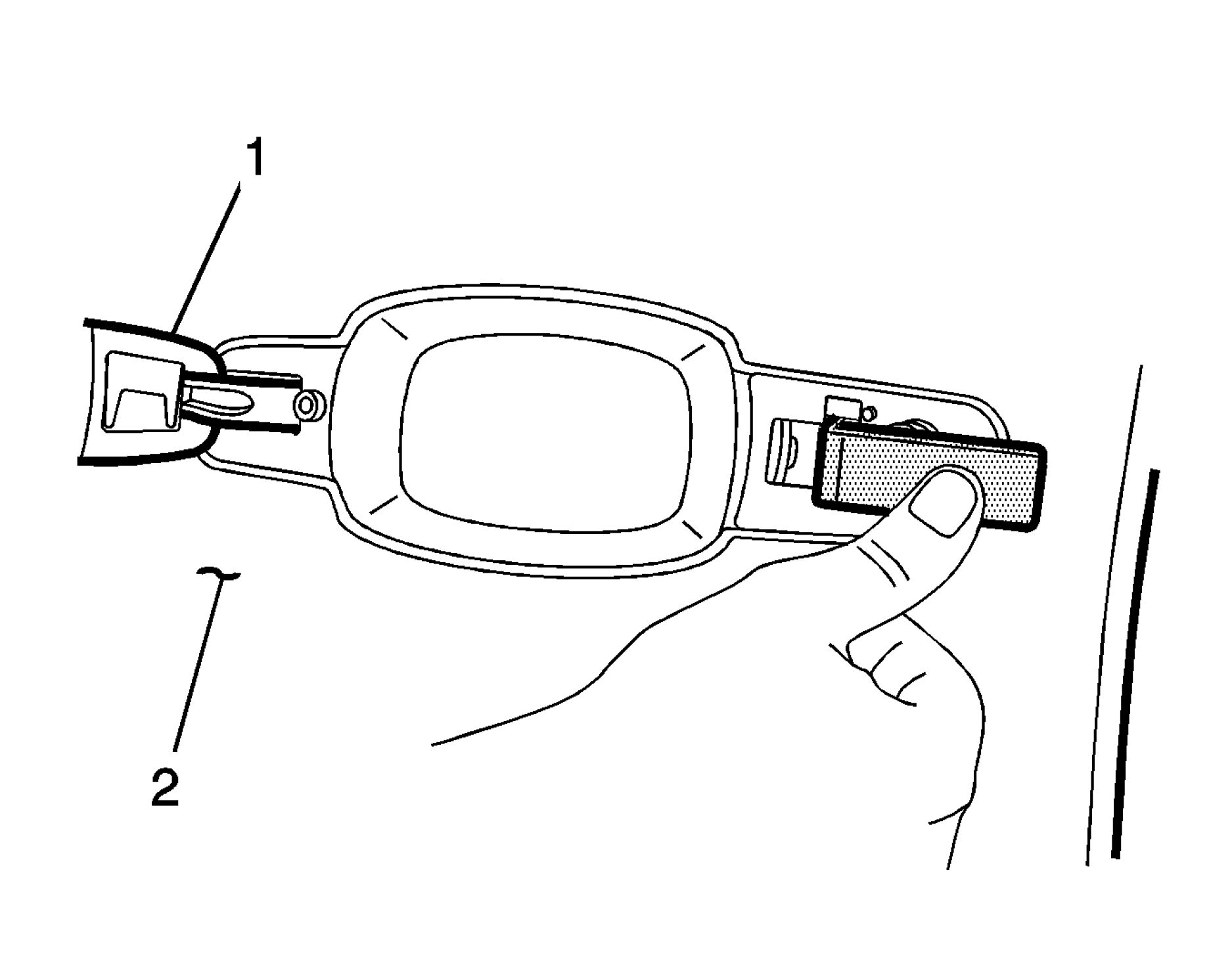 |
|
Fig. 24: Front Side Door Outside Handle At 90 Degrees Courtesy of GENERAL MOTORS COMPANY |
10. Pull front side door outside handle (1) forward until door handle is approximately at a 90 degree angle to
door (2).
 |
|
Fig. 25: Removing Front Side Door Outside Handle Courtesy of GENERAL MOTORS COMPANY |
11. Gentle pull front side door outside handle (1) outward and remove from door (2).

|
Fig. 26: Hooked Pick Tool And Door Handle Mechanism | ||
| ||
|
12. If BO-51363 Door Handle Spring Retainer slips off of door handle mechanism during repair, use a |

13. Pull door handle mechanism outward to the open position and reinstall BO-51363 Door Handle Spring
Retainer into door handle mechanism. The hooked pick tool (1) or equivalent tool can then be removed.
Installation Procedure
 |
|
Fig. 28: Front Side Door Outside Handle At 90 Degrees Courtesy of GENERAL MOTORS COMPANY |
1. While holding BO-51363 Door Handle Spring Retainer in place, install front side door outside handle (1)
into door (2) at approximately a 90 degree angle to door.

2. Rotate front side door outside handle (1) rearward into front side door handle mechanism (2).

3. Slide front side door outside handle (1) forward to lock into position.
 |
|
Fig. 31: Front Side Door Outside Handle & Spring Retainer Courtesy of GENERAL MOTORS COMPANY |
4. Release pressure on BO-51363 Door Handle Spring Retainer. Pull front side door outside handle (1)
outward and remove BO-51363 Door Handle Spring Retainer from door (2).
5. Tighten the screw for the front side door lock cylinder opening cover. Refer to Front Side Door Lock
Cylinder Opening Cover Replacement.
6. Connect the electrical connector at the door handle for the pass key entry (ATH).
7. Install the door water deflector.
8. Install the front side door armrest bracket. Refer to Front Side Door Armrest Bracket Replacement .
9. Ensure that the door lock system operates properly.
Removal Procedure
1. Remove Front Side Door Window Channel Retainer. Refer to Front Side Door Window Channel
2. Remove Front Side Door Lock Cylinder Opening Cover. Refer to Front Side Door Lock Cylinder
Opening Cover Replacement
3. Remove Front Side Door Outside Handle. Refer to Front Side Door Outside Handle Replacement
(Base)Front Side Door Outside Handle Replacement (Pass Key Entry ATH)

Fig. 32: Front Side Door Outside Handle Bracket Screw
Courtesy of GENERAL MOTORS COMPANY
4. Remove Front side door outside handle bracket screw (1)

Fig. 33: Front Side Door Lock Rod And Front Side Door Lock Cylinder
Courtesy of GENERAL MOTORS COMPANY
5. Remove Front Side Door Lock Rod (1) @ Front Side Door Lock Cylinder (2)
 |
|
Fig. 34: Side Door Outside Handle Bracket Courtesy of GENERAL MOTORS COMPANY |
6. Lower down the front side door outside handle bracket (1) to the inside door opening.
 |
|
Fig. 35: Side Door Outside Cable And Retainers |
7. Remove Front side door outside cable (1) @ retainers (2)
 |
|
Fig. 36: Side Door Outside Handle Bracket Cable And Counter Balance Courtesy of GENERAL MOTORS COMPANY |
8. Remove Front side door outside handle bracket cable (1) @ counter balance (2)
Installation Procedure
1. Transfer the lock cylinder.
NOTE: It may be necessary to transfer the wire harness retainers from the old
handle bracket.

2. Reset the front side door outside handle bracket counter balance as follows:
1. The outside door handle Can Not be install until the counter balance is reset.
2. Grasp the front side door outside handle bracket (1) with one hand.
3. From the back side of the counter balance (2) push forward on the counter balance until it can be
held in place using the bracket clip (3).
 |
|
Fig. 38: Side Door Outside Handle Bracket Cable And Counter Balance |
3. Install Front side door outside handle bracket cable (1) @ counter balance (2)
 |
|
Fig. 39: Side Door Outside Cable And Retainers |
4. Install Front side door outside cable (1) @ retainers (2)

Fig. 40: Front Side Door Lock Rod And Front Side Door Lock Cylinder
Courtesy of GENERAL MOTORS COMPANY
5. Install Front Side Door Lock Rod (1) @ Front Side Door Lock Cylinder (2)
 |
|
Fig. 41: Side Door Outside Handle Bracket Courtesy of GENERAL MOTORS COMPANY |
6. Raise the front side door outside handle bracket (1) up to the outside door opening.

Fig. 42: Front Side Door Outside Handle Bracket Screw
Courtesy of GENERAL MOTORS COMPANY
CAUTION: Refer to Fastener Caution .
7. Install and tighten Front side door outside handle bracket screw (1) to 5 N.m (44 lb in)
|
NOTE: |
|
8.
9. Install Front Side Door Lock Cylinder Opening Cover. Refer to Front Side Door Lock Cylinder
Opening Cover Replacement
10. Install Front Side Door Outside Handle. Refer to Front Side Door Outside Handle Replacement
(Base)Front Side Door Outside Handle Replacement (Pass Key Entry ATH)
11. Install Front Side Door Window Channel Retainer. Refer to Front Side Door Window Channel
Retainer Replacement
12. Ensure the door system operates properly.
FRONT SIDE DOOR OUTSIDE HANDLE BRACKET REPLACEMENT (PASSENGER SIDE)
Removal Procedure
1. Remove Front Side Door Window Channel Retainer. Refer to Front Side Door Window Channel
Retainer Replacement
2. Remove Front Side Door Lock Cylinder Opening Cover. Refer to Front Side Door Lock Cylinder
Opening Cover Replacement
3. Remove Front Side Door Outside Handle. Refer to Front Side Door Outside Handle Replacement
(Base)Front Side Door Outside Handle Replacement (Pass Key Entry ATH)
 |
|
Fig. 43: Side Door Outside Handle Bracket Screw |
4. Remove Front side door outside handle bracket screw (1)
 |
|
Fig. 44: Side Door Outside Handle Bracket Courtesy of GENERAL MOTORS COMPANY |
5. Lower the front side door outside handle bracket (1) to the inside door opening.
 |
|
Fig. 45: Side Door Outside Cable And Retainers |
6. Remove Front side door outside cable (1) @ retainers (2)
 |
|
Fig. 46: Side Door Outside Handle Bracket Cable And Counter Balance |
7. Remove Front side door outside handle bracket cable (1) @ counter balance (2)
Installation Procedure
NOTE: It may be necessary to transfer the wire harness retainers from the old
handle bracket.

1. Reset the front side door outside handle bracket counter balance as follows:
1. The outside door handle Can Not be install until the counter balance is reset.
2. Grasp the front side door outside handle bracket (1) with one hand.
3. From the back side of the counter balance (2) push forward on the counter balance until it can be
held in place using the bracket clip (3).
 |
|
Fig. 48: Side Door Outside Handle Bracket Cable And Counter Balance |
2. Install Front side door outside handle bracket cable (1) @ counter balance (2)
 |
|
Fig. 49: Side Door Outside Cable And Retainers |
3. Install Front side door outside cable (1) @ retainers (2)
 |
|
Fig. 50: Side Door Outside Handle Bracket Courtesy of GENERAL MOTORS COMPANY |
4. Raise the front side door outside handle bracket (1) up to the outside door opening.
 |
|
Fig. 51: Side Door Outside Handle Bracket Screw |
|
CAUTION: |
Refer to Fastener Caution . |
|
5. Install and tighten Front side door outside handle bracket screw (1) to 5 N.m (44 lb in) | ||
|
6. Install Front Side Door Lock Cylinder Opening Cover. Refer to Front Side Door Lock Cylinder
Opening Cover Replacement
7. Install Front Side Door Outside Handle. Refer to Front Side Door Outside Handle Replacement
(Base)Front Side Door Outside Handle Replacement (Pass Key Entry ATH)
8. Install Front Side Door Window Channel Retainer. Refer to Front Side Door Window Channel
Retainer Replacement
9. Ensure the door system operates properly.
FRONT SIDE DOOR OUTSIDE HANDLE CABLE REPLACEMENT
 |
|
Fig. 52: Side Door Outside Handle Cable |
|
Callout |
Component Name |
|
Preliminary Procedure Remove the front side door latch and handle bracket assembly from the door. Refer to Front Side Door Latch Replacement. | |
|
1 |
Front Side Door Outside Handle Cable Procedure
NOTE: Ensure that |
REAR SIDE DOOR OUTSIDE HANDLE BRACKET REPLACEMENT
Removal Procedure
1. Remove Rear Side Door Window Channel Rear Retainer. Refer to Rear Side Door Window Channel
Rear Retainer Replacement
2. Remove Rear Side Door Lock Cylinder Opening Cover. Refer to Rear Side Door Lock Cylinder
Opening Cover Replacement
3. Remove Rear Side Door Outside Handle. Refer to Rear Side Door Outside Handle Replacement
 |
|
Fig. 53: Side Door Outside Handle Bracket Screw |
4. Remove Rear side door outside handle bracket screw (1)
 |
|
Fig. 54: Side Door Outside Handle Bracket Courtesy of GENERAL MOTORS COMPANY |
5. Lower the rear side door outside handle bracket (1) down to the inside door opening.
 |
|
Fig. 55: Side Door Outside Cable And Retainers |
6. Remove Rear side door outside cable (1) @ retainers (2)
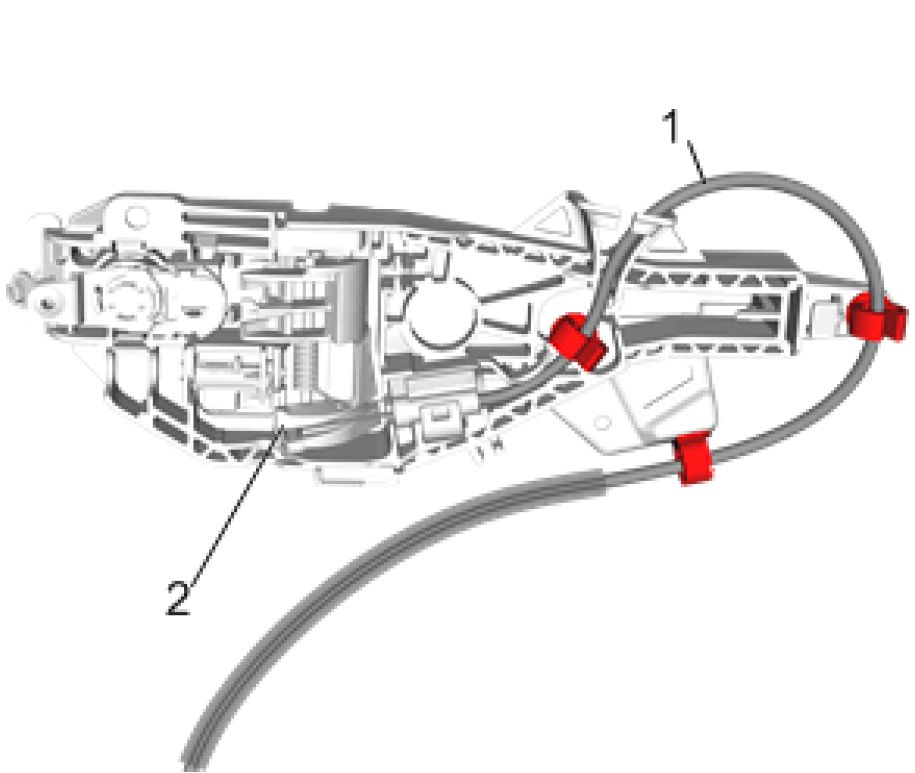 |
|
Fig. 56: Side Door Outside Handle Bracket Cable And Counter Balance |
7. Remove Rear side door outside handle bracket cable (1) @ counter balance (2)
Installation Procedure
NOTE: It may be necessary to transfer the wire harness retainers from the old
handle bracket.

1. Reset the rear side door outside handle bracket counter balance as follows:
1. The outside door handle Can Not be install until the counter balance is reset.
2. Grasp the rear side door outside handle bracket (1) with one hand.
3. From the back side of the counter balance (2) push forward on the counter balance until it can be
held in place using the bracket clip (3).
 |
|
Fig. 58: Side Door Outside Handle Bracket Cable And Counter Balance |
2. Install Rear side door outside handle bracket cable (1) @ counter balance (2)
 |
|
Fig. 59: Side Door Outside Cable And Retainers |
3. Install Rear side door outside cable (1) @ retainers (2)
 |
|
Fig. 60: Side Door Outside Handle Bracket Courtesy of GENERAL MOTORS COMPANY |
4. Raise the rear side door outside handle bracket (1) up to the outside door opening.
 |
|
Fig. 61: Side Door Outside Handle Bracket Screw |
|
CAUTION: |
Refer to Fastener Caution . |
|
5. Install and tighten Rear side door outside handle bracket screw (1) to 5 N.m (44 lb in) | ||
|
6. Install Rear Side Door Lock Cylinder Opening Cover. Refer to Rear Side Door Lock Cylinder Opening
Cover Replacement
7. Install Rear Side Door Outside Handle. Refer to Rear Side Door Outside Handle Replacement
8. Install Rear Side Door Window Channel Rear Retainer. Refer to Rear Side Door Window Channel
Rear Retainer Replacement
9. Ensure the door system operates properly.
LIFTGATE OUTSIDE HANDLE REPLACEMENT
 |
|
Fig. 62: Liftgate Outside Handle Courtesy of GENERAL MOTORS COMPANY |
|
Callout |
Component Name |
|
Preliminary Procedure Remove Liftgate Lower Trim Finish Panel. Refer to Liftgate Lower Trim Finish Panel Replacement . | |
|
1 |
Liftgate Outside Handle Bolt Cap (Qty: 2) |
|
2 |
Liftgate Outside Handle Bolt (Qty: 2) CAUTION: Refer to Caution . Tighten 2.5 N.m (22 lb in) |
|
3 |
Liftgate Outside Handle Procedure
|
LIFTGATE LATCH REPLACEMENT
 |
|
Fig. 63: Liftgate Latch Courtesy of GENERAL MOTORS COMPANY |
| |||||||||||||
|
REAR SIDE DOOR OUTSIDE HANDLE REPLACEMENT | |||||||||||||
 |
|
Fig. 64: Rear Side Door Outside Handle |
| ||||||
|
REAR SIDE DOOR OUTSIDE HANDLE CABLE REPLACEMENT | ||||||
 |
|
Fig. 65: Rear Side Door Outside Handle Cable |
|
Callout |
Component Name |
|
Preliminary Procedure Remove the rear side door latch and handle bracket assembly from the door. Refer to Rear Side Door Latch Replacement. | |
|
1 |
Rear Side Door Outside Handle Cable Procedure
Do not remove the inside door handle cable from the latch.
NOTE: |
FRONT SIDE DOOR LATCH REPLACEMENT
Removal Procedure
1. Remove Front Side Door Window Channel Retainer. Refer to Front Side Door Window Channel
Retainer Replacement
|
NOTE: |
Disconnect the window from the window regulator, place the window in |
2. Remove Front Side Door Window Regulator. Refer to Front Side Door Window Regulator
Replacement
3. Remove Front Side Door Outside Handle Bracket. Refer to Front Side Door Outside Handle Bracket
Replacement (Driver Side)Front Side Door Outside Handle Bracket Replacement (Passenger Side)
4. Remove Front Side Door Locking Rod Knob. Refer to Front Side Door Locking Rod Knob
Replacement
5. Disconnect the electrical connector.
 |
|
Fig. 66: Four Fasteners Courtesy of GENERAL MOTORS COMPANY |
6. Remove Four bolts (1) @ the Front Side Door Latch
 |
|
Fig. 67: Front Door Outside Handle Bracket And Front Side Door Latch |
7. Remove Front Door Outside Handle Bracket (1) @ the Front Side Door Latch (2)
8. Remove Front Side Door Outside Handle Cable. Refer to Front Side Door Outside Handle Cable
Replacement
9. Remove Front Side Door Inside Handle Cable. Refer to Front Side Door Inside Handle Cable
Replacement
Installation Procedure
1. Install Front Side Door Inside Handle Cable. Refer to Front Side Door Inside Handle Cable
Replacement
2. Install Front Side Door Outside Handle Cable. Refer to Front Side Door Outside Handle Cable
Replacement
3. Transfer components as necessary.
 |
|
Fig. 68: Front Door Outside Handle Bracket And Front Side Door Latch |
Courtesy of GENERAL MOTORS COMPANY
4. Install Front Door Outside Handle Bracket (1) @ the Front Side Door Latch (2)
 |
|
Fig. 69: Four Fasteners Courtesy of GENERAL MOTORS COMPANY |
CAUTION: Refer to Fastener Caution
NOTE: Install and torque the four latch bolts in proper sequence to prevent
damage to the latch mechanism.
5. Install and tighten Four bolts (1) @ the Front Side Door Latch to 11 N.m (97 lb in)
6. Install Front Side Door Locking Rod Knob. Refer to Front Side Door Locking Rod Knob Replacement
7. Install Front Side Door Outside Handle Bracket. Refer to Front Side Door Outside Handle Bracket
Replacement (Driver Side)Front Side Door Outside Handle Bracket Replacement (Passenger Side)
8. Install Front Side Door Window Regulator. Refer to Front Side Door Window Regulator Replacement
9. Install Front Side Door Window Channel Retainer. Refer to Front Side Door Window Channel
Retainer Replacement
10. Connect the electrical connector.
11. Inspect the door latch and outside handle for proper operation before installing the door trim.
12. Remove the tape from the front side door window and frame.
REAR SIDE DOOR LATCH REPLACEMENT
Removal Procedure
1. Remove Rear Side Door Window Channel Rear Retainer. Refer to Rear Side Door Window Channel
Rear Retainer Replacement
NOTE: Disconnect the window from the window regulator, place the window in
the full up position, use masking tape to tape the window to the upper
door frame.
2. Remove Rear Side Door Window Regulator. Refer to Rear Side Door Window Regulator Replacement
3. Remove Rear Side Door Outside Handle Bracket. Refer to Rear Side Door Outside Handle Bracket
Replacement
4. Remove Rear Side Door Locking Rod Knob. Refer to Rear Side Door Locking Rod Knob
Replacement
5. Disconnect the electrical connector.
 |
|
Fig. 70: Rear Side Door Latch Bolts |
Courtesy of GENERAL MOTORS COMPANY
6. Remove Rear Side Door Latch Bolts (1) (Qty: 4)
|
1 |
 |
|
2 |
7. Remove Rear Door Outside Handle (1) @ the Rear Side Door Latch (2)
8. Remove Rear Side Door Outside Handle Cable. Refer to Rear Side Door Outside Handle Cable
Replacement
9. Remove Rear Side Door Inside Handle Cable. Refer to Rear Side Door Inside Handle Cable
Replacement
Installation Procedure
1. Install Rear Side Door Inside Handle Cable. Refer to Rear Side Door Inside Handle Cable
Replacement
2. Install Rear Side Door Outside Handle Cable. Refer to Rear Side Door Outside Handle Cable
Replacement
3. Transfer components as necessary.
 |
|
Fig. 72: Rear Side Door Outside Handle Bracket And Rear Side Door Latch |
4. Install Rear Side Door Outside Handle Bracket (1) @ the Rear Side Door Latch (2)
 |
|
Fig. 73: Rear Side Door Latch Bolts Courtesy of GENERAL MOTORS COMPANY |
CAUTION: Refer to Fastener Caution
NOTE: Install and torque the four latch bolts in proper sequence to prevent
damage to the latch mechanism.
5. Install and tighten Rear Side Door Latch Bolts (1) (Qty: 4) to 11 N.m (97 lb in)
6. Install Rear Side Door Locking Rod Knob. Refer to Rear Side Door Locking Rod Knob Replacement
7. Install Rear Side Door Outside Handle Bracket. Refer to Rear Side Door Outside Handle Bracket
8. Install Rear Side Door Window Regulator. Refer to Rear Side Door Window Regulator Replacement
9. Install Rear Side Door Window Channel Rear Retainer. Refer to Rear Side Door Window Channel
10. Connect the electrical connector.
11. Inspect the door latch and outside handle for proper operation before installing the door trim.
12. Remove the tape from the rear side door window and frame.
 |
|
Fig. 74: Passenger Side Door Lock Cylinder Opening Cover (Front) |
|
Callout |
Component Name |
|
1 |
Passenger Side Door Inner Panel Hole Plug Procedure Using the appropriate tool, remove the cap that conceals the screw from the inside of the |
|
2 |
Passenger Side Door Lock Cylinder Opening Cover Screw CAUTION: NOTE: |
| ||||||
|
REAR SIDE DOOR LOCK CYLINDER OPENING COVER REPLACEMENT |
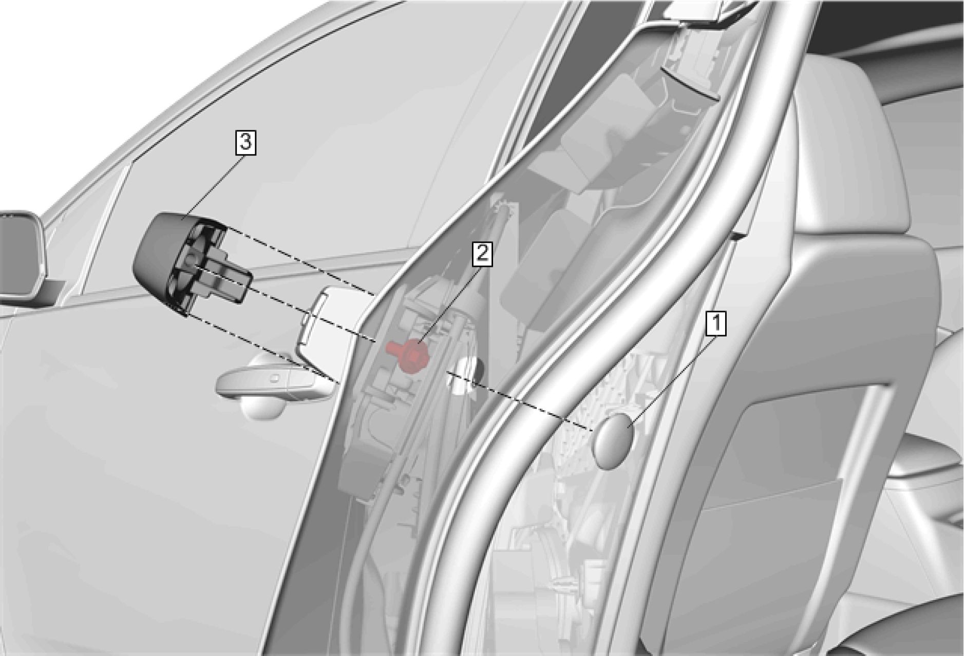 |
|
Fig. 75: Rear Side Door Lock Cylinder Opening Cover |
| ||||||||
|
FRONT SIDE DOOR LOCKING ROD REPLACEMENT |
 |
|
Fig. 76: Front Side Door Locking Rod Courtesy of GENERAL MOTORS COMPANY |
| ||||||||
|
FRONT SIDE DOOR LOCKING ROD CLIP REPLACEMENT | ||||||||
 |
|
Fig. 77: Front Side Door Locking Rod Clip |
| ||||||||
|
FRONT SIDE DOOR LOCKING ROD KNOB REPLACEMENT | ||||||||
 |
|
Fig. 78: Front Side Door Locking Rod Knob |
| ||||||||
|
FRONT SIDE DOOR LOCK CYLINDER ROD REPLACEMENT | ||||||||
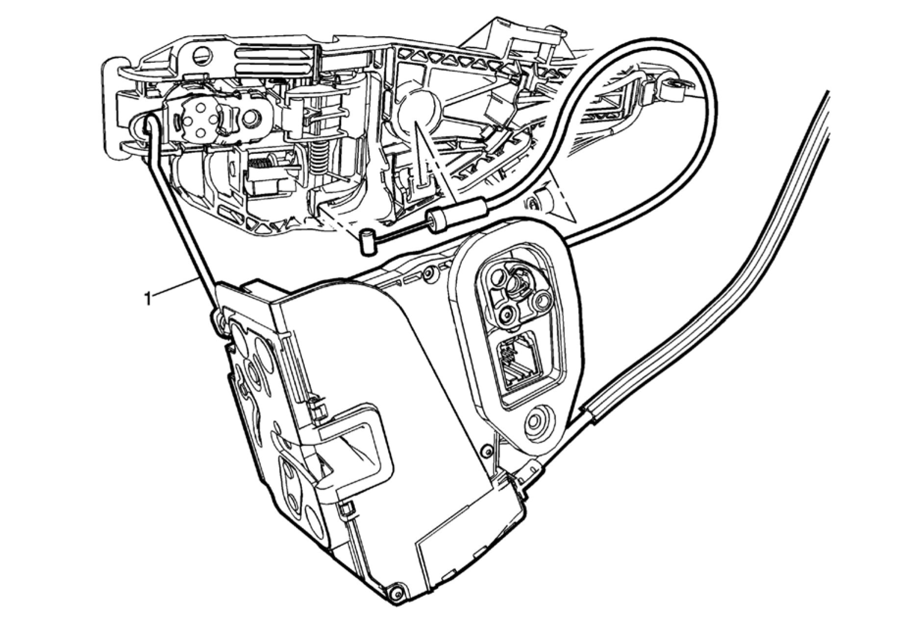 |
|
Fig. 79: Front Side Door Lock Cylinder Rod |
|
Callout |
Component Name |
|
Preliminary Procedure Remove the front side door latch and handle bracket assembly from the door. Refer to Front Side Door Latch Replacement. | |
|
1 |
Front Side Door Lock Cylinder Rod Procedure
NOTE: Ensure that |
FRONT SIDE DOOR OUTSIDE HANDLE CABLE RETAINER REPLACEMENT
 |
|
Fig. 80: Front Side Door Outside Handle Cable Retainer |
| ||||||
|
REAR SIDE DOOR LOCKING ROD KNOB REPLACEMENT | ||||||
 |
|
Fig. 81: Rear Side Door Locking Rod Knob |
| ||||||||
|
FRONT SIDE DOOR LOCK STRIKER ADJUSTMENT | ||||||||
 |
|
Fig. 82: Door Lock Striker And Bolts Courtesy of GENERAL MOTORS COMPANY |
NOTE: To determine if the striker adjustment is required, proceed as follows.
1. Ensure that the door is properly aligned with the door opening before proceeding with the striker
adjustment.
2. Open and close the door on the striker (2). Note if the door drags on the striker causing the door to move
upward or downward upon contact with the striker. Also note the closing effort to fully engage the latch.
 |
|
Fig. 83: Door Striker Anchor Plate And Door Striker |
3. The striker plate weld nuts (1) are welded in place. Using a soft marker, mark around the striker (2) for
reference of the original position. Loosen the striker screws just enough to allow the movement of the
door striker and shims if equipped.
 |
|
Fig. 84: Adjusting Door Striker Courtesy of GENERAL MOTORS COMPANY |
4. Adjust the door striker up or down and inboard or outboard as required.
5. Move the striker to eliminate drag on the striker and door latch and to achieve proper door position within
door opening. Start with up/down position, then position the striker to achieve proper alignment to the
door opening. Set the in/out adjustment for proper door seal engagement ensuring that the door closing
efforts are correct.
CAUTION: Refer to Fastener Caution .
6. Adjust the striker and add spacers as required and tighten the screws to 22 N.m (16 lb ft).
7. Inspect the door for proper operation.
8. Close the door.
FRONT SIDE DOOR LOCK STRIKER REPLACEMENT
 |
|
Fig. 85: Front Side Door Lock Striker Courtesy of GENERAL MOTORS COMPANY |
| ||||||
|
LIFTGATE LATCH STRIKER REPLACEMENT |
 |
|
Fig. 86: Liftgate Latch Striker Courtesy of GENERAL MOTORS COMPANY |
| ||||||||
|
REAR SIDE DOOR LOCK STRIKER ADJUSTMENT | ||||||||
 |
|
Fig. 87: Door Lock Striker And Bolts Courtesy of GENERAL MOTORS COMPANY |
NOTE: To determine if the striker adjustment is required, proceed as follows.
1. Ensure that the door is properly aligned with the door opening before proceeding with the striker
adjustment.
2. Open and close the door on the striker (2). Note if the door drags on the striker causing the door to move
upward or downward upon contact with the striker. Also note the closing effort to fully engage the latch.
 |
|
Fig. 88: Door Striker Anchor Plate And Door Striker |
3. The striker plate weld nuts (1) are welded in place. Using a soft marker, mark around the striker (2) for
reference of the original position. Loosen the striker screws just enough to allow the movement of the
door striker and shims if equipped.
 |
|
Fig. 89: Adjusting Door Striker Courtesy of GENERAL MOTORS COMPANY |
4. Adjust the door striker up or down and inboard or outboard as required.
5. Move the striker to eliminate drag on the striker and door latch and to achieve proper door position within
door opening. Start with up/down position, then position the striker to achieve proper alignment to the
door opening. Set the in/out adjustment for proper door seal engagement ensuring that the door closing
efforts are correct.
CAUTION: Refer to Fastener Caution .
6. Adjust the striker and add spacers as required and tighten the screws to 22 N.m (16 lb ft).
7. Inspect the door for proper operation.
8. Close the door.
REAR SIDE DOOR LOCK STRIKER REPLACEMENT
 |
|
Fig. 90: Rear Side Door Lock Striker |
|
Courtesy of GENERAL MOTORS COMPANY | ||||||
| ||||||
|
OPENING THE FUEL TANK FILLER DOOR WHEN THE DOOR LOCK MALFUNCTIONS |
1. Remove the right rear wheelhouse panel liner. Refer to Rear Wheelhouse Liner Replacement .
2. Reach in behind the fuel filler pipe housing and manually slide the actuator rod forward, using light
pressure, to override the actuator to release the fuel tank filler door.
FUEL TANK FILLER DOOR LOCK RELEASE SWITCH REPLACEMENT
 |
|
Fig. 91: Fuel Tank Filler Door Lock Release Switch |
| ||||||
|
LIFTGATE RELEASE SWITCH REPLACEMENT | ||||||
 |
|
Fig. 92: Liftgate Release Switch Courtesy of GENERAL MOTORS COMPANY |
| ||||||
|
DOOR LOCK SWITCH REPLACEMENT - DRIVER SIDE | ||||||
 |
|
Fig. 93: Door Lock Switch - Driver Side |
| ||||||
|
DOOR LOCK SWITCH REPLACEMENT - PASSENGER FRONT | ||||||
 |
|
Fig. 94: Door Lock Switch - Passenger Front |
|
Callout |
Component Name |
|
Preliminary Procedure Remove Front Side Door Trim. Refer to Front Side Door Trim Replacement | |
|
1 |
Door Lock Switch Passenger Front Procedure
|
DESCRIPTION AND OPERATION
CHARGE PORT DOOR DESCRIPTION AND OPERATION
Charge Port System Components
The charge port system consists of the following components:
• Charge port door position sensor
• Hybrid/EV powertrain control module 2
Charge Port Ajar Message
When the vehicle is in the Service Mode or ON, the hybrid/EV powertrain control module 2 supplies a 5 V
signal to the charge port door position switch through the charge port door sensor signal circuit. The charge port
door position switch contains a resistor ladder interface for switch position between two resistors for sensing
used by the hybrid/EV powertrain control module 2 to determine if the charge port door is in the open position
or the closed position. The hybrid/EV powertrain control module 2 sends a serial data message to the driver
information center in the instrument panel cluster to display the Charge Door Open message.
DOOR AJAR INDICATOR DESCRIPTION AND OPERATION
Door Ajar Indicator System Components
The door ajar indicator system consists of the following components:
• Body control module (BCM)
• Instrument cluster
• Driver door latch
• Passenger door latch
• Left rear door latch
• Right rear door latch
• Driver window motor
• Passenger window switch
• Left rear window switch
• Right rear window switch
1 P16
I Instrument
Cluster
t K9
■ Body
Control
I Module
г 1 M74D
I I Window
1 Motor -
I I Driver
1 S79P
■ Window
Switch -
I Passenger
"I S79LR
■ Window
Switch -
I Left Rear
1 S79RR
I Window
1 Switch -
I Right
. Rear
1 A23D
I Door
Latch
I Assembly
• • Driver
1 A23P
I Door Latch
' Assembly -
I Passenger
"I A23LR
I Door
' Latch
I Assembly
j - Left
Rear
4 A23RR
I Door Latch
Assembly -
I Right Rear
Fig. 95: Door Ajar Indicator With AXG/AED/AEQ Block Diagram
Courtesy of GENERAL MOTORS COMPANY
| ||||||||||||||||||||||
|
Driver Door Ajar |
The driver window motor provides a 12V signal to the driver door ajar switch signal circuit. The driver door
ajar switch is integral to the driver door latch assembly. When the driver door is opened, the normally open door
ajar switch closes. With the door ajar switch closed, ground is provided to the door ajar switch signal circuit and
the voltage within the signal circuit drops. The driver window motor will detect the voltage drop and will send a
serial data message to the body control module which will then send a message to the instrument panel cluster
to command the door ajar message
Passenger Door Ajar
The passenger window switches each provide a 12 V signal to their respective door ajar switch signal circuits.
The door ajar switches are integral to each door latch assembly. When a door is opened, the normally open door
ajar switch closes. With the door ajar switch closed, ground is provided to the door ajar switch signal circuit and
the voltage within the signal circuit drops. The window switches will detect the voltage drop and will send a
serial data message to the body control module which will then send a message to the instrument panel cluster
to command the door ajar message.
FUEL FILL DOOR DESCRIPTION AND OPERATION
Refueling System Components
The refueling system consists of the following components:
• Refuel request switch
• Fuel door position sensor
• Fuel door latch
• Hybrid powertrain control module 2
г — H S117
■ | Refuel
' Request
I I Switch
 |
|
| Hybnd/EV I I Control |

Fig. 96: Refueling System Block Diagram
Courtesy of GENERAL MOTORS COMPANY
Refueling System Overview
To effectively manage evaporative fuel emissions, hybrid vehicles with extended electrical range capability
must be equipped with a "pressurized" fuel system that can be sealed from atmosphere when the internal
combustion engine is not operating.
When the fuel system is sealed, the internal pressure will vary with changes in temperature, such as the natural
variation in ambient temperature that occurs throughout the day. To maintain evaporative emissions compliance,
vehicle refueling can only be permitted once the fuel system has been adequately vented to atmosphere through
the carbon canister. The Refueling Management feature described in this document provides the necessary
means to regulate customer access to the fuel cap and manage venting of the fuel system in order to facilitate
vehicle refueling without compromising evaporative emissions compliance.
Refueling System Operation
The hybrid/EV powertrain control module 2 monitors the voltage values of the fuel fill door open request wake-
up signal circuit and the fuel door request signal circuit. When the refuel request switch is pressed, the two
switch contacts close. This provides B+ to the wake-up circuit input and changes the voltage level of the fuel
door request signal as it passes through a single resistor instead of 2 resistors. The hybrid/EV powertrain control
module 2 will detect the 12 volts on the wake-up circuit and the voltage change on the fuel door request circuit,
it will then command the fuel system to vent and sends a serial data message to the driver information center to
display the Wait to Refuel message. The hybrid/EV powertrain control module 2 then energizes the fuel door
lock/unlock actuator to unlock the fuel door.
After the system has been vented, the hybrid powertrain control module 2 will send a command to unlock the
fuel filler door and will send a serial data message to the driver information center to display the Ready To
Refuel message. After the vehicle has been refueled, the hybrid powertrain control module 2 will send a serial
data message to the driver information center to display the Close Fuel Door message until the fuel filler door is
closed. The hybrid powertrain control module 2 will then command the fuel filler door to lock 5 seconds after
the fuel filler door is closed or the vehicle speed exceeds 40 km/h (25 mph).
LIFTGATE AJAR INDICATOR DESCRIPTION AND OPERATION
Hatch Open Indicator
The body control module (BCM) monitors the voltage level of the rear hatch ajar signal circuit which is
normally at the system voltage when the hatch is closed. When the hatch is ajar or open, a switch within the rear
hatch latch closes providing a path to ground for the hatch ajar signal circuit. The voltage within the signal
circuit will then drop to 0 volts, the BCM will then detect the voltage drop and will send a serial data message
to the instrument panel cluster (IPC). The IPC will then display an icon of the vehicle with the hatch open.
POWER DOOR LOCKS DESCRIPTION AND OPERATION
Door Lock System Components
The power door lock system consists of the following components:
• Driver door lock switch
• Passenger door lock switch
• Key cylinder switch
• Body control module (BCM)
• Driver door latch
• Passenger door latch
• Left rear door latch
• Right rear door latch
• Exterior door handle switches
• Keyless entry control module
ч S13D
| Door Lock
Switch -
I Driver
r — 1 S13P
■ I Door Lock
Switch -
I I Passenger
 |
|
К 84 |
|
■ Door ' Latch I Assembly I Door Latch I Passenger I Door Latch I Right Rear |
 |
|
Exterior Left Rear Right Rear |
 |
Exterior |


Fig. 97: Power Door Locks System Block Diagram
Courtesy of GENERAL MOTORS COMPANY
| ||||||||||||||||||||||||||
|
Door Lock and Unlock Operation |
When the driver or passenger door lock switch is activated in the lock or unlock position, the BCM will receive
a ground signal on either the door lock switch lock or unlock signal circuits.
The BCM, upon receipt of a lock switch lock or unlock signal, will supply battery voltage to the door lock
actuator lock or unlock control circuits. Since the opposite side of the lock actuator is connected to ground
through the other lock actuator control circuit, the doors will then lock or unlock as commanded.
The following three circuits are used to operate the lock:
• Driver door unlock
• Passenger door unlock
• All door lock
The driver door lock actuator is isolated so it can be unlocked by itself using the keyless entry transmitter.
Key Cylinder Switch
The driver window switch monitors the voltage level of the driver door lock motor status signal circuit. When
the key is inserted into the driver door key cylinder and turned to the Lock position, a switch within the driver
door latch closes causing the voltage to drop within the driver door lock motor status signal circuit. The driver
window switch will detect the drop in voltage and will send a serial data message to the BCM commanding all
the doors to Lock.
The driver key cylinder switch is used by the customer for programming the keyless entry transmitters, The
driver window/outside rearview mirror switch monitors the voltage level of the key switch unlock signal circuit
and when it detects a reprogramming request, it will send a serial data message to the body control module.
Passive Door Lock/Unlock Operation
The exterior door handle switch signal circuits provide inputs to the keyless entry control module when the
exterior door handle switches are activated. These inputs allow the keyless entry control module to detect a door
lock or a door unlock request. The keyless entry control module provides a 12 V signal to each exterior door
handle switch via the door handle switch signal circuits. When a door handle switch is pressed, the switch
closes and the voltage signal within the signal circuit is pulled to ground. The keyless entry control module will
detect the voltage drop and a low frequency antenna will transmit a challenge to the keyless entry transmitter. If
the challenge is met, the keyless entry transmitter will respond and the keyless entry control module will send a
serial data message to the body control module to command the door(s) to be locked or unlocked
REAR HATCH/GATE DESCRIPTION AND OPERATION
Rear Hatch Release System Components
• Liftgate Latch
• Liftgate Release Switch
• Liftgate Relay
• Body Control Module
• 15 A Fuse
Rear Hatch Release Operation
The rear hatch can be released by placing the transaxle in park, unlocking all the doors and then pressing the
touchpad located at the rear of the vehicle above the license plate.
Pressing the touchpad closes a contact providing a ground for the rear closure handle switch open signal circuit.
The body control module (BCM) will detect the voltage drop and will pulse 12 V to one side of the relay coil
and provide a ground for the other side of the relay coil, this will briefly energize the liftgate relay closing the
switch contacts and provide B+ voltage to the liftgate latch. When the doors are locked, the BCM will disable
the rear hatch release system by ignoring the liftgate release switch input command and not providing 12 V for
the liftgate relay.
Article GUID: A00884719
ACCESSORIES & EQUIPMENT
Wipers and Washers - Volt
SPECIFICATIONS
FASTENER SPECIFICATIONS
Reusable Threaded Fastener Tightening Specifications
NOTE:
All fasteners
listed in this
table can be
reused after
removal.
|
Application |
Specification |
|
Dash Upper Extension Panel Opening Cover Bolt |
9 N.m (80 lb in) |
|
Front Suspension Strut Housing Brace Bolt |
22 N.m (16 lb ft) |
|
Windshield Washer Solvent Container Nut |
9 N.m (80 lb in) |
|
Windshield Wiper Arm Nut |
30 N.m (22 lb ft) |
|
Windshield Wiper System Module Bolt |
9 N.m (80 lb in) |
SCHEMATIC WIRING DIAGRAMS
WIPER/WASHER WIRING SCHEMATICS
Windshield Wiper/Washer
 |
|
Fig. 1: Windshield Wiper/Washer Courtesy of GENERAL MOTORS COMPANY |
DIAGNOSTIC INFORMATION AND PROCEDURES
DTC B3715: WINDSHIELD WIPER RELAY CIRCUIT
Diagnostic Instructions
• Perform the Diagnostic System Check - Vehicle prior to using this diagnostic procedure.
• Review Strategy Based Diagnosis for an overview of the diagnostic approach.
Diagnostic Procedure Instructions provides an overview of each diagnostic category.
DTC Descriptors
DTC B3715
Windshield Wiper Relay Circuit
For symptom byte information, refer to Symptom Byte List .
|
Diagnostic Fault Information | ||||||||||
|
| |||||||||||||||||||||||||||||||||||||||||||||
|
Circuit/System Description | |||||||||||||||||||||||||||||||||||||||||||||
The body control module (BCM) controls the windshield wiper motor based on inputs from the windshield
wiper/washer switch, and when intermittent mode is selected, the rain/ambient light sensor module. The BCM
monitors the windshield wiper/washer switch through two separate signal circuits and a low reference circuit.
The windshield wiper/washer switch utilizes resistive multiplexing to signal a low speed and intermittent
operation request to the BCM while a separate discrete signal circuit is used to indicate a high speed wiper
request. When the wiper switch is placed in the low speed or intermittent position, the BCM monitors the
voltage drop, which changes dependent upon switch position, over an internal pulled high resistor. The BCM
will respond by commanding on the low speed or intermittent wipers. With the windshield wiper/washer switch
in the high speed position, the BCM's high speed signal circuit is pulled low. The BCM will respond by
commanding the windshield wiper motor to operate at high speed via serial data.
Conditions for Running the DTC
• The DTC runs only when a wiper output is actively being requested by the BCM.
• The system voltage is between 9 - 16 V.
Conditions for Setting the DTC
• A short to ground is detected in the front wiper relay control circuit or in the high speed relay control
circuit.
Action Taken When the DTC Sets
The BCM will not activate the wiper output.
Conditions for Clearing the DTC
• A current DTC will clear when the condition for setting the fault is no longer present.
• A history DTC will clear after 50 consecutive ignition cycles without a fault present.
Reference Information
Schematic Reference
Connector End View Reference
Description and Operation
Electrical Information Reference
Circuit Testing
Connector Repairs
Testing for Intermittent Conditions and Poor Connections
Wiring Repairs
Scan Tool Reference
Control Module References for scan tool information
Circuit/System Verification
1. Vehicle ON.
2. Verify that there are no communications DTCs set.
• If any communication DTCs are set
Refer to Diagnostic Trouble Code (DTC) List - Vehicle .
• If no communication DTCs are set
3. Verify that DTC B371A is not set.
Refer to DTC B371A.
4. Verify the scan tool Windshield Wiper High Speed Switch parameter changes between Active and
Inactive when activating the high speed windshield wipers.
• If the parameter does not change
Refer to Circuit/System Testing - Windshield Wiper/Washer Switch Malfunction.
5. Verify the scan tool Windshield Wiper Switch parameter changes between Off and Low when activating
the low speed windshield wipers.
• If the parameter does not change
Refer to Circuit/System Testing - Windshield Wiper/Washer Switch Malfunction.
6. Verify the scan tool Windshield Wiper Switch parameter changes between Delay 1 and Delay 5 when
cycling the intermittent speed windshield wipers.
• If the parameter does not change
Test or replace the S82 Windsheild Wiper/Washer Switch.
7. Verify the M75 Windshield Wiper Motor changes between Off, Low, and High when cycling the S82
Windshield Wiper/Washer Switch between Off, Low, and High.
• If the M75 Windshield Wiper Motor does not cycle between Off, Low, and High
Refer to Circuit/System Testing - Windshield Wiper Motor Malfunction
8. All OK.
Circuit/System Testing
1. Vehicle OFF and all vehicle systems OFF, disconnect the harness connector at the S82 Windshield
Wiper/Washer Switch. It may take up to 11 min for all vehicle systems to power down.
2. Test for less than 10 fi between the low reference circuit terminal 1 and ground.
• If 10 fi or greater
1. Vehicle OFF, disconnect the harness connector at the K9 Body Control Module.
2. Test for less than 2 fi in the low reference circuit end to end.
• If 2 fi or greater, repair the open/high resistance in the circuit.
• If less than 2 fi, replace the K9 Body Control Module.
3. Vehicle in Service Mode.
4. Verify the scan tool Windshield Wiper High Speed Switch parameter is Inactive.
1. Vehicle OFF, disconnect the harness connector at the K9 Body Control Module.
2. Test for infinite resistance between the signal circuit terminal 2 and ground.
• If less than infinite resistance, repair the short to ground on the circuit.
• If infinite resistance, replace the K9 Body Control Module.
5. Install a 3 A fused jumper wire between the signal circuit terminal 2 and the low reference circuit
terminal 1.
6. Verify the scan tool Windshield Wiper High Speed Switch parameter is Active.
1. Vehicle OFF, remove the jumper wire, disconnect the harness connector at the K9 Body Control
Module, vehicle in Service Mode.
2. Test for less than 1 V between the signal circuit and ground.
• If 1 V or greater, repair the short to voltage on the circuit.
• If less than 1 V
3. Test for less than 2 Q in the signal circuit end to end.
• If 2 Q or greater, repair the open/high resistance in the circuit.
• If less than 2 Q, replace the K9 Body Control Module.
7. Test for greater than 8 V between the signal circuit terminal 3 and ground.
1. Vehicle OFF, disconnect the harness connector at the K9 Body Control Module.
2. Test for infinite resistance between the signal circuit and ground
• If less than infinite resistance, repair the short to ground on the circuit.
• If infinite resistance
3. Test for less than 2 Q in the signal circuit end to end.
• If 2 Q or greater, repair the open/high resistance in the circuit.
• If less than 2 Q, replace the K9 Body Control Module.
• If 8 V or greater
8. Vehicle OFF, disconnect the X3 harness connector at the K9 Body Control Module, vehicle in Service
Mode.
9. Test for less than 1 V between the S82 Windshield Wiper/Washer Switch signal circuit terminal 3 and
ground.
• If 1 V or greater
Repair the short to voltage on the circuit.
10. Test or replace the S82 Windshield Wiper/Washer Switch.
1. Vehicle OFF and all vehicle systems OFF, disconnect the harness connector at the M75 Windshield Wiper
Motor. It may take up to 2 min for all vehicle systems to power down.
2. Test for less than 10 Q between the ground circuit terminal 2 and ground.
• If 10 Q or greater
1. Vehicle OFF.
2. Test for less than 2 fi in the ground circuit end to end.
• If 2 fi or greater, repair the open/high resistance in the circuit.
• If less than 2 fi, repair the open/high resistance in the ground connection.
3. Vehicle in Service Mode.
4. Verify a test lamp illuminates between the B+ circuit terminal 1 and ground.
• If the test lamp does not illuminate and the circuit fuse is good
1. Vehicle OFF.
2. Test for less than 2 fi in the B+ circuit end to end.
• If 2 fi or greater, repair the open/high resistance in the circuit.
• If less than 2 fi, verify the fuse is OK and there is voltage at the fuse.
• If the test lamp does not illuminate and the circuit fuse is open
1. Vehicle OFF, remove the test lamp.
2. Test for infinite resistance between the B+ circuit and ground.
• If less than infinite resistance, repair the short to ground on the circuit.
• If infinite resistance, M75 Windshield Wiper Motor
• If the test lamp illuminates
5. Connect a test lamp between the control circuit terminal 3 and ground.
6. Verify the test lamp turns ON and OFF when turning the high speed wipers ON and OFF.
• If the test lamp is always OFF
1. Vehicle OFF, remove the test lamp, disconnect the harness connector at the K9 Body Control
Module.
2. Test for infinite resistance between the control circuit and ground.
• If less than infinite resistance, repair the short to ground on the circuit.
• If infinite resistance
3. Test for less than 2 fi in the control circuit end to end.
• If 2 fi or greater, repair the open/high resistance in the circuit.
• If less than 2 fi, replace the K9 Body Control Module.
• If the test lamp is always ON
1. Vehicle OFF, remove the test lamp, disconnect the harness connector at the K9 Body Control
Module, vehicle in Service Mode.
2. Test for less than 1 V between the control circuit and ground.
• If 1 V or greater, repair the short to voltage on the circuit.
• If less than 1 V, replace the K9 Body Control Module.
• If the test lamp turns ON and OFF
7. Remove the test lamp.
8. Test for 8 - 9 V between the serial data circuit terminal 4 and ground.
• If less than 8 V
1. Vehicle OFF, disconnect the harness connector at the K9 Body Control Module.
2. Test for infinite resistance between the serial data circuit and ground.
• If less than infinite resistance, repair the short to ground on the circuit.
• If infinite resistance
3. Test for less than 2 Q in the serial data circuit end to end.
• If 2 Q or greater, repair the open/high resistance in the circuit.
• If less than 2 Q, replace the K9 Body Control Module.
• If greater than 9 V
1. Vehicle OFF, disconnect the harness connector at the K9 Body Control Module, vehicle in Service
Mode.
2. Test for less than 1 V between the serial data circuit and ground.
• If 1 V or greater, repair the short to voltage on the circuit.
• If less than 1 V or greater, replace the K9 Body Control Module.
9. Test or replace the M75 Windshield Wiper Motor.
Component Testing
1. Vehicle OFF, disconnect the harness connector at the S82 Windshield Wiper/Washer Switch.
2. Test for infinite resistance between the signal terminal 1 and the low reference terminal 2 with the high
speed switch in the open position.
Replace the S82 Windshield Wiper/Washer Switch.
3. Test for less than 2 Q between the signal circuit terminal 1 and the low reference circuit terminal 2 with
the high speed switch in the closed position.
• If 2 О or greater
Replace the S82 Windshield Wiper/Washer Switch.
4. Test for infinite resistance between the signal terminal 3 and the low reference terminal 2 with the low
speed switch in the open position.
Replace the S82 Windshield Wiper/Washer Switch.
5. Verify the resistance readings are within the specified range listed below between the signal circuit
terminal 3 and the low reference circuit terminal 1 by pushing the switch in the listed positions below.
• Delay 1 : 3.75-3.85Ю
• Delay 2 : 2.75-2.85Ю
• Delay 3 : 1.95-2.05Ю
• Delay 4 : 1.25-1.35Ю
• Delay 5 : 765-775Q
Replace the S82 Windshield Wiper/Washer Switch.
6. All OK
Repair Instructions
Perform the Diagnostic Repair Verification after completing the diagnostic procedure.
Control Module References for body control module replacement, programming and setup.
Diagnostic Instructions
• Perform the Diagnostic System Check - Vehicle prior to using this diagnostic procedure.
• Review Strategy Based Diagnosis for an overview of the diagnostic approach.
Diagnostic Procedure Instructions provides an overview of each diagnostic category.
DTC Descriptor
Windshield Wiper Motor Internal Malfunction
Circuit/System Description
B+ voltage and ground are supplied to the windshield wiper motor. Whenever the vehice is ON or in Service
Mode, the body control module (BCM) sends the wiper/washer switch status through the LIN communication
bus. If a fault occurs at any time in the windshield wiper motor, the BCM will set the DTC.
Conditions for Running the DTC
The BCM runs the diagnostic to detect an internal fault when power up is commanded. The only requirements
are voltage and ground. This diagnostic runs even if the voltage is out of the valid operating range.
Conditions for Setting the DTC
The BCM receives an invalid signal from the windshield wiper motor.
Action Taken When the DTC Sets
The BCM ignores all additional inputs.
Conditions for Clearing the DTC
A current DTC clears when the diagnostic runs and passes.
Reference Information
Schematic Reference
Wiper/Washer Schematics
Connector End View Reference
COMPONENT CONNECTOR END VIEWS - INDEX
Description and Operation
Wiper/Washer System Description and Operation
Electrical Information Reference
Circuit Testing
Connector Repairs
Testing for Intermittent Conditions and Poor Connections
Wiring Repairs
Scan Tool Reference
Control Module References for scan tool information
Circuit/System Verification
1. Vehicle in Service Mode.
2. Verify that there is no communications DTC set.
• If there is a communications DTC set
Refer to Diagnostic Trouble Code (DTC) List - Vehicle .
• If there is no communications DTC set
3. Verify that DTC B371A is not set.
• If DTC B371A is set
Replace the M75 Windshield Wiper Motor.
• If DTC B371A is not set
4. All OK.
Repair Instructions
Perform the Diagnostic Repair Verification after completing the diagnostic procedure.
Windshield Wiper System Module Replacement
DTC B371C: FRONT WIPER MOTOR 2
Diagnostic Instructions
• Perform the Diagnostic System Check - Vehicle prior to using this diagnostic procedure.
• Review Strategy Based Diagnosis for an overview of the diagnostic approach.
Diagnostic Procedure Instructions provides an overview of each diagnostic category.
DTC Descriptor
Front Wiper Motor 2
For symptom byte information, refer to Symptom Byte List .
Circuit/System Description
B+ voltage and ground are supplied to the windshield wiper motor. Whenever the vehice is ON or in Service
Mode, the body control module (BCM) sends the wiper/washer switch status through the LIN communication
bus. If a fault occurs at any time in the windshield wiper motor, the BCM will set the DTC.
Conditions for Running the DTC
The BCM runs the diagnostic to detect an internal fault when power up is commanded. The only requirements
are voltage and ground. This diagnostic runs even if the voltage is out of the valid operating range.
Conditions for Setting the DTC
The BCM receives an invalid signal from the windshield wiper motor.
Action Taken When the DTC Sets
The BCM ignores all additional inputs.
Conditions for Clearing the DTC
A current DTC clears when the diagnostic runs and passes.
Reference Information
Schematic Reference
Connector End View Reference
COMPONENT CONNECTOR END VIEWS - INDEX
Description and Operation
Wiper/Washer System Description and Operation
Electrical Information Reference
Circuit Testing
Connector Repairs
Testing for Intermittent Conditions and Poor Connections
Wiring Repairs
Scan Tool Reference
Control Module References for scan tool information
Circuit/System Verification
1. Vehicle in Service Mode.
2. Verify that there is no communications DTC set.
• If there is a communications DTC set
Refer to Diagnostic Trouble Code (DTC) List - Vehicle .
• If there is no communications DTC set
3. Verify that DTC B371C is not set.
• If DTC B371C is set
Replace the M75 Windshield Wiper Motor.
• If DTC B371C is not set
4. All OK.
Repair Instructions
Perform the Diagnostic Repair Verification after completing the diagnostic procedure.
Windshield Wiper System Module Replacement
DTC B3873: FRONT WASHER RELAY CIRCUIT
Diagnostic Instructions
• Perform the Diagnostic System Check - Vehicle prior to using this diagnostic procedure.
• Review Strategy Based Diagnosis for an overview of the diagnostic approach.
Diagnostic Procedure Instructions provides an overview of each diagnostic category.
DTC Descriptors
DTC B3873
Front Washer Relay Circuit
For symptom byte information, refer to Symptom Byte List .
|
Diagnostic Fault Information | ||||||||||
| ||||||||||
|
Circuit/System Description |
The windshield washer pump is controlled by the body control module (BCM) via a printed circuit board (PCB)
relay. When the washer switch is depressed, the BCM's internally pulled high resistor is pulled low by the
washer request circuit. The BCM then applies voltage through a control circuit to the PCB windshield washer
pump relay. With the relay energized, fused battery voltage is applied through the switch contacts of the relay
and the control circuit to activate the windshield washer fluid pump.
Conditions for Running the DTC
• Vehicle ON or in Service Mode
• The system voltage is between 9 - 16 V.
Conditions for Setting the DTC
The body control module detects a short to B+ in the windshield washer pump relay control circuit
The body control module detects a short to ground in the windshield washer pump relay control circuit
The body control module detects an open or high resistance in the windshield washer pump relay control circuit
Action Taken When the DTC Sets
Washer operation is suspended.
Conditions for Clearing the DTC
A current DTC clears when the diagnostic runs and passes.
Reference Information
Schematic Reference
Connector End View Reference
Description and Operation
Electrical Information Reference
Circuit Testing
Connector Repairs
Testing for Intermittent Conditions and Poor Connections
Wiring Repairs
Scan Tool Reference
Control Module References for scan tool information
Circuit/System Verification
1. Vehicle in Service Mode.
2. Verify the G24 Windshield Washer Pump activates when commanding the Windshield Washer Relay On
and Off with a scan tool.
• If the G24 Windshield Washer Pump does not activate
Refer to Circuit/System Testing
3. All OK.
Circuit/System Testing
1. Vehicle OFF, disconnect the X4 harness connector at the K9 Body Control Module, vehicle in Service
Mode.
2. Verify the G24 Windshield Washer Pump is not activated.
• If the G24 Windshield Washer Pump is activated
1. Vehicle OFF, disconnect the X2 harness connector at the X50A Fuse Block - Underhood, vehicle in
Service Mode.
2. Test for less than 1 V between the K9 Body Control Module control circuit terminal 14 X4 and
ground.
• If 1 V or greater, repair the short to voltage on the circuit.
• If less than 1 V, replace the X50A Fuse Block - Underhood.
• If the G24 Windshield Washer Pump is not activated
3. Connect a 10 A fused jumper wire between the control circuit terminal 14 and B+.
4. Verify the G24 Windshield Washer Pump activates.
• If the G24 Windshield Washer Pump does not activate
1. Vehicle OFF, remove the jumper wire, disconnect the X2 harness connector at the X50A Fuse
Block - Underhood.
2. Test for infinite resistance between the control circuit and ground.
• If less than infinite resistance, repair the short to ground on the circuit.
• If less than infinite resistance
3. Test for less than 2 Q in the control circuit end to end.
• If 2 Q or greater, repair the open/high resistance in the circuit.
• If less than 2 Q, test or replace the X50A Fuse Block - Underhood.
• If the G24 Windshield Washer Pump activates
5. Replace the K9 Body Control Module.
Repair Instructions
Perform the Diagnostic Repair Verification after completing the diagnostic procedure.
Control Module References for body control module replacement, programming and setup.
SYMPTOMS - WIPER/WASHER SYSTEMS
NOTE: The following steps must be completed before using the symptom tables:
1. Perform Diagnostic System Check - Vehicle , in order to verify that all of the following conditions are
true:
• No DTCs are set.
• The control modules can communicate via the serial data link.
2. Refer to Wiper/Washer System Description and Operation in order to familiarize yourself with the
system functions.
Visual/Physical Inspection
• Inspect for aftermarket devices which may affect the operation of the windshield wiper/washer system.
Refer to Checking Aftermarket Accessories .
• Inspect the easily accessible or visible system components for obvious damage or conditions which may
cause the symptom.
• Inspect the washer fluid reservoir for the proper fluid level.
Intermittent
Faulty electrical connections or wiring may be the cause of intermittent conditions. Refer to Testing for
Intermittent Conditions and Poor Connections .
Symptom List
Refer to a symptom diagnostic procedure from the following list in order to diagnose the symptom:
Windshield Wiper System Malfunction
Washer Malfunction
WINDSHIELD WIPER SYSTEM MALFUNCTION
Diagnostic Instructions
• Perform the Diagnostic System Check - Vehicle prior to using this diagnostic procedure.
• Review Strategy Based Diagnosis for an overview of the diagnostic approach.
Diagnostic Procedure Instructions provides an overview of each diagnostic category.
|
Diagnostic Fault Information | |||||||||||||||||||||||||||||||||||||||||||||
| |||||||||||||||||||||||||||||||||||||||||||||
|
Circuit/System Description | |||||||||||||||||||||||||||||||||||||||||||||
The body control module (BCM) controls the windshield wiper motor based on inputs from the windshield
wiper/washer switch, and when intermittent mode is selected, the rain/ambient light sensor module. The BCM
monitors the windshield wiper/washer switch through two separate signal circuits and a low reference circuit.
The windshield wiper/washer switch utilizes resistive multiplexing to signal a low speed and intermittent
operation request to the BCM while a separate discrete signal circuit is used to indicate a high speed wiper
request. When the wiper switch is placed in the low speed or intermittent position, the BCM monitors the
voltage drop, which changes dependent upon switch position, over an internal pulled high resistor. The BCM
will respond by commanding on the low speed or intermittent wipers. With the windshield wiper/washer switch
in the high speed position, the BCM's high speed signal circuit is pulled low. The BCM will respond by
commanding the windshield wiper motor to operate at high speed via serial data.
Reference Information
Schematic Reference
Connector End View Reference
Description and Operation
Electrical Information Reference
Circuit Testing
Connector Repairs
Testing for Intermittent Conditions and Poor Connections
Wiring Repairs
Scan Tool Reference
Control Module References for scan tool information
Circuit/System Verification
1. Vehicle ON.
2. Verify that there are no communications DTCs set.
• If any communication DTCs are set
Refer to Diagnostic Trouble Code (DTC) List - Vehicle .
• If no communication DTCs are set
3. Verify that DTC B371A is not set.
Refer to DTC B371A.
4. Verify the scan tool Windshield Wiper High Speed Switch parameter changes between Active and
Inactive when activating the high speed windshield wipers.
• If the parameter does not change
Refer to Circuit/System Testing - Windshield Wiper/Washer Switch Malfunction.
5. Verify the scan tool Windshield Wiper Switch parameter changes between Off and Low when activating
the low speed windshield wipers.
• If the parameter does not change
Refer to Circuit/System Testing - Windshield Wiper/Washer Switch Malfunction.
6. Verify the scan tool Windshield Wiper Switch parameter changes between Delay 1 and Delay 5 when
cycling the intermittent speed windshield wipers.
• If the parameter does not change
Test or replace the S82 Windsheild Wiper/Washer Switch.
7. Verify the M75 Windshield Wiper Motor changes between Off, Low, and High when cycling the S82
Windshield Wiper/Washer Switch between Off, Low, and High.
• If the M75 Windshield Wiper Motor does not cycle between Off, Low, and High
Refer to Circuit/System Testing - Windshield Wiper Motor Malfunction
8. All OK.
Circuit/System Testing
1. Vehicle OFF and all vehicle systems OFF, disconnect the harness connector at the S82 Windshield
Wiper/Washer Switch. It may take up to 11 min for all vehicle systems to power down.
2. Test for less than 10 fi between the low reference circuit terminal 1 and ground.
• If 10 fi or greater
1. Vehicle OFF, disconnect the harness connector at the K9 Body Control Module.
2. Test for less than 2 fi in the low reference circuit end to end.
• If 2 fi or greater, repair the open/high resistance in the circuit.
• If less than 2 fi, replace the K9 Body Control Module.
3. Vehicle in Service Mode.
4. Verify the scan tool Windshield Wiper High Speed Switch parameter is Inactive.
1. Vehicle OFF, disconnect the harness connector at the K9 Body Control Module.
2. Test for infinite resistance between the signal circuit terminal 2 and ground.
• If less than infinite resistance, repair the short to ground on the circuit.
• If infinite resistance, replace the K9 Body Control Module.
5. Install a 3 A fused jumper wire between the signal circuit terminal 2 and the low reference circuit
terminal 1.
6. Verify the scan tool Windshield Wiper High Speed Switch parameter is Active.
1. Vehicle OFF, remove the jumper wire, disconnect the harness connector at the K9 Body Control
Module, vehicle in Service Mode.
2. Test for less than 1 V between the signal circuit and ground.
• If 1 V or greater, repair the short to voltage on the circuit.
• If less than 1 V
3. Test for less than 2 Q in the signal circuit end to end.
• If 2 Q or greater, repair the open/high resistance in the circuit.
• If less than 2 Q, replace the K9 Body Control Module.
7. Test for greater than 8 V between the signal circuit terminal 3 and ground.
1. Vehicle OFF, disconnect the harness connector at the K9 Body Control Module.
2. Test for infinite resistance between the signal circuit and ground
• If less than infinite resistance, repair the short to ground on the circuit.
• If infinite resistance
3. Test for less than 2 Q in the signal circuit end to end.
• If 2 Q or greater, repair the open/high resistance in the circuit.
• If less than 2 Q, replace the K9 Body Control Module.
• If 8 V or greater
8. Vehicle OFF, disconnect the X3 harness connector at the K9 Body Control Module, vehicle in Service
Mode.
9. Test for less than 1 V between the S82 Windshield Wiper/Washer Switch signal circuit terminal 3 and
ground.
• If 1 V or greater
Repair the short to voltage on the circuit.
10. Test or replace the S82 Windshield Wiper/Washer Switch.
1. Vehicle OFF and all vehicle systems OFF, disconnect the harness connector at the M75 Windshield Wiper
Motor. It may take up to 2 min for all vehicle systems to power down.
2. Test for less than 10 Q between the ground circuit terminal 2 and ground.
• If 10 Q or greater
1. Vehicle OFF.
2. Test for less than 2 Q in the ground circuit end to end.
• If 2 Q or greater, repair the open/high resistance in the circuit.
• If less than 2 Q, repair the open/high resistance in the ground connection.
3. Vehicle in Service Mode.
4. Verify a test lamp illuminates between the B+ circuit terminal 1 and ground.
• If the test lamp does not illuminate and the circuit fuse is good
1. Vehicle OFF.
2. Test for less than 2 Q in the B+ circuit end to end.
• If 2 Q or greater, repair the open/high resistance in the circuit.
• If less than 2 Q, verify the fuse is OK and there is voltage at the fuse.
• If the test lamp does not illuminate and the circuit fuse is open
1. Vehicle OFF, remove the test lamp.
2. Test for infinite resistance between the B+ circuit and ground.
• If less than infinite resistance, repair the short to ground on the circuit.
• If infinite resistance, M75 Windshield Wiper Motor
• If the test lamp illuminates
5. Connect a test lamp between the control circuit terminal 3 and ground.
6. Verify the test lamp turns ON and OFF when turning the high speed wipers ON and OFF.
• If the test lamp is always OFF
1. Vehicle OFF, remove the test lamp, disconnect the harness connector at the K9 Body Control
Module.
2. Test for infinite resistance between the control circuit and ground.
• If less than infinite resistance, repair the short to ground on the circuit.
• If infinite resistance
3. Test for less than 2 Q in the control circuit end to end.
• If 2 Q or greater, repair the open/high resistance in the circuit.
• If less than 2 Q, replace the K9 Body Control Module.
• If the test lamp is always ON
1. Vehicle OFF, remove the test lamp, disconnect the harness connector at the K9 Body Control
Module, vehicle in Service Mode.
2. Test for less than 1 V between the control circuit and ground.
• If 1 V or greater, repair the short to voltage on the circuit.
• If less than 1 V, replace the K9 Body Control Module.
• If the test lamp turns ON and OFF
7. Remove the test lamp.
8. Test for 8 - 9 V between the serial data circuit terminal 4 and ground.
1. Vehicle OFF, disconnect the harness connector at the K9 Body Control Module.
2. Test for infinite resistance between the serial data circuit and ground.
• If less than infinite resistance, repair the short to ground on the circuit.
• If infinite resistance
3. Test for less than 2 Q in the serial data circuit end to end.
• If 2 Q or greater, repair the open/high resistance in the circuit.
• If less than 2 Q, replace the K9 Body Control Module.
• If greater than 9 V
1. Vehicle OFF, disconnect the harness connector at the K9 Body Control Module, vehicle in Service
Mode.
2. Test for less than 1 V between the serial data circuit and ground.
• If 1 V or greater, repair the short to voltage on the circuit.
• If less than 1 V or greater, replace the K9 Body Control Module.
9. Test or replace the M75 Windshield Wiper Motor.
Component Testing
1. Vehicle OFF, disconnect the harness connector at the S82 Windshield Wiper/Washer Switch.
2. Test for infinite resistance between the signal terminal 1 and the low reference terminal 2 with the high
speed switch in the open position.
Replace the S82 Windshield Wiper/Washer Switch.
3. Test for less than 2 Q between the signal circuit terminal 1 and the low reference circuit terminal 2 with
the high speed switch in the closed position.
• If 2 Q or greater
Replace the S82 Windshield Wiper/Washer Switch.
4. Test for infinite resistance between the signal terminal 3 and the low reference terminal 2 with the low
speed switch in the open position.
Replace the S82 Windshield Wiper/Washer Switch.
5. Verify the resistance readings are within the specified range listed below between the signal circuit
terminal 3 and the low reference circuit terminal 1 by pushing the switch in the listed positions below.
• Delay 1 : 3.75-3.85kQ
• Delay 2 : 2.75-2.85kQ
• Delay 3 : 1.95-2.05kQ
• Delay 4 : 1.25-1.35kQ
• Delay 5 : 765-775Q
• If not within the specified range
Replace the S82 Windshield Wiper/Washer Switch.
6. All OK
Repair Instructions
Perform the Diagnostic Repair Verification after completing the repair.
Control Module References for body control module replacement, programming and setup.
Diagnostic Instructions
• Perform the Diagnostic System Check - Vehicle prior to using this diagnostic procedure.
• Review Strategy Based Diagnosis for an overview of the diagnostic approach.
Diagnostic Procedure Instructions provides an overview of each diagnostic category.
|
Diagnostic Fault Information | ||||||||||||||||||||
| ||||||||||||||||||||
|
Circuit/System Description | ||||||||||||||||||||
The check washer fluid message is controlled by the instrument cluster using signal from the Windshield
Washer Fluid level Sensor. The washer fluid level signal circuit is supplied voltage through a resistor then
monitored within the instrument cluster. The Windshield Washer Fluid level Sensor is normally open so the
instrument cluster detects voltage on the Windshield Washer Fluid level Sensor signal circuit whenever the
washer fluid level sensor is low. When the washer fluid reaches the point where the driver should be informed
that the washer fluid is low, the washer fluid level sensor closes. When the washer fluid level sensor is closed
the washer fluid level signal circuit voltage is pulled low, and the instrument cluster displays the Adding Washer
Fluid message on the driver information center. In order to prevent the Adding Washer Fluid message from
being displayed while sloshing is occurring in the washer fluid container, the instrument cluster is programed
with a 1 min delay before changing states of the check washer fluid message during an ignition cycle.
Reference Information
Schematic Reference
Connector End View Reference
Description and Operation
Electrical Information Reference
Circuit Testing
Connector Repairs
Testing for Intermittent Conditions and Poor Connections
Wiring Repairs
Scan Tool Reference
Control Module References for Scan Tool Information
Circuit/System Verification
1. Ignition ON.
2. Verify the scan tool Washer Fluid Level Switch parameter changes between ON and OFF, when filling
and emptying the windshield water bottle.
• If the parameter does not change
Refer to Circuit/System Testing.
3. All OK.
Circuit/System Testing
1. Ignition OFF and all vehicle systems OFF, disconnect the harness connector at the B118B Windshield
Washer Fluid Level Switch. It may take up to 2 min for all vehicle systems to power down.
2. Test for less than 10 fi between the ground circuit terminal 2 and ground.
• If 10 fi or greater
1. Ignition OFF.
2. Test for less than 2 fi in the ground circuit end to end.
• If 2 fi or greater, repair the open/high resistance in the circuit.
• If less than 2 fi, repair the open/high resistance in the ground connection.
3. Ignition ON.
4. Verify the scan tool Washer Fluid Level Switch parameter is Off
1. Ignition OFF, disconnect the harness connector at the P16 Instrument Cluster.
2. Test for infinite resistance between the signal circuit terminal 1 and ground.
• If less than infinite resistance, repair the short to ground on the circuit.
• If infinite resistance, replace the P16 Instrument Cluster.
5. Install a 3 A fused jumper wire between the signal circuit terminal 1 and the ground circuit terminal 2.
6. Verify the scan tool Washer Fluid Level Switch parameter is On.
1. Ignition OFF, remove the jumper wire, disconnect the harness connector at the P16 Instrument
Cluster, ignition ON.
2. Test for less than 1 V between the signal circuit and ground.
• If 1 V or greater, repair the short to voltage on the circuit.
• If less than 1 V
3. Test for less than 2 fi in the signal circuit end to end.
• If 2 fi or greater, repair the open/high resistance in the circuit.
• If less than 2 fi, replace the P16 Instrument Cluster.
7. Test or replace the B118B Windshield Washer Fluid Level Switch.
Repair Instructions
Perform the Diagnostic Repair Verification after completing the repair.
Control Module References for instrument cluster replacement, programming and setup
WASHER MALFUNCTION
Diagnostic Instructions
• Perform the Diagnostic System Check - Vehicle prior to using this diagnostic procedure.
• Review Strategy Based Diagnosis for an overview of the diagnostic approach.
Diagnostic Procedure Instructions provides an overview of each diagnostic category.
DTC Descriptors
Front Washer Relay Circuit
For symptom byte information, refer to Symptom Byte List .
|
Diagnostic Fault Information | ||||||||||
|
| |||||||||||||||||||||||||||||||||||
|
Circuit/System Description | |||||||||||||||||||||||||||||||||||
The windshield washer pump is controlled by the body control module (BCM) via a printed circuit board (PCB)
relay. When the washer switch is depressed, the BCM's internally pulled high resistor is pulled low by the
washer request circuit. The BCM then applies voltage through a control circuit to the PCB windshield washer
pump relay. With the relay energized, fused battery voltage is applied through the switch contacts of the relay
and the control circuit to activate the windshield washer fluid pump.
Reference Information
Schematic Reference
Connector End View Reference
Description and Operation
Electrical Information Reference
Circuit Testing
Connector Repairs
Testing for Intermittent Conditions and Poor Connections
Wiring Repairs
Scan Tool Reference
Control Module References for scan tool information
Circuit/System Verification
1. Vehicle in Service Mode.
2. Verify the scan tool Windshield Washer Switch parameter changes between Active and Inactive when
pressing the windshield washer switch.
• If the parameter does not change
Refer to Circuit/System Testing - Windshield Wiper/Washer Switch Malfunction.
3. Verify the G24 Windshield Washer Pump activates and deactivates when commanding the Windshield
Washer Relay Active and Inactive with a scan tool.
• If the G24 Windshield Washer Pump does not activate or does not deactivate
Refer to Circuit/System Testing - Windshield Washer Pump Malfunction
4. All OK.
Circuit/System Testing
1. Vehicle OFF and all vehicle systems OFF, disconnect the harness connector at the S82 Windshield
Wiper/Washer Switch. It may take up to 11 min for all vehicle systems to power down.
2. Test for less than 10 Q between the low reference circuit terminal 2 and ground.
• If 10 Q or greater
1. Vehicle OFF.
2. Test for less than 2 Q in the low reference circuit end to end.
• If 2 Q or greater, repair the open/high resistance in the circuit.
• If less than 2 Q, replace the K9 Body Control Module.
3. Vehicle in Service Mode.
4. Verify the scan tool Windshield Washer Switch parameter is Inactive.
1. Vehicle OFF, disconnect the harness connector at the K9 Body Control Module.
2. Test for infinite resistance between the signal circuit terminal 5 and ground.
• If less than infinite resistance, repair the short to ground on the circuit.
• If infinite resistance, replace the K9 Body Control Module.
5. Install a 3 A fused jumper wire between the signal circuit terminal 5 and the low reference circuit
terminal 2.
6. Verify the scan tool Windshield Washer Switch parameter is Active.
1. Vehicle OFF, remove the jumper wire, disconnect the harness connector at the K9 Body Control
Module, vehicle in Service Mode.
2. Test for less than 1 V between the signal circuit and ground.
• If 1 V or greater, repair the short to voltage on the circuit.
• If less than 1 V
3. Test for less than 2 Q in the signal circuit end to end.
• If 2 Q or greater, repair the open/high resistance in the circuit.
• If less than 2 Q, replace the K9 Body Control Module.
7. Test or replace the S82 Windshield Wiper/Washer Switch.
1. Vehicle OFF, and all vehicle systems OFF. Disconnect the harness connector at the G24 Windshield
Washer Pump. It may take up to 2 min for all vehicle systems to power down.
2. Test for less than 10 Q between the ground circuit terminal 2 and ground.
• If 10 Q or greater
1. Test for less than 2 Q in the ground circuit end to end.
• If 2 Q or greater, repair the open/high resistance in the circuit.
• If less than 2 Q, repair the open/high resistance in the ground connection.
3. Connect a test lamp between the control circuit terminal 1 and the ground circuit terminal 2, vehicle in
Service Mode.
4. Verify the test lamp turn ON and OFF when commanding the Windshield Washer Relay Active and
Inactive with a scan tool.
• If the test lamp turns ON and OFF
Test or replace the G24 Windshield Washer Pump.
5. Vehicle OFF, connect the harness connector at the G24 Windshield Washer Pump. Disconnect the X1
harness connector at the X50A Fuse Block - Underhood. It may take up to 2 min for all vehicle systems
to power down.
6. Test for less than 10 Q between the ground circuit terminal 48 and ground.
• If 10 Q or greater
1. Test for less than 2 Q in the ground circuit end to end.
• If 2 Q or greater, repair the open/high resistance in the circuit.
• If less than 2 Q, repair the open/high resistance in the ground connection.
7. Vehicle in Service Mode.
8. Verify the G24 Windshield Washer Pump is not activated.
• If the G24 Windshield Washer Pump is activated
1. Vehicle OFF, disconnect the harness connector at the G24 Windshield Washer Pump, vehicle in
Service Mode.
2. Test for less than 1 V between the control circuit terminal 1 and ground.
• If 1 V or greater, repair the short to voltage on the circuit.
• If less than 1 V, replace the G24 Windshield Washer Pump.
• If the G24 Windshield Washer Pump is not activated
9. Connect a 20 A fused jumper wire between the control circuit terminal 14 and B+.
10. Verify the G24 Windshield Washer Pump activates.
• If the G24 Windshield Washer Pump does not activate
1. Vehicle OFF, remove the jumper wire, disconnect the harness connector at the G24 Windshield
Washer Pump.
2. Test for infinite resistance between the control circuit and ground.
• If less than Infinite resistance, repair the short to ground on the circuit.
• If infinite resistance
3. Test for less than 2 Q in the control circuit end to end.
• If 2 Q or greater, repair the open/high resistance in the circuit.
• If less than 2 Q, replace the G24 Windshield Washer Pump.
• If the G24 Windshield Washer Pump activates
11. Vehicle OFF, connect the X1 harness connector at the X50A Fuse Block - Underhood. Disconnect the X4
harness connector at the K9 Body Control Module, vehicle in Service Mode.
12. Verify the G24 Windshield Washer Pump is not activated.
• If the G24 Windshield Washer Pump is activated
1. Vehicle OFF, disconnect the X2 harness connector at the X50A Fuse Block - Underhood, vehicle in
Service Mode.
2. Test for less than 1 V between the K9 Body Control Module control circuit terminal 14 X4 and
ground, vehicle in Service Mode.
• If 1 V or greater, repair the short to voltage on the circuit.
• If less than 1 V, replace the X50A Fuse Block - Underhood.
• If the G24 Windshield Washer Pump is not activated
13. Connect a 10 A fused jumper wire between the control circuit terminal 14 and B+.
14. Verify the G24 Windshield Washer Pump activates.
• If the G24 Windshield Washer Pump does not activate
1. Vehicle OFF, remove the jumper wire, disconnect the X2 harness connector at the X50A Fuse
Block - Underhood.
2. Test for infinite resistance between the control circuit and ground.
• If less than infinite resistance, repair the short to ground on the circuit.
• If less than infinite resistance
3. Test for less than 2 Q in the control circuit end to end.
• If 2 Q or greater, repair the open/high resistance in the circuit.
• If less than 2 Q, test or replace the X50A Fuse Block - Underhood.
• If the G24 Windshield Washer Pump activates
15. Replace the K9 Body Control Module.
Component Testing
1. Vehicle OFF, disconnect the harness connector at the S82 Windshield Wiper/Washer Switch.
2. Test for infinite resistance between the signal terminal 5 and the low reference terminal 2 with the switch
in the open position.
Replace the S82 Windshield Wiper/Washer Switch.
3. Test for less than 2 fi between the signal circuit terminal 5 and the low reference circuit terminal 2 with
the switch in the closed position.
Replace the S82 Windshield Wiper/Washer Switch.
4. All OK
Repair Instructions
Perform the Diagnostic Repair Verification after completing the diagnostic procedure.
Control Module References for body control module replacement, programming and setup.

1. Remove the wiper blade from the wiper arm. Refer to Windshield Wiper Blade Replacement.
2. Look down the entire length of the blade element.
3. The rubber part of the element (2) that contacts the window must be on the center line of the blade plus or
minus 15 degrees (1).
4. Replace the blade element (2) if the element exceeds 15 degrees from the centerline of the blade, or if the
element is cracked or torn. Refer to Windshield Wiper Blade Replacement
5. Install the wiper blade onto the windshield wiper arm.
REPAIR INSTRUCTIONS
WINDSHIELD WIPER AND WASHER SWITCH REPLACEMENT
 |
|
Fig. 3: Windshield Wiper and Washer Switch |
| ||||||
|
WINDSHIELD WASHER NOZZLE HOSE REPLACEMENT | ||||||
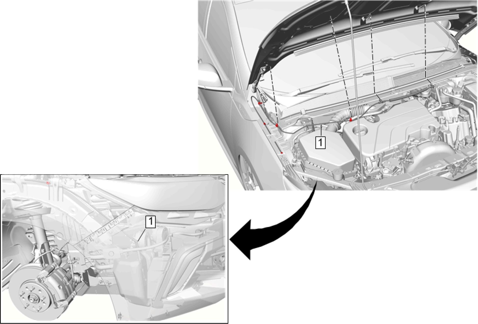 |
|
Fig. 4: Windshield Washer Nozzle Hose Courtesy of GENERAL MOTORS COMPANY |
Callout Component Name
WARNING:
Always perform the
High Voltage
Disabling procedure
prior to servicing any
High Voltage
component or
connection. Personal
Protection Equipment
(PPE) and proper
procedures must be
followed.
The High Voltage
Disabling procedure
includes the following
steps:
• Identify how to
disable high
voltage.
• Identify how to
test for the
presence of high
voltage.
• Identify
condition under
which high
voltage is
always present
and personal
protection
equipment (PPE)
and proper
procedures
must be
followed.
Before working on
any high voltage
system, be sure to
wear the following
Personal Protection
Equipment:
• Safety glasses
with appropriate
side shields
when within 15
meters (50 feet)
of the vehicle,
either indoors or
outdoors.
• Certified and up-
to-date Class "0"
Insulation
gloves rated at
1000V with
leather
protectors.
• Visually
and
functionally
inspect the
gloves
before use.
• Wear the
Insulation
gloves with
leather
| ||||||||
|
WINDSHIELD WASHER NOZZLE REPLACEMENT | ||||||||
 |
|
Fig. 5: Windshield Washer Nozzle Courtesy of GENERAL MOTORS COMPANY |
| ||||||
|
WINDSHIELD WASHER SOLVENT CONTAINER FILLER TUBE REPLACEMENT | ||||||
 |
|
Fig. 6: Windshield Washer Solvent Container Filler Tube |
| ||||||
|
WINDSHIELD WASHER SOLVENT CONTAINER GROMMET REPLACEMENT | ||||||
 |
|
Fig. 7: Windshield Washer Solvent Container Grommet |
| ||||||
|
WINDSHIELD WASHER SOLVENT CONTAINER REPLACEMENT | ||||||
 |
|
Fig. 8: Windshield Washer Solvent Container |
|
Callout |
Component Name |
|
Preliminary Procedures 1. Windshield Washer Solvent Container Filler Tube Replacement | |
| |
|
1 |
Windshield Washer Solvent Container Nut (Qty: 3) CAUTION: Refer to Caution . Tighten 9 N.m (80 lb in) |
|
2 |
Windshield Washer Pump Hose Procedure Disconnect the windshield washer pump hose. |
|
3 |
Windshield Washer Solvent Container Procedure |
| ||||
|
WINDSHIELD WASHER PUMP REPLACEMENT |
 |
|
Fig. 9: Windshield Washer Pump Courtesy of GENERAL MOTORS COMPANY |
Component Name
2. Place a clean suitable drain pan under the windshield washer solvent container to contain any lost
windshield washer solvent.
Windshield Washer Pump
1. Disconnect the electrical connector.
2. Disconnect the windshield washer pump hose.
3. Using two flat-bladed tools underneath the washer pump grommet, turn the flat-blades
in opposite directions to disengage the washer pump from the washer pump grommet.
4. Remove the washer pump grommet and discard.
WINDSHIELD WASHER PUMP GROMMET REPLACEMENT
 |
|
Fig. 10: Windshield Washer Pump Grommet |
| ||||||
|
DASH UPPER EXTENSION PANEL OPENING COVER REPLACEMENT | ||||||
 |
|
Fig. 11: Dash Upper Extension Panel Opening Cover |
|
Callout |
Component Name |
|
Preliminary Procedure Air Inlet Grille Panel Replacement | |
|
1 |
Dash Upper Extension Panel Opening Cover Retainer (Qty: 3) |
|
2 |
Dash Upper Extension Panel Opening Cover Bolt Plug (Qty: 6) |
|
3 |
Dash Upper Extension Panel Opening Cover Bolt (Qty: 2) CAUTION: Fastener Tighten 22 N.m (16 lb in) |
|
4 |
Front Suspension Strut Housing Brace Bolt (Qty: 4) Tighten 22 N.m (16 lb ft) |
|
5 |
Dash Upper Extension Panel Opening Cover Procedure Transfer components as necessary. NOTE: |
| ||||
|
AIR INLET GRILLE PANEL REPLACEMENT |
 |
|
Fig. 12: Air Inlet Grille Panel Courtesy of GENERAL MOTORS COMPANY |
Callout Component Name
WARNING:
Always perform the
High Voltage
Disabling procedure
prior to servicing any
High Voltage
component or
connection. Personal
Protection Equipment
(PPE) and proper
procedures must be
followed.
The High Voltage
Disabling procedure
includes the following
steps:
• Identify how to
disable high
voltage.
• Identify how to
test for the
presence of high
voltage.
• Identify
condition under
which high
voltage is
always present
and personal
protection
equipment (PPE)
and proper
procedures
must be
followed.
Before working on
any high voltage
system, be sure to
wear the following
Personal Protection
Equipment:
• Safety glasses
with appropriate
side shields
when within 15
meters (50 feet)
of the vehicle,
either indoors or
outdoors.
|
Callout |
Component Name |
|
• Certified and up-
Failure to follow the Preliminary Procedures
| |
|
1 |
Air Inlet Grille Panel Retainer (Qty: 8) Procedure Use a flat bladed plastic tool to remove the push-in retainers. |
Air Inlet Grille Panel
Lift the grille panel forward and upward to clear the pivot shafts from the vehicle.
 |
|
Fig. 13: Air Inlet Grille Panel Extension Courtesy of GENERAL MOTORS COMPANY |
| ||||
|
WINDSHIELD WIPER ARM REPLACEMENT |
 |
|
Fig. 14: Windshield Wiper Arm Courtesy of GENERAL MOTORS COMPANY |
|
Callout |
Component Name |
|
Preliminary Procedure Open the hood. | |
|
1 |
Windshield Wiper Arm Finish Cap Procedure Using a flat balded tool, remove the cap from the wiper arm. |
|
2 |
Windshield Wiper Arm Nut CAUTION: Refer to Tighten 30 N.m (22 lb ft) |
|
3 |
Windshield Wiper Arm CAUTION: To avoid |
| ||||
|
WINDSHIELD WIPER BLADE REPLACEMENT |
 |
|
Fig. 15: Windshield Wiper Blade Courtesy of GENERAL MOTORS COMPANY |
| ||||
|
WINDSHIELD WIPER SYSTEM MODULE REPLACEMENT |
 |
|
Fig. 16: Windshield Wiper System Module |
Callout Component Name
WARNING:
Always perform the
High Voltage
Disabling procedure
prior to servicing any
High Voltage
component or
connection. Personal
Protection Equipment
(PPE) and proper
procedures must be
followed.
The High Voltage
Disabling procedure
includes the following
steps:
• Identify how to
disable high
voltage.
• Identify how to
test for the
presence of high
voltage.
• Identify
condition under
which high
voltage is
always present
and personal
protection
equipment (PPE)
and proper
procedures
must be
followed.
Before working on
any high voltage
system, be sure to
wear the following
Personal Protection
Equipment:
• Safety glasses
with appropriate
side shields
when within 15
meters (50 feet)
of the vehicle,
either indoors or
outdoors.
• Certified and up-
to-date Class "0"
Insulation
gloves rated at
1000V with
leather
protectors.
• Visually
and
functionally
inspect the
gloves
before use.
• Wear the
Insulation
gloves with
leather
protectors
at all times
when
working
with the
high
voltage
battery
assembly,
whether
the system
is
energized
or not.
Failure to follow the
procedures may
result in serious
injury or death.
CAUTION:
To avoid
breakage of
the
windshield,
protect the
surrounding
area of the
part which
you are
removing or
installing.
Preliminary Procedures
1. Open the hood.
2. Front Suspension Strut Housing Brace Replacement
Windshield Wiper System Module Bolt (Qty: 3)
CAUTION:
Refer to
1 Fastener
Caution .
Callout
9 N.m (80 lb in)_____________________________________________________________________
Windshield Wiper System Module
1. Slide a 3 foot piece of 5/16 inch rubber hose, cut along its length, along the edge of
the windshield to prevent any accidental damage. Remove the hose before reinstalling
components.
2. Lift the front edge of the assembly and pull slightly forward in order to disengage the
center support from the backside of the plenum.
3. Disconnect the electrical connector.
4. Remove the system module from the plenum.
NOTE:
• The lower
part of the
windshield
is not
supported
by the body
structure. It
cannot
support a
technician's
weight when
leaning on
the lower
edge of the
windshield
while
performing
repairs. The
glass also
may crack if
the exposed
edge of the
windshield
is hit with
any tool.
• The
windshield
wiper
transmission
and motor
are a one
| ||||
|
WINDSHIELD MULTIFUNCTION SENSOR MOUNT BRACKET COVER REPLACEMENT |
 |
|
Fig. 17: Windshield Multifunction Sensor Mount Bracket Cover |
| ||||
|
WINDSHIELD MULTIFUNCTION SENSOR MOUNT BRACKET LOWER COVER REPLACEMENT |
 |
|
Fig. 18: Windshield Multifunction Sensor Mount Bracket Lower Cover |
|
Callout |
Component Name |
|
Preliminary Procedure Windshield Multifunction Sensor Mount Bracket Cover Replacement | |
|
1 |
Windshield Multifunction Sensor Mount Bracket Lower Cover |
WINDSHIELD GLASS CLEANING
Exterior
Clean the windshield with windshield cleaner, GM P/N 19287404 (18 oz.) or 19259280 (6 oz.) (Canadian P/N
88865156) or equivalent. The cleaner should not harm the paint finish or scratch the glass. The glass is clean
when the water no longer beads, but sheets across the entire glass surface.
Interior
The interior glass should be cleaned with plain water only applied with a clean terry cloth towel. Water only
eliminates any film or haze on the window and helps prevent fogging.
Lift each blade assembly off of the windshield and clean the element with a cloth saturated with full strength
washer solvent. Hold the blade in one hand and wipe the element with the saturated cloth until the black residue
disappears. Then rinse the blade assembly elements with clean drinkable water.
WIPER CHATTER REPAIR
Some vehicles may exhibit a condition where the windshield wipers chatter and/or wipe unevenly. Several items
may contribute to this condition. To completely repair this condition, ALL of the items listed should be
inspected and corrected as necessary.
1. Inspect the wiper blade element set. Refer to Wiper Blade Element Check
2. Clean the wiper blade elements. Refer to Wiper Blade Element Cleaning
3. Clean the windshield. Refer to Windshield Glass Cleaning
DESCRIPTION AND OPERATION
WIPER/WASHER SYSTEM DESCRIPTION AND OPERATION
Wiper/Washer System Components
The wiper/washer system consists of the following electrical components:
• Windshield Washer Pump Relay
• Windshield Washer Pump
• Windshield Wiper Motor
• Windshield Wiper/Washer Switch
• Underhood Fuse Block (Contains Windshield Washer Pump PCB Relay)
• Body Control Module (BCM)
Windshield Wiper System
The body control module (BCM) controls the wiper motor based on an input from the wiper switch, and when
wiper operation is requested, the BCM will send serial data messages to the windshield wiper motor module.
The front wiper system consists of a driver's side and passenger's side wiper arm which are connected by a
mechanical linkage driven by the windshield wiper motor module. The windshield wiper motor module
contains the necessary electronics, motor, and position sensors to execute front wiper commands from the
BCM. The windshield wiper motor module clears the front windshield by controlling the up and down wiper
arm movement by the use of a reversing motor and an internal position sensor. The sensor keeps track of the
gear wheel position and when the windshield wiper motor module determines that the wiper arms are at a
position to reverse direction, it reverses the motor supply voltage by use of its internal motor control circuitry.
The BCM communicates with the windshield wiper motor module through serial data. The windshield wiper
motor module provides system status and diagnostic information to the BCM for diagnostic reporting and
operational purposes.
The BCM utilizes resistive multiplexing through the wiper switch to discern the requested action from the
driver. The BCM will respond by commanding the specific wiper function to operate as follows:
1. Using intermittent wipes, the wipers pause briefly on the windshield. If the wiper level is moved to OFF
or if additional wipes are not required, the wipers may move to the base of the windshield.
2. If the ignition is put in OFF while the wipers are on LO, HI, or INT, they will immediately stop.
3. If the ignition is put in OFF while the wipers are performing wipes due to windshield washing, the wipers
continue to run until they reach the base of the windshield.
4. the wipe delay interval is a function of the INTERMITTENT Delay Interval Switch setting. When
enabled, the Intermittent with Speed feature affects each of the 5 normal Intermittent Delay Intervals as a
function of vehicle Speed. The Delay Intervals shall be biased to a shorter delay period with faster vehicle
speeds and to a longer delay period with a slower vehicle speed.
The windshield wiper system MIST operation is identical to LOW speed operation, except that the MIST switch
is a press and release type switch. When the wiper switch is moved to the MIST position (1X) and released, low
speed wiper motor operation is started and will continue until 1 cycle is complete. If the wiper switch is moved
to the MIST position and held, the wiper motor will operate in the LOW speed mode until the switch is
released.
To initiate high speed wiping operation, the BCM provides continuous high speed wiper operation through
setting the serial data signal to high speed Wipe. When the wiper switch lever is moved to the high position (HI)
and released, high speed wiper motor operation is started and high speed wiping operation is performed.
r — 1 S82
■ I Windshield
Wiper/
I I Washer
j Switch
1K9
I Body
Control
I Module
Г “ 1 M75
| | Windshield
Wiper Motor
Fig. 19: Windshield Wiper System Diagram
Courtesy of GENERAL MOTORS COMPANY
| ||||||||
|
Windshield Washer System |
The windshield washer pump is controlled by the body control module (BCM) via a printed circuit board (PCB)
relay. When the washer switch is depressed, the BCM's internally pulled high resistor is pulled low by the
washer request circuit. The BCM then applies voltage through a control circuit to the PCB windshield washer
pump relay. With the relay energized, fused battery voltage is applied through the switch contacts of the relay
and the control circuit to activate the windshield washer fluid pump.
I S82
■ Windshield
Wiper/
I Washer
j Switch
1 K9
I Body
’ Control
I Module
F ■*" “I G24
I I Windshield
' Washer
I I Pump
Fig. 20: Windshield Washer System Diagram
Courtesy of GENERAL MOTORS COMPANY
|
Callout |
Component Name |
|
S82 |
S82 Windshield Wiper/Washer Switch |
|
K9 |
K9 Body Control Module |
|
G24 |
G24 Windshield Washer Pump |
SPECIAL TOOLS AND EQUIPMENT
|
SPECIAL TOOLS | ||||||
|
Article GUID: A00884672
GENERAL INFORMATION
Air/Wind Noise - Volt
DIAGNOSTIC INFORMATION AND PROCEDURES
AIR/WIND NOISE
Air / Wind Noise-Diagnosis and Tests
• Stethoscope
• Duct tape, foam, etc.
WARNING: Refer to Assistant Driving Warning .
To analyze a reported wind noise condition, use the following outline:
• Speak with the customer to obtain as much information as possible.
• Perform a static evaluation of the vehicle to identify potential areas of concern.
• Test drive the vehicle to determine the source of the noise.
• Select the appropriate solution.
• After repair, re-evaluate the vehicle to confirm the customer's complaint is resolved.
When test driving the vehicle, choose a regular route with smooth and straight roads. The area should have little
traffic and little noise in order to minimize interference with the test. Drive the vehicle at the speed in which the
noise was noticed, or until the noise is heard. Maintain safe and legal speeds.
You can diagnose the following types of wind noise:
• Wind whistle / wind leaks
• Wind rush
When moving at highway speeds, air pressure inside the vehicle becomes greater than the air pressure outside.
When a leak occurs, the escaping air causes a hiss or a whistle. Wind whistle / wind leaks are repairable when
properly root caused.
Wind rush occurs when air presses over the vehicle's body, and is related to the aerodynamics of the vehicle.
Some wind rush is repairable as it relates to part fits and body panel fits. A thorough root cause analysis is
required before concluding that the wind noise is not repairable.
Use the following procedure in order to diagnose wind noise:
1. It is important to obtain as many details from the customer as possible in order to assure that you are
addressing the issue that the customer hears. Note the following details:
• The perceived location (B-pillar, mirror, roof, rear of vehicle, front of vehicle, high or low in
vehicle)
• The location where the noise is loudest (specific location along the door header, front edge of
sunroof, etc.)
• The volume of the noise (very loud, can only hear when radio is off and no ambient noises)
• The ambient conditions (temperature, windy, direction of wind, quiet)
• The road surface (rough, smooth, smooth concrete, ribbed concrete, asphalt)
• The vehicle speed (city, highway, all speeds)
• The interior fan speed (off, low, high, floor mode, defrost, etc.)
• The position of the windows (closed, partially open, full open, which windows are open-front
and/or rear, driver and/or passenger)
• The position of the sunroof (closed, partially open, full open)
• What the noise sounds like (whistle, hiss, swoosh, etc.)
2. Using the details learned from the customer, perform a visual inspection of the vehicle for possible causes
of the wind noise.
• Misinstalled / torn weatherstrips (door glass seals, door to body seals, sunroof seals) - improper
crimping, pins not fully engaged, seals not fully seated, seals pinched or deformed
• Poor Door fits (panels proud to each other, door headers protruding out, etc.)
• Poor Sunroof fits (sunroof proud to roof)
• Poor Windshield fits (windshield proud to roof, windshield lace/molding gaps/distortions, etc.)
• Roof Rack improperly installed (cross bar position fore-aft or backwards)
• Mirrors misinstalled (gapping of mirror patch, mirror skull cap gaps, mirror gasket pinched, seals
pinched, etc.)
• Poor Molding fits (windshield moldings, belt moldings, grilles, emblems)
• Any exterior aftermarket items installed (bug deflector, rain guards, etc.)
• Loose fasteners, broken weld joints, sealer and/or adhesive skips
3. Use the customer information to duplicate the driving conditions in order to duplicate the customer
concern. Make sure you are working on the issue that the customer hears.
4. Tape off the area of concern on the outside of the vehicle to turn the noise off. Start with a large area of
taping to identify the general area of the noise. Then progressively remove sections of the tape until the
noise returns. This method can help pinpoint the source of the noise quickly.
5. If necessary, utilize some of the specific diagnostic procedures below (air pressure, bubble, etc.) to
understand the leak path.
6. Based on a thorough understanding of the leak path from inside to outside, select the appropriate
resolution (refit doors, reposition weatherstrips, reposition gaskets, replace seals, etc.).
7. After repair, test drive the vehicle to confirm the customer complaint is resolved.
Clean the weatherstrips and the contact surfaces with cleaning solvent.
1. Apply powder or chalk in an unbroken line to the contact surface of the weatherstrip surrounding the
perimeter of the suspected areas.
2. Close the panel very lightly so as to not disturb the chalk or over-travel the door. Closing the panel
completely presses the weatherstrip firmly against the mating surface.
3. Inspect the applied line on the weatherstrip. The applied line is marred where contact is good. A
corresponding imprint is on the mating surfaces.
4. Gaps or irregularities in the powder or the chalk line on the mating surfaces indicate the areas with a poor
seal.
1. Close all the windows.
2. Turn the vehicles ventilation fan to the on position, with the selector on high speed and in the defrost
mode (or panel mode with fresh air vent on - no recirc).
3. Unlock and close the doors.
4. Listen for escaping air along the door and the window seals with a stethoscope or a length of heater hose.
5. If unsuccessful in identifying the leak path, consider masking off the pressure relief valves (to increase
cabin pressure) and perform the evaluation again.
1. Close all the windows.
2. Turn the vehicles ventilation fan to the on position, with the selector on high speed and in the defrost
mode (or panel mode with fresh air vent on - no recirc).
3. Unlock and close the doors.
4. Apply the soap solution to the potential leak areas.
5. Look for bubbles revealing escaping air.
6. If unsuccessful in identifying the leak path, consider masking off the pressure relief valves (to increase
cabin pressure) and perform the evaluation again.
REPAIR INSTRUCTIONS
EXTERIOR WINDNOISE
WARNING: Refer to Assistant Driving Warning .
Interior windnoise is not heard when the window is lowered. Interior windnoise is caused by the air leaving the
inside of the vehicle through a seal or a seam.
1. Tape over the relief valves to cause added air pressure within the vehicle.
2. Test drive the vehicle and listen for windnoise or a whistle.
3. Pull the vehicle over and make the temporary repairs using masking tape. If you cannot determine the
source of the windnoise, perform one or more of the following diagnostic tests:
Air Pressure Test
Soap Suds or Bubble Test
Tracing Powder or Chalk Test
INTERIOR WINDNOISE
WARNING: Refer to Assistant Driving Warning .
Interior windnoise is not heard when the window is lowered. Interior windnoise is caused by the air leaving the
inside of the vehicle through a seal or a seam.
1. Tape over the relief valves to cause added air pressure within the vehicle.
2. Test drive the vehicle and listen for windnoise or a whistle.
3. Pull the vehicle over and make the temporary repairs using masking tape. If you cannot determine the
source of the windnoise, perform one or more of the following diagnostic tests:
Air Pressure Test
Soap Suds or Bubble Test
Tracing Powder or Chalk Test
SPECIAL TOOLS AND EQUIPMENT
|
SPECIAL TOOLS | ||
|
|
Illustration |
Tool |
|
CH-39570 |
|
Illustration |
Tool |
|
GE-41416 |
Article GUID: A00884732
ACCESSORIES & EQUIPMENT
SPECIFICATIONS
FASTENER SPECIFICATIONS
|
Reusable Threaded Fastener Tightening Specifications | |||||||||||||||||||||||||||
| |||||||||||||||||||||||||||
SCHEMATIC WIRING DIAGRAMS
ACTIVE GRILLE AIR SHUTTER WIRING SCHEMATICS
Active Grille Air Shutter
 |
|
Fig. 1: Active Grille Air Shutter Courtesy of GENERAL MOTORS COMPANY |
DIAGNOSTIC INFORMATION AND PROCEDURES
DTC P059F OR P151E: ACTIVE GRILLE AIR SHUTTER
Diagnostic Instructions
• Perform the Diagnostic System Check - Vehicle prior to using this diagnostic procedure.
• Review Strategy Based Diagnosis for an overview of the diagnostic approach.
Diagnostic Procedure Instructions provides an overview of each diagnostic category.
DTC Descriptors
DTC P059F
Active Grille Air Shutter 1 Performance
DTC P151E
Active Grille Air Shutter Actuator 1 Signal Message Counter Incorrect
Diagnostic Fault Information
Circuit
Short to
Open/High
Short to
Signal Performance
| ||||||||||||||||||||
|
Circuit/System Description |
The active grille air shutter actuator closes louvers at the front bumper to enhance vehicle aerodynamics in
driving situations where cooling and A/C loads are relatively low and high levels of front end airflow are not
required. If high levels of airflow are required the active grille air shutter actuator opens the louvers. The Local
Interconnect Network (LIN) Serial Data Bus signal from the engine control module, ignition and ground circuits
enable the active grille air shutter actuator to operate. If the conditions for opening the louvers are reached the
engine control module commands the active grille air shutter actuator to open the louvers.
Conditions for Running the DTC
• Ignition On/Vehicle in Service Mode.
• The battery voltage is greater than 10 V.
• The DTC runs continuously when the above conditions are met.
Conditions for Setting the DTC
• The DTC P059F will be set during a key cycle when the commanded louver position can not be achieved
after 5 attempts are made to move the louver. The DTC will be stored as current for this key cycle but the
malfunction indicator lamp (MIL) will not be illuminated. The malfunction indicator lamp will illuminate
in the second key cycle after a failed movement attempt is made in each of two back to back key cycles.
• The DTC P151E will set if there is a serial data communication failure.
Action Taken When the DTC Sets
DTC P059F and P151E are type B DTCs.
Conditions for Clearing the DTC
DTC P059F and P151E are type B DTCs.
Reference Information
Schematic Reference
Connector End View Reference
Description and Operation
Electrical Information Reference
Circuit Testing
Connector Repairs
Testing for Intermittent Conditions and Poor Connections
Wiring Repairs
Scan Tool Reference
Control Module References for scan tool information
Circuit/System Verification
1. Ignition On/Vehicle in Service Mode.
2. Verify DTC U1510 is not set.
• If DTC U1510 is set
Refer to Diagnostic Trouble Code (DTC) List - Vehicle for further diagnosis.
• If DTC U1510 is not set
3. Verify the active grille air shutter position parameter changes from 0% (fully closed) to 100% (fully open)
when using the scan tool ECM Active Grille Air Shutter Position control function.
• If the louvers at the front bumper do not open and close
Refer to Circuit/System Testing.
4. Verify none of the following conditions are present:
• Snow or ice packed in the front fascia which prevents the louvers from moving.
• Debris or foreign objects which prevent the louvers from moving.
• If any of the conditions are present
Clear any snow, ice or foreign objects from the front grille.
5. All OK
Circuit/System Testing
1. Ignition/Vehicle Off and all vehicle systems Off, disconnect the harness connector(s) at the active grille
air shutter actuator(s). It may take up to 2 minutes for all vehicle systems to power down.
2. Test for less than 10 fi between the ground circuit and ground.
• If 10 fi or greater
1. Ignition/Vehicle Off.
2. Test for less than 2 fi in the ground circuit end to end.
• If 2 Q or greater, repair the open/high resistance in the circuit.
• If less than 2 Q, repair the open/high resistance in the ground connection.
3. Ignition On/Vehicle in Service Mode.
4. Verify a test lamp illuminates between the ignition circuit and ground.
• If the test lamp does not illuminate and the circuit fuse is good
1. Ignition/Vehicle Off.
2. Test for less than 2 Q in the ignition circuit end to end.
• If 2 Q or greater, repair the open/high resistance in the circuit.
• If less than 2 Q, verify the fuse is not open and there is voltage at the fuse. Refer to Power
Mode Mismatch .
• If the test lamp does not illuminate and the circuit fuse is open
1. Ignition/Vehicle Off.
2. Test for infinite resistance between the ignition circuit and ground.
• If less than infinite resistance, repair the short to ground on the circuit.
• If the test lamp illuminates
5. Ignition/Vehicle Off, disconnect the harness connector at the K20 Engine Control Module.
1. Test for infinite resistance between the LIN Serial Data Bus circuit and ground.
• If less than infinite resistance, repair the short to ground on the circuit.
• If infinite resistance
2. Test for less than 2 Q in the LIN Serial Data Bus circuit end to end.
• If 2 Q or greater, repair the open/high resistance in the circuit.
• If less than 2 Q
3. Test for less than 1 V between the LIN Serial Data Bus circuit and ground.
• If 1 V or greater, repair the short to voltage on the circuit.
• If less than 1 V
6. Test or replace the M60A Active Grille Air Shutter 1 Motor Module.
7. Verify DTCs P059F, P151E or U1510 are not set while operating the vehicle under the conditions for
setting the DTC.
Replace the K20 Engine Control Module.
8. All OK.
Repair Instructions
Perform the Diagnostic Repair Verification after completing the repair.
Control Module References for control module replacement, programming and setup.
SYMPTOMS - ACTIVE GRILLE AIR SHUTTER
NOTE: The following steps must be completed before using the symptom tables:
1. Perform the Diagnostic System Check - Vehicle before using the Symptom Tables in order to verify that
all of the following are true:
• There are no DTCs set.
• The control modules can communicate via the serial data link.
2. Review the system operation in order to familiarize yourself with the system functions. Refer to Active
Grille Air Shutter Description and Operation.
Visual/Physical Inspection
• Inspect for aftermarket devices which may affect the operation of the system. Refer to Checking
Aftermarket Accessories .
• Inspect the easily accessible or visible system components for obvious damage or conditions which may
cause the symptom.
Intermittent
Faulty electrical connections or wiring may be the cause of intermittent conditions. Refer to Testing for
Intermittent Conditions and Poor Connections .
Symptom List
Active Grille Air Shutter 1 Malfunction
ACTIVE GRILLE AIR SHUTTER 1 MALFUNCTION
Diagnostic Instructions
• Perform the Diagnostic System Check - Vehicle prior to using this diagnostic procedure.
• Review Strategy Based Diagnosis for an overview of the diagnostic approach.
Diagnostic Procedure Instructions provides an overview of each diagnostic category.
DTC Descriptors
Active Grille Air Shutter 1 Performance
Active Grille Air Shutter Actuator 1 Signal Message Counter Incorrect
|
Diagnostic Fault Information | ||||||||||
|
| ||||||||||||||||||||
|
Circuit/System Description |
The active grille air shutter actuator closes louvers at the front bumper to enhance vehicle aerodynamics in
driving situations where cooling and A/C loads are relatively low and high levels of front end airflow are not
required. If high levels of airflow are required the active grille air shutter actuator opens the louvers. The Local
Interconnect Network (LIN) Serial Data Bus signal from the engine control module, ignition and ground circuits
enable the active grille air shutter actuator to operate. If the conditions for opening the louvers are reached the
engine control module commands the active grille air shutter actuator to open the louvers.
Conditions for Running the DTC
• Ignition On/Vehicle in Service Mode.
• The battery voltage is greater than 10 V.
• The DTC runs continuously when the above conditions are met.
Conditions for Setting the DTC
• The DTC P059F will be set during a key cycle when the commanded louver position can not be achieved
after 5 attempts are made to move the louver. The DTC will be stored as current for this key cycle but the
malfunction indicator lamp (MIL) will not be illuminated. The malfunction indicator lamp will illuminate
in the second key cycle after a failed movement attempt is made in each of two back to back key cycles.
• The DTC P151E will set if there is a serial data communication failure.
Action Taken When the DTC Sets
DTC P059F and P151E are type B DTCs.
Conditions for Clearing the DTC
DTC P059F and P151E are type B DTCs.
Reference Information
Schematic Reference
Connector End View Reference
Description and Operation
Electrical Information Reference
Circuit Testing
Connector Repairs
Testing for Intermittent Conditions and Poor Connections
Wiring Repairs
Scan Tool Reference
Control Module References for scan tool information
Circuit/System Verification
1. Ignition On/Vehicle in Service Mode.
2. Verify DTC U1510 is not set.
• If DTC U1510 is set
Refer to Diagnostic Trouble Code (DTC) List - Vehicle for further diagnosis.
• If DTC U1510 is not set
3. Verify the active grille air shutter position parameter changes from 0% (fully closed) to 100% (fully open)
when using the scan tool ECM Active Grille Air Shutter Position control function.
• If the louvers at the front bumper do not open and close
Refer to Circuit/System Testing.
4. Verify none of the following conditions are present:
• Snow or ice packed in the front fascia which prevents the louvers from moving.
• Debris or foreign objects which prevent the louvers from moving.
• If any of the conditions are present
Clear any snow, ice or foreign objects from the front grille.
5. All OK
Circuit/System Testing
1. Ignition/Vehicle Off and all vehicle systems Off, disconnect the harness connector(s) at the active grille
air shutter actuator(s). It may take up to 2 minutes for all vehicle systems to power down.
2. Test for less than 10 Q between the ground circuit and ground.
• If 10 О or greater
1. Ignition/Vehicle Off.
2. Test for less than 2 Q in the ground circuit end to end.
• If 2 Q or greater, repair the open/high resistance in the circuit.
• If less than 2 Q, repair the open/high resistance in the ground connection.
3. Ignition On/Vehicle in Service Mode.
4. Verify a test lamp illuminates between the ignition circuit and ground.
• If the test lamp does not illuminate and the circuit fuse is good
1. Ignition/Vehicle Off.
2. Test for less than 2 Q in the ignition circuit end to end.
• If 2 Q or greater, repair the open/high resistance in the circuit.
• If less than 2 Q, verify the fuse is not open and there is voltage at the fuse. Refer to Power
Mode Mismatch .
• If the test lamp does not illuminate and the circuit fuse is open
1. Ignition/Vehicle Off.
2. Test for infinite resistance between the ignition circuit and ground.
• If less than infinite resistance, repair the short to ground on the circuit.
• If the test lamp illuminates
5. Ignition/Vehicle Off, disconnect the harness connector at the K20 Engine Control Module.
1. Test for infinite resistance between the LIN Serial Data Bus circuit and ground.
• If less than infinite resistance, repair the short to ground on the circuit.
• If infinite resistance
2. Test for less than 2 Q in the LIN Serial Data Bus circuit end to end.
• If 2 Q or greater, repair the open/high resistance in the circuit.
• If less than 2 Q
3. Test for less than 1 V between the LIN Serial Data Bus circuit and ground.
• If 1 V or greater, repair the short to voltage on the circuit.
• If less than 1 V
6. Test or replace the M60A Active Grille Air Shutter 1 Motor Module.
7. Verify DTCs P059F, P151E or U1510 are not set while operating the vehicle under the conditions for
setting the DTC.
Replace the K20 Engine Control Module.
8. All OK.
Repair Instructions
Perform the Diagnostic Repair Verification after completing the repair.
Control Module References for control module replacement, programming and setup.
REPAIR INSTRUCTIONS
FRONT BUMPER FASCIA ENERGY ABSORBER REPLACEMENT

Fig. 2: Front Bumper Fascia Energy Absorber
Courtesy of GENERAL MOTORS COMPANY
| ||||||||
|
FRONT BUMPER IMPACT ABSORBER REPLACEMENT | ||||||||
 |
|
Fig. 3: Front Bumper Impact Absorber Courtesy of GENERAL MOTORS COMPANY |
| ||||||||
|
FRONT BUMPER IMPACT BAR REPLACEMENT | ||||||||

Fig. 4: Front Bumper Impact Bar
Courtesy of GENERAL MOTORS COMPANY
| ||||||||
|
FRONT BUMPER FASCIA REMOVAL AND INSTALLATION | ||||||||
 |
|
Fig. 5: Front Bumper Fascia Courtesy of GENERAL MOTORS COMPANY |
|
Callout |
Component Name |
|
Preliminary Procedures
| |
|
(Right Side) | |
|
1 |
Front Bumper Fascia Bolt (Qty: 8) CAUTION: Refer to Caution . Tighten 2.5 N.m (22 lb in) |
|
2 |
Front Bumper Fascia Procedure 1. Carefully push a small nylon wedge between the fascia and the front fascia retainers. |
| ||||
|
FRONT BUMPER FASCIA GUIDE REPLACEMENT |
 |
|
Fig. 6: Front Bumper Fascia Guide Courtesy of GENERAL MOTORS COMPANY |
|
Callout |
Component Name |
|
Preliminary Procedure Front Bumper Fascia Removal and Installation | |
|
1 |
Front Bumper Fascia Guide Bolt (Qty: 3) CAUTION: Refer to Tighten 2.5 N.m (22 lb in) |
| ||||||
|
FRONT BUMPER FASCIA CENTER SUPPORT REPLACEMENT |
 |
|
Fig. 7: Front Bumper Fascia Center Support |
|
Callout |
Component Name |
|
Preliminary Procedures Front Bumper Fascia Removal and Installation | |
|
1 |
Front Bumper Fascia Center Support Bolt (Qty: 4) CAUTION: Refer to Caution . Tighten 22 N.m (16 lb ft) |
|
2 |
Front Bumper Fascia Center Support |
FRONT BUMPER SHUTTER REPLACEMENT

Fig. 8: Front Bumper Shutter
Courtesy of GENERAL MOTORS COMPANY
|
Callout |
Component Name |
|
Preliminary Procedures Front Bumper Fascia Removal and Installation | |
|
1 |
Front Bumper Shutter Bolt (Qty: 4) CAUTION: Refer to Caution . Tighten 2.5 N.m (22 lb in) |
|
2 |
Front Bumper Shutter Procedure
|
FRONT BUMPER FASCIA LOWER STIFFENER REPLACEMENT
 |
|
Fig. 9: Front Bumper Fascia Lower Stiffener (Center) |
| ||||||||
|
FRONT BUMPER FASCIA CENTER AIR DEFLECTOR REPLACEMENT | ||||||||
 |
|
Fig. 10: Front Bumper Fascia Center Air Deflector |
| ||||||||
|
REAR BUMPER FASCIA REMOVAL AND INSTALLATION | ||||||||
 |
|
Fig. 11: Rear Bumper Fascia Courtesy of GENERAL MOTORS COMPANY |
|
Callout |
Component Name |
|
Preliminary Procedure | |
|
1 |
Rear Bumper Fascia Bolt (Qty: 4) CAUTION: Refer to Tighten 2.5 N.m (22 lb in) |
|
2 |
Rear Bumper Fascia Procedure
|
REAR BUMPER FASCIA GUIDE REPLACEMENT
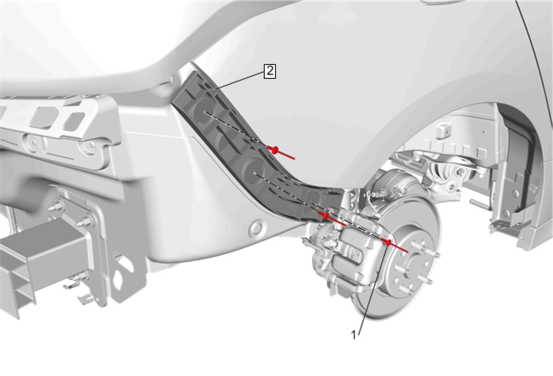 |
|
Fig. 12: Rear Bumper Fascia Guide Courtesy of GENERAL MOTORS COMPANY |
| ||||||||
|
REAR BUMPER UPPER FASCIA REPLACEMENT | ||||||||
 |
|
Fig. 13: Rear Bumper Upper Fascia Courtesy of GENERAL MOTORS COMPANY |
| ||||||||
|
REAR BUMPER LOWER FASCIA REPLACEMENT | ||||||||
 |
|
Fig. 14: Rear Bumper Lower Fascia Courtesy of GENERAL MOTORS COMPANY |
| ||||||||
|
REAR BUMPER ENERGY ABSORBER REPLACEMENT | ||||||||

Fig. 15: Rear Bumper Energy Absorber
Courtesy of GENERAL MOTORS COMPANY
| ||||||||
|
REAR BUMPER IMPACT BAR REPLACEMENT | ||||||||
 |
|
Fig. 16: Rear Bumper Impact Bar Courtesy of GENERAL MOTORS COMPANY |
|
Callout |
Component Name |
|
Preliminary Procedure Rear Bumper Fascia Removal and Installation | |
|
1 |
Rear Bumper Impact Bar Nut (Qty: 6) CAUTION: Refer to Tighten 58 N.m (43 lb ft) |
|
2 |
Rear Bumper Impact Bar Procedure Transfer components as necessary. |
DESCRIPTION AND OPERATION
The active grille air shutter system closes shutters in the front grille to enhance vehicle aerodynamics in driving
situations where cooling and A/C loads are relatively low and high levels of front end airflow are not required.
If high levels of airflow are required the active grille air shutter system will open one or both shutters. The
control signal from the engine control module, ignition and ground circuits enable the active grille air shutter
actuators to operate. If the conditions for opening the shutters are reached the engine control module commands
the active grille air shutter actuators to open one or both shutters.
The dual active grille air shutter system consists of two aero shutter mechanisms located in the front grille for
controlling the amount of air flowing through the grille. It includes three wires; ground, power and a Local
Interconnect Network (LIN) Bus serial data circuit from the engine control module to the shutter actuator. The
engine control module determines shutter state based on various vehicle conditions such as vehicle speed,
coolant temperature, fan state, refrigerant system pressure, A/C compressor state and ambient temperature. The
engine control module has the ability to command each shutter individually to the open or closed positions
through communications on the LIN Bus.
The actuators are powered by an ignition circuit that is active when the key is in the RUN position. The vehicle
may have to be driven for up to 13 minutes at speeds greater than 41 km/h (25 mph) before a shutter begins to
move. If low ambient temperature is detected, the shutters will remain in the closed position.
Article GUID: A00884632
ACCESSORIES & EQUIPMENT
Collision Repair - Volt
SPECIFICATIONS
DIMENSIONS - BODY
Point-to-point measurements are for reference only. All measurements are given in millimeters. Use these
measurements for diagnosing and estimating. Point-to-point measurements are duplicated with tram bar pointers
set at equal lengths. All die marks, holes, slots, and fasteners are measured to the center. All dimensions are
symmetrical unless otherwise specified.
|
Point-to-Point Measurements Engine Compartment |
 |
|
Fig. 1: Engine Compartment Dimensions |
Side
 |
|
Fig. 2: Side Dimensions Courtesy'of GENERAL MOTORS COMPANY |
Rear End

Fig. 3: Rear End Dimensions
Courtesy of GENERAL MOTORS COMPANY
Rear End Upper
 |
|
Fig. 4: Rear End Upper Dimensions Courtesy of GENERAL MOTORS COMPANY |
VISUAL IDENTIFICATION
STRUCTURE IDENTIFICATION
View Front
 |
|
Fig. 5: Front View Structure Courtesy'of GENERALMOTORS COMPANY |
| ||||||||||||||||||||||||||||||||||||||||||
|
View Side Inner |
 |
|
Fig. 6: Side Inner View Structure Courtesy'of GENERALMOTORS COMPANY |
| ||||||||||||||||||||||||||||||||||||
|
View Side Outer |
 |
|
Fig. 7: Side Outer View Structure Courtesy'of GENERALMOTORS COMPANY |
| ||||||||||||||||||||||||||||||||||
|
View Side |
 |
|
Fig. 8: Side View Structure Courtesy'of GENERALMOTORS COMPANY |
| ||||||||||||||||||||||||||||||
|
View Rear |
 |
|
Fig. 9: Rear View Structure Courtesy'of GENERALMOTORS COMPANY |
|
Number |
Description |
Material |
Procedure |
|
1 |
Body Rear End Panel |
Mild Steel |
Body Rear End Panel |
|
2 |
Rear Floor Panel Filler |
High Strength Low |
Rear Floor Panel Filler |
|
Alloy Steel |
Replacement | ||
|
3 |
Floor Panel Number 5 |
Mild Steel |
Floor Panel Number 5 Cross |
|
4 |
Floor Panel Number 5 |
High Strength Low |
Floor Panel Number 5 Cross |
|
Alloy Steel |
Bar Replacement | ||
|
5 |
Rear Floor Panel Filler |
Ultra High Strength |
|
|
6 |
Rear Floor Panel |
Mild Steel |
Rear Floor Panel Sectioning |
|
7 |
Rear Rail |
Ultra High Strength |
Rear Rail Replacement |
|
8 |
Rear Rail Section |
Ultra High Strength |
Rail Replacement - Rear |
|
Steel |
Section |
REPAIR INSTRUCTIONS
FRONT END UPPER TIE BAR REPLACEMENT
WARNING: Always perform the High Voltage Disabling procedure prior to servicing any
High Voltage component or connection. Personal Protection Equipment (PPE)
and proper procedures must be followed.
The High Voltage Disabling procedure includes the following steps:
• Identify how to disable high voltage.
• Identify how to test for the presence of high voltage.
• Identify condition under which high voltage is always present and
personal protection equipment (PPE) and proper procedures must be
followed.
Before working on any high voltage system, be sure to wear the following
Personal Protection Equipment:
• Safety glasses with appropriate side shields when within 15 meters (50
feet) of the vehicle, either indoors or outdoors.
• Certified and up-to-date Class "0" Insulation gloves rated at 1000V with
leather protectors.
• Visually and functionally inspect the gloves before use.
• Wear the Insulation gloves with leather protectors at all times when
working with the high voltage battery assembly, whether the system
is energized or not.
Failure to follow the procedures may result in serious injury or death.
Removal Procedure
WARNING: Refer to Approved Equipment for Collision Repair Warning .
WARNING: Refer to Collision Sectioning Warning .
WARNING: Refer to Glass and Sheet Metal Handling Warning .
CAUTION: Refer to Collision Repair Anchoring Caution .
1. Disable the SIR system. SIR Disabling and Enabling .
2. Inspect the high voltage system. High Voltage System Inspection .
3. Remove all related panels and components.
4. Visually inspect the vehicle for additional damage to the vehicle structure. Repair as much of the damage
to the vehicle structure as possible, prior to replacing any damaged parts.
5. Remove the sealers and anti-corrosion materials from the repair area, as necessary. Anti-Corrosion
Treatment and Repair .
 |
|
Fig. 10: Front End Upper Tie Bar Courtesy of GENERAL MOTORS COMPANY |
| ||||
|
6. Remove all factory welds from front end upper tie bar (1). |
 |
|
Fig. 11: Front End Upper Tie Bar Courtesy of GENERAL MOTORS COMPANY |
7. Remove the damaged front end upper tie bar (1) from vehicle (2).
NOTE: If impact resistant adhesive is present remove and replace as necessary.
8. Remove the impact resistant adhesive from the repair area, as necessary. Metal Panel Bonding.
Installation Procedure
NOTE: Squeeze Type Resistance Spot Welds equivalent to the factory spot welds
are recommended. If access to use Squeeze Type Resistance Spot Welds
is not possible, MIG/MAG plug welds may be used, to replace those
specific welds.
1. Prepare all mating surfaces for welding as necessary.
 |
|
Fig. 12: Front End Upper Tie Bar Courtesy of GENERAL MOTORS COMPANY |
2. Position the front end upper tie bar (1) on the vehicle (2) using 3-dimensional measuring equipment.
3. Verify the fit of the front end upper tie bar (1).
4. Apply the impact resistant adhesive to the repair area, as necessary. Metal Panel Bonding.
 |
|
Fig. 13: Front End Upper Tie Bar Courtesy of GENERAL MOTORS COMPANY |
5. Clamp the front end upper tie bar (1) into position.
6. Weld the front end upper tie bar (1) accordingly.
7. Apply the sealers and anti-corrosion materials to the repair area, as necessary. Anti-Corrosion
Treatment and Repair .
8. Install the body side outer panel as necessary.
9. Paint the repaired area. Basecoat/Clearcoat Paint Systems .
10. Install all related panels and components.
11. If disabled, enable the high voltage system. High Voltage Enabling .
12. Enable the SIR System. SIR Disabling and Enabling .
FRONT END LOWER TIE BAR REPLACEMENT
WARNING: Always perform the High Voltage Disabling procedure prior to servicing any
High Voltage component or connection. Personal Protection Equipment (PPE)
and proper procedures must be followed.
The High Voltage Disabling procedure includes the following steps:
• Identify how to disable high voltage.
• Identify how to test for the presence of high voltage.
• Identify condition under which high voltage is always present and
personal protection equipment (PPE) and proper procedures must be
followed.
Before working on any high voltage system, be sure to wear the following
Personal Protection Equipment:
• Safety glasses with appropriate side shields when within 15 meters (50
feet) of the vehicle, either indoors or outdoors.
• Certified and up-to-date Class "0" Insulation gloves rated at 1000V with
leather protectors.
• Visually and functionally inspect the gloves before use.
• Wear the Insulation gloves with leather protectors at all times when
working with the high voltage battery assembly, whether the system
is energized or not.
Failure to follow the procedures may result in serious injury or death.
Removal Procedure
WARNING: Refer to Approved Equipment for Collision Repair Warning .
WARNING: Refer to Collision Sectioning Warning .
WARNING: Refer to Glass and Sheet Metal Handling Warning .
CAUTION: Refer to Collision Repair Anchoring Caution .
NOTE: Left shown, right similar.
1. Disable the SIR System. Refer to SIR Disabling and Enabling .
2. Inspect the high voltage system. Refer to High Voltage System Inspection .
3. Remove all related panels and components.
4. Visually inspect the vehicle for additional damage to the vehicle structure. Repair as much of the damage
to the vehicle structure as possible, prior to replacing any damaged parts.
5. Remove the sealers and anti-corrosion materials from the repair area, as necessary. Refer to Anti-
Corrosion Treatment and Repair .
 |
|
Fig. 14: Front End Lower Tie Bar Courtesy of GENERAL MOTORS COMPANY |
| ||||
|
6. Remove all factory welds from the front end lower tie bar (1). |
 |
|
Fig. 15: Front End Lower Tie Bar Courtesy of GENERAL MOTORS COMPANY |
7. Remove the damaged front end lower tie bar (2) from vehicle (1).
NOTE: If impact resistant adhesive is present remove and replace as necessary.
8. Remove the impact resistant adhesive from the repair area, as necessary. Refer to Metal Panel Bonding.
Installation Procedure
NOTE: Squeeze Type Resistance Spot Welds equivalent to the factory spot welds
are recommended. If access to use Squeeze Type Resistance Spot Welds
is not possible, MIG/MAG plug welds may be used, to replace those
specific welds.
1. Prepare all mating surfaces for welding as necessary.
 |
|
Fig. 16: Front End Lower Tie Bar Courtesy of GENERAL MOTORS COMPANY |
2. Position the front end lower tie bar (2) on the vehicle (1) using 3-dimensional measuring equipment.
3. Verify the fit of the front end lower tie bar (2).
 |
|
Fig. 17: Front End Lower Tie Bar Courtesy of GENERAL MOTORS COMPANY |
4. Apply the impact resistant adhesive to the repair area, as necessary. Refer to Metal Panel Bonding.
5. Clamp the front end lower tie bar (1) into position.
6. Weld the front end lower tie bar (1) accordingly.
7. Apply the sealers and anti-corrosion materials to the repair area, as necessary. Refer to Anti-Corrosion
Treatment and Repair .
8. Install the body side outer panel as necessary.
9. Paint the repaired area. Refer to Basecoat/Clearcoat Paint Systems .
10. Install all related panels and components.
11. If disabled, enable the high voltage system. Refer to High Voltage Enabling .
12. Enable the SIR system. Refer to SIR Disabling and Enabling .
FRONT WHEELHOUSE PANEL REPLACEMENT
WARNING: Always perform the High Voltage Disabling procedure prior to servicing any
High Voltage component or connection. Personal Protection Equipment (PPE)
and proper procedures must be followed.
The High Voltage Disabling procedure includes the following steps:
• Identify how to disable high voltage.
• Identify how to test for the presence of high voltage.
• Identify condition under which high voltage is always present and
personal protection equipment (PPE) and proper procedures must be
followed.
Before working on any high voltage system, be sure to wear the following
Personal Protection Equipment:
• Safety glasses with appropriate side shields when within 15 meters (50
feet) of the vehicle, either indoors or outdoors.
• Certified and up-to-date Class "0" Insulation gloves rated at 1000V with
leather protectors.
• Visually and functionally inspect the gloves before use.
• Wear the Insulation gloves with leather protectors at all times when
working with the high voltage battery assembly, whether the system
is energized or not.
Failure to follow the procedures may result in serious injury or death.
Removal Procedure
WARNING: Refer to Approved Equipment for Collision Repair Warning .
WARNING: Refer to Collision Sectioning Warning .
WARNING: Refer to Glass and Sheet Metal Handling Warning .
CAUTION: Refer to Collision Repair Anchoring Caution .
NOTE: Left shown, right similar.
1. Disable the SIR system. SIR Disabling and Enabling .
2. Inspect the high voltage system. High Voltage System Inspection .
3. Remove all related panels and components.
4. Visually inspect the vehicle for additional damage to the vehicle structure. Repair as much of the damage
to the vehicle structure as possible, prior to replacing any damaged parts.
5. Remove the sealers and anti-corrosion materials from the repair area as necessary. Anti-Corrosion
Treatment and Repair .
 |
|
Fig. 18: Front Wheelhouse Panel Courtesy of GENERAL MOTORS COMPANY |
| ||||
|
6. Remove all factory welds from the front wheelhouse panel (1). |

Fig. 19: Front Wheelhouse Panel
Courtesy of GENERAL MOTORS COMPANY
7. Remove the damaged front wheelhouse panel (2) from vehicle (1).
NOTE: If impact resistant adhesive is present remove and replace as necessary.
8. Remove the impact resistant adhesive from the repair area, as necessary. Metal Panel Bonding.
Installation Procedure
NOTE: Squeeze Type Resistance Spot Welds equivalent to the factory spot welds
are recommended. If access to use Squeeze Type Resistance Spot Welds
is not possible, MIG/MAG plug welds may be used, to replace those
specific welds.
1. Prepare all mating surfaces for welding as necessary.

2. Position the front wheelhouse panel (2) on the vehicle (1) using 3-dimensional measuring equipment.
3. Verify the fit of the front wheelhouse panel (2).
4. Apply the impact resistant adhesive to the repair area, as necessary. Metal Panel Bonding.

Fig. 21: Front Wheelhouse Panel
Courtesy of GENERAL MOTORS COMPANY
5. Clamp the front wheelhouse panel (1) into position.
6. Weld the front wheelhouse panel (1) accordingly.
7. Apply the sealers and anti-corrosion materials to the repair area as necessary. Anti-Corrosion Treatment
and Repair .
8. Paint the repaired area. Basecoat/Clearcoat Paint Systems .
9. Install all related panels and components.
10. If disabled, enable the high voltage system. High Voltage Enabling .
11. Enable the SIR System. SIR Disabling and Enabling .
FRONT WHEELHOUSE EXTENSION REPLACEMENT
WARNING: Always perform the High Voltage Disabling procedure prior to servicing any
High Voltage component or connection. Personal Protection Equipment (PPE)
and proper procedures must be followed.
The High Voltage Disabling procedure includes the following steps:
• Identify how to disable high voltage.
• Identify how to test for the presence of high voltage.
• Identify condition under which high voltage is always present and
personal protection equipment (PPE) and proper procedures must be
followed.
Before working on any high voltage system, be sure to wear the following
Personal Protection Equipment:
• Safety glasses with appropriate side shields when within 15 meters (50
feet) of the vehicle, either indoors or outdoors.
• Certified and up-to-date Class "0" Insulation gloves rated at 1000V with
leather protectors.
• Visually and functionally inspect the gloves before use.
• Wear the Insulation gloves with leather protectors at all times when
working with the high voltage battery assembly, whether the system
is energized or not.
Failure to follow the procedures may result in serious injury or death.
Removal Procedure
WARNING: Refer to Approved Equipment for Collision Repair Warning .
WARNING: Refer to Collision Sectioning Warning .
WARNING: Refer to Glass and Sheet Metal Handling Warning .
CAUTION: Refer to Collision Repair Anchoring Caution .
NOTE: Left shown, right similar.
1. Disable the SIR system. SIR Disabling and Enabling
2. Inspect the high voltage system. High Voltage System Inspection
3. Remove all related panels and components.
4. Visually inspect the vehicle for additional damage to the vehicle structure. Repair as much of the damage
to the vehicle structure as possible, prior to replacing any damaged parts.
5. Remove the sealers and anti-corrosion materials from the repair area, as necessary. Anti-Corrosion
Treatment and Repair
 |
|
Fig. 22: Front Wheelhouse Extension Courtesy of GENERAL MOTORS COMPANY |
| ||||
|
6. Remove all factory welds from the front wheelhouse extension (1). |
 |
|
Fig. 23: Front Wheelhouse Extension Courtesy of GENERAL MOTORS COMPANY |
7. Remove the damaged front wheelhouse extension (2) from vehicle (1).
NOTE: If impact resistant adhesive is present remove and replace as necessary.
8. Remove the impact resistant adhesive from the repair area, as necessary. Metal Panel Bonding
Installation Procedure
NOTE: Squeeze Type Resistance Spot Welds equivalent to the factory spot welds
are recommended. If access to use Squeeze Type Resistance Spot Welds
is not possible, MIG/MAG plug welds may be used, to replace those
specific welds.
1. Prepare all mating surfaces for welding as necessary.
 |
|
Fig. 24: Front Wheelhouse Extension Courtesy of GENERAL MOTORS COMPANY |
2. Position the front wheelhouse extension (2) on the vehicle (1) using 3-dimensional measuring equipment.
3. Verify the fit of the front wheelhouse extension (2).
 |
|
Fig. 25: Front Wheelhouse Extension Courtesy of GENERAL MOTORS COMPANY |
4. Apply the impact resistant adhesive to the repair area, as necessary. Metal Panel Bonding
5. Clamp the front wheelhouse extension (1) into position.
6. Weld the front wheelhouse extension (1) accordingly.
7. Apply the sealers and anti-corrosion materials to the repair area, as necessary. Anti-Corrosion
Treatment and Repair
8. Install the body side outer panel as necessary.
9. Paint the repaired area. Basecoat/Clearcoat Paint Systems
10. Install all related panels and components.
11. If disabled, enable the high voltage system. High Voltage Enabling
12. Enable the SIR System. SIR Disabling and Enabling
FRONT WHEELHOUSE PANEL BRACE REPLACEMENT
WARNING: Always perform the High Voltage Disabling procedure prior to servicing any
High Voltage component or connection. Personal Protection Equipment (PPE)
and proper procedures must be followed.
The High Voltage Disabling procedure includes the following steps:
• Identify how to disable high voltage.
• Identify how to test for the presence of high voltage.
• Identify condition under which high voltage is always present and
personal protection equipment (PPE) and proper procedures must be
followed.
Before working on any high voltage system, be sure to wear the following
Personal Protection Equipment:
• Safety glasses with appropriate side shields when within 15 meters (50
feet) of the vehicle, either indoors or outdoors.
• Certified and up-to-date Class "0" Insulation gloves rated at 1000V with
leather protectors.
• Visually and functionally inspect the gloves before use.
• Wear the Insulation gloves with leather protectors at all times when
working with the high voltage battery assembly, whether the system
is energized or not.
Failure to follow the procedures may result in serious injury or death.
Removal Procedure
WARNING: Refer to Approved Equipment for Collision Repair Warning .
WARNING: Refer to Collision Sectioning Warning .
WARNING: Refer to Glass and Sheet Metal Handling Warning .
CAUTION: Refer to Collision Repair Anchoring Caution .
NOTE: Left shown, right similar.
1. Disable the SIR system. SIR Disabling and Enabling
2. Inspect the high voltage system. High Voltage System Inspection
3. Remove all related panels and components.
4. Visually inspect the vehicle for additional damage to the vehicle structure. Repair as much of the damage
to the vehicle structure as possible, prior to replacing any damaged parts.
5. Remove the sealers and anti-corrosion materials from the repair area, as necessary. Anti-Corrosion
Treatment and Repair
 |
|
Fig. 26: Front Wheelhouse Panel Brace Courtesy of GENERAL MOTORS COMPANY |
| ||||
|
6. Remove all factory welds from the front wheelhouse panel brace (1). |
 |
|
Fig. 27: Front Wheelhouse Panel Brace |
7. Remove the damaged front wheelhouse panel brace (2) from vehicle (1).
NOTE: If impact resistant adhesive is present remove and replace as necessary.
8. Remove the impact resistant adhesive from the repair area, as necessary. Metal Panel Bonding
Installation Procedure
NOTE: Squeeze Type Resistance Spot Welds equivalent to the factory spot welds
are recommended. If access to use Squeeze Type Resistance Spot Welds
is not possible, MIG/MAG plug welds may be used, to replace those
specific welds.
1. Prepare all mating surfaces for welding as necessary.
 |
|
Fig. 28: Front Wheelhouse Panel Brace |
2. Position the front wheelhouse panel brace (2) on the vehicle (1) using 3-dimensional measuring
equipment.
3. Verify the fit of the front wheelhouse panel brace (2).
4. Apply the impact resistant adhesive to the repair area, as necessary. Metal Panel Bonding
 |
|
Fig. 29: Front Wheelhouse Panel Brace |
5. Clamp the front wheelhouse panel brace (1) into position.
6. Weld the front wheelhouse panel brace (1) accordingly.
7. Apply the sealers and anti-corrosion materials to the repair area, as necessary. Anti-Corrosion
Treatment and Repair
8. Install the body side outer panel as necessary.
9. Paint the repaired area. Basecoat/Clearcoat Paint Systems
10. Install all related panels and components.
11. If disabled, enable the high voltage system. High Voltage Enabling
12. Enable the SIR System. SIR Disabling and Enabling
FRONT COMPARTMENT UPPER SIDE RAIL REPLACEMENT
WARNING: Always perform the High Voltage Disabling procedure prior to servicing any
High Voltage component or connection. Personal Protection Equipment (PPE)
and proper procedures must be followed.
The High Voltage Disabling procedure includes the following steps:
• Identify how to disable high voltage.
• Identify how to test for the presence of high voltage.
• Identify condition under which high voltage is always present and
personal protection equipment (PPE) and proper procedures must be
followed.
Before working on any high voltage system, be sure to wear the following
Personal Protection Equipment:
• Safety glasses with appropriate side shields when within 15 meters (50
feet) of the vehicle, either indoors or outdoors.
• Certified and up-to-date Class "0" Insulation gloves rated at 1000V with
leather protectors.
• Visually and functionally inspect the gloves before use.
• Wear the Insulation gloves with leather protectors at all times when
working with the high voltage battery assembly, whether the system
is energized or not.
Failure to follow the procedures may result in serious injury or death.
Removal Procedure
WARNING: Refer to Approved Equipment for Collision Repair Warning .
WARNING: Refer to Collision Sectioning Warning .
WARNING: Refer to Glass and Sheet Metal Handling Warning .
CAUTION: Refer to Collision Repair Anchoring Caution .
NOTE: Left shown, right similar.
1. Disable the SIR System. Refer to SIR Disabling and Enabling .
2. Inspect the high voltage system. Refer to High Voltage System Inspection .
3. Remove all related panels and components.
4. Visually inspect the vehicle for additional damage to the vehicle structure. Repair as much of the damage
to the vehicle structure as possible, prior to replacing any damaged parts.
5. Remove the sealers and anti-corrosion materials from the repair area, as necessary. Refer to Anti-
Corrosion Treatment and Repair .

|
Fig. 30: Front Compartment Upper Side Rail | ||||
| ||||
|
6. Remove all factory spot welds from front compartment upper side rail (1). |

Fig. 31: Front Compartment Upper Side Rail Brazing Welds
Courtesy of GENERAL MOTORS COMPANY
7. Remove all factory brazing welds (1) from front compartment upper side rail.
 |
|
Fig. 32: Front Compartment Upper Side Rail |
8. Remove the damaged front compartment upper side rail (1) from vehicle (2).
NOTE: If impact resistant adhesive is present remove and replace as necessary.
Installation Procedure | ||
| ||
|
NOTE: MIG Brazing Welds equivalent to the factory brazing welds are |
recommended.
1. Prepare all mating surfaces for welding as necessary.
 |
|
Fig. 33: Front Compartment Upper Side Rail |
2. Apply the impact resistant adhesive to the repair area, as necessary. Refer to Metal Panel Bonding.
3. Position the front compartment upper side rail (1) on the vehicle (2) using 3-dimensional measuring
equipment.
4. Verify the fit of the front compartment upper side rail (1).

5. Clamp the front compartment upper side rail (1) into position.
6. Weld the front compartment upper side rail (1) accordingly.

Fig. 35: Front Compartment Upper Side Rail Brazing Welds
Courtesy of GENERAL MOTORS COMPANY
7. Replace factory brazing welds with MIG brazing welds (1) on front compartment upper side rail
accordingly.
8. Apply the sealers and anti-corrosion materials to the repair area, as necessary. Refer to Anti-Corrosion
Treatment and Repair .
9. Install the body side outer panel as necessary.
10. Paint the repaired area. Refer to Basecoat/Clearcoat Paint Systems .
11. Install all related panels and components.
12. If disabled, enable the high voltage system. Refer to High Voltage Enabling .
13. Enable the SIR system. Refer to SIR Disabling and Enabling .
WINDSHIELD INNER UPPER FRAME REINFORCEMENT REPLACEMENT
WARNING: Always perform the High Voltage Disabling procedure prior to servicing any
High Voltage component or connection. Personal Protection Equipment (pPe)
and proper procedures must be followed.
The High Voltage Disabling procedure includes the following steps:
• Identify how to disable high voltage.
• Identify how to test for the presence of high voltage.
• Identify condition under which high voltage is always present and
personal protection equipment (PPE) and proper procedures must be
followed.
Before working on any high voltage system, be sure to wear the following
Personal Protection Equipment:
• Safety glasses with appropriate side shields when within 15 meters (50
feet) of the vehicle, either indoors or outdoors.
• Certified and up-to-date Class "0" Insulation gloves rated at 1000V with
leather protectors.
• Visually and functionally inspect the gloves before use.
• Wear the Insulation gloves with leather protectors at all times when
working with the high voltage battery assembly, whether the system
is energized or not.
Failure to follow the procedures may result in serious injury or death.
Removal Procedure
WARNING: Refer to Approved Equipment for Collision Repair Warning .
WARNING: Refer to Collision Sectioning Warning .
WARNING: Refer to Glass and Sheet Metal Handling Warning .
CAUTION: Refer to Collision Repair Anchoring Caution .
NOTE: The windshield inner upper frame reinforcement is an ultra-high strength
dual phase steel and cannot be sectioned or repaired. Ultra High Strength
Steel.
NOTE: There are sectioning procedures available for various locations of the
body side outer panel. The sectioning procedure and location should be
chosen based on the extent of damage to the vehicle and any additional
inner reinforcements that need to be replaced. Refer to the body side outer
panel sectioning procedures for the specific location where sectioning is
required.
NOTE: Left shown right similar.
1. Disable the SIR system. SIR Disabling and Enabling .
2. Inspect the high voltage system. High Voltage System Inspection .
3. Remove all related panels and components.
4. Visually inspect the vehicle for additional damage to the vehicle structure. Repair as much of the damage
to the vehicle structure as possible, prior to replacing any damaged parts.
5. Remove the sealers and anti-corrosion materials from the repair area, as necessary. Anti-Corrosion
Treatment and Repair .
6. Section the body side outer panel as required for access to replace the windshield inner upper frame
reinforcement.

| ||||
|
7. Remove all factory welds from the windshield inner upper frame reinforcement (1). |
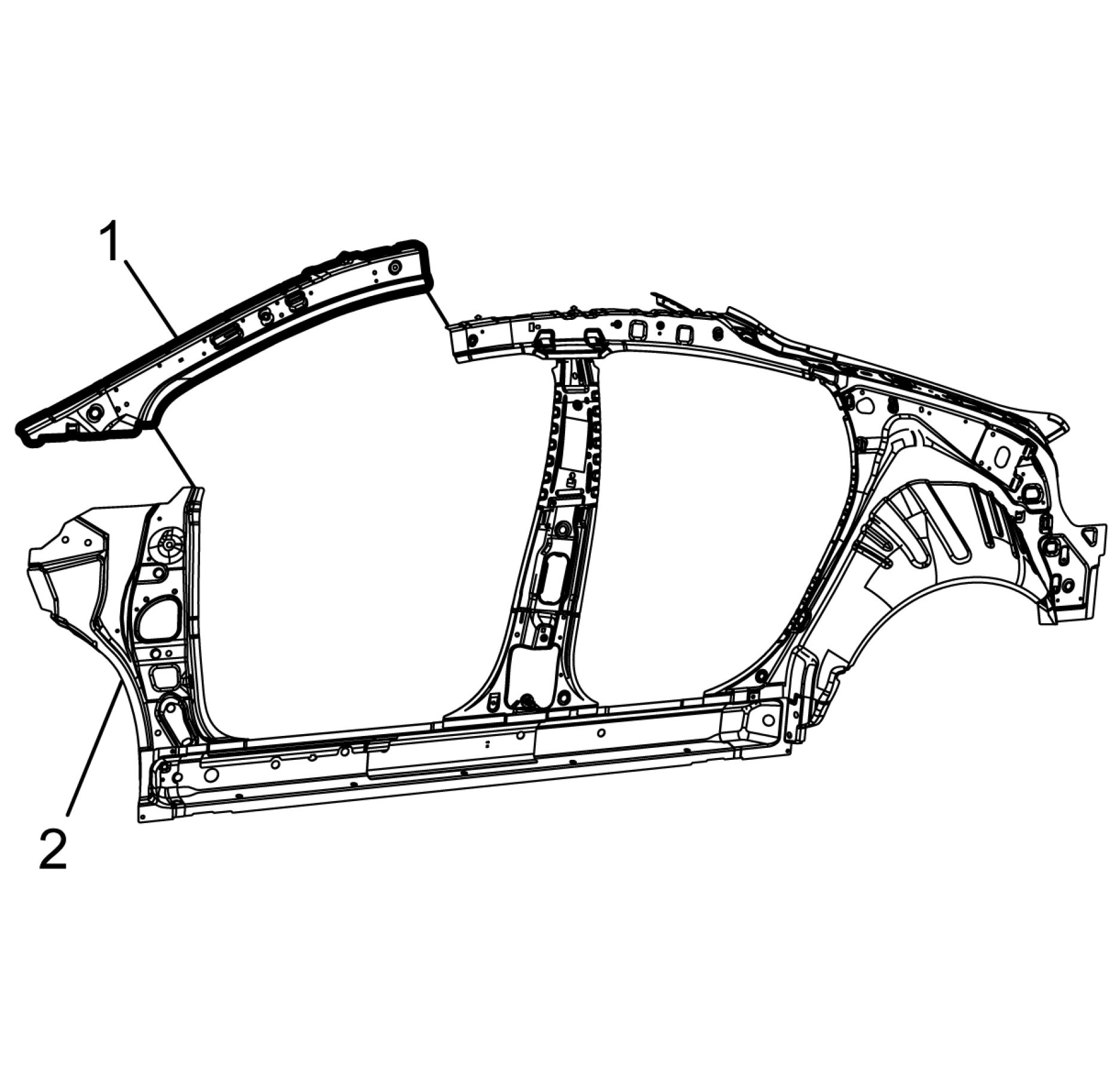 |
|
Fig. 37: Windshield Inner Upper Frame Reinforcement Courtesy of GENERAL MOTORS COMPANY |
8. Remove the damaged windshield inner upper frame reinforcement (1) from vehicle (2).
NOTE: If impact resistant adhesive is present remove and replace as necessary.
9. Remove the impact resistant adhesive from the repair area, as necessary. Metal Panel Bonding.
Installation Procedure
NOTE: Squeeze Type Resistance Spot Welds equivalent to the factory spot welds are
recommended. If access to use Squeeze Type Resistance Spot Welds is not
possible, MIG/MAG plug welds may be used, to replace those specific welds.
1. Prepare all mating surfaces for welding as necessary.
 |
|
Fig. 38: Windshield Inner Upper Frame Reinforcement |
2. Apply the impact resistant adhesive to the repair area, as necessary. Metal Panel Bonding.
3. Position the windshield inner upper frame reinforcement (1) on the vehicle (2) using 3-dimensional
measuring equipment.
4. Verify the fit of the windshield inner upper frame reinforcement (1).
5. Apply the impact resistant adhesive to the repair area, as necessary. Metal Panel Bonding

6. Clamp the windshield inner upper frame reinforcement (1) into position.
7. Weld the windshield inner upper frame reinforcement (1) accordingly.
8. Apply the sealers and anti-corrosion materials to the repair area as necessary. Anti-Corrosion Treatment
and Repair .
|
NOTE: |
Before refinishing, refer to Adhesive Installation of Windshields , and |
9. Install the body side outer panel as necessary
11. Install all related panels and components.
12. If disabled, enable the high voltage system. High Voltage Enabling .
13. Enable the SIR System. SIR Disabling and Enabling .
WARNING: Always perform the High Voltage Disabling procedure prior to servicing any
High Voltage component or connection. Personal Protection Equipment (PPE)
and proper procedures must be followed.
The High Voltage Disabling procedure includes the following steps:
• Identify how to disable high voltage.
• Identify how to test for the presence of high voltage.
• Identify condition under which high voltage is always present and
personal protection equipment (PPE) and proper procedures must be
followed.
Before working on any high voltage system, be sure to wear the following
Personal Protection Equipment:
• Safety glasses with appropriate side shields when within 15 meters (50
feet) of the vehicle, either indoors or outdoors.
• Certified and up-to-date Class "0" Insulation gloves rated at 1000V with
leather protectors.
• Visually and functionally inspect the gloves before use.
• Wear the Insulation gloves with leather protectors at all times when
working with the high voltage battery assembly, whether the system
is energized or not.
Failure to follow the procedures may result in serious injury or death.
Removal Procedure
WARNING: Refer to Approved Equipment for Collision Repair Warning .
WARNING: Refer to Collision Sectioning Warning .
WARNING: Refer to Glass and Sheet Metal Handling Warning .
CAUTION: Refer to Collision Repair Anchoring Caution .
NOTE: The front hinge pillar is an ultra-high strength steel and cannot be
sectioned or repaired. Refer to Ultra High Strength Steel.
NOTE: There are sectioning procedures available for various locations of the
body side outer panel. The sectioning procedure and location should be
chosen based on the extent of damage to the vehicle and any additional
inner reinforcements that need to be replaced. Refer to the body side outer
panel sectioning procedures for the specific location where sectioning is
required.
NOTE: Left shown right similar.
1. Disable the SIR System. Refer to SIR Disabling and Enabling .
2. Inspect the high voltage system. Refer to High Voltage System Inspection .
3. Remove all related panels and components.
4. Visually inspect the vehicle for additional damage to the vehicle structure. Repair as much of the damage
to the vehicle structure as possible, prior to replacing any damaged parts.
5. Remove the sealers and anti-corrosion materials from the repair area, as necessary. Refer to Anti-
Corrosion Treatment and Repair .
6. Section the body side outer panel as required for access to replace the front hinge pillar.

| ||||
|
7. Remove all factory welds from front hinge pillar body (1). |
 |
|
Fig. 41: Front Hinge Pillar Body Courtesy of GENERAL MOTORS COMPANY |
8. Remove the damaged front hinge pillar body (1) from vehicle (2).
NOTE: If impact resistant adhesive is present remove and replace as necessary.
9. Remove the impact resistant adhesive from the repair area, as necessary. Refer to Metal Panel Bonding.
Installation Procedure
NOTE: Squeeze Type Resistance Spot Welds equivalent to the factory spot welds
are recommended. If access to use Squeeze Type Resistance Spot Welds
is not possible, MIG/MAG plug welds may be used, to replace those
specific welds.
1. Prepare all mating surfaces for welding as necessary.
 |
|
Fig. 42: Front Hinge Pillar Body Courtesy of GENERAL MOTORS COMPANY |
2. Position the front hinge pillar body (1) on the vehicle (2) using 3-dimensional measuring equipment.
3. Verify the fit of the front hinge pillar body (1).

4. Apply the impact resistant adhesive to the repair area, as necessary. Refer to Metal Panel Bonding.
5. Clamp the front hinge pillar body (1) into position.
6. Weld the front hinge pillar body (1) accordingly.
7. Apply the sealers and anti-corrosion materials to the repair area, as necessary. Refer to Anti-Corrosion
Treatment and Repair .
8. Install the body side outer panel as necessary.
9. Paint the repaired area. Refer to Basecoat/Clearcoat Paint Systems .
10. Install all related panels and components.
11. If disabled, enable the high voltage system. Refer to High Voltage Enabling .
12. Enable the SIR system. Refer to SIR Disabling and Enabling .
ROOF OUTER PANEL REPLACEMENT
WARNING: Always perform the High Voltage Disabling procedure prior to servicing any
High Voltage component or connection. Personal Protection Equipment (PPE)
and proper procedures must be followed.
The High Voltage Disabling procedure includes the following steps:
• Identify how to disable high voltage.
• Identify how to test for the presence of high voltage.
• Identify condition under which high voltage is always present and
personal protection equipment (PPE) and proper procedures must be
followed.
Before working on any high voltage system, be sure to wear the following
Personal Protection Equipment:
• Safety glasses with appropriate side shields when within 15 meters (50
feet) of the vehicle, either indoors or outdoors.
• Certified and up-to-date Class "0" Insulation gloves rated at 1000V with
leather protectors.
• Visually and functionally inspect the gloves before use.
• Wear the Insulation gloves with leather protectors at all times when
working with the high voltage battery assembly, whether the system
is energized or not.
Failure to follow the procedures may result in serious injury or death.
Removal Procedure
WARNING: Refer to Approved Equipment for Collision Repair Warning .
WARNING: Refer to Collision Sectioning Warning .
WARNING: Refer to Glass and Sheet Metal Handling Warning .
CAUTION: Refer to Collision Repair Anchoring Caution .
1. Disable the SIR system. SIR Disabling and Enabling .
2. Inspect the high voltage system. High Voltage System Inspection .
3. Remove all related panels and components.
4. Visually inspect the vehicle for additional damage to the vehicle structure. Repair as much of the damage
to the vehicle structure as possible, prior to replacing any damaged parts.
5. Remove the sealers and anti-corrosion materials from the repair area as necessary. Anti-Corrosion
Treatment and Repair .
 |
|
Fig. 44: Roof Outer Panel Courtesy of GENERAL MOTORS COMPANY |
| ||||
|
NOTE: If impact resistant adhesive is present remove and replace as necessary.
7. Remove the impact resistant adhesive from the repair area, as necessary. Metal Panel Bonding.
 |
|
Fig. 45: Roof Outer Panel Courtesy of GENERAL MOTORS COMPANY |
8. Remove the damaged roof panel (1) from vehicle (2).
Installation Procedure
 |
|
Fig. 46: Roof Outer Panel Courtesy of GENERAL MOTORS COMPANY |
NOTE: Squeeze Type Resistance Spot Welds equivalent to the factory spot welds
are recommended. If access to use Squeeze Type Resistance Spot Welds
is not possible, MIG/MAG plug welds may be used, to replace those
specific welds.
1. Dry fit the roof panel (1) to the vehicle (2).
2. Remove roof panel (1) from vehicle (2) and prepare all mating surfaces for welding as necessary.

3. Apply anti-flutter foam-slow set 40 - 50 minute working time, or equivalent, to roof bows (1) as noted
form original roof bows.
 |
|
Fig. 48: Roof Outer Panel Courtesy of GENERAL MOTORS COMPANY |
4. Position the roof outer panel (1) on the vehicle (2) using 3-dimensional measuring equipment.
5. Verify the fit of the roof outer panel (1).
6. Apply the impact resistant adhesive to the repair area, as necessary. Metal Panel Bonding
7. Clamp the roof outer panel (1) to the vehicle (2).
 |
|
Fig. 49: Roof Outer Panel Courtesy of GENERAL MOTORS COMPANY |
8. Weld the front and rear roof outer panel (1) accordingly to the vehicle (2).
9. Weld both sides of the roof outer panel to the vehicle (2). To create a solid weld with minimum heat
distortion, make 25 mm (1 in) stitch welds along the seam with 25 mm (1 in) gaps between them. Then go
back and complete the stitch weld.
10. Apply the sealers and anti-corrosion materials to the repair area as necessary. Anti-Corrosion Treatment
and Repair .
NOTE: Before refinishing, refer to Adhesive Installation of Windshields , and
Adhesive Installation of Liftqate Windows .
11. Paint the repaired area. Basecoat/Clearcoat Paint Systems
12. Install all related panels and components.
13. If disabled, enable the high voltage system. High Voltage Enabling .
14. Enable the SIR System. SIR Disabling and Enabling .
ROOF INNER SIDE RAIL REPLACEMENT
WARNING: Always perform the High Voltage Disabling procedure prior to servicing any
High Voltage component or connection. Personal Protection Equipment (PPE)
and proper procedures must be followed.
The High Voltage Disabling procedure includes the following steps:
| ||
|
Before working on any high voltage system, be sure to wear the following
Personal Protection Equipment:
|
» Safety glasses with appropriate side shields when within 15 meters (50 » Certified and up-to-date Class "0" Insulation gloves rated at 1000V with
|
Failure to follow the procedures may result in serious injury or death.
|
Removal Procedure | ||||||||||||||
|
1. Disable the SIR system. SIR Disabling and Enabling .
2. Inspect the high voltage system. Refer to High Voltage System Inspection .
3. Remove all related panels and components.
4. Visually inspect the vehicle for additional damage to the vehicle structure. Repair as much of the damage
to the vehicle structure as possible, prior to replacing any damaged parts.
5. Remove the sealers and anti-corrosion materials from the repair area as necessary. Anti-Corrosion
Treatment and Repair .
6. Section the body side outer panel as required for access to replace the roof inner side rail.

Fig. 50: Roof Inner Side Rail
|
Courtesy of GENERAL MOTORS COMPANY | ||||
|
7. Remove all factory welds from the roof inner side rail (1).

Fig. 51: Roof Inner Side Rail
Courtesy'of GENERALMOTORS COMPANY
8. Remove the damaged roof inner side rail (1) from vehicle (2).
NOTE: If impact resistant adhesive is present remove and replace as necessary.
9. Remove the impact resistant adhesive from the repair area, as necessary. Metal Panel Bonding.
Installation Procedure
NOTE: Squeeze Type Resistance Spot Welds equivalent to the factory spot welds
are recommended. If access to use Squeeze Type Resistance Spot Welds
is not possible, MIG/MAG plug welds may be used, to replace those
specific welds.
1. Prepare all mating surfaces for welding as necessary.

2. Apply the impact resistant adhesive to the repair area, as necessary. Metal Panel Bonding.
3. Position the roof inner side rail (1) on the vehicle (2) using 3-dimensional measuring equipment.
4. Verify the fit of the roof inner side rail (1).
5. Apply the impact resistant adhesive to the repair area, as necessary. Metal Panel Bonding
 |
|
Fig. 53: Roof Inner Side Rail Courtesy of GENERAL MOTORS COMPANY |
6. Clamp the roof inner side rail (1) into position.
7. Weld the roof inner side rail (1) accordingly.
8. Apply the sealers and anti-corrosion materials to the repair area as necessary. Anti-Corrosion Treatment
and Repair .
9. Install the body side outer panel as necessary.
|
NOTE: |
Before refinishing, refer to Adhesive Installation of Windshields , and |
11. Install all related panels and components.
12. If disabled, enable the high voltage system. High Voltage Enabling .
13. Enable the SIR System. SIR Disabling and Enabling .
WARNING: Always perform the High Voltage Disabling procedure prior to servicing any
High Voltage component or connection. Personal Protection Equipment (PPE)
and proper procedures must be followed.
The High Voltage Disabling procedure includes the following steps:
• Identify how to disable high voltage.
• Identify how to test for the presence of high voltage.
• Identify condition under which high voltage is always present and
personal protection equipment (PPE) and proper procedures must be
followed.
Before working on any high voltage system, be sure to wear the following
Personal Protection Equipment:
• Safety glasses with appropriate side shields when within 15 meters (50
feet) of the vehicle, either indoors or outdoors.
• Certified and up-to-date Class "0" Insulation gloves rated at 1000V with
leather protectors.
• Visually and functionally inspect the gloves before use.
• Wear the Insulation gloves with leather protectors at all times when
working with the high voltage battery assembly, whether the system
is energized or not.
Failure to follow the procedures may result in serious injury or death.
Removal Procedure
WARNING: Refer to Approved Equipment for Collision Repair Warning .
WARNING: Refer to Collision Sectioning Warning .
WARNING: Refer to Glass and Sheet Metal Handling Warning .
CAUTION: Refer to Collision Repair Anchoring Caution .
NOTE: The rocker outer panel reinforcement is an ultra-high strength dual phase
steel and cannot be sectioned or repaired. Ultra High Strength Steel
NOTE: There are sectioning procedures available for various locations of the
body side outer panel. The sectioning procedure and location should be
chosen based on the extent of damage to the vehicle and any additional
inner reinforcements that need to be replaced. Refer to the body side outer
panel sectioning procedures for the specific location where sectioning is
required.
NOTE: Left shown right similar
1. Disable the SIR system. SIR Disabling and Enabling .
2. Inspect the high voltage system. High Voltage System Inspection .
3. Remove all related panels and components.
4. Visually inspect the vehicle for additional damage to the vehicle structure. Repair as much of the damage
to the vehicle structure as possible, prior to replacing any damaged parts.
5. Remove the sealers and anti-corrosion materials from the repair area, as necessary. Anti-Corrosion
Treatment and Repair .
6. Section the body side outer panel as required for access to replace the rocker inner panel.
 |
|
Fig. 54: Rocker Inner Panel Courtesy'of GENERALMOTORS COMPANY |
| ||||
|
7. Remove all factory welds from the rocker inner panel (1). |

Fig. 55: Rocker Inner Panel
Courtesy of GENERAL MOTORS COMPANY
8. Remove the damaged rocker inner panel (1) from vehicle.
NOTE: If impact resistant adhesive is present remove and replace as necessary.
9. Remove the impact resistant adhesive from the repair area, as necessary. Metal Panel Bonding.
Installation Procedure
NOTE: Squeeze Type Resistance Spot Welds equivalent to the factory spot welds
are recommended. If access to use Squeeze Type Resistance Spot Welds
is not possible, MIG/MAG plug welds may be used, to replace those
specific welds.
1. Prepare all mating surfaces for welding as necessary.

2. Position the rocker inner panel (1) on the vehicle using 3-dimensional measuring equipment.
3. Verify the fit of the rocker inner panel (1).
4. Apply the impact resistant adhesive to the repair area, as necessary. Metal Panel Bonding.
 |
|
Fig. 57: Rocker Inner Panel Courtesy of GENERAL MOTORS COMPANY |
5. Clamp the rocker inner panel (1) into position.
6. Weld the rocker inner panel (1) accordingly.
7. Apply the sealers and anti-corrosion materials to the repair area as necessary. Anti-Corrosion Treatment
and Repair .
8. Install the body side outer panel as necessary.
9. Paint the repaired area. Basecoat/Clearcoat Paint Systems .
10. Install all related panels and components.
11. If disabled, enable the high voltage system. High Voltage Enabling .
12. Enable the SIR System. SIR Disabling and Enabling .
ROCKER OUTER PANEL REINFORCEMENT REPLACEMENT
WARNING: Always perform the High Voltage Disabling procedure prior to servicing any
High Voltage component or connection. Personal Protection Equipment (PPE)
and proper procedures must be followed.
The High Voltage Disabling procedure includes the following steps:
• Identify how to disable high voltage.
• Identify how to test for the presence of high voltage.
• Identify condition under which high voltage is always present and
personal protection equipment (PPE) and proper procedures must be
followed.
Before working on any high voltage system, be sure to wear the following
Personal Protection Equipment:
• Safety glasses with appropriate side shields when within 15 meters (50
feet) of the vehicle, either indoors or outdoors.
• Certified and up-to-date Class "0" Insulation gloves rated at 1000V with
leather protectors.
• Visually and functionally inspect the gloves before use.
• Wear the Insulation gloves with leather protectors at all times when
working with the high voltage battery assembly, whether the system
is energized or not.
Failure to follow the procedures may result in serious injury or death.
Removal Procedure
WARNING: Refer to Approved Equipment for Collision Repair Warning .
WARNING: Refer to Collision Sectioning Warning .
WARNING: Refer to Glass and Sheet Metal Handling Warning .
CAUTION: Refer to Collision Repair Anchoring Caution .
NOTE: The rocker outer panel reinforcement is an ultra-high strength dual phase
steel and cannot be sectioned or repaired. Ultra High Strength Steel
NOTE: There are sectioning procedures available for various locations of the
body side outer panel. The sectioning procedure and location should be
chosen based on the extent of damage to the vehicle and any additional
inner reinforcements that need to be replaced. Refer to the body side outer
panel sectioning procedures for the specific location where sectioning is
required.
NOTE: Left shown right similar.
1. Disable the SIR system. SIR Disabling and Enabling
2. Inspect the high voltage system. High Voltage System Inspection
3. Remove all related panels and components.
4. Visually inspect the vehicle for additional damage to the vehicle structure. Repair as much of the damage
to the vehicle structure as possible, prior to replacing any damaged parts.
5. Remove the sealers and anti-corrosion materials from the repair area, as necessary. Anti-Corrosion
Treatment and Repair
6. Section the body side outer panel as required for access to replace the rocker outer panel reinforcement.
 |
|
Fig. 58: Rocker Outer Panel Reinforcement Courtesy'of GENERAL'MOTORS'COMPANY |
| ||||
|
7. Remove all factory welds from the rocker outer panel reinforcement (1). |

Fig. 59: Rocker Outer Panel Reinforcement
Courtesy of GENERAL MOTORS COMPANY
8. Remove the damaged rocker outer panel reinforcement (2) from vehicle (1).
NOTE: If impact resistant adhesive is present remove and replace as necessary.
9. Remove the impact resistant adhesive from the repair area, as necessary. Metal Panel Bonding
Installation Procedure
NOTE: Squeeze Type Resistance Spot Welds equivalent to the factory spot welds
are recommended. If access to use Squeeze Type Resistance Spot Welds
is not possible, MIG/MAG plug welds may be used, to replace those
specific welds.
1. Prepare all mating surfaces for welding as necessary.
 |
|
Fig. 60: Rocker Outer Panel Reinforcement Courtesy of GENERAL MOTORS COMPANY |
2. Position the rocker outer panel reinforcement (2) on the vehicle (1) using 3-dimensional measuring
equipment.
3. Verify the fit of the rocker outer panel reinforcement (2).
4. Apply the impact resistant adhesive to the repair area, as necessary. Metal Panel Bonding
 |
|
Fig. 61: Rocker Outer Panel Reinforcement Courtesy of GENERAL MOTORS COMPANY |
5. Clamp the rocker outer panel reinforcement (1) into position.
6. Weld the rocker outer panel reinforcement (1) accordingly.
7. Apply the sealers and anti-corrosion materials to the repair area, as necessary. Anti-Corrosion
Treatment and Repair
8. Install the body side outer panel as necessary.
9. Paint the repaired area. Basecoat/Clearcoat Paint Systems
10. Install all related panels and components.
11. If disabled, enable the high voltage system. High Voltage Enabling
12. Enable the SIR System. SIR Disabling and Enabling
BODY SIDE FRAME UPPER FRONT EXTENSION REPLACEMENT
WARNING: Always perform the High Voltage Disabling procedure prior to servicing any
High Voltage component or connection. Personal Protection Equipment (PPE)
and proper procedures must be followed.
The High Voltage Disabling procedure includes the following steps:
• Identify how to disable high voltage.
• Identify how to test for the presence of high voltage.
• Identify condition under which high voltage is always present and
personal protection equipment (PPE) and proper procedures must be
followed.
Before working on any high voltage system, be sure to wear the following
Personal Protection Equipment:
• Safety glasses with appropriate side shields when within 15 meters (50
feet) of the vehicle, either indoors or outdoors.
• Certified and up-to-date Class "0" Insulation gloves rated at 1000V with
leather protectors.
• Visually and functionally inspect the gloves before use.
• Wear the Insulation gloves with leather protectors at all times when
working with the high voltage battery assembly, whether the system
is energized or not.
Failure to follow the procedures may result in serious injury or death.
Removal Procedure
WARNING: Refer to Approved Equipment for Collision Repair Warning .
WARNING: Refer to Collision Sectioning Warning .
WARNING: Refer to Glass and Sheet Metal Handling Warning .
CAUTION: Refer to Collision Repair Anchoring Caution .
NOTE: The body side frame upper front extension reinforcement is an ultra-high
strength steel and cannot be sectioned or repaired. Ultra High Strength
Steel.
NOTE: There are sectioning procedures available for various locations of the
body side outer panel. The sectioning procedure and location should be
chosen based on the extent of damage to the vehicle and any additional
inner reinforcements that need to be replaced. Refer to the body side outer
panel sectioning procedures for the specific location where sectioning is
required.
NOTE: Left shown right similar.
1. Disable the SIR system. SIR Disabling and Enabling .
2. Inspect the high voltage system. High Voltage System Inspection .
3. Remove all related panels and components.
4. Visually inspect the damage.Repair as much of the damage as possible.
5. Remove the sealers and anti-corrosion materials from the repair area as necessary. Anti-Corrosion
Treatment and Repair .
 |
|
Fig. 62: Body Side Frame Upper Front Extension Reinforcement |
| ||||
|
6. Remove all factory welds from the body side frame upper front extension reinforcement (1). |
 |
|
Fig. 63: Body Side Frame Upper Front Extension Reinforcement |
7. Remove the body side frame upper front extension reinforcement (1) from vehicle (2).
NOTE: If impact resistant adhesive is present remove and replace as necessary.
8. Remove the impact resistant adhesive from the repair area, as necessary. Metal Panel Bonding.
Installation Procedure
NOTE: Squeeze Type Resistance Spot Welds equivalent to the factory spot welds
are recommended. If access to use Squeeze Type Resistance Spot Welds
is not possible, MIG/MAG plug welds may be used, to replace those
specific welds.
1. Prepare all mating surfaces for welding as necessary.
 |
|
Fig. 64: Body Side Frame Upper Front Extension Reinforcement |
2. Position the body side frame upper front extension reinforcement (1) on the vehicle (2) using
3-dimensional measuring equipment.
3. Verify the fit of the body side frame upper front extension reinforcement (1).
4. Apply the impact resistant adhesive to the repair area, as necessary. Metal Panel Bonding
 |
|
Fig. 65: Body Side Frame Upper Front Extension Reinforcement |
5. Clamp the body side frame upper front extension reinforcement (1) into position.
6. Weld the body side frame upper front extension reinforcement (1) accordingly.
7. Apply the sealers and anti-corrosion materials to the repair area as necessary. Anti-Corrosion Treatment
and Repair .
NOTE: Before refinishing, refer to Adhesive Installation of Windshields , and
Adhesive Installation of Liftqate Windows .
9. Install all related panels and components.
10. If disabled, enable the high voltage system. High Voltage Enabling .
11. Enable the SIR System. SIR Disabling and Enabling .
WARNING: Always perform the High Voltage Disabling procedure prior to servicing any
High Voltage component or connection. Personal Protection Equipment (PPE)
and proper procedures must be followed.
The High Voltage Disabling procedure includes the following steps:
• Identify how to disable high voltage.
• Identify how to test for the presence of high voltage.
• Identify condition under which high voltage is always present and
personal protection equipment (PPE) and proper procedures must be
followed.
Before working on any high voltage system, be sure to wear the following
Personal Protection Equipment:
• Safety glasses with appropriate side shields when within 15 meters (50
feet) of the vehicle, either indoors or outdoors.
• Certified and up-to-date Class "0" Insulation gloves rated at 1000V with
leather protectors.
• Visually and functionally inspect the gloves before use.
• Wear the Insulation gloves with leather protectors at all times when
working with the high voltage battery assembly, whether the system
is energized or not.
Failure to follow the procedures may result in serious injury or death.
Removal Procedure
WARNING: Refer to Approved Equipment for Collision Repair Warning .
WARNING: Refer to Collision Sectioning Warning .
WARNING: Refer to Glass and Sheet Metal Handling Warning .
CAUTION: Refer to Collision Repair Anchoring Caution .
NOTE: Left shown right similar.
1. Disable the SIR system. SIR Disabling and Enabling .
2. Inspect the high voltage system. High Voltage System Inspection .
3. Remove all related panels and components.
4. Visually inspect the vehicle for additional damage to the vehicle structure. Repair as much of the damage
to the vehicle structure as possible, prior to replacing any damaged parts.
5. Remove the sealers and anti-corrosion materials from the repair area as necessary. Anti-Corrosion
Treatment and Repair .

Fig. 66: Body Side Outer Panel
Courtesy of GENERAL MOTORS COMPANY
NOTE: Do not damage or cut attaching panels and reinforcements. Structure
Identification.
NOTE: Record the number and location of the original welds for installation of the
service assembly.
6. Remove all factory welds from the body side outer panel (1).

Fig. 67: Body Side Outer Panel
Courtesy of GENERAL MOTORS COMPANY
7. Remove the damaged body side outer panel (1) from vehicle (2).
NOTE: If impact resistant adhesive is present remove and replace as necessary.
8. Remove the impact resistant adhesive from the repair area, as necessary. Metal Panel Bonding.
Installation Procedure
NOTE: Squeeze Type Resistance Spot Welds equivalent to the factory spot welds
are recommended. If access to use Squeeze Type Resistance Spot Welds
is not possible, MIG/MAG plug welds may be used, to replace those
specific welds.
1. Prepare all mating surfaces for welding as necessary.

2. Position the body side outer panel (1) on the vehicle (2) using 3-dimensional measuring equipment.
3. Verify the fit of the body side outer panel (1).

4. Apply the impact resistant adhesive to the repair area, as necessary. Refer to Metal Panel Bonding.
5. Clamp the body side outer panel (1) into position.
6. Weld the body side outer panel (1) accordingly.
7. Apply the sealers and anti-corrosion materials to the repair area as necessary. Anti-Corrosion Treatment
and Repair .
|
NOTE: |
Before refinishing, refer to Adhesive Installation of Windshields , and |
8. Paint the repaired area. Refer to Basecoat/Clearcoat Paint Systems .
9. Install all related panels and components.
10. If disabled, enable the high voltage system. High Voltage Enabling .
11. Enable the SIR System. SIR Disabling and Enabling .
BODY SIDE OUTER PANEL SECTIONING
WARNING: Always perform the High Voltage Disabling procedure prior to servicing any
High Voltage component or connection. Personal Protection Equipment (PPE)
and proper procedures must be followed.
The High Voltage Disabling procedure includes the following steps:
• Identify how to disable high voltage.
• Identify how to test for the presence of high voltage.
• Identify condition under which high voltage is always present and
personal protection equipment (PPE) and proper procedures must be
followed.
Before working on any high voltage system, be sure to wear the following
Personal Protection Equipment:
• Safety glasses with appropriate side shields when within 15 meters (50
feet) of the vehicle, either indoors or outdoors.
• Certified and up-to-date Class "0" Insulation gloves rated at 1000V with
leather protectors.
• Visually and functionally inspect the gloves before use.
• Wear the Insulation gloves with leather protectors at all times when
working with the high voltage battery assembly, whether the system
is energized or not.
Failure to follow the procedures may result in serious injury or death.
Removal Procedure
WARNING: Refer to Approved Equipment for Collision Repair Warning .
WARNING: Refer to Collision Sectioning Warning .
WARNING: Refer to Glass and Sheet Metal Handling Warning .
CAUTION: Refer to Collision Repair Anchoring Caution .
NOTE: Left shown right similar.
1. Disable the SIR system. SIR Disabling and Enabling .
2. Inspect the high voltage system. High Voltage System Inspection .
3. Remove all related panels and components.
4. Visually inspect the damage.Repair as much of the damage as possible.
5. Remove the sealers and anti-corrosion materials from the repair area as necessary. Anti-Corrosion
Treatment and Repair .

Fig. 70: Body Side Outer Panel Sectioning Areas
Courtesy of GENERAL MOTORS COMPANY
6. Section the body side outer panel within the recommended areas (1).

Fig. 71: Center Pillar Of Body Side Outer Panel Sectioning Area
Courtesy of GENERAL MOTORS COMPANY
7. Section the center pillar of the body side outer panel within the recommended area (1).
NOTE: The following steps are to be used for both the body side outer and the
center pillar sections.
8. Locate and remove all factory welds. Note the number and location of welds for installation of the body
side outer section.
NOTE: Do not damage any other panel or reinforcements when cutting at the
marked locations.
9. Cut the body side outer panel at the recommended areas (1).
10. Remove the body side outer section.
NOTE: If impact resistant adhesive is present remove and replace as necessary.
11. Remove the impact resistant adhesive from the repair area, as necessary. Metal Panel Bonding.
Installation Procedure

|
Fig. 72: Body Side Outer Panel Sectioning Areas | ||||
| ||||
|
1. From the service part, cut the body side outer panel in corresponding locations (1) to overlap the |

2. From the service part, cut the body side outer panel for the center pillar section in corresponding locations
(1) to overlap the remaining original panel by 25 mm (1 in) at each joint locations.
NOTE: The following steps are to be used for both the body side outer and the
center pillar sections.
3. Prepare all mating surfaces for welding, as necessary.
4. Apply GM - approved Weld-Thru coating or equivalent to all mating surfaces. Anti-Corrosion
Treatment and Repair .
5. Apply the impact resistant adhesive to the repair area, as necessary. Metal Panel Bonding.
6. Position the new service panel and clamp in place.
7. Weld accordingly.
8. Clean and prepare all welded surfaces.
9. Apply the sealers and anti-corrosion materials to the repair area as necessary. Anti-Corrosion Treatment
and Repair .
NOTE: Before refinishing, refer to Adhesive Installation of Windshields , and
Adhesive Installation of Liftqate Windows .
10. Paint the repaired area. Basecoat/Clearcoat Paint Systems .
11. Install all related panels and components.
12. Enable the SIR System. SIR Disabling and Enabling .
13. Connect the battery negative cable. Battery Negative Cable Disconnection and Connection .
REAR FLOOR PANEL SECTIONING
WARNING: Always perform the High Voltage Disabling procedure prior to servicing any
High Voltage component or connection. Personal Protection Equipment (PPE)
and proper procedures must be followed.
The High Voltage Disabling procedure includes the following steps:
• Identify how to disable high voltage.
• Identify how to test for the presence of high voltage.
• Identify condition under which high voltage is always present and
personal protection equipment (PPE) and proper procedures must be
followed.
Before working on any high voltage system, be sure to wear the following
Personal Protection Equipment:
• Safety glasses with appropriate side shields when within 15 meters (50
feet) of the vehicle, either indoors or outdoors.
• Certified and up-to-date Class "0" Insulation gloves rated at 1000V with
leather protectors.
• Visually and functionally inspect the gloves before use.
• Wear the Insulation gloves with leather protectors at all times when
working with the high voltage battery assembly, whether the system
is energized or not.
Failure to follow the procedures may result in serious injury or death.
Removal Procedure
WARNING: Refer to Approved Equipment for Collision Repair Warning .
WARNING: Refer to Collision Sectioning Warning .
WARNING: Refer to Glass and Sheet Metal Handling Warning .
CAUTION: Refer to Collision Repair Anchoring Caution .
1. Disable the SIR system. Refer to SIR Disabling and Enabling .
2. Inspect the high voltage system. Refer to High Voltage System Inspection .
3. Remove all related panels and components.
4. Visually inspect the damage. Repair as much of the damage as possible.
5. Remove the sealers and anti-corrosion materials from the repair area, as necessary. Refer to Anti-
Corrosion Treatment and Repair .
 |
|
Fig. 74: Marking Cut Location Rearward From No. 5 Bar |
6. Measure 40 mm rearward from the rear edge of the #5 bar (1). Mark the cut location (2).
 |
|
Fig. 75: Marked Cut Location Courtesy of GENERAL MOTORS COMPANY |
NOTE: Do not damage or cut attaching panels and reinforcements. Refer to
Structure Identification.
7. Cut the floor at the marked location (1).
 |
|
Fig. 76: Rear Floor Panel Section Courtesy of GENERAL MOTORS COMPANY |
8. Remove all factory welds (1).
9. Remove floor section (2) from vehicle.
NOTE: If impact resistant adhesive is present remove and replace as necessary.
10. Remove the impact resistant adhesive from the repair area, as necessary. Refer to Metal Panel Bonding.
 |
|
Fig. 77: Cutting Service Part In Corresponding Location |
NOTE: The service part is supplied as a complete floor and will need to be cut at
the proper location for sectioning. The service part will overlap the original
floor panel by approximately 40 mm at the cut location.
11. Locate rear edge of the #5 bar location (1). Mark the cut location.
12. Cut the service part at the marked location (1).
Installation Procedure
 |
|
Fig. 78: Marking Service Part For Plug Welding Locations |
NOTE: Squeeze Type Resistance Spot Welds equivalent to the factory spot welds
are recommended. If access to use Squeeze Type Resistance Spot Welds
is not possible, MIG/MAG plug welds may be used, to replace those
specific welds.
1. Create 1 row of plug welds in the service part as follows. Measure 20 mm from the front edge of the
service part (1). Mark a straight line across the width of the service part (2).
 |
|
Fig. 79: Drilling Plug Weld Holes Courtesy of GENERAL MOTORS COMPANY |
2. Drill 8 mm (5/16 in) plug weld holes, every 40 mm along the marked row.
3. Prepare all mating surfaces for welding, as necessary.
4. Apply GM-approved Weld-Thru Coating or equivalent to all mating surfaces. Refer to Anti-Corrosion
Treatment and Repair .
5. Apply the impact resistant adhesive to the repair area, as necessary. Refer to Metal Panel Bonding.
 |
|
Fig. 80: Rear Floor Panel Section Courtesy of GENERAL MOTORS COMPANY |
6. Position the rear floor section (2) to the vehicle using 3-dimensional measuring equipment. Clamp the
part in place.
7. Weld accordingly (1).
8. Clean and prepare all welded surfaces for painting.
9. Paint the repaired area. Refer to Basecoat/Clearcoat Paint Systems .
10. Apply the sealers and anti-corrosion materials to the repair area, as necessary. Refer to Anti-Corrosion
Treatment and Repair .
11. Paint the repaired area. Refer to Basecoat/Clearcoat Paint Systems .
12. Install all related panels and components.
13. If disabled, enable the high voltage system. Refer to High Voltage Enabling .
14. Enable the SIR system. Refer to SIR Disabling and Enabling .
REAR WHEELHOUSE INNER PANEL REPLACEMENT
WARNING: Always perform the High Voltage Disabling procedure prior to servicing any
High Voltage component or connection. Personal Protection Equipment (PPE)
and proper procedures must be followed.
The High Voltage Disabling procedure includes the following steps:
• Identify how to disable high voltage.
• Identify how to test for the presence of high voltage.
• Identify condition under which high voltage is always present and
personal protection equipment (PPE) and proper procedures must be
followed.
Before working on any high voltage system, be sure to wear the following
Personal Protection Equipment:
• Safety glasses with appropriate side shields when within 15 meters (50
feet) of the vehicle, either indoors or outdoors.
• Certified and up-to-date Class "0" Insulation gloves rated at 1000V with
leather protectors.
• Visually and functionally inspect the gloves before use.
• Wear the Insulation gloves with leather protectors at all times when
working with the high voltage battery assembly, whether the system
is energized or not.
Failure to follow the procedures may result in serious injury or death.
Removal Procedure
WARNING: Refer to Approved Equipment for Collision Repair Warning .
WARNING: Refer to Collision Sectioning Warning .
WARNING: Refer to Glass and Sheet Metal Handling Warning .
CAUTION: Refer to Collision Repair Anchoring Caution .
NOTE: Left shown right similar.
1. Disable the SIR System. Refer to SIR Disabling and Enabling .
2. Inspect the high voltage system. Refer to High Voltage System Inspection .
3. Remove all related panels and components.
4. Visually inspect the vehicle for additional damage to the vehicle structure. Repair as much of the damage
to the vehicle structure as possible, prior to replacing any damaged parts.
5. Remove the sealers and anti-corrosion materials from the repair area, as necessary. Refer to Anti-
Corrosion Treatment and Repair .

|
Fig. 81: Rear Wheelhouse Inner Panel Courtesy of GENERAL MOTORS COMPANY | ||||
| ||||
|
6. Remove all factory welds from the rear wheelhouse inner panel (1). |
 |
|
Fig. 82: Rear Wheelhouse Inner Panel Courtesy of GENERAL MOTORS COMPANY |
7. Remove the damaged rear wheelhouse inner panel (2) from vehicle (1).
NOTE: If impact resistant adhesive is present remove and replace as necessary.
8. Remove the impact resistant adhesive from the repair area, as necessary. Refer to Metal Panel Bonding.
Installation Procedure
NOTE: Squeeze Type Resistance Spot Welds equivalent to the factory spot welds
are recommended. If access to use Squeeze Type Resistance Spot Welds
is not possible, MIG/MAG plug welds may be used, to replace those
specific welds.
1. Prepare all mating surfaces for welding as necessary.
 |
|
Fig. 83: Rear Wheelhouse Inner Panel Courtesy of GENERAL MOTORS COMPANY |
2. Position the rear wheelhouse inner panel (2) on the vehicle (1) using 3-dimensional measuring equipment.
3. Verify the fit of the rear wheelhouse inner panel (2).

4. Apply the impact resistant adhesive to the repair area, as necessary. Refer to Metal Panel Bonding.
5. Clamp the rear wheelhouse inner panel (1) into position.
6. Weld the rear wheelhouse inner panel (1) accordingly.
7. Apply the sealers and anti-corrosion materials to the repair area, as necessary. Refer to Anti-Corrosion
Treatment and Repair .
8. Install the body side outer panel as necessary.
9. Paint the repaired area. Refer to Basecoat/Clearcoat Paint Systems .
10. Install all related panels and components.
11. If disabled, enable the high voltage system. Refer to High Voltage Enabling .
12. Enable the SIR system. Refer to SIR Disabling and Enabling .
REAR WHEELHOUSE OUTER PANEL REPLACEMENT
WARNING: Always perform the High Voltage Disabling procedure prior to servicing any
High Voltage component or connection. Personal Protection Equipment (PPE)
and proper procedures must be followed.
The High Voltage Disabling procedure includes the following steps:
• Identify how to disable high voltage.
• Identify how to test for the presence of high voltage.
• Identify condition under which high voltage is always present and
personal protection equipment (PPE) and proper procedures must be
followed.
Before working on any high voltage system, be sure to wear the following
Personal Protection Equipment:
• Safety glasses with appropriate side shields when within 15 meters (50
feet) of the vehicle, either indoors or outdoors.
• Certified and up-to-date Class "0" Insulation gloves rated at 1000V with
leather protectors.
• Visually and functionally inspect the gloves before use.
• Wear the Insulation gloves with leather protectors at all times when
working with the high voltage battery assembly, whether the system
is energized or not.
Failure to follow the procedures may result in serious injury or death.
Removal Procedure
WARNING: Refer to Approved Equipment for Collision Repair Warning .
WARNING: Refer to Collision Sectioning Warning .
WARNING: Refer to Glass and Sheet Metal Handling Warning .
CAUTION: Refer to Collision Repair Anchoring Caution .
NOTE: There are sectioning procedures available for various locations of the
body side outer panel. The sectioning procedure and location should be
chosen based on the extent of damage to the vehicle and any additional
inner reinforcements that need to be replaced. Refer to the body side outer
panel sectioning procedures for the specific location where sectioning is
required.
NOTE: Left shown right similar.
1. Disable the SIR System. Refer to SIR Disabling and Enabling .
2. Inspect the high voltage system. Refer to High Voltage System Inspection .
3. Remove all related panels and components.
4. Visually inspect the vehicle for additional damage to the vehicle structure. Repair as much of the damage
to the vehicle structure as possible, prior to replacing any damaged parts.
5. Remove the sealers and anti-corrosion materials from the repair area, as necessary. Refer to Anti-
Corrosion Treatment and Repair .
6. Section the body side outer panel as required for access to replace the rear wheelhouse outer panel.
 |
|
Fig. 85: Rear Wheelhouse Outer Panel Courtesy'of GENERAL'MOTORS'COMPANY |
NOTE: Do not damage or cut attaching panels and reinforcements. Refer to
Structure Identification.
NOTE: Record the number and location of the original welds for installation of the
service assembly.
7. Remove all factory welds from rear wheelhouse outer panel (1).

Fig. 86: Rear Wheelhouse Outer Panel
Courtesy of GENERAL MOTORS COMPANY
8. Remove the damaged rear wheelhouse outer panel (2) from vehicle (1).
NOTE: If impact resistant adhesive is present remove and replace as necessary.
9. Remove the impact resistant adhesive from the repair area, as necessary. Refer to Metal Panel Bonding.
Installation Procedure
NOTE: Squeeze Type Resistance Spot Welds equivalent to the factory spot welds
are recommended. If access to use Squeeze Type Resistance Spot Welds
is not possible, MIG/MAG plug welds may be used, to replace those
specific welds.
1. Prepare all mating surfaces for welding as necessary.

2. Position the rear wheelhouse outer panel (2) on the vehicle (1) using 3-dimensional measuring equipment.
3. Verify the fit of the rear wheelhouse outer panel (2).
 |
|
Fig. 88: Rear Wheelhouse Outer Panel Courtesy of GENERAL MOTORS COMPANY |
4. Apply the impact resistant adhesive to the repair area, as necessary. Refer to Metal Panel Bonding.
5. Clamp the rear wheelhouse outer panel (1) into position.
6. Weld the rear wheelhouse outer panel (1) accordingly.
7. Apply the sealers and anti-corrosion materials to the repair area, as necessary. Refer to Anti-Corrosion
Treatment and Repair .
8. Install the body side outer panel as necessary.
9. Paint the repaired area. Refer to Basecoat/Clearcoat Paint Systems .
10. Install all related panels and components.
11. If disabled, enable the high voltage system. Refer to High Voltage Enabling .
12. Enable the SIR system. Refer to SIR Disabling and Enabling .
FLOOR PANEL NUMBER 5 CROSS BAR REPLACEMENT
WARNING: Always perform the High Voltage Disabling procedure prior to servicing any
High Voltage component or connection. Personal Protection Equipment (PPE)
and proper procedures must be followed.
The High Voltage Disabling procedure includes the following steps:
• Identify how to disable high voltage.
• Identify how to test for the presence of high voltage.
• Identify condition under which high voltage is always present and
personal protection equipment (PPE) and proper procedures must be
followed.
Before working on any high voltage system, be sure to wear the following
Personal Protection Equipment:
• Safety glasses with appropriate side shields when within 15 meters (50
feet) of the vehicle, either indoors or outdoors.
• Certified and up-to-date Class "0" Insulation gloves rated at 1000V with
leather protectors.
• Visually and functionally inspect the gloves before use.
• Wear the Insulation gloves with leather protectors at all times when
working with the high voltage battery assembly, whether the system
is energized or not.
Failure to follow the procedures may result in serious injury or death.
Removal Procedure
WARNING: Refer to Approved Equipment for Collision Repair Warning .
WARNING: Refer to Collision Sectioning Warning .
WARNING: Refer to Glass and Sheet Metal Handling Warning .
CAUTION: Refer to Collision Repair Anchoring Caution .
1. Disable the SIR System. Refer to SIR Disabling and Enabling .
2. Inspect the high voltage system. Refer to High Voltage System Inspection .
3. Remove all related panels and components.
4. Visually inspect the vehicle for additional damage to the vehicle structure. Repair as much of the damage
to the vehicle structure as possible, prior to replacing any damaged parts
5. Remove the sealers and anti-corrosion materials from the repair area, as necessary. Refer to Anti-
Corrosion Treatment and Repair .
 |
|
Fig. 89: Floor Panel Number 5 Cross Bar |
| ||||
|
6. Remove all factory welds from the floor panel number 5 cross bar (1).. |
 |
|
Fig. 90: Floor Panel Number 5 Cross Bar |
7. Remove the damaged floor panel number 5 cross bar (1) from vehicle (2).
NOTE: If impact resistant adhesive is present remove and replace as necessary.
8. Remove the impact resistant adhesive from the repair area, as necessary. Refer to Metal Panel Bonding.
Installation Procedure
NOTE: Squeeze Type Resistance Spot Welds equivalent to the factory spot welds
are recommended. If access to use Squeeze Type Resistance Spot Welds
is not possible, MIG/MAG plug welds may be used, to replace those
specific welds.
1. Prepare all mating surfaces for welding as necessary.
 |
|
Fig. 91: Floor Panel Number 5 Cross Bar |
2. Position the floor panel number 5 cross bar (1) on the vehicle (2) using 3-dimensional measuring
equipment.
3. Verify the fit of the floor panel number 5 cross bar (1).
 |
|
Fig. 92: Floor Panel Number 5 Cross Bar |
4. Apply the impact resistant adhesive to the repair area, as necessary. Refer to Metal Panel Bonding.
5. Clamp the floor panel number 5 cross bar (1) into position.
6. Weld the floor panel number 5 cross bar (1) accordingly.
7. Apply the sealers and anti-corrosion materials to the repair area, as necessary. Refer to Anti-Corrosion
Treatment and Repair .
8. Paint the repaired area. Refer to Basecoat/Clearcoat Paint Systems .
9. Install all related panels and components.
10. If disabled, enable the high voltage system. Refer to High Voltage Enabling .
11. Enable the SIR system. Refer to SIR Disabling and Enabling .
FLOOR PANEL NUMBER 5 CROSS BAR EXTENSION REPLACEMENT
WARNING: Always perform the High Voltage Disabling procedure prior to servicing any
High Voltage component or connection. Personal Protection Equipment (PPE)
and proper procedures must be followed.
The High Voltage Disabling procedure includes the following steps:
• Identify how to disable high voltage.
• Identify how to test for the presence of high voltage.
• Identify condition under which high voltage is always present and
personal protection equipment (PPE) and proper procedures must be
followed.
Before working on any high voltage system, be sure to wear the following
Personal Protection Equipment:
• Safety glasses with appropriate side shields when within 15 meters (50
feet) of the vehicle, either indoors or outdoors.
• Certified and up-to-date Class "0" Insulation gloves rated at 1000V with
leather protectors.
• Visually and functionally inspect the gloves before use.
• Wear the Insulation gloves with leather protectors at all times when
working with the high voltage battery assembly, whether the system
is energized or not.
Failure to follow the procedures may result in serious injury or death.
Removal Procedure
WARNING: Refer to Approved Equipment for Collision Repair Warning .
WARNING: Refer to Collision Sectioning Warning .
WARNING: Refer to Glass and Sheet Metal Handling Warning .
CAUTION: Refer to Collision Repair Anchoring Caution .
NOTE: Left shown right similar.
1. Disable the SIR system. SIR Disabling and Enabling .
2. Inspect the high voltage system. High Voltage System Inspection .
3. Remove all related panels and components.
4. Visually inspect the vehicle for additional damage to the vehicle structure. Repair as much of the damage
to the vehicle structure as possible, prior to replacing any damaged parts.
5. Remove the sealers and anti-corrosion materials from the repair area, as necessary. Anti-Corrosion
Treatment and Repair .

|
Fig. 93: Floor Panel Number 5 Cross Bar Extension | ||||
| ||||
|
6. Remove all factory welds from the floor panel number 5 cross bar extension (1). |

Fig. 94: Floor Panel Number 5 Cross Bar Extension
Courtesy of GENERAL MOTORS COMPANY
7. Remove the damaged floor panel number 5 cross bar extension (1) from vehicle (2).
NOTE: If impact resistant adhesive is present remove and replace as necessary.
8. Remove the impact resistant adhesive from the repair area, as necessary. Metal Panel Bonding.
Installation Procedure
NOTE: Squeeze Type Resistance Spot Welds equivalent to the factory spot welds
are recommended. If access to use Squeeze Type Resistance Spot Welds
is not possible, MIG/MAG plug welds may be used, to replace those
specific welds.
1. Prepare all mating surfaces for welding as necessary.

2. Position the floor panel number 5 cross bar extension (1) on the vehicle (2) using 3-dimensional
measuring equipment.
3. Verify the fit of the floor panel number 5 cross bar extension (1).

4. Apply the impact resistant adhesive to the repair area, as necessary. Metal Panel Bonding.
5. Clamp the floor panel number 5 cross bar extension (1) into position.
6. Weld the floor panel number 5 cross bar extension (1) accordingly.
7. Apply the sealers and anti-corrosion materials to the repair area as necessary. Anti-Corrosion Treatment
and Repair .
8. Install the body side outer panel as necessary.
9. Paint the repaired area. Basecoat/Clearcoat Paint Systems .
10. Install all related panels and components.
11. If disabled, enable the high voltage system. High Voltage Enabling .
12. Enable the SIR System. SIR Disabling and Enabling .
BODY REAR END PANEL REPLACEMENT
WARNING: Always perform the High Voltage Disabling procedure prior to servicing any
High Voltage component or connection. Personal Protection Equipment (PPE)
and proper procedures must be followed.
The High Voltage Disabling procedure includes the following steps:
• Identify how to disable high voltage.
• Identify how to test for the presence of high voltage.
• Identify condition under which high voltage is always present and
personal protection equipment (PPE) and proper procedures must be
followed.
Before working on any high voltage system, be sure to wear the following
Personal Protection Equipment:
• Safety glasses with appropriate side shields when within 15 meters (50
feet) of the vehicle, either indoors or outdoors.
• Certified and up-to-date Class "0" Insulation gloves rated at 1000V with
leather protectors.
• Visually and functionally inspect the gloves before use.
• Wear the Insulation gloves with leather protectors at all times when
working with the high voltage battery assembly, whether the system
is energized or not.
Failure to follow the procedures may result in serious injury or death.
Removal Procedure
WARNING: Refer to Approved Equipment for Collision Repair Warning .
WARNING: Refer to Collision Sectioning Warning .
WARNING: Refer to Glass and Sheet Metal Handling Warning .
CAUTION: Refer to Collision Repair Anchoring Caution .
1. Disable the SIR system. SIR Disabling and Enabling .
2. Inspect the high voltage system. High Voltage System Inspection .
3. Remove all related panels and components.
4. Visually inspect the vehicle for additional damage to the vehicle structure. Repair as much of the damage
to the vehicle structure as possible, prior to replacing any damaged parts.
5. Remove the sealers and anti-corrosion materials from the repair area, as necessary. Anti-Corrosion
Treatment and Repair .

Fig. 97: Body Rear End Panel
Courtesy of GENERAL MOTORS COMPANY
NOTE: Do not damage or cut attaching panels and reinforcements. Structure
Identification
NOTE: Record the number and location of the original welds for installation of the
service assembly.
6. Remove all factory welds from body rear end panel (1).

Fig. 98: Body Rear End Panel
Courtesy of GENERAL MOTORS COMPANY
7. Remove the damaged body rear end panel (1) from vehicle (2).
NOTE: If impact resistant adhesive is present remove and replace as necessary.
8. Remove the impact resistant adhesive from the repair area, as necessary. Metal Panel Bonding
Installation Procedure
NOTE: Squeeze Type Resistance Spot Welds equivalent to the factory spot welds
are recommended. If access to use Squeeze Resistance Type Spot Welds
is not possible, MIG/MAG plug welds may be used, to replace those
specific welds.
1. Prepare all mating surfaces for welding as necessary.

2. Position the body rear end panel (1) on the vehicle (2) using 3-dimensional measuring equipment.
3. Verify the fit of the body rear end panel (1).
4. Apply the impact resistant adhesive to the repair area, as necessary. Metal Panel Bonding
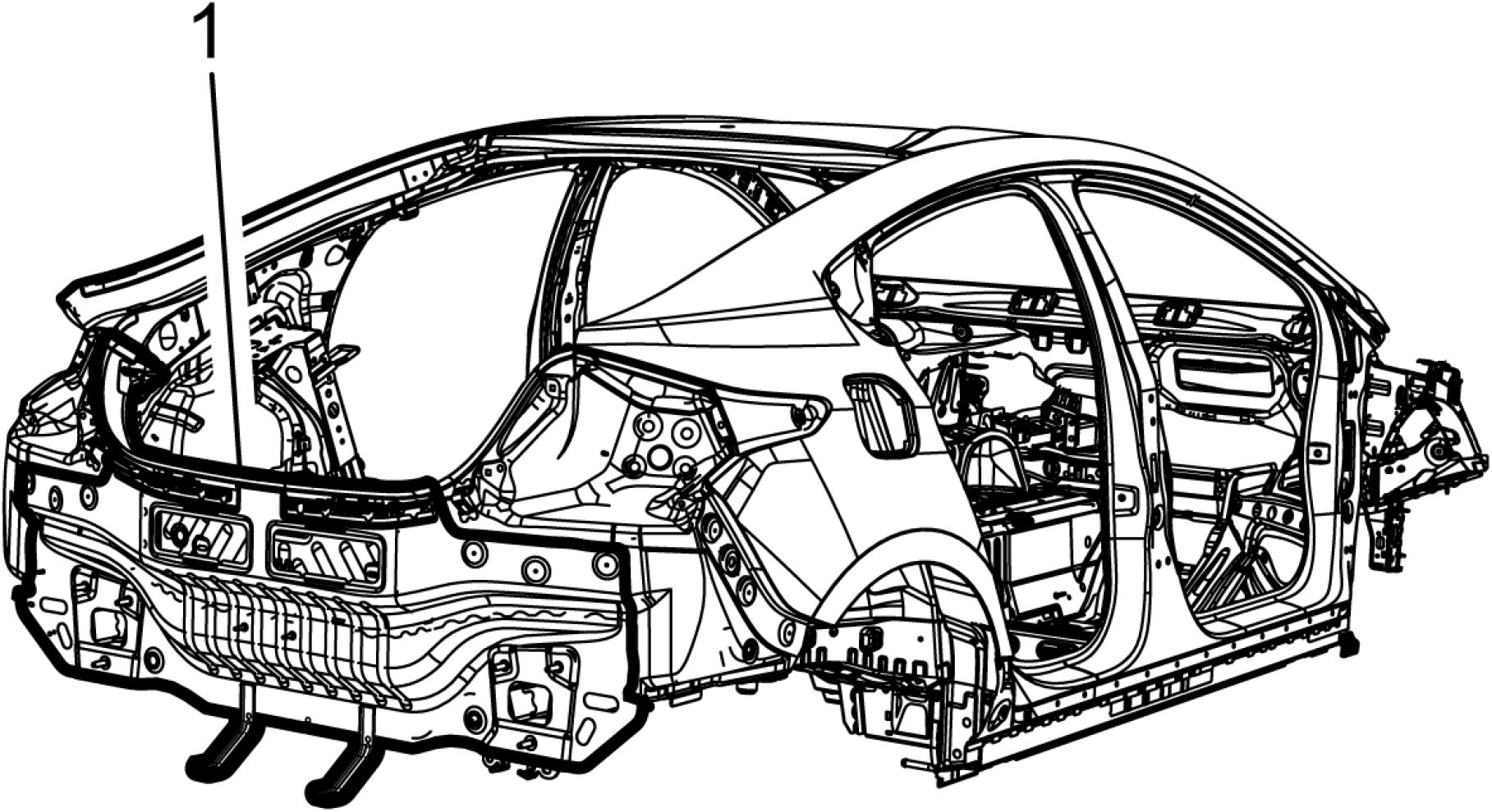
Fig. 100: Body Rear End Panel
Courtesy of GENERAL MOTORS COMPANY
5. Clamp the body rear end panel (1) into position.
6. Weld the body rear end panel (1) accordingly.
7. Apply the sealers and anti-corrosion materials to the repair area as necessary. Anti-Corrosion Treatment
and Repair .
8. Paint the repaired area. Basecoat/Clearcoat Paint Systems .
9. Install all related panels and components.
10. If disabled, enable the high voltage system. High Voltage Enabling .
11. Enable the SIR System. SIR Disabling and Enabling .
FRONT RAIL REPLACEMENT
WARNING: Always perform the High Voltage Disabling procedure prior to servicing any
High Voltage component or connection. Personal Protection Equipment (PPE)
and proper procedures must be followed.
The High Voltage Disabling procedure includes the following steps:
• Identify how to disable high voltage.
• Identify how to test for the presence of high voltage.
• Identify condition under which high voltage is always present and
personal protection equipment (PPE) and proper procedures must be
followed.
Before working on any high voltage system, be sure to wear the following
Personal Protection Equipment:
• Safety glasses with appropriate side shields when within 15 meters (50
feet) of the vehicle, either indoors or outdoors.
• Certified and up-to-date Class "0" Insulation gloves rated at 1000V with
leather protectors.
• Visually and functionally inspect the gloves before use.
• Wear the Insulation gloves with leather protectors at all times when
working with the high voltage battery assembly, whether the system
is energized or not.
Failure to follow the procedures may result in serious injury or death.
Removal Procedure
WARNING: Refer to Approved Equipment for Collision Repair Warning .
CAUTION: Refer to Collision Repair Anchoring Caution .
NOTE: The front rail is an ultra-high strength steel and cannot be sectioned or
repaired. Ultra High Strength Steel
NOTE: Left shown, right similar.
1. Disable the SIR system. SIR Disabling and Enabling .
2. Inspect the high voltage system. High Voltage System Inspection .
3. Remove all related panels and components.
4. Repair as much of the damage as possible to factory specifications. Dimensions - Body.
5. Note the location and remove the sealers and anti-corrosion materials from the repair area. Anti-
Corrosion Treatment and Repair .
 |
|
Fig. 101: Front Rail Courtesy of GENERAL MOTORS COMPANY |
NOTE: Do not damage any inner panels or reinforcements.
6. Locate and remove out all factory welds. Note the number and location of the welds for installation of the
front rail (1).

Fig. 102: Front Rail
Courtesy of GENERAL MOTORS COMPANY
7. Remove the damaged front rail (2) from the vehicle (1).
NOTE: If impact resistant adhesive is present remove and replace as necessary.
8. Remove the impact resistant adhesive from the repair area, as necessary. Metal Panel Bonding.
Installation Procedure
NOTE: Squeeze Type Resistance Spot Welds equivalent to the factory spot welds are
recommended. If access to use Squeeze Type Resistance Spot Welds is not
possible, MIG/MAG plug welds may be used, to replace those specific welds.

Fig. 103: Service Part Front Rail
Courtesy of GENERAL MOTORS COMPANY
NOTE: If the location of the original plug weld holes cannot be determined, space
the plug weld holes every 40 mm (1 1/2 in) apart.
1. Drill 8 mm (5/16 in) plug weld holes in the service part front rail (1) as necessary in the locations noted
from the original panel.
2. Prepare all mating surfaces as necessary.
3. Apply GM-approved Weld-Thru Coating or equivalent to all mating surfaces. Anti-Corrosion
Treatment and Repair .

4. Apply the impact resistant adhesive to the repair area, as necessary. Metal Panel Bonding.
5. Position the front rail (1) to the vehicle (2) using 3-dimensional measuring equipment. Clamp the rail in
place.
 |
|
Fig. 105: Front Rail Courtesy of GENERAL MOTORS COMPANY |
6. Weld the front rail (1) accordingly.
7. Clean and prepare all welded surfaces.
8. Install all related panels and components.
9. Apply the sealers and anti-corrosion materials to the repair area as necessary. Anti-Corrosion Treatment
and Repair .
10. Paint the repaired area. Basecoat/Clearcoat Paint Systems .
11. If disabled, enable the high voltage system. High Voltage Enabling .
12. Enable the SIR System. SIR Disabling and Enabling .
REAR RAIL END REPLACEMENT
WARNING: Always perform the High Voltage Disabling procedure prior to servicing any
High Voltage component or connection. Personal Protection Equipment (PPE)
and proper procedures must be followed.
The High Voltage Disabling procedure includes the following steps:
• Identify how to disable high voltage.
• Identify how to test for the presence of high voltage.
• Identify condition under which high voltage is always present and
personal protection equipment (PPE) and proper procedures must be
followed.
Before working on any high voltage system, be sure to wear the following
Personal Protection Equipment:
• Safety glasses with appropriate side shields when within 15 meters (50
feet) of the vehicle, either indoors or outdoors.
• Certified and up-to-date Class "0" Insulation gloves rated at 1000V with
leather protectors.
• Visually and functionally inspect the gloves before use.
• Wear the Insulation gloves with leather protectors at all times when
working with the high voltage battery assembly, whether the system
is energized or not.
Failure to follow the procedures may result in serious injury or death.
Removal Procedure
WARNING: Refer to Approved Equipment for Collision Repair Warning .
WARNING: Refer to Collision Sectioning Warning .
WARNING: Refer to Glass and Sheet Metal Handling Warning .
CAUTION: Refer to Collision Repair Anchoring Caution .
NOTE: Left shown right similar.
1. Disable the SIR system. SIR Disabling and Enabling .
2. Inspect the high voltage system. High Voltage System Inspection .
3. Remove all related panels and components.
4. Visually inspect the vehicle for additional damage to the vehicle structure. Repair as much of the damage
to the vehicle structure as possible, prior to replacing any damaged parts.
5. Remove the sealers and anti-corrosion materials from the repair area as necessary. Anti-Corrosion
Treatment and Repair .

|
Fig. 106: Rear Rail End Courtesy of GENERAL MOTORS COMPANY | ||||
| ||||
|
6. Remove all factory welds from rear rail end (1). |

Fig. 107: Rear Rail End
Courtesy of GENERAL MOTORS COMPANY
7. Remove the damaged rear rail end (1) from vehicle (2).
NOTE: If impact resistant adhesive is present remove and replace as necessary.
8. Remove the impact resistant adhesive from the repair area, as necessary. Metal Panel Bonding.
Installation Procedure
NOTE: Squeeze Type Resistance Spot Welds equivalent to the factory spot welds are
recommended. If access to use Squeeze Type Resistance Spot Welds is not
possible, MIG/MAG plug welds may be used, to replace those specific welds.
1. Prepare all mating surfaces for welding as necessary.

2. Position the rear rail end (1) on the vehicle (2) using 3-dimensional measuring equipment.
3. Verify the fit of the rear rail end (1).

Fig. 109: Rear Rail End
Courtesy of GENERAL MOTORS COMPANY
4. Apply the impact resistant adhesive to the repair area, as necessary. Metal Panel Bonding.
5. Clamp the rear rail end (1) into position.
6. Weld the rear rail end (1) accordingly.
7. Apply the sealers and anti-corrosion materials to the repair area as necessary. Anti-Corrosion Treatment
and Repair .
8. Paint the repaired area. Basecoat/Clearcoat Paint Systems
9. Install all related panels and components.
10. If disabled, enable the high voltage system. High Voltage Enabling
11. Enable the SIR System. SIR Disabling and Enabling .
BODY HINGE PILLAR INNER PANEL REPLACEMENT
WARNING: Always perform the High Voltage Disabling procedure prior to servicing any
High Voltage component or connection. Personal Protection Equipment (PPE)
and proper procedures must be followed.
The High Voltage Disabling procedure includes the following steps:
• Identify how to disable high voltage.
• Identify how to test for the presence of high voltage.
• Identify condition under which high voltage is always present and
personal protection equipment (PPE) and proper procedures must be
followed.
Before working on any high voltage system, be sure to wear the following
Personal Protection Equipment:
• Safety glasses with appropriate side shields when within 15 meters (50
feet) of the vehicle, either indoors or outdoors.
• Certified and up-to-date Class "0" Insulation gloves rated at 1000V with
leather protectors.
• Visually and functionally inspect the gloves before use.
• Wear the Insulation gloves with leather protectors at all times when
working with the high voltage battery assembly, whether the system
is energized or not.
Failure to follow the procedures may result in serious injury or death.
Removal Procedure
WARNING: Refer to Approved Equipment for Collision Repair Warning .
WARNING: Refer to Collision Sectioning Warning .
WARNING: Refer to Glass and Sheet Metal Handling Warning .
CAUTION: Refer to Collision Repair Anchoring Caution .
NOTE: There are sectioning procedures available for various locations of the
body side outer panel. The sectioning procedure and location should be
chosen based on the extent of damage to the vehicle and any additional
inner reinforcements that need to be replaced. Refer to the body side outer
panel sectioning procedures for the specific location where sectioning is
required.
NOTE: The Roof side rail reinforcement is a High strength low alloy steel. High
Strength Low Alloy Steel.
NOTE: Left shown right similar.
1. Disable the SIR system. SIR Disabling and Enabling .
2. Inspect the high voltage system. High Voltage System Inspection .
3. Remove all related panels and components.
4. Visually inspect the vehicle for additional damage to the vehicle structure. Repair as much of the damage
to the vehicle structure as possible, prior to replacing any damaged parts.
5. Remove the sealers and anti-corrosion materials from the repair area as necessary. Anti-Corrosion
Treatment and Repair .
6. Section the body side outer panel as required for access to replace the Front Hinge Pillar.
 |
|
Fig. 110: Body Hinge Pillar Inner Courtesy'of GENERALMOTORS COMPANY |
| ||||
|
7. Remove all factory welds from body hinge pillar inner (1). |

Fig. 111: Body Hinge Pillar Inner
Courtesy of GENERAL MOTORS COMPANY
8. Remove the damaged body hinge pillar inner (1) from vehicle (2).
NOTE: If impact resistant adhesive is present remove and replace as necessary.
9. Remove the impact resistant adhesive from the repair area, as necessary. Metal Panel Bonding.
Installation Procedure
NOTE: Squeeze Type Resistance Spot Welds equivalent to the factory spot welds
are recommended. If access to use Squeeze Type Resistance Spot Welds
is not possible, MIG/MAG plug welds may be used, to replace those
specific welds.
1. Prepare all mating surfaces for welding as necessary.

2. Position the body hinge pillar inner (1) on the vehicle (2) using 3-dimensional measuring equipment.
3. Verify the fit of the body hinge pillar inner (1).

4. Apply the impact resistant adhesive to the repair area, as necessary. Metal Panel Bonding.
5. Clamp the body hinge pillar inner (1) into position.
6. Weld the body hinge pillar inner (1) accordingly.
7. Apply the sealers and anti-corrosion materials to the repair area as necessary. Anti-Corrosion Treatment
and Repair .
8. Install the body side outer panel as necessary.
NOTE: Before refinishing, refer to Adhesive Installation of Windshields , or
Adhesive Installation of Liftqate Windows .
9. Paint the repaired area. Basecoat/Clearcoat Paint Systems .
10. Install all related panels and components.
11. If disabled, enable the high voltage system. High Voltage Enabling .
12. Enable the SIR System. SIR Disabling and Enabling .
CENTER PILLAR INNER PANEL REPLACEMENT
WARNING: Always perform the High Voltage Disabling procedure prior to servicing any
High Voltage component or connection. Personal Protection Equipment (pPe)
and proper procedures must be followed.
The High Voltage Disabling procedure includes the following steps:
| ||
|
Before working on any high voltage system, be sure to wear the following
Personal Protection Equipment:
|
» Safety glasses with appropriate side shields when within 15 meters (50 » Certified and up-to-date Class "0" Insulation gloves rated at 1000V with
|
Failure to follow the procedures may result in serious injury or death.
|
Removal Procedure | ||||||||||||||
|
1. Disable the SIR system. SIR Disabling and Enabling .
2. Inspect the high voltage system. High Voltage System Inspection .
3. Remove all related panels and components.
4. Visually inspect the vehicle for additional damage to the vehicle structure. Repair as much of the damage
to the vehicle structure as possible, prior to replacing any damaged parts.
5. Remove the sealers and anti-corrosion materials from the repair area, as necessary. Anti-Corrosion
Treatment and Repair .
6. Section the body side outer panel as required for access to replace the center inner panel.
 |
|
Fig. 114: Center Inner Panel |
|
Courtesy of GENERAL MOTORS COMPANY | ||||
|
7. Remove all factory welds from the center inner panel (1).

Fig. 115: Center Inner Panel
Courtesy'of GENERALMOTORS COMPANY
8. Remove the damaged center inner panel (1) from vehicle (2).
NOTE: If impact resistant adhesive is present remove and replace as necessary.
9. Remove the impact resistant adhesive from the repair area, as necessary. Metal Panel Bonding.
Installation Procedure
NOTE: Squeeze Type Resistance Spot Welds equivalent to the factory spot welds
are recommended. If access to use Squeeze Type Resistance Spot Welds
is not possible, MIG/MAG plug welds may be used, to replace those
specific welds.
1. Prepare all mating surfaces for welding as necessary.

2. Position the center inner panel (1) on the vehicle (2) using 3-dimensional measuring equipment.
3. Verify the fit of the center inner panel (1).
 |
|
Fig. 117: Center Inner Panel Courtesy of GENERAL MOTORS COMPANY |
4. Apply the impact resistant adhesive to the repair area, as necessary. Refer to Metal Panel Bonding.
5. Clamp the center inner panel (1) into position.
6. Weld the center inner panel (1) accordingly.
7. Apply the sealers and anti-corrosion materials to the repair area as necessary. Anti-Corrosion Treatment
and Repair .
8. Install the body side outer panel as necessary.
9. Paint the repaired area. Basecoat/Clearcoat Paint Systems .
10. Install all related panels and components.
11. If disabled, enable the high voltage system. Refer to High Voltage Enabling .
12. Enable the SIR System. SIR Disabling and Enabling .
CENTER PILLAR REPLACEMENT
WARNING: Always perform the High Voltage Disabling procedure prior to servicing any
High Voltage component or connection. Personal Protection Equipment (PPE)
and proper procedures must be followed.
The High Voltage Disabling procedure includes the following steps:
| ||
|
Before working on any high voltage system, be sure to wear the following
Personal Protection Equipment:
|
» Safety glasses with appropriate side shields when within 15 meters (50 • Certified and up-to-date Class "0" Insulation gloves rated at 1000V with
|
Failure to follow the procedures may result in serious injury or death.
|
Removal Procedure | ||||||||||||||
| ||||||||||||||
|
3. Remove all related panels and components.
4. Visually inspect the vehicle for additional damage to the vehicle structure. Repair as much of the damage
to the vehicle structure as possible, prior to replacing any damaged parts.
5. Remove the sealers and anti-corrosion materials from the repair area, as necessary. Refer to Anti-
Corrosion Treatment and Repair .
6. Section the body side outer panel as required for access to replace the center pillar.

Fig. 118: Center Pillar
|
Courtesy of GENERAL MOTORS COMPANY | ||||
| ||||
|
7. Remove all factory welds from center pillar (1). |

Fig. 119: Center Pillar
Courtesy of GENERAL MOTORS COMPANY
8. Remove the damaged center pillar (1) from vehicle (2).
NOTE: If impact resistant adhesive is present remove and replace as necessary.
9. Remove the impact resistant adhesive from the repair area, as necessary. Refer to Metal Panel Bonding.
Installation Procedure
NOTE: Squeeze Type Resistance Spot Welds equivalent to the factory spot welds
are recommended. If access to use Squeeze Type Resistance Spot Welds
is not possible, MIG/MAG plug welds may be used, to replace those
specific welds.
1. Prepare all mating surfaces for welding as necessary.
 |
|
Fig. 120: Center Pillar Courtesy of GENERAL MOTORS COMPANY |
2. Position the center pillar (1) on the vehicle (2) using 3-dimensional measuring equipment.
3. Verify the fit of the center pillar.

4. Apply the impact resistant adhesive to the repair area, as necessary. Refer to Metal Panel Bonding.
5. Clamp the center pillar (1) into position.
6. Weld the center pillar (1) accordingly.
7. Apply the sealers and anti-corrosion materials to the repair area, as necessary. Refer to Anti-Corrosion
Treatment and Repair .
8. Install the body side outer panel as necessary.
9. Paint the repaired area. Refer to Basecoat/Clearcoat Paint Systems .
10. Install all related panels and components.
11. If disabled, enable the high voltage system. Refer to High Voltage Enabling .
12. Enable the SIR system. Refer to SIR Disabling and Enabling .
FRONT SIDE DOOR OUTER PANEL REPLACEMENT
WARNING: Always perform the High Voltage Disabling procedure prior to servicing any
High Voltage component or connection. Personal Protection Equipment (PPE)
and proper procedures must be followed.
The High Voltage Disabling procedure includes the following steps:
• Identify how to disable high voltage.
• Identify how to test for the presence of high voltage.
• Identify condition under which high voltage is always present and
personal protection equipment (PPE) and proper procedures must be
followed.
Before working on any high voltage system, be sure to wear the following
Personal Protection Equipment:
• Safety glasses with appropriate side shields when within 15 meters (50
feet) of the vehicle, either indoors or outdoors.
• Certified and up-to-date Class "0" Insulation gloves rated at 1000V with
leather protectors.
• Visually and functionally inspect the gloves before use.
• Wear the Insulation gloves with leather protectors at all times when
working with the high voltage battery assembly, whether the system
is energized or not.
Failure to follow the procedures may result in serious injury or death.
Removal Procedure
WARNING: Refer to Approved Equipment for Collision Repair Warning .
NOTE: Before beginning the repair, refer to Metal Panel Bonding for proper adhesive
applicator preparations and general information.
1. Disable the SIR system. Refer to SIR Disabling and Enabling .
2. Inspect the high voltage system. Refer to High Voltage System Inspection .
3. Remove the door from the vehicle. Refer to Front Side Door Replacement .
4. Remove the outer door handle.
5. Remove the outside rearview mirror.
 |
|
Fig. 122: Door Shell Courtesy of GENERAL MOTORS COMPANY |
6. Grind the edges of the door outer panel to separate the outer door panel from the door shell (1).
 |
|
Fig. 123: Outer Door Panel And Door Shell |
WARNING: Inspection of the door guard beam for damage must be performed before
replacement of the door outer panel. If damage to the door guard beam is
found the door must be replaced. Failure to do so may compromise the
structural integrity of the vehicle and may cause personal injury if the
vehicle is involved in a collision.
7. Remove the outer door panel (2) from the door shell (1).
8. Remove the sealers and anti-corrosion materials from the repair area, as necessary. Refer to Anti-
Corrosion Treatment and Repair .
 |
|
Fig. 124: Door Shell Courtesy of GENERAL MOTORS COMPANY |
9. Straighten the edges of the door shell (1).
Installation Procedure
 |
|
Fig. 125: Door Shell Courtesy of GENERAL MOTORS COMPANY |
1. Using a grinding disk grind the surface of the door shell (1) mating flanges to bare steel.
 |
|
Fig. 126: Door Outer Panel Courtesy of GENERAL MOTORS COMPANY |
2. Scuff the opposing mating surfaces of the door outer panel (1) to remove the gloss of the E-Coat.
3. Clean the mating surfaces.
 |
|
Fig. 127: Apply Anti-Flutter Foam On Inner Safety Beam |
4. Apply anti-flutter foam-slow set 40 - 50 minute working time, or equivalent, in 4 - 6 evenly spaced on the
inner safety beam (1).
 |
|
Fig. 128: Apply Bead Of Metal Panel Bonding Adhesive To Mating Surfaces |
NOTE: The adhesive has a 40 - 50 minute working time. Do not allow the door to
totally cure off the vehicle, as proper alignment of the door outer panel to
the door shell will be difficult.
5. Apply a 3 - 6 mm (1/8 - 1/4 in) bead of metal panel bonding adhesive Metal Panel Bonding, to both of
the mating surfaces.
6. Using a small acid brush, spread a coat of adhesive to cover all the bare metal surfaces to ensure
corrosion protection.
 |
|
Fig. 129: Outer Door Panel And Door Shell Courtesy of GENERAL MOTORS COMPANY |
NOTE: Do NOT pull the panels apart after joined together. If necessary, slide the
panels against each other to realign the panels.
7. Install the door outer panel (1) to the door shell (2).
 |
|
Fig. 130: Door Shell Courtesy of GENERAL MOTORS COMPANY |
8. Clamp the door outer panel into position, as required.
9. Using a hammer, re-hem the hem flanges around the door shell (1). Continue to hammer in stages along
the hem flanges.
10. Using lacquer thinner remove the excess adhesive from the door panel area.
11. Install the door to the vehicle. Inspect the door outer panel for proper alignment. Adjust the alignment, as
required. Refer to Front Side Door Replacement .
12. Clean and prepare all welded surfaces.
13. Apply sealers and anti-corrosion materials to the repair area, as necessary. Refer to Anti-Corrosion
Treatment and Repair .
14. Paint the repaired area. Refer to Basecoat/Clearcoat Paint Systems .
15. Install the outer door handle.
16. Install the outside rearview mirror.
17. Install the door to the vehicle. Refer to Front Side Door Replacement .
18. Enable the SIR system. Refer to SIR Disabling and Enabling .
19. If disabled, enable the high voltage system. Refer to High Voltage Enabling .
REAR SIDE DOOR OUTER PANEL REPLACEMENT
WARNING: Always perform the High Voltage Disabling procedure prior to servicing any
High Voltage component or connection. Personal Protection Equipment (pPe)
and proper procedures must be followed.
The High Voltage Disabling procedure includes the following steps:
• Identify how to disable high voltage.
• Identify how to test for the presence of high voltage.
• Identify condition under which high voltage is always present and
personal protection equipment (PPE) and proper procedures must be
followed.
Before working on any high voltage system, be sure to wear the following
Personal Protection Equipment:
• Safety glasses with appropriate side shields when within 15 meters (50
feet) of the vehicle, either indoors or outdoors.
• Certified and up-to-date Class "0" Insulation gloves rated at 1000V with
leather protectors.
• Visually and functionally inspect the gloves before use.
• Wear the Insulation gloves with leather protectors at all times when
working with the high voltage battery assembly, whether the system
is energized or not.
Failure to follow the procedures may result in serious injury or death.
Removal Procedure
WARNING: Refer to Approved Equipment for Collision Repair Warning .
NOTE: Before beginning the repair, refer to Metal Panel Bonding for proper adhesive
applicator preparations and general information.
1. Disable the SIR system. Refer to SIR Disabling and Enabling .
2. Inspect the high voltage system. Refer to High Voltage System Inspection .
3. Remove the door from the vehicle. Refer to Rear Side Door Replacement .
4. Remove the outer door handle.
 |
|
Fig. 131: Door Shell Courtesy of GENERAL MOTORS COMPANY |
5. Grind the edges of the door outer panel to separate the outer door panel from the door shell (1).
 |
|
Fig. 132: Outer Door Panel And Door Shell |
WARNING: Inspection of the door guard beam for damage must be performed before
replacement of the door outer panel. If damage to the door guard beam is
found the door must be replaced. Failure to do so may compromise the
structural integrity of the vehicle and may cause personal injury if the
vehicle is involved in a collision.
6. Remove the outer door panel (2) from the door shell (1).
7. Remove the sealers and anti-corrosion materials from the repair area, as necessary. Refer to Anti-
Corrosion Treatment and Repair .
 |
|
Fig. 133: Door Shell Courtesy of GENERAL MOTORS COMPANY |
8. Straighten the edges of the door shell (1).
Installation Procedure
 |
|
Fig. 134: Door Shell Courtesy of GENERAL MOTORS COMPANY |
1. Using a grinding disk grind the surface of the door shell (1) mating flanges to bare steel.
 |
|
Fig. 135: Door Outer Panel Courtesy of GENERAL MOTORS COMPANY |
2. Scuff the opposing mating surfaces of the door outer panel (1) to remove the gloss of the E-Coat.
3. Clean the mating surfaces.
 |
|
Fig. 136: Apply Anti-Flutter Foam To Inner Safety Beam |
4. Apply anti-flutter foam-slow set 40 - 50 minute working time, or equivalent, in 4 - 6 evenly spaced on the
inner safety beam (1).
 |
|
Fig. 137: Apply Bead Of Metal Panel Bonding Adhesive To Mating Surfaces |
NOTE: The adhesive has a 40 - 50 minute working time. Do not allow the door to
totally cure off the vehicle, as proper alignment of the door outer panel to
the door shell will be difficult.
5. Apply a 3 - 6 mm (1/8 - 1/4 in) bead of metal panel bonding adhesive Metal Panel Bonding, to both of
the mating surfaces.
6. Using a small acid brush, spread a coat of adhesive to cover all the bare metal surfaces to ensure
corrosion protection.
 |
|
Fig. 138: Outer Door Panel And Door Shell Courtesy of GENERAL MOTORS COMPANY |
NOTE: Do NOT pull the panels apart after joined together. If necessary, slide the
panels against each other to realign the panels.
7. Install the door outer panel (2) to the door shell (1).
 |
|
Fig. 139: Door Shell Courtesy of GENERAL MOTORS COMPANY |
8. Clamp the door outer panel into position, as required.
9. Using a hammer, re-hem the hem flanges around the door shell (1). Continue to hammer in stages along
the hem flanges.
10. Using lacquer thinner remove the excess adhesive from the door panel area.
11. Install the door to the vehicle. Inspect the door outer panel for proper alignment. Adjust the alignment, as
required. Refer to Rear Side Door Replacement .
12. Clean and prepare all welded surfaces.
13. Apply sealers and anti-corrosion materials to the repair area, as necessary. Refer to Anti-Corrosion
Treatment and Repair .
14. Paint the repaired area. Refer to Basecoat/Clearcoat Paint Systems .
15. Install the outer door handle.
16. Install the door to the vehicle. Refer to Front Side Door Replacement .
17. Enable the SIR system. Refer to SIR Disabling and Enabling .
18. If disabled, enable the high voltage system. Refer to High Voltage Enabling .
ROOF SIDE RAIL REINFORCEMENT REPLACEMENT
WARNING: Always perform the High Voltage Disabling procedure prior to servicing any
High Voltage component or connection. Personal Protection Equipment (pPe)
and proper procedures must be followed.
The High Voltage Disabling procedure includes the following steps:
| ||
|
Before working on any high voltage system, be sure to wear the following
Personal Protection Equipment:
|
» Safety glasses with appropriate side shields when within 15 meters (50 » Certified and up-to-date Class "0" Insulation gloves rated at 1000V with
|
Failure to follow the procedures may result in serious injury or death.
|
Removal Procedure | ||||||||||||||
|
1. Disable the SIR system. SIR Disabling and Enabling .
2. Inspect the high voltage system. High Voltage System Inspection .
3. Remove all related panels and components.
4. Visually inspect the damage.Repair as much of the damage as possible.
5. Remove the sealers and anti-corrosion materials from the repair area as necessary. Anti-Corrosion
Treatment and Repair .

Fig. 140: Roof Side Rail Reinforcement
Courtesy'of GENERAl'mOTORS'cOMPANY
| ||||
|
6. Remove all factory welds from the roof side rail reinforcement (1). |

Fig. 141: Roof Side Rail Reinforcement
Courtesy of GENERAL MOTORS COMPANY
7. Remove the roof side rail reinforcement (1) from vehicle (2).
NOTE: If impact resistant adhesive is present remove and replace as necessary.
8. Remove the impact resistant adhesive from the repair area, as necessary. Metal Panel Bonding.
Installation Procedure
NOTE: Squeeze Type Resistance Spot Welds equivalent to the factory spot welds
are recommended. If access to use Squeeze Type Resistance Spot Welds
is not possible, MIG/MAG plug welds may be used, to replace those
specific welds.
1. Prepare all mating surfaces for welding as necessary.

2. Position the roof side rail reinforcement (1) on the vehicle (2) using 3-dimensional measuring equipment.
3. Verify the fit of the roof side rail reinforcement (1).
4. Apply the impact resistant adhesive to the repair area, as necessary. Metal Panel Bonding
 |
|
Fig. 143: Roof Side Rail Reinforcement Courtesy of GENERAL MOTORS COMPANY |
5. Clamp the roof side rail reinforcement (1) into position.
6. Weld the roof side rail reinforcement (1) accordingly.
7. Apply the sealers and anti-corrosion materials to the repair area as necessary. Anti-Corrosion Treatment
and Repair .
NOTE: Before refinishing, refer to Adhesive Installation of Windshields , and
Adhesive Installation of Liftqate Windows .
9. Install all related panels and components.
10. If disabled, enable the high voltage system. High Voltage Enabling .
11. Enable the SIR System. SIR Disabling and Enabling .
WARNING: Always perform the High Voltage Disabling procedure prior to servicing any
High Voltage component or connection. Personal Protection Equipment (PPE)
and proper procedures must be followed.
The High Voltage Disabling procedure includes the following steps:
• Identify how to disable high voltage.
• Identify how to test for the presence of high voltage.
• Identify condition under which high voltage is always present and
personal protection equipment (PPE) and proper procedures must be
followed.
Before working on any high voltage system, be sure to wear the following
Personal Protection Equipment:
• Safety glasses with appropriate side shields when within 15 meters (50
feet) of the vehicle, either indoors or outdoors.
• Certified and up-to-date Class "0" Insulation gloves rated at 1000V with
leather protectors.
• Visually and functionally inspect the gloves before use.
• Wear the Insulation gloves with leather protectors at all times when
working with the high voltage battery assembly, whether the system
is energized or not.
Failure to follow the procedures may result in serious injury or death.
Removal Procedure
WARNING: Refer to Approved Equipment for Collision Repair Warning .
CAUTION: Refer to Collision Repair Anchoring Caution .
NOTE: Left shown, right similar.
1. Disable the SIR system. SIR Disabling and Enabling .
2. Inspect the high voltage system. High Voltage System Inspection .
3. Remove all related panels and components.
4. Repair as much of the damage as possible to factory specifications. Dimensions - Body.
5. Note the location and remove the sealers and anti-corrosion materials from the repair area. Anti-
Corrosion Treatment and Repair .

Fig. 144: Rear Rail
Courtesy of GENERAL MOTORS COMPANY
NOTE: Do not damage or cut attaching panels and reinforcements.
6. Locate and remove out all factory welds. Note the number and location of the welds for installation of the
rear rail (1).
 |
|
Fig. 145: Rear Rail Courtesy of GENERAL MOTORS COMPANY |
7. Remove the damaged rear rail (2) from the vehicle (1).
NOTE: If impact resistant adhesive is present remove and replace as necessary.
8. Remove the impact resistant adhesive from the repair area, as necessary. Metal Panel Bonding.
Installation Procedure
NOTE: Squeeze Type Resistance Spot Welds equivalent to the factory spot welds
are recommended. If access to use Squeeze Type Resistance Spot Welds
is not possible, MIG/MAG plug welds may be used, to replace those
specific welds.
NOTE: If the location of the original plug weld holes cannot be determined, space
the plug weld holes every 40 mm (1 1/2 in) apart.
1. Drill 8 mm (5/16 in) plug weld holes in the service part front rail as necessary in the locations noted from
the original panel.
2. Prepare all mating surfaces as necessary.
3. Apply GM-approved Weld-Thru Coating or equivalent to all mating surfaces. Anti-Corrosion
Treatment and Repair .
 |
|
Fig. 146: Rear Rail Courtesy of GENERAL MOTORS COMPANY |
4. Position the rear rail (1) to the vehicle using 3-dimensional measuring equipment.
5. Apply the impact resistant adhesive to the repair area, as necessary. Metal Panel Bonding
6. Clamp the rail into position.

Fig. 147: Rear Rail
Courtesy of GENERAL MOTORS COMPANY
7. Weld the rear rail (1) accordingly.
8. Clean and prepare all welded surfaces.
9. Install all related panels and components.
10. Apply the sealers and anti-corrosion materials to the repair area as necessary. Anti-Corrosion Treatment
and Repair .
11. Paint the repaired area. Basecoat/Clearcoat Paint Systems .
12. If disabled, enable the high voltage system. High Voltage Enabling .
13. Enable the SIR System. SIR Disabling and Enabling .
RAIL REPLACEMENT - REAR SECTION
WARNING: Always perform the High Voltage Disabling procedure prior to servicing any
High Voltage component or connection. Personal Protection Equipment (PPE)
and proper procedures must be followed.
The High Voltage Disabling procedure includes the following steps:
• Identify how to disable high voltage.
• Identify how to test for the presence of high voltage.
• Identify condition under which high voltage is always present and
personal protection equipment (PPE) and proper procedures must be
followed.
Before working on any high voltage system, be sure to wear the following
Personal Protection Equipment:
• Safety glasses with appropriate side shields when within 15 meters (50
feet) of the vehicle, either indoors or outdoors.
• Certified and up-to-date Class "0" Insulation gloves rated at 1000V with
leather protectors.
• Visually and functionally inspect the gloves before use.
• Wear the Insulation gloves with leather protectors at all times when
working with the high voltage battery assembly, whether the system
is energized or not.
Failure to follow the procedures may result in serious injury or death.
Removal Procedure
WARNING: Refer to Approved Equipment for Collision Repair Warning .
WARNING: Refer to Collision Sectioning Warning .
WARNING: Refer to Glass and Sheet Metal Handling Warning .
CAUTION: Refer to Collision Repair Anchoring Caution .
NOTE: Right shown, left similar.
1. Disable the SIR system. SIR Disabling and Enabling .
2. Inspect the high voltage system. High Voltage System Inspection .
3. Remove all related panels and components.
4. Visually inspect the vehicle for additional damage to the vehicle structure. Repair as much of the damage
to the vehicle structure as possible, prior to replacing any damaged parts.
5. Remove the sealers and anti-corrosion materials from the repair area, as necessary. Anti-Corrosion
Treatment and Repair .

|
Fig. 148: Rear Rail Section Courtesy of GENERAL MOTORS COMPANY | ||||
| ||||
|
6. Remove all factory welds from rear rail section (1). |
 |
|
Fig. 149: Rear Rail Section Courtesy of GENERAL MOTORS COMPANY |
7. Remove the damaged rear rail section (2) from vehicle (1).
NOTE: If impact resistant adhesive is present remove and replace as necessary.
8. Remove the impact resistant adhesive from the repair area, as necessary. Metal Panel Bonding.
Installation Procedure
NOTE: Squeeze Type Resistance Spot Welds equivalent to the factory spot welds are
recommended. If access to use Squeeze Type Resistance Spot Welds is not
possible, MIG/MAG plug welds may be used, to replace those specific welds.
1. Prepare all mating surfaces for welding as necessary.
 |
|
Fig. 150: Rear Rail Section Courtesy of GENERAL MOTORS COMPANY |
2. Position the rear rail section (2) on the vehicle (1) using 3-dimensional measuring equipment.
3. Verify the fit of the rear rail section (2).

Fig. 151: Rear Rail Section
Courtesy of GENERAL MOTORS COMPANY
4. Apply the impact resistant adhesive to the repair area, as necessary. Metal Panel Bonding.
5. Clamp the rear rail section (1) into position.
6. Weld the rear rail section (1) accordingly.
7. Apply the sealers and anti-corrosion materials to the repair area as necessary. Anti-Corrosion Treatment
and Repair .
8. Paint the repaired area. Basecoat/Clearcoat Paint Systems .
9. Install all related panels and components.
10. If disabled, enable the high voltage system. High Voltage Enabling .
11. Enable the SIR System. SIR Disabling and Enabling .
REAR FLOOR PANEL FILLER REPLACEMENT
WARNING: Always perform the High Voltage Disabling procedure prior to servicing any
High Voltage component or connection. Personal Protection Equipment (PPE)
and proper procedures must be followed.
The High Voltage Disabling procedure includes the following steps:
• Identify how to disable high voltage.
• Identify how to test for the presence of high voltage.
• Identify condition under which high voltage is always present and
personal protection equipment (PPE) and proper procedures must be
followed.
Before working on any high voltage system, be sure to wear the following
Personal Protection Equipment:
• Safety glasses with appropriate side shields when within 15 meters (50
feet) of the vehicle, either indoors or outdoors.
• Certified and up-to-date Class "0" Insulation gloves rated at 1000V with
leather protectors.
• Visually and functionally inspect the gloves before use.
• Wear the Insulation gloves with leather protectors at all times when
working with the high voltage battery assembly, whether the system
is energized or not.
Failure to follow the procedures may result in serious injury or death.
Removal Procedure
WARNING: Refer to Approved Equipment for Collision Repair Warning .
WARNING: Refer to Collision Sectioning Warning .
WARNING: Refer to Glass and Sheet Metal Handling Warning .
CAUTION: Refer to Collision Repair Anchoring Caution .
NOTE: Left shown right similar.
1. Disable the SIR System. Refer to SIR Disabling and Enabling .
2. Inspect the high voltage system. Refer to High Voltage System Inspection .
3. Remove all related panels and components.
4. Visually inspect the vehicle for additional damage to the vehicle structure. Repair as much of the damage
to the vehicle structure as possible, prior to replacing any damaged parts.
5. Remove the sealers and anti-corrosion materials from the repair area, as necessary. Refer to Anti-
Corrosion Treatment and Repair .

|
Fig. 152: Rear Floor Panel Filler Courtesy of GENERAL MOTORS COMPANY | ||||
| ||||
|
6. Remove all factory welds from rear floor panel filler (1). |

Fig. 153: Rear Floor Panel Filler
Courtesy of GENERAL MOTORS COMPANY
7. Remove the damaged rear floor panel filler (1) from vehicle (2).
NOTE: If impact resistant adhesive is present remove and replace as necessary.
8. Remove the impact resistant adhesive from the repair area, as necessary. Refer to Metal Panel Bonding.
Installation Procedure
NOTE: Squeeze Type Resistance Spot Welds equivalent to the factory spot welds
are recommended. If access to use Squeeze Type Resistance Spot Welds
is not possible, MIG/MAG plug welds may be used, to replace those
specific welds.
1. Prepare all mating surfaces as necessary.

2. Position the rear floor panel filler (1) on the vehicle (2) using 3-dimensional measuring equipment.
3. Verify the fit of the rear floor panel filler (1).

4. Apply the impact resistant adhesive to the repair area, as necessary. Refer to Metal Panel Bonding.
5. Clamp the rear floor panel filler (1) into position.
6. Weld the rear floor panel filler (1) accordingly.
7. Apply the sealers and anti-corrosion materials to the repair area, as necessary. Refer to Anti-Corrosion
Treatment and Repair .
8. Paint the repaired area. Refer to Basecoat/Clearcoat Paint Systems , Basecoat/Clearcoat Paint
Systems .
9. Install all related panels and components.
10. If disabled, enable the high voltage system. Refer to High Voltage Enabling .
11. Enable the SIR system. Refer to SIR Disabling and Enabling .
REAR FLOOR PANEL FILLER REPLACEMENT - LEFT SIDE
WARNING: Always perform the High Voltage Disabling procedure prior to servicing any
High Voltage component or connection. Personal Protection Equipment (PPE)
and proper procedures must be followed.
The High Voltage Disabling procedure includes the following steps:
• Identify how to disable high voltage.
• Identify how to test for the presence of high voltage.
• Identify condition under which high voltage is always present and
personal protection equipment (PPE) and proper procedures must be
followed.
Before working on any high voltage system, be sure to wear the following
Personal Protection Equipment:
• Safety glasses with appropriate side shields when within 15 meters (50
feet) of the vehicle, either indoors or outdoors.
• Certified and up-to-date Class "0" Insulation gloves rated at 1000V with
leather protectors.
• Visually and functionally inspect the gloves before use.
• Wear the Insulation gloves with leather protectors at all times when
working with the high voltage battery assembly, whether the system
is energized or not.
Failure to follow the procedures may result in serious injury or death.
Removal Procedure
WARNING: Refer to Approved Equipment for Collision Repair Warning .
WARNING: Refer to Collision Sectioning Warning .
WARNING: Refer to Glass and Sheet Metal Handling Warning .
CAUTION: Refer to Collision Repair Anchoring Caution .
1. Disable the SIR System. Refer to SIR Disabling and Enabling .
2. Inspect the high voltage system. Refer to High Voltage System Inspection .
3. Remove all related panels and components.
4. Visually inspect the vehicle for additional damage to the vehicle structure. Repair as much of the damage
to the vehicle structure as possible, prior to replacing any damaged parts
5. Remove the sealers and anti-corrosion materials from the repair area, as necessary. Refer to Anti-
Corrosion Treatment and Repair .

|
Fig. 156: Rear Floor Panel Filler Courtesy of GENERAL MOTORS COMPANY | ||||
| ||||
|
6. Remove all factory welds from the rear floor panel filler (1). |
 |
|
Fig. 157: Rear Floor Panel Filler Courtesy of GENERAL MOTORS COMPANY |
7. Remove the damaged rear floor panel filler (1) from vehicle (2).
NOTE: If impact resistant adhesive is present remove and replace as necessary.
8. Remove the impact resistant adhesive from the repair area, as necessary. Refer to Metal Panel Bonding.
Installation Procedure
NOTE: Squeeze Type Resistance Spot Welds equivalent to the factory spot welds
are recommended. If access to use Squeeze Type Resistance Spot Welds
is not possible, MIG/MAG plug welds may be used, to replace those
specific welds.
1. Prepare all mating surfaces for welding as necessary.
 |
|
Fig. 158: Rear Floor Panel Filler Courtesy of GENERAL MOTORS COMPANY |
2. Position the rear floor panel filler (1) on the vehicle (2) using 3-dimensional measuring equipment.
3. Verify the fit of the rear floor panel filler (1).
4. Apply the impact resistant adhesive to the repair area, as necessary. Refer to Metal Panel Bonding.
5. Clamp the rear floor panel filler (1) into position
6. Weld the rear floor panel filler (1) accordingly.
7. Apply the sealers and anti-corrosion materials to the repair area, as necessary. Refer to Anti-Corrosion
Treatment and Repair .
8. Paint the repaired area. Refer to Basecoat/Clearcoat Paint Systems .
9. Install all related panels and components.
10. If disabled, enable the high voltage system. Refer to High Voltage Enabling .
11. Enable the SIR system. Refer to SIR Disabling and Enabling .
REAR FLOOR PANEL FILLER REPLACEMENT - RIGHT SIDE
WARNING: Always perform the High Voltage Disabling procedure prior to servicing any
High Voltage component or connection. Personal Protection Equipment (PPE)
and proper procedures must be followed.
The High Voltage Disabling procedure includes the following steps:
• Identify how to disable high voltage.
• Identify how to test for the presence of high voltage.
• Identify condition under which high voltage is always present and
personal protection equipment (PPE) and proper procedures must be
followed.
Before working on any high voltage system, be sure to wear the following
Personal Protection Equipment:
• Safety glasses with appropriate side shields when within 15 meters (50
feet) of the vehicle, either indoors or outdoors.
• Certified and up-to-date Class "0" Insulation gloves rated at 1000V with
leather protectors.
• Visually and functionally inspect the gloves before use.
• Wear the Insulation gloves with leather protectors at all times when
working with the high voltage battery assembly, whether the system
is energized or not.
Failure to follow the procedures may result in serious injury or death.
Removal Procedure
WARNING: Refer to Approved Equipment for Collision Repair Warning .
WARNING: Refer to Collision Sectioning Warning .
WARNING: Refer to Glass and Sheet Metal Handling Warning .
CAUTION: Refer to Collision Repair Anchoring Caution .
1. Disable the SIR System. Refer to SIR Disabling and Enabling .
2. Inspect the high voltage system. Refer to High Voltage System Inspection .
3. Remove all related panels and components.
4. Visually inspect the vehicle for additional damage to the vehicle structure. Repair as much of the damage
to the vehicle structure as possible, prior to replacing any damaged parts
5. Remove the sealers and anti-corrosion materials from the repair area, as necessary. Refer to Anti-
Corrosion Treatment and Repair .

Fig. 160: Rear Floor Panel Filler
Courtesy of GENERAL MOTORS COMPANY
NOTE: Do not damage or cut attaching panels and reinforcements. Refer to
Structure Identification.
NOTE: Record the number and location of the original welds for installation of the
service assembly.
6. Remove all factory welds from the rear floor panel filler (1).
 |
|
Fig. 161: Rear Floor Panel Filler Courtesy of GENERAL MOTORS COMPANY |
7. Remove the damaged rear floor panel filler (1) from vehicle (2).
NOTE: If impact resistant adhesive is present remove and replace as necessary.
8. Remove the impact resistant adhesive from the repair area, as necessary. Refer to Metal Panel Bonding.
Installation Procedure
NOTE: Squeeze Type Resistance Spot Welds equivalent to the factory spot welds
are recommended. If access to use Squeeze Type Resistance Spot Welds
is not possible, MIG/MAG plug welds may be used, to replace those
specific welds.
1. Prepare all mating surfaces for welding as necessary.
 |
|
Fig. 162: Rear Floor Panel Filler Courtesy of GENERAL MOTORS COMPANY |
2. Position the rear floor panel filler (1) on the vehicle (2) using 3-dimensional measuring equipment.
3. Verify the fit of the rear floor panel filler (1).
4. Apply the impact resistant adhesive to the repair area, as necessary. Refer to Metal Panel Bonding.
5. Clamp the rear floor panel filler (1) into position
6. Weld the rear floor panel filler (1) accordingly.
7. Apply the sealers and anti-corrosion materials to the repair area, as necessary. Refer to Anti-Corrosion
Treatment and Repair .
8. Paint the repaired area. Refer to Basecoat/Clearcoat Paint Systems .
9. Install all related panels and components.
10. If disabled, enable the high voltage system. Refer to High Voltage Enabling .
11. Enable the SIR system. Refer to SIR Disabling and Enabling .
BATTERY TRAY REPLACEMENT
WARNING: Always perform the High Voltage Disabling procedure prior to servicing any
High Voltage component or connection. Personal Protection Equipment (PPE)
and proper procedures must be followed.
The High Voltage Disabling procedure includes the following steps:
• Identify how to disable high voltage.
• Identify how to test for the presence of high voltage.
• Identify condition under which high voltage is always present and
personal protection equipment (PPE) and proper procedures must be
followed.
Before working on any high voltage system, be sure to wear the following
Personal Protection Equipment:
• Safety glasses with appropriate side shields when within 15 meters (50
feet) of the vehicle, either indoors or outdoors.
• Certified and up-to-date Class "0" Insulation gloves rated at 1000V with
leather protectors.
• Visually and functionally inspect the gloves before use.
• Wear the Insulation gloves with leather protectors at all times when
working with the high voltage battery assembly, whether the system
is energized or not.
Failure to follow the procedures may result in serious injury or death.
Removal Procedure
WARNING: Refer to Approved Equipment for Collision Repair Warning .
WARNING: Refer to Collision Sectioning Warning .
WARNING: Refer to Glass and Sheet Metal Handling Warning .
CAUTION: Refer to Collision Repair Anchoring Caution .
1. Disable the SIR system. SIR Disabling and Enabling .
2. Inspect the high voltage system. High Voltage System Inspection .
3. Remove all related panels and components.
4. Visually inspect the vehicle for additional damage to the vehicle structure. Repair as much of the damage
to the vehicle structure as possible, prior to replacing any damaged parts.
5. Remove the sealers and anti-corrosion materials from the repair area, as necessary. Anti-Corrosion
Treatment and Repair .

|
Fig. 164: Battery Tray Courtesy of GENERAL MOTORS COMPANY | ||||
| ||||
|
6. Remove all factory welds from battery tray (1). |

Fig. 165: Battery Tray
Courtesy of GENERAL MOTORS COMPANY
7. Remove the damaged battery tray (1) from vehicle (2).
NOTE: If impact resistant adhesive is present remove and replace as necessary.
8. Remove the impact resistant adhesive from the repair area, as necessary. Metal Panel Bonding
Installation Procedure
NOTE: Squeeze Type Resistance Spot Welds equivalent to the factory spot welds
are recommended. If access to use Squeeze Type Resistance Spot Welds
is not possible, MIG/MAG plug welds may be used, to replace those
specific welds.
1. Prepare all mating surfaces as necessary.

2. Position the battery tray (1) on the vehicle (2) using 3-dimensional measuring equipment.
3. Verify the fit of the battery tray (1).
4. Apply the impact resistant adhesive to the repair area, as necessary. Metal Panel Bonding

Fig. 167: Battery Tray
Courtesy of GENERAL MOTORS COMPANY
5. Clamp the battery tray (1) into position.
6. Weld the battery tray (1) accordingly.
7. Apply the sealers and anti-corrosion materials to the repair area as necessary. Anti-Corrosion Treatment
and Repair .
8. Paint the repaired area. Basecoat/Clearcoat Paint Systems .
9. Install all related panels and components.
10. If disabled, enable the high voltage system. High Voltage Enabling .
11. Enable the SIR System. SIR Disabling and Enabling .
RESISTANCE SPOT WELDED FULL PANEL REPLACEMENT
NOTE: Use this procedure for all panels that are replaced at the factory seams, unless
a specific procedure exists in the Collision Repair section of this vehicle's
service information.
Removal Procedure
WARNING: Refer to Approved Equipment for Collision Repair Warning .
1. Disable the SIR system. Refer to SIR Disabling and Enabling .
2. Disconnect the negative battery cable. Refer to Battery Negative Cable Disconnection and Connection
.
3. Remove all related panels and components.
4. Repair as much of the damage as possible to factory specifications.
WARNING: Refer to Foam Sound Deadeners Warning .
5. Note the location and remove the sealers and anti-corrosion materials from the repair area, as necessary.
Refer to Anti-Corrosion Treatment and Repair .
 |
|
Fig. 168: Drilling Out Factory Welds (Full Panel) Courtesy of GENERAL MOTORS COMPANY |
NOTE: Do not damage any inner panels or reinforcements.
6. Locate and drill out all factory welds (1). Note the number and location of the welds for installation of the
service part.
 |
|
Fig. 169: Damaged Part (Full Panel) |
7. Remove the damaged part (1).
Installation Procedure
NOTE: If the location of the original plug weld holes cannot be determined, space
the plug weld holes every 40 mm (1 1/2 in) apart. Where structural
adhesive was present, space the plug weld holes every 20 mm (3/4 in)
apart.
1. Prepare all mating surfaces as necessary.
2. Apply GM-approved Weld-Thru Coating or equivalent to all mating surfaces. Refer to Anti-Corrosion
Treatment and Repair .
3. Position the service part. Clamp in place.
 |
|
Fig. 170: Welding New Part (Full Panel) |
4. Apply welds accordingly (1).
5. Clean and prepare all welded surfaces.
6. Apply the sealers and anti-corrosion materials to the repair area, as necessary. Refer to Anti-Corrosion
Treatment and Repair .
7. Paint the repair area. Refer to Basecoat/Clearcoat Paint Systems .
8. Install all related panels and components.
9. Connect the negative battery cable. Refer to Battery Negative Cable Disconnection and Connection .
10. Enable the SIR system. Refer to SIR Disabling and Enabling .
MIG WELDED FULL PANEL REPLACEMENT
Removal Procedure
WARNING: Refer to Approved Equipment for Collision Repair Warning .
NOTE: Use this procedure for all panels that are replaced at the factory seams, unless
a specific procedure exists in the Collision Repair section of this vehicle's
service information.
1. Disable the SIR system. Refer to SIR Disabling and Enabling .
2. Disconnect the negative battery cable. Refer to Battery Negative Cable Disconnection and Connection
.
3. Remove all related panels and components.
4. Repair as much of the damage as possible to factory specifications.
WARNING: Refer to Foam Sound Deadeners Warning .
5. Note the location and remove the sealers and anti-corrosion materials from the repair area, as necessary.
Refer to Anti-Corrosion Treatment and Repair .
 |
|
Fig. 171: Drilling Out Factory Welds (Full Panel) Courtesy of GENERAL MOTORS COMPANY |
NOTE: Do not damage any inner panels or reinforcements.
6. Locate and drill out all factory welds (1). Note the number and location of the welds for installation of the
service part.
 |
|
Fig. 172: Damaged Part (Full Panel) |
7. Remove the damaged part (1).
Installation Procedure

Fig. 173: Drilling Plug Weld Holes (Full Panel)
Courtesy'of GENERALMOTORS COMPANY
NOTE: If the location of the original plug weld holes can not be determined, space
the plug weld holes every 40 mm (1 1/2 in) apart. Where structural
adhesive was present, space the plug weld holes every 20 mm (3/4 in)
apart.
1. Drill 8 mm (5/16 in) plug weld holes in the service part as necessary in the locations noted from the
original panel (1).
2. Prepare all attachment surfaces as necessary.
3. Prepare all mating surfaces as necessary.
4. Apply GM-approved Weld-Thru Coating or equivalent to all mating surfaces. Refer to Anti-Corrosion
Treatment and Repair .
5. Position the service part. Clamp in place.
 |
|
Fig. 174: Plug Welding Service Part (Full Panel) Courtesy'of GENERALMOTORS'cOMPANY |
6. Plug weld accordingly (1).
7. Clean and prepare all welded surfaces.
8. Apply the sealers and anti-corrosion materials to the repair area, as necessary. Refer to Anti-Corrosion
Treatment and Repair .
9. Paint the repair area. Refer to Basecoat/Clearcoat Paint Systems .
10. Install all related panels and components.
11. Connect the negative battery cable. Refer to Battery Negative Cable Disconnection and Connection .
12. Enable the SIR system. Refer to SIR Disabling and Enabling .
DESCRIPTION AND OPERATION
This information provides repair recommendations and general guidelines for steel classified as Dual Phase
Steel, also known as DP. This type of steel normally has a tensile strength below 780 MPa.
General Motors recommends the following when repairing or replacing this type of steel during collision repair.
NOTE:
The use of heat to repair damage is not recommended for this classification of
steel.
• Cold repairs can be performed on this type of steel, unless the damage includes kinks. If the damage
includes kinks, the part should be replaced.
• Sectioning or partial replacement of this type of steel is recommended only at approved locations, in a
specific sectioning procedure.
• When recommended in a specific sectioning procedure, this type of steel can be used as a weld plate for
reinforcing the sectioning location.
• Squeeze Resistance Spot Welding can be used to replace factory spot welds, where applicable.
• MIG plug welding and MIG stitch welding can be used on this type of steel.
• MIG Brazing can be used on this type of steel.
This information provides repair recommendations and general guidelines for steel classified as High Strength
Low Alloy Steel, also known as HSLA. This type of steel normally has a tensile strength range from 300 - 700
MPa.
General Motors recommends the following when repairing or replacing this type of steel during collision repair.
• Cold repairs can be performed on this type of steel, unless the damage includes kinks. If the damage
includes kinks, the part should be replaced.
• Controlled use of heat can be used to repair damage, if the heat does not exceed 650A°C (1200A°F). The
heat should be applied a maximum of 2 times, for up to 90 seconds.
• Sectioning or partial replacement of this type of steel is recommended only at approved locations, in a
specific sectioning procedure.
• When recommended in a specific sectioning procedure, this type of steel can be used as a weld plate for
reinforcing the sectioning location.
• Squeeze Resistance Spot Welding can be used to replace factory spot welds, where applicable.
• MIG plug welding and MIG stitch welding can be used on this type of steel.
• MIG Brazing can be used on this type of steel.
This information is intended to provide general guidelines for adhesive bonding of steel panels. Panel bonding
of steel is only recommended when the panel is originally bonded to the vehicle.
The adhesives listed in this document are known to meet the General Motors specifications and requirements
for bonding of steel body panels.
Bonding procedures in general are applicable only at factory joints.
The use of adhesive to section steel panels is not recommended by General Motors.
Rivets, or other mechanical fasteners, may be used in combination with adhesive bonding of steel panels. The
specified rivets, or fasteners, should be used with adhesive, when replacing the original panel.
Two types of adhesives are listed here. Impact Resistant Adhesive is used in joints in frame rail assemblies and
strut tower assemblies and other body structure joints that have critical strength requirements. The factory
applied Impact Resistant Adhesive is purple in color when cured. The Impact Resistant adhesives available for
servicing these joints are considerably stronger once cured than panel bonding adhesives. The other bonding
adhesives are non-impact resistant, offer a lower strength rating and can be used in all other joints that are not
originally made with Impact Resistant Adhesive.
NOTE: Always follow the adhesive manufacturer's instructions for application,
handling, and curing for the specific product.
Adhesives currently meeting the performance requirements include the adhesive products listed below meet
these guidelines:
|
Steel Panel Bonding Impact Resistant | ||||||||
|
|
Steel Panel Bonding | ||||||||||||||
| ||||||||||||||
|
MILD STEEL |
This information provides repair recommendations and general guidelines for steel classified as Mild Steel. This
type of steel normally has a tensile strength less than 270 MPa. This includes the common steel names of:
• Mild Steel
• Bake Hardenable Steel (BH)
• Solid Solution Strengthened Steel
General Motors recommends the following when repairing or replacing this type of steel during collision repair.
• Cold repairs can be performed on this type of steel, unless the damage includes kinks. If the damage
includes kinks, the part should be replaced.
• Controlled use of heat can be used to repair damage, if the heat does not exceed 650A°C (1200A°F). The
heat should be applied a maximum of 2 times, for up to 90 seconds.
• Sectioning or partial replacement of this type of steel is recommended only at approved locations, in a
specific sectioning procedure.
• When recommended in a specific sectioning procedure, this type of steel can be used as a weld plate for
reinforcing the sectioning location.
• Squeeze Resistance Spot Welding can be used to replace factory spot welds, where applicable
• MIG plug welding and MIG stitch welding can be used on this type of steel.
• MIG Brazing can be used on this type of steel.
This information provides repair recommendations and general guidelines for steel classified as Ultra High
Strength Dual Phase Steel, also known as DPX. This type of steel normally has a tensile strength of 780 MPa,
or greater.
General Motors recommends the following when repairing or replacing this type of steel during collision repair.
NOTE:
• Repair of this type of steel is not recommended.
• This type of steel should be replaced at factory joints only. Sectioning or
partial replacement is not recommended.
• The use of heat to repair damage is not recommended for this type of
steel.
• Stitch Welding is not recommended for this type of steel (unless replacing
a factory installed stitch weld).
• This type of steel should not be used as a weld plate for reinforcing the
sectioning location.
• Squeeze Resistance Spot Welding can be used to replace factory spot welds, where applicable.
• MIG plug welding can be used to replace factory spot welds.
• MIG Brazing can be used to replace factory spot welds.
This information provides repair recommendations and general guidelines for steel classified as Ultra High
Strength Steel, also known as UHSS. This type of steel normally has a tensile strength of 780 MPa, or greater.
• Ultra High Strength Dual Phase Steel (DPX)
• Martensitic Steel (M)
• Boron/Press Hardened Steel (B)
• Multi-Phase Steel (MP)
• TRIP Steel (TR)
General Motors recommends the following when repairing or replacing this type of steel during collision repair.
NOTE:
• Repair of this type of steel is not recommended.
• This type of steel should be replaced only, at factory joints. Sectioning or
partial replacement is not recommended.
• The use of heat to repair damage is not recommended for this type of
steel.
• Stitch Welding is not recommended for this type of steel (unless replacing
a factory installed stitch weld).
• This type of steel should not be used as a weld plate for reinforcing the
sectioning location.
Recommended Repairs
• Squeeze Resistance Spot Welding can be used to replace factory spot welds, where applicable.
• MIG plug welding can be used to replace factory spot welds.
• MIG Brazing can be used to replace factory spot welds.
Article GUID: A00884709
ACCESSORIES & EQUIPMENT
SPECIFICATIONS
FASTENER SPECIFICATIONS
|
Single Use Threaded Fastener/Component Tightening Specifications | |||||||||||||||||||||||||||||||||||
| |||||||||||||||||||||||||||||||||||
|
NOTE: All | |
|
Application |
Specification |
|
Metric (English) | |
|
Front Lower Control Arm Rear Bushing Nut | |
|
• First Pass: |
100 N.m (74 lb ft) |
|
• Final Pass: |
30 - 45 Degrees |
|
Stabilizer Shaft Insulator Clamp Bolt | |
|
• First Pass: |
22 N.m (16 lb ft) |
|
• Final Pass: |
30 - 45 Degrees |
|
Transmission Mount Strut Bolt - Drivetrain and Front Suspension Cradle Side | |
|
• First Pass: |
100 N.m (74 lb ft) |
|
• Final Pass: |
60 - 75 Degrees |
|
Transmission Mount Strut Bolt - Transmission Side | |
|
• First Pass: |
100 N.m (74 lb ft) |
|
• Final Pass: |
60 - 75 Degrees |
|
Reusable Threaded Fastener Tightening Specifications | |||||||||||||
| |||||||||||||
|
NOTE: All fasteners | |
|
Application |
Specification |
|
Metric (English) | |
|
Front Compartment Air Deflector Fastener M4 |
2.5 N.m (22 lb in) |
|
Front Compartment Air Deflector Fastener M6 |
7 N.m (62 lb in) |
|
Front Compartment Air Deflector Bolt |
3 N.m (27 lb in) |
|
Front Wheelhouse Liner Bolt |
2.5 N.m (22 lb in) |
|
Heater Water Bypass Valve Bracket Bolt |
9 N.m (80 lb in) |
|
Lower Ball Joint to Steering Knuckle Nut | |
|
• First Pass: |
35 N.m (26 lb ft) |
|
• Final Pass: |
30 - 45 Degrees |
|
Radiator Air Side Baffle Bolt |
9 N.m (80 lb in) |
|
Rear Tire Front Air Deflector Fastener |
2.5 N.m (22 lb in) |
|
Rear Wheelhouse Liner Bolt |
2.5 N.m (22 lb in) |
|
Rear Wheelhouse Panel Liner Nut |
2.5 N.m (22 lb in) |
|
Stabilizer Shaft Link Nut |
65 N.m (48 lb ft) |
|
Underbody Front Air Deflector Nut |
3 N.m (27 lb in) |
|
Underbody Front Air Deflector Bolt |
2.5 N.m (22 lb in) |
|
Underbody Rear Air Deflector Nut |
3 N.m (27 lb in) |
|
Underbody Rear Air Deflector Screw |
2.5 N.m (22 lb in) |
REPAIR INSTRUCTIONS
FRONT COMPARTMENT SPLASH SHIELD REPLACEMENT
 |
|
Fig. 1: Front Compartment Splash Shield |
| ||||||||||||||
|
FRONT COMPARTMENT AIR DEFLECTOR REPLACEMENT | ||||||||||||||
 |
|
Fig. 2: Front Compartment Air Deflector |
|
Callout |
Component Name |
|
Preliminary Procedure | |
|
1 |
Front Compartment Air Deflector Fastener (Qty: 6) CAUTION: Fastener Tighten 2.5 N.m (22 lb in) |
|
2 |
Front Compartment Air Deflector Fastener (Qty: 2) Tighten 7 N.m (62 lb in) |
|
3 |
Front Compartment Air Deflector Bolt Tighten 3 N.m (27 lb in) |
|
4 |
Front Compartment Air Deflector Procedure Slide the front compartment air deflector from in between the front tire front air deflector |
FRONT UNDERBODY AIR DEFLECTOR REPLACEMENT
 |
|
Fig. 3: Front Underbody Air Deflector |
|
Callout |
Component Name |
|
Preliminary Procedures
| |
|
1 |
Front Wheelhouse Liner Bolt (Qty: 2) CAUTION: Fastener Tighten 2.5 N.m (22 lb in) |
|
2 |
Front Underbody Air Deflector Bolt (Qty: 10) Tighten 2.5 N.m (22 lb in) |
|
3 |
Front Underbody Air Deflector Procedure Slightly bend the front wheelhouse liner on one side away to remove the front underbody air |
deflector.
UNDERBODY FRONT AIR DEFLECTOR REPLACEMENT - LEFT SIDE
 |
|
Fig. 4: Underbody Front Air Deflector - Left Side |
| ||||||||||
|
UNDERBODY FRONT AIR DEFLECTOR REPLACEMENT - RIGHT SIDE | ||||||||||
 |
|
Fig. 5: Underbody Front Air Deflector - Right Side |
| ||||||
|
UNDERBODY REAR AIR DEFLECTOR REPLACEMENT |
 |
|
Fig. 6: Underbody Rear Air Deflector Courtesy of GENERAL MOTORS COMPANY |
| ||||||||||||||
|
DRIVETRAIN AND FRONT SUSPENSION CROSSMEMBER EXTENSION REPLACEMENT | ||||||||||||||
Special Tools
EN-45059 Angle Meter
Equivalent regional tools: Special Tools
Removal Procedure
1. Support the radiator using mechanics wire.
2. Remove the drivetrain and front suspension cradle. Drivetrain and Front Suspension Cradle
Replacement
3. Remove the front underbody air deflector. Front Underbody Air Deflector Replacement
 |
|
Fig. 7: Generator Control Module Coolant Pump Bracket And Nuts |
4. Remove the generator control module coolant pump bracket (1) from the drivetrain and front suspension
cross member extension. Generator Control Module Coolant Pump Replacement
 |
|
Fig. 8: Hose Clamps And Retainer Courtesy of GENERAL MOTORS COMPANY |
5. Remove the hose clamps (1, 4).
6. Disconnect the hose (2) from the clamps (3).
7. Disconnect the retainer (5) from the drivetrain and front suspension cross member extension.
 |
|
Fig. 9: Heater Coolant Heater And Bolts Courtesy of GENERAL MOTORS COMPANY |
8. Remove the heater coolant heater bolts (1).
9. Support the heater coolant heater (2) with a strap or mechanics wire.
10. Disconnect all wiring harness retainers from the drivetrain and front suspension cross member extension.
11. Support the drivetrain and front suspension cross member extension using a suitable jack.
 |
|
Fig. 10: Front Suspension Cross Member Extension Bolts |
12. Remove and DISCARD the drivetrain and front suspension cross member extension bolts (1).
 |
|
Fig. 11: Drivetrain And Front Suspension Cross Member Extension |
13. Lower the drivetrain and front suspension cross member extension (1).
Installation Procedure
 |
|
Fig. 12: Drivetrain And Front Suspension Cross Member Extension |
1. Raise the drivetrain and front suspension cross member extension (1) into position.
2. Connect all wiring harness retainers to the drivetrain and front suspension cross member extension.
 |
|
Fig. 13: Heater Coolant Heater And Bolts |
CAUTION: Fastener Caution
3. Install the heater coolant heater bolts (1) and tighten to 9 N.m (80 lb in).
4. Remove the strap or mechanics wire from the heater coolant heater.
 |
|
Fig. 14: Generator Control Module Coolant Pump Bracket And Nuts |
5. Install the generator control module coolant pump bracket (1) to the drivetrain and front suspension cross
member extension. Generator Control Module Coolant Pump Replacement
 |
|
Fig. 15: Hose Clamps And Retainer Courtesy of GENERAL MOTORS COMPANY |
6. Install the hose clamps (1, 4).
7. Connect the hose (2) to the clamps (3).
8. Connect the retainer (5) from the drivetrain and front suspension cross member extension.
9. Loosely install the NEW drivetrain and front suspension cross member extension bolts to support the
cradle extension.
10. Install the drivetrain and front suspension cradle. Drivetrain and Front Suspension Cradle
Replacement
11. Remove the jack supporting the drivetrain and front suspension cross member extension.
 |
|
Fig. 16: Front Suspension Cross Member Extension Bolts |
WARNING: Torque-to-Yield Fastener Warning
CAUTION: Fastener Caution
12. Tighten the NEW drivetrain and front suspension cross member extension bolts (1) as follows:
1. First Pass: 100 N.m (74 lb ft)
2. Final Pass: 45 - 60 degrees use the EN-45059 meter
13. Install the front underbody air deflector. Front Underbody Air Deflector Replacement
15. Remove mechanics wire from the radiator.
Special Tools
• EN-45059 Angle Meter
• CH-51034 - A Cradle Alignment Pins
Equivalent regional tools: Special Tools
Removal Procedure
CAUTION: With wheels of the vehicle facing straight ahead, secure the steering wheel
utilizing steering column anti-rotation pin, steering column lock, or a strap
to prevent rotation. Locking of the steering column will prevent damage
and a possible malfunction of the SIR system. The steering wheel must be
secured in position before disconnecting the following components:
• The steering column
• The intermediate shaft(s)
• The steering gear
After disconnecting these components, do not rotate the steering wheel or
move the front tires and wheels. Failure to follow this procedure may
cause the SIR coil assembly to become un-centered and cause possible
damage to the SIR coil. If you think the SIR coil has became un-centered,
refer to your specific SIR coil's centering procedure to re-center SIR Coil.
CAUTION: Electrostatic discharge (ESD) can damage many solid-state electrical
components. ESD susceptible components may or may not be labeled
with the ESD symbol. Handle all electrical components carefully. Use the
following precautions in order to avoid ESD damage:
• Touch a metal ground point in order to remove your body's static
charge before servicing any electronic component; especially after
sliding across the vehicle seat.
• Do not touch exposed terminals. Terminals may connect to circuits
susceptible the ESD damage.
• Do not allow tools to contact exposed terminals when servicing
connectors.
• Do not remove components from their protective packaging until
required to do so.
• Avoid the following actions unless required by the diagnostic
procedure:
• Jumpering or grounding of the components or connectors.
• Connecting test equipment probes to components or
connectors. Connect the ground lead first when using test
probes.
• Ground the protective packaging of any component before opening.
Do not rest solid-state components on metal workbenches, or on top
of TVs, radios, or other electrical devices.
NOTE:
Vehicle alignment is not required if the cradle is being lowered or dropped
to perform another procedure. This vehicle is equipped with a cradle to
body aligning feature: cradle to body through holes or self-aligning pins
that are part of the cradle or body. Only align if replacing the cradle with a
NEW part and transferring components.
1. Disable the high voltage system. High Voltage Disabling
2. Disconnect the steering intermediate shaft from the steering gear. Intermediate Steering Shaft
Replacement
3. Remove the front tire and wheel assemblies. Tire and Wheel Removal and Installation
4. Remove Front Wheelhouse Liner Front Wheelhouse Liner Replacement (Left Side)Front
Wheelhouse Liner Replacement (Right Side)
5. Remove Front Underbody Air Deflector Front Underbody Air Deflector Replacement
 |
|
Fig. 17: Radiator Air Side Baffle Bolt And Radiator Air Lower Baffle Bracket |
6. Remove Radiator Air Side Baffle Bolt (1) @Radiator Air Lower Baffle Bracket (2)
 |
|
Fig. 18: Drivetrain And Front Suspension Crossmember Extension Fasteners |
7. Loosen Drivetrain and Front Suspension Cradle Extension Bolt (3)
 |
|
Fig. 19: Heater Water Bypass Valve Bracket Bolt And Heater Water Bypass Valve Bracket |
8. Remove Heater Water Bypass Valve Bracket Bolt (1) @Heater Water Bypass Valve Bracket (2)
 |
|
Fig. 20: Drivetrain And Front Suspension Cradle, Brace And Bolt |
9. Remove the drivetrain and front suspension brace (2) from the drivetrain and front suspension cradle (1).
10. Remove Exhaust Muffler Exhaust Muffler Replacement
 |
|
Fig. 21: Stabilizer Shaft Link, Stabilizer Shaft And Nut |
|
NOTE: |
Hold against the hex of the threaded stud to release the nuts. Use a |
|
NOTE: |
Support the front suspension with a hydraulic jack to disconnect the |
11. Remove Stabilizer Shaft Link Nut (2)
12. Disconnect Stabilizer Shaft Link (1) @Stabilizer Shaft (3)
 |
|
Fig. 22: Steering Knuckle, Lower Ball Joint And Nut |
NOTE: Support the front suspension under the front lower control arm ball joint
with a hydraulic jack to release the nut.
13. Remove Lower Ball Joint Nut (1)
14. Separate the steering knuckle (2) from the lower ball joint stud (3).
15. Disconnect the outer tie rod from the steering knuckle. Steering Linkage Outer Tie Rod Replacement
 |
|
Fig. 23: Transmission Mount Strut Bolt And Transmission Mount Strut |
16. Remove Transmission Mount Strut Bolt (1) @Transmission Mount Strut (2) and DISCARD
 |
|
Fig. 24: Drivetrain And Front Suspension Cradle Supported With Suitable Hydraulic Jack |
17. Support the drivetrain and front suspension cradle (1) with a suitable hydraulic jack (2).
18. Wiring Harness@Drivetrain and Front Suspension Cradle - Disconnect as necessary
19. Wiring Harness@Electric Belt Drive Rack and Pinion Steering Gear - Disconnect as necessary
 |
|
Fig. 25: Drivetrain And Front Suspension Crossmember Extension Fasteners |
20. Loosen the Drivetrain and Front Suspension Cradle (2) and Drivetrain and Front Suspension Cradle
Extension bolts (3) and lower both cradle and extension until the 4 bolts (2) which attach the Drivetrain
and Front Suspension Cradle to the Drivetrain and Front Suspension Cradle Extension can be removed.
NOTE: Note: Drivetrain and Front Suspension Cradle Extension removal is not
required for Drivetrain and Front Suspension Cradle replacement.
21. Remove and DISCARD Drivetrain and Front Suspension Cradle to Drivetrain and Front Suspension
Cradle Extension bolts (2) and nuts (1).
 |
|
Fig. 26: Drivetrain And Front Suspension Cradle Bolts |
22. Remove and DISCARD the drivetrain and front cradle bolts (2).
23. Carefully lower the drivetrain and front suspension cradle as far as necessary to disconnect the wiring
harness.
 |
|
Fig. 27: Power Steering Assist Motor And Electrical Connectors |
NOTE: Wiring harness routing is critical. Note the exact routing of the steering
gear wiring harness before repositioning it.
24. Disconnect Electrical Connector (1) @Power Steering Assist Motor (2)
25. Disconnect Electrical Connector (3) @Power Steering Assist Motor (2)
 |
|
Fig. 28: Electric Belt Drive Rack And Pinion Steering Gear, Bolts, Nuts And Washers |
NOTE: If the steering gear bolts are not removed, the vehicle sheet metal could
become distorted.
26. Remove the left 2 of the 3 steering gear bolts (4) and nuts (1) and DISCARD the bolts and nuts. Loosen
the third bolt on the right, so the steering gear (3) can be pivoted forward as the cradle is lowered. This
will allow the steering gear input shaft to clear the hole in the floor as the Drivetrain and Front
Suspension Cradle is lowered.
NOTE: Continue to carefully lower the drivetrain and front suspension cradle,
pivoting the steering gear, moving rearward and downward until the
drivetrain and front suspension cradle is clear of the drivetrain and front
suspension cradle extension.
27. Carefully lower the drivetrain and front suspension cradle.

Fig. 29: Stabilizer Shaft And Bolts
28. Remove Stabilizer Shaft Bracket Bolt (1) and DISCARD
29. Remove Stabilizer Shaft (2)
 |
|
Fig. 30: Steering Gear Bolt And Electric Belt Drive Rack and Pinion Steering Gear |
30. Remove Steering Gear Bolt (4) @ Electric Belt Drive Rack and Pinion Steering Gear (3) and DISCARD
31. Remove Steering Gear Nut (1) @Electric Belt Drive Rack and Pinion Steering Gear (3)
32. Remove the 3 washers (2) from the electric belt drive rack and pinion steering gear.
33. Remove Electric Belt Drive Rack and Pinion Steering Gear (3)
 |
|
Fig. 31: Front Lower Control Arm, Bushing Bolts And Nuts |
34. Remove Front Lower Control Arm Bushing Bolt (1) and DISCARD
35. Remove Front Lower Control Arm Rear Bushing Bolt (3) and DISCARD
36. Remove Front Lower Control Arm Rear Bushing Nut (2) and DISCARD
37. Remove Front Lower Control Arm (4)
 |
|
Fig. 32: Transmission Mount Strut And Bolt |
38. Remove Transmission Mount Strut Bolt (2) and DISCARD
39. Remove Transmission Mount Strut (1)
40. Transfer components as necessary.
Installation Procedure
 |
|
Fig. 33: Transmission Mount Strut And Bolt |
1. Install Transmission Mount Strut (1)
WARNING: Torque-to-Yield Fastener Warning
CAUTION: Fastener Caution
2. Install New Transmission Mount Strut Bolt (2)Transmission Mount Strut Replacement
 |
|
Fig. 34: Front Lower Control Arm, Bushing Bolts And Nuts Courtesy of GENERAL MOTORS COMPANY |
3. Install Front Lower Control Arm (4)
WARNING: Torque-to-Yield Fastener Warning
4. Install New Front Lower Control Arm Rear Bushing Bolt (3)Lower Control Arm Replacement
5. Install New Front Lower Control Arm Rear Bushing Nut (2)Lower Control Arm Replacement
WARNING: Torque-to-Yield Fastener Warning
6. Install New Front Lower Control Arm Bushing Bolt (1)Lower Control Arm Replacement
 |
|
Fig. 35: Steering Gear Bolt And Electric Belt Drive Rack and Pinion Steering Gear |
NOTE: Install one new bolt (4), washer (2) and nut (1) loosely, on the right side to
allow steering gear to pivot on cradle during drivetrain and front
suspension cradle installation.
7. Install Electric Belt Drive Rack and Pinion Steering Gear ((3)
8. Install the 1 washer (2) to the electric belt drive rack and pinion steering gear.
9. Install Steering Gear Nut (1) @Electric Belt Drive Rack and Pinion Steering Gear
10. Install Steering Gear Bolt(4) @Electric Belt Drive Rack and Pinion Steering Gear (3)Electric Belt Drive
Rack and Pinion Steering Gear Replacement

Fig. 36: Stabilizer Shaft And Bolts
11. Install Stabilizer Shaft (2)
12. Install Stabilizer Shaft Bracket Bolt (1) and tighten the NEW bolt. Stabilizer Shaft Replacement
 |
|
Fig. 37: Steering Column Dash Outer Seal |
13. Make sure the notch in the steering column dash outer seal (1) is still correctly aligned to the nose on the
electric belt drive rack and pinion steering gear.
NOTE: Pivot the electric belt drive rack and pinion steering forward as the
drivetrain and front suspension cradle is being raised up to the vehicle.
Insert the front horns of the drivetrain and front suspension cradle into the
drivetrain and front suspension cradle extension as the drivetrain and
front suspension cradle gets closer to the body. Once the drivetrain and
front suspension cradle is inserted into the drivetrain and front
suspension cradle extension, pivot the steering gear rearward so steering
shaft goes up into the floor as the cradle is raised up to the vehicle.
14. Raise the drivetrain and front suspension cradle to the vehicle.
 |
|
Fig. 38: Drivetrain And Front Suspension Crossmember Extension Fasteners |
15. Install New Insert NEW Drivetrain and Front Suspension Crossmember Extension Rear Bolt (2)
16. Install New Drivetrain and Front Suspension Cradle Nut (1)
 |
|
Fig. 39: Electric Belt Drive Rack And Pinion Steering Gear, Bolts, Nuts And Washers |
17. Install the two washers (2) to the electric belt drive rack and pinion steering gear.
18. Install the remaining steering gear bolts (4), washers (2) and nuts (1). Electric Belt Drive Rack and
Pinion Steering Gear Replacement
 |
|
Fig. 40: Power Steering Assist Motor And Electrical Connectors |
19. Connect Electrical Connector(1)@Power Steering Assist Motor(2)
20. Connect Electrical Connector(3) @Power Steering Assist Motor (2)
 |
|
Fig. 41: Drivetrain And Front Suspension Cradle And Alignment Pins |
21. Install the 2 CH-51034 - A Cradle Alignment Pins (1, 3) to arrange the drivetrain and front suspension
cradle during tightening.
22. Make sure that the drivetrain and front suspension cradle (2) fits closely to the vehicle.
23. Make sure that the 2 CH-51034 - A Cradle Alignment Pins fit closely to the drivetrain and front
suspension cradle (2).
 |
|
Fig. 42: Steering Column Dash Outer Seal, Electric Belt Drive Rack And Pinion Steering Gear |
24. Make sure the steering column dash outer seal (3) fits correctly on the electric belt drive rack and pinion
steering gear (2). See arrows.
25. Make sure the steering column dash outer seal (3) fits correctly on the dash panel front lower cross bar
(1). See arrows.
26. Wiring Harness@Drivetrain and Front Suspension Cradle - Connect as necessary
27. Wiring Harness@Electric Belt Drive Rack and Pinion Steering Gear - Connect as necessary
 |
|
Fig. 43: Transmission Mount Strut Bolt And Transmission Mount Strut |
28. Install New Transmission Mount Strut Bolt(1)@Transmission Mount Strut(2) - Do NOT tighten. -
Transmission Mount Strut Replacement
 |
|
Fig. 44: Drivetrain And Front Suspension Cradle Bolts |
WARNING: Torque-to-Yield Fastener Warning
29. Install New Drivetrain and Front Suspension Cradle Bolt (2).
Tighten:
1. First Pass:70 N.m (52 lb ft)
2. Final Pass:45 - 60 degrees, use the EN-45059 meter
 |
|
Fig. 45: Drivetrain And Front Suspension Crossmember Extension Fasteners |
WARNING: Torque-to-Yield Fastener Warning
30. Install New Drivetrain and Front Suspension Crossmember Extension Rear Bolt (2).Drivetrain and
Front Suspension Crossmember Extension Replacement
31. Install New Drivetrain and Front Suspension Crossmember Extension Bolt (3).Drivetrain and Front
Suspension Crossmember Extension Replacement
32. Install New Drivetrain and Front Suspension Cradle Nut (1).
Tighten
1. First Pass:100 N.m (74 lb ft)
2. Final Pass: 45 - 60 Degrees, use the EN-45059 Angle Meter
 |
|
Fig. 46: Transmission Mount Strut Bolt And Transmission Mount Strut |
WARNING: Torque-to-Yield Fastener Warning
33. Install New Transmission Mount Strut Bolt(1) @Transmission Mount Strut(2)Transmission Mount
Strut Replacement
 |
|
Fig. 47: Stabilizer Shaft Link, Stabilizer Shaft And Nut |
|
NOTE: |
Hold against the hex of the threaded stud to tighten the nuts. Use a |
|
NOTE: |
Support the front suspension with a hydraulic jack to connect the |
34. Connect Stabilizer Shaft Link(1)@Stabilizer Shaft(3)
35. Install Stabilizer Shaft Link Nut(2)@Stabilizer Shaft Link(1) and tighten the nut - Stabilizer Shaft
Replacement
36. Connect the outer tie rod to the steering knuckle Steering Linkage Outer Tie Rod Replacement
 |
|
Fig. 48: Steering Knuckle, Lower Ball Joint And Nut |
NOTE: Support the lower control arm under the ball joint with a hydraulic jack to
tighten the nut.
37. Install the lower ball joint stud (3) to the steering knuckle (2).
WARNING: Torque-to-Yield Fastener Warning
38. Install Lower Ball Joint Nut (1)Lower Control Arm Replacement
 |
|
Fig. 49: Radiator Air Side Baffle Bolt And Radiator Air Lower Baffle Bracket |
39. Install Radiator Air Side Baffle Bolt (1) @Radiator Air Lower Baffle Bracket (2) and tighten Radiator
Air Lower Baffle and Deflector Replacement
 |
|
Fig. 50: Heater Water Bypass Valve Bracket Bolt And Heater Water Bypass Valve Bracket |
40. Install Heater Water Bypass Valve Bracket Bolt (1) @Heater Water Bypass Valve Bracket (2) and tighten
- Heater Water Shutoff Valve Replacement
41. Install Exhaust Muffler Exhaust Muffler Replacement
 |
|
Fig. 51: Drivetrain And Front Suspension Cradle, Brace And Bolt |
42. Install the drivetrain and front suspension brace (2) to the drivetrain and front suspension cradle (1).
43. Install Drivetrain and Front Suspension Cradle Bolt (3) and tighten 58 N.m (43 lb ft)
44. Install Front Underbody Air Deflector Front Underbody Air Deflector Replacement
46. Install the front tire and wheel assemblies. Tire and Wheel Removal and Installation
47. Connect the steering intermediate shaft to the steering gear. Intermediate Steering Shaft Replacement
48. Enable the high voltage system. High Voltage Enabling
49. Check the steering wheel angle sensor centering. Steering Wheel Angle Sensor Centering
50. If the drivetrain and front suspension cradle was replaced with a NEW cradle, perform a wheel alignment.
Wheel Alignment Measurement
DRIVETRAIN AND FRONT SUSPENSION CRADLE REMOVAL AND INSTALLATION
Special Tools
• EN-45059 Angle Meter
• CH-51034 - A Cradle Alignment Pins
Equivalent regional tools: Special Tools
Removal Procedure
CAUTION: With wheels of the vehicle facing straight ahead, secure the steering wheel
utilizing steering column anti-rotation pin, steering column lock, or a strap
to prevent rotation. Locking of the steering column will prevent damage
and a possible malfunction of the SIR system. The steering wheel must be
secured in position before disconnecting the following components:
• The steering column
• The intermediate shaft(s)
• The steering gear
After disconnecting these components, do not rotate the steering wheel or
move the front tires and wheels. Failure to follow this procedure may
cause the SIR coil assembly to become un-centered and cause possible
damage to the SIR coil. If you think the SIR coil has became un-centered,
refer to your specific SIR coil's centering procedure to re-center SIR Coil.
CAUTION: Electrostatic discharge (ESD) can damage many solid-state electrical
components. ESD susceptible components may or may not be labeled
with the ESD symbol. Handle all electrical components carefully. Use the
following precautions in order to avoid ESD damage:
• Touch a metal ground point in order to remove your body's static
charge before servicing any electronic component; especially after
sliding across the vehicle seat.
• Do not touch exposed terminals. Terminals may connect to circuits
susceptible the ESD damage.
• Do not allow tools to contact exposed terminals when servicing
connectors.
• Do not remove components from their protective packaging until
required to do so.
• Avoid the following actions unless required by the diagnostic
procedure:
• Jumpering or grounding of the components or connectors.
• Connecting test equipment probes to components or
connectors. Connect the ground lead first when using test
probes.
• Ground the protective packaging of any component before opening.
Do not rest solid-state components on metal workbenches, or on top
of TVs, radios, or other electrical devices.
NOTE: Vehicle alignment is not required if cradle is being lowered or dropped to
perform another procedure. This vehicle is equipped with a cradle to body
aligning feature: cradle to body through holes or self-aligning pins that are
part of cradle or body. Only align if replacing the cradle with NEW part and
transferring components.
1. Disable the high voltage system. High Voltage Disabling
2. Disconnect the steering intermediate shaft from the steering gear. Intermediate Steering Shaft
Replacement
3. Remove the front tire and wheel assemblies. Tire and Wheel Removal and Installation
4. Remove Front Wheelhouse Liner Front Wheelhouse Liner Replacement (Left Side)Front
Wheelhouse Liner Replacement (Right Side)
5. Remove Front Underbody Air Deflector Front Underbody Air Deflector Replacement
 |
|
Fig. 52: Radiator Air Side Baffle Bolt And Radiator Air Lower Baffle Bracket |
6. Remove Radiator Air Side Baffle Bolt (1) @Radiator Air Lower Baffle Bracket (2)

Fig. 53: Drivetrain And Front Suspension Crossmember Extension Fasteners
Courtesy of GENERAL MOTORS COMPANY
7. Loosen Drivetrain and Front Suspension Cradle Extension Bolt (3)
 |
|
Fig. 54: Heater Water Bypass Valve Bracket Bolt And Heater Water Bypass Valve Bracket |
8. Heater Water Bypass Valve Bracket Bolt (1) @Heater Water Bypass Valve Bracket (2)
 |
|
Fig. 55: Drivetrain And Front Suspension Cradle, Brace And Bolt |
9. Remove the drivetrain and front suspension brace (2) from the drivetrain and front suspension cradle (1).
10. Remove Exhaust Muffler Exhaust Muffler Replacement
 |
|
Fig. 56: Stabilizer Shaft Link, Stabilizer Shaft And Nut |
NOTE: Hold against the hex of the threaded stud to release the nuts. Use a
suitable tool.
NOTE: Support the front suspension with a hydraulic jack to disconnect the
stabilizer shaft links.
11. Remove Stabilizer Shaft Link Nut (2)
12. Disconnect Stabilizer Shaft Link (1) @Stabilizer Shaft(3)
 |
|
Fig. 57: Steering Knuckle, Lower Ball Joint And Nut |
NOTE: Support the front suspension under the front lower control arm ball joint
with a hydraulic jack to release the nut.
13. Remove Lower Ball Joint Nut (1)
14. Separate the steering knuckle (2) from the lower ball joint stud (3).
15. Disconnect the outer tie rod from the steering knuckle. Steering Linkage Outer Tie Rod Replacement
 |
|
Fig. 58: Transmission Mount Strut Bolt And Transmission Mount Strut |
16. Remove Transmission Mount Strut Bolt (1) @Transmission Mount Strut (2) and DISCARD
 |
|
Fig. 59: Drivetrain And Front Suspension Cradle Supported With Suitable Hydraulic Jack |
17. Support the drivetrain and front suspension cradle (1) with a suitable hydraulic jack (2).
18. Wiring Harness@Drivetrain and Front Suspension Cradle - Disconnect as necessary
19. Wiring Harness@Electric Belt Drive Rack and Pinion Steering Gear - Disconnect as necessary
 |
|
Fig. 60: Drivetrain And Front Suspension Crossmember Extension Fasteners |
20. Loosen the Drivetrain and Front Suspension Cradle (2) and Drivetrain and Front Suspension Cradle
Extension bolts (3) and lower both cradle and extension until the 4 bolts (2) which attach the Drivetrain
and Front Suspension Cradle to the Drivetrain and Front Suspension Cradle Extension can be removed.
NOTE: Note: Drivetrain and Front Suspension Cradle Extension removal is not
required for Drivetrain and Front Suspension Cradle replacement.
21. Remove and DISCARD Drivetrain and Front Suspension Cradle to Drivetrain and Front Suspension
Cradle Extension bolts (2) and nuts (1).
 |
|
Fig. 61: Drivetrain And Front Suspension Cradle Bolts |
22. Remove and DISCARD the drivetrain and front cradle bolts (2).
23. Carefully lower the drivetrain and front suspension cradle as far as necessary to disconnect the wiring
harness.
 |
|
Fig. 62: Power Steering Assist Motor And Electrical Connectors |
NOTE: Wiring harness routing is critical. Note the exact routing of the steering
gear wiring harness before repositioning it.
24. Disconnect Electrical Connector(1)@Power Steering Assist Motor (2)
25. Disconnect Electrical Connector (3) @Power Steering Assist Motor (2)
 |
|
Fig. 63: Electric Belt Drive Rack And Pinion Steering Gear, Bolts, Nuts And Washers |
NOTE: If the steering gear bolts are not removed, the vehicle sheet metal could
become distorted.
26. Remove the left 2 of the 3 steering gear bolts (4) and nuts (1) and DISCARD the bolts and nuts. Loosen
the third bolt on the right, so the steering gear (3) can be pivoted forward as the cradle is lowered. This
will allow the steering gear input shaft to clear the hole in the floor as the Drivetrain and Front
Suspension Cradle is lowered.
NOTE: Continue to carefully lower the drivetrain and front suspension cradle,
pivoting the steering gear, moving rearward and downward until the
drivetrain and front suspension cradle is clear of the drivetrain and front
suspension cradle extension.
27. Carefully lower the drivetrain and front suspension cradle.
 |
|
Fig. 64: Stabilizer Shaft And Bolts Courtesy of GENERAL MOTORS COMPANY |
28. Remove Stabilizer Shaft Bracket Bolt (1) and DISCARD
29. Remove Stabilizer Shaft (2)
 |
|
Fig. 65: Steering Gear Bolt And Electric Belt Drive Rack and Pinion Steering Gear |
30. Remove Steering Gear Bolt (4) @Electric Belt Drive Rack and Pinion Steering Gear(3) and DISCARD
31. Remove Steering Gear Nut(1)@Electric Belt Drive Rack and Pinion Steering Gear(3)
32. Remove the 3 washers (2) from the electric belt drive rack and pinion steering gear.
33. Remove Electric Belt Drive Rack and Pinion Steering Gear(3)
 |
|
Fig. 66: Transmission Mount Strut And Bolt |
34. Remove Transmission Mount Strut Bolt (2) and DISCARD
35. Remove Transmission Mount Strut (1)
 |
|
Fig. 67: Transmission Mount Strut And Bolt |
1. Install Transmission Mount Strut (1)
WARNING: Torque-to-Yield Fastener Warning
CAUTION: Fastener Caution
2. Install New Transmission Mount Strut Bolt (2)Transmission Mount Strut Replacement
 |
|
Fig. 68: Steering Gear Bolt And Electric Belt Drive Rack and Pinion Steering Gear |
NOTE:
Install one new bolt (4), washer (2) and nut (1) loosely, on the right side to
allow steering gear to pivot on cradle during drivetrain and front
suspension cradle installation.
3. Install Electric Belt Drive Rack and Pinion Steering Gear (3)
4. Install the 1 washer (2) to the electric belt drive rack and pinion steering gear.
5. Install Steering Gear Nut(1)@Electric Belt Drive Rack and Pinion Steering Gear
6. Install Steering Gear Bolt(4)@Electric Belt Drive Rack and Pinion Steering Gear(3) - Electric Belt Drive
Rack and Pinion Steering Gear Replacement

7. Install Stabilizer Shaft (2)
8. Install New Stabilizer Shaft Bracket Bolt (1) and tighten the NEW bolt. Stabilizer Shaft Replacement
 |
|
Fig. 70: Steering Column Dash Outer Seal |
9. Make sure the notch in the steering column dash outer seal (1) is still correctly aligned to the nose on the
electric belt drive rack and pinion steering gear.
NOTE: Pivot the electric belt drive rack and pinion steering forward as the
drivetrain and front suspension cradle is being raised up to the vehicle.
Insert the front horns of the drivetrain and front suspension cradle into the
drivetrain and front suspension cradle extension as the drivetrain and
front suspension cradle gets closer to the body. Once the drivetrain and
front suspension cradle is inserted into the drivetrain and front
suspension cradle extension, pivot the steering gear rearward so steering
shaft goes up into the floor as the cradle is raised up to the vehicle.
10. Raise the drivetrain and front suspension cradle to the vehicle.
 |
|
Fig. 71: Drivetrain And Front Suspension Crossmember Extension Fasteners |
11. Insert NEW Drivetrain and Front Suspension Crossmember Extension Rear Bolt (2) - Install the NEW
bolts snug
12. Install New Drivetrain and Front Suspension Cradle Nut (1)
 |
|
Fig. 72: Electric Belt Drive Rack And Pinion Steering Gear, Bolts, Nuts And Washers |
13. Install the two washers (2) to the electric belt drive rack and pinion steering gear.
14. Install the remaining steering gear bolts (4), washers (2) and nuts (1). Electric Belt Drive Rack and
Pinion Steering Gear Replacement
 |
|
Fig. 73: Power Steering Assist Motor And Electrical Connectors |
15. Connect Electrical Connector(1)@Power Steering Assist Motor(2)
16. Connect Electrical Connector(3)@Power Steering Assist Motor(2)
 |
|
Fig. 74: Drivetrain And Front Suspension Cradle And Alignment Pins |
17. Install the 2 CH-51034-A cradle alignment pins (1, 3) to arrange the drivetrain and front suspension
cradle during tightening.
18. Make sure that the drivetrain and front suspension cradle (2) fits closely to the vehicle.
19. Make sure that the 2 CH-51034-A cradle alignment pins fit closely to the drivetrain and front suspension
cradle (2).
 |
|
Fig. 75: Steering Column Dash Outer Seal, Electric Belt Drive Rack And Pinion Steering Gear |
20. Make sure the steering column dash outer seal (3) fits correctly on the electric belt drive rack and pinion
steering gear (2). See arrows.
21. Make sure the steering column dash outer seal (3) fits correctly on the dash panel front lower cross bar
(1). See arrows.
22. Wiring Harness@Drivetrain and Front Suspension Cradle - Connect as necessary
23. Wiring Harness@Electric Belt Drive Rack and Pinion Steering Gear - Connect as necessary
 |
|
Fig. 76: Transmission Mount Strut Bolt And Transmission Mount Strut |
24. Install New Transmission Mount Strut Bolt(1)@Transmission Mount Strut(2) - Do NOT tighten.
Transmission Mount Strut Replacement
 |
|
Fig. 77: Drivetrain And Front Suspension Cradle Bolts |
WARNING: Torque-to-Yield Fastener Warning
25. Install New Drivetrain and Front Suspension Cradle Bolt (2)
1. First Pass:70 N.m (52 lb ft)
2. Final Pass:45 - 60 degrees, use the EN-45059 meter
 |
|
Fig. 78: Drivetrain And Front Suspension Crossmember Extension Fasteners |
WARNING: Torque-to-Yield Fastener Warning
26. Install New Drivetrain and Front Suspension Crossmember Extension Rear Bolt (2) Drivetrain and
Front Suspension Crossmember Extension Replacement
27. Install New Drivetrain and Front Suspension Crossmember Extension Bolt (3) Drivetrain and Front
Suspension Crossmember Extension Replacement
28. Install New Drivetrain and Front Suspension Cradle Nut (1)
Tighten
1. First Pass:100 N.m (74 lb ft)
2. Final Pass: 45 - 60 Degrees, use the EN-45059 Angle Meter
 |
|
Fig. 79: Transmission Mount Strut Bolt And Transmission Mount Strut |
WARNING: Torque-to-Yield Fastener Warning
29. Install New Transmission Mount Strut Bolt(1)@Transmission Mount Strut (2)Transmission Mount
Strut Replacement
 |
|
Fig. 80: Stabilizer Shaft Link, Stabilizer Shaft And Nut |
|
NOTE: |
Hold against the hex of the threaded stud to tighten the nuts. Use a |
|
NOTE: |
Support the front suspension with a hydraulic jack to connect the |
30. Connect Stabilizer Shaft Link(1)@Stabilizer Shaft(3)
31. Install Stabilizer Shaft Link Nut(2)@Stabilizer Shaft Link(1) and tighten the nut Stabilizer Shaft
Replacement
32. Connect the outer tie rod to the steering knuckle. Steering Linkage Outer Tie Rod Replacement

Fig. 81: Steering Knuckle, Lower Ball Joint And Nut
Courtesy of GENERAL MOTORS COMPANY
NOTE: Support the lower control arm under the ball joint with a hydraulic jack to
tighten the nut.
33. Install the lower ball joint stud (3) to the steering knuckle (2).
WARNING: Torque-to-Yield Fastener Warning
34. Install Lower Ball Joint Nut (1)Lower Control Arm Replacement
 |
|
Fig. 82: Radiator Air Side Baffle Bolt And Radiator Air Lower Baffle Bracket Courtesy of GENERAL MOTORS COMPANY |
35. Radiator Air Side Baffle Bolt (1) @Radiator Air Lower Baffle Bracket (2) and tighten Radiator Air
Lower Baffle and Deflector Replacement
 |
|
Fig. 83: Heater Water Bypass Valve Bracket Bolt And Heater Water Bypass Valve Bracket |
36. Install Heater Water Bypass Valve Bracket Bolt (1) @Heater Water Bypass Valve Bracket (2) and tighten
Heater Water Shutoff Valve Replacement
37. Install Exhaust Muffler Exhaust Muffler Replacement
 |
|
Fig. 84: Drivetrain And Front Suspension Cradle, Brace And Bolt |
38. Install the drivetrain and front suspension brace (2) to the drivetrain and front suspension cradle (1).
39. Install Drivetrain and Front Suspension Cradle Bolt (3) and tighten 58 N.m (43 lb ft)
40. Install Front Underbody Air Deflector Front Underbody Air Deflector Replacement
41. Install Front Wheelhouse Liner Front Wheelhouse Liner Replacement (Left Side)Front Wheelhouse
Liner Replacement (Right Side)
42. Install the front tire and wheel assemblies. Tire and Wheel Removal and Installation
43. Connect the steering intermediate shaft to the steering gear. Intermediate Steering Shaft Replacement
44. Enable the high voltage system. High Voltage Enabling
45. Check the steering wheel angle sensor centering. Steering Wheel Angle Sensor Centering
FRONT WHEELHOUSE LINER REPLACEMENT (LEFT SIDE)
 |
|
Fig. 85: Front Wheelhouse Liner (Left Side) |
Callout Component Name
Preliminary Procedures
1. Tire and Wheel Removal and Installation
2. Left Side Front Compartment Splash Shield Replacement
3. Right Side Front Compartment Air Deflector Replacement
4. Front Tire Front Air Deflector Replacement
Front Wheelhouse Liner Bolt (Qty: 10)
CAUTION:
1 Fastener
Caution
| ||||||||
|
FRONT WHEELHOUSE LINER REPLACEMENT (RIGHT SIDE) |
 |
|
Fig. 86: Front Wheelhouse Liner (Right Side) |
|
Callout |
Component Name |
|
Preliminary Procedures
| |
|
1 |
CAUTION: Fastener Front Wheelhouse Liner Screw (Qty: 10)Tighten 2.5 N.m (22 lb in) |
|
2 |
Retainer |
Callout
3
4
Component Name
Front Wheelhouse Liner Bolt (Qty: 4)
Front Wheelhouse Liner
REAR WHEELHOUSE LINER REPLACEMENT
 |
|
Fig. 87: Rear Wheelhouse Liner |
|
Courtesy of GENERAL MOTORS COMPANY | ||||||||
| ||||||||
|
Callout |
Component Name |
|
2.5 N.m (22 lb in) | |
|
3 |
Rear Wheelhouse Liner |
FRONT TIRE FRONT AIR DEFLECTOR REPLACEMENT
 |
|
Fig. 88: Front Tire Front Air Deflector Courtesy of GENERAL MOTORS COMPANY |
| ||||||||
|
REAR TIRE FRONT AIR DEFLECTOR REPLACEMENT | ||||||||
 |
|
Fig. 89: Rear Tire Front Air Deflector Courtesy of GENERAL MOTORS COMPANY |
|
Callout |
Component Name |
|
Preliminary Procedure | |
|
1 |
Rear Tire Front Air Deflector Fastener (Qty: 4) CAUTION: Fastener Tighten 2.5 N.m (22 lb in) |
|
2 |
Rear Tire Front Air Deflector |
FLOOR PANEL NUMBER 4 CROSS BAR REPLACEMENT
Removal Procedure
1. Raise and support the vehicle. Lifting and Jacking the Vehicle
 |
|
Fig. 90: Fuel Tank And Suitable Jack Courtesy of GENERAL MOTORS COMPANY |
2. Remove Fuel Tank (1)Fuel Tank Replacement
3. Support the drive motor battery with a suitable jack.
 |
|
Fig. 91: Floor Panel Number 4 Crossbar, Drive Motor Battery Tray Bolts And High Voltage Battery Courtesy of GENERAL MOTORS COMPANY |
4. Remove Drive Motor Battery Tray Bolt (1)
5. Remove High Voltage Battery Hold Down Retainer Bolt (2)
6. Remove High Voltage Battery Hold Down Retainer Bolt (3)
7. Remove Floor Panel Number 4 Crossbar (4)
Installation Procedure
 |
|
Fig. 92: Floor Panel Number 4 Crossbar, Drive Motor Battery Tray Bolts And High Voltage Battery Courtesy of GENERAL MOTORS COMPANY |
1. Install Floor Panel Number 4 Crossbar (4)
CAUTION: Refer to Fastener Caution .
2. Install Drive Motor Battery Tray Bolt (1) and tighten 22 N.m (16 lb ft)
3. Install High Voltage Battery Hold Down Retainer Bolt (2) and tighten 58 N.m (43 lb ft)
4. Install High Voltage Battery Hold Down Retainer Bolt (3) and tighten 22 N.m (16 lb ft)
5. Remove the drive motor battery support jack.

Fig. 93: Fuel Tank And Suitable Jack
Courtesy of GENERAL MOTORS COMPANY
6. Install Fuel Tank (1)Fuel Tank Replacement
7. Lower the vehicle.
SPECIAL TOOLS AND EQUIPMENT
|
SPECIAL TOOLS | ||||
|
Tool
Number/
|
Illustration | |
 |
CH-51034-A |
Description
Article GUID: A00884654
ACCESSORIES & EQUIPMENT
SPECIFICATIONS
|
CLEARCOAT REPAIR SPECIFICATIONS - 3M PRODUCTS | |||||||||||||||||||||||||||||||||||||||||||||||||||||||
|
|
Paint |
Wet Sanding |
Scratch |
Compounding |
Rotary Polisher |
Dual Action |
Hand Glazing/ |
|
05776 | ||||||
|
• Perfect-It | ||||||
|
• Perfect-It Clay P/N |
• Perfect-It 3000 Swirl |
3000 Swirl Mark Remover P/N 06064 |
• Perfect-It 3000 Swirl | |||
|
Overspray |
- |
- |
|
|
|
|
|
05776 | ||||||
|
• Perfect-It | ||||||
|
Heavy |
Micro Fine 2000 |
- |
|
|
3000 Swirl P/N
05725/38
|
3000 Swirl
|
|
05776 | ||||||
|
Dust nibs, |
• Trizact |
• Perfect-It |
• Perfect-It |
• Perfect-It |
• Perfect-It | |
|
minor |
Micro Fine 1500 or 2000 |
Hookit II Foam Disc 6 |
3000 Rubbing Compound |
3000 Swirl Mark |
3000 Swirl |
3000 Swirl Mark |
|
acid rain |
in 3000 |
P/N |
P/N 06064 |
Remover |
P/N 06066 |
|
Paint |
Wet Sanding |
Scratch |
Compounding |
Rotary Polisher |
Dual Action |
Hand Glazing/ |
|
P/N | ||||||
|
pitting |
02075
II Soft
II |
06060/62 • Superbuff |
|
P/N
|
| |
|
05251 | ||||||
|
Orange |
|
|
|
|
3000 P/N
|
3000 Swirl
|
|
Pad P/N |
05776 |
INTRODUCTION
BASECOAT/CLEARCOAT PAINT SYSTEMS
WARNING: Exposure to isocyanates during paint preparation and application processes can
cause severe breathing problems. Read and follow all of the instructions from the
manufacturers of painting materials, equipment, and protective gear.
All paint finish repairs of rigid exterior surfaces must meet GM standards. Refer to the latest revision of the GM
Approved Refinish Materials book to identify the paint systems you may use that have been engineered to meet
GM standards. The GM Approved Refinish Materials book supplies all approved products, including volatile
organic compound (VOC) compliant regulations recommended by the individual manufacturer, and detailed
procedures for materials used in their paint system.
The latest revision of the GM Approved Refinish Materials booklet is located on the Genuine GM Parts website at
www.genuinegmparts.com.
ANTI-CORROSION TREATMENT AND REPAIR
Corrosion Preventative Paint (Chassis Coating) and Primer Coatings
NOTE: Always use these products according to their manufacturer's recommendations.
Corrosion Resistant paint and primers will only function properly when mixed
properly and when applied to a properly prepared metal surface. Always follow
paint manufacturers recommendations for application and use of Corrosion
Preventative Paint Products.
Corrosion Preventative Primers are also referred to as Direct to Metal or DTM primers. Extensive testing is done
for corrosion resistance and adhesion of these products. Most paint manufacturers require a bare metal treatment
chemical first be applied before the paint or primer product is applied. These coatings are very important to
providing a properly prepared metal surface for the paint or primer to perform properly. The GM Approved Primers
are listed in the GM Approved Refinish Materials book. The latest revision of the GM Approved Refinish
Materials booklet is located on the GM Genuine Parts website at www.genuinegmparts.com.
Corrosion Preventative Paint Products are recommended for under-carriage areas like frames, drive line and
suspension components that often show corrosion and need to be painted in the field. Any place where bare metal
is exposed for stud repair or where corrosion prevention is desired from a paint like product that will not likely be
top coated with color can use this Corrosion Preventative Paint. A Phosphate metal treatment MUST be applied to
the cleaned and dried surface that is free of corrosion scale. This Phosphate prep works well on both Aluminum
and steel. While sandblasting can be performed for corrosion removal, it is not necessary for these products to work
properly. Application of this product must be performed to Manufacturer's recommendations for them to work
properly. See product listing below for Corrosion Preventative Paint Products.
| |||||||||
|
Undercoating and Closed Cavity Coatings |
WARNING: When applying sound deadeners, or anti-corrosion materials due care and
preventative measures must be exercised to prevent any material from being
sprayed into door and quarter panel mechanisms such as door locks, window run
channels, window regulators and seat belt retractors, as well as any moving or
rotating mechanical or suspension parts on the underbody, particularly the
parking brake cable. After material application, be sure that all body drain holes
are open. Improper application may increase chance of corrosion damage or limit
the operation of moving parts, resulting in personal injury.
Any procedure that disturbs these special treatments, such as panel replacement or collision damage repair
operations, may leave the metal unprotected and result in corrosion. Proper recoating of these surfaces with
service-type anti-corrosion material is essential.
After repair and/or replacement parts are installed, all accessible bare metal surfaces must be treated with metal
conditioner and reprimed. Refer to the GM Approved Refinish Materials book which identifies the paint systems
you may use.
The latest revision of the GM Approved Refinish Materials booklet is located on the GM Genuine Parts website at
www.genuinegmparts.com.
After a collision, some vehicle structure areas such as frame rails, cross-members and rocker panel sections may
need to be repaired. In most cases, the anti-corrosion materials need to be removed to perform these repairs. These
materials are classified into two types: Closed Cavity coatings and Undercoat coatings. The primary difference is
the way the products set up or "dry". Both are intended to protect the surface they are applied to from corrosion
caused by water, salt water or Magnesium Chloride blended de-icing compounds used to thaw icy winter roads.
They also can provide a measure of sound deadening.
The Closed Cavity coatings remain sticky to the touch and will seep into seams initially and over extended periods
of time. Closed Cavity coatings provide the best corrosion protection inside of rocker panel sections, pillar
sections, frame rails, cross-members, doors, rear compartment lids and closed areas of hoods - anywhere that is
concealed or closed off to exterior surfaces.
The Undercoat coatings are "dry to the touch" and offer the best corrosion protection and sound deadening for floor
pans, wheelhouses, inside rear compartment and underhood areas - anywhere the coated surface is exposed.
Below is a listing of Undercoat coatings and Closed Cavity coatings that GM believes to be reliable. While others
may exist, we have found these products, or equivalents to them, can be used with satisfactory results. Always use
these products according to their manufacturer's recommendations.
The following products are available from *Automotive International/Valugard. Contact them at 1-800-543-7156,
or at www.valugard.net
|
Stock number |
Type |
Description |
|
VG-104 |
WAX/SOLVENT BASED |
Traditional Wax/Solvent based Undercoating |
|
VG-076M |
HYBRID (SOLV./WATER) |
Meets OE specifications for corrosion resistance |
|
VG-140 |
WATER BASED UNDERCOAT |
Meets OE specifications for corrosion resistance |
|
VG-101 |
WAX BASED CLOSED CAVITY |
Meets OE specifications for corrosion resistance |
|
VG-UCG |
CANISTER UNDERCOATING GUN |
High quality undercoating gun uses canister |
|
Stock number |
Type |
Description |
|
VG-CRG |
CANISTER CLOSED CAVITY |
High quality closed cavity coating gun uses |
The following products are available through your local *3MA® distributor. Information about 3MA® product
retailers in your area may be obtained at 1-866-364-3577 or at www.mmm.com/automotive.
|
Stock number |
тУРе |
Description |
|
08804 |
No Cleanup Water-Based |
Coarse texture SBR rubber and acrylic applied with |
|
08964 |
No Cleanup Undercoating - Black |
Smooth texture SBR rubber applied with 3M No- |
|
08881 |
16 oz aerosol Undercoating |
Calcium Carbonate and asphalt based undercoating |
|
08882 |
17 oz aerosol Underseal™ |
Rubber based, paintable undercoating |
|
08883 |
19.7 oz aerosol Rubberized |
Synthetic polymer based undercoating |
|
08891 |
Rust Fighter - 1 Amber Closed |
Synthetic Resin remains tacky seeps into crevices; |
|
08892 |
Rust Fighter - 1 Amber Closed |
Synthetic Resin remains tacky seeps into crevices; |
|
08801 |
No Cleanup Undercoating Gun |
- |
|
The following products are available from *Crest Industries, Inc. at 1-800-822-4100 or www.crestauto.com. | |||||||||||||||||||||
|
|
Stock number |
Type |
Description |
|
WZ-GRP |
GUN AND SIPHON HOSE |
USED WITH BZ-BAC AND BZ-BACB |
|
WA-ND |
FLEXIBLE SPRAY WAND |
USED WITH WZ-GRP |
The following products are available from *Kent Automotive. Contact them at 1-888-YES-KENT (888-937-5368)
or at www.kent-automotive.com.
|
Stock number |
Type |
Description |
|
P60305 |
Wax Based Inner Panel Rustproofer - |
24 oz Aerosol (can apply with 36 in wand and 360 |
|
KT14912 |
Rubber Guard Low VOC Rubber |
24 oz Aerosol (can apply with 36 in wand and 360 |
|
KT14725 |
Aerosol Extension Wand Kit |
36 in wand and 360 degree nozzle |
|
KT14796 |
Rubber Guard Low VOC Rubber |
QUART - Applied with undercoating gun |
|
P30025 |
Siphon Feed Gun |
- |
|
P86079 |
360 Degree Wand for siphon feed |
- |
|
Weld Thru Coating | ||||
|
*We believe these sources and their products to be reliable. There may be additional manufacturers of such
material. General Motors does not endorse, indicate any preference for or assume any responsibility for the
products from these firms or for any such items which may be available from other sources.
Seam Sealers
Sealers are intended to prevent water and dust from entering the vehicle and also are anti-corrosion barriers. Sealers
are applied to such areas as rear compartment lid hem flanges, wheelhouse, quarter outer, floor, cowl, roof, and
various other panel to panel attaching points. The originally sealed joints are obvious and any damage to these
sealed locations should be corrected by resealing. Attaching points of new replacement panels should be resealed.
Replacement lids and doors will also require sealing in the hem flange areas.
Flanged joints, overlap joints, and seams should be sealed using a quality sealer of medium-bodied consistency.
The sealer used must retain its flexible characteristics after curing and be paintable.
Open joints which require bridging of the sealer in order to close a gap should be sealed using a heavy-bodied
caulking material. Follow the label directions for the material selected.
Color application may be required in order to restore repaired areas such as hood, fenders, doors, quarters, lid, roof,
engine compartment, underbody, and inner panels to original appearance. When this is necessary, conventional
refinishing preparation, undercoat buildup, and color application techniques should be followed.
Deadener materials, spray-on type, are used on various metal panels in order to provide corrosion resistance and
joint sealing. They control the general noise level inside the passenger area of the vehicle. When deadeners are
disturbed because of damage, are removed during repair operations, or a new replacement panel is installed, the
deadener material must be replaced by a service equivalent material. The application pattern and location of
deadener materials can be determined by observing the original production installation.
Cleaning of the interior and underbody panel surfaces is necessary when original galvanized or other anti-corrosion
materials have been burned off during welding or heating operations. Removal of the residue from burning will
require additional care in such areas as interior surfaces of box-type construction and when configurations of the
metal panels limit access to interior surfaces.
PAINT IDENTIFICATION
WARNING: Exposure to isocyanates during paint preparation and application processes can
cause severe breathing problems. Read and follow all of the instructions from the
manufacturers of painting materials, equipment, and protective gear.
NOTE: Always refer to the GM Approved Refinish Materials book. This book identifies the
paint systems you may use.
The latest revision of the GM Approved Refinish Materials booklet is located on the Goodwrench website at
www.gmgoodwrench.com.
Use the service parts identification label to identify the type of paint technology, paint codes, trim level, and any
special order paint colors on the vehicle. Refer to Vehicle Certification, Tire Placard, Anti-Theft, and Service
Parts ID Label .
REPAIR INSTRUCTIONS
CLEARCOAT REPAIR WITHOUT REPAINTING
Repair Procedure
1. Thoroughly wash the repair area with Liquid Wash and Wax GM P/N 1052870 or the equivalent.
2. Environmental damage may be corrected. Refer to Environmental Fallout (Acid Rain), or Rail Dust
Damage Repair.
IMPORTANT: Follow all of the instructions from the manufacturer of the polishing material.
3. Use a paint gauge before, during, and after sanding and/or polishing, to avoid removing too much clearcoat.
Refer to Paint Gauges.
ENVIRONMENTAL FALLOUT (ACID RAIN)
CAUTION: Refer to Clearcoat/Ultraviolet Screeners Caution .
NOTE: Always refer to the manufacturer's packaged instructions for the detailed
procedures of materials used for compounding and/or polishing.
Since the severity of the condition varies from area to area, proper diagnosis of the contamination extent is critical
to the success of the repairs. Perform the diagnosis under high intensity fluorescent lighting on the horizontal
surfaces (hood, roof panel, rear compartment lid), after the surfaces have been properly cleaned by washing the
vehicle with GM Wash and Wax GM P/N 1237841 (Canadian P/N 10953203), or equivalent.
There are 3 basic types of acid rain damage:
May be repaired by simply washing the vehicle, cleaning the surface with a silicone wax and grease remover,
neutralizing acidic residue, and finesse polishing - Refer to Surface Level Contamination Repair.
Slight etching is still noticeable after the above washing and finesse polishing procedure. Refer to Slight
Clearcoat Damage - Wet Sanding, Finesse Polishing.
Severe etching beyond the clearcoat into the basecoat in the affected areas will require refinishing. Refer to
Basecoat/Clearcoat Paint Systems.
Surface Level Contamination Repair
1. Thoroughly wash and dry the contaminated area with GM Wash and Wax GM P/N 1237841 (Canadian P/N
10953203), or equivalent.
2. Clean the affected area with silicone, wax and grease remover.
3. Remove and neutralize acidic residue by cleaning the contaminated areas with a mixture of baking soda and
water (1 tablespoon of baking soda per 1 liter or 1 quart of water). Rinse thoroughly and dry the panel
completely.
4. Apply finesse-type polish with a foam panel. If damage has been repaired, remove any swirl marks with a
dual action orbital polisher and foam pad. Refer to Clearcoat Repair Specifications - 3M Products.
5. If some damage remains, refer to Slight Clearcoat Damage - Wet Sanding, Finesse Polishing.
Slight Clearcoat Damage - Wet Sanding, Finesse Polishing
1. Select a small contaminated test area.
2. Film thickness should be taken prior to the sanding and polishing. Refer to Paint Gauges.
3. Wet sand and finesse polish the contaminated test area. Refer to Clearcoat Repair Specifications - 3M
Products. If during the polishing you suspect or observe that etching has penetrated into the basecoat, too
much clearcoat has been removed during sanding, or base color is transferred to the polishing pad during
polishing, then the affected areas will require refinishing. Refer to Basecoat/Clearcoat Paint Systems.
Paint thickness gauges measure the total thickness of the vehicle finish. It is important to accurately measure the
thickness of the finish on each vehicle as the thickness of the finish will vary on each vehicle. Use a paint gauge
before the sanding process in order to accurately measure how much finish there is to remove before, during, and
after the sanding process. Paint gauges range from magnetic pull type to sophisticated electronic types, and are
available from a variety of sources. The older magnetic type gauges, at best have a 5 percent accuracy range and
are not sensitive enough to detect removal of 0.02 mm 0.5 mil (0.0005 in) clearcoat. The newer type magnetic
gauges have improved accuracy ranges. Most gauges are confined to checking either ferrous metal, steel, non-
ferrous metal, or aluminum panel. At this time, there are no viable gauges for reading film thickness on composite
(SCM doors, RIM fenders) panels. The more sophisticated (ETG) electronic paint thickness gauges digital type
gauges are able to read film thickness on both ferrous and non-ferrous metal panel. Digital ETG gauges may have
an accuracy range of 1 percent and include thickness standards for recalibration. The following paint thickness
gauges are available. Call 1-800-GM-TOOLS for information:
Paint Thickness Gauges
• 147-5437-ETG Standard model
• 147-5437-ETG-P Standard model with print option
• 147-5437-N-ETG-N Non-ferrous model for aluminum panels
• 147-5437-NP-ETG-NP Non-ferrous model with print option
• 147-54437-SD-ETG Steel and aluminum gauge
The clearcoat on the vehicle is typically 0.059 - 0.078 mm (1.5 - 2 mils [0.0015 - 0.0020 in]) thick. The clearcoat
contains ultraviolet screeners. Removing more than 0.5 mils (0.019 in) of the clearcoat may result in early paint
failure.
RAIL DUST DAMAGE REPAIR
WARNING: Refer to Eye Protection Warning .
NOTE: If rail dust has penetrated into the basecoat, the panel requires refinishing. Ensure
all the rail dust has been removed prior to refinishing or the rust spots will return.
Rail dust damage comes from the tiny iron particles produced from the friction between the train wheels and the
track. It can also be deposited on vehicles if stored near any operation producing iron dust (i.e., steel ore yards).
This dust can either lay on top of, or embed into the paint surface. It is usually diagnosed as bumps in the paint
surface or rust colored spots in the paint.
1. Move the vehicle to a cool shaded area and ensure the vehicle surfaces are cool during the removal process.
2. Thoroughly wash the repair area with Liquid Wash and Wax GM P/N 1052870, or equivalent.
3. Wipe the area dry.
4. Clean the affected area with silicone, wax and grease remover.
5. Perform the removal process according to the manufacturer's directions of the type of repair material used
(Gel Type Oxalic Acid or Clay Type Non-Acid Based). If, upon inspection, some particles are still present,
the process may be repeated. If the damage has been repaired, complete the repair to the entire panel.
6. Polish the entire panel after the removal process. Refer to Clearcoat Repair Specifications - 3M Products.
If small pits remain in the clearcoat after all of the damage has been repaired, refer to Clearcoat Repair
without Repainting.
Article GUID: A00884710
ACCESSORIES & EQUIPMENT
Plastic Panel Information and Repair - Volt
SPECIFICATIONS
Product - 88861039, *88861040, High Strength Plastic Repair 50 ml
Components - 12 cartridges with 2 mixers each
Structural and Cosmetic
|
Recommended Repair Material | |||||||||||||||
| |||||||||||||||
|
Working Time | |||||||||||||||
| |||||||||||||||
|
RIGID PLASTIC PART REPAIR MATERIALS | ||||||||
|
|
Thermoset Plastic |
Type of Repair |
Recommended Repair |
Availability |
|
equivalent) | |||
|
Sikkens Polystop LP™ or |
Refer to a local paint | ||
|
Most rigid plastic parts |
Cosmetic repair, |
GM GoodwrenchA® |
GM Dealer |
|
Lord FusorA® SMC Body |
Refer to local paint supplier | ||
|
Most rigid plastic parts |
Adhesive bonding |
GM GoodwrenchA® |
GM Dealer |
|
Dynatron Dyna-Weld Plio |
Refer to local paint supplier | ||
|
Most rigid plastic parts |
Adhesive structural* |
GM GoodwrenchA® |
GM Dealer |
|
Most rigid plastic parts |
Adhesive bonding Structural bonding |
Ashland PliogripA® 7773B
Ashland PliogripA® 7779B
Ashland PliogripA® 7770B
|
Supplied by Crest |
|
SRIM most rigid plastic |
Cosmetic repair, |
GM GoodwrenchA® |
SIA Adhesives, INC. |
|
* Structural adhesive bonding may require the use of a pneumatic applicator, |
Kent-Moore 1-800-GM- | ||
REPAIR INSTRUCTIONS
GENERAL PLASTIC REPAIR
WARNING: In order to reduce the risk of personal injury when exposed to toxic fumes while
grinding, cutting, or applying repair material on any type of sheet molded
compound or RIM rigid plastic, observe the following guidelines:
• Work in a properly ventilated area
• Apply protective cream to any exposed skin
• Remove any mixture that comes into contact with skin
• Wash skin with cold water to remove glass and resin dust
• Use a sander with a vacuum attachment
• Follow the repair material manufacturer's instructions
Also, always wear the following:
• An approved respirator, or air supplied respirator
• Eye protection
• Rubber gloves
• Earplugs
• Protective clothing
The following procedures should be followed when repairing all types of thermoset plastic:
• Follow the manufacturer's application and curing recommendations.
• Do not intermix systems. Use the supplies and the repair materials from the same manufacturer.
• Clean the inner and outer surfaces of the repair area with a soap impregnated scouring pad in order to
remove any dirt or mold release agent.
• Clean the area with a wax and grease remover, using only enough of the remover to dampen a cloth.
Allow the panel to dry thoroughly.
• Remove the surface finish from the area to be repaired. Adhesives are designed to adhere to the plastic
substrate, not the finish.
• Prime a metal surface before applying the repair material.
• Inspect the rear side of the work area before making repairs in order to avoid possible damage to wires,
motors, etc.
DESCRIPTION AND OPERATION
HOW TO IDENTIFY PLASTIC PARTS
 |
|
Fig. 1: Identifying SAE Code Courtesy of GENERAL MOTORS COMPANY |
Plastic parts can be identified by the SAE code, which is usually found on the rear of the part, and/or by the
characteristics of the plastic. Knowing the type of plastic aids in selecting the proper repair materials and in
selecting the proper repair procedure.
Look for the SAE code stamped into the part.
Code Found
Match the code to those in the plastic identification chart to determine whether the plastic is thermoplastic or
thermoset plastic, and whether the plastic is rigid or flexible. Refer to Plastic Identification and Refinishing
Systems.
No Code Found
WARNING: Do NOT use a plastic burn test to distinguish the type of plastic. The burn test
produces vapors which are harmful.
Perform one or both of the following tests to determine if the part is thermoplastic polyolefin or thermoset non-
polyolefin.
Float Test
1. Cut a shaving of plastic from the back of the part.
The shaving should be free of mold release agents and paint.
2. Place the shaving in a container of water.
• Thermoplastic polyolefin floats.
• Thermoset non-polyolefin sinks.
Abrasion Test
• Sand a spot near the damaged area with Grade 36 Roloc Disc.
• Thermoplastic polyolefin material melts or frays when sanded.
• Thermoset non-polyolefin material sands cleanly.
Thermoplastic and thermoset plastics can be either rigid or flexible. Thermoplastic plastic parts are best repaired
with a hot iron plastic material-feed welder, but are usually replaced. Thermoset plastic can be repaired with
epoxy or other more rigid 2 package repair material.
• For rigid thermoset repair materials, refer to Rigid Plastic Part Repair Materials.
• For flexible thermoset repair materials, refer to Flexible Plastic Part Repair Materials.
• For general repair instructions, refer to General Plastic Repair.
|
PLASTIC IDENTIFICATION AND REFINISHING SYSTEMS | |||||||||||||||||||||||||
|
|
Identifying |
Chemical Composition |
Typical Area(s) |
Examples of |
Type of Plastic |
|
EVA (EVAC) |
Ethylene / Vinyl Acetate |
Head Rest Cover, |
Elvax, Microthane |
Flexible |
|
PA |
Polyamide |
Headlamp Bezels, |
Nylon, Capron, |
Rigid |
|
PA, PAG, |
Polyamide |
Exterior Finish |
Capron, Minlon, |
Rigid, Thermoset |
|
PA + PPE |
Polymide + |
Exterior Trim, |
GTX |
Rigid, Thermoset |
|
PBT + TEEE |
Polybutylene, |
Fascia, Rocker |
Bexloy M |
Rigid |
|
PC |
Polycarbonate |
Interior Rigid / |
Calibre, Lexan, |
Rigid, Thermoset |
|
PC + PETP |
Polycarbonate + |
Bumper Fascia |
Macroblend, Valox, |
Flexible, |
|
PE |
Polyethylene |
Fuel Tank Shield, |
Alathon, Dylan, |
Rigid, |
|
PF |
Phenol Formaldehyde |
Ashtray |
Amberol, Bakelite, |
Rigid, Thermoset |
|
PP |
Polypropylene |
Bumper Fascia, |
Azdel, Daplen, |
Flexible, |
|
PPE (PPO) |
Polyphenylene Ether |
Bezels, Chromed |
Noryl, Oleflo, Prevex |
Rigid, Thermoset |
|
Identifying |
Chemical Composition |
Typical Area(s) |
Examples of |
Type of Plastic |
|
PS |
Polystyrene |
Dash Panel, Door |
Durathon, Dylan, |
Flexible, Soft |
|
PUR |
Polyurethane, Thermoset |
Bumper Fascia, |
Bayflex, Castethane, |
Thermoset |
|
PVC |
Polyvinyl Chloride |
Interior Soft Trim, |
Geon, Pliovic, |
Flexible, Vinyl |
|
SAN (SA) |
Styrene Acrylonitrite |
Center Console, |
Foracryl, Lustran, |
Rigid |
|
TEO (EP, EPM, |
Ethylene / Propylene |
Air Dam, Bumper |
EPI, EPII, TPO, TPR |
Flexible, |
|
TPO |
Thermal Plastic Oletin |
Bumper Covers |
TPO |
Flexible |
|
TPU (TPUR) |
Polyurethane, Polyolefin |
Bumper Fascia, |
Estane, Pellethane, |
Flexible, |
|
UP |
Polyester / Thermoset |
Air Scoop, Air |
Fiberglass, Premi- |
Rigid, Thermoset |
|
For symbols not listed in this table, contact the Society of Automotive Engineers, 400 Commonwealth | ||||
Article GUID: A00884659
ACCESSORIES & EQUIPMENT
Squeaks and Rattles - Volt
DIAGNOSTIC INFORMATION AND PROCEDURES
Special Tools
• CH-39570 Chassis Ear
• GE-41416 Ultrasonic Leak Detector
For equivalent regional tools, refer to Special Tools.
NOTE: Squeaks and rattles are caused by improperly controlled relative motion
between vehicle components. There are 4 ways to prevent squeaks and
rattles.
To aid in diagnosing, use CH-39570 ear or GE-41416 detector.
• Attach the component that squeaks or rattles securely.
• Separate the components that squeak or rattle to prevent contact.
• Insulate the components that squeak or rattle.
• Insulate low uniform friction surfaces to eliminate stickslip motion.
SPECIAL TOOLS AND EQUIPMENT
SPECIAL TOOLS
|
Illustration |
Tool |
|
Illustration |
Tool |
|
CH-39570 |
|
Illustration |
Tool |
|
GE-41416 |
Article GUID: A00884679
GENERAL INFORMATION
Waterleaks - Volt
DIAGNOSTIC INFORMATION AND PROCEDURES
• GM vehicles are designed to operate under normal environmental conditions.
• The design criteria for sealing materials and components takes into consideration the sealing forces
required to withstand the natural elements. These specifications cannot take into consideration any
artificial conditions, i.e., high pressure car washes.
• The water leak test procedure has been correlated to the natural elements and will determine the ability of
a vehicle to perform under normal operating conditions.
• The first step in diagnosing a leak is determining the conditions under which a leak occurs. If the general
leak area can be found, the exact entry point can be isolated using a water hose or an air hose. Some trim
panels or components may need to be removed in order to repair the leak.
• If leaks are found around a door, door window, rear compartment lid or liftgate area this does not
necessarily indicate a bad weatherstrip. An adjustment to these areas may resolve the condition.
1. Watertest Stand Assembly
20
 |
|
Fig. 1: View Of Watertest Stand Assembly |
Assemble the water test stand as shown.
|
Callout |
Component Name |
|
1 |
Pipe (0.5 x 36 in) |
|
Callout |
Component Name |
|
2 |
Reducing Tee, Right Stand Only (0.5 x 0.5 x 0.25 in) |
|
3 |
Coupling, Left Stand Only, (0.5 in) |
|
4 |
Tee, Left Stand Only (0.5 in) |
|
5 |
Cross, Right Stand Only (0.5 in) |
|
6 |
Pipe to Hose Nipple, Right Stand Only (0.5 in) |
|
7 |
Female Hose Coupling (5/8 in) |
|
8 |
Input Hose, Right Stand Only (2.0 ft) (5/8 in diameter) |
|
9 |
Close Nipple (0.5 in) |
|
10 |
Cross (0.5 in) with Weld-On Cap (0.5 in) |
|
11 |
Nipple (0.5 x 12 in) |
|
12 |
Cap (0.5 in) |
|
13 |
Female Hose Coupling (5/8 in) |
|
14 |
Cross Hose (12 ft) (5/8 in diameter) |
|
15 |
Hose Quick Connect |
|
16 |
Pipe to Hose Nipple (0.5 in) |
|
17 |
Pipe (0.5 x 60 in) |
|
18 |
Water Pressure Gauge, Right Stand Only |
|
19 |
Full Jet Spray Nozzle, No. 1/2GG-25 or Equivalent |
|
20 |
Coupling (0.5 in) |

2. Position the stands as shown.
The water spray from the stands should overlap the vehicle as shown.
3. Have an assistant inside of the vehicle during the test in order to locate any leaks.
4. The water pressure at the nozzle should maintain a 155 kPa (22 psi), for at least 4 minutes.

5. In order to check the windshield, aim the water spray 30 degrees down and 45 degrees toward the rear.
Aim the water towards the corner of the windshield.
6. In order to check the side windows for leaks, position the water stand towards the center of the rear
quarter, aiming the water spray 30 degrees down and 45 degrees toward the rear.
7. In order to check the back window, aim the water spray 30 degrees down and 30 degrees toward the front.
Dust may leak into the vehicle where water will not. This happens particularly in the lower portion of the
interior.
Forward motion of the vehicle can create a slight vacuum which pulls air and dust into the vehicle.
In order to determine the location of dust leaks, perform the following steps:
1. Remove the mats from the floor.
2. Remove the mats from the kick panel.
3. Remove the insulation from the floor.
4. Remove the insulation from the kick panel.
5. Drive the vehicle on a dusty road.
6. Examine the interior.
Dust in the shape of a small cone or slit will usually be found at the point of leakage.
7. Mark the points of leakage.
NOTE: Ensure that the interior is darkened when performing this step.
8. Shine bright lamps on the underside of the floor and the cowl.
9. Have an assistant mark any points inside of the vehicle for any points where the light shines through.
• Inspect the weld joints.
• Inspect the body mounts.
10. Seal any leaks with an air-drying, body-sealing compound.
WATER HOSE TEST

NOTE: Use a water hose without the nozzle attached.
1. Have an assistant inside of the vehicle in order to locate the leak.
2. Begin testing at the base of the window or the windshield.
3. Slowly move the hose upward and across the top of the vehicle.
AIR HOSE TEST

Fig. 5: Performing Air Hose Test
Courtesy of GENERAL MOTORS COMPANY
CAUTION: The air hose test should only be used on fully cured urethane adhesive.
Otherwise, damage to the urethane adhesive bead could result in
additional leaks.
1. Using a liquid detergent, diluted with water in a spray bottle, spray the window at the edges. Begin at the
bottom and gradually move up and across the top.
NOTE: The compressed air should not exceed 205 kPa (30 psi).
2. Have an assistant inside of the vehicle with an air hose.
3. Have the assistant aim the compressed air at the suspected areas.
Bubbles will form in the soap solution at the location of the leak.
REPAIR INSTRUCTIONS
BODY WATERLEAK REPAIR
 |
|
Fig. 6: Cutting Out Adhesive Caulking (1 Of 2) Courtesy of GENERAL MOTORS COMPANY |
WARNING: If the vehicle interior is exposed to moisture and becomes soaked up to the
level of the sensing and diagnostic module (SDM), the SDM and SDM harness
connector must be replaced. The SDM could be activated when powered, which
could cause airbag deployment and result in personal injury.
Depending on the location of the waterleak, you may have to remove certain interior components in order to
repair the leak.
1. If the floor carpet is wet refer to Floor Carpet Drying .
 |
|
Fig. 7: Cutting Out Adhesive Caulking (2 Of 2) |
2. Cut out a portion of the adhesive caulking in the leak area from inside or outside of the vehicle.
3. Clean and remove all loose particles of the adhesive old caulking from the area.
4. Apply joint body and seam sealer where the old adhesive caulking was removed.
5. Allow the adhesive caulking to dry for several hours.
6. Test for leaks.
7. Install the trim, if removed.
STATIONARY WINDOW WATERLEAK REPAIR
WARNING: If any water enters the vehicle interior up to the level of the carpet or higher and
soaks the carpet, the sensing and diagnostic module (SDM) and the SDM
harness connector may need to be replaced. The SDM could be activated when
powered, which could cause deployment of the air bag(s) and result in personal
injury. Before attempting these procedures, the SIR system must be disabled.
Refer to Disabling the SIR System.
With the ignition OFF, inspect the SDM mounting area, including the carpet. If
any significant soaking or evidence of significant soaking is detected, you must
perform the following tasks:
1. Remove all water.
2. Repair the water damage.
3. Replace the SDM harness connector.
4. Replace the SDM.
Failure to follow these tasks could result in possible air bag deployment,
personal injury, or otherwise unneeded SIR system repairs.
1. If the floor carpet is wet refer to Floor Carpet Drying .
2. Remove the trim moldings or the headliner in order to repair the leak, if needed.
3. Determine the source of water entry.
4. If water is leaking at the edge of the windshield, reseal the windshield using Urethane Adhesive Systems
which meet GM Specification GM 3651G.
5. If water leaks into the vehicle at the sides of the stationary windows, reseal the window using Urethane
Adhesive Systems which meet GM Specification GM 3651G.
Article GUID: A00884727
SPECIFICATIONS
FASTENER SPECIFICATIONS
|
Reusable Threaded Fastener Tightening Specifications | |||||||||||||||||||||||||
| |||||||||||||||||||||||||
SCHEMATIC WIRING DIAGRAMS
ANTILOCK BRAKE SYSTEM WIRING SCHEMATICS
Power, Ground, Data Communication and Brake Pedal Control
 |
|
Fig. 1: Power, Ground, Data Communication and Brake Pedal Control |
Vehicle Stability
 |
|
Fig. 2: Vehicle Stability Courtesy of GENERAL MOTORS COMPANY |
Wheel Speed Signals


Fig. 3: Wheel Speed Signals
Courtesy of GENERAL MOTORS COMPANY
DIAGNOSTIC INFORMATION AND PROCEDURES
DTC B2745: TRACTION CONTROL SWITCH CIRCUIT
Diagnostic Instructions
• Perform the Diagnostic System Check - Vehicle prior to using this diagnostic procedure.
• Review Strategy Based Diagnosis for an overview of the diagnostic approach.
Diagnostic Procedure Instructions provides an overview of each diagnostic category.
DTC Descriptor
DTC B2745
Traction Control Switch Circuit
For symptom byte information refer to Symptom Byte List
|
Diagnostic Fault Information | ||||||||||
|
| |||||||||||||||
|
Circuit/System Description | |||||||||||||||
The body control module monitors the electronic stability control switch. When the electronic stability control
switch is pressed once, the body control module will request the electronic brake control module via serial data
to disable the traction control. When the electronic stability control switch is pressed and held for five seconds,
the body control module will request the electronic brake control module to disable the stability control. The
Electronic Brake Control Module will request the Instrument Cluster to turn the Traction Control Off and
Stability Control Off indicator ON to notify the driver of the deactivation.
Conditions for Running the DTC
Ignition ON.
Conditions for Setting the DTC
The body control module detects a short to ground on the signal circuit.
Action Taken When the DTC Sets
The body control module ignores the traction control switch signal input.
Conditions for Clearing the DTC
• When the condition for setting the DTC is no longer present.
• The history DTC will clear after 40 consecutive fault-free ignition cycles have occurred.
Reference Information
Schematic Reference
Connector End View Reference
Description and Operation
Electrical Information Reference
Circuit Testing
• Connector Repairs
Testing for Intermittent Conditions and Poor Connections
Wiring Repairs
Scan Tool Reference
Control Module References for scan tool information
Circuit/System Verification
1. Ignition ON.
2. Verify the Instrument Cluster indicators listed below turn ON and OFF when commanding the All
Indicators ON and OFF with a scan tool.
• Traction Control Off indicator
• Stability Control Off indicator
• Traction/stability Control indicator
• If any indicator does not turn ON and OFF
Replace the P16 Instrument Cluster.
3. Verify the scan tool Body Control Module, Traction Control Switch parameter changes between Active
and Inactive while pressing and releasing the S48E Multifunction Switch-Instrument Panel.
• If the parameter does not change
Refer to Circuit/System Testing.
4. All OK.
Circuit/System Testing
NOTE: Circuit/System Verification must be performed before Circuit/System Testing.
1. Ignition OFF and all vehicle systems OFF, disconnect the harness connector at the S48E Multifunction
Switch-Instrument Panel. It may take up to 2 minutes for all vehicle systems to power down.
2. Test for less than 10 Q between the ground circuit terminal 1 and ground.
• If 10 Q or greater
1. Ignition OFF.
2. Test for less than 2 Q in the ground circuit end to end.
• If 2 Q or greater, repair the open/high resistance in the circuit.
• If less than 2 Q, repair the open/high resistance in the ground connection.
3. Ignition ON.
4. Verify the scan tool Body Control Module, Traction Control Switch parameter is Inactive.
1. Ignition OFF, disconnect the X2 harness connector at the K9 Body Control Module.
2. Test for infinite resistance between the signal circuit terminal 14 and ground.
• If less than infinite resistance, repair the short to ground on the circuit.
• If infinite resistance, replace the K9 Body Control Module.
5. Install a 3 A fused jumper wire between the signal circuit terminal 4 and ground.
6. Verify the scan tool Traction Control Switch parameter is Active.
1. Ignition OFF, disconnect the X2 harness connector at the K9 Body Control Module, ignition ON.
2. Test for less than 1 V between the signal circuit and ground.
• If 1 V or greater, repair the short to voltage on the circuit.
• If less than 1 V.
3. Test for less than 2 fi in the signal circuit end to end.
• If 2 fi or greater, repair the open/high resistance in the circuit.
• If less than 2 fi, replace the K9 Body Control Module.
7. Test or replace the S48E Multifunction Switch-Instrument Panel.
Component Testing
1. Ignition OFF, disconnect the harness connector at the S48E Multifunction Switch-Instrument Panel.
2. Test for infinite resistance between the signal terminal 4 and the ground terminal 1 with the switch in the
open position.
Replace the S48E Multifunction Switch-Instrument Panel.
3. Test for less than 2 fi between the signal circuit terminal 4 and the ground terminal 1 with the switch in
the closed position.
Replace the S48E Multifunction Switch-Instrument Panel.
4. All OK.
Repair Instructions
Perform the Diagnostic Repair Verification after completing the repair.
Control Module References for Body Control Module or Instrument Cluster replacement, programming
and setup.
Diagnostic Instructions
• Perform the prior to Diagnostic System Check - Vehicle using this diagnostic procedure.
• Review Strategy Based Diagnosis for an overview of the diagnostic approach.
Diagnostic Procedure Instructions provides an overview of each diagnostic category.
DTC Descriptor
Left Front Inlet Control
Left Front Outlet Control
Right Front Inlet Control
Right Front Outlet Control
Left Rear Inlet Control
Left Rear Outlet Control
Right Rear Inlet Control
Right Rear Outlet Control
Circuit/System Description
The solenoid valves are integral parts of the brake pressure modulator valve assembly. The brake pressure
modulator valve assembly contains an inlet solenoid valve and an outlet solenoid valve for each wheel. The
solenoid valves are not engaged during normal system operation. When the ABS, electronic brake force
distribution or traction control/stability control operation is required the electronic brake control module turns
the required solenoid valves ON.
Conditions for Running the DTC
Ignition ON.
Conditions for Setting the DTC
The electronic brake control module detects a short to ground or open/high resistance on the internal control
circuit.
Action Taken When the DTC Sets
• The electronic brake control module disables the ABS, the electronic brake force distribution and the
traction control/stability control for the duration of the ignition cycle.
• The ABS warning indicator turns ON.
• The traction control/stability control-active indicator turns ON.
• The brake force distribution indicator turns ON.
Conditions for Clearing the DTC
• A current DTC clears when the diagnostic runs and passes.
• The electronic brake control module will turn OFF the indicators and enable the system functions in the
next ignition cycle.
Reference Information
Schematic Reference
Connector End View Reference
Description and Operation
Electrical Information Reference
Circuit Testing
Connector Repairs
Testing for Intermittent Conditions and Poor Connections
Wiring Repairs
Scan Tool Reference
Control Module References for scan tool information
Circuit/System Testing
1. Ignition ON/Vehicle in Service mode.
2. Verify that DTC C0010, C0011, C0014, C0015, C0018, C0019, C001C or C001D are not set while
operating the vehicle under normal driving conditions.
• If any of the DTCs are set
1. Vehicle OFF and all vehicle systems OFF, disconnect the harness connector at the K17 Electronic
Brake Control Module. It may take up to 2 min for all vehicle systems to power down.
2. Test for less than 10 fi between the ground circuit terminals listed below and ground:
Repair the open/high resistance in the circuit.
3. Replace the Q5 Brake Pressure Modulator
3. All OK.
Repair Instructions
Perform the Diagnostic Repair Verification after completing the repair.
Control Module References for electronic brake control module replacement, programming and setup.
Diagnostic Instructions
• Perform the Diagnostic System Check - Vehicle prior to using this diagnostic procedure.
• Review Strategy Based Diagnosis for an overview of the diagnostic approach.
Diagnostic Procedure Instructions provides an overview of each diagnostic category.
DTC Descriptors
Steering Wheel Angle Sensor
For symptom byte information refer to Symptom Byte List
Circuit/System Description
The steering wheel angle sensor is integrated into the steering gear assembly. The steering wheel angle sensor
identifies the position and direction of the steering wheel rotation.
The electronic brake control module receives high speed serial data inputs from the steering angle sensor
identifying the position and direction of the steering wheel rotation. The electronic brake control module utilizes
this signal to calculate the driver intended driving direction.
Conditions for Running the DTC
Vehicle ON or Vehicle in Service Mode.
Conditions for Setting the DTC
The steering wheel angle sensor signal rate of change is to fast greater than 30A°.
The steering wheel angle sensor signal is found to not be calibrated.
The steering wheel angle sensor signal is above the maximum specification.
Action Taken When the DTC Sets
• The traction/stability control indicator turns ON.
• A Service Stabile Trak message may displayed on the driver information center.
• A Service Brake Assist message may displayed on the driver information center.
• A Service Power Steering Drive with Care message may displayed on the driver information center.
• The electronic brake control module disables the traction control and the electronic stability control for
the duration of the ignition cycle.
Conditions for Clearing the DTC
• A current DTC clears when the diagnostic runs and passes.
• The history DTC will clear after 40 consecutive fault-free ignition cycles have occurred.
Diagnostic Aids
• Check and adjust all tires to the stated cold air pressure as identified on the tire placard.
• The car should not pull in either direction causing the steering wheel to be off center while driving in a
straight line on a level surface.
• Confirm that all tires are of the proper size and matching brands. If a mis-sized or non-matching brand
tire is present, inform the customer that in order for the vehicle stability enhanced system to function
normally, tires need to be a uniform size and rolling diameter.
• Inspect the serial data circuits and connections at the power steering control module and the electronic
brake control module. They should be free from sources of electromagnetic interference and the
connections should be clean and tight.
Reference Information
Schematic Reference
Connector End View Reference
Description and Operation
ABS Description and Operation
Electrical Information Reference
Circuit Testing
Connector Repairs
Testing for Intermittent Conditions and Poor Connections
Wiring Repairs
Scan Tool Reference
Control Module References for scan tool information
Circuit/System Verification
1. Vehicle in Service Mode.
2. With a scan tool check the Power Steering Control Module for any DTCs.
• If any DTCs are present in the Power Steering Control Module
Refer to Diagnostic Trouble Code (DTC) List - Vehicle in Power Steering Diagnostic Information
and Procedures.
• If there are no DTCs present in the Power Steering Control Module
1. With a scan tool check to see if DTCs U0126, U0130, or U0130 are set.
• If DTCs U0126, U0130, or U0131 are set
Refer to DTC U0100-U02FF
• If DTCs U0126, U0130, and U0130 are not set
2. With a scan tool check to see if DTCs DTC C0500-C0504, C0506-C0510, C050A, C050C-C050F,
or C0512-C0516 are set in the Electronic Brake Control Module
• If DTCs C0500-C0504, C0506-C0510, C050A, C050C-C050F, or C0512-C0516 are set in
the Electronic Brake Control Module
Refer to Diagnostic Trouble Code (DTC) List - Vehicle
• If DTCs C0500-C0504, C0506-C0510, C050A, C050C-C050F, or C0512-C0516 are not
set in the Electronic Brake Control Module
3. Perform the Steering Wheel Angle Sensor Centering procedure.
• If the Steering Angle Sensor Centering procedure corrected the DTC
Proceed to step 6
• If the Steering Angle Sensor Centering procedure did not correct the DTC
4. Replace the steering gear assembly
• If steering gear assembly replacement corrected the DTC
Proceed to step 6
5. Replace the K17 Electronic Brake Control Module.
6. All OK
Repair Instructions
Perform the Diagnostic Repair Verification after completing the repair.
Control Module References for module replacement, programming and setup.
DTC C006B: STABILITY SYSTEM ACTIVE TOO LONG
Diagnostic Instructions
• Perform the Diagnostic System Check - Vehicle prior to using this diagnostic procedure.
• Review Strategy Based Diagnosis for an overview of the diagnostic approach.
Diagnostic Procedure Instructions provides an overview of each diagnostic category.
DTC Descriptor
Stability System Active Too Long
Circuit/System Description
The electronic brake control module activates the stability system depending on steering angle and multi-axis
acceleration sensor input. When the traction control or stability control operation is required the EBCM turns
the required solenoid valves ON.
The electronic brake control module receives high speed serial data inputs from the steering angle sensor and
multi-axis sensor, that identify the position and direction of the steering wheel rotation as well as vehicle yaw
and lateral movement. The electronic brake control module utilizes these signal to calculate the driver intended
driving direction.
The steering wheel angle sensor is integrated into the steering gear assembly. The multi-axis sensor is located
internally into the inflatable restraint and sensing diagnostic module.
Conditions for Running the DTC
• Ignition ON
• Stability control is active.
Conditions for Setting the DTC
Stability control is active for more than 15 s.
Action Taken When the DTC Sets
• The EBCM disables the traction control and stability control for the duration of the ignition cycle.
• The traction control/stability control-active indicator turns ON.
Conditions for Clearing the DTC
• A current DTC clears when the diagnostic runs and passes.
• The EBCM will turn OFF the indicators and enable the system functions in the next ignition cycle.
Reference Information
Schematic Reference
Connector End View Reference
Description and Operation
Electrical Information Reference
Circuit Testing
Connector Repairs
Testing for Intermittent Conditions and Poor Connections
Wiring Repairs
Scan Tool Reference
Control Module References for scan tool information
Diagnostic Aids
Inspect the serial data circuits and connections at the power steering control module and the electronic brake
control module. They should be free from sources of electromagnetic interference and the connections should
be clean and tight.
Circuit/System Verification
1. Vehicle in Service Mode.
2. With a scan tool check the Power Steering Control Module for any DTCs.
• If any DTCs are present in the Power Steering Control Module
Refer to Diagnostic Trouble Code (DTC) List - Vehicle in Power Steering Diagnostic Information
and Procedures.
3. Verify that the steering gear assembly is not incorrectly installed.
• If the steering gear assembly is installed incorrectly
Refer to Electric Belt Drive Rack and Pinion Steering Gear Replacement
• If the steering gear assembly is installed correctly
4. Perform the Steering Wheel Angle Sensor Centering procedure.
• If the Steering Angle Sensor Centering procedure corrected the DTC
Proceed to step 7
• If the Steering Angle Sensor Centering procedure did not correct the DTC
5. Verify that the inflatable restraint and sensing diagnostic module is installed correctly.
• If inflatable restraint and sensing diagnostic module is not installed correctly
Refer to Airbag Sensing and Diagnostic Module Replacement
• If inflatable restraint and sensing diagnostic module is installed correctly
6. Replace the K17 Electronic Brake Control Module.
7. All OK
Repair Instructions
Perform the Diagnostic Repair Verification after completing the repair.
Electric Belt Drive Rack and Pinion Steering Gear Replacement
Control Module References for module replacement, programming and setup.
DTC C0186, C018B, C0196, C019B, C027E, OR C0287 (WITH UGN): LATERAL
ACCELERATION/LONGITUDINAL ACCELERATION/YAW RATE SIGNALS
Diagnostic Instructions
• Perform the Diagnostic System Check - Vehicle prior to using this diagnostic procedure.
• Review Strategy Based Diagnosis for an overview of the diagnostic approach.
Diagnostic Procedure Instructions provides an overview of each diagnostic category.
DTC Descriptors
DTC C0186
Lateral Acceleration Sensor Signal
DTC C018B
Lateral Acceleration Signals 1-2 Not Plausible
DTC C0196
Yaw Rate Signal
DTC C019B
Yaw Rate Signals 1-2 Not Plausible
Longitudinal Acceleration Signals 1-2 Not Plausible
Longitudinal Acceleration Sensor Signal
Symptom Byte Information: Symptom Byte List
|
Diagnostic Fault Information | |||||||||||||||
| |||||||||||||||
|
Circuit/System Description |
The yaw rate, lateral acceleration and longitudinal acceleration sensors are combined into one multi-axis
acceleration sensor, external to the electronic brake control module. The electronic brake control module
supplies ignition voltage to the multi-axis acceleration sensor. The multi-axis acceleration sensor communicates
with the electronic brake control module via serial data. The electronic brake control module activates the ABS,
the traction control and the stability control depending on the multi-axis acceleration sensor input.
Conditions for Running the DTC
• Ignition ON begins the initialization of the brake system power-up self test.
• Drive the vehicle at speeds greater than 16 km/h (10 MPH) to complete the active brake system test.
Conditions for Setting the DTC
The lateral acceleration signal is out of the specified range.
The lateral acceleration signal is not plausible with the yaw rate signal, steering angle signal and vehicle speed.
• The electronic brake control module received an invalid lateral acceleration signal.
• An open/high resistance is detected on the multi-axis acceleration ground circuit.
• A short to ground or open/high resistance is detected on the multi-axis acceleration ignition circuit.
The yaw rate signal is out of the specified range.
• The yaw rate signal offset is out of the specified range.
• The yaw rate signal is not plausible with the lateral acceleration signal, the steering angle signal and the
vehicle speed.
• A short to ground or open/high resistance is detected on the ignition circuit.
• The electronic brake control module received an invalid lateral acceleration signal.
• An open/high resistance is detected on the multi-axis acceleration ground circuit.
The longitudinal acceleration signal is not plausible.
The longitudinal acceleration sensor is not calibrated.
The longitudinal acceleration signal is not plausible with the vehicle speed.
• An open/high resistance is detected on the multi-axis acceleration ground circuit.
• The electronic brake control module received an invalid longitudinal acceleration signal.
• A short to ground or open/high resistance is detected on the multi-axis acceleration ignition circuit.
Action Taken When the DTC Sets
• The adaptive cruise control is inhibited.
• The traction control Off indicator turns ON.
• The traction/stability control indicator turns ON.
• A Traction Control Off message may be displayed.
• A Service Stabilitrak message may be displayed.
• The electronic brake control module disables the traction control and stability control for the duration of
the ignition cycle.
Conditions for Clearing the DTC
• The DTC clears when the diagnostic runs and passes.
• The history DTC will clear after 40 consecutive fault-free ignition cycles have occurred.
Reference Information
Schematic Reference
Connector End View Reference
Description and Operation
Electrical Information Reference
Circuit Testing
Connector Repairs
Testing for Intermittent Conditions and Poor Connections
Wiring Repairs
Scan Tool Reference
Control Module References for scan tool information
Circuit/System Testing
1. Ignition ON.
2. Verify DTC C0186 5A, C018B 5A, C0196 5A, C019B 5A, C027E 5A, C0287 4B, or C0287 5A is not set.
• If any of the DTCs are set
1. Perform the Vehicle Yaw Sensor Learn (with UGN)Vehicle Yaw Sensor Learn (without UGN)
procedures to complete the learn.
2. Verify the DTC does not set while operating the vehicle within the Conditions for Running the
DTC.
• If the DTC sets, replace the K17 Electronic Brake Control Module.
• If the DTC does not set
3. All OK.
3. Verify the B119 Multi-axis Acceleration Sensor is installed correctly.
Correct the installation of the component.
4. Ignition OFF, all vehicle system OFF, and the scan tool disconnected, disconnect the harness connector at
the B119 Multi-axis Acceleration Sensor. It may take up to 2 minutes for all vehicle systems to power
down.
5. Test for less than 10 Q between the ground circuit terminal 6 and ground.
• If 10 Q or greater
1. Ignition OFF.
2. Test for less 2 Q in the ground circuit end to end.
• If 2 Q or greater, repair the open/high resistance in the circuit.
• If less than 2 Q, repair the open/high resistance in the ground connection.
6. Ignition ON.
7. Verify a test lamp illuminates between the ignition circuit terminal 5 and ground.
• If the test lamp does not illuminate
1. Ignition OFF, disconnect the harness connector at the K17 Electronic Brake Control Module.
2. Test for infinite resistance between the ignition circuit and ground.
• If less than infinite resistance, repair the short to ground on the circuit.
• If infinite resistance
3. Test for less than 2 Q in the ignition circuit end to end.
• If 2 Q or greater, repair the open/high resistance in the circuit.
• If less than 2 Q, replace the K17 Electronic Brake Control Module.
• If the test lamp illuminates
8. Replace the B119 Multi-axis Acceleration Sensor.
9. Verify the DTC does not set while operating the vehicle within the Conditions for Running the DTC.
Replace the K17 Electronic Brake Control Module.
10. All OK.
Repair Instructions
Perform the Diagnostic Repair Verification after completing the repair.
Control Module References for Electronic Brake Control Module replacement, programming and setup
DTC C0500-C0504, C0506-C0510, OR C0512-C0516: WHEEL SPEED SENSORS
Diagnostic Instructions
• Perform the Diagnostic System Check - Vehicle prior to using this diagnostic procedure.
• Review Strategy Based Diagnosis for an overview of the diagnostic approach.
Diagnostic Procedure Instructions provides an overview of each diagnostic category.
DTC Descriptors
Left Front Wheel Speed Sensor Circuit Open
Left Front Wheel Speed Sensor Circuit Range Performance
Left Front Wheel Speed Sensor Short to Ground
Left Front Wheel Speed Sensor Short to Battery
Left Front Wheel Speed Sensor Circuit Signal Erratic/Intermittent
Right Front Wheel Speed Sensor Circuit Open
Right Front Wheel Speed Sensor Circuit Range Performance
Right Front Wheel Speed Sensor Short to Ground
Right Front Wheel Speed Sensor Short to Battery
Right Front Wheel Speed Sensor Circuit Signal Erratic/Intermittent
Left Rear Wheel Speed Sensor Circuit Open
Left Rear Wheel Speed Sensor Circuit Range Performance
Left Rear Wheel Speed Sensor Short to Ground
Left Rear Wheel Speed Sensor Short to Battery
Left Rear Wheel Speed Sensor Circuit Signal Erratic/Intermittent
Right Rear Wheel Speed Sensor Circuit Open
Right Rear Wheel Speed Sensor Circuit Range Performance
Right Rear Wheel Speed Sensor Short to Ground
Right Rear Wheel Speed Sensor Short to Battery
Right Rear Wheel Speed Sensor Circuit Signal Erratic/Intermittent
|
Diagnostic Fault Information | |||||||||||||||||||||||||||||||||||||||||||||
| |||||||||||||||||||||||||||||||||||||||||||||
|
Circuit/System Description |
The wheel speeds are detected by active wheel speed sensors and encoder rings. The encoder rings consist of
permanent magnets located in the hub. As the wheel spins the magnetic encoder ring rotates and passes by the
wheel speed sensor head; which generates a sign wave in the wheel speed sensor. Each wheel speed sensor
receives ignition voltage from the electronic brake control module and provides an alternating current square
wave signal to the electronic brake control module. The electronic brake control module uses the frequency of
the signals to calculate the wheel speeds.
Conditions for Running the DTC
• Vehicle On or Vehicle in Service Mode
• Ignition voltage is greater than 10 V.
Conditions for Setting the DTC
• An open or a high resistance is detected on a wheel speed sensor circuit.
• A short to ground or an open/high resistance is detected on a wheel speed sensor signal circuit.
• A short to voltage is detected on a wheel speed sensor signal circuit.
• The tone ring may be demagnetized
• Water intrusion in the wiring harness
• Incorrectly mounted wheel speed sensor
• Debris on the wheel speed sensor or the tone ring
• Missing tooth or teeth on the wheel speed sensor tone ring
• Air gap between the wheel speed sensor and the tone ring too large
• Electrical magnetic interference with the wheel speed sensor harness
Actions Taken when the DTC Sets
• The ABS indicator turns ON.
• The traction/stability control indicator turns ON.
• The Service Brake Assist and Service StabiliTrak messages are displayed on the driver information
center.
• The electronic brake control module disables the ABS, the traction control system and the electronic
stability program for the duration of the drive cycle.
Conditions for Clearing the DTC
• The condition for setting the DTC is no longer present.
• The history DTC will clear after 40 consecutive fault-free drive cycles have occurred.
Diagnostic Aids
• Do not use a magnet to clean the wheel speed sensor magnetic encoder ring.
• Inspect the wheel speed sensor magnetic encoder ring for debris or corrosion.
• If two or more wheel speed sensors are inoperative, diagnose each wheel speed sensor individually.
• If the customer comments that the ABS indicator is ON only during moist environmental conditions (rain,
snow, vehicle wash, etc.), inspect the wheel speed sensor wiring for signs of water intrusion.
Reference Information
Schematic Reference
Connector End View Reference
Description and Operation
Electrical Information Reference
Circuit Testing
Connector Repairs
Testing for Intermittent Conditions and Poor Connections
Wiring Repairs
Scan Tool Reference
Control Module References for scan tool information
Circuit/System Verification
1. Test drive the vehicle in a straight line at a speed greater than 20 km/h (13 MPH).
2. Verify all scan tool Wheel Speed Sensor parameters are within 1.6 km/h (1 MPH) of each other.
• If any parameter is not within 1.6 km/h (1 MPH) of each other
Refer to Circuit/System Testing.
3. All OK.
Circuit/System Testing
1. Ignition OFF and all vehicle systems OFF, disconnect the harness connectors at the appropriate B5 Wheel
Speed Sensor and the harness connector at the K17 Electronic Brake Control Module, vehicle in service
mode.
2. Test for less than 1 V between the appropriate K17 Electronic Brake Control Module harness connector
terminals listed below and ground:
• B5LF Wheel Speed Sensor - Left Front - terminal 24 and terminal 7
• B5LR Wheel Speed Sensor - Left Rear - terminal 39 and terminal 23
• B5RF Wheel Speed Sensor - Right Front - terminal 21 and terminal 26
• B5RR Wheel Speed Sensor - Right Rear - terminal 22 and terminal 37
• If 1 V or greater
Repair the short to voltage on the circuit.
3. Vehicle OFF.
4. Test for infinite resistance between the K17 Electronic Brake Control Module harness connector
terminals listed below and ground:
• B5LF Wheel Speed Sensor - Left Front - terminal 24 and terminal 7
• B5LR Wheel Speed Sensor - Left Rear - terminal 39 and terminal 23
• B5RF Wheel Speed Sensor - Right Front - terminal 21 and terminal 26
• B5RR Wheel Speed Sensor - Right Rear - terminal 22 and terminal 37
Repair the short to ground on the circuit.
5. Test for less than 2 Q between the B5 Wheel Speed Sensor harness connector terminal 1 and the K17
Electronic Brake Control Module harness connector terminal listed below:
• B5LF Wheel Speed Sensor - Left Front - terminal 24
• B5LR Wheel Speed Sensor - Left Rear - terminal 39
• B5RF Wheel Speed Sensor - Right Front - terminal 21
• B5RR Wheel Speed Sensor - Right Rear - terminal 22
• If 2 Q or greater
Repair the open/high resistance in the circuit.
6. Test for less than 2 Q between the B5 Wheel Speed Sensor harness connector terminal 2 and the K17
Electronic Brake Control Module harness connector terminal listed below:
• B5LF Wheel Speed Sensor - Left Front - terminal 7
• B5LR Wheel Speed Sensor - Left Rear - terminal 23
• B5RF Wheel Speed Sensor - Right Front - terminal 26
• B5RR Wheel Speed Sensor - Right Rear - terminal 37
• If 2 Q or greater
Repair the open/high resistance in the circuit.
7. Replace the B5 Wheel Speed Sensor.
8. Verify the DTC does not set while operating the vehicle within the Conditions for Running the DTC.
Replace the K17 Electronic Brake Control Module.
9. All OK.
Repair Instructions
Perform the Diagnostic Repair Verification after completing the repair.
Control Module References for Electronic Brake Control Module replacement, programming and setup
DTC C052B, C052D, C052F, C055B, OR C05AE: ABS PUMP MOTOR
Diagnostic Instructions
• Perform the Diagnostic System Check - Vehicle prior to using this diagnostic procedure.
• Review Strategy Based Diagnosis for an overview of the diagnostic approach.
Diagnostic Procedure Instructions provides an overview of each diagnostic category.
DTC Descriptors
ABS Pump Motor Performance
ABS Pump Motor Supply Control Circuit High
ABS Pump Motor Supply Circuit
ABS Pump Motor Supply Circuit Low
ABS Pump Motor Calibration Not Learned
|
Diagnostic Fault Information | ||||||||||
|
| ||||||||||||||||||||
|
Circuit/System Description |
The electronic brake control module monitors two different blocks of memory to determine its capability to
control the system shutdown process.
Conditions for Running the DTC
Vehicle ON or Vehicle in Service Mode.
Conditions for Setting the DTC
• Keep alive voltage regulator not functional.
• Processor loses complete battery power.
• Battery voltage is under 9 V and the vehicle is not moving.
Action Taken When the DTC Sets
• A warning indicator may be displayed.
• A driver information center message may be displayed.
• The electronic brake control module disables ABS, traction control system and vehicle stability
enhancement system for the duration of the drive cycle.
Conditions for Clearing the DTC
• The condition for setting the DTC is no longer present.
• The electronic brake control module clears the history DTC when a current DTC is not detected in 40
consecutive drive cycles.
Reference Information
Schematic Reference
Connector End View Reference
Description and Operation
Electrical Information Reference
Circuit Testing
Connector Repairs
Testing for Intermittent Conditions and Poor Connections
Wiring Repairs
Scan Tool Reference
Control Module References for scan tool information
Circuit/System Verification
Check to ensure battery shunt is not opened.
Circuit/System Testing
1. Vehicle OFF and all vehicle systems OFF, disconnect the harness connector at the K17 Electronic Brake
Control Module. It may take up to 2 min for all vehicle systems to power down.
2. Test for less than 10 Q between the ground circuit terminals listed below and ground:
• Terminal 14
• Terminal 46
• If 10 Q or greater
1. Vehicle OFF.
2. Test for less than 2 Q in the ground circuit end to end.
• If 2 Q or greater, repair the open/high resistance in the circuit.
• If less than 2 Q, repair the open/high resistance in the ground connection.
3. Vehicle in Service Mode.
4. Verify that a test lamp illuminates between the B+ circuit terminals listed below and ground.
• Terminal 1
• Terminal 30
• If the test lamp does not illuminate and the circuit fuse is good
1. Vehicle OFF.
2. Test for less than 2 Q in the B+ circuit end to end.
• If 2 Q or greater, repair the open/high resistance or the short to ground in the circuit.
• If less than 2 Q, verify the fuse is not open and there is voltage at the fuse.
• If the test lamp illuminates
5. Vehicle in Service Mode.
6. Verify that a test lamp illuminates between the ignition circuit terminal 17 and ground.
• If the test lamp does not illuminate and the circuit fuse is good
1. Vehicle OFF.
2. Test for less than 2 Q in the ignition circuit end to end.
• If 2 Q or greater, repair the open/high resistance or the short to ground in the circuit.
• If less than 2 Q, verify the fuse is not open and there is voltage at the fuse.
7. Replace the K17 Electronic Brake Control Module.
Repair Instructions
Perform the Diagnostic Repair Verification after completing the repair.
Control Module References for Electronic Brake Control Module replacement, programming and setup
Diagnostic Instructions
• Perform the Diagnostic System Check - Vehicle prior to using this diagnostic procedure.
• Review Strategy Based Diagnosis for an overview of the diagnostic approach.
Diagnostic Procedure Instructions provides an overview of each diagnostic category.
DTC Descriptors
Yaw Rate Circuit Performance
Yaw Rate 1 - 2 Not Plausible
Circuit/System Description
The yaw rate, lateral acceleration and longitudinal acceleration sensors are combined into one multi-axis
acceleration sensor, internal to the inflatable restraint sensing and diagnostic module. The multi-axis
acceleration sensor communicates with the electronic brake control module via serial data. The electronic brake
control module activates the stability control function depending on the multi-axis acceleration sensor input.
The inflatable restraint sensing and diagnostic module uses the multi-axis acceleration sensor to determine if the
vehicle is in a roll over or near collision incident.
Conditions for Running the DTC
Vehicle ON or Vehicle in Service Mode.
Conditions for Setting the DTC
The yaw rate acceleration signal is not plausible with the vehicle acceleration.
Action Taken When the DTC Sets
• The Air Bag Indicator turns ON.
• The traction/stability control indicator turns ON.
• The electric brake control module disables the stability control and the hill start assist for the duration of
the ignition cycle.
Conditions for Clearing the DTC
• A current DTC clears when the diagnostic runs and passes.
• The history DTC will clear after 40 consecutive fault-free ignition cycles have occurred.
Reference Information
Schematic Reference
Connector End View Reference
Description and Operation
Electrical Information Reference
Circuit Testing
Connector Repairs
Testing for Intermittent Conditions and Poor Connections
Wiring Repairs
Scan Tool Reference
Control Module References for scan tool information
Circuit/System Testing
1. Verify the K36 Inflatable Restraint Sensing and Diagnostic Module is installed correctly.
Correct the installation of the component.
2. Verify the DTC does not set while operating the vehicle within the Conditions for Running the
DTC.
• If the DTC sets, replace the K36 Inflatable Restraint Sensing and Diagnostic Module.
3. Verify the DTC does not set while operating the vehicle within the Conditions for Running the
DTC.
• If the DTC sets, replace the K17 Electronic Brake Control Module.
• If the DTC does not set
4. All OK.
Repair Instructions
Control Module References for Electronic Brake Control Module or Inflatable Restraint Sensing and
Diagnostic Module replacement, programming and setup
DTC C0555-C0558: WHEEL SPEED SENSOR INCORRECT COMPONENT INSTALLED
Diagnostic Instructions
• Perform the Diagnostic System Check - Vehicle prior to using this diagnostic procedure.
• Review Strategy Based Diagnosis for an overview of the diagnostic approach.
Diagnostic Procedure Instructions provides an overview of each diagnostic category.
DTC Descriptors
Left Front Wheel Speed Sensor Incorrect Component Installed
Right Front Wheel Speed Sensor Incorrect Component Installed
Left Rear Wheel Speed Sensor Incorrect Component Installed
Right Rear Wheel Speed Sensor Incorrect Component Installed
|
Diagnostic Fault Information | ||||||
| ||||||
|
Circuit/System Description |
The wheel speeds are detected by active wheel speed sensors and encoder rings. The encoder rings consist of
permanent magnets located in the hub. As the wheel spins the magnetic encoder ring rotates and passes by the
wheel speed sensor head; which generates a sign wave in the wheel speed sensor. Each wheel speed sensor
receives ignition voltage from the electronic brake control module and provides an alternating current square
wave signal to the electronic brake control module. The electronic brake control module uses the frequency of
the signals to calculate the wheel speeds.
Conditions for Running the DTC
• Vehicle On or Vehicle in Service Mode
• Ignition voltage is greater than 10 V.
Conditions for Setting the DTC
• Incorrect part number wheel speed sensor installed
• The tone ring may be demagnetized
• Water intrusion in the wiring harness
• Debris on the wheel speed sensor or the tone ring
• Missing tooth or teeth on the wheel speed sensor tone ring
• Air gap between the wheel speed sensor and the tone ring too large
• Electrical magnetic interference with the wheel speed sensor harness
Actions Taken when the DTC Sets
• The ABS indicator turns ON.
• The traction/stability control indicator turns ON.
• The Service Brake Assist and Service StabiliTrak messages are displayed on the driver information
center.
• The electronic brake control module disables the ABS, the traction control system and the electronic
stability program for the duration of the drive cycle.
Conditions for Clearing the DTC
• The condition for setting the DTC is no longer present.
• The history DTC will clear after 40 consecutive fault-free drive cycles have occurred.
Diagnostic Aids
• Do not use a magnet to clean the wheel speed sensor magnetic encoder ring.
• Inspect the wheel speed sensor magnetic encoder ring for debris or corrosion.
• If two or more wheel speed sensors are inoperative, diagnose each wheel speed sensor individually.
• If any of the DTCs are set, refer to the Diagnostic Fault Information table for possible mechanical faults
or conditions.
• If the customer comments that the ABS indicator is ON only during moist environmental conditions (rain,
snow, vehicle wash, etc.), inspect the wheel speed sensor wiring for signs of water intrusion.
Reference Information
Schematic Reference
Connector End View Reference
Description and Operation
Electrical Information Reference
Circuit Testing
Connector Repairs
Testing for Intermittent Conditions and Poor Connections
Wiring Repairs
Scan Tool Reference
Control Module References for scan tool information
Circuit/System Verification
1. Test drive the vehicle in a straight line at a speed greater than 20 km/h (13 MPH).
2. Verify all scan tool Wheel Speed Sensor parameters are within 1.6 km/h (1 MPH) of each other.
• If any parameter is not within 1.6 km/h (1 MPH) of each other
Refer to Circuit/System Testing.
3. All OK.
Circuit/System Testing
1. Ignition On
2. Verify DTCs C0500-C0504, C0506-C0510, C050A, C050C-C050F, or C0512-C0516 are not set.
• If any listed DTCs are set
Refer to Diagnostic Trouble Code (DTC) List - Vehicle
• If none of the listed DTCs are set
3. Inspect the appropriate B5 Wheel Speed Sensor and encoder ring for contamination, metallic particles,
physical damage, incorrect installation and the correct component.
• If contamination, physical damage, incorrect installation, or the wrong component is
diagnosed
Replace the appropriate B5 Wheel Speed Sensor.
4. Replace the K17 Electronic Brake Control Module.
Repair Instructions
Perform the Diagnostic Repair Verification after completing the repair.
Control Module References for Electronic Brake Control Module replacement, programming and setup
DTC C059B OR C0560: RIGHT/LEFT FRONT BRAKE PRESSURE SENSOR MISSING
CALIBRATION
Diagnostic Instructions
• Perform the Diagnostic System Check - Vehicle prior to using this diagnostic procedure.
• Review Strategy Based Diagnosis for an overview of the diagnostic approach.
Diagnostic Procedure Instructions provides an overview of each diagnostic category.
DTC Descriptors
Right Front Brake Pressure Sensor Missing Calibration
Left Front Brake Pressure Sensor Missing Calibration
Circuit/System Description
The brake pressure sensors located in the brake pressure modulator send testpulses to determine if they are
calibration with each other.
Conditions for Running the DTC
• Vehicle ON or Vehicle in Service Mode.
Conditions for Setting the DTC
This diagnostic detects that the brake pressure module testpulses differ from the nominal value by more than
10%.
Action Taken When the DTC Sets
• The ABS indicator turns ON.
• The red brake indicator turns ON.
• The traction/stability control indicator turns ON.
• The Service Brake Assist and Service StabiliTrak messages are displayed on the driver information
center.
• The electronic brake control module disables the ABS, the traction control system and the electronic
stability program for the duration of the drive cycle.
Conditions for Clearing the DTC
• The condition for setting the DTC is no longer present.
• The history DTC will clear after 40 consecutive fault-free drive cycles have occurred.
Reference Information
Schematic Reference
Connector End View Reference
Description and Operation
Electrical Information Reference
Circuit Testing
Connector Repairs
Testing for Intermittent Conditions and Poor Connections
Wiring Repairs
Scan Tool Reference
Control Module References for scan tool information
Circuit/System Verification
1. Verify the DTC does not set while operating the vehicle under the Conditions for Running the DTC.
Replace the Q5 Brake Pressure Modulator.
2. All OK.
Repair Instructions
Perform the Diagnostic Repair Verification after completing the repair.
Control Module References for Electronic Brake Control Module replacement, programming and setup
DTC C0571, C0572, OR C0574: BRAKE MASTER CYLINDER PRESSURE SENSOR 1 CIRCUIT
Diagnostic Instructions
• Perform the Diagnostic System Check - Vehicle prior to using this diagnostic procedure.
• Review Strategy Based Diagnosis for an overview of the diagnostic approach.
Diagnostic Procedure Instructions provides an overview of each diagnostic category.
DTC Descriptors
Brake Master Cylinder Pressure Sensor 1 Circuit Low Voltage
Brake Master Cylinder Pressure Sensor 1 Circuit High Voltage
Brake Master Cylinder Pressure Sensor 1 Circuit Performance
Circuit/System Description
The electronic brake control module uses input from the master cylinder pressure sensor for more accurate
control during a vehicle stability enhancement system event. The master cylinder pressure sensor is internal to
the brake pressure modulator.
Conditions for Running the DTC
• The brake pedal is not applied.
• Ignition voltage is greater than 10 V.
• Vehicle ON or Vehicle in Service Mode.
Conditions for Setting the DTC
A short to ground or open is detected on the sensor signal circuit.
A short to battery is detected on the sensor signal circuit.
The master cylinder pressure sensor raw offset is out of specified range.
Action Taken When the DTC Sets
• The ABS indicator turns ON.
• The red brake indicator turns ON.
• The traction/stability control indicator turns ON.
• The Service Brake Assist and Service StabiliTrak messages are displayed on the driver information
center.
• The electronic brake control module disables the ABS, the traction control system and the electronic
stability program for the duration of the drive cycle.
Conditions for Clearing the DTC
• The condition for setting the DTC is no longer present.
• The history DTC will clear after 40 consecutive fault-free drive cycles have occurred.
Reference Information
Schematic Reference
Connector End View Reference
Description and Operation
Electrical Information Reference
Circuit Testing
Connector Repairs
Testing for Intermittent Conditions and Poor Connections
Wiring Repairs
Scan Tool Reference
Control Module References for scan tool information
Circuit/System Verification
1. Perform a brake hydraulic system test, refer to Hydraulic Brake System Diagnosis .
• If the brake hydraulic system test does not pass
Repair as necessary.
2. Replace the K17 Electronic Brake Control Module.
Repair Instructions
Perform the Diagnostic Repair Verification after completing the repair.
Electronic Brake Control Module with Brake Pressure Modulator Valve Replacement
Control Module References for Electronic Brake Control Module replacement, programming and setup
DTC C0575, C0576, OR C0578: LEFT REAR BRAKE PRESSURE SENSOR CIRCUIT
Diagnostic Instructions
• Perform the Diagnostic System Check - Vehicle prior to using this diagnostic procedure.
• Review Strategy Based Diagnosis for an overview of the diagnostic approach.
Diagnostic Procedure Instructions provides an overview of each diagnostic category.
DTC Descriptors
Left Rear Brake Pressure Sensor Circuit Low Voltage
Left Rear Brake Pressure Sensor Circuit High Voltage
Left Rear Brake Pressure Sensor Circuit Performance
Circuit/System Description
The Electronic Brake Control Module detects an issue with the Left Rear Brake Pressure Sensor which is
located internally in the Brake Pressure Modulator Valve.
Conditions for Running the DTC
• Vehicle ON or Vehicle in Service Mode.
Conditions for Setting the DTC
The Electronic Brake Control Module detects the Left Rear Brake Pressure Sensor is shorted to ground.
The Electronic Brake Control Module detects the Left Rear Brake Pressure Sensor is shorted to voltage.
The Electronic Brake Control Module detects the Left Rear Brake Pressure Sensor is out of the specified value.
Action Taken When the DTC Sets
• The ABS indicator turns ON.
• The red brake indicator turns ON.
• The traction/stability control indicator turns ON.
• The Service Brake Assist and Service StabiliTrak messages are displayed on the driver information
center.
• The electronic brake control module disables the ABS, the traction control system and the electronic
stability program for the duration of the drive cycle.
Conditions for Clearing the DTC
• The condition for setting the DTC is no longer present.
• The history DTC will clear after 40 consecutive fault-free drive cycles have occurred.
Reference Information
Schematic Reference
Connector End View Reference
Description and Operation
Electrical Information Reference
Circuit Testing
Connector Repairs
Testing for Intermittent Conditions and Poor Connections
Wiring Repairs
Scan Tool Reference
Control Module References for scan tool information
Circuit/System Verification
1. Verify the DTC does not set while operating the vehicle under the Conditions for Running the DTC.
Replace the Q5 Brake Pressure Modulator.
2. All OK.
Repair Instructions
Perform the Diagnostic Repair Verification after completing the repair.
Electronic Brake Control Module with Brake Pressure Modulator Valve Replacement
Control Module References for Electronic Brake Control Module replacement, programming and setup
DTC C05A3, C05A4, OR C10EE: WHEEL SPEED SENSOR SUPPLY CIRCUIT/WHEEL SPEED
SENSOR FREQUENCY
Diagnostic Instructions
• Perform the Diagnostic System Check - Vehicle prior to using this diagnostic procedure.
• Review Strategy Based Diagnosis for an overview of the diagnostic approach.
Diagnostic Procedure Instructions provides an overview of each diagnostic category.
DTC Descriptors
Wheel Speed Sensor Supply Circuit High
Wheel Speed Sensor Supply Circuit Low
Wheel Speed Sensor Frequency
|
Diagnostic Fault Information | |||||||||||||||||||||||||||||||||||||||||||||
| |||||||||||||||||||||||||||||||||||||||||||||
|
Circuit/System Description |
The wheel speeds are detected by active wheel speed sensors and encoder rings. The encoder rings consist of
permanent magnets located in the hub. As the wheel spins the magnetic encoder ring rotates and passes by the
wheel speed sensor head; which generates a sign wave in the wheel speed sensor. Each wheel speed sensor
receives ignition voltage from the electronic brake control module and provides an alternating current square
wave signal to the electronic brake control module. The electronic brake control module uses the frequency of
the signals to calculate the wheel speeds.
Conditions for Running the DTC
• Vehicle On or Vehicle in Service Mode
• Ignition voltage is greater than 10 V.
Conditions for Setting the DTC
• An open or a high resistance is detected on a wheel speed sensor circuit.
• A short to ground or an open/high resistance is detected on a wheel speed sensor signal circuit.
• A short to voltage is detected on a wheel speed sensor signal circuit.
• The tone ring may be demagnetized
• Water intrusion in the wiring harness
• Incorrectly mounted wheel speed sensor
• Debris on the wheel speed sensor or the tone ring
• Missing tooth or teeth on the wheel speed sensor tone ring
• Air gap between the wheel speed sensor and the tone ring too large
• Electrical magnetic interference with the wheel speed sensor harness
Actions Taken when the DTC Sets
• The ABS indicator turns ON.
• The traction/stability control indicator turns ON.
• The Service Brake Assist and Service StabiliTrak messages are displayed on the driver information
center.
• The electronic brake control module disables the ABS, the traction control system and the electronic
stability program for the duration of the drive cycle.
Conditions for Clearing the DTC
• The condition for setting the DTC is no longer present.
• The history DTC will clear after 40 consecutive fault-free drive cycles have occurred.
Diagnostic Aids
• Do not use a magnet to clean the wheel speed sensor magnetic encoder ring.
• Inspect the wheel speed sensor magnetic encoder ring for debris or corrosion.
• If two or more wheel speed sensors are inoperative, diagnose each wheel speed sensor individually.
• If the customer comments that the ABS indicator is ON only during moist environmental conditions (rain,
snow, vehicle wash, etc.), inspect the wheel speed sensor wiring for signs of water intrusion.
Reference Information
Schematic Reference
Connector End View Reference
Description and Operation
Electrical Information Reference
Circuit Testing
Connector Repairs
Testing for Intermittent Conditions and Poor Connections
Wiring Repairs
Scan Tool Reference
Control Module References for scan tool information
Circuit/System Verification
1. Test drive the vehicle in a straight line at a speed greater than 20 km/h (13 MPH).
2. Verify all scan tool Wheel Speed Sensor parameters are within 1.6 km/h (1 MPH) of each other.
• If any parameter is not within 1.6 km/h (1 MPH) of each other
Refer to Circuit/System Testing.
3. All OK.
Circuit/System Testing
1. Ignition OFF and all vehicle systems OFF, disconnect the harness connectors at the appropriate B5 Wheel
Speed Sensor and the harness connector at the K17 Electronic Brake Control Module, vehicle in service
mode.
2. Test for less than 1 V between the appropriate K17 Electronic Brake Control Module harness connector
terminals listed below and ground:
• B5LF Wheel Speed Sensor - Left Front - terminal 24 and terminal 7
• B5LR Wheel Speed Sensor - Left Rear - terminal 39 and terminal 23
• B5RF Wheel Speed Sensor - Right Front - terminal 21 and terminal 26
• B5RR Wheel Speed Sensor - Right Rear - terminal 22 and terminal 37
• If 1 V or greater
Repair the short to voltage on the circuit.
3. Vehicle OFF.
4. Test for infinite resistance between the K17 Electronic Brake Control Module harness connector
terminals listed below and ground:
• B5LF Wheel Speed Sensor - Left Front - terminal 24 and terminal 7
• B5LR Wheel Speed Sensor - Left Rear - terminal 39 and terminal 23
• B5RF Wheel Speed Sensor - Right Front - terminal 21 and terminal 26
• B5RR Wheel Speed Sensor - Right Rear - terminal 22 and terminal 37
Repair the short to ground on the circuit.
5. Test for less than 2 Q between the B5 Wheel Speed Sensor harness connector terminal 1 and the K17
Electronic Brake Control Module harness connector terminal listed below:
• B5LF Wheel Speed Sensor - Left Front - terminal 24
• B5LR Wheel Speed Sensor - Left Rear - terminal 39
• B5RF Wheel Speed Sensor - Right Front - terminal 21
• B5RR Wheel Speed Sensor - Right Rear - terminal 22
• If 2 Q or greater
Repair the open/high resistance in the circuit.
6. Test for less than 2 Q between the B5 Wheel Speed Sensor harness connector terminal 2 and the K17
Electronic Brake Control Module harness connector terminal listed below:
• B5LF Wheel Speed Sensor - Left Front - terminal 7
• B5LR Wheel Speed Sensor - Left Rear - terminal 23
• B5RF Wheel Speed Sensor - Right Front - terminal 26
• B5RR Wheel Speed Sensor - Right Rear - terminal 37
• If 2 Q or greater
Repair the open/high resistance in the circuit.
7. Replace the B5 Wheel Speed Sensor.
8. Verify the DTC does not set while operating the vehicle within the Conditions for Running the DTC.
Replace the K17 Electronic Brake Control Module.
9. All OK.
Repair Instructions
Perform the Diagnostic Repair Verification after completing the repair.
Control Module References for Electronic Brake Control Module replacement, programming and setup
DTC C05AD: BRAKE BLENDING SYSTEM PERFORMANCE
Diagnostic Instructions
• Perform the Diagnostic System Check - Vehicle prior to using this diagnostic procedure.
• Review Strategy Based Diagnosis for an overview of the diagnostic approach.
Diagnostic Procedure Instructions provides an overview of each diagnostic category.
DTC Descriptors
Brake Blending System Performance
Circuit/System Description
The electronic brake control module uses input from the master cylinder pressure sensor for more accurate
control during a vehicle stability enhancement system event. The master cylinder pressure sensor is internal to
the brake pressure modulator.
Conditions for Running the DTC
• The brake pedal is not applied.
• Ignition voltage is greater than 10 V.
• Vehicle ON or Vehicle in Service Mode.
Conditions for Setting the DTC
An anomaly in brake pressure in the master cylinder or hydraulic lines has been detected.
Action Taken When the DTC Sets
• The ABS indicator turns ON.
• The traction/stability control indicator turns ON.
• The Service Brake Assist and Service StabiliTrak messages are displayed on the driver information
center.
• The electronic brake control module disables the ABS, the traction control system and the electronic
stability program for the duration of the drive cycle.
Conditions for Clearing the DTC
• The condition for setting the DTC is no longer present.
• The history DTC will clear after 40 consecutive fault-free drive cycles have occurred.
Diagnostic Aids
The diagnostic for DTC C05AD will have you test and inspect the base hydraulic brake system for any issues.
The hydraulic brake system must be thoroughly inspected for any bent or kinked brake lines, both metal and
rubber. Also the vehicles brake calipers must also be able to slide and apply freely.
Reference Information
Schematic Reference
Connector End View Reference
Description and Operation
Electrical Information Reference
Circuit Testing
Connector Repairs
Testing for Intermittent Conditions and Poor Connections
Wiring Repairs
Scan Tool Reference
Control Module References for scan tool information
Circuit/System Verification
1. Perform a brake hydraulic system test, refer to Hydraulic Brake System Diagnosis .
• If the brake hydraulic system test does not pass
Repair as necessary.
2. Replace the K17 Electronic Brake Control Module.
Repair Instructions
Control Module References for Control Module replacement, programming and setup.
DTC C05B0 OR C05B1: ABS FRONT HYDRAULIC CIRCUIT LEAK DETECTED/ABS REAR
HYDRAULIC CIRCUIT LEAK DETECTED
Diagnostic Instructions
• Perform the Diagnostic System Check - Vehicle prior to using this diagnostic procedure.
• Review Strategy Based Diagnosis for an overview of the diagnostic approach.
Diagnostic Procedure Instructions provides an overview of each diagnostic category.
DTC Descriptors
ABS Front Hydraulic Circuit Leak Detected
ABS Rear Hydraulic Circuit Leak Detected
Circuit/System Description
The electronic brake control module uses input from the master cylinder pressure sensor for more accurate
control during a vehicle stability enhancement system event. The master cylinder pressure sensor is internal to
the brake pressure modulator.
Conditions for Running the DTC
• The brake pedal is applied.
• Ignition voltage is greater than 10 V.
• Vehicle ON or Vehicle in Service Mode.
Conditions for Setting the DTC
The Electronic Brake Control Module detects a pressure loss associated to a hydraulic leak.
Action Taken When the DTC Sets
• The ABS indicator turns ON.
• The red brake indicator turns ON.
• The traction/stability control indicator turns ON.
• The Service Brake Assist and Service StabiliTrak messages are displayed on the driver information
center.
• The electronic brake control module disables the ABS, the traction control system and the electronic
stability program for the duration of the drive cycle.
Conditions for Clearing the DTC
• The condition for setting the DTC is no longer present.
• The history DTC will clear after 40 consecutive fault-free drive cycles have occurred.
Reference Information
Schematic Reference
Antilock Brake System Schematics
Connector End View Reference
COMPONENT CONNECTOR END VIEWS - INDEX
Description and Operation
ABS Description and Operation
Electrical Information Reference
Circuit Testing
Connector Repairs
Testing for Intermittent Conditions and Poor Connections
Wiring Repairs
Scan Tool Reference
Control Module References for scan tool information
Circuit/System Verification
1. Perform a brake hydraulic system test, refer to Hydraulic Brake System Diagnosis .
• If the brake hydraulic system test does not pass
Repair as necessary.
• If the brake hydraulic system tests normal
2. Replace the K17 Electronic Brake Control Module.
Repair Instructions
Perform the Diagnostic Repair Verification after completing the repair.
Electronic Brake Control Module with Brake Pressure Modulator Valve Replacement
Control Module References for Electronic Brake Control Module replacement, programming and setup
DTC C05B2: STEERING WHEEL ANGLE SENSOR SIGNAL - YAW RATE SENSOR SIGNAL NOT
PLAUSIBLE
Diagnostic Instructions
• Perform the Diagnostic System Check - Vehicle prior to using this diagnostic procedure.
• Review Strategy Based Diagnosis for an overview of the diagnostic approach.
Diagnostic Procedure Instructions provides an overview of each diagnostic category.
DTC Descriptors
Steering Wheel Angle Sensor Signal - Yaw Rate Sensor Signal Not Plausible
Circuit/System Description
The electronic brake control module receives high speed serial data inputs from the steering angle sensor and
multi-axis sensor, that identify the position and direction of the steering wheel rotation as well as vehicle yaw
and lateral movement. The electronic brake control module utilizes these signal to calculate the driver intended
driving direction.
The steering wheel angle sensor is integrated into the steering gear assembly. The multi-axis sensor is located
internally into the inflatable restraint and sensing diagnostic module.
Conditions for Running the DTC
Vehicle ON or Vehicle in Service Mode.
Conditions for Setting the DTC
The difference between model yaw rate out of steering angle, model yaw rate out of wheel speeds and measured
yaw rate has to be less than 2 deg/s during straight ahead driving and cornering.
Action Taken When the DTC Sets
• The traction/stability control indicator turns ON.
• A Service StabiliTrak message may displayed on the driver information center.
• The electronic brake control module disables the traction control and the electronic stability control for
the duration of the ignition cycle.
Conditions for Clearing the DTC
• A current DTC clears when the diagnostic runs and passes.
• The history DTC will clear after 40 consecutive fault-free ignition cycles have occurred.
Reference Information
Schematic Reference
Connector End View Reference
COMPONENT CONNECTOR END VIEWS - INDEX
Description and Operation
ABS Description and Operation
Electrical Information Reference
Circuit Testing
Connector Repairs
Testing for Intermittent Conditions and Poor Connections
Wiring Repairs
Scan Tool Reference
Control Module References for scan tool information
Diagnostic Aids
Inspect the serial data circuits and connections at the power steering control module and the electronic brake
control module. They should be free from sources of electromagnetic interference and the connections should
be clean and tight.
Circuit/System Verification
1. Vehicle in Service Mode.
2. With a scan tool check the Power Steering Control Module for any DTCs.
• If any DTCs are present in the Power Steering Control Module
Refer to Diagnostic Trouble Code (DTC) List - Vehicle in Power Steering Diagnostic Information
and Procedures.
• If there are no DTCs are present in the Power Steering Control Module
3. Verify that the steering gear assembly is not incorrectly installed.
• If the steering gear assembly is installed incorrectly
Refer to Electric Belt Drive Rack and Pinion Steering Gear Replacement
• If the steering gear assembly is installed correctly
4. Perform the Steering Wheel Angle Sensor Centering procedure.
• If the Steering Angle Sensor Centering procedure corrected the DTC
Proceed to step 7
• If the Steering Angle Sensor Centering procedure did not correct the DTC
5. Verify that the inflatable restraint and sensing diagnostic module is installed correctly.
• If inflatable restraint and sensing diagnostic module is not installed correctly
Refer to Airbag Sensing and Diagnostic Module Replacement
6. Replace the K17 Electronic Brake Control Module.
7. All OK
Repair Instructions
Perform the Diagnostic Repair Verification after completing the repair.
Control Module References for module replacement, programming and setup.
DTC C106A OR C106B: PUMP MOTOR RELAY CIRCUIT LOW/PUMP MOTOR RELAY CIRCUIT
HIGH
Diagnostic Instructions
• Perform the Diagnostic System Check - Vehicle prior to using this diagnostic procedure.
• Review Strategy Based Diagnosis for an overview of the diagnostic approach.
Diagnostic Procedure Instructions provides an overview of each diagnostic category.
DTC Descriptors
Pump Motor Relay Circuit Low
Pump Motor Relay Circuit High
|
Diagnostic Fault Information | |||||||||||||||||||||||||
| |||||||||||||||||||||||||
|
Circuit/System Description |
Battery positive voltage is supplied to the electronic brake control module at all times through a 60 A fuse
located in the underhood fuse block. The electronic brake control module uses this voltage to power the pump
motor. The pump motor is an integral part of the brake pressure modulator, while the pump motor relay is
integral to the electronic brake control module. The pump motor relay is not engaged during normal system
operation. When the ABS or the action control system operation is required the electronic brake control module
activates the pump motor relay and turns the pump motor ON.
Conditions for Running the DTC
• Vehicle ON or Vehicle in Service Mode.
• The ignition voltage is greater than 10 V.
Conditions for Setting the DTC
The electronic brake control module detects the ABS pump motor relay circuit is shorted to ground.
The electronic brake control module detects the ABS pump motor relay circuit is shorted to voltage.
Action Taken When the DTC Sets
• The ABS indicator turns ON.
• The red brake indicator turns ON.
• The traction/stability control indicator turns ON.
• The Service Brake Assist and Service StabiliTrak messages are displayed on the driver information
center.
• The electronic brake control module disables the ABS, the traction control system and the electronic
stability program for the duration of the drive cycle.
Conditions for Clearing the DTC
• The condition for setting the DTC is no longer present.
• The history DTC will clear after 40 consecutive fault-free drive cycles have occurred.
Reference Information
Schematic Reference
Connector End View Reference
Description and Operation
Electrical Information Reference
Circuit Testing
Connector Repairs
Testing for Intermittent Conditions and Poor Connections
Wiring Repairs
Scan Tool Reference
Control Module References for scan tool information
Circuit/System Testing
1. Vehicle OFF and all vehicle systems OFF, disconnect the harness connector at the K17 Electronic Brake
Control Module. It may take up to 2 min for all vehicle systems to power down.
2. Test for less than 10 fi between the ground circuit terminals listed below and ground:
• Terminal 14
• Terminal 46
• If 10 fi or greater
1. Vehicle OFF.
2. Test for less than 2 fi in the ground circuit end to end.
• If 2 fi or greater, repair the open/high resistance in the circuit.
• If less than 2 fi, repair the open/high resistance in the ground connection.
3. Vehicle in Service Mode.
4. Verify that a test lamp illuminates between the B+ circuit terminals listed below and ground.
• Terminal 1
• Terminal 30
• If the test lamp does not illuminate and the circuit fuse is good
1. Vehicle OFF.
2. Test for less than 2 fi in the B+ circuit end to end.
• If 2 fi or greater, repair the open/high resistance or the short to ground in the circuit.
• If less than 2 fi, verify the fuse is not open and there is voltage at the fuse.
• If the test lamp illuminates
5. Vehicle in Service Mode.
6. Verify that a test lamp illuminates between the ignition circuit terminal 17 and ground.
• If the test lamp does not illuminate and the circuit fuse is good
1. Vehicle OFF.
2. Test for less than 2 fi in the ignition circuit end to end.
• If 2 fi or greater, repair the open/high resistance or the short to ground in the circuit.
• If less than 2 fi, verify the fuse is not open and there is voltage at the fuse.
• If the test lamp illuminates
7. Replace the K17 Electronic Brake Control Module.
Repair Instructions
Control Module References for Electronic Brake Control Module replacement, programming and setup.
DTC C106D-C106F OR C1070: VALVE RELAY CIRCUIT
Diagnostic Instructions
• Perform the Diagnostic System Check - Vehicle prior to using this diagnostic procedure.
• Review Strategy Based Diagnosis for an overview of the diagnostic approach.
Diagnostic Procedure Instructions provides an overview of each diagnostic category.
DTC Descriptors
Valve Relay Circuit
Valve Relay Circuit Performance
Valve Relay Circuit Low
Valve Relay Circuit High
|
Diagnostic Fault Information | |||||||||||||||||||||||||
| |||||||||||||||||||||||||
|
Circuit/System Description |
Battery positive voltage is supplied to the electronic brake control module at all times through a 60 A fuse
located in the underhood fuse block. The electronic brake control module uses this voltage to power the pump
motor. The pump motor is an integral part of the brake pressure modulator, while the pump motor relay is
integral to the electronic brake control module. The pump motor relay is not engaged during normal system
operation. When the ABS or the action control system operation is required the electronic brake control module
activates the pump motor relay and turns the pump motor ON.
Conditions for Running the DTC
• Vehicle ON or Vehicle in Service Mode.
• The ignition voltage is greater than 10 V.
Conditions for Setting the DTC
The electronic brake control module detects the valve relay has not switched ON successfully.
The electronic brake control module detects the valve relay is exposed to fatal error to avoid damage.
The electronic brake control module detects the valve relay circuit is shorted to ground.
The electronic brake control module detects the valve relay circuit is shorted to voltage.
Action Taken When the DTC Sets
• The ABS indicator turns ON.
• The red brake indicator turns ON.
• The traction/stability control indicator turns ON.
• The Service Brake Assist and Service StabiliTrak messages are displayed on the driver information
center.
• The electronic brake control module disables the ABS, the traction control system and the electronic
stability program for the duration of the drive cycle.
Conditions for Clearing the DTC
• The condition for setting the DTC is no longer present.
• The history DTC will clear after 40 consecutive fault-free drive cycles have occurred.
Reference Information
Schematic Reference
Connector End View Reference
Description and Operation
Electrical Information Reference
Circuit Testing
Connector Repairs
Testing for Intermittent Conditions and Poor Connections
Wiring Repairs
Scan Tool Reference
Control Module References for scan tool information
Circuit/System Testing
1. Vehicle OFF and all vehicle systems OFF, disconnect the harness connector at the K17 Electronic Brake
Control Module. It may take up to 2 min for all vehicle systems to power down.
2. Test for less than 10 fi between the ground circuit terminals listed below and ground:
• Terminal 14
• Terminal 46
• If 10 fi or greater
1. Vehicle OFF.
2. Test for less than 2 fi in the ground circuit end to end.
• If 2 fi or greater, repair the open/high resistance in the circuit.
• If less than 2 fi, repair the open/high resistance in the ground connection.
3. Vehicle in Service Mode.
4. Verify that a test lamp illuminates between the B+ circuit terminals listed below and ground.
• Terminal 1
• Terminal 30
• If the test lamp does not illuminate and the circuit fuse is good
1. Vehicle OFF.
2. Test for less than 2 fi in the B+ circuit end to end.
• If 2 fi or greater, repair the open/high resistance or the short to ground in the circuit.
• If less than 2 fi, verify the fuse is not open and there is voltage at the fuse.
• If the test lamp illuminates
5. Vehicle in Service Mode.
6. Verify that a test lamp illuminates between the ignition circuit terminal 17 and ground.
• If the test lamp does not illuminate and the circuit fuse is good
1. Vehicle OFF.
2. Test for less than 2 fi in the ignition circuit end to end.
• If 2 fi or greater, repair the open/high resistance or the short to ground in the circuit.
• If less than 2 fi, verify the fuse is not open and there is voltage at the fuse.
7. Replace the K17 Electronic Brake Control Module.
Repair Instructions
Perform the Diagnostic Repair Verification after completing the repair.
Control Module References for Electronic Brake Control Module replacement, programming and setup.
Diagnostic Instructions
• Perform the Diagnostic System Check - Vehicle prior to using this diagnostic procedure.
• Review Strategy Based Diagnosis for an overview of the diagnostic approach.
Diagnostic Procedure Instructions provides an overview of each diagnostic category.
DTC Descriptor
Brake System Calculated Component Overheat
Circuit/System Description
The electronic brake control module monitors how often the traction control or the stability control system
activates in order to calculate an estimate of the front brake discs temperature. In most cases the high
temperatures are caused by extended traction control activation. If the electronic brake control module
calculates that the front brake components temperatures are too high, the electronic brake control module will
temporarily suspend the traction control system function until the front brake discs cool down.
Conditions for Running the DTC
Ignition ON.
Conditions for Setting the DTC
The electronic brake control module detects the calculated temperature of the brake components is higher than
500A°C (932A°F).
Action Taken When the DTC Sets
• The traction/stability control indicator turns ON.
• The electronic brake control module disables the ABS, the traction control, the stability control and the
electronic brake distribution for the duration of the ignition cycle.
Conditions for Clearing the DTC
• The condition for setting the DTC is no longer present.
• The history DTC will clear after 40 consecutive fault-free ignition cycles have occurred.
Diagnostic Aids
DTC C10AC does not indicate a malfunction has occurred. This DTC indicates there was excessive ABS,
traction control or stability control activation that caused the high temperatures.
Reference Information
Schematic Reference
Connector End View Reference
Description and Operation
Electrical Information Reference
Circuit Testing
Connector Repairs
Testing for Intermittent Conditions and Poor Connections
Wiring Repairs
Scan Tool Reference
Control Module References for scan tool information
Circuit/System Verification
1. Allow the brakes to cool down before performing test.
2. Verify that no other DTCs are set.
• If any other DTCs are set
Refer to Diagnostic Trouble Code (DTC) List - Vehicle .
• If no other DTCs are set
3. Verify DTC C10AC does not set while driving the vehicle under normal braking conditions.
• If the DTC sets
Replace the K17 Electronic Brake Control Module.
4. All OK.
Repair Instructions
Perform the Diagnostic Repair Verification after completing the repair.
Control Module References for Electronic Brake Control Module replacement, programming, and setup
DTC C10EA: POWERTRAIN CONTROL MODULE INDICATED REQUESTED TORQUE
Diagnostic Instructions
• Perform the Diagnostic System Check - Vehicle prior to using this diagnostic procedure.
• Review Strategy Based Diagnosis for an overview of the diagnostic approach.
Diagnostic Procedure Instructions provides an overview of each diagnostic category.
DTC Descriptors
Powertrain Control Module Indicated Requested Torque
Circuit/System Description
The electronic brake control module and the engine control module simultaneously control the regenerative
braking. When certain engine control module DTCs are set, the engine control module will not be able to
perform the regenerative braking. A serial data message is sent to the electronic brake control module indicating
that regenerative braking is not allowed.
Conditions for Running the DTC
• Vehicle in Service Mode.
• The ignition voltage is greater than 10 V.
Conditions for Setting the DTC
The engine control module diagnoses a condition preventing the engine control portion of the regenerative
braking function and sends a serial data message to the electronic brake control module indicating that
regenerative braking is not allowed.
Action Taken When the DTC Sets
• The ABS indicator turns ON.
• The MIL indicator may be on or flashing.
• The traction control/stability control indicator turns ON.
• The Service StabiliTrak message is displayed on the driver information center.
• The electronic brake control module disables the ABS, the traction control system and the electronic
stability program for the duration of the drive cycle.
Conditions for Clearing the DTC
• The condition for setting the DTC is no longer present.
• The history DTC will clear after 40 consecutive fault-free drive cycles have occurred.
Reference Information
Schematic Reference
Connector End View Reference
Description and Operation
Electrical Information Reference
Circuit Testing
Connector Repairs
Testing for Intermittent Conditions and Poor Connections
Wiring Repairs
Scan Tool Reference
Control Module References for scan tool information
Circuit/System Verification
1. Vehicle in Service Mode.
2. Verify that no other DTCs are set except for C10EA.
• If any other DTCs are set
Refer to Diagnostic Trouble Code (DTC) List - Vehicle .
• If no other DTCs are set
3. Replace the K20 Engine Control Module.
4. Verify that DTC C10EA does not set while operating the vehicle under the Conditions for Running the
DTC. You may also operate the vehicle under the conditions that you observed from the Freeze
Frame/Failure Records data.
Replace the K17 Electronic Brake Control Module.
• If DTC C10EA does not set
5. All OK.
Repair Instructions
Perform the Diagnostic Repair Verification after completing the repair.
Control Module References for Electronic Brake Control Module or Engine Control Module replacement,
programming and setup
DTC C10EB: ENGINE CONTROL MODULE INDICATED TRACTION CONTROL
Diagnostic Instructions
• Perform the Diagnostic System Check - Vehicle prior to using this diagnostic procedure.
• Review Strategy Based Diagnosis for an overview of the diagnostic approach.
Diagnostic Procedure Instructions provides an overview of each diagnostic category.
DTC Descriptors
Engine Control Module Indicated Traction Control
Circuit/System Description
The electronic brake control module and the engine control module simultaneously control the traction control.
The electronic brake control module sends a serial data message to the engine control module requesting torque
reduction. When certain engine control module DTCs are set, the engine control module will not be able to
perform the torque reduction for traction control. A serial data message is sent to the electronic brake control
module indicating that traction control is not allowed.
Conditions for Running the DTC
• Vehicle in Service Mode.
• The ignition voltage is greater than 10 V.
Conditions for Setting the DTC
The engine control module diagnoses a condition preventing the engine control portion of the traction control
function and sends a serial data message to the electronic brake control module indicating that torque reduction
is not allowed.
Action Taken When the DTC Sets
• The ABS indicator turns ON.
• The MIL indicator may be on or flashing.
• The traction control/stability control indicator turns ON.
• The Service StabiliTrak message is displayed on the driver information center.
• The electronic brake control module disables the ABS, the traction control system and the electronic
stability program for the duration of the drive cycle.
Conditions for Clearing the DTC
• The condition for setting the DTC is no longer present.
• The history DTC will clear after 40 consecutive fault-free drive cycles have occurred.
Reference Information
Schematic Reference
Connector End View Reference
Description and Operation
Electrical Information Reference
Circuit Testing
Connector Repairs
Testing for Intermittent Conditions and Poor Connections
Wiring Repairs
Scan Tool Reference
Control Module References for scan tool information
Circuit/System Verification
1. Vehicle in Service Mode.
2. Verify that no other DTCs are set except for C10EB.
• If any other DTCs are set
Refer to Diagnostic Trouble Code (DTC) List - Vehicle .
• If no other DTCs are set
3. Replace the K20 Engine Control Module.
4. Verify that DTC C10EB does not set while operating the vehicle under the Conditions for Running the
DTC. You may also operate the vehicle under the conditions that you observed from the Freeze
Frame/Failure Records data.
Replace the K17 Electronic Brake Control Module.
5. All OK.
Repair Instructions
Control Module References for Electronic Brake Control Module or Engine Control Module replacement,
programming and setup
DTC C112B: ACTIVE BRAKE SYSTEM PERFORMANCE
Diagnostic Instructions
• Perform the Diagnostic System Check - Vehicle prior to using this diagnostic procedure.
• Review Strategy Based Diagnosis for an overview of the diagnostic approach.
Diagnostic Procedure Instructions provides an overview of each diagnostic category.
DTC Descriptors
Active Brake System Performance
Circuit/System Description
The Electronic Brake Control Module detects that there has been no pressure increase for a period of time.
Conditions for Running the DTC
• Vehicle ON or Vehicle in Service Mode.
Conditions for Setting the DTC
The Electronic Brake Control Module detects that there has been no pressure increase for a period of time.
Action Taken When the DTC Sets
• The ABS indicator turns ON.
• The red brake indicator turns ON.
• The traction/stability control indicator turns ON.
• The Service Brake Assist and Service StabiliTrak messages are displayed on the driver information
center.
• The electronic brake control module disables the ABS, the traction control system and the electronic
stability program for the duration of the drive cycle.
Conditions for Clearing the DTC
• Accelerating to 60 KPH and maintaining this speed for 5 s with no pressure increase noted by the
electronic brake control module.
• The history DTC will clear after 40 consecutive fault-free drive cycles have occurred.
Reference Information
Schematic Reference
Antilock Brake System Schematics
Connector End View Reference
COMPONENT CONNECTOR END VIEWS - INDEX
Description and Operation
ABS Description and Operation
Electrical Information Reference
Circuit Testing
Connector Repairs
Testing for Intermittent Conditions and Poor Connections
Wiring Repairs
Scan Tool Reference
Control Module References for scan tool information
Circuit/System Verification
1. Verify the DTC does not set while operating the vehicle under the Conditions for Running the DTC.
• If the DTC sets
Replace the K17 Electronic Brake Control Module.
• If the DTC does not set
2. All OK.
Repair Instructions
Perform the Diagnostic Repair Verification after completing the repair.
Electronic Brake Control Module with Brake Pressure Modulator Valve Replacement
Control Module References for Electronic Brake Control Module replacement, programming and setup
DTC C112F: ISOLATION VALVE PERFORMANCE
Diagnostic Instructions
• Perform the Diagnostic System Check - Vehicle prior to using this diagnostic procedure.
• Review Strategy Based Diagnosis for an overview of the diagnostic approach.
• Diagnostic Procedure Instructions provides an overview of each diagnostic category.
DTC Descriptor
DTC C112F
Isolation Valve Performance
Circuit/System Description
The electronic brake control module calculates and monitors the internal temperature of the brake pressure
modulator valves. In most cases the high temperatures are caused by extended traction control activation. If the
electronic brake control module calculates that the brake pressure modulator valves temperatures are too high,
the electronic brake control module will temporarily suspend the traction control system function until the brake
pressure modulator valves cool down.
Conditions for Running the DTC
Vehicle ON or in Service Mode.
Conditions for Setting the DTC
The electronic brake control module detects the calculated temperature of the brake pressure modulator valves
is higher than 195A°C (383A°F).
Action Taken When the DTC Sets
• The traction/stability control indicator turns ON.
• The electronic brake control module disables the ABS, the traction control, the stability control and the
electronic brake distribution for the duration of the ignition cycle.
Conditions for Clearing the DTC
• The condition for setting the DTC is no longer present.
• The history DTC will clear after 40 consecutive fault-free ignition cycles have occurred.
Diagnostic Aids
DTC C112F does not indicate a malfunction has occurred. This DTC indicates there was excessive ABS,
traction control or stability control activation that caused the high temperatures.
Reference Information
Schematic Reference
Connector End View Reference
Description and Operation
Electrical Information Reference
Circuit Testing
Connector Repairs
Testing for Intermittent Conditions and Poor Connections
Wiring Repairs
Scan Tool Reference
Control Module References for scan tool information
Circuit/System Verification
1. Allow the brakes to cool down before performing test.
2. Verify that no other DTCs are set.
• If any other DTCs are set
Refer to Diagnostic Trouble Code (DTC) List - Vehicle .
• If no other DTCs are set
3. Verify DTC C112F does not set while driving the vehicle under normal braking conditions.
• If the DTC sets
Replace the K17 Electronic Brake Control Module.
• If the DTC does not set
4. All OK.
Repair Instructions
Perform the Diagnostic Repair Verification after completing the repair.
Control Module References for Electronic Brake Control Module replacement, programming, and setup
DTC C1200: POWERTRAIN SENSED BRAKE PEDAL INFORMATION MESSAGE COUNTER
INCORRECT
Diagnostic Instructions
• Perform the Diagnostic System Check - Vehicle prior to using this diagnostic procedure.
• Review Strategy Based Diagnosis for an overview of the diagnostic approach.
Diagnostic Procedure Instructions provides an overview of each diagnostic category.
DTC Descriptors
DTC C1200
Powertrain Sensed Brake Pedal Information Message Counter Incorrect
Circuit/System Description
The body control module monitors the brake pedal position sensor and sends a serial data message to the both
the electronic brake control module and engine control modules when the brake pedal is applied. The engine
control module compares the correlation between the brake pedal positions and the brake control brake pedal
position sensor to sense the driver's application of the brake pedal.
Conditions for Running the DTC
• Vehicle ON
• The brake pedal is applied.
• The ignition voltage is greater than 10 V.
• The accelerator pedal position is greater than 20 %.
Conditions for Setting the DTC
The brake pedal position sensor signal is not applied while the brake control brake pedal position sensor
indicates the brake pedal is applied.
Action Taken When the DTC Sets
A driver information center message and/or a warning indicator will not be displayed.
Conditions for Clearing the DTC
• The condition for setting the DTC is no longer present.
• The history DTC will clear after 40 consecutive fault-free drive cycles have occurred.
Diagnostic Aids
• DTC C1200 may set if the brake pedal is applied while accelerating.
• Check the Engine Control Module for any accelerator pedal DTCs and correct them first before
diagnosing this DTC.
Reference Information
Schematic Reference
Connector End View Reference
Description and Operation
Electrical Information Reference
Circuit Testing
Connector Repairs
Scan Tool Reference
Circuit/System Verification
1. Vehicle in Service Mode.
2. Verify that no other DTCs are set except for C1200.
3. Verify the brake pedal position sensor or the brake pedal is not binding causing residual brake pressure to
be detected.
Repair or replace the applicable component.
4. Verify the scan tool electronic brake control module Brake Pedal Position Sensor Signal parameter
changes between Applied and Released when applying and releasing the brake pedal.
5. Replace the K17 Electronic Brake Control Module.
Repair Instructions
Perform the Diagnostic Repair Verification after completing the repair.
Control Module References for Electronic Brake Control Module replacement, programming and setup
Diagnostic Instructions
• Perform the Diagnostic System Check - Vehicle prior to using this diagnostic procedure.
• Review Strategy Based Diagnosis for an overview of the diagnostic approach.
Diagnostic Procedure Instructions provides an overview of each diagnostic category.
DTC Descriptors
Invalid Data Received From Integrated Chassis Control Module
Circuit/System Description
The electronic shift braking request data is delivered from the chassis control module to the electronic brake
control module (EBCM) via serial data.
Conditions for Running the DTC
• Vehicle in Service Mode.
• The ignition voltage is greater than 10 V.
Conditions for Setting the DTC
The electronic brake control module detects that the electronic shift braking request signal value is not a
continuous successor of the previous value.
Action Taken When the DTC Sets
The DTC is stored in memory. No indicators or service messages are displayed.
Conditions for Clearing the DTC
• The condition for setting the DTC is no longer present.
• The history DTC will clear after 40 consecutive fault-free drive cycles have occurred.
Reference Information
Schematic Reference
Connector End View Reference
Description and Operation
Electrical Information Reference
Circuit Testing
Connector Repairs
Testing for Intermittent Conditions and Poor Connections
Wiring Repairs
Scan Tool Reference
Control Module References for scan tool information
Diagnostic Aids
Inspect the chassis control module for any DTCs.
Circuit/System Verification
1. Vehicle in Service Mode.
2. Verify that no other DTCs are set except for C1203.
3. Replace the K17 Electronic Brake Control Module.
Repair Instructions
Perform the Diagnostic Repair Verification after completing the repair.
Control Module References for Electronic Brake Control Module or Engine Control Module replacement,
programming and setup
Diagnostic Instructions
• Perform the Diagnostic System Check - Vehicle prior to using this diagnostic procedure.
• Review Strategy Based Diagnosis for an overview of the diagnostic approach.
Diagnostic Procedure Instructions provides an overview of each diagnostic category.
DTC Descriptors
Left Front Wheel Speed Sensor Incorrect Mounting
Right Front Wheel Speed Sensor Incorrect Mounting
Left Rear Wheel Speed Sensor Incorrect Mounting
Right Rear Wheel Speed Sensor Incorrect Mounting
|
Diagnostic Fault Information | ||||||
|
| ||||||
|
Circuit/System Description |
The wheel speeds are detected by active wheel speed sensors and encoder rings. The encoder rings consist of
permanent magnets located in the hub. As the wheel spins the magnetic encoder ring rotates and passes by the
wheel speed sensor head; which generates a sign wave in the wheel speed sensor. Each wheel speed sensor
receives ignition voltage from the electronic brake control module and provides an alternating current square
wave signal to the electronic brake control module. The electronic brake control module uses the frequency of
the signals to calculate the wheel speeds.
Conditions for Running the DTC
• Vehicle On or Vehicle in Service Mode
• Ignition voltage is greater than 10 V.
Conditions for Setting the DTC
• Loose or improperly mounted sensor
• The tone ring may be demagnetized
• Water intrusion in the wiring harness
• Debris on the wheel speed sensor or the tone ring
• Missing tooth or teeth on the wheel speed sensor tone ring
• Air gap between the wheel speed sensor and the tone ring too large
• Electrical magnetic interference with the wheel speed sensor harness
Actions Taken when the DTC Sets
• The ABS indicator turns ON.
• The traction/stability control indicator turns ON.
• The Service Brake Assist and Service StabiliTrak messages are displayed on the driver information
center.
• The electronic brake control module disables the ABS, the traction control system and the electronic
stability program for the duration of the drive cycle.
Conditions for Clearing the DTC
• The condition for setting the DTC is no longer present.
• The history DTC will clear after 40 consecutive fault-free drive cycles have occurred.
Diagnostic Aids
• Do not use a magnet to clean the wheel speed sensor magnetic encoder ring.
• Inspect the wheel speed sensor magnetic encoder ring for debris or corrosion.
• If two or more wheel speed sensors are inoperative, diagnose each wheel speed sensor individually.
• If any of the DTCs are set, refer to the Diagnostic Fault Information table for possible mechanical faults
or conditions.
• If the customer comments that the ABS indicator is ON only during moist environmental conditions (rain,
snow, vehicle wash, etc.), inspect the wheel speed sensor wiring for signs of water intrusion.
Reference Information
Schematic Reference
Connector End View Reference
Description and Operation
Electrical Information Reference
Circuit Testing
Connector Repairs
Testing for Intermittent Conditions and Poor Connections
Wiring Repairs
Scan Tool Reference
Control Module References for scan tool information
Circuit/System Verification
1. Test drive the vehicle in a straight line at a speed greater than 20 km/h (13 MPH).
2. Verify all scan tool Wheel Speed Sensor parameters are within 1.6 km/h (1 MPH) of each other.
• If any parameter is not within 1.6 km/h (1 MPH) of each other
Refer to Circuit/System Testing.
3. All OK.
Circuit/System Testing
1. Ignition On
2. Verify DTCs C0500-C0504, C0506-C0510, C050A, C050C-C050F, or C0512-C0516 are not set.
• If any listed DTCs are set
Refer to Diagnostic Trouble Code (DTC) List - Vehicle
• If none of the listed DTCs are set
3. Inspect the appropriate B5 Wheel Speed Sensor and encoder ring for contamination, metallic particles,
physical damage, incorrect installation and the correct component.
• If contamination, physical damage, incorrect installation, or the wrong component is
diagnosed
Replace the appropriate B5 Wheel Speed Sensor.
4. Replace the K17 Electronic Brake Control Module.
Repair Instructions
Perform the Diagnostic Repair Verification after completing the repair.
Control Module References for Electronic Brake Control Module replacement, programming and setup
DTC C1259: POWERTRAIN AUTOMATIC BRAKING REQUEST MESSAGE COUNTER
INCORRECT
Diagnostic Instructions
• Perform the Diagnostic System Check - Vehicle prior to using this diagnostic procedure.
• Review Strategy Based Diagnosis for an overview of the diagnostic approach.
Diagnostic Procedure Instructions provides an overview of each diagnostic category.
DTC Descriptors
Powertrain Automatic Braking Request Message Counter Incorrect
Circuit/System Description
The automatic braking request signal is delivered from the engine control module (ECM) to the electronic brake
control module (EBCM) via serial data.
Conditions for Running the DTC
• Vehicle in Service Mode.
• The ignition voltage is greater than 10 V.
Conditions for Setting the DTC
The electronic brake control module detects that the automatic braking request signal value is not a continuous
successor of the previous value.
Action Taken When the DTC Sets
• The ABS indicator turns ON.
• The MIL indicator may be on or flashing.
• The traction control/stability control indicator turns ON.
• The Service StabiliTrak message is displayed on the driver information center.
• The electronic brake control module disables the ABS, the traction control system and the electronic
stability program for the duration of the drive cycle.
Conditions for Clearing the DTC
• The condition for setting the DTC is no longer present.
• The history DTC will clear after 40 consecutive fault-free drive cycles have occurred.
Reference Information
Schematic Reference
Connector End View Reference
Description and Operation
Electrical Information Reference
Circuit Testing
Connector Repairs
Testing for Intermittent Conditions and Poor Connections
Wiring Repairs
Scan Tool Reference
Control Module References for scan tool information
Diagnostic Aids
Inspect the engine control module, hybrid powertrain control modules, and drive motor control modules for any
DTCs.
Circuit/System Verification
1. Vehicle in Service Mode.
2. Verify that no other DTCs are set except for C1259.
3. Replace the K17 Electronic Brake Control Module.
Repair Instructions
Perform the Diagnostic Repair Verification after completing the repair.
Control Module References for Electronic Brake Control Module or Engine Control Module replacement,
programming and setup
Diagnostic Instructions
• Perform the Diagnostic System Check - Vehicle prior to using this diagnostic procedure.
• Review Strategy Based Diagnosis for an overview of the diagnostic approach.
Diagnostic Procedure Instructions provides an overview of each diagnostic category.
DTC Descriptors
Accelerator Pedal Override Active Message Counter Incorrect
Circuit/System Description
The accelerator pedal position data is delivered from the engine control module (ECM) to the electronic brake
control module (EBCM) via serial data.
Conditions for Running the DTC
• Vehicle in Service Mode.
• The ignition voltage is greater than 10 V.
Conditions for Setting the DTC
The electronic brake control module detects that the accelerator pedal position signal value is not a continuous
successor of the previous value.
Action Taken When the DTC Sets
• The ABS indicator turns ON.
• The MIL indicator may be on or flashing.
• The traction control/stability control indicator turns ON.
• The Service StabiliTrak message is displayed on the driver information center.
• The electronic brake control module disables the ABS, the traction control system and the electronic
stability program for the duration of the drive cycle.
Conditions for Clearing the DTC
• The condition for setting the DTC is no longer present.
• The history DTC will clear after 40 consecutive fault-free drive cycles have occurred.
Reference Information
Schematic Reference
Connector End View Reference
Description and Operation
Electrical Information Reference
Circuit Testing
Connector Repairs
Testing for Intermittent Conditions and Poor Connections
Wiring Repairs
Scan Tool Reference
Control Module References for scan tool information
Diagnostic Aids
Inspect the engine control module, hybrid powertrain control modules, and drive motor control modules for any
DTCs.
Circuit/System Verification
1. Vehicle in Service Mode.
2. Verify that no other DTCs are set except for C1268.
• If any other DTCs are set
Refer to Diagnostic Trouble Code (DTC) List - Vehicle .
• If no other DTCs are set
3. Replace the K17 Electronic Brake Control Module.
Repair Instructions
Perform the Diagnostic Repair Verification after completing the repair.
Control Module References for Electronic Brake Control Module or Engine Control Module replacement,
programming and setup
DTC C1284 OR C1285: BRAKE ASSIST INFORMATION 1 MESSAGE COUNTER
INCORRECT/BRAKE ASSIST INFORMATION 2 MESSAGE COUNTER INCORRECT
Diagnostic Instructions
• Perform the Diagnostic System Check - Vehicle prior to using this diagnostic procedure.
• Review Strategy Based Diagnosis for an overview of the diagnostic approach.
Diagnostic Procedure Instructions provides an overview of each diagnostic category.
DTC Descriptors
Brake Assist Information 1 Message Counter Incorrect
Brake Assist Information 2 Message Counter Incorrect
Circuit/System Description
The brake assist data is delivered from the brake booster control module to the electronic brake control module
(EBCM) via serial data.
Conditions for Running the DTC
• Vehicle in Service Mode.
• The ignition voltage is greater than 10 V.
Conditions for Setting the DTC
The electronic brake control module detects that the brake assist signal value is not a continuous successor of
the previous value.
Action Taken When the DTC Sets
• The ABS indicator turns ON.
• The MIL indicator may be on or flashing.
• The traction control/stability control indicator turns ON.
• The Service StabiliTrak message is displayed on the driver information center.
• The electronic brake control module disables the ABS, the traction control system and the electronic
stability program for the duration of the drive cycle.
Conditions for Clearing the DTC
• The condition for setting the DTC is no longer present.
• The history DTC will clear after 40 consecutive fault-free drive cycles have occurred.
Reference Information
Schematic Reference
Connector End View Reference
Description and Operation
Electrical Information Reference
Circuit Testing
Connector Repairs
Testing for Intermittent Conditions and Poor Connections
Wiring Repairs
Scan Tool Reference
Control Module References for scan tool information
Diagnostic Aids
Inspect the brake booster control module for any DTCs.
Circuit/System Verification
1. Vehicle in Service Mode.
2. Verify that no other DTCs are set except for C1284 or C1285.
• If any other DTCs are set
Refer to Diagnostic Trouble Code (DTC) List - Vehicle .
• If no other DTCs are set
3. Replace the K17 Electronic Brake Control Module.
Repair Instructions
Perform the Diagnostic Repair Verification after completing the repair.
Control Module References for Electronic Brake Control Module or Engine Control Module replacement,
programming and setup
DTC C1286: COMMANDED AXLE TORQUE MESSAGE COUNTER INCORRECT
Diagnostic Instructions
• Perform the Diagnostic System Check - Vehicle prior to using this diagnostic procedure.
• Review Strategy Based Diagnosis for an overview of the diagnostic approach.
Diagnostic Procedure Instructions provides an overview of each diagnostic category.
DTC Descriptors
Commanded Axle Torque Message Counter Incorrect
Circuit/System Description
The commanded axle torque data is delivered from the engine control module (ECM) to the electronic brake
control module (EBCM) via serial data.
Conditions for Running the DTC
• Vehicle in Service Mode.
• The ignition voltage is greater than 10 V.
Conditions for Setting the DTC
The electronic brake control module detects that the commanded axle torque signal value is not a continuous
successor of the previous value.
Action Taken When the DTC Sets
• The ABS indicator turns ON.
• The MIL indicator may be on or flashing.
• The traction control/stability control indicator turns ON.
• The Service Stability Trak message is displayed on the driver information center.
• The electronic brake control module disables the ABS, the traction control system and the electronic
stability program for the duration of the drive cycle.
Conditions for Clearing the DTC
• The condition for setting the DTC is no longer present.
• The history DTC will clear after 40 consecutive fault-free drive cycles have occurred.
Reference Information
Schematic Reference
Connector End View Reference
Description and Operation
Electrical Information Reference
Circuit Testing
Connector Repairs
Testing for Intermittent Conditions and Poor Connections
Wiring Repairs
Scan Tool Reference
Control Module References for scan tool information
Diagnostic Aids
Inspect the engine control module, hybrid powertrain control modules, and drive motor control modules for any
DTCs.
Circuit/System Verification
1. Vehicle in Service Mode.
2. Verify that no other DTCs are set except for C1286.
• If any other DTCs are set
Refer to Diagnostic Trouble Code (DTC) List - Vehicle .
• If no other DTCs are set
3. Replace the K17 Electronic Brake Control Module.
Repair Instructions
Perform the Diagnostic Repair Verification after completing the repair.
Control Module References for Electronic Brake Control Module or Engine Control Module replacement,
programming and setup
DTC C1287: REGENERATIVE BRAKING AXLE TORQUE ACHIEVED MESSAGE COUNTER
INCORRECT
Diagnostic Instructions
• Perform the Diagnostic System Check - Vehicle prior to using this diagnostic procedure.
• Review Strategy Based Diagnosis for an overview of the diagnostic approach.
Diagnostic Procedure Instructions provides an overview of each diagnostic category.
DTC Descriptors
Regenerative Braking Axle Torque Achieved Message Counter Incorrect
Circuit/System Description
The regenerative braking axle torque data is delivered from the hybrid powertrain control module to the
electronic brake control module (EBCM) via serial data.
Conditions for Running the DTC
• Vehicle in Service Mode.
• The ignition voltage is greater than 10 V.
Conditions for Setting the DTC
The electronic brake control module detects that the regenerative braking axle torque signal value is not a
continuous successor of the previous value.
Action Taken When the DTC Sets
• The ABS indicator turns ON.
• The MIL indicator may be on or flashing.
• The traction control/stability control indicator turns ON.
• The Service Stability Trak message is displayed on the driver information center.
• The electronic brake control module disables the ABS, the traction control system and the electronic
stability program for the duration of the drive cycle.
Conditions for Clearing the DTC
• The condition for setting the DTC is no longer present.
• The history DTC will clear after 40 consecutive fault-free drive cycles have occurred.
Reference Information
Schematic Reference
Connector End View Reference
Description and Operation
Electrical Information Reference
Circuit Testing
Connector Repairs
Scan Tool Reference
Control Module References for scan tool information
Diagnostic Aids
Inspect the engine control module, hybrid powertrain control modules, and drive motor control modules for any
DTCs.
Circuit/System Verification
1. Vehicle in Service Mode.
2. Verify that no other DTCs are set except for C1287.
• If any other DTCs are set
Refer to Diagnostic Trouble Code (DTC) List - Vehicle .
• If no other DTCs are set
3. Replace the K17 Electronic Brake Control Module.
Repair Instructions
Perform the Diagnostic Repair Verification after completing the repair.
Control Module References for Electronic Brake Control Module or Engine Control Module replacement,
programming and setup
DTC C1288: AUTONOMOUS BRAKING ACCELERATOR ACTUAL POSITION STATUS MESSAGE
COUNTER INCORRECT
Diagnostic Instructions
• Perform the Diagnostic System Check - Vehicle prior to using this diagnostic procedure.
• Review Strategy Based Diagnosis for an overview of the diagnostic approach.
Diagnostic Procedure Instructions provides an overview of each diagnostic category.
DTC Descriptors
Autonomous Braking Accelerator Actual Position Status Message Counter Incorrect
Circuit/System Description
The autonomous braking accelerator actual position data is delivered from the engine control module (ECM) to
the electronic brake control module (EBCM) via serial data.
Conditions for Running the DTC
• Vehicle in Service Mode.
• The ignition voltage is greater than 10 V.
Conditions for Setting the DTC
The electronic brake control module detects that the autonomous braking accelerator actual position signal
value is not a continuous successor of the previous value.
Action Taken When the DTC Sets
• The ABS indicator turns ON.
• The MIL indicator may be on or flashing.
• The traction control/stability control indicator turns ON.
• The Service StabiliTrak message is displayed on the driver information center.
• The electronic brake control module disables the ABS, the traction control system and the electronic
stability program for the duration of the drive cycle.
Conditions for Clearing the DTC
• The condition for setting the DTC is no longer present.
• The history DTC will clear after 40 consecutive fault-free drive cycles have occurred.
Reference Information
Schematic Reference
Connector End View Reference
Description and Operation
Electrical Information Reference
Circuit Testing
Connector Repairs
Testing for Intermittent Conditions and Poor Connections
Wiring Repairs
Scan Tool Reference
Control Module References for scan tool information
Diagnostic Aids
Inspect the engine control module, hybrid powertrain control modules, and drive motor control modules for any
DTCs.
Circuit/System Verification
1. Vehicle in Service Mode.
2. Verify that no other DTCs are set except for C1288.
• If any other DTCs are set
Refer to Diagnostic Trouble Code (DTC) List - Vehicle .
• If no other DTCs are set
3. Replace the K17 Electronic Brake Control Module.
Repair Instructions
Perform the Diagnostic Repair Verification after completing the repair.
Control Module References for Electronic Brake Control Module or Engine Control Module replacement,
programming and setup
DTC C1289: CHARGING SYSTEM PARK BRAKE AUTONOMOUS APPLY REQUEST MESSAGE
COUNTER INCORRECT
Diagnostic Instructions
• Perform the Diagnostic System Check - Vehicle prior to using this diagnostic procedure.
• Review Strategy Based Diagnosis for an overview of the diagnostic approach.
Diagnostic Procedure Instructions provides an overview of each diagnostic category.
DTC Descriptors
Charging System Park Brake Autonomous Apply Request Message Counter Incorrect
Circuit/System Description
The charging system park brake autonomous apply request data is delivered from the Hybrid Powertrain
Control Module 2 (VICM) to the electronic brake control module (EBCM) via serial data.
Conditions for Running the DTC
• Vehicle in Service Mode.
• The ignition voltage is greater than 10 V.
Conditions for Setting the DTC
The electronic brake control module detects that the charging system park brake autonomous apply signal value
is not a continuous successor of the previous value.
Action Taken When the DTC Sets
• The ABS indicator turns ON.
• The MIL indicator may be on or flashing.
• The traction control/stability control indicator turns ON.
• The Service StabiliTrak message is displayed on the driver information center.
• The electronic brake control module disables the ABS, the traction control system and the electronic
stability program for the duration of the drive cycle.
Conditions for Clearing the DTC
• The condition for setting the DTC is no longer present.
• The history DTC will clear after 40 consecutive fault-free drive cycles have occurred.
Reference Information
Schematic Reference
Connector End View Reference
Description and Operation
Electrical Information Reference
Circuit Testing
Connector Repairs
Testing for Intermittent Conditions and Poor Connections
Wiring Repairs
Scan Tool Reference
Control Module References for scan tool information
Diagnostic Aids
Inspect the vehicle integration control modules for any DTCs.
Circuit/System Verification
1. Vehicle in Service Mode.
2. Verify that no other DTCs are set except for C1289.
• If any other DTCs are set
Refer to Diagnostic Trouble Code (DTC) List - Vehicle .
3. Replace the K17 Electronic Brake Control Module.
Repair Instructions
Perform the Diagnostic Repair Verification after completing the repair.
Control Module References for Electronic Brake Control Module or Engine Control Module replacement,
programming and setup
DTC C1445: SYSTEM DISABLED INFORMATION STORED TEMPERATURE HIGH
Diagnostic Instructions
• Perform the Diagnostic System Check - Vehicle prior to using this diagnostic procedure.
• Review Strategy Based Diagnosis for an overview of the diagnostic approach.
Diagnostic Procedure Instructions provides an overview of each diagnostic category.
DTC Descriptors
System Disabled Information Stored Temperature High
Circuit/System Description
The electronic brake control module receives data from other modules; engine control module, body control
module, 14 V accessory power module, hybrid powertrain control module 1, and hybrid powertrain control
module 2. The multi-axis acceleration sensor and the steering wheel angle sensor are needed to perform brake
control functions. The module must ensure that all serial data and sensor inputs are properly received and
learned.
Conditions for Running the DTC
• Ignition voltage is greater than 10 V.
• Vehicle ON or Vehicle in Service Mode.
Conditions for Setting the DTC
This diagnostics detects an over temperature condition with one of the twelve solenoids due to an extended
ABS, traction control and vehicle stability event lasting more than 45 seconds.
Action Taken When the DTC Sets
• The ABS indicator turns ON.
• The red brake indicator turns ON.
• The traction/stability control indicator turns ON.
• The Service Brake Assist and Service StabiliTrak messages are displayed on the driver information
center.
• The electronic brake control module disables the ABS, the dynamic rear proportioning, the traction
control system and the electronic stability program for the duration of the drive cycle.
Conditions for Clearing the DTC
• It may take two Vehicle ON cycles to clear this DTC.
• The condition for setting the DTC is no longer present.
• The history DTC will clear after 40 consecutive fault-free drive cycles have occurred.
Diagnostic Aids
• Check for hydraulic leaks, air in the brake system or incorrect brake bleed.
• Excessive traction control event for greater than 45 seconds.
Reference Information
Schematic Reference
Connector End View Reference
Description and Operation
Electrical Information Reference
Circuit Testing
Connector Repairs
Testing for Intermittent Conditions and Poor Connections
Wiring Repairs
Scan Tool Reference
Control Module References for scan tool information
Circuit/System Verification
DTC C1445 54
NOTE: This diagnostic detects an over temperature condition with 1 of the 12
solenoids due to an extended ABS, traction control and vehicle stability
event lasting more than 45 seconds. This does not indicate a failure with
the Electronic Brake Control Module.
1. Verify DTC C1445 54 does not set while operating the vehicle under normal driving conditions.
• If the DTC sets
Replace the K17 Electronic Brake Control Module.
2. All OK.
Repair Instructions
Perform the Diagnostic Repair Verification after completing the repair.
Control Module References for Electronic Brake Control Module replacement, programming and setup
DTC C144B: ELECTRONIC CONTROL UNIT SOFTWARE
Diagnostic Instructions
• Perform the Diagnostic System Check - Vehicle prior to using this diagnostic procedure.
• Review Strategy Based Diagnosis for an overview of the diagnostic approach.
Diagnostic Procedure Instructions provides an overview of each diagnostic category.
DTC Descriptors
Electronic Control Unit Software
For symptom byte information refer to Symptom Byte List
Circuit/System Description
The electronic brake control module determines that the electronic park brake portion of the module is
programmed incorrectly.
Conditions for Running the DTC
• Vehicle ON or Vehicle in Service Mode.
Conditions for Setting the DTC
The electronic brake control module is not properly programmed.
Action Taken When the DTC Sets
• The ABS indicator turns ON.
• The traction/stability control indicator turns ON.
• The Service Brake Assist and Service StabiliTrak messages are displayed in the driver information center.
• The electronic brake control module disables the ABS, the traction control system and the electronic
stability program fro the duration of the drive cycle.
Conditions for Clearing the DTC
• The condition for setting the DTC is no longer present.
• The history DTC will clear after 40 consecutive fault-free drive cycles have occurred.
Diagnostic Aids
A newly replaced electronic brake control module can set one or more DTC on its initial vehicle in service
mode cycle.
Reference Information
Schematic Reference
Connector End View Reference
Description and Operation
Electrical Information Reference
Circuit Testing
Connector Repairs
Testing for Intermittent Conditions and Poor Connections
Wiring Repairs
Scan Tool Reference
Control Module References for scan tool information
Circuit/System Verification
1. Vehicle in Service Mode.
2. Verify that DTC C144B is not set
Program the K17 Electronic Brake Control Module. Refer to Electronic Brake Control Module
Programming and Setup .
1. Verify the DTC does not reset.
• If the DTC resets, replace the K17 Electronic Brake Control Module.
• If the DTC does not reset
2. All OK
3. All OK.
Repair Instructions
Control Module References for Electronic Brake Control Module replacement, programming and setup.
DTC C158F OR C1590-C1592: TRACTION CONTROL PRIME SOLENOID VALVE
CIRCUITS/TRACTION CONTROL ISOLATION SOLENOID VALVE CIRCUITS
Diagnostic Instructions
• Perform the Diagnostic System Check - Vehicle prior to using this diagnostic procedure.
• Review Strategy Based Diagnosis for an overview of the diagnostic approach.
Diagnostic Procedure Instructions provides an overview of each diagnostic category.
DTC Descriptors
Traction Control Front Prime Solenoid Valve Circuit
Traction Control Front Isolation Solenoid Valve Circuit
Traction Control Rear Prime Solenoid Valve Circuit
Traction Control Rear Isolation Solenoid Valve Circuit
|
Diagnostic Fault Information | |||||||||||||||||||||||||
| |||||||||||||||||||||||||
|
Circuit/System Description |
The traction control prime (fill) and isolation (return) solenoid valves are located internally to the brake pressure
modulator. The electronic brake control module activates the valve relay to supply voltage to the valve
solenoids. This voltage is referred to as the system voltage. The electronic brake control module activates
individual valve solenoids by grounding the valve solenoid control circuits. This verification is used to perform
hydraulic checks at the normally open base brake valve, the front hydraulic circuit and the block.
Conditions for Running the DTC
• Vehicle ON or Vehicle in Service Mode.
• The ignition voltage is greater than 10 V.
Conditions for Setting the DTC
The electronic brake control module detects a general failure with the front hydraulic traction control circuit fill
valve.
The electronic brake control module detects a general failure with the front hydraulic traction control circuit
isolation valve.
The electronic brake control module detects a general failure with the rear hydraulic traction control circuit fill
valve.
The electronic brake control module detects a general failure with the rear hydraulic traction control circuit
isolation valve.
Action Taken When the DTC Sets
• The ABS indicator turns ON.
• The red brake indicator turns ON.
• The traction/stability control indicator turns ON.
• The Service Brake Assist and Service StabiliTrak messages are displayed on the driver information
center.
• The electronic brake control module disables the ABS, the traction control system and the electronic
stability program for the duration of the drive cycle.
Conditions for Clearing the DTC
• The condition for setting the DTC is no longer present.
• The history DTC will clear after 40 consecutive fault-free drive cycles have occurred.
Reference Information
Schematic Reference
Antilock Brake System Schematics
Connector End View Reference
Description and Operation
Electrical Information Reference
Circuit Testing
Connector Repairs
Testing for Intermittent Conditions and Poor Connections
Wiring Repairs
Scan Tool Reference
Control Module References for scan tool information
Circuit/System Testing
1. Vehicle OFF and all vehicle systems OFF, disconnect the harness connector at the K17 Electronic Brake
Control Module. It may take up to 2 min for all vehicle systems to power down.
2. Test for less than 10 Q between the ground circuit terminals listed below and ground:
• Terminal 14
• Terminal 46
• If 10 О or greater
1. Vehicle OFF.
2. Test for less than 2 Q in the ground circuit end to end.
• If 2 Q or greater, repair the open/high resistance in the circuit.
• If less than 2 Q, repair the open/high resistance in the ground connection.
3. Vehicle in Service Mode.
4. Verify that a test lamp illuminates between the B+ circuit terminals listed below and ground.
• Terminal 1
• Terminal 30
• If the test lamp does not illuminate and the circuit fuse is good
1. Vehicle OFF.
2. Test for less than 2 Q in the B+ circuit end to end.
• If 2 Q or greater, repair the open/high resistance or the short to ground in the circuit.
• If less than 2 Q, verify the fuse is not open and there is voltage at the fuse.
• If the test lamp illuminates
5. Vehicle in Service Mode.
6. Verify that a test lamp illuminates between the ignition circuit terminal 17 and ground.
1. Vehicle OFF.
2. Test for less than 2 Q in the ignition circuit end to end.
• If 2 Q or greater, repair the open/high resistance or the short to ground in the circuit.
• If less than 2 Q, verify the fuse is not open and there is voltage at the fuse.
7. Replace the K17 Electronic Brake Control Module.
Repair Instructions
Perform the Diagnostic Repair Verification after completing the repair.
Control Module References for Electronic Brake Control Module replacement, programming and setup.
Diagnostic Instructions
• Perform the Diagnostic System Check - Vehicle prior to using this diagnostic procedure.
• Review Strategy Based Diagnosis for an overview of the diagnostic approach.
Diagnostic Procedure Instructions provides an overview of each diagnostic category.
DTC Descriptors
Adaptive Cruise Control Braking Request - Accelerator Pedal Position Not Plausible
Circuit/System Description
Adaptive cruise control is allowed via serial data inputs from various modules to the active safety control
module. The adaptive cruise control braking request signal is delivered from the active safety control module to
the electronic brake control module (EBCM) via serial data.
Conditions for Running the DTC
• Vehicle in Service Mode.
• The ignition voltage is greater than 10 V.
Conditions for Setting the DTC
The electronic brake control module detects that the adaptive cruise control braking request signal value is not a
continuous successor of the previous value.
Action Taken When the DTC Sets
• The ABS indicator turns ON.
• The MIL indicator may be on or flashing.
• The traction control/stability control indicator turns ON.
• The Service StabiliTrak message is displayed on the driver information center.
• The electronic brake control module disables the ABS, the traction control system and the electronic
stability program for the duration of the drive cycle.
Conditions for Clearing the DTC
• The condition for setting the DTC is no longer present.
• The history DTC will clear after 40 consecutive fault-free drive cycles have occurred.
Reference Information
Schematic Reference
Connector End View Reference
Description and Operation
Electrical Information Reference
Circuit Testing
Connector Repairs
Testing for Intermittent Conditions and Poor Connections
Wiring Repairs
Scan Tool Reference
Control Module References for scan tool information
Diagnostic Aids
• Inspect the active safety control module for any DTCs.
• Inspect the engine control module for any DTCs, specifically for accelerator pedal DTCs.
Circuit/System Verification
1. Vehicle in Service Mode.
2. Verify that no other DTCs are set except for C1594.
• If any other DTCs are set
Refer to Diagnostic Trouble Code (DTC) List - Vehicle .
3. Replace the K17 Electronic Brake Control Module.
Repair Instructions
Perform the Diagnostic Repair Verification after completing the repair.
Control Module References for Electronic Brake Control Module or Engine Control Module replacement,
programming and setup
DTC P0560, P0562, OR P0563: SYSTEM VOLTAGE
Diagnostic Instructions
• Perform the Diagnostic System Check - Vehicle prior to using this diagnostic procedure.
• Review Strategy Based Diagnosis for an overview of the diagnostic approach.
Diagnostic Procedure Instructions provides an overview of each diagnostic category.
DTC Descriptors
System Voltage
System Low Voltage
DTC P0563
System High Voltage
|
Diagnostic Fault Information | |||||||||||||||||||||||||
| |||||||||||||||||||||||||
|
Circuit/System Description |
The electronic brake control module monitors two different blocks of memory to determine its capability to
control the system shutdown process.
Conditions for Running the DTC
Vehicle ON or Vehicle in Service Mode.
Conditions for Setting the DTC
• Keep alive voltage regulator not functional.
• Processor loses complete battery power.
• Battery voltage is under 9 V and the vehicle is not moving.
Action Taken When the DTC Sets
• A warning indicator may be displayed.
• A driver information center message may be displayed.
• The electronic brake control module disables ABS, traction control system and vehicle stability
enhancement system for the duration of the drive cycle.
Conditions for Clearing the DTC
• The condition for setting the DTC is no longer present.
• The electronic brake control module clears the history DTC when a current DTC is not detected in 40
consecutive drive cycles.
Reference Information
Schematic Reference
Connector End View Reference
Description and Operation
Electrical Information Reference
Circuit Testing
Connector Repairs
Testing for Intermittent Conditions and Poor Connections
Wiring Repairs
Scan Tool Reference
Control Module References for scan tool information
Circuit/System Verification
Check to ensure battery shunt is not opened.
Circuit/System Testing
1. Vehicle OFF and all vehicle systems OFF, disconnect the harness connector at the K17 Electronic Brake
Control Module. It may take up to 2 min for all vehicle systems to power down.
2. Test for less than 10 Q between the ground circuit terminals listed below and ground:
• Terminal 14
• Terminal 46
• If 10 Q or greater
1. Vehicle OFF.
2. Test for less than 2 Q in the ground circuit end to end.
• If 2 Q or greater, repair the open/high resistance in the circuit.
• If less than 2 Q, repair the open/high resistance in the ground connection.
3. Vehicle in Service Mode.
4. Verify that a test lamp illuminates between the B+ circuit terminals listed below and ground.
• Terminal 1
• Terminal 30
• If the test lamp does not illuminate and the circuit fuse is good
1. Vehicle OFF.
2. Test for less than 2 Q in the B+ circuit end to end.
• If 2 Q or greater, repair the open/high resistance or the short to ground in the circuit.
• If less than 2 Q, verify the fuse is not open and there is voltage at the fuse.
• If the test lamp illuminates
5. Vehicle in Service Mode.
6. Verify that a test lamp illuminates between the ignition circuit terminal 17 and ground.
• If the test lamp does not illuminate and the circuit fuse is good
1. Vehicle OFF.
2. Test for less than 2 Q in the ignition circuit end to end.
• If 2 Q or greater, repair the open/high resistance or the short to ground in the circuit.
• If less than 2 Q, verify the fuse is not open and there is voltage at the fuse.
• If the test lamp illuminates
7. Replace the K17 Electronic Brake Control Module.
Repair Instructions
Perform the Diagnostic Repair Verification after completing the repair.
Control Module References for Electronic Brake Control Module replacement, programming and setup
DTC P05FF: BRAKE PRESSURE SENSOR AND BRAKE PEDAL POSITION SENSOR
CORRELATION
Diagnostic Instructions
• Perform the Diagnostic System Check - Vehicle prior to using this diagnostic procedure.
• Review Strategy Based Diagnosis for an overview of the diagnostic approach.
Diagnostic Procedure Instructions provides an overview of each diagnostic category.
DTC Descriptors
Brake Pressure Sensor / Brake Pedal Position Sensor Correlation
Circuit/System Description
The K177 Brake Booster Control Module has an internal brake travel sensor. The K17 Electronic Brake Control
Module (EBCM) communicates with the K177 Brake Booster Control Module to determine if the amount of
travel by the internal brake travel sensor is equal to the amount of expected pressure.
Conditions for Running the DTC
• Vehicle in Service Mode.
• Ignition voltage is greater than 10 V.
Conditions for Setting the DTC
• The electronic brake control module detects the brake pressure is high when the internal brake travel
sensor is reading low travel.
• The electronic brake control module detects the brake pressure is low when the internal brake travel
sensor is reading high travel.
Action Taken When the DTC Sets
• The ABS indicator turns ON.
• The red brake indicator turns ON.
• The traction/stability control indicator turns ON.
• The Service Brake Assist and Service StabiliTrak messages are displayed on the driver information
center.
• The electronic brake control module disables the ABS, the traction control system and the electronic
stability program for the duration of the drive cycle.
Conditions for Clearing the DTC
• The condition for setting he DTC is no longer present.
• The history DTC will clear after 40 consecutive fault-free drive cycles have occurred.
Reference Information
Schematic Reference
Connector End View Reference
COMPONENT CONNECTOR END VIEWS - INDEX
Description and Operation
Electrical Information Reference
Circuit Testing
Connector Repairs
Testing for Intermittent Conditions and Poor Connections
Wiring Repairs
Scan Tool Reference
Control Module References for scan tool information
Circuit/System Verification
1. Verify no other DTCs are set.
• If any DTCs are set
Refer to Diagnostic Trouble Code (DTC) List - Vehicle .
• If no DTCs are set
NOTE: To ensure the complete brake modulator and high pressure accumulator
pressure relief procedure is allowed to occur; the brake controller must
see 1 pedal apply with the propulsion system enabled, followed by a
proper shutdown without applying the brake pedal.
2. Vehicle ON, apply and release the brake pedal.
NOTE: Vehicle OFF, without applying the brake pedal ensure the brake modulator
and high pressure accumulator pressure relief occurs. This process will
take approximately 1-3 minutes.
3. Vehicle OFF, without applying the brake pedal.
4. Remove the remote keyless entry transmitter and close all of the vehicle doors. Wait approximately 1-3
minutes until the brake modulator and the high pressure accumulator pressure relief is complete and the
vehicle powers down.
5. Vehicle in Service Mode.
6. Verify the scan tool parameters listed below are within 0 - 2 mm of each other as the brake pedal is
applied:
• Input Rod Position Sensor.
• Output Rod Position Sensor.
• Brake Pedal Position Calculated from Input Rod Position Sensor 1.
• Brake Pedal Position Calculated from Input Rod Position Sensor 2.
• If the parameters are not within the specified range
Replace the K177 Brake Booster Control Module.
7. Inspect for binding brake pedal, correct mounting of the K177 Brake Booster Control Module, or for
brake fluid leaks.
• Were any of the above conditions found
Repair as necessary.
8. Perform a brake hydraulic system test, refer to Hydraulic Brake System Diagnosis .
• If the brake hydraulic system test does not pass
Repair as necessary.
9. Replace the K177 Brake Booster Control Module.
10. Verify the DTC does not set while operating the vehicle within the Conditions for Running the DTC.
Replace the K17 Electronic Brake Control Module.
11. All OK.
Repair Instructions
Perform the Diagnostic Repair Verification after completing the repair.
Control Module References for Control Module replacement, programming and setup.
DTC P0601-P0604, P0606, P060B, OR P062F: CONTROL MODULE (ELECTRONIC BRAKE
CONTROL MODULE)
Diagnostic Instructions
• Perform the Diagnostic System Check - Vehicle prior to using this diagnostic procedure.
• Review Strategy Based Diagnosis for an overview of the diagnostic approach.
Diagnostic Procedure Instructions provide an overview of each diagnostic category.
DTC Descriptors
Control Module Read Only Memory Performance
Control Module- Calibration Set Not Programmed
Control Module Long Term Memory Reset
Control Module Random Access Memory Performance
Control Module Processor Performance
Control Module Analog to Digital Converter Performance
Control Module Long Term Memory Performance
Circuit/System Description
The electronic brake control module (EBCM) detects an internal malfunction.
Conditions for Running the DTC
• Vehicle ON or Vehicle in Service Mode.
• Ignition voltage is between 8 V and 16 V.
Conditions for Setting the DTC
The EBCM detects an internal failure or incomplete programming for more than 10 s.
Action Taken When the DTC Sets
• The ABS indicator turns ON.
• The red brake indicator turns ON.
• The traction control/stability control indicator turns ON.
• The Service Brake Assist and Service StabiliTrak messages are displayed on the driver information
center.
• The electronic brake control module disables the ABS, the traction control system and the electronic
stability program for the duration of the drive cycle.
Conditions for Clearing the DTC
• The condition for setting the DTC is no longer present.
• The history DTC will clear after 40 consecutive fault-free drive cycles have occurred.
Reference Information
Schematic Reference
Connector End View Reference
Description and Operation
Electrical Information Reference
Circuit Testing
Connector Repairs
Testing for Intermittent Conditions and Poor Connections
Wiring Repairs
Scan Tool Reference
Control Module References for scan tool information
Diagnostic Aids
Low voltage or a momentary loss of power or ground to the EBCM may cause a DTC to set. Verify the
following:
• The battery cables are clean and tight, and the battery is fully charged.
• The EBCM ground circuits do not have an open or high resistance.
• The EBCM power circuits do not have an open, short to ground, or high resistance.
Circuit/System Verification
1. Vehicle in Service Mode, clear the DTC information with a scan tool.
2. Verify no other DTCs are set.
• If any other DTCs are set
Refer to Diagnostic Trouble Code (DTC) List - Vehicle for further diagnosis.
• If no other DTCs are set
3. Verify DTC P0602 is not set.
1. Program the K17 Electronic Brake Control Module. Refer to Control Module References .
2. Verify DTC P0602 is not set.
• If the DTC is set, replace the K17 Electronic Brake Control Module.
• If the DTC is not set
3. All OK.
• If none of the DTCs are set
4. Verify DTC P0601, P0603, P0604, P0606, or P062F is not set.
Replace the K17 Electronic Brake Control Module.
5. All OK.
Repair Instructions
Perform the Diagnostic Repair Verification after completing the repair.
Control Module References for Electronic Brake Control Module replacement, programming and setup
Diagnostic Instructions
• Perform the Diagnostic System Check - Vehicle prior to using this diagnostic procedure.
• Review Strategy Based Diagnosis for an overview of the diagnostic approach.
Diagnostic Procedure Instructions provides an overview of each diagnostic category.
DTC Descriptor
Traction Control Torque Request Signal Message Counter Incorrect
Circuit/System Description
When traction control is active, the electronic brake control module sends a serial data message to the engine
control module requesting torque reduction. When certain electronic brake control module DTCs are set, the
engine control module will not be able to perform the torque reduction for traction control. A serial data
message is sent to the electronic brake control module indicating that traction control is not allowed.
Conditions for Running the DTC
Engine running.
Conditions for Setting the DTC
The engine control module detects a fault that prevents it from performing a traction control function and sends
a serial data message to the electronic brake control module indicating that torque reduction is not allowed.
Action Taken When the DTC Sets
• The traction/stability control indicator turns ON.
• The electronic brake control module disables the traction control and stability control for the duration of
the ignition cycle.
Conditions for Clearing the DTC
• A current DTC clears when the diagnostic runs and passes.
• The electronic brake control module will turn OFF the indicator in the next ignition cycle.
Reference Information
Schematic Reference
Connector End View Reference
Description and Operation
Electrical Information Reference
Circuit Testing
Connector Repairs
Testing for Intermittent Conditions and Poor Connections
Wiring Repairs
Scan Tool Reference
Control Module References for scan tool information
Circuit/System Testing
1. Verify that no other DTCs are set except for P0856.
• If any other DTCs are set
Refer to Diagnostic Trouble Code (DTC) List - Vehicle .
• If only DTC P0856 is set
2. Replace the K20 Engine Control Module.
3. Verify the DTC does not set while operating the vehicle within the Conditions for Running the DTC.
Replace the K17 Electronic Brake Control Module.
4. All OK.
Repair Instructions
Perform the Diagnostic Repair Verification after completing the repair.
Control Module References for electronic brake control module and engine control module replacement,
programming and setup
DTC P15F8: AUTOMATIC BRAKING ENGINE TORQUE REQUEST SIGNAL MESSAGE
COUNTER INCORRECT
Diagnostic Instructions
• Perform the Diagnostic System Check - Vehicle prior to using this diagnostic procedure.
• Review Strategy Based Diagnosis for an overview of the diagnostic approach.
Diagnostic Procedure Instructions provides an overview of each diagnostic category.
DTC Descriptor
Automatic Braking Engine Torque Request Signal Message Counter Incorrect
Circuit/System Description
The electronic brake control module and the engine control module simultaneously control the vehicle
performance. During a automatic brake event the electronic brake control module sends a serial data message to
the engine control module requesting torque reduction. If the engine control module receives corrupt data from
the electronic brake control module, DTC P15F8 will set in the engine control module. The engine control
module then sends a serial data message to the electronic brake control module that torque reduction is not
allowed.
Conditions for Running the DTC
• The ignition is ON.
• Ignition voltage is greater than 8 V.
Conditions for Setting the DTC
The engine control module detects a corrupted data message from the electronic brake control module.
Action Taken When the DTC Sets
• The ABS remains functional.
• DTC P15F8 is a Type B DTC.
• The traction Off indicator turns ON.
• The traction/stability control indicator turns ON.
• The Service Stabilitrak message may be displayed on the driver information center.
Conditions for Clearing the DTC
DTC P15F8 is a Type B DTC.
Diagnostic Aids
Inspect the serial data circuits and connections at the engine control module and the electronic brake control
module. They should be free from sources of electromagnetic interference and the connections should be clean
and tight.
Reference Information
Schematic Reference
Connector End View Reference
Description and Operation
Electrical Information Reference
Circuit Testing
Connector Repairs
Testing for Intermittent Conditions and Poor Connections
Wiring Repairs
Scan Tool Reference
Control Module References for scan tool information
Circuit/System Testing
1. Verify that no other DTCs are set except for DTC P15F8.
• If any other DTCs are set
Refer to Diagnostic Trouble Code (DTC) List - Vehicle .
• If only DTC P15F8 is set
2. Replace the K17 Electronic Brake Control Module.
3. Verify the DTC does not set while operating the vehicle within the Conditions for Running the DTC.
Replace the K20 Engine Control Module.
4. All OK.
Repair Instructions
Perform the Diagnostic Repair Verification after completing the repair.
Control Module References for electronic brake control module and engine control module replacement,
programming and setup
DTC P15FD: WHEEL SPEED SENSOR MESSAGE SEQUENCE INCORRECT
Diagnostic Instructions
• Perform the Diagnostic System Check - Vehicle prior to using this diagnostic procedure.
• Review Strategy Based Diagnosis for an overview of the diagnostic approach.
Diagnostic Procedure Instructions provides an overview of each diagnostic category.
DTC Descriptor
Wheel Speed Sensor Message Sequence Incorrect
Circuit/System Description
The wheel speeds are detected by active wheel speed sensors. Each wheel speed sensor receives a 12 V
reference voltage from the electronic brake control module (EBCM) and provides an alternating current square
wave signal to the EBCM. As the wheel spins, the EBCM uses the frequency of the square wave signal to
calculate the wheel speed. The EBCM sends the wheel speed information as a high speed controller area
network (CAN) serial data message.
Conditions for Running the DTC
Ignition ON
Conditions for Setting the DTC
A supervised periodic message that includes the wheel speed serial data has not been received.
Action Taken When the DTC Sets
Specific subsystems will not function or operate in degraded mode.
Conditions for Clearing the DTC
A current DTC clears when the diagnostic runs and passes.
Reference Information
Schematic Reference
Connector End View Reference
Description and Operation
Electrical Information Reference
Circuit Testing
Connector Repairs
Testing for Intermittent Conditions and Poor Connections
Wiring Repairs
Scan Tool Reference
Control Module References for scan tool information
Diagnostic Aids
• This DTC can be set due to an incorrect part wheel speed sensor installed.
• Inspect the wheel encoder ring for rust or corrosion.
• If the customer comments that the ABS indicator is ON only during moist environmental conditions (rain,
snow, vehicle wash, etc.), inspect the wheel speed sensor wiring for signs of water intrusion.
Circuit/System Verification
Ignition ON, observe the scan tool EBCM Wheel Speed Sensor parameters. The reading should be the same
speed on all sensors when driving in a straight line at a speed greater than 20 km/h (13 MPH).
Circuit/System Testing
1. Ignition ON.
2. Verify that DTC C0035, C0040, C0045, or C0050 is not set in the EBCM.
• If any listed DTC is set
Refer to Diagnostic Trouble Code (DTC) List - Vehicle to diagnose that DTC prior to this
diagnostic.
3. Replace the K17 Electronic Brake Control Module.
4. Verify the DTC does not set while operating the vehicle under the Conditions for Running the DTC.
Replace the module that set the DTC.
5. All OK.
Repair Instructions
Perform the Diagnostic Repair Verification after completing the repair.
Control Module References for control module replacement, programming and setup
DTC P1B12: DRIVER INTENDED BRAKING TORQUE SIGNAL MESSAGE COUNTER
INCORRECT
Diagnostic Instructions
• Perform the Diagnostic System Check - Vehicle prior to using this diagnostic procedure.
• Review Strategy Based Diagnosis for a overview of the diagnostic approach.
Diagnostic Procedure Instructions provides an overview of each diagnostic category.
DTC Descriptor
Driver Intended Braking Torque Signal Message Counter Incorrect
Circuit/System Description
The electronic brake control module provides brake pedal position information to the engine control module,
via the serial data circuit. The engine control module monitors a series of 16 rolling counts, with each count
assigned a value, when the engine control module determines that too many of the counts have an incorrect
value, the engine control module sets DTC P1B12.
Conditions for Running the DTC
• The propulsion system is active.
• DTC P1B12 runs continuously when the above condition is met.
Conditions for Setting the DTC
The engine control module detects that 10 of the 16 rolling counts have an incorrect value.
Action Taken When the DTC Sets
DTC P1B12 is a Type C DTC.
Conditions for Clearing the DTC
DTC P1B12 is a Type C DTC.
Diagnostic Aids
• DTC P1B12 is an informational DTC.
• Verify the electronic brake control module and engine control module contain the latest calibrations.
• Diagnose all other engine control module DTCs prior to DTC P1B12.
• Find out from the customer the conditions under which the DTC was set. This information may help
duplicate the concern like the specific number of brake pedal applies in a row prior to the fault set.
Reference Information
Schematic Reference
Connector End View Reference
COMPONENT CONNECTOR END VIEWS - INDEX
Description and Operation
ABS Description and Operation
Electrical Information Reference
Circuit Testing
Connector Repairs
Testing for Intermittent Conditions and Poor Connections
Wiring Repairs
DTC Type Reference
Powertrain Diagnostic Trouble Code (DTC) Type Definitions
Scan Tool Reference
Control Module References for scan tool information
Circuit/System Verification
1. Verify that no other DTCs are set except for DTC P1B12 is set.
• If any other DTCs are set
Refer to Diagnostic Trouble Code (DTC) List - Vehicle .
• If no other DTCs are set
2. Replace the K17 Electronic Brake Control Module.
3. Verify the DTC P1B12 does not set while operating the vehicle within the Conditions for Running the
DTC.
• If only DTC P1B12 is set
Replace the K20 Engine Control Module.
• If the DTC does not set
4. All OK.
Repair Instructions
Perform the Diagnostic Repair Verification after completing the diagnostic procedure.
Control Module References for Electronic Brake Control Module and Engine Control Module replacement,
programming and setup.
DTC P215A: VEHICLE SPEED-WHEEL SPEED CORRELATION
Diagnostic Instructions
• Perform the Diagnostic System Check - Vehicle prior to using this diagnostic procedure.
• Review Strategy Based Diagnosis for an overview of the diagnostic approach.
Diagnostic Procedure Instructions provides an overview of each diagnostic category.
DTC Descriptors
Vehicle Speed-Wheel Speed Correlation
|
Diagnostic Fault Information | ||||||
| ||||||
|
Circuit/System Description |
The wheel speeds are detected by active wheel speed sensors and encoder rings. The encoder rings consist of
permanent magnets located in the hub. As the wheel spins the magnetic encoder ring rotates and passes by the
wheel speed sensor head; which generates a sign wave in the wheel speed sensor. Each wheel speed sensor
receives ignition voltage from the electronic brake control module and provides an alternating current square
wave signal to the electronic brake control module. The electronic brake control module uses the frequency of
the signals to calculate the wheel speeds.
Conditions for Running the DTC
• Vehicle On or Vehicle in Service Mode
• Ignition voltage is greater than 10 V.
Conditions for Setting the DTC
• Loose or improperly mounted sensor
• The tone ring may be demagnetized
• Water intrusion in the wiring harness
• Debris on the wheel speed sensor or the tone ring
• Missing tooth or teeth on the wheel speed sensor tone ring
• Air gap between the wheel speed sensor and the tone ring too large
• Electrical magnetic interference with the wheel speed sensor harness
Actions Taken when the DTC Sets
• The ABS indicator turns ON.
• The traction/stability control indicator turns ON.
• The Service Brake Assist and Service StabiliTrak messages are displayed on the driver information
center.
• The electronic brake control module disables the ABS, the traction control system and the electronic
stability program for the duration of the drive cycle.
Conditions for Clearing the DTC
• The condition for setting the DTC is no longer present.
• The history DTC will clear after 40 consecutive fault-free drive cycles have occurred.
Diagnostic Aids
• Do not use a magnet to clean the wheel speed sensor magnetic encoder ring.
• Inspect the wheel speed sensor magnetic encoder ring for debris or corrosion.
• If two or more wheel speed sensors are inoperative, diagnose each wheel speed sensor individually.
• If any of the DTCs are set, refer to the Diagnostic Fault Information table for possible mechanical faults
or conditions.
• If the customer comments that the ABS indicator is ON only during moist environmental conditions (rain,
snow, vehicle wash, etc.), inspect the wheel speed sensor wiring for signs of water intrusion.
• An incorrect wheel and tire size or mounting issue may also cause DTC P215A to set.
Reference Information
Schematic Reference
Connector End View Reference
Description and Operation
Electrical Information Reference
• Circuit Testing
Connector Repairs
Testing for Intermittent Conditions and Poor Connections
Scan Tool Reference
Circuit/System Verification
1. Test drive the vehicle in a straight line at a speed greater than 20 km/h (13 MPH).
2. Verify all scan tool Wheel Speed Sensor parameters are within 1.6 km/h (1 MPH) of each other.
Refer to Circuit/System Testing.
3. All OK.
Circuit/System Testing
1. Ignition On
2. Verify DTCs C0500-C0504, C0506-C0510, C050A, C050C-C050F, or C0512-C0516 are not set.
3. Inspect the appropriate B5 Wheel Speed Sensor and encoder ring for contamination, metallic particles,
physical damage, incorrect installation and the correct component.
Replace the appropriate B5 Wheel Speed Sensor.
4. Replace the K17 Electronic Brake Control Module.
Repair Instructions
Perform the Diagnostic Repair Verification after completing the repair.
Control Module References for Electronic Brake Control Module replacement, programming and setup
Diagnostic Instructions
• Perform the Diagnostic System Check - Vehicle prior to using this diagnostic procedure.
• Review Strategy Based Diagnosis for an overview of the diagnostic approach.
Diagnostic Procedure Instructions provides an overview of each diagnostic category.
DTC Descriptors
Brake Pedal Position/Accelerator Pedal Position Incompatible
Circuit/System Description
The body control module monitors the brake pedal position sensor and sends a serial data message to the both
the electronic brake control module and engine control modules when the brake pedal is applied. The engine
control module compares the correlation between the brake pedal positions and the brake control brake pedal
position sensor to sense the driver's application of the brake pedal.
Conditions for Running the DTC
• Vehicle ON
• The brake pedal is applied.
• The ignition voltage is greater than 10 V.
• The accelerator pedal position is greater than 20 %.
Conditions for Setting the DTC
The brake pedal position sensor signal is not applied while the brake control brake pedal position sensor
indicates the brake pedal is applied.
Action Taken When the DTC Sets
A driver information center message and/or a warning indicator will not be displayed.
Conditions for Clearing the DTC
• The condition for setting the DTC is no longer present.
• The history DTC will clear after 40 consecutive fault-free drive cycles have occurred.
Diagnostic Aids
• DTC P2299 may set if the brake pedal is applied while accelerating.
• Diagnose all other stop lamp DTCs or Symptoms prior to performing this diagnostic procedure.
Reference Information
Schematic Reference
Connector End View Reference
Description and Operation
Electrical Information Reference
Circuit Testing
Connector Repairs
Testing for Intermittent Conditions and Poor Connections
Wiring Repairs
Scan Tool Reference
Control Module References
Circuit/System Verification
1. Vehicle in Service Mode.
2. Verify that no other DTCs are set except for P2299.
• If any other DTCs are set
Refer to Diagnostic Trouble Code (DTC) List - Vehicle .
• If no other DTCs are not set
3. Verify the brake pedal position sensor or the brake pedal is not binding causing residual brake pressure to
be detected.
Repair or replace the applicable component.
4. Verify the scan tool electronic brake control module Brake Pedal Position Sensor Signal parameter
changes between Applied and Released when applying and releasing the brake pedal.
• If the parameter does not change
Refer to Symptoms - Lighting .
• If the parameter changes
5. Replace the K17 Electronic Brake Control Module.
Repair Instructions
Perform the Diagnostic Repair Verification after completing the repair.
Control Module References for Electronic Brake Control Module replacement, programming and setup
SYMPTOMS - ANTILOCK BRAKE SYSTEM
1. Perform the Diagnostic System Check - Vehicle before using the symptom tables in order to verify that
all of the following are true:
• There are no DTCs set.
• The control modules can communicate via the serial data link.
2. Review the system description and operation in order to familiarize yourself with the system functions.
Refer to ABS Description and Operation.
Visual/Physical Inspection
• Inspect for aftermarket devices which could affect the operation of the ABS. Refer to Checking
Aftermarket Accessories .
• Inspect the easily accessible or visible system components, for obvious damage or conditions, which
could cause the symptom.
Intermittent
Faulty electrical connections or wiring may be the cause of intermittent conditions. Refer to Testing for
Intermittent Conditions and Poor Connections .
Symptom List
Refer to a symptom diagnostic procedure from the following list in order to diagnose the symptom:
ABS Indicator Malfunction
Traction Control/Stability Control Indicator Malfunction
ABS INDICATOR MALFUNCTION
Diagnostic Instructions
• Perform the Diagnostic System Check - Vehicle prior to using this diagnostic procedure.
• Review Strategy Based Diagnosis for an overview of the diagnostic approach.
Diagnostic Procedure Instructions provides an overview of each diagnostic category.
Circuit/System Description
The instrument cluster turns ON the ABS indicator for 5 seconds after Vehicle in Service Mode or when the
electronic brake control module detects a fault and sends a serial data message to the instrument cluster
commanding the indicator ON.
Reference Information
Schematic Reference
Connector End View Reference
Description and Operation
Electrical Information Reference
Circuit Testing
Connector Repairs
Testing for Intermittent Conditions and Poor Connections
Wiring Repairs
Scan Tool Reference
Control Module References for scan tool information
Circuit/System Verification
1. Vehicle in Service Mode.
2. Verify that no DTCs are set.
• If any DTCs are set
Refer to Diagnostic Trouble Code (DTC) List - Vehicle .
• If no DTCs are set
3. Verify the instrument cluster ABS indicator turns ON and OFF when commanding the All Indicators ON
and OFF with a scan tool.
Replace the P16 instrument cluster.
4. Verify the ABS indicator turns OFF 5 seconds after the ignition is turned ON.
Replace the K17 electronic brake control module.
5. All OK.
Repair Instructions
Perform the Diagnostic Repair Verification after completing the diagnostic procedure.
Control Module References for electronic brake control module or instrument cluster replacement,
programming and setup
TRACTION CONTROL/STABILITY CONTROL INDICATOR MALFUNCTION
Diagnostic Instructions
• Perform the Diagnostic System Check - Vehicle prior to using this diagnostic procedure.
• Review Strategy Based Diagnosis for an overview of the diagnostic approach.
Diagnostic Procedure Instructions provides an overview of each diagnostic category.
Circuit Description
The instrument cluster illuminates the traction/stability control indicator for five seconds after the ignition is
turned ON. When the electronic brake control module detects a fault it sends a serial data message to the
instrument cluster commanding the traction/stability control indicator on.
Reference Information
Schematic Reference
Connector End View Reference
Description and Operation
Electrical Information Reference
Circuit Testing
Connector Repairs
Testing for Intermittent Conditions and Poor Connections
Wiring Repairs
Scan Tool Reference
Control Module References for scan tool information
Circuit/System Verification
When the ignition is turned ON, the traction/stability control indicator lamp should illuminate, then after 5
seconds it should turn OFF.
1. Vehicle in Service Mode.
2. Verify the instrument cluster traction/stability control indicator turns ON and OFF when commanding the
All Indicators ON and OFF with a scan tool.
Replace the P16 Instrument Cluster.
• If the indicator turns ON and OFF
3. All OK.
Repair Instructions
Perform the Diagnostic Repair Verification after completing the repair.
Control Module References for Instrument Cluster replacement, programming and setup
REPAIR INSTRUCTIONS
CONNECTOR RECONNECTION - WHEEL SPEED SENSOR
EL-35616 Terminal Test Probe Kit
For equivalent regional tools, refer to Special Tools .
When the condition is not currently present, but is indicated in DTC history, the cause may be intermittent. An
intermittent may also be the cause when there is a customer complaint, but the symptom cannot be duplicated.
Refer to the Symptom Table of the system that is suspect of causing the condition before trying to locate an
intermittent condition.
Most intermittent conditions are caused by faulty electrical connections or wiring. Inspect for the following
items:
• Loose, corroded, or painted terminal stud/fastener
• Wiring broken inside the insulation
• Poor connection between the male and female terminal at a connector
• A terminal not seated all the way into the connector body
• Poor terminal to wire connection - Some conditions which fall under this description are poor crimps,
poor solder joints, crimping over the wire insulation rather than the wire itself, and corrosion in the wire
to terminal contact area, etc.
• Pierced or damaged insulation can allow moisture to enter the wiring causing corrosion. The conductor
can corrode inside the insulation, with little visible evidence. Look for swollen and stiff sections of wire
in the suspect circuits.
• Wiring which has been pinched, cut, or its insulation rubbed through may cause an intermittent open or
short as the bare area touches other wiring or parts of the vehicle.
• Wiring that comes in contact with hot or exhaust components
• Refer to Inducing Intermittent Fault Conditions in order to duplicate the conditions required, in order
to verify the customer concern.
• Refer to Testing for Electrical Intermittents for test procedures to detect intermittent open, high
resistance, short to ground, and short to voltage conditions.
• Refer to Scan Tool Snapshot Procedure for advanced intermittent diagnosis and Vehicle Data Recorder
operation.
Testing for Terminal Fretting
Some intermittent conditions can be caused by wire terminal fretting corrosion. Fretting corrosion is a build-up
of insulating, oxidized wear debris that can form when there is a small motion between electrical contacts. The
oxidized wear debris can pile up enough at the electrical contact spots that the electrical resistance across the
connection increases. Movement between the contacting surfaces as small as 10 to 100 microns can cause
fretting. To put this in perspective, a sheet of paper is about 100 microns thick, so fretting motion is small and
hard to see. Vibration and thermal expansion/contraction are the main sources that create fretting motion. Since
vehicles vibrate and can experience large temperature swings, they are a good source for fretting motion. Tin,
copper, nickel, and iron surfaces are all susceptible to fretting corrosion. Fretting corrosion can be difficult to
see but it looks like small, dark smudges on the terminals contact surface.
To correct a fretting condition disconnect the suspect connector and add dielectric grease / lubricant (Nyogel
760G or equivalent, meeting GM specification 9986087) to both sides of the connector terminals. Then
reconnect the connector and wipe away any excess lubricant. This will correct the additional terminal contact
resistance due to the terminal fretting corrosion.
Testing for Proper Terminal Contact
It is important to test terminal contact at the component and any inline connectors before replacing a suspect
component. Mating terminals must be inspected to ensure good terminal contact. A poor connection between
the male and female terminal at a connector may be the result of contamination or deformation.
Contamination may be caused by the connector halves being improperly connected. A missing or damaged
connector seal, damage to the connector itself, or exposing the terminals to moisture and dirt can also cause
contamination. Contamination, usually in the underhood or underbody connectors, leads to terminal corrosion,
causing an open circuit or intermittently open circuit.
Deformation is caused by probing the mating side of a connector terminal without the proper adapter. Always
use the EL-35616 kit when probing connectors. Other causes of terminal deformation are improperly joining
the connector halves, or repeatedly separating and joining the connector halves. Deformation, usually to the
female terminal contact tang, can result in poor terminal contact causing an open or intermittently open circuit.
It is very important to use the correct test adapter when testing for proper terminal contact of fuses and relays in
a bussed electrical center. Use the EL-35616 kit to test for proper terminal contact. Failure to use the EL-35616
kit can result in improper diagnosis of the bussed electrical center.
Follow the procedure below in order to test terminal contact:
1. Separate the connector halves.
2. Visually inspect the connector halves for contamination. Contamination may result in a white or green
build-up within the connector body or between terminals. This causes high terminal resistance,
intermittent contact, or an open circuit. An underhood or underbody connector that shows signs of
contamination should be replaced in its entirety: terminals, seals, and connector body.
3. Using an equivalent male terminal/terminated lead, verify that the retention force is significantly different
between a known good terminal and the suspect terminal. Replace the female terminal in question.
Flat Wire Connectors
There are no serviceable parts for flat wire connectors on the harness side or the component side.
Follow the procedure below in order to test terminal contact:
1. Remove the component in question.
2. Visually inspect each side of the connector for signs of contamination. Avoid touching either side of the
connector as oil from your skin may be a source of contamination as well.
3. Visually inspect the terminal bearing surfaces of the flat wire circuits for splits, cracks, or other
imperfections that could cause poor terminal contact. Visually inspect the component side connector to
ensure that all of the terminals are uniform and free of damage or deformation.
4. Insert the appropriate adapter into the flat wire harness connector in order to test the circuit in question.
Control Module/Component Voltage and Grounds
Poor voltage or ground connections can cause widely varying symptoms.
• Test all control module voltage supply circuits. Many vehicles have multiple circuits supplying voltage to
a control module. Other components in the system may have separate voltage supply circuits that may
also need to be tested. Inspect connections at the module/component connectors, fuses, and any
intermediate connections between the voltage source and the module/component. A test lamp or a DMM
may indicate that voltage is present, but neither tests the ability of the circuit to carry sufficient current.
Operate the component to test the ability of the circuit to carry sufficient current. Refer to Circuit Testing
, and Power Distribution Schematics .
• Test all control module ground and system ground circuits. The control module may have multiple ground
circuits. Other components in the system may have separate grounds that may also need to be tested.
Inspect grounds for clean and tight connections at the grounding point (screw or stud). Inspect the
connections at the component and in splice packs, where applicable. Operate the component to test the
ability of the circuit to carry sufficient current. Refer to Circuit Testing , and Ground Distribution
Schematics .
Temperature Sensitivity
• An intermittent condition may occur when a component/connection reaches normal operating
temperature. The condition may occur only when the component/connection is cold, or only when the
component/connection is hot.
• Freeze Frame, Failure Records, Snapshot, or Vehicle Data Recorder data may help with this type of
intermittent condition, where applicable.
• If the intermittent is related to heat, review the data for a relationship with the following:
• High ambient temperatures
• Underhood/engine generated heat
• Circuit generated heat due to a poor connection, or high electrical load
• Higher than normal load conditions, towing, etc.
• If the intermittent is related to cold, review the data for the following:
• Low ambient temperatures - In extremely low temperatures, ice may form in a connection or
component. Inspect for water intrusion.
• The condition only occurs on a cold start.
• The condition goes away when the vehicle warms up.
• Information from the customer may help to determine if the trouble follows a pattern that is temperature
related.
• If temperature is suspected of causing an intermittent fault condition, attempt to duplicate the condition.
Refer to Inducing Intermittent Fault Conditions in order to duplicate the conditions required.
Electromagnetic Interference and Electrical Noise
Some electrical components/circuits are sensitive to electromagnetic interference or other types of electrical
noise. Inspect for the following conditions:
• A mis-routed harness that is too close to high voltage/high current devices such as secondary ignition
components, motors, generator etc. - These components may induce electrical noise on a circuit that could
interfere with normal circuit operation.
• Electrical system interference caused by a malfunctioning relay, or a control module driven solenoid or
switch - These conditions can cause a sharp electrical surge. Normally, the condition will occur when the
malfunctioning component is operating.
• Installation of non-factory or aftermarket add on accessories such as lights, 2-way radios, amplifiers,
electric motors, remote starters, alarm systems, cell phones, etc. - These accessories may create
interference in other circuits while operating and the interference would disappear when the accessory is
not operating. Refer to Checking Aftermarket Accessories .
• Test for an open diode across the A/C compressor clutch and for other open diodes. Some relays may
contain a clamping diode.
• The generator may be allowing AC noise into the electrical system.
Incorrect Control Module
• There are only a few situations where reprogramming a control module is appropriate:
• A new service control module is installed.
• A control module from another vehicle is installed.
• Revised software/calibration files have been released for this vehicle.
NOTE: DO NOT re-program the control module with the SAME
software/calibration files that are already present in the control module.
This is not an effective repair for any type of concern.
• Verify that the control module contains the correct software/calibration. If incorrect programming is
found, reprogram the control module with the most current software/calibration. Refer to Control
Module References for replacement, setup, and programming.
ANTILOCK BRAKE SYSTEM AUTOMATED BLEED
WARNING: Refer to Brake Fluid Irritant Warning .
CAUTION: Refer to Brake Fluid Effects on Paint and Electrical Components Caution .
NOTE: Before performing the ABS Automated Bleed Procedure, first perform a
pressure bleed of the base brake system. Refer to Hydraulic Brake System
Bleeding . The automated bleed procedure is recommended when one of the
following conditions exist:
• Base brake system bleeding does not achieve the desired pedal height or
feel
• Extreme loss of brake fluid has occurred
• Air ingestion is suspected in the secondary circuits of the brake modulator
assembly
The ABS Automated Bleed Procedure uses a scan tool to cycle the system solenoid valves and run the pump in
order to purge any air from the secondary circuits. These circuits are normally closed off, and are only opened
during system initialization at vehicle start up and during ABS operation. The automated bleed procedure opens
these secondary circuits and allows any air trapped in these circuits to flow out toward the brake corners.
Performing the Automated Bleed Procedure
CAUTION: The Auto Bleed Procedure may be terminated at any time during the
process by pressing the EXIT button. No further Scan Tool prompts
pertaining to the Auto Bleed procedure will be given. After exiting the
bleed procedure, relieve bleed pressure and disconnect bleed equipment
per manufacturers instructions. Failure to properly relieve pressure may
result in spilled brake fluid causing damage to components and painted
surfaces.
1. Raise and support the vehicle. Refer to Lifting and Jacking the Vehicle .
2. Remove all four tire and wheel assemblies. Refer to Tire and Wheel Removal and Installation .
3. Inspect the brake system for leaks and visual damage. Repair or replace components as needed.
4. Lower the vehicle.
5. Inspect the battery state of charge. Refer to Battery Inspection/Test .
6. Install a scan tool.
7. Place the Power button in Service Only Mode.
8. With the scan tool, establish communications with the ABS system. Select Control Functions. Select
Automated Bleed from the Control Functions menu.
9. Raise and support the vehicle. Refer to Lifting and Jacking the Vehicle .
10. Following the directions given on the scan tool, pressure bleed the base brake system. Refer to Hydraulic
Brake System Bleeding .
11. Follow the scan tool directions until the desired brake pedal height is achieved.
12. If the bleed procedure is aborted, a malfunction exists. Perform the following steps before resuming the
bleed procedure:
• If a DTC is detected, refer to Diagnostic Trouble Code (DTC) List - Vehicle , and diagnose the
appropriate DTC.
• If the brake pedal feels spongy, perform the conventional brake bleed procedure again. Refer to
Hydraulic Brake System Bleeding .
13. When the desired pedal height is achieved, press the brake pedal to inspect for firmness.
14. Install the tire and wheel assemblies. Refer to Tire and Wheel Removal and Installation .
15. Lower the vehicle.
16. Remove the scan tool.
17. Inspect the brake fluid level. Refer to Master Cylinder Reservoir Filling .
18. Road test the vehicle while inspecting that the pedal remains high and firm.
The steering angle sensor does not require centering often. Centering of the steering angle sensor might be
required after certain service procedures are performed. Some of these procedures are as follows:
• Wheel alignment
• Steering gear replacement
• Steering column replacement
• Collision or other physical damage
• Power steering control module replacement
• Electronic brake control module replacement
The steering angle sensor centering procedure can be completed with a scan tool using the following steps:
1. Using the steering wheel, align and center the front wheels forward.
2. Apply the parking brake, or set the transmission in Park.
3. Install the scan tool to the data link connector.
4. Vehicle in Service Mode.
5. With the scan tool select the Power Steering Control Module.
6. Select the Steering Wheel Angle Sensor Centering under Configuration/Reset Functions list.
7. Follow the scan tool directions to complete the learn procedure.
8. With the scan tool select the Electronic Brake Control Module.
9. Select the Steering Wheel Angle Sensor Centering under Configuration/Reset Functions list.
10. Follow the scan tool directions to complete the learn procedure.
11. Clear any DTCs that may be set.
12. Vehicle OFF.
ELECTRONIC BRAKE CONTROL MODULE REPLACEMENT
 |
|
Fig. 4: Electronic Brake Control Module Courtesy of GENERAL MOTORS COMPANY |
Callout Component Name
Preliminary Procedure Electronic Brake Control Module with Brake Pressure Modulator Valve
Replacement
Electronic Brake Control Module Bolt (Qty: 4)
|
Callout |
Component Name |
|
Refer to Tighten 3 N.m (27 lb in) | |
|
2 |
Electronic Brake Control Module Procedure
|
ELECTRONIC BRAKE CONTROL MODULE WITH BRAKE PRESSURE MODULATOR VALVE
REPLACEMENT
Removal Procedure
1. Disable the high voltage system. High Voltage Disabling
2. Remove Dash Upper Extension Panel Opening Cover Dash Upper Extension Panel Opening Cover
Replacement

Fig. 5: Radiator Surge Tank And Bracket Clip
Courtesy of GENERAL MOTORS COMPANY
3. Remove Radiator Surge Tank Bracket Clip (2)
4. Position aside Radiator Surge Tank (1)
 |
|
Fig. 6: Brake Pressure Modulator Valve And Brake Pipe Fittings |
5. Remove Brake Pipe Fitting (1) @Brake Pressure Modulator Valve (3)
6. Remove Brake Pipe Fitting (2) @Brake Pressure Modulator Valve (3)
 |
|
Fig. 7: Brake Pressure Modulator Valve And Brake Pressure Modulator Valve Primary Pipe |
NOTE:
7. Remove Brake Pressure Modulator Valve Primary Pipe (1) @Brake Pressure Modulator Valve (2)
 |
|
Fig. 8: Brake Pressure Modulator Valve And Brake Pressure Modulator Valve Primary Pipe |
8. Remove Brake Pressure Modulator Valve Primary Pipe (1) @Brake Pressure Modulator Valve (2)
 |
|
Fig. 9: Electronic Brake Control Module And Electrical Connector |
9. Disconnect Electrical Connector (1) @Electronic Brake Control Module (2)
 |
|
Fig. 10: Brake Pressure Modulator Valve, Bracket And Bolt |
10. Remove Brake Pressure Modulator Valve Bracket Bolt (1)
11. Carefully remove the brake pressure modulator valve (3) and the brake pressure modulator valve bracket
(2) from the vehicle.
12. Remove Brake Pressure Modulator Valve Bracket Brake Pressure Modulator Valve Bracket
Replacement
Installation Procedure
1. Install Brake Pressure Modulator Valve Bracket Brake Pressure Modulator Valve Bracket
Replacement
 |
|
Fig. 11: Brake Pressure Modulator Valve, Bracket And Bolt |
2. Carefully install the brake pressure modulator valve (3) and the brake pressure modulator valve bracket
(2) to the vehicle.
CAUTION: Refer to Fastener Caution .
3. Install Brake Pressure Modulator Valve Bracket Bolt (1) and tighten 22 N.m (16 lb ft)
 |
|
Fig. 12: Electronic Brake Control Module And Electrical Connector |
4. Connect Electrical Connector (1) @Electronic Brake Control Module (2)
 |
|
Fig. 13: Brake Pressure Modulator Valve And Brake Pressure Modulator Valve Primary Pipe |
WARNING: Make sure brake pipes are correctly connected to brake pressure
modulator valve. If brake pipes are switched by mistake, wheel lockup will
occur and personal injury may result. The only two ways this condition
can be detected are by using a Scan Tool or by doing an Antilock stop.
5. Install Brake Pressure Modulator Valve Primary Pipe (1) @Brake Pressure Modulator Valve (2) and
tighten 32 N.m (24 lb ft)
 |
|
Fig. 14: Brake Pressure Modulator Valve And Brake Pressure Modulator Valve Primary Pipe |
6. Install Brake Pressure Modulator Valve Primary Pipe (1) @Brake Pressure Modulator Valve (2) and
tighten 32 N.m (24 lb ft)
 |
|
Fig. 15: Brake Pressure Modulator Valve And Brake Pipe Fittings |
7. Install Brake Pipe Fitting (1) @Brake Pressure Modulator Valve (3) and tighten 18 N.m (13 lb ft)
8. Install Brake Pipe Fitting (2) @Brake Pressure Modulator Valve (3) and tighten 32 N.m (24 lb ft)
 |
|
Fig. 16: Radiator Surge Tank And Bracket Clip |
9. Install Radiator Surge Tank (1)
10. Install Radiator Surge Tank Bracket Clip (2)
12. Enable the high voltage system. High Voltage Enabling
13. Program the electronic brake control module. Control Module References
 |
|
Fig. 17: Brake Pressure Modulator Valve Bracket |
|
Callout |
Component Name |
|
Preliminary Procedure Electronic Brake Control Module with Brake Pressure Modulator Valve Replacement | |
|
1 |
Brake Pressure Modulator Valve Bracket Nut CAUTION: Fastener Tighten 22 N.m (16 lb ft) |
|
2 |
Electronic Brake Control Module with Brake Pressure Modulator Valve |
|
3 |
Brake Pressure Modulator Valve Bracket |
FRONT WHEEL SPEED SENSOR REPLACEMENT
Removal Procedure
1. Remove Tire and Wheel Removal and Installation
2. Remove Front Wheelhouse Liner Replacement (Left Side) Front Wheelhouse Liner Replacement
(Right Side)
 |
|
Fig. 18: Front Wheel Speed Sensor And Fastener |
3. Remove Front Wheel Speed Sensor Fastener (1)
4. Remove Front Wheel Speed Sensor (2)
 |
|
Fig. 19: Front Wheel Speed Sensor Wiring Harness |
5. Unclip Front Wheel Speed Sensor Wiring Harness (1 - 3)
 |
|
Fig. 20: Wheel Speed Sensor Connector Courtesy of GENERAL MOTORS COMPANY |
6. Disconnect Wheel Speed Sensor Connector (1)
Installation Procedure
 |
|
Fig. 21: Wheel Speed Sensor Connector Courtesy of GENERAL MOTORS COMPANY |
1. Connect Wheel Speed Sensor Connector (1)
 |
|
Fig. 22: Front Wheel Speed Sensor Wiring Harness |
2. Install Front Wheel Speed Sensor Wiring Harness (1-3)
 |
|
Fig. 23: Front Wheel Speed Sensor And Fastener |
3. Install Front Wheel Speed Sensor (2)
4. Install Front Wheel Speed Sensor Fastener (1) and tighten 9.5 N.m (84 lb in)
5. Install Front Wheelhouse Liner Replacement (Left Side) Front Wheelhouse Liner Replacement
(Right Side)
6. Install Tire and Wheel Removal and Installation
REAR WHEEL SPEED SENSOR REPLACEMENT
 |
|
Fig. 24: Rear Wheel Speed Sensor Courtesy of GENERAL MOTORS COMPANY |
| ||
|
Procedure Tire and Wheel Removal and Installation |
| ||||
|
VEHICLE STABILITY CONTROL SYSTEM SWITCH REPLACEMENT |
 |
|
Fig. 25: Vehicle Stability Control System Switch |
|
Callout |
Component Name |
|
Preliminary Procedure Front Floor Console Accessory Trim Plate Replacement | |
|
1 |
Vehicle Stability Control System Switch |
The yaw rate sensor does not require calibration often. Calibrating the yaw rate sensor might be required after
certain service procedures are performed. Some of these procedures are as follows:
• Yaw Rate Sensor replacement
• Electronic Brake Control Module replacement
• Inflatable Restraint Sensing and Diagnostic Module replacement
The yaw rate sensor learn procedure can be completed with a scan tool using the following steps:
1. Place vehicle on a level surface
2. Apply the parking brake, or set the transmission in the Park position.
3. Install the scan tool to the data link connector.
4. Ignition ON/Vehicle in Service Mode.
5. Select Yaw Rate Sensor Learn in the Electronic Brake Control Module Configuration/Reset Functions
list.
6. Follow the scan tool directions to complete the calibration procedure.
7. Clear any DTCs that may be set.
The yaw rate sensor does not require calibration often. Calibrating the yaw rate sensor might be required after
certain service procedures are performed. Some of these procedures are as follows:
• Inflatable Restraint Sensing and Diagnostic Module replacement
The yaw rate sensor learn procedure can be completed with a scan tool using the following steps:
1. Place vehicle on a level surface
2. Apply the parking brake, or set the transmission in the Park position.
3. Install the scan tool to the data link connector.
4. Ignition ON, engine OFF.
5. Select Yaw Rate Sensor Learn in the Inflatable Restraint Sensing and Diagnostic Module
Configuration/Reset Functions list.
6. Follow the scan tool directions to complete the calibration procedure.
7. Clear any DTCs that may be set.
VEHICLE DYNAMIC SENSOR REPLACEMENT
 |
|
Fig. 26: Vehicle Dynamic Sensor Courtesy of GENERAL MOTORS COMPANY |
|
Callout |
Component Name |
|
Preliminary Procedure Front Floor Console Replacement | |
|
1 |
Vehicle Dynamic Sensor Nut (Qty: 2) CAUTION: Fastener Tighten 9 N.m (80 lb in) |
|
2 |
Vehicle Dynamic Sensor Procedure
|
DESCRIPTION AND OPERATION
This vehicle is equipped with a Bosch ABS/SCB/TC/VSC module.
This module provides the following vehicle performance enhancement systems:
• Antilock Brake System (ABS)
• Electric Parking Brake (EBP apply and EPB release (automatic)
• Extended Hill Start Assist (EHSA)
• Regenerative Braking (in conjunction with the Eboost module)
• Electronic Brake Distribution
• Traction Control (TC)
• Vehicle Stability Control (VSC)
The following components are involved in the operation of the above systems:
• Electronic brake control module (EBCM) - The EBCM controls the system functions and detects failures.
The EBCM contains the following components:
• System relay - The system relay is internal to the EBCM. The system relay is energized when the
power button is placed in ON/RUN or a remote function actuation (RFA) commands remote
START. The system relay supplies battery positive voltage to the valve solenoids and to the ABS
pump motor. This voltage is referred to as system voltage.
• Solenoids - The solenoids are commanded ON and OFF by the EBCM to operate the appropriate
valves in the brake pressure modulator valve.
• Brake pressure modulator valve - The brake pressure modulator valve uses a 4-circuit configuration to
control hydraulic pressure to each wheel independently.
The brake pressure modulator valve contains the following components:
• ABS pump motor and pump
• Isolation valves
• Dump valves
• Electronic hydraulic control unit
• Steering angle sensor--The EBCM receives serial data message inputs from the steering angle sensor. The
steering angle sensor signal is used to calculate the desired yaw rate. The steering angle sensor is mounted
internally to the electric power steering gear.
• Traction control switch--Traction control and stability control are manually disabled or enabled by
pressing the traction control switch.
• Multi-axis acceleration sensor--The yaw rate, lateral acceleration and longitudinal acceleration sensors
are combined into one multi-axis acceleration sensor. The EBCM receives serial data message inputs
from the yaw rate, lateral acceleration and longitudinal acceleration sensor and activates stability control
depending on multi-axis acceleration sensor input.
Depending on vehicle options, the vehicle multi-axis sensor may be installed internal to the inflatable
restraint sensing diagnostic module, separately externally, or a combination of both. Confirm with vehicle
RPO codes and schematics.
• Wheel speed sensors - The wheel speeds are detected by active wheel speed sensors and encoder rings.
The encoder ring consists of permanent magnets. Each wheel speed sensor receives ignition voltage from
the electronic brake control module (EBCM) and provides a DC square wave signal back to the module.
As the wheel spins, the EBCM uses the frequency of the square wave signal to calculate the wheel speed.
• Electronic park brake motors - Controlled by the EBCM and attached to each rear caliper.
General Antilock Brake Operation
The Bosch ESPhev Hydraulic Unit and iBooster work in conjunction to provide both friction and regenerative
braking. The iBooster Brake Booster assembly works very similarly to a standard vacuum booster, except brake
boost is provided by an electric motor instead of engine vacuum. When the driver applies the brake pedal the
iBooster and master cylinder delivers fluid to the ESPhev unit. The ESPhev unit then balances the friction and
regenerative braking via a series of valves and a low pressure fluid line that is connected to the brake fluid
reservoir. The ESPhev unit can move fluid to and from the reservoir via this low pressure line to meet the
drivers braking demand with friction that cannot be achieved via regenerative braking. In order to balance the
brake pedal feel of the driver, the iBooster braking support force is changed to match the brake fluid pressure in
the system. When there is no regenerative braking possible (i.e. standstill), the separation valve inside the
ESPhev is closed and the master cylinder only supplies brake fluid to the front axle. The rear axle braking
demand is supplied by the ESP pump pulling fluid from the reservoir.
A pressure transducer on the primary master cylinder circuit (Master Cylinder Pressure), a pedal travel sensor
on the input piston assembly, and the brake switch are inputs into the electronic control unit. These inputs are
used to determine the driver's braking intent which is used to control the torque applied to the wheels.
The braking torque applied to the wheels in proportion to the driver's braking intent is achieved with a
combination of regenerative braking from the powertrain and hydraulically applied friction braking controlled
by the electro-hydraulic control unit. The friction braking achieved by the electro-hydraulic control unit
controlling a combination of valves and ESP Pump Motor Duty in a way that moves fluid in and out of the
wheels via the low pressure line connected to the brake fluid reservoir. The Bosch ESPhev system is designed to
be used with a Bosch iBooster in order to achieve seamless driver brake pedal feel.
The Separation Valve (SV) and Pressure Control Relief (PCR) Valves are open and closed respectively when
they are not being controlled. In this state the brake fluid delivered by the master cylinder is sent directly to the
wheels. This mode is used during a failsafe state to ensure proper friction braking and during the first apply of a
new vehicle power cycle for diagnostics.
When regenerative braking is available from the electric powertrain, the ESPhev unit will try to utilize this as
much as possible. It does this by leaving the SV valve open and opening the PCR valve to return the brake fluid
in the system to the brake fluid reservoir. If the regenerative braking is not able to met the driver brake demand,
the fluid can be reintroduced into the system by the ABS Pump pulling fluid from the reservoir. In order to
match the driver brake pedal feel with the amount of fluid in the brake system, the iBooster support force is
adjusted to match the expected feel.
When there is no regenerative braking available, i.e. vehicle is at standstill or very low speed, the SV valve will
close with a driver brake apply. The SV valve closing diverts all the fluid from the master cylinder to the front
brakes. The rear brake fluid will be pulled from the brake fluid reservoir via the low pressure line by the ABS
Pump.
Electronic Brake Control Feature Descriptions
The ABS system includes one hydraulic modulator that is capable of performing ABS and Electronic Brake
force Distribution (EBD) functions. The ABS monitors wheel speeds and other select vehicle parameters. The
ABS and EBD operations shall meet the brake balance requirements defined by four regions of friction
utilization and Z critical parameter in the base brake SSTS. The EBD shall balance brake forces both
longitudinally and laterally at full speed range. This function shall improve vehicle stability during normal
braking by means of all corners brake pressure control without the use of a conventional mechanical
proportioning valve(s). In addition, the included sub-functions (such as split coefficient yaw control and
Cornering Brake Control - CBC) have to reduce unwanted yawing while braking in any condition (straight-line
as well as any cornering). When braking on straight line homogeneous road surface the EBD shall provide
optimum front and rear brake balance and control the rear brakes with equal pressure. During braking in a turn
or steering while braking the EBD shall provide appropriate side-to-side brake proportioning through CBC to
optimize vehicle deceleration and meet vehicle stability specified in ABS vehicle performance requirements.
The ECU and relays are integral to the hydraulic modulator.
SLS is used when vehicles exhibit excess yaw during straight line non-ABS, or threshold, brake applies.
Vehicles with short wheelbases often exhibit this behavior. Straight Line Stability control shall have the
capability to adjust front and rear brake corner pressures to assist the driver to maintain intended straight line
vehicle path.
Enhanced Corner Brake Control shall have the ability to detect vehicle path deviation during very slight
cornering maneuvers. Corner Brake Control may not engage in these maneuvers because the turn is not big
enough. Also, ECBC shall integrate EBD and CBC to control both front and rear inner wheels to maintain
vehicle stability.
PBA detects that the driver intent is to stop the vehicle as quickly as possible, but does not apply sufficient
brake pressure to do so. The feature will detect this driver intent then actively apply brake pressure to maximum
pressure, thus activating the ABS system and stopping the vehicle as quickly as possible.
The Hydraulic Fade Compensation (HFC) function detects a fading brake condition and activates the ESC
modulator to increase the brake pressure above current master cylinder pressure from the driver apply. Once
activated, HFC will drive all wheels into ABS. Built on a brake disc/pad temperature model, brake pressure and
deceleration rate, brake pressure will be added to the already applied pressure from the driver. This increases the
total brake pressure in the system and enhancing stopping distance in fading situations. The driver will
experience fading brakes while using low or medium brake pedal force application. The HFC will activate only
during high brake pedal force application.
This feature is designed to mitigate drop-throttle-oversteer. During maximum cornering while applying throttle,
the vehicle could exhibit oversteer when the driver quickly releases the throttle. This feature will slowly reduce
the engine torque in order to maintain vehicle stability.
Engine Torque Steer Control uses engine torque reductions to minimize torque steer. This is a pre-emptive
engine torque reduction used on vehicles that exhibit excessive torque steer during large accelerator pedal
inputs. This feature will also improve the Intersection maneuver (standing launch with 90 deg turn)
performance.
Extended Hold Hill Start Assist is a feature that will hold the vehicle while on a grade, to prevent the vehicle
from rolling down the hill. This feature will activate the Electronic Park Brake under driver exist scenarios.
Dynamic Braking with the Electronic Park Brake (EPB) provides autonomous braking when the EPB switch is
pressed when the vehicle is in motion. With the use of this feature, if the EPB switch is pressed while the
vehicle is moving, the EBCM will apply braking at all 4 corners until the vehicle is stopped, then the EPB will
apply and EBCM will release pressure
On brake by wire systems, it is possible to reduce the amount of pressure applied by the system upstream of the
wheel valves to improve ABS wheel control on low mu surfaces. This in essence reduces the amount of driver
applied pressure when low mu ABS is detected. The overall goal of this feature is to improve ABS feel.
Powerhop is defined as an oscillation of the driven wheels due to acceleration on high coefficient surfaces. This
wheel oscillation causes the vehicle to bounce resulting in driver discomfort, failure of driveline components
and potentially other damage to the vehicle. Powertrain Mount Resonance is also related to wheel oscillation.
With the TCS feature "ON", power hop shall be detected using wheel speed sensor signals. With the TCS
feature "OFF", the EBCM and ECM shall be required to mitigate power hop. If the vehicle is exhibiting this
signature, the traction control system will attenuate powerhop by reducing engine torque and applying brake
pressure.
Vehicle Stability Control
Stability control provides added stability during aggressive maneuvers. Yaw rate is the rate of rotation about the
vehicle's vertical axis. The stability control is activated when the EBCM determines that the desired yaw rate
does not match the actual yaw rate as measured by the yaw rate sensor.
The desired yaw rate is calculated by the EBCM using the following inputs:
• Steering wheel position
• Vehicle speed
• Lateral acceleration
The difference between the desired yaw rate and the actual yaw rate is the yaw rate error, which is a
measurement of oversteer or understeer. When a yaw rate error is detected, the EBCM attempts to correct the
vehicle's yaw motion by applying brake pressure to one or more of the wheels. The amount of applied brake
pressure varies, depending on the correction required.
Power-up Self-Test
The electronic brake control module (EBCM) is able to detect many malfunctions whenever the ignition is ON.
However, certain failures cannot be detected unless active diagnostic tests are performed on the components.
Shorted solenoid coil or motor windings, for example, cannot be detected until the components are commanded
ON by the EBCM. Therefore, a power-up self-test is required at the beginning of each ignition cycle to verify
correct operation of components before the various control systems can be enabled. The EBCM performs the
power-up self-test when the ignition is first turned ON. The system relay, solenoids and the antilock brake
system (ABS) pump motor are commanded ON and OFF to verify proper operation and the EBCM verifies the
ability to return the system to base braking in the event of a failure. The power-up self-test may be heard by the
driver, depending on how soon the engine is cranked and started after turning ON the ignition.
Driver Information Indicators
The following indicators are used to inform the driver of several different factors.
The instrument panel cluster illuminates the brake warning indicator when the following occurs.
• The electronic brake control module (EBCM) detects that the park brake is engaged. The instrument
panel cluster receives a serial data message from the BCM requesting illumination. The brake warning
indicator flashes at a rate of approximately twice per second when the park brake is engaged.
• The electronic brake control module (EBCM) detects a low brake fluid condition or a base brake pressure
differential and sends a serial data message to the instrument panel cluster requesting illumination.
• The instrument panel cluster performs the bulb check.
• The EBCM detects an antilock brake system (ABS)-disabling malfunction which also disables electronic
brake distribution and sends a serial data message to the instrument panel cluster requesting illumination.
The instrument panel cluster illuminates the ABS indicator when the following occurs:
• The electronic brake control module (EBCM) detects an ABS-disabling malfunction and sends a serial
data message to the instrument panel cluster requesting illumination.
• The instrument panel cluster performs the bulb check.
• The instrument panel cluster detects a loss of serial data communication with the EBCM.
• A DTC is set during the previous ignition cycle which requires a United Nations Economic Commission
for Europe regulation number 13 (ECE 13) response at the beginning of the current ignition cycle. The
EBCM sends a serial data message to the instrument panel cluster requesting illumination.
The instrument cluster turns the traction control/stability control indicator ON when the following occurs:
• The electronic brake control module (EBCM) detects an ABS/TC/VSC-disabling malfunction and sends a
serial data message to the instrument panel cluster requesting illumination.
• The instrument panel cluster performs the bulb check.
• The instrument panel cluster detects a loss of serial data communication with the EBCM.
• A DTC is set during the previous ignition cycle which requires a United Nations Economic Commission
for Europe regulation number 13 (ECE 13) response at the beginning of the current ignition cycle. The
EBCM sends a serial data message to the instrument panel cluster requesting illumination.
• The EBCM is actively controlling propulsive torque or brake torque due to a loss of traction or vehicle
stability event.
• The TC/VSC system has been manually disabled by the vehicle operator.
United Nations Economic Commission for Europe Regulation Number 13 (ECE 13) Response
The electronic brake control module (EBCM) illuminates the antilock brake system (ABS) indicator when a
malfunction which disables ABS is detected. Usually, the ABS indicator is turned OFF during the following
ignition cycle unless the fault is detected during that ignition cycle. However, the setting of a wheel speed
sensor related DTC may cause the ABS indicator to remain illuminated during the following ignition cycle until
the vehicle is operated at a speed greater than 13 km/h (8 mph) or, occasionally, 64 km/h (40 mph), depending
on which DTC sets. This allows the EBCM to verify that no malfunction exists, before turning OFF the ABS
indicator. It is important to verify that United Nations Economic Commission for Europe regulation number 13
(ECE 13) is not the cause of an ABS indicator which is illuminated when no DTCs are set, before attempting to
diagnose other possible causes.
SPECIAL TOOLS AND EQUIPMENT
|
Illustration |
 |
CH
29532-A
J 29532-A
Pressure
Brake
Bleeder
|
Illustration |
Tool |
|
CH |
|
Illustration |
Tool |
|
EL 35616-F |
Article GUID: A00884651
SPECIFICATIONS
FASTENER SPECIFICATIONS
Single Use Non-Threaded Fasteners/Components
All
fasteners/components
listed in this table
MUST BE
DISCARDED and
replaced with NEW
after removal.
Application
Brake Hose Fitting Gasket
Brake Caliper Dust Boot Seal
Brake Caliper Piston Seal
|
Single Use Threaded Fastener/Component Tightening Specifications | |||||||||
| |||||||||
|
Reusable Threaded Fastener Tightening Specifications | |||||||||
| |||||||||
| |||||||||||||||||||||||||||||
|
DISC BRAKE COMPONENT SPECIFICATIONS | |||||||||||||||||||||||||||||
|
Application |
Specification | |
|
Metric |
English | |
|
Front Brakes | ||
|
• Caliper Bore Diameter-Front (15" Brake System) (J67) |
60 mm |
2.362 in |
|
• Rotor Diameter (15" Brake System) (J67) |
276 mm |
10.866 in |
|
• Rotor Thickness (15" Brake System) (J67) |
26 mm |
1.024 in |
|
• Rotor Discard Thickness (15" Brake System) (J67) |
23 mm |
0.906 in |
|
• Rotor Maximum Allowable Assembled Lateral Runout |
0.04 mm |
0.0016 in |
|
• Rotor Maximum Allowable Scoring (15" Brake System) |
0.4 mm |
0.0158 in |
|
Application |
Specification | |
|
Metric |
English | |
|
• Rotor Minimum Allowable Thickness After Refinish |
23.2 mm |
0.9134 in |
|
• Rotor Maximum Allowable Thickness Variation (15" |
0.006 mm |
0.0002 in |
|
• Brake Pad Thickness New without Pad Plate |
11.4 mm |
0.449 in |
|
• Brake Pad Discard Thickness without Pad Plate |
2 mm |
0.079 in |
|
Rear Brakes | ||
|
• Caliper Bore Diameter-Rear (15" Brake System) |
38 mm |
1.496 in |
|
• Rotor Diameter (15" Brake System) |
264 mm |
10.394 in |
|
• Rotor Thickness (15" Brake System) |
10 mm |
0.394 in |
|
• Rotor Discard Thickness (15" Brake System) |
8 mm |
0.315 in |
|
• Rotor Maximum Allowable Assembled Lateral Runout |
0.04 mm |
0.0016 in |
|
• Rotor Maximum Allowable Scoring (15" Brake System) |
0.4 mm |
0.0157 in |
|
• Rotor Minimum Allowable Thickness After Refinish |
8.2 mm |
0.323 in |
|
• Rotor Maximum Allowable Thickness Variation (15" |
0.006 mm |
0.0002 in |
|
• Brake Pad Thickness New without Pad Plate |
10 mm |
0.394 in |
|
• Brake Pad Discard Thickness without Pad Plate |
2 mm |
0.079 in |
|
ADHESIVES, FLUIDS, LUBRICANTS, AND SEALERS | ||||||||||
| ||||||||||
DIAGNOSTIC INFORMATION AND PROCEDURES
BRAKE ROTOR THICKNESS MEASUREMENT
CH-230-A Disc Gauge
Equivalent regional tools: Special Tools
 |
|
Fig. 1: Disc Gauge On Brake Rotor Courtesy of GENERAL MOTORS COMPANY |
1. If the inboard friction surface of the brake rotor is not accessible, remove the brake pads. Refer to Front Disc
Brake Pads Replacement, and/or Rear Disc Brake Pads Replacement, if equipped.
2. Clean the friction surfaces of the brake rotor with denatured alcohol, or an equivalent approved brake cleaner.
3. Install the CH-230-A gauge for lateral runout measurement.
1. Measure and record the thickness of the brake rotor at 4 or more points from the brake rotor inside to
outside.
2. Compare the lowest thickness measurement to the disc brake component specifications. Refer to Disc
Brake Component Specifications.
4. If the lowest thickness measurement of the brake rotor is above the minimum allowable thickness after
refinishing specification, the rotor may be able to be refinished, depending upon surface and wear conditions
which may be present.
5. If the lowest thickness measurement of the brake rotor is at or below the minimum allowable thickness after
refinishing specification, the rotor may not be refinished.
6. If the lowest thickness measurement of the brake rotor is at or below the discard thickness specification, the
rotor requires replacement. Refer to Front Brake Rotor Replacement, and/or Rear Brake Rotor
Replacement.
BRAKE ROTOR THICKNESS VARIATION MEASUREMENT
CH-45101 Hub and Wheel Runout Gauge
For equivalent regional tools, refer to Special Tools.
1. If the inboard friction surface of the brake rotor is not accessible, remove the brake pads. Refer to Front Disc
Brake Pads Replacement, and/or Rear Disc Brake Pads Replacement, if equipped.
2. Clean the friction surfaces of the brake rotor with denatured alcohol, or an equivalent approved brake cleaner.
 |
|
Fig. 2: Mounting Dial Indicator To Measure Lateral Runout Courtesy of GENERAL MOTORS COMPANY |
3. Install the CH-45101 runout gauge for lateral runout measurement and compare with the correct
specifications. Refer to Disc Brake Component Specifications.
4. If the brake rotor lateral runout measurement exceeds the specification, the rotor requires refinishing or
replacement. Refer to Front Brake Rotor Replacement, Rear Brake Rotor Replacement, or Brake Rotor
Refinishing.
BRAKE ROTOR SURFACE AND WEAR INSPECTION
1. If the inboard friction surface of the brake rotor is not accessible, remove the brake pads. Refer to Front Disc
Brake Pads Replacement, or/and Rear Disc Brake Pads Replacement.
2. Clean the friction surfaces of the brake rotor with denatured alcohol, or an equivalent approved brake cleaner.
3. Inspect the friction surfaces of the brake rotor for the following Braking Surface Conditions:
• Heavy rust and/or pitting.
• Light surface rust can be removed with an abrasive disc. Heavy surface rust and/or pitting must be
removed by refinishing the rotor. Refer to Brake Rotor Refinishing.
• Cracks and/or heat spots.
• Excessive bluing discoloration.
4. If the friction surfaces of the brake rotor exhibit one or more of the Braking Surface Conditions, the rotor
requires refinishing or replacement. Refer to Front Brake Rotor Replacement, Rear Brake Rotor
Replacement, or Brake Rotor Refinishing.
BRAKE ROTOR ASSEMBLED LATERAL RUNOUT MEASUREMENT
• CH-41013 Rotor Resurfacing Kit
• CH-42450-A Wheel Hub Resurfacing Kit
• CH-45101 Hub and Wheel Runout Gauge
• CH-45101-100 Conical Brake Rotor Washers
For equivalent regional tool, refer to Special Tools.
|
NOTE: |
|
|
NOTE: |
Whenever the brake rotor has been separated from the hub/axle flange, any |
1. Inspect the mating surface of the hub/axle flange and the brake rotor to ensure that there are no foreign
particles, corrosion, rust, or debris remaining. If the wheel hub/axle flange and/or if the brake rotor mating
surfaces exhibit these conditions, perform the following steps:
1. Remove the brake rotor from the vehicle. Refer to Front Brake Rotor Replacement, and/or Rear
Brake Rotor Replacement.
2. Using the CH-42450-A resurfacing kit, thoroughly clean any rust or corrosion from the mating surface
of the hub/axle flange.
3. Using the CH-41013 resurfacing kit, thoroughly clean any rust or corrosion from the mating surface of
the brake rotor.
4. Clean the friction surfaces of the brake rotor with denatured alcohol, or an equivalent approved brake
cleaner.
2. Install the rotor to the hub/axle flange.
 |
|
Fig. 3: Conical Brake Rotor Washer And Lug Nut |
3. Hold the rotor firmly in place against the hub/axle flange and install one of the CH-45101-100 washers (1),
and one lug nut (2) onto the upper-most wheel stud.
4. Continue to hold the rotor secure and tighten the lug nut firmly by hand.
 |
|
Fig. 4: Conical Brake Rotor Washers And Lug Nuts Courtesy of GENERAL MOTORS COMPANY |
5. Install the remaining CH-45101-100 washers (1) and lug nuts onto the wheel studs and tighten the nuts firmly
by hand in a star-pattern.
6. Tighten the lug nuts in a star-pattern to specification, in order to properly secure the rotor. Refer to Tire and
Wheel Removal and Installation .
7. If the brake rotor has been REFINISHED or REPLACED with a new rotor, proceed to step 13.
8. If the brake rotor meets the following criteria, proceed to step 9.
• The rotor is within specifications and is being REUSED.
• The rotor has NOT been refinished.
• The rotor does NOT exhibit thickness variation exceeding the maximum allowable level.
 |
|
Fig. 5: Measuring Brake Rotor Lateral Runout Courtesy of GENERAL MOTORS COMPANY |
9. Mount the CH-45101 gauge (1) or equivalent, to the strut and position the indicator button so it contacts the
brake rotor friction surface at a 90 degree angle, approximately 13 mm (0.5 in) from the outer edge of the
rotor.
10. Measure and record the assembled LRO of the brake rotor.
1. Rotate the rotor until the lowest reading is displayed on the indicator dial, then set the dial to zero.
2. Rotate the rotor until the highest reading is displayed on the dial.
3. Mark the location of the high spot relative to the nearest wheel stud, or studs.
4. Measure and record the amount of LRO.
11. Compare the brake rotor assembled LRO to the disc brake component specifications. Refer to Disc Brake
Component Specifications
12. If the brake rotor assembled LRO is within specifications, proceed to step 17.
If the brake rotor assembled LRO exceeds the specification, refinish the rotor to ensure true parallelism. Refer
to Brake Rotor Refinishing. After refinishing the rotor, proceed to step 13.
13. Mount the CH-45101 gauge (1) or equivalent, to the strut and position the indicator button so it contacts the
brake rotor friction surface at a 90 degree angle, approximately 13 mm (0.5 in) from the outer edge of the
rotor.
14. Measure and record the assembled LRO of the brake rotor.
1. Rotate the rotor until the lowest reading is displayed on the indicator dial, then set the dial to zero.
2. Rotate the rotor until the highest reading is displayed on the dial.
3. Mark the location of the high spot relative to the nearest wheel stud, or studs.
4. Measure and record the amount of LRO.
15. Compare the brake rotor assembled LRO to the disc brake component specifications.
16. If the brake rotor assembled LRO measurement exceeds the specification, replace the brake rotors. Refer to
Front Brake Rotor Replacement, and/or Rear Brake Rotor Replacement.
17. If the brake rotor assembled LRO measurement is within specification, install the brake caliper and depress the
brake pedal several times to secure the rotor in place before removing the CH-45101-100 washers.
BRAKE PAD INSPECTION
CH-230-A Disc Gauge
For equivalent regional tools, refer to Special Tools.
1. Remove brake pads. Refer to Front Disc Brake Pads Replacement, and/or Rear Disc Brake Pads
Replacement.
 |
|
Fig. 6: Measuring Brake Pad Thickness |
2. Measure remaining brake pad thickness at several points, using the CH-230-A disc gauge (1).
3. Compare brake pad thickness to disc brake component specifications.
BRAKE CALIPER INSPECTION
 |
|
Fig. 7: Brake Caliper Components Courtesy of GENERAL MOTORS COMPANY |
1. Inspect the brake caliper housing (1) for cracks, excess wear, and/or damage. If any of these conditions are
present, the brake caliper requires replacement.
2. Inspect the caliper piston dust boot seal (2) for cracks, tears, cuts, deterioration and/or improper seating in the
caliper body. If any of these conditions are present, the brake caliper requires overhaul or replacement.
3. Inspect for brake fluid leakage around the caliper piston dust boot seal (2) and on the disc brake pads. If there
is any evidence of brake fluid leakage, the brake caliper requires overhaul or replacement.
 |
|
Fig. 8: Compressing Caliper Piston Courtesy of GENERAL MOTORS COMPANY |
4. Inspect for smooth and complete travel of the caliper pistons into the caliper bores:
The movement of the caliper pistons into the caliper bores should be smooth and even. If the caliper piston is
frozen or difficult to bottom, the caliper requires overhaul or replacement.
• For single piston caliper applications, insert a discarded inner brake pad (2) or block of wood in front of
the piston. Using a large C-clamp (1) installed over the body of the caliper (3) and against the brake pad
or block of wood, slowly bottom the piston in the bore.
• For dual piston caliper applications, insert a discarded inner brake pad (2) or block of wood in front of
the pistons. Using 2 large C-clamps (1) installed over the body of the caliper (3) and against the brake
pad or block of wood, slowly bottom the pistons evenly into the bores.
FRONT DISC BRAKE MOUNTING AND HARDWARE INSPECTION
 |
|
Fig. 9: Exploded View Of Brake Pads And Brake Caliper Mounting Bracket Courtesy of GENERAL MOTORS COMPANY |
1. Inspect the fluid level in the brake master cylinder reservoir.
2. If the brake fluid level is midway between the maximum-full point and the minimum allowable level then no
brake fluid needs to be removed from the reservoir before proceeding.
3. If the brake fluid level is higher than midway between the maximum-full point and the minimum allowable
level then remove brake fluid to the midway point before proceeding.
4. Raise and support the vehicle. Refer to Lifting and Jacking the Vehicle .
5. Remove the tire and wheel assembly. Refer to Tire and Wheel Removal and Installation .
6. Grasp the brake caliper housing and try to move the brake caliper housing up/down and forward/reverse in
relation to the brake caliper mounting bracket (3). If excessive looseness is observed the brake caliper bracket
bushings and/or the brake caliper mounting bolts may need to be replaced. Compress the front caliper pistons
7. Compress the front caliper pistons.
1. Install a large C-clamp over the top of the caliper housing and against the back of the outboard pad (1).
2. Slowly tighten the C-clamp until the pistons are pushed completely into the caliper bores.
3. Remove the C-clamp from the caliper.
8. With the pistons compressed into the caliper bores, grasp the brake caliper housing and slide it back and forth
on the brake caliper mounting bolts. Check for smooth operation. If the brake caliper housing slide force is
high or the brake caliper housing does not slide smoothly, inspect the brake caliper mounting bolts and/or the
brake caliper mounting bracket bushings for wear or damage. If wear or damage conditions are found,
replacement of the brake caliper mounting bolts and/or the brake caliper mounting bracket bushings is
necessary.
9. Remove the brake caliper mounting bolts from the brake caliper mounting bracket and support the brake
caliper using heavy mechanics wire. Do Not remove the hydraulic brake hose from the caliper. Refer to Front
Brake Caliper Replacement.
10. Remove the disc brake pads (1, 2) from the brake caliper mounting bracket (3).
11. Inspect the disc brake pad mounting hardware for the following:
• Missing mounting hardware.
• Excessive corrosion.
• Bent pad retainer spring (2).
• Looseness at the brake caliper mounting bracket (3).
• Looseness at the disc brake pads (1, 4).
• Excessive contaminants in the brake caliper mounting bracket (3) surface and threads.
12. If any of the conditions listed are found, the disc brake pad mounting hardware requires replacement.
13. Ensure the disc brake pads are held firmly in place on the brake caliper mounting bracket, yet slide easily on
the mounting hardware without binding.
 |
|
Fig. 10: Caliper, Guide Pin Bolt, Caliper Mounting Bracket And Guide Pin Seal/Boot |
14. Inspect the brake caliper mounting hardware for the following:
• Binding
• Seizing
• Looseness in the brake caliper mounting bracket (3).
• Bent or damaged brake caliper mounting bolts (1).
• Cracked or torn boots (4).
• Missing boots.
• Bent or damaged brake caliper mounting bracket (3).
• Cracked or damaged brake caliper (2).
15. If any of the conditions listed are found then the brake caliper mounting hardware requires replacement.
16. Install the disc brake pads to the brake caliper mounting bracket.
17. Install the disc brake caliper to the brake caliper mounting bracket. Refer to Front Brake Caliper
Replacement.
REAR DISC BRAKE MOUNTING AND HARDWARE INSPECTION
1. Remove Rear Brake Caliper Bracket. Refer to Rear Brake Caliper Bracket Replacement
 |
|
Fig. 11: Exploded View Of Brake Pads And Brake Caliper Mounting Bracket Courtesy of GENERAL MOTORS COMPANY |
2. Remove the disc brake caliper from the caliper mounting bracket (2).
3. Remove the disc brake pads (1) from the caliper mounting bracket (2).
4. Inspect the disc brake pad mounting hardware (3) (if installed) for the following:
• Missing mounting hardware.
• Excessive corrosion.
• Brake pad fastener spring is bent.
• Looseness at the brake caliper mounting bracket.
• Looseness at the disc brake pads.
• Excessive contaminants in the brake caliper mounting bracket surface and threads.
5. If any of the conditions listed are found, the disc brake pad mounting hardware requires replacement.
6. Ensure the disc brake pads are held firmly on the brake caliper mounting bracket, yet slide easily on the
mounting hardware without binding.

7. Inspect the brake caliper mounting hardware for the following:
• Binding
• Seizing
• Looseness in the brake caliper mounting bracket (1)
• Bent or damaged brake caliper mounting bolts
• Cracked or torn boots (4)
• Missing boots
• Bent or damaged brake caliper mounting bracket (3)
• Cracked or damaged brake caliper (2)
8. If any of the conditions listed are found then the brake caliper mounting hardware requires replacement.
9. Install the disc brake pads to the caliper mounting bracket.
10. Install the disc brake caliper to the mounting bracket.
11. Install Rear Brake Caliper Bracket. Refer to Rear Brake Caliper Bracket Replacement
REPAIR INSTRUCTIONS
FRONT DISC BRAKE PADS REPLACEMENT
Removal Procedure
WARNING: Refer to Brake Dust Warning .
WARNING: Refer to Brake Fluid Irritant Warning .
WARNING: Refer to Torque-to-Yield Fastener Warning .
NOTE: Always replace disc brake pads in axle sets.
1. Inspect the fluid level in the brake master cylinder reservoir.
2. If the brake fluid level is midway between the maximum-full point and the minimum allowable level, no brake
fluid needs to be removed before proceeding.
3. If the brake fluid level is higher than midway between the maximum-full point and the minimum allowable
level, remove brake fluid to the midway point before proceeding.
4. Raise and support the vehicle. Refer to Lifting and Jacking the Vehicle
5. Remove the tire and wheel assembly. Refer to Tire and Wheel Removal and Installation
6. Place a large C-clamp over the brake caliper body and against the outer brake pad.
7. Using the C-clamp, carefully compress the brake caliper piston fully into the brake caliper bore.
 |
|
Fig. 13: Brake Caliper Guide Pin Bolt Courtesy of GENERAL MOTORS COMPANY |
|
NOTE: |
|
brake caliper while removing or installing caliper guide pin bolt. DO NOT
allow the open end wrench to come in contact with the brake caliper.
Allowing the open end wrench to come in contact with the brake caliper
will cause a pulsation when the brakes are applied.
8. Remove and DISCARD Brake Caliper Guide Pin Bolt (1)
 |
|
Fig. 14: Front Brake Caliper Courtesy of GENERAL MOTORS COMPANY |
CAUTION: Support the brake caliper with heavy mechanic wire, or equivalent, whenever it
is separated from its mount and the hydraulic flexible brake hose is still
connected. Failure to support the caliper in this manner will cause the flexible
brake hose to bear the weight of the caliper, which may cause damage to the
brake hose and in turn may cause a brake fluid leak.
9. Remove Front Brake Caliper (1)
10. Pivot the brake caliper upward and secure with heavy mechanics wire, or equivalent.
 |
|
Fig. 15: Front Brake Caliper Springs Courtesy of GENERAL MOTORS COMPANY |
11. Remove Front Brake Caliper Springs (1) (Qty: 2)
 |
|
Fig. 16: Inner Disc Brake Pad Courtesy of GENERAL MOTORS COMPANY |
12. Remove Inner Disc Brake Pad (1)
 |
|
Fig. 17: Outer Disc Brake Pad Courtesy of GENERAL MOTORS COMPANY |
13. Remove Outer Disc Brake Pad (1)
 |
|
Fig. 18: Front Disc Brake Pad Retaining Springs |
14. Remove Front Disc Brake Pad Retaining Springs (1) (Qty: 2)
15. Thoroughly clean the disc brake pad retaining spring contact area and mating surfaces of the brake caliper
bracket of any corrosion and debris.
16. Inspect the front brake caliper guide pins for freedom of movement and inspect the condition of the guide pin
boots.
17. Move the brake caliper guide pins inboard and outboard within the brake caliper bracket guide pin bores,
without disengaging the guide pins from the guide pin boots, and observe for the following conditions:
• Restricted brake caliper guide pin movement
• Looseness in the brake caliper bracket guide pin bores
• Seized or binding brake caliper guide pins
• Split, torn, or otherwise damaged brake caliper guide pin boots
18. If any of the conditions listed are found, the brake caliper guide pins and/or brake caliper guide pin boots
require replacement.
Installation Procedure
 |
|
Fig. 19: Front Disc Brake Pad Retaining Springs |
1. Install Front Disc Brake Pad Retaining Springs (1) (Qty: 2)
 |
|
Fig. 20: Outer Disc Brake Pad Courtesy of GENERAL MOTORS COMPANY |
2. Install Outer Disc Brake Pad (1)

Fig. 21: Inner Disc Brake Pad
Courtesy of GENERAL MOTORS COMPANY
3. Install Inner Disc Brake Pad (1)
 |
|
Fig. 22: Front Brake Caliper Springs Courtesy of GENERAL MOTORS COMPANY |
4. Install Front Brake Caliper Springs (1) (Qty: 2)
 |
|
Fig. 23: Front Brake Caliper Courtesy of GENERAL MOTORS COMPANY |
CAUTION: The phenolic brake caliper piston can be damaged if it contacts the edges of
the brake pads upon installation. To avoid phenolic brake caliper piston
damage, carefully hold the brake pads against the rotor and do nOt allow the
caliper piston to contact the edges of the brake pads while installing the
caliper. If the brake caliper piston sustains any damage, the entire caliper will
need to be replaced.
5. Install Front Brake Caliper (1)
 |
|
Fig. 24: Brake Caliper Guide Pin Bolt Courtesy of GENERAL MOTORS COMPANY |
CAUTION: Refer to Fastener Caution .
NOTE: Install a NEW bolt.
6. Install and tighten NEW Brake Caliper Guide Pin Bolt (1) to 40 N.m (30 lb ft)
7. Install the tire and wheel assembly. Refer to Tire and Wheel Removal and Installation
8. With the engine OFF, gradually apply the brake pedal to approximately 2/3 of its travel distance.
9. Slowly release the brake pedal.
10. Wait 15 seconds, then repeat steps 9-10 until a firm brake pedal is obtained. This will properly seat the brake
caliper pistons and brake pads.
11. Fill the brake master cylinder reservoir to the maximum-full level with GM approved brake fluid from a clean,
sealed brake fluid container. Refer to Master Cylinder Reservoir Filling
12. Burnish the brake pads and rotors. Refer to Brake Pad and Rotor Burnishing
REAR DISC BRAKE PADS REPLACEMENT
Removal Procedure
WARNING: Refer to Brake Dust Warning
WARNING: Refer to Brake Fluid Irritant Warning
CAUTION: Refer to Brake Fluid Effects on Paint and Electrical Components Caution
NOTE: Always replace disc brake pads in axle sets.
1. Inspect the fluid level in the brake master cylinder reservoir.
2. If the brake fluid level is midway between the maximum-full point and the minimum allowable level, no brake
fluid needs to be removed before proceeding.
3. If the brake fluid level is higher than midway between the maximum-full point and the minimum allowable
level, remove brake fluid to the midway point before proceeding.
4. Set the parking brake in service mode. With Scan Tool.
1. Connect the scan tool.
2. Ignition ON, engine OFF.
3. Select Electronic Brake Control Module.
4. Select Control Functions.
5. Select Rear Brake Caliper Piston Retract.
5. Turn OFF the ignition.
6. Raise and support the vehicle. Refer to Lifting and Jacking the Vehicle
7. Remove the rear tire and wheel assemblies. Refer to Tire and Wheel Removal and Installation
 |
|
Fig. 25: Brake Caliper And Electrical Connector |
8. Disconnect Electrical Connector (1)
9. Remove Wiring Harness @ Brake Caliper (2)

|
Fig. 26: Brake Caliper And Guide Pin Bolt | ||||
| ||||
|
10. Remove and DISCARD Brake Caliper Guide Pin Bolt (2) |
 |
|
Fig. 27: Rear Brake Caliper And Rear Disc Brake Pads |
CAUTION: Support the brake caliper with heavy mechanic wire, or equivalent, whenever it
is separated from its mount and the hydraulic flexible brake hose is still
connected. Failure to support the caliper in this manner will cause the flexible
brake hose to bear the weight of the caliper, which may cause damage to the
brake hose and in turn may cause a brake fluid leak.
11. Without disconnecting the hydraulic brake flexible hose, pivot the rear brake caliper (2) downward and secure
with heavy mechanics wire, or equivalent.
12. Remove Rear Disc Brake Pads (1) (Qty: 2)
 |
|
Fig. 28: Rear Brake Caliper Bracket And Brake Pad Springs Courtesy of GENERAL MOTORS COMPANY |
13. Remove Brake Pad Springs (2) (Qty: 2) @ Brake Caliper Bracket (1)
14. Thoroughly clean the brake pad hardware mating surfaces of the caliper bracket of any debris and corrosion.
15. Inspect the rear brake caliper guide pins for freedom of movement and inspect the condition of the guide pin
boots. Move the guide pins inboard and outboard within the bracket bores, without disengaging the slides from
the boots, and observe for the following:
• Restricted caliper guide pin movement
• Looseness in the brake caliper mounting bracket
• Seized or binding caliper guide pins
• Split or torn boots.
16. If any of the conditions listed are found, the brake caliper guide pins and/or boots require replacement.
Installation Procedure
 |
|
Fig. 29: Rear Brake Caliper Bracket And Brake Pad Springs |
1. Ensure the brake pad hardware mating surfaces are clean.
2. Install Brake Pad Springs (2) (Qty: 2) @ Brake Caliper Bracket (1)
 |
|
Fig. 30: Inner Brake Pad Nose And Piston Slot Courtesy of GENERAL MOTORS COMPANY |
3. Ensure the brake caliper piston slots are aligned vertically and the inner brake pad nose (2) fits into the piston
slot (1).
 |
|
Fig. 31: Rear Brake Caliper And Rear Disc Brake Pads |
4. Install Rear Disc Brake Pads (1) (Qty: 2) @ Rear Brake Caliper Bracket
5. Push the brake caliper piston into the brake caliper housing. Use a suitable tool.

Fig. 32: Brake Caliper And Guide Pin Bolt
Courtesy of GENERAL MOTORS COMPANY
6. Remove the support, and rotate the rear brake caliper (1) into position over the disc brake pads and to the
caliper mounting bracket.
NOTE:
7. Install the NEW upper rear brake caliper guide pin bolt (2) and tighten to 36 N.m (27 lb ft). Counter the hex
flange on the rear brake caliper bracket using a suitable wrench.
 |
|
Fig. 33: Brake Caliper And Electrical Connector |
8. Install Wiring Harness @ Brake Caliper (2)
9. Connect Electrical Connector (1)
10. Install the rear tire and wheel assemblies. Refer to Tire and Wheel Removal and Installation
11. With the engine OFF, gradually apply the brake pedal to approximately 2/3 of its travel distance.
12. Slowly release the brake pedal.
13. Wait 15 seconds, then gradually apply the brake pedal approximately 2/3 of its travel distance again until a
firm brake pedal apply is obtained. This will properly seat the brake caliper pistons and brake pads.
14. Inspect the fluid level in the brake master cylinder reservoir.
15. Fill the brake master cylinder reservoir to the maximum-full level with GM approved brake fluid from a clean,
sealed brake fluid container. Refer to Master Cylinder Reservoir Filling
16. Perform Parking Brake Calibration. Refer to Park Brake Calibration
17. Burnish the brake pads and rotors. Refer to Brake Pad and Rotor Burnishing
BRAKE PAD AND ROTOR BURNISHING
Burnishing the brake pads and brake rotors is necessary in order to ensure that the braking surfaces are properly
prepared after service has been performed on the disc brake system.
This procedure should be performed whenever the disc brake rotors have been refinished or replaced, and/or
whenever the disc brake pads have been replaced.
1. Select a smooth road with little or no traffic.
2. Accelerate the vehicle to 48 km/h (30 mph).
NOTE: Use care to avoid overheating the brakes while performing this step.
3. Using moderate to firm pressure, apply the brakes to bring the vehicle to a stop. Do not allow the brakes to
lock.
4. Repeat steps 2 and 3 until approximately 20 stops have been completed. Allow sufficient cooling periods
between stops in order to properly burnish the brake pads and rotors.
FRONT BRAKE CALIPER REPLACEMENT
Removal Procedure
WARNING: Refer to Brake Dust Warning
WARNING: Refer to Brake Fluid Irritant Warning
WARNING: Use of eye goggles is necessary to prevent personal injury.
CAUTION: Refer to Brake Fluid Effects on Paint and Electrical Components Caution
1. Raise and support the vehicle. Refer to Lifting and Jacking the Vehicle .
2. Remove the front tire and wheel assemblies. Refer to Tire and Wheel Removal and Installation .
 |
|
Fig. 34: Brake Hose Fitting Bolt, Sealing Washers And Front Brake Caliper |
3. Remove Brake Hose Fitting Bolt (1) @ Front Brake Caliper (3)
4. Remove Brake Hose @ Front Brake Caliper (3)
5. Cap the opening in the brake caliper and the brake hose to prevent fluid loss and contamination.
6. Remove and DISCARD Sealing Washer (2) @ Front Brake Caliper
7. Remove and DISCARD Sealing Washer (2) @ Brake Hose
 |
|
Fig. 35: Brake Caliper Guide Pin Bolts And Front Brake Caliper |
8. Remove Brake Caliper Guide Pin Bolts (1) (Qty: 2) @ Front Brake Caliper (2)
9. Remove Front Brake Caliper (2)
 |
|
Fig. 36: Brake Caliper Guide Pins, Boots And Caliper Mounting Bracket |
10. Inspect the brake caliper guide pins (1) for freedom of movement, and inspect the condition of the guide pin
boots (2). Move the guide pins inboard and outboard within the bracket bores, without disengaging the slides
from the boots, and observe for the following:
• Restricted caliper guide pin movement
• Looseness in the brake caliper mounting bracket
• Seized or binding caliper guide pins
• Split or torn boots
11. If a condition exists - Replace damaged components.
Installation Procedure
 |
|
Fig. 37: Brake Caliper Guide Pin Bolts And Front Brake Caliper Courtesy of GENERAL MOTORS COMPANY |
1. Install Front Brake Caliper (2)
2. Install and tighten Brake Caliper Guide Pin Bolts (1) (Qty: 2) @ Front Brake Caliper (2) to 40 N.m (30 lb ft)
 |
|
Fig. 38: Brake Hose Fitting Bolt, Sealing Washers And Front Brake Caliper Courtesy of GENERAL MOTORS COMPANY |
3. Install NEW Sealing Washers (2) (Qty: 2) Install a NEW seal.
4. Remove the caps from the brake caliper opening and the brake hose.
5. Install Brake Hose @ Front Brake Caliper (3)
6. Install and tighten Brake Hose Fitting Bolt (1) @ Front Brake Caliper (3) to 40 N.m (30 lb ft)
7. Bleed the brake system. Refer to Hydraulic Brake System Bleeding
8. Install the front tire and wheel assemblies. Refer to Tire and Wheel Removal and Installation .
9. Remove the support and lower the vehicle.
10. With the engine OFF, gradually apply the brake pedal to approximately 2/3 of its travel distance.
11. Slowly release the brake pedal.
12. Wait 15 seconds, then repeat step 11 and 12 until a firm brake pedal is obtained.
REAR BRAKE CALIPER REPLACEMENT
Removal Procedure
1. Set the parking brake in service mode.
1. Connect the scan tool.
2. Ignition ON, engine OFF.
3. Select "Electronic Brake Control Module".
4. Select "Control Functions".
5. Select "Rear Brake Caliper Piston Retract".
2. Turn OFF the ignition.
3. Raise and support the vehicle. Refer to Lifting and Jacking the Vehicle
4. Remove the rear tire and wheel assemblies. Refer to Tire and Wheel Removal and Installation
 |
|
Fig. 39: Brake Hose, Fitting Bolt And Sealing Washers |
5. Remove Brake Hose Fitting Bolt (1) @ Rear Brake Caliper
6. Remove Brake Hose (2) @ Rear Brake Caliper
7. Cap the brake hose fitting to prevent brake fluid loss and contamination.
8. DISCARD the brake hose fitting gaskets. (3) (Qty: 2)
 |
|
Fig. 40: Brake Caliper And Electrical Connector |
9. Disconnect the electrical connector (1) and remove the wiring harness from the brake caliper assembly (2).
 |
|
Fig. 41: Rear Brake Caliper And Guide Pin Bolts |
10. Remove Brake Caliper Guide Pin Bolts (2) (Qty: 2) @ Rear Brake Caliper (1)
11. Remove Rear Brake Caliper
 |
|
Fig. 42: Brake Caliper Guide Pins, Boots And Caliper Mounting Bracket |
12. Inspect the brake caliper guide pins (3) for freedom of movement, and inspect the condition of the guide pin
boots (2). Move the guide pins inboard and outboard within the bracket bores, without disengaging the slides
from the boots, and observe for the following:
• Restricted caliper guide pin movement
• Looseness in the brake caliper mounting bracket
• Seized or binding caliper guide pins
• Split or torn boots
13. If a condition exists - Replace damaged components.
14. Remove Rear Parking Brake Actuator. Refer to Rear Parking Brake Actuator Replacement
Installation Procedure
1. Install Rear Parking Brake Actuator. Refer to Rear Parking Brake Actuator Replacement
 |
|
Fig. 43: Rear Brake Caliper And Guide Pin Bolts |
2. Install Rear Brake Caliper (1)
3. Install and tighten Brake Caliper Guide Pin Bolts (2) (Qty: 2) @ Rear Brake Caliper to 36 N.m (27 lb ft)
 |
|
Fig. 44: Brake Caliper And Electrical Connector |
4. Connect the electrical connector (1) and fix the wiring harness with 2 cable straps to the brake caliper
assembly (2).
5. Remove the caps from the brake caliper opening and the brake hose.
 |
|
Fig. 45: Brake Hose, Fitting Bolt And Sealing Washers |
6. Install NEW brake hose fitting gaskets. (3) (Qty: 2)
7. Install and tighten Brake Hose Fitting Bolt (1) @ Rear Brake Caliper to 40 N.m (30 lb ft)
8. Bleed the brake system. Refer to Hydraulic Brake System Bleeding
9. Install the rear tire and wheel assemblies. Refer to Tire and Wheel Removal and Installation .
10. Remove the support and lower the vehicle.
11. With the engine OFF, gradually apply the brake pedal to approximately 2/3 of its travel distance.
12. Slowly release the brake pedal.
13. Wait 15 seconds, then repeat step 10 and 11 until a firm brake pedal is obtained.
14. Calibrate the park brake. Refer to Park Brake Calibration .
REAR BRAKE CALIPER GUIDE PIN REPLACEMENT
Removal Procedure
1. Remove the rear tire and wheel assemblies. Refer to Tire and Wheel Removal and Installation
 |
|
Fig. 46: Brake Caliper And Guide Pin Bolts |
NOTE: Do NOT disconnect the brake hoses from the calipers.
CAUTION: Support the brake caliper with heavy mechanic wire, or equivalent, whenever it
is separated from its mount and the hydraulic flexible brake hose is still
connected. Failure to support the caliper in this manner will cause the flexible
brake hose to bear the weight of the caliper, which may cause damage to the
brake hose and in turn may cause a brake fluid leak.
2. Remove Brake Caliper Guide Pin Bolts (2) (Qty: 2) @ Rear Brake Caliper (1)
3. Remove the brake caliper assembly and support with heavy mechanics wire.
 |
|
Fig. 47: Brake Caliper Guide Pins, Boots And Caliper Mounting Bracket |
4. Remove Rear Brake Caliper Guide Pins (3) (Qty: 2)
Installation Procedure
 |
|
Fig. 48: Brake Caliper Guide Pins, Boots And Caliper Mounting Bracket |
1. Apply a light coating of high temperature, silicone brake lubricant to the brake caliper bracket guide pin bores,
the inner portion of the guide pin seals, and the brake caliper guide pins. Refer to Adhesives, Fluids,
Lubricants, and Sealers
2. Install Rear Brake Caliper Guide Pins (3) (Qty: 2)
3. Inspect the brake caliper guide pins (3) for free movement, and inspect the condition of the guide pin boots (2).
Move the guide pins inboard and outboard within the bracket bores, without disengaging the slides from the
boots, and observe for the following:
• Restricted caliper guide pin movement
• Looseness in the brake caliper mounting bracket
• Seized or binding caliper guide pins
• Split or torn boots
 |
|
Fig. 49: Brake Caliper And Guide Pin Bolts |
CAUTION: Refer to Fastener Caution
4. Install and tighten Brake Caliper Guide Pin Bolts (2) (Qty: 2) @ Front Brake Caliper (1) to 36 N.m (27 lb ft)
5. Install the rear tire and wheel assemblies. Refer to Tire and Wheel Removal and Installation
FRONT BRAKE CALIPER OVERHAUL
Disassembly Procedure
WARNING: Refer to Brake Dust Warning .
WARNING: Refer to Brake Fluid Irritant Warning .
WARNING: Use of eye goggles is necessary to prevent personal injury.
WARNING: Do not place fingers in front of the caliper piston(s) in an attempt to catch or
protect it when applying compressed air. The piston(s) can fly out with force
and could result in serious bodily injury.
CAUTION: Use clean cloths to pad interior of caliper housing during piston removal. Use
just enough air to ease the pistons out of the bores. If the pistons are blown
out, even with the padding provided, it may be damaged.
1. Remove the brake caliper from the vehicle. Refer to Front Brake Caliper Replacement.

Fig. 50: Using Low Pressure Compressed Air To Remove Brake Caliper Piston
Courtesy of GENERAL MOTORS COMPANY

2. Remove the brake caliper piston from the caliper bore by directing low pressure compressed air into the caliper
(1) through the fluid inlet hole.
3. Remove the piston dust boot seal (1) from the seal counterbore in the caliper (4). Discard the boot seal.
4. Using a small wooden or plastic tool, remove the piston seal (3) from the caliper bore. Discard the piston seal.
5. Remove the bleeder valve cap (6).
6. Remove the bleeder valve (5).
7. If cracks, scoring, pitting, excessive rust, and/or excessive corrosion are present in the caliper bore, replace the
caliper assembly.
8. If light rust or light corrosion are present in the caliper bore, attempt to remove the imperfection with a fine
emery paper. If the imperfection cannot be removed, replace the caliper assembly.
9. Clean the brake caliper piston bore and seal counterbore, and the caliper piston with denatured alcohol, or
equivalent.
10. Dry the caliper piston bore and counterbore, and the piston with non-lubricated, filtered, compressed air.
11. Inspect the caliper piston for cracks, scoring, and/or damage to the plating. Replace the caliper piston if any of
these conditions exist.
12. Inspect the caliper mounting holes for cracks, scoring, pitting, rust and/or excessive corrosion. Replace the
caliper assembly if any of these conditions exist.
Assembly Procedure

1. Lubricate the new piston seal (3) with brake fluid from a clean, sealed brake fluid container. Refer to
Adhesives, Fluids, Lubricants, and Sealers for the recommended brake fluid.
2. Install the lubricated, new piston seal into the caliper bore.
3. Install the bleeder valve (5) to the caliper and tighten the valve to 10 N.m (88.508 lb in).
4. Install the bleeder valve cap (6).
5. Apply a thin coat of brake fluid from a clean, sealed brake fluid container to the brake caliper (4) bore. Refer
to Adhesives, Fluids, Lubricants, and Sealers for the recommended brake fluid.
 |
|
Fig. 53: Caliper Piston And Caliper Piston Dust Boot Seal Courtesy of GENERAL MOTORS COMPANY |
6. Install the new piston dust boot seal (1) over the caliper piston.
7. Install the bottom half of the caliper piston (2) into the caliper bore.
8. Compress the caliper piston to the bottom of the caliper bore.
9. Fully seat the piston dust boot seal into caliper counterbore.
10. Install the brake caliper to the vehicle. Refer to Front Brake Caliper Replacement.
REAR BRAKE CALIPER MOUNT PLATE REPLACEMENT
Special Tools
EN-45059 Angle Meter
Equivalent regional tools: Special Tools
Removal Procedure
1. Remove the rear tire and wheel assemblies. Refer to Tire and Wheel Removal and Installation
CAUTION: Support the brake caliper with heavy mechanic wire, or equivalent, whenever it
is separated from its mount and the hydraulic flexible brake hose is still
connected. Failure to support the caliper in this manner will cause the flexible
brake hose to bear the weight of the caliper, which may cause damage to the
brake hose and in turn may cause a brake fluid leak.
2. Remove Rear Brake Rotor. Refer to Rear Brake Rotor Replacement
3. Remove Rear Wheel Speed Sensor. Refer to Rear Wheel Speed Sensor Replacement
 |
|
Fig. 54: Rear Shock Absorber, Bolt And Hydraulic Lift Courtesy of GENERAL MOTORS COMPANY |
4. Support the rear axle with a hydraulic lift table. (3)
5. Remove Rear Shock Absorber Bolt (2)
6. Push up to the shock absorber (1) gain access to the rear wheel bearing and hub bolts.
 |
|
Fig. 55: Rear Wheel Bearing And Hub Bolts |
7. Remove Bolts (1) (Qty: 4)
 |
|
Fig. 56: Rear Brake Caliper Mount Plate, Rear Brake Shield, Rear Wheel Bearing and Hub Assembly |
8. Remove Rear Wheel Bearing and Hub Assembly (1)
9. Remove the rear brake shield (2).
10. Remove the rear brake caliper mount plate (3).
Installation Procedure
 |
|
Fig. 57: Rear Brake Caliper Mount Plate, Rear Brake Shield, Rear Wheel Bearing and Hub Assembly |
1. Install the rear brake caliper mount plate (3).
2. Install the rear brake shield (2).
3. Install Rear Wheel Bearing and Hub Assembly (1)
 |
|
Fig. 58: Rear Wheel Bearing And Hub Bolts |
4. Apply thread locking adhesive to the fasteners.
5. Install and tighten Bolts (1) (Qty: 4)
1. First Pass: 50 N.m (37 lb ft).
2. Final Pass: 30 - 45 degrees, use the EN-45059 meter
 |
|
Fig. 59: Rear Shock Absorber, Bolt And Hydraulic Lift Courtesy of GENERAL MOTORS COMPANY |
6. Support the rear axle with a tall jack stand near the shock absorber.
7. Install, but do NOT tighten Rear Shock Absorber Bolt (2)
8. Install Rear Wheel Speed Sensor. Refer to Rear Wheel Speed Sensor Replacement
9. Install Rear Brake Rotor. Refer to Rear Brake Rotor Replacement
10. Install Tire and Wheel. Refer to Tire and Wheel Removal and Installation
11. Lower the vehicle.
 |
|
Fig. 60: Rear Shock Absorber Bolt Courtesy of GENERAL MOTORS COMPANY |
12. Tighten Rear Shock Absorber Bolt (1) to 100 N.m (74 lb ft)
FRONT BRAKE CALIPER HARDWARE REPLACEMENT
Removal Procedure
1. Raise and support the vehicle. Refer to Lifting and Jacking the Vehicle
2. Remove the front tire and wheel assemblies. Refer to Tire and Wheel Removal and Installation
 |
|
Fig. 61: Front Brake Caliper And Guide Pin Bolts |
| ||||
|
3. Remove and DISCARD Brake Caliper Guide Pin Bolts (1) (Qty: 2) @ Front Brake Caliper (2) |
CAUTION: Support the brake caliper with heavy mechanic wire, or equivalent, whenever it
is separated from its mount and the hydraulic flexible brake hose is still
connected. Failure to support the caliper in this manner will cause the flexible
brake hose to bear the weight of the caliper, which may cause damage to the
brake hose and in turn may cause a brake fluid leak.
4. Remove Front Brake Caliper (2)
 |
|
Fig. 62: Disc Brake Pads Courtesy of GENERAL MOTORS COMPANY |
5. Remove the disc brake pads. (1) (Qty: 2)
 |
|
Fig. 63: Brake Caliper Guide Pins, Boots And Caliper Mounting Bracket Courtesy of GENERAL MOTORS COMPANY |
6. Remove Front Brake Caliper Guide Pins (1) (Qty: 2) @ Front Brake Caliper Bracket (3)
 |
|
Fig. 64: Brake Pad Springs And Caliper Bracket Courtesy of GENERAL MOTORS COMPANY |
7. Remove Brake Pad Springs (2) (Qty: 2) @ Brake Caliper Bracket (1)
Installation Procedure
 |
|
Fig. 65: Brake Pad Springs And Caliper Bracket Courtesy of GENERAL MOTORS COMPANY |
1. Install Brake Pad Springs (2) (Qty: 2) @ Brake Caliper Bracket (1)
 |
|
Fig. 66: Brake Caliper Guide Pins, Boots And Caliper Mounting Bracket Courtesy of GENERAL MOTORS COMPANY |
2. Seat the brake caliper guide pin seal in the groove of the brake caliper guide pin. (2)
3. Install Front Brake Caliper Guide Pins (1) (Qty: 2) @ Front Brake Caliper Bracket (3)
4. Inspect the brake caliper guide pins (1) for freedom of movement, and inspect the condition of the guide pin
boots (2). Move the guide pins inboard and outboard within the bracket bores, without disengaging the slides
from the boots, and observe for the following:
• Restricted caliper guide pin movement
• Looseness in the brake caliper mounting bracket
• Seized or binding caliper guide pins
• Split or torn boots
5. Ensure the brake caliper guide pin seal is fully seated in the groove of the brake caliper guide pin and the guide
pin slides freely in caliper bracket bore.
 |
|
Fig. 67: Disc Brake Pads Courtesy of GENERAL MOTORS COMPANY |
6. Install the disc brake pads. (1) (Qty: 2)
 |
|
Fig. 68: Rear Brake Caliper Courtesy of GENERAL MOTORS COMPANY |
7. Install Front Brake Caliper (2)
8. Install NEW Brake Caliper Guide Pin Bolts (1) (Qty: 2) @ Front Brake Caliper (2) and tighten to 40 N.m (30
lb ft). Install NEW bolts.
9. Install Tire and Wheel. Refer to Tire and Wheel Removal and Installation
REAR BRAKE CALIPER HARDWARE REPLACEMENT
Removal Procedure
Lifting the vehicle with a jack in those other locations could cause the vehicle to slip
off the jack and roll; this could cause injury or death.
WARNING: Refer to Brake Dust Warning
WARNING: Refer to Brake Fluid Irritant Warning
1. Raise and support the vehicle. Refer to Lifting and Jacking the Vehicle
2. Remove the tire and wheel assembly. Refer to Tire and Wheel Removal and Installation
 |
|
Fig. 69: Brake Caliper And Guide Pin Bolts |
| ||||
|
CAUTION: Support the brake caliper with heavy mechanic wire, or equivalent, whenever it
is separated from its mount and the hydraulic flexible brake hose is still
connected. Failure to support the caliper in this manner will cause the flexible
brake hose to bear the weight of the caliper, which may cause damage to the
brake hose and in turn may cause a brake fluid leak.
4. Remove the brake caliper assembly and support with heavy mechanics wire.
 |
|
Fig. 70: Disc Brake Pads Courtesy of GENERAL MOTORS COMPANY |
5. Remove the disc brake pads. (1) (Qty: 2)
 |
|
Fig. 71: Brake Caliper Bracket And Brake Pad Springs |
6. Remove Brake Pad Springs (1) (Qty: 2) @ Brake Caliper Bracket (2)
 |
|
Fig. 72: Brake Caliper Guide Pins, Boots And Caliper Mounting Bracket |
7. Seat the brake caliper guide pin seal in the groove of the brake caliper guide pin. (2) (Qty: 2)
NOTE: The lower brake caliper guide pin is equipped with a bushing and must be
installed in the same location.
8. Install Rear Brake Caliper Guide Pins (3) (Qty: 2)
NOTE: If reusing the brake caliper guide pins (3) and the guide pin seals (2).
Inspect the brake caliper guide pins for freedom of movement, and
inspect the condition of the guide pin boots. Move the guide pins inboard
and outboard within the bracket bores, without disengaging the slides
from the boots, and observe for the following:
• Restricted caliper guide pin movement
• Looseness in the brake caliper mounting bracket
• Seized or binding caliper guide pins
• Split or torn boots
9. Ensure the brake caliper guide pin seal is fully seated in the groove of the brake caliper guide pin and the guide
pin slides freely in caliper bracket bore.
Installation Procedure
 |
|
Fig. 73: Brake Caliper Bracket And Brake Pad Springs |
1. Install Brake Pad Springs (1) (Qty: 2) @ Brake Caliper Bracket (2)

Fig. 74: Disc Brake Pads
Courtesy of GENERAL MOTORS COMPANY
2. Install the disc brake pads. (1) (Qty: 2)
 |
|
Fig. 75: Brake Caliper And Guide Pin Bolts |
3. Install the brake caliper. (1)
4. Install NEW Brake Caliper Guide Pin Bolts (2) (Qty: 2) @ Rear Brake Caliper (1) and tighten to 36 N.m (27
lb ft). Install NEW bolts.
5. Install the tire and wheel assembly. Refer to Tire and Wheel Removal and Installation
6. Remove the support and lower the vehicle.
7. With the engine OFF, gradually apply the brake pedal to approximately 2/3 of its travel distance.
8. Slowly release the brake pedal.
9. Wait 15 seconds, then gradually apply the brake pedal approximately 2/3 of its travel distance again until a
firm brake pedal apply is obtained. This will properly seat the brake caliper pistons and brake pads.
10. Inspect the fluid level in the brake master cylinder reservoir.
11. Fill the brake master cylinder reservoir to the maximum-full level with GM approved brake fluid from a clean,
sealed brake fluid container. Refer to Master Cylinder Reservoir Filling
FRONT BRAKE CALIPER BRACKET REPLACEMENT
Special Tools
EN-45059 Angle Meter
Equivalent regional tools: Special Tools
Removal Procedure
WARNING: Refer to Brake Dust Warning .
|
 |
|
Fig. 76: Front Brake Caliper And Guide Pin Bolts | ||||
|
3. Remove and DISCARD Brake Caliper Guide Pin Bolts (1) (Qty: 2) @ Front Brake Caliper (2)
CAUTION: Support the brake caliper with heavy mechanic wire, or equivalent, whenever it
is separated from its mount and the hydraulic flexible brake hose is still
connected. Failure to support the caliper in this manner will cause the flexible
brake hose to bear the weight of the caliper, which may cause damage to the
brake hose and in turn may cause a brake fluid leak.
4. Remove Front Brake Caliper
 |
|
Fig. 77: Disc Brake Pads Courtesy of GENERAL MOTORS COMPANY |
5. Remove the disc brake pads. (1) (Qty: 2)
 |
|
Fig. 78: Brake Pad Springs And Caliper Bracket Courtesy of GENERAL MOTORS COMPANY |
6. Remove Brake Pad Springs (2) (Qty: 2) @ Brake Caliper Bracket (1)
 |
|
Fig. 79: Brake Caliper Bracket And Bolts |
7. Remove Bolts (1) (Qty: 2) @ Brake Caliper Bracket (2)
8. Remove Front Brake Caliper Bracket
Installation Procedure
 |
|
Fig. 80: Brake Caliper Bracket And Bolts Courtesy of GENERAL MOTORS COMPANY |
1. Install Front Brake Caliper Bracket (2)
2. Install and tighten Bolts (1) (Qty: 2) @ Brake Caliper Bracket (2)
1. First Pass: 150 N.m (111 lb ft).
2. Final Pass: 15 - 30 degrees
 |
|
Fig. 81: Brake Caliper Guide Pins, Boots And Caliper Mounting Bracket |
3. Apply a light coating of high temperature, silicone brake lubricant to the brake caliper bracket guide pin bores,
the inner portion of the guide pin seals, and the brake caliper guide pins.
4. Seat the brake caliper guide pin seal in the groove of the brake caliper guide pin. (2) (Qty: 2)
NOTE: The lower brake caliper guide pin is equipped with a bushing and must be
installed in the same location.
5. Install Front Brake Caliper Guide Pins (1) (Qty: 2)
6. Ensure the brake caliper guide pin seal is fully seated in the groove of the brake caliper guide pin and the guide
pin slides freely in caliper bracket bore.
NOTE: If reusing the brake caliper guide pins (1) and the guide pin seals (2).
Inspect the brake caliper guide pins for freedom of movement, and
inspect the condition of the guide pin boots. Move the guide pins inboard
and outboard within the bracket bores, without disengaging the slides
from the boots, and observe for the following:
• Restricted caliper guide pin movement
• Looseness in the brake caliper mounting bracket
• Seized or binding caliper guide pins
• Split or torn boots
 |
|
Fig. 82: Brake Pad Springs And Caliper Bracket Courtesy of GENERAL MOTORS COMPANY |
7. Install Brake Pad Springs (2) (Qty: 2) @ Brake Caliper Bracket (1)
 |
|
Fig. 83: Disc Brake Pads Courtesy of GENERAL MOTORS COMPANY |
NOTE: The disc brake pad equipped with wear sensor has to be mounted in upper
position on the inner side of the rotor.
8. Install the disc brake pads. (1) (Qty: 2)
 |
|
Fig. 84: Front Brake Caliper And Guide Pin Bolts Courtesy of GENERAL MOTORS COMPANY |
9. Install the brake caliper. (2)
10. Install and tighten Brake Caliper Guide Pin Bolts (1) (Qty: 2) @ Front Brake Caliper (2) to 40 N.m (30 lb ft)
11. Install the front tire and wheel assemblies. Refer to Tire and Wheel Removal and Installation
12. With the engine OFF, gradually apply the brake pedal to approximately 2/3 of its travel distance.
13. Slowly release the brake pedal.
14. Wait 15 seconds, then gradually apply the brake pedal approximately 2/3 of its travel distance again until a
firm brake pedal apply is obtained. This will properly seat the brake caliper pistons and brake pads.
15. Inspect the fluid level in the brake master cylinder reservoir.
16. Fill the brake master cylinder reservoir to the maximum-full level with GM approved brake fluid from a clean,
sealed brake fluid container. Refer to Master Cylinder Reservoir Filling
REAR BRAKE CALIPER BRACKET REPLACEMENT
Special Tools
EN-45059 Angle Meter
Equivalent regional tools: Special Tools
Removal Procedure
1. Set the parking brake in service mode
1. Change the transmission gear in neutral position.
2. Press the electronic park brake switch until the red parking brake status lamp is illuminating in the
instrument cluster.
3. Press the brake pedal 5 times slightly until the vacuum in the power brake booster is empty.
4. Turn the ignition ON, with the engine OFF.
5. Press the brake pedal slightly and the electronic park brake switch for 15 seconds until the orange brake
service lamp is illuminating.
6. By keeping brake pedal applied, release and re-press the electronic park brake switch for 5 seconds.
7. Release the electronic park brake switch and the brake pedal simultaneously. The rear brake calipers are
retracting and the orange service brake lamp is flashing.
2. Turn OFF the ignition.
3. Raise and support the vehicle. Refer to Lifting and Jacking the Vehicle
4. Remove the front tire and wheel assemblies. Refer to Tire and Wheel Removal and Installation

|
Fig. 85: Brake Caliper And Guide Pin Bolts | ||||
| ||||
|
5. Remove and DISCARD Brake Caliper Guide Pin Bolts (2) (Qty: 2) @ Rear Brake Caliper (1) |
CAUTION: Support the brake caliper with heavy mechanic wire, or equivalent, whenever it
is separated from its mount and the hydraulic flexible brake hose is still
connected. Failure to support the caliper in this manner will cause the flexible
brake hose to bear the weight of the caliper, which may cause damage to the
brake hose and in turn may cause a brake fluid leak.
6. Remove the brake caliper assembly.
 |
|
Fig. 86: Disc Brake Pads Courtesy of GENERAL MOTORS COMPANY |
7. Remove the disc brake pads. (1) (Qty: 2)
 |
|
Fig. 87: Brake Caliper Bracket And Brake Pad Springs |
8. Remove Brake Pad Springs (1) (Qty: 2) @ Brake Caliper Bracket (2)
 |
|
Fig. 88: Rear Brake Caliper Bracket And Bolts |
9. Remove Bolts (2) (Qty: 2) @ Rear Brake Caliper Bracket (1)
10. Remove Rear Brake Caliper Bracket
Installation Procedure
 |
|
Fig. 89: Rear Brake Caliper Bracket And Bolts |
1. Install Rear Brake Caliper Bracket (1)
2. Install and tighten Bolts (2) (Qty: 2) @ Brake Caliper Bracket
1. First Pass: 100 N.m (74 lb ft).
2. Final Pass: 15 - 30 degrees, using the EN-45059 meter
 |
|
Fig. 90: Brake Caliper Guide Pins, Boots And Caliper Mounting Bracket Courtesy of GENERAL MOTORS COMPANY |
3. Apply a light coating of high temperature, silicone brake lubricant to the brake caliper bracket guide pin bores,
the inner portion of the guide pin seals, and the brake caliper guide pins.
4. Seat the brake caliper guide pin seal in the groove of the brake caliper guide pin. (2) (Qty: 2)
5. Install Front Brake Caliper Guide Pins (1) (Qty: 2)
6. Ensure the brake caliper guide pin seal is fully seated in the groove of the brake caliper guide pin and the guide
pin slides freely in caliper bracket bore.
NOTE: If reusing the brake caliper guide pins (3) and the guide pin seals (2).
Inspect the brake caliper guide pins for freedom of movement, and
inspect the condition of the guide pin boots. Move the guide pins inboard
and outboard within the bracket bores, without disengaging the slides
from the boots, and observe for the following:
• Restricted caliper guide pin movement
• Looseness in the brake caliper mounting bracket
• Seized or binding caliper guide pins
• Split or torn boots
 |
|
Fig. 91: Brake Caliper Bracket And Brake Pad Springs |
7. Install Brake Pad Springs (1) (Qty: 2) @ Brake Caliper Bracket (2)

Fig. 92: Disc Brake Pads
Courtesy of GENERAL MOTORS COMPANY
8. Install the disc brake pads. (1) (Qty: 2)
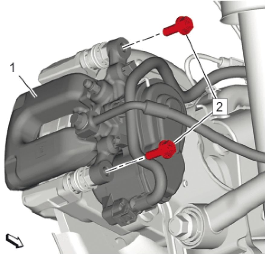 |
|
Fig. 93: Brake Caliper And Guide Pin Bolts |
9. Install the brake caliper assembly (1).
10. Install and tighten Brake Caliper Guide Pin Bolts (2) (Qty: 2) @ Rear Brake Caliper (1) to 36 N.m (27 lb ft)
11. Install the tire and wheel assembly. Refer to Tire and Wheel Removal and Installation
12. With the engine OFF, gradually apply the brake pedal to approximately 2/3 of its travel distance.
13. Slowly release the brake pedal.
14. Wait 15 seconds, then gradually apply the brake pedal approximately 2/3 of its travel distance again until a
firm brake pedal apply is obtained. This will properly seat the brake caliper pistons and brake pads.
15. Inspect the fluid level in the brake master cylinder reservoir.
16. Fill the brake master cylinder reservoir to the maximum-full level with GM approved brake fluid from a clean,
sealed brake fluid container. Refer to Master Cylinder Reservoir Filling
17. Activate the electronic parking brake.
1. Turn the ignition ON, with the engine OFF.
2. Press the brake pedal slightly and push the electronic parking brake switch for over 5 seconds. The
orange service lamp goes off and the red parking brake status lamp is flashing a few times.
FRONT BRAKE ROTOR REPLACEMENT
Special Tools
• CH-41013 Rotor Resurfacing Kit
• CH-42450-A Wheel Hub Resurfacing Kit
For equivalent regional tools, refer to Special Tools.
Removal Procedure
1. Raise and support the vehicle. Refer to Lifting and Jacking the Vehicle .
2. Remove the tire and wheel assembly. Refer to Tire and Wheel Removal and Installation .
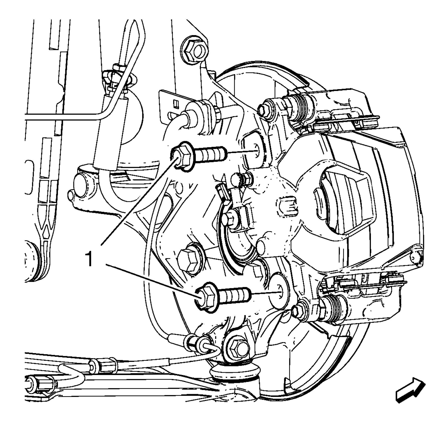 |
|
Fig. 94: Brake Caliper Bracket Bolts Courtesy of GENERAL MOTORS COMPANY |
3. Remove the brake caliper bracket bolts (1).
4. Remove the brake caliper and bracket as an assembly and support with heavy mechanics wire or equivalent.

Fig. 95: Brake Rotor Bolt
Courtesy of GENERAL MOTORS COMPANY
5. Remove the brake rotor bolt (1).
 |
|
Fig. 96: Brake Rotor Courtesy of GENERAL MOTORS COMPANY |
6. Remove the brake rotor (1).
Installation Procedure
1. If installing a new brake rotor, clean the friction surfaces of the brake rotor with denatured alcohol or
equivalent.
2. Using the CH-42450-A Wheel Hub Resurfacing Kit, thoroughly clean any rust or corrosion from the mating
surface of the hub/axle flange.
3. Using the CH-41013 Rotor Resurfacing Kit, thoroughly clean any rust or corrosion from the mating surface of
the rotor to the hub/axle flange.
 |
|
Fig. 97: Brake Rotor Courtesy of GENERAL MOTORS COMPANY |
4. Install the brake rotor (1).
 |
|
Fig. 98: Brake Rotor Bolt Courtesy of GENERAL MOTORS COMPANY |
5. Install the brake rotor bolt (1) and tighten to 9 N.m (80 lb in).
6. Position the brake caliper and bracket assembly over the brake rotor and to the steering knuckle.
 |
|
Fig. 99: Brake Caliper Bracket Bolts Courtesy of GENERAL MOTORS COMPANY |
7. Install the brake caliper bracket bolts (1).
1. First Pass: 150 N.m (111 lb ft)
2. Final Pass: 15-30 degrees
8. Install the tire and wheel assembly. Refer to Tire and Wheel Removal and Installation .
9. Burnish the brake pads and rotors. Refer to Brake Pad and Rotor Burnishing.
REAR BRAKE ROTOR REPLACEMENT
Special Tools
• CH-41013 Rotor Resurfacing Kit
• CH-42450-A Wheel Hub Resurfacing Kit
• CH-45059 Angle Meter
Equivalent regional tools: Special Tools
Removal Procedure
1. Set the electronic parking brake in the service mode.
1. Change the transmission gear to Neutral position.
2. Press the electronic park brake switch until the red parking brake status lamp is illuminating in the
instrument cluster.
3. Press the brake pedal 5 times slightly until the vacuum in the power brake booster is empty.
4. Turn the ignition ON, with the engine OFF.
5. Press the brake pedal and the electronic park brake switch for 15 seconds until the orange brake service
lamp is illuminating.
6. By keeping brake pedal applied, release and re-press the electronic park brake switch for 5 seconds.
7. Release the electronic park brake switch and the brake pedal simultaneously. The rear brake calipers are
retracting and the orange brake service lamp is flashing.
2. Turn OFF the ignition.
3. Raise and support the vehicle. Refer to Lifting and Jacking the Vehicle
4. Remove the tire and wheel assembly. Refer to Tire and Wheel Removal and Installation
 |
|
Fig. 100: Electrical Connector, Fasteners And Wiring Harness |
5. Disconnect Electrical Connector (4)
6. Remove Fasteners (1) (Qty: 2)
7. Remove Fastener (2)
8. Remove Wiring Harness (3)
 |
|
Fig. 101: Brake Caliper And Bracket Bolts |
9. Remove Rear Brake Caliper Bracket Bolts (2) (Qty: 2)
CAUTION: Support the brake caliper with heavy mechanic wire, or equivalent, whenever it
is separated from its mount and the hydraulic flexible brake hose is still
connected. Failure to support the caliper in this manner will cause the flexible
brake hose to bear the weight of the caliper, which may cause damage to the
brake hose and in turn may cause a brake fluid leak.
10. Remove the brake caliper assembly and support with heavy mechanics wire. (1)

Fig. 102: Rear Brake Rotor And Bolt
Courtesy of GENERAL MOTORS COMPANY
11. Remove Rear Brake Rotor Bolt (1)
12. Remove Rear Brake Rotor (2)
Installation Procedure
1. If installing a NEW brake rotor, clean the friction surfaces of the brake rotor with denatured alcohol.
2. Using the CH-42450-A resurfacing kit, thoroughly clean any rust or corrosion from the mating surface of the
hub/axle flange.
3. Using the CH-41013 resurfacing kit, thoroughly clean any rust or corrosion from the mating surface of the
rotor to the hub/axle flange.

Fig. 103: Rear Brake Rotor And Bolt
Courtesy of GENERAL MOTORS COMPANY
4. Install Rear Brake Rotor (2)
5. Install and tighten Rear Brake Rotor Bolt (1) to 9 N.m (80 lb in)
 |
|
Fig. 104: Brake Caliper And Bracket Bolts |
6. Position the rear brake caliper assembly (1).
7. Install and tighten Rear Brake Caliper Bracket Bolts (2) (Qty: 2)
1. First Pass: 100 N.m (74 lb ft)
2. Final Pass: 15 - 30 degrees
 |
|
Fig. 105: Electrical Connector, Fasteners And Wiring Harness Courtesy of GENERAL MOTORS COMPANY |
8. Install Wiring Harness (3)
9. Install Fastener (2)
10. Install Fasteners (1) (Qty: 2)
11. Connect Electrical Connector (4)
12. Install the tire and wheel assembly. Refer to Tire and Wheel Removal and Installation
13. Lower the vehicle.
14. Activate the electronic parking brake.
1. Turn the ignition ON, with the engine OFF.
2. Press the brake pedal and the electronic parking brake switch for over 5 seconds. The orange brake
service lamp turns off and the red parking brake status lamp is flashing a few times.
15. Burnish the brake pads and rotors. Refer to Brake Pad and Rotor Burnishing
FRONT BRAKE SHIELD REPLACEMENT
Special Tools
EN-45059 Angle Meter
Equivalent regional tools: Special Tools
Removal Procedure
1. Raise and support the vehicle. Refer to Lifting and Jacking the Vehicle .
2. Remove Front Wheel Bearing and Hub. Refer to Front Wheel Bearing and Hub Replacement
 |
|
Fig. 106: Wheel Bearing/Hub, Front Brake Shield And Steering Knuckle Courtesy of GENERAL MOTORS COMPANY |
3. Remove the wheel bearing/hub (1) and front brake shield (2) from the steering knuckle.
Installation Procedure
 |
|
Fig. 107: Wheel Bearing/Hub, Front Brake Shield And Steering Knuckle |
1. Position the front brake shield (2) and wheel bearing/hub assembly (1) in the steering knuckle.
2. Install Front Wheel Bearing and Hub. Refer to Front Wheel Bearing and Hub Replacement
3. Remove the support and lower the vehicle.
REAR BRAKE SHIELD REPLACEMENT
Special Tools
EN-45059 Angle Meter
Equivalent regional tools: Special Tools
Removal Procedure
1. Remove the rear tire and wheel assemblies. Refer to Tire and Wheel Removal and Installation
2. Remove Rear Brake Rotor. Refer to Rear Brake Rotor Replacement
3. Remove Rear Wheel Speed Sensor. Refer to Rear Wheel Speed Sensor Replacement
 |
|
Fig. 108: Rear Shock Absorber, Bolt And Hydraulic Lift Courtesy of GENERAL MOTORS COMPANY |
4. Support the rear axle with a hydraulic lift table. (3)
5. Remove Rear Shock Absorber Bolt (2)
6. Push up to the shock absorber (1) gain access to the rear wheel bearing and hub bolts.
 |
|
Fig. 109: Rear Wheel Bearing And Hub Bolts |
7. Remove Bolts (1) (Qty: 4)
 |
|
Fig. 110: Rear Brake Caliper Mount Plate, Rear Brake Shield, Rear Wheel Bearing and Hub Assembly |
8. Remove Rear Wheel Bearing and Hub Assembly (1)
9. Remove the rear brake shield (2).
10. Remove the rear brake caliper mount plate (3).
Installation Procedure
 |
|
Fig. 111: Rear Brake Caliper Mount Plate, Rear Brake Shield, Rear Wheel Bearing and Hub Assembly |
1. Install the rear brake caliper mount plate (3).
2. Install the rear brake shield (2).
3. Install Rear Wheel Bearing and Hub Assembly (1)
 |
|
Fig. 112: Rear Wheel Bearing And Hub Bolts |
4. Apply thread locking adhesive to the fasteners.
5. Install and tighten Bolts (1) (Qty: 4)
1. First Pass: 50 Nm. (37 lb ft).
2. Final Pass: 30 - 45 degrees, use the EN-45059 meter
 |
|
Fig. 113: Rear Shock Absorber, Bolt And Hydraulic Lift Courtesy of GENERAL MOTORS COMPANY |
6. Support the rear axle with a tall jack stand near the shock absorber.
7. Install, but do NOT tighten Rear Shock Absorber Bolt (2)
8. Install Rear Wheel Speed Sensor. Refer to Rear Wheel Speed Sensor Replacement
9. Install Rear Brake Rotor. Refer to Rear Brake Rotor Replacement - Install
10. Install Tire and Wheel. Refer to Tire and Wheel Removal and Installation
11. Lower the vehicle.
 |
|
Fig. 114: Rear Shock Absorber Bolt Courtesy of GENERAL MOTORS COMPANY |
NOTE: Tighten the bolt with vehicle standing on the ground.
12. Tighten Rear Shock Absorber Bolt (1) to 100 N.m (74 lb ft)
|
BRAKE ROTOR ASSEMBLED LATERAL RUNOUT CORRECTION | ||
| ||
|
Review the following acceptable methods for bringing the brake rotor assembled LRO to within specifications. |
• The indexing method of correcting assembled LRO is most effective when the LRO specification is only
exceeded by a relatively small amount: 0.025 - 0.127 mm (0.001 - 0.005 in). Indexing is used to achieve the
best possible match of high spots to low spots between related components. Refer to Brake Rotor Assembled
Lateral Runout Correction - Indexing
• The on-vehicle brake lathe method is used to bring the LRO to within specifications through compensating for
LRO while refinishing the brake rotor. Refer to Brake Rotor Assembled Lateral Runout Correction - On
Vehicle Lathe
If the assembled LRO cannot be corrected using these methods, then other components must be suspected as causing
and/or contributing to the LRO concern.
BRAKE ROTOR ASSEMBLED LATERAL RUNOUT CORRECTION - INDEXING
CH-45101-100 Conical Brake Rotor Washers
For equivalent regional tools, refer to Special Tools.
 |
|
Fig. 115: Conical Brake Rotor Washer And Lug Nut |
|
NOTE: |
|
1. Remove the CH-45101-100 Conical Brake Rotor Washers and the lug nuts that were installed during the
assembled LRO measurement procedure.
2. Inspect the mating surface of the hub/axle flange and the brake rotor to ensure that there are no foreign
particles or debris remaining.
3. Index the brake rotor in a different orientation to the hub/axle flange.
4. Hold the rotor firmly in place against the hub/axle flange and install one of the CH-45101-100 Conical Brake
Rotor Washers (1) and one lug nut (2) onto the upper-most wheel stud.
5. Continue to hold the rotor secure and tighten the lug nut firmly by hand.

6. Install the remaining CH-45101-100 Conical Brake Rotor Washers and lug nuts onto the wheel studs and
tighten the nuts firmly by hand in a star-pattern.
7. Tighten the lug nuts in a star-pattern to specification, in order to properly secure the rotor. Refer to Tire and
Wheel Removal and Installation
8. Measure the assembled LRO of the brake rotor. Refer to Brake Rotor Assembled Lateral Runout
Measurement
9. Compare the amount of change between this measurement and the original measurement.
10. If this measurement is within specifications, proceed to step 14.
11. If this measurement still exceeds specifications, repeat steps 1 - 9 until the best assembled LRO measurement
is obtained.
12. Matchmark the final location of the rotor to the wheel studs if the orientation is different than it was originally.
13. If the brake rotor assembled LRO measurement still exceeds the maximum allowable specification, refer to
Brake Rotor Assembled Lateral Runout Correction.
14. If the brake rotor assembled LRO is within specification, install the brake caliper and depress the brake pedal
several times to secure the rotor in place before removing the CH-45101-100 Conical Brake Rotor Washers
and the lug nuts.
BRAKE ROTOR ASSEMBLED LATERAL RUNOUT CORRECTION - CORRECTION PLATES
CH-45101-100 Conical Brake Rotor Washers
For equivalent regional tools, refer to Special Tools.


|
Fig. 117: Correction Plate, High Spot Mark And V-Shaped Notch | ||||
|
• Brake rotor assembled LRO exceeding the maximum allowable
specification can cause thickness variation to develop in the brake rotor
over time, usually between 4800 - 11300 km (3,000 - 7,000 mi). Refer to
Brake Rotor Assembled Lateral Runout Measurement
1. Rotate the brake rotor to position the high spot, identified and marked during the brake rotor assembled LRO
measurement procedure, to face upward.
2. Remove the CH-45101-100 Conical Brake Rotor Washers and the lug nuts that were installed during the
assembled LRO measurement procedure and/or the indexing correction procedure.
3. Inspect the mounting surface of the hub/axle flange and the brake rotor to ensure that there are no foreign
particles or debris remaining.
4. Select the correction plate, following the manufacturer's instructions, which has a specification closest to the
assembled LRO measurement.
For example: If the assembled LRO measurement was 0.076 mm (0.003 in), the 0.076 mm (0.003 in)
correction plate would be used. If the measurement was 0.127 mm (0.005 in), the 0.152 mm (0.006 in)
correction plate would be used.
5. Determine the positioning for the correction plate (1) using the high spot mark (3) made during the brake rotor
assembled LRO measurement procedure.
NOTE:
• Do NOT install used correction plates in an attempt to correct brake rotor
assembled LRO.
• Do NOT stack up, or install more than one correction plate onto one
hub/axle flange location, in an attempt to correct brake rotor assembled
LRO.
6. Install the correction plate (1) onto the hub/axle flange, with the V-shaped notch (2) orientated to align with the
high spot mark (3), that was positioned to face upward.
 |
|
Fig. 118: Conical Brake Rotor Washer And Lug Nut |
7. Install the brake rotor to the hub/axle flange. Use the matchmark made prior to removal for proper orientation
to the flange.
8. Hold the rotor firmly in place against the hub/axle flange and install one of the CH-45101-100 Conical Brake
Rotor Washers (1) and one lug nut (2) onto the upper-most wheel stud.
9. Continue to hold the rotor secure and tighten the lug nut firmly by hand.
 |
|
Fig. 119: Conical Brake Rotor Washers And Lug Nuts Courtesy of GENERAL MOTORS COMPANY |
10. Install the remaining CH-45101-100 Conical Brake Rotor Washers and lug nuts onto the wheel studs and
tighten the nuts firmly by hand in a star-pattern.
11. Tighten the lug nuts in a star-pattern to specification, in order to properly secure the rotor. Refer to Tire and
Wheel Removal and Installation
12. Measure the assembled LRO of the brake rotor. Refer to Brake Rotor Assembled Lateral Runout
Measurement
13. If the brake rotor assembled LRO measurement still exceeds the maximum allowable specification, refer to
Brake Rotor Assembled Lateral Runout Correction.
14. If the brake rotor assembled LRO measurement is within specification, install the brake caliper and depress the
brake pedal several times to secure the rotor in place before removing the CH-45101-100 Conical Brake Rotor
Washers and the lug nuts.
BRAKE ROTOR ASSEMBLED LATERAL RUNOUT CORRECTION - ON VEHICLE LATHE
CH-45101-100 Conical Brake Rotor Washers
|
For equivalent regional tools, refer to Special Tools. | ||||
|
1. Ensure that the caliper and caliper bracket that are already being supported, are clear from contacting any
rotating components, such as the brake rotor.
2. Remove the CH-45101-100 Conical Brake Rotor Washers and the lug nuts that were installed during the
assembled LRO measurement procedure and/or the indexing correction procedure.
3. Inspect the mounting surface of the hub/axle flange and the brake rotor to ensure that there are no foreign
particles or debris remaining.
4. Set up the lathe, following the manufacturer's instructions.
5. Refinish the brake rotor, following the brake lathe manufacturer's instructions.
6. After each successive cut, inspect the brake rotor thickness. Refer to Brake Rotor Thickness Measurement
7. If at any time the brake rotor exceeds the minimum allowable thickness after refinish specification, the brake
rotor must be replaced. After replacing the rotor, proceed to step 10.
8. After refinishing the brake rotor, use the following procedure in order to obtain the desired non-directional
finish:
1. Follow the brake lathe manufacturer's recommended speed setting for applying a non-directional finish.
2. Using moderate pressure, apply the non-directional finish:
• If the lathe is equipped with a non-directional finishing tool, apply the finish with 120-grit
aluminum oxide sandpaper.
• If the lathe is not equipped with a non-directional finishing tool, apply the finish with a sanding
block and 150-grit aluminum oxide sandpaper.
3. After applying a non-directional finish, clean each friction surface of the brake rotor with denatured
alcohol, or an equivalent approved brake cleaner.
9. Remove the lathe from the vehicle.
10. Measure the assembled LRO of the brake rotor. Refer to Brake Rotor Assembled Lateral Runout
Measurement
11. If the brake rotor assembled LRO measurement still exceeds the maximum allowable specification, refer to
Brake Rotor Assembled Lateral Runout Correction.
12. If the brake rotor assembled LRO is within specification, install the brake caliper and depress the brake pedal
several times to secure the rotor in place before removing the CH-45101-100 Conical Brake Rotor Washers
and the lug nuts.
BRAKE ROTOR REFINISHING
Special Tools
• CH-41013 Rotor Resurfacing Kit
• CH-42450-A Wheel Hub Resurfacing Kit
|
For equivalent regional tools, refer to Special Tools. | ||||||||
| ||||||||
|
1. Using the CH-42450-A Wheel Hub Resurfacing Kit, thoroughly clean any rust or corrosion from the mating |
surface of the hub/axle flange.
2. Using the CH-41013 Rotor Resurfacing Kit, thoroughly clean any rust or corrosion from the mating surface
and mounting surface of the brake rotor.
3. Inspect the mating surfaces of the hub/axle flange and the rotor to ensure that there are no foreign particles or
debris remaining.
4. Mount the brake rotor to the brake lathe according to the lathe manufacturer's instructions, ensuring that all
mounting attachments and adapters are clean and free of debris.
5. Ensure that any vibration dampening attachments are securely in place.
6. With the brake lathe running, slowly bring in the cutting tools until they just contact the brake rotor friction
surfaces.
7. Observe the witness mark on the brake rotor. If the witness mark extends approximately three-quarters or more
of the way around the brake rotor friction surface on each side, the brake rotor is properly mounted to the
lathe.
8. If the witness mark does not extend three-quarters or more of the way around the brake rotor, re-mount the
rotor to the lathe.
9. Following the brake lathe manufacturer's instructions, refinish the brake rotor.
10. After each successive cut, inspect the brake rotor thickness. Refer to Brake Rotor Thickness Measurement
11. If at any time the brake rotor exceeds the minimum allowable thickness after refinish specification, the brake
rotor must be replaced.
12. After refinishing the brake rotor, use the following procedure in order to obtain the desired non-directional
finish:
1. Follow the brake lathe manufacturer's recommended speed setting for applying a non-directional finish.
2. Using moderate pressure, apply the non-directional finish:
• If the lathe is equipped with a non-directional finishing tool, apply the finish with 120-grit
aluminum oxide sandpaper.
• If the lathe is not equipped with a non-directional finishing tool, apply the finish with a sanding
block and 150-grit aluminum oxide sandpaper.
NOTE: Thoroughly cleaning the brake rotor will prevent the possible transfer of
finite metal dust left as a by-product of machining to the brake pad
material during the burnishing process, thereby reducing the possibility
for brake squeal or other brake noises to occur.
3. After applying a non-directional finish, clean each friction surface of the brake rotor with a solution of
mild dish washing detergent and water, or a GM approved brake cleaner and a clean shop towel to
remove metal particles remaining from machining. Repeat the cleaning process if necessary to remove
all metal particles.
13. Remove the brake rotor from the brake lathe.
14. Measure the assembled LRO of the brake rotor to ensure optimum performance of the disc brakes. Refer to
Brake Rotor Assembled Lateral Runout Measurement
15. If the brake rotor assembled LRO measurement exceeds the specification, bring the LRO to within
specifications. Refer to Brake Rotor Assembled Lateral Runout Correction
DESCRIPTION AND OPERATION
DISC BRAKE SYSTEM DESCRIPTION AND OPERATION

Fig. 120: Brake Caliper Piston, Rotor And Brake Pads
Courtesy of GENERAL MOTORS COMPANY
The brake caliper is single piston type; and is installed on knuckle by two mounting bolts. Brake caliper transforms
hydraulic pressure generated by depressing brake pedal into braking force. The braking force evenly acts on the
piston (1) and the bottom of brake caliper cylinder bore, and then move the piston outward and slide brake caliper
inward so that there generates a clamping effect on brake rotor (2). The clamping effect forces brake pad (3) to attach
to brake rotor, and the resulting friction will make vehicles stop.
When maintaining the brake caliper, replace all parts included in repair sets.
• Lubricate the rubber parts with clean brake fluid to make assembly easier.
• Do not apply compressed air to brake parts with workshop with lubricant, otherwise the rubber parts may be
damaged.
• If any hydraulic component is removed or disconnected, it may be necessary to bleed all or part of the brake
system.
• Replace whole brake pad (3) according to service parts in the maintenance package.
• The torque values are specified for dry, non-lubricated fasteners.
• Perform the service operations on a clean bench, free from all mineral oil materials.
Gap Calibration
 |
|
Fig. 121: Sectional View Of Pads, Piston Seal And Piston |
When the hydraulic pressure acts on the piston (3), the piston moves left. The piston seals (2) exert pressure on the
piston and move together with the cylinder. However, parts of the piston seals are fixed in the grooves of the
cylinder. As shown, the shape of seals deforms toward the direction of piston.
When the pressure on the brake pedal is removed and the hydraulic pressure on the piston is released, there generates
recovery elasticity on the seals. The force pushes the piston to the right side and return to its original position.
When the brake pad (1) exhibits wear, and the gap between the brake rotor and brake pad gets much larger, the piston
moves farther.
Seals may further deform. Because the end of seals is fixed in the groove of the cylinder, the deformation is limited
in the above-mentioned scope. Pistons further move to fill the gap. When the piston returns to the same position, the
rubber seals resume original shape, and the gap between brake rotor and brake pad keeps the original level.
SPECIAL TOOLS AND EQUIPMENT
|
SPECIAL TOOLS | ||||
|
|
Illustration |
Tool Number/Description |
|
CH-41013 J-41013 Rotor Resurfacing | |
|
Kit |

|
Illustration |
Tool |
|
) л СУ\Х |
CH-45101 J-45101 Hub and Wheel |
|
Illustration |
Tool Number/Description |
|
CH-45101-100 J-45101-100 Conical Brake Rotor |
|
Illustration |
Tool |
|
SL © |
EN-45059 |
Article GUID: A00884650
SPECIFICATIONS
FASTENER SPECIFICATIONS
Single Use Non-Threaded Fasteners/Components
All
fasteners/components
listed in this table
MUST BE
DISCARDED and
replaced with NEW
after removal.
Application
Brake Hose Fitting Gasket
Master Cylinder Primary Piston Assembly
Master Cylinder Primary Piston Retainer
Master Cylinder Secondary Piston Seal
Master Cylinder Secondary Piston Seal Retainer
Power Brake Booster Gasket
|
Reusable Threaded Fastener Tightening Specifications | |||||||||||||||||||||
| |||||||||||||||||||||
| |||||||||
|
APPROXIMATE FLUID CAPACITIES | |||||||||
|
Application |
Specification | |
|
Metric |
English | |
|
Hydraulic Brake System |
1 liter |
1.06 quarts |
|
BRAKE COMPONENT SPECIFICATIONS | |||||||||||
| |||||||||||
|
BRAKE SYSTEM SPECIFICATIONS | ||||||||
| ||||||||
|
ADHESIVES, FLUIDS, LUBRICANTS, AND SEALERS | ||||||||||
| ||||||||||
SCHEMATIC WIRING DIAGRAMS
HYDRAULIC BRAKE WIRING SCHEMATICS
Hydraulic Brakes
 |
|
Fig. 1: Hydraulic Brakes Courtesy of GENERAL MOTORS COMPANY |
DIAGNOSTIC INFORMATION AND PROCEDURES
DTC C0075: BRAKE PEDAL POSITION SENSOR PERFORMANCE
Diagnostic Instructions
• Perform the Diagnostic System Check prior to using this diagnostic procedure: Diagnostic System
Check - Vehicle
• Review the description of Strategy Based Diagnosis:Strategy Based Diagnosis
• An overview of each diagnostic category can be found here: Diagnostic Procedure Instructions
DTC Descriptor
DTC C0075
Brake Pedal Position Sensor Performance
Symptom Byte Information: Symptom Byte List
Circuit/System Description
For an overview of the component/system, refer to: Hydraulic Brake System Description and Operation
Conditions for Running the DTC
Ignition - On / Vehicle - In Service Mode
Conditions for Setting the DTC
Brake Pedal Position Sensor = Out Of Range
Actions Taken When the DTC Sets
Boost/Blending = Not Available
Conditions for Clearing the DTC
The conditions for setting the DTC no longer exist.
Reference Information
Schematic Reference
Connector End View Reference
Electrical Information Reference
Circuit Testing
Connector Repairs
Testing for Intermittent Conditions and Poor Connections
Wiring Repairs
Scan Tool Reference
Control Module References for scan tool information
Circuit/System Verification
1. Ignition - On / Vehicle - In Service Mode
2. Verify DTC C0075 is not set.
Replace the component: K177 Brake Booster Control Module
3. All OK.
Circuit/System Verification
1. Ignition - On / Vehicle - In Service Mode
2. Verify DTC C0075 is not set.
1. Perform all necessary programming and setup procedures for the control module:K177 Brake
Booster Control Module
2. Verify the DTC does not set.
• If the DTC sets - Replace the component:K177 Brake Booster Control Module
• If the DTC is not set
3. All OK.
3. All OK.
Repair Instructions
Perform the Diagnostic Repair Verification after completing the repair: Diagnostic Repair Verification
For control module replacement, programming, and setup refer to: Control Module References
DTC C0579, C057A, OR C057E: BRAKE BOOSTER CONTROL MODULE TEMPERATURE
SENSOR
Diagnostic Instructions
• Perform the Diagnostic System Check prior to using this diagnostic procedure: Diagnostic System
Check - Vehicle
• Review the description of Strategy Based Diagnosis:Strategy Based Diagnosis
• An overview of each diagnostic category can be found here: Diagnostic Procedure Instructions
DTC Descriptor
Brake Booster Control Module Temperature Sensor 2 Circuit Low Voltage
Brake Booster Control Module Temperature Sensor 2 Circuit High Voltage
Brake Booster Control Module Temperature Sensor 1-2 Correlation
Symptom Byte Information: Symptom Byte List
Circuit/System Description
For an overview of the component/system, refer to: Hydraulic Brake System Description and Operation
Conditions for Running the DTC
Ignition - On / Vehicle - In Service Mode
Conditions for Setting the DTC
Brake Booster Temperature = Out Of Range
Actions Taken When the DTC Sets
Boost= Full
Conditions for Clearing the DTC
The conditions for setting the DTC no longer exist.
Reference Information
Schematic Reference
Connector End View Reference
Electrical Information Reference
Circuit Testing
Connector Repairs
Testing for Intermittent Conditions and Poor Connections
Wiring Repairs
Scan Tool Reference
Control Module References for scan tool information
Circuit/System Verification
1. Ignition - On / Vehicle - In Service Mode
2. Verify DTC C0579, C057A, C057E is not set.
1. Perform all necessary programming and setup procedures for the control module:K177 Brake
Booster Control Module
2. Verify the DTC does not set.
• If the DTC sets - Replace the component:K177 Brake Booster Control Module
• If the DTC is not set
3. All OK.
3. All OK.
Repair Instructions
Perform the Diagnostic Repair Verification after completing the repair: Diagnostic Repair Verification
For control module replacement, programming, and setup refer to: Control Module References
DTC C057F, C0582, C058A, C0590, C0591, C0595, C0596, OR C1275-C1277: BRAKE BOOSTER
MOTOR
Diagnostic Instructions
• Perform the Diagnostic System Check prior to using this diagnostic procedure: Diagnostic System
Check - Vehicle
• Review the description of Strategy Based Diagnosis:Strategy Based Diagnosis
• An overview of each diagnostic category can be found here: Diagnostic Procedure Instructions
DTC Descriptor
Brake Booster Motor 1 Phase U-V-W Circuit
Brake Booster Motor 1 Phase U-V-W Circuit Performance
Brake Booster Motor 1 Position Sensor Circuit Performance
Brake Booster Motor 1 Phase U-V-W Circuit High Current
Brake Booster Motor 1 Phase U-V-W Circuit Low Current
Brake Booster Control Module Internal Driver Performance
Brake Booster Motor 1 Current Sensor Circuit Performance
Brake Booster Motor Position Sensor Unexpected Reset
DTC C1276
Brake Booster Motor Position Sensor Message Counter Incorrect
Brake Booster Motor Position Sensor Configuration Error
Symptom Byte Information: Symptom Byte List
Circuit/System Description
For an overview of the component/system, refer to: Hydraulic Brake System Description and Operation
Conditions for Running the DTC
• Ignition - On / Vehicle - In Service Mode
• Brake Pedal = Released
• Automatic Braking Event = None - For greater than 5 s
• Vehicle = On
Conditions for Setting the DTC
K177 Brake Booster Control Module = Internal Malfunction
Actions Taken When the DTC Sets
Boost/Blending = Not Available
Conditions for Clearing the DTC
The conditions for setting the DTC no longer exist.
Reference Information
Schematic Reference
Connector End View Reference
Electrical Information Reference
Circuit Testing
• Connector Repairs
Testing for Intermittent Conditions and Poor Connections
Wiring Repairs
Control Module References for scan tool information
Circuit/System Verification
1. Ignition - On / Vehicle - In Service Mode
2. Verify DTC C057F, C0582, C058A, C0590, C0591, C0595, C0596, C1275, C1276, C1277 is not set.
1. Perform all necessary programming and setup procedures for the control module:K177 Brake
Booster Control Module
2. Verify the DTC does not set.
• If the DTC sets - Replace the component:K177 Brake Booster Control Module
• If the DTC is not set
3. All OK.
3. All OK.
Repair Instructions
Perform the Diagnostic Repair Verification after completing the repair: Diagnostic Repair Verification
For control module replacement, programming, and setup refer to: Control Module References
DTC C0580 OR C0594: BRAKE BOOSTER MOTOR
Diagnostic Instructions
• Perform the Diagnostic System Check prior to using this diagnostic procedure: Diagnostic System
Check - Vehicle
• Review the description of Strategy Based Diagnosis:Strategy Based Diagnosis
• An overview of each diagnostic category can be found here: Diagnostic Procedure Instructions
DTC Descriptor
Brake Pedal Position Sensor Performance
Brake Pedal Position Sensor Performance
Symptom Byte Information: Symptom Byte List
Circuit/System Description
For an overview of the component/system, refer to: Hydraulic Brake System Description and Operation
Conditions for Running the DTC
Ignition - On / Vehicle - In Service Mode
Conditions for Setting the DTC
Brake Pedal Position Sensor = Out Of Range
Actions Taken When the DTC Sets
Boost/Blending = Not Available
Brake System Warning Indicator = On
Conditions for Clearing the DTC
The conditions for setting the DTC no longer exist.
Reference Information
Schematic Reference
Connector End View Reference
Electrical Information Reference
Circuit Testing
Connector Repairs
Testing for Intermittent Conditions and Poor Connections
Wiring Repairs
Scan Tool Reference
Control Module References for scan tool information
Circuit/System Verification
1. Ignition - On / Vehicle - In Service Mode
2. Verify DTC C0580, C0594 is not set.
1. Perform all necessary programming and setup procedures for the control module:K177 Brake
Booster Control Module
2. Verify the DTC does not set.
• If the DTC sets - Replace the component:K177 Brake Booster Control Module
• If the DTC is not set
3. All OK.
3. All OK.
Repair Instructions
Perform the Diagnostic Repair Verification after completing the repair: Diagnostic Repair Verification
For control module replacement, programming, and setup refer to: Control Module References
DTC C1072: BRAKE FLUID LEVEL SENSOR CIRCUIT
Diagnostic Instructions
• Perform the Diagnostic System Check prior to using this diagnostic procedure: Diagnostic System
Check - Vehicle
• Review the description of Strategy Based Diagnosis: Strategy Based Diagnosis
• An overview of each diagnostic category can be found here: Diagnostic Procedure Instructions
DTC Descriptor
Brake Fluid Level Sensor Circuit
Symptom Byte Information: Symptom Byte List
|
Diagnostic Fault Information | |||||||||||||||
| |||||||||||||||
|
Circuit/System Description |
|
For an overview of the component/system, refer to:Hydraulic Brake System Description and Operation | ||||||
|
|
Component |
Description |
|
B20 Brake Fluid Level Switch |
The brake fluid level switch is a normally open switch that |
|
K17 Electronic Brake Control Module |
The electronic brake control module detects a malfunction |
| ||||
|
Conditions for Running the DTC |
Ignition - On / Vehicle - In Service Mode
Conditions for Setting the DTC
• Ground circuit = open
• Signal circuit = open/Short to Ground
Actions Taken When the DTC Sets
Brake System Warning Indicator = On
Conditions for Clearing the DTC
The conditions for setting the DTC no longer exist.
Reference Information
Schematic Reference
Connector End View Reference
Electrical Information Reference
Circuit Testing
Connector Repairs
Testing for Intermittent Conditions and Poor Connections
Wiring Repairs
Scan Tool Reference
Control Module References
Circuit/System Verification
1. Ignition/Vehicle - Off
2. Verify the condition does not exist: Incorrect fluid level or condition - Refer to: Master Cylinder
Reservoir Filling
Repair or replace as necessary.
• If no condition exists
3. Refer to Circuit/System Testing.
Circuit/System Testing
1. Ignition/Vehicle & All vehicle systems - Off
2. Disconnect the electrical connector: B20 Brake Fluid Level Switch
3. Test for less than 10 ohms between the test points:Ground circuit terminal 2 & Ground
• If 10 ohms or greater
1. Disconnect ground terminal.
2. Test for less than 2 ohms between the test points:Ground circuit terminal 2 @Component harness &
The other end of the circuit @ Ground terminal
• If 2 ohms or greater - Repair the open/high resistance in the circuit.
• If less than 2 ohms - Repair the open/high resistance in the ground connection.
4. Ignition - On / Vehicle - In Service Mode
5. Verify the scan tool parameter: Brake Fluid Level Sensor = OK
• If not the specified state
1. Ignition/Vehicle - Off
2. Disconnect the electrical connector: K17 Electronic Brake Control Module
3. Test for infinite resistance between the test points: Signal circuit terminal 1 @ Component harness
& Ground
• If less than infinite resistance - Repair the short to ground on the circuit.
• If infinite resistance - Replace the component: K17 Electronic Brake Control Module
• If the specified state
6. Connect a 3 A fused jumper wire between the test points:Signal circuit terminal 1 & Ground
7. Verify the scan tool parameter: Brake Fluid Level Sensor= Low
• If not the specified state
1. Ignition/Vehicle - Off & Remove - Jumper wire(s)
2. Disconnect the electrical connector: K17 Electronic Brake Control Module
3. Ignition - On / Vehicle - In Service Mode
4. Test for less than 1 V between the test points:Signal circuit terminal 1 @Component harness &
Ground
• If 1 V or greater - Repair the short to voltage on the circuit.
• If less than 1 V
5. Ignition/Vehicle - Off
6. Test for less than 2 ohms between the test points:Signal circuit terminal 1 @ Component harness &
The other end of the circuit @Control module harness
• If 2 ohms or greater - Repair the open/high resistance in the circuit.
• If less than 2 ohms - Replace the component: K17 Electronic Brake Control Module
• If the specified state
8. Test or replace the component: B20 Brake Fluid Level Switch
Repair Instructions
Perform the Diagnostic Repair Verification after completing the repair: Diagnostic Repair Verification
• For control module replacement, programming, and setup refer to: Control Module References
DTC C111C: LOW BRAKE FLUID INDICATED
Diagnostic Instructions
• Perform the Diagnostic System Check prior to using this diagnostic procedure: Diagnostic System
Check - Vehicle
• Review the description of Strategy Based Diagnosis: Strategy Based Diagnosis
• An overview of each diagnostic category can be found here: Diagnostic Procedure Instructions
DTC Descriptor
Low Brake Fluid Indicated
Symptom Byte Information: Symptom Byte List
|
Diagnostic Fault Information | |||||||||||||||
| |||||||||||||||
|
Circuit/System Description |
For an overview of the component/system, refer to:Hydraulic Brake System Description and Operation
|
Circuit |
Description |
|
Signal |
The control module input circuit has an internal resistance |
|
Ground |
Chassis Ground |
|
Component |
Description |
|
B20 Brake Fluid Level Switch |
The brake fluid level switch is a normally open switch that |
| ||||
|
Conditions for Running the DTC |
Ignition - On / Vehicle - In Service Mode
Conditions for Setting the DTC
• Ground circuit = open
• Signal circuit = open/Short to Ground
Actions Taken When the DTC Sets
Brake System Warning Indicator = On
Conditions for Clearing the DTC
The conditions for setting the DTC no longer exist.
Reference Information
Schematic Reference
Connector End View Reference
Electrical Information Reference
Circuit Testing
Connector Repairs
Testing for Intermittent Conditions and Poor Connections
Wiring Repairs
Scan Tool Reference
Control Module References
Circuit/System Verification
1. Ignition/Vehicle - Off
2. Verify the condition does not exist: Incorrect fluid level or condition - Refer to: Master Cylinder
Reservoir Filling
Repair or replace as necessary.
3. Refer to Circuit/System Testing.
Circuit/System Testing
1. Ignition/Vehicle & All vehicle systems - Off
2. Disconnect the electrical connector: B20 Brake Fluid Level Switch
3. Test for less than 10 ohms between the test points:Ground circuit terminal 2 & Ground
• If 10 ohms or greater
1. Disconnect ground terminal.
2. Test for less than 1 ohms between the test points:Ground circuit terminal 2 @Component harness &
The other end of the circuit @ Ground terminal
• If 2 ohms or greater - Repair the open/high resistance in the circuit.
• If less than 2 ohms - Repair the open/high resistance in the ground connection.
4. Ignition - On / Vehicle - In Service Mode
5. Verify the scan tool parameter: Brake Fluid Level Sensor = OK
• If not the specified state
1. Ignition/Vehicle - Off
2. Disconnect the electrical connector: K17 Electronic Brake Control Module
3. Test for infinite resistance between the test points: Signal circuit terminal 1 @ Component harness
& Ground
• If less than infinite resistance - Repair the short to ground on the circuit.
• If infinite resistance - Replace the component: K17 Electronic Brake Control Module
• If the specified state
6. Connect a 3 A fused jumper wire between the test points:Signal circuit terminal 1 & Ground
7. Verify the scan tool parameter: Brake Fluid Level Sensor= Low
• If not the specified state
1. Ignition/Vehicle - Off & Remove - Jumper wire(s)
2. Disconnect the electrical connector: K17 Electronic Brake Control Module
3. Ignition - On / Vehicle - In Service Mode
4. Test for less than 1 V between the test points:Signal circuit terminal 1 @Component harness &
Ground
• If 1 V or greater - Repair the short to voltage on the circuit.
• If less than 1 V
5. Ignition/Vehicle - Off
6. Test for less than 2 ohms between the test points:Signal circuit terminal 1 @ Component harness &
The other end of the circuit @Control module harness
• If 2 ohms or greater - Repair the open/high resistance in the circuit.
• If less than 2 ohms - Replace the component: K17 Electronic Brake Control Module
• If the specified state
8. Test or replace the component: B20 Brake Fluid Level Switch
Repair Instructions
Perform the Diagnostic Repair Verification after completing the repair: Diagnostic Repair Verification
For control module replacement, programming, and setup refer to: Control Module References
DTC C1278 OR C1279: BRAKE SYSTEM DATA 2 MESSAGE COUNTER INCORRECT
Diagnostic Instructions
• Perform the Diagnostic System Check prior to using this diagnostic procedure: Diagnostic System
Check - Vehicle
• Review the description of Strategy Based Diagnosis:Strategy Based Diagnosis
• An overview of each diagnostic category can be found here: Diagnostic Procedure Instructions
DTC Descriptor
Brake System Data 1 Message Counter Incorrect
Brake System Data 2 Message Counter Incorrect
Symptom Byte Information: Symptom Byte List
Circuit/System Description
For an overview of the component/system, refer to: Hydraulic Brake System Description and Operation
Conditions for Running the DTC
Ignition - On / Vehicle - In Service Mode
Conditions for Setting the DTC
K177 Brake Booster Control Module = Internal Malfunction
Actions Taken When the DTC Sets
Boost = Full
Conditions for Clearing the DTC
The conditions for setting the DTC no longer exist.
Reference Information
Schematic Reference
Connector End View Reference
Electrical Information Reference
Circuit Testing
Connector Repairs
Testing for Intermittent Conditions and Poor Connections
Wiring Repairs
Scan Tool Reference
Control Module References for scan tool information
Circuit/System Verification
1. Ignition - On / Vehicle - In Service Mode
2. Verify DTC C1278, C1279 is not set.
1. Perform all necessary programming and setup procedures for the control module:K177 Brake
Booster Control Module
2. Verify the DTC does not set.
• If the DTC sets - Replace the component:K177 Brake Booster Control Module
• If the DTC is not set
3. All OK.
3. All OK.
Repair Instructions
Perform the Diagnostic Repair Verification after completing the repair: Diagnostic Repair Verification
For control module replacement, programming, and setup refer to: Control Module References
DTC C1449: SYSTEM CONFIGURATION ERROR
Diagnostic Instructions
• Perform the Diagnostic System Check prior to using this diagnostic procedure: Diagnostic System
Check - Vehicle
• Review the description of Strategy Based Diagnosis:Strategy Based Diagnosis
• An overview of each diagnostic category can be found here: Diagnostic Procedure Instructions
DTC Descriptor
DTC C1449
System Configuration Error
Symptom Byte Information: Symptom Byte List
Circuit/System Description
For an overview of the component/system, refer to: Hydraulic Brake System Description and Operation
Conditions for Running the DTC
Ignition - On / Vehicle - In Service Mode
Conditions for Setting the DTC
K177 Brake Booster Control Module = Internal Malfunction
Actions Taken When the DTC Sets
Boost/Blending = Not Available
Brake System Warning Indicator = ON
Conditions for Clearing the DTC
The conditions for setting the DTC no longer exist.
Reference Information
Schematic Reference
Hydraulic Brake Schematics
Connector End View Reference
COMPONENT CONNECTOR END VIEWS - INDEX
Electrical Information Reference
Circuit Testing
Connector Repairs
Testing for Intermittent Conditions and Poor Connections
Wiring Repairs
Scan Tool Reference
Control Module References for scan tool information
Circuit/System Verification
1. Ignition - On / Vehicle - In Service Mode
2. Verify DTC C1449 is not set.
1. Perform all necessary programming and setup procedures for the control module:K177 Brake
Booster Control Module
2. Verify the DTC does not set.
• If the DTC sets - Replace the component:K177 Brake Booster Control Module
• If the DTC is not set
3. All OK.
3. All OK.
Repair Instructions
Perform the Diagnostic Repair Verification after completing the repair: Diagnostic Repair Verification
For control module replacement, programming, and setup refer to: Control Module References
DTC P057B-P057E, P05DC-P05DF, OR P05E0: BRAKE PEDAL POSITION SENSOR
Diagnostic Instructions
• Perform the Diagnostic System Check - Vehicle prior to using this diagnostic procedure.
• Review Strategy Based Diagnosis for an overview of the diagnostic approach.
Diagnostic Procedure Instructions provides an overview of each diagnostic category.
DTC Descriptor
Brake Pedal Position Sensor 1 Performance
Brake Pedal Position Sensor Circuit Low Voltage
Brake Pedal Position Sensor 1 Circuit High Voltage
Brake Pedal Position Sensor Circuit Erratic
Brake Pedal Position Sensor "B" Circuit Range/Performance
Brake Pedal Position Sensor 2 Circuit Low Voltage
Brake Pedal Position Sensor 2 Circuit High Voltage
Brake Pedal Position Sensor 2 Circuit Erratic
Brake Pedal Position Sensors 1-2 Not Plausible
For symptom byte information refer to Symptom Byte List .
|
Diagnostic Fault Information | |||||||||||||||||||||||||
| |||||||||||||||||||||||||
|
Circuit/System Description |
The brake booster system consists of a motor, electronic control unit (ECU), pedal travel sensor, and a master
cylinder. The pedal travel sensor is connected to the brake pedal and measures the amount of brake pedal input
to control the amount of boost needed. The pedal travel sensor consists of two travel sensors in one assembly,
consisting of a shared 5 volt reference, shared low reference, and two signal circuits.
Conditions for Running the DTC
• Ignition ON/Vehicle in Service Mode.
Conditions for Setting the DTC
The brake pedal position sensor 1 upper and lower and lower range has been exceeded
Brake pedal position sensor 1 erratic signal
Brake pedal position sensor 1 signal shorted to ground
Brake pedal position sensor 1 signal shorted to voltage
The brake pedal position sensor 2 upper and lower and lower range has been exceeded
Brake pedal position sensor 2 signal shorted to ground
Brake pedal position sensor 2 signal shorted to voltage
Brake pedal position sensor 2 erratic signal
The deviation between Brake pedal position sensor 1 and 2 is too large
Action Taken When the DTC Sets
• No boost or blending is available
• Red brake light and MIL are illuminated
Conditions for Clearing the DTC
The condition for setting the DTC is no longer present.
Diagnostic Aids
DTC P050E may set if the brake pedal is applied for 60 seconds or more while also applying the accelerator
pedal.
Reference Information
Schematic Reference
Connector End View Reference
Description and Operation
Electrical Information Reference
Circuit Testing
Connector Repairs
Testing for Intermittent Conditions and Poor Connections
Wiring Repairs
Scan Tool Reference
Control Module References for scan tool information
Circuit/System Testing
1. Ignition OFF/Vehicle OFF and all vehicle systems OFF, disconnect the harness connector at the B201
Brake Control Brake Pedal Position Sensor. It may take up to 2 min for all vehicle systems to power
down.
2. Test for less than 10 fi between the low reference circuit terminal 3 and ground.
• If 10 fi or greater
1. Disconnect the harness connector at the K177 Brake Booster Control Module.
2. Test for less than 2 fi in the low reference circuit end to end.
• If 2 fi or greater, repair the open/high resistance in the circuit.
• If less than 2 fi, replace the K177 Brake Booster Control Module.
3. Ignition ON/Vehicle in Service Mode.
4. Test for 4.8 - 5.2 V between the 5 V reference circuit terminal 1 and ground.
1. Ignition OFF/Ignition OFF/Vehicle OFF, disconnect the harness connector at the K177 Brake
Booster Control Module.
2. Test for infinite resistance between the 5 V reference circuit and ground.
• If less than infinite resistance, repair the short to ground on the circuit.
• If infinite resistance
3. Test for less than 2 fi in the 5 V reference circuit end to end.
• If 2 fi or greater, repair the open/high resistance in the circuit.
• If less than 2 fi, replace the K177 Brake Booster Control Module.
• If greater than 5.2 V
1. Ignition OFF/Vehicle OFF, disconnect the harness connector at the K177 Brake Booster Control
Module, Ignition ON/Vehicle in Service Mode.
2. Test for less than 1 V between the 5 V reference circuit and ground.
• If 1 V or greater, repair the short to voltage on the circuit.
• If less than 1 V, replace the K177 Brake Booster Control Module.
5. Test for less than 1 V between the B201 Brake Control Brake Pedal Position Sensor signal circuit
terminal 2 and ground.
• If greater than 1 V
1. Ignition OFF/Ignition OFF/Vehicle OFF, disconnect the harness connector at the K177 Brake
Booster Control Module, ignition ON.
2. Test for less than 1 V between the signal circuit and ground.
• If 1 V or greater, repair the short to voltage on the circuit.
• If less than 1 V, replace the K177 Brake Booster Control Module.
6. Ignition OFF/Vehicle OFF, disconnect the harness connector at the K177 Brake Booster Control Module.
7. Test for infinite resistance between the B201 Brake Control Brake Pedal Position Sensor signal circuit
terminal 2 and ground.
Repair the short to ground on the circuit.
8. Test for less than 2 Q in the B201 Brake Control Brake Pedal Position Sensor signal circuit end to end.
• If 2 Q or greater
Repair the open/high resistance in the circuit.
9. Test for less than 1 V between the B201 Brake Control Brake Pedal Position Sensor signal circuit
terminal 4 and ground.
• If greater than 1 V
1. Ignition OFF/Ignition OFF/Vehicle OFF, disconnect the harness connector at the K177 Brake
Booster Control Module, ignition ON.
2. Test for less than 1 V between the signal circuit and ground.
• If 1 V or greater, repair the short to voltage on the circuit.
• If less than 1 V, replace the K177 Brake Booster Control Module.
10. Ignition OFF/Vehicle OFF, disconnect the harness connector at the K177 Brake Booster Control Module.
11. Test for infinite resistance between the B201 Brake Control Brake Pedal Position Sensor signal circuit
terminal 4 and ground.
Repair the short to ground on the circuit.
• If infinite resistance
12. Test for less than 2 Q in the B201 Brake Control Brake Pedal Position Sensor signal circuit end to end.
• If 2 Q or greater
Repair the open/high resistance in the circuit.
13. Replace the K177 Brake Booster Control Module.
Repair Instructions
Perform the Diagnostic Repair Verification after completing the repair.
Control Module References for control module replacement, programming and setup
DTC P0601, P0603, P0604, P0606, P060B, OR P062F: CONTROL MODULE
Diagnostic Instructions
• Perform the Diagnostic System Check prior to using this diagnostic procedure: Diagnostic System
Check - Vehicle
• Review the description of Strategy Based Diagnosis:Strategy Based Diagnosis
• An overview of each diagnostic category can be found here: Diagnostic Procedure Instructions
DTC Descriptor
Control Module Read Only Memory Performance
Control Module Long Term Memory Reset
Control Module Random Access Memory Performance
Control Module Processor Performance
Control Module Analog to Digital Converter Performance
Control Module Long Term Memory Performance
Circuit/System Description
For an overview of the component/system, refer to: Hydraulic Brake System Description and Operation
Conditions for Running the DTC
Ignition - On / Vehicle - In Service Mode
Conditions for Setting the DTC
K177 Brake Booster Control Module = Internal Malfunction
Actions Taken When the DTC Sets
Brake System Warning Indicator = ON
Conditions for Clearing the DTC
The conditions for setting the DTC no longer exist.
A history DTC will clear after 50 consecutive malfunction-free ignition cycles.
Reference Information
Schematic Reference
Connector End View Reference
Electrical Information Reference
Circuit Testing
Connector Repairs
Testing for Intermittent Conditions and Poor Connections
Wiring Repairs
Scan Tool Reference
Control Module References for scan tool information
Circuit/System Verification
1. Ignition - On / Vehicle - In Service Mode
2. Verify DTC P0601, P0603, P0604, P0606, P060B, P062F is not set.
1. Perform all necessary programming and setup procedures for the control module:K177 Brake
Booster Control Module
2. Verify the DTC does not set.
• If the DTC sets - Replace the component:K177 Brake Booster Control Module
• If the DTC is not set
3. All OK.
3. All OK.
Repair Instructions
Perform the Diagnostic Repair Verification after completing the repair: Diagnostic Repair Verification
For control module replacement, programming, and setup refer to: Control Module References
DTC P0642, P06A6, OR P06A7: SENSOR REFERENCE VOLTAGE
Diagnostic Instructions
• Perform the Diagnostic System Check - Vehicle prior to using this diagnostic procedure.
• Review Strategy Based Diagnosis for an overview of the diagnostic approach.
Diagnostic Procedure Instructions provides an overview of each diagnostic category.
DTC Descriptor
Sensor Reference Voltage 1 Low Voltage
Sensor Reference Voltage 1 Performance
Sensor Reference Voltage 2 Performance
For symptom byte information refer to Symptom Byte List .
|
Diagnostic Fault Information | ||||||||||
| ||||||||||
|
Circuit/System Description |
The brake booster system consists of a motor, electronic control unit (ECU), pedal travel sensor, and a master
cylinder. The pedal travel sensor is attached to the brake pedal and measures the amount of brake pedal input to
control the amount of boost needed. The pedal travel sensor consists of two travel sensors in one assembly,
consisting of a shared 5 volt reference, shared low reference, and two signal circuits.
Conditions for Running the DTC
Ignition ON/Vehicle in Service Mode.
Conditions for Setting the DTC
Pedal travel sensor voltage supply failure
Action Taken When the DTC Sets
• No boost or blending available
• Red brake light and MIL are illuminated
Conditions for Clearing the DTC
The condition for setting the DTC is no longer present.
Reference Information
Schematic Reference
Connector End View Reference
Description and Operation
Electrical Information Reference
Circuit Testing
Connector Repairs
Testing for Intermittent Conditions and Poor Connections
Wiring Repairs
Scan Tool Reference
Control Module References for scan tool information
Circuit/System Testing
1. Ignition OFF/Vehicle OFF and all vehicle systems OFF, disconnect the harness connector at the B201
Brake Control Brake Pedal Position Sensor. It may take up to 2 min for all vehicle systems to power
down.
2. Ignition ON/Vehicle in Service Mode.
3. Test for 4.8 - 5.2 V between the 5 V reference circuit terminal 1 and ground.
1. Ignition OFF/Ignition OFF/Vehicle OFF, disconnect the harness connector at the K177 Brake
Booster Control Module.
2. Test for infinite resistance between the 5 V reference circuit and ground.
• If less than infinite resistance, repair the short to ground on the circuit.
• If infinite resistance
3. Test for less than 2 Q in the 5 V reference circuit end to end.
• If 2 Q or greater, repair the open/high resistance in the circuit.
• If less than 2 Q, replace the K177 Brake Booster Control Module.
• If greater than 5.2 V
1. Ignition OFF/Vehicle OFF, disconnect the harness connector at the K177 Brake Booster Control
Module, Ignition ON/Vehicle in Service Mode.
2. Test for less than 1 V between the 5 V reference circuit and ground.
• If 1 V or greater, repair the short to voltage on the circuit.
• If less than 1 V, replace the K177 Brake Booster Control Module.
4. Replace the K177 Brake Booster Control Module.
Repair Instructions
Perform the Diagnostic Repair Verification after completing the repair.
Control Module References for control module replacement, programming and setup
DTC P25C6 OR P25C7: BRAKE BOOSTER TEMPERATURE SENSOR
Diagnostic Instructions
• Perform the Diagnostic System Check prior to using this diagnostic procedure: Diagnostic System
Check - Vehicle
• Review the description of Strategy Based Diagnosis:Strategy Based Diagnosis
• An overview of each diagnostic category can be found here: Diagnostic Procedure Instructions
DTC Descriptor
Brake Booster Temperature Sensor Circuit Low Voltage
Brake Booster Temperature Sensor 1 Circuit High Voltage
Symptom Byte Information: Symptom Byte List
Circuit/System Description
For an overview of the component/system, refer to: Hydraulic Brake System Description and Operation
Conditions for Running the DTC
Ignition - On / Vehicle - In Service Mode
Conditions for Setting the DTC
Brake Booster Control Module Temperature= Out Of Range
Actions Taken When the DTC Sets
Boost = Full
Conditions for Clearing the DTC
The conditions for setting the DTC no longer exist.
Reference Information
Schematic Reference
Connector End View Reference
Electrical Information Reference
Circuit Testing
Connector Repairs
Testing for Intermittent Conditions and Poor Connections
Wiring Repairs
Scan Tool Reference
Control Module References for scan tool information
Circuit/System Verification
1. Ignition - On / Vehicle - In Service Mode
2. Verify DTC P25C6, P25C7 is not set.
1. Perform all necessary programming and setup procedures for the control module:K177 Brake
Booster Control Module
2. Verify the DTC does not set.
• If the DTC sets - Replace the component:K177 Brake Booster Control Module
• If the DTC is not set
3. All OK.
3. All OK.
Repair Instructions
Perform the Diagnostic Repair Verification after completing the repair: Diagnostic Repair Verification
For control module replacement, programming, and setup refer to: Control Module References
IMPORTANT: The following steps must be completed before using the symptom tables.
1. Perform Diagnostic System Check - Vehicle before using the brake indicator symptom tables in order to
verify that all of the following are true:
• There are no DTCs set.
• The control module(s) can communicate via the serial data link.
2. Perform the Brake System Vehicle Road Test before using the hydraulic brake symptom tables in order
to duplicate the customer's concern.
3. Review the system operation in order to familiarize yourself with the system functions.
Power Brake Booster Description and Operation
Brake Warning System Description and Operation
Hydraulic Brake System Description and Operation
Disc Brake System Description and Operation
Visual/Physical Inspection
• Inspect for aftermarket devices which could affect the operation of the brake warning system. Checking
Aftermarket Accessories
• Inspect the easily accessible or visible system components for obvious damage or conditions which could
cause the symptom.
Intermittent
Faulty electrical connections or wiring may be the cause of intermittent conditions. Testing for Intermittent
Conditions and Poor Connections
Symptom List
Perform a symptom diagnostic procedure from the following list in order to diagnose the symptom:
Brake Warning Indicator Malfunction
Brake Pulsation
Brake System Noise
Braking Action Uneven - Pulls to One Side
Braking Action Uneven - Front to Rear
Brake Pedal Excessive Travel
Brake Pedal Excessive Effort
Brakes Drag
• Brake System Slow Release
Brake Fluid Loss
BRAKE WARNING INDICATOR MALFUNCTION
Diagnostic Instructions
• Perform the Diagnostic System Check prior to using this diagnostic procedure: Diagnostic System
Check - Vehicle
• Review the description of Strategy Based Diagnosis: Strategy Based Diagnosis
• An overview of each diagnostic category can be found here: Diagnostic Procedure Instructions
DTC Descriptor
Brake Fluid Level Sensor Circuit
|
Diagnostic Fault Information | |||||||||||||||
| |||||||||||||||
|
Circuit/System Description |
|
For an overview of the component/system, refer to:Hydraulic Brake System Description and Operation | ||||||
|
| ||||||
|
Conditions for Running the DTC |
Ignition - On / Vehicle - In Service Mode
Conditions for Setting the DTC
• Ground circuit = open
• Signal circuit = open/Short to Ground
Actions Taken When the DTC Sets
Brake System Warning Indicator = On
Conditions for Clearing the DTC
The conditions for setting the DTC no longer exist.
Reference Information
Schematic Reference
Hydraulic Brake Schematics
Connector End View Reference
COMPONENT CONNECTOR END VIEWS - INDEX
Electrical Information Reference
Circuit Testing
Connector Repairs
Testing for Intermittent Conditions and Poor Connections
Wiring Repairs
Scan Tool Reference
Control Module References
Circuit/System Verification
1. Ignition/Vehicle - Off
2. Verify the condition does not exist: Incorrect fluid level or condition - Refer to: Master Cylinder
Reservoir Filling
• If a condition exists
Repair or replace as necessary.
• If no condition exists
3. Refer to Circuit/System Testing.
Circuit/System Testing
1. Ignition/Vehicle & All vehicle systems - Off
2. Disconnect the electrical connector: B20 Brake Fluid Level Switch
3. Test for less than 10 ohms between the test points:Ground circuit terminal 2 & Ground
• If 10 ohms or greater
1. Disconnect ground terminal.
2. Test for less than 2 ohms between the test points:Ground circuit terminal 2 @Component harness &
The other end of the circuit @ Ground terminal
• If 2 ohms or greater - Repair the open/high resistance in the circuit.
• If less than 2 ohms - Repair the open/high resistance in the ground connection.
4. Ignition - On / Vehicle - In Service Mode
5. Verify the scan tool parameter: Brake Fluid Level Sensor = OK
• If not the specified state
1. Ignition/Vehicle - Off
2. Disconnect the electrical connector: K17 Electronic Brake Control Module
3. Test for infinite resistance between the test points: Signal circuit terminal 1 @ Component harness
& Ground
• If less than infinite resistance - Repair the short to ground on the circuit.
• If infinite resistance - Replace the component: K17 Electronic Brake Control Module
• If the specified state
6. Connect a 3 A fused jumper wire between the test points:Signal circuit terminal 1 & Ground
7. Verify the scan tool parameter: Brake Fluid Level Sensor= Low
• If not the specified state
1. Ignition/Vehicle - Off & Remove - Jumper wire(s)
2. Disconnect the electrical connector: K17 Electronic Brake Control Module
3. Ignition - On / Vehicle - In Service Mode
4. Test for less than 1 V between the test points:Signal circuit terminal 1 @Component harness &
Ground
• If 1 V or greater - Repair the short to voltage on the circuit.
• If less than 1 V
5. Ignition/Vehicle - Off
6. Test for less than 2 ohms between the test points:Signal circuit terminal 1 @ Component harness &
The other end of the circuit @Control module harness
• If 2 ohms or greater - Repair the open/high resistance in the circuit.
• If less than 2 ohms - Replace the component: K17 Electronic Brake Control Module
• If the specified state
8. Test or replace the component: B20 Brake Fluid Level Switch
Repair Instructions
Perform the Diagnostic Repair Verification after completing the repair: Diagnostic Repair Verification
• For control module replacement, programming, and setup refer to: Control Module References
|
BRAKE PULSATION | ||||||||||||||||||||
| ||||||||||||||||||||
|
BRAKE SYSTEM NOISE | ||||||||||||||||||||
DEFINITION: Vehicle exhibits abnormal noise when braking; vehicle may exhibit abnormal noise during
motion just after brake pedal release.
|
Step |
Action |
Yes |
No |
|
1 |
Were you sent here from the Hydraulic Brake Symptom |
Go to Step 2 |
Go to Diagnostic |
|
2 |
Disc Brake System Diagnosis Did you find and correct a condition? |
Go to Step 6 |
Go to Step 3 |
|
3 |
Hydraulic Brake System Diagnosis Did you find and correct a condition? |
Go to Step 6 |
Go to Step 4 |
|
Step |
Action |
Yes |
No |
|
4 |
Hydraulic Brake System Diagnosis Did you find and correct a condition? |
Go to Step 6 |
Go to Step 5 |
|
5 |
Inspect the park brake system for proper operation. Park Brake System Diagnosis |
Go to Step 6 |
Go to Diagnostic |
|
Did you find and correct a condition? |
Vehicle | ||
|
6 |
Is the condition still present? |
Go to Step 2 |
System OK |
BRAKING ACTION UNEVEN - PULLS TO ONE SIDE
Test Description
The numbers below refer to the step numbers on the diagnostic table.
Suspension components that are not operating properly may cause a disturbance to the vehicle during
application of the brake system.
Steering components that are not operating properly may cause a disturbance to the vehicle during
application of the brake system.
|
Step |
Action |
Yes |
No |
|
DEFINITION: Vehicle pulls to one side only when braking. | |||
|
1 |
Were you sent here from the Hydraulic Brake Symptom |
Go to Step 2 |
Go to Diagnostic |
|
2 |
1. Inspect the hydraulic brake system for the
|
Go to Step 6 |
Go to Step 3 |
|
Step |
Action |
Yes |
No |
|
• Brake fluid leak 2. Adjust, repair or replace components as necessary. Hydraulic Brake System Diagnosis Did you find and correct a condition? | |||
|
3 |
Disc Brake System Diagnosis Did you find and correct a condition? |
Go to Step 6 |
Go to Step 4 |
|
4 |
Diagnostic Starting Point - Vehicle Did you find and correct a condition? |
Go to Step 6 |
Go to Step 5 |
|
5 |
Diagnostic Starting Point - Vehicle |
Go to Step 6 |
Go to Diagnostic |
|
Step |
Action |
Yes |
No |
|
Did you find and correct a condition? | |||
|
6 |
Is the condition still present? |
Go to Step 2 |
System OK |
BRAKING ACTION UNEVEN - FRONT TO REAR
Test Descriptions
The number below refers to the step number on the diagnostic table.
Suspension components that are not operating properly may cause a disturbance to the vehicle during
application of the brake system.
|
Step |
Action |
Yes |
No |
|
DEFINI |
TION: Braking action or stopping force sensitive or grabbing and/or more pronounced at the | ||
|
1 |
Were you sent here from the Hydraulic Brake Symptom |
Go to Step 2 |
Go to Diagnostic Starting Point - |
|
Vehicle | |||
|
2 |
Hydraulic Brake System Diagnosis Did you find and correct a condition? |
Go to Step 6 |
Go to Step 3 |
|
3 |
1. Inspect the disc brake system for the following
|
Go to Step 6 |
Go to Step 4 |
|
Step |
Action |
Yes |
No |
2. Adjust, repair or replace components as necessary. Disc Brake System Diagnosis Did you find and correct a condition? | |||
|
4 |
Diagnostic Starting Point - Vehicle Did you find and correct a condition? |
Go to Step 6 |
Go to Step 5 |
|
5 |
Hydraulic Brake System Diagnosis Did you find and correct a condition? |
Go to Step 6 |
Go to Diagnostic |
|
6 |
Is the condition still present? |
Go to Step 2 |
System OK |
|
BRAKE PEDAL EXCESSIVE TRAVEL | |||
|
Step |
Action |
Yes |
No |
|
DEFINITION: Brake pedal travels further than expected to obtain firm pedal and/or firm pedal cannot be | |||
|
Step |
Action |
Yes |
No |
|
1 |
Were you sent here from the Hydraulic Brake Symptom |
Go to Step 2 |
Go to Symptoms - Hydraulic Brakes |
|
2 |
Inspect the travel and feel of brake pedal applies. Perform
Did you complete the brake pedal travel and feel |
Go to Step 3 |
- |
|
3 |
1. Inspect the hydraulic brake system for the
|
Go to Step 9 |
Go to Step 4 |
|
Step |
Action |
Yes |
No |
|
hoses; hindering fluid return
Hydraulic Brake System Diagnosis
Did you find and correct a condition? | |||
|
4 |
Disc Brake System Diagnosis
Did you find and correct a condition? |
Go to Step 9 |
Go to Step 5 |
|
5 |
Inspect for proper brake pedal travel. Brake Pedal Travel Measurement and Inspection |
Go to Step 8 |
Go to Step 6 |
|
Is the brake pedal travel distance within the acceptable |
|
Step |
Action |
Yes |
No |
|
6 |
Did you find and replace any worn, missing, misaligned, |
Go to Step 9 |
Go to Step 7 |
|
7 |
Measurement and Inspection Did you find and correct a condition? |
Go to Step 9 |
Go to Step 8 |
|
8 |
Hydraulic Brake System Diagnosis Did you find and correct a condition? |
Go to Step 9 |
Go to Symptoms - Hydraulic Brakes |
|
9 |
Is the condition still present? |
Go to Step 2 |
System OK |
|
BRAKE PEDAL EXCESSIVE EFFORT | ||||||||||||
| ||||||||||||
|
Step |
Action |
Yes |
No |
|
Vehicle | |||
|
2 |
Hydraulic Brake System Diagnosis Did you find and correct a condition? |
Go to Step 5 |
Go to Step 3 |
|
3 |
Hydraulic Brake System Diagnosis Did you find and correct a condition? |
Go to Step 5 |
Go to Step 4 |
|
4 |
1. Inspect the disc brake system for the following
|
Go to Step 5 |
Go to Diagnostic |
|
Step |
Action |
Yes |
No |
|
discoloration of rotor friction surfaces 2. Adjust, repair or replace components as necessary. Disc Brake System Diagnosis Did you find and correct a condition? | |||
|
5 |
Is the condition still present? |
Go to Step 2 |
System OK |
|
BRAKES DRAG | |||||||||||||||||||||||||||||||||
| |||||||||||||||||||||||||||||||||
|
Step |
Action |
Yes |
No |
|
Did you find and correct a condition? | |||
|
7 |
Inspect the park brake system for proper operation. Park Brake System Diagnosis Did you find and correct a condition? |
Go to Step 14 |
Go to Step 8 |
|
8 |
Disc Brake System Diagnosis Did you find and correct a condition? |
Go to Step 14 |
Go to Step 9 |
|
9 |
Do the brake corners still exhibit the brake drag |
Go to Step 11 |
Go to Step 10 |
|
10 |
Did you complete the repair or replacement? |
Go to Step 14 |
- |
|
11 |
|
Go to Step 13 |
Go to Step 12 |
|
Step |
Action |
Yes |
No |
|
Do the brake corners still exhibit the brake drag | |||
|
12 |
Replace the brake booster assembly. |
Go to Step 14 |
- |
|
13 |
Hydraulic Brake System Diagnosis Did you find and correct a condition? |
Go to Step 14 |
Go to Diagnostic |
|
14 |
Is the condition still present? |
Go to Step 2 |
System OK |
|
BRAKE SYSTEM SLOW RELEASE | ||||||||||||||||
| ||||||||||||||||
|
Step |
Action |
Yes |
No |
|
2. Adjust, repair or replace components as necessary. Hydraulic Brake System Diagnosis Did you find and correct a condition? | |||
|
3 |
Disc Brake System Diagnosis Did you find and correct a condition? |
Go to Step 4 |
Go to Symptoms - |
|
4 |
Is the condition still present? |
Go to Step 2 |
System OK |
|
BRAKE FLUID LOSS | |||||||||||||||||
| |||||||||||||||||
|
Step |
Action |
Yes |
No |
|
• Brake pressure modulator valve (BPMV) 2. Repair or replace components as necessary. Hydraulic Brake System Diagnosis Did you find and correct a condition? | |||
|
3 |
Is the vehicle equipped with a vacuum brake booster? |
Go to Step 4 |
Go to Step 6 |
|
4 |
Did you find a brake fluid leak? |
Go to Step 5 |
Go to Diagnostic |
|
Vehicle | |||
|
5 |
Replace the brake master cylinder and the vacuum brake Did you complete the replacement? |
Go to Step 8 |
- |
|
6 |
Did you find a brake fluid leak? |
Go to Step 7 |
Go to Diagnostic |
|
Vehicle | |||
|
7 |
Replace the brake master cylinder. |
Go to Step 8 |
- |
|
8 |
Brake System Vehicle Road Test Is the condition still present? |
Go to Step 2 |
System OK |
DISC BRAKE SYSTEM DIAGNOSIS
Test Description
The numbers below refer to the step numbers on the diagnostic table:
Lubricant leaks from non-brake system components may come in contact with and contaminate brake
system components.
Lubricant leaks from non-brake system components may come in contact with and contaminate brake
system components.
Disc brake rotor shields/backing plates that come in contact with disc brake rotors may cause brake
system noise.
Disc brake rotor thickness variation that exceeds the maximum acceptable level can cause brake
pulsation.
Disc brake rotor thickness variation that exceeds the maximum acceptable level can cause brake
pulsation.
Disc brake rotor assembled lateral runout (LRO) that exceeds the maximum acceptable level can lead to
thickness variation.
|
Step |
Action |
Yes |
No |
|
DEFINITION: This diagnostic table is designed to diagnose ONLY the components of the DISC brake | |||
|
1 |
Were you sent here from a Brake Symptom table? |
Go to Step 2 |
Go to Diagnostic Starting Point - |
|
2 |
Visually inspect the disc brake pads for the following Brake Pad Inspection
|
Go to Step 3 |
Go to Step 12 |
|
Step |
Action |
Yes |
No |
|
Did you find any conditions to indicate a concern with | |||
|
3 |
Are any of the front and/or rear disc brake pads |
Go to Step 8 |
Go to Step 4 |
|
4 |
Are any of the front and/or rear disc brake pads worn |
Go to Step 7 |
Go to Step 5 |
|
5 |
Are any of the front and/or rear disc brake pads and/or |
Go to Step 7 |
Go to Step 6 |
|
6 |
Did you complete the inspection and replacement? |
Go to Step 12 |
- |
|
7 |
CAUTION: |
Go to Step 12 |
- |
|
Step |
Action |
Yes |
No |
|
hose and in NOTE: Do NOT
Front Disc Brake Mounting and Hardware
Did you complete the inspection and replacement? |
|
Step |
Action |
Yes |
No |
|
8 |
Did you find and correct the source of the leak causing |
Go to Step 11 |
Go to Step 9 |
|
9 |
Did you find and correct the source of the leak causing |
Go to Step 11 |
Go to Step 10 |
|
10 |
Did you find and correct the source of the leak causing |
Go to Step 11 |
- |
|
11 |
1. Clean the remaining disc brake system CAUTION: |
Go to Step 12 |
- |
|
Step |
Action |
Yes |
No |
|
Support the NOTE: 2. Remove the front and/or rear disc brake calipers, |
|
Step |
Action |
Yes |
No |
|
Replacement
Front Disc Brake Mounting and Hardware
Did you complete the cleaning, inspection and | |||
|
12 |
Visually inspect each of the rear disc brake rotor Are any of the brake rotor shields/backing plates |
Go to Step 13 |
Go to Step 14 |
|
13 |
Repair or replace the disc brake rotor shields/backing |
Go to Step 14 |
- |
|
Step |
Action |
Yes |
No |
|
14 |
NOTE: Make the
Brake Rotor Thickness Measurement Does the disc |
Go to Step 15 |
Go to Step 18 |
|
brake rotor meet the minimum requirements for | |||
|
15 |
NOTE: Perform the Inspect each of the disc brake rotors for thickness Brake Rotor Thickness Variation Measurement |
Go to Step 17 |
Go to Step 16 |
|
Does the brake rotor exhibit thickness variation that | |||
|
16 |
1. Inspect each of the disc brake rotors for the Brake Rotor Surface and Wear Inspection
|
Go to Step 17 |
Go to Step 22 |
|
Step |
Action |
Yes |
No |
|
NOTE: Make the 2. MfaltaSWidH<tprm'nat'on for each brake rotor if the rotor. Does the brake rotor require REFINISHING? | |||
|
17 |
Refinishing
Were you able to REFINISH the brake rotor within the |
Go to Step 22 |
Go to Step 21 |
|
18 |
Is the brake rotor at or below the DISCARD |
Go to Step 21 |
Go to Step 19 |
|
19 |
NOTE: Perform the Inspect each of the disc brake rotors for thickness Brake Rotor Thickness Variation Measurement |
Go to Step 21 |
Go to Step 20 |
|
Does the brake rotor exhibit thickness variation that | |||
|
20 |
1. Inspect each of the disc brake rotors for the Brake Rotor Surface and Wear Inspection
|
Go to Step 21 |
Go to Step 22 |
|
Step |
Action |
Yes |
No |
|
NOTE: Make the 2. MfalkSWidH<tprm'nat'on for each brake rotor if the rotor. Does the brake rotor require REPLACEMENT? | |||
|
21 |
NOTE: Replace the brake rotor. Front Brake Rotor |
Go to Step 24 |
- |
|
22 |
NOTE: Perform the Inspect each of the disc brake rotors for assembled Brake Rotor Assembled Lateral Runout |
Go to Step 23 |
Go to Step 24 |
|
Measurement Does the brake rotor exhibit assembled |
| ||||||||||||
|
HYDRAULIC BRAKE SYSTEM DIAGNOSIS |
|
Step |
Action |
Yes |
No |
|
DEFINITION: This diagnostic table is designed to diagnose ONLY the components of the HYDRAULIC | |||
|
1 |
Were you sent here from a Brake Symptom table? |
Go to Step 2 |
Go to Symptoms - Hydraulic Brakes |
|
2 |
Inspect and adjust the brake fluid level in the brake |
Go to Step 3 |
Go to Step 4 |
|
3 |
Do any of the above conditions exist? |
Go to Step 5 |
Go to Step 6 |
|
4 |
1. Inspect the brake fluid for the following • Fluid separation, indicating two types of |
Go to Step 5 |
Go to Step 12 |
|
Step |
Action |
Yes |
No |
|
fluid are present
• Fluid discoloration
2. Inspect the master cylinder reservoir cap Do any of the above conditions exist? | |||
|
5 |
|
Go to Step 9 |
- |
|
Step |
Action |
Yes |
No |
|
equivalent, then dry the reservoir
Hydraulic Brake System Bleeding Did you complete the operation and any required repairs | |||
|
6 |
|
Go to Step 7 |
Go to Step 12 |
|
Step |
Action |
Yes |
No |
|
While bleeding the hydraulic brake system,
Did you find and correct a condition? | |||
|
7 |
Was there air in the system at a bleeder valve location |
Go to Step 19 |
Go to Step 8 |
|
8 |
Was the flow of brake fluid unrestricted and even per |
Go to Step 9 |
Go to Step 10 |
|
9 |
Inspect the hydraulic function of the brake calipers Hydraulic Brake Component Operation Visual |
Go to Step 21 |
Go to Step 14 |
|
Inspection Was the hydraulic function of the brake calipers/wheel | |||
|
10 |
Was the flow of brake fluid restricted or uneven through |
Go to Step 13 |
Go to Step 11 |
|
11 |
Was the flow of brake fluid restricted or uneven through |
Go to Step 17 |
- |
|
12 |
Inspect the hydraulic function of the brake Brake Component Operation Visual Inspection |
Go to Step 15 |
Go to Step 13 |
|
Was the hydraulic function of the brake calipers/wheel | |||
|
13 |
Determine if the brake caliper is restricting the flow of
Jacking the Vehicle
|
Go to Step 17 |
Go to Step 14 |
|
Step |
Action |
Yes |
No |
|
brake fluid and for free movement of the caliper 5. Close the caliper bleeder valve. Was the flow of brake fluid unrestricted and did the | |||
|
14 |
Repair or replace any brake caliper/wheel cylinder that
Did you complete the repair and/or replacement? |
Go to Step 21 |
- |
|
15 |
Bleed the hydraulic brake system to observe for the Was there air in the system? |
Go to Step 19 |
Go to Step 16 |
|
16 |
Was the flow of brake fluid unrestricted and even per |
Go to Step 21 |
Go to Step 17 |
|
17 |
Did you find and correct a condition? |
Go to Step 21 |
Go to Step 18 |
|
18 |
Replace the brake modulator assembly, in order to |
Go to Step 21 |
- |
|
Step |
Action |
Yes |
No |
|
Replacement Did you complete the replacement? | |||
|
19 |
Did you find and correct a condition? |
Go to Step 21 |
Go to Step 20 |
|
20 |
Did you find and correct a condition? |
Go to Step 21 |
Return to Symptom |
|
21 |
Install or connect components that were removed or Did you complete the operation? |
Hydraulic Brake |
- |
BRAKE SYSTEM VEHICLE ROAD TEST
Preliminary Inspections
1. Visually inspect easily accessible brake system components for obvious damage and/or leaks which may
indicate that the vehicle should not be driven until further inspections have been completed.
2. Inspect the brake master cylinder reservoir fluid level and adjust only if necessary for brake system road
testing. Master Cylinder Reservoir Filling
3. Inspect the tire inflation pressures and adjust as necessary.
4. Inspect the tire tread patterns to ensure that they are the same or very similar, especially per axle.
5. Ensure that the vehicle is not loaded unevenly prior to brake system road testing.
Road Testing Procedure
WARNING: Road test a vehicle under safe conditions and while obeying all traffic laws. Do
not attempt any maneuvers that could jeopardize vehicle control. Failure to
adhere to these precautions could lead to serious personal injury and vehicle
damage.
1. Start the engine and allow it to idle.
2. Check to see if the brake system warning lamp remains illuminated.
3. If the brake system warning lamp remains illuminated, DO NOT proceed to test drive the vehicle until it
is diagnosed and repaired. Symptoms - Hydraulic Brakes
4. Select a smooth, dry, clean and level road or large lot that is as free of traffic and obstacles as possible for
brake system low speed road testing.
5. With the transmission in PARK, lightly apply the brake pedal. Observe both the pedal feel and the pedal
travel.
6. If the brake pedal apply felt spongy, or the pedal travel was excessive, DO NOT drive the vehicle until it
is repaired.
7. If the brake pedal apply did not feel spongy and the pedal travel was not excessive, proceed to step 8.
8. Release and apply the brakes.
9. While continuing to apply the brakes, shift the transmission into DRIVE, release the brakes and allow the
engine to idle the vehicle away from the stopped position. Observe for a slow release of the brake system.
10. With the aid of an assistant to observe the vehicle's performance from outside of the vehicle, drive the
vehicle at a low speed and lightly apply the brakes while driving past the assistant. Have the assistant
observe for brake system noise from the side of the vehicle closest to them, while you observe both the
pedal effort and the pedal travel.
11. If the brake pedal apply effort was excessive, or the pedal travel was excessive, DO NOT continue to test
drive the vehicle until it is repaired.
12. If the brake pedal apply effort was not excessive and the pedal travel was not excessive, proceed to step
13.
13. Drive the vehicle in the opposite direction, at the same low speed and lightly apply the brakes while
driving past the assistant. Have the assistant observe for brake system noise from the side of the vehicle
closest to him.
14. Drive the vehicle at a low speed and shift the transmission into NEUTRAL without applying the brakes.
Observe for a rapid deceleration in vehicle speed, indicating possible brake drag.
15. Select a smooth, dry, clean and level road that is as free of heavy traffic as possible for brake system
moderate speed road testing.
16. Drive the vehicle at a moderate speed. Observe for a pull and/or incorrect tracking of the vehicle without
the brakes applied.
17. While continuing to drive the vehicle at a moderate speed, perform several light applies of the brakes.
Observe the pedal effort and the pedal travel, observe for brake system noise, pulsation and/or brake drag.
18. If the brake pedal apply effort was excessive, or the pedal travel was excessive, DO NOT continue to test
drive the vehicle until it is repaired.
19. If the brake pedal apply effort was not excessive and the pedal travel was not excessive, proceed to step
20.
20. While continuing to drive the vehicle at a moderate speed, perform several moderate applies of the
brakes. Observe the pedal effort and the pedal travel, observe for brake system pulsation and/or uneven
braking action - either side to side, or front to rear.
A small amount of vehicle front end dip is expected during a moderate apply of the brakes.
21. If the brake pedal apply effort was excessive, or the pedal travel was excessive, DO NOT continue to test
drive the vehicle until it is repaired.
BRAKE PEDAL TRAVEL MEASUREMENT AND INSPECTION
CH-28662 Brake Pedal Effort Gauge
For equivalent regional tools, refer to Special Tools.
1. Perform this procedure with the power OFF and the brakes cool.
 |
|
Fig. 2: Steering Wheel, Brake Pedal And Gauge Courtesy of GENERAL MOTORS COMPANY |
2. Install the CH-28662 gauge (1), or equivalent, to the brake pedal (3).
3. Measure and record the distance (a) from the brake pedal (3) to the rim of the steering wheel (2). Note the
points of measurement.
 |
|
Fig. 3: Brake Pedal Components And Travel Measurement Courtesy of GENERAL MOTORS COMPANY |
4. Apply and maintain a force of 445 N (100 lb) to the brake pedal, as indicated on the CH-28662 gauge (1),
or equivalent.
5. While maintaining 445 N (100 lb) of force to the brake pedal (3), measure and record the distance (b)
from the same point on the brake pedal (3) to the same point on the rim of the steering wheel (2).
6. Release the brake pedal (3) and repeat steps 4 and 5 to obtain a second measurement. After obtaining a
second measurement, proceed to step 7.
7. Average the first and second measurements recorded for the 2 applies of the brakes.
8. Subtract the initial unapplied distance (a), from the average applied distance (b) to obtain the brake pedal
travel measurement (c).
9. Compare the measurement obtained with the specification. Refer to Brake System Specifications.
BRAKE SYSTEM EXTERNAL LEAK INSPECTION
1. In order to inspect for external brake fluid leaks, first check the fluid level in the master cylinder.
While a slight brake fluid level drop can be considered a normal condition due to brake lining wear, a
very low level may indicate a brake fluid leak in the hydraulic system.
If the fluid level is abnormally low, adjust the brake fluid level. Master Cylinder Reservoir Filling
2. Start the engine and allow it to idle.
3. Apply constant, moderate foot pressure to the brake pedal.
If the brake pedal gradually falls away while under foot pressure, there may be a brake fluid leak.
4. Turn OFF the ignition.
5. Visually inspect the following brake system components for brake fluid leaks, excessive corrosion, and
damage. Give particular attention to all brake pipe and flexible hose connections to ensure that there are
not any slight brake fluid leaks - even though the brake pedal may feel firm and hold steady:
• Master cylinder brake pipe fittings
• All brake pipe connections
• Brake pipes
• Brake hoses and connections
• Brake calipers and/or wheel cylinders, if equipped
6. While slight dampness around the master cylinder reservoir can be considered acceptable, brake fluid
leaking from any of the brake system components requires immediate attention. If any of these
components exhibit signs of brake fluid leakage, repair or replace those components. After the repair or
replacement, reinspect the hydraulic brake system to assure proper function.
BRAKE SYSTEM INTERNAL LEAK TEST
1. Ensure is ignition is OFF for at least 60 seconds to allow the system to depressurize and deplete the
power reserve.
2. Apply the brake pedal several times to verify the power reserve is fully depleted.
3. Apply light, steady pressure to the brake pedal. Observe both the brake pedal feel and travel.
4. Release the brake pedal.
5. If the brake pedal apply felt spongy, but the brake pedal travel was not excessive, perform the following
steps:
1. Inspect the brake system for external leaks. Brake System External Leak Inspection
2. Pressure bleed the brake system in order to purge any air that may be trapped in the system.
Hydraulic Brake System Bleeding
 |
|
Fig. 4: Identifying Brake Master Cylinder (Cross Sectional View) Courtesy of GENERAL MOTORS COMPANY |
6. If the brake pedal apply did not feel spongy, but the brake pedal travel was excessive, perform the
following steps:
1. Loosen the master cylinder-to-adapter mounting nuts.
2. Carefully pull the master cylinder away from the adapter just enough to inspect the mounting
surface of the master cylinder.
3. Inspect the master cylinder mounting surface at the primary piston (2) for brake fluid leaks.
7. If the master cylinder exhibits any leakage around the primary piston (2), then the primary piston primary
seal (4) and/or secondary seal (3) is leaking and the master cylinder requires replacement.
8. If the master cylinder primary piston (2) does not exhibit any leakage, install the master cylinder to the
adapter and pressure bleed the brake system. Hydraulic Brake System Bleeding
9. If the brake pedal apply did not feel spongy, and the brake pedal travel was initially steady and not
excessive, but then gradually fell, then the master cylinder requires replacement due to an internal leak
past a piston seal.
10. If the brake pedal apply did not feel spongy, and the brake pedal travel was initially steady and not
excessive, then fell slightly, then became steady again, then the brake pressure modulator valve (BPMV)
may be leaking internally, and may require replacement.
HYDRAULIC BRAKE COMPONENT OPERATION VISUAL INSPECTION
 |
|
Fig. 5: Identifying Brake Caliper/Pad Inspection Areas |
1. With the tire and wheel assemblies removed and the brake rotors retained by wheel lug nuts, visually
inspect the caliper piston dust boot (2) sealing area to ensure that there are no brake fluid leaks.
2. If any evidence of a brake fluid leak is present, the brake caliper requires overhaul or replacement.
3. While the brake system is at rest (4), observe the position of the caliper piston (1) in relation to the caliper
housing.
4. Have an assistant apply and release the brake pedal several times while you observe the operation of the
hydraulic brake caliper.
1. Observe the caliper piston (1) for unrestricted and even movement during each apply of the brake
system (5).
2. Observe the caliper piston (1) for an unrestricted and even return motion during each release of the
brake system (6).
5. If the caliper piston (1) did not exhibit unrestricted and even movement during brake system apply and/or
release, the piston square seal (3) may be worn or damaged and the caliper may require overhaul or
replacement.
BRAKE PIPE AND HOSE INSPECTION
1. Visually inspect all of the brake pipes for the following conditions:
• Kinks, improper routing, missing or damaged retainers, Leaking fittings, excessive corrosion
2. If any of the brake pipes exhibited any of the conditions listed, then the identified pipe, or pipes, require
replacement.
3. Ensure that the vehicle axles are properly supported at ride height in order to maintain the proper
relationship of the flexible brake hoses to the chassis.
 |
|
Fig. 6: Identifying Flexible Brake Hose Failure Conditions Courtesy of GENERAL MOTORS COMPANY |
4. Visually inspect all of the flexible brake hoses for the following conditions:
• Kinks (1), improper routing, twists, chafing, missing or damaged retainers
• Leaking connections, cracking, dry-rot, blisters, bulges
5. If any of the flexible brake hoses exhibited any of the conditions listed, then the identified flexible brake
hose, or hoses require replacement.
6. Tightly press the flexible brake hose with fingers to check whether there are any spongy spots (2) (which
indicates the existence of interior blocking). Inspect the entire length of each hose.
7. If any of the flexible brake hoses were found to have soft spots (2), then the identified flexible brake hose,
or hoses require replacement.
BRAKE PEDAL PUSHROD INSPECTION
 |
|
Fig. 7: View of Brake Pedal Pushrod Courtesy of GENERAL MOTORS COMPANY |
1. Disconnect the brake pedal pushrod (1) from the brake pedal.
2. Inspect the brake pedal pushrod eyelet bushing (2), if equipped, for cracks and/or excessive wear.
3. Reposition the pedal pushrod boot (3) toward the front of the vehicle to expose as much of the pedal
pushrod (1) as possible.
4. Inspect the brake pedal pushrod (1) for straightness.
5. If the brake pedal pushrod eyelet bushing (2) exhibited cracks and/or excessive wear, then the bushing
requires replacement.
6. If the brake pedal pushrod (1) is not straight, then the pushrod requires replacement.
7. Return the pedal pushrod boot (3) to its original position on the pedal pushrod (1).
8. Connect the brake pedal pushrod (1) to the brake pedal.
REPAIR INSTRUCTIONS
HYDRAULIC BRAKE FLUID REPLACEMENT
WARNING: Brake Fluid Irritant Warning
CAUTION: Brake Fluid Effects on Paint and Electrical Components Caution
CAUTION: Only use products that comply with GM specifications and check manufacturer
information respectively. We recommend the use of GM genuine products.
Instructions must be followed at all times. The use of any type of fluid other
than the recommended type of brake fluid, may cause contamination which
could result in damage to the internal rubber seals and/or rubber linings of
hydraulic brake system components.
1. With the engine OFF, apply and release the brake pedal several times until the pedal effort becomes firm
to deplete the brake booster power reserve.
2. Clean the outer surface of the master cylinder brake fluid reservoir, on and around the reservoir cap, prior
to removing the cap and diaphragm. Master Cylinder Reservoir Filling
3. Fill the master cylinder brake fluid reservoir to the maximum-fill level with GM approved brake fluid
from a clean, sealed brake fluid container. Adhesives, Fluids, Lubricants, and Sealers
4. Maintain the brake fluid level in the master cylinder brake fluid reservoir to between the minimum and
maximum-fill level during the brake fluid replacement procedure.
5. Following the hydraulic brake system bleeding procedure, bleed each of the hydraulic brake wheel
circuits until clean, clear brake fluid is observed coming from each bleeder valve. Hydraulic Brake
System Bleeding
6. Fill the master cylinder brake fluid reservoir to the maximum-fill level with GM approved brake fluid
from a clean, sealed brake fluid container. Master Cylinder Reservoir Filling
7. Securely install the master cylinder brake fluid reservoir diaphragm and cap.
8. Slowly apply and release the brake pedal, observing the brake pedal feel.
9. If the brake pedal feels spongy, perform the following:
1. Visually inspect the hydraulic brake system for external leaks. Brake System External Leak
Inspection
2. Using a scan tool, perform the antilock brake system automated bleed procedure to remove any air
that may have become trapped in the brake pressure modulator valve (BPMV). Antilock Brake
System Automated Bleed
MASTER CYLINDER RESERVOIR FILLING
WARNING: Refer to Brake Fluid Irritant Warning .
CAUTION: Refer to Brake Fluid Effects on Paint and Electrical Components Caution .
 |
|
Fig. 8: Inspecting Brake Fluid Level Through Brake Master Cylinder Reservoir |
1. Visually inspect the brake fluid level through the brake master cylinder reservoir.
2. If the brake fluid level is half way or less between the MAX and MIN levels (1) in the master cylinder
reservoir, the brake system should be inspected for wear and possible brake fluid leaks.
3. If the brake fluid level is half way or less between the MAX and MIN levels during routine fluid checks,
and an inspection of the brake system did not reveal wear or brake fluid leaks, the brake fluid may be
topped-off up to the MAX fill level.
4. If brake system service was just completed, the brake fluid may be topped-off up to the MAX fill level.
5. If the brake fluid level is above the half way point, adding brake fluid is not recommended under normal
conditions.
6. If brake fluid is to be added to the master cylinder reservoir, clean the outside of the reservoir on and
around the reservoir cap prior to removing the cap and diaphragm.
7. If necessary, add GM approved brake fluid from a clean, sealed brake fluid container. Refer to Adhesives,
Fluids, Lubricants, and Sealers.
MASTER CYLINDER RESERVOIR REPLACEMENT
Removal Procedure
1. Remove Dash Upper Extension Panel Opening Cover Replacement
2. Using a suitable tool, remove and properly dispose of the brake fluid from the brake master cylinder
reservoir.
 |
|
Fig. 9: Radiator Surge Tank And Bracket Clip |
3. Remove Clip(2)@Radiator Surge Tank (1)
4. Slide the radiator surge tank forward and lift to remove.

Fig. 10: Electrical Connector And Brake Fluid Level Sensor
Courtesy of GENERAL MOTORS COMPANY
5. Disconnect Electrical Connector (2) @Brake Fluid Level Sensor (1)
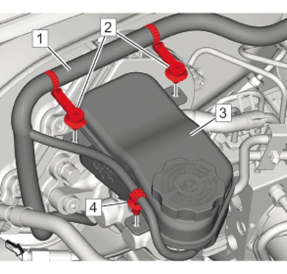 |
|
Fig. 11: Brake Master Cylinder Reservoir And Body Wiring Harnes |
6. Unclip Clip (2)@Brake Master Cylinder Reservoir (3)
7. Unclip Clip (4) @Brake Master Cylinder Reservoir
8. Body Wiring Harness (1) @Brake Master Cylinder Reservoir
 |
|
Fig. 12: Brake Master Cylinder Reservoir Hose |
9. Disconnect Brake Master Cylinder Reservoir Hose (2)
10. Remove Bolt (3) @Brake Master Cylinder Reservoir (1)
 |
|
Fig. 13: Brake Master Cylinder Reservoir |
11. Remove Brake Master Cylinder Reservoir (1) @Brake Master Cylinder (3)
12. Remove Brake Master Cylinder Reservoir Seal (2) @Brake Master Cylinder
13. Remove Brake Fluid Level Sensor Replacement
Installation Procedure
1. Install Brake Fluid Level Sensor Replacement
 |
|
Fig. 14: Brake Master Cylinder Reservoir |
2. Lubricate the brake master cylinder reservoir seals with GM approved brake fluid from a clean, sealed,
brake fluid container. - Adhesives, Fluids, Lubricants, and Sealers
3. Install Brake Master Cylinder Reservoir Seal (2) @Brake Master Cylinder (3)
4. Install Brake Master Cylinder Reservoir (1) @Brake Master Cylinder
 |
|
Fig. 15: Brake Master Cylinder Reservoir Hose |
5. Connect Brake Master Cylinder Reservoir Hose (2)
6. Install Bolt (3) @Brake Master Cylinder Reservoir (1) and tighten 2.5 N.m (22 lb in)
 |
|
Fig. 16: Brake Master Cylinder Reservoir And Body Wiring Harnes |
7. Install Body Wiring Harness (1) @Brake Master Cylinder Reservoir (3)
8. Install Clip (2) @Brake Master Cylinder Reservoir
9. Clip (4) @Brake Master Cylinder Reservoir
 |
|
Fig. 17: Electrical Connector And Brake Fluid Level Sensor |
10. Connect Electrical Connector (2) @Brake Fluid Level Sensor (1)
 |
|
Fig. 18: Radiator Surge Tank And Bracket Clip Courtesy of GENERAL MOTORS COMPANY |
11. Install the radiator surge tank into the bracket and slide rearward to secure.(1)
12. Install Clip (2) @Radiator Surge Tank
13. Install Dash Upper Extension Panel Opening Cover Replacement
14. Bleed the brake system. Hydraulic Brake System Bleeding
MASTER CYLINDER REPLACEMENT
 |
|
Fig. 19: Master Cylinder Courtesy of GENERAL MOTORS COMPANY |
Callout Component Name
WARNING:
Brake Fluid
Irritant
Warning
WARNING:
Eye
Protection
Warning
CAUTION:
Brake Fluid
Effects on
Paint and
Electrical
Components
Caution
CAUTION:
If there is no
brake fluid in
|
Callout |
Component Name |
|
the master Preliminary Procedures
| |
|
1 |
Brake Pipe Fitting (Qty: 2) CAUTION: Fastener Tighten 32 N.m (24 lb ft) |
|
2 |
Brake Master Cylinder Bolt Tighten 22 N.m (16 lb ft) |
|
3 |
Brake Master Cylinder Replace the power brake booster gasket. NOTE: Protect the Cap the brake |
| ||||||
|
MASTER CYLINDER OVERHAUL |
WARNING: Refer to Brake Fluid Irritant Warning .
CAUTION: Refer to Brake Fluid Effects on Paint and Electrical Components Caution .
Disassembly Procedure

1. Remove the brake master cylinder from the vehicle. Refer to Master Cylinder Replacement.
2. Secure the mounting flange of the brake master cylinder in a bench vise so that the rear of the primary
piston is accessible.
3. Clean the outside of the master cylinder reservoir on and around the reservoir cap prior to removing the
cap and diaphragm.
4. Remove the reservoir cap and diaphragm from the reservoir.
5. Inspect the reservoir cap and diaphragm for the following conditions. If any of these conditions are
present, replace the affected components.
• Cuts or cracks
• Nicks or deformation
6. Remove the master cylinder reservoir from the master cylinder. Refer to Master Cylinder Reservoir
Replacement.
7. Using a smooth, round-ended tool, depress the primary piston (2) and remove the piston retainer.
8. Remove the primary piston assembly from the cylinder bore.
9. Plug the cylinder inlet ports and the rear outlet port. Apply low pressure, non-lubricated, filtered air into
the front outlet port, in order the remove the secondary piston (1) with the primary (6) and secondary (5)
seals, and the return spring.
10. Discard the primary piston assembly, the piston retainer, and the seals and seal retainer from the
secondary piston.
Assembly Procedure
 |
|
Fig. 21: Identifying Brake Master Cylinder (Cross Sectional View) |
1. Clean the interior and exterior of the master cylinder, the secondary piston (1), and the return spring in
denatured alcohol, or equivalent.
2. Inspect the master cylinder bore, inlet and outlet ports, the secondary piston (1), and the return spring for
cracks, scoring, pitting, and/or corrosion. Replace the master cylinder if any of these conditions exist.
3. Dry the master cylinder and the individual components with non-lubricated, filtered air.
4. Lubricate the master cylinder bore, the secondary piston (1), the return spring, and all of the individual
overhaul components with Delco Supreme 11A®, GM P/N 12377967 (Canadian P/N 992667), or
equivalent DOT - 3 brake fluid from a clean, sealed brake fluid container.
5. Assemble the lubricated, new primary seal (6) and retainer, and new secondary seal (5) onto the
secondary piston.
6. Install the lubricated return spring and secondary piston assembly (1) into the cylinder bore.
7. Install the lubricated, new primary piston assembly (2) into the cylinder bore.
8. Using a smooth, round-ended tool, depress the primary piston (2) and install the new piston retainer.
9. Install the master cylinder reservoir to the master cylinder. Refer to Master Cylinder Reservoir
Replacement.
10. Install the reservoir cap and diaphragm to the reservoir.
11. Install the master cylinder to the vehicle. Refer to Master Cylinder Replacement.
MASTER CYLINDER BENCH BLEEDING
 |
|
Fig. 22: Bleeding Master Cylinder Courtesy of GENERAL MOTORS COMPANY |
1. Secure the mounting flange of the brake master cylinder in a bench vise so that the rear of the primary
piston is accessible.
2. Remove the master cylinder reservoir cap and diaphragm.
3. Install suitable fittings to the master cylinder ports that match the type of flare seat required and also
provide for hose attachment.
4. Install transparent hoses to the fittings installed to the master cylinder ports, then route the hoses into the
master cylinder reservoir.
5. Fill the master cylinder reservoir to at least the half-way point with GM approved brake fluid from a
clean, sealed brake fluid container. Adhesives, Fluids, Lubricants, and Sealers
6. Ensure that the ends of the transparent hoses running into the master cylinder reservoir are fully
submerged in the brake fluid.
7. Using a smooth, round-ended tool, depress and release the primary piston as far as it will travel, a depth
of about 25 mm (1 in), several times. Observe the flow of fluid coming from the ports.
As air is bled from the primary and secondary pistons, the effort required to depress the primary piston
will increase and the amount of travel will decrease.
8. Continue to depress and release the primary piston until fluid flows freely from the ports with no
evidence of air bubbles.
9. Remove the transparent hoses from the master cylinder reservoir.
10. Install the master cylinder reservoir cap and diaphragm.
11. Remove the fittings with the transparent hoses from the master cylinder ports. Wrap the master cylinder
with a clean shop cloth to prevent brake fluid spills.
12. Remove the master cylinder from the vise.
BRAKE MASTER CYLINDER SHIELD REPLACEMENT
Removal Procedure
1. Remove Dash Upper Extension Panel Opening Cover Replacement
 |
|
Fig. 23: Fuel Feed Hose Courtesy of GENERAL MOTORS COMPANY |
2. Disconnect Fuel Feed Hose (1) @Clip
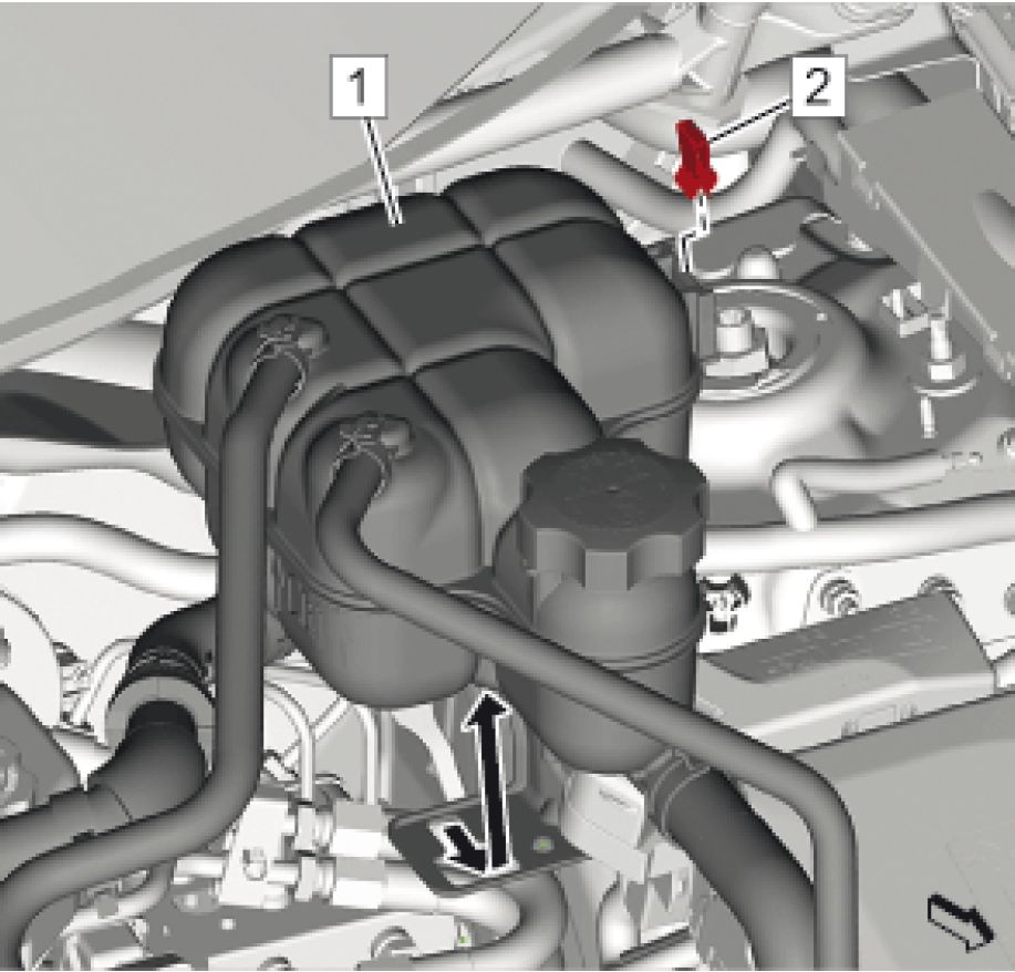 |
|
Fig. 24: Radiator Surge Tank And Bracket Clip Courtesy of GENERAL MOTORS COMPANY |
3. Remove Radiator Surge Tank Bracket Clip (2)
4. Reposition away Radiator Surge Tank (1)
 |
|
Fig. 25: Brake Master Cylinder Shield Courtesy of GENERAL MOTORS COMPANY |
5. Disconnect the brake master cylinder shield (1) from the brake master cylinder assembly.
Installation Procedure
 |
|
Fig. 26: Brake Master Cylinder Shield Courtesy of GENERAL MOTORS COMPANY |
1. Connect the brake master cylinder shield (1) to the brake master cylinder assembly.
 |
|
Fig. 27: Radiator Surge Tank And Bracket Clip |
2. Install Radiator Surge Tank (1)
3. Install Radiator Surge Tank Bracket Clip (2)
 |
|
Fig. 28: Fuel Feed Hose Courtesy of GENERAL MOTORS COMPANY |
4. Install Fuel Feed Hose (1) @ Clip
5. Install Dash Upper Extension Panel Opening Cover Replacement
BRAKE FLUID LEVEL SENSOR REPLACEMENT
Removal Procedure
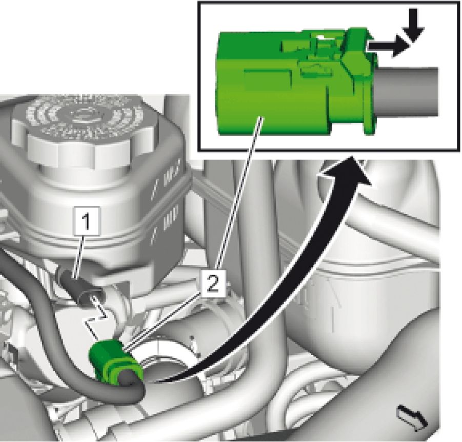 |
|
Fig. 29: Electrical Connector And Brake Fluid Level Sensor |
1. Disconnect Electrical Connector (2) @Brake Fluid Level Sensor (1)
 |
|
Fig. 30: Brake Fluid Level Sensor And Brake Master Cylinder Reservoir |
2. Disconnect Brake Fluid Level Sensor (2) @Brake Master Cylinder Reservoir (1)
Installation Procedure
 |
|
Fig. 31: Brake Fluid Level Sensor And Brake Master Cylinder Reservoir |
Courtesy of GENERAL MOTORS COMPANY
1. Connect Brake Fluid Level Sensor (2) @Brake Master Cylinder Reservoir (1)
 |
|
Fig. 32: Electrical Connector And Brake Fluid Level Sensor |
2. Connect Electrical Connector (2) @Brake Fluid Level Sensor (1)
BRAKE AND ACCELERATOR PEDAL ASSEMBLY REPLACEMENT
Removal Procedure
1. High Voltage Disabling
2. Remove Accelerator Pedal Replacement
3. Remove Power Brake Master Cylinder Booster Assembly Replacement
4. Remove Instrument Panel Tie Bar Replacement
 |
|
Fig. 33: Brake And Accelerator Pedal Assembly And Nuts |
5. Remove the 2 brake and accelerator pedal assembly nuts (1) from the brake and accelerator pedal
assembly (2).
 |
|
Fig. 34: Brake And Accelerator Pedal Assembly |
6. Remove the brake and accelerator pedal assembly (1) from the vehicle.
Installation Procedure
 |
|
Fig. 35: Brake And Accelerator Pedal Assembly Courtesy of GENERAL MOTORS COMPANY |
1. Install the brake and accelerator pedal assembly (1) to the vehicle.
 |
|
Fig. 36: Brake And Accelerator Pedal Assembly And Nuts |
2. Install the 2 brake and accelerator pedal assembly nuts (1) to the brake and accelerator pedal assembly (2)
and tighten to 22 N.m (16 lb ft).
3. Install Power Brake Master Cylinder Booster Assembly Replacement
4. Install Instrument Panel Tie Bar Replacement
5. Install Accelerator Pedal Replacement
6. High Voltage Enabling
BRAKE PIPE REPLACEMENT
Special Tools
CH-45405 Brake Pipe Flaring Kit
For equivalent regional tools, refer to Special Tools.
WARNING: Refer to Brake Fluid Irritant Warning .
WARNING: Always use double walled steel brake pipe when replacing brake pipes. The use
of any other pipe is not recommended and may cause brake system failure.
Carefully route and retain replacement brake pipes. Always use the correct
fasteners and the original location for replacement brake pipes. Failure to
properly route and retain brake pipes may cause damage to the brake pipes and
cause brake system failure.
CAUTION: Refer to Brake Fluid Effects on Paint and Electrical Components Caution .
NOTE: When servicing the brake pipes, note the following:
• If sectioning the brake pipe, use replacement pipe of the same type
and outside diameter.
1. Inspect the area of brake pipe to be repaired or replaced.
2. Remove components as necessary to gain access to the brake pipe to be repaired or replaced.
3. Release the brake pipe to be replaced from the retainers, as required.
4. Select an appropriate location to section the brake pipe, if necessary.
• Allow adequate clearance in order to maneuver the CH-45405 Brake Pipe Flaring Kit.
• Avoid sectioning the brake pipe at bends or mounting points.
5. Using a string or wire, measure the length of the pipe to be replaced including all pipe bends.
6. Add to the measurement taken the appropriate additional length required for each flare to be created.
• 6.35 mm (0.250 in) for 4.76 mm (3/16 in) diameter pipe
• 9.50 mm (0.374 in) for 6.35 mm (1/4 in) diameter pipe
• 12.67 mm (0.499 in) for 7.94 mm (5/16 in) diameter pipe
 |
|
Fig. 37: Sectioning Brake Pipe Using Pipe Cutter |
7. Using the pipe cutter included in the CH-45405 Brake Pipe Flaring Kit, carefully cut the brake pipe
squarely to the measured length.
8. Remove the sectioned brake pipe from the vehicle.
9. Select the appropriate size of brake pipe and tube nuts, as necessary. The brake pipe outside diameter
determines brake pipe size.
 |
|
Fig. 38: Stripping Nylon Coating From Brake Pipe Ends Courtesy of GENERAL MOTORS COMPANY |
10. Strip the nylon coating from the brake pipe end to be flared, if necessary.
• Select the appropriate blade on the coating stripping tool included in the CH-45405 Brake Pipe
Flaring Kit, by unthreading the blade block from the stripping tool and installing the block with the
desired blade facing the tool rollers.
• 6.35 mm (0.250 in) blade for 4.76 mm (3/16 in) diameter pipe
• 9.50 mm (0.374 in) blade for 6.35 mm (1/4 in) and 7.94 mm (5/16 in) diameter pipe
• Insert the brake pipe end to be flared into the stripping tool to the depth of the ledge on the tool
rollers.
• While holding the brake pipe firmly against the stripping tool roller ledges, rotate the thumbwheel
of the tool until the blade contacts the brake pipe coated surface.
• Rotate the stripping tool in a clockwise direction, ensuring that the brake pipe end remains against
the tool roller ledges.
• After each successive revolution of the stripping tool, carefully rotate the thumbwheel of the tool
clockwise, in order to continue stripping the coating from the brake pipe until the metal pipe
surface is exposed.
• Loosen the thumbwheel of the tool and remove the brake pipe.
• Inspect the stripped end of the brake pipe to ensure that the proper amount of coating has been
removed.
• 6.35 mm (0.250 in) for 4.76 mm (3/16 in) diameter pipe
• 9.50 mm (0.374 in) for 6.35 mm (1/4 in) and 7.94 mm (5/16 in) diameter pipe
 |
|
Fig. 39: Chamfering Pipe Using De-Burring Tool |
11. Chamfer the inside and outside diameter of the pipe with the de-burring tool included in the CH-45405
Brake Pipe Flaring Kit.
12. Install the tube nuts on the brake pipe, noting their orientation.
13. Clean the brake pipe and the CH-45405 Brake Pipe Flaring Kit of lubricant, contaminants, and debris.

14. Loosen the die clamping screw of the CH-45405 Brake Pipe Flaring Kit.
15. Select the corresponding die set and install the die halves into the die cage with the full, flat face of one
die facing the clamping screw, and the counterbores of both dies facing the forming ram.

16. Place the flat face of an unused die (1) against the die halves in the clamping cage and hold firmly against
the counterbored face of the dies.
17. Insert the prepared end of the pipe to be flared through the back of the dies until the pipe is seated against
the flat surface of the unused die (1).
18. Remove the unused die (1).
19. Ensure that the rear of both dies are seated firmly against the enclosed end of the die cage.
20. Firmly hand tighten the clamping screw (2) against the dies.
 |
|
Fig. 42: Rotating J 45405 To Bottom Against Die Cage |
21. Select the appropriate forming mandrel and place into the forming ram.
22. Rotate the hydraulic fluid control valve clockwise to the closed position.
23. Rotate the body of the CH-45405 Brake Pipe Flaring Kit until it bottoms against the die cage.
 |
|
Fig. 43: Bottoming Forming Mandrel Against Clamping Dies Using Pipe Flaring Tool |
24. While guiding the forming mandrel into the exposed end of pipe to be flared, operate the lever of the
CH-45405 Brake Pipe Flaring Kit until the forming mandrel bottoms against the clamping dies.
25. Rotate the hydraulic fluid control valve counterclockwise to the open position to allow the hydraulic
forming ram to retract.
 |
|
Fig. 44: Using Pipe Flaring Tool Courtesy of GENERAL MOTORS COMPANY |
26. Insert the finishing cone into the forming ram.
27. Rotate the hydraulic fluid control valve clockwise to the closed position.
28. Rotate the body of the CH-45405 Brake Pipe Flaring Kit until it bottoms against the die cage.
29. While guiding the finishing cone into the exposed end of pipe to be flared, operate the lever of the
CH-45405 Brake Pipe Flaring Kit until the finishing cone bottoms against the dies.
30. Rotate the hydraulic fluid control valve counterclockwise to the open position to allow the hydraulic
forming ram to retract.
31. Loosen the die clamping screw and remove the dies and pipe.
32. If necessary, lightly tap the dies until the die halves separate.
 |
|
Fig. 45: Identifying Correct Brake Pipe Flare Shape & Diameter Courtesy of GENERAL MOTORS COMPANY |
33. Inspect the brake pipe flare for correct shape and diameter (a).
• 6.74 - 7.10 mm (0.265 - 0.279 in) flare diameter for 4.76 mm (3/16 in) diameter pipe
• 8.57 - 9.27 mm (0.344 - 0.358 in) flare diameter for 6.35 mm (1/4 in) diameter pipe
• 10.42 - 10.79 mm (0.410 - 0.425 in) flare diameter for 7.94 mm (5/16 in) diameter pipe
34. If necessary, using the removed section of brake pipe as a template, shape the new pipe with a suitable
brake pipe bending tool.
35. Install the pipe to the vehicle with the appropriate brake pipe unions, as required.
36. If previously released, secure the brake pipe to the retainers.
37. Install any components that may have been removed to gain access to the brake pipe.
38. Bleed the hydraulic brake system. Hydraulic Brake System Bleeding
39. With the aid of an assistant, inspect the brake pipe flares for leaks by starting the engine and applying the
brakes.
BRAKE MASTER CYLINDER RESERVOIR HOSE REPLACEMENT
Removal Procedure
1. Remove Dash Upper Extension Panel Opening Cover Replacement
 |
|
Fig. 46: Radiator Surge Tank And Bracket Clip |
2. Remove Radiator Surge Tank Bracket Clip (2)
3. Reposition away Radiator Surge Tank (1)
 |
|
Fig. 47: Brake Master Cylinder Reservoir And Hose |
4. Disconnect the brake master cylinder reservoir hose (2) from the brake master cylinder reservoir (1).
5. Remove Brake Pipe Fitting (3) @Brake Pressure Modulator Valve
6. Remove the brake master cylinder reservoir hose from the vehicle.
Installation Procedure
 |
|
Fig. 48: Brake Master Cylinder Reservoir And Hose |
1. Install Brake Pipe Fitting (3) @Brake Pressure Modulator Valve and tighten 32 N.m (24 lb ft)
2. Connect the brake master cylinder reservoir hose (2) to the brake master cylinder reservoir (1).
 |
|
Fig. 49: Radiator Surge Tank And Bracket Clip |
3. Install Radiator Surge Tank (1)
4. Install Radiator Surge Tank Bracket Clip (2)
5. Install Dash Upper Extension Panel Opening Cover Replacement
6. Hydraulic Brake System Bleeding
FRONT BRAKE HOSE REPLACEMENT
Removal Procedure
1. Remove Tire and Wheel Removal and Installation
 |
|
Fig. 50: Front Brake Hose And Brake Hose Fitting Bolt |
2. Remove Front Brake Hose (3) @Brake Hose Fitting Bolt (1)
3. Cap the brake hose fitting to prevent brake fluid loss and contamination.
4. Cap the brake caliper inlet port to prevent brake fluid loss and contamination.
5. DISCARD the brake hose fitting gaskets.(2)
 |
|
Fig. 51: Front Brake Hose And Front Brake Pipe Fitting |
6. Remove Front Brake Hose (2) @Front Brake Pipe Fitting (1)
7. Cap the brake pipe fitting to prevent brake fluid loss and contamination.
8. Cap the brake hose fitting to prevent brake fluid loss and contamination.
Installation Procedure
1. Remove the caps from brake pipe fitting and the brake hose.
 |
|
Fig. 52: Front Brake Hose And Front Brake Pipe Fitting |
2. Install Front Brake Hose (2) @Front Brake Pipe Fitting (1) and tighten 20 N.m (15 lb ft)
3. Remove the caps from the brake hose and the brake caliper inlet port.
 |
|
Fig. 53: Front Brake Hose And Brake Hose Fitting Bolt Courtesy of GENERAL MOTORS COMPANY |
4. Install NEW brake hose fitting gaskets.(2)
5. Install Front Brake Hose (3) @Brake Hose Fitting Bolt (1) and tighten 40 N.m (30 lb ft)
6. Hydraulic Brake System Bleeding
7. Install Tire and Wheel Removal and Installation - Install
REAR BRAKE HOSE REPLACEMENT
 |
|
Fig. 54: Rear Brake Hose |
Courtesy of GENERAL MOTORS COMPANY
Callout Component Name
Preliminary Procedure Tire and Wheel Removal and Installation
Brake Hose Fitting Bolt
Tighten
| ||||||||||
|
HYDRAULIC BRAKE SYSTEM BLEEDING |
WARNING: Refer to Brake Fluid Irritant Warning .
CAUTION: Refer to Brake Fluid Effects on Paint and Electrical Components Caution .
CAUTION: Only use products that comply with GM specifications and check manufacturer
information respectively. We recommend the use of GM genuine products.
Instructions must be followed at all times. The use of any type of fluid other
than the recommended type of brake fluid, may cause contamination which
could result in damage to the internal rubber seals and/or rubber linings of
hydraulic brake system components.
If hydraulic components were serviced on only one wheel hydraulic circuit, perform the following procedure.
1. Place the Power button in the Service Only Mode.
2. Place a clean shop cloth beneath the brake master cylinder to catch brake fluid spills.
3. Clean the outside of the reservoir on and around the reservoir cap prior to removing the cap and
diaphragm.
4. Fill the brake master cylinder reservoir to the maximum-full level with GM approved brake fluid from a
clean, sealed brake fluid container. Refer to Fluid and Lubricant Recommendations .
NOTE: The pressure bleeding equipment must be the diaphragm type. The rubber
diaphragm between the air supply and the brake fluid prevents air,
moisture, oil, and other contaminants from entering the hydraulic system.
5. Following the brake pressure bleeder manufacturer's instructions, fill the brake pressure bleeder with GM
approved brake fluid from a clean, sealed brake fluid container.
6. Install the appropriate master cylinder reservoir adapter and connect the brake pressure bleeder.
7. Charge the brake pressure bleeder air tank to 170-200 kPa/1.7-2.0 bar (25-30 psi), or as recommended by
the brake pressure bleeder manufacturer's instructions.
8. Open the brake pressure bleeder fluid tank valve to allow pressurized brake fluid to enter the brake
hydraulic system.
NOTE: Any brake fluid leaks identified require repair prior to completing this
procedure.
9. Wait approximately 30 seconds, then inspect the entire hydraulic brake system for external brake fluid
leaks.
10. Install a proper box-end wrench onto the wheel hydraulic circuit bleeder valve which has been serviced.
11. Install a transparent hose over the end of the bleeder valve.
12. Submerge the open end of the transparent hose into a transparent container partially filled with brake fluid
from a clean, sealed brake fluid container.
13. Loosen the bleeder valve to purge air from the wheel hydraulic circuit.
14. Allow fluid to flow until air bubbles stop flowing from the bleeder.
15. After all air has been purged from the hydraulic circuit, tighten the bleeder valve and install the dust cap.
NOTE: The brake reservoir may have residual pressure after the bleeding
operation is complete. Wrap a clean shop towel around the bleeder
adapter and all hose connections before disconnecting the pressure
bleeding equipment to prevent brake fluid from contacting and damaging
vehicle components and painted surfaces.
16. Close the brake pressure bleeder fluid tank valve then disconnect the brake pressure bleeder from the
master cylinder reservoir bleeder adapter.
17. Remove the master cylinder reservoir bleeder adapter from the master cylinder reservoir.
18. Fill the brake master cylinder reservoir to the maximum-fill level with GM approved brake fluid from a
clean, sealed brake fluid container.
19. Slowly press and release the brake pedal. Observe the brake pedal feel.
20. If the brake pedal feels spongy, perform the Bleeding the Complete Brake Hydraulic System procedure:
21. Turn the ignition key ON, with the engine OFF. Check to see if the brake system warning lamp remains
illuminated.
NOTE: DO NOT allow the vehicle to be driven until it is diagnosed and repaired.
22. If the brake system warning lamp remains illuminated, refer to Diagnostic Starting Point - Vehicle .
1. Place the Power button in the Service Only Mode.
2. Place a clean shop cloth beneath the brake master cylinder to catch brake fluid spills.
3. Clean the outside of the reservoir on and around the reservoir cap prior to removing the cap and
diaphragm.
4. Fill the brake master cylinder reservoir to the maximum-full level with GM approved brake fluid from a
clean, sealed brake fluid container. Refer to Fluid and Lubricant Recommendations .
5. If the master cylinder was replaced, the master cylinder must be bench bled. Refer to Master Cylinder
Bench Bleeding.
NOTE: The pressure bleeding equipment must be the diaphragm type. The rubber
diaphragm between the air supply and the brake fluid prevents air,
moisture, oil, and other contaminants from entering the hydraulic system.
6. Following the brake pressure bleeder manufacturer's instructions, fill the brake pressure bleeder with GM
approved brake fluid from a clean, sealed brake fluid container.
7. Install the appropriate master cylinder reservoir adapter and connect the brake pressure bleeder.
8. Charge the brake pressure bleeder air tank to 170-200 kPa/1.7-2.0 bar (25-30 psi), or as recommended by
the brake pressure bleeder manufacturer's instructions.
9. Open the brake pressure bleeder fluid tank valve to allow pressurized brake fluid to enter the brake
hydraulic system.
NOTE: Any brake fluid leaks identified require repair prior to completing this
procedure.
10. Wait approximately 30 seconds, then inspect the entire hydraulic brake system for external brake fluid
leaks.
11. Install a proper box-end wrench onto the RIGHT REAR wheel hydraulic circuit bleeder valve.
12. Install a transparent hose over the end of the bleeder valve.
13. Submerge the open end of the transparent hose into a transparent container partially filled with GM
approved brake fluid from a clean, sealed brake fluid container.
14. Loosen the bleeder valve to purge air from the wheel hydraulic circuit.
15. Allow fluid to flow until air bubbles stop flowing from the bleeder.
16. After all air has been purged from the hydraulic circuit, tighten the bleeder valve and install the dust cap.
17. Install a proper box-end wrench onto the LEFT REAR wheel hydraulic circuit bleeder valve, then repeat
steps 12-16.
18. Install a proper box-end wrench onto the RIGHT FRONT wheel hydraulic circuit bleeder valve, then
repeat steps 12-16.
19. Install a proper box-end wrench onto the LEFT FRONT wheel hydraulic circuit bleeder valve, then repeat
steps 12-16.
20. Close the brake pressure bleeder fluid tank valve.
NOTE: The brake reservoir may have residual pressure after the bleeding
operation is complete. Wrap a clean shop towel around the bleeder
adapter and all hose connections before disconnecting the pressure
bleeding equipment to prevent brake fluid from contacting and damaging
vehicle components and painted surfaces.
21. Remove the brake pressure bleeding equipment from the vehicle.
22. Fill the brake master cylinder reservoir to the maximum-full level with GM approved brake fluid from a
clean, sealed brake fluid container. Refer to Fluid and Lubricant Recommendations .
23. Slowly press and release the brake pedal. Observe the brake pedal feel.
24. If the brake pedal feels spongy, perform the following procedure.
1. If equipped with antilock brakes, install a scan tool and perform the Antilock Brake System
Automated Bleed to remove air which may be trapped in the BPMV.
2. Inspect the hydraulic brake system for external leaks. Refer to Brake System External Leak
Inspection.
3. Repeat the Bleeding the Complete Brake Hydraulic System procedure.
25. If the brake pedal still feels spongy, pressure bleed the hydraulic brake system. Refer to Hydraulic Brake
System Bleeding.
26. Turn the ignition switch ON with the engine OFF. Check to see if the brake system warning lamp remains
illuminated.
NOTE: DO NOT allow the vehicle to be driven until the brake system is diagnosed
and repaired.
27. If the brake system warning lamp remains illuminated, refer to Diagnostic Starting Point - Vehicle .
HYDRAULIC BRAKE SYSTEM FLUSHING
WARNING: Refer to Brake Fluid Irritant Warning .
CAUTION: Refer to Brake Fluid Effects on Paint and Electrical Components Caution .
CAUTION: Only use products that comply with GM specifications and check manufacturer
information respectively. We recommend the use of GM genuine products.
Instructions must be followed at all times. The use of any type of fluid other
than the recommended type of brake fluid, may cause contamination which
could result in damage to the internal rubber seals and/or rubber linings of
hydraulic brake system components.
1. Inspect the brake fluid for the following conditions, indicating brake fluid contamination:
• Fluid separation, indicating two types of fluid are present; a substance other than the recommended
brake fluid has been introduced into the brake hydraulic system
• Swirled appearance - oil-based substance
• Layered appearance - silicone-based substance
• Fluid discoloration, indicating the presence of moisture or particles that have been introduced into
the brake hydraulic system
• Cloudy appearance - moisture
• Dark appearance/suspended particles in fluid - dirt, rust, corrosion, brake dust
2. Inspect the master cylinder reservoir cap diaphragm and the reservoir-to-master cylinder grommets for
swelling, indicating brake fluid contamination.
3. If the brake fluid WAS contaminated with an oil-based or a silicone-based substance, indicated by fluid
separation and/or a swollen master cylinder reservoir cap diaphragm and/or swollen reservoir-to-master
cylinder grommets, perform the following:
1. Remove ALL of the following components listed from the vehicle. Each component contains
internal rubber seals/linings which have been contaminated by the contaminated brake fluid in the
brake hydraulic system.
Master Cylinder Replacement
Front Brake Hose Replacement
Rear Brake Hose Replacement
Front Brake Caliper Replacement
Rear Brake Caliper Replacement
Electronic Brake Control Module with Brake Pressure Modulator Valve Replacement
2. Clean out all the hydraulic brake pipes using denatured alcohol, or equivalent.
3. Dry the brake pipes using non-lubricated, filtered air.
4. Repair or replace ALL of the following components listed and install them to the vehicle. Each
component contains internal rubber seals/linings which have been contaminated by the
contaminated brake fluid in the brake hydraulic system.
Master Cylinder Replacement; also perform the following:
Clean the brake master cylinder reservoir using denatured alcohol, or equivalent, then dry the
reservoir using non-lubricated, filtered air. Inspect the reservoir for cracks and/or damage and
replace if necessary. Master Cylinder Reservoir Replacement
Replace the brake master cylinder reservoir cap.
Front Brake Hose Replacement
Rear Brake Hose Replacement
Front Brake Caliper Overhaul , or Front Brake Caliper Replacement
Rear Brake Caliper Replacement
Electronic Brake Control Module with Brake Pressure Modulator Valve Replacement
4. If the brake fluid was NOT contaminated with an oil-based or a silicone-based substance, but WAS
contaminated with water or dirt, rust, corrosion, and/or brake dust, replace the brake master cylinder
reservoir cap. The diaphragm may have allowed the moisture or particles to enter the hydraulic system.
5. Fill the brake master cylinder reservoir to the maximum-fill level with GM approved brake fluid from a
clean, sealed brake fluid container. Adhesives, Fluids, Lubricants, and Sealers
6. Pressure bleed the hydraulic brake system. Begin the procedure with the pressure bleeder reservoir filled
to the maximum-fill level with the correct brake fluid as indicated. Hydraulic Brake System Bleeding
POWER BRAKE MASTER CYLINDER BOOSTER ASSEMBLY REPLACEMENT
Removal Procedure
1. Remove one of the electric brake booster fuses from the engine compartment fuse block.
2. Remove Dash Upper Extension Panel Opening Cover Replacement
 |
|
Fig. 55: Electrical Connector And Power Brake Booster |
3. Disconnect Electrical Connector (1) @Power Brake Booster (2)
4. Disconnect Electrical Connector (3) @Power Brake Booster (2)
 |
|
Fig. 56: Electrical Connector And Brake Fluid Level Sensor |
5. Disconnect Electrical Connector (2) @Brake Fluid Level Sensor (1)
 |
|
Fig. 57: Brake Master Cylinder Reservoir And Body Wiring Harnes |
6. Unclip Clip (2) @Brake Master Cylinder Reservoir (3)
7. Unclip Clip (4) @Brake Master Cylinder Reservoir
8. Remove Body Wiring Harness (1) @Brake Master Cylinder Reservoir
 |
|
Fig. 58: Radiator Surge Tank And Bracket Clip |
9. Remove Clip (2) @Radiator Surge Tank (1)
10. Slide the radiator surge tank forward and lift to remove.
 |
|
Fig. 59: Brake Master Cylinder Reservoir Hose And Brake Pressure Modulator Valve Secondary Courtesy of GENERAL MOTORS COMPANY |
11. Disconnect Brake Master Cylinder Reservoir Hose (2) @Brake Master Cylinder Reservoir (1)
12. Remove Brake Pressure Modulator Valve Secondary Pipe Fitting (7) @Brake Master Cylinder (8)
13. Remove Brake Pressure Modulator Valve Secondary Pipe (6) @Brake Master Cylinder
14. Remove Brake Pressure Modulator Valve Primary Pipe Fitting (4) @Brake Master Cylinder
15. Remove Brake Pressure Modulator Valve Primary Pipe (5) @Brake Master Cylinder
16. Remove the master cylinder without removing the master cylinder reservoir. Master Cylinder
Replacement

17. Loosen Bolt (2) @Power Brake Booster (1)
18. Remove Brake Pedal Position Sensor Replacement
 |
|
Fig. 61: Brake Pedal Push Rod And Brake Pedal |
19. Disconnect the brake pedal push rod (1) from the brake pedal (2). Press the 2 tabs of the click fit
connector (3) together and pull the brake pedal to facilitate the removal.
 |
|
Fig. 62: Brake Pedal Courtesy of GENERAL MOTORS COMPANY |
20. Remove and DISCARD the click fit connector (1) from the brake pedal (2).
21. Remove Power Brake Booster@Vehicle
 |
|
Fig. 63: Power Brake Booster Gasket Courtesy of GENERAL MOTORS COMPANY |
22. Remove and DISCARD the power brake booster gasket (1).
23. Remove the power brake booster heat shield.(2)
Installation Procedure
 |
|
Fig. 64: Power Brake Booster Gasket Courtesy of GENERAL MOTORS COMPANY |
1. Install the power brake booster heat shield (2).
2. Install the NEW power brake booster gasket (1).
3. Install Power Brake Booster@Vehicle
 |
|
Fig. 65: Brake Pedal Courtesy of GENERAL MOTORS COMPANY |
4. Install the NEW click fit connector (1) to the brake pedal (2).
 |
|
Fig. 66: Brake Pedal Push Rod And Brake Pedal |
5. Connect the brake pedal push rod (1) to the brake pedal (2).
6. Install Brake Pedal Position Sensor Replacement
 |
|
Fig. 67: Power Brake Booster Courtesy of GENERAL MOTORS COMPANY |
7. Bolt (2) @Power Brake Booster (1) Tighten 22 N.m (16 lb ft)
8. Install the master cylinder with the master cylinder reservoir. Master Cylinder Replacement
 |
|
Fig. 68: Brake Master Cylinder Reservoir Hose And Brake Pressure Modulator Valve Secondary Courtesy of GENERAL MOTORS COMPANY |
9. Install Brake Pressure Modulator Valve Primary Pipe (5) @Brake Master Cylinder (8)
10. Brake Pressure Modulator Valve Primary Pipe Fitting (4)@Brake Master Cylinder - Tighten 32 N.m (24
lb ft)
11. Install Brake Pressure Modulator Valve Secondary Pipe (6) @Brake Master Cylinder
12. Brake Pressure Modulator Valve Secondary Pipe Fitting (7) @Brake Master Cylinder - Tighten 32 N.m
(24 lb ft)
13. Install Brake Master Cylinder Reservoir Hose (2) @Brake Master Cylinder Reservoir (1)
 |
|
Fig. 69: Brake Pressure Modulator Valve Primary And Secondary Pipe Fitting |
14. Ensure the brake pipes are correctly installed.
1. Brake Pressure Modulator Valve Primary Pipe Fitting (1)
2. Brake Pressure Modulator Valve Secondary Pipe (2)
 |
|
Fig. 70: Radiator Surge Tank And Bracket Clip |
15. Install Radiator Surge Tank (1)
16. Install Radiator Surge Tank Bracket Clip (2)
 |
|
Fig. 71: Brake Master Cylinder Reservoir And Body Wiring Harnes |
17. Install Body Wiring Harness (1)
18. Install Clip (2) @Brake Master Cylinder Reservoir (3)
19. Install Clip (2) @Brake Master Cylinder Reservoir
 |
|
Fig. 72: Electrical Connector And Brake Fluid Level Sensor |
20. Connect Electrical Connector(2)@Brake Fluid Level Sensor(1)
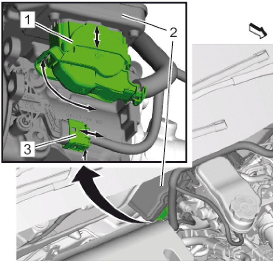 |
|
Fig. 73: Electrical Connector And Power Brake Booster |
21. Connect Electrical Connector(1)@Power Brake Booster(2)
22. Connect Electrical Connector(3)@Power Brake Booster
24. Install the electric brake booster fuse to the engine compartment fuse block.
26. Program and calibrate the power brake booster control module. Refer to Control Module References .
DESCRIPTION AND OPERATION
POWER BRAKE BOOSTER DESCRIPTION AND OPERATION
Power Brake Booster Description and Operation
The brake booster is an electromechanical brake booster that replaces a vacuum booster including its vacuum
supply. It is designed to make hybrid and electric vehicles more efficient by providing situation-dependent
support when a driver initiates braking.
The brake booster unit takes the driver applied brake demand and transforms this into an amplified brake
pressure and does not rely on vacuum to function. The brake booster unit is designed to operate together with an
electronic stability control module which is normally responsible for ABS, traction control and stability control.
Since the brake booster unit operates electromechanically, it does not require vacuum from the engine and
recovers almost all the energy lost in typical braking. It uses electrical current only during braking.
The brake booster unit consists of a PSM motor for force build up, and ECU for the control of the brake booster,
a stage gear control to transmit the motor torque to the output pressure in the master cylinder, a vehicle interface
to connect the brake booster and the vehicle, a pedal coupling unit to couple the brake booster with the vehicle
pedal unit, a pedal travel sensor to detect the driver brake request, TMC to connect the brake booster with the
braking system and a reservoir to support the braking system with brake fluid.
For maximum efficiency, a hybrid or EV must recover as much energy as possible when braking. Ideally, a
vehicle would be slowed down purely by the electric motor, avoiding the loss of valuable energy through
braking. The system recovers almost all the energy lost in typical braking operations by ensuring deceleration
rates of up to 0.3 g are achieved using the electric motor alone. If the brakes are applied harder, the brake
booster system generates the additional braking pressure needed in the traditional way, using the brake master
cylinder.
The brake booster unit is purely electromechanical, without brake fluid, which means it can be rotated flexibly
about the longitudinal axis.
BRAKE WARNING SYSTEM DESCRIPTION AND OPERATION
Brake Warning Indicator
г — Л B20
I I Brake
’ Fluid Level
I I Switch
Г -* 1 K17
■ I Electronic
1 Brake
I I Control
j Module
|
1 I I |
 |
■ Instrument
Cluster
I
|
Callout |
Component Name |
|
P16 |
P16 Instrument Cluster |
|
B20 |
B20 Brake Fluid Level Switch |
|
K17 |
K17 Electronic Brake Control Module |
The instrument cluster turns the brake warning indicator ON when the following occurs:
• The instrument cluster performs the bulb check. The brake warning indicator illuminates for 5 seconds.
• When the EBCM detects a too low brake fluid level it sets a DTC and sends a serial data message to the
instrument cluster, which will illuminate.
Electronic brake control module (EBCM) monitors the brake fluid level in the brake fluid reservoir. When the
fluid within the brake fluid reservoir is below the MIN level, contacts within the brake fluid level switch closes
causing the voltage within the signal circuit to drop. The electronic brake control module (EBCM) will detect
the voltage drop and will send a serial data message to the instrument cluster commanding the brake warning
indicator to illuminate.
HYDRAULIC BRAKE SYSTEM DESCRIPTION AND OPERATION
System Component Description
The hydraulic brake system consists of the following:
Contains supply of brake fluid for the hydraulic brake system.
Converts mechanical input force into hydraulic output pressure.
Hydraulic output pressure is distributed from the master cylinder through 2 hydraulic circuits, supplying
diagonally-opposed wheel apply circuits.
Regulates brake fluid pressure delivered to hydraulic brake wheel circuits, in order to control the
distribution of braking force.
Pressure balance control is achieved through dynamic rear proportioning (DRP), which is a function of
the ABS modulator.
Carries brake fluid to and from hydraulic brake system components.
Converts hydraulic input pressure into mechanical output force.
System Operation
Mechanical force is converted into hydraulic pressure by the master cylinder, regulated to meet braking system
demands by the pressure balance control system, and delivered to the hydraulic brake wheel circuits by the
pipes and flexible hoses. The wheel apply components then convert the hydraulic pressure back into mechanical
force which presses linings against rotating brake system components.
SPECIAL TOOLS AND EQUIPMENT
SPECIAL TOOLS
|
Illustration |
Tool |
|
Illustration |
Tool |
|
[ ! SX F/f / |
CH 28662 Brake Pedal |
|
Illustration |
Tool |
|
CH | |
|
Brake | |
|
Bleeder |
|
Illustration |
Tool |
|
CH |
Tool
Number/
Description
|
Illustration | |
 |
CH 45405 J 45405 |
Article GUID: A00884698
SPECIFICATIONS
FASTENER SPECIFICATIONS
Single Use Non-Threaded Fasteners/Components
All
fasteners/components
listed in this table
MUST BE
DISCARDED and
replaced with NEW
after removal.
Application
Brake Hose Fitting Gasket
Rear Parking Brake Actuator Seal Ring
|
Reusable Threaded Fastener Tightening Specifications | |||||||||
| |||||||||
SCHEMATIC WIRING DIAGRAMS
PARK BRAKE SYSTEM WIRING SCHEMATICS
 |
|
Fig. 1: Park Brake Courtesy of GENERAL MOTORS COMPANY |
DIAGNOSTIC INFORMATION AND PROCEDURES
DTC C1138: SUPPLY VOLTAGE GOES BELOW 7 V AND ABOVE 16.5 V/SIGNAL PERFORMANCE
Diagnostic Instructions
• Perform the Diagnostic System Check - Vehicle prior to using this diagnostic procedure.
• Review Strategy Based Diagnosis for an overview of the diagnostic approach.
Diagnostic Procedure Instructions provides an overview of each diagnostic category.
DTC Descriptors
DTC C1138 03
Supply Voltage Goes Below 7 V
DTC C1138 07
Supply Voltage Goes Above 16.5 V
DTC C1138 58
Signal Performance
|
Diagnostic Fault Information | |||||||||||||||
| |||||||||||||||
|
Circuit/System Description |
The Electronic Brake Control Module monitors its supply voltage to verify the supply voltage is within the
normal operating range
Conditions for Running the DTC
The ignition is ON.
Conditions for Setting the DTC
The EBCM detects its supply voltage of less than approximately 7 V.
The EBCM detects a supply voltage of more than 16.5 V.
The Park Brake Controller (PBC) loses communication with the EBCM during park brake actuation.
Action Taken When the DTC Sets
• DTC is stored in memory.
• Park brake actuation unavailable.
Conditions for Clearing the DTC
The supply voltage returns to normal operating range.
Diagnostic Aids
• A high or low voltage DTC set or voltage value in multiple modules/sensors indicates a concern in the
charging system.
• A possible cause of this DTC could be overcharging with a battery charger or jump starting.
Reference Information
Schematic Reference
Connector End View Reference
COMPONENT CONNECTOR END VIEWS - INDEX
Description and Operation
Electronic Parking Brake Description
Electrical Information Reference
Circuit Testing
Connector Repairs
Testing for Intermittent Conditions and Poor Connections
Wiring Repairs
Scan Tool Reference
Control Module References for scan tool information
Circuit/System Verification
1. Verify that no other DTCs are set.
• If any other DTCs are set
Refer to Diagnostic Trouble Code (DTC) List - Vehicle .
• If no other DTCs are set
2. Vehicle OFF, measure and record the battery voltage at the battery terminals.
3. Verify the battery voltage stabilizes between 12.4 V and 12.8 V within a few minutes of turning the
vehicle OFF.
• If battery voltage is less than 12.4 V or more than 12.8 V
Refer to Battery Inspection/Test .
• If battery voltage is between 12.4 and 12.8 V
4. Engine running, headlights ON, measure and record the battery voltage at the battery terminals.
5. Verify the voltage is at least 1 V greater than the voltage measured in step 1, but less than 15 V.
• If the voltage is not at least 1 V greater than the voltage measured in step 2 or is greater than
15 V.
Refer to Charging System Test .
• If the voltage is at least 1 V greater than the voltage measured in step 2, but less than 15 V.
6. Verify the K17 Electronic Brake Control Module scan tool ignition voltage parameter is within 1 V of the
battery voltage.
• If not within 1 V of the battery voltage
Refer to Circuit/System Testing.
• If within 1 V of the battery voltage
7. All OK.
|
Circuit/System Testing | ||
|
1. Ignition OFF and all vehicle systems OFF, disconnect the X1 harness connector at the K17 Electronic
Brake Control Module. It may take up to 2 min for all vehicle systems to power down.
2. Test for less than 10 fi between ground circuit terminal 46 and ground.
• If 10 fi or greater
1. Ignition OFF.
2. Test for less than 2 fi in the ground circuit end to end.
• If 2 fi or greater, repair the open/high resistance in the circuit.
• If less than 2 fi, repair the open/high resistance in the ground connection.
3. Verify a test lamp illuminates between B+ circuit terminal 1 and ground.
• If the test lamp does not illuminate and the circuit fuse is good
1. Ignition OFF.
2. Test for less than 2 fi in the B+ circuit end to end.
• If 2 fi or greater, repair the open/high resistance in the circuit.
• If less than 2 fi, verify the fuse is not open and there is voltage at the fuse.
• If the test lamp does not illuminate and the circuit fuse is open
1. Ignition OFF.
2. Test for infinite resistance between the B+ circuit and ground.
• If less than infinite resistance, repair the short to ground on the circuit.
• If infinite resistance, replace the K17 Electronic Brake Control Module.
• If the test lamp illuminates
4. Replace the K17 Electronic Brake Control Module.
1. Verify that no other DTCs are set.
• If any other DTCs are set
Refer to Diagnostic Trouble Code (DTC) List - Vehicle .
2. Using the S91 Park Brake Control Switch, apply and release the park brake.
3. Verify that the DTC does not reset.
Replace the K17 Electronic Brake Control Module.
4. All OK.
Repair Instructions
Perform the Diagnostic Repair Verification after completing the repair.
Control Module References for control module replacement, programming and setup.
DTC C1148: LEFT PARK BRAKE ACTUATOR CIRCUIT
Diagnostic Instructions
• Perform the Diagnostic System Check - Vehicle prior to using this diagnostic procedure.
• Review Strategy Based Diagnosis for an overview of the diagnostic approach.
Diagnostic Procedure Instructions provide an overview of each diagnostic category.
DTC Descriptors
Left Park Brake Actuator Circuit
For symptom byte information, refer to: Symptom Byte List
|
Diagnostic Fault Information | |||||||||||||||
| |||||||||||||||
|
Circuit/System Description |
The Electronic Brake Control Module will diagnose the park brake motor circuits to verify that they are
functioning properly. The park brake motor circuits are used to command actuator motor operation, which will
apply and release the parking brake. These circuits are used to activate the actuator, which applies or releases
pressure on the rear caliper pistons, ultimately applying and releasing the park brake.
When the Park Brake Switch is pulled, a signal is sent to the Electronic Brake Control Module which will
supply 12 V to the apply control circuits and ground to the release control circuits which will cause the left and
right park brake actuators to activate causing the park brakes to engage. When the Park Brake Switch is pressed,
a signal is sent to the Electronic Brake Control Module which will supply 12 V to the released control circuits
and ground to the apply control circuits which will cause the left and right park brake actuators to activate
causing the park brakes to release.
Conditions for Running the DTC
• Vehicle ON or in SERVICE MODE.
• Battery voltage is between 9 - 16 V
Conditions for Setting the DTC
The Electronic Brake Control Module detects a malfunction in the left park brake actuator or its circuits.
Action Taken When the DTC Sets
• The parking brake is disabled, one release allowed.
• A message and/or a warning indicator may be displayed.
Conditions for Clearing the DTC
• The Electronic Brake Control Module will clear the DTC after 40 consecutive ignition on/off cycles with
at least one test pass in each ignition cycle and no test fail result.
• The condition for the DTC is no longer present.
Diagnostic Aids
After repairing any fault, the DTC will still be set as current and the park brakes will not function. It is
necessary to clear the DTC with a scan tool in order to place the DTC in history and regain park brake function.
Reference Information
Schematic Reference
Connector End View Reference
Description and Operation
Electrical Information Reference
Circuit Testing
Connector Repairs
Testing for Intermittent Conditions and Poor Connections
Wiring Repairs
Control Module References for scan tool information
Circuit/System Verification
1. Verify the M104L Park Brake Actuator - Left apply when pulling the S91 Park Brake Switch.
• If the M104L Park Brake Actuator - Left does not apply
Refer to the Circuit/System Testing.
2. Verify the M104L Park Brake Actuator - Left release when pressing the S91 Park Brake Switch.
Refer to the Circuit/System Testing.
3. All OK.
Circuit/System Testing
1. Ignition OFF, disconnect the harness connector at the M104L Park Brake Actuator - Left and the harness
connector at the K17 Electronic Brake Control Module. Ignition ON
2. Test for less than 1 V between the K17 Electronic Brake Control Module harness connector terminals
listed below and ground:
• Terminal 12
• Terminal 13
• If 1 V or greater
Repair the short to voltage on the circuit.
3. Ignition OFF.
4. Test for infinite resistance between the K17 Electronic Brake Control Module harness connector
terminals listed below and ground:
Repair the short to ground on the circuit.
5. Test for less than 2 Q between the M104L Park Brake Actuator - Left harness connector terminal 1 and
the K17 Electronic Brake Control Module harness connector terminal 13
• If 2 Q or greater
Repair the open/high resistance in the circuit.
6. Test for less than 2 Q between the M104L Park Brake Actuator - Left harness connector terminal 2 and
the K17 Electronic Brake Control Module harness connector terminal 12
• If 2 Q or greater
Repair the open/high resistance in the circuit.
7. Install a 25 A fused jumper wire between one of the control terminals at the M104L Park Brake Actuator
- Left and 12 V. Momentarily install a jumper wire between the other control terminal and ground.
Reverse the jumper wires at least two times, the M104L Park Brake Actuator - Left should perform the
apply and release function.
• If the actuator does not perform the apply and release function
Replace the M104L Park Brake Actuator - Left.
8. Replace the K17 Electronic Brake Control Module.
Repair Instructions
Perform the Diagnostic Repair Verification after completing the repair.
Control Module References for control module replacement, programming and setup
DTC C114C: PARK BRAKE SWITCH CIRCUIT
Diagnostic Instructions
• Perform the Diagnostic System Check - Vehicle prior to using this diagnostic procedure.
• Review Strategy Based Diagnosis for an overview of the diagnostic approach.
Diagnostic Procedure Instructions provide an overview of each diagnostic category.
DTC Descriptors
Park Brake Switch Circuit
For symptom byte information, refer to: Symptom Byte List
Diagnostic Fault Information
| |||||||||||||||||||||||||||||||||||
|
Circuit/System Description |
The parking brake function is integrated into the Electronic Brake Control Module. The Electronic Brake
Control Module contains the logic for applying and releasing the parking brake when commanded by the Park
Brake Switch. The Electronic Brake Control Module will perform diagnostics on the Park Brake Switch and its
wiring harness to verify it is functioning properly.
The Park Brake Switch diagnostic checks for failure conditions in the Park Brake Switch and associated wiring
into the Electronic Brake Control Module.
Conditions for Running the DTC
Vehicle ON or in SERVICE MODE.
Conditions for Setting the DTC
The Electronic Brake Control Module detects a short to battery, short to ground, open circuit, or an internal
Parking Brake Control Switch malfunction. The Electronic Brake Control Module detects the apply or release
button was activated for more than 90 s.
Action Taken When the DTC Sets
• The parking brake is disabled.
• A message and/or a warning indicator may be displayed.
Conditions for Clearing the DTC
• The Electronic Brake Control Module will clear the DTC after 40 consecutive Vehicle on/off cycles with
at least one test pass in each Vehicle cycle and no test fail result.
• The condition for the DTC is no longer present.
• The Park Brake Switch button is INACTIVE using the scan tool without the switch being activated.
Reference Information
Connector End View Reference
Description and Operation
Electrical Information Reference
Circuit Testing
Connector Repairs
Testing for Intermittent Conditions and Poor Connections
Wiring Repairs
Scan Tool Reference
Control Module References for scan tool information
Circuit/System Verification
1. Vehicle ON.
2. Verify the scan tool Park Brake Switch parameter changes between Released and Apply while pressing
and releasing the S91 Park Brake Switch.
• If the parameter does not change
Refer to Circuit/System Test.
3. All OK.
Circuit/System Test
1. Vehicle OFF, disconnect the harness connector at the K17 Electronic Brake Control Module. Vehicle ON.
2. Test for less than 1 V between each circuit terminals listed below and ground;
• Terminal 16
• Terminal 32
• Terminal 9
• Terminal 15
• Terminal 31
• Terminal 8
• If 1 V or greater
Repair the short to voltage on the circuit.
3. Vehicle OFF.
4. Test for infinite resistance between the circuit terminals listed below and ground;
• Terminal 16
• Terminal 32
• Terminal 9
• Terminal 15
• Terminal 31
• Terminal 8
Repair the short to ground on the circuit.
5. Test for less than 5 fi between the circuit terminal 32 and the circuit terminal 31.
• If 5 fi or greater
1. Vehicle OFF, disconnect the harness connector at the S91 Park Brake Switch.
2. Test for less than 2 fi in the circuits end to end.
• If 2 fi or greater, repair the open/high resistance in the circuit.
• If less than 2 fi, replace the S91 Park Brake Switch.
6. Test for less than 5 fi between the circuit terminal 8 and the circuit terminal 15.
• If 5 fi or greater
1. Vehicle OFF, disconnect the harness connector at the S91 Park Brake Switch.
2. Test for less than 2 fi in the circuits end to end.
• If 2 fi or greater, repair the open/high resistance in the circuit.
• If less than 2 fi, replace the S91 Park Brake Switch.
7. Test for less than 5 fi between the circuit terminal 16 and the circuit terminal 9.
• If 5 fi or greater
1. Vehicle OFF, disconnect the harness connector at the S91 Park Brake Switch.
2. Test for less than 2 fi in the circuits end to end.
• If 2 fi or greater, repair the open/high resistance in the circuit.
• If less than 2 fi, replace the S91 Park Brake Switch.
8. Test for less than 5 fi between the circuit terminal 9 and the circuit terminal 31 while closing the switch.
• If 5 fi or greater
Replace the S91 Park Brake Switch.
9. Test for less than 5 Q between the circuit terminal 9 and the circuit terminal 15 while closing the switch.
Replace the S91 Park Brake Switch.
10. Vehicle OFF, all access doors closed, all vehicle systems OFF, disconnect the harness connector at the
S91 Park Brake Switch.
11. Test for less than 10 Q between the ground circuit terminal 8 at the S91 Park Brake Switch and ground.
1. Vehicle OFF.
2. Test for less than 2 Q in the ground circuit end to end.
• If 2 Q or greater, repair the open/high resistance in the circuit.
• If less than 2 Q, repair the open/high resistance in the ground connection.
12. Replace the S91 Park Brake Switch.
13. Verify that DTC C114C does not set while operating the vehicle within the Conditions for Running the
DTC.
Replace the K17 Electronic Brake Control Module.
14. All OK.
Repair Instructions
Perform the Diagnostic Repair Verification after completing the repair.
Control Module References for control module replacement, programming and setup.
Diagnostic Instructions
• Perform the Diagnostic System Check - Vehicle prior to using this diagnostic procedure.
• Review Strategy Based Diagnosis for an overview of the diagnostic approach.
Diagnostic Procedure Instructions provide an overview of each diagnostic category.
DTC Descriptors
Right Park Brake Actuator Circuit
|
Diagnostic Fault Information | |||||||||||||||
| |||||||||||||||
|
Circuit/System Description |
The Electronic Brake Control Module will diagnose the park brake motor circuits to verify that they are
functioning properly. The park brake motor circuits are used to command actuator motor operation, which will
apply and release the parking brake. These circuits are used to activate the actuator, which applies or releases
pressure on the rear caliper pistons, ultimately applying and releasing the park brake.
When the Park Brake Switch is pulled, a signal is sent to the Electronic Brake Control Module which will
supply 12 V to the apply control circuits and ground to the release control circuits which will cause the left and
right park brake actuators to activate causing the park brakes to engage. When the Park Brake Switch is pressed,
a signal is sent to the Electronic Brake Control Module which will supply 12 V to the released control circuits
and ground to the apply control circuits which will cause the left and right park brake actuators to activate
causing the park brakes to release.
Conditions for Running the DTC
• Vehicle ON or in SERVICE MODE.
• Battery voltage is between 9 - 16 V
Conditions for Setting the DTC
The Electronic Brake Control Module detects a malfunction in the right park brake actuator or its circuits.
Action Taken When the DTC Sets
• The parking brake is disabled, one release allowed.
• A message and/or a warning indicator may be displayed.
Conditions for Clearing the DTC
• The Electronic Brake Control Module will clear the DTC after 40 consecutive ignition on/off cycles with
at least one test pass in each ignition cycle and no test fail result.
• The condition for the DTC is no longer present.
Diagnostic Aids
After repairing any fault, the DTC will still be set as current and the park brakes will not function. It is
necessary to clear the DTC with a scan tool in order to place the DTC in history and regain park brake function.
Reference Information
Connector End View Reference
Description and Operation
Electrical Information Reference
Circuit Testing
Connector Repairs
Testing for Intermittent Conditions and Poor Connections
Wiring Repairs
Scan Tool Reference
Control Module References for scan tool information
Circuit/System Verification
1. Verify the M104R Park Brake Actuator - Right apply when pulling the S91 Park Brake Switch.
• If the M104R Park Brake Actuator - Right does not apply
Refer to the Circuit/System Testing.
2. Verify the M104R Park Brake Actuator - Right release when pressing the S91 Park Brake Switch.
• If the M104R Park Brake Actuator - Right does not release
Refer to the Circuit/System Testing.
3. All OK.
Circuit/System Testing
1. Ignition OFF, disconnect the harness connector at the M104R Park Brake Actuator - Right and the
harness connector at the K17 Electronic Brake Control Module. Ignition ON
2. Test for less than 1 V between the K17 Electronic Brake Control Module harness connector terminals
listed below and ground:
• Terminal 2
• Terminal 3
• If 1 V or greater
Repair the short to voltage on the circuit.
3. Ignition OFF.
4. Test for infinite resistance between the K17 Electronic Brake Control Module harness connector
terminals listed below and ground:
Repair the short to ground on the circuit.
5. Test for less than 2 fi between the M104R Park Brake Actuator - Right harness connector terminal 1 and
the K17 Electronic Brake Control Module harness connector terminal 2
• If 2 fi or greater
Repair the open/high resistance in the circuit.
6. Test for less than 2 fi between the M104R Park Brake Actuator - Right harness connector terminal 2 and
the K17 Electronic Brake Control Module harness connector terminal 3
• If 2 fi or greater
Repair the open/high resistance in the circuit.
7. Install a 25 A fused jumper wire between one of the control terminals at the M104R Park Brake Actuator
- Right and 12 V. Momentarily install a jumper wire between the other control terminal and ground.
Reverse the jumper wires at least two times, the M104R Park Brake Actuator - Right should perform the
apply and release function.
• If the actuator does not perform the apply and release function
Replace the M104R Park Brake Actuator - Right.
8. Replace the K17 Electronic Brake Control Module.
Repair Instructions
Perform the Diagnostic Repair Verification after completing the repair.
Control Module References for control module replacement, programming and setup
DTC C1587: LEFT PARK BRAKE ACTUATOR
Diagnostic Instructions
• Perform the Diagnostic System Check - Vehicle prior to using this diagnostic procedure.
• Review Strategy Based Diagnosis for an overview of the diagnostic approach.
Diagnostic Procedure Instructions provide an overview of each diagnostic category.
DTC Descriptors
Left Park Brake Actuator
For symptom byte information, refer to: Symptom Byte List
Circuit/System Description
The Electronic Brake Control Module will diagnose the park brake motor circuits to verify that they are
functioning properly. The park brake motor circuits are used to command actuator motor operation, which will
apply and release the parking brake. These circuits are used to activate the actuator, which applies or releases
pressure on the rear caliper pistons, ultimately applying and releasing the park brake.
When the Park Brake Switch is pulled, a signal is sent to the Electronic Brake Control Module which will
supply 12 V to the apply control circuits and ground to the release control circuits which will cause the left and
right park brake actuators to activate causing the park brakes to engage. When the Park Brake Switch is pressed,
a signal is sent to the Electronic Brake Control Module which will supply 12 V to the released control circuits
and ground to the apply control circuits which will cause the left and right park brake actuators to activate
causing the park brakes to release.
Conditions for Running the DTC
• Vehicle ON or in SERVICE MODE.
• Battery voltage is between 9 - 16 V
Conditions for Setting the DTC
The Electronic Brake Control Module detects a malfunction in the left park brake actuator.
Action Taken When the DTC Sets
• The parking brake is disabled, one release allowed.
• A message and/or a warning indicator may be displayed.
Conditions for Clearing the DTC
• The Electronic Brake Control Module will clear the DTC after 40 consecutive ignition on/off cycles with
at least one test pass in each ignition cycle and no test fail result.
• The condition for the DTC is no longer present.
Reference Information
Connector End View Reference
Description and Operation
Electrical Information Reference
Circuit Testing
Connector Repairs
Testing for Intermittent Conditions and Poor Connections
Wiring Repairs
Scan Tool Reference
Control Module References for scan tool information
Circuit/System Verification
1. Vehicle ON.
2. Verify that DTC C1587 is not set.
1. Perform the Park Brake Calibration learn procedure. Refer to Park Brake Calibration.
2. Ignition ON.
3. Apply and release the park brake.
4. Verify the DTC is not set.
• If the DTC is set, replace the M104L Park Brake Actuator - Left.
• If the DTC is not set
5. All OK.
3. All OK.
Repair Instructions
Perform the Diagnostic Repair Verification after completing the repair.
• Control Module References for control module replacement, programming and setup
DTC C1588: RIGHT PARK BRAKE ACTUATOR
Diagnostic Instructions
• Perform the Diagnostic System Check - Vehicle prior to using this diagnostic procedure.
• Review Strategy Based Diagnosis for an overview of the diagnostic approach.
Diagnostic Procedure Instructions provide an overview of each diagnostic category.
DTC Descriptors
Right Park Brake Actuator
For symptom byte information, refer to: Symptom Byte List
Circuit/System Description
The Electronic Brake Control Module will diagnose the park brake motor circuits to verify that they are
functioning properly. The park brake motor circuits are used to command actuator motor operation, which will
apply and release the parking brake. These circuits are used to activate the actuator, which applies or releases
pressure on the rear caliper pistons, ultimately applying and releasing the park brake.
When the Park Brake Switch is pulled, a signal is sent to the Electronic Brake Control Module which will
supply 12 V to the apply control circuits and ground to the release control circuits which will cause the left and
right park brake actuators to activate causing the park brakes to engage. When the Park Brake Switch is pressed,
a signal is sent to the Electronic Brake Control Module which will supply 12 V to the released control circuits
and ground to the apply control circuits which will cause the left and right park brake actuators to activate
causing the park brakes to release.
Conditions for Running the DTC
• Vechicle ON or in SERVICE MODE.
• Battery voltage is between 9 - 16 V
Conditions for Setting the DTC
The Electronic Brake Control Module detects a malfunction in the right park brake actuator.
Action Taken When the DTC Sets
• The parking brake is disabled, one release allowed.
• A message and/or a warning indicator may be displayed.
Conditions for Clearing the DTC
• The Electronic Brake Control Module will clear the DTC after 40 consecutive ignition on/off cycles with
at least one test pass in each ignition cycle and no test fail result.
• The condition for the DTC is no longer present.
Reference Information
Schematic Reference
Park Brake System Schematics
Connector End View Reference
Description and Operation
Electrical Information Reference
Circuit Testing
Connector Repairs
Testing for Intermittent Conditions and Poor Connections
Wiring Repairs
Scan Tool Reference
Control Module References for scan tool information
Circuit/System Verification
1. Vehicle ON.
2. Verify that DTC C1588 is not set.
1. Perform the Park Brake Calibration learn procedure. Refer to Park Brake Calibration.
2. Ignition ON.
3. Apply and release the park brake.
4. Verify the DTC is not set.
• If the DTC is set, replace the M104R Park Brake Actuator - Right.
• If the DTC is not set
5. All OK.
3. All OK.
Repair Instructions
Perform the Diagnostic Repair Verification after completing the repair.
Control Module References for control module replacement, programming and setup
SYMPTOMS - PARK BRAKE
Refer to Park Brake System Diagnosis.
1. Inspect for aftermarket devices which could affect the operation of the park brake system.
2. Inspect the easily accessible or visible system components for obvious damage or conditions which could
cause the symptom.
3. Listen to working noise in both parking brake actuators during pushing the parking brake indictor switch.
If no noises occur, check the fuse.
4. Perform a test with a scan tool.
PARK BRAKE WILL NOT HOLD OR RELEASE
| ||||||||||||||||||||
|
PARK BRAKE SYSTEM DIAGNOSIS |
|
Step |
Action |
Yes |
No |
|
DEFINITION: This diagnostic table is designed to diagnose ONLY the components of the PARK brake | |||
|
1 |
Do the rear brakes have a significant amount of drag? |
Go to Step 4 |
Go to Step 2 |
|
2 |
Do the rear brakes have a significant amount of drag? |
Go to Step 4 |
Go to Step 3 |
|
Step |
Action |
Yes |
No |
|
3 |
Do the electronic park brake actuators working? |
Go to Step 10 |
Go to Step 5 |
|
4 |
Calibrate the park brake. Park Brake Calibration |
Go to Step 5 |
Go to Step 10 |
|
5 |
Did you find the condition? |
Go to Step 6 |
Go to Step 7 |
|
6 |
Did you correct the condition? |
Go to Step 9 |
Go to Step 6 |
|
7 |
CAUTION: |
Go to Step 8 |
Go to Step 10 |
|
Step |
Action |
Yes |
No |
Does the park brake hardware and/or the park brake | |||
|
8 |
Rear Brake Caliper Replacement Did you complete the replacement? |
Go to Step 9 |
- |
|
9 |
1. Calibrate the electronic brake system. Park Brake Calibration Did you complete the replacement and adjustment? |
Go to Step 10 |
Go to Symptoms - |
|
10 |
Install or connect any components that were removed Did you complete the operation? |
Park Brake System |
Go to Symptoms - |
REPAIR INSTRUCTIONS
1. Block the drive wheels.
2. Install a scan tool to the vehicle.
3. Turn the ignition switch to the ON/RUN position with the engine OFF.
4. Select Configuration/Reset Functions from the electronic brake control module menu.
5. Perform the parking brake calibration procedure.
PARKING BRAKE ACTUATOR SWITCH REPLACEMENT
Removal Procedure
1. Remove Front Floor Console Accessory Trim Plate Replacement
 |
|
Fig. 2: Electrical Connector And Parking Brake Switch |
2. Disconnect Electrical Connector (2) @Parking Brake Switch (1)
3. Remove Parking Brake Switch (1)
Installation Procedure
 |
|
Fig. 3: Electrical Connector And Parking Brake Switch |
1. Install Parking Brake Switch (1)
2. Connect Electrical Connector (2) @Parking Brake Switch (1)
3. Install Front Floor Console Accessory Trim Plate Replacement
REAR PARKING BRAKE ACTUATOR REPLACEMENT
Removal Procedure
1. Set the parking brake in service mode. With Scan Tool.
1. Connect the scan tool.
2. Ignition ON, engine OFF.
3. Select Electronic Brake Control Module.
4. Select Control Functions.
5. Select Rear Brake Caliper Piston Retract.
2. Turn OFF the ignition.
3. Raise and support the vehicle. Lifting and Jacking the Vehicle .
4. Remove the rear tire and wheel assemblies. Tire and Wheel Removal and Installation .
 |
|
Fig. 4: Brake Hose, Fitting Bolt And Sealing Washers |
5. Remove Brake Hose Fitting Bolt (1) @Rear Brake Caliper
6. Remove Brake Hose (2) @Rear Brake Caliper
7. Cap the brake caliper inlet port to prevent brake fluid loss and contamination.
8. Cap the brake hose fitting to prevent brake fluid loss and contamination.
9. DISCARD the brake hose fitting gaskets. (3)
 |
|
Fig. 5: Brake Caliper Assembly And Lectrical Connector |
10. Disconnect the electrical connector (1) and remove the wiring harness from the brake caliper assembly
(2).
 |
|
Fig. 6: Parking Brake Actuator Courtesy of GENERAL MOTORS COMPANY |
11. Remove Bolt (2) @Parking Brake Actuator (1)
 |
|
Fig. 7: Seal Ring And Rear Brake Caliper |
12. Remove Seal Ring (1) @Rear Brake Caliper (2) and DISCARD
Installation Procedure
 |
|
Fig. 8: Seal Ring And Rear Brake Caliper |
1. Install a NEW O-ring seal.(1)
 |
|
Fig. 9: Parking Brake Actuator Courtesy of GENERAL MOTORS COMPANY |
2. Install Bolt (2) @Parking Brake Actuator (1) and tighten 12 N.m (106 lb in)
 |
|
Fig. 10: Brake Caliper Assembly And Lectrical Connector |
3. Connect the electrical connector (1) and fix the wiring harness with 2 cable straps to the brake caliper
assembly (2).
4. Remove the caps from the brake caliper opening and the brake hose.
 |
|
Fig. 11: Brake Hose, Fitting Bolt And Sealing Washers |
5. Install NEW brake hose fitting gaskets. (3)
6. Install Brake Hose Fitting Bolt (1) @Rear Brake Caliper and tighten 40 N.m (30 lb ft)
7. Bleed the brake system. Hydraulic Brake System Bleeding
8. Install the rear tire and wheel assemblies. Tire and Wheel Removal and Installation .
9. Remove the support and lower the vehicle.
10. With the engine OFF, gradually apply the brake pedal to approximately 2/3 of its travel distance.
11. Slowly release the brake pedal.
12. Wait 15 seconds, then repeat step 10 and 11 until a firm brake pedal is obtained.
13. Park Brake Calibration
REAR PARKING BRAKE SERVICE MODE SELECTION
Rear Parking Brake Actuator Release - Service Mode
Prior to any rear disc brake or parking brake service, the parking brake actuator must be placed in Service
Mode.
1. Install a scan tool to the vehicle.
2. Turn the ignition ON with the engine OFF.
3. On the scan tool menu, select Electronic Brake Control Module.
4. Select Control Functions.
5. Select Rear Brake Caliper Piston Retract.
6. After the repair is complete, calibrate the park brake. Park Brake Calibration
Rear Parking Brake Actuator Release - Manual Release
In the event the rear parking brake actuator fails or there is a loss of electrical power, the parking brake may be
released manually.
1. Remove the rear parking brake actuator. Rear Parking Brake Actuator Replacement
2. Insert an appropriate hex tool past the splines of the parking brake actuator piston apply spindle in the
brake caliper.
3. Rotate the parking brake actuator piston apply spindle clockwise to release the parking brake.
4. After the repair is complete, calibrate the park brake. Park Brake Calibration
DESCRIPTION AND OPERATION
Vehicles with the electric parking brake have a switch in the center console or on the dash, which takes the
place of the manual parking brake system, the foot pedal and release handle. In case of insufficient electrical
power, the electric parking brake cannot be applied or released.
Electronic Brake Control Module
The parking brake function is integrated into the Electronic Brake Control Module. The Electronic Brake
Control Module contains the logic for applying and releasing the parking brake when commanded by the Park
Brake Switch.
When the Park Brake Switch is pulled, a signal is sent to the Electronic Brake Control Module which will
supply 12 V to the apply control circuits and ground to the release control circuits which will cause the left and
right park brake actuators to activate causing the park brakes to engage. When the Park Brake Switch is pressed,
a signal is sent to the Electronic Brake Control Module which will supply 12 V to the released control circuits
and ground to the apply control circuits which will cause the left and right park brake actuators to activate
causing the park brakes to release.
The Electronic Brake Control Module will diagnose the park brake motor circuits to verify that they are
functioning properly. The park brake motor circuits are used to command actuator motor operation, which will
apply and release the parking brake. These circuits are used to activate the actuator, which applies or releases
pressure on the rear caliper pistons, ultimately applying and releasing the park brake.
The Park Brake Motor Position Sensor is an internal sensor to the park brake actuator, this sensor is used to
monitor the park brake motor position.
Electric Parking Brake Apply
The electric parking brake can be applied any time the vehicle is stopped or in motion. The electric parking
brake is applied by momentarily lifting up on the park brake control switch. The red park brake light will
momentarily flash while the parking brake is being applied. Once fully applied, the red park brake light will
turn on. If the electric parking brake is applied while the vehicle is in motion, a chime will sound, and the
message "Release Park Brake Switch" will be displayed.
If the red park brake light is flashing, the electric parking brake is only partially applied or released, or there is a
problem with the electric parking brake. The message "Service Park Brake" will be displayed.
The vehicle may automatically apply the electric parking brake in some situations when the vehicle is not
moving. This is normal, and is done to periodically check the correct operation of the electric parking brake
system.
Electric Parking Brake Release
To release the electric parking brake, turn the ignition switch to the ON or RUN position, apply and hold the
brake pedal, and push down momentarily on the park brake control switch. When the electric parking brake is
released the red park brake light turns off.
The electric parking brake can be used to prevent roll back for vehicles with a manual transmission taking off
on a hill. In a situation where no roll back is desired, an applied electric parking brake will allow both feet to be
used for the clutch and accelerator pedals in preparation for starting the vehicle moving in the intended
direction. In this situation, perform the normal clutch and accelerator actions required to begin moving the
vehicle. There is no need to push the switch to release the electric parking brake. To disable this feature lift and
hold the park brake control switch while the vehicle is in motion, this will keep the electric parking brake
applied.
PARK BRAKE SYSTEM DESCRIPTION AND OPERATION
Electronic Park Brake System
By pushing the parking brake switch, the actuators on each rear disc brake caliper will be activated and the rear
brake caliper pistons apply pressure to the rear disc brake rotors until the rear tire and wheel assemblies are
locked. A red brake lamp shows the status of the activated parking brake and is illuminating during the On
position of the ignition switch.
By pressing the parking brake switch a second time, the electronic parking brake will release and the red brake
lamp go out.
Non mechanical problems with the electronic parking brake system can be localized with a scan tool.
Service
Before a repair service procedure on the rear brakes is carried out, the electronic parking brake system has to be
set in a service mode. After the repair service procedure of the rear disc brakes, the electronic parking brake
system has to be calibrated before the vehicle can leave the workshop. The rotation of the rear brake caliper
piston of a brake caliper equipped with an electronic parking brake system is not allowed. The rear brake caliper
piston can be retracted by pressing in the caliper bore with a suitable tool.
Article GUID: A00884723
COMMON SPECS & PROCEDURES INDEX
|
VOLT - COMMON SPECS & PROCEDURES | |||||||||||||||||||||||||||||||||||||||||||||||||||||||||||||||||||||||||||||||||||||||||||||||||||
| |||||||||||||||||||||||||||||||||||||||||||||||||||||||||||||||||||||||||||||||||||||||||||||||||||
|
System |
Specification/Procedure | |
|
Compression |
Compression Ratio: 12.5:1 ENGINE COMPRESSION TEST | |
|
Oil Pressure - @ 1500 RPM |
200-250 kPa (29-36 psi) | |
|
Overhaul |
SPECIFICATIONS | |
|
Torque |
FASTENER SPECIFICATIONS | |
|
Fluid Specifications |
See FLUIDS under MAINTENANCE/FLUIDS tab. From within | |
|
Flywheel/Flex Plate/Drive Plate |
First Pass - 30 N.m (22 lb ft) | |
|
Fuel System | ||
|
Pressure Specification |
Engine OFF, Pump Commanded ON - 345-650 kPa (50-94 | |
|
Fuel Pressure Test Procedure |
CIRCUIT/SYSTEM VERIFICATION | |
|
Fuel Filter Location |
In the fuel tank, part of the Fuel Tank Fuel Pump Module | |
|
Fuel Filter R & I |
FUEL TANK FUEL PUMP MODULE REPLACEMENT | |
|
Ignition | ||
|
Firing Order & Cylinder |
See info and graphic for 4 cylinder engine under: FIRING ORDER & CYLINDER IDENTIFICATION | |
|
Ignition Wires (Resistance) |
Individual Ignition Coils | |
|
Ignition Wires (Routing) | ||
|
1.5L |
Coil on Plug | |
|
Spark Plug (Type = Refer to Electronic Parts Catalog) | ||
|
Gap |
0.60 - 0.70 mm (0.024 - 0.028 in) | |
|
Torque |
17 N.m (13 lb ft) | |
|
Starting | ||
|
Starter |
STARTING SYSTEM DESCRIPTION AND | |
|
OPERATION | ||
|
Torque |
FASTENER SPECIFICATIONS | |
|
Wheel Alignment | ||
|
Adjustment Specifications |
WHEEL ALIGNMENT SPECIFICATIONS | |
|
Torque |
FASTENER SPECIFICATIONS | |
|
Wheel & Tire | ||
|
Wheel Lug Nut Torque |
140 N.m (103 lb ft) See graphic at "wheel nut tightening sequence" under: INSTALLATION PROCEDURE | |
Article GUID: A00889009
ANTILOCK BRAKE SYSTEM - DTCS
|
ANTILOCK BRAKE SYSTEM - DIAGNOSTIC TROUBLE CODE (DTC) IDENTIFICATION | ||||||||||||||||||||||||||||||||||||||||||||||||||||||
|
|
DTC |
Description |
|
DTC C124C, C124E or C1269 |
Wheel Speed Sensor Incorrect Mounting |
|
DTC C1259 |
Powertrain Automatic Braking Request Message Counter Incorrect |
|
DTC C1268 |
Accelerator Pedal Override Active Message Counter Incorrect |
|
DTC C1284 or C1285 |
Brake Assist Information 1 Message Counter |
|
DTC C1286 |
Commanded Axle Torque Message Counter Incorrect |
|
DTC C1287 |
Regenerative Braking Axle Torque Achieved |
|
DTC C1288 |
Autonomous Braking Accelerator Actual Position |
|
DTC C1289 |
Charging System Park Brake Autonomous Apply |
|
DTC C1445 |
System Disabled Information Stored Temperature High |
|
DTC C144B |
Electronic Control Unit Software |
|
DTC C158F or C1590, C1592 |
Traction Control Prime Solenoid Valve Circuits/Traction Control Isolation Solenoid Valve |
|
DTC C1594 |
Adaptive Cruise Control Braking Request - |
|
DTC P0560, P0562, or P0563 |
System Voltage |
|
DTC P05FF |
Brake Pressure Sensor and Brake Pedal Position Sensor Correlation |
|
DTC P0601, P0604, P0606, P060B, or P062F |
Control Module (Electronic Brake Control Module) |
|
DTC P0856 |
Traction Control Torque Request Circuit |
|
DTC P15F8 |
Automatic Braking Engine Torque Request Signal |
|
DTC P15FD |
Wheel Speed Sensor Message Sequence Incorrect |
|
DTC P1B12 |
Driver Intended Braking Torque Signal Message Counter Incorrect |
|
DTC P215A |
Vehicle Speed-Wheel Speed Correlation |
|
DTC P2299 |
Brake Pedal Position/Accelerator Pedal Position Incompatible |
AUTOMATIC TRANSMISSION - 5ET50 (MKV) - DTCS
|
AUTOMATIC TRANSMISSION - 5ET50 (MKV) - DIAGNOSTIC TROUBLE CODE (DTC) | ||||
|
|
DTC |
Description |
|
DTC P0711, P0713 |
Transmission Fluid Temperature Sensor |
|
DTC P0721 |
Output Speed Sensor Performance |
|
DTC P077B, P077D |
Output Speed Sensor Circuit |
|
DTC P079A |
Transmission Clutch 1 Slip Detected |
|
DTC P079B |
Transmission Clutch 2 Slip Detected |
|
DTC P079C |
Transmission Clutch 3 Slip Detected |
|
DTC P07A3 |
Transmission Clutch 1 Stuck On |
|
DTC P07A5 |
Transmission Clutch 2 Stuck On |
|
DTC P07A7 |
Transmission Clutch 3 Stuck On |
|
DTC P0960, P0962, or P0963 |
Transmission Control Solenoid Valve 1 Control Circuit |
|
DTC P0964, P0966, P0968, P0970, P0971, P2718, |
Transmission Control Solenoid Valve 2 Control |
|
P2720, P2721, P2727, P2729, or P2730 | |
|
DTC P152A or P152D |
Regenerative Braking Control Switch 1 Circuit/Regenerative Braking Control Switch 1 and 2 |
|
DTC P152C |
Regenerative Braking Control Switch Signal |
|
DTC P16F7 |
Control Module Pressure Control Solenoid Command Incorrect |
|
DTC P179C |
Transmission Clutch 1 Minor Slip Detected |
|
DTC P179D |
Transmission Clutch 2 Minor Slip Detected |
|
DTC P1824, P182A, P182F, P1838-P1841, |
Internal Mode Switch |
|
P18B5-P18BA, P18BC, P18BF, P18C0, P18C2, | |
|
or P18C3 | |
|
DTC P215B |
Vehicle Speed - Output Shaft Speed Not Plausible |
|
DTC P215C |
Output Shaft Speed - Wheel Speed Not Plausible |
|
DTC P2670 or P2671 |
Actuator High Control Circuit Group 2 Voltage |
|
DTC P27A7 |
Transmission Control Solenoid Valve 1 Calibration Incorrect |
BATTERY, CHARGING SYSTEM AND STARTING SYSTEM - DTCS
|
BATTERY, CHARGING SYSTEM AND STARTING SYSTEM - DIAGNOSTIC TROUBLE CODE | ||||||||
|
|
DTC |
Description |
|
DTC B151A |
Low Battery Capacity Detected |
|
DTC B1527 |
Parasitic Load |
|
DTC P0A8D |
14V Power Module System Voltage Low Voltage |
|
DTC P1F5D or P1F5E |
14 Volt Power Module L-Terminal Circuit |
|
DTC P1F59, P1F5A, or P1F5B |
14 Volt Power Module Status Terminal Circuit |
|
DTC U3001, U3003, U3006, U3009, U3013, |
Battery Voltage/Control Module |
|
U3014, U3018, U3019, or U350O-U350B |
BOLTED EXTERIOR BODY PANELS AND CLOSURES - DTCS
|
BOLTED EXTERIOR BODY PANELS AND CLOSURES - DIAGNOSTIC TROUBLE CODE (DTC) | ||||||
|
BUMPERS AND FASCIAS - DTCS
|
BUMPERS AND FASCIAS - DIAGNOSTIC TROUBLE CODE (DTC) IDENTIFICATION | ||||
|
CELLULAR, ENTERTAINMENT, AND NAVIGATION - DTCS
|
CELLULAR, ENTERTAINMENT, AND NAVIGATION - DIAGNOSTIC TROUBLE CODE (DTC) | ||||||||||||||||||||||||||
|
|
DTC |
Description |
|
DTC B2455 |
Cellular Phone Microphone Circuit |
|
DTC B2462 |
Global Positioning System |
|
DTC B2470 |
Cellular Phone Antenna Circuit Malfunction |
|
DTC B2476 or B2482 |
Cellular Phone Select Service Switch |
CRUISE CONTROL SYSTEM - DTCS
|
CRUISE CONTROL SYSTEM - DIAGNOSTIC TROUBLE CODE (DTC) IDENTIFICATION | ||||||||||||
|
DATA COMMUNICATION SYSTEM - DTCS
|
DATA COMMUNICATION SYSTEM - DIAGNOSTIC TROUBLE CODE (DTC) IDENTIFICATION (1 OF 2)_____________________________________________________________________________ | ||||||||||||||||||||||||||||||||||
|
|
DTC |
Description |
|
DTC P1EB2, P1EB5, P1FA6-P1FAB, P3030, or |
Hybrid/EV Battery Interface Control Module |
|
DTC P1EB9 |
High Voltage Energy Management Communication Bus Enable Circuit |
|
DTC P1EB9 |
High Voltage Energy Management Communication |
|
DTC U0020 |
Low Speed CAN Bus |
|
DTC U0028 |
MOST Bus |
|
DTC U0029 |
MOST Bus Performance |
|
DTC U0073 or U2100 |
Control Module Communication Bus A Off/CAN Bus Communication |
|
DTC U0074 |
Control Module Communication Powertrain |
|
DTC U0075 |
Control Module Communication Object Detection CAN Bus Off |
|
DTC U0077 |
Control Module Communication Chassis Expansion |
|
DTC U0078 |
Control Module Communication Low Speed CAN Bus Off |
|
DTC U007A |
Control Module Communication High Voltage |
|
DTC U0100, U02FF |
Control Module U Code List |
|
DTC U0300, U0336 |
Control Module U Code List |
|
DTC U0400, U05FF |
Control Module U Code List |
|
DTC U1340, U135F |
Control Module U Code List |
|
DTC U1500, U15FF |
Control Module U Code List |
|
DTC U179A |
Lost Communication with Hybrid Powertrain Control Module 2 |
|
DTC U179D |
Lost Communication with Brake System Control |
|
DTC U1803 |
Lost Communication with Hybrid Powertrain Control Module 2 |
|
DTC U1806 |
Battery Energy Control Module High Voltage Energy Management CAN Bus Off |
|
DTC U180B |
Battery Energy Control Module High Speed CAN Bus Off |
|
DTC U1814 |
Powertrain Wake-Up Communication Circuit |
|
DATA COMMUNICATION SYSTEM - DIAGNOSTIC TROUBLE CODE (DTC) IDENTIFICATION (2 OF 2)_____________________________________________________________________________ | ||||
|
|
DTC |
Description |
|
DTC U1818 |
Lost Communication with Engine Control Module |
|
DTC U182D |
Lost Communication with Hybrid Powertrain |
|
DTC U182E or U182F |
Drive Motor Control Module Lost Communication |
|
DTC U1833 |
Lost Communication with Electronic Brake Control |
|
DTC U183E |
Lost Communication with Telematics |
|
DTC U1845 or U1846 |
Drive Motor Control Module Lost Communication |
|
DTC U184A |
Lost Communication with Body Control Module on |
|
DTC U184B |
Lost Communication with Remote Heater and Air |
|
DTC U184C |
Lost Communication with Instrument Cluster on |
|
DTC U184D |
Lost Communication with Radio on Low Speed CAN Bus |
|
DTC U184E |
Lost Communication with Inflatable Restraint |
|
DTC U185A |
Lost Communication with Battery Energy Control |
|
DTC U185B |
Battery Energy Control Module Lost |
|
DTC U1860 |
Electric A/C Compressor Control Module Lost |
|
DTC U1876 |
Drive Motor Control Module 1 Lost Communication |
|
DTC U1879 |
Drive Motor Control Module 2 Lost Communication |
|
DTC U1885 |
Battery Energy Control Module Lost |
|
DTC |
Description |
|
DTC U18A2 |
Lost Communication with Fuel Pump Driver Control Module |
|
DTC U18B5 |
Lost Communication With Hybrid Powertrain |
|
DTC U18B9, U18BF |
Primary/Secondary High Speed CAN Bus Subnet Configuration List |
|
DTC U2098 |
MOST Communication Enable Circuit |
|
DTC U2099 |
High Speed Communication Enable Circuit |
|
DTC U2160, U2231 |
Control Module U Code List |
|
DTC U2401 |
Battery Energy Control Module Dedicated Bus 1 Off |
|
DTC U2602 |
Battery Energy Control Module Lost |
|
DTC U2603, U2606 or U2617-U2624 |
Battery Energy Control Module Lost |
|
DTC U2616 |
Fuel Pump Driver Control Module Lost |
|
DTC U3000 |
Control Module |
|
DTC U3012 |
Control Module Improper Wake-up Perfomance |
ENGINE CONTROLS / FUEL - 1.5L (L3A) - DTCS
|
ENGINE CONTROLS / FUEL - 1.5L (L3A) - DIAGNOSTIC TROUBLE CODE (DTC) IDENTIFICATION (1 OF 2)_____________________________________________ | |||||||||||||||||||||||||||||
|
|
DTC |
Description |
|
DTC P0102 or P0103 |
Mass Air Flow (MAF) Sensor |
|
DTC P0106 |
Manifold Absolute Pressure (MAP) Sensor Performance |
|
DTC P0107 or P0108 |
Manifold Absolute Pressure (MAP) Sensor |
|
DTC P0112, P0113, or P0114 |
Intake Air Temperature (IAT) Sensor 1 |
|
DTC P0117, P0118, or P0119 |
Engine Coolant Temperature (ECT) Sensor |
|
DTC P0121, P0123, P0222, P0223, P16A0- |
Throttle Position Sensor/Sensor Communication |
|
P16A2, or P2135 |
Circuit |
|
DTC P0128 |
Engine Coolant Temperature (ECT) Below |
|
DTC P0131, P0132, P0137, or P0138 |
HO2S Circuit Low/High Voltage Sensor |
|
DTC P0133, P013A, P013B, P013E, P013F, |
HO2S Slow/Delayed Response |
|
DTC P0171 or P0172 |
Fuel Trim System |
|
DTC P0191 or P0192 |
Fuel Rail Pressure Sensor Performance |
|
DTC P0182, P0183, P0187, P0188, P111F, |
Fuel Temperature Sensor |
|
DTC P018B, P018D |
Fuel Pressure Sensor |
|
DTC P0201, P0204, P0261, P0262, P0264, P0265, |
Cylinder Injector Control |
|
DTC P0231, P0232, or P023F |
Fuel Pump Control |
|
DTC P0300, P0304 |
Engine/Cylinder Misfire Detected |
|
DTC P0315 |
Crankshaft Position System Variation Not Learned |
|
DTC P0324, P0326, or P06B6 |
Knock Sensor System Performance/Control Module Knock Sensor Processor Performance |
|
DTC P0325, P0327, or P0328 |
Knock Sensor Circuit |
|
DTC P0335 or P0336 |
Crankshaft Position Sensor |
|
DTC P0340, P0341, P0365, or P0366 |
Intake/Exhaust Camshaft Position Sensor |
|
DTC P0351, P0354, P2300, P2301, P2303, P2304, |
Ignition Coil Control Circuit |
|
DTC P0401 |
Exhaust Gas Recirculation (EGR) Flow Insufficient |
|
DTC P0403, P0489, or P0490 |
Exhaust Gas Recirculation (EGR) Control |
|
DTC P0404 or P042E |
Exhaust Gas Recirculation Open/Closed Position Performance |
|
DTC P0405 or P0406 |
Exhaust Gas Recirculation (EGR) Position Sensor |
|
DTC P040B, P040E or P041B-P041E |
Exhaust Gas Recirculation (EGR) Temperature Sensor |
|
DTC P0420 |
Catalyst System Low Efficiency |
|
DTC P043E, P043F, or P145F |
Evaporative Emission (EVAP) System Reference |
|
DTC P0442 or P0455 |
Evaporative Emission (EVAP) System |
|
DTC |
Description |
|
DTC P0443, P0458, or P0459 |
Evaporative Emission (EVAP) Purge Solenoid Valve Control |
|
ENGINE CONTROLS / FUEL - 1.5L (L3A) - DIAGNOSTIC TROUBLE CODE (DTC) IDENTIFICATION (2 OF 2)_____________________________________________ | |||||||||||||||||||||||||||||||||||||||||||||||||||||
|
|
DTC |
Description |
|
DTC P1461 |
Evaporative Emission (EVAP) System Pressure |
|
DTC P1462 |
Evaporative Emission (EVAP) System Reference Orifice Flow Erratic |
|
DTC P1426 |
Exhaust Gas Recirculation (EGR) Valve Internal Performance |
|
DTC P1427, P142A or P1437 |
EGR Temperature Sensor |
|
DTC P1516, P2101, P2119, or P2176 |
Throttle Actuator Control (TAC) Module Throttle |
|
DTC P15F2 |
Engine Torque Command Signal Message Counter Incorrect |
|
DTC P15F9 |
Hybrid/EV System Engine Speed Control |
|
DTC P15FB |
Brake Pedal Position Sensor Signal Message Counter Incorrect |
|
DTC P162D |
Evaporative Emission (EVAP) System Alarm Clock |
|
DTC P163A |
Control Module Fuel Pressure Regulator 1 Control |
|
DTC P2096 or P2097 |
Post Catalyst Fuel Trim System |
|
DTC P2122, P2123, P2127, P2128, or P2138 |
Accelerator Pedal Position (APP) Sensor |
|
DTC P2199 |
Intake Air Temperature (IAT) Sensor 1-2 Not Plausible |
|
DTC P219A |
Fuel Trim Cylinder Balance |
|
DTC P2227, P2230 |
Barometric Pressure (BARO) Sensor |
|
DTC P2400, P2402 |
Evaporative Emission (EVAP) System Leak Detection Pump |
|
DTC P2418, P2420 |
Evaporative Emission (EVAP) System Leak |
|
DTC P2422 |
Evaporative Emission (EVAP) Vent Solenoid Valve Stuck Closed |
|
DTC P2450 |
Evaporative Emission (EVAP) System Leak |
|
DTC P2457 |
Exhaust Gas Recirculation (EGR) Cooler Low |
|
DTC P24B9, P24BB |
Evaporative Emission (EVAP) System Leak |
|
DTC P2618 |
Crankshaft Position Signal Output Circuit Low |
|
DTC P2635 |
Fuel Pump Flow Performance |
ENGINE COOLING SYSTEM - DTCS
|
ENGINE COOLING SYSTEM - DIAGNOSTIC TROUBLE CODE (DTC) IDENTIFICATION | ||||||||||||||
|
ENGINE MECHANICAL - 1.5L (L3A) - DTCS
|
ENGINE MECHANICAL - 1.5L (L3A) - DIAGNOSTIC TROUBLE CODE (DTC) IDENTIFICATION | ||||
|
FIXED AND MOVEABLE WINDOWS - DTCS
|
FIXED AND MOVEABLE WINDOWS - DIAGNOSTIC TROUBLE CODE (DTC) IDENTIFICATION | ||||||||
|
HORN SYSTEM - DTCS
|
HORN SYSTEM - DIAGNOSTIC TROUBLE CODE (DTC) IDENTIFICATION | ||||||
|
HVAC SYSTEM - AUTOMATIC - DTCS
|
HVAC SYSTEM - AUTOMATIC - DIAGNOSTIC TROUBLE CODE (DTC) IDENTIFICATION | ||||||||||
|
|
DTC |
Description |
|
DTC B0193 |
Front Blower Motor Speed Circuit |
|
DTC B0223, B0233, B023A, or B0408 |
Recirculate Position Command 1 Circuit/Air Flow |
|
DTC B048E |
Auxiliary Heater System |
|
DTC B3844 |
Engine Coolant Circulation Pump Circuit |
|
DTC P0531, P0532, or P0533 |
Air Conditioning (A/C) Refrigerant Pressure Sensor |
|
DTC P0534 |
Air Conditioning (A/C) Refrigerant Charge Low |
|
DTC P0D69, P0D7F |
A/C Compressor Motor Voltage Sensor/Electric A/C |
|
DTC P151C or P2516, P2518 |
Air Conditioning (A/C) Refrigerant Low Side Pressure Sensor |
|
DTC P154F |
Electric A/C Compressor motor Input Current- |
|
DTC P156A, P156C |
Air Conditioning (A/C) Pressure Too High when A/C |
|
DTC P15C6 or P15C8, P15CB |
Electric A/C Compressor Speed Request Signal |
|
DTC P1F0A, P1F0D |
A/C Compressor Motor Speed Performance/A/C |
|
DTC P15C5, P2682, P2683, P26A5, P26A7, |
Engine Coolant Bypass Valve Position |
|
P26A9, P26AD, or P26AE |
HYBRID / EV CONTROL SYSTEM - DTCS
|
HYBRID / EV CONTROL SYSTEM - DIAGNOSTIC TROUBLE CODE (DTC) IDENTIFICATION | |||||||||||
|
|
DTC |
Description |
|
DTC P06AF |
Torque Management System Performance - Forced Engine Shutdown |
|
DTC P06B1, P06B2, P06B4, P06B5, P06E7, or |
Sensor Supply Voltage |
|
P06E8 | |
|
DTC P0A1B or P0A1C |
Drive Motor Control Module Performance |
|
DTC P0A3F, P0A40, P0C52, P0C53, P0C5C, |
Drive Motor 1 Position Sensor |
|
P0C5D, or P1B03 | |
|
DTC P0A45, P0A46, P0C57, P0C58, P0C61, |
Drive Motor Position Sensor |
|
P0C62, or P1B04 | |
|
DTC P0A5E, P0A61, P0A64, P0A67, P0A6A, or |
Drive Motor Phase |
|
P0A6D | |
|
DTC P0A78 or P0A79 |
Drive Motor Inverter Performance |
|
DTC P0AB9 |
Hybrid/EV System Performance |
|
DTC P0AEE, P0AEF, P0AF0, P0AF3, P0AF5, |
Drive Motor Inverter Temperature Sensor |
|
P0BD2-P0BD4, P0BD7-P0BD9, P0BDC-P0BDE, | |
|
or P0BE1-P0BE3 | |
|
DTC P0B01, P0B04, or P0B07 |
Auxiliary Transmission Fluid Pump Low Current |
|
DTC P0BE6, P0BE8, P0BEA-P0BEC, P0BEE, |
Drive Motor |
|
P0BEF, P0BF0, P0BF2-P0BF4, P0BF6-P0BF8, or | |
|
P0BFA-P0BFC | |
|
DTC P0BFD or P0BFE |
Drive Motor Phases U-V-W Not Plausible |
|
DTC P0C01 or P0C04 |
Drive Motor High Current |
|
DTC P0C0B or P0C0E |
Drive Motor Inverter Supply Voltage Circuit |
|
DTC P0C11, P0C16 |
Drive Motor Inverter Phase |
|
DTC P0C17, P0C18, P1B0F, or P1B10 |
Drive Motor Position |
|
DTC P0C19 |
Drive Motor 1 Torque Delivered Performance |
|
DTC P0C1A |
Drive Motor 2 Torque Delivered Performance |
|
DTC P0C28 |
Auxiliary Transmission Fluid Pump High Current |
|
DTC P0C4E |
Drive Motor 1 Position Exceeded Learning Limit |
|
DTC P0C4F |
Drive Motor 2 Position Exceeded Learning Limit |
|
DTC P0C76 |
Hybrid/EV Battery System High Voltage Present |
|
DTC P150D or P150E |
Supply Voltage Circuit |
|
DTC P15F0 |
Engine Torque Delivered Signal Message Counter Incorrect |
|
DTC P15F1 |
Axle Torque Request Signal Message Counter Incorrect |
|
DTC P15F2 |
Engine Torque Command Signal Message Counter Incorrect |
|
DTC P15FC |
Hybrid/EV Battery Contactor Status Message Counter Incorrect |
|
DTC P16E0 |
Engine Performance - No Torque Detected |
|
DTC |
Description |
|
DTC P16F3 |
Control Module Redundant Memory Performance |
|
DTC P16F4 |
Control Module Transmission Range Switch |
|
DTC P16F6 |
Control Module Transmission Range Calculation |
|
DTC P179A |
Auxiliary Transmission Fluid Pump Overspeed |
|
DTC P190A, P190F |
Drive Motor Inverter Phase |
|
DTC P1A4F, P1A50, P1A54, P1ADC, or P1ADD |
Drive Motor Control Module |
|
DTC P1ADE, P1ADF, P1AE0, or P1AE1 |
Drive Motor Control Module System |
|
DTC P1AEE or P1AEF |
Drive Motor Control Module Hybrid/EV Battery |
|
DTC P1AF0 or P1AF2 |
Drive Motor Control Module Hybrid/EV Battery |
|
DTC P1AF4, P1AF7 |
Drive Motor Control Module Hybrid/EV Battery |
|
DTC P1B0B or P1B0C |
Drive Motor 1 Control Module Hybrid/EV Battery |
|
DTC P1B0D or P1B0E |
Drive Motor Control Module Drive Motor |
|
DTC P1B15 |
Regenerative Braking Torque Request Signal |
|
DTC P1B41 or P1B42 |
Drive Motor Control Module Hybrid/EV Battery |
|
DTC P1B43 or P1B44 |
Drive Motor Control Module Hybrid/EV Battery |
|
DTC P1E0A or P1E0B |
Drive Motor Control Module Torque Calculation Performance |
|
DTC P1E1B, P1E1F |
Auxiliary Transmission Fluid Pump Control Module |
|
DTC P1E22 |
Auxiliary Transmission Fluid Pump Control Module Hybrid/EV Battery Voltage System Isolation Lost |
|
DTC P1E29 |
Auxiliary Transmission Fluid Pump Control Module |
|
DTC P1E2A, P1E2F |
Auxiliary Transmission Fluid Pump Phase |
|
DTC P1E34, P1E36 |
Auxiliary Transmission Fluid Pump Inverter Temperature Sensor |
|
DTC P1E37 |
Auxiliary Transmission Fluid Pump Inverter High |
|
DTC P1E38 |
Auxiliary Transmission Fluid Pump Inverter Supply |
|
DTC |
Description |
|
DTC P1E39 |
Auxiliary Transmission Fluid Pump Inverter Performance |
|
DTC P1E3A |
Auxiliary Transmission Fluid Pump Motor Torque Delivered Performance |
|
DTC P1E4A or P1E4B |
Control Module Redundant Drive Motor 1 Speed |
|
DTC P1F00 |
Auxiliary Transmission Fluid Pump Inverter |
|
DTC P1F63, P1F65 |
Hybrid/EV System Voltage Discharge Circuit |
|
DTC P2797 |
Auxiliary Transmission Fluid Pump Performance |
|
DTC P3260 |
Internal Control Module Drive Motor Control Performance |
HYBRID / EV COOLING SYSTEM - DTCS
|
HYBRID / EV COOLING SYSTEM - DIAGNOSTIC TROUBLE CODE (DTC) IDENTIFICATION | |||||||||||||||||||||||||||||
|
HYBRID / EV ENERGY STORAGE SYSTEM - DTCS
|
HYBRID / EV ENERGY STORAGE SYSTEM - DIAGNOSTIC TROUBLE CODE (DTC) | ||||||
|
|
DTC |
Description |
|
DTC P0AA1, P0AA4, P0AD9, P0ADD, P0AE3, |
Hybrid/EV Battery Positive Contactor/Hybrid/EV |
|
P0AE4, P0D09, P0D0A, P1EBD, P1EC0, or | |
|
P1EC3 | |
|
DTC P0AA6 or P1AE6 |
Hybrid/EV Battery Voltage System Isolation |
|
DTC P0ABB, P0ABC, or P0ABD |
Hybrid/EV Battery Voltage Sensor |
|
DTC P0AC1, P0AC2, P0B10, P0B11, P0B13, |
Hybrid/EV Battery Low Resolution Current |
|
P1EBA, or P1EBB | |
|
DTC P0AF8 |
Hybrid System Voltage |
|
DTC P0AFA or P0AFB |
Hybrid/EV Battery System Voltage |
|
DTC P0B3B, P0BBB, P1B16-P1B2D, P1B45- |
Hybrid/EV Battery (1-96) Circuit(s) |
|
P1BFE, P1E01-P1E06, or P1E4C-P1E8B | |
|
DTC P0C78 or P3061 |
Hybrid/EV Battery System Precharge Time Too |
|
DTC P1A07, P1E93, P1E99, P1E9F, P1EA5, |
Battery Energy Control Module 5 V Reference |
|
P1FC3, P1FC8, P3035, or P3040 | |
|
DTC P1E92, P1E98, P1E9E, P1EA4, P1FC9, |
Hybrid/EV Battery Interface Control Module (1-12) |
|
P1FCA, P1FCE, P3036, or P3041 | |
|
DTC P1EAB or P1EAC |
Battery Energy Control Module Hybrid/EV Battery |
|
DTC P1FD5, P1FF2, P3038-P303A, or P3043- |
Hybrid/EV Battery Interface Control Module (1-12) |
|
P3045 | |
|
DTC P1F17 |
System Isolation / Impact Sensor Fault - Hybrid/EV |
HYBRID PLUG-IN CHARGING - DTCS
|
HYBRID PLUG-IN CHARGING - DIAGNOSTIC TROUBLE CODE (DTC) IDENTIFICATION | ||||||||||||||
|
|
DTC |
Description |
|
DTC P0D4D, P0D4F |
Battery Charger Hybrid/EV Battery Output Voltage Sensor |
|
DTC P0D58 or P0D59 |
Proximity Detection Circuit Low/High Voltage |
|
DTC P0D5A |
Proximity Detection Circuit Erratic |
|
DTC P0D5C |
Battery Charger Hybrid/EV Battery Output Power Performance |
|
DTC P0D5E |
Battery Charger System High Voltage Present |
|
DTC P0E61 or P0E65 |
Battery Charger Enable Circuit |
|
DTC P1EE6 |
Battery Charger AC Voltage Not Present |
HYDRAULIC BRAKE SYSTEM - DTCS
|
HYDRAULIC BRAKE SYSTEM - DIAGNOSTIC TROUBLE CODE (DTC) IDENTIFICATION | ||||||||||||||||||||||||||||
|
IMMOBILIZER SYSTEM - DTCS
|
IMMOBILIZER SYSTEM - DIAGNOSTIC TROUBLE CODE (DTC) IDENTIFICATION | ||||||||||||||||
|
|
DTC |
Description |
|
DTC B389A |
Environment Identification |
|
DTC B3902 |
Incorrect Immobilizer Identifier Received |
|
DTC B3924, B3928 |
Incorrect Environmental Identifier Received |
|
DTC B3935 |
Transponder Authentication |
|
DTC B3976 |
Unconfigured Transponder |
|
DTC B3978, B3982 |
Incorrect Environmental Identifier Received |
|
DTC B3984 |
Device 1 Environment Identifier Not Programmable |
|
DTC P0513 |
Immobilizer Key Incorrect |
|
DTC P0633 |
Immobilizer Key Not Programmed |
|
DTC P162B |
Remote Vehicle Speed Limiting Signal Message Counter Incorrect |
|
DTC P1631 |
Immobilizer Fuel Enable Signal Not Correct |
|
DTC P1649 |
Immobilizer Security Code Not Programmed |
INSTRUMENT PANEL SYSTEM DISPLAYS AND GAUGES - DTCS
|
INSTRUMENT PANEL SYSTEM DISPLAYS AND GAUGES - DIAGNOSTIC TROUBLE CODE (DTC) IDENTIFICATION_____________________________________________________ | ||||||||||||||||
|
KEYLESS ENTRY SYSTEM AND REMOTE FUNCTIONS - DTCS
|
KEYLESS ENTRY SYSTEM AND REMOTE FUNCTIONS - DIAGNOSTIC TROUBLE CODE (DTC) | ||||||||||||||||||||||
|
|
DTC |
Description |
|
DTC B3123 |
Keyless Entry Antenna 5 |
|
DTC B3124 |
Keyless Entry Antenna 6 |
LIGHTING SYSTEM - DTCS
|
LIGHTING SYSTEM - DIAGNOSTIC TROUBLE CODE (DTC) IDENTIFICATION | ||||||||||||||||||||||||||||||||||||||||||||||
|
|
DTC |
Description |
|
DTC C0277 or C0890 |
Brake Pedal Position Sensor Circuit/Control Module Voltage Reference Output 3 Circuit Voltage |
|
DTC C0297 |
Brake Applied Output Circuit Short to Ground |
OBJECT DETECTION SYSTEM - PARK ASSIST SYSTEM - DTCS
|
OBJECT DETECTION SYSTEM - PARK ASSIST SYSTEM - DIAGNOSTIC TROUBLE CODE (DTC) | ||||||||||||||||||||||||||||||||
|
PARKING BRAKE SYSTEM - DTCS
|
PARKING BRAKE SYSTEM - DIAGNOSTIC TROUBLE CODE (DTC) IDENTIFICATION | ||||||||||||||
|
POWER DOOR LOCK SYSTEM AND RELEASE SYSTEMS - DTCS
|
POWER DOOR LOCK SYSTEM AND RELEASE SYSTEMS - DIAGNOSTIC TROUBLE CODE (DTC) IDENTIFICATION_____________________________________________________ | ||||||||||||||||||||||||||||
|
POWER STEERING SYSTEM - DTCS
|
POWER STEERING SYSTEM - DIAGNOSTIC TROUBLE CODE (DTC) IDENTIFICATION | ||||||||||||||||||||
|
SEAT BELT SYSTEM - DTCS
|
SEAT BELT SYSTEM - DIAGNOSTIC TROUBLE CODE (DTC) IDENTIFICATION | ||||||
|
SEAT HEATING SYSTEM AND SEAT COOLING SYSTEM - DTCS
|
SEAT HEATING SYSTEM AND SEAT COOLING SYSTEM - DIAGNOSTIC TROUBLE CODE | ||||
|
SECONDARY AND CONFIGURABLE CUSTOMER CONTROL SYSTEM -
DTCS
|
SECONDARY AND CONFIGURABLE CUSTOMER CONTROL SYSTEM - DIAGNOSTIC | ||||
|
SHIFT LOCK CONTROL SYSTEM - DTCS
|
SHIFT LOCK CONTROL SYSTEM - DIAGNOSTIC TROUBLE CODE (DTC) IDENTIFICATION | ||||
|
SUPPLEMENTAL INFLATABLE RESTRAINT SYSTEM - DTCS
|
SUPPLEMENTAL INFLATABLE RESTRAINT SYSTEM - DIAGNOSTIC TROUBLE CODE (DTC) | ||||||||||||||
|
|
DTC |
Description |
|
Deployment Loop Stage 2 | |
|
DTC B0052 |
Deployment Commanded |
|
DTC B0074 |
Passenger Presence Sensor |
|
DTC B0081 |
Passenger Presence Module |
|
DTC B0083 or B0084 |
Left Front Impact Sensor/Right Front Impact Sensor |
|
DTC B0085 or B0088 |
Left Front Side Impact Sensor/Right Rear Side |
|
DTC B0086 or B0087 |
Right Front Side Impact Sensor/Left Rear Side |
|
DTC B067F or B0680 |
Passenger Air Bag On Indicator Circuit/Passenger |
|
DTC B1001 |
Option Configuration (Inflatable Restraint Sensing |
|
DTC B1001 |
Option Configuration Error (Passenger Presence |
|
DTC B1019 |
System Configuration Error |
THEFT DETERRENT SYSTEM - DTCS
|
THEFT DETERRENT SYSTEM - DIAGNOSTIC TROUBLE CODE (DTC) IDENTIFICATION | ||||||
|
TIRE PRESSURE MONITORING SYSTEM - DTCS
|
TIRE PRESSURE MONITORING SYSTEM - DIAGNOSTIC TROUBLE CODE (DTC) | ||||||||
|
WIPER SYSTEM AND WASHER SYSTEM - DTCS
|
WIPER SYSTEM AND WASHER SYSTEM - DIAGNOSTIC TROUBLE CODE (DTC) | ||||||||
|
|
DTC |
Description |
|
DTC B3873 |
Front Washer Relay Circuit |
|
WIRING SYSTEMS AND POWER MANAGEMENT - DTCS WIRING SYSTEMS AND POWER MANAGEMENT - DIAGNOSTIC TROUBLE CODE (DTC) | |
|
DTC |
Description |
|
DTC B097B |
Power Mode Start Switch Circuit (1 Of 2) |
|
DTC B097B |
Power Mode Start Switch Circuit (2 Of 2) |
|
DTC B097C |
Power Mode Run/Crank Indicator Circuit Short to Ground |
|
DTC B1370 |
Control Module Ignition On and Start Circuit |
|
DTC B144A |
Run Power Relay Circuit |
|
DTC B144B |
Run/Crank Power Relay Circuit |
|
DTC B1451 |
Accessory Power Circuit |
|
DTC B305E |
Interruptible RAP Relay Circuit |
|
DTC P15B9 or P15BA |
Electric A/C Compressor Control Module Ignition |
|
DTC P1A5E or P1A5F |
Battery Energy Control Module Ignition On/Start |
|
DTC P1A60 |
Battery Energy Control Module Ignition Accessory |
|
DTC P2534 or P2535 |
Ignition On/Start Switch Circuit Voltage |
|
DTC P2537 |
Ignition Accessory Switch Circuit Low Voltage |
Article GUID: A00889010
ELECTRICAL CENTER IDENTIFICATION VIEWS
A28 HYBRID/EV BATTERY CONTACTOR ASSEMBLY - FRONT VIEW

 |
|
Fig. 1: A28 Hybrid/EV Battery Contactor Assembly - Front View Fuses Courtesy'of GENERALMOTORS'COMPANY |
|
A28 HYBRID/EV BATTERY CONTACTOR ASSEMBLY FUSE IDENTIFICATION | |||||||||||||||
| |||||||||||||||
| |||||||||||||||
|
A28 HYBRID/EV BATTERY CONTACTOR ASSEMBLY - REAR VIEW |
 |
|
X2 Fig. 2: A28 Hybrid/EV Battery Contactor Assembly - Rear View |
|
A28 HYBRID/EV BATTERY CONTACTOR ASSEMBLY FUSE AND RELAY IDENTIFICATION | ||||||||||
| ||||||||||
| |||||||||||||||||||||||||||||||||||
|
T6 POWER INVERTER MODULE | |||||||||||||||||||||||||||||||||||
 |
|
Fig. 3: T6 Power Inverter Module |
Courtesy of GENERAL MOTORS COMPANY
X50A FUSE BLOCK - UNDERHOOD LABEL
 |
|
Fig. 4: X50A Fuse Block - Underhood Label |
X50A FUSE BLOCK - UNDERHOOD TOP VIEW
 |
|
Fig. 5: X50A Fuse Block - Underhood Top View Courtesy'of GENERALMOTORS'cOMPANY |
|
X50A FUSE BLOCK - UNDERHOOD FUSE AND RELAY IDENTIFICATION LEGEND | ||||||||||||||||||||||||||||||
| ||||||||||||||||||||||||||||||
|
No. |
Device Label Name |
Device Assigned |
Rating |
Description |
|
F05 |
AEROSHUTTER |
F5UA |
10A |
• M96 Active Grill Air Shutter |
|
F06 |
TPIM 1 |
F6UA |
15A |
• T6 Power Inverter Module |
|
F07 |
TPIM 2 |
F7UA |
15A |
• T6 Power Inverter Module |
|
F08 |
ECM |
F8UA |
10A |
• K20 Engine Control Module |
|
F09 |
ACCM |
F9UA |
10A |
• G1 A/C Compressor |
|
F10 |
VICM |
F10UA |
10A |
• K114B Hybrid/EV Powertrain Control Module 2 |
|
F11 |
E BOOST |
F11UA |
10A |
• K177 Brake Booster Control |
|
F12 |
RESS |
F12UA |
10A |
• K16 Battery Energy Control |
|
F13 |
CABIN HTR |
F13UA |
10A |
• KR31 Coolant Pump Relay - |
|
F14 |
COOLANT HTR CM |
F14UA |
5A |
• K10 Coolant Heater Control |
|
F15 |
O2/MAF/IAT/TIAP |
F15UA |
10A |
|
|
F16 |
IGN COILS |
F16UA |
15A |
|
|
F17 |
ECM |
F17UA |
15A |
• K20 Engine Control Module |
|
F18 |
EMPTY |
F18UA |
- |
• Not Used |
|
F19 |
EMPTY |
F19UA |
- |
• Not Used |
|
F20 |
EBOOST |
F20UA |
40A |
• K177 Brake Booster Control |
 |
|
X1 Fig. 6: X50A Fuse Block - Underhood Bottom View |
X50A FUSE BLOCK - UNDERHOOD X1

10 18 26 29 31 34 42 50 55 60
Connector Part Information
• Harness Type: Forward Lamp
• OEM Connector: 13968447
• Service Connector: 19332381
• Description: 60-Way F 1.5, 2.8 CTS, 6.3 MCP Series (BK)
|
Terminal Part Information | ||||||||||||||||||||||||||||||||||||||||||||||||||||||||
|
|
Pin |
Size |
Color |
Circuit |
Function |
Terminal |
Option |
|
1 - 26 |
- |
- |
- |
Not Occupied |
- |
- |
|
27 |
0.75 |
RD/BU |
3940 |
Battery Positive Voltage |
II |
- |
|
28 - 29 |
- |
- |
- |
Not Occupied |
- |
- |
|
30 |
3 |
RD/BU |
540 |
Battery Positive Voltage |
III |
- |
|
31 |
- |
- |
- |
Not Occupied |
- |
- |
|
32 |
3 |
RD/WH |
140 |
Battery Positive Voltage |
III |
- |
|
33 - 38 |
- |
- |
- |
Not Occupied |
- |
- |
|
39 |
0.5 |
BK/BU |
6813 |
Coolant Temperature Sensor 2 |
I |
- |
|
40 - 41 |
- |
- |
- |
Not Occupied |
- |
- |
|
42 |
0.5 |
YE/BK |
3000 |
Coolant Temperature Sensor 2 |
I |
- |
|
43 - 51 |
- |
- |
- |
Not Occupied |
- |
- |
|
52 |
0.5 |
GY/VT |
228 |
Windshield Washer Pump Control |
V |
- |
|
53 |
1 |
BK |
1150 |
Ground |
IV |
- |
|
54 - 55 |
- |
- |
- |
Not Occupied |
- |
- |
|
56 |
0.5 |
WH |
711 |
Left Headlamp High Beam |
V |
- |
|
57 |
1.5 |
WH |
311 |
Right Headlamp High Beam |
VI |
- |
|
58 |
0.75 |
RD/VT |
3340 |
Battery Positive Voltage |
V |
- |
| |||||||||||||||||||||
|
X50A FUSE BLOCK - UNDERHOOD X2 |
 |
|
Connector Part Information |
• Harness Type: Body
• OEM Connector: 13968446
• Service Connector: 19332382
• Description: 74-Way F 1.5, 2.8 CTS, 6.3 MCP Series (BK)
|
Terminal Part Information | ||||||||||||||||||||||||||||||||||||||||||||||||
|
|
Terminal |
Terminated |
Diagnostic Test Probe |
Terminal |
Service |
Tray |
Core |
Insulation |
|
VI |
19332366 |
J-35616-35 (VT) |
J-38125-12A |
Not |
Not |
Not |
Not |
|
VII |
19332367 |
J-35616-35 |
J-38125-36 |
Not |
Not |
Not |
Not |
|
Pin |
Size |
Color |
Circuit |
Function |
Terminal |
Option |
|
1 |
0.5 |
VT/WH |
639 |
Run/Crank Ignition 1 Voltage |
IV |
- |
|
2 |
0.5 |
VT/GN |
439 |
Run/Crank Ignition 1 Voltage |
IV |
- |
|
3 |
- |
- |
- |
Not Occupied |
- |
- |
|
4 |
0.5 |
VT/GY |
139 |
Run/Crank Ignition 1 Voltage |
IV |
- |
|
5 |
0.75 |
VT/GY |
539 |
Run/Crank Ignition 1 Voltage |
IV |
- |
|
6 |
0.5 |
VT/GY |
2339 |
Run/Crank Ignition 1 Voltage |
IV |
- |
|
7 - 13 |
- |
- |
- |
Not Occupied |
- |
- |
|
14 |
0.75 |
BN/YE |
2267 |
Mirror Heating Element Control |
I |
- |
|
15 |
0.5 |
GN/VT |
5199 |
Run/Crank Relay Coil Control |
I |
- |
|
16 - 20 |
- |
- |
- |
Not Occupied |
- |
- |
|
21 |
0.35 |
BN/VT |
1969 |
Headlamp High Beam Relay |
V |
- |
|
22 - 23 |
- |
- |
- |
Not Occupied |
- |
- |
|
24 |
0.5 |
VT/GN |
39 |
Run/Crank Ignition 1 Voltage |
I |
- |
|
25 |
0.35 |
BN/GY |
2268 |
Windshield Washer Relay |
V |
- |
|
26 |
0.5 |
BN/VT |
193 |
Rear Defog Relay Control |
I |
- |
|
27 - 30 |
- |
- |
- |
Not Occupied |
- |
- |
|
31 |
4 |
RD/WH |
342 |
Battery Positive Voltage |
II |
- |
|
2 |
RD/BN |
3640 |
Battery Positive Voltage |
UEC | ||
|
32 |
2 |
RD/BN |
3640 |
Battery Positive Voltage |
III |
UEC |
|
2.5 |
RD/BN |
3640 |
Battery Positive Voltage |
UEC | ||
|
33 |
- |
- |
- |
Not Occupied |
- |
- |
|
34 |
4 |
BN/VT |
293 |
Rear Defog Element Control |
II |
- |
|
35 |
- |
- |
- |
Not Occupied |
- |
- |
|
36 |
2.5 |
RD/YE |
3740 |
Battery Positive Voltage |
III |
- |
|
37 |
4 |
RD/BN |
1742 |
Battery Positive Voltage |
VII |
- |
|
38 - 42 |
- |
- |
- |
Not Occupied |
- |
- |
|
43 |
4 |
RD/BU |
1542 |
Battery Positive Voltage |
II |
- |
|
44 - 50 |
- |
- |
- |
Not Occupied |
- |
- |
|
51 |
0.35 |
BN/WH |
28 |
Horn Relay Control |
V |
- |
|
52 - 65 |
- |
- |
- |
Not Occupied |
- |
- |
|
66 |
0.5 |
VT/GN |
1097 |
Coolant Pump Motor Control |
I |
- |
|
67 |
0.5 |
VT/BU |
5705 |
Powertrain Main Relay Fused |
IV |
- |
|
68 |
0.5 |
RD/GY |
2140 |
Battery Positive Voltage |
IV |
- |
|
69 |
- |
- |
- |
Not Occupied |
- |
- |
| ||||||||||||||||||||||||||||||||||||||||||
|
X50A FUSE BLOCK - UNDERHOOD X3 |

10 18 26 29 31 34 42 50 55 60
Connector Part Information
• Harness Type: Engine
• OEM Connector: 13968449
• Service Connector: 19332383
• Description: 60-Way F 1.5 CTS, 2.8 CTS, 6.3 MCP, 9.5 YPT Series (GY)
|
Terminal Part Information | ||||||||||||||||||||||||||||||||
|
| |||||||||||||||||||||||||||||||||||||||||||||||||||||||||||||||||||||||||||||||||||||||||||||||||||||||||||||||||||||||||||||||||||||||||||||||||||||||||||||||||||||||||||||||
|
X50B FUSE BLOCK - UNDERHOOD AUXILIARY TOP VIEW |

Fig. 7: X50B Fuse Block - Underhood Auxiliary Top View
Courtesy'of GENERALMOTORS'COMPANY
X50B fuse block - underhood auxiliary fuse identification
|
No. |
Device Label |
Device Assigned |
Rating |
Description |
|
Fuses | ||||
|
1 |
- |
F1UB |
80A |
• Charging Provision |
|
2 |
- |
F2UB |
80A |
• K43 Power Steering Control Module |
X50B fuse block - underhood auxiliary X1
 |
|
Connector Part Information |
• Harness Type: Body
• OEM Connector: 33183558
• Service Connector: Service by Cable Assembly - See Part Catalog
• Description: 1-Way Ring Terminal
|
Terminal Part Information | ||||||||||||||||
|
| ||||||||||||||
|
X50B FUSE BLOCK - UNDERHOOD AUXILIARY X2 |

Connector Part Information
• Harness Type: Battery Cable
• OEM Connector: 33183558
• Service Connector: Service by Cable Assembly - See Part Catalog
• Description: 1-Way Ring Terminal
|
Terminal Part Information | ||||||||||||||||
|
| ||||||||||||||
|
X50B FUSE BLOCK - UNDERHOOD AUXILIARY X3 |
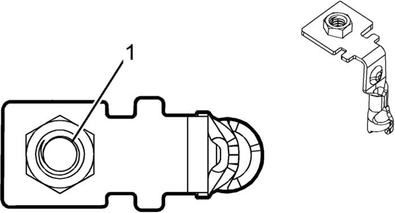
Connector Part Information
• Harness Type: Engine
• OEM Connector: 33188540
• Service Connector: Service by Cable Assembly - See Part Catalog
• Description: 1-Way Ring Terminal
|
Terminal Part Information | ||||||||||||||||
|
| ||||||||||||||
|
X50D FUSE BLOCK - BATTERY TOP VIEW |
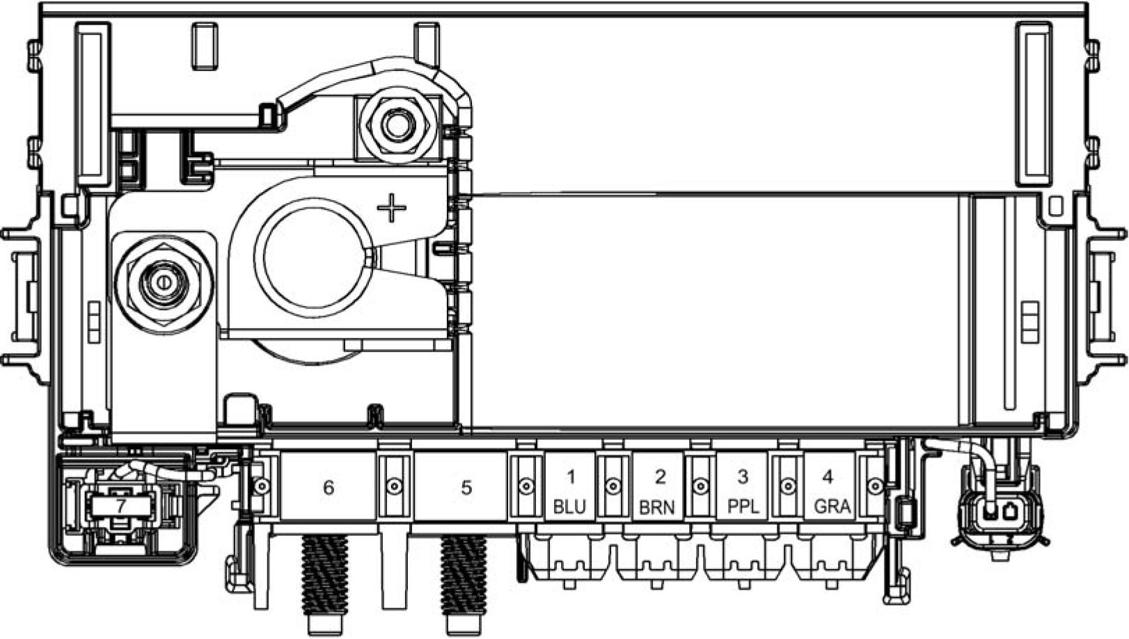
Fig. 8: X50D Fuse Block - Battery Top View
Courtesy'of GENERALMOTORS'cOMPANY
|
X50D FUSE BLOCK - BATTERY FUSE IDENTIFICATION | |||||||||||||||||||||||||||||||||||||||||||||
| |||||||||||||||||||||||||||||||||||||||||||||
|
X50D FUSE BLOCK - BATTERY BOTTOM VIEW | |||||||||||||||||||||||||||||||||||||||||||||
 |
|
Fig. 9: X50D Fuse Block - Battery Bottom View Courtesy'of GENERALMOTORS'cOMPANY |
X50D FUSE BLOCK - BATTERY X1

Connector Part Information
• Harness Type: Body
• OEM Connector: 33121434
• Service Connector: Service by Harness - See Part Catalog
• Description: 1-Way F 6.3 Series (BU)
|
Terminal Part Information | ||||||||||||||||
|
| ||||||||||||||
|
X50D FUSE BLOCK - BATTERY X2 |
 |
|
Connector Part Information |
• Harness Type: Body
• OEM Connector: 13596077
• Service Connector: Service by Harness - See Part Catalog
• Description: 1-Way F 6.3 Series (BN)
|
Terminal Part Information | ||||||||||||||||
|
|
Pin |
Size |
Color |
Circuit |
Function |
Terminal |
Option |
|
1 |
8 |
RD/GY |
142 |
Battery Positive Voltage |
I |
- |

|
Terminal Part Information | ||||||||||||||||
|
| ||||||||||||||
|
X50D FUSE BLOCK - BATTERY X5 |
Connector Part Information
• Harness Type: Body
• OEM Connector: 20051
• Service Connector: Not Available
• Description: 1-Way
|
Terminal Part Information | ||||||||||||||||
|
| ||||||||||||||
|
X50D FUSE BLOCK - BATTERY X6 |

Connector Part Information
• Harness Type: Battery Cable
• OEM Connector: 33183551
• Service Connector: Service by Cable Assembly - See Part Catalog
• Description: 1-Way Ring Terminal
|
Terminal Part Information | ||||||||||||||||
|
| ||||||||||||||
|
X50D FUSE BLOCK - BATTERY X7 |
 |
|
Connector Part Information |
• Harness Type: Battery Sense Pigtail
• OEM Connector: 12103514
• Service Connector: Service by Cable Assembly - See Part Catalog
• Description: 1-Way F Ring Terminal
|
Terminal Part Information | ||||||||||||||||
|
|
Pin |
Size |
Color |
Circuit |
Function |
Terminal |
Option |
|
A |
0.75 |
RD/WH |
4740 |
Battery Positive Voltage |
I |
- |
|
X50D FUSE BLOCK - BATTERY X8 |
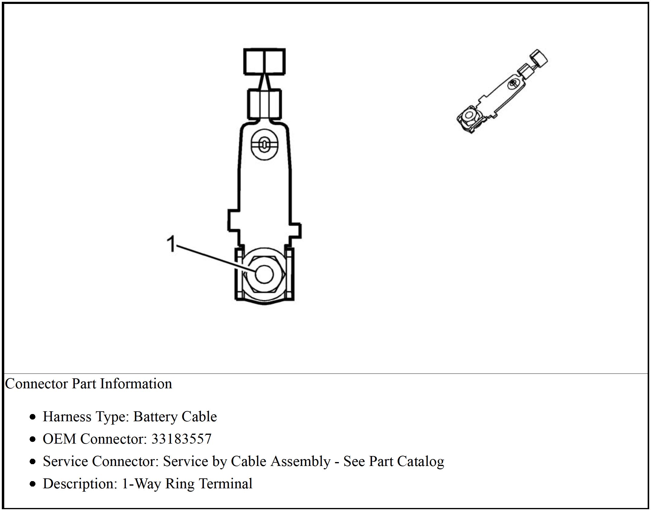 |
|
Terminal Part Information | ||||||||||||||||
|
| ||||||||||||||
|
X51A FUSE BLOCK - INSTRUMENT PANEL LABEL |
 |
|
Fig. 10: X51A Fuse Block - Instrument Panel Label |
|
X51A FUSE BLOCK - INST |
RUMENT PANEL FUSE AND RELAY IDENTIFICATION LEGEND | |||
|
No. |
Device Label |
Device Assigned |
Rating |
Description |
|
Fuses | ||||
|
F1 |
EMPTY |
F1DA |
30A |
• Not Used |
|
F2 |
EMPTY |
F2DA |
30A |
• Not Used |
|
F3 |
EMPTY |
F3DA |
30A |
• Not Used |
|
No. |
Device Label |
Device Assigned |
Rating |
Description |
|
F4 |
HVAC BLWR |
F4DA |
40A |
• K8 Blower Motor Control Module |
|
F5 |
BCM 2 |
F5DA |
15A |
• K9 Body Control Module |
|
F6 |
EMPTY |
F6DA |
25A |
• Not Used |
|
F7 |
EMPTY |
F7DA |
30A |
• Not Used |
|
F8 |
BCM 3 |
F8DA |
15A |
• K9 Body Control Module |
|
F9 |
FPPM |
F9DA |
25A |
• K111 Fuel Pump Driver Control |
|
F10 |
EMPTY |
F10DA |
30A |
• Not Used |
|
F11 |
EMPTY |
F11DA |
30A |
• Not Used |
|
F12 |
EMPTY |
F12DA |
30A |
• Not Used |
|
F13 |
EMPTY |
F13DA |
30A |
• Not Used |
|
F14 |
EMPTY |
F14DA |
15A |
• Not Used |
|
F15 |
EMPTY |
F15DA |
30A |
• Not Used |
|
F16 |
EMPTY |
F16DA |
30A |
• Not Used |
|
F17 |
DLC |
F17DA |
15A |
• X84 Data Link Connector |
|
F18 |
BCM 7 |
F18DA |
15A |
• K9 Body Control Module |
|
F19 |
CLUSTER |
F19DA |
10A |
• P16 Instrument Cluster |
|
F20 |
BCM 1 |
F20DA |
15A |
• K9 Body Control Module |
|
F21 |
BCM 4 |
F21DA |
15A |
• K9 Body Control Module |
|
F22 |
BCM 6 |
F22DA |
15A |
• K9 Body Control Module |
|
F23 |
ONSTAR |
F23DA |
10A |
• K73 Telematics Communication |
|
No. |
Device Label |
Device Assigned |
Rating |
Description |
|
F24 |
AIRBAG |
F24DA |
10A |
|
|
F25 |
DISPLY |
F25DA |
7.5A |
|
|
F26 |
INFT |
F26DA |
10A |
|
|
F27 |
EMPTY |
F27DA |
30A |
• Not Used |
|
F28 |
EMPTY |
F28DA |
30A |
• Not Used |
|
F29 |
OVRHD CNSL |
F29DA |
7.5A |
• S48B Multifunction Switch - |
|
F30 |
RDO |
F30DA |
15A |
• A11 Radio |
|
F31 |
SWC |
F31DA |
2A |
|
|
F32 |
BCM 8 |
F32DA |
20A |
• K9 Body Control Module |
|
F33 |
HVAC |
F33DA |
10A |
|
|
F34 |
PEPS |
F34DA |
5A |
• K84 Keyless Entry Control Module |
|
F35 |
REAR CLOSR |
F35DA |
7.5A |
• KR95A Liftgate Unlatch Relay |
|
F36 |
CHARGER |
F36DA |
5A |
• T22 Mobile Device Wireless Charger |
|
F37 |
EMPTY |
F37DA |
20A |
• Not Used |
|
F38 |
EMPTY |
F38DA |
- |
• Not Used |
|
F39 |
EMPTY |
F39DA |
- |
• Not Used |
| ||||||||||||||||||||||||||||||||||||||||||||||||||||||||||||
|
X51A FUSE BLOCK - INSTRUMENT PANEL TOP VIEW | ||||||||||||||||||||||||||||||||||||||||||||||||||||||||||||


|
Fig. 11: X51A Fuse Block - Instrument Panel Top View X51A FUSE BLOCK - INSTRUMENT PANEL WIRE ENTRY |
 |
Connector Part Information
• Harness Type: Instrument Panel
• OEM Connector: 33192630
• Service Connector: Service by Component Assembly - See Part Catalog
• Description: 71-Way F Wire Entry Fuse Block
|
Terminal Part Information | ||||||||||||||||||||||||||||||||||||||||||||||||
|
|
Pin |
Size |
Color |
Circuit |
Function |
Terminal |
Option |
|
1 |
8 |
RD/BU |
42 |
Battery Positive Voltage |
V |
- |
|
2 |
8 |
RD/GY |
142 |
Battery Positive Voltage |
V |
- |
|
3 - 8 |
- |
- |
- |
Not Occupied |
- |
- |
|
9 |
1 |
RD/BN |
4240 |
Battery Positive Voltage |
III |
- |
|
10 |
0.5 |
RD/GN |
2440 |
Battery Positive Voltage |
II |
- |
|
11 - 15 |
- |
- |
- |
Not Occupied |
- |
- |
|
16 |
1.5 |
RD/YE |
4340 |
Battery Positive Voltage |
IV |
- |
|
17 |
1 |
RD/VT |
340 |
Battery Positive Voltage |
III |
- |
|
18 - 19 |
- |
- |
- |
Not Occupied |
- |
- |
|
20 |
1 |
RD/GN |
4140 |
Battery Positive Voltage |
III |
- |
|
21 |
0.5 |
RD/WH |
5440 |
Battery Positive Voltage |
II |
- |
|
22 |
0.35 |
VT |
4601 |
Retained Accessory Power Fused |
II |
- |
|
23 - 25 |
- |
- |
- |
Not Occupied |
- |
- |
|
26 |
0.5 |
RD/VT |
2640 |
Battery Positive Voltage |
II |
- |
|
27 |
1 |
RD/BN |
4940 |
Battery Positive Voltage |
III |
- |
|
28 |
- |
- |
- |
Not Occupied |
- |
- |
|
29 |
4 |
RD/VT |
542 |
Battery Positive Voltage |
I |
- |
|
30 - 31 |
- |
- |
- |
Not Occupied |
- |
- |
|
32 |
0.35 |
RD/BK |
2240 |
Battery Positive Voltage |
III |
- |
|
0.5 |
RD/BK |
2240 |
Battery Positive Voltage |
- |
| ||||||||||||||||||||||||||||||||||||||||||||||||||||||||||||||||||||||||||||||||||||||||||||||||||||||||||||||||||||||||||||||||||||||||||||||||||||||||||||||||||||||||||||||||||||||||||||||||||||||||||||||||||
|
X53A FUSE BLOCK - REAR BODY LABEL |
 |
|
Fig. 12: X53A Fuse Block - Rear Body Label |
X53A FUSE BLOCK - REAR BODY TOP VIEW

Fig. 13: X53A Fuse Block - Rear Body Top View
Courtesy'of GENERAl'mOTORS'cOMPANY
|
X53A FUSE BLOCK - REAR BODY FUSE IDENTIFICATION | ||||||||||||||||||||||||||||||||||||||||||||||||||||||||||||||||||||||||||||||||||||||||||
| ||||||||||||||||||||||||||||||||||||||||||||||||||||||||||||||||||||||||||||||||||||||||||
| |||||||||||||||||||||||||||||||||||||||||||||||||||||||||||||||||||||||||||
|
X53A FUSE BLOCK - REAR BODY WIRE ENTRY | |||||||||||||||||||||||||||||||||||||||||||||||||||||||||||||||||||||||||||
 |
|
Connector Part Information |
• Harness Type: Body
• OEM Connector: 13367496
• Service Connector: Service by Component Assembly - See Part Catalog
• Description: 34-Way F Wire Entry Fuse Block
|
Terminal Part Information | ||||||||||||||||||||||||||||||||||||||||
|
|
Pin |
Size |
Color |
Circuit |
Function |
Terminal |
Option |
|
A1 |
0.5 |
YE |
6817 |
LED Backlight Dimming |
III |
- |
|
A2 - A7 |
- |
- |
- |
Not Occupied |
- |
- |
|
A8 |
0.5 |
RD/GY |
2840 |
Battery Positive Voltage |
III |
- |
| |||||||||||||||||||||||||||||||||||||||||||||||||||||||||||||||||||||||||||||||||||||||||||||||||||||||||
|
X55AL FUSE HOLDER - BODY CONTROL MODULE |
Connector Part Information
• Harness Type: Body
• OEM Connector: Not Available
• Service Connector: Service by Harness - See Part Catalog
• Description: 2-Way
|
Terminal Part Information | ||||||||||||||||
|
|
Pin |
Size |
Color |
Circuit |
Function |
Terminal |
Option |
|
1 |
0.75 |
RD/WH |
4740 |
Battery Positive Voltage |
I |
- |
|
2 |
0.75 |
RD/WH |
4740 |
Battery Positive Voltage |
I |
- |
Article GUID: A00884677
DRIVER DOOR COMPONENTS
 |
|
Fig. 1: Driver Door Components Courtesy of GENERAL MOTORS COMPANY |
Items
1. A23D Door Latch Assembly - Driver A23D Door Latch Assembly - Driver
2. A24D Door Handle Assembly - Driver Exterior A24D Door Handle Assembly - Driver Exterior
3. M74D Window Motor - Driver M74D Window Motor - Driver
4. P19AG Speaker - Left Front Door P19AG Speaker - Left Front Door (UQA) P19AG Speaker - Left
Front Door (UZ6)
5. B63LF Side Impact Sensor - Left Front B63LF Side Impact Sensor - Left Front
DRIVER DOOR TRIM COMPONENTS
 |
|
Fig. 2: Driver Door Trim Components Courtesy of GENERAL MOTORS COMPANY |
Items
1. E1D Accent Lamp - Driver Door E1D Accent Lamp - Driver Door
2. E63D Flood Lamp - Driver Door Handle E63D Flood Lamp - Driver Door Handle
3. S13D Door Lock Switch - Driver S13D Door Lock Switch - Driver
4. S146 Window/Outside Rearview Mirror Switch - Driver S146 Window/Outside Rearview Mirror
Switch - Driver
5. S117 Refuel Request Switch S117 Refuel Request Switch
PASSENGER DOOR COMPONENTS
 |
|
Fig. 3: Passenger Door Components Courtesy of GENERAL MOTORS COMPANY |
Items
1. A24P Door Handle Assembly - Passenger Exterior A24P Door Handle Assembly - Passenger
Exterior
2. A23P Door Latch Assembly - Passenger A23P Door Latch Assembly - Passenger
3. B63RF Side Impact Sensor - Right Front B63RF Side Impact Sensor - Right Front
4. M74P Window Motor - Passenger M74P Window Motor - Passenger
5. P19AH Speaker - Right Front Door P19AH Speaker - Right Front Door (UQA)
PASSENGER DOOR TRIM COMPONENTS
 |
|
Fig. 4: Passenger Door Trim Components |
Items
1. S13P Door Lock Switch - Passenger S13P Door Lock Switch - Passenger
2. E1P Accent Lamp - Passenger Door E1P Accent Lamp - Passenger Door
3. E63P Flood Lamp - Passenger Door Handle E63P Flood Lamp - Passenger Door Handle
4. S79P Window Switch - Passenger S79P Window Switch - Passenger
LEFT REAR DOOR COMPONENTS
 |
|
Fig. 5: Left Rear Door Components Courtesy of GENERAL MOTORS COMPANY |
Items
1. A23LR Door Latch Assembly - Left Rear A23LR Door Latch Assembly - Left Rear
2. A24LR Door Handle Assembly - Left Rear Exterior A24LR Door Handle Assembly - Left Rear
Exterior
3. P19AL Speaker - Left Rear Door P19AL Speaker - Left Rear Door (UQA) P19AL Speaker - Left
Rear Door (UZ6)_________________________________________________________________
4. M74LR Window Motor - Left Rear M74LR Window Motor - Left Rear
LEFT REAR DOOR TRIM COMPONENTS
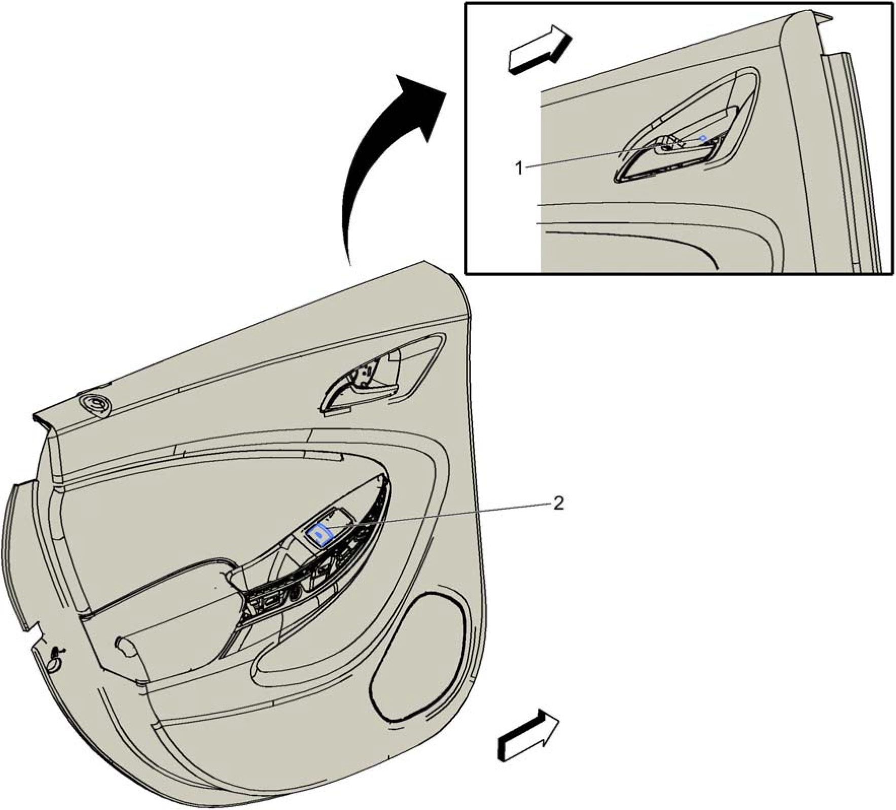 |
|
Fig. 6: Left Rear Door Trim Components |
Items
1. E63LR Flood Lamp - Left Rear Door Handle E63LR Flood Lamp - Left Rear Door Handle
2. S79LR Window Switch - Left Rear S79LR Window Switch - Left Rear
RIGHT REAR DOOR COMPONENTS
 |
|
Fig. 7: Right Rear Door Components Courtesy of GENERAL MOTORS COMPANY |
Items
1. A24RR Door Handle Assembly - Right Rear Exterior A24RR Door Handle Assembly - Right Rear
Exterior
2. A23RR Door Latch Assembly - Right Rear A23RR Door Latch Assembly - Right Rear
3. M74RR Window Motor - Right Rear M74RR Window Motor - Right Rear___________________
4. P19AM Speaker - Right Rear Door P19AM Speaker - Right Rear Door (UQA) P19AM Speaker -
Right Rear Door (UZ6)
RIGHT REAR DOOR TRIM COMPONENTS
 |
|
Fig. 8: Right Rear Door Trim Components |
Items
1. S79RR Window Switch - Right Rear S79RR Window Switch - Right Rear
2. E63RR Flood Lamp - Right Rear Door Handle E63RR Flood Lamp - Right Rear Door Handle
Article GUID: A00884673
ENGINE COMPARTMENT COMPONENTS
 |
|
Fig. 1: Engine Compartment Components |
Items
1. M75 Windshield Wiper Motor M75 Windshield Wiper Motor
2. X55QA Fuse Holder 1 - Hybrid/EV Battery Pack
3. A28 Hybrid/EV Battery Contactor Assembly A28 Hybrid/EV Battery Contactor Assembly X3 A28
Hybrid/EV Battery Contactor Assembly X4 A28 Hybrid/EV Battery Contactor Assembly X5 A28
Hybrid/EV Battery Contactor Assembly X6
ENGINE COMPARTMENT COMPONENTS - FRONT (1 OF 4)

Fig. 2: Engine Compartment Components - Front (1 of 4)
Courtesy of GENERAL MOTORS COMPANY
Items
1. B258 Hybrid/EV Battery Coolant Level Switch B258 Hybrid/EV Battery Coolant Level Switch
ENGINE COMPARTMENT COMPONENTS - FRONT (2 OF 4)
 |
|
Fig. 3: Engine Compartment Components - Front (2 of 4) |
Items
1. G10L Cooling Fan Motor - Left G10L Cooling Fan Motor - Left
2. G37 Hybrid/EV Battery Pack Coolant Pump G37 Hybrid/EV Battery Pack Coolant Pump
3. B202 Hybrid/EV Electronics Coolant Temperature Sensor B202 Hybrid/EV Electronics Coolant
Temperature Sensor
4. B203 Radiator Coolant Temperature Sensor B203 Engine Coolant Radiator Temperature Sensor
5. G10R Cooling Fan Motor - Right G10R Cooling Fan Motor - Right
ENGINE COMPARTMENT COMPONENTS - FRONT (3 OF 4)
 |
|
Fig. 4: Engine Compartment Components - Front (3 of 4) |
Items
1. X50A Fuse Block - Underhood X50A Fuse Block - Underhood X1 X50A Fuse Block - Underhood
X2 X50A Fuse Block - Underhood X3_________________________________________________
2. G35 Hybrid/EV Electronics Coolant Pump G35 Hybrid/EV Electronics Coolant Pump
3. B55 Hood Ajar Switch B55 Engine Hood Switch
4. P48 Pedestrian Alert Sound Speaker P48 Pedestrian Alert Sound Speaker
ENGINE COMPARTMENT COMPONENTS - FRONT (4 OF 4)
 |
|
Fig. 5: Engine Compartment Components - Front (4 of 4) |
Items
1. M96 Active Grille Air Shutter Actuator M96 Active Grille Air Shutter Actuator
ENGINE COMPARTMENT COMPONENTS - LEFT
 |
|
Fig. 6: Engine Compartment Components - Left |
Items
1. K177 Brake Booster Control Module K177 Brake Booster Control Module
2. B20 Brake Fluid Level Switch B20 Brake Fluid Level Switch
3. X50B Fuse Block - Underhood Auxiliary X50B Fuse Block - Underhood Auxiliary X1
4. X50A Fuse Block - Underhood X50A Fuse Block - Underhood X1 X50A Fuse Block - Underhood
X2 X50A Fuse Block - Underhood X3__________________________________________________
5. K17 Electronic Brake Control Module K17 Electronic Brake Control Module
6. B201 Brake Control Brake Pedal Position Sensor B201 Brake Control Brake Pedal Position Sensor
ENGINE COMPARTMENT COMPONENTS - RIGHT
 |
|
Fig. 7: Engine Compartment Components - Right |
Items
1. K10 Coolant Heater Control Module K10 Coolant Heater Control Module X1
FRONT OF VEHICLE COMPONENTS (1 OF 2)
 |
|
Fig. 8: Front of Vehicle Components (1 of 2) |
|
Items |
|
1. E2RF Side Marker Lamp - Right Front |
|
2. A9B Outside Rearview Mirror - Passenger |
|
3. E4H Headlamp - Right Low Beam |
|
4. E4F Headlamp - Right High Beam E4F Headlamp - Right High Beam |
|
5. E4RF Turn Signal Lamp - Right Front |
|
6. E4LF Turn Signal Lamp - Left Front |
|
7. E4E Headlamp - Left High Beam E4E Headlamp - Left High Beam |
|
8. E4G Headlamp - Left Low Beam |
|
9. A9A Outside Rearview Mirror - Driver |
|
10. E2LF Side Marker Lamp - Left Front |
|
11. E13LA Headlamp Assembly - Left |
|
12. B306K Parking Assist Sensor - Side Left Front (UKC) B306K Parking Assist Sensor - Side Left Front |
|
13. E4AC Park/Daytime Running Lamp - Left E4AC Park/Daytime Running Lamp - Left |
|
14. B306A Parking Assist Sensor - Front Left Outer (UFQ) B306A Parking Assist Sensor - Front Left Outer |
|
15. B306B Parking Assist Sensor - Front Left Middle (UFQ) B306B Parking Assist Sensor - Front Left |
|
Middle |
|
16. B9 Ambient Air Temperature Sensor B9 Ambient Air Temperature Sensor |
Items
17. B306C Parking Assist Sensor - Front Right Middle (UFQ) B306C Parking Assist Sensor - Front
Right Middle___________________________________________________________________________
18. B306D Parking Assist Sensor - Front Right Outer (UFQ) B306D Parking Assist Sensor - Front
Right Outer
19. E4AD Park/Daytime Running Lamp - Right E4AD Park/Daytime Running Lamp - Right
20. B306L Parking Assist Sensor - Side Right Front (UKC) B306L Parking Assist Sensor - Side Right
Front
21. E13RA Headlamp Assembly - Right
FRONT OF VEHICLE COMPONENTS (2 OF 2)
 |
|
Fig. 9: Front of Vehicle Components (2 of 2) |
Items
1. B59L Front Impact Sensor - Left B59L Front Impact Sensor - Left
2. B59R Front Impact Sensor - Right B59R Front Impact Sensor - Right
LEFT FRONT OF VEHICLE COMPONENTS (1 OF 2)
 |
|
Fig. 10: Left Front of Vehicle Components (1 of 2) |
Items
1. K20 Engine Control Module K20 Engine Control Module X1 K20 Engine Control Module X2 K20
Engine Control Module X3
LEFT FRONT OF VEHICLE COMPONENTS (2 OF 2)
 |
|
Fig. 11: Left Front of Vehicle Components (2 of 2) |
Items
1. X98 Hybrid/EV Battery Charger Receptacle X98 Hybrid/EV Battery Charger Receptacle
2. E85 Hybrid/EV Battery Charger Receptacle Accent Lamp
3. B197 Charge Port Door Position Switch B197 Charge Port Door Position Switch
RIGHT FRONT OF VEHICLE COMPONENTS
 |
|
Fig. 12: Right Front of Vehicle Components |
Items
1. P12 Horn P12 Horn
2. B118B Windshield Washer Fluid Level Switch B118B Windshield Washer Fluid Level Switch
3. G24 Windshield Washer Pump G24 Windshield Washer Pump
Article GUID: A00884703
ELECTRICAL
Wiring Systems and Power Management - Component Locator - Ground Views - Volt
G101
 |
|
Fig. 1: G101 Courtesy of GENERAL MOTORS COMPANY |
Items
1. G101
G102

Fig. 2: G102
Courtesy of GENERAL MOTORS COMPANY
Items
1. G102
G104 AND G113
 |
|
Fig. 3: G104 and G113 Courtesy of GENERAL MOTORS COMPANY |
Items
1. G104___________________________________________
2. G113
G105
 |
|
Fig. 4: G105 Courtesy of GENERAL MOTORS COMPANY |
Items
1. G105
G109
 |
|
Fig. 5: G109 Courtesy of GENERAL MOTORS COMPANY |
Items
1. G109
G110 AND G112
 |
|
Fig. 6: G110 and G112 Courtesy of GENERAL MOTORS COMPANY |
Items
1. G110___________________________________________
2. G112
G117
 |
|
Fig. 7: G117 Courtesy of GENERAL MOTORS COMPANY |
Items
1. G117
G122
 |
|
Fig. 8: G122 Courtesy of GENERAL MOTORS COMPANY |
Items
1. G122
G201 AND G204


|
Fig. 9: G201 and G204 Courtesy of GENERAL MOTORS COMPANY |
 |
 |
|
Fig. 10: G202 Courtesy of GENERAL MOTORS COMPANY |
Items
1. G202
G205

Fig. 11: G205
Courtesy of GENERAL MOTORS COMPANY
Items
1. G205
G301

Fig. 12: G301
Courtesy of GENERAL MOTORS COMPANY
Items
1. G301
G302

Fig. 13: G302
Courtesy of GENERAL MOTORS COMPANY
Items
1. G302
G304

Fig. 14: G304
Courtesy of GENERAL MOTORS COMPANY
Items
1. G304
G340 AND G341
 |
|
Fig. 15: G340 and G341 Courtesy of GENERAL MOTORS COMPANY |
Items
1. G340___________________________________________
2. G341
G403
1. G403
G405
 |
|
Fig. 16: G403 Courtesy of GENERAL MOTORS COMPANY |
Items
 |
|
Fig. 17: G405 Courtesy of GENERAL MOTORS COMPANY |
Items
1. G405
G406
 |
|
Fig. 18: G406 Courtesy of GENERAL MOTORS COMPANY |
Items
1. G406
G408 AND G409
 |
|
Fig. 19: G408 and G409 Courtesy of GENERAL MOTORS COMPANY |
Items
1. G408
2. G409
Article GUID: A00884716
SPECIFICATIONS
FASTENER SPECIFICATIONS
|
Reusable Threaded Fastener Tightening Specifications | |||||||||||||
| |||||||||||||
SCHEMATIC WIRING DIAGRAMS
HYBRID/EV CONTROLS WIRING SCHEMATICS
Power, Ground and Data Communication
 |
|
Fig. 1: Power, Ground and Data Communication |
Manual Drive Mode Select Interface
Fig. 2: Manual Drive Mode Select Interface
Courtesy'of GENERAL'MOTORS'COMPANY
Drive Motor Monitoring
 |
|
Fig. 3: Drive Motor Monitoring Courtesy'of GENERAL'MOTORS COMPANY |
Drive Motors and Auxiliary Transmission Fluid Pump Controls
 |
|
Fig. 4: Drive Motors and Auxiliary Transmission Fluid Pump Controls |
COMPONENT LOCATOR
hybrid controls electronic component views
|
Hybrid Control Electronic Component Views |
 |
|
Fig. 5: Hybrid Control Electronic Component Views |
|
Callout |
Component Name |
|
1 |
K1 14 V Power Module |
|
Callout |
Component Name |
|
2 |
High Voltage Battery |
|
3 |
T6 Power Inverter Module |
|
4 |
T12 Automatic Transmission Assembly |
|
5 |
T18 Battery Charger |
DIAGNOSTIC INFORMATION AND PROCEDURES
DTC P0335 OR P0336: CRANKSHAFT POSITION SENSOR
Diagnostic Instructions
• Perform the Diagnostic System Check prior to using this diagnostic procedure: Diagnostic System Check -
Vehicle
• Review the description of Strategy Based Diagnosis: Strategy Based Diagnosis
• An overview of each diagnostic category can be found here: Diagnostic Procedure Instructions
DTC Descriptor
Crankshaft Position Sensor Circuit
Crankshaft Position Sensor Performance
Circuit/System Description
The crankshaft position sensor circuits consist of an engine control module (ECM) supplied 5 V reference circuit,
low reference circuit, and an output signal circuit. The crankshaft position sensor is a magnetic biased digital output
integrated circuit sensing device. The sensor detects magnetic flux changes of invisible magnetic segments on the
edge of the crankshaft position reluctor ring mounted on the crankshaft. Each magnetic segment on the ring is spaced
at a 60 segment spacing with 2 missing spaces for a reference gap. The crankshaft position sensor produces an
ON/OFF DC voltage of varying frequency, with 58 output pulses per crankshaft revolution. The frequency of the
crankshaft position sensor output depends on the velocity of the crankshaft. The crankshaft position sensor sends a
digital signal, which represents an image of the crankshaft reluctor ring, to the ECM as each segment on the ring
rotates past the crankshaft position sensor. The ECM uses each crankshaft position signal pulse to determine
crankshaft speed and decodes the crankshaft reluctor ring reference gap to identify crankshaft position. This
information is then used to determine the optimum ignition and injection points of the engine. The ECM also uses
crankshaft position sensor output information to determine the camshaft relative position to the crankshaft, to control
camshaft phasing, and to detect cylinder misfire.
The ECM also generates and sends a replicated signal over a dedicated line to the hybrid/EV powertrain control
module 1.
The hybrid/EV powertrain control module 1 uses crankshaft speed and position to confirm internal combustion
engine (ICE) status in various modes; for example to confirm Autostart and Autostop functionality. In addition to the
signal sent over the dedicated line, this information is also sent from the ECM to the hybrid/EV powertrain control
module 1 over serial data. The serial data status will be used by the hybrid/EV powertrain control module 1 in the
event of a failure of this circuit.
Conditions for Running the DTC
The vehicle is ON.
Conditions for Setting the DTC
No signal from the crank sensor for more than 1.4 seconds.
The signal from the crank sensor is invalid for more than 1.4 seconds.
OR
15 crankshaft sensor resync events occur in less than 10 seconds.
Action Taken When the DTC Sets
DTCs P0335 and P0336 are Type B DTCs.
Conditions for Clearing the DTC
DTCs P0335 and P0336 are Type B DTCs.
Diagnostic Aids
A high resistance ground for either the power inverter module, often referred to as the drive motor generator power
inverter module, or the ECM may cause these DTCs to set intermittently. Inspect all grounds for good, secure
connections.
Reference Information
Schematic Reference
Connector End View Reference
Description and Operation
Electrical Information Reference
Circuit Testing
Connector Repairs
Testing for Intermittent Conditions and Poor Connections
• Wiring Repairs
DTC Type Reference
Scan Tool Reference
Special Tools
• EL-35616 Terminal Test Kit
• EL-38522 Variable Signal Generator
Equivalent regional tools: Special Tools
Circuit/System Verification
1. Engine Running, observe the hybrid/EV powertrain control module Engine Speed parameter with a scan tool.
2. Verify the Engine Speed parameter displays the current engine speed, matching the tachometer and/or the
ECM Engine Speed parameter.
Refer to Circuit/System Testing.
3. All OK
Circuit/System Testing
1. Vehicle OFF and all vehicle systems OFF. It may take up to 2 minutes for all vehicle systems to power down.
2. Disconnect the X2 harness connector at the K20 ECM.
3. Using the EL 35616 terminal test kit, connect the EL 38522 variable signal generator red lead to the
Crankshaft 60X Sensor Signal circuit terminal 42 at the harness. Connect the EL 38522 variable signal
generator black lead to ground.
4. Set the EL 38522 variable signal generator SIGNAL to 12 V, FREQUENCY to 30 Hz, and DUTY CYCLE to
NORMAL, 50 percent. Plug power cord in to vehicle being tested or another power source.
5. Vehicle ON.
6. Verify with a scan tool the hybrid/EV powertrain control module Crankshaft Position Resync Counter
parameter displays a constantly changing value.
1. Vehicle OFF, disconnect EL 38522 variable signal generator red and black leads, disconnect the X1
harness connector at the T6 power inverter module, vehicle ON.
2. Test for less than 1 V between the signal circuit terminal 29 and ground.
• If 1 V or greater, repair the short to voltage on the circuit.
• If less than 1 V
3. Vehicle OFF.
4. Test for infinite resistance between the signal circuit terminal 29 and ground.
• If less than infinite resistance, repair the short to ground on the circuit.
• If infinite resistance
5. Test for less than 2 Q in the signal circuit end to end.
• If 2 Q or greater, repair the open/high resistance in the circuit.
• If less than 2 Q, replace the T6 power inverter module.
7. Replace the K20 ECM.
Repair Instructions
Perform the Diagnostic Repair Verification after completing the repair: Diagnostic Repair Verification
Refer to Control Module References for engine control module or T6 Power Inverter Module, often referred to as
the Drive Motor Generator Power Inverter Module, replacement, programming, and setup
Diagnostic Instructions
• Perform the Diagnostic System Check - Vehicle prior to using this diagnostic procedure.
• Review Strategy Based Diagnosis for an overview of the diagnostic approach.
• Refer to Diagnostic Procedure Instructions to provide an overview of each diagnostic category.
DTC Descriptors
Idle Speed Low
Idle Speed High
Circuit/System Description
The hybrid/EV powertrain control module 1 determines the engine idling speed which varies based on the hybrid/EV
battery pack state of charge. The engine control module (ECM) achieves throttle positioning by providing a pulse
width modulated voltage to the throttle actuator motor. The throttle blade is spring loaded in both directions, and the
default position is slightly open. The hybrid/EV powertrain control module 1 can detect a condition where the engine
is cranking but does not start or has stalled, or if the engine speed does not match the commanded speed.
The throttle actuator control (TAC) motor is controlled by the ECM. The DC motor located in the throttle body
drives the throttle blade. In order to decrease engine speed, along with spark and fuel delivery changes the ECM
commands the throttle closed reducing air flow into the engine and the engine speed decreases. In order to increase
engine speed, the ECM commands the throttle plate open allowing more air to pass the throttle plate. If the
hybrid/EV powertrain control module 1 detects the actual engine speed is not within a predetermined range of the
commanded engine speed, this DTC sets.
Conditions for Running the DTC
• DTCs P0722, P077B, P0A3F, P0A40, P0A45, P0A46, P0C52, P0C53, P0C57, P0C58, P0C5C, P0C5D,
P0C61, P0C62, P1B03, P1B04, P215C are not set.
• The system voltage is greater than 9 volts.
• The accelerator pedal position is valid.
• The accelerator pedal position is less than 1 percent.
• The engine has been running for greater than 60 seconds.
• The vehicle speed is less than 2 km/h (1.2 mph).
• The engine coolant temperature (ECT) is 60A°C (140A°F) or greater.
• The commanded engine speed is steady within 50 RPM.
• The commanded engine speed is steady within 25 RPM.
• A scan tool output control is not active.
• DTCs P0506 or P0507 run continuously when the above conditions are met for greater than 10 seconds.
Conditions for Setting the DTC
The actual engine speed is at least 91 RPM less than the commanded engine speed.
The actual engine speed is at least 182 RPM greater than the commanded engine speed.
Action Taken When the DTC Sets
DTCs P0506 and P0507 are Type B DTCs.
Conditions for Clearing the DTC
DTCs P0506 and P0507 are Type B DTCs.
Diagnostic Aids
• A stalling condition can cause DTC P0506 to set.
• An intermittent vehicle speed sensor (VSS) signal can cause DTC P0507 to set.
Reference Information
Schematic Reference
Connector End View Reference
Electrical Information Reference
Circuit Testing
Connector Repairs
• Testing for Intermittent Conditions and Poor Connections
Wiring Repairs
DTC Type Reference
Scan Tool Reference
Control Module References for scan tool information
Circuit/System Verification
1. Verify no other DTCs are set.
• If any other DTCs are set
Refer to Diagnostic Trouble Code (DTC) List - Vehicle .
• If no other DTCs are set
2. Verify none of the conditions listed below exist:
• Excess deposits in the Q38 Throttle Body. Refer to Throttle Body Inspection and Cleaning .
• Restricted exhaust
• Mechanical conditions that limit engine speed
• Parasitic load on the engine - For example, a transmission condition, a belt driven accessory condition.
Repair as necessary.
3. All OK
• Vacuum leaks
• A throttle valve that does not close correctly
• Verify the correct operation of the crankcase ventilation system. Inspect for the following conditions:
• The routing of the positive crankcase ventilation (PCV) system
• Vacuum leaks in the PCV system
Repair as necessary.
4. All OK
Repair Instructions
Perform the Diagnostic Repair Verification after completing the repair.
DTC P0601-P0604, P0606, P062F, P1EB6, OR P1EB7: CONTROL MODULE (HYBRID/EV POWERTRAIN
CONTROL MODULE 1)
Diagnostic Instructions
• Perform the Diagnostic System Check - Vehicle prior to using this diagnostic procedure.
• Review Strategy Based Diagnosis for an overview of the diagnostic approach.
• Refer to Diagnostic Procedure Instructions to provide an overview of each diagnostic category.
DTC Descriptors
Control Module Read Only Memory Performance
Control Module Not Programmed
Control Module Long Term Memory Reset
Control Module Random Access Memory Performance
Control Module Processor Performance
Control Module Long Term Memory Performance
Drive Motor 1 Control Module Long Term Memory Reset
Drive Motor 2 Control Module Long Term Memory Reset
Circuit/System Description
This is an internal fault detection of the hybrid/EV powertrain control module 1 or drive motor control modules. The
hybrid/EV powertrain control module 1 and both drive motor control modules are internal to the power inverter
module, often referred to as the drive motor generator power inverter module, and not serviced separately. This fault
is handled inside the power inverter module, and no external circuits are involved.
Conditions for Running the DTC
• The vehicle is ON.
• The system voltage is greater than 9.5 V.
Conditions for Setting the DTC
The control module has detected an internal malfunction.
Action Taken When the DTC Sets
• DTCs P0601 - P0604, P0606, P061A, P061B, P1EB6, and P1EB7 are Type A DTCs.
• DTC P062F is a Type B DTC.
• The hybrid/EV powertrain control module 1 requests the hybrid/EV powertrain control module 2 to open the
high voltage contactor relays.
Conditions for Clearing the DTC
• DTCs P0601 - P0604, P0606, P061A, P061B, P1EB6, and P1EB7 are Type A DTCs.
• DTC P062F is a Type B DTC.
Reference Information
Electrical Information Reference
Circuit Testing
Connector Repairs
Testing for Intermittent Conditions and Poor Connections
Wiring Repairs
DTC Type Reference
Powertrain Diagnostic Trouble Code (DTC) Type Definitions
Circuit/System Verification
1. Vehicle ON.
2. Verify DTC P0562 is not set.
• If the DTC is set
Refer to DTC B1325, B1330, B1517, C0800, C0899, C0900, C12E1, C12E2, P0561-P0563, P1A0C,
P1A0D, or P1EFC .
3. Verify DTC P0601, P0602, P0603, P0604, P0606, P061A, P061B, P062F, P1EB6, or P1EB7 is not set.
• If any of the DTCs are set
1. Verify the T6 Power Inverter Module has the latest calibration in Calibration Information.
• If the T6 Power Inverter Module does not have the latest calibration, program the T6 power
inverter module.
• If the T6 Power Inverter Module has the latest calibration, replace the T6 Power Inverter Module.
2. Verify the DTC does not set.
• If the DTC sets, replace the T6 Power Inverter Module.
• If the DTC does not set.
3. All OK
4. All OK
Repair Instructions
Perform the Diagnostic Repair Verification after completing the repair.
Refer to Control Module References for T6 Power Inverter Module, often referred to as the Drive Motor Generator
Power Inverter Module, replacement, programming, and setup
DTC P061A OR P061B: CONTROL MODULE TORQUE SYSTEM
Diagnostic Instructions
• Perform the Diagnostic System Check - Vehicle prior to using this diagnostic procedure.
• Review Strategy Based Diagnosis for an overview of the diagnostic approach.
• Refer to Diagnostic Procedure Instructions to provide an overview of each diagnostic category.
DTC Descriptors
Control Module Torque System Circuitry Performance
Control Module Torque Calculation Performance
Circuit/System Description
The hybrid/EV powertrain control module 1 is responsible for vehicle torque management. To accomplish this, the
hybrid/EV powertrain control module 1 constantly monitors all aspects of requested and actual delivered torque from
involved controllers. If a torque management fault is detected, propulsion power will be reduced or shut down. The
hybrid/EV powertrain control module 1 is internal to the power inverter module, often referred to as the drive motor
generator power inverter module, and is not serviced separately. This fault is handled inside the power inverter
module and no external circuits are involved.
Conditions for Running the DTC
• The vehicle is ON.
• The system voltage is at least 9.5 V.
Conditions for Setting the DTC
The control module has detected an internal malfunction.
Action Taken When the DTC Sets
• DTCs P061A or P061B are Type A DTCs.
• The hybrid/EV powertrain control module 1 requests the hybrid/EV powertrain control module 2 to open the
high voltage contactor relays.
Conditions for Clearing the DTC
DTCs P061A and P061B are Type A DTCs.
Reference Information
Electrical Information Reference
Circuit Testing
Connector Repairs
Testing for Intermittent Conditions and Poor Connections
Wiring Repairs
DTC Type Reference
Powertrain Diagnostic Trouble Code (DTC) Type Definitions
Circuit/System Verification
1. Vehicle ON.
2. Verify DTC P0562 is not set.
• If the DTC is set
Refer to DTC B1325, B1330, B1517, C0800, C0899, C0900, C12E1, C12E2, P0561-P0563, P1A0C,
P1A0D, or P1EFC .
3. Verify DTC P061A or P061B is not set.
• If any of the DTCs are set
Replace the T6 Power Inverter Module.
4. All OK
Repair Instructions
Perform the Diagnostic Repair Verification after completing the repair.
Refer to Control Module References for T6 Power Inverter Module, often referred to as the Drive Motor Generator
Power Inverter Module, replacement, programming, and setup
DTC P06AF: TORQUE MANAGEMENT SYSTEM PERFORMANCE - FORCED ENGINE SHUTDOWN
Diagnostic Instructions
• Perform the Diagnostic System Check - Vehicle prior to using this diagnostic procedure.
• Review Strategy Based Diagnosis for an overview of the diagnostic approach.
• Refer to Diagnostic Procedure Instructions to provide an overview of each diagnostic category.
DTC Descriptor
Torque Management System Performance - Forced Engine Shutdown
Circuit/System Description
The hybrid/EV powertrain control module 1 monitors a state of health message that the ECM transmits to verify the
ECM is functioning properly. The hybrid/EV powertrain control module 1 is part of the power inverter module, often
referred to as the drive motor generator power inverter module, and is not serviced separately.
Conditions for Running the DTC
The system voltage is greater than 9.5 V
Conditions for Setting the DTC
The hybrid/EV powertrain control module 1 does not detect a valid state of health message from the ECM.
Action Taken When the DTC Sets
• DTC P06AF is a Type A DTC.
• The hybrid/EV powertrain control module 1 requests the hybrid/EV powertrain control module 2 to open the
high voltage contactor relays.
Conditions for Clearing the DTC
DTC P06AF is a Type A DTC.
Reference Information
Schematic Reference
Connector End View Reference
Electrical Information Reference
Circuit Testing
Connector Repairs
Testing for Intermittent Conditions and Poor Connections
Wiring Repairs
DTC Type Reference
Scan Tool Reference
Control Module References for scan tool information
Circuit/System Verification
1. Vehicle ON.
2. Verify DTC P0606 is not set.
• If the DTC is set
Refer to DTC P0601-P0604, P0606, P062F, P1EB6, or P1EB7 (Hybrid/EV Powertrain Control
Module 1).
3. Verify DTC P06AF is not set.
1. Verify the T6 Power Inverter Module has the latest calibration in Calibration Information.
• If the T6 Power Inverter Module does not have the latest calibration, program the T6 power
inverter module.
• If the T6 Power Inverter Module has the latest calibration, replace the T6 Power Inverter Module.
2. Operate the vehicle within the Conditions for Running the DTC. You may also operate the vehicle
within the conditions that you observed from the Freeze Frame/Failure Records data.
3. Verify the DTC does not set.
• If the DTC sets, continue to Circuit/System Testing.
• If the DTC does not set.
4. All OK.
4. All OK.
Circuit/System Testing
1. Vehicle OFF.
2. Disconnect the X1 harness connector at the T6 Power Inverter Module and disconnect the X1 harness at the
K20 ECM.
3. Test for less than 2 Q on the serial data circuits listed below end to end.
• T6 Power Inverter Module X1 connector terminal 33 to K20 ECM X1 connector terminal 8
• T6 Power Inverter Module X1 connector terminal 34 to K20 ECM X1 connector terminal 7
Repair the open/high resistance in the circuit.
4. Replace the K20 ECM.
5. Operate the vehicle within the Conditions for Running the DTC. You may also operate the vehicle within the
conditions that you observed from the Freeze Frame/Failure Records data.
6. Verify the DTC does not set.
Replace the T6 Power Inverter Module.
7. All OK
Repair Instructions
Perform the Diagnostic Repair Verification after completing the repair.
Refer to Control Module References for K20 ECM or T6 Power Inverter Module, often referred to as the Drive
Motor Generator Power Inverter Module, replacement, programming, and setup
Diagnostic Instructions
• Perform the Diagnostic System Check prior to using this diagnostic procedure: Diagnostic System Check -
• Review the description of Strategy Based Diagnosis: Strategy Based Diagnosis
• An overview of each diagnostic category can be found here: Diagnostic Procedure Instructions
DTC Descriptor
Sensor Supply Voltage Circuit 1 Low Voltage
Sensor Supply Voltage Circuit 1 High Voltage
Sensor Supply Voltage Circuit 2 Low Voltage
Sensor Supply Voltage Circuit 2 High Voltage
Sensor Supply Voltage Circuit 3 Low Voltage
Sensor Supply Voltage Circuit 3 High Voltage
Circuit/System Description
The Hybrid/EV powertrain control module 1 and motor control modules share an internal 15 V reference power
supply in order to operate the drive motor sensors processors. This fault is handled inside the power inverter module,
often referred to as the drive motor generator power inverter module, and no external circuits are involved. The
control modules listed below are part of the power inverter module and are not serviced separately:
• Drive motor 1 control module
• Drive motor 2 control module
• Hybrid/EV powertrain control module 1
Conditions for Running the DTC
• The vehicle is ON.
• The system voltage is 8 - 18 V.
Conditions for Setting the DTC
The reference voltage is less than 12 V for 1 s.
The reference voltage is greater than 22 V for 1 s.
Actions Taken When the DTC Sets
• DTCs P06B1, P06B2, P06B4, P06B5, P06E7, and P06E8 are Type A DTCs.
• The power inverter module requests the hybrid/EV powertrain control module 2 to open the high voltage
contactor relays.
Actions Taken When the DTC Sets
DTCs P06B1, P06B2, P06B4, P06B5, P06E7, and P06E8 are Type A DTCs.
Diagnostic Aids
This DTC may set due to low 12 V system voltage.
Reference Information
DTC Type Reference
Powertrain Diagnostic Trouble Code (DTC) Type Definitions
Circuit/System Verification
1. Vehicle ON.
2. Verify DTC P06B1, P06B2, P06B4, P06B5, P06E7, or P06E8 is not set.
• If any of the DTCs are set
1. Verify the T6 Power Inverter Module has the latest calibration in Calibration Information.
• If the T6 Power Inverter Module does not have the latest calibration, program the T6 power
inverter module.
• If the T6 Power Inverter Module has the latest calibration, replace the T6 Power Inverter Module.
2. Verify the DTC does not set.
• If the DTC sets, replace the T6 Power Inverter Module.
• If the DTC does not set.
3. All OK
3. All OK
Repair Instructions
Perform the Diagnostic Repair Verification after completing the repair.
Refer to Control Module References for T6 Power Inverter Module, often referred to as the Drive Motor Generator
Power Inverter Module, replacement, programming, and setup
DTC P0A1B OR P0A1C: DRIVE MOTOR 1-2 CONTROL MODULE PERFORMANCE
Diagnostic Instructions
• Perform the Diagnostic System Check - Vehicle prior to using this diagnostic procedure.
• Review Strategy Based Diagnosis for an overview of the diagnostic approach.
• Refer to Diagnostic Procedure Instructions to provide an overview of each diagnostic category.
DTC Descriptors
DTC P0A1B
Drive Motor 1 Control Module Performance
Drive Motor 2 Control Module Performance
Circuit/System Description
The power inverter module is often referred to as the drive motor generator power inverter module. This is a fault
detection of the power inverter module's internal motor control modules. This fault is handled inside the power
inverter module; no external circuits are involved. The motor control modules are part of the power inverter module
and are not serviced separately.
Conditions for Running the DTC
• The vehicle is ON.
• The system voltage is greater than 9.5 V.
Conditions for Setting the DTC
The control module has detected an internal malfunction.
Action Taken When the DTC Sets
• DTCs P0A1B and P0A1C are Type A DTCs.
• The power inverter module requests the hybrid powertrain control module 2 to open the high voltage contactor
relays.
Conditions for Clearing the DTC
DTCs P0A1B and P0A1C are Type A DTCs.
Reference Information
DTC Type Reference
Circuit/System Verification
1. Vehicle ON.
2. Verify DTC P0A1B or P0A1C is not set.
1. Verify the T6 Power Inverter Module has the latest calibration in Calibration Information.
• If the T6 Power Inverter Module does not have the latest calibration, program the T6 power
inverter module.
• If the T6 Power Inverter Module has the latest calibration, replace the T6 Power Inverter Module.
2. Verify the DTC does not set.
• If the DTC sets, replace the T6 Power Inverter Module.
• If the DTC does not set.
3. All OK
3. All OK
Repair Instructions
Refer to Control Module References for T6 Power Inverter Module, often referred to as the Drive Motor Generator
Power Inverter Module, replacement, programming, and setup
DTC P0A3F, P0A40, P0C52, P0C53, P0C5C, P0C5D, OR P1B03: DRIVE MOTOR 1 POSITION SENSOR
Diagnostic Instructions
• Perform the Diagnostic System Check - Vehicle prior to using this diagnostic procedure.
• Review Strategy Based Diagnosis for an overview of the diagnostic approach.
• Refer to Diagnostic Procedure Instructions to provide an overview of each diagnostic category.
DTC Descriptors
Drive Motor 1 Position Sensor Circuit
Drive Motor 1 Position Sensor Performance
Drive Motor 1 Position Sensor Circuit 1 Low Voltage
Drive Motor 1 Position Sensor Circuit 1 High Voltage
Drive Motor 1 Position Sensor Circuit 2 Low Voltage
Drive Motor 1 Position Sensor Circuit 2 High Voltage
Drive Motor 1 Position Sensor Circuit Tracking Lost
|
Diagnostic Fault Information | |||||||||||||||||||||||||
| |||||||||||||||||||||||||
|
Circuit/System Description | |||||||||||||||||||||||||
The drive motor position sensor is monitored by the motor control module. The motor control module monitors the
angular position, speed and direction of the drive motor rotor based upon the signals of the resolver-type position
sensor. The position sensor contains a drive coil, two driven coils, and an irregular shaped metallic rotor. The
metallic rotor is mechanically attached to the shaft of the drive motor. At vehicle ON, the motor control module
outputs a 7 V AC, 10 kHz excitation signal to the drive coil. The drive coil excitation signal creates a magnetic field
surrounding the two driven coils and the irregular shaped rotor. The motor control module then monitors the two
driven coil circuits for return signals, often referred to as Sine and Cosine waveforms, abbreviated SIN and COS.
The position of the irregular metallic rotor causes the magnetically-induced return signals of the driven coils to vary
in size and shape. A comparison of the two driven coil signals allows the motor control module to determine the
exact position, speed and direction of the drive motor rotor. The drive motor 1 position sensor is serviceable
separately from the drive motor assembly.
Conditions for Running the DTC
The vehicle is ON.
Conditions for Setting the DTC
Circuit voltage is less than 0.5 V.
Circuit voltage is greater than 4.5 V.
SIN or COS signal is less than 2.3 V The motor control module cannot determine the motor position based upon the
sensor signals.
SIN or COS signal is greater than 4 V. The motor control module detects a degraded motor position sensor signal.
The motor control module is unable to track the motor position based upon the sensor signals.
Action Taken When the DTC Sets
• DTCs P0A3F, P0A40, and P1B03 are Type A DTCs.
• Vehicle propulsion will be disabled.
DTCs P0C52, P0C53, P0C5C, and P0C5D are Type B DTCs.
Conditions for Clearing the DTC
• DTCs P0A3F, P0A40, and P1B03 are Type A DTCs.
• DTCs P0C52, P0C53, P0C5C, and P0C5D are Type B DTCs.
Diagnostic Aids
The drive motor position sensor circuits operate at very low current. These circuits are susceptible to moisture
intrusion, corrosion, and terminal damage. Extreme care must be taken when probing terminals and manipulating
harnesses. Poor terminal connections can result in intermittent operation.
In the case of intermittent concerns, clearing DTC information and returning the vehicle to the customer without a
repair is not appropriate. Contact technical assistance when the cause of an intermittent concern cannot be identified.
Reference Information
Schematic Reference
Hybrid/EV Controls Schematics
Connector End View Reference
COMPONENT CONNECTOR END VIEWS - INDEX
INLINE HARNESS CONNECTOR END VIEWS - INDEX
Electrical Information Reference
Circuit Testing
Connector Repairs
Testing for Intermittent Conditions and Poor Connections
Wiring Repairs
DTC Type Reference
Powertrain Diagnostic Trouble Code (DTC) Type Definitions
Scan Tool Reference
Control Module References for scan tool information
Special Tools
DT-44152 Jumper Harness
For equivalent regional tools, refer to Special Tools.
Circuit/System Testing
1. Disable High Voltage, refer to High Voltage Disabling .
2. Remove the Drive Motor Power Inverter Module Cover, refer to Drive Motor Power Inverter Module Cover
Replacement .
3. Vehicle OFF, disconnect the X4 harness connector at the T6 Power Inverter Module.
4. Test for greater than 10,000 Q between the terminals listed below and ground:
• Excitation Reference circuit terminal 9 X4
• Excitation Reference circuit terminal 10 X4
• SIN Signal circuit terminal 5 X4
• SIN Signal circuit terminal 6 X4
• COS Signal circuit terminal 7 X4
• COS Signal circuit terminal 8 X4
• If less than 10,000 fi
1. Remove the transmission, refer to Transmission Replacement .
2. Disconnect the connector at the B228B Drive Motor 1 Position Sensor, refer to Drive Motor Removal -
1st Position .
3. Test for less than 10,000 Q between the appropriate harness terminal and ground.
• If less than 10,000 Q, replace the transmission wiring harness assembly.
• If greater than 10,000 Q, replace the B228B Drive Motor 1 Position Sensor.
• If greater than 10,000 fi
5. Test for 4.0 - 25 Q between the terminals listed below:
• Excitation Reference circuit terminal 10 and Reference circuit terminal 9
• COS Signal circuit 1 terminal 7 and Signal circuit 1 terminal 8
• SIN Signal circuit 2 terminal 5 and Signal circuit 2 terminal 6
• If not within the specified range
1. Disconnect the connector at the B228B Drive Motor 1 Position Sensor.
2. Test for 4.0 - 25 Q between the connector terminals listed below:
• Excitation Reference circuit terminal 3 and Excitation Reference circuit terminal 4
• COS Signal circuit terminal 1 and COS Signal circuit terminal 2
• SIN Signal circuit terminal 5 and SIN Signal circuit terminal 6
• If within the specified range, replace the transmission wiring harness assembly.
• If not within the specified range, replace the B228B Drive Motor 1 Position Sensor.
• If within the specified range
6. Replace the T6 Power Inverter Module.
Repair Instructions
Perform the Diagnostic Repair Verification after completing the repair.
• Refer to Drive Motor Disassemble - 1st Position for B228A Drive Motor 1 Position Sensor replacement
• Refer to Control Module References for T6 Power Inverter Module, often referred to as the Drive Motor
Generator Power Inverter Module, replacement, programming and setup
DTC P0A45, P0A46, P0C57, P0C58, P0C61, P0C62, OR P1B04: DRIVE MOTOR 2 POSITION SENSOR
Diagnostic Instructions
• Perform the Diagnostic System Check - Vehicle prior to using this diagnostic procedure.
• Review Strategy Based Diagnosis for an overview of the diagnostic approach.
• Refer to Diagnostic Procedure Instructions to provide an overview of each diagnostic category.
DTC Descriptors
Drive Motor 2 Position Sensor Circuit
Drive Motor 2 Position Sensor Performance
Drive Motor 2 Position Sensor Circuit 1 Low Voltage
Drive Motor 2 Position Sensor Circuit 1 High Voltage
Drive Motor 2 Position Sensor Circuit 2 Low Voltage
Drive Motor 2 Position Sensor Circuit 2 High Voltage
Drive Motor 2 Position Sensor Circuit Tracking Lost
|
Diagnostic Fault Information | |||||||||||||||||||||||||
| |||||||||||||||||||||||||
|
Circuit/System Description | |||||||||||||||||||||||||
The drive motor position sensor is monitored by the motor control module. The motor control module monitors the
angular position, speed and direction of the drive motor rotor based upon the signals of the resolver-type position
sensor. The position sensor contains a drive coil, two driven coils and an irregular shaped metallic rotor. The metallic
rotor is mechanically attached to the shaft of the drive motor. At vehicle ON, the motor control module outputs a 7 V
AC, 10 kHz excitation signal to the drive coil. The drive coil excitation signal creates a magnetic field surrounding
the two driven coils and the irregular shaped rotor. The motor control module then monitors the two driven coil
circuits for return signals, often referred to as Sine and Cosine waveforms, abbreviated SIN and COS. The position
of the irregular metallic rotor causes the magnetically-induced return signals of the driven coils to vary in size and
shape. A comparison of the two driven coils signals allows the motor control module to determine the exact position,
speed and direction of the drive motor rotor. The drive motor 2 position sensor is serviceable separately from the
drive motor assembly.
Conditions for Running the DTC
The vehicle is ON.
Conditions for Setting the DTC
Circuit voltage is less than 0.5 V.
Circuit voltage is greater than 4.5 V.
SIN or COS signal is less than 2.3 V The motor control module cannot determine the motor position based upon the
sensor signals.
SIN or COS signal is greater than 4 V. The motor control module detects a degraded motor position sensor signal.
The motor control module is unable to track the motor position based upon the sensor signals.
Action Taken When the DTC Sets
• DTCs P0A45, P0A46, and P1B04 are Type A DTCs.
• Vehicle propulsion will be disabled.
DTCs P0C57, P0C58, P0C61, and P0C62 are Type B DTCs.
Conditions for Clearing the DTC
• DTCs P0A45, P0A46, and P1B04 are Type A DTCs.
• DTCs P0C57, P0C58, P0C61, and P0C62 are Type B DTCs.
Diagnostic Aids
The drive motor position sensor circuits operate at very low current. These circuits are susceptible to moisture
intrusion, corrosion, and terminal damage. Extreme care must be taken when probing terminals and manipulating
harnesses. Poor terminal connections can result in intermittent operation.
In the case of intermittent concerns, clearing DTC information and returning the vehicle to the customer without a
repair is not appropriate. Contact technical assistance when the cause of an intermittent concern cannot be identified.
Reference Information
Schematic Reference
Hybrid/EV Controls Schematics
Connector End View Reference
COMPONENT CONNECTOR END VIEWS - INDEX
INLINE HARNESS CONNECTOR END VIEWS - INDEX
Electrical Information Reference
Circuit Testing
Connector Repairs
Testing for Intermittent Conditions and Poor Connections
Wiring Repairs
DTC Type Reference
Powertrain Diagnostic Trouble Code (DTC) Type Definitions
Scan Tool Reference
Control Module References for scan tool information
Circuit/System Testing
WARNING: Always perform the High Voltage Disabling procedure prior to servicing any
High Voltage component or connection. Personal Protection Equipment (PPE)
and proper procedures must be followed.
The High Voltage Disabling procedure will perform the following tasks:
• Identify how to disable high voltage.
• Identify how to test for the presence of high voltage.
• Identify condition under which high voltage is always present and
personal protection equipment (PPE) and proper procedures must be
followed.
Failure to follow the procedures exactly as written may result in serious injury
or death.
NOTE: If the position sensor or wiring harness circuits fail the circuit tests, replace
the component; do not repair.
1. Disable High Voltage, refer to High Voltage Disabling .
2. Remove the Drive Motor Power Inverter Module Cover, refer to Drive Motor Power Inverter Module Cover
Replacement .
3. Vehicle OFF, disconnect the X5 harness connector at the T6 Power Inverter Module.
4. Test for greater than 10,000 Q between the terminals listed below and ground:
• Excitation Reference circuit terminal 9 X5
• Excitation Reference circuit terminal 10 X5
• SIN Signal circuit terminal 5 X5
• SIN Signal circuit terminal 6 X5
• COS Signal circuit terminal 7 X5
• COS Signal circuit terminal 8 X5
• If less than 10,000 fi
1. Remove the transmission, refer to Transmission Replacement .
2. Disconnect the connector at the B228B Drive Motor 2 Position Sensor, refer to Drive Motor Removal -
2nd Position .
3. Test for less than 10,000 Q between the appropriate harness terminal and ground.
• If less than 10,000 Q, replace the transmission wiring harness assembly.
• If greater than 10,000 Q, replace the B228B Drive Motor 2 Position Sensor.
• If greater than 10,000 fi
5. Test for 4.0 - 25 Q between the terminals listed below:
• Excitation Reference circuit terminal 10 and Reference circuit terminal 9
• COS Signal circuit 1 terminal 7 and Signal circuit 1 terminal 8
• SIN Signal circuit 2 terminal 5 and Signal circuit 2 terminal 6
• If not within the specified range
1. Disconnect the connector at the B228B Drive Motor 2 Position Sensor.
2. Test for 4.0 - 25 Q between the connector terminals listed below:
• Excitation Reference circuit terminal 3 and Excitation Reference circuit terminal 4
• COS Signal circuit terminal 1 and COS Signal circuit terminal 2
• SIN Signal circuit terminal 5 and SIN Signal circuit terminal 6
• If within the specified range, replace the transmission wiring harness assembly.
• If not within the specified range, replace the B228B Drive Motor 2 Position Sensor.
• If within the specified range
6. Replace the T6 Power Inverter Module.
Repair Instructions
Perform the Diagnostic Repair Verification after completing the repair.
• Refer to Drive Motor Disassemble - 2nd Position for B228B Drive Motor 2 Position Sensor replacement
• Refer to Automatic Transmission Wiring Harness Replacement
• Refer to Control Module References for T6 Power Inverter Module, often referred to as the Drive Motor
Generator Power Inverter Module, replacement, programming, and setup
DTC P0A5E, P0A61, P0A64, P0A67, P0A6A, OR P0A6D: DRIVE MOTOR 1-2 PHASE U, V OR W LOW
CURRENT
Diagnostic Instructions
• Perform the Diagnostic System Check - Vehicle prior to using this diagnostic procedure.
• Review Strategy Based Diagnosis for an overview of the diagnostic approach.
• Refer to Diagnostic Procedure Instructions to provide an overview of each diagnostic category.
DTC Descriptors
Drive Motor 1 Phase U Low Current
Drive Motor 1 Phase V Low Current
Drive Motor 1 Phase W Low Current
Drive Motor 2 Phase U Low Current
Drive Motor 2 Phase V Low Current
Drive Motor 2 Phase W Low Current
Circuit/System Description
The power inverter module, often referred to as the drive motor generator power inverter module, contains the motor
control modules and the hybrid/EV powertrain control module 1. Each motor control module operates its respective
drive motor based upon hybrid/EV powertrain control module 1 commands. Each motor control module controls the
speed, direction and output torque of its respective drive motor through the sequencing actuation of high current
switching transistors called insulated gate bipolar transistors. Each drive motor operates utilizing 3-phase alternating
current (AC) electricity. Each insulated gate bipolar transistor operates a single phase of the drive motor. Each phase
is individually identified as U, V and W. Each motor control module monitors the current of each phase in order to
detect power inverter module fault conditions.
Conditions for Running the DTC
The vehicle is ON.
Conditions for Setting the DTC
One or more phase currents are less than 1.0 A.
Action Taken When the DTC Sets
DTCs P0A5E, P0A61, P0A64, P0A67, P0A6A, and P0A6D are Type A DTCs.
Conditions for Clearing the DTC
DTCs P0A5E, P0A61, P0A64, P0A67, P0A6A, and P0A6D are Type A DTCs.
Reference Information
Schematic Reference
Hybrid/EV Controls Schematics
Electrical Information Reference
Circuit Testing
Connector Repairs
Testing for Intermittent Conditions and Poor Connections
Wiring Repairs
DTC Type Reference
Powertrain Diagnostic Trouble Code (DTC) Type Definitions
Circuit/System Verification
1. Vehicle ON.
2. Verify DTC P0A5E, P0A61, P0A64, P0A67, P0A6A, and P0A6D is not set.
• If any of the DTCs are set
1. Clear the DTC, vehicle OFF for 2 minutes to allow all control modules to shut down.
2. Operate the vehicle within the Conditions for Running the DTC. You may also operate the vehicle
within the conditions that you observed from the Freeze Frame/Failure Records data.
3. Verify the DTC does not set.
• If the DTC sets, continue to Circuit/System Testing.
• If the DTC does not set
4. All OK.
• If none of the DTCs are set
3. All OK.
Circuit/System Testing
WARNING: Always perform the High Voltage Disabling procedure prior to servicing any
High Voltage component or connection. Personal Protection Equipment (PPE)
and proper procedures must be followed.
The High Voltage Disabling procedure will perform the following tasks:
• Identify how to disable high voltage.
• Identify how to test for the presence of high voltage.
• Identify condition under which high voltage is always present and
personal protection equipment (PPE) and proper procedures must be
followed.
Failure to follow the procedures exactly as written may result in serious injury
or death.
1. Perform the High Voltage Disabling procedure for servicing the T6 Power Inverter Module or T12
Transmission.
2. Remove the T6 Power Inverter Module. Refer to Drive Motor Generator Power Inverter Module
Replacement .
3. Test for infinite resistance between each of the AC circuit terminals listed below and ground for each phase of
the appropriate M15 Drive Motor:
• Terminal 3 phase U
• Terminal 2 phase V
• Terminal 1 phase W
Replace the M15 Drive Motor.
4. Test for less than 1 Q between the AC circuit terminals listed below:
• Terminal 3 phase U to terminal 2 phase V
• Terminal 3 phase U to terminal 1 phase W
• Terminal 2 phase V to terminal 1 phase W
• If 1 fi or greater
Replace the M15 Drive Motor.
5. Verify the DTC does not set.
1. Perform each of the operations listed below one at a time until the fault is corrected.
• Replace the T6 Power Inverter Module.
• Replace the M15 Drive Motor.
2. Operate the vehicle within the Conditions for Running the DTC. You may also operate the vehicle
within the conditions that you observed from the Freeze Frame/Failure Records data.
3. Repeat the DTC check.
6. All OK.
Repair Instructions
Perform the Diagnostic Repair Verification after completing the repair.
• Refer to Drive Motor Removal - 1st Position for Drive Motor 1 replacement
• Refer to Drive Motor Removal - 2nd Position for Drive Motor 2 replacement
• Refer to Control Module References for Power Inverter Module, often referred to as the Drive Motor
Generator Power Inverter Module, replacement, programming, and setup
DTC P0A78 OR P0A79: DRIVE MOTOR 1-2 INVERTER PERFORMANCE
Diagnostic Instructions
• Perform the Diagnostic System Check prior to using this diagnostic procedure: Diagnostic System Check -
Vehicle
• Review the description of Strategy Based Diagnosis: Strategy Based Diagnosis
• An overview of each diagnostic category can be found here: Diagnostic Procedure Instructions
DTC Descriptor
Drive Motor 1 Inverter Performance
Drive Motor 2 Inverter Performance
Circuit/System Description
The power inverter module, often referred to as the drive motor generator power inverter module, contains the motor
control modules and the hybrid/EV powertrain control module 1. Each motor control module operates its respective
drive motor based upon hybrid/EV powertrain control module 1 commands. Each motor control module controls the
speed, direction and output torque of its respective drive motor through the sequencing actuation of high current
switching transistors called insulated gate bipolar transistors. Each drive motor operates utilizing 3-phase alternating
current (AC) electricity. Each insulated gate bipolar transistor operates a single phase of the drive motor. Each phase
is individually identified as U, V and W. Each motor control module monitors the current of each phase in order to
detect power inverter module over current conditions.
Conditions for Running the DTC
The high voltage contactor relays are closed.
Conditions for Setting the DTC
The motor control module detects excessive current flow through the switched portion of the insulated gate bipolar
transistor.
Actions Taken When the DTC Sets
• DTCs P0A78 and P0A79 are Type A DTCs.
• The power inverter module requests hybrid/EV powertrain control module 2 to open the high voltage contactor
relays.
Conditions for Clearing the DTC
DTCs P0A78 and P0A79 are Type A DTCs.
Reference Information
Schematic Reference
Hybrid/EV Controls Schematics
Connector End View Reference
COMPONENT CONNECTOR END VIEWS - INDEX
Electrical Information Reference
Circuit Testing
Connector Repairs
Testing for Intermittent Conditions and Poor Connections
Wiring Repairs
DTC Type Reference
Powertrain Diagnostic Trouble Code (DTC) Type Definitions
Circuit/System Verification
1. Vehicle ON.
2. Verify DTC P0A78 or P0A79 is not set.
• If any of the DTCs are set
1. Clear the DTC, vehicle OFF for 2 minutes to allow all control modules to shut down.
2. Operate the vehicle within the Conditions for Running the DTC. You may also operate the vehicle
within the conditions that you observed from the Freeze Frame/Failure Records data.
3. Verify the DTC does not set.
• If the DTC sets, continue to Circuit/System Testing.
• If the DTC does not set.
4. All OK
• If none of the DTCs are set
3. All OK
Circuit/System Testing
1. Perform the High Voltage Disabling procedure for servicing the T6 Power Inverter Module or T12
Transmission.
3. Test for infinite resistance between each of the AC circuit terminals listed below and ground for each phase of
the appropriate M15 Drive Motor:
• Terminal 3 phase U
• Terminal 2 phase V
• Terminal 1 phase W
Replace the M15 Drive Motor.
1. Perform each of the operations listed below one at a time until the fault is corrected.
1. Replace the T6 Power Inverter Module.
2. Replace the M15 Drive Motor.
2. Operate the vehicle within the Conditions for Running the DTC. You may also operate the vehicle
within the conditions that you observed from the Freeze Frame/Failure Records data.
3. Repeat the DTC check.
4. All OK.
Repair Instructions
Perform the Diagnostic Repair Verification after completing the repair.
• Refer to Drive Motor Removal - 1st Position for Drive Motor 1 replacement
• Refer to Drive Motor Removal - 2nd Position for Drive Motor 2 replacement
• Refer to Control Module References for Power Inverter Module, often referred to as the Drive Motor
Generator Power Inverter Module, replacement, programming, and setup
Diagnostic Instructions
• Perform the Diagnostic System Check prior to using this diagnostic procedure: Diagnostic System Check -
Vehicle
• Review the description of Strategy Based Diagnosis: Strategy Based Diagnosis
• An overview of each diagnostic category can be found here: Diagnostic Procedure Instructions
DTC Descriptor
Hybrid/EV System Performance
Circuit/System Description
This vehicle does not use a 12 V starter motor to crank the internal combustion engine. A much more powerful 300
V motor located within the transmission is utilized to crank the engine. This motor, drive motor 1, can rotate the
engine to operating speed within just a few hundred milliseconds. The hybrid/EV powertrain control module 1 can
detect a condition where the engine is cranking but does not start or has stalled.
Conditions for Running the DTC
Drive motor 1 is cranking the engine.
Conditions for Setting the DTC
The hybrid/EV powertrain control module 1 detects that crankshaft position sensor engine speed has not risen above
the commanded cranking speed indicating the engine has failed to start, or the hybrid/EV powertrain control module
1 detects crankshaft position sensor engine speed has fallen below a specific minimum speed indicating the engine
has stalled.
Actions Taken When the DTC Sets
DTC P0AB9 is a Type A DTC.
When system commands engine Crank, the hybrid/EV powertrain control module 1 will command drive motor 1 to
rotate the engine. The drive motor will continue to rotate the engine at a specific RPM until the engine starts and
causes increased engine RPM. The hybrid/EV powertrain control module 1 will cease engine rotation if an increase
in engine RPM is not observed after several seconds. This function may have the appearance of a start/stall
condition.
• Commanded engine torque is greater than 20 N.m (15 lb ft)
• Low fuel level condition not set
• Fuel level sensors DTCs not set
• Engine CMP or CKP sensor DTCs not set
• DTC P16E0 not set
If a stall occurs after a successful engine start, the hybrid/EV powertrain control module 1 will recognize the drop in
engine RPM and command drive motor 1 to maintain engine RPM in an attempt to restart the engine. Drive motor 1
will continue to rotate the engine until the hybrid/EV powertrain control module 1 commands it to stop. The engine
may be rotated for many minutes after the actual engine stall condition occurred and is typically stopped only after
the hybrid/EV battery state of charge gets too low. This function may have the appearance of a running engine.
• Engine is running
• Low fuel level condition not set
• Fuel level sensors DTCs not set
• Engine CMP or CKP sensor DTCs not set
• DTC P16E0 not set
Conditions for Clearing the DTC
DTC P0AB9 is a Type A DTC.
Diagnostic Aids
Any condition that causes the engine to stall and/or not start may set this DTC. Possible conditions include:
• Fuel conditions such as low level, low pressure, or contamination
• Engine conditions such as low compression
• Restricted exhaust or air intake systems
• Loose or disconnected grounds
Always inspect for DTCs that would cause an engine stall and/or no start condition.
This DTC may set if the vehicle is powered off while driving.
Circuit/System Verification
1. Vehicle ON. Operate the hood release to open the hood. Under normal operation, the engine should start and
run.
2. Verify the engine starts and runs for at least 20 seconds.
• If the engine fails to start and run for at least 20 seconds
Diagnose the engine and transmission systems. Perform Line Pressure Check. Refer to Line Pressure
Check .
3. Verify DTC P0AB9 is not set.
1. Verify the T6 Power Inverter Module has the latest calibration in Calibration Information.
• If the T6 Power Inverter Module does not have the latest calibration, program the T6 power
inverter module.
• If the T6 Power Inverter Module has the latest calibration, replace the T6 Power Inverter Module.
2. Verify the DTC does not set.
• If the DTC sets, replace the T6 Power Inverter Module.
• If the DTC does not set.
3. All OK
4. All OK
Repair Instructions
Perform the Diagnostic Repair Verification after completing the repair.
Refer to Control Module References for T6 Power Inverter Module, often referred to as the Drive Motor Generator
Power Inverter Module, replacement, programming, and setup
DTC P0AEE, P0AEF, P0AF0, P0AF3-P0AF5, P0BD2-P0BD4, P0BD7-P0BD9, P0BDC-P0BDE, OR P0BE1-
P0BE3: DRIVE MOTOR INVERTER TEMPERATURE SENSOR(S) 1-6
Diagnostic Instructions
• Perform the Diagnostic System Check prior to using this diagnostic procedure: Diagnostic System Check -
Vehicle
• Review the description of Strategy Based Diagnosis: Strategy Based Diagnosis
• An overview of each diagnostic category can be found here: Diagnostic Procedure Instructions
DTC Descriptor
Drive Motor Inverter Temperature Sensor 1 Performance
Drive Motor Inverter Temperature Sensor 1 Circuit Low Voltage
Drive Motor Inverter Temperature Sensor 1 Circuit High Voltage
Drive Motor Inverter Temperature Sensor 2 Performance
Drive Motor Inverter Temperature Sensor 2 Circuit Low Voltage
Drive Motor Inverter Temperature Sensor 2 Circuit High Voltage
Drive Motor Inverter Temperature Sensor 3 Performance
Drive Motor Inverter Temperature Sensor 3 Circuit Low Voltage
Drive Motor Inverter Temperature Sensor 3 Circuit High Voltage
Drive Motor Inverter Temperature Sensor 4 Performance
Drive Motor Inverter Temperature Sensor 4 Circuit Low Voltage
DTC P0BD9
Drive Motor Inverter Temperature Sensor 4 Circuit High Voltage
Drive Motor Inverter Temperature Sensor 5 Performance
Drive Motor Inverter Temperature Sensor 5 Circuit Low Voltage
Drive Motor Inverter Temperature Sensor 5 Circuit High Voltage
Drive Motor Inverter Temperature Sensor 6 Performance
Drive Motor Inverter Temperature Sensor 6 Circuit Low Voltage
Drive Motor Inverter Temperature Sensor 6 Circuit High Voltage
Circuit/System Description
This is an internal fault detection of the power inverter module, often referred to as the drive motor generator power
inverter module. This fault is handled inside the power inverter module, and no external circuits are involved.
Conditions for Running the DTC
• Vehicle ON after the vehicle has been OFF for 6 hours.
• Temperature average of the inverter phase temperature sensors is greater than -20A°C (-4A°F).
• DTCs P0AEF, P0AF0, P0AF4, P0AF5, P0BD3, P0BD4, P0BD8, P0BD9, P0BDD, P0BDE, P0BE2, and
P0BE3 are not set.
The vehicle is ON.
• The vehicle is ON.
• Inverter warmup time is 90 s or greater.
Conditions for Setting the DTC
A 20A°C (36A°F) difference is observed between the individual inverter phase temperature sensor and the average
of the power electronics coolant and transmission fluid temperatures, at vehicle ON after a cold soak.
The inverter phase temperature sensor is greater than 170A°C (338A°F) for 3 s.
The inverter phase temperature sensor is less than -50A°C (-58A°F) for 2.6 s.
Actions Taken When the DTC Sets
DTCs P0AEE, P0AEF, P0AF0, P0AF3, P0AF4, P0AF5, P0BD2, P0BD3, P0BD4, P0BD7, P0BD8, P0BD9, P0BDC,
P0BDD, P0BDE, P0BE1, P0BE2 and P0BE3 are Type B DTCs.
Conditions for Clearing the DTC
DTCs P0AEE, P0AEF, P0AF0, P0AF3, P0AF4, P0AF5, P0BD2, P0BD3, P0BD4, P0BD7, P0BD8, P0BD9, P0BDC,
P0BDD, P0BDE, P0BE1, P0BE2 and P0BE3 are Type B DTCs.
Reference Information
DTC Type Reference
Powertrain Diagnostic Trouble Code (DTC) Type Definitions
Circuit/System Verification
1. Vehicle ON.
2. Verify DTC P0AEE, P0AEF, P0AF0, P0AF3, P0AF4, P0AF5, P0BD2, P0BD3, P0BD4, P0BD7, P0BD8,
P0BD9, P0BDC, P0BDD, P0BDE, P0BE1, P0BE2, or P0BE3 is not set.
• If any of the DTCs are set
1. Verify the T6 Power Inverter Module has the latest calibration in Calibration Information.
• If the T6 Power Inverter Module does not have the latest calibration, program the T6 power
inverter module.
• If the T6 Power Inverter Module has the latest calibration, replace the T6 Power Inverter Module.
2. Verify the DTC does not set.
• If the DTC sets, replace the T6 Power Inverter Module.
• If the DTC does not set.
3. All OK.
3. All OK.
Repair Instructions
Perform the Diagnostic Repair Verification after completing the repair.
Refer to Control Module References for T6 Power Inverter Module, often referred to as the Drive Motor Generator
Power Inverter Module replacement, programming, and setup
DTC P0B01, P0B04, OR P0B07: AUXILIARY TRANSMISSION FLUID PUMP LOW CURRENT
Diagnostic Instructions
• Perform the Diagnostic System Check - Vehicle prior to using this diagnostic procedure.
• Review Strategy Based Diagnosis for an overview of the diagnostic approach.
• Refer to Diagnostic Procedure Instructions to provide an overview of each diagnostic category.
DTC Descriptors
Auxiliary Transmission Fluid Pump Low Current
Auxiliary Transmission Fluid Pump Low Current
Auxiliary Transmission Fluid Pump Low Current
Circuit/System Description
The power inverter module, often referred to as the drive motor generator power inverter module, contains two motor
control modules and the hybrid/EV powertrain control module 1. The motor control modules operate their respective
drive motor based upon power inverter module commands. The hybrid/EV powertrain control module 1 controls the
auxiliary transmission fluid pump. The pump motor utilizes 3 phase AC electricity. The motor stator coil is
comprised of three phase circuits. The phase circuits are identified as phase U, phase V, and phase W. The U-V-W
phase circuits are connected in a wye configuration. This means each phase is connected at a single, central point.
The motor control modules monitor a current sensor connected to each motor phase. The current sensor is part of the
power inverter module assembly and is not serviced separately. The hybrid/EV powertrain control module 1 is part
of the power inverter module and is not serviced separately.
Conditions for Running the DTC
Vehicle is ON.
Conditions for Setting the DTC
One or more phase currents are less than 1 A.
Action Taken When the DTC Sets
• DTCs P0B01, P0B04, and P0B07 are Type A DTCs.
• Vehicle propulsion will be disabled.
Conditions for Clearing the DTC
DTCs P0B01, P0B04, and P0B07 are Type A DTCs.
Reference Information
Schematic Reference
Electrical Information Reference
Circuit Testing
Connector Repairs
Testing for Intermittent Conditions and Poor Connections
Wiring Repairs
DTC Type Reference
Powertrain Diagnostic Trouble Code (DTC) Type Definitions
Circuit/System Testing
WARNING: Always perform the High Voltage Disabling procedure prior to servicing any
High Voltage component or connection. Personal Protection Equipment (PPE)
and proper procedures must be followed.
The High Voltage Disabling procedure will perform the following tasks:
• Identify how to disable high voltage.
• Identify how to test for the presence of high voltage.
• Identify condition under which high voltage is always present and
personal protection equipment (PPE) and proper procedures must be
followed.
Failure to follow the procedures exactly as written may result in serious injury
or death.
1. Perform the High Voltage Disabling procedure for servicing the T6 Power Inverter Module or T12
Transmission.
2. Remove the T6 Power Inverter Module cover. Refer to Drive Motor Power Inverter Module Cover
Replacement .
3. Disconnect the G5 transmission fluid pump high voltage AC 3 phase circuit harness connector at the rear of
the T6 Power Inverter Module.
4. Test for infinite resistance between each of the AC circuit terminals listed below and ground for each phase of
the G5 Transmission Fluid Pump - Electric/Auxiliary:
• Terminal 3 phase U
• Terminal 2 phase V
• Terminal 1 phase W
• If less than infinite resistance
Replace the G5 Transmission Fluid Pump - Electric/Auxiliary.
• If infinite resistance
5. With the pump at 25A°C (77A°F), test for 2.4 - 2.8 Q between the AC circuit terminals listed below:
• Terminal 3 phase U to terminal 2 phase V
• Terminal 3 phase U to terminal 1 phase W
• Terminal 2 phase V to terminal 1 phase W
• If not within the specified range
Replace the G5 Transmission Fluid Pump - Electric/Auxiliary.
• If within the specified range
6. Replace the T6 Power Inverter Module.
Repair Instructions
• Refer to Automatic Transmission Fluid Pump and Fluid Filter Removal for G5 Transmission Fluid Pump -
Electric/Auxiliary, often referred to as the A/Trans Fluid Pump Motor, replacement
• Refer to Control Module References for T6 Power Inverter Module, often referred to as the Drive Motor
Generator Power Inverter Module, replacement, programming, and setup
DTC P0BE6-P0BE8, P0BEA-P0BEC, P0BEE, P0BEF, P0BF0, P0BF2-P0BF4, P0BF6-P0BF8, OR P0BFA-
P0BFC: DRIVE MOTOR 1-2 PHASE U, V OR W CURRENT SENSOR(S)
Diagnostic Instructions
• Perform the Diagnostic System Check - Vehicle prior to using this diagnostic procedure.
• Review Strategy Based Diagnosis for an overview of the diagnostic approach.
• Refer to Diagnostic Procedure Instructions to provide an overview of each diagnostic category.
DTC Descriptors
Drive Motor 1 Phase U Current Sensor Performance
Drive Motor 1 Phase U Current Sensor Circuit Low Voltage
Drive Motor 1 Phase U Current Sensor Circuit High Voltage
Drive Motor 1 Phase V Current Sensor Performance
Drive Motor 1 Phase V Current Sensor Circuit Low Voltage
Drive Motor 1 Phase V Current Sensor Circuit High Voltage
Drive Motor 1 Phase W Current Sensor Performance
Drive Motor 1 Phase W Current Sensor Circuit Low Voltage
Drive Motor 1 Phase W Current Sensor Circuit High Voltage
Drive Motor 2 Phase U Current Sensor Performance
Drive Motor 2 Phase U Current Sensor Circuit Low Voltage
Drive Motor 2 Phase U Current Sensor Circuit High Voltage
Drive Motor 2 Phase V Current Sensor Performance
Drive Motor 2 Phase V Current Sensor Circuit Low Voltage
Drive Motor 2 Phase V Current Sensor Circuit High Voltage
Drive Motor 2 Phase W Current Sensor Performance
Drive Motor 2 Phase W Current Sensor Circuit Low Voltage
Drive Motor 2 Phase W Current Sensor Circuit High Voltage
Circuit/System Description
This is an internal fault detection of the power inverter module, often referred to as the drive motor generator power
inverter module. This fault is handled inside the drive motor generator power inverter module and no external
circuits are involved.
Conditions for Running the DTC
The control module runs the program to detect an internal fault when the Hybrid wake-up circuit is active.
Conditions for Setting the DTC
The control module has detected an internal malfunction.
Action Taken When the DTC Sets
• DTCs P0BE6, P0BE7, P0BE8, P0BEA, P0BEB, P0BEC, P0BEE, P0BEF, P0BF0, P0BF2, P0BF3, P0BF4,
P0BF6, P0BF7, P0BF8, P0BFA, P0BFB and P0BFC are Type A DTCs.
• The power inverter module requests the hybrid powertrain control module 2 to open the high voltage contactor
relays.
Conditions for Clearing the DTC
DTCs P0BE6, P0BE7, P0BE8, P0BEA, P0BEB, P0BEC, P0BEE, P0BEF, P0BF0, P0BF2, P0BF3, P0BF4, P0BF6,
P0BF7, P0BF8, P0BFA, P0BFB and P0BFC are Type A DTCs.
Reference Information
DTC Type Reference
Powertrain Diagnostic Trouble Code (DTC) Type Definitions
Circuit/System Verification
1. Vehicle ON.
2. Verify DTC P0BE6, P0BE7, P0BE8, P0BEA, P0BEB, P0BEC, P0BEE, P0BEF, P0BF0, P0BF2, P0BF3,
P0BF4, P0BF6, P0BF7, P0BF8, P0BFA, P0BFB or P0BFC is not set.
• If any of the DTCs are set
1. Verify the T6 Power Inverter Module has the latest calibration in Calibration Information.
• If the T6 Power Inverter Module does not have the latest calibration, program the T6 power
inverter module.
• If the T6 Power Inverter Module has the latest calibration, replace the T6 Power Inverter Module.
2. Verify the DTC does not set.
• If the DTC sets, replace the T6 Power Inverter Module.
• If the DTC does not set.
3. All OK
3. All OK
Repair Instructions
Perform the Diagnostic Repair Verification after completing the repair.
Refer to Control Module References for T6 Power Inverter Module, often referred to as the Drive Motor Generator
Power Inverter Module, replacement, programming, and setup
DTC P0BFD OR P0BFE: DRIVE MOTOR 1-2 PHASES U-V-W NOT PLAUSIBLE
Diagnostic Instructions
• Perform the Diagnostic System Check prior to using this diagnostic procedure: Diagnostic System Check -
Vehicle
• Review the description of Strategy Based Diagnosis: Strategy Based Diagnosis
• An overview of each diagnostic category can be found here: Diagnostic Procedure Instructions
DTC Descriptor
Drive Motor 1 Phases U-V-W Not Plausible
Drive Motor 2 Phases U-V-W Not Plausible
Circuit/System Description
The power inverter module, often referred to as the drive motor generator power inverter module, contains the motor
control modules and the hybrid/EV powertrain control module 1. Each motor control module operates its respective
drive motor based upon hybrid/EV powertrain control module 1 commands. Each motor control module controls the
speed, direction and output torque of its respective drive motor through the sequencing actuation of high current
switching transistors called insulated gate bipolar transistors. Each drive motor operates utilizing 3-phase alternating
current (AC) electricity. Each insulated gate bipolar transistor operates a single phase of the drive motor. Each phase
is individually identified as U, V and W. Each motor control module monitors the current of each phase in order to
detect power inverter module over current conditions.
Because all the motor generator phase circuits are electrically joined together, they should each flow about the same
amount of current. The motor control modules perform a mathematical calculation to verify that the phase current
sensors are accurate. If the U-V-W phase current sensors indicate about the same amount of phase current, the sum of
the calculation should be near zero. If the U-V-W phase currents are not similar, this DTC will set.
Conditions for Running the DTC
• The vehicle is ON.
• The high voltage contactor relays are closed.
Conditions for Setting the DTC
The sum of the 3 phase current sensors is 110 A or greater.
Actions Taken When the DTC Sets
• DTCs P0BFD and P0BFE are Type A DTCs.
• The power inverter module requests the hybrid/EV powertrain control module 2 to open the high voltage
contactor relays.
Conditions for Clearing the DTC
DTCs P0BFD and P0BFE are Type A DTCs.
Reference Information
Schematic Reference
Electrical Information Reference
Circuit Testing
Connector Repairs
Testing for Intermittent Conditions and Poor Connections
Wiring Repairs
DTC Type Reference
Powertrain Diagnostic Trouble Code (DTC) Type Definitions
Circuit/System Verification
1. Vehicle ON.
2. Verify DTC P0BFD or P0BFE is not set.
• If any of the DTCs are set
1. Verify the T6 Power Inverter Module has the latest calibration in Calibration Information.
• If the T6 Power Inverter Module does not have the latest calibration, program the T6 power
inverter module.
• If the T6 Power Inverter Module has the latest calibration, replace the T6 Power Inverter Module.
2. Operate the vehicle within the Conditions for Running the DTC. You may also operate the vehicle
within the conditions that you observed from the Freeze Frame/Failure Records data.
3. Verify the DTC does not set.
• If the DTC sets, continue to Circuit/System Testing.
• If the DTC does not set.
4. All OK.
3. All OK.
Circuit/System Testing
NOTE: Perform Circuit/System Verification before Circuit/System Testing.
WARNING: Always perform the High Voltage Disabling procedure prior to servicing any
High Voltage component or connection. Personal Protection Equipment (PPE)
and proper procedures must be followed.
The High Voltage Disabling procedure will perform the following tasks:
• Identify how to disable high voltage.
• Identify how to test for the presence of high voltage.
• Identify condition under which high voltage is always present and
personal protection equipment (PPE) and proper procedures must be
followed.
Failure to follow the procedures exactly as written may result in serious injury
or death.
1. Perform the High Voltage Disabling procedure for servicing the T6 Power Inverter Module cable connections.
2. Remove the T6 Power Inverter Module. Refer to Drive Motor Generator Power Inverter Module
Replacement .
3. Test for infinite resistance between each of the AC circuit terminals listed below and ground for each phase of
the appropriate M15 Drive Motor:
• Terminal 1B phase U
• Terminal 1A phase V
• Terminal 1C phase W
• Terminal 2B phase U
• Terminal 2A phase V
• Terminal 2C phase W
Replace the M15 Drive Motor.
4. Perform each of the operations listed below one at a time until the fault is corrected.
1. Replace the T6 Power Inverter Module.
2. Replace the M15 Drive Motor.
Repair Instructions
Perform the Diagnostic Repair Verification after completing the repair.
• Refer to Drive Motor Removal - 1st Position for Drive Motor 1 replacement
• Refer to Drive Motor Removal - 2nd Position for Drive Motor 2 replacement
• Refer to Control Module References for T6 Power Inverter Module, often referred to as the Drive Motor
Generator Power Inverter Module, replacement, programming, and setup
DTC P0C01 OR P0C04: DRIVE MOTOR 1-2 HIGH CURRENT
Diagnostic Instructions
• Perform the Diagnostic System Check prior to using this diagnostic procedure: Diagnostic System Check -
Vehicle
• Review the description of Strategy Based Diagnosis: Strategy Based Diagnosis
• An overview of each diagnostic category can be found here: Diagnostic Procedure Instructions
DTC Descriptor
Drive Motor 1 High Current
Drive Motor 2 High Current
Circuit/System Description
The power inverter module, often referred to as the drive motor generator power inverter module, contains the motor
control modules and the hybrid/EV powertrain control module 1. Each motor control module operates its respective
drive motor based upon hybrid/EV powertrain control module 1 commands. Each motor control module controls the
speed, direction and output torque of its respective drive motor through the sequencing actuation of high current
switching transistors called insulated gate bipolar transistors. Each drive motor operates utilizing 3-phase alternating
current (AC) electricity. Each insulated gate bipolar transistor operates a single phase of the drive motor. Each phase
is individually identified as U, V and W. Each motor control module monitors the current of each phase in order to
detect power inverter module over current conditions.
Conditions for Running the DTC
The hybrid wakeup circuit is active.
Conditions for Setting the DTC
One or more phase currents are greater than 600 A.
Actions Taken When the DTC Sets
• DTCs P0C01 and P0C04 are Type A DTCs.
• The power inverter module requests the hybrid/EV powertrain control module 2 to open the high voltage
contactor relays.
Conditions for Clearing the DTC
DTCs P0C01 and P0C04 are Type A DTCs.
Reference Information
Schematic Reference
Electrical Information Reference
Circuit Testing
Connector Repairs
Testing for Intermittent Conditions and Poor Connections
Wiring Repairs
DTC Type Reference
Powertrain Diagnostic Trouble Code (DTC) Type Definitions
Circuit/System Verification
1. Vehicle ON.
2. Verify DTC P0C01 or P0C04 is not set.
• If any of the DTCs are set
1. Clear the DTC, vehicle OFF for 2 minutes to allow all control modules to shut down.
2. Operate the vehicle within the Conditions for Running the DTC. You may also operate the vehicle
within the conditions that you observed from the Freeze Frame/Failure Records data.
3. Verify the DTC does not set.
• If the DTC sets, continue to Circuit/System Testing.
• If the DTC does not set.
4. All OK
3. All OK
Circuit/System Testing
The High Voltage Disabling procedure will perform the following tasks:
• Identify how to disable high voltage.
• Identify how to test for the presence of high voltage.
• Identify condition under which high voltage is always present and
personal protection equipment (PPE) and proper procedures must be
followed.
Failure to follow the procedures exactly as written may result in serious injury
or death.
NOTE: Perform Circuit/System Verification before Circuit/System Testing.
1. Perform the High Voltage Disabling procedure for servicing the T6 Power Inverter Module or T12
Transmission.
2. Remove the T6 Power Inverter Module. Refer to Drive Motor Generator Power Inverter Module
Replacement .
3. Test for infinite resistance between each of the AC circuit terminals listed below and ground for each phase of
the appropriate M15 Drive Motor:
• Terminal 3 phase U
• Terminal 2 phase V
• Terminal 1 phase W
Replace the M15 Drive Motor.
4. Verify the DTC does not set.
1. Perform each of the operations listed below one at a time until the fault is corrected.
1. Verify the T6 Power Inverter Module has the latest calibration in Calibration Information.
• If the T6 Power Inverter Module does not have the latest calibration, program the T6 power
inverter module.
• If the T6 Power Inverter Module has the latest calibration
2. Replace the T6 Power Inverter Module.
3. Replace the M15 Drive Motor.
2. Operate the vehicle within the Conditions for Running the DTC. You may also operate the vehicle
within the conditions that you observed from the Freeze Frame/Failure Records data.
3. Repeat the DTC check.
• If the DTC does not set
5. All OK.
Repair Instructions
• Refer to Drive Motor Removal - 1st Position for Drive Motor 1 replacement
• Refer to Drive Motor Removal - 2nd Position for Drive Motor 2 replacement
• Refer to Control Module References for T6 Power Inverter Module, often referred to as the Drive Motor
Generator Power Inverter Module, replacement, programming, and setup
DTC P0C0B OR P0C0E: DRIVE MOTOR 1-2 INVERTER SUPPLY VOLTAGE CIRCUIT
Diagnostic Instructions
• Perform the Diagnostic System Check prior to using this diagnostic procedure: Diagnostic System Check -
Vehicle
• Review the description of Strategy Based Diagnosis: Strategy Based Diagnosis
• An overview of each diagnostic category can be found here: Diagnostic Procedure Instructions
DTC Descriptor
Drive Motor 1 Inverter Supply Voltage Circuit
Drive Motor 2 Inverter Supply Voltage Circuit
Circuit/System Description
The power inverter module, often referred to as the drive motor generator power inverter module, contains the motor
control modules and the hybrid/EV powertrain control module 1. Each motor control module operates its respective
drive motor based upon hybrid/EV powertrain control module 1 commands. Each motor control module controls the
speed, direction and output torque of its respective drive motor through the sequencing actuation of high current
switching transistors called insulated gate bipolar transistors. Each drive motor operates utilizing 3-phase alternating
current (AC) electricity. Each insulated gate bipolar transistor operates a single phase of the drive motor. Each phase
is individually identified as U, V and W. Each motor control module monitors the current of each phase in order to
detect power inverter module over current conditions.
Conditions for Running the DTC
• Vehicle is ON or Charge Mode is active.
• High voltage is greater than 100 V
Conditions for Setting the DTC
The control module does not detect voltage at the insulated gate bi-polar transistor bias supply.
Actions Taken When the DTC Sets
• DTCs P0C0B and P0C0E are Type A DTCs.
• Propulsion will be disabled.
Conditions for Clearing the DTC
DTCs P0C0B and P0C0E are Type A DTCs.
Reference Information
Schematic Reference
Hybrid/EV Controls Schematics
Electrical Information Reference
Circuit Testing
Connector Repairs
Testing for Intermittent Conditions and Poor Connections
Wiring Repairs
DTC Type Reference
Powertrain Diagnostic Trouble Code (DTC) Type Definitions
Circuit/System Verification
1. Vehicle ON.
2. Verify DTC P0C0B or P0C0E is not set.
• If any of the DTCs are set
1. Clear the DTC, vehicle OFF for 2 minutes to allow all control modules to shut down.
2. Operate the vehicle within the Conditions for Running the DTC. You may also operate the vehicle
within the conditions that you observed from the Freeze Frame/Failure Records data.
3. Verify the DTC does not set.
• If the DTC sets, continue to Circuit/System Testing.
• If the DTC does not set.
4. All OK
• If none of the DTCs are set
3. All OK
Circuit/System Testing
1. Perform the High Voltage Disabling procedure for servicing the T6 Power Inverter Module cable connections.
2. Remove the T6 Power Inverter Module. Refer to Drive Motor Generator Power Inverter Module
Replacement .
3. Test for infinite resistance between each of the AC circuit terminals listed below and ground for each phase of
the appropriate M15 Drive Motor:
• Terminal 3 phase U
• Terminal 2 phase V
• Terminal 1 phase W
Replace the M15 Drive Motor.
4. Verify the DTC does not set.
1. Perform each of the operations listed below one at a time until the fault is corrected.
1. Verify the T6 Power Inverter Module has the latest calibration in Calibration Information.
• If the T6 Power Inverter Module does not have the latest calibration, program the T6 power
inverter module.
• If the T6 Power Inverter Module has the latest calibration
2. Replace the T6 Power Inverter Module.
3. Replace the applicable M15 Drive Motor.
2. Operate the vehicle within the Conditions for Running the DTC. You may also operate the vehicle
within the conditions that you observed from the Freeze Frame/Failure Records data.
3. Repeat the DTC check.
5. All OK.
Repair Instructions
Perform the Diagnostic Repair Verification after completing the repair.
• Refer to Drive Motor Removal - 1st Position for M15A Drive Motor 1 replacement
• Refer to Drive Motor Removal - 2nd Position for M15B Drive Motor 2 replacement
• Refer to Control Module References for T6 Power Inverter Module, often referred to as the Drive Motor
Generator Power Inverter Module, replacement, programming, and setup
DTC P0C11-P0C16: DRIVE MOTOR 1-2 INVERTER PHASE U, V OR W HIGH TEMPERATURE
Diagnostic Instructions
• Perform the Diagnostic System Check - Vehicle prior to using this diagnostic procedure.
• Review Strategy Based Diagnosis for an overview of the diagnostic approach.
• Refer to Diagnostic Procedure Instructions to provide an overview of each diagnostic category.
DTC Descriptor
Drive Motor 1 Inverter Phase U High Temperature
Drive Motor 1 Inverter Phase V High Temperature
Drive Motor 1 Inverter Phase W High Temperature
Drive Motor 2 Inverter Phase U High Temperature
Drive Motor 2 Inverter Phase V High Temperature
Drive Motor 2 Inverter Phase W High Temperature
Circuit/System Description
The power inverter module, often referred to as the drive motor generator power inverter module, contains two drive
motor control modules and the hybrid/EV powertrain control module 1. Each motor control module operates its
respective drive motor based upon hybrid/EV powertrain control module 1 commands. Each motor control module
controls the speed, direction and output torque of its respective drive motor through the sequencing actuation of high
current switching transistors called insulated gate bipolar transistors. Each drive motor operates utilizing 3 phase AC.
Each insulated gate bipolar transistor operates a single phase of the drive motor. Each phase is individually identified
as U, V and W. Each motor control module monitors the temperature of each phase in order to detect power inverter
module over-temperature conditions.
Conditions for Running the DTC
Vehicle ON.
Conditions for Setting the DTC
The phase temperature has exceeded 131A°C (268A°F) for 5 seconds.
Action Taken When the DTC Sets
• DTCs P0C11, P0C12, P0C13, P0C14, P0C15 and P0C16 are Type A DTCs.
• The power inverter module requests the hybrid/EV powertrain control module 2 to open the high voltage
contactor relays.
Conditions for Clearing the DTC
DTCs P0C11, P0C12, P0C13, P0C14, P0C15 and P0C16 are Type A DTCs.
Reference Information
Description and Operation
DTC Type Reference
Powertrain Diagnostic Trouble Code (DTC) Type Definitions
Circuit/System Verification
1. Vehicle ON, observe the scan tool ECM Engine Coolant Temperature (ECT) parameter in freeze frame data.
2. Verify the Engine Coolant Temperature parameter was below 125A°C (257A°F) when the DTC set.
• If the ECT was 125A°C (257A°F) or greater when the DTC set
Refer to Symptoms - Engine Cooling and correct that concern first.
3. Inspect for proper coolant level in the hybrid cooling system reservoir.
• If coolant level is low
Refer to Hybrid Cooling System Loss of Coolant (Power Electronics) Hybrid Cooling System Loss
of Coolant (Battery) .
4. Inspect the hybrid/EV cooling system radiator for debris or obstruction.
Repair or replace the restricted or damaged components as necessary.
5. Inspect for proper operation of all hybrid/EV system coolant pumps. Refer Hybrid/EV Electronics Cooling
Diagnostic .
Repair or replace the coolant pumps as necessary.
6. Command the cooling fans through all operating speeds.
• If the cooling fans do not operate in all speeds
Refer to Hybrid/EV Electronics Cooling Diagnostic .
7. All OK.
Repair Instructions
Perform the Diagnostic Repair Verification after completing the repair.
Refer to Control Module References for T6 Power Inverter Module, often referred to as the Drive Motor Generator
Power Inverter Module, replacement, programming, and setup
DTC P0C17, P0C18, P1B0F, OR P1B10: DRIVE MOTOR 1-2 POSITION NOT LEARNED/LEARN
INCORRECT
Diagnostic Instructions
• Perform the Diagnostic System Check prior to using this diagnostic procedure: Diagnostic System Check -
Vehicle
• Review the description of Strategy Based Diagnosis: Strategy Based Diagnosis
• An overview of each diagnostic category can be found here: Diagnostic Procedure Instructions
DTC Descriptor
Drive Motor 1 Position Not Learned
Drive Motor 2 Position Not Learned
Drive Motor 1 Position Learn Incorrect
Drive Motor 2 Position Learn Incorrect
Circuit/System Description
The drive motor position sensor is monitored by the drive motor control module. The motor control module monitors
the angular position, speed and direction of the drive motor rotor based upon the signals of the resolver-type position
sensor. The position sensor contains a drive coil, two driven coils and an irregular shaped metallic rotor. The metallic
rotor is mechanically attached to the shaft of the drive motor generator. At vehicle ON, the motor control module
outputs a 7 V AC, 10 kHz excitation signal to the drive coil. The drive coil excitation signal creates a magnetic field
surrounding the two driven coils and the irregular shaped rotor. The motor control module then monitors the two
driven coil circuits for a return signal. The position of the irregular metallic rotor causes the magnetically-induced
return signals of the driven coils to vary in size and shape. A comparison of the two driven coils signals allows the
motor control module to determine the exact position, speed and direction of the drive motor rotor.
A measurement called offset is needed for accurate determination of the motor position. Offset is the relationship
between the position sensor and the drive motor generator output shaft. Whenever the vehicle is cycled to OFF, the
motor control module attempts to learn the offset of the drive motor position sensor by rapidly oscillating the motor
and observing the position sensor signals.
The motor control module will attempt to learn the position at vehicle OFF. The non-learned condition would
normally occur only after a motor control module reprogramming event. The control modules listed below are part of
the power inverter module, often referred to as the drive motor generator power inverter module, and are not serviced
separately:
• Auxiliary transmission fluid pump control module
• Drive motor 1 control module
• Drive motor 2 control module
• Hybrid/EV powertrain control module 1
Conditions for Running the DTC
• Vehicle is cycled from ON to OFF.
• The motor control module has no valid drive motor position sensor offset value in memory.
• Vehicle is cycled from ON to OFF.
• The motor control module has learned a valid drive motor position sensor offset value at least once.
Conditions for Setting the DTC
Position sensor offset value not learned because drive motor speed is greater than 50 RPM.
Position sensor offset value not learned because hybrid battery voltage as observed at the motor control module is
less than 200 V.
• Position sensor offset value not learned because drive motor phase to phase current difference is less than 30
A.
• P1B0F or P1B10 failed to learn for 15 consecutive key cycle learn attempts.
Actions Taken When the DTC Sets
DTCs P0C17 and P0C18 are Type A DTCs.
• DTCs P1B0F and P1B10 are Type B DTCs.
• The motor control module operates the drive motor generator using the last valid learned offset.
Conditions for Clearing the DTC
• DTCs P0C17 and P0C18 are Type A DTCs.
• DTCs P1B0F and P1B10 are Type B DTCs.
Diagnostic Aids
• If the vehicle is powered off while driving, DTC P1B0F or P1B10 may set.
• The drive motor position sensor circuits operate at very low current. These circuits are susceptible to moisture
intrusion, corrosion, and terminal damage. Extreme care must be taken when probing terminals and
manipulating harnesses. Poor terminal connections can result in intermittent operation.
• Intermittent appearance of DTC P0A3F, P0A40, P0C52, P0C53, P0C5C, P0C5D, or P1B03 for drive motor 1
or DTC P0A45, P0A46, P0C57, P0C58, P0C61, P0C62, or P1B04 for drive motor 2 suggests intermittent
position sensor circuit or connector problems.
Reference Information
Scan Tool Reference
Control Module References for scan tool information
Circuit/System Verification
1. Vehicle ON.
2. Verify that DTCs P0A3F, P0A40, P0A45, P0A46, P0A78, P0A79, P0C01, P0C04, P0C0B, P0C0E, P0C4E,
P0C4F, P0C52, P0C53, P0C57, P0C58, P0C5C, P0C5D, P0C61, P0C62, P1B03, P1B04, P1B0D, or P1B0E is
not set.
• If any of the DTCs are set
Refer to Diagnostic Trouble Code (DTC) List - Vehicle .
• If none of the DTCs are set
3. Cycle vehicle power 4 times, using a scan tool to monitor the state of the appropriate Drive Motor Position
Sensor Offset Learn Status.
• If Drive Motor Position Sensor Offset Learn Status showed Motor Current Incorrect all 4 cycles
Refer to Circuit/System Testing.
4. Vehicle ON.
5. Verify DTC P0C17, P0C18, P1B0F, or P1B10 is not set.
• If any of the DTCs are set
1. Verify the T6 Power Inverter Module has the latest calibration in Calibration Information.
• If the T6 Power Inverter Module does not have the latest calibration, program the T6 power
inverter module.
• If the T6 Power Inverter Module has the latest calibration, replace the T6 Power Inverter Module.
2. Cycle vehicle power 4 times, using a scan tool to monitor the state of the appropriate Drive Motor
Position Sensor Offset Learn Status.
3. Verify the DTC does not set.
• If the DTC sets, replace the T6 Power Inverter Module.
• If the DTC does not set
4. All OK.
• If none of the DTCs are set
6. All OK.
Circuit/System Testing
NOTE: You must perform the Circuit/System Verification before proceeding with
Circuit/System Testing
WARNING: Always perform the High Voltage Disabling procedure prior to servicing any
High Voltage component or connection. Personal Protection Equipment (PPE)
and proper procedures must be followed.
The High Voltage Disabling procedure will perform the following tasks:
• Identify how to disable high voltage.
• Identify how to test for the presence of high voltage.
• Identify condition under which high voltage is always present and
personal protection equipment (PPE) and proper procedures must be
followed.
Failure to follow the procedures exactly as written may result in serious injury
or death.
1. Perform the High Voltage Disabling procedure for servicing the T6 Power Inverter Module or T12
Transmission.
2. Remove the T6 Power Inverter Module. Refer to Drive Motor Generator Power Inverter Module
Replacement .
3. Test for infinite resistance between each of the AC circuit terminals listed below and ground for each phase of
the appropriate M15 Drive Motor:
Drive Motor 1
• Terminal 1B phase U
• Terminal 1A phase V
• Terminal 1C phase W
Drive Motor 2
• Terminal 2B phase U
• Terminal 2A phase V
• Terminal 2C phase W
• If less than infinite resistance
Replace the M15 Drive Motor.
• If infinite resistance for all AC circuits
4. Verify the DTC does not set.
• If the DTC sets
1. Perform each of the operations listed below one at a time until the fault is corrected.
1. Replace the T6 Power Inverter Module.
2. Replace the appropriate M15 Drive Motor.
2. Operate the vehicle within the Conditions for Running the DTC. You may also operate the vehicle
within the conditions that you observed from the Freeze Frame/Failure Records data.
3. Repeat the DTC check.
5. All OK.
Repair Instructions
Perform the Diagnostic Repair Verification after completing the diagnostic procedure.
• Refer to Drive Motor Removal - 1st Position for K107A Drive Motor 1 replacement
• Refer to Drive Motor Removal - 2nd Position for K107B Drive Motor 2 replacement
• Refer to Control Module References for T6 Power Inverter Module, often referred to as the Drive Motor
Generator Power Inverter Module, replacement, programming, and setup.
DTC P0C19: DRIVE MOTOR 1 TORQUE DELIVERED PERFORMANCE
Diagnostic Instructions
• Perform the Diagnostic System Check prior to using this diagnostic procedure: Diagnostic System Check -
Vehicle
• Review the description of Strategy Based Diagnosis: Strategy Based Diagnosis
• An overview of each diagnostic category can be found here: Diagnostic Procedure Instructions
DTC Descriptor
Drive Motor 1 Torque Delivered Performance
Circuit/System Description
Each drive motor is controlled by a motor control module. The motor control module constantly monitors the
requested torque and the delivered torque of its respective drive motor. The motor control module is part of the
power inverter module, often referred to as the drive motor generator power inverter module, and is not serviced
separately.
Conditions for Running the DTC
• DTCs P0A3F, P0A40, P1AF5, P0BFD, P1B03, P1B0C or P16EB is not set.
• Vehicle ON.
• Drive motor 1 is commanded to develop torque.
Conditions for Setting the DTC
The motor control module has detected that difference between drive motor delivered and commanded torque is
greater than 123 N.m (91 lb ft).
Actions Taken When the DTC Sets
• DTC P0C19 is a Type A DTC.
• The hybrid/EV powertrain control module 1 requests the hybrid/EV powertrain control module 2 to open the
high voltage contactor relays.
Conditions for Clearing the DTC
DTC P0C19 is a Type A DTC.
Diagnostic Aids
Because the engine and drive motor 1 are mechanically connected through a planetary gear set, an engine condition
that requires drive motor 1 to consume excessive current while trying to rotate the engine may cause this DTC to set
such as:
• Extreme braking during regeneration may cause this DTC to be set in history.
• Seized or binding engine
• Seized or binding accessory drive belt
Reference Information
DTC Type Reference
Powertrain Diagnostic Trouble Code (DTC) Type Definitions
Circuit/System Verification
1. Vehicle ON. Operate the hood release to open the hood. The engine should start and run.
2. Verify the engine is not seized or binding.
• If the engine is seized or binding
Refer to Symptoms - Engine Mechanical .
• If the engine is not seized or binding
3. Verify DTC P0C19 is not set.
1. Verify the T6 Power Inverter Module has the latest calibration in Calibration Information.
• If the T6 Power Inverter Module does not have the latest calibration, program the T6 power
inverter module.
• If the T6 Power Inverter Module has the latest calibration, replace the T6 Power Inverter Module.
2. Verify the DTC does not set.
• If the DTC sets, replace the T6 Power Inverter Module.
• If the DTC does not set.
3. All OK
4. All OK
Repair Instructions
Perform the Diagnostic Repair Verification after completing the repair.
Refer to Control Module References for T6 Power Inverter Module, often referred to as the Drive Motor Generator
Power Inverter Module, replacement, programming, and setup.
DTC P0C1A: DRIVE MOTOR 2 TORQUE DELIVERED PERFORMANCE
Diagnostic Instructions
• Perform the Diagnostic System Check prior to using this diagnostic procedure: Diagnostic System Check -
Vehicle
• Review the description of Strategy Based Diagnosis: Strategy Based Diagnosis
• An overview of each diagnostic category can be found here: Diagnostic Procedure Instructions
DTC Descriptor
Drive Motor 2 Torque Delivered Performance
Circuit/System Description
Each drive motor is controlled by a motor control module. The motor control module constantly monitors the
requested torque and the delivered torque of its respective drive motor. The motor control module is part of the
power inverter module, often referred to as the drive motor generator power inverter module, and is not serviced
separately.
Conditions for Running the DTC
• Vehicle ON.
• DTCs P0A3F, P0A40, P1AF5, P0BFD, P1B03, P1B0C, P1B41, or P16EB is not set.
• Drive motor 2 is commanded to develop torque.
Conditions for Setting the DTC
The motor control module has detected that difference between drive motor delivered and commanded torque is
greater than 132 N.m (97 lb ft).
Actions Taken When the DTC Sets
• DTC P0C1A is a Type A DTC.
• The hybrid/EV powertrain control module 1 requests the hybrid/EV powertrain control module 2 to open the
high voltage contactor relays.
Conditions for Clearing the DTC
DTC P0C1A is a Type A DTC.
Reference Information
DTC Type Reference
Powertrain Diagnostic Trouble Code (DTC) Type Definitions
Circuit/System Verification
1. Vehicle ON.
2. Verify DTC P0C1A is not set.
1. Verify the T6 Power Inverter Module has the latest calibration in Calibration Information.
• If the T6 Power Inverter Module does not have the latest calibration, program the T6 power
inverter module.
• If the T6 Power Inverter Module has the latest calibration, replace the T6 Power Inverter Module.
2. Operate the vehicle within the Conditions for Running the DTC. You may also operate the vehicle
within the conditions that you observed from the Freeze Frame/Failure Records data.
3. Verify the DTC does not set.
• If the DTC sets, replace the T6 Power Inverter Module.
• If the DTC does not set.
4. All OK
3. All OK
Repair Instructions
Perform the Diagnostic Repair Verification after completing the repair.
Refer to Control Module References for T6 Power Inverter Module, often referred to as the Drive Motor Generator
Power Inverter Module, replacement, programming, and setup
DTC P0C28: AUXILIARY TRANSMISSION FLUID PUMP HIGH CURRENT
Diagnostic Instructions
• Perform the Diagnostic System Check prior to using this diagnostic procedure: Diagnostic System Check -
Vehicle
• Review the description of Strategy Based Diagnosis: Strategy Based Diagnosis
• An overview of each diagnostic category can be found here: Diagnostic Procedure Instructions
DTC Descriptor
Auxiliary Transmission Fluid Pump High Current
Circuit/System Description
The power inverter module, often referred to as the drive motor generator power inverter module, contains two motor
control modules and the hybrid/EV powertrain control module 1. The motor control modules operate their respective
drive motor based upon power inverter module commands. The hybrid/EV powertrain control module 1 controls the
auxiliary transmission fluid pump. The motors utilize 3 phase AC electricity. The motor stator coil is comprised of
three phase circuits. The phase circuits are identified as phase U, phase V, and phase W. The U-V-W phase circuits
are connected in a wye configuration. This means each phase is connected at a single, central point. The motor
control modules monitor a current sensor connected to each motor phase. The current sensor is part of the motor
assembly and is not serviced separately. The hybrid/EV powertrain control module 1 is part of the power inverter
module and are not serviced separately.
Conditions for Running the DTC
Vehicle is ON.
Conditions for Setting the DTC
One or more phase currents are greater than 35 A.
Actions Taken When the DTC Sets
• DTC P0C28 is a Type A DTC.
• Vehicle propulsion will be disabled.
Conditions for Clearing the DTC
DTC P0C28 is a Type A DTC.
Reference Information
Schematic Reference
Hybrid/EV Controls Schematics
Electrical Information Reference
Circuit Testing
Connector Repairs
Testing for Intermittent Conditions and Poor Connections
Wiring Repairs
DTC Type Reference
Powertrain Diagnostic Trouble Code (DTC) Type Definitions
Circuit/System Testing
WARNING: Always perform the High Voltage Disabling procedure prior to servicing any
High Voltage component or connection. Personal Protection Equipment (PPE)
and proper procedures must be followed.
The High Voltage Disabling procedure will perform the following tasks:
• Identify how to disable high voltage.
• Identify how to test for the presence of high voltage.
• Identify condition under which high voltage is always present and
personal protection equipment (PPE) and proper procedures must be
followed.
Failure to follow the procedures exactly as written may result in serious injury
or death.
1. Perform the High Voltage Disabling procedure for servicing the T6 Power Inverter Module or T12
Transmission.
2. Disconnect the X8 harness connector at the T6 Power Inverter Module.
3. Test for infinite resistance between each of the AC circuit terminals listed below and ground for each phase of
the G5 Transmission Fluid Pump - Electric/Auxiliary:
• Terminal 3 phase U
• Terminal 2 phase V
• Terminal 1 phase W
• If less than infinite resistance
Replace the G5 Transmission Fluid Pump - Electric/Auxiliary.
• If infinite resistance
4. Replace the T6 Power Inverter Module.
Repair Instructions
Perform the Diagnostic Repair Verification after completing the repair.
• Refer to Automatic Transmission Fluid Pump and Fluid Filter Removal for G5 Transmission Fluid Pump -
Electric/Auxiliary replacement
• Refer to Control Module References for T6 Power Inverter Module, often referred to as the Drive Motor
Generator Power Inverter Module, replacement, programming, and setup
DTC P0C4E: DRIVE MOTOR 1 POSITION EXCEEDED LEARNING LIMIT
Diagnostic Instructions
• Perform the Diagnostic System Check prior to using this diagnostic procedure: Diagnostic System Check -
Vehicle
• Review the description of Strategy Based Diagnosis: Strategy Based Diagnosis
• An overview of each diagnostic category can be found here: Diagnostic Procedure Instructions
DTC Descriptor
Drive Motor 1 Position Exceeded Learning Limit
Circuit/System Description
The drive motor position sensor is monitored by the drive motor control module. The motor control module monitors
the angular position, speed and direction of the drive motor rotor based upon the signals of the resolver-type position
sensor. The position sensor contains a drive coil, two driven coils and an irregular shaped metallic rotor. The metallic
rotor is mechanically attached to the shaft of the drive motor generator. At vehicle ON, the motor control module
outputs a 7 V AC, 10 kHz excitation signal to the drive coil. The drive coil excitation signal creates a magnetic field
surrounding the two driven coils and the irregular shaped rotor. The motor control module then monitors the two
driven coil circuits for a return signal. The position of the irregular metallic rotor causes the magnetically-induced
return signals of the driven coils to vary in size and shape. A comparison of the two driven coils signals allows the
motor control module to determine the exact position, speed and direction of the drive motor rotor.
A measurement called offset is needed for accurate determination of the motor position. Offset is the relationship
between the position sensor and the drive motor generator output shaft. Whenever the vehicle is cycled to OFF, the
motor control module attempts to learn the offset of the drive motor position sensor by rapidly oscillating the motor
and observing the position sensor signals.
The control modules listed below are part of the power inverter module, often referred to as the drive motor
generator power inverter module, and are not serviced separately:
• Auxiliary transmission fluid pump control module
• Drive motor 1 control module
• Drive motor 2 control module
• Hybrid/EV powertrain control module 1
Conditions for Running the DTC
• The vehicle is cycled OFF.
• Offset Learn has completed.
Conditions for Setting the DTC
• The position sensor total offset exceeds 30 degrees during the learning process.
OR
• The current learned value differs from the previous learned value by greater than 10 degrees.
Actions Taken When the DTC Sets
DTC P0C4E is a Type A DTC.
Conditions for Clearing the DTC
DTC P0C4E is a Type A DTC.
Diagnostic Aids
This DTC sets when the drive motor control module is unable to learn the position of the drive motor. When this
DTC sets, or after replacement of a drive motor position sensor, drive motor, or power inverter module, it is possible
that a special wide angle learn needs to occur. This wide angle learn occurs when the drive motor control module
sees a programming event on the High Speed GMLAN bus.
• The drive motor position sensor circuits operate at very low current. These circuits are susceptible to moisture
intrusion, corrosion, and terminal damage. Extreme care must be taken when probing terminals and
manipulating harnesses. Poor terminal connections can result in intermittent operation.
• If the customer comments that the problem occurs only during moist environmental conditions: rain, snow,
vehicle wash, etc., inspect the sensor wiring for signs of water intrusion.
• Intermittent appearance of DTC P0A3F, P0A40, P0C52, P0C53, P0C5C, P0C5D, or P1B03 suggests
intermittent position sensor circuit or connector problems.
• Drive motor control modules 1 and 2 monitor and report their respective Drive Motor Position Sensor Offset
Learn Status. This information can be observed using a scan tool. Status is updated during the transition from
vehicle ON to vehicle OFF during normal conditions. Alternating, and possibly intermittent, appearance of
"Not Run," "Learn Failed Motor Speed Not Zero," and "Motor Current Incorrect" suggests intermittent
position sensor circuit or connector problems.
|
Drive Motor 1/2 Position Sensor Offset Learn Status Parameter Descriptions | ||||||||||||||||
|
| |||||||||
|
Reference Information |
Schematic Reference
Hybrid/EV Controls Schematics
Connector End View Reference
COMPONENT CONNECTOR END VIEWS - INDEX
INLINE HARNESS CONNECTOR END VIEWS - INDEX
Electrical Information Reference
Circuit Testing
Connector Repairs
Testing for Intermittent Conditions and Poor Connections
Wiring Repairs
Circuit/System Verification
1. Vehicle ON.
2. Verify DTC P0A3F, P0A40, P0C52, P0C53, P0C5C, P0C5D, or P1B03 is not set.
• If any of the DTCs are set
Refer to DTC P0A3F, P0A40, P0C52, P0C53, P0C5C, P0C5D, or P1B03.
• If none of the DTCs are set
3. Verify DTC P0C4E is not set.
• If the DTC sets
NOTE: A current DTC indicates that the Motor Control Module cannot learn the
motor position. Programming any module on the High Speed GMLAN bus
will initiate a Motor Control Module wide angle learn. If current T6 Power
Inverter Module software is already up-to-date, then programming will not
take place and the wide angle learn will not be initiated. Program a
different module, such as the ECM, to initiate the wide angle learn. If
necessary, the majority of modules can be forced to reprogram using the
SPS Replace and Program option.
1. Perform each of the operations listed below one at a time until the fault is corrected.
1. Program the T6 Power Inverter Module or another High Speed GMLAN module if software is
already up-to-date.
NOTE: Check for physical damage on the position sensor and drive motor
2. Replace the B228A Drive Motor 1 Position Sensor, and if the DTC still sets, program a module to
initiate wide angle learn.
3. Replace the M15A Drive Motor 1, and if the DTC still sets, program a module to initiate wide
angle learn.
4. Replace and program the T6 Power Inverter Module.
2. Repeat the DTC check in step 3.
4. All OK.
Repair Instructions
Perform the Diagnostic Repair Verification after completing the repair.
• Refer to Drive Motor Disassemble - 1st Position for B228A Drive Motor 1 Position Sensor, often referred to
as the Generator Position Sensor Stator (Unit A), replacement
• Refer to Control Module References for T6 Power Inverter Module, often referred to as the Drive Motor
Generator Power Inverter Module, replacement, programming, and setup
Diagnostic Instructions
• Perform the Diagnostic System Check prior to using this diagnostic procedure: Diagnostic System Check -
Vehicle
• Review the description of Strategy Based Diagnosis: Strategy Based Diagnosis
• An overview of each diagnostic category can be found here: Diagnostic Procedure Instructions
DTC Descriptor
Drive Motor 2 Position Exceeded Learning Limit
Circuit/System Description
The drive motor position sensor is monitored by the drive motor control module. The motor control module monitors
the angular position, speed and direction of the drive motor rotor based upon the signals of the resolver-type position
sensor. The position sensor contains a drive coil, two driven coils and an irregular shaped metallic rotor. The metallic
rotor is mechanically attached to the shaft of the drive motor generator. At vehicle ON, the motor control module
outputs a 7 V AC, 10 kHz excitation signal to the drive coil. The drive coil excitation signal creates a magnetic field
surrounding the two driven coils and the irregular shaped rotor. The motor control module then monitors the two
driven coil circuits for a return signal. The position of the irregular metallic rotor causes the magnetically-induced
return signals of the driven coils to vary in size and shape. A comparison of the two driven coils signals allows the
motor control module to determine the exact position, speed and direction of the drive motor rotor.
A measurement called offset is needed for accurate determination of the motor position. Offset is the relationship
between the position sensor and the drive motor generator output shaft. Whenever the vehicle is cycled to OFF, the
motor control module attempts to learn the offset of the drive motor position sensor by rapidly oscillating the motor
and observing the position sensor signals.
The control modules listed below are part of the power inverter module, often referred to as the drive motor
generator power inverter module, and are not serviced separately:
• Auxiliary transmission fluid pump control module
• Drive motor 1 control module
• Drive motor 2 control module
• Hybrid/EV powertrain control module 1
Conditions for Running the DTC
• The vehicle is cycled OFF.
• Offset learn has completed.
Conditions for Setting the DTC
• The position sensor offset total exceeds 30 degrees during the learning process.
OR
• The current learned value differs from the previous learned value by greater than 10 degrees.
Actions Taken When the DTC Sets
DTC P0C4F is a Type A DTC.
Conditions for Clearing the DTC
DTC P0C4F is a Type A DTC.
Diagnostic Aids
This DTC sets when the drive motor control module is unable to learn the position of the drive motor. When this
DTC sets, or after replacement of a drive motor position sensor, drive motor, or power inverter module, it is possible
that a special wide angle learn needs to occur. This wide angle learn occurs when the drive motor control module
sees a programming event on the High Speed GMLAN bus.
• The drive motor position sensor circuits operate at very low current. These circuits are susceptible to moisture
intrusion, corrosion, and terminal damage. Extreme care must be taken when probing terminals and
manipulating harnesses. Poor terminal connections can result in intermittent operation.
• If the customer comments that the problem occurs only during moist environmental conditions: rain, snow,
vehicle wash, etc., inspect the sensor wiring for signs of water intrusion.
• Intermittent appearance of DTC P0A45, P0A46, P0C57, P0C58, P0C61, P0C62, or P1B04 suggests
intermittent position sensor circuit or connector problems.
• Drive motor control modules 1 and 2 monitor and report their respective Drive Motor Position Sensor Offset
Learn Status. This information can be observed using a scan tool. Status is updated during the transition from
vehicle ON to vehicle OFF during normal conditions. Alternating or intermittent display of "Not Run," "Learn
Failed Motor Speed Not Zero," and "Motor Current Incorrect" suggests intermittent position sensor circuit or
connector problems.
|
Drive Motor 1/2 Position Sensor Offset Learn Status Parameter Descriptions | ||
|
Drive Motor Position Sensor |
Description |
May Be Caused By |
| ||||||||||||||||||||||
|
Reference Information |
Schematic Reference
Connector End View Reference
Electrical Information Reference
Circuit Testing
Connector Repairs
Testing for Intermittent Conditions and Poor Connections
Wiring Repairs
Circuit/System Verification
1. Vehicle ON.
2. Verify DTC P0A45, P0A46, P0C57, P0C58, P0C61, P0C62, or P1B04 is not set.
• If any of the DTCs are set
Refer to DTC P0A45, P0A46, P0C57, P0C58, P0C61, P0C62, or P1B04.
• If none of the DTCs are set
3. Verify DTC P0C4F is not set.
• If the DTC sets
Inverter Module software is already up-to-date, then programming will not
take place and the wide angle learn will not be initiated. Program a
different module, such as the ECM, to initiate the wide angle learn. If
necessary, the majority of modules can be forced to reprogram using the
SPS Replace and Program option.
1. Perform each of the operations listed below one at a time until the fault is corrected.
1. Program the T6 Power Inverter Module or another High Speed GMLAN module if software is
already up-to-date.
NOTE: Check for physical damage on the position sensor and drive motor
rotor and replace any damaged component first.
2. Replace the B228B Drive Motor 2 Position Sensor, and if the DTC still sets, program a module to
initiate wide angle learn.
3. Replace the M15B Drive Motor 2, and if the DTC still sets, program a module to initiate wide
angle learn.
4. Replace and program the T6 Power Inverter Module.
2. Repeat the DTC check in step 3.
4. All OK.
Repair Instructions
Perform the Diagnostic Repair Verification after completing the repair.
• Refer to Drive Motor Disassemble - 2nd Position for B228B Drive Motor 2 Position Sensor replacement
• Refer to Control Module References for T6 Power Inverter Module, often referred to as the Drive Motor
Generator Power Inverter Module, replacement, programming, and setup
Diagnostic Instructions
• Perform the Diagnostic System Check prior to using this diagnostic procedure: Diagnostic System Check -
Vehicle
• Review the description of Strategy Based Diagnosis: Strategy Based Diagnosis
• An overview of each diagnostic category can be found here: Diagnostic Procedure Instructions
DTC Descriptor
Hybrid/EV Battery System High Voltage Present
Circuit/System Description
The hybrid/EV battery pack contains 4 high voltage contactors and 1 solid state relay (transistor). The high voltage
contactors allow the high voltage DC to be connected to the vehicle or safely contained within the hybrid/EV battery
pack. The 4 high voltage contactors are a main positive high voltage contactor, main negative high voltage contactor,
charge positive high voltage contactor, and a precharge negative high voltage contactor. The transistor controls the
battery heater high voltage positive circuit.
Conditions for Running the DTC
• High voltage contactors are commanded open.
• The system voltage is at least 10 V
Conditions for Setting the DTC
The high voltage bus voltage is greater than 200 V 3.5 seconds after the contactors have been commanded open.
Action Taken When the DTC Sets
DTC P0C76 is a Type A DTC.
Conditions for Clearing the DTC
• DTC P0C76 is a Type A DTC.
• The Clear Secured High Voltage DTCs reset function must be performed to prevent resetting the DTC.
Reference Information
Schematic Reference
Powertrain Diagnostic Trouble Code (DTC) Type Definitions
Circuit/System Verification
1. Verify the contactors are operating normally.
• If the contactors are not operating properly
Repair as necessary.
2. Vehicle ON.
3. With a scan tool, perform the Clear Secured High Voltage DTCs reset function.
4. Verify DTC P0C76 is not set.
Replace the T6 Power Inverter Module.
5. All OK
Repair Instructions
Perform the Diagnostic Repair Verification after completing the repair: Diagnostic Repair Verification
Refer to Control Module References for T6 Power Inverter Module, often referred to as the Drive Motor Generator
Power Inverter Module, replacement, programming, and setup
DTC P150D OR P150E: SUPPLY VOLTAGE CIRCUIT(S) 1-2 LOW VOLTAGE
Diagnostic Instructions
• Perform the Diagnostic System Check prior to using this diagnostic procedure: Diagnostic System Check -
Vehicle
• Review the description of Strategy Based Diagnosis: Strategy Based Diagnosis
• An overview of each diagnostic category can be found here: Diagnostic Procedure Instructions
DTC Descriptor
Supply Voltage Circuit 2 Low Voltage
Supply Voltage Circuit 1 Low Voltage
Circuit/System Description
The power inverter module, often referred to as the drive motor generator power inverter module, contains three
motor control modules and the hybrid/EV powertrain control module 1. Two of the motor control modules operate
their respective drive motor based upon power inverter module commands. The third motor control module controls
the auxiliary transmission fluid pump. The hybrid/EV powertrain control module 1 and the motor control modules
share the power inverter module ignition voltage circuit, battery voltage circuits and chassis ground.
Conditions for Running the DTC
The vehicle is ON.
Conditions for Setting the DTC
Battery voltage on circuit 2 is less than 8.0 V for more than 2.5 s.
Battery voltage on circuit 1 is less than 8.0 V for more than 2.5 s.
Action Taken When the DTC Sets
DTC P150D and P150E are Type C DTCs.
Conditions for Clearing the DTC
DTC P150D and P150E are Type C DTCs.
Reference Information
Schematic Reference
Connector End View Reference
Electrical Information Reference
Circuit Testing
Connector Repairs
Testing for Intermittent Conditions and Poor Connections
Wiring Repairs
DTC Type Reference
Powertrain Diagnostic Trouble Code (DTC) Type Definitions
Circuit/System Testing
1. Vehicle ON.
2. Verify DTC P0562 or P0563 is not set.
• If any of the DTCs are set
Refer to DTC B1325, B1330, B1517, C0800, C0899, C0900, C12E1, C12E2, P0561-P0563, P1A0C,
P1A0D, or P1EFC .
3. Verify DTC P150D or P150E is not set.
1. Vehicle OFF, disconnect the X1 harness connector at the T6 Power Inverter Module.
2. Verify a test lamp illuminates between the B+ circuit terminal 50 and ground.
• If the test lamp does not illuminate and the circuit fuse is good
1. Remove the test lamp.
2. Test for less than 2 Q in the B+ circuit end to end.
• If 2 Q or greater, repair the open/high resistance in the circuit.
• If less than 2 Q, verify the fuse is not open and there is voltage at the fuse.
• If the test lamp does not illuminate and the circuit fuse is open
1. Remove the test lamp.
2. Test for infinite resistance between the B+ circuit and ground.
• If less than infinite resistance, repair the short to ground on the circuit.
• If infinite resistance, replace the T6 Power Inverter Module.
• If the test lamp illuminates
3. Verify the T6 Power Inverter Module has the latest calibration in Calibration Information.
• If the T6 Power Inverter Module does not have the latest calibration, program the T6 power
inverter module.
• If the T6 Power Inverter Module has the latest calibration, replace the T6 Power Inverter Module.
4. Verify the DTC does not set.
• If the DTC sets, replace the T6 Power Inverter Module.
• If the DTC does not set
5. All OK.
1. Vehicle OFF, disconnect the X1 harness connector at the T6 Power Inverter Module.
2. Verify a test lamp illuminates between the B+ circuit terminal 2 and ground.
• If the test lamp does not illuminate and the circuit fuse is good
1. Remove the test lamp.
2. Test for less than 2 Q in the B+ circuit end to end.
• If 2 Q or greater, repair the open/high resistance in the circuit.
• If less than 2 Q, verify the fuse is not open and there is voltage at the fuse.
1. Remove the test lamp.
2. Test for infinite resistance between the B+ circuit and ground.
• If less than infinite resistance, repair the short to ground on the circuit.
• If infinite resistance, replace the T6 Power Inverter Module.
3. Verify the T6 Power Inverter Module has the latest calibration in Calibration Information.
• If the T6 Power Inverter Module does not have the latest calibration, program the T6 power
inverter module.
• If the T6 Power Inverter Module has the latest calibration, replace the T6 Power Inverter
Module.
4. Verify the DTC does not set.
• If the DTC sets, replace the T6 Power Inverter Module.
• If the DTC does not set
5. All OK.
4. All OK.
Repair Instructions
Perform the Diagnostic Repair Verification after completing the repair: Diagnostic Repair Verification
Refer to Control Module References for T6 Power Inverter Module, often referred to as the Drive Motor Generator
Power Inverter Module, replacement, programming, and setup
Diagnostic Instructions
• Perform the Diagnostic System Check - Vehicle prior to using this diagnostic procedure.
• Review Strategy Based Diagnosis for an overview of the diagnostic approach.
• Refer to Diagnostic Procedure Instructions to provide an overview of each diagnostic category.
DTC Descriptor
Engine Torque Delivered Signal Message Counter Incorrect
Circuit/System Description
This diagnostic applies to internal microprocessor integrity conditions within the hybrid/EV powertrain control
module 1. The hybrid/EV powertrain control module 1 is internal to the power inverter module, often referred to as
the drive motor generator power inverter module, and is not serviced separately. The hybrid/EV powertrain control
module 1 monitors its ability to read and write to the memory. The hybrid/EV powertrain control module 1 processor
monitors the data to verify that the indicated engine torque delivered calculation is correct.
Conditions for Running the DTC
• Vehicle is ON.
• Run/Crank is 9.5 V or greater.
OR
Ignition Run/Crank is 11 V or greater.
Conditions for Setting the DTC
The control module has detected an internal malfunction.
Action Taken When the DTC Sets
• DTC P15F0 is a Type A DTC.
• The hybrid/EV powertrain control module 1 requests the hybrid powertrain control module 2 to open the high
voltage contactor relays.
Conditions for Clearing the DTC
DTC P15F0 is a Type A DTC.
Reference Information
DTC Type Reference
Powertrain Diagnostic Trouble Code (DTC) Type Definitions
Circuit/System Verification
1. Vehicle ON.
2. Verify DTC P15F0 is not set.
1. Verify the T6 Power Inverter Module has the latest calibration in Calibration Information.
• If the T6 Power Inverter Module does not have the latest calibration, program the T6 power
inverter module.
• If the T6 Power Inverter Module has the latest calibration, replace the T6 Power Inverter Module.
2. Verify the DTC does not set.
• If the DTC sets, replace the T6 Power Inverter Module.
• If the DTC does not set.
3. All OK
3. All OK
Repair Instructions
Perform the Diagnostic Repair Verification after completing the repair.
Refer to Control Module References for T6 Power Inverter Module, often referred to as the Drive Motor Generator
Power Inverter Module, replacement, programming, and setup
DTC P15F1: AXLE TORQUE REQUEST SIGNAL MESSAGE COUNTER INCORRECT
Diagnostic Instructions
• Perform the Diagnostic System Check - Vehicle prior to using this diagnostic procedure.
• Review Strategy Based Diagnosis for an overview of the diagnostic approach.
• Refer to Diagnostic Procedure Instructions to provide an overview of each diagnostic category.
DTC Descriptor
Axle Torque Request Signal Message Counter Incorrect
Circuit/System Description
This diagnostic applies to internal microprocessor integrity conditions within the hybrid/EV powertrain control
module 1. The hybrid/EV powertrain control module 1 is internal to the power inverter module, often referred to as
the drive motor generator power inverter module, and is not serviced separately. The hybrid/EV powertrain control
module 1 monitors its ability to read and write to the memory. The hybrid/EV powertrain control module 1 processor
monitors the data to verify that the indicated axle torque requested calculation is correct.
Conditions for Running the DTC
• Vehicle is ON.
• The run/crank voltage is 9.5 V or greater.
OR
The ignition run/crank voltage is 11 V or greater.
Conditions for Setting the DTC
The control module has detected an internal malfunction.
Action Taken When the DTC Sets
• DTC P15F1 is a Type A DTC.
• The hybrid/EV powertrain control module 1 requests the hybrid powertrain control module 2 to open the high
voltage contactor relays.
Conditions for Clearing the DTC
DTC P15F1 is a Type A DTC.
Reference Information
DTC Type Reference
Powertrain Diagnostic Trouble Code (DTC) Type Definitions
Circuit/System Verification
1. Vehicle ON.
2. Verify DTC P15F1 is not set.
1. Verify the T6 Power Inverter Module has the latest calibration in Calibration Information.
• If the T6 Power Inverter Module does not have the latest calibration, program the T6 power
inverter module.
• If the T6 Power Inverter Module has the latest calibration, replace the T6 Power Inverter Module.
2. Verify the DTC does not set.
• If the DTC sets, replace the T6 Power Inverter Module.
• If the DTC does not set.
3. All OK
3. All OK
Repair Instructions
Perform the Diagnostic Repair Verification after completing the repair.
Refer to Control Module References for T6 Power Inverter Module, often referred to as Drive Motor Generator
Power Inverter Module, replacement, programming, and setup
DTC P15F2: ENGINE TORQUE COMMAND SIGNAL MESSAGE COUNTER INCORRECT
Diagnostic Instructions
• Perform the Diagnostic System Check - Vehicle prior to using this diagnostic procedure.
• Review Strategy Based Diagnosis for an overview of the diagnostic approach.
• Refer to Diagnostic Procedure Instructions to provide an overview of each diagnostic category.
DTC Descriptor
Engine Torque Command Signal Message Counter Incorrect
Circuit/System Description
This diagnostic applies to internal microprocessor integrity conditions within the engine control module (ECM). The
hybrid/EV powertrain control module 1 is internal to the power inverter module, often referred to as the drive motor
generator power inverter module, and is not serviced separately. The hybrid/EV powertrain control module 1 sends
an engine torque requested message to the ECM over the serial data circuits. The ECM monitors the data to verify
the indicated engine torque requested calculation is correct. The ECM processor monitors the data to verify that the
engine torque command is correct.
Conditions for Running the DTC
• Vehicle is ON.
• The system voltage is 8 - 18 V.
• DTC U1817 is not set.
Conditions for Setting the DTC
The control module has detected an internal malfunction.
Action Taken When the DTC Sets
• DTC P15F2 is a Type A DTC.
• The hybrid/EV powertrain control module 1 requests the hybrid/EV powertrain control module 2 to open the
high voltage contactor relays.
Conditions for Clearing the DTC
DTC P15F2 is a Type A DTC.
Reference Information
DTC Type Reference
Powertrain Diagnostic Trouble Code (DTC) Type Definitions
Circuit/System Verification
1. Vehicle ON.
2. Verify DTC P15F2 is not set.
1. Verify the K20 ECM has the latest calibration in Calibration Information.
• If the K20 ECM does not have the latest calibration, program the K20 ECM.
• If the K20 ECM has the latest calibration, replace the K20 ECM.
2. Verify the DTC does not set.
• If the DTC sets, replace the K20 ECM.
• If the DTC does not set.
3. All OK
3. All OK
Repair Instructions
Perform the Diagnostic Repair Verification after completing the repair.
Refer to Control Module References for K20 ECM replacement, programming, and setup
DTC P15FC: HYBRID/EV BATTERY CONTACTOR STATUS MESSAGE COUNTER INCORRECT
Diagnostic Instructions
• Perform the Diagnostic System Check prior to using this diagnostic procedure: Diagnostic System Check -
Vehicle
• Review the description of Strategy Based Diagnosis: Strategy Based Diagnosis
• An overview of each diagnostic category can be found here: Diagnostic Procedure Instructions
DTC Descriptor
Hybrid/EV Battery Contactor Status Message Counter Incorrect
Circuit/System Description
This diagnostic applies to internal microprocessor integrity conditions within the hybrid/EV powertrain control
module 1. The hybrid/EV powertrain control module 1 is internal to the power inverter module, often referred to as
the drive motor generator power inverter module, and is not serviced separately. The hybrid/EV powertrain control
module 1 monitors its ability to read and write to the memory. The hybrid/EV powertrain control module 1 processor
monitors the data to verify that the indicated contactor closure status is correct.
Conditions for Running the DTC
The vehicle is ON for 1 second.
Conditions for Setting the DTC
The control module has detected an internal malfunction.
Actions Taken When the DTC Sets
• DTC P15FC is a Type A DTC.
• The hybrid/EV powertrain control module 1 requests the hybrid/EV powertrain control module 2 to open the
high voltage contactor relays.
Conditions for Clearing the DTC
DTC P15FC is a Type A DTC.
Reference Information
DTC Type Reference
Powertrain Diagnostic Trouble Code (DTC) Type Definitions
Circuit/System Verification
1. Vehicle ON.
2. Verify DTC P15FC is not set.
1. Verify the T6 Power Inverter Module has the latest calibration in Calibration Information.
• If the T6 Power Inverter Module does not have the latest calibration, program the T6 power
inverter module.
• If the T6 Power Inverter Module has the latest calibration, replace the T6 Power Inverter Module.
2. Verify the DTC does not set.
• If the DTC sets, replace the T6 Power Inverter Module.
• If the DTC does not set.
3. All OK
3. All OK
Repair Instructions
Perform the Diagnostic Repair Verification after completing the repair.
Refer to Control Module References for T6 Power Inverter Module, often referred to as the Drive Motor Generator
Power Inverter Module, replacement, programming, and setup
DTC P16E0: ENGINE PERFORMANCE - NO TORQUE DETECTED
Diagnostic Instructions
• Perform the Diagnostic System Check - Vehicle prior to using this diagnostic procedure.
• Review Strategy Based Diagnosis for an overview of the diagnostic approach.
• Refer to Diagnostic Procedure Instructions to provide an overview of each diagnostic category.
DTC Descriptor
Engine Performance - No Torque Detected
Circuit/System Description
This vehicle does not use a 12 V starter motor to crank the internal combustion engine. A much more powerful 300
V motor located within the transmission is utilized to crank the engine. This motor, drive motor 1, can rotate the
engine to operating speed within just a few hundred milliseconds. The hybrid/EV powertrain control module 1 can
detect a condition where the engine is cranking but does not start or has stalled.
Conditions for Running the DTC
• The vehicle is ON.
• DTC U0100 is not set.
• Engine running.
• Fuel Level is NOT Low.
• No Fuel Level sensor DTCs set.
• Commanded engine torque is 50 or greater.
Conditions for Setting the DTC
The difference between commanded engine torque and delivered engine torque is 50 or greater for 3.5 seconds out of
a 4 second window.
Action Taken When the DTC Sets
DTC P16E0 is a Type A DTC.
Conditions for Clearing the DTC
DTC P16E0 is a Type A DTC.
Diagnostic Aids
Any condition that causes the engine to stall and/or not start may set this DTC. Possible conditions include:
• Fuel conditions such as low pressure or contamination.
• Engine conditions such as low compression.
• Restricted exhaust or air intake systems.
Always inspect for DTCs that would cause an engine stall and/or no start condition.
Reference Information
Electrical Information Reference
Circuit Testing
Connector Repairs
Testing for Intermittent Conditions and Poor Connections
Wiring Repairs
DTC Type Reference
Powertrain Diagnostic Trouble Code (DTC) Type Definitions
Circuit/System Verification
1. Vehicle ON. Operate the hood release to open the hood. The engine should start and run.
2. Verify the engine starts.
• If the engine fails to start
Diagnose the engine system. Refer to Engine Cranks But Does Not Run .
3. All OK
Repair Instructions
Perform the Diagnostic Repair Verification after completing the repair.
DTC P16F3: CONTROL MODULE REDUNDANT MEMORY PERFORMANCE (HYBRID/EV
POWERTRAIN CONTROL MODULE 1)
Diagnostic Instructions
• Perform the Diagnostic System Check - Vehicle prior to using this diagnostic procedure.
• Review Strategy Based Diagnosis for an overview of the diagnostic approach.
• Refer to Diagnostic Procedure Instructions to provide an overview of each diagnostic category.
DTC Descriptor
Control Module Redundant Memory Performance
Circuit/System Description
This diagnostic applies to internal microprocessor integrity conditions within the hybrid/EV powertrain control
module 1. The hybrid/EV powertrain control module 1 is internal to the power inverter module, often referred to as
the drive motor generator power inverter module, and is not serviced separately. The hybrid/EV powertrain control
module 1 monitors its ability to read and write to the memory. The hybrid/EV powertrain control module 1 processor
stores identical data in two locations and compares the data to verify that the stored data is correct.
Conditions for Running the DTC
The system voltage is 11 V or greater.
Conditions for Setting the DTC
The control module has detected that data identical when stored is not the same when retrieved.
Action Taken When the DTC Sets
• DTC P16F3 is a Type A DTC.
• The hybrid/EV powertrain control module 1 requests the hybrid/EV powertrain control module 2 to open the
high voltage contactor relays.
Conditions for Clearing the DTC
DTC P16F3 is a Type A DTC.
Reference Information
DTC Type Reference
Powertrain Diagnostic Trouble Code (DTC) Type Definitions
Circuit/System Verification
1. Vehicle ON.
2. Verify DTC P0335 or any communication U-code DTC is not set.
• If any of the DTCs are set
Refer to Diagnostic Trouble Code (DTC) List - Vehicle .
• If none of the DTCs are set
3. Verify DTC P16F3 is not set.
1. Verify the T6 Power Inverter Module has the latest calibration in Calibration Information.
• If the T6 Power Inverter Module does not have the latest calibration, program the T6 power
inverter module.
• If the T6 Power Inverter Module has the latest calibration, replace the T6 Power Inverter Module.
2. Verify the DTC does not set.
• If the DTC sets, replace the T6 Power Inverter Module.
• If the DTC does not set.
3. All OK
4. All OK
Repair Instructions
Perform the Diagnostic Repair Verification after completing the repair.
Refer to Control Module References for T6 Power Inverter Module, often referred to as the Drive Motor Generator
Power Inverter Module, replacement, programming, and setup.
DTC P16F4: CONTROL MODULE TRANSMISSION RANGE SWITCH INPUT CIRCUITRY
PERFORMANCE (HYBRID/EV POWERTRAIN CONTROL MODULE 1)
Diagnostic Instructions
• Perform the Diagnostic System Check - Vehicle prior to using this diagnostic procedure.
• Review Strategy Based Diagnosis for an overview of the diagnostic approach.
• Refer to Diagnostic Procedure Instructions to provide an overview of each diagnostic category.
DTC Descriptor
Control Module Transmission Range Switch Input Circuitry Performance
Circuit/System Description
The transmission internal mode switch, often referred to as the automatic transmission manual shift shaft position
switch, is a hall-effect switch attached to the transmission case within the transmission. The 5 outputs from the
switch indicate which position is selected by the transmission manual shaft. Five outputs (A, B, C, P, S) are range
selection inputs to the hybrid/EV powertrain control module 1. The input voltage at the modules is high when the
switch is open and low when the switch is closed to ground. The state of each input is displayed on the scan tool as
Internal Mode Switch A/B/C/P/S. The Internal Mode Switch Range input parameters represented are transmission
range signal A, signal B, signal C, and signal P signal S. The hybrid/EV powertrain control module 1 is internal to
the power inverter module, often referred to as the drive motor generator power inverter module, and is not serviced
separately.
Conditions for Running the DTC
• The vehicle is ON.
• Ignition voltage is greater than 9.5 V
Conditions for Setting the DTC
The control module has detected the commanded transmission range state is not correct based upon internal
calculations or by a comparison to input or output torque conditions.
Action Taken When the DTC Sets
• DTC P16F4 is a Type A DTC.
• Vehicle propulsion will be disabled. The hybrid/EV powertrain control module 1 requests the hybrid/EV
powertrain control module 2 to open the high voltage contactor relays.
Conditions for Clearing the DTC
DTC P16F4 is a Type A DTC.
Reference Information
Schematic Reference
Connector End View Reference
Electrical Information Reference
Circuit Testing
Connector Repairs
Testing for Intermittent Conditions and Poor Connections
DTC Type Reference
Scan Tool Reference
Control Module References for scan tool information
Circuit/System Verification
1. Verify DTC P1824, P182A - P182F, P1838 - P1841, P18B5 - P18BA, P18BC, P18BF, P18C0, P18C2, or
P18C3 is not set.
• If any of the DTCs are set
Refer to DTC P1824, P182A-P182F, P1838-P1841, P18B5-P18BA, P18BC, P18BF, P18C0, P18C2,
or P18C3 .
2. Verify that DTC P16F4 is not set.
1. Verify the T6 Power Inverter Module has the latest calibration in Calibration Information.
• If the T6 Power Inverter Module does not have the latest calibration, program the T6 power
inverter module.
• If the T6 Power Inverter Module has the latest calibration, replace the T6 Power Inverter Module.
2. Operate the vehicle within the Conditions for Running the DTC. You may also operate the vehicle
within the conditions that you observed from the Freeze Frame/Failure Records data.
3. Verify the DTC does not set.
• If the DTC sets, replace the T6 Power Inverter Module.
• If the DTC does not set
4. All OK
3. All OK
Repair Instructions
Perform the Diagnostic Repair Verification after completing the repair.
Refer to Control Module References for T6 Power Inverter Module, often referred to as the Drive Motor Generator
Power Inverter Module, replacement, programming and setup.
DTC P16F6: CONTROL MODULE TRANSMISSION RANGE CALCULATION PERFORMANCE
(HYBRID/EV POWERTRAIN CONTROL MODULE 1)
Diagnostic Instructions
• Perform the Diagnostic System Check - Vehicle prior to using this diagnostic procedure.
• Review Strategy Based Diagnosis for an overview of the diagnostic approach.
• Refer to Diagnostic Procedure Instructions to provide an overview of each diagnostic category.
DTC Descriptor
Control Module Transmission Range Calculation Performance
Circuit/System Description
This diagnostic applies to internal microprocessor integrity conditions within the hybrid/EV powertrain control
module 1. The hybrid/EV powertrain control module 1 is internal to the power inverter module, often referred to as
the drive motor generator power inverter module, and is not serviced separately. The hybrid/EV powertrain control
module 1 monitors its ability to read and write to the memory. The hybrid/EV powertrain control module 1 processor
monitors the data to verify that the commanded range state calculation is correct.
Conditions for Running the DTC
• The vehicle is ON.
• The system voltage is greater than 9.5 V.
Conditions for Setting the DTC
The control module has detected the commanded transmission range state is not correct based upon internal
calculations or by a comparison to input or output torque conditions.
Action Taken When the DTC Sets
• DTC P16F6 is a Type A DTC.
• The hybrid/EV powertrain control module 1 requests the hybrid powertrain control module 2 to open the high
voltage contactor relays.
Conditions for Clearing the DTC
DTC P16F6 is a Type A DTC.
Reference Information
DTC Type Reference
Powertrain Diagnostic Trouble Code (DTC) Type Definitions
Circuit/System Verification
1. Vehicle ON.
2. Verify DTC P16F6 is not set.
1. Verify the T6 Power Inverter Module has the latest calibration in Calibration Information.
• If the T6 Power Inverter Module does not have the latest calibration, program the T6 power
inverter module.
• If the T6 Power Inverter Module has the latest calibration, replace the T6 Power Inverter Module.
2. Verify the DTC does not set.
• If the DTC sets, replace the T6 Power Inverter Module.
• If the DTC does not set.
3. All OK
3. All OK
Repair Instructions
Refer to Control Module References for T6 Power Inverter Module, often referred to as the Drive Motor Generator
Power Inverter Module, replacement, setup, and programming
DTC P179A: AUXILIARY TRANSMISSION FLUID PUMP OVERSPEED
Diagnostic Instructions
• Perform the Diagnostic System Check - Vehicle prior to using this diagnostic procedure.
• Review Strategy Based Diagnosis for an overview of the diagnostic approach.
• Refer to Diagnostic Procedure Instructions to provide an overview of each diagnostic category.
DTC Descriptor
Auxiliary Transmission Fluid Pump Overspeed
Circuit/System Description
The power inverter module, often referred to as the drive motor generator power inverter module, contains two motor
control modules and the hybrid/EV powertrain control module 1. The motor control modules operate their respective
drive motor generator based upon drive motor generator power inverter module commands. The hybrid/EV
powertrain control module 1 controls the auxiliary transmission fluid pump motor. The hybrid powertrain control
module and the motor control modules share the power inverter module ignition voltage circuit, battery voltage
circuits and chassis ground.
Conditions for Running the DTC
The vehicle is ON or the power inverter module is awake.
Conditions for Setting the DTC
An auxiliary transmission fluid pump motor speed of greater than 6500 RPM has been detected.
Action Taken When the DTC Sets
DTC P179A is a Type A DTC.
Conditions for Clearing the DTC
DTC P179A is a Type A DTC.
Reference Information
DTC Type Reference
Powertrain Diagnostic Trouble Code (DTC) Type Definitions
Circuit/System Verification
1. Vehicle ON.
2. Verify DTC P179A is not set.
• If the DTC is set
1. Verify the T6 Power Inverter Module has the latest calibration in Calibration Information.
• If the T6 Power Inverter Module does not have the latest calibration, program the T6 power
inverter module.
• If the T6 Power Inverter Module has the latest calibration, replace the T6 Power Inverter Module.
2. Verify the DTC does not set.
• If the DTC sets, replace the T6 Power Inverter Module.
• If the DTC does not set.
3. All OK
3. All OK
Repair Instructions
Perform the Diagnostic Repair Verification after completing the repair.
Refer to Control Module References for T6 Power Inverter Module, often referred to as the Drive Motor Generator
Power Inverter Module, replacement, programming, and setup.
DTC P190A-P190F: DRIVE MOTOR 1-2 INVERTER PHASE U, V OR W TEMPERATURE ERRATIC
Diagnostic Instructions
• Perform the Diagnostic System Check prior to using this diagnostic procedure: Diagnostic System Check -
Vehicle
• Review the description of Strategy Based Diagnosis: Strategy Based Diagnosis
• An overview of each diagnostic category can be found here: Diagnostic Procedure Instructions
DTC Descriptor
Drive Motor 1 Inverter Phase U Temperature Erratic
Drive Motor 1 Inverter Phase V Temperature Erratic
Drive Motor 1 Inverter Phase W Temperature Erratic
Drive Motor 2 Inverter Phase U Temperature Erratic
Drive Motor 2 Inverter Phase V Temperature Erratic
Drive Motor 2 Inverter Phase W Temperature Erratic
Circuit/System Description
This is an internal fault detection of the power inverter module, often referred to as the drive motor generator power
inverter module. This fault is handled inside the power inverter module, and no external circuits are involved.
Conditions for Running the DTC
The vehicle is ON.
Conditions for Setting the DTC
The inverter phase temperature is intermittent.
Actions Taken When the DTC Sets
DTCs P190A-P190F are Type B DTCs.
Conditions for Clearing the DTC
DTCs P190A-P190F are Type B DTCs.
Reference Information
DTC Type Reference
Powertrain Diagnostic Trouble Code (DTC) Type Definitions
Circuit/System Verification
1. Vehicle ON.
2. Verify DTCs P190A-P190F are not set.
• If any of the DTCs are set
1. Verify the T6 Power Inverter Module has the latest calibration in Calibration Information.
• If the T6 Power Inverter Module does not have the latest calibration, program the T6 power
inverter module.
• If the T6 Power Inverter Module has the latest calibration, replace the T6 Power Inverter Module.
2. Verify the DTC does not set.
• If the DTC sets, replace the T6 Power Inverter Module.
• If the DTC does not set
3. All OK.
3. All OK.
Repair Instructions
Perform the Diagnostic Repair Verification after completing the repair.
Refer to Control Module References for T6 Power Inverter Module, often referred to as the Drive Motor Generator
Power Inverter Module replacement, programming, and setup
DTC P1A4F, P1A50-P1A54, P1ADC, OR P1ADD: DRIVE MOTOR 1-2 CONTROL MODULE
Diagnostic Instructions
• Perform the Diagnostic System Check prior to using this diagnostic procedure: Diagnostic System Check -
Vehicle
• Review the description of Strategy Based Diagnosis: Strategy Based Diagnosis
• An overview of each diagnostic category can be found here: Diagnostic Procedure Instructions
DTC Descriptor
Drive Motor 1 Control Module Not Programmed
Drive Motor 1 Control Module Random Access Memory
Drive Motor 1 Control Module Read Only Memory
Drive Motor 2 Control Module Not Programmed
Drive Motor 2 Control Module Random Access Memory
Drive Motor 2 Control Module Read Only Memory
Drive Motor 1 Control Module Long Term Memory Performance
Drive Motor 2 Control Module Long Term Memory Performance
Circuit/System Description
The drive motor control modules are internal to the power inverter module, often referred to as the drive motor
generator power inverter module, and are not serviced separately. This fault is handled inside the drive motor control
modules and no external circuits are involved.
Conditions for Running the DTC
• The vehicle is ON.
• Ignition voltage is 8 - 18 V.
Conditions for Setting the DTC
The control module has detected an internal malfunction or a service module has been installed but not yet
programmed.
Actions Taken When the DTC Sets
• DTCs P1A4F, P1A50, P1A51, P1A52, P1A53, and P1A54 are Type A DTCs.
• P1ADC and P1ADD are Type B DTCs.
• The power inverter module requests the hybrid powertrain control module 2 to open the high voltage contactor
relays.
Conditions for Clearing the DTC
• DTCs P1A4F, P1A50, P1A51, P1A52, P1A53, and P1A54 are Type A DTCs.
• P1ADC and P1ADD are Type B DTCs.
Reference Information
DTC Type Reference
Powertrain Diagnostic Trouble Code (DTC) Type Definitions
Circuit/System Verification
1. Vehicle ON.
2. Verify DTC P1A4F, P1A50, P1A51, P1A52, P1A53, P1A54, P1ADC and P1ADD is not set.
• If any of the DTCs are set
1. Verify the T6 Power Inverter Module has the latest calibration in Calibration Information.
• If the T6 Power Inverter Module does not have the latest calibration, program the T6 power
inverter module.
• If the T6 Power Inverter Module has the latest calibration, replace the T6 Power Inverter Module.
2. Verify the DTC does not set.
• If the DTC sets, replace the T6 Power Inverter Module.
• If the DTC does not set.
3. All OK
3. All OK
Repair Instructions
Perform the Diagnostic Repair Verification after completing the repair.
Refer to Control Module References for T6 Power Inverter Module, often referred to as the Drive Motor Generator
Power Inverter Module, replacement, programming, and setup
DTC P1ADE, P1ADF, P1AE0, OR P1AE1: DRIVE MOTOR 1-2 CONTROL MODULE SYSTEM VOLTAGE
Diagnostic Instructions
• Perform the Diagnostic System Check prior to using this diagnostic procedure: Diagnostic System Check -
Vehicle
• Review the description of Strategy Based Diagnosis: Strategy Based Diagnosis
• An overview of each diagnostic category can be found here: Diagnostic Procedure Instructions
DTC Descriptor
Drive Motor 1 Control Module System Voltage Low Voltage
DTC P1ADF
Drive Motor 1 Control Module System Voltage High Voltage
Drive Motor 2 Control Module System Voltage Low Voltage
Drive Motor 2 Control Module System Voltage High Voltage
Circuit/System Description
The power inverter module, often referred to as the drive motor generator power inverter module, contains two motor
control modules and the hybrid/EV powertrain control module 1. The two motor control modules operate their
respective drive motor based upon power inverter module commands. The hybrid/EV powertrain control module 1
controls the auxiliary transmission fluid pump. The hybrid/EV powertrain control module 1 and the motor control
modules share the power inverter module ignition voltage circuit, battery voltage circuits and chassis ground.
Conditions for Running the DTC
The Vehicle is ON.
Conditions for Setting the DTC
Motor control module ignition-voltage is less than or equal to 10 V for 5 s.
Motor control module ignition voltage is greater than 16 V for 5 s.
Actions Taken When the DTC Sets
DTCs P1ADE, P1ADF, P1AE0 and P1AE1 are Type C DTCs.
Conditions for Clearing the DTC
DTCs P1ADE, P1ADF, P1AE0 and P1AE1 are Type C DTCs.
Diagnostic Aids
A battery charger or vehicle jump start may have set DTCs P1ADF or P1AE1.
Reference Information
DTC Type Reference
Powertrain Diagnostic Trouble Code (DTC) Type Definitions
Circuit/System Verification
1. Vehicle ON.
2. Verify DTC P0562 or P0563 is not set.
• If any of the DTCs are set
Refer to DTC B1325, B1330, B1517, C0800, C0899, C0900, C12E1, C12E2, P0561-P0563, P1A0C,
3. Verify DTC P1ADE, P1ADF, P1AE0, or P1AE1 is not set.
1. Verify the T6 Power Inverter Module has the latest calibration in Calibration Information.
• If the T6 Power Inverter Module does not have the latest calibration, program the T6 power
inverter module.
• If the T6 Power Inverter Module has the latest calibration, replace the T6 Power Inverter Module.
2. Verify the DTC does not set.
• If the DTC sets, replace the T6 Power Inverter Module.
• If the DTC does not set.
3. All OK
4. All OK
Repair Instructions
Perform the Diagnostic Repair Verification after completing the repair.
Refer to Control Module References for T6 Power Inverter Module, often referred to as the Drive Motor Generator
Power Inverter Module, replacement, programming, and setup.
Diagnostic Instructions
• Perform the Diagnostic System Check prior to using this diagnostic procedure: Diagnostic System Check -
Vehicle
• Review the description of Strategy Based Diagnosis: Strategy Based Diagnosis
• An overview of each diagnostic category can be found here: Diagnostic Procedure Instructions
DTC Descriptor
Drive Motor 1 Control Module Hybrid/EV Battery System Voltage High Voltage
Drive Motor 2 Control Module Hybrid/EV Battery System Voltage High Voltage
Circuit/System Description
The power inverter module, often referred to as the drive motor generator power inverter module contains two drive
motor control modules. Each motor control module measures hybrid battery high voltage with several internal
sensors.
The motor control modules monitors for high voltage that is greater than the system allows during normal operation.
Conditions for Running the DTC
• The hybrid/EV battery system contactor relays are closed.
• Ignition voltage is greater than 8 V and no more than 18 V
Conditions for Setting the DTC
Greater than 450 V on the high voltage circuit is detected by the motor control module.
OR
The motor control module has detected an internal fault.
Actions Taken When the DTC Sets
• DTCs P1AEE and P1AEF are Type A DTCs.
• The power inverter module disables propulsion during the current ignition cycle.
Conditions for Clearing the DTC
DTCs P1AEE and P1AEF are Type A DTCs.
Diagnostic Aids
If the high voltage contactor relays open while high current is present a large voltage surge may be created. The
resultant voltage surge may set DTC P1AEE or P1AEF. Always check for other DTCs or conditions such as loss of
isolation, contactor control, etc. that could result in a vehicle shutdown/stall.
Reference Information
DTC Type Reference
Powertrain Diagnostic Trouble Code (DTC) Type Definitions
Circuit/System Verification
1. Vehicle ON.
2. Verify DTC P0ABB, P0ABC, or P0ABD is not set.
• If any of the DTCs are set
Refer to Diagnostic Trouble Code (DTC) List - Vehicle .
• If none of the DTCs are set
3. Verify DTC P1AF0, P1AF2, P1AF4, P1AF6, P1B0B, P1B43, P1E1C, or P1E1E is not set.
• If any of the DTCs are set
Inspect the vehicle for a loss of isolation condition. Refer to Loss of Isolation on the High Voltage
Main Bus .
4. Verify no other DTCs are set.
• If any DTCs are set
Refer to Diagnostic Trouble Code (DTC) List - Vehicle .
5. Verify DTC P1AEE or P1AEF is not set.
Replace the T6 Power Inverter Module.
6. All OK.
Repair Instructions
Perform the Diagnostic Repair Verification after completing the repair.
Refer to Control Module References for T6 Power Inverter Module, often referred to as the Drive Motor Generator
Power Inverter Module, replacement, programming, and setup.
Diagnostic Instructions
• Perform the Diagnostic System Check prior to using this diagnostic procedure: Diagnostic System Check -
Vehicle
• Review the description of Strategy Based Diagnosis: Strategy Based Diagnosis
• An overview of each diagnostic category can be found here: Diagnostic Procedure Instructions
DTC Descriptor
Drive Motor 1 Control Module Hybrid/EV Battery Voltage System Isolation Lost
Drive Motor 2 Control Module Hybrid/EV Battery Voltage System Isolation Lost
Circuit/System Description
The power inverter module, often referred to as the drive motor generator power inverter module, contains two motor
control modules and the hybrid/EV powertrain control module 1. The two motor control modules operate their
respective drive motor based upon power inverter module commands. The hybrid/EV powertrain control module 1
controls the auxiliary transmission fluid pump. The motor control modules test for isolation between each high
voltage bus and vehicle chassis whenever high voltage is present at the power inverter module.
If the motor control modules detect an isolation loss on either the positive or negative high voltage bus, the
hybrid/EV powertrain control module 1 reports a fault. The isolation loss may be caused by any component in the
high voltage system.
Conditions for Running the DTC
• DTCs P1AE8, P1AE9, P1AEC, or are not set.
• The high voltage contactor relays are closed.
• High voltage is greater than 50 V.
• Ignition voltage is 8 - 18 V.
Conditions for Setting the DTC
The ratio between Negative Supply Isolation Voltage and Positive Supply Isolation Voltage is greater than 4.53 or
less than 0.21 for greater than 2.5 s in a 5 s window.
Actions Taken When the DTC Sets
DTCs P1AF0 and P1AF2 are Type B DTCs.
Conditions for Clearing the DTC
DTCs P1AF0 and P1AF2 are Type B DTCs.
Reference Information
Schematic Reference
Hybrid/EV Controls Schematics
Connector End View Reference
COMPONENT CONNECTOR END VIEWS - INDEX
Electrical Information Reference
Circuit Testing
Connector Repairs
Testing for Intermittent Conditions and Poor Connections
Wiring Repairs
DTC Type Reference
Powertrain Diagnostic Trouble Code (DTC) Type Definitions
Scan Tool Reference
Control Module References for scan tool information
Circuit/System Verification
1. Vehicle ON.
2. Verify DTC P0AA6 or P1AE6 is not set.
• If any of the DTCs are set
Refer to DTC P0AA6 or P1AE6 .
• If none of the DTCs are set
3. Verify DTC P0A78, P0A79, P0BFD, P0BFE, P0C01, or P0C04 is not set.
• If any of the DTCs are set
Refer to Diagnostic Trouble Code (DTC) List - Vehicle .
• If none of the DTCs are set
4. Verify DTC P1AF0 or P1AF2 is not set.
• If any of the DTCs are set
5. All OK
Repair Instructions
Perform the Diagnostic Repair Verification after completing the repair.
DTC P1AF4-P1AF7: DRIVE MOTOR 1-2 CONTROL MODULE HYBRID/EV BATTERY VOLTAGE
ISOLATION SENSING CIRCUIT 1 LOW/HIGH VOLTAGE
Diagnostic Instructions
• Perform the Diagnostic System Check prior to using this diagnostic procedure: Diagnostic System Check -
Vehicle
• Review the description of Strategy Based Diagnosis: Strategy Based Diagnosis
• An overview of each diagnostic category can be found here: Diagnostic Procedure Instructions
DTC Descriptor
Drive Motor 1 Control Module Hybrid/EV Battery Voltage Isolation Sensing Circuit 1 Low Voltage
Drive Motor 1 Control Module Hybrid/EV Battery Voltage Isolation Sensing Circuit 1 High Voltage
Drive Motor 2 Control Module Hybrid/EV Battery Voltage Isolation Sensing Circuit 1 Low Voltage
Drive Motor 2 Control Module Hybrid/EV Battery Voltage Isolation Sensing Circuit 1 High Voltage
Circuit/System Description
The power inverter module, often referred to as the drive motor generator power inverter module, contains two motor
control modules and the hybrid/EV powertrain control module 1. Two of the motor control modules operate their
respective drive motor based upon power inverter module commands. The hybrid/EV powertrain control module 1
controls the auxiliary transmission fluid pump. The motor control modules and the hybrid/EV powertrain control
module 1 are part of the power inverter module and are not serviced separately.
The motor control modules test for isolation between each high voltage bus and vehicle chassis whenever high
voltage is present at the power inverter module.
Conditions for Running the DTC
• The Vehicle is ON.
• The hybrid/EV contactors are closed.
P1AF5 and P1AF7
The Vehicle is ON.
Conditions for Setting the DTC
The motor control module detects Positive Supply Isolation sensor voltage less than 20 V
The motor control module detects the value of the Positive Supply Isolation voltage subtracted from the pack voltage
is greater than 60 V
Actions Taken When the DTC Sets
• DTCs P1AF4, P1AF5, P1AF6 and P1AF7 are Type A DTCs.
• The hybrid/EV powertrain control module 1 requests the hybrid/EV powertrain control module 2 to open the
high voltage contactor relays.
Conditions for Clearing the DTC
DTCs P1AF4, P1AF5, P1AF6 and P1AF7 are Type A DTCs.
Reference Information
DTC Type Reference
Powertrain Diagnostic Trouble Code (DTC) Type Definitions
Circuit/System Verification
1. Vehicle ON.
2. Verify DTC P0AA6 is not set.
• If the DTC is set
Refer to DTC P0AA6 or P1AE6 .
• If the DTC is not set
3. Verify DTC P1AF4, P1AF5, P1AF6, or P1AF7 is not set.
• If any of the DTCs are set
Refer to Loss of Isolation on the High Voltage Main Bus .
• If none of the DTCs are set
4. All OK
Repair Instructions
Perform the Diagnostic Repair Verification after completing the repair.
DTC P1B0B OR P1B0C: DRIVE MOTOR 1 CONTROL MODULE HYBRID/EV BATTERY VOLTAGE
ISOLATION SENSING CIRCUIT 2 LOW/HIGH VOLTAGE
Diagnostic Instructions
• Perform the Diagnostic System Check prior to using this diagnostic procedure: Diagnostic System Check -
• Review the description of Strategy Based Diagnosis: Strategy Based Diagnosis
• An overview of each diagnostic category can be found here: Diagnostic Procedure Instructions
DTC Descriptor
Drive Motor 1 Control Module Hybrid/EV Battery Voltage Isolation Sensing Circuit 2 Low Voltage
Drive Motor 1 Control Module Hybrid/EV Battery Voltage Isolation Sensing Circuit 2 High Voltage
Circuit/System Description
The power inverter module, often referred to as the drive motor generator power inverter module, contains two motor
control modules and the hybrid/EV powertrain control module 1. The two motor control modules operate their
respective drive motor based upon power inverter module commands. The hybrid/EV powertrain control module 1
controls the auxiliary transmission fluid pump. The motor control modules and the hybrid/EV powertrain control
module 1 are part of the power inverter module and are not serviced separately.
The motor control modules test for isolation between each high voltage bus and vehicle chassis whenever high
voltage is present at the power inverter module.
Conditions for Running the DTC
• The vehicle is ON.
• Contactors are closed.
Conditions for Setting the DTC
The motor control module detects Negative Supply Isolation sensor voltage less than 20 V.
The motor control module detects Negative Supply Isolation sensor voltage greater than 60 V.
Actions Taken When the DTC Sets
• DTCs P1B0B and P1B0C are Type A DTCs.
• The hybrid/EV powertrain control module 1 requests the hybrid/EV powertrain control module 2 to open the
high voltage contactor relays.
Conditions for Clearing the DTC
DTCs P1B0B and P1B0C are Type A DTCs.
Reference Information
Schematic Reference
Hybrid/EV Controls Schematics
Connector End View Reference
COMPONENT CONNECTOR END VIEWS - INDEX
Electrical Information Reference
Circuit Testing
Connector Repairs
Testing for Intermittent Conditions and Poor Connections
Wiring Repairs
DTC Type Reference
Powertrain Diagnostic Trouble Code (DTC) Type Definitions
Scan Tool Reference
Control Module References for scan tool information
Circuit/System Verification
1. Vehicle ON.
2. Verify DTC P1BOB or P1B0C is not set.
• If any of the DTCs are set
Refer to Loss of Isolation on the High Voltage Main Bus .
• If none of the DTCs are set
3. All OK
Repair Instructions
Perform the Diagnostic Repair Verification after completing the repair.
DTC P1B0D OR P1B0E: DRIVE MOTOR 1-2 CONTROL MODULE DRIVE MOTOR 1-2 OVERSPEED
Diagnostic Instructions
• Perform the Diagnostic System Check prior to using this diagnostic procedure: Diagnostic System Check -
Vehicle
• Review the description of Strategy Based Diagnosis: Strategy Based Diagnosis
• An overview of each diagnostic category can be found here: Diagnostic Procedure Instructions
DTC Descriptor
DTC P1B0D
Drive Motor 1 Control Module Drive Motor 1 Overspeed
DTC P1B0E
Drive Motor 2 Control Module Drive Motor 2 Overspeed
Circuit/System Description
The drive motor position sensor is monitored by the drive motor control module. The drive motor control module
monitors the angular position, speed and direction of the drive motor based upon the signals of the resolver-type
position sensor. The position sensor allows the drive motor control module to determine the exact position, speed and
direction of the drive motor. The motor control modules are part of the power inverter module, often referred to as
the drive motor generator power inverter module, and are not serviced separately.
Conditions for Running the DTC
Vehicle is ON.
Conditions for Setting the DTC
Drive motor speed is greater than 12,700 RPM.
Actions Taken When the DTC Sets
• DTCs P1B0D and P1B0E are Type A DTCs.
• The hybrid/EV powertrain control module 1 requests the hybrid/EV powertrain control module 2 to open the
high voltage contactor relays.
Conditions for Clearing the DTC
DTCs P1B0D and P1B0E are Type A DTCs.
Diagnostic Aids
• A transmission mechanical failure that occurs during high drive motor generator torque may cause these DTCs
to set.
• Repeated drive motor operation at speeds in excess of the DTC limits may cause deterioration of the drive
motor rotor magnets.
Reference Information
DTC Type Reference
Circuit/System Verification
1. Vehicle ON.
2. Verify no other Hybrid Transmission DTCs are set.
3. Verify DTC P1B0D or P1B0E is not set.
1. Verify the T6 Power Inverter Module has the latest calibration in Calibration Information.
• If the T6 Power Inverter Module does not have the latest calibration, program the T6 power
inverter module.
• If the T6 Power Inverter Module has the latest calibration, replace the T6 Power Inverter Module.
2. Operate the vehicle within the Conditions for Running the DTC. You may also operate the vehicle
within the conditions that you observed from the Freeze Frame/Failure Records data.
3. Verify the DTC does not set.
• If the DTC sets, replace the T6 Power Inverter Module.
• If the DTC does not set.
4. All OK
4. All OK
Repair Instructions
Perform the Diagnostic Repair Verification after completing the repair.
Refer to Control Module References for T6 Power Inverter Module, often referred to as the Drive Motor Generator
Power Inverter Module, replacement, programming, and setup
DTC P1B15: REGENERATIVE BRAKING TORQUE REQUEST SIGNAL MESSAGE COUNTER
INCORRECT
Diagnostic Instructions
• Perform the Diagnostic System Check prior to using this diagnostic procedure: Diagnostic System Check -
Vehicle
• Review the description of Strategy Based Diagnosis: Strategy Based Diagnosis
• An overview of each diagnostic category can be found here: Diagnostic Procedure Instructions
DTC Descriptor
Regenerative Braking Torque Request Signal Message Counter Incorrect
Circuit/System Description
This diagnostic applies to internal microprocessor integrity conditions within the hybrid/EV powertrain control
module 1. The hybrid/EV powertrain control module 1 is internal to the power inverter module, often referred to as
the drive motor generator power inverter module, and is not serviced separately. The hybrid/EV powertrain control
module 1 monitors its ability to read and write to the memory. The hybrid/EV powertrain control module 1 processor
monitors the data to verify that the indicated brake torque request calculation is correct.
Conditions for Running the DTC
• The vehicle is ON for 1 second.
• The Run/Crank system voltage is 9.5 V or greater
OR
The ignition/Run/Crank voltage is 11 V or greater.
Conditions for Setting the DTC
The control module has detected an internal malfunction.
Actions Taken When the DTC Sets
• DTC P1B15 is a Type A DTC.
• The hybrid/EV powertrain control module 1 requests the hybrid/EV powertrain control module 2 to open the
high voltage contactor relays.
Conditions for Clearing the DTC
DTC P1B15 is a Type A DTC.
Reference Information
DTC Type Reference
Powertrain Diagnostic Trouble Code (DTC) Type Definitions
Circuit/System Verification
1. Vehicle ON.
2. Verify DTC P1B15 is not set.
1. Verify the T6 Power Inverter Module has the latest calibration in Calibration Information.
• If the T6 Power Inverter Module does not have the latest calibration, program the T6 power
inverter module.
• If the T6 Power Inverter Module has the latest calibration, replace the T6 Power Inverter Module.
2. Verify the DTC does not set.
• If the DTC sets, replace the T6 Power Inverter Module.
• If the DTC does not set.
3. All OK
3. All OK
Repair Instructions
Perform the Diagnostic Repair Verification after completing the repair.
Refer to Control Module References for T6 Power Inverter Module, often referred to as the Drive Motor Generator
Power Inverter Module, replacement, programming, and setup
DTC P1B41 OR P1B42: DRIVE MOTOR 1-2 CONTROL MODULE HYBRID/EV BATTERY VOLTAGE
ISOLATION SENSING PERFORMANCE
Diagnostic Instructions
• Perform the Diagnostic System Check prior to using this diagnostic procedure: Diagnostic System Check -
Vehicle
• Review the description of Strategy Based Diagnosis: Strategy Based Diagnosis
• An overview of each diagnostic category can be found here: Diagnostic Procedure Instructions
DTC Descriptor
Drive Motor 1 Control Module Hybrid/EV Battery Voltage Isolation Sensing Performance
DTC P1B42
Drive Motor 2 Control Module Hybrid/EV Battery Voltage Isolation Sensing Performance
Circuit/System Description
The power inverter module, often referred to as the drive motor generator power inverter module, contains two motor
control modules and the hybrid/EV powertrain control module 1. The two motor control modules operate their
respective drive motor based upon power inverter module commands. The hybrid/EV powertrain control module 1
controls the auxiliary transmission fluid pump. The motor control modules and the hybrid/EV powertrain control
module 1 are part of the power inverter module and are not serviced separately.
The motor control modules test for isolation between each high voltage bus and vehicle chassis whenever high
voltage is present at the power inverter module.
Conditions for Running the DTC
• The vehicle is ON.
• The high voltage contactor relays are closed.
DTC P1AE8, P1AE9, P1B0B, or P1B0C is not set.
DTC P1AEA, P1AEB, P1B43, or P1B44 is not set.
Conditions for Setting the DTC
The difference between the Isolation Supply voltage sensed and hybrid battery voltage is greater than 70 V.
And
The difference between the Isolation Supply voltage sensed and the high voltage measured is greater than 70 V.
Actions Taken When the DTC Sets
• DTCs P1B41 and P1B42 are Type A DTCs.
• The hybrid/EV powertrain control module 1 requests the hybrid/EV powertrain control module 2 to open the
high voltage contactor relays.
Conditions for Clearing the DTC
DTCs P1B41 and P1B42 are Type A DTCs.
Reference Information
DTC Type Reference
Powertrain Diagnostic Trouble Code (DTC) Type Definitions
Circuit/System Verification
1. Vehicle ON.
2. Verify DTC P1B41 or P1B42 is not set.
• If any of the DTCs are set
3. All OK
Repair Instructions
Perform the Diagnostic Repair Verification after completing the repair.
DTC P1B43 OR P1B44: DRIVE MOTOR 2 CONTROL MODULE HYBRID/EV BATTERY VOLTAGE
ISOLATION SENSING CIRCUIT 2 LOW/HIGH VOLTAGE
Diagnostic Instructions
• Perform the Diagnostic System Check prior to using this diagnostic procedure: Diagnostic System Check -
Vehicle
• Review the description of Strategy Based Diagnosis: Strategy Based Diagnosis
• An overview of each diagnostic category can be found here: Diagnostic Procedure Instructions
DTC Descriptor
Drive Motor 2 Control Module Hybrid/EV Battery Voltage Isolation Sensing Circuit 2 Low Voltage
Drive Motor 2 Control Module Hybrid/EV Battery Voltage Isolation Sensing Circuit 2 High Voltage
Circuit/System Description
The power inverter module, often referred to as the drive motor generator power inverter module, contains two motor
control modules and the hybrid/EV powertrain control module 1. The two motor control modules operate their
respective drive motor based upon power inverter module commands. The hybrid/EV powertrain control module 1
controls the auxiliary transmission fluid pump. The motor control modules and the hybrid/EV powertrain control
module 1 are part of the power inverter module and are not serviced separately.
The motor control modules test for isolation between each high voltage bus and vehicle chassis whenever high
voltage is present at the power inverter module.
Conditions for Running the DTC
• The vehicle is ON.
• The high voltage contactor relays are closed.
Conditions for Setting the DTC
The drive motor control module detects Negative Supply Isolation sensor voltage less than 20 V for 1 s.
The drive motor control module detects Negative Supply Isolation sensor voltage greater than 60 V for 1 s.
Actions Taken When the DTC Sets
• DTCs P1B43 and P1B44 are Type A DTCs.
• The hybrid/EV powertrain control module 1 requests the hybrid/EV powertrain control module 2 to open the
high voltage contactor relays.
Conditions for Clearing the DTC
DTCs P1B43 and P1B44 are Type A DTCs.
Reference Information
DTC Type Reference
Powertrain Diagnostic Trouble Code (DTC) Type Definitions
Circuit/System Verification
1. Vehicle ON.
2. Verify DTC P1B43 or P1B44 is not set.
• If any of the DTCs are set
Refer to Loss of Isolation on the High Voltage Main Bus .
• If none of the DTCs are set
3. All OK
Repair Instructions
Perform the Diagnostic Repair Verification after completing the repair.
DTC P1E0A OR P1E0B: DRIVE MOTOR 1-2 CONTROL MODULE TORQUE CALCULATION
PERFORMANCE
Diagnostic Instructions
• Perform the Diagnostic System Check - Vehicle prior to using this diagnostic procedure.
• Review Strategy Based Diagnosis for an overview of the diagnostic approach.
• Refer to Diagnostic Procedure Instructions to provide an overview of each diagnostic category.
DTC Descriptors
Drive Motor 1 Control Module Torque Calculation Performance
Drive Motor 2 Control Module Torque Calculation Performance
Circuit/System Description
The motor control modules perform redundant calculations of desired and achieved torque values. These values are
continuously compared and should always be the same.
Conditions for Running the DTC
Ignition voltage is 8 - 18 V
Conditions for Setting the DTC
The redundant torque calculation does not match the primary calculation.
Action Taken When the DTC Sets
• DTCs P1E0A and P1E0B are Type A DTCs.
• The hybrid/EV powertrain control module 1 requests the hybrid/EV powertrain control module 2 to open the
high voltage contactor relays.
Conditions for Clearing the DTC
DTCs P1E0A and P1E0B are Type A DTCs.
Reference Information
DTC Type Reference
Circuit/System Verification
1. Vehicle ON.
2. Verify no transmission or motor control module DTCs are set.
3. Verify DTC P1E0A or P1E0B is not set.
1. Verify the T6 Power Inverter Module has the latest calibration in Calibration Information.
• If the T6 Power Inverter Module does not have the latest calibration, program the T6 power
inverter module.
• If the T6 Power Inverter Module has the latest calibration, replace the T6 Power Inverter Module.
2. Operate the vehicle within the Conditions for Running the DTC. You may also operate the vehicle
within the conditions that you observed from the Freeze Frame/Failure Records data.
3. Verify the DTC does not set.
• If the DTC sets, replace the T6 Power Inverter Module.
• If the DTC does not set.
4. All OK
4. All OK
Repair Instructions
Perform the Diagnostic Repair Verification after completing the repair.
Refer to Control Module References for T6 Power Inverter Module, often referred to as the Drive Motor Generator
Power Inverter Module, replacement, programming, and setup
BATTERY VOLTAGE ISOLATION SENSING
Diagnostic Instructions
• Perform the Diagnostic System Check - Vehicle prior to using this diagnostic procedure.
• Review Strategy Based Diagnosis for an overview of the diagnostic approach.
• Refer to Diagnostic Procedure Instructions to provide an overview of each diagnostic category.
DTC Descriptors
Auxiliary Transmission Fluid Pump Control Module Hybrid/EV Battery Voltage Isolation Sensing
Performance
Auxiliary Transmission Fluid Pump Control Module Hybrid/EV Battery Voltage Isolation Sensing Circuit 1
Low Voltage
Auxiliary Transmission Fluid Pump Control Module Hybrid/EV Battery Voltage Isolation Sensing Circuit 1
High Voltage
Auxiliary Transmission Fluid Pump Control Module Hybrid/EV Battery Voltage Isolation Sensing Circuit 2
Low Voltage
Auxiliary Transmission Fluid Pump Control Module Hybrid/EV Battery Voltage Isolation Sensing Circuit 2
High Voltage
Circuit/System Description
The power inverter module, often referred to as the drive motor generator power inverter module, contains three
motor control modules and the hybrid/EV powertrain control module 1. Two of the motor control modules operate
their respective drive motor based upon power inverter module commands. The third motor control module controls
the auxiliary transmission fluid pump. The motor control modules and the hybrid/EV powertrain control module 1
are part of the power inverter module and are not serviced separately.
The motor control modules test for isolation between each high voltage bus and vehicle chassis whenever high
voltage is present at the power inverter module.
Conditions for Running the DTC
• The vehicle is ON.
• The system voltage is at least 9 V
Conditions for Setting the DTC
The motor control module detects a correlation difference between the Isolation Supply sensor and overall pack
voltage.
P1E1C and P1E1E
The motor control module detects Isolation Supply sensor voltage less than 20 V
P1E1D and P1E1F
The motor control module detects Isolation Supply sensor voltage greater than 40 V
Action Taken When the DTC Sets
DTCs P1E1B, P1E15C, P1E1D, P1E1E, and P1E1F are Type B DTCs.
Conditions for Clearing the DTC
DTCs P1E1B, P1E15C, P1E1D, P1E1E, and P1E1F are Type B DTCs.
Reference Information
Electrical Information Reference
Circuit Testing
Connector Repairs
Testing for Intermittent Conditions and Poor Connections
Wiring Repairs
DTC Type Reference
Powertrain Diagnostic Trouble Code (DTC) Type Definitions
Circuit/System Verification
1. Vehicle ON.
2. Verify DTC P1E1B, P1E1C, P1E1D, P1E1E, or P1E1F is not set.
• If any of the DTCs are set
Refer to Loss of Isolation on the High Voltage Main Bus .
• If none of the DTCs are set
3. All OK.
Repair Instructions
Perform the Diagnostic Repair Verification after completing the repair.
DTC P1E22: AUXILIARY TRANSMISSION FLUID PUMP CONTROL MODULE HYBRID/EV BATTERY
VOLTAGE SYSTEM ISOLATION LOST
Diagnostic Instructions
• Perform the Diagnostic System Check - Vehicle prior to using this diagnostic procedure.
• Review Strategy Based Diagnosis for an overview of the diagnostic approach.
• Refer to Diagnostic Procedure Instructions to provide an overview of each diagnostic category.
DTC Descriptors
Auxiliary Transmission Fluid Pump Control Module Hybrid/EV Battery Voltage System Isolation Lost
Circuit/System Description
The power inverter module, often referred to as the drive motor generator power inverter module, contains three
motor control modules and the hybrid/EV powertrain control module 1. Two of the motor control modules operate
their respective drive motor based upon power inverter module commands. The third motor control module controls
the auxiliary transmission fluid pump. Each drive motor control module monitors its internal high voltage sensor for
correct operation; no external circuits are involved. The motor control modules and the hybrid/EV powertrain control
module 1 are part of the power inverter module and are not serviced separately.
The motor control modules test for isolation between each high voltage bus and vehicle chassis whenever high
voltage is present at the power inverter module.
Conditions for Running the DTC
• The vehicle is ON.
• The system voltage is 8 - 18 V.
• The high voltage contactor relays are closed.
• DTCs P1AE8, P1AE9, or P1AEC are not set.
Conditions for Setting the DTC
The drive motor control module detects an isolation fault between the battery pack and chassis ground.
Action Taken When the DTC Sets
DTC P1E22 is a Type B DTC.
Conditions for Clearing the DTC
DTC P1E22 is a Type B DTC.
Reference Information
DTC Type Reference
Circuit/System Verification
1. Vehicle ON.
2. Verify DTC P1E22 is not set.
3. All OK
MOTOR POSITION PERFORMANCE
Diagnostic Instructions
• Perform the Diagnostic System Check prior to using this diagnostic procedure: Diagnostic System Check -
Vehicle
• Review the description of Strategy Based Diagnosis: Strategy Based Diagnosis
• An overview of each diagnostic category can be found here: Diagnostic Procedure Instructions
DTC Descriptor
Auxiliary Transmission Fluid Pump Control Module Calculated Motor Position Performance
Circuit/System Description
The power inverter module, often referred to as the drive motor generator power inverter module, contains two motor
control modules and the hybrid/EV powertrain control module 1. The two motor control modules operate their
respective drive motor based upon power inverter module commands. The hybrid/EV powertrain control module 1
controls the auxiliary transmission fluid pump. The hybrid/EV powertrain control module 1 and the motor control
modules share the power inverter module ignition voltage circuit, battery voltage circuits and chassis ground. The
motor control modules and the hybrid/EV powertrain control module 1 are part of the power inverter module and are
not serviced separately.
The auxiliary transmission fluid pump control module uses sensorless control to estimate motor speed and position
from the phase current sensors.
Conditions for Running the DTC
The vehicle is ON or the power inverter module is awake.
Conditions for Setting the DTC
The auxiliary transmission fluid pump control module detects a fault.
Actions Taken When the DTC Sets
DTC P1E29 is a Type A DTC.
Conditions for Clearing the DTC
DTC P1E29 is a Type A DTC.
Reference Information
DTC Type Reference
Powertrain Diagnostic Trouble Code (DTC) Type Definitions
Circuit/System Verification
1. Vehicle ON.
2. Verify DTC P179A, P1E20, P1E21, P1E22, P1E27, P1E28, P1E1C, P1E1D, P1E1E, P1E1F, P1E1B, P1E29,
P1E34, P1E35, or P1E36 is not set.
• If any of the DTCs are set
3. Verify DTC P1E29 is not set.
1. Verify the T6 Power Inverter Module has the latest calibration in Calibration Information.
• If the T6 Power Inverter Module does not have the latest calibration, program the T6 power
inverter module.
• If the T6 Power Inverter Module has the latest calibration, replace the T6 Power Inverter Module.
2. Verify the DTC does not set.
• If the DTC sets, replace the T6 Power Inverter Module.
• If the DTC does not set.
3. All OK
4. All OK
Repair Instructions
Perform the Diagnostic Repair Verification after completing the repair.
Refer to Control Module References for T6 Power Inverter Module, often referred to as the Drive Motor Generator
Power Inverter Module, replacement, programming, and setup.
DTC P1E2A-P1E2F: AUXILIARY TRANSMISSION FLUID PUMP PHASE U-V CURRENT SENSOR
Diagnostic Instructions
• Perform the Diagnostic System Check prior to using this diagnostic procedure: Diagnostic System Check -
Vehicle
• Review the description of Strategy Based Diagnosis: Strategy Based Diagnosis
• An overview of each diagnostic category can be found here: Diagnostic Procedure Instructions
DTC Descriptor
Auxiliary Transmission Fluid Pump Phase U Current Sensor Circuit Low Voltage
Auxiliary Transmission Fluid Pump Phase U Current Sensor Circuit High Voltage
Auxiliary Transmission Fluid Pump Phase U Current Sensor Performance
Auxiliary Transmission Fluid Pump Phase V Current Sensor Circuit Low Voltage
Auxiliary Transmission Fluid Pump Phase V Current Sensor Circuit High Voltage
Auxiliary Transmission Fluid Pump Phase V Current Sensor Performance
Circuit/System Description
The power inverter module, often referred to as the drive motor generator power inverter module, contains two motor
control modules and the hybrid/EV powertrain control module 1. The two motor control modules operate their
respective drive motor generator based upon power inverter module commands. The hybrid/EV powertrain control
module 1 controls the auxiliary transmission fluid pump. This is an internal fault detection of the power inverter
module. This fault is handled inside the power inverter module and no external circuits are involved.
Each motor control module operates its respective drive motor based upon hybrid/EV powertrain control module 1
commands. Each motor control module controls its respective motor through the sequencing actuation of high
current switching transistors called insulated gate bipolar transistors. Each motor operates utilizing 3-phase
alternating current AC electricity. Each insulated gate bipolar transistor operates a single phase of the drive motor
generator. Each phase is individually identified as U, V, and W. Each motor control module monitors the current of
each phase in order to detect out of range current conditions.
Because each individual motor's phase circuits are electrically joined together, the phases normally flow about the
same amount of current. The motor control module performs a mathematical calculation to verify that the phase
current sensors are accurate. If the U-V-W phase current sensors indicate about the same amount of phase current,
the sum of the calculation should be near zero. If the U-V-W phase currents are not similar, this DTC will set.
Conditions for Running the DTC
The vehicle is ON or the module is awake.
Conditions for Setting the DTC
The control module has detected an internal malfunction.
Actions Taken When the DTC Sets
• DTCs P1E2A, P1E2B, P1E2C, P1E2D, P1E2E, P1E2F, are Type A DTCs.
• The power inverter module requests the hybrid/EV powertrain control module 2 to open the high voltage
contactor relays.
Conditions for Clearing the DTC
DTCs P1E2A, P1E2B, P1E2C, P1E2D, P1E2E, P1E2F, are Type A DTCs.
Reference Information
DTC Type Reference
Circuit/System Verification
1. Vehicle ON.
2. Verify DTC P1E2A, P1E2B, P1E2C, P1E2D, P1E2E, P1E2F is not set.
1. Verify the T6 Power Inverter Module has the latest calibration in Calibration Information.
• If the T6 Power Inverter Module does not have the latest calibration, program the T6 power
inverter module.
• If the T6 Power Inverter Module has the latest calibration, replace the T6 Power Inverter Module.
2. Verify the DTC does not set.
• If the DTC sets, replace the T6 Power Inverter Module.
• If the DTC does not set.
3. All OK
3. All OK
Repair Instructions
Perform the Diagnostic Repair Verification after completing the repair.
Refer to Control Module References for T6 Power Inverter Module, often referred to as the Drive Motor Generator
Power Inverter Module, replacement, programming, and setup
DTC P1E34-P1E36: AUXILIARY TRANSMISSION FLUID PUMP INVERTER TEMPERATURE SENSOR
Diagnostic Instructions
• Perform the Diagnostic System Check prior to using this diagnostic procedure: Diagnostic System Check -
Vehicle
• Review the description of Strategy Based Diagnosis: Strategy Based Diagnosis
• An overview of each diagnostic category can be found here: Diagnostic Procedure Instructions
DTC Descriptor
Auxiliary Transmission Fluid Pump Inverter Temperature Sensor Circuit High Voltage
Auxiliary Transmission Fluid Pump Inverter Temperature Sensor Circuit Low Voltage
Auxiliary Transmission Fluid Pump Inverter Temperature Sensor Performance
Circuit/System Description
This is an internal fault detection of the power inverter module, often referred to as the drive motor generator power
inverter module. This fault is handled inside the power inverter module, and no external circuits are involved.
Conditions for Running the DTC
• The vehicle is ON or the module is awake.
• Motor temperature is greater than -20A°C (-4A°F). If motor temperature is less than -20A°C (-4A°F) at
vehicle ON, the drive motor must operate at greater than 20 N.m (14.75 lb ft) for a cumulative time of 1.5
minutes before the DTC will run.
• The vehicle is ON or the module is awake for more than 10 minutes.
• The drive motor(s) have been operating.
The vehicle is ON or the module is awake.
• The inverter temperature is greater than -20A°C (-4A°F).
• P0AF0 and P0AEF are not present.
Conditions for Setting the DTC
The inverter phase temperature sensor is less than -50A°C (-58A°F) for 3 seconds. If the fault is detected at the start
of a drive cycle the DTC will set after 600 s.
The inverter phase temperature sensor is greater than 170A°C (338A°F) for 3 s.
A 20A°C (36A°F) difference is observed between the individual inverter phase temperature sensor and the average
of the Hybrid Electronics Coolant Temperature and the Transmission Fluid Temperature.
Actions Taken When the DTC Sets
DTCs P1E34, P1E35, and P1E36 are Type B DTCs.
Conditions for Clearing the DTC
DTCs P1E34, P1E35, and P1E36 are Type B DTCs.
Reference Information
DTC Type Reference
Circuit/System Verification
1. Vehicle ON.
2. Verify DTC P1E34, P1E35, or P1E36 is not set.
1. Verify the T6 Power Inverter Module has the latest calibration in Calibration Information.
• If the T6 Power Inverter Module does not have the latest calibration, program the T6 power
inverter module.
• If the T6 Power Inverter Module has the latest calibration, replace the T6 Power Inverter Module.
2. Operate the vehicle within the Conditions for Running the DTC. You may also operate the vehicle
within the conditions that you observed from the Freeze Frame/Failure Records data.
3. Verify the DTC does not set.
• If the DTC sets, replace the T6 Power Inverter Module.
• If the DTC does not set.
4. All OK
3. All OK
Repair Instructions
Perform the Diagnostic Repair Verification after completing the repair.
Refer to Control Module References for T6 Power Inverter Module, often referred to as the Drive Motor Generator
Power Inverter Module, replacement, programming, and setup.
DTC P1E37: AUXILIARY TRANSMISSION FLUID PUMP INVERTER HIGH TEMPERATURE
Diagnostic Instructions
• Perform the Diagnostic System Check prior to using this diagnostic procedure: Diagnostic System Check -
Vehicle
• Review the description of Strategy Based Diagnosis: Strategy Based Diagnosis
• An overview of each diagnostic category can be found here: Diagnostic Procedure Instructions
DTC Descriptor
Auxiliary Transmission Fluid Pump Inverter High Temperature
Circuit/System Description
The power inverter module, often referred to as the drive motor generator power inverter module, contains two motor
control modules and the hybrid/EV powertrain control module 1. The two motor control modules operate their
respective drive motor based upon power inverter module commands. The hybrid/EV powertrain control module 1
controls the auxiliary transmission fluid pump. The inverter temperature sensor is part of the power inverter module
and is not serviced separately.
Conditions for Setting the DTC
The pump inverter temperature sensor is greater than 122A°C (252A°F).
Actions Taken When the DTC Sets
• DTC P1E37 is a Type A DTC.
• The hybrid/EV powertrain control module 1 may command the engine into derate mode.
Conditions for Clearing the DTC
DTC P1E37 is a Type A DTC.
Diagnostic Aids
• Ask about the customer's driving habits, trailer towing, etc.
• Ensure the engine cooling system is functioning normally.
Reference Information
DTC Type Reference
Scan Tool Reference
Circuit/System Verification
1. Vehicle ON.
2. Verify DTC P1E36 is not set.
3. Verify that DTC P0C11, P0C12, P0C13, P0C14, P0C15, or P0C16 is not set.
4. Verify DTC P1E37 is not set.
1. Verify the T6 Power Inverter Module has the latest calibration in Calibration Information.
• If the T6 Power Inverter Module does not have the latest calibration, program the T6 power
inverter module.
• If the T6 Power Inverter Module has the latest calibration, replace the T6 Power Inverter Module.
2. Operate the vehicle within the Conditions for Running the DTC. You may also operate the vehicle
within the conditions that you observed from the Freeze Frame/Failure Records data.
3. Verify the DTC does not set.
• If the DTC sets, replace the T6 Power Inverter Module.
• If the DTC does not set.
4. All OK
5. All OK
Repair Instructions
Perform the Diagnostic Repair Verification after completing the repair.
Refer to Control Module References for T6 Power Inverter Module, often referred to as the Drive Motor Generator
Power Inverter Module, replacement, programming, and setup.
Diagnostic Instructions
• Perform the Diagnostic System Check prior to using this diagnostic procedure: Diagnostic System Check -
• Review the description of Strategy Based Diagnosis: Strategy Based Diagnosis
• An overview of each diagnostic category can be found here: Diagnostic Procedure Instructions
DTC Descriptor
Auxiliary Transmission Fluid Pump Inverter Supply Voltage Circuit
Circuit/System Description
The power inverter motor, often referred to as the drive motor generator power inverter module, contains two motor
control modules and the hybrid/EV powertrain control module 1. The two motor control modules operate their
respective drive motor based upon power inverter module commands. The hybrid/EV powertrain control module 1
controls the auxiliary transmission fluid pump. The hybrid/EV powertrain control module 1 and the motor control
modules share the power inverter module ignition voltage circuit, battery voltage circuits and chassis ground.
Conditions for Running the DTC
Vehicle is ON or module is awake.
Conditions for Setting the DTC
The control module does not detect voltage at the insulated gate bi-polar transistor bias power supply.
Actions Taken When the DTC Sets
• DTC P1E38 is a Type A DTC.
• Propulsion is disabled.
Conditions for Clearing the DTC
DTC P1E38 is a Type A DTC.
Diagnostic Aids
To assist in troubleshooting and duplicating intermittent failure conditions, observe the Freeze Frame/Failure
Records data. This is especially important to do before programming or replacing the power inverter module.
Reference Information
Schematic Reference
Connector End View Reference
Electrical Information Reference
• Circuit Testing
Connector Repairs
Testing for Intermittent Conditions and Poor Connections
Wiring Repairs
DTC Type Reference
Powertrain Diagnostic Trouble Code (DTC) Type Definitions
Circuit/System Verification
WARNING: Always perform the High Voltage Disabling procedure prior to servicing any
High Voltage component or connection. Personal Protection Equipment (PPE)
and proper procedures must be followed.
The High Voltage Disabling procedure will perform the following tasks:
• Identify how to disable high voltage.
• Identify how to test for the presence of high voltage.
• Identify condition under which high voltage is always present and
personal protection equipment (PPE) and proper procedures must be
followed.
Failure to follow the procedures exactly as written may result in serious injury
or death.
1. Perform the High Voltage Disabling procedure for servicing the T6 Power Inverter Module or the T12
Transmission.
2. Disconnect the X4 harness connector at the T6 Power Inverter Module.
3. Test for infinite resistance between the each of the AC circuit terminals listed below and ground for each phase
of the G5 Transmission Fluid Pump - Electric/Auxiliary:
• X4 terminal 3 phase U
• X4 terminal 2 phase V
• X4 terminal 1 phase W
Replace the G5 Transmission Fluid Pump - Electric/Auxiliary.
4. Verify DTC P1E38 does not set.
1. Perform each of the operations listed below one at a time until the fault is corrected.
1. Verify the T6 Power Inverter Module has the latest calibration in Calibration Information.
• If the T6 Power Inverter Module does not have the latest calibration, program the T6 power
inverter module.
• If the T6 Power Inverter Module has the latest calibration
2. Replace the T6 Power Inverter Module.
3. Replace the G5 Transmission Fluid Pump - Electric/Auxiliary.
2. Repeat the DTC check.
5. All OK
Repair Instructions
Perform the Diagnostic Repair Verification after completing the repair.
• Refer to Automatic Transmission Fluid Pump and Fluid Filter Removal for G5 Transmission Fluid Pump -
Electric/Auxiliary, often referred to as the A/Trans Fluid Pump Motor, replacement
• Refer to Control Module References for T6 Power Inverter Module, often referred to as the Drive Motor
Generator Power Inverter Module, replacement, programming, and setup
DTC P1E39: AUXILIARY TRANSMISSION FLUID PUMP INVERTER PERFORMANCE
Diagnostic Instructions
• Perform the Diagnostic System Check prior to using this diagnostic procedure: Diagnostic System Check -
Vehicle
• Review the description of Strategy Based Diagnosis: Strategy Based Diagnosis
• An overview of each diagnostic category can be found here: Diagnostic Procedure Instructions
DTC Descriptor
Auxiliary Transmission Fluid Pump Inverter Performance
Circuit/System Description
The power inverter module, often referred to as the drive motor generator power inverter module, contains two motor
control modules and the hybrid/EV powertrain control module 1. The two motor control modules operate their
respective drive motor based upon power inverter module commands. The hybrid/EV powertrain control module 1
controls the auxiliary transmission fluid pump. Each motor control module controls its respective motor through the
sequencing actuation of high current switching transistors called insulated gate bipolar transistors. Each insulated
gate bipolar transistor assembly is monitored for fault conditions. The motor control modules are part of the power
inverter module and are not serviced separately.
Conditions for Running the DTC
Vehicle is ON or Charge Mode is active.
Conditions for Setting the DTC
The motor control module detects excessive current flow through the switched portion of the insulated gate bipolar
transistor.
Actions Taken When the DTC Sets
• DTC P1E39 is a Type A DTC.
• Propulsion is disabled.
Conditions for Clearing the DTC
DTC P1E39 is a Type A DTC.
Diagnostic Aids
To assist in troubleshooting and duplicating intermittent failure conditions, observe the Freeze Frame/Failure
Records data. This is especially important to do before programming or replacing the power inverter module.
Reference Information
Schematic Reference
Hybrid/EV Controls Schematics
Connector End View Reference
COMPONENT CONNECTOR END VIEWS - INDEX
INLINE HARNESS CONNECTOR END VIEWS - INDEX
Electrical Information Reference
Circuit Testing
Connector Repairs
Testing for Intermittent Conditions and Poor Connections
Wiring Repairs
DTC Type Reference
Powertrain Diagnostic Trouble Code (DTC) Type Definitions
Circuit/System Verification
WARNING: Always perform the High Voltage Disabling procedure prior to servicing any
High Voltage component or connection. Personal Protection Equipment (PPE)
and proper procedures must be followed.
The High Voltage Disabling procedure will perform the following tasks:
• Identify how to disable high voltage.
• Identify how to test for the presence of high voltage.
• Identify condition under which high voltage is always present and
personal protection equipment (PPE) and proper procedures must be
followed.
Failure to follow the procedures exactly as written may result in serious injury
or death.
1. Perform the High Voltage Disabling procedure for servicing the T6 Power Inverter Module or the T12
Transmission.
2. Disconnect the X4 harness connector at the T6 Power Inverter Module.
3. Test for infinite resistance between the each of the AC circuit terminals listed below and ground for each phase
of the G5 Transmission Fluid Pump - Electric/Auxiliary:
• Terminal 3 phase U
• Terminal 2 phase V
• Terminal 1 phase W
• If less than infinite resistance
Replace the G5 Transmission Fluid Pump - Electric/Auxiliary.
• If infinite resistance
4. Verify DTC P1E39 does not set.
• If the DTC sets
1. Perform each of the operations listed below one at a time until the fault is corrected.
1. Verify the T6 Power Inverter Module has the latest calibration in Calibration Information.
• If the T6 Power Inverter Module does not have the latest calibration, program the T6 power
inverter module.
• If the T6 Power Inverter Module has the latest calibration
2. Replace the T6 Power Inverter Module.
3. Replace the G5 Transmission Fluid Pump - Electric/Auxiliary.
2. Repeat the DTC check.
5. All OK
Repair Instructions
Perform the Diagnostic Repair Verification after completing the repair.
• Refer to Automatic Transmission Fluid Pump and Fluid Filter Removal for G5 Transmission Fluid Pump -
Electric/Auxiliary, often referred to as the A/Trans Fluid Pump Motor, replacement
• Refer to Control Module References for T6 Power Inverter Module, often referred to as the Drive Motor
Generator Power Inverter Module, replacement, programming, and setup
DTC P1E3A: AUXILIARY TRANSMISSION FLUID PUMP MOTOR TORQUE DELIVERED
PERFORMANCE
Diagnostic Instructions
• Perform the Diagnostic System Check prior to using this diagnostic procedure: Diagnostic System Check -
Vehicle
• Review the description of Strategy Based Diagnosis: Strategy Based Diagnosis
• An overview of each diagnostic category can be found here: Diagnostic Procedure Instructions
DTC Descriptor
Auxiliary Transmission Fluid Pump Motor Torque Delivered Performance
Circuit/System Description
The power inverter module, often referred to as the drive motor generator power inverter module, contains two motor
control modules and the hybrid/EV powertrain control module 1. The two motor control modules operate their
respective drive motor based upon power inverter module commands. The hybrid/EV powertrain control module 1
controls the auxiliary transmission fluid pump. The hybrid/EV powertrain control module 1 and the motor control
modules share the power inverter module ignition voltage circuit, battery voltage circuits and chassis ground.
Conditions for Running the DTC
• The vehicle is ON.
• The system voltage is between 11.0 - 16.0 V.
• Auxiliary transmission fluid pump torque command is greater than 6.5 N.m (4.8 lb ft).
Conditions for Setting the DTC
The actual auxiliary transmission fluid pump speed is more than 200 RPM different from the commanded speed.
DTC P1E3A is a Type A DTC.
Conditions for Clearing the DTC
DTC P1E3A is a Type A DTC.
Diagnostic Aids
There should always be other hybrid/EV powertrain or motor control module DTCs set along with DTC P1E3A.
Always diagnose other DTCs before addressing this DTC.
Reference Information
DTC Type Reference
Circuit/System Verification
1. Verify that no other hybrid/EV powertrain or motor control module DTC is set.
2. Verify DTC P1E3A is not set.
1. Verify the T6 Power Inverter Module has the latest calibration in Calibration Information.
• If the T6 Power Inverter Module does not have the latest calibration, program the T6 power
inverter module.
• If the T6 Power Inverter Module has the latest calibration, replace the T6 Power Inverter Module.
2. Verify the DTC does not set.
• If the DTC sets.
1. Replace the G5 Automatic Transmission Fluid Pump.
2. Verify the DTC does not set.
• If the DTC sets, replace the T6 Power Inverter Module.
• If the DTC does not set
3. All OK
• If the DTC is not set.
3. All OK
3. All OK
Repair Instructions
Perform the Diagnostic Repair Verification after completing the repair.
Fluid Pump, often referred to as the A/Trans Fluid Pump Motor, replacement
• Refer to Control Module References for T6 Power Inverter Module, often referred to as the Drive Motor
Generator Power Inverter Module, replacement, programming, and setup
DTC P1E4A OR P1E4B: CONTROL MODULE REDUNDANT DRIVE MOTOR 1-2 SPEED SENSING
CIRCUIT
Diagnostic Instructions
• Perform the Diagnostic System Check prior to using this diagnostic procedure: Diagnostic System Check -
Vehicle
• Review the description of Strategy Based Diagnosis: Strategy Based Diagnosis
• An overview of each diagnostic category can be found here: Diagnostic Procedure Instructions
DTC Descriptor
Control Module Redundant Drive Motor 1 Speed Sensing Circuit
Control Module Redundant Drive Motor 2 Speed Sensing Circuit
Circuit/System Description
The drive motor position sensor is monitored by the motor control module. The motor control module monitors the
angular position, speed and direction of the drive motor based upon the signals of the resolver-type position sensor.
The position sensor allows the motor control module to determine the exact position, speed and direction of the drive
motor. The hybrid/EV powertrain control module 1 also calculates motor speed. This fault is handled inside the
power inverter module, often referred to as the drive motor generator power inverter module, and no external circuits
are involved.
Conditions for Running the DTC
• This diagnostic runs one time at vehicle ON.
• System voltage is greater than 11 V
• No serial data communication faults.
Conditions for Setting the DTC
The calculated motor speed is greater than 400 RPM different from the measured speed for 3 s within a 5 s window.
Actions Taken When the DTC Sets
• DTC P1E4A is a Type A DTC.
• DTC P1E4B is a Type A DTC.
• Propulsion will be disabled.
Conditions for Clearing the DTC
• DTC P1E4A is a Type A DTC.
• DTC P1E4B is a Type A DTC.
Reference Information
DTC Type Reference
Powertrain Diagnostic Trouble Code (DTC) Type Definitions
Circuit/System Verification
1. Vehicle ON.
2. Verify DTC P0562 or P0563 is not set.
• If any of the DTCs are set
Refer to DTC B1325, B1330, B1517, C0800, C0899, C0900, C12E1, C12E2, P0561-P0563, P1A0C,
P1A0D, or P1EFC .
3. Verify DTC P1E4A or P1E4B is not set.
• If any of the DTCs are set
1. Verify the T6 Power Inverter Module has the latest calibration in Calibration Information.
• If the T6 Power Inverter Module does not have the latest calibration, program the T6 power
inverter module.
• If the T6 Power Inverter Module has the latest calibration, replace the T6 Power Inverter Module.
2. Verify the DTC does not set.
• If the DTC sets, replace the T6 Power Inverter Module.
• If the DTC does not set.
3. All OK
4. All OK
Repair Instructions
Perform the Diagnostic Repair Verification after completing the repair.
Refer to Control Module References for T6 Power Inverter Module, often referred to as the Drive Motor Generator
Power Inverter Module, replacement, programming, and setup.
DTC P1F00: AUXILIARY TRANSMISSION FLUID PUMP INVERTER TEMPERATURE SENSOR
CIRCUIT ERRATIC
Diagnostic Instructions
• Perform the Diagnostic System Check prior to using this diagnostic procedure: Diagnostic System Check -
Vehicle
• Review the description of Strategy Based Diagnosis: Strategy Based Diagnosis
• An overview of each diagnostic category can be found here: Diagnostic Procedure Instructions
DTC Descriptor
Auxiliary Transmission Fluid Pump Inverter Temperature Sensor Circuit Erratic
Circuit/System Description
This is an internal fault detection of the power inverter module, often referred to as the drive motor generator power
inverter module. This fault is handled inside the power inverter module, and no external circuits are involved.
Conditions for Running the DTC
• The vehicle is ON or the module is awake.
• The module has been awake for more than 10 minutes.
Conditions for Setting the DTC
The inverter phase temperature sensor signal is intermittent.
Actions Taken When the DTC Sets
DTC P1F00 is a Type B DTC.
Conditions for Clearing the DTC
DTC P1F00 is a Type B DTC.
Reference Information
DTC Type Reference
Powertrain Diagnostic Trouble Code (DTC) Type Definitions
Circuit/System Verification
1. Vehicle ON.
2. Verify DTC P1F00 is not set.
1. Verify the T6 Power Inverter Module has the latest calibration in Calibration Information.
• If the T6 Power Inverter Module does not have the latest calibration, program the T6 power
inverter module.
• If the T6 Power Inverter Module has the latest calibration, replace the T6 Power Inverter Module.
2. Operate the vehicle within the Conditions for Running the DTC. You may also operate the vehicle
within the conditions that you observed from the Freeze Frame/Failure Records data.
3. Verify the DTC does not set.
• If the DTC sets, replace the T6 Power Inverter Module.
• If the DTC does not set
4. All OK.
3. All OK.
Repair Instructions
Perform the Diagnostic Repair Verification after completing the repair.
Refer to Control Module References for T6 Power Inverter Module, often referred to as the Drive Motor Generator
Power Inverter Module, replacement, programming, and setup.
DTC P1F63-P1F65: HYBRID/EV SYSTEM VOLTAGE DISCHARGE CIRCUIT
Diagnostic Instructions
• Perform the Diagnostic System Check prior to using this diagnostic procedure: Diagnostic System Check -
Vehicle
• Review the description of Strategy Based Diagnosis: Strategy Based Diagnosis
• An overview of each diagnostic category can be found here: Diagnostic Procedure Instructions
DTC Descriptor
Hybrid/EV System Voltage Discharge Circuit Performance
Hybrid/EV System Voltage Discharge Circuit Low Voltage
Hybrid/EV System Voltage Discharge Circuit High Voltage
Circuit/System Description
This is an internal fault detection of the power inverter module, often referred to as the drive motor generator power
inverter module. This fault is handled inside the power inverter module, and no external circuits are involved.
Conditions for Running the DTC
• High voltage as measured by the power inverter module prior to commanding discharge is greater than 330 V
• The high voltage main contactors are commanded OPEN.
• High voltage as measured by the power inverter module after discharge completes is less than 200 V
• Drive motor speeds are less than 200 RPM.
The vehicle is ON or the module is awake.
Conditions for Setting the DTC
The high voltage as measured by the power inverter module does not decrease by 20 V or greater within 0.1 seconds
of commanding the discharge circuit ON.
The module internal diagnostic circuit detects the discharge resistor circuit is OPEN.
The module internal diagnostic circuit detects the discharge resistor circuit is shorted.
Actions Taken When the DTC Sets
DTCs P1F63, P1F64, and P1F65 are Type A DTCs.
Conditions for Clearing the DTC
DTCs P1F63, P1F64, and P1F65 are Type A DTCs.
Diagnostic Aids
Low 12 V system voltage may cause one or more of these DTCs to set.
Reference Information
DTC Type Reference
Powertrain Diagnostic Trouble Code (DTC) Type Definitions
Circuit/System Verification
1. Vehicle ON.
2. Verify DTC B1325, B1330, B1517, C0800, C0899, C0900, C12E1, C12E2, P0561-P0563, P1A0C, P1A0D, or
P1EFC is not set.
• If any of the DTCs are set
Refer to DTC B1325, B1330, B1517, C0800, C0899, C0900, C12E1, C12E2, P0561-P0563, P1A0C,
P1A0D, or P1EFC .
3. Verify DTC P1F63, P1F64, or P1F65 is not set.
• If any of the DTCs are set
1. Verify the T6 Power Inverter Module has the latest calibration in Calibration Information.
• If the T6 Power Inverter Module does not have the latest calibration, program the T6 power
inverter module.
• If the T6 Power Inverter Module has the latest calibration, replace the T6 Power Inverter Module.
2. Operate the vehicle within the Conditions for Running the DTC. You may also operate the vehicle
within the conditions that you observed from the Freeze Frame/Failure Records data.
3. Verify the DTC does not set.
• If the DTC sets, replace the T6 Power Inverter Module.
• If the DTC does not set
4. All OK.
4. All OK.
Repair Instructions
Perform the Diagnostic Repair Verification after completing the repair.
Refer to Control Module References for T6 Power Inverter Module, often referred to as the Drive Motor Generator
Power Inverter Module, replacement, programming, and setup.
DTC P2797: AUXILIARY TRANSMISSION FLUID PUMP PERFORMANCE
Diagnostic Instructions
• Perform the Diagnostic System Check - Vehicle prior to using this diagnostic procedure.
• Review Strategy Based Diagnosis for an overview of the diagnostic approach.
• Refer to Diagnostic Procedure Instructions to provide an overview of each diagnostic category.
DTC Descriptor
Auxiliary Transmission Fluid Pump Performance
Circuit/System Description
The power inverter module, often referred to as the drive motor generator power inverter module, contains three
motor control modules and the hybrid/EV powertrain control module 1. Two of the motor control modules operate
their respective drive motor based upon power inverter module commands. The third motor control module controls
the auxiliary transmission fluid pump. The hybrid/EV powertrain control module 1 and the motor control modules
share the power inverter module ignition voltage circuit, battery voltage circuits and chassis ground.
Conditions for Running the DTC
• The vehicle is ON.
• The system voltage is greater than 9 V
• Auxiliary transmission fluid pump speed is greater than 5 RPM.
Conditions for Setting the DTC
The actual auxiliary transmission fluid pump speed is not within a calibrated threshold of the commanded speed.
Action Taken When the DTC Sets
• DTC P2797 is a Type A DTC.
• The power inverter module requests the hybrid/EV powertrain control module 2 to open the high voltage
contactor relays.
Conditions for Clearing the DTC
DTC P2797 is a Type A DTC.
Diagnostic Aids
• Usually, other hybrid/EV powertrain or motor control module DTCs set along with DTC P2797. Always
diagnose other DTCs before addressing this DTC.
• This DTC may set if the vehicle is run out of fuel while driving.
• This DTC may be set if the high voltage contactors open while the Auxiliary Transmission Fluid Pump has
been commanded on using the Scan Tool.
• This DTC may be set if the transmission fluid gets too hot. Causes of transmission overheating include
transmission fluid level that is either too low or too high.
Reference Information
DTC Type Reference
Powertrain Diagnostic Trouble Code (DTC) Type Definitions
Circuit/System Verification
1. Verify that no other hybrid/EV powertrain or motor control module DTC is set.
• If any of the DTCs are set
Refer to Diagnostic Trouble Code (DTC) List - Vehicle .
• If none of the DTCs are set
2. Verify the transmission fluid level and condition is correct and inspect for other causes of transmission
overheating. Refer to Transmission Fluid Level and Condition Check , and Transmission Overheats .
Repair as necessary.
3. Verify DTC P2797 is not set.
1. Verify the T6 Power Inverter Module has the latest calibration in Calibration Information.
• If the T6 Power Inverter Module does not have the latest calibration, program the T6 power
inverter module.
• If the T6 Power Inverter Module has the latest calibration, replace the T6 Power Inverter Module.
2. Verify the DTC does not set.
• If the DTC sets.
1. Replace the G5 Transmission Fluid Pump - Electric/Auxiliary.
2. Verify the DTC does not set.
• If the DTC sets, replace the T6 Power Inverter Module.
4. All OK.
Repair Instructions
Perform the Diagnostic Repair Verification after completing the repair.
• Refer to Automatic Transmission Fluid Pump and Fluid Filter Removal G5 Transmission Fluid Pump -
Electric/Auxiliary, often referred to as the A/Trans Aux Fluid Pump Motor, replacement
• Refer to Control Module References for T6 Power Inverter Module, often referred to as the Drive Motor
Generator Power Inverter Module, replacement, programming, and setup
DTC P3260: INTERNAL CONTROL MODULE DRIVE MOTOR CONTROL PERFORMANCE
Diagnostic Instructions
• Perform the Diagnostic System Check - Vehicle prior to using this diagnostic procedure.
• Review Strategy Based Diagnosis for an overview of the diagnostic approach.
• Refer to Diagnostic Procedure Instructions to provide an overview of each diagnostic category.
DTC Descriptor
DTC P3260
Internal Control Module Drive Motor Control Performance
Circuit/System Description
The hybrid/EV powertrain control module 1 monitors for the engine speed and drive motor torque to go below
calibrated limits when the transmission is shifted into Neutral. The hybrid/EV powertrain control module 1 is part of
the drive motor generator power inverter module and is not serviced separately.
Conditions for Running the DTC
• Automatic transmission manual shift shaft is in Neutral.
• No Vehicle Speed DTCs or P1824, P182A-P182F, P1838-P1841, P18B5-P18BA, P18BC, P18BF, P18C0,
P18C2, or P18C3 internal mode switch DTCs are set.
• Vehicle speed is less than 3 MPH (5 km/h).
Conditions for Setting the DTC
Either of the following conditions is detected 33 seconds after the Conditions for Running the DTC have been met:
• Drive Motor A torque is greater than 4.
OR
• Engine speed is greater than 200 RPM.
Action Taken When the DTC Sets
DTC P3260 is a Type A DTC.
Conditions for Clearing the DTC
DTC P3260 is a Type A DTC.
Reference Information
Schematic Reference
Connector End View Reference
Electrical Information Reference
Circuit Testing
Connector Repairs
• Testing for Intermittent Conditions and Poor Connections
Wiring Repairs
DTC Type Reference
Powertrain Diagnostic Trouble Code (DTC) Type Definitions
Scan Tool Reference
Control Module References for scan tool information.
Circuit/System Verification
1. Verify DTCs that inhibit Autostop operation, or stuck clutch DTCs P07A3 or P07A5, or pressure controls
solenoid DTCs P0960, P0962, or P0963 are not set.
• If any of the DTCs are set
Refer to Diagnostic Trouble Code (DTC) List - Vehicle .
• If none of the DTCs are set
2. Verify DTC P3260 is not set.
• If the DTC is set
1. Verify the T6 Power Inverter Module has the latest calibration in Calibration Information.
• If the T6 Power Inverter Module does not have the latest calibration, program the T6 power
inverter module.
• If the T6 Power Inverter Module has the latest calibration, replace the T6 Power Inverter Module.
2. Vehicle ON, verify the DTC does not set.
• If the DTC sets, replace the T6 Power Inverter Module.
• If the DTC is not set
3. All OK.
• If the DTC is not set
3. All OK.
Repair Instructions
Perform the Diagnostic Repair Verification after completing the diagnostic procedure.
Refer to Control Module References for T6 Power Inverter Module, often referred to as the Drive Motor Generator
Power Inverter Module, replacement, programming and setup
SYMPTOMS - HYBRID CONTROLS
1. Perform the Diagnostic System Check - Vehicle before using the symptom tables in order to verify that all of
the following are true:
• There are no DTCs set.
• The control modules can communicate via the serial data link.
2. Review the system operation in order to familiarize yourself with the system functions.
Refer to the following procedures:
Drive Motor Power Inverter Module Description and Operation
High Voltage Monitoring Systems Description
Hybrid Modes of Operation Description
Drive Motor Battery System Description
Transmission General Description
Visual/Physical Inspection
• Inspect for aftermarket devices which could affect the operation of the Hybrid System. Refer to Checking
Aftermarket Accessories .
• Inspect the easily accessible or visible system components for obvious damage or conditions which could
cause the symptom.
Intermittent
Faulty electrical connections or wiring may be the cause of intermittent conditions. Refer to Testing for
Intermittent Conditions and Poor Connections .
Symptom List
Refer to a symptom diagnostic procedure from the following list in order to diagnose the symptom:
DC Power Conversion Test
Drive Mode Select Switch Malfunction
DRIVE MODE SELECT SWITCH MALFUNCTION
Diagnostic Instructions
• Perform the Diagnostic System Check - Vehicle prior to using this diagnostic procedure.
• Review Strategy Based Diagnosis for an overview of the diagnostic approach.
• Refer to Diagnostic Procedure Instructions to provide an overview of each diagnostic category.
|
Diagnostic Fault Information | |||||||||||||||
| |||||||||||||||
|
Circuit/System Description |
The body control module (BCM) monitors the state of the drive mode select switch. The BCM sends the drive mode
select switch signal message to the ECM over the serial data circuits. The ECM uses this message to determine the
following driver selected mode of operation:
• Normal
• Sport
• Mountain
• Hold, some models
Diagnostic Aids
• Under normal operation, when the DRIVE MODE button is pressed, the drive mode select switch closes and
the scan tool BCM Drive Mode Select Switch parameter displays Active. When the DRIVE MODE button is
released, the switch opens, the parameter displays Inactive, and the driver information center display is
updated.
• When attempting to run or set ECM serial data DTCs, run the vehicle in propulsion system active mode for at
least 1 minute, and then shut the vehicle off for 30 seconds. Following this procedure will allow for a complete
ECM shutdown.
Reference Information
Schematic Reference
Connector End View Reference
Electrical Information Reference
Circuit Testing
Connector Repairs
Testing for Intermittent Conditions and Poor Connections
Wiring Repairs
Scan Tool Reference
Control Module References for scan tool information
Circuit/System Verification
1. Run the vehicle in propulsion system active mode for 1 minute, then vehicle OFF for 30 seconds.
2. Verify the scan tool BCM Drive Mode Select Switch parameter displays Inactive when DRIVE MODE button
is not pressed and Active when pressed and held.
• If the BCM Drive Mode Select Switch parameter does not indicate the correct status
Refer to Circuit/System Testing.
3. All OK.
Circuit/System Testing
1. Vehicle OFF and all vehicle systems OFF, disconnect the harness connector at the S126 Drive Mode Select
Switch. It may take up to 2 minutes for all vehicle systems to power down.
2. Test for less than 10 Q between the ground circuit terminal 4 and ground
• If 10 fi or greater
1. Vehicle OFF.
2. Test for less than 2 Q in the ground circuit end to end.
• If 2 Q or greater, repair the open/high resistance in the circuit.
• If less than 2 Q, repair the open/high resistance in the ground connection.
• If less than 10 fi
3. Vehicle ON.
4. Verify the scan tool BCM Drive Mode Select Switch parameter displays Inactive.
• If the parameter does not display Inactive
1. Vehicle OFF, disconnect the X6 harness connector at the K9 BCM.
2. Test for infinite resistance between the signal circuit terminal 22 and ground.
• If less than infinite resistance, repair the short to ground on the circuit.
• If infinite resistance, replace the K9 BCM.
• If the parameter displays Inactive
5. Install a 3 A fused jumper wire between the signal circuit terminal 1 and the ground circuit terminal 4.
6. Verify the scan tool BCM Drive Mode Select Switch parameter displays Active.
• If the parameter does not display Active
1. Vehicle OFF, remove the jumper wire, disconnect the X6 harness connector at the K9 BCM.
2. Test for less than 2 Q in the signal circuit end to end.
• If 2 Q or greater, repair the open/high resistance in the circuit.
• If less than 2 Q, replace the K9 BCM.
• If the parameter displays Active
7. Test or replace the S126 Drive Mode Select Switch.
Component Testing
1. Vehicle OFF, disconnect the harness connector at the S126 Drive Mode Select Switch.
2. Test for infinite resistance between the signal terminal 1 and the ground terminal 4 with the switch in the open
position.
Replace the S126 Drive Mode Select Switch.
3. Test for less than 2 Q between the signal terminal 1 and the ground terminal 4 with the switch in the closed
position.
• If 2 fi or greater
Replace the S126 Drive Mode Select Switch.
4. All OK.
Repair Instructions
Perform the Diagnostic Repair Verification after completing the repair.
• Refer to Control Module References for K9 Body Control Module replacement, programming, and setup
• Refer to Radio Control Assembly Replacement for S126 Drive Mode Select Switch replacement
DC POWER CONVERSION TEST
Diagnostic Instructions
• Perform the Diagnostic System Check prior to using this diagnostic procedure: Diagnostic System Check -
Vehicle
• Review the description of Strategy Based Diagnosis: Strategy Based Diagnosis
• An overview of each diagnostic category can be found here: Diagnostic Procedure Instructions
Circuit/System Description
The 14 V power module, often referred to as the accessory DC power control module, supplies the energy that flows
between the high voltage (360 V) direct current (DC) and low voltage (14 V) DC to charge the 12 V battery and to
operate the power accessories. The ECM controls the 14 V power module by supplying 5 V pulse width modulated
(PWM) signal through a control circuit. The 14 V power module sends 5 V PWM feedback signal to the ECM
through the feedback circuit. The 14 V power module generates more power as the commanded duty cycle increases.
Diagnostic Aids
Using a carbon pile tester is the preferred method to test the 14 V power module. The carbon pile tester can put an
increasing load on the system to reach a target current level. If a carbon pile tester is not available, the alternative
method is using the scan tool 14 V power module setpoint.
Reference Information
Schematic Reference
Connector End View Reference
Description and Operation
Electrical Information Reference
DTC Type Reference
Circuit/System Verification
1. Vehicle OFF.
2. Measure and record the C1 battery voltage at the C1 battery terminals. The C1 battery voltage should stabilize
between 12.4 and 12.8 V within a few minutes of turning the vehicle OFF.
3. Vehicle ON, accessories OFF.
4. Measure and record the C1 battery voltage at the C1 battery terminals. The voltage should be at least 1 V
greater than the voltage measured in step 1 but less than 15.6 V
Refer to Circuit/System Testing.
5. All OK.
Circuit/System Testing
1. Vehicle ON.
2. Verify that no K1 14 V Power Module or B18 Battery Current Sensor DTCs are set that would cause a
charging system concern.
• If an applicable DTC is set
Refer to Diagnostic Trouble Code (DTC) List - Vehicle .
• If no applicable DTCs are set
3. Vehicle OFF.
4. Test for 12.4 V or greater at room temperature across the C1 Battery terminals.
• If not within the specified range
Refer to Battery Inspection/Test .
• If within the specified range
5. Connect a carbon pile tester to the C1 Battery.
6. Vehicle ON, turn all accessories off. Observe the voltage reading on the tester. The voltage should read
between 12.6 - 15.5 V.
7. Adjust the carbon pile tester so that the Low - Voltage Battery Current parameter on the 14 V Power Module
data list of the Engine Control Module is reading 160 amps.
8. Verify the voltage reading remains between 12.6 - 15.5 V.
• If not within the specified range
Replace the K1 14 V Power Module.
9. All OK.
1. Vehicle ON.
2. Verify that no K1 14 V Power Module or B18 Battery Current Sensor DTCs are set that would cause a
charging system concern.
• If an applicable DTC is set
Refer to Diagnostic Trouble Code (DTC) List - Vehicle .
• If no applicable DTCs are set
3. Vehicle OFF.
4. Test for 12.4 V or greater at room temperature across the C1 Battery terminals.
• If not within the specified range
Refer to Battery Inspection/Test .
• If within the specified range
5. Vehicle ON.
6. Verify the scan tool Engine Control Module Ignition 1 Signal parameter continually increases when controlling
the Engine Control Module 14 V Power Module Setpoint from 10 - 80% with a scan tool. It may take up to 10
s for the battery voltage to stabilize between each setpoint change.
• If the battery voltage does not continually increase
Replace the K1 14 V Power Module.
• If the battery voltage continually increases
7. All OK.
Repair Instructions
Perform the Diagnostic Repair Verification after completing the repair.
Refer to Control Module References for K1 14 V Power Module, often referred to as the Accessory DC Power
Control Module, replacement, programming, and setup
REPAIR INSTRUCTIONS
ACCESSORY DC POWER CONTROL MODULE REPLACEMENT
Special Tools
BO-38185 Hose Clamp Pliers
Equivalent regional tools: Special Tools
Removal Procedure
WARNING: Always perform the High Voltage Disabling procedure prior to servicing any
High Voltage component or connection. Personal Protection Equipment (PPE)
and proper procedures must be followed.
The High Voltage Disabling procedure will perform the following tasks:
• Identify how to disable high voltage.
• Identify how to test for the presence of high voltage.
• Identify condition under which high voltage is always present and
personal protection equipment (PPE) and proper procedures must be
followed.
Failure to follow the procedures exactly as written may result in serious injury
or death.
1. Disable high voltage system. Refer to High Voltage Disabling
2. Remove Rear Compartment Floor Stowage Trim Compartment. Refer to Rear Compartment Floor Stowage
Trim Compartment Replacement
3. Disconnect Battery Negative Cable. Refer to Battery Negative Cable Disconnection and Connection
4. Drain the cooling system. Refer to Drive Motor Generator Power Inverter Module Cooling System
Draining and Filling
CAUTION: Ensure the cooling system is drained, and hoses are removed prior to
disconnecting any electrical connections. Failure to do this may result in
damage to the electrical connectors or components. Any damaged electrical
connectors or components must be replaced.
 |
|
Fig. 6: Accessory DC Power Control Module, Bolt, Nuts, Coolant Hoses, Clamps And Electrical Courtesy'of GENERAL MOTORS COMPANY |
5. Loosen Clamps (3, 5) (Qty: 2) using BO-38185 pliers
6. Remove Coolant Hoses (Qty: 2)
7. Disconnect Electrical Connectors (2, 4)
8. Remove the battery positive and negative cable nut (APM ground cable) (6).
9. Remove the battery positive and negative cable nut (B+ APM Module to Battery Fuse Block) (7).
10. Remove 2 the accessory dc power control module nuts (1).
11. Remove the accessory dc power control module bolt (8).
12. Remove the accessory dc power control module (9).
Installation Procedure
CAUTION: Ensure that all electrical connections are made before the hoses are
connected, and the cooling system is filled. Failure to do this may result in
damage to the electrical connectors or components. Any damaged electrical
connectors or components must be replaced.
 |
|
Fig. 7: Accessory DC Power Control Module, Bolt, Nuts, Coolant Hoses, Clamps And Electrical Courtesy'of GENERAL MOTORS COMPANY |
1. Install the accessory dc power control module (9).
2. Install the accessory dc power control module bolt (8) and tighten to 22 N.m (16 lb ft).
3. Install 2 the accessory dc power control module nuts (1) and tighten to 22 N.m (16 lb ft).
4. Install the battery positive and negative cable nuts (B+ APM Module to Battery Fuse Block) (7) and tighten to
22 N.m (16 lb ft).
5. Install the battery positive and negative cable nut (APM ground cable) (6) and tighten to 22 N.m (16 lb ft).
6. Connect Electrical Connectors (2, 4)
7. Install Coolant Hoses (Qty: 2)
8. Install Clamps (3, 5) (Qty: 2) using BO-38185 pliers
9. Fill the cooling system. Refer to Drive Motor Generator Power Inverter Module Cooling System Draining
and Filling
10. Connect Battery Negative Cable. Refer to Battery Negative Cable Disconnection and Connection
11. Install Rear Compartment Floor Stowage Trim Compartment. Refer to Rear Compartment Floor Stowage
Trim Compartment Replacement
12. Enable high voltage system. Refer to High Voltage Enabling
DESCRIPTION AND OPERATION
ACCESSORY DC POWER CONTROL MODULE DESCRIPTION AND OPERATION
Location
The 14 V power module, also called the accessory DC power control module, is located in the rear trunk
compartment underneath the floor stowage trim panel. It is attached to the chassis with four fasteners. The 14 V
power module is cooled with pre-mixed DexcoolA® circulating through a cooling system that is separate from the
engine cooling system.
The 14 V power module is an electronic device that takes the place of the generator on a traditional vehicle. On a
hybrid or electric vehicle the 14 V power module converts high voltage (300 V) direct current (DC) to low voltage
(12 V) DC for accessory electrical operation and to charge the 12 V battery.
Normally, the 14 V power module only supplies 12 V DC when the vehicle is under a normal drive cycle. However
there are certain instances when the vehicle is being charged through a standard wall socket where the 14 V power
module operation is required to sustain the 12 V battery.
The 14 V power module is capable of supplying up to 130 Amps of 12 V DC.
Communication and Hosted Diagnostics
The 14 V power module has no internal diagnostic tests and does not communicate over serial data. The engine
control module (ECM) monitors and controls the 14 V power module and will report DTCs if a fault is detected.
Circuit Inputs
Inputs to the 14 V power module include the high voltage and 12 V circuits. The 14 V power module also has a pulse
width modulated set point input from the engine control module (ECM). This input enables conversion of voltage
from high to the desired 12 V output level.
For more information on the 12 V Battery Charging System, refer to Charging System Description and Operation
.
Circuit Outputs
The only outputs supported by the 14 V power module are the status feedback circuit to the engine control module
(ECM) and 12 V DC which powers the 12 V components in the vehicle and charges the 12 V battery.
Low voltage 12 V cables on the hybrid/EV vehicle do not require unique coloring or servicing procedures.
DRIVE MOTOR POWER INVERTER MODULE DESCRIPTION AND OPERATION
Overview
The power inverter module, often referred to as the drive motor generator power inverter module, converts high
voltage direct current (DC) electrical energy to 3-phase alternating current (AC) electrical energy. It is mounted
directly to the transmission and is cooled with pre-mixed DEX-COOLA® circulating through a cooling system that
is separate from the engine cooling system. The hybrid cooling system utilizes a heat exchanger at the front of the
vehicle and electric pumps to circulate the coolant. Refer to Hybrid/EV Cooling System Description and
Operation .
High Voltage Circuits
The power inverter module is connected to the positive and negative terminals of the high voltage DC hybrid/EV
battery pack. Both of the negative and positive high voltage DC battery poles are electrically isolated from the
vehicle chassis by a specific amount of resistance. Each high voltage DC bus is switched ON or OFF by a high
voltage, high current contactor relay contained within the hybrid/EV battery pack. All high voltage DC negative and
positive DC cables are individually shielded and orange in color to alert the technician to the potential presence of
high voltage.
There two 3-phase motors in the transmission, connected directly to the power inverter module via ring terminals and
A/C connector rods. A single shielded cable connects the auxiliary transmission fluid pump to the power inverter
module. This cable contains 3 individual wires that are connected to the 3 phases of the auxiliary transmission fluid
pump. The cable is orange in color to alert the technician to the potential presence of high voltage.
Drive Motor Generator Power Inverter Module
The power inverter module contains 2 motor control modules and the hybrid/EV powertrain control module 1. Two
of the motor control modules operate their respective drive motors based upon power inverter module commands.
The third motor control module controls the auxiliary transmission fluid pump. The hybrid/EV powertrain control
module 1 and the motor control modules share the power inverter module ignition voltage circuit, battery voltage
circuits and chassis ground. All four modules are flash-programmable microprocessors.
Hybrid Powertrain Control Module
The hybrid/EV powertrain control module 1 is a non-serviceable, flash-programmable microprocessor contained
within the power inverter module.
The hybrid/EV powertrain control module 1 is the main controller of powertrain operation. The hybrid/EV
powertrain control module 1 determines when to perform normal operating modes such as electric mode, extended
range mode, and regenerative braking. The hybrid/EV powertrain control module 1 also operates in conjunction with
the hybrid/EV powertrain control module 2 to determine when to enable and disable the DC high voltage circuits.
Each motor control module operates the applicable motor based upon hybrid/EV powertrain control module 1
commands.
The hybrid/EV powertrain control module 1 is the host controller for DTC information for the following control
modules:
• Drive motor 1 control module
• Drive motor 2 control module
• Auxiliary transmission fluid pump control module
These modules diagnose their own operation and determine when a fault condition is present.
The motor control modules and the hybrid/EV powertrain control module 1 exchange information and commands on
a serial peripheral interface bus internal communication circuit as well as the hi-speed GMLAN communication
circuit.
In the event a hosted module communicates a fault condition, the hybrid/EV powertrain control module 1 will
determine if one or more operating modes are affected and notify the vehicle operator by requesting the MIL
illuminate and/or by displaying a message in the Driver Information Center. In addition, the hybrid/EV powertrain
control module 1 will store the associated DTC information for retrieval by a scan tool. Some hosted modules may
require an ignition cycle to clear certain DTCs from the hybrid/EV powertrain control module 1.
In addition to data parameters, the hybrid/EV powertrain control module 1 directly monitors the following signal
circuits:
• Transmission internal mode switch direction and Park/Neutral switch signals
• Crankshaft position sensor signal
Motor Control Modules
Both of the drive motors and the auxiliary transmission fluid pump motor are located within the transmission. They
are each controlled by their own motor control module; each module is a flash-programmable micro-processor. Each
motor control module is contained within the power inverter module. Also contained within the power inverter
module is the hybrid/EV powertrain control module 1 micro-processor.
The motor control modules operate their respective motors based upon hybrid/EV powertrain control module 1
commands. Each motor control module controls the speed, direction, and output torque of its respective drive motor
or the auxiliary transmission fluid pump through the sequencing actuation of high current switching transistors called
insulated gate bipolar transistors.
In addition to the internal serial peripheral interface bus communication circuit that the hybrid/EV powertrain control
module 1 and each motor control module control use to communicate, the motor control modules also communicate
on the hi-speed and hybrid serial data circuits. The motor control modules do not store their own Diagnostic Trouble
Code (DTC) information. The hybrid/EV powertrain control module 1 will store motor control module associated
DTC information for retrieval by a scan tool. The scan tool can communicate directly with each motor control
module in order to retrieve data parameters only.
In addition to data parameters, each motor control module monitors its respective motor for voltage, current, speed,
direction and temperature. Additionally, the motor control module monitors the insulated gate bipolar transistor
components for temperature and proper operation. Some of the motor control module operation data is shared with
the hybrid/EV powertrain control module 1.
Each motor control module controls its respective insulated gate bipolar transistor driver board that in-turn controls
each motor. The motors operate using 3 - phase AC electricity, and are connected directly to the power inverter
module via ring terminals and A/C connector rods. A single shielded cable connects the auxiliary transmission fluid
pump to the power inverter module. This cable contains 3 individual wires that are connected to the 3 phases of the
auxiliary transmission fluid pump. The cable is orange in color to alert the technician to the potential presence of
high voltage.
ELECTROMAGNETIC COMPATIBILITY DESCRIPTION
Overview
Vehicles are typically subject to certain legal requirements that limit the amount of electromagnetic interference
(EMI) that can be generated by the vehicles electronic devices. Additionally, the electronic devices within the vehicle
must be able to withstand a certain amount of EMI without affecting their operation. EMI is generated whenever
electrical current flows through a circuit. The amount of EMI generated, or amplitude, is usually dependent upon the
amount of current flow, amperage, and the on-off pattern of current flow through the circuit, frequency. The EMI
requirements are generally referred to as electromagnetic compatibility.
There are many ways of ensuring the vehicle meets electromagnetic compatibility requirements. These include:
• Adding capacitors and resistors to certain electrical circuits
• Regulating the frequency at which a component may operate
• Shielding the wires, cables and components
Circuit Design
The power inverter module, often referred to as the drive motor generator power inverter module, and the 14 V
power module, often referred to as the accessory DC power control module, each contain filter capacitors connected
to the high voltage circuits. These capacitors are necessary to reduce the voltage spikes that occur as a result of the
switching of current On and Off. Reducing voltage spikes reduces EMI. The frequency of current switching is also
closely regulated. Too high a frequency can cause an increase in EMI generation.
Wiring/Cable Design
Different types of wire/cable shielding methods are utilized in the vehicle. Common types of circuit shielding include
twisted-pair and internal braid or foil. Twisted pair is typically used in circuits such as serial data circuits. The wire
pair is twisted together at a particular turns-per-length ratio. Shielded cable is utilized for all other circuits requiring
either protection from external EMI or to reduce EMI radiation of the cable itself into other nearby components or
circuits.
High Voltage Cable
• 300-Volt Battery Positive and Negative Cable
• Air Conditioning and Drive Motor Battery Cooling Compressor
The high voltage cables utilize internal braid shielding. Typically, both ends of the internal braid shield are attached
to chassis ground. All of the high voltage, internally shielded cables are grounded at their cable end attachment
points. Mounting blocks, where used, perform the shield to chassis ground connection. Connection points not
serviced with a mounting block utilize a separate ring terminal.
Low and Intermediate Voltage Wiring
The signal circuits for the transmission sensors utilize shielding protection. The drive motor position sensor circuits
utilize internal foil shielding. The wiring harness external of the transmission assembly is connected to chassis
ground with ring terminals at the power inverter module. The internal transmission wiring harness is attached to
chassis ground with a ring terminal at the valve body assembly.
The auxiliary transmission fluid pump 3 phase cables utilize internal foil shielding. The wiring harness shield is
connected to chassis ground within the power inverter module.
Component Shielding
Certain components utilize their structure to effectively shield EMI. Metal covers, chassis grounded metal cases and
electro-magnetically conductive gaskets may all be part of a components electromagnetic compatibility design.
Shielding Loss
A loss of proper shielding may result in poor AM band radio reception and/or incorrect sensor circuit readings
depending upon the location of the shield loss. Damage that has penetrated to the insulated conductor of high voltage
cables is not repairable. Certain Low and Intermediate voltage shielded wiring harnesses may be repairable. Refer to
Wiring Repairs , and Splicing Twisted or Shielded Cable .
HIGH VOLTAGE MONITORING SYSTEMS DESCRIPTION
The hybrid/EV system monitors several high voltage components for attempted access. Additionally, a minimum
amount of isolation resistance is maintained at all times between both negative and positive poles of the hybrid/EV
battery and the vehicle chassis. Microprocessors internal to the power inverter module, often referred to as the drive
motor generator power inverter module, and the hybrid/EV powertrain control module 2 monitor the hybrid/EV
system for access and loss of isolation.
High Voltage Interlock Circuit
The high voltage interlock circuit is a wire loop that passes through certain high voltage components. The high
voltage interlock circuit is used to determine if access to high voltage components is being attempted. The opening
of these high voltage components causes the high voltage interlock circuit to open. The hybrid/EV system may react
to the loss of high voltage interlock circuit continuity by opening the high voltage contactor relays and discharging
the high voltage capacitors. The high voltage interlock circuit signal is generated by the hybrid/EV powertrain
control module 2. The high voltage interlock circuit status is monitored by the hybrid/EV powertrain control module
2.
High Voltage DC Chassis Isolation
Vehicles equipped with high voltage storage and propulsion capability are designed with the high voltage circuits
isolated from the vehicle chassis. If either the positive or negative high voltage Direct Current (DC) circuits or any of
the high voltage Alternating Current (AC) phase circuits lose this isolation to the vehicle chassis, one or more
diagnostic trouble codes (DTCs) may set. Additional information can be found in Hybrid/EV System High Voltage
Isolation Description .
HYBRID MODES OF OPERATION DESCRIPTION
Vehicle Operating Modes Description
This vehicle is an Extended Range Electric Vehicle. It uses an electric propulsion system to drive the vehicle at all
times. Electricity is the vehicle's primary source of energy, while gasoline is the secondary source.
The vehicle has two modes of operation - Electric and Extended Range. In both modes, the vehicle is propelled by
the electric motors that are internal to the transmission. Electrical energy is converted into mechanical energy to
drive the wheels and propel the vehicle. The vehicle's performance remains the same in either mode.
This overview is not a comprehensive list of all aspects of the Extended Range Electric Vehicle. Refer to Automatic
Transmission 5ET50 Electronic Component Description for information regarding transmission operation. More
detailed and comprehensive information is also available through the dealer training program.
Electric Mode
Electric Mode is the primary mode of operation for this vehicle. While in Electric mode, the vehicle is powered by
electrical energy stored in the high voltage hybrid/EV battery pack. The vehicle can operate in this mode for a range
of up to 40 - 80 km (25 - 50 miles) until the battery has reached a low state of charge.
Extended Range Mode
When the vehicle reaches the end of its electric range, it switches to Extended Range Mode. In this mode, electricity
is produced by the drive motor, which is driven by the internal combustion engine (ICE). This secondary source of
electric power extends the vehicle range. Operation will continue in extended range mode until the vehicle can be
plugged in to recharge the hybrid/EV battery pack and restore electric mode.
The hybrid/EV battery pack will continue to provide some power and work together with the ICE to provide peak
performance when it is required, such as driving up a steep incline or during high acceleration. The hybrid/EV
battery pack will not be recharged while in extended range mode.
Internal Combustion Engine (ICE) Starting
This vehicle does not use a 12 V starter motor to crank the ICE. A much more powerful 300 V motor, drive motor 1,
located within the transmission is utilized to crank the ICE. Drive motor 1 can rotate the ICE to operating speed
within just a few hundred milliseconds. This allows near-instant starting of the ICE.
The vehicle's on-board computers determine when the ICE needs to run. Some of the normal vehicle conditions that
force the ICE to run are:
• The hybrid/EV battery pack has a low state of charge
• The hood is open or not completely latched
• The ICE is needed to maintain the hybrid/EV battery pack temperature
• The ICE needs to run for maintenance
• Extremely low ambient temperatures
When the hood is open, the ICE will run without turning off. The hybrid/EV battery pack is neither charged nor
discharged when this occurs.
Some hybrid/EV battery pack faults will cause the ICE to run without turning off.
Service Mode
Service Mode is available for service and diagnostics and to verify the proper operation of the MIL and may be
required for emission inspection purposes. With vehicle OFF, and the brake pedal not applied, pressing and holding
the POWER button for more than 5 seconds will place the vehicle in Service Mode. The instruments and audio
systems will operate as they do in ON, but the vehicle will not be able to be driven. The propulsion system will not
start in Service Mode.
Engine Unavailable
If the vehicle runs out of fuel, or the power inverter module has detected the ICE will not start due to a malfunction,
the vehicle can continue to be driven in Electric Mode.
Propulsion Power is Reduced
This message comes on any time the battery is reporting less than 35 kW of power available for any reason. This
message will NOT require service by a dealer unless the Propulsion Power Reduced message is accompanied by a
Malfunction Indicator Lamp.
• This message may appear while severe highway grades, even in Mountain Mode.
• This message may appear on start up if the battery is at or below -15A°C (5A°F), possibly from the vehicle
sitting outside unplugged in the winter.
• This message may appear in Normal or Sport mode in non-mountainous terrain, typically with aggressive
driving. When this message appears with aggressive driving, the battery reserve has been depleted.
Maintenance Modes
Engine Maintenance Mode runs the engine to keep it in good working condition when the vehicle has been operated
in Electric Mode only for a prolonged period. Engine Maintenance Mode will run the ICE, even if the hybrid/EV
battery pack state of charge is sufficient to operate the vehicle in Electric Mode.
Fuel Maintenance Mode
When only Electric Mode is used for a prolonged period, Fuel Maintenance Mode will run the ICE to use up old fuel.
The ICE will run until enough fresh fuel is added or a low fuel level is detected. During Fuel Maintenance Mode the
ICE may cycle on and off.
Regenerative Braking
When the vehicle is coasting or braking the power inverter module may operate the drive motor as a generator in an
Electrical Generation Mode. Operating as an electrical generator, the drive motor exerts a driveline load that helps to
slow the vehicle. The electrical energy that the drive motor creates is transferred by the power inverter module to the
hybrid/EV battery pack. Constant communication between the power inverter module and the electronic brake
control module allows the blending of regenerative braking force with hydraulic braking force.
SPECIAL TOOLS AND EQUIPMENT
SPECIAL TOOLS
Illustration
 |
EL-48569 Terminal |
Article GUID: A00884667
SPECIFICATIONS
FASTENER SPECIFICATIONS
|
Reusable Threaded Fastener Tightening Specifications | |||||||||||||||||||||||||||||||||||||||||||||||||||||||||||
| |||||||||||||||||||||||||||||||||||||||||||||||||||||||||||
|
ADHESIVES, FLUIDS, LUBRICANTS, AND SEALERS | |||||||||||||||||||||||||||||||||||||||||||||||||||||||||||
|
Application |
Type of Material |
GM Part Number | |
|
United States |
Canada | ||
|
High Voltage Battery Cover Fasteners |
Threadlocker |
12345382 |
10953489 |
SCHEMATIC WIRING DIAGRAMS
HYBRID/EV ENERGY STORAGE WIRING SCHEMATICS
|
Battery Energy Control Module Power, Ground and Data Communication |
 |
|
Fig. 1: Battery Energy Control Module Power, Ground and Data Communication Courtesy'of GENERAl'mOTORS'cOMPANY |
K114B Hybrid Powertrain Control Module 2 Power, Ground, and Internal Battery Communication
 |
|
Fig. 2: K114B Hybrid Powertrain Control Module 2 Power, Ground, and Internal Battery Communication |
|
High Voltage Interlock Loop - Main |
 |
Fig. 3: High Voltage Interlock Loop - Main
Courtesy'of GENERAl'mOTORS COMPANY
|
High Voltage Contactors - Control |
 |
|
Fig. 4: High Voltage Contactors - Control |
High Voltage Contactors
 |
|
Fig. 5: High Voltage Contactors Courtesy'of GENERAl'mOTORS COMPANY |
Hybrid/EV Battery Section 1

Fig. 6: Hybrid/EV Battery Section 1
Courtesy of GENERAL'MOTORS'COMPANY
Hybrid/EV Battery Section 2
 |
|
Fig. 7: Hybrid/EV Battery Section 2 |
Hybrid/EV Battery Section 3
 |
|
Fig. 8: Hybrid/EV Battery Section 3 |
COMPONENT LOCATOR
DISASSEMBLED VIEWS
Battery Cover Assembly
 |
|
Fig. 9: Battery Cover Assembly Components |
| ||||||||||||||||
|
Battery Cable Assembly |
 |
|
Fig. 10: Battery Cable Assembly Components |
| ||||||||||||||||
|
Battery Harness Module Assembly |
 |
|
Fig. 11: Battery Harness Module Assembly Components |
| ||||||||||||||||||||||||
|
Battery Cell Assembly |
|
1 |
 |
|
Fig. 12: Battery Cell Assembly Components |
| ||||||||||||||||||||||||||||
|
Battery Relay Mounting Assembly |
 |
|
Fig. 13: Battery Relay Mounting Assembly Components |
| ||||||||||||||||||||||
|
Battery Relay Assembly |
 |
|
Fig. 14: Battery Relay Assembly Components |
|
Callout |
Component Name |
|
1 |
Generator Battery Disconnect Relay |
|
2 |
Heater Outlet Hose Bolt |
|
3 |
Heater Outlet Hose Bolt |
|
4 |
High Voltage Battery Heater |
HIGH VOLTAGE BATTERY IDENTIFICATION
Battery Label with Smart Number
 |
|
Fig. 15: Battery Label with Smart Number Courtesy'of GENERAL'MOTORS'COMPANY |
1. Smart Number
2. GM Assigned Part Number Identifier
3. Model Year
4. Technology Type: Energy, BAS, or HEV
5. Generation
6. Serial Number
7. VPPS Code
8. VPPS Identifier
9. VPPS: GM Compressed Vehicle Partitioning and Product Structure Code
10. Vehicle Mounting Location
11. DUNS Code
12. DUNS Identifier
13. Supplier Manufacturing/Assembly Site
14. Trace Code
15. Trace Code Identifier
16. Line/Machine
17. Shift
18. Manufactured/Assembled Year
19. Julian Day of Manufacture/Assembly
20. Daily Sequence
Battery Label with Part Number
 |
|
Fig. 16: Battery Label with Part Number |
1. GM Part Number
2. GM Assigned Part Number Identifier
3. GM 8-Digit P/N
4. Revision Level
5. VPPS Code
6. VPPS Identifier
7. VPPS: GM Compressed Vehicle Partitioning and Product Structure Code
8. Vehicle Mounting Location
9. DUNS Code
10. DUNS Identifier
11. Supplier Manufacturing/Assembly Site
12. Trace Code
13. Trace Code Identifier
14. Line/Machine
15. Shift
16. Manufactured/Assembled Year
17. Julian Day of Manufacture/Assembly
18. Daily Sequence
diagnostic information and procedures
high voltage safety
The High Voltage Safety procedure will perform the following tasks:
• Identify precautions when performing service or inspections.
• Identify labels for components, wire harness, and connectors.
• Identify high voltage insulation glove inspection procedure.
When applicable, additional region-specific high voltage service requirements and/or Dangers will be located in the
General Information, Safety Regulations service category and take precedence over the information presented here.
General High Voltage Dangers
WARNING: Always perform the High Voltage Disabling procedure prior to servicing any High
Voltage component or connection. Personal Protection Equipment (PPE) and proper
procedures must be followed.
The High Voltage Disabling procedure includes the following steps:
• Identify how to disable high voltage.
• Identify how to test for the presence of high voltage.
• Identify condition under which high voltage is always present and personal
protection equipment (PPE) and proper procedures must be followed.
Before working on any high voltage system, be sure to wear the following Personal
Protection Equipment:
• Safety glasses with appropriate side shields when within 15 meters (50 feet) of
the vehicle, either indoors or outdoors.
• Certified and up-to-date Class "0" Insulation gloves rated at 1000V with leather
protectors.
• Visually and functionally inspect the gloves before use.
• Wear the Insulation gloves with leather protectors at all times when
working with the high voltage battery assembly, whether the system is
energized or not.
Failure to follow the procedures may result in serious injury or death.
NOTE: For European Region, a face shield is required in place of safety glasses.
WARNING: High voltage circuits should only be tested using a digital multimeter (DMM) and
test leads with at least a CAT III rating, such as the J 39200-A Digital Multimeter.
Failure to follow the procedures may result in serious injury or death.
NOTE: For European Region, a special voltage tester such as the EL-52229 may be
required. A multimeter that can measure current is prohibited.
WARNING: This vehicle is equipped with a high voltage battery that is completely isolated from
the chassis ground. Never utilize AC powered test equipment to probe the high
voltage system. Serious injury, death and component damage could occur if the
high voltage system is grounded through the electric utility.
Failure to follow the procedure exactly as written may result in serious injury or
death.
Precautions when Performing Service or Inspections
• Always verify that the high voltage has been disabled before working on or around high voltage components,
wires, cables, or harnesses.
• Remove all metal objects such as rings and watches.
• The EL-48900 HEV safety kit contains safety cones. Place the safety cones around the vehicle to alert other
technicians that you are working on the high voltage system.
• Remove all keyless entry transmitters and the manual service disconnect from the vehicle and secure in a place
outside the vehicle.
• Always wear certified and tested high voltage insulation gloves when inspecting or testing any high voltage
wires and components.
• Use the "One Hand" rule whenever possible:
• Work with only one hand.
• Keep the other hand behind your back.
• DO NOT carry any metal objects such as a mechanical pencil or a measuring tape that could fall and cause a
short circuit.
• After removing ring-terminal style high voltage wires, protect and insulate the terminal ends immediately with
the EL-50209 high voltage terminal cover and ULA® Listed or equivalent insulation tape rated at a minimum
of 600V
• Always tighten the high voltage terminal fasteners to the specified torque. Insufficient or excessive torque will
cause malfunctions or damage.
• After finishing work on the high voltage systems and before reinstalling the high voltage manual disconnect,
inspect for the following:
• Verify high voltage system integrity and that all connectors are installed.
• Verify that all tools or loose components have been removed.
Labels for Components, Wire Harness, and Connectors
The wire harnesses and cables for high voltage circuits are encased in an orange colored covering. In addition, high
voltage components such as the Energy Storage System and high voltage cables are affixed with "High Voltage" red
danger and orange warning labels.
High Voltage Insulation Glove Inspection Procedure
 |
|
Fig. 17: Glove Inspection Procedure Courtesy'of GENERAL'MOTORS'COMPANY |
The following procedure visually and functionally inspects the insulation gloves to be used while performing service
on high voltage systems. This inspection procedure should be performed prior to any procedure that requires the use
of class "0" insulation gloves rated at 1000 V.
1. Remove glove from leather protector.
2. Trap air in the glove and seal opening. Pinch or roll the opening closed tightly to prevent any air loss.
3. Press glove to increase pressure.
4. Inspect for the following conditions:
• Pin holes
• Air leaks
• Wear, tears, or abrasions
• Damp or wet material
• Expired certification
Do not use the gloves.
5. All OK. Gloves are OK to use.
HIGH VOLTAGE DISABLING
Diagnostic Instructions
• Perform the Diagnostic System Check - Vehicle prior to using this diagnostic procedure.
• Review Strategy Based Diagnosis for an overview of the diagnostic approach.
• Refer to Diagnostic Procedure Instructions to provide an overview of each diagnostic category.
Circuit/System Description
The High Voltage Disabling procedure will perform the following tasks:
• Identify how to disable high voltage.
• Identify how to test for the presence of high voltage.
• Identify condition under which high voltage is always present and personal protection equipment (PPE) and
proper procedures must be followed.
The High Voltage Disabling procedure utilizes two possible methods to disable high voltage:
NOTE: The High Voltage Disable procedure, regardless of the method, only de-
energizes the high voltage circuits and components outside of the Hybrid/EV
battery pack, dangerous voltage levels always exist within the Hybrid/EV
battery pack.
1. Scan Tool Method: The on-vehicle control module software, initiated by the GDS2 scan tool, disables and
discharges high voltage outside of the Hybrid/EV battery pack.
2. DMM Method: If the GDS2 Scan Tool Method does not complete or cannot be implemented, A DMM-based
physical measurement method is performed at certain high voltage connectors.
A successful GDS2 Scan Tool High Voltage Disable Procedure will:
1. Perform an analysis of the vehicle condition by verifying specific DTCs have run and passed.
2. Calculate the high voltage isolation resistance to the vehicle chassis.
3. Open the high voltage contactor relays and discharge the high voltage system by setting a crash event lockout.
When this stage is reached the Clear Secured High Voltage DTCs procedure will have to be performed to
enable the system again.
4. Latch a Service Lockout condition to prevent unintended enabling of the high voltage system.
5. Instruct you when to remove the manual service disconnect.
6. Indicate successful high voltage disabling by:
• Displaying a PROCEDURE COMPLETE message on the scan tool
• Displaying a CHECK VEHICLE'S HIGH VOLTAGE STATUS message on the scan tool which will
require you to verify:
• Vehicle is displaying an Instrument Cluster DIC message
• Vehicle is sounding a continuous audible response from the vehicle Pedestrian Alert alarm
• High Voltage Inverter Voltage parameter on scan tool indicates system high voltage has been
lowered to a safe level
An Unsuccessful GDS2 Scan Tool High Voltage Disable Procedure:
If vehicle conditions DO NOT permit the GDS2 scan tool procedure to complete, you will have to verify high
voltage disabling by measuring the applicable connectors for safe voltage level with a DMM.
Diagnostic Aids
Review the High Voltage Connectors information for connector identification and the approved procedures for
disconnecting and connecting high voltage connectors.
Reference Information
Schematic Reference
Hybrid/EV Energy Storage Schematics
Connector End View Reference
COMPONENT CONNECTOR END VIEWS - INDEX
INLINE HARNESS CONNECTOR END VIEWS - INDEX
Description and Operation
Drive Motor Battery System Description
Electrical Information Reference
Circuit Testing
Scan Tool Reference
Control Module References for scan tool information
Special Tools
EL-48900 HEV Safety Kit
For equivalent regional tools, refer to Special Tools.
Circuit/System Testing
WARNING: Ensure all High Voltage safety procedures are followed. Failure to follow the
procedure exactly as written may result in serious injury or death.
WARNING: Before working on any high voltage system, be sure to wear the following Personal
Protection Equipment:
• Safety glasses with appropriate side shields when within 50 feet of the vehicle,
either indoors or outdoors
• Certified and up-to-date Class "0" Insulation gloves rated at 1000V with leather
protectors
• Visually and functionally inspect the gloves before use.
• Wear the Insulation gloves at all times when working with the high
voltage battery assembly, whether the system is energized or not.
Failure to follow the procedure exactly as written may result in serious injury or
death.
1. Review the high voltage safety information. Refer to High Voltage Safety.
NOTE: Ensure the 12V battery is fully charged and tested prior to continuing.
2. Disconnect and remove all 12 V Battery Chargers and the Charge Cable from the X98 Hybrid Battery Charger
Receptacle.
NOTE: If vehicle conditions do not allow for GDS2 scan tool usage, proceed to GDS2
Scan Tool Procedure Unsuccessful below.
3. Access the GDS2 scan tool High Voltage Disable Procedure located under HPCM2 Control Functions.
4. Perform the actions as specified within the GDS2 scan tool procedure.
NOTE: If at any point the GDS2 scan tool displays a "PROCEDURE UNSUCCESSFUL"
warning message or you lose communication, stop the GDS2 procedure and
proceed to GDS2 Scan Tool Procedure Unsuccessful below.
5. WHEN INSTRUCTED by the GDS2 procedure, remove the S15 Manual Service Disconnect. Refer to Drive
Motor Battery High Voltage Manual Disconnect Lever Replacement. Place the S15 Manual Service
Disconnect in a secure place outside the vehicle. Cover the exposed high voltage opening with UL listed, or
equivalent, insulation tape rated at a minimum of 600 V
6. Verify the GDS2 scan tool procedure completed successfully by observing a GDS2 scan tool "PROCEDURE
COMPLETE" message followed by a "CHECK VEHICLE'S HIGH VOLTAGE STATUS" message. Verify
these messages are combined with ALL the following conditions:
• Continuous Audible Vehicle Response of the Pedestrian Alert alarm
• DIC message
• High Voltage Inverter Voltage parameter on scan tool indicates system high voltage is less than 10 volts
• If the procedure was unsuccessful
Proceed to GDS2 Scan Tool Procedure Unsuccessful below.
1. Turn the vehicle power mode to OFF.
2. Disconnect the 12 V battery. Refer to Battery Negative Cable Disconnection and Connection . Note:
Disconnecting the 12 V battery is the only method to deactivate the audible vehicle response. The
audible response will not resume when the 12 V battery is reconnected.
NOTE: You will have to perform the Clear Secured High Voltage DTCs GDS2 scan
tool procedure in order to re-enable the high voltage system upon
completion of the required vehicle servicing.
3. The high voltage circuits and components OUTSIDE of the Hybrid/EV battery pack are now
disabled/discharged.
NOTE: Print the High Voltage Disable Confirmation table if necessary. Circle Steps
Completed to identify which components have been disabled.
|
High Voltage Disable Confirmation Table | ||||
|
|
If YES, all high voltage external of the A4 If NO, perform GDS2 Scan Tool Procedure | ||||||||||||||||||||||||||||||||||||||||||||||||||||||||||||
| ||||||||||||||||||||||||||||||||||||||||||||||||||||||||||||
GDS2 Scan Tool Procedure Unsuccessful
1. Turn the vehicle power mode to OFF. Remove all keyless entry transmitters from the vehicle and secure in a
place outside the vehicle.
2. Attempt to start the vehicle with the Ignition Mode Switch.
• If the vehicle enters Propulsion System Active mode or the engine starts
Locate and remove all keyless entry transmitters from within the vehicle and return to the beginning of
the GDS2 Scan Tool Procedure Unsuccessful procedure.
• If the vehicle did not enter Propulsion System Active mode and the engine did not start
3. Disconnect the 12 V battery. Refer to Battery Negative Cable Disconnection and Connection
4. Remove the S15 Manual Service Disconnect. Refer to Drive Motor Battery High Voltage Manual
Disconnect Lever Replacement. Place the S15 Manual Service Disconnect in a secure place outside the
vehicle. Cover the exposed high voltage opening with ULA® listed, or equivalent, insulation tape rated at a
minimum of 600 V.
5. Wait 5 min before continuing, to allow the high voltage capacitors to discharge.
 |
|
Fig. 18: T6 Power Inverter Module X1 56-Way Connector Cover, Nut And Bolts |
6. Remove the T6 Power Inverter Module X1 56-way connector cover nut (1) and bolts (2). Remove the cover
(3).
7. Disconnect the T6 Power Inverter Module X1 56-way connector.
 |
|
Fig. 19: T6 Power Inverter Module X2 HV Cable Cover And Remaining Bolt |
8. Remove the T6 Power Inverter Module X2 HV cable cover remaining bolt (1) and HV cable cover (2).
NOTE:
9. Verify the test DMM by measuring a known good 9 to 12 V battery.
• If the DMM does not properly measure the test battery
Repair or replace the DMM and repeat all voltage measurements.
• If the DMM properly measures the test battery
|
NOTE: |
|
10. Disconnect the T6 Power Inverter Module X2 high voltage harness connector which connects to the A4
Hybrid/EV Battery Pack.
 |
|
Fig. 20: T6 Power Inverter Module X2 Connector |
11. Verify the voltage measures less than 3 V at the T6 Power Inverter Module X2 connector (1) at the following
points:
• High voltage DC (-360 V) negative terminal B to vehicle chassis ground.
• High voltage DC (+360 V) positive terminal A to vehicle chassis ground.
• High voltage DC (+360 V) positive terminal A and high voltage DC (-360 V) negative terminal B.
• If 3 V or greater
Leave the DMM connected to the terminals until the voltage drops below 3 V to allow the high voltage
capacitors to discharge. Continue to the next step once the voltage is below 3 V
12. Verify the voltage measures less than 3 V at the HV DC harness connector (2) to the T6 Power Inverter
Module X2 at the following points:
• High voltage DC (-360 V) negative terminal B to vehicle chassis ground.
• High voltage DC (+360 V) positive terminal A to vehicle chassis ground.
• High voltage DC (+360 V) positive terminal A and high voltage DC (-360 V) negative terminal B.
• If 3 V or greater
There is a stuck closed contactor and a loss of isolation within the A4 Hybrid/EV Battery Pack. Refer to
Hybrid/EV Battery Voltage Present.
13. Verify the test DMM by measuring a known good 9 to 12 V battery.
• If the DMM does not properly measure the test battery
Repair or replace the DMM and repeat all voltage measurements.
14. The T6 Power Inverter Module is now discharged. You may perform T6 Power Inverter Module, T12
Transmission or General vehicle service and exit the High Voltage Disabling procedure at this time but you
MUST continue if additional high voltage component service is required.
• If you do not need to perform additional high voltage component service
HV Disable for T6 power inverter module and/or T12 Transmission is complete.
• If you need to perform additional high voltage component service
 |
|
Fig. 21: A28 Hybrid/EV Battery Contactor Assembly Connectors |
15. Disconnect the low voltage harness connectors X357 and X358 at the A28 Hybrid/EV Battery Contactor
Assembly.
16. Disconnect the T18 Battery Charger harness connector at the A28 Hybrid/EV Battery Contactor Assembly X6.
17. Verify the voltage measures less than 3 V at the A28 Hybrid/EV Battery Contactor Assembly connector X6 at
the following points:
• High voltage DC (-360 V) negative terminal 2 to vehicle chassis ground.
• High voltage DC (+360 V) positive terminal 1 to vehicle chassis ground.
• High voltage DC (+360 V) positive terminal 1 and high voltage DC (-360 V) negative terminal 2.
• If 3 V or greater
There is a stuck closed contactor and a loss of isolation within the A4 Hybrid/EV Battery Pack. Refer to
Hybrid/EV Battery Voltage Present.
18. Verify the voltage measures less than 3 V at the A28 Hybrid/EV Battery Contactor Assembly connector X6 at
the T18 Battery Charger harness side at the following points:
• High voltage DC (-360 V) negative terminal 2 to vehicle chassis ground.
• High voltage DC (+360 V) positive terminal 1 to vehicle chassis ground.
• High voltage DC (+360 V) positive terminal 1 and high voltage DC (-360 V) negative terminal 2.
• If 3 V or greater
Leave the DMM connected to the terminals until the voltage drops below 3 V to allow the high voltage
capacitors to discharge. Continue to the next step once the voltage is below 3 V.
19. Disconnect the G1 A/C Compressor harness connector at the A28 Hybrid/EV Battery Contactor Assembly X5.
20. Verify the voltage measures less than 3 V at the A28 Hybrid/EV Battery Contactor Assembly connector X5 at
the following points:
• High voltage DC (-360 V) negative terminal 2 to vehicle chassis ground.
• High voltage DC (+360 V) positive terminal 1 to vehicle chassis ground.
• High voltage DC (+360 V) positive terminal 1 and high voltage DC (-360 V) negative terminal 2.
• If 3 V or greater
There is a stuck closed contactor and a loss of isolation within the A4 Hybrid/EV Battery Pack. Refer to
Hybrid/EV Battery Voltage Present.
21. Verify the voltage measures less than 3 V at the A28 Hybrid/EV Battery Contactor Assembly connector X5 at
the G1 A/C Compressor harness side at the following points:
• High voltage DC (-360 V) negative terminal 2 to vehicle chassis ground.
• High voltage DC (+360 V) positive terminal 1 to vehicle chassis ground.
• High voltage DC (+360 V) positive terminal 1 and high voltage DC (-360 V) negative terminal 2.
• If 3 V or greater
Leave the DMM connected to the terminals until the voltage drops below 3 V to allow the high voltage
capacitors to discharge. Continue to the next step once the voltage is below 3 V.
• If less than 3 V
22. Disconnect the K10 Cabin Heater Control Module harness connector at the A28 Hybrid/EV Battery Contactor
Assembly connector X4.
23. Verify the voltage measures less than 3 V at the A28 Hybrid/EV Battery Contactor Assembly connector X4 at
the following points:
• High voltage DC (-360 V) negative terminal 2 to vehicle chassis ground.
• High voltage DC (+360 V) positive terminal 1 to vehicle chassis ground.
• High voltage DC (+360 V) positive terminal 1 and high voltage DC (-360 V) negative terminal 2.
• If 3 V or greater
There is a stuck closed contactor and a loss of isolation within the A4 Hybrid/EV Battery Pack. Refer to
Hybrid/EV Battery Voltage Present.
24. Verify the voltage measures less than 3 V at the A28 Hybrid/EV Battery Contactor Assembly connector X4 at
the K10 Cabin Heater Control Module harness side at the following points:
• High voltage DC (-360 V) negative terminal B to vehicle chassis ground.
• High voltage DC (+360 V) positive terminal A to vehicle chassis ground.
• High voltage DC (+360 V) positive terminal A and high voltage DC (-360 V) negative terminal B.
• If 3 V or greater
Leave the DMM connected to the terminals until the voltage drops below 3 V to allow the high voltage
capacitors to discharge. Continue to the next step once the voltage is below 3 V.
25. Disconnect the T6 Power Inverter Module harness connector at the A28 Hybrid/EV Battery Contactor
Assembly X3.
26. Verify the voltage measures less than 3 V at the A28 Hybrid/EV Battery Contactor Assembly connector X3 at
the following points:
• High voltage DC (-360 V) negative terminal B to vehicle chassis ground.
• High voltage DC (+360 V) positive terminal A to vehicle chassis ground.
• High voltage DC (+360 V) positive terminal A and high voltage DC (-360 V) negative terminal B.
• If 3 V or greater
There is a stuck closed contactor and a loss of isolation within the A4 Hybrid/EV Battery Pack. Refer to
Hybrid/EV Battery Voltage Present.
• If less than 3 V
27. Verify the test DMM by measuring a known good 9 to 12 V battery.
• If the DMM does not properly measure the test battery
Repair or replace the DMM and repeat all voltage measurements.
• If the DMM properly measures the test battery
28. The high voltage connectors at the A4 Hybrid/EV battery pack are now discharged. You may perform A4
Hybrid/EV battery pack removal and exit the High Voltage Disabling procedure at this time but you MUST
continue if additional high voltage component service is required.
• If you do not need to perform additional high voltage component service
HV Disable for T6 power inverter module, T12 Transmission and A4 Hybrid battery pack is complete.
29. Disconnect the high voltage connector(s) at the component(s) to be serviced.
30. Verify the voltage measures less than 3 V at the Module connector at the following points:
• High voltage DC (-360 V) negative terminal B or 2 to vehicle chassis ground.
• High voltage DC (+360 V) positive terminal A or 1 to vehicle chassis ground.
• High voltage DC (+360 V) positive terminal A or 1 and high voltage DC (-360 V) negative terminal B
or 2.
• If 3 V or greater
Leave the DMM connected to the terminals until the voltage drops below 3 V to allow the high voltage
capacitors to discharge. Continue to the next step once the voltage is below 3 V.
31. Repeat the previous step at all high voltage module connectors for any additional high voltage components
requiring service.
32. Verify the test DMM by measuring a known good 9 to 12 V battery.
• If the DMM does not properly measure the test battery
Repair or replace the DMM and repeat all voltage measurements.
33. High voltage is disabled/discharged at all TESTED modules.
HIGH VOLTAGE ENABLING
Diagnostic Instructions
• Perform the Diagnostic System Check - Vehicle prior to using this diagnostic procedure.
• Review Strategy Based Diagnosis for an overview of the diagnostic approach.
• Refer to Diagnostic Procedure Instructions to provide an overview of each diagnostic category.
Circuit/System Description
The High Voltage Enabling procedure will perform the following tasks:
• Identify how to enable high voltage.
• Verify high voltage system integrity and that all connectors are installed.
Diagnostic Aids
Review the High Voltage Connectors information for connector identification and the approved procedures for
disconnecting and connecting high voltage connectors.
Reference Information
Schematic Reference
Hybrid/EV Energy Storage Schematics
Connector End View Reference
COMPONENT CONNECTOR END VIEWS - INDEX
Description and Operation
Drive Motor Battery System Description
Electrical Information Reference
Circuit Testing
Connector Repairs
Testing for Intermittent Conditions and Poor Connections
Wiring Repairs
Scan Tool Reference
Control Module References for scan tool information
Circuit/System Testing
WARNING: Ensure all High Voltage safety procedures are followed. Failure to follow the
procedure exactly as written may result in serious injury or death.
WARNING: Before working on any high voltage system, be sure to wear the following Personal
Protection Equipment:
• Safety glasses with appropriate side shields when within 50 feet of the vehicle,
either indoors or outdoors
• Certified and up-to-date Class "0" Insulation gloves rated at 1000V with leather
protectors
• Visually and functionally inspect the gloves before use.
• Wear the Insulation gloves at all times when working with the high
voltage battery assembly, whether the system is energized or not.
Failure to follow the procedure exactly as written may result in serious injury or
death.
High Voltage Safety
Connection | ||
|
3. After finishing work on the high voltage systems and before installing the S15 Manual Service Disconnect,
inspect for the following:
• Verify that all tools or loose components have been removed.
• Inspect any disconnected 300 V Battery Positive and Negative cable seals for being deformed, missing,
or damaged. Replace any seals that are deformed, missing, or damaged.
• Verify high voltage system integrity and that all connectors are installed.
• Verify that all high voltage interlock circuit connectors and covers are installed.
• Install any components or connectors that have been removed or replaced during diagnosis.
4. Install the S15 Manual Service Disconnect (1). Refer to Drive Motor Battery High Voltage Manual
Disconnect Lever Replacement
5. Connect the 12 V battery. Refer to Battery Negative Cable Disconnection and Connection .
6. Vehicle in Service Mode.
7. Verify if the A4 Hybrid/EV Battery Pack or the K16 Battery Energy Control Module has been replaced.
• If the A4 Hybrid/EV Battery Pack or the K16 Battery Energy Control Module has been replaced
Program the K16 Battery Energy Control Module. Refer to Battery Energy Control Module
Programming and Setup . Continue to the next step once programming is complete.
8. Verify if the High Voltage Disabling procedure performed prior to vehicle repair utilized the GDS2 scan tool
method.
• If the GDS2 scan tool high voltage disabling procedure was performed, the high voltage contactor
relays are in a lockout state.
Perform the Clear Secured High Voltage DTCs procedure and return to the next step.
9. Vehicle in Service Mode, perform the driver window express learn and clear all DTC Information with a scan
tool. Refer to Window Motor Programming - Express Function .
10. Vehicle OFF and all vehicle systems OFF. It may take up to 5 min for all vehicle systems to power down.
11. Vehicle in Service Mode.
12. Verify with a scan tool no DTCs are set.
• If any DTCs are set
Refer to Diagnostic Trouble Code (DTC) List - Vehicle .
• If no DTCs are set
13. Vehicle ON. Open the hood to start and idle the engine for 2 min.
14. Vehicle OFF and wait 5 min.
15. Vehicle in Service Mode. Verify with the scan tool the Hybrid/EV Powertrain Control Module and K114B
Hybrid/EV Powertrain Control Module 2 DTC Information that the following DTCs have Ran Since Code
Clear and have not set:
• Motor position sensor learn DTCs P0C17 and P0C18.
• Contactor DTCs P0AD9, P0ADD, P0D0A, and P1EBD.
• Discharge and Pre-charge DTCs P0C76, P0C77, P0C78 and P0AFB.
• High voltage loss of isolation DTCs P0AA6, P1AE6, P1AF0 and P1AF2.
1. Review and operate the vehicle according to the applicable DTC Conditions for Running and ensure the
DTCs run and pass.
2. Verify with the scan tool the Hybrid/EV Powertrain Control Module and K114B Hybrid/EV Powertrain
Control Module 2 DTC Information that the specified DTCs have Ran Since Code Clear and have not
set:
• If the DTCs have Ran and Passed
3. Test drive the vehicle and verify no DTCs are set.
16. Test drive the vehicle and verify no DTCs are set.
EL-48571-55 Battery Pin Out Box Adapter
|
For regional equivalent tools, refer to Special Tools. | |||||||||||||||||||||||||||||||||||||||||||||||||||||||||||||||||
| |||||||||||||||||||||||||||||||||||||||||||||||||||||||||||||||||
|
Battery Section 2 | ||||
|
Connector ID |
Battery Module 5 |
Battery Module 4 | ||
|
Selector Switch |
Switch Number |
Test Cells 57 - 72 |
Switch Number |
Test Cells 45 - 56 |
|
A |
1 |
57 |
1 |
45 |
|
2 |
58 |
2 |
46 | |
|
3 |
59 |
3 |
47 | |
|
4 |
60 |
4 |
48 | |
|
Battery Section 2 | ||||
|
Connector ID |
Battery Module 5 |
Battery Module 4 | ||
|
Selector Switch |
Switch Number |
Test Cells 57 - 72 |
Switch Number |
Test Cells 45 - 56 |
|
5 |
61 |
5 |
49 | |
|
6 |
62 |
6 |
50 | |
|
B |
7 |
63 |
7 |
51 |
|
8 |
64 |
8 |
52 | |
|
9 |
65 |
9 |
53 | |
|
10 |
66 |
10 |
54 | |
|
11 |
67 |
11 |
55 | |
|
12 |
68 |
12 |
56 | |
|
C |
13 |
69 |
- |
- |
|
14 |
70 |
- |
- | |
|
15 |
71 |
- |
- | |
|
16 |
72 |
- |
- | |
| ||||||||||||||||||||||||||||||||||||||||||||||||||||||||||||||||||||||||||||||||||||||||||||||||||||||||||||||||||||||||
|
HIGH VOLTAGE CONNECTORS | ||||||||||||||||||||||||||||||||||||||||||||||||||||||||||||||||||||||||||||||||||||||||||||||||||||||||||||||||||||||||
Connector Type Identification

|
Fig. 22: Connector Type Identification Courtesy'of GENERAl'mOTORS'cOMPANY | ||||||||||||||||||||||||||||||||||||||||||||||||||||||
| ||||||||||||||||||||||||||||||||||||||||||||||||||||||
WARNING: Before working on any high voltage system, be sure to wear the following Personal
Protection Equipment:
• Safety glasses with appropriate side shields when within 50 feet of the vehicle,
either indoors or outdoors
• Certified and up-to-date Class "0" Insulation gloves rated at 1000V with leather
protectors
• Visually and functionally inspect the gloves before use.
• Wear the Insulation gloves at all times when working with the high
voltage battery assembly, whether the system is energized or not.
Failure to follow the procedure exactly as written may result in serious injury or
death.
WARNING: Ensure all High Voltage safety procedures are followed. Failure to follow the
Review the high voltage safety information. Refer to High Voltage Safety.
HV280 Connector Procedure
HV280 Disconnect Procedure
 |
|
Fig. 23: Connector Position Assurance (CPA) Tab Courtesy'of GENERAl'mOTORS'cOMPANY |
1. Pull the connector position assurance (CPA) (1) tab back from the locked position to the pre-stage position.
There will be an audible click sound when the CPA tab is in the correct position.
 |
|
Fig. 24: Female Connector And Female Connector Lock Courtesy'of GENERAL'MOTORS'COMPANY |
2. Press firmly on the back of the female connector lock (1) and hold down, while pulling the female connector
(2) assembly halfway apart, until the connector is in the partial-mate position.
 |
|
Fig. 25: Second Connector Lock And Female Connector Courtesy'of GENERAL'MOTORS'COMPANY |
3. Insert a suitable tool into the slot under the second connector lock (1). Using the tool as a lever, release the
female connector by gently raising the second connector lock. An audible click or clicks will be heard on both
sides of the connector as the second lock is released.
4. Remove the tool and pull the female connector (2) to fully disconnect.
HV280 Connect Procedure

Fig. 26: Connector Position Assurance (CPA) Tab, Index Guides And Connector
Courtesy'of GENERAL'MOTORS'COMPANY
NOTE:
1. Align the connector with the index features (2) and install the connector by pushing on the sides of the
connector (3).
 |
|
Fig. 27: Connector Position Assurance (CPA) Tab |
2. Push the CPA tab (1) forward from the pre-stage position to the locked position.
AMP+HVA280 Connector Procedure
AMP+HVA280 Disconnect Procedure

1. Pull the connector position assurance (CPA) (1) tab back from the locked position to the pre-stage position.
There will be an audible click sound when the CPA tab is in the correct position.
 |
|
Fig. 29: Female Connector Lock And Female Connector Courtesyof GENERAL'MOTORS'COMPANY |
2. Press firmly on the back of the female connector lock (1) and hold down, while pulling the female connector
(2) assembly halfway apart, until the connector is in the partial-mate position.

3. Insert a suitable tool into the slot (1) and depress the second connector lock. An audible click will be heard as
the second lock is released.
4. Remove the tool and pull the female connector (2) to fully disconnect.
AMP+HVA280 Connect Procedure
 |
|
Fig. 31: Connector Position Assurance (CPA) Tab, Index Guides And Connector |
NOTE:
1. Align the connector with the index features (2) and install the connector by pushing on the sides of the
connector (3).
 |
|
Fig. 32: Connector Position Assurance (CPA) Tab |
2. Push the CPA tab (1) forward from the pre-stage position to the locked position.
PP2000 Axial Connector Procedure
PP2000 Axial Disconnect Procedure
 |
|
Fig. 33: Connector Position Assurance (CPA) Tab Courtesy'of GENERAL'MOTORS'COMPANY |
1. Pull the connector position assurance (CPA) tab (1) back from the locked position to the pre-stage position.
There will be an audible click sound when the CPA tab is in the correct position.
 |
|
Fig. 34: Primary Lock Feature Courtesy'of GENERAl'mOTORS COMPANY |
2. Depress the primary lock feature (1) to release the lever.
 |
|
Fig. 35: Lift And Rotate Lever Courtesy'of GENERAl'mOTORS COMPANY |
3. Lift and rotate the lever (1) to place the connector in the partial-mate position.
 |
|
Fig. 36: Connector Lock And Lever |
4. Depress the connector lock (1). Keep the lock depressed and rotate the lever (2) forward to the pre-stage
position. There will be an audible click sound when the connector lock disengages.
5. Pull back on the female connector to disconnect the connector completely.
 |
|
Fig. 37: Lever, Connector Position Assurance (CPA) Tab And Index Guide |
CAUTION: Using the connector lever to draw the connectors together during the pre-
stage position may damage the connector lever pivots. Initial mating of the
connector halves MUST be performed without the use of the connector lever.
Engage the harness connector to the header connector by hand and allow the
connector lever to freely rotate from the pre-stage position. Use the lever to
fully mate the connector halves only when lever has rotated beyond the pre-
stage position.
NOTE: Ensure the lever (1) and CPA tab (2) are in the pre-stage position.
1. Align the connector with the index features (3) and install the connector to the pre-locking position. The lever
will be released from its pre-stage position with a short movement.
 |
|
Fig. 38: Lever And Connector Position Assurance (CPA) Tab |
2. Close the lever (1) to the full-stage position. There will be a very audible click sound.
3. Push the CPA tab (2) to lock the connector in the full-stage position. There will be a very audible click sound
when the connector is secured.
PP2000 90 NFS Connector Procedure
PP2000 90 NFS Disconnect Procedure
 |
|
Fig. 39: Using Tool Through Opening To Unlock Lever |
1. Place a suitable tool, such as a small flat-blade screwdriver, through the opening (1) at the front of the lever,
and extend the tip down to near the base of the connector (2).
2. Rotate the tool slightly in either direction to unlock the lever.
 |
|
Fig. 40: Lever And Female Connector Courtesy'of GENERAL'MOTORS'COMPANY |
3. Rotate the lever (1) to place the connector in a partial-mate position.
4. Remove the female connector (2) to complete the disconnection.
5. Inspect the High Voltage DC harness connector for seal residue or debris. Clean as necessary.
6. Inspect the High Voltage DC header connector seal for deformation or damage. Replace the DC connector
header when seal damage is observed.
PP2000 90 NFS Connect Procedure
 |
|
Fig. 41: Lever In Pre-Stage Assembly Position |
1. Ensure the lever is in the pre-stage assembly position (1).
 |
|
Fig. 42: Female Connector And Lever Courtesy'of GENERAL'MOTORS'COMPANY |
2. Install the female connector (1) in the partial-mate position.
3. Rotate the lever (2) to place the connector in the full-mate position. There will be a very audible click sound
when the lever locks in the full-stage position.
DTC P0A0C OR P0A0D: HIGH VOLTAGE SYSTEM INTERLOCK CIRCUIT VOLTAGE
Diagnostic Instructions
• Perform the Diagnostic System Check prior to using this diagnostic procedure: Diagnostic System Check -
Vehicle
• Review the description of Strategy Based Diagnosis: Strategy Based Diagnosis
• An overview of each diagnostic category can be found here: Diagnostic Procedure Instructions
DTC Descriptor
High Voltage System Interlock Circuit Low Voltage
High Voltage System Interlock Circuit High Voltage
Circuit/System Description
The main high voltage interlock circuit loop is used to determine if access to high voltage components is being
attempted. Attempting to gain access to these high voltage components causes the main high voltage interlock circuit
to open. The hybrid/EV powertrain control module 2 sources 5 V on the main high voltage interlock circuit loop and
monitors the return voltage. A resistor in the manual service disconnect allows the hybrid/EV powertrain control
module 2 to detect improper main high voltage interlock circuit voltage, such as open or shorted circuits.
Conditions for Running the DTC
• The 12 V battery voltage is greater than 10.2 V
• The high voltage contactors are closed.
• The 12 V battery voltage is greater than 10.2 V
• The hybrid/EV powertrain control module 2 is awake and communicating.
Conditions for Setting the DTC
The hybrid/EV powertrain control module 2 detects main high voltage interlock circuit loop voltage is less than 1.5
V.
• The hybrid/EV powertrain control module 2 detects main high voltage interlock circuit loop voltage is greater
than 1.2 V when the circuit is inactive.
OR
• The hybrid/EV powertrain control module 2 detects main high voltage interlock circuit loop voltage is greater
than 2.2 V when the circuit is active.
Actions Taken When the DTC Sets
• DTCs P0A0C and P0A0D are Type A DTCs.
• The hybrid/EV powertrain control module 2 opens the high voltage contactors.
Conditions for Clearing the DTC
DTCs P0A0C and P0A0D are Type A DTCs.
Diagnostic Aids
• Test for a fully engaged hybrid battery pack high voltage manual disconnect whenever an open high voltage
interlock circuit condition is observed. The hybrid battery pack high voltage manual disconnect must be
pressed down fully in order to engage the high voltage interlock circuit terminals.
• The main high voltage interlock circuit is also routed through several inline connectors.
• The hybrid powertrain control module 2 scan tool parameter High Voltage Interlock Circuit Status will indicate
Open Circuit whenever improper interlock circuit voltage is observed. Manipulating connections while
monitoring the parameter for a change from Closed Circuit to Open Circuit may help locate intermittent
connections.
Reference Information
Schematic Reference
Connector End View Reference
Description and Operation
Electrical Information Reference
Circuit Testing
Connector Repairs
Testing for Intermittent Conditions and Poor Connections
Wiring Repairs
DTC Type Reference
Scan Tool Reference
Control Module References for scan tool information
Special Tools
EL-48900 HEV Safety Kit
For equivalent regional tools, refer to Special Tools.
Circuit/System Verification
1. Vehicle in Service Mode.
2. With a scan tool, observe the hybrid/EV powertrain control module 2 High Voltage Interlock Circuit Status
parameter.
• The parameter indicates an OPEN CIRCUIT condition.
Refer to Circuit/System Testing
3. All OK.
Circuit/System Testing
WARNING: Always perform the High Voltage Disabling procedure prior to servicing any
High Voltage component or connection. Personal Protection Equipment (PPE)
and proper procedures must be followed.
The High Voltage Disabling procedure includes the following steps:
• Identify how to disable high voltage.
• Identify how to test for the presence of high voltage.
• Identify condition under which high voltage is always present and
personal protection equipment (PPE) and proper procedures must be
followed.
Before working on any high voltage system, be sure to wear the following
Personal Protection Equipment:
• Safety glasses with appropriate side shields when within 15 meters (50
feet) of the vehicle, either indoors or outdoors.
• Certified and up-to-date Class "0" Insulation gloves rated at 1000V with
leather protectors.
• Visually and functionally inspect the gloves before use.
• Wear the Insulation gloves with leather protectors at all times when
working with the high voltage battery assembly, whether the system
is energized or not.
Failure to follow the procedures may result in serious injury or death.
NOTE: The main high voltage interlock circuit is routed through several inline
connectors and the S15 Manual Service Disconnect. The following steps
assume the S15 manual service disconnect and the appropriate inline
connectors are connected.
1. Vehicle OFF, disconnect the X357 harness connector at the A4 Hybrid/EV Battery Pack.
2. Vehicle in Service Mode. Test for 4.8 V or greater between the 5 V reference circuit terminal 9 and ground.
• If less than 4.8V
1. Vehicle OFF, disconnect the X1 connector at the K114B Hybrid/EV Powertrain Control Module 2.
2. Test for infinite resistance between the 5 V reference circuit terminal 47, X1 and ground.
• If less than infinite resistance, repair the short to ground on the circuit.
• If infinite resistance
3. Test for less than 2 Q in the 5 V reference circuit terminal 47 end to end.
• If 2 Q or greater, repair the open/high resistance on the circuit.
• If less than 2 Q replace the K114B Hybrid/EV Powertrain Control Module 2.
• If 4.8V or greater
NOTE: Installing a 35 - 50 О resistor in place of a jumper should result in a constant
Closed Circuit parameter indication.
3. With a scan tool, observe the hybrid/EV powertrain control module 2 High Voltage Interlock Circuit Status
parameter while momentarily installing a jumper between the 5 V reference circuit terminal 9 and the signal
circuit terminal 11, X357. Verify the parameter momentarily indicates a Closed Circuit whenever the jumper is
first connected.
1. Vehicle OFF, disconnect the X1 connector at the K114B Hybrid/EV Powertrain Control Module 2.
2. Test for infinite resistance between the signal circuit terminal 45 and ground.
• If less than infinite resistance, repair the short to ground on the circuit.
• If infinite resistance
3. Test for less than 2 Q in the signal circuit terminal 45 end to end.
• If 2 Q or greater, repair the open/high resistance on the circuit.
• If less than 2 Q replace the K114B Hybrid/EV Powertrain Control Module 2.
• If the parameter will indicate a Closed Circuit condition
4. Vehicle OFF. Test for 35 - 50 Q between the 5 V reference circuit terminal 9 and the signal circuit terminal 11,
X357 at the A4 Hybrid/EV battery pack.
• If within the specified range
All OK.
5. Disable the high voltage for servicing at the A4 Hybrid/EV Battery Pack. Refer to High Voltage Disabling.
6. Disconnect the S15 Manual Service Disconnect.
7. Test for 35 - 45 Q between the high voltage interlock circuit terminals of the S15 Manual Service Disconnect
lever, terminal 1 and terminal 2.
• If not within the specified range
Replace the S15 Manual Service Disconnect.
8. Disconnect A4 Hybrid/EV battery pack connector X3.
9. Test for less than 2 Q between the high voltage interlock circuit terminals of the 300V Battery Positive and
Negative Cable.
• If 2 fi or greater
Replace the 300V Battery Positive and Negative Cable assembly.
10. Replace the A4 Hybrid/EV battery pack.
Component Testing
1. Disconnect the S15 Manual Service Disconnect.
2. Test for 35 - 45 Q between the following terminals of the S15 Manual Service Disconnect, Terminal 1 and
terminal 2.
• If not within the specified range
Replace the S15 Manual Service Disconnect.
3. All OK.
Repair Instructions
Perform the Diagnostic Repair Verification after completing the repair.
• Refer to Drive Motor Battery High Voltage Manual Disconnect Lever Replacement for S15 Manual
Service Disconnect replacement.
• Refer to Drive Motor Battery Replacement and Shipping Preparation for A4 Hybrid/EV battery pack
replacement.
• Refer to Battery 300-Volt Positive and Negative Cable Replacement - High Voltage Battery to Power
Inverter Module and A/C Compressor
• Refer to Control Module References for hybrid/EV powertrain control module 2 replacement, programming
and setup.
DTC P0A7F: HYBRID/EV BATTERY PACK
Diagnostic Instructions
• Perform the Diagnostic System Check - Vehicle prior to using this diagnostic procedure.
• Review Strategy Based Diagnosis for an overview of the diagnostic approach.
• Refer to Diagnostic Procedure Instructions to provide an overview of each diagnostic category.
DTC Descriptor
Hybrid/EV Battery Pack
Circuit/System Description
The hybrid/EV powertrain control module 2 calculates the high voltage battery pack capability and determines the
high voltage battery pack end of life.
Conditions for Running the DTC
• Vehicle ON.
• The system voltage is at least 10.2 V.
• Hybrid battery temperature is greater than 20A° C (68A° F).
• Hybrid battery temperature is less than 50A° C (122A° F).
• Hybrid battery state of charge is between 15% and 100%.
• When the hybrid/EV powertrain control module 2 calculates the actual battery power has exceeded the power
limits multiplied by seconds of duration is greater than 80%.
• None of the following DTCs are set: P0A9C, P0A9D, P0A9E, P0ABB, P0ABC, P0ABD, P0AC1, P0AC2,
P0AC6, P0AC7, P0AC8, P0ACB, P0ACC, P0ACD, P0AE9, P0AEA, P0AEB, P0AF8, P0BC3, P0BC4,
P0BC5, P0C34, P0C35, P0C36, P0C7D, P0C7E, P0C7F, P0C82, P0C83, P0C84, P0C89, P0C8A, P0C8B,
P0C8E, P0C8F, P0C90, P0C93, P0C94, P0C95, P0C98, P0C99, P0C9A, P0CA9, P0CAA, P0CAB, P0CAE,
P0CAF, P0CB0, P0CB3, P0CB4, P0CB5, P0CB8, P0CB9, P0CBA, P1A07, P1E8E, P1E8F, P1E90, P1E91,
P1E93, P1E94, P1E95, P1E96, P1E97, P1E99, P1E9A, P1E9B, P1E9C, P1E9D, P1E9F, P1EA0, P1EA1,
P1EA2, P1EA3, P1EA5, P1EB1, P1EB2, P1EB3, P1EB4, P1EB5, P1EBA, P1EBB, U0111, U185A, U2401,
U2603, U2604, U2605, or U2606.
Conditions for Setting the DTC
• Battery voltage and current is varying. Requires more than 10 minutes of city driving.
• The hybrid/EV powertrain control module 2 calculates the power limits is less than the KW end of life power
threshold.
Action Taken When the DTC Sets
DTC P0A7F is a type B DTC.
Conditions for Clearing the DTC
DTC P0A7F is a type B DTC.
Diagnostic Aids
Removing the manual service disconnect before disconnecting the 12 V battery may cause a DTC P0A7F to set.
Reference Information
Schematic Reference
Hybrid/EV Energy Storage Schematics
Connector End View Reference
COMPONENT CONNECTOR END VIEWS - INDEX
Description and Operation
Drive Motor Battery System Description
Electrical Information Reference
Circuit Testing
Connector Repairs
Testing for Intermittent Conditions and Poor Connections
Wiring Repairs
DTC Type Reference
Powertrain Diagnostic Trouble Code (DTC) Type Definitions
Scan Tool Reference
Control Module References for scan tool information
Special Tools
EL-48900 HEV Safety Kit
For equivalent regional tools, refer to Special Tools.
Circuit/System Verification
• Identify condition under which high voltage is always present and
personal protection equipment (PPE) and proper procedures must be
followed.
Before working on any high voltage system, be sure to wear the following
Personal Protection Equipment:
• Safety glasses with appropriate side shields when within 15 meters (50
feet) of the vehicle, either indoors or outdoors.
• Certified and up-to-date Class "0" Insulation gloves rated at 1000V with
leather protectors.
• Visually and functionally inspect the gloves before use.
• Wear the Insulation gloves with leather protectors at all times when
working with the high voltage battery assembly, whether the system
is energized or not.
Failure to follow the procedures may result in serious injury or death.
NOTE: Removing the manual service disconnect before disconnecting the 12 V
battery may cause a DTC P0A7F to set. Incorrectly performing the High Voltage
Disabling procedure steps will cause false DTCs to set and result in
misdiagnosis of vehicle components.
1. Record the freeze frame/failure records.
2. Verify that no other DTCs are set.
• If any other DTCs are set
Refer to Diagnostic Trouble Code (DTC) List - Vehicle
• No other DTCs are set
3. Verify DTC P0A7F is set.
• If DTC P0A7F is set
1. Vehicle OFF, disconnect the 12 V battery. Wait 30 seconds, reconnect the 12 V battery. Refer to Battery
Negative Cable Disconnection and Connection .
2. Review and operate the vehicle according to the DTC Conditions for Running. Operate the vehicle for
more than 10 minutes of city driving.
3. Verify that DTC P0A7F does not reset.
• If DTC P0A7F resets
1. Vehicle OFF, disable the high voltage at the A4 Hybrid/EV Battery Pack. Refer to High Voltage
Disabling.
2. Remove the A4 Hybrid/EV Battery Pack cover. Refer to High Voltage Battery Cover
Replacement.
3. Inspect all internal high voltage busbar/cable terminals for arc-flash damage.
• If high voltage terminal damage is present, replace the effected components.
• If high voltage terminal damage is not present, replace the A4 hybrid/EV battery pack.
• If DTC P0A7F does not reset
4. All OK.
• If DTC P0A7F is not set
4. All OK.
Repair Instructions
• Refer to Control Module References for battery energy control module and hybrid battery interface control
modules replacement, programming and setup.
DTC P0AA1, P0AA4, P0AD9, P0ADD, P0AE3, P0AE4, P0D09, P0D0A, P1EBD, P1EC0, OR P1EC3:
HYBRID/EV BATTERY & BATTERY CHARGING SYSTEM
Diagnostic Instructions
• Perform the Diagnostic System Check prior to using this diagnostic procedure: Diagnostic System Check -
Vehicle
• Review the description of Strategy Based Diagnosis: Strategy Based Diagnosis
• An overview of each diagnostic category can be found here: Diagnostic Procedure Instructions
DTC Descriptor
Hybrid/EV Battery Positive Contactor Circuit Stuck Closed
Hybrid/EV Battery Negative Contactor Circuit Stuck Closed
Hybrid/EV Battery Positive Contactor Control Circuit
Hybrid/EV Battery Negative Contactor Control Circuit
Hybrid/EV Battery Precharge Contactor Circuit Stuck Open
Hybrid/EV Battery Precharge Contactor Control Circuit
Battery Charging System Positive Contactor Control Circuit
Battery Charging System Positive Contactor Stuck Open
DTC P1EBD
Battery Charging System Contactor(s) Stuck Open
Hybrid/EV Battery System Contactor(s) Stuck Open
Hybrid/EV Battery Pack Heater Transistor Control Circuit
Circuit/System Description
The hybrid/EV battery contains 4 high voltage contactors and 1 solid state relay (transistor). The high voltage
contactors and transistor allow the high voltage DC batteries to be connected to the vehicle or contain the high
voltage DC within the hybrid/EV battery assembly. The 4 high voltage contactors consist of a main positive high
voltage contactor, main negative high voltage contactor, charge positive high voltage contactor and a precharge
negative high voltage contactor. The transistor controls the battery heater high voltage positive circuit. The
contactors and transistor close and open in a specific sequence controlled by the hybrid/EV powertrain control
module 2. The hybrid/EV powertrain control module 2 supplies voltage to the control circuit for each high voltage
contactor/transistor. Ground is provided through a vehicle ground external of the high voltage battery.
Conditions for Running the DTC
• The 12 V battery voltage is greater than 10.2 V
• The main negative contactor is open.
• The main positive contactor has been open for more than 2 minutes.
• The charger positive contactor has been open for more than 2 minutes.
• None of the following DTCs are set; P0ABB, P0ABC, P0ABD, P0AF8, P1A07, P1AE8, P1AE9, or P1AEC.
• The 12 V battery voltage is greater than 10.2 V
• The main negative contactor is open.
• The main positive contactor has been open for more than 2 minutes.
• The charger positive contactor has been open for more than 2 minutes.
• Active battery heating is not enabled.
• None of the following DTCs are set; P0ABB, P0ABC, P0ABD, P0AF8, P1A07, P1AE8, P1AE9, or P1AEC.
The 12 V battery voltage is greater than 10.2 V.
• During precharge mode.
• The negative contactor is open.
• Battery heating is not enabled.
• During precharge mode.
• The negative contactor is open.
• The charger contactor is closed.
• Negative bus voltage is greater than 40 V.
• The 12 V battery voltage is greater than 10.2 V
• The main positive and negative contactors have been closed for more than 1 second.
• The charger positive contactor is closed.
• None of the following DTCs are set; P1AE8, P1AE9, or P1AEC.
Conditions for Setting the DTC
The positive bus voltage is greater than 30 V.
The negative bus voltage is greater than 30 V.
The hybrid/EV powertrain control module 2 has detected an open or short to voltage in the control circuit for the
corresponding contactor.
The negative bus voltage is less than 5 V.
The hybrid/EV powertrain control module 2 has detected a short to voltage in the control circuit.
The battery charger sensed voltage is less than 10 V.
The battery charger sensed voltage is less than 80% of hybrid/EV battery voltage.
The main bus voltage is less than 80% of hybrid/EV battery voltage.
The hybrid/EV powertrain control module 2 has detected an open, short to ground or short to voltage in the heater
transistor control circuit.
Actions Taken When the DTC Sets
• DTCs P0AE3, P0D09, P1EBD, or P1EC0 are type A DTCs.
• DTCs P0AA1, P0AA4, P0AD9, P0ADD, P0AE4, P0D0A, or P1EC3 are type B DTCs.
Conditions for Clearing the DTC
• DTCs P0AE3, P0D09, P1EBD, or P1EC0 are type A DTCs.
• DTCs P0AA1, P0AA4, P0AD9, P0ADD, P0AE4, P0D0A, or P1EC3 are type B DTCs.
Diagnostic Aids
DTC P1EC3 will prevent battery heating and the vehicle will be unable to start in cold weather with battery
temperatures below -25A°C (-13A°F).
Reference Information
Schematic Reference
Connector End View Reference
Description and Operation
Electrical Information Reference
Circuit Testing
Connector Repairs
Testing for Intermittent Conditions and Poor Connections
Wiring Repairs
DTC Type Reference
Scan Tool Reference
Control Module References for scan tool information
Circuit/System Verification
1. Vehicle in Service Mode.
2. Verify that DTC P0AD9, P0ADD, P0AE4, P0D0A, or P1EC3 is not set.
• If any of the DTCs are set
Refer to Circuit/System Testing.
3. Verify that DTC P0AA1 and/or P0AA4 is set without any of the above contactor Control Circuit DTCs.
Replace the A28 Hybrid/EV Battery Contactor Assembly.
• If the DTC is not set
4. Connect the drive motor battery charger cable. Verify DTC P0D26 is not set and the vehicle will charge.
• If the DTC is set and the vehicle will not charge
Refer to DTC P0D26 .
• If the DTC is not set and the vehicle charges
5. Verify that DTC P0C78 is not set.
• If the DTC is set
Refer to DTC P0C78 or P3061.
• If the DTC is not set
6. Ignition OFF and all vehicle systems OFF. It may take up to 2 minutes for all vehicle systems to power down.
7. OPEN the driver door using outside door handle. Leave driver door OPEN.
8. PRESS and HOLD the brake pedal.
9. Command the Hybrid/EV Battery Contactors ALL OPEN with a scan tool.
10. Disconnect the S15 Manual Service Disconnect.
11. Command the Hybrid/EV Battery Negative Contactor CLOSED and ALL OPEN with a scan tool while
listening for the contactor to close and open.
12. Verify the Hybrid/EV Battery Negative Contactor should be heard closing and opening.
• If the Hybrid/EV Battery Negative Contactor does not open and close
Refer to Circuit/System Testing.
13. Command the Hybrid/EV Battery Positive Contactor CLOSED and ALL OPEN with a scan tool while
listening for the contactor to close and open.
14. Verify the Hybrid/EV Battery Positive Contactor should be heard closing and opening.
• If the Hybrid/EV Battery Positive Contactor does not open and close
Refer to Circuit/System Testing.
15. Command the Hybrid/EV Battery Precharge Contactor CLOSED and ALL OPEN with a scan tool while
listening for the contactor to close and open.
16. Verify the Hybrid/EV Battery Precharge Contactor should be heard opening and closing.
• If the Hybrid/EV Battery Precharge Contactor does not open and close
Refer to Circuit/System Testing.
17. Command the Hybrid/EV Battery Charger Contactor CLOSED and ALL OPEN with a scan tool while
listening for the contactor to close and open.
18. Verify the Hybrid/EV Battery Charger Contactor should be heard opening and closing.
• If the Hybrid/EV Battery Charger Contactor does not open and close
Refer to Circuit/System Testing.
19. All OK.
Circuit/System Testing
1. Vehicle OFF and all vehicle systems OFF. It may take up to 2 minutes for all vehicle systems to power down.
2. Disconnect the X358 harness connector at the A4 Hybrid/EV Battery Pack.
3. Test for less than 10 Q between the ground circuit terminal 5 and ground.
1. Vehicle OFF.
2. Test for less than 2 Q in the ground circuit end to end.
• If 2 Q or greater, repair the open/high resistance in the circuit.
• If less than 2 Q, repair the open/high resistance in the ground connection.
4. Verify that a test lamp illuminates between the B+ circuit terminal 1 and ground.
• If the test lamp does not illuminate and the circuit fuse is good
1. Vehicle OFF.
2. Test for less than 2 Q in the B+ circuit end to end.
• If 2 Q or greater, repair the open/high resistance in the circuit.
• If less than 2 Q, verify the fuse is not open and there is voltage at the fuse.
• If the test lamp does not illuminate and the circuit fuse is open
1. Vehicle OFF.
2. Test for infinite resistance between the B+ circuit and ground.
• If less than infinite resistance, repair the short to ground on the circuit.
• If infinite resistance, replace the K16 Battery Energy Control Module and A28 Hybrid/EV Battery
Contactor Assembly.
• If the test lamp illuminates
5. Vehicle OFF, disconnect the X357 harness connector at the A4 Hybrid/EV Battery Pack. Vehicle in Service
Mode.
6. Verify that a test lamp does not illuminate between each A4 Hybrid/EV Battery Pack harness connector control
circuit terminals listed below and ground:
• Terminal 2 X357
• Terminal 4 X357
• Terminal 6 X357
• Terminal 7 X357
• If the test lamp illuminates on any circuit
1. Vehicle OFF, disconnect the X1 harness connector at the K114B Hybrid Powertrain Control Module 2.
Vehicle in Service Mode.
2. Test for less than 1 V between the control circuit and ground.
• If 1 V or greater, repair the short to voltage on the circuit.
• If less than 1 V, replace the K114B Hybrid Powertrain Control Module 2.
• If the test lamp does not illuminate on all circuits
7. Vehicle OFF, disconnect the X1 harness connector at the K114B Hybrid Powertrain Control Module 2.
8. Test for infinite resistance between each A4 Hybrid/EV Battery Pack harness connector control circuit
terminals listed below and ground:
• Terminal 2 X357
• Terminal 4 X357
• Terminal 6 X357
• Terminal 7 X357
Repair the short to ground on the circuit.
9. Test for less than 2 Q between the harness connector terminals listed below:
• Terminal 2 X357 at the A4 Hybrid/EV Battery Pack and terminal 9 X1 at the K114B Hybrid Powertrain
Control Module 2
• Terminal 4 X357 at the A4 Hybrid/EV Battery Pack and terminal 6 X1 at the K114B Hybrid Powertrain
Control Module 2
• Terminal 6 X357 at the A4 Hybrid/EV Battery Pack and terminal 8 X1 at the K114B Hybrid Powertrain
Control Module 2
• Terminal 7 X357 at the A4 Hybrid/EV Battery Pack and terminal 3 X1 at the K114B Hybrid Powertrain
Control Module 2
• If 2 fi or greater on any circuit
Repair the open/high resistance in the circuit.
10. Replace the A28 Hybrid/EV Battery Contactor Assembly.
11. Verify that DTC P0C78 or P3061 does not set while operating the vehicle within the Conditions for Running
the DTC.
Replace the K114B Hybrid Powertrain Control Module 2.
12. All OK.
1. Vehicle in Service Mode.
2. Verify that DTC P0AA1, P0AA4, P0AD9, P0ADD, P0AE3, P0AE4, P0D0A, P0D09, P1EBD, or P1EC0, is
not set.
• If any contactor DTC is set
Refer to the appropriate contactor Circuit/System Testing.
3. Vehicle OFF, disconnect the X358 harness connector at the A4 Hybrid/EV Battery Pack.
4. Vehicle in Service Mode.
5. Verify that a test lamp does not illuminate between the A4 Hybrid/EV Battery Pack harness control circuit
terminal 2 and ground.
• If the test lamp illuminates
1. Vehicle OFF, disconnect the X1 harness connector at the K114B Hybrid Powertrain Control Module 2.
Vehicle in Service Mode.
2. Test for less than 1 V between the control circuit and ground.
• If 1 V or greater, repair the short to voltage on the circuit.
• If less than 1 V, replace the K114B Hybrid Powertrain Control Module 2.
• If the test lamp does not illuminate
6. Vehicle OFF, disconnect the X1 harness connector at the K114B Hybrid Powertrain Control Module 2.
7. Test for infinite resistance between the A4 Hybrid/EV Battery Pack harness control circuit terminal 2 and
ground.
Repair the short to ground on the circuit.
Test for less than 2 Q in the control circuit end to end.
Repair the open/high resistance in the circuit.
8. Perform the High Voltage Disabling procedure and replace the A28 Hybrid/EV Battery Contactor Assembly.
9. Verify that DTC P1EC3 does not set while operating the vehicle within the Conditions for Running the DTC.
Replace the K114B Hybrid Powertrain Control Module 2.
10. All OK.
Repair Instructions
Perform the Diagnostic Repair Verification after completing the repair.
• Refer to High Voltage Battery Disconnect Relay Replacement for A28 Hybrid/EV Battery Contactor
Assembly replacement.
• Refer to Control Module References for battery energy control module and hybrid/EV powertrain control
module 2 replacement, programming and setup.
DTC P0AA6 OR P1AE6: HYBRID/EV BATTERY VOLTAGE SYSTEM ISOLATION LOST & BATTERY
ENERGY CONTROL MODULE HYBRID/EV BATTERY VOLTAGE ISOLATION SENSOR CIRCUIT
Diagnostic Instructions
• Perform the Diagnostic System Check prior to using this diagnostic procedure: Diagnostic System Check -
Vehicle
• Review the description of Strategy Based Diagnosis: Strategy Based Diagnosis
• An overview of each diagnostic category can be found here: Diagnostic Procedure Instructions
DTC Descriptor
Hybrid/EV Battery Voltage System Isolation Lost
Battery Energy Control Module Hybrid/EV Battery Voltage Isolation Sensor Circuit
Circuit/System Description
The vehicle is equipped with a high voltage isolation monitor feature. The purpose of the battery energy control
module high voltage isolation monitor circuit is to test the resistance between the high voltage positive and negative
direct current (DC) bus and chassis ground. The battery energy control module isolation monitoring method is
sometimes referred to as the active isolation monitor. The hybrid powertrain control module 2 requests the battery
energy control module to perform this test. Measurement values are reported to the hybrid powertrain control module
2, which makes the determination of an isolation fault.
The isolation check for P0AA6 Hybrid Battery Voltage System Isolation Lost runs when all the contactors are open.
This check monitors isolation in the battery system. This check runs only once during the time that the hybrid
powertrain control module 2 is awake and runs after the contactors have been open for 35 seconds. This monitor
typically runs when the vehicle is turned off after a drive. It could also run when the vehicle is first started, if there is
a long enough period between the hybrid powertrain control module 2 waking up and the main contactors closing.
The battery energy control module runs an internal self check of this sensor circuit. When this test fails, DTC P1AE6
will be set.
Conditions for Running the DTC
• The hybrid powertrain control module 2 and battery energy control module are awake and communicating
• All the contactors have been open for 35 seconds.
• The 12 V battery voltage is greater than 11 V.
• The hybrid powertrain control module 2 and battery energy control module are awake and communicating.
• The hybrid powertrain control module 2 has requested the battery energy control module to run the isolation
test.
• The main contactors are open.
• DTC U185B is not set.
Conditions for Setting the DTC
• The battery energy control module has detected active isolation resistance is less than 300K Q if P0AA6 has
not failed, or less than 350K Q if P0AA6 has failed at least once.
• 5 out of 10 tests have failed.
The battery energy control module has detected a fault with the active isolation sensing circuits.
Actions Taken When the DTC Sets
P0AA6 and P1AE6 are Type A DTCs.
Conditions for Clearing the DTC
• P0AA6 and P1AE6 are Type A DTCs.
• P0AA6 requires one passing test at greater than 350K Q resistance.
Diagnostic Aids
• A single high voltage contactor stuck closed may set this DTC.
• Condensation or water intrusion into the hybrid/EV battery pack may cause P0AA6 or P1AE6 to set.
Reference Information
Schematic Reference
Connector End View Reference
Description and Operation
Electrical Information Reference
Circuit Testing
Connector Repairs
Testing for Intermittent Conditions and Poor Connections
Wiring Repairs
DTC Type Reference
Powertrain Diagnostic Trouble Code (DTC) Type Definitions
Control Module References for scan tool information
Special Tools
• EL-48900 HEV Safety Kit
• EL-50772 Insulation Multimeter
For equivalent regional tools, refer to Special Tools.
Circuit/System Verification
1. Verify that DTC P0A7E, P0AA1, P0AA4, P0AD9, P0ADD, P0AE3, P0AE4, P0C32, P0D0A, P0D09, P1EBD,
P1EC0 or P1EC3 is not set.
• If any DTC is set
Refer to Diagnostic Trouble Code (DTC) List - Vehicle .
• If none of the DTCs are set
2. Verify that DTC P1AE6 is set and P0AA6 is not set.
• If DTC P1AE6 is set without DTC P0AA6
Replace the K16 Battery Energy Control Module.
• If both DTCs are set, or only DTC P0AA6 is set
3. Verify with a scan tool the hybrid powertrain control module 2, Isolation Test Resistance parameter is greater
than 350k Q.
• If the parameter is 350k Q or less
Refer to Circuit/System Testing.
• If the parameter is greater than 350k Q
4. All OK.
Circuit/System Testing
WARNING: Always perform the High Voltage Disabling procedure prior to servicing any High
Voltage component or connection. Personal Protection Equipment (PPE) and proper
procedures must be followed.
The High Voltage Disabling procedure includes the following steps:
• Identify how to disable high voltage.
• Identify how to test for the presence of high voltage.
• Identify condition under which high voltage is always present and personal
protection equipment (PPE) and proper procedures must be followed.
Before working on any high voltage system, be sure to wear the following Personal
Protection Equipment:
• Safety glasses with appropriate side shields when within 15 meters (50 feet) of
the vehicle, either indoors or outdoors.
1. Vehicle OFF, disable the high voltage at the A4 Hybrid/EV Battery Pack. Refer to High Voltage Disabling.
2. Remove the Drive Motor Battery Cover. Refer to High Voltage Battery Cover Replacement.
3. Disconnect the harness connector at the E54 Hybrid/EV Battery Pack Coolant Heater.
4. Test for 61 - 75 Q between terminal A and terminal B at the E54 Hybrid/EV Battery Pack Coolant Heater.
• If not within the specified range
Verify that the heater fuse is not blown. Replace the heater fuse if it is blown and the E54 Hybrid/EV
Battery Pack Coolant Heater.
• If within the specified range
5. Ensure only the EL-50772 insulation multimeter or equivalent is used with this procedure. Select the Isolation
Test setting, then select the 500 V range. Refer to Troubleshooting With an Insulation Multimeter for
important usage instructions.
6. Test for 550M Q between the E54 Hybrid/EV Battery Pack Coolant Heater terminals listed below and battery
tray ground:
Verify that the heater fuse is not blown. Replace the heater fuse if it is blown and the E54 Hybrid/EV
Battery Pack Coolant Heater.
7. Replace the A4 Hybrid/EV Battery Pack.
Repair Instructions
Perform the Diagnostic Repair Verification after completing the repair.
• Refer to High Voltage Battery Disconnect Relay Replacement for A28 Hybrid Battery Contactor Assembly
replacement
• Refer to Drive Motor Battery Replacement and Shipping Preparation
• Refer to Control Module References for K16 battery energy control module replacement, programming and
setup.
DTC P0ABB, P0ABC, OR P0ABD: HYBRID/EV BATTERY VOLTAGE SENSOR
Diagnostic Instructions
• Perform the Diagnostic System Check prior to using this diagnostic procedure: Diagnostic System Check -
Vehicle
• Review the description of Strategy Based Diagnosis: Strategy Based Diagnosis
• An overview of each diagnostic category can be found here: Diagnostic Procedure Instructions
DTC Descriptor
Hybrid/EV Battery Voltage Sensor Performance
Hybrid/EV Battery Voltage Sensor Circuit Low Voltage
Hybrid/EV Battery Voltage Sensor Circuit High Voltage
Circuit/System Description
The hybrid/EV powertrain control module 2 monitors individual cell voltage readings from the battery energy
control module. The battery energy control module monitors the voltage of the 96 battery cell groups. Voltage sense
lines are attached to each individual cell group, and these sense lines terminate at a connector located on the top
surface of the battery section. A voltage sense harness joins this connector to the battery energy control module.
Conditions for Running the DTC
• The hybrid/EV powertrain control module 2 and battery energy control module are awake and communicating.
• DTC U0111 or U185A is not set.
• The hybrid/EV powertrain control module 2 and battery energy control module are awake and communicating.
• The 12 V battery voltage is greater than 10.2 V
• DTC P1A07 is not set.
Conditions for Setting the DTC
The hybrid/EV powertrain control module 2 detects difference of 12 V between the average cell group voltage
multiplied by 96 and the voltage measured at battery side of the main contactors.
The battery energy control module detects the terminal voltage is less than 24 V on the battery side of the main
contactors.
The battery energy control module detects the terminal voltage is greater than 479 V on the battery side of the main
contactors.
• DTCs P0ABB, P0ABC, and P0ABD are Type A DTCs.
• The vehicle will operate in a reduced power mode and the extended range mode.
Conditions for Clearing the DTC
DTCs P0ABB, P0ABC, and P0ABD are Type A DTCs.
Diagnostic Aids
• The hybrid/EV battery pack high voltage manual service disconnect is out, not installed correctly, or a blown
manual service disconnect fuse may cause P0ABB and/or P0ABC to set.
• The hybrid/EV battery pack high voltage manual service disconnect was removed, out of sequence, or was out
during a service procedure with the 12 V battery connected may cause P0ABB and/or P0ABC to set.
CAUTION: The battery energy control modules internal cell balancing circuitry is powered
by the cell group voltage sense circuits. In order to prevent an unrecoverable,
unbalanced Hybrid/EV battery section or internal control module damage,
always take the following actions:
1. Disconnect ALL of the battery energy control module connectors prior to
disconnecting any Hybrid/EV battery section connector.
2. Reconnect all the Hybrid/EV battery section connectors prior to
reconnecting the battery energy control module connectors.
3. Disconnect and reconnect the battery energy control module connectors
ONLY in the sequence provided in Repair Instructions.
• The Hybrid/EV Battery Section schematics in Energy Storage identify the battery section and voltage sense
circuit terminal locations appropriate to each cell group.
Reference Information
Schematic Reference
Hybrid/EV Energy Storage Schematics
Connector End View Reference
COMPONENT CONNECTOR END VIEWS - INDEX
Description and Operation
Drive Motor Battery System Description
Electrical Information Reference
Circuit Testing
• Connector Repairs
Testing for Intermittent Conditions and Poor Connections
Wiring Repairs
DTC Type Reference
Powertrain Diagnostic Trouble Code (DTC) Type Definitions
Scan Tool Reference
Control Module References for scan tool information
Special Tools
• EL-48571 High Voltage Battery Pin Out Box
• EL-48571-55 Battery Pin Out Box Adapter
• EL-48900 HEV Safety Kit
For equivalent regional tools, refer to Special Tools.
Circuit/System Verification
1. Vehicle in Service Mode.
2. Verify that no other DTCs are set.
• If any DTCs are set
Refer to Diagnostic Trouble Code (DTC) List - Vehicle
• If no other DTCs are set
3. Verify and record with a scan tool, the battery energy control module Hybrid Battery Pack Terminal 1 Voltage
parameter and the hybrid/EV powertrain control module 2 Hybrid Battery Pack Voltage parameters are
between 205 - 419 V and within 12 V of each other.
• If not within the specified range and not within 12 V of each other
Refer to Circuit/System Testing.
• If within the specified range and within 12 V of each other
4. All OK.
Circuit/System Testing
WARNING: Always perform the High Voltage Disabling procedure prior to servicing any High
Voltage component or connection. Personal Protection Equipment (PPE) and proper
procedures must be followed.
The High Voltage Disabling procedure includes the following steps:
• Identify how to disable high voltage.
• Identify how to test for the presence of high voltage.
• Identify condition under which high voltage is always present and personal
protection equipment (PPE) and proper procedures must be followed.
Before working on any high voltage system, be sure to wear the following Personal
Protection Equipment:
• Safety glasses with appropriate side shields when within 15 meters (50 feet) of
the vehicle, either indoors or outdoors.
• Certified and up-to-date Class "0" Insulation gloves rated at 1000V with leather
protectors.
• Visually and functionally inspect the gloves before use.
• Wear the Insulation gloves with leather protectors at all times when
working with the high voltage battery assembly, whether the system is
energized or not.
Failure to follow the procedures may result in serious injury or death.
1. Vehicle OFF, disable the high voltage at the A4 Hybrid/EV Battery Pack. Refer to High Voltage Disabling
2. Remove the S15 Manual Service Disconnect.
3. Test for less than 10 Q across the S15 Manual Service Disconnect fuse terminals.
• If 10 fi or greater
Replace the S15 Manual Service Disconnect.
• If less than 10 fi
4. Remove the A4 hybrid/EV battery pack cover. Refer to High Voltage Battery Cover Replacement.
CAUTION: The battery energy control modules internal cell balancing circuitry is powered
by the cell group voltage sense circuits. In order to prevent an unrecoverable,
unbalanced Hybrid/EV battery section or internal control module damage,
always take the following actions:
1. Disconnect ALL of the battery energy control module connectors prior to
disconnecting any Hybrid/EV battery section connector.
2. Reconnect all the Hybrid/EV battery section connectors prior to
reconnecting the battery energy control module connectors.
3. Disconnect and reconnect the battery energy control module connectors
ONLY in the sequence provided in Repair Instructions.
5. Disconnect all K16 battery energy control module connectors in the sequence provided in Repair Instructions.
Refer to Battery Energy Control Module Replacement.
6. Inspect the harness connectors and the 16 battery energy control module connectors for corrosion.
• If corrosion is present
Replace the Hybrid/EV Battery Pack Internal Harness and the K16 Battery Energy Control Module as
applicable.
• If corrosion is not present
NOTE: The Hybrid/EV Battery Section schematics in Energy Storage identify the
battery section and voltage sense circuit terminal locations appropriate to
each cell group.
7. Disconnect the harness connectors at the C5A Hybrid/EV Battery Module 1 and the C5G Hybrid/EV Battery
Module 7.
8. Inspect the harness connector and the appropriate C5 Hybrid/EV Battery Module connector for corrosion.
• If corrosion is present
Replace the A4 Hybrid/EV Battery Pack Internal Harness and the C4 Hybrid/EV Battery Section as
applicable.
9. Connect the EL-48571 High Voltage Battery Pin Out Box with the EL-48571-55 Battery Pin Out Box Adapter
to the appropriate battery module.
10. Insert the DMM probes into the EL-48571 High Voltage Battery Pin Out Box test cavities.
11. Measure and record the voltage of each of the cell groups by cycling the EL-48571 High Voltage Battery Pin
Out Box through each of the switch positions. Refer to EL-48571 High Voltage Battery Pin Out Box
Reference.
12. Verify each cell group voltage reading is between 3.45-4.05 V
Replace the appropriate C4 Hybrid/EV Battery Section.
13. Verify each cell group voltage reading is within 0.03 V of each other.
Replace the appropriate C4 Hybrid/EV Battery Section.
14. Test for infinite resistance between each appropriate voltage sense circuit terminals and ground.
Replace the Hybrid/EV Battery Pack Internal Harness.
15. Test for less than 2Q in each appropriate voltage sense circuits end to end.
Replace the Hybrid/EV Battery Pack Internal Harness.
16. Replace the K16 Battery Energy Control Module.
Repair Instructions
Perform the Diagnostic Repair Verification after completing the repair.
• Refer to Control Module References for K16 battery energy control module replacement, programming and
setup.
DTC P0AC1, P0AC2, P0B10, P0B11, P0B13, P1EBA, OR P1EBB: HYBRID/EV BATTERY LOW
RESOLUTION CURRENT SENSOR & HYBRID/EV BATTERY HIGH RESOLUTION CURRENT
SENSOR
Diagnostic Instructions
• Perform the Diagnostic System Check - Vehicle prior to using this diagnostic procedure.
• Review Strategy Based Diagnosis for an overview of the diagnostic approach.
• Refer to Diagnostic Procedure Instructions to provide an overview of each diagnostic category.
DTC Descriptor
Hybrid/EV Battery Low Resolution Current Sensor Circuit Low Voltage
Hybrid/EV Battery Low Resolution Current Sensor Circuit High Voltage
Hybrid/EV Battery High Resolution Current Sensor Circuit Low Voltage
Hybrid/EV Battery High Resolution Current Sensor Circuit High Voltage
Hybrid/EV Battery Low Resolution Current Sensor - High Resolution Current Sensor Not Plausible
Hybrid/EV Battery Low Resolution Current Sensor Exceeded Learning Limit
Hybrid/EV Battery High Resolution Current Sensor Exceeded Learning Limit
Circuit/System Description
The hybrid/EV battery current sensor is mounted inside the hybrid/EV battery pack. The positive high voltage cable
that goes to the positive contactor relay passes through the hybrid/EV battery pack current sensor. The hybrid/EV
battery pack current sensor detects the amperage that flows in and out of the hybrid/EV batteries. The battery energy
control module supplies and monitors a 5 V reference signal to the hybrid/EV battery pack current sensor. The
hybrid/EV battery pack current sensor returns a signal between 0 and 5 V to the battery energy control module. The
hybrid/EV battery pack current sensor signal is in proportion to the amperage going in and out of the hybrid/EV
battery pack. The hybrid/EV battery pack current sensor has 2 measurement ranges in order to maintain accuracy.
The ranges are low resolution and high resolution. The measurement ranges of the hybrid/EV battery pack current
sensor have some overlap with each other. A signal voltage of the high resolution hybrid/EV battery pack current
sensor greater than 2.5 V indicates that the hybrid/EV battery is being charged, and a signal voltage less than 2.5 V
indicates discharging. A signal voltage of the low resolution hybrid/EV battery pack current sensor greater than 3.24
V indicates that the hybrid/EV battery is being charged and a signal voltage less than 3.24 V indicates discharging.
The high resolution measures from -20 to +20 A. The low resolution measures from -500 to +230 A.
Conditions for Running the DTC
• The 12 V battery voltage is greater than 10.2 V
• The battery energy control module is awake and communicating.
• The hybrid/EV battery low resolution current sensor or the hybrid/EV battery high resolution current sensor
value is between -20 and +20 A.
• None of the following DTCs are set: P0AC1, P0AC2, P1EBA, P1A07, P0B10, P0B11, P0B13, P1EBB,
U0111, U185A.
• Runs during battery energy control module initialization.
• The 12 V battery voltage is greater than 10.2 V
• The high voltage main and charger contactors are open (during wake-up).
• DTC P1A07 is not set.
Conditions for Setting the DTC
The battery energy control module detects that the hybrid/EV battery pack current sensor low resolution is less than
-555 A.
The battery energy control module detects that the hybrid/EV battery pack current sensor low resolution is greater
than +285 A.
The battery energy control module detects that the hybrid/EV battery pack current sensor high resolution is less than
-23 A.
The battery energy control module detects that the hybrid/EV battery pack current sensor high resolution is greater
than +23 A.
The difference between the Hybrid/EV Battery's low resolution current sensor value and its high resolution current
sensor value is greater than 10 A.
P1EBA
The battery energy control module detects that the Pack Current Low Resolution Offset is greater than the calibration
Low Resolution Offset of 8 A.
P1EBB
The battery energy control module detects that the Pack Current High Resolution Offset is greater than the
calibration High Resolution Offset of 2.5 A.
Action Taken When the DTC Sets
• DTC P0AC1, P0AC2, P0B10, P0B11, P1EBA and P1EBB are type A DTCs.
• The vehicle will operate in a reduced power mode and the extended range mode.
Conditions for Clearing the DTC
DTC P0AC1, P0AC2, P0B10, P0B11, P1EBA and P1EBB are type A DTCs.
Diagnostic Aids
CAUTION: The battery energy control modules internal cell balancing circuitry is powered by
the cell group voltage sense circuits. In order to prevent an unrecoverable,
unbalanced Hybrid/EV battery section or internal control module damage, always
take the following actions:
1. Disconnect ALL of the battery energy control module connectors prior to
disconnecting any Hybrid/EV battery section connector.
2. Reconnect all the Hybrid/EV battery section connectors prior to reconnecting
the battery energy control module connectors.
3. Disconnect and reconnect the battery energy control module connectors ONLY
in the sequence provided in Repair Instructions.
Reference Information
Schematic Reference
Hybrid/EV Energy Storage Schematics
Connector End View Reference
COMPONENT CONNECTOR END VIEWS - INDEX
Description and Operation
Drive Motor Battery System Description
Electrical Information Reference
Circuit Testing
Connector Repairs
Testing for Intermittent Conditions and Poor Connections
Wiring Repairs
DTC Type Reference
Powertrain Diagnostic Trouble Code (DTC) Type Definitions
Scan Tool Reference
Control Module References for scan tool information
Special Tools
EL-48900 HEV Safety Kit
For equivalent regional tools, refer to Special Tools.
Circuit/System Verification
1. Vehicle in Service Mode, all accessories OFF.
NOTE: Typical current in a parked vehicle with the Vehicle in Service Mode and all
accessories OFF is between 1 A and 10 A.
2. Verify the scan tool battery energy control module Hybrid/EV Battery Pack Low Resolution Current Sensor
parameter is between -555 A and +285 A and changes with the amount of current draw on the hybrid/EV
battery pack.
• If not within the specified range
Refer to Circuit/System Testing.
• If within the specified range
NOTE: Typical current in a parked vehicle with the Vehicle in Service Mode and all
accessories OFF is between 1 A and 10 A.
3. Verify the scan tool Hybrid/EV Battery Pack High Resolution Current Sensor parameter is between -23 A and
+23 A, and changes with the amount of current draw on the hybrid/EV battery pack.
• If not within the specified range
Refer to Circuit/System Testing.
• If within the specified range
4. All OK.
Circuit/System Testing
WARNING: Always perform the High Voltage Disabling procedure prior to servicing any High
Voltage component or connection. Personal Protection Equipment (PPE) and proper
procedures must be followed.
The High Voltage Disabling procedure includes the following steps:
• Identify how to disable high voltage.
• Identify how to test for the presence of high voltage.
• Identify condition under which high voltage is always present and personal
protection equipment (PPE) and proper procedures must be followed.
Before working on any high voltage system, be sure to wear the following Personal
Protection Equipment:
• Safety glasses with appropriate side shields when within 15 meters (50 feet) of
the vehicle, either indoors or outdoors.
• Certified and up-to-date Class "0" Insulation gloves rated at 1000V with leather
protectors.
• Visually and functionally inspect the gloves before use.
• Wear the Insulation gloves with leather protectors at all times when
working with the high voltage battery assembly, whether the system is
energized or not.
Failure to follow the procedures may result in serious injury or death.
1. Vehicle OFF, disable the high voltage at the A4 Hybrid/EV Battery Pack. Refer to High Voltage Disabling
2. Remove the A4 Hybrid/EV Battery Pack cover. Refer to High Voltage Battery Cover Replacement
3. Disconnect the X7 harness connector at the K16 Battery Energy Control Module.
NOTE: 2016 model year and early model year vehicles have an inline 4-wire
harness connector, late model and newer vehicles have a 20-wire
connector.
4. Disconnect the A28 Hybrid/EV Battery Contactor Assembly inline connector that contains the B30 Hybrid/EV
Battery Pack Current Sensor circuits.
5. Test for less than 2 Q in the low reference circuit end to end.
• If 2 fi or greater
Replace the Auxiliary Battery Wiring Harness.
6. Test for less than 2 Q in the 5V reference circuit end to end.
• If 2 fi or greater
Replace the Auxiliary Battery Wiring Harness.
7. Test for less than 2 Q in the low resolution signal circuit end to end.
• If 2 fi or greater
Replace the Auxiliary Battery Wiring Harness.
8. Test for less than 2 Q in the high resolution signal circuit end to end.
• If 2 fi or greater
Replace the Auxiliary Battery Wiring Harness.
9. Test for infinite resistance between the 5 V reference circuit terminal and ground.
Replace the Auxiliary Battery Wiring Harness.
10. Test for infinite resistance between the low resolution signal circuit terminal and ground.
Replace the Auxiliary Battery Wiring Harness.
11. Test for infinite resistance between the high resolution signal circuit terminal and ground.
Replace the Auxiliary Battery Wiring Harness.
• If infinite resistance
12. Replace the A28 Hybrid/EV Battery Contactor Assembly.
13. Operate the vehicle within the Conditions for Running the DTC. You may also operate the vehicle within the
conditions that you observed from the Freeze Frame/Failure Records data.
14. Verify the DTC does not set.
Replace the K16 battery energy control module.
15. All OK.
Repair Instructions
Perform the Diagnostic Repair Verification after completing the repair.
• Refer to Generator Battery Disconnector Relay Replacement for A28 Hybrid/EV Battery Contactor
Assembly replacement
• Refer to Auxiliary Battery Wiring Harness Replacement
• Refer to Control Module References for K16 battery energy control module replacement, programming, and
setup.
DTC P0AF8: HYBRID SYSTEM VOLTAGE
Diagnostic Instructions
• Perform the Diagnostic System Check - Vehicle prior to using this diagnostic procedure.
• Review Strategy Based Diagnosis for an overview of the diagnostic approach.
• Refer to Diagnostic Procedure Instructions to provide an overview of each diagnostic category.
DTC Descriptor
Hybrid System Voltage
Circuit/System Description
The hybrid battery contains 192 individual cells. Two cells are welded together in parallel and called a cell group.
There are a total of 96 cell groups in the hybrid battery assembly. These cell groups are electrically connected in
series. Each individual cell group is rated at 3.7 V, for a nominal system voltage of 355 V direct current. The battery
cell groups are joined to form 3 distinct sections. The first 24 battery cell groups make up battery section 1. This
section is adjacent to the cowl and contains battery cell groups 73 through 96. The next 28 battery cell groups make
up battery section 2. This section is located behind section 1 and contains battery cell groups 45 through 72. The
transverse battery section is section number 3 and it contains the remaining 44 battery cell groups 1 through 44. The
battery sections also contain two temperature sensors, with one sensor located at each end of the section.
The battery energy control module monitors the voltage of the 96 battery cell groups. The voltage sense lines are
attached to each individual cell group, and these sense lines terminate at a connector located on the top surface of the
battery section. A voltage sense harness joins this connector to the battery energy control module.
The battery energy control module will determine when a fault condition is present. Diagnostics and system status
are communicated from the battery energy control module to the hybrid powertrain control module 2 through serial
data. The hybrid powertrain control module 2 is the host controller for diagnostic trouble code information.
Conditions for Running the DTC
• The hybrid/EV battery main contactors are closed.
• None of the following DTCs are set; P0ABB, P0ABC, P0ABD, P1A07, P1AE8, P1AE9, P1AEA, P1AEB,
P1AEC, P1AED, P1E20, P1E21, P1E28, or U1817.
OR
• Battery charging is active.
• None of the following DTCs are set; P0ABB, P0ABC, P0ABD, P0D4E, P0D4F, P0D5C, P16C5, P1A07,
P1EEB, P1EEC, P1ECE, or U1838.
Conditions for Setting the DTC
• The difference between the Hybrid/EV Battery pack voltage and the hybrid/EV powertrain control module 1
bus voltage is greater than 16 V.
OR
• The difference between the Hybrid/EV Battery pack voltage and the charger module's bus voltage is greater
than 16 V.
Action Taken When the DTC Sets
• DTC P0AF8 is a type A DTC.
• The vehicle will operate in a reduced power mode and the extended range mode.
Conditions for Clearing the DTC
DTC P0AF8 is a type A DTC.
Diagnostic Aids
• An open charger fuse may cause DTC P0AF8 to set.
• DTC P1EC0 may set a DTC P0AF8 if the vehicle is ON or vehicle in service mode while the contactors are
stuck OPEN
Reference Information
Schematic Reference
Connector End View Reference
Description and Operation
Electrical Information Reference
Circuit Testing
Connector Repairs
Testing for Intermittent Conditions and Poor Connections
Wiring Repairs
DTC Type Reference
Scan Tool Reference
Control Module References for scan tool information
Special Tools
EL-48900 HEV Safety Kit
For equivalent regional tools, refer to Special Tools.
Circuit/System Verification
1. Verify that no other DTCs are set.
• If any DTCs are set
Refer to Diagnostic Trouble Code (DTC) List - Vehicle
• If no DTCs are set
2. Ensure the battery charge cord is not connected.
3. Vehicle ON.
4. Verify with a scan tool, the hybrid/EV powertrain control module 1 High Voltage Circuit and the battery
energy control module Hybrid Battery Pack Terminal 1 Voltage are within 16 V of each other and DTC P0AF8
did not reset.
• If the parameters are not within 16 V of each other or DTC P0AF8 is set
Refer to Circuit/System Testing, Battery Main Bus Diagnostics.
• If the parameters are within 16 V of each other and DTC P0AF8 is not set
5. Connect the battery charge cord.
6. Verify with a scan tool, the hybrid/EV powertrain control module 2 Battery Charger High Output and the
battery energy control module Hybrid Battery Pack Terminal 1 Voltage are within 16 V of each other and DTC
P0AF8 did not reset.
• If the parameters are not within 16 V of each other or DTC P0AF8 is set
Refer to Circuit/System Testing, Battery Charger Bus Diagnostics.
• If the parameters are within 16 V of each other and DTC P0AF8 is not set
7. All OK
Circuit/System Testing
WARNING: Always perform the High Voltage Disabling procedure prior to servicing any High
Voltage component or connection. Personal Protection Equipment (PPE) and proper
procedures must be followed.
The High Voltage Disabling procedure includes the following steps:
• Identify how to disable high voltage.
• Identify how to test for the presence of high voltage.
• Identify condition under which high voltage is always present and personal
protection equipment (PPE) and proper procedures must be followed.
Before working on any high voltage system, be sure to wear the following Personal
Protection Equipment:
• Safety glasses with appropriate side shields when within 15 meters (50 feet) of
the vehicle, either indoors or outdoors.
• Certified and up-to-date Class "0" Insulation gloves rated at 1000V with leather
protectors.
• Visually and functionally inspect the gloves before use.
• Wear the Insulation gloves with leather protectors at all times when
working with the high voltage battery assembly, whether the system is
energized or not.
Failure to follow the procedures may result in serious injury or death.
Battery Charger Bus Diagnostics
1. Vehicle OFF, disable the high voltage at the T18 Battery Charger. Refer to High Voltage Disabling.
2. Disconnect the T18 Battery Charger high voltage DC connector.
3. Disconnect the K1 14V Power Module high voltage connector.
 |
|
Fig. 43: A4 Hybrid/EV Battery Pack Connector Identification |
4. Disconnect the X6 harness connector at the A4 Hybrid/EV Battery Pack.
5. Test for infinite resistance between the High voltage DC (+360 V) positive terminal A and the high voltage DC
(-360 V) negative terminal B X6 harness connector.
Replace the high voltage DC cables. After the repair is complete with a scan tool, the Clear Secured
High Voltage DTCs reset function must be performed.
6. Test for less than 10 Q between the terminals listed below:
• High voltage DC (-360 V) negative terminal B harness connector at the T18 Battery Charger and the
high voltage DC (-360 V) negative terminal B X6 harness connector at the A4 Hybrid/EV Battery Pack.
• High voltage DC (+360 V) positive terminal A harness connector at the T18 Battery Charger and the
high voltage DC (+360 V) negative terminal A X6 harness connector at the A4 Hybrid/EV Battery Pack.
Replace the high voltage DC cables. After the repair is complete with a scan tool, the Clear Secured
High Voltage DTCs reset function must be performed.
7. Replace the T18 Battery Charger and the fuse, if open.
8. Verify that DTC P0AF8 does not set while operating the vehicle within the Conditions for Running the DTC.
Replace the K1 14V Power Module and the fuse, if open.
9. Verify that DTC P0AF8 does not set while operating the vehicle within the Conditions for Running the DTC.
Replace the high voltage battery disconnect relay assembly.
10. All OK.
1. Vehicle OFF, disable the high voltage at the T6 Power Inverter Module. Refer to High Voltage Disabling.
2. Disconnect the X3 harness connector at the A4 Hybrid/EV Battery Pack.
3. Disconnect the high voltage connector at the T6 power inverter module.
4. Test for infinite resistance between the High voltage DC (+360 V) positive terminal A and the high voltage DC
(-360 V) negative terminal B X3 harness connector.
Replace the high voltage DC cables. After the repair is complete with a scan tool, the Clear Secured
High Voltage DTCs reset function must be performed.
5. Test for less than 10 Q between the terminals listed below:
• High voltage DC (-360 V) negative terminal B X3 harness connector at the A4 Hybrid/EV Battery Pack
and the high voltage DC (-360 V) negative terminal B harness connector at the T6 Power Inverter
Module.
• High voltage DC (+360 V) positive terminal A X3 harness connector at the A4 Hybrid/EV Battery Pack
and the high voltage DC (+360 V) negative terminal A harness connector at the T6 Power Inverter
Module.
• If 10 fi or greater
Replace the high voltage DC cables. After the repair is complete with a scan tool, the Clear Secured
High Voltage DTCs reset function must be performed.
6. Replace the T6 Power Inverter Module.
7. Verify that DTC P0AF8 does not set while operating the vehicle within the Conditions for Running the DTC.
Replace the high voltage battery disconnect relay assembly.
8. All OK.
Repair Instructions
Perform the Diagnostic Repair Verification after completing the repair.
• Refer to Battery 300-Volt Positive and Negative Cable Replacement - High Voltage Battery to Power
Inverter Module and A/C Compressor
• Refer to Battery 300-Volt Positive and Negative Cable Replacement - High Voltage Battery to Charger
Receptacle, Accessory DC Power Control Module, and Drive Motor Battery Charger
• Refer to Drive Motor Battery Charger Replacement for T18 Battery Charger replacement.
• Refer to Accessory DC Power Control Module Replacement for K1 14V Power Module replacement.
• Refer to High Voltage Battery Disconnect Relay Fuse Replacement (Front - BDU)High Voltage Battery
Disconnect Relay Fuse Replacement (Rear - BDU)
• Refer to High Voltage Battery Disconnect Relay Replacement for high voltage battery disconnect relay
assembly.
• Refer to Control Module References for battery charger, power inverter module replacement, programming
and setup.
DTC P0AFA OR P0AFB: HYBRID/EV BATTERY SYSTEM VOLTAGE
Diagnostic Instructions
• Perform the Diagnostic System Check - Vehicle prior to using this diagnostic procedure.
• Review Strategy Based Diagnosis for an overview of the diagnostic approach.
• Refer to Diagnostic Procedure Instructions to provide an overview of each diagnostic category.
DTC Descriptor
Hybrid/EV Battery System Voltage Low Voltage
Hybrid/EV Battery System Voltage High Voltage
Circuit/System Description
The battery energy control module will diagnose its own systems and determine when a fault condition is present.
Diagnostics and system status is communicated from the battery energy control module to the hybrid/EV powertrain
control module 2 through serial data. The hybrid/EV powertrain control module 2 is the host controller for diagnostic
trouble code (DTC) information. The battery energy control module monitors the hybrid/EV battery voltage at the
battery side of the high voltage main contactors.
Conditions for Running the DTC
• The battery energy control module is awake and communicating.
• None of the following DTCs are set; P0ABC, P0ABD, P1A07, P0AF8, P0ABB, U0111, U185A.
Conditions for Setting the DTC
The Hybrid Battery Pack Voltage initially is less than 148.9 V and does not exceed 164.9 V.
OR
The Minimum Hybrid Battery Cell Group Voltage in the hybrid battery initially is less than 1.55 V and does not
exceed 1.72 V.
The Hybrid Battery Pack Voltage is greater than 438 V.
OR
The Maximum Hybrid Battery Cell Group Voltage in the hybrid battery is greater than 4.56 V.
Action Taken When the DTC Sets
• DTCs P0AFA and P0AFB are type A DTCs.
• The vehicle will operate in a reduced power mode and the extended range mode.
• Once the vehicle has been turned OFF, the hybrid/EV powertrain control module 2 will not CLOSE the high
voltage contactors until the DTC has been cleared.
Conditions for Clearing the DTC
• DTCs P0AFA and P0AFB are type A DTCs.
• The Clear Secured High Voltage DTCs reset function must be performed with a scan tool before clear codes.
Diagnostic Aids
CAUTION: The battery energy control modules internal cell balancing circuitry is powered by
the cell group voltage sense circuits. In order to prevent an unrecoverable,
unbalanced Hybrid/EV battery section or internal control module damage, always
take the following actions:
1. Disconnect ALL of the battery energy control module connectors prior to
disconnecting any Hybrid/EV battery section connector.
2. Reconnect all the Hybrid/EV battery section connectors prior to reconnecting
the battery energy control module connectors.
3. Disconnect and reconnect the battery energy control module connectors ONLY
in the sequence provided in Repair Instructions.
The hybrid/EV battery pack high voltage manual service disconnect is not installed correctly, or a blown manual
service disconnect fuse will cause P0AFA to set.
Reference Information
Schematic Reference
Hybrid/EV Energy Storage Schematics
Connector End View Reference
COMPONENT CONNECTOR END VIEWS - INDEX
Description and Operation
Drive Motor Battery System Description
Electrical Information Reference
Circuit Testing
Connector Repairs
Testing for Intermittent Conditions and Poor Connections
Wiring Repairs
DTC Type Reference
Powertrain Diagnostic Trouble Code (DTC) Type Definitions
Scan Tool Reference
Control Module References for scan tool information
Special Tools
• EL-48571 High Voltage Battery Pin Out Box
• EL-48571-55 Battery Pinout Box Adapter
• EL-48900 HEV Safety Kit
For equivalent regional tools, refer to Special Tools.
Circuit/System Verification
1. Record the freeze frame/failure records.
2. Vehicle in Service Mode.
3. Verify that DTC P0AA1, P0AD9, P0ADD, P0AE2, P0AE4, P0B3B, P0B3C, P0B3D, P0B3E, P0B40, P0B41,
P0B42, P0B43, P0B45, P0B46, P0B47, P0B48, P0B4A, P0B4B, P0B4D, P0B4C, P0B4F, P0B50, P0B51,
P0B52, P0B54, P0B55, P0B56, P0B57, P0B59, P0B5A, P0B5B, P0B5C, P0B5E, P0B60, P0B5F, P0B61,
P0B63, P0B64, P0B65, P0B66, P0B69, P0B68, P0B6A, P0B6D, P0B6B, P0B6E, P0B70, P0B6F, P0B72,
P0B74, P0B73, P0B75, P0B77, P0B78, P0B79, P0B7A, P0B7D, P0B7C, P0B7E, P0B7F, P0B81, P0B82,
P0B83, P0B84, P0B86, P0B87, P0B88, P0B89, P0B8B, P0B8C, P0B8D, P0B8E, P0B90, P0B91, P0B92,
P0B93, P0B95, P0B96, P0B97, P0B98, P0B9A, P0B9B, P0B9C, P0B9D, P0B9F, P0BA1, P0BA0, P0BA2,
P0BA4, P0BA5, P0BA6, P0BA7, P0BA9, P0BAA, P0BAB, P0BAC, P0BAE, P0BAF, P0BB0, P0BB1,
P0BB3, P0BB4, P0BB5, P0BB6, P0BB8, P0BB9, P0BBA, P0BBB, P0D0A, P0D11, P1B16, P1B17, P1B18,
P1B19, P1B1A, P1B1B, P1B1C, P1B1D, P1B1E, P1B1F, P1B20, P1B21, P1B22, P1B23, P1B24, P1B25,
P1B26, P1B27, P1B28, P1B29, P1B2B, P1B2A, P1B2C, P1B2D, P1B45, P1B46, P1B47, P1B48, P1B49,
P1B4A, P1B4B, P1B4C, P1B4D, P1B4E, P1B4F, P1B50, P1B51, P1B52, P1B53, P1B54, P1B55, P1B56,
P1B57, P1B58, P1B59, P1B5A, P1B5B, P1B5C, P1B5D, P1B5E, P1B5F, P1B60, P1B61, P1B62, P1B63,
P1B64, P1B65, P1B66, P1B67, P1B68, P1B69, P1B6A, P1B6B, P1B6C, P1B6D, P1B6E, P1B6F, P1B70,
P1B71, P1B72, P1B73, P1B74, P1B75, P1B76, P1B77, P1B78, P1B79, P1B7A, P1B7B, P1B7C, P1B7D,
P1B7F, P1B7E, P1B80, P1B81, P1B82, P1B83, P1B84, P1B85, P1B86, P1B87, P1B88, P1B89, P1B8A,
P1B8B, P1B8C, P1B8D, P1B8E, P1B8F, P1B90, P1B91, P1B92, P1B93, P1B94, P1B95, P1B97, P1B96,
P1B98, P1B99, P1B9A, P1B9B, P1B9C, P1B9D, P1B9E, P1B9F, P1BA0, P1BA1, P1BA2, P1BA3, P1BA4,
P1BA5, P1BA6, P1BA7, P1BA8, P1BA9, P1BAB, P1BAA, P1BAC, P1BAD, P1BAE, P1BAF, P1BB0,
P1BB1, P1BB2, P1BB3, P1BB4, P1BB5, P1BB6, P1BB7, P1BB8, P1BB9, P1BBA, P1BBB, P1BBC,
P1BBD, P1BBE, P1BBF, P1BC0, P1BC1, P1BC2, P1BC3, P1BC4, P1BC5, P1BC6, P1BC7, P1BC8, P1BC9,
P1BCA, P1BCB, P1BCC, P1BCE, P1BCD, P1BCF, P1BD0, P1BD2, P1BD1, P1BD3, P1BD4, P1BD5,
P1BD6, P1BD7, P1BD8, P1BD9, P1BDA, P1BDB, P1BDD, P1BDC, P1BDE, P1BDF, P1BE1, P1BE0,
P1BE3, P1BE2, P1BE4, P1BE5, P1BE6, P1BE7, P1BE8, P1BE9, P1BEA, P1BEB, P1BEC, P1BED, P1BEE,
P1BF0, P1BEF, P1BF1, P1BF2, P1BF4, P1BF3, P1BF5, P1BF4, P1BF7, P1BF8, P1BF9, P1BFA, P1BFB,
P1BFC, P1BFD, P1BFE, P1E01, P1E02, P1E03, P1E04, P1E05, P1E06, P1E4C, P1E4D, P1E4E, P1E4F,
P1E50, P1E51, P1E52, P1E53, P1E54, P1E55, P1E56, P1E57, P1E58, P1E59, P1E5A, P1E5B, P1E5C,
P1E5D, P1E5E, P1E5F, P1E60, P1E62, P1E61, P1E63, P1E64, P1E65, P1E66, P1E67, P1E68, P1E69,
P1E6A, P1E6B, P1E6D, P1E6C, P1E6E, P1E6F, P1E70, P1E71, P1E72, P1E73, P1E74, P1E76, P1E75,
P1E77, P1E78, P1E79, P1E7A, P1E7B, P1E7C, P1E7D, P1E7E, P1E7F, P1E80, P1E81, P1E82, P1E83,
P1E84, P1E85, P1E86, P1E87, P1E88, P1E89, P1E8A, P1EBC, P1EBF, P1EC0, P1EC3, P1EC4, P1EC5,
U2603, U2604, U2605, U2606, or U2401 is not set.
• If any of the DTCs are set
Refer to Diagnostic Trouble Code (DTC) List - Vehicle
• If none of the DTCs are set
4. Verify the scan tool Hybrid/EV Battery Pack Terminal 1 Voltage is between 164.9 - 438 V
• If not within the specified range
Refer to Circuit/System Testing, Hybrid Battery Pack Voltage Diagnosis.
• If within the specified range
5. Verify the scan tool Hybrid/EV Battery 1 - 96 voltages are between 3.45-4.56 V and all readings are within
0.03 V of each other.
• If not between 3.45-4.56 V or not within 0.03 V of each other
Refer to Circuit/System Testing, Hybrid Battery 1 - 96 Cell Group Diagnosis.
• If between 3.45-4.56 V and within 0.03 V of each other
NOTE: If the freeze frame/failure records were not initially stored, operate the vehicle
under high hybrid/EV battery load conditions, such as hard acceleration, and
attempt to set the DTC.
6. Review the freeze frame/failure records. Verify the stored Hybrid/EV Battery 1 - 96 voltages were all between
3.45 - 4.56 V and all readings were within 0.03 V of each other at the time the DTC set.
• If not between 3.45 - 4.56 V or not within 0.03 V of each other
Replace the appropriate C4 Hybrid/EV Battery Section.
• If between 3.45 - 4.56 V and within 0.03 V of each other
7. All OK.
Circuit/System Testing
WARNING: Always perform the High Voltage Disabling procedure prior to servicing any High
Voltage component or connection. Personal Protection Equipment (PPE) and proper
procedures must be followed.
The High Voltage Disabling procedure includes the following steps:
• Identify how to disable high voltage.
• Identify how to test for the presence of high voltage.
• Identify condition under which high voltage is always present and personal
protection equipment (PPE) and proper procedures must be followed.
Before working on any high voltage system, be sure to wear the following Personal
Protection Equipment:
• Safety glasses with appropriate side shields when within 15 meters (50 feet) of
the vehicle, either indoors or outdoors.
• Certified and up-to-date Class "0" Insulation gloves rated at 1000V with leather
protectors.
• Visually and functionally inspect the gloves before use.
• Wear the Insulation gloves with leather protectors at all times when
working with the high voltage battery assembly, whether the system is
energized or not.
Failure to follow the procedures may result in serious injury or death.
Hybrid Battery Pack Voltage Diagnosis
1. Vehicle OFF, disable the high voltage at the A4 Hybrid/EV Battery Pack. Refer to High Voltage Disabling
2. Remove the S15 manual service disconnect.
3. Test for less than 10 Q across the S15 manual service disconnect fuse terminals.
• If 10 fi or greater
Replace the S15 manual service disconnect and repeat Circuit/System Verification.
• If less than 10 fi
4. Remove the A4 hybrid/EV battery pack cover. Refer to High Voltage Battery Cover Replacement
5. Install a known good S15 manual service disconnect.
WARNING: High voltage circuits should only be tested using a digital multimeter (DMM)
and test leads with at least a CAT III rating, such as the J 39200-A Digital
Multimeter. Failure to follow the procedures may result in serious injury or
death.
NOTE: You are testing high voltage.
6. Test for 164.9 - 438 V between the negative (300 V) C5A and positive (300 V) C5G at the A28 Hybrid/EV
Battery Contactor Assembly.
• If not within the specified range
Replace the A4 Hybrid/EV Battery Pack. After the repair is complete with a scan tool, the Clear
Secured High Voltage DTCs reset function must be performed.
• If within the specified range
7. Replace the K16 Battery Energy Control Module. Disconnect and reconnect the battery energy control module
connectors ONLY in the sequence provided in Repair Instructions. After the repair is complete with a scan
tool, the Clear Secured High Voltage DTCs reset function must be performed.
Hybrid Battery 1 - 96 Cell Group Diagnosis
1. Vehicle OFF, disable the high voltage at the A4 hybrid/EV battery pack. Refer to High Voltage Disabling.
2. Remove the A4 hybrid/EV battery pack cover. Refer to High Voltage Battery Cover Replacement
CAUTION: The battery energy control modules internal cell balancing circuitry is powered
by the cell group voltage sense circuits. In order to prevent an unrecoverable,
unbalanced Hybrid/EV battery section or internal control module damage,
always take the following actions:
1. Disconnect ALL of the battery energy control module connectors prior to
disconnecting any Hybrid/EV battery section connector.
2. Reconnect all the Hybrid/EV battery section connectors prior to
reconnecting the battery energy control module connectors.
3. Disconnect and reconnect the battery energy control module connectors
ONLY in the sequence provided in Repair Instructions.
3. Disconnect all K16 battery energy control module connectors in the sequence provided in Repair Instructions.
Refer to Battery Energy Control Module Replacement.
4. Disconnect the harness connector at the appropriate C4 Hybrid/EV Battery Section connector.
5. Connect the EL-48571 High Voltage Battery Pin Out Box with the EL-48571-55 Battery Pinout Box Adapter
to the appropriate battery section.
6. Insert the DMM probes into the EL-48571 test cavities.
7. Measure and record the voltage of each of the cell groups by cycling the EL-48571 through each of the switch
positions. Refer to EL-48571 High Voltage Battery Pin Out Box Reference
8. Verify each cell group voltage reading is between 3.45-4.05 V
• If not within the specified range
Replace the appropriate C4 Hybrid/EV Battery Section.
9. Verify each cell group voltage reading is within 0.03 V of each other.
• If greater than 0.03 V
Replace the appropriate C4 hybrid/EV battery section.
10. Test for infinite resistance between each appropriate voltage sense circuit terminals and ground.
Replace the Hybrid/EV Battery Pack Internal Harness.
11. Test for less than 2 Q in each appropriate voltage sense circuits end to end.
• If 2 fi or greater
Replace the Hybrid/EV Battery Pack Internal Harness.
12. Replace the K16 Battery Energy Control Module. After the repair is complete with a scan tool, the Clear
Secured High Voltage DTCs reset function must be performed.
Repair Instructions
Perform the Diagnostic Repair Verification after completing the repair.
• Refer to Drive Motor Battery High Voltage Manual Disconnect Lever Replacement for S15 manual
service disconnect replacement.
• Refer to High Voltage Section Battery Replacement (Battery Section 1)High Voltage Section Battery
Replacement (Battery Section 2)High Voltage Section Battery Replacement (Battery Section 3)
• Refer to Auxiliary Battery Wiring Harness Replacement for Hybrid/EV Battery Pack Internal Harness
replacement
• Refer to Drive Motor Battery Replacement and Shipping Preparation
• Refer to Control Module References for K16 battery energy control module replacement, programming and
setup.
DTC P0B3B-P0BBB, P1B16-P1B2D, P1B45-P1BFE, P1E01-P1E06, OR P1E4C-P1E8B: HYBRID/EV
BATTERY CIRCUITS
Diagnostic Instructions
• Perform the Diagnostic System Check - Vehicle prior to using this diagnostic procedure.
• Review Strategy Based Diagnosis for an overview of the diagnostic approach.
• Refer to Diagnostic Procedure Instructions to provide an overview of each diagnostic category.
DTC Descriptor
Hybrid/EV Battery 1 Circuit
Hybrid/EV Battery 1 Circuit Performance
Hybrid/EV Battery 1 Circuit Low Voltage
Hybrid/EV Battery 1 Circuit High Voltage
Hybrid/EV Battery 2 Circuit
Hybrid/EV Battery 2 Circuit Performance
Hybrid/EV Battery 2 Circuit Low Voltage
Hybrid/EV Battery 2 Circuit High Voltage
Hybrid/EV Battery 3 Circuit
Hybrid/EV Battery 3 Circuit Performance
Hybrid/EV Battery 3 Circuit Low Voltage
DTC P0B48
Hybrid/EV Battery 4 Circuit
Hybrid/EV Battery 4 Circuit Performance
Hybrid/EV Battery 4 Circuit Low Voltage
Hybrid/EV Battery 4 Circuit High Voltage
Hybrid/EV Battery 5 Circuit
Hybrid/EV Battery 5 Circuit Performance
Hybrid/EV Battery 5 Circuit Low Voltage
Hybrid/EV Battery 5 Circuit High Voltage
Hybrid/EV Battery 6 Circuit
Hybrid/EV Battery 6 Circuit Performance
Hybrid/EV Battery 6 Circuit Low Voltage
Hybrid/EV Battery 6 Circuit High Voltage
Hybrid/EV Battery 7 Circuit
DTC P0B5A
Hybrid/EV Battery 7 Circuit Performance
Hybrid/EV Battery 7 Circuit Low Voltage
Hybrid/EV Battery 7 Circuit High Voltage
Hybrid/EV Battery 8 Circuit
Hybrid/EV Battery 8 Circuit Performance
Hybrid/EV Battery 8 Circuit Low Voltage
Hybrid/EV Battery 8 Circuit High Voltage
Hybrid/EV Battery 9 Circuit
Hybrid/EV Battery 9 Circuit Performance
Hybrid/EV Battery 9 Circuit Low Voltage
Hybrid/EV Battery 9 Circuit High Voltage
Hybrid/EV Battery 10 Circuit
Hybrid/EV Battery 10 Circuit Performance
Hybrid/EV Battery 10 Circuit Low Voltage
Hybrid/EV Battery 10 Circuit High Voltage
Hybrid/EV Battery 11 Circuit Performance
Hybrid/EV Battery 11 Circuit Low Voltage
Hybrid/EV Battery 11 Circuit High Voltage
Hybrid/EV Battery 12 Circuit
Hybrid/EV Battery 12 Circuit Performance
Hybrid/EV Battery 12 Circuit Low Voltage
Hybrid/EV Battery 12 Circuit High Voltage
Hybrid/EV Battery 13 Circuit
Hybrid/EV Battery 13 Circuit Performance
Hybrid/EV Battery 13 Circuit Low Voltage
Hybrid/EV Battery 13 Circuit High Voltage
Hybrid/EV Battery 14 Circuit
Hybrid/EV Battery 14 Circuit Performance
DTC P0B7E
Hybrid/EV Battery 14 Circuit High Voltage
Hybrid/EV Battery 15 Circuit
Hybrid/EV Battery 15 Circuit Performance
Hybrid/EV Battery 15 Circuit Low Voltage
Hybrid/EV Battery 15 Circuit High Voltage
Hybrid/EV Battery 16 Circuit
Hybrid/EV Battery 16 Circuit Performance
Hybrid/EV Battery 16 Circuit Low Voltage
Hybrid/EV Battery 16 Circuit High Voltage
Hybrid/EV Battery 17 Circuit
Hybrid/EV Battery 17 Circuit Performance
Hybrid/EV Battery 17 Circuit Low Voltage
Hybrid/EV Battery 17 Circuit High Voltage
Hybrid/EV Battery 18 Circuit
DTC P0B91
Hybrid/EV Battery 18 Circuit Low Voltage
Hybrid/EV Battery 18 Circuit High Voltage
Hybrid/EV Battery 19 Circuit
Hybrid/EV Battery 19 Circuit Performance
Hybrid/EV Battery 19 Circuit Low Voltage
Hybrid/EV Battery 19 Circuit High Voltage
Hybrid/EV Battery 20 Circuit
Hybrid/EV Battery 20 Circuit Performance
Hybrid/EV Battery 20 Circuit Low Voltage
Hybrid/EV Battery 20 Circuit High Voltage
Hybrid/EV Battery 21 Circuit
Hybrid/EV Battery 21 Circuit Performance
Hybrid/EV Battery 21 Circuit Low Voltage
DTC P0BA2
Hybrid/EV Battery 22 Circuit
Hybrid/EV Battery 22 Circuit Performance
Hybrid/EV Battery 22 Circuit Low Voltage
Hybrid/EV Battery 22 Circuit High Voltage
Hybrid/EV Battery 23 Circuit
Hybrid/EV Battery 23 Circuit Performance
Hybrid/EV Battery 23 Circuit Low Voltage
Hybrid/EV Battery 23 Circuit High Voltage
Hybrid/EV Battery 24 Circuit
Hybrid/EV Battery 24 Circuit Performance
Hybrid/EV Battery 24 Circuit Low Voltage
Hybrid/EV Battery 24 Circuit High Voltage
Hybrid/EV Battery 25 Circuit
Hybrid/EV Battery 25 Circuit Performance
Hybrid/EV Battery 25 Circuit High Voltage
Hybrid/EV Battery 26 Circuit
Hybrid/EV Battery 26 Circuit Performance
Hybrid/EV Battery 26 Circuit Low Voltage
Hybrid/EV Battery 26 Circuit High Voltage
Hybrid/EV Battery 27 Circuit Performance
Hybrid/EV Battery 27 Circuit Low Voltage
Hybrid/EV Battery 27 Circuit High Voltage
Hybrid/EV Battery 28 Circuit Performance
Hybrid/EV Battery 28 Circuit Low Voltage
Hybrid/EV Battery 28 Circuit High Voltage
Hybrid/EV Battery 29 Circuit Performance
Hybrid/EV Battery 29 Circuit Low Voltage
DTC P1B1E
Hybrid/EV Battery 30 Circuit Performance
Hybrid/EV Battery 30 Circuit Low Voltage
Hybrid/EV Battery 30 Circuit High Voltage
Hybrid/EV Battery 31 Circuit Performance
Hybrid/EV Battery 31 Circuit Low Voltage
Hybrid/EV Battery 31 Circuit High Voltage
Hybrid/EV Battery 32 Circuit Performance
Hybrid/EV Battery 32 Circuit Low Voltage
Hybrid/EV Battery 32 Circuit High Voltage
Hybrid/EV Battery 27 Circuit
Hybrid/EV Battery 28 Circuit
Hybrid/EV Battery 29 Circuit
Hybrid/EV Battery 30 Circuit
DTC P1B2C
Hybrid/EV Battery 33 Circuit Performance
Hybrid/EV Battery 33 Circuit Low Voltage
Hybrid/EV Battery 33 Circuit High Voltage
Hybrid/EV Battery 34 Circuit Performance
Hybrid/EV Battery 34 Circuit Low Voltage
Hybrid/EV Battery 34 Circuit High Voltage
Hybrid/EV Battery 35 Circuit Performance
Hybrid/EV Battery 35 Circuit Low Voltage
Hybrid/EV Battery 35 Circuit High Voltage
Hybrid/EV Battery 36 Circuit Performance
Hybrid/EV Battery 36 Circuit Low Voltage
Hybrid/EV Battery 36 Circuit High Voltage
Hybrid/EV Battery 37 Circuit Performance
DTC P1B52
Hybrid/EV Battery 37 Circuit High Voltage
Hybrid/EV Battery 38 Circuit Performance
Hybrid/EV Battery 38 Circuit Low Voltage
Hybrid/EV Battery 38 Circuit High Voltage
Hybrid/EV Battery 39 Circuit Performance
Hybrid/EV Battery 39 Circuit Low Voltage
Hybrid/EV Battery 39 Circuit High Voltage
Hybrid/EV Battery 40 Circuit Performance
Hybrid/EV Battery 40 Circuit Low Voltage
Hybrid/EV Battery 40 Circuit High Voltage
Hybrid/EV Battery 41 Circuit Performance
Hybrid/EV Battery 41 Circuit Low Voltage
Hybrid/EV Battery 41 Circuit High Voltage
Hybrid/EV Battery 42 Circuit Performance
Hybrid/EV Battery 42 Circuit High Voltage
Hybrid/EV Battery 43 Circuit Performance
Hybrid/EV Battery 43 Circuit Low Voltage
Hybrid/EV Battery 43 Circuit High Voltage
Hybrid/EV Battery 44 Circuit Performance
Hybrid/EV Battery 44 Circuit Low Voltage
Hybrid/EV Battery 44 Circuit High Voltage
Hybrid/EV Battery 45 Circuit Performance
Hybrid/EV Battery 45 Circuit Low Voltage
Hybrid/EV Battery 45 Circuit High Voltage
Hybrid/EV Battery 46 Circuit Performance
Hybrid/EV Battery 46 Circuit Low Voltage
Hybrid/EV Battery 46 Circuit High Voltage
DTC P1B6F
Hybrid/EV Battery 47 Circuit Low Voltage
Hybrid/EV Battery 47 Circuit High Voltage
Hybrid/EV Battery 48 Circuit Performance
Hybrid/EV Battery 48 Circuit Low Voltage
Hybrid/EV Battery 48 Circuit High Voltage
Hybrid/EV Battery 49 Circuit Performance
Hybrid/EV Battery 49 Circuit Low Voltage
Hybrid/EV Battery 49 Circuit High Voltage
Hybrid/EV Battery 50 Circuit Performance
Hybrid/EV Battery 50 Circuit Low Voltage
Hybrid/EV Battery 50 Circuit High Voltage
Hybrid/EV Battery 51 Circuit Performance
Hybrid/EV Battery 51 Circuit Low Voltage
Hybrid/EV Battery 51 Circuit High Voltage
Hybrid/EV Battery 52 Circuit Low Voltage
Hybrid/EV Battery 52 Circuit High Voltage
Hybrid/EV Battery 53 Circuit Performance
Hybrid/EV Battery 53 Circuit Low Voltage
Hybrid/EV Battery 53 Circuit High Voltage
Hybrid/EV Battery 54 Circuit Performance
Hybrid/EV Battery 54 Circuit Low Voltage
Hybrid/EV Battery 54 Circuit High Voltage
Hybrid/EV Battery 55 Circuit Performance
Hybrid/EV Battery 55 Circuit Low Voltage
Hybrid/EV Battery 55 Circuit High Voltage
Hybrid/EV Battery 56 Circuit Performance
Hybrid/EV Battery 56 Circuit Low Voltage
DTC P1B8C
Hybrid/EV Battery 57 Circuit Performance
Hybrid/EV Battery 57 Circuit Low Voltage
Hybrid/EV Battery 57 Circuit High Voltage
Hybrid/EV Battery 58 Circuit Performance
Hybrid/EV Battery 58 Circuit Low Voltage
Hybrid/EV Battery 58 Circuit High Voltage
Hybrid/EV Battery 59 Circuit Performance
Hybrid/EV Battery 59 Circuit Low Voltage
Hybrid/EV Battery 59 Circuit High Voltage
Hybrid/EV Battery 60 Circuit Performance
Hybrid/EV Battery 60 Circuit Low Voltage
Hybrid/EV Battery 60 Circuit High Voltage
Hybrid/EV Battery 61 Circuit Performance
Hybrid/EV Battery 61 Circuit Low Voltage
Hybrid/EV Battery 62 Circuit Performance
Hybrid/EV Battery 62 Circuit Low Voltage
Hybrid/EV Battery 62 Circuit High Voltage
Hybrid/EV Battery 63 Circuit Performance
Hybrid/EV Battery 63 Circuit Low Voltage
Hybrid/EV Battery 63 Circuit High Voltage
Hybrid/EV Battery 64 Circuit Performance
Hybrid/EV Battery 64 Circuit Low Voltage
Hybrid/EV Battery 64 Circuit High Voltage
Hybrid/EV Battery 65 Circuit Performance
Hybrid/EV Battery 65 Circuit Low Voltage
Hybrid/EV Battery 65 Circuit High Voltage
Hybrid/EV Battery 66 Circuit Performance
DTC P1BA9
Hybrid/EV Battery 66 Circuit High Voltage
Hybrid/EV Battery 67 Circuit Performance
Hybrid/EV Battery 67 Circuit Low Voltage
Hybrid/EV Battery 67 Circuit High Voltage
Hybrid/EV Battery 68 Circuit Performance
Hybrid/EV Battery 68 Circuit Low Voltage
Hybrid/EV Battery 68 Circuit High Voltage
Hybrid/EV Battery 69 Circuit Performance
Hybrid/EV Battery 69 Circuit Low Voltage
Hybrid/EV Battery 69 Circuit High Voltage
Hybrid/EV Battery 70 Circuit Performance
Hybrid/EV Battery 70 Circuit Low Voltage
Hybrid/EV Battery 70 Circuit High Voltage
Hybrid/EV Battery 71 Circuit Performance
Hybrid/EV Battery 71 Circuit High Voltage
Hybrid/EV Battery 72 Circuit Performance
Hybrid/EV Battery 72 Circuit Low Voltage
Hybrid/EV Battery 72 Circuit High Voltage
Hybrid/EV Battery 73 Circuit Performance
Hybrid/EV Battery 73 Circuit Low Voltage
Hybrid/EV Battery 73 Circuit High Voltage
Hybrid/EV Battery 74 Circuit Performance
Hybrid/EV Battery 74 Circuit Low Voltage
Hybrid/EV Battery 74 Circuit High Voltage
Hybrid/EV Battery 75 Circuit Performance
Hybrid/EV Battery 75 Circuit Low Voltage
Hybrid/EV Battery 75 Circuit High Voltage
DTC P1BC6
Hybrid/EV Battery 76 Circuit Low Voltage
Hybrid/EV Battery 76 Circuit High Voltage
Hybrid/EV Battery 77 Circuit Performance
Hybrid/EV Battery 77 Circuit Low Voltage
Hybrid/EV Battery 77 Circuit High Voltage
Hybrid/EV Battery 78 Circuit Performance
Hybrid/EV Battery 78 Circuit Low Voltage
Hybrid/EV Battery 78 Circuit High Voltage
Hybrid/EV Battery 79 Circuit Performance
Hybrid/EV Battery 79 Circuit Low Voltage
Hybrid/EV Battery 79 Circuit High Voltage
Hybrid/EV Battery 80 Circuit Performance
Hybrid/EV Battery 80 Circuit Low Voltage
Hybrid/EV Battery 80 Circuit High Voltage
Hybrid/EV Battery 81 Circuit Low Voltage
Hybrid/EV Battery 81 Circuit High Voltage
Hybrid/EV Battery 82 Circuit Performance
Hybrid/EV Battery 82 Circuit Low Voltage
Hybrid/EV Battery 82 Circuit High Voltage
Hybrid/EV Battery 83 Circuit Performance
Hybrid/EV Battery 83 Circuit Low Voltage
Hybrid/EV Battery 83 Circuit High Voltage
Hybrid/EV Battery 84 Circuit Performance
Hybrid/EV Battery 84 Circuit Low Voltage
Hybrid/EV Battery 84 Circuit High Voltage
Hybrid/EV Battery 85 Circuit Performance
Hybrid/EV Battery 85 Circuit Low Voltage
DTC P1BE3
Hybrid/EV Battery 86 Circuit Performance
Hybrid/EV Battery 86 Circuit Low Voltage
Hybrid/EV Battery 86 Circuit High Voltage
Hybrid/EV Battery 87 Circuit Performance
Hybrid/EV Battery 87 Circuit Low Voltage
Hybrid/EV Battery 87 Circuit High Voltage
Hybrid/EV Battery 88 Circuit Performance
Hybrid/EV Battery 88 Circuit Low Voltage
Hybrid/EV Battery 88 Circuit High Voltage
Hybrid/EV Battery 89 Circuit Performance
Hybrid/EV Battery 89 Circuit Low Voltage
Hybrid/EV Battery 89 Circuit High Voltage
Hybrid/EV Battery 90 Circuit Performance
Hybrid/EV Battery 90 Circuit Low Voltage
Hybrid/EV Battery 91 Circuit Performance
Hybrid/EV Battery 91 Circuit Low Voltage
Hybrid/EV Battery 91 Circuit High Voltage
Hybrid/EV Battery 92 Circuit Performance
Hybrid/EV Battery 92 Circuit Low Voltage
Hybrid/EV Battery 92 Circuit High Voltage
Hybrid/EV Battery 93 Circuit Performance
Hybrid/EV Battery 93 Circuit Low Voltage
Hybrid/EV Battery 93 Circuit High Voltage
Hybrid/EV Battery 94 Circuit Performance
Hybrid/EV Battery 94 Circuit Low Voltage
Hybrid/EV Battery 94 Circuit High Voltage
Hybrid/EV Battery 95 Circuit Performance
DTC P1E02
Hybrid/EV Battery 95 Circuit High Voltage
Hybrid/EV Battery 96 Circuit Performance
Hybrid/EV Battery 96 Circuit Low Voltage
Hybrid/EV Battery 96 Circuit High Voltage
Hybrid/EV Battery 33 Circuit
Hybrid/EV Battery 34 Circuit
Hybrid/EV Battery 35 Circuit
Hybrid/EV Battery 36 Circuit
Hybrid/EV Battery 37 Circuit
Hybrid/EV Battery 38 Circuit
Hybrid/EV Battery 39 Circuit
Hybrid/EV Battery 40 Circuit
Hybrid/EV Battery 41 Circuit
DTC P1E55
DTC P1E56
Hybrid/EV Battery 44 Circuit
Hybrid/EV Battery 45 Circuit
Hybrid/EV Battery 46 Circuit
Hybrid/EV Battery 47 Circuit
Hybrid/EV Battery 48 Circuit
Hybrid/EV Battery 49 Circuit
Hybrid/EV Battery 50 Circuit
Hybrid/EV Battery 51 Circuit
Hybrid/EV Battery 52 Circuit
Hybrid/EV Battery 53 Circuit
Hybrid/EV Battery 54 Circuit
Hybrid/EV Battery 55 Circuit
Hybrid/EV Battery 56 Circuit
DTC P1E64
Hybrid/EV Battery 58 Circuit
Hybrid/EV Battery 59 Circuit
Hybrid/EV Battery 60 Circuit
Hybrid/EV Battery 61 Circuit
Hybrid/EV Battery 62 Circuit
Hybrid/EV Battery 63 Circuit
Hybrid/EV Battery 64 Circuit
Hybrid/EV Battery 65 Circuit
Hybrid/EV Battery 66 Circuit
Hybrid/EV Battery 67 Circuit
Hybrid/EV Battery 68 Circuit
Hybrid/EV Battery 69 Circuit
Hybrid/EV Battery 70 Circuit
DTC P1E72
DTC P1E73
Hybrid/EV Battery 73 Circuit
Hybrid/EV Battery 74 Circuit
Hybrid/EV Battery 75 Circuit
Hybrid/EV Battery 76 Circuit
Hybrid/EV Battery 77 Circuit
Hybrid/EV Battery 78 Circuit
Hybrid/EV Battery 79 Circuit
Hybrid/EV Battery 80 Circuit
Hybrid/EV Battery 81 Circuit
Hybrid/EV Battery 82 Circuit
Hybrid/EV Battery 83 Circuit
Hybrid/EV Battery 84 Circuit
Hybrid/EV Battery 85 Circuit
DTC P1E81
Hybrid/EV Battery 87 Circuit
Hybrid/EV Battery 88 Circuit
Hybrid/EV Battery 89 Circuit
Hybrid/EV Battery 90 Circuit
Hybrid/EV Battery 91 Circuit
Hybrid/EV Battery 92 Circuit
Hybrid/EV Battery 93 Circuit
Hybrid/EV Battery 94 Circuit
Hybrid/EV Battery 95 Circuit
Hybrid/EV Battery 96 Circuit
Circuit/System Description
The hybrid battery contains 192 individual cells. Two cells are welded together in parallel and called a cell group.
There are a total of 96 cell groups in the hybrid battery assembly. These cell groups are electrically connected in
series. Each individual cell group is rated at 3.7 V, for a nominal system voltage of 355 V direct current. The battery
cell groups are joined to form 3 distinct sections. The first 24 battery cell groups make up battery section 1. This
section is adjacent to the cowl and contains battery cell groups 73 through 96. The next 28 battery cell groups make
up battery section 2. This section is located behind section 1 and contains battery cell groups 45 through 72. The
transverse battery section is section number 3 and it contains the remaining 44 battery cell groups 1 through 44. The
battery sections also contain two temperature sensors, with one sensor located at each end of the section.
The battery energy control module monitors the voltage of the 96 battery cell groups. The voltage sense lines are
attached to each individual cell group, and these sense lines terminate at a connector located on the top surface of the
battery section. A voltage sense harness joins this connector to the battery energy control module.
The battery energy control module will determine when a fault condition is present. Diagnostics and system status
are communicated from the battery energy control module to the hybrid powertrain control module 2 through serial
data. The hybrid powertrain control module 2 is the host controller for diagnostic trouble code information.
Conditions for Running the DTC
DTC P0B3B, P0B3D, P0B3E, P0B40, P0B42, P0B43, P0B45, P0B47, P0B48, P0B4A, P0B4C, P0B4D, P0B4F,
P0B51, P0B54, P0B52, P0B56, P0B57, P0B59, P0B5B, P0B5C, P0B5E, P0B60, P0B61, P0B63, P0B65, P0B66,
P0B68, P0B6A, P0B6B, P0B6D, P0B6F, P0B70, P0B72, P0B74, P0B75, P0B77, P0B79, P0B7A, P0B7C, P0B7E,
P0B7F, P0B81, P0B83, P0B84, P0B86, P0B88, P0B89, P0B8B, P0B8D, P0B8E, P0B90, P0B92, P0B93, P0B95,
P0B97, P0B98, P0B9A, P0B9C, P0B9D, P0B9F, P0BA1, P0BA2, P0BA4, P0BA6, P0BA7, P0BA9, P0BAB,
P0BAC, P0BAE, P0BB0, P0BB1, P0BB3, P0BB5, P0BB6, P0BB8, P0BBA, P0BBB, P1B17, P1B18, P1B1A,
P1B1B, P1B1D, P1B1E, P1B20, P1B21, P1B23, P1B24, P1B26, P1B27, P1B28, P1B29, P1B2A, P1B2B, P1B2C,
P1B2D, P1B46, P1B47, P1B4A, P1B4C, P1B4D, P1B4F, P1B50, P1B52, P1B53, P1B55, P1B56, P1B58, P1B59,
P1B5B, P1B5C, P1B5E, P1B5F, P1B61, P1B64, P1B62, P1B65, P1B67, P1B68, P1B6A, P1B6B, P1B6D, P1B6E,
P1B70, P1B71, P1B73, P1B74, P1B76, P1B77, P1B79, P1B7A, P1B7C, P1B7D, P1B7F, P1B80, P1B82, P1B83,
P1B85, P1B86, P1B88, P1B89, P1B8B, P1B8C, P1B8E, P1B8F, P1B91, P1B92, P1B94, P1B95, P1B97, P1B98,
P1B9A, P1B9B, P1B9D, P1B9E, P1BA0, P1BA1, P1BA3, P1BA4, P1BA6, P1BA7, P1BA9, P1BAA, P1BAC,
P1BAD, P1BAF, P1BB0, P1BB2, P1BB3, P1BB5, P1BB6, P1BB8, P1BB9, P1BBB, P1BBC, P1BBE, P1BBF,
P1BC1, P1BC2, P1BC4, P1BC5, P1BC7, P1BC8, P1BCA, P1BCB, P1BCD, P1BCE, P1BD0, P1BD1, P1BD3,
P1BD4, P1BD6, P1BD7, P1BD9, P1BDA, P1BDC, P1BDD, P1BDF, P1BE0, P1BE2, P1BE3, P1BE5, P1BE6,
P1BE8, P1BE9, P1BEB, P1BEC, P1BEE, P1BEF, P1BF1, P1BF2, P1BF4, P1BF5, P1BF7, P1BF8, P1BFA,
P1BFB, P1BFD, P1BFE, P1E02, P1E03, P1E05, P1E06, P1E4C, P1E4D, P1E4E, P1E4F, P1E50, P1E51,
P1E52, P1E53, P1E54, P1E55, P1E56, P1E57, P1E58, P1E59, P1E5A, P1E5B, P1E5C, P1E5D, P1E5E, P1E5F,
P1E60, P1E61, P1E62, P1E63, P1E64, P1E65, P1E66, P1E67, P1E68, P1E69, P1E6A, P1E6B, P1E6C, P1E6D,
P1E6E, P1E6F, P1E70, P1E71, P1E72, P1E73, P1E74, P1E75, P1E76, P1E77, P1E78, P1E79, P1E7A, P1E7B,
P1E7C, P1E7D, P1E7E, P1E7F, P1E80, P1E81, P1E82, P1E83, P1E84, P1E85, P1E86, P1E87, P1E88, P1E89,
P1E8A, P1E8B
All of the following conditions exist:
• Vehicle in Service Mode, Vehicle ON or Engine Running.
• The hybrid/EV battery energy control module is awake and communicating.
• None of the following DTCs are set; P1A07, P1E8E, P1E8F, P1E90, P1E91, P1E92, P1E93, P1E94, P1E95,
P1E96, P1E97, P1E98, P1E99, P1E9A, P1E9B, P1E9C, P1E9D, P1E9E, P1E9F, P1EA0, P1EA1, P1EA2,
P1EA3, P1EA4, P1EA5, P1EB1, P1EB2, P1EB3, P1EB4, P1EB5, U2402, U2603, U2604, U2605, U2606,
U2617, U2618, U2619, U2620, U2621, U2622, U2623, U2624.
DTC P0B3C, P0B41, P0B46, P0B4B, P0B50, P0B55, P0B5A, P0B5F, P0B64, P0B69, P0B6E, P0B73, P0B78,
P0B7D, P0B82, P0B87, P0B8C, P0B91, P0B96, P0B9B, P0BA0, P0BA5, P0BAA, P0BAF, P0BB4, P0BB9,
P1B19, P1B1F, P1B25, P1B45, P1B48, P1B4B, P1B4E, P1B51, P1B54, P1B57, P1B5A, P1B5D, P1B60, P1B63,
P1B66, P1B69, P1B6C, P1B6F, P1B72, P1B75, P1B78, P1B7B, P1B7E, P1B81, P1B84, P1B87, P1B8A, P1B8D,
P1B90, P1B93, P1B96, P1B99, P1B9C, P1B9F, P1BA2, P1BA5, P1BA8, P1BAB, P1BAE, P1BB1, P1BB4,
P1BB7, P1BBA, P1BBD, P1BC0, P1BC3, P1BC6, P1BC9, P1BCC, P1BCF, P1BD2, P1BD5, P1BD8, P1BDB,
P1BDE, P1BE1, P1BE4, P1BE7, P1BEA, P1BED, P1BF0, P1BF3, P1BF6, P1BF9, P1BFC, P1E01, P1E04
All of the following conditions exist:
• Vehicle ON.
• Vehicle speed is greater than 0.
• There is a change in the Voltage and Current readings.
• DTC U185A is not set.
Conditions for Setting the DTC
• P0B3B, P0B40, P0B45, P0B4A, P0B4F, P0B54, P0B59, P0B5E, P0B63, P0B68, P0B6D, P0B72, P0B77,
P0B7C, P0B81, P0B86, P0B8B, P0B90, P0B95, P0B9A, P0B9F, P0BA4, P0BA9, P0BAE, P0BB3, P0BB8,
P1B28, P1B29, P1B2A, P1B2B, P1B2C, P1B2D, P1E4C, P1E4D, P1E4E, P1E4F, P1E50, P1E51, P1E52,
P1E53, P1E54, P1E55, P1E56, P1E57, P1E58, P1E59, P1E5A, P1E5B, P1E5C, P1E5D, P1E5E, P1E5F,
P1E60, P1E61, P1E62, P1E63, P1E64, P1E65, P1E66, P1E67, P1E68, P1E69, P1E6A, P1E6B, P1E6C,
P1E6D, P1E6E, P1E6F, P1E70, P1E71, P1E72, P1E73, P1E74, P1E75, P1E76, P1E77, P1E78, P1E79,
P1E7A, P1E7B, P1E7C, P1E7D, P1E7E, P1E7F, P1E80, P1E81, P1E82, P1E83, P1E84, P1E85, P1E86,
P1E87, P1E88, P1E89, P1E8A, P1E8B are Type A DTCs.
• The hybrid/EV battery energy control module detects high resistance on the circuit.
• P0B3C, P0B41, P0B46, P0B4B, P0B50, P0B55, P0B5A, P0B5F, P0B64, P0B69, P0B6E, P0B73, P0B78,
P0B7D, P0B82, P0B87, P0B8C, P0B91, P0B96, P0B9B, P0BA0, P0BA5, P0BAA, P0BAF, P0BB4, P0BB9,
P1B19, P1B1F, P1B25, P1B45, P1B48, P1B4B, P1B4E, P1B51, P1B54, P1B57, P1B5A, P1B5D, P1B60,
P1B63, P1B66, P1B69, P1B6C, P1B6F, P1B72, P1B75, P1B78, P1B7B, P1B7E, P1B81, P1B84, P1B87,
P1B8A, P1B8D, P1B90, P1B93, P1B96, P1B99, P1B9C, P1B9F, P1BA2, P1BA5, P1BA8, P1BAB, P1BAE,
P1BB1, P1BB4, P1BB7, P1BBA, P1BBD, P1BC0, P1BC3, P1BC6, P1BC9, P1BCC, P1BCF, P1BD2, P1BD5,
P1BD8, P1BDB, P1BDE, P1BE1, P1BE4, P1BE7, P1BEA, P1BED, P1BF0, P1BF3, P1BF6, P1BF9, P1BFC,
P1E01, P1E04 are Type A DTCs.
• The faulted cell group does not change voltage.
• P0B3D, P0B42, P0B47, P0B4C, P0B51, P0B56, P0B5B, P0B60, P0B65, P0B6A, P0B6F, P0B74, P0B79,
P0B7E, P0B83, P0B88, P0B8D, P0B92, P0B97, P0B9C, P0BA1, P0BA6, P0BAB, P0BB0, P0BB5, P0BBA,
P1B17, P1B1A, P1B1D, P1B20, P1B23, P1B26, P1B46, P1B4C, P1B4F, P1B52, P1B55, P1B58, P1B5B,
P1B5E, P1B61, P1B64, P1B67, P1B6A, P1B6D, P1B70, P1B73, P1B76, P1B79, P1B7C, P1B7F, P1B82,
P1B85, P1B88, P1B8B, P1B8E, P1B91, P1B94, P1B97, P1B9A, P1B9D, P1BA0, P1BA3, P1BA6, P1BA9,
P1BAC, P1BAF, P1BB2, P1BB5, P1BB8, P1BBB, P1BBE, P1BC1, P1BC4, P1BC7, P1BCA, P1BCD,
P1BD0, P1BD3, P1BD6, P1BD9, P1BDC, P1BDF, P1BE2, P1BE5, P1BE8, P1BEB, P1BEE, P1BF1, P1BF4,
P1BF7, P1BFA, P1BFD, P1E02, P1E05 are Type A DTCs.
• Any hybrid/EV battery voltage signal is less than 0.2 V.
• P0B3E, P0B43, P0B48, P0B4D, P0B52, P0B57, P0B5C, P0B61, P0B66, P0B6B, P0B70, P0B75, P0B7A,
P0B7F, P0B84, P0B89, P0B8E, P0B93, P0B98, P0B9D, P0BA2, P0BA7, P0BAC, P0BB1, P0BB6, P0BBB,
P1B18, P1B1B, P1B1E, P1B21, P1B24, P1B27, P1B47, P1B4A, P1B4D, P1B50, P1B53, P1B56, P1B59,
P1B5C, P1B5F, P1B62, P1B65, P1B68, P1B6B, P1B6E, P1B71, P1B74, P1B77, P1B7A, P1B7D, P1B80,
P1B83, P1B86, P1B89, P1B8C, P1B8F, P1B92, P1B95, P1B98, P1B9B, P1B9E, P1BA1, P1BA4, P1BA7,
P1BAA, P1BAD, P1BB0, P1BB3, P1BB6, P1BB9, P1BBC, P1BBF, P1BC2, P1BC5, P1BC8, P1BCB,
P1BCE, P1BD1, P1BD4, P1BD7, P1BDA, P1BDD, P1BE0, P1BE3, P1BE6, P1BE6, P1BE9, P1BEC, P1BEF,
P1BF2, P1BF5, P1BF8, P1BFB, P1BFE, P1E03, P1E06 are Type A DTCs.
• Any hybrid/EV battery voltage signal is greater than 4.8 V.
Action Taken When the DTC Sets
• DTC P0B3B-P0BBB, P1B16-P1B2D, P1B45-P1BFE, P1E01-P1E06 or P1E4C-P1E8B are type A DTCs.
• If any of these DTCs are set, the vehicle will operate in a reduced power mode and the extended range mode.
• Battery Circuit, Low Voltage or High Voltage DTCs set: Once the vehicle has been turned OFF, the hybrid/EV
powertrain control module 2 will not CLOSE the high voltage contactors until the DTC has been cleared.
Conditions for Clearing the DTC
• DTC P0B3B-P0BBB, P1B16-P1B2D, P1B45-P1BFE, P1E01-P1E06 or P1E4C-P1E8B are type A DTCs.
• Vehicle must be cycled from ON to OFF.
Diagnostic Aids
CAUTION: The battery energy control modules internal cell balancing circuitry is powered by
the cell group voltage sense circuits. In order to prevent an unrecoverable,
unbalanced Hybrid/EV battery section or internal control module damage, always
take the following actions:
1. Disconnect ALL of the battery energy control module connectors prior to
disconnecting any Hybrid/EV battery section connector.
2. Reconnect all the Hybrid/EV battery section connectors prior to reconnecting
the battery energy control module connectors.
3. Disconnect and reconnect the battery energy control module connectors ONLY
in the sequence provided in Repair Instructions.
The Hybrid/EV Battery Section schematics in Energy Storage identify the battery section and voltage sense circuit
terminal locations appropriate to each cell group and corresponding DTC.
Reference Information
Schematic Reference
Hybrid/EV Energy Storage Schematics
Connector End View Reference
COMPONENT CONNECTOR END VIEWS - INDEX
Description and Operation
Drive Motor Battery System Description
Electrical Information Reference
Circuit Testing
Connector Repairs
Testing for Intermittent Conditions and Poor Connections
Wiring Repairs
DTC Type Reference
Powertrain Diagnostic Trouble Code (DTC) Type Definitions
Scan Tool Reference
Control Module References for scan tool information
Special Tools
• EL-48571 High Voltage Battery Pin Out Box
• EL-48571-55 Battery Pinout Box Adapter
• EL-48900 HEV Safety Kit
For equivalent regional tools, refer to Special Tools.
Circuit/System Verification
1. Record the freeze frame/failure records.
2. Vehicle in Service Mode.
3. Verify the scan tool Hybrid/EV Battery 1 - 96 voltages are between 3.45-4.05 V and all readings are within
0.03 V of each other.
• If not between 3.45-4.05 V or not within 0.03 V of each other
Refer to Circuit/System Testing.
• If between 3.45-4.05 V and within 0.03 V of each other
4. Clear the DTC and perform the Clear Secured High Voltage DTCs procedure.
5. Review and operate the vehicle according to the DTC Conditions for Running. Operate the vehicle for more
than 10 minutes of city driving.
6. Verify the DTC does not reset.
• If the DTC resets
Refer to Circuit/System Testing.
• If the DTC does not reset
7. Plug-in the vehicle and charge the A4 Hybrid/EV Battery Pack.
8. Verify the DTC does not reset.
• If the DTC resets
Refer to Circuit/System Testing.
• If the DTC does not reset
9. All OK.
Circuit/System Testing
Protection Equipment:
• Safety glasses with appropriate side shields when within 15 meters (50 feet) of
the vehicle, either indoors or outdoors.
• Certified and up-to-date Class "0" Insulation gloves rated at 1000V with leather
protectors.
• Visually and functionally inspect the gloves before use.
• Wear the Insulation gloves with leather protectors at all times when
working with the high voltage battery assembly, whether the system is
energized or not.
Failure to follow the procedures may result in serious injury or death.
1. Vehicle OFF, disable high voltage at the A4 hybrid/EV battery pack. Refer to High Voltage Disabling
2. Remove the A4 hybrid/EV battery pack cover. Refer to High Voltage Battery Cover Replacement
CAUTION: The battery energy control modules internal cell balancing circuitry is powered
by the cell group voltage sense circuits. In order to prevent an unrecoverable,
unbalanced Hybrid/EV battery section or internal control module damage,
always take the following actions:
1. Disconnect ALL of the battery energy control module connectors prior to
disconnecting any Hybrid/EV battery section connector.
2. Reconnect all the Hybrid/EV battery section connectors prior to
reconnecting the battery energy control module connectors.
3. Disconnect and reconnect the battery energy control module connectors
ONLY in the sequence provided in Repair Instructions.
3. Disconnect all K16 battery energy control module connectors in the sequence provided in Repair Instructions.
Refer to Battery Energy Control Module Replacement.
4. Inspect the harness connectors and the K16 battery energy control module connectors for corrosion.
• If corrosion is present
Replace the Hybrid/EV Battery Pack Internal Harness and the K16 Battery Energy Control Module as
applicable.
• If corrosion is not present
NOTE: The Hybrid/EV Battery Section schematics in Energy Storage identify the
battery section and voltage sense circuit terminal locations appropriate to
each cell group and corresponding DTC.
5. Disconnect the harness connector at the appropriate C4 Hybrid/EV Battery Section harness connector as
indicated by the voltages or DTCs observed during Circuit/System Verification.
6. Inspect the harness connector and the appropriate C4 Hybrid/EV Battery Section connector for corrosion.
• If corrosion is present
Replace the Hybrid/EV Battery Pack Internal Harness and the C4 Hybrid/EV Battery Section, as
applicable.
• If corrosion is not present
7. Connect the EL-48571 High Voltage Battery Pin Out Box with the EL-48571-55 Battery Pinout Box Adapter
to the appropriate battery section.
8. Insert the DMM probes into the EL-48571 test cavities.
9. Measure and record the voltage of each of the cell groups by cycling the EL-48571 through each of the switch
positions. Refer to EL-48571 High Voltage Battery Pin Out Box Reference
10. Verify each cell group voltage reading is between 3.45-4.05 V
• If not within the specified range
Replace the appropriate C4 Hybrid/EV Battery Section.
11. Verify each cell group voltage reading is within 0.03 V of each other.
• If greater than 0.03 V
Replace the appropriate C4 hybrid/EV battery section.
• If 0.03 V or less
12. Test for infinite resistance between each appropriate voltage sense circuit terminals and ground.
Replace the Hybrid/EV Battery Pack Internal Harness.
13. Test for less than 2 Q in each appropriate voltage sense circuits end to end.
• If 2 fi or greater
Replace the Hybrid/EV Battery Pack Internal Harness.
14. Replace the appropriate C4 hybrid/EV battery section. Operate the vehicle and verify the DTC does not reset.
Replace the K16 Battery Energy Control Module.
15. All OK.
Repair Instructions
Perform the Diagnostic Repair Verification after completing the repair.
• Refer to High Voltage Section Battery Replacement (Battery Section 1)High Voltage Section Battery
Replacement (Battery Section 2)High Voltage Section Battery Replacement (Battery Section 3)
• Refer to Drive Motor Battery Replacement and Shipping Preparation
• Refer to Auxiliary Battery Wiring Harness Replacement
• Refer to Control Module References for hybrid/EV battery energy control module replacement, programming
and setup.
DTC P0C78 OR P3061: HYBRID/EV BATTERY SYSTEM PRECHARGE TIME TOO LONG &
HYBRID/EV BATTERY PRECHARGE HIGH CURRENT
Diagnostic Instructions
• Perform the Diagnostic System Check prior to using this diagnostic procedure: Diagnostic System Check -
Vehicle
• Review the description of Strategy Based Diagnosis: Strategy Based Diagnosis
• An overview of each diagnostic category can be found here: Diagnostic Procedure Instructions
DTC Descriptor
Hybrid/EV Battery System Precharge Time Too Long
Hybrid/EV Battery Precharge High Current
Circuit/System Description
The hybrid/EV battery contains 4 high voltage contactors and 1 solid state relay (transistor). The high voltage
contactors and transistor allow the high voltage DC batteries to be connected to the vehicle or contain the high
voltage DC within the hybrid/EV battery assembly. The 4 high voltage contactors consist of a main positive high
voltage contactor, main negative high voltage contactor, charge positive high voltage contactor and a precharge
negative high voltage contactor. The transistor controls the battery heater high voltage positive circuit. The
contactors and transistor close and open in a specific sequence controlled by the hybrid/EV powertrain control
module 2. The hybrid/EV powertrain control module 2 supplies voltage to the control circuit for the high voltage
contactors/transistors. Ground is provided through the case ground.
In order to prevent large in-rush current, system bus high voltage is routed through a pre-charge resistor whenever
high voltage is commanded ON. The hybrid/EV powertrain control module 2 monitors the time and current it takes
the system bus voltage to attain the same level as the battery pack voltage. If it takes too long, or too much current
flows, a DTC is set.
Conditions for Running the DTC
• Battery voltage sensor has not failed.
• Bus voltage sensor has not failed.
• Battery voltage sensor has not failed.
• Battery current sensor has not failed.
• Precharge is active.
Conditions for Setting the DTC
The bus voltage has not reached 95% of battery voltage within 700 ms of the contactors closing.
P3061
The bus current is greater than 3 amps for 88 ms during precharge.
Actions Taken When the DTC Sets
• DTC P0C78 and P3061 are type A DTCs.
• The hybrid/EV powertrain control module 2 opens the high voltage contactors.
Conditions for Clearing the DTC
DTC P0C78 and P3061 are type A DTCs.
Reference Information
Schematic Reference
Hybrid/EV Energy Storage Schematics
Connector End View Reference
COMPONENT CONNECTOR END VIEWS - INDEX
INLINE HARNESS CONNECTOR END VIEWS - INDEX
Description and Operation
Drive Motor Battery System Description
Electrical Information Reference
Circuit Testing
Connector Repairs
Testing for Intermittent Conditions and Poor Connections
Wiring Repairs
DTC Type Reference
Powertrain Diagnostic Trouble Code (DTC) Type Definitions
Scan Tool Reference
Control Module References for scan tool information
Circuit/System Verification
1. Record the freeze frame/failure records.
2. Vehicle in Service Mode.
3. Verify that DTC P0AA1, P0AA4, P0AD9, P0ADD, P0AE4, P0D0A, or P1EC3 is not set.
• If any of the DTCs are set
Refer to Diagnostic Trouble Code (DTC) List - Vehicle
• If none of the DTCs are set
4. Ignition OFF and all vehicle systems OFF. It may take up to 2 minutes for all vehicle systems to power down.
5. OPEN the driver door using outside door handle. Leave driver door OPEN.
6. PRESS and HOLD the brake pedal.
7. Command the Hybrid/EV Battery Contactors ALL OPEN with a scan tool.
8. Disconnect the S15 Manual Service Disconnect.
9. Command the Hybrid/EV Battery Negative Contactor CLOSED and ALL OPEN with a scan tool while
listening for the contactor to close and open.
10. Verify the Hybrid/EV Battery Negative Contactor should be heard closing and opening.
• If the Hybrid/EV Battery Negative Contactor does not open and close
Refer to Circuit/System Testing, Contactor Function Diagnosis.
11. Command the Hybrid/EV Battery Positive Contactor CLOSED and ALL OPEN with a scan tool while
listening for the contactor to close and open.
12. Verify the Hybrid/EV Battery Positive Contactor should be heard closing and opening.
• If the Hybrid/EV Battery Positive Contactor does not open and close
Refer to Circuit/System Testing, Contactor Function Diagnosis.
13. Command the Hybrid/EV Battery Precharge Contactor CLOSED and ALL OPEN with a scan tool while
listening for the contactor to close and open.
14. Verify the Hybrid/EV Battery Precharge Contactor should be heard opening and closing.
• If the Hybrid/EV Battery Precharge Contactor does not open and close
Refer to Circuit/System Testing, Contactor Function Diagnosis.
15. Command the Hybrid/EV Battery Charger Contactor CLOSED and ALL OPEN with a scan tool while
listening for the contactor to close and open.
NOTE: It is normal for the contactor to make noise only when opening.
16. Verify the Hybrid/EV Battery Charger Contactor should be heard opening and closing.
• If the Hybrid/EV Battery Charger Contactor does not open and close
Refer to Circuit/System Testing, Contactor Function Diagnosis.
17. Test for less than 10 Q across the S15 manual service disconnect fuse terminals.
• If 10 fi or greater
Obtain a new S15 manual service disconnect and Refer to Circuit/System Testing, High Voltage System
Bus Diagnosis without DTC P0D26.
18. Vehicle OFF.
19. Install the S15 Manual Service Disconnect.
20. Clear the DTC Information. Vehicle OFF and wait 5 minutes. Vehicle ON, verify DTC P0C78 or P3061 do not
set.
• If any of the DTCs are set
NOTE: The vehicle must remain OFF to prevent DTC P0C78 and P3061 from
running.
1. Vehicle OFF.
2. Wait 5 minutes.
3. Connect the drive motor battery charger cable.
4. Verify DTC P0D26 is not set and the vehicle will charge.
• If the DTC is set and the vehicle will not charge, refer to Circuit/System Testing, High Voltage
System Bus Diagnosis with DTC P0D26.
• If the DTC is not set and the vehicle charges, refer to Circuit/System Testing, High Voltage
System Bus Diagnosis without DTC P0D26.
21. All OK.
Circuit/System Testing
WARNING: Always perform the High Voltage Disabling procedure prior to servicing any High
Voltage component or connection. Personal Protection Equipment (PPE) and proper
procedures must be followed.
The High Voltage Disabling procedure includes the following steps:
• Identify how to disable high voltage.
• Identify how to test for the presence of high voltage.
• Identify condition under which high voltage is always present and personal
protection equipment (PPE) and proper procedures must be followed.
Before working on any high voltage system, be sure to wear the following Personal
Protection Equipment:
• Safety glasses with appropriate side shields when within 15 meters (50 feet) of
the vehicle, either indoors or outdoors.
• Certified and up-to-date Class "0" Insulation gloves rated at 1000V with leather
protectors.
• Visually and functionally inspect the gloves before use.
• Wear the Insulation gloves with leather protectors at all times when
working with the high voltage battery assembly, whether the system is
energized or not.
Failure to follow the procedures may result in serious injury or death.
1. Vehicle OFF and all vehicle systems OFF. It may take up to 2 minutes for all vehicle systems to power down.
2. Disconnect the X358 harness connector at the A4 Hybrid/EV Battery Pack.
3. Test for less than 10 Q between the ground circuit terminal 5 and ground.
1. Vehicle OFF.
2. Test for less than 2 Q in the ground circuit end to end.
• If 2 Q or greater, repair the open/high resistance in the circuit.
• If less than 2 Q, repair the open/high resistance in the ground connection.
4. Verify that a test lamp illuminates between the B+ circuit terminal 1 and ground.
• If the test lamp does not illuminate and the circuit fuse is good
1. Vehicle OFF.
2. Test for less than 2 Q in the B+ circuit end to end.
• If 2 Q or greater, repair the open/high resistance in the circuit.
• If less than 2 Q, verify the fuse is not open and there is voltage at the fuse.
• If the test lamp does not illuminate and the circuit fuse is open
1. Vehicle OFF.
2. Test for infinite resistance between the B+ circuit and ground.
• If less than infinite resistance, repair the short to ground on the circuit.
• If infinite resistance, replace the K16 Battery Energy Control Module and A28 Hybrid/EV Battery
Contactor Assembly.
• If the test lamp illuminates
5. Vehicle OFF, disconnect the X357 harness connector at the A4 Hybrid/EV Battery Pack. Vehicle in Service
Mode.
6. Verify that a test lamp does not illuminate between each A4 Hybrid/EV Battery Pack harness connector control
circuit terminals listed below and ground:
• Terminal 2 X357
• Terminal 4 X357
• Terminal 6 X357
• Terminal 7 X357
• If the test lamp illuminates on any circuit
1. Vehicle OFF, disconnect the X1 harness connector at the K114B Hybrid Powertrain Control Module 2.
Vehicle in Service Mode.
2. Test for less than 1 V between the control circuit and ground.
• If 1 V or greater, repair the short to voltage on the circuit.
• If less than 1 V, replace the K114B Hybrid Powertrain Control Module 2.
• If the test lamp does not illuminate on all circuits
7. Vehicle OFF, disconnect the X1 harness connector at the K114B Hybrid Powertrain Control Module 2.
8. Test for infinite resistance between each A4 Hybrid/EV Battery Pack harness connector control circuit
terminals listed below and ground:
• Terminal 2 X357
• Terminal 4 X357
• Terminal 6 X357
• Terminal 7 X357
Repair the short to ground on the circuit.
9. Test for less than 2 Q between the harness connector terminals listed below:
• Terminal 2 X357 at the A4 Hybrid/EV Battery Pack and terminal 9 X1 at the K114B Hybrid Powertrain
Control Module 2
• Terminal 4 X357 at the A4 Hybrid/EV Battery Pack and terminal 6 X1 at the K114B Hybrid Powertrain
Control Module 2
• Terminal 6 X357 at the A4 Hybrid/EV Battery Pack and terminal 8 X1 at the K114B Hybrid Powertrain
Control Module 2
• Terminal 7 X357 at the A4 Hybrid/EV Battery Pack and terminal 3 X1 at the K114B Hybrid Powertrain
Control Module 2
• If 2 fi or greater on any circuit
Repair the open/high resistance in the circuit.
10. Replace the A28 Hybrid/EV Battery Contactor Assembly.
11. Verify that DTC P0C78 or P3061 does not set while operating the vehicle within the Conditions for Running
the DTC.
Replace the K114B Hybrid Powertrain Control Module 2.
12. All OK.
1. Disable the high voltage for servicing at the A4 Battery Pack, K1 14V Power Module and the T18 Battery
Charger. Refer to High Voltage Disabling.
2. Disconnect the X3 connector at the T18 Battery Charger and the X4 connector at the K1 14V Power Module.
3. Verify that all HV harness connector and mating module connector terminals are free from moisture, corrosion
and arc flash damage.
• If any terminals show signs of damage
Replace the HV wiring harness and effected modules as necessary.
• If no arc flash damage, moisture, or corrosion is found
NOTE: This test is performed at the module terminals with the test measurement
initially several Meg ohms and slowly decreasing to a minimal value. You must
measure with a high-impedance Digital Multimeter (DMM). DO NOT use the
EL-50772 to measure insulation resistance.
4. Test the K1 14 V Power Module X4 terminals for greater than 10K Q, X4-A to X4-B.
1. Replace the K1 14V Power Module.
2. Verify that DTC P0C78 or P3061 does not set while operating the vehicle within the Conditions for
Running the DTC.
• If DTC P0C78 or P3061 sets, replace the A28 Hybrid/EV Battery Contactor Assembly.
• If DTC P0C78 or P3061 does not set
3. All OK.
• If greater than 10K fi
NOTE: This test is performed at the module terminals with the test measurement
initially several Meg ohms and slowly decreasing to a minimal value. You must
measure with a high-impedance Digital Multimeter (DMM). DO NOT use the
EL-50772 to measure insulation resistance.
5. Test the T18 Battery Charger terminals for greater than 10K Q, X3-1 to X3-2.
1. Replace the T18 Battery Charger.
2. Verify that DTC P0C78 or P3061 does not set while operating the vehicle within the Conditions for
Running the DTC.
• If DTC P0C78 or P3061 sets, replace the A28 Hybrid/EV Battery Contactor Assembly.
• If DTC P0C78 or P3061 does not set
3. All OK.
• If greater than 10K fi
6. Remove and open the A4 Battery Pack. Refer to High Voltage Battery Cover Replacement.
7. Inspect the High Voltage bus bars for loose/damaged terminal fasteners.
Replace all affected components.
8. Replace the A28 Hybrid/EV Battery Contactor Assembly.
9. Verify that DTC P0C78 or P3061 does not set while operating the vehicle within the Conditions for Running
the DTC.
Replace the K114B Hybrid Powertrain Control Module 2.
10. All OK.
1. Disable the high voltage for servicing at the A4 Battery Pack, G1 A/C Compressor, T6 Power Inverter Module
and the K10 Coolant Heater. Refer to High Voltage Disabling.
2. Disconnect the X2 connector at the T6 Power Inverter Module, the X3, X4 and X5 connectors at the A4
Battery Pack, the X2 connector at the K10 Coolant Heater and the X2 connector at the G1 A/C Compressor.
3. Verify that all HV harness connector and mating module connector terminals are free from moisture, corrosion
and arc flash damage.
• If any terminals show signs of damage
Replace the HV wiring harness and effected modules as necessary.
• If no arc flash damage, moisture, or corrosion is found
NOTE: This test is performed at the module terminals with the test measurement
initially several Meg ohms and slowly decreasing to a minimal value. You must
measure with a high-impedance Digital Multimeter (DMM). DO NOT use the
EL-50772 to measure insulation resistance.
4. Test the T6 Power Inverter Module X2 terminals for greater than 10K Q, X2-A to X2-B.
1. Replace the T6 Power Inverter Module.
2. Verify that DTC P0C78 or P3061 does not set while operating the vehicle within the Conditions for
Running the DTC.
• If DTC P0C78 or P3061 sets, replace the A28 Hybrid/EV Battery Contactor Assembly.
• If DTC P0C78 or P3061 does not set
3. All OK.
• If greater than 10K fi
NOTE: This test is performed at the module terminals with the test measurement
initially several Meg ohms and slowly decreasing to a minimal value. You must
measure with a high-impedance Digital Multimeter (DMM). DO NOT use the
EL-50772 to measure insulation resistance.
5. Test the K10 Coolant Heater X2 terminals for greater than 10K Q, X2-1 to X2-2.
1. Replace the K10 Coolant Heater Control Module.
2. Verify that DTC P0C78 or P3061 does not set while operating the vehicle within the Conditions for
Running the DTC.
• If DTC P0C78 or P3061 sets, replace the A28 Hybrid/EV Battery Contactor Assembly.
• If DTC P0C78 or P3061 does not set
3. All OK.
• If greater than 10K fi
NOTE: This test is performed at the module terminals with the test measurement
initially several Meg ohms and slowly decreasing to a minimal value. You must
measure with a high-impedance Digital Multimeter (DMM). DO NOT use the
EL-50772 to measure insulation resistance.
6. Test the G1 A/C Compressor X2 terminals for greater than 10K fi, X2-A to X2-B.
1. Replace the G1 A/C Compressor.
2. Verify that DTC P0C78 or P3061 does not set while operating the vehicle within the Conditions for
Running the DTC.
• If DTC P0C78 or P3061 sets, replace the A28 Hybrid/EV Battery Contactor Assembly.
• If DTC P0C78 or P3061 does not set
3. All OK.
• If greater than 10K fi
7. Remove and open the A4 Battery Pack. Refer to High Voltage Battery Cover Replacement.
8. Inspect the High Voltage bus bars for loose/damaged terminal fasteners.
Replace all affected components.
9. Replace the A28 Hybrid/EV Battery Contactor Assembly and the K16 Battery Energy Control Module.
10. Verify that DTC P0C78 or P3061 does not set while operating the vehicle within the Conditions for Running
the DTC.
Replace the K114B Hybrid Powertrain Control Module 2.
11. All OK.
Repair Instructions
Perform the Diagnostic Repair Verification after completing the repair.
• Refer to High Voltage Battery Disconnect Relay Replacement for A28 Hybrid/EV Battery Contactor
Assembly
• Refer to Air Conditioning and Drive Motor Battery Cooling Compressor Replacement for G1 A/C
compressor
• Refer to Heater Coolant Heater Replacement for K10 Coolant Heater
• Refer to Control Module References for T6 power inverter module, K1 14V Power Module, T18 battery
charger, battery energy control module, or hybrid/EV powertrain control module 2 replacement, programming
and setup.
DTC P1A07, P1E93, P1E99, P1E9F, P1EA5, P1FC3-P1FC8, P3035, OR P3040: BATTERY ENERGY
CONTROL MODULE 5 V REFERENCE CIRCUIT & HYBRID/EV BATTERY INTERFACE CONTROL
MODULE 1-12 5 V REFERENCE CIRCUIT(S)
Diagnostic Instructions
• Perform the Diagnostic System Check prior to using this diagnostic procedure: Diagnostic System Check -
Vehicle
• Review the description of Strategy Based Diagnosis: Strategy Based Diagnosis
• An overview of each diagnostic category can be found here: Diagnostic Procedure Instructions
DTC Descriptor
Battery Energy Control Module 5 V Reference Circuit
Hybrid/EV Battery Interface Control Module 1 5 V Reference Circuit
Hybrid/EV Battery Interface Control Module 2 5 V Reference Circuit
Hybrid/EV Battery Interface Control Module 3 5 V Reference Circuit
Hybrid/EV Battery Interface Control Module 4 5 V Reference Circuit
Hybrid/EV Battery Interface Control Module 5 5 V Reference Circuit
Hybrid/EV Battery Interface Control Module 6 5 V Reference Circuit
Hybrid/EV Battery Interface Control Module 7 5 V Reference Circuit
Hybrid/EV Battery Interface Control Module 8 5 V Reference Circuit
Hybrid/EV Battery Interface Control Module 9 5 V Reference Circuit
Hybrid/EV Battery Interface Control Module 10 5 V Reference Circuit
Hybrid/EV Battery Interface Control Module 11 5 V Reference Circuit
Hybrid/EV Battery Interface Control Module 12 5 V Reference Circuit
Circuit/System Description
The hybrid battery contains 192 individual cells. Two cells are welded together in parallel and called a cell group.
There are a total of 96 cell groups in the hybrid battery assembly. These cell groups are electrically connected in
series. Each individual cell group is rated at 3.7 V, for a nominal system voltage of 355 V direct current. The battery
cell groups are joined to form 3 distinct sections. The first 24 battery cell groups make up battery section 1. This
section is adjacent to the cowl and contains battery cell groups 73 through 96. The next 28 battery cell groups make
up battery section 2. This section is located behind section 1 and contains battery cell groups 45 through 72. The
transverse battery section is section number 3 and it contains the remaining 44 battery cell groups 1 through 44. The
battery sections also contain two temperature sensors, with one sensor located at each end of the section.
The battery energy control module monitors the voltage of the 96 battery cell groups. The voltage sense lines are
attached to each individual cell group, and these sense lines terminate at a connector located on the top surface of the
battery section. A voltage sense harness joins this connector to the battery energy control module.
The battery energy control module contains internal interface control modules that monitor specific cell groups.
The battery energy control module will determine when a fault condition is present. Diagnostics and system status
are communicated from the battery energy control module to the hybrid powertrain control module 2 through serial
data. The hybrid powertrain control module 2 is the host controller for diagnostic trouble code information.
Conditions for Running the DTC
• The battery energy control module is awake and communicating.
• The 12 V battery voltage greater than or equal to 9 V.
• The battery energy control module is awake and communicating.
• None of the following DTCs are set; U2603, U2604, U2605, U2606, U2617, U2618, U2619, U2620, U2621,
U2622, U2623, U2624
Conditions for Setting the DTC
The battery energy control module has detected an internal 5 V reference circuit voltage is less than 2.8 V or greater
than 3.2 V.
Actions Taken When the DTC Sets
• DTCs P1A07 P1E93, P1E99, P1E9F, P1EA5, P1FC3, P1FC4, P1FC5, P1FC6, P1FC7, P1FC8, P3035, and
P3040 are Type A DTCs.
• The vehicle will operate in a reduced power mode and the extended range mode.
Conditions for Clearing the DTC
DTCs P1A07 P1E93, P1E99, P1E9F, P1EA5, P1FC3, P1FC4, P1FC5, P1FC6, P1FC7, P1FC8, P3035, and P3040 are
Type A DTCs.
Reference Information
Description and Operation
Drive Motor Battery System Description
DTC Type Reference
Powertrain Diagnostic Trouble Code (DTC) Type Definitions
Scan Tool Reference
Control Module References for scan tool information
Special Tools
EL-48900 HEV Safety Kit
For equivalent regional tools, refer to Special Tools.
Circuit/System Verification
1. Verify that DTC P1A07, P1E93, P1E99, P1E9F, P1EA5, P1FC3, P1FC4, P1FC5, P1FC6, P1FC7, P1FC8,
P3035, or P3040 is not set.
• If DTC P1A07, P1E93, P1E99, P1E9F, P1EA5, P1FC3, P1FC4, P1FC5, P1FC6, P1FC7, P1FC8,
P3035, or P3040 is set
1. Disable the high voltage at the A4 Hybrid/EV Battery Pack. Refer to High Voltage Disabling.
2. Replace the K16 Battery Energy Control Module ensuring you reconnect the connectors in the sequence
provided in Repair Instructions. Refer to Battery Energy Control Module Replacement.
• If none of the DTCs are set
2. All OK.
Repair Instructions
Perform the Diagnostic Repair Verification after completing the repair.
Refer to Control Module References for battery energy control module programming and setup.
DTC P1E92, P1E98, P1E9E, P1EA4, P1FC9, P1FCA-P1FCE, P3036, OR P3041: HYBRID/EV BATTERY
INTERFACE CONTROL MODULE 1-12 CELL BALANCING CIRCUIT(S)
Diagnostic Instructions
• Perform the Diagnostic System Check prior to using this diagnostic procedure: Diagnostic System Check -
Vehicle
• Review the description of Strategy Based Diagnosis: Strategy Based Diagnosis
• An overview of each diagnostic category can be found here: Diagnostic Procedure Instructions
DTC Descriptor
Hybrid/EV Battery Interface Control Module 1 Cell Balancing Circuit
Hybrid/EV Battery Interface Control Module 2 Cell Balancing Circuit
Hybrid/EV Battery Interface Control Module 3 Cell Balancing Circuit
Hybrid/EV Battery Interface Control Module 4 Cell Balancing Circuit
Hybrid/EV Battery Interface Control Module 5 Cell Balancing Circuit
Hybrid/EV Battery Interface Control Module 6 Cell Balancing Circuit
Hybrid/EV Battery Interface Control Module 7 Cell Balancing Circuit
Hybrid/EV Battery Interface Control Module 8 Cell Balancing Circuit
Hybrid/EV Battery Interface Control Module 9 Cell Balancing Circuit
Hybrid/EV Battery Interface Control Module 10 Cell Balancing Circuit
Hybrid/EV Battery Interface Control Module 11 Cell Balancing Circuit
Hybrid/EV Battery Interface Control Module 12 Cell Balancing Circuit
Circuit/System Description
To maintain a similar state of charge on the cell groups, the hybrid/EV powertrain control module 2 looks at the cell
group voltages and determines which cell groups need energy removed in order to maintain the battery groups at a
similar state of charge. This is known as cell balancing. There is a transistor switched resistor wired in parallel with
the cell group internal to the hybrid/EV battery interface control module portion of the battery energy control
module. The hybrid/EV powertrain control module 2 sends a command to the hybrid/EV battery energy control
module to begin cell balancing.
Conditions for Running the DTC
• The hybrid/EV battery energy control module is awake and communicating.
• The high voltage fault circuit diagnostic is not running.
• The cell balancing circuit is greater than 3.0 V.
• None of the following DTCs are set, P1E8E, P1E94, P1E9A, P1EA0, P1FBD, P1FBE, P1FBF, P1FC0, P1FC1,
P1FC2, P3037, P3042, U2603, U2604, U2605, U2606, U2617, U2618, U2619, U2620, U2621, U2622,
U2623, or U2624.
Conditions for Setting the DTC
The battery energy control module has detected an internal cell balancing switch fault.
Actions Taken When the DTC Sets
• DTCs P1E92, P1E98, P1E9E, P1EA4, P1FC9, P1FCA, P1FCB, P1FCC, P1FCD, P1FCE, P3036, and P3041
are Type A DTCs.
• Cell balancing is disabled.
• The vehicle will operate in a reduced power mode and the extended range mode.
Conditions for Clearing the DTC
DTCs P1E92, P1E98, P1E9E, P1EA4, P1FC9, P1FCA, P1FCB, P1FCC, P1FCD, P1FCE, P3036, and P3041 are
Type A DTCs.
Reference Information
Description and Operation
DTC Type Reference
Scan Tool Reference
Control Module References for scan tool information
Special Tools
EL-48900 HEV Safety Kit
For equivalent regional tools, refer to Special Tools.
Circuit/System Verification
1. Verify that no other DTCs are set.
• If any other DTCs are set
Refer to Diagnostic Trouble Code (DTC) List - Vehicle .
• If no other DTCs are set
2. Verify that DTC P1E92, P1E98, P1E9E, P1EA4, P1FC9, P1FCA, P1FCB, P1FCC, P1FCD, P1FCE, P3036, or
P3041 is set.
• DTC P1E92, P1E98, P1E9E, P1EA4, P1FC9, P1FCA, P1FCB, P1FCC, P1FCD, P1FCE, P3036 or
P3041 is set
1. Disable the high voltage at the A4 Hybrid/EV Battery Pack. Refer to High Voltage Disabling.
2. Replace the K16 Battery Energy Control Module ensuring you reconnect the connectors in the sequence
provided in Repair Instructions. Refer to Battery Energy Control Module Replacement.
• If none of the DTCs are set
3. All OK.
Repair Instructions
Perform the Diagnostic Repair Verification after completing the repair.
Refer to Control Module References for battery energy control module replacement, programming and setup.
DTC P1EAB OR P1EAC: BATTERY ENERGY CONTROL MODULE HYBRID/EV BATTERY CELL
HIGH VOLTAGE & HYBRID/EV BATTERY CELL OVERVOLTAGE SIGNAL CIRCUIT
PERFORMANCE
Diagnostic Instructions
• Perform the Diagnostic System Check - Vehicle prior to using this diagnostic procedure.
• Review Strategy Based Diagnosis for an overview of the diagnostic approach.
• Refer to Diagnostic Procedure Instructions to provide an overview of each diagnostic category.
DTC Descriptor
DTC P1EAB
Battery Energy Control Module Hybrid/EV Battery Cell High Voltage
DTC P1EAC
Hybrid/EV Battery Cell Overvoltage Signal Circuit Performance
Circuit/System Description
The 2nd protection is a redundant method to monitor cell group overvoltage. The 2nd protection circuit is the actual
hardwire signal from the hybrid/EV battery energy control module to the hybrid/EV powertrain control module 2.
The hybrid/EV powertrain control module 2 monitors this line to determine when a cell group overvoltage condition
exists, independently of the cell group diagnostic trouble codes transmitted via serial data from the battery energy
control module to the hybrid powertrain control module 2.
The 2nd protection self test diagnostic is used to check the signal circuit. The hybrid/EV battery energy control
module performs this test, once, every power up cycle. When run/crank input signal transitions high and after a
calibrated delay, the hybrid/EV battery energy control module informs the hybrid/EV powertrain control module 2,
via serial data communication bus that it is about to run the diagnostics on the 2nd protection circuit. The hybrid/EV
battery energy control module then proceeds to command, via internal serial data, each of its internal hybrid/EV
battery interface control modules to run the check on its hardwire output. Each of the four hybrid/EV battery
interface control modules pulls the signal circuit low and releases it, in sequence. If any pulses are missing, the
hybrid/EV battery energy control module sets a related fault, and sends this information to the hybrid/EV powertrain
control module 2 on the serial data. Additionally, the hybrid powertrain control module 2 monitors the 2nd protection
circuit for opens, shorts to ground and shorts to voltage.
Conditions for Running the DTC
• The hybrid/EV battery energy control module and hybrid/EV powertrain control module 2 are awake and
communicating.
• DTC P0B3D, P0B42, P0B47, P0B4C, P0B51, P0B56, P0B5B, P0B60, P0B65, P0B6A, P0B6F, P0B74,
P0B79, P0B7E, P0B83, P0B88, P0B8D, P0B92, P0B97, P0B9C, P0BA1, P0BA6, P0BAB, P0BB0, P0BB5,
P0BBA, P1B17, P1B1A, P1B1D, P1B20, P1B23, P1B26, P1B46, P1B49, P1B4C, P1B4F, P1B52, P1B55,
P1B58, P1B5B, P1B5E, P1B61, P1B64, P1B67, P1B6A, P1B6D, P1B70, P1B73, P1B76, P1B79, P1B7C,
P1B7F, P1B82, P1B85, P1B88, P1B8B, P1B8E, P1B91, P1B94, P1B97, P1B9A, P1B9D, P1BA0, P1BA3,
P1BA6, P1BA9, P1BAC, P1BAF, P1BB2, P1BB5, P1BB8, P1BBB, P1BBE, P1BC1, P1BC4, P1BC7,
P1BCA, P1BCD, P1BD0, P1BD3, P1BD6, P1BD9, P1BDC, P1BDF, P1BE2, P1BE5, P1BE8, P1BEB,
P1BEE, P1BF1, P1BF4, P1BF7, P1BFA, P1BFD, P1E02, P1E05, P0B3E, P0B43, P0B48, P0B4D, P0B52,
P0B57, P0B5C, P0B61, P0B66, P0B6B, P0B70, P0B75, P0B7A, P0B7F, P0B84, P0B89, P0B8E, P0B93,
P0B98, P0B9D, P0BA2, P0BA7, P0BAC, P0BB1, P0BB6, P0BBB, P1B18, P1B1B, P1B1E, P1B21, P1B24,
P1B27, P1B47, P1B4A, P1B4D, P1B50, P1B53, P1B56, P1B59, P1B5C, P1B5F, P1B62, P1B65, P1B68,
P1B6B, P1B6E, P1B71, P1B74, P1B77, P1B7A, P1B7D, P1B80, P1B83, P1B86, P1B89, P1B8C, P1B8F,
P1B92, P1B95, P1B98, P1B9B, P1B9E, P1BA1, P1BA4, P1BA7, P1BAA, P1BAD, P1BB0, P1BB3, P1BB6,
P1BB9, P1BBC, P1BBF, P1BC2, P1BC5, P1BC8, P1BCB, P1BCE, P1BD1, P1BD4, P1BD7, P1BDA,
P1BDD, P1BE0, P1BE3, P1BE6, P1BE9, P1BEC, P1BEF, P1BF2, P1BF5, P1BF8, P1BFB, P1BFE, P1E03,
P1E06, P0B3B, P0B40, P0B45, P0B4A, P0B4F, P0B54, P0B59, P0B5E, P0B63, P0B68, P0B6D, P0B77,
P0B7C, P0B81, P0B86, P0B8B, P0B95, P0B9A, P0B9F, P0BA4, P0BA9, P0BAE, P0BB3, P0BB8, P1B28,
P1B29, P1B2A, P1B2B, P1B2C, P1B2D, P1E4C, P1E4D, P1E4E, P1E4F, P1E50, P1E51, P1E52, P1E53,
P1E54, P1E56, P1E57, P1E58, P1E59, P1E5A, P1E5B, P1E5C, P1E5D, P1E5E, P1E5F, P1E60, P1E61,
P1E62, P1E63, P1E64, P1E65, P1E66, P1E67, P1E68, P1E69, P1E6A, P1E6B, P1E6C, P1E6E, P1E6F,
P1E70, P1E71, P1E72, P1E73, P1E74, P1E75, P1E76, P1E77, P1E78, P1E79, P1E7A, P1E7B, P1E7C,
P1E7D, P1E7E, P1E7F, P1E80, P1E81, P1E82, P1E83, P1E84, P1E86, P1E87, P1E88, P1E89, P1E8A,
U2603, U2604, U2605, U2606, U2617, U2618, U2619, U2620, U2621, U2622, U2623, U2624, P1EB1,
P1EB2, P1EB3, P1EB4, P1EB5, P1FA6, P1FA7, P1FA8, P1FA9, P1FAA, P1FAB, P3030, P303B, U0111, or
U185A is not set
• The 12 V battery voltage is greater than or equal to 10.2 V.
• Vehicle must be cycled from Vehicle OFF to Vehicle ON.
• Vehicle is ON for greater than 5 seconds.
• Hybrid powertrain control module 1 detects high voltage bus is greater than 312 V
• Battery charging is not active.
• The hybrid/EV battery energy control module and hybrid/EV powertrain control module 2 are awake and
communicating.
• DTC U0111 or U185A is not set.
• The 12 V battery voltage greater than or equal to 10.2 V
• Vehicle must be cycled from Vehicle OFF to Vehicle ON.
• Vehicle is ON for greater than 5 seconds.
Conditions for Setting the DTC
A cell group voltage of greater than 4.5 V is detected.
OR
The hybrid powertrain control module 2 has detected a fault with the 2nd protection circuit.
The hybrid/EV powertrain control module 2 has detected a fault with the 2nd protection circuit.
Action Taken When the DTC Sets
• DTCs P1EAB and P1EAC are type A DTCs.
• If any of these DTCs are set, the vehicle will operate in a reduced power mode and the extended range mode.
Once the vehicle has been turned OFF, the hybrid/EV powertrain control module 2 will not CLOSE the high voltage
contactors until the DTC has been cleared.
Conditions for Clearing the DTC
• DTCs P1EAB and P1EAC are type A DTCs.
• Vehicle Power cycled from ON to OFF after code clear.
After the repair for DTC P1EAB, with a scan tool, perform the Clear Secured High Voltage DTCs repair
instruction.
Diagnostic Aids
CAUTION: The battery energy control modules internal cell balancing circuitry is powered by
the cell group voltage sense circuits. In order to prevent an unrecoverable,
unbalanced Hybrid/EV battery section or internal control module damage, always
take the following actions:
The Hybrid/EV Battery Section schematics in Energy Storage identify the battery section and voltage sense circuit
terminal locations appropriate to each cell group and corresponding DTC.
Reference Information
Schematic Reference
Hybrid/EV Energy Storage Schematics
Connector End View Reference
COMPONENT CONNECTOR END VIEWS - INDEX
INLINE HARNESS CONNECTOR END VIEWS - INDEX
Description and Operation
Drive Motor Battery System Description
Electrical Information Reference
Circuit Testing
Connector Repairs
Testing for Intermittent Conditions and Poor Connections
Wiring Repairs
DTC Type Reference
Powertrain Diagnostic Trouble Code (DTC) Type Definitions
Scan Tool Reference
Control Module References for scan tool information
Special Tools
• EL-48900 HEV Safety Kit
• EL-50211 Low Voltage Jumper Harness Extension
Equivalent regional tools: Special Tools.
Circuit/System Verification
1. Vehicle in Service Mode.
2. Verify that DTC P0B3B, P0B3D, P0B3E, P0B40, P0B42, P0B43, P0B45, P0B47, P0B48, P0B4A, P0B4C,
P0B4D, P0B4F, P0B51, P0B54, P0B52, P0B56, P0B57, P0B59, P0B5B, P0B5C, P0B5E, P0B60, P0B61,
P0B63, P0B65, P0B66, P0B68, P0B6A, P0B6B, P0B6D, P0B6F, P0B70, P0B72, P0B74, P0B75, P0B77,
P0B79, P0B7A, P0B7C, P0B7E, P0B7F, P0B81, P0B83, P0B84, P0B86, P0B88, P0B89, P0B8B, P0B8D,
P0B8E, P0B90, P0B92, P0B93, P0B95, P0B97, P0B98, P0B9A, P0B9C, P0B9D, P0B9F, P0BA1, P0BA2,
P0BA4, P0BA6, P0BA7, P0BA9, P0BAB, P0BAC, P0BAE, P0BB0, P0BB1, P0BB3, P0BB5, P0BB6,
P0BB8, P0BBA, P0BBB, P1B17, P1B18, P1B1A, P1B1B, P1B1D, P1B1E, P1B20, P1B21, P1B23, P1B24,
P1B26, P1B27, P1B28, P1B29, P1B2A, P1B2B, P1B2C, P1B2D, P1B46, P1B47, P1B4A, P1B4C, P1B4D,
P1B4F, P1B50, P1B52, P1B53, P1B55, P1B56, P1B58, P1B59, P1B5B, P1B5C, P1B5E, P1B5F, P1B61,
P1B64, P1B62, P1B65, P1B67, P1B68, P1B6A, P1B6B, P1B6D, P1B6E, P1B70, P1B71, P1B73, P1B74,
P1B76, P1B77, P1B79, P1B7A, P1B7C, P1B7D, P1B7F, P1B80, P1B82, P1B83, P1B85, P1B86, P1B88,
P1B89, P1B8B, P1B8C, P1B8E, P1B8F, P1B91, P1B92, P1B94, P1B95, P1B97, P1B98, P1B9A, P1B9B,
P1B9D, P1B9E, P1BA0, P1BA1, P1BA3, P1BA4, P1BA6, P1BA7, P1BA9, P1BAA, P1BAC, P1BAD,
P1BAF, P1BB0, P1BB2, P1BB3, P1BB5, P1BB6, P1BB8, P1BB9, P1BBB, P1BBC, P1BBE, P1BBF, P1BC1,
P1BC2, P1BC4, P1BC5, P1BC7, P1BC8, P1BCA, P1BCB, P1BCD, P1BCE, P1BD0, P1BD1, P1BD3,
P1BD4, P1BD6, P1BD7, P1BD9, P1BDA, P1BDC, P1BDD, P1BDF, P1BE0, P1BE2, P1BE3, P1BE5,
P1BE6, P1BE8, P1BE9, P1BEB, P1BEC, P1BEE, P1BEF, P1BF1, P1BF2, P1BF4, P1BF5, P1BF7, P1BF8,
P1BFA, P1BFB, P1BFD, P1BFE, P1E02, P1E03, P1E05, P1E06, P1E4C, P1E4D, P1E4E, P1E4F, P1E50,
P1E51, P1E52, P1E53, P1E54, P1E55, P1E56, P1E57, P1E58, P1E59, P1E5A, P1E5B, P1E5C, P1E5D,
P1E5E, P1E5F, P1E60, P1E61, P1E62, P1E63, P1E64, P1E65, P1E66, P1E67, P1E68, P1E69, P1E6A,
P1E6B, P1E6C, P1E6D, P1E6E, P1E6F, P1E70, P1E71, P1E72, P1E73, P1E74, P1E75, P1E76, P1E77,
P1E78, P1E79, P1E7A, P1E7B, P1E7C, P1E7D, P1E7E, P1E7F, P1E80, P1E81, P1E82, P1E83, P1E84,
P1E85, P1E86, P1E87, P1E88, P1E89, P1E8A, U2603, U2604, U2605, or U2606 is not set.
• If any of the DTCs are set
Refer to Diagnostic Trouble Code (DTC) List - Vehicle
• If none of the DTCs are set
3. Verify that DTC P1EAB or P1EAC is not set.
Refer to Circuit/System Testing
4. All OK.
Circuit/System Testing
WARNING: Always perform the High Voltage Disabling procedure prior to servicing any High
Voltage component or connection. Personal Protection Equipment (PPE) and proper
procedures must be followed.
The High Voltage Disabling procedure includes the following steps:
• Identify how to disable high voltage.
• Identify how to test for the presence of high voltage.
• Identify condition under which high voltage is always present and personal
protection equipment (PPE) and proper procedures must be followed.
Before working on any high voltage system, be sure to wear the following Personal
Protection Equipment:
• Safety glasses with appropriate side shields when within 15 meters (50 feet) of
the vehicle, either indoors or outdoors.
• Certified and up-to-date Class "0" Insulation gloves rated at 1000V with leather
protectors.
1. Vehicle in Service Mode.
2. Verify the hybrid/EV powertrain control module 2 scan tool Maximum Hybrid/EV Battery Module Voltage
parameter is 4.5 V or less.
• If greater than 4.5 V
Perform the applicable DTC diagnosis for the battery module indicating high voltage. Refer to DTC
P0B3B-P0BBB, P1B16-P1B2D, P1B45-P1BFE, P1E01-P1E06, or P1E4C-P1E8B.
3. Vehicle OFF, disable the high voltage at the A4 Hybrid/EV Battery Pack. Refer to High Voltage Disabling.
4. Connect the 12 V battery. Disconnect the X358 harness connector at the A4 Hybrid/EV Battery Pack. Vehicle
in Service Mode.
5. Test for 4.8 - 5.2 V between the signal circuit terminal 6 and ground.
1. Vehicle OFF, disconnect the X2 harness connector at the K114B Hybrid Powertrain Control Module 2.
2. Test for infinite resistance between the signal circuit and ground.
• If less than infinite resistance, repair the short to ground on the circuit.
• If infinite resistance
3. Test for less than 2 Q in the signal circuit end to end.
• If 2 Q or greater, repair the open/high resistance in the circuit.
• If less than 2 Q, replace the K114B Hybrid Powertrain Control Module 2. After the repair, with a
scan tool, perform the Clear Secured High Voltage DTCs repair instruction.
• If 5.2 V or greater
1. Vehicle OFF, disconnect the X2 harness connector at the K114B Hybrid Powertrain Control Module 2.
Vehicle in Service Mode.
2. Test for less than 1 V between the signal circuit and ground.
• If 1 V or greater, repair the short to voltage on the circuit.
• If less than 1 V, replace the K114B Hybrid Powertrain Control Module 2. After the repair, with a
scan tool, perform the Clear Secured High Voltage DTCs repair instruction.
6. Vehicle OFF, remove the A4 Hybrid/EV Battery Pack Cover. Refer to High Voltage Battery Cover
Replacement.
7. Connect EL-50211 Low Voltage Jumper Harness Extension. Disconnect the X8 harness connector at the K16
Battery Energy Control Module. Vehicle in Service Mode.
8. Test for 4.8 - 5.2 V between the signal circuit terminal 8 and ground.
• If not within the specified range
Repair or replace the Hybrid/EV Battery Pack Internal Harness. After the repair, with a scan tool,
perform the Clear Secured High Voltage DTCs repair instruction.
9. Replace the K16 Battery Energy Control Module ensuring you reconnect the connectors in the sequence
provided in Repair Instructions. Refer to Battery Energy Control Module Replacement.
Repair Instructions
Perform the Diagnostic Repair Verification after completing the repair.
• Refer to Auxiliary Battery Wiring Harness Replacement for Hybrid/EV Battery Pack Internal Harness
replacement
• Refer to Control Module References for battery energy control module or hybrid/EV powertrain control
module 2 replacement, programming and setup.
DTC P1FD5-P1FF2, P3038-P303A, OR P3043-P3045: HYBRID/EV BATTERY INTERFACE CONTROL
MODULE 1-12 VOLTAGE SENSOR(S)
Diagnostic Instructions
• Perform the Diagnostic System Check prior to using this diagnostic procedure: Diagnostic System Check -
Vehicle
• Review the description of Strategy Based Diagnosis: Strategy Based Diagnosis
• An overview of each diagnostic category can be found here: Diagnostic Procedure Instructions
DTC Descriptor
Hybrid/EV Battery Interface Control Module 1 Voltage Sensor Circuit Low Voltage
Hybrid/EV Battery Interface Control Module 2 Voltage Sensor Circuit Low Voltage
Hybrid/EV Battery Interface Control Module 3 Voltage Sensor Circuit Low Voltage
Hybrid/EV Battery Interface Control Module 4 Voltage Sensor Circuit Low Voltage
Hybrid/EV Battery Interface Control Module 5 Voltage Sensor Circuit Low Voltage
Hybrid/EV Battery Interface Control Module 6 Voltage Sensor Circuit Low Voltage
Hybrid/EV Battery Interface Control Module 7 Voltage Sensor Circuit Low Voltage
Hybrid/EV Battery Interface Control Module 8 Voltage Sensor Circuit Low Voltage
Hybrid/EV Battery Interface Control Module 9 Voltage Sensor Circuit Low Voltage
Hybrid/EV Battery Interface Control Module 10 Voltage Sensor Circuit Low Voltage
Hybrid/EV Battery Interface Control Module 1 Voltage Sensor Circuit High Voltage
Hybrid/EV Battery Interface Control Module 2 Voltage Sensor Circuit High Voltage
Hybrid/EV Battery Interface Control Module 3 Voltage Sensor Circuit High Voltage
Hybrid/EV Battery Interface Control Module 4 Voltage Sensor Circuit High Voltage
Hybrid/EV Battery Interface Control Module 5 Voltage Sensor Circuit High Voltage
Hybrid/EV Battery Interface Control Module 6 Voltage Sensor Circuit High Voltage
Hybrid/EV Battery Interface Control Module 7 Voltage Sensor Circuit High Voltage
Hybrid/EV Battery Interface Control Module 8 Voltage Sensor Circuit High Voltage
Hybrid/EV Battery Interface Control Module 9 Voltage Sensor Circuit High Voltage
Hybrid/EV Battery Interface Control Module 10 Voltage Sensor Circuit High Voltage
Hybrid/EV Battery Interface Control Module 1 Voltage Sensor Performance
DTC P1FEA
Hybrid/EV Battery Interface Control Module 2 Voltage Sensor Performance
Hybrid/EV Battery Interface Control Module 3 Voltage Sensor Performance
Hybrid/EV Battery Interface Control Module 4 Voltage Sensor Performance
Hybrid/EV Battery Interface Control Module 5 Voltage Sensor Performance
Hybrid/EV Battery Interface Control Module 6 Voltage Sensor Performance
Hybrid/EV Battery Interface Control Module 7 Voltage Sensor Performance
Hybrid/EV Battery Interface Control Module 8 Voltage Sensor Performance
Hybrid/EV Battery Interface Control Module 9 Voltage Sensor Performance
Hybrid/EV Battery Interface Control Module 10 Voltage Sensor Performance
Hybrid/EV Battery Interface Control Module 11 Voltage Sensor Circuit Low Voltage
Hybrid/EV Battery Interface Control Module 11 Voltage Sensor Circuit High Voltage
Hybrid/EV Battery Interface Control Module 11 Voltage Sensor Circuit Performance
Hybrid/EV Battery Interface Control Module 12 Voltage Sensor Circuit Low Voltage
Hybrid/EV Battery Interface Control Module 12 Voltage Sensor Circuit High Voltage
Hybrid/EV Battery Interface Control Module 12 Voltage Sensor Circuit Performance
Circuit/System Description
The hybrid battery contains 192 individual cells. Two cells are welded together in parallel and called a cell group.
There are a total of 96 cell groups in the hybrid battery assembly. These cell groups are electrically connected in
series. Each individual cell group is rated at 3.7 V, for a nominal system voltage of 355 V direct current. The battery
cell groups are joined to form 3 distinct sections. The first 24 battery cell groups make up battery section 1. This
section is adjacent to the cowl and contains battery cell groups 73 through 96. The next 28 battery cell groups make
up battery section 2. This section is located behind section 1 and contains battery cell groups 45 through 72. The
transverse battery section is section number 3 and it contains the remaining 44 battery cell groups 1 through 44. The
battery sections also contain two temperature sensors, with one sensor located at each end of the section.
The battery energy control module monitors the voltage of the 96 battery cell groups. The voltage sense lines are
attached to each individual cell group, and these sense lines terminate at a connector located on the top surface of the
battery section. A voltage sense harness joins this connector to the battery energy control module.
The battery energy control module contains internal interface control modules that monitor specific cell groups.
The battery energy control module will determine when a fault condition is present. Diagnostics and system status
are communicated from the battery energy control module to the hybrid powertrain control module 2 through serial
data. The hybrid powertrain control module 2 is the host controller for diagnostic trouble code information.
Conditions for Running the DTC
• The hybrid/EV battery energy control module and hybrid/EV powertrain control module 2 are awake and
communicating.
• None of the hybrid/EV battery energy control module loss of communication with hybrid/EV battery interface
control module 1 - 12 DTCs are set.
• None of the hybrid/EV battery interface control module 1 - 12 performance DTCs are set.
• None of the hybrid/EV battery 1 - 96 circuit low voltage DTCs are set.
• None of the hybrid/EV battery 1 - 96 circuit high voltage DTCs are set.
• None of the hybrid/EV battery 1 - 96 circuit DTCs are set.
Conditions for Setting the DTC
A hybrid/EV battery interface control module has detected the voltage sum of 8 cell groups in a section are less than
1.5 V.
A hybrid/EV battery interface control module has detected the voltage sum of 8 cell groups in a section are greater
than 48.5 V.
A hybrid/EV battery interface control module has detected a deviation between the module voltage sum of a half
section minus the voltage sum of 8 individual cell groups in a section is greater than 0.6 V
Actions Taken When the DTC Sets
• DTCs P1FD5, P1FD6, P1FD7, P1FD8, P1FD9, P1FDA, P1FDB, P1FDC, P1FDD, P1FDE, P1FDF, P1FE0,
P1FE1, P1FE2, P1FE3, P1FE4, P1FE5, P1FE6, P1FE7, P1FE8, P1FE9, P1FEA, P1FEB, P1FEC, P1FED,
P1FEE, P1FEF, P1FF0, P1FF1, P1FF2, P3038, P3039, P303A, P3043, P3044, and P3045 are Type A DTCs.
• The vehicle will operate in a reduced power mode and the extended range mode.
• Once the vehicle has been turned OFF, the hybrid/EV powertrain control module 2 will not CLOSE the high
voltage contactors until the DTC has been cleared.
Conditions for Clearing the DTC
DTCs P1FD5, P1FD6, P1FD7, P1FD8, P1FD9, P1FDA, P1FDB, P1FDC, P1FDD, P1FDE, P1FDF, P1FE0, P1FE1,
P1FE2, P1FE3, P1FE4, P1FE5, P1FE6, P1FE7, P1FE8, P1FE9, P1FEA, P1FEB, P1FEC, P1FED, P1FEE, P1FEF,
P1FF0, P1FF1, P1FF2, P3038, P3039, P303A, P3043, P3044, and P3045 are Type A DTCs.
Reference Information
Description and Operation
DTC Type Reference
Special Tools
EL-48900 HEV Safety Kit
For equivalent regional tools, refer to Special Tools.
Circuit/System Verification
WARNING: Always perform the High Voltage Disabling procedure prior to servicing any High
Voltage component or connection. Personal Protection Equipment (PPE) and proper
procedures must be followed.
The High Voltage Disabling procedure will perform the following tasks:
• Identify how to disable high voltage.
• Identify how to test for the presence of high voltage.
• Identify condition under which high voltage is always present and personal
protection equipment (PPE) and proper procedures must be followed.
Failure to follow the procedures exactly as written may result in serious injury or
death.
1. Verify that DTC P1FD5-P1FF2, P3038, P3039, P303A, or P3043-P3045 is not set.
• If DTC P1FD5-P1FF2, P3038, P3039, P303A, or P3043-P3045 is set
1. Vehicle OFF, disable high voltage. Refer to High Voltage Disabling.
2. Replace the K16 Battery Energy Control Module ensuring you reconnect the connectors in the sequence
provided in Repair Instructions. Refer to Battery Energy Control Module Replacement.
2. All OK.
Repair Instructions
Perform the Diagnostic Repair Verification after completing the repair.
Refer to Control Module References for K16 battery energy control module replacement, programming and setup.
DTC P1F17: SYSTEM ISOLATION/IMPACT SENSOR FAULT - HYBRID/EV BATTERY SYSTEM
CONTACTORS OPEN
Diagnostic Instructions
• Perform the Diagnostic System Check - Vehicle prior to using this diagnostic procedure.
• Review Strategy Based Diagnosis for an overview of the diagnostic approach.
• Refer to Diagnostic Procedure Instructions to provide an overview of each diagnostic category.
DTC Descriptor
System Isolation/Impact Sensor Fault - Hybrid/EV Battery System Contactors Open
Circuit/System Description
The hybrid/EV powertrain control module 2 will set DTC P1F17 if the hybrid/EV powertrain control module 1 has
detected a passive loss of isolation in combination with the supplemental inflatable restraint sensors are not working
or has lost communications with the hybrid/EV powertrain control module 1 and the supplemental inflatable restraint
module.
Conditions for Running the DTC
Vehicle ON.
Conditions for Setting the DTC
• DTC P1AF0, P1AF2 or P1E22 is set in the hybrid/EV powertrain control module 1.
AND
• DTCs B0083-B0088 are set in the supplemental inflatable restraint module.
OR
• DTC P1AF0, P1AF2 or P1E22 is set in the hybrid/EV powertrain control module 1.
AND
• DTC U184E is set.
OR
• The hybrid/EV powertrain control module 2 has lost communications with the hybrid/EV powertrain control
module 1 and the supplemental inflatable restraint module.
AND
• DTC U184E is set.
OR
• The hybrid/EV powertrain control module 2 has lost communications with the hybrid/EV powertrain control
module 1.
AND
• DTCs B0083-B0088 are set in the supplemental inflatable restraint module.
Action Taken When the DTC Sets
• DTC P1F17 is a type A DTC.
• The hybrid/EV powertrain control module 2 opens the high voltage contactors.
Conditions for Clearing the DTC
• DTC P1F17 is a type A DTC.
• The Clear Secured High Voltage DTCs reset function must be performed with a scan tool before clear codes.
Reference Information
Schematic Reference
Connector End View Reference
Description and Operation
Electrical Information Reference
Circuit Testing
Connector Repairs
Testing for Intermittent Conditions and Poor Connections
Wiring Repairs
DTC Type Reference
Scan Tool Reference
Control Module References for scan tool information
Circuit/System Verification
1. Vehicle in Service Mode.
2. Verify that no other DTCs are set.
3. Verify that DTC P1F17 is not set.
1. Verify the K36 Inflatable Restraint Sensing And Diagnostic Module is programmed with the correct
software calibration.
• If the correct software is not installed, program the K36 Inflatable Restraint Sensing And
Diagnostic Module.
• If the correct software is installed
2. Perform the Clear Secured High Voltage DTCs repair instruction.
3. Verify that DTC P1F17 does not set while operating the vehicle within the Conditions for Running the
DTC.
• If DTC P1F17 is set, replace the K114B Hybrid Powertrain Control Module 2.
• If DTC P1F17 is not set
4. All OK.
4. All OK.
Repair Instructions
Perform the Diagnostic Repair Verification after completing the repair.
Refer to Control Module References for hybrid/EV powertrain control module 2 and inflatable restraint sensing and
diagnostic module replacement, programming and setup.
Diagnostic Instructions
• Perform the Diagnostic System Check prior to using this diagnostic procedure: Diagnostic System Check -
Vehicle
• Review the description of Strategy Based Diagnosis: Strategy Based Diagnosis
• An overview of each diagnostic category can be found here: Diagnostic Procedure Instructions
Circuit/System Description
Vehicles equipped with high voltage energy storage are designed with the high voltage circuits isolated from the
vehicle chassis. If either the positive or negative high voltage Direct Current (DC) circuits or any of the high voltage
Alternating Current (AC) phase circuits lose this isolation to the vehicle chassis, one or more diagnostic trouble
codes (DTCs) may set.
The vehicle utilizes Passive and Active isolation testing to determine the amount of isolation between the high
voltage and the chassis.
Passive isolation testing is performed within the power inverter module and tests whenever the high voltage main
contactors are closed. Utilizing a high impedance resistor network, passive isolation detection monitors all high
voltage components including the hybrid/EV battery pack and isolation loss results in DTCs P1AF0, P1AF2 and/or
P1E22. Real-time status of passive isolation detection can be determined by observing the delta between the Positive
Supply Isolation Voltage and Negative Supply Isolation Voltage scan tool parameters. The parameters are displayed
by any of the Motor Control Modules.
Active isolation testing is performed by the hybrid powertrain control module 2 and tests after the high voltage main
contactors open. Utilizing a switched resistance, active isolation detection monitors the internal Hybrid/EV battery
pack as well as the charging system direct current (DC) high voltage circuits and isolation loss results in DTC
P0AA6. Status for the prior active isolation detection event can be determined by observing the hybrid powertrain
control module 2 Isolation Test Resistance scan tool parameter. Real-time status observation requires the HPCM2
scan tool control function Hybrid/EV Battery Pack Isolation Test.
Diagnosis for isolation requires testing with high voltage potential. Special insulation testing multimeters such as the
EL-50772 utilize their own internal high voltage and must be used to test the isolation capability of high voltage
components and circuits. Refer to Troubleshooting With an Insulation Multimeter.
Diagnostic Aids
Monitoring certain scan tool parameters when high voltage is active may help to identify which high voltage
components and circuits have lost their chassis isolation. The Vehicle Information selection within the HPCM2 scan
tool Data Display contains many parameters related to isolation diagnosis. The Drive Motor 1 Control Module
Positive Supply Isolation Voltage and Drive Motor 1 Control Module Negative Supply Isolation Voltage parameters
provide a real-time indication of isolation status. The parameters will shift in respect to one another relative to the
level of isolation loss. The greater the delta, or difference, between parameters, the less isolation exists between high
voltage and the vehicle chassis.
|
Isolation Loss between HV Components and Chassis, Positive Side* | |||||||||||||||||||||||||||||||||||||||||||||
| |||||||||||||||||||||||||||||||||||||||||||||
Certain isolation loss concerns may only appear during high moisture environmental conditions. Drive the vehicle
thru an underbody spraying-style car wash while monitoring the delta between Positive Supply Isolation Voltage and
the Negative Supply Isolation Voltage scan tool parameters.
Isolation loss might only occur when a high voltage device is active. Use the High Voltage Component Test Method
table and operate each HV component while monitoring the delta between Positive Supply Isolation Voltage and the
Negative Supply Isolation Voltage scan tool parameters.
High Voltage Component Test Methods
| ||||||||||||||||||||||||||||||||||
|
After disabling high voltage: | ||||||||||||||||||||||||||||||||||
High Voltage cables disconnected at each end from their respective modules must be tested with the insulation meter
connected to their shield circuit and not to vehicle chassis.
The EL-50772 insulation meter, when set to the 500V scale, indicates 550M Q when measuring infinite or open
circuit conditions. An equivalent meter may display 'infinite' value in a different manner.
Reference Information
Schematic Reference
Connector End View Reference
Description and Operation
Hybrid/EV System High Voltage Isolation Description for:
• Passive Isolation circuit detail
• Active Isolation circuit detail
• Complete High Voltage system schematic
Electrical Information Reference
Scan Tool Reference
Control Module References for scan tool information
• EL-48900 HEV Safety Kit
• EL-50772 Insulation Multimeter
For equivalent regional tools, refer to Special Tools.
Circuit/System Verification
1. Remove all vehicle chargers.
2. Vehicle ON.
3. Verify that DTC P0AA1, P0AA4, P0AD9, P0ADD, P0AE3, P0AE4, P0D09, P0D0A, P1EBD, P1EC0, or
P1EC3 is not set.
• If any DTC is set
Refer to DTC P0AA1, P0AA4, P0AD9, P0ADD, P0AE3, P0AE4, P0D09, P0D0A, P1EBD, P1EC0,
or P1EC3.
4. Verify that DTC P0AA6 or P1AE6 is not set.
• If any DTC is set
Refer to DTC P0AA6 or P1AE6.
• If none of the DTCs are set
5. Vehicle ON, observe the scan tool Drive Motor 1 Positive Supply Isolation Voltage and the Drive Motor 1
Negative Supply Isolation Voltage scan tool parameters.
6. Is the delta, or difference, between the Positive Supply Isolation Voltage and the Negative Supply Isolation
Voltage scan tool parameters greater than 15 volts?
• If the delta is greater than 15 volts
Using the High Voltage Component Test Methods table as a guide, observe and record which
components are active. Refer to Circuit/System Testing.
7. Using the High Voltage Component Test Method table as a guide, turn ON devices one at a time while
monitoring the isolation voltage delta.
8. Is the delta between the Positive Supply Isolation Voltage and the Negative Supply Isolation Voltage scan tool
parameters greater than 15 volts when a component is active?
• If the delta is greater than 15 volts
Observe and record which components are active. Refer to Circuit/System Testing.
• If the delta is 15 volts or less
9. Turn the vehicle OFF, open and close the drivers door and wait two minutes.
10. PRESS and HOLD the brake pedal and activate the HPCM2 scan tool control function Hybrid/EV Battery
Pack Isolation Test. The battery pack isolation test will complete in less than a minute. Verify the Isolation Test
Resistance parameter when the test is complete is greater than 350K ohms.
• If the resistance is 350K or less
Refer to DTC P0AA6 or P1AE6.
• If the resistance is greater than 350K ohms
11. Vehicle OFF. Connect the vehicle charge cord. Ensure charge mode is active.
12. With charge mode already active, Vehicle ON and observe the scan tool Drive Motor 1 Positive Supply
Isolation Voltage and the Drive Motor 1 Negative Supply Isolation Voltage scan tool parameters.
13. Is the delta between the Positive Supply Isolation Voltage and the Negative Supply Isolation Voltage scan tool
parameters greater than 15 volts?
• If the delta is greater than 15 volts
Refer to Circuit/System Testing.
• If the delta is less than 15 volts
14. All OK, review Diagnostic Aids.
Circuit/System Testing
WARNING: Ensure all High Voltage safety procedures are followed. Failure to follow the
procedure exactly as written may result in serious injury or death.
WARNING: Before working on any high voltage system, be sure to wear the following
Personal Protection Equipment:
• Safety glasses with appropriate side shields when within 50 feet of the
vehicle, either indoors or outdoors
• Certified and up-to-date Class "0" Insulation gloves rated at 1000V with
leather protectors
• Visually and functionally inspect the gloves before use.
• Wear the Insulation gloves at all times when working with the high
voltage battery assembly, whether the system is energized or not.
Failure to follow the procedure exactly as written may result in serious injury
or death.
WARNING: This vehicle is equipped with a high voltage battery that is completely isolated
from the chassis ground. Never utilize AC powered test equipment to probe
the high voltage system. Serious injury, death and component damage could
occur if the high voltage system is grounded through the electric utility.
1. Disable the high voltage for servicing at the A4 Hybrid/EV Battery Pack. Refer to High Voltage Disabling.
2. Disconnect the A4 Hybrid/EV Battery pack high voltage harness connector at the T6 Power Inverter Module if
not already disconnected during the High Voltage Disabling procedure.
3. Disconnect the G1 Air Conditioning Compressor high voltage harness connector located above the
transmission if not already disconnected during the High Voltage Disabling procedure.
4. Disconnect all HV connectors at the A4 Hybrid/EV Battery Pack if not already disconnected during the High
Voltage Disabling procedure.
5. Ensure only the EL-50772 Insulation Multimeter or equivalent is used with this procedure. Select the Isolation
Test setting, then select the 500V range. Refer to Troubleshooting With an Insulation Multimeter for
important usage instructions.
6. Test for 550M Q between the circuit terminals listed below and cable shield, using the EL-50772 Insulation
Multimeter :
• T18 Battery Charger/K1 14V Power Module harness connector terminal A +300V, at the A4 Hybrid/EV
Battery Pack.
• T18 Battery Charger/K1 14V Power Module harness connector terminal B -300V, at the A4 Hybrid/EV
Battery Pack.
1. Disconnect the high voltage harness connector at the K1 14V Power Module.
2. Test for 550M Q between the circuit terminals listed below and chassis ground:
• K1 14V Power Module connector terminal A +300V
• K1 14V Power Module connector terminal B -300V
• If less than 550M Q, replace the K1 14V Power Module.
• If 550M Q
3. Disconnect the high voltage direct current (DC) harness connector at the T18 Battery Charger.
4. Test for 550M Q between the circuit terminals listed below and chassis ground:
• T18 Battery Charger module connector terminal A +300V
• T18 Battery Charger module connector terminal B -300V
• If less than 550M Q, replace the T18 Battery Charger.
• If 550M Q, replace the 300V DC cable assembly.
7. Test for 550M Q between the circuit terminals listed below and chassis ground:
• K10 Heater module harness connector Terminal A +300V at the A4 Hybrid/EV Battery Pack
• K10 Heater module harness connector Terminal B -300V at the A4 Hybrid/EV Battery Pack
1. Disconnect the high voltage connector at the K10 Heater module.
2. Retest for 550M Q between the circuit terminals listed below and chassis ground:
• K10 Heater module harness connector Terminal A +300V at the A4 Hybrid/EV Battery Pack
• K10 Heater module harness connector Terminal B -300V at the A4 Hybrid/EV Battery Pack
• If 550M Q, replace the K10 Heater module.
• If less than 550M Q, replace the 300V DC cable assembly.
8. Test for 550M Q between the circuit terminals listed below and chassis ground:
• G1 A/C Compressor module harness connector Terminal A +300V at the A4 Hybrid/EV Battery Pack
• G1 A/C Compressor module harness connector Terminal B -300V at the A4 Hybrid/EV Battery Pack
• If less than 550M Q, replace the 300V DC cable assembly.
9. Test for 550M Q between the circuit terminals listed below and chassis ground:
• T6 Power Inverter Module harness connector Terminal A +300V at the A4 Hybrid/EV Battery Pack
• T6 Power Inverter Module harness connector Terminal B -300V at the A4 Hybrid/EV Battery Pack
• If less than 550M Q, replace the 300V DC cable assembly.
• If 550M fi
NOTE: There may be up to a 5 second delay for proper test results to be displayed,
always Press and Hold the EL-50772 test button until maximum measurement
values are observed.
10. Test for 550M Q between the circuit terminals listed below and chassis ground:
• G1 A/C Compressor module harness connector Terminal A +300V, located above the transmission
• G1 A/C Compressor module harness connector Terminal B -300V, located above the transmission
1. Disconnect the high voltage connector at the G1 A/C Compressor module.
2. Retest for 550M Q between the circuit terminals listed below and chassis ground:
• G1 A/C Compressor module harness connector Terminal A +300V, located above the transmission
• G1 A/C Compressor module harness connector Terminal B -300V, located above the transmission
• If 550M Q, replace the G1 A/C Compressor module.
• If less than 550M Q, replace the 300V DC cable assembly.
• If 550M fi
NOTE: Testing of the drive motors and transmission fluid pump motor cannot be
performed while connected to the T6 Power Inverter Module.
11. Remove the T6 Power Inverter Module from the transmission. Refer to Drive Motor Power Inverter Module
Removal .
NOTE: There may be up to a 5 second delay for proper test results to be displayed,
always Press and Hold the EL-50772 test button until maximum measurement
values are observed.
12. Test for 550M Q between each M15B Drive Motor 2, 3 phase buss bar terminal and the transmission case:
• Terminal U 300V
• Terminal V 300V
• Terminal W 300V
Replace the M15B Drive Motor 2 and the 3 phase connector assembly.
13. Test for 550M Q between each M15A Drive Motor 1, 3 phase buss bar terminal and the transmission case:
Replace the M15A Drive Motor 1 and the 3 phase connector assembly.
14. Test for 550M Q between the G5 Transmission Fluid Pump 3 phase cable harness circuit terminals listed
below and chassis ground:
Replace the G5 Transmission Fluid Pump.
15. Test for 1.1M Q or greater between each T6 Power Inverter Module high voltage circuit terminal and the
chassis of the power inverter module.
Replace the T6 Power Inverter Module.
16. All OK, review Diagnostic Aids.
Component Testing
1. Perform component testing only after high voltage is disabled.
2. Testing of the Battery Heater must be performed after the A28 Hybrid/EV Battery Contactor Assembly is
removed from the Hybrid/EV Battery Pack assembly.
3. Testing of the drive motors and transmission fluid pump must be performed disconnected from the power
inverter module.
4. Test with the EL-50772 insulation multimeter or equivalent, set only at 500V.
|
HV Component |
Component Setup |
Insulation Multimeter Test |
EL-50772 Expected |
|
G1 Electric A/C |
None |
|
550M Q |
| ||||||||||||||||||||||||||||||||||||||||
|
Repair Instructions |
Perform the Diagnostic Repair Verification after completing the repair.
• Refer to Battery 300-Volt Positive and Negative Cable Replacement - High Voltage Battery to Power
Inverter Module and A/C Compressor
• Refer to Battery 300-Volt Positive and Negative Cable Replacement - High Voltage Battery to Heater
Coolant Heater
• Refer to Battery 300-Volt Positive and Negative Cable Replacement - High Voltage Battery to Charger
Receptacle, Accessory DC Power Control Module, and Drive Motor Battery Charger
• Refer to Air Conditioning and Drive Motor Battery Cooling Compressor Replacement
• Refer to Heater Coolant Heater Replacement
• Refer to Accessory DC Power Control Module Replacement
• Refer to Drive Motor Disassemble - 1st Position
• Refer to Drive Motor Disassemble - 2nd Position
• Refer to Automatic Transmission Fluid Pump and Fluid Filter Removal
• Refer to High Voltage Battery Heater Replacement
• Refer to Control Module References for the T6 power inverter module replacement, programming and setup.
HYBRID/EV BATTERY VOLTAGE PRESENT
Diagnostic Instructions
• Perform the Diagnostic System Check - Vehicle prior to using this diagnostic procedure.
• Review Strategy Based Diagnosis for an overview of the diagnostic approach.
• Refer to Diagnostic Procedure Instructions to provide an overview of each diagnostic category.
Circuit/System Description
The hybrid/EV battery contains 4 high voltage contactors and 1 transistor. The high voltage contactors and transistor
allow the high voltage DC batteries to be connected to the vehicle or safely contain the high voltage DC within the
hybrid/EV battery assembly. The 4 high voltage contactors consist of a main positive high voltage contactor, main
negative high voltage contactor, charge positive high voltage contactor and precharge negative high voltage
contactor. The transistor controls the battery heater. The contactors and transistor close and open in a specific
sequence controlled by the hybrid/EV powertrain control module 2. The hybrid/EV powertrain control module 2
supplies voltage to the control circuit for each high voltage contactor/transistor. Ground is provided through a vehicle
ground external of the high voltage battery.
Reference Information
Schematic Reference
Connector End View Reference
COMPONENT CONNECTOR END VIEWS - INDEX
Testing for Intermittent Conditions and Poor Connections
Description and Operation
Electrical Information Reference
Circuit Testing
Connector Repairs
Testing for Intermittent Conditions and Poor Connections
Wiring Repairs
DTC Type Reference
Powertrain Diagnostic Trouble Code (DTC) Type Definitions
Scan Tool Reference
Control Module References for scan tool information
Special Tools
EL-48900 HEV Safety Kit
For equivalent regional tools, refer to Special Tools.
Circuit/System Testing
WARNING: Always perform the High Voltage Disabling procedure prior to servicing any High
Voltage component or connection. Personal Protection Equipment (PPE) and proper
procedures must be followed.
The High Voltage Disabling procedure includes the following steps:
• Identify how to disable high voltage.
• Identify how to test for the presence of high voltage.
• Identify condition under which high voltage is always present and personal
protection equipment (PPE) and proper procedures must be followed.
Before working on any high voltage system, be sure to wear the following Personal
Protection Equipment:
• Safety glasses with appropriate side shields when within 15 meters (50 feet) of
the vehicle, either indoors or outdoors.
• Certified and up-to-date Class "0" Insulation gloves rated at 1000V with leather
protectors.
• Visually and functionally inspect the gloves before use.
• Wear the Insulation gloves with leather protectors at all times when
working with the high voltage battery assembly, whether the system is
energized or not.
Failure to follow the procedures may result in serious injury or death.
WARNING: This vehicle is equipped with a high voltage battery that is completely isolated from
the chassis ground. Never utilize AC powered test equipment to probe the high
voltage system. Serious injury, death and component damage could occur if the
high voltage system is grounded through the electric utility.
Failure to follow the procedure exactly as written may result in serious injury or
death.
1. Review the high voltage safety information prior to performing the High Voltage Disabling procedure. Refer to
High Voltage Safety
2. Verify the High Voltage Disabling procedure has been performed and the S15 manual service disconnect has
been removed.
• The procedure has not been performed
Refer to High Voltage Disabling before continuing to the next step.
• The procedure has been performed
|
X357- |  |
|
Fig. 44: A4 Hybrid/EV Battery Pack Connector Identification | |
NOTE:
3. Disconnect the low voltage (X357) and (X358) harness connectors at the A4 Hybrid/EV Battery Pack.
Connect the 12 V battery. Vehicle in Service Mode.
4. Test for less than 9.5 V at the following points and ground:
• X357, Terminal 2
• X357, Terminal 4
• X357, Terminal 6
• X357, Terminal 7
• If 9.5 V or greater
1. Vehicle OFF, disconnect the X1 harness connector at the K114B Hybrid Powertrain Control Module 2.
Vehicle in Service Mode.
2. Test for less than 1 V between the control circuit and ground.
• If 1 V or greater, repair the short to voltage on the circuit.
• If less than 1 V, replace the K114B Hybrid Powertrain Control Module 2.
5. Vehicle OFF.
NOTE:
6. Test the DMM by measuring a known good 9 to 12 V battery.
• If the DMM does not properly measure the test battery
Repair or replace the DMM and repeat all voltage measurements.
7. Replace the A4 Hybrid/EV Battery Pack. There is a stuck closed contactor and a loss of isolation within the
A4 Hybrid/EV Battery Pack.
Repair Instructions
Perform the Diagnostic Repair Verification after completing the repair.
Refer to Drive Motor Battery Replacement and Shipping Preparation
TROUBLESHOOTING WITH AN INSULATION MULTIMETER
Special Tools
EL-50772 Insulation Multimeter
For regional equivalent tools, refer to Special Tools
Diagnosis for isolation loss requires insulation testing with high voltage potential. Special multimeters that utilize
their own built-in high voltage, such as the EL-50772 Insulation Multimeter, test the isolation capability of high
voltage components and circuits. Understanding an insulation multimeter and how it functions is necessary to obtain
proper test results.
How to Use the Insulation Multimeter
1. Read all instructions and warnings that came with your insulation multimeter.

1000V CAT Ш 600V CAT Ш COM mA 440mA |
|
Fig. 45: Ports Courtesy'of GENERAL MOTORS COMPANY |
2.
3.
Plug into the correct ports (1, 2) for insulation testing. This is easy to get wrong especially
EL-50772 for standard DMM testing too. Do NOT use ports (3, 4) for insulation testing.
if you use the
Always test at the 500V range.
 |
|
Fig. 46: Insulation Multimeter (550) Courtesy'of GENERAL'MOTORS'COMPANY |
4. With the test leads not connected to anything, press and hold test button to know how your meter displays an
infinite measurement. The EL-50772 will display 550M Q when measuring an open circuit while set to the
500V range.
 |
|
Fig. 47: Insulation Multimeter (0.0) Courtesy'of GENERAl'mOTORS COMPANY |
5. With the test leads connected together, press and hold test button to know how your meter displays continuity.
The EL-50772 will display 0.0 Q.
 |
|
Fig. 48: Insulation Multimeter (0.0) Courtesy'of GENERAl'mOTORS COMPANY |
6. When performing insulation testing you need a good ground reference. When possible use an alligator clamp
to attach the ground lead. Typically, the reference point will be to vehicle chassis except cable testing which
requires connection to the cable shield termination at the connector and not to the chassis.
7. Verify your ground connection prior to every test measurement at a suitable ground location near your test
point. The EL-50772 should display 0.0 Q, indicating continuity.
8. When testing components with large capacitance or inductance, such as certain modules and larger motor
stators, it may be necessary to hold the test for a few seconds until the maximum resistance value is displayed.
RECHARGEABLE ENERGY STORAGE SYSTEM SMOKE TEST
• EL-50812 Volt Battery Smoke Test Leak Adapters
• EL-51753 Volt Battery Smoke Test Leak Adapters
• GE 41413-A Evaporative Emissions System Tester (EEST)
Equivalent regional tools: Special Tools
1. Remove Drive Motor Battery. Refer to Drive Motor Battery Replacement and Shipping Preparation
 |
|
Fig. 49: A4 Hybrid/EV Battery Pack Connector Identification |
2. Install the EL-51753 Drive Motor Battery smoke test leak adapters to the following Drive Motor Battery
Connectors:
3. Install the EL-50812 Drive Motor Battery smoke test leak adapters to the following Drive Motor Battery
Connectors:
4. Cap or apply duct tape to coolant connector (C1).
5. Reinstall the S15 manual service disconnect lever.

Fig. 50: Gore Patches
6. Cover all gore patches (1, 2 and 3) with tape.
7. Create a pencil size hole through the duct tape and vent patch (2) to allow a full soak of the smoke into the
Drive Motor Battery.
8. Turn OFF any fans that may cause air movement around or near the Drive Motor Battery.
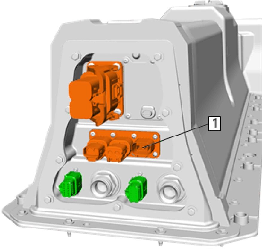 |
|
Fig. 51: Connector Courtesy'of GENERAL MOTORS COMPANY |
9. Install the GE 41413-A Evaporative Emissions System Tester (EEST) to connector (1).
10. Turn the nitrogen/smoke valve on the control panel to smoke.
11. Press and release the remote switch to activate the tester and inject smoke into the Drive Motor Battery.
 |
|
Fig. 52: Gore Patches Courtesy'of GENERAL MOTORS COMPANY |
12. Soak/Fill the RESS with smoke for FIVE MINUTES until smoke is observed from the hole in vent (2).
13. Once smoke in observed from the hole, press and release the remote switch to deactivate the tester to relieve
the pressure within the Drive Motor Battery.
14. Seal the hole in vent (2) with masking tape.
15. Introduce smoke into the Drive Motor Battery for THREE MINUTES. Using a high-intensity white light, look
for any visible smoke emitting anywhere from the Drive Motor Battery.
16. Press and release the remote switch to deactivate the tester.
17. Repair any visible leaks by retightening the fasteners or by resealing any areas.
18. Retest the Drive Motor Battery, to ensure repair has been completed.
19. Remove the masking tape from the gore patches (1 and 3).
20. Remove the masking tape from rear vent (2).
21. Open the nitrogen tank valve and turn the nitrogen/smoke valve on the control panel to Nitrogen.
22. Press and release the remote switch to activate the tester and inject nitrogen into the Drive Motor Battery for
FIVE MINUTES, verify no smoke is coming from the vent.
23. Remove all old vents from the Drive Motor Battery.
24. Install NEW Gore patches (P/N 20791600), replacing the old vents.
25. Disconnect the tester and remove the adapters from the Drive Motor Battery.
26. Remove the S15 manual service disconnect lever.
27. Install Drive Motor Battery. Refer to Drive Motor Battery Replacement and Shipping Preparation.
REPAIR INSTRUCTIONS
HIGH VOLTAGE SYSTEM INSPECTION
Circuit/System Description
WARNING: Damage to a Lithium Ion hybrid/EV battery pack could result in fire, loss of electrical
isolation or exposure to high voltage. Until the high voltage system inspection has
been completed, store the vehicle with hybrid/EV battery pack installed outside in a
secure area away from buildings and other vehicles and protected from rain, snow
and other moisture. Remove the hybrid/EV battery pack high voltage manual
disconnect lever and store it in a secure place outside the vehicle. Cover the
exposed high voltage opening with ULA® listed, or equivalent, insulation tape rated
at a minimum of 600 V.
Failure to follow these precautions could result in personal injury, death and
property damage.
The high voltage system and Hybrid/EV battery pack inspection process consists of two levels of inspection:
1. Component Initial Inspection
2. High Voltage Operation Inspection
Results of the inspection processes may result in:
• Hybrid/EV Battery Depower
• Repair, or replacement and recycling of the Hybrid/EV Battery
• Replacement of high voltage components
The supplemental inflatable restraint system supplements the protection offered by the seat belts. The supplemental
inflatable restraint sensing and diagnostic module determines the severity of a collision with the assistance of impact
sensors located at strategic points on the vehicle. The hybrid/EV powertrain control module 2 will open the high
voltage contactor relays, placing the vehicle in a high voltage lockout state and disabling the vehicle whenever a
crash event of sufficient intensity has been detected.
The supplemental inflatable restraint module transmits through serial data to the hybrid/EV powertrain control
module 2 both the crash event status and whenever a sensor fault is detected.
NOTE: The Crash Event Detected/Air Bag Deployed high voltage lockout state will remain
active until cleared by the Clear Secured High Voltage DTCs procedure.
A complete inspection of the high voltage system must be performed if the vehicle has been involved in a collision.
The Lithium Ion hybrid/EV battery pack should be depowered whenever internal components have been exposed to
moisture, whether due to vehicle flood, coolant leakage within the hybrid/EV battery pack assembly, etc.
Reference Information
Schematic Reference
• Hybrid/EV Energy Storage Schematics
Hybrid/EV Controls Schematics
Plug-In Charging Schematics
Description and Operation
Drive Motor Battery System Description
Scan Tool Reference
Control Module References for scan tool information
Special Tools
• EL-48900 HEV Safety Kit
• EL-50332 EV/HEV Battery Service Tool
• J-35616-35 Test Probes
Equivalent regional tools: Special Tools.
Component Initial Inspection
WARNING: Always perform the High Voltage Disabling procedure prior to servicing any High
Voltage component or connection. Personal Protection Equipment (PPE) and proper
procedures must be followed.
The High Voltage Disabling procedure includes the following steps:
• Identify how to disable high voltage.
• Identify how to test for the presence of high voltage.
• Identify condition under which high voltage is always present and personal
protection equipment (PPE) and proper procedures must be followed.
Before working on any high voltage system, be sure to wear the following Personal
Protection Equipment:
• Safety glasses with appropriate side shields when within 15 meters (50 feet) of
the vehicle, either indoors or outdoors.
• Certified and up-to-date Class "0" Insulation gloves rated at 1000V with leather
protectors.
• Visually and functionally inspect the gloves before use.
• Wear the Insulation gloves with leather protectors at all times when
working with the high voltage battery assembly, whether the system is
energized or not.
Failure to follow the procedures may result in serious injury or death.
WARNING: High voltage circuits should only be tested using a digital multimeter (DMM) and
test leads with at least a CAT III rating, such as the J 39200-A Digital Multimeter.
Failure to follow the procedures may result in serious injury or death.
WARNING: This vehicle is equipped with a high voltage battery that is completely isolated from
the chassis ground. Never utilize AC powered test equipment to probe the high
voltage system. Serious injury, death and component damage could occur if the
high voltage system is grounded through the electric utility.
Failure to follow the procedure exactly as written may result in serious injury or
death.
1. Disconnect the 12V battery.
2. Wear personal protection equipment - high voltage gloves, safety glasses or face shield, and remove the S15
Manual Service Disconnect. If vehicle damage does not allow for access to the S15 Manual Service
Disconnect, remove the damaged portion of the vehicle until such time as the S15 Manual Service Disconnect
can be removed. Refer to Drive Motor Battery High Voltage Manual Disconnect Lever Replacement.
3. Inspect the Hybrid/EV battery pack for evidence of exposure to fire, either directly or in close proximity.
• If exposure to fire is evident
1. Depowering of the Hybrid/EV battery pack is recommended. Maintain post-crash 50 foot vehicle
isolation until depowering completion. See Battery Depower after inspection is complete.
NOTE: Never return a damaged battery pack or section to the Warranty Parts
Center (WPC), Electronic Service Center (ESC) or Battery Service Center
(BSC).
2. After depowering, repair or replace and recycle battery as applicable. Vehicle dismantlers should refer to
www.recyclemybattery.com.
3. Continue with inspection.
• If not exposed to fire
4. Inspect the Hybrid/EV battery pack enclosure for damage including foreign object intrusion.
• If damage is evident
1. Depowering of the Hybrid/EV battery pack and/or damaged module section is recommended. Maintain
post-crash 50 foot vehicle isolation until depowering completion. See Battery Depower after inspection
is complete.
NOTE: Never return a damaged battery pack or section to the Warranty Parts
Center (WPC), Electronic Service Center (ESC) or Battery Service Center
(BSC).
2. After depowering, repair or replace and recycle battery as applicable. Vehicle dismantlers should refer to
www.recyclemybattery.com.
3. Continue with inspection.
• If not damaged
5. Inspect the vehicle for exposure to water at a level higher than the vehicle rocker panel.
• If the vehicle was exposed to flood
1. Remove the battery drain plug, capture and discard any drained fluid.
2. Lift the vehicle rear slightly to assist in fluid extraction.
• If fluid is present
1. Depowering of the Hybrid/EV battery pack is recommended. Maintain post-crash 50 foot vehicle
isolation until depowering completion. See Battery Depower after inspection is complete.
NOTE: Never return a damaged battery pack or section to the Warranty
Parts Center (WPC), Electronic Service Center (ESC) or Battery
Service Center (BsC).
2. After depowering, repair or replace and recycle battery as applicable. Vehicle dismantlers should
refer to www.recyclemybattery.com.
3. Continue with inspection.
• If fluid was not present
Install a new drain plug and continue with inspection.
6. Inspect the battery coolant system for proper level.
• If battery coolant level is low
1. Verify if the low coolant is the result of system damage external of the A4 Hybrid/EV battery pack.
• If the cooling system external of the A4 Hybrid/EV Battery Pack is not damaged and/or leaking
1. Remove the battery drain plug, capture and discard any drained fluid.
2. Lift the vehicle rear slightly to assist in fluid extraction.
• If fluid is present
3. Depowering of the Hybrid/EV battery pack is recommended. Maintain post-crash 50 foot vehicle
isolation until depowering completion. See Battery Depower after inspection is complete.
4. After depowering, repair or replace and recycle battery as applicable. Vehicle dismantlers should
refer to www.recyclemybattery.com.
5. Continue with inspection.
• If fluid is not present
6. Install a new drain plug and continue with inspection.
• If the cooling system external of the A4 Hybrid/EV Battery Pack is damaged and/or leaking
2. Continue with inspection.
• If the battery coolant system is at the proper level
7. Inspect each high voltage component listed below for visible damage. Record the results on the High Voltage
Component Inspection Table below.
• G1 Electric A/C Compressor
• K1 14V Power Module
• K10 Coolant Heater
• T6 Power Inverter Module
• T18 Battery Charger
• Transmission case
• X98 Hybrid/EV Battery Charger Receptacle
• All High voltage orange cables
• If any high voltage component inspection failed and Hybrid/EV battery Depower is recommended
Disconnect the damaged components from the high voltage bus before attempting in-vehicle depowering
of the Hybrid/EV battery pack. In extreme cases depowering may need to occur by connecting directly
within the Hybrid/EV battery pack with the cover removed. See Battery Depower below.
• If any high voltage component inspection failed and Hybrid/EV battery Depower is NOT
recommended
1. Perform the High Voltage Disabling procedure and replace the damaged components before attempting
to operate the vehicle
2. Once you have confirmed or repaired all high voltage component visual integrity, perform High Voltage
Operation Inspection below.
• If all high voltage component inspection passed
Perform High Voltage Operation Inspection below.
|
High Voltage Component Inspection Table | ||||||||||||||||||
| ||||||||||||||||||
|
High Voltage Operation Inspection |
1. Verify you have successfully passed the Component Initial Inspection.
• If the Component Initial Inspection has failed or not been performed
DO NOT CONTINUE. Restart the Inspection procedure.
• If the Component Initial Inspection has passed
2. Verify the S15 Manual Service Disconnect is installed.
• If the S15 Manual Service Disconnect is not installed
1. Wear personal protection equipment - high voltage gloves, safety glasses or face shield.
2. Install the S15 Manual Service Disconnect. Refer to Drive Motor Battery High Voltage Manual
Disconnect Lever Replacement.
3. Proceed to step 3.
• If the S15 Manual Service Disconnect is installed
3. Connect the 12V battery.
4. Vehicle in Service Mode. With a scan tool select the Hybrid/EV powertrain Control Module 2, Hybrid Battery
Pack Contactor Open Reasons data list. Verify if either the Crash Event Detected or Air Bag Deployed
parameters indicate YES.
• If either parameter displays YES
The high voltage contactors may be prevented from closing. The vehicle will not start. Perform the Clear
Secured High Voltage DTCs procedure and proceed to the next step.
• If BOTH parameters indicate NO
5. Vehicle ON. With a scan tool check for the following HV system DTCs: Contactor DTCs P0AA1, P0AA4,
P0AD9, P0ADD, P0AE1, P0AE3, P0D0A, P0D09, P1EBD, P1EC0, P1EC3, Isolation DTCs P0AA6, P1AE6,
P1AF0, or P1AF2, Precharge DTCs P0C76, P0C78 or P3061.
• If any DTCs are set
Repair these DTCs first. Refer to Diagnostic Trouble Code (DTC) List - Vehicle .
• If none of the DTCs are set
6. Verify collision repairs are necessary.
• If collision repairs are not necessary
High Voltage System Inspection passed.
• If collision repairs are necessary
7. Verify High Voltage Disabling is necessary prior to carrying out the collision repairs.
• If High Voltage Disabling is necessary
Perform the High Voltage Disabling before carrying out the collision repairs.
• If High Voltage Disabling is not necessary
8. High Voltage System Inspection passed.
Battery Depower
WARNING: Damage to a Lithium Ion hybrid/EV battery pack could result in fire, loss of electrical
isolation or exposure to high voltage. Store the vehicle with hybrid/EV battery pack
installed or the hybrid/EV battery pack assembly outside in a secure area away from
buildings and other vehicles and protected from rain, snow and other moisture until
the hybrid/EV battery pack has been discharged. Remove the hybrid/EV battery
pack high voltage manual disconnect lever and store it in a secure place outside the
vehicle. Cover the exposed high voltage opening with ULA® listed, or equivalent,
insulation tape rated at a minimum of 600 V. Contact the GM Technical Assistance
Center for discharge instructions prior to storage and shipping of the hybrid/EV
battery pack.
Failure to follow these precautions could result in personal injury, death and
property damage.
NOTE: Depowering of the battery:
• Will NOT reduce battery voltage to a safe level. The battery will contain high
voltage after depower procedure is complete.
• Reduces the state of charge to the lowest level thus reducing the likelihood of
a battery fire.
• Requires special tool EL-50332 battery service tool.
• Allows for future recovery of the battery after an internal battery inspection
and/or repair is completed.
NOTE: Depowering is not required if TOTAL hybrid/EV battery pack voltage is 285 volts or
less as monitored by either:
• hybrid/EV powertrain control module 2 scan tool Hybrid/EV Battery Pack
Voltage parameter
OR
• A DMM directly at the battery sections
Depowering can occur with the Hybrid/EV battery pack in or out of the vehicle. You can configure the EL-50332
high voltage connections to the Hybrid/EV battery pack at any of the following locations:
High Voltage power inverter module connection under hood with EL-50332-255 *
High Voltage 12V Power Module connection in rear cargo area with EL-50332-265 *
High Voltage connection at Hybrid/EV Battery Pack with EL-50332-260 *
Directly at battery section terminals with EL-50332-170
*Also requires connection to the contactor relay control circuits with EL-50332-115 and EL-50332-270 and
two J-35616-35 test probes.
In-Vehicle or Hybrid/EV Battery Pack Cover Installed Depower Instructions
NOTE:
• The EL-50332 will close the Hybrid/EV battery pack contactors. You must
verify the vehicles high voltage system integrity prior to enabling high
voltage. Disconnect visually damaged high voltage components/cables
from the high voltage system before attempting in-vehicle depowering.
• You must be able to connect to the hybrid/EV powertrain control module
2 vehicle harness connectors or the hybrid/EV battery pack low voltage
connectors.
• Wear your Personal Protective Equipment for the duration of the battery
depower event.
1. Ensure the integrity of the vehicles high voltage system.
2. Connect to the Hybrid/EV battery pack contactor control circuits with one of the two methods below:
Method 1: Connecting at Hybrid/EV Powertrain Control Module 2 Connectors
NOTE:
In this configuration the EL-50332 will supply 12V+ power to the battery
energy control module via the vehicle wiring and under hood fuse relay
center. Because the EL-50332 has limited 12V+ capacity it will be
necessary to jumper the circuits such that only the battery energy control
module is supplied with 12V+ power.
1. Connect the EL-50332 to the contactor control circuits at the hybrid/EV powertrain control module 2
connectors with the EL-50332-270 interface module and 50332-115 harness.
2. Remove the hybrid/EV powertrain control module 2 fuse F10 and the battery energy control module
fuse F12 from the underhood electrical center.
 |
|
Fig. 53: Fuse Load Circuits Courtesy'of GENERAl'mOTORS COMPANY |
3. Jumper the fuse load circuits together (1, 2) using two J-35616-35 test probes and a 10A maximum
fused jumper.
1. Connect the EL-50332 to the contactor control circuits at the hybrid/EV battery pack low voltage
connectors with the EL-50332-270 interface module and 50332-115 harness.
3. Connect the EL-50332 to the applicable high voltage connector.
4. Install the manual service disconnect lever.
5. Follow the EL-50332 on-screen prompts until depower is completed.
| ||
|
6. Remove the manual service disconnect lever. |
7. Repair, replace or recycle the hybrid/EV battery pack as applicable. Vehicle dismantlers should refer to
www.recyclemybattery.com.
8. Replace any damaged components noted in the High Voltage Component Inspection before attempting to
operate the vehicle.
9. Perform the High Voltage Operation Inspection before attempting to operate the vehicle.
Hybrid/EV Battery Pack Removed Depower Instructions
1. Connect the EL-50332-260 harness to the applicable battery section terminals. If depowering all battery
sections install the manual service disconnect lever.
2. Follow the EL-50332 on-screen prompts until depower is completed.
NOTE: Post-crash 50 foot vehicle isolation is no longer required upon successful
depower completion.
3. Remove the manual service disconnect lever.
NOTE: Never return a damaged battery pack or section to the Warranty Parts Center
(WPC), Electronic Service Center (ESC) or Battery Service Center (BSC).
4. Repair, replace or recycle the hybrid/EV battery pack as applicable. Vehicle dismantlers should refer to
www.recyclemybattery.com.
5. Replace any damaged components noted in the High Voltage Component Inspection before attempting to
operate the vehicle.
6. Perform the High Voltage Operation Inspection before attempting to operate the vehicle.
DRIVE MOTOR BATTERY HIGH VOLTAGE MANUAL DISCONNECT LEVER REPLACEMENT
WARNING: Ensure all High Voltage safety procedures are followed. Failure to follow the
procedure exactly as written may result in serious injury or death.
WARNING: Before working on any high voltage system, be sure to wear the following Personal
Protection Equipment:
• Safety glasses with appropriate side shields when within 50 feet of the vehicle,
either indoors or outdoors
• Certified and up-to-date Class "0" Insulation gloves rated at 1000V with leather
protectors
• Visually and functionally inspect the gloves before use.
• Wear the Insulation gloves at all times when working with the high
voltage battery assembly, whether the system is energized or not.
Failure to follow the procedure exactly as written may result in serious injury or
death.
Removal Procedure
1. Remove Front Floor Console Compartment Divider. Refer to Front Floor Console Compartment Divider
Replacement
 |
|
Fig. 54: Drive Motor High Voltage Manual Disconnect Lever |
2. Rotate Drive Motor Battery High Voltage Manual Disconnect Lever (1) Left
 |
|
Fig. 55: Drive Motor High Voltage Manual Disconnect Lever |
3. Lift Drive Motor Battery High Voltage Manual Disconnect Lever (1) Upwards
 |
|
Fig. 56: Drive Motor High Voltage Manual Disconnect Lever |
4. Rotate Drive Motor Battery High Voltage Manual Disconnect Lever (1) Left
 |
|
Fig. 57: Drive Motor High Voltage Manual Disconnect Lever |
5. Remove Drive Motor Battery High Voltage Manual Disconnect Lever (1)
Installation Procedure
 |
|
Fig. 58: Drive Motor High Voltage Manual Disconnect Lever |
1. Install Drive Motor Battery High Voltage Manual Disconnect Lever (1)
 |
|
Fig. 59: Drive Motor High Voltage Manual Disconnect Lever |
2. Rotate Drive Motor Battery High Voltage Manual Disconnect Lever (1) Right
 |
|
Fig. 60: Drive Motor High Voltage Manual Disconnect Lever |
3. Push Drive Motor Battery High Voltage Manual Disconnect Lever (1) Downwards
 |
|
Fig. 61: Drive Motor High Voltage Manual Disconnect Lever |
4. Rotate Drive Motor Battery High Voltage Manual Disconnect Lever (1) Right
5. Pull up on the handle to ensure the lever is in the locked position.
6. Install Front Floor Console Compartment Divider. Refer to Front Floor Console Compartment Divider
Replacement
HIGH VOLTAGE BATTERY HIGH VOLTAGE MANUAL DISCONNECT CONNECTOR
REPLACEMENT
Removal Procedure
either indoors or outdoors
• Certified and up-to-date Class "0" Insulation gloves rated at 1000V with leather
protectors
• Visually and functionally inspect the gloves before use.
• Wear the Insulation gloves at all times when working with the high
voltage battery assembly, whether the system is energized or not.
Failure to follow the procedure exactly as written may result in serious injury or
death.
1. Remove High Voltage Battery Cover. Refer to High Voltage Battery Cover Replacement
 |
|
Fig. 62: High Voltage Battery Positive Cable And Fastener |
2. Remove High Voltage Battery Positive Cable Fastener (1)
3. Remove High Voltage Battery Positive Cable (2)
 |
|
Fig. 63: High Voltage Battery Positive Cable And Fastener |
4. Remove High Voltage Battery Positive Cable Fastener (1)
5. Remove High Voltage Battery Positive Cable (2)
 |
|
Fig. 64: Electrical Connector Courtesy'of GENERAl'mOTORS COMPANY |
6. Disconnect Electrical Connector (1)
 |
|
Fig. 65: High Voltage Battery High Voltage Manual Disconnect Connector And Retaining Tabs |
7. Disconnect Retaining Tabs (1) (Qty: 2)
8. Remove High Voltage Battery High Voltage Manual Disconnect Connector (2)
Installation Procedure

Fig. 66: Electrical Connector
Courtesy of GENERAL MOTORS COMPANY
1. Connect Electrical Connector (1)
 |
|
Fig. 67: High Voltage Battery High Voltage Manual Disconnect Connector And Retaining Tabs |
2. Install High Voltage Battery High Voltage Manual Disconnect Connector (2)
 |
|
Fig. 68: High Voltage Battery Positive Cable And Fastener Courtesy'of GENERAL'MOTORS'COMPANY |
3. Install High Voltage Battery Positive Cable (2)
4. Install and tighten High Voltage Battery Positive Cable Fastener (1) to 9 N.m (80 lb in)
 |
|
Fig. 69: High Voltage Battery Positive Cable And Fastener |
5. Install High Voltage Battery Positive Cable (2)
6.
7. Install and tighten High Voltage Battery Positive Cable Fastener (1) to 9 N.m (80 lb in)
8. Install High Voltage Battery Cover. Refer to High Voltage Battery Cover Replacement
9. Install Drive Motor Battery. Refer to Drive Motor Battery Replacement and Shipping Preparation - Install
HIGH VOLTAGE BATTERY COVER REPLACEMENT
Removal Procedure
WARNING: Always perform the High Voltage Disabling procedure prior to servicing any High
Voltage component or connection. Personal Protection Equipment (PPE) and proper
procedures must be followed.
The High Voltage Disabling procedure includes the following steps:
• Identify how to disable high voltage.
• Identify how to test for the presence of high voltage.
• Identify condition under which high voltage is always present and personal
protection equipment (PPE) and proper procedures must be followed.
Before working on any high voltage system, be sure to wear the following Personal
Protection Equipment:
• Safety glasses with appropriate side shields when within 15 meters (50 feet) of
the vehicle, either indoors or outdoors.
• Certified and up-to-date Class "0" Insulation gloves rated at 1000V with leather
protectors.
• Visually and functionally inspect the gloves before use.
• Wear the Insulation gloves with leather protectors at all times when
working with the high voltage battery assembly, whether the system is
energized or not.
Failure to follow the procedures may result in serious injury or death.
1. Disable the high voltage system. Refer to High Voltage Disabling
2. Remove Drive Motor Battery. Refer to Drive Motor Battery Replacement and Shipping Preparation

Fig. 70: High Voltage Battery High Voltage Manual Disconnect Connector Fasteners And High Voltage
3. Remove and DISCARD High Voltage Battery High Voltage Manual Disconnect Connector Fasteners (3) (Qty:
4). Remove and DISCARD the fasteners.
4. Remove High Voltage Battery Cover Fasteners (1) (Qty: 9)
 |
|
Fig. 71: High Voltage Battery Cover Fasteners |
5. Remove High Voltage Battery Cover Fasteners (1) (Qty: 38)

Fig. 72: High Voltage Battery Cover And Drive Motor Battery Wire Junction Block Relay
Courtesy'of GENERAL'MOTORS'COMPANY
6. Carefully lift the corner of the high voltage battery cover (1), where it contacts the drive motor battery wire
junction block relay (2) and gently lift the front cover up.
 |
|
Fig. 73: High Voltage Battery Cover Courtesy'of GENERAL'MOTORS'COMPANY |
7. Remove High Voltage Battery Cover (1)
Installation Procedure
1. Perform the Hybrid/EV Battery System verification. Refer to Hybrid/EV Battery System Verification
 |
|
Fig. 74: High Voltage Battery Cover Courtesy'of GENERAL'MOTORS'COMPANY |
2. Install the high voltage battery cover (1) by aligning the manual service disconnect (MSD) housing with the
high voltage cover opening and gently push the front of the cover down against the drive motor battery wire
junction block relay.

Fig. 75: High Voltage Battery Cover Fasteners
Courtesy'of GENERAL'MOTORS'COMPANY
3. Loosely install High Voltage Battery Cover Fasteners (1) (Qty: 38)
 |
|
Fig. 76: High Voltage Battery Cover Fastener Courtesy'of GENERAL'MOTORS'COMPANY |
4. Loosely install High Voltage Battery Cover Fastener (1)
 |
|
Fig. 77: New Fasteners Courtesy'of GENERAL MOTORS COMPANY |
5. Loosely install NEW fasteners. (1)
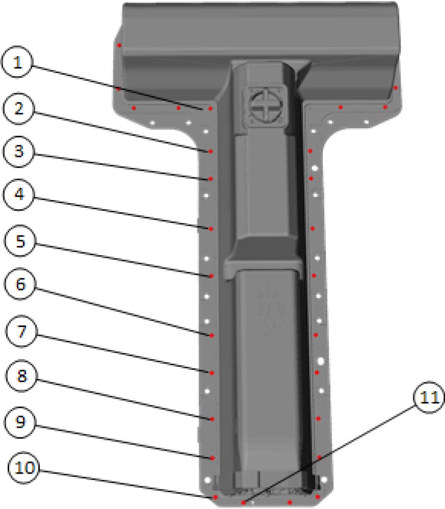 |
|
Fig. 78: High Voltage Battery Cover Fastener Tightening Sequence (1 Of 3) |
6. Tighten High Voltage Battery Cover Fasteners in sequence to 9 N.m (80 lb in)
 |
|
Fig. 79: High Voltage Battery Cover Fastener Tightening Sequence (2 Of 3) |
7. Tighten High Voltage Battery Cover Fasteners in sequence to 9 N.m (80 lb in)
 |
|
Fig. 80: High Voltage Battery Cover Fastener Tightening Sequence (3 Of 3) Courtesy'of GENERAL'MOTORS'COMPANY |
8. Tighten High Voltage Battery Cover Fasteners in sequence to 9 N.m (80 lb in)
 |
|
Fig. 81: High Voltage Battery High Voltage Manual Disconnect Connector Fastener Tightening Courtesy of GENERAL MOTORS COMPANY |
9. Tighten NEW fasteners in sequence to 9 N.m (80 lb in)
10. Perform a smoke test on the rechargeable energy storage system. Refer to Rechargeable Energy Storage
System Smoke Test
11. Install Drive Motor Battery. Refer to Drive Motor Battery Replacement and Shipping Preparation
12. Enable the high voltage system. Refer to High Voltage Enabling
HIGH VOLTAGE BATTERY TRAY REPLACEMENT
 |
|
Fig. 82: High Voltage Battery Tray |
| ||||||||
|
HIGH VOLTAGE BATTERY TRAY SPACER REPLACEMENT | ||||||||

Fig. 83: High Voltage Battery Tray Spacer
Courtesy'of GENERAL'MOTORS'COMPANY
|
Callout |
Component Name |
|
Preliminary Procedures
| |
|
Battery Replacement (Battery Section 3) | |
|
1 |
High Voltage Battery Tray Spacer - Battery Section 1 |
|
2 |
High Voltage Battery Tray Spacer - Battery Section 2 |
|
3 |
High Voltage Battery Tray Spacer - Battery Section 3 |
BATTERY COVER SEAL REPLACEMENT

Fig. 84: Battery Cover Seal
Courtesy'of GENERAL'MOTORS COMPANY
Callout Component Name
WARNING:
Before working on
any high voltage
system, be sure to
wear the following
Personal Protection
Equipment:
• Safety glasses
with appropriate
side shields
when within 50
feet of the
vehicle, either
indoors or
outdoors
• Certified and up-
to-date Class "0"
Insulation
gloves rated at
1000V with
leather
protectors
| ||||||
|
BATTERY ENERGY CONTROL MODULE REPLACEMENT | ||||||
Removal Procedure
WARNING: Before working on any high voltage system, be sure to wear the following Personal
Protection Equipment:
• Safety glasses with appropriate side shields when within 50 feet of the vehicle,
either indoors or outdoors
• Certified and up-to-date Class "0" Insulation gloves rated at 1000V with leather
protectors
• Visually and functionally inspect the gloves before use.
• Wear the Insulation gloves at all times when working with the high
voltage battery assembly, whether the system is energized or not.
Failure to follow the procedure exactly as written may result in serious injury or
death.
1. Remove High Voltage Battery Cover. Refer to High Voltage Battery Cover Replacement
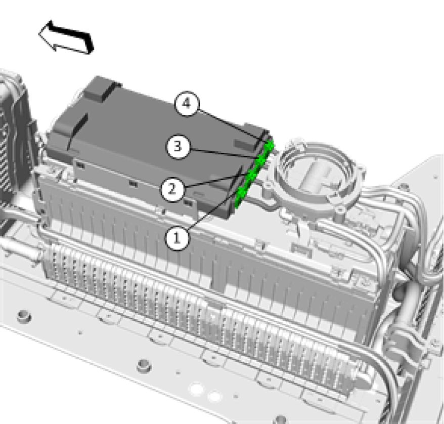 |
|
Fig. 85: Battery Energy Control Module Connector Disconnect Sequence (1 Of 2) |
CAUTION: The battery energy control modules internal cell balancing circuitry is powered
by the cell group voltage sense circuits. In order to prevent an unrecoverable,
unbalanced Hybrid/EV battery section or internal control module damage,
always take the following actions:
1. Disconnect ALL of the battery energy control module connectors prior to
disconnecting any Hybrid/EV battery section connector.
2. Reconnect all the Hybrid/EV battery section connectors prior to
reconnecting the battery energy control module connectors.
3. Disconnect and reconnect the battery energy control module connectors
ONLY in the sequence provided in Repair Instructions.
2. Disconnect the battery energy control module connectors in the sequence shown above.

Fig. 86: Battery Energy Control Module Connector Disconnect Sequence (2 Of 2)
Courtesy'of GENERAL'MOTORS'COMPANY
3. Disconnect the battery energy control module connectors in the sequence shown above.
 |
|
Fig. 87: Battery Energy Control Module And Retaining Tabs |
4. Disconnect Retaining Tabs (1) (Qty: 3)
5. Remove Battery Energy Control Module (2)
Installation Procedure
 |
|
Fig. 88: Battery Energy Control Module And Retaining Tabs |
1. Install Battery Energy Control Module (2)
 |
|
Fig. 89: Battery Energy Control Module Connector Reconnection Sequence (1 Of 2) |
CAUTION: The battery energy control modules internal cell balancing circuitry is powered
by the cell group voltage sense circuits. In order to prevent an unrecoverable,
unbalanced Hybrid/EV battery section or internal control module damage,
always take the following actions:
1. Disconnect ALL of the battery energy control module connectors prior to
disconnecting any Hybrid/EV battery section connector.
2. Reconnect all the Hybrid/EV battery section connectors prior to
reconnecting the battery energy control module connectors.
3. Disconnect and reconnect the battery energy control module connectors
ONLY in the sequence provided in Repair Instructions.
2. Connect the battery energy control module connectors in the sequence shown above.
 |
|
Fig. 90: Battery Energy Control Module Connector Reconnection Sequence (2 Of 2) |
3. Connect the battery energy control module connectors in the sequence shown above.
4. Install High Voltage Battery Cover. Refer to High Voltage Battery Cover Replacement
5. Install Drive Motor Battery. Refer to Drive Motor Battery Replacement and Shipping Preparation
NOTE: Service replacement module requires programming.
6. Program the battery energy control module. Refer to Control Module References
HIGH VOLTAGE BATTERY POSITIVE CABLE REPLACEMENT (BATTERY SECTION 1 TO BATTERY
SECTION 2)
Removal Procedure
WARNING: Before working on any high voltage system, be sure to wear the following Personal
Protection Equipment:
• Safety glasses with appropriate side shields when within 50 feet of the vehicle,
either indoors or outdoors
• Certified and up-to-date Class "0" Insulation gloves rated at 1000V with leather
protectors
• Visually and functionally inspect the gloves before use.
• Wear the Insulation gloves at all times when working with the high
voltage battery assembly, whether the system is energized or not.
Failure to follow the procedure exactly as written may result in serious injury or
death.
1. Remove High Voltage Battery Cover. Refer to High Voltage Battery Cover Replacement
 |
|
Fig. 91: High Voltage Battery Positive Cable And Fasteners |
2. Remove High Voltage Battery Positive Cable Fasteners (1) (Qty: 2)
3. Remove High Voltage Battery Positive Cable (2) (Qty: 2)
 |
|
Fig. 92: High Voltage Battery Positive Cable Courtesy'of GENERAL'MOTORS'COMPANY |
4. Remove High Voltage Battery Positive Cable (1)
Installation Procedure
 |
|
Fig. 93: High Voltage Battery Positive Cable |
1. Install High Voltage Battery Positive Cable (1)
 |
|
Fig. 94: High Voltage Battery Positive Cable And Fasteners |
2. Install High Voltage Battery Positive Cable (2) (Qty: 2)
CAUTION: Refer to Fastener Caution
NOTE: Critical high voltage fastener. Perform second torque verification check
following re-assembly.
3. Install and tighten High Voltage Battery Positive Cable Fasteners (1) (Qty: 2) to 9 N.m (80 lb in)
4. Install High Voltage Battery Cover. Refer to High Voltage Battery Cover Replacement
5. Install Drive Motor Battery. Refer to Drive Motor Battery Replacement and Shipping Preparation
HIGH VOLTAGE BATTERY POSITIVE CABLE REPLACEMENT (GENERATOR BATTERY
DISCONNECTOR RELAY TO BATTERY SECTION 3)
Removal Procedure
WARNING: Before working on any high voltage system, be sure to wear the following Personal
Protection Equipment:
• Safety glasses with appropriate side shields when within 50 feet of the vehicle,
either indoors or outdoors
• Certified and up-to-date Class "0" Insulation gloves rated at 1000V with leather
protectors
• Visually and functionally inspect the gloves before use.
• Wear the Insulation gloves at all times when working with the high
voltage battery assembly, whether the system is energized or not.
Failure to follow the procedure exactly as written may result in serious injury or
death.
1. Remove High Voltage Battery Cover. Refer to High Voltage Battery Cover Replacement
 |
|
Fig. 95: Terminal Cover, High Voltage Battery Positive Cable And Fastener |
2. Open Terminal Cover (3)
3. Remove High Voltage Battery Positive Cable Fastener (2)
4. Remove High Voltage Battery Positive Cable (1)

5. Disconnect Retainer (1)
 |
|
Fig. 97: High Voltage Battery Positive Cable And Fastener |
6. Remove High Voltage Battery Positive Cable Fastener (1)
7. Remove High Voltage Battery Positive Cable (2)
 |
|
Fig. 98: Retainers And Cable Tie Courtesy'of GENERAL'MOTORS COMPANY |
8. Disconnect Retainers (1) (Qty: 2)
9. Remove Cable Tie (2)
 |
|
Fig. 99: Retainers Courtesy'of GENERAL MOTORS COMPANY |
10. Disconnect Retainers (1) (Qty: 2)

Fig. 100: Retainers And Cable Ties
Courtesy of GENERAL MOTORS COMPANY
11. Disconnect Retainers (1) (Qty: 2)
12. Remove Cable Ties (2) (Qty: 2)
 |
|
Fig. 101: High Voltage Battery Positive Cable |
13. Remove High Voltage Battery Positive Cable (1)
Installation Procedure
 |
|
Fig. 102: Retainers And Cable Ties |
1. Install Retainers (1) (Qty: 2)
2. Install Cable Ties (2) (Qty: 2)
3. Install Retainers (1) (Qty: 2)
 |
|
Fig. 103: Retainers Courtesy'of GENERAL MOTORS COMPANY |
 |
|
Fig. 104: Retainers And Cable Tie Courtesy'of GENERAL'MOTORS COMPANY |
4. Install Retainers (1) (Qty: 2)
5. Install Cable Tie (2)
 |
|
Fig. 105: High Voltage Battery Positive Cable And Fastener Courtesy'of GENERAL'MOTORS'COMPANY |
6. Install High Voltage Battery Positive Cable (2)
7. Install and tighten High Voltage Battery Positive Cable Fastener (1) to 9 N.m (80 lb in)
 |
|
Fig. 106: Retainer Courtesy'of GENERAL MOTORS COMPANY |
8. Install Retainer (1)
 |
|
Fig. 107: Terminal Cover, High Voltage Battery Positive Cable And Fastener |
9. Install High Voltage Battery Positive Cable (1)
NOTE: Critical high voltage fastener. Perform second torque verification check
following re-assembly.
10. Install and tighten High Voltage Battery Positive Cable Fastener (2) to 9 N.m (80 lb in)
11. Close Terminal Cover (3)
12. Install High Voltage Battery Cover. Refer to High Voltage Battery Cover Replacement
13. Install Drive Motor Battery. Refer to Drive Motor Battery Replacement and Shipping Preparation
HIGH VOLTAGE BATTERY POSITIVE CABLE REPLACEMENT (GENERATOR BATTERY
DISCONNECTOR RELAY TO BATTERY SECTION 1)
Removal Procedure
WARNING: Before working on any high voltage system, be sure to wear the following Personal
Protection Equipment:
• Safety glasses with appropriate side shields when within 50 feet of the vehicle,
either indoors or outdoors
• Certified and up-to-date Class "0" Insulation gloves rated at 1000V with leather
protectors
• Visually and functionally inspect the gloves before use.
• Wear the Insulation gloves at all times when working with the high
voltage battery assembly, whether the system is energized or not.
Failure to follow the procedure exactly as written may result in serious injury or
death.
1. Remove High Voltage Battery Cover. Refer to High Voltage Battery Cover Replacement
 |
|
Fig. 108: High Voltage Battery Positive Cable, Fasteners And Terminal Cover |
2. Remove High Voltage Battery Positive Cable Fastener (1)
3. Remove High Voltage Battery Positive Cable (2)
4. Open Terminal Cover (3)
5. Remove High Voltage Battery Positive Cable Fastener (5)
6. Remove High Voltage Battery Positive Cable (4)
Installation Procedure
 |
|
Fig. 109: High Voltage Battery Positive Cable, Fasteners And Terminal Cover |
1. Install High Voltage Battery Positive Cable (2)
2. Install and tighten High Voltage Battery Positive Cable Fastener (1) to 9 N.m (80 lb in)
3. Install High Voltage Battery Positive Cable (4)
NOTE: Critical high voltage fastener. Perform second torque verification check
following re-assembly.
4. Install and tighten High Voltage Battery Positive Cable Fastener (5) to 9 N.m (80 lb in)
5. Close Terminal Cover (3)
6. Install High Voltage Battery Cover. Refer to High Voltage Battery Cover Replacement
7. Install Drive Motor Battery. Refer to Drive Motor Battery Replacement and Shipping Preparation
GENERATOR BATTERY CURRENT SENSOR REPLACEMENT
Removal Procedure
WARNING: Before working on any high voltage system, be sure to wear the following
Personal Protection Equipment:
• Safety glasses with appropriate side shields when within 50 feet of the
vehicle, either indoors or outdoors
• Certified and up-to-date Class "0" Insulation gloves rated at 1000V with
leather protectors
• Visually and functionally inspect the gloves before use.
• Wear the Insulation gloves at all times when working with the high
voltage battery assembly, whether the system is energized or not.
Failure to follow the procedure exactly as written may result in serious injury
or death.
1. Remove High Voltage Battery Cover. Refer to High Voltage Battery Cover Replacement
2. Remove High Voltage Battery Disconnect Relay. Refer to High Voltage Battery Disconnect Relay
Replacement
 |
|
Fig. 110: Terminal Cover, Fastener And Battery Current Sensor Connector |
3. Open Terminal Cover (1)
4. Remove Fastener (2)
5. Disconnect Battery Current Sensor Connector (3)
 |
|
Fig. 111: Fasteners Courtesy'of GENERAL MOTORS COMPANY |
6. Remove Fasteners (1) (Qty: 2)
7. Remove Battery Current Sensor (1)
Installation Procedure
 |
|
Fig. 113: Battery Current Sensor Courtesy'of GENERAL'MOTORS COMPANY |
1. Install Battery Current Sensor (1)
 |
|
Fig. 114: Fasteners Courtesy'of GENERAL MOTORS COMPANY |
2. Install and tighten Fasteners (1) (Qty: 2) to 9 N.m (80 lb in)
 |
|
Fig. 115: Terminal Cover, Fastener And Battery Current Sensor Connector Courtesy'of GENERAL'MOTORS'COMPANY |
NOTE: Critical high voltage fastener. Perform second torque verification check
following re-assembly.
3. Install and tighten Fastener (2) to 9 N.m (80 lb in)
4. Connect Battery Current Sensor Connector (3)
5. Close Terminal Cover (1)
6. Install High Voltage Battery Disconnect Relay. Refer to High Voltage Battery Disconnect Relay
Replacement
7. Install High Voltage Battery Cover. Refer to High Voltage Battery Cover Replacement
8. Install Drive Motor Battery. Refer to Drive Motor Battery Replacement and Shipping Preparation
9. Lower the vehicle.
10. Fill the cooling system. Refer to Drive Motor Battery Cooling System Draining and Filling
GENERATOR BATTERY DISCONNECTOR RELAY REPLACEMENT
Removal Procedure
WARNING: Before working on any high voltage system, be sure to wear the following Personal
Protection Equipment:
• Safety glasses with appropriate side shields when within 50 feet of the vehicle,
either indoors or outdoors
• Certified and up-to-date Class "0" Insulation gloves rated at 1000V with leather
protectors
• Visually and functionally inspect the gloves before use.
• Wear the Insulation gloves at all times when working with the high
voltage battery assembly, whether the system is energized or not.
Failure to follow the procedure exactly as written may result in serious injury or
death.
1. Remove High Voltage Battery Cover. Refer to High Voltage Battery Cover Replacement - Remove
2. Drain the cooling system. Refer to Drive Motor Battery Cooling System Draining and Filling
 |
|
Fig. 116: Terminal Cover, High Voltage Battery Positive Cable And Fastener |
Courtesy of GENERAL MOTORS COMPANY
3. Open Terminal Cover (3)
4. Remove High Voltage Battery Positive Cable Fastener (2)
5. Remove High Voltage Battery Positive Cable (1)
 |
|
Fig. 117: High Voltage Battery Positive Cable, Fasteners And Terminal Cover |
Courtesy of GENERAL MOTORS COMPANY
6. Remove High Voltage Battery Positive Cable Fastener (1)
7. Remove High Voltage Battery Positive Cable (2)
8. Open Terminal Cover (3)
9. Remove High Voltage Battery Positive Cable Fastener (5)
10. Remove High Voltage Battery Positive Cable (4)
 |
|
Fig. 118: Electrical Connectors And Retainers |
11. Disconnect Electrical Connectors (1) (Qty: 2)
12. Release Retainers (2) (Qty: 4)
 |
|
Fig. 119: Ground Nut And Ground Cable |
13. Remove Ground Nut (1)
14. Remove Ground Cable (2)
 |
|
Fig. 120: Ground Nut And Ground Cable |
15. Remove Ground Nut (1)
16. Remove Ground Cable (2)
 |
|
Fig. 121: High Voltage Battery Cooling Manifold Outlet Hose And Retainer |
17. Unclip the hose retainer. (1)
18. Remove High Voltage Battery Cooling Manifold Outlet Hose (2)
 |
|
Fig. 122: High Voltage Battery Cooling Manifold Inlet Hose And Retainer |
19. Unclip the hose retainer. (1)
20. Remove High Voltage Battery Cooling Manifold Inlet Hose (2)
 |
|
Fig. 123: High Voltage Battery Disconnect Relay And Battery Tray Front Brace |
21. Disengage High Voltage Battery Disconnect Relay (2) @ Battery Tray Front Brace (1)
22. Remove High Voltage Battery Disconnect Relay (2)
23. Transfer components as necessary.
Installation Procedure
 |
|
Fig. 124: High Voltage Battery Disconnect Relay And Battery Tray Front Brace |
1. Engage High Voltage Battery Disconnect Relay (2) @ Battery Tray Front Brace (1)
 |
|
Fig. 125: High Voltage Battery Cooling Manifold Inlet Hose And Retainer |
2. Install High Voltage Battery Cooling Manifold Inlet Hose (2)
3. Install the retainer. (1)
 |
|
Fig. 126: High Voltage Battery Cooling Manifold Outlet Hose And Retainer |
4. Install High Voltage Battery Cooling Manifold Outlet Hose (2)
5. Install the retainer. (1)
 |
|
Fig. 127: Ground Nut And Ground Cable |
6. Install Ground Cable (2)
7. Install and tighten Ground Nut (1) to 9 N.m (80 lb in)
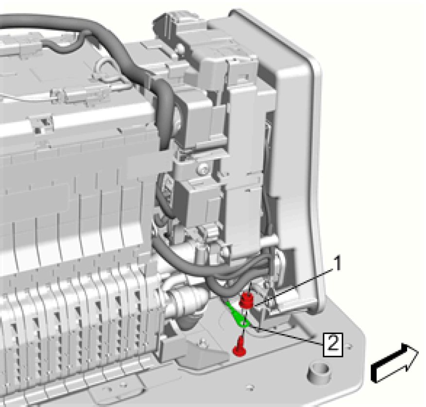 |
|
Fig. 128: Ground Nut And Ground Cable |
8. Install Ground Cable (2)
9. Install and tighten Ground Nut (1) to 9 N.m (80 lb in)
 |
|
Fig. 129: Electrical Connectors And Retainers |
10. Connect Electrical Connectors (1) (Qty: 2)
11. Install Retainers (2) (Qty: 4)
 |
|
Fig. 130: High Voltage Battery Positive Cable, Fasteners And Terminal Cover |
12. Install High Voltage Battery Positive Cable (2)
13. Install and tighten High Voltage Battery Positive Cable Fastener (1) to 9 N.m (80 lb in)
14. Install High Voltage Battery Positive Cable (4)
15. Install and tighten High Voltage Battery Positive Cable Fastener (5) to 9 N.m (80 lb in)
16. Close Terminal Cover (3)
 |
|
Fig. 131: Terminal Cover, High Voltage Battery Positive Cable And Fastener |
17. Install High Voltage Battery Positive Cable (1)
NOTE:
18. Install and tighten High Voltage Battery Positive Cable Fastener (2) to 9 N.m (80 lb in)
19. Close Terminal Cover (3)
20. Install High Voltage Battery Cover. Refer to High Voltage Battery Cover Replacement
21. Install Drive Motor Battery. Refer to Drive Motor Battery Replacement and Shipping Preparation
22. Fill the cooling system. Refer to Drive Motor Generator Power Inverter Module Cooling System Draining
and Filling
23. Perform Hybrid Cooling System Leak Test. Refer to Hybrid Cooling System Leak Test
CELL BATTERY HIGH VOLTAGE SENSOR REPLACEMENT (THERMISTOR 6)
 |
|
Fig. 132: Cell Battery High Voltage Sensor (Thermistor 6) |
| ||||||||||
|
CELL BATTERY HIGH VOLTAGE SENSOR REPLACEMENT (THERMISTOR 4) | ||||||||||
 |
|
Fig. 133: Cell Battery High Voltage Sensor (Thermistor 4) |
| ||||||||||
|
CELL BATTERY HIGH VOLTAGE SENSOR REPLACEMENT (THERMISTOR 1) | ||||||||||
 |
|
Fig. 134: Cell Battery High Voltage Sensor (Thermistor 1) |
| ||||||||||
|
CELL BATTERY HIGH VOLTAGE SENSOR REPLACEMENT (THERMISTOR 5) | ||||||||||
 |
|
а Fig. 135: Cell Battery High Voltage Sensor (Thermistor 5) |
| ||||||||||
|
CELL BATTERY HIGH VOLTAGE SENSOR REPLACEMENT (THERMISTOR 3) | ||||||||||
 |
|
Fig. 136: Cell Battery High Voltage Sensor (Thermistor 3) |
| ||||||||||
|
CELL BATTERY HIGH VOLTAGE SENSOR REPLACEMENT (THERMISTOR 2) | ||||||||||
 |
|
Fig. 137: Cell Battery High Voltage Sensor (Thermistor 2) |
|
Callout |
Component Name |
|
Preliminary Procedure Remove High Voltage Battery Cover. Refer to High Voltage Battery Cover Replacement | |
|
1 |
Cell Battery High Voltage Sensor Connector |
|
2 |
Fastener |
|
3 |
Cell Battery High Voltage Sensor 2 Procedure Gently pull up on the tab (2) and rotate 90 Degrees. |
HIGH VOLTAGE SECTION BATTERY REPLACEMENT (BATTERY SECTION 1)
Removal Procedure
Special Tools
• EL-51763 High Voltage Battery Section Covers
• EL-50115 Battery Section Lifting Adapters
• EL-48264 Battery Pack Lifting Adapter
Equivalent regional tools: Special Tools
• Visually and functionally inspect the gloves before use.
• Wear the Insulation gloves at all times when working with the high
voltage battery assembly, whether the system is energized or not.
Failure to follow the procedure exactly as written may result in serious injury or
death.
1. Remove High Voltage Battery Cover. Refer to High Voltage Battery Cover Replacement
CAUTION: The battery energy control modules internal cell balancing circuitry is powered
by the cell group voltage sense circuits. In order to prevent an unrecoverable,
unbalanced Hybrid/EV battery section or internal control module damage,
always take the following actions:
1. Disconnect ALL of the battery energy control module connectors prior to
disconnecting any Hybrid/EV battery section connector.
2. Reconnect all the Hybrid/EV battery section connectors prior to
reconnecting the battery energy control module connectors.
3. Disconnect and reconnect the battery energy control module connectors
ONLY in the sequence provided in Repair Instructions.
2. Disconnect the Battery Energy Control Module Connectors. Refer to Battery Energy Control Module
Replacement
3. Drain the cooling system. Refer to Drive Motor Battery Cooling System Draining and Filling
 |
|
Fig. 138: Terminal Cover, High Voltage Battery Positive Cable And Fastener |
4. Open Battery Terminal Cover (3)
5. Remove High Voltage Battery Positive Cable Fastener (2)
6. Remove High Voltage Battery Positive Cable (1)
NOTE: Cover exposed terminal with high voltage tape.
 |
|
Fig. 139: Retainers Courtesy'of GENERAL MOTORS COMPANY |
7. Disengage Retainers (1) (Qty: 2)
 |
|
Fig. 140: High Voltage Battery Positive Cable, Fasteners And Terminal Cover |
8. Remove High Voltage Battery Positive Cable Fastener (1)
9. Remove High Voltage Battery Positive Cable (2)
10. Open Battery Terminal Cover (3)
11. Remove High Voltage Battery Positive Cable Fastener (5)
12. Remove High Voltage Battery Positive Cable (4)
 |
|
Fig. 141: High Voltage Battery Positive Cable And Fasteners |
13. Remove High Voltage Battery Positive Cable Fasteners (1) (Qty: 2)
14. Remove High Voltage Battery Positive Cable (2) (Qty: 2)
 |
|
Fig. 142: High Voltage Battery Cooling Manifold Outlet Hose And Retainer |
15. Unclip the hose retainer. (1)
16. Remove Cell Battery Cooling Manifold Outlet Hose (2)
 |
|
Fig. 143: High Voltage Battery Cooling Manifold Inlet Hose And Retainer |
17. Unclip the hose retainer. (1)
18. Remove Cell Battery Cooling Manifold Inlet Hose (2)

19. Loosen the clamps (1) (Qty: 4)
20. Move the 2 cell battery cooling plate hoses (2, 3) in direction of arrow.
 |
|
Fig. 145: Electrical Connectors And Retainers |
21. Disconnect Electrical Connectors (1) (Qty: 6) @ Battery Section 1
22. Disengage Retainers (2) (Qty: 4)
23. Disengage any harness retainers attached to battery section 1 and set aside the harnesses.
 |
|
Fig. 146: Battery Hold Down Retainers And Fasteners |
24. Remove Fasteners (1) (Qty: 10)
25. Remove Battery Hold Down Retainers (2) (Qty: 2)
 |
|
Fig. 147: Battery Section Lifting Adapters And Battery Section 1 Courtesy'of GENERAL'MOTORS'COMPANY |
26. Install EL-50115 Battery Section Lifting Adapters (1) (Qty: 2) @ Battery Section 1 (2)
 |
|
Fig. 148: Battery Section 1 Courtesy'of GENERAL'MOTORS COMPANY |
27. Remove Battery Section 1 (1)
Installation Procedure
 |
|
Fig. 149: Battery Section 1 Courtesy'of GENERAl'mOTORS COMPANY |
1. Install Battery Section 1 (1)
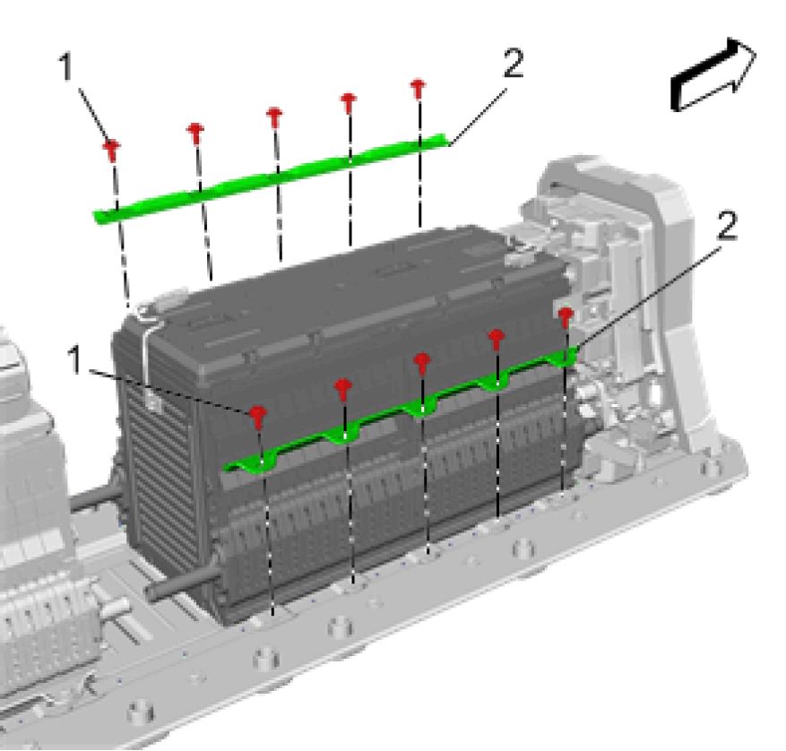 |
|
Fig. 150: Battery Hold Down Retainers And Fasteners |
2. Install Battery Hold Down Retainers (2) (Qty: 2)
3. Push and hold battery section 1 firmly against the front brace, before tightening fasteners. (1)
4. Install and tighten Fasteners (1) (Qty: 10) to 9 N.m (80 lb in)
 |
|
Fig. 151: Cell Battery Cooling Plate Hoses And Clamps |
5. Move the 2 cell battery cooling plate hoses (2, 3) against direction of arrow.
6. Tighten Clamps (1) (Qty: 4) to 2.1 N.m (19 lb in)

Fig. 152: High Voltage Battery Cooling Manifold Inlet Hose And Retainer
Courtesy'of GENERAL'MOTORS'COMPANY
7. Install Cell Battery Cooling Manifold Inlet Hose (2)
8. Install the retainer. (1)
 |
|
Fig. 153: High Voltage Battery Cooling Manifold Outlet Hose And Retainer |
9. Install Cell Battery Cooling Manifold Outlet Hose (2)
10. Install the retainer. (1)
 |
|
Fig. 154: Electrical Connectors And Retainers |
11. Connect Electrical Connectors (1) (Qty: 6) @ Battery Section 1 (3)
12. Engage Retainers (2) (Qty: 4)
 |
|
Fig. 155: High Voltage Battery Positive Cable, Fasteners And Terminal Cover |
13. Install High Voltage Battery Positive Cable (2)
14. Install and tighten High Voltage Battery Positive Cable Fastener (1) to 9 N.m (80 lb in)
15. Install High Voltage Battery Positive Cable (4)
16. Install and tighten High Voltage Battery Positive Cable Fastener (5) to 9 N.m (80 lb in)
17. Close Battery Terminal Cover (3)
 |
|
Fig. 156: Terminal Cover, High Voltage Battery Positive Cable And Fastener |
18. Install High Voltage Battery Positive Cable (1)
19. Install and tighten High Voltage Battery Positive Cable Fastener (2) to 9 N.m (80 lb in)
20. Close Battery Terminal Cover (3)
 |
|
Fig. 157: Retainers Courtesy'of GENERAL MOTORS COMPANY |
21. Engage Retainers (1) (Qty: 2)
22. Connect the Battery Energy Control Module Connectors in sequence. Refer to Battery Energy Control
Module Replacement
23. Perform the Hybrid/EV battery cell balancing procedure. Refer to Hybrid/EV Battery Cell Balancing
24. Install High Voltage Battery Cover. Refer to High Voltage Battery Cover Replacement
25. Install Drive Motor Battery. Refer to Drive Motor Battery Replacement and Shipping Preparation
26. Fill the cooling system. Refer to Drive Motor Battery Cooling System Draining and Filling
HIGH VOLTAGE SECTION BATTERY REPLACEMENT (BATTERY SECTION 2)
Removal Procedure
Special Tools
• EL-51763 High Voltage Battery Section Covers
• EL-50115 Battery Section Lifting Adapters
• EL-48264 Battery Pack Lifting Adapter
Equivalent regional tools: Special Tools
• Visually and functionally inspect the gloves before use.
• Wear the Insulation gloves at all times when working with the high
voltage battery assembly, whether the system is energized or not.
Failure to follow the procedure exactly as written may result in serious injury or
death.
1. Remove High Voltage Battery Cover. Refer to High Voltage Battery Cover Replacement
2. Drain the cooling system. Refer to Drive Motor Battery Cooling System Draining and Filling
3. Remove High Voltage Battery Positive Cable. Refer to High Voltage Battery Positive Cable Replacement
(Battery Section 1 to Battery Section 2)
4. Remove High Voltage Battery High Voltage Manual Disconnect Connector. Refer to High Voltage Battery
High Voltage Manual Disconnect Connector Replacement
CAUTION: The battery energy control modules internal cell balancing circuitry is powered
by the cell group voltage sense circuits. In order to prevent an unrecoverable,
unbalanced Hybrid/EV battery section or internal control module damage,
always take the following actions:
1. Disconnect ALL of the battery energy control module connectors prior to
disconnecting any Hybrid/EV battery section connector.
2. Reconnect all the Hybrid/EV battery section connectors prior to
reconnecting the battery energy control module connectors.
3. Disconnect and reconnect the battery energy control module connectors
ONLY in the sequence provided in Repair Instructions.
5. Remove Battery Energy Control Module. Refer to Battery Energy Control Module Replacement
 |
|
Fig. 158: Cell Battery Cooling Plate Hoses And Clamps |
6. Loosen the clamps. (1) (Qty: 4)
7. Move the 2 cell battery cooling plate hoses (2, 3) in direction of arrow.

8. Loosen the clamps. (1) (Qty: 2)
9. Remove the cell battery cooling manifold inlet hose (2).
 |
|
Fig. 160: High Voltage Battery Cooling Manifold Outlet Hose And Clamps |
10. Loosen the clamps. (2) (Qty: 2)
11. Remove the cell battery cooling manifold outlet hose (1).
 |
|
Fig. 161: Electrical Connectors And Retainers |
12. Disconnect Electrical Connectors (1) (Qty: 4) @ Battery Section 2 (3)
13. Disengage Retainers (2) (Qty: 4)
14. Disengage any harness retainers attached to battery section 2 and set aside the harnesses.
 |
|
Fig. 162: Battery Energy Control Module Bracket And Retainers |
15. Disengage Retainers (1) (Qty: 4)
16. Remove Battery Energy Control Module Bracket (2)
 |
|
Fig. 163: Battery Hold Down Retainers And Fasteners |
17. Remove Fasteners (1) (Qty: 12)
18. Remove Battery Hold Down Retainers (2) (Qty: 2)
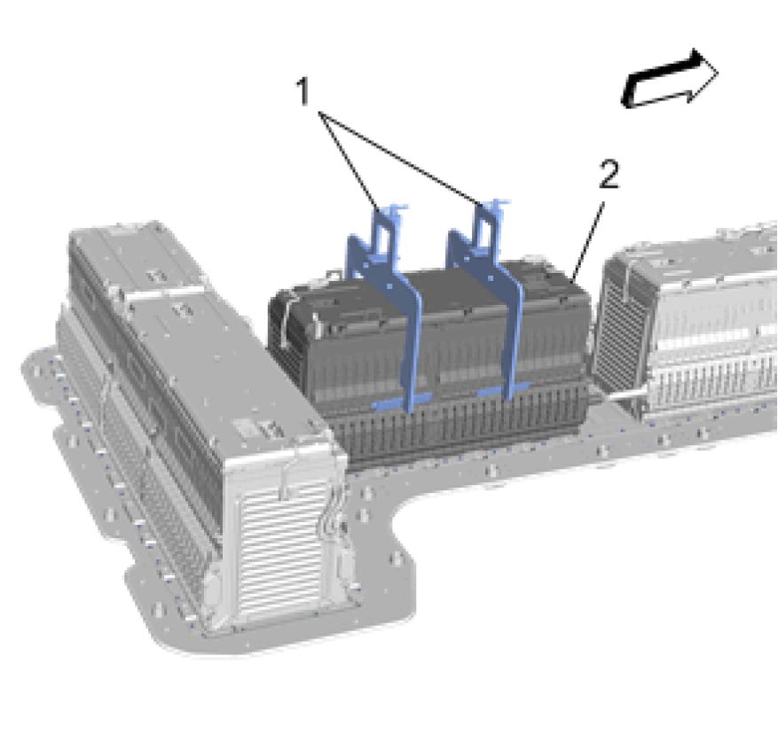 |
|
Fig. 164: Battery Section Lifting Adapters And Battery Section 2 |
19. Install EL-50115 Battery Section Lifting Adapters (1) (Qty: 2) @ Battery Section 2 (2)
 |
|
Fig. 165: Battery Section 2 Courtesy'of GENERAL'MOTORS COMPANY |
20. Remove Battery Section 2 (1)
Installation Procedure
 |
|
Fig. 166: Battery Section 2 Courtesy'of GENERAl'mOTORS COMPANY |
1. Install Battery Section 2 (1)
 |
|
Fig. 167: Battery Hold Down Retainers And Fasteners |
2. Install Battery Hold Down Retainers (2) (Qty: 2)
3. Install and tighten Fasteners (1) (Qty: 12) to 9 N.m (80 lb in)
 |
|
Fig. 168: Battery Energy Control Module Bracket And Retainers |
4. Install Battery Energy Control Module Bracket (2)
5. Engage Retainers (1) (Qty: 4)

6. Move the 2 cell battery cooling plate hoses (2, 3) against direction of arrow.
7. Tighten Clamps (1) (Qty: 4) to 2.1 N.m (19 lb in)
 |
|
Fig. 170: High Voltage Battery Cooling Manifold Outlet Hose And Clamps |
8. Install the cell battery cooling manifold outlet hose (1).
9. Tighten Clamps (2) (Qty: 2) to 2.1 N.m (19 lb in)
 |
|
Fig. 171: High Voltage Battery Cooling Manifold Inlet Hose And Clamps |
10. Install the cell battery cooling manifold inlet hose (2).
11. Tighten Clamps (1) (Qty: 2) to 2.1 N.m (19 lb in)
 |
|
Fig. 172: Electrical Connectors And Retainers |
12. Connect Electrical Connectors (1) (Qty: 4) @ Battery Section 2 (3)
13. Engage Retainers (2) (Qty: 4)
 |
|
Fig. 173: Battery Energy Control Module And Retaining Tabs |
14. Install Battery Energy Control Module (2)
 |
|
Fig. 174: Battery Energy Control Module Connector Reconnection Sequence (1 Of 2) |
15. Install connectors in the sequence shown @ Battery Energy Control Module
 |
|
Fig. 175: Battery Energy Control Module Connector Reconnection Sequence (2 Of 2) |
16. Install connectors in the sequence shown @ Battery Energy Control Module
17. Install High Voltage Battery High Voltage Manual Disconnect Connector. Refer to High Voltage Battery
High Voltage Manual Disconnect Connector Replacement
18. Install High Voltage Battery Positive Cable. Refer to High Voltage Battery Positive Cable Replacement
(Battery Section 1 to Battery Section 2)
19. Perform the Hybrid/EV battery cell balancing procedure. Refer to Hybrid/EV Battery Cell Balancing
20. Install High Voltage Battery Cover. Refer to High Voltage Battery Cover Replacement
21. Install Drive Motor Battery. Refer to Drive Motor Battery Replacement and Shipping Preparation
22. Fill the cooling system. Refer to Drive Motor Battery Cooling System Draining and Filling
HIGH VOLTAGE SECTION BATTERY REPLACEMENT (BATTERY SECTION 3)
Removal Procedure
Special Tools
• EL-51763 High Voltage Battery Section Covers
• EL-50115 Battery Section Lifting Adapters
• EL-48264 Battery Pack Lifting Adapter
Equivalent regional tools: Special Tools
WARNING: Before working on any high voltage system, be sure to wear the following Personal
Protection Equipment:
• Safety glasses with appropriate side shields when within 50 feet of the vehicle,
either indoors or outdoors
• Certified and up-to-date Class "0" Insulation gloves rated at 1000V with leather
protectors
• Visually and functionally inspect the gloves before use.
• Wear the Insulation gloves at all times when working with the high
voltage battery assembly, whether the system is energized or not.
Failure to follow the procedure exactly as written may result in serious injury or
death.
1. Remove High Voltage Battery Cover. Refer to High Voltage Battery Cover Replacement
CAUTION: The battery energy control modules internal cell balancing circuitry is powered
by the cell group voltage sense circuits. In order to prevent an unrecoverable,
unbalanced Hybrid/EV battery section or internal control module damage,
always take the following actions:
1. Disconnect ALL of the battery energy control module connectors prior to
disconnecting any Hybrid/EV battery section connector.
2. Reconnect all the Hybrid/EV battery section connectors prior to
reconnecting the battery energy control module connectors.
3. Disconnect and reconnect the battery energy control module connectors
ONLY in the sequence provided in Repair Instructions.
2. Disconnect the electrical connectors at the Battery Energy Control Module. Refer to Battery Energy Control
Module Replacement
3. Drain the cooling system. Refer to Drive Motor Battery Cooling System Draining and Filling
 |
|
Fig. 176: High Voltage Battery Positive Cable And Fastener |
4. Remove High Voltage Battery Positive Cable Fastener (1)
5. Remove High Voltage Battery Positive Cable (2)
 |
|
Fig. 177: High Voltage Battery Positive Cable And Fastener |
6. Remove High Voltage Battery Positive Cable Fastener (1)
7. Remove High Voltage Battery Positive Cable (2)
 |
|
Fig. 178: Retainers And Cable Tie Courtesy'of GENERAL'MOTORS COMPANY |
8. Disconnect Retainers (1) (Qty: 2)
9. Remove Cable Tie (2)
 |
|
Fig. 179: Electrical Connectors And Retainers |
10. Disconnect Electrical Connectors (1) (Qty: 5) @ Battery Section 3
11. Disengage Retainers (2) (Qty: 9)
12. Disconnect any harness retainers attached to battery section 3.
 |
|
Fig. 180: High Voltage Battery Cooling Manifold Inlet Hose And Clamps |
13. Loosen the clamps. (1) (Qty: 2)
14. Remove the cell battery cooling manifold inlet hose (2).
 |
|
Fig. 181: High Voltage Battery Cooling Manifold Outlet Hose And Clamps |
15. Loosen the clamps. (2) (Qty: 2)
16. Remove the cell battery cooling manifold outlet hose (1).
 |
|
Fig. 182: Battery Hold Down Retainers And Fasteners |
17. Remove Fasteners (1) (Qty: 18)
18. Remove Battery Hold Down Retainers (2) (Qty: 2)
 |
|
Fig. 183: Battery Section Lifting Adapters And Battery Section 3 |
19. Install EL-50115 Battery Section Lifting Adapters (1) (Qty: 2) @ Battery Section 3 (2)
 |
|
Fig. 184: Battery Section 3 Courtesy'of GENERAl'mOTORS COMPANY |
20. Remove Battery Section 3 (1)
Installation Procedure
 |
|
Fig. 185: Battery Section 3 Courtesy'of GENERAL'MOTORS COMPANY |
1. Install Battery Section 3 (1)
 |
|
Fig. 186: Battery Hold Down Retainers And Fasteners |
2. Install Battery Hold Down Retainers (2) (Qty: 2)
3. Install and tighten Fasteners (1) (Qty: 18) to 9 N.m (80 lb in)
 |
|
Fig. 187: Electrical Connectors And Retainers |
4. Connect Electrical Connectors (1) (Qty: 5) @ Battery Section 3 (3)
5. Connect Retainers (2) (Qty: 9)
 |
|
Fig. 188: High Voltage Battery Cooling Manifold Outlet Hose And Clamps |
6. Install the cell battery cooling manifold outlet hose (1).
7. Tighten Clamps (2) (Qty: 2) to 2.1 N.m (19 lb in)
 |
|
Fig. 189: High Voltage Battery Cooling Manifold Inlet Hose And Clamps |
8. Install the cell battery cooling manifold inlet hose (2).
9. Tighten Clamps (1) (Qty: 2) to 2.1 N.m (19 lb in)
 |
|
Fig. 190: High Voltage Battery Positive Cable And Fastener |
10. Install High Voltage Battery Positive Cable (2)
11. Install and tighten High Voltage Battery Positive Cable Fastener (1) to 9 N.m (80 lb in)
 |
|
Fig. 191: Retainers And Cable Tie |
12. Install Retainers (1) (Qty: 2)
13. Install Cable Tie (2)
 |
|
Fig. 192: High Voltage Battery Positive Cable And Fastener |
14. Install High Voltage Battery Positive Cable (2)
NOTE: Critical high voltage fastener. Perform second torque verification check
following re-assembly.
15. Install and tighten High Voltage Battery Positive Cable Fastener (1) to 9 N.m (80 lb in)
 |
|
Fig. 193: Battery Energy Control Module Connector Reconnection Sequence (1 Of 2) |
CAUTION: The battery energy control modules internal cell balancing circuitry is powered
by the cell group voltage sense circuits. In order to prevent an unrecoverable,
unbalanced Hybrid/EV battery section or internal control module damage,
always take the following actions:
1. Disconnect ALL of the battery energy control module connectors prior to
disconnecting any Hybrid/EV battery section connector.
2. Reconnect all the Hybrid/EV battery section connectors prior to
reconnecting the battery energy control module connectors.
3. Disconnect and reconnect the battery energy control module connectors
ONLY in the sequence provided in Repair Instructions.
16. Connect the connectors in the sequence shown @ Battery Energy Control Module
 |
|
Fig. 194: Battery Energy Control Module Connector Reconnection Sequence (2 Of 2) |
17. Connect the connectors in the sequence shown @ Battery Energy Control Module
18. Install High Voltage Battery Positive Cable. Refer to High Voltage Battery Positive Cable Replacement
(Generator Battery Disconnector Relay to Battery Section 3)
19. Perform the Hybrid/EV battery cell balancing procedure. Refer to Hybrid/EV Battery Cell Balancing
20. Install High Voltage Battery Cover. Refer to High Voltage Battery Cover Replacement
21. Install Drive Motor Battery. Refer to Drive Motor Battery Replacement and Shipping Preparation
22. Fill the cooling system. Refer to Drive Motor Battery Cooling System Draining and Filling
HIGH VOLTAGE BATTERY DISCONNECT RELAY REPLACEMENT
Removal Procedure
WARNING: Before working on any high voltage system, be sure to wear the following Personal
Protection Equipment:
• Safety glasses with appropriate side shields when within 50 feet of the vehicle,
either indoors or outdoors
• Certified and up-to-date Class "0" Insulation gloves rated at 1000V with leather
protectors
• Visually and functionally inspect the gloves before use.
• Wear the Insulation gloves at all times when working with the high
voltage battery assembly, whether the system is energized or not.
Failure to follow the procedure exactly as written may result in serious injury or
death.
1. Remove High Voltage Battery Cover. Refer to High Voltage Battery Cover Replacement
2. Drain the cooling system. Refer to Drive Motor Battery Cooling System Draining and Filling
 |
|
Fig. 195: Terminal Cover, High Voltage Battery Positive Cable And Fastener |
Courtesy of GENERAL MOTORS COMPANY
3. Open Terminal Cover (3)
4. Remove High Voltage Battery Positive Cable Fastener (2)
5. Remove High Voltage Battery Positive Cable (1)
 |
|
Fig. 196: High Voltage Battery Positive Cable, Fasteners And Terminal Cover |
Courtesy of GENERAL MOTORS COMPANY
6. Remove High Voltage Battery Positive Cable Fastener (1)
7. Remove High Voltage Battery Positive Cable (2)
8. Open Terminal Cover (3)
9. Remove High Voltage Battery Positive Cable Fastener (5)
10. Remove High Voltage Battery Positive Cable (4)
 |
|
Fig. 197: Electrical Connectors And Retainers |
11. Disconnect Electrical Connectors (1) (Qty: 2)
12. Release Retainers (2) (Qty: 4)
 |
|
Fig. 198: Ground Nut And Ground Cable |
13. Remove Ground Nut (1)
14. Remove Ground Cable (2)
 |
|
Fig. 199: Ground Nut And Ground Cable |
15. Remove Ground Nut (1)
16. Remove Ground Cable (2)
 |
|
Fig. 200: High Voltage Battery Cooling Manifold Outlet Hose And Retainer |
17. Unclip the hose retainer. (1)
18. Remove High Voltage Battery Cooling Manifold Outlet Hose (2)
 |
|
Fig. 201: High Voltage Battery Cooling Manifold Inlet Hose And Retainer |
19. Unclip the hose retainer. (1)
20. Remove High Voltage Battery Cooling Manifold Inlet Hose (2)
 |
|
Fig. 202: High Voltage Battery Disconnect Relay And Battery Tray Front Brace |
21. Disengage High Voltage Battery Disconnect Relay (2) @ Battery Tray Front Brace (1)
22. Remove High Voltage Battery Disconnect Relay (2)
 |
|
Fig. 203: High Voltage Battery Disconnect Relay - Pre-Charge Contactor |
23. Remove High Voltage Battery Disconnect Relay - Pre-Charge Contactor (1)
 |
|
Fig. 204: High Voltage Battery Disconnect Relay - Charge Contactor |
24. Remove High Voltage Battery Disconnect Relay - Charge Contactor (1)
25. Transfer components as necessary.
Installation Procedure
 |
|
Fig. 205: High Voltage Battery Disconnect Relay - Charge Contactor |
1. Install High Voltage Battery Disconnect Relay - Charge Contactor (1)
 |
|
Fig. 206: High Voltage Battery Disconnect Relay - Pre-Charge Contactor |
2. Install High Voltage Battery Disconnect Relay - Pre-Charge Contactor (1)
 |
|
Fig. 207: High Voltage Battery Disconnect Relay And Battery Tray Front Brace |
3. Engage High Voltage Battery Disconnect Relay (2) @ Battery Tray Front Brace (1)
 |
|
Fig. 208: High Voltage Battery Cooling Manifold Inlet Hose And Retainer |
4. Install High Voltage Battery Cooling Manifold Inlet Hose (2)
5. Install the retainer. (1)
 |
|
Fig. 209: High Voltage Battery Cooling Manifold Outlet Hose And Retainer |
6. Install High Voltage Battery Cooling Manifold Outlet Hose (2)
7. Install the retainer. (1)
 |
|
Fig. 210: Ground Nut And Ground Cable |
8. Install Ground Cable (2)
9. Install and tighten Ground Nut (1) to 9 N.m (80 lb in)
 |
|
Fig. 211: Ground Nut And Ground Cable |
10. Install Ground Cable (2)
11. Install and tighten Ground Nut (1) to 9 N.m (80 lb in)
 |
|
Fig. 212: Electrical Connectors And Retainers |
12. Connect Electrical Connectors (1) (Qty: 2)
13. Install Retainers (2) (Qty: 4)
 |
|
Fig. 213: High Voltage Battery Positive Cable, Fasteners And Terminal Cover |
14. Install High Voltage Battery Positive Cable (2)
15. Install and tighten High Voltage Battery Positive Cable Fastener (1) to 9 N.m (80 lb in)
16. Install High Voltage Battery Positive Cable (4)
17. Install and tighten High Voltage Battery Positive Cable Fastener (5) to 9 N.m (80 lb in)
18. Close Terminal Cover (3)
 |
|
Fig. 214: Terminal Cover, High Voltage Battery Positive Cable And Fastener |
19. Install High Voltage Battery Positive Cable (1)
20. Install and tighten High Voltage Battery Positive Cable Fastener (2) to 9 N.m (80 lb in)
21. Close Terminal Cover (3)
22. Perform a smoke test on the rechargeable energy storage system. Refer to Rechargeable Energy Storage
System Smoke Test
23. Install High Voltage Battery Cover. Refer to High Voltage Battery Cover Replacement
24. Install Drive Motor Battery. Refer to Drive Motor Battery Replacement and Shipping Preparation
25. Fill the cooling system. Refer to Drive Motor Generator Power Inverter Module Cooling System Draining
and Filling
HIGH VOLTAGE BATTERY DISCONNECT RELAY SEAL REPLACEMENT
 |
|
Fig. 215: High Voltage Battery Disconnect Relay Seal |
| ||||||
|
HIGH VOLTAGE BATTERY DISCONNECT RELAY FUSE REPLACEMENT (FRONT - BDU) | ||||||
 |
|
Fig. 216: High Voltage Battery Disconnect Relay Fuse (Front - BDU) |
Callout Component Name
Preliminary Procedures
WARNING:
Always perform the
High Voltage
Disabling procedure
prior to servicing any
High Voltage
component or
connection. Personal
Protection Equipment
(PPE) and proper
procedures must be
followed.
The High Voltage
Disabling procedure
includes the following
steps:
• Identify how to
disable high
voltage.
• Identify how to
test for the
presence of high
voltage.
• Identify
condition under
which high
voltage is
always present
and personal
protection
equipment (PPE)
and proper
procedures
must be
followed.
Before working on
any high voltage
system, be sure to
wear the following
Personal Protection
Equipment:
• Safety glasses
with appropriate
side shields
when within 15
meters (50 feet)
of the vehicle,
either indoors or
outdoors.
• Certified and up-
to-date Class "0"
Insulation
gloves rated at
1000V with
leather
protectors.
• Visually
and
functionally
inspect the
gloves
before use.
• Wear the
Insulation
gloves with
leather
protectors
at all times
when
working
with the
| ||||||||||
|
HIGH VOLTAGE BATTERY DISCONNECT RELAY FUSE REPLACEMENT (REAR - BDU) | ||||||||||
 |
|
Fig. 217: High Voltage Battery Disconnect Relay Fuse (Rear - BDU) |
Callout |_______________________________Component Name_______________________________
Preliminary Procedures
1. Raise and support the vehicle. Refer to Lifting and Jacking the Vehicle
2. Remove Drive Motor Battery. Refer to Drive Motor Battery Replacement and Shipping Preparation
3. Remove High Voltage Battery Cover. Refer to High Voltage Battery Cover Replacement
1 10 Amp Heater Fuse
HIGH VOLTAGE BATTERY PRECHARGE RESISTOR REPLACEMENT
Removal Procedure
1. Remove High Voltage Battery Disconnect Relay. Refer to High Voltage Battery Disconnect Relay
Replacement

Fig. 218: Tie-Wrap
Courtesy of GENERAL MOTORS COMPANY
2. Remove Tie-Wrap (1)
 |
|
Fig. 219: High Voltage Battery Pre-Charge Resistor |
3. Remove High Voltage Battery Pre-Charge Resistor (1)
Installation Procedure
 |
|
Fig. 220: High Voltage Battery Pre-Charge Resistor |
1. Install High Voltage Battery Pre-Charge Resistor (1)
 |
|
Fig. 221: Tie-Wrap Courtesy of GENERAL MOTORS COMPANY |
2. Install Tie-Wrap (1)
3. Install High Voltage Battery Disconnect Relay. Refer to High Voltage Battery Disconnect Relay
Replacement
FUSE BLOCK COVER REPLACEMENT
 |
|
Fig. 222: Fuse Block Cover |
Courtesy of GENERAL MOTORS COMPANY
Callout |_______________________________Component Name
Preliminary Procedure
WARNING:
Always perform the
High Voltage
Disabling procedure
prior to servicing any
High Voltage
component or
connection. Personal
Protection Equipment
(PPE) and proper
procedures must be
followed.
The High Voltage
Disabling procedure
includes the following
steps:
• Identify how to
disable high
voltage.
• Identify how to
test for the
presence of high
voltage.
• Identify
condition under
which high
voltage is
always present
and personal
protection
equipment (PPE)
and proper
procedures
must be
followed.
Before working on
any high voltage
system, be sure to
wear the following
Personal Protection
Equipment:
• Safety glasses
with appropriate
side shields
when within 15
meters (50 feet)
of the vehicle,
either indoors or
outdoors.
• Certified and up-
to-date Class "0"
Insulation
gloves rated at
1000V with
leather
protectors.
• Visually
and
functionally
inspect the
gloves
before use.
• Wear the
Insulation
gloves with
leather
protectors
at all times
when
working
with the
| ||||||||
|
DRIVE MOTOR BATTERY NEGATIVE HIGH VOLTAGE CONTACTOR RELAY REPLACEMENT | ||||||||
 |
|
Fig. 223: Drive Motor Battery Negative High Voltage Contactor Relay |
| ||||||
|
DRIVE MOTOR BATTERY POSITIVE HIGH VOLTAGE CONTACTOR RELAY REPLACEMENT | ||||||
 |
|
Fig. 224: Drive Motor Battery Positive High Voltage Contactor Relay |
| ||||||
|
BATTERY 300-VOLT POSITIVE AND NEGATIVE CABLE REPLACEMENT - HIGH VOLTAGE | ||||||
Removal Procedure
WARNING: Always perform the High Voltage Disabling procedure prior to servicing any High
Voltage component or connection. Personal Protection Equipment (PPE) and proper
procedures must be followed.
The High Voltage Disabling procedure includes the following steps:
• Identify how to disable high voltage.
• Identify how to test for the presence of high voltage.
• Identify condition under which high voltage is always present and personal
protection equipment (PPE) and proper procedures must be followed.
Before working on any high voltage system, be sure to wear the following Personal
Protection Equipment:
• Safety glasses with appropriate side shields when within 15 meters (50 feet) of
the vehicle, either indoors or outdoors.
• Certified and up-to-date Class "0" Insulation gloves rated at 1000V with leather
protectors.
• Visually and functionally inspect the gloves before use.
• Wear the Insulation gloves with leather protectors at all times when
working with the high voltage battery assembly, whether the system is
energized or not.
Failure to follow the procedures may result in serious injury or death.
|
1. Disable the high voltage system. Refer to High Voltage Disabling |
 |
|
Fig. 225: Heater Outlet Hose Vapor Vent Hose |
2. Remove Heater Outlet Hose Vapor Vent Hose (1). Refer to Heater Outlet Hose Vapor Vent Hose
Replacement
 |
|
Fig. 226: Air Cleaner Outlet Duct, Air Cleaner Assembly And Throttle Body |
3. Remove Air Cleaner Outlet Duct (2). Refer to Air Cleaner Outlet Duct Replacement
 |
|
Fig. 227: Engine Wiring Harness Retainer |
4. Disengage Engine Wiring Harness Retainer (1)
 |
|
Fig. 228: T6 Power Inverter Module X1 56-Way Connector Cover, Nut And Bolts |
5. Remove Power Inverter Module Connector Cover Nut (1)
6. Remove Power Inverter Module Connector Cover Bolts (2) (Qty: 2)
7. Remove Power Inverter Module Connector Cover (3)
 |
|
Fig. 229: T6 Power Inverter Module X2 HV Cable Cover And Remaining Bolt |
8. Remove Power Inverter Module High Voltage Cable Cover Bolt (1)
9. Remove Power Inverter Module High Voltage Cable Cover (2)
 |
|
Fig. 230: Electrical Connectors And Fastener |
10. Remove Fastener (1)
11. Disconnect Electrical Connector (2)
12. Disconnect Electrical Connector (3)
 |
|
Fig. 231: Cable Bracket And Fasteners |
13. Remove Fasteners (1) (Qty: 2)
14. Remove Cable Bracket (2)
15. Raise and support the vehicle. Refer to Lifting and Jacking the Vehicle
16. Remove Front Compartment Splash Shield. Refer to Front Compartment Splash Shield Replacement
 |
|
Fig. 232: Electrical Connectors And Fastener |
17. Remove Fastener (1)
18. Disconnect Electrical Connector (2)
19. Disconnect Electrical Connector (3)

Fig. 233: High Voltage Battery Positive Cable
Courtesy'of GENERAL'MOTORS'COMPANY
20. Remove High Voltage Battery Positive Cable (1)
Installation Procedure

1. Install High Voltage Battery Positive Cable (1)
 |
|
Fig. 235: Electrical Connectors And Fastener |
2. Connect Electrical Connector (3)
3. Connect Electrical Connector (2)
4. Install Front Compartment Splash Shield. Refer to Front Compartment Splash Shield Replacement
5. Install and tighten Fastener (1) to 9 N.m (80 lb in)
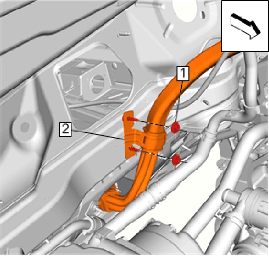
6. Install Cable Bracket (2)
7. Install and tighten Fasteners (1) (Qty: 2) to 9 N.m (80 lb in)
 |
|
Fig. 237: Electrical Connectors And Fastener |
8. Connect Electrical Connector (3)
9. Connect Electrical Connector (2)
10. Install and tighten Fastener (1) to 9 N.m (80 lb in)
 |
|
Fig. 238: T6 Power Inverter Module X2 HV Cable Cover And Remaining Bolt |
11. Install Power Inverter Module High Voltage Cable Cover (2)
12. Install and tighten Power Inverter Module High Voltage Cable Cover Bolt (1) to 9 N.m (80 lb in)
 |
|
Fig. 239: T6 Power Inverter Module X1 56-Way Connector Cover, Nut And Bolts |
13. Install Power Inverter Module Connector Cover (3)
14. Install and tighten Power Inverter Module Connector Cover Bolts (2) (Qty: 2) to 9 N.m (80 lb in)
15. Install and tighten Power Inverter Module Connector Cover Nut (1) to 9 N.m (80 lb in)
 |
|
Fig. 240: Engine Wiring Harness Retainer |
16. Engage Engine Wiring Harness Retainer (1)
 |
|
Fig. 241: Heater Outlet Hose Vapor Vent Hose |
17. Install Heater Outlet Hose Vapor Vent Hose (1). Refer to Heater Outlet Hose Vapor Vent Hose Replacement
 |
|
Fig. 242: Air Cleaner Outlet Duct, Air Cleaner Assembly And Throttle Body |
18. Install Air Cleaner Outlet Duct (2). Refer to Air Cleaner Outlet Duct Replacement
19. Enable High Voltage System. Refer to High Voltage Enabling
BATTERY 300-VOLT POSITIVE AND NEGATIVE CABLE REPLACEMENT - HIGH VOLTAGE
BATTERY TO HEATER COOLANT HEATER
Removal Procedure
WARNING: Always perform the High Voltage Disabling procedure prior to servicing any High
Voltage component or connection. Personal Protection Equipment (PPE) and proper
procedures must be followed.
The High Voltage Disabling procedure includes the following steps:
• Identify how to disable high voltage.
• Identify how to test for the presence of high voltage.
• Identify condition under which high voltage is always present and personal
protection equipment (PPE) and proper procedures must be followed.
Before working on any high voltage system, be sure to wear the following Personal
Protection Equipment:
• Safety glasses with appropriate side shields when within 15 meters (50 feet) of
the vehicle, either indoors or outdoors.
• Certified and up-to-date Class "0" Insulation gloves rated at 1000V with leather
protectors.
• Visually and functionally inspect the gloves before use.
• Wear the Insulation gloves with leather protectors at all times when
working with the high voltage battery assembly, whether the system is
energized or not.
Failure to follow the procedures may result in serious injury or death.
1. Disable the high voltage system. Refer to High Voltage Disabling
2. Raise and support the vehicle. Refer to Lifting and Jacking the Vehicle
3. Remove Front Compartment Splash Shield. Refer to Front Compartment Splash Shield Replacement
4. Remove Front Compartment Air Deflector. Refer to Front Compartment Air Deflector Replacement
5. Remove Front Wheelhouse Liner (Right Side). Refer to Front Wheelhouse Liner Replacement (Right Side)

6. Disconnect Electrical Connector (1)
 |
|
Fig. 244: Cable Brackets, Retainer And Fasteners |
7. Disengage Retainer (1)
8. Remove Fasteners (2) (Qty: 2)
9. Remove Cable Brackets (3) (Qty: 2)
 |
|
Fig. 245: Electrical Connector Courtesy'of GENERAl'mOTORS COMPANY |
10. Disconnect Electrical Connector (1)
 |
|
Fig. 246: High Voltage Battery Positive Cable |
11. Remove High Voltage Battery Positive Cable (1)
Installation Procedure
 |
|
Fig. 247: High Voltage Battery Positive Cable |
1. Install High Voltage Battery Positive Cable (1)
 |
|
Fig. 248: Electrical Connector Courtesy'of GENERAL'MOTORS COMPANY |
2. Connect Electrical Connector (1)
 |
|
Fig. 249: Cable Brackets, Retainer And Fasteners |
3. Install Cable Brackets (3) (Qty: 2)
4. Install and tighten Fasteners (2) (Qty: 2) to 9 N.m (80 lb in)
5. Engage Retainer (1)
 |
|
Fig. 250: Electrical Connector Courtesy'of GENERAL'MOTORS COMPANY |
6. Connect Electrical Connector (1)
7. Install Front Wheelhouse Liner (Right Side). Refer to Front Wheelhouse Liner Replacement (Right Side)
8. Install Front Compartment Splash Shield. Refer to Front Compartment Splash Shield Replacement
9. Install Front Compartment Air Deflector. Refer to Front Compartment Air Deflector Replacement
10. Lower the vehicle.
11. Enable high voltage system. Refer to High Voltage Enabling
BATTERY 300-VOLT POSITIVE AND NEGATIVE CABLE REPLACEMENT - HIGH VOLTAGE
BATTERY TO CHARGER RECEPTACLE, ACCESSORY DC POWER CONTROL MODULE, AND
DRIVE MOTOR BATTERY CHARGER
Removal Procedure
WARNING: Always perform the High Voltage Disabling procedure prior to servicing any High
Voltage component or connection. Personal Protection Equipment (PPE) and proper
procedures must be followed.
The High Voltage Disabling procedure includes the following steps:
• Identify how to disable high voltage.
• Identify how to test for the presence of high voltage.
• Identify condition under which high voltage is always present and personal
protection equipment (PPE) and proper procedures must be followed.
Before working on any high voltage system, be sure to wear the following Personal
Protection Equipment:
• Safety glasses with appropriate side shields when within 15 meters (50 feet) of
the vehicle, either indoors or outdoors.
• Certified and up-to-date Class "0" Insulation gloves rated at 1000V with leather
protectors.
• Visually and functionally inspect the gloves before use.
• Wear the Insulation gloves with leather protectors at all times when
working with the high voltage battery assembly, whether the system is
energized or not.
Failure to follow the procedures may result in serious injury or death.
1. Disable the high voltage system. Refer to High Voltage Disabling
2. Remove Rear Compartment Floor Stowage Trim Compartment. Refer to Rear Compartment Floor Stowage
Trim Compartment Replacement
3. Raise and support the vehicle. Refer to Lifting and Jacking the Vehicle
4. Remove Drive Motor Battery. Refer to Drive Motor Battery Replacement and Shipping Preparation
 |
|
Fig. 251: Drive Motor Battery Electrical Connector And Fasteners |
5. Disconnect Electrical Connector (1) @ Drive Motor Battery
6. Remove Fasteners (2) (Qty: 3)
 |
|
Fig. 252: Brake Pressure Modulator Valve, Bracket And Bolt |
7. Reposition the brake pressure modulator valve (3) without disconnecting the brake lines. Refer to Electronic
Brake Control Module with Brake Pressure Modulator Valve Replacement
 |
|
Fig. 253: Retainers And Clip Courtesy'of GENERAL'MOTORS COMPANY |
8. Disengage Retainers (1) (Qty: 3)
9. Disengage Clip (2)

Fig. 254: Electrical Connectors
Courtesy of GENERAL MOTORS COMPANY
10. Disconnect Electrical Connectors (1) (Qty: 2)
 |
|
Fig. 255: Retainer Clip And Retainers |
11. Disengage Retainer Clip (1)
12. Disengage Retainers (2) (Qty: 2)
 |
|
Fig. 256: Engine Wiring Harness And Ground Nut |
13. Remove Engine Wiring Harness Ground Nut (1)
14. Reposition Engine Wiring Harness (2) away


Fig. 257: Accessory DC Power Control Module, Drive Motor Battery Charger And Electrical
Connectors
Courtesy'of GENERAL MOTORS COMPANY
15. Disconnect Electrical Connector (1) @ Accessory DC Power Control Module (4)
16. Disconnect Electrical Connectors (2) (Qty: 2) @ Drive Motor Battery Charger (3)
 |
|
Fig. 258: Retainers Courtesy'of GENERAL MOTORS COMPANY |
17. Disengage Retainers (1) (Qty: 4)
18. Raise and support the vehicle. Refer to Lifting and Jacking the Vehicle
 |
|
Fig. 259: Fastener Courtesy'of GENERAL MOTORS COMPANY |
19. Remove Fastener (1)
 |
|
Fig. 260: Pass-Through Grommet And Fasteners |
20. Remove Fasteners (1) (Qty: 3)
21. Remove Pass-Through Grommet (2)
 |
|
Fig. 261: Fuel Tank Straps Courtesy'of GENERAL'MOTORS COMPANY |
22. Support the fuel tank and only remove the fuel tank straps (1). Refer to Fuel Tank Replacement
23. Support the drive motor battery.
 |
|
Fig. 262: Drive Motor Battery Tray Fasteners And Floor Panel Bar |
24. Remove Drive Motor Battery Tray Fasteners (1) (Qty: 2)
25. Remove Drive Motor Battery Tray Fasteners (2) (Qty: 4)
26. Remove Drive Motor Battery Tray Fasteners (3) (Qty: 4)
27. Remove Floor Panel Bar (4)
 |
|
Fig. 263: Retainer Clips And Fastener Courtesy'of GENERAL'MOTORS'COMPANY |
28. Disengage Retainer Clips (1) (Qty: 4)
29. Remove Fastener (3)

Fig. 264: High Voltage Battery Positive Cable
Courtesy'of GENERAL'MOTORS'COMPANY
30. Remove High Voltage Battery Positive Cable (1)
Installation Procedure

Fig. 265: High Voltage Battery Positive Cable
Courtesy'of GENERAL'MOTORS'COMPANY
1. Install High Voltage Battery Positive Cable (1)
 |
|
Fig. 266: Retainer Clips And Fastener |
2. Install High Voltage Battery Positive Cable (2) @ Retainer Clips (1) (Qty: 4)
3. Engage Retainer Clips (1) (Qty: 4)
4. Install and tighten Fastener (3) to 9 N.m (80 lb in)
 |
|
Fig. 267: Fastener Courtesy'of GENERAL MOTORS COMPANY |
5. Install and tighten Fastener (1) to 9 N.m (80 lb in)
 |
|
Fig. 268: Pass-Through Grommet And Fasteners |
6. Install Pass-Through Grommet (2)
7. Install and tighten Fasteners (1) (Qty: 3) to 9 N.m (80 lb in)
 |
|
Fig. 269: Fuel Tank Straps Courtesy'of GENERAL'MOTORS COMPANY |
8. Install the fuel tank straps (1). Refer to Fuel Tank Replacement
 |
|
Fig. 270: Drive Motor Battery Tray Fasteners And Floor Panel Bar |
9. Install Floor Panel Bar (4)
10. Install and tighten Drive Motor Battery Tray Fasteners (2) (Qty: 4) to 22 N.m (16 lb ft)
11. Install and tighten Drive Motor Battery Tray Fasteners (3) (Qty: 4) to 22 N.m (16 lb ft)
12. Install and tighten Drive Motor Battery Tray Fasteners (1) (Qty: 2) to 58 N.m (43 lb ft)
13. Lower the vehicle.


Fig. 271: Accessory DC Power Control Module, Drive Motor Battery Charger And Electrical
Connectors
Courtesy'of GENERAL MOTORS COMPANY
14. Connect Electrical Connector (1) @ Accessory DC Power Control Module (4)
15. Connect Electrical Connectors (2) (Qty: 2) @ Drive Motor Battery Charger (3)
 |
|
Fig. 272: Retainers Courtesy'of GENERAL MOTORS COMPANY |
16. Engage Retainers (1) (Qty: 4)
17. Install Rear Compartment Floor Stowage Trim Compartment. Refer to Rear Compartment Floor Stowage
Trim Compartment Replacement
 |
|
Fig. 273: Retainers And Clip Courtesy'of GENERAL'MOTORS COMPANY |
18. Engage Retainers (1) (Qty: 3)
19. Engage Clip (2)

20. Connect Electrical Connectors (1) (Qty: 2)
 |
|
Fig. 275: Engine Wiring Harness And Ground Nut |
21. Install Engine Wiring Harness (2)
22. Install and tighten Engine Wiring Harness Ground Nut (1) to 9 N.m (80 lb in)
 |
|
Fig. 276: Brake Pressure Modulator Valve, Bracket And Bolt |
23. Install the brake pressure modulator valve (3). Refer to Electronic Brake Control Module with Brake
Pressure Modulator Valve Replacement
 |
|
Fig. 277: Drive Motor Battery Electrical Connector And Fasteners |
24. Install and tighten Fasteners (2) (Qty: 3) to 9 N.m (80 lb in)
25. Connect Electrical Connector (1)
26. Install Drive Motor Battery. Refer to Drive Motor Battery Replacement and Shipping Preparation
27. Lower the vehicle.
28. Enable the high voltage system. Refer to High Voltage Enabling
BATTERY TRAY FRONT BRACE REPLACEMENT

Fig. 278: Battery Tray Front Brace
Courtesy'of GENERAl'mOTORS' COMPANY
| ||||||||||||
|
DRIVE MOTOR BATTERY REPLACEMENT AND SHIPPING PREPARATION | ||||||||||||
Special Tools
Equivalent regional tools: Special Tools
Removal Procedure
WARNING: Always perform the High Voltage Disabling procedure prior to servicing any High
Voltage component or connection. Personal Protection Equipment (PPE) and proper
procedures must be followed.
The High Voltage Disabling procedure includes the following steps:
• Identify how to disable high voltage.
• Identify how to test for the presence of high voltage.
• Identify condition under which high voltage is always present and personal
protection equipment (PPE) and proper procedures must be followed.
Before working on any high voltage system, be sure to wear the following Personal
Protection Equipment:
• Safety glasses with appropriate side shields when within 15 meters (50 feet) of
the vehicle, either indoors or outdoors.
• Certified and up-to-date Class "0" Insulation gloves rated at 1000V with leather
protectors.
• Visually and functionally inspect the gloves before use.
• Wear the Insulation gloves with leather protectors at all times when
working with the high voltage battery assembly, whether the system is
energized or not.
Failure to follow the procedures may result in serious injury or death.
1. Disable high voltage system. Refer to High Voltage Disabling
2. Remove Front Compartment Splash Shield. Refer to Front Compartment Splash Shield Replacement
3. Remove Underbody Front Air Deflector-Left Side. Refer to Underbody Front Air Deflector Replacement -
Left Side
4. Remove Underbody Rear Air Deflector. Refer to Underbody Rear Air Deflector Replacement
5. Remove the drive motor battery radiator surge tank cap. Refer to Drive Motor Battery Radiator Surge Tank
Cap Replacement
 |
|
Fig. 279: Inspection Plug Courtesy'of GENERAL MOTORS COMPANY |
6. Place a drain pan under the vehicle.
7. Remove and DISCARD Inspection Plug (1)
8. Collect any fluid present in the drain pan and if no fluid is present, insert a clean white cloth or cotton swab
through the inspection plug opening, looking for any evidence of coolant residue.
 |
|
Fig. 280: Ground Straps And Nuts Courtesy'of GENERAL'MOTORS COMPANY |
9. Remove Ground Strap Nuts (1) (Qty: 4)
10. Remove Ground Straps (2) (Qty: 2)
 |
|
Fig. 281: Electrical Connectors And Retainers |
11. Disconnect Electrical Connectors (1) (Qty: 2)
12. Release Retainers (2) (Qty: 2)
 |
|
Fig. 282: Drive Motor Battery Coolant Cooler Inlet Hose, Outlet Hose And Retainers |
13. Place a drain pan under the vehicle.
14. Release Retainer (4)
15. Reposition Drive Motor Battery Coolant Cooler Outlet Hose (3)
16. Release Retainer (1)
17. Reposition Drive Motor Battery Coolant Cooler Inlet Hose (2)
 |
|
Fig. 283: Cabin Heater Control Module Harness Connector, A/C Compressor Harness Connector And Courtesy'of GENERAL'MOTORS'COMPANY |
18. Disconnect the following:
• Disconnect K10 Cabin Heater Control Module Harness Connector (1)
• Disconnect G1 Air Conditioning Compressor Harness Connector (2)
• Disconnect T18 Battery Charger Harness Connector (3)
 |
|
Fig. 284: T6 Power Inverter Module Connector, Cable Retainer And Fastener |
19. Remove Fastener (1)
20. Remove Cable Retainer (2)
NOTE:
21. Disconnect T6 Power Inverter Module Connector (3)
22. Wrap exposed electrical connections with electrical tape to keep coolant out of electrical connections.
 |
|
Fig. 285: Rear Body Exhaust Heat Shield |
23. Remove Rear Body Exhaust Heat Shield (2). Refer to Rear Body Exhaust Heat Shield Replacement

Fig. 286: Drive Motor Battery Support Fixture And Locating Pins
Courtesy of GENERAL MOTORS COMPANY
24. Mount the EL 49976 Drive Motor Battery Support Fixture, to a lift table with 4 fasteners.
25. Ensure the long axis of the drive motor battery support fixture (1) is mounted to the long side of the lift table.
26. Insert the locating pins (2) into the drive motor battery locating holes.
27. Adjust the angle of the table/lifting fixture until it is parallel to the battery tray/aero shield.
28. Raise the fixture until it is firmly resting against the tray along the entire perimeter of the fixture.
 |
|
Fig. 287: Drive Motor Battery Tray Fasteners |
29. Remove Drive Motor Battery Tray Fasteners (1) (Qty: 18)
30. Remove Drive Motor Battery Tray Fasteners (2) (Qty: 4)
31. Remove the drive motor battery and the EL-49976 drive motor battery support fixture from the lift table and
set aside.
32. Remove the replacement drive motor battery and the replacement EL-49976 drive motor battery support
fixture from the container and mount to the lift table.
33. Ensure that tape covers the manual disconnect terminals on the drive motor battery.
34. If the drive motor battery is being returned, prepare the drive motor battery for safe shipping by performing the
following:
 |
|
Fig. 288: Coolant Plugs And S15 Manual Service Disconnect (MSD) Cover |
NOTE: As part of the battery removal process, all coolant should be drained
from the battery pack.
1. Install coolant plugs (1) in the coolant lines. Coolant plugs can be removed from the new service battery
assembly and installed in the returned battery. Additional coolant plugs (GM p/n 22770854) can be
ordered if they are needed.
NOTE: The MSD lever should remain with the vehicle and not be returned with
the battery assembly.
2. Install the S15 Manual Service Disconnect (MSD) Cover (2). The MSD cover can be removed from the
new service battery assembly and installed in the returned battery. Additional MSD covers (GM p/n
22770856) can be ordered if they are needed.
NOTE: The failed battery must be removed and returned with a battery assembly
lifting fixture (GM Special Tool EL-49976). This lifting fixture will be
attached to the failed battery and placed in the shipping container. Each
new service battery will come with a battery assembly lifting fixture for
use during installation. You will keep this fixture for servicing future
battery removals.
3. Install the High Voltage Connector Cover. The high voltage connector cover can be removed from the
service battery and installed on the returned battery. If the service battery assembly did not come with a
high voltage connector cover, additional covers can be ordered by calling 1-800 GM TOOLS.
Installation Procedure
1. Mount the lifting table to the EL 49976 drive motor battery support fixture with 4 fasteners.
NOTE: Ensure the long axis of the lifting fixture is mounted and parallel to the long
side of the lift table.
2. Install the drive motor battery, with the EL 49976 drive motor battery support fixture to the lift table.
 |
|
Fig. 289: Drive Motor Battery Tray Fasteners |
3. Install and tighten Drive Motor Battery Tray Fasteners (1) (Qty: 6) to 58 N.m (43 lb ft)
4. Install and tighten Drive Motor Battery Tray Fasteners (2) (Qty: 2) to 22 N.m (16 lb ft)
 |
|
Fig. 290: Drive Motor Battery Tray Fasteners |
5. Install and tighten Drive Motor Battery Tray Fasteners (1) (Qty: 12) to 58 N.m (43 lb ft)
6. Install and tighten Drive Motor Battery Tray Fasteners (2) (Qty: 2) to 22 N.m (16 lb ft)
 |
|
Fig. 291: Inspection Plug Courtesy'of GENERAL MOTORS COMPANY |
7. Install and tighten the NEW Inspection Plug (1) to 9 N.m (80 lb in)
 |
|
Fig. 292: Ground Straps And Nuts Courtesy'of GENERAL'MOTORS COMPANY |
8. Install Ground Straps (2) (Qty: 2)
9. Install and tighten Ground Strap Nuts (1) (Qty: 4) to 9 N.m (80 lb in)
 |
|
Fig. 293: Rear Body Exhaust Heat Shield |
10. Install Rear Body Exhaust Heat Shield (2). Refer to Rear Body Exhaust Heat Shield Replacement
 |
|
Fig. 294: T6 Power Inverter Module Connector, Cable Retainer And Fastener |
11. Connect T6 Power Inverter Module Connector (3)
12. Install Cable Retainer (2)
13. Install and tighten Fastener (1) to 9 N.m (80 lb in)
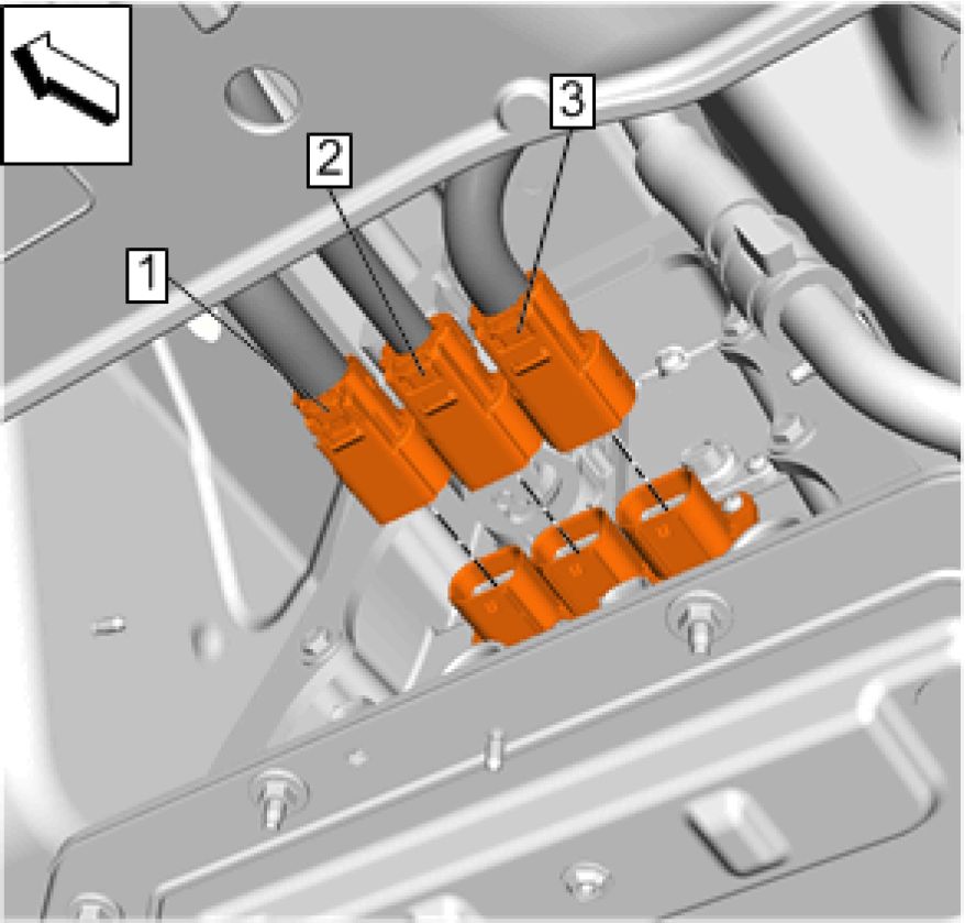 |
|
Fig. 295: Cabin Heater Control Module Harness Connector, A/C Compressor Harness Connector And Courtesy'of GENERAL'MOTORS'COMPANY |
14. Connect the following:
• Connect K10 Cabin Heater Control Module Harness Connector (1)
• Connect G1 Air Conditioning Compressor Harness Connector (2)
• Connect T18 Battery Charger Harness Connector (3)
 |
|
Fig. 296: Drive Motor Battery Coolant Cooler Inlet Hose, Outlet Hose And Retainers |
15. Install Drive Motor Battery Coolant Cooler Outlet Hose (3)
16. Install Retainer (4)
17. Install Drive Motor Battery Coolant Cooler Inlet Hose (2)
18. Retainer (1)
 |
|
Fig. 297: Electrical Connectors And Retainers Courtesy'of GENERAL'MOTORS'COMPANY |
19. Connect Electrical Connectors (1) (Qty: 2)
20. Install Retainers (2) (Qty: 2)
21. Fill the drive motor battery with coolant. Refer to Drive Motor Battery Cooling System Draining and
Filling
22. Install Underbody Rear Air Deflector. Refer to Underbody Rear Air Deflector Replacement
23. Install Underbody Front Air Deflector-Left Side. Refer to Underbody Front Air Deflector Replacement -
Left Side
24. Install Front Compartment Splash Shield. Refer to Front Compartment Splash Shield Replacement
25. Install the drive motor battery radiator surge tank cap. Refer to Drive Motor Battery Radiator Surge Tank
Cap Replacement
26. Enable the high voltage system. Refer to High Voltage Enabling
27. Check the battery pack cooling system for leaks. Refer to Hybrid Cooling System Leak Test
28. Reprogram the battery energy control module. Refer to Control Module References
29. Reprogram the HPCM2. Refer to Control Module References
30. Clear the secured high voltage DTC's. Refer to Clear Secured High Voltage DTCs
31. If required, perform the battery Hybrid/EV battery pack capacity learn procedure. Refer to Hybrid/EV
Battery Pack Capacity Learn
AUXILIARY BATTERY WIRING HARNESS REPLACEMENT
Removal Procedure
1. Remove High Voltage Battery Cover. Refer to High Voltage Battery Cover Replacement
2. Remove Battery Energy Control Module. Refer to Battery Energy Control Module Replacement
3. Remove High Voltage Battery High Voltage Manual Disconnect Connector. Refer to High Voltage Battery
High Voltage Manual Disconnect Connector Replacement
 |
|
Fig. 298: Electrical Connectors And Retainers |
4. Disconnect Electrical Connectors (1) (Qty: 6) @ High Voltage Battery Section 1
5. Disengage Retainers (2) (Qty: 4)
 |
|
Fig. 299: Electrical Connectors And Retainers |
6. Disconnect Electrical Connectors (1) (Qty: 4) @ High Voltage Battery Section 2
7. Disengage Retainers (2) (Qty: 4)
 |
|
Fig. 300: Electrical Connectors And Retainers |
8. Disconnect Electrical Connectors (1) (5) @ High Voltage Battery Section 3
9. Disengage Retainers (2) (Qty: 9)
 |
|
Fig. 301: Auxiliary Battery Wiring Harness Courtesy'of GENERAL'MOTORS'COMPANY |
10. Remove Auxiliary Battery Wiring Harness (1)
Installation Procedure
 |
|
Fig. 302: Auxiliary Battery Wiring Harness |
1. Install Auxiliary Battery Wiring Harness (1)
 |
|
Fig. 303: Electrical Connectors And Retainers |
2. Connect Electrical Connectors (1) (Qty: 5) @ High Voltage Battery Section 3
3. Connect Retainers (2) (Qty: 9)
 |
|
Fig. 304: Electrical Connectors And Retainers |
4. Connect Electrical Connectors (1) (Qty: 4) @ High Voltage Battery Section 2
5. Connect Retainers (2) (Qty: 4)
 |
|
Fig. 305: Electrical Connectors And Retainers |
6. Connect Electrical Connectors (1) (Qty: 6) @ High Voltage Battery Section 1
7. Connect Retainers (2) (Qty: 4)
8. Install Battery Energy Control Module. Refer to Battery Energy Control Module Replacement
9. Install High Voltage Battery High Voltage Manual Disconnect Connector. Refer to High Voltage Battery
High Voltage Manual Disconnect Connector Replacement
10. Install High Voltage Battery Cover. Refer to High Voltage Battery Cover Replacement
11. Install Drive Motor Battery. Refer to Drive Motor Battery Replacement and Shipping Preparation
CLEAR SECURED HIGH VOLTAGE DTCS
Circuit/System Description
The hybrid powertrain control modules 1 and 2 independently monitor for high voltage safety conditions such as
airbag deploy events and certain high voltage system faults. When either module identifies one of these conditions, a
DTC may set and the vehicle is placed into a 'high voltage lockout' state. While in the lockout state, the high voltage
contactor relays are prevented from closing.
The purpose of the high voltage lockout state is to allow for high voltage system inspection prior to re-enabling. A
complete inspection of the high voltage system and components must be performed if the vehicle has been involved
in a collision. Perform the High Voltage System Inspection procedure, if necessary, prior to clearing a Secured High
Voltage DTCs/lockout state.
Diagnostic Aids
• The following conditions may result in a HV lockout state without a corresponding DTC:
• High voltage component replacement
• Low 12 V battery event
• SPS programming event
• Airbag deployment/crash event detected: The Inflatable Restraint Sensing and Diagnostic Module may
or may not set a DTC but will continue to broadcast a crash event status until reset.
• Performing a scan tool DTC Clear may clear the diagnostic that set the HV lockout state, but will not reset the
lockout.
• Clearing powertrain DTCs will set the Inspection/Maintenance (I/M) system status indicators to NO.
• The Clear Secured High Voltage DTCs procedure must be completed when the following components, as
applicable, are replaced:
• K16 Hybrid/EV Battery Energy Control Module
• K112A - K112H Hybrid/EV Battery Interface Control Module
• A4 Hybrid/EV Battery Pack
• K114A Hybrid/EV Powertrain Control Module 1
• K114B Hybrid/EV Powertrain Control Module 2
The hybrid/EV powertrain control module 2, Hybrid/EV Battery Contactor Open Reasons scan tool parameter list
identifies all past events that commanded contactors open. The parameters can only be reset by either reprogramming
the hybrid/EV powertrain control module 2 or by performing the scan tool Hybrid/EV Battery Contactor Open
Reasons Reset function. To aid in possible future intermittent diagnosis, the parameters should be reset to NO once
all diagnostic procedures are successfully completed.
Scan Tool Hybrid/EV Battery Contactor Open Reasons Reset Function
1. Complete the Circuit System Verification and Testing as necessary.
2. Remove any chargers and as applicable, the charge cord.
3. Vehicle OFF, wait 5 minutes.
4. Disengage the S15 Manual Service Disconnect to the first position to open the high voltage interlock loop
circuit.
5. Service Mode, enable the scan tool reset function.
6. Vehicle OFF, wait 5 minutes.
7. Fully engage the S15 Manual Service Disconnect.
8. Start the vehicle and Clear Vehicle DTCs.
Reference Information
Special Tools
EL-49642 SPS Programming Support Tool
For equivalent regional tools, refer to Special Tools .
Circuit/System Verification
1. Vehicle ON.
2. With a scan tool, verify the Hybrid/EV Powertrain Control Module 2 parameters Hybrid/EV Battery Positive
Contactor Command and Hybrid/EV Battery Negative Contactor Command each indicate Closed.
Refer to Circuit/System Testing.
3. A Secured High Voltage DTC HV lockout state is not present. All OK.
Circuit/System Testing
The Clear Secured High Voltage DTCs reset process requires scan tool interaction with two or three different
control modules in sequence and can be completed using the following steps:
1. Install EL-49642 SPS programming support tool.
2. Vehicle in Service Mode. With a scan tool select the Hybrid/EV Powertrain Control Module 2, Hybrid Battery
Pack Contactor Open Reasons data list. Verify if either the Crash Event Detected or Air Bag Deployed
parameters indicate YES.
• If either parameter displays YES
1. Perform the High Voltage System Inspection procedure.
2. If the results of the inspection procedure support enabling of the high voltage system, perform the
Inflatable Restraint and Sensing Diagnostic Module function Reset High Voltage Disable Request After
Crash Event Detected.
3. Turn the vehicle OFF for 5 minutes.
4. Proceed to next step.
• If BOTH parameters indicate NO
3. Vehicle in Service Mode. With a scan tool, clear All DTCs.
4. With a scan tool, select Hybrid/EV Powertrain Control Module 2 Control Functions list. Select Clear Secured
High Voltage DTCs and follow the on-screen instructions waiting 45 seconds before exiting the screen.
5. With a scan tool, select Hybrid/EV Powertrain Control Module Control Functions list. Select Clear Secured
High Voltage DTCs. Select Continue button waiting 45 seconds before exiting the screen.
6. With a scan tool, select Hybrid/EV Powertrain Control Module 2 Control Functions list. Select Clear Secured
High Voltage DTCs and follow the on-screen instructions.
7. With a scan tool, clear All DTCs.
8. Allow the Hybrid/EV powertrain Control Modules to enter sleep mode by performing the following:
1. Turn the vehicle OFF.
2. Ensure the scan tool is not communicating with any control modules by returning to the Home screen.
3. Ensure the scan tool is accessible without having to open doors or otherwise cause control module wake-
up.
4. Shut all doors. Do NOT depress the brake pedal or activate any vehicle controls such as the parking
lights, fuel door release, etc.
5. Wait 5 minutes with the vehicle in the prescribed condition so that the modules may enter sleep mode.
9. With a scan tool, verify the Hybrid/EV Powertrain Control Module 2 has gone to sleep by ensuring
communication is not present.
Repeat the previous step.
10. Start the vehicle.
11. Verify that no DTCs are set.
12. All OK.
Circuit/System Description
The Hybrid Powertrain Control Module 2 learns the battery capacity as the Hybrid/EV battery pack is discharged and
charged. Once learned, the capacity value is allowed to change over a long period of time, as the battery ages.
Replacement of the battery pack, all battery sections or the Hybrid Powertrain Control Module 2 requires capacity
learning at a faster rate than normal.
To enable hardware replacement, the Hybrid Powertrain Control Module 2 can be placed into a fast learn mode with
the scan tool.
Activating the fast Capacity Learn mode will reset the battery capacity to a much lower value and subsequent
charge/discharge cycles will then learn the capacity back up to the proper value. Initially this may have a noticeable
effect on EV range until the capacity learning for the new hardware begins. It may take several battery pack
depletions and charges for a maximum EV range to be learned/displayed.
Diagnostic Aids
The Hybrid/EV Battery Pack Capacity Learn procedure must be completed when the following components are
replaced:
• Hybrid Powertrain Control Module 2
• Hybrid/EV Battery Pack
• All battery sections
Whenever the Hybrid/EV Battery Pack Capacity Learn is activated the vehicle needs to be operated in a normal
manner in order to learn an accurate battery capacity value.
NEVER disconnect the 12V battery supply to the vehicle or the Hybrid Powertrain Control Module 2 after initially
activating the Hybrid/EV Battery Pack Capacity Learn. Loss of 12V power will force the Hybrid Powertrain Control
Module 2 to store the current capacity value as accurate and will also disable fast learning. The process needs to
complete without 12V battery interruption for the best results. Repeat the Hybrid/EV Battery Pack Capacity Learn
any time 12V battery interruption occurs prior to operating the vehicle by driving and/or charging. It is possible to
observe whether an update has occurred by looking at the battery capacity after charging and/or driving the vehicle.
Hybrid/EV Battery Pack Capacity Learn
The Hybrid/EV Battery Pack Capacity Learn procedure can be activated with a scan tool using the following steps:
1. Vehicle On
2. With a scan tool, select Hybrid Powertrain Control Module 2 Configuration/Reset Functions. Select the Learn
Functions - Hybrid/EV Battery Pack Capacity Learn and command a Learn.
3. Observe and record the alphanumeric value in the Hybrid/EV Battery Pack Capacity scan tool parameter.
4. Connect the vehicle charge cord and completely charge the hybrid/EV battery pack.
5. The vehicle is OK to return to the customer. Inform the customer that their EV range will continue to learn as
the vehicle is operated normally. Longer drive trips followed by full charging will allow the fastest learn.
6. If the customer returns with an EV Range concern, contact technical assistance.
HYBRID/EV BATTERY CELL BALANCING
Diagnostic Instructions
• Perform the Diagnostic System Check - Vehicle prior to using this diagnostic procedure.
• Review Strategy Based Diagnosis for an overview of the diagnostic approach.
• Refer to Diagnostic Procedure Instructions to provide an overview of each diagnostic category.
Circuit/System Description
The EL-50332 Hybrid/EV Battery Service Tool is used to match the voltage level of a replacement battery section to
the existing battery sections following a service event. The tool will charge or discharge the replacement section, as
required, based on measured cell group voltage data. The EL-50332 requires feedback from the battery energy
control module during the balancing process. Communication is through the A4 Hybrid/EV Battery Pack X357 and
X358 connectors and a low voltage interface harness provided with the EL-50332 Hybrid/EV Battery Service Tool.
The charging and discharging is performed by direct connection to the replacement battery section positive and
negative terminals.
Reference Information
Schematic Reference
Hybrid/EV Energy Storage Schematics
Connector End View Reference
Testing for Intermittent Conditions and Poor Connections
Description and Operation
Drive Motor Battery System Description
Electrical Information Reference
Circuit Testing
Connector Repairs
Testing for Intermittent Conditions and Poor Connections
Wiring Repairs
DTC Type Reference
Powertrain Diagnostic Trouble Code (DTC) Type Definitions
Scan Tool Reference
Control Module References for scan tool information
Special Tools
• EL-50332 Hybrid/EV Battery Service Tool
• EL-50332-105 Universal Fuse Box
• EL-50332-120 High Voltage Interface Cable
• EL-50332-125 Vehicle Interface Module Low Voltage 24-Pin Cable
• EL-50332-135 Hybrid/EV Battery Contactor Assembly Interface Cable
• EL-50332-145 Black Banana Jack Cable
• EL-50332-150 Red Banana Jack Cable
• EL-50332-155 Green Banana Jack Cable
• EL-50332-170 High Voltage Alligator Clamps
• EL-50332-175 120 V Power Cable
• EL-50332-175 120 V Power Cable - EU
• EL-50332-180 250 V Power Cable - AUS
• EL-50332-270 Vehicle Interface Module 2
Circuit/System Testing
• Identify how to disable high voltage.
• Identify how to test for the presence of high voltage.
• Identify condition under which high voltage is always present and personal
protection equipment (PPE) and proper procedures must be followed.
Before working on any high voltage system, be sure to wear the following Personal
Protection Equipment:
• Safety glasses with appropriate side shields when within 15 meters (50 feet) of
the vehicle, either indoors or outdoors.
• Certified and up-to-date Class "0" Insulation gloves rated at 1000V with leather
protectors.
• Visually and functionally inspect the gloves before use.
• Wear the Insulation gloves with leather protectors at all times when
working with the high voltage battery assembly, whether the system is
energized or not.
Failure to follow the procedures may result in serious injury or death.
WARNING: High voltage circuits should only be tested using a digital multimeter (DMM) and
test leads with at least a CAT III rating, such as the J 39200-A Digital Multimeter.
Failure to follow the procedures may result in serious injury or death.
WARNING: This vehicle is equipped with a high voltage battery that is completely isolated from
the chassis ground. Never utilize AC powered test equipment to probe the high
voltage system. Serious injury, death and component damage could occur if the
high voltage system is grounded through the electric utility.
Failure to follow the procedure exactly as written may result in serious injury or
death.
WARNING: Damage to a Lithium Ion hybrid/EV battery pack could result in fire, loss of electrical
isolation or exposure to high voltage. Until the high voltage system inspection has
been completed, store the vehicle with hybrid/EV battery pack installed outside in a
secure area away from buildings and other vehicles and protected from rain, snow
and other moisture. Remove the hybrid/EV battery pack high voltage manual
disconnect lever and store it in a secure place outside the vehicle. Cover the
exposed high voltage opening with ULA® listed, or equivalent, insulation tape rated
at a minimum of 600 V.
Failure to follow these precautions could result in personal injury, death and
property damage.
Inspection Procedure
NOTE: Before balancing a battery section, make sure all of the external EL-50332
components and cables are in good condition and working order.
1. Connect the EL-50332-145 Black Banana Jack Cable, EL-50332-150 Red Banana Jack Cable, and
EL-50332-155 Green Banana Jack Cable to the EL-50332-105 Universal Fuse Box.
2. Connect the EL-50332-120 High Voltage Interface Cable to the EL-50332-105 Universal Fuse Box.
3. Connect the EL-50332-120 High Voltage Interface Cable to the EL - 50332 Hybrid/EV Battery Service Tool.
4. Connect the EL-50332-135 Hybrid/EV Battery Contactor Assembly Interface Cable to the EL-50332-270
Vehicle Interface Module 2.
5. Connect the EL-50332-125 Vehicle Interface Module Low Voltage 24-Pin Cable to the EL-50332-270 Vehicle
Interface Module 2.
6. Connect the EL-50332-125 Vehicle Interface Module Low Voltage 24-Pin Cable to the EL-50332 Hybrid/EV
Battery Service Tool.
NOTE: Refer to the Special Tools for the correct regional power cord.
7. Connect the appropriate regional power cord to the EL-50332 Hybrid/EV Battery Service Tool.
8. Connect the appropriate regional power cord into a known good power outlet.
9. Turn ON the EL - 50332 Hybrid/EV Battery Service Tool using the power switch.
10. At the MAIN MENU, select SECTION BALANCE, press the SELECT soft key.
11. At the TYPE menu, select VOLTEC, press the NEXT soft key.
12. At the TARGET menu, select appropriate section to be balanced, press the NEXT soft key.
13. Connect the EL-50332-155 Green Banana Jack Cable to the A4 Hybrid/EV Battery Pack ground stud.
14. Connect the EL-50332-145 Black Banana Jack Cable to the appropriate section negative stud to be balanced.
Refer to Hybrid/EV Energy Storage Schematics for Hybrid Battery Section 1, Hybrid Battery Section 2, or
Hybrid Battery Section 3.
15. Connect the EL-50332-150 Red Banana Jack Cable to the appropriate section positive stud to be balanced.
Refer to Hybrid/EV Energy Storage Schematics for Hybrid Battery Section 1, Hybrid Battery Section 2, or
Hybrid Battery Section 3.
16. Press the NEXT soft key.
17. Connect the EL-50332-135 Hybrid/EV Battery Contactor Assembly Interface Cable to the A4 Hybrid/EV
Battery Pack.
NOTE: Depending on the charge condition of the battery pack and the section being
balanced, this process may take up to 4 hours to complete.
18. Press the NEXT soft key.
NOTE: The EL-50332 will now balance the selected section by charging/discharging,
as appropriate. Target voltage varies based on measured pack cell group
voltages. Initial balancing will be in a constant current mode (max 5 amp
charge, 7.5 amp discharge). The tool will transition to a constant voltage mode
(decreasing current) near the end of the event. A warranty code and pack
voltage current data will be displayed at the conclusion of the balancing event.
19. An audible tone will sound at the end of balancing or in the event of a fault condition.
Refer to the EL - 50332 Hybrid/EV Battery Service Tool Instruction Manual.
20. At the Completed menu, press the NEXT soft key. Record warranty code. Press the EXIT soft key.
21. Disconnect the EL - 50332 Hybrid/EV Battery Service Tool from the Hybrid/EV Battery Pack.
22. All OK.
Diagnostic Instructions
• Perform the Diagnostic System Check - Vehicle prior to using this diagnostic procedure.
• Review Strategy Based Diagnosis for an overview of the diagnostic approach.
• Refer to Diagnostic Procedure Instructions to provide an overview of each diagnostic category.
Circuit/System Description
Hybrid/EV Battery System Verification
After major internal A4 Hybrid/EV Battery Pack repairs the technician may use the EL-50332 Hybrid/EV Battery
Service Tool to verify proper cell group voltage and temperature connection/operation prior to installing the battery
pack cover and/or installing the battery pack into the vehicle.
The EL-50332 Hybrid/EV Battery Service Tool communicates with the battery energy control module through the
A4 Hybrid/EV Battery Pack low voltage connectors. The tool displays battery cell group voltages for the 96 battery
cell groups along with the calculated voltage difference between the highest and lowest readings. The tool also
displays the temperatures read by the thermistors located within the battery sections.
Diagnostic Aids
Hybrid/EV Battery System Verification requires that the battery pack is removed from the vehicle and that the
battery energy control module contains software. If you are installing a service replacement battery energy control
module, connect the battery pack to the vehicle with the EL-50211 Low Voltage Jumper Harness Extension and
program the battery energy control module prior to performing Hybrid/EV Battery System Verification. Perform the
Clear Secured High Voltage DTCs procedure after successfully programming the service replacement battery
energy control module.
Reference Information
Schematic Reference
Connector End View Reference
Description and Operation
Electrical Information Reference
Circuit Testing
Connector Repairs
Testing for Intermittent Conditions and Poor Connections
Wiring Repairs
DTC Type Reference
Powertrain Diagnostic Trouble Code (DTC) Type Definitions
Control Module References for scan tool information
Special Tools
• EL-50211 Low Voltage Jumper Harness Extension
• EL-50332 Hybrid/EV Battery Service Tool
• EL-50332-10 220V Power Cable - China
• EL-50332-125 Vehicle Interface Module Low Voltage 24-Pin Cable
• EL-50332-135 Hybrid/EV Battery Contactor Assembly Interface Cable
• EL-50332-175 120 V Power Cable
• EL-50332-175 120 V Power Cable - EU
• EL-50332-180 250 V Power Cable - AUS
• EL-50332-270 Vehicle Interface Module 2
For equivalent regional tools, refer to Special Tools
Circuit/System Testing
WARNING: Always perform the High Voltage Disabling procedure prior to servicing any High
Voltage component or connection. Personal Protection Equipment (PPE) and proper
procedures must be followed.
The High Voltage Disabling procedure includes the following steps:
• Identify how to disable high voltage.
• Identify how to test for the presence of high voltage.
• Identify condition under which high voltage is always present and personal
protection equipment (PPE) and proper procedures must be followed.
Before working on any high voltage system, be sure to wear the following Personal
Protection Equipment:
• Safety glasses with appropriate side shields when within 15 meters (50 feet) of
the vehicle, either indoors or outdoors.
• Certified and up-to-date Class "0" Insulation gloves rated at 1000V with leather
protectors.
• Visually and functionally inspect the gloves before use.
• Wear the Insulation gloves with leather protectors at all times when
working with the high voltage battery assembly, whether the system is
energized or not.
Failure to follow the procedures may result in serious injury or death.
WARNING: High voltage circuits should only be tested using a digital multimeter (DMM) and
test leads with at least a CAT III rating, such as the J 39200-A Digital Multimeter.
Failure to follow the procedures may result in serious injury or death.
WARNING: This vehicle is equipped with a high voltage battery that is completely isolated from
the chassis ground. Never utilize AC powered test equipment to probe the high
voltage system. Serious injury, death and component damage could occur if the
high voltage system is grounded through the electric utility.
Failure to follow the procedure exactly as written may result in serious injury or
death.
WARNING: Damage to a Lithium Ion hybrid/EV battery pack could result in fire, loss of electrical
isolation or exposure to high voltage. Until the high voltage system inspection has
been completed, store the vehicle with hybrid/EV battery pack installed outside in a
secure area away from buildings and other vehicles and protected from rain, snow
and other moisture. Remove the hybrid/EV battery pack high voltage manual
disconnect lever and store it in a secure place outside the vehicle. Cover the
exposed high voltage opening with ULA® listed, or equivalent, insulation tape rated
at a minimum of 600 V.
Failure to follow these precautions could result in personal injury, death and
property damage.
NOTE: Before performing the Hybrid/EV Battery System Verification, make sure all of
the external EL-50332 components are in good condition and working order.
1. Connect the EL-50332-125 to the EL-50332-270 .
2. Connect the EL-50332-125 to the EL-50332 .
3. Connect the appropriate regional power cord to the EL-50332 .
4. Connect the power cord into a known good power outlet.
5. Turn ON the EL-50332 using the power switch.
6. At the MAIN MENU, select PACK INFO, press the SELECT soft key.
NOTE: Selecting One-shot will take and display a single snapshot of the battery
parameters, selecting Continuous will display live parameter values.
7. At the PACK INFO TYPE menu, select ONE-SHOT, press the NEXT soft key.
8. At the MANUFACTURER menu, select correct BRAND, press the NEXT soft key.
9. At the MODEL menu, select correct MODEL, press the NEXT soft key.
10. At the COMM CONNECTION menu, select HYBRID BATTERY CONTACTOR ASSEMBLY, press the
NEXT soft key.
11. Connect the EL-50332-135 to the A4 Hybrid/EV Battery Pack.
12. Connect the EL-50332-135 to the EL-50332-270 , press the NEXT soft key.
13. At the PACK INFO menu, scroll down to the DELTA VCELL parameter. Record and verify the DELTA
VCELL is less than 0.1 V
• If the DELTA VCELL is 0.1 V or greater
There is an internal battery pack concern. Inspect for conditions such as improper internal wiring
connections or improper cell balancing service procedures.
• The DELTA VCELL is less than 0.1 V
14. Record and verify all of the battery temperature sensor readings are within 6A°C (10.8A°F) of each other.
• If any of the battery temperature sensor readings are 6A°C (10.8A°F) or greater of each other
There is an internal battery pack concern. Inspect for conditions such as improper internal wiring
connections or damaged components.
15. All OK.
DESCRIPTION AND OPERATION
DRIVE MOTOR BATTERY SYSTEM DESCRIPTION
 |
|
Fig. 306: Drive Motor Battery System Courtesy'of GENERAL'MOTORS'COMPANY |
| ||||||||||||
|
Overview |
The high voltage hybrid/EV battery contains 192 individual lithium-ion cells. Two cells are welded together in
parallel and called a cell group. There are a total of 96 cell groups in the hybrid/EV battery assembly. These cell
groups are electrically connected in series. Each individual cell group is rated at 3.7 V, for a nominal system voltage
of 355 V direct current. The battery cell groups are joined to form 3 distinct sections. The first 24 battery cell groups
make up battery section 1. This section is adjacent to the cowl and contains battery cell groups 73 through 96. The
next 28 battery cell groups make up battery section 2. This section is located behind section 1 and contains battery
cell groups 45 through 72. The transverse battery section is section number 3 and it contains the remaining 44 battery
cell groups 1 through 44. The battery sections also contain two temperature sensors, with one sensor located at each
end of the section for a Hybrid/EV battery pack total of six temperature sensors.
Located within the high voltage Hybrid/EV battery pack, the battery energy control module monitors the
temperature, current and voltage of the 96 battery cell groups. The voltage sense lines are attached to each individual
cell group, and these sense lines terminate at a connector located on the top surface of the battery section. A voltage
sense harness joins this connector to the battery energy control module.
The battery energy control module will determine when a fault condition is present. Diagnostics and system status
are communicated from the battery energy control module to the hybrid powertrain control module 2 through serial
data. The hybrid powertrain control module 2 is the host controller for battery energy control module diagnostic
trouble code information.
Location
The high voltage hybrid/EV battery is located beneath the vehicle. The battery energy control module, current sensor,
and high voltage contactors are located within the hybrid battery assembly. The hybrid powertrain control module 2
is located behind the front passenger seat instrument panel.
High Voltage Control
The hybrid/EV battery contains 4 high voltage contactors and 1 solid state relay (transistor). The high voltage
contactors and transistor allow the high voltage DC batteries to be connected to the vehicle or contain the high
voltage DC within the hybrid/EV battery assembly. The 4 high voltage contactors consist of a main positive high
voltage contactor, main negative high voltage contactor, charge positive high voltage contactor and a precharge
negative high voltage contactor. The transistor controls the battery heater high voltage negative circuit.
In order to prevent large in-rush current to capacitors located in the vehicles high voltage components, the contactors
close in a specific precharge sequence controlled by the hybrid/EV powertrain control module 2.
1. Plug-In Charge Positive Contactor
2. Main Positive Contactor
3. Precharge Negative Contactor
4. Main Negative Contactor
5. The precharge contactor opens when bus voltage and hybrid/EV battery voltage are equal.
Thermal Management
The hybrid/EV battery is cooled and heated with pre-mixed DEX-COOLA®, which is a 50/50 mixture of DEX-
COOLA® and de-ionized water. A refrigerant/coolant heat exchanger (chiller) and the electric A/C compressor
motor control module assembly cools down the high voltage hybrid/EV battery. A high voltage heater inside the
hybrid/EV battery can also heat the coolant entering the hybrid/EV battery when needed. Refer to Hybrid/EV
Cooling System Description and Operation .
HYBRID/EV SYSTEM HIGH VOLTAGE ISOLATION DESCRIPTION
Loss of Isolation Description
Vehicles equipped with high voltage storage and propulsion capability are designed with the high voltage circuits
isolated from the vehicle chassis. If either the positive or negative high voltage Direct Current (DC) circuits or any of
the high voltage Alternating Current (AC) phase circuits lose this isolation to the vehicle chassis, one or more
diagnostic trouble codes (DTCs) may set.
Similar to typical 12V vehicle systems, loss of isolation can be as simple as a direct conductor-to-chassis short.
Unlike 12V systems however, the potential within high voltage systems means that insulation breakdown is also a
cause for loss of isolation. Therefore diagnosis for isolation loss requires testing with high voltage potential. Special
multi-meters that utilize their own built-in high voltage, such as the EL-50772 Insulation Multimeter, are used to test
the isolation capability of high voltage components and circuits. Additionally, monitoring certain scan tool
parameters when high voltage is active may also help to identify which high voltage components and circuits may
have lost their chassis isolation.
Vehicle Loss of Isolation Detection
The vehicle performs two independent tests for isolation:
1. Passive isolation testing which is performed within the power inverter module by the hybrid powertrain
control module 1.
2. Active isolation testing which is performed within the Hybrid/EV battery pack by the hybrid powertrain
control module 2.
Passive Isolation Testing
 |
|
Fig. 307: Power Inverter Module Operation Graph |
The power inverter module continuously performs isolation testing whenever high voltage to the module is present.
The power inverter module has one isolation sensing circuit although the drive motor and aux pump control modules
monitor and display the sensor data redundantly. The Positive Supply Isolation Voltage and the Negative Supply
Isolation Voltage scan tool parameters give a real-time indication of Isolation status. Under normal operating
conditions each of the parameters will indicate about half of the total Hybrid/EV battery pack high voltage potential.
When a loss of isolation condition is observed, the Voltage scan tool parameter values will shift in respect to each
other. When the voltage shift exceeds a set ratio, DTCs P1AF0, P1AF2, or P1E22 will set.
NOTE: Some high voltage components contain internal switching or inverter circuits that
can interrupt a portion of their high voltage circuitry. If such a component, for
example the passenger cabin heater, is OFF its complete internal circuitry is not
being monitored. Likewise, these internally switched components cannot be fully
tested off-vehicle with the EL-50772 Insulation Multimeter, or equivalent.
• Drive Motor 1 Positive Supply Isolation Voltage
• Drive Motor 1 Negative Supply Isolation Voltage
• Drive Motor 2 Positive Supply Isolation Voltage
• Drive Motor 2 Negative Supply Isolation Voltage
• Aux Trans Fluid Pump Positive Supply Isolation Voltage
• Aux Trans Fluid Pump Negative Supply Isolation Voltage
The power inverter module isolation sensing circuit communicates one value, which is displayed redundantly by
three different modules. The data within the parameters for each module is identical.
|
Isolation Loss between HV Components and Chassis, Positive Side* | |||||||||||||||||||||||||||||||||||||||||||||
| |||||||||||||||||||||||||||||||||||||||||||||
|
Active Isolation Testing | |||||||||||||||||||||||||||||||||||||||||||||
Active isolation testing is dedicated to monitoring the internal Hybrid/EV battery pack HV circuits. The battery
energy control module switches fixed resistors between the high voltage system and vehicle chassis. The difference
between the switched-to-chassis state and the unswitched state is used to calculate a resistance-to-chassis value.
When resistance-to-chassis decreases below a set value, DTC P0AA6 will set.
Active isolation testing occurs when the main high voltage contactor relays are open. For this reason most testing of
the Hybrid/EV battery pack occurs just after the vehicle is shut off following a drive trip. The Isolation Test
Resistance scan tool parameter indicates the resistance-to-chassis calculation determined when the last Active
isolation test was performed.
High Voltage System
 |
|
Fig. 308: High Voltage System Courtesy'of GENERAL'MOTORS COMPANY |
SPECIAL TOOLS AND EQUIPMENT
|
SPECIAL TOOLS | ||
|
 |
GE-41413-A J-41413-A Evaporative |
|
Illustration |
Tool |
|
EL-48264 Battery | |
|
Pack Lifting Adapter |
 |
EL-48571 High Voltage Battery |
|
Illustration |
Tool |
|
EL-48571-55 |
|
Illustration |
Tool |
|
EL-48900 | |
|
HEV Safety Kit |
|
Illustration |
Tool |
|
EL-49976 |
 |
Battery Lifting EL-49976-50 |
|
Illustration |
Tool | |
|
^7 |
EL-50115 Battery | |
 |
EL-50211 |
|
Illustration |
Tool |
|
* 1__ ------ И W ^*^***^********4__ j {// ^^‘*M-»^__ e / ^^******i_ / |
EL-50332 Hybrid/EV |
|
Illustration |
Tool |
|
EL-50332-105 Universal Fuse Box |
|
Illustration |
Tool |
|
EL-50332-120 High |
|
Illustration |
Tool |
|
U _J “aLZj 1 Z< £"XX I l IIе ° IK. £r—Jr\x\ г 1 1 lp°ll x \\\ / II liooll \ 4J H°5ll \ I it >. 'ч*ч. ИСв1> i у/ WlfA® X |
EL-50332-125 |

EL-50332-135
Hybrid/EV Battery
Contactor Assembly
Interface Cable
|
Illustration |
Tool |
|
EL-50332-145 Black | |
|
Banana Jack Cable |
|
Illustration |
Tool |
|
EL-50332-150 Red | |
|
Banana Jack Cable |
|
Illustration |
Tool |
|
EL-50332-155 Green Banana Jack Cable |
|
Illustration |
Tool |
|
EL-50332-160 12 V |
|
Illustration |
Tool |
|
II |
EL-50332-165 12 V |
|
Illustration |
Tool |
|
EL-50332-170 High |
|
Illustration |
Tool |
|
ДУ /ggj/J |
EL-50332-175 120 V |
 |
EL-50332-255 Power Inverter Interface Cable |
 |
EL-50332-260 High Voltage Battery |
 |
EL-50332-265 |
 |
EL-50332-270 |
 |
EL-50772 Insulation Multimeter |
|
Illustration |
Tool |
|
WL ©3Wi a ( |
EL-50812 |
 |
EL-51753 High Voltage Battery |
 |
EL-51763 High Voltage Battery |
Article GUID: A00884664
SPECIFICATIONS
TEMPERATURE VERSUS RESISTANCE
|
B204 Hybrid/EV Battery Pack Coolant Temperature Sensor* | ||||||||||||||||||||||
|
|
B32 Hybrid/EV Battery Temperature Sensor* | ||||||||||||||||||||
|
|
B202 Hybrid/EV Electronics Coolant Temperature Sensor* | ||||||||||||||||||||||
|
FASTENER SPECIFICATIONS
Single Use Non-Threaded Fasteners/Components
All
fasteners/components
listed in this table
MUST BE
DISCARDED and
replaced with NEW
after removal.
Application
Drive Motor Generator Control Module Cooling Outlet Hose Seal
Heater Outlet Hose Fitting O-Ring Seal
|
Reusable Threaded Fastener Tightening Specifications | |||||||||||||||||||||||||||||||||||||||
| |||||||||||||||||||||||||||||||||||||||
|
APPROXIMATE FLUID CAPACITIES | |||||||||||||||||||||||||||||||||||||||
|
Application |
Specification | |
|
Metric |
US English | |
|
Cooling System Filling | ||
|
High Voltage Battery Pack Cooling |
3.8 liters |
4.0 Quarts |
|
Power Electronics Cooling |
4.2 liters |
4.4 Quarts |
|
ADHESIVES, FLUIDS, LUBRICANTS, AND SEALERS | ||||||||||
| ||||||||||
SCHEMATIC WIRING DIAGRAMS
HYBRID/EV COOLING WIRING SCHEMATICS
|
Hybrid/EV Battery Modules - Temperature Sensors 1 through 6 |
 |
|
Fig. 1: Hybrid/EV Battery Modules - Temperature Sensors 1 through 6 Courtesy of GENERAL'MOTORS'COMPANY |
Hybrid/EV Battery Pack Cooling
 |
|
Fig. 2: Hybrid/EV Battery Pack Cooling |
Cooling Fans
 |
|
Fig. 3: Cooling Fans Courtesy'of GENERAL MOTORS COMPANY |
Hybrid/EV Electronics Cooling
 |
|
Fig. 4: Hybrid/EV Electronics Cooling |
DIAGNOSTIC INFORMATION AND PROCEDURES
DTC P0480: COOLING FAN RELAY CONTROL CIRCUIT
Diagnostic Instructions
• Perform the Diagnostic System Check - Vehicle prior to using this diagnostic procedure.
• Review Strategy Based Diagnosis for an overview of the diagnostic approach.
Diagnostic Procedure Instructions provides an overview of each diagnostic category.
DTC Descriptors
Cooling Fan Relay Control Circuit
Circuit/System Description
The radiator cooling fans are controlled as a pair with a pulse width modulated (PWM) signal on the cooling fan
relay control circuit from the hybrid/EV powertrain control module 2. Although the hybrid/EV powertrain
control module 2 is directly connected to the cooling fans, the ECM is considered the master controller. The
ECM sends a fan command PWM signal to the hybrid/EV powertrain control module 2 through the cooling fan
signal hardwire circuit. The hybrid/EV powertrain control module 2 operates in a pass-through mode for any
ECM-derived fan request. The higher the duty cycle the higher the cooling fan speed. The right side fan
operates at a maximum speed of 3200 RPM while the left side fan operates at a maximum speed of 2900 RPM.
When the ECM is awake and there are no faults, the hybrid/EV powertrain control module 2 sends its cooling
fan requests to the ECM via serial data. The ECM uses this request and other vehicle inputs to decide if and
what speed the cooling fans should operate. The ECM sends the cooling fan signal command to the hybrid/EV
powertrain control module 2. The hybrid/EV powertrain control module 2 sends the fan relay control signal to
the cooling fans to operate and at what speed.
If the vehicle is in Charge Mode and the hybrid/EV powertrain control module 2 requests the cooling fans to
operate and the ECM is not awake, the hybrid/EV powertrain control module 2 will directly control the cooling
fans. If active cooling is needed, the ECM wakes up to operate the air conditioning control module and then the
ECM is the master controller for the fans.
Conditions for Running the DTC
The 12 V battery voltage is greater than or equal to 10.2 V.
Conditions for Setting the DTC
The hybrid/EV powertrain control module 2 has detected an open, short to ground or short to voltage fault on
the fan relay control circuit.
Action Taken When the DTC Sets
DTC P0480 is a type B DTC.
Conditions for Clearing the DTC
DTC P0480 is a type B DTC.
Reference Information
Schematic Reference
Connector End View Reference
Description and Operation
Electrical Information Reference
Circuit Testing
Connector Repairs
Testing for Intermittent Conditions and Poor Connections
• Wiring Repairs
DTC Type Reference
Powertrain Diagnostic Trouble Code (DTC) Type Definitions
Control Module References for scan tool information
Circuit/System Verification
1. Vehicle in Service Mode.
2. Verify that both the cooling fans are operating at a high speed when commanding the Cooling Fan Motor
Command to 90% with a scan tool.
• If either or both cooling fans are not operating at a high speed
Refer to Circuit/System Testing.
3. Verify that both the cooling fans are operating at a low speed when commanding the Cooling Fan Motor
Command to 10% with a scan tool.
• If either or both cooling fans are not operating at a low speed
Refer to Circuit/System Testing.
4. All OK.
Circuit/System Testing
1. Vehicle OFF, disconnect the harness connector at the appropriate G10 Cooling Fan Motor.
2. Test for less than 10 Q between the ground circuit terminal 2 and ground.
• If 10 Q or greater
Repair the open/high resistance in the circuit.
3. Connect a test lamp between the B+ circuit terminal 1 and ground.
4. Verify a test lamp illuminates between the B+ circuit terminal 1 and ground.
• If the test lamp does not illuminate and the circuit fuse is good
1. Vehicle OFF.
2. Test for less than 2 Q in the B+ circuit end to end.
• If 2 Q or greater, repair the open/high resistance in the circuit.
• If less than 2 Q, verify the fuse is not open and there is voltage at the fuse.
• If the test lamp does not illuminate and the circuit fuse is open
1. Vehicle OFF.
2. Test for infinite resistance between the B+ circuit and ground.
• If less than infinite resistance, repair the short to ground on the circuit.
• If infinite resistance, replace the G10 Cooling Fan Motor and the fuse.
• If the test lamp illuminates
5. Connect a test lamp between the control circuit terminal 4 and the B+ circuit terminal 1.
6. Vehicle in service mode, verify the test lamp changes between dim (10%) and bright (90%) when
commanding the Cooling Fan Motor Command ON between 10% and 90% with a scan tool.
1. Vehicle OFF, disconnect the X2 harness connector at the K114B Hybrid/EV Powertrain Control
Module 2. Vehicle in Service Mode.
2. Test for less than 1 V between the control circuit and ground.
• If 1 V or greater, repair the short to voltage on the circuit.
• If less than 1 V
3. Vehicle OFF.
4. Test for less than 2 fi in the control circuit end to end.
• If 2 fi or greater, repair the open/high resistance in the circuit.
• If less than 2 fi, replace the K114B Hybrid/EV Powertrain Control Module 2.
1. Vehicle OFF, disconnect the X2 harness connector at the K114B Hybrid/EV Powertrain Control
Module 2.
2. Test for infinite resistance between the control circuit and ground.
• If less than infinite resistance, repair the short to ground on the circuit.
• If infinite resistance, replace the K114B Hybrid/EV Powertrain Control Module 2.
7. Replace the G10 cooling fan motor.
Repair Instructions
Perform the Diagnostic Repair Verification after completing the repair.
Control Module References for hybrid/EV powertrain control module 2 replacement, programming and
setup.
Diagnostic Instructions
• Perform the Diagnostic System Check - Vehicle prior to using this diagnostic procedure.
• Review Strategy Based Diagnosis for an overview of the diagnostic approach.
Diagnostic Procedure Instructions provides an overview of each diagnostic category.
DTC Descriptors
Hybrid/EV Battery Pack High Temperature
Circuit/System Description
The hybrid/EV battery pack has 6 hybrid/EV battery module temperature sensors. The hybrid/EV powertrain
control module 2 uses the battery temperature sensors to determine the hybrid/EV battery module temperature
to control the energy storage cooling system operation.
The energy storage system cooling system uses a 12 V hybrid/EV battery pack coolant pump, a
refrigerant/coolant heat exchanger (chiller) and the electric A/C compressor motor control module assembly to
cool down the high voltage hybrid/EV battery.
Conditions for Running the DTC
• The hybrid/EV powertrain control module 2 and hybrid/EV battery energy control module are awake and
communicating.
• None of the following DTCs are set: P0A9C, P0A9D, P0A9E, P0AC6, P0AC7, P0AC8, P0ACB, P0ACC,
P0ACD, P0AE9, P0AEA, P0AEB, P0BC3, P0BC4, P0BC5, P0C34, P0C35, P0C36, or U179C.
Conditions for Setting the DTC
The maximum sensed temperature in the hybrid/EV battery is greater than 73.5A°C (164.3A°F).
Action Taken When the DTC Sets
• DTC P0A7E is a type A DTC.
• The hybrid/EV powertrain control module 2 opens the high voltage contactors.
Conditions for Clearing the DTC
DTC P0A7E is a type A DTC.
Reference Information
Schematic Reference
Connector End View Reference
Description and Operation
DTC Type Reference
Scan Tool Reference
Control Module References for scan tool information
Circuit/System Verification
1. Vehicle in Service Mode.
2. Verify that DTC P0480, P0534, P0C47, P148A-P148C, P1EC6, P1E8C or P1E8D is not set.
• If any DTC is set
Refer to Diagnostic Trouble Code (DTC) List - Vehicle
• If none of the DTCs are set
WARNING: Do NOT attempt to repair a Lithium Ion Hybrid/EV Battery Pack when an
internal coolant leak is evident. The Hybrid/EV Battery Pack must always
be replaced as an assembly. Failure to replace a coolant contaminated
Hybrid/EV Battery Pack may result in fire, which can cause severe injury
or death.
3. Test for proper coolant level and operation of the hybrid/EV battery coolant system, refrigerant system
and coolant fan system. Refer to Hybrid/EV Battery Cooling Diagnostic.
DTC P0A9C-P0A9E, P0AC6-P0ACD, P0AE9-P0AEB, P0BC3-P0BC5, OR P0C34-P0C36: HYBRID/EV
BATTERY TEMPERATURE SENSOR
Diagnostic Instructions
• Perform the Diagnostic System Check - Vehicle prior to using this diagnostic procedure.
• Review Strategy Based Diagnosis for an overview of the diagnostic approach.
Diagnostic Procedure Instructions provides an overview of each diagnostic category.
DTC Descriptors
Hybrid/EV Battery Temperature Sensor 1 Performance
Hybrid/EV Battery Temperature Sensor 1 Circuit Low Voltage
Hybrid/EV Battery Temperature Sensor 1 Circuit High Voltage
Hybrid/EV Battery Temperature Sensor 2 Performance
Hybrid/EV Battery Temperature Sensor 2 Circuit Low Voltage
Hybrid/EV Battery Temperature Sensor 2 Circuit High Voltage
Hybrid/EV Battery Temperature Sensor 3 Performance
Hybrid/EV Battery Temperature Sensor 3 Circuit Low Voltage
Hybrid/EV Battery Temperature Sensor 3 Circuit High Voltage
Hybrid/EV Battery Temperature Sensor 4 Performance
Hybrid/EV Battery Temperature Sensor 4 Circuit Low Voltage
Hybrid/EV Battery Temperature Sensor 4 Circuit High Voltage
Hybrid/EV Battery Temperature Sensor 5 Performance
Hybrid/EV Battery Temperature Sensor 5 Circuit Low Voltage
Hybrid/EV Battery Temperature Sensor 5 Circuit High Voltage
Hybrid/EV Battery Temperature Sensor 6 Performance
Hybrid/EV Battery Temperature Sensor 6 Circuit Low Voltage
Hybrid/EV Battery Temperature Sensor 6 Circuit High Voltage
Circuit/System Description
The hybrid/EV battery temperature sensor is a variable resistor that measures the temperature of the hybrid/EV
battery cell groups. The hybrid/EV battery interface control module supplies 5 V to the signal circuit and a
ground for the low reference circuit. The hybrid/EV battery temperature sensor resistance changes with battery
temperature. The lower the temperature, the higher the resistance of the sensor. The higher the temperature, the
lower the resistance of the sensor. The hybrid/EV powertrain control module 2 uses the battery temperature
sensors to control the battery cooling system operation.
Conditions for Running the DTC
• The 12 V battery voltage is greater than 9 V.
• Hybrid/EV powertrain control module 2 and hybrid/EV battery energy control module are awake and
communicating
• None of the following DTCs are set: P1E93, P1E99, P1E9F, P1EA5, P1E8E, P1E94, P1E9A, or P1EA0
None of the following DTCs are set: P0A9C, P0A9D, P0A9E, P0AC6, P0AC7, P0AC8, P0ACB, P0ACC,
P0ACD, P0AE9, P0AEA, P0AEB, P0BC3, P0BC4, P0BC5, P0C34, P0C35, P0C36, P1E8E, P1E8F, P1E90,
P1E91, P1E93, P1E94, P1E95, P1E96, P1E97, P1E99, P1E9A, P1E9B, P1E9C, P1E9D, P1E9F, P1EA0,
P1EA1, P1EA2, P1EA3, P1EA5, P1EB1, P1EB2, P1EB3, P1EB4, P1EB5, U2401, U2603, U2604, U2605,
U2606.
Conditions for Setting the DTC
The difference between a hybrid/EV battery temperature sensor and the average of all the other hybrid/EV
battery temperature sensors is greater than 20A°C (36A°F).
The hybrid/EV battery temperature sensor is greater than 80A°C (176A°F).
The hybrid/EV battery temperature sensor is -40A°C (-40A°F).
Action Taken When the DTC Sets
• DTCs P0A9C, P0A9D, P0A9E, P0AC6, P0AC7, P0AC8, P0ACB, P0ACC, P0ACD, P0AE9, P0AEA,
P0AEB, P0BC3, P0BC4, P0BC5, P0C34, P0C35 and P0C36 are type B DTCs.
• If all sensors fail, the vehicle will operate in a reduced power mode and the extended range mode.
Conditions for Clearing the DTC
DTCs P0A9C, P0A9D, P0A9E, P0AC6, P0AC7, P0AC8, P0ACB, P0ACC, P0ACD, P0AE9, P0AEA, P0AEB,
P0BC3, P0BC4, P0BC5, P0C34, P0C35 and P0C36 are type B DTCs.
Diagnostic Aids
Low or no coolant or refrigerant in the system may set a DTC P0A9D, P0AC7, P0ACC, P0AEA, P0BC4 or
P0C35.
Reference Information
Schematic Reference
Connector End View Reference
COMPONENT CONNECTOR END VIEWS - INDEX
Description and Operation
Hybrid/EV Cooling System Description and Operation
Electrical Information Reference
Circuit Testing
Connector Repairs
Testing for Intermittent Conditions and Poor Connections
Wiring Repairs
DTC Type Reference
Powertrain Diagnostic Trouble Code (DTC) Type Definitions
Scan Tool Reference
Control Module References for scan tool information
Special Tools
• EL-48900 HEV Safety Kit
• EL-50211 Low Voltage Harness
For equivalent regional tools, refer to Special Tools.
Circuit/System Verification
1. Vehicle in Service Mode.
2. Verify that DTC P0C47, P1E8C or P1EC6 is not set.
• If any DTC is set
Refer to Diagnostic Trouble Code (DTC) List - Vehicle
• If none of the DTCs are set
3. Observe the scan tool Hybrid Battery 1 - 6 temperature parameters. The sensor readings should be
between -39 and +80A°C (-38.2 and + 176A°F) with less than a 20A°C (36A°F) difference between any
of the temperature sensor readings. Refer to Temperature Versus Resistance
• If not within the specified range
Refer to Circuit/System Testing.
• If within the specified range
4. All OK.
Circuit/System Testing
The High Voltage Disabling procedure will perform the following tasks:
• Identify how to disable high voltage.
• Identify how to test for the presence of high voltage.
• Identify condition under which high voltage is always present and
personal protection equipment (PPE) and proper procedures must be
followed.
Failure to follow the procedures exactly as written may result in serious injury
or death.
1. Vehicle OFF, disable the high voltage at the A4 Hybrid/EV Battery Pack. Refer to High Voltage
Disabling . Remove the A4 Hybrid/EV Battery Pack cover. Refer to High Voltage Battery Cover
Replacement
2. Disconnect the harness connector at the appropriate B32 Hybrid/EV Battery Temperature Sensor.
3. Test for less than 10 fi between the low reference circuit terminal 2 and ground.
• If 10 fi or greater
1. Disconnect the appropriate harness connector at the K16 Battery Energy Control Module.
2. Test for less than 2 fi in the low reference circuit end to end.
• If 2 fi or greater, replace the Hybrid/EV Battery Pack internal wiring harness.
• If less than 2 fi, replace the K16 Battery Energy Control Module.
• If less than 10 fi
NOTE: With the S15 manual service disconnect removed the 12 V battery
connected and the Vehicle in Service Mode, may cause additional DTCs to
set. Continue with diagnostics and clear any additional DTCs when repairs
are complete.
4. Connect the EL-50211 Low Voltage Jumper Harness Extension. Connect the 12 V battery. Vehicle in
Service Mode.
5. Verify with the scan tool the appropriate Hybrid/EV Battery Temperature Sensor is less than -35A°C
(-38.2A°F).
• If -35A°C (-38.2A°F) or greater
1. Vehicle OFF, disconnect the appropriate harness connector at the K16 Battery Energy Control
Module.
2. Test for infinite resistance between the signal circuit and ground.
• If less than infinite resistance, replace the Hybrid/EV Battery Pack internal wiring harness.
• If infinite resistance, replace the K16 Battery Energy Control Module.
• If less than -35A°C (-38.2A°F)
6. Install a 3 A fused jumper wire between the signal circuit terminal 1 and the low reference circuit
terminal 2. Verify with the scan tool the appropriate Hybrid/EV Battery Temperature Sensor is greater
than 80A°C (176A°F).
• If less than 80A°C (176A°F)
1. Vehicle OFF, disconnect the appropriate harness connector at the K16 Battery Energy Control
Module. Vehicle in Service Mode.
2. Test for less than 1 V between the signal circuit terminal and ground.
• If 1 V or greater, replace the Hybrid/EV Battery Pack internal wiring harness.
• If less than 1 V
3. Vehicle Off.
4. Test for less than 2 Q in the signal circuit end to end.
• If 2 Q or greater, replace the Hybrid/EV Battery Pack internal wiring harness.
• If less than 2 Q, replace the K16 Battery Energy Control Module.
• If 80A°C (176A°F) or greater
7. Test or replace the appropriate B32 Hybrid/EV Battery Temperature Sensor.
Component Testing
1. Vehicle OFF, disconnect the harness connector at the appropriate B32 Hybrid/EV Battery Temperature
Sensor.
2. Test for 9.9 - 13.4 k Q at approximately 21.11A°C (70A°F) between the signal terminal and the low
reference terminal. Refer to Temperature Versus Resistance for Hybrid/EV Battery Temperature Sensor.
• If not within the specified range
Replace the appropriate B32 Hybrid/EV Battery Temperature Sensor.
3. All OK.
Repair Instructions
Perform the Diagnostic Repair Verification after completing the repair.
Cell Battery High Voltage Sensor Replacement (Thermistor 6) Cell Battery High Voltage Sensor
Replacement (Thermistor 4) Cell Battery High Voltage Sensor Replacement (Thermistor 1) Cell
Battery High Voltage Sensor Replacement (Thermistor 5) Cell Battery High Voltage Sensor
Replacement (Thermistor 3) Cell Battery High Voltage Sensor Replacement (Thermistor 2) for B32
Hybrid/EV Battery Temperature Sensor replacement.
Control Module References for K16 battery energy control module replacement, programming and
setup.
DTC P0C43-P0C46: HYBRID/EV BATTERY PACK COOLANT TEMPERATURE SENSOR
Diagnostic Instructions
• Perform the Diagnostic System Check - Vehicle prior to using this diagnostic procedure.
• Review Strategy Based Diagnosis for an overview of the diagnostic approach.
Diagnostic Procedure Instructions provides an overview of each diagnostic category.
DTC Descriptors
Hybrid/EV Battery Pack Coolant Temperature Sensor 1 Performance
DTC P0C44
Hybrid/EV Battery Pack Coolant Temperature Sensor 1 Circuit Low Voltage
Hybrid/EV Battery Pack Coolant Temperature Sensor 1 Circuit High Voltage
Hybrid/EV Battery Pack Coolant Temperature Sensor 1 Circuit Erratic
Circuit/System Description
The hybrid/EV battery pack coolant temperature sensor is located in the coolant inlet of the hybrid/EV battery.
The temperature sensor is a variable resistor that measures the temperature of the hybrid/EV battery coolant.
The hybrid/EV battery pack coolant temperature sensor resistance changes with battery coolant temperature.
The lower the temperature, the higher the resistance of the sensor. The higher the temperature, the lower the
resistance of the sensor. The battery energy control module uses the hybrid/EV battery temperature sensor to
determine the hybrid/EV battery pack temperature to control the battery cooling and heating operations.
Conditions for Running the DTC
• Vehicle ON after all high voltage contactor relays had been Open for 4 hours.
• The 12 V battery voltage is greater than 10.2 V.
• None of the following DTCs are set: P0C44, P0C45, P0C46, P0C47, P0A9C, P0A9D, P0A9E, P1E8C,
P1E8D, P19FD, P19FE, P19FF, or U0111.
• The 12 V battery voltage is greater than 10.2 V.
• Battery energy control module is awake and communicating.
• DTC P1A07 is not set.
• The 12 V battery voltage is greater than 10.2 V.
• Battery energy control module is awake and communicating.
• DTC P1A07 is not set.
• The 12 V battery voltage is greater than 10.2 V.
• Battery energy control module is awake and communicating.
• None of the following DTCs are set: DTC P0C44, P0C45 or U185A.
Conditions for Setting the DTC
The hybrid/EV battery pack coolant temperature sensor reading is not within 22A°C (40A°F) of the outside air
temperature AND is not within 23A°C (41A°F) of the Average Hybrid Battery Pack Temperature.
The hybrid/EV battery pack coolant temperature sensor 1 is greater than 87.5A°C (189.5A°F).
The hybrid/EV battery pack coolant temperature sensor 1 is less than or equal to -40A°C (-40A°F).
The hybrid/EV battery pack coolant temperature sensor is intermittent or has changed by 64A°C (115A°F) or
greater within 4 seconds.
Action Taken When the DTC Sets
• DTC P0C43 - P0C46 are type B DTCs.
• The active heating mode is disabled.
Conditions for Clearing the DTC
DTC P0C43 - P0C46 are type B DTCs.
Diagnostic Aids
• Low or no coolant or refrigerant in the system may set a DTC P0C43.
• DTC P0C43 - P0C46 will prevent battery heating and the vehicle will be unable to start in cold weather
with battery temperatures below -25A°C (-13A°F).
Reference Information
Schematic Reference
Connector End View Reference
Description and Operation
Electrical Information Reference
Circuit Testing
Connector Repairs
Testing for Intermittent Conditions and Poor Connections
Wiring Repairs
DTC Type Reference
Powertrain Diagnostic Trouble Code (DTC) Type Definitions
Control Module References for scan tool information
Special Tools
EL-48900 HEV Safety Kit
For equivalent regional tools, refer to Special Tools.
Circuit/System Verification
1. Vehicle in Service Mode.
2. Verify that DTC P0AC1 or P0B10 is not set.
• If any DTC is set
Refer to Diagnostic Trouble Code (DTC) List - Vehicle
• If none of the DTCs are set
3. Verify the scan tool Hybrid/EV Battery Pack Coolant Temperature Sensor 1 parameter is between -39 and
+87.5A°C (-38.2 and + 189.5A°F).
• If not within the specified range
Refer to Circuit/System Testing.
• If within the specified range
4. Verify the scan tool Hybrid/EV Battery Pack Coolant Temperature Sensor and Outside Air Temperature
Sensor parameters are within 22A°C (40A°F) of each other after the vehicle has been OFF and not
charging for 4 hours or greater.
• If not within the specified range
Refer to Circuit/System Testing.
• If within the specified range
5. All OK.
Circuit/System Testing
Personal Protection Equipment:
• Safety glasses with appropriate side shields when within 15 meters (50
feet) of the vehicle, either indoors or outdoors.
• Certified and up-to-date Class "0" Insulation gloves rated at 1000V with
leather protectors.
• Visually and functionally inspect the gloves before use.
• Wear the Insulation gloves with leather protectors at all times when
working with the high voltage battery assembly, whether the system
is energized or not.
Failure to follow the procedures may result in serious injury or death.
1. Vehicle OFF, disable the high voltage at the A4 Hybrid/EV Battery Pack. Refer to High Voltage
Disabling . Remove the A4 Hybrid/EV Battery Pack cover. Refer to High Voltage Battery Cover
Replacement . Disconnect the harness connector at the B204A Hybrid/EV Battery Pack Coolant
Temperature Sensor.
2. Test for less than 10 fi between the low reference circuit terminal 2 and ground.
• If 10 fi or greater
1. Test for less than 2 fi in the low reference circuit end to end.
• If 2 fi or greater, repair the open/high resistance in the circuit.
• If less than 2 fi, replace the K16 Battery Energy Control Module.
• If less than 10 fi
NOTE: With the S15 Manual Service Disconnect removed, the 12 V battery
connected, and the Vehicle in Service Mode, may cause additional DTCs to
set. Continue with diagnostics and clear any additional DTCs when repairs
are complete.
3. Connect the EL-50211 Low Voltage Jumper Harness Extension. Connect the 12 V battery. Vehicle in
Service Mode.
4. Verify the scan tool Hybrid/EV Battery Pack Coolant Temperature Sensor is less than -35A°C
(-38.2A°F).
• If greater than -35A°C (-38.2A°F)
1. Vehicle OFF, test for infinite resistance between the signal circuit terminal 1 and ground.
• If less than infinite resistance, repair the short to ground on the circuit.
• If infinite resistance, replace the K16 Battery Energy Control Module.
• If less than -35A°C (-38.2A°F)
5. Install a 3 A fused jumper wire between the signal circuit terminal 1 and the low reference circuit
terminal 2.
6. Verify the scan tool Hybrid/EV Battery Pack Coolant Temperature Sensor is greater than 87.5A°C
(189.5A°F).
• If less than 87.5A°C (189.5A°F)
1. Test for less than 1 V between the signal circuit and ground.
• If 1 V or greater, repair the short to voltage on the circuit.
• If less than 1 V
2. Vehicle OFF, test for less than 2 Q in the signal circuit end to end.
• If 2 Q or greater, repair the open/high resistance in the circuit.
• If less than 2 Q, replace the K16 Battery Energy Control Module.
7. Replace the B204A Hybrid/EV Battery Pack Coolant Temperature Sensor.
Component Testing
1. Vehicle OFF, disconnect the harness connector at the B204A Hybrid/EV Battery Pack Coolant
Temperature Sensor.
2. Test for 2.2 - 3.0K Q at approximately 21A°C (70A°F) between the signal terminal and the low reference
terminal. Refer to Temperature Versus Resistance for Hybrid/EV Battery Pack Coolant Temperature
Sensor.
Replace the B204A Hybrid/EV Battery Pack Coolant Temperature Sensor.
3. All OK.
Repair Instructions
Perform the Diagnostic Repair Verification after completing the repair.
Engine Coolant Temperature Sensor Replacement for B204A Hybrid/EV battery pack coolant
temperature sensor.
Control Module References for battery energy control module replacement, programming and setup.
Diagnostic Instructions
• Perform the Diagnostic System Check - Vehicle prior to using this diagnostic procedure.
• Review Strategy Based Diagnosis for an overview of the diagnostic approach.
Diagnostic Procedure Instructions provides an overview of each diagnostic category.
DTC Descriptors
Hybrid/EV Battery Pack Coolant Pump Control Circuit
Hybrid/EV Battery Pack Coolant Pump Enable Circuit Low Voltage
Hybrid/EV Battery Pack Coolant Pump Enable Circuit High Voltage
Circuit/System Description
The hybrid/EV battery pack coolant pump circulates coolant through the hybrid/EV battery refrigerant/coolant
heat exchanger and the hybrid/EV battery pack to control the temperature of the hybrid/EV battery pack.
The Enable, Control and Feedback circuits connect the hybrid/EV powertrain control module 2 to the
hybrid/EV battery pack coolant pump.
When the Enable circuit is high, the pump is allowed to operate as specified by the Control circuit signal. The
pulse-width modulated Control circuit signal from the hybrid/EV powertrain control module 2 determines the
hybrid/EV battery pack coolant pump speed. The higher the duty cycle the higher the pump speed. The
hybrid/EV battery pack coolant pump utilizes a pulse-width modulated signal on the Feedback circuit to the
hybrid/EV powertrain control module 2. During normal operation, the feedback circuit provides pump speed
information to the hybrid/EV powertrain control module 2. If the hybrid/EV battery pack coolant pump
determines there is an internal fault it provides this information on the same feedback circuit instead of pump
speed information.
Conditions for Running the DTC
• The 12 V battery voltage is greater than or equal to 10.2 V.
• The coolant pump is enabled.
• The coolant pump is commanded between 5 - 95%.
• The 12 V battery voltage is greater than or equal to 10.2 V.
• The coolant pump is enabled.
• The 12 V battery voltage is greater than or equal to 10.2 V.
• The coolant pump is disabled.
Conditions for Setting the DTC
The hybrid/EV powertrain control module 2 detects the Coolant Pump Control circuit is open, shorted to
voltage or shorted to ground.
The hybrid/EV powertrain control module 2 detects the Coolant Pump Enable circuit is shorted to ground.
The hybrid/EV powertrain control module 2 detects the Coolant Pump Enable circuit is open or shorted to
voltage.
Action Taken When the DTC Sets
• DTCs P0C47, P1E8C and P1E8D are type B DTCs.
• Hybrid/EV battery pack active heating is disabled.
Conditions for Clearing the DTC
DTCs P0C47, P1E8C and P1E8D are type B DTCs.
Diagnostic Aids
• Always verify coolant freeze point protection if a fault occurs in cold climate conditions. An improper
coolant to water ratio may result in slushy or frozen coolant, resulting in DTCs or overheating. Measure
coolant concentration using the J-26568 refractometer or equivalent to verify a 50/50 mix and freeze
protection to -37A°C (-34A°F).
• The Coolant Pump Feedback parameter on the scan tool indicates the status of the pump. When the pump
self-diagnostics indicate normal operation, the parameter will indicate a PWM between 45 and 55%.
Different PWM values will identify when a pump self-diagnostic has failed:
|
Coolant Pump Feedback Parameter | ||||||||||||||||||||
| ||||||||||||||||||||
|
Reference Information | ||||||||||||||||||||
Schematic Reference
Connector End View Reference
Description and Operation
Electrical Information Reference
• Circuit Testing
Connector Repairs
Testing for Intermittent Conditions and Poor Connections
DTC Type Reference
Scan Tool Reference
Control Module References for scan tool information
Circuit/System Verification
1. Vehicle On.
2. Verify that DTC P0C43, P0C44, P0C45, P0C46, P1FFB, P1FFC, P1FFD, P1FFE, U0111, U185B, or
U2602 is not set.
• If any DTC is set
Refer to Diagnostic Trouble Code (DTC) List - Vehicle .
• If none of the DTCs are set
3. Verify the hybrid/EV powertrain control module 2 parameters listed below when commanding the
hybrid/EV battery pack coolant pump between 20% and 90% with a scan tool.
• Hybrid/EV Battery Pack Coolant Pump Command to be 10% or greater.
• Hybrid/EV Battery Pack Coolant Pump Feedback to be 50% +/-5%.
• Hybrid/EV Battery Pack Coolant Pump Speed is greater than 500 RPM.
• The scan tool parameters listed are not within the specified ranges
Refer to Circuit/System Testing.
4. All OK.
Circuit/System Testing
1. Vehicle OFF, disconnect the harness connector at the G37 Hybrid/EV Battery Pack Coolant Pump.
2. Test for less than 5 fi between the ground circuit terminal 4 and ground.
• If 5 fi or greater
Repair the open/high resistance on the ground circuit.
3. Vehicle On.
4. Test for B+ between the B+ circuit terminal 5 and the ground circuit terminal 4.
1. Vehicle OFF, test for infinite resistance between the B+ circuit terminal 5 and ground.
• If less than infinite resistance, repair the short to ground on the circuit.
• If infinite resistance
2. Test for less than 2 fi in the B+ circuit end to end.
• If 2 Q or greater, repair the open/high resistance in the circuit.
• If less than 2 Q and the fuse is blown, replace the G37 Hybrid/EV Battery Pack Coolant
Pump.
5. Connect a test lamp between the enable circuit terminal 1 and the ground circuit terminal 4.
6. Vehicle OFF, charge cord removed. Verify the test lamp is OFF.
• If the test lamp is ON
1. Vehicle OFF, disconnect the X2 harness connector at the K114B Hybrid/EV Powertrain Control
Module 2.
2. Test for less than 1 V between the pump enable circuit terminal and ground.
• If 1 V or greater, repair the short to voltage on the circuit.
• If less than 1 V, replace the K114B hybrid/EV powertrain control module 2.
• If the test lamp is OFF
7. Vehicle On. Verify the test lamp illuminates. Command the Hybrid Battery Pack Coolant Pump ON (20 -
90%) with a scan tool if necessary.
• If the test lamp is OFF
1. Vehicle OFF, disconnect the X2 harness connector at the K114B Hybrid/EV Powertrain Control
Module 2.
2. Test for infinite resistance between the pump enable circuit and ground.
• If less than infinite resistance, repair the short to ground on the circuit.
• If infinite resistance
3. Test for less than 2 Q in the pump enable circuit end to end.
• If 2 Q or greater, repair the open/high resistance in the circuit.
• If less than 2 Q, replace the K114B Hybrid/EV Powertrain Control Module 2.
• If the test lamp is ON
8. Connect a test lamp between the control circuit terminal 3 and the B+ circuit terminal 5.
9. Verify that a test lamp changes illumination between bright (20%) and dim (90%) when commanding the
Hybrid Battery Pack Coolant Pump ON between 20% and 90% with a scan tool.
• If the test lamp is always dim or does not illuminate
1. Vehicle OFF, disconnect the X2 harness connector at the K114B Hybrid/EV Powertrain Control
Module 2.
2. Test for less than 1 V between the control circuit terminal and ground.
• If 1 V or greater, repair the short to voltage on the circuit.
• If less than 1 V
3. Test for less than 2 Q in the control circuit end to end.
• If 2 Q or greater, repair the open/high resistance in the circuit.
• If less than 2 Q, replace the K114B Hybrid/EV Powertrain Control Module 2.
• If the test lamp is always bright
1. Vehicle OFF, disconnect the X2 harness connector at the K114B Hybrid/EV Powertrain Control
Module 2.
2. Test for infinite resistance between the control circuit and ground.
• If less than infinite resistance, repair the short to ground on the circuit.
• If infinite resistance, replace the K114B Hybrid/EV Powertrain Control Module 2.
• The test lamp changes illumination between bright (20%) and dim (90%)
10. Remove the test lamp.
11. Verify the scan tool Hybrid Battery Pack Coolant Pump Feedback parameter is 0%.
• If greater than 0%
1. Vehicle OFF, disconnect the X2 harness connector at the K114B Hybrid/EV Powertrain Control
Module 2.
2. Test for infinite resistance between the feedback circuit terminal 2 and ground.
• If less than infinite resistance, repair the short to ground on the circuit.
• If infinite resistance, replace the K114B Hybrid/EV Powertrain Control Module 2.
12. Install a 3 A fused jumper wire between the feedback circuit terminal 2 and the ground circuit terminal 4.
13. Verify the scan tool Hybrid Battery Pack Coolant Pump Feedback parameter is greater than 90%.
1. Vehicle OFF, disconnect the X2 harness connector at the K114B Hybrid/EV Powertrain Control
Module 2.
2. Test for less than 1 V between the feedback circuit terminal and ground.
• If 1 V or greater, repair the short to voltage on the circuit.
• If less than 1 V
3. Test for less than 2 Q in the feedback circuit end to end.
• If 2 Q or greater, repair the open/high resistance in the circuit.
• If less than 2 Q, replace the K114B Hybrid/EV Powertrain Control Module 2.
• If greater than 90%
14. Replace the G37 Hybrid/EV Battery Pack Coolant Pump.
Repair Instructions
Perform the Diagnostic Repair Verification after completing the repair.
Control Module References for hybrid/EV powertrain control module 2 replacement, programming and
setup.
DTC P0CE9, P1F44, OR P1F45: HYBRID/EV ELECTRONICS COOLANT PUMP
Diagnostic Instructions
• Perform the Diagnostic System Check - Vehicle prior to using this diagnostic procedure.
• Review Strategy Based Diagnosis for an overview of the diagnostic approach.
Diagnostic Procedure Instructions provides an overview of each diagnostic category.
DTC Descriptors
Hybrid/EV Electronics Coolant Pump Control Circuit
Hybrid/EV Electronics Coolant Pump Enable Circuit Low Voltage
Hybrid/EV Electronics Coolant Pump Enable Circuit High Voltage
Circuit/System Description
The hybrid/EV electronics coolant pump circulates coolant through the power electronics coolant radiator, drive
motor generator power inverter module, the battery charger, and the 14 V accessory power module to control
the temperature of these modules.
The Enable, Control and Feedback circuits connect the hybrid/EV powertrain control module 2 to the
hybrid/EV electronics coolant pump.
When the Enable circuit is high, the pump is allowed to operate as specified by the Control circuit signal. The
pulse-width modulated Control circuit signal from the hybrid/EV powertrain control module 2 determines the
hybrid/EV electronics coolant pump speed. The higher the duty cycle the higher the pump speed. The
hybrid/EV electronics coolant pump utilizes a pulse-width modulated signal on the Feedback circuit to the
hybrid/EV powertrain control module 2. During normal operation, the feedback circuit provides pump speed
information to the hybrid/EV powertrain control module 2. If the hybrid/EV electronics coolant pump
determines there is an internal fault it provides this information on the same feedback circuit instead of pump
speed information.
Conditions for Running the DTC
• The 12 V battery voltage is greater than 10.2 V.
• The hybrid/EV electronics coolant pump is enabled.
• The hybrid/EV electronics coolant pump is commanded between 5% and 95%.
• The 12 V battery voltage is greater than 10.2 V.
• The hybrid/EV electronics coolant pump is enabled.
• The 12 V battery voltage is greater than 10.2 V.
• The Hybrid/EV electronics coolant pump is disabled.
Conditions for Setting the DTC
The Hybrid/EV Powertrain Control Module 2 detects the Coolant Pump Control circuit is open, shorted to
voltage or shorted to ground.
P1F44
The Hybrid/EV Powertrain Control Module 2 detects the Coolant Pump Enable circuit is shorted to ground.
The Hybrid/EV Powertrain Control Module 2 detects the Coolant Pump Enable circuit is open or shorted to
voltage.
Action Taken When the DTC Sets
DTCs P0CE9, P1F44, and P1F45 are a Type B DTCs.
Conditions for Clearing the DTC
DTCs P0CE9, P1F44, and P1F45 are a Type B DTCs.
Diagnostic Aids
• DTC P1F44, and P1F45 may cause DTC P0CE9 to set.
• Always verify coolant freeze point protection if a fault occurs in cold climate conditions. An improper
coolant to water ratio may result in slushy or frozen coolant, resulting in DTCs or overheating. Measure
coolant concentration using the J-26568 refractometer or equivalent to verify a 50/50 mix and freeze
protection to -37A°C (-34A°F).
• The Coolant Pump Feedback parameter on the scan tool indicates the status of the pump. When the pump
self-diagnostics indicate normal operation, the parameter will indicate a PWM between 45 and 55%.
Different PWM values will identify when a pump self-diagnostic has failed:
|
Coolant Pump Feedback Parameter | ||||||||||||||||||||
| ||||||||||||||||||||
|
Reference Information | ||||||||||||||||||||
Schematic Reference
Connector End View Reference
Description and Operation
Electrical Information Reference
Circuit Testing
Connector Repairs
Testing for Intermittent Conditions and Poor Connections
Wiring Repairs
DTC Type Reference
Scan Tool Reference
Control Module References for scan tool information
Circuit/System Verification
1. Vehicle On.
2. Verify that DTC P0C43, P0C44, P0C45, P0C46, P0C47, or P1EC6 is not set.
• If any of the DTCs are set
Refer to Diagnostic Trouble Code (DTC) List - Vehicle
• If none of the DTCs are set
3. Verify the hybrid/EV powertrain control module 2 parameters listed below when commanding the
hybrid/EV electronics coolant pump between 20% and 90% with a scan tool.
• Hybrid/EV Electronics Coolant Pump Command to be 10% or greater
• Hybrid/EV Electronics Coolant Pump Feedback to be 50% +/-5%
• Hybrid/EV Electronics Coolant Pump Speed is greater than 500 RPM.
• The scan tool parameters listed are not within the specified ranges
Refer to Circuit/System Testing.
4. All OK.
Circuit/System Testing
1. Vehicle OFF, disconnect the harness connector at the G35 Hybrid/EV Electronics Coolant Pump.
2. Test for less than 5 fi between the ground circuit terminal 4 and ground.
• If 5 fi or greater
Repair the open/high resistance on the ground circuit.
3. Vehicle On.
4. Test for B+ between the B+ circuit terminal 5 and the ground circuit terminal 4.
1. Vehicle OFF, test for infinite resistance between the B+ circuit terminal 5 and ground.
• If less than infinite resistance, repair the short to ground on the circuit.
• If infinite resistance
2. Test for less than 2 fi in the B+ circuit end to end.
• If 2 fi or greater, repair the open/high resistance in the circuit.
• If less than 2 fi and the fuse is blown
3. Replace the G35 Hybrid/EV Electronics Coolant Pump.
5. Connect a test lamp between the enable circuit terminal 1 and the ground circuit terminal 4.
6. Vehicle OFF, charge cord removed. Verify the test lamp is OFF.
• If the test lamp is ON
1. Vehicle OFF, disconnect the X2 harness connector at the K114B Hybrid/EV Powertrain Control
Module 2. Vehicle On.
2. Test for less than 1 V between the pump enable circuit terminal and ground.
• If 1 V or greater, repair the short to voltage on the circuit.
• If less than 1 V
3. Replace the K114B Hybrid/EV Powertrain Control Module 2.
• If the test lamp is OFF
7. Vehicle On. Verify the test lamp illuminates. Command the Hybrid/EV electronics coolant pump ON (20
- 90%) with a scan tool if necessary.
• If the test lamp is OFF
1. Vehicle OFF, disconnect the X2 harness connector at the K114B Hybrid/EV Powertrain Control
Module 2.
2. Test for infinite resistance between the pump enable circuit and ground.
• If less than infinite resistance, repair the short to ground on the circuit.
• If infinite resistance
3. Test for less than 2 fi in the pump enable circuit end to end.
• If 2 fi or greater, repair the open/high resistance in the circuit.
• If less than 2 fi
4. Replace the K114B Hybrid/EV Powertrain Control Module 2.
• If the test lamp is ON
8. Connect a test lamp between the control circuit terminal 3 and the B+ circuit terminal 5.
9. Verify the test lamp changes illumination between bright (20%) and dim (90%) when commanding the
hybrid/EV electronics coolant pump ON between 20% and 90% with a scan tool.
• If the test lamp is always dim or does not illuminate
1. Vehicle OFF, disconnect the X2 harness connector at the K114B Hybrid/EV Powertrain Control
Module 2.
2. Test for less than 1 V between the control circuit terminal and ground.
• If 1 V or greater, repair the short to voltage on the circuit.
• If less than 1 V
3. Test for less than 2 Q in the control circuit end to end.
• If 2 Q or greater, repair the open/high resistance in the circuit.
• If less than 2 Q
4. Replace the K114B Hybrid/EV Powertrain Control Module 2.
• If the test lamp is always bright
1. Vehicle OFF, disconnect the X2 harness connector at the K114B Hybrid/EV Powertrain Control
Module 2.
2. Test for infinite resistance between the control circuit and ground.
• If less than infinite resistance, repair the short to ground on the circuit.
• If infinite resistance
3. Replace the K114B Hybrid/EV Powertrain Control Module 2.
• The test lamp changes illumination between bright (20%) and dim (90%)
10. Remove the test lamp.
11. Verify the scan tool Hybrid/EV Electronics Coolant Pump Feedback parameter is 0%.
• If greater than 0%
1. Vehicle OFF, disconnect the X2 harness connector at the K114B Hybrid/EV Powertrain Control
Module 2.
2. Test for infinite resistance between the feedback circuit terminal 2 and ground.
• If less than infinite resistance, repair the short to ground on the circuit.
• If infinite resistance
3. Replace the K114B Hybrid/EV Powertrain Control Module 2.
12. Install a 3 A fused jumper wire between the feedback circuit terminal 2 and the ground circuit terminal 4.
13. Verify the scan tool, Hybrid/EV Electronics Coolant Pump Feedback parameter is greater than 90%.
1. Vehicle OFF, disconnect the X2 harness connector at the K114B Hybrid/EV Powertrain Control
Module 2.
2. Test for less than 1 V between the feedback circuit terminal and ground.
• If 1 V or greater, repair the short to voltage on the circuit.
• If less than 1 V
3. Test for less than 2 Q in the feedback circuit end to end.
• If 2 Q or greater, repair the open/high resistance in the circuit.
• If less than 2 Q
4. Replace the K114B Hybrid/EV Powertrain Control Module 2.
• If greater than 90%
14. Replace the G35 Hybrid/EV Electronics Coolant Pump.
Repair Instructions
Perform the Diagnostic Repair Verification after completing the repair.
Generator Control Module Coolant Pump Replacement for Hybrid/EV electronics coolant pump
replacement
Control Module References for hybrid/EV powertrain control module 2 replacement, programming and
setup.
DTC P0CEF-P0CF2: HYBRID/EV ELECTRONICS COOLANT TEMPERATURE SENSOR
Diagnostic Instructions
• Perform the Diagnostic System Check prior to using this diagnostic procedure: Diagnostic System
Check - Vehicle
• Review the description of Strategy Based Diagnosis: Strategy Based Diagnosis
• An overview of each diagnostic category can be found here: Diagnostic Procedure Instructions
DTC Descriptor
Hybrid/EV Electronics Coolant Temperature Sensor Performance
Hybrid/EV Electronics Coolant Temperature Sensor Circuit Low Voltage
Hybrid/EV Electronics Coolant Temperature Sensor Circuit High Voltage
Hybrid/EV Electronics Coolant Temperature Sensor Circuit Erratic
Circuit/System Description
The hybrid/EV electronics coolant temperature sensor is located in the combined electronics coolant radiator/air
conditioning condenser assembly. The temperature sensor is a variable resistor that measures the temperature of
the hybrid/EV electronics coolant. The hybrid/EV electronics coolant temperature sensor resistance changes
with coolant temperature. The lower the temperature, the higher the resistance of the sensor. The higher the
temperature, the lower the resistance of the sensor. The hybrid/EV powertrain control module 2 uses the
hybrid/EV electronics coolant temperature sensor to determine the hybrid/EV electronics temperature to control
the hybrid/EV electronics cooling operation.
Conditions for Running the DTC
• The 12 V battery voltage is greater than or equal to 10.2 V.
• Vehicle ON for less than 20 seconds.
• Propulsion system inactive time is greater than 5 hours.
• Hybrid/EV electronics coolant pump off soak time is greater than 1 hour.
• Air Conditioning compressor off soak time is greater than 1 hour.
• On Board Charger module off soak time is greater than 1 hour.
• None of the following DTCs are set; P0071-P0074, P0532, P0533, P0606, P0711-P0713, P0CF0, P0CF1,
P0CE9, P0A2B, P0A2C, P0A2D, P1F44, or P1F45.
• Vehicle ON.
• The 12 V battery voltage is greater than or equal to 10.2 V.
Conditions for Setting the DTC
• The hybrid/EV electronics coolant temperature does not fall within 27A°C (48.6A°F) of the outside air
temperature.
AND
• The hybrid/EV electronics coolant temperature does not fall within 27A°C (48.6A°F) of the transmission
fluid temperature.
AND
• The hybrid/EV electronics coolant temperature does not fall within 28A°C (50A°F) of the air condition
high side pressure, converted to temperature.
The hybrid/EV electronics coolant temperature is greater than 100A°C (212A°F) indicating a circuit voltage
less than 0.20 V.
The hybrid/EV electronics coolant temperature is less than -40A°C (-40A°F) indicating a circuit voltage greater
than 4.90 V.
• The hybrid/EV electronics coolant temperature is intermittent or has changed greater than 90A°C
(162A°F).
• Condition exists for 4 seconds or more.
Actions Taken When the DTC Sets
• P0CEF-P0CF2 are type B DTCs.
• The Hybrid/EV Electronics Coolant Pump is commanded to a fixed speed.
Conditions for Clearing the DTC
P0CEF-P0CF2 are type B DTCs.
Reference Information
Schematic Reference
Connector End View Reference
Description and Operation
Electrical Information Reference
Circuit Testing
Connector Repairs
Testing for Intermittent Conditions and Poor Connections
Wiring Repairs
DTC Type Reference
Scan Tool Reference
Control Module References for scan tool information
Circuit/System Verification
1. Vehicle in Service Mode, verify that DTC P0CE9 is not set.
• If any DTC is set
Refer to Diagnostic Trouble Code (DTC) List - Vehicle
• If none of the DTCs are set
2. Verify the Hybrid Electronics Coolant Temperature is between -39 and +99A°C (-38.2 and +210A°F)
with a scan tool.
• If not within the specified range
Refer to Circuit/System Testing.
3. All OK.
Circuit/System Testing
1. Vehicle OFF and all vehicle systems OFF. It may take up to 2 minutes for all vehicle systems to power
down. Disconnect the harness connector at the B202 Hybrid/EV Electronics Coolant Temperature Sensor.
2. Test for less than 10 fi between the low reference circuit terminal 2 and ground.
• If 10 fi or greater
1. Vehicle OFF, disconnect the X1 harness connector at the K114B Hybrid/EV Powertrain Control
Module 2.
2. Test for less than 2 fi in the low reference circuit end to end.
• If 2 fi or greater, repair the open/high resistance in the circuit.
• If less than 2 fi, replace the K114B Hybrid/EV Powertrain Control Module 2.
• If less than 10 fi
3. Vehicle in Service Mode.
4. Verify the scan tool Hybrid Electronics Coolant Temperature is less than -35A°C (-38.2A°F).
• If -35A°C (-38.2A°F) or greater
1. Vehicle OFF, disconnect the X1 harness connector at the K114B Hybrid/EV Powertrain Control
Module 2.
2. Test for infinite resistance between the signal circuit and the circuits listed below:
• Low reference circuit
• Chassis ground
• If less than infinite resistance, repair the appropriate short to ground on the circuit.
• If infinite resistance, replace the K114B Hybrid/EV Powertrain Control Module 2.
• If less than -35A°C (-38.2A°F)
5. Install a 3 A fused jumper wire between the signal circuit terminal 1 and the low reference circuit
terminal 2.
6. Verify the scan tool Hybrid Electronics Coolant Temperature is greater than 99A°C (210A°F).
• If less than 99A°C (210A°F)
1. Vehicle OFF, remove the jumper wire, disconnect the X1 harness connector at the K114B
Hybrid/EV Powertrain Control Module 2, Vehicle ON.
2. Test for less than 1 V between the signal circuit and ground.
• If 1 V or greater, repair the short to voltage on the circuit.
• If less than 1 V
3. Vehicle OFF, test for less than 2 Q in the signal circuit end to end.
• If 2 Q or greater, repair the open/high resistance in the circuit.
• If less than 2 Q, replace the K114B Hybrid/EV Powertrain Control Module 2.
• If 99A°C (210A°F) or greater
7. Replace the B202 Hybrid/EV Electronics Coolant Temperature Sensor.
Component Testing
1. Vehicle OFF, disconnect the harness connector at the B202 Hybrid/EV Electronics Coolant Temperature
Sensor.
2. Test for 2 - 2.5k Q at approximately 21.11A°C (70A°F) between the signal terminal and the low reference
terminal. Refer to Temperature Versus Resistance for Hybrid/EV Electronics Coolant Temperature
Sensor.
• If not within the specified range
Replace the B202 Hybrid/EV Electronics Coolant Temperature Sensor.
3. All OK.
Repair Instructions
Perform the Diagnostic Repair Verification after completing the repair.
Coolant Temperature Sensor Replacement
Control Module References for hybrid/EV powertrain control module 2 replacement, programming and
setup.
DTC P19FA-P19FC: HYBRID/EV ELECTRONICS COOLANT PUMP FEEDBACK
Diagnostic Instructions
• Perform the Diagnostic System Check - Vehicle prior to using this diagnostic procedure.
• Review Strategy Based Diagnosis for an overview of the diagnostic approach.
Diagnostic Procedure Instructions provides an overview of each diagnostic category.
DTC Descriptors
Hybrid/EV Electronics Coolant Pump Feedback Circuit High Frequency
Hybrid/EV Electronics Coolant Pump Feedback Circuit Low Frequency
Hybrid/EV Electronics Coolant Pump Feedback Circuit Performance
Circuit/System Description
The hybrid/EV electronics coolant pump circulates coolant through the power electronics coolant radiator, drive
motor generator power inverter module, the battery charger, and the 14 V accessory power module to control
the temperature of these modules.
The Enable, Control and Feedback circuits connect the hybrid/EV powertrain control module 2 to the
hybrid/EV electronics coolant pump.
When the Enable circuit is high, the pump is allowed to operate as specified by the Control circuit signal. The
pulse-width modulated Control circuit signal from the hybrid/EV powertrain control module 2 determines the
hybrid/EV electronics coolant pump speed. The higher the duty cycle the higher the pump speed. The
hybrid/EV electronics coolant pump utilizes a pulse-width modulated signal on the Feedback circuit to the
hybrid/EV powertrain control module 2. During normal operation, the feedback circuit provides pump speed
information to the hybrid/EV powertrain control module 2. If the hybrid/EV electronics coolant pump
determines there is an internal fault it provides this information on the same feedback circuit instead of pump
speed information.
Conditions for Running the DTC
• The 12 V battery voltage is greater than or equal to 10.2 V.
• The coolant pump is enabled.
• The coolant pump is commanded between 11 - 90%.
• All above conditions met for at least 3 seconds.
P19FC
• The 12 V battery voltage is greater than or equal to 10.2 V.
• The coolant pump is disabled for at least 10 seconds.
• DTC P19FC has not already failed when coolant pump was enabled.
OR
• The 12 V battery voltage is greater than or equal to 10.2 V.
• The coolant pump is enabled.
• The coolant pump is commanded between 11 - 90%.
• Hybrid/EV electronics coolant temperature sensor is greater than -20A°C (-4A°F).
• All above conditions met for at least 5 seconds.
• None of the following DTCs are set: P0CE9, P0CEF, P0CF0, P0CF1, P0CF2, P1F44, or P1F45.
Conditions for Setting the DTC
The hybrid/EV powertrain control module 2 detects the Coolant Pump Feedback circuit frequency is greater
than 750 Hz.
The hybrid/EV powertrain control module 2 detects the Coolant Pump Feedback circuit frequency is less than
8.6 Hz.
The hybrid/EV powertrain control module 2 detects the Coolant Pump Feedback circuit indicated pump speed is
greater than 250 RPM when the pump is not enabled.
OR
The hybrid/EV powertrain control module 2 detects the Coolant Pump Feedback circuit indicated pump speed is
more than 800 RPM different than the expected pump speed when the pump is commanded between 11 - 90%
PWM.
Action Taken When the DTC Sets
DTCs P19FA, P19FB and P19FC are type B DTCs.
Conditions for Clearing the DTC
DTCs P19FA, P19FB and P19FC are type B DTCs.
Diagnostic Aids
• Always verify coolant freeze point protection if a fault occurs in cold climate conditions. An improper
coolant to water ratio may result in slushy or frozen coolant, resulting in DTCs or overheating. Measure
coolant concentration using the J-26568 refractometer or equivalent to verify a 50/50 mix and freeze
protection to -37A°C (-34A°F).
• The Coolant Pump Feedback parameter on the scan tool indicates the status of the pump. When the pump
self-diagnostics indicate normal operation, the parameter will indicate a PWM between 45 and 55%.
Different PWM values will identify when a pump self-diagnostic has failed:
|
Coolant Pump Feedback Parameter | ||||||||||||||||||||
| ||||||||||||||||||||
|
Reference Information | ||||||||||||||||||||
Schematic Reference
Connector End View Reference
Description and Operation
Electrical Information Reference
Circuit Testing
Connector Repairs
Testing for Intermittent Conditions and Poor Connections
Wiring Repairs
DTC Type Reference
Scan Tool Reference
Control Module References for scan tool information
Circuit/System Verification
1. Vehicle On.
2. Verify that DTC P0C43, P0C44, P0C45, P0C46, or P0C47 is not set.
• If any DTC is set
3. Verify the hybrid/EV powertrain control module 2 parameters listed below when commanding the
hybrid/EV electronics coolant pump between 20% and 90% with a scan tool.
• Hybrid/EV Electronics Coolant Pump Command to be 10% or greater.
• Hybrid/EV Electronics Coolant Pump Feedback to be 50% +/-5%.
• Hybrid/EV Electronics Coolant Pump Speed is greater than 500 RPM.
• The scan tool parameters listed are not within the specified ranges
Refer to Circuit/System Testing.
4. All OK.
Circuit/System Testing
1. Vehicle OFF, disconnect the harness connector at the G35 Hybrid/EV Electronics Coolant Pump.
2. Test for less than 5 Q between the ground circuit terminal 4 and ground.
• If 5 Q or greater
Repair the open/high resistance on the ground circuit.
3. Vehicle On.
4. Test for B+ between the B+ circuit terminal 5 and the ground circuit terminal 4.
1. Vehicle OFF, test for infinite resistance between the B+ circuit terminal 5 and ground.
• If less than infinite resistance, repair the short to ground on the circuit.
• If infinite resistance
2. Test for less than 2 Q in the B+ circuit end to end.
• If 2 Q or greater, repair the open/high resistance in the circuit.
• If less than 2 Q and the fuse is blown
3. Replace the G35 Hybrid/EV Electronics Coolant Pump.
5. Connect a test lamp between the enable circuit terminal 1 and the ground circuit terminal 4.
6. Vehicle OFF, charge cord removed. Verify the test lamp is OFF.
• If the test lamp is ON
1. Vehicle OFF, disconnect the X2 harness connector at the K114B Hybrid/EV Powertrain Control
Module 2.
2. Test for less than 1 V between the pump enable circuit terminal and ground.
• If 1 V or greater, repair the short to voltage on the circuit.
• If less than 1 V
3. Replace the K114B hybrid/EV powertrain control module 2.
• If the test lamp is OFF
7. Vehicle On. Verify the test lamp illuminates. Command the Hybrid/EV Electronics Coolant Pump ON (20
- 90%) with a scan tool if necessary.
• If the test lamp is OFF
1. Vehicle OFF, disconnect the X2 harness connector at the K114B Hybrid/EV Powertrain Control
Module 2.
2. Test for infinite resistance between the pump enable circuit and ground.
• If less than infinite resistance, repair the short to ground on the circuit.
• If infinite resistance
3. Test for less than 2 fi in the pump enable circuit end to end.
• If 2 fi or greater, repair the open/high resistance in the circuit.
• If less than 2 fi
4. Replace the K114B Hybrid/EV Powertrain Control Module 2.
• If the test lamp is ON
8. Connect a test lamp between the control circuit terminal 3 and the B+ circuit terminal 5.
9. Verify that a test lamp changes illumination between bright (20%) and dim (90%) when commanding the
Hybrid/EV Electronics Coolant Pump ON between 20% and 90% with a scan tool.
• If the test lamp is always dim or does not illuminate
1. Vehicle OFF, disconnect the X2 harness connector at the K114B Hybrid/EV Powertrain Control
Module 2.
2. Test for less than 1 V between the control circuit terminal and ground.
• If 1 V or greater, repair the short to voltage on the circuit.
• If less than 1 V
3. Test for less than 2 fi in the control circuit end to end.
• If 2 fi or greater, repair the open/high resistance in the circuit.
• If less than 2 fi
4. Replace the K114B Hybrid/EV Powertrain Control Module 2.
• If the test lamp is always bright
1. Vehicle OFF, disconnect the X2 harness connector at the K114B Hybrid/EV Powertrain Control
Module 2.
2. Test for infinite resistance between the control circuit and ground.
• If less than infinite resistance, repair the short to ground on the circuit.
• If infinite resistance
3. Replace the K114B Hybrid/EV Powertrain Control Module 2.
• The test lamp changes illumination between bright (20%) and dim (90%)
10. Remove the test lamp.
11. Verify the scan tool Hybrid/EV Electronics Coolant Pump Feedback parameter is 0%.
• If greater than 0%
1. Vehicle OFF, disconnect the X2 harness connector at the K114B Hybrid/EV Powertrain Control
Module 2.
2. Test for infinite resistance between the feedback circuit terminal 2 and ground.
• If less than infinite resistance, repair the short to ground on the circuit.
• If infinite resistance
3. Replace the K114B Hybrid/EV Powertrain Control Module 2.
12. Install a 3 A fused jumper wire between the feedback circuit terminal 2 and the ground circuit terminal 4.
13. Verify the scan tool Hybrid/EV Electronics Coolant Pump Feedback parameter is greater than 90%.
1. Vehicle OFF, disconnect the X2 harness connector at the K114B Hybrid/EV Powertrain Control
Module 2.
2. Test for less than 1 V between the feedback circuit terminal and ground.
• If 1 V or greater, repair the short to voltage on the circuit.
• If less than 1 V
3. Test for less than 2 fi in the control circuit end to end.
• If 2 fi or greater, repair the open/high resistance in the circuit.
• If less than 2 fi
4. Replace the K114B Hybrid/EV Powertrain Control Module 2.
14. Replace the G35 Hybrid/EV Electronics Coolant Pump.
Repair Instructions
Perform the Diagnostic Repair Verification after completing the repair.
Generator Control Module Coolant Pump Replacement for Hybrid/EV electronics coolant pump
replacement.
Control Module References for hybrid/EV powertrain control module 2 replacement, programming and
setup.
Diagnostic Instructions
• Perform the Diagnostic System Check - Vehicle prior to using this diagnostic procedure.
• Review Strategy Based Diagnosis for an overview of the diagnostic approach.
Diagnostic Procedure Instructions provides an overview of each diagnostic category.
DTC Descriptors
Hybrid/EV Battery Pack Coolant Pump Feedback Circuit High Frequency
Hybrid/EV Battery Pack Coolant Pump Feedback Circuit Low Frequency
Hybrid/EV Battery Pack Coolant Pump Feedback Circuit Performance
Circuit/System Description
The hybrid/EV battery pack coolant pump circulates coolant through the hybrid/EV battery refrigerant/coolant
heat exchanger and the hybrid/EV battery pack to control the temperature of the hybrid/EV battery pack.
The Enable, Control and Feedback circuits connect the hybrid/EV powertrain control module 2 to the
hybrid/EV battery pack coolant pump.
When the Enable circuit is high, the pump is allowed to operate as specified by the Control circuit signal. The
pulse-width modulated Control circuit signal from the hybrid/EV powertrain control module 2 determines the
hybrid/EV battery pack coolant pump speed. The higher the duty cycle the higher the pump speed. The
hybrid/EV battery pack coolant pump utilizes a pulse-width modulated signal on the Feedback circuit to the
hybrid/EV powertrain control module 2. During normal operation, the feedback circuit provides pump speed
information to the hybrid/EV powertrain control module 2. If the hybrid/EV battery pack coolant pump
determines there is an internal fault it provides this information on the same feedback circuit instead of pump
speed information.
Conditions for Running the DTC
• The 12 V battery voltage is greater than or equal to 10.2 V.
• The coolant pump is enabled.
• The coolant pump is commanded between 11 - 90%.
• All above conditions met for at least 3 seconds.
• The 12 V battery voltage is greater than or equal to 10.2 V.
• The coolant pump is disabled for at least 10 seconds.
• DTC P19FF has not already failed when coolant pump was enabled.
OR
• The 12 V battery voltage is greater than or equal to 10.2 V.
• The coolant pump is enabled.
• The coolant pump is commanded between 11 - 90%.
• Hybrid/EV battery pack coolant inlet temperature sensor is greater than -20A°C (-4A°F).
• All above conditions met for at least 5 seconds.
• None of the following DTCs are set: P0C43, P0C44, P0C45, P0C47, P1E8C, P1E8D, P19FD or P19FE.
Conditions for Setting the DTC
The hybrid/EV powertrain control module 2 detects the Coolant Pump Feedback circuit frequency is greater
than 750 Hz.
The hybrid/EV powertrain control module 2 detects the Coolant Pump Feedback circuit frequency is less than
8.6 Hz.
The hybrid/EV powertrain control module 2 detects the Coolant Pump Feedback circuit indicated pump speed is
greater than 250 RPM when the pump is not enabled.
OR
The hybrid/EV powertrain control module 2 detects the Coolant Pump Feedback circuit indicated pump speed is
more than 800 RPM different than the expected pump speed when the pump is commanded between 11 - 90%
PWM.
Action Taken When the DTC Sets
• DTCs P19FD, P19FE and P19FF are type B DTCs.
• Hybrid/EV battery pack active heating and active cooling are disabled.
Conditions for Clearing the DTC
DTCs P19FD, P19FE and P19FF are type B DTCs.
Diagnostic Aids
• Always verify coolant freeze point protection if a fault occurs in cold climate conditions. An improper
coolant to water ratio may result in slushy or frozen coolant, resulting in DTCs or overheating. Measure
coolant concentration using the J-26568 refractometer or equivalent to verify a 50/50 mix and freeze
protection to -37A°C (-34A°F).
• The Coolant Pump Feedback parameter on the scan tool indicates the status of the pump. When the pump
self-diagnostics indicate normal operation, the parameter will indicate a PWM between 45 and 55%.
Different PWM values will identify when a pump self-diagnostic has failed:
|
Coolant Pump Feedback Parameter | ||||||||||||||||||||
| ||||||||||||||||||||
|
Reference Information | ||||||||||||||||||||
Schematic Reference
Connector End View Reference
Description and Operation
Electrical Information Reference
Circuit Testing
Connector Repairs
Testing for Intermittent Conditions and Poor Connections
Wiring Repairs
DTC Type Reference
Scan Tool Reference
Control Module References for scan tool information
Circuit/System Verification
1. Vehicle in Service Mode.
2. Verify that DTC P0C43, P0C44, P0C45, P0C46, P1FFB, P1FFC, P1FFD, P1FFE, U0111, U185B, or
U2602 is not set.
• If any DTC is set
Refer to Diagnostic Trouble Code (DTC) List - Vehicle .
• If none of the DTCs are set
3. Verify the hybrid/EV powertrain control module 2 parameters listed below when commanding the
hybrid/EV battery pack coolant pump between 20% and 90% with a scan tool.
• Hybrid/EV Battery Pack Coolant Pump Command to be 10% or greater.
• Hybrid/EV Battery Pack Coolant Pump Feedback to be 50% +/-5%.
• Hybrid/EV Battery Pack Coolant Pump Speed is greater than 500 RPM.
• The scan tool parameters listed are not within the specified ranges
Refer to Circuit/System Testing.
4. All OK.
Circuit/System Testing
1. Vehicle OFF, disconnect the harness connector at the G37 Hybrid/EV Battery Pack Coolant Pump.
2. Test for less than 5 fi between the ground circuit terminal 4 and ground.
• If 5 fi or greater
Repair the open/high resistance on the ground circuit.
3. Vehicle in Service Mode.
4. Test for B+ between the B+ circuit terminal 5 and the ground circuit terminal 4.
1. Vehicle OFF, test for infinite resistance between the B+ circuit terminal 5 and ground.
• If less than infinite resistance, repair the short to ground on the circuit.
• If infinite resistance
2. Test for less than 2 Q in the B+ circuit end to end.
• If 2 Q or greater, repair the open/high resistance in the circuit.
• If less than 2 Q and the fuse is blown
3. Replace the G37 Hybrid/EV Battery Pack Coolant Pump.
5. Connect a test lamp between the enable circuit terminal 1 and the ground circuit terminal 4.
6. Vehicle OFF, charge cord removed. Verify the test lamp is OFF.
• If the test lamp is ON
1. Vehicle OFF, disconnect the X2 harness connector at the K114B Hybrid/EV Powertrain Control
Module 2.
2. Test for less than 1 V between the pump enable circuit terminal and ground.
• If 1 V or greater, repair the short to voltage on the circuit.
• If less than 1 V
3. Replace the K114B hybrid/EV powertrain control module 2.
• If the test lamp is OFF
7. Vehicle ON. Verify the test lamp illuminates. Command the Hybrid Battery Pack Coolant Pump ON (20 -
90%) with a scan tool if necessary.
• If the test lamp is OFF
1. Vehicle OFF, disconnect the X2 harness connector at the K114B Hybrid/EV Powertrain Control
Module 2.
2. Test for infinite resistance between the pump enable circuit and ground.
• If less than infinite resistance, repair the short to ground on the circuit.
• If infinite resistance
3. Test for less than 2 Q in the pump enable circuit end to end.
• If 2 Q or greater, repair the open/high resistance in the circuit.
• If less than 2 Q
4. Replace the K114B Hybrid/EV Powertrain Control Module 2.
• If the test lamp is ON
8. Connect a test lamp between the control circuit terminal 3 and the B+ circuit terminal 5.
9. Verify that a test lamp changes illumination between bright (20%) and dim (90%) when commanding the
Hybrid Battery Pack Coolant Pump ON between 20% and 90% with a scan tool.
• If the test lamp is always dim or does not illuminate
1. Vehicle OFF, disconnect the X2 harness connector at the K114B Hybrid/EV Powertrain Control
Module 2.
2. Test for less than 1 V between the control circuit terminal and ground.
• If 1 V or greater, repair the short to voltage on the circuit.
• If less than 1 V
3. Test for less than 2 Q in the control circuit end to end.
• If 2 Q or greater, repair the open/high resistance in the circuit.
• If less than 2 Q
4. Replace the K114B Hybrid/EV Powertrain Control Module 2.
• If the test lamp is always bright
1. Vehicle OFF, disconnect the X2 harness connector at the K114B Hybrid/EV Powertrain Control
Module 2.
2. Test for infinite resistance between the control circuit and ground.
• If less than infinite resistance, repair the short to ground on the circuit.
• If infinite resistance
3. Replace the K114B Hybrid/EV Powertrain Control Module 2.
• The test lamp changes illumination between bright (20%) and dim (90%)
10. Remove the test lamp.
11. Verify the scan tool Hybrid Battery Pack Coolant Pump Feedback parameter is 0%.
• If greater than 0%
1. Vehicle OFF, disconnect the X2 harness connector at the K114B Hybrid/EV Powertrain Control
Module 2.
2. Test for infinite resistance between the feedback circuit terminal 2 and ground.
• If less than infinite resistance, repair the short to ground on the circuit.
• If infinite resistance
3. Replace the K114B Hybrid/EV Powertrain Control Module 2.
12. Install a 3 A fused jumper wire between the feedback circuit terminal 2 and the ground circuit terminal 4.
13. Verify the scan tool Hybrid Battery Pack Coolant Pump Feedback parameter is greater than 90%.
1. Vehicle OFF, disconnect the X2 harness connector at the K114B Hybrid/EV Powertrain Control
Module 2.
2. Test for less than 1 V between the feedback circuit terminal and ground.
• If 1 V or greater, repair the short to voltage on the circuit.
• If less than 1 V
3. Test for less than 2 Q in the control circuit end to end.
• If 2 Q or greater, repair the open/high resistance in the circuit.
• If less than 2 Q
4. Replace the K114B Hybrid/EV Powertrain Control Module 2.
• If greater than 90%
14. Replace the G37 Hybrid/EV Battery Pack Coolant Pump.
Repair Instructions
Control Module References for hybrid/EV powertrain control module 2 replacement, programming and
setup.
DTC P148A-P148C: COOLING FAN SIGNAL CIRCUIT
Diagnostic Instructions
• Perform the Diagnostic System Check - Vehicle prior to using this diagnostic procedure.
• Review Strategy Based Diagnosis for an overview of the diagnostic approach.
Diagnostic Procedure Instructions provides an overview of each diagnostic category.
DTC Descriptors
Cooling Fan Signal Circuit Performance
Cooling Fan Signal Circuit Low Voltage
Cooling Fan Signal Circuit High Voltage
|
Diagnostic Fault Information | |||||||||||||||
| |||||||||||||||
|
Circuit/System Description | |||||||||||||||
The hybrid/EV powertrain control module 2 indirectly controls the radiator fans. When propulsion is active, the
engine control module (ECM) processes all requests for the cooling fans to be turned ON regardless of which
module originates the request. The ECM decides if and at what speed the cooling fans should operate. The ECM
sends the cooling fan command to the hybrid/EV powertrain control module 2. The hybrid/EV powertrain
control module 2 sends the signal to the cooling fans to operate and at what speed. If the vehicle is in Charge
Mode and the hybrid/EV powertrain control module 2 requests the cooling fans to operate and the ECM is not
awake, the hybrid/EV powertrain control module 2 will control the cooling fans without ECM intervention.
The ECM communicates the fan command PWM signal to the hybrid/EV powertrain control module 2 through
the cooling fan speed signal circuit/hardwire circuit and also sends a redundant serial data signal. Since the
hardwire circuit is an output from the ECM but an input to the hybrid/EV powertrain control module 2, each
module has unique DTCs to monitor the same circuit.
Conditions for Running the DTC
• The 12 V battery voltage is greater than or equal to 10.2 V.
• The propulsion system is active for more than 43 seconds.
• The cooling fan speed request has not changed by greater than 5% for at least 43 seconds.
• None of the following DTCs are set: P148B, P148C, or U0293.
OR
• The 12 V battery voltage is greater than or equal to 10.2 V.
• The propulsion system is inactive.
• The energy storage system thermal condition request is ActiveCool.
• The cooling fans are enabled for more than 43 seconds.
• The cooling fan speed request has not changed by greater than 5% for at least 43 seconds.
• None of the following DTCs are set: P148B, P148C, or U0293.
The 12 V battery voltage is greater than or equal to 10.2 V.
• The 12 V battery voltage is greater than or equal to 10.2 V.
• The propulsion system is active for more than 43 seconds.
OR
• The 12 V battery voltage is greater than or equal to 10.2 V.
• The propulsion system is inactive.
• The energy storage system thermal condition request is ActiveCool.
• The cooling fans are enabled for more than 43 seconds.
Conditions for Setting the DTC
The PWM cooling fan signal circuit duty cycle request from engine control module (Hardwire) is not within
30% of the redundant engine cooling fan speed sent to the hybrid/EV powertrain control module 2 via serial
data.
The hybrid/EV powertrain control module 2 has detected a duty cycle of less than 3% from the engine control
module.
The hybrid/EV powertrain control module 2 has detected a duty cycle of greater than 97% from the engine
control module.
DTCs P148A, P148B and P148C are type B DTCs.
Conditions for Clearing the DTC
DTCs P148A, P148B and P148C are type B DTCs.
Reference Information
Schematic Reference
Connector End View Reference
Description and Operation
Electrical Information Reference
Circuit Testing
Connector Repairs
Testing for Intermittent Conditions and Poor Connections
Wiring Repairs
DTC Type Reference
Scan Tool Reference
Control Module References for scan tool information
Circuit/System Verification
1. Vehicle ON.
2. Verify DTC P1485, P1486, P1487, P148A, P148B, or P148C is not set.
Refer to Circuit/System Testing.
3. All OK.
Circuit/System Testing
1. Vehicle OFF, disconnect the X2 harness connector at the K114B Hybrid/EV Powertrain Control Module
2, vehicle in Service Mode.
NOTE:
2. Test for 3 - 4 V between the cooling fan circuit terminal 9 and ground.
• If less than 3 V
1. Vehicle OFF, disconnect the X1 harness connector at the K20 Engine Control Module.
2. Test for infinite resistance between the cooling fan circuit and ground.
• If less than infinite resistance, repair the short to ground on the circuit.
• If infinite resistance
3. Test for less than 2 Q in the signal circuit end to end.
• If 2 Q or greater, repair the open/high resistance in the circuit.
• If less than 2 Q, replace the K20 Engine Control Module.
1. Vehicle OFF. Disconnect the X1 harness connector at the K20 Engine Control Module, vehicle in
Service Mode.
2. Test for less than 1 V between the cooling fan circuit and ground.
• If greater than 1 V, repair the short to voltage on the circuit.
• If 1 V or less, replace the K20 Engine Control Module.
• If 3 - 4 V
3. Vehicle OFF, disconnect the X1 harness connector at the K20 Engine Control Module.
4. Reconnect the K114B Hybrid/EV Powertrain Control Module 2 connector X2.
5. Vehicle in Service Mode. Test for greater than 10 V between the signal circuit and ground.
• If 10 V or less
Replace the Hybrid/EV Powertrain Control Module 2.
• If greater than 10 V
6. Replace the K20 Engine Control Module.
Repair Instructions
Perform the Diagnostic Repair Verification after completing the repair.
Control Module References for engine control module or hybrid/EV powertrain control module 2
replacement, programming and setup.
Diagnostic Instructions
• Perform the Diagnostic System Check - Vehicle prior to using this diagnostic procedure.
• Review Strategy Based Diagnosis for an overview of the diagnostic approach.
• Diagnostic Procedure Instructions provides an overview of each diagnostic category.
DTC Descriptor
Hybrid/EV Battery Pack Heater Performance
Circuit/System Description
The hybrid/EV battery pack coolant heater is mounted to the coolant inlet on the back side of the hybrid/EV
battery contactor assembly. The hybrid/EV battery pack coolant heater uses the hybrid/EV battery high voltage
as its power source. The hybrid/EV battery pack heater high voltage is controlled by a solid state
relay/transistor. The hybrid/EV powertrain control module 2 supplies voltage to the control circuit for the high
voltage solid state relay/transistor. The hybrid/EV battery pack coolant heater high voltage circuit is fuse
protected.
When the Conditions for Running the DTC are met, the hybrid/EV battery pack coolant heater is commanded
ON. The hybrid/EV powertrain control module 2 then monitors for a temperature change at the hybrid/EV
battery pack coolant temperature sensor 1 to determine if the hybrid/EV battery pack coolant heater is
functioning properly.
Conditions for Running the DTC
• The 12 V battery voltage is greater than 10.2 V.
• The hybrid/EV battery pack coolant temperature sensor is less than 20A°C (68A°F).
• Runs once per drive cycle, either in propulsion system active or in Charge Mode.
• Hybrid/EV battery pack state of charge is greater than 5%.
• Hybrid/EV battery pack voltage is greater than 280 V.
• None of the following DTCs are set; P0C43, P0C44, P0C45, P0C47, P19FD, P19FE, P19FF, P1EC3,
P1E8C, P1E8D, P1FFB, P1FFC, P1FFD, or P1FFE.
Conditions for Setting the DTC
• The hybrid/EV powertrain control module 2 commands the hybrid/EV battery pack coolant pump to 7%
and the battery heater to 100% for 4 seconds, then varies battery heater output in relation to battery
voltage for a maximum of 3 minutes.
• The hybrid/EV powertrain control module 2 did not see the battery pack coolant temperature rise more
than 3A°C (5.4A°F) within 60 seconds of commanding the battery heater OFF.
Action Taken When the DTC Sets
• DTC P1EC6 is a type B DTC.
• Hybrid/EV battery pack active heating is disabled.
Conditions for Clearing the DTC
DTC P1EC6 is a type B DTC.
Diagnostic Aids
P1EC6 will prevent battery heating and the vehicle will be unable to start in cold weather if battery temperature
drops below -25A°C (-13A°F).
Reference Information
Schematic Reference
Connector End View Reference
Description and Operation
Electrical Information Reference
Circuit Testing
Connector Repairs
Testing for Intermittent Conditions and Poor Connections
Wiring Repairs
DTC Type Reference
Scan Tool Reference
Control Module References for scan tool information
Special Tools
• EL-48900 HEV Safety Kit
• EL-50772 Insulation Multimeter
For equivalent regional tools, refer to Special Tools.
Circuit/System Verification
1. Vehicle in Service Mode.
2. Verify that DTC P0AA1, P0AA4, P0AD9, P0ADD, P0AE1, P0AE3, P0D0A, P0D09, P1EBD, P1EC0, or
P1EC3 is not set.
• If any DTC is set
Refer to Diagnostic Trouble Code (DTC) List - Vehicle .
• If none of the DTCs are set
3. Vehicle OFF. Remove the G37 Hybrid/EV Battery Pack Coolant Pump fuse. Set the vehicle Charge Mode
to IMMEDIATE. Connect the charge cord set. With the vehicle in Charge Mode, Vehicle in Service
Mode.
4. Verify the scan tool Hybrid/EV Battery Pack Coolant Temperature Sensor parameter increases 3A° C
(5.4A° F) within 120 s when command the hybrid/EV battery pack coolant heater ON with a scan tool.
• If the Hybrid/EV Battery Pack Coolant Temperature Sensor did not increase 3A° C (5.4A° F)
within 120 s
Refer to Circuit/System Testing.
• If the Hybrid/EV Battery Pack Coolant Temperature Sensor did increase 3A° C (5.4A° F)
within 120 s
5. All OK.
Circuit/System Testing
WARNING: Always perform the High Voltage Disabling procedure prior to servicing any
High Voltage component or connection. Personal Protection Equipment (PPE)
and proper procedures must be followed.
The High Voltage Disabling procedure includes the following steps:
• Identify how to disable high voltage.
• Identify how to test for the presence of high voltage.
• Identify condition under which high voltage is always present and
personal protection equipment (PPE) and proper procedures must be
followed.
Before working on any high voltage system, be sure to wear the following
Personal Protection Equipment:
• Safety glasses with appropriate side shields when within 15 meters (50
feet) of the vehicle, either indoors or outdoors.
• Certified and up-to-date Class "0" Insulation gloves rated at 1000V with
leather protectors.
• Visually and functionally inspect the gloves before use.
• Wear the Insulation gloves with leather protectors at all times when
working with the high voltage battery assembly, whether the system
is energized or not.
Failure to follow the procedures may result in serious injury or death.
1. Vehicle OFF, disable the high voltage at the A4 Hybrid/EV Battery Pack. Refer to High Voltage
Disabling .
2. Remove the Drive Motor Battery Cover. Refer to High Voltage Battery Cover Replacement .
Disconnect the E54 Hybrid/EV Battery Pack Coolant Heater harness connector at the A28 Hybrid/EV
Battery Contactor Assembly.
NOTE: The following continuity tests must be performed using the Ohm setting.
3. Test for 61 - 75 fi between terminal 1 and terminal 2 at the E54 Hybrid/EV Battery Pack Coolant Heater.
• If not within the specified range
Verify that the battery pack coolant heater fuse is not blown. Replace the fuse if it is blown and the
E54 Hybrid/EV Battery Pack Coolant Heater.
• If within the specified range
4. Select the Isolation test setting, then select the 500 V range. Refer to Troubleshooting With an
Insulation Multimeter . Test for greater than 550M Q between the E54 Hybrid/EV Battery Pack Coolant
Heater terminals listed below and battery tray ground with the EL-50772 , set on the Isolation test setting:
• Terminal 1
• Terminal 2
• If less than 550M Q
Replace the E54 Hybrid/EV Battery Pack Coolant Heater.
5. Replace the A28 Hybrid/EV Battery Contactor Assembly.
Repair Instructions
Perform the Diagnostic Repair Verification after completing the repair.
High Voltage Battery Heater Replacement
High Voltage Battery Disconnect Relay Fuse Replacement (Front - BDU) High Voltage Battery
Disconnect Relay Fuse Replacement (Rear - BDU) for Battery Heater Fuse Replacement
High Voltage Battery Disconnect Relay Replacement for A28 Hybrid/EV Battery Contactor Assembly
replacement
DTC P1FFB-P1FFE: HYBRID/EV BATTERY PACK COOLANT LEVEL
Diagnostic Instructions
• Perform the Diagnostic System Check - Vehicle prior to using this diagnostic procedure.
• Review Strategy Based Diagnosis for an overview of the diagnostic approach.
Diagnostic Procedure Instructions provides an overview of each diagnostic category.
DTC Descriptors
Hybrid/EV Battery Pack Coolant Level Sensor Circuit
Hybrid/EV Battery Pack Coolant Level Sensor Circuit Low Voltage
Hybrid/EV Battery Pack Coolant Level Sensor Circuit High Voltage
Hybrid/EV Battery Pack Coolant Level Low
Circuit/System Description
The hybrid/EV battery pack coolant system has a level sensor. The hybrid/EV battery pack coolant level sensor
is attached to the coolant surge tank. The level sensor is a 2 state bi-metallic reed switch which changes state
when the switch reed is exposed to magnetism. The level of the hybrid/EV battery pack coolant in the surge
tank causes a magnet-equipped float to move towards and away from the sensor as coolant level decreases or
increases. The hybrid/EV powertrain control module 2 supplies 5 V to the signal circuit and a ground for the
low reference circuit. The hybrid/EV battery pack coolant level sensor resistance decreases when the battery
coolant level in the surge tank gets low. The hybrid/EV powertrain control module 2 uses the hybrid/EV battery
pack coolant level sensor to determine if the hybrid/EV battery pack coolant system is low on coolant.
Conditions for Running the DTC
The 12 V battery voltage is greater than 10.2 V.
• The vehicle speed is zero for more than 30 seconds
• The battery pack temperature is between 0A°C (32A°F) and 120A°C (248A°F)
• None of the following DTCs are set: P0721, P077B, P215C, P2610, U0100 or U0101
• Once set, the DTC will not run again until a scan tool clear code command is sent.
Conditions for Setting the DTC
The hybrid/EV battery pack coolant level sensor voltage is between 2.8 V - 3.1 V
The hybrid/EV battery pack coolant level sensor voltage is below 1.37 V
The hybrid/EV battery pack coolant level sensor voltage is above 4.0 V
The hybrid/EV battery pack coolant level sensor voltage is between 1.38 - 2.84 V for more than 2 consecutive
key cycles
Action Taken When the DTC Sets
• DTC P1FFB, P1FFC, P1FFD, and P1FFE are type A DTCs.
• The driver information center (DIC) displays the SERVICE HIGH VOLTAGE CHARGING SYSTEM
message.
• Hybrid/EV battery pack charging is disabled.
• Hybrid/EV battery pack active heating and active cooling are disabled.
• DTC P1FFF is set.
Conditions for Clearing the DTC
• DTC P1FFB, P1FFC, and P1FFD are type A DTCs.
• DTC P1FFE is a type A DTC but will only clear with a scan tool clear code command.
Diagnostic Aids
• Parking the vehicle on a steep incline may set DTC P1FFE.
• DTC P1FFE will not clear or go to history with ignition cycles once DTC is set. DTC P1FFE will only
clear with a scan tool clear code command.
Reference Information
Schematic Reference
Hybrid/EV Cooling Schematics
Connector End View Reference
COMPONENT CONNECTOR END VIEWS - INDEX
Description and Operation
Hybrid/EV Cooling System Description and Operation
Electrical Information Reference
Circuit Testing
Connector Repairs
Testing for Intermittent Conditions and Poor Connections
Wiring Repairs
DTC Type Reference
Powertrain Diagnostic Trouble Code (DTC) Type Definitions
Scan Tool Reference
Control Module References for scan tool information
Circuit/System Verification
1. Verify that the vehicle hybrid/EV battery cooling system is full.
• If the hybrid/EV battery cooling system is low
WARNING: Do NOT attempt to repair a Lithium Ion Hybrid/EV Battery Pack when
an internal coolant leak is evident. The Hybrid/EV Battery Pack must
always be replaced as an assembly. Failure to replace a coolant
contaminated Hybrid/EV Battery Pack may result in fire, which can
Refer to Hybrid Cooling System Loss of Coolant (Battery), Hybrid Cooling System Loss of
Coolant (Power Electronics)Hybrid Cooling System Loss of Coolant (Battery)
2. Refer to Circuit/System Testing.
Circuit/System Testing
1. Vehicle OFF and all vehicle systems OFF. It may take up to 2 minutes for all vehicle systems to power
down. Disconnect the harness connector at the B258 Hybrid/EV Battery Coolant Level Sensor.
2. Test for less than 10 Q between the low reference circuit terminal B and ground.
• If 10 Q or greater
1. Vehicle OFF, disconnect the X1 harness connector at the K114B Hybrid/EV Powertrain Control
Module 2.
2. Test for less than 2 Q in the low reference circuit end to end.
• If 2 Q or greater, repair the open/high resistance in the circuit.
• If less than 2 Q, replace the K114B Hybrid/EV Powertrain Control Module 2.
3. Vehicle in Service Mode.
4. Test for 4.8 - 5.2 V between the 5 V signal circuit terminal A and ground.
1. Vehicle OFF, disconnect the X1 harness connector at the K114B Hybrid/EV Powertrain Control
Module 2.
2. Test for infinite resistance between the signal circuit and ground.
• If less than infinite resistance, repair the short to ground on the circuit.
• If infinite resistance
3. Test for less than 2 Q in the signal circuit end to end.
• If 2 Q or greater, repair the open/high resistance in the circuit.
• If less than 2 Q, replace the K114B Hybrid/EV Powertrain Control Module 2.
• If 5.2 V or greater
1. Vehicle OFF, disconnect the X1 harness connector at the K114B Hybrid/EV Powertrain Control
Module 2. Vehicle in Service Mode.
2. Test for less than 1 V between the signal circuit and ground.
• If 1 V or greater, repair the short to voltage on the circuit.
• If less than 1 V, replace the K114B Hybrid/EV Powertrain Control Module 2.
• If within the specified range
5. Vehicle OFF, remove the B258 Hybrid/EV Battery Coolant Level Sensor from the coolant surge tank.
6. Test for 24 - 25.4k Q between the signal terminal A and the low reference terminal B.
• If not within the specified range
Replace the B258 Hybrid/EV Battery Coolant Level Sensor.
• If within the specified range
NOTE: Moving the magnet slightly along the bottom of the sensor will assist
closing the internal switch.
7. Using a magnet, place the magnet off center of the B258 Hybrid/EV Battery Coolant Level Sensor,
opposite of the terminals on the epoxy side to close the internal reed switch.
8. Test for 7.1 - 7.54k Q between the signal terminal A and the low reference terminal B.
• If not within the specified range
Replace the B258 Hybrid/EV Battery Coolant Level Sensor.
• If within the specified range
9. Replace the coolant surge tank.
Repair Instructions
Perform the Diagnostic Repair Verification after completing the repair.
Radiator Surge Tank Replacement (Drive Motor Battery Radiator Surge Tank)Radiator Surge
Tank Replacement (Drive Motor Generator Power Inverter Module Surge Tank)
Control Module References for hybrid/EV powertrain control module 2 replacement, programming and
setup.
DTC P1FFF: SYSTEM ISOLATION/COOLANT LEVEL SENSOR FAULT - HYBRID/EV BATTERY
CHARGING SYSTEM DISABLED
Diagnostic Instructions
• Perform the Diagnostic System Check - Vehicle prior to using this diagnostic procedure.
• Review Strategy Based Diagnosis for an overview of the diagnostic approach.
Diagnostic Procedure Instructions provides an overview of each diagnostic category.
DTC Descriptor
DTC P1FFF
System Isolation/Coolant Level Sensor Fault - Hybrid/EV Battery Charging System Disabled
Circuit/System Description
This diagnostic is an indicator that hybrid/EV battery pack charging is disabled because the hybrid/EV
powertrain control module 2 detected one of the following conditions:
WARNING: Do NOT attempt to repair a Lithium Ion Hybrid/EV Battery Pack when an internal
coolant leak is evident. The Hybrid/EV Battery Pack must always be replaced as
an assembly. Failure to replace a coolant contaminated Hybrid/EV Battery Pack
may result in fire, which can cause severe injury or death.
• A loss of isolation between the hybrid/EV battery pack high voltage circuits and vehicle chassis
• A low coolant condition of the hybrid/EV battery pack coolant system
• A fault in the hybrid/EV battery pack coolant level sensor/circuit
Conditions for Running the DTC
• The hybrid powertrain control module 2 and battery energy control module are awake and
communicating.
• Once set, the DTC will not run again until a scan tool clear code command is sent.
Conditions for Setting the DTC
When DTC P0AA6, P1AE6, P1FFB, P1FFC, P1FFD, or P1FFE is set, DTC P1FFF will also be set.
Action Taken When the DTC Sets
• DTC P1FFF is a type A DTC.
• The driver information center (DIC) displays the SERVICE HIGH VOLTAGE CHARGING SYSTEM
message.
• Hybrid/EV battery pack charging is disabled.
• Hybrid/EV battery pack active cooling is disabled.
Conditions for Clearing the DTC
DTC P1FFF is a type A DTC but will only clear with a scan tool clear code command.
Diagnostic Aids
• DTC P1FFF will not clear or go to history with ignition cycles once DTC is set.
• DTC P1FFF will only clear with a scan tool clear code command.
Reference Information
Schematic Reference
Connector End View Reference
Description and Operation
Electrical Information Reference
• Circuit Testing
Connector Repairs
Testing for Intermittent Conditions and Poor Connections
Wiring Repairs
DTC Type Reference
Powertrain Diagnostic Trouble Code (DTC) Type Definitions
Scan Tool Reference
Control Module References for scan tool information
Circuit/System Verification
1. Verify that DTC P0AA6, P1AE6, P1FFB, P1FFC, P1FFD, or P1FFE are not set.
• If DTC P0AA6 or P1AE6 is set
Refer to DTC P0AA6 or P1AE6 .
• If DTC P1FFB, P1FFC, P1FFD, or P1FFE is set
Refer to DTC P1FFB-P1FFE.
• If none of the DTCs are set
2. Clear Codes. Verify DTC P0AA6, P1AE6, P1FFB, P1FFC, P1FFD, or P1FFE does not set.
• If any DTC is set
Refer to Diagnostic Trouble Code (DTC) List - Vehicle .
• If none of the DTCs are set
3. All OK.
HYBRID/EV ELECTRONICS COOLING DIAGNOSTIC
|
Step |
Action |
Yes |
No |
|
1 |
Were you sent here from Symptoms or another |
Go to Step 2 |
Go to Diagnostic |
|
Vehicle | |||
|
2 |
WARNING: Refer to WARNING: |
Go to Step 3 |
Go to Step 17 |
|
Step |
Action |
Yes |
No |
|
Wear safety
Is there coolant flowing out of the drive motor control | |||
|
3 |
Quickly remove and install the drive motor control Radiator Inlet Hose Replacement |
Go to Step 4 |
Go to Step 18 |
|
Is there coolant flowing out of the drive motor control | |||
|
4 |
Quickly remove and install the drive motor control Inlet Hose Replacement Is there coolant flowing out of the drive motor control |
Go to Step 5 |
Go to Step 19 |
|
5 |
Quickly remove and install the drive motor control Radiator Outlet Hose Replacement |
Go to Step 6 |
Go to Step 20 |
|
Is there coolant flowing out of the air conditioning | |||
|
6 |
Quickly remove and install the drive motor generator |
Go to Step 7 |
Go to Step 21 |
|
(Underbody Line)Drive Motor Generator Control | |||
|
Module Cooling Outlet Hose Replacement | |||
|
(Underbody Line to Traction Power Inverter | |||
|
Module Inlet) Is there coolant flowing out of the drive motor |
|
Step |
Action |
Yes |
No |
|
7 |
Quickly remove and install the drive motor generator |
Go to Step 8 |
Go to Step 22 |
|
(Underbody Line)Drive Motor Generator Control | |||
|
Module Cooling Outlet Hose Replacement | |||
|
(Underbody Line to Traction Power Inverter | |||
|
Module Inlet) Is there coolant flowing out of the drive motor | |||
|
8 |
Quickly remove and install the generator control Control Module Coolant Radiator Hose |
Go to Step 9 |
Go to Step 23 |
|
Replacement Is there coolant flowing out of the drive motor | |||
|
9 |
Quickly remove and install the generator control Coolant Radiator Hose Replacement |
Go to Step 10 |
Go to Step 24 |
|
Is there coolant flowing out of the generator control | |||
|
10 |
Quickly remove and install the generator control Hose Replacement Is there coolant flowing out of the accessory DC |
Go to Step 11 |
Go to Step 25 |
|
11 |
Quickly remove and install the generator control Is there coolant flowing out of the generator control |
Go to Step 12 |
Go to Step 26 |
|
12 |
Quickly remove and install the generator control Is there coolant flowing out of the drive motor battery |
Go to Step 13 |
Go to Step 27 |
|
13 |
Quickly remove and install the generator control |
Go to Step 14 |
Go to Step 28 |
|
Is there coolant flowing out of the generator control |
|
Step |
Action |
Yes |
No |
|
14 |
Quickly remove and install the drive motor generator |
Go to Step 15 |
Go to Step 23 |
|
(Underbody Line)Drive Motor Generator Control | |||
|
Module Cooling Outlet Hose Replacement | |||
|
(Underbody Line to Traction Power Inverter | |||
|
Module Inlet) Is there coolant flowing out of the drive motor | |||
|
15 |
Quickly remove and install the drive motor generator |
Go to Step 16 |
Go to Step 22 |
|
(Underbody Line)Drive Motor Generator Control | |||
|
Module Cooling Outlet Hose Replacement | |||
|
(Underbody Line to Traction Power Inverter | |||
|
Module Inlet) Is there coolant flowing out of the drive motor | |||
|
16 |
Quickly remove and install the drive motor generator Module Cooling Outlet Hose Replacement |
Go to Step 30 |
Go to Step 22 |
|
(Underbody Line)Drive Motor Generator Control | |||
|
Module Cooling Outlet Hose Replacement | |||
|
(Underbody Line to Traction Power Inverter | |||
|
Module Inlet) Is there coolant flowing out of the drive motor | |||
|
17 |
Replace the drive motor generator control module Module Coolant Pump Hose Replacement |
Go to Step 30 |
Go to Step 1 |
|
Is the repair complete? | |||
|
18 |
Replace the generator control module coolant pump. Generator Control Module Coolant Pump |
Go to Step 30 |
Go to Step 1 |
|
Replacement. Is the repair complete? | |||
|
19 |
Replace the drive motor control module radiator inlet Hose Replacement Is the repair complete? |
Go to Step 30 |
Go to Step 1 |
|
20 |
Replace the air conditioning condenser. Air Conditioning Condenser Replacement |
Go to Step 30 |
Go to Step 1 |
|
Is the repair complete? |
|
Step |
Action |
Yes |
No |
|
21 |
Replace the drive motor control module radiator outlet Hose Replacement Is the repair complete? |
Go to Step 30 |
Go to Step 1 |
|
22 |
Replace the drive motor generator control module |
Go to Step 30 |
Go to Step 1 |
|
Hose Replacement (Underbody Line)Drive Motor | |||
|
Generator Control Module Cooling Outlet Hose | |||
|
Replacement (Underbody Line to Traction Power | |||
|
Inverter Module Inlet) | |||
|
23 |
Replace the drive motor generator control module Is the repair complete? |
Go to Step 30 |
Go to Step 1 |
|
24 |
Replace the generator control module coolant radiator Hose Replacement Is the repair complete? |
Go to Step 30 |
Go to Step 1 |
|
25 |
Replace the accessory DC power control module. Accessory DC Power Control Module Replacement |
Go to Step 30 |
Go to Step 1 |
|
Is the repair complete? | |||
|
26 |
Replace the generator control module coolant hose. Generator Control Module Coolant Hose |
Go to Step 30 |
Go to Step 1 |
|
Replacement Is the repair complete? | |||
|
27 |
Replace the drive motor battery charger. Drive Motor Battery Charger Replacement Is the repair complete? |
Go to Step 30 |
Go to Step 1 |
|
28 |
Replace the generator control module coolant tank Hose Replacement Is the repair complete? |
Go to Step 30 |
Go to Step 1 |
|
29 |
Replace the drive motor generator control module Module Cooling Outlet Hose Replacement |
Go to Step 1 |
Go to Step 1 |
|
(Underbody Line)Drive Motor Generator Control | |||
|
Module Cooling Outlet Hose Replacement | |||
|
(Underbody Line to Traction Power Inverter | |||
|
Module Inlet) Is the repair complete? | |||
|
30 |
Drive Motor Generator Power Inverter Module Cooling System Draining and Filling
Did you find and correct the condition? |
System OK |
Go to Step 1 |
|
HYBRID/EV BATTERY COOLING DIAGNOSTIC | |||||||||||||||||||||||
|
|
Step |
Action |
Yes |
No |
|
Coolant Cooler Inlet Hose Replacement (Pump | |||
|
Outlet to Chiller Inlet)Drive Motor Battery | |||
|
Coolant Cooler Inlet Hose Replacement (Tube | |||
|
Assembly to Chiller) (tube to cooler inlet). Is there coolant flowing out of the drive motor battery | |||
|
5 |
Quickly remove and install the drive motor battery Drive Motor Battery Coolant Inlet Hose |
Go to Step 6 |
Go to Step 13 |
|
Replacement. Is there coolant flowing out of the drive motor battery | |||
|
6 |
Quickly remove and install the drive motor battery Is there coolant flowing out of the drive motor battery |
Go to Step 7 |
Go to Step 14 |
|
7 |
Quickly remove and install the drive motor battery |
Go to Step 8 |
Go to Step 15 |
|
Motor Battery Coolant Outlet Hose Replacement | |||
|
(Tube to Drive Motor Battery Reservoir). | |||
|
Is there coolant flowing out of the drive motor | |||
|
8 |
Quickly remove and install the drive motor battery |
Go to Step 9 |
Go to Step 16 |
|
Motor Battery to Tube)Drive Motor Battery | |||
|
Coolant Outlet Hose Replacement (Tube to Drive | |||
|
Motor Battery Reservoir). Is there coolant flowing out of the drive motor battery | |||
|
9 |
Quickly remove and install the drive motor battery |
Go to Step 10 |
Go to Step 17 |
|
(Drive Motor Battery to Tube)Drive Motor Battery | |||
|
Coolant Outlet Hose Replacement (Tube to Drive | |||
|
Motor Battery Reservoir). Is there coolant flowing out of the drive motor battery | |||
|
10 |
Quickly remove and install the drive motor battery |
Go to Step 19 |
Go to Step 18 |
|
Step |
Action |
Yes |
No |
|
Pump Inlet Hose Replacement. Is there coolant flowing out of the drive motor battery | |||
|
11 |
Replace the drive motor battery coolant cooler inlet |
Go to Step 19 |
Go to Step 1 |
|
Inlet)Drive Motor Battery Coolant Cooler Inlet | |||
|
Hose Replacement (Tube Assembly to Chiller) | |||
|
(pump outlet to tube). | |||
|
12 |
Replace the drive motor battery coolant cooler inlet Inlet Hose Replacement (Pump Outlet to Chiller |
Go to Step 19 |
Go to Step 1 |
|
Inlet)Drive Motor Battery Coolant Cooler Inlet | |||
|
Hose Replacement (Tube Assembly to Chiller) (tube | |||
|
to cooler inlet). Is the repair complete? | |||
|
13 |
Replace the drive motor battery coolant cooler. Refer Is the repair complete? |
Go to Step 19 |
Go to Step 1 |
|
14 |
Replace the drive motor battery coolant inlet hose. Refer to Drive Motor Battery Coolant Inlet Hose Is the repair complete? |
Go to Step 19 |
Go to Step 1 |
|
15 |
Replace the drive motor battery. Refer to Drive Motor Battery Replacement and Shipping Preparation . |
Go to Step 19 |
Go to Step 1 |
|
Is the repair complete? | |||
|
16 |
Replace the drive motor battery coolant outlet hose. Refer to Drive Motor Battery Coolant Outlet Hose |
Go to Step 19 |
Go to Step 1 |
|
Motor Battery Coolant Outlet Hose Replacement | |||
|
(Tube to Drive Motor Battery Reservoir). | |||
|
Is the repair complete? | |||
|
17 |
Replace the drive motor battery coolant outlet hose |
Go to Step 19 |
Go to Step 1 |
|
(Drive Motor Battery to Tube)Drive Motor Battery | |||
|
Coolant Outlet Hose Replacement (Tube to Drive | |||
|
Motor Battery Reservoir). Is the repair complete? | |||
|
18 |
Replace the drive motor battery coolant pump inlet Is the repair complete? |
Go to Step 19 |
Go to Step 1 |
|
19 |
1. Add coolant to the coolant surge tank as needed. Refer to Drive Motor Battery Cooling System |
System OK |
Go to Step 1 |
|
Step |
Action |
Yes |
No |
|
2. Operate the system in order to verify the repair. Did you find and correct the condition? |
HYBRID/EV BATTERY PACK COOLANT PUMP MALFUNCTION
Diagnostic Instructions
• Perform the Diagnostic System Check prior to using this diagnostic procedure: Diagnostic System
Check - Vehicle
• Review the description of Strategy Based Diagnosis: Strategy Based Diagnosis
• An overview of each diagnostic category can be found here: Diagnostic Procedure Instructions
Circuit/System Description
The hybrid/EV battery pack coolant pump circulates coolant through the hybrid/EV battery refrigerant/coolant
heat exchanger and the hybrid/EV battery pack to control the temperature of the hybrid/EV battery pack.
The Enable, Control and Feedback circuits connect the hybrid/EV powertrain control module 2 to the
hybrid/EV battery pack coolant pump.
When the Enable circuit is high, the pump is allowed to operate as specified by the Control circuit signal. The
pulse-width modulated Control circuit signal from the hybrid/EV powertrain control module 2 determines the
hybrid/EV battery pack coolant pump speed. The higher the duty cycle the higher the pump speed. The
hybrid/EV battery pack coolant pump utilizes a pulse-width modulated signal on the Feedback circuit to the
hybrid/EV powertrain control module 2. During normal operation, the feedback circuit provides pump speed
information to the hybrid/EV powertrain control module 2. If the hybrid/EV battery pack coolant pump
determines there is an internal fault it provides this information on the same feedback circuit instead of pump
speed information.
Diagnostic Aids
• Always verify coolant freeze point protection if a fault occurs in cold climate conditions. An improper
coolant to water ratio may result in slushy or frozen coolant, resulting in DTCs or overheating. Measure
coolant concentration using the J-26568 refractometer or equivalent to verify a 50/50 mix and freeze
protection to -37A°C (-34A°F).
• The Coolant Pump Feedback parameter on the scan tool indicates the status of the pump. When the pump
self-diagnostics indicate normal operation, the parameter will indicate a PWM between 45 and 55%.
Different PWM values will identify when a pump self-diagnostic has failed:
|
Coolant Pump Feedback Parameter | ||||||||||||||
|
| ||||||||
|
Reference Information | ||||||||
Schematic Reference
Connector End View Reference
Description and Operation
Electrical Information Reference
Circuit Testing
Connector Repairs
Testing for Intermittent Conditions and Poor Connections
Wiring Repairs
Scan Tool Reference
Control Module References for scan tool information
Circuit/System Verification
1. Vehicle On.
2. Verify that DTC P0C47, P1E8C, P1E8D, P19FD, P19FE, or P19FF is not set.
• If any DTC is set
Refer to Diagnostic Trouble Code (DTC) List - Vehicle .
• If none of the DTCs are set
3. Verify the hybrid/EV powertrain control module 2 parameters listed below when commanding the
hybrid/EV battery pack coolant pump between 20% and 90% with a scan tool.
• Hybrid/EV Battery Pack Coolant Pump Command to be 10% or greater.
• Hybrid/EV Battery Pack Coolant Pump Feedback to be 50% +/-5%.
• Hybrid/EV Battery Pack Coolant Pump Speed is greater than 500 RPM.
• The scan tool parameters listed are not within the specified ranges
Refer to Circuit/System Testing.
4. All OK.
Circuit/System Testing
1. Vehicle OFF, disconnect the harness connector at the G37 Hybrid/EV Battery Pack Coolant Pump.
2. Test for less than 5 fi between the ground circuit terminal 4 and ground.
• If 5 fi or greater
Repair the open/high resistance on the ground circuit.
3. Vehicle On.
4. Test for B+ between the B+ circuit terminal 5 and the ground circuit terminal 4.
1. Vehicle OFF, test for infinite resistance between the B+ circuit terminal 5 and ground.
• If less than infinite resistance, repair the short to ground on the circuit.
• If infinite resistance
2. Test for less than 2 fi in the B+ circuit end to end.
• If 2 fi or greater, repair the open/high resistance in the circuit.
• If less than 2 fi and the fuse is blown
3. Replace the G37 Hybrid/EV Battery Pack Coolant Pump.
5. Connect a test lamp between the enable circuit terminal 1 and the ground circuit terminal 4.
6. Vehicle OFF, charge cord removed. Verify the test lamp is OFF.
• If the test lamp is ON
1. Vehicle OFF, disconnect the X2 harness connector at the K114B Hybrid/EV Powertrain Control
Module 2.
2. Test for less than 1 V between the pump enable circuit terminal and ground.
• If 1 V or greater, repair the short to voltage on the circuit.
• If less than 1 V
3. Replace the K114B hybrid/EV powertrain control module 2.
• If the test lamp is OFF
7. Vehicle On. Verify the test lamp illuminates. Command the Hybrid/EV Battery Pack Coolant Pump ON
(20 - 90%) with a scan tool if necessary.
• If the test lamp is OFF
1. Vehicle OFF, disconnect the X2 harness connector at the K114B Hybrid/EV Powertrain Control
Module 2.
2. Test for infinite resistance between the pump enable circuit and ground.
• If less than infinite resistance, repair the short to ground on the circuit.
• If infinite resistance
3. Test for less than 2 fi in the pump enable circuit end to end.
• If 2 fi or greater, repair the open/high resistance in the circuit.
• If less than 2 fi
4. Replace the K114B Hybrid/EV Powertrain Control Module 2.
• If the test lamp is ON
8. Connect a test lamp between the control circuit terminal 3 and the B+ circuit terminal 5.
9. Verify that a test lamp changes illumination between bright (20%) and dim (90%) when commanding the
Hybrid/EV Battery Pack Coolant Pump ON between 20% and 90% with a scan tool.
• If the test lamp is always dim or does not illuminate
1. Vehicle OFF, disconnect the X2 harness connector at the K114B Hybrid/EV Powertrain Control
Module 2.
2. Test for less than 1 V between the control circuit terminal and ground.
• If 1 V or greater, repair the short to voltage on the circuit.
• If less than 1 V
3. Test for less than 2 Q in the control circuit end to end.
• If 2 Q or greater, repair the open/high resistance in the circuit.
• If less than 2 Q
4. Replace the K114B Hybrid/EV Powertrain Control Module 2.
• If the test lamp is always bright
1. Vehicle OFF, disconnect the X2 harness connector at the K114B Hybrid/EV Powertrain Control
Module 2.
2. Test for infinite resistance between the control circuit and ground.
• If less than infinite resistance, repair the short to ground on the circuit.
• If infinite resistance
3. Replace the K114B Hybrid/EV Powertrain Control Module 2.
• The test lamp changes illumination between bright (20%) and dim (90%)
10. Remove the test lamp.
11. Verify the scan tool Hybrid/EV Battery Pack Coolant Pump Feedback parameter is 0%.
• If greater than 0%
1. Vehicle OFF, disconnect the X2 harness connector at the K114B Hybrid/EV Powertrain Control
Module 2.
2. Test for infinite resistance between the feedback circuit terminal 2 and ground.
• If less than infinite resistance, repair the short to ground on the circuit.
• If infinite resistance
3. Replace the K114B Hybrid/EV Powertrain Control Module 2.
12. Install a 3 A fused jumper wire between the feedback circuit terminal 2 and the ground circuit terminal 4.
13. Verify the scan tool Hybrid/EV Battery Pack Coolant Pump Feedback parameter is greater than 90%.
1. Vehicle OFF, disconnect the X2 harness connector at the K114B Hybrid/EV Powertrain Control
Module 2.
2. Test for less than 1 V between the feedback circuit terminal and ground.
• If 1 V or greater, repair the short to voltage on the circuit.
• If less than 1 V
3. Test for less than 2 Q in the control circuit end to end.
• If 2 Q or greater, repair the open/high resistance in the circuit.
• If less than 2 Q
4. Replace the K114B Hybrid/EV Powertrain Control Module 2.
14. Connect the G37 Hybrid/EV Battery Pack Coolant Pump.
15. Vehicle On.
16. Place your hand on the coolant pump and verify that pump operation is felt when commanding the
Hybrid/EV Battery Pack Coolant Pump ON to 90% with a scan tool.
Replace the G37 Hybrid/EV Battery Pack Coolant Pump.
17. All OK. Refer to Hybrid/EV Battery Cooling Diagnostic to verify for proper flow of the coolant pump
and system.
Repair Instructions
Perform the Diagnostic Repair Verification after completing the repair.
Control Module References for hybrid/EV powertrain control module 2 replacement, programming and
setup.
Diagnostic Instructions
• Perform the Diagnostic System Check prior to using this diagnostic procedure: Diagnostic System
Check - Vehicle
• Review the description of Strategy Based Diagnosis: Strategy Based Diagnosis
• An overview of each diagnostic category can be found here: Diagnostic Procedure Instructions
Circuit/System Description
The hybrid/EV electronics coolant pump circulates coolant through the power electronics coolant radiator, drive
motor generator power inverter module, the battery charger, and the 14V accessory power module to control the
temperature of these modules.
The Enable, Control and Feedback circuits connect the hybrid/EV powertrain control module 2 to the
hybrid/EV electronics coolant pump.
When the Enable circuit is high, the pump is allowed to operate as specified by the Control circuit signal. The
pulse-width modulated Control circuit signal from the hybrid/EV powertrain control module 2 determines the
hybrid/EV electronics coolant pump speed. The higher the duty cycle the higher the pump speed. The
hybrid/EV electronics coolant pump utilizes a pulse-width modulated signal on the Feedback circuit to the
hybrid/EV powertrain control module 2. During normal operation, the feedback circuit provides pump speed
information to the hybrid/EV powertrain control module 2. If the hybrid/EV electronics coolant pump
determines there is an internal fault it provides this information on the same feedback circuit instead of pump
speed information.
Diagnostic Aids
• Always verify coolant freeze point protection if a fault occurs in cold climate conditions. An improper
coolant to water ratio may result in slushy or frozen coolant, resulting in DTCs or overheating. Measure
coolant concentration using the J-26568 refractometer or equivalent to verify a 50/50 mix and freeze
protection to -37A°C (-34A°F).
• The Coolant Pump Feedback parameter on the scan tool indicates the status of the pump. When the pump
self-diagnostics indicate normal operation, the parameter will indicate a PWM between 45 and 55%.
Different PWM values will identify when a pump self-diagnostic has failed:
|
Coolant Pump Feedback Parameter | ||||||||||||||||||||
| ||||||||||||||||||||
|
Reference Information | ||||||||||||||||||||
Schematic Reference
Connector End View Reference
Description and Operation
Electrical Information Reference
Circuit Testing
Connector Repairs
Testing for Intermittent Conditions and Poor Connections
Wiring Repairs
Scan Tool Reference
Control Module References for scan tool information
Circuit/System Verification
1. Vehicle On.
2. Verify that DTC P0CE9, P1F44, P1F45, P19FA, P19FB, or P19FC is not set.
• If any of the DTCs are set
Refer to Diagnostic Trouble Code (DTC) List - Vehicle
• If none of the DTCs are set
3. Verify the hybrid/EV powertrain control module 2 parameters listed below when commanding the
hybrid/EV electronics coolant pump between 20% and 90% with a scan tool.
• Hybrid/EV Electronics Coolant Pump Command to be 10% or greater.
• Hybrid/EV Electronics Coolant Pump Feedback to be 50% +/-5%.
• Hybrid/EV Electronics Coolant Pump Speed is greater than 500 RPM.
• The scan tool parameters listed are not within the specified ranges
Refer to Circuit/System Testing.
4. All OK.
Circuit/System Testing
1. Vehicle OFF, disconnect the harness connector at the G35 Hybrid/EV Electronics Coolant Pump.
2. Test for less than 5 fi between the ground circuit terminal 4 and ground.
• If 5 fi or greater
Repair the open/high resistance on the ground circuit.
3. Vehicle On.
4. Test for B+ between the B+ circuit terminal 5 and the ground circuit terminal 4.
1. Vehicle OFF, test for infinite resistance between the B+ circuit terminal 5 and ground.
• If less than infinite resistance, repair the short to ground on the circuit.
• If infinite resistance
2. Test for less than 2 fi in the B+ circuit end to end.
• If 2 fi or greater, repair the open/high resistance in the circuit.
• If less than 2 fi and the fuse is blown
3. Replace the G35 Hybrid/EV Electronics Coolant Pump.
5. Connect a test lamp between the enable circuit terminal 1 and the ground circuit terminal 4.
6. Vehicle OFF, charge cord removed. Verify the test lamp is OFF.
• If the test lamp is ON
1. Vehicle OFF, disconnect the X2 harness connector at the K114B Hybrid/EV Powertrain Control
Module 2.
2. Test for less than 1 V between the pump enable circuit terminal and ground.
• If 1 V or greater, repair the short to voltage on the circuit.
• If less than 1 V
3. Replace the K114B hybrid/EV powertrain control module 2.
• If the test lamp is OFF
7. Vehicle On. Verify the test lamp illuminates. Command the Hybrid/EV Electronics Coolant Pump ON (20
- 90%) with a scan tool if necessary.
• If the test lamp is OFF
1. Vehicle OFF, disconnect the X2 harness connector at the K114B Hybrid/EV Powertrain Control
Module 2.
2. Test for infinite resistance between the pump enable circuit and ground.
• If less than infinite resistance, repair the short to ground on the circuit.
• If infinite resistance
3. Test for less than 2 fi in the pump enable circuit end to end.
• If 2 fi or greater, repair the open/high resistance in the circuit.
• If less than 2 fi
4. Replace the K114B Hybrid/EV Powertrain Control Module 2.
• If the test lamp is ON
8. Connect a test lamp between the control circuit terminal 3 and the B+ circuit terminal 5.
9. Verify that a test lamp changes illumination between bright (20%) and dim (90%) when commanding the
Hybrid/EV Electronics Coolant Pump ON between 20% and 90% with a scan tool.
• If the test lamp is always dim or does not illuminate
1. Vehicle OFF, disconnect the X2 harness connector at the K114B Hybrid/EV Powertrain Control
Module 2.
2. Test for less than 1 V between the control circuit terminal and ground.
• If 1 V or greater, repair the short to voltage on the circuit.
• If less than 1 V
3. Test for less than 2 fi in the control circuit end to end.
• If 2 fi or greater, repair the open/high resistance in the circuit.
• If less than 2 fi
4. Replace the K114B Hybrid/EV Powertrain Control Module 2.
• If the test lamp is always bright
1. Vehicle OFF, disconnect the X2 harness connector at the K114B Hybrid/EV Powertrain Control
Module 2.
2. Test for infinite resistance between the control circuit and ground.
• If less than infinite resistance, repair the short to ground on the circuit.
• If infinite resistance
3. Replace the K114B Hybrid/EV Powertrain Control Module 2.
• The test lamp changes illumination between bright (20%) and dim (90%)
10. Remove the test lamp.
11. Verify the scan tool Hybrid/EV Electronics Coolant Pump Feedback parameter is 0%.
• If greater than 0%
1. Vehicle OFF, disconnect the X2 harness connector at the K114B Hybrid/EV Powertrain Control
Module 2.
2. Test for infinite resistance between the feedback circuit terminal 2 and ground.
• If less than infinite resistance, repair the short to ground on the circuit.
• If infinite resistance
3. Replace the K114B Hybrid/EV Powertrain Control Module 2.
12. Install a 3 A fused jumper wire between the feedback circuit terminal 2 and the ground circuit terminal 4.
13. Verify the scan tool Hybrid/EV Electronics Coolant Pump Feedback parameter is greater than 90%.
1. Vehicle OFF, disconnect the X2 harness connector at the K114B Hybrid/EV Powertrain Control
Module 2.
2. Test for less than 1 V between the feedback circuit terminal and ground.
• If 1 V or greater, repair the short to voltage on the circuit.
• If less than 1 V
3. Test for less than 2 Q in the feedback circuit end to end.
• If 2 Q or greater, repair the open/high resistance in the circuit.
• If less than 2 Q
4. Replace the K114B Hybrid/EV Powertrain Control Module 2.
• If greater than 90%
14. Connect the G35 Hybrid/EV Electronics Coolant Pump.
15. Vehicle On.
16. Place your hand on the coolant pump and verify that pump operation is felt when commanding the
Hybrid/EV Electronics Coolant Pump ON to 90% with a scan tool.
• If pump operation cannot be felt at 90%
Replace the G35 Hybrid/EV Electronics Coolant Pump.
17. Electronic control of the pump is OK. Verify for proper flow of the coolant pump and system.
Repair Instructions
Perform the Diagnostic Repair Verification after completing the repair.
Generator Control Module Coolant Pump Replacement for Hybrid/EV electronics coolant pump
replacement.
Control Module References for hybrid/EV powertrain control module 2 replacement, programming and
setup.
|
HYBRID COOLING SYSTEM LOSS OF COOLANT (POWER ELECTRONICS) | |||||||||||||
|
|
Step |
Action |
Yes |
No |
|
Is the action complete? | |||
|
3 |
Overheating can cause a loss of coolant. Is the Hybrid/EV Electronics Cooling Diagnostic |
Go to Step 11 |
Go to Step 4 |
|
4 |
Visually inspect the hoses, pipes and hose clamps. |
Go to Step 12 |
Go to Step 5 |
|
5 |
Visually inspect the following components:
Are any of the listed components leaking? |
Go to Step 12 |
Go to Step 6 |
|
6 |
Are any leaks present? |
Go to Step 12 |
Go to Step 7 |
|
7 |
Pressure test the coolant pressure cap. Refer to Hybrid Cooling System Pressure Cap Testing. |
Go to Step 9 |
Go to Step 8 |
|
Does the coolant pressure cap hold pressure? | |||
|
8 |
Replace the coolant pressure cap. |
Go to Step 13 |
- |
|
9 |
Does the hybrid cooling system hold pressure? |
- |
Go to Step 10 |
|
10 |
Replace the surge tank-drive motor generator power |
Go to Step 13 |
- |
|
Tank)Radiator Surge Tank Replacement (Drive | |||
|
Motor Generator Power Inverter Module Surge | |||
|
Tank). Is the repair complete? | |||
|
11 |
Repair the hybrid cooling system overheating condition. Refer to Hybrid/EV Battery Cooling Diagnostic. Is the repair complete? |
Go to Step 13 |
- |
|
12 |
Repair or replace the leaking component. Refer to the |
Go to Step 13 |
- |
| ||||||||||||
|
HYBRID COOLING SYSTEM LOSS OF COOLANT (BATTERY) |
| ||||
|
DEFINITION: Perform this procedure in conjunction with a high-voltage battery overheating condition, |
WARNING:
Before working on
any high voltage
system, be sure to
wear the following
Personal Protection
Equipment:
• Safety glasses
with appropriate
side shields
when within 50
feet of the
vehicle, either
indoors or
outdoors
• Certified and up-
to-date Class "0"
Insulation
gloves rated at
1000V with
leather
|
Step |
Action |
Yes |
No |
protectors
• Visually
and
functionally
inspect the
gloves
before use.
• Wear the
Insulation
gloves at
all times
when
working
with the
high
voltage
battery
assembly,
whether
the system
is
energized
or not.
Failure to follow the
procedure exactly as
written may result in
serious injury or
death.
WARNING:
Do NOT
attempt to
repair a
Lithium Ion
Hybrid/EV
Battery Pack
when an
internal
coolant leak
is evident.
The
Hybrid/EV
Battery Pack
must always
be replaced
as an
assembly.
|
Step |
Action |
Yes |
No |
|
Failure to | |||
|
1 |
Raise and support the hood with prop rod. Was the hood raised and supported with the prop rod? |
Go to Step 2 |
Go to Step 1 |
|
2 |
J-G * к 1 V ГЯ Visually inspect the coolant level in the high-voltage battery Is the coolant level at the fill line (1)? |
Go to Step 3 |
Go to Step 4 |
|
3 |
Are any of the following DTCs present?
|
Perform DTC |
Go to Step 4 |
|
4 |
Inspect the HV battery for internal coolant leakage. |
Then Go to Step 5 |
Go to Step 6 |
|
5 |
Call the GM Technical Assistance Center (TAC) for further Was TAC called? |
Go to Step 6 |
Go to Step 5 |
|
6 |
Inspect the coolant cap for proper seat. |
Go to Step 7 |
Go to Step 6 |
|
Step |
Action |
Yes |
No |
|
7 |
Special Tools: м 1 К Fig. 5: Radiator Cap And Surge Tank Test Adapter |
Go to Step 9 |
Go to Step 8 |
Pressure test high-voltage battery cooling loop and pressure Does the system hold pressure for at least five minutes? | |||
|
8 |
NOTE: When Visually inspect the following components-Also inspect
Was a coolant leak found? |
Replace Then Go to Step 9 |
Go to Step 9 |
|
9 |
Special Tools:
Fill and adjust high-voltage battery cooling system level at |
Go to Step 10 |
Go to Step 9 |
|
Step |
Action |
Yes |
No |
|
System Draining and Filling. Was the high-voltage battery cooling system level filled and | |||
|
10 |
Verify the following before returning vehicle to customer:
Did you find and correct the condition? |
System OK |
Go to Step 1 |
HYBRID COOLING SYSTEM PRESSURE CAP TESTING
Special Tools
• GE-46143 Radiator Cap and Surge Tank Test Adapter
• EN-24460-A Cooling System Pressure Tester
For equivalent regional tools, Refer to Special Tools
Pressure Cap Testing
WARNING: To avoid being burned, do not remove the radiator cap or surge tank cap
while the engine is hot. The cooling system will release scalding fluid and
steam under pressure if radiator cap or surge tank cap is removed while
the engine and radiator are still hot.
1. Remove the pressure cap.
2. Wash the pressure cap sealing surface with water.

Fig. 6: Identifying Pressure Cap Tester
Courtesy'of GENERAL'MOTORS'COMPANY
NOTE: Lubricate GE-46143 Radiator Cap and Surge Tank Test Adapter and
pressure cap O-rings with coolant and press cap to seat O-ring on
GE-46143 Radiator Cap and Surge Tank Test Adapter before turning to
engage threads.
3. Use the EN-24460-A Cooling System Pressure Tester (1) with GE-46143 Radiator Cap and Surge Tank
Test Adapter (2) in order to test the pressure cap.
4. Test the pressure cap for the following conditions:
• Pressure release when the EN-24460-A Cooling System Pressure Tester exceeds the pressure rating
of the pressure cap.
• Maintain the rated pressure for at least 10 seconds.
Note the rate of pressure loss.
5. Replace the pressure cap under the following conditions:
• The pressure cap does not release pressure which exceeds the rated pressure of the cap.
• The pressure cap does not hold the rated pressure.
HYBRID COOLING SYSTEM LEAK TEST
• EN-24460-A Cooling System Pressure Tester
• GE-46143 Radiator Cap and Surge Tank Test Adapter
For equivalent regional tools, Refer to Special Tools
WARNING: Under pressure, the temperature of the solution in the radiator can be
considerably higher, without boiling. Removing the radiator cap while the
engine is hot (pressure is high), will cause the solution to boil
instantaneously, with explosive force. The solution will spew out over the
engine, fenders, and the person removing the cap. Serious bodily injury
may result. Flammable antifreeze, such as alcohol, is not recommended
for use at any time. Flammable antifreeze could cause a serious fire.
WARNING: In order to help avoid being burned, do not remove the radiator cap while
the engine and the radiator are hot. Scalding fluid and steam can be blown
out under pressure if the cap is removed too soon.
|
 |
|
Fig. 7: Cooling System Pressure Tester Components Courtesy of GENERAL MOTORS COMPANY |
4. Use the EN-24460-A Cooling System Pressure Tester with the GE-46143 Radiator Cap and Surge Tank
Test Adapter in order to apply pressure to the cooling system.
Do not exceed the pressure cap rating.
5. The cooling system should hold the rated pressure for at least 2 minutes.
Observe the gauge for any pressure loss.
NOTE: Do not use stop leak or any other chemicals. Only use premix Dexcool
(50/50 mixture of Dexcool and deionized)
6. Repair any leaks as required.
REPAIR INSTRUCTIONS
DRIVE MOTOR BATTERY COOLING SYSTEM DRAINING AND FILLING
Special Tools
• GE-26568 Coolant and Battery Tester
• GE-46143 Cooling System Adapter
• GE-47716 Vac-N-Fill Coolant Refill Tool
• GE-50385 Battery Pack Coolant Adapters
• EL-51753 Battery Leak Test Kit
• EL-50812 Battery Leak Test Kit
Equivalent regional tools: Special Tools.
WARNING: Before conducting any repair to this high voltage cooling system, it is
necessary to determine/verify whether no high-voltage system faults exist. If
high-voltage faults exist, follow published DTC diagnostics/repair procedures
prior to performing any cooling system repairs. Failure to correct High Voltage
Faults before working on the high voltage cooling system could result in
personal injury or death.
WARNING: Do NOT attempt to repair a Lithium Ion Hybrid/EV Battery Pack when an internal
coolant leak is evident. The Hybrid/EV Battery Pack must always be replaced as
an assembly. Failure to replace a coolant contaminated Hybrid/EV Battery Pack
may result in fire, which can cause severe injury or death.
WARNING: To avoid being burned, do not remove the radiator cap or surge tank cap while
the engine is hot. The cooling system will release scalding fluid and steam
under pressure if radiator cap or surge tank cap is removed while the engine
and radiator are still hot.
NOTE: If system is being drained to perform internal service or replacement of the
high-voltage battery, it is necessary to purge the high-voltage battery of any
residual coolant. Refer to the High-Voltage Battery Coolant Purge procedure at
the end of this procedure.
Drain Points
 |
|
Fig. 8: Battery Inlet And Outlet Branch Drain Point |
1. The graphic shows the 2 draining points:
1. Battery Inlet Branch Drain Point (1)
2. Battery Outlet Branch Drain Point (2)
|
Draining Procedure | ||
|
1. Turn the Vehicle Power Off, remove all keyless entry transmitters from the vehicle and secure in a place
outside the vehicle.
2. Drain battery coolant inlet branch. Disconnect the battery coolant pump outlet hose at the chiller inlet
pipe at the right frame rail. Drive Motor Battery Coolant Cooler Inlet Hose Replacement (Pump
Outlet to Chiller Inlet)Drive Motor Battery Coolant Cooler Inlet Hose Replacement (Tube
Assembly to Chiller) (Tube Assembly to Chiller).
3. Drain battery coolant outlet branch. Disconnect the high-voltage battery outlet pipe at the surge tank inlet
hose quick connect near the left frame rail. Drive Motor Control Module Radiator Outlet Hose
Replacement.
4. Drain the inlet and outlet branch at the battery. Disconnect high-voltage battery inlet pipe and outlet pipe.
Refer to Drive Motor Control Module Radiator Inlet Hose Replacement (Drive Motor Battery to
Tube).
Vac-N-Fill Procedure
1. Turn the Vehicle Power Off, remove all keyless entry transmitters from the vehicle and secure in a place
outside the vehicle.

Fig. 9: Radiator Cap & Surge Tank Test Adapter
Courtesy'of GENERAL'MOTORS'COMPANY
NOTE:
2. Install GE-46143 adapter.
3. Attach the Van-N-Fill cap (1) to GE-46143 adapter.
 |
|
Fig. 10: Vacuum Gauge Assembly & Vac N Fill Cap |
4. Attach the vacuum gauge assembly (1) to the Vac-N-Fill cap (2).
 |
|
Fig. 11: Vacuum Gauge Assembly & Fill Hose Courtesy of GENERAL MOTORS COMPANY |
5. Attach the fill hose (1) to the barb fitting on the vacuum gauge assembly (2).
Ensure that the valve is closed.
 |
|
Fig. 12: Graduated Reservoir, Vacuum Tank & Cut-Out Area Courtesy'of GENERAL'MOTORS'COMPANY |
6. Pour the coolant mixture into the graduated reservoir (1).
7. Place the fill hose in the graduated reservoir (1).
8. Install the vacuum tank (2) on the graduated reservoir with the fill hose routed through the cut-out area
(3) in the vacuum tank.
 |
|
Fig. 13: Vacuum Tank & Venturi Assembly |
9. Attach the venturi assembly (1) to the vacuum tank (2).
 |
|
Fig. 14: Venturi Assembly & Valve |
10. Attach a shop air hose to the venturi assembly (1).
Ensure the valve (2) on the venturi assembly is closed.
 |
|
Fig. 15: Vacuum Hose, Gauge Assembly & Tank |
11. Attach the vacuum hose (1) to the vacuum gauge assembly (2) and the vacuum tank (3).
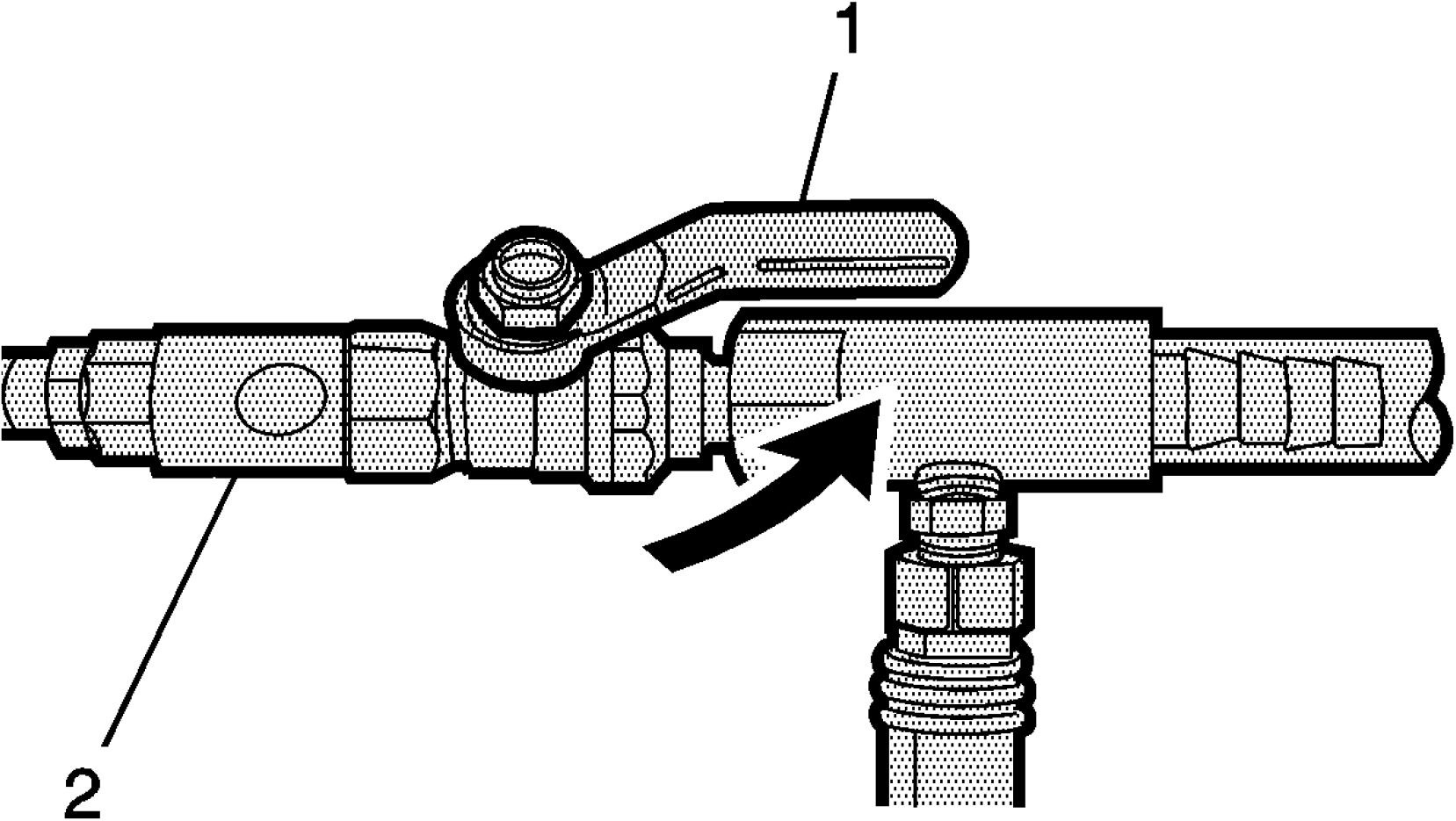
12. Open the valve (1) on the venturi assembly (2). The vacuum gauge will begin to rise and a hissing noise
will be present.
 |
|
Fig. 17: Vacuum Gauge Needle Courtesy'of GENERALMOTORS COMPANY |
13. Continue to draw vacuum until the needle stops rising (1). This should be 610 - 660 mm Hg (24 - 26 in
Hg).
Cooling hoses may start to collapse. This is normal due to vacuum draw.
14. To aid in the fill process, position the graduated reservoir above the coolant fill port.
 |
|
Fig. 18: Vacuum Gauge Assembly & Needle |
15. Slowly open the valve (1) on the vacuum gauge assembly (2). When the coolant reaches the top of the fill
hose, close the valve. This will eliminate air from the fill hose.
16. Close the valve on the venturi assembly.
17. If there is a suspected leak in the cooling system, allow the system to stabilize under vacuum and monitor
for vacuum loss.
18. Open the valve on the vacuum gauge assembly. The vacuum gauge will drop as coolant is drawn into the
system.
 |
|
Fig. 19: Vacuum Gauge Courtesy'of GENERAL MOTORS COMPANY |
19. Once the vacuum gauge (1) reaches zero, close the valve on the vacuum gauge assembly and repeat steps
12 - 18.
20. Place vehicle in Service Mode. With the GDS scan tool, activate the hybrid/EV battery pack coolant
pump for 5 minutes while maintaining 381 mm (15 in Hg) vacuum throughout the process. The pump can
be activated by navigating to the following location:
1. Module Diagnostics
2. Hybrid Powertrain Control Module 2
3. Control Functions
4. Hybrid/EV Battery Pack Coolant Pump
5. Command Pump to 80%
21. Detach the Vac-N-Fill cap from the GE-46143 adapter.
22. Remove GE-46143 adapter from the surge tank fill neck.
 |
|
Fig. 20: Surge Tank Courtesy'of GENERAL MOTORS COMPANY |
23. Upon completion of the hybrid/EV battery pack coolant pump activation, adjust the surge tank coolant
level to the FULL COLD line on the side of the surge tank (1).
24. Inspect the concentration of the coolant mixture using GE-26568 tester.
REMOVING EXCESS COOLANT FROM SYSTEM
1. Detach the vacuum hose from the vacuum gauge assembly.

Fig. 21: Vacuum Hose & Extraction Hose
Courtesy'of GENERAL'MOTORS'COMPANY
2. Attach the extraction hose (1) to the vacuum hose (2).
 |
|
Fig. 22: Venturi Assembly & Valve |
3. Open the valve (1) on the venturi assembly (2) to start a vacuum draw.
 |
|
Fig. 23: Extraction Hose And Surge Tank |
4. Assemble the extraction hose (1) and insert into the surge tank (2).

Fig. 24: Surge Tank
5. Adjust the surge tank coolant level to the FULL COLD line on the side of the surge tank (1).
6. The vacuum tank has a drain valve on the bottom of the tank. Open the valve to drain coolant from the
vacuum tank into a suitable container for disposal.
PURGING & REMOVAL OF COOLANT FROM BATTERY
NOTE: Prior to performing high-voltage battery internal service, it is necessary to
purge any residual coolant inside the battery that is left over from the cooling
system draining procedure. Similarly, coolant must be removed from the battery
prior to return shipping. This procedure must also be used when purging
complete system of contaminated coolant.
NOTE: This procedure can be performed in vehicle, or with battery removed from
vehicle.
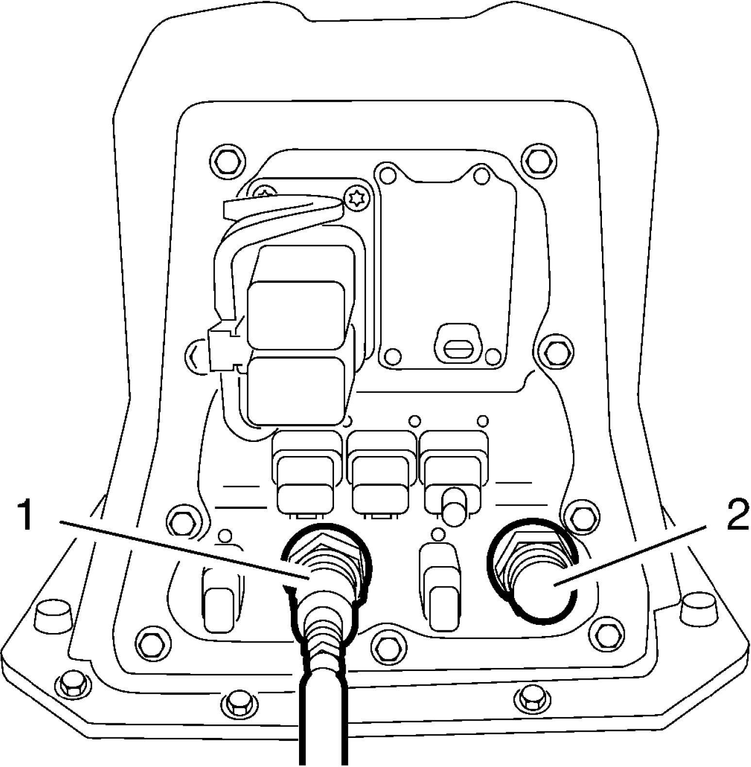 |
|
Fig. 25: Plugs From Battery Leak Test Kits Courtesy'of GENERAL'MOTORS'COMPANY |
1. Install necessary plugs from EL-50812 & EL-51753 Battery Leak Test Kits (1, 2).
2. Install GE-50385 Battery Pack Coolant Adapters to the battery coolant ports.
3. Connect the GE-47716 Vac N Fill vacuum hose to the GE-50385 adapter with thru-port.
 |
|
Fig. 26: Connect Other End Of Vacuum Hose to Vac N Fill Vacuum Tank |
4. Connect other end of vacuum hose to the Vac N Fill vacuum tank.
5. Install the venturi assembly to the vacuum tank with valve closed.
6. Attached regulated shop air supply hose to venturi assembly.
7. Open valve on venturi assembly to apply vacuum to high-voltage battery internal coolant loop.
8. Build vacuum for at least one minute.
 |
|
Fig. 27: GE-50385 Plug to Break Vacuum And Purge Battery Of Coolant |
9. Temporarily remove GE-50385 plug to break vacuum and purge battery of coolant.
10. Install plug to build vacuum again.
11. Repeat step 7-9 several times until no more coolant can be extracted.
DRIVE MOTOR GENERATOR POWER INVERTER MODULE COOLING SYSTEM DRAINING
AND FILLING
Special Tools
• GE-26568 Coolant and Battery Tester
• GE-47716 Vac-N-Fill Coolant Refill Tool
• BO-38185 Hose Clamp Pliers
Equivalent regional tools: Special Tools
WARNING: To avoid being burned, do not remove the radiator cap or surge tank cap while
the engine is hot. The cooling system will release scalding fluid and steam
under pressure if radiator cap or surge tank cap is removed while the engine
and radiator are still hot.
Draining Procedure
1. Turn Vehicle Power Off and remove all keyless entry transmitters from the vehicle and secure in a place
outside the vehicle.
2. Raise and support the vehicle. Lifting and Jacking the Vehicle
3. Remove Front Wheelhouse Liner Replacement (Left Side) Front Wheelhouse Liner Replacement
(Right Side)
 |
|
Fig. 28: Clamp And Coolant Hose Courtesy'of GENERALMOTORS COMPANY |
4. Loosen Clamp (2) BO-38185 pliers
5. Remove Coolant Hose (1)
6. Lower the vehicle.
Vac-N-Fill Procedure
1. Turn Vehicle Power Off and remove all keyless entry transmitters from the vehicle and secure in a place
outside the vehicle.
 |
|
Fig. 29: Radiator Cap & Surge Tank Test Adapter |
NOTE:
To prevent boiling of the coolant/water mixture in the vehicles cooling
system, do not apply vacuum to a cooling system above 49A°C (120A°F).
The tool will not operate properly when the coolant is boiling.
2. Install GE-46143 cooling system adapter
3. Attach the Vac-N-Fill cap (1) to GE-46143 cooling system adapter.
 |
|
Fig. 30: Vacuum Gauge Assembly & Vac N Fill Cap |
4. Attach the vacuum gauge assembly (1) to the Vac-N-Fill cap (2).
 |
|
Fig. 31: Vacuum Gauge Assembly & Fill Hose Courtesy of GENERAL MOTORS COMPANY |
5. Attach the fill hose (1) to the barb fitting on the vacuum gauge assembly (2).
Ensure that the valve is closed.
 |
|
Fig. 32: Graduated Reservoir, Vacuum Tank & Cut-Out Area Courtesy'of GENERALMOTORS'COMPANY |
6. Pour the coolant mixture into the graduated reservoir (1).
7. Place the fill hose in the graduated reservoir (1).
8. Install the vacuum tank (2) on the graduated reservoir with the fill hose routed through the cut-out area
(3) in the vacuum tank.
 |
|
Fig. 33: Vacuum Tank & Venturi Assembly |
9. Attach the venturi assembly (1) to the vacuum tank (2).
 |
|
Fig. 34: Venturi Assembly & Valve |
10. Attach a shop air hose to the venturi assembly (1).
Ensure the valve (2) on the venturi assembly is closed.
 |
|
Fig. 35: Vacuum Hose, Gauge Assembly & Tank |
11. Attach the vacuum hose (1) to the vacuum gauge assembly (2) and the vacuum tank (3).

12. Open the valve (1) on the venturi assembly (2). The vacuum gauge will begin to rise and a hissing noise
will be present.
 |
|
Fig. 37: Vacuum Gauge Needle Courtesy'of GENERALMOTORS COMPANY |
13. Continue to draw vacuum until the needle stops rising (1). This should be 610 - 660 mm Hg (24 - 26 in
Hg).
Cooling hoses may start to collapse. This is normal due to vacuum draw.
14. To aid in the fill process, position the graduated reservoir above the coolant fill port.
 |
|
Fig. 38: Vacuum Gauge Assembly & Needle |
15. Slowly open the valve (1) on the vacuum gauge assembly (2). When the coolant reaches the top of the fill
hose, close the valve. This will eliminate air from the fill hose.
16. Close the valve on the venturi assembly.
17. If there is a suspected leak in the cooling system, allow the system to stabilize under vacuum and monitor
for vacuum loss.
If vacuum loss is observed, refer to Loss of Coolant .
18. Open the valve on the vacuum gauge assembly. The vacuum gauge will drop as coolant is drawn into the
system.
 |
|
Fig. 39: Vacuum Gauge At Zero Courtesy'of GENERAl'mOTORS COMPANY |
19. Once the vacuum gauge reaches zero (1), close the valve on the vacuum gauge assembly and repeat steps
12 - 18.
20. Detach the Vac-N-Fill cap from the GE-46143 adapter.
21. Remove GE-46143 adapter from the surge tank fill neck.
22. Add coolant to the system as necessary.
23. Inspect the concentration of the coolant mixture using GE-26568 tester.
24. Detach the vacuum hose form the vacuum gauge assembly.

Fig. 40: Vacuum Hose & Extraction Hose
Courtesy'of GENERAL'MOTORS'COMPANY
25. Attach the extraction hose (1) to the vacuum hose (2).
 |
|
Fig. 41: Venturi Assembly & Valve |
26. Open the valve (1) on the venturi assembly (2) to start a vacuum draw.
 |
|
Fig. 42: Coolant Extraction Hose |
27. Use the extraction hose (1) to draw out coolant to the proper level.
28. The vacuum tank has a drain valve on the bottom of the tank. Open the valve to drain coolant from the
vacuum tank into a suitable container for disposal.
COOLANT TEMPERATURE SENSOR REPLACEMENT
Removal Procedure
WARNING: Before conducting any repair to this high voltage cooling system, it is
necessary to determine/verify whether no high-voltage system faults exist. If
high-voltage faults exist, follow published DTC diagnostics/repair procedures
prior to performing any cooling system repairs. Failure to correct High Voltage
Faults before working on the high voltage cooling system could result in
personal injury or death.
1. Turn the Vehicle Power Off, remove all keyless entry transmitters from the vehicle and secure in a place
outside the vehicle.
2. Drain the cooling system. Drive Motor Generator Power Inverter Module Cooling System Draining
and Filling
3. Remove Front Bumper Fascia Center Support Replacement
4. Remove Pedestrian Sound Alert Speaker Replacement
 |
|
Fig. 43: Electrical Connector And Coolant Temperature Sensor |
5. Disconnect Electrical Connector (1).
6. Remove the coolant temperature sensor (2).
Installation Procedure
 |
|
Fig. 44: Electrical Connector And Coolant Temperature Sensor |
1. Install the coolant temperature sensor (2) and tighten to 33 N.m (24 lb ft).
2. Connect Electrical Connector (1)
3. Install Front Bumper Fascia Center Support Replacement
4. Install Pedestrian Sound Alert Speaker Replacement
5. Fill the cooling system. Drive Motor Generator Power Inverter Module Cooling System Draining
and Filling
ENGINE COOLANT TEMPERATURE SENSOR REPLACEMENT
Removal Procedure
WARNING: Ensure all High Voltage safety procedures are followed. Failure to follow the
procedure exactly as written may result in serious injury or death.
WARNING: Before working on any high voltage system, be sure to wear the following
Personal Protection Equipment:
• Safety glasses with appropriate side shields when within 50 feet of the
vehicle, either indoors or outdoors
• Certified and up-to-date Class "0" Insulation gloves rated at 1000V with
leather protectors
• Visually and functionally inspect the gloves before use.
• Wear the Insulation gloves at all times when working with the high
voltage battery assembly, whether the system is energized or not.
Failure to follow the procedure exactly as written may result in serious injury or
death.
1. Remove High Voltage Battery Cover Replacement
2. Remove High Voltage Battery Disconnect Relay Replacement
 |
|
Fig. 45: Electrical Connector And Engine Coolant Temperature Sensor |
3. Disconnect Electrical Connector(1).
4. Loosen Clamp(2).
5. Remove Engine Coolant Temperature Sensor(3).
Installation Procedure
 |
|
Fig. 46: Electrical Connector And Engine Coolant Temperature Sensor |
1. Install Engine Coolant Temperature Sensor(3).
2. Install Clamp(2).
3. Connect Electrical Connector(1).
4. Install High Voltage Battery Disconnect Relay Replacement
5. Install High Voltage Battery Cover Replacement
DRIVE MOTOR CONTROL MODULE RADIATOR INLET HOSE REPLACEMENT
Removal Procedure
WARNING: Before conducting any repair to this high voltage cooling system, it is
necessary to determine/verify whether no high-voltage system faults exist. If
high-voltage faults exist, follow published DTC diagnostics/repair procedures
prior to performing any cooling system repairs. Failure to correct High Voltage
Faults before working on the high voltage cooling system could result in
personal injury or death.
WARNING: Do not use a service jack in locations other than those specified to lift this
vehicle. Lifting the vehicle with a jack in those other locations could cause the
vehicle to slip off the jack and roll; this could cause injury or death.
1. Turn the Vehicle Power Off, remove all keyless entry transmitters from the vehicle and secure in a place
outside the vehicle.
2. Drain the cooling system. Drive Motor Generator Power Inverter Module Cooling System Draining
and Filling
3. Raise and support the vehicle. Lifting and Jacking the Vehicle
4. Remove Front Wheelhouse Liner Replacement (Left Side) Front Wheelhouse Liner Replacement
(Right Side)
5. Remove Headlamp Replacement
 |
|
Fig. 47: Clamp And Coolant Hose Courtesy'of GENERALMOTORS COMPANY |
6. Disengage Clamp(1) Hose Clamp Replacement Guidelines - Spring Type
7. Remove Coolant Hose(2)
 |
|
Fig. 48: Coolant Hose And Clip Courtesy'of GENERAL'MOTORS COMPANY |
8. Remove Coolant Hose(2).
9. Remove Clip(1).
 |
|
Fig. 49: Generator Control Module Coolant Pump Bracket And Nuts |
10. Remove the 2 generator control module coolant pump bracket nuts (2).
11. Remove the generator control module coolant pump bracket (1).
 |
|
Fig. 50: Clamp And Coolant Hose |
13. Remove Coolant Hose(1)
14. Remove the drive motor control module radiator inlet hose from the vehicle.
Installation Procedure
1. Install the drive motor control module radiator inlet hose to the vehicle.
 |
|
Fig. 51: Clamp And Coolant Hose Courtesy'of GENERAl'mOTORS COMPANY |
2. Install Coolant Hose(1)
3. Engage Clamp(2) Hose Clamp Replacement Guidelines - Spring Type
 |
|
Fig. 52: Generator Control Module Coolant Pump Bracket And Nuts |
4. Install the generator control module coolant pump bracket (1).
5. Install the 2 generator control module coolant pump bracket nuts (2) and tighten to 9 N.m (80 lb in).
 |
|
Fig. 53: Coolant Hose And Clip Courtesy'of GENERALMOTORS COMPANY |
6. Install Clip (1)
7. Install Coolant Hose(2)
 |
|
Fig. 54: Clamp And Coolant Hose Courtesy'of GENERALMOTORS COMPANY |
8. Install Coolant Hose(2)
9. Engage Clamp(1)Hose Clamp Replacement Guidelines - Spring Type
10. Install Headlamp Replacement
11. Install Front Wheelhouse Liner Replacement (Left Side) Front Wheelhouse Liner Replacement
(Right Side)
12. Lower the vehicle.
13. Fill the cooling system. Drive Motor Generator Power Inverter Module Cooling System Draining
and Filling
DRIVE MOTOR CONTROL MODULE RADIATOR OUTLET HOSE REPLACEMENT
Overview
 |
|
Fig. 55: Drive Motor Control Module Radiator Outlet Hose |
1. Routing and the fixations of the drive motor control module radiator outlet hose (1) without the body.
Removal Procedure
WARNING: Before conducting any repair to this high voltage cooling system, it is
necessary to determine/verify whether no high-voltage system faults exist. If
high-voltage faults exist, follow published DTC diagnostics/repair procedures
prior to performing any cooling system repairs. Failure to correct High Voltage
Faults before working on the high voltage cooling system could result in
personal injury or death.
WARNING: Do not use a service jack in locations other than those specified to lift this
vehicle. Lifting the vehicle with a jack in those other locations could cause the
vehicle to slip off the jack and roll; this could cause injury or death.
1. Turn the Vehicle Power Off, remove all keyless entry transmitters from the vehicle and secure in a place
outside the vehicle.
2. Drain the cooling system. Drive Motor Generator Power Inverter Module Cooling System Draining
and Filling
3. Remove Headlamp Replacement
 |
|
Fig. 56: Coolant Hose And Clamp Courtesy'of GENERALMOTORS COMPANY |
4. Disengage Clamp(1).Hose Clamp Replacement Guidelines - Spring Type
5. Remove Coolant Hose(2).
6. Raise and support the vehicle. Lifting and Jacking the Vehicle
7. Remove Front Wheelhouse Liner Replacement (Left Side) Front Wheelhouse Liner Replacement
(Right Side)
 |
|
Fig. 57: Coolant Hose And Clamp Courtesy'of GENERAL'MOTORS COMPANY |
8. Disengage Clamp(1)
9. Remove Coolant Hose(2)
 |
|
Fig. 58: Drive Motor Control Module Radiator Outlet Hose Bracket Nut |
10. Loosen Drive motor control module radiator outlet hose bracket nut (3)
11. Unclip Retainer(1)
12. Remove the drive motor control module radiator outlet hose (2).
Installation Procedure
 |
|
Fig. 59: Drive Motor Control Module Radiator Outlet Hose Bracket Nut |
1. Install the drive motor control module radiator outlet hose (2).
2. Install Retainer (1)
3. Drive motor control module radiator outlet hose bracket nut (3) - Tighten 9 N.m (80 lb in)
 |
|
Fig. 60: Coolant Hose And Clamp Courtesy'of GENERALMOTORS COMPANY |
4. Install Coolant Hose (2)
5. Engage Clamp (1)
6. Install Front Wheelhouse Liner Replacement (Left Side) Front Wheelhouse Liner Replacement
(Right Side)
7. Lower the vehicle.
 |
|
Fig. 61: Coolant Hose And Clamp Courtesy'of GENERALMOTORS COMPANY |
8. Install Coolant Hose (2)
9. Engage Clamp (1)Hose Clamp Replacement Guidelines - Spring Type
10. Install Headlamp Replacement
11. Fill the cooling system. Drive Motor Generator Power Inverter Module Cooling System Draining
and Filling
GENERATOR CONTROL MODULE COOLANT TANK HOSE REPLACEMENT
Special Tools
BO-38185 Hose Clamp Pliers
Equivalent regional tools: Special Tools
Removal Procedure
WARNING: Before conducting any repair to this high voltage cooling system, it is
necessary to determine/verify whether no high-voltage system faults exist. If
high-voltage faults exist, follow published DTC diagnostics/repair procedures
prior to performing any cooling system repairs. Failure to correct High Voltage
Faults before working on the high voltage cooling system could result in
personal injury or death.
1. Turn the Vehicle Power Off, remove all keyless entry transmitters from the vehicle and secure in a place
outside the vehicle.
2. Drain the cooling system. Drive Motor Generator Power Inverter Module Cooling System Draining
and Filling
3. Remove Rear Compartment Floor Stowage Trim Compartment Replacement
 |
|
Fig. 62: Clamp And Generator Control Module Coolant Tank Hose |
4. Loosen Clamp (2) BO-38185 pliers
5. Remove Generator Control Module Coolant Tank Hose (1)
Installation Procedure
 |
|
Fig. 63: Clamp And Generator Control Module Coolant Tank Hose |
1. Install Generator Control Module Coolant Tank Hose (1).
2. Install Clamp (2) BO-38185 pliers
3. Install Rear Compartment Floor Stowage Trim Compartment Replacement
4. Fill the cooling system. Drive Motor Generator Power Inverter Module Cooling System Draining
and Filling
RADIATOR SURGE TANK REPLACEMENT (DRIVE MOTOR BATTERY RADIATOR SURGE
TANK)
Special Tools
BO-38185 Hose Clamp Pliers
Equivalent regional tools: Special Tools
Removal Procedure
WARNING: Before conducting any repair to this high voltage cooling system, it is
necessary to determine/verify whether no high-voltage system faults exist. If
high-voltage faults exist, follow published DTC diagnostics/repair procedures
prior to performing any cooling system repairs. Failure to correct High Voltage
Faults before working on the high voltage cooling system could result in
personal injury or death.
1. Turn the Vehicle Power Off, remove all keyless entry transmitters from the vehicle and secure in a place
outside the vehicle.
2. Drain the cooling system. Drive Motor Battery Cooling System Draining and Filling
 |
|
Fig. 64: Clamp And Coolant Hose Courtesy'of GENERALMOTORS COMPANY |
3. Loosen Clamp (2)BO-38185 pliers
4. Remove Coolant Hose (1)
5. Remove the 2 radiator surge tank bracket bolts (3).
 |
|
Fig. 65: Radiator Surge Tank Bolt |
6. Move the radiator surge tank bracket (2) in engine direction (arrow) until the front bolt is accessible.
7. Remove Radiator Surge Tank Bolt (1)
 |
|
Fig. 66: Radiator Surge Tank Courtesy'of GENERALMOTORS COMPANY |
8. Move the radiator surge tank (1) in the right direction (arrow) and in top direction until the lower hose
and the electrical connector is accessible.
9. Disconnect Electrical Connector (4)
10. Loosen Clamp (3)BO-38185 pliers
11. Remove Coolant Hose (2)
12. Remove Radiator Surge Tank (1)
Installation Procedure
 |
|
Fig. 67: Radiator Surge Tank Courtesy'of GENERALMOTORS COMPANY |
1. Install Coolant Hose (2).
2. Install Clamp (3) BO-38185 pliers
3. Connect Electrical Connector (4)
4. Move the radiator surge tank (1) in the left direction (arrow) to the original position.
 |
|
Fig. 68: Radiator Surge Tank Bolt Courtesy'of GENERALMOTORS COMPANY |
5. Install Radiator Surge Tank Bolt (1) - Install and tighten 9 N.m (80 lb in)
6. Position the radiator surge tank bracket (2) in front direction (arrow) to the original position.
 |
|
Fig. 69: Clamp And Coolant Hose Courtesy'of GENERAL'MOTORS COMPANY |
7. Install the 2 radiator surge tank bracket bolt (3) and tighten to 22 N.m (16 lb ft).
8. Install Coolant Hose(1)
9. Clamp (2) - Tighten - BO-38185 pliers
10. Fill the cooling system. Drive Motor Battery Cooling System Draining and Filling
RADIATOR SURGE TANK REPLACEMENT (DRIVE MOTOR GENERATOR POWER INVERTER
MODULE SURGE TANK)
Special Tools
BO-38185 Hose Clamp Pliers
Equivalent regional tools: Special Tools
Removal Procedure
WARNING: Before conducting any repair to this high voltage cooling system, it is
necessary to determine/verify whether no high-voltage system faults exist. If
high-voltage faults exist, follow published DTC diagnostics/repair procedures
prior to performing any cooling system repairs. Failure to correct High Voltage
Faults before working on the high voltage cooling system could result in
personal injury or death.
1. Turn the Vehicle Power Off, remove all keyless entry transmitters from the vehicle and secure in a place
outside the vehicle.
2. Drain the cooling system. Drive Motor Generator Power Inverter Module Cooling System Draining
and Filling
 |
|
Fig. 70: Clamp And Coolant Hose Courtesy'of GENERAl'mOTORS COMPANY |
3. Loosen Clamp (1) BO-38185 pliers
4. Remove Coolant Hose (2)
5. Remove Radiator Surge Tank Bolt (3)
 |
|
Fig. 71: Radiator Surge Tank And Coolant Hose |
6. Move the radiator surge tank (1) in engine direction (arrow) and in top direction until the lower hose is
accessible.
7. Loosen Clamp (3)BO-38185 pliers
8. Remove Coolant Hose (2)
9. Remove Radiator Surge Tank (1)
Installation Procedure
 |
|
Fig. 72: Radiator Surge Tank And Coolant Hose |
1. Install Coolant Hose (2)
2. Install Clamp (3)BO-38185 pliers
3. Move the radiator surge tank (1) in front direction (arrow) to their original position.
 |
|
Fig. 73: Clamp And Coolant Hose Courtesy'of GENERAl'mOTORS COMPANY |
CAUTION: Fastener Caution
4. Install Radiator Surge Tank Bolt (3) and tighten 9 N.m (80 lb in)
5. Install Coolant Hose (2)
6. Clamp (1) - Tighten BO-38185 pliers
7. Fill the cooling system. Drive Motor Generator Power Inverter Module Cooling System Draining
and Filling
drive motor generator control module coolant pump hose replacement
Special Tools
BO-38185 Hose Clamp Pliers
Equivalent regional tools: Special Tools
Removal Procedure
WARNING: Before conducting any repair to this high voltage cooling system, it is
necessary to determine/verify whether no high-voltage system faults exist. If
high-voltage faults exist, follow published DTC diagnostics/repair procedures
prior to performing any cooling system repairs. Failure to correct High Voltage
Faults before working on the high voltage cooling system could result in
personal injury or death.
1. Turn the Vehicle Power Off, remove all keyless entry transmitters from the vehicle and secure in a place
outside the vehicle.
2. Drain the cooling system. Drive Motor Generator Power Inverter Module Cooling System Draining
and Filling
3. Raise and support the vehicle. Lifting and Jacking the Vehicle
4. Remove Front Wheelhouse Liner Replacement (Left Side) Front Wheelhouse Liner Replacement
(Right Side)
 |
|
Fig. 74: Clamp And Coolant Hose Courtesy'of GENERALMOTORS COMPANY |
5. Loosen Clamp (2) BO-38185 pliers
6. Remove Coolant Hose(1)
7. Lower the vehicle.
 |
|
Fig. 75: Surge Tank Bolt Courtesy'of GENERALMOTORS COMPANY |
8. Remove Radiator Surge Tank Bolt (1)
 |
|
Fig. 76: Radiator Surge Tank And Coolant Hose |
9. Move the radiator surge tank (1) in engine direction (arrow) and in top direction until the lower hose is
accessible.
10. Loosen Clamp (3) BO-38185 pliers
11. Remove Coolant Hose (2)
Installation Procedure
 |
|
Fig. 77: Radiator Surge Tank And Coolant Hose |
1. Install Coolant Hose (2)
2. Install Clamp (3)BO-38185 pliers
3. Move the radiator surge tank (1) in front direction (arrow) to their original position.
 |
|
Fig. 78: Surge Tank Bolt Courtesy'of GENERALMOTORS COMPANY |
4. Install Radiator Surge Tank Bolt (1) -and tighten 9 N.m (80 lb in)
5. Raise the vehicle.
 |
|
Fig. 79: Clamp And Coolant Hose |
6. Install Coolant Hose (1)
7. Install Clamp (2) BO-38185 pliers
8. Install Front Wheelhouse Liner Replacement (Left Side) Front Wheelhouse Liner Replacement
(Right Side)
9. Lower the vehicle.
10. Fill the cooling system. Drive Motor Generator Power Inverter Module Cooling System Draining
and Filling
DRIVE MOTOR GENERATOR CONTROL MODULE COOLING OUTLET HOSE REPLACEMENT
(UNDERBODY LINE)
Special Tools
BO-38185 Hose Clamp Pliers
Equivalent regional tools: Special Tools
Overview
 |
|
Fig. 80: Drive Motor Generator Control Module Cooling Outlet Hose Courtesy'of GENERAL'MOTORS'COMPANY |
1. Routing and the fixations of the drive motor generator control module cooling outlet hose (1) without the
body.
Removal Procedure
WARNING: Before conducting any repair to this high voltage cooling system, it is
necessary to determine/verify whether no high-voltage system faults exist. If
high-voltage faults exist, follow published DTC diagnostics/repair procedures
prior to performing any cooling system repairs. Failure to correct High Voltage
Faults before working on the high voltage cooling system could result in
personal injury or death.
WARNING: Do not use a service jack in locations other than those specified to lift this
vehicle. Lifting the vehicle with a jack in those other locations could cause the
vehicle to slip off the jack and roll; this could cause injury or death.
1. Turn the Vehicle Power Off, remove all keyless entry transmitters from the vehicle and secure in a place
outside the vehicle.
2. Remove the floor panel number 4 cross bar. Floor Panel Number 4 Cross Bar Replacement
3. Drain the cooling system. Drive Motor Generator Power Inverter Module Cooling System Draining
and Filling
4. Raise and support the vehicle. Lifting and Jacking the Vehicle
5. Remove Front Wheelhouse Liner Replacement (Left Side) Front Wheelhouse Liner Replacement
(Right Side)
6. Remove Drivetrain and Front Suspension Cradle Replacement
7. Remove Front Wheel Drive Shaft Replacement
 |
|
Fig. 81: Coolant Hose And Clamp Courtesy'of GENERALMOTORS COMPANY |
8. Loosen Clamp (2)
9. Remove Coolant Hose (1)
 |
|
Fig. 82: Retainer Courtesy'of GENERAL MOTORS COMPANY |
10. Unclip Retainer(2, 3)
11. Remove Drive Motor Generator Control Module Cooling Outlet Hose Nut (1)
12. Loosen Clamp (1)
13. Remove Coolant Hose (2)
 |
|
Fig. 83: Coolant Hose And Clamp Courtesy'of GENERAl'mOTORS COMPANY |
 |
|
Fig. 84: Drive Motor Generator Control Module Cooling Outlet Hose And Nut |
14. Remove Drive Motor Generator Control Module Cooling Outlet Hose Nut (1)
 |
|
Fig. 85: Coolant Hose And Clamp Courtesy'of GENERALMOTORS COMPANY |
15. Loosen Clamp (1)BO-38185 pliers
16. Remove Coolant Hose (2)
 |
|
Fig. 86: Drive Motor Generator Control Module Cooling Outlet Hose And Nut |
17. Remove Drive Motor Generator Control Module Cooling Outlet Hose Nut (1)
18. Unclip Retainer (2)
 |
|
Fig. 87: Drive Motor Generator Control Module Cooling Outlet Hose |
19. Unclip Retainer (1)
20. Remove Drive Motor Generator Control Module Cooling Outlet Hose (2)
Installation Procedure
 |
|
Fig. 88: Drive Motor Generator Control Module Cooling Outlet Hose |
1. Install Drive Motor Generator Control Module Cooling Outlet Hose (2)
2. Install Retainer (1)
 |
|
Fig. 89: Drive Motor Generator Control Module Cooling Outlet Hose And Nut |
3. Install Retainer(2)
4. Install Drive Motor Generator Control Module Cooling Outlet Hose Nut (1) and tighten 9 N.m (80 lb in)
 |
|
Fig. 90: Coolant Hose And Clamp |
5. Install Coolant Hose (2)
6. Install Clamp (1)BO-38185 pliers
 |
|
Fig. 91: Drive Motor Generator Control Module Cooling Outlet Hose And Nut |
7. Install Drive Motor Generator Control Module Cooling Outlet Hose Nut (1) and tighten 9 N.m (80 lb in)
 |
|
Fig. 92: Coolant Hose And Clamp Courtesy'of GENERAL'MOTORS COMPANY |
8. Install Coolant Hose (2)
9. Install Clamp (1)
 |
|
Fig. 93: Retainer Courtesy'of GENERAL MOTORS COMPANY |
10. Install Drive Motor Generator Control Module Cooling Outlet Hose Nut (1) and tighten 90 N.m (80 lb in)
11. Install Retainer(2, 3)
 |
|
Fig. 94: Coolant Hose And Clamp Courtesy'of GENERALMOTORS COMPANY |
12. Install Coolant Hose (1)
13. Install Clamp(2)
14. Install Front Wheel Drive Shaft Replacement
15. Install Drivetrain and Front Suspension Cradle Replacement
16. Install Front Wheelhouse Liner Replacement (Left Side) Front Wheelhouse Liner Replacement
(Right Side)
17. Install the floor panel number 4 cross bar. Floor Panel Number 4 Cross Bar Replacement
18. Lower the vehicle.
19. Fill the cooling system. Drive Motor Generator Power Inverter Module Cooling System Draining
and Filling
DRIVE MOTOR GENERATOR CONTROL MODULE COOLING OUTLET HOSE REPLACEMENT
(UNDERBODY LINE TO TRACTION POWER INVERTER MODULE INLET)
Special Tools
BO-38185 Hose Clamp Pliers
Equivalent regional tools: Special Tools
Overview
 |
|
Fig. 95: Drive Motor Generator Control Module Cooling Outlet Hose Courtesy of GENERAL MOTORS COMPANY |
1. Routing and the fixations of the drive motor generator control module cooling outlet hose (1) without the
engine.
Removal Procedure
WARNING: Before conducting any repair to this high voltage cooling system, it is
necessary to determine/verify whether no high-voltage system faults exist. If
high-voltage faults exist, follow published DTC diagnostics/repair procedures
prior to performing any cooling system repairs. Failure to correct High Voltage
Faults before working on the high voltage cooling system could result in
personal injury or death.
WARNING: Do not use a service jack in locations other than those specified to lift this
vehicle. Lifting the vehicle with a jack in those other locations could cause the
vehicle to slip off the jack and roll; this could cause injury or death.
1. Turn the Vehicle Power Off, remove all keyless entry transmitters from the vehicle and secure in a place
outside the vehicle.
2. Drain the cooling system. Drive Motor Generator Power Inverter Module Cooling System Draining
and Filling
 |
|
Fig. 96: Electrical Connector Courtesy'of GENERALMOTORS COMPANY |
3. Disconnect Electrical Connector(1, 2)
 |
|
Fig. 97: Clamp And Coolant Hose Courtesy'of GENERALMOTORS COMPANY |
4. Loosen Clamp (2) BO-38185 pliers
5. Remove Coolant Hose (1)
 |
|
Fig. 98: Drive Motor Generator Control Module Cooling Outlet Hose And Bolts |
6. Remove Drive Motor Generator Control Module Cooling Outlet Hose Bolt (1)
7. Remove Seal (2) and DISCARD
8. Raise and support the vehicle. Lifting and Jacking the Vehicle
9. Remove Front Wheelhouse Liner Replacement (Left Side) Front Wheelhouse Liner Replacement
(Right Side) - Remove
 |
|
Fig. 99: Coolant Hose And Clamp Courtesy'of GENERAL'MOTORS COMPANY |
10. Loosen Clamp (2)
11. Remove Drive Motor Generator Control Module Cooling Outlet Hose (1)
Installation Procedure
 |
|
Fig. 100: Coolant Hose And Clamp Courtesy'of GENERALMOTORS COMPANY |
1. Install Drive Motor Generator Control Module Cooling Outlet Hose (1)
2. Install Clamp (2)
3. Install Front Wheelhouse Liner Replacement (Left Side) Front Wheelhouse Liner Replacement
(Right Side)
4. Lower the vehicle.
 |
|
Fig. 101: Drive Motor Generator Control Module Cooling Outlet Hose And Bolts |
5. Install a NEW seal.(2)
6. Install Drive Motor Generator Control Module Cooling Outlet Hose Bolt(1) and tighten 9 N.m (80 lb in)
 |
|
Fig. 102: Clamp And Coolant Hose Courtesy'of GENERALMOTORS COMPANY |
7. Install Coolant Hose (1)
8. Install Clamp (2)BO-38185 pliers
 |
|
Fig. 103: Electrical Connector Courtesy'of GENERALMOTORS COMPANY |
9. Connect Electrical Connector (1, 2)
10. Fill the cooling system. Drive Motor Generator Power Inverter Module Cooling System Draining
and Filling
GENERATOR CONTROL MODULE COOLANT RADIATOR HOSE REPLACEMENT
Special Tools
BO-38185 Hose Clamp Pliers
Equivalent regional tools: Special Tools
Removal Procedure
WARNING: Before conducting any repair to this high voltage cooling system, it is
necessary to determine/verify whether no high-voltage system faults exist. If
high-voltage faults exist, follow published DTC diagnostics/repair procedures
prior to performing any cooling system repairs. Failure to correct High Voltage
Faults before working on the high voltage cooling system could result in
personal injury or death.
1. Turn the Vehicle Power Off, remove all keyless entry transmitters from the vehicle and secure in a place
outside the vehicle.
2. Drain the cooling system. Drive Motor Generator Power Inverter Module Cooling System Draining
and Filling
3. Remove Rear Compartment Floor Stowage Trim Compartment Replacement
 |
|
Fig. 104: Clamp Courtesy of GENERAL MOTORS COMPANY |
4. Loosen Clamp (1) BO-38185 pliers
5. Remove the generator control module coolant radiator hose (2).
Installation Procedure
 |
|
Fig. 105: Clamp Courtesy'of GENERAL MOTORS COMPANY |
1. Install the generator control module coolant radiator hose (2).
2. Install Clamp (1) BO-38185 pliers
3. Install Rear Compartment Floor Stowage Trim Compartment Replacement
4. Fill the cooling system. Drive Motor Generator Power Inverter Module Cooling System Draining
and Filling
GENERATOR CONTROL MODULE COOLANT HOSE REPLACEMENT
Special Tools
BO-38185 Hose Clamp Pliers
Equivalent regional tools: Special Tools
Removal Procedure
WARNING: Before conducting any repair to this high voltage cooling system, it is
necessary to determine/verify whether no high-voltage system faults exist. If
high-voltage faults exist, follow published DTC diagnostics/repair procedures
prior to performing any cooling system repairs. Failure to correct High Voltage
Faults before working on the high voltage cooling system could result in
personal injury or death.
1. Turn the Vehicle Power Off, remove all keyless entry transmitters from the vehicle and secure in a place
outside the vehicle.
2. Drain the cooling system. Drive Motor Generator Power Inverter Module Cooling System Draining
and Filling
3. Remove Rear Compartment Floor Stowage Trim Compartment Replacement
 |
|
Fig. 106: Generator Control Module Coolant Hose |
4. Loosen Clamp (2) BO-38185 pliers
5. Remove the generator control module coolant hose (1).
Installation Procedure
 |
|
Fig. 107: Generator Control Module Coolant Hose |
1. Install the generator control module coolant hose (1).
2. Install Clamp (2) BO-38185 pliers
3. Install Rear Compartment Floor Stowage Trim Compartment Replacement
4. Fill the cooling system. Drive Motor Generator Power Inverter Module Cooling System Draining
and Filling
GENERATOR CONTROL MODULE COOLANT PUMP REPLACEMENT
Special Tools
BO-38185 Hose Clamp Pliers
Equivalent regional tools: Special Tools
Removal Procedure
WARNING: Before conducting any repair to this high voltage cooling system, it is
necessary to determine/verify whether no high-voltage system faults exist. If
high-voltage faults exist, follow published DTC diagnostics/repair procedures
prior to performing any cooling system repairs. Failure to correct High Voltage
Faults before working on the high voltage cooling system could result in
personal injury or death.
WARNING: Do not use a service jack in locations other than those specified to lift this
vehicle. Lifting the vehicle with a jack in those other locations could cause the
vehicle to slip off the jack and roll; this could cause injury or death.
1. Turn the Vehicle Power Off, remove all keyless entry transmitters from the vehicle and secure in a place
outside the vehicle.
2. Drain the cooling system. Drive Motor Generator Power Inverter Module Cooling System Draining
and Filling
3. Raise and support the vehicle. Lifting and Jacking the Vehicle
4. Remove Front Wheelhouse Liner Replacement (Left Side) Front Wheelhouse Liner Replacement
(Right Side)
 |
|
Fig. 108: Coolant Hose And Retainer Courtesy'of GENERAL'MOTORS'COMPANY |
5. Disconnect Electrical Connector (4)
6. Unclip Retainer (3)
7. Loosen Clamp (1) BO-38185 pliers
8. Remove Coolant Hose (2)
 |
|
Fig. 109: Generator Control Module Coolant Pump Bracket And Nuts |
9. Remove the 2 generator control module coolant pump bracket nuts (2).
10. Remove the front half generator control module coolant pump bracket (1).
 |
|
Fig. 110: Clamp And Coolant Hose |
11. Loosen Clamp (2)BO-38185 pliers
12. Remove Coolant Hose (1)
13. Remove the generator control module coolant pump (3).
14. Remove the rear half of the generator control module coolant pump bracket (4).
Installation Procedure
 |
|
Fig. 111: Clamp And Coolant Hose Courtesy'of GENERAl'mOTORS COMPANY |
1. Install Coolant Hose (1)
2. Install Clamp (2)BO-38185 pliers
3. Install the rear half of the generator control module coolant pump bracket (4).
4. Install the generator control module coolant pump (3).
 |
|
Fig. 112: Generator Control Module Coolant Pump Bracket And Nuts |
5. Install the front half of the generator control module coolant pump bracket (1).
6. Install the 2 generator control module coolant pump bracket nuts (2) and tighten to 9 N.m (80 lb in).
 |
|
Fig. 113: Coolant Hose And Retainer Courtesy'of GENERAL'MOTORS'COMPANY |
7. Install Coolant Hose (2)
8. Install Clamp (1)BO-38185 pliers
9. Install Retainer (3)
10. Connect Electrical Connector (4)
11. Install Front Wheelhouse Liner Replacement (Left Side) Front Wheelhouse Liner Replacement
(Right Side)
12. Lower the vehicle.
13. Fill the cooling system. Drive Motor Generator Power Inverter Module Cooling System Draining
and Filling
HIGH VOLTAGE BATTERY HEATER REPLACEMENT
Removal Procedure
WARNING: Before working on any high voltage system, be sure to wear the following
Personal Protection Equipment:
• Safety glasses with appropriate side shields when within 50 feet of the
vehicle, either indoors or outdoors
• Certified and up-to-date Class "0" Insulation gloves rated at 1000V with
leather protectors
• Visually and functionally inspect the gloves before use.
• Wear the Insulation gloves at all times when working with the high
voltage battery assembly, whether the system is energized or not.
Failure to follow the procedure exactly as written may result in serious injury or
death.
1. Remove High Voltage Battery Cover Replacement
2. Remove High Voltage Battery Disconnect Relay Replacement

3. Disconnect the electrical connectors.(1, 6)
4. Remove the high voltage battery heater ground cable bolt (5).
5. Hang the high voltage battery heater ground cable (4) aside.
6. Use a paint pen and place match marks on the high voltage battery heater (2) and the drive motor battery
wire junction block relay (3) to ensure proper realignment during installation.
 |
|
Fig. 115: High Voltage Battery Heater And High Voltage Heater Outlet Hose Fitting |
7. Remove High Voltage Heater Outlet Hose Fitting(4)
8. Remove High Voltage Battery Heater(1)
9. Remove and DISCARD the 2 heater outlet hose fitting O-ring seals (2, 3)
Installation Procedure
 |
|
Fig. 116: High Voltage Battery Heater And High Voltage Heater Outlet Hose Fitting |
1. Install the 2 NEW heater outlet hose fitting O-ring seals (2, 3)
2. Position the high voltage battery heater (1) to the drive motor battery wire junction block relay ensuring
to align the match marks.
3. Install High Voltage Heater Outlet Hose Fitting(4)
4. Hold the high voltage battery heater (1) and tighten the heater outlet hose fitting (4) to 45 N.m (33 lb ft).
 |
|
Fig. 117: Electrical Connectors Courtesy of GENERAL MOTORS COMPANY |
5. Reposition the high voltage battery heater ground cable (4) to the high voltage battery heater (1).
6. Install the high voltage battery heater ground cable bolt (5).
7. Connect the electrical connectors.(1, 6)
8. Install High Voltage Battery Disconnect Relay Replacement
9. Install High Voltage Battery Cover Replacement
DRIVE MOTOR BATTERY RADIATOR SURGE TANK CAP REPLACEMENT
WARNING: Before conducting any repair to this high voltage cooling system, it is
necessary to determine/verify whether no high-voltage system faults exist. If
high-voltage faults exist, follow published DTC diagnostics/repair procedures
prior to performing any cooling system repairs. Failure to correct High Voltage
Faults before working on the high voltage cooling system could result in
personal injury or death.
WARNING: To avoid being burned, do not remove the radiator cap or surge tank cap while
the engine is hot. The cooling system will release scalding fluid and steam
under pressure if radiator cap or surge tank cap is removed while the engine
and radiator are still hot.
NOTE: The tamper-resistant coolant cap has a one-way mechanism to deter the service
of cooling systems by unqualified individuals.
Removal Procedure
1. Turn the Vehicle Power Off, remove all keyless entry transmitters from the vehicle and secure in a place
outside the vehicle.
 |
|
Fig. 118: Cap Cover And Cap Body Courtesy of GENERAL MOTORS COMPANY |
2. Rotate the cap upper cover counter-clockwise to align the slot in the cap cover (1) with the slot in the cap
body (2).
 |
|
Fig. 119: Flat Bladed Screwdriver And Slot Courtesy'of GENERAL'MOTORS'COMPANY |
3. Insert a flat bladed screwdriver (1) into the slot (2), no wider than 8 mm (5/16").
NOTE: Do not use the flat bladed screwdriver to loosen the cap.
4. With the cap sections engaged, rotate the cap counter-clockwise by hand to loosen and remove from the
surge tank.
Installation Procedure
1. Install and rotate cap clockwise until it is tight, and the detent in cap engages to the rib in the surge tank.
DRIVE MOTOR BATTERY COOLANT COOLER REPLACEMENT
Special Tools
BO-38185 Hose Clamp Pliers
Equivalent regional tools: Special Tools
Removal Procedure
WARNING: Before conducting any repair to this high voltage cooling system, it is
necessary to determine/verify whether no high-voltage system faults exist. If
high-voltage faults exist, follow published DTC diagnostics/repair procedures
prior to performing any cooling system repairs. Failure to correct High Voltage
Faults before working on the high voltage cooling system could result in
personal injury or death.
WARNING: Do not use a service jack in locations other than those specified to lift this
vehicle. Lifting the vehicle with a jack in those other locations could cause the
1. Turn the Vehicle Power Off, remove all keyless entry transmitters from the vehicle and secure in a place
outside the vehicle.
2. Remove Air Cleaner Outlet Duct Replacement
3. Recover the refrigerant. Refrigerant Recovery and Recharging
4. Drain the cooling system. Drive Motor Battery Cooling System Draining and Filling
5. Disconnect the evaporative emission pipe from the evaporative emission canister purge solenoid valve
and reposition. Plastic Collar Quick Connect Fitting Service
6. Disconnect the air conditioning evaporator hose assembly from the thermal expansion valve and
reposition. Air Conditioning Evaporator Hose Assembly Replacement
 |
|
Fig. 120: Air Conditioning Evaporator Hose Nut |
7. Remove the air conditioning evaporator hose nut (2).
8. Remove the air conditioning evaporator hose (1).
9. Remove Air Conditioning Condenser Tube(3)
10. Loosen Clamp (5) BO-38185 pliers
11. Remove Coolant Hose (4, 5)
 |
|
Fig. 121: Clip And Coolant Hose |
12. Remove the clip (2) along with the coolant hose (1).
 |
|
Fig. 122: Battery Positive And Negative Cable Bracket Nuts |
13. Remove the 2 battery positive and negative cable bracket nuts (2).
14. Remove Battery Positive and Negative Cable(2)
15. Remove the drive motor battery coolant cooler nut (3).
 |
|
Fig. 123: Drive Motor Battery Coolant Cooler |
16. Remove the drive motor battery coolant cooler (1).
Installation Procedure
 |
|
Fig. 124: Drive Motor Battery Coolant Cooler |
1. Install the drive motor battery coolant cooler (1).
 |
|
Fig. 125: Battery Positive And Negative Cable Bracket Nuts |
2. Install the drive motor battery coolant cooler nut (3) and tighten to 9 N.m (80 lb in).
3. Install Battery Positive and Negative Cable (3)
4. Install the 2 battery positive and negative cable bracket nuts (2) and tighten to 9 N.m (80 lb in).
 |
|
Fig. 126: Clip And Coolant Hose Courtesy'of GENERAL'MOTORS COMPANY |
5. Install the clip (2) along with the coolant hose (1).
 |
|
Fig. 127: Air Conditioning Evaporator Hose Nut |
6. Install Coolant Hose (4, 6)
7. Install Clamp (3)BO-38185 pliers
8. Install Air Conditioning Condenser Tube (3)
9. Install the air conditioning evaporator hose (1).
10. Install the air conditioning evaporator hose nut (2) and tighten to 22 N.m (16 lb ft).
11. Lower the vehicle.
12. Connect the air conditioning evaporator hose assembly to the thermal expansion valve and reposition. Air
Conditioning Evaporator Hose Assembly Replacement
13. Connect the evaporative emission pipe to the evaporative emission canister purge solenoid valve and
reposition. Plastic Collar Quick Connect Fitting Service
14. Install Air Cleaner Outlet Duct Replacement
15. Fill the cooling system. Drive Motor Battery Cooling System Draining and Filling
16. Evacuate and charge the refrigerant system. Refrigerant Recovery and Recharging
DRIVE MOTOR BATTERY COOLANT PUMP REPLACEMENT
Special Tools
BO-38185 Hose Clamp Pliers
Equivalent regional tools: Special Tools
Removal Procedure
WARNING: Before conducting any repair to this high voltage cooling system, it is
necessary to determine/verify whether no high-voltage system faults exist. If
high-voltage faults exist, follow published DTC diagnostics/repair procedures
prior to performing any cooling system repairs. Failure to correct High Voltage
Faults before working on the high voltage cooling system could result in
personal injury or death.
1. Turn the Vehicle Power Off, remove all keyless entry transmitters from the vehicle and secure in a place
outside the vehicle.
2. Drain the cooling system. Drive Motor Battery Cooling System Draining and Filling
3. Raise and support the vehicle. Lifting and Jacking the Vehicle
4. Remove Exhaust Front Pipe Replacement
 |
|
Fig. 128: Heat Shield Courtesy'of GENERAL MOTORS COMPANY |
5. Remove Heat Shield Nut (2)
6. Remove Heat Shield (1)

Fig. 129: Electrical Connector
Courtesy of GENERAL MOTORS COMPANY
7. Disconnect Electrical Connector(5)
8. Loosen Clamp(1, 4) BO-38185 pliers
9. Remove Coolant Hose(2, 3)
 |
|
Fig. 130: Drive Motor Battery Coolant Pump Bracket Stud |
10. Remove Drive Motor Battery Coolant Pump Bracket Stud (2)
11. Remove Drive Motor Battery Coolant Pump Bracket (1)
 |
|
Fig. 131: Drive Motor Battery Coolant Pump |
12. Remove Drive Motor Battery Coolant Pump (1)
13. Remove Drive Motor Battery Coolant Pump Bracket (2)
Installation Procedure
 |
|
Fig. 132: Drive Motor Battery Coolant Pump |
Courtesy of GENERAL MOTORS COMPANY
1. Install Drive Motor Battery Coolant Pump Bracket (2)
2. Install Drive Motor Battery Coolant Pump (1)
 |
|
Fig. 133: Drive Motor Battery Coolant Pump Bracket Stud |
3. Install Drive Motor Battery Coolant Pump Bracket (1)
4. Install Drive Motor Battery Coolant Pump Bracket Stud (2) and tighten 9 N.m (80 lb in)

Fig. 134: Electrical Connector
Courtesy of GENERAL MOTORS COMPANY
5. Install Coolant Hose (2)
6. Install Clamp (1, 4) BO-38185 pliers
7. Connect Electrical Connector (5)
 |
|
Fig. 135: Heat Shield Courtesy of GENERAL MOTORS COMPANY |
8. Install Heat Shield (1)
9. Install Heat Shield Nut (2) and tighten 9 N.m (80 lb in)
10. Install Exhaust Front Pipe Replacement
11. Lower the vehicle.
12. Fill the cooling system. Drive Motor Battery Cooling System Draining and Filling
DRIVE MOTOR BATTERY COOLANT PUMP INLET HOSE REPLACEMENT
Special Tools
BO-38185 Hose Clamp Pliers
Equivalent regional tools: Special Tools
Removal Procedure
WARNING: Before conducting any repair to this high voltage cooling system, it is
necessary to determine/verify whether no high-voltage system faults exist. If
high-voltage faults exist, follow published DTC diagnostics/repair procedures
prior to performing any cooling system repairs. Failure to correct High Voltage
Faults before working on the high voltage cooling system could result in
personal injury or death.
WARNING: Do not use a service jack in locations other than those specified to lift this
vehicle. Lifting the vehicle with a jack in those other locations could cause the
vehicle to slip off the jack and roll; this could cause injury or death.
1. Turn the Vehicle Power Off, remove all keyless entry transmitters from the vehicle and secure in a place
outside the vehicle.
2. Drain the cooling system. Drive Motor Battery Cooling System Draining and Filling
3. Raise and support the vehicle. Lifting and Jacking the Vehicle
4. Remove Exhaust Front Pipe Replacement
 |
|
Fig. 136: Heat Shield Courtesy of GENERAL MOTORS COMPANY |
5. Remove Heat Shield Nut (2)
6. Remove Heat Shield (1)

Fig. 137: Coolant Hose
Courtesy of GENERAL MOTORS COMPANY
7. Loosen Clamp (1)BO-38185 pliers
8. Remove Coolant Hose (2)
9. Lower the vehicle.
 |
|
Fig. 138: Drive Motor Battery Coolant Pump Inlet Hose |
10. Loosen Clamp (1) - BO-38185 pliers
11. Remove Drive Motor Battery Coolant Pump Inlet Hose (2)
Installation Procedure
 |
|
Fig. 139: Drive Motor Battery Coolant Pump Inlet Hose |
1. Install Drive Motor Battery Coolant Pump Inlet Hose (2)
2. Install Clamp (1) BO-38185 pliers
3. Raise the vehicle.
 |
|
Fig. 140: Coolant Hose Courtesy'of GENERAL MOTORS COMPANY |
4. Install Coolant Hose (2)
5. Install Clamp (1) BO-38185 pliers
 |
|
Fig. 141: Heat Shield Courtesy of GENERAL MOTORS COMPANY |
6. Install Heat Shield (1)
7. Install Heat Shield Nut (2) and tighten 9 N.m (80 lb in)
8. Install Exhaust Front Pipe Replacement
9. Lower the vehicle.
10. Fill the cooling system. Drive Motor Battery Cooling System Draining and Filling
DRIVE MOTOR BATTERY COOLANT INLET HOSE REPLACEMENT
Special Tools
BO-38185 Hose Clamp Pliers
Equivalent regional tools: Special Tools
Overview
 |
|
Fig. 142: Drive Motor Battery Coolant Inlet Hose |
1. Routing and the fixations of the drive motor battery coolant inlet hose (1) without the engine.
Removal Procedure
WARNING: Before conducting any repair to this high voltage cooling system, it is
necessary to determine/verify whether no high-voltage system faults exist. If
high-voltage faults exist, follow published DTC diagnostics/repair procedures
prior to performing any cooling system repairs. Failure to correct High Voltage
Faults before working on the high voltage cooling system could result in
personal injury or death.
WARNING: Do not use a service jack in locations other than those specified to lift this
vehicle. Lifting the vehicle with a jack in those other locations could cause the
vehicle to slip off the jack and roll; this could cause injury or death.
1. Turn the Vehicle Power Off, remove all keyless entry transmitters from the vehicle and secure in a place
outside the vehicle.
2. Drain the cooling system. Drive Motor Battery Cooling System Draining and Filling
3. Remove Air Cleaner Outlet Duct Replacement
 |
|
Fig. 143: Clamp And Coolant Hose Courtesy'of GENERALMOTORS COMPANY |
4. Loosen Clamp (1) BO-38185 pliers
5. Remove Coolant Hose (2)
6. Raise and support the vehicle. Lifting and Jacking the Vehicle
7. Remove Front Compartment Splash Shield Replacement
 |
|
Fig. 144: Retainer And Drive Motor Battery Coolant Inlet Hose |
8. Remove Retainer (2)
9. Remove Drive Motor Battery Coolant Inlet Hose (1)
Installation Procedure
 |
|
Fig. 145: Retainer And Drive Motor Battery Coolant Inlet Hose |
1. Install the retainer (2) to the fitting.
2. Install Drive Motor Battery Coolant Inlet Hose (1)
3. Install Front Compartment Splash Shield Replacement
4. Lower the vehicle.
 |
|
Fig. 146: Clamp And Coolant Hose |
5. Install Coolant Hose (2)
6. Install Clamp (1)BO-38185 pliers
7. Install Air Cleaner Outlet Duct Replacement
8. Fill the cooling system. Drive Motor Battery Cooling System Draining and Filling
DRIVE MOTOR BATTERY COOLANT OUTLET HOSE REPLACEMENT (DRIVE MOTOR
BATTERY TO TUBE)
Overview
 |
|
Fig. 147: Drive Motor Battery Coolant Outlet Hose Courtesy'of GENERAL'MOTORS'COMPANY |
1. Routing and the fixations of the drive motor battery coolant outlet hose (1) without the body.
Removal Procedure
WARNING: Before conducting any repair to this high voltage cooling system, it is
necessary to determine/verify whether no high-voltage system faults exist. If
high-voltage faults exist, follow published DTC diagnostics/repair procedures
prior to performing any cooling system repairs. Failure to correct High Voltage
Faults before working on the high voltage cooling system could result in
personal injury or death.
WARNING: Do not use a service jack in locations other than those specified to lift this
vehicle. Lifting the vehicle with a jack in those other locations could cause the
vehicle to slip off the jack and roll; this could cause injury or death.
1. Turn the Vehicle Power Off, remove all keyless entry transmitters from the vehicle and secure in a place
outside the vehicle.
2. Drain the cooling system. Drive Motor Battery Cooling System Draining and Filling
3. Raise and support the vehicle. Lifting and Jacking the Vehicle
4. Remove Front Wheelhouse Liner Replacement (Left Side) Front Wheelhouse Liner Replacement
(Right Side)
5. Remove Drivetrain and Front Suspension Cradle Replacement
6. Unclip Retainer (3)
7. Loosen Clamp (1)
8. Remove Coolant Hose (2)
9. Unclip Retainer (1)
 |
|
Fig. 148: Coolant Hose And Clamp Courtesy'of GENERALMOTORS COMPANY |
 |
|
Fig. 149: Retainer Courtesy'of GENERAL MOTORS COMPANY |
 |
|
Fig. 150: Retainer Courtesy'of GENERAL MOTORS COMPANY |
10. Unclip Retainer (1)
 |
|
Fig. 151: Clamp And Drive Motor Battery Coolant Outlet Hose |
11. Loosen Clamp (1)
12. Remove Drive Motor Battery Coolant Outlet Hose (2)
Installation Procedure
 |
|
Fig. 152: Clamp And Drive Motor Battery Coolant Outlet Hose |
1. Install Drive Motor Battery Coolant Outlet Hose (2)
2. Install Clamp (1)
 |
|
Fig. 153: Retainer Courtesy'of GENERAL MOTORS COMPANY |
3. Install Retainer (1)
 |
|
Fig. 154: Retainer Courtesy'of GENERAL MOTORS COMPANY |
4. Install Retainer (1)
 |
|
Fig. 155: Coolant Hose And Clamp Courtesy'of GENERALMOTORS COMPANY |
5. Install Coolant Hose (2)
6. Install Clamp (2)
7. Install Retainer (3)
8. Install Drivetrain and Front Suspension Cradle Replacement
9. Install Front Wheelhouse Liner Replacement (Left Side) Front Wheelhouse Liner Replacement
(Right Side)
10. Lower the vehicle.
11. Fill the cooling system. Drive Motor Battery Cooling System Draining and Filling
DRIVE MOTOR BATTERY COOLANT OUTLET HOSE REPLACEMENT (TUBE TO DRIVE
MOTOR BATTERY RESERVOIR)
Special Tools
BO-38185 Hose Clamp Pliers
Equivalent regional tools: Special Tools
Overview
 |
|
Fig. 156: Drive Motor Battery Coolant Outlet Hose Courtesy'of GENERALMOTORS'COMPANY |
1. Routing and the fixations of the drive motor battery coolant outlet hose (1) without the body and the
radiator.
Removal Procedure
WARNING: Before conducting any repair to this high voltage cooling system, it is
necessary to determine/verify whether no high-voltage system faults exist. If
high-voltage faults exist, follow published DTC diagnostics/repair procedures
prior to performing any cooling system repairs. Failure to correct High Voltage
Faults before working on the high voltage cooling system could result in
personal injury or death.
WARNING: Do not use a service jack in locations other than those specified to lift this
vehicle. Lifting the vehicle with a jack in those other locations could cause the
vehicle to slip off the jack and roll; this could cause injury or death.
1. Turn the Vehicle Power Off, remove all keyless entry transmitters from the vehicle and secure in a place
outside the vehicle.
2. Drain the cooling system. Drive Motor Battery Cooling System Draining and Filling
 |
|
Fig. 157: Clamp And Coolant Hose Courtesy'of GENERALMOTORS COMPANY |
3. Loosen Clamp (1) BO-38185 pliers
4. Remove Coolant Hose (2)
5. Raise and support the vehicle. Lifting and Jacking the Vehicle
6. Remove Front Wheelhouse Liner Replacement (Left Side) Front Wheelhouse Liner Replacement
(Right Side)
 |
|
Fig. 158: Clamp And Coolant Hose |
7. Loosen Clamp (4)
8. Remove oolant Hose (3)
9. Unclip Retainer (1)
10. Remove the drive motor battery coolant outlet hose (2).
Installation Procedure
 |
|
Fig. 159: Clamp And Coolant Hose Courtesy'of GENERALMOTORS COMPANY |
1. Install the drive motor battery coolant outlet hose (2).
2. Install Retainer (1)
3. Install Coolant Hose (3)
4. Clamp (4)
5. Install Front Wheelhouse Liner Replacement (Left Side) Front Wheelhouse Liner Replacement
(Right Side)
6. Lower the vehicle.
 |
|
Fig. 160: Clamp And Coolant Hose |
7. Install Coolant Hose (2)
8. Install Clamp (1)BO-38185 pliers
9. Fill the cooling system. Drive Motor Battery Cooling System Draining and Filling
DRIVE MOTOR BATTERY COOLANT COOLER INLET HOSE REPLACEMENT (PUMP OUTLET
TO CHILLER INLET)
Special Tools
BO-38185 Hose Clamp Pliers
Equivalent regional tools: Special Tools
Removal Procedure
WARNING: Before conducting any repair to this high voltage cooling system, it is
necessary to determine/verify whether no high-voltage system faults exist. If
high-voltage faults exist, follow published DTC diagnostics/repair procedures
prior to performing any cooling system repairs. Failure to correct High Voltage
Faults before working on the high voltage cooling system could result in
personal injury or death.
WARNING: Do not use a service jack in locations other than those specified to lift this
vehicle. Lifting the vehicle with a jack in those other locations could cause the
vehicle to slip off the jack and roll; this could cause injury or death.
1. Turn the Vehicle Power Off, remove all keyless entry transmitters from the vehicle and secure in a place
outside the vehicle.
2. Drain the cooling system. Drive Motor Battery Cooling System Draining and Filling
3. Raise and support the vehicle. Lifting and Jacking the Vehicle
4. Remove Front Wheelhouse Liner Replacement (Left Side) Front Wheelhouse Liner Replacement
(Right Side)
 |
|
Fig. 161: Clamp And Coolant Hose |
5. Loosen Clamp(1)
6. Remove Coolant Hose(2)
7. Remove Exhaust Front Pipe Replacement
 |
|
Fig. 162: Clamp And Coolant Hose Courtesy'of GENERALMOTORS COMPANY |
8. Loosen Clamp(1) BO-38185 pliers
9. Remove Coolant Hose(2)
 |
|
Fig. 163: Drive Motor Battery Coolant Cooler Inlet Hose And Retainer |
10. Remove the drive motor battery coolant cooler inlet hose (1) from the retainer (2).
Installation Procedure
 |
|
Fig. 164: Drive Motor Battery Coolant Cooler Inlet Hose And Retainer |
1. Install the drive motor battery coolant cooler inlet hose (1) to the retainer (2).
 |
|
Fig. 165: Clamp And Coolant Hose |
2. Install Coolant Hose (2)
3. Install Clamp (1) BO-38185 pliers
4. Install Exhaust Front Pipe Replacement
 |
|
Fig. 166: Clamp And Coolant Hose Courtesy'of GENERALMOTORS COMPANY |
5. Install Coolant Hose (2)
6. Install Clamp(1)
7. Install Front Wheelhouse Liner Replacement (Left Side) Front Wheelhouse Liner Replacement
(Right Side)
8. Lower the vehicle.
9. Fill the cooling system. Drive Motor Battery Cooling System Draining and Filling
DRIVE MOTOR BATTERY COOLANT COOLER INLET HOSE REPLACEMENT (TUBE
ASSEMBLY TO CHILLER)
Special Tools
BO-38185 Hose Clamp Pliers
Equivalent regional tools: Special Tools
Overview
 |
|
Fig. 167: Drive Motor Battery Coolant Cooler Inlet Hose |
1. Routing and the fixations of the drive motor battery coolant cooler inlet hose (1) without the engine.
Removal Procedure
WARNING: Before conducting any repair to this high voltage cooling system, it is
necessary to determine/verify whether no high-voltage system faults exist. If
high-voltage faults exist, follow published DTC diagnostics/repair procedures
prior to performing any cooling system repairs. Failure to correct High Voltage
Faults before working on the high voltage cooling system could result in
personal injury or death.
WARNING: Do not use a service jack in locations other than those specified to lift this
vehicle. Lifting the vehicle with a jack in those other locations could cause the
vehicle to slip off the jack and roll; this could cause injury or death.
1. Turn the Vehicle Power Off, remove all keyless entry transmitters from the vehicle and secure in a place
outside the vehicle.
2. Drain the cooling system. Drive Motor Battery Cooling System Draining and Filling
3. Remove Air Cleaner Outlet Duct Replacement
 |
|
Fig. 168: Clamp And Coolant Hose Courtesy'of GENERALMOTORS COMPANY |
4. Loosen Clamp (2)
5. Remove Coolant Hose (1)BO-38185 pliers
 |
|
Fig. 169: Retainer Courtesy'of GENERAL MOTORS COMPANY |
6. Unclip Retainer (1)
7. Raise and support the vehicle. Lifting and Jacking the Vehicle
8. Unclip Retainer (1)
 |
|
Fig. 170: Retainer Courtesy'of GENERAL MOTORS COMPANY |
 |
|
Fig. 171: Retainer Courtesy'of GENERAL MOTORS COMPANY |
9. Unclip Retainer (1)
10. Remove Front Underbody Air Deflector Replacement
11. Unclip Retainer (1, 2)
 |
|
Fig. 172: Retainer Courtesy'of GENERAL MOTORS COMPANY |
 |
|
Fig. 173: Clamp And Coolant Hose |
12. Loosen Clamp(1)
13. Remove Coolant Hose(2)
 |
|
Fig. 174: Drive Motor Battery Coolant Cooler Inlet Hose Nut |
14. Remove the drive motor battery coolant cooler inlet hose nut (1).
15. Remove the drive motor battery coolant cooler inlet hose (2) in the front direction.
Installation Procedure
 |
|
Fig. 175: Drive Motor Battery Coolant Cooler Inlet Hose Nut |
1. Install the drive motor battery coolant cooler inlet hose (2).
2. Install the drive motor battery coolant cooler inlet hose nut (1) and tighten to 9 N.m (80 lb in).
 |
|
Fig. 176: Clamp And Coolant Hose |
3. Install Coolant Hose (2)
4. Install Clamp (1)
 |
|
Fig. 177: Retainer Courtesy'of GENERAL MOTORS COMPANY |
5. Install Retainer (1, 2)
6. Install Front Underbody Air Deflector Replacement
7. Install Retainer(l)
 |
|
Fig. 178: Retainer Courtesy'of GENERAL MOTORS COMPANY |
 |
|
Fig. 179: Retainer Courtesy'of GENERAL MOTORS COMPANY |
8. Install Retainer (1)
9. Lower the vehicle.
 |
|
Fig. 180: Retainer Courtesy'of GENERAL MOTORS COMPANY |
10. Install Retainer (1)
 |
|
Fig. 181: Clamp And Coolant Hose Courtesy'of GENERALMOTORS COMPANY |
11. Install Coolant Hose (1)
12. Install Clamp (2) BO-38185 pliers
13. Install Air Cleaner Outlet Duct Replacement
14. Fill the cooling system. Drive Motor Battery Cooling System Draining and Filling
HIGH VOLTAGE BATTERY COOLING MANIFOLD INLET HOSE REPLACEMENT (JUNCTION
BLOCK TO SECTION 1)
Removal Procedure
Personal Protection Equipment:
• Safety glasses with appropriate side shields when within 50 feet of the
vehicle, either indoors or outdoors
• Certified and up-to-date Class "0" Insulation gloves rated at 1000V with
leather protectors
• Visually and functionally inspect the gloves before use.
• Wear the Insulation gloves at all times when working with the high
voltage battery assembly, whether the system is energized or not.
Failure to follow the procedure exactly as written may result in serious injury or
death.
1. Remove High Voltage Battery Cover Replacement
2. Remove High Voltage Battery Disconnect Relay Replacement
 |
|
Fig. 182: Cell Battery Cooling Manifold Inlet Hose |
3. Loosen the clamp.(1)
4. Remove the cell battery cooling manifold inlet hose (2).
Installation Procedure
 |
|
Fig. 183: Cell Battery Cooling Manifold Inlet Hose Courtesy'of GENERAL'MOTORS'COMPANY |
1. Install the cell battery cooling manifold inlet hose (2).
2. Install Clamp (1)
3. Install High Voltage Battery Disconnect Relay Replacement
4. Install High Voltage Battery Cover Replacement
HIGH VOLTAGE BATTERY COOLING MANIFOLD INLET HOSE REPLACEMENT (SECTION 2
TO REAR SECTION)
Removal Procedure
WARNING: Before working on any high voltage system, be sure to wear the following
Personal Protection Equipment:
• Safety glasses with appropriate side shields when within 50 feet of the
vehicle, either indoors or outdoors
• Certified and up-to-date Class "0" Insulation gloves rated at 1000V with
leather protectors
• Visually and functionally inspect the gloves before use.
• Wear the Insulation gloves at all times when working with the high
voltage battery assembly, whether the system is energized or not.
Failure to follow the procedure exactly as written may result in serious injury or
death.
1. Install High Voltage Battery Cover Replacement
 |
|
Fig. 184: High Voltage Battery Cooling Manifold Inlet Hose Clamp |
2. Loosen High Voltage Battery Cooling Manifold Inlet Hose Clamp (1)
3. Remove the cell battery cooling manifold inlet hose (2).
Installation Procedure
 |
|
Fig. 185: High Voltage Battery Cooling Manifold Inlet Hose Clamp |
1. Install the cell battery cooling manifold inlet hose (2).
2. High Voltage Battery Cooling Manifold Inlet Hose Clamp (1) Tighten 2.1 N.m (19 lb in)
3. Install High Voltage Battery Cover Replacement
HIGH VOLTAGE BATTERY COOLING PLATE HOSE REPLACEMENT
WARNING: Before working on any high voltage system, be sure to wear the following
Personal Protection Equipment:
• Safety glasses with appropriate side shields when within 50 feet of the
vehicle, either indoors or outdoors
• Certified and up-to-date Class "0" Insulation gloves rated at 1000V with
leather protectors
• Visually and functionally inspect the gloves before use.
• Wear the Insulation gloves at all times when working with the high
voltage battery assembly, whether the system is energized or not.
Failure to follow the procedure exactly as written may result in serious injury or
death.
1. Remove High Voltage Battery Cover Replacement
 |
|
Fig. 186: High Voltage Battery Cooling Plate Hose Clamp Courtesy'of GENERAL'MOTORS'COMPANY |
2. Loosen High Voltage Battery Cooling Plate Hose Clamp (1, 4)
3. Move the 2 high voltage battery cooling plate hoses (2, 3) in direction of arrow.
 |
|
Fig. 187: High Voltage Battery Cooling Plate Hose And Clamp |
4. High Voltage Battery Cooling Plate Hose Clamp (1)
5. High Voltage Battery Cooling Plate Hose (2, 3)
Installation Procedure
 |
|
Fig. 188: High Voltage Battery Cooling Plate Hose And Clamp |
Courtesy of GENERAL MOTORS COMPANY
1. Install High Voltage Battery Cooling Plate Hose (2, 3)
2. Install High Voltage Battery Cooling Plate Hose Clamp (1)
 |
|
Fig. 189: High Voltage Battery Cooling Plate Hose Clamp Courtesy'of GENERAL'MOTORS'COMPANY |
3. Move the 2 cell battery cooling plate hoses (2, 3) against direction of arrow.
CAUTION: Fastener Caution
4. High Voltage Battery Cooling Plate Hose Clamp (1) - Tighten 2.1 N.m (19 lb in)
5. Install High Voltage Battery Cover Replacement
HIGH VOLTAGE BATTERY COOLING MANIFOLD OUTLET HOSE REPLACEMENT (JUNCTION
BLOCK TO SECTION 1)
Removal Procedure
WARNING: Before working on any high voltage system, be sure to wear the following
Personal Protection Equipment:
• Safety glasses with appropriate side shields when within 50 feet of the
vehicle, either indoors or outdoors
• Certified and up-to-date Class "0" Insulation gloves rated at 1000V with
leather protectors
• Visually and functionally inspect the gloves before use.
• Wear the Insulation gloves at all times when working with the high
voltage battery assembly, whether the system is energized or not.
Failure to follow the procedure exactly as written may result in serious injury or
death.
1. Remove High Voltage Battery Cover Replacement
2. Remove High Voltage Battery Disconnect Relay Replacement
 |
|
Fig. 190: Clamp And Cell Battery Cooling Manifold Outlet Hose |
3. Loosen the clamp.(2)
4. Remove the cell battery cooling manifold outlet hose (1).
Installation Procedure
 |
|
Fig. 191: Clamp And Cell Battery Cooling Manifold Outlet Hose |
1. Install the cell battery cooling manifold outlet hose (1).
2. Install Clamp (2)
3. Install High Voltage Battery Disconnect Relay Replacement
4. Install High Voltage Battery Cover Replacement
HIGH VOLTAGE BATTERY COOLING MANIFOLD OUTLET HOSE REPLACEMENT (SECTION 2
TO REAR SECTION)
WARNING: Before working on any high voltage system, be sure to wear the following
Personal Protection Equipment:
• Safety glasses with appropriate side shields when within 50 feet of the
vehicle, either indoors or outdoors
• Certified and up-to-date Class "0" Insulation gloves rated at 1000V with
leather protectors
• Visually and functionally inspect the gloves before use.
• Wear the Insulation gloves at all times when working with the high
voltage battery assembly, whether the system is energized or not.
Failure to follow the procedure exactly as written may result in serious injury or
death.
1. Remove High Voltage Battery Cover Replacement
 |
|
Fig. 192: High Voltage Battery Cooling Manifold Outlet Hose Clamp |
2. Loosen High Voltage Battery Cooling Manifold Outlet Hose Clamp (2)
3. Remove the high voltage battery cooling manifold outlet hose (1).
Installation Procedure
 |
|
Fig. 193: High Voltage Battery Cooling Manifold Outlet Hose Clamp Courtesy'of GENERAL'MOTORS'COMPANY |
1. Install the high voltage battery cooling manifold outlet hose (1).
2. High Voltage Battery Cooling Manifold Outlet Hose Clamp (2) - Tighten 2.1 N.m (19 lb in)
3. Install High Voltage Battery Cover Replacement
DESCRIPTION AND OPERATION
This vehicle is equipped with three fully independent cooling systems.
1. The hybrid/EV electronics cooling system is dedicated to cooling the following components:
• 14V accessory power module
• battery charger
• drive motor generator power inverter module
2. The hybrid/EV battery pack cooling system is dedicated to cooling and heating the high voltage
hybrid/EV battery.
3. The engine cooling system is dedicated to:
• cooling the engine
• providing heat to the passenger compartment
Hybrid Electronics Cooling System Description and Operation
 |
|
Fig. 194: Hybrid Electronics Cooling System Components |
|
Callout |
Component Name |
|
1 |
Electronics Coolant Reservoir |
|
2 |
Drive Motor Generator Power Inverter Module |
|
3 |
Transmission Coolant Inlet and Outlet Ports |
|
4 |
Battery Charger |
|
5 |
14 V Accessory Power Module |
|
6 |
12 V Hybrid/EV Coolant Pump |
|
7 |
Hybrid/EV Radiator |
The primary purpose of the hybrid/EV electronics cooling loop is to cool the drive motor generator power
inverter module, battery charger, and the 14V accessory power module. The hybrid/EV electronics cooling
system uses the hybrid/EV electronics radiator, engine control module inputs, two 12 V pulse width modulated
(PWM) radiator fans and a 12 V hybrid/EV electronics coolant pump to circulate coolant through the system.
The hybrid/EV powertrain control module 2 activates the hybrid/EV electronics coolant pump and monitors a
temperature sensor in the hybrid/EV electronics radiator. The hybrid/EV electronics coolant pump will be
activated when the vehicle is on and during charging.
The hybrid/EV electronics cooling system circulates a pre-mixed DEX-COOLA® which is a 50/50 mixture of
DEX-COOLA® and de-ionized water. De-ionized water is required for high voltage isolation and to prevent
corrosion from effecting heat sink performance. Always use pre-mixed coolant and never use tap water in the
hybrid/EV electronics coolant system.
Hybrid/EV Battery Pack Cooling System Description and Operation
 |
|
Fig. 195: Hybrid/EV Battery Pack Cooling System Components |
|
Callout |
Component Name |
|
1 |
Coolant Surge Tank |
|
2 |
12 V Hybrid/EV Battery Pack Coolant Pump |
|
3 |
A/C Compressor |
|
4 |
Refrigerant/Coolant Heat Exchanger |
|
5 |
Hybrid/EV Battery Coolant Inlet |
|
6 |
Hybrid/EV Battery Coolant Outlet |
The energy storage system cooling system uses a 12 V hybrid/EV battery pack coolant pump, a
refrigerant/coolant heat exchanger (chiller) and the electric A/C compressor motor control module assembly to
cool down the high voltage hybrid/EV battery. There is also a high voltage heater inside the hybrid/EV battery
to heat the coolant entering the hybrid/EV battery when needed. The hybrid/EV powertrain control module 2
monitors the hybrid/EV battery coolant temperature, hybrid/EV battery cell temperature, refrigerant
temperature, refrigerant pressure, and Coolant Level Sensor. The hybrid/EV powertrain control module 2
determines how much hybrid/EV battery cooling or heating is required and turns on the hybrid/EV battery pack
coolant pump. Depending on what is required, it will operate the radiator fans and request the A/C Compressor
Module to turn on the high voltage A/C compressor, or turn on the high voltage hybrid/EV battery pack heater.
The hybrid/EV battery pack cooling system could be activated when the vehicle is operating, during charging,
or when the vehicle is OFF and maintaining the hybrid/EV battery pack temperature. Refer to Automatic
HVAC Description and Operation .
The hybrid/EV battery pack coolant level sensor is attached to the coolant surge tank. The level sensor is a 2
state switch which changes state when the level in the surge tank gets low. The hybrid/EV powertrain control
module 2 uses the hybrid/EV battery pack coolant level sensor to determine if disabling the hybrid/EV battery
pack charging operation is necessary due to a loss of coolant.
The hybrid/EV battery pack cooling system circulates a pre-mixed DEX-COOLA® which is a 50/50 mixture of
DEX-COOLA® and de-ionized water. De-ionized water is required for high voltage isolation and to prevent
corrosion from effecting heat sink performance. Always use pre-mixed coolant and never use tap water in the
battery coolant system.
|
Passenger Compartment Heater System Description and Operation |
 |
|
Fig. 196: Passenger Compartment Heater System Components |
|
Callout |
Component Name |
|
1 |
Engine Coolant Surge Tank |
|
Callout |
Component Name |
|
2 |
Check Valve |
|
3 |
Engine Connection |
|
4 |
High Voltage Heater Control Module |
|
5 |
12 V Auxiliary Heater Coolant Pump |
|
6 |
Passenger Compartment Heater Coolant Control Valve |
|
7 |
Heater Core |
The passenger compartment heater system uses the engine radiator, a 12 V auxiliary heater coolant pump, a
passenger compartment heater coolant control valve, a high voltage coolant heater control module and a heater
core.
The passenger compartment heater coolant control valve has two positions. When commanded in bypass mode,
as when the engine is OFF, the passenger compartment heater coolant control valve separates the engine and the
high voltage coolant heater control module coolant loops to prevent heat generated by the high voltage heater
from dissipating into the engine coolant loop. After the engine starts up and has attained sufficient warmth, the
passenger compartment heater coolant control valve is commanded to normal mode and the two coolant loops
are linked. Linking allows excess engine heat to assist the high voltage coolant heater control module in heating
the passenger compartment. The passenger compartment heater control valve contains an internal position
sensor that the hybrid powertrain control module 2 monitors. When the engine coolant temperature heats up, a
valve position learn procedure takes place.
The HVAC control module turns on the auxiliary heater coolant pump and monitors the temperature sensors in
the passenger compartment and coolant loop to determine if high voltage coolant heater control module
operation is needed. Passenger compartment heat is provided by air flowing through the heater core. When
operating the vehicle in cold temperatures, the engine may run for short periods to assist in maximizing heat
efficiency to the passenger compartment depending on the outside temperature and the amount of passenger
compartment heat requested by the vehicle operator.
The hybrid/EV powertrain control module 2 will command the passenger compartment heater coolant control
valve into bypass mode when the module goes to sleep, at controller wake-up, and during other times except:
• During learn, after extended loss of 12 V power to the controller
• When the scan tool is sending a command.
• If the valve is stuck in an intermediate position, between two end positions, due to failure or debris.
The engine/passenger compartment heater cooling system circulates a 50/50 mixture of DEX-COOLA® and
deionized water.
Radiator Cooling Fan Operation
The hybrid/EV powertrain control module 2 indirectly controls the radiator fans. The engine control module
processes all requests for the cooling fans to be turned ON regardless of which module originates the request.
The engine control module decides if and at what speed the cooling fans should operate. The engine control
module sends the cooling fan command to the hybrid/EV powertrain control module 2. The hybrid/EV
powertrain control module 2 sends the signal to the cooling fans to operate and at what speed. The hybrid/EV
electronics coolant pump and radiator cooling fans may also be enabled during an after-run event, determined
by coolant loop temperature.
If the vehicle is in Charge Mode and the hybrid/EV powertrain control module 2 requests the cooling fans to
operate and the engine control module is not awake, the hybrid/EV powertrain control module 2 will control the
cooling fans. If active cooling of the Hybrid/EV Battery Pack is needed, the engine control module wakes up to
operate the air conditioning control module and then the engine control module is the master controller for the
fans.
SPECIAL TOOLS AND EQUIPMENT
|
SPECIAL TOOLS | ||||
|
|
Illustration |
Tool |
|
EN |
|
Illustration |
Tool |
|
GE 26568 | |
|
Tester |
Tool
Number/
Description
|
Illustration | |
 |
BO 38185 |
|
Illustration |
Tool |
|
GE 46143 |
|
Illustration |
Tool |
|
GE-50385 |
Tool
Number/
Description
|
Illustration | |
 |
GE-50389 Coolant |
Article GUID: A00884668
INSTRUMENT PANEL COMPONENTS (1 OF 4)
 |
|
Fig. 1: Instrument Panel Components (1 of 4) Courtesy of GENERAL MOTORS COMPANY |
Items
1. P16 Instrument Cluster P16 Instrument Cluster
2. B305 B305 Ambient Light/Sunload Sensor and Battery State of Charge Indicator
3. P17 Info Display Module P17 Info Display Module X1
4. F101 Passenger Instrument Panel Air Bag F101 Passenger Instrument Panel Air Bag X1 F101
Passenger Instrument Panel Air Bag X2
5. A26 HVAC Controls A26 HVAC Controls
6. S83 Vehicle On/Off Switch S83 Vehicle On/Off Switch___________________________________
7. S30 Headlamp Switch S30 Headlamp Switch
INSTRUMENT PANEL COMPONENTS (2 OF 4)
 |
|
Fig. 2: Instrument Panel Components (2 of 4) |
| |||||||||||||
|
INSTRUMENT PANEL COMPONENTS (3 OF 4) |
 |
|
Fig. 3: Instrument Panel Components (3 of 4) |
Items
1. T10B Keyless Entry Antenna - Instrument Panel Compartment T10B Keyless Entry Antenna -
Instrument Panel Compartment
2. X51A Fuse Block - Instrument Panel
3. X84 Data Link Connector X84 Data Link Connector
4. T15 Navigation Antenna Signal Splitter T15 Navigation Antenna Signal Splitter X1 T15 Navigation
Antenna Signal Splitter X2 T15 Navigation Antenna Signal Splitter X3
INSTRUMENT PANEL COMPONENTS (4 OF 4)
 |
|
Fig. 4: Instrument Panel Components (4 of 4) |
Items
1. B22 Brake Pedal Position Sensor B22 Brake Pedal Position Sensor
2. B107 Accelerator Pedal Position Sensor B107 Accelerator Pedal Position Sensor
INSTRUMENT PANEL - BOTTOM
 |
|
Fig. 5: Instrument Panel - Bottom Courtesy of GENERAL MOTORS COMPANY |
Items
1. E88 E1W Accent Lamp - Instrument Panel
2. M8 Blower Motor M8 Blower Motor
CENTER CONSOLE COMPONENTS (1 OF 3)
 |
|
Fig. 6: Center Console Components (1 of 3) |
Items
1. S48E Multifunction Switch - Center Console S48E Multifunction Switch - Center Console
2. S26 Hazard Warning Switch S26 Hazard Warning Switch
3. P2 Transmission Shift Lever Position Indicator P2 Transmission Shift Lever Position Indicator
4. S91 Park Brake Control Switch S91 Park Brake Control Switch
5. X80H Accessory Power Receptacle - Center Console X80H Accessory Power Receptacle - Center
Console
6. X83 Auxiliary Audio Input X83 Auxiliary Audio Input X1 X83 Auxiliary Audio Input X2
7. X80L Accessory Power Receptacle - Center Console Rear X80L Accessory Power Receptacle -
Center Console Rear
8. S32RR Seat Heating Switch - Right Rear (KA6) S32RR Seat Heating Switch - Right Rear
9. S32LR Seat Heating Switch - Left Rear (KA6) S32LR Seat Heating Switch - Left Rear
CENTER CONSOLE COMPONENTS (2 OF 3)
 |
|
Fig. 7: Center Console Components (2 of 3) |
Items
1. T10K Keyless Entry Antenna - Center Console Rear T10K Keyless Entry Antenna - Center Console
Rear
2. K89 Immobilizer Control Module K89 Immobilizer Control Module
3. T22 Mobile Device Wireless Charger Module T22 Mobile Device Wireless Charger Module
CENTER CONSOLE COMPONENTS (3 OF 3)
 |
|
Fig. 8: Center Console Components (3 of 3) |
Items
1. S3 Transmission Shift Lever S3 Transmission Shift Lever
STEERING WHEEL COMPONENTS
 |
|
Fig. 9: Steering Wheel Components Courtesy of GENERAL MOTORS COMPANY |
Items
1. S70L Steering Wheel Controls Switch - Left S70L Steering Wheel Controls Switch - Left
2. F107 Steering Wheel Air Bag F107 Steering Wheel Air Bag X1 F107 Steering Wheel Air Bag X2
3. S70R Steering Wheel Controls Switch - Right S70R Steering Wheel Controls Switch - Right
4. E15 Steering Wheel Heater (UVD)
5. S70F Steering Wheel Controls Switch - Radio Volume S70F Steering Wheel Controls Switch -
Radio Volume
6. S2L Transmission Manual Shift Switch - Left S151 Regenerative Braking On-Demand Switch
7. K32 Steering Wheel Heating Control Module K32 Steering Wheel Heating Control Module X1 K32
Steering Wheel Heating Control Module X2 (UVD)
8. S70E Steering Wheel Controls Switch - Radio Presets S70E Steering Wheel Controls Switch - Radio
Presets
STEERING COLUMN COMPONENTS

Fig. 10: Steering Column Components
Courtesy of GENERAL MOTORS COMPANY
Items
1. S78 Turn Signal/Multifunction Switch S78 Turn Signal/Multifunction Switch
2. X85 Steering Wheel Air Bag Coil X85 Steering Wheel Air Bag Coil X1
3. S82 Windshield Wiper/Washer Switch S82 Windshield Wiper/Washer Switch
Article GUID: A00884683
LUGGAGE COMPARTMENT COMPONENTS (1 OF 2)
 |
|
Fig. 1: Luggage Compartment Components (1 of 2) |
Items
1. K111 Fuel Pump Driver Control Module K111 Fuel Pump Driver Control Module
2. P19AC Speaker - Subwoofer P19AC Speaker - Subwoofer (UQA)
3. T3 Audio Amplifier (UQA) T3 Audio Amplifier X1 T3 Audio Amplifier X2 T3 Audio Amplifier
X3 T3 Audio Amplifier X4___________________________________________________________
4. B18 Battery Current Sensor B18 Battery Current Sensor
5. C1 Battery C1 Battery
6. X53A Fuse Block - Rear Body X53A Fuse Block - Rear Body Wire Entry
7. K1 14V Power Module K1 14V Power Module X1 K1 14V Power Module X2 K1 14V Power
Module X3 K1 14V Power Module X4____________________________________________
8. T10E Keyless Entry Antenna - Rear Compartment T10E Keyless Entry Antenna - Rear
Compartment
9. T18 Battery Charger T18 Battery Charger X1
Items
10. A11 Radio A11 Radio X1 A11 Radio X2 A11 Radio X3 A11 Radio X4 A11 Radio X6
LUGGAGE COMPARTMENT COMPONENTS (2 OF 2)
 |
|
Fig. 2: Luggage Compartment Components (2 of 2) |
Items
1. X50D Fuse Block - Battery X50D Fuse Block - Battery X1 X50D Fuse Block - Battery X2 X50D
Fuse Block - Battery X3 X50D Fuse Block - Battery X5 X50D Fuse Block - Battery X6 X50D Fuse
Block - Battery X8
LIFTGATE COMPONENTS (1 OF 2)
 |
|
Fig. 3: Liftgate Components (1 of 2) Courtesy of GENERAL MOTORS COMPANY |
Items
1. S46 Liftgate Handle Switch S46 Liftgate Handle Switch
2. E33 Cargo Lamp E33 Cargo Lamp
LIFTGATE COMPONENTS (2 OF 2)
 |
|
Fig. 4: Liftgate Components (2 of 2) Courtesy of GENERAL MOTORS COMPANY |
Items
1. E18 Rear Defogger Grid E18 Rear Defogger Grid X1 E18 Rear Defogger Grid X2
2. E6 Center High Mounted Stop Lamp E6 Center High Mounted Stop Lamp
3. A23C Liftgate Latch Assembly A23C Liftgate Latch Assembly
REAR OF VEHICLE COMPONENTS (1 OF 3)
 |
|
Fig. 5: Rear of Vehicle Components (1 of 3) |
| ||||||||||||||
|
REAR OF VEHICLE COMPONENTS (2 OF 3) |

Fig. 6: Rear of Vehicle Components (2 of 3)
Courtesy of GENERAL MOTORS COMPANY
Items
1. B218R Side Object Sensor Module - Right (UFG) B218R Side Object Sensor Module - Right
2. B306H Parking Assist Sensor - Rear Right Outer (UD7) B306H Parking Assist Sensor - Rear Right
Outer
3. B306G Parking Assist Sensor - Rear Right Middle (UD7) B306G Parking Assist Sensor - Rear
Right Middle
4. E7R License Plate Lamp - Right E7R License Plate Lamp - Right
5. B87 Rearview Camera (UVC) B87 Rearview Camera
6. E7L License Plate Lamp - Left E7L License Plate Lamp - Left
7. B306F Parking Assist Sensor - Rear Left Middle (UD7) B306F Parking Assist Sensor - Rear Left
Middle_____________________________________________________________________________
8. B306E Parking Assist Sensor - Rear Left Outer (UD7) B306E Parking Assist Sensor - Rear Left
Outer
9. B218L Side Object Sensor Module - Left (UFG) B218L Side Object Sensor Module - Left
REAR OF VEHICLE COMPONENTS (3 OF 3)
 |
|
Fig. 7: Rear of Vehicle Components (3 of 3) |
Items
1. T10G Keyless Entry Antenna - Rear Fascia T10G Keyless Entry Antenna - Rear Fascia
Article GUID: A00884714
|
Code |
Name |
Option |
Location |
Locator View |
Connector End View |
|
A4 |
Hybrid/EV Battery |
- |
Under the center |
- |
- |
|
A7 |
Fuel Pump and Level |
- |
Under the |
- |
A7 Fuel Pump and |
|
A9A |
Outside Rearview Mirror - Driver |
- |
Outside the |
Front of Vehicle |
- |
|
A9B |
Outside Rearview |
- |
Outside the |
Front of Vehicle |
- |
|
A10 |
Inside Rearview Mirror |
- |
In the passenger |
Headliner Components (3 |
A10 Inside Rearview |
|
A11 |
Radio |
- |
In the right side |
Luggage Compartment |
|
|
A22 |
Radio Controls |
- |
Internal to the |
- |
- |
|
A23C |
Liftgate Latch |
- |
At the rear |
Liftgate Components (2 of 2) |
A23C Liftgate Latch |
|
A23D |
Door Latch Assembly - Driver |
- |
In the passenger |
Driver Door Components |
A23D Door Latch |
|
A23LR |
Door Latch Assembly - Left Rear |
- |
In the passenger |
Left Rear Door |
A23LR Door Latch |
|
Code |
Name |
Option |
Location |
Locator View |
Connector End View |
|
the rear middle | |||||
|
A23P |
Door Latch |
- |
In the passenger |
Passenger Door |
A23P Door Latch |
|
A23RR |
Door Latch Assembly - Right Rear |
- |
In the passenger |
Right Rear Door |
A23RR Door Latch |
|
A24D |
Door Handle Assembly - Driver |
- |
In the passenger |
Driver Door Components |
A24D Door Handle |
|
A24LR |
Door Handle Assembly - Left Rear |
- |
In the passenger |
Left Rear Door |
A24LR Door Handle |
|
A24P |
Door Handle Assembly - Passenger Exterior |
- |
In the passenger |
Passenger Door |
A24P Door Handle |
|
A24RR |
Door Handle |
- |
In the passenger |
Right Rear Door |
A24RR Door Handle |
|
A26 |
HVAC Controls |
- |
In the passenger |
Instrument Panel |
A26 HVAC Controls |
|
A28 |
Hybrid/EV Battery |
- |
Under the |
Engine Compartment |
|
|
Code |
Name |
Option |
Location |
Locator View |
Connector End View |
|
Battery
| |||||
|
B1 |
A/C Refrigerant Pressure Sensor |
- |
In the engine |
Right Rear of Engine |
B1 A/C Refrigerant |
|
B1C |
A/C Low Side |
- |
In the engine |
Right Rear of Engine |
B1C A/C Low Side |
|
B5LF |
Wheel Speed Sensor - Left Front |
- |
Under the |
Underbody - Wheel |
B5LF Wheel Speed |
|
Code |
Name |
Option |
Location |
Locator View |
Connector End View |
|
B5LR |
Wheel Speed Sensor - Left Rear |
- |
Under the |
Underbody - Wheel |
B5LR Wheel Speed |
|
B5RF |
Wheel Speed Sensor - Right Front |
- |
Under the |
Underbody - Wheel |
B5RF Wheel Speed |
|
B5RR |
Wheel Speed Sensor - Right Rear |
- |
Under the |
Underbody - Wheel |
B5RR Wheel Speed |
|
B7D |
Air Temperature Lower |
- |
In the passenger |
- |
B7D Air Temperature |
|
B7H |
Air Temperature Upper |
- |
In the passenger |
- |
B7H Air Temperature |
|
B9 |
Ambient Air Temperature Sensor |
- |
At the right |
Front of Vehicle |
B9 Ambient Air |
|
B13 |
Transmission Fluid Temperature Sensor |
- |
In the engine |
- |
- |
|
Code |
Name |
Option |
Location |
Locator View |
Connector End View |
|
control solenoid | |||||
|
B14A |
Transmission Output |
- |
In the engine |
Transmission Components |
B14A Transmission |
|
B15 |
Transmission Internal Mode |
- |
In the engine |
Transmission Components |
B15 Transmission |
|
B18 |
Battery Current |
- |
In the luggage |
Luggage Compartment |
B18 Battery Current |
|
B20 |
Brake Fluid Level |
- |
In the left rear |
Engine Compartment |
B20 Brake Fluid Level |
|
B22 |
Brake Pedal Position |
- |
In the passenger |
Instrument Panel |
B22 Brake Pedal |
|
B23E |
Camshaft Position Sensor - Exhaust |
- |
In the left front |
Left Rear of Engine |
B23E Camshaft |
|
B23F |
Camshaft Position Sensor - Intake |
- |
In the left rear |
|
B23F Camshaft |
|
B24 |
Cellular Phone |
- |
In the passenger |
Headliner Components (2 |
B24 Mobile Telephone |
|
Code |
Name |
Option |
Location |
Locator View |
Connector End View |
|
of the headliner, | |||||
|
B26 |
Crankshaft Position |
- |
In the left rear |
Right Rear of Engine |
B26 Crankshaft |
|
B27D |
Door Handle Switch - Driver Exterior |
- |
In the driver |
- |
- |
|
B27LR |
Door Handle Switch - Left Rear Exterior |
- |
In the left rear |
- |
- |
|
B27P |
Door Handle Switch - Passenger Exterior |
- |
In the passenger |
- |
- |
|
B27RR |
Door Handle Switch - Right Rear Exterior |
- |
In the right rear |
- |
- |
|
B30 |
Hybrid/EV Battery Pack Current Sensor |
- |
Under the |
Underbody - Hybrid/EV |
B30 Hybrid/EV |
|
B32A |
Hybrid/EV Battery |
- |
Under the |
Underbody - Hybrid/EV |
B32A Hybrid/EV |
|
Code |
Name |
Option |
Location |
Locator View |
Connector End View |
|
1 | |||||
|
B32B |
Hybrid/EV Battery |
- |
Under the |
Underbody - Hybrid/EV |
B32B Hybrid/EV |
|
B32C |
Hybrid/EV Battery |
- |
Under the |
Underbody - Hybrid/EV |
B32C Hybrid/EV |
|
B32D |
Hybrid/EV Battery |
- |
Under the |
Underbody - Hybrid/EV |
B32D Hybrid/EV |
|
B32E |
Hybrid/EV Battery |
- |
Under the |
Underbody - Hybrid/EV |
B32E Hybrid/EV |
|
B32F |
Hybrid/EV Battery |
- |
Under the |
Underbody - Hybrid/EV |
B32F Hybrid/EV |
|
B34 |
Engine Coolant |
- |
In the engine |
Left Rear of Engine |
B34 Engine Coolant |
|
Code |
Name |
Option |
Location |
Locator View |
Connector End View |
|
in the coolant | |||||
|
B37B |
Engine Oil Pressure |
- |
In the rear of the |
Left Rear of Engine |
B37B Engine Oil Pressure Sensor |
|
B46 |
Fuel Level Sensor |
- |
Under the |
- |
- |
|
B47 |
Fuel Pressure Sensor |
- |
Under the |
Underbody - Fuel System |
B47 Fuel Pressure |
|
B52A |
Heated Oxygen Sensor 1 |
- |
In the front of |
Right Front of Engine |
B52A Heated Oxygen |
|
B52B |
Heated Oxygen Sensor 2 |
- |
In the front of |
Right Front of Engine |
B52B Heated Oxygen |
|
B55 |
Hood Ajar Switch |
- |
At the front |
Engine Compartment |
B55 Engine Hood |
|
B59L |
Front Impact Sensor - Left |
- |
At the front of |
Front of Vehicle |
B59L Front Impact |
|
B59R |
Front Impact Sensor - Right |
- |
At the front of |
Front of Vehicle |
B59R Front Impact |
|
Code |
Name |
Option |
Location |
Locator View |
Connector End View |
|
radiator core | |||||
|
B63LF |
Side Impact Sensor - |
- |
In the passenger |
Driver Door Components |
B63LF Side Impact |
|
B63LR |
Side Impact Sensor - |
- |
In the passenger |
Rear Seat Components (2 |
B63LR Side Impact |
|
B63RF |
Side Impact Sensor - |
- |
In the passenger |
Passenger Door |
B63RF Side Impact |
|
B63RR |
Side Impact Sensor - |
- |
In the passenger |
Rear Seat Components (3 |
B63RR Side Impact |
|
B68 |
Knock Sensor |
- |
In the engine |
Left Front of Engine |
B68 Knock Sensor |
|
B74 |
Manifold Absolute Pressure Sensor |
- |
In the engine |
|
B74 Manifold Absolute |
|
B75C |
Multifunction Intake Air Sensor |
- |
At the right rear |
Right Front of Engine |
B75C Multifunction |
|
B81B |
Park Position Switch |
- |
In the passenger |
- |
B81B Park Position |
|
B87 |
Rearview Camera |
UVC |
At the rear of |
Rear of Vehicle |
B87 Rearview Camera |
|
Code |
Name |
Option |
Location |
Locator View |
Connector End View |
|
lamps, in the | |||||
|
B88D |
Seat Belt Switch - |
- |
In the passenger |
- |
B88D Seat Belt Switch |
|
B88P |
Seat Belt Switch - |
- |
In the passenger |
- |
B88P Seat Belt Switch - |
|
B101 |
Immobilizer Antenna |
- |
In the passenger |
- |
- |
|
B107 |
Accelerator Pedal Position Sensor |
- |
In the passenger |
Instrument Panel |
B107 Accelerator Pedal |
|
B118B |
Windshield Washer Fluid Level Switch |
- |
At the left front |
Right Front of Vehicle |
B118B Windshield |
|
B130A |
Exhaust Gas |
- |
On the right |
Right Front of Engine |
B130A Exhaust Gas |
|
B130B |
Exhaust Gas |
- |
On the engine, |
Right Front of Engine |
B130B Exhaust Gas |
|
Code |
Name |
Option |
Location |
Locator View |
Connector End View |
|
manifold, near | |||||
|
B150 |
Fuel Tank Pressure |
- |
Under the |
- |
B150 Fuel Tank Pressure Sensor |
|
B153D |
Seat Belt Buckle - |
- |
In the passenger |
- |
- |
|
B153P |
Seat Belt Buckle - |
- |
In the passenger |
- |
- |
|
B160 |
Windshield |
- |
In the passenger |
Headliner Components (3 |
B160 Windshield |
|
B197 |
Charge Port Door Position Switch |
- |
At the left front |
Left Front of Vehicle |
B197 Charge Port Door |
|
B201 |
Brake Control Brake |
- |
In the engine |
Engine Compartment |
B201 Brake Control |
|
B202 |
Hybrid/EV Electronics Coolant Temperature Sensor |
- |
At the right |
Engine Compartment |
B202 Hybrid/EV |
|
B203 |
Radiator Coolant Temperature Sensor |
- |
At the right |
Engine Compartment |
B203 Engine Coolant |
|
Code |
Name |
Option |
Location |
Locator View |
Connector End View |
|
right center of | |||||
|
B204A |
Hybrid/EV Battery |
- |
Under the |
- |
B204A Hybrid/EV |
|
B208 |
Fuel Fill Door Status |
- |
At the right rear |
Underbody - Fuel System |
B208 Fuel Fill Door |
|
B218L |
Side Object Sensor Module - Left |
UFG |
At the right rear |
Rear of Vehicle |
B218L Side Object |
|
B218R |
Side Object Sensor |
UFG |
At the left rear |
Rear of Vehicle |
B218R Side Object |
|
B228A |
Drive Motor 1 Position Sensor |
- |
In the engine |
Transmission Components |
B228A Drive Motor 1 |
|
B228B |
Drive Motor 2 Position Sensor |
- |
In the engine |
Transmission Components |
B228B Drive Motor 2 |
|
B233B |
Radar Sensor Range |
UGN |
In the engine |
- |
B233B Radar Sensor |
|
B258 |
Hybrid/EV Battery |
- |
In the front |
Engine Compartment |
B258 Hybrid/EV |
|
Code |
Name |
Option |
Location |
Locator View |
Connector End View |
|
compartment, in | |||||
|
B284 |
Vehicle Dynamic |
- |
In the passenger |
Passenger Compartment |
B284 Vehicle Dynamic |
|
B305 |
Ambient |
- |
In the passenger |
Instrument Panel |
B305 Ambient |
|
B306A |
Parking Assist |
UFQ |
At the front of |
Front of Vehicle |
B306A Parking Assist |
|
B306B |
Parking Assist Middle |
UFQ |
At the front of |
Front of Vehicle |
B306B Parking Assist |
|
B306C |
Parking Assist |
UFQ |
At the front of |
Front of Vehicle |
B306C Parking Assist |
|
B306D |
Parking Assist Outer |
UFQ |
At the front of |
Front of Vehicle |
B306D Parking Assist |
|
B306E |
Parking Assist |
UD7 |
At the rear of |
Rear of Vehicle |
B306E Parking Assist |
|
B306F |
Parking Assist Middle |
UD7 |
At the rear of |
Rear of Vehicle |
B306F Parking Assist |
|
B306G |
Parking Assist |
UD7 |
At the rear of |
Rear of Vehicle |
B306G Parking Assist |
|
Code |
Name |
Option |
Location |
Locator View |
Connector End View |
|
B306H |
Parking Assist Sensor - Rear Right |
UD7 |
At the rear of |
Rear of Vehicle |
B306H Parking Assist |
|
B306K |
Parking Assist Front |
UKC |
At the front of |
Front of Vehicle |
B306K Parking Assist |
|
B306L |
Parking Assist Front |
UKC |
At the front of |
Front of Vehicle |
B306L Parking Assist |
|
B310 |
Fuel Pressure/Temperature Sensor |
- |
On the top of |
Right Front of Engine |
B310 Fuel |
|
C1 |
Battery |
- |
In the luggage |
Luggage Compartment |
C1 Battery |
|
C4A |
Hybrid/EV Battery Section 1 |
- |
Under the |
- |
- |
|
C4B |
Hybrid/EV Battery Section 2 |
- |
Under the |
- |
- |
|
C4C |
Hybrid/EV Battery Section 3 |
- |
Under the |
- |
- |
|
C5A |
Hybrid/EV Battery Module 1 |
- |
Under the |
Underbody - Hybrid/EV |
C5A Hybrid/EV Battery Module 1 |
|
Code |
Name |
Option |
Location |
Locator View |
Connector End View |
|
battery section 3 | |||||
|
C5B |
Hybrid/EV Battery Module 2 |
- |
Under the |
Underbody - Hybrid/EV |
C5B Hybrid/EV Battery Module 2 |
|
C5C |
Hybrid/EV Battery Module 3 |
- |
Under the |
Underbody - Hybrid/EV |
C5C Hybrid/EV Battery Module 3 |
|
C5D |
Hybrid/EV Battery Module 4 |
- |
Under the |
- |
C5D Hybrid/EV Battery Module 4 |
|
C5E |
Hybrid/EV Battery Module 5 |
- |
Under the |
Underbody - Hybrid/EV |
C5E Hybrid/EV Battery Module 5 |
|
C5F |
Hybrid/EV Battery Module 6 |
- |
Under the |
Underbody - Hybrid/EV |
C5F Hybrid/EV |
|
C5G |
Hybrid/EV Battery Module 7 |
- |
Under the |
- |
C5G Hybrid/EV Battery Module 7 |
|
E1D |
Accent Lamp - |
- |
In the passenger |
Driver Door Trim |
E1D Accent Lamp - |
|
Code |
Name |
Option |
Location |
Locator View |
Connector End View |
|
trim | |||||
|
E1P |
Accent Lamp - |
- |
In the passenger |
Passenger Door Trim |
E1P Accent Lamp - |
|
E2LF |
Side Marker Lamp - |
- |
At left side, |
Front of Vehicle |
E2LF Side Marker |
|
E2RF |
Side Marker Lamp - |
- |
At right side, |
Front of Vehicle |
E2RF Side Marker |
|
E4AC |
Park/Daytime |
- |
At the left front |
Front of Vehicle |
E4AC Park/Daytime |
|
E4AD |
Park/Daytime |
- |
At the right |
Front of Vehicle |
E4AD Park/Daytime |
|
E4E |
Headlamp - Left |
- |
At the left front |
Front of Vehicle |
E4E Headlamp - Left |
|
E4F |
Headlamp - Right |
- |
At the right |
Front of Vehicle |
E4F Headlamp - Right |
|
E4G |
Headlamp - Left Low |
- |
At the left front |
Front of Vehicle |
E4G Headlamp - Left |
|
E4H |
Headlamp - Right |
- |
At the right |
Front of Vehicle |
E4H Headlamp - Right |
|
Code |
Name |
Option |
Location |
Locator View |
Connector End View |
|
E4LF |
Turn Signal Lamp - |
- |
At the left front |
Front of Vehicle |
E4LF Turn Signal |
|
E4LR |
Turn Signal Lamp - |
- |
At the left rear |
Rear of Vehicle |
E4LR Turn Signal |
|
E4RF |
Turn Signal Lamp - |
- |
At the right |
Front of Vehicle |
E4RF Turn Signal |
|
E4RR |
Turn Signal Lamp - |
- |
At the right rear |
Rear of Vehicle |
E4RR Turn Signal |
|
E5A |
Backup Lamp - Left |
- |
At the left rear |
Rear of Vehicle |
E5A Backup Lamp - |
|
E5B |
Backup Lamp - Right |
- |
At the right rear |
Rear of Vehicle |
E5B Backup Lamp - |
|
E5E |
Tail Lamp - Left |
- |
At the left rear |
Rear of Vehicle |
- |
|
E5F |
Tail Lamp - Right |
- |
At the right rear |
Rear of Vehicle |
- |
|
E5L |
Stop Lamp - Left |
- |
At the left rear |
Rear of Vehicle |
E5L Stop Lamp - Left |
|
Code |
Name |
Option |
Location |
Locator View |
Connector End View |
|
E5R |
Stop Lamp - Right |
- |
At the right rear |
Rear of Vehicle |
E5R Stop Lamp - Right |
|
E6 |
Center High |
- |
At the rear of |
Liftgate Components (2 of |
E6 Center High |
|
E7L |
License Plate Lamp - |
- |
At the rear of |
Rear of Vehicle |
E7L License Plate |
|
E7R |
License Plate Lamp - |
- |
At the rear of |
Rear of Vehicle |
E7R License Plate |
|
E13LA |
Headlamp Assembly - Left |
- |
At the left front |
Front of Vehicle |
- |
|
E13RA |
Headlamp Assembly - Right |
- |
At the right |
Front of Vehicle |
- |
|
E14A |
Seat Heating |
KA1 |
In the passenger |
- |
E14A Seat Heating |
|
E14B |
Seat Heating |
KA1 |
In the passenger |
- |
E14B Seat Heating |
|
E14C |
Seat Heating |
KA1 |
In the passenger |
- |
E14C Seat Heating |
|
Code |
Name |
Option |
Location |
Locator View |
Connector End View |
|
E14D |
Seat Heating Element - Passenger Cushion |
KA1 |
In the passenger |
- |
E14D Seat Heating |
|
E14F |
Seat Heating Element - Left Rear |
KA6 |
In the passenger |
- |
E14F Seat Heating |
|
E14H |
Seat Heating |
KA6 |
In the passenger |
- |
E14H Seat Heating |
|
E15 |
Steering Wheel Heater |
UVD |
In the passenger |
Steering Wheel |
- |
|
E17D |
Outside Rearview Mirror Glass - Driver |
- |
Outside the |
Rear of Vehicle |
|
|
E17P |
Outside Rearview |
- |
Outside the |
Rear of Vehicle |
|
|
E18 |
Rear Defogger Grid |
- |
In the passenger |
Compartment/Roof Component Views
Components (2 of 2) |
Defogger Grid X1
Defogger Grid X2 |
|
E31L |
Sunshade Mirror Lamp - Left |
- |
In the passenger |
Headliner Components (1 |
E31L Sunshade Mirror |
|
Code |
Name |
Option |
Location |
Locator View |
Connector End View |
|
part of the | |||||
|
E31R |
Sunshade Mirror |
- |
In the passenger |
Headliner Components (1 |
E31R Sunshade Mirror |
|
E33 |
Cargo Lamp |
- |
In the luggage |
Liftgate Components (1 of |
E33 Cargo Lamp |
|
E37F |
Dome/Reading |
- |
In the passenger |
Headliner Components (1 |
- |
|
E37R |
Dome/Reading |
- |
In the passenger |
Headliner Components (1 |
E37R Dome/Reading |
|
E41 |
Engine Coolant |
- |
In the engine |
Right Front of Engine |
E41 Engine Coolant |
|
E42L |
Tail Lamp Assembly - Left |
- |
At the left rear |
Rear of Vehicle |
E42L Tail Lamp |
|
E42R |
Tail Lamp Assembly - Right |
- |
At the right rear |
Rear of Vehicle |
E42R Tail Lamp |
|
E54 |
Hybrid/EV Battery |
- |
Under the |
Underbody - Hybrid/EV |
- |
|
E63D |
Flood Lamp - Driver |
- |
In the passenger |
Driver Door Trim |
E63D Flood Lamp - |
|
Code |
Name |
Option |
Location |
Locator View |
Connector End View |
|
E63LR |
Flood Lamp - Left |
- |
In the passenger |
Left Rear Door Trim |
E63LR Flood Lamp - |
|
E63P |
Flood Lamp - |
- |
In the passenger |
Passenger Door Trim |
E63P Flood Lamp - |
|
E63RR |
Flood Lamp - Right |
- |
In the passenger |
Right Rear Door Trim |
E63RR Flood Lamp - |
|
E85 |
Hybrid/EV Battery |
- |
In the left |
Left Front of Vehicle |
E85 Hybrid/EV |
|
E88 |
Front Floor Console |
- |
In center of |
Instrument Panel - Bottom |
E1W Accent Lamp - |
|
F101 |
Passenger Instrument |
- |
In the passenger |
Instrument Panel |
|
|
F105L |
Roof Rail Air Bag - |
- |
In the passenger |
Passenger Compartment |
F105L Roof Rail Air |
|
F105R |
Roof Rail Air Bag - |
- |
In the passenger |
Passenger Compartment |
F105R Roof Rail Air |
|
F106LF |
Seat Side Air Bag - |
- |
In the passenger |
- |
F106LF Seat Side Air |
|
Code |
Name |
Option |
Location |
Locator View |
Connector End View |
|
F106LR |
Seat Side Air Bag - |
- |
In the passenger |
Rear Seat Components (1 |
F106LR Seat Side Air |
|
F106RF |
Seat Side Air Bag - |
- |
In the passenger |
- |
F106RF Seat Side Air |
|
F106RR |
Seat Side Air Bag - |
- |
In the passenger |
Rear Seat Components (1 |
F106RR Seat Side Air |
|
F107 |
Steering Wheel Air |
- |
In the passenger |
Steering Wheel |
|
|
F112D |
Seat Belt Retractor |
- |
In the passenger |
Passenger Compartment |
F112D Seat Belt |
|
F112P |
Seat Belt Retractor |
- |
In the passenger |
Passenger Compartment |
F112P Seat Belt |
|
F113D |
Seat Belt Anchor |
- |
In the passenger |
- |
F113D Seat Belt |
|
F113P |
Seat Belt Anchor |
- |
In the passenger |
- |
F113P Seat Belt |
|
Code |
Name |
Option |
Location |
Locator View |
Connector End View |
|
F114D |
Knee Air Bag - |
- |
In the passenger |
Instrument Panel |
F114D Knee Air Bag - |
|
F114P |
Knee Air Bag - |
- |
In the passenger |
Instrument Panel |
F114P Knee Air Bag - |
|
F115 |
Hybrid/EV Battery |
- |
Under the |
- |
F115 Hybrid/EV |
|
G1 |
A/C Compressor |
- |
In the engine |
|
Compressor X1
Compressor X2 |
|
G5 |
Transmission Fluid Pump - Electric/Auxiliary |
- |
In the engine |
- |
- |
|
G10L |
Cooling Fan Motor - |
- |
At the front of |
Engine Compartment |
G10L Cooling Fan |
|
G10R |
Cooling Fan Motor - |
- |
At the front of |
Engine Compartment |
G10R Cooling Fan |
|
G12 |
Fuel Pump |
- |
Under the rear |
- |
- |
|
Code |
Name |
Option |
Location |
Locator View |
Connector End View |
|
G18 |
High Pressure Fuel |
- |
In the fuel |
Left Front of Engine |
G18 High Pressure |
|
G24 |
Windshield Washer |
- |
At the left front |
Right Front of Vehicle |
G24 Windshield |
|
G35 |
Hybrid/EV Electronics Coolant |
- |
At the left front |
Engine Compartment |
G35 Hybrid/EV Pump |
|
G36 |
Auxiliary Heater |
- |
At the rear of |
Right Rear of Engine |
G36 Auxiliary Heater |
|
G37 |
Hybrid/EV Battery |
- |
At the front of |
Engine Compartment |
G37 Hybrid/EV |
|
K1 |
14V Power Module |
- |
In the luggage |
Luggage Compartment |
|
|
Code |
Name |
Option |
Location |
Locator View |
Connector End View |
|
K9 |
Body Control Module |
- |
In the passenger |
Passenger Compartment |
|
|
K10 |
Coolant Heater Control Module |
- |
At the right side |
Engine Compartment |
|
|
K16 |
Battery Energy Control Module |
- |
Under the |
Underbody - Hybrid/EV |
|
|
Code |
Name |
Option |
Location |
Locator View |
Connector End View |
|
• K16 Battery Energy Control Module X8 | |||||
|
K17 |
Electronic Brake Control Module |
- |
At the left rear |
Engine Compartment |
K17 Electronic Brake |
|
K20 |
Engine Control Module |
- |
At the left front |
Left Front of Vehicle |
|
|
K29F |
Seat Heating Control Module - Front |
KA1 |
In the passenger |
- |
|
|
K29R |
Seat Heating Control Module - Rear |
KA6 |
In the passenger |
- |
|
|
K32 |
Steering Wheel Heating Control Module |
- |
In the passenger |
Steering Wheel |
|
|
Code |
Name |
Option |
Location |
Locator View |
Connector End View |
|
X2 | |||||
|
K33 |
HVAC Control Module |
- |
In the passenger |
Instrument Panel |
|
|
K36 |
Inflatable Restraint Sensing and Diagnostic Module |
- |
In the passenger |
Passenger Compartment |
|
|
K43 |
Power Steering Control Module |
- |
Under the |
Underbody - Steering |
|
|
K57 |
Battery Charger Control Module |
- |
In the luggage |
- |
- |
|
K73 |
Telematics |
UE1 |
In the passenger |
Instrument Panel |
|
|
Code |
Name |
Option |
Location |
Locator View |
Connector End View |
|
Interface Control • K73 Telematics | |||||
|
K74 |
Human Machine Interface Control |
- |
In the passenger |
Instrument Panel |
|
|
K77 |
Remote Control Door Lock Receiver |
- |
In the luggage |
Passenger Compartment |
K77 Remote Control |
|
K84 |
Keyless Entry Control Module |
- |
In the luggage |
Passenger Compartment |
|
|
K85 |
Passenger Presence Module |
- |
In the passenger |
- |
K85 Passenger |
|
K89 |
Immobilizer Control Module |
- |
In the passenger |
Center Console |
K89 Immobilizer |
|
Code |
Name |
Option |
Location |
Locator View |
Connector End View |
|
under the center | |||||
|
K107A |
Drive Motor 1 Control Module |
- |
In the left side |
- |
- |
|
K107B |
Drive Motor 2 |
- |
In the left side |
- |
- |
|
K109 |
Frontview Camera Module |
UHY |
In the passenger |
Headliner Components (3 |
K109 Frontview |
|
K111 |
Fuel Pump Driver |
- |
In the luggage |
Luggage Compartment |
K111 Fuel Pump |
|
K114A |
Hybrid/EV Powertrain Control Module 1 |
- |
In the left side |
- |
- |
|
K114B |
Hybrid/EV Powertrain Control Module 2 |
- |
In the passenger |
Passenger Compartment |
|
|
K118 |
Electric A/C |
- |
In the engine |
- |
- |
|
Code |
Name |
Option |
Location |
Locator View |
Connector End View |
|
K124 |
Active Safety Control Module |
UGN |
In the left rear |
Passenger Compartment |
|
|
K132 |
Pedestrian Alert |
- |
In the passenger |
Passenger Compartment |
K132 Pedestrian Alert |
|
K177 |
Brake Booster Control Module |
- |
In the engine |
Engine Compartment |
K177 Brake Booster |
|
K182 |
Parking Assist Control Module |
UFQ |
In the left rear |
Passenger Compartment |
|
|
M6 |
Air Temperature Door Actuator |
- |
In the passenger |
- |
M6 Air Temperature |
|
M7 |
Transmission Shift Lock Control |
- |
In the passenger |
- |
M7 Transmission Shift |
|
M8 |
Blower Motor |
- |
In the passenger |
Instrument Panel - Bottom |
M8 Blower Motor |
|
Code |
Name |
Option |
Location |
Locator View |
Connector End View |
|
passenger side | |||||
|
M15A |
Drive Motor 1 |
- |
In the engine |
Transmission Components |
- |
|
M15B |
Drive Motor 2 |
- |
In the engine |
Transmission Components |
- |
|
M37 |
Mode Door Actuator |
- |
In the passenger |
- |
M37 Mode Door |
|
M46 |
Air Recirculation Door Actuator |
- |
In the passenger |
- |
M46 Air Recirculation |
|
M74D |
Window Motor - |
- |
In the passenger |
Driver Door Components |
M74D Window Motor - |
|
M74LR |
Window Motor - Left Rear |
- |
In the passenger |
Left Rear Door |
M74LR Window Motor |
|
Code |
Name |
Option |
Location |
Locator View |
Connector End View |
|
rear door panel | |||||
|
M74P |
Window Motor - |
- |
In the passenger |
Passenger Door |
M74P Window Motor - |
|
M74RR |
Window Motor - |
- |
In the passenger |
Right Rear Door |
M74RR Window |
|
M75 |
Windshield Wiper |
- |
At the rear of |
Engine Compartment |
M75 Windshield Wiper |
|
M77D |
Outside Rearview |
- |
At the front of |
- |
M77D Outside |
|
M77P |
Outside Rearview |
- |
At the front of |
- |
M77P Outside |
|
M96 |
Active Grille Air |
- |
At front of |
Engine Compartment |
M96 Active Grille Air |
|
M97 |
Fuel Fill Door Lock |
- |
At the right rear |
Underbody - Fuel System |
M97 Fuel Fill Door |
|
M104L |
Park Brake Actuator - Left |
- |
Behind the left |
Underbody - Wheel |
M104L Park Brake |
|
M104R |
Park Brake Actuator - Right |
- |
Behind the right |
Underbody - Wheel |
M104R Park Brake |
|
Code |
Name |
Option |
Location |
Locator View |
Connector End View |
|
P2 |
Transmission Shift |
- |
In the passenger |
Center Console |
P2 Transmission Shift |
|
P12 |
Horn |
- |
At right front |
Right Front of Vehicle |
P12 Horn |
|
P16 |
Instrument Cluster |
- |
In the passenger |
Instrument Panel |
P16 Instrument Cluster |
|
P17 |
Info Display Module |
- |
In the passenger |
Instrument Panel |
|
|
P19AC |
Speaker - Subwoofer |
- |
In the luggage |
Luggage Compartment |
P19AC Speaker - |
|
P19AG |
Speaker - Left Front |
- |
In the passenger |
Driver Door Components |
|
|
P19AH |
Speaker - Right Front |
- |
In the passenger |
Passenger Door |
|
|
P19AL |
Speaker - Left Rear Door |
- |
In the passenger |
Left Rear Door |
|
|
Code |
Name |
Option |
Location |
Locator View |
Connector End View |
|
(UZ6) | |||||
|
P19AM |
Speaker - Right Rear Door |
- |
In the passenger |
Right Rear Door |
|
|
P19B |
Speaker - Center Instrument Panel |
- |
In the passenger |
Instrument Panel |
P19B Speaker - Center |
|
P19H |
Speaker - Left Front Tweeter |
- |
In the passenger |
Instrument Panel |
P19H Speaker - Left |
|
P19V |
Speaker - Right Front Tweeter |
- |
In the passenger |
Instrument Panel |
P19V Speaker - Right |
|
P34D |
Side Object Driver |
- |
Outside the |
- |
- |
|
P34P |
Side Object Detection Indicator - Passenger |
- |
Outside the |
- |
- |
|
P43 |
Collision Alert Indicators |
- |
In the passenger |
Instrument Panel |
P43 Collision Alert |
|
Code |
Name |
Option |
Location |
Locator View |
Connector End View |
|
cluster | |||||
|
P48 |
Pedestrian Alert |
- |
At the front of |
Engine Compartment |
P48 Pedestrian Alert |
|
Q5 |
Brake Pressure |
- |
At the left rear |
- |
- |
|
Q6E |
Camshaft Position Actuator Solenoid |
- |
At the right |
Right Front of Engine |
Q6E Camshaft Position |
|
Q6F |
Camshaft Position |
- |
At the right rear |
Right Front of Engine |
Q6F Camshaft Position |
|
Q8 |
Control Solenoid Valve Assembly |
- |
In the engine |
Transmission Components |
Q8 Control Solenoid Valve Assembly |
|
Q12 |
Evaporative |
- |
In the engine |
|
Q12 Evaporative |
|
Q13 |
Evaporative |
- |
Under the |
- |
Q13 Evaporative |
|
Q14 |
Exhaust Gas Recirculation Valve |
- |
On the front of |
Right Front of Engine |
Q14 Exhaust Gas |
|
Code |
Name |
Option |
Location |
Locator View |
Connector End View |
|
Q17A |
Fuel Injector 1 |
- |
In the engine |
Right Front of Engine |
Q17A Fuel Injector 1 |
|
Q17B |
Fuel Injector 2 |
- |
In the engine |
Right Front of Engine |
Q17B Fuel Injector 2 |
|
Q17C |
Fuel Injector 3 |
- |
In the engine |
Right Front of Engine |
Q17C Fuel Injector 3 |
|
Q17D |
Fuel Injector 4 |
- |
In the engine |
Right Front of Engine |
Q17D Fuel Injector 4 |
|
Q23 |
Line Pressure Control Solenoid Valve |
- |
In the engine |
Transmission Components |
Q23 Line Pressure |
|
Q27B |
Pressure Control Solenoid Valve 2 |
- |
In the engine |
- |
- |
|
Q27C |
Pressure Control Solenoid Valve 3 |
- |
In the engine |
- |
- |
|
Q27D |
Pressure Control Solenoid Valve 4 |
- |
In the engine |
- |
- |
|
Q27E |
Pressure Control Solenoid Valve 5 |
- |
In the engine |
- |
- |
|
Code |
Name |
Option |
Location |
Locator View |
Connector End View |
|
control solenoid | |||||
|
Q38 |
Throttle Body |
- |
In the engine |
|
Q38 Throttle Body |
|
Q44 |
Engine Oil Pressure Control Solenoid |
- |
In the engine |
Left Rear of |
Q44 Engine Oil |
|
Q63 |
Evaporative |
- |
Under the |
- |
Q63 Evaporative |
|
Q66 |
Passenger Compartment Heater Coolant Control |
- |
In the rear |
Right Rear of Engine |
Q66 Passenger |
|
R6A |
Terminating Resistor - High Speed Bus |
- |
In the passenger |
Passenger Compartment |
R6A Terminating |
|
R25 |
Hybrid/EV Battery Pre-Charge Resistor |
- |
Under the |
Underbody - Hybrid/EV |
- |
|
S3 |
Transmission Shift Lever |
- |
In the passenger |
Center Console |
S3 Transmission Shift |
|
S13D |
Door Lock Switch - |
- |
In the passenger |
Driver Door Trim |
S13D Door Lock |
|
Code |
Name |
Option |
Location |
Locator View |
Connector End View |
|
of the driver | |||||
|
S13P |
Door Lock Switch - |
- |
In the passenger |
Passenger Door Trim |
S13P Door Lock Switch |
|
- Passenger | |||||
|
S15 |
Manual Service Disconnect |
- |
Under the |
Underbody - Hybrid/EV |
- |
|
S26 |
Hazard Warning |
- |
In the passenger |
Center Console |
S26 Hazard Warning |
|
S30 |
Headlamp Switch |
- |
In the |
Instrument Panel |
S30 Headlamp Switch |
|
S32LR |
Seat Heating Switch - Left Rear |
KA6 |
In the center |
Center Console |
S32LR Seat Heating |
|
S32RR |
Seat Heating Switch - Right Rear |
KA6 |
In the center |
Center Console |
S32RR Seat Heating |
|
S33 |
Horn Switch |
- |
In the passenger |
- |
|
|
Code |
Name |
Option |
Location |
Locator View |
Connector End View |
|
bag | |||||
|
S46 |
Liftgate Handle |
- |
At the rear of |
Liftgate Components (1 of |
S46 Liftgate Handle |
|
S48B |
Multifunction Switch - Overhead Console |
- |
In the passenger |
Headliner Components (2 |
S48B Multifunction |
|
S48E |
Multifunction Switch - Center Console |
- |
In the passenger |
Center Console |
S48E Multifunction |
|
S70E |
Steering Wheel Radio Presets |
- |
In the passenger |
Steering Wheel |
S70E Steering Wheel |
|
S70F |
Steering Wheel Radio Volume |
- |
In the passenger |
Steering Wheel |
S70F Steering Wheel |
|
S70L |
Steering Wheel |
- |
In the passenger |
Steering Wheel |
S70L Steering Wheel |
|
S70R |
Steering Wheel Right |
- |
In the passenger |
Steering Wheel |
S70R Steering Wheel |
|
S78 |
Turn Signal/Multifunction Switch |
- |
In the passenger |
Steering Column |
S78 Turn |
|
S79LR |
Window Switch - |
- |
In the passenger |
Left Rear Door Trim |
S79LR Window Switch |
|
Code |
Name |
Option |
Location |
Locator View |
Connector End View |
|
S79P |
Window Switch - |
- |
In the passenger |
Passenger Door Trim |
S79P Window Switch - |
|
S79RR |
Window Switch - |
- |
In the passenger |
Right Rear Door Trim |
S79RR Window Switch - Right Rear |
|
S82 |
Windshield Wiper/Washer Switch |
- |
In the passenger |
Steering Column |
S82 Windshield |
|
S83 |
Vehicle On/Off Switch |
- |
In the passenger |
Instrument Panel |
S83 Vehicle On/Off |
|
S91 |
Park Brake Control |
- |
In the passenger |
Center Console |
S91 Park Brake |
|
S117 |
Refuel Request |
- |
In the passenger |
Driver Door Trim |
S117 Refuel Request |
|
S146 |
Window/Outside Rearview Mirror |
- |
In the passenger |
Driver Door Trim |
S146 Window/Outside |
|
S151 |
Regenerative Braking On-Demand Switch |
- |
In the passenger |
Steering Wheel |
S151 Regenerative |
|
Code |
Name |
Option |
Location |
Locator View |
Connector End View |
|
steering wheel | |||||
|
T2RR |
Antenna - Roof Rear |
- |
Outside the |
Rear of Vehicle |
|
|
T3 |
Audio Amplifier |
UQA |
In the luggage |
Luggage Compartment |
|
|
T6 |
Power Inverter Module |
- |
In the engine |
|
|
|
T8A |
Ignition Coil 1 |
- |
In the engine |
Right Front of Engine |
T8A Ignition Coil 1 |
|
T8B |
Ignition Coil 2 |
- |
In the engine |
Right Front of Engine |
T8B Ignition Coil 2 |
|
Code |
Name |
Option |
Location |
Locator View |
Connector End View |
|
between the | |||||
|
T8C |
Ignition Coil 3 |
- |
In the engine |
Right Front of Engine |
T8C Ignition Coil 3 |
|
T8D |
Ignition Coil 4 |
- |
In the engine |
Right Front of Engine |
T8D Ignition Coil 4 |
|
T10B |
Keyless Entry Antenna - Instrument Panel Compartment |
- |
In the passenger |
Instrument Panel |
T10B Keyless Entry |
|
T10C |
Keyless Entry Antenna - Left Front |
- |
In the driver |
- |
- |
|
T10D |
Keyless Entry |
- |
In the passenger |
- |
- |
|
T10E |
Keyless Entry |
- |
In the passenger |
Luggage Compartment |
T10E Keyless Entry |
|
T10G |
Keyless Entry Antenna - Rear |
- |
On the vehicle |
Rear of Vehicle |
T10G Keyless Entry |
|
T10K |
Keyless Entry Antenna - Center Console Rear |
- |
In the passenger |
Center Console |
T10K Keyless Entry |
|
Code |
Name |
Option |
Location |
Locator View |
Connector End View |
|
console - rear | |||||
|
T12 |
Automatic Assembly |
- |
In the engine |
Left Rear of |
- |
|
T15 |
Navigation Antenna |
- |
In the passenger |
Instrument Panel |
|
|
T18 |
Battery Charger |
- |
In the luggage |
Luggage Compartment |
|
|
T21 |
Hybrid/EV Battery |
- |
Under the |
Underbody - Hybrid/EV |
- |
|
T22 |
Mobile Device Wireless Charger Module |
- |
In the passenger |
Center Console |
T22 Mobile Device |
|
X21 |
Manual Service Disconnect Receptacle |
- |
At the top of the |
- |
|
|
X50A |
Fuse Block - |
- |
In the left side |
• Engine Compartment |
Electrical Center |
|
Code |
Name |
Option |
Location |
Locator View |
Connector End View |
|
power inverter |
• Engine Compartment Components - Left | ||||
|
X50B |
Fuse Block - Underhood Auxiliary |
- |
In the left rear |
Engine Compartment |
Electrical Center |
|
X50D |
Fuse Block - Battery |
- |
In the luggage |
Luggage Compartment |
Electrical Center |
|
X51A |
Fuse Block - Instrument Panel |
- |
At the left side |
Instrument Panel |
Electrical Center |
|
X53A |
Fuse Block - Rear Body |
- |
In the luggage |
Luggage Compartment |
Electrical Center |
|
X55AL |
Fuse Holder - Body |
- |
In the luggage |
- |
Electrical Center |
|
X55QA |
Fuse Holder 1 - |
- |
In the |
Engine Compartment |
Electrical Center |
|
X55QB |
Fuse Holder 2 - |
- |
In the |
Underbody - Hybrid/EV |
Electrical Center |
|
Code |
Name |
Option |
Location |
Locator View |
Connector End View |
|
assembly | |||||
|
X80H |
Accessory Power Console |
- |
In the passenger |
Center Console |
X80H Accessory Power |
|
X80L |
Accessory Power |
- |
In the passenger |
Center Console |
X80L Accessory Power |
|
X83 |
Auxiliary Audio |
- |
In the passenger |
Center Console |
Audio Input X1
Audio Input X2 |
|
X84 |
Data Link Connector |
- |
In the passenger |
Instrument Panel |
X84 Data Link |
|
X85 |
Steering Wheel Air |
- |
In the passenger |
Steering Column |
|
|
X98 |
Hybrid/EV Battery |
- |
At the left front |
Left Front of Vehicle |
X98 Hybrid/EV Battery Charger Receptacle |
|
X100 |
Forward Lamp |
- |
|
|
|
|
Code |
Name |
Option |
Location |
Locator View |
Connector End View |
|
At the left | |||||
|
X102 |
Forward Lamp |
- |
In the engine |
|
X102 Forward Lamp |
|
X104 |
Engine Cooling Fan |
- |
In the engine |
|
X104 Cooling Fan |
|
X105 |
Body Harness to |
- |
In the right rear |
- |
X105 Body Harness to |
|
X106 |
Forward Lamp Extension Harness to Forward Lamp Harness (3 cavities) |
- |
In the engine |
- |
X106 Forward Lamp |
|
X107 |
Forward Lamp Harness to Body Harness (40 cavities) |
- |
In the left front |
|
X107 Forward Lamp |
|
X110 |
Body Harness to Left |
- |
In the engine |
Forward Lamp Harness |
X110 Body Harness to |
|
Code |
Name |
Option |
Location |
Locator View |
Connector End View |
|
assembly | |||||
|
X120 |
Body Harness to |
- |
In the engine |
|
X120 Body Harness to |
|
X121 |
Forward Lamp Harness to Body Harness (16 cavities) |
- |
In the engine |
Right Side of Engine |
X121 Forward Lamp |
|
X130 |
Battery Cable |
- |
In the left rear |
Left of Engine |
X130 Battery Cable |
|
X149 |
Engine Harness to |
- |
At the rear |
- |
X149 Engine Harness |
|
X150 |
Engine Harness to Engine Jumper Harness (12 cavities) |
- |
In the engine |
Right Side of Engine |
X150 Engine Harness |
|
X155 |
Body Harness to |
- |
In the left side |
|
X155 Engine Harness |
|
X160 |
Engine Harness to |
- |
At the left top |
- |
X160 Engine Harness |
|
X190 |
Engine Harness to |
- |
In the left side |
Left Side of Engine |
X190 Engine Harness |
|
X211 |
Body Harness to |
- |
In the passenger |
Right Side of Passenger |
X211 Body Harness to |
|
Code |
Name |
Option |
Location |
Locator View |
Connector End View |
|
footwell, behind | |||||
|
X225 |
Instrument Panel |
- |
In the passenger |
Instrument Panel Harness |
X225 Instrument Panel |
|
Harness to Body | |||||
|
Routing | |||||
|
X252 |
Instrument Panel |
- |
In the passenger |
- |
X252 Instrument Panel |
|
Harness to HVAC | |||||
|
X275 |
Instrument Panel |
- |
In the passenger |
|
X275 Instrument Panel |
|
Harness to Body | |||||
|
X302 |
Instrument Panel |
- |
Behind the right |
- |
X302 Instrument Panel |
|
Harness to Passenger | |||||
|
X310 |
Body Harness to |
- |
In the passenger |
Left Side of Passenger |
X310 Body Harness to |
|
X315 |
Floor Console Harness to Instrument Panel Harness (48 cavities) |
- |
In the passenger |
Harness Routing
|
X315 Floor Console |
|
X316 |
Instrument Panel |
- |
In the passenger |
Harness Routing
|
X316 Instrument Panel |
|
Harness to Floor |
|
Code |
Name |
Option |
Location |
Locator View |
Connector End View |
|
X320 |
Driver Seat Harness |
- |
In the passenger |
Right Side of Passenger |
X320 Driver Seat |
|
X325 |
Headliner Harness to Instrument Panel Harness (22 cavities) |
- |
In the passenger |
|
X325 Headliner |
|
X340 |
Body Harness to |
KA6 |
Under the right |
- |
X340 Body Harness to |
|
X350 |
Body Harness to Fuel |
- |
Under the |
Right Rear of Vehicle |
X350 Body Harness to |
|
X351 |
Body Harness to Fuel |
- |
Under the |
Right Rear of Vehicle |
X351 Body Harness to |
|
X354 |
Fuel Tank Jumper to |
- |
Under the |
- |
X354 Body Harness to |
|
X357 |
Body Harness to |
- |
Under the |
- |
X357 Body Harness to |
|
X358 |
Body Harness to |
- |
Under the |
- |
X358 Body Harness to |
|
X359 |
Auxiliary Battery |
- |
• (EARLY) |
Hybrid/EV Battery Pack |
|
|
Code |
Name |
Option |
Location |
Locator View |
Connector End View |
|
forward • (LATE) |
to Hybrid/EV | ||||
|
X360 |
Body Harness to |
EARLY |
Beneath the |
Hybrid/EV Battery Pack |
X360 Auxiliary Battery |
|
X400 |
Body Harness to |
- |
In the luggage |
- |
X400 Body Harness to |
|
X406 |
Body Harness to |
- |
In the luggage |
Right Rear of Passenger |
X406 Body Harness to |
|
X450 |
Rear Fascia Harness |
- |
• (UFQ) At |
|
|
|
Code |
Name |
Option |
Location |
Locator View |
Connector End View |
|
of the rear • (-UFQ) At the | |||||
|
X452 |
Body Harness to |
- |
In the luggage |
|
X452 Body Harness to |
|
X500 |
Driver Door Harness |
- |
In the passenger |
|
X500 Driver Door |
|
X505 |
Driver Door Harness |
- |
In the passenger |
|
X505 Driver Door |
|
Trim Harness | |||||
|
X510 |
Driver Door Harness Mirror Harness (12 |
- |
In the passenger |
Left Front Door Harness |
X510 Driver Door |
|
X600 |
Passenger Door |
- |
In the passenger |
|
X600 Passenger Door |
|
Code |
Name |
Option |
Location |
Locator View |
Connector End View |
|
X605 |
Passenger Door |
- |
In the passenger |
|
X605 Passenger Door |
|
X610 |
Passenger Door |
- |
In the passenger |
Right Front Door Harness |
X610 Passenger Door |
|
X700 |
Left Rear Door Harness to Body Harness (20 cavities) |
- |
In the passenger |
|
X700 Left Rear Door |
|
X800 |
Right Rear Door Harness to Body |
- |
In the passenger |
|
X800 Right Rear Door |
|
X900 |
Liftgate Jumper Harness to Body Harness (8 cavities) |
- |
In the passenger |
Roof Airbag Harness |
X900 Liftgate Jumper |
|
X901 |
Liftgate Jumper Harness to Body Harness (2 cavities) |
- |
In the passenger |
- |
X901 Liftgate Jumper |
|
X905 |
Liftgate Jumper Harness to Liftgate Harness (8 cavities) |
- |
In the liftgate, |
Liftgate Harness Routing |
X905 Liftgate Jumper |
|
X906 |
Liftgate Jumper Harness to Liftgate Harness (2 cavities) |
- |
In the liftgate, |
Liftgate Harness Routing |
X906 Liftgate Jumper |
|
Code |
Name |
Option |
Location |
Locator View |
Connector End View |
|
trim, near the | |||||
|
G101 |
Forward Lamp Harness |
- |
In the engine |
G101 |
- |
|
G102 |
Forward Lamp Harness |
- |
In the engine |
G102 |
- |
|
G104 |
Forward Lamp Harness |
- |
In the engine |
G104 and G113 |
- |
|
G105 |
Cooling Fan Jumper Harness |
- |
In the engine |
G105 |
- |
|
G109 |
Engine Harness |
- |
In the engine |
G109 |
- |
|
G110 |
Engine Harness |
- |
In the engine |
G110 and G112 |
- |
|
G112 |
Engine Harness |
- |
In the engine |
G110 and G112 |
- |
|
G113 |
Engine Harness |
- |
In the engine |
G104 and G113 |
- |
|
Code |
Name |
Option |
Location |
Locator View |
Connector End View |
|
on the rear of | |||||
|
G117 |
Body Harness |
- |
In the engine |
G117 |
- |
|
G122 |
Engine Extension Harness |
- |
In the engine |
G122 |
- |
|
G201 |
Instrument Panel Harness |
- |
In the passenger |
G201 and G204 |
- |
|
G202 |
Instrument Panel Harness |
- |
In the passenger |
G202 |
- |
|
G204 |
Instrument Panel Harness |
- |
In the passenger |
G201 and G204 |
- |
|
G205 |
Instrument Panel Harness |
- |
In the passenger |
G205 |
- |
|
Code |
Name |
Option |
Location |
Locator View |
Connector End View |
|
panel support | |||||
|
G301 |
Body Harness |
- |
In the passenger |
G301 |
- |
|
G302 |
Body Harness |
- |
In the passenger |
G302 |
- |
|
G304 |
Instrument Panel |
- |
In the passenger |
G304 |
- |
|
G340 |
Hybrid/EV Battery |
- |
Under the |
G340 and G341 |
- |
|
G341 |
Hybrid/EV Battery |
- |
Under the |
G340 and G341 |
- |
|
G401 |
14V Power Module |
- |
In the luggage |
- |
- |
|
G403 |
Body Harness |
- |
In the luggage |
G403 |
- |
|
G404 |
Body Harness |
- |
In the luggage |
- |
- |
|
G405 |
Body Harness |
- |
In the luggage |
G405 |
- |
|
Code |
Name |
Option |
Location |
Locator View |
Connector End View |
|
G406 |
Body Harness |
- |
In the luggage |
G406 |
- |
|
G408 |
Hybrid/EV Battery |
- |
Under the |
G408 and G409 |
- |
|
G409 |
Hybrid/EV Battery |
- |
Under the |
G408 and G409 |
- |
|
J100 |
Front Fascia Harness |
- |
In the front |
Front Fascia Harness |
- |
|
J101 |
Front Fascia Harness |
- |
In the front |
Front Fascia Harness |
- |
|
J102 |
Front Fascia Harness |
TR6 |
In the front |
- |
- |
|
J103 |
Left Headlamp |
TR6 |
In the left |
- |
- |
|
J104 |
Right Headlamp |
- |
In the right |
- |
- |
|
Code |
Name |
Option |
Location |
Locator View |
Connector End View |
|
J110 |
Cooling Fan Jumper Harness |
- |
In the cooling |
Front of Engine |
- |
|
J115 |
Left Headlamp Assembly Harness |
- |
In the left |
Front Fascia Harness |
- |
|
J116 |
Body Harness |
- |
In the passenger |
Left Side of Passenger |
- |
|
J117 |
Body Harness |
- |
In the passenger |
Right Side of Passenger |
- |
|
J121 |
Right Headlamp Assembly Harness |
- |
In the right |
- |
- |
|
J125 |
Engine Harness |
- |
In the engine |
Engine Harness Routing |
- |
|
J127 |
Engine Harness |
- |
In the engine |
Engine Harness Routing |
- |
|
J128 |
Engine Harness |
- |
In the engine |
Engine Harness Routing |
- |
|
Code |
Name |
Option |
Location |
Locator View |
Connector End View |
|
inverter module | |||||
|
J129 |
Engine Harness |
- |
In the engine |
Engine Harness Routing |
- |
|
J131 |
Engine Harness |
- |
In the engine |
Engine Harness Routing |
- |
|
J133 |
Transmission Harness |
- |
Internal to the |
- |
- |
|
J135 |
Engine Harness |
- |
In back of |
Engine Harness Routing |
- |
|
J136 |
Engine Harness |
- |
In back of |
Engine Harness Routing |
- |
|
Code |
Name |
Option |
Location |
Locator View |
Connector End View |
|
J137 |
Engine Harness |
- |
In back of |
Engine Harness Routing |
- |
|
J139 |
Body Harness |
- |
In the engine |
Left Side of Engine |
- |
|
J150 |
HVAC Harness |
- |
In the HVAC |
- |
- |
|
J200 |
Instrument Panel |
- |
In the |
Left Side of Passenger |
- |
|
J201 |
Instrument Panel |
- |
In the |
- |
- |
|
J218 |
Instrument Panel |
UQA |
In the |
- |
- |
|
Code |
Name |
Option |
Location |
Locator View |
Connector End View |
|
J220 |
Body Harness |
- |
In the body |
- |
- |
|
J221 |
Instrument Panel Harness |
KA1/KA6 |
In the |
Instrument Panel Harness |
- |
|
J222 |
Body Harness |
- |
At the rear of |
Right Rear of Passenger |
- |
|
J223 |
Steering Wheel Harness |
UVD |
In the steering |
- |
- |
|
J225 |
Steering Wheel Heater Harness |
- |
In the steering |
- |
- |
|
J227 |
Instrument Panel Harness |
- |
In the |
- |
- |
|
J228 |
Instrument Panel Harness |
UGN |
In the |
- |
- |
|
Code |
Name |
Option |
Location |
Locator View |
Connector End View |
|
approximately 4.6 cm (1.81 in) | |||||
|
J230 |
Body Harness |
- |
In the body |
- |
- |
|
J232 |
Instrument Panel Harness |
- |
In the |
Instrument Panel Harness |
- |
|
J233 |
Steering Wheel Harness |
- |
In the steering |
- |
- |
|
J234 |
Instrument Panel Harness |
- |
In the |
Left Side of Passenger |
- |
|
J255 |
HVAC Harness |
- |
In the HVAC |
- |
- |
|
J301 |
Body Harness |
- |
In the body |
Left Side of Passenger |
- |
|
J303 |
Body Harness |
- |
In the body |
Instrument Panel Harness |
- |
|
Code |
Name |
Option |
Location |
Locator View |
Connector End View |
|
in) from the | |||||
|
J308 |
Body Harness |
- |
In the body |
Left Rear of Passenger |
- |
|
J310 |
Body Harness |
- |
In the body |
Right Rear of Passenger |
- |
|
J314 |
Headliner Harness |
- |
In the headliner |
Left Rear of Passenger |
- |
|
J316 |
Transmission Shift Lever Harness |
- |
Inside the |
- |
- |
|
J325 |
Instrument Panel |
- |
In the |
- |
- |
|
J326 |
Body Harness |
- |
In the body |
- |
- |
|
J328 |
Body Harness |
- |
In the passenger |
Left Side of Passenger |
- |
|
Code |
Name |
Option |
Location |
Locator View |
Connector End View |
|
J330 |
Passenger Seat |
- |
In the passenger |
- |
- |
|
J331 |
Passenger Seat |
- |
In the passenger |
- |
- |
|
J333 |
Body Harness |
- |
In the passenger |
Left Rear of Passenger |
- |
|
J335 |
Driver Seat Harness |
- |
In the driver |
- |
- |
|
J336 |
Driver Seat Harness |
- |
In the driver |
- |
- |
|
J337 |
Driver Seat Harness |
- |
In the driver |
- |
- |
|
J340 |
Rear Seat Harness |
- |
In the rear seat |
- |
- |
|
J341 |
Rear Seat Harness |
- |
In the rear seat |
- |
- |
|
J350 |
Headliner Harness |
- |
In the headliner |
Center Console Harness |
- |
|
J351 |
Headliner Harness |
- |
In the headliner |
Headliner Harness |
- |
|
J352 |
Headliner Harness |
- |
In the headliner |
Headliner Harness |
- |
|
Code |
Name |
Option |
Location |
Locator View |
Connector End View |
|
J353 |
Headliner Harness |
- |
In the headliner |
Headliner Harness |
- |
|
J354 |
Headliner Harness |
- |
In the headliner |
Headliner Harness |
- |
|
J355 |
Body Harness |
- |
In the body |
- |
- |
|
J376 |
Body Harness |
- |
In the body |
Right Rear of Passenger |
- |
|
J377 |
Body Harness |
- |
In the body |
Right Rear of Passenger |
- |
|
J400 |
Body Harness |
- |
In the luggage |
Left Side of Luggage |
- |
|
Code |
Name |
Option |
Location |
Locator View |
Connector End View |
|
G403 breakout | |||||
|
J402 |
Body Harness |
- |
In the body |
Left Rear of Passenger |
- |
|
J407 |
Body Harness |
UKC |
In the passenger |
Left Rear of Passenger Compartment Harness Routing |
- |
|
J409 |
Rear Fascia Harness |
- |
Behind the left |
Rear Fascia Harness |
- |
|
J420 |
High Voltage Battery |
- |
In the high |
- |
- |
|
J421 |
High Voltage Battery |
- |
In the high |
- |
- |
|
J450 |
Left Tail Lamp Harness |
- |
In the left tail |
- |
- |
|
J451 |
Rear Fascia Harness |
- |
In the rear fascia |
Rear Fascia Harness |
- |
|
Code |
Name |
Option |
Location |
Locator View |
Connector End View |
|
breakout | |||||
|
J452 |
Rear Fascia Harness |
- |
In the rear fascia |
- |
- |
|
J453 |
Rear Fascia Harness |
- |
In the rear fascia |
Rear Fascia Harness |
- |
|
J455 |
Rear Fascia Harness |
- |
In the rear fascia |
Rear Fascia Harness |
- |
|
J456 |
Rear Fascia Harness |
- |
In the rear fascia |
Rear Fascia Harness |
- |
|
J505 |
Driver Door Trim Harness |
UKC |
In the driver |
- |
- |
|
J510 |
Driver Outside Rearview Mirror Harness |
- |
In the driver |
- |
- |
|
J514 |
Driver Door Harness |
- |
In the left front |
Left Front Door Harness |
- |
|
Code |
Name |
Option |
Location |
Locator View |
Connector End View |
|
approximately | |||||
|
J515 |
Driver Door Harness |
- |
In the left front |
Left Front Door Harness |
- |
|
J516 |
Driver Door Harness |
- |
In the left front |
- |
- |
|
J517 |
Driver Door Trim Harness |
- |
In the left door |
Left Front Door Trim |
- |
|
J518 |
Driver Door Trim Harness |
- |
In the left door |
Left Front Door Trim |
- |
|
J519 |
Driver Door Trim Harness |
- |
In the left door |
Left Front Door Trim |
- |
|
J520 |
Body Harness |
- |
In the body |
- |
- |
|
Code |
Name |
Option |
Location |
Locator View |
Connector End View |
|
from the | |||||
|
J605 |
Passenger Door Trim |
UKC |
In the passenger |
- |
- |
|
J610 |
Passenger Outside Harness |
- |
In the passenger |
- |
- |
|
J611 |
Passenger Door |
- |
In the right front |
Right Front Door Harness |
- |
|
J615 |
Passenger Door |
- |
In the right front |
Right Front Door Harness |
- |
|
J618 |
Passenger Door Trim |
- |
In the passenger |
- |
- |
|
J720 |
Left Rear Door |
- |
In the left rear |
- |
- |
|
Code |
Name |
Option |
Location |
Locator View |
Connector End View |
|
J820 |
Right Rear Door |
- |
In the right rear |
- |
- |
|
J902 |
Liftgate Harness |
- |
In the liftgate |
Liftgate Harness Routing |
- |
|
J908 |
Rear Fascia Harness |
- |
Behind the left |
Rear Fascia Harness |
- |
|
J920 |
Right Tail Lamp |
- |
In the right tail |
- |
- |
Article GUID: A00884676
PASSENGER COMPARTMENT COMPONENTS (1 OF 3)
 |
|
Fig. 1: Passenger Compartment Components (1 of 3) |
Items
1. K84 Keyless Entry Control Module K84 Keyless Entry Control Module X1 K84 Keyless Entry
Control Module X2
2. K124 Active Safety Control Module (UGN) K124 Active Safety Control Module X1 K124 Active
Safety Control Module X2
3. K182 Parking Assist Control Module (UFQ) K182 Parking Assist Control Module X1 K182
Parking Assist Control Module X2 K182 Parking Assist Control Module X3
4. K77 Remote Control Door Lock Receiver K77 Remote Control Door Lock Receiver
PASSENGER COMPARTMENT COMPONENTS (2 OF 3)
 |
|
Fig. 2: Passenger Compartment Components (2 of 3) |
Items
1. F112D Seat Belt Retractor Pretensioner - Driver F112D Seat Belt Retractor Pretensioner - Driver
2. F105L Roof Rail Air Bag - Left F105L Roof Rail Air Bag - Left______________________________
3. K132 Pedestrian Alert Sound Control Module K132 Pedestrian Alert Sound Control Module
PASSENGER COMPARTMENT COMPONENTS (3 OF 3)
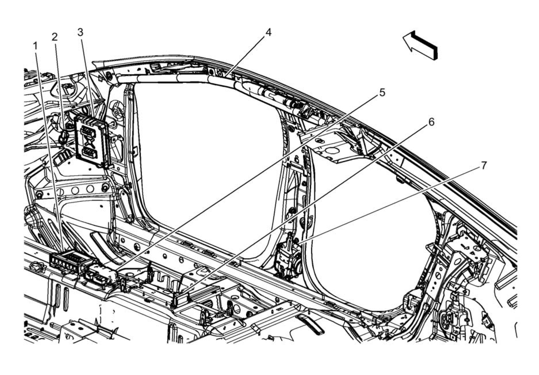 |
|
Fig. 3: Passenger Compartment Components (3 of 3) |
Items
1. K9 Body Control Module K9 Body Control Module X1 K9 Body Control Module X2 K9 Body
Control Module X3 K9 Body Control Module X4 K9 Body Control Module X5 K9 Body Control
Module X6 K9 Body Control Module X7_____________________________________________
2. R6A Terminating Resistor - High Speed Bus R6A Terminating Resistor - High Speed Bus
3. K114B Hybrid/EV Powertrain Control Module 2 K114B Hybrid/EV Powertrain Control Module 2
X1 K114B Hybrid/EV Powertrain Control Module 2 X2__________________________________
4. F105R Roof Rail Air Bag - Right F105R Roof Rail Air Bag - Right___________________________
5. K36 Inflatable Restraint Sensing and Diagnostic Module K36 Inflatable Restraint Sensing and
Diagnostic Module X1 K36 Inflatable Restraint Sensing and Diagnostic Module X2
6. B284 Vehicle Dynamic Sensor B284 Vehicle Dynamic Sensor
7. F112P Seat Belt Retractor Pretensioner - Passenger F112P Seat Belt Retractor Pretensioner -
Passenger
HEADLINER COMPONENTS (1 OF 4)
 |
|
Fig. 4: Headliner Components (1 of 4) Courtesy of GENERAL MOTORS COMPANY |
Items
1. E31L Sunshade Mirror Lamp - Left E31L Sunshade Mirror Lamp - Left
2. E37R Dome/Reading Lamps - Rear E37R Dome/Reading Lamps - Rear
3. E31R Sunshade Mirror Lamp - Right E31R Sunshade Mirror Lamp - Right
4. E37F Dome/Reading Lamps - Front
HEADLINER COMPONENTS (2 OF 4)
 |
|
Fig. 5: Headliner Components (2 of 4) Courtesy of GENERAL MOTORS COMPANY |
Items
1. S48B Multifunction Switch - Overhead Console S48B Multifunction Switch - Overhead Console
2. B24 Cellular Phone Microphone B24 Mobile Telephone Microphone
HEADLINER COMPONENTS (3 OF 4)
 |
|
Fig. 6: Headliner Components (3 of 4) Courtesy of GENERAL MOTORS COMPANY |
Items
1. B160 Windshield Temperature and Inside Moisture Sensor B160 Windshield Temperature and
Inside Moisture Sensor
2. A10 Inside Rearview Mirror A10 Inside Rearview Mirror
3. K109 Frontview Camera Module (UHY) K109 Frontview Camera Module
PASSENGER COMPARTMENT/ROOF COMPONENT VIEWS
 |
|
Fig. 7: Headliner Components (4 of 4) Courtesy of GENERAL MOTORS COMPANY |
Items
1. E18 Rear Defogger Grid E18 Rear Defogger Grid X1 E18 Rear Defogger Grid X2
REAR SEAT COMPONENTS (1 OF 3)
 |
|
Fig. 8: Rear Seat Components (1 of 3) Courtesy of GENERAL MOTORS COMPANY |
Items
1. F106RR Seat Side Air Bag - Right Rear F106RR Seat Side Air Bag - Right Rear
2. F106LR Seat Side Air Bag - Left Rear F106LR Seat Side Air Bag - Left Rear
REAR SEAT COMPONENTS (2 OF 3)
 |
|
Fig. 9: Rear Seat Components (2 of 3) Courtesy of GENERAL MOTORS COMPANY |
Items
1. B63LR Side Impact Sensor - Left Rear B63LR Side Impact Sensor - Left Rear
REAR SEAT COMPONENTS (3 OF 3)
 |
|
Fig. 10: Rear Seat Components (3 of 3) |
Items
1. B63RR Side Impact Sensor - Right Rear B63RR Side Impact Sensor - Right Rear
Article GUID: A00884713
SPECIFICATIONS
FASTENER SPECIFICATIONS
|
Application |
Specification | |
|
Metric |
English (USA) | |
|
Drive Motor Battery Charger Bolt |
22 N.m |
16 lb ft |
|
Drive Motor Battery Charger Fastener |
22 N.m |
16 lb ft |
|
Drive Motor Battery Charger Receptacle Fastener |
12 N.m |
106 lb in |
SCHEMATIC WIRING DIAGRAMS
PLUG-IN CHARGING WIRING SCHEMATICS
Battery State of Charge
 |
|
Fig. 1: Battery State of Charge Courtesy'of GENERAL'MOTORS COMPANY |
Charging Port Door
Fig. 2: Charging Port Door
Courtesy'of GENERAL'MOTORS COMPANY
Battery Charger


Fig. 3: Battery Charger
Courtesy'of GENERAL MOTORS COMPANY
DIAGNOSTIC INFORMATION AND PROCEDURES
DTC P0CF4-P0CF6: CONTROL PILOT CIRCUIT
Diagnostic Instructions
• Perform the Diagnostic System Check prior to using this diagnostic procedure: Diagnostic System Check -
Vehicle
• Review the description of Strategy Based Diagnosis: Strategy Based Diagnosis
• An overview of each diagnostic category can be found here: Diagnostic Procedure Instructions
DTC Descriptor
Control Pilot Circuit Performance
Control Pilot Circuit Low Voltage
Control Pilot Circuit High Voltage
|
Diagnostic Fault Information | |||||||||||||||||||||||||||||||||||
| |||||||||||||||||||||||||||||||||||
|
Circuit/System Description | |||||||||||||||||||||||||||||||||||
The hybrid/EV powertrain control module 2 monitors a pilot signal from the drive motor battery charger cable. The
hybrid/EV powertrain control module 2 utilizes this signal to manage the charging process between the drive motor
battery charger cable and the hybrid/EV powertrain control module 2.
Under normal charging conditions the control pilot signal is generated by the drive motor battery charger cable. This
diagnostic runs with the drive motor battery charger cable disconnected to verify the vehicle side circuit integrity.
The diagnostic signal is generated internally by the hybrid/EV powertrain control module 2.
Conditions for Running the DTC
DTC P0CF4
• The vehicle 12 V battery system voltage is 10.2 V or greater.
• The drive motor battery charger cable is disconnected and the charge port door is closed.
• The vehicle needs to be driven above 8 km/h (5 mph).
• The vehicle 12 V battery system voltage is 10.2 V or greater.
• The drive motor battery charger cable is disconnected and the charge port door is closed.
• The vehicle 12 V battery system voltage is 10.2 V or greater.
• The drive motor battery charger cable is disconnected and the charge port door is closed.
• The vehicle needs to be driven above 8 km/h (5 mph).
Conditions for Setting the DTC
The control pilot circuit is not meeting its internal range requirements for 5 seconds. This can only be set internal to
the hybrid/EV powertrain control module 2. This is an internal circuit voltage in the hybrid/EV powertrain control
module 2 and can not be measured.
The control pilot circuit voltage divided by the system voltage is less than 0.03 V for 5 seconds. This is an internal
circuit voltage in the hybrid/EV powertrain control module 2 and can not be measured.
The control pilot circuit voltage divided by the system voltage is greater than 0.55 V for 5 seconds. This is an
internal circuit voltage in the hybrid/EV powertrain control module 2 and can not be measured.
Actions Taken When the DTC Sets
• DTC P0CF4-P0CF6 are type A DTCs.
• Disables high voltage battery charging.
Conditions for Clearing the DTC
DTC P0CF4-P0CF6 are type A DTCs.
Reference Information
Schematic Reference
Connector End View Reference
Description and Operation
Plug-In Charging System Description and Operation
Electrical Information Reference
Circuit Testing
Connector Repairs
Testing for Intermittent Conditions and Poor Connections
Wiring Repairs
DTC Type Reference
Powertrain Diagnostic Trouble Code (DTC) Type Definitions
Scan Tool Reference
Control Module References for scan tool information
Special Tools
EL-48900 HEV Safety Kit
For equivalent regional tools, refer to Special Tools.
Circuit/System Testing
WARNING: Always perform the High Voltage Disabling procedure prior to servicing any High
Voltage component or connection. Personal Protection Equipment (PPE) and proper
procedures must be followed.
The High Voltage Disabling procedure includes the following steps:
• Identify how to disable high voltage.
• Identify how to test for the presence of high voltage.
• Identify condition under which high voltage is always present and personal
protection equipment (PPE) and proper procedures must be followed.
Before working on any high voltage system, be sure to wear the following Personal
Protection Equipment:
• Safety glasses with appropriate side shields when within 15 meters (50 feet) of
the vehicle, either indoors or outdoors.
• Certified and up-to-date Class "0" Insulation gloves rated at 1000V with leather
protectors.
• Visually and functionally inspect the gloves before use.
• Wear the Insulation gloves with leather protectors at all times when
working with the high voltage battery assembly, whether the system is
energized or not.
Failure to follow the procedures may result in serious injury or death.
1. Vehicle OFF, disable the high voltage at the T18 Battery Charger. Refer to High Voltage Disabling .
Disconnect the X2 harness connector at the K114B Hybrid/EV Powertrain Control Module 2.
 |
|
Fig. 4: Hybrid/Ev Battery Charger Receptacle And Terminals |
2. Test for infinite resistance between control pilot signal circuit terminal 2 of the X98 Hybrid/EV Battery
Charger Receptacle and the terminals listed below:
1. Disconnect the harness connector from the X98 Hybrid/EV Battery Charger Receptacle.
2. Test for infinite resistance between the harness connector control pilot signal circuit terminal 2 and the
terminals listed below:
• Terminal 4
• Terminal 1
• Terminal 5
• Terminal 3
• If less than infinite resistance, repair the short between the circuits.
• If infinite resistance, replace the X98 Hybrid/EV Battery Charger Receptacle.
3. Replace the K114B Hybrid/EV Powertrain Control Module 2.
Repair Instructions
Perform the Diagnostic Repair Verification after completing the repair.
Drive Motor Battery Charger Receptacle Replacement
Control Module References for hybrid/EV powertrain control module 2 replacement, programming and
setup.
DTC P0CF9 OR P0D01: CONTROL PILOT CHARGING SWITCH PERFORMANCE
Diagnostic Instructions
• Perform the Diagnostic System Check prior to using this diagnostic procedure: Diagnostic System Check -
Vehicle
• Review the description of Strategy Based Diagnosis: Strategy Based Diagnosis
• An overview of each diagnostic category can be found here: Diagnostic Procedure Instructions
DTC Descriptor
Control Pilot Charging Switch Performance
Control Pilot Charging Ventilation Switch Performance
|
Diagnostic Fault Information | |||||||||||||||||||||||||||||||||||
| |||||||||||||||||||||||||||||||||||
|
Circuit/System Description | |||||||||||||||||||||||||||||||||||
The hybrid/EV powertrain control module 2 has two internal switches used to modify the control pilot signal. The
first internal switch modifies the control pilot signal to indicate to the drive motor battery charger cable that the
vehicle is either ready or not ready to accept energy. The second internal switch modifies the control pilot signal to
indicate to some drive motor battery charger cables (currently not used) if indoor ventilation is required.
Conditions for Running the DTC
• The 12 V battery voltage is greater than 10.2 V
• The drive motor battery charger cable is disconnected and the charge port door is closed.
• The diagnostics for DTC P0CF4-P0CF6 must have passed before these will run.
Conditions for Setting the DTC
The hybrid/EV powertrain control module 2 measures a pilot signal voltage out of range for 5 seconds. This is an
internal circuit voltage in the hybrid/EV powertrain control module 2 and can not be measured.
Actions Taken When the DTC Sets
• DTC P0CF9 and P0D01 are type A DTCs
• Disables the high voltage battery charging.
Conditions for Clearing the DTC
DTC P0CF9 and P0D01 are type A DTCs.
Reference Information
Schematic Reference
Connector End View Reference
Description and Operation
Electrical Information Reference
Circuit Testing
Connector Repairs
Testing for Intermittent Conditions and Poor Connections
Wiring Repairs
DTC Type Reference
Scan Tool Reference
Control Module References for scan tool information
Special Tools
EL-48900 HEV Safety Kit
For equivalent regional tools, refer to Special Tools.
Circuit/System Verification
1. Vehicle ON.
2. Verify that DTC P0CF9 or P0D01 is not set.
Replace the K114B Hybrid/EV Powertrain Control Module 2.
3. All OK.
Repair Instructions
Control Module References for hybrid/EV powertrain control module 2 replacement, programming and setup.
DTC P0D1F: CONTROL MODULE DATE/TIME SYNCHRONIZATION PERFORMANCE
Diagnostic Instructions
• Perform the Diagnostic System Check prior to using this diagnostic procedure: Diagnostic System Check -
Vehicle
• Review the description of Strategy Based Diagnosis: Strategy Based Diagnosis
• An overview of each diagnostic category can be found here: Diagnostic Procedure Instructions
DTC Descriptor
Control Module Date/Time Synchronization Performance
Circuit/System Description
The hybrid/EV powertrain control module 2 monitors the date and time data it receives from the radio. This time
information is used to ensure the module's internal clock is synchronized to the customer's local time. The Time of
Day Charging feature utilizes this internal clock to keep track of time and alarms for delayed charging modes. If this
radio time data is received during a drive cycle, the system is considered synchronized.
Conditions for Running the DTC
The vehicle needs to go from Vehicle OFF to Vehicle in Service Mode to start the diagnostic.
Conditions for Setting the DTC
The vehicle is driven for more than 5 consecutive drive cycles where trip distance exceeds 15 Km (9.3 mi), and the
date and time were unavailable from the OnStar Module.
Actions Taken When the DTC Sets
• DTC P0D1F is a type C DTC.
• On the Navigation screen "Default Charge Mode: Immediately" is displayed.
• The battery charger Time Of Day charging option is disabled, and charging mode is set to IMMEDIATE.
Conditions for Clearing the DTC
DTC P0D1F is a type C DTCs.
Reference Information
Schematic Reference
Connector End View Reference
Description and Operation
Plug-In Charging System Description and Operation
Electrical Information Reference
Circuit Testing
Connector Repairs
Testing for Intermittent Conditions and Poor Connections
Wiring Repairs
DTC Type Reference
Powertrain Diagnostic Trouble Code (DTC) Type Definitions
Scan Tool Reference
Control Module References for scan tool information
Special Tools
EL-48900 HEV Safety Kit
For equivalent regional tools, refer to Special Tools.
Circuit/System Verification
1. Vehicle in Service Mode, verify no radio DTC's are set.
• If any radio DTC's are set
Refer to Diagnostic Trouble Code (DTC) List - Vehicle .
• If no radio DTC's are set
2. Replace the K114B Hybrid/EV Powertrain Control Module 2.
Repair Instructions
Perform the Diagnostic Repair Verification after completing the repair.
Control Module References for hybrid/EV powertrain control module 2 replacement, programming and setup.
DTC P0D26: BATTERY CHARGER SYSTEM PRECHARGE TIME TOO LONG
Diagnostic Instructions
• Perform the Diagnostic System Check prior to using this diagnostic procedure: Diagnostic System Check -
Vehicle
• Review the description of Strategy Based Diagnosis: Strategy Based Diagnosis
• An overview of each diagnostic category can be found here: Diagnostic Procedure Instructions
DTC Descriptor
DTC P0D26
Battery Charger System Precharge Time Too Long
Circuit/System Description
In order to prevent large in-rush current, battery charger bus high voltage is routed through a pre-charge resistor
whenever high voltage charging is commanded ON. The hybrid/EV powertrain control module 2 monitors the time it
takes the battery charger bus voltage to attain the same level as the battery pack voltage. If it takes too long, a DTC is
set.
Conditions for Running the DTC
• Battery charger must go from disconnected to connected.
• Drive motor battery charger cable must be connected and vehicle receiving power.
Conditions for Setting the DTC
The hybrid/EV powertrain control module 2 determines the battery charger does not reach its pre-charge voltage
within 1 second.
Actions Taken When the DTC Sets
• DTC P0D26 is a Type A DTC.
• Disables the high voltage battery charging.
• Disables 12V battery charging.
Conditions for Clearing the DTC
DTC P0D26 is a Type A DTC.
Reference Information
Schematic Reference
Connector End View Reference
Description and Operation
Electrical Information Reference
Circuit Testing
Connector Repairs
Testing for Intermittent Conditions and Poor Connections
Wiring Repairs
DTC Type Reference
Scan Tool Reference
Control Module References for scan tool information
Circuit/System Verification
1. Verify DTC P0C78 is not set.
• If the DTC is set
Refer to Diagnostic Trouble Code (DTC) List - Vehicle .
• If the DTC is not set
2. Verify DTC P0CF4, P0CF5, P0CF6, P0D4E, P0D4F, P0D58, or P0D59 is not set.
• If any of the DTCs are set
Refer to Diagnostic Trouble Code (DTC) List - Vehicle .
• If none of the DTCs are set
3. Connect the drive motor battery charger cable. Verify DTC P0D26 is not set and the vehicle will charge.
• If the DTC is set and the vehicle will not charge
Refer to Circuit/System Testing.
• If the DTC is not set and the vehicle charges
4. All OK.
Circuit/System Testing
WARNING: Always perform the High Voltage Disabling procedure prior to servicing any
High Voltage component or connection. Personal Protection Equipment (PPE)
and proper procedures must be followed.
The High Voltage Disabling procedure will perform the following tasks:
• Identify how to disable high voltage.
• Identify how to test for the presence of high voltage.
• Identify condition under which high voltage is always present and
personal protection equipment (PPE) and proper procedures must be
followed.
Failure to follow the procedures exactly as written may result in serious injury
or death.
1. Disable the high voltage for servicing at the A4 Battery Pack, K1 14V Power Module and the T18 Battery
Charger. Refer to High Voltage Disabling .
2. Disconnect the X3 connector at the T18 Battery Charger, the X4 connector at the K1 14V Power Module and
the X6 connector at the A4 Battery Pack.
3. Verify that all HV harness connector and mating module connector terminals are free from moisture, corrosion
and arc flash damage.
• If any terminals show signs of damage
Replace the HV wiring harness and effected modules as necessary.
• If no arc flash damage, moisture, or corrosion is found
4. Test the following HV harness terminals for less than 2 Q end to end:
• X6-1 to X3-1
• X6-1 to X4-B
• X6-2 to X3-2
• X6-2 to X4-A
• If 2 fi or greater
Replace the HV wiring harness.
• If less than 2 fi
5. Remove the T18 Battery Charger 15A fuse from the A4 Battery Pack. Refer to High Voltage Battery
Disconnect Relay Fuse Replacement (Front - BDU) High Voltage Battery Disconnect Relay Fuse
Replacement (Rear - BDU) for Front-BDU.
6. Test the battery charger 15A fuse for an open condition.
• If the fuse is open
1. Test the HV harness terminals X6-1 to X6-2 for infinite resistance.
• If less than infinite resistance, replace the fuse and the HV wiring harness.
• If infinite resistance
2. Test the K1 14 V Power Module X4 terminals for greater than 10K fi, X4-A to X4-B.
• If 10K fi or less, replace the K1 14V Power Module and the fuse.
• If greater than 10 K fi
3. Test the T18 Battery Charger terminals for greater than 10K fi, X3-1 to X3-2.
• If 10K fi or less, replace the T18 Battery Charger and the fuse.
• If greater than 10 K fi
4. Replace the T18 Battery Charger and the fuse, reassemble the vehicle, clear DTCs and repeat
Circuit/System Verification.
• If Circuit/System Verification is not OK, replace the A28 Hybrid/EV Battery Contactor Assembly.
• If Circuit/System Verification is OK, all OK.
7. Reinstall the fuse. Replace the T18 Battery Charger, reassemble the vehicle, clear DTCs and repeat
Circuit/System Verification.
• If Circuit/System Verification is not OK
Replace the A28 Hybrid/EV Battery Contactor Assembly.
8. All OK.
Repair Instructions
Battery 300-Volt Positive and Negative Cable Replacement - High Voltage Battery to Charger
Receptacle, Accessory DC Power Control Module, and Drive Motor Battery Charger for HV wiring
harness
Generator Battery Disconnector Relay Replacement for A28 hybrid/EV battery contactor assembly
Control Module References for T18 Battery Charger, often referred to as the Drive Motor Battery Charger, or
K1 14V Power Module replacement, programming and setup
DTC P0D2B OR P0D2C: CONTROL PILOT/STATUS INDICATOR CONTROL CIRCUIT
Diagnostic Instructions
• Perform the Diagnostic System Check prior to using this diagnostic procedure: Diagnostic System Check -
Vehicle
• Review the description of Strategy Based Diagnosis: Strategy Based Diagnosis
• An overview of each diagnostic category can be found here: Diagnostic Procedure Instructions
DTC Descriptor
Control Pilot Indicator Control Circuit
Charge Status Indicator Control Circuit
|
Diagnostic Fault Information | ||||||||||||||||||||||||||||||
| ||||||||||||||||||||||||||||||
|
Circuit/System Description | ||||||||||||||||||||||||||||||
The status of charging events (including delays) is communicated to the user through a charge status indicator and
audio tones. The battery state of charge indicator, located on the top middle of the instrument panel, will be solid lit
green when the vehicle is charging under automatic control. It will have a fast flash green if the charging is delayed
and will begin later. It will have a slow flash green when charging is complete. A solid lit yellow indicator means the
vehicle is not able to accept a charge. And if there is no indicator lit it means the electronic vehicle supply equipment
is not working properly or connected.
Conditions for Running the DTC
Both conditions need to run for diagnostic to pass.
Condition 1
• The 12 V battery voltage is greater than 10.2 V
• Vehicle in Service Mode.
• The drive motor battery charger cable is disconnected (charge status indicator commanded OFF).
• The 12 V battery voltage is greater than 10.2 V
• Vehicle in Service Mode.
• The vehicle is connected to an AC supply and the battery charger is charging the vehicle (charge status
indicator commanded ON).
Conditions for Setting the DTC
• Charge status indicator Commanded OFF, The hybrid/EV powertrain control module 2 detects a short to
battery for about 4 s.
• Charge status indicator Commanded ON, The hybrid/EV powertrain control module 2 detects a short to
ground or an open/high resistance for 4 s.
Actions Taken When the DTC Sets
DTC P0D2B and P0D2C are type C DTCs.
Conditions for Clearing the DTC
DTC P0D2B and P0D2C are type C DTCs.
Reference Information
Schematic Reference
Connector End View Reference
Description and Operation
Electrical Information Reference
Circuit Testing
Connector Repairs
Testing for Intermittent Conditions and Poor Connections
Wiring Repairs
DTC Type Reference
Scan Tool Reference
Control Module References for scan tool information
Special Tools
EL-48900 HEV Safety Kit
For equivalent regional tools, refer to Special Tools.
Circuit/System Testing
WARNING: Always perform the High Voltage Disabling procedure prior to servicing any High
Voltage component or connection. Personal Protection Equipment (PPE) and proper
procedures must be followed.
The High Voltage Disabling procedure includes the following steps:
• Identify how to disable high voltage.
• Identify how to test for the presence of high voltage.
• Identify condition under which high voltage is always present and personal
protection equipment (PPE) and proper procedures must be followed.
Before working on any high voltage system, be sure to wear the following Personal
Protection Equipment:
• Safety glasses with appropriate side shields when within 15 meters (50 feet) of
the vehicle, either indoors or outdoors.
• Certified and up-to-date Class "0" Insulation gloves rated at 1000V with leather
protectors.
• Visually and functionally inspect the gloves before use.
• Wear the Insulation gloves with leather protectors at all times when
working with the high voltage battery assembly, whether the system is
energized or not.
Failure to follow the procedures may result in serious injury or death.
1. Vehicle OFF, disconnect the X1 harness connector at the B305 Ambient Light/Sunload Sensor and Battery
State of Charge Indicator.
2. Test for less than 10 Q between the low reference terminal 1 and ground.
• If 10 fi or greater
Repair the open/high resistance in the circuit.
• If less than 10 fi
NOTE: If the drive motor battery charger cable is connected. The drive motor battery
charger cable must be disconnected for more than 10 seconds before
performing the next step.
3. Connect a test lamp between the control circuit terminal 4 and ground.
4. Verify the test lamp does not illuminate.
• If the test lamp does illuminate
1. Disconnect the X2 harness connector at the K114B Hybrid/EV Powertrain Control Module 2.
2. Test for less than 1 V between the control circuit and ground.
• If 1 V or greater, repair the short to voltage in the circuit.
• If less than 1 V, replace the K114B Hybrid/EV Powertrain Control Module 2.
• If the test lamp does not illuminate
5. Connect the drive motor battery charger cable.
6. Verify that the test lamp illuminates within the first 5 seconds of connecting the drive motor battery charger
cable.
• If the test lamp does not illuminate
1. Disconnect the drive motor battery charger cable. Disconnect the X2 harness connector at the K114B
Hybrid/EV Powertrain Control Module 2.
2. Test for infinite resistance between the control circuit and ground
• If less than infinite resistance, repair the short to ground on the circuit.
• If infinite resistance
3. Test for less than 2 Q in the control circuit end to end.
• If 2 Q or greater, repair the open/high resistance in the circuit.
• If less than 2 Q, replace the K114B Hybrid/EV Powertrain Control Module 2.
• If the test lamp does illuminate
7. Disconnect the drive motor battery charger cable for at least 10 seconds. Connect a test lamp between the
control circuit terminal 3 and ground.
8. Verify the test lamp does not illuminate.
• If the test lamp does illuminate
1. Disconnect the X2 harness connector at the K114B Hybrid/EV Powertrain Control Module 2.
2. Test for less than 1 V between the control circuit and ground.
• If 1 V or greater, repair the short to voltage in the circuit.
• If less than 1 V, replace the K114B Hybrid/EV Powertrain Control Module 2.
• If the test lamp does not illuminate
9. Connect the drive motor battery charger cable.
10. Verify that the test lamp illuminates within 25 seconds of connecting the drive motor battery charger cable.
• If the test lamp does not illuminate
1. Disconnect the drive motor battery charger cable. Disconnect the X2 harness connector at the K114B
Hybrid/EV Powertrain Control Module 2.
2. Test for infinite resistance between the control circuit and ground
• If less than infinite resistance, repair the short to ground on the circuit.
• If infinite resistance
3. Test for less than 2 Q in the control circuit end to end.
• If 2 Q or greater, repair the open/high resistance in the circuit.
• If less than 2 Q, replace the K114B Hybrid/EV Powertrain Control Module 2.
• If the test lamp does illuminate
11. Replace the B305 Ambient Light/Sunload Sensor and Battery State of Charge Indicator.
Repair Instructions
Perform the Diagnostic Repair Verification after completing the repair.
Sun Load Temperature and Headlamp Automatic Control Ambient Light Sensor Replacement for B305
Ambient Light/Sunload Sensor and Battery State of Charge Indicator replacement.
Control Module References for battery charger replacement, programming and setup.
DTC P0D3E-P0D40: BATTERY CHARGER INPUT VOLTAGE SENSOR
Diagnostic Instructions
• Perform the Diagnostic System Check prior to using this diagnostic procedure: Diagnostic System Check -
Vehicle
• Review the description of Strategy Based Diagnosis: Strategy Based Diagnosis
• An overview of each diagnostic category can be found here: Diagnostic Procedure Instructions
DTC Descriptor
Battery Charger Input Voltage Sensor Performance
Battery Charger Input Voltage Sensor Circuit Low Voltage
Battery Charger Input Voltage Sensor Circuit High Voltage
Circuit/System Description
The hybrid/EV powertrain control module 2 monitors the AC voltage sensor inside the battery charger. The signal is
pulse-width modulated and the duty cycle increases as the AC voltage increases. The duty cycle equals 10% when
the AC voltage sensor reports less than 60 V. The duty cycle equals 90% when the AC voltage sensor reports more
than 280 V. Therefore, during normal operation the duty cycle is between 10% and 90%.
Conditions for Running the DTC
• The 12 V battery voltage is greater than 10.2 V
• The vehicle is driven above 6 km/h (4 mph).
• The 12 V battery voltage is greater than 10.2 V
• The vehicle is connected to an AC supply and the battery charger is charging the vehicle.
Conditions for Setting the DTC
The battery charger AC input duty cycle is greater than 12% or less than 8%.
The battery charger AC input duty cycle is between 1% and 8%.
OR
The battery charger AC input duty cycle equals 100%.
The battery charger AC input duty cycle is between 92% and 99%.
OR
The battery charger AC input duty cycle equals 0%.
Actions Taken When the DTC Sets
• DTC P0D3E, P0D3F and P0D40 are type B DTCs.
• Disables high voltage battery charging.
Conditions for Clearing the DTC
DTC P0D3E, P0D3F and P0D40 are type B DTCs.
Reference Information
Schematic Reference
Connector End View Reference
Description and Operation
Electrical Information Reference
Circuit Testing
Connector Repairs
Testing for Intermittent Conditions and Poor Connections
Wiring Repairs
DTC Type Reference
Scan Tool Reference
Control Module References for scan tool information
Circuit/System Verification
1. Drive the vehicle above 6 km/h (4 mph).
2. Vehicle OFF. Connect the vehicle to an AC supply to begin charging.
3. Vehicle in Service Mode.
4. Verify that P0D3E, P0D3F, or P0D40 is not set.
• If any of the DTCs are set
Refer to Circuit/System Testing.
5. All OK.
Circuit/System Testing
1. Vehicle OFF, disconnect the X1 harness connector at the T18 Battery Charger. Vehicle in Service Mode.
2. Verify the scan tool High Voltage Battery Charger AC Input Duty Cycle parameter is less than 10%.
1. Vehicle OFF, disconnect the X2 harness connector at the K114B Hybrid/EV Powertrain Control Module
2.
2. Test for infinite resistance between the AC voltage sensor circuit terminal 10 and ground.
• If less than infinite resistance, repair the short to ground on the circuit.
• If infinite resistance, replace the K114B Hybrid/EV Powertrain Control Module 2.
3. Install a 3 A fused jumper wire between the AC voltage sensor circuit terminal 10 and the ground circuit
terminal 2.
4. Verify the scan tool Battery Charger AC Input Status Duty Cycle parameter is greater than 90%.
1. Vehicle OFF, disconnect the X2 harness connector at the K114B Hybrid/EV Powertrain Control Module
2. Vehicle in Service Mode.
2. Test for less than 1 V between the AC voltage sensor circuit terminal 10 and ground.
• If 1 V or greater, repair the short to voltage on the circuit.
• If less than 1 V
3. Vehicle OFF.
4. Test for less than 2 Q in the AC voltage sensor circuit end to end.
• If 2 Q or greater, repair the open/high resistance in the circuit.
• If less than 2 Q, replace the K114B Hybrid/EV Powertrain Control Module 2.
5. Replace the T18 Battery Charger.
Repair Instructions
Perform the Diagnostic Repair Verification after completing the repair.
Control Module References for K114B Hybrid/EV Powertrain Control Module 2 or T18 Battery Charger
replacement, programming and setup
Diagnostic Instructions
• Perform the Diagnostic System Check prior to using this diagnostic procedure: Diagnostic System Check -
• Review the description of Strategy Based Diagnosis: Strategy Based Diagnosis
• An overview of each diagnostic category can be found here: Diagnostic Procedure Instructions
DTC Descriptor
Battery Charger Hybrid/EV Battery Output Voltage Sensor Performance
Battery Charger Hybrid/EV Battery Output Voltage Sensor Circuit Low Voltage
Battery Charger Hybrid/EV Battery Output Voltage Sensor Circuit High Voltage
Circuit/System Description
The hybrid/EV powertrain control module 2 monitors the DC voltage sensor inside the battery charger. The signal is
pulse-width modulated and the duty cycle increases as the DC voltage increases. The duty cycle equals 10% when
the DC voltage sensor reports less than 0 V. The duty cycle equals 90% when the DC voltage sensor reports more
than 500 V. Therefore, during normal operation the duty cycle is between 10% and 90%.
Conditions for Running the DTC
• The 12 V battery voltage is greater than 10.2 V
• The vehicle is connected to an AC supply and the battery charger is charging the vehicle.
Conditions for Setting the DTC
The difference between the battery charger DC output voltage and hybrid/EV battery DC input voltage is greater
than 30 V.
The battery charger DC output duty cycle is between 1% and 8%.
OR
The battery charger DC output duty cycle equals 100%.
The battery charger DC output duty cycle is between 92% and 99%.
OR
The battery charger DC output duty cycle equals 0%.
Actions Taken When the DTC Sets
• DTC P0D4D, P0D4E and P0D4F are type B DTCs.
• Disables high voltage battery charging.
Conditions for Clearing the DTC
DTC P0D4D, P0D4E and P0D4F are type B DTCs.
Reference Information
Schematic Reference
Plug-In Charging Schematics
Connector End View Reference
COMPONENT CONNECTOR END VIEWS - INDEX
Description and Operation
Plug-In Charging System Description and Operation
Electrical Information Reference
Circuit Testing
Connector Repairs
Testing for Intermittent Conditions and Poor Connections
Wiring Repairs
DTC Type Reference
Powertrain Diagnostic Trouble Code (DTC) Type Definitions
Scan Tool Reference
Control Module References for scan tool information
Circuit/System Verification
1. Verify that DTC P0D4E or P0D4F is not set.
• If any of the DTCs are set
Refer to Circuit/System Testing.
• If none of the DTCs are set
2. Connect the vehicle to an AC supply to begin charging. Vehicle in Service Mode.
3. Verify that DTC P0D26 is not set.
• If the DTC is set
Refer to DTC P0D26.
• If the DTC is not set
4. Verify that DTC P0D4D is not set.
• If the DTC is set
Refer to Circuit/System Testing.
• If the DTC is not set
5. All OK.
Circuit/System Testing
1. Vehicle OFF, disconnect the X1 harness connector at the T18 Battery Charger. Vehicle in Service Mode.
2. Verify the scan tool High Voltage Battery Charger Output Duty Cycle parameter is less than 10%.
1. Vehicle OFF, disconnect the X2 harness connector at the K114B Hybrid/EV Powertrain Control Module
2.
2. Test for infinite resistance between the DC voltage sensor circuit terminal 3 and ground.
• If less than infinite resistance, repair the short to ground on the circuit.
• If infinite resistance, replace the K114B Hybrid/EV Powertrain Control Module 2.
3. Install a 3 A fused jumper wire between the DC voltage sensor circuit terminal 3 and the ground circuit
terminal 2.
4. Verify the scan tool Battery Charger DC Output Status Duty Cycle parameter is greater than 90%.
1. Vehicle OFF, disconnect the X2 harness connector at the K114B Hybrid/EV Powertrain Control Module
2. Vehicle in Service Mode.
2. Test for less than 1 V between the DC voltage sensor circuit terminal 3 and ground.
• If 1 V or greater, repair the short to voltage on the circuit.
• If less than 1 V
3. Vehicle OFF.
4. Test for less than 2 Q in the DC voltage sensor circuit end to end.
• If 2 Q or greater, repair the open/high resistance in the circuit.
• If less than 2 Q, replace the K114B Hybrid/EV Powertrain Control Module 2.
5. Replace the T18 Battery Charger.
Repair Instructions
Perform the Diagnostic Repair Verification after completing the repair.
Control Module References for K114B Hybrid/EV Powertrain Control Module 2 or T18 Battery Charger
replacement, programming and setup.
Diagnostic Instructions
• Perform the Diagnostic System Check prior to using this diagnostic procedure: Diagnostic System Check -
Vehicle
• Review the description of Strategy Based Diagnosis: Strategy Based Diagnosis
• An overview of each diagnostic category can be found here: Diagnostic Procedure Instructions
DTC Descriptor
Proximity Detection Circuit Low Voltage
Proximity Detection Circuit High Voltage
|
Diagnostic Fault Information | |||||||||||||||||||||||||||||||||||
| |||||||||||||||||||||||||||||||||||
|
Circuit/System Description | |||||||||||||||||||||||||||||||||||
The proximity detection circuit prevents movement of the vehicle while the drive motor battery charger cable is
connected. This diagnostic runs with the drive motor battery charger cable disconnected to verify the vehicle side
circuit integrity.
Conditions for Running the DTC
• The 12 V battery voltage is greater than 10.2 V
• The vehicle speed is greater than 20 km/h (15 mph) for more than 5 seconds.
• No vehicle speed DTCs are set.
Conditions for Setting the DTC
The hybrid/EV powertrain control module 2 measures a voltage less than 4.2 V for 5 seconds.
The hybrid/EV powertrain control module 2 measures a voltage greater than 4.8 V for 5 seconds.
Actions Taken When the DTC Sets
• DTC P0D58 and P0D59 are type A DTCs.
• Disable the high voltage battery charging.
Conditions for Clearing the DTC
DTC P0D58 and P0D59 are type A DTCs.
Reference Information
Schematic Reference
Connector End View Reference
Description and Operation
Plug-In Charging System Description and Operation
Electrical Information Reference
Circuit Testing
Connector Repairs
Testing for Intermittent Conditions and Poor Connections
Wiring Repairs
DTC Type Reference
Powertrain Diagnostic Trouble Code (DTC) Type Definitions
Scan Tool Reference
Control Module References for scan tool information
Special Tools
EL-48900 HEV Safety Kit
For equivalent regional tools, refer to Special Tools.
Circuit/System Testing
WARNING: Always perform the High Voltage Disabling procedure prior to servicing any High
Voltage component or connection. Personal Protection Equipment (PPE) and proper
procedures must be followed.
The High Voltage Disabling procedure includes the following steps:
• Identify how to disable high voltage.
• Identify how to test for the presence of high voltage.
• Identify condition under which high voltage is always present and personal
protection equipment (PPE) and proper procedures must be followed.
Before working on any high voltage system, be sure to wear the following Personal
Protection Equipment:
• Safety glasses with appropriate side shields when within 15 meters (50 feet) of
the vehicle, either indoors or outdoors.
• Certified and up-to-date Class "0" Insulation gloves rated at 1000V with leather
protectors.
• Visually and functionally inspect the gloves before use.
• Wear the Insulation gloves with leather protectors at all times when
working with the high voltage battery assembly, whether the system is
energized or not.
Failure to follow the procedures may result in serious injury or death.
1. Vehicle OFF, disable the high voltage at the T18 Battery Charger. Refer to High Voltage Disabling .
Reconnect the X2 harness connector at the T18 Battery Charger.
 |
|
Fig. 5: Hybrid/Ev Battery Charger Receptacle And Terminals |
2. Test for less than 10 Q between the low reference circuit terminal 1 and ground.
• If 10 fi or greater
1. Disconnect the X2 harness connector at the T18 Battery Charger.
2. Test for less than 2 Q in the low reference circuit end to end.
• If 2 Q or greater, repair the open/high resistance in the circuit.
• If less than 2 Q, replace the T18 Battery Charger.
3. Connect the 12 V battery. Vehicle in Service Mode.
 |
|
Fig. 6: Hybrid/Ev Battery Charger Receptacle And Terminals |
4. Test for 4.2 - 4.8 V between the signal circuit terminal 5 and ground.
1. Vehicle OFF, disconnect the harness connector to the X98 Hybrid/EV Battery Charger Receptacle.
Vehicle in Service Mode.
2. Test for 4.2 - 4.8 V between the signal circuit terminal 5 and ground.
• If less than 4.2 V
3. Disconnect the X2 harness connector at the K114B Hybrid/EV Powertrain Control Module 2.
4. Test for infinite resistance between the signal circuit terminal 5 and ground.
• If less than infinite resistance, repair the short to ground in the circuit.
• If infinite resistance
5. Test for less than 2 Q in the signal circuit end to end.
• If 2 Q or greater, repair the open/high resistance in the circuit.
• If less than 2 Q, replace the K114B Hybrid/EV Powertrain Control Module 2.
1. Vehicle OFF, disconnect the X2 harness connector at the T18 Battery Charger. Disconnect the harness
connector to the X98 Hybrid/EV Battery Charger Receptacle. Vehicle in Service Mode.
2. Test for 4.2 - 4.8 V between the signal circuit terminal 5 and ground.
• If greater than 4.8 V
3. Disconnect the X2 harness connector at the K114B Hybrid/EV Powertrain Control Module 2.
4. Test for less than 1 V between the signal circuit terminal 5 and ground.
• If 1 V or greater, repair the short to voltage in the circuit.
• If less than 1 V
5. Test for 2.565 - 2.835K Q between the signal circuit terminal 5 and the low reference circuit terminal 1.
• If not within the specified range, replace the X98 Hybrid/EV Battery Charger Receptacle.
• If within the specified range, replace the K114B Hybrid/EV Powertrain Control Module 2.
5. Replace the K114B Hybrid/EV Powertrain Control Module 2.
Repair Instructions
Perform the Diagnostic Repair Verification after completing the repair.
Control Module References for battery charger or hybrid/EV powertrain control module 2 replacement,
programming and setup.
Diagnostic Instructions
• Perform the Diagnostic System Check prior to using this diagnostic procedure: Diagnostic System Check -
• Review the description of Strategy Based Diagnosis: Strategy Based Diagnosis
• An overview of each diagnostic category can be found here: Diagnostic Procedure Instructions
DTC Descriptor
Proximity Detection Circuit Erratic
Circuit/System Description
This diagnostic runs with the drive motor battery charger cable connected. The hybrid/EV powertrain control module
2 uses a 5 V regulated signal through a 2700 Q resistor to a low reference circuit in the battery charger to detect if the
drive motor battery charger cable is attached.
Conditions for Running the DTC
The drive motor battery charger cable is connected.
Conditions for Setting the DTC
The hybrid/EV powertrain control module 2 determines the proximity signal voltage is erratic for 40 seconds.
Actions Taken When the DTC Sets
DTC P0D5A is a type C DTC.
Conditions for Clearing the DTC
DTC P0D5A is a type C DTC.
Diagnostic Aids
The proximity status circuit is susceptible to moisture intrusion. If signs of moisture intrusion are observed in the
hybrid/EV battery charger receptacle harness connector, the hybrid/EV battery charger receptacle should be replaced.
If moisture is detected on one connector, always be sure to inspect the mating connector as well.
Reference Information
Schematic Reference
Connector End View Reference
Description and Operation
Electrical Information Reference
Circuit Testing
Connector Repairs
DTC Type Reference
Scan Tool Reference
Control Module References for scan tool information
Circuit/System Verification
1. Connect the drive motor battery charger cable.
2. Verify DTC P0D5A is not set.
Replace the X98 Hybrid/EV Battery Charger Receptacle.
3. All OK.
Repair Instructions
Perform the Diagnostic Repair Verification after completing the repair.
Drive Motor Battery Charger Receptacle Replacement
DTC P0D5C: BATTERY CHARGER HYBRID/EV BATTERY OUTPUT POWER PERFORMANCE
Diagnostic Instructions
• Perform the Diagnostic System Check prior to using this diagnostic procedure: Diagnostic System Check -
Vehicle
• Review the description of Strategy Based Diagnosis: Strategy Based Diagnosis
• An overview of each diagnostic category can be found here: Diagnostic Procedure Instructions
DTC Descriptor
Battery Charger Hybrid/EV Battery Output Power Performance
Circuit/System Description
The hybrid/EV powertrain control module 2 monitors the hybrid/EV battery pack voltage and current sensors to
determine battery charger output power efficiency.
Conditions for Running the DTC
• The vehicle 12 V battery system voltage needs to be above 10 V.
• There cannot be any high voltage or current sensor faults present.
• Drive motor battery charger cable must be connected and vehicle receiving power.
Conditions for Setting the DTC
• Battery charger output power efficiency is less than 67% of nominal value for 10 seconds.
• Hybrid/EV electronics coolant temperature is between -12A°C (10A°F) and 65A°C (149A°F).
Actions Taken When the DTC Sets
• DTC P0D5C is a type B DTC.
• Disables the high voltage battery charging.
Conditions for Clearing the DTC
DTC P0D5C is a type B DTC.
Reference Information
Schematic Reference
Connector End View Reference
Description and Operation
Electrical Information Reference
Circuit Testing
Connector Repairs
Testing for Intermittent Conditions and Poor Connections
Wiring Repairs
DTC Type Reference
Scan Tool Reference
Control Module References for scan tool information
Circuit/System Verification
1. Connect the drive motor battery charger cable.
2. Verify DTC P0D5C is not set.
Replace the T18 Battery Charger.
3. All OK.
Repair Instructions
Perform the Diagnostic Repair Verification after completing the repair.
Control Module References for T18 Battery Charger, often referred to as the Drive Motor Battery Charger,
replacement, programming, and setup
DTC P0D5E: BATTERY CHARGER SYSTEM HIGH VOLTAGE PRESENT
Diagnostic Instructions
• Perform the Diagnostic System Check prior to using this diagnostic procedure: Diagnostic System Check -
Vehicle
• Review the description of Strategy Based Diagnosis: Strategy Based Diagnosis
• An overview of each diagnostic category can be found here: Diagnostic Procedure Instructions
DTC Descriptor
Battery Charger System High Voltage Present
Circuit/System Description
The hybrid/EV battery contains 4 high voltage contactors and 1 transistor. The high voltage contactors allow the high
voltage DC batteries to be connected to the vehicle or contain the high voltage DC within the hybrid/EV battery
assembly. The 4 high voltage contactors are a main positive high voltage contactor, main negative high voltage
contactor, charge positive high voltage contactor, and precharge high voltage contactor. The 1 transistor is the heater
transistor. These contactors/transistors close and open in sequence and are controlled by the hybrid/EV powertrain
control module 2. The hybrid/EV powertrain control module 2 supplies voltage to the control circuit for the high
voltage contactors/transistors. Ground is provided through the case ground.
Conditions for Running the DTC
• All contactors are commanded open.
• Runs once per charger contacts discharge event.
• None of the following DTCs are set: P0D4D, P0D4E or P0D4F.
Conditions for Setting the DTC
High voltage bus does not discharge to below 60 V within 4 seconds of the charger contactors being commanded
open.
Actions Taken When the DTC Sets
• DTC P0D5E is a type A DTC.
• The hybrid/EV powertrain control module 2 opens the high voltage contactors.
Conditions for Clearing the DTC
• DTC P0D5E is a type A DTC.
• The Clear Secured High Voltage DTCs reset function must be performed with a scan tool before clear codes.
Reference Information
Schematic Reference
Hybrid/EV Energy Storage Schematics
Connector End View Reference
COMPONENT CONNECTOR END VIEWS - INDEX
INLINE HARNESS CONNECTOR END VIEWS - INDEX
Description and Operation
Drive Motor Battery System Description
Electrical Information Reference
Circuit Testing
Connector Repairs
Testing for Intermittent Conditions and Poor Connections
Wiring Repairs
DTC Type Reference
Powertrain Diagnostic Trouble Code (DTC) Type Definitions
Scan Tool Reference
Control Module References for scan tool information
Circuit/System Verification
1. Ignition OFF and all vehicle systems OFF. It may take up to 2 minutes for all vehicle systems to power down.
2. OPEN the driver door using outside door handle. Leave driver door OPEN.
3. PRESS and HOLD the brake pedal.
4. Command the Hybrid/EV Battery Contactors ALL OPEN with a scan tool.
5. Disconnect the S15 Manual Service Disconnect.
6. Command the Battery Charging System Positive Contactor CLOSED and ALL OPEN with a scan tool while
listening for the contactor to close and open. The KR116B Battery Charging System Positive Contactor should
be heard closing and opening.
• If the Battery Charging System Positive Contactor does not open and close
Refer to Circuit/System Testing.
• If the Battery Charging System Positive Contactor does open and close
7. Replace the T18 Battery Charger.
Circuit/System Testing
WARNING: Always perform the High Voltage Disabling procedure prior to servicing any High
Voltage component or connection. Personal Protection Equipment (PPE) and proper
procedures must be followed.
The High Voltage Disabling procedure includes the following steps:
• Identify how to disable high voltage.
• Identify how to test for the presence of high voltage.
• Identify condition under which high voltage is always present and personal
protection equipment (PPE) and proper procedures must be followed.
Before working on any high voltage system, be sure to wear the following Personal
Protection Equipment:
• Safety glasses with appropriate side shields when within 15 meters (50 feet) of
the vehicle, either indoors or outdoors.
• Certified and up-to-date Class "0" Insulation gloves rated at 1000V with leather
protectors.
• Visually and functionally inspect the gloves before use.
• Wear the Insulation gloves with leather protectors at all times when
working with the high voltage battery assembly, whether the system is
energized or not.
Failure to follow the procedures may result in serious injury or death.
1. Vehicle OFF, disconnect the X358 harness connector at the A4 Hybrid/EV Battery Pack.
2. Test for less than 10 Q between the ground circuit terminal 5 and ground.
• If 10 fi or greater
1. Vehicle OFF.
2. Test for less than 2 Q in the ground circuit end to end.
• If 2 Q or greater, repair the open/high resistance in the circuit.
• If less than 2 Q, repair the open/high resistance in the ground connection.
• If less than 10 fi
3. Verify that a test lamp illuminates between the A4 Hybrid/EV Battery Pack harness B+ circuit terminal 1 X358
and ground.
• If the test lamp does not illuminate and the circuit fuse is good
1. Vehicle OFF.
2. Test for less than 2 Q in the B+ circuit end to end.
• If 2 Q or greater, repair the open/high resistance in the circuit.
• If less than 2 Q, verify the fuse is not open and there is voltage at the fuse.
• If the test lamp does not illuminate and the circuit fuse is open
1. Vehicle OFF.
2. Test for infinite resistance between the B+ circuit and ground.
• If less than infinite resistance, repair the short to ground on the circuit.
• If infinite resistance, replace the A28 Hybrid/EV Battery Contactor Assembly and K16 Battery
Energy Control Module ensuring you reconnect the connectors in the sequence provided in Repair
Instructions. Refer to Battery Energy Control Module Replacement .
• If the test lamp illuminates
4. Vehicle OFF, disconnect the X357 harness connector at the A4 Hybrid/EV Battery Pack. Vehicle in Service
Mode.
5. Verify that a test lamp does not illuminate between the A4 Hybrid/EV Battery Pack harness control circuit
terminal 7 X357 and ground.
• If the test lamp illuminates
1. Vehicle OFF, disconnect the X1 harness connector at the K114B Hybrid Powertrain Control Module 2.
Vehicle in Service Mode.
2. Test for less than 1 V between the control circuit and ground.
• If 1 V or greater, repair the short to voltage on the circuit.
• If less than 1 V, replace the K114B Hybrid Powertrain Control Module 2.
• If the test lamp does not illuminate
6. Vehicle OFF, disconnect the X1 harness connector at the K114B Hybrid Powertrain Control Module 2.
7. Test for infinite resistance between the A4 Hybrid/EV Battery Pack harness control circuit terminal 7 X357
and ground.
Repair the short to ground on the circuit.
8. Test for less than 2 Q in the control circuit end to end.
• If 2 fi or greater
Repair the open/high resistance in the circuit.
9. Replace the K114B Hybrid Powertrain Control Module 2.
10. Verify that DTC P0D5E does not set while operating the vehicle within the Conditions for Running the DTC.
Replace the A28 Hybrid/EV Battery Contactor Assembly.
11. All OK.
Repair Instructions
Perform the Diagnostic Repair Verification after completing the repair.
High Voltage Battery Disconnect Relay Replacement for A28 Hybrid/EV Battery Contactor Assembly.
Control Module References for battery charger, battery energy control module or hybrid/EV powertrain
control module 2 replacement, programming and setup.
DTC P0E61 OR P0E65: BATTERY CHARGER ENABLE CIRCUIT
Diagnostic Instructions
• Perform the Diagnostic System Check prior to using this diagnostic procedure: Diagnostic System Check -
Vehicle
• Review the description of Strategy Based Diagnosis: Strategy Based Diagnosis
• An overview of each diagnostic category can be found here: Diagnostic Procedure Instructions
DTC Descriptor
Battery Charger Enable Circuit
DTC P0E65
Battery Charger Control Circuit
|
Diagnostic Fault Information | |||||||||||||||
| |||||||||||||||
|
Circuit/System Description |
The battery charger is controlled with a charger enable signal and a pulse width modulated (PWM) charger control
circuit from the hybrid/EV powertrain control module 2. The charger enable signal is set to 12 V when the
hybrid/EV powertrain control module 2 is awake. This allows the battery charger to operate while driving to allow
DC voltage sensor operation.
Conditions for Running the DTC
The 12 V battery voltage is greater than 10.2 V.
• The 12 V battery voltage is greater than 10.2 V
• Vehicle in Service Mode or the drive motor battery charger cable is connected.
Conditions for Setting the DTC
The hybrid/EV powertrain control module 2 detects an open, short to ground, or short to voltage on battery charger
enable circuit for 1 second.
The hybrid/EV powertrain control module 2 detects an open, short to ground, or short to voltage on battery charger
control circuit for 1 second.
Actions Taken When the DTC Sets
• DTC P0E61 and P0E65 are type B DTCs.
• Disables high voltage battery charging.
Conditions for Clearing the DTC
DTC P0E61 and P0E65 are type B DTCs.
Reference Information
Schematic Reference
Connector End View Reference
Description and Operation
Electrical Information Reference
Circuit Testing
Connector Repairs
Testing for Intermittent Conditions and Poor Connections
Wiring Repairs
DTC Type Reference
Scan Tool Reference
Control Module References for scan tool information
Circuit/System Testing
1. Vehicle OFF. Disconnect the X2 harness connector at the K114B Hybrid/EV Powertrain Control Module 2.
Disconnect the X1 harness connector at the T18 Battery Charger.
2. Test for infinite resistance between the terminals listed below at the T18 Battery Charger X1 harness
connector:
• Battery charger enable terminal 11 and B+ terminal 9
• Battery charger enable terminal 11 and ground terminal 2
• Battery charger control terminal 4 and B+ terminal 9
• Battery charger control terminal 4 and ground terminal 2
Repair the short between the circuits.
3. Test for less than 2 Q between the terminals listed below end to end:
• T18 Battery Charger terminal 11 X1 and K114B Hybrid/EV Powertrain Control Module 2 terminal 44
X2
• T18 Battery Charger terminal 4 X1 and K114B Hybrid/EV Powertrain Control Module 2 terminal 53 X2
Repair the open/high resistance in the circuit.
4. Replace the K114B Hybrid/EV Powertrain Control Module 2.
5. Verify P0E61 or P0E65 is not set.
Replace the T18 Battery Charger.
6. All OK.
Repair Instructions
Perform the Diagnostic Repair Verification after completing the repair.
Control Module References for battery charger or hybrid/EV powertrain control module 2 replacement,
programming and setup.
Diagnostic Instructions
• Perform the Diagnostic System Check prior to using this diagnostic procedure: Diagnostic System Check -
Vehicle
• Review the description of Strategy Based Diagnosis: Strategy Based Diagnosis
• An overview of each diagnostic category can be found here: Diagnostic Procedure Instructions
DTC Descriptor
Battery Charger AC Voltage Not Present
|
Diagnostic Fault Information | |||||||||||||||||||||||||
| |||||||||||||||||||||||||
|
Circuit/System Description | |||||||||||||||||||||||||
The hybrid battery charger receptacle is connected to the battery charger through two 110/220 V AC circuits and one
ground circuit. When the battery charger has been enabled by the hybrid/EV powertrain control module 2, the battery
charger will provide an AC voltage measurement to the hybrid/EV powertrain control module 2. The hybrid/EV
powertrain control module 2 allows charging to occur if proper AC voltage is present.
Conditions for Running the DTC
• The 12 V battery voltage is greater than 10.2 V
• The drive motor battery charger cable is connected.
• DTCs P0D3E, P0D3F, P0D40, or P0D5C is not set.
Conditions for Setting the DTC
The battery charger AC input voltage is below 5 V.
Actions Taken When the DTC Sets
• DTC P1EE6 is a type C DTC.
• Disables the vehicle high voltage battery charging.
Conditions for Clearing the DTC
DTC P1EE6 is a type C DTC.
Diagnostic Aids
The hybrid/EV battery charger receptacle contains internal fuses on Voltage AC Line 1 and Voltage AC Neutral Line
2 circuits. A battery charger internal failure may cause these fuses to blow. If an open circuit is found in the
hybrid/EV battery charger receptacle, the battery charger may also need to be replaced.
Reference Information
Schematic Reference
Connector End View Reference
Description and Operation
Electrical Information Reference
Circuit Testing
Connector Repairs
Testing for Intermittent Conditions and Poor Connections
Wiring Repairs
DTC Type Reference
Scan Tool Reference
Control Module References for scan tool information
Special Tools
EL-48900 HEV Safety Kit
For equivalent regional tools, refer to Special Tools.
Circuit/System Testing
WARNING: Always perform the High Voltage Disabling procedure prior to servicing any High
Voltage component or connection. Personal Protection Equipment (PPE) and proper
procedures must be followed.
The High Voltage Disabling procedure includes the following steps:
• Identify how to disable high voltage.
• Identify how to test for the presence of high voltage.
• Identify condition under which high voltage is always present and personal
protection equipment (PPE) and proper procedures must be followed.
Before working on any high voltage system, be sure to wear the following Personal
Protection Equipment:
• Safety glasses with appropriate side shields when within 15 meters (50 feet) of
the vehicle, either indoors or outdoors.
• Certified and up-to-date Class "0" Insulation gloves rated at 1000V with leather
protectors.
• Visually and functionally inspect the gloves before use.
• Wear the Insulation gloves with leather protectors at all times when
working with the high voltage battery assembly, whether the system is
energized or not.
Failure to follow the procedures may result in serious injury or death.
1. Clear DTC, connect a known good drive motor battery charger cable to vehicle and household supply voltage.
2. Verify DTC P1EE6 is set.
• If DTC P1EE6 is not set
Replace customer's drive motor battery charger cable.
• If DTC P1EE6 is set
3. Vehicle OFF, disable the high voltage at the T18 Battery Charger. Refer to High Voltage Disabling
4. Disconnect the X2 harness connector at the T18 Battery Charger.
5. Test into the harness for infinite resistance between the 110/220 V AC circuit terminals listed below and
ground:
• T18 Battery Charger terminal 1 X2
• T18 Battery Charger terminal 4 X2
• If less than infinite resistance
1. Disconnect the harness connector to the X98 Hybrid/EV Battery Charger Receptacle.
2. Test into the harness for infinite resistance between the appropriate 110/220 V AC circuit terminal and
ground.
• If less than infinite resistance, repair the short to ground in the circuit.
• If infinite resistance, replace the X98 Hybrid/EV Battery Charger Receptacle.
• If infinite resistance
6. Test into the harness for infinite resistance between all the 110/220 V AC circuit terminals listed below:
• T18 Battery Charger terminal 1 X2
• T18 Battery Charger terminal 3 X2
• T18 Battery Charger terminal 4 X2
1. Disconnect the harness connector to the X98 Hybrid/EV Battery Charger Receptacle.
2. Test into the harness for infinite resistance between the three 110/220 V AC circuit terminals.
• If less than infinite resistance, repair the short between the circuits.
• If infinite resistance, replace the X98 Hybrid/EV Battery Charger Receptacle.
• If infinite resistance
 |
|
Fig. 7: Hybrid/Ev Battery Charger Receptacle And Terminals |
7. Test for less than 10 Q between the 110/220 V AC circuit terminals listed below:
• T18 Battery Charger terminal 1 X2 and X98 Hybrid/EV Battery Charger Receptacle 3
• T18 Battery Charger terminal 3 X2 and X98 Hybrid/EV Battery Charger Receptacle 1
• T18 Battery Charger terminal 4 X2 and X98 Hybrid/EV Battery Charger Receptacle 4
• If 10 О or greater
1. Disconnect the harness connector to the X98 Hybrid/EV Battery Charger Receptacle.
2. Test for less than 2 Q in the 110/220 V AC circuit end to end.
• If 2 Q or greater, repair the open/high resistance in the circuit.
• If less than 2 Q
3. Replace the X98 Hybrid/EV Battery Charger Receptacle.
4. Verify the DTC does not set.
• If the DTC sets, replace the T18 Battery Charger and X98 Hybrid/EV Battery Charger Receptacle.
• If the DTC does not set
5. All OK.
8. Replace the T18 Battery Charger.
Repair Instructions
Control Module References for battery charger replacement, programming and setup.
PLUG-IN CHARGING MALFUNCTION
Diagnostic Instructions
• Perform the Diagnostic System Check prior to using this diagnostic procedure: Diagnostic System Check -
Vehicle
• Review the description of Strategy Based Diagnosis: Strategy Based Diagnosis
• An overview of each diagnostic category can be found here: Diagnostic Procedure Instructions
|
Diagnostic Fault Information | |||||||||||||||||||||||||||||||||||
| |||||||||||||||||||||||||||||||||||
|
Circuit/System Description | |||||||||||||||||||||||||||||||||||
The drive motor battery charger cable allows the vehicle to be charged using a common household power outlet. The
drive motor battery charger cable contains LEDs that indicate the status of the drive motor battery charger cable. The
drive motor battery charger cable automatically prohibits voltage transfer to the hybrid/EV battery charger receptacle
and the Fault Indicator is illuminated red if it senses internal faults or inadequate household voltage. If the drive
motor battery charger cable senses no faults the AC Present Indicator is illuminated solid green.
When the hybrid/EV powertrain control module 2 senses the drive motor battery charger cable is connected to the
vehicle charge receptacle, it will communicate with the off-vehicle charge equipment to ensure compatibility and
proper function. The hybrid/EV powertrain control module 2 will then indicate the status of charging events
(including user-programmable delays) to the user via instrument panel mounted plug-in charging status indicator
LEDs and audio tones.
Diagnostic Aids
If the drive motor battery charger cable Fault Indicator is illuminated solid red or flashing red before plugging into
the vehicle, the charger cable will need to be diagnosed first.
Reference Information
Schematic Reference
Plug-In Charging Schematics
Connector End View Reference
COMPONENT CONNECTOR END VIEWS - INDEX
Description and Operation
Plug-In Charging System Description and Operation
Electrical Information Reference
Circuit Testing
Connector Repairs
Testing for Intermittent Conditions and Poor Connections
Wiring Repairs
DTC Type Reference
Powertrain Diagnostic Trouble Code (DTC) Type Definitions
Scan Tool Reference
Control Module References for scan tool information
Special Tools
EL-48900 HEV Safety Kit
For equivalent regional tools, refer to Special Tools.
Circuit/System Verification
1. Vehicle ON, verify no DTCs are set.
• If DTCs are set
Refer to Diagnostic Trouble Code (DTC) List - Vehicle .
• If no DTCs are set
2. With the charge cord NOT connected to the vehicle battery charger receptacle, verify the vehicle plug-in
charging status indicators are OFF.
• If the vehicle plug-in charging status indicators are not OFF with the charge cord disconnected
from the vehicle
Refer to Plug-In Charging Indicator Malfunction.
• If the vehicle plug-in charging status indicators are OFF
3. Vehicle OFF and connect the charge cord to the vehicle battery charger receptacle.
4. Verify the vehicle charge status indicators are operating properly.
• If the vehicle charge status indicator is solid yellow
Refer to Circuit/System Testing.
• If the vehicle charge status indicator is not illuminated
1. Vehicle ON.
NOTE: Vehicle must be ON and not in Service Mode for message operation.
2. Verify the Charge Cord Connected message is displayed in the instrument panel/message center.
• If the Charge Cord Connected message is displayed, refer to Plug-In Charging Indicator
Malfunction.
• If the Charge Cord Connected message is NOT displayed, refer to Circuit/System Testing.
• If the vehicle charge status indicator is operating properly
5. All OK.
Circuit/System Testing
WARNING: Always perform the High Voltage Disabling procedure prior to servicing any High
Voltage component or connection. Personal Protection Equipment (PPE) and proper
procedures must be followed.
The High Voltage Disabling procedure includes the following steps:
• Identify how to disable high voltage.
• Identify how to test for the presence of high voltage.
• Identify condition under which high voltage is always present and personal
protection equipment (PPE) and proper procedures must be followed.
Before working on any high voltage system, be sure to wear the following Personal
Protection Equipment:
• Safety glasses with appropriate side shields when within 15 meters (50 feet) of
the vehicle, either indoors or outdoors.
• Certified and up-to-date Class "0" Insulation gloves rated at 1000V with leather
protectors.
• Visually and functionally inspect the gloves before use.
• Wear the Insulation gloves with leather protectors at all times when
working with the high voltage battery assembly, whether the system is
energized or not.
Failure to follow the procedures may result in serious injury or death.
1. Connect the customer's drive motor battery charger cable to household power outlet, but not the vehicle battery
charger receptacle.
2. After 25 seconds, verify drive motor battery charger cable AC Present Indicator illuminates solid green.
• If drive motor battery charger cable AC Present Indicator does not illuminate solid green
1. Connect a known good drive motor battery charger cable to the same household power outlet.
• If known good drive motor battery charger cable AC Present Indicator illuminates solid green,
replace the customer's drive motor battery charger cable.
• If known good drive motor battery charger cable AC Present Indicator does not illuminate solid
green, have the service provider inspect the household power outlet for insufficient voltage, high
frequency noise, or open/high resistance.
• If drive motor battery charger cable AC Present Indicator does illuminate solid green

Fig. 8: Drive Motor Battery Charger Cable Terminals
Courtesy'of GENERAL'MOTORS'COMPANY
3. Test for greater than 1 V between the low voltage circuits listed below on drive motor battery charger cable.
• Proximity status signal circuit terminal 5
• Control pilot signal circuit terminal 2
• If less than 1 V
Replace drive motor battery charger cable.
• If greater than 1 V
 |
|
Fig. 9: Hybrid/Ev Battery Charger Receptacle And Terminals |
|
NOTE: |
The following tests are performed at the X98 Hybrid/EV Battery Charger |
|
NOTE: |
When measuring resistance observe proper meter polarity by connecting the |
NOTE:
4. Vehicle OFF and all vehicle systems OFF. It may take up to 2 minutes for all vehicle systems to power down.
Test for 100k Q - 4M Q between the control pilot signal terminal 2 at the X98 Hybrid/EV Battery Charger
Receptacle and ground.
• If 4M fi or greater
1. Disconnect the X2 harness connector from K114B Hybrid/EV Powertrain Control Module 2
2. Test for 2 Q in the control pilot signal circuit end to end.
• If 2 Q or greater, repair the open/high resistance in the circuit.
• If less than 2 Q, replace the K114B Hybrid/EV Powertrain Control Module 2.
1. Disconnect the X2 harness connector from K114B Hybrid/EV Powertrain Control Module 2
2. Test for infinite resistance between the control pilot signal circuit and ground.
• If less than infinite resistance, repair the short to ground in the circuit.
• If infinite resistance, replace the K114B Hybrid/EV Powertrain Control Module 2.
• If within the specified range
 |
|
Fig. 10: Hybrid/Ev Battery Charger Receptacle And Terminals |
5. Test for less than 1 V between the control pilot signal terminal 2 at the X98 Hybrid/EV Battery Charger
Receptacle and ground.
• If greater than 1 V
1. Disconnect the X2 harness connector from K114B Hybrid/EV Powertrain Control Module 2
2. Test for less than 1 V between the control pilot signal circuit and ground.
• If greater than 1 V, repair the short to voltage in the circuit.
• If less than 1 V, replace the K114B Hybrid/EV Powertrain Control Module 2.
6. Vehicle in Service Mode.
 |
|
Fig. 11: Hybrid/Ev Battery Charger Receptacle And Terminals |
7. Test for 4.2 - 4.8 V between the proximity status signal terminal 5 at the X98 Hybrid/EV Battery Charger
Receptacle and ground.
1. Vehicle OFF, test for infinite resistance between the proximity status signal circuit and ground.
• If less than infinite resistance, repair the short to ground on the circuit.
• If infinite resistance
2. Disconnect the X2 harness connector from K114B Hybrid/EV Powertrain Control Module 2.
3. Test for less than 2 Q in the proximity status signal circuit end to end.
• If 2 Q or greater, repair the open/high resistance in the circuit.
• If less than 2 Q, replace the K114B Hybrid/EV Powertrain Control Module 2.
• If greater than 4.8 V
1. Disconnect the X2 harness connector from K114B Hybrid/EV Powertrain Control Module 2
2. Test for 0 V between the proximity status signal circuit and ground.
• If greater than 0 V, repair the short to voltage in the circuit.
• If 0 V, replace the K114B Hybrid/EV Powertrain Control Module 2.
• If within the specified range
8. Vehicle OFF and all vehicle systems OFF. It may take up to 2 minutes for all vehicle systems to power down.
Disconnect the X2 harness connector from T18 Battery Charger and the X2 harness connector from the K114B
Hybrid/EV Powertrain Control Module 2.
 |
|
Fig. 12: Hybrid/Ev Battery Charger Receptacle And Terminals |
9. Test for infinite resistance between the terminals listed below at the X98 Hybrid/EV Battery Charger
Receptacle:
• 110/220 V A/C Line 1 terminal 3 and 110/220 V A/C Neutral Line 2 terminal 4
• 110/220 V A/C Line 1 terminal 3 and 110/220 V A/C Ground terminal 1
• 110/220 V A/C Line 1 terminal 3 and Control pilot signal circuit terminal 2
• 110/220 V A/C Line 1 terminal 3 and Proximity status signal circuit terminal 5
• 110/220 V A/C Neutral Line 2 terminal 4 and 110/220 V A/C Ground terminal 1
• 110/220 V A/C Neutral Line 2 terminal 4 and Control pilot signal circuit terminal 2
• 110/220 V A/C Neutral Line 2 terminal 4 and Proximity status signal circuit terminal 5
• 110/220 V A/C Ground terminal 1 and Control pilot signal circuit terminal 2
• Control pilot signal circuit terminal 2 and Proximity status signal circuit terminal 5
• If less than infinite resistance
Repair the short between the circuits.
10. Disconnect the harness connector from the X98 Hybrid/EV Battery Charger Receptacle.
 |
|
Fig. 13: Hybrid/Ev Battery Charger Receptacle And Terminals Courtesy'of GENERAL'MOTORS'COMPANY |
11. Test for 2.56 - 2.84k Q between the 110/220 V A/C Ground terminal 1 and Proximity status signal circuit
terminal 5 at the X98 Hybrid/EV Battery Charger Receptacle.
• If not within the specified range
Replace the X98 Hybrid/EV Battery Charger Receptacle.
• If within the specified range
12. Test for infinite resistance between the 110/220 V A/C Ground terminal 1 and Proximity status signal circuit
terminal 5 of the harness connector.
Repair the short between the circuits.
13. Replace and program the K114B Hybrid/EV Powertrain Control Module 2.
14. Repeat Circuit/System Verification and confirm vehicle is All OK.
• If Circuit/System Verification was not All OK
Replace the T18 Battery Charger.
15. All OK.
Repair Instructions
Perform the Diagnostic Repair Verification after completing the repair.
Control Module References for T18 battery charger, or K114B hybrid/EV powertrain control module 2
replacement, programming and setup.
PLUG-IN CHARGING INDICATOR MALFUNCTION
Diagnostic Instructions
• Perform the Diagnostic System Check prior to using this diagnostic procedure: Diagnostic System Check -
Vehicle
• Review the description of Strategy Based Diagnosis: Strategy Based Diagnosis
• An overview of each diagnostic category can be found here: Diagnostic Procedure Instructions
|
Diagnostic Fault Information | ||||||||||||||||||||||||||||||
| ||||||||||||||||||||||||||||||
|
Circuit/System Description | ||||||||||||||||||||||||||||||
The status of charging events (including delays) is communicated to the user through a vehicle plug-in charge status
indicator and audio tones. The vehicle plug-in charge status indicator, located on the top middle of the instrument
panel, contains a green LED (charge status indicator) and yellow LED (charge pilot indicator) controlled by the
Hybrid Powertrain Control Module 2 and a second green LED (charge complete indicator) controlled by the BCM.
The indicator will have a short flash green when the vehicle is charging under automatic control. The flash rate
increases from one to four as the battery charges. It will have a long flash green if the charging is delayed and will
begin later. It will be illumined solid green when charging is complete. A solid lit yellow indicator means the vehicle
is not able to accept a charge.
Reference Information
Schematic Reference
Connector End View Reference
Description and Operation
Electrical Information Reference
Circuit Testing
Connector Repairs
Testing for Intermittent Conditions and Poor Connections
Wiring Repairs
DTC Type Reference
Scan Tool Reference
Control Module References for scan tool information
Special Tools
EL-48900 HEV Safety Kit
For equivalent regional tools, refer to Special Tools.
Circuit/System Verification
1. Vehicle in Service Mode.
2. Verify that DTC U135B is not set.
• If DTC U135B is set
Refer to DTC U1340-U135F .
• If DTC U135B is not set
3. Verify no other hybrid/EV battery-related DTCs are set.
• If any hybrid/EV battery-related DTCs are set
Refer to Diagnostic Trouble Code (DTC) List - Vehicle
• If no hybrid/EV battery-related DTCs are set
4. Vehicle OFF. Ensure the charge cord is not connected to the vehicle.
5. Verify the vehicle charge indicator is OFF.
• If the vehicle charge indicator is not OFF
Refer to Circuit/System Testing.
6. Connect the charge cord.
7. Verify the vehicle charge indicator is operating properly.
• If the vehicle charge indicator is solid yellow
Refer to Plug-In Charging Malfunction
• If the vehicle charge indicator is OFF
1. Vehicle ON.
2. Verify the Charge Cord Connected message is displayed in the instrument panel/message center.
• If the Charge Cord Connected message is displayed, refer to Circuit/System Testing.
• If the Charge Cord Connected message is NOT displayed, refer to Plug-In Charging
Malfunction.
• If the vehicle charge indicator is operating properly
8. All OK.
Circuit/System Testing
WARNING: Always perform the High Voltage Disabling procedure prior to servicing any High
Voltage component or connection. Personal Protection Equipment (PPE) and proper
procedures must be followed.
The High Voltage Disabling procedure includes the following steps:
• Identify how to disable high voltage.
• Identify how to test for the presence of high voltage.
• Identify condition under which high voltage is always present and personal
protection equipment (PPE) and proper procedures must be followed.
Before working on any high voltage system, be sure to wear the following Personal
Protection Equipment:
• Safety glasses with appropriate side shields when within 15 meters (50 feet) of
the vehicle, either indoors or outdoors.
• Certified and up-to-date Class "0" Insulation gloves rated at 1000V with leather
protectors.
• Visually and functionally inspect the gloves before use.
• Wear the Insulation gloves with leather protectors at all times when
working with the high voltage battery assembly, whether the system is
energized or not.
Failure to follow the procedures may result in serious injury or death.
1. Vehicle OFF, disconnect the X1 harness connector at the B305 Ambient Light/Sunload Sensor and Battery
State of Charge Indicator.
2. Test for less than 10 Q between the low reference terminal 1 and ground.
• If 10 fi or greater
Repair the open/high resistance in the circuit.
• If less than 10 fi
NOTE: If the drive motor battery charger cable is connected. The drive motor battery
charger cable must be disconnected for more than 10 s before performing the
next step.
3. Connect a test lamp between the yellow LED control circuit terminal 4 and ground.
4. Verify the test lamp does not illuminate.
• If the test lamp illuminates
1. Disconnect the X2 harness connector at the K114B Hybrid/EV Powertrain Control Module 2.
2. Test for less than 1 V between the control circuit and ground.
• If 1 V or greater, repair the short to voltage in the circuit.
• If less than 1 V, replace the K114B Hybrid/EV Powertrain Control Module 2.
• If the test lamp does not illuminate
5. Connect the drive motor battery charger cable.
6. Verify that the test lamp illuminates or flashes in the first 5 s of connecting the drive motor battery charger
cable.
• If the test lamp does not illuminate
1. Disconnect the X2 harness connector at the K114B Hybrid/EV Powertrain Control Module 2.
2. Test for infinite resistance between the control circuit and ground
• If less than infinite resistance, repair the short to ground on the circuit.
• If infinite resistance
3. Test for less than 2 Q in the control circuit end to end.
• If 2 Q or greater, repair the open/high resistance in the circuit.
• If less than 2 Q, replace the K114B Hybrid/EV Powertrain Control Module 2.
• If the test lamp illuminates
7. Disconnect the drive motor battery charger cable for at least 10 s. Connect a test lamp between the green LED
control circuit terminal 3 and ground.
8. Verify test lamp does not illuminate.
• If the test lamp illuminates
1. Disconnect the X2 harness connector at the K114B Hybrid/EV Powertrain Control Module 2.
2. Test for less than 1 V between the control circuit and ground.
• If 1 V or greater, repair the short to voltage in the circuit.
• If less than 1 V, replace the K114B Hybrid/EV Powertrain Control Module 2.
• If the test lamp does not illuminate
9. Connect the drive motor battery charger cable.
10. Verify that the test lamp illuminates or flashes within 25 s of connecting the drive motor battery charger cable.
• If the test lamp does not illuminate
1. Disconnect the X2 harness connector at the K114B Hybrid/EV Powertrain Control Module 2.
2. Test for infinite resistance between the control circuit and ground.
• If less than infinite resistance, repair the short to ground on the circuit.
• If infinite resistance
3. Test for less than 2 Q in the control circuit end to end.
• If 2 Q or greater, repair the open/high resistance in the circuit.
• If less than 2 Q, replace the K114B Hybrid/EV Powertrain Control Module 2.
• If the test lamp illuminates
11. Replace the B305 Ambient Light/Sunload Sensor and Battery State of Charge Indicator.
Repair Instructions
Perform the Diagnostic Repair Verification after completing the repair.
Sun Load Temperature and Headlamp Automatic Control Ambient Light Sensor Replacement for B305
Ambient Light/Sunload Sensor and Battery State of Charge Indicator replacement.
Control Module References for T18 battery charger, or K114B hybrid/EV powertrain control module 2
replacement, programming and setup.
REPAIR INSTRUCTIONS
CHARGE PORT HOUSING BEZEL REPLACEMENT
 |
|
Fig. 14: Charge Port Housing Bezel Courtesy'of GENERAL'MOTORS'COMPANY |
Callout |Component Name
WARNING:
Always perform the
High Voltage
Disabling procedure
prior to servicing any
High Voltage
component or
connection. Personal
Protection Equipment
(PPE) and proper
procedures must be
followed.
The High Voltage
Disabling procedure
includes the following
steps:
• Identify how to
disable high
voltage.
• Identify how to
test for the
presence of high
voltage.
• Identify
condition under
which high
voltage is
always present
and personal
protection
equipment (PPE)
and proper
procedures
must be
followed.
Before working on
any high voltage
system, be sure to
wear the following
Personal Protection
Equipment:
• Safety glasses
with appropriate
side shields
when within 15
meters (50 feet)
of the vehicle,
either indoors or
outdoors.
• Certified and up-
to-date Class "0"
Insulation
gloves rated at
1000V with
leather
protectors.
• Visually
and
functionally
inspect the
gloves
before use.
• Wear the
Insulation
gloves with
leather
protectors
at all times
when
working
with the
high
| ||||||
|
CHARGE PORT DOOR REPLACEMENT | ||||||
 |
|
Fig. 15: Charge Port Door Courtesy'of GENERAL'MOTORS COMPANY |
| ||||||
|
CHARGE PORT HOUSING REPLACEMENT | ||||||
 |
|
Fig. 16: Charge Port Housing Courtesy'of GENERAL'MOTORS COMPANY |
Callout |Component Name
WARNING:
Always perform the
High Voltage
Disabling procedure
prior to servicing any
High Voltage
component or
connection. Personal
Protection Equipment
(PPE) and proper
procedures must be
followed.
The High Voltage
Disabling procedure
includes the following
steps:
• Identify how to
disable high
voltage.
• Identify how to
test for the
presence of high
voltage.
• Identify
condition under
which high
voltage is
always present
and personal
protection
equipment (PPE)
and proper
procedures
must be
followed.
Before working on
any high voltage
system, be sure to
wear the following
Personal Protection
Equipment:
• Safety glasses
with appropriate
side shields
when within 15
meters (50 feet)
of the vehicle,
either indoors or
outdoors.
• Certified and up-
to-date Class "0"
Insulation
gloves rated at
1000V with
leather
protectors.
• Visually
and
functionally
inspect the
gloves
before use.
• Wear the
Insulation
gloves with
leather
protectors
at all times
when
working
with the
high
| ||||||
|
CHARGE PORT DOOR AJAR INDICATOR SWITCH REPLACEMENT | ||||||
 |
|
Fig. 17: Charge Port Door Ajar Indicator Switch |
Callout |Component Name
WARNING:
Always perform the
High Voltage
Disabling procedure
prior to servicing any
High Voltage
component or
connection. Personal
Protection Equipment
(PPE) and proper
procedures must be
followed.
The High Voltage
Disabling procedure
includes the following
steps:
• Identify how to
disable high
voltage.
• Identify how to
test for the
presence of high
voltage.
• Identify
condition under
which high
voltage is
always present
and personal
protection
equipment (PPE)
and proper
procedures
must be
followed.
Before working on
any high voltage
system, be sure to
wear the following
Personal Protection
Equipment:
• Safety glasses
with appropriate
side shields
when within 15
meters (50 feet)
of the vehicle,
either indoors or
outdoors.
• Certified and up-
to-date Class "0"
Insulation
gloves rated at
1000V with
leather
protectors.
• Visually
and
functionally
inspect the
gloves
before use.
• Wear the
Insulation
gloves with
leather
protectors
at all times
when
working
with the
high
| ||||||
|
DRIVE MOTOR BATTERY CHARGER REPLACEMENT | ||||||

Fig. 18: Drive Motor Battery Charger
Courtesy'of GENERAL'MOTORS COMPANY
Callout Component Name
WARNING:
Always perform the
High Voltage
Disabling procedure
prior to servicing any
High Voltage
component or
connection. Personal
Protection Equipment
(PPE) and proper
procedures must be
followed.
The High Voltage
Disabling procedure
includes the following
steps:
• Identify how to
disable high
voltage.
• Identify how to
test for the
presence of high
voltage.
• Identify
condition under
which high
voltage is
always present
and personal
protection
equipment (PPE)
and proper
procedures
must be
followed.
Before working on
any high voltage
system, be sure to
wear the following
Personal Protection
Equipment:
• Safety glasses
with appropriate
side shields
when within 15
meters (50 feet)
of the vehicle,
either indoors or
outdoors.
• Certified and up-
to-date Class "0"
Insulation
gloves rated at
1000V with
leather
protectors.
• Visually
and
functionally
inspect the
gloves
before use.
• Wear the
Insulation
gloves with
leather
protectors
at all times
when
working
with the
high
voltage
battery
assembly,
whether
the system
is
energized
or not.
Failure to follow the
procedures may
result in serious
injury or death.
Preliminary Procedures
1. High Voltage Disabling
2. Drive Motor Generator Power Inverter Module Cooling System Draining and Filling
3. Disconnect all electrical connectors.
NOTE:
| ||||||||||||||
|
DRIVE MOTOR BATTERY CHARGER RECEPTACLE REPLACEMENT | ||||||||||||||
 |
|
Fig. 19: Drive Motor Battery Charger Receptacle |
Callout |Component Name
WARNING:
Always perform the
High Voltage
Disabling procedure
prior to servicing any
High Voltage
component or
connection. Personal
Protection Equipment
(PPE) and proper
procedures must be
followed.
The High Voltage
Disabling procedure
includes the following
steps:
• Identify how to
disable high
voltage.
• Identify how to
test for the
presence of high
voltage.
• Identify
condition under
which high
voltage is
always present
and personal
protection
equipment (PPE)
and proper
procedures
must be
followed.
Before working on
any high voltage
system, be sure to
wear the following
Personal Protection
Equipment:
• Safety glasses
with appropriate
side shields
when within 15
meters (50 feet)
of the vehicle,
either indoors or
outdoors.
• Certified and up-
to-date Class "0"
Insulation
gloves rated at
1000V with
leather
protectors.
• Visually
and
functionally
inspect the
gloves
before use.
• Wear the
Insulation
gloves with
leather
protectors
at all times
when
working
with the
high
|
Callout |
Component Name |
|
voltage Failure to follow the Preliminary Procedures
| |
|
1 |
Drive Motor Battery Charger Receptacle Fastener (Qty: 4) CAUTION: Refer to Caution . Tighten 12 N.m (106 lb in) |
|
2 |
Drive Motor Battery Charger Receptacle Retainer Procedure Using a trim type tool, release the retainer. |
|
3 |
Drive Motor Battery Charger Receptacle Procedure
|
DESCRIPTION AND OPERATION
PLUG-IN CHARGING SYSTEM DESCRIPTION AND OPERATION
Plug-In Charging System Components
The high voltage battery charging system consists of four main components:
1. The off-vehicle charging equipment:
• Drive motor battery charger cable, often referred to as the travel cord set
• Optional, permanent 230/240 V charge station
2. The hybrid/EV battery charger receptacle, often referred to as the drive motor battery charger receptacle.
3. The battery charger, often referred to as the drive motor battery charger.
4. The hybrid/EV battery pack.
A variety of mechanical, visual, and audio indicators/devices are used to communicate with the user of the charging
equipment.
The drive motor battery charger cable provided with the vehicle features a standard household electrical plug on one
end and a plug designed to interface with the vehicles hybrid/EV battery charger receptacle on the other end. The
drive motor battery charger cable features a charge current interrupt device with AC power and fault indicators, and
it is stored in the vehicle's cargo area. An optional charge station is available for customers who want to reduce the
amount of time needed to recharge. The optional charge station, if available, is hard-wired to a 230/240 V power
supply and must be permanently mounted at the customer's location. The optional charge station features the same
plug on the vehicle end as the drive motor battery charger cable.
The drive motor battery charger cable has two indicators, the AC Present Indicator and the Fault Indicator, which
display its status.
• Solid green AC Present Indicator means AC voltage is present at the wall plug and there are no faults.
• Flashing green AC Present Indicator and solid red Fault Indicator means the electrical outlet or plug is faulty
or overheated.
• Solid red Fault Indicator means the AC outlet does not have a proper ground and charging is not permitted for
safety reasons.
• Flashing red Fault Indicator means there is a vehicle fault and the charger cable ground-fault circuit interrupter
(GFCI) has tripped.
• Solid green AC Present Indicator and flashing red Fault Indicator means the charger cable has failed self-
check.
The off-vehicle battery charging equipment is supervised and controlled by the hybrid/EV powertrain control module
2. The hybrid/EV powertrain control module 2 is the primary controller, and all diagnostic trouble codes will set in
that module even though some of the diagnostics are actually run within the battery charger. Charging events can be
delayed at customer request to take advantage of lower rates during non-peak hours. The status of charging events,
including delays, is communicated to the user through visual indications, instrument panel mounted charge status
indicator, and audio tones. The vehicle charge status indicator, located on the top middle of the instrument panel, will
be short flashing green when the vehicle is charging under automatic control. The flash rate increases from one to
four as the battery charges. It will be long flashing green if the charging is delayed and will begin later. It will be
solid green when charging is complete. A solid yellow indicator means the vehicle is not able to accept a charge. If
there is no indicator, the drive motor battery charger cable is not working properly or not connected.
The vehicle receptacle, or hybrid/EV battery charger receptacle, is located behind the charging port door on the
driver's side front fender. The receptacle is accessed by depressing and opening the receptacle door. The vehicle may
be equipped with a secondary charge status indicator at the receptacle.
The battery charger is a serviceable assembly containing several micro-processors and two separate high voltage
chargers. One of the high voltage chargers is used while charging with a 120 V charge source, and both are used with
a 230/240 V charge source. The battery charger is mounted beneath the vehicle cargo load floor. DEX-COOLA®
coolant is used to ensure that the charger does not exceed its maximum designed operating temperature. The battery
charger, along with the 14 V power module and the drive motor generator power inverter module, are cooled by a
power electronics cooling loop, which is separate from other cooling systems.
Battery Maintenance Mode is an automatic function that prevents deep discharge of the 12 V battery in specific
circumstances. It is enabled when the drive motor battery charger cable is plugged into the hybrid/EV battery charger
receptacle and the hybrid/EV battery pack is not being charged. Operation differs depending on whether the power
mode is Vehicle Off or Vehicle in Service Mode.
With Vehicle Off, the 12 V battery is monitored at periodic intervals up to a maximum of 30 days. With Vehicle in
Service Mode, the 12 V battery is monitored at periodic intervals up to a maximum of 60 hours. If voltage is low, the
12 V battery is charged by the 14 V power module using external power for up to four hours. This function is only
intended to prevent a dead 12 V battery and does not provide a full charge. This is more efficient than continuously
trickle charging, thus minimizing the usage of external power.
Under normal circumstances, with a 12 V battery that is charged when the vehicle is parked, Battery Maintenance
Mode will simply monitor the voltage level, and no charging will be necessary. With Vehicle Off, Battery
Maintenance Mode will maintain the 12 V battery for up to 30 days. For longer periods, refer to Owner Manual for
instructions.
SPECIAL TOOLS AND EQUIPMENT
SPECIAL TOOLS
|
Illustration |
Tool |
|
Illustration |
Tool |
|
EL-48900 |
 |
EL-50774 |
Article GUID: A00884693
SPECIFICATIONS
FASTENER SPECIFICATIONS
|
Reusable Threaded Fastener Tightening Specifications | |||||||
| |||||||
SCHEMATIC WIRING DIAGRAMS
CIGAR LIGHTER/POWER OUTLET WIRING SCHEMATICS
|
Cigar Lighter/Power Outlets |
 |
Fig. 1: Cigar Lighter/Power Outlets
Courtesy of GENERAL'MOTORS'COMPANY
DIAGNOSTIC INFORMATION AND PROCEDURES
SYMPTOMS - MOBILE DEVICE WIRELESS CHARGER
Diagnostic Instructions
• Perform the Diagnostic System Check - Vehicle prior to using this diagnostic procedure.
• Review Strategy Based Diagnosis for an overview of the diagnostic approach.
Diagnostic Procedure Instructions provides an overview of each diagnostic category.
• Review the system description and operation in order to familiarize yourself with the system functions.
Refer to Mobile Device Wireless Charger Description and Operation.
Visual/Physical Inspection
• Inspect for aftermarket devices which can affect the operation of the power outlets. Refer to Checking
Aftermarket Accessories
• Inspect the accessible system components or the visible system components for obvious damage or for
obvious conditions which can cause the symptom.
Intermittent
Electrical connections or wiring may be the cause of intermittent conditions. Refer to Testing for Intermittent
Conditions and Poor Connections
Symptom List
Refer to Mobile Device Wireless Charger Malfunction (with EL-51755) in order to diagnose the system.
SYMPTOMS - POWER OUTLETS
Visual/Physical Inspection
• Inspect for aftermarket devices which can affect the operation of the power outlets. Refer to Checking
Aftermarket Accessories .
• Inspect the accessible system components or the visible system components for obvious damage or for
obvious conditions which can cause the symptom.
Intermittent
Electrical connections or wiring may be the cause of intermittent conditions. Refer to Testing for Intermittent
Conditions and Poor Connections .
Symptom List
Refer to Power Outlet Receptacle Malfunction in order to diagnose the system.
MOBILE DEVICE WIRELESS CHARGER MALFUNCTION (WITH EL-51755)
Diagnostic Instructions
• Perform the Diagnostic System Check prior to using this diagnostic procedure: Diagnostic System
• Review the description of Strategy Based Diagnosis:Strategy Based Diagnosis
• An overview of each diagnostic category can be found here: Diagnostic Procedure Instructions
|
Diagnostic Fault Information | |||||||||||||||||||||||||
| |||||||||||||||||||||||||
|
Circuit/System Description | |||||||||||||||||||||||||
|
Circuit |
Description |
|
Ignition |
Supplied from a relay. |
|
Signal |
The control module input circuit has an internal resistance When the switch is closed it will pull the signal voltage low. |
|
Ground |
Chassis Ground |
|
Component |
Description |
|
T22 Mobile Device Wireless Charger |
Inductive charging, also known as "wireless charging", uses |
|
K9 Body Control Module |
The module controls various vehicle functions like lighting, The control module also reads various switches and sensors |
The T22 Mobile Device Wireless Charger Module is controlled by an ignition operated relay and is operational
when the ignition is in the Accessory or On position. When a wireless charging device is placed on the charging
pad/pocket the charging of the device battery will start. The K9 Body Control Module detects the device battery
is charging and sends a serial data message to the P17 Info Display Module which illuminates the charge
indicator.
Diagnostic Aids
• Verify the mobile device can be charged with the proper wireless charging adapter. To check for phone or
other device compatibility, refer to GM Total Connect website.
• Verify the charging pad/pocket is free from debris or any obstruction that may impede charging.
• The component T22 contains an internal temperature switch that will open if it exceeds 85 A°C (185
A°F).
• The ambient operating temperature is between -20 and 60A°C (-4 and 140A°F) for the charging system
and between 0 and 35A°C (32 and 95A°F) for the mobile device. If the mobile device temperature
exceeds 35 A°C (95 A°F) the mobile device may stop accepting a charge (this may vary with different
mobile devices).
• Verify the mobile device is positioned correctly on the charging pad/pocket and there are no foreign
objects between the mat and the mobile device. It may be necessary to move the device around slightly or
rotate 180 degrees to properly align it on the charging pad/pocket until the device starts to charge. The use
of a protective case may require more precise device placement to allow charging or may inhibit
charging. Try removing the protective case.
• The mobile device may not charge if the charge mat is NOT completely flat or has an air gap which can
be verified by a finger push at the target graphic located at the center of the mat. If the charge mat is NOT
flat, replace the charge mat/rubber liner.
• While operating the vehicle in rough conditions, it is possible for the device to move out of position,
repositioning of the device may be necessary.
• If the mobile device battery is fully charged, the charge indicator on the P17 Info Display Module may
not illuminate.
Reference Information
Schematic Reference
Connector End View Reference
Description and Operation
Electrical Information Reference
Circuit Testing
Connector Repairs
Testing for Intermittent Conditions and Poor Connections
Wiring Repairs
Special Tools
EL-51755 Inductive Charging Test Tool
Equivalent regional tools: Special Tools
Circuit/System Verification
WARNING: Remove all objects from the charging pad before charging your mobile device.
Objects, such as coins, keys, rings, paper clips, or cards, between the phone
and charging pad will become very hot. On the rare occasion that the charging
system does not detect an object, and the object gets wedged between the
phone and charger, remove the phone and allow the object to cool before
removing it from the charging pad, to prevent burns.
1. Ignition - On / Vehicle - In Service Mode
2. Verify the charging pad is clear of any wireless device.
Verify the function:Wireless Charging Indicator=Off
• If the indicator is On
Refer to: Circuit/System Testing
• If the indicator is Off
NOTE: There is a charging coil located in the center of the Charging Pad/Pocket.
The EL-51755 Inductive Charging Test Tool has a charging coil in the
center of the tool. These coils must be aligned in order for the test tool to
illuminate.
To complete successfully, the procedure may need to be repeated 5
times.Between each attempt, remove the tool and wait 3 s.
On a charging pad, align the EL-51755 Inductive Charging Test Tool
against the alignment rib. In a pocket, insert the EL-51755 Inductive
Charging Test Tool until it stops. For both the pad and pocket, ensure that
the flat side (non-LED side) of the EL-51755 Inductive Charging Test Tool
aligns against the flat charging surface.
3. Install the special tool: EL-51755 Inductive Charging Test Tool @ Charging Pad/Pocket
Verify the function: Special Tools LED (Light Emitting Diode) = On
• If the special tool is Off
Refer to: Circuit/System Testing
• If the special tool is On
4. Verify the function: Wireless Charging Indicator = On
• If the indicator is Off
Refer to: Circuit/System Testing
• If the indicator is On
NOTE: The customer's device may not be compatible or is defective.
5. All OK.
Circuit/System Testing
1. Ignition/Vehicle & All vehicle systems - Off
2. Disconnect the electrical connector: T22 Mobile Device Wireless Charger Module
3. Test for less than 10 ohms between the test points: Ground circuit terminal 2 & Ground
• If 10 ohms or greater
1. Disconnect ground terminal.
2. Test for less than 2 ohms between the test points: Ground circuit terminal 1 @ Component harness
& The other end of the circuit @ Ground terminal
• If 2 ohms or greater - Repair the open/high resistance in the circuit.
• If less than 2 ohms - Repair the open/high resistance in the ground connection.
4. Ignition - On / Vehicle - In Service Mode
5. Verify a test lamp turns On between the test points: Ignition circuit terminal 1 & Ground
• If the test lamp does not turn On and the circuit fuse is OK
1. Remove - Test Lamp
2. Test for less than 2 ohms between the test points: Ignition circuit terminal 1 & Output terminal @
Fuse
• If 2 ohms or greater - Repair the open/high resistance in the circuit.
• If less than 2 ohms Refer to:Retained Accessory Power Malfunction
• If the test lamp does not turn On and the circuit fuse is open
1. Remove - Test Lamp
2. Test for infinite resistance between the test points: Ignition circuit terminal 1 & Ground
• If less than infinite resistance - Repair the short to ground on the circuit.
• If infinite resistance - Replace the component: T22 Mobile Device Wireless Charger Module.
• If the test lamp turns On
6. Verify the function: Wireless Charging Indicator = Off
1. Ignition/Vehicle - Off
2. Disconnect the electrical connector: K9 Body Control Module
3. Test for infinite resistance between the test points: Signal circuit terminal 3 @ Component harness
& Ground
• If less than infinite resistance - Repair the short to ground on the circuit.
• If infinite resistance - Replace the component:K9 Body Control Module
7. Connect a 3 A fused jumper wire between the test points: Signal circuit terminal 3 & Ground circuit
terminal 2
8. Verify the function: Wireless Charging Indicator = On
1. Ignition/Vehicle - Off & Remove - Jumper wire(s)
2. Disconnect the electrical connector: K9 Body Control Module
3. Ignition - On / Vehicle - In Service Mode
4. Test for less than 1 V between the test points: Signal circuit terminal 3 @ Component harness &
Ground
• If 1 V or greater - Repair the short to voltage on the circuit.
• If less than 1 V
5. Ignition/Vehicle - Off
6. Test for less than 2 ohms between the test points: Signal circuit terminal 3 @ Component harness &
The other end of the circuit @ Control module harness
• If 2 ohms or greater - Repair the open/high resistance in the circuit.
• If less than 2 ohms - Replace the component: K9 Body Control Module
9. Test or replace the component: T22 Mobile Device Wireless Charger Module
Repair Instructions
Perform the Diagnostic Repair Verification after completing the repair: Diagnostic Repair Verification
Wireless Charging System Module Replacement - T22 Mobile Device Wireless Charger Module
POWER OUTLET RECEPTACLE MALFUNCTION
Diagnostic Instructions
• Perform the Diagnostic System Check - Vehicle prior to using this diagnostic procedure.
• Review Strategy Based Diagnosis for an overview of the diagnostic approach.
Diagnostic Procedure Instructions provides an overview of each diagnostic category.
|
Diagnostic Fault Information | ||||||||||||||||||||
| ||||||||||||||||||||
|
Circuit/System Description | ||||||||||||||||||||
The vehicle is fitted with a 12 V accessory power receptacle. The accessory power outlets are controlled by an
ignition operated relay. The accessory power receptacle is operational when Vehicle in Service Mode or Vehicle
ON.
Diagnostic Aids
It may be helpful to discuss with the customer the usage of any device that may have drawn too much current
and caused an open fuse.
Reference Information
Schematic Reference
Connector End View Reference
Description and Operation
Electrical Information Reference
Circuit Testing
Connector Repairs
Testing for Intermittent Conditions and Poor Connections
Wiring Repairs
Circuit/System Verification
1. Vehicle in Service Mode, connect an appropriate device to the X80 Accessory Power Receptacle.
2. Verify the device is powered by the X80 Accessory Power Receptacle.
• If the device is not powered
Refer to Circuit/System Testing
3. All OK.
Circuit/System Testing
1. Vehicle OFF, disconnect the harness connector at the appropriate X80 Accessory Power Receptacle or
E32 Cigarette Lighter Receptacle.
2. Test for less than 10 fi between the ground circuit terminal C and ground.
• If greater than 10 fi
1. Vehicle OFF.
2. Test for less than 2 fi in the ground circuit end to end.
• If 2 fi or greater, repair the open/high resistance in the circuit.
• If less than 2 fi, repair the open/high resistance in the ground connection.
3. Vehicle in Service Mode.
4. Verify that a test lamp illuminates between the control circuit terminal A and ground.
• If the test lamp does not illuminate and the circuit fuse/circuit breaker is good
1. Vehicle OFF.
2. Test for less than 2 fi in the control circuit end to end.
• If greater than 2 Q, repair the open/high resistance in the circuit.
• If less than 2 Q, verify the fuse/circuit breaker is not open and there is voltage at the
fuse/circuit breaker. Refer to Retained Accessory Power Malfunction .
• If the test lamp does not illuminate and the circuit fuse/circuit breaker is open
1. Vehicle OFF.
2. Test for infinite resistance between the control circuit terminal A and ground.
• If less than infinite resistance, repair the short to ground on the circuit.
• If infinite resistance, replace the appropriate X80 Accessory Power Receptacle.
• If the test lamp illuminates
5. Replace the appropriate X80 Accessory Power Receptacle or E32 Cigarette Lighter Receptacle.
Repair Instructions
Perform the Diagnostic Repair Verification after completing the repair.
Accessory Power Receptacle Replacement
REPAIR INSTRUCTIONS
WIRELESS CHARGING SYSTEM MODULE REPLACEMENT
Removal Procedure
1. Remove Front Floor Rear Console Side Trim Panel Replacement - Left Side
2. Remove Front Floor Rear Console Side Trim Panel Replacement - Right Side
 |
|
Fig. 2: Front Floor Console Bracket Bolts |
3. Remove Front Floor Console Bracket Bolt (1)
 |
|
Fig. 3: Front Floor Console Housing Assembly And Radio Cooling Duct |
4. Disconnect the Front Floor Console Housing Assembly (1) from the Radio Cooling Duct (2).
5. Disconnect the electrical connector.
6. Remove the Front Floor Console Housing Assembly (1) from the Front Floor Console Assembly.
 |
|
Fig. 4: Front Floor Console Accessory Bracket, Wireless Charging System Module And Bracket Courtesy of GENERAL MOTORS COMPANY |
7. Remove Front Floor Console Bracket Bolt (1)
8. Separate the Front Floor Console Accessory Bracket (2) from the Wireless Charging System Module (3).
9. Transfer components as necessary.
Installation Procedure
 |
|
Fig. 5: Front Floor Console Accessory Bracket, Wireless Charging System Module And Bracket Courtesy of GENERAL MOTORS COMPANY |
1. Assemble the Front Floor Console Accessory Bracket (2) to the Wireless Charging System Module (3).
2. Install Front Floor Console Bracket Bolt (1) and tighten 1 N.m (9 lb in)
 |
|
Fig. 6: Front Floor Console Housing Assembly And Radio Cooling Duct |
3. Connect the Front Floor Console Housing Assembly (1) to the Radio Cooling Duct (2).
4. Connect the electrical connector.
 |
|
Fig. 7: Front Floor Console Bracket Bolts |
5. Install Front Floor Console Bracket Bolt (1) and tighten 2.5 N.m (22 lb in)
6. Install Front Floor Rear Console Side Trim Panel Replacement - Right Side
7. Install Front Floor Rear Console Side Trim Panel Replacement - Left Side
ACCESSORY POWER RECEPTACLE REPLACEMENT
Special Tools
EL-42059 Cigar Lighter Socket Remover
For equivalent regional tools, refer to Special Tools.
Removal Procedure
 |
|
Fig. 8: View Of Cigar Lighter Socket/Accessory Power Outlet |
1. Remove the auxiliary power outlet fuse from the fuse block.
2. Remove the receptacle:
1. Look into the receptacle. There are two 3 mm (0.11 in) tab windows 12 mm (0.47 in) from the front
of the receptacle. The EL-42059 remover pushes the plastic latches from these tab windows and the
receptacle can be pulled straight out.
2. Place one side of the "T" portion of the EL-42059 remover into the tab window. The EL-42059
remover will not fit straight into the receptacle. Angle the slightly for insertion into the receptacle.
3. Insert the other side of the "T" into the opposite tab window.
You must move the EL-42059 remover handle toward horizontal to engage the other tab window.
4. Use the EL-42059 remover to pull the receptacle straight out.
 |
|
Fig. 9: Removing Cigar Housing Using Grinding Tool |
3. If EL-42059 remover tool fails to release the lighter socket from the retainer, perform the following
alternate method:
1. Insert a small grinding tool with a cutoff wheel into the socket.
2. Remove the plastic latches in the 3 mm (0.11 in) square windows.
3. Use the EL-42059 remover as directed above to remove the socket.
Installation Procedure

1. Route the connector through the retainer. Align the accessory power receptacle retainer to the slot in the
opening.
2. Install the retainer by pressing into place fully seated.
3. Connect the electrical connector to the receptacle.
4. Align the tabs on the receptacle to the slots in the retainer. Install the accessory power receptacle by
pressing into place until fully seated.
5. Install the accessory power receptacle fuse.
DESCRIPTION AND OPERATION
MOBILE DEVICE WIRELESS CHARGER DESCRIPTION AND OPERATION
Mobile Device Wireless Charging System
 |
|
| Mobile Device I Charger ■ Module I Human Machine I Interface I Control Module Г 1 P17 I I Info Display I I Module |
|
Callout |
Component Name |
|
K9 |
K9 Body Control Module |
|
T22 |
Mobile Device Wireless Charger Module |
|
K74 |
Human Machine Interface Control Module |
|
P17 |
P17 Info Display Module |
The Mobile Device Wireless Charging System (WCS) is an system for wirelessly charging mobile devices. It is
capable of charging the batteries of compatible mobile devices. A compatible device is one that is compliant
with Power Matters Alliance (PMA) or Wireless Power Consortium (WPC) Standard, meaning that it is
equipped with a PMA or WPC wireless charge "receiver" that will work with the charge "transmitter" installed
in the vehicle. The devices may utilize built-in charging circuitry or an adapter (external plug-in device which
contains the charging circuitry). To check for phone or other device compatibility, refer to GM Total Connect.
WARNING: Remove all objects from the charging pad before charging your mobile device.
Objects, such as coins, keys, rings, paper clips, or cards, between the phone
and charging pad will become very hot. On the rare occasion that the charging
system does not detect an object, and the object gets wedged between the
phone and charger, remove the phone and allow the object to cool before
removing it from the charging pad, to prevent burns.
Charging
To charge a device, place it on the charging surface in the vehicle. There is a charging coil located in the center
of the charging surface. The device has a charging coil typically near the center of the device. These coils must
be lined up in order for charging to proceed. When the interruptible retained accessory power (IRAP) relay is
closed (this is true typically when vehicle ignition is in Run or Accessory position), the WCS will detect the
device, establish communications with the device to confirm it is a compatible device, and then deliver charging
power to the device via wireless interface. The WCS will be able to deliver up to 5W of power to compatible
devices. It shall only enter a charging state if communication is established and a compatible device is
identified.
The WCS shall not enter a charging state if there is no communication established with a compatible device. If a
non-compatible device or metallic foreign object is detected, the WCS will not transfer power. The charger
monitors its internal temperature and will shut down if the charger temperature exceeds 185F (85C).
Indicator
The body control module will detect the device battery is charging and send a serial data message on the
GMLAN bus to the radio display. The radio display will indicate a device is currently charging. When the
indicator is toggling on and off this indicates a thermal limit has been reached and the device will not charge.
For more information refer to the infotainment owners manual.
POWER OUTLETS DESCRIPTION AND OPERATION
12 Volt Power Outlet Receptacle Description and Operation
The accessory power receptacles and cigarette lighter receptacle are supplied with 12 V when the vehicle is in
Service Mode or in Vehicle ON Mode.
SPECIAL TOOLS AND EQUIPMENT
|
SPECIAL TOOLS | ||
|
|
Illustration |
Tool |
|
EL 42059 Cigar |
Tool
Number/
Description

EL 51755
Inductive
Charging
Test Tool
Article GUID: A00884646
RIGHT FRONT OF ENGINE COMPONENTS (1 OF 2)
 |
|
Fig. 1: Right Front of Engine Components (1 of 2) |
Items
1. B75C Multifunction Intake Air Sensor B75C Multifunction Intake Air Sensor
RIGHT FRONT OF ENGINE COMPONENTS (2 OF 2)
 |
|
Fig. 2: Right Front of Engine Components (2 of 2) |
|
Items |
|
1. Q6E Camshaft Position Actuator Solenoid Valve - Exhaust Q6E Camshaft Position Actuator Solenoid Valve - Exhaust |
|
2. Q6F Camshaft Position Actuator Solenoid Valve - Intake Q6F Camshaft Position Actuator Solenoid Valve - Intake |
|
3. Q17A Fuel Injector 1 Q17A Fuel Injector 1 |
|
4. T8A Ignition Coil 1 T8A Ignition Coil 1 |
|
5. Q17B Fuel Injector 2 Q17B Fuel Injector 2 |
|
6. B310 Fuel Pressure/Temperature Sensor B310 Fuel Pressure/Temperature Sensor |
|
7. T8B Ignition Coil 2 T8B Ignition Coil 2 |
|
8. Q17C Fuel Injector 3 Q17C Fuel Injector 3 |
|
9. T8C Ignition Coil 3 T8C Ignition Coil 3 |
|
10. Q17D Fuel Injector 4 Q17D Fuel Injector 4 |
|
11. T8D Ignition Coil 4 T8D Ignition Coil 4 |
Items
12. B130B Exhaust Gas Recirculation Temperature Sensor 2 B130B Exhaust Gas Recirculation
Temperature Sensor 2
13. B130A Exhaust Gas Recirculation Temperature Sensor 1 B130A Exhaust Gas Recirculation
Temperature Sensor 1
14. B52A Heated Oxygen Sensor 1 B52A Heated Oxygen Sensor 1
15. E41 Engine Coolant Thermostat Heater E41 Engine Coolant Thermostat Heater
16. B52B Heated Oxygen Sensor 2 B52B Heated Oxygen Sensor 2
17. Q14 Exhaust Gas Recirculation Valve Q14 Exhaust Gas Recirculation Valve
LEFT FRONT OF ENGINE COMPONENTS
 |
|
Fig. 3: Left Front of Engine Components |
Items
1. G18 High Pressure Fuel Pump G18 High Pressure Fuel Pump
2. B68 Knock Sensor B68 Knock Sensor
RIGHT REAR OF ENGINE COMPONENTS

Fig. 4: Right Rear of Engine Components
Courtesy of GENERAL MOTORS COMPANY
Items
1. G36 Auxiliary Heater Coolant Pump G36 Auxiliary Heater Coolant Pump
2. B1 A/C Refrigerant Pressure Sensor B1 A/C Refrigerant Pressure Sensor
3. B1C A/C Low Side Pressure Sensor B1C A/C Low Side Pressure Sensor
4. Q66 Passenger Compartment Heater Coolant Control Valve Q66 Passenger Compartment Heater
Coolant Control Valve
5. B26 Crankshaft Position Sensor B26 Crankshaft Position Sensor
LEFT REAR OF ENGINE COMPONENTS
 |
|
Fig. 5: Left Rear of Engine Components |
Items
1. B23E Camshaft Position Sensor - Exhaust B23E Camshaft Position Sensor - Exhaust
2. B23F Camshaft Position Sensor - Intake B23F Camshaft Position Sensor - Intake
3. Q38 Throttle Body Q38 Throttle Body
4. Q12 Evaporative Emission Purge Solenoid Valve Q12 Evaporative Emission Purge Solenoid Valve
5. G1 A/C Compressor G1 A/C Compressor X1 G1 A/C Compressor X2
6. B74 Manifold Absolute Pressure Sensor B74 Manifold Absolute Pressure Sensor
7. B37B Engine Oil Pressure Sensor B37B Engine Oil Pressure Sensor
8. B34 Engine Coolant Temperature Sensor B34 Engine Coolant Temperature Sensor
LEFT REAR OF ENGINE/TRANSMISSION COMPONENTS
 |
|
Fig. 6: Left Rear of Engine/Transmission Components Courtesy of GENERAL MOTORS COMPANY |
Items
1. T6 Power Inverter Module T6 Power Inverter Module X1 T6 Power Inverter Module X2 G5
Transmission Fluid Pump - Electric/Auxiliary T6 Power Inverter Module X4
2. B74 Manifold Absolute Pressure Sensor B74 Manifold Absolute Pressure Sensor
3. B23F Camshaft Position Sensor - Intake B23F Camshaft Position Sensor - Intake
4. Q38 Throttle Body Q38 Throttle Body
5. Q12 Evaporative Emission Purge Solenoid Valve Q12 Evaporative Emission Purge Solenoid Valve
6. G1 A/C Compressor G1 A/C Compressor X1 G1 A/C Compressor X2
7. Q44 Engine Oil Pressure Control Solenoid Valve Q44 Engine Oil Pressure Control Solenoid Valve
8. T12 Automatic Transmission Assembly
TRANSMISSION COMPONENTS
 |
|
Fig. 7: Transmission Components Courtesy of GENERAL MOTORS COMPANY |
Items
1. T6 Power Inverter Module T6 Power Inverter Module X1 T6 Power Inverter Module X2 G5
Transmission Fluid Pump - Electric/Auxiliary T6 Power Inverter Module X4
2. B15 Transmission Internal Mode Switch B15 Transmission Internal Mode Switch
3. B14A Transmission Output Shaft Speed Sensor B14A Transmission Output Shaft Speed Sensor
4. Q8 Control Solenoid Valve Assembly Q8 Control Solenoid Valve Assembly
5. M15B Drive Motor 2____________________________________________
6. B228B Drive Motor 2 Position Sensor B228B Drive Motor 2 Position Sensor
7. M15A Drive Motor 1
8. B228A Drive Motor 1 Position Sensor B228A Drive Motor 1 Position Sensor
9. Q23 Line Pressure Control Solenoid Valve Q23 Line Pressure Control Solenoid Valve
Article GUID: A00884695
UNDERBODY - HYBRID/EV BATTERY PACK INTERNALS
 |
|
Fig. 1: Underbody - Hybrid/EV Battery Pack Internals |
Items
1. B32D Hybrid/EV Battery Temperature Sensor 4 B32D Hybrid/EV Battery Temperature Sensor 4
2. C5E Hybrid/EV Battery Module 5 C5E Hybrid/EV Battery Module 5
3. C5B Hybrid/EV Battery Module 2 C5B Hybrid/EV Battery Module 2
4. B32C Hybrid/EV Battery Temperature Sensor 3 B32C Hybrid/EV Battery Temperature Sensor 3
5. S15 Manual Service Disconnect
Items
6. K16 Battery Energy Control Module K16 Battery Energy Control Module X1 K16 Battery Energy
Control Module X2 K16 Battery Energy Control Module X3 K16 Battery Energy Control Module
X4 K16 Battery Energy Control Module X5 K16 Battery Energy Control Module X6 K16 Battery
Energy Control Module X7 K16 Battery Energy Control Module X8
7. B32E Hybrid/EV Battery Temperature Sensor 5 B32E Hybrid/EV Battery Temperature Sensor 5
8. C5F Hybrid/EV Battery Module 6 C5F Hybrid/EV Battery Module 6
9. B32F Hybrid/EV Battery Temperature Sensor 6 B32F Hybrid/EV Battery Temperature Sensor 6
10. C5C Hybrid/EV Battery Module 3 C5C Hybrid/EV Battery Module 3_______________________
11. B32B Hybrid/EV Battery Temperature Sensor 2 B32B Hybrid/EV Battery Temperature Sensor 2
12. C5A Hybrid/EV Battery Module 1 C5A Hybrid/EV Battery Module 1
13. B32A Hybrid/EV Battery Temperature Sensor 1 B32A Hybrid/EV Battery Temperature Sensor 1
UNDERBODY - HYBRID/EV BATTERY PACK CONTACTOR ASSEMBLY COMPONENTS
 |
|
Fig. 2: Underbody - Hybrid/EV Battery Pack Contactor Assembly Components |
2. KR116B Battery Charging System Positive Contactor
3. X55QB Fuse Holder 2 - Hybrid/EV Battery Pack_______________________________________
4. T21 Hybrid/EV Battery Coolant Heater Transistor
5. E54 Hybrid/EV Battery Pack Coolant Heater
6. R25 Hybrid/EV Battery Pre-Charge Resistor
7. KR134 Pre-Charge Contactor
8. KR34A Drive Motor Battery Negative High Voltage Contactor Relay
9. KR34B Drive Motor Battery Positive High Voltage Contactor Relay
UNDERBODY - FUEL SYSTEM COMPONENTS (1 OF 2)
 |
|
Fig. 3: Underbody - Fuel System Components (1 of 2) |
1. M97 Fuel Fill Door Lock Actuator M97 Fuel Fill Door Lock Actuator
2. B208 Fuel Fill Door Status Switch Assembly B208 Fuel Fill Door Status Switch Assembly
UNDERBODY - FUEL SYSTEM COMPONENTS (2 OF 2)
 |
|
Fig. 4: Underbody - Fuel System Components (2 of 2) |
Items
1. B47 Fuel Pressure Sensor B47 Fuel Pressure Sensor
UNDERBODY - STEERING COMPONENTS
 |
|
Fig. 5: Underbody - Steering Components |
Items
1. K43 Power Steering Control Module K43 Power Steering Control Module X1 K43 Power Steering
Control Module X2
UNDERBODY - WHEEL COMPONENTS (1 OF 4)
 |
|
Fig. 6: Underbody - Wheel Components (1 of 4) |
Items
1. B5RF Wheel Speed Sensor - Right Front B5RF Wheel Speed Sensor - Right Front
UNDERBODY - WHEEL COMPONENTS (2 OF 4)
 |
|
2 |
Fig. 7: Underbody - Wheel Components (2 of 4)
Courtesy of GENERAL MOTORS COMPANY
Items
1. B5LR Wheel Speed Sensor - Left Rear B5LR Wheel Speed Sensor - Left Rear
2. M104L Park Brake Actuator - Left M104L Park Brake Actuator - Left
UNDERBODY - WHEEL COMPONENTS (3 OF 4)
 |
|
Fig. 8: Underbody - Wheel Components (3 of 4) |
Items
1. B5LF Wheel Speed Sensor - Left Front B5LF Wheel Speed Sensor - Left Front
UNDERBODY - WHEEL COMPONENTS (4 OF 4)
 |
|
1 |
Fig. 9: Underbody - Wheel Components (4 of 4)
Courtesy of GENERAL MOTORS COMPANY
Items
1. M104R Park Brake Actuator - Right M104R Park Brake Actuator - Right
2. B5RR Wheel Speed Sensor - Right Rear B5RR Wheel Speed Sensor - Right Rear
Article GUID: A00884715
COMPONENT CONNECTOR END VIEWS - MISCELLANEOUS
Connector Part Information
• Harness Type: TAIL LAMP
• OEM Connector: Not Available
• Service Connector: Service by Harness - See Part Catalog
• Description: 2-Way
|
Terminal Part Information | ||||||||||||||||
|
| |||||||||||||||||||||
|
E4RR TURN SIGNAL LAMP - RIGHT REAR |
Connector Part Information
• Harness Type: TAIL LAMP
• OEM Connector: Not Available
• Service Connector: Service by Harness - See Part Catalog
• Description: 2-Way
|
Terminal Part Information | ||||||||||||||||
|
| |||||||||||||||||||||
|
E5A BACKUP LAMP - LEFT |
Connector Part Information
• Harness Type: TAIL LAMP
• OEM Connector: Not Available
• Service Connector: Service by Harness - See Part Catalog
• Description: 2-Way
|
Terminal Part Information | ||||||||||||||||
|
| |||||||||||||||||||||
|
E5B BACKUP LAMP - RIGHT |
Connector Part Information
• Harness Type: TAIL LAMP
• OEM Connector: Not Available
• Service Connector: Service by Harness - See Part Catalog
• Description: 2-Way
|
Terminal Part Information | ||||||||||||||||
| ||||||||||||||||
|
Pin Size Color Circuit Function Terminal Option |
| |||||||||||||||||||||
|
E5L STOP LAMP - LEFT |
Connector Part Information
• Harness Type: TAIL LAMP
• OEM Connector: Not Available
• Service Connector: Service by Harness - See Part Catalog
• Description: 2-Way
|
Terminal Part Information | ||||||||||||||||
|
| |||||||||||||||||||||
|
E5R STOP LAMP - RIGHT |
Connector Part Information
• Harness Type: TAIL LAMP
• OEM Connector: Not Available
• Service Connector: Service by Harness - See Part Catalog
• Description: 2-Way
|
Terminal Part Information | ||||||||||||||||
|
|
Pin |
Size |
Color |
Circuit |
Function |
Terminal |
Option |
|
A |
0.5 |
WH/YE |
7541 |
Right Rear Stop Lamp Control |
I |
- |
| ||||||||||||||
|
E17D OUTSIDE REARVIEW MIRROR GLASS - DRIVER X1 |

Connector Part Information
• Harness Type: OSRVM
• OEM Connector: Not Available
• Service Connector: Service by Harness - See Part Catalog
• Description: 2-Way
|
Terminal Part Information | ||||||||||||||||
|
| ||||||||||||||
|
E17D OUTSIDE REARVIEW MIRROR GLASS - DRIVER X2 |

Connector Part Information
• Harness Type: OSRVM
• OEM Connector: Not Available
• Service Connector: Service by Harness - See Part Catalog
• Description: 2-Way
|
Terminal Part Information | ||||||||||||||||
|
| ||||||||||||||
|
E17P OUTSIDE REARVIEW MIRROR GLASS - PASSENGER X1 |

Connector Part Information
• Harness Type: OSRVM
• OEM Connector: Not Available
• Service Connector: Service by Harness - See Part Catalog
• Description: 4-Way
|
Terminal Part Information | ||||||||||||||||
|
| ||||||||||||||
|
E17P OUTSIDE REARVIEW MIRROR GLASS - PASSENGER X2 |

Connector Part Information
• Harness Type: OSRVM
• OEM Connector: Not Available
• Service Connector: Service by Harness - See Part Catalog
• Description: 2-Way
|
Terminal Part Information | ||||||||||||||||
|
| ||||||||||||||
|
E42L TAIL LAMP ASSEMBLY - LEFT |
 |
|
Connector Part Information |
• Harness Type: Body
• OEM Connector: 33472-0606
• Service Connector: 13578533
• Description: 6-Way F 150 MX Series, Sealed (BK)
|
Terminal Part Information | ||||||||||||||||
|
| |||||||||||||||||||||||||||||||||||||||||||||||||
|
E42R TAIL LAMP ASSEMBLY - RIGHT |
 |
|
Connector Part Information |
• Harness Type: Body
• OEM Connector: 33472-0606
• Service Connector: 13578533
• Description: 6-Way F 150 MX Series, Sealed (BK)
|
Terminal Part Information | ||||||||||||||||
|
| |||||||||||||||||||||||||||||||||||||||||||||||||
|
T2RR ANTENNA - ROOF REAR X1 |
 |
|
Connector Part Information |
• Harness Type: Body COAX
• OEM Connector: CCEND
• Service Connector: Service by Cable Assembly - See Part Catalog
• Description: -
|
Terminal Part Information | ||||||||||||||||
|
| ||||||||||||||
|
T2RR ANTENNA - ROOF REAR X2 |
|
• Harne |
ss Type: Body Terminated Connteeaor: CC |
COAX ENDt Probe ervice by Cab |
Terminal |
Service See Part Cata |
Tray |
Core |
Insulation |
|
• IDesci |
ipthtiRequired |
No Tool |
No Tool |
Not Required |
og Required |
Not |
Not |
 |
|
Connector Part Information Terminal Part Information |
Coax
(XM +/-HD) Coaxial Antenna
XM Signal
Article GUID: A00884726
COMPONENT CONNECTOR END VIEWS
A7 FUEL PUMP AND LEVEL SENSOR ASSEMBLY

Connector Part Information
• Harness Type: Fuel Tank
• OEM Connector: 2109441-2
• Service Connector: Service by Harness - See Part Catalog
• Description: 8-Way F 2.8 Series, Sealed (BK)
|
Terminal Part Information | ||||||||||||||||
|
|
Pin |
Size |
Color |
Circuit |
Function |
Terminal |
Option |
|
1 - 2 |
- |
- |
- |
Not Occupied |
- |
- |
|
3 |
2 |
GY |
120 |
Fuel Pump Control |
I |
- |
| |||||||||||||||||||||||||||||||||||
|
A10 INSIDE REARVIEW MIRROR |
 |
|
Connector Part Information |
• Harness Type: Body
• OEM Connector: 13577390
• Service Connector: 13577390
• Description: 10-Way F 0.64 Kaizen Series (BK)
|
Terminal Part Information | ||||||||||||||||
|
|
Pin |
Size |
Color |
Circuit |
Function |
Terminal |
Option |
|
1 |
0.35 |
GN/WH |
1324 |
Backup Lamp Control |
I |
- |
| |||||||||||||||||||||||||||||||||||
|
A11 RADIO X1 |

Connector Part Information
• Harness Type: Body
• OEM Connector: 31410-1201
• Service Connector: 15126710
• Description: 20-Way F 64 Series, Sealed (GY)
|
Terminal Part Information | ||||||||||||||||
|
|
Pin |
Size |
Color |
Circuit |
Function |
Terminal |
Option |
|
1 |
0.75 |
RD/VT |
340 |
Battery Positive Voltage |
I |
- |
|
2 - 10 |
- |
- |
- |
Not Occupied |
- |
- |
|
11 |
0.75 |
BK |
1450 |
Ground |
I |
- |
| |||||||||||||||||||||||||||||||||||||||||||||||||
|
A11 RADIO X2 |
 |
|
Connector Part Information |
• Harness Type: Body
• OEM Connector: 7283-9029-40
• Service Connector: 19115653
• Description: 8-Way F YESC Kaizen Series (L-GY)
|
Terminal Part Information | ||||||||||||||||
|
| ||||||||||||||||||||||||||||||||||||||||||||||||||||||||
|
A11 RADIO X3 (UZ6) |
 |
|
Connector Part Information |
• Harness Type: Body
• OEM Connector: 7283-6453-60
• Service Connector: 89047090
• Description: 16-Way F 1.5 Kaizen Series (GN)
|
Terminal Part Information | ||||||||||||||||
|
|
Pin |
Size |
Color |
Circuit |
Function |
Terminal |
Option |
|
Pin |
Size |
Color |
Circuit |
Function |
Terminal |
Option |
|
1 |
0.75 |
BU |
201 |
Left Front Speaker Control (+) 1 |
I |
- |
|
2 |
1 |
YE |
200 |
Right Front Speaker Control (+) |
I |
- |
|
3 |
0.75 |
GN |
199 |
Left Rear Speaker Control (+) |
I |
- |
|
4 |
0.75 |
WH |
46 |
Right Rear Speaker Control (+) |
I |
- |
|
5 - 8 |
- |
- |
- |
Not Occupied |
- |
- |
|
9 |
0.75 |
BN/BU |
118 |
Left Front Speaker Signal (-) 1 |
I |
- |
|
10 |
1 |
BN/YE |
117 |
Right Front Speaker Signal (-) 1 |
I |
- |
|
11 |
0.75 |
BN/GN |
116 |
Left Rear Speaker Signal (-) |
I |
- |
|
12 |
0.75 |
WH/BN |
115 |
Right Rear Speaker Signal (-) |
I |
- |
|
13 - 16 |
- |
- |
- |
Not Occupied |
- |
- |
|
A11 RADIO X4 |
 |
|
Terminal Part Information | ||||||||
|
|
Terminal |
Terminated |
Diagnostic Test Probe |
Terminal |
Service |
Tray |
Core |
Insulation |
|
I |
Not Required |
No Tool |
No Tool |
Not Required |
Not |
Not |
Not |
| ||||||||||||||
|
A11 RADIO X6 |

Connector Part Information
• Harness Type: Body
• OEM Connector: 13585516
• Service Connector: Service by Cable Assembly - See Part Catalog
• Description: 1-Way F Coax Type (YE)
|
Terminal Part Information | ||||||||||||||||
| ||||||||||||||||
|
Terminal |
Pin Size Color Circuit
Function
Option
| ||||||||||||||
|
A23C LIFTGATE LATCH ASSEMBLY |
 |
|
Connector Part Information |
• Harness Type: Liftgate
• OEM Connector: 6098-5516
• Service Connector: Service by Harness - See Part Catalog
• Description: 4-Way F 1.5 Series (BK)
|
Terminal Part Information | ||||||||||||||||
|
|
Pin |
Size |
Color |
Circuit |
Function |
Terminal |
Option |
|
1 |
0.5 |
BK |
850 |
Ground |
I |
- |
|
2 |
0.5 |
VT/GY |
1303 |
Lift Gate Ajar Switch Signal 1 |
I |
- |
|
3 |
0.5 |
BU/YE |
6795 |
Lift Glass/Rear Compartment Lid Motor Release Control 2 |
I |
- |
|
4 |
- |
- |
- |
Not Occupied |
- |
- |
 |
|
Connector Part Information |
• Harness Type: Driver Door
• OEM Connector: 7283-9043-60
• Service Connector: Service by Harness - See Part Catalog
• Description: 10-Way F 0.64 YESC Kaizen Series (GN)
|
Terminal Part Information | ||||||||||||||||
|
|
Pin |
Size |
Color |
Circuit |
Function |
Terminal |
Option |
|
1 |
0.35 |
GY/BK |
745 |
Left Front Door Ajar Switch |
I |
- |
|
2 |
- |
- |
- |
Not Occupied |
- |
- |
|
3 |
0.5 |
BK |
1550 |
Ground |
I |
- |
|
4 |
0.35 |
BN/GN |
3270 |
Driver Door Lock Motor Status |
I |
- |
|
5 |
0.35 |
BN/WH |
1124 |
Door Lock Key Switch Unlock |
I |
- |
|
6 |
- |
- |
- |
Not Occupied |
- |
- |
| ||||||||||||||||||||||||||||
|
A23LR DOOR LATCH ASSEMBLY - LEFT REAR |

Connector Part Information
• Harness Type: Left Rear Door
• OEM Connector: 7283-9043-60
• Service Connector: Service by Harness - See Part Catalog
• Description: 10-Way F 0.64 YESC Kaizen Series (GN)
|
Terminal Part Information | ||||||||||||||||
|
|
Pin |
Size |
Color |
Circuit |
Function |
Terminal Type ID |
Option |
|
1 |
0.35 |
GY |
747 |
Left Rear Door Ajar Switch |
I |
- |
| ||||||||||||||||||||||||||||||||||||||||||||||||||||||||
|
A23P DOOR LATCH ASSEMBLY - PASSENGER |

Connector Part Information
• Harness Type: Passenger Door
• OEM Connector: 7283-9043-60
• Service Connector: Service by Harness - See Part Catalog
• Description: 10-Way F 0.64 YESC Kaizen Series (GN)
|
Terminal Part Information | ||||||||||||||||
|
| |||||||||||||||||||||||||||||||||||||||||||||||||||||||||||||||
|
A23RR DOOR LATCH ASSEMBLY - RIGHT REAR |

Connector Part Information
• Harness Type: Right Rear Door
• OEM Connector: 7283-9043-60
• Service Connector: Service by Harness - See Part Catalog
• Description: 10-Way F 0.64 YESC Kaizen Series (GN)
|
Terminal Part Information | ||||||||
|
|
Terminal |
Terminated |
Diagnostic Test Probe |
Terminal |
Service |
Tray |
Core |
Insulation |
|
I |
Not Required |
J-35616-64B |
No Tool |
Not |
Not |
Not |
Not |
|
Pin |
Size |
Color |
Circuit |
Function |
Terminal |
Option |
|
1 - 2 |
- |
- |
- |
Not Occupied |
- |
- |
|
3 |
0.5 |
BK |
850 |
Ground |
I |
- |
|
4 |
- |
- |
- |
Not Occupied |
- |
- |
|
5 |
0.35 |
GY |
748 |
Right Rear Door Ajar Switch |
I |
- |
|
6 - 7 |
- |
- |
- |
Not Occupied |
- |
- |
|
8 |
0.75 |
BN/YE |
294 |
Door Lock Actuator Unlock |
I |
- |
|
9 |
0.75 |
GY |
295 |
Door Lock Actuator Lock |
I |
- |
|
10 |
- |
- |
- |
Not Occupied |
- |
- |
|
A24D DOOR HANDLE ASSEMBLY - DRIVER EXTERIOR |
 |
|
Terminal Part Information | ||||||||||||||||
|
| ||||||||||||||||||||||||||||||||||||||||||
|
A24LR DOOR HANDLE ASSEMBLY - LEFT REAR EXTERIOR |
 |
|
Connector Part Information |
• Harness Type: Left Rear Door
• OEM Connector: SRVWSB-02-DK
• Service Connector: Service by Harness - See Part Catalog
• Description: 5-Way M 1.2 Series, Sealed (BK)
|
Terminal Part Information | ||||||||||||||||
|
| ||||||||||||||||||||||||||||
|
A24P DOOR HANDLE ASSEMBLY - PASSENGER EXTERIOR |
 |
|
Connector Part Information |
• Harness Type: Passenger Door
• OEM Connector: SRVWSB-04-BS
• Service Connector: Service by Harness - See Part Catalog
• Description: 5-Way M 1.2 Series, Sealed (NA)
|
Terminal Part Information | ||||||||
|
|
Terminal |
Terminated |
Diagnostic |
Terminal |
Service |
Tray |
Core |
Insulation |
|
I |
Not Required |
J-35616-13 |
No Tool |
Not Required |
Not |
Not |
Not |
| ||||||||||||||||||||||||||||||||||||||||||
|
A24RR DOOR HANDLE ASSEMBLY - RIGHT REAR EXTERIOR |
 |
|
Connector Part Information |
• Harness Type: Right Rear Door
• OEM Connector: SRVWSB-02-DK
• Service Connector: Service by Harness - See Part Catalog
• Description: 5-Way M 1.2 Series, Sealed (BK)
Terminal Part Information
|
Terminal |
Terminated |
Diagnostic |
Terminal |
Service |
Tray |
Core |
Insulation |
|
I |
Not Required |
J-35616-13 |
No Tool |
Not Required |
Not |
Not |
Not |
| ||||||||||||||||||||||||||||
|
A26 HVAC CONTROLS |

Connector Part Information
• Harness Type: Instrument Panel
• OEM Connector: AIT2PB-10P-2BH
• Service Connector: 13581139
• Description: 10-Way F 0.64 Kaizen Series (GY)
|
Terminal Part Information | ||||||||||||||||
|
| |||||||||||||||||||||||||||||||||||||||||||||||||
|
A28 HYBRID/EV BATTERY CONTACTOR ASSEMBLY X1 |

Connector Part Information
• Harness Type: Battery Disconnect
• OEM Connector: Not Available
• Service Connector: Service by Harness - See Part Catalog
• Description: 6-Way
|
Terminal Part Information | ||||||||||||||||
| ||||||||||||||||
|
Pin I Size | Color Circuit Function Terminal Option |
| |||||||||||||||||||||||||||||||||||||||||||||||||
|
A28 HYBRID/EV BATTERY CONTACTOR ASSEMBLY X2 |
 |
|
Connector Part Information |
• Harness Type: Battery Disconnect
• OEM Connector: Not Available
• Service Connector: Service by Harness - See Part Catalog
• Description: 2-Way
|
Terminal Part Information | ||||||||||||||||
| ||||||||||||||||
|
Pin Size Color Circuit Function Terminal Option |
| |||||||||||||||||||||
|
A28 HYBRID/EV BATTERY CONTACTOR ASSEMBLY X3 |
 |
|
Connector Part Information |
• Harness Type: Battery Cable
• OEM Connector: 33201523
• Service Connector: Service by Harness - See Part Catalog
• Description: 2-Way F Power Pack 2000 Series, Sealed (OG)
|
Terminal Part Information | ||||||||||||||||
|
|
Pin |
Size |
Color |
Circuit |
Function |
Terminal |
Option |
|
A |
35 |
OG |
7639 |
High Voltage Battery Pack |
I |
- |
| ||||||||||||||
|
A28 HYBRID/EV BATTERY CONTACTOR ASSEMBLY X4 |
 |
|
Connector Part Information |
• Harness Type: Battery Cable
• OEM Connector: 33184733
• Service Connector: Service by Harness - See Part Catalog
• Description: 2-Way F HVA280-2PHI Series, Sealed (OG)
|
Terminal Part Information | ||||||||||||||||
|
|
Pin |
Size |
Color |
Circuit |
Function |
Terminal |
Option |
|
1 |
5 |
OG |
3970 |
High Voltage Battery 4 (+) |
I |
- |
|
2 |
5 |
OG/BK |
3969 |
High Voltage Battery 4 (-) |
I |
- |
 |
|
Connector Part Information |
• Harness Type: Battery Cable
• OEM Connector: 33156861
• Service Connector: Service by Harness - See Part Catalog
• Description: 2-Way F HVA280-2PHI Series, Sealed (OG)
|
Terminal Part Information | ||||||||||||||||
|
| |||||||||||||||||||||
|
A28 HYBRID/EV BATTERY CONTACTOR ASSEMBLY X6 |

Connector Part Information
• Harness Type: Battery Cable
• OEM Connector: 33184905
• Service Connector: Service by Harness - See Part Catalog
• Description: 2-Way F HVA280-2PHI Series, Sealed (OG)
|
Terminal Part Information | ||||||||||||||||
|
| |||||||||||||||||||||
|
A28 HYBRID/EV BATTERY CONTACTOR ASSEMBLY X7 |


Connector Part Information
• Harness Type: HV Energy Storage
• OEM Connector: Not Available
• Service Connector: Service by Cable Assembly - See Part Catalog
• Description: 1-Way Ring Terminal
|
Terminal Part Information | ||||||||||||||||
|
| ||||||||||||||
|
A28 HYBRID/EV BATTERY CONTACTOR ASSEMBLY X8 |


Connector Part Information
• Harness Type: HV Energy Storage
• OEM Connector: Not Available
• Service Connector: Service by Cable Assembly - See Part Catalog
• Description: 1-Way Ring Terminal
|
Terminal Part Information | ||||||||||||||||
|
| ||||||||||||||
|
B1 A/C REFRIGERANT PRESSURE SENSOR |
 |
|
Connector Part Information |
• Harness Type: Engine
• OEM Connector: 13602480
• Service Connector: 88988301
• Description: 3-Way F 150 GT Series, Sealed (BK)
|
Terminal Part Information | ||||||||||||||||
|
| ||||||||||||||||||||||||||||
|
B1C A/C LOW SIDE PRESSURE SENSOR |
 |
|
Connector Part Information |
• Harness Type: Engine
• OEM Connector: 13602480
• Service Connector: 88988301
• Description: 3-Way F 150 GT Series, Sealed (BK)
|
Terminal Part Information | ||||||||||||||||
|
| ||||||||||||||||||||||||||||
|
B5LF WHEEL SPEED SENSOR - LEFT FRONT |

Connector Part Information
• Harness Type: Body
• OEM Connector: 7287-0973-30
• Service Connector: 13586115
• Description: 2-Way F 1.5 GT Series, Sealed (BK)
|
Terminal Part Information | ||||||||||||||||
|
| |||||||||||||||||||||
|
B5LR WHEEL SPEED SENSOR - LEFT REAR |

Connector Part Information
• Harness Type: Body
• OEM Connector: 7287-0973-30
• Service Connector: 13586115
• Description: 2-Way F 1.5 GT Series, Sealed (BK)
|
Terminal Part Information | ||||||||||||||||
|
| |||||||||||||||||||||
|
B5RF WHEEL SPEED SENSOR - RIGHT FRONT |

Connector Part Information
• Harness Type: Body
• OEM Connector: 7287-0973-30
• Service Connector: 13586115
• Description: 2-Way F 1.5 GT Series, Sealed (BK)
|
Terminal Part Information | ||||||||||||||||
|
| |||||||||||||||||||||
|
B5RR WHEEL SPEED SENSOR - RIGHT REAR |

Connector Part Information
• Harness Type: Body
• OEM Connector: 7287-0973-30
• Service Connector: 13586115
• Description: 2-Way F 1.5 GT Series, Sealed (BK)
|
Terminal Part Information | ||||||||||||||||
|
| |||||||||||||||||||||
|
B7D AIR TEMPERATURE SENSOR - DUCT LEFT LOWER |

Connector Part Information
• Harness Type: HVAC
• OEM Connector: Not Available
• Service Connector: Service by Harness - See Part Catalog
• Description: 2-Way
|
Terminal Part Information | ||||||||||||||||
|
| |||||||||||||||||||||
|
B7H AIR TEMPERATURE SENSOR - DUCT LEFT UPPER |

Connector Part Information
• Harness Type: HVAC
• OEM Connector: Not Available
• Service Connector: Service by Harness - See Part Catalog
• Description: 2-Way
|
Terminal Part Information | ||||||||||||||||
|
| |||||||||||||||||||||
|
B9 AMBIENT AIR TEMPERATURE SENSOR |

Connector Part Information
• Harness Type: Front Fascia
• OEM Connector: 1-1718643-1
• Service Connector: Service by Harness - See Part Catalog
• Description: 2-Way F 1.2 MCP Series, Sealed (BK)
|
Terminal Part Information | ||||||||||||||||
|
| |||||||||||||||||||||
|
B14A TRANSMISSION OUTPUT SHAFT SPEED SENSOR |
 |
|
Connector Part Information |
• Harness Type: Transmission
• OEM Connector: 33145080
• Service Connector: Service by Harness - See Part Catalog
• Description: 2-Way F 1.2 OCS Series (NA)
|
Terminal Part Information | ||||||||||||||||
|
| |||||||||||||||||||||
|
B15 TRANSMISSION INTERNAL MODE SWITCH |

Connector Part Information
• Harness Type: Transmission
• OEM Connector: 13960977
• Service Connector: Service by Harness - See Part Catalog
• Description: 8-Way F 0.64 II Series (GY)
|
Terminal Part Information | ||||||||||||||||
|
|
Pin |
Size |
Color |
Circuit |
Function |
Terminal |
Option |
|
1 |
0.5 |
PK |
3992 |
Internal Mode Switch Voltage |
I |
- |
|
2 |
0.5 |
BK |
3494 |
Transmission IMS Mode Switch |
I |
- |
|
3 |
0.5 |
BN |
3496 |
Transmission IMS Mode Switch |
I |
- |
|
4 |
- |
- |
- |
Not Occupied |
- |
- |
|
5 |
0.5 |
GN |
3493 |
Transmission IMS Mode Switch S |
I |
- |
|
6 |
0.5 |
BU |
3495 |
Transmission IMS Mode Switch |
I |
- |
| |||||||||||||||||||||
|
B18 BATTERY CURRENT SENSOR |
 |
|
Connector Part Information |
• Harness Type: Body
• OEM Connector: 34250-3001
• Service Connector: 19179750
• Description: 3-Way F 1.5 Series, Sealed (BK)
|
Terminal Part Information | ||||||||||||||||
|
|
Pin |
Size |
Color |
Circuit |
Function |
Terminal |
Option |
|
1 |
0.35 |
BU/VT |
5076 |
Current Sensor Control |
I |
- |
|
2 |
0.35 |
BK/VT |
5077 |
Current Sensor Low Reference |
I |
- |
| ||||||||||||||
|
B20 BRAKE FLUID LEVEL SWITCH |
 |
|
Connector Part Information |
• Harness Type: Body
• OEM Connector: 10010337
• Service Connector: 13587326
Description: 2-Way F 1.2 Multilock Series, Sealed (BK)
|
Terminal Part Information | ||||||||||||||||
|
| |||||||||||||||||||||
|
B22 BRAKE PEDAL POSITION SENSOR |
 |
|
Connector Part Information |
• Harness Type: Instrument Panel
• OEM Connector: 31404-6810
• Service Connector: 19304011
• Description: 6-Way F 64 Series, Sealed (NA)
|
Terminal Part Information | ||||||||||||||||
|
| |||||||||||||||||||||||||||||||||||||||||||||||||
|
B23E CAMSHAFT POSITION SENSOR - EXHAUST |

Connector Part Information
• Harness Type: Engine
• OEM Connector: 2098541-5
• Service Connector: 19329387
• Description: 3-Way F 1.2 MCP Series, Sealed (BN)
|
Terminal Part Information | ||||||||||||||||
|
| ||||||||||||||||||||||||||||
|
B23F CAMSHAFT POSITION SENSOR - INTAKE |

Connector Part Information
• Harness Type: Engine
• OEM Connector: 2098541-5
• Service Connector: 19329387
• Description: 3-Way F 1.2 MCP Series, Sealed (BN)
|
Terminal Part Information | ||||||||||||||||
|
| ||||||||||||||||||||||||||||
|
B24 MOBILE TELEPHONE MICROPHONE |
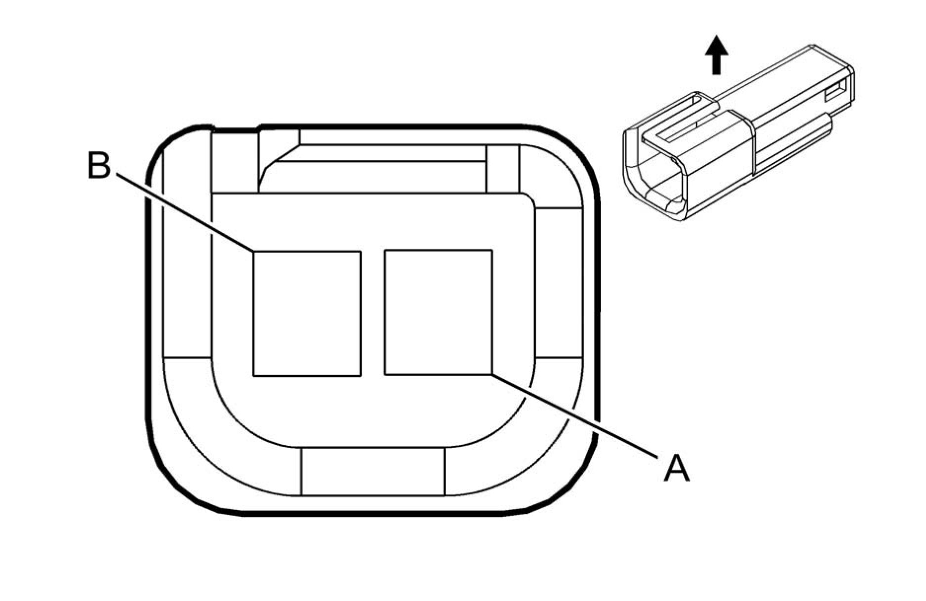 |
|
Connector Part Information |
• Harness Type: Headliner
• OEM Connector: 12047663
• Service Connector: 13584278
• Description: 2-Way M 150 Metri-Pack Series (BK)
|
Terminal Part Information | ||||||||||||||||
|
| |||||||||||||||||||||
|
B26 CRANKSHAFT POSITION SENSOR |

Connector Part Information
• Harness Type: Engine
• OEM Connector: 2098541-5
• Service Connector: 19329387
• Description: 3-Way F 1.2 MCP Series, Sealed (BN)
|
Terminal Part Information | ||||||||||||||||
|
| ||||||||||||||||||||||||||||
|
B30 HYBRID/EV BATTERY PACK CURRENT SENSOR |

Connector Part Information
• Harness Type: Auxiliary Battery Cable
• OEM Connector: 33124854
• Service Connector: Service by Harness - See Part Catalog
• Description: 4-Way F 1.2 Series (BK)
|
Terminal Part Information | ||||||||||||||||
|
| |||||||||||||||||||||||||||||||||||
|
B32A HYBRID/EV BATTERY TEMPERATURE SENSOR 1 |

Connector Part Information
• Harness Type: Auxiliary Battery Cable
• OEM Connector: 33148040
• Service Connector: Service by Harness - See Part Catalog
• Description: 2-Way F 1.2 Series (BK)
|
Terminal Part Information | ||||||||||||||||
|
| |||||||||||||||||||||
|
B32B HYBRID/EV BATTERY TEMPERATURE SENSOR 2 |

Connector Part Information
• Harness Type: Auxiliary Battery Cable
• OEM Connector: 33148040
• Service Connector: Service by Harness - See Part Catalog
• Description: 2-Way F 1.2 Series (BK)
|
Terminal Part Information | ||||||||||||||||
|
| |||||||||||||||||||||
|
B32C HYBRID/EV BATTERY TEMPERATURE SENSOR 3 |

Connector Part Information
• Harness Type: Auxiliary Battery Cable
• OEM Connector: 33148040
• Service Connector: Service by Harness - See Part Catalog
• Description: 2-Way F 1.2 Series (BK)
|
Terminal Part Information | ||||||||||||||||
|
| |||||||||||||||||||||
|
B32D HYBRID/EV BATTERY TEMPERATURE SENSOR 4 |

Connector Part Information
• Harness Type: Auxiliary Battery Cable
• OEM Connector: 33148040
• Service Connector: Service by Harness - See Part Catalog
• Description: 2-Way F 1.2 Series (BK)
|
Terminal Part Information | ||||||||||||||||
|
| |||||||||||||||||||||
|
B32E HYBRID/EV BATTERY TEMPERATURE SENSOR 5 |

Connector Part Information
• Harness Type: Auxiliary Battery Cable
• OEM Connector: 33148040
• Service Connector: Service by Harness - See Part Catalog
• Description: 2-Way F 1.2 Series (BK)
|
Terminal Part Information | ||||||||||||||||
|
| |||||||||||||||||||||
|
B32F HYBRID/EV BATTERY TEMPERATURE SENSOR 6 |

Connector Part Information
• Harness Type: Auxiliary Battery Cable
• OEM Connector: 33148040
• Service Connector: Service by Harness - See Part Catalog
• Description: 2-Way F 1.2 Series (BK)
|
Terminal Part Information | ||||||||||||||||
|
| |||||||||||||||||||||
|
B34 ENGINE COOLANT TEMPERATURE SENSOR |

Connector Part Information
• Harness Type: Engine
• OEM Connector: 13503566
• Service Connector: Service by Harness - See Part Catalog
• Description: 2-Way F 1.2 Multilock Series, Sealed (BK)
|
Terminal Part Information | ||||||||||||||||
|
| |||||||||||||||||||||
|
B37B ENGINE OIL PRESSURE SENSOR |
 |
|
Connector Part Information |
• Harness Type: Engine
• OEM Connector: 13503573
• Service Connector: Service by Harness - See Part Catalog
• Description: 3-Way F 1.2 Multilock Series, Sealed (BK)
|
Terminal Part Information | ||||||||||||||||
|
| ||||||||||||||||||||||||||||
|
B47 FUEL PRESSURE SENSOR |

Connector Part Information
• Harness Type: Body
• OEM Connector: 13511131
• Service Connector: 19168035
• Description: 3-Way F 150 GT Series, Sealed (BK)
|
Terminal Part Information | ||||||||||||||||
|
| ||||||||||||||||||||||||||||
|
B52A HEATED OXYGEN SENSOR 1 |

Connector Part Information
• Harness Type: Engine
• OEM Connector: 10010348
• Service Connector: 19301716
• Description: 4-Way F 1.2 Multilock Series, Sealed (D-GY)
|
Terminal Part Information | ||||||||||||||||
|
| |||||||||||||||||||||||||||||||||||
|
B52B HEATED OXYGEN SENSOR 2 |

Connector Part Information
• Harness Type: Engine
• OEM Connector: 10010348
• Service Connector: 19301716
• Description: 4-Way F 1.2 Multilock Series, Sealed (D-GY)
|
Terminal Part Information | ||||||||||||||||
|
| |||||||||||||||||||||||||||||||||||
|
B55 ENGINE HOOD SWITCH |

Connector Part Information
• Harness Type: Forward Lamp
• OEM Connector: 13519047
• Service Connector: 13580871
• Description: 3-Way F 150 GT Series, Sealed (BK)
|
Terminal Part Information | ||||||||||||||||
|
| ||||||||||||||||||||||||||||
|
B59L FRONT IMPACT SENSOR - LEFT |

Connector Part Information
• Harness Type: Body
• OEM Connector: 54390242
• Service Connector: 13585852
• Description: 2-Way F 0.64 Series, Sealed (D-GY)
|
Terminal Part Information | ||||||||||||||||
|
| |||||||||||||||||||||
|
B59R FRONT IMPACT SENSOR - RIGHT |

Connector Part Information
• Harness Type: Body
• OEM Connector: 54390242
• Service Connector: 13585852
• Description: 2-Way F 0.64 Series, Sealed (D-GY)
|
Terminal Part Information | ||||||||||||||||
|
| |||||||||||||||||||||
|
B63LF SIDE IMPACT SENSOR - LEFT FRONT |

Connector Part Information
• Harness Type: Driver Door
• OEM Connector: 54390240
• Service Connector: Service by Harness - See Part Catalog
• Description: 2-Way F 0.64 Series, Sealed (L-GY)
|
Terminal Part Information | ||||||||||||||||
|
| |||||||||||||||||||||
|
B63LR SIDE IMPACT SENSOR - LEFT REAR |

Connector Part Information
• Harness Type: Body
• OEM Connector: 54390242
• Service Connector: 13585852
• Description: 2-Way F 0.64 Series, Sealed (D-GY)
|
Terminal Part Information | ||||||||||||||||
|
| |||||||||||||||||||||
|
B63RF SIDE IMPACT SENSOR - RIGHT FRONT |

Connector Part Information
• Harness Type: Passenger Door
• OEM Connector: 54390240
• Service Connector: Service by Harness - See Part Catalog
• Description: 2-Way F 0.64 Series, Sealed (L-GY)
|
Terminal Part Information | ||||||||||||||||
|
| |||||||||||||||||||||
|
B63RR SIDE IMPACT SENSOR - RIGHT REAR |

Connector Part Information
• Harness Type: Body
• OEM Connector: 54390242
• Service Connector: 13585852
• Description: 2-Way F 0.64 Series, Sealed (D-GY)
|
Terminal Part Information | ||||||||||||||||
|
| |||||||||||||||||||||
|
B68 KNOCK SENSOR |

Connector Part Information
• Harness Type: Engine
• OEM Connector: 13583154
• Service Connector: Service by Harness - See Part Catalog
• Description: 2-Way F 150 MX Series, Sealed (BK)
|
Terminal Part Information | ||||||||||||||||
|
| |||||||||||||||||||||
|
B74 MANIFOLD ABSOLUTE PRESSURE SENSOR |

Connector Part Information
• Harness Type: Engine
• OEM Connector: 13503570
• Service Connector: 19299690
• Description: 3-Way F 1.2 Multilock Series, Sealed (BK)
|
Terminal Part Information | ||||||||||||||||
|
| ||||||||||||||||||||||||||||
|
B75C MULTIFUNCTION INTAKE AIR SENSOR |
 |
|
Connector Part Information |
• Harness Type: Engine
• OEM Connector: ATSSPB-C08C-1AK
• Service Connector: 13583440
• Description: 8-Way F 0.64 Series, Sealed (BK)
|
Terminal Part Information | ||||||||||||||||
|
|
Pin |
Size |
Color |
Circuit |
Function |
Terminal |
Option |
|
1 |
0.5 |
WH/BU |
6289 |
Induction Air Temperature Sensor |
I |
- |
|
2 |
0.5 |
WH/RD |
3201 |
Throttle Inlet Absolute Pressure |
I |
- |
|
3 |
0.5 |
BK/WH |
2051 |
Signal Ground |
I |
- |
|
4 |
0.5 |
YE/WH |
3200 |
Throttle Inlet Absolute Pressure |
I |
- |
|
5 |
0.5 |
VT/BU |
5294 |
Powertrain Main Relay Fused |
I |
- |
|
6 |
0.5 |
GN/WH |
492 |
Mass Air Flow Sensor Signal |
I |
- |
|
7 |
0.5 |
BK/WH |
151 |
Signal Ground |
I |
- |
| ||||||||||||||
|
B81B PARK POSITION SWITCH |
Connector Part Information
• Harness Type: Shift Lock
• OEM Connector: Not Available
• Service Connector: Service by Harness - See Part Catalog
• Description: 2-Way
|
Terminal Part Information | ||||||||||||||||
|
| |||||||||||||||||||||
|
B87 REARVIEW CAMERA |
 |
|
Connector Part Information |
• Harness Type: Rear Lamp
• OEM Connector: SRVWSB-05-AH
• Service Connector: Service by Harness - See Part Catalog
• Description: 5-Way M 1.2 Series, Sealed (L-GY)
|
Terminal Part Information | ||||||||||||||||
|
| ||||||||||||||||||||||||||||||||||||||||||
|
B88D SEAT BELT SWITCH - DRIVER |

Connector Part Information
• Harness Type: Seats
• OEM Connector: 1563189-1
• Service Connector: Service by Harness - See Part Catalog
• Description: 2-Way F 1.6 Timer Series (BK)
|
Terminal Part Information | ||||||||||||||||
|
| |||||||||||||||||||||
|
B88P SEAT BELT SWITCH - PASSENGER |

Connector Part Information
• Harness Type: Seats
• OEM Connector: 1563189-1
• Service Connector: Service by Harness - See Part Catalog
• Description: 2-Way F 1.6 Timer Series (BK)
|
Terminal Part Information | ||||||||||||||||
|
| |||||||||||||||||||||
|
B107 ACCELERATOR PEDAL POSITION SENSOR |
 |
|
Connector Part Information |
• Harness Type: Instrument Panel
• OEM Connector: 1924292-1
• Service Connector: 19330667
• Description: 6-Way F 1.2 MCP Series, Sealed (BK)
|
Terminal Part Information | ||||||||||||||||
|
|
Pin |
Size |
Color |
Circuit |
Function |
Terminal |
Option |
|
1 |
0.35 |
BN/RD |
1274 |
Accelerator Pedal Position 5 V Reference 2 |
I |
- |
|
2 |
0.35 |
WH/RD |
1164 |
Accelerator Pedal Position 5 V Reference 1 |
I |
- |
|
3 |
0.35 |
YE/WH |
1161 |
Accelerator Pedal Position Signal |
I |
- |
|
4 |
0.35 |
BK/BU |
1271 |
Accelerator Pedal Position Low |
I |
- |
|
5 |
0.35 |
BK/VT |
1272 |
Accelerator Pedal Position Low |
I |
- |
| ||||||||||||||
|
B118B WINDSHIELD WASHER FLUID LEVEL SWITCH |

Connector Part Information
• Harness Type: Forward Lamp
• OEM Connector: 7287-8378-40
• Service Connector: 13593220
• Description: 2-Way F 1.5 Series (L-GY)
|
Terminal Part Information | ||||||||||||||||
|
|
Pin |
Size |
Color |
Circuit |
Function |
Terminal |
Option |
|
1 |
0.5 |
VT |
185 |
Low Washer Fluid Indicator |
I |
- |
|
2 |
0.5 |
BK |
1050 |
Ground |
I |
- |
 |
|
Connector Part Information |
• Harness Type: Engine
• OEM Connector: 10094234
• Service Connector: 19332719
• Description: 2-Way F 1.2 Multilock Series, Sealed (BK)
|
Terminal Part Information | ||||||||||||||||
|
| |||||||||||||||||||||
|
B130B EXHAUST GAS RECIRCULATION TEMPERATURE SENSOR 2 |
 |
|
Connector Part Information |
• Harness Type: Engine
• OEM Connector: 10094234
• Service Connector: 19332719
• Description: 2-Way F 1.2 Multilock Series, Sealed (BK)
|
Terminal Part Information | ||||||||||||||||
|
| |||||||||||||||||||||
|
B150 FUEL TANK PRESSURE SENSOR |

Connector Part Information
• Harness Type: Seats
• OEM Connector: 88988721
• Service Connector: Service by Harness - See Part Catalog
• Description: 3-Way F 150 GT Series, Sealed (BK)
|
Terminal Part Information | ||||||||||||||||
|
| ||||||||||||||||||||||||||||
|
B160 WINDSHIELD TEMPERATURE AND INSIDE MOISTURE SENSOR |

|
Terminal Part Information | ||||||||||||||||
|
| |||||||||||||||||||||||||||||||||||||||||||||||||
|
B197 CHARGE PORT DOOR POSITION SWITCH |

Connector Part Information
• Harness Type: Body
• OEM Connector: 13519047
• Service Connector: 13580871
• Description: 3-Way F 150 GT Series, Sealed (BK)
|
Terminal Part Information | ||||||||||||||||
|
| ||||||||||||||||||||||||||||
|
B201 BRAKE CONTROL BRAKE PEDAL POSITION SENSOR |
 |
|
Connector Part Information |
• Harness Type: Body
• OEM Connector: 1-967640-1
• Service Connector: 13585332
• Description: 4-Way F 0.64 Micro-Quadlock Series, Sealed (BK)
|
Terminal Part Information | ||||||||||||||||
|
| |||||||||||||||||||||||||||||||||||
|
B202 HYBRID/EV ELECTRONICS COOLANT TEMPERATURE SENSOR |

Connector Part Information
• Harness Type: Cooling Fan
• OEM Connector: 10010337
• Service Connector: Service by Harness - See Part Catalog
• Description: 2-Way F 1.2 Multilock Series, Sealed (BK)
|
Terminal Part Information | ||||||||||||||||
|
| |||||||||||||||||||||
|
B203 ENGINE COOLANT RADIATOR TEMPERATURE SENSOR |

Connector Part Information
• Harness Type: Cooling Fan
• OEM Connector: 10010337
• Service Connector: Service by Harness - See Part Catalog
• Description: 2-Way F 1.2 Multilock Series, Sealed (BK)
|
Terminal Part Information | ||||||||||||||||
|
| |||||||||||||||||||||
|
B204A HYBRID/EV BATTERY PACK COOLANT TEMPERATURE SENSOR 1 |

Connector Part Information
• Harness Type: Auxiliary Battery Cable
• OEM Connector: 1-967644-1
• Service Connector: Service by Harness - See Part Catalog
• Description: 2-Way F 0.64 Micro-Quadlock Series, Sealed (BK)
|
Terminal Part Information | ||||||||||||||||
|
| |||||||||||||||||||||
|
B208 FUEL FILL DOOR STATUS SWITCH ASSEMBLY |

Connector Part Information
• Harness Type: Body
• OEM Connector: 33471-0406
• Service Connector: 13577535
• Description: 4-Way F 1.5 Series, Sealed (BK)
|
Terminal Part Information | ||||||||||||||||
|
| |||||||||||||||||||||||||||||||||||
|
B218L SIDE OBJECT SENSOR MODULE - LEFT |

Connector Part Information
• Harness Type: Rear Lamp
• OEM Connector: ATSSPB-A0805G-1AK
• Service Connector: Service by Harness - See Part Catalog
• Description: 8-Way F 0.64 Series, Sealed (BK)
|
Terminal Part Information | ||||||||||||||||
|
| |||||||||||||||||||||||||||||||||||||||||||||||||||||||||||||||
|
B218R SIDE OBJECT SENSOR MODULE - RIGHT |

Connector Part Information
• Harness Type: Rear Lamp
• OEM Connector: ATSSPB-A0805H-1AK
• Service Connector: Service by Harness - See Part Catalog
• Description: 8-Way F 0.64 Series, Sealed (BK)
|
Terminal Part Information | ||||||||||||||||
|
| ||||||||||||||||||||||||||||||||||||||||||||||||||||||||
|
B228A DRIVE MOTOR 1 POSITION SENSOR |

Connector Part Information
• Harness Type: Transmission
• OEM Connector: 33134940
• Service Connector: Service by Harness - See Part Catalog
• Description: 6-Way F 1.2 OCS Series (NA)
|
Terminal Part Information | ||||||||||||||||
|
|
Pin |
Size |
Color |
Circuit |
Function |
Terminal |
Option |
|
1 |
0.5 |
GY/WH |
7652 |
Traction Power Inverter Module Resolver 1 S3 Signal |
I |
- |
|
2 |
0.5 |
YE/BK |
7649 |
Traction Power Inverter Module Resolver 1 S1 Signal |
I |
- |
|
3 |
0.5 |
GN |
7645 |
Traction Power Inverter Module Resolver 1 Excitation Signal |
I |
- |
|
4 |
0.5 |
PK |
7648 |
Traction Power Inverter Module |
I |
- |
| |||||||||||||||||||||
|
B228B DRIVE MOTOR 2 POSITION SENSOR |

Connector Part Information
• Harness Type: Transmission
• OEM Connector: 33134940
• Service Connector: Service by Harness - See Part Catalog
• Description: 6-Way F 1.2 OCS Series (NA)
|
Terminal Part Information | ||||||||||||||||
|
|
Pin |
Size |
Color |
Circuit |
Function |
Terminal |
Option |
| |||||||||||||||||||||||||||||||||||||||||||||||||
|
B233B RADAR SENSOR MODULE - LONG RANGE |

Connector Part Information
• Harness Type: Forward Lamp
• OEM Connector: 13833301
• Service Connector: 19299773
• Description: 12-Way F 1.5 Series, Sealed (BK)
Terminal Part Information
|
Terminal |
Terminated |
Diagnostic |
Terminal |
Service |
Tray |
Core |
Insulation |
|
I |
19300649 |
J-35616-64B |
J-38125-553 |
Not |
Not |
Not |
Not |
|
Pin |
Size |
Color |
Circuit |
Function |
Terminal |
Option |
|
1 |
- |
- |
- |
Not Occupied |
- |
- |
|
2 |
0.5 |
WH |
3811 |
High Speed GMLAN Serial Data |
I |
- |
|
3 |
0.5 |
BU/VT |
3813 |
High Speed GMLAN Serial Data |
I |
- |
|
4 |
0.5 |
WH |
3811 |
High Speed GMLAN Serial Data |
I |
- |
|
5 |
0.5 |
BU/VT |
3813 |
High Speed GMLAN Serial Data |
I |
- |
|
6 |
0.35 |
GY/VT |
3808 |
Front Object Sensor Control 2 |
I |
- |
|
7 |
0.5 |
BK |
1050 |
Ground |
I |
- |
|
8 - 9 |
- |
- |
- |
Not Occupied |
- |
- |
|
10 |
0.5 |
WH |
3811 |
High Speed GMLAN Serial Data |
I |
- |
|
11 |
0.5 |
BU/VT |
3813 |
High Speed GMLAN Serial Data |
I |
- |
|
12 |
- |
- |
- |
Not Occupied |
- |
- |
|
B258 HYBRID/EV BATTERY COOLANT LEVEL SWITCH |
 |
Connector Part Information
• Harness Type: Cooling Fan
• OEM Connector: 12186685
• Service Connector: Service by Harness - See Part Catalog
• Description: 2-Way F 150 Metri-Pack Series (BK)
|
Terminal Part Information | ||||||||||||||||
|
| |||||||||||||||||||||
|
B284 VEHICLE DYNAMIC SENSOR |

Connector Part Information
• Harness Type: Body
• OEM Connector: 47715-6100
• Service Connector: 19299684
Description: 6-Way F 0.64 Series, Sealed (BK)
|
Terminal Part Information | ||||||||||||||||
|
| |||||||||||||||||||||||||||||||||||||||||||||||||
|
B305 AMBIENT LIGHT/SUNLOAD SENSOR AND BATTERY STATE OF CHARGE INDICATOR |
 |
|
Connector Part Information |
• Harness Type: Instrument Panel
• OEM Connector: 965413-1
• Service Connector: 19333315
• Description: 6-Way F 0.64 Micro-Quadlock Series (BK)
|
Terminal Part Information | ||||||||||||||||
|
| |||||||||||||||||||||||||||||||||||||||||||||||||
|
B306A PARKING ASSIST SENSOR - FRONT LEFT OUTER |
 |
|
Connector Part Information |
• Harness Type: Front Fascia
• OEM Connector: 1488991-5
• Service Connector: Service by Harness - See Part Catalog
• Description: 3-Way F 1.2 MCP Series, Sealed (BK)
|
Terminal Part Information | ||||||||||||||||
|
| ||||||||||||||||||||||||||||
|
B306B PARKING ASSIST SENSOR - FRONT LEFT MIDDLE |

Connector Part Information
• Harness Type: Front Fascia
• OEM Connector: 1488991-5
• Service Connector: Service by Harness - See Part Catalog
• Description: 3-Way F 1.2 MCP Series, Sealed (BK)
|
Terminal Part Information | ||||||||||||||||
|
| ||||||||||||||||||||||||||||
|
B306C PARKING ASSIST SENSOR - FRONT RIGHT MIDDLE |

Connector Part Information
• Harness Type: Front Fascia
• OEM Connector: 1488991-5
• Service Connector: Service by Harness - See Part Catalog
• Description: 3-Way F 1.2 MCP Series, Sealed (BK)
|
Terminal Part Information | ||||||||
|
|
Terminal |
Terminated |
Diagnostic |
Terminal |
Service |
Tray |
Core |
Insulation |
|
I |
Not Required |
J-35616-16 |
No Tool |
Not Required |
Not |
Not |
Not |
| ||||||||||||||||||||||||||||
|
B306D PARKING ASSIST SENSOR - FRONT RIGHT OUTER |
 |
|
Connector Part Information |
• Harness Type: Front Fascia
• OEM Connector: 1488991-5
• Service Connector: Service by Harness - See Part Catalog
• Description: 3-Way F 1.2 MCP Series, Sealed (BK)
|
Terminal Part Information | ||||||||||||||||
|
|
Terminal |
Terminated |
Diagnostic |
Terminal |
Service |
Tray |
Core |
Insulation |
|
(LT GN) |
Required |
Required |
Required |
Required |
| ||||||||||||||||||||||||||||
|
B306E PARKING ASSIST SENSOR - REAR LEFT OUTER |
 |
|
Connector Part Information |
• Harness Type: Rear Lamp
• OEM Connector: 1488991-5
• Service Connector: Service by Harness - See Part Catalog
• Description: 3-Way F 1.2 MCP Series, Sealed (BK)
|
Terminal Part Information | ||||||||||||||||
|
|
Terminal |
Terminated |
Diagnostic |
Terminal |
Service |
Tray |
Core |
Insulation |
|
(LT GN) |
Required |
Required |
Required |
Required |
| ||||||||||||||||||||||||||||
|
B306F PARKING ASSIST SENSOR - REAR LEFT MIDDLE |
 |
|
Connector Part Information |
• Harness Type: Rear Lamp
• OEM Connector: 1488991-5
• Service Connector: Service by Harness - See Part Catalog
• Description: 3-Way F 1.2 MCP Series, Sealed (BK)
|
Terminal Part Information | ||||||||||||||||
|
| ||||||||||||||||||||||||||||
|
B306G PARKING ASSIST SENSOR - REAR RIGHT MIDDLE |
 |
|
Connector Part Information |
• Harness Type: Rear Lamp
• OEM Connector: 1488991-5
• Service Connector: Service by Harness - See Part Catalog
• Description: 3-Way F 1.2 MCP Series, Sealed (BK)
|
Terminal Part Information | ||||||||||||||||
|
|
Pin |
Size |
Color |
Circuit |
Function |
Terminal |
Option |
|
1 |
0.5 |
RD/VT |
5974 |
Park Assist Sensor Control Park |
I |
- |
| |||||||||||||||||||||
|
B306H PARKING ASSIST SENSOR - REAR RIGHT OUTER |
 |
|
Connector Part Information |
• Harness Type: Rear Lamp
• OEM Connector: 1488991-5
• Service Connector: Service by Harness - See Part Catalog
• Description: 3-Way F 1.2 MCP Series, Sealed (BK)
|
Terminal Part Information | ||||||||||||||||
|
|
Pin |
Size |
Color |
Circuit |
Function |
Terminal |
Option |
|
1 |
0.5 |
RD/VT |
5974 |
Park Assist Sensor Control Park |
I |
- |
|
2 |
0.5 |
YE/VT |
2378 |
Right Rear Corner Object Sensor |
I |
- |
| ||||||||||||||
|
B306K PARKING ASSIST SENSOR - SIDE LEFT FRONT |
 |
|
Connector Part Information |
• Harness Type: Front Fascia
• OEM Connector: 1488991-6
• Service Connector: Service by Harness - See Part Catalog
• Description: 3-Way F 1.2 MCP Series, Sealed (NA)
|
Terminal Part Information | ||||||||||||||||
|
|
Pin |
Size |
Color |
Circuit |
Function |
Terminal |
Option |
|
1 |
0.5 |
RD/BU |
5974 |
Park Assist Sensor Control Park |
I |
- |
|
2 |
0.5 |
GY |
3154 |
Left Front Supplemental Object |
I |
- |
|
3 |
0.5 |
BK/BU |
5214 |
Front Parking Sensor Low |
I |
- |

Connector Part Information
• Harness Type: Front Fascia
• OEM Connector: 1488991-6
• Service Connector: Service by Harness - See Part Catalog
• Description: 3-Way F 1.2 MCP Series, Sealed (NA)
|
Terminal Part Information | ||||||||||||||||
|
|
Pin |
Size |
Color |
Circuit |
Function |
Terminal |
Option |
|
1 |
0.5 |
RD/BU |
5974 |
Park Assist Sensor Control Park |
I |
- |
|
2 |
0.5 |
GN |
3155 |
Right Front Supplemental Object |
I |
- |
|
3 |
0.5 |
BK/BU |
5214 |
Front Parking Sensor Low |
I |
- |
Article GUID: A00884629
COMPONENT CONNECTOR END VIEWS
B310 FUEL PRESSURE/TEMPERATURE SENSOR
 |
|
Connector Part Information |
• Harness Type: Engine
• OEM Connector: 13503573
• Service Connector: Service by Harness - See Part Catalog
• Description: 3-Way F 1.2 Multilock Series, Sealed (BK)
|
Terminal Part Information | ||||||||||||||||
|
|
Pin |
Size |
Color |
Circuit |
Function |
Terminal |
Option |
|
1 |
0.5 |
BK/GN |
2919 |
Fuel Rail Pressure Sensor Low |
I |
- |
| |||||||||||||||||||||
|
C1 BATTERY |
Connector Part Information
• Harness Type: Negative Battery Cable
• OEM Connector: 13574943
• Service Connector: Service by Cable Assembly - See Part Catalog
• Description: Ring Terminal 1-Way
|
Terminal Part Information | ||||||||||||||||
|
| |||||||||||||||||||
|
C5A HYBRID/EV BATTERY MODULE 1 |
 |
|
Connector Part Information |
• Harness Type: Auxiliary Battery Cable
• OEM Connector: 33201128
• Service Connector: Service by Harness - See Part Catalog
• Description: 18-Way F 1.2 Multilock Series (OG)
|
Terminal Part Information | ||||||||||||||||
|
|
Pin |
Size |
Color |
Circuit |
Function |
Terminal |
Option |
|
1 |
0.35 |
BK/VT |
5403 |
Battery Pack Monitor Low |
I |
- |
|
2 |
0.35 |
YE/VT |
5394 |
Battery Voltage Signal 2 |
I |
- |
|
3 |
0.35 |
GY/YE |
5396 |
Battery Voltage Signal 4 |
I |
- |
|
4 |
0.35 |
GN |
5398 |
Battery Voltage Signal 6 |
I |
- |
|
5 |
0.35 |
BU |
5400 |
Battery Voltage Signal 8 |
I |
- |
|
6 |
0.35 |
BU/GY |
5392 |
Battery Voltage Signal 10 |
I |
- |
|
7 |
0.35 |
BN |
5571 |
Battery Voltage Signal 12 |
I |
- |
|
8 |
0.35 |
YE |
5573 |
Battery Voltage Signal 14 |
I |
- |
|
9 |
0.35 |
BN/WH |
5575 |
Battery Voltage Signal 16 |
I |
- |
| ||||||||||||||||||||||||||||||||||||||||||||||||||||||||||||||||||||||
|
C5B HYBRID/EV BATTERY MODULE 2 |
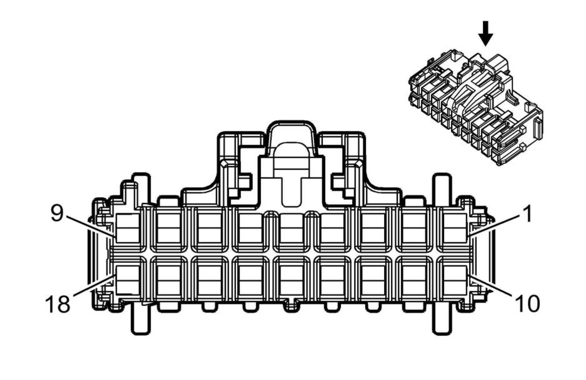 |
|
Connector Part Information |
• Harness Type: Auxiliary Battery Cable
• OEM Connector: 33201128
• Service Connector: Service by Harness - See Part Catalog
• Description: 18-Way F 1.2 Multilock Series (OG)
|
Terminal Part Information | ||||||||||||||||
|
| ||||||||||||||||||||||||||||||||||||||||||||||||||||||||||||||||||||||||||||||||||||||||||||||||||||||||||||||||
|
C5C HYBRID/EV BATTERY MODULE 3 |
 |
|
Connector Part Information |
• Harness Type: Auxiliary Battery Cable
• OEM Connector: 33201128
• Service Connector: Service by Harness - See Part Catalog
• Description: 18-Way F 1.2 Multilock Series (OG)
|
Terminal Part Information | ||||||||||||||||
|
| |||||||||||||||||||||||||||||||||||||||||||||||||||||||||||||||||||||||||||||||||||||||||||||||||||||||||||||||||||||||||||||||||||||
|
C5D HYBRID/EV BATTERY MODULE 4 |
 |
|
Connector Part Information |
• Harness Type: Auxiliary Battery Cable
• OEM Connector: 33201128
• Service Connector: Service by Harness - See Part Catalog
• Description: 18-Way F 1.2 Multilock Series (OG)
|
Terminal Part Information | ||||||||||||||||
|
|
Pin |
Size |
Color |
Circuit |
Function |
Terminal |
Option |
|
1 |
0.35 |
GN/BK |
4525 |
Battery Cell Voltage Signal 44 |
I |
- |
|
2 |
0.35 |
GN/GY |
4527 |
Battery Cell Voltage Signal 46 |
I |
- |
|
3 |
0.35 |
YE/GY |
4529 |
Battery Cell Voltage Signal 48 |
I |
- |
|
4 |
0.35 |
WH/BK |
4531 |
Battery Cell Voltage Signal 50 |
I |
- |
|
5 |
0.35 |
BU/YE |
4533 |
Battery Cell Voltage Signal 52 |
I |
- |
|
6 |
0.35 |
GN/VT |
4536 |
Battery Cell Voltage Signal 54 |
I |
- |
|
7 |
0.35 |
YE/BK |
4538 |
Battery Cell Voltage Signal 56 |
I |
- |
|
8 - 9 |
- |
- |
- |
Not Occupied |
- |
- |
|
10 |
0.35 |
BU/GY |
4526 |
Battery Cell Voltage Signal 45 |
I |
- |
|
11 |
0.35 |
BN |
4528 |
Battery Cell Voltage Signal 47 |
I |
- |
| ||||||||||||||||||||||||||||||||||||||||||
|
C5E HYBRID/EV BATTERY MODULE 5 |
 |
|
Connector Part Information |
• Harness Type: Auxiliary Battery Cable
• OEM Connector: 33201128
• Service Connector: Service by Harness - See Part Catalog
• Description: 18-Way F 1.2 Multilock Series (OG)
|
Terminal Part Information | ||||||||||||||||
|
|
Pin |
Size |
Color |
Circuit |
Function |
Terminal |
Option |
|
1 |
0.35 |
YE/BK |
4538 |
Battery Cell Voltage Signal 56 |
I |
- |
| ||||||||||||||||||||||||||||||||||||||||||||||||||||||||||||||||||||||||||||||||||||||||||||||||||||||||||||||||||||||||||||||
|
C5F HYBRID/EV BATTERY MODULE 6 |
 |
|
Connector Part Information |
• Harness Type: Auxiliary Battery Cable
• OEM Connector: 33201128
• Service Connector: Service by Harness - See Part Catalog
Description: 18-Way F 1.2 Multilock Series (OG)
|
Terminal Part Information | ||||||||||||||||
|
| ||||||||||||||||||||||||||||||||||||||||||||||||||||||||||||||||||||||||||||||||||||||||||||||||||||||||||||||||
|
C5G HYBRID/EV BATTERY MODULE 7 |
 |
|
Connector Part Information |
• Harness Type: Auxiliary Battery Cable
• OEM Connector: 33201128
• Service Connector: Service by Harness - See Part Catalog
• Description: 18-Way F 1.2 Multilock Series (OG)
|
Terminal Part Information | ||||||||||||||||
|
|
Pin |
Size |
Color |
Circuit |
Function |
Terminal |
Option |
|
1 |
0.35 |
YE/GY |
4573 |
Battery Cell Voltage Signal 84 |
I |
- |
|
2 |
0.35 |
WH/BK |
4575 |
Battery Cell Voltage Signal 86 |
I |
- |
|
3 |
0.35 |
BU/YE |
4577 |
Battery Cell Voltage Signal 88 |
I |
- |
|
4 |
0.35 |
WH/BU |
2390 |
Battery Cell Voltage Signal 90 |
I |
- |
|
5 |
0.35 |
BU/BK |
2392 |
Battery Cell Voltage Signal 92 |
I |
- |
|
6 |
0.35 |
GN/BK |
2394 |
Battery Cell Voltage Signal 94 |
I |
- |
|
7 |
0.35 |
GY/YE |
2396 |
Battery Cell Voltage Signal 96 |
I |
- |
|
8 - 9 |
- |
- |
- |
Not Occupied |
- |
- |
|
10 |
0.35 |
YE |
4574 |
Battery Cell Voltage Signal 85 |
I |
- |
|
11 |
0.35 |
BN/WH |
4576 |
Battery Cell Voltage Signal 87 |
I |
- |
| ||||||||||||||||||||||||||||||||||||||||||
|
E1D ACCENT LAMP - DRIVER DOOR |

Connector Part Information
• Harness Type: Driver Door Trim
• OEM Connector: 6098-7685
• Service Connector: Service by Harness - See Part Catalog
• Description: 2-Way F 1.2 Series (BK)
|
Terminal Part Information | ||||||||||||||||
|
|
Pin |
Size |
Color |
Circuit |
Function |
Terminal |
Option |
|
1 |
0.5 |
BK |
1550 |
Ground |
I |
- |
| ||||||||||||||
|
E1P ACCENT LAMP - PASSENGER DOOR |
 |
|
Connector Part Information |
• Harness Type: Passenger Door Trim
• OEM Connector: 6098-7685
• Service Connector: Service by Harness - See Part Catalog
• Description: 2-Way F 1.2 Series (BK)
|
Terminal Part Information | ||||||||||||||||
|
|
Pin |
Size |
Color |
Circuit |
Function |
Terminal |
Option |
|
1 |
0.5 |
BK |
2050 |
Ground |
I |
- |
|
2 |
0.5 |
WH/YE |
7557 |
LED Ambient Lighting Control |
I |
- |
Connector Part Information
• Harness Type: Headlamp
• OEM Connector: Not Available
• Service Connector: Service by Harness - See Part Catalog
• Description: 2-Way
|
Terminal Part Information | ||||||||||||||||
|
| |||||||||||||||||||||
|
E2RF SIDE MARKER LAMP - RIGHT FRONT |
Connector Part Information
• Harness Type: Headlamp
• OEM Connector: Not Available
• Service Connector: Service by Harness - See Part Catalog
• Description: 2-Way
|
Terminal Part Information | ||||||||||||||||
|
| |||||||||||||||||||||
|
E4AC PARK/DAYTIME RUNNING LAMP - LEFT |

Connector Part Information
• Harness Type: Front Fascia
• OEM Connector: 33471-0306
• Service Connector: Service by Harness - See Part Catalog
• Description: 3-Way F 1.5 Series, Sealed (BK)
|
Terminal Part Information | ||||||||||||||||
|
| ||||||||||||||||||||||||||||
|
E4AD PARK/DAYTIME RUNNING LAMP - RIGHT |

Connector Part Information
• Harness Type: Front Fascia
• OEM Connector: 33471-0306
• Service Connector: Service by Harness - See Part Catalog
• Description: 3-Way F 1.5 Series, Sealed (BK)
|
Terminal Part Information | ||||||||||||||||
|
| ||||||||||||||||||||||||||||
|
E4E HEADLAMP - LEFT HIGH BEAM |

Connector Part Information
• Harness Type: Headlamp
• OEM Connector: 12059183
• Service Connector: Service by Harness - See Part Catalog
• Description: 2-Way F 280 Metri-Pack Series, Sealed (BK)
|
Terminal Part Information | ||||||||||||||||
|
| |||||||||||||||||||||
|
E4F HEADLAMP - RIGHT HIGH BEAM |

Connector Part Information
• Harness Type: Headlamp
• OEM Connector: 12059183
• Service Connector: Service by Harness - See Part Catalog
• Description: 2-Way F 280 Metri-Pack Series, Sealed (BK)
|
Terminal Part Information | ||||||||||||||||
|
| |||||||||||||||||||||
|
E4G HEADLAMP - LEFT LOW BEAM |
Connector Part Information
• Harness Type: Headlamp
• OEM Connector: Not Available
• Service Connector: Service by Harness - See Part Catalog
• Description: 4-Way
|
Terminal Part Information | ||||||||||||||||
|
| |||||||||||||||||||||||||||||||||||
|
E4H HEADLAMP - RIGHT LOW BEAM |
Connector Part Information
• Harness Type: Headlamp
• OEM Connector: Not Available
• Service Connector: Service by Harness - See Part Catalog
• Description: 4-Way
|
Terminal Part Information | ||||||||||||||||
|
| |||||||||||||||||||||||||||||||||||
|
E4LF TURN SIGNAL LAMP - LEFT FRONT |
Connector Part Information
• Harness Type: Headlamp
• OEM Connector: Not Available
• Service Connector: Service by Harness - See Part Catalog
• Description: 2-Way
|
Terminal Part Information | ||||||||||||||||
|
| |||||||||||||||||||||
|
E4LR TURN SIGNAL LAMP - LEFT REAR |
Connector Part Information
• Harness Type: Tail Lamp
• OEM Connector: Not Available
• Service Connector: Service by Harness - See Part Catalog
• Description: 2-Way
|
Terminal Part Information | ||||||||||||||||
|
| |||||||||||||||||||||
|
E4RF TURN SIGNAL LAMP - RIGHT FRONT |
Connector Part Information
• Harness Type: Headlamp
• OEM Connector: Not Available
• Service Connector: Service by Harness - See Part Catalog
• Description: 2-Way
|
Terminal Part Information | ||||||||||||||||
|
| |||||||||||||||||||||
|
E4RR TURN SIGNAL LAMP - RIGHT REAR |
Connector Part Information
• Harness Type: Tail Lamp
• OEM Connector: Not Available
• Service Connector: Service by Harness - See Part Catalog
• Description: 2-Way
|
Terminal Part Information | ||||||||||||||||
|
| |||||||||||||||||||||
|
E5A BACKUP LAMP - LEFT |
Connector Part Information
• Harness Type: Tail Lamp
• OEM Connector: Not Available
• Service Connector: Service by Harness - See Part Catalog
• Description: 2-Way
|
Terminal Part Information | ||||||||||||||||
|
| |||||||||||||||||||||
|
E5B BACKUP LAMP - RIGHT |
Connector Part Information
• Harness Type: Tail Lamp
• OEM Connector: Not Available
• Service Connector: Service by Harness - See Part Catalog
• Description: 2-Way
|
Terminal Part Information | ||||||||||||||||
|
| |||||||||||||||||||||
|
E5L STOP LAMP - LEFT |
Connector Part Information
• Harness Type: Tail Lamp
• OEM Connector: Not Available
• Service Connector: Service by Harness - See Part Catalog
• Description: 2-Way
|
Terminal Part Information | ||||||||||||||||
|
| |||||||||||||||||||||
|
E5R STOP LAMP - RIGHT |
Connector Part Information
• Harness Type: Tail Lamp
• OEM Connector: Not Available
• Service Connector: Service by Harness - See Part Catalog
• Description: 2-Way
|
Terminal Part Information | ||||||||||||||||
|
| |||||||||||||||||||||
|
E6 CENTER HIGH MOUNTED STOP LAMP |

Connector Part Information
• Harness Type: Liftgate
• OEM Connector: 33471-0206
• Service Connector: Service by Harness - See Part Catalog
• Description: 2-Way F 1.5 Series, Sealed (BK)
|
Terminal Part Information | ||||||||||||||||
|
| |||||||||||||||||||||
|
E7L LICENSE PLATE LAMP - LEFT |

Connector Part Information
• Harness Type: Rear Lamp
• OEM Connector: 15344089
• Service Connector: Service by Harness - See Part Catalog
• Description: 2-Way F 150 GT Series, Sealed (WH)
|
Terminal Part Information | ||||||||||||||||
|
| |||||||||||||||||||||
|
E7R LICENSE PLATE LAMP - RIGHT |

Connector Part Information
• Harness Type: Rear Lamp
• OEM Connector: 15344089
• Service Connector: Service by Harness - See Part Catalog
• Description: 2-Way F 150 GT Series, Sealed (WH)
|
Terminal Part Information | ||||||||||||||||
|
| |||||||||||||||||||||
|
E14A SEAT HEATING ELEMENT - DRIVER BACK |
 |
|
Connector Part Information |
• Harness Type: Seat
• OEM Connector: 6098-7781
• Service Connector: Service by Harness - See Part Catalog
• Description: 4-Way M 1.2 Series (GY)
|
Terminal Part Information | ||||||||||||||||
|
| |||||||||||||||||||||||||||||||||||
|
E14B SEAT HEATING ELEMENT - DRIVER CUSHION |
 |
|
Connector Part Information |
• Harness Type: Seats
• OEM Connector: 6098-7779
• Service Connector: Service by Harness - See Part Catalog
• Description: 4-Way M 1.2 Series (BK)
|
Terminal Part Information | ||||||||||||||||
|
| |||||||||||||||||||||||||||||||||||
|
E14C SEAT HEATING ELEMENT - PASSENGER BACK |
 |
|
Connector Part Information |
• Harness Type: Seats
• OEM Connector: 6098-7781
• Service Connector: Service by Harness - See Part Catalog
• Description: 4-Way M 1.2 Series (GY)
|
Terminal Part Information | ||||||||||||||||
|
| |||||||||||||||||||||||||||||||||||
|
E14D SEAT HEATING ELEMENT - PASSENGER CUSHION |
 |
|
Connector Part Information |
• Harness Type: Seats
• OEM Connector: 6098-7779
• Service Connector: Service by Harness - See Part Catalog
• Description: 4-Way M 1.2 Series (BK)
|
Terminal Part Information | ||||||||||||||||
|
| |||||||||||||||||||||||||||||||||||
|
E14F SEAT HEATING ELEMENT - LEFT REAR CUSHION |
 |
|
Connector Part Information |
• Harness Type: Seats
• OEM Connector: 6098-7779
• Service Connector: Service by Harness - See Part Catalog
• Description: 4-Way M 1.2 Series (BK)
|
Terminal Part Information | ||||||||||||||||
|
| |||||||||||||||||||||||||||||||||||
|
E14H SEAT HEATING ELEMENT - RIGHT REAR CUSHION |
 |
|
Connector Part Information |
• Harness Type: Seats
• OEM Connector: 6098-7781
• Service Connector: Service by Harness - See Part Catalog
• Description: 4-Way M 1.2 Series (GY)
|
Terminal Part Information | ||||||||||||||||
|
| |||||||||||||||||||||||||||||||||||
|
E17D OUTSIDE REARVIEW MIRROR GLASS - DRIVER X1 |

Connector Part Information
• Harness Type: Outside Rearview Mirror - Driver
• OEM Connector: 9-520272-2
• Service Connector: Service by Harness - See Part Catalog
• Description: 1-Way
|
Terminal Part Information | ||||||||||||||||
|
| ||||||||||||||
|
E17D OUTSIDE REARVIEW MIRROR GLASS - DRIVER X2 |

Connector Part Information
• Harness Type: Outside Rearview Mirror - Driver
• OEM Connector: 9-520272-2
• Service Connector: Service by Harness - See Part Catalog
• Description: 1-Way
|
Terminal Part Information | ||||||||||||||||
|
| ||||||||||||||
|
E17P OUTSIDE REARVIEW MIRROR GLASS - PASSENGER X1 |

Connector Part Information
• Harness Type: Outside Rearview Mirror - Passenger
• OEM Connector: 9-520272-2
• Service Connector: Service by Harness - See Part Catalog
• Description: 1-Way
|
Terminal Part Information | ||||||||||||||||
|
| ||||||||||||||
|
E17P OUTSIDE REARVIEW MIRROR GLASS - PASSENGER X2 |
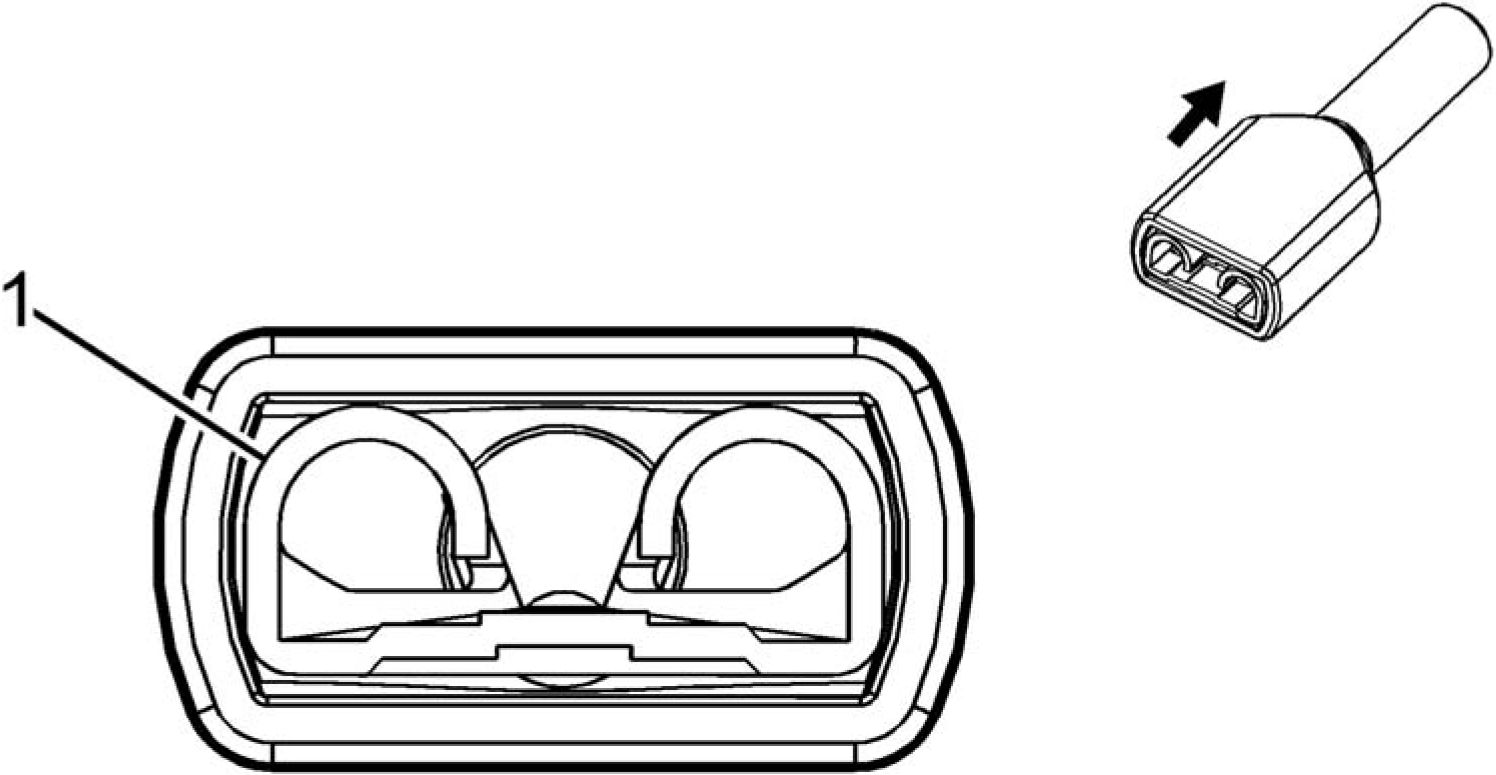
Connector Part Information
• Harness Type: Outside Rearview Mirror - Passenger
• OEM Connector: 9-520272-2
• Service Connector: Service by Harness - See Part Catalog
• Description: 1-Way
|
Terminal Part Information | ||||||||||||||||
|
| ||||||||||||||
|
E18 REAR DEFOGGER GRID X1 |

Connector Part Information
• Harness Type: Liftgate
• OEM Connector: 7286-9357-30
• Service Connector: Service by Harness - See Part Catalog
• Description: 1-Way M 6.3 Series (BK)
|
Terminal Part Information | ||||||||||||||||
|
| ||||||||||||||
|
E18 REAR DEFOGGER GRID X2 |

Connector Part Information
• Harness Type: Liftgate
• OEM Connector: 7286-9357-30
• Service Connector: Service by Harness - See Part Catalog
• Description: 1-Way M 6.3 Series (BK)
|
Terminal Part Information | ||||||||||||||||
|
| ||||||||||||||
|
E31L SUNSHADE MIRROR LAMP - LEFT |
 |
|
Connector Part Information |
• Harness Type: Headliner
• OEM Connector: 12047663
• Service Connector: 13584278
• Description: 2-Way M 150 Metri-Pack Series (BK)
|
Terminal Part Information | ||||||||||||||||
|
| |||||||||||||||||||||
|
E31R SUNSHADE MIRROR LAMP - RIGHT |
 |
|
Connector Part Information |
• Harness Type: Headliner
• OEM Connector: 12047663
• Service Connector: 13584278
• Description: 2-Way M 150 Metri-Pack Series (BK)
|
Terminal Part Information | ||||||||||||||||
|
| |||||||||||||||||||||
|
E33 CARGO LAMP |
 |
|
Connector Part Information |
• Harness Type: Liftgate
• OEM Connector: 6098-5510
• Service Connector: Service by Harness - See Part Catalog
• Description: 2-Way F 1.5 Series (BK)
|
Terminal Part Information | ||||||||||||||||
|
| |||||||||||||||||||||
|
E37R DOME/READING LAMPS - REAR |
 |
|
Connector Part Information |
• Harness Type: Headliner
• OEM Connector: 12092162
• Service Connector: 15306021
• Description: 4-Way F 150 Metri-Pack Series (BK)
|
Terminal Part Information | ||||||||||||||||
|
| |||||||||||||||||||||||||||||||||||
|
E41 ENGINE COOLANT THERMOSTAT HEATER |
 |
|
Connector Part Information |
• Harness Type: Engine
• OEM Connector: 33471-0206
• Service Connector: 13577534
• Description: 2-Way F 1.5 Series, Sealed (BK)
|
Terminal Part Information | ||||||||||||||||
|
| |||||||||||||||||||||
|
E42L TAIL LAMP ASSEMBLY - LEFT |
 |
|
Connector Part Information |
• Harness Type: Body
• OEM Connector: 33472-0606
• Service Connector: 13585853
• Description: 6-Way F 150 MX Series, Sealed (BK)
|
Terminal Part Information | ||||||||||||||||
|
| |||||||||||||||||||||||||||||||||||||||||||||||||
|
E42R TAIL LAMP ASSEMBLY - RIGHT |
 |
|
Connector Part Information |
• Harness Type: Body
• OEM Connector: 33472-0606
• Service Connector: 13585853
• Description: 6-Way F 150 MX Series, Sealed (BK)
|
Terminal Part Information | ||||||||||||||||
|
| |||||||||||||||||||||||||||||||||||||||||||||||||
|
E63D FLOOD LAMP - DRIVER DOOR HANDLE |

Connector Part Information
• Harness Type: Driver Door Trim
• OEM Connector: 1563189-1
• Service Connector: Service by Harness - See Part Catalog
• Description: 2-Way F 1.6 Timer Series (BK)
|
Terminal Part Information | ||||||||||||||||
|
| |||||||||||||||||||||
|
E63LR FLOOD LAMP - LEFT REAR DOOR HANDLE |

Connector Part Information
• Harness Type: Left Rear Door
• OEM Connector: 1563189-1
• Service Connector: Service by Harness - See Part Catalog
• Description: 2-Way F 1.6 Timer Series (BK)
|
Terminal Part Information | ||||||||||||||||
|
| |||||||||||||||||||||
|
E63P FLOOD LAMP - PASSENGER DOOR HANDLE |

Connector Part Information
• Harness Type: Passenger Door Trim
• OEM Connector: 1563189-1
• Service Connector: Service by Harness - See Part Catalog
• Description: 2-Way F 1.6 Timer Series (BK)
|
Terminal Part Information | ||||||||||||||||
|
| |||||||||||||||||||||
|
E63RR FLOOD LAMP - RIGHT REAR DOOR HANDLE |

Connector Part Information
• Harness Type: Right Rear Door
• OEM Connector: 1563189-1
• Service Connector: Service by Harness - See Part Catalog
• Description: 2-Way F 1.6 Timer Series (BK)
|
Terminal Part Information | ||||||||||||||||
|
| |||||||||||||||||||||
|
E85 HYBRID/EV BATTERY CHARGER RECEPTACLE ACCENT LAMP |
Connector Part Information
• Harness Type: Charge Port
• OEM Connector: Not Available
• Service Connector: Service by Harness - See Part Catalog
• Description: 2-Way
 |
|
Terminal Part Information |
Terminal
Terminated
Diagnostic
Terminal
Service
Tray
Core
Insulation
|
Terminal Part Information | ||||||||||||||||
|
|
Pin |
Size |
Color |
Circuit |
Function |
Terminal |
Option |
|
1 |
0.5 |
WH/BU |
9000 |
Power |
I |
- |
|
2 |
0.5 |
BK |
1550 |
Ground |
I |
- |
|
Type ID |
Lead |
Test Probe |
Removal |
Terminal |
Name |
Crimp |
Crimp |
|
I |
Not Required |
J-35616-14 (GN) |
Not |
Not Required |
Not |
Not |
Not |
|
Pin |
Size |
Color |
Circuit |
Function |
Terminal |
Option |
|
1 |
0.35 |
GY |
157 |
Interior Lamp Control |
I |
- |
|
2 |
0.5 |
BK |
1650 |
Ground |
I |
- |
|
3 |
0.35 |
WH/YE |
7557 |
LED Ambient Lighting Control |
I |
- |
|
F101 PASSENGER INSTRUMENT PANEL AIR BAG X1 |
 |
|
Terminal Part Information | ||||||||||||||||
|
| |||||||||||||||||||||
|
F101 PASSENGER INSTRUMENT PANEL AIR BAG X2 |

Connector Part Information
• Harness Type: Air Bag
• OEM Connector: 13580453
• Service Connector: Service by Harness - See Part Catalog
• Description: 2-Way F AK-2 Series (YE with YE Cover)
|
Terminal Part Information | ||||||||||||||||
|
|
Pin |
Size |
Color |
Circuit |
Function |
Terminal |
Option |
|
1 |
0.5 |
GY/OG |
3027 |
Passenger IP Module Stage 2 |
I |
- |
| ||||||||||||||
|
F101 PASSENGER INSTRUMENT PANEL AIR BAG X3 |
Connector Part Information
• Harness Type: Air Bag
• OEM Connector: Not Available
• Service Connector: Service by Harness - See Part Catalog
• Description: 1-Way
|
Terminal Part Information | ||||||||
|
| ||||||||||||||
|
F105L ROOF RAIL AIR BAG - LEFT |

Connector Part Information
• Harness Type: Body
• OEM Connector: 13596556
• Service Connector: 13596556
• Description: 2-Way F 1.0 MAC Series (GY with YE Cover)
|
Terminal Part Information | ||||||||||||||||
|
| |||||||||||||||||||||
|
F105R ROOF RAIL AIR BAG - RIGHT |
 |
|
Connector Part Information |
• Harness Type: Body
• OEM Connector: 13596556
• Service Connector: 13596556
• Description: 2-Way F 1.0 MAC Series (GY with YE Cover)
|
Terminal Part Information | ||||||||||||||||
|
| |||||||||||||||||||||
|
F106LF SEAT SIDE AIR BAG - LEFT FRONT |

Connector Part Information
• Harness Type: Seat
• OEM Connector: 13580455
• Service Connector: Service by Harness - See Part Catalog
• Description: 2-Way F AK-2 Series (BK)
|
Terminal Part Information | ||||||||||||||||
|
|
Pin |
Size |
Color |
Circuit |
Function |
Terminal |
Option |
|
1 |
0.35 |
OG/BU |
3068 |
Driver Side Impact Module High |
I |
- |
|
2 |
0.35 |
GN/OG |
3069 |
Driver Side Impact Module Low |
I |
- |

|
Terminal Part Information | ||||||||
|
|
Terminal |
Terminated |
Diagnostic Test Probe |
Terminal |
Service |
Tray |
Core |
Insulation |
|
I |
Not Required |
J-35616-64B |
Not |
Not |
Not |
Not |
Not |
|
Pin |
Size |
Color |
Circuit |
Function |
Terminal |
Option |
|
1 |
0.5 |
OG/GY |
5223 |
Left Rear Side Impact SIR |
I |
- |
|
2 |
0.5 |
VT/OG |
5224 |
Left Rear Side Impact SIR |
I |
- |
|
F106RF SEAT SIDE AIR BAG - RIGHT FRONT |
 |
|
Terminal Part Information | ||||||||||||||||
|
|
Terminal |
Terminated |
Diagnostic Test Probe |
Terminal |
Service |
Tray |
Core |
Insulation |
|
Required |
Required |
Required |
Required |
|
Pin |
Size |
Color |
Circuit |
Function |
Terminal |
Option |
|
1 |
0.35 |
OG/GY |
3066 |
Passenger Side Impact Module |
I |
- |
|
2 |
0.35 |
BN/OG |
3067 |
Passenger Side Impact Module |
I |
- |

|
Terminal Part Information | ||||||||||||||||
|
| |||||||||||||||||||||
|
F107 STEERING WHEEL AIR BAG X1 |
 |
|
Connector Part Information |
• Harness Type: Steering Wheel
• OEM Connector: 33154418
• Service Connector: Service by Harness - See Part Catalog
• Description: 2-Way F 1.0 MAC Series (PK with YE Cover)
|
Terminal Part Information | ||||||||||||||||
|
|
Pin |
Size |
Color |
Circuit |
Function |
Terminal |
Option |
|
1 |
0.5 |
BU |
3021 |
Steering Wheel Module Stage 1 |
I |
- |
| ||||||||||||||
|
F107 STEERING WHEEL AIR BAG X2 |

Connector Part Information
• Harness Type: Steering Wheel
• OEM Connector: 33154433
• Service Connector: Service by Harness - See Part Catalog
• Description: 2-Way F 1.0 MAC Series (PU with YE Cover)
|
Terminal Part Information | ||||||||||||||||
|
|
Pin |
Size |
Color |
Circuit |
Function |
Terminal |
Option |
|
1 |
0.5 |
TN |
3023 |
Steering Wheel Module Stage 2 |
I |
- |
|
2 |
0.5 |
BN |
3022 |
Steering Wheel Module Stage 2 |
I |
- |

Connector Part Information
• Harness Type: Body
• OEM Connector: 13596555
• Service Connector: 13596555
• Description: 2-Way F 1.0 MAC Series (PU with YE Cover)
|
Terminal Part Information | ||||||||||||||||
|
| |||||||||||||||||||||
|
F112P SEAT BELT RETRACTOR PRETENSIONER - PASSENGER |
 |
|
Connector Part Information |
• Harness Type: Body
• OEM Connector: 13596555
• Service Connector: 13596555
• Description: 2-Way F 1.0 MAC Series (PU with YE Cover)
|
Terminal Part Information | ||||||||||||||||
|
| |||||||||||||||||||||
|
F113D SEAT BELT ANCHOR PRETENSIONER - DRIVER |

|
Terminal Part Information | ||||||||||||||||
|
| |||||||||||||||||||||
|
F113P SEAT BELT ANCHOR PRETENSIONER - PASSENGER |

|
Terminal Part Information | ||||||||||||||||
|
| |||||||||||||||||||||
|
F114D KNEE AIR BAG - DRIVER |
 |
|
Connector Part Information |
• Harness Type: Instrument Panel
• OEM Connector: 13596554
• Service Connector: 13596554
• Description: 2-Way F 1.0 MAC Series (PK with YE Cover)
|
Terminal Part Information | ||||||||||||||||
|
| |||||||||||||||||||||
|
F114P KNEE AIR BAG - PASSENGER |
 |
|
Connector Part Information |
• Harness Type: Instrument Panel
• OEM Connector: 13596554
• Service Connector: 13596554
• Description: 2-Way F 1.0 MAC Series (PK with YE Cover)
|
Terminal Part Information | ||||||||||||||||
|
| |||||||||||||||||||||
|
F115 HYBRID/EV BATTERY PACK FUSE COVER |

Connector Part Information
• Harness Type: Battery Pack
• OEM Connector: 24461693
• Service Connector: Service by Harness - See Part Catalog
• Description: 2-Way F 0.64 Micro-Quadlock Series, Sealed (BK)
|
Terminal Part Information | ||||||||||||||||
|
| |||||||||||||||||||||
|
G1 A/C COMPRESSOR X1 |
 |
|
Connector Part Information |
• Harness Type: Engine
• OEM Connector: 33472-0806
• Service Connector: 13577527
• Description: 8-Way F 150 MX Series, Sealed (BK)
|
Terminal Part Information | ||||||||||||||||
|
|
Pin |
Size |
Color |
Circuit |
Function |
Terminal |
Option |
|
1 |
0.75 |
BK |
250 |
Ground |
I |
- |
|
2 |
0.5 |
BU/WH |
3977 |
Accessory Wakeup Serial Data 2 |
I |
- |
|
3 |
0.5 |
VT/WH |
639 |
Run/Crank Ignition 1 Voltage |
I |
- |
|
4 |
0.5 |
RD/WH |
2740 |
Battery Positive Voltage |
I |
- |
|
5 |
0.5 |
WH |
2501 |
High Speed GMLAN Serial Data |
I |
- |
|
6 |
0.5 |
WH |
2501 |
High Speed GMLAN Serial Data |
I |
- |
|
7 |
0.5 |
BU |
2500 |
High Speed GMLAN Serial Data |
I |
- |
| ||||||||||||||
|
G1 A/C COMPRESSOR X2 |
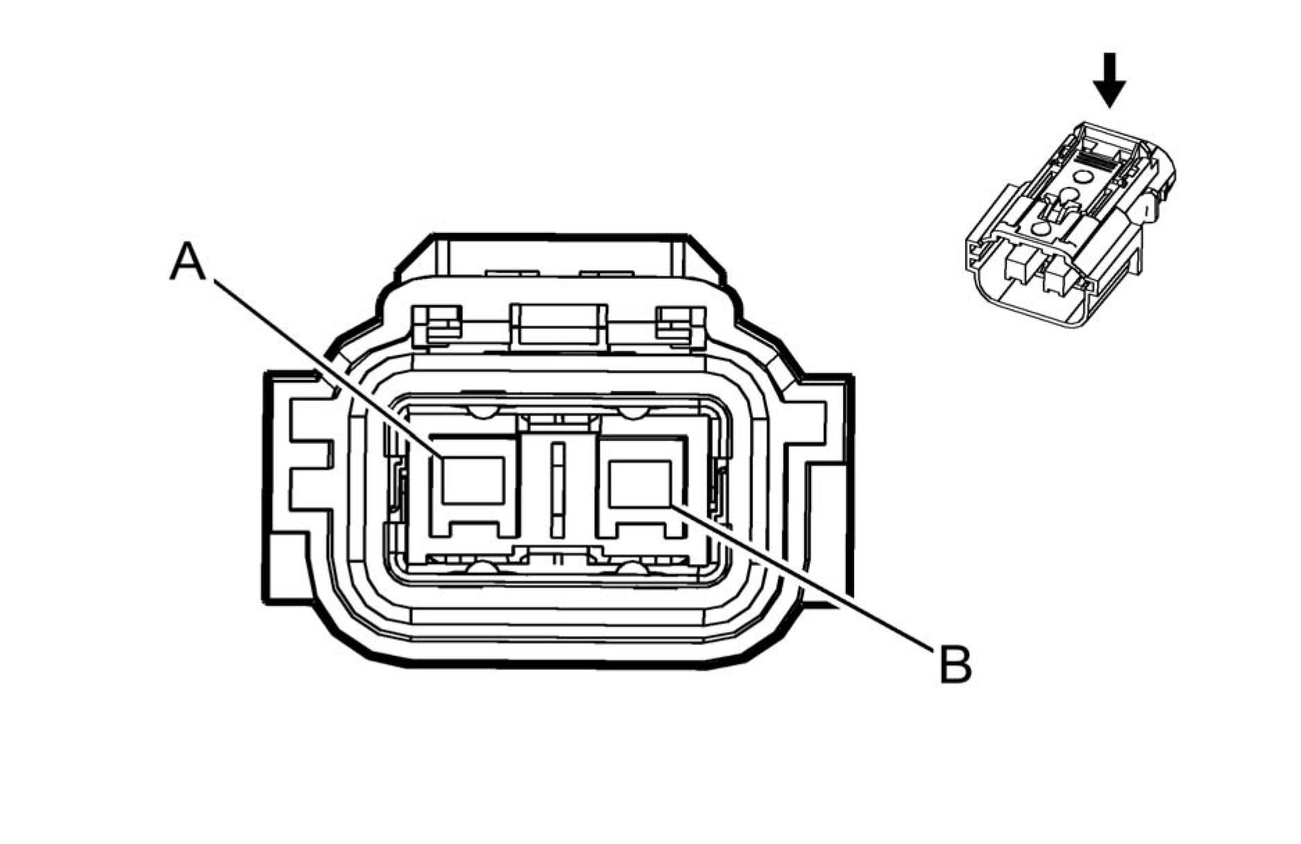 |
|
Connector Part Information |
• Harness Type: Battery Cable
• OEM Connector: 13830159
• Service Connector: Service by Harness - See Part Catalog
• Description: 2-Way F 280 Metri-Pack Series, Sealed (OG)
|
Terminal Part Information | ||||||||||||||||
|
| |||||||||||||||||||||
|
G10L COOLING FAN MOTOR - LEFT |

Connector Part Information
• Harness Type: Cooling Fan
• OEM Connector: 7283-8496-30
• Service Connector: Service by Harness - See Part Catalog
• Description: 4-Way F 1.5, 9.5 Series, Sealed (BK)
|
Terminal Part Information | ||||||||||||||||||||||||
|
| |||||||||||||||||||||||||||||||||||
|
G10R COOLING FAN MOTOR - RIGHT |

Connector Part Information
• Harness Type: Cooling Fan
• OEM Connector: 7283-8496-30
• Service Connector: Service by Harness - See Part Catalog
• Description: 4-Way F 1.5, 9.5 Series, Sealed (BK)
|
Terminal Part Information | ||||||||||||||||||||||||
|
| |||||||||||||||||||||||||||||||||||
|
G18 HIGH PRESSURE FUEL PUMP |

Connector Part Information
• Harness Type: Engine
• OEM Connector: 13343443
• Service Connector: Service by Harness - See Part Catalog
• Description: 2-Way F 2.8 Series, Sealed (BK)
|
Terminal Part Information | ||||||||||||||||
|
| |||||||||||||||||||||
|
G24 WINDSHIELD WASHER PUMP |

Connector Part Information
• Harness Type: Forward Lamp
• OEM Connector: 1-1355200-1
• Service Connector: 13576532
• Description: 2-Way F 2.8 MDK5 Series, Sealed (BK)
|
Terminal Part Information | ||||||||||||||||
|
| |||||||||||||||||||||
|
G35 HYBRID/EV ELECTRONICS COOLANT PUMP |
 |
|
Connector Part Information |
• Harness Type: Forward Lamp
• OEM Connector: 9408621
• Service Connector: 19300589
• Description: 5-Way F 1.2 Multilock Series, Sealed (BK)
|
Terminal Part Information | ||||||||||||||||
|
| ||||||||||||||||||||||||||||||||||||||||||
|
G36 AUXILIARY HEATER COOLANT PUMP |

Connector Part Information
• Harness Type: Engine
• OEM Connector: 805-121-521
• Service Connector: 13574937
• Description: 3-Way F 1.2 Multilock Series, Sealed (BK)
|
Terminal Part Information | ||||||||||||||||
|
| ||||||||||||||||||||||||||||
|
G37 HYBRID/EV BATTERY PACK COOLANT PUMP |
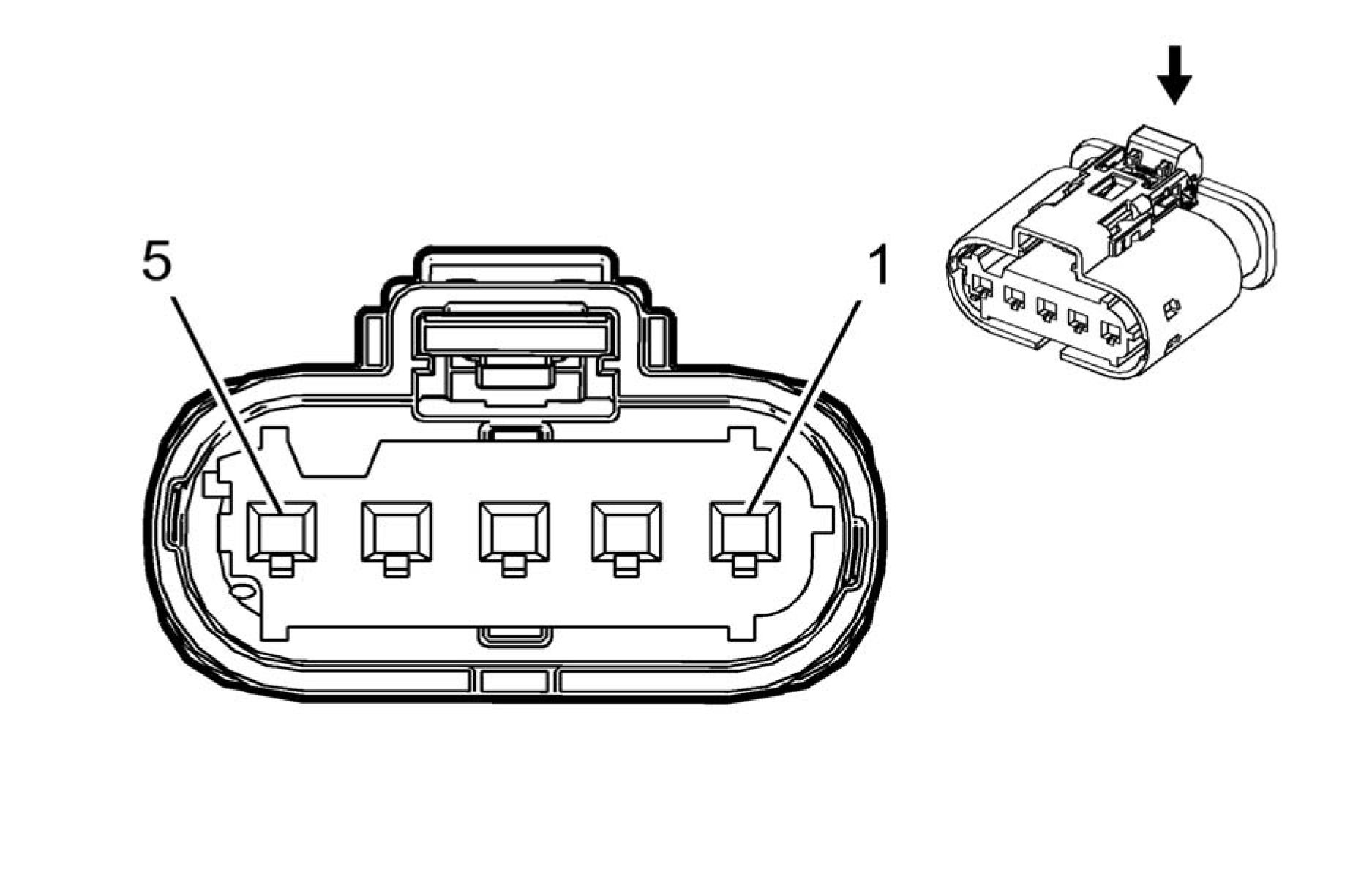 |
|
Connector Part Information |
• Harness Type: Cooling Fan
• OEM Connector: 9408621
• Service Connector: Service by Harness - See Part Catalog
• Description: 5-Way F 1.2 Multilock Series, Sealed (BK)
|
Terminal Part Information | ||||||||||||||||
|
| ||||||||||||||||||||||||||||||||||||||||||
|
K1 14V POWER MODULE X1 |

Connector Part Information
• Harness Type: Body
• OEM Connector: ATSSPB-C0802Y-1AK
• Service Connector: 19352910
• Description: 8-Way F 0.64 Series, Sealed (BK)
|
Terminal Part Information | ||||||||||||||||
|
| |||||||||||||||||||||||||||||||||||
|
K1 14V POWER MODULE X2 |

Connector Part Information
• Harness Type: Battery Cable
• OEM Connector: 33194395
• Service Connector: Service by Cable Assembly - See Part Catalog
• Description: 1-Way Ring Terminal
|
Terminal Part Information | ||||||||||||||||
|
| ||||||||||||||
|
K1 14V POWER MODULE X3 |

Connector Part Information
• Harness Type: Battery Cable
• OEM Connector: 33194394
• Service Connector: Service by Cable Assembly - See Part Catalog
• Description: 1-Way Ring Terminal
|
Terminal Part Information | ||||||||||||||||
|
| ||||||||||||||
|
K1 14V POWER MODULE X4 |
 |
|
Connector Part Information |
• Harness Type: Battery Cable
• OEM Connector: 33107347
• Service Connector: Service by Harness - See Part Catalog
• Description: 4-Way F/M 0.8, 2.8 Metri-Pack Series, Sealed (BU)
|
Terminal Part Information | ||||||||||||||||
|
| ||||||||||||||||||||||||||||
|
K9 BODY CONTROL MODULE X1 |

Connector Part Information
• Harness Type: Instrument Panel
• OEM Connector: 2098067-1
• Service Connector: 13576031
• Description: 26-Way F 0.64, 2.8 Series (NA)
|
Terminal Part Information | ||||||||||||||||||||||||||||||||
|
|
Pin |
Size |
Color |
Circuit |
Function |
Terminal |
Option |
|
1 |
1.5 |
BK |
2150 |
Ground |
I |
- |
|
2 |
1.5 |
RD/YE |
4340 |
Battery Positive Voltage |
I |
- |
|
3 |
1.5 |
RD/GN |
4440 |
Battery Positive Voltage |
I |
- |
|
4 |
1 |
RD/BU |
4540 |
Battery Positive Voltage |
III |
- |
|
5 |
0.35 |
WH |
6816 |
Indicator Dimming Control |
II |
- |
|
6 |
0.35 |
GY/VT |
755 |
RAP Relay Coil Control |
II |
- |
| |||||||||||||||||||||||||||||||||||||||||||||||||||||||||||||||||||||||||||||||||||||||||||||||||||||||||||||||||||||||||||||||||||||
|
K9 BODY CONTROL MODULE X2 |

Connector Part Information
• Harness Type: Instrument Panel
• OEM Connector: 2098067-2
• Service Connector: 13576032
• Description: 27-Way F 0.64, 2.8 Series (BU)
|
Terminal Part Information | ||||||||||||||||||||||||||||||||
|
|
Pin |
Size |
Color |
Circuit |
Function |
Terminal |
Option |
|
1 |
1 |
RD/BN |
4240 |
Battery Positive Voltage |
III |
- |
|
2 |
1.5 |
BK |
2150 |
Ground |
I |
- |
|
3 |
- |
- |
- |
Not Occupied |
- |
- |
|
4 |
1 |
RD/BN |
4940 |
Battery Positive Voltage |
III |
- |
|
5 |
0.35 |
GY |
157 |
Interior Lamp Control |
II |
- |
|
6 |
- |
- |
- |
Not Occupied |
- |
- |
|
7 |
0.35 |
BU/YE |
5361 |
Brake Apply Sensor Signal |
II |
- |
| ||||||||||||||||||||||||||||||||||||||||||||||||||||||||||||||||||||||||||||||||||||||||||||||||||||||||||||||||||||||||||||||
|
K9 BODY CONTROL MODULE X3 |

Connector Part Information
• Harness Type: Instrument Panel
• OEM Connector: 2098067-7
• Service Connector: 13576037
• Description: 25-Way F 0.64, 2.8 Series (GN)
|
Terminal Part Information | ||||||||||||||||
|
|
Pin |
Size |
Color |
Circuit |
Function |
Terminal |
Option |
|
1 |
0.35 |
GN/GY |
3277 |
Vehicle Anti-Theft System |
I |
- |
|
2 |
0.35 |
GN/VT |
7533 |
Local Interconnect Network Serial Data Bus 11 |
I |
- |
|
3 |
0.35 |
GY/BK |
3276 |
Vehicle Anti-Theft System |
I |
- |
|
4 |
0.5 |
WH/RD |
1444 |
12V Reference |
I |
- |
|
5 |
0.35 |
VT/YE |
4 |
Accessory Ignition Voltage |
I |
- |
|
6 |
0.35 |
VT/BK |
3 |
Run/Crank Ignition 1 Voltage |
I |
- |
|
7 |
- |
- |
- |
Not Occupied |
- |
- |
|
Pin |
Size |
Color |
Circuit |
Function |
Terminal |
Option |
|
8 |
0.5 |
GY/GN |
5737 |
Adaptive Cruise Control Gap |
I |
- |
|
9 |
0.5 |
BN/GN |
1884 |
Cruise Control Set/Coast/Resume /Accelerate Switch Signal |
I |
- |
|
10 |
0.5 |
BK/GY |
6009 |
Windshield Wiper Switch Low |
I |
- |
|
11 |
0.5 |
WH |
524 |
Headlamp Dimmer Switch High |
I |
- |
|
12 |
0.5 |
BU/WH |
1414 |
Left Front Turn Signal Switch |
I |
- |
|
13 |
0.5 |
YE/BU |
1714 |
Windshield Wiper Switch Low |
I |
- |
|
14 - 16 |
- |
- |
- |
Not Occupied |
- |
- |
|
17 |
0.5 |
YE/BN |
307 |
Headlamp Switch Flash To Pass |
I |
- |
|
18 |
0.5 |
GN/WH |
3287 |
Horn Switch Signal |
I |
- |
|
19 |
0.35 |
GN/WH |
4115 |
Local Interconnect Network |
I |
- |
|
20 |
0.5 |
GY |
1715 |
Windshield Wiper Switch High |
I |
- |
|
21 |
0.5 |
VT/YE |
5526 |
Tap Up/Tap Down Switch Signal |
I |
- |
|
22 - 23 |
- |
- |
- |
Not Occupied |
- |
- |
|
24 |
0.5 |
GN/VT |
1415 |
Right Front Turn Signal Switch |
I |
- |
|
25 |
0.5 |
WH/BK |
94 |
Windshield Washer Switch Signal |
I |
- |
Article GUID: A00884637
COMPONENT CONNECTOR END VIEWS

Connector Part Information
• Harness Type: Body
• OEM Connector: 1-2141127-3
• Service Connector: 13581575
• Description: 26-Way F 0.64, 2.8 Series (BK)
|
Terminal Part Information | ||||||||||||||||||||||||||||||||
| ||||||||||||||||||||||||||||||||
|
Pin | Size | Color Circuit Function Terminal Option |
| |||||||||||||||||||||||||||||||||||||||||||||||||||||||||||||||||||||||||||||||||||||||||||||||||||||||||||||||||||||||||||||||||||||||||||||||||||||||||||||||||||||||||||||||
|
K9 BODY CONTROL MODULE X5 |

Connector Part Information
• Harness Type: Body
• OEM Connector: 1-2141127-4
• Service Connector: 13581576
• Description: 26-Way F 0.64, 2.8 Series (BN)
|
Terminal Part Information | ||||||||||||||||||||||||||||||||
|
|
Pin |
Size |
Color |
Circuit |
Function |
Terminal |
Option |
|
1 |
0.5 |
YE/BN |
618 |
Left Rear Turn Signal Lamp |
I |
- |
|
2 |
0.5 |
BU/WH |
1314 |
Left Front Turn Signal Lamp |
I |
- |
|
3 |
0.75 |
RD/GY |
4840 |
Battery Positive Voltage |
III |
- |
|
4 |
0.75 |
RD/GN |
4140 |
Battery Positive Voltage |
III |
- |
|
5 |
0.5 |
GY/BU |
7538 |
Left Front DRL Control |
II |
- |
|
6 |
0.35 |
BK/VT |
5077 |
Current Sensor Low Reference |
II |
- |
| |||||||||||||||||||||||||||||||||||||||||||||||||||||||||||||||||||||||||||||||||||||||||||||||||||||||||
|
K9 BODY CONTROL MODULE X6 |

Connector Part Information
• Harness Type: Body
• OEM Connector: 1-2141127-5
• Service Connector: 13581577
Description: 27-Way F 0.64, 2.8 Series (PK)
|
Terminal Part Information | ||||||||||||||||||||||||||||||||
|
| |||||||||||||||||||||||||||||||||||||||||||||||||||||||||||||||||||||||||||||||||||||||||||||||||||||||||||||||||||||||||||||||||||||||||||||||||||
|
K9 BODY CONTROL MODULE X7 |

Connector Part Information
• Harness Type: Body
• OEM Connector: 1-2141127-6
• Service Connector: 13581578
• Description: 26-Way F 0.64, 2.8 Series (GY)
|
Terminal Part Information | ||||||||||||||||||||||||||||||||
|
|
Pin |
Size |
Color |
Circuit |
Function |
Terminal |
Option |
|
1 |
0.75 |
GY |
157 |
Interior Lamp Control |
III |
- |
|
2 |
0.5 |
GN/WH |
1324 |
Backup Lamp Control |
I |
- |
|
3 |
0.75 |
WH/BN |
6815 |
Inadvertent Power Control |
III |
- |
|
4 - 5 |
- |
- |
- |
Not Occupied |
- |
- |
|
6 |
0.35 |
VT/BK |
7553 |
Park Lock Solenoid Control |
II |
- |
|
7 |
0.5 |
GN/GY |
737 |
Rear Compartment Lid Lamp |
II |
- |
| ||||||||||||||||||||||||||||||||||||||||||||||||||||||||||||||||||||||||||||||||||||
|
K10 COOLANT HEATER CONTROL MODULE X1 |

Connector Part Information
• Harness Type: Body
• OEM Connector: 33471-0306
• Service Connector: 19301648
• Description: 3-Way F 1.5 Series, Sealed (BK)
Terminal Part Information
|
Terminal |
Terminated |
Diagnostic Test Probe |
Terminal |
Service |
Tray |
Core |
Insulation |
|
I |
Not Required |
J-35616-2A |
Not |
Not Required |
Not |
Not |
Not |
| ||||||||||||||||||||||||||||
|
K10 COOLANT HEATER CONTROL MODULE X2 |

Connector Part Information
• Harness Type: Battery Cable
• OEM Connector: 33184733
• Service Connector: Service by Harness - See Part Catalog
• Description: 2-Way F HVA280-2PHI Series, Sealed (OG)
|
Terminal Part Information | ||||||||||||||||
|
|
Terminal |
Terminated |
Diagnostic |
Terminal |
Service |
Tray |
Core |
Insulation |
|
(VT) |
Required |
Required |
Required |
Required |
| |||||||||||||||||||||
|
K16 BATTERY ENERGY CONTROL MODULE X1 |
|
I |
 |
Connector Part Information
• Harness Type: Auxiliary Battery Cable
• OEM Connector: 33125545
• Service Connector: Service by Harness - See Part Catalog
• Description: 20-Way F 64 Series, Sealed (BK)
|
Terminal Part Information | ||||||||||||||||
| ||||||||||||||||
|
Pin Size Color Circuit Function Terminal Option |
|
Type ID | ||||||
|
1 |
- |
- |
- |
Not Occupied |
- |
- |
|
2 |
0.35 |
VT |
5391 |
Battery Voltage Signal 1 |
I |
- |
|
3 |
0.35 |
WH |
5395 |
Battery Voltage Signal 3 |
I |
- |
|
4 |
0.35 |
GY/YE |
5396 |
Battery Voltage Signal 4 |
I |
- |
|
5 |
0.35 |
GN |
5398 |
Battery Voltage Signal 6 |
I |
- |
|
6 |
0.35 |
BU |
5400 |
Battery Voltage Signal 8 |
I |
- |
|
7 |
0.35 |
BU/GY |
5392 |
Battery Voltage Signal 10 |
I |
- |
|
8 |
0.35 |
BN |
5571 |
Battery Voltage Signal 12 |
I |
- |
|
9 |
0.35 |
YE/GY |
5572 |
Battery Voltage Signal 13 |
I |
- |
|
10 |
0.35 |
WH/BK |
5574 |
Battery Voltage Signal 15 |
I |
- |
|
11 |
0.35 |
BK/VT |
5403 |
Battery Pack Monitor Low |
I |
- |
|
12 |
0.35 |
YE/VT |
5394 |
Battery Voltage Signal 2 |
I |
- |
|
13 |
0.35 |
GY/YE |
5396 |
Battery Voltage Signal 4 |
I |
- |
|
14 |
0.35 |
YE/GN |
5397 |
Battery Voltage Signal 5 |
I |
- |
|
15 |
0.35 |
YE/BN |
5399 |
Battery Voltage Signal 7 |
I |
- |
|
16 |
0.35 |
GN/BK |
5401 |
Battery Voltage Signal 9 |
I |
- |
|
17 |
0.35 |
GN/GY |
5393 |
Battery Voltage Signal 11 |
I |
- |
|
18 |
0.35 |
BN |
5571 |
Battery Voltage Signal 12 |
I |
- |
|
19 |
0.35 |
YE |
5573 |
Battery Voltage Signal 14 |
I |
- |
|
20 |
0.35 |
BN/WH |
5575 |
Battery Voltage Signal 16 |
I |
- |
|
K16 BATTERY ENERGY CONTROL MODULE X2 |
 |
Connector Part Information
• Harness Type: Auxiliary Battery Cable
• OEM Connector: 13859758
• Service Connector: Service by Harness - See Part Catalog
• Description: 20-Way F USCAR 64 Series (GY)
|
Terminal Part Information | ||||||||||||||||
|
| |||||||||||||||||||||||||||||||||||||||||||||||||||||||||||||||||||||||||||||||||||||||||||||||||||||||||||||||||||||||||||||||||||||||||||||||||||
|
K16 BATTERY ENERGY CONTROL MODULE X3 |

Connector Part Information
• Harness Type: Auxiliary Battery Cable
• OEM Connector: 13950640
• Service Connector: Service by Harness - See Part Catalog
• Description: 20-Way F USCAR 64 Series (BN)
|
Terminal Part Information | ||||||||||||||||
|
|
Pin |
Size |
Color |
Circuit |
Function |
Terminal |
Option |
|
1 |
0.35 |
GY/BK |
5587 |
Battery Voltage Signal 28 |
I |
- |
|
2 |
0.35 |
VT/GN |
5589 |
Battery Voltage Signal 30 |
I |
- |
|
3 |
0.35 |
GY |
5591 |
Battery Voltage Signal 32 |
I |
- |
|
4 |
0.35 |
GY/WH |
5592 |
Battery Voltage Signal 33 |
I |
- |
|
5 |
0.35 |
BK/VT |
4516 |
Battery Cell Voltage Signal 35 |
I |
- |
|
6 |
0.35 |
YE/VT |
4518 |
Battery Cell Voltage Signal 37 |
I |
- |
|
7 |
0.35 |
GY/YE |
4520 |
Battery Cell Voltage Signal 39 |
I |
- |
|
8 |
0.35 |
YE/GN |
4521 |
Battery Cell Voltage Signal 40 |
I |
- |
|
9 |
0.35 |
GN |
4522 |
Battery Cell Voltage Signal 41 |
I |
- |
|
10 |
0.35 |
BU |
4524 |
Battery Cell Voltage Signal 43 |
I |
- |
| |||||||||||||||||||||||||||||||||||||||||||||||||||||||||||||||||||||||||||||
|
K16 BATTERY ENERGY CONTROL MODULE X4 |

Connector Part Information
• Harness Type: Auxiliary Battery Cable
• OEM Connector: 13950640
• Service Connector: Service by Harness - See Part Catalog
• Description: 20-Way F USCAR 64 Series (BN)
|
Terminal Part Information | ||||||||
|
|
Terminal |
Terminated |
Diagnostic Test Probe |
Terminal |
Service |
Tray |
Core |
Insulation |
|
I |
Not Required |
J-35616-64B |
No Tool |
Not |
Not |
Not |
Not |
| |||||||||||||||||||||||||||||||||||||||||||||||||||||||||||||||||||||||||||||||||||||||||||||||||||||||||||||||||||||||||||||||||||||||||||||||||||
|
K16 BATTERY ENERGY CONTROL MODULE X5 |
|
I |
 |
Connector Part Information
• Harness Type: Auxiliary Battery Cable
• OEM Connector: 33125545
• Service Connector: Service by Harness - See Part Catalog
• Description: 20-Way F 64 Series, Sealed (BK)
|
Terminal Part Information | ||||||||||||||||
|
|
Pin |
Size |
Color |
Circuit |
Function |
Terminal |
Option |
|
1 |
0.35 |
GY/GN |
4547 |
Battery Cell Voltage Signal 62 |
I |
- |
|
2 |
0.35 |
GY/BK |
4549 |
Battery Cell Voltage Signal 64 |
I |
- |
|
3 |
0.35 |
VT/GN |
4554 |
Battery Cell Voltage Signal 66 |
I |
- |
|
4 |
0.35 |
GY |
4556 |
Battery Cell Voltage Signal 68 |
I |
- |
|
5 |
0.35 |
VT/BK |
4558 |
Battery Cell Voltage Signal 70 |
I |
- |
|
6 |
0.35 |
VT |
4561 |
Battery Cell Voltage Signal 72 |
I |
- |
|
7 |
0.35 |
YE/VT |
4562 |
Battery Cell Voltage Signal 73 |
I |
- |
|
8 |
0.35 |
GY/YE |
4564 |
Battery Cell Voltage Signal 75 |
I |
- |
|
9 |
0.35 |
YE/GN |
4565 |
Battery Cell Voltage Signal 76 |
I |
- |
|
10 |
0.35 |
YE/BN |
4567 |
Battery Cell Voltage Signal 78 |
I |
- |
| |||||||||||||||||||||||||||||||||||||||||||||||||||||||||||||||||||||||||||||
|
K16 BATTERY ENERGY CONTROL MODULE X6 |
 |
|
Connector Part Information |
• Harness Type: Auxiliary Battery Cable
• OEM Connector: 13859758
• Service Connector: Service by Harness - See Part Catalog
• Description: 20-Way F USCAR 64 Series (GY)
|
Terminal Part Information | ||||||||
|
|
Terminal |
Terminated |
Diagnostic Test Probe |
Terminal |
Service |
Tray |
Core |
Insulation |
|
I |
Not Required |
J-35616-64B |
No Tool |
Not |
Not |
Not |
Not |
| |||||||||||||||||||||||||||||||||||||||||||||||||||||||||||||||||||||||||||||||||||||||||||||||||||||||||||||||||||||||||||||||||||||||||||||||||||
|
K16 BATTERY ENERGY CONTROL MODULE X7 |

Connector Part Information
• Harness Type: Auxiliary Battery Cable
• OEM Connector: 13950637
• Service Connector: Service by Harness - See Part Catalog
• Description: 20-Way F 0.64 Series (GN)
|
Terminal Part Information | ||||||||||||||||
|
|
Pin |
Size |
Color |
Circuit |
Function |
Terminal |
Option |
|
1 |
0.35 |
BN |
5405 |
Battery Module Temperature |
I |
- |
|
2 |
0.35 |
BN/WH |
5406 |
Battery Module Temperature |
I |
- |
|
3 |
0.35 |
GN/GY |
5407 |
Battery Module Temperature |
I |
- |
|
4 |
0.35 |
WH/BK |
5408 |
Battery Module Temperature |
I |
- |
|
5 |
0.35 |
GN/BK |
5409 |
Battery Module Temperature |
I |
- |
| ||||||||||||||||||||||||||||||||||||||||||||||||||||||||||||||||||||||||||||||||||||||||||||||||||||||||||||||||
|
K16 BATTERY ENERGY CONTROL MODULE X8 |

Connector Part Information
• Harness Type: Auxiliary Battery Cable
• OEM Connector: 13819409
• Service Connector: Service by Harness - See Part Catalog
• Description: 16-Way F 0.64 OCS Series (BK)
|
Terminal Part Information | ||||||||||||||||
|
|
Pin |
Size |
Color |
Circuit |
Function |
Terminal |
Option |
|
1 |
0.5 |
RD/VT |
1640 |
Battery Positive Voltage |
I |
- |
|
2 |
- |
- |
- |
Not Occupied |
- |
- |
|
3 |
0.5 |
BU/WH |
3977 |
Accessory Wakeup Serial Data 2 |
I |
- |
|
4 |
0.5 |
WH/BK |
6435 |
CAN Bus Low 2 Serial Data |
I |
- |
|
5 |
0.5 |
BU/GY |
6434 |
CAN Bus High 2 Serial Data |
I |
- |
|
6 |
0.5 |
WH |
2501 |
High Speed GMLAN Serial Data |
I |
- |
|
7 |
0.5 |
BU |
2500 |
High Speed GMLAN Serial Data |
I |
- |
|
8 |
0.5 |
BU/GN |
5139 |
High Voltage Fault Signal |
I |
- |
| ||||||||||||||||||||||||||||||||||||||||||||||||||||||||
|
K17 ELECTRONIC BRAKE CONTROL MODULE |

Connector Part Information
• Harness Type: Body
• OEM Connector: 1928405782
• Service Connector: 19333357
• Description: 46-Way F 1.5, 2.8, 5.8 Series, Sealed (BK)
|
Terminal Part Information | ||||||||||||||||
|
|
Terminal |
Terminated |
Diagnostic |
Terminal |
Service |
Tray |
Core |
Insulation |
|
II |
19333305 |
J-35616-40 |
J-38125-556 |
Not |
Not |
Not |
Not |
|
III |
19333312 |
J-35616-16 |
J-38125-22 |
Not |
Not |
Not |
Not |
|
Pin |
Size |
Color |
Circuit |
Function |
Terminal |
Option |
|
1 |
4 |
RD/BN |
1742 |
Battery Positive Voltage |
II |
- |
|
2 |
2.5 |
GN/VT |
1988 |
Park Brake Motor Apply Right |
I |
- |
|
3 |
2.5 |
GY |
4368 |
Park Brake Motor Low |
I |
- |
|
4 |
0.5 |
BU |
2500 |
High Speed GMLAN Serial Data |
III |
- |
|
5 |
0.5 |
BU |
2500 |
High Speed GMLAN Serial Data |
III |
- |
|
6 |
0.5 |
BU/YE |
6105 |
High Speed GMLAN Serial Data |
III |
- |
|
7 |
0.5 |
GY |
830 |
Wheel Speed Sensor Signal Left |
III |
- |
|
8 |
0.5 |
YE/RD |
7683 |
Park Brake Release Switch |
III |
- |
|
9 |
0.5 |
BU/VT |
1134 |
Park Brake Switch Signal |
III |
- |
|
10 |
- |
- |
- |
Not Occupied |
- |
- |
|
11 |
0.5 |
BU/YE |
6105 |
High Speed GMLAN Serial Data |
III |
- |
|
12 |
2.5 |
GY/BK |
4369 |
Park Brake Motor Low |
I |
- |
|
13 |
2.5 |
WH |
2001 |
Park Brake Motor Apply Left |
I |
- |
|
14 |
4 |
BK |
2650 |
Ground |
II |
- |
|
15 |
0.5 |
BU/BK |
6108 |
Park Brake Release Switch |
III |
- |
|
16 |
0.5 |
YE |
1492 |
Park Brake Switch Supply |
III |
- |
|
17 |
0.5 |
VT/GY |
139 |
Run/Crank Ignition 1 Voltage |
III |
- |
|
18 |
0.5 |
WH |
2501 |
High Speed GMLAN Serial Data |
III |
- |
|
19 |
0.5 |
WH |
2501 |
High Speed GMLAN Serial Data |
III |
- |
|
20 |
- |
- |
- |
Not Occupied |
- |
- |
|
21 |
0.5 |
GY/BN |
7065 |
Wheel Speed Sensor Control |
III |
- |
|
22 |
0.5 |
GY/YE |
7128 |
Wheel Speed Sensor Control |
III |
- |
| |||||||||||||||||||||||||||||||||||||||||||||||||||||||||||||||||||||||||||||||||||||||||||||||||||||||||||||||||||||||||||||||||||||
|
K20 ENGINE CONTROL MODULE X1 |

Connector Part Information
• Harness Type: Engine
• OEM Connector: 34566-6743
• Service Connector: 13574946
• Description: 73-Way F 0.64, 2.8 Series, Sealed (BK with BU Terminal Position Assurance)
|
Terminal Part Information | ||||||||||||||||||||||||
|
|
Pin |
Size |
Color |
Circuit |
Function |
Terminal |
Option |
|
1 - 6 |
- |
- |
- |
Not Occupied |
- |
- |
|
7 |
0.5 |
WH |
7494 |
High Speed GMLAN Serial Data (-) |
II |
- |
|
8 |
0.5 |
BU/BK |
7493 |
High Speed GMLAN Serial Data |
II |
- |
|
9 |
0.5 |
BU |
2500 |
High Speed GMLAN Serial Data |
II |
- |
|
10 |
0.5 |
WH |
2501 |
High Speed GMLAN Serial Data (-) |
II |
- |
|
Pin |
Size |
Color |
Circuit |
Function |
Terminal |
Option |
|
11 |
0.5 |
BN/RD |
1274 |
Accelerator Pedal Position 5 V |
II |
- |
|
12 |
0.5 |
WH/RD |
1164 |
Accelerator Pedal Position 5 V Reference 1 |
II |
- |
|
13 |
0.5 |
BU/WH |
3977 |
Accessory Wakeup Serial Data 2 |
II |
- |
|
14 |
0.5 |
VT/BK |
339 |
Run/Crank Ignition 1 Voltage |
II |
- |
|
15 |
0.5 |
RD/BN |
440 |
Battery Positive Voltage |
II |
- |
|
16 |
0.75 |
VT/BU |
5292 |
Powertrain Main Relay Fused |
II |
- |
|
17 - 24 |
- |
- |
- |
Not Occupied |
- |
- |
|
25 |
0.5 |
BK/YE |
5382 |
Brake Position Sensor Low |
II |
- |
|
26 |
- |
- |
- |
Not Occupied |
- |
- |
|
27 |
0.5 |
BK/VT |
1272 |
Accelerator Pedal Position Low |
II |
- |
|
28 |
0.5 |
BK/BU |
1271 |
Accelerator Pedal Position Low |
II |
- |
|
29 - 32 |
- |
- |
- |
Not Occupied |
- |
- |
|
33 |
0.5 |
GN/WH |
1162 |
Accelerator Pedal Position Signal 2 |
II |
- |
|
34 |
0.5 |
GN/WH |
492 |
Mass Air Flow Sensor Signal |
II |
- |
|
35 - 36 |
- |
- |
- |
Not Occupied |
- |
- |
|
37 |
0.5 |
BN/RD |
2700 |
A/C Pressure Sensor 5 V Reference |
II |
- |
|
38 - 40 |
- |
- |
- |
Not Occupied |
- |
- |
|
41 |
0.5 |
WH/RD |
5381 |
Brake Position Sensor 5 V |
II |
- |
|
42 |
- |
- |
- |
Not Occupied |
- |
- |
|
43 |
0.5 |
BN/RD |
3724 |
Evap Leak Check Module (ELCM) |
II |
- |
|
44 |
- |
- |
- |
Not Occupied |
- |
- |
|
45 |
0.5 |
YE/WH |
1161 |
Accelerator Pedal Position Signal 1 |
II |
- |
|
46 |
0.5 |
YE/BK |
3000 |
Coolant Temperature Sensor 2 |
II |
- |
|
47 |
- |
- |
- |
Not Occupied |
- |
- |
|
48 |
0.5 |
WH/BU |
6289 |
Induction Air Temperature Sensor |
II |
- |
|
49 |
- |
- |
- |
Not Occupied |
- |
- |
|
50 |
0.5 |
WH/BU |
6311 |
Cruise/ETC/TCC Brake Signal |
II |
- |
|
51 |
0.5 |
VT/BU |
5291 |
Powertrain Main Relay Fused |
II |
- |
|
52 |
0.5 |
BU/VT |
2364 |
Cooling Fan Speed Signal |
II |
- |
|
53 - 56 |
- |
- |
- |
Not Occupied |
- |
- |
|
57 |
0.5 |
GN |
380 |
A/C Refrigerant Pressure Sensor |
II |
- |
|
58 - 59 |
- |
- |
- |
Not Occupied |
- |
- |
| |||||||||||||||||||||||||||||||||||||||||||||||||||||||||||||||||||||||||||||||||||||||||||||||||||||||||
|
K20 ENGINE CONTROL MODULE X2 |
 |
|
Connector Part Information |
• Harness Type: Engine
• OEM Connector: 34566-6753
• Service Connector: 13574947
• Description: 73-Way F 0.64, 2.8 Series, Sealed (BK with BK Terminal Position Assurance)
|
Terminal Part Information | ||||||||||||||||||||||||
|
|
Pin |
Size |
Color |
Circuit |
Function |
Terminal |
Option |
|
1 |
- |
- |
- |
Not Occupied |
- |
- |
|
2 |
0.5 |
BU |
410 |
Engine Coolant Temperature |
II |
- |
|
3 |
- |
- |
- |
Not Occupied |
- |
- |
|
4 |
0.5 |
BN/RD |
7445 |
Fuel Line Pressure Sensor 5 V |
II |
- |
|
5 |
0.5 |
GY/RD |
2704 |
Manifold Absolute Pressure |
II |
- |
|
6 |
0.5 |
GY/YE |
5297 |
Camshaft Position Exhaust Sensor Control 1 |
II |
- |
|
7 |
0.5 |
GY/BU |
5300 |
Camshaft Position Intake Sensor Control 1 |
II |
- |
|
8 - 11 |
- |
- |
- |
Not Occupied |
- |
- |
|
12 |
0.5 |
BN/RD |
2701 |
Throttle Position Sensor 5 V |
II |
- |
|
13 |
0.5 |
BU/WH |
3630 |
Throttle Position Sensor (SENT1) |
II |
- |
|
14 |
0.5 |
WH/RD |
2705 |
Oil Pressure Sensor 5 V Reference |
II |
- |
|
15 |
0.5 |
VT/BU |
6270 |
Crankshaft 60X Sensor 5 V |
II |
- |
|
16 - 19 |
- |
- |
- |
Not Occupied |
- |
- |
|
20 |
0.5 |
BU/WH |
7446 |
Fuel Line Pressure Sensor Signal |
II |
- |
|
21 |
0.5 |
BK/GN |
469 |
Manifold Absolute Pressure |
II |
- |
|
22 |
0.5 |
BK/GY |
5296 |
Camshaft Position Exhaust |
II |
- |
|
23 |
0.5 |
BK/GN |
5301 |
Camshaft Position Intake Sensor |
II |
- |
|
24 - 27 |
- |
- |
- |
Not Occupied |
- |
- |
|
28 |
0.5 |
BK/BN |
2752 |
Throttle Position Sensor Low |
II |
- |
|
29 |
0.5 |
YE/BN |
331 |
Oil Pressure Sensor Signal |
II |
- |
|
Pin |
Size |
Color |
Circuit |
Function |
Terminal |
Option |
|
30 |
0.5 |
BK/VT |
2755 |
Oil Pressure Sensor Low |
II |
- |
|
31 |
0.5 |
BK/VT |
6272 |
Crankshaft 60X Sensor Low |
II |
- |
|
32 |
- |
- |
- |
Not Occupied |
- |
- |
|
33 |
0.5 |
WH/BK |
3111 |
Heated Oxygen Sensor Low |
II |
- |
|
34 |
0.5 |
WH/YE |
3121 |
Heated Oxygen Sensor Low |
II |
- |
|
35 |
- |
- |
- |
Not Occupied |
- |
- |
|
36 |
0.5 |
BK/VT |
6754 |
Cam Phaser X Low Reference |
II |
- |
|
37 |
0.5 |
BK/BN |
6753 |
Cam Phaser W Low Reference |
II |
- |
|
38 |
0.5 |
VT/BK |
5273 |
Camshaft Position Exhaust |
II |
- |
|
39 |
0.5 |
YE/VT |
5275 |
Camshaft Position Intake Sensor |
II |
- |
|
40 |
0.5 |
GN |
6271 |
Crankshaft 60X Sensor Signal |
II |
- |
|
41 |
- |
- |
- |
Not Occupied |
- |
- |
|
42 |
0.5 |
VT/BU |
6091 |
Crankshaft Position Sensor |
II |
- |
|
43 |
0.5 |
BK/WH |
2051 |
Signal Ground |
II |
- |
|
44 |
0.5 |
BK/BU |
2129 |
Ignition Control Low Reference |
II |
- |
|
45 |
0.5 |
GN/BU |
2123 |
Ignition Control 3 |
II |
- |
|
46 |
0.5 |
BU/VT |
2121 |
Ignition Control 1 |
II |
- |
|
47 |
- |
- |
- |
Not Occupied |
- |
- |
|
48 |
0.75 |
BU |
4802 |
Direct Fuel Injector (DFI) High |
II |
- |
|
49 |
0.75 |
GY/BU |
4804 |
Direct Fuel Injector (DFI) High |
II |
- |
|
50 |
0.75 |
GN |
4803 |
Direct Fuel Injector (DFI) High |
II |
- |
|
51 |
0.75 |
BN |
4801 |
Direct Fuel Injector (DFI) High |
II |
- |
|
52 |
0.5 |
YE |
581 |
Throttle Actuator Control Open |
II |
- |
|
53 |
0.5 |
VT/GY |
3110 |
Heated Oxygen Sensor High |
II |
- |
|
54 |
0.5 |
VT/BU |
3120 |
Heated Oxygen Sensor High |
II |
- |
|
55 |
- |
- |
- |
Not Occupied |
- |
- |
|
56 |
0.5 |
GY/BU |
5282 |
Camshaft Phaser Exhaust |
II |
- |
|
57 |
0.5 |
VT/BN |
5284 |
Camshaft Phaser Intake Solenoid |
II |
- |
|
58 - 59 |
- |
- |
- |
Not Occupied |
- |
- |
| ||||||||||||||||||||||||||||||||||||||||||||||||||||||||||||||||||||||||||||||||||||||||||||||||||
|
K20 ENGINE CONTROL MODULE X3 |
 |
|
Connector Part Information |
• Harness Type: Engine
• OEM Connector: 34566-6763
• Service Connector: 13574948
• Description: 73-Way F 0.64, 2.8 Series, Sealed (BK with GY Terminal Position Assurance)
|
Terminal Part Information | ||||||||||||||||||||||||
|
|
Pin |
Size |
Color |
Circuit |
Function |
Terminal |
Option |
|
1 - 3 |
- |
- |
- |
Not Occupied |
- |
- |
|
4 |
0.5 |
GN/BU |
428 |
EVAP Canister Purge Solenoid |
II |
- |
|
5 |
0.5 |
BU |
3722 |
Evap Leak Check Module |
II |
- |
|
6 |
0.5 |
BN/RD |
2917 |
Fuel Rail Pressure Sensor 5 V |
II |
- |
|
7 |
- |
- |
- |
Not Occupied |
- |
- |
|
8 |
0.5 |
YE/RD |
2709 |
Fuel Tank Pressure Sensor 5 V |
II |
- |
|
9 - 13 |
- |
- |
- |
Not Occupied |
- |
- |
|
14 |
0.5 |
WH/RD |
3201 |
Throttle Inlet Absolute Pressure |
II |
- |
|
15 |
- |
- |
- |
Not Occupied |
- |
- |
|
16 |
0.5 |
VT/BU |
5293 |
Powertrain Main Relay Fused |
II |
- |
|
17 |
- |
- |
- |
Not Occupied |
- |
- |
|
18 |
0.5 |
BN |
25 |
Charge Indicator Control |
II |
- |
|
19 |
0.5 |
GY |
23 |
Generator Field Duty Cycle |
II |
- |
|
20 |
0.5 |
BK/WH |
2151 |
Signal Ground |
II |
- |
|
21 |
0.5 |
BU/WH |
2918 |
Fuel Rail Pressure Sensor Signal |
II |
- |
|
22 |
0.5 |
BK/GN |
2919 |
Fuel Rail Pressure Sensor Low |
II |
- |
|
23 - 28 |
- |
- |
- |
Not Occupied |
- |
- |
|
29 |
0.5 |
BK/BN |
2753 |
Exhaust Gas Recirculation Sensor |
II |
- |
|
30 - 33 |
- |
- |
- |
Not Occupied |
- |
- |
|
34 |
0.5 |
BN/VT |
4322 |
Exhaust Gas Recirculation Pulse |
II |
- |
|
35 - 39 |
- |
- |
- |
Not Occupied |
- |
- |
|
40 |
0.5 |
GN/WH |
432 |
Manifold Absolute Pressure |
II |
- |
| |||||||||||||||||||||||||||||||||||||||||||||||||||||||||||||||||||||||||||||||||||||||||||||||||||||||||||||||||||||||||||||||||||||||||||||||||||
|
K29F SEAT HEATING CONTROL MODULE - FRONT X1 (KA1) |
 |
|
Connector Part Information |
• Harness Type: Rear Seat Cushion
• OEM Connector: 31372-1000
• Service Connector: Service by Harness - See Part Catalog
• Description: 10-Way F 1.5, 2.8 Series (BK)
|
Terminal Part Information | ||||||||||||||||
|
|
Pin |
Size |
Color |
Circuit |
Function |
Terminal |
Option |
|
1 |
- |
- |
- |
Not Occupied |
- |
- |
|
2 |
0.75 |
BN/BU |
2479 |
Passenger Heated Seat Element |
I |
- |
|
3 |
0.75 |
GY/BK |
2480 |
Passenger Heated Seat Element |
I |
- |
|
4 |
0.75 |
VT/BK |
2424 |
Driver Heated Back Element |
I |
- |
|
5 |
- |
- |
- |
Not Occupied |
- |
- |
|
6 |
0.75 |
BN/VT |
2077 |
Driver Heated Seat Element |
I |
- |
|
7 |
0.75 |
RD/BN |
1742 |
Battery Positive Voltage |
I |
- |
| ||||||||||||||||||||||||||||
|
K29F SEAT HEATING CONTROL MODULE - FRONT X2 (KA1) |

Connector Part Information
• Harness Type: Rear Seat Cushion
• OEM Connector: 7283-9076-30
• Service Connector: Service by Harness - See Part Catalog
• Description: 16-Way F 0.64 Kaizen Series (BK)
|
Terminal Part Information | ||||||||||||||||
|
|
Pin |
Size |
Color |
Circuit |
Function |
Terminal |
Option |
|
1 |
0.35 |
BK/YE |
2080 |
Driver Heated Seat NTC Low |
I |
- |
| |||||||||||||||||||||||||||||||||||||||||||||||||||||||||||||||||||||||||||||
|
K29R SEAT HEATING CONTROL MODULE - REAR X1 (KA6) |
 |
|
Connector Part Information |
• Harness Type: Rear Seat Cushion
• OEM Connector: 13582823
• Service Connector: Service by Harness - See Part Catalog
• Description: 10-Way F 1.5, 2.8 Series (BK)
|
Terminal Part Information | ||||||||||||||||
|
|
Pin |
Size |
Color |
Circuit |
Function |
Terminal |
Option |
|
1 |
- |
- |
- |
Not Occupied |
- |
- |
|
2 |
0.5 |
GN/BN |
2296 |
Right Rear Heated Seat Cushion |
I |
- |
|
3 |
0.5 |
GN/BK |
2297 |
Right Rear Heated Seat Cushion |
I |
- |
|
4 |
0.5 |
BN/BK |
2295 |
Left Rear Heated Seat Cushion |
I |
- |
|
5 |
- |
- |
- |
Not Occupied |
- |
- |
|
6 |
0.5 |
GY |
2294 |
Left Rear Heated Seat Cushion |
I |
- |
|
7 |
0.75 |
RD/GN |
1840 |
Battery Positive Voltage |
I |
- |
|
8 |
1.0 |
BK |
850 |
Ground |
I |
- |
|
9 |
- |
- |
- |
Not Occupied |
- |
- |
|
10 |
0.75 |
RD/GN |
1840 |
Battery Positive Voltage |
I |
- |
|
K29R SEAT HEATING CONTROL MODULE - REAR X2 (KA6) |
 |
Connector Part Information
• Harness Type: Rear Seat Cushion
• OEM Connector: 15136073
• Service Connector: Service by Harness - See Part Catalog
• Description: 16-Way F 0.64 Kaizen Series (BK)
|
Terminal Part Information | ||||||||||||||||
|
| |||||||||||||||||||||||||||||||||||||||||||||||||||||||||||||||
|
K32 STEERING WHEEL HEATING CONTROL MODULE X1 |
 |
|
Connector Part Information |
• Harness Type: Steering Wheel
• OEM Connector: 31072-1010
• Service Connector: Service by Harness - See Part Catalog
• Description: 5-Way F 31072 Series (BK)
|
Terminal Part Information | ||||||||||||||||
|
| ||||||||||||||||||||||||||||||||||||||||||
|
K32 STEERING WHEEL HEATING CONTROL MODULE X2 |
 |
|
Connector Part Information |
• Harness Type: Steering Wheel
• OEM Connector: 31068-1010
• Service Connector: Service by Harness - See Part Catalog
• Description: 4-Way F 0.64 H-DAC Series (BK)
|
Terminal Part Information | ||||||||||||||||
|
| |||||||||||||||||||||||||||||||||||
|
K33 HVAC CONTROL MODULE X1 |
 |
|
Connector Part Information |
• Harness Type: Instrument Panel
• OEM Connector: 31410-1203
• Service Connector: 13576644
• Description: 20-Way F 0.64 Series (GN)
|
Terminal Part Information | ||||||||||||||||
|
|
Pin |
Size |
Color |
Circuit |
Function |
Terminal |
Option |
|
1 |
- |
- |
- |
Not Occupied |
- |
- |
|
2 |
0.35 |
GY/GN |
7565 |
Windscreen Temp Sensor Signal |
I |
- |
|
3 - 4 |
- |
- |
- |
Not Occupied |
- |
- |
|
5 |
0.35 |
YE/BU |
3197 |
Humidity Temperature Sensor |
I |
- |
|
6 |
0.35 |
YE/RD |
597 |
5 V Reference |
I |
- |
|
7 |
0.35 |
BK/BN |
6102 |
Inside Air Temperature Sensor |
I |
- |
|
8 - 11 |
- |
- |
- |
Not Occupied |
- |
- |
|
12 |
0.35 |
GY/BU |
7564 |
Humidity Sensor Signal |
I |
- |
|
13 - 17 |
- |
- |
- |
Not Occupied |
- |
- |
| |||||||||||||||||||||
|
K33 HVAC CONTROL MODULE X2 |

Connector Part Information
• Harness Type: Instrument Panel
• OEM Connector: 31410-1202
• Service Connector: 15126709
• Description: 20-Way F 64 Series, Sealed (BN)
|
Terminal Part Information | ||||||||||||||||
|
|
Pin |
Size |
Color |
Circuit |
Function |
Terminal |
Option |
|
1 |
0.5 |
RD/WH |
3440 |
Battery Positive Voltage |
I |
- |
|
2 |
0.5 |
GN |
5060 |
Low Speed GMLAN Serial Data |
I |
- |
|
3 |
- |
- |
- |
Not Occupied |
- |
- |
| ||||||||||||||||||||||||||||||||||||||||||||||||||||||||||||||||||||||||||||||||||||||||||||||||||
|
K33 HVAC CONTROL MODULE X3 |
 |
|
Connector Part Information |
• Harness Type: HVAC
• OEM Connector: 31410-1200
• Service Connector: Service by Harness - See Part Catalog
• Description: 20-Way F 64 Series, Sealed (BK)
|
Terminal Part Information | ||||||||||||||||
|
| |||||||||||||||||||||||||||||||||||||||||||||||||||||||||||||||||||||||||||||||||||||||||||||||||||||||||||||||||||||||||||||||||||||
|
K36 INFLATABLE RESTRAINT SENSING AND DIAGNOSTIC MODULE X1 |

Connector Part Information
• Harness Type: Instrument Panel
• OEM Connector: 2203516-7
• Service Connector: 19332831
• Description: 24-Way F 0.64 Series, Sealed (YE)
|
Terminal Part Information | ||||||||||||||||||||||||
|
|
Pin |
Size |
Color |
Circuit |
Function |
Terminal |
Option |
|
1 |
0.5 |
OG/BK |
3023 |
Steering Wheel Module Stage 2 |
I |
- |
|
2 |
0.5 |
WH/OG |
3022 |
Steering Wheel Module Stage 2 |
I |
- |
|
3 |
0.5 |
BN/OG |
3020 |
Steering Wheel Module Stage 1 |
I |
- |
|
4 |
0.5 |
OG/VT |
3021 |
Steering Wheel Module Stage 1 |
I |
- |
|
5 |
0.35 |
YE/OG |
3025 |
Passenger IP Module Stage 1 High |
I |
- |
| |||||||||||||||||||||||||||||||||||||||||||||||||||||||||||||||||||||||||||||||||||||||||||||||||||||||||||||||||||||||||||||||||||||
|
K36 INFLATABLE RESTRAINT SENSING AND DIAGNOSTIC MODULE X2 |
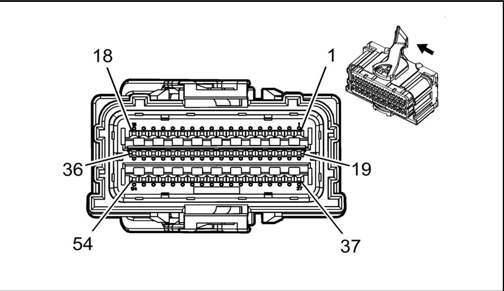 |
|
Connector Part Information |
• Harness Type: Body
• OEM Connector: 7-2098922-3
• Service Connector: 19333100
• Description: 54-Way F 0.64 Series, Sealed (YE)
|
Terminal Part Information | ||||||||||||||||
|
|
Pin |
Size |
Color |
Circuit |
Function |
Terminal |
Option |
|
1 |
0.5 |
OG/GY |
5223 |
Left Rear Side Impact SIR Inflator |
I |
- |
|
2 |
0.5 |
VT/OG |
5224 |
Left Rear Side Impact SIR Inflator |
I |
- |
|
3 |
0.5 |
OG/GY |
5226 |
Right Rear Side Impact SIR |
I |
- |
|
4 |
0.5 |
VT/OG |
5225 |
Right Rear Side Impact SIR |
I |
- |
|
5 - 8 |
- |
- |
- |
Not Occupied |
- |
- |
|
9 |
0.5 |
OG/YE |
3481 |
Driver Seat Belt Anchor |
I |
- |
|
Pin |
Size |
Color |
Circuit |
Function |
Terminal |
Option |
|
10 |
0.5 |
YE/OG |
3482 |
Driver Seat Belt Anchor |
I |
- |
|
11 |
0.35 |
GY/OG |
3480 |
Passenger Seat Belt Anchor |
I |
- |
|
12 |
0.35 |
OG/BN |
3479 |
Passenger Seat Belt Anchor |
I |
- |
|
13 |
0.5 |
OG/BU |
3068 |
Driver Side Impact Module High |
I |
- |
|
14 |
0.5 |
GN/OG |
3069 |
Driver Side Impact Module Low |
I |
- |
|
15 |
0.35 |
BN/OG |
3067 |
Passenger Side Impact Module |
I |
- |
|
16 |
0.35 |
OG/GY |
3066 |
Passenger Side Impact Module |
I |
- |
|
17 |
0.35 |
OG/GN |
5019 |
Left Front Head Curtain Module |
I |
- |
|
18 |
0.35 |
VT/OG |
5020 |
Left Front Head Curtain Module |
I |
- |
|
19 |
0.35 |
GN/WH |
2132 |
Left Front Side Impact Sensing |
I |
- |
|
20 |
0.35 |
GN |
6628 |
Left Front Side Impact Sensing |
I |
- |
|
21 |
0.35 |
BN/WH |
6629 |
Right Front Side Impact Sensing |
I |
- |
|
22 |
0.35 |
BN/OG |
2134 |
Right Front Side Impact Sensing |
I |
- |
|
23 |
0.5 |
OG/YE |
354 |
Left Front Discriminating Sensor |
I |
- |
|
24 |
0.5 |
BK/OG |
5045 |
Left Front Discriminating Sensor |
I |
- |
|
25 |
0.5 |
GN |
5600 |
Right Front Discriminating Sensor |
I |
- |
|
26 |
0.5 |
OG/GN |
1409 |
Right Front Discriminating Sensor |
I |
- |
|
27 |
0.5 |
OG/BU |
6620 |
Left Middle Side Impact Sensing |
I |
- |
|
28 |
0.5 |
BU |
6621 |
Left Middle Side Impact Sensing |
I |
- |
|
29 |
0.5 |
BK/OG |
6625 |
Right Middle Side Impact Sensing |
I |
- |
|
30 |
0.5 |
OG/VT |
6624 |
Right Middle Side Impact Sensing |
I |
- |
|
31 - 36 |
- |
- |
- |
Not Occupied |
- |
- |
|
37 |
0.35 |
OG/WH |
3477 |
Driver Seat Belt Retractor |
I |
- |
| ||||||||||||||||||||||||||||||||||||||||||||||||||||||||||||||||||||||||||||||||||||
|
K43 POWER STEERING CONTROL MODULE X1 |
 |
|
Connector Part Information |
• Harness Type: Engine
• OEM Connector: 7287-1990-30
• Service Connector: Service by Harness - See Part Catalog
Description: 2-Way F 9.5 Series, Sealed (BK)
|
Terminal Part Information | ||||||||||||||||
|
| |||||||||||||||||||||
|
K43 POWER STEERING CONTROL MODULE X2 |

Connector Part Information
• Harness Type: Engine
• OEM Connector: 3-2098269-8
• Service Connector: 19299774
• Description: 10-Way F 0.64 Series, Sealed (BK)
|
Terminal Part Information | ||||||||
|
|
Terminal |
Terminated |
Diagnostic |
Terminal |
Service |
Tray |
Core |
Insulation |
|
I |
19300631 |
J-35616-64B |
J-38125-215A |
Not |
Not |
Not |
Not |
|
Pin |
Size |
Color |
Circuit |
Function |
Terminal |
Option |
|
1 |
0.5 |
BU/YE |
6105 |
High Speed GMLAN Serial Data |
I |
- |
|
2 |
0.5 |
WH |
6106 |
High Speed GMLAN Serial Data |
I |
- |
|
3 |
0.5 |
BU |
2500 |
High Speed GMLAN Serial Data |
I |
- |
|
4 |
0.5 |
WH |
2501 |
High Speed GMLAN Serial Data |
I |
- |
|
5 |
0.5 |
WH/BU |
5986 |
Serial Data Communication Enable |
I |
- |
|
6 |
0.5 |
BU/YE |
6105 |
High Speed GMLAN Serial Data |
I |
- |
|
7 |
0.5 |
WH |
6106 |
High Speed GMLAN Serial Data |
I |
- |
|
8 |
0.5 |
BU |
2500 |
High Speed GMLAN Serial Data |
I |
- |
|
9 |
0.5 |
WH |
2501 |
High Speed GMLAN Serial Data |
I |
- |
|
10 |
- |
- |
- |
Not Occupied |
- |
- |
Article GUID: A00884638
ELECTRICAL
COMPONENT CONNECTOR END VIEWS
K73 TELEMATICS COMMUNICATION INTERFACE CONTROL MODULE X1

Connector Part Information
• Harness Type: Instrument Panel
• OEM Connector: 1456601-1
• Service Connector: 19153138
• Description: 16-Way F 040 Multilock II Series (WH)
|
Terminal Part Information | ||||||||||||||||||||||||
|
|
Pin |
Size |
Color |
Circuit |
Function |
Terminal |
Option |
|
1 |
0.5 |
GN |
5060 |
Low Speed GMLAN Serial Data |
I |
- |
| |||||||||||||||||||||||||||||||||||||||||||||||||||||||||||||||||||||||||||||||||||||||||||
|
K73 TELEMATICS COMMUNICATION INTERFACE CONTROL MODULE X2 |

Connector Part Information
• Harness Type: Instrument Panel
• OEM Connector: 1456599-1
• Service Connector: 88952886
• Description: 12-Way F 040 Multilock II Series (WH)
Terminal Part Information
|
Terminal |
Terminated |
Diagnostic |
Terminal |
Service |
Tray |
Core |
Insulation |
|
I |
13575740 |
J-35616-16 |
J-38125-559 |
15445905 |
Delphi 23 |
J |
J |
|
II |
13575803 |
J-35616-16 |
J-38125-559 |
15445905 |
Delphi 23 |
J |
J |
| |||||||||||||||||||||||||||||||||||||||||||||||||||||||||||||||||||||||||||||||||||||||||||
|
K73 TELEMATICS COMMUNICATION INTERFACE CONTROL MODULE X5 |

Connector Part Information
• Harness Type: Instrument Panel
• OEM Connector: 13591273
• Service Connector: Service by Cable Assembly - See Part Catalog
• Description: 1-Way F Coax Type (VT)
|
Terminal Part Information | ||||||||||||||||
|
| ||||||||||||||
|
K73 TELEMATICS COMMUNICATION INTERFACE CONTROL MODULE X7 |
 |
|
Connector Part Information |
• Harness Type: Instrument Panel
• OEM Connector: 13595582
• Service Connector: Service by Cable Assembly - See Part Catalog
• Description: 1-Way F Coax Type (BU)
|
Terminal Part Information | ||||||||||||||||
|
| ||||||||||||||
|
K74 HUMAN MACHINE INTERFACE CONTROL MODULE X1 |

Connector Part Information
• Harness Type: Instrument Panel
• OEM Connector: 15136073
• Service Connector: 15136073
• Description: 16-Way F 0.64 Kaizen Series (BK)
|
Terminal Part Information | ||||||||||||||||
|
|
Pin |
Size |
Color |
Circuit |
Function |
Terminal |
Option |
|
1 |
0.35 |
GY/YE |
5149 |
Voice Recognition Audio Signal |
I |
- |
|
2 |
0.35 |
BK/GY |
5152 |
Voice Recognition Audio Low |
I |
- |
|
3 - 4 |
- |
- |
- |
Not Occupied |
- |
- |
|
5 |
0.35 |
WH/BU |
5986 |
Serial Data Communication Enable |
I |
- |
|
6 |
- |
- |
- |
Not Occupied |
- |
- |
|
7 |
0.5 |
RD/YE |
5040 |
Battery Positive Voltage |
I |
- |
|
8 |
0.5 |
BK |
1650 |
Ground |
I |
- |
|
9 |
0.35 |
GN/WH |
7527 |
Local Interconnect Network Serial Data Bus 5 |
I |
- |
|
10 |
- |
- |
- |
Not Occupied |
- |
- |
| ||||||||||||||||||||||||||||||||||||||||||
|
K74 HUMAN MACHINE INTERFACE CONTROL MODULE X2 |

0000 0000 |
|
Connector Part Information |
• Harness Type: Instrument Panel
• OEM Connector: 31410-1121
• Service Connector: 19151154
• Description: 12-Way F 64 Series, Sealed (GY)
|
Terminal Part Information | ||||||||||||||||
|
|
Pin |
Size |
Color |
Circuit |
Function |
Terminal |
Option |
|
1 |
0.35 |
WH/VT |
3999 |
MOST Control |
I |
- |
|
2 |
0.35 |
WH/GN |
3997 |
MOST Serial Data (-) |
I |
- |
|
3 |
0.35 |
GY/VT |
3998 |
MOST Serial Data (+) |
I |
- |
|
4 |
- |
- |
- |
Not Occupied |
- |
- |
|
5 |
0.35 |
GY/YE |
6972 |
Camera Signal 2 + |
I |
- |
|
6 |
0.35 |
WH/BU |
6973 |
Camera Signal 2 |
I |
- |
|
7 |
- |
- |
- |
Not Occupied |
- |
- |
|
8 |
0.5 |
GY/VT |
3998 |
MOST Serial Data (+) |
I |
- |
|
9 |
0.5 |
WH/GN |
3997 |
MOST Serial Data (-) |
I |
- |
|
10 - 12 |
- |
- |
- |
Not Occupied |
- |
- |
|
K74 HUMAN MACHINE INTERFACE CONTROL MODULE X3 |
 |
|
Terminal Part Information | ||||||||
|
|
Terminal |
Terminated |
Diagnostic Test Probe |
Terminal |
Service |
Tray |
Core |
Insulation |
|
I |
Not Required |
No Tool |
No Tool |
Not Required |
Not |
Not |
Not |
| ||||||||||||||
|
K74 HUMAN MACHINE INTERFACE CONTROL MODULE X5 |

Connector Part Information
• Harness Type: Instrument Panel
• OEM Connector: 13578154
• Service Connector: Service by Cable Assembly - See Part Catalog
• Description: 5-Way M 2.0 Mini-B USB Type (BU)
|
Terminal Part Information | ||||||||||||||||
| ||||||||||||||||
|
Terminal |
Pin Size Color Circuit
Function
Option
|
Type ID | ||||||
|
- |
- |
USB |
- |
USB Serial Data |
I |
- |

|
Terminal Part Information | ||||||||||||||||
|
| ||||||||||||||
|
K77 REMOTE CONTROL DOOR LOCK RECEIVER |
 |
|
Connector Part Information |
• Harness Type: Body
• OEM Connector: 1379029-3
• Service Connector: 13316147
• Description: 4-Way F 0.64 Micro-Quadlock Series (BU)
|
Terminal Part Information | ||||||||||||||||
|
| |||||||||||||||||||||||||||||||||||
|
K84 KEYLESS ENTRY CONTROL MODULE X1 |

Connector Part Information
• Harness Type: Body
• OEM Connector: 31410-1202
• Service Connector: 15126709
• Description: 20-Way F 64 Series, Sealed (BN)
|
Terminal Part Information | ||||||||||||||||
|
|
Pin |
Size |
Color |
Circuit |
Function |
Terminal |
Option |
|
1 |
- |
- |
- |
Not Occupied |
- |
- |
|
2 |
0.5 |
RD/WH |
640 |
Battery Positive Voltage |
I |
- |
|
3 |
0.5 |
GN |
5060 |
Low Speed GMLAN Serial Data |
I |
- |
|
4 |
- |
- |
- |
Not Occupied |
- |
- |
|
5 |
0.35 |
VT/YE |
4 |
Accessory Ignition Voltage |
I |
- |
|
6 |
- |
- |
- |
Not Occupied |
- |
- |
|
7 |
0.35 |
GY/GN |
4083 |
RAP Relay 2 Coil Control |
I |
- |
|
8 - 9 |
- |
- |
- |
Not Occupied |
- |
- |
|
10 |
0.35 |
YE/BU |
4086 |
Pushbutton Start Challenge |
I |
- |
|
11 |
0.35 |
GN/BK |
3558 |
Passive Start Switch Signal 2 |
I |
- |
| ||||||||||||||||||||||||||||||||||||||||||||||||||||||||||||||||||||||
|
K84 KEYLESS ENTRY CONTROL MODULE X2 |

Connector Part Information
• Harness Type: Body
• OEM Connector: 31410-1201
• Service Connector: 15126710
• Description: 20-Way F 64 Series, Sealed (GY)
|
Terminal Part Information | ||||||||||||||||
|
| |||||||||||||||||||||||||||||||||||||||||||||||||||||||||||||||||||||||||||||||||||||||||||||||||||||||||||||||||||||||
|
K85 PASSENGER PRESENCE MODULE |
 |
|
Connector Part Information |
• Harness Type: Driver Seat
• OEM Connector: 7282-6449-40
• Service Connector: Service by Harness - See Part Catalog
• Description: 4-Way M 1.5 Series (L-GY)
|
Terminal Part Information | ||||||||||||||||
|
| |||||||||||||||||||||||||||||||||||
|
K89 IMMOBILIZER CONTROL MODULE |

Connector Part Information
• Harness Type: Floor Console
• OEM Connector: 4-1718346-1
• Service Connector: Service by Harness - See Part Catalog
• Description: 3-Way F 0.64 Micro-Quadlock Series (PU)
|
Terminal Part Information | ||||||||||||||||
|
| ||||||||||||||||||||||||||||
|
K109 FRONTVIEW CAMERA MODULE |
 |
|
Connector Part Information |
• Harness Type: Body
• OEM Connector: 34824-1124
• Service Connector: 13588265
• Description: 12-Way F Mini 50 Series (BK)
|
Terminal Part Information | ||||||||||||||||
|
|
Pin |
Size |
Color |
Circuit |
Function |
Terminal Type ID |
Option |
|
1 |
0.35 |
BK |
1550 |
Ground |
I |
- |
|
2 |
- |
- |
- |
Not Occupied |
- |
- |
|
3 |
0.35 |
RD/GY |
2840 |
Battery Positive Voltage |
I |
- |
|
4 |
0.35 |
WH |
3152 |
Lane Departure Warning |
I |
- |
|
5 |
0.35 0.35 |
BU/VT BU |
3813 2500 |
High Speed GMLAN Serial Data (+) 4 High Speed GMLAN Serial Data (+) 1 |
I I |
UGN UHY |
|
6 |
0.35 0.35 |
WH WH |
3811 2501 |
High Speed GMLAN Serial Data (-) 4 High Speed GMLAN Serial |
I I |
UGN UHY |
| ||||||||||||||||||||||||||||||||||||||||||||||||||||||||
|
K111 FUEL PUMP DRIVER CONTROL MODULE |

Connector Part Information
• Harness Type: Body
• OEM Connector: 34985-4003
• Service Connector: 19352906
• Description: 16-Way F 1.5, 2.8 Series, Sealed (BK)
|
Terminal Part Information | ||||||||||||||||||||||||||||||||
|
| |||||||||||||||||||||||||||||||||||||||||||||||||||||||||||||||||||||||||||||||||||||||||||
|
K114B HYBRID/EV POWERTRAIN CONTROL MODULE 2 X1 |
 |
|
Connector Part Information |
• Harness Type: Body
• OEM Connector: 34566-6733
• Service Connector: 13577545
• Description: 80-Way F MX123 Series, Sealed (BK with BU Terminal Position Assurance)
|
Terminal Part Information | ||||||||||||||||||||||||
|
|
Pin |
Size |
Color |
Circuit |
Function |
Terminal |
Option |
|
1 |
0.75 |
BK |
2050 |
Ground |
II |
- |
|
2 |
0.75 |
RD/BU |
5240 |
Battery Positive Voltage |
II |
- |
|
3 |
0.5 |
YE/VT |
3962 |
High Voltage Battery 3 (+) Relay |
I |
- |
|
4 |
0.5 |
WH/BU |
9000 |
- |
I |
- |
|
5 |
- |
- |
- |
Not Occupied |
- |
- |
|
6 |
0.5 |
VT/GY |
3961 |
High Voltage Battery (-) Relay |
I |
- |
|
7 |
- |
- |
- |
Not Occupied |
- |
- |
|
Pin |
Size |
Color |
Circuit |
Function |
Terminal |
Option |
|
8 |
0.5 |
WH/VT |
5137 |
Precharge Relay PWM Signal |
I |
- |
|
9 |
0.5 |
BN/GN |
3959 |
High Voltage Battery 1 (+) Relay |
I |
- |
|
10 |
0.5 |
VT |
3195 |
Auxiliary Heater Control |
I |
- |
|
11 - 16 |
- |
- |
- |
Not Occupied |
- |
- |
|
17 |
0.5 |
BU |
2500 |
High Speed GMLAN Serial Data |
I |
- |
|
18 |
0.5 |
WH |
2501 |
High Speed GMLAN Serial Data |
I |
- |
|
19 |
0.5 |
BU |
2500 |
High Speed GMLAN Serial Data |
I |
- |
|
20 |
0.5 |
BK/YE |
407 |
Sensor Low Reference |
I |
- |
|
21 - 25 |
- |
- |
- |
Not Occupied |
- |
- |
|
26 |
0.5 |
BU/GY |
636 |
Outside Ambient Air Temperature |
I |
- |
|
27 |
0.5 |
GN/VT |
2032 |
Coolant Temperature Sensor |
I |
- |
|
28 - 30 |
- |
- |
- |
Not Occupied |
- |
- |
|
31 |
0.5 |
BU |
204 |
A/C Low Pressure Sensor Signal |
I |
- |
|
32 |
0.5 |
BU/YE |
68 |
Low Coolant Level Indicator |
I |
- |
|
33 |
0.5 |
BK/VT |
476 |
Sensor Low Reference |
I |
- |
|
34 - 36 |
- |
- |
- |
Not Occupied |
- |
- |
|
37 |
0.5 |
BU |
2500 |
High Speed GMLAN Serial Data |
I |
- |
|
38 |
0.5 |
WH |
2501 |
High Speed GMLAN Serial Data |
I |
- |
|
39 |
0.5 |
WH |
2501 |
High Speed GMLAN Serial Data |
I |
- |
|
40 |
0.5 |
BK/BU |
61 |
Outside Ambient Temperature |
I |
- |
|
41 - 44 |
- |
- |
- |
Not Occupied |
- |
- |
|
45 |
0.5 |
BK/YE |
5088 |
High Voltage Interlock Loop Low |
I |
- |
|
46 |
- |
- |
- |
Not Occupied |
- |
- |
|
47 |
0.5 |
VT/WH |
5087 |
High Voltage Interlock Loop |
I |
- |
|
48 |
- |
- |
- |
Not Occupied |
- |
- |
|
49 |
0.5 |
BK/BU |
720 |
Sensor Low Reference |
I |
- |
|
50 |
0.5 |
VT/BN |
2028 |
Coolant Valve Position Sensor |
I |
- |
|
51 |
0.5 |
YE/BK |
3829 |
Fuel Door Status Signal |
I |
- |
|
52 |
0.5 |
YE |
4063 |
Hood Status A Signal |
I |
- |
|
53 |
- |
- |
- |
Not Occupied |
- |
- |
| ||||||||||||||||||||||||||||||||||||||||||||||||||||||||||||||||||||||||||||||||||||||||||||||||||||||||||||||||||||||||||||||||||||||||||||||||||||||||||
|
K114B HYBRID/EV POWERTRAIN CONTROL MODULE 2 X2 |
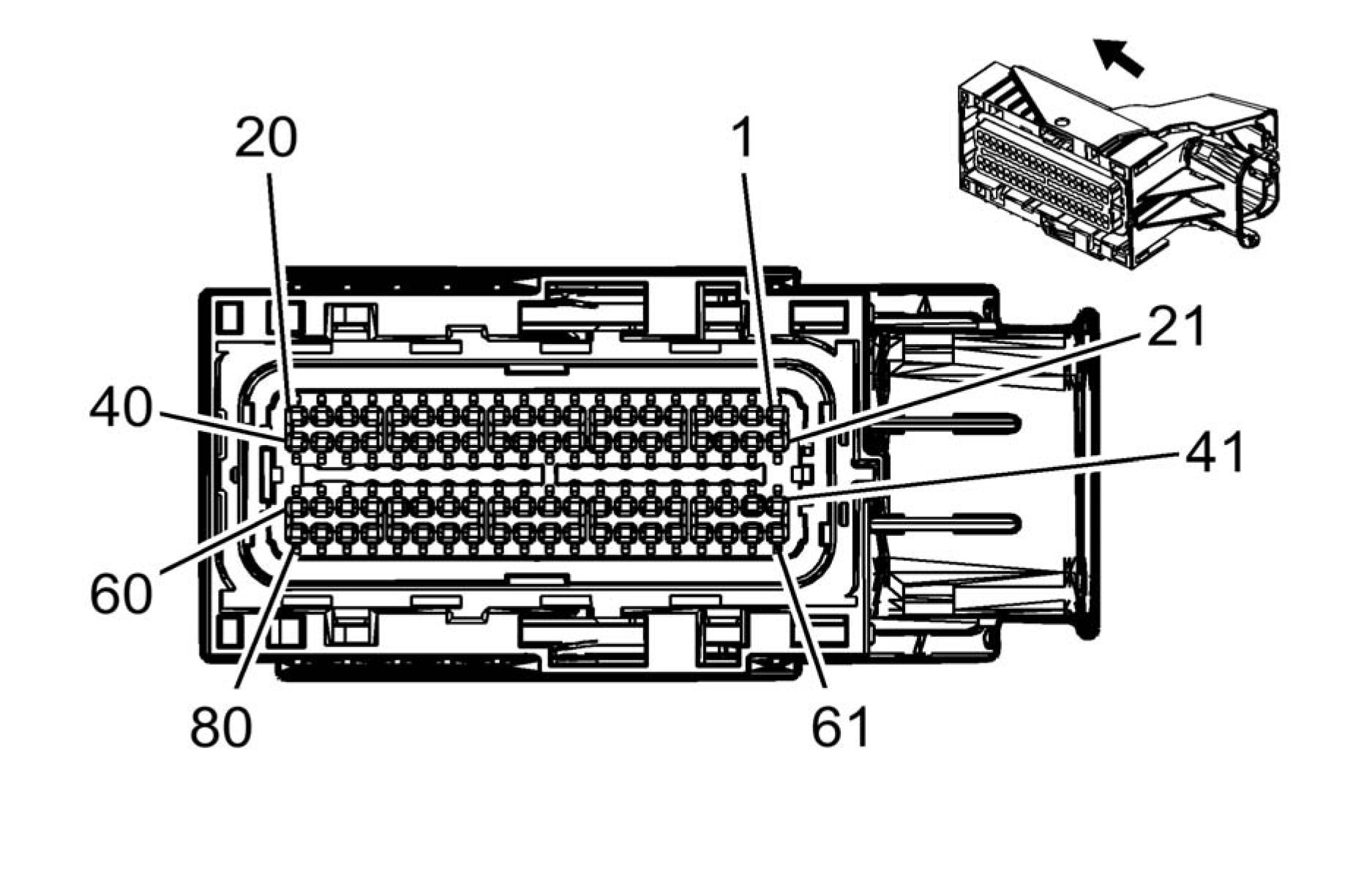 |
|
Connector Part Information |
• Harness Type: Body
• OEM Connector: 34566-6723
• Service Connector: 19115670
• Description: 80-Way F 0.64 Series, Sealed (BK with GY Terminal Position Assurance)
|
Terminal Part Information | ||||||||||||||||
|
|
Pin |
Size |
Color |
Circuit |
Function |
Terminal |
Option |
|
1 - 6 |
- |
- |
- |
Not Occupied |
- |
- |
|
7 |
0.5 |
BN/WH |
3827 |
Refuel Request Switch Signal |
I |
- |
|
8 |
0.5 |
GY/GN |
3954 |
Control Pilot Signal 1 |
I |
- |
|
9 |
0.5 |
BU/VT |
2364 |
Cooling Fan Speed Signal |
I |
- |
|
10 |
0.5 |
BU/GN |
5139 |
High Voltage Fault Signal |
I |
- |
|
11 |
- |
- |
- |
Not Occupied |
- |
- |
|
12 |
0.5 |
GN/GY |
3644 |
High Voltage Onboard Charging |
I |
- |
|
13 |
0.5 |
VT/WH |
3643 |
High Voltage Onboard Charging |
I |
- |
|
Pin |
Size |
Color |
Circuit |
Function |
Terminal |
Option |
|
14 |
0.5 |
VT/BU |
3790 |
Electric Coolant Motor Feedback |
I |
- |
|
15 |
0.5 |
BU/YE |
3953 |
Proximity Status Signal 1 |
I |
- |
|
16 - 17 |
- |
- |
- |
Not Occupied |
- |
- |
|
18 |
0.5 |
GN |
5060 |
Low Speed GMLAN Serial Data |
I |
- |
|
19 - 24 |
- |
- |
- |
Not Occupied |
- |
- |
|
25 |
0.5 |
WH/BU |
3697 |
Charge Port Door Sensor Signal |
I |
- |
|
26 |
- |
- |
- |
Not Occupied |
- |
- |
|
27 |
0.5 |
VT/GY |
2339 |
Run/Crank Ignition 1 Voltage |
I |
- |
|
28 - 32 |
- |
- |
- |
Not Occupied |
- |
- |
|
33 |
0.5 |
YE/GY |
3796 |
Rechargeable Energy Storage |
I |
- |
|
34 - 37 |
- |
- |
- |
Not Occupied |
- |
- |
|
38 |
0.5 |
GN |
5060 |
Low Speed GMLAN Serial Data |
I |
- |
|
39 - 40 |
- |
- |
- |
Not Occupied |
- |
- |
|
41 |
0.5 |
BU/BK |
6801 |
Fuel Door Lock/Unlock 1 |
I |
- |
|
42 |
0.5 |
WH/GN |
3794 |
Rechargeable Energy Storage |
I |
- |
|
43 |
0.5 |
BU/WH |
3977 |
Accessory Wakeup Serial Data 2 |
I |
- |
|
44 |
0.5 |
BU/YE |
3646 |
High Voltage Onboard Charging |
I |
- |
|
45 - 51 |
- |
- |
- |
Not Occupied |
- |
- |
|
52 |
0.5 |
WH |
2368 |
Cooling Fan Control Signal |
I |
- |
|
53 |
0.5 |
YE/GY |
3645 |
High Voltage Onboard Charging |
I |
- |
|
54 - 58 |
- |
- |
- |
Not Occupied |
- |
- |
|
59 |
0.5 |
BU/VT |
3818 |
Rechargeable Energy Storage |
I |
- |
|
60 |
- |
- |
- |
Not Occupied |
- |
- |
|
61 |
0.5 |
BU |
6800 |
Fuel Door Lock/Unlock 1 Signal |
I |
- |
|
62 |
0.5 |
GY/GN |
3957 |
Charging Pilot Signal Indicator |
I |
- |
|
63 |
0.5 |
BN/BU |
3788 |
Electric Coolant Motor Control |
I |
- |
|
64 |
0.5 |
YE/VT |
3956 |
Charging Status Indicator Control |
I |
- |
|
65 |
0.5 |
BU/BN |
3787 |
High Voltage Energy Management |
I |
- |
|
66 |
- |
- |
- |
Not Occupied |
- |
- |
|
67 |
0.5 |
VT/YE |
5985 |
Accessory Wakeup Serial Data |
I |
- |
|
68 - 72 |
- |
- |
- |
Not Occupied |
- |
- |
|
73 |
0.5 |
BU/VT |
3795 |
Rechargeable Energy Storage |
I |
- |
|
Pin |
Size |
Color |
Circuit |
Function |
Terminal |
Option |
|
74 |
0.5 |
YE/GN |
3789 |
Electric Coolant Motor Control |
I |
- |
|
75 - 78 |
- |
- |
- |
Not Occupied |
- |
- |
|
79 |
0.5 |
WH/YE |
3819 |
Rechargeable Energy Storage |
I |
- |
|
80 |
- |
- |
- |
Not Occupied |
- |
- |
 |
|
Terminal Part Information |
| ||||||||||||||||||||||||
|
Pin Size Color Circuit Function Terminal Option |
| |||||||||||||||||||||||||||||||||||||||||||||||||||||||||||||||||||||||||||||||||||||||||||
|
K124 ACTIVE SAFETY CONTROL MODULE X2 |

Connector Part Information
• Harness Type: Body
• OEM Connector: 15136073
• Service Connector: 15136073
• Description: 16-Way F 0.64 Kaizen Series (BK)
|
Terminal Part Information | ||||||||||||||||
|
| ||||||||||||||||||||||||||||||||||||||||||||||||||||||||||||||||||||||||||||||||||||||||||||||||||||||||||||||||
|
K132 PEDESTRIAN ALERT SOUND CONTROL MODULE |

Connector Part Information
• Harness Type: Body
• OEM Connector: 13569289
• Service Connector: 19178082
• Description: 10-Way F 0.64 Series, Sealed (BK)
|
Terminal Part Information | ||||||||||||||||
|
|
Pin |
Size |
Color |
Circuit |
Function |
Terminal |
Option |
|
1 |
0.5 |
WH |
2501 |
High Speed GMLAN Serial Data |
I |
- |
|
2 |
0.5 |
BU |
2500 |
High Speed GMLAN Serial Data |
I |
- |
|
3 |
0.5 |
BK |
1450 |
Ground |
I |
- |
|
4 |
0.5 |
WH/BU |
5986 |
Serial Data Communication Enable |
I |
- |
|
5 |
- |
- |
- |
Not Occupied |
- |
- |
|
6 |
0.5 |
WH |
2501 |
High Speed GMLAN Serial Data |
I |
- |
|
7 |
0.5 |
BU |
2500 |
High Speed GMLAN Serial Data |
I |
- |
| ||||||||||||||||||||||||||||
|
K177 BRAKE BOOSTER CONTROL MODULE |

Connector Part Information
• Harness Type: Body
• OEM Connector: 13590059
• Service Connector: 19332378
• Description: 26-Way F 1.5, 2.8, 4.8 Series, Sealed (BK)
|
Terminal Part Information | ||||||||||||||||||||||||||||||||
|
| |||||||||||||||||||||||||||||||||||||||||||||||||||||||||||||||||||||||||||||||||||||||||||||||||||||||||||||||||||||||||||||||||||||||||||||||||||
|
K182 PARKING ASSIST CONTROL MODULE X1 |
 |
|
Connector Part Information |
• Harness Type: Body
• OEM Connector: 31410-1120
• Service Connector: 89047364
• Description: 12-Way F 0.64 Series, Sealed (BK)
|
Terminal Part Information | ||||||||||||||||
|
|
Pin |
Size |
Color |
Circuit |
Function |
Terminal |
Option |
|
1 |
0.5 |
RD/GY |
2840 |
Battery Positive Voltage |
I |
- |
|
2 |
- |
- |
- |
Not Occupied |
- |
- |
|
3 |
0.35 |
GN/BN |
5852 |
Rear Park Assist LED Disable |
I |
- |
|
4 |
- |
- |
- |
Not Occupied |
- |
- |
|
5 |
0.5 |
BU/YE |
6105 |
High Speed GMLAN Serial Data (+) 2 |
I |
- |
|
6 |
0.5 |
BU/YE |
6105 |
High Speed GMLAN Serial Data (+) 2 |
I |
- |
|
7 |
0.5 |
BK |
650 |
Ground |
I |
- |
|
8 |
0.35 |
GY/GN |
2555 |
Rear Park Assist Disable Signal |
I |
- |
| |||||||||||||||||||||||||||||||||||
|
K182 PARKING ASSIST CONTROL MODULE X2 |
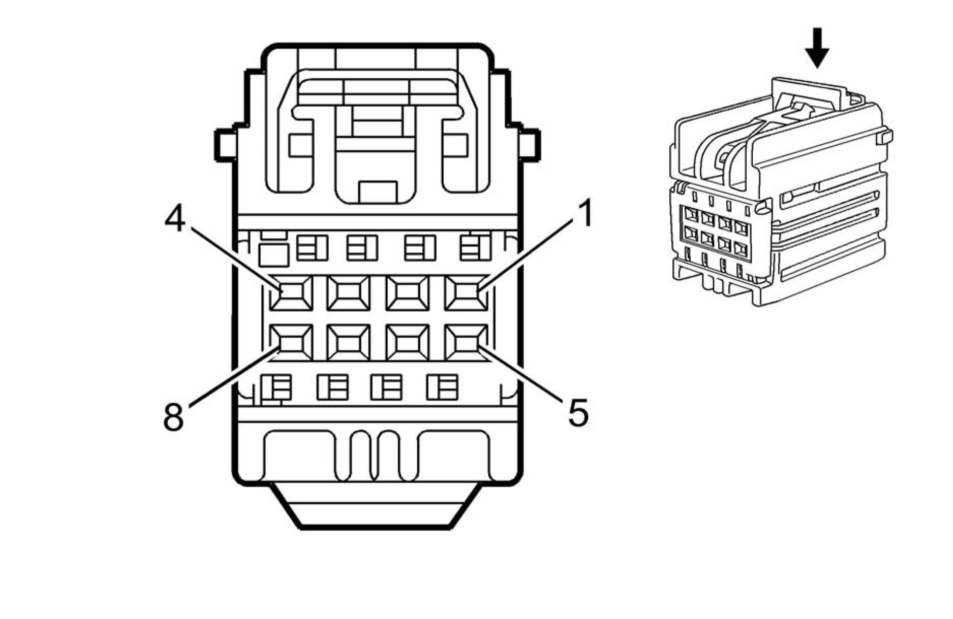 |
|
Connector Part Information |
• Harness Type: Body
• OEM Connector: 7283-9029-40
• Service Connector: 19115653
• Description: 8-Way F YESC Kaizen Series (L-GY)
|
Terminal Part Information | ||||||||||||||||
| ||||||||||||||||
|
Pin Size Color Circuit Function Terminal Option |
| |||||||||||||||||||||||||||||||||||||||||||||||||||||||||||||||
|
K182 PARKING ASSIST CONTROL MODULE X3 |

Connector Part Information
• Harness Type: Body
• OEM Connector: 7283-9068-90
• Service Connector: 15127038
• Description: 14-Way F 0.64 Kaizen Series (BU)
|
Terminal Part Information | ||||||||||||||||
|
|
Terminal |
Terminated |
Diagnostic |
Terminal |
Service |
Tray |
Core |
Insulation |
|
(LT BU) |
M064 |
14 |
| |||||||||||||||||||||||||||||||||||||||||||||||||||||||||||||||||||||||||||||||||||||||||||
|
M6 AIR TEMPERATURE DOOR ACTUATOR |

Connector Part Information
• Harness Type: HVAC
• OEM Connector: 13691690
• Service Connector: Service by Harness - See Part Catalog
• Description: 6-Way F 0.64 Series (BK)
|
Terminal Part Information | ||||||||||||||||
|
| |||||||||||||||||||||||||||||||||||||||||||||||||
|
M7 TRANSMISSION SHIFT LOCK CONTROL SOLENOID ACTUATOR |
Connector Part Information
• Harness Type: Shift Lock
• OEM Connector: Not Available
• Service Connector: Service by Harness - See Part Catalog
• Description: 2-Way
|
Terminal Part Information | ||||||||||||||||
|
|
Pin |
Size |
Color |
Circuit |
Function |
Terminal |
Option |
|
1 |
0.3 |
RD |
5905 |
Key Capture/Column Lock Shift |
I |
- |
|
2 |
0.3 |
BK |
650 |
Ground |
I |
- |
|
M8 BLOWER MOTOR |
 |
|
Connector Part Information |
• Harness Type: Instrument Panel
• OEM Connector: 7287-9355-30
• Service Connector: 19330673
• Description: 6-Way F 0.64 GET, 6.3 Series (BK)
|
Terminal Part Information | ||||||||||||||||||||||||
|
| |||||||||||||||||||||||||||||||||||
|
M37 MODE DOOR ACTUATOR |
 |
|
Connector Part Information |
• Harness Type: HVAC
• OEM Connector: 13691690
• Service Connector: Service by Harness - See Part Catalog
• Description: 6-Way F 0.64 Series (BK)
|
Terminal Part Information | ||||||||||||||||
|
|
Pin |
Size |
Color |
Circuit |
Function |
Terminal |
Option |
|
1 |
0.5 |
BU/BN |
3167 |
Mode Door Stepper Motor |
I |
- |
|
2 |
0.5 |
RD |
7572 |
HVAC Motor Control |
I |
- |
|
3 |
0.5 |
GN/RD |
3165 |
Mode Door Stepper Motor |
I |
- |
|
4 |
0.5 |
BN/RD |
3168 |
Mode Door Stepper Motor |
I |
- |
|
5 |
- |
- |
- |
Not Occupied |
- |
- |
|
6 |
0.5 |
BU |
3166 |
Mode Door Stepper Motor |
I |
- |
M46 AIR RECIRCULATION DOOR ACTUATOR
 |
|
Connector Part Information |
• Harness Type: HVAC
• OEM Connector: 13691690
• Service Connector: Service by Harness - See Part Catalog
• Description: 6-Way F 0.64 Series (BK)
|
Terminal Part Information | ||||||||||||||||
|
|
Pin |
Size |
Color |
Circuit |
Function |
Terminal |
Option |
|
1 |
0.5 |
BU/VT |
3173 |
Air Inlet Door Stepper Motor |
I |
- |
|
2 |
0.5 |
RD |
7572 |
HVAC Motor Control |
I |
- |
|
3 |
0.5 |
GN/RD |
3174 |
Air Inlet Door Stepper Motor |
I |
- |
|
4 |
0.5 |
BN/RD |
3175 |
Air Inlet Door Stepper Motor |
I |
- |
|
5 |
- |
- |
- |
Not Occupied |
- |
- |
| ||||||||||||||
|
M74D WINDOW MOTOR - DRIVER |

Connector Part Information
• Harness Type: Driver Door
• OEM Connector: 1-1732115-1
• Service Connector: Service by Harness - See Part Catalog
• Description: 7-Way F 0.64, 2.8 Kaizen Timer Series, Sealed (BK)
|
Terminal Part Information | ||||||||||||||||||||||||
|
|
Pin |
Size |
Color |
Circuit |
Function |
Terminal |
Option |
|
1 |
2.5 |
BK |
1550 |
Ground |
I |
- |
|
2 |
2.5 |
RD/BN |
3640 |
Battery Positive Voltage |
I |
- |
| ||||||||||||||||||||||||||||||||||||||||||
|
M74LR WINDOW MOTOR - LEFT REAR |
 |
|
Connector Part Information |
• Harness Type: Left Rear Door
• OEM Connector: 54200220N
• Service Connector: Service by Harness - See Part Catalog
• Description: 2-Way F 2.8 Series, Sealed (BK)
|
Terminal Part Information | ||||||||||||||||
|
|
Terminal |
Terminated |
Diagnostic |
Terminal |
Service |
Tray |
Core |
Insulation |
|
(VT) |
Required |
Required |
Required |
Required |
| |||||||||||||||||||||
|
M74P WINDOW MOTOR - PASSENGER |

Connector Part Information
• Harness Type: Passenger Door
• OEM Connector: 54200220N
• Service Connector: Service by Harness - See Part Catalog
• Description: 2-Way F 2.8 Series, Sealed (BK)
|
Terminal Part Information | ||||||||||||||||
|
| |||||||||||||||||||||
|
M74RR WINDOW MOTOR - RIGHT REAR |

Connector Part Information
• Harness Type: Right Rear Door
• OEM Connector: 54200220N
• Service Connector: Service by Harness - See Part Catalog
• Description: 2-Way F 2.8 Series, Sealed (BK)
|
Terminal Part Information | ||||||||||||||||
|
|
Pin |
Size |
Color |
Circuit |
Function |
Terminal |
Option |
|
1 |
2.5 |
GN/BK |
671 |
Power Window Motor Right |
I |
- |
| ||||||||||||||
|
M75 WINDSHIELD WIPER MOTOR |

Connector Part Information
• Harness Type: Body
• OEM Connector: 42122100
• Service Connector: 13578531
• Description: 4-Way F 2.8 Junior Power Timer Series, Sealed (BK)
|
Terminal Part Information | ||||||||||||||||
|
|
Pin |
Size |
Color |
Circuit |
Function |
Terminal |
Option |
|
1 |
2.5 |
RD/YE |
3740 |
Battery Positive Voltage |
I |
- |
|
2 |
2.5 |
BK |
2050 |
Ground |
I |
- |
|
3 |
0.5 |
GY |
91 |
Windshield Wiper Motor Relay |
I |
- |
|
Pin |
Size |
Color |
Circuit |
Function |
Terminal |
Option |
|
4 |
0.5 |
GN/BN |
6132 |
Local Interconnect Network |
I |
- |

|
Terminal Part Information | ||||||||||||||||
|
|
Pin |
Size |
Color |
Circuit |
Function |
Terminal |
Option |
|
1 |
0.35 |
GN |
3389 |
Driver Mirror Motor Right (+) |
I |
- |
|
2 |
0.35 |
BU |
3391 |
Driver Mirror Motor Common |
I |
- |
|
Pin |
Size |
Color |
Circuit |
Function |
Terminal |
Option |
|
3 |
0.35 |
VT/BU |
3390 |
Driver Mirror Motor Up (+) |
I |
- |

|
Terminal Part Information | ||||||||||||||||
|
|
Pin |
Size |
Color |
Circuit |
Function |
Terminal |
Option |
|
1 |
0.35 |
GN |
3396 |
Passenger Mirror Motor Right |
I |
- |
|
2 |
0.35 |
BU |
3398 |
Passenger Mirror Motor |
I |
- |
| ||||||||||||||
|
M96 ACTIVE GRILLE AIR SHUTTER ACTUATOR |
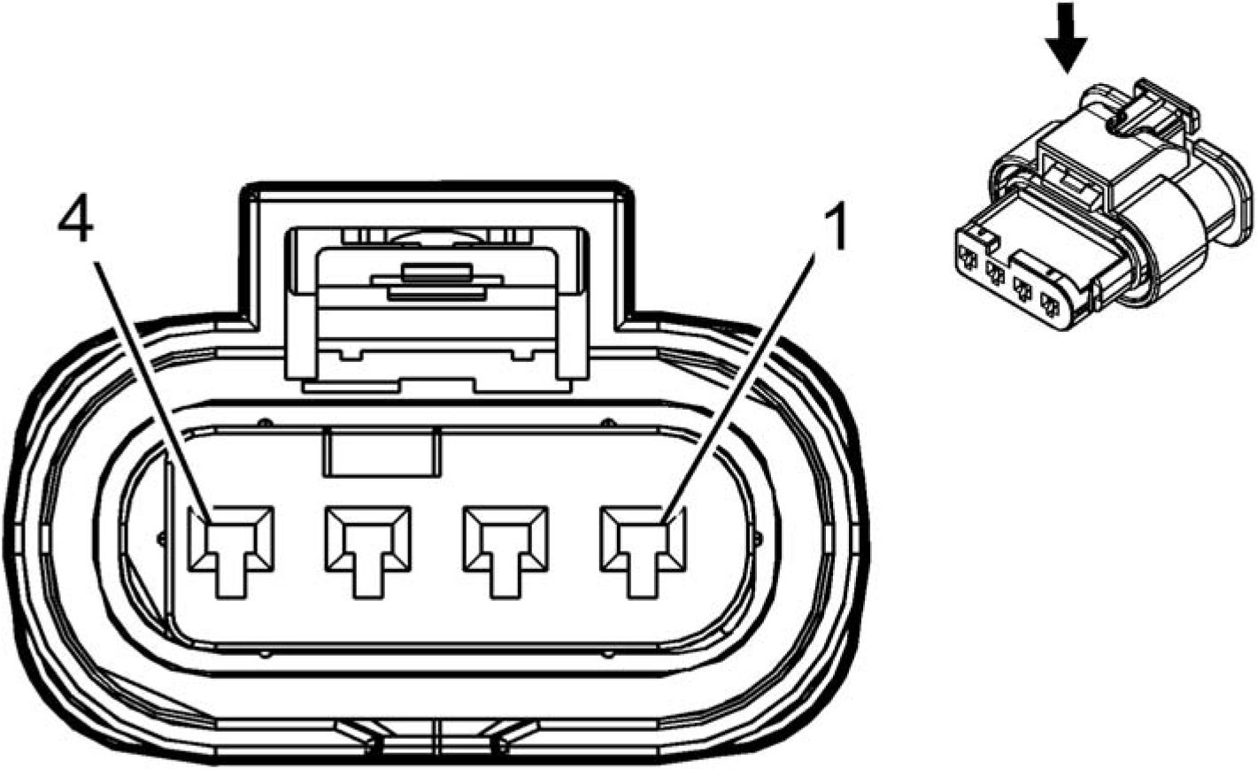
Connector Part Information
• Harness Type: Forward Lamp Extension
• OEM Connector: 1-1456426-6
• Service Connector: Service by Harness - See Part Catalog
• Description: 4-Way F 1.2 MCON Series (NA)
|
Terminal Part Information | ||||||||||||||||
|
|
Pin |
Size |
Color |
Circuit |
Function |
Terminal |
Option |
|
1 |
0.5 |
VT/BU |
5705 |
Powertrain Main Relay Fused |
I |
- |
|
2 |
0.35 |
GN/VT |
4621 |
Local Interconnect Network Serial Data Bus 21 |
I |
- |
|
Pin |
Size |
Color |
Circuit |
Function |
Terminal |
Option |
|
3 |
- |
- |
- |
Not Occupied |
- |
- |
|
4 |
0.5 |
BK/ |
1150 |
Ground |
I |
- |

|
Terminal Part Information | ||||||||||||||||
|
|
Pin |
Size |
Color |
Circuit |
Function |
Terminal |
Option |
|
1 |
0.5 |
BU |
6800 |
Fuel Door Lock/Unlock 1 Signal |
I |
- |
|
2 |
0.5 |
BU/BK |
6801 |
Fuel Door Lock/Unlock 1 |
I |
- |
M104L PARK BRAKE ACTUATOR - LEFT

Connector Part Information
• Harness Type: Body
• OEM Connector: 1928405715
• Service Connector: 19299882
• Description: 2-Way F 2.8 Series, Sealed (BK)
|
Terminal Part Information | ||||||||||||||||
|
| |||||||||||||||||||||
|
M104R PARK BRAKE ACTUATOR - RIGHT |

Connector Part Information
• Harness Type: Body
• OEM Connector: 1928405715
• Service Connector: 19299882
• Description: 2-Way F 2.8 Series, Sealed (BK)
|
Terminal Part Information | ||||||||||||||||
|
| |||||||||||||||||||||
|
P2 TRANSMISSION SHIFT LEVER POSITION INDICATOR |
 |
|
Connector Part Information |
• Harness Type: Floor Console
• OEM Connector: 24414934
• Service Connector: Service by Harness - See Part Catalog
• Description: 6-Way F 0.64 Micro-Quadlock Series (BK)
|
Terminal Part Information | ||||||||||||||||
|
| |||||||||||||||||||||||||||||||||||
|
P12 HORN |
 |
|
Connector Part Information |
• Harness Type: Forward Lamp
• OEM Connector: 34062-0027
• Service Connector: 19300543
• Description: 2-Way F 1.5 Series, Sealed (BK)
|
Terminal Part Information | ||||||||||||||||
|
| |||||||||||||||||||||
|
P16 INSTRUMENT CLUSTER |

Connector Part Information
• Harness Type: Instrument Panel
• OEM Connector: 90587345
• Service Connector: 88988405
• Description: 32-Way F 0.64 Micro-Quadlock Series (BK)
|
Terminal Part Information | ||||||||||||||||||||||||
|
|
Pin |
Size |
Color |
Circuit |
Function |
Terminal |
Option |
|
1 |
0.35 |
WH/GN |
3997 |
MOST Serial Data (-) |
I |
- |
|
2 |
0.35 |
GY/VT |
3998 |
MOST Serial Data (+) |
I |
- |
|
3 |
0.5 |
GN |
5060 |
Low Speed GMLAN Serial Data |
II |
- |
|
4 - 5 |
- |
- |
- |
Not Occupied |
- |
- |
|
6 |
0.35 |
WH/VT |
3999 |
MOST Control |
I |
- |
|
7 |
0.5 |
RD/GN |
502 |
Battery Positive Voltage |
II |
- |
|
8 |
0.5 |
VT/GN |
39 |
Run/Crank Ignition 1 Voltage |
II |
- |
|
9 - 11 |
- |
- |
- |
Not Occupied |
- |
- |
| |||||||||||||||||||||||||||||||||||||||||||||||||||||||||||||||||||||||||||||||||||||||||||
|
P17 INFO DISPLAY MODULE X1 |

Connector Part Information
• Harness Type: Instrument Panel
• OEM Connector: 13577390
• Service Connector: 13577390
• Description: 10-Way F 0.64 Kaizen Series (BK)
|
Terminal Part Information | ||||||||||||||||
|
| ||||||||||||||||||||||||||||||||||||||||||||||||||||||||||||||||||||||
|
P17 INFO DISPLAY MODULE X2 |

Connector Part Information
• Harness Type: Instrument Panel
• OEM Connector: 13580212
• Service Connector: Service by Cable Assembly - See Part Catalog
Description: 5-Way M 2.0 Mini-B USB Type (BK)
|
Terminal Part Information | ||||||||||||||||
|
|
Pin |
Size |
Color |
Circuit |
Function |
Terminal |
Option |
|
- |
- |
USB |
- |
USB Serial Data |
I |
- |
|
P19AC SPEAKER - SUBWOOFER (UQA) |
 |
|
Terminal Part Information | ||||||||
|
|
Terminal |
Terminated |
Diagnostic Test Probe |
Terminal |
Service |
Tray |
Core |
Insulation |
|
I |
Not Required |
J-35616-2A |
Not |
Not Required |
Not |
Not |
Not |
|
Pin |
Size |
Color |
Circuit |
Function |
Terminal |
Option |
|
1 |
1.5 |
GN/BK |
1794 |
Left/Rear Subwoofer Speaker (-) |
I |
- |
|
2 |
1.5 |
BU/GY |
346 |
Left/Rear Subwoofer Speaker |
I |
- |
|
P19AG SPEAKER - LEFT FRONT DOOR (UQA) |
 |
|
Terminal Part Information | ||||||||||||||||
|
|
Terminal |
Terminated |
Diagnostic Test Probe |
Terminal |
Service |
Tray |
Core |
Insulation |
|
(GY) |
Required |
Required |
Required |
Required |
| |||||||||||||||||||||
|
P19AG SPEAKER - LEFT FRONT DOOR (UZ6) |
 |
|
Connector Part Information |
• Harness Type: Driver Door
• OEM Connector: 34062-0046
• Service Connector: Service by Harness - See Part Catalog
• Description: 2-Way F 1.5 Series, Sealed (BK)
|
Terminal Part Information | ||||||||||||||||
| ||||||||||||||||
|
Pin Size Color Circuit Function Terminal Option |
| |||||||||||||||||||||
|
P19AH SPEAKER - RIGHT FRONT DOOR (UQA) |
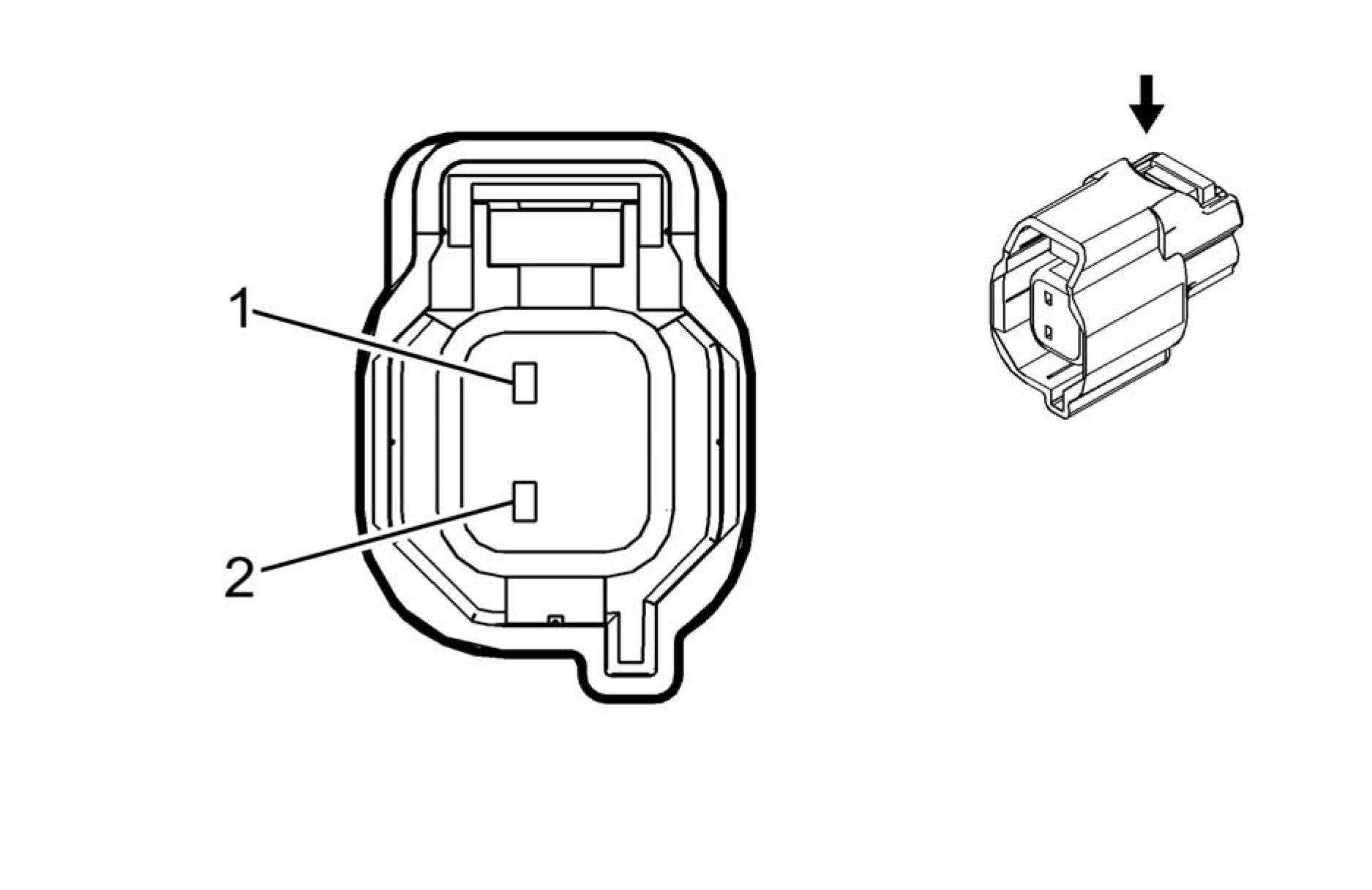 |
|
Connector Part Information |
• Harness Type: Passenger Door
• OEM Connector: 34062-0026
• Service Connector: Service by Harness - See Part Catalog
• Description: 2-Way F 1.5 Series, Sealed (L-GY)
|
Terminal Part Information | ||||||||||||||||
|
| |||||||||||||||||||||
|
P19AH SPEAKER - RIGHT FRONT DOOR (UZ6) |
 |
|
Connector Part Information |
• Harness Type: Passenger Door
• OEM Connector: 34062-0046
• Service Connector: Service by Harness - See Part Catalog
• Description: 2-Way F 1.5 Series, Sealed (BK)
|
Terminal Part Information | ||||||||||||||||
|
| |||||||||||||||||||||
|
P19AL SPEAKER - LEFT REAR DOOR (UQA) |

Connector Part Information
• Harness Type: Left Rear Door
• OEM Connector: 34062-0026
• Service Connector: Service by Harness - See Part Catalog
• Description: 2-Way F 1.5 Series, Sealed (L-GY)
|
Terminal Part Information | ||||||||||||||||
|
| |||||||||||||||||||||
|
P19AL SPEAKER - LEFT REAR DOOR (UZ6) |

Connector Part Information
• Harness Type: Left Rear Door
• OEM Connector: 7287-8378-40
• Service Connector: Service by Harness - See Part Catalog
• Description: 2-Way F 1.5 Series (L-GY)
|
Terminal Part Information | ||||||||||||||||
|
| |||||||||||||||||||||
|
P19AM SPEAKER - RIGHT REAR DOOR (UQA) |

Connector Part Information
• Harness Type: Right Rear Door
• OEM Connector: 34062-0026
• Service Connector: Service by Harness - See Part Catalog
• Description: 2-Way F 1.5 Series, Sealed (L-GY)
|
Terminal Part Information | ||||||||||||||||
|
| |||||||||||||||||||||
|
P19AM SPEAKER - RIGHT REAR DOOR (UZ6) |

Connector Part Information
• Harness Type: Right Rear Door
• OEM Connector: 7287-8378-40
• Service Connector: Service by Harness - See Part Catalog
• Description: 2-Way F 1.5 Series (L-GY)
|
Terminal Part Information | ||||||||||||||||
|
| |||||||||||||||||||||
|
P19B SPEAKER - CENTER INSTRUMENT PANEL (UQA) |
 |
|
Connector Part Information |
• Harness Type: Instrument Panel
• OEM Connector: 6098-5527
• Service Connector: 19352037
• Description: 2-Way F 1.5 Series (GY)
|
Terminal Part Information | ||||||||||||||||
|
| |||||||||||||||||||||
|
P19H SPEAKER - LEFT FRONT TWEETER |

Connector Part Information
• Harness Type: Instrument Panel
• OEM Connector: AIT2PB-2G-1AK
• Service Connector: 19332379
• Description: 2-Way F 0.64 Series (BK)
|
Terminal Part Information | ||||||||||||||||
|
| |||||||||||||||||||||
|
P19V SPEAKER - RIGHT FRONT TWEETER |

Connector Part Information
• Harness Type: Instrument Panel
• OEM Connector: AIT2PB-2G-1AK
• Service Connector: 19332379
• Description: 2-Way F 0.64 Series (BK)
|
Terminal Part Information | ||||||||||||||||
|
| |||||||||||||||||||||||||||
|
P43 COLLISION ALERT INDICATORS |

|
Terminal Part Information | ||||||||||||||||
|
| |||||||||||||||||||||||||||||||||||
|
P48 PEDESTRIAN ALERT SOUND SPEAKER |

Connector Part Information
• Harness Type: Forward Lamp
• OEM Connector: 34062-0033
• Service Connector: 19332516
• Description: 2-Way F 1.5 Series, Sealed (BK)
|
Terminal Part Information | ||||||||||||||||
|
| |||||||||||||||||||||
|
Q6E CAMSHAFT POSITION ACTUATOR SOLENOID VALVE - EXHAUST |

Connector Part Information
• Harness Type: Engine
• OEM Connector: 10010338
• Service Connector: 13587325
• Description: 2-Way F 1.2 Multilock Series, Sealed (L-GY)
|
Terminal Part Information | ||||||||||||||||
|
| |||||||||||||||||||||
|
Q6F CAMSHAFT POSITION ACTUATOR SOLENOID VALVE - INTAKE |

Connector Part Information
• Harness Type: Engine
• OEM Connector: 10010338
• Service Connector: 13587325
• Description: 2-Way F 1.2 Multilock Series, Sealed (L-GY)
|
Terminal Part Information | ||||||||||||||||
|
| |||||||||||||||||||||
|
Q8 CONTROL SOLENOID VALVE ASSEMBLY |

Connector Part Information
• Harness Type: Transmission
• OEM Connector: 13960977
• Service Connector: Service by Harness - See Part Catalog
• Description: 8-Way F 0.64 II Series (GY)
|
Terminal Part Information | ||||||||||||||||
|
|
Pin |
Size |
Color |
Circuit |
Function |
Terminal |
Option |
|
1 |
0.75 |
BK |
6387 |
Transmission High Side Driver 1 |
I |
- |
|
2 |
0.5 |
TN |
6401 |
Clutch B Control |
I |
- |
|
3 |
0.5 |
VT |
585 |
Transmission Oil Temperature |
I |
- |
|
4 |
0.5 |
GN |
586 |
Transmission Oil Temperature |
I |
- |
|
5 |
0.5 |
WH |
6404 |
Clutch E Control |
I |
- |
|
6 |
0.5 |
OG |
6403 |
Clutch D Control |
I |
- |
|
7 |
0.75 |
BN |
6388 |
Transmission High Side Driver 2 |
I |
- |
| ||||||||||||||
|
Q12 EVAPORATIVE EMISSION PURGE SOLENOID VALVE |

Connector Part Information
• Harness Type: Engine
• OEM Connector: 10010337
• Service Connector: 13587326
• Description: 2-Way F 1.2 Multilock Series, Sealed (BK)
|
Terminal Part Information | ||||||||||||||||
|
|
Pin |
Size |
Color |
Circuit |
Function |
Terminal |
Option |
|
1 |
0.5 |
VT/BU |
5293 |
Powertrain Main Relay Fused |
I |
- |
|
2 |
0.5 |
GN/BU |
428 |
EVAP Canister Purge Solenoid |
I |
- |
Q13 EVAPORATIVE EMISSION VENT SOLENOID VALVE

Connector Part Information
• Harness Type: EVAP
• OEM Connector: 7283-5062-30
• Service Connector: Service by Harness - See Part Catalog
• Description: 2-Way F 090 Series, Sealed (BK)
|
Terminal Part Information | ||||||||||||||||
|
| |||||||||||||||||||||
|
Q14 EXHAUST GAS RECIRCULATION VALVE |

Connector Part Information
• Harness Type: Engine
• OEM Connector: 2272975-5
• Service Connector: 19352911
• Description: 6-Way F 1.2 MCON Series, Sealed (BK)
|
Terminal Part Information | ||||||||||||||||
|
|
Pin |
Size |
Color |
Circuit |
Function |
Terminal |
Option |
|
1 |
0.5 |
VT/BU |
5293 |
Powertrain Main Relay Fused |
I |
- |
|
2 |
0.5 |
BK |
250 |
Ground |
I |
- |
|
3 |
0.5 |
BN/VT |
4322 |
Exhaust Gas Recirculation Pulse |
I |
- |
|
4 |
0.5 |
BN/WH |
4323 |
Exhaust Gas Recirculation Pulse |
I |
- |
|
5 |
0.5 |
BK/BN |
2753 |
Exhaust Gas Recirculation Sensor |
I |
- |
|
6 |
- |
- |
- |
Not Occupied |
- |
- |
Q17A FUEL INJECTOR 1
 |
|
Connector Part Information |
• Harness Type: Fuel
• OEM Connector: 13581410
• Service Connector: Service by Harness - See Part Catalog
• Description: 2-Way F 1.5 Series, Sealed (BK)
|
Terminal Part Information | ||||||||||||||||
|
| |||||||||||||||||||||
|
Q17B FUEL INJECTOR 2 |
 |
|
Connector Part Information |
• Harness Type: Fuel
• OEM Connector: 13581410
• Service Connector: Service by Harness - See Part Catalog
• Description: 2-Way F 1.5 Series, Sealed (BK)
|
Terminal Part Information | ||||||||||||||||
|
| |||||||||||||||||||||
|
Q17C FUEL INJECTOR 3 |
 |
|
Connector Part Information |
• Harness Type: Fuel
• OEM Connector: 13581410
• Service Connector: Service by Harness - See Part Catalog
• Description: 2-Way F 1.5 Series, Sealed (BK)
|
Terminal Part Information | ||||||||||||||||
|
| |||||||||||||||||||||
|
Q17D FUEL INJECTOR 4 |
 |
|
Connector Part Information |
• Harness Type: Fuel
• OEM Connector: 13581410
• Service Connector: Service by Harness - See Part Catalog
• Description: 2-Way F 1.5 Series, Sealed (BK)
|
Terminal Part Information | ||||||||||||||||
|
| |||||||||||||||||||||
|
Q23 LINE PRESSURE CONTROL SOLENOID VALVE |
|
• Harne |
ss Type: Body Terminated Connteeaor: 15 |
Diagnostic ’^TeSrProbe ervice by Har |
Terminal |
Service t Catalog |
Tray |
Core |
Insulation |
|
• IDesci |
iptirtnieqUfeylT |
NattAGUahlri |
es№)oo! Required |
Not Required |
Not |
Not |
Not |
 |
|
Connector Part Information Terminal Part Information |
Pin
Size
Color
Circuit
Function
Terminal
Type ID
Option
0.75
BK
6387
Transmission High Side Driver 1
Signal Driver
B 0.5 YE 6400 Clutch A Control
Article GUID: A00884639
ELECTRICAL
COMPONENT CONNECTOR END VIEWS
Q38 THROTTLE BODY

Connector Part Information
• Harness Type: Engine
• OEM Connector: 2272975-5
• Service Connector: 19352911
• Description: 6-Way F 1.2 MCON Series, Sealed (BK)
|
Terminal Part Information | ||||||||||||||||
|
|
Pin |
Size |
Color |
Circuit |
Function |
Terminal |
Option |
|
1 |
0.5 |
YE |
581 |
Throttle Actuator Control Open |
I |
- |
|
2 |
0.5 |
BN/WH |
582 |
Throttle Actuator Control Close |
I |
- |
| |||||||||||||||||||||||||||||||||||
|
Q44 ENGINE OIL PRESSURE CONTROL SOLENOID VALVE |
 |
|
Connector Part Information |
• Harness Type: Engine Oil Level Sensor
• OEM Connector: 13587570
• Service Connector: Service by Harness - See Part Catalog
• Description: 2-Way F 1.2 MCON Series (BN)
|
Terminal Part Information | ||||||||||||||||
| ||||||||||||||||
|
Pin Size Color Circuit Function Terminal Option |
| |||||||||||||||||||||
|
Q63 EVAPORATIVE EMISSION SYSTEM LEAK DETECTION PUMP ASSEMBLY |

Connector Part Information
• Harness Type: EVAP
• OEM Connector: 6189-1240
• Service Connector: Service by Harness - See Part Catalog
• Description: 8-Way F TS Series, Sealed (D-GY)
|
Terminal Part Information | ||||||||||||||||
|
|
Pin |
Size |
Color |
Circuit |
Function |
Terminal |
Option |
|
1 |
0.5 |
GY |
3723 |
Evap Leak Check Module |
I |
- |
|
2 |
- |
- |
- |
Not Occupied |
- |
- |
| |||||||||||||||||||||||||||||||||||||||||||||||||
|
Q66 PASSENGER COMPARTMENT HEATER COOLANT CONTROL VALVE |

Connector Part Information
• Harness Type: Engine
• OEM Connector: 33472-0611
• Service Connector: 13585853
• Description: 6-Way F 150 MX Series, Sealed (BK)
|
Terminal Part Information | ||||||||||||||||
|
|
Terminal |
Terminated |
Diagnostic Test Probe |
Terminal |
Service |
Tray |
Core |
Insulation |
|
(GY) |
Required |
Required |
Required |
Required |
| |||||||||||||||||||||||||||||||||||||||||||||||||
|
R6A TERMINATING RESISTOR - HIGH SPEED BUS |
 |
|
Connector Part Information |
• Harness Type: Body
• OEM Connector: 13510085
• Service Connector: 13580114
• Description: 2-Way F 150 GT Series, Sealed (BK)
|
Terminal Part Information | ||||||||||||||||
|
| |||||||||||||||||||||
|
S3 TRANSMISSION SHIFT LEVER |

Connector Part Information
• Harness Type: Body
• OEM Connector: AIT2PB-06-1AK
• Service Connector: 19167753
• Description: 6-Way F 0.64 Kaizen Series (BK)
|
Terminal Part Information | ||||||||||||||||
|
| |||||||||||||||||||||||||||||||||||||||||||||||||
|
S13D DOOR LOCK SWITCH - DRIVER |

Connector Part Information
• Harness Type: Driver Door Trim
• OEM Connector: 1379029-2
• Service Connector: Service by Harness - See Part Catalog
• Description: 4-Way F 0.64 Micro-Quadlock Series (WH)
|
Terminal Part Information | ||||||||||||||||
| ||||||||||||||||
|
Pin I Size | Color Circuit Function Terminal Option |
| |||||||||||||||||||||||||||||||||||
|
S13P DOOR LOCK SWITCH - PASSENGER |
 |
|
Connector Part Information |
• Harness Type: Passenger Door Trim
• OEM Connector: 1379029-2
• Service Connector: Service by Harness - See Part Catalog
• Description: 4-Way F 0.64 Micro-Quadlock Series (WH)
|
Terminal Part Information | ||||||||||||||||
|
|
Pin |
Size |
Color |
Circuit |
Function |
Terminal |
Option |
|
Pin |
Size |
Color |
Circuit |
Function |
Terminal |
Option |
|
1 |
0.35 |
YE |
6817 |
LED Backlight Dimming Control |
I |
- |
|
2 |
0.35 |
YE/VT |
244 |
Passenger Door Lock Switch |
I |
- |
|
3 |
0.35 |
BN/VT |
245 |
Passenger Door Lock Switch |
I |
- |
|
4 |
0.35 |
BK |
2050 |
Ground |
I |
- |

|
Terminal Part Information | ||||||||||||||||
|
|
Pin |
Size |
Color |
Circuit |
Function |
Terminal |
Option |
| |||||||||||||||||||||||||||||||||||
|
S30 HEADLAMP SWITCH |
 |
|
Connector Part Information |
• Harness Type: Instrument Panel
• OEM Connector: 31410-1120
• Service Connector: 89047364
• Description: 12-Way F 0.64 Series, Sealed (BK)
|
Terminal Part Information | ||||||||||||||||
|
|
Pin |
Size |
Color |
Circuit |
Function |
Terminal |
Option |
|
1 |
0.35 |
WH/VT |
103 |
Headlamp Switch On Signal |
I |
- |
|
2 |
0.35 |
YE |
6817 |
LED Backlight Dimming Control |
I |
- |
| ||||||||||||||||||||||||||||||||||||||||||||||||||||||||||||||||||||||
|
S32LR SEAT HEATING SWITCH - LEFT REAR |
 |
|
Connector Part Information |
• Harness Type: Body
• OEM Connector: 24414934
• Service Connector: 88988105
• Description: 6-Way F 0.64 Micro-Quadlock Series (BK)
Terminal Part Information_____________________
I Terminal Terminated Diagnostic Terminal
Service
Tray Core
Insulation
|
Type ID |
Lead |
Test Probe |
Removal |
Terminal |
Name |
Crimp |
Crimp |
|
I |
Not Required |
J-35616-64B |
Not |
Not |
Not |
Not |
Not |
| |||||||||||||||||||||||||||||||||||||||||||||||||
|
S32RR SEAT HEATING SWITCH - RIGHT REAR |
 |
|
Connector Part Information |
• Harness Type: Body
• OEM Connector: 2-968291-2
• Service Connector: 13225892
• Description: 6-Way F 0.64 Micro-Quadlock Series (NA)
Terminal Part Information
|
Terminal |
Terminated |
Diagnostic Test Probe |
Terminal |
Service |
Tray |
Core |
Insulation |
|
I |
Not Required |
J-35616-64B |
Not |
Not |
Not |
Not |
Not |
| |||||||||||||||||||||||||||||||||||||||||||||||||
|
S33 HORN SWITCH X1 |
 |
|
Connector Part Information |
• Harness Type: Steering Wheel
• OEM Connector: 1742086-1
• Service Connector: Service by Harness - See Part Catalog
• Description: 1-Way F Fast-In-On Series
|
Terminal Part Information | ||||||||||||||||
|
| ||||||||||||||
|
S33 HORN SWITCH X2 |
 |
|
Connector Part Information |
• Harness Type: Steering Wheel
• OEM Connector: 1742086-1
• Service Connector: Service by Harness - See Part Catalog
• Description: 1-Way F Fast-In-On Series
|
Terminal Part Information | ||||||||||||||||
|
| ||||||||||||||
|
S46 LIFTGATE HANDLE SWITCH |

Connector Part Information
• Harness Type: Liftgate
• OEM Connector: 1-1703498-3
• Service Connector: Service by Harness - See Part Catalog
• Description: 2-Way M 1.2 Multilock Series, Sealed (BK)
|
Terminal Part Information | ||||||||||||||||
|
| |||||||||||||||||||||
|
S48B MULTIFUNCTION SWITCH - OVERHEAD CONSOLE |

Connector Part Information
• Harness Type: Headliner
• OEM Connector: AIT2PB-22-2AK
• Service Connector: 13504097
• Description: 22-Way F 0.64 Kaizen Series (BK)
|
Terminal Part Information | ||||||||||||||||
|
|
Pin |
Size |
Color |
Circuit |
Function |
Terminal |
Option |
|
1 |
0.5 |
RD/GN |
2440 |
Battery Positive Voltage |
I |
- |
|
2 |
0.5 |
WH/YE |
7557 |
LED Ambient Lighting Control 1 |
I |
- |
|
3 |
0.35 |
GY |
156 |
Courtesy Lamp Switch Signal |
I |
- |
|
4 |
- |
- |
- |
Not Occupied |
- |
- |
|
5 |
0.5 |
BK |
2150 |
Ground |
I |
- |
|
6 |
- |
- |
- |
Not Occupied |
- |
- |
|
7 |
0.5 |
WH/BN |
6815 |
Inadvertent Power Control |
I |
- |
|
8 |
0.5 |
GY |
157 |
Interior Lamp Control |
I |
- |
|
9 - 10 |
- |
- |
- |
Not Occupied |
- |
- |
|
11 |
0.35 |
GN |
2308 |
Passenger Air Bag Off Indicator |
I |
- |
| ||||||||||||||||||||||||||||||||||||||||||||||||||||||||||||||||||||||||||||||||||||
|
S48E MULTIFUNCTION SWITCH - CENTER CONSOLE |

Connector Part Information
• Harness Type: Floor Console
• OEM Connector: 7283-9068-90
• Service Connector: Service by Harness - See Part Catalog
• Description: 14-Way F 0.64 Kaizen Series (BU)
|
Terminal Part Information | ||||||||||||||||
|
| |||||||||||||||||||||||||||||||||||||||||||||||||||||||||||||||||||||||||||||
|
S70E STEERING WHEEL CONTROLS SWITCH - RADIO PRESETS |
 |
|
Connector Part Information |
• Harness Type: Steering Wheel
• OEM Connector: 50-57-9404
• Service Connector: Service by Harness - See Part Catalog
• Description: 4-Way F 0.64 SL Series (BK)
|
Terminal Part Information | ||||||||||||||||
|
| |||||||||||||||||||||||||||||||||||
|
S70F STEERING WHEEL CONTROLS SWITCH - RADIO VOLUME |
 |
|
Connector Part Information |
• Harness Type: Steering Wheel
• OEM Connector: 4-1718346-1
• Service Connector: Service by Harness - See Part Catalog
• Description: 3-Way F 0.64 Micro-Quadlock Series (PU)
|
Terminal Part Information | ||||||||||||||||
|
| ||||||||||||||||||||||||||||
|
S70L STEERING WHEEL CONTROLS SWITCH - LEFT |
 |
|
Connector Part Information |
• Harness Type: Steering Wheel
• OEM Connector: 1-1355524-3
• Service Connector: Service by Harness - See Part Catalog
• Description: 12-Way F 0.64 GET Series (BK with BK Case)
|
Terminal Part Information | ||||||||||||||||
|
|
Terminal |
Terminated |
Diagnostic Test Probe |
Terminal |
Service |
Tray |
Core |
Insulation |
|
Required |
Required |
Required |
Required |
| |||||||||||||||||||||||||||||||||||||||||||||||||||||||||||||||||||||||||||||||||||||||||||
|
S70R STEERING WHEEL CONTROLS SWITCH - RIGHT |

Connector Part Information
• Harness Type: Steering Wheel
• OEM Connector: 2-1355524-3
• Service Connector: Service by Harness - See Part Catalog
• Description: 12-Way F 0.64 GET Series (BK with NA Case)
|
Terminal Part Information | ||||||||||||||||
|
| ||||||||||||||||||||||||||||||||||||||||||||||||||||||||||||||||||||||||||||||||||||
|
S78 TURN SIGNAL/MULTIFUNCTION SWITCH |
 |
|
Connector Part Information |
• Harness Type: Instrument Panel
• OEM Connector: 1488973-1
• Service Connector: 19299776
• Description: 10-Way F 0.64 Micro-Quadlock Series (BK)
|
Terminal Part Information | ||||||||||||||||
|
|
Pin |
Size |
Color |
Circuit |
Function |
Terminal |
Option |
|
1 |
0.5 |
BU/WH |
1414 |
Left Front Turn Signal Switch |
I |
- |
|
2 |
0.5 |
GN/VT |
1415 |
Right Front Turn Signal Switch |
I |
- |
|
3 |
0.5 |
BK |
1650 |
Ground |
I |
- |
|
4 |
0.5 |
BU |
6856 |
Headlamp Automatic High Beam |
I |
- |
|
5 |
- |
- |
- |
Not Occupied |
- |
- |
|
6 |
0.5 |
YE/BN |
307 |
Headlamp Switch Flash To Pass |
I |
- |
|
7 |
0.5 |
WH |
524 |
Headlamp Dimmer Switch High |
I |
- |
| ||||||||||||||
|
S79LR WINDOW SWITCH - LEFT REAR |
 |
|
Connector Part Information |
• Harness Type: Left Rear Door
• OEM Connector: 31372-1000
• Service Connector: Service by Harness - See Part Catalog
• Description: 10-Way F 1.5, 2.8 Series (BK)
|
Terminal Part Information | ||||||||||||||||||||||||
|
|
Pin |
Size |
Color |
Circuit |
Function |
Terminal |
Option |
|
1 |
0.5 |
GN/GY |
6135 |
Local Interconnect Network |
I |
- |
| ||||||||||||||||||||||||||||||||||||||||||||||||||||||||
|
S79P WINDOW SWITCH - PASSENGER |
 |
|
Connector Part Information |
• Harness Type: Passenger Door Trim
• OEM Connector: 31372-1000
• Service Connector: Service by Harness - See Part Catalog
• Description: 10-Way F 1.5, 2.8 Series (BK)
|
Terminal Part Information | ||||||||||||||||
|
|
Terminal |
Terminated |
Diagnostic Test Probe |
Terminal |
Service |
Tray |
Core |
Insulation |
|
(GY) |
Required |
Required |
Required |
Required | |||
|
II |
Not Required |
J-35616-4A |
No Tool |
Not Required |
Not |
Not |
Not |
| ||||||||||||||||||||||||||||||||||||||||||||||||||||||||
|
S79RR WINDOW SWITCH - RIGHT REAR |
 |
|
Connector Part Information |
• Harness Type: Right Rear Door
• OEM Connector: 31372-1000
• Service Connector: Service by Harness - See Part Catalog
Description: 10-Way F 1.5, 2.8 Series (BK)
|
Terminal Part Information | ||||||||||||||||||||||||
|
|
Pin |
Size |
Color |
Circuit |
Function |
Terminal |
Option |
|
1 |
0.5 |
GN/GY |
6135 |
Local Interconnect Network |
I |
- |
|
2 |
0.35 |
GY |
748 |
Right Rear Door Ajar Switch |
I |
- |
|
3 - 6 |
- |
- |
- |
Not Occupied |
- |
- |
|
7 |
2.5 |
BK |
850 |
Ground |
II |
- |
|
8 |
2.5 |
RD/YE |
3740 |
Battery Positive Voltage |
II |
- |
|
9 |
2.5 |
BU/GY |
670 |
Power Window Motor Right Rear |
II |
- |
|
10 |
2.5 |
GN/BK |
671 |
Power Window Motor Right Rear |
II |
- |
|
S82 WINDSHIELD WIPER/WASHER SWITCH |
 |
Connector Part Information
• Harness Type: Instrument Panel
• OEM Connector: 1488973-2
• Service Connector: 19330677
• Description: 10-Way F 0.64 Micro-Quadlock Series (BK)
|
Terminal Part Information | ||||||||||||||||
|
| |||||||||||||||||||||||||||||||||||||||||||||||||
|
S83 VEHICLE ON/OFF SWITCH |
 |
|
Connector Part Information |
• Harness Type: Instrument Panel
• OEM Connector: 7283-9029-40
• Service Connector: 19115653
• Description: 8-Way F YESC Kaizen Series (L-GY)
|
Terminal Part Information | ||||||||||||||||
|
|
Pin |
Size |
Color |
Circuit |
Function |
Terminal |
Option |
|
1 - 2 |
- |
- |
- |
Not Occupied |
- |
- |
|
3 |
0.35 |
GN/BK |
3558 |
Passive Start Switch Signal 2 |
I |
- |
|
4 |
0.5 |
BK |
1650 |
Ground |
I |
- |
|
5 |
0.35 |
BU/BK |
5719 |
Ignition Mode Switch Start LED |
I |
- |
|
6 |
0.35 |
BU/GN |
5723 |
Ignition Mode Switch Mode |
I |
- |
|
7 |
0.35 |
BK/GY |
3559 |
Passive Start Switch 2 Low |
I |
- |
|
8 |
0.35 |
YE/GY |
230 |
Instrument Panel Lamp Dimming |
I |
- |
S91 PARK BRAKE CONTROL SWITCH
 |
|
Connector Part Information |
• Harness Type: Floor Console
• OEM Connector: HCMDPB-08-K
• Service Connector: Service by Harness - See Part Catalog
• Description: 8-Way F 1.2 HCM Series (BK)
|
Terminal Part Information | ||||||||||||||||
|
|
Pin |
Size |
Color |
Circuit |
Function |
Terminal |
Option |
|
1 |
0.35 |
YE |
1492 |
Park Brake Switch Supply |
I |
- |
|
2 |
0.35 |
BU/VT |
1134 |
Park Brake Switch Signal |
I |
- |
|
3 |
0.35 |
YE/RD |
7683 |
Park Brake Release Switch |
I |
- |
|
4 |
0.35 |
BN |
6107 |
Park Brake Apply Switch Signal |
I |
- |
|
5 |
0.35 |
BU/BK |
6108 |
Park Brake Release Switch |
I |
- |
| ||||||||||||||||||||||||||||
|
S117 REFUEL REQUEST SWITCH |
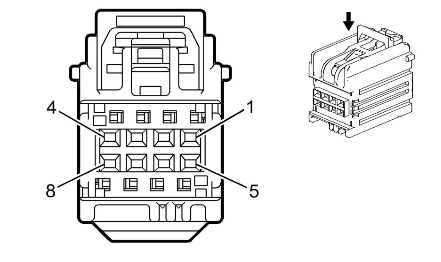
Connector Part Information
• Harness Type: Driver Door Trim
• OEM Connector: 7283-9028-30
• Service Connector: Service by Harness - See Part Catalog
• Description: 8-Way F YESC Kaizen Series (BK)
|
Terminal Part Information | ||||||||||||||||
|
|
Pin |
Size |
Color |
Circuit |
Function |
Terminal |
Option |
|
1 |
0.35 |
RD/WH |
4740 |
Battery Positive Voltage |
I |
- |
| |||||||||||||||||||||||||||||||||||||||||||||||||
|
S146 WINDOW/OUTSIDE REARVIEW MIRROR SWITCH - DRIVER |

Connector Part Information
• Harness Type: Driver Door Trim
• OEM Connector: 7287-3260-30
• Service Connector: Service by Harness - See Part Catalog
• Description: 24-Way F 0.64, 1.5, 2.8 Series (BK)
|
Terminal Part Information | ||||||||||||||||||||||||
|
| ||||||||||||||||||||||||||||||||||||||||||||||||||||||||||||||||||||||||||||||||||||||||||||||||||||||||||||||||||||||||||||||
|
S151 REGENERATIVE BRAKING ON-DEMAND SWITCH |
 |
|
Connector Part Information |
• Harness Type: Steering Wheel
• OEM Connector: 1-1718346-1
• Service Connector: Service by Harness - See Part Catalog
• Description: 3-Way F 0.64 Micro-Quadlock Series (BK)
|
Terminal Part Information | ||||||||||||||||
|
| ||||||||||||||||||||||||||||
|
T2RR ANTENNA - ROOF REAR X1 |

Connector Part Information
• Harness Type: Instrument Panel
• OEM Connector: 13583909
• Service Connector: Service by Cable Assembly - See Part Catalog
• Description: 2-Way M Coax Type (VT)
|
Terminal Part Information | ||||||||||||||||
|
| |||||||||||||||||||||
|
T2RR ANTENNA - ROOF REAR X2 |

Connector Part Information
• Harness Type: Body
• OEM Connector: 13585485
• Service Connector: Service by Cable Assembly - See Part Catalog
• Description: 2-Way F Coax Type (YE)
|
Terminal Part Information | ||||||||||||||||
|
| |||||||||||||||||||||
|
T3 AUDIO AMPLIFIER X1 |
 |
|
Connector Part Information |
• Harness Type: Body
• OEM Connector: 6098-4798
• Service Connector: 19115652
• Description: 8-Way F 2.8 Series (GY)
|
Terminal Part Information | ||||||||||||||||
|
|
Pin |
Size |
Color |
Circuit |
Function |
Terminal |
Option |
|
1 |
1.5 |
BU/GY |
346 |
Left/Rear Subwoofer Speaker |
I |
- |
|
2 |
2 |
YE |
200 |
Right Front Speaker Control (+) |
I |
- |
|
3 |
2 |
BU |
201 |
Left Front Speaker Control (+) 1 |
I |
- |
|
4 |
3 |
RD/BN |
1140 |
Battery Positive Voltage |
I |
- |
|
5 |
1.5 |
GN/BK |
1794 |
Left/Rear Subwoofer Speaker (-) |
I |
- |
|
6 |
2 |
YE/BK |
117 |
Right Front Speaker Signal (-) 1 |
I |
- |
|
7 |
2 |
BN/BU |
118 |
Left Front Speaker Signal (-) 1 |
I |
- |
|
8 |
3 |
BK |
1450 |
Ground |
I |
- |
T3 AUDIO AMPLIFIER X2
 |
|
Connector Part Information |
• Harness Type: Body
• OEM Connector: 7283-6453-60
• Service Connector: 89047090
• Description: 16-Way F 1.5 Kaizen Series (GN)
|
Terminal Part Information | ||||||||||||||||
|
|
Pin |
Size |
Color |
Circuit |
Function |
Terminal |
Option |
|
1 - 4 |
- |
- |
- |
Not Occupied |
- |
- |
|
5 |
1 |
YE/WH |
1860 |
Front Center Speaker Control (+) |
I |
- |
|
6 |
0.75 |
WH |
46 |
Right Rear Speaker Control (+) |
I |
- |
|
7 |
0.75 |
GN |
199 |
Left Rear Speaker Control (+) |
I |
- |
|
8 - 12 |
- |
- |
- |
Not Occupied |
- |
- |
|
13 |
1 |
BU/YE |
1960 |
Front Center Speaker (-) Low |
I |
- |
|
14 |
0.75 |
BU/BK |
115 |
Right Rear Speaker Signal (-) |
I |
- |
|
15 |
0.75 |
GN/BK |
116 |
Left Rear Speaker Signal (-) |
I |
- |
|
16 |
- |
- |
- |
Not Occupied |
- |
- |
T3 AUDIO AMPLIFIER X3

Connector Part Information
• Harness Type: Body
• OEM Connector: 15136073
• Service Connector: 15136073
• Description: 16-Way F 0.64 Kaizen Series (BK)
|
Terminal Part Information | ||||||||||||||||
|
| |||||||||||||||||||||
|
T3 AUDIO AMPLIFIER X4 |

Connector Part Information
• Harness Type: Body
• OEM Connector: 7283-9078-80
• Service Connector: 15136074
• Description: 16-Way F 0.64 Kaizen Series (BN)
|
Terminal Part Information | ||||||||||||||||
|
| |||||||||||||||||||||||||||||||||||||||||||||||||||||||||||||||
|
T6 POWER INVERTER MODULE X1 |

Connector Part Information
• Harness Type: Engine
• OEM Connector: 34576-0803
• Service Connector: 19352787
• Description: 56-Way F MX123 34576 Series (BK with GY Terminal Position Assurance)
|
Terminal Part Information | ||||||||||||||||
|
|
Pin |
Size |
Color |
Circuit |
Function |
Terminal |
Option |
|
1 |
0.75 |
BK/WH |
151 |
Signal Ground |
I |
- |
|
2 |
0.75 |
RD/YE |
240 |
Battery Positive Voltage |
I |
- |
|
3 |
0.5 |
VT/BK |
339 |
Run/Crank Ignition 1 Voltage |
I |
- |
|
4 |
0.5 |
BU/WH |
3977 |
Accessory Wakeup Serial Data 2 |
I |
- |
|
5 |
- |
- |
- |
Not Occupied |
- |
- |
|
6 |
0.5 |
BU/YE |
6105 |
High Speed GMLAN Serial Data |
I |
- |
|
7 |
0.5 |
WH |
6106 |
High Speed GMLAN Serial Data |
I |
- |
|
8 |
0.5 |
BU/YE |
6105 |
High Speed GMLAN Serial Data |
I |
- |
| |||||||||||||||||||||||||||||||||||||||||||||||||||||||||||||||||||||||||||||||||||||||||||||||||||||||||||||||||||||||||||||||||||||||||||||||||||
|
T6 POWER INVERTER MODULE X2 |

Connector Part Information
• Harness Type: Battery Cable
• OEM Connector: 15515644
• Service Connector: Service by Harness - See Part Catalog
• Description: 2-Way F Power Pack 2000 Series, Sealed
|
Terminal Part Information | ||||||||||||||||
|
| |||||||||||||||||||||
|
G5 TRANSMISSION FLUID PUMP - ELECTRIC/AUXILIARY |

Connector Part Information
• Harness Type: Transmission
• OEM Connector: 13805752
• Service Connector: Service by Harness - See Part Catalog
• Description: 3-Way F 2.8 Hybrid Series (OG)
|
Terminal Part Information | ||||||||||||||||
|
| ||||||||||||||||||||||||||||
|
T6 POWER INVERTER MODULE X4 |
 |
|
Connector Part Information |
• Harness Type: Transmission
• OEM Connector: 13578969
• Service Connector: Service by Harness - See Part Catalog
• Description: 20-Way F 0.64 Kaizen Series (GY)
|
Terminal Part Information | ||||||||||||||||
|
|
Pin |
Size |
Color |
Circuit |
Function |
Terminal |
Option |
|
1 - 4 |
- |
- |
- |
Not Occupied |
- |
- |
|
5 |
0.5 |
RD |
7647 |
Transmission Traction Power |
I |
- |
|
6 |
0.5 |
BU |
7646 |
Transmission Traction Power |
I |
- |
|
7 |
0.5 |
YE/BK |
7649 |
Traction Power Inverter Module Resolver 1 S1 Signal |
I |
- |
|
8 |
0.5 |
GY/WH |
7652 |
Traction Power Inverter Module Resolver 1 S3 Signal |
I |
- |
|
Pin |
Size |
Color |
Circuit |
Function |
Terminal |
Option |
|
9 |
0.5 |
GN |
7645 |
Traction Power Inverter Module Resolver 1 Excitation Signal |
I |
- |
|
10 |
0.5 |
PK |
7648 |
Traction Power Inverter Module |
I |
- |
|
11 |
0.8 |
BK |
6387 |
Transmission High Side Driver 1 |
I |
- |
|
12 |
0.5 |
YE |
6400 |
Clutch A Control |
I |
- |
|
13 |
0.5 |
TN |
6401 |
Clutch B Control |
I |
- |
|
14 |
0.8 |
BN |
6388 |
Transmission High Side Driver 2 |
I |
- |
|
15 |
0.5 |
GY |
6402 |
Clutch C Control |
I |
- |
|
16 |
0.5 |
OG |
6403 |
Clutch D Control |
I |
- |
|
17 |
0.5 |
WH |
6404 |
Clutch E Control |
I |
- |
|
18 |
0.5 |
GN |
586 |
Transmission Oil Temperature |
I |
- |
|
19 |
0.5 |
VT |
585 |
Transmission Oil Temperature |
I |
- |
|
20 |
- |
- |
- |
Not Occupied |
- |
- |
|
T6 POWER INVERTER MODULE X5 |
 |
Connector Part Information
• Harness Type: Transmission
• OEM Connector: 13578970
• Service Connector: Service by Harness - See Part Catalog
• Description: 20-Way F 0.64 Kaizen Series (GN)
|
Terminal Part Information | ||||||||||||||||
|
|
Pin |
Size |
Color |
Circuit |
Function |
Terminal |
Option |
|
1 - 4 |
- |
- |
- |
Not Occupied |
- |
- |
|
5 |
0.5 |
GN |
3491 |
Traction Power Inverter Module Resolver 2 S2 Signal |
I |
- |
|
6 |
0.5 |
BK |
3492 |
Traction Power Inverter Module Resolver 2 S4 Signal |
I |
- |
|
7 |
0.5 |
YE |
3488 |
Traction Power Inverter Module Resolver 2 S1 Signal |
I |
- |
|
8 |
0.5 |
BU |
3487 |
Traction Power Inverter Module Resolver 2 S3 Signal |
I |
- |
|
9 |
0.5 |
WH |
3486 |
Traction Power Inverter Module Resolver 2 Excitation Signal |
I |
- |
|
10 |
0.5 |
TN |
3485 |
Transmission Traction Power |
I |
- |
|
11 |
- |
- |
- |
Not Occupied |
- |
- |
|
12 |
0.5 |
RD |
3098 |
Output Speed (Digital) Signal |
I |
- |
|
13 |
0.5 |
VT |
3604 |
Transmission Output Speed Sensor |
I |
- |
|
14 |
0.5 |
PK |
3992 |
Internal Mode Switch Voltage |
I |
- |
|
15 |
0.5 |
OG |
3991 |
Internal Mode Switch Voltage |
I |
- |
|
16 |
0.5 |
BK |
3494 |
Transmission IMS Mode Switch |
I |
- |
|
17 |
0.5 |
BU |
3495 |
Transmission IMS Mode Switch |
I |
- |
|
18 |
0.5 |
BN |
3496 |
Transmission IMS Mode Switch |
I |
- |
| |||||||||||||||||||||
|
T8A IGNITION COIL 1 |
 |
|
Connector Part Information |
• Harness Type: Engine
• OEM Connector: 1-1456426-5
• Service Connector: 19300397
• Description: 4-Way F 1.2 MCP Series, Sealed (BK)
|
Terminal Part Information | ||||||||||||||||
|
|
Pin |
Size |
Color |
Circuit |
Function |
Terminal |
Option |
|
1 |
0.75 |
BK |
450 |
Ground |
I |
- |
| ||||||||||||||||||||||||||||
|
T8B IGNITION COIL 2 |

Connector Part Information
• Harness Type: Engine
• OEM Connector: 1-1456426-5
• Service Connector: 19300397
• Description: 4-Way F 1.2 MCP Series, Sealed (BK)
|
Terminal Part Information | ||||||||||||||||
|
|
Pin |
Size |
Color |
Circuit |
Function |
Terminal |
Option |
|
1 |
0.75 |
BK |
450 |
Ground |
I |
- |
| ||||||||||||||||||||||||||||
|
T8C IGNITION COIL 3 |

Connector Part Information
• Harness Type: Engine
• OEM Connector: 1-1456426-5
• Service Connector: 19300397
• Description: 4-Way F 1.2 MCP Series, Sealed (BK)
|
Terminal Part Information | ||||||||||||||||
|
|
Pin |
Size |
Color |
Circuit |
Function |
Terminal |
Option |
|
1 |
0.75 |
BK |
450 |
Ground |
I |
- |
| ||||||||||||||||||||||||||||
|
T8D IGNITION COIL 4 |

Connector Part Information
• Harness Type: Engine
• OEM Connector: 1-1456426-5
• Service Connector: 19300397
• Description: 4-Way F 1.2 MCP Series, Sealed (BK)
|
Terminal Part Information | ||||||||||||||||
|
|
Pin |
Size |
Color |
Circuit |
Function |
Terminal |
Option |
|
1 |
0.75 |
BK |
450 |
Ground |
I |
- |
| ||||||||||||||||||||||||||||
|
T10 KEYLESS ENTRY ANTENNA |

Connector Part Information
• Harness Type: Instrument Panel
• OEM Connector: 1-1823608-5
• Service Connector: 19300402
• Description: 2-Way F 1.2 MCP Series, Sealed (BK)
|
Terminal Part Information | ||||||||||||||||
|
|
Pin |
Size |
Color |
Circuit |
Function |
Terminal Type ID |
Option |
|
1 |
0.5 |
BN/WH |
3552 |
Passive Start Interior Antenna 1 |
I |
- |
| |||||||||||||||||||||
|
T10B KEYLESS ENTRY ANTENNA - INSTRUMENT PANEL COMPARTMENT |

Connector Part Information
• Harness Type: Instrument Panel
• OEM Connector: 1-1823608-5
• Service Connector: 19300402
• Description: 2-Way F 1.2 MCP Series, Sealed (BK)
|
Terminal Part Information | ||||||||||||||||
|
|
Pin |
Size |
Color |
Circuit |
Function |
Terminal |
Option |
|
1 |
0.5 |
BN/WH |
3552 |
Passive Start Interior Antenna 1 |
I |
- |
| ||||||||||||||
|
T10E KEYLESS ENTRY ANTENNA - REAR COMPARTMENT |
 |
|
Connector Part Information |
• Harness Type: Body
• OEM Connector: 2-1823608-1
• Service Connector: 19332213
• Description: 2-Way F 1.2 MCP Series, Sealed (BK)
|
Terminal Part Information | ||||||||||||||||
|
|
Pin |
Size |
Color |
Circuit |
Function |
Terminal |
Option |
|
1 |
0.5 |
OG |
3556 |
Passive Start Interior Antenna 3 |
I |
- |
|
2 |
0.5 |
OG/BU |
3557 |
Passive Start Interior Antenna 3 |
I |
- |
T10G KEYLESS ENTRY ANTENNA - REAR FASCIA
 |
|
Connector Part Information |
• Harness Type: Body
• OEM Connector: 1-1823608-5
• Service Connector: 19300402
• Description: 2-Way F 1.2 MCP Series, Sealed (BK)
|
Terminal Part Information | ||||||||||||||||
|
| |||||||||||||||||||||
|
T10K KEYLESS ENTRY ANTENNA - CENTER CONSOLE REAR |
 |
|
Connector Part Information |
• Harness Type: Floor Console
• OEM Connector: 1-1823608-5
• Service Connector: Service by Harness - See Part Catalog
• Description: 2-Way F 1.2 MCP Series, Sealed (BK)
|
Terminal Part Information | ||||||||||||||||
|
| |||||||||||||||||||||
|
T15 NAVIGATION ANTENNA SIGNAL SPLITTER X1 |
 |
|
Connector Part Information |
• Harness Type: Instrument Panel
• OEM Connector: 13585502
• Service Connector: Service by Cable Assembly - See Part Catalog
• Description: 1-Way F Coax Type (GY)
|
Terminal Part Information | ||||||||||||||||
|
| ||||||||||||||
|
T15 NAVIGATION ANTENNA SIGNAL SPLITTER X2 |
 |
|
Connector Part Information |
• Harness Type: Instrument Panel
• OEM Connector: 13585501
• Service Connector: Service by Cable Assembly - See Part Catalog
• Description: 1-Way F Coax Type (PK)
|
Terminal Part Information | ||||||||||||||||
|
| ||||||||||||||
|
T15 NAVIGATION ANTENNA SIGNAL SPLITTER X3 |
 |
|
Connector Part Information |
• Harness Type: Instrument Panel
• OEM Connector: 13585520
• Service Connector: Service by Cable Assembly - See Part Catalog
• Description: 1-Way F Coax Type (BU)
|
Terminal Part Information | ||||||||||||||||
|
| ||||||||||||||
|
T18 BATTERY CHARGER X1 |
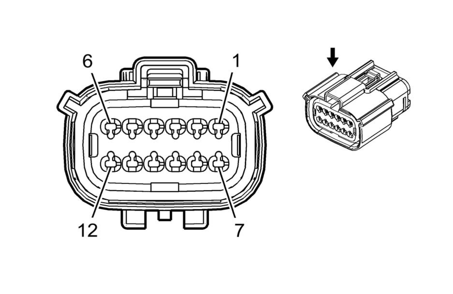 |
|
Connector Part Information |
• Harness Type: Body
• OEM Connector: 33472-1291
• Service Connector: 19352907
• Description: 12-Way F 150 MX Series, Sealed (BK)
|
Terminal Part Information | ||||||||||||||||
|
|
Pin |
Size |
Color |
Circuit |
Function |
Terminal |
Option |
|
1 |
- |
- |
- |
Not Occupied |
- |
- |
|
2 |
0.5 |
BK |
850 |
Ground |
I |
- |
|
3 |
0.5 |
VT/WH |
3643 |
High Voltage Onboard Charging |
I |
- |
|
4 |
0.5 |
YE/GY |
3645 |
High Voltage Onboard Charging |
I |
- |
|
5 - 8 |
- |
- |
- |
Not Occupied |
- |
- |
|
9 |
0.5 |
RD/BU |
1240 |
Battery Positive Voltage |
I |
- |
|
10 |
0.5 |
GN/GY |
3644 |
High Voltage Onboard Charging |
I |
- |
|
11 |
0.5 |
BU/YE |
3646 |
High Voltage Onboard Charging |
I |
- |
| ||||||||||||||
|
T18 BATTERY CHARGER X2 |
 |
|
Connector Part Information |
• Harness Type: Battery Cable
• OEM Connector: 15525754
• Service Connector: Service by Harness - See Part Catalog
• Description: 6-Way F 1.0, 2.4 HES Sealed (OG)
|
Terminal Part Information | ||||||||||||||||
|
|
Pin |
Size |
Color |
Circuit |
Function |
Terminal |
Option |
|
1 |
3 |
BU |
3837 |
Voltage AC Line 1 |
I |
- |
|
2 |
- |
- |
- |
Not Occupied |
- |
- |
|
3 |
3 |
GN |
3952 |
Voltage AC Ground |
I |
- |
|
4 |
3 |
WH |
3838 |
Voltage AC Neutral Line 2 |
I |
- |
|
5 - 6 |
- |
- |
- |
Not Occupied |
- |
- |
T18 BATTERY CHARGER X3

Connector Part Information
• Harness Type: Battery Cable
• OEM Connector: 33184905
• Service Connector: Service by Harness - See Part Catalog
• Description: 2-Way F HVA280-2PHI Series, Sealed (OG)
|
Terminal Part Information | ||||||||||||||||
|
| |||||||||||||||||||||
|
T22 MOBILE DEVICE WIRELESS CHARGER MODULE |
 |
|
Connector Part Information |
• Harness Type: Floor Console
• OEM Connector: AIT2PB-06-1FS
• Service Connector: Service by Harness - See Part Catalog
• Description: 6-Way F 0.64 Series (NA)
|
Terminal Part Information | ||||||||||||||||
|
| |||||||||||||||||||||||||||||||||||
|
X21 MANUAL SERVICE DISCONNECT RECEPTACLE |

Connector Part Information
• Harness Type: Auxiliary Battery Cable
• OEM Connector: 13670097
• Service Connector: Service by Harness - See Part Catalog
• Description: 2-Way F 1.6 Timer Series (BK)
|
Terminal Part Information | ||||||||||||||||
|
| |||||||||||||||||||||
|
X21 MANUAL SERVICE DISCONNECT RECEPTACLE X2 |
Connector Part Information
• Harness Type: High Voltage Manual Service Disconnect
• OEM Connector: E02393900
• Service Connector: Service by Harness - See Part Catalog
• Description: 2-Way
|
Terminal Part Information | ||||||||||||||||
|
| |||||||||||||||||||||
|
X80H ACCESSORY POWER RECEPTACLE - CENTER CONSOLE |
 |
|
Connector Part Information |
• Harness Type: Floor Console
• OEM Connector: 12176836
• Service Connector: Service by Harness - See Part Catalog
• Description: 3-Way F 280 Metri-Pack Series (GY)
Terminal Part Information
|
Terminal |
Terminated |
Diagnostic Test Probe |
Terminal |
Service |
Tray |
Core |
Insulation |
|
I |
Not Required |
J-35616-4A |
No Tool |
Not Required |
Not |
Not |
Not |
|
Pin |
Size |
Color |
Circuit |
Function |
Terminal |
Option |
|
A |
1 |
VT |
1301 |
Retained Accessory Power Fuse |
I |
- |
|
B |
- |
- |
- |
Not Occupied |
- |
- |
|
C |
1 |
BK |
2150 |
Ground |
I |
- |

|
Terminal Part Information | ||||||||||||||||
|
|
Terminal |
Terminated |
Diagnostic Test Probe |
Terminal |
Service |
Tray |
Core |
Insulation |
|
(PU) |
Required |
Required |
Required |
Required |
| ||||||||||||||||||||||||||||
|
X83 AUXILIARY AUDIO INPUT X1 |

Connector Part Information
• Harness Type: Floor Console
• OEM Connector: AIT2PB-06-1AK
• Service Connector: Service by Harness - See Part Catalog
• Description: 6-Way F 0.64 Kaizen Series (BK)
|
Terminal Part Information | ||||||||||||||||
|
|
Pin |
Size |
Color |
Circuit |
Function |
Terminal |
Option |
|
1 - 3 |
- |
- |
- |
Not Occupied |
- |
- |
|
4 |
0.5 |
BK |
1650 |
Ground |
I |
- |
|
5 |
- |
- |
- |
Not Occupied |
- |
- |
|
6 |
0.5 |
RD/YE |
5040 |
Battery Positive Voltage |
I |
- |

|
Terminal Part Information | ||||||||||||||||
|
|
Pin |
Size |
Color |
Circuit |
Function |
Terminal |
Option |
|
- |
- |
USB |
- |
USB Serial Data |
I |
- |
X84 DATA LINK CONNECTOR

Connector Part Information
• Harness Type: Instrument Panel
• OEM Connector: 12110250
• Service Connector: 12110250
• Description: 16-Way F 150 Metri-Pack Series (BK)
|
Terminal Part Information | ||||||||||||||||
|
|
Pin |
Size |
Color |
Circuit |
Function |
Terminal |
Option |
|
1 |
0.5 |
GN |
5060 |
Low Speed GMLAN Serial Data |
I |
- |
|
2 |
- |
- |
- |
Not Occupied |
- |
- |
|
3 |
0.5 |
BU/VT |
3813 |
High Speed GMLAN Serial Data |
I |
- |
|
4 |
0.5 |
BK |
1650 |
Ground |
I |
- |
|
5 |
0.5 |
BK |
1650 |
Ground |
I |
- |
|
6 |
0.35 |
BU BU |
2500 2500 |
High Speed GMLAN Serial Data High Speed GMLAN Serial Data |
I |
- |
| ||||||||||||||||||||||||||||||||||||||||||||||||||||||||
|
X85 STEERING WHEEL AIR BAG COIL X1 |
 |
|
Connector Part Information |
• Harness Type: Instrument Panel
• OEM Connector: ATLCPB-21-2AY
• Service Connector: 19330689
• Description: 21-Way F 0.64 Series, Sealed (YE)
|
Terminal Part Information | ||||||||||||||||||||||||
|
| |||||||||||||||||||||||||||||||||||||||||||||||||||||||||||||||||||||||||||||||||||||||||||||||||||||||||||||||||||||||||||||||||||||||||||||||||||
|
X85 STEERING WHEEL AIR BAG COIL X2 |
 |
|
Connector Part Information |
• Harness Type: Steering Wheel
• OEM Connector: ATLCPB-21-2AY
• Service Connector: Service by Harness - See Part Catalog
• Description: 21-Way F 0.64 Series, Sealed (YE)
|
Terminal Part Information | ||||||||||||||||
|
|
Pin |
Size |
Color |
Circuit |
Function |
Terminal |
Option |
|
1 |
0.5 |
BK |
1650 |
Ground |
I |
- |
|
2 |
- |
- |
- |
Not Occupied |
- |
- |
|
3 |
0.5 |
BK |
1650 |
Ground |
I |
- |
|
4 |
0.35 |
RD |
3287 |
Horn Switch Signal |
I |
- |
|
5 |
0.5 |
TN |
3023 |
Steering Wheel Module Stage 2 |
I |
- |
|
6 |
0.5 |
BN |
3022 |
Steering Wheel Module Stage 2 |
I |
- |
|
7 |
0.5 |
GN |
3020 |
Steering Wheel Module Stage 1 |
I |
- |
| ||||||||||||||||||||||||||||||||||||||||||||||||||||||||||||||||||||||||||||||||||||||||||||||||||
|
X98 HYBRID/EV BATTERY CHARGER RECEPTACLE |
 |
|
Connector Part Information |
• Harness Type: Battery Cable
• OEM Connector: 13990592
• Service Connector: Service by Harness - See Part Catalog
• Description: 6-Way M 1.0, 2.4 HES Sealed (OG)
|
Terminal Part Information | ||||||||||||||||||||||||
|
|
Pin |
Size |
Color |
Circuit |
Function |
Terminal |
Option |
|
1 |
3 |
GN |
3952 |
Voltage AC Ground |
I |
- |
|
2 |
0.5 |
GY/GN |
3954 |
Control Pilot Signal 1 |
II |
- |
|
3 |
3 |
BU |
3837 |
Voltage AC Line 1 |
I |
- |
|
4 |
3 |
WH |
3838 |
Voltage AC Neutral Line 2 |
I |
- |
|
5 |
0.5 |
BU/YE |
3953 |
Proximity Status Signal 1 |
II |
- |
|
6 |
- |
- |
- |
Not Occupied |
- |
- |
Article GUID: A00884640
ELECTRICAL
INLINE HARNESS CONNECTOR END VIEWS
X100 FORWARD LAMP HARNESS TO FRONT FASCIA HARNESS (UFQ)


Connector Part Information
• Harness Type: Forward Lamp
• OEM Connector: 54241630
• Service Connector: 13577550
• Description: 16-Way F 1.5 Series, Sealed (BK)
Connector Part Information
• Harness Type: Front Fascia
• OEM Connector: 54241604
• Service Connector: Service by Harness - See Part Catalog
• Description: 16-Way M 1.5 APEX Series, Sealed (BK)
|
Terminal Part Information | ||||||||||||||||||||||||
|
| |||||||||||||||||||||||||||||||||||||||||||||||||||||||||||||||||||||||||||||||||||||||||||||||||||||||||||||||||||||||||||||||||||||||||||||||||||||||||||||||||||||||||||||||||||||||||||||||||||||||||||||||||||||||||||||
|
X100 FORWARD LAMP HARNESS TO FRONT FASCIA HARNESS (-UFQ) |


Connector Part Information
• Harness Type: Forward Lamp
• OEM Connector: 13580235
• Service Connector: 19301723
• Description: 8-Way F 1.5 Series, Sealed (BK)
Connector Part Information
• Harness Type: Front Fascia
• OEM Connector: 33482-0827
• Service Connector: Service by Harness - See Part Catalog
• Description: 8-Way M 150 MX Series, Sealed (BK)


Connector Part Information
• Harness Type: Forward Lamp
• OEM Connector: 33472-1206
• Service Connector: 13503528
• Description: 12-Way F 150 MX Series, Sealed (BK)
Connector Part Information
• Harness Type: Cooling Fan
• OEM Connector: 33482-1201
• Service Connector: Service by Harness - See Part Catalog
• Description: 12-Way M 150 MX Series, Sealed (BK)
|
Terminal Part Information | ||||||||||||||||||||||||
|
| |||||||||||||||||||||||||||||||||||||||||||||||||||||||||||||||||||||||||||||||||||||||||||||||||||||||||||||||||||||
|
X102 FORWARD LAMP HARNESS TO COOLING FAN HARNESS |
|
Terminal Part Information | ||||||||||||||||||||||||||||||||
|
| |||||||||||||||||||||||||||||||||||||||||||||||||||||||||||||||||||||||||||||||||||||||||||||||||||||||||||||||||||||||||||||||||||||||||||||||||||||||||||||||||||||||||
|
X104 COOLING FAN HARNESS TO FORWARD LAMP HARNESS |


Connector Part Information
• Harness Type: Cooling Fan
• OEM Connector: 7283-5596-10
• Service Connector: Service by Harness - See Part Catalog
• Description: 2-Way F YESC USCAR Class III Series (D-GY)
Connector Part Information
• Harness Type: Forward Lamp
• OEM Connector: 7282-5596-10
• Service Connector: 88953304
• Description: 2-Way M 6.3 Weather Pack Series (D-GY)
|
Terminal Part Information | ||||||||||||||||||||||||
|
| |||||||||||||||||||||||||||||||||||||||
|
X105 BODY HARNESS TO BATTERY CABLE HARNESS |
|
Terminal Part Information | ||||||||||||||||||||||||
|
| |||||||||||||||||||||||||||||||||||||||
|
X106 FORWARD LAMP EXTENSION HARNESS TO FORWARD LAMP HARNESS |


Connector Part Information
• Harness Type: Body
• OEM Connector: 13782480
• Service Connector: 13577534
• Description: 2-Way F 150 MX Series, Sealed (BK)
Connector Part Information
• Harness Type: Battery Cable
• OEM Connector: 13883040
• Service Connector: Service by Harness - See Part Catalog
• Description: 2-Way M 1.5 MX Series, Sealed (BK)
 |
|
Connector Part Information Connector Part Information |
• Harness Type: Forward Lamp Extension
• Harness Type: Forward Lamp
• OEM Connector: 33481-0301
• Service Connector: 13580232
• Description: 3-Way M 150 MX Series (BK)
• OEM Connector: 33471-0306
• Service Connector: Service by Harness - See Part Catalog
• Description: 3-Way F 1.5 Series, Sealed (BK)
|
Terminal Part Information | ||||||||||||||||||||||||
|
|
Pin |
Size |
Color |
Circuit |
Terminal Type |
Option |
Function |
Pin |
Size |
Color |
Circuit |
Terminal Type |
Option |
|
1 |
0.5 |
VT/BU |
5705 |
I |
- |
Powertrain Main |
1 |
0.5 |
VT/BU |
5705 |
II |
- |
| |||||||||||||||||||||||||||||||||||||||
|
X107 FORWARD LAMP HARNESS TO BODY HARNESS |


Connector Part Information
• Harness Type: Forward Lamp
• OEM Connector: 13603185
• Service Connector: 13576549
• Description: 40-Way F 1.5, 2.8 Series, Sealed (BK)
Connector Part Information
• Harness Type: Body
• OEM Connector: 13603205
• Service Connector: 13576552
• Description: 40-Way M 1.5, 2.8 Series, Sealed (BK)
|
Terminal Part Information | ||||||||||||||||||||||||||||||||||||||||||||||||
|
|
Pin |
Size |
Color |
Circuit |
Terminal Type |
Option |
Function |
Pin |
Size |
Color |
Circuit |
Terminal Type |
Option |
|
1 |
0.75 |
BK |
1150 |
II |
- |
Ground |
1 |
0.75 |
BK |
1150 |
V |
- |
|
2 |
0.5 |
BN/GN |
4064 |
I |
- |
Hood Status B Signal |
2 |
0.35 |
BN/GN |
4064 |
IV |
- |
|
3 |
0.5 |
YE |
4063 |
I |
- |
Hood Status A Signal |
3 |
0.5 |
YE |
4063 |
III |
- |
|
4 - 5 |
- |
- |
- |
- |
- |
Not Occupied |
4 - 5 |
- |
- |
- |
- |
- |
|
6 |
0.5 |
WH |
3811 |
I |
- |
High Speed GMLAN |
6 |
0.35 |
WH |
3811 |
IV |
- |
|
7 |
0.5 |
BU/VT |
3813 |
I |
- |
High Speed GMLAN |
7 |
0.35 |
BU/VT |
3813 |
IV |
- |
|
8 |
0.35 |
GN/VT |
4621 |
I |
- |
Local Interconnect Bus 21 |
8 |
0.35 |
GN/VT |
4621 |
IV |
- |
|
9 |
0.35 |
GY/VT |
3808 |
I |
- |
Front Object Sensor Control 2 |
9 |
0.35 |
GY/VT |
3808 |
IV |
- |
|
10 - 11 |
- |
- |
- |
- |
- |
Not Occupied |
10 - 11 |
- |
- |
- |
- |
- |
|
12 |
0.5 |
WH |
2368 |
I |
- |
Cooling Fan Control |
12 |
0.5 |
WH |
2368 |
III |
- |
|
13 - 15 |
- |
- |
- |
- |
- |
Not Occupied |
13 - 15 |
- |
- |
- |
- |
- |
|
16 |
0.5 |
WH |
711 |
II |
- |
Left Headlamp High |
16 |
0.5 |
WH |
711 |
V |
- |
|
17 |
0.5 |
BK |
1150 |
II |
- |
Ground Ground |
17 |
0.5 |
BK BK |
1150 1150 |
V V |
- |
|
18 |
0.5 |
VT/BU |
5705 |
I |
- |
Powertrain Main |
18 |
0.5 |
VT/BU |
5705 |
III |
- |
|
19 - 23 |
- |
- |
- |
- |
- |
Not Occupied |
19 - 23 |
- |
- |
- |
- |
- |
|
24 |
0.5 |
BU/YE |
68 |
I |
- |
Low Coolant Level |
24 |
0.5 |
BU/YE |
68 |
III |
- |
|
25 |
0.5 |
BK/GN |
476 |
I |
- |
Sensor Low Reference |
25 |
0.5 |
BK/VT |
476 |
III |
- |
|
26 |
0.5 |
WH/YE |
1204 |
I |
- |
Left Park Lamp |
26 |
0.5 |
WH/YE |
1204 |
III |
- |
|
27 |
- |
- |
- |
- |
- |
Not Occupied |
27 |
- |
- |
- |
- |
- |
|
28 |
0.5 |
GY |
3154 |
I |
- |
Left Front Supplemental Object |
28 |
0.35 |
GY |
3154 |
IV |
- |
| ||||||||||||||||||||||||||||||||||||||||||||||||||||||||||||||||||||||||||||||||||||||||||||||||||||||||||||||||||||||||||||||||||||||||||||||||||||||||||||||||||||||||
|
X110 BODY HARNESS TO LEFT HEADLAMP HARNESS | ||||||||||||||||||||||||||||||||||||||||||||||||||||||||||||||||||||||||||||||||||||||||||||||||||||||||||||||||||||||||||||||||||||||||||||||||||||||||||||||||||||||||


Connector Part Information
• Harness Type: Body
• OEM Connector: 33472-0806
• Service Connector: 13577527
• Description: 8-Way F 150 MX Series, Sealed (BK)
Connector Part Information
• Harness Type: Left Headlamp
• OEM Connector: Not Available
• Service Connector: Service by Harness - See Part Catalog
• Description: 8-Way M
|
Terminal Part Information | ||||||||||||||||||||||||
|
| ||||||||||||||||||||||||||||||||||||||||||||||||||||||||||||||||||||||||||||||||||||||||||||||||||||||||
|
X120 BODY HARNESS TO RIGHT HEADLAMP HARNESS |
|
Terminal Part Information | ||||||||||||||||||||||||
|
| ||||||||||||||||||||||||||||||||||||||||||||||||||||||||||||||||||||||||||||||||||||||||||||||||||||||||
|
X121 FORWARD LAMP HARNESS TO BODY HARNESS |


Connector Part Information
• Harness Type: Body
• OEM Connector: 33472-0806
• Service Connector: 13577527
• Description: 8-Way F 150 MX Series, Sealed (BK)
Connector Part Information
• Harness Type: Right Headlamp
• OEM Connector: Not Available
• Service Connector: Service by Harness - See Part Catalog
• Description: 8-Way M


Connector Part Information
• Harness Type: Forward Lamp
• OEM Connector: 33476-1606
• Service Connector: 13587961
• Description: 16-Way F 1.5, 2.8 Series, Sealed (BN)
Connector Part Information
• Harness Type: Body
• OEM Connector: 34986-1601
• Service Connector: 19331031
• Description: 16-Way M 1.5, 2.8 Series, Sealed (BK)
|
Terminal Part Information | ||||||||
|
|
Terminal Type |
Terminated Lead |
Diagnostic Test Probe |
Terminal Removal Tool |
Service Terminal |
Tray Name |
Core Crimp |
Insulation Crimp |
|
I |
13505803 |
J-35616-35 (VT) |
J-38125-12A |
1326030-8 |
Lear 17 |
A |
4 |
|
II |
19300625 |
J-35616-2A (GY) |
J-38125-12A |
Not Available |
Not Available |
Not Available |
Not Available |
|
III |
19119440 |
J-35616-3 (GY) |
J-38125-217 |
Not Available |
Not Available |
Not Available |
Not Available |
|
IV |
19329833 |
J-35616-5 (PU) |
J-38125-12A |
1326030-6 |
Lear 17 |
E |
2 |
|
V |
19329833 |
J-35616-5 (PU) |
J-38125-12A |
1326030-6 |
Lear 17 |
E |
C |
| |||||||||||||||||||||||||||||||||||||||||||||||||||||||||||||||||||||||||||||||||||||||||||||||||||||||||||||||||||||||||||||||||||||||||||||||||||||||||||||||||||||||||||||||||||||||||||||||||||||||||||||||||||||||||||||
|
X130 BATTERY CABLE HARNESS TO BATTERY CABLE HARNESS |


Connector Part Information
• Harness Type: Battery Cable
• OEM Connector: 13859922
• Service Connector: Service by Harness - See Part Catalog
• Description: 4-Way F 150, 280 CTS Series, Sealed (OG)
Connector Part Information
• Harness Type: Battery Cable
• OEM Connector: 13966949
• Service Connector: Service by Harness - See Part Catalog
• Description: 4-Way M 2.8 High Voltage Shield Pack Series, Sealed (OG)
Terminal Part Information
|
Terminal Type |
Terminated Lead |
Diagnostic Test Probe |
Terminal Removal Tool |
Service Terminal |
Tray Name |
Core Crimp |
Insulation Crimp |
|
I |
Not Required |
J-35616-35 (VT) |
No Tool Required |
Not Required |
Not Required |
Not Required |
Not Required |
|
II |
Not Required |
No Tool Required |
No Tool Required |
Not Required |
Not Required |
Not Required |
Not Required |
| ||||||||||||||||||||||||||||||||||||||||||||||||||||
|
X149 ENGINE HARNESS TO ENGINE OIL LEVEL SENSOR HARNESS |
 |
|
Connector Part Information Connector Part Information |
• Harness Type: Engine
• OEM Connector: 2138387-9
• Service Connector: 19333443
• Description: 6-Way F 1.2 Series, Sealed (BK)
• Harness Type: Engine Oil Level Sensor
• OEM Connector: Not Available
• Service Connector: Service by Harness - See Part Catalog
• Description: 6-Way M

|
Terminal Part Information | ||||||||||||||||||||||||
|
| |||||||||||||||||||||||||||||||||||||||||||||||||||||||||||||||||
|
X150 ENGINE HARNESS TO ENGINE JUMPER HARNESS |
|
Connector Part Information
|
Connector Part Information
|
|
Terminal Part Information | ||||||||||||||||||||||||
|
| ||||||||||||||||||||||||||||||||||||||||||||||||||||||||||||||||||||||||||||||||||||||||||||||||||||||||||||||||||||||||||||||||||||||||||||||||||||||||||||
|
X155 ENGINE HARNESS TO BODY HARNESS |
|
1> 8 1 16 9 |
2 7 \ rm / /(?&--'8 1 О О О О О О 1=|1| 1 О О О О О О uzrjl / .....\^F~16 /ДУ и 10 15 |
|
Connector Part Information
|
Connector Part Information
|
|
Terminal Part Information | ||||||||||||||||||||||||||||||||||||||||
|
|
Pin |
Size |
Color |
Circuit |
Terminal Type |
Option |
Function |
Pin |
Size |
Color |
Circuit |
Terminal Type |
Option |
|
1 |
- |
- |
- |
- |
- |
Not Occupied |
1 |
- |
- |
- |
- |
- |
| |||||||||||||||||||||||||||||||||||||||||||||||||||||||||||||||||||||||||||||||||||||||||||||||||||||||||||||||||||||||||||||||||||||||||||||||||||||||||||||||||||||||||
|
X160 ENGINE HARNESS TO FUEL SYSTEM HARNESS |


Connector Part Information
• Harness Type: Engine
• OEM Connector: 33472-1216
• Service Connector: 19150019
• Description: 12-Way F 150 MX Series, Sealed (BK)
Connector Part Information
• Harness Type: Fuel System
• OEM Connector: Not Available
• Service Connector: Service by Harness - See Part Catalog
• Description: 12-Way M
|
Terminal Part Information | ||||||||||||||||||||||||
|
|
Pin |
Size |
Color |
Circuit |
Terminal Type |
Option |
Function |
Pin |
Size |
Color |
Circuit |
Terminal Type |
Option |
|
1 |
0.75 |
GY/BU |
4804 |
I |
- |
Direct Fuel Injector |
1 |
0.75 |
GY/BU |
4804 |
II |
- |
|
2 |
0.75 |
BN |
4801 |
I |
- |
Direct Fuel Injector |
2 |
0.75 |
BN |
4801 |
II |
- |
|
3 |
0.75 |
BN/WH |
4901 |
I |
- |
Direct Fuel Injector |
3 |
0.75 |
BN/WH |
4901 |
II |
- |
|
4 |
0.75 |
BU |
4802 |
I |
- |
Direct Fuel Injector |
4 |
0.75 |
BU |
4802 |
II |
- |
|
5 |
0.75 |
BU/GY |
4902 |
I |
- |
Direct Fuel Injector |
5 |
0.75 |
BU/GY |
4902 |
II |
- |
|
6 |
- |
- |
- |
- |
- |
Not Occupied |
6 |
- |
- |
- |
- |
- |
| |||||||||||||||||||||||||||||||||||||||||||||||||||||||||||||||||||||||||||||||||||||||||||
|
X190 ENGINE HARNESS TO BODY HARNESS |


25 40
Connector Part Information
• Harness Type: Engine
• OEM Connector: 13603186
• Service Connector: 13576550
• Description: 40-Way F 1.5, 2.8 Series, Sealed (GY)
Connector Part Information
• Harness Type: Body
• OEM Connector: 13603206
• Service Connector: 13576553
• Description: 40-Way M 1.5, 2.8 Series, Sealed (GY)
|
Terminal Part Information | ||||||||||||||||||||||||||||||||||||||||||||||||||||||||
|
|
Pin |
Size |
Color |
Circuit |
Terminal Type |
Option |
Function |
Pin |
Size |
Color |
Circuit |
Terminal Type |
Option |
|
1 |
- |
- |
- |
- |
- |
Not Occupied |
1 |
- |
- |
- |
- |
- |
|
2 |
0.5 |
YE/WH |
1161 |
I |
- |
Accelerator Pedal |
2 |
0.35 |
YE/WH |
1161 |
IV |
- |
|
3 |
0.5 |
WH/RD |
1164 |
I |
- |
Accelerator Pedal Position 5V Reference 1 |
3 |
0.35 |
WH/RD |
1164 |
IV |
- |
|
4 |
0.5 |
BK/BU |
1271 |
I |
- |
Accelerator Pedal Position Low Reference 1 |
4 |
0.35 |
BK/BU |
1271 |
IV |
- |
|
5 |
0.5 |
BK/VT |
1272 |
I |
- |
Accelerator Pedal Position Low Reference 2 |
5 |
0.35 |
BK/VT |
1272 |
IV |
- |
|
6 |
0.5 |
BN/RD |
1274 |
I |
- |
Accelerator Pedal Position 5V Reference 2 |
6 |
0.35 |
BN/RD |
1274 |
IV |
- |
|
7 |
0.5 |
GN/WH |
1162 |
I |
- |
Accelerator Pedal |
7 |
0.35 |
GN/WH |
1162 |
IV |
- |
|
8 |
0.5 |
GN |
3726 |
I |
- |
Diurnal Control Valve |
8 |
0.35 |
GN |
3726 |
IV |
- |
|
9 |
0.5 |
GY |
3723 |
I |
- |
Evap Leak Check |
9 |
0.35 |
GY |
3723 |
IV |
- |
| ||||||||||||||||||||||||||||||||||||||||||||||||||||||||||||||||||||||||||||||||||||||||||||||||||||||||||||||||||||||||||||||||||||||||||||||||||||||||||||||||||||||||||||||||||||||||||||||||||||||||||||||||||||||||||||||||||||||||||||||||||||||||||||||||||||||||||||||||||||||||||||||||||||||||||||||||||||||||||||||||||||||||||||||||||||||||||||||||||||||||||||||||||||||||||||||||||||||||||||||||||||||||||||||||
|
X211 BODY HARNESS TO INSTRUMENT PANEL HARNESS |
|
—у 2 V) I' i J | ||||||||||||||||||
|
Connector Part Information Terminal Part Information |
Connector Part Information | |||||||||||||||||
|
TeTnHifflaiesyTyi • OEM Conn |
e: Body Terminated Lead |
Diagnostic Test Probe |
Terminal Removal Tool |
|
ment Panel Tray Name |
Core Crimp |
Insulation Crimp | |||||||||||
|
___• Service Cor |
г iectorSSle'l*Vequ'bed/able |
AlMd I‘sue"i'>e',il c |
italcNJo Tool Required |
__« SAKfelUWeJor < |
erVfee fcqcMiH a. |
isemotl-ReqUiredirt |
Cat» Required | |||||||||||
|
Pin |
Size |
:- ay Color |
Circuit |
' Terminal Type |
Option |
Pin |
Size |
ay Color |
Circuit |
Terminal Type |
Option | |||||||
|
ID |
ID | |||||||||||||||||
|
1 |
- |
Coax |
6758 |
I |
- |
Coaxial Antenna GPS 2 Signal |
1 |
- |
Coax |
6758 |
I |
- | ||||||
|
2 |
- |
Coax |
6449 |
I |
- |
Coaxial Antenna |
2 |
- |
Coax |
6449 |
I |
- | ||||||
Article GUID: A00884680
ELECTRICAL
INLINE HARNESS CONNECTOR END VIEWS
X225 INSTRUMENT PANEL HARNESS TO BODY HARNESS

Connector Part Information

Connector Part Information
|
|
|
Terminal Part Information | ||||||||||||||||||||||||||||||||||||||||||||||||||||||||||||||||||||||||||||||||
|
|
Pin |
Size |
Color |
Circuit |
Terminal Type |
Option |
Function |
Pin |
Size |
Color |
Circuit |
Terminal Type |
Option |
|
1 |
0.35 |
YE/WH |
1161 |
I |
- |
Accelerator Pedal |
1 |
0.35 |
YE/WH |
1161 |
VII |
- |
|
2 |
0.35 |
WH/RD |
1164 |
I |
- |
Accelerator Pedal Position 5V Reference 1 |
2 |
0.35 |
WH/RD |
1164 |
VII |
- |
|
3 |
0.35 |
BK/BU |
1271 |
I |
- |
Accelerator Pedal |
3 |
0.35 |
BK/BU |
1271 |
VII |
- |
|
4 |
0.35 |
BK/VT |
1272 |
I |
- |
Accelerator Pedal |
4 |
0.35 |
BK/VT |
1272 |
VII |
- |
|
5 |
0.35 |
BN/RD |
1274 |
I |
- |
Accelerator Pedal Position 5V Reference 2 |
5 |
0.35 |
BN/RD |
1274 |
VII |
- |
|
6 |
0.35 |
GN/WH |
1162 |
I |
- |
Accelerator Pedal |
6 |
0.35 |
GN/WH |
1162 |
VII |
- |
|
7 |
0.35 |
BN/WH |
419 |
I |
- |
Check Engine Indicator |
7 |
0.35 |
BN/WH |
419 |
VII |
- |
|
8 |
0.5 |
RD/WH |
640 |
I |
- |
Battery Positive Voltage |
8 |
0.5 |
RD/WH |
640 |
VII |
- |
|
9 |
0.35 |
GY/GN |
4083 |
I |
- |
RAP Relay 2 Coil Control |
9 |
0.35 |
GY/GN |
4083 |
VII |
- |
|
10 |
0.35 |
WH/GN |
5380 |
I |
- |
Brake Position Sensor |
10 |
0.35 |
WH/GN |
5380 |
VII |
- |
|
11 |
0.35 |
BK/YE |
5382 |
I |
- |
Brake Position Sensor |
11 |
0.35 |
BK/YE |
5382 |
VII |
- |
|
12 |
0.35 |
WH/RD |
5381 |
I |
- |
Brake Position Sensor 5 V Reference |
12 |
0.35 |
WH/RD |
5381 |
VII |
- |
|
13 |
0.35 |
YE/BU |
3197 |
I |
- |
Humidity Temperature |
13 |
0.35 |
YE/BU |
3197 |
VII |
- |
|
14 - 15 |
- |
- |
- |
- |
- |
Not Occupied |
14 - 15 |
- |
- |
- |
- |
- |
|
Pin |
Size |
Color |
Circuit |
Terminal Type |
Option |
Function |
Pin |
Size |
Color |
Circuit |
Terminal Type |
Option |
|
16 |
0.35 |
BU/YE |
6105 |
I |
- |
High Speed GMLAN |
16 |
0.5 |
BU/YE |
6105 |
VII |
- |
|
17 |
0.35 |
WH |
6106 |
I |
- |
High Speed GMLAN |
17 |
0.5 |
WH/BU |
6106 |
VII |
- |
|
18 |
0.35 |
YE/GY |
230 |
I |
- |
Instrument Panel Lamp |
18 |
0.35 |
YE/GY |
230 |
VII |
- |
|
19 |
0.5 |
YE |
6817 |
I |
- |
LED Backlight |
19 |
0.5 |
YE |
6817 |
VII |
- |
|
20 |
0.35 |
VT/BN |
41 |
I |
- |
Run Ignition 3 Voltage |
20 |
0.35 |
VT/BN |
41 |
VII |
- |
|
21 |
0.35 |
YE/RD |
597 |
I |
- |
5V Reference |
21 |
0.35 |
YE/RD |
597 |
VII |
- |
|
22 - 24 |
- |
- |
- |
- |
- |
Not Occupied |
22 - 24 |
- |
- |
- |
- |
- |
|
25 |
0.35 |
BN/VT |
193 |
I |
- |
Rear Defog Relay |
25 |
0.5 |
BN/VT |
193 |
VII |
- |
|
26 |
0.35 |
BN/YE |
780 |
I |
- |
Driver Door Lock |
26 |
0.35 |
BN/YE |
780 |
VII |
- |
|
27 |
0.35 |
BN/WH |
781 |
I |
- |
Driver Door Lock |
27 |
0.35 |
BN/WH |
781 |
VII |
- |
|
28 |
0.5 |
WH |
3152 |
I |
- |
Lane Departure |
28 |
0.35 |
WH |
3152 |
VII |
- |
|
29 - 33 |
- |
- |
- |
- |
- |
Not Occupied |
29 - 33 |
- |
- |
- |
- |
- |
|
34 |
0.35 |
GY/GN |
2555 |
I |
- |
Rear Park Assist Disable Signal |
34 |
0.35 |
GY/GN |
2555 |
VII |
- |
|
35 |
0.35 |
BU/BN |
3161 |
I |
- |
Parallel Park Assist Disable Switch Signal |
35 |
0.35 |
BU/BN |
3161 |
VII |
- |
|
36 |
0.35 |
GN/BN |
5852 |
I |
- |
Rear Park Assist LED |
36 |
0.35 |
GN/BN |
5852 |
VII |
- |
|
37 |
0.35 |
GY/RD |
7684 |
I |
- |
Park Brake Apply |
37 |
0.5 |
GY/RD |
7684 |
VII |
- |
|
38 |
0.35 |
YE/RD |
7683 |
I |
- |
Park Brake Release |
38 |
0.5 |
YE/RD |
7683 |
VII |
- |
|
39 |
0.35 |
BN |
6107 |
I |
- |
Park Brake Apply |
39 |
0.5 |
BN |
6107 |
VII |
- |
|
40 |
0.35 |
BU/BK |
6108 |
I |
- |
Park Brake Release |
40 |
0.5 |
BU/BK |
6108 |
VII |
- |
|
41 |
0.35 |
YE |
1492 |
I |
- |
Park Brake Switch |
41 |
0.5 |
YE |
1492 |
VII |
- |
|
42 |
0.35 |
BU/VT |
1134 |
I |
- |
Park Brake Switch |
42 |
0.5 |
BU/VT |
1134 |
VII |
- |
|
43 |
- |
- |
- |
- |
- |
Not Occupied |
43 |
- |
- |
- |
- |
- |
|
44 |
0.35 |
GN/BU |
6133 |
I |
- |
Local Interconnect Bus 2 |
44 |
0.35 |
GN/BU |
6133 |
VII |
- |
|
45 |
0.35 |
WH/BU |
5986 |
I |
- |
Serial Data Communication Enable |
45 |
0.5 |
WH/BU |
5986 |
VII |
- |
|
46 |
- |
- |
- |
- |
- |
Not Occupied |
46 |
- |
- |
- |
- |
- |
|
47 |
0.35 |
YE |
5704 |
I |
- |
Endgate Latch Relay |
47 |
0.35 |
YE |
5704 |
VII |
- |
|
48 |
0.5 |
BU/YE |
6795 |
I |
- |
Lift Glass/Rear |
48 |
0.75 |
BU/YE |
6795 |
VIII |
- |
|
49 |
0.35 |
YE |
6817 |
I |
- |
LED Backlight |
49 |
0.5 |
YE |
6817 |
VII |
- |
|
50 |
0.35 |
VT |
185 |
I |
- |
Low Washer Fluid |
50 |
0.35 |
VT |
185 |
VII |
- |
|
51 - 58 |
- |
- |
- |
- |
- |
Not Occupied |
51 - 58 |
- |
- |
- |
- |
- |
|
59 |
0.35 |
GN/BU |
7532 |
I |
- |
Local Interconnect Bus 10 |
59 |
0.35 |
GN/BU |
7532 |
VII |
- |
|
60 - 63 |
- |
- |
- |
- |
- |
Not Occupied |
60 - 63 |
- |
- |
- |
- |
- |
|
64 |
0.35 |
WH |
2501 |
I |
- |
High Speed GMLAN High Speed GMLAN |
64 |
0.5 |
WH WH |
2501 2501 |
VII VII |
-UHY |
|
65 |
0.35 |
BU |
2500 |
I |
- |
High Speed GMLAN |
65 |
0.5 |
BU BU |
2500 2500 |
VII VII |
-UHY |
|
66 |
- |
- |
- |
- |
- |
Not Occupied |
66 |
- |
- |
- |
- |
- |
|
67 |
0.35 |
BK/BN |
6102 |
I |
- |
Inside Air Temperature |
67 |
0.35 |
BK/BN |
6102 |
VII |
- |
|
68 |
0.35 |
GY/GN |
7565 |
I |
- |
Windscreen Temp |
68 |
0.35 |
GY/GN |
7565 |
VII |
- |
|
69 |
0.35 |
GY/BU |
7564 |
I |
- |
Humidity Sensor Signal |
69 |
0.35 |
GY/BU |
7564 |
VII |
- |
|
70 |
- |
- |
- |
- |
- |
Not Occupied |
70 |
- |
- |
- |
- |
- |
| ||||||||||||||||||||||||||||||||||||||||||||||||||||||||||||||||||||||||||||||||||||||||||||||||||||||||||||||||||||||||||||||||||||||||||||||||||||||||||||||||||||||||||||||||||||||||||||||||||||||||||||||||||||||||||||||||||||||||||||||||||||||||||||||||||||||||||||||||||||||||||||||
|
X252 INSTRUMENT PANEL HARNESS TO HVAC SYSTEM HARNESS |
 |
|
Connector Part Information Connector Part Information |
• Harness Type: Instrument Panel
• OEM Connector: 15332129
• Service Connector: 15306425
• Description: 2-Way F 150 GT Series (BK)
• Harness Type: HVAC System
• OEM Connector: Not Available
• Service Connector: Service by Harness - See Part Catalog
• Description: 2-Way M
|
Terminal Part Information | ||||||||||||||||
|
|
Terminal Type |
Terminated Lead |
Diagnostic Test Probe |
Terminal Removal Tool |
Service Terminal |
Tray Name |
Core Crimp |
Insulation Crimp |
|
II |
Not Required |
Not Available |
No Tool Required |
Not Required |
Not Required |
Not Required |
Not Required |
| |||||||||||||||||||||||||||||||||||||||
|
X275 INSTRUMENT PANEL HARNESS TO BODY HARNESS |


Connector Part Information
• Harness Type: Instrument Panel
• OEM Connector: 1355713-1
• Service Connector: 13574784
• Description: 102-Way F 1.5, 2.5, 9.5 Series (BK)
Connector Part Information
• Harness Type: Body
• OEM Connector: 1670174-4
• Service Connector: 13588077
• Description: 102-Way M 1.6, 2.8, 8.0 Timer Series (BK)
|
Terminal Part Information | ||||||||||||||||||||||||||||||||||||||||||||||||||||||||||||||||
|
|
Pin |
Size |
Color |
Circuit |
Terminal Type |
Option |
Function |
Pin |
Size |
Color |
Circuit |
Terminal Type |
Option |
|
1 - 3 |
- |
- |
- |
- |
- |
Not Occupied |
1 - 3 |
- |
- |
- |
- |
- |
|
4 |
0.35 |
GY |
156 |
I |
- |
Courtesy Lamp |
4 |
0.35 |
GY |
156 |
VI |
- |
|
5 |
0.75 |
GY |
157 |
I |
- |
Interior Lamp |
5 |
0.75 |
GY |
157 |
VII |
- |
|
6 |
- |
- |
- |
- |
- |
Not Occupied |
6 |
- |
- |
- |
- |
- |
|
7 |
0.35 |
BU/GY |
4672 |
I |
- |
Dome Lamp Off |
7 |
0.35 |
BU/GY |
4672 |
VI |
- |
|
8 - 11 |
- |
- |
- |
- |
- |
Not Occupied |
8 - 11 |
- |
- |
- |
- |
- |
|
12 |
0.35 |
WH/VT |
3999 |
I |
- |
MOST Control |
12 |
0.35 |
WH/VT |
3999 |
VI |
- |
|
13 |
0.5 |
BARE |
1782 |
I |
- |
Low Reference |
13 |
0.5 |
BARE |
1782 |
VI |
- |
|
14 |
0.35 |
YE |
658 |
I |
- |
Cellular Telephone |
14 |
0.35 |
YE |
658 |
VI |
- |
|
15 |
0.35 |
BK/YE |
659 |
I |
- |
Cellular Telephone Voice Low Reference |
15 |
0.35 |
BK/YE |
659 |
VI |
- |
|
16 |
0.35 |
GY/VT |
3998 |
I |
- |
MOST Serial Data |
16 |
0.35 |
GY/VT |
3998 |
VI |
- |
|
17 |
0.35 |
WH/GN |
3997 |
I |
- |
MOST Serial Data (-) |
17 |
0.35 |
WH/GN |
3997 |
VI |
- |
|
18 - 20 |
- |
- |
- |
- |
- |
Not Occupied |
18 - 20 |
- |
- |
- |
- |
- |
|
21 |
0.5 |
GY/VT |
3998 |
I |
- |
MOST Serial Data |
21 |
0.35 |
GY/VT |
3998 |
VI |
- |
|
22 |
0.5 |
WH/GN |
3997 |
I |
- |
MOST Serial Data (-) |
22 |
0.35 |
WH/GN |
3997 |
VI |
- |
|
23 |
0.35 |
VT/BK |
3 |
I |
- |
Run/Crank Ignition 1 |
23 |
0.35 |
VT/BK |
3 |
VI |
- |
|
24 - 29 |
- |
- |
- |
- |
- |
Not Occupied |
24 - 29 |
- |
- |
- |
- |
- |
|
Pin |
Size |
Color |
Circuit |
Terminal Type |
Option |
Function |
Pin |
Size |
Color |
Circuit |
Terminal Type |
Option |
|
30 |
0.5 |
BN/WH |
3552 |
I |
- |
Passive Start Interior |
30 |
0.35 |
BN/WH |
3552 |
VI |
- |
|
31 |
0.5 |
WH |
3553 |
I |
- |
Passive Start Interior |
31 |
0.35 |
WH |
3553 |
VI |
- |
|
32 - 33 |
- |
- |
- |
- |
- |
Not Occupied |
32 - 33 |
- |
- |
- |
- |
- |
|
34 |
0.35 |
GN/BK |
3558 |
I |
- |
Passive Start Switch |
34 |
0.35 |
GN/BK |
3558 |
VI |
- |
|
35 |
0.35 |
BK/GY |
3559 |
I |
- |
Passive Start Switch |
35 |
0.35 |
BK/GY |
3559 |
VI |
- |
|
36 |
- |
- |
- |
- |
- |
Not Occupied |
36 |
- |
- |
- |
- |
- |
|
37 |
0.35 |
GY |
5054 |
I |
- |
Sport Mode Switch |
37 |
0.35 |
GY |
5054 |
VI |
- |
|
38 - 39 |
- |
- |
- |
- |
- |
Not Occupied |
38 - 39 |
- |
- |
- |
- |
- |
|
40 |
0.35 |
YE/VT |
3956 |
I |
- |
Charging Status |
40 |
0.5 |
YE/VT |
3956 |
VI |
- |
|
41 |
- |
- |
- |
- |
- |
Not Occupied |
41 |
- |
- |
- |
- |
- |
|
42 |
0.35 |
GY/GN |
3957 |
I |
- |
Charging Pilot Signal |
42 |
0.5 |
GY/GN |
3957 |
VI |
- |
|
43 |
- |
- |
- |
- |
- |
Not Occupied |
43 |
- |
- |
- |
- |
- |
|
44 |
0.35 |
VT/YE |
4 |
I |
- |
Accessory Ignition |
44 |
0.35 |
VT/YE |
4 |
VI |
- |
|
45 - 48 |
- |
- |
- |
- |
- |
Not Occupied |
45 - 48 |
- |
- |
- |
- |
- |
|
49 |
0.35 |
RD/BK |
2240 |
I |
- |
Battery Positive |
49 |
0.5 |
RD/GY |
2240 |
VI |
- |
|
50 |
- |
- |
- |
- |
- |
Not Occupied |
50 |
- |
- |
- |
- |
- |
|
51 |
0.35 |
WH/BN |
1089 |
I |
- |
Coolant Pump Motor |
51 |
0.35 |
WH/BN |
1089 |
VI |
- |
|
52 - 55 |
- |
- |
- |
- |
- |
Not Occupied |
52 - 55 |
- |
- |
- |
- |
- |
|
56 |
0.5 |
BK |
6974 |
I |
- |
Camera Low |
56 |
0.5 |
BK |
6974 |
VI |
- |
|
57 |
0.35 |
GY/YE |
6972 |
I |
- |
Camera Signal 2 + |
57 |
0.5 |
GY/YE |
6972 |
VI |
- |
|
58 |
0.35 |
WH/BU |
6973 |
I |
- |
Camera Signal 2 |
58 |
0.5 |
WH/BU |
6973 |
VI |
- |
|
59 - 62 |
- |
- |
- |
- |
- |
Not Occupied |
59 - 62 |
- |
- |
- |
- |
- |
|
63 |
0.35 |
WH |
6816 |
I |
- |
Indicator Dimming |
63 |
0.35 |
WH |
6816 |
VI |
- |
|
64 |
0.5 |
WH/BN |
6815 |
I |
- |
Inadvertent Power |
64 |
0.75 |
WH/BN |
6815 |
VII |
- |
|
65 - 68 |
- |
- |
- |
- |
- |
Not Occupied |
65 - 68 |
- |
- |
- |
- |
- |
|
69 |
0.35 |
OG |
3554 |
I |
- |
Passive Start Interior |
69 |
0.35 |
OG |
3554 |
VI |
- |
|
70 |
0.35 |
OG/BU |
3555 |
I |
- |
Passive Start Interior |
70 |
0.35 |
OG/BU |
3555 |
VI |
- |
|
71 - 90 |
- |
- |
- |
- |
- |
Not Occupied |
71 - 90 |
- |
- |
- |
- |
- |
|
91 |
1 |
VT/WH |
1701 |
IV |
- |
Retained Accessory |
91 |
1 |
VT/WH |
1701 |
V |
- |
|
92 |
0.5 |
YE/BK |
117 |
III |
- |
Right Front Speaker Signal (-) 1 Right Front Speaker Signal (-) 1 |
92 |
0.5 2 |
YE/BK YE/BK |
117 117 |
V V |
UQA UQA |
|
93 |
0.5 |
YE |
200 |
III |
- |
Right Front Speaker Control (+) 1 Right Front Speaker Control (+) 1 |
93 |
0.5 2 |
YE YE |
200 200 |
V V |
UQA UQA |
|
94 |
- |
- |
- |
- |
- |
Not Occupied |
94 |
- |
- |
- |
- |
- |
|
95 |
0.75 |
BU/YE |
1960 |
IV III |
UQA |
Right Front Speaker Front Center Speaker |
95 |
0.5 1 1 |
YE YE |
200 |
V V V |
UZ6 UQA |
|
96 |
0.75 |
YE/WH |
1860 117 |
IV III |
UQA UZ6 |
Right Front Speaker Signal (-) 1 Front Center Speaker Control (+) Right Front Speaker Signal (-) 1 |
96 |
0.5 1 1 |
BN/YE BN/YE |
117 |
V V V |
UZ6 UQA UZ6 |
|
97 - 98 |
- |
- |
- |
- |
- |
Not Occupied |
97 - 98 |
- |
- |
- |
- |
- |
|
99 |
0.35 |
GN/GY |
6135 |
II |
- |
Local Interconnect Network Serial Data Bus 4 Local Interconnect Network Serial Data Bus 4 |
99 |
0.35 |
GN/GY GN/GY |
6135 6135 |
V V |
- |
|
100 |
2 |
BU BN/BU BN/BU |
201 118 118 |
IV III IV |
UQA |
Left Front Speaker Control (+) 1 Left Front Speaker Signal (-) 1 Left Front Speaker Signal (-) 1 |
100 |
2 |
BU |
201 118 |
V V |
UQA |
| |||||||||||||||||||||||||||||||||||||||
|
X302 INSTRUMENT PANEL HARNESS TO PASSENGER INSTRUMENT PANEL AIR BAG HARNESS |
 |
|
Connector Part Information Connector Part Information |
• Harness Type: Instrument Panel
• OEM Connector: 13599892
• Service Connector: 19353876
• Description: 6-Way F 1.2 MCON-LL Series, Sealed (YE)
• Harness Type: Passenger Instrument Panel Air Bag
• OEM Connector: Not Available
• Service Connector: Service by Harness - See Part Catalog
• Description: 6-Way M
|
Terminal Part Information | ||||||||||||||||||||||||
|
| |||||||||||||||||||||||||||||||||||||||||||||||||||||||||||||||||||||||||||||||||||||||||||
|
X310 BODY HARNESS TO DRIVER SEAT HARNESS |
|
Terminal Part Information | ||||||||||||||||||||||||||||||||||||||||
|
| ||||||||||||||||||||||||||||||||||||||||||||||||||||||||||||||||||||||||||||||||||||||||||||||||||||||||||||||||||||||||||||||||||||||||||||||||||||||||||||||||||||||||||||||||||||||||||||||||||||||||||||||||
|
X315 FLOOR CONSOLE HARNESS TO INSTRUMENT PANEL HARNESS |
|
Terminal Part Information | ||||||||||||||||||||||||||||||||||||||||||||||||
|
|
Pin |
Size |
Color |
Circuit |
Terminal Type |
Option |
Function |
Pin |
Size |
Color |
Circuit |
Terminal Type |
Option |
|
1 |
0.5 |
RD/YE |
5040 |
II |
- |
Battery Positive |
1 |
0.35 |
RD/YE |
5040 |
III |
- |
|
2 |
0.35 |
GY/VT |
755 |
II |
- |
RAP Relay Coil |
2 |
0.35 |
GY/VT |
755 |
III |
- |
|
3 |
1 |
VT |
1301 |
II |
- |
Retained Accessory |
3 |
1 |
VT |
1301 |
IV |
- |
|
4 |
- |
- |
- |
- |
- |
Not Occupied |
4 |
- |
- |
- |
- |
- |
|
5 |
0.35 |
GN/BU |
6133 |
I |
- |
Local Interconnect Bus 2 |
5 |
0.35 |
GN/BU |
6133 |
V |
- |
|
6 |
- |
- |
- |
- |
- |
Not Occupied |
6 |
- |
- |
- |
- |
- |
|
7 |
0.5 |
YE |
6817 |
I |
- |
LED Backlight |
7 |
0.35 |
YE |
6817 |
V |
- |
|
8 |
0.35 |
GN |
4512 |
I |
- |
Wireless Charging |
8 |
0.35 |
GN |
4512 |
V |
- |
|
9 - 10 |
- |
- |
- |
- |
- |
Not Occupied |
9 - 10 |
- |
- |
- |
- |
- |
|
11 |
0.5 |
OG |
3554 |
I |
- |
Passive Start Interior |
11 |
0.35 |
OG |
3554 |
V |
- |
|
12 |
0.5 |
OG/BU |
3555 |
I |
- |
Passive Start Interior |
12 |
0.35 |
OG/BU |
3555 |
V |
- |
|
13 |
- |
- |
- |
- |
- |
Not Occupied |
13 |
- |
- |
- |
- |
- |
|
14 |
0.35 |
VT |
4601 |
II |
- |
Retained Accessory |
14 |
0.35 |
VT |
4601 |
III |
- |
|
15 |
- |
- |
- |
- |
- |
Not Occupied |
15 |
- |
- |
- |
- |
- |
|
16 |
0.35 |
GY/RD |
7684 |
I |
- |
Park Brake Apply |
16 |
0.35 |
GY/RD |
7684 |
V |
- |
|
17 |
0.35 |
YE/RD |
7683 |
I |
- |
Park Brake Release |
17 |
0.35 |
YE/RD |
7683 |
V |
- |
|
18 |
0.35 |
BN |
6107 |
I |
- |
Park Brake Apply |
18 |
0.35 |
BN |
6107 |
V |
- |
|
19 |
0.35 |
BU/BK |
6108 |
I |
- |
Park Brake Release |
19 |
0.35 |
BU/BK |
6108 |
V |
- |
|
20 |
0.35 |
YE |
1492 |
I |
- |
Park Brake Switch |
20 |
0.35 |
YE |
1492 |
V |
- |
|
21 |
0.35 |
BU/VT |
1134 |
I |
- |
Park Brake Switch |
21 |
0.35 |
BU/VT |
1134 |
V |
- |
|
22 |
0.35 |
BU/VT |
1788 |
I |
- |
Traction Control |
22 |
0.35 |
BU/VT |
1788 |
V |
- |
|
23 - 27 |
- |
- |
- |
- |
- |
Not Occupied |
23 - 27 |
- |
- |
- |
- |
- |
| ||||||||||||||||||||||||||||||||||||||||||||||||||||||||||||||||||||||||||||||||||||||||||||||||||||||||||||||||||||||||||||||||||||||||||||||||||||||||||||||||||||||||||||||||||||||||||||||||||||||||||||||||
|
X316 INSTRUMENT PANEL HARNESS TO FLOOR CONSOLE HARNESS |

Connector Part Information
• Harness Type: Body
• OEM Connector: 34985-2294
• Service Connector: 19352908
• Description: 16-Way F 1.5, 2.8 Series, Sealed (YE)

Connector Part Information
• Harness Type: Driver Seat
• OEM Connector: Not Available
• Service Connector: Service by Harness - See Part Catalog
• Description: 16-Way M


Connector Part Information
• Harness Type: Floor Console
• OEM Connector: 1-2109452-3
• Service Connector: Service by Harness - See Part Catalog
• Description: 48-Way F 1.2 MCON, 2.8 MCP Series (GY)
Connector Part Information
• Harness Type: Instrument Panel
• OEM Connector: 1-2109455-3
• Service Connector: 19329738
• Description: 48-Way M 1.2 MCON, 2.8 MCP Series

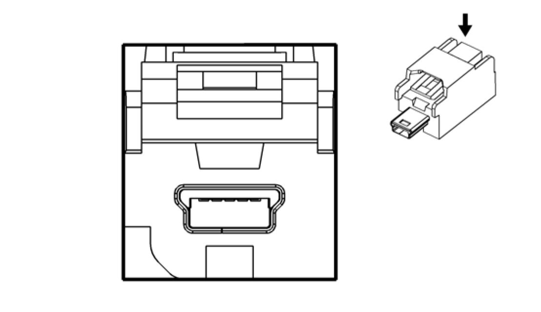
Connector Part Information
• Harness Type: Instrument Panel
• OEM Connector: 13578976
• Service Connector: Service by Cable Assembly - See Part Catalog
• Description: 5-Way F 2.0 Mini-B USB Type (BK)
Connector Part Information
• Harness Type: Floor Console
• OEM Connector: 13584747
• Service Connector: Service by Cable Assembly - See Part Catalog
• Description: 5-Way M 2.0 Mini-B USB Type (GY)
|
Terminal Part Information | ||||||||||||||||
|
| ||||||||||||||||||||||||||
|
X320 DRIVER SEAT HARNESS TO BODY HARNESS |
|
Terminal Part Information | ||||||||||||||||||||||||||||||||||||||||||||||||||||||||
|
|
Pin |
Size |
Color |
Circuit |
Terminal Type |
Option |
Function |
Pin |
Size |
Color |
Circuit |
Terminal Type |
Option |
|
1 |
0.75 |
RD/GY |
1740 |
I |
- |
Battery Positive |
1 |
0.75 |
RD/GY |
1740 |
IV |
- |
|
2 |
- |
- |
- |
- |
- |
Not Occupied |
2 |
- |
- |
- |
- |
- |
|
3 |
0.35 |
OG |
1362 |
I |
- |
Passenger Seat Belt |
3 |
0.35 |
OG/VT |
1362 |
III |
- |
|
4 |
0.5 |
BK/OG |
1361 |
I |
- |
Passenger Seat Belt |
4 |
0.5 |
BK/OG |
1361 |
II |
- |
|
5 |
0.5 |
BK/YE |
2080 |
I |
- |
Driver Heated Seat |
5 |
0.5 |
BK/YE |
2080 |
II |
- |
|
6 |
0.5 |
YE/GY |
2079 |
I |
- |
Driver Heated Seat |
6 |
0.5 |
YE/GY |
2079 |
II |
- |
|
7 |
0.75 |
BN/VT |
2077 |
I |
- |
Driver Heated Seat |
7 |
0.75 |
BN/VT |
2077 |
II |
- |
|
8 |
0.5 |
BU |
2425 |
I |
- |
Driver Heated Back |
8 |
0.5 |
BU |
2425 |
II |
- |
|
9 |
0.35 |
GN/BU |
6133 |
I |
- |
Local Interconnect Bus 2 |
9 |
0.35 |
GN/BU |
6133 |
III |
- |
|
10 |
0.35 |
OG/GY |
3066 |
I |
- |
Passenger Side |
10 |
0.35 |
OG/GY |
3066 |
V |
- |
|
11 |
0.35 |
BN/OG |
3067 |
I |
- |
Passenger Side |
11 |
0.35 |
BN/OG |
3067 |
V |
- |
|
12 |
- |
- |
- |
- |
- |
Not Occupied |
12 |
- |
- |
- |
- |
- |
|
13 |
0.5 |
GN |
5060 |
I |
- |
Low Speed GMLAN |
13 |
0.5 |
GN |
5060 |
II |
- |
|
14 |
0.5 |
RD |
2240 |
I |
- |
Battery Positive |
14 |
0.5 |
RD/GY |
2240 |
II |
- |
|
15 |
0.35 |
BK |
2050 |
I |
- |
Ground |
15 |
0.5 |
BK |
2050 |
VI |
- |
|
16 |
1 |
BK |
2050 |
I |
KA1 |
Ground |
16 |
1 |
BK |
2050 |
IV |
KA1 |
|
17 |
- |
- |
- |
- |
- |
Not Occupied |
17 |
- |
- |
- |
- |
- |
|
18 |
0.35 |
OG/BN |
3479 |
I |
- |
Passenger Seat Belt |
18 |
0.35 |
OG/BN |
3479 |
V |
- |
|
19 |
0.35 |
GY/OG |
3480 |
I |
- |
Passenger Seat Belt |
19 |
0.35 |
GY/OG |
3480 |
V |
- |
|
20 |
- |
- |
- |
- |
- |
Not Occupied |
20 |
- |
- |
- |
- |
- |
| ||||||||||||||||||||||||||||||||||||||||||||||||||||
|
X325 HEADLINER HARNESS TO INSTRUMENT PANEL HARNESS |


Connector Part Information
• Harness Type: Driver Seat
• OEM Connector: Not Available
• Service Connector: Service by Harness - See Part Catalog
• Description: 23-Way F
Connector Part Information
• Harness Type: Body
• OEM Connector: 13750010
• Service Connector: 19332380
• Description: 23-Way M 1.5 DSQ, 2.8 AST Series, Sealed (BK)


Connector Part Information
Connector Part Information
• Harness Type: Instrument Panel
• OEM Connector: 1897540-2
• Service Connector: 13580994
• Description: 22-Way M 0.64 MQS, 2.8 MCP Series (BK)
• Harness Type: Headliner
• OEM Connector: 1897543-2
• Service Connector: 13395404
• Description: 22-Way F 0.64 Micro-Quadlock, 2.8 Micro-Power Series (BK)
|
Terminal Part Information | ||||||||||||||||||||||||||||||||||||||||||||||||
|
|
Pin |
Size |
Color |
Circuit |
Terminal Type |
Option |
Function |
Pin |
Size |
Color |
Circuit |
Terminal Type |
Option |
|
1 |
0.35 |
GY/GN |
328 |
I |
- |
Interior Lamp Defeat |
1 |
0.35 |
GY/GN |
328 |
IV |
- |
|
2 |
0.35 |
GY |
156 |
I |
- |
Courtesy Lamp |
2 |
0.35 |
GY |
156 |
IV |
- |
|
3 |
- |
- |
- |
- |
- |
Not Occupied |
3 |
- |
- |
- |
- |
- |
|
4 |
0.5 |
BK |
2150 |
III |
- |
Ground |
4 |
0.5 |
BK |
2150 |
V |
- |
|
5 |
- |
- |
- |
- |
- |
Not Occupied |
5 |
- |
- |
- |
- |
- |
|
6 |
0.5 |
WH/YE |
7557 |
II |
- |
LED Ambient Lighting Control 1 |
6 |
0.35 |
WH/YE |
7557 |
IV |
- |
|
7 |
0.5 |
YE |
6817 |
II |
- |
LED Backlight |
7 |
0.35 |
YE |
6817 |
IV |
- |
|
8 |
0.5 |
WH/BN |
6815 |
II |
- |
Inadvertent Power |
8 |
0.5 |
WH/BN |
6815 |
IV |
- |
|
9 |
0.35 |
WH |
6816 |
I |
- |
Indicator Dimming |
9 |
0.35 |
WH |
6816 |
IV |
- |
|
10 |
0.35 |
BU/GY |
4672 |
I |
- |
Dome Lamp Off |
10 |
0.35 |
BU/GY |
4672 |
IV |
- |
|
11 |
0.5 |
GY |
157 |
II |
- |
Interior Lamp |
11 |
0.75 |
GY |
157 |
IV |
- |
|
12 |
0.35 |
GN/BK |
2515 |
I |
- |
Keypad Control |
12 |
0.35 |
GN/BK |
2515 |
IV |
- |
|
13 |
0.35 |
GN/WH |
2514 |
I |
- |
Keypad Signal |
13 |
0.35 |
GN/WH |
2514 |
IV |
- |
|
14 |
0.35 |
YE/VT |
2516 |
I |
- |
Keypad Green LED |
14 |
0.35 |
YE/VT |
2516 |
IV |
- |
|
15 |
0.35 |
GN |
2308 |
I |
- |
Passenger Air Bag |
15 |
0.35 |
GN |
2308 |
IV |
- |
|
16 |
0.35 |
BU |
2307 |
I |
- |
Passenger Air Bag |
16 |
0.35 |
BU |
2307 |
IV |
- |
|
17 |
0.35 |
VT/WH |
5234 |
I |
- |
Passenger Seat Belt |
17 |
0.35 |
VT/WH |
5234 |
IV |
- |
|
18 |
- |
- |
- |
- |
- |
Not Occupied |
18 |
- |
- |
- |
- |
- |
| |||||||||||||||||||||||||||||||||||||||||||||||||||||||||||||||||
|
X340 BODY HARNESS TO REAR SEAT HARNESS |
 |
|
Connector Part Information Connector Part Information |
• Harness Type: Body
• OEM Connector: 7283-6446-40
• Service Connector: 19119857
• Description: 4-Way F YESC Kaizen Series (L-GY)
• Harness Type: Rear Seat
• OEM Connector: Not Available
• Service Connector: Service by Harness - See Part Catalog
• Description: 4-Way M
|
Terminal Part Information | ||||||||||||||||||||||||
|
| |||||||||||||||||||||||||||||||||||||||||||||||||||||||||||||||||
|
X350 BODY HARNESS TO FUEL SYSTEM HARNESS |
|
Terminal Part Information | ||||||||||||||||||||||||||||||||||||||||
|
| |||||||||||||||||||||||||||||||||||||||||||||||||||||||||||||||||||||||||||||||||||||||||||||||||||||||||||||||||||||||||||||||||||||||||||||||
|
X351 BODY HARNESS TO FUEL SYSTEM HARNESS |

Connector Part Information
• Harness Type: Body
• OEM Connector: 34985-1606
• Service Connector: 19352906
• Description: 16-Way F 1.5, 2.8 Series, Sealed (BK)
Connector Part Information
• Harness Type: Fuel System
• OEM Connector: Not Available
• Service Connector: Service by Harness - See Part Catalog
• Description: 16-Way M


Connector Part Information
• Harness Type: Body
• OEM Connector: 33472-0806
• Service Connector: 13577527
• Description: 8-Way F 150 MX Series, Sealed (BK)
Connector Part Information
• Harness Type: Fuel System
• OEM Connector: Not Available
• Service Connector: Service by Harness - See Part Catalog
• Description: 8-Way M
|
Terminal Part Information | ||||||||||||||||||||||||
|
|
Pin |
Size |
Color |
Circuit |
Terminal Type |
Option |
Function |
Pin |
Size |
Color |
Circuit |
Terminal Type |
Option |
|
1 |
0.35 |
GY |
3723 |
I |
- |
Evap Leak Check |
1 |
0.35 |
GY |
3723 |
II |
- |
| ||||||||||||||||||||||||||||||||||||||||||||||||||||||||||||||||||||||||||||||||||||||||||||||||||||||||
|
X354 FUEL TANK JUMPER TO FUEL JUMPER |


Connector Part Information
• Harness Type: Body
• OEM Connector: Not Available
• Service Connector: Service by Harness - See Part Catalog
• Description: 6-Way F
Connector Part Information
• Harness Type: Fuel Tank
• OEM Connector: 7282-5577-10
• Service Connector: Service by Harness - See Part Catalog
• Description: 6-Way M 2.8 Series, Sealed (D-GY)
|
Terminal Part Information | ||||||||||||||||||||||||
|
| |||||||||||||||||||||||||||||||||||||||||||||||||||||||||||||||||||||||||||||||||||||||||||
|
X357 BODY HARNESS TO BATTERY PACK JUMPER HARNESS |
|
Terminal Part Information | ||||||||||||||||||||||||
|
| |||||||||||||||||||||||||||||||||||||||||||||||||||||||||||||||||||||||||||||||||||||||||||||||||||||||||||||||||||||||||||||||||||||||||||||||||||||||||||||||||||||||||
|
X358 BODY HARNESS TO BATTERY PACK JUMPER HARNESS |
|
Connector Part Information
|
Connector Part Information
|
|
Terminal Part Information | ||||||||||||||||||||||||
|
| |||||||||||||||||||||||||||||||||||||||||||||||||||||||||||||||||||||||||||||||||||||||||||||||||||||||||||||||||||||||||||||||||||||||||||||||||||||||||||||||||||||||||
|
X359 AUXILIARY BATTERY CABLE HARNESS TO BATTERY PACK JUMPER HARNESS |


Connector Part Information
• Harness Type: Body
• OEM Connector: 33472-1260
• Service Connector: 19352788
• Description: 12-Way F 150 MX Series, Sealed (D-GY)
Connector Part Information
• Harness Type: Battery Pack Jumper
• OEM Connector: Not Available
• Service Connector: Service by Harness - See Part Catalog
• Description: 12-Way M

 |
|
Connector Part Information Connector Part Information |
• Harness Type: Auxiliary Battery Cable
• OEM Connector: 33155082
• Service Connector: Service by Harness - See Part Catalog
• Description: 16-Way F 1.2 Series (BK)
• Harness Type: Battery Pack Jumper
• OEM Connector: Not Available
• Service Connector: Service by Harness - See Part Catalog
• Description: 16-Way M
|
Terminal Part Information | ||||||||||||||||||||||||
|
|
Pin |
Size |
Color |
Circuit |
Terminal Type |
Option |
Function |
Pin |
Size |
Color |
Circuit |
Terminal Type |
Option |
|
1 |
0.5 |
BU/GY |
6434 |
I |
- |
CAN Bus High 2 Serial |
1 |
0.5 |
BU/GY |
6434 |
II |
- |
|
Pin |
Size |
Color |
Circuit |
Terminal Type |
Option |
Function |
Pin |
Size |
Color |
Circuit |
Terminal Type |
Option |
|
Data | ||||||||||||
|
2 |
0.5 |
WH/BK |
6435 |
I |
- |
CAN Bus Low 2 Serial |
2 |
0.5 |
WH/BU |
6435 |
II |
- |
|
3 |
0.5 |
BU/BN |
3787 |
I |
- |
High Voltage Energy |
3 |
0.5 0.5 |
BU/BN BU/GY |
3787 3787 |
II II |
EARLY/LATE MID |
|
4 |
0.5 |
BK |
2050 |
I |
- |
Ground |
4 |
0.5 |
BK |
2050 |
II |
- |
|
5 |
0.5 |
WH |
2501 |
I |
- |
High Speed GMLAN |
5 |
0.5 |
WH |
2501 |
II |
- |
|
6 |
0.5 |
BU |
2500 |
I |
- |
High Speed GMLAN |
6 |
0.5 |
BU |
2500 |
II |
- |
|
7 |
0.5 |
BK/YE |
5088 |
I |
- |
High Voltage Interlock Loop Low Reference 1 |
7 |
0.5 |
BK/YE |
5088 |
II |
- |
|
8 |
0.5 |
VT/WH |
5087 |
I |
- |
High Voltage Interlock Loop Signal 1 |
8 |
0.5 |
VT/WH |
5087 |
II |
- |
|
9 |
0.5 |
RD/VT |
1640 |
I |
- |
Battery Positive |
9 |
0.5 |
RD/VT |
1640 |
II |
- |
|
10 |
0.5 |
BU/WH |
3977 |
I |
- |
Accessory Wakeup Serial Data 2 |
10 |
0.5 |
BU/WH |
3977 |
II |
- |
|
11 |
0.5 |
VT/WH |
1139 |
I |
- |
Run/Crank Ignition 1 |
11 |
0.5 |
VT/WH |
1139 |
II |
- |
|
12 |
0.5 |
BU/GN |
5139 |
I |
- |
High Voltage Fault |
12 |
0.5 |
BU/GN |
5139 |
II |
- |
|
13 |
0.5 |
BU |
2500 |
I |
- |
High Speed GMLAN |
13 |
0.5 |
BU |
2500 |
II |
- |
|
14 |
0.5 |
WH |
2501 |
I |
- |
High Speed GMLAN |
14 |
0.5 |
WH |
2501 |
II |
- |
|
15 |
0.5 |
YE |
5411 |
I |
- |
Battery Module Temperature Signal 7 |
15 |
0.5 |
YE |
5411 |
II |
- |
|
16 |
0.5 |
BK/BU |
3779 |
I |
- |
Battery Module |
16 |
0.5 |
BK/BU |
3779 |
II |
- |
Article GUID: A00884681
ELECTRICAL
INLINE HARNESS CONNECTOR END VIEWS
X359 BATTERY CABLE - HIGH VOLTAGE HARNESS TO HYBRID/EV POWERTRAIN CONTROL MODULE HARNESS (LATE)


|
Connector Part Information
|
Connector Part Information
|
|
Terminal Part Information | ||||||||||||
|
|
Pin |
Size |
Color |
Circuit |
Terminal Type |
Option |
Function |
Pin |
Size |
Color |
Circuit |
Terminal Type |
Option |
|
1 |
0.5 |
BU/GY |
6434 |
I |
- |
CAN Bus High 2 Serial |
1 |
0.5 |
BU/GY |
6434 |
II |
- |
|
2 |
0.5 |
WH/BK |
6435 |
I |
- |
CAN Bus Low 2 Serial |
2 |
0.5 |
WH/BU |
6435 |
II |
- |
|
3 |
0.5 |
BU/BN |
3787 |
I |
- |
High Voltage Energy |
3 |
- |
- |
- |
- |
- |
|
4 |
0.5 |
BK |
2050 |
I |
- |
Ground |
4 |
0.5 |
BK |
2050 |
II |
- |
|
5 |
0.5 |
WH |
2501 |
I |
- |
High Speed GMLAN |
5 |
0.5 |
WH |
2501 |
II |
- |
|
6 |
0.5 |
BU |
2500 |
I |
- |
High Speed GMLAN |
6 |
0.5 |
BU |
2500 |
II |
- |
|
7 |
0.5 |
BK/YE |
5088 |
I |
- |
High Voltage Interlock Loop Low Reference 1 |
7 |
0.5 |
BK/YE |
5088 |
II |
- |
|
8 |
0.5 |
VT/WH |
5087 |
I |
- |
High Voltage Interlock Loop Signal 1 |
8 |
0.5 |
VT/WH |
5087 |
II |
- |
|
9 |
0.5 |
RD/VT |
1640 |
I |
- |
Battery Positive Voltage |
9 |
0.5 |
RD/VT |
1640 |
II |
- |
|
10 |
0.5 |
BU/WH |
3977 |
I |
- |
Accessory Wakeup Serial Data 2 |
10 |
0.5 |
BU/WH |
3977 |
II |
- |
|
11 |
0.5 |
VT/WH |
1139 |
I |
- |
Run/Crank Ignition 1 |
11 |
0.5 |
VT/WH |
1139 |
II |
- |
|
12 |
0.5 |
BU/GN |
5139 |
I |
- |
High Voltage Fault |
12 |
0.5 |
BU/GN |
5139 |
II |
- |
|
13 |
0.5 |
BU |
2500 |
I |
- |
High Speed GMLAN |
13 |
0.5 |
BU |
2500 |
II |
- |
|
14 |
0.5 |
WH |
2501 |
I |
- |
High Speed GMLAN |
14 |
0.5 |
WH |
2501 |
II |
- |
|
15 |
0.5 |
YE |
5411 |
I |
- |
Battery Module Temperature Signal 7 |
15 |
0.5 |
YE |
5411 |
II |
- |
|
16 |
0.5 |
BK/BU |
3779 |
I |
- |
Battery Module |
16 |
0.5 |
BK/BU |
3779 |
II |
- |
|
17 |
0.5 |
BU/YE |
2962 |
I |
- |
High Voltage Battery Signal |
17 |
0.5 |
BU/YE |
2962 |
II |
- |
|
18 |
0.5 |
VT/RD |
2965 |
I |
- |
High Voltage Battery |
18 |
0.5 |
VT/RD |
2965 |
II |
- |
| |||||||||||||||||||||||||||||||||||||||
|
X360 AUXILIARY BATTERY CABLE HARNESS TO BATTERY FUSE BLOCK HARNESS |
 |
|
Connector Part Information Connector Part Information |
• Harness Type: Auxiliary Battery Cable
• OEM Connector: 33124854
• Service Connector: Service by Harness - See Part Catalog
• Description: 4-Way F 1.2 Series (BK)
• Harness Type: Battery Fuse Block
• OEM Connector: Not Available
• Service Connector: Service by Harness - See Part Catalog
• Description: 4-Way M
|
Terminal Part Information | ||||||||||||||||||||||||
|
| |||||||||||||||||||||||||||||||||||||||||||||||||||||||||||||||||
|
X400 BODY HARNESS TO BATTERY FUSE BLOCK HARNESS |


Connector Part Information
• Harness Type: Body
• OEM Connector: 33471-0224
• Service Connector: 19352909
• Description: 2-Way F 1.5 Series, Sealed (BK)
Connector Part Information
• Harness Type: Battery Fuse Block
• OEM Connector: Not Available
• Service Connector: Service by Harness - See Part Catalog
• Description: 2-Way M


Connector Part Information
• Harness Type: Body
• OEM Connector: 7283-6443-40
• Service Connector: 88988504
• Description: 2-Way F 1.5 YESC Series (L-GY)
Connector Part Information
• Harness Type: Body
• OEM Connector: 7282-6443-40
• Service Connector: 88988503
• Description: 2-Way M 1.5 Series (L-GY)
|
Terminal Part Information | ||||||||||||||||||||||||
|
| |||||||||||||||||||||||||||||||||||||||
|
X406 BODY HARNESS TO BODY HARNESS |
|
Terminal Part Information | ||||||||||||||||||||||||
|
|
Pin |
Size |
Color |
Circuit |
Terminal Type |
Option |
Function |
Pin |
Size |
Color |
Circuit |
Terminal Type |
Option |
|
1 |
0.35 |
GY/VT |
3998 |
I |
- |
MOST Serial Data |
1 |
0.5 |
GY/VT |
3998 |
II |
- |
| ||||||||||||||||||||||||||
|
X450 REAR LAMP HARNESS TO BODY HARNESS (-UFQ) |


Connector Part Information
• Harness Type: Rear Lamp
• OEM Connector: 33472-1008
• Service Connector: Service by Harness - See Part Catalog
• Description: 8-Way F 150 MX Series, Sealed (BK)
Connector Part Information
• Harness Type: Body
• OEM Connector: 33482-0842
• Service Connector: 13577534
• Description: 8-Way M 150 MX Series, Sealed (BK)
|
Terminal Part Information | ||||||||||||||||||||||||
|
| |||||||||||||||||||||||||||||||||||||||||||||||||||||||||||||||||||||||||||||||||||||||||||||||||||||||||||||||||||||
|
X450 REAR LAMP HARNESS TO BODY HARNESS (UFQ) |
|
Terminal Part Information | ||||||||||||||||||||||||
|
| |||||||||||||||||||||||||||||||||||||||||||||||||||||||||||||||||||||||||||||||||||||||||||||||||||||||||||||||||||||||||||||||||||||||||||||||||||||||||||||||||||||||||||||||||||||||||||||||||||||||||||||||||||||||||||||||||||||||||||||||||||||||||||||||||||||||||||||||||
|
X452 BODY HARNESS TO BATTERY CABLE HARNESS |
 |
|
Connector Part Information Connector Part Information |
• Harness Type: Rear Lamp
• OEM Connector: 33472-2001
• Service Connector: Service by Harness - See Part Catalog
• Harness Type: Body
• OEM Connector: 33482-2101
• Service Connector: 19351705
• Description: 20-Way F 150 MX Series, Sealed (BK)
• Description: 20-Way M 1.5 Series, Sealed (BK)


Connector Part Information
• Harness Type: Body
• OEM Connector: 1563189-1
• Service Connector: 13580951
• Description: 2-Way F 1.6 Timer Series (BK)
Connector Part Information
• Harness Type: Battery Cable
• OEM Connector: 13662506
• Service Connector: Service by Harness - See Part Catalog
• Description: 2-Way M 1.6 Timer Series (BK)
Terminal Part Information
|
Terminal Type |
Terminated Lead |
Diagnostic Test Probe |
Terminal Removal Tool |
Service Terminal |
Tray Name |
Core Crimp |
Insulation Crimp |
|
I |
Not Required |
J-35616-14 (GN) |
Not Required |
Not Required |
Not Required |
Not Required |
Not Required |
|
II |
Not Required |
J-35616-34 (YE) |
No Tool Required |
Not Required |
Not Required |
Not Required |
Not Required |
| |||||||||||||||||||||||||||||||||||||||
|
X500 DRIVER DOOR HARNESS TO BODY HARNESS |


Connector Part Information
Connector Part Information
• Harness Type: Body
• OEM Connector: 13946876
• Service Connector: 13587760
• Description: 41-Way M 1.5, 2.8 Series (GY)
• Harness Type: Driver Door
• OEM Connector: 13678795
• Service Connector: Service by Harness - See Part Catalog
• Description: 41-Way F 4.8 Timer, 1.5 DSQ Series (GY)
|
Terminal Part Information | ||||||||||||||||||||||||||||||||||||||||||||||||||||||||||||||||
|
|
Pin |
Size |
Color |
Circuit |
Terminal Type |
Option |
Function |
Pin |
Size |
Color |
Circuit |
Terminal Type |
Option |
|
1 |
2.5 |
RD/BN |
3640 |
II |
- |
Battery Positive |
1 |
2 |
RD/BN |
3640 |
VII |
- |
|
2 |
2.5 |
BK |
1550 |
II |
- |
Ground |
2 |
2.5 |
BK |
1550 |
VII |
- |
|
3 |
- |
- |
- |
- |
- |
Not Occupied |
3 |
- |
- |
- |
- |
- |
|
4 |
0.5 |
GN/WH |
3570 |
I |
- |
Driver Door Handle |
4 |
0.35 |
GN/WH |
3570 |
IV |
- |
|
5 |
- |
- |
- |
- |
- |
Not Occupied |
5 |
- |
- |
- |
- |
- |
|
6 |
0.75 |
BN/YE |
294 |
I |
- |
Door Lock Actuator |
6 |
0.75 |
BN/YE |
294 |
VI |
- |
|
7 |
0.75 |
GY |
5911 |
I |
- |
Door Lock Actuator Lock Control 2 |
7 |
0.75 |
GY |
5911 |
VI |
- |
|
8 |
0.75 |
BN/YE |
2267 |
I |
- |
Mirror Heating Element Control |
8 |
0.5 |
BN/YE |
2267 |
V |
- |
|
9 |
0.5 |
YE/VT |
3397 |
I |
- |
Passenger Mirror |
9 |
0.35 |
YE/VT |
3397 |
IV |
- |
|
10 |
0.5 |
GN/BK |
3396 |
I |
- |
Passenger Mirror |
10 |
0.35 |
GN/BK |
3396 |
IV |
- |
|
11 |
0.5 |
WH |
3398 |
I |
- |
Passenger Mirror Control |
11 |
0.35 |
WH |
3398 |
IV |
- |
|
12 |
0.5 |
YE |
6817 |
I |
- |
LED Backlight |
12 |
0.35 |
YE |
6817 |
IV |
- |
|
13 - 14 |
- |
- |
- |
- |
- |
Not Occupied |
13 - 14 |
- |
- |
- |
- |
- |
|
15 |
0.5 |
RD/WH |
4740 |
I |
- |
Battery Positive |
15 |
0.5 |
RD/WH |
4740 |
V |
- |
|
16 - 17 |
- |
- |
- |
- |
- |
Not Occupied |
16 - 17 |
- |
- |
- |
- |
- |
| |||||||||||||||||||||||||||||||||||||||||||||||||||||||||||||||||||||||||||||||||||||||||||||||||||||||||||||||||||||||||||||||||||||||||||||||||||||||||||||||||||||||||||||||||||||||||||||||||||||||||||||||||||||||||||||
|
X505 DRIVER DOOR HARNESS TO DRIVER DOOR TRIM HARNESS |
 |
|
Connector Part Information Connector Part Information |
• Harness Type: Driver Door
• Harness Type: Driver Door Trim
• OEM Connector: 1897540-2
• Service Connector: Service by Harness - See Part Catalog
• Description: 22-Way M 0.64 MQS, 2.8 MCP Series (BK)
• OEM Connector: 1897543-2
• Service Connector: Service by Harness - See Part Catalog
• Description: 22-Way F 0.64 Micro-Quadlock, 2.8 Micro-Power Series (BK)
|
Terminal Part Information | ||||||||||||||||||||||||||||||||||||||||
| ||||||||||||||||||||||||||||||||||||||||
|
| Pin | Size | Color | Circuit | Terminal Type | Option | Function | Pin | Size | Color | Circuit | Terminal Type | Option |
| |||||||||||||||||||||||||||||||||||||||||||||||||||||||||||||||||||||||||||||||||||||||||||||||||||||||||||||||||||||||||||||||||||||||||||||||||||||||||||||||||||||||||||||||||||||||||||||||||||||||||||||||||||||||||||||||||||||||||||||||||||||||||||||||||||||||||||||||||||||||||||||||||||||||||||
|
X510 DRIVER DOOR HARNESS TO OUTSIDE REAR VIEW MIRROR HARNESS |
|
Terminal Part Information | ||||||||||||||||||||||||
|
| |||||||||||||||||||||||||||||||||||||||||||||||||||||||||||||||||||||||||||||||||||||||||||||||||||||||||||||||||||||||||||||||||||||||||||||||||||||||||||||||||||||||||
|
X600 PASSENGER DOOR HARNESS TO BODY HARNESS |


Connector Part Information
• Harness Type: Driver Door
• OEM Connector: ARVPB-12C12-2AK
• Service Connector: Service by Harness - See Part Catalog
• Description: 12-Way F 0.64 Series (BK)
Connector Part Information
• Harness Type: Outside Rear View Mirror
• OEM Connector: Not Available
• Service Connector: Service by Harness - See Part Catalog
• Description: 12-Way M


Connector Part Information
Connector Part Information
• Harness Type: Body
• OEM Connector: 13946876
• Service Connector: 13587760
• Description: 41-Way M 1.5, 2.8 Series (GY)
• Harness Type: Passenger Door
• OEM Connector: 13678795
• Service Connector: Service by Harness - See Part Catalog
• Description: 41-Way F 4.8 Timer, 1.5 DSQ Series (GY)
|
Terminal Part Information | ||||||||||||||||||||||||||||||||||||||||||||||||||||||||
|
|
Pin |
Size |
Color |
Circuit |
Terminal Type |
Option |
Function |
Pin |
Size |
Color |
Circuit |
Terminal Type |
Option |
|
1 |
2.5 |
RD/YE |
3740 |
II |
- |
Battery Positive |
1 |
2 |
RD/YE |
3740 |
VI |
- |
|
2 |
2.5 |
BK |
2050 |
II |
- |
Ground |
2 |
2.5 |
BK |
2050 |
VI |
- |
|
3 |
- |
- |
- |
- |
- |
Not Occupied |
3 |
- |
- |
- |
- |
- |
|
4 |
0.5 |
VT/WH |
3571 |
I |
- |
Passenger Door |
4 |
0.35 |
VT/WH |
3571 |
III |
- |
|
5 |
- |
- |
- |
- |
- |
Not Occupied |
5 |
- |
- |
- |
- |
- |
|
6 |
0.75 |
BN/YE |
294 |
I |
- |
Door Lock Actuator |
6 |
0.75 |
BN/YE |
294 |
V |
- |
| ||||||||||||||||||||||||||||||||||||||||||||||||||||||||||||||||||||||||||||||||||||||||||||||||||||||||||||||||||||||||||||||||||||||||||||||||||||||||||||||||||||||||||||||||||||||||||||||||||||||||||||||||||||||||||||||||||||||||||||||||||||||||||||||||||||||||||||||||||||||||||||||
|
X605 PASSENGER DOOR HARNESS TO PASSENGER DOOR TRIM HARNESS |
|
Terminal Part Information | ||||||||||||||||||||||||||||||||||||||||
|
| |||||||||||||||||||||||||||||||||||||||||||||||||||||||||||||||||||||||||||||||||||||||||||||||||||||||||||||||||||||||||||||||||||||||||||||||||||||||||||||||||||||||||
|
X610 PASSENGER DOOR HARNESS TO OUTSIDE REAR VIEW MIRROR HARNESS |
 |
|
Connector Part Information Connector Part Information |
• Harness Type: Passenger Door
• OEM Connector: 7283-6447-40
• Harness Type: Passenger Door Trim
• OEM Connector: 89047433
• Service Connector: Service by Harness - See Part Catalog
• Description: 14-Way F 1.5, 2.8 Series (L-GY)
• Service Connector: Service by Harness - See Part Catalog
• Description: 14-Way M 1.5, 2.8 Series (L-GY)


Connector Part Information
• Harness Type: Passenger Door
• OEM Connector: ARVPB-12C12-2AK
• Service Connector: Service by Harness - See Part Catalog
• Description: 12-Way F 0.64 Series (BK)
Connector Part Information
• Harness Type: Outside Rear View Mirror
• OEM Connector: Not Available
• Service Connector: Service by Harness - See Part Catalog
• Description: 12-Way M
|
Terminal Part Information | ||||||||||||||||||||||||
|
|
Pin |
Size |
Color |
Circuit |
Terminal Type |
Option |
Function |
Pin |
Size |
Color |
Circuit |
Terminal Type |
Option |
|
1 |
0.75 |
BN/YE |
2267 |
I |
- |
Mirror Heating Element Control |
1 |
0.75 |
BK/GY |
2267 |
II |
- |
|
2 |
- |
- |
- |
- |
- |
Not Occupied |
2 |
- |
- |
- |
- |
- |
| |||||||||||||||||||||||||||||||||||||||||||||||||||||||||||||||||||||||||||||||||||||||||||||||||||||||||||||||||||||||||||||||||||||||||||||||
|
X700 LEFT REAR DOOR HARNESS TO BODY HARNESS |


Connector Part Information
• Harness Type: Left Rear Door
• OEM Connector: 13678789
• Service Connector: Service by Harness - See Part Catalog
• Description: 20-Way F 4.8 Timer, 1.5 DSQ Series (GY)
Connector Part Information
• Harness Type: Body
• OEM Connector: 13680032
• Service Connector: 13577518
• Description: 20-Way M 1.5, 5.8 TTS Series (GY)
|
Terminal Part Information | ||||||||||||||||||||||||||||||||||||||||||||||||||||||||
|
|
Pin |
Size |
Color |
Circuit |
Terminal Type |
Option |
Function |
Pin |
Size |
Color |
Circuit |
Terminal Type |
Option |
|
1 |
2.5 |
RD/BN |
3640 |
II |
- |
Battery Positive |
1 |
2.5 |
RD/BN |
3640 |
VI |
- |
|
2 |
2.5 |
BK |
650 |
II |
- |
Ground |
2 |
2.5 |
BK |
650 |
VI |
- |
|
3 |
0.5 |
BK |
650 |
I |
- |
Ground |
3 |
0.5 |
BK |
650 |
IV |
- |
|
4 |
0.75 |
GY |
295 |
I |
- |
Door Lock Actuator Lock Control |
4 |
0.75 |
GY |
295 |
V |
- |
|
5 |
0.75 |
BN/YE |
294 |
I |
- |
Door Lock Actuator |
5 |
0.75 |
BN/YE |
294 |
V |
- |
|
6 - 8 |
- |
- |
- |
- |
- |
Not Occupied |
6 - 8 |
- |
- |
- |
- |
- |
|
9 |
0.5 |
BN/YE |
6157 |
I |
- |
Left Rear Door |
9 |
0.35 |
BN/YE |
6157 |
III |
- |
|
10 |
0.5 |
GN/GY |
6135 |
I |
- |
Local Interconnect Bus 4 |
10 |
0.5 |
GN/GY |
6135 |
IV |
- |
|
11 - 14 |
- |
- |
- |
- |
- |
Not Occupied |
11 - 14 |
- |
- |
- |
- |
- |
|
15 |
0.5 |
WH/YE |
7557 |
I |
- |
LED Ambient Lighting Control 1 |
15 |
0.35 |
WH/YE |
7557 |
III |
- |
|
16 - 18 |
- |
- |
- |
- |
- |
Not Occupied |
16 - 18 |
- |
- |
- |
- |
- |
| |||||||||||||||||||||||||||||||||||||||
|
X800 RIGHT REAR DOOR HARNESS TO BODY HARNESS |


Connector Part Information
• Harness Type: Right Rear Door
• OEM Connector: 13678789
• Service Connector: Service by Harness - See Part Catalog
• Description: 20-Way F 4.8 Timer, 1.5 DSQ Series (GY)
Connector Part Information
• Harness Type: Body
• OEM Connector: 13680032
• Service Connector: 13577518
• Description: 20-Way M 1.5, 5.8 TTS Series (GY)
|
Terminal Part Information | ||||||||||||||||||||||||||||||||||||||||||||||||||||||||
|
| ||||||||||||||||||||||||||||||||||||||||||||||||||||||||||||||||||||||||||||||||||||||||||||||||||||||||||||||||||||||||||||||||||||||||||||||||||||||||||||||||||||||||||||||||||||||
|
X900 LIFTGATE JUMPER HARNESS TO BODY HARNESS |
|
Terminal Part Information | ||||||||||||||||||||||||
|
| |||||||||||||||||||||||||||||||||||||||||||||||||||||||||||||||||||||||||||||||||||||||||||||||||||||||||||||||||||||
|
X901 LIFTGATE JUMPER HARNESS TO BODY HARNESS |


Connector Part Information
• Harness Type: Liftgate Jumper
• OEM Connector: 7283-6448-40
• Service Connector: Service by Harness - See Part Catalog
• Description: 8-Way F YESC Kaizen Series (L-GY)
Connector Part Information
• Harness Type: Body
• OEM Connector: 7282-6448-40
• Service Connector: 19301405
• Description: 8-Way M 1.5, 2.8 Kaizen Series (L-GY)


Connector Part Information
• Harness Type: Liftgate Jumper
• OEM Connector: 7283-6458-40
• Service Connector: Service by Harness - See Part Catalog
• Description: 2-Way F 6.3 Series (L-GY)
Connector Part Information
• Harness Type: Body
• OEM Connector: 7282-6458-40
• Service Connector: 13577788
• Description: 2-Way M YESC Kaizen Series (L-GY)
Terminal Part Information
|
Terminal Type |
Terminated Lead |
Diagnostic Test Probe |
Terminal Removal Tool |
Service Terminal |
Tray Name |
Core Crimp |
Insulation Crimp |
|
I |
Not Required |
J-35616-42 (RD) |
No Tool Required |
Not Required |
Not Required |
Not Required |
Not Required |
|
II |
Not Required |
J-35616-43 (RD) |
Not Required |
Not Required |
Not Required |
Not Required |
Not Required |
| |||||||||||||||||||||||||||||||||||||||
|
X905 LIFTGATE JUMPER HARNESS TO LIFTGATE HARNESS |


Connector Part Information
• Harness Type: Liftgate Jumper
• OEM Connector: 7283-6448-40
• Service Connector: Service by Harness - See Part Catalog
• Description: 8-Way F YESC Kaizen Series (L-GY)
Connector Part Information
• Harness Type: Liftgate
• OEM Connector: 7282-6448-40
• Service Connector: Service by Harness - See Part Catalog
• Description: 8-Way M 1.5, 2.8 Kaizen Series (L-GY)
|
Terminal Part Information | ||||||||||||||||||||||||
|
| |||||||||||||||||||||||||||||||||||||||||||||||||||||||||||||||||||||||||||||||||||||||||||||||||||||||||||||||||||||
|
X906 LIFTGATE JUMPER HARNESS TO LIFTGATE HARNESS |
|
—i L v- I I—I----J 1 1 T \ 1Ит1 LrilUjy |
cm ж> [й m з J | |||||||
|
Connector Part Information Terminal Part Information |
Connector Part Information | |||||||
|
TeTnHifflaiesyTyP • OEM Conne |
e: Liftgate Jumper Terminated Lead |
Diagnostic Test Probe |
Terminal Removal Tool |
|
te Tray Name |
Core Crimp |
Insulation Crimp | |
|
• Service Con |
iectoiNSleRVi0uib>edllarn |
:ss j-356Par4catai?lb |
No Tool Required |
. NoWRSlUBfidector: ‘ |
erVfee I'VHiaWss |
- sYo-lieCiiftiil- |
Not Required | |
|
____■ Description: |
2.WiN<F R3queweS (T- |
gyJ-35616-43 (RD) |
No Tool Required |
___. DSJjeqwin^-way i |
m YES Rem£d s, |
■rieSSoT RGTquired |
Not Required | |
|
Pin |
Size |
Color |
Circuit |
Terminal Type |
Option |
Function |
Pin |
Size |
Color |
Circuit |
Terminal Type |
Option |
|
1 |
3 |
BN/VT |
293 |
I |
- |
Rear Defog Element Control |
1 |
3 |
BK |
293 |
II |
- |
|
2 |
3 |
BK |
850 |
I |
- |
Ground |
2 |
3 |
BK |
850 |
II |
- |
Article GUID: A00884682
Wiring Systems and Power Management - Description and Operation - Volt
DESCRIPTION AND OPERATION
ELECTRONIC PARK LOCK DESCRIPTION AND OPERATION
If the vehicle is equipped with automatic transmission and a floor mounted console gear shift, it has an
electronic park lock system. The electronic park lock system purpose is to prevent the ignition from being
switched to the Vehicle OFF position when the transmission is in any position other than PARK and the vehicle
may still be moving. The electronic park lock system incorporates the park position switch that located in the
A/T shift lock control switch. When the transmission shift selector is in PARK, the park position switch closes
and the BCM allows the ignition to be turned Vehicle OFF.
If the vehicle is not in PARK, the ignition will return to ACC/ACCESSORY and display the message SHIFT
TO PARK in the Driver Information Center. When the vehicle is shifted into PARK, the ignition system will
switch to Vehicle OFF.
POWER MODE DESCRIPTION AND OPERATION
 |
|
Fig. 1: Power Mode System Block Diagram |
|
Callout |
Component Name |
|
K20 |
K20 Engine Control Module |
|
KR73 |
KR73 Ignition Main Relay |
| ||||||||||||
|
Serial Data Power Mode Master |
Power to many of this vehicles circuits is controlled by the module that is designated the power mode master.
This vehicles power mode master is the body control module (BCM). The BCM has multiple B+ circuits that
feed into it. Each of those circuits are partitioned within the controller to drive certain outputs of the vehicle's
body functions. An open or short in any one of the B+ circuits may induce multiple codes/or a section of non-
functionality within the BCM with the rest of the BCM functioning normally. In this case it is useful to refer to
the power distribution schematics to determine if the nonfunctional partition of the controller shares a common
B+ circuit. The power button switch is a low current push button switch with discrete power button switch
signals to the power mode master for determination of the power mode that will be sent over the serial data
circuits to the other modules that need this information. The power mode master will also activate relays and
other direct outputs of the power mode master as needed. The power mode master determines which power
mode (Vehicle Off, Vehicle On, Vehicle in Service Mode) is required, and reports this information to other
modules via serial data. Modules which have switched voltage inputs may operate in a default mode if the
power mode serial data message does not match what the individual module can see from its own connections.
The power mode master receives power button switch signals and transmitter in range signals to identify the
operators desired power mode. The Power Mode Parameters table below illustrates the correct state of these
input parameters (circuits) in correspondence to the power button switch position and the transmitter to vehicle
range:
|
Power Mode Parameters | |||||||||||||||||||||||||
|
| ||||||||||||||||||||
|
Relay Controlled Power Mode |
The BCM uses the discrete power button switch inputs, transmitter in range status, current power mode state,
and the brake pedal position state to distinguish the correct power mode (Vehicle Off, Vehicle On, and Vehicle
in Service Mode). The BCM, after determining the desired power mode, will activate the appropriate relays for
that power mode and send the power mode message out to other modules in a serial data message.
The retained accessory power relay remains on for a timed period after the power mode transitions to Vehicle
Off. Refer to Retained Accessory Power Description and Operation for more information on the retained
accessory power function.
Push Button Start
The vehicle has an electronic push button start switch. The power button switch is equipped with two LED's,
one for backlighting and one for Vehicle On indication or Vehicle In Service Mode indication. The power button
switch light flashes when the driver door is open and the vehicle is not on. The flashing light will eventually
time out. The power button switch light is on steady when in Vehicle On or Vehicle In Service Mode. When the
vehicle is turned off, the power button switch light will turn off.
Vehicle On
This position is for driving and starting. The Vehicle On mode will be used for service (including maintenance
and lubrication) and diagnostics on the electronic propulsion system or the gas engine. With the vehicle off,
transmitter in the vehicle and the brake pedal applied, pressing the power button switch once will place the
vehicle in Vehicle On mode. The instrument cluster displays an active fuel or battery gauge, along with an audio
startup cue, when the vehicle is ready to be driven. This could take up to 15 s at extremely cold temperatures.
The gas engine will only start if needed. If the vehicle did not start, the instrument cluster will display a screen
with inactive fuel and battery gauges. The electric propulsion system is active in this power mode. The gas
engine will start if the hood is opened while in this power mode. The vehicle can be charged while in this power
mode. If the vehicle is left in PARK while in Vehicle On mode and the transmitter is removed from the vehicle,
the vehicle will automatically turn off after 1.5 hours. If the vehicle is left in PARK while in Vehicle On mode
and the transmitter is in the vehicle, the vehicle will automatically turn OFF after 3 hours. The timer will stop
when the vehicle is shifted out of PARK and the timer will reset after the vehicle is placed back in PARK while
in Vehicle On mode.
Vehicle In Service Mode
NOTE: The vehicle will not charge if the charging cable is attached to the vehicle after
being placed into the Vehicle In Service Mode. Attach the charging cable to the
vehicle before entering the Vehicle In Service Mode to charge the vehicle.
This power mode is available for service and diagnostics, and to verify the proper operation of the MIL as may
be required for emission inspection purposes. The Vehicle In Service Mode will be used for service and
diagnostics for items not requiring the electronic propulsion to be active or the operation of the gas engine. With
the vehicle off, and the brake pedal not applied, pressing and holding the power button switch for 5 s will place
the vehicle in Vehicle In Service Mode for approximately 3 hours. After being in Vehicle In Service Mode for
1.5 hours, the vehicle will look to see if the transmitter in still present. If the transmitter is not present in the
vehicle, it will power down instead of staying powered up for the full 3 hours. Pressing and holding the power
button switch for at least 10 s will place the vehicle in Vehicle In Service Mode until the vehicle is manually
turned OFF. The instruments and audio systems will operate as they do in Vehicle On mode, but the vehicle will
not be able to be driven. The electric propulsion system is inactive in this power mode. The gas engine will not
start if the hood is opened while in this power mode. The vehicle can only be charged in this power mode if the
charging cable is attached before this power mode is enabled.
Vehicle Off
To turn the vehicle off, push the power button switch with the vehicle in P (Park). Retained Accessory Power
(RAP) will remain active until the driver door is opened. Refer to Retained Accessory Power Description and
Operation for more information on the retained accessory power function. When turning off the vehicle, if the
vehicle is not in P (Park), the SHIFT TO PARK message is displayed in the Driver Information Center (DIC).
The electric propulsion system is inactive in this power mode. The gas engine will not start if the hood is
opened in this power mode. The vehicle can be charged while in this power mode.
Battery Saver Mode (Transport Mode) (If Equipped)
The battery saver mode (transport mode) reduces the parasitic load of some modules during overseas shipment
or during vehicle storage conditions. This improves the drain time on the battery (up to 70 days without the
battery going dead). When the vehicle is in transport/storage, some features may have reduced functionality
while in the battery saver mode (transport mode), such as disabling the Remote Function Actuator or content
theft features.
The battery saver mode (transport mode) incorporates a latching relay that when enabled disconnects some
modules from their ignition power or memory power sources. Battery saver mode (transport mode) is initiated
by turning on the hazard flashers, applying the brake pedal, and then pushing the power button switch for
greater than 15 s. The mode is disengaged by repeating the previous process causing the relay to latch in the
other direction. Once the vehicle is in Vehicle On mode and the hazard flashers are on, pushing the power
button switch for greater than 15 s will latch the relay in the other direction. This feature can be used as many
times as necessary if the vehicle is to be stored for an extended period of time.
BCM Awake/Sleep States
The BCM is able to control or perform all of the BCM functions in the awake state. The BCM enters the sleep
state when active control or normal monitoring of system functions has stopped and a time limit has passed. The
BCM must detect certain wake-up inputs before entering the awake state. The BCM monitors for these inputs
during the sleep state.
The BCM will enter the awake state if any of the following wake-up inputs are detected:
• Activity on the serial data line (including wake-up circuits)
• Detection of a battery reconnect
• Any door open signal
• Headlamps ON
• Vehicle On
• Vehicle In Service Mode
• Park lamps ON
• Keyless entry or remote start message
The BCM will enter a sleep state when all of the following conditions exist:
• Vehicle Off, transmitter is out of range
• No activity exists on the serial data line (including wake-up circuits)
• No outputs are commanded.
• No delay timers are actively counting.
• No wake-up inputs are present.
If all these conditions are met, the BCM will enter a low power or sleep condition.
Serial Data Wake-Up
Control modules on the serial data wake-up circuit enable or disable communication based on the voltage level
of this circuit.
RETAINED ACCESSORY POWER DESCRIPTION AND OPERATION
 |
|
Fig. 2: 16 Volt Retained Accessory Power System Block Diagram |
| ||||||||||||||
|
Retained Accessory Power |
The body control module (BCM) monitors the vehicle power modes, battery condition, and each door ajar/open
switch status to determine whether the retained accessory power should be initiated or terminated. Retained
accessory power is controlled by two different methods; relay control and serial data. Some modules receive a
retained accessory power message from the BCM over the serial data circuits. Serial data controlled retained
accessory power is deactivated as required by their modules retained accessory power mode operation. Other
subsystems are activated directly. Components and systems that are active in retained accessory power are also
activated anytime the vehicle power mode is any state other than Vehicle OFF regardless of the door switch
signals.
Interruptible Retained Accessory Power Relay Controlled Retained Accessory Power
The Keyless entry control module keeps the relay energized during all power modes, except Vehicle Off. The
relay is also energized for approximately 10 minutes after moving to the Vehicle OFF state and moving the
transmitter out of range, providing no door is opened. The keyless entry control module controls components in
the same manner as BCM direct controlled retained accessory power with one exception; interruptible retained
accessory power is deactivated during transmitter authentication. The keyless entry control module will
deactivate components that may cause radio frequency (RF) interference when the vehicle On/Off switch is
pressed which may result in "NO REMOTE DETECTED" displayed on the driver information center.
Relay controlled retained accessory power will end when one of the following conditions is met:
• The keyless entry control module receives a message that any door ajar or open switch indicating the
opening of any door after entering the Vehicle Off state and the transmitter is out of range.
NOTE: If the keyless entry control module is receiving any door ajar or open
signal from those switches when the Vehicle Off state is entered and the
transmitter is out of range, retained accessory power will not initiate.
• The keyless entry control module detects a decrease in battery capacity below a prescribed limit.
Systems powered by the retained accessory power relay during the retained accessory power mode are as
follows:
• Accessory Power Receptacle
• Cigarette Lighter Receptacle
Serial Data Controlled Retained Accessory Power
Retained accessory power systems controlled by serial data are as follows:
Radio
Radio retained accessory power activation/termination is the same as relay operation with one exception; the
only door switch that will turn off the radio during retained accessory power is the driver door open switch.
Vehicle Communication Interface Module (VCIM) (OnstarA®) (If Equipped)
VCIM RAP activation/termination is the same as radio operation with 1 exception; if there is an active call
when the ignition key is turned off the VCIM will remain in RAP mode, and keep the radio in RAP mode until
the call is terminated.
Article GUID: A00884707
Wiring Systems and Power Management - Diagnostic Information and Procedures - Volt
DIAGNOSTIC INFORMATION AND PROCEDURES
DTC B097B: POWER MODE START SWITCH CIRCUIT (1 OF 2)
Diagnostic Instructions
• Perform the Diagnostic System Check - Vehicle prior to using this diagnostic procedure.
• Review Strategy Based Diagnosis for an overview of the diagnostic approach.
Diagnostic Procedure Instructions provides an overview of each diagnostic category.
DTC Descriptors
DTC B097B
Power Mode Start Switch Circuit
For symptom byte information refer to Symptom Byte List
|
Diagnostic Fault Information | ||||||||||||||||||||||||||||||
| ||||||||||||||||||||||||||||||
|
Circuit/System Description | ||||||||||||||||||||||||||||||
The vehicle ON/OFF switch has a single LED that indicate the vehicle power mode. When the vehicle is in the
off mode, the LED is not illuminated. Pressing and holding the vehicle ON/OFF switch up to 10 s, without the
brake pedal applied, will enter the Vehicle Service Mode and the blue LED will illuminate. With the vehicle
OFF and the brake pedal applied, pressing the vehicle ON/OFF switch once, the vehicle will enter the Vehicle
ON mode and the blue LED will illuminate.
The vehicle ON/OFF switch contains two individual switches that provides redundant switch inputs to both the
body control module (BCM) and the keyless entry control module. The BCM supplies the vehicle ON/OFF
switch a constant B+ signal. The BCM monitors this signal to determine if the switch is released or pressed.
When the vehicle ON/OFF switch is not pressed, voltage on the signal circuit is pulled down through two
resistors in the switch. When the vehicle ON/OFF switch is pressed, voltage on the signal circuit is pulled down
through only one resistor, changing the voltage seen at the BCM and indicating that the vehicle ON/OFF switch
is pressed.
The keyless entry control module monitors voltage on the switch in the same manner as the BCM, but monitors
the s switch located in the vehicle ON/OFF switch. The keyless entry control module also controls the backup
power for the ignition run relay through the control circuit by applying voltage to the ignition voltage circuit.
This circuit is a pass-thru in the BCM and will energize the ignition circuit when the vehicle is in Service Mode,
the vehicle is ON, or when a remote start is requested.
Conditions for Running the DTC
Control module voltage is 9 - 16 V.
Conditions for Setting the DTC
B097B 00
• The voltage seen at the BCM monitored switch does not match the voltage seen at the keyless entry
control module monitored switch.
• The above condition exists for more than 1 s
B097B 02
• The control module detects a short to ground in the vehicle ON/OFF switch signal circuit
• The above condition exists for more than 1 s
B097B 04
• The control module detects an open in the vehicle ON/OFF switch signal circuit
• The above condition exists for more than 1 s
B097B 05
• The control module detects an open in the vehicle ON/OFF switch signal circuit
• The above condition exists for more than 1 s
B097B 08
• The control module detects a change in the ignition mode without observing a switch press
• The above condition occurs 4 consecutive times
B097B 61
• The control module detects a continuously closed vehicle ON/OFF switch
• The above condition exists for more than 1 min
Action Taken When the DTC Sets
No action is taken.
Conditions for Clearing the DTC
• A current DTC clears when the malfunction is no longer present.
• A history DTC clears after 40 consecutive module ignition cycles without a repeat of the malfunction.
Reference Information
Power Distribution Schematics
Power Moding Schematics
Connector End View Reference
COMPONENT CONNECTOR END VIEWS - INDEX
Description and Operation
Power Mode Description and Operation
Keyless Entry System Description and Operation
Electrical Information Reference
Circuit Testing
Connector Repairs
Testing for Intermittent Conditions and Poor Connections
Wiring Repairs
Scan Tool Reference
Control Module References for scan tool information
Circuit/System Verification
1. Verify DTC B097B 61 is not set.
• If DTC B097B 61 is set
Test or replace the S83 Vehicle On/Off Switch.
• If DTC B097B 61 is not set
2. Refer to Circuit/System Testing.
Circuit/System Testing
1. Vehicle OFF and all vehicle systems OFF, disconnect the harness connector at the S83 Vehicle On/Off
Switch. It may take up to 2 min for all vehicle systems to power down.
2. Test for less than 10 fi between the ground circuit terminal 4 and ground.
• If 10 fi or greater
1. Test for less than 2 fi in the ground circuit end to end.
• If 2 fi or greater, repair the open/high resistance in the circuit.
• If less than 2 fi, repair the open/high resistance in the ground connection.
• If less than 10 fi
3. Test for less than 10 fi between the low reference circuit terminal 7 and ground.
• If 10 fi or greater
1. Test for less than 2 fi in the ground circuit end to end.
• If 2 fi or greater, repair the open/high resistance in the circuit.
• If less than 2 Q, replace the K84 Keyless Entry Control Module.
• If less than 10 Q
4. Connect the S83 Vehicle On/Off Switch, Vehicle in Service Mode.
5. Disconnect the S83 Vehicle On/Off Switch.
6. Verify the scan tool K9 Body Control Module Push Button Ignition Switch Voltage parameter is greater
than 11 V.
• If 11 V or less
1. Connect the S83 Vehicle On/Off Switch.
2. Vehicle OFF, disconnect the X2 harness connector at the K9 Body Control Module and S83 Vehicle
On/Off Switch.
3. Test for infinite resistance between the signal circuit terminal 6 and ground.
• If less than infinite resistance, repair the short to ground on the circuit.
• If infinite resistance, replace the K9 Body Control Module.
• If greater than 11 V
7. Install a 3 A fused jumper wire between the signal circuit terminal 6 and ground.
8. Verify the scan tool K9 Body Control Module Push Button Ignition Switch Voltage parameter is less than
1 V.
• If 1 V or greater
1. Disconnect the harness connector at the K9 Body Control Module.
2. Test for less than 1 V between the signal circuit and ground.
• If 1 V or greater, repair the short to voltage on the circuit.
• If less than 1 V
3. Test for less than 2 Q in signal circuit end to end.
• If 2 Q or greater, repair the open/high resistance in the circuit.
• If less than 2 Q, replace the K9 Body Control Module.
• If less than 1 V
9. Connect the harness connector at the S83 Vehicle On/Off Switch.
10. Verify the scan tool K9 Body Control Module Push Button Ignition Switch Voltage parameter is 8 - 10 V,
with the S83 Vehicle On/Off Switch released.
• If not between 8 - 10 V
Test or replace the S83 Vehicle On/Off Switch.
• If between 8 - 10 V
11. Verify the scan tool K9 Body Control Module Push Button Ignition Switch Voltage parameter is 4 - 7 V,
with the S83 Vehicle On/Off Switch pressed.
• If not between 4 - 7 V
Test or replace the S83 Vehicle On/Off Switch.
• If between 4 - 7 V
12. Disconnect the X1 harness connector at the K84 Keyless Entry Control Module.
13. Test for infinite resistance between the signal circuit terminal 11 and ground.
• If less than infinite resistance
Repair the short to ground on the circuit.
• If infinite resistance
14. Vehicle in Service Mode.
15. Test for less than 1 V between the signal circuit terminal 11 and ground.
• If 1 V or greater
Repair the short to voltage on the circuit.
• If less than 1 V
16. Test for 4.5 - 5.5 k Q between the signal circuit terminal 11 and the low reference circuit terminal 12, with
the S83 Vehicle On/Off Switch released.
• If not between 4.5 - 5.5 k Q
1. Vehicle OFF, disconnect the harness connector at the S83 Vehicle On/Off Switch.
2. Test for less than 2 Q in the signal circuit end to end.
• If 2 Q or greater, repair the open/high resistance in the circuit.
• If less than 2 Q, test or replace the S83 Vehicle On/Off Switch.
• If between 4.5 - 5.5 k Q
17. Test for 1 - 1.5 k Q between the signal circuit terminal 11 and the low reference circuit terminal 12, with
the S83 Vehicle On/Off Switch pressed.
• If not between 1 - 1.5 k Q
Test or replace the S83 Vehicle On/Off Switch.
• If between 1 - 1.5 k Q
18. Replace the K84 Keyless Entry Control Module.
Component Testing
Ignition Mode Switch Test
1. Vehicle OFF, disconnect the harness connector at the S83 Vehicle ON/OFF Switch.
2. Test for 4.5 - 5.5 k Q between the terminal listed below with the S83 Vehicle ON/OFF Switch released:
• Signal terminal 6 and ground terminal 4
• Signal terminal 3 and low reference terminal 7
• If not between 4.5 - 5.5 k Q
Replace the S83 Vehicle On/Off Switch.
• If between 4.5 - 5.5 k Q
3. Test for 1 - 1.5k Q between the terminals listed below with the S83 Vehicle On/Off Switch pressed, :
• Signal terminal 6 and ground terminal 4
• Signal terminal 3 and low reference terminal 7
• If not between 1 - 1.5 k Q
Replace the S83 Vehicle On/Off Switch.
• If between 1 - 1.5 k Q
4. All OK.
Repair Instructions
Perform the Diagnostic Repair Verification after completing the repair.
Ignition and Start Switch Replacement
Control Module References for the appropriate control module replacement, programming and setup.
DTC B097B: POWER MODE START SWITCH CIRCUIT (2 OF 2)
Diagnostic Instructions
• Perform the Diagnostic System Check - Vehicle prior to using this diagnostic procedure.
• Review Strategy Based Diagnosis for an overview of the diagnostic approach.
Diagnostic Procedure Instructions provides an overview of each diagnostic category.
DTC Descriptors
DTC B097B
Power Mode Start Switch Circuit
For symptom byte information refer to Symptom Byte List
|
Diagnostic Fault Information | ||||||||||||||||||||||||||||||
| ||||||||||||||||||||||||||||||
|
Circuit/System Description | ||||||||||||||||||||||||||||||
The vehicle ON/OFF switch has a single LED that indicate the vehicle power mode. When the vehicle is in the
off mode, the LED is not illuminated. Pressing and holding the vehicle ON/OFF switch up to 10 s, without the
brake pedal applied, will enter the Vehicle Service Mode and the blue LED will illuminate. With the vehicle
OFF and the brake pedal applied, pressing the vehicle ON/OFF switch once, the vehicle will enter the Vehicle
ON mode and the blue LED will illuminate.
The vehicle ON/OFF switch contains two individual switches that provides redundant switch inputs to both the
body control module (BCM) and the keyless entry control module. The BCM supplies the vehicle ON/OFF
switch a constant B+ signal. The BCM monitors this signal to determine if the switch is released or pressed.
When the vehicle ON/OFF switch is not pressed, voltage on the signal circuit is pulled down through two
resistors in the switch. When the vehicle ON/OFF switch is pressed, voltage on the signal circuit is pulled down
through only one resistor, changing the voltage seen at the BCM and indicating that the vehicle ON/OFF switch
is pressed.
The keyless entry control module monitors voltage on the switch in the same manner as the BCM, but monitors
the s switch located in the vehicle ON/OFF switch. The keyless entry control module also controls the backup
power for the ignition run relay through the control circuit by applying voltage to the ignition voltage circuit.
This circuit is a pass-thru in the BCM and will energize the ignition circuit when the vehicle is in Service Mode,
the vehicle is ON, or when a remote start is requested.
Conditions for Running the DTC
Control module voltage is 9 - 16 V.
Conditions for Setting the DTC
B097B 00
• The voltage seen at the BCM monitored switch does not match the voltage seen at the keyless entry
control module monitored switch.
• The above condition exists for more than 1 s
B097B 02
• The control module detects a short to ground in the vehicle ON/OFF switch signal circuit
• The above condition exists for more than 1 s
B097B 04
• The control module detects an open in the vehicle ON/OFF switch signal circuit
• The above condition exists for more than 1 s
B097B 05
• The control module detects an open in the vehicle ON/OFF switch signal circuit
• The above condition exists for more than 1 s
B097B 08
• The control module detects a change in the ignition mode without observing a switch press
• The above condition occurs 4 consecutive times
B097B 61
• The control module detects a continuously closed vehicle ON/OFF switch
• The above condition exists for more than 1 min
Action Taken When the DTC Sets
No action is taken.
Conditions for Clearing the DTC
• A current DTC clears when the malfunction is no longer present.
• A history DTC clears after 40 consecutive module ignition cycles without a repeat of the malfunction.
Reference Information
Schematic Reference
Power Distribution Schematics
Power Moding Schematics
Connector End View Reference
COMPONENT CONNECTOR END VIEWS - INDEX
Description and Operation
Power Mode Description and Operation
Keyless Entry System Description and Operation
Electrical Information Reference
Circuit Testing
Connector Repairs
Testing for Intermittent Conditions and Poor Connections
Wiring Repairs
Scan Tool Reference
Control Module References for scan tool information
Circuit/System Verification
1. Verify DTC B097B 61 is not set.
• If DTC B097B 61 is set
Test or replace the S83 Vehicle On/Off Switch.
• If DTC B097B 61 is not set
2. Refer to Circuit/System Testing.
Circuit/System Testing
1. Vehicle OFF and all vehicle systems OFF, disconnect the harness connector at the S83 Vehicle On/Off
Switch. It may take up to 2 min for all vehicle systems to power down.
2. Test for less than 10 fi between the ground circuit terminal 4 and ground.
• If 10 fi or greater
1. Test for less than 2 fi in the ground circuit end to end.
• If 2 fi or greater, repair the open/high resistance in the circuit.
• If less than 2 fi, repair the open/high resistance in the ground connection.
• If less than 10 fi
3. Test for less than 10 Q between the low reference circuit terminal 7 and ground.
• If 10 Q or greater
1. Test for less than 2 Q in the ground circuit end to end.
• If 2 Q or greater, repair the open/high resistance in the circuit.
• If less than 2 Q, replace the K84 Keyless Entry Control Module.
• If less than 10 Q
4. Connect the S83 Vehicle On/Off Switch, Vehicle in Service Mode.
5. Disconnect the S83 Vehicle On/Off Switch.
6. Verify the scan tool K9 Body Control Module Push Button Ignition Switch Voltage parameter is greater
than 11 V.
• If 11 V or less
1. Connect the S83 Vehicle On/Off Switch.
2. Vehicle OFF, disconnect the X2 harness connector at the K9 Body Control Module and S83 Vehicle
On/Off Switch.
3. Test for infinite resistance between the signal circuit terminal 6 and ground.
• If less than infinite resistance, repair the short to ground on the circuit.
• If infinite resistance, replace the K9 Body Control Module.
• If greater than 11 V
7. Install a 3 A fused jumper wire between the signal circuit terminal 6 and ground.
8. Verify the scan tool K9 Body Control Module Push Button Ignition Switch Voltage parameter is less than
1 V.
• If 1 V or greater
1. Disconnect the harness connector at the K9 Body Control Module.
2. Test for less than 1 V between the signal circuit and ground.
• If 1 V or greater, repair the short to voltage on the circuit.
• If less than 1 V
3. Test for less than 2 Q in signal circuit end to end.
• If 2 Q or greater, repair the open/high resistance in the circuit.
• If less than 2 Q, replace the K9 Body Control Module.
• If less than 1 V
9. Verify the scan tool K84 Keyless Entry Control Module Push Button Ignition Switch Voltage parameter is
greater than 11 V.
• If 11 V or less
1. Connect the S83 Vehicle On/Off Switch.
2. Vehicle OFF, disconnect the X1 harness connector at the K84 Keyless Entry Control Module and
S83 Vehicle On/Off Switch.
3. Test for infinite resistance between the signal circuit terminal 3 and ground.
• If less than infinite resistance, repair the short to ground on the circuit.
• If infinite resistance, replace the K84 Keyless Entry Control Module.
• If greater than 11 V
10. Install a 3 A fused jumper wire between the signal circuit terminal 3 and ground.
11. Verify the scan tool K84 Keyless Entry Control Module Push Button Ignition Switch Voltage parameter is
less than 1 V.
• If 1 V or greater
1. Disconnect the X1 harness connector at the K84 Keyless Entry Control Module.
2. Test for less than 1 V between the signal circuit and ground.
• If 1 V or greater, repair the short to voltage on the circuit.
• If less than 1 V
3. Test for less than 2 Q in signal circuit end to end.
• If 2 Q or greater, repair the open/high resistance in the circuit.
• If less than 2 Q, replace the K84 Keyless Entry Control Module.
• If less than 1 V
12. Test or replace the S83 Vehicle On/Off Switch
Component Testing
Ignition Mode Switch Test
1. Vehicle OFF, disconnect the harness connector at the S83 Vehicle ON/OFF Switch.
2. Test for 4.5 - 5.5 k Q between the terminal listed below with the S83 Vehicle ON/OFF Switch released:
• Signal terminal 6 and ground terminal 4
• Signal terminal 3 and low reference terminal 7
• If not between 4.5 - 5.5 k Q
Replace the S83 Vehicle On/Off Switch.
• If between 4.5 - 5.5 k Q
3. Test for 1 - 1.5k Q between the terminals listed below with the S83 Vehicle On/Off Switch pressed, :
• Signal terminal 6 and ground terminal 4
• Signal terminal 3 and low reference terminal 7
• If not between 1 - 1.5 k Q
Replace the S83 Vehicle On/Off Switch.
• If between 1 - 1.5 k Q
4. All OK.
Repair Instructions
Perform the Diagnostic Repair Verification after completing the repair.
Ignition and Start Switch Replacement
Control Module References for control module replacement, programming and setup.
DTC B097C: POWER MODE RUN/CRANK INDICATOR CIRCUIT SHORT TO GROUND
Diagnostic Instructions
• Perform the Diagnostic System Check - Vehicle prior to using this diagnostic procedure.
• Review Strategy Based Diagnosis for an overview of the diagnostic approach.
Diagnostic Procedure Instructions provides an overview of each diagnostic category.
DTC Descriptor
DTC B097C 02
Power Mode Run/Crank Indicator Circuit Short to Ground
|
Diagnostic Fault Information | ||||||||||||||||||||
| ||||||||||||||||||||
|
Circuit/System Description | ||||||||||||||||||||
The vehicle ON/OFF switch has a single LED that indicates the vehicle power mode. When the vehicle is in the
OFF mode, the LED is not illuminated. Pressing and holding the vehicle ON/OFF switch up to 10 s, without the
brake pedal applied, will enter the Vehicle Service Mode and the blue LED will illuminate. With the vehicle
OFF and the brake pedal applied, pressing the vehicle ON/OFF switch once, the vehicle will enter the Vehicle
ON mode and the blue LED will illuminate.
Conditions for Running the DTC
Control module voltage is 9 - 16 V
Conditions for Setting the DTC
• The BCM detects a short to ground in the control circuit.
• The above condition exists for more than 1 min.
Action Taken When the DTC Sets
The BCM disables the control output.
Conditions for Clearing the DTC
• A current DTC clears when the malfunction is no longer present.
• A history DTC clears when the module power mode cycle counter reaches 40, without a repeat of the
malfunction.
Reference Information
Schematic Reference
Power Moding Schematics
Connector End View Reference
COMPONENT CONNECTOR END VIEWS - INDEX
Description and Operation
Power Mode Description and Operation
Electrical Information Reference
Circuit Testing
Connector Repairs
Testing for Intermittent Conditions and Poor Connections
Wiring Repairs
Scan Tool Reference
Control Module References for scan tool information
Circuit/System Verification
1. Verify the blue LED illuminates when the S83 Vehicle On/Off Switch is pressed and held up to 10 s, with
the brake pedal released.
• If the blue LED does not illuminate
Refer to Circuit/System Testing.
• If the blue LED illuminates
2. All OK.
Circuit/System Testing
1. Vehicle OFF and all vehicle systems OFF, disconnect the harness connector at the S83 Vehicle On/Off
Switch. It may take up to 2 min for all vehicle systems to power down.
2. Test for less than 10 fi between the low reference circuit terminal 4 and ground.
• If 10 fi or greater
1. Vehicle OFF.
2. Test for less than 2 fi in the ground circuit end to end.
• If 2 fi or greater, repair the open/high resistance in the circuit.
• If less than 2 fi, repair the open/high resistance in the ground connection.
• If less than 10 fi
3. Test for less than 1 V between the control circuit terminal 5 and ground.
• If 1 V of greater
1. Vehicle OFF, disconnect the harness connector at the K9 Body Control Module, Vehicle in Service
Mode.
2. Test for less than 1 V between the control circuit and ground.
• If 1 V or greater, repair the short to voltage on the circuit.
• If less than 1 V
4. Vehicle OFF, connect the harness connector at the S83 Vehicle On/Off Switch.
5. Vehicle in Service Mode, disconnect the harness connector at the S83 Vehicle On/Off Switch.
6. Verify a test lamp illuminates between the control circuit terminal 5 and ground.
• If the test lamp does not illuminate
1. Vehicle OFF, disconnect the harness connector at the K9 Body Control Module.
2. Test for infinite resistance between the control circuit and ground.
• If less than infinite resistance, repair the short to ground on the circuit.
• If infinite resistance
3. Test for less than 2 Q in the control circuit end to end.
• If 2 Q or greater, repair the open/high resistance in the circuit.
• If less than 2 Q, replace the K9 Body Control Module.
• If the test lamp illuminates
7. Test or replace the S83 Vehicle On/Off Switch.
Component Testing
1. Vehicle OFF, disconnect the harness at the S83 Vehicle On/Off Switch.
2. Connect a jumper wire between the S83 Vehicle On/Off Switch terminal 4 and ground.
3. Connect a 3 A fused jumper wire between the S83 Vehicle On/Off Switch terminal 5 and B+.
4. Verify the blue LED illuminates.
• If the LED does not illuminate
Replace the S83 Vehicle On/Off Switch.
• If the LED illuminates
5. All OK.
Repair Instructions
Perform the Diagnostic Repair Verification after completing the repair.
Ignition and Start Switch Replacement
Control Module References for the body control module replacement, programming and setup.
DTC B1370: CONTROL MODULE IGNITION ON AND START CIRCUIT (INSTRUMENT
CLUSTER)
Diagnostic Instructions
• Perform the Diagnostic System Check - Vehicle prior to using this diagnostic procedure.
• Review Strategy Based Diagnosis for an overview of the diagnostic approach.
Diagnostic Procedure Instructions provides an overview of each diagnostic category.
DTC Descriptors
DTC B1370
Control Module Ignition On and Start Circuit
For symptom byte information refer to Symptom Byte List
|
Diagnostic Fault Information | ||||||||||
| ||||||||||
|
Circuit/System Description |
The vehicle power mode master is the body control module (BCM). The vehicle ON/OFF switch contains two
individual switches that provides redundant switch inputs to both the body control module (BCM) and the
keyless entry control module. The BCM monitors this signal to determine if the switch is released or pressed.
When the vehicle ON/OFF switch is not pressed, voltage on the signal circuit is pulled down through two
resistors in the switch. When the vehicle ON/OFF switch is pressed, voltage on the signal circuit is pulled down
through only one resistor, changing the voltage seen at the BCM and indicating that the vehicle ON/OFF switch
is pressed. The power mode master will activate relays and other direct outputs of the power mode master as
needed according to the calculated power mode.
The keyless entry control module monitors voltage on the switch is the same manner as the BCM, but monitors
the second switch located in the vehicle ON/OFF switch.
Conditions for Running the DTC
B1370 01
Vehicle ON.
B1370 06
Vehicle ON, or Vehicle in Service Mode.
Conditions for Setting the DTC
B1370 01
Ignition circuit is shorted to voltage.
B1370 06
• Ignition circuit is open.
• Ignition circuit is shorted to ground.
Action Taken When the DTC Sets
The Instrument Cluster still functions except the malfunction indicator light is always off.
Conditions for Clearing the DTC
• The condition responsible for setting the DTC no longer exists.
• A history DTC will clear once 50 consecutive malfunction-free Vehicle On/Off cycles have occurred.
Reference Information
Instrument Cluster Schematics
Connector End View Reference
COMPONENT CONNECTOR END VIEWS - INDEX
Description and Operation
Instrument Cluster Description and Operation
Power Mode Description and Operation
Electrical Information Reference
Circuit Testing
Connector Repairs
Testing for Intermittent Conditions and Poor Connections
Wiring Repairs
Scan Tool Reference
Control Module References for scan tool information
Circuit/System Verification
1. Verify that DTC B144B is not set.
• If DTC B144B is set
Refer to Diagnostic Trouble Code (DTC) List - Vehicle .
• If DTC B144B is not set
2. Refer to Circuit/System Testing.
Circuit/System Testing
1. Vehicle OFF, disconnect the harness connector at the P16 Instrument Cluster.
2. Verify that a test lamp does not illuminate between the ignition circuit terminal 8 and ground.
• If the test lamp illuminates
Repair the short to voltage on the ignition circuit.
• If the test lamp does not illuminate
3. Vehicle in Service Mode.
4. Verify that a test lamp illuminates between the ignition terminal 8 and ground.
• If the test lamp does not illuminate and the Ignition fuse is good
1. Vehicle OFF, remove the test lamp.
2. Test for less than 2 fi in the ignition circuit end to end.
• If 2 fi or greater, repair the open/high resistance in the circuit.
• If less than 2 fi, refer to Power Mode Mismatch.
• If the test lamp does not illuminate and the Ignition fuse is open
1. Vehicle OFF, remove the test lamp.
2. Test for infinite resistance between the ignition circuit and ground.
• If less than infinite resistance, repair the short to ground on the circuit.
• If infinite resistance, replace the P16 Instrument Cluster.
• If the test lamp illuminates
5. Replace the P16 Instrument Cluster.
Repair Instructions
Perform the Diagnostic Repair Verification after completing the repair.
Control Module References for control module replacement, programming and setup.
DTC B144A: RUN POWER RELAY CIRCUIT
Diagnostic Instructions
• Perform the Diagnostic System Check - Vehicle prior to using this diagnostic procedure.
• Review Strategy Based Diagnosis for an overview of the diagnostic approach.
Diagnostic Procedure Instructions provides an overview of each diagnostic category.
DTC Descriptor
DTC B144A
Run Power Relay Circuit
For symptom byte information refer to Symptom Byte List
|
Diagnostic Fault Information | ||||||||||
| ||||||||||
|
Circuit/System Description |
The body control module (BCM) feeds the ignition circuit by applying voltage when the vehicle is in Vehicle in
Service Mode or Vehicle ON mode.
Conditions for Running the DTC
• The system voltage is between 9 - 16 V.
• The DTC can only run when the output is activated.
Conditions for Setting the DTC
The BCM detects a short to ground in the ignition circuit.
Action Taken When the DTC Sets
The module output driver will be shut down and not supply voltage to the ignition circuit.
Conditions for Clearing the DTC
• The current DTC will clear when the module request for the output is removed or the malfunction is no
longer present.
• A history DTC clears when the module ignition cycle counter reaches the reset threshold of 50, without a
repeat of the malfunction.
Reference Information
Schematic Reference
HVAC Schematics
Connector End View Reference
COMPONENT CONNECTOR END VIEWS - INDEX
Description and Operation
Power Mode Description and Operation
Electrical Information Reference
Circuit Testing
Connector Repairs
Testing for Intermittent Conditions and Poor Connections
Wiring Repairs
Scan Tool Reference
Control Module References for scan tool information
Circuit/System Testing
1. Vehicle OFF, disconnect the X2 harness connector at the K33 HVAC control module.
2. Connect a test lamp between the ignition circuit terminal 9 and ground.
3. Verify the test lamp turns ON and OFF when cycling the S83 vehicle ON/OFF switch between Vehicle in
Service Mode and Vehicle OFF.
• If the test lamp is always OFF
1. Vehicle OFF, remove the test lamp.
2. Test for infinite resistance between the ignition circuit and ground.
• If less than infinite resistance, repair the short to ground on the circuit.
• If infinite resistance
3. Test for less than 2 Q in the ignition circuit end to end.
• If 2 Q or greater, repair the open/high resistance in the circuit.
• If less than 2 Q, replace the K9 Body Control Module.
• If the test lamp is always ON
1. Vehicle OFF, remove the test lamp.
2. Test for less than 1 V between the ignition circuit and ground.
• If 1 V or greater, repair the short to voltage on the circuit.
• If less than 1 V, replace the K9 Body Control Module.
• If the test lamp turns ON and OFF
4. Test or replace the K33 HVAC control module.
Repair Instructions
Perform the Diagnostic Repair Verification after completing the repair.
Control Module References for body control module and HVAC control module replacement,
programming and setup.
DTC B144B: RUN/CRANK POWER RELAY CIRCUIT
Diagnostic Instructions
• Perform the Diagnostic System Check - Vehicle prior to using this diagnostic procedure.
• Review Strategy Based Diagnosis for an overview of the diagnostic approach.
Diagnostic Procedure Instructions provides an overview of each diagnostic category.
DTC Descriptors
DTC B144B
Run/Crank Power Relay Circuit
For symptom byte information refer to Symptom Byte List
|
Diagnostic Fault Information | ||||||||||||||||||||
| ||||||||||||||||||||
|
Circuit/System Description | ||||||||||||||||||||
The body control module (BCM) controls the ignition main relay through the control circuit by applying voltage
to the ignition main relay coil control circuit. The ignition main relay is energized when the vehicle is in Service
Mode, the vehicle is ON, or when a remote start is requested. This is part of the BCM's primary function in
controlling the vehicle power mode.
The keyless entry control module controls the backup power for the ignition main relay through the control
circuit by applying voltage to the ignition circuit. This circuit is a pass-thru in the BCM and will energize the
ignition circuit when the vehicle is in Service Mode, the vehicle is ON, or when a remote start is requested.
Conditions for Running the DTC
System voltage is greater than 9 V
Conditions for Setting the DTC
B144B 01
The ignition output is not active and a short to battery is detected 3 consecutive times on the ignition voltage
circuit
B144B 02 - BCM
A short to ground is detected on the ignition main relay coil control circuit
B144B 02 - Keyless Entry Control Module
The ignition output is active and a short to ground is detected 3 consecutive times on the ignition voltage circuit
B144B 04
The ignition output is not active and an open is detected 20 consecutive times on the ignition voltage circuit
Action Taken When the DTC Sets
B144B 01, B144B 04
No action is taken
B144B 02
The ignition relay is deactivated when the fault is set. After 100 ms, the ignition main relay will be activated. If
the fault is still set, the relay will be deactivated. The ignition main relay will again be activated after 100 ms. If
this also results in a fault, the ignition main relay will be deactivated until a new ignition request is received.
Conditions for Clearing the DTC
• The current DTC will clear when the malfunction is no longer present and an ignition request is received.
• A history DTC will clear after 40 malfunction-free ignition cycles.
Diagnostic Aids
A short to voltage on the ignition main relay coil control will cause the engine to remain running after the
vehicle mode is changed to OFF.
Reference Information
Schematic Reference
Power Moding Schematics
Connector End View Reference
COMPONENT CONNECTOR END VIEWS - INDEX
Description and Operation
Power Mode Description and Operation
Electrical Information Reference
Circuit Testing
Connector Repairs
Relay Replacement (Attached to Wire Harness) Relay Replacement (Within an Electrical Center)
Testing for Intermittent Conditions and Poor Connections
Wiring Repairs
Scan Tool Reference
Control Module References for scan tool information
Circuit/System Verification
1. Vehicle in Service Mode.
2. Verify the KR73 Ignition Main Relay clicks ON and OFF when commanding the Run/Crank Relay On
and Off with a scan tool.
• If the KR73 Ignition Main Relay does not click ON and OFF
Refer to Circuit/System Testing.
• If the KR73 Ignition Main Relay clicks ON and OFF
3. All OK.
Circuit/System Testing
1. Vehicle OFF, disconnect the X3 harness connector at the K9 Body Control Module.
2. Test for less than 1 V between the ignition circuit terminal 6 and ground.
• If 1 V or greater
Repair the short to voltage on the circuit.
• If less than 1 V
3. Vehicle in Service Mode.
4. Verify a test lamp illuminates between the ignition circuit terminal 6 and ground.
• If the test lamp does not illuminate
1. Vehicle OFF, remove the test lamp.
2. Test for infinite resistance between the ignition circuit and ground.
• If less than infinite resistance, repair the short to ground on the circuit.
• If infinite resistance.
3. Test for less than 2 fi in the ignition circuit end to end.
• If 2 fi or greater, repair the open/high resistance in the circuit.
• If less than 2 fi, replace the K84 Keyless Entry Control Module.
• If the test lamp illuminates
5. Vehicle OFF, connect the X3 harness connector at the K9 Body Control Module.
6. Vehicle OFF and all vehicle systems OFF, disconnect the KR73 Ignition Main Relay. It may take up to 2
min for all vehicle systems to power down.
7. Test for less than 10 fi between the ground circuit terminal 1 and ground.
• If 10 fi or greater
1. Vehicle OFF.
2. Test for less than 2 fi in the ground circuit end to end.
• If 2 fi or greater, repair the open/high resistance in the circuit.
• If less than 2 fi, repair the open/high resistance in the ground connection.
• If less than 10 fi
8. Connect a test lamp between the control circuit terminal 2 and the ground circuit terminal 1.
9. Verify the test lamp turns ON and OFF when commanding the Run/Crank Relay On and Off with a scan
tool.
• If the test lamp is always OFF
1. Vehicle OFF, remove the test lamp, disconnect the harness connector at the K9 Body Control
Module.
2. Test for infinite resistance between the control circuit and ground.
• If less than infinite resistance, repair the short to ground on the circuit.
• If infinite resistance.
3. Test for less than 2 fi in the control circuit end to end.
• If 2 fi or greater, repair the open/high resistance in the circuit.
• If less than 2 fi, replace the K9 Body Control Module.
• If the test lamp is always ON
1. Vehicle OFF, remove the test lamp, disconnect the harness connector at the K9 Body Control
Module, Vehicle in Service Mode.
2. Test for less than 1 V between the control circuit and ground.
• If 1 V or greater, repair the short to voltage on the circuit.
• If less than 1 V, replace the K9 Body Control Module.
• If the test lamp turns ON and OFF
10. Test or replace the KR73 Ignition Main Relay.
Repair Instructions
Perform the Diagnostic Repair Verification after completing the repair.
Control Module References for control module replacement, programming and setup.
DTC B1451: ACCESSORY POWER CIRCUIT
Diagnostic Instructions
• Perform the Diagnostic System Check - Vehicle prior to using this diagnostic procedure.
• Review Strategy Based Diagnosis for an overview of the diagnostic approach.
Diagnostic Procedure Instructions provides an overview of each diagnostic category.
DTC Descriptors
DTC B1451
Accessory Power Circuit
For symptom byte information refer to Symptom Byte List
|
Diagnostic Fault Information | ||||||||||
| ||||||||||
|
Circuit/System Description |
The keyless entry control module provides backup controls for the ignition power circuit, through the control
circuit, by applying voltage to the circuit. The ignition power circuit is energized when the vehicle power mode
is in Vehicle ON or Vehicle in Service Mode.
Conditions for Running the DTC
B1451 01, B1451 04
• Vehicle power mode is Vehicle OFF
• Module is awake
• DTC B1451 not already set
• System voltage between 6 and 16 V
B1451 02
• Vehicle power mode is Vehicle ON or Vehicle in Service Mode
• Module is awake
• The DTC is only run when the output is active
• DTC B1451 is not already set
• System voltage between 6 and 16 V
Conditions for Setting the DTC
B1451 01
Ignition output is not active and a short to battery is detected 3 consecutive times.
B1451 02
Ignition output is active and a short to ground is detected 3 consecutive times.
B1451 04
Ignition output is not active and an open circuit is detected 20 consecutive times.
Action Taken When the DTC Sets
B1451 02
The ignition output is deactivated when a short to ground is detected. After 100 ms the output is activated again.
This happens 3 times and then the output is deactivated until a new Vehicle ON or Vehicle in Service Mode
request is received.
B1451 01, B1451 04
No action is taken.
Conditions for Clearing the DTC
• The current DTC will clear when the malfunction is no longer present during a DTC check.
• A history DTC clears when the module power mode cycle counter reaches the reset threshold of 40,
without a repeat of the malfunction.
Diagnostic Aids
• A short to voltage in the ignition control circuit will keep the vehicle modules awake, which can drain the
vehicle's battery.
• A short to ground in the extension of this circuit through the body control module can back feed to the
keyless entry control module. Check for a short to ground on the ignition circuit on the other side of the
ignition pass thru, in the body control module, before replacing the body control module.
Reference Information
Schematic Reference
Power Moding Schematics
Connector End View Reference
COMPONENT CONNECTOR END VIEWS - INDEX
Description and Operation
Power Mode Description and Operation
Electrical Information Reference
Circuit Testing
Connector Repairs
Testing for Intermittent Conditions and Poor Connections
Wiring Repairs
Scan Tool Reference
Control Module References for scan tool information
Circuit/System Verification
1. Verify DTC U1814 is not set.
• If DTC U1814 is set
Refer to Diagnostic Trouble Code (DTC) List - Vehicle .
• If DTC U1814 is not set
2. Refer to Circuit/System Testing.
Circuit/System Testing
1. Vehicle in Service Mode, disconnect the X2 harness connector at the K84 Keyless Entry Control Module.
2. Verify that a test lamp illuminates between B+ circuit terminal 5 and ground.
• If the test lamp does not illuminate and the circuit fuse is good
1. Vehicle OFF, remove the test lamp.
2. Test for less than 2 Q in the B+ circuit end to end.
• If 2 Q or greater, repair the open/high resistance in the circuit.
• If less than 2 Q, verify the fuse is not open and there is voltage at the fuse.
• If the test lamp does not illuminate and the circuit fuse is open
1. Vehicle OFF, remove the test lamp.
2. Test for infinite resistance between the ignition circuit and ground.
• If less than infinite resistance, repair the short to ground on the circuit.
• If infinite resistance, replace the K84 Keyless Entry Control Module.
• If the test lamp illuminates
3. Vehicle OFF, connect the X2 harness connector at the K84 Keyless Entry Control Module and disconnect
the X3 harness connector at the K9 Body Control Module.
4. Test for less than 1 V between the ignition circuit terminal 5 and ground.
• If 1 V or greater
Repair the short to voltage on the circuit.
• If less than 1 V
5. Vehicle in Service Mode.
6. Verify a test lamp illuminates between the ignition circuit terminal 5 and ground.
• If the test lamp does not illuminate
1. Vehicle OFF. remove the test lamp.
2. Test for infinite resistance between the ignition circuit and ground.
• If less than infinite resistance, repair the short to ground on the circuit.
• If infinite resistance.
3. Test for less than 2 Q in the ignition circuit end to end.
• If 2 Q or greater, repair the open/high resistance in the circuit.
• If less than 2 Q, replace the K84 Keyless Entry Control Module.
• If the test lamp illuminates
7. Replace the K9 Body Control Module.
Repair Instructions
Perform the Diagnostic Repair Verification after completing the repair.
Control Module References for the body control module and keyless entry control module replacement,
programming and setup.
DTC B305E: INTERRUPTIBLE RAP RELAY CIRCUIT
Diagnostic Instructions
• Perform the Diagnostic System Check - Vehicle prior to using this diagnostic procedure.
• Review Strategy Based Diagnosis for an overview of the diagnostic approach.
Diagnostic Procedure Instructions provides an overview of each diagnostic category.
DTC Descriptor
DTC B305E
Interruptible RAP Relay Circuit
For symptom byte information refer to Symptom Byte List
|
Diagnostic Fault Information | ||||||||||
| ||||||||||
|
Circuit/System Description |
The keyless entry control module controls the retained accessory power relay through the control circuit by
applying voltage to the interruptible retained accessory power relay coil control circuit. The retained accessory
power relay is energized when the ignition is in the Vehicle In Service Mode or the Vehicle On mode. The relay
is also energized for approximately 10 min after shutting the vehicle OFF, providing no door is opened
Conditions for Running the DTC
• System voltage is greater than 6 V.
• The DTC can only set when the output is actively being requested by the module.
Conditions for Setting the DTC
B305E 01
The ignition output is not active and a short to battery is detected 3 consecutive times on the ignition voltage
circuit.
B305E 02
The ignition output is active and a short to ground is detected on the ignition voltage circuit.
B305E 05
The ignition output is active and an open or short to battery is detected on the ignition voltage circuit.
Action Taken When the DTC Sets
B305E 01, B305E 05
No action is taken.
B305E 02
The module output driver will be shut down and not supply voltage to the circuit.
Conditions for Clearing the DTC
• The current DTC will clear when the malfunction is no longer present and the ignition output is active.
• A history DTC clears when the module ignition cycle counter reaches the reset threshold of 50, without a
repeat of the malfunction.
Reference Information
Schematic Reference
Power Moding Schematics
Power Distribution Schematics
Connector End View Reference
COMPONENT CONNECTOR END VIEWS - INDEX
Description and Operation
Retained Accessory Power Description and Operation
Electrical Information Reference
Circuit Testing
Connector Repairs
Testing for Intermittent Conditions and Poor Connections
Wiring Repairs
Scan Tool Reference
Control Module References for scan tool information
Circuit/System Verification
1. Vehicle in Service Mode.
2. Verify the KR76 Retained Accessory Power Relay clicks ON and OFF when cycling the S83 vehicle
ON/OFF switch between Vehicle in Service Mode and Vehicle OFF with the door open.
• If the KR76 Retained Accessory Power Relay does not click ON and OFF
Refer to Circuit/System Testing.
• If the KR76 Retained Accessory Power Relay clicks ON and OFF
3. All OK.
Circuit/System Testing
1. Vehicle OFF and all vehicle systems OFF, disconnect the KR76 Retained Accessory Power Relay. It may
take up to 2 min for all vehicle systems to power down.
2. Test for less than 10 fi between the ground circuit terminal 85 and ground.
• If 10 fi or greater
1. Vehicle OFF.
2. Test for less than 2 fi in the ground circuit end to end.
• If 2 fi or greater, repair the open/high resistance in the circuit.
• If less than 2 fi, repair the open/high resistance in the ground connection.
• If less than 10 fi
3. Vehicle in Service Mode, connect a test lamp between the control circuit terminal 86 and ground circuit
terminal 85.
4. Verify the test lamp turns ON and OFF when cycling the S83 vehicle ON/OFF switch between Vehicle in
Service Mode and Vehicle OFF with the door open.
• If the test lamp is always OFF
1. Vehicle OFF, remove the test lamp, disconnect the harness connector at the K84 Keyless Entry
Control Module.
2. Test for infinite resistance between the control circuit and ground.
• If less than infinite resistance, repair the short to ground on the circuit.
• If infinite resistance
3. Test for less than 2 fi in the control circuit end to end.
• If 2 fi or greater, repair the open/high resistance in the circuit.
• If less than 2 fi, replace the K84 Keyless Entry Control Module.
• If the test lamp is always ON
1. Vehicle OFF, remove the test lamp, disconnect the harness connector at the K84 Keyless Entry
Control Module, Vehicle in Service Mode.
2. Test for less than 1 V between the control circuit and ground.
• If 1 V or greater, repair the short to voltage on the circuit.
• If less than 1 V, replace the K84 Keyless Entry Control Module.
• If the test lamp turns ON and OFF
5. Test or replace the KR76 Retained Accessory Power Relay.
Repair Instructions
Perform the Diagnostic Repair Verification after completing the repair.
Relay Replacement (Attached to Wire Harness) Relay Replacement (Within an Electrical Center)
Control Module References for control module replacement, programming and setup.
DTC P15B9 OR P15BA: ELECTRIC A/C COMPRESSOR CONTROL MODULE IGNITION
ON/START SWITCH CIRCUIT VOLTAGE
Diagnostic Instructions
• Perform the Diagnostic System Check - Vehicle prior to using this diagnostic procedure.
• Review Strategy Based Diagnosis for an overview of the diagnostic approach.
Diagnostic Procedure Instructions provides an overview of each diagnostic category.
DTC Descriptors
DTC P15B9
Electric A/C Compressor Control Module Ignition On/Start Switch Circuit Low Voltage
DTC P15BA
Electric A/C Compressor Control Module Ignition On/Start Switch Circuit High Voltage
|
Diagnostic Fault Information | ||||||||||
| ||||||||||
|
Circuit/System Description |
The body control module (BCM) controls the ignition main relay by applying voltage to the run/crank coil
control circuit. The ignition circuit is energized when the vehicle power mode is Vehicle ON or Vehicle in
Service Mode. The hybrid powertrain control module 2 receives the power mode status from the A/C
compressor over serial data and compares this status to its own internal power mode status.
Conditions for Running the DTC
P15B9
• Vehicle power mode is Vehicle ON or Vehicle in Service Mode.
• Hybrid powertrain control module 2 is awake.
• DTC's P2534, P2535, or U016B is not set.
• System voltage greater than 10.2 V.
P15BA
• Vehicle power mode is Vehicle OFF.
• Hybrid powertrain control module 2 is awake.
• DTC's P2534, P2535, or U016B is not set.
• System voltage greater than 10.2 V.
Conditions for Setting the DTC
P15B9
• Vehicle power mode is Vehicle ON or Vehicle in Service Mode.
• Hybrid powertrain control module 2 ignition input is active.
• A/C compressor ignition input is not active for more than 2 s.
P15BA
• Vehicle power mode is Vehicle OFF.
• Hybrid powertrain control module 2 is awake.
• Hybrid powertrain control module 2 ignition input is not active.
• A/C compressor ignition input is active for more than 2 s
Action Taken When the DTC Sets
P15B9, P15BA
DTCs P15B9 and P15BA are type B DTCs.
Conditions for Clearing the DTC
P15B9 or P15BA
DTCs P15B9 and P15BA, are type B DTCs.
Diagnostic Aids
A short to voltage in the ignition circuit will keep the vehicle modules awake, which can drain the vehicle's
battery.
Reference Information
Schematic Reference
Power Distribution Schematics
Connector End View Reference
COMPONENT CONNECTOR END VIEWS - INDEX
Description and Operation
Power Mode Description and Operation
Electrical Information Reference
Circuit Testing
Connector Repairs
Testing for Intermittent Conditions and Poor Connections
Wiring Repairs
DTC Type Reference
Powertrain Diagnostic Trouble Code (DTC) Type Definitions
Scan Tool Reference
Control Module References for scan tool information
1. Verify DTC B144B is not set.
• If the DTC is set
Refer to DTC B144B.
• If the DTC is not set
2. Refer to Circuit/System Testing.
Circuit/System Testing
WARNING: Always perform the High Voltage Disabling procedure prior to servicing any
High Voltage component or connection. Personal Protection Equipment (PPE)
and proper procedures must be followed.
The High Voltage Disabling procedure includes the following steps:
• Identify how to disable high voltage.
• Identify how to test for the presence of high voltage.
• Identify condition under which high voltage is always present and
personal protection equipment (PPE) and proper procedures must be
followed.
Before working on any high voltage system, be sure to wear the following
Personal Protection Equipment:
• Safety glasses with appropriate side shields when within 15 meters (50
feet) of the vehicle, either indoors or outdoors.
• Certified and up-to-date Class "0" Insulation gloves rated at 1000V with
leather protectors.
• Visually and functionally inspect the gloves before use.
• Wear the Insulation gloves with leather protectors at all times when
working with the high voltage battery assembly, whether the system
is energized or not.
Failure to follow the procedures may result in serious injury or death.
1. Vehicle OFF, disconnect the X1 harness connector at the G1 A/C Compressor.
2. Verify that a test lamp does not illuminate between the ignition circuit terminal 3 and ground.
• If the test lamp illuminates
Repair the short to voltage on the ignition circuit.
• If the test lamp does not illuminate
3. Vehicle in Service Mode
4. Verify a test lamp illuminates between the ignition circuit terminal 3 and ground.
• If the test lamp does not illuminate and the circuit fuse is good
1. Vehicle OFF.
2. Test for less than 2 Q in the ignition circuit end to end.
• If 2 Q or greater, repair the open/high resistance in the circuit.
• If less than 2 Q, refer to Power Mode Mismatch.
• If the test lamp does not illuminate and the circuit fuse is open
1. Vehicle OFF, disconnect the harness connector at the G1 A/C Compressor and all devices that share
the same ignition circuit.
2. Test for infinite resistance between the ignition circuit terminal 3 and ground.
• If less than infinite resistance, repair the short to ground on the circuit.
• If infinite resistance.
3. Connect each of the devices one at a time and test for greater than 10 Q between the ignition circuit
terminal 3 and ground.
• If 10 Q or less, disconnect the appropriate device and retest to verify if the short is in the
circuit or the component.
• If greater than 10 Q replace the appropriate device.
• If the test lamp illuminates
5. Replace the G1 A/C Compressor.
Repair Instructions
Perform the Diagnostic Repair Verification after completing the repair.
Control Module References for control module replacement, programming and setup.
DTC P1A5E OR P1A5F: BATTERY ENERGY CONTROL MODULE IGNITION ON/START SWITCH
CIRCUIT LOW VOLTAGE
Diagnostic Instructions
• Perform the Diagnostic System Check - Vehicle prior to using this diagnostic procedure.
• Review Strategy Based Diagnosis for an overview of the diagnostic approach.
Diagnostic Procedure Instructions provides an overview of each diagnostic category.
DTC Descriptors
DTC P1A5E
Battery Energy Control Module Ignition On/Start Switch Circuit Low Voltage
DTC P1A5F
Battery Energy Control Module Ignition On/Start Switch Circuit High Voltage
|
Diagnostic Fault Information | ||||||||||
|
Circuit/System Description
The body control module (BCM) controls the ignition main relay through the control circuit by applying voltage
to the run/crank coil control circuit. The ignition circuit is energized when the vehicle power mode is Vehicle
ON or Vehicle in Service Mode.
Conditions for Running the DTC
P1A5E
• Hybrid powertrain control module 2 is awake.
• Vehicle power mode is Vehicle ON or Vehicle in Service Mode.
• Battery energy control module is awake.
• System voltage greater than 9 V.
P1A5F
• Hybrid powertrain control module 2 is awake.
• Vehicle power mode is Vehicle OFF.
• Battery energy control module is awake.
• System voltage greater than 9 V.
Conditions for Setting the DTC
P1A5E
• Hybrid powertrain control module 2 is awake.
• Ignition input is active and not above 5 V.
P1A5F
• Hybrid powertrain control module 2 is awake.
• Ignition input is not active and not below 5 V.
Action Taken When the DTC Sets
P1A5E, P1A5F
DTCs P1A5E and P1A5F are type B DTCs.
Conditions for Clearing the DTC
P1A5E, P1A5F
DTCs P1A5E and P1A5F are type B DTCs.
Diagnostic Aids
A short to voltage in the ignition circuit will keep the vehicle modules awake, which can drain the vehicle's
battery.
Reference Information
Power Distribution Schematics
Connector End View Reference
COMPONENT CONNECTOR END VIEWS - INDEX
Description and Operation
Power Mode Description and Operation
Electrical Information Reference
Circuit Testing
Connector Repairs
Testing for Intermittent Conditions and Poor Connections
Wiring Repairs
DTC Type Reference
Powertrain Diagnostic Trouble Code (DTC) Type Definitions
Scan Tool Reference
Control Module References for scan tool information
Circuit/System Verification
1. Verify DTC B144B is not set.
• If the DTC is set
Refer to DTC B144B.
• If the DTC is not set
2. Refer to Circuit/System Testing.
Circuit/System Testing
WARNING: Always perform the High Voltage Disabling procedure prior to servicing any
High Voltage component or connection. Personal Protection Equipment (PPE)
and proper procedures must be followed.
The High Voltage Disabling procedure includes the following steps:
• Identify how to disable high voltage.
• Identify how to test for the presence of high voltage.
• Identify condition under which high voltage is always present and
personal protection equipment (PPE) and proper procedures must be
followed.
Before working on any high voltage system, be sure to wear the following
Personal Protection Equipment:
• Safety glasses with appropriate side shields when within 15 meters (50
feet) of the vehicle, either indoors or outdoors.
• Certified and up-to-date Class "0" Insulation gloves rated at 1000V with
leather protectors.
• Visually and functionally inspect the gloves before use.
• Wear the Insulation gloves with leather protectors at all times when
working with the high voltage battery assembly, whether the system
is energized or not.
Failure to follow the procedures may result in serious injury or death.
1. Vehicle OFF, disable the high voltage at the A4 Hybrid/EV Battery Pack. Refer to High Voltage
Disabling
2. Connect the 12 V battery, disconnect the X358 harness connector at the A4 Hybrid/EV Battery Pack.
3. Verify that a test lamp does not illuminate between the ignition circuit terminal 4 and ground.
• If the test lamp illuminates
Repair the short to voltage on the ignition circuit.
• If the test lamp does not illuminate
4. Vehicle in Service Mode
5. Verify a test lamp illuminates between the ignition circuit terminal 4 and ground.
• If the test lamp does not illuminate and the circuit fuse is good
1. Vehicle OFF.
2. Test for less than 2 fi in the ignition circuit end to end.
• If 2 fi or greater, repair the open/high resistance in the circuit.
• If less than 2 fi, refer to Power Mode Mismatch.
• If the test lamp does not illuminate and the circuit fuse is open
1. Vehicle OFF, disconnect the harness connector at all devices that share the same ignition circuit.
2. Test for infinite resistance between the ignition circuit terminal 4 and ground.
• If less than infinite resistance, repair the short to ground on the circuit.
• If infinite resistance.
3. Vehicle OFF, remove the A4 Hybrid/EV Battery Pack cover. Refer to High Voltage Battery Cover
Replacement
4. Connect the EL-50211 low voltage jumper harness extension.
5. Disconnect the X8 harness connector at the K16 Battery Energy Control Module.
6. Test for infinite resistance between the ignition circuit terminal 9 and ground.
• If less than infinite resistance, repair the short to ground on the circuit.
• If infinite resistance.
7. Connect each of the devices that share the same ignition circuit one at a time and test for greater
than 100 fi between the ignition circuit terminal 9 and ground.
• If 100 fi or less, disconnect the appropriate device and retest to verify if the short is in the
circuit or the component.
• If greater than 100 Q replace the appropriate device.
• If the test lamp illuminates
6. Vehicle OFF, remove the A4 Hybrid/EV Battery Pack cover. Refer to High Voltage Battery Cover
Replacement
7. Connect the EL-50211 low voltage jumper harness extension.
8. Disconnect the X8 harness connector at the K16 Battery Energy Control Module.
9. Verify that a test lamp does not illuminate between the ignition circuit terminal 9 and ground.
• If the test lamp illuminates
Repair the short to voltage on the ignition circuit.
• If the test lamp does not illuminate
10. Vehicle in Service Mode
11. Verify a test lamp illuminates between the ignition circuit terminal 9 and ground.
• If the test lamp does not illuminate.
1. Vehicle OFF.
2. Test for less than 2 Q in the ignition circuit end to end.
• If 2 Q or greater, repair the open/high resistance in the circuit.
• If the test lamp illuminates
12. Replace the K16 Battery Energy Control Module.
Repair Instructions
Perform the Diagnostic Repair Verification after completing the repair.
Control Module References for control module replacement, programming and setup.
DTC P1A60: BATTERY ENERGY CONTROL MODULE IGNITION ACCESSORY SWITCH
CIRCUIT LOW VOLTAGE
Diagnostic Instructions
• Perform the Diagnostic System Check - Vehicle prior to using this diagnostic procedure.
• Review Strategy Based Diagnosis for an overview of the diagnostic approach.
Diagnostic Procedure Instructions provides an overview of each diagnostic category.
DTC Descriptors
DTC P1A60
Battery Energy Control Module Ignition Accessory Switch Circuit Low Voltage
|
Diagnostic Fault Information | ||||||||||
|
| ||||||||||
|
Circuit/System Description |
The hybrid powertrain control module 2 sends the serial data wake-up power mode status in a serial data
message to the battery energy control module. The hybrid powertrain control module 2 also powers up the serial
data wake-up circuit to the battery energy control module when the vehicle power mode is Vehicle ON or
Vehicle in Service Mode.
Conditions for Running the DTC
• Vehicle power mode is Vehicle ON or Vehicle in Service Mode
• Battery energy control module is awake
• System voltage greater than 9 V
Conditions for Setting the DTC
Ignition input is active, and 500 ms after the ignition input transitions high, a voltage below 5 V is detected 3
consecutive times
Action Taken When the DTC Sets
DTC P1A60 is a type B DTC.
Conditions for Clearing the DTC
DTC P1A60 is a type B DTC.
Diagnostic Aids
A short to voltage in the serial data wake-up circuit will keep the vehicle bus awake, which can drain the
vehicle's battery.
Reference Information
Schematic Reference
Data Communication Schematics
Connector End View Reference
COMPONENT CONNECTOR END VIEWS - INDEX
Description and Operation
Power Mode Description and Operation
Electrical Information Reference
Circuit Testing
Connector Repairs
Testing for Intermittent Conditions and Poor Connections
Wiring Repairs
DTC Type Reference
Powertrain Diagnostic Trouble Code (DTC) Type Definitions
Scan Tool Reference
Control Module References for scan tool information
Circuit/System Verification
1. Verify DTC U1814, U2099, or P06E4 is not set.
• If any of the DTCs are set
Refer to Diagnostic Trouble Code (DTC) List - Vehicle .
• If none of the DTCs are set
2. Refer to Circuit/System Testing.
Circuit/System Testing
WARNING: Always perform the High Voltage Disabling procedure prior to servicing any
High Voltage component or connection. Personal Protection Equipment (PPE)
and proper procedures must be followed.
The High Voltage Disabling procedure includes the following steps:
• Identify how to disable high voltage.
• Identify how to test for the presence of high voltage.
• Identify condition under which high voltage is always present and
personal protection equipment (PPE) and proper procedures must be
followed.
Before working on any high voltage system, be sure to wear the following
Personal Protection Equipment:
• Safety glasses with appropriate side shields when within 15 meters (50
feet) of the vehicle, either indoors or outdoors.
• Certified and up-to-date Class "0" Insulation gloves rated at 1000V with
leather protectors.
• Visually and functionally inspect the gloves before use.
• Wear the Insulation gloves with leather protectors at all times when
working with the high voltage battery assembly, whether the system
is energized or not.
Failure to follow the procedures may result in serious injury or death.
1. Vehicle OFF, disable the high voltage at the A4 Hybrid/EV Battery Pack. Refer to High Voltage
Disabling
2. Connect the 12 V battery, disconnect the X357 harness connector at the A4 Hybrid/EV Battery Pack.
3. Connect a test lamp between the serial data wake-up circuit terminal 5 and ground.
4. Verify the test lamp turns ON and OFF when cycling the S39 Ignition Mode Switch between Vehicle in
Service Mode and Vehicle OFF.
• If the test lamp is always OFF
1. Vehicle OFF, disconnect the harness connector at the K114B Hybrid/EV Powertrain Control
Module 2.
2. Test for less than 2 fi in the serial data wake-up circuit end to end.
• If 2 fi or greater, repair the open/high resistance in the circuit.
• If less than 2 fi, replace the K114B Hybrid/EV Powertrain Control Module 2.
• If the test lamp is always ON
1. Vehicle OFF, disconnect the harness connector at the K114B Hybrid/EV Powertrain Control
Module 2.
2. Test for less than 1 V between the ignition circuit and ground.
• If 1 V or greater, repair the short to voltage on the circuit.
• If less than 1 V, replace the K114B Hybrid/EV Powertrain Control Module 2.
• If the test lamp turns ON and OFF
5. Vehicle OFF, remove the A4 Hybrid/EV Battery Pack cover. Refer to High Voltage Battery Cover
Replacement
6. Connect the EL-50211 low voltage jumper harness extension.
7. Disconnect the X8 harness connector at the K16 Battery Energy Control Module.
8. Connect a test lamp between the serial data wake-up circuit terminal 3 and ground.
9. Verify the test lamp turns ON and OFF when cycling the S39 Ignition Mode Switch between Vehicle in
Service Mode and Vehicle OFF.
• If the test lamp is always OFF
1. Vehicle OFF, disconnect the EL-50211 low voltage jumper harness extension.
2. Test for less than 2 fi in the serial data wake-up circuit end to end.
• If 2 fi or greater, repair the open/high resistance in the circuit.
• If the test lamp is always ON
1. Vehicle OFF, disconnect the EL-50211 low voltage jumper harness extension.
2. Test for less than 1 V between the ignition circuit and ground.
• If 1 V or greater, repair the short to voltage on the circuit.
• If the test lamp turns ON and OFF
10. Replace the K16 Battery Energy Control Module.
Repair Instructions
Perform the Diagnostic Repair Verification after completing the repair.
Control Module References for control module replacement, programming and setup,
DTC P2534 OR P2535: IGNITION ON/START SWITCH CIRCUIT VOLTAGE
Diagnostic Instructions
• Perform the Diagnostic System Check - Vehicle prior to using this diagnostic procedure.
• Review Strategy Based Diagnosis for an overview of the diagnostic approach.
Diagnostic Procedure Instructions provides an overview of each diagnostic category.
DTC Descriptors
DTC P2534
Ignition On/Start Switch Circuit Low Voltage
DTC P2535
Ignition On/Start Switch Circuit High Voltage
|
Diagnostic Fault Information | ||||||||||
| ||||||||||
|
Circuit/System Description |
The body control module (BCM) controls the ignition relay through the control circuit by applying voltage to
the circuit. The ignition circuit is energized when the vehicle power mode is Vehicle ON or Vehicle in Service
Mode.
Conditions for Running the DTC
P2534, P2535
The control module is awake.
Conditions for Setting the DTC
P2534
The control module detects 2 V or less on the ignition voltage circuit.
P2535
The control module detects greater than 5 V or greater on the ignition voltage circuit, with the ignition turned
OFF.
Action Taken When the DTC Sets
P2534, P2535
DTCs P2534 and P2535 are type A DTCs.
Conditions for Clearing the DTC
P2534, P2535
DTCs P2534 and P2535 are type A DTCs.
Diagnostic Aids
A short to voltage in the ignition circuit will keep the vehicle modules awake, which can drain the vehicle's
battery.
Reference Information
Schematic Reference
Power Distribution Schematics
Connector End View Reference
COMPONENT CONNECTOR END VIEWS - INDEX
Description and Operation
Power Mode Description and Operation
Electrical Information Reference
Circuit Testing
Connector Repairs
Testing for Intermittent Conditions and Poor Connections
Wiring Repairs
DTC Type Reference
Powertrain Diagnostic Trouble Code (DTC) Type Definitions
Scan Tool Reference
Control Module References for scan tool information
Circuit/System Verification
1. Verify DTC B144B is not set.
• If the DTC is set
Refer to DTC B144B.
• If the DTC is not set
2. Refer to Circuit/System Testing.
Circuit/System Testing
For European Regions
WARNING: High voltage enabling and disabling shall be only performed by High Voltage
Qualified Technicians. The procedures for high voltage enabling/disabling can
be found in the service instructions and must be strictly followed at all times.
The usage of the Protocol High Voltage Disabling / Enabling is mandatory. The
High Voltage Qualified Technician is responsible for the adherence to the
manufacturer's service instructions as well as current national legal
regulations.
Failure to follow the procedures exactly as written may result in serious injury
or death.
Questions regarding training can be answered by your national training center.
WARNING: Any hybrid/EV battery pack replacement shall be performed by High Voltage
Qualified Technicians only. The replacement procedure can be found in the
service instruction and must be strictly followed at all times. The High Voltage
Qualified Technician is responsible for adherence to the manufacturer's service
instructions as well as current national legal regulations. If the hybrid/EV
battery pack needs to be replaced contact the Technical Assistance Centre for
further instructions prior removal of the battery pack.
For Non-European Regions
WARNING: Always perform the High Voltage Disabling procedure prior to servicing any
High Voltage component or connection. Personal Protection Equipment (PPE)
and proper procedures must be followed.
The High Voltage Disabling procedure includes the following steps:
• Identify how to disable high voltage.
• Identify how to test for the presence of high voltage.
• Identify condition under which high voltage is always present and
personal protection equipment (PPE) and proper procedures must be
followed.
Before working on any high voltage system, be sure to wear the following
Personal Protection Equipment:
• Safety glasses with appropriate side shields when within 15 meters (50
feet) of the vehicle, either indoors or outdoors.
• Certified and up-to-date Class "0" Insulation gloves rated at 1000V with
leather protectors.
• Visually and functionally inspect the gloves before use.
• Wear the Insulation gloves with leather protectors at all times when
working with the high voltage battery assembly, whether the system
is energized or not.
Failure to follow the procedures may result in serious injury or death.
1. Vehicle OFF and all vehicle systems off, disconnect the harness connector at the control module setting
the DTC.
2. Verify that a test lamp does not illuminate between the ignition circuit and ground.
• If the test lamp illuminates
Repair the short to voltage on the ignition circuit.
• If the test lamp does not illuminate
3. Vehicle in Service Mode.
4. Verify a test lamp illuminates between the ignition circuit and ground.
• If the test lamp does not illuminate and the circuit fuse is good
1. Vehicle OFF, remove the test lamp.
2. Test for less than 2 Q in the ignition circuit end to end.
• If 2 Q or greater, repair the open/high resistance in the circuit.
• If less than 2 Q, refer to Power Mode Mismatch
• If the test lamp does not illuminate and the circuit fuse is open
1. Vehicle OFF, remove the test lamp.
2. Test for infinite resistance between the ignition circuit and ground.
• If less than infinite resistance, repair the short to ground on the circuit.
• If infinite resistance, replace the control module setting the DTC.
• If the test lamp illuminates
5. Replace the control module setting the DTC.
Repair Instructions
Perform the Diagnostic Repair Verification after completing the repair.
Control Module References for the appropriate control module replacement, programming and setup.
DTC P2537: IGNITION ACCESSORY SWITCH CIRCUIT LOW VOLTAGE
Diagnostic Instructions
• Perform the Diagnostic System Check - Vehicle prior to using this diagnostic procedure.
• Review Strategy Based Diagnosis for an overview of the diagnostic approach.
Diagnostic Procedure Instructions provides an overview of each diagnostic category.
DTC Descriptors
DTC P2537
Ignition Accessory Switch Circuit Low Voltage
|
Diagnostic Fault Information | ||||||||||
| ||||||||||
|
Circuit/System Description |
The control module continuously monitors the voltage on the ignition accessory circuit every 0.1s. Higher or
lower than normal voltage may cause erratic vehicle operation.
Conditions for Running the DTC
P2537
Propulsion system is active for.5 s.
Conditions for Setting the DTC
P2537
The device detects the accessory voltage circuit is open for 0.1 s.
Action Taken When the DTC Sets
P2537
P2537 is a Type B DTC.
Conditions for Clearing the DTC
P2537
P2537 is a Type B DTC.
Diagnostic Aids
Short to ground may set multiple no communication codes for high speed GMLAN devices.
Reference Information
Schematic Reference
Data Communication Schematics
Connector End View Reference
COMPONENT CONNECTOR END VIEWS - INDEX
Description and Operation
Power Mode Description and Operation
Electrical Information Reference
Circuit Testing
Connector Repairs
Testing for Intermittent Conditions and Poor Connections
Wiring Repairs
DTC Type Reference
Powertrain Diagnostic Trouble Code (DTC) Type Definitions
Scan Tool Reference
Control Module References for scan tool information
Circuit/System Verification
1. Verify DTC U1814, U2099, or P06E4 is not set.
• If any of the DTCs are set
Refer to Diagnostic Trouble Code (DTC) List - Vehicle .
• If none of the DTCs are set
2. Refer to Circuit/System Testing.
Circuit/System Testing
WARNING: Always perform the High Voltage Disabling procedure prior to servicing any
High Voltage component or connection. Personal Protection Equipment (PPE)
and proper procedures must be followed.
The High Voltage Disabling procedure includes the following steps:
• Identify how to disable high voltage.
• Identify how to test for the presence of high voltage.
• Identify condition under which high voltage is always present and
personal protection equipment (PPE) and proper procedures must be
followed.
Before working on any high voltage system, be sure to wear the following
Personal Protection Equipment:
• Safety glasses with appropriate side shields when within 15 meters (50
feet) of the vehicle, either indoors or outdoors.
• Certified and up-to-date Class "0" Insulation gloves rated at 1000V with
leather protectors.
• Visually and functionally inspect the gloves before use.
• Wear the Insulation gloves with leather protectors at all times when
working with the high voltage battery assembly, whether the system
is energized or not.
Failure to follow the procedures may result in serious injury or death.
Hybrid/EV Powertrain Control Module 2 Circuit Malfunction
1. Vehicle OFF, disconnect the X2 harness connector at the K114B Hybrid/EV Powertrain Control Module
2.
2. Vehicle in Service Mode.
3. Verify a test lamp illuminates between the accessory wake up serial data circuit terminal 67 and ground.
• If the test lamp does not illuminate.
1. Ignition OFF remove the test lamp, disconnect the X4 connector at the K9 Body Control Module.
2. Test for less than 2 fi on the ignition circuit end to end.
• If 2 fi or greater, repair the open/high resistance in the circuit.
• If less than 2 fi, replace the K9 Body Control Module.
• If the test lamp illuminates
4. Replace the K114B Hybrid/EV Powertrain Control Module 2.
Engine Control Module Circuit Malfunction
1. Vehicle OFF and all vehicle systems off, disconnect the X1 harness connector at the K20 Engine Control
Module.
2. Vehicle in Service Mode.
3. Verify a test lamp illuminates between the Accessory Wake up Serial Data 2 circuit terminal 13 and
ground.
• If the test lamp does not illuminate
1. Vehicle OFF, remove the test lamp, disconnect the harness connector at the KR114B Hybrid/EV
Powertrain Control Module 2.
2. Test for less than 2 Q on the Accessory Wake up Serial Data 2 circuit end to end.
• If 2 Q or greater, repair the open/high resistance in the circuit.
• If less than 2 Q, replace the KR114B Hybrid/EV Powertrain Control Module 2.
• If the test lamp illuminates
4. Replace the control module setting the K20 Engine Control Module.
Repair Instructions
Perform the Diagnostic Repair Verification after completing the repair.
Control Module References for control module replacement, programming and setup,
SYMPTOMS - WIRING SYSTEMS
NOTE: The following steps must be completed before using the symptom tables.
1. Perform the Diagnostic System Check - Vehicle before using the symptom tables in order to verify that
all of the following are true:
• There are no DTCs set.
• The control modules can communicate via the serial data links.
2. Review the system operation in order to familiarize yourself with the system functions. Refer to:
Power Mode Description and Operation
Retained Accessory Power Description and Operation
Visual/Physical Inspection
• Inspect for aftermarket devices which could affect the operation of the systems. Refer to Checking
Aftermarket Accessories.
• Inspect the easily accessible or visible system components for obvious damage or conditions which could
cause the symptom.
Intermittent
Faulty electrical connections or wiring may be the cause of intermittent conditions. Refer to Testing for
Intermittent Conditions and Poor Connections.
Symptom List
Refer to a symptom diagnostic procedure from the following list in order to diagnose the symptom:
Power Mode Mismatch
Retained Accessory Power Malfunction
Vehicle ON/OFF Switch Indicator Malfunction
Vehicle Will Not Change Power Mode
IGNITION CAN/CANNOT BE TURNED OFF WITH TRANSMISSION IN ANY GEAR
Diagnostic Instructions
• Perform the Diagnostic System Check - Vehicle prior to using this diagnostic procedure.
• Review Strategy Based Diagnosis for an overview of the diagnostic approach.
Diagnostic Procedure Instructions provides an overview of each diagnostic category
|
Diagnostic Fault Information | ||||||||||||||||||||
| ||||||||||||||||||||
|
Circuit/System Description | ||||||||||||||||||||
The electronic park lock system purpose is to prevent the ignition from being switched to the OFF position
when the transmission shift lever is in any position other than Park and the vehicle may still be moving. The
electronic park lock system incorporates the park position switch that located in the shift lock control switch.
When the transmission shift lever is in Park, the park position switch closes and the BCM allows the ignition to
be turned OFF.
If the vehicle is not in Park, the ignition will turn to ACC/ACCESSORY and display the message SHIFT TO
PARK in the Driver Information Center. When the vehicle is shifted into Park, the ignition system will switch to
OFF.
Diagnostic Aids
Verify that the transmission shift selector indicator matches the position of the gear shift lever while selecting
between the Park, Reverse, Drive and Low positions.
Reference Information
Schematic Reference
Shift Lock Control Schematics
Connector End View Reference
COMPONENT CONNECTOR END VIEWS - INDEX
Description and Operation
Electronic Park Lock Description and Operation
Electrical Information Reference
Circuit Testing
Connector Repairs
Testing for Intermittent Conditions and Poor Connections
Wiring Repairs
Circuit/System Verification
1. Vehicle in Service Mode.
2. Verify the scan tool Body Control Module In Park Switch Status parameter changes between On and Off
when shifting the S3 Transmission Shift Lever in and out of Park.
• If the parameter does not change
Refer to Circuit/System Testing.
• If the parameter changes
3. All OK.
Circuit/System Testing
1. Vehicle OFF and all vehicle systems OFF, disconnect the harness connector at the S3 Transmission Shift
Lever. It may take up to 2 min for all vehicle systems to power down.
2. Test for less than 10 fi between the ground circuit terminal 2 and ground.
• If 10 fi or greater
1. Vehicle OFF.
2. Test for less than 2 fi in the ground circuit end to end.
• If 2 fi or greater, repair the open/high resistance in the circuit.
• If less than 2 fi, repair the open/high resistance in the ground connection.
• If less than 10 fi
3. Vehicle in Service Mode.
4. Verify the scan tool Body Control Module In Park Switch Status parameter is Off.
• If not Off
1. Vehicle OFF, disconnect the harness connector at the K9 Body Control Module.
2. Test for infinite resistance between the signal circuit terminal 6 and ground.
• If less than infinite resistance, repair the short to ground on the circuit.
• If infinite resistance, replace the K9 Body Control Module.
• If Off
5. Install a 3 A fused jumper wire between the signal circuit terminal 6 and the ground circuit terminal 2.
6. Verify the scan tool Body Control Module In Park Switch Status parameter is On.
• If not On
1. Vehicle OFF, remove the jumper wire, disconnect the harness connector at the K9 Body Control
Module, Vehicle in Service Mode.
2. Test for less than 1 V between the signal circuit and ground.
• If 1 V or greater, repair the short to voltage on the circuit.
• If less than 1 V
3. Test for less than 2 Q in the signal circuit end to end.
• If 2 Q or greater, repair the open/high resistance in the circuit.
• If less than 2 Q, replace the K9 Body Control Module.
• If On
7. Test or replace the S3 Transmission Shift Lever.
Repair Instructions
Perform the Diagnostic Repair Verification after completing the repair.
Transmission Control Replacement (With Base) Transmission Control Replacement (Without Base)
Control Module References for the appropriate control module replacement, programming, and setup.
POWER MODE MISMATCH
Diagnostic Instructions
• Perform the Diagnostic System Check - Vehicle prior to using this diagnostic procedure.
• Review Strategy Based Diagnosis for an overview of the diagnostic approach.
Diagnostic Procedure Instructions provides an overview of each diagnostic category.
Circuit/System Description
The body control module (BCM) controls the ignition main relay by applying voltage to the run/crank relay coil
control circuit. The ignition main relay is energized when the vehicle is in Service Mode, the vehicle is ON, or
when a remote start is requested.
The keyless entry control module controls the retained accessory power relay by applying voltage to the
interruptible retained accessory power relay coil control circuit. The retained accessory power relay is energized
during all power modes, except OFF-awake. The relay is also energized for approximately 10 min after shutting
the vehicle OFF providing, no door is opened and during transmitter authentication. The keyless entry control
module will deactivate components that may cause radio frequency (RF) interference when the vehicle on/off
switch is pressed which may result in NO REMOTE DETECTED displayed on the driver information center.
The engine control module (ECM) controls the engine controls ignition relay by applying voltage to the engine
controls relay control circuit.
Reference Information
Schematic Reference
Power Distribution Schematics
• Power Moding Schematics
Connector End View Reference
COMPONENT CONNECTOR END VIEWS - INDEX
Description and Operation
Power Mode Description and Operation
Electrical Information Reference
Circuit Testing
Connector Repairs
Relay Replacement (Attached to Wire Harness) Relay Replacement (Within an Electrical Center)
Testing for Intermittent Conditions and Poor Connections
Wiring Repairs
Scan Tool Reference
Control Module References for scan tool information
Circuit/System Verification
NOTE: Use schematics to determine which ignition relay supplies the ignition feed for
the appropriate devices. Use the connector end view to identify the ignition
circuit terminal for each of those devices.
1. Vehicle in Service Mode.
2. Verify that the appropriate devices controlled by the KR73 Ignition Main Relay turn ON and OFF when
commanding the Run/Crank Relay On and Off with a scan tool.
• If the devices do not turn ON and OFF
Refer to Circuit/System Testing - Diagnostic A.
• If the devices turn ON and OFF
3. Verify that the appropriate devices controlled by the KR75 Engine Controls Ignition Relay turn ON and
OFF when cycling the between Vehicle in Service Mode and Vehicle OFF.
• If the devices do not turn ON and OFF
Refer to Circuit/System Testing - Diagnostic B.
• If the devices turn ON and OFF
4. Verify that the appropriate devices controlled by the KR76 Retained Accessory Power Relay turn ON and
OFF when cycling the between Vehicle in Service Mode and Vehicle OFF.
• If the devices do not turn ON and OFF
Refer to Circuit/System Testing - Diagnostic C.
• If the devices turn ON and OFF
5. All OK.
Circuit/System Testing
WARNING: High voltage enabling and disabling shall be only performed by High Voltage
Qualified Technicians. The procedures for high voltage enabling/disabling can
be found in the service instructions and must be strictly followed at all times.
The usage of the Protocol High Voltage Disabling / Enabling is mandatory. The
High Voltage Qualified Technician is responsible for the adherence to the
manufacturer's service instructions as well as current national legal
regulations.
Failure to follow the procedures exactly as written may result in serious injury
or death.
Questions regarding training can be answered by your national training centre.
WARNING: Any hybrid/EV battery pack replacement shall be performed by High Voltage
Qualified Technicians only. The replacement procedure can be found in the
service instruction and must be strictly followed at all times. The High Voltage
Qualified Technician is responsible for adherence to the manufacturer's service
instructions as well as current national legal regulations. If the hybrid/EV
battery pack needs to be replaced contact the Technical Assistance Centre for
further instructions prior removal of the battery pack.
Diagnostic A
1. Vehicle OFF and all vehicle systems OFF, disconnect the KR73 Ignition Main Relay. It may take up to 2
min for all vehicle systems to power down.
2. Test for less than 10 fi between the ground circuit terminal 1 and ground.
• If 10 fi or greater
1. Vehicle OFF.
2. Test for less than 2 fi in the ground circuit end to end.
• If 2 fi or greater, repair the open/high resistance in the circuit.
• If less than 2 fi, repair the open/high resistance in the ground connection.
• If less than 10 fi
3. Vehicle in Service Mode.
4. Verify a test lamp illuminates between the B+ circuit terminal 3 and ground.
• If the test lamp does not illuminate
Replace the X50A Fuse Block - Underhood
• If the test lamp illuminates
5. Connect a test lamp between the control circuit terminal 2 and the ground circuit terminal 1.
6. Verify the test lamp turns ON and OFF when commanding the Run/Crank Relay On and Off with a scan
tool.
• If the test lamp is always OFF
1. Vehicle OFF, remove the test lamp, disconnect the harness connector at the K9 Body Control
Module.
2. Test for infinite resistance between the control circuit and ground.
• If less than infinite resistance, repair the short to ground on the circuit.
• If infinite resistance.
3. Test for less than 2 Q in the control circuit end to end.
• If 2 Q or greater, repair the open/high resistance in the circuit.
• If less than 2 Q, replace the K9 Body Control Module.
• If the test lamp is always ON
1. Vehicle OFF, remove the test lamp, disconnect the harness connector at the K9 Body Control
Module, Vehicle in Service Mode.
2. Test for less than 1 V between the control circuit and ground.
• If 1 V or greater, repair the short to voltage on the circuit.
• If less than 1 V, replace the K9 Body Control Module.
• If the test lamp turns ON and OFF
7. Verify that a test lamp does not illuminate between the ignition circuit terminal 5 and ground.
• If the test lamp illuminates
Repair the short to voltage on the ignition circuit.
• If the test lamp does not illuminate
8. Vehicle in Service Mode, connect a 40 A fused jumper wire between the B+ circuit terminal 3 and the
ignition circuits listed below.
• Ignition circuit terminal 4
• Ignition circuit terminal 5
9. Verify the device is activated.
• If the device does not activate
1. Vehicle OFF, disconnect the harness connector at the device.
2. Test for infinite resistance between the ignition circuit and ground.
• If less than infinite resistance, repair the short to ground on the circuit.
• If infinite resistance
3. Test for less than 2 Q in the ignition circuit end to end.
• If 2 Q or greater, repair the open/high resistance in the circuit.
• If less than 2 Q, replace the device.
• If the device activates
10. Test or replace the KR73 Ignition Main Relay.
Diagnostic B
1. Vehicle OFF and all vehicle systems OFF, disconnect the KR75 Engine Controls Ignition Relay, Vehicle
in Service Mode.
2. Verify a test lamp illuminates between the B+ circuit terminal 1 and ground.
• If the test lamp does not illuminate
Replace the X50A Fuse Block - Underhood
• If the test lamp illuminates
3. Verify a test lamp illuminates between the B+ circuit terminal 3 and ground.
• If the test lamp does not illuminate
Replace the X50A Fuse Block - Underhood
• If the test lamp illuminates
4. Connect a test lamp between the B+ circuit terminal 1 and the control circuit terminal 2.
5. Verify the test lamp turns ON and OFF when cycling the S83 vehicle ON/OFF switch between Vehicle in
Service Mode and Vehicle OFF.
• If the test lamp is always OFF
1. Vehicle OFF, remove the test lamp, disconnect the harness connector at the K20 engine control
module, Vehicle in Service Mode.
2. Test for less than 1 V between the control circuit and ground.
• If 1 V or greater, repair the short to voltage on the circuit.
• If less than 1 V
3. Vehicle OFF.
4. Test for less than 2 fi in the control circuit end to end.
• If 2 fi or greater, repair the open/high resistance in the circuit.
• If less than 2 fi, replace the K20 engine control module.
• If the test lamp is always ON
1. Vehicle OFF, remove the test lamp, disconnect the harness connector at the K20 engine control
module.
2. Test for infinite resistance between the control circuit and ground.
• If less than infinite resistance, repair the short to ground on the circuit.
• If infinite resistance, replace the K20 engine control module.
• If the test lamp turns ON and OFF
6. Verify that a test lamp does not illuminate between the ignition circuit terminal 5 and ground.
• If the test lamp illuminates
Repair the short to voltage on the ignition circuit.
• If the test lamp does not illuminate
7. Vehicle in Service Mode, connect a 40 A fused jumper wire between the B+ circuit terminal 3 and the
ignition circuit terminal 5.
8. Verify device is activated.
• If the device does not activate
1. Vehicle OFF, disconnect the harness connector at the device.
2. Test for infinite resistance between the ignition circuit terminal 87 and ground.
• If less than infinite resistance, repair the short to ground on the circuit.
• If infinite resistance
3. Test for less than 2 fi in the ignition circuit end to end.
• If 2 fi or greater, repair the open/high resistance in the circuit.
• If less than 2 fi, replace the device.
• If the device activates
9. Test or replace the KR75 Engine Controls Ignition Relay.
Diagnostic C
1. Vehicle OFF and all vehicle systems OFF, disconnect the KR76 Retained Accessory Power Relay. It may
take up to 2 min for all vehicle systems to power down.
2. Test for less than 10 Q between the ground circuit terminal 85 and ground.
• If 10 Q or greater
1. Vehicle OFF.
2. Test for less than 2 Q in the ground circuit end to end.
• If 2 Q or greater, repair the open/high resistance in the circuit.
• If less than 2 Q, repair the open/high resistance in the ground connection.
• If less than 10 Q
3. Vehicle in Service Mode.
4. Verify a test lamp illuminates between the B+ circuit terminal 30 and ground.
• If the test lamp does not illuminate
Replace the X51A Fuse Block - Instrument Panel
• If the test lamp illuminates
5. Connect a test lamp between the control circuit terminal 86 and the ground circuit terminal 85.
6. Verify the test lamp turns ON and OFF when cycling the between Vehicle in Service Mode and Vehicle
OFF.
• If the test lamp is always OFF
1. Vehicle OFF, remove the test lamp, disconnect the harness connector at the K84 Keyless Entry
Control Module.
2. Test for infinite resistance between the control circuit and ground.
• If less than infinite resistance, repair the short to ground on the circuit.
• If infinite resistance.
3. Test for less than 2 Q in the control circuit end to end.
• If 2 Q or greater, repair the open/high resistance in the circuit.
• If less than 2 Q, replace the K84 Keyless Entry Control Module.
• If the test lamp is always ON
1. Vehicle OFF, remove the test lamp, disconnect the harness connector at the K84 Keyless Entry
Control Module, Vehicle in Service Mode.
2. Test for less than 1 V between the control circuit and ground.
• If 1 V or greater, repair the short to voltage on the circuit.
• If less than 1 V, replace the K84 Keyless Entry Control Module.
• If the test lamp turns ON and OFF
7. Verify that a test lamp does not illuminate between the ignition circuit terminal 87 and ground.
• If the test lamp illuminates
Repair the short to voltage on the ignition circuit.
• If the test lamp does not illuminate
8. Vehicle in Service Mode, connect a 40 A fused jumper wire between the B+ circuit terminal 30 and the
ignition circuit terminal 87.
9. Verify device is activated.
• If the device does not activate
1. Vehicle OFF, disconnect the harness connector at the device.
2. Test for infinite resistance between the ignition circuit and ground.
• If less than infinite resistance, repair the short to ground on the circuit.
• If infinite resistance
3. Test for less than 2 Q in the ignition circuit end to end.
• If 2 Q or greater, repair the open/high resistance in the circuit.
• If less than 2 Q, replace the device.
• If the device activates
10. Test or replace the KR76 Retained Accessory Power Relay.
Component Testing
Relay Test
1. Vehicle OFF, disconnect the appropriate relay.
2. Test for 70 - 150 Q between terminals (85 or 1) and (86 or 2).
• If less than 70 or greater than 150 Q
Replace the relay.
• If between 70 - 150 Q
3. Test for infinite resistance between the terminals listed below:
• (30 or 3) and (86 or 2)
• (30 or 3) and (87 or 5)
• (30 or 3) and (85 or 1)
• (85 or 1) and (87 or 5)
• (86 or 2) and (87 or 5)
• If less than infinite resistance
Replace the relay.
• If infinite resistance
4. Install a 3 A fused jumper wire between relay terminal (85 or 1) and 12 V. Install a jumper wire between
relay terminal (86 or 2) and ground.
5. Test for less than 5.0 Q between terminals (30 or 3) and (87 or 5).
• If 5.0 Q or greater
Replace the relay.
• If less than 5.0 Q
6. All OK
Repair Instructions
Control Module References for control module replacement, programming and setup.
RETAINED ACCESSORY POWER MALFUNCTION
Diagnostic Instructions
• Perform the Diagnostic System Check - Vehicle prior to using this diagnostic procedure.
• Review Strategy Based Diagnosis for an overview of the diagnostic approach.
Diagnostic Procedure Instructions provides an overview of each diagnostic category.
|
Diagnostic Fault Information | |||||||||||||||||||||||||||||||||||
| |||||||||||||||||||||||||||||||||||
|
Circuit/System Description | |||||||||||||||||||||||||||||||||||
The keyless entry control module controls the retained accessory power relay by applying voltage to the
interruptible retained accessory power relay coil control circuit. The retained accessory power relay is energized
during all power modes, except OFF-awake. The relay is also energized for approximately 10 min after shutting
the vehicle OFF providing, no door is opened and during transmitter authentication. The keyless entry control
module will deactivate components that may cause radio frequency (RF) interference when the vehicle on/off
switch is pressed which may result in NO REMOTE DETECTED displayed on the driver information center.
Reference Information
Schematic Reference
Power Distribution Schematics
Power Moding Schematics
Connector End View Reference
COMPONENT CONNECTOR END VIEWS - INDEX
Description and Operation
Retained Accessory Power Description and Operation
Electrical Information Reference
Circuit Testing
Connector Repairs
Relay Replacement (Attached to Wire Harness) Relay Replacement (Within an Electrical Center)
Testing for Intermittent Conditions and Poor Connections
Wiring Repairs
Scan Tool Reference
Control Module References for scan tool information
Circuit/System Verification
NOTE: Use schematics to determine which devices are controlled by the KR76
Retained Accessory Power Relay. Use the connector end view to identify the
ignition circuit terminal for each of those devices.
1. Ignition ON.
2. Verify the appropriate devices controlled by the KR76 Retained Accessory Power Relay turn ON and
OFF when cycling the S83 vehicle ON/OFF switch between Vehicle in Service Mode and Vehicle OFF
with the door open.
• If the devices do not turn ON and OFF
Refer to Circuit/System Testing
• If the devices turn ON and OFF
3. All OK.
Circuit/System Testing
1. Vehicle OFF and all vehicle systems OFF, disconnect the KR76 Retained Accessory Power Relay. It may
take up to 2 min for all vehicle systems to power down.
2. Test for less than 10 fi between the ground circuit terminal 85 and ground.
• If 10 fi or greater
1. Vehicle OFF.
2. Test for less than 2 fi in the ground circuit end to end.
• If 2 fi or greater, repair the open/high resistance in the circuit.
• If less than 2 fi, repair the open/high resistance in the ground connection.
• If less than 10 fi
3. Vehicle in Service Mode.
4. Verify a test lamp illuminates between the B+ circuit terminal 30 and ground.
• If the test lamp does not illuminate
Replace the X51A Fuse Block - Instrument Panel
• If the test lamp illuminates
5. Connect a test lamp between the control circuit terminal 86 and the ground circuit terminal 85.
6. Verify the test lamp turns ON and OFF when cycling the S83 vehicle ON/OFF switch between Vehicle in
Service Mode and Vehicle OFF with the door open.
• If the test lamp is always OFF
1. Vehicle OFF, remove the test lamp, disconnect the harness connector at the K84 Keyless Entry
Control Module.
2. Test for infinite resistance between the control circuit and ground.
• If less than infinite resistance, repair the short to ground on the circuit.
• If infinite resistance.
3. Test for less than 2 fi in the control circuit end to end.
• If 2 fi or greater, repair the open/high resistance in the circuit.
• If less than 2 fi, replace the K84 Keyless Entry Control Module.
• If the test lamp is always ON
1. Vehicle OFF, remove the test lamp, disconnect the harness connector at the K84 Keyless Entry
Control Module, Vehicle in Service Mode.
2. Test for less than 1 V between the ignition circuit and ground.
• If 1 V or greater, repair the short to voltage on the circuit.
• If less than 1 V, replace the K84 Keyless Entry Control Module.
• If the test lamp turns ON and OFF
7. Connect the KR76 Retained Accessory Power Relay.
8. Disconnect the appropriate X80 Accessory Power Receptacle or T22 Mobile Device Wireless Charger
Module.
9. Vehicle OFF.
10. Verify that a test lamp does not illuminate between each of the ignition circuits listed below and ground.
• X80H Accessory Power Receptacle - Center Console - Ignition circuit terminal A
• X80L Accessory Power Receptacle - Center Console Rear - Ignition circuit terminal A
• T22 Mobile Device Wireless Charger Module - Ignition circuit terminal 1
• If the test lamp illuminates
Repair the short to voltage on the ignition circuit.
• If the test lamp does not illuminate
11. Vehicle in Service Mode.
12. Verify that a test lamp illuminates between each of the ignition circuits listed below and ground.
• X80H Accessory Power Receptacle - Center Console - Ignition circuit terminal A
• X80L Accessory Power Receptacle - Center Console Rear - Ignition circuit terminal A
• T22 Mobile Device Wireless Charger Module - Ignition circuit terminal 1
• If the test lamp does not illuminate and the circuit breaker or fuse is good
1. Vehicle OFF, remove the test lamp.
2. Test for less than 2 fi in the ignition circuit end to end.
• If 2 fi or greater, repair the open/high resistance in the circuit.
• If less than 2 fi, test or replace the K84 Keyless Entry Control Module.
• If the test lamp does not illuminate and the circuit breaker or fuse is open
1. Vehicle OFF, remove the test lamp.
2. Test for infinite resistance between the ignition circuit and ground.
• If less than infinite resistance, repair the short to ground on the circuit.
• If infinite resistance, test or replace the appropriate X80 Accessory Power Receptacle or T22
Mobile Device Wireless Charger Module.
• If the test lamp illuminates
13. Test or replace the appropriate X80 Accessory Power Receptacle or T22 Mobile Device Wireless Charger
Module.
Component Testing
Relay Test
1. Vehicle OFF, disconnect the KR76 Retained Accessory Power Relay.
2. Test for 70 - 150 Q between terminals 85 and 86.
• If less than 70 or greater than 150 Q
Replace the relay.
• If between 70 - 150 Q
3. Test for infinite resistance between the following terminals:
• 30 and 86
• 30 and 87
• 30 and 85
• 85 and 87
• If less than infinite resistance
Replace the relay.
• If infinite resistance
4. Test for less than 5.0 Q between terminals 30 and 87.
• If 5.0 Q or greater
Replace the relay.
• If less than 5.0 Q
5. Install a 3 A fused jumper wire between relay terminal 41 and 12 V. Install a jumper wire between relay
terminal 40 and ground.
6. Test for less than 5.0 Q between terminals 30 and 87.
• If 5.0 Q or greater
Replace the relay.
• If less than 5.0 Q
7. All OK
Repair Instructions
Perform the Diagnostic Repair Verification after completing the repair.
Accessory Power Receptacle Replacement
Control Module References for control module replacement, programming and setup.
VEHICLE ON/OFF SWITCH INDICATOR MALFUNCTION
Diagnostic Instructions
• Perform the Diagnostic System Check - Vehicle prior to using this diagnostic procedure.
• Review Strategy Based Diagnosis for an overview of the diagnostic approach.
Diagnostic Procedure Instructions provides an overview of each diagnostic category.
|
Diagnostic Fault Information | ||||||||||||||||||||
| ||||||||||||||||||||
|
Circuit/System Description | ||||||||||||||||||||
The vehicle ON/OFF switch has a single LED that indicates the vehicle power mode. When the vehicle is in the
OFF mode, the LED is not illuminated. Pressing and holding the vehicle ON/OFF switch for at least 5 s,
without the brake pedal applied, will enter the Vehicle Service Mode and the blue LED will illuminate. With the
vehicle OFF and the brake pedal applied, pressing the vehicle ON/OFF switch once, the vehicle will enter the
Vehicle ON mode and the blue LED will illuminate.
The vehicle ON/OFF switch contains two individual switches that provides redundant switch inputs to both the
body control module (BCM) and the keyless entry control module. The BCM supplies the vehicle ON/OFF
switch a constant B+ signal. The BCM monitors this signal to determine if the switch is released or pressed.
When the vehicle ON/OFF switch is not pressed, voltage on the signal circuit is pulled down through two
resistors in the switch. When the vehicle ON/OFF switch is pressed, voltage on the signal circuit is pulled down
through only one resistor, changing the voltage seen at the BCM and indicating that the vehicle ON/OFF switch
is pressed.
The keyless entry control module monitors voltage on the switch is the same manner as the BCM, but monitors
the second switch located in the vehicle ON/OFF switch.
Reference Information
Schematic Reference
Power Moding Schematics
Connector End View Reference
COMPONENT CONNECTOR END VIEWS - INDEX
Description and Operation
Power Mode Description and Operation
Electrical Information Reference
Circuit Testing
Connector Repairs
Testing for Intermittent Conditions and Poor Connections
Wiring Repairs
Scan Tool Reference
Control Module References for scan tool information
Circuit/System Verification
1. Verify the blue LED illuminates when the S83 Vehicle ON/OFF Switch is pressed and held for at least 5
s, with the brake pedal released.
• If the blue LED does not illuminate
Refer to Circuit/System Testing.
• If the blue LED illuminates
2. All OK.
Circuit/System Testing
1. Vehicle OFF and all vehicle systems OFF, disconnect the harness connector at the S83 Vehicle ON/OFF
Switch. It may take up to 2 min for all vehicle systems to power down.
2. Test for less than 10 fi between the low reference circuit terminal 4 and ground.
• If 10 fi or greater
1. Vehicle OFF.
2. Test for less than 2 fi in the ground circuit end to end.
• If 2 fi or greater, repair the open/high resistance in the circuit.
• If less than 2 fi, repair the open/high resistance in the ground connection.
• If less than 10 fi
3. Test for less than 1 V between the control circuit terminal 5 and ground.
• If 1 V of greater
1. Vehicle OFF, disconnect the harness connector at the K9 Body Control Module, Vehicle in Service
Mode.
2. Test for less than 1 V between the control circuit and ground.
• If 1 V or greater, repair the short to voltage on the circuit.
• If less than 1 V
3. Test for less than 2 fi in control circuit end to end.
• If 2 fi or greater, repair the open/high resistance in the circuit.
• If less than 2 fi, replace the K9 Body Control Module.
• If less than 1 V
4. Vehicle OFF, connect the harness connector at the S83 Vehicle ON/OFF Switch.
5. Vehicle in Service Mode, disconnect the harness connector at the S83 Vehicle ON/OFF Switch.
6. Verify a test lamp illuminates between the control circuit terminal 5 and ground.
• If the test lamp does not illuminate
1. Vehicle OFF, remove the test lamp, disconnect the harness connector at the K9 Body Control
Module.
2. Test for infinite resistance between the control circuit and ground.
• If less than infinite resistance, repair the short to ground on the circuit.
• If infinite resistance
3. Test for less than 2 Q in the control circuit end to end.
• If 2 Q or greater, repair the open/high resistance in the circuit.
• If less than 2 Q, replace the K9 Body Control Module.
• If the test lamp illuminates
7. Test or replace the S83 Vehicle ON/OFF Switch.
Component Testing
1. Vehicle OFF, disconnect the harness at the S83 Vehicle ON/OFF Switch.
2. Connect a jumper wire between the S83 Vehicle ON/OFF Switch terminal 4 and ground.
3. Connect a 3 A fused jumper wire between the S83 Vehicle ON/OFF Switch terminal 5 and B+.
4. Verify the blue LED illuminates.
• If the LED does not illuminate
Replace the S83 vehicle ON/OFF switch.
• If the LED illuminates
5. All OK.
Repair Instructions
Perform the Diagnostic Repair Verification after completing the repair.
Ignition and Start Switch Replacement
Control Module References for the body control module replacement, programming and setup.
VEHICLE WILL NOT CHANGE POWER MODE
Diagnostic Instructions
• Perform the Diagnostic System Check - Vehicle prior to using this diagnostic procedure.
• Review Strategy Based Diagnosis for an overview of the diagnostic approach.
Diagnostic Procedure Instructions provides an overview of each diagnostic category.
|
Diagnostic Fault Information | ||||||||||||||||||||
|
| |||||||||||||||
|
Circuit/System Description | |||||||||||||||
The vehicle ON/OFF switch has a single LED that indicate the vehicle power mode. When the vehicle is in the
off mode, the LED is not illuminated. Pressing and holding the vehicle ON/OFF switch for up to 10 s, without
the brake pedal applied, will enter the Vehicle Service Mode and the blue LED will illuminate. With the vehicle
OFF and the brake pedal applied, pressing the vehicle ON/OFF switch once, the vehicle will enter the Vehicle
ON mode and the blue LED will illuminate.
The vehicle ON/OFF switch contains 2 individual switches that provides redundant switch inputs to both the
body control module (BCM) and the keyless entry control module. The BCM supplies the vehicle ON/OFF
switch a constant B+ signal. The BCM monitors this signal to determine if the switch is released or pressed.
When the vehicle ON/OFF switch is not pressed, voltage on the signal circuit is pulled down through 2 resistors
in the switch. When the vehicle ON/OFF switch is pressed, voltage on the signal circuit is pulled down through
only one resistor, changing the voltage seen at the BCM and indicating that the vehicle ON/OFF switch is
pressed.
The keyless entry control module monitors voltage on the switch is the same manner as the BCM, but monitors
the second switch located in the vehicle ON/OFF switch. The keyless entry control module also controls the
backup power for the ignition run relay through the control circuit by applying voltage to the ignition voltage
circuit. This circuit is a pass-thru in the BCM and will energize the ignition circuit when the vehicle is in
Service Mode, the vehicle is ON, or when a remote start is requested.
Reference Information
Schematic Reference
Power Distribution Schematics
Power Moding Schematics
Connector End View Reference
COMPONENT CONNECTOR END VIEWS - INDEX
Description and Operation
Power Mode Description and Operation
Keyless Entry System Description and Operation
Electrical Information Reference
Circuit Testing
• Connector Repairs
Testing for Intermittent Conditions and Poor Connections
Wiring Repairs
Control Module References for scan tool information
Circuit/System Verification
1. Verify DTC B097B 08 or B097B 61 is not set.
• If either DTC is set
Test or replace the S83 Vehicle On/Off Switch.
• If the DTCs are not set
2. Verify the blue LED illuminates when the S83 Vehicle On/Off Switch is pressed and held for up to 10 s,
with the brake pedal released.
• If the blue LED does not illuminate
Refer to Circuit/System Testing.
• If the blue LED illuminates
3. All OK.
Circuit/System Testing
1. Vehicle OFF and all vehicle systems OFF, disconnect the harness connector at the S83 Vehicle On/Off
Switch. It may take up to 2 min for all vehicle systems to power down.
2. Test for less than 10 fi between the ground circuit terminal 4 and ground.
• If 10 fi or greater
1. Test for less than 2 fi in the ground circuit end to end.
• If 2 fi or greater, repair the open/high resistance in the circuit.
• If less than 2 fi, repair the open/high resistance in the ground connection.
• If less than 10 fi
3. Test for less than 10 fi between the low reference circuit terminal 7 and ground.
• If 10 fi or greater
1. Test for less than 2 fi in the ground circuit end to end.
• If 2 fi or greater, repair the open/high resistance in the circuit.
• If less than 2 fi, replace the K84 Keyless Entry Control Module.
• If less than 10 fi
4. Connect the S83 Vehicle On/Off Switch, Vehicle in Service Mode.
5. Disconnect the S83 Vehicle On/Off Switch.
6. Verify the scan tool K9 Body Control Module Push Button Ignition Switch Voltage parameter is greater
than 11 V.
• If 11 V or less
1. Connect the S83 Vehicle On/Off Switch.
2. Vehicle OFF, disconnect the X2 harness connector at the K9 Body Control Module and S83 Vehicle
On/Off Switch.
3. Test for infinite resistance between the signal circuit terminal 6 and ground.
• If less than infinite resistance, repair the short to ground on the circuit.
• If infinite resistance, replace the K9 Body Control Module.
• If greater than 11 V
7. Install a 3 A fused jumper wire between the signal circuit terminal 6 and ground.
8. Verify the scan tool K9 Body Control Module Push Button Ignition Switch Voltage parameter is less than
1 V.
• If 1 V or greater
1. Disconnect the harness connector at the K9 Body Control Module.
2. Test for less than 1 V between the signal circuit and ground.
• If 1 V or greater, repair the short to voltage on the circuit.
• If less than 1 V
3. Test for less than 2 fi in signal circuit end to end.
• If 2 fi or greater, repair the open/high resistance in the circuit.
• If less than 2 fi, replace the K9 Body Control Module.
• If less than 1 V
9. Connect the harness connector at the S83 Vehicle On/Off Switch.
10. Verify the scan tool K9 Body Control Module Push Button Ignition Switch Voltage parameter is 8 - 10 V,
with the S83 Vehicle On/Off Switch released.
• If not between 8 - 10 V
Test or replace the S83 Vehicle On/Off Switch.
• If between 8 - 10 V
11. Verify the scan tool K9 Body Control Module Push Button Ignition Switch Voltage parameter is 4 - 7 V,
with the S83 Vehicle On/Off Switch pressed.
• If not between 4 - 7 V
Test or replace the S83 Vehicle On/Off Switch.
• If between 4 - 7 V
12. Disconnect the X1 harness connector at the K84 Keyless Entry Control Module.
13. Test for infinite resistance between the signal circuit terminal 11 and ground.
• If less than infinite resistance
Repair the short to ground on the circuit.
• If infinite resistance
14. Vehicle in Service Mode.
15. Test for less than 1 V between the signal circuit terminal 11 and ground.
• If 1 V or greater
Repair the short to voltage on the circuit.
• If less than 1 V
16. Test for 4.5 - 5.5 k fi between the signal circuit terminal 11 and the low reference circuit terminal 12, with
the S83 Vehicle On/Off Switch released.
• If not between 4.5 - 5.5 k Q
1. Vehicle OFF, disconnect the harness connector at the S83 Vehicle On/Off Switch.
2. Test for less than 2 Q in the signal circuit end to end.
• If 2 Q or greater, repair the open/high resistance in the circuit.
• If less than 2 Q, test or replace the S83 Vehicle On/Off Switch.
• If between 4.5 - 5.5 k Q
17. Test for 1 - 1.5 k Q between the signal circuit terminal 11 and the low reference circuit terminal 12, with
the S83 Vehicle On/Off Switch pressed.
• If not between 1 - 1.5 k Q
Test or replace the S83 Vehicle On/Off Switch.
• If between 1 - 1.5 k Q
18. Replace the K84 Keyless Entry Control Module.
Component Testing
Ignition Mode Switch Test
1. Vehicle OFF, disconnect the harness connector at the S83 vehicle ON/OFF switch.
2. With the S83 vehicle ON/OFF switch released, test for 4.5 - 5.5 kQ between the terminal listed below:
• Signal terminal 6 and ground terminal 4
• Signal terminal 3 and low reference terminal 7
• If not between 4.5 - 5.5 kQ
Replace the S83 Vehicle On/Off Switch.
• If between 4.5 - 5.5 kQ
3. With the S83 Vehicle On/Off Switch pressed, test for 1 - 1.5k Q between the terminals listed below:
• Signal terminal 6 and ground terminal 4
• Signal terminal 3 and low reference terminal 7
• If not between 1 - 1.5 kQ
Replace the S83 Vehicle On/Off Switch.
• If between 1 - 1.5 kQ
4. All OK.
Repair Instructions
Perform the Diagnostic Repair Verification after completing the repair.
Ignition and Start Switch Replacement
• Control Module References for the appropriate control module replacement, programming and setup.
GENERAL ELECTRICAL DIAGNOSIS
Basic Knowledge Required
Without a basic knowledge of electricity, it will be difficult to use the diagnostic procedures contained in the
service manual. You should understand the basic theory of electricity, and know the meaning of voltage (V),
current (A), and resistance (Q). You should also be able to read and understand a wiring diagram, as well as
understand what happens in a circuit with an open or a shorted wire.
CHECKING AFTERMARKET ACCESSORIES
WARNING: Refer to SIR Warning .
Do not connect aftermarket accessories into the SIR circuits, all such circuits are indicated on circuit diagrams
with the SIR symbol.
Always check for aftermarket accessories (non-OEM) as the first step in diagnosing electrical problems. If the
vehicle is so equipped, disconnect the system to verify that these add-on accessories are not the cause of the
problems.
Possible causes of vehicle problems related to aftermarket accessories include:
• Power feeds connected to points other than the battery
• Antenna location
• Transceiver wiring located too close to vehicle electronic modules or wiring
• Poor shielding or poor connectors on antenna feed line
• Check for recent service bulletins detailing installation guidelines for aftermarket accessories.
CIRCUIT TESTING
The Circuit Testing section contains the following diagnostic testing information. Using this information along
with the diagnostic procedures will identify the cause of the electrical malfunction.
Using Connector Test Adapters
Probing Electrical Connectors
Troubleshooting with a Digital Multimeter
Troubleshooting with a Test Lamp
Using Fused Jumper Wires
Measuring Voltage
Measuring Voltage Drop
Measuring Frequency
Testing Ground and Low Reference Circuits
Testing for Continuity
Testing for Short to Ground
Testing for a Short to Voltage
Testing for Intermittent Conditions and Poor Connections
• Inducing Intermittent Fault Conditions
Testing for Electrical Intermittents
Scan Tool Snapshot Procedure
Circuit Protection - Fuses
Circuit Protection - Circuit Breakers
Circuit Protection - Fusible Links
USING CONNECTOR TEST ADAPTERS
Special Tools
EL-35616 Terminal Test Probe Kit
For equivalent regional tools, refer to Special Tools .
WARNING: This procedure should not be performed on high voltage circuits. Performing
this procedure on high voltage circuits may result in serious injury or death.
CAUTION: Do not insert test equipment probes (DMM etc.) into any connector or fuse
block terminal. The diameter of the test probes will deform most terminals. A
deformed terminal will cause a poor connection, which will result in a system
failure. Always use the J-35616-F GM Approved Terminal Release Tool Kit in
order to front probe terminals. Do not use paper clips or other substitutes to
probe terminals.
When using the J-35616-F GM Approved Terminal Release Tool Kit, ensure the
terminal test adapter choice is the correct size for the connector terminal. Do
not visually choose the terminal test adapter because some connector terminal
cavities may appear larger than the actual terminal in the cavity. Using a larger
terminal test adapter will damage the terminal. Refer to the J-35616-F GM
Approved Terminal Release Tool Kit label on the inside of the J-35616-F GM
Approved Terminal Release Tool Kit for the correct adapter along with the
connector end view for terminal size.
PROBING ELECTRICAL CONNECTORS
Special Tools
EL-35616 Terminal Test Probe Kit
For equivalent regional tools, refer to Special Tools .
WARNING: This procedure should not be performed on high voltage circuits. Performing
this procedure on high voltage circuits may result in serious injury or death.
NOTE: Always be sure to reinstall the connector position assurance (CPA) and terminal
position assurance (TPA) when reconnecting connectors or replacing terminals.
Front probe
Disconnect the connector and probe the terminals from the mating side (front) of the connector.
CAUTION: Refer to Test Probe Caution .
NOTE: When probing female 0.64 terminals, it is important to use the correct adapter.
There have been some revisions to the test adapter for 0.64 terminals. The
proper adapter for 0.64 terminals is the J-35616-64B which has a gold terminal
and a black wire between the base and tip. Failure to use the proper test
adapter may result in damage to the terminal being tested and improper
diagnosis.
NOTE: The proper adapter for probing the terminals for fuses, relays, or diodes in an
electrical center is J-35616-35. Using any other tool or adapter may damage the
terminal being tested.
|
Refer to the following table as a guide in selecting the correct test adapter for front probing connectors: | ||||||||||||||||||||||||||||||||||||||||||||||||||||||||||||||||||
|
| ||||||||||
|
Backprobe |
|
NOTE: |
|
Do not disconnect the connector and probe the terminals from the harness side (back) of the connector.
TROUBLESHOOTING WITH A DIGITAL MULTIMETER
Special Tools
EL-39200 Digital Multimeter (DMM)
For equivalent regional tools, refer to Special Tools .
WARNING: High voltage circuits should only be tested using a digital multimeter (DMM)
and test leads with at least a CAT III rating, such as the J 39200-A Digital
Multimeter. Failure to follow the procedures may result in serious injury or
death.
CAUTION: Refer to Test Probe Caution .
Digital Multimeter (DMM) Basic Requirements
Service information is validated using digital multimeters that meet or exceed the following requirements.
Using a multimeter that does not meet these basic requirements may give inaccurate readings which could lead
to an incorrect diagnosis.
Display and Settings
1. Four digits displayed
2. Voltage, current, resistance, frequency, diode test settings, and min-max function
3. Display positive and negative values
Voltage
1. Have at least 10 M Q input impedance
2. Test a DC voltage range of 0.1 - 1000 V.
3. Test an AC voltage range of 0.1 - 1000 V.
Current
1. Test a DC current range of 0.1 pA - 10 A.
2. Test an AC current range of 0.1 pA - 10 A.
Resistance
Test a resistance range of 0.1 Q - 40 MQ and displays infinite for a value greater than 40 M Q (O.L. (Over-
load))
Frequency
Test for a frequency range of 0.5 HZ - 199 K HZ
Diode Test
1. Apply at least 2 mA when performing the diode bias test
2. Display the break over voltage drop (0 - 3 V) of a forward biased diode
3. Display infinite (O.L. (Over-load)) when a diode is reverse biased
Min-Max Readings
1. Can update at a 25 ms sample rate
2. Saves and displays minimum and maximum values
NOTE: Circuits which include any solid state control modules, such as the engine
control module (ECM), should only be tested with a 10 megohm or higher
impedance digital multimeter such as the EL-39200.
The DMM instruction manual is a good source of information and should be read thoroughly upon receipt of the
DMM as well as kept on hand for future reference.
A DMM should be used instead of a test lamp in order to test for voltage in high impedance circuits. While a
test lamp shows whether voltage is present if the impedance is low enough, a DMM indicates how much
voltage is present. In other words, if there is not enough current, the test lamp will not illuminate even though
voltage is present.
The ohmmeter function on a DMM shows how much resistance exists between 2 points along a circuit. Low
resistance in a circuit means good continuity.
NOTE: Disconnect the power feed from the suspect circuit when measuring resistance
with a DMM. This prevents incorrect readings. DMMs apply such a small voltage
to measure resistance that the presence of voltages can upset a resistance
reading.
Diodes and solid state components in a circuit can cause a DMM to display a false reading. To find out if a
component is affecting a measurement take a reading once, then reverse the leads and take a second reading. If
the readings differ the solid state component is affecting the measurement.
Following are examples of the various methods of connecting the DMM to the circuit to be tested:
• Probe both ends of the connector and either hold the leads in place while manipulating the connector or
tape the leads to the harness for continuous monitoring while you perform other operations or test driving.
Refer to Probing Electrical Connectors.
• Disconnect the harness at both ends of the suspected circuit where it connects either to a component or to
other harnesses.
• If the system that is being diagnosed has a specified pinout or breakout box, it may be used in order to
simplify connecting the DMM to the circuit or for testing multiple circuits quickly.
TROUBLESHOOTING WITH A TEST LAMP
Special Tools
EL-35616-200 Test Light - Probe Kit
For equivalent regional tools, refer to Special Tools .
WARNING: This procedure should not be performed on high voltage circuits. Performing
this procedure on high voltage circuits may result in serious injury or death.
CAUTION: Refer to Test Probe Caution .
A test lamp can simply and quickly test a low impedance circuit for voltage. A digital multimeter (DMM)
should be used instead of a test lamp in order to test for voltage in high impedance circuits. While a test lamp
shows whether voltage is present if the impedance is low enough, a DMM indicates how much voltage is
present. In other words, if there is not enough current, the test lamp will not illuminate even though voltage is
present.
The EL-35616-200 kit is Micro-Pack compatible and comprised of a 12 V light bulb with an attached pair of
leads.
To properly operate this tool use the following procedures.
When testing for voltage:
1. Attach one lead to ground.
2. Touch the other lead to various points along the circuit where voltage should be present.
3. When the bulb illuminates, there is voltage at the point being tested.
When testing for ground:
1. Attach one lead to battery positive voltage.
2. Touch the other lead to various points along the circuit where ground should be present.
3. When the bulb illuminates, there is ground at the point being tested.
USING FUSED JUMPER WIRES
Special Tools
EL 35616-20F Fused Jumper Wire
For equivalent regional tools, refer to Special Tools .
NOTE: A fused jumper may not protect solid state components from being damaged.
 |
|
Fig. 1: Fused Jumper Wire Courtesy'of GENERALMOTORS COMPANY |
The EL 35616-20F Fused Jumper Wire includes banana jack connectors that provide adaptation to most
connectors without damage. This fused jumper wire is supplied with a 20 A fuse which may not be suitable for
some circuits. Do not use a fuse with a higher rating than the fuse that protects the circuit being tested.
MEASURING VOLTAGE
Special Tools
EL-39200 Digital Multimeter (DMM)
For equivalent regional tools, refer to Special Tools .
WARNING: Before working on any high voltage system, be sure to wear the following
Personal Protection Equipment:
• Safety glasses with appropriate side shields when within 50 feet of the
vehicle, either indoors or outdoors
• Certified and up-to-date Class "0" Insulation gloves rated at 1000V with
leather protectors
• Visually and functionally inspect the gloves before use.
• Wear the Insulation gloves at all times when working with the high
voltage battery assembly, whether the system is energized or not.
Failure to follow the procedure exactly as written may result in serious injury or
death.
CAUTION: Refer to Test Probe Caution .
The following procedure measures the voltage at a selected point in a circuit.
1. Disconnect the electrical harness connector for the circuit being tested, if necessary.
2. Enable the circuit and/or system being tested. Use the following methods:
• Vehicle power mode to Vehicle in Service Mode or Vehicle On.
• Turn ON the circuit and/or system with a scan tool in Output Controls.
• Turn ON the switch for the circuit and/or system being tested.
3. Select the V (AC) or V (DC) position on the digital multimeter (DMM).
4. Connect the positive lead of the DMM to the point of the circuit to be tested.
5. Connect the negative lead of the DMM to a good ground.
6. The DMM displays the voltage measured at that point.
MEASURING VOLTAGE DROP
Special Tools
EL - 39200 Digital Multimeter (DMM)
For equivalent regional tools, refer to Special Tools .
CAUTION: Refer to Test Probe Caution .
The following procedure determines the difference in voltage potential between 2 points.
 |
|
Fig. 2: Measuring Voltage Drop Courtesy'of GENERAL MOTORS COMPANY |
1. Set the Digital Multimeter (DMM) to the V (DC) position.
2. Connect the positive lead of the DMM to one point of the circuit to be tested.
3. Connect the negative lead of the DMM to the other point of the circuit.
4. Operate the circuit.
5. The DMM displays the difference in voltage between the 2 points.
MEASURING FREQUENCY
Special Tools
EL - 39200 Digital Multimeter (DMM)
For equivalent regional tools, refer to Special Tools .
CAUTION: Refer to Test Probe Caution .
The following procedure determines the frequency of a signal.
NOTE: Connecting the Digital Multimeter (DMM) to the circuit before pressing the Hz
button will allow the DMM to autorange to an appropriate range.
1. Apply power to the circuit.
2. Set the DMM to the V (AC) position.
3. Connect the positive lead of the DMM to the circuit to be tested.
4. Connect the negative lead of the DMM to a good ground.
5. Set to Hz on the DMM.
6. The DMM will display the frequency measured.
TESTING GROUND AND LOW REFERENCE CIRCUITS
Because a test lamp can light with up to 200 fi in a ground or low reference circuit they are not recommended
to be used for this type of test. A low impedance test lamp can light and indicate the circuit is good when there
is as much as 20 - 30 fi present, while a high impedance test lamp can light with up to 200 fi present in the
circuit. This is why the Digital Multi-Meter (DMM) is used when validating a ground or low reference circuit
continuity.
When using the DMM there are many vehicle conditions that can affect the ground and low reference continuity
testing. If these conditions are not met, a ground or low reference circuit test can fail on a good circuit. This
may cause longer diagnosis time and incorrect component replacement.
Any current flow through a ground or low reference circuit, while being tested, will skew the DMM continuity
reading, or display a reading higher than when there is no current flowing. Performing a ground or low
reference circuit continuity test, in reference to the vehicles battery negative terminal, will have the highest risk
of failing a good ground or low reference circuit test than any other ground reference point. The best ground test
points would be a control module housing (if the control modules housing is metal and grounded), door jamb
striker (if attached to metal), under dash metal frame work, engine block, or body ground studs (other than
where the negative battery cable is attached).
A typical DMM ground or low reference circuit continuity reading can be as high as 100 fi with the vehicle
power mode in Vehicle ON or Vehicle in Service Mode, and drop to 15 - 25 fi after switching the vehicle off.
The reading will drop below 10 fi after 30 - 40 s, then below 5 fi after 60 s. Once the vehicle completely goes
to sleep (generally 3-10 min) the reading will drop below 0.3 fi.
The following list of conditions may need to be met to ensure a valid continuity reading on a ground or low
reference circuit:
• Vehicle off
• Transmitter out of range of the vehicle
• Retained Accessory Power off (open and close the driver door after vehicle off)
• Battery charger set at a 2 A or less charge rate
• Scan tool not communicating with any vehicle control module (in some cases it may need to be
disconnected from the DLC)
• All entry doors closed
• Headlamps off(auto headlamps disabled)
• Any delay lighting off
• HVAC after blow off
• Any accessory that can work when the vehicle power mode is Vehicle OFF
• Wait up to 60 s (after all other listed conditions are met)
Locking the doors with a remote transmitter can greatly reduce the time to achieve a valid ground or low
reference continuity test result.
There are some low reference circuits that use a driver to isolate the circuit while the ignition is off. This is done
in most cases for accidental reverse battery connections or reverse polarity jump starting. When this driver is
present, the ignition will need to be on to validate the circuit.
TESTING FOR CONTINUITY
Special Tools
EL-39200 Digital Multimeter (DMM)
For equivalent regional tools, refer to Special Tools .
WARNING: This procedure should not be performed on high voltage circuits. Performing
this procedure on high voltage circuits may result in serious injury or death.
CAUTION: Refer to Test Probe Caution .
The following procedures verify good continuity in a circuit.
With a Digital Multimeter (DMM)
1. Set the DMM to the fi position.
2. Disconnect the power feed (i.e. fuse, control module) from the suspect circuit.
3. Disconnect the load.
4. Select the MIN MAX function on the DMM.
5. Connect one lead of the DMM to one end of the circuit to be tested.
6. Connect the other lead of the DMM to the other end of the circuit.
7. If the DMM displays low or no resistance, the circuit has good continuity.
With a Test Lamp
NOTE: Only use the test lamp procedure on low impedance power and ground circuits.
1. Remove the power feed (i.e. fuse, control module) from the suspect circuit.
2. Disconnect the load.
3. Connect one lead of the test lamp to one end of the circuit to be tested.
4. Connect the other lead of the test lamp to battery positive voltage.
5. Connect the other end of the circuit to ground.
6. If the test lamp illuminates (full intensity), then the circuit has good continuity.
TESTING FOR SHORT TO GROUND
WARNING: This procedure should not be performed on high voltage circuits. Performing
this procedure on high voltage circuits may result in serious injury or death.
CAUTION: Refer to Test Probe Caution .
The following procedures test for a short to ground in a circuit.
With a Digital Multimeter (DMM)
1. Remove the power feed (i.e. fuse, control module) from the suspect circuit.
2. Disconnect the load.
3. Set the rotary dial of the DMM to the Q position.
4. Connect one lead of the DMM to one end of the circuit to be tested.
5. Connect the other lead of the DMM to a good ground.
6. If the DMM does NOT display infinite resistance (OL), there is a short to ground in the circuit.
With a Test Lamp
1. Remove the power feed (i.e. fuse, control module) from the suspect circuit.
2. Disconnect the load.
3. Connect one lead of the test lamp to battery positive voltage.
4. Connect the other lead of the test lamp to one end of the circuit to be tested.
5. If the test lamp illuminates, there is a short to ground in the circuit.
Fuse Powering Several Loads
1. Review the system schematic and locate the fuse that is open.
2. Open the first connector or switch leading from the fuse to each load.
3. Connect a DMM across the fuse terminals (be sure that the fuse is powered).
• When the DMM displays voltage the short is in the wiring leading to the first connector or switch.
• If the DMM does not display voltage refer to the next step.
4. Close each connector or switch until the DMM displays voltage in order to find which circuit is shorted.
TESTING FOR A SHORT TO VOLTAGE
Special Tools
EL-39200 Digital Multimeter (DMM)
For equivalent regional tools, refer to Special Tools .
WARNING: This procedure should not be performed on high voltage circuits. Performing
this procedure on high voltage circuits may result in serious injury or death.
CAUTION: Refer to Test Probe Caution .
The following procedure tests for a short to voltage in a circuit.
1. Remove the power feed (i.e. fuse, control module) from the suspect circuit.
2. Disconnect the load.
3. Set the digital multimeter (DMM) to the V (DC) position.
4. Connect the positive lead of the DMM to one end of the circuit to be tested.
5. Connect the negative lead of the DMM to a good ground.
6. Switch the vehicle power mode to Vehicle in Service Mode and operate all accessories.
7. If the voltage measured is greater than 1 V, there is a short to voltage in the circuit.
TESTING FOR INTERMITTENT CONDITIONS AND POOR CONNECTIONS
Special Tools
EL-35616 Terminal Test Probe Kit
For equivalent regional tools, refer to Special Tools .
WARNING: This procedure should not be performed on high voltage circuits. Performing
this procedure on high voltage circuits may result in serious injury or death.
When the condition is not currently present, but is indicated in DTC history, the cause may be intermittent. An
intermittent may also be the cause when there is a customer complaint, but the symptom cannot be duplicated.
Refer to the Symptom Table of the system that is suspect of causing the condition before trying to locate an
intermittent condition.
Most intermittent conditions are caused by faulty electrical connections or wiring. Inspect for the following
items:
• Wiring broken inside the insulation
• Poor connection between the male and female terminal at a connector
• Poor terminal to wire connection - Some conditions which fall under this description are poor crimps,
poor solder joints, crimping over the wire insulation rather than the wire itself, and corrosion in the wire
to terminal contact area, etc.
• Pierced or damaged insulation can allow moisture to enter the wiring causing corrosion. The conductor
can corrode inside the insulation, with little visible evidence. Look for swollen and stiff sections of wire
in the suspect circuits.
• Wiring which has been pinched, cut, or its insulation rubbed through may cause an intermittent open or
short as the bare area touches other wiring or parts of the vehicle.
• Wiring that comes in contact with hot or exhaust components
• Refer to Inducing Intermittent Fault Conditions in order to duplicate the conditions required, in order
to verify the customer concern.
• Refer to Testing for Electrical Intermittents for test procedures to detect intermittent open, high
resistance, short to ground, and short to voltage conditions.
• Refer to Scan Tool Snapshot Procedure for advanced intermittent diagnosis and Vehicle Data Recorder
operation.
Testing for Terminal Fretting
Some intermittent conditions can be caused by wire terminal fretting corrosion. Fretting corrosion is a build-up
of insulating, oxidized wear debris that can form when there is a small motion between electrical contacts. The
oxidized wear debris can pile up enough at the electrical contact spots that the electrical resistance across the
connection increases. Movement between the contacting surfaces as small as 10 to 100 microns can cause
fretting. To put this in perspective, a sheet of paper is about 100 microns thick, so fretting motion is small and
hard to see. Vibration and thermal expansion/contraction are the main sources that create fretting motion. Since
vehicles vibrate and can experience large temperature swings, they are a good source for fretting motion. Tin,
copper, nickel, and iron surfaces are all susceptible to fretting corrosion. Fretting corrosion can be difficult to
see but it looks like small, dark smudges on the terminals contact surface.
To correct a fretting condition disconnect the suspect connector and add dielectric grease / lubricant (Nyogel
760G or equivalent, meeting GM specification 9986087) to both sides of the connector terminals. Then
reconnect the connector and wipe away any excess lubricant. This will correct the additional terminal contact
resistance due to the terminal fretting corrosion.
Testing for Proper Terminal Contact
It is important to test terminal contact at the component and any inline connectors before replacing a suspect
component. Mating terminals must be inspected to ensure good terminal contact. A poor connection between
the male and female terminal at a connector may be the result of contamination or deformation.
Contamination may be caused by the connector halves being improperly connected. A missing or damaged
connector seal, damage to the connector itself, or exposing the terminals to moisture and dirt can also cause
contamination. Contamination, usually in the underhood or underbody connectors, leads to terminal corrosion,
causing an open circuit or intermittently open circuit.
Deformation is caused by probing the mating side of a connector terminal without the proper adapter. Always
use the EL-35616 kit when probing connectors. Other causes of terminal deformation are improperly joining
the connector halves, or repeatedly separating and joining the connector halves. Deformation, usually to the
female terminal contact tang, can result in poor terminal contact causing an open or intermittently open circuit.
Testing for Proper Terminal Contact in Bussed Electrical Centers (BEC)
It is very important to use the correct test adapter when testing for proper terminal contact of fuses and relays in
a bussed electrical center (BEC). Use EL-35616 kit to test for proper terminal contact. Failure to use EL-35616
kit can result in improper diagnosis of the bussed electrical center.
Follow the procedure below in order to test terminal contact:
1. Separate the connector halves.
2. Visually inspect the connector halves for contamination. Contamination may result in a white or green
build-up within the connector body or between terminals. This causes high terminal resistance,
intermittent contact, or an open circuit. An underhood or underbody connector that shows signs of
contamination should be replaced in its entirety: terminals, seals, and connector body.
3. Using an equivalent male terminal/terminated lead, verify that the retention force is significantly different
between a known good terminal and the suspect terminal. Replace the female terminal in question.
Flat Wire Connectors
There are no serviceable parts for flat wire connectors on the harness side or the component side.
Follow the procedure below in order to test terminal contact:
1. Remove the component in question.
2. Visually inspect each side of the connector for signs of contamination. Avoid touching either side of the
connector as oil from your skin may be a source of contamination as well.
3. Visually inspect the terminal bearing surfaces of the flat wire circuits for splits, cracks, or other
imperfections that could cause poor terminal contact. Visually inspect the component side connector to
ensure that all of the terminals are uniform and free of damage or deformation.
4. Insert the appropriate adapter from the on the flat wire harness connector in order to test the circuit in
question.
Control Module/Component Voltage and Grounds
Poor voltage or ground connections can cause widely varying symptoms.
• Test all control module voltage supply circuits. Many vehicles have multiple circuits supplying voltage to
a control module. Other components in the system may have separate voltage supply circuits that may
also need to be tested. Inspect connections at the module/component connectors, fuses, and any
intermediate connections between the voltage source and the module/component. A test lamp or a DMM
may indicate that voltage is present, but neither tests the ability of the circuit to carry sufficient current.
Operate the component to test the ability of the circuit to carry sufficient current. Refer to Circuit
Testing, and Power Distribution Schematics .
• Test all control module ground and system ground circuits. The control module may have multiple ground
circuits. Other components in the system may have separate grounds that may also need to be tested.
Inspect grounds for clean and tight connections at the grounding point. Inspect the connections at the
component and in splice packs, where applicable. Operate the component to test the ability of the circuit
to carry sufficient current. Refer to Circuit Testing, and Ground Distribution Schematics .
Temperature Sensitivity
• An intermittent condition may occur when a component/connection reaches normal operating
temperature. The condition may occur only when the component/connection is cold, or only when the
component/connection is hot.
• Freeze Frame, Failure Records, Snapshot, or Vehicle Data Recorder data may help with this type of
intermittent condition, where applicable.
• If the intermittent is related to heat, review the data for a relationship with the following:
• High ambient temperatures
• Underhood/engine generated heat
• Circuit generated heat due to a poor connection, or high electrical load
• Higher than normal load conditions, towing, etc.
• If the intermittent is related to cold, review the data for the following:
• Low ambient temperatures - In extremely low temperatures, ice may form in a connection or
component. Inspect for water intrusion.
• The condition only occurs on a cold start.
• The condition goes away when the vehicle warms up.
• Information from the customer may help to determine if the trouble follows a pattern that is temperature
related.
• If temperature is suspected of causing an intermittent fault condition, attempt to duplicate the condition.
Refer to Inducing Intermittent Fault Conditions in order to duplicate the conditions required.
Electromagnetic Interference and Electrical Noise
Some electrical components/circuits are sensitive to electromagnetic interference (EMI) or other types of
electrical noise. Inspect for the following conditions:
• A mis-routed harness that is too close to high voltage/high current devices such as secondary ignition
components, motors, generator, etc. - These components may induce electrical noise on a circuit that
could interfere with normal circuit operation.
• Electrical system interference caused by a malfunctioning relay, or a control module driven solenoid or
switch - These conditions can cause a sharp electrical surge. Normally, the condition will occur when the
malfunctioning component is operating.
• Improper installation of non-factory or aftermarket add on accessories such as lights, 2-way radios,
amplifiers, electric motors, remote starters, alarm systems, cell phones, etc. - These accessories may
create interference in other circuits while operating and the interference would disappear when the
accessory is not operating. Refer to Checking Aftermarket Accessories.
• Test for an open diode across the A/C compressor clutch and for other open diodes. Some relays may
contain a clamping diode.
• The generator may be allowing AC noise into the electrical system.
Incorrect Control Module
• There are only a few situations where reprogramming a control module is appropriate:
• A new service control module is installed.
• A control module from another vehicle is installed.
• Revised software/calibration files have been released for this vehicle.
NOTE: DO NOT re-program the control module with the SAME
software/calibration files that are already present in the control module.
This is not an effective repair for any type of concern.
• Verify that the control module contains the correct software/calibration. If incorrect programming is
found, reprogram the control module with the most current software/calibration. Refer to Control
Module References for replacement, setup, and programming.
INDUCING INTERMITTENT FAULT CONDITIONS
Special Tools
EL-25070 Heat Gun
For equivalent regional tools, refer to Special Tools .
WARNING: Before working on any high voltage system, be sure to wear the following
Personal Protection Equipment:
• Safety glasses with appropriate side shields when within 50 feet of the
vehicle, either indoors or outdoors
• Certified and up-to-date Class "0" Insulation gloves rated at 1000V with
leather protectors
• Visually and functionally inspect the gloves before use.
• Wear the Insulation gloves at all times when working with the high
voltage battery assembly, whether the system is energized or not.
Failure to follow the procedure exactly as written may result in serious injury or
death.
Many intermittent open or shorted circuits are affected by harness/connector movement that is caused by
vibration, torque, bumps/rough pavement, etc. In order to duplicate the customer's concern, it may be necessary
to manipulate the wiring harness if the malfunction appears to be vibration related. Manipulation of a circuit can
consist of a wide variety of actions, including:
• Wiggling the harness
• Disconnecting a connector and reconnecting
• Stressing the mechanical connection of a connector
• Pulling on the harness or wire in order to identify a separation/break inside the insulation
• Relocating a harness or wires
All these actions should be performed with some goal in mind. For instance, with a scan tool connected,
wiggling the wires may uncover a faulty input to the control module. The snapshot option would be appropriate
here. Refer to Scan Tool Snapshot Procedure. Another option is, with the component commanded ON and
OFF by the scan tool, to move related connectors and wiring and observe the component operation. With the
vehicle ON, move related connectors and wiring while monitoring vehicle operation. If harness or connector
movement affects the data displayed, component/system operation, or vehicle operation, inspect and repair the
harness/connections as necessary.
You may need to load the vehicle in order to duplicate the concern. This may require the use of weights, floor
jacks, jackstands, frame machines, etc. In these cases you are attempting to duplicate the concern by
manipulating the suspension or frame. This method is useful in finding harnesses that are too short and their
connectors pull apart enough to cause a poor connection. A DMM set to the Min/Max mode and connected to
the suspect circuit while testing can yield desirable results. Refer to Testing for Electrical Intermittents.
Certainly, using the senses of sight, smell, and hearing while manipulating the circuit can provide good results
as well.
There may be instances where circuit manipulation alone will not meet the required criteria for the fault
condition to appear. In such cases it may be necessary to expose the suspect circuit to other conditions while
manipulating the harness. Such conditions would include high moisture conditions, along with exceptionally
high or low temperatures. The following discusses how to expose the circuit to these kinds of conditions.
High Temperature Conditions
If the complaint tends to be heat related, you can simulate the condition using the EL-25070 heat gun.
Using the heat gun, you can heat up the suspected area or component. Manipulate the harnesses under high
temperature conditions while monitoring the scan tool or DMM to locate the fault condition.
The high temperature condition may be achieved simply by test driving the vehicle at normal operating
temperature. If a heat gun is unavailable, consider this option to enhance your diagnosis. This option does not
allow for the same control, however.
Low Temperature Conditions
Depending on the nature of the fault condition, placing a fan in front of the vehicle while the vehicle is in the
shade can have the desired effect.
If this is unsuccessful, use local cooling treatments such as ice or a venturi type nozzle (one that provides hot or
cold air). This type of tool is capable of producing air stream temperatures down to -18A°C (0A°F) from one
end and +71A°C (160A°F) from the other. This is ideally suited for localized cooling needs. In addition, circuit
cooling spray can be used to cool down a component or circuit.
Once the vehicle, component, or harness has been sufficiently cooled, manipulate the harness or components in
an effort to duplicate the concern.
Duplicating Failure Conditions
• If none of the previous tests are successful, attempt to duplicate and/or capture the failure conditions.
• Freeze Frame/Failure Records data, where applicable, contains the conditions that were present when the
DTC set.
1. Review and record Freeze Frame/Failure Records data.
2. Clear the DTCs using the scan tool.
3. Switch the vehicle power mode to Vehicle Off and wait 15 seconds.
4. Operate the vehicle under the same conditions that were noted in Freeze Frame/Failure Records
data, as closely as possible. The vehicle must also be operating within the Conditions for Running
the DTC. Refer to Conditions for Running the DTC in the supporting text if a DTC is being
diagnosed.
5. Monitor DTC Status for the DTC being tested. The scan tool will indicate Ran, when the enabling
conditions have been satisfied long enough for the DTC to run. The scan tool will also indicate
whether the DTC passed or failed.
• An alternate method is to drive the vehicle with the DMM connected to a suspected circuit. An abnormal
reading on the DMM when the concern occurs, may help you locate the concern.
TESTING FOR ELECTRICAL INTERMITTENTS
Special Tools
EL-39200 Digital Multimeter (DMM)
For equivalent regional tools, refer to Special Tools .
WARNING: This procedure should not be performed on high voltage circuits. Performing
this procedure on high voltage circuits may result in serious injury or death.
Perform the following procedures while wiggling the harness from side to side. Continue this at convenient
points (about 6 inches apart) while watching the test equipment.
Testing for Short to Ground
Testing for Continuity
Testing for a Short to Voltage
If the fault is not identified, perform the procedure below using the MIN MAX feature on the EL-39200 DMM.
This feature allows you to manipulate the circuit without having to watch the DMM. The DMM will generate
an audible tone when a change is detected.
NOTE: The DMM must be used in order to perform the following procedure since the
DMM can monitor current, resistance or voltage while recording the minimum
(MIN), and maximum (MAX) values measured.
1. Connect the DMM to both sides of a suspected connector (still connected), or from one end of a
suspected circuit to the other. Refer to Troubleshooting with a Digital Multimeter for information on
connecting the DMM to the circuit.
2. Set the rotary dial of the DMM to the V (AC) or V (DC) position.
3. Press the range button of the DMM in order to select the desired voltage range.
NOTE: The 100 ms RECORD mode is the length of time an input must stay at a
new value in order to record the full change.
4. Select the MIN MAX function of the DMM. The DMM displays the 100 ms RECORD and emits an
audible tone (beep).
5. Simulate the condition that is potentially causing the intermittent connection, either by wiggling the
connections or the wiring, test driving, or performing other operations. Refer to Inducing Intermittent
Fault Conditions.
6. Listen for the audible Min Max Alert which indicates that a new minimum or maximum value has been
recorded.
7. Press the MIN MAX button until the MAX value is displayed and note the value.
8. Press the MIN MAX button until the MIN value is displayed and note the value.
9. Determine the difference between the MIN and MAX values.
• If the variation between the recorded MIN and MAX voltage values is 1 V or greater an
intermittent open or high resistance condition exists. Repair the condition as necessary.
• If the variation between the recorded MIN and MAX voltage values is less than 1 V an intermittent
open or high resistance condition does not exist.
SCAN TOOL SNAPSHOT PROCEDURE
Reviewing Stored Data in Global Diagnostic System (GDS)
Overview
A snapshot is a recording of what a control module on the vehicle was receiving for information while the
snapshot is being made. A snapshot is used to analyze the data during the time a vehicle condition is current. In
GDS 2 there is not a traditional snapshot as there has been in the past. GDS 2 saves all past VIN and diagnostic
data for future viewing. GDS 2 automatically records data whenever the user views Module Diagnostics,
Vehicle Diagnostics and/or Systems Diagnostics. Module Diagnostics includes DTC Data, Identification
Information, Data Display, Control Functions and Configuration/Reset Functions. Vehicle Diagnostics includes
Vehicle Wide DTCs. Systems Diagnostics includes Inspection/Maintenance Status and Inspection/Maintenance
Information.
Reviewing Stored Data
The Review Stored Data function allows viewing and playing of previously recorded vehicle data. This
information can be used in analysis of vehicle problems and detection of trigger error conditions. The graph
function can be used to compare multiple parameters to see if a component is functioning properly. Recorded
sessions can be selected for viewing by the following two methods:
• From the Home Page, click on Review Stored Data. In the Review Stored Data page, highlight a vehicle
in the Sessions screen located in the upper pane and highlight the desired Stored Data in the lower pane,
then click the Review button.
• The user can view stored data without ending a current on-vehicle diagnostic session by clicking the
Vehicle Menu button (when active) or Back button until the Session Manager is displayed in the menu.
This is used when a user is viewing live data and wants the quickest way to review the data. Click on the
Session Manager button. Highlight the desired Stored Data in the lower pane and click the Review button.
Stored Data Review Selections
The following information can be selected in the tabs at the top of the screen:
• Graphical Data Display - Allows a detailed review of parameter data. The buttons on the right side
modify the graph data
• Diagnostic Data Display - Displays incoming information from the file. The current value of the
parameters is displayed on the screen.
• Line Graph - Allows selected locked parameters to be graphed with parameters overlaid for data
comparison. The current value of the parameters is displayed on the screen. Use the buttons on the right
side to modify the graph data.
• Bookmarks - If bookmarks are present, this displays the Type, Description and Time of automatic and
manually generated bookmarks.
• System Information - Displays the GDS 2 Software Version and MDI Serial Number used when the
session was recorded.
• Selected Vehicle Configuration - Displays vehicle identifiers, such as transmission type, for the vehicle
selected on the Stored Data Review screen in the Sessions field.
• RPO - Displays vehicle build information.
Graphical Data Display
On the Graphical Data Display tab there are multiple selections at the top of the page. The selections available
are:
• Create Report - Opens and internet browser page where a data display report can be printed or saved for
future reference.
• Unit Switch - Toggles graph units between English and metric.
• Lock - When a parameter is selected, clicking the lock button locks a selected parameter for viewing in
the Line Graph tab. In the Line Graph tab, locked parameters are isolated and overlaid for data
comparison.
• Up Arrow - Click the up arrow to move a highlighted parameter up a position on the list.
• Down Arrow - Click the down arrow to move a highlighted parameter down a position on the list.
• Save As - This selection is available in the Graphical Data Display and Diagnostic Data Display tabs.
This allows the user to export the graph data to a worksheet for in depth analysis and to timestamp data.
Review Stored Data Functions
To review the session there are buttons at the bottom of the window to control the cursor. From left to right the
buttons are:
• Insert Bookmark - This button allows the user to insert bookmarks anywhere along the timeline. This
provision allows the user to record notes regarding the inserted bookmark.
• Return Bookmark - This button moves the cursor to the previous bookmark.
• Back - This button moves the cursor back 1 frame.
• Timeline Slider Control - This allows the user to slide and select any position on the Timeline required.
• Forward - This button moves the cursor forward 1 frame.
• Forward Bookmark - This button moves the cursor forward 1 bookmark.
• Bookmarks - Allows the user to toggle bookmark visibility ON and OFF.
Graphical Preference Selections
The vertical side bar on the right side of the screen in the Graphical Data Display and Line Graph tabs toggles
the Graphical Selection Panel from hidden to visible. The graphical preference selections available are:
• Reset - Resets the graph display back to the initial standard GDS 2 setting.
• Grid Line Toggle - This toggle reverses the current state of showing or removing grid lines.
• Hash Mark Toggle - This toggle reverses the current state of showing or removing data acquisition points
or hash marks.
• Horizontal Graph Compression - Compresses the scale of the graph horizontally.
• Horizontal Graph Expansion - Expands the scale of the graph horizontally.
• Vertical Graph Compression - Compresses the scale of the graph vertically.
• Vertical Graph Expansion - Expands the scale of the graph vertically.
• Move Centerline of Graph Up - Moves the centerline of the graph up incrementally.
• Move Centerline of Graph Down - Moves the centerline of the graph down incrementally.
CIRCUIT PROTECTION - FUSES
Special Tools
EL - 39200 Digital Multimeter (DMM)
For equivalent regional tools, refer to Special Tools .

1 2
Fig. 3: Identifying Open Fuse Element
Courtesy'of GENERAL'MOTORS'COMPANY
The fuse is the most common method of an automotive wiring circuit protection. Whenever there is an
excessive amount of current flowing through a circuit the fusible element will melt and create an open or
incomplete circuit. Fuses are a one time protection device and must be replaced each time the circuit is
overloaded. To determine if a fuse is open, remove the suspected fuse and examine if the element in the fuse is
broken (2). If not broken (1), also check for continuity using a Digital Multimeter (DMM) or a continuity tester.
If the element is broken or continuity is suspect, replace the fuse with one of equal current rating.
|
Fuse Types | ||||||||||||
| ||||||||||||
| ||||||||||||||||||||||||||||||||||||||||||||||||
|
CIRCUIT PROTECTION - CIRCUIT BREAKERS | ||||||||||||||||||||||||||||||||||||||||||||||||
A circuit breaker is a protective device that is designed to open the circuit when a current load is in excess of the
rated breaker capacity. If there is a short or other type of overload condition in the circuit, the excessive current
will open the circuit between the circuit breaker terminals. Two types of circuit breakers are used.
Circuit Breaker
This type opens when excessive current passes through it for a period of time. It closes again after a few
seconds, and if the cause of the high current is still present, it will open again. The circuit breaker will
continue to cycle open and closed until the condition causing the high current is removed.
Positive Temperature Coefficient (PTC) Circuit Breaker
This type greatly increases its resistance when excessive current passes through it. The excessive current
heats the PTC device, as the device heats its resistance increases. Eventually the resistance gets so high
that the circuit is effectively open. Unlike the ordinary circuit breaker the PTC unit will not reset until the
circuit is opened, by removing the voltage from its terminals. Once the voltage is removed the circuit
breaker will re-close within a second or 2.
CIRCUIT PROTECTION - FUSIBLE LINKS
Special Tools
EL - 39200 Digital Multimeter (DMM)
For equivalent regional tools, refer to Special Tools .
NOTE: When repairing a fusible link, fusible links cut longer than 225 mm
(approximately 9 in) will not provide sufficient overload protection.
Fusible link is wire designed to melt and break continuity when excessive current is applied. It is often located
between or near the battery and starter or electrical center. Use a continuity tester or a Digital Multimeter
(DMM) at each end of the wire containing the fusible link in order to determine if it is broken. If broken, it must
be replaced with fusible link of the same gauge size.
WIRING REPAIRS
The Wiring Repairs section contains the following types of wiring repair information. Using these elements
together will make wiring repair faster and easier:
Flat Wire Repairs
Serial Data Circuit Wiring Repairs
High Temperature Wiring Repairs
Heated Oxygen Sensor Wiring Repairs
Wire to Wire Repair
Splicing Inline Harness Diodes
Splicing Twisted or Shielded Cable
SIR/SRS Wiring Repairs
CONNECTOR REPAIRS
Connector Repairs contains a list of all connector repairs. The connector repairs are listed by the connector
manufacturer and then by connector type. If the technician cannot identify the manufacturer of the connector,
refer to Identifying Connectors below. Knowing the connector manufacturer will assist in finding the correct
connector repair from the following list:
Connector Position Assurance Locks
Terminal Position Assurance Locks
AFL/EPC Connectors
Bosch Connectors (BSK) Bosch Connectors (0.64) Bosch Connectors (2.8 JPT) Bosch Connectors
(ECM)
Delphi Connectors (Weather Pack) Delphi Connectors (Push To Seat) Delphi Connectors (Pull To
Seat) Delphi Connectors (Micro-Pack 100W) Delphi Connectors (Micro.64) Delphi Connectors (12-
Way) Delphi Connectors (Steering Gear)
FCI Connectors (Lever Lock) FCI Connectors (SIR)
FEP Connectors (Steering Gear)
JST Connectors
• Kostal Connectors (Glow Plug Control Module) Kostal Connectors (Transmission)
Molex Connectors (Lever Lock) Molex Connectors (SIR)
Sumitomo Connectors
Tyco/AMP Connectors (CM 42-Way) Tyco/AMP Connectors (Sensor) Tyco/AMP Connectors (0.25
Cap) Tyco/AMP Connectors (43-Way) Tyco/AMP Connectors (Door Module) Tyco/AMP
Connectors (Seat) Tyco/AMP Connectors (102-Way Inline) Tyco/AMP Connectors (SIR)
Yazaki Connectors (2-Way) Yazaki Connectors (16-Way)
Repairing Connector Terminals (Terminated Lead Repair) Repairing Connector Terminals
(Terminal Repair)
Connector Anatomy
 |
|
Fig. 4: Identifying Typical Connector Components |
|
Callout |
Component Name |
|
1 |
Connector Positive Assurance (CPA) |
|
2 |
Assist Lever |
|
3 |
Wiredress Cover |
|
4 |
Seal Strain/Relief |
|
5 |
Slide Left Hand |
|
6 |
Slide Right Hand |
|
7 |
Terminal Positive Assurance (TPA) |
| ||||||||||
|
Identifying Connectors |
Knowing the connector manufacturer is helpful when trying to locating the correct connector repair procedure.
There are many different connector designs used on GM vehicles and it is sometimes difficult to identify the
connector manufacturer. The information in this document should help with the identification of connector
manufactures.
The following connector manufacturers make most of the connectors found in GM vehicles:
• AFL/EPC (Alcoa Fujikura Ltd./Engineered Plastics Components)
• Bosch
• Delphi
• FCI (Framatome Connectors International)
• JAE (Japan Aviation Electronics)
• JST (Japan Solderless Terminals)
• Kostal
• Molex
• Sumitomo
• Tyco/AMP
• Yazaki
Identifying the manufacturer of a connector is often difficult. When trying to determine the manufacturer of a
connector, look for specific identifying marks that are unique to that connector supplier. Most of these identify
marks are hard to find or see. Check the connector carefully and refer to the information below for pictures and
descriptions of connector identification markings.
 |
|
Fig. 5: View Of EPC Identification On Connector Body |
• Most of AFL's connectors have EPC on their connector body. Some of the smaller connectors will not
have any markings on them.
 |
|
Fig. 6: View Of Bosch Identification On Connector Body |
• In some cases Bosch will actually be printed on the connector. If Bosch does not appear on the connector,
look for the Bosch logo. The Bosch logo is a circle with a blunted arrow inside. This logo can appear
anywhere on the connector and is often very small.
 |
|
Fig. 7: View Of PED Identification On Connector Body |
• In some cases Delphi will actually be printed on the connector. If Delphi is not printed on the connector,
look for PED. In both cases there is no specific orientation for Delphi or PED and they can appear
anywhere on the connector.
 |
|
Fig. 8: View Of FCI Identification On Connector Body |
• FCI connectors may have the FCI logo on their connectors. The logo is the letters FCI with an "A" above
it.

 |
|
Fig. 9: View Of JAF Identification On Connector Body |
• JAE connector have JAE in small letters on their connectors.
 |
|
Fig. 10: View Of JST Identification On Connector Body Courtesy'of GENERAL'MOTORS'COMPANY |
• JST connectors have JST in small letters on their connectors, similar to that above. The location of the
logo will vary with the connector size and style.
 |
|
Fig. 11: View Of Kostel Connector Identifier Courtesy'of GENERAL'MOTORS'COMPANY |
• Kostel has an "LK" with a circle around it. These connector are usually used as a transmissions
connection.


Fig. 12: View Of Molex Identification On Connector Body
Courtesy'of GENERALMOTORS'COMPANY
 |
|
Fig. 13: View Of Sumitono Identification On Connector Body |
• Most Molex connectors will have the Molex logo on the dresscover of the connector. In some cases the
connectors may have MX followed by another letter. The third letter indicates where the connector was
made. A connector with MXD is a Molex connector made in Detroit.
Sumitomo has a unique symbol on their connector and possibly a part number. The symbol is similar to
that of a diamond lying on its side, similar to that shown. The logo could appear anywhere but the most
common place is at the wire side of the housing.
• Tyco/AMP has many different and unique connector designs. Some may or may not have identifiable
marks on them.
 |
|
Fig. 14: View Of Yazaki Identification On Connector Body |
• Yazaki has a wedge or arrow shape, similar to that shown.
Article GUID: A00884641
ELECTRICAL
INLINE HARNESS CONNECTOR END VIEWS - INDEX
|
Inline Harness Connector End Views - Index | ||||||||||||||||||||||||||||||||||||||
|
|
Description |
|
X406 Body Harness to Body Harness |
|
X450 Rear Lamp Harness to Body Harness (-UFQ) |
|
X450 Rear Lamp Harness to Body Harness (UFQ) |
|
X452 Body Harness to Battery Cable Harness |
|
X500 Driver Door Harness to Body Harness |
|
X505 Driver Door Harness to Driver Door Trim Harness |
|
X510 Driver Door Harness to Outside Rear View Mirror Harness |
|
X600 Passenger Door Harness to Body Harness |
|
X605 Passenger Door Harness to Passenger Door Trim Harness |
|
X610 Passenger Door Harness to Outside Rear View Mirror Harness |
|
X700 Left Rear Door Harness to Body Harness |
|
X800 Right Rear Door Harness to Body Harness |
|
X900 Liftgate Jumper Harness to Body Harness |
|
X901 Liftgate Jumper Harness to Body Harness |
|
X905 Liftgate Jumper Harness to Liftgate Harnes_s |
|
X906 Liftgate Jumper Harness to Liftgate Harness |
Article GUID: A00888957
Wiring Systems and Power Management - Repair Instructions - Volt
REPAIR INSTRUCTIONS
REPAIRING DAMAGED WIRE INSULATION
WARNING: In order to reduce the risk of personal injury, loss of high voltage isolation to
ground and higher system impedance, do not attempt to repair any HV wiring,
connector, or terminal that is damaged. High voltage coaxial type cables are not
repairable. Never attempt to repair a coaxial type cable. The entire
cable/harness or component must be replaced. In order to maintain system
integrity and personal safety, never attempt to repair any high voltage wiring,
cables, or terminals. Performing this procedure on high voltage circuits may
result in serious injury or death.
If the wire insulation has been chafed, or broken, enough to show the conductive portion of the wire, and the
wire is not damaged, determine the length of insulation that needs to be repaired. If the repair is less than 280
mm (11 in), cut the wire within the damaged area. Then slide the appropriate heat shrink tubing (listed below)
over the wire, and repair the wire by splicing the wires together. Refer to Wire to Wire Repair. Once the wire
is spliced together slide heat shrink tubing over the damaged area and apply heat to seal the repaired wire.
If the wire is damaged, or the damaged area is larger than 280 mm (11 in), then replace the damaged wire by
splicing in a new section of wire. Refer to Wire to Wire Repair.
|
GM Part |
Diameter |
Description |
Color |
Length | ||
|
Metric |
English |
Metric |
English | |||
|
12355003 |
9.5 mm2 |
0.375 in |
Tubing, Shrink |
Black |
305 mm2 |
12 in |
|
12355005 |
12.7 mm2 |
0.5 in |
Tubing, Shrink |
Black |
305 mm2 |
12 in |
|
12355011 |
19.1 mm2 |
0.75 in |
Tubing, Shrink |
Black |
305 mm2 |
12 in |
|
12355008 |
25.4 mm2 |
1.0 in |
Tubing, Shrink |
Black |
305 mm2 |
12 in |
|
Wire Size Conversion | ||||||||||||||||||||
|
| ||||||
|
COAXIAL CABLE REPAIRS |
The GM global coaxial cable repair strategy uses coaxial cables, connectors and jumpers to repair coaxial
cables. The intent is to install the new service cable in vehicle, but removal of the old cable is not necessary.
There are several repair scenarios:
• New cables, jumpers, and connector housing are required.
• Only new cables are required while it is possible to reuse the existing connector housing in vehicle. A
jumper may or may not be needed.
• Only new connector housing are required, while it is possible to reuse the existing cable in the vehicle.
• A new cable would need to be installed from source to destination and by-pass the inline connector in
some cases when an inline connector is unrepairable (Example: a cracked male end of a 1-way
connector).
Coaxial Cable Kits
Four different kits will be available to repair coaxial cables. Components of each kit cannot be ordered
separately from the kit.
• Communication Interface Module Antenna Cable Kit (Kit # 13581174) is used to repair Cellular
coaxial cables. This kit uses RG58 low loss coaxial cables that are available in four lengths. The coaxial
cables can be attached together in various lengths to closely match the length of the faulty/damaged
coaxial cable.
• Digital Radio and Vehicle Locator Antenna Coaxial Cable Kit (Kit # 13581173) is used to repair XM
and GPS coaxial cables. For vehicles that have a combined GPS and Cellular/OnStar signal on one cable,
use Kit # 13581174. This kit uses RG316 low loss coaxial cables that are available in three lengths. The
coaxial cables can be attached together in various lengths to closely match the length of the
faulty/damaged coaxial cable.
• Digital Radio, Mobile Telephone and Vehicle Locator Antenna Coaxial Cable Kit (Kit # 19119056)
is used with OnStar, XM, and GPS cables. This kit consists of jumpers and connectors. The jumpers are
used to adapt different types of connectors together (to attach 2-way and 3-way connector onto the long 7,
5, and 3 foot cables). The connectors are used to replace existing connectors. The 1-way and 2-way
connectors in the kit are in water-blue color (different than what the vehicle is built with) and are non-
keyed (universal fit). The 3-way connectors in the kit are in the same color as in the vehicle.
• Communication Interface Module Antenna Cable Kit (Kit # 22803854) is used for the OnStar module
on some vehicles built before the 2011 model year.
|
Coaxial Cable Repair Kits | ||||||
|
|
Repair Kit Name |
Description | |
|
RG58 coaxial cable with | ||
|
Digital Radio and Vehicle Locator Antenna Coaxial Cable Kit (Kit |
RG316 coaxial cable with | |
|
RG316 coaxial cable with | ||
|
RG316 coaxial cable with | ||
|
Digital Radio, Mobile Telephone |
3-way Gen 1 sub-kit |
1-way to 3-way Gen 1 jumper for 1-way to 3-way Gen 1 jumper for |
|
White female connector | ||
|
White male connector | ||
|
Blue female connector | ||
|
Blue male connector | ||
|
3-way Gen 2 sub-kit |
1-way to 3-way Gen 2 jumper for 1-way to 3-way Gen 2 jumper for | |
|
Tan female connector | ||
|
Tan male connector | ||
|
Gray female connector | ||
|
Gray male connector | ||
|
2-way Gen 1 sub-kit |
1-way to 2-way Gen 1 jumper for | |
|
Water-blue female connector | ||
|
2-way Gen 2 sub-kit |
1-way to 2-way Gen 2 jumper for | |
|
1-way to 2-way Gen 2 jumper for | ||
|
Water-blue female connector | ||
|
Water-blue male connector | ||
|
2-way Gen 2 and 3 sub-kit |
1-way to 2-way Gen 2 and 3 jumper | |
|
Use the 1-way to 2-way Gen 2 | ||
| |||||||||||||||
|
Connector Housing Repair Procedure | |||||||||||||||
The connector housings (available in Digital Radio, Mobile Telephone and Vehicle Locator Antenna Coaxial
Cable Kit) are available for 1-way housings, 2-way housings and 3-way housings. Determine the connector
housing required:
1- way housing
No change to the service coaxial cable is necessary in order to install the new coaxial cable into the vehicle.
2- way housing
A 4-inch jumper is required.
1. Determine the appropriate generation (1, 2, or 3) and/or size (12.7mm or 8mm) of the 2-way housing that
is in the vehicle.
2. Remove the faulty/damaged coaxial cable from the 2-way connector housing by removing the terminal
position assurance (TPA) from the connector housing and then slide the cable out of the connector.
 |
|
Fig. 1: Connector Housing Courtesy'of GENERALMOTORS COMPANY |
3. Install the new service coaxial cable into the vehicle. Use the 4-inch jumper for the appropriate 2-way
connector housing to connect the new service coaxial cable to the connector housing.
4. If the issue is found to be the connector housing and not cable, a new connector housing may be installed
while reusing all other components.
3-way housing
A 4-inch jumper is required.
1. Determine the appropriate generation (1 or 2) and keyed 3-way connector housing based on the connector
housing color.
2. Note the locations of each of the cables in 3-way housing, as it is important for new cables be placed in
the appropriate terminal location in the new connector. The connector housing colors are not
interchangeable.
3. Remove the faulty/damaged coaxial cable from the 3-way connector housing by using a pair of
side/diagonal cutters to nip and break away the housing.
 |
|
Fig. 2: Using Side/Diagonal Cutters To Nip And Break Away Connector Housing |
4. Use caution not to damage the conductive ends of the coaxial cables inside the connector housing. Do not
bend or force the terminal out or it could be damaged.
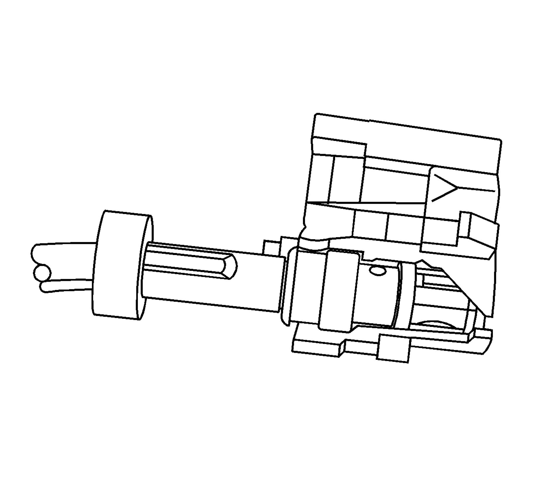 |
|
Fig. 3: Connecting New Service Coaxial Cable To New 3-Way Connector Housing |
5. Install the new service coaxial cable into the vehicle. Use the 4-inch jumper for the appropriate color
3-way connector housing to connect the new service coaxial cable to the new 3-way connector housing.
6. If the issue is found to be the connector housing and not cable, a new connector housing may be installed
while reusing all other components.
Coaxial Cable Repair Procedure
1. Identify the faulty/damaged coaxial cable.
2. Disconnect the faulty/damaged coaxial cable and leave it in the vehicle.
3. Identify the type of coaxial cable to be replaced and match up with the appropriate pieces to repair the
damaged coaxial cable. Match up the type of coaxial cable, cable length and connector types. In some
cases there may be extra length of cable left over.
 |
|
Fig. 4: Coaxial Cable Courtesy'of GENERAL MOTORS COMPANY |
NOTE: Avoid routing the new coaxial cable near sharp edges that can damage the
new coaxial cable.
4. Install the new coaxial cable in the vehicle.
Use tie-straps to attach the new service coaxial cable to existing harnesses or brackets. Use felt tape/foam
to reduce rattles, as necessary.
NOTE: To avoid permanent damage, do not pinch the cable or bend it tighter than
a 2 inch (5 centimeter) radius.
5. Remove the faulty/damaged connectors, if applicable.
6. Install new connectors or jumpers, as needed. Refer to Connector Housing Repair Procedure.
7. Verify the repair by operating the system with the vehicle in Service Mode.
FLAT WIRE REPAIRS
The flat wire within the flex wiring harness is not serviceable. If an open or short exists within the flex wiring
harness the complete harness must be replaced.
FOLDED-OVER WIRE REPAIR
Special Tools
• EL-38125-10 Splice Sleeve Crimping Tool (non GMNA)
• J-38125-5A Ultra Torch Special Tool
• J-38125-8 Splice Sleeve Crimping Tool (GMNA)
For equivalent regional tools, refer to Special Tools .
The GM global wire repair strategy uses connector assemblies (pigtails) and terminated leads to repair wiring
harnesses.
To reduce and manage GM Service Parts proliferation, the service pigtails and terminated leads are designed
with the largest wire gauge size that can be held by either the terminal or the connector housing.
The folded over wire repair technique, in which the copper wire strands are folded over before being installed
into a splice sleeve, allows the service part to be used when repairing a smaller gauge size wire in a vehicle.
This technique has passed all GM testing standards.

Fig. 5: View Of Stripped Wires In Splice Sleeve Connector
Courtesy'of GENERAL'MOTORS'COMPANY
The larger harness size wires (1) will be placed in one side of the splice sleeve and match the splice sleeve
closely in size. The wires are moved into the splice sleeve until they hit the stop (4) in the splice sleeve. The
smaller harness size wires (2) will be placed in the other side of the splice sleeve. The smaller harness size wires
will be folded over (3) to match up with the splice sleeve size.
Use the folded over wire repair for:
NOTE: Increasing the amount of copper strands in the smaller gauge size will
allow for a better crimp
• Splicing wires of 0.35 mm or less (22, 24, 26 gauge sizes)
NOTE: Vehicle side needs to be of same or less gauge size (not greater than the
service part's gauge size)
• Splicing wires of different gauges
Use the Service Information (SI) connector end-views to determine:
• Gauge size of wiring harness
• Recommended Repair: Terminated Lead or Pigtail
The following table lists the acceptable variance within the gauge size
|
Folded-Over Wire Selection Table | ||||||||||||||||||||||||||||||||||||||||||||||||||||||||||||||||||||||||||||||||||||
| ||||||||||||||||||||||||||||||||||||||||||||||||||||||||||||||||||||||||||||||||||||
| ||||||||||||
|
Example | ||||||||||||
For an IP Harness of 0.22 mm (24 gauge on left side of table) wire size, the SI connector end-view recommends
a pigtail with leads of 0.8 mm (18 gauge on the top of the table) with a salmon colored DuraSeal splice sleeve
of 0.5 - 1.0 mm (20 - 16 gauge).
Follow these steps to use the folded over wire (1) technique on an IP Harness.
 |
|
Fig. 6: View Of Stripped Wires Courtesy'of GENERAL'MOTORS COMPANY |
Strip twice the amount of insulation on the smaller (1) wire (IP Harness is the lower wire) than normally
required. Normally, the terminated leads have 5 mm of insulation stripped off the wire.
 |
|
Fig. 7: Splice Sleeve Crimping Tool |
NOTE: Use EL-38125-10 splice sleeve crimping tool (non GMNA) or J-38125-8
splice sleeve crimping tool (GMNA).
1. For wiring repair, refer to Wire to Wire Repair.
 |
|
Fig. 8: View Of Twisted And Folded Wire To Length |
2. Twist the wires before you fold them over to prevent the wire strands from opening up. Fold over the
copper wire strands of the smaller (1) gauge wire so that it is the same length as the non-folded wire.
 |
|
Fig. 9: View Of Folded Wire & Splice Sleeve |
3. Insert the folded over wire (1) into the splice sleeve.
 |
|
Fig. 10: Crimping The Splice Sleeve Courtesy'of GENERALMOTORS'COMPANY |
4. Use the proper crimp tool to crimp the splice sleeve to the smaller wire (harness side of repair). Complete
the crimp as usual (using the heat tool to shrink the tube).
SERIAL DATA CIRCUIT WIRING REPAIRS
Special Tools
• EL-38125-10 Splice Sleeve Crimping Tool
• DuraSeal splice sleeves
• A wire stripping tool
For equivalent regional tools, refer to Special Tools .
The DuraSeal splice sleeves have the following 2 critical features:
• A special heat shrink sleeve environmentally seals the splice. The heat shrink sleeve contains a sealing
adhesive inside.
• A cross hatched (knurled) core crimp provides necessary contact integrity for the sensitive, low energy
circuits.
The GM Local Area Network (GMLAN) System requires special wiring repair procedures due to the sensitive
nature of the circuitry. Follow the specific procedures and instructions when working on GMLAN connectors
and terminals.
GMLAN Repairs
NOTE: When making a repair to any GMLAN network, the original wire length after the
repair must be the same length as before the repair. If the network is a twisted
pair, the twist must be maintained after the repair is completed.
GMLAN has 2 types of networks, low speed and high speed. Low speed GMLAN has a single wire and works
at slow speeds. High speed GMLAN has 2 wires in a twisted pair and works at higher speeds. For more
information on GMLAN, refer to Data Link Communications Description and Operation .
GMLAN Connector Terminal Repair
NOTE: A terminated lead can be used to replace damaged connector terminals for both
high speed and low speed GMLAN systems. When making a connector terminal
repair on a GMLAN high speed system with twisted pair wires, do not untwist
the wires more than necessary to make the repair.
If the individual terminals are damaged on any GMLAN connection, use the appropriate connector repair
procedure in order to repair the terminal. Refer to Connector Repairs for the appropriate connector repair
procedure.
GMLAN Wire Repair
NOTE: Refer to Wiring Repairs in the service information connector end views or the
vehicle schematics in order to determine the correct wire size for the circuit you
are repairing. You must obtain this information in order to ensure circuit
integrity.
If any wire except the pigtail is damaged, repair the wire by splicing in a new section of wire of the same gauge
size (0.5 mm2,0.8 mm2 , 1.0 mm2 etc.). Use the DuraSeal splice sleeves and EL-38125-10 tool. For wiring
repair, refer to Wire to Wire Repair.
Media Oriented Systems Transport (MOST) Wiring Repair
NOTE: If harness repair/analysis is performed, MOST bus Twist Pair unshielded wire
should be 0.35 mm2 (22 AWG) wire with at least one twist per each 1 45/64 inch
(45 mm) and must not be untwisted for more than 3 15/16 of an inch (10 cm).
The following conditions need to be met to ensure a valid continuity:
• Untwisted length for all MOST 50 circuits at each wire harness connector should be no longer 50 mm
max (25 mm preferred).
• When wire repairs are made, a minimum 25 twists/meter for all MOST 50 circuits.
• MOST 50 has specific receive and transmit I/O.
The transmit of one module is connected to receive of the next module in ring topology.
HEATED OXYGEN SENSOR WIRING REPAIRS
CAUTION: Do not solder repairs under any circumstances as this could result in the air
reference being obstructed.
If the heated oxygen sensor pigtail wiring, connector, or terminal is damaged the entire oxygen sensor assembly
must be replaced. Do not attempt to repair the wiring, connector, or terminals. In order for the sensor to function
properly it must have a clean air reference. This clean air reference is obtained by way of the oxygen sensor
signal and heater wires. Any attempt to repair the wires, connectors or terminals could result in the obstruction
of the air reference and degrade oxygen sensor performance.
The following guidelines should be used when servicing the heated oxygen sensor:
• Do not apply contact cleaner or other materials to the sensor or vehicle harness connectors. These
materials may get into the sensor, causing poor performance. Also, the sensor pigtail and harness wires
must not be damaged in such a way that the wires inside are exposed. This could provide a path for
foreign materials to enter the sensor and cause performance problems.
• Neither the sensor nor vehicle lead wires should be bent sharply or kinked. Sharp bends, kinks, etc., could
block the reference air path through the lead wire.
• Do not remove or defeat the oxygen sensor ground wire (where applicable). Vehicles that utilize the
ground wire sensor may rely on this ground as the only ground contact to the sensor. Removal of the
ground wire will also cause poor engine performance.
• To prevent damage due to water intrusion, be sure that the peripheral seal remains intact on the vehicle
harness connector.
HIGH TEMPERATURE WIRING REPAIRS
NOTE: All wiring repairs need to be 200 mm from the heat zone. Areas of consideration
would be any area located near the exhaust manifolds, catalytic converter,
exhaust pipes, and turbocharged engines.
Items Required
• DuraSeal splice sleeves to crimp and seal connections
• High temperature SCT1 shrink tubing to protect the splice sleeves
• Terminated leads or pigtails
• The correct tools to remove the terminals from the connectors
Use high temperature bulk wire rated at 150A°C (302A°F) continuous temperature of the same or larger gauge
size as the original wire when repair damage wire. Also replace any reflective tape that you remove during the
repair.
High Temperature Wiring
Wiring that is exposed to high temperatures, 135A°C (275A°F) or higher, for prolonged periods of time may
use materials i.e. wires, connectors, and shielding that has a higher heat rating than typical wiring. When
making a repair in a high temperature area observe the following:
• Use high temperature bulk wire rated at 150A°C (302A°F) continuous temperature to replace any
damaged wire.
• Replace any heat shielding that is removed.
• Cover any DuraSeal splice sleeves with SCT1 shrink tubing.
• After making a wiring repair, ensure that the location of the wiring is not moved closer to the heat source.
Identifying High Temperature Wiring
NOTE: High temperature areas would be areas located near exhaust manifolds,
catalytic converters, exhaust pipes, and turbocharged engines.
Wiring that is exposed to high temperature, 135A°C (275A°F) or higher, for prolonged periods of time need
special considerations when making wiring repairs. Areas that may be exposed to higher temperatures can be
identified by heat resistant materials that are being used in those areas. These materials may include heat
reflective tape and high temperature shrink tubing. Also conduit and other protective coverings may be used.
Because conduit or similar coverings are used throughout the vehicle regardless of the temperature, it may be
necessary for the technician to determine if an area is exposed to excessive heat before making a wiring repair.
SIR/SRS WIRING REPAIRS
NOTE: Refer to SIR Service Precautions .
For European Regions
CAUTION: If the SIR/SRS wiring, connector, or terminal is damaged, the affected wiring
harness must be replaced. Do not attempt to repair the wiring, connector, or
terminals. Any attempt to repair the wires, connectors, or terminals could result
in performance problems of the SIR/SRS System. Operations on restraint
systems must only be performed by trained and qualified personnel.
For Non-European Regions
Special Tools
Splice Sleeve Crimping Tool, refer to Special Tools .
The Supplemental Inflatable Restraint (SIR) System/Supplemental Restraint System (SRS) requires special
wiring repair procedures due to the sensitive nature of the circuitry. Follow the specific procedures and
instructions when working with the SIR/SRS, and the wiring components, such as connectors and terminals.
SIR/SRS Connector Repair (Plastic Body and Terminal Metal Pin)
NOTE: Do not use the terminals in the kit in order to replace damaged SIR/SRS system
terminals. Use either an SIR/SRS pigtail or a terminated lead from the SIR
Repair Kit Tray.
The terminals in the SIR/SRS system are made with a special plating. This plating provides the necessary
contact integrity for the sensitive, low energy circuits.
Pigtail repair packs are available for SIR/SRS connectors with eight or less terminals. Only the connector body
is available for connectors with more than eight terminals. Terminated leads can be used to replace damaged
terminals when replacing the connector body.
SIR/SRS Component Wire Pigtail Repair
NOTE: Do not make wire, connector, or terminal repairs on components with wire
pigtails.
A wire pigtail is a wire or wires attached directly to the device, not by a connector. If a wiring pigtail is
damaged, you must replace the entire component, with pigtail. The inflatable restraint steering wheel module
coil is an example of a pigtail component.
SIR/SRS Wire Repair
CAUTION: Do not install more than 2 DuraSeal splice sleeves per SIR deployment loop. A
deployment loop consists of both wires from the k36 Inflatable Restraint
Sensing and Diagnostic Module to the deployable component. If more than 2
DuraSeal splice sleeves are required for any SIR deployment loop, the complete
circuit of the loop must be replaced. More than 2 DuraSeal splice sleeves per
deployment loop may increase the resistance in the circuit causing a DTC to be
set.
NOTE: Refer to Wiring Repairs in the service information connector end views or the
vehicle schematics in order to determine the correct wire size for the circuit you
are repairing. You must obtain this information in order to ensure circuit
integrity.
If any wire except the pigtail is damaged, repair the wire by splicing in a new section of wire of the same gauge
size (0.5 mm, 0.8 mm, 1.0 mm etc.). Use the DuraSeal splice sleeves and the appropriate splice sleeve crimping
tool. For wiring repair, refer to Wire to Wire Repair.
For connector position assurance (CPA), refer to Connector Position Assurance Locks.
For terminal position assurance (TPA), refer to Terminal Position Assurance Locks.
SPLICING INLINE HARNESS DIODES
Many vehicle electrical systems use a diode to isolate circuits and protect the components from voltage spikes.
When installing a new diode use the following procedure.
1. Open the harness.
• If the harness is taped, remove the tape.
• To avoid wiring insulation damage, use a sewing seam ripper (available from sewing supply stores)
in order to cut open the harness.
• If the harness has a black plastic conduit, pull out the diode.
2. If the diode is taped to the harness, remove all of the tape.
3. Check and record the current flow direction and orientation of diode.
4. Remove the inoperative diode from the harness with a suitable soldering tool.
NOTE: If the diode is located next to a connector terminal remove the terminal(s)
from the connector to prevent damage from the soldering tool.
5. Carefully strip away a section of insulation next to the old soldered portion of the wire(s). Do not remove
any more than is needed to attach the new diode.
6. Check current flow direction of the new diode, being sure to install the diode with correct bias. Reference
the appropriate service manual wiring schematic to obtain the correct diode installation position.
7. Attach the new diode to the wire(s) using 60/40 rosin core solder. Before soldering attach some heat sinks
(aluminum alligator clips) across the diode wire ends to protect the diode from excessive heat. Follow the
manufacturer's instruction for the soldering equipment.
8. Reinstall terminal(s) into the connector body if previously removed.
NOTE: To prevent shorts to ground and water intrusion, completely cover all
exposed wire and diode attachment points with tape.
9. Tape the diode to the harness or connector using electrical tape.
SPLICING TWISTED OR SHIELDED CABLE
WARNING: In order to reduce the risk of personal injury, loss of high voltage isolation to
ground and higher system impedance, do not attempt to repair any HV wiring,
connector, or terminal that is damaged. High voltage coaxial type cables are not
repairable. Never attempt to repair a coaxial type cable. The entire
cable/harness or component must be replaced. In order to maintain system
integrity and personal safety, never attempt to repair any high voltage wiring,
cables, or terminals. Performing this procedure on high voltage circuits may
result in serious injury or death.
Twisted/shielded cable is used in order to protect wiring from electrical noise. Two-conductor cable of this
construction is used between the radio and the Delco-BoseA® speaker/amplifier units and other applications
where low level, sensitive signals must be carried. Follow the instructions below in order to repair the
twisted/shielded cable.

Fig. 11: View Of Outer Wiring Jacket
Courtesy'of GENERALMOTORS'COMPANY
1. Remove the outer jacket (1). Use care not to cut into the drain wire of the mylar tape.
2. Unwrap the tape. Do not remove the tape. Use the tape in order to rewrap the twisted conductors after the
splice is made.
 |
|
Fig. 12: Preparing The Splice Courtesy'of GENERAL'MOTORS COMPANY |
3. Prepare the splice. Untwist the conductors and follow the instructions for Wire to Wire Repair.
Staggering the splices by 65 mm (2.5 in) is recommended.

Fig. 13: Identifying Diode On Wire
Courtesy'of GENERALMOTORS COMPANY
NOTE: Apply the mylar tape with the aluminum side inward. This ensures good
electrical contact with the drain wire.
4. Re-assemble the cable.
• Rewrap the conductors with the mylar tape. If the mylar tape is damaged, use 3M product
AL-36FR to replace the damaged mylar tape.
• Use caution not to wrap the drain wire in the tape (1).
• Follow the splicing instructions for copper wire and splice the drain wire.
• Wrap the drain wire around the conductors and tape with electrical tape to replace the outer
insulation.
 |
|
Fig. 14: View Of Repaired Wire Covered With Electrical Tape |
5. Tape over the entire cable. Use a winding motion when you apply the tape.
WIRE TO WIRE REPAIR
Special Tools
• EL-38125-10 Splice Sleeve Crimping Tool
• EL-38125-5 Ultra Torch Special Tool
• DuraSeal splice sleeves, in order to repair the SIR/SRS wiring
For equivalent regional tools, refer to Special Tools .
WARNING: In order to reduce the risk of personal injury, loss of high voltage isolation to
ground and higher system impedance, do not attempt to repair any HV wiring,
connector, or terminal that is damaged. High voltage coaxial type cables are not
|
repairable. Never attempt to repair a coaxial type cable. The entire | |
|
NOTE: |
If the wiring harness internal to the transmission is damaged, the wiring |
|
NOTE: |
Do not splice wires in Door Harness Grommets. |
|
NOTE: |
|
Use DuraSeal splice sleeves to form a one-to-one splice on all types of insulation except high voltage and
specialty cables. Use DuraSeal splice sleeves where there are special requirements such as moisture sealing.
Follow the instructions below in order to splice copper wire using DuraSeal splice sleeves.
|
Splice Sleeve Color |
Crimp Tool Nest Color |
Wire Gauge mm2 / | |
|
3 Crimp Nests |
4 Crimp Nests | ||
|
Salmon (Yellow-Pink) 19168446 |
Red (1) or Red/Green (1) |
Red (2) |
0.5 - 0.8/(18 - 20) |
|
Blue 19168447 |
Blue (2) |
Blue (3) |
1.0 - 2.6/(14 - 16) |
|
Yellow |
Yellow (3) |
Yellow (4) |
3.0 - 5.0/(10 - 12) |
NOTE: You must perform the following procedures in the listed order. Repeat the
procedure if any wire strands are damaged. You must obtain a clean strip
with all of the wire strands intact.
1. Open the harness by removing any tape:
• Use a sewing seam ripper, available from sewing supply stores, in order to cut open the harness in
order to avoid wire insulation damage.
• Use the DuraSeal splice sleeves on all types of insulation except Tefzel and coaxial.
• Do not use the crimp and DuraSeal splice sleeve to form a splice with more than 2 wires coming
together.
2. Cut as little wire off the harness as possible. You may need the extra length of wire in order to change the
location of a splice.
Adjust splice locations so that each splice is at least 40 mm (1.5 in) away from the other splices, harness
branches, or connectors.
3. Strip the insulation:
• When adding a length of wire to the existing harness, use the same size wire as the original wire.
• Perform one of the following items in order to find the correct wire size:
• Find the wire on the schematic and convert to regional wiring gauge size.
• If you are unsure of the wire size, begin with the largest opening in the wire stripper and
work down until achieving a clean strip of the insulation.
• Strip approximately 5.0 mm (0.20 in) of insulation from each wire to be spliced.
• Do not nick or cut any of the strands. Inspect the stripped wire for nicks or cut strands.
• If the wire is damaged, repeat this procedure after removing the damaged section.
4. For high temperature wiring, slide a section of high temperature SCT1 shrink tubing down the length of
wire to be spliced. Ensure that the shrink tubing will not interfere with the splice procedure.
5. Select the proper DuraSeal splice sleeve according to the wire size. Refer to the above table at the
beginning of the repair procedure for the color coding of the DuraSeal splice sleeves and the crimp tool
nests.
 |
|
Fig. 15: Splice Sleeve Crimping Tool With 4 Crimp Nests Courtesy of GENERAL MOTORS COMPANY |
6. The EL-38125-10 splice sleeve crimping tool has four crimp nests. The largest crimp nest (4) is used for
crimping 10 and 12 gauge wires. The second largest crimp nest (3) is used for crimping 14 and 16 gauge
wires. The third largest crimp nest (2) is used for crimping 18 and 20 gauge wires. The smallest crimp
nest (1) is used for crimping 22 to 26 gauge wires. The crimp nests are referenced in the table (farther
above) under the crimp tool nest color.
 |
|
Fig. 16: Splice Sleeve Crimping Tool With 3 Crimp Nests |
7. The J-38125-8 splice sleeve crimping tool has three crimp nests. The largest crimp nest (3) is used for
crimping 10 and 12 gauge wires. The second largest crimp nest (2) is used for crimping 14 and 16 gauge
wires. The smallest crimp nest (1) is used for crimping 18 to 20 gauge wires. The crimp nests are
referenced in the table (farther above) under the crimp tool nest color.
8. Use the splice sleeve crimp tool in order to position the DuraSeal splice sleeve in the proper color nest of
the splice sleeve crimp tool. For the four crimp nest tool, use the three largest crimp nests to crimp the
splice sleeves. For the three crimp nest tool, use all three crimp nests to crimp the splice sleeves. Use the
four and three crimp tool diagrams (above) and the table (farther above) to match the splice sleeve with
the correct crimp nest. The crimp tool diagram callout numbers match the numbers in the table (under
crimp tool nest color).

Fig. 17: Identifying Duraseal Splice Sleeve
Courtesy'of GENERAL'MOTORS'COMPANY
9. Place the DuraSeal splice sleeve in the nest. Ensure that the crimp falls midway between the end of the
barrel and the stop. The sleeve has a stop (3) in the middle of the barrel (2) in order to prevent the wire (1)
from going further. Close the hand crimper handles slightly in order to firmly hold the DuraSeal splice
sleeve in the proper nest.
 |
|
Fig. 18: Crimped Duraseal Splice Sleeve Courtesy'of GENERAL'MOTORS'COMPANY |
10. Insert the wire into the splice sleeve barrel until the wire hits the barrel stop.
11. Tightly close the handles of the crimp tool until the crimper handles open when released.
The crimper handles will not open until you apply the proper amount of pressure to the DuraSeal splice
sleeve. Repeat steps 4 and 6 for the opposite end of the splice.
 |
|
Fig. 19: Crimped Duraseal Splice Sleeve Courtesy'of GENERAL'MOTORS'COMPANY |
12. Using the EL-38125 - 5 ultra torch, apply heat to the crimped area of the barrel.
13. Start in the middle and gradually move the heat barrel to the open ends of the tubing:
• The tubing will shrink completely as the heat is moved along the insulation.
• A small amount of sealant will come out of the end of the tubing when sufficient shrinkage is
achieved.
Weatherpack™ Wiring Repair
NOTE: Some replacement pigtail connectors may be delivered without the terminated
leads installed into the connector. For Weatherpack™ connectors, all
terminated leads included in the package should to be installed into the
connector. If the connector end view shows that a terminal is not occupied, the
extra terminated lead(s) need to be installed and the end(s) sealed using a
DuraSeal splice sleeve and taped back into the harness.
1. Insert the wire into the splice sleeve barrel until the wire hits the barrel stop. Refer to Folded-Over Wire
Repair for splicing wires of 0.35 mm or less (22, 24, 26 gauge sizes) and for splicing wires of different
gauges.
 |
|
Fig. 20: Tightly Close Handles Of Crimp Tool Courtesy of GENERAL MOTORS COMPANY |
2. Tightly close the handles of the crimp tool until the crimper handles open when released.
The crimper handles will not open until you apply the proper amount of pressure to the DuraSeal splice
sleeve. Holding the DuraSEAL with one hand gently tug on the wire to ensure it is crimped in the
DuraSeal.
3. Using the heat torch, apply heat to the crimped area of the barrel.
 |
|
Fig. 21: Heat To Crimped Area Of Barrel Courtesy of GENERAL MOTORS COMPANY |
4. Start in the middle and gradually move the heat barrel to the open ends of the tubing:
• The tubing will shrink completely as the heat is moved along the insulation.
• A small amount of sealant will come out of the end of the tubing when sufficient shrinkage is
achieved.

Fig. 22: Taping Extra Terminated Leads Back Into Harness
Courtesy of GENERAL MOTORS COMPANY
5. Tape the extra terminated lead(s) back into the harness.
High Temperature Wiring Repairs
Use the following procedures to perform high temperature wiring repairs:
1. Center the high temperature SCT1 shrink tube over the DuraSeal splice sleeve.
2. Using the EL-38125 - 5 ultra torch, apply heat to the high temperature heat shrink tubing.
3. Gradually move the heat from the center to the open end of the tubing:
• The tubing will shrink completely as the heat is moved along the insulation.
• A small amount of sealant will come out of the end of the tubing when sufficient shrinkage is
achieved.
4. Replace any reflective tape and clips that may have been removed during the repair.
CONNECTOR POSITION ASSURANCE LOCKS
The connector position assurance (CPA) is a small plastic insert that fits through the locking tabs of the
connector. CPAs are used in various connectors throughout the vehicle. CPAs are also used in all SIR system
electrical connectors. The CPA ensures that the connector halves cannot vibrate apart. You must have the CPA
in place in order to ensure good contact between the mating terminals of the connector.
TERMINAL POSITION ASSURANCE LOCKS
The terminal position assurance (TPA) insert resembles the plastic combs used in the control module
connectors. The TPA keeps the terminal securely seated in the connector body. Do not remove the TPA from the
connector body unless you remove a terminal for replacement. If the TPA is removed, be sure to reinstall it
before reconnecting the connector.
AFL/EPC CONNECTORS
Special Tools
• EL-38125-550 Terminal Release Tool Kit
• EL-38125-580 Terminal Release Tool Kit
• J-38125-12A Terminal Release Tool
• J-38125-216 Terminal Release Tool
For equivalent regional tools, refer to Special Tools .
Terminal Removal Procedure
Follow the steps below in order to remove terminals from the connector.

Fig. 23: View Of Bolt On Connector Cover
Courtesy'of GENERAL'MOTORS'COMPANY

Fig. 24: Identifying Connector Position Assurance (CPA)
Courtesy'of GENERAL'MOTORS'COMPANY
1. For connectors with a bolt in the dress cover, turn the bolt counterclockwise to remove the connector
from the component.
2. Locate the connector position assurance (CPA) on the top of the wire dress cover. Slide the CPA forward.

Fig. 25: Identifying Lever Lock & Lever Lock Release Tab
Courtesy'of GENERAL'MOTORS'COMPANY
3. Slide the lever lock forward while pressing down on the lever lock release tab.
 |
|
Fig. 26: View Showing Depressing Lever Lock Release Tab |
4. View showing depressing of the lever lock release tab.

Fig. 27: View of connector in released position
Courtesy'of GENERAL'MOTORS'COMPANY
5. View of connector in released position.
6. Disconnect the connector from the component.
7. Locate the dress cover locking tabs at the corners of the dress cover. Use a small flat-blade tool to release
the locking tabs and remove the dress cover.
 |
|
Fig. 28: View Of Connector In Released Position |
8. Release the rear lower half of the wiredress cover.
 |
|
Fig. 29: Identifying Tabs Holding Wiredress Cover |
9. Release the tabs that are holding the wiredress cover to the connector body.
10. Remove the nose piece by inserting a small flat-blade tool into the slots on both ends of the connector
body. Gently pry the nose piece out of the connector. J-38125-216 can also be used to remove the nose
piece.
 |
|
Fig. 30: Lifting Terminal Retaining Tabs |
11. Use the J-38125-12A tool to release the terminals by lifting the terminal retaining tabs on the inside of the
connector.
 |
|
Fig. 31: Pulling Wire Out Of Back Of Connector Courtesy'of GENERAL'MOTORS'COMPANY |
12. While holding the removal tool in place, gently pull the wire out of the back of the connector. Always
remember never use force when pulling a terminal out of a connector.
13. Repair the terminal by following the Repairing Connector Terminals (Terminated Lead
Repair)Repairing Connector Terminals (Terminal Repair) procedure.
14. Insert the repaired terminal back into the cavity. Repeat the diagnostic procedure to verify the repair and
reconnect the connector bodies.
BOSCH CONNECTORS (BSK)
Special Tools
• EL-38125-550 Terminal Release Tool Kit
• EL-38125-580 Terminal Release Tool Kit
• J-38125-561 Terminal Release Tool
For equivalent regional tools, refer to Special Tools .
Terminal Removal Procedure
1. Disconnect the connector from the component.
2. Remove the wire dress cover, if necessary.
3. Push the wire side of the terminal that is being removed toward the connector and hold it in position.
 |
|
Fig. 32: View Of Bosch Connector Terminals (BSK) Courtesy'of GENERAL'MOTORS'COMPANY |
4. Insert the J-38125-561 tool into the 2 cavities on each side of the terminal at the front of the connector
and push until you feel the tool disengage the terminal retainers.
5. Carefully pull the terminal out of the connector. Always remember never use force when pulling a
terminal out of a connector. If the terminal is difficult to remove, repeat the entire procedure.
6. Repair the terminal by following the Repairing Connector Terminals (Terminated Lead
Repair)Repairing Connector Terminals (Terminal Repair) procedure.
7. Insert the repaired terminal back into the cavity. Repeat the diagnostic procedure to verify the repair and
reconnect the connector bodies.
BOSCH CONNECTORS (0.64)
Special Tools
• EL-38125-550 Terminal Release Tool Kit
• EL-38125-580 Terminal Release Tool Kit
• J-38125-560 Terminal Release Tool
For equivalent regional tools, refer to Special Tools .
Terminal Removal Procedure
1. Locate the lever lock on the wire dress cover. While pressing the lock, pull the lever over and past the
lock until the lever is at the end of its travel.
2. Disconnect the connector from the component.
3. Pull the rubber boot that covers the wires back to expose the end of the connector dress cover.
4. Place the connector locking lever in the center of the connector.
 |
|
Fig. 33: View Of Flat-Bladed Tool Being Inserted Between Cover & Connector Body |
5. Locate the 2 dress cover locking tabs that are on the wire end of the connector. Insert a small flat-bladed
tool between the cover and connector body and pry up.
 |
|
Fig. 34: View Of Flat-Bladed Tool Between Cover & Connector End |
6. Locate the 2 dress cover locking tabs located on the opposite side of the connector. Insert a small flat-
bladed tool between the cover at the connector end and pry up.
7. Remove the dress cover.
8. Cut the tie wrap on the wire bundle.
 |
|
Fig. 35: View Of Terminal Position Assurance (TPA) Courtesy'of GENERAL'MOTORS'COMPANY |
9. Remove the terminal position assurance (TPA) by inserting a small flat-bladed tool into the small slot in
the end of the slider and pushing on the TPA until it comes out of the connector. When the TPA exits the
opposite side of the connector, gasp the TPA and pull it completely out of the connector.
10. Push the wire side of the terminal that is being removed toward the connector and hold it in position.
 |
|
Fig. 36: View Of J 38125-560 Being Inserted Into Triangular Cavities Courtesy'of GENERALMOTORS COMPANY |
11. Insert the J-38125-560 into the 2 triangular cavities on each side of the terminal at the front of the
connector.
12. Carefully pull the terminal out of the connector. Always remember never use force when pulling a
terminal out of a connector. If the terminal is difficult to remove, repeat the entire procedure.
13. Repair the terminal by following the Repairing Connector Terminals (Terminated Lead
Repair)Repairing Connector Terminals (Terminal Repair) procedure.
14. Insert the repaired terminal back into the cavity. Repeat the diagnostic procedure to verify the repair and
reconnect the connector bodies.
Terminal Insertion Procedure
 |
|
Fig. 37: Aligning Coding Lugs With Connector Coding Grooves |
1. Prior to installation the terminal must be aligned so the (1) coding lugs align with the (2) coding grooves
on the connector.
2. Once the terminal is aligned, slide the terminal into the cavity until the retainer has engaged in the cavity
of the connector.
3. Slide the TPA in the connector body and seat it using a small flat bladed tool. The TPA is seated when it
is flush with the contact housing.
4. Secure the wires to the connector body using a tie wrap and replace the dress cover and grommet.
BOSCH CONNECTORS (2.8 JPT)
Special Tools
• EL-38125-550 Terminal Release Tool Kit
• EL-38125-580 Terminal Release Tool Kit
• J-38125-557 Terminal Release Tool
For equivalent regional tools, refer to Special Tools .
Terminal Removal Procedure
1. Pull out the slider on the connector position assurance (CPA) until it is at the end of its travel.
2. Disconnect the connector from the component.
3. Remove the wire dress cover, if necessary.
4. Push the wire side of the terminal that is being removed toward the connector and hold it in position.
 |
|
Fig. 38: Bosch Connector Terminals Courtesy'of GENERAL'MOTORS'COMPANY |
5. Insert the J-38125-557 into the 2 cavities on each side of the terminal at the front of the connector and
push until you feel the tool disengage the terminal retainers.
6. Carefully pull the terminal out of the connector. Always remember never use force when pulling a
terminal out of a connector. If the terminal is difficult to remove, repeat the entire procedure.
7. Repair the terminal by following the Repairing Connector Terminals (Terminated Lead
Repair)Repairing Connector Terminals (Terminal Repair) procedure.
8. Insert the repaired terminal back into the cavity. Repeat the diagnostic procedure to verify the repair and
reconnect the connector bodies.
BOSCH CONNECTORS (ECM)
Special Tools
• EL-38125-550 Terminal Release Tool Kit
• EL-38125-580 Terminal Release Tool Kit
• J-38125-213 Terminal Release Tool
• J-38125-556 Terminal Release Tool
For equivalent regional tools, refer to Special Tools .
Terminal Removal Procedure

Fig. 39: View Of Bosch Connectors
Courtesy'of GENERALMOTORS' COMPANY
1. Locate the assist lever on the top of the connector. Move the assist lever to the forward position.

Fig. 40: Identifying Assist Lever In Forward Position
Courtesy'of GENERAL'MOTORS'COMPANY
2. Disconnect the connector from the component.
 |
|
Fig. 41: View Of Releasing Locking Tabs |
3. Locate the dress cover locking tabs at the corners of the connector. Use a small flat-blade tool to release
the locking tabs and remove the dress cover.
 |
|
Fig. 42: View Of Terminal Positive Assurance (TPA) Connector |
4. The terminal positive assurance (TPA) is located in the front of the connector.
 |
|
Fig. 43: View Of Removing TPA From Connector |
5. Use a small flat-blade tool to remove TPA from the connector.

Fig. 44: View Of Special Tools And Terminals
Courtesy'of GENERAL'MOTORS'COMPANY
6. Use the J-38125-213 or the J-38125-556 tool to release the terminals by inserting the tool into the
terminal release cavity.
7. While holding the removal tool in place, gently pull the wire out of the back of the connector. Always
remember never use force when pulling a terminal out of a connector.
8. Repair the terminal by following the Repairing Connector Terminals (Terminated Lead
Repair)Repairing Connector Terminals (Terminal Repair) procedure.
9. Insert the repaired terminal back into the cavity. Repeat the diagnostic procedure to verify the repair and
reconnect the connector bodies.
|
NOTE: |
Ensure that the dress cover and connector body are both in the released |
10. Reconnect the connector bodies.
DELPHI CONNECTORS (WEATHER PACK)
Special Tools
• EL-38125-550 Terminal Release Tool Kit
• EL-38125-580 Terminal Release Tool Kit
• J-38125-10A Terminal Release Tool
For equivalent regional tools, refer to Special Tools .
Terminal Removal Procedure
The following is the proper procedure for the repair of Weather PackA® Connectors.

Fig. 45: View Of Connector Halves
Courtesy'of GENERAL'MOTORS COMPANY
1. Separate the connector halves (1).
2. Open the secondary lock. A secondary lock aids in terminal retention and is usually molded to the
connector (1).
3. Grasp the wire and push the terminal to the forward most position. Hold the wire in this position.
 |
|
Fig. 46: Identifying Removal Tool & Terminal Courtesy'of GENERAL'MOTORS'COMPANY |
4. Insert the Weather PackA® terminal removal tool J-38125-10A into the front (mating end) of the
connector cavity until it rests on the cavity shoulder (1).
5. Gently pull on the wire to remove the terminal through the back of the connector (2).
NOTE: Never use force to remove a terminal from a connector.
6. Inspect the terminal and connector for damage. Repair as necessary. Refer to Repairing Connector
Terminals (Terminated Lead Repair)Repairing Connector Terminals (Terminal Repair).
7. Reform the lock tang (2) and reset terminal in connector body.
8. Close secondary locks and join connector halves.
9. Verify that circuit is complete and working satisfactorily.
10. Perform system check.
11. Repair the terminal by following the Repairing Connector Terminals (Terminated Lead
Repair)Repairing Connector Terminals (Terminal Repair) procedure.
12. Insert the repaired terminal back into the cavity. Repeat the diagnostic procedure to verify the repair and
reconnect the connector bodies.
DELPHI CONNECTORS (PUSH TO SEAT)
Special Tools
• EL-38125-550 Terminal Release Tool Kit
• EL-38125-580 Terminal Release Tool Kit
For equivalent regional tools, refer to Special Tools .
Terminal Removal Procedure
Follow the steps below in order to repair push to seat connectors.
1. Remove the terminal position assurance (TPA) device, the connector position assurance (CPA) device,
and/or the secondary lock.

Fig. 47: View Of Connector Halves
Courtesy'of GENERALMOTORS COMPANY
2. Separate the connector halves (1).
 |
|
Fig. 48: Identifying Removal Tool & Terminal |
3. Use the proper pick or removal tool (1) in order to release the terminal.
4. Gently pull the cable and the terminal (2) out of the back of the connector.
 |
|
Fig. 49: Identifying Locking Device Courtesy'of GENERALMOTORS COMPANY |
5. Re-form the locking device if you are going to reuse the terminal (1).
6. Repair the terminal by following the Repairing Connector Terminals (Terminated Lead
Repair)Repairing Connector Terminals (Terminal Repair) procedure.
7. Insert the repaired terminal back into the cavity. Repeat the diagnostic procedure to verify the repair and
reconnect the connector bodies.
Terminal Insertion Procedure
1. In order to reuse a terminal or lead assembly, refer to Wiring Repairs .
2. Ensure that the cable seal is kept on the terminal side of the splice.
3. Insert the lead from the back until it catches.
4. Install the TPA, CPA, and/or the secondary locks.
DELPHI CONNECTORS (PULL TO SEAT)
Special Tools
• EL-38125-550 Terminal Release Tool Kit
• EL-38125-580 Terminal Release Tool Kit
For equivalent regional tools, refer to Special Tools .
Terminal Removal Procedure
If the terminal is visibly damaged or is suspected of having a faulty connection, the terminal should be replaced.
 |
|
Fig. 50: Aligning Removal Tool - Delphi (Pull To Seat) Courtesy'of GENERAL'MOTORS'COMPANY |
Follow the steps below in order to repair pull-to-seat connectors:
1. Remove the connector position assurance (CPA) device and/or the secondary lock.
2. Disconnect the connector from the component or separate the connectors for in-line connectors.
3. Remove the terminal position assurance (TPA) device.
4. Review the connector end view to determine the proper test probe and release tool.
5. Insert the release tool into the front of the connector body.
6. Grasp the wire at the back of the connector body and gently push the terminal out the front of the
connector body.
7. Repair the terminal by following the Repairing Connector Terminals (Terminated Lead
Repair)Repairing Connector Terminals (Terminal Repair) procedure.
8. Insert the repaired terminal back into the cavity. Repeat the diagnostic procedure to verify the repair and
reconnect the connector bodies.
Terminal Insertion Procedure
1. Align the terminal and pull the wire from the back of the connector in order to seat the terminal.
2. If the connector is outside of the passenger compartment, apply dielectric grease to the connector.
3. Install the TPA, CPA, and/or the secondary locks.
DELPHI CONNECTORS (MICRO-PACK 100W)
Special Tools
• EL-38125-550 Terminal Release Tool Kit
• EL-38125-580 Terminal Release Tool Kit
• J-38125-12A Terminal Release Tool
For equivalent regional tools, refer to Special Tools .
Terminal Removal Procedure
There are 2 styles of Micro-Pack 100W connectors. These connectors are very similar but use different
terminals and have some minor physical differences also.
 |
|
Fig. 51: Identifying Micro-Pack 100W First & Second Connector Designs |
The first connector design of the Micro-Pack 100W (1) has a white connector interface that holds the terminals.
The second design of the Micro-Pack 100W (2) has a gray interface to hold the terminals. Also, the first design
has terminal cavities that are further apart (3 mm centerline) and offset from the other row of terminal cavities
in the connector. The second design has terminals cavities that are closer together (2.54 mm centerline) and
aligned vertically. One other way to identify the second design is the thin strip of material that runs along the
outside of the cavities.
 |
|
Fig. 52: Identifying Micro-Pack 100W Short & Long Terminals |
NOTE: There are 2 styles of Micro-Pack 100W terminals which are very similar. Ensure
that you have the correct terminal before crimping the new terminal to the wire.
The first design connector uses the longer terminal (1) that has a raised area in
front of the recess in the terminal. The second design connector uses the
shorter terminal without the raised area.
Follow the steps below in order to remove terminals from Micro-Pack 100W connectors. Some Micro-Pack
100W connector disassembly procedures will vary. Use this procedure as a guide.
1. Disconnect the connector from the component.
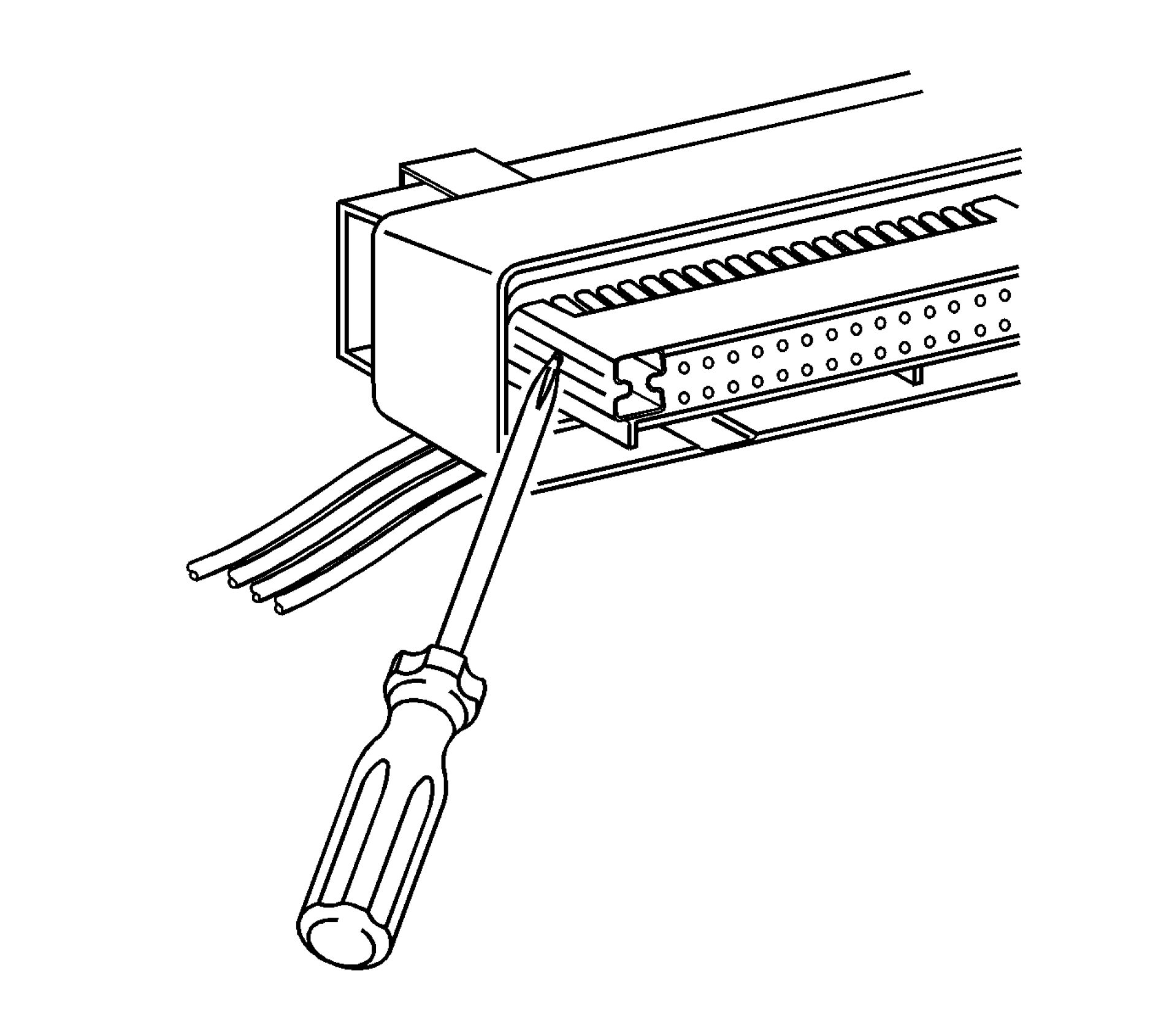 |
|
Fig. 53: Locating Nose Piece Locking Tabs Courtesy'of GENERAL'MOTORS'COMPANY |
2. Locate the nose piece locking tabs that are positioned on the side of the connector nose piece. The
connector nose piece acts as a terminal positive assurance (TPA) and may be referred to as such.
 |
|
Fig. 54: Loosening Nose Piece Locking Tabs |
3. Use a small flat-blade tool to push in one of the locking tabs while gently pulling on the same side of the
nose piece.
4. Repeat the procedure for the other locking tab and remove the nose piece.
5. Remove the wire dress cover. The following is a general procedure for wire dress cover removal. Use this
procedure as a guide, some dress cover removal procedures may vary.
 |
|
Fig. 55: Squeezing Cover Locking Legs |
6. Use fingers to squeeze the 2 locking legs of the cover.
 |
|
Fig. 56: Unseating Locking Leg Courtesy'of GENERALMOTORS COMPANY |
7. Apply pressure and gently rock the cover until one locking leg is unseated.
 |
|
Fig. 57: Removing Cover Courtesy'of GENERALMOTORS COMPANY |
8. Continue to apply pressure and rock the cover until the second locking leg is unseated. Repeat procedure
for the other side of the dress cover and remove the cover.
 |
|
Fig. 58: Identifying Terminal Retaining Tab Courtesy'of GENERAL'MOTORS'COMPANY |
9. Use J-38125-12A to gently lift the terminal retaining tab while gently pulling the wire out of the back of
the connector. Always remember never use force when pulling a terminal out of a connector.
10. If the terminal is severely bent or damaged, it may be possible on some connectors to push the wire out of
the front of the connector instead of pulling it through. This will prevent damage to the internal seals of
the connector. Once the terminal is pushed out of the connector, cut the wire as close to the terminal as
possible and pull the wire through the connector.
11. Repair the terminal by following the Repairing Connector Terminals (Terminated Lead
Repair)Repairing Connector Terminals (Terminal Repair) procedure.
12. Insert the repaired terminal back into the cavity. Repeat the diagnostic procedure to verify the repair and
reconnect the connector bodies.
Terminal Insertion Procedure
After the terminal is crimped to the wire perform the following procedure in order to replace Micro-Pack 100
terminals.
1. Slide the new terminal into the correct cavity at the back of the connector.
2. Push the terminal into the connector until it locks into place. The new terminal should be even with the
other terminals. Ensure that the terminal is locked in place by gently pulling on the wire.
3. To assemble the connector, reverse the Terminal Removal Procedure.
DELPHI CONNECTORS (MICRO.64)
Special Tools
• EL-38125-550 Terminal Release Tool Kit
• EL-38125-580 Terminal Release Tool Kit
• J-38125-21 Terminal Release Tool
For equivalent regional tools, refer to Special Tools .
Terminal Removal Procedure
Follow the steps below in order to remove terminals from Micro.64 connectors.
 |
|
Fig. 59: Identifying Wire Dress Cover Lever Lock |

Fig. 60: View Of Typical Micro 64 Connector
Courtesy'of GENERAL'MOTORS'COMPANY

Fig. 61: Depressing Lock And Pulling Lever
Courtesy'of GENERAL'MOTORS'COMPANY
 |
|
Fig. 62: View Of Connector When Released From Component |

Fig. 63: View Of Another Type Of Micro 64 Connector
Courtesy'of GENERAL'MOTORS'COMPANY
 |
|
Fig. 64: Locating Locks On Both Sides Of Wiredress Cover |

Fig. 65: View Of Connector When Released From Component
Courtesy'of GENERAL'MOTORS'COMPANY
1. Locate the lever lock on the wire dress cover. While depressing the lock, pull the lever over and past the
lock. The lever lock may be located on the top or sides of the wire dress cover.
View of a typical Micro 64 connector.
Depress the lock and pull the lever over and past the lock.
View of the connector when released from the component.
View of another type of Micro 64 connector.
Depress the locks that are located on both sides of the wire dress cover and pull the lever over and past
the locks.
View of the connector when released from the component.
2. Disconnect the connector from the component.
 |
|
Fig. 66: View Of Releasing Locking Tabs |
3. Locate the dress cover locking tabs at the front of the connector. Using a small flat-blade tool push down
on one of the locking tabs and pull the cover up until the dress cover releases. Repeat this procedure for
the other locking tab.
4. Once the front 2 locks are unlocked, lift the front of the dress cover and pull it forward.

Fig. 67: View Of Removing Terminal Position Assurance
Courtesy'of GENERAL'MOTORS'COMPANY
NOTE: Always use care when removing a terminal position assurance (TPA) in
order to avoid damaging it.
5. Remove the TPA by inserting a small flat-blade tool into the small slot on the TPA and pushing down
until the TPA releases. Gently pry the TPA out of the connector.

Fig. 68: Identifying Terminal Release Tool
Courtesy'of GENERAL'MOTORS'COMPANY
NOTE: Be careful not to angle or rock the J-38125-21 tool when inserting it into
the connector or the tool may break.
6. Insert the J-38125-21 tool into the round canal between the terminals cavities at the front of the connector.
 |
|
Fig. 69: Removing Wire From Back Of Connector Courtesy'of GENERAL'MOTORS'COMPANY |
7. While holding the removal tool in place, gently pull the wire out of the back of the connector. Always
remember never use force when pulling a terminal out of a connector.
8. Repair the terminal by following the Repairing Connector Terminals (Terminated Lead
Repair)Repairing Connector Terminals (Terminal Repair) procedure.
9. Insert the repaired terminal back into the cavity. Repeat the diagnostic procedure to verify the repair and
reconnect the connector bodies.
DELPHI CONNECTORS (12-WAY)
Special Tools
• EL-38125-550 Terminal Release Tool Kit
• EL-38125-580 Terminal Release Tool Kit
• J-38125-12A Terminal Release Tool
For equivalent regional tools, refer to Special Tools .
Terminal Removal Procedure
Follow the steps below in order to remove terminals from the connector.

Fig. 70: Identifying Lever Lock
Courtesy'of GENERALMOTORS COMPANY
1. Locate the lever lock on the wire dress cover. Remove the connector position assurance (CPA) and slide
the lever lock away from the connector body.
2. Disconnect the connector from the component.

Fig. 71: Identifying Dress Cover Locking Tabs
Courtesy'of GENERAL'MOTORS'COMPANY
3. Locate the dress cover locking tabs on the dress cover of the connector. Using a small flat-blade tool
release all of the locking tabs.
 |
|
Fig. 72: Identifying Lower Wire Dress Cover Locking Tab |
4. Release the lower wire dress cover locking tab.
 |
|
Fig. 73: Identifying Upper Wire Dress Cover Locking Tab |
5. Release the upper wire dress cover locking tab.
6. Once the locks are unlocked, lift the dress cover off.
 |
|
Fig. 74: View Of TPA Being Pried Out Of Connector Courtesy'of GENERAL'MOTORS'COMPANY |
NOTE: Always use care when removing a terminal position assurance (TPA) in
order to avoid damaging it.
7. Remove the TPA by inserting a small flat-blade tool into the locking tabs on both sides of the TPA.
Gently pry the TPA out of the connector.
 |
|
Fig. 75: View Of Nose Piece Courtesy'of GENERALMOTORS COMPANY |
8. Remove the nose piece by inserting a small flat-blade tool into the locking tabs on both sides of the nose
piece. Gently pry the nose piece out of the connector.
 |
|
Fig. 76: Inserting Special Tool Into Terminal Release Cavity |
9. Insert the J-38125-12A tool to release the terminals by inserting the tool into the terminal release cavity.
 |
|
Fig. 77: Pulling Wire Out Of Back Of Connector |
10. While holding the removal tool in place, gently pull the wire out of the back of the connector. Always
remember never use force when pulling a terminal out of a connector.
11. Repair the terminal by following the Repairing Connector Terminals (Terminated Lead
Repair)Repairing Connector Terminals (Terminal Repair) procedure.
12. Insert the repaired terminal back into the cavity. Repeat the diagnostic procedure to verify the repair and
reconnect the connector bodies.
DELPHI CONNECTORS (STEERING GEAR)
Removal Procedure
 |
|
Fig. 78: Releasing Locking Tab On Connector |
1. Use a small flat-bladed tool to release the locking tab on the connector.
 |
|
Fig. 79: Releasing Connector Courtesy'of GENERALMOTORS COMPANY |
2. Push down the locking tab to release the connector. The small flat-bladed tool may need to be pushed
down and angled back slightly to depress the locking tab. Pull on the connector body while releasing the
locking tab to disconnect the connector.
FCI CONNECTORS (LEVER LOCK)
Special Tools
• EL-38125-550 Terminal Release Tool Kit
• EL-38125-580 Terminal Release Tool Kit
• J-38125-556 Terminal Release Tool
• J-38125-560 Terminal Release Tool
For equivalent regional tools, refer to Special Tools .
Terminal Removal Procedure
Follow the steps below in order to remove terminals from the connector.

Fig. 80: Identifying Release Tab
Courtesy'of GENERALMOTORS COMPANY
1. Slide the lever lock forward while pressing down on the lever lock release tab.
2. The release tab is located on the top of the wiredress cover.
 |
|
Fig. 81: View Of Connector In Released Position |
3. View of connector in released position.
4. Disconnect the connector from the component.
5. Locate the dress cover locking tabs at the corners of the dress cover. Use a small flat-blade tool to release
the locking tabs and remove the dress cover.
 |
|
Fig. 82: View Of Sliding Terminal Position Assurance (TPA) Up One Notch |
6. Use a small flat-blade tool to slide the terminal position assurance (TPA) up one notch on both ends of the
connector. The TPA is located underneath the wire dress cover.
 |
|
Fig. 83: View Of Releasing Terminals Courtesy'of GENERAL'MOTORS'COMPANY |
7. For the larger terminals insert the J-38125-556 tool to release the terminals by inserting the tool into the
terminal release cavity. For the smaller terminals insert the J-38125-560 tool to release the terminals by
inserting the tool into the terminal release cavity.
 |
|
Fig. 84: View Of Wire Being Pulled Out Of Back Of Connector While Holding Removal Tool In Place Courtesy of GENERAL MOTORS COMPANY |
8. While holding the removal tool in place, gently pull the wire out of the back of the connector. Always
remember never use force when pulling a terminal out of a connector.
9. Repair the terminal by following the Repairing Connector Terminals (Terminated Lead
Repair)Repairing Connector Terminals (Terminal Repair) procedure.
10. Insert the repaired terminal back into the cavity. Repeat the diagnostic procedure to verify the repair and
reconnect the connector bodies.
FCI CONNECTORS (SIR)
Removal Procedure
NOTE:
The orange or yellow connector position assurance (CPA) must be released first
to disconnect or to connect the connector.

Fig. 85: Lifting Orange CPA
Courtesy'of GENERALMOTORS COMPANY
1. Lift the orange or yellow CPA vertically (avoid lifting on an angle to the connector) approximately 4 mm
to release the connector. Use a small flat-bladed tool to help release the CPA. The CPA may also be
released manually without any tools.
 |
|
Fig. 86: Grabbing Connector On Both Sides Courtesy'of GENERAL'MOTORS'COMPANY |
2. Grab the connector on both sides and lift vertically to disconnect the connector.
Installation Procedure
 |
|
Fig. 87: Lifting Orange CPA Courtesy'of GENERALMOTORS COMPANY |
1. The CPA should be approximately 4 mm above the yellow cover before installing the connector. If not,
use a small flat-bladed tool to help release the CPA. The CPA may also be released manually without any
tools.
 |
|
Fig. 88: Seating Connector Sub-Assembly |
2. Line up the connector key tabs with the initiator key slots. Grab the connector on both sides and push
down into the initiator connector sub assembly until fully seated.
 |
|
Fig. 89: Pushing CPA Down Courtesy'of GENERALMOTORS COMPANY |
3. After the connector is fully seated, push the CPA down with your thumb until the CPA is touching the
yellow cover on the connector.
4. After the CPA is seated, lightly pull on the connector, it should not pull off if the connector and CPA are
properly engaged.
FEP CONNECTORS (STEERING GEAR)
Removal Procedure
 |
|
Fig. 90: Releasing Locking Tab On Connector |
1. Use a flat-bladed tool to release the locking tab on the connector.
 |
|
Fig. 91: Twisting Flat-Bladed Tool To Push Top Of Locking Tab Inward |
2. Option 1: Twist the flat-bladed tool to push the top of the locking tab inward while pulling the connector
body out.
 |
|
Fig. 92: Using Flat-Bladed Tool To Depress Locking Tab Courtesy'of GENERAL'MOTORS'COMPANY |
3. Option 2: Pry using the flat-bladed tool to depress the locking tab while pulling the connector body out.
JST CONNECTORS
Special Tools
• EL-38125-550 Terminal Release Tool Kit
• EL-38125-580 Terminal Release Tool Kit
• J-38125-553 Terminal Release Tool
For equivalent regional tools, refer to Special Tools .
Terminal Removal Procedure
The JST connector family consists of seven unique connector housings differentiated by color and keying. This
connector family is designed to use both 0.64 and 2.8 sized terminals.
JST BCM Connector
I GM Service Part #
Color
|
GM Service Part # |
Color |
|
88988806 |
Gray |
|
88988837 |
Brown |
|
88988838 |
Lt Green |
|
88988839 |
Natural |
|
88988840 |
Lt Blue |
|
88988841 |
Black |
|
88988842 |
Pink |
 |
|
Fig. 93: Identifying Terminal Position Assurance (TPA) |
1. While depressing the lock, remove the connector from the component.
 |
|
Fig. 94: Identifying TPA On Both Sides Of Connector |
2. Unlock the terminal position assurance (TPA):
• Position connector as shown (above) and locate TPA staging cavities.
 |
|
Fig. 95: Terminal Release Tool Courtesy'of GENERALMOTORS COMPANY |
• Using connector terminal release tool J-38125-553 (1) lift the TPA into the staged position. Perform
this step on both sides of the TPA.

Fig. 96: TPA In Staged Position
Courtesy'of GENERALMOTORS COMPANY
• You will feel the TPA click into place when fully extended into the staged position. The figure
above shows the TPA (1) in the staged position.
 |
|
Fig. 97: Connector Terminal Release Tool |
3. Release the terminal from the connector:
• Position the connector as shown (above) and locate the terminal release entry canal (1) of the
suspect terminal.
• Insert the connector terminal release tool J-38125-553 into the entry canal with the angled side of
the tool facing the connector wall containing cavity 4 (2).
 |
|
Fig. 98: Connector Lance And TPA Courtesy'of GENERAL'MOTORS'COMPANY |
• The cavity on the left (1) is a 2.8 mm2 cavity and the cavity on the right (2) is a 0.64 mm2 cavity.
• Place the tip of the connector terminal release tool onto the connector lance (3) and deflect the
lance to the right (5) to release the lock. Hold this released position.
• Holding the lance in the released position, slightly pull on the suspect terminal to remove it from
the connector housing. The side TPA (4) is a secondary lock.
4. Repair the terminal by following the Repairing Connector Terminals (Terminated Lead
Repair)Repairing Connector Terminals (Terminal Repair) procedure.
5. Insert the repaired terminal back into the cavity. Repeat the diagnostic procedure to verify the repair and
reconnect the connector bodies.
KOSTAL CONNECTORS (GLOW PLUG CONTROL MODULE)
Special Tools
• EL-38125-550 Terminal Release Tool Kit
• EL-38125-580 Terminal Release Tool Kit
• J-38125-24 Terminal Release Tool
• J-38125-560 Terminal Release Tool
For equivalent regional tools, refer to Special Tools .
Terminal Removal Procedure

Fig. 99: View Of Typical Kostal Connector
Courtesy'of GENERAL'MOTORS'COMPANY
View of typical connector.

Fig. 100: View Of Connector In Released Position
Courtesy'of GENERALMOTORS'COMPANY
View of connector in released position.
1. Locate the assist lever at the back of the connector. Move the assist lever to the rear position.
2. Disconnect the connector from the component.
 |
|
Fig. 101: Using Small Flat-Blade Tool To Remove Dress Cover |
3. Use a small flat-blade tool to remove the dress cover.
 |
|
Fig. 102: Sliding Dress Cover Forward & Off Of Kostal Connector (Glow Plug Control Module) |
4. Slide the dress cover forward and off of the connector.
 |
|
Fig. 103: Locating TPA In Front & Rear Of Connector Courtesy'of GENERAL'MOTORS'COMPANY |
5. The terminal positive assurance (TPA) is located in the front and rear of the connector.
NOTE: The front TPA cannot be removed from the connector. Only move it to the
preset position.
6. Use a small flat-blade tool to move the front TPA to the preset position, outboard approximately 0.125 in.
(3 mm).
 |
|
Fig. 104: Using Small Flat-Blade Tool To Remove Rear TPA |
7. Use a small flat-blade tool to completely remove the rear TPA from the connector.
 |
|
Fig. 105: Using Special Tool To Release Terminals |
8. Use the J-38125-24 or the J-38125-560 tool to release the terminals by inserting the tool into the terminal
release cavity.
9. While holding the removal tool in place, gently pull the wire out of the back of the connector. Always
remember never use force when pulling a terminal out of a connector.
10. Repair the terminal by following the Repairing Connector Terminals (Terminated Lead
Repair)Repairing Connector Terminals (Terminal Repair) procedure.
KOSTAL CONNECTORS (TRANSMISSION)
Special Tools
• EL-38125-550 Terminal Release Tool Kit
• EL-38125-580 Terminal Release Tool Kit
• J-38125-28 Terminal Release Tool
For equivalent regional tools, refer to Special Tools .
Terminal Removal Procedure
 |
|
Fig. 106: View Of Connector & Lock |
1. While depressing the lock, twist and remove the connector from the component.
 |
|
Fig. 107: View Of Terminal Position Assurance (TPA) |
2. Locate the terminal position assurance (TPA).

Fig. 108: View Of TPA & Flat-Bladed Tool
Courtesy of GENERAL MOTORS COMPANY
NOTE: The TPA cannot be removed from the connector while there are terminals
present in the connector body.
3. Use a small flat-blade tool to push the TPA until it bottoms out.
 |
|
Fig. 109: Using J 38125-28 Tool To Release Terminals Courtesy'of GENERAL'MOTORS'COMPANY |
4. Use the J-38125-28 tool to release the terminals by inserting the tool into the terminal cavity as shown in
the graphic.
5. While holding the removal tool in place, gently pull the wire out of the back of the connector. Always
remember never use force when pulling a terminal out of a connector.
6. Repair the terminal by following the Repairing Connector Terminals (Terminated Lead
Repair)Repairing Connector Terminals (Terminal Repair) procedure.
Terminal Insertion Procedure
After the terminal is replaced, perform the following procedure in order to insert the terminal.
1. Slide the new terminal into the correct cavity at the back of the connector.
2. Push the terminal into the connector until it locks into place. The new terminal should be even with the
other terminals. Ensure that the terminal is locked in place by gently pulling on the wire.
 |
|
Fig. 110: Locating Terminal Position Assurance (TPA) |
3. Locate the TPA.
 |
|
Fig. 111: View Of TPA & Flat-Bladed Tool |
4. Use a small flat-blade tool to push the TPA until it bottoms out.
 |
|
Fig. 112: View Of Terminal Position Assurance (TPA) Courtesy'of GENERAL'MOTORS'COMPANY |
5. Ensure the TPA is fully seated. The TPA should be centered and flush with the connector body when
viewed.
MOLEX CONNECTORS (LEVER LOCK)
Special Tools
• EL-38125-550 Terminal Release Tool Kit
• EL-38125-580 Terminal Release Tool Kit
• J-38125-213 Terminal Release Tool
For equivalent regional tools, refer to Special Tools .
Terminal Removal Procedure
1. Locate the connector position assurance (CPA) on the top of the wire dress cover. Slide the CPA forward.

Fig. 113: Identifying Lever Lock Release Tab
Courtesy'of GENERAL'MOTORS'COMPANY
2. Slide the lever lock forward while pressing down on the lever lock release tab.
 |
|
Fig. 114: View Of Lever In Full Forward Position |
3. The lever should be in the full forward position.

Fig. 115: View Of CPA Connector
Courtesy'of GENERALMOTORS COMPANY
4. Disconnect the connector from the component.
 |
|
Fig. 116: View Of Dress Cover Courtesy'of GENERALMOTORS COMPANY |
5. Remove the dress cover by using a flat bladed tool to release the dress cover locking tabs and lift up on
the dress cover.
6. Cut the tie wrap that holds the wires to the connector body.
 |
|
Fig. 117: Prying One Side Of Nose Piece |
7. Use a small flat-blade tool to pry one side of the nose piece up to the pre-stage position. When the nose
piece is in the pre-staged position, the nose piece will be raised above the connector body the length of
the step in the nose piece.

Fig. 118: Prying Side Of Nose Piece
Courtesy'of GENERALMOTORS COMPANY
8. Use a small flat-blade tool to pry the other side of the piece to the pre-stage position. If the nose piece is
higher than the first step in the nose piece, gently push down on the nose piece until it meets with
resistance from the connector body, you should feel the nose piece click into position.
 |
|
Fig. 119: Releasing Terminal Courtesy'of GENERAl'mOTORS COMPANY |
9. Insert the J-38125-213 into the small terminal release hole on the nose piece and gently pull on the back
of the wire.
10. Repair the terminal by following the Repairing Connector Terminals (Terminated Lead
Repair)Repairing Connector Terminals (Terminal Repair) procedure.
11. Insert the repaired terminal back into the cavity. Repeat the diagnostic procedure to verify the repair and
reconnect the connector bodies.
Terminated Lead Repair
1. Remove the terminal.
2. Find the appropriate terminated lead.
3. Use the appropriate splice sleeves depending on the gauge size.
4. Refer to Wire to Wire Repair.
Terminal Insertion Procedure
After the terminal is replaced, perform the following procedure in order to insert the terminal.
1. Slide the new terminal into the correct cavity at the back of the connector.
2. Push the terminal into the connector until it locks into place. The new terminal should be even with the
other terminals. Insure that the terminal is locked in place by gently pulling on the wire.
3. To assemble the connector, reverse the connector disassembly procedure.
MOLEX CONNECTORS (SIR)
Removal Procedure
NOTE: The orange or yellow connector position assurance (CPA) must be released first
to disconnect or to connect the connector.
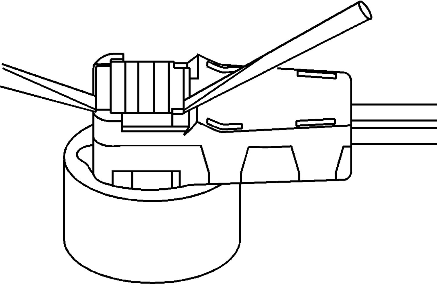
Fig. 120: Lifting Orange CPA
Courtesy'of GENERALMOTORS COMPANY
1. Lift the orange or yellow CPA vertically (avoid lifting on an angle to the connector) approximately 4 mm
to release the connector. Use a small flat-bladed tool to help release the CPA. The CPA may also be
released manually without any tools.
 |
|
Fig. 121: Grabbing Connector On Both Sides Courtesy'of GENERALMOTORS'COMPANY |
2. Grab the connector on both sides and lift vertically to disconnect the connector.
Installation Procedure
 |
|
Fig. 122: Lifting Orange CPA Courtesy'of GENERALMOTORS COMPANY |
1. The CPA should be approximately 4 mm above the yellow cover before installing the connector. If not,
use a small flat-bladed tool to help release the CPA. The CPA may also be released manually without any
tools.
 |
|
Fig. 123: Seating Connector Sub-Assembly |
2. Line up the connector key tabs with the initiator key slots. Grab the connector on both sides and push
down into the initiator connector sub assembly until fully seated.
 |
|
Fig. 124: Pushing CPA Down Courtesy'of GENERALMOTORS COMPANY |
3. After the connector is fully seated, push the CPA down with your thumb until the CPA is touching the
yellow cover on the connector.
SUMITOMO CONNECTORS
Special Tools
• EL-38125-550 Terminal Release Tool Kit
• EL-38125-580 Terminal Release Tool Kit
• J-38125-12A Terminal Release Tool
• J-38125-552 Terminal Release Tool
• J-38125-553 Terminal Release Tool
For equivalent regional tools, refer to Special Tools .
Terminal Removal Procedure

Fig. 125: Identifying Lever Lock
Courtesy'of GENERALMOTORS COMPANY

Fig. 126: View Of Lever Lock In Forward Position
Courtesy'of GENERALMOTORS'COMPANY
1. Slide the lever lock forward while pressing down on the lever lock release tab.
2. Disconnect the connector from the component.
 |
|
Fig. 127: View Of Connector Locking Tabs |
3. Remove the dress cover by using a flat-blade tool to release the connector locking tabs and pulling off the
dress cover.
 |
|
Fig. 128: Identifying Nose Piece Locking Tabs Courtesy'of GENERAL'MOTORS'COMPANY |
4. Relieve the tension on the nose piece retainers by inserting J-38125-12A into the single retainer slot on
the end of the nose piece and gently prying out the locking tab. Repeat the process for both of the nose
piece locking tabs on the opposite side of the nose piece.
|
□nDQDdnbnninllob |
 |
Fig. 129: Pulling Up One End Of Nose Piece (1st Side)
Courtesy'of GENERAL'MOTORS'COMPANY
5. Once the nose piece retainers are relaxed, use the J-38125-552 to pull up the nose piece by hooking the
tool under the nose piece and pulling up. The nose piece should raise slightly.

Fig. 130: Pulling Up One End Of Nose Piece (2nd Side)
Courtesy'of GENERAL'MOTORS'COMPANY
6. On the opposite side of the nose piece, use the J-38125-552 pull up the nose piece by hooking the tool
under the nose piece and pulling up. The nose piece should release completely. If the nose piece does not
come off, repeat the procedure on the opposite side.
 |
|
Fig. 131: View Of Terminal & Entry Canal |
7. The illustration above identifies the entry canal where the terminal release tool will be inserted, and the
terminal cavity.
• Terminal (1)
• Entry Canal (2)
 |
|
Fig. 132: Inserting J-38125-553 (15315247) Tool Into Entry Canal |
8. Insert the J-38125-553 tool into the entry canal and pry up on the terminal retainer. The terminal retainer
is a small plastic piece on the top of the terminal. The terminal retainer must be held up while the terminal
is pulled out of the connector.
 |
|
Fig. 133: Cutaway View Of Connector Courtesy'of GENERAL'MOTORS'COMPANY |
9. The illustration shows a cutaway view of the connector to aid the technician in releasing the terminal
retainer.
10. Repair the terminal by following the Repairing Connector Terminals (Terminated Lead
Repair)Repairing Connector Terminals (Terminal Repair) procedure.
11. Insert the repaired terminal back into the cavity. Repeat the diagnostic procedure to verify the repair and
reconnect the connector bodies.
Terminal Insertion Procedure
After the terminal is replaced, perform the following procedure in order to insert the terminal.
1. Slide the new terminal into the correct cavity at the back of the connector.
2. Push the terminal into the connector until it locks into place. The new terminal should be even with the
other terminals. Ensure that the terminal is locked in place by gently pulling on the wire.
3. To assemble the connector, reverse the connector disassembly procedure.
TYCO/AMP CONNECTORS (CM 42-WAY)
Special Tools
• EL-38125-550 Terminal Release Tool Kit
• EL-38125-580 Terminal Release Tool Kit
• J-38125-12A Terminal Release Tool
For equivalent regional tools, refer to Special Tools .
Terminal Removal Procedure
1. Locate the connector position assurance (CPA) on the connector body and pull the CPA out. The CPA is
on the wire harness side of connector.
2. Disconnect the connector from the component.
 |
|
Fig. 134: View Of Dress Cover Courtesy of GENERAL MOTORS COMPANY |
3. Use a small flat-bladed tool to gently pry off the dress cover by inserting the tool under the cover opposite
the harness side and prying up.
4. Remove the cover.
 |
|
Fig. 135: View Of Terminal Position Assurance (TPA) |
5. Using a small flat-bladed tool, push on the side of the nose piece retainer while pushing the nose piece
forward with your thumb. This will release the terminal position assurance (TPA).
 |
|
Fig. 136: Inserting Special Tool Into Terminal Release Cavity |
6. Insert the J-38125-12A tool into the corresponding terminal release cavity. The release cavities are the 2
center rows of cavities on one half of the connector.
 |
|
Fig. 137: Identifying Special Tool & Release Cavity Courtesy'of GENERAL'MOTORS'COMPANY |
7. Pressing the J-38125-12A tool in the release cavity of the terminal you are removing, gently pull the wire
out of the back of the connector. Always remember never use force when pulling a terminal out of a
connector.
8. Repair the terminal by following the Repairing Connector Terminals (Terminated Lead
Repair)Repairing Connector Terminals (Terminal Repair) procedure.
9. Insert the repaired terminal back into the cavity. Repeat the diagnostic procedure to verify the repair and
reconnect the connector bodies.
TYCO/AMP CONNECTORS (SENSOR)
Special Tools
• EL-38125-550 Terminal Release Tool Kit
• EL-38125-580 Terminal Release Tool Kit
• J-38125-11A Terminal Release Tool
For equivalent regional tools, refer to Special Tools .
1. Disconnect the connector from the component.
 |
|
Fig. 138: View Of Inserting Special Tool Into Lower Right Face Cavity Courtesy'of GENERAL'MOTORS'COMPANY |
2. Insert the J-38125-11A tool into the cavity on the lower right hand face of the connector until the terminal
release tang access panel slides over.

 |
|
Fig. 139: Pushing Wire Side Of Terminal Toward Connector |
3. Ensure that the terminal release tang access panel is in the correct location to access the terminals.
4. Push the wire side of the terminal that is being removed toward the connector and hold it in position.
 |
|
Fig. 140: View Of Inserting Tool Into Terminal Release Tang Access Slot (Sensor) |
5. Insert the J-38125-11A into the terminal release tang access slot located behind the access panel of the
connector and press down on the terminal while carefully pulling the terminal out of the connector.
Always remember never use force when pulling a terminal out of a connector. If the terminal is difficult
to remove, repeat the entire procedure.
6. Repair the terminal by following the Repairing Connector Terminals (Terminated Lead
Repair)Repairing Connector Terminals (Terminal Repair) procedure.
7. Insert the repaired terminal back into the cavity. Repeat the diagnostic procedure to verify the repair and
reconnect the connector bodies.
TYCO/AMP CONNECTORS (0.25 CAP)
Special Tools
• EL-38125-550 Terminal Release Tool Kit
• EL-38125-580 Terminal Release Tool Kit
• J-38125-24 Terminal Release Tool
For equivalent regional tools, refer to Special Tools .
1. Disconnect the connector from the component by pressing down on the connector position assurance
(CPA).

Fig. 141: Releasing TPA Using Small Flat-Bladed Tool
Courtesy'of GENERAL'MOTORS'COMPANY
NOTE: The TPA on this connector cannot be removed unless the terminals are
removed first. The TPA will come out of the connector body, but only
slightly. When the TPA is slightly raised the terminals can be removed.
Using excessive force to remove the TPA with the terminals still in the
connector will damage the connector.
2. Use a small flat-bladed tool to release the terminal position assurance (TPA) by inserting the tool in the
small recess on the side of the connector and pushing up until the TPA releases from the connector body.
The TPA should raise just slightly. Do not try to remove the TPA.
3. Repeat the process for the other side of the connector.

□oon
inn no
Fig. 142: View Of Terminal Position Assurance
Courtesy'of GENERAL'MOTORS'COMPANY
4. Ensure that the TPA is in the proper position to remove the terminals.
 |
|
Fig. 143: Identifying Special Tool & Release Cavity |
5. While pushing the terminal forward, insert the J-38125-24 in the release cavity above the terminal you are
removing, gently pull the wire out of the back of the connector. Always remember never use force when
pulling a terminal out of a connector.
6. Repair the terminal by following the Repairing Connector Terminals (Terminated Lead
Repair)Repairing Connector Terminals (Terminal Repair) procedure.
7. Insert the repaired terminal back into the cavity. Repeat the diagnostic procedure to verify the repair and
reconnect the connector bodies.
TYCO/AMP CONNECTORS (43-WAY)
Special Tools
• EL-38125-550 Terminal Release Tool Kit
• EL-38125-580 Terminal Release Tool Kit
• J-38125-12A Terminal Release Tool
• J-38125-13A Terminal Release Tool
For equivalent regional tools, refer to Special Tools .
Follow the steps below in order to remove terminals from the connector.
1. Locate the lever lock on the wire dress cover. Slide the lever lock away from the connector body.
2. Disconnect the connector from the component.
3. Locate the dress cover locking tabs on the dress cover of the connector. Using a small flat-bladed tool
release all of the locking tabs.
4. Once the locks are unlocked, lift the dress cover off.
 |
|
Fig. 144: Releasing TPA Courtesy of GENERAL MOTORS COMPANY |
NOTE: Always use care when removing a terminal position assurance (TPA) in
order to avoid damaging it.
5. Release the TPA by inserting a small flat-bladed tool into the blue locking tabs on both ends of the
connector. Gently slide the TPA up to the released position on both ends.
 |
|
Fig. 145: View Of Inserting Tool Into Terminal Release Cavity |

Fig. 146: View Of Release Tool Being Used For Larger Terminals
Courtesy'of GENERAL'MOTORS'COMPANY

вввввввввввв в
вввввввв в ввв
Fig. 147: View Of Release Tool Being Used For Larger Terminals
Courtesy'of GENERALMOTORS'COMPANY
 |
|
Fig. 148: View Of Release Tool Being Used For Smaller Terminals |
6. For the larger terminals insert the J-38125-13A tool to release the terminals by inserting the tool into the
terminal release cavity. For the smaller terminals insert the J-38125-12A tool to release the terminals by
inserting the tool into the terminal release cavity.
View of the release tool being used for the larger terminals.
View of the release tool being used for the larger terminals.
View of the release tool being used for the smaller terminals.
7. While holding the removal tool in place, gently pull the wire out of the back of the connector. Always
remember never use force when pulling a terminal out of a connector.
8. Repair the terminal by following the Repairing Connector Terminals (Terminated Lead
Repair)Repairing Connector Terminals (Terminal Repair) procedure.
9. Insert the repaired terminal back into the cavity. Repeat the diagnostic procedure to verify the repair and
reconnect the connector bodies.
TYCO/AMP CONNECTORS (DOOR MODULE)
Special Tools
• EL-38125-550 Terminal Release Tool Kit
• EL-38125-580 Terminal Release Tool Kit
• J-38125-12A Terminal Release Tool
For equivalent regional tools, refer to Special Tools .
Terminal Removal Procedure

Fig. 149: Side View Of Tyco/AMP Connector
Courtesy'of GENERAL'MOTORS'COMPANY
Side view of connector.

Fig. 150: Top View Of Tyco/AMP Connector
Courtesy'of GENERAL'MOTORS'COMPANY
View of top of connector.
1. Locate the assist lever and lock on the top of the connector.

Fig. 151: View Of Depressing Lock & Pulling Assist Lever
Courtesy'of GENERAL'MOTORS'COMPANY
2. While depressing the lock, pull the lever over and past the lock.

Fig. 152: View Of Component Connector
Courtesy'of GENERAL'MOTORS'COMPANY
3. Disconnect the connector from the component.

Fig. 153: Identifying Locking Tabs
Courtesy'of GENERALMOTORS COMPANY
4. Locate the dress cover locking tabs at the rear of the connector. Use a small flat-blade tool to release the
locking tabs. Repeat this procedure for the other locking tab.

Fig. 154: Sliding Inner Connector Out Of Connector Housing
Courtesy'of GENERALMOTORS'COMPANY
5. Once the locking tabs are unlocked, slide the inner connector out of the rear of the connector housing.

Fig. 155: Using Special Tool To Release Terminals
Courtesy'of GENERAL'MOTORS'COMPANY
6. Use the J-38125-12A tool to release the terminals by pressing on the tang.
7. While holding the removal tool in place, gently pull the wire out of the back of the connector. Always
remember never use force when pulling a terminal out of a connector.
8. Repair the terminal by following the Repairing Connector Terminals (Terminated Lead
Repair)Repairing Connector Terminals (Terminal Repair) procedure.
9. Insert the repaired terminal back into the cavity. Repeat the diagnostic procedure to verify the repair and
reconnect the connector bodies.
TYCO/AMP CONNECTORS (SEAT)
Special Tools
• EL-38125-550 Terminal Release Tool Kit
• EL-38125-580 Terminal Release Tool Kit
• J-38125-11A Terminal Release Tool
• J-38125-212 Terminal Release Tool
• J-38125-556 Terminal Release Tool
• J-38125-560 Terminal Release Tool
For equivalent regional tools, refer to Special Tools .
Terminal Removal Procedure

Fig. 156: Locating Locking Slide Lever
Courtesy'of GENERAL'MOTORS'COMPANY
1. Grasp the locking slide lever and pull outward from the end of the connector.

Fig. 157: Pulling Slide Lever Out Of Mating Connector
Courtesy'of GENERAL'MOTORS'COMPANY
2. As the slide lever is pulled out the mating connector is lifted from the seated position.
 |
|
Fig. 158: Pushing TPA Tabs Into Connector Body Courtesy'of GENERAL'MOTORS'COMPANY |
NOTE: Terminal position assurance (TPA) is keyed and can only be inserted in
one direction.
3. Using terminal release tool J-38125-11A or equivalent, push the TPA tabs into the connector body.

Fig. 159: Pulling TPA From Connector Body
Courtesy'of GENERAL'MOTORS'COMPANY
4. Pull the TPA from the connector body.

Fig. 160: Releasing Connector Wire Dress Cover Locking Tab
Courtesy'of GENERAL'MOTORS'COMPANY
5. Using terminal release tool J-38125-11A or equivalent, release the connector wire dress cover locking
tab.
 |
|
Fig. 161: Lifting Connector Wire Dress Cover From Connector Body |
6. With the lock tab released, lift the connector wire dress cover from the connector body.
 |
|
Fig. 162: Using Terminal Release Tool Courtesy'of GENERAL'MOTORS'COMPANY |
7. Using terminal release tool J-38125-212, press the prongs into the holes each side of the terminal to be
removed to release the lock tabs and pull the terminal out of the connector body.
 |
|
Fig. 163: Using Terminal Release Tool Courtesy'of GENERAL'MOTORS'COMPANY |
8. Using terminal release tool J-38125-560, press the prongs into the holes on each side of the terminal to be
removed to release the lock tabs and pull the terminal out of the connector body.
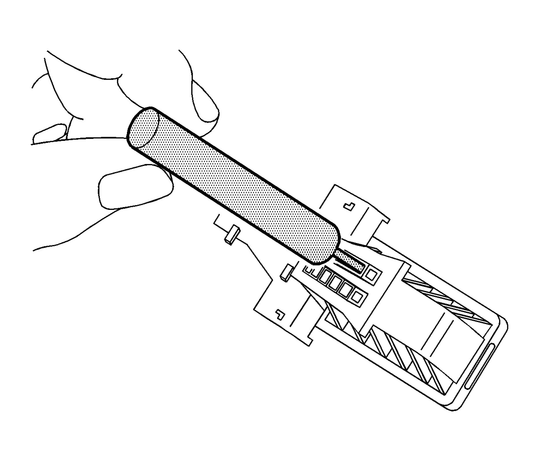 |
|
Fig. 164: Using Terminal Release Tool Courtesy'of GENERAL'MOTORS'COMPANY |
9. Using terminal release tool J-38125-556, press the prongs into the holes on each side of the terminal to be
removed to release the lock tabs and pull the terminal out of the connector body.
10. Repair the terminal by following the Repairing Connector Terminals (Terminated Lead
Repair)Repairing Connector Terminals (Terminal Repair) procedure.
11. Insert the repaired terminal back into the cavity. Repeat the diagnostic procedure to verify the repair and
reconnect the connector bodies.
TYCO/AMP CONNECTORS (102-WAY INLINE)
Special Tools
• EL-38125-550 Terminal Release Tool Kit
• EL-38125-580 Terminal Release Tool Kit
• J-38125-11A Terminal Release Tool
• J-38125-212 Terminal Release Tool
• J-38125-216 Terminal Release Tool
• J-38125-221 Terminal Release Tool
• J-38125-560 Terminal Release Tool
• J-38125-566 Terminal Release Tool
For equivalent regional tools, refer to Special Tools .
Terminal Removal Procedure
 |
|
Fig. 165: View Of Typical Connector In Assembled Position |
View of a typical connector in the assembled position.
 |
|
Fig. 166: View Of Locking Lever At 90 Degrees From Connector Body |
1. Pull the locking lever to the 90 degree position from the connector body.
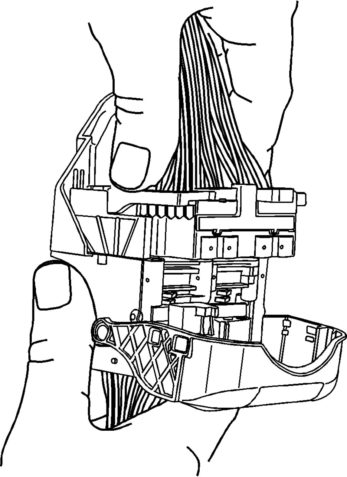 |
|
Fig. 167: Assembled View Of Connector - Tyco/AMP (102-Way Inline) Courtesy'of GENERAL'MOTORS'COMPANY |
2. With the locking lever in the 90 degree position and the male connector body separated, it can be slid
outward for removal.
 |
|
Fig. 168: Sliding Male Connector Body Away From Guide Plates |
3. Slide the male connector body out away from the guide plates.
 |
|
Fig. 169: View of Terminal Release Tool And TPA Courtesy'of GENERAL'MOTORS'COMPANY |
NOTE: During assembly the terminal position assurance (TPA) will not fully seat if
any terminal is not fully seated.
4. Using terminal release tool J-38125-11A or equivalent, remove the TPA from the connector body.
 |
|
Fig. 170: Releasing Lock Tabs Courtesy'of GENERALMOTORS COMPANY |
5. Using terminal release tool J-38125-566, press the prongs into the holes on each side of the terminal to be
removed to release the lock tabs and pull the terminal out of the connector body.
 |
|
Fig. 171: Using Terminal Release Tool Courtesy'of GENERAL'MOTORS'COMPANY |
6. Using terminal release tool J-38125-560, press the prongs into the holes on each side of the terminal to be
removed to release the lock tabs and pull the terminal out of the connector body.
 |
|
Fig. 172: Releasing Lock Tabs - Tyco/AMP (102-Way Inline) |
7. Using terminal release tool J-38125-221, press the prongs into the holes on each side of the terminal to be
removed to release the lock tabs and pull the terminal out of the connector body.
 |
|
Fig. 173: View Of Female Connector Body - Tyco/AMP (102-Way Inline) |
8. The female connector body may have an additional connector hooked to the edge of the body. Use
terminal release tool J-38125-11A or equivalent to release the locking tab and slide the connector off the
female body.
 |
|
Fig. 174: Moving Locking Lever |
9. Move the locking lever 180 degrees from the connected position.
 |
|
Fig. 175: Removing Guide Plates From Connector Body |
10. With the locking lever in the 180 degree position the guide plates can be removed from the connector
body.
 |
|
Fig. 176: Removing TPA Courtesy'of GENERAl'mOTORS COMPANY |
NOTE: During assembly the TPA will not fully seat if any terminal is not fully
seated.
11. Using terminal release tool J-38125-11A or equivalent, remove the TPA from the connector body.
 |
|
Fig. 177: Lifting Terminal Plate Past The Terminals Courtesy'of GENERAL'MOTORS'COMPANY |
12. Using terminal release tool J-38125-216, lift the terminal plate past the terminals and out of the connector
body cavity.
 |
|
Fig. 178: View Of Terminal Plate Courtesy'of GENERALMOTORS COMPANY |
13. Terminal plate will bind slightly on each corner.
 |
|
Fig. 179: Releasing Lock Tabs Courtesy'of GENERALMOTORS COMPANY |
14. Using terminal release tool J-38125-221, press the prongs into the holes on each side of the terminal to be
removed to release the lock tabs and pull the terminal out of the connector body.
 |
|
Fig. 180: View of Pressing Prongs On Each Side Of Terminal |
15. Using terminal release tool J-38125-212, press the prongs into the holes on each side of the terminal to be
removed to release the lock tabs and pull the terminal out of the connector body.
 |
|
Fig. 181: Pressing Prongs On Each Side Of Terminal - Tyco/AMP (102-Way Inline) |
16. Using terminal release tool J-38125-560, press the prongs into the holes on each side of the terminal to be
removed to release the lock tabs and pull the terminal out of the connector body.

Fig. 182: View Of Terminal Plate
Courtesy of GENERAL MOTORS COMPANY
17. Press the terminal plate back into the female connector to the preset position. The plate will bind slightly
on each corner.
 |
|
Fig. 183: Aligning Guide Plates To Mesh With Locking Lever Gears Courtesy'of GENERAL'MOTORS'COMPANY |
18. With the locking lever in the 180 degree position, align the guide plates to mesh with the gears on the
locking lever.
 |
|
Fig. 184: Sliding Male Connector Body Away From Guide Plates |
19. Slide the male connector body back inward toward the guide plates.
 |
|
Fig. 185: Assembled View Of Connector - Tyco/AMP (102-Way Inline) Courtesy'of GENERAL'MOTORS'COMPANY |
20. With the locking lever in the 90 degree position and the male connector body connected, it can be slid
inward for assembly.
 |
|
Fig. 186: View Of Typical Connector In Assembled Position Courtesy'of GENERAL'MOTORS'COMPANY |
21. Move the lever into the locked position or in the assembled position. This will pull the male connector
down into the female connector.
22. Repair the terminal by following the Repairing Connector Terminals (Terminated Lead
Repair)Repairing Connector Terminals (Terminal Repair) procedure.
23. Insert the repaired terminal back into the cavity. Repeat the diagnostic procedure to verify the repair and
reconnect the connector bodies.
TYCO/AMP CONNECTORS (SIR)
Special Tools
• EL-38125 - 550 Terminal Release Tool Kit
• EL-38125 - 580 Terminal Release Tool Kit
• J-38125 - 11A Terminal Release Tool
• J-38125-215A Terminal Release Tool
For equivalent regional tools, refer to Special Tools .
 |
|
Fig. 187: Sliding Red CPA Away From Connector Lever Courtesy'of GENERAL'MOTORS'COMPANY |
1. Using your thumbs press down and slide the red CPA away from the connector lever.
 |
|
Fig. 188: Pressing Down On Locking Tab - Tyco/AMP Connectors (SIR) |
2. Using your thumb press down on the locking tab and move the lever to the released position.
 |
|
Fig. 189: Releasing Wire Dress Cover Locking Tabs |
3. Using terminal tool J-38125-11A or equivalent, release the wire dress cover locking tabs.
 |
|
Fig. 190: Pivoting Connector Wire Dress Cover Courtesy'of GENERAL'MOTORS'COMPANY |
4. Pivot connector wire dress cover while removing from the connector body.

Fig. 191: Removing TPA
Courtesy'of GENERALMOTORS COMPANY
5. Using terminal tool J-38125-11A or equivalent, remove the TPA by lifting straight off the connector body.
 |
|
Fig. 192: View of Terminal Release Tool & Rear of Connector Body |
6. Using terminal release tool J-38125-215A, place the tip of the tool on the outside edge next to the
terminal and depress the lock tab and remove the rear of the connector body.
Terminal Repair Procedure
Use the appropriate terminal and crimper in order to replace the terminal.
YAZAKI CONNECTORS (2-WAY)
For equivalent regional tools, refer to Special Tools .
Special Tools
• EL-38125-550 Terminal Release Tool Kit
• EL-38125-580 Terminal Release Tool Kit
• J-38125-553 Terminal Release Tool
Terminal Removal Procedure
1. Disconnect the connector from the component.
 |
|
Fig. 193: Identifying Terminal Position Assurance |
2. Insert a small flat-blade tool in the slot below the front loaded terminal position assurance (TPA) and pry
up.
3. Remove the TPA by pulling it out of the connector.
4. Push the wire side of the terminal that is being removed toward the connector and hold it in position.
Fig. 194: Inserting Tool Into Terminal Cavity
Courtesy'of GENERAL'MOTORS'COMPANY
5. Insert the J-38125-553 on a slight upward angle into the cavity below the terminal to be removed. Ensure
that the pointed on the end of the tool is facing the bottom of the terminal and it stays in contact with the
terminal until it stops on the plastic terminal retainer.
 |
|
Fig. 195: Pulling Terminal Out Of Connector Courtesy'of GENERAL'MOTORS'COMPANY |
6. Gently pry the plastic terminal retainer down and carefully pull the terminal out of the connector. Always
remember never use force when pulling a terminal out of a connector. If the terminal is difficult to
remove, repeat the entire procedure.
7. Repair the terminal by following the Repairing Connector Terminals (Terminated Lead
Repair)Repairing Connector Terminals (Terminal Repair) procedure.
8. Insert the repaired terminal back into the cavity. Repeat the diagnostic procedure to verify the repair and
reconnect the connector bodies.
YAZAKI CONNECTORS (16-WAY)
Special Tools
• EL-38125-550 Terminal Release Tool Kit
• EL-38125-580 Terminal Release Tool Kit
• J-38125-215 Terminal Release Tool
For equivalent regional tools, refer to Special Tools .
 |
|
Fig. 196: Pulling Two Connector Halves Apart Courtesy'of GENERAL'MOTORS'COMPANY |
1. While depressing the lock, pull the two connector halves apart.
NOTE: The terminal position assurance (TPA) is fragile and may break if not done
carefully.
2. Use a small flat-blade tool to very carefully push the TPA towards the face of the connector on both sides
of the connector.

Fig. 197: View Of Male Connector Half & Female Terminals
Courtesy'of GENERALMOTORS'COMPANY
3. View of the male half of the connector with female terminals.
 |
|
Fig. 198: View Of Female Half Of Connector With Male Terminals |
4. View of the female half of the connector with male terminals.
5. Use the J-38125-215 tool to release the terminals by inserting the tool into the terminal release cavity.

Fig. 199: Using Removal Tool On Female Half Of Connector
Courtesy'of GENERAL'MOTORS'COMPANY
6. View of the female half of the connector with male terminals.
 |
|
Fig. 200: Using Removal Tool On Male Half Of Connector |
7. View of the male half of the connector with female terminals.
8. While holding the removal tool in place, gently pull the wire out of the back of the connector. Always
remember never use force when pulling a terminal out of a connector.
9. Repair the terminal by following the Repairing Connector Terminals (Terminated Lead
Repair)Repairing Connector Terminals (Terminal Repair) procedure.
10. Insert the repaired terminal back into the cavity. Repeat the diagnostic procedure to verify the repair and
reconnect the connector bodies.
REPAIRING CONNECTOR TERMINALS (TERMINATED LEAD REPAIR)
Special Tools
EL-38125-10 Splice Sleeve Crimp Tool
For equivalent regional tools, refer to Special Tools .
|
NOTE: |
All repairs near the engine manifold, turbo engine and all exhaust pipes should |
For high temperature wiring repairs, refer to High Temperature Wiring Repairs.
Terminated leads are terminals that are crimped onto wires. The terminated lead can be used throughout the
vehicle since it is designed for temperatures up to 150A°C. The length of the wire is 450 mm.
1. Use the connector end view to identify the correct terminated lead.
2. The terminated lead package should include a DuraSeal splice sleeve. If not, use the chart to in Splicing
Copper Wire Using Splice Sleeves to identify the correct DuraSeal splice sleeve, refer to Wire to Wire
Repair.
REPAIRING CONNECTOR TERMINALS (TERMINAL REPAIR)
Special Tools
• J-38125 - 580 Terminal Repair Kit
• J-38125-6 Crimp Tool
• J-38125-7 Crimp Tool
• J-38125-8 Crimp Tool
• J-38125-64 Crimp Tool
• J-38125-101 Crimp Tool
• J-38125-641 Crimp Tool
• J-38125-642 Crimp Tool
• J-38125-643 Crimp Tool
For equivalent regional tools, refer to Special Tools .
Use the following repair procedures to repair each type of terminal:
• For push to seat terminals, refer to Delphi Connectors (Weather Pack)Delphi Connectors (Push To
Seat)Delphi Connectors (Pull To Seat)Delphi Connectors (Micro-Pack 100W)Delphi Connectors
(Micro.64)Delphi Connectors (12-Way)Delphi Connectors (Steering Gear).
• For pull to seat terminals, refer to Delphi Connectors (Weather Pack)Delphi Connectors (Push To
Seat)Delphi Connectors (Pull To Seat)Delphi Connectors (Micro-Pack 100W)Delphi Connectors
(Micro.64)Delphi Connectors (12-Way)Delphi Connectors (Steering Gear).
NOTE: The first step for all terminal repairs is to find the connector end view in SI.
Cable Seal Terminals
1. Cut off the terminal between the core and the insulation crimp to minimize any wire loss.
2. Remove the old seal.
3. Apply the correct cable seal, per the wire gauge size, from the kit. Slide the seal back along the wire to
enable removal of the insulation.
4. To minimize wire loss, remove only the insulation required.
5. Using the connector end view, determine the correct crimp tool and crimp jaw.
6. Align the seal with the end of the cable insulation.
7. Position the stripped wire and seal in the terminal.
8. Hand Crimp the core wings first.
9. Hand Crimp the insulation wings around the seal and the cable.
Unsealed Terminals
1. Cut off the terminal between the core and the insulation crimp to minimize any wire loss.
2. To minimize wire loss, remove only the insulation required.
3. Position the stripped wire in the terminal.
4. Hand Crimp the core wings first.
5. Hand Crimp the insulation wings around the cable.
Micro-Pack 100W Size Terminal
The Micro-Pack 100W connectors have small terminals that are difficult to handle and hold when crimping. In
order to aid the technician when crimping these terminals, a new crimping tool was developed. The J 38125-101
(W jaw) crimping tool was developed to crimp Micro-Pack 100W terminals. The J 38125-101 (W jaw)
crimping tool has a terminal holding block that will hold the terminal in place while the terminal is being
crimped. After the terminal is removed from the connector perform the following procedure in order to repair
Micro-Pack 100 terminals.
1. Cut the wire as close to the terminal as possible.
NOTE: After cutting the damaged terminal from the wire, determine if the
remaining wire is long enough to reach the connector without putting a
strain on the wire. If the wire is not long enough, splice a small length of
the same gauge wire to the existing wire, then crimp the new terminal on
the added wire.
2. Strip 5 mm (3/16 in) of insulation from the wire.
 |
|
Fig. 201: Identifying Crimping Tool Spring Loaded Locator Courtesy'of GENERAL'MOTORS'COMPANY |
3. Depress the spring loaded locator of the J 38125-101 (W jaw) crimping tool until the terminal holder is
completely visible.

Fig. 202: Locating Terminal In Crimping Tool
Courtesy'of GENERAL'MOTORS'COMPANY
4. Insert the terminal into the crimp tool until the core wings are flush with the anvil on the crimp tool. Be
sure that the wings are pointed toward the crimp tool former and release the spring locator. The locator
will hold the terminal in place. Inspect the alignment of the terminal wings with the crimp tool former. If
the terminal wings are wider than the crimp tool former, remove the terminal and bend the terminal wings
in slightly.
5. Place stripped wire into terminal.
6. Crimp the new terminal to the wire. If a jam occurs, press the emergency release to open applicator.
Micro 0.64 Size Terminal
The Micro 64 connectors have small terminals that are difficult to handle and hold when crimping. In order to
aid the technician when crimping these terminals, a new crimping tool was developed. The J 38125-64 (M jaw)
was developed to crimp Micro 64 terminals. The J-38125-64 crimping tool has a terminal holding block that
will hold the terminal in place while the terminal is being crimped. The J-38125-64 crimping tool is also
designed to crimp both the wire and the insulation at the same time.
After the terminal is removed from the connector perform the following procedure in order to repair Micro 64
terminals.
NOTE:
After cutting the damaged terminal from the wire, determine if the remaining
wire is long enough to reach the connector without putting a strain on the wire.
If the wire is not long enough, splice a small length of the same gauge wire to
the existing wire, then crimp the new terminal on the added wire.
1. Cut the wire as close to the damaged terminal as possible.
2. Strip 5 mm (3/16 in) of insulation from the wire.
 |
|
Fig. 203: Identifying Crimping Tool Spring Loaded Locator Courtesy'of GENERAL'MOTORS'COMPANY |
3. Depress the spring loaded locator of the crimping tool until the terminal holder is completely visible.
 |
|
Fig. 204: Identifying Terminal Holder Courtesy'of GENERAL'MOTORS'COMPANY |
4. Insert terminal into the appropriate terminal holder until it hits bottom and stops. The correct terminal
holder is determined by the wire size. Also ensure that the terminals wings are pointing towards the
former on the tool and the release locator.
5. Insert the stripped cable into the terminal. Insulation should be visible on both sides of the terminal
insulation wings.
6. Compress the handles until the ratchet automatically releases.
7. Place the terminal into the appropriate cavity and assemble the connector.
TERMINAL REMOVAL
Special Tools
• EL-38125-550 Terminal Release Tool Kit
• EL-38125-580 Terminal Release Tool Kit
• EL-35616 Terminal Test Probe Kit
For equivalent regional tools, refer to Special Tools .
NOTE: All repairs near the engine manifold, turbo engine and all exhaust pipes should
follow the High Temperature Wiring Repair procedures.
1. Find the appropriate connector end view within the connector end view section. The connector end view
has the following information:
• Diagnostic probe tool
• Terminal release tool
• Terminal/terminated lead part numbers
NOTE: Not using the proper test kit probe may cause damage to the terminal(s)
that are probed.
2. Determine if a terminal is damaged.
1. Locate the diagnostic probe tool from the connector end view. The connector end view describes
the color and part number to help the technician find and use the correct tool.
2. Connect the probe tool to the Digital Multimeter.
3. Insert the probe tool into the cavity and follow the procedures from the Troubleshooting with a
Digital Multimeter .
3. Disconnect the connector body to perform the repair.
4. Use the following procedure to remove the terminal from the connector body.
NOTE: Several procedures for specific connector bodies are called out in the
Wiring Repairs section.
1. The terminal position assurance (TPA) and connector position assurance (CPA) should be removed
before releasing the terminal for the connector body.
2. Look at the connector end view to locate the cavity of the damaged terminal and find the proper
terminal release tool from the terminal release tool kit.
NOTE: Using the incorrect terminal release tool can damage the connector
body.
NOTE: Some terminals have a lever that must be disengaged before the
terminal can be released.
3. Insert the terminal release tool into the cavity.

Fig. 205: Gently Pulling Wire Out Of Back Of Connector
Courtesy'of GENERAL'MOTORS'COMPANY
5. Gently pull the wire out of the back of the connector.
6. Repair the terminal by following the Repairing Connector Terminals (Terminated Lead
Repair)Repairing Connector Terminals (Terminal Repair) procedure.
7. Insert the repaired terminal back into the cavity. Repeat the diagnostic procedure to verify the repair and
reconnect the connector bodies.
RELAY REPLACEMENT (ATTACHED TO WIRE HARNESS)
Removal Procedure
 |
|
Fig. 206: Identifying Relay & Wire Harness Connector Courtesy'of GENERAL'MOTORS'COMPANY |
1. Locate the relay. Refer to the Master Electrical Component List to locate the relay in the vehicle.
2. Remove any fasteners which hold the relay in place.
3. Remove any connector position assurance (CPA) devices or secondary locks.
NOTE: Use care when removing a relay in a wiring harness when the relay is
secured by fasteners or tape.
4. Separate the relay (1) from the wire harness connector (2).
Installation Procedure
 |
|
Fig. 207: Identifying Relay & Wire Harness Connector Courtesy'of GENERAL'MOTORS'COMPANY |
1. Connect the relay (1) to the wire harness connector (2).
2. Install any connector position assurance (CPA) devices or secondary locks.
3. Install the relay using any fasteners or tape that originally held the relay in place.
RELAY REPLACEMENT (WITHIN AN ELECTRICAL CENTER)
Special Tools
EL-43244 Relay Puller Pliers
Removal Procedure
1. Remove the electrical center cover.
NOTE:
• Always note the orientation of the relay.
• If equipped with a notch style relay; observe the location of the notch
on the old relay to verify the new relay is installed with the notch in
the same location.
• Ensure that the electrical center is secure, as not to put added stress
on the wires or terminals.
2. Locate the relay. Refer to Electrical Center Identification Views to locate the electrical center where the
relay exists.


Fig. 208: Identifying Relay & Special Tool
3. Using the EL-43244 (1) position the tool on opposing corners of the relay (2).
CAUTION: Use EL-43244 to pull the relay straight out from the electrical center
terminals. The use of pliers or a flat bladed tool could damage the
electrical center.
4. Remove the relay (2) from the electrical center.
Installation Procedure


Fig. 209: Identifying Relay & Special Tool
Courtesy'of GENERAL'MOTORS'COMPANY
1. Install the relay (2) in the same position as removed.
2. Install the electrical center cover.
GROUND REPAIR
Electrical Grounds
Proper electrical system function relies on secure, positive, corrosion-free ground connections. Loose, stripped,
or corroded connections increase the possibility of improper system function and loss of module
communication. These conditions may also lead to unnecessary repairs and component replacements.
In general, electrical ground connections are accomplished using one, or a combination of, three attachment
methods:
• Welded M6 stud and nut
• Welded M6 nut and bolt
• Welded M8 nut and bolt
CAUTION: Use GM approved replacement fasteners with conductive finish for electrical
ground repair.
Determine which attachment method is used, and carry out the appropriate repair.
M6 Weld Stud Replacement
1. Select a location adjacent the damaged or missing M6 ground stud having 20 mm (0.79 in) clearance
behind the panel surface and 20 mm (0.79 in) clearance surrounding the M6 rivet stud flange.
2. Using GM approved residue-free solvent or equivalent, remove any grease from the repair site and allow
to dry.
NOTE: Ensure 20 mm (0.79 in) clearance is maintained behind the panel to be
drilled.
3. Drill a 10 mm (0.40 in) diameter hole through the panel.
4. Carefully remove paint and primer from the area surrounding the rivet stud flange until bare metal is
visible.
CAUTION: Use GM approved replacement fasteners with conductive finish for
electrical ground repair.
5. Select a replacement conductive M6 rivet stud. Reference the GM parts catalog for the correct part
number and application.
6. Using a rivet stud installer, install the replacement conductive M6 rivet stud.
7. Ensure the new rivet stud is securely fastened, with no detectable movement.
NOTE: The rivet stud and surrounding panel area must be properly refinished
prior to the installation of the ground terminal and nut to maintain positive
electrical grounding.
8. Completely wrap the threads of the rivet stud with painters tape or equivalent.
9. Refinish the repair area using an anti-corrosion primer.
10. Allow the refinished repair area to cure sufficiently before removing the protective material applied to the
rivet stud threads.
11. Remove the painters tape or equivalent from the rivet stud threads.
12. Using GM approved residue-free solvent or equivalent, thoroughly clean the rivet stud threads to remove
any adhesive and allow to dry.
13. Carefully remove any corrosion from the electrical ground wire terminal. Testing for Intermittent
Conditions and Poor Connections
14. Using a small brush, apply Dielectric Lubricant GM P/N 12377900 (Canadian P/N 10953529) to the new
conductive M6 rivet stud threads.
15. Install the ground terminal to the new rivet stud.
16. Select a new, conductive M6 nut. Reference the GM parts catalog for the correct part number and
application.
CAUTION: Fastener Caution
17. Install the conductive M6 nut and tighten to 8 N.m (71 lb in).
18. Check for proper system operation.
M6 Weld Nut
CAUTION: Use GM approved replacement fasteners with conductive finish for
electrical ground repair.
1. If the M6 weld nut at the electrical ground location is damaged or stripped, a new, conductive self-
threading M7 bolt may be used to secure the ground terminal. Reference the GM parts catalog for the
correct part number and application.
2. Using GM approved residue-free solvent or equivalent, remove any grease from the surface surrounding
the weld nut and allow to dry.
3. Remove any loose metal particles from the damaged or stripped weld nut with a stiff brush.
4. Using a small brush, apply Dielectric Lubricant GM P/N 12377900 (Canadian P/N 10953529) to the new,
conductive, self-threading M7 bolt threads.
5. Carefully remove any corrosion from the electrical ground terminal. Testing for Intermittent
Conditions and Poor Connections
6. Install the electrical ground terminal to the new, conductive M7 bolt.
CAUTION: Fastener Caution
7. Install the conductive M7 bolt and tighten to 9 N.m (80 lb in).
8. Check for proper system operation.
M6 Weld Nut (Alternative Repair)
CAUTION: Use GM approved replacement fasteners with conductive finish for
electrical ground repair.
1. If the electrical ground location is accessible from both sides of the panel, a conductive M6 bolt and a
conductive M6 nut may be used to secure the electrical ground terminal. Reference the GM parts catalog
for the correct part number and application.
2. Select a location adjacent the damaged M6 weld nut having 20 mm (0.79) clearance behind the panel
surface and 20 mm (0.79 in) clearance surrounding the new electrical ground site.
3. Using GM approved residue-free solvent or equivalent, remove any grease from the surface surrounding
the ground location and allow to dry.
NOTE: Ensure 20 mm (0.79 in) clearance is maintained behind the panel to be
drilled.
4. Drill a 10 mm (0.40 in) diameter hole through the panel.
5. Carefully remove paint and primer from the area surrounding the new ground site until bare metal is
visible.
6. Using a small brush, apply Dielectric Lubricant GM P/N 12377900 (Canadian P/N 10953529) to the new,
conductive M6 bolt threads.
7. Carefully remove any corrosion from the electrical ground terminal. Testing for Intermittent
Conditions and Poor Connections
8. Install the electrical ground terminal and new, conductive M6 bolt to the ground location.
CAUTION: Fastener Caution
9. Install the conductive M6 nut and tighten to 8 N.m (71 lb in).
NOTE: The repair area must be properly refinished to maintain positive electrical
grounding.
10. Refinish the repair area using an anti-corrosion primer.
11. Check for proper system operation.
M8 Weld Nut
CAUTION: Use GM approved replacement fasteners with conductive finish for
electrical ground repair.
1. If the M8 weld nut electrical ground location is accessible from both sides of the panel, a conductive M8
bolt and a conductive M8 nut may be used to secure the ground terminal. Reference the GM parts catalog
for the correct part number and application.
2. Select a location adjacent to M8 weld nut having 20 mm (0.79 in) clearance behind the panel surface and
20 mm (0.79 in) clearance surrounding the new electrical ground site.
3. Using GM approved residue-free solvent or equivalent, remove any grease from the surface surrounding
the ground location and allow to dry.
NOTE: Ensure 20 mm (0.79 in) clearance is maintained behind the panel to be
drilled.
4. Drill a 10 mm (0.40 in) diameter hole through the panel.
5. Carefully remove paint and primer from the area surrounding the new ground site until bare metal is
visible.
6. Using a small brush, apply Dielectric Lubricant GM P/N 12377900 (Canadian P/N 10953529) to the new,
conductive M8 bolt threads.
7. Carefully remove any corrosion from the electrical ground terminal. Testing for Intermittent
Conditions and Poor Connections
8. Install the electrical ground terminal and new, conductive M8 bolt to the ground location.
CAUTION: Fastener Caution
9. Install the conductive M8 nut and tighten to 22 N.m (16 lb ft).
NOTE: The repair area must be properly refinished to maintain positive electrical
grounding.
10. Refinish the repair area using an anti-corrosion primer.
11. Check for proper system operation.
M8 Weld Nut (Alternative Repair)
CAUTION: Use GM approved replacement fasteners with conductive finish for
electrical ground repair.
1. If the M8 weld nut electrical ground location is not accessible from both sides of the panel, a conductive
M6 rivet stud and a conductive M6 nut may be used to secure the ground terminal. Reference the GM
parts catalog for the correct part number and application.
2. Select a location adjacent the damaged M8 weld nut having 20 mm (0.79 in) clearance behind the panel
surface and 20 mm (0.79 in) clearance surrounding the new, conductive M6 rivet stud flange.
3. Using GM approved residue-free solvent or equivalent, remove any grease from the repair site and allow
to dry.
NOTE: Ensure 20 mm (0.79 in) clearance is maintained behind the panel to be
drilled.
4. Drill a 10 mm (0.40 in) diameter hole through the panel.
5. Carefully remove paint and primer from the area surrounding the rivet stud flange until bare metal is
visible.
6. Using a rivet stud installer, install the replacement conductive M6 rivet stud.
7. Ensure the new rivet stud is securely fastened, with no detectable movement.
NOTE: The rivet stud and surrounding panel area must be properly refinished
prior to the installation of the ground terminal and nut to maintain positive
electrical grounding.
8. Completely wrap the threads of the rivet stud with painters tape or equivalent.
9. Refinish the repair area using an anti-corrosion primer.
10. Allow the refinished repair area to cure sufficiently before removing the protective material applied to the
rivet stud threads.
11. Remove the painters tape or equivalent from the rivet stud threads.
12. Using GM approved residue-free solvent or equivalent, thoroughly clean the rivet stud threads to remove
any adhesive and allow to dry.
13. Carefully remove any corrosion from the electrical ground wire terminal. Testing for Intermittent
Conditions and Poor Connections
14. Using a small brush, apply Dielectric Lubricant GM P/N 12377900 (Canadian P/N 10953529) to the new
conductive M6 rivet stud threads.
15. Install the ground terminal to the new, conductive M6 rivet stud.
CAUTION: Fastener Caution
16. Install the conductive M6 nut and tighten to 8 N.m (71 lb in).
17. Check for proper system operation.
Securing Loose Electrical Ground Connections
If the electrical ground connection is loose and the ground attachments are not damaged, properly securing the
loose electrical ground may be all that is necessary. Carry out the following procedure to secure loose electrical
ground connections.
CAUTION: Use GM approved replacement fasteners with conductive finish for electrical
ground repair.
1. Using GM approved residue-free solvent or equivalent, thoroughly clean the ground stud threads and
allow to dry.
2. Carefully remove any corrosion from the electrical ground wire terminal. Testing for Intermittent
Conditions and Poor Connections
3. Using a small brush, apply Dielectric Lubricant GM P/N 12377900 (Canadian P/N 10953529) to the
ground stud threads.
4. Install the ground wire terminal to the ground stud.
CAUTION: Fastener Caution
5. Install the appropriate conductive nut.
• Conductive M6 nut: Tighten to 8 N.m (71 lb in)
• Conductive M8 nut: Tighten to 22 N.m (16 lb ft)
• Conductive M10 nut: Tighten to 45 N.m (33 lb ft)
6. Check for proper system operation.
FUSE BLOCK REPLACEMENT
Removal Procedure
WARNING: Always perform the High Voltage Disabling procedure prior to servicing any
High Voltage component or connection. Personal Protection Equipment (pPe)
and proper procedures must be followed.
The High Voltage Disabling procedure will perform the following tasks:
• Identify how to disable high voltage.
• Identify how to test for the presence of high voltage.
• Identify condition under which high voltage is always present and
personal protection equipment (PPE) and proper procedures must be
followed.
Failure to follow the procedures exactly as written may result in serious injury
or death.
Preliminary Procedures
1. High Voltage Disabling .
2. Battery Negative Cable Disconnection and Connection
3. Rear Compartment Floor Stowage Trim Compartment Replacement
 |
|
Fig. 210: Fuse Block Cover Courtesy'of GENERALMOTORS COMPANY |
4. Remove Fuse Block Cover(1)
 |
|
Fig. 211: Fuse Block Terminal Hold Down Nut Courtesy'of GENERAL'MOTORS'COMPANY |
5. Remove Fuse Block Terminal Hold Down Nut (1) and (2)
 |
|
Fig. 212: Battery Positive Cable Junction Block Nut And Body Wiring Harness Nut |
6. Remove Battery Positive Cable Junction Block Nut (1) and Body Wiring Harness Nut (2)
 |
|
Fig. 213: Electrical Connectors Courtesy'of GENERALMOTORS COMPANY |
7. Disconnect all electrical connectors.(1)
 |
|
Fig. 214: Fuse Block Courtesy'of GENERAL MOTORS COMPANY |
8. Remove Fuse Block(1)
Installation Procedure
 |
|
Fig. 215: Fuse Block Courtesy'of GENERAL MOTORS COMPANY |
1. Install Fuse Block(1)

Fig. 216: Electrical Connectors
Courtesy of GENERAL MOTORS COMPANY
2. Connect all electrical connectors.
 |
|
Fig. 217: Battery Positive Cable Junction Block Nut And Body Wiring Harness Nut |
CAUTION: Refer to Fastener Caution .
3. Install Battery Positive Cable Junction Block Nut (1) and tighten 15 N.m (11 lb ft)
4. Install Body Wiring Harness Nut (2) and tighten 15 N.m (11 lb ft)
 |
|
Fig. 218: Fuse Block Terminal Hold Down Nut |
5. Install Battery Post Clamp Nut (2) and tighten 9 N.m (80 lb in)
6. Install Battery Positive Cable Junction Block Nut (1) and tighten 15 N.m (11 lb ft)
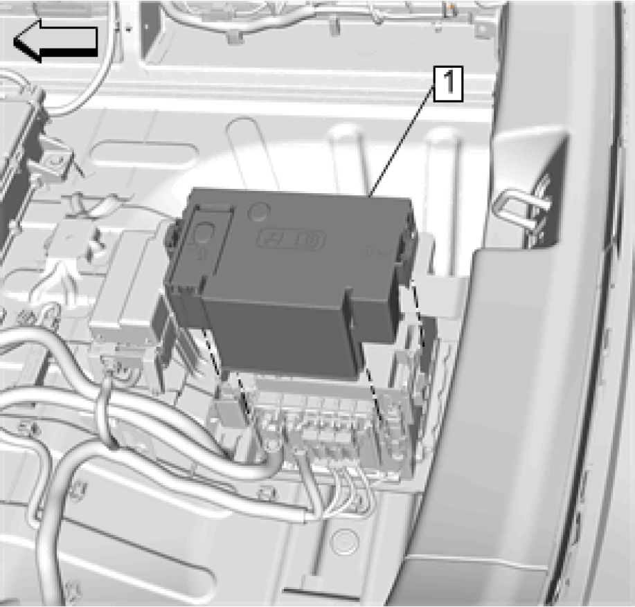
Fig. 219: Fuse Block Cover
Courtesy of GENERAL MOTORS COMPANY
7. Install Fuse Block Cover(1)
8. Battery Negative Cable Disconnection and Connection
9. Rear Compartment Floor Stowage Trim Compartment Replacement
10. High Voltage Enabling
IGNITION AND START SWITCH REPLACEMENT

Fig. 220: Ignition and Start Switch
Courtesy'of GENERALMOTORS COMPANY
|
Callout |
Component Name |
|
Preliminary Procedure Instrument Panel Cluster Trim Plate Replacement | |
|
1 |
Ignition and Start Switch Procedure
|
Article GUID: A00884670
Wiring Systems and Power Management - Schematic and Routing Diagrams - Volt
SCHEMATIC WIRING DIAGRAMS
HARNESS ROUTING VIEWS
|
Front Fascia Harness Routing |
 |
|
Fig. 1: Front Fascia Harness Routing Courtesy'of GENERAL'MOTORS'COMPANY |
Items
1. X100 X100 Forward Lamp Harness to Front Fascia Harness (-UFQ) X100 Forward Lamp
Harness to Front Fascia Harness (UFQ)______________________________________________
2. J115
3. J101__________________________________________________________________________________________
4. J100
A
Front of Engine Compartment Harness Routing
 |
|
Fig. 2: Front of Engine Compartment Harness Routing |
Items
1. X102 X102 Forward Lamp Harness to Cooling Fan Harness
2. X104 X104 Cooling Fan Harness to Forward Lamp Harness
3. J110
Forward Lamp Harness Routing
 |
|
Fig. 3: Forward Lamp Harness Routing |
Items
1. X107 X107 Forward Lamp Harness to Body Harness
2. X110 X110 Body Harness to Left Headlamp Harness
3. X100 X100 Forward Lamp Harness to Front Fascia Harness (-UFQ) X100 Forward Lamp
Harness to Front Fascia Harness (UFQ)
4. X104 X104 Cooling Fan Harness to Forward Lamp Harness
5. X102 X102 Forward Lamp Harness to Cooling Fan Harness
6. X120 X120 Body Harness to Right Headlamp Harness
Left Side of Engine Compartment Harness Routing
 |
|
Fig. 4: Left Side of Engine Compartment Harness Routing |
Items
1. J139
X155 X155 Engine Harness to Body Harness
2. X190 X190 Engine Harness to Body Harness
3. X107 X107 Forward Lamp Harness to Body Harness
Left of Engine Compartment Harness Routing
 |
|
Fig. 5: Left of Engine Compartment Harness Routing |
Items
1. X130 X130 Battery Cable Harness to Battery Cable Harness
Right Side of Engine Compartment Harness Routing
 |
|
Fig. 6: Right Side of Engine Compartment Harness Routing |
Items
1. X121 X121 Forward Lamp Harness to Body Harness
2. X120 X120 Body Harness to Right Headlamp Harness
Engine Harness Routing
 |
|
Fig. 7: Engine Harness Routing Courtesy'of GENERAL'MOTORS COMPANY |
Items
1. J131 (NU6) ~
2. J127______________________________________________
3. J125_________________________________________________
4. J128_________________________________________________
5. J129_________________________________________________
6. X155 X155 Engine Harness to Body Harness
Right Side of Engine Harness Routing
|
12 3 4 5 6 7 8 9 10 11 12 13 14 15 16 17 |
 |
|
Fig. 8: Right Side of Engine Harness Routing |
Items
1. X150 X150 Engine Harness to Engine Jumper Harness
Instrument Panel Harness Routing
 |
|
Fig. 9: Instrument Panel Harness Routing |
Items
1. X325 X325 Headliner Harness to Instrument Panel Harness
2. J303
3. J221_______________________________________________________________
4. X225 X225 Instrument Panel Harness to Body Harness
5. X316 X316 Instrument Panel Harness to Floor Console Harness
6. X315 X315 Floor Console Harness to Instrument Panel Harness
7. J232
8. X275 X275 Instrument Panel Harness to Body Harness
Headliner Harness Routing
 |
|
Fig. 10: Headliner Harness Routing Courtesy'of GENERAL'MOTORS’COMPANY |
Items
1. X325 X325 Headliner Harness to Instrument Panel Harness
2. J352
3. J354__________________________________________________________
4. J351___________________________________________________________
5. J353
Roof Airbag Harness Routing
 |
|
Fig. 11: Roof Airbag Harness Routing Courtesy'of GENERAL'MOTORS'COMPANY |
Items
1. X900 X900 Liftgate Jumper Harness to Body Harness
Left Front Door Harness Routing
 |
|
Fig. 12: Left Front Door Harness Routing |
Items
1. X505 X505 Driver Door Harness to Driver Door Trim Harness
2. X510 X510 Driver Door Harness to Outside Rear View Mirror Harness
3. J515
4. X500 X500 Driver Door Harness to Body Harness
5. J514
Left Front Door Trim Harness Routing
 |
|
Fig. 13: Left Front Door Trim Harness Routing |
Items
1. X505 X505 Driver Door Harness to Driver Door Trim Harness
2. J517 ~
3. J519_____________________________________________________________
4. J518
Right Front Door Harness Routing
 |
|
Fig. 14: Right Front Door Harness Routing |
Items
1. X600 X600 Passenger Door Harness to Body Harness
2. J615
3. X610 X610 Passenger Door Harness to Outside Rear View Mirror Harness
4. X605 X605 Passenger Door Harness to Passenger Door Trim Harness
5. J611
Right Front Door Trim Harness Routing
 |
|
Fig. 15: Right Front Door Trim Harness Routing |
Items
1. X605 X605 Passenger Door Harness to Passenger Door Trim Harness
Left Rear Door Harness Routing
 |
|
Fig. 16: Left Rear Door Harness Routing |
Items
1. X700 X700 Left Rear Door Harness to Body Harness
Right Rear Door Harness Routing
|
12 3 4 5 6 7 8 9 10 11 12 13 14 15 16 17 |
 |
|
Fig. 17: Right Rear Door Harness Routing |
Items
1. X800 X800 Right Rear Door Harness to Body Harness
Center Console Harness Routing
 |
|
Fig. 18: Center Console Harness Routing |
Items
1. X315 X315 Floor Console Harness to Instrument Panel Harness
2. X316 X316 Instrument Panel Harness to Floor Console Harness
3. J350
Left Side of Passenger Compartment Harness Routing
 |
|
Fig. 19: Left Side of Passenger Compartment Harness Routing |
Items
1. X700 X700 Left Rear Door Harness to Body Harness
3. J234___________________________________________________
4. J301___________________________________________________
5. X500 X500 Driver Door Harness to Body Harness
7. X310 X310 Body Harness to Driver Seat Harness
Right Side of Passenger Compartment Harness Routing
 |
|
Fig. 20: Right Side of Passenger Compartment Harness Routing |
Items
1. X600 X600 Passenger Door Harness to Body Harness
2. X275 X275 Instrument Panel Harness to Body Harness
3. X800 X800 Right Rear Door Harness to Body Harness
4. J117
5. X320 X320 Driver Seat Harness to Body Harness
6. X211 X211 Body Harness to Instrument Panel Harness
Left Rear of Passenger Compartment Harness Routing
 |
|
Fig. 21: Left Rear of Passenger Compartment Harness Routing |
Items
1. X452 X452 Body Harness to Battery Cable Harness
2. J314
3. J407__________________________________________________
4. J320_______________________________________________
5. J402__________________________________________________
6. J308__________________________________________________
7. J333
Right Rear of Passenger Compartment Harness Routing
 |
|
Fig. 22: Right Rear of Passenger Compartment Harness Routing |
Items
1. J310
2. J222 (KA1/KA6)______________________________
3. J376_________________________________________________
4. J377______________________________________________
5. X406 X406 Body Harness to Body Harness
Hybrid/EV Battery Pack Harness Routing
 |
|
Fig. 23: Hybrid/EV Battery Pack Harness Routing |
Items
1. X359 X359 Auxiliary Battery Cable Harness to Battery Pack Jumper Harness
2. X360 X360 Auxiliary Battery Cable Harness to Battery Fuse Block Harness
Left Side of Luggage Compartment Harness Routing
 |
|
Fig. 24: Left Side of Luggage Compartment Harness Routing |
Items
1. J400
Left Rear of Vehicle Harness Routing
 |
|
Fig. 25: Left Rear of Vehicle Harness Routing |
Items
1. X451 X450 Rear Lamp Harness to Body Harness (UFQ)
Right Rear of Vehicle Harness Routing
 |
|
Fig. 26: Right Rear of Vehicle Harness Routing Courtesy'of GENERAL'MOTORS'COMPANY |
Items
1. J403
2. X351 X351 Body Harness to Fuel System Harness
3. X350 X350 Body Harness to Fuel System Harness
12V Battery Negative Harness Routing
|
12 3 4 5 6 7 8 9 10 11 12 13 14 15 16 17 |
 |
|
Fig. 27: 12 V Battery Negative Harness Routing |
Items
1. X452 X452 Body Harness to Battery Cable Harness
Liftgate Harness Routing
 |
|
Fig. 28: Liftgate Harness Routing Courtesy'of GENERAL'MOTORS COMPANY |
Items
1. J902
2. X905 X905 Liftgate Jumper Harness to Liftgate Harness
3. X906 X906 Liftgate Jumper Harness to Liftgate Harness
Rear Fascia Harness Routing
 |
|
Fig. 29: Rear Fascia Harness Routing Courtesy'of GENERAL'MOTORS'COMPANY |
Items
1. J456
2. J453_______________________________________________________
3. J451_______________________________________________________
4. J455_______________________________________________________
5. J409 (UKC)_________________________________________
6. J908_______________________________________________________
7. X450 X450 Rear Lamp Harness to Body Harness (-UFQ)
HOW TO USE ELECTRICAL SCHEMATICS
Information Overview
The following explains some of the key parts of the GM wiring diagrams. Included are:
• Color Abbreviations
• Electronic Delivery Navigation Features
Color Abbreviations
The following sequence is used when depicting wire colors:
1. Color modifier of the wire, such as light or dark (if applicable)
2. Primary color of the wire
3. Secondary color of the wire (tracer/stripe)
Wire insulation and connector body colors in schematic information are abbreviated with a two character code as
listed below.
| ||||||||||||||||||||||||||||||||||||||||||||||||||||||||||||||||
|
Additionally, industry standard cable types are not identified by color, but are listed by cable type as follows: | ||||||||||||||||||||||||||||||||||||||||||||||||||||||||||||||||
| ||||||||||||||||
|
Electronic Delivery Navigation Features |
The schematics information has been enhanced for electronic delivery and the following explains the features
that are now available.
The enhanced features are categorized into three types:
• Mouse-overs, which are active when the mouse pointer is placed over the activated area
• Hotspots (links to other information), which are active by placing the mouse pointer over the activated area
and clicking the left mouse button
• Hotspot Target Highlighting, which is when linking from one graphic to another graphic, the point of
interest will be highlighted in red. This feature is available only when linking from a schematic graphic to
a component locator/harness routing view, or when linking from a schematic to an electrical center
identification view
Depending on the amount of information that is linked to from a hotspot, the mouse pointer changes shape.
 |
|
Fig. 30: Mouse Pointer Changes Shape Courtesy'of GENERAL'MOTORS'COMPANY |
1. Basic mouse pointer - this means there are no hotspots available, but there may be a mouse-over available.
2. Single hand pointer - this means there is a mouse-over and hotspot link to a single document. Clicking on
these areas will automatically take you to the target link.
3. Multiple hand pointer - this means there is a mouse-over and hotspot link to a multiple document. Clicking
on these areas will bring up a pop-up menu that will display all available links. You may then select one of
the available links clicking on one of the displayed links.
To see which areas of the schematic information have an available hotspot and/or a mouse-over, select and hold
down the highlight hotspots button of the cgm viewer. This will highlight all areas of the graphic that have an
available hotspot and/or a mouse-over in red. Once the button is released, the areas of the graphic will no longer
be highlighted.
 |
|
Fig. 31: Available Hotspot And/Or A Mouse-Over In Red Courtesy'of GENERAL'MOTORS'COMPANY |
Each type of schematic related information has some level of these features. The schematic related information
consists of the following information types:
• Schematics
• Connector End Views
• Component Locator Views
• Harness Routing Views
• Electrical Center Identification Views
• Master Electrical Component List
• Master Electrical Schematic Icons
• Schematics RPO Code List
• Circuit Number/Wire Colors
• Wire Lines
• Connector Cavities
Schematics
An electrical schematic hotspot is an activated icon or area in the schematic that can be cursor selected to link to
additional information. Additionally, each of the hotspots in schematics has a mouse-over.
Hotspots in schematics are categorized into three types:
• Schematic Navigational Icon Hotspots
• Schematic Informational Icon Hotspots
• Schematic Navigational Hotspots
Schematic Navigational Icon Hotspots
The following lists icons that may appear on the upper right corner of a schematic that have an available mouse-
over and hotspot.
|
Icon |
Mouse-Over |
Hotspot Link to |
|
L |
Master Electrical |
Links to the vehicle Master |
|
s |
Title of the |
Links to the System |
|
Icon |
Mouse-Over |
Hotspot Link to |
|
Control Module |
Links to the Control Module | |
|
Title of the next |
Links to the next schematic |
| ||||||
|
Schematic Informational Icon Hotspots |
The following lists the icons that may appear anywhere on a schematic that have an available mouse-over and
hotspot.
|
Icon |
Mouse-Over |
Hotspot Link to |
|
Danger |
Master |
Links to the vehicle |
|
Icon |
Mouse-Over |
Hotspot Link to |
|
High Voltage A |
Master Electrical Schematic Icons |
Links to the vehicle |
|
Caution. |
Master Electrical Schematic Icons |
Links to the vehicle |
|
Supplemental Restraint |
Master |
Links to the vehicle |
|
Icon |
Mouse-Over |
Hotspot Link to |
|
Pedestrian Impact !Sf |
Master Electrical Schematic Icons |
Links to the vehicle |
|
Additional Information |
Master Electrical Schematic Icons |
Links to the vehicle |
| ||||||
|
Schematic Navigational Hotspots |
In addition to the navigational icons, schematics have other active hotspots that link to supporting information
such as related schematics, component locator views, harness routing views, and connector end views.
These hotspots can be either text based or symbol based. The following are the items that will have a mouse-over
and hotspot.
|
Schematic Title Circuit References |
 |
|
Fig. 32: Schematic Title Circuit References |
1. Mouse-over: Displays the title of the schematic page linked to.
2. Hotspot Link to Information: Links to the individual subsystem schematic page(s) that shows the circuit
in detail. If multiple circuits are included, or if the circuit is shown in multiple schematics, a menu will
appear when the link is selected. This menu includes links to all schematics that contain the same circuit
number as the circuit being referenced. Additionally, when the target schematic is opened, the referenced
circuit will be highlighted to draw visual attention. Note that when there are multiple target links, the links
may appear to be duplicate in the menu, however, they are not. The exact same title is repeated for each
circuit number that is pointing to the same target schematic. A future update will include the circuit
number before the link description to further assist in link selection.
Serial Data Functional Circuit Icon
 |
Data Communication Schematics Chassis High Speed GMLAN Chassis High Speed GMLAN Communications Enable - High Speed GMLAN Low Speed GMLAN Low Speed GMLAN |
|
Fig. 33: Serial Data Functional Circuit Icon Courtesy'of GENERAL'MOTORS'COMPANY | |
Data Communication Schematics
1. Mouse-over: Displays the schematic title Data Communication Schematics.
2. Hotspot Link to Information:
• When a dashed serial data wire and icon are shown without any circuit numbers, the serial data
circuit icon will link to the complete list of Data Communication schematic pages, and not a specific
schematic. This is due to no circuit numbers are shown.
• When a circuit wire(s) are shown with circuit numbers, a menu will appear when the link is selected.
This menu includes links to the list of Data Communication schematic pages as well as links to the
individual schematics that contain the same circuit number as the circuit being referenced.
Additionally, when the target schematic is opened, the referenced circuit will be highlighted to draw
visual attention. Note that when there are multiple target links, the links may appear to be duplicate
in the menu, however, they are not. The exact same title is repeated for each circuit number that is
pointing to the same target schematic. A future update will include the circuit number before the link
description to further assist in link selection.
Fuse/Circuit Breaker Symbol and Name within Subsystem Schematics
 |
|
Fig. 34: Fuse/Circuit Breaker Symbol And Name Within Subsystem Wiring Schematics Courtesy'of GENERAL'MOTORS'COMPANY |
1. Mouse-over: Displays the code and the amperage of the protection device.
2. Hotspot Link to Information:
• When multiple links are available, a menu will appear when the link is selected. This menu includes
all available links in a structured sequence.
1. Links to the individual schematic page(s) within the Power Distribution Schematics where the
circuits are shown in detail. Additionally, when the target schematic is opened, the circuit protection
device will be highlighted to draw visual attention.
2. Links to individual fuse block top or bottom view(s) within the Electrical Center Identification
Views and will show where the device is located in the fuse block. Additionally, when the target
view is opened, the device outline will be highlighted for visual attention.
Ground Symbol/Name in Subsystem Schematics
 |
|
Fig. 35: Ground Symbol/Name In Subsystem Wiring Schematics Courtesy'of GENERAL'MOTORS'COMPANY |
1. Mouse-over: Displays the ground number.
2. Hotspot Link to Information:
• When multiple links are available, a menu will appear when the link is selected. This menu includes
all available links in a structured sequence.
1. Links to the individual schematic page(s) within the Ground Distribution Schematics where the
circuits are shown in detail. Additionally, when the target schematic is opened, the ground will be
highlighted to draw visual attention.
2. Links to the individual locator view(s) within the Ground Views and will show where the ground is
located on the vehicle. Additionally, when the target view is opened, the ground and callout leader
line/number will be highlighted to draw visual attention.
Body Control Module High-Side Driver Output Symbol/Driver Source Fuse Name in Subsystem Schematics
 |
|
Fig. 36: Body Control Module High-Side Driver Output Symbol/Driver Source Fuse Name in Subsystem Courtesy'of GENERAL MOTORS COMPANY |
1. Mouse-over: Displays the code of the protection device that supplies the high-side driver output circuit.
2. Hotspot Link to Information:
• When multiple links are available, a menu will appear when the link is selected. This menu includes
all available links in a structured sequence.
1. Links to the individual schematic page(s) within the Power Distribution Schematics where the
circuits are shown in detail. Additionally, when the target schematic is opened, the circuit protection
device will be highlighted to draw visual attention.
2. Links to individual fuse block top or bottom view(s) within the Electrical Center Identification
Views and will show where the device is located in the fuse block. Additionally, when the target
view is opened, the device outline will be highlighted for visual attention.
Component Name in Power and Ground Distribution Schematics
 |
|
Fig. 37: Component Name in Power and Ground Distribution Wiring Schematics Courtesy'of GENERAL'MOTORS'COMPANY |
1. Mouse-over: Displays the code and name of the component.
2. Hotspot Link to Information:
• When multiple links are available, a menu will appear when the link is selected. This menu includes
all available links in a structured sequence.
1. Links to the individual schematic page(s) within the Subsystem Schematic(s) where the circuits are
shown in detail. Additionally, when the target schematic is opened, the component code and name
will be highlighted to draw visual attention.
2. Links to the individual locator view(s) within the applicable component view category and will show
where the component is located on the vehicle. Additionally, when the target view is opened, the
component and callout leader line/number will be highlighted to draw visual attention.
3. Links to individual connector end view(s) within the Component Connector End Views.
Twisted Pair Symbols
 |
|
Fig. 38: Twisted Pair Symbols Courtesy'of GENERAL'MOTORS COMPANY |
1. Mouse-over: Displays the repair specification for the number of twists of the wire within the specified
distance.
2. Hotspot Link to Information: Links to the Master Electrical Schematic Icons list that shows the icon
along with the repair specification details for the wire.
Relay Name (located within a block)
 |
|
Fig. 39: Relay Name (located within a block) Courtesy'of GENERAL'MOTORS'COMPANY |
1. Mouse-over: Displays the relay code and name.
2. Hotspot Link to Information: Links to individual fuse block top or bottom view(s) within the Electrical
Center Identification Views and will show where the device is located in the fuse block. Additionally,
when the target view is opened, the device outline will be highlighted for visual attention.
Component Name in Subsystem Schematics
 |
|
Fig. 40: Component Name In Subsystem Wiring Schematics Courtesy'of GENERAL'MOTORS COMPANY |
1. Mouse-over: Displays the code and name of the component.
2. Hotspot Link to Information:
• When multiple links are available, a menu will appear when the link is selected. This menu includes
all available links in a structured sequence.
1. Links to the individual locator view(s) within the applicable component view category and will show
where the component is located on the vehicle. Additionally, when the target view is opened, the
component and callout leader line/number will be highlighted to draw visual attention.
2. Links to individual connector end view(s) within the Component Connector End Views.
Splice Names
 |
|
Fig. 41: Splice Names |
Courtesy of GENERAL MOTORS COMPANY
1. Mouse-over: Displays the code of the harness splice.
2. Hotspot Link to Information: Links to the individual harness routing view(s) within the Harness Routing
Views and will show where the harness item is located on the vehicle harness. Additionally, when the
target view is opened, the harness item and callout leader line/number will be highlighted to draw visual
attention.
Splice Pack Names
 |
|
Fig. 42: Splice Pack Names Courtesy of GENERAL'MOTORS COMPANY |
1. Mouse-over: Displays the code of the harness splice pack.
2. Hotspot Link to Information:
• When multiple links are available, a menu will appear when the link is selected. This menu includes
all available links in a structured sequence.
1. Links to the individual harness routing view(s) within the Harness Routing Views and will show
where the harness item is located on the vehicle harness. Additionally, when the target view is
opened, the harness item and callout leader line/number will be highlighted to draw visual attention.
2. Links to individual connector end view(s) within the Splice Pack Connector End Views.
Inline Harness Connector Names
 |
|
Fig. 43: Inline Harness Connector Names |
1. Mouse-over: Displays the code of the inline harness connector.
2. Hotspot Link to Information:
• When multiple links are available, a menu will appear when the link is selected. This menu includes
all available links in a structured sequence.
1. Links to the individual harness routing view(s) within the Harness Routing Views and will show
where the harness item is located on the vehicle harness. Additionally, when the target view is
opened, the harness item and callout leader line/number will be highlighted to draw visual attention.
2. Links to individual connector end view(s) within the Inline Harness Connector End Views.
Regular Production Option (RPO) Codes/Icons
 |
|
Fig. 44: Regular Production Option (RPO) Codes/Icons Courtesy'of GENERAL'MOTORS'COMPANY |
1. Mouse-over: Displays the description of the RPO code as well as the country group names where the
option is possible to order. Note that each RPO shown will have its own mouse-over and description. Also
note that the mouse-over does not include any symbols indicating with (shown as a + sign if combined
option) or without (shown as a - sign to mean without/except).
2. Hotspot Link to Information: Links to the Schematics RPO Code List that shows the RPO, the
description of the option, and the country group names where the option is possible to order.
|
Circuit Number/Wire Colors |
 |
Fig. 45: Circuit Number/Wire Colors
Courtesy'of GENERAL'MOTORS'COMPANY
1. Mouse-over: Displays the circuit number (if shown) and the color abbreviation of the wire insulation.
Refer to Color Abbreviations for an explanation of each wire color abbreviation. A future update may spell
out the wire colors in all languages.
2. Hotspot Link to Information: None at this time.
Wire Lines

 |
|
Fig. 46: Wire Lines Courtesy'of GENERAL MOTORS COMPANY |
1. Mouse-over: Displays the circuit function of the wire as used on the vehicle. This same function is shown
in the connector end view pinout table for the component the wire connects. Note if there is no circuit
number shown, the circuit will not have an associated mouse-over.
2. Hotspot Link to Information: None at this time. A future update may include links to harness routing
views to show the routing of the circuit within the vehicle harness.
|
Connector Identifiers and Cavities |
 |
Fig. 47: Connector Identifiers And Cavities
Courtesy'of GENERAL'MOTORS'COMPANY
1. Mouse-over: Displays the cavity (pin) identifier (letter/number) for the connection at the component or
inline harness connection.
2. Hotspot Link to Information: None at this time.
Connector End Views
Connector end view graphics now have mouse-overs to show the wire details of each of the populated cavities.
Additionally, the terminal part information has been restructured into an easier to read table.

Fig. 48: Connector End View Graphics Table Information
Courtesy'of GENERAL'MOTORS'COMPANY
1. Mouse-over: Displays all of the pinout table information for each column including Pin, Size, Color,
Circuit, Function, Terminal Type ID, and Option. Note, that not used/not occupied cavities will not have a
mouse-over at all. For not used/not occupied cavities, the connector graphic will appear to have a mouse-
over, but no information will be displayed in a pop-up menu.
2. Hotspot Link to Information: None at this time. A future update may include links to individual
subsystem schematic(s) for each circuit.
Component Locator Views
Component locator views now have links to component connector end views.
 |
|
Fig. 49: Component Locator Views Have Links To Component Connector End Views Courtesy'of GENERAL'MOTORS'COMPANY |
1. Mouse-over: Displays the code and name of the component.
2. Hotspot Link to Information: Links to individual connector end view(s) within Component Connector
End Views.
Harness Routing Views
Harness routing views now have links to splice pack and inline harness connector end views.
 |
|
Fig. 50: Harness Routing Views Have Links To Splice Pack And Inline Harness Connector End Views |
1. Mouse-over: Displays the code of the harness item.
2. Hotspot Link to Information: Links to individual splice pack connector end view(s) within Splice Pack
Connector End Views for splice packs and to the individual inline harness connector end view(s) within
Inline Harness Connector End Views for inline harness connectors.
Electrical Center Identification Views
Electrical center identification views (top and bottom/front and back) graphics now have mouse-overs to show
the function details of each of utilized devices. Note that the label view will not have any mouse-overs or links at
all.


Fig. 51: Electrical Center Identification Views Graphics Have Mouse-Overs To Show Function Details
Courtesy'of GENERAL'MOTORS'COMPANY
1. Mouse-over: Displays all of the usage table information for each column including No., Device Label
Name, Device Assigned Name, Rating, and Description. Note, that not used/not occupied devices will not
have a mouse-over at all. For not used/not occupied devices, the device graphic may appear to have a
mouse-over, but no information will be displayed in a pop-up screen.
2. Hotspot Link to Information: None at this time.
Master Electrical Component List
While the master electrical component list format has not changed, it will continue to have links to component
locator, harness routing, and connector end views for each of the available electrical devices within the vehicle.
 |
|
Fig. 52: Master Electrical Component List Format Courtesy'of GENERAL'MOTORS'COMPANY |
1. Mouse-over: None at this time.
2. Hotspot Link to Information:
• A future update may include links to individual subsystem schematic(s) for each component/harness
item.
• Components
• Links to individual locator view within one of the eight component view categories and will show
where the component is located in the vehicle.
• Links to individual connector end view(s) within Component Connector End Views.
• Electrical Centers (Fuse Blocks)
• Links to individual locator view within one of the eight component view categories and will show
where the component is located in the vehicle.
• Links to individual connector end view(s) within Electrical Center Identification Views.
• Inline Harness Connectors
• Links to individual harness routing view(s) within Harness Routing Views and will show where the
harness item is located on the vehicle harness.
• Links to individual connector end view(s) within Inline Harness Connector End Views.
• Grounds
• Links to individual locator view within Ground Views component view and will show where the
ground is located in the vehicle.
• Splices
• Links to individual harness routing view(s) within Harness Routing Views and will show where the
harness item is located on the vehicle harness.
• Splice Packs
• Links to individual harness routing view(s) within Harness Routing Views and will show where the
harness item is located on the vehicle harness.
• Links to individual connector end view(s) within Splice Pack Connector End Views.
Master Electrical Schematic Icons
While the master electrical schematic icons list format has not changed, it will continue to include icons used in
the vehicle schematics along with the message for the icon.
|
Master t Ire the al Schematic Icom |
 |
Fig. 53: Master Electrical Wiring Schematic Icons List Format
Courtesy'of GENERAL'MOTORS'COMPANY
1. Mouse-over: None at this time.
2. Hotspot Link to Information: None at this time.
Schematic RPO Code List
The schematic RPO code list only includes RPOs shown in schematics and also includes the country groupings
for the options. This list is in addition to the vehicle RPO Code List that is included in General Information.
|
'khemotk* ЯРО Code I м «MJ UM |
 |
|
Fig. 54: Schematic RPO Code List Courtesy’of GENERAL’MOTORS COMPANY |
ELECTRICAL SCHEMATIC SYMBOLS Voltage Indicators | ||
|
|
Symbol |
Description |
|
Battery Voltage |
|
Symbol |
Description |
|
Ignition |
|
Symbol |
Description |
|
Ignition Switch - Accessory Position |
|
Symbol |
Description |
|
Ignition Switch - Run Position |
|
Symbol |
Description |
|
Ignition |
|
General Icons | ||
|
|
Symbol |
Description |
|
О |
Master This icon is used |
|
Symbol |
Description |
|
О |
Description and |
|
Symbol |
Description |
|
Computer This icon is used |
|
Symbol |
Description |
|
Next Schematic This icon is used |
|
Symbol |
Description |
|
Previous This icon is used |
|
Symbol |
Description |
|
Supplemental |
|
Symbol |
Description |
|
Information Icon |
|
Symbol |
Description |
|
Danger Icon This icon is used |
|
Symbol |
Description |
|
A |
High Voltage This icon is used |
|
Symbol |
Description |
|
Caution Icon |
|
Symbol |
Description |
|
И |
Functional Serial |
Switch Position Icons
|
Symbol |
Description |
|
Symbol |
Description |
|
t Л Д |
Generic Up |
|
Symbol |
Description |
|
J V V |
Generic Down Arrows |
|
Symbol |
Description |
|
Generic Left |
|
Symbol |
Description |
|
Generic Right Arrows |
|
Symbol |
Description |
|
II |
Generic Express |
|
Symbol |
Description |
|
<!> |
On/Off Icon |
|
Symbol |
Description |
|
a |
Generic Lock Icon |
|
Symbol |
Description |
|
a |
Generic Unlock Icon |
|
Symbol |
Description |
|
Generic Window Door |
|
Symbol |
Description |
|
■Z) CB |
Generic Window Door |
|
Module Circuit Function Icons | ||
|
|
Symbol |
Description |
|
1 7* |
I/O Pull- Down |
|
Symbol |
Description |
|
I/O Pull-Up |
|
Symbol |
Description |
|
I/O High- | |
|
Switch (+) |
|
Symbol |
Description |
|
I/O Low- |
|
Symbol |
Description |
|
A A |
I/O Bidirectional Switch (+/-) |
|
Symbol |
Description |
|
ллл_ |
Pulse-Width |
|
Symbol |
Description |
|
B+ |
Battery Voltage |
|
Symbol |
Description |
|
IGN |
Ignition |
|
Symbol |
Description |
|
5V |
Voltage |
|
Symbol |
Description |
|
5VAC |
A/C Voltage |
|
Symbol |
Description |
|
+ 1* |
Low |
|
Symbol |
Description |
|
Ground |
|
Symbol |
Description |
|
tl |
Serial Data |
|
Symbol |
Description |
|
4 'f |
Antenna |
|
Symbol |
Description |
|
ък *T |
Antenna |
|
Symbol |
Description |
|
Brake Apply |
|
Harness Components | ||
|
|
Symbol |
Description |
|
Fuse |
|
Symbol |
Description |
|
| PWR/TRN Relay | |
Fuse |
|
Symbol |
Description |
|
Circuit Breaker |
|
Symbol |
Description |
|
Fusible Link |
|
Symbol |
Description |
|
Ground |
|
Symbol |
Description |
|
Case | |
|
Ground |
|
Symbol |
Description | |
|
хюо |
Female S12 |
Inline |
|
\_ Male |
Harness |
|
Symbol |
Description | |
|
Male |
Inline Harness | |
|
хюо4 |
VI2 \_ Female |
Connector |
|
Symbol |
Description |
|
xr\x |
Pigtail |

Pigtail
Connection
X100 12
|
Symbol |
Description |
|
1 T |
Provisional |
|
Symbol |
Description |
|
1 ' |
Blunt Cut |
|
Symbol |
Description |
|
Incomplete | |
|
Splice |
|
Symbol |
Description |
|
Complete |
|
Symbol |
Description |
|
Complete |
|
Symbol |
Description |
|
Wire |
|
Symbol |
Description |
|
£___9__ |
Twisted |
|
Symbol |
Description |
|
Shield |
|
Symbol |
Description |
|
—[ |
Circuit |
|
Symbol |
Description |
|
A V |
Circuit Continuation |
|
Symbol |
Description |
|
Option |
|
Symbol |
Description | |
|
1 1 |
Ground Circuit |
|
Symbol |
Description |
|
M PH |
Connector |
|
Component Parts | ||
|
|
Symbol |
Description |
|
Partial |
|
Symbol |
Description |
|
Entire |
|
Symbol |
Description |
|
12 |
Connector |
|
Symbol |
Description |
|
r\12 |
Pigtail |
|
Switches and Relays | ||
|
|
Symbol |
Description |
|
Accessory |
|
Symbol |
Description |
|
1 I |
Cigar |
|
Symbol |
Description |
|
Switch - 2 |
|
Symbol |
Description |
|
Switch - 2 |
|
Symbol |
Description |
|
II" ■ 3 |
Switch - |
|
Symbol |
Description |
|
'Г |
Switch - |
|
'Г* |
Contact |
|
L 1 1 |
|
Symbol |
Description |
|
[TzzT] |
Switch - |
|
Symbol |
Description |
|
1 |
Switch - 3 |
|
Symbol |
Description |
|
(''Г 1 1 1 |
Switch - 4 |
|
Symbol |
Description |
|
Switch - 5 | |
|
1 1 1 |
Position |
|
Symbol |
Description |
|
1 1 1 1 |
Switch - 6 |
|
Symbol |
Description |
|
■ 1 |
Switch |
|
Symbol |
Description |
|
e в |
Switch |
|
Symbol |
Description |
|
™ ™ и |
Switch |
|
Symbol |
Description |
|
Switch |
|
Symbol |
Description |
|
™ ™ и |
Switch |
|
Symbol |
Description |
|
Switch |
|
Symbol |
Description |
|
■ 1 |
Switch |
|
Symbol |
Description |
|
и B |
Switch |
|
Symbol |
Description |
|
в--- |
Switch |
|
Symbol |
Description |
|
Switch |
|
Symbol |
Description |
|
Switch |
|
Symbol |
Description |
|
™ ™ ™ ™ ™ |
4-Pin Single |
|
Symbol |
Description |
|
5-Pin Relay - |
|
Devices and Sensors | ||
|
|
Symbol |
Description |
|
1 |
Battery |
|
Symbol |
Description |
|
1 TIT 1 |
Battery Assembly - Hybrid |
|
Symbol |
Description |
|
Single |
|
Symbol |
Description |
|
Double |
|
Symbol |
Description |
|
Light |
|
Symbol |
Description |
|
Photo |
|
Symbol |
Description |
|
$ |
Gauge |
|
Symbol |
Description |
|
Diode |
|
Symbol |
Description |
|
Capacitor |
|
Symbol |
Description |
|
Resistor |
|
Symbol |
Description |
|
Variable Resistor |
|
Symbol |
Description |
|
ffl |
Variable |
|
Symbol |
Description |
|
Breakable |
|
Symbol |
Description |
|
Heating | |
|
Element |
|
Symbol |
Description |
|
Position |
|
Symbol |
Description |
|
IpTI |
Pressure |
|
Symbol |
Description |
|
7Г |
Knock |
|
Symbol |
Description |
|
@ ijl |
Inductive Type Sensor - 2-Wire |
|
Symbol |
Description |
|
1__________________________ |
Inductive Type Sensor - 3-Wire |
|
Symbol |
Description |
|
Hall Effect |
|
Symbol |
Description |
|
Hall Effect |
|
Symbol |
Description |
|
Oxygen |
|
Symbol |
Description |
|
Heated | |
|
Oxygen | |
|
Sensor - | |
|
4-Wire |
|
Symbol |
Description |
|
1 |
Solenoid - |
|
Symbol |
Description |
|
Solenoid - |
|
Symbol |
Description |
|
Clutch |
|
Symbol |
Description |
|
Motor |
|
Symbol |
Description |
|
G) |
Motor with |
|
nW |
|
Symbol |
Description |
|
Antenna |

|
Symbol |
Description |
|
Horn |
|
Symbol |
Description |
|
Microphone |
|
Symbol |
Description |
|
■ ■ ■ |
Airbag |
|
Symbol |
Description |
|
SIR Coil |
|
Symbol |
Description |
|
Щ1 |
SIR Impact |
|
I 4 I |
Sensor |
VEHICLE ZONING STRATEGY
All grounds, in-line connectors, and splices have identifying numbers that correspond to where they are located
in the vehicle. The following table explains the numbering system.
|
500-599 (RHD) | |
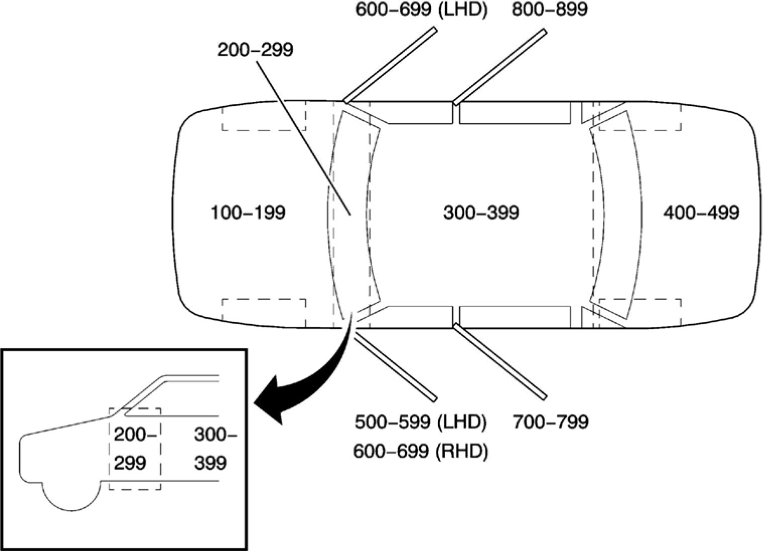 |
900-999 |
|
Fig. 55: Passenger Car Zoning View | |
|
Callout Numbers |
Zone Description |
|
100-199 |
Engine compartment (all forward of the instrument |
|
200-299 |
Within the instrument panel area (between the |
|
300-399 |
Passenger compartment (from instrument panel to the |
|
400-499 |
Luggage compartment (from the back of the rear |
|
500-599 |
Inline harness connectors to or within the driver door |
|
600-699 |
Inline harness connectors to or within the front |
|
700-799 |
Inline harness connectors to or within the left rear |
|
800-899 |
Inline harness connectors to or within the right rear |
|
900-999 |
Inline harness connectors to or within the luggage |
SCHEMATICS RPO CODE LIST
|
RPO |
Option Name |
|
62G |
ACCESSORY-ACCENT LIGHTING - FRONT EXTERIOR |
|
D71 |
MIRROR O/S-LH and RH, REMOTE CONTROL, ELECTRIC, MANUAL FOLDING |
|
RPO |
Option Name |
|
DLW |
MIRROR O/S-LH and RH, REMOTE CONTROL, ELECTRIC, MANUAL FOLDING, |
|
IO5 |
RADIO-INFOTAINMENT SYSTEM - UPLEVEL HMI, ENHANCED CONNECTIVITY |
|
IO6 |
RADIO-INFOTAINMENT SYSTEM - UPLEVEL HMI, ENHANCED CONNECTIVITY, |
|
K4C |
CHARGER-INDUCTIVE PORTABLE WIRELESS DEVICE |
|
KA1 |
HEATER SEAT FRT-DRVR and PASS |
|
KA6 |
HEATER SEAT-REAR |
|
TQ5 |
HEADLAMP HIGH BEAM-AUTO CONTROL |
|
UEU |
SENSOR INDICATOR-FORWARD COLLISION ALERT |
|
UFQ |
PARK ASSIST-FRONT, REAR, LATERAL-FRONT (SEMIAUTOMATIC STEERING |
|
UGN |
COLL IMMINENT BRK-ALL SPEED, VEH FWD MOVEMENT, BRAKE PREFILL, |
|
UHX |
LANE ACTIVE SAFETY-KEEP ASSIST |
|
UHY |
COLL IMMINENT BRK-LOW SPEED, VEH FWD MOVEMENT, BRAKE PREFILL, |
|
UKC |
SIDE ACTIVE SAFETY-OBSTACLE DETECTION ENHANCED |
|
UQA |
SPEAKER SYSTEM-PREMIUM AUDIO, BRANDED AMPLIFIER |
|
UVC |
VISION-REAR VIEW, MONO, ANALOG |
|
UVD |
STEERING WHEEL HEAT-MANUAL |
|
UZ6 |
SPEAKER SYSTEM-6, PREMIUM |
|
V7Y |
SALES PACKAGE-#2 |
MASTER ELECTRICAL SCHEMATIC ICONS
|
Icon |
Icon Definition |
|
Icon |
Icon Definition |
|
WARNING: deployment |
WARNING:
The high
intensity
discharge
system
produces high
voltage and
current. To
reduce the risk
of severe
shocks and
burns:

• Never
open the
high
intensity
discharge
system
ballast or
the arc
tube
assembly
starter.
• Never
probe
between
the high
intensity
discharge
system
ballast
output
connector
and the
arc tube
assembly.
WARNING:
To help
avoid
personal
injury,
always treat
the
accessory
power
|
Icon |
Icon Definition |
|
receptacle, power WARNING: The High
|
• Identify
condition
under
which high
voltage is
always
present
and
personal
protection
equipment
(PPE) and
proper
procedures
must be
followed.
Failure to follow
the procedures
exactly as
written may
result in serious
injury or death.

WARNING:
Always perform the
High Voltage
Disabling procedure
prior to servicing any
High Voltage
component or
connection. Personal
Protection Equipment
(PPE) and proper
procedures must be
followed.
The High Voltage
Disabling procedure
includes the following
steps:
• Identify how to
disable high
voltage.
• Identify how to
test for the
presence of high
voltage.
• Identify
|
Icon |
Icon Definition |
|
condition under Before working on
|
high
voltage
battery
assembly,
whether
the system
is
energized
or not.
Failure to follow the
procedures may
result in serious
injury or death.
NOTE:

Twisted wires
provide an
effective
shield that
helps protect
sensitive
electronic
components
from electrical
interference.
In order to
prevent
electrical
interference
from
degrading the
performance
of the
connected
components,
you must
maintain the
proper
specification
when making
any repairs to
the twisted
wires shown :
• The wires
must be
twisted a
minimum
of 16
|
Icon |
Icon Definition |
|
turns per • The |
POWER DISTRIBUTION WIRING SCHEMATICS
|
X50A Fuse Block - Underhood Bussing |
 |
|
Fig. 56: X50A Fuse Block - Underhood Bussing |
Courtesy of GENERAL MOTORS COMPANY
|
Callout |
Component Name |
|
2 |
Battery Positive Voltage |
|
2_RD/YE |
2 RD/YE |
|
P_REF |
P |
|
F21UA |
F21UA 30A |
|
F22UA |
F22UA 60A |
|
F27UA |
F27UA 30A |
|
F28UA |
F28UA 30A |
|
F35UA |
F35UA 10A |
|
F44UA |
F44UA 10A |
|
F46UA |
F46UA 5A |
|
F53UA |
F53UA 30A |
|
F54UA |
F54UA 30A |
|
F55UA |
F55UA 10A |
|
F36UA |
F36UA 10A |
|
F37UA |
F37UA 10A |
|
F34UA |
F34UA 15A |
|
F7UA |
F7UA 15A |
|
F8UA |
F8UA 10A |
|
F6UA |
F6UA 15A |
|
F32UA |
F32UA 7.5A |
|
F41UA |
F41UA 7.5A |
|
F42UA |
F42UA 10A |
|
F45UA |
F45UA 15A |
|
F52UA |
F52UA 7.5A |
|
F30UA |
F30UA 7.5A |
|
F29UA |
F29UA 40A |
|
F3UA |
F3UA 15A |
|
F4UA |
F4UA 25A |
|
F5UA |
F5UA 10A |
|
F9UA |
F9UA 10A |
|
F10UA |
F10UA 10A |
|
F11UA |
F11UA 10A |
|
F12UA |
F12UA 10A |
|
F14UA |
F14UA 5A |
|
F15UA |
F15UA 10A |
|
F16UA |
F16UA 15A |
|
F17UA |
F17UA 15A |
|
F20UA |
F20UA 40A |
|
F13UA |
F13UA 10A |
|
F23UA |
F23UA 10A |
|
KR48 |
KR48 Headlamp High Beam Relay |
|
X50B |
X50B Fuse Block - Underhood Auxiliary |
| ||||||||||||||||
|
X50D Fuse Block - Battery and X50B Fuse Block - Underhood Auxiliary Bussing |
 |
|
Fig. 57: X50D Fuse Block - Battery and X50B Fuse Block - Underhood Auxiliary Bussing |
|
Callout |
Component Name |
|
2 |
Battery Positive Voltage |
|
2_RD/YE |
2 RD/YE |
|
CONN_X2 |
X2 |
|
CAV_A |
A |
|
CONN_X6 |
X6 |
|
4740 |
Battery Positive Voltage |
|
42 |
Battery Positive Voltage |
|
42_RD/BU |
42 RD/BU |
|
CAV_A |
A |
|
Callout |
Component Name |
|
CONN_X1 |
X1 |
|
142 |
Battery Positive Voltage |
|
142_RD/GY |
142 RD/GY |
|
CAV_A |
A |
|
CONN_X2 |
X2 |
|
102 |
Battery Positive Voltage |
|
102_RD/VT |
102 RD/VT |
|
CAV_A |
A |
|
CONN_X3 |
X3 |
|
40 |
Battery Positive Voltage |
|
40_RD |
40 RD |
|
CAV_A |
A |
|
CONN_X1 |
X1 |
|
CAV_A |
A |
|
CONN_X5 |
X5 |
|
2_RD/YE |
2 RD/YE |
|
CAV_A |
A |
|
CONN_X2 |
X2 |
|
242 |
Battery Positive Voltage |
|
242_RD/GN |
242 RD/GN |
|
CAV_2 |
2 |
|
CONN_X1 |
X1 |
|
CAV_A |
A |
|
CONN_X3 |
X3 |
|
42_RD/BU |
42 RD/BU |
|
142_RD/GY |
142 RD/GY |
|
CAV_20 |
20 |
|
CAV_1 |
1 |
|
CONN_X4 |
X4 |
|
BUS |
BUS |
|
BUS_BAR |
BUS BAR |
|
CAV_A |
A |
|
CONN_X8 |
X8 |
|
4740_RD/WH |
4740 RD/WH |
|
4740_RD/WH |
4740 RD/WH |
|
CAV_A |
A |
|
A |
A |
|
X225 |
X225 |
|
CAV_89 |
89 |
|
CAV_90 |
90 |
|
F_REF |
F |
|
M_REF |
M |
|
N_REF |
N |
|
P_REF |
P |
| ||||||||||||||||||||||||||||||||||||||||||||||||
|
F3UA, F4UA, F5UA, F10UA, F15UA, F16UA, F17UA, F22UA and F27UA Fuses |
 |
|
Fig. 58: F3UA, F4UA, F5UA, F10UA, F15UA, F16UA, F17UA, F22UA and F27UA Fuses |
|
Callout |
Component Name |
|
342 |
Battery Positive Voltage |
|
342_RD/WH |
342 RD/WH |
|
CAV_30 |
30 |
|
CAV_31 |
31 |
|
5240 |
Battery Positive Voltage |
|
5240_RD/BU |
5240 RD/BU |
|
CAV_2 |
2 |
|
CONN_X1 |
X1 |
|
CAV_71 |
71 |
|
5291 |
Powertrain Main Relay Fused Supply (2) |
|
CAV_1 |
1 |
|
5291_BU |
5291 BU |
|
CAV_1 |
1 |
|
5291_BU |
5291 BU |
|
CAV_1 |
1 |
|
5290 |
Powertrain Main Relay Fused Supply (1) |
|
CAV_73 |
73 |
|
5293 |
Powertrain Main Relay Fused Supply (4) |
|
CAV_53 |
53 |
|
5293_VT/BU |
5293 VT/BU |
|
Callout |
Component Name |
|
CAV_1 |
1 |
|
5290_VT/BU |
5290 VT/BU |
|
5293_VT/BU |
5293 VT/BU |
|
5293_VT/BU |
5293 VT/BU |
|
5291_VT/YE |
5291 VT/YE |
|
5291_BU |
5291 BU |
|
5291_BU |
5291 BU |
|
5293_VT/BU |
5293 VT/BU |
|
CAV_1 |
1 |
|
5293_VT/BU |
5293 VT/BU |
|
5293_VT/BU |
5293 VT/BU |
|
CAV_1 |
1 |
|
CAV_16 |
16 |
|
CONN_X3 |
X3 |
|
CAV_5 |
5 |
|
5293_VT/BU |
5293 VT/BU |
|
5294 |
Powertrain Main Relay Fused Supply (5) |
|
CAV_5 |
5 |
|
CAV_2 |
2 |
|
5294_VT/BU |
5294 VT/BU |
|
5294_VT/BU |
5294 VT/BU |
|
CAV_2 |
2 |
|
5705_VT/BU |
5705 VT/BU |
|
5705_VT/BU |
5705 VT/BU |
|
CAV_52 |
52 |
|
CONN_X3 |
X3 |
|
1742 |
Battery Positive Voltage |
|
1742_RD/BN |
1742 RD/BN |
|
CAV_1 |
1 |
|
CAV_37 |
37 |
|
CONN_X2 |
X2 |
|
5293_VT/BU |
5293 VT/BU |
|
CAV_1 |
1 |
|
CAV_54 |
54 |
|
5705 |
Powertrain Main Relay Fused Control (6) |
|
CAV_1 |
1 |
|
CAV_67 |
67 |
|
CONN_X2 |
X2 |
|
CAV_18 |
18 |
|
CONN_X3 |
X3 |
|
CAV_31 |
31 |
|
5291_BU |
5291 BU |
|
CAV_1 |
1 |
|
CAV_51 |
51 |
| ||||||||||||||||||||||||||||||||||||||||||||||||||||||||||||||||||||||||||||||
|
F6UA, F7UA, F8UA, F9UA, F12UA, F13UA and F28UA Fuses |
 |
|
Fig. 59: F6UA, F7UA, F8UA, F9UA, F12UA, F13UA and F28UA Fuses |
|
Callout |
Component Name |
|
440 |
Battery Positive Voltage |
|
440_RD/BN |
440 RD/BN |
|
CAV_15 |
15 |
|
CONN_X1 |
X1 |
|
CAV_3 |
3 |
|
240 |
Battery Positive Voltage |
|
CAV_5 |
5 |
|
240_RD/YE |
240 RD/YE |
|
1940 |
Battery Positive Voltage |
|
CAV_4 |
4 |
|
3640 |
Battery Positive Voltage |
|
3640_RD/BN |
3640 RD/BN |
|
CAV_2 |
2 |
|
3640_RD/BN |
3640 RD/BN |
|
CAV_8 |
8 |
|
1089 |
Coolant Pump Motor Relay Control |
|
CAV_17 |
17 |
|
CAV_2 |
2 |
|
2740 |
Battery Positive Voltage |
|
2740_RD/WH |
2740 RD/WH |
|
Callout |
Component Name |
|
CAV_70 |
70 |
|
1640_RD/VT |
1640 RD/VT |
|
1940_RD/VT |
1940 RD/VT |
|
3640_RD/BN |
3640 RD/BN |
|
3640_RD/BN |
3640 RD/BN |
|
2740_RD/WH |
2740 RD/WH |
|
CONN_X8 |
X8 |
|
CAV_13 |
13 |
|
CONN_X2 |
X2 |
|
1089_WH/BN |
1089 WH/BN |
|
1089_WH/BN |
1089 WH/BN |
|
CAV_51 |
51 |
|
1089_WH/BN |
1089 WH/BN |
|
1097 |
Coolant Pump Motor Supply Voltage |
|
1097_VT/GN |
1097 VT/GN |
|
CAV_10 |
10 |
|
CAV_4 |
4 |
|
CAV_1 |
1 |
|
CAV_1 |
1 |
|
CAV_9 |
9 |
|
CAV_17 |
17 |
|
1097_VT/GN |
1097 VT/GN |
|
CAV_74 |
74 |
|
CAV_66 |
66 |
|
CAV_2 |
2 |
|
CONN_X1 |
X1 |
|
CAV_50 |
50 |
|
1640_RD/VT |
1640 RD/VT |
|
1640_RD/VT |
1640 RD/VT |
|
1640 |
Battery Positive Voltage |
|
CAV_1 |
1 |
|
CAV_73 |
73 |
|
CAV_9 |
9 |
|
CONN_X3 |
X3 |
|
CONN_X3 |
X3 |
|
CONN_X2 |
X2 |
|
CAV_9 |
9 |
|
2740_RD/WH |
2740 RD/WH |
|
1640_RD/VT |
1640 RD/VT |
|
CAV_32 |
32 |
|
F8UA |
F8UA 10A |
|
F6UA |
F6UA 15A |
|
F7UA |
F7UA 15A |
|
F9UA |
F9UA 10A |
| ||||||||||||||||||||||||||||||||||||||||||||||
|
F7UA, F21UA, F23UA, F29UA, F30UA, F34UA, F36UA and F37UA Fuses |
 |
|
Fig. 60: F7UA, F21UA, F23UA, F29UA, F30UA, F34UA, F36UA and F37UA Fuses |
|
Callout |
Component Name |
|
2267 |
Mirror Heating Element Supply Voltage |
|
CAV_14 |
14 |
|
2267_BN/YE |
2267 BN/YE |
|
2267_BN/YE |
2267 BN/YE |
|
2267_BN/YE |
2267 BN/YE |
|
CAV_8 |
8 |
|
2267_BN/YE |
2267 BN/YE |
|
2267_BN/YE |
2267 BN/YE |
|
CAV_8 |
8 |
|
29 |
Horn Control |
|
29_BN/GY |
29 BN/GY |
|
CAV_2 |
2 |
|
CONN_X1 |
X1 |
|
2267_BK/GY |
2267 BK/GY |
|
2267_BK/GY |
2267 BK/GY |
|
CAV_1 |
1 |
|
CAV_1 |
1 |
|
CAV_1 |
1 |
|
CONN_X1 |
X1 |
|
CAV_1 |
1 |
|
Callout |
Component Name |
|
CONN_X1 |
X1 |
|
DLW |
MIRROR O/S-LH and RH, REMOTE CONTROL, ELECTRIC, MANUAL |
|
293_BN/VT |
293 BN/VT |
|
1940_RD/VT |
1940 RD/VT |
|
228_GY/VT |
228 GY/VT |
|
293 |
Rear Defog Element Supply Voltage |
|
CAV_1 |
1 |
|
CONN_X1 |
X1 |
|
CAV_34 |
34 |
|
CONN_X2 |
X2 |
|
228 |
Windshield Washer Pump Control |
|
CAV_1 |
1 |
|
CAV_52 |
52 |
|
CONN_X1 |
X1 |
|
1940 |
Battery Positive Voltage |
|
CAV_50 |
50 |
|
CONN_X1 |
X1 |
|
CAV_4 |
4 |
|
CONN_X3 |
X3 |
|
2267_BN/YE |
2267 BN/YE |
|
2267_BN/YE |
2267 BN/YE |
|
711_WH |
711 WH |
|
311 |
Right Headlamp High Beam Supply Voltage |
|
311_WH |
311 WH |
|
CAV_57 |
57 |
|
3740_RD/YE |
3740 RD/YE |
|
711_WH |
711 WH |
|
311_WH |
311 WH |
|
CAV_8 |
8 |
|
CAV_A |
A |
|
711_WH |
711 WH |
|
311_WH |
311 WH |
|
3740 |
Battery Positive Voltage |
|
CAV_1 |
1 |
|
CAV_36 |
36 |
|
CONN_X2 |
X2 |
|
711 |
Left Headlamp High Beam Supply Voltage |
|
CAV_A |
A |
|
CAV_56 |
56 |
|
CONN_X1 |
X1 |
|
CAV_16 |
16 |
|
CAV_1 |
1 |
|
CAV_1 |
1 |
| ||||||||||||||||||||||||||||||||||||||||||||||||||||||||||||||||||||||||||||||||
|
F14UA, F35UA, F53UA, F54UA and F55UA Fuses |
 |
|
Fig. 61: F14UA, F35UA, F53UA, F54UA and F55UA Fuses |
|
Callout |
Component Name |
|
540 |
Battery Positive Voltage |
|
CAV_30 |
30 |
|
3340 |
Battery Positive Voltage |
|
CAV_5 |
5 |
|
CAV_58 |
58 |
|
2140 |
Battery Positive Voltage |
|
CAV_68 |
68 |
|
3940 |
Battery Positive Voltage |
|
CAV_5 |
5 |
|
CAV_27 |
27 |
|
CAV_9 |
9 |
|
3340_RD/VT |
3340 RD/VT |
|
540_RD/BU |
540 RD/BU |
|
540_RD/BU |
540 RD/BU |
|
140_RD/WH |
140 RD/WH |
|
140_RD/WH |
140 RD/WH |
|
3940_RD/BU |
3940 RD/BU |
|
2140_GY |
2140 GY |
|
3340_RD/VT |
3340 RD/VT |
|
CAV_2 |
2 |
| ||||||||||||||||||||||||||||||||||||||||||||||||||
|
F32UA, F41UA, F42UA, F44UA, F45UA, F46UA and F52UA Fuses |
 |
|
Fig. 62: F32UA, F41UA, F42UA, F44UA, F45UA, F46UA and F52UA Fuses |
|
Callout |
Component Name |
|
139_VT/GY |
139 VT/GY |
|
139 |
Run/Crank Ignition 1 Voltage |
|
139_VT/GY |
139 VT/GY |
|
439 |
Run/Crank Ignition 1 Voltage |
|
CAV_2 |
2 |
|
39 |
Run/Crank Ignition 1 Voltage |
|
CAV_8 |
8 |
|
CAV_24 |
24 |
|
2339 |
Run/Crank Ignition 1 Voltage |
|
2339_VT/GY |
2339 VT/GY |
|
CAV_27 |
27 |
|
CONN_X2 |
X2 |
|
CAV_6 |
6 |
|
639 |
Run/Crank Ignition 1 Voltage |
|
639_VT/WH |
639 VT/WH |
|
CAV_6 |
6 |
|
CAV_1 |
1 |
|
39_VT/GN |
39 VT/GN |
|
39_VT/GN |
39 VT/GN |
|
39_VT/GN |
39 VT/GN |
|
Callout |
Component Name |
|
39_RD |
39 RD |
|
CAV_102 |
102 |
|
439_VT/GN |
439 VT/GN |
|
439_VT/GN |
439 VT/GN |
|
UVC |
VISION-REAR VIEW, MONO, ANALOG |
|
39_VT/GN |
39 VT/GN |
|
CAV_1 |
1 |
|
CAV_4 |
4 |
|
39_VT/GN |
39 VT/GN |
|
DD8 |
MIRROR I/S R/V-LT SENSITIVE |
|
CAV_2 |
2 |
|
139_VT/GY |
139 VT/GY |
|
CAV_21 |
21 |
|
CAV_8 |
8 |
|
CAV_1 |
1 |
|
CAV_5 |
5 |
|
CONN_X2 |
X2 |
|
V7Y |
SALES PACKAGE-#2 |
|
CAV_11 |
11 |
|
CAV_9 |
9 |
|
CONN_X8 |
X8 |
|
A |
A |
|
139_VT/GY |
139 VT/GY |
|
139_VT/GY |
139 VT/GY |
|
CAV_17 |
17 |
|
CAV_4 |
4 |
|
CONN_X2 |
X2 |
|
539 |
Run/Crank Ignition 1 Voltage |
|
539_VT/GY |
539 VT/GY |
|
CAV_21 |
21 |
|
CONN_X1 |
X1 |
|
CAV_5 |
5 |
|
CONN_X2 |
X2 |
|
639_VT/BU |
639 VT/BU |
|
CAV_1 |
1 |
|
CONN_X3 |
X3 |
|
UVD |
STEERING WHEEL HEAT-MANUAL |
|
CAV_3 |
3 |
|
UFQ |
PARK ASSIST-FRONT, REAR, LATERAL-FRONT (SEMIAUTOMATIC |
|
UFQ |
PARK ASSIST-FRONT, REAR, LATERAL-FRONT (SEMIAUTOMATIC |
|
339_VT/BK |
339 VT/BK |
|
CAV_14 |
14 |
| ||||||||||||||||||||||||||||||||||||||||||||||||||||||||||||||||||||||||||||||||||||
|
F4DA, F5DA, F8DA, F9DA, F17DA, F18DA, and F19DA Fuses |
 |
|
Fig. 63: F4DA, F5DA, F8DA, F9DA, F17DA, F18DA, and F19DA Fuses |
|
Callout |
Component Name |
|
CAV_29 |
29 |
|
CAV_49 |
49 |
|
CAV_35 |
35 |
|
CAV_50 |
50 |
|
42 |
Battery Positive Voltage |
|
42_RD/BU |
42 RD/BU |
|
542 |
Battery Positive Voltage |
|
542_RD/VT |
542 RD/VT |
|
CAV_1 |
1 |
|
4440 |
Battery Positive Voltage |
|
4440_RD/BU |
4440 RD/BU |
|
CONN_X1 |
X1 |
|
CAV_3 |
3 |
|
4540 |
Battery Positive Voltage |
|
4540_RD/BU |
4540 RD/BU |
|
CAV_4 |
4 |
|
4840 |
Battery Positive Voltage |
|
4840_RD/GY |
4840 RD/GY |
|
CAV_3 |
3 |
|
4840_RD/GY |
4840 RD/GY |
| ||||||||||||||||||||||||||||||||||||||||||||||||||||||||||||||||||||||
|
F20DA, F21DA, F22DA, F23DA, F26DA, F29DA, F31DA, F32DA, F33DA, F34DA, and F36DA Fuses |
 |
|
Fig. 64: F20DA, F21DA, F22DA, F23DA, F26DA, F29DA, F31DA, F32DA, F33DA, F34DA, and F36DA Fuses Courtesy of GENERAL MOTORS COMPANY |
|
Callout |
Component Name |
|
1301 |
Retained Accessory Power Fuse Supply Voltage |
|
1301_VT |
1301 VT |
|
CAV_A |
A |
|
CAV_A |
A |
|
1701_VT |
1701 VT |
|
1701_VT |
1701 VT |
|
1701 |
Retained Accessory Power Fuse Supply Voltage |
|
842 |
Battery Positive Voltage |
|
842_RD/BU |
842 RD/BU |
|
842_RD/BU |
842 RD/BU |
|
4340 |
Battery Positive Voltage |
|
4340_RD/YE |
4340 RD/YE |
|
CAV_2 |
2 |
|
CONN_X1 |
X1 |
|
4240 |
Battery Positive Voltage |
|
4240_RD/BN |
4240 RD/BN |
|
CAV_1 |
1 |
|
CONN_X2 |
X2 |
|
2640 |
Battery Positive Voltage |
|
Callout |
Component Name |
|
2640_RD/VT |
2640 RD/VT |
|
CAV_15 |
15 |
|
CONN_X1 |
X1 |
|
5040_RD/YE |
5040 RD/YE |
|
CAV_6 |
6 |
|
CONN_X1 |
X1 |
|
2440 |
Battery Positive Voltage |
|
2440_RD/GN |
2440 RD/GN |
|
2440_RD/GN |
2440 RD/GN |
|
CAV_19 |
19 |
|
142 |
Battery Positive Voltage |
|
142_RD/GY |
142 RD/GY |
|
CAV_40 |
40 |
|
CAV_34 |
34 |
|
CAV_91 |
91 |
|
1301_VT |
1301 VT |
|
CAV_1 |
1 |
|
5040 |
Battery Positive Voltage |
|
5040_RD/YE |
5040 RD/YE |
|
CAV_7 |
7 |
|
CONN_X1 |
X1 |
|
5040_RD/YE |
5040 RD/YE |
|
4601 |
Retained Accessory Power Fused Supply Voltage |
|
CAV_1 |
1 |
|
CAV_14 |
14 |
|
K4C |
CHARGER-INDUCTIVE PORTABLE WIRELESS DEVICE |
|
CAV_27 |
27 |
|
4140 |
Battery Positive Voltage |
|
4140_RD/GN |
4140 RD/GN |
|
CAV_4 |
4 |
|
4940 |
Battery Positive Voltage |
|
4940_RD/BN |
4940 RD/BN |
|
CAV_4 |
4 |
|
CONN_X2 |
X2 |
|
4140_RD/GN |
4140 RD/GN |
|
CAV_92 |
92 |
|
3440 |
Battery Positive Voltage |
|
3440_RD/WH |
3440 RD/WH |
|
CAV_5 |
5 |
|
CONN_X1 |
X1 |
|
640 |
Battery Positive Voltage |
|
640_RD/WH |
640 RD/WH |
|
CAV_2 |
2 |
|
CONN_X1 |
X1 |
|
Callout |
Component Name |
|
640_RD/WH |
640 RD/WH |
|
CONN_X5 |
X5 |
|
CAV_8 |
8 |
|
3440_RD/WH |
3440 RD/WH |
|
CAV_1 |
1 |
|
CONN_X2 |
X2 |
|
4601_VT |
4601 VT |
|
4601_VT |
4601 VT |
|
5440 |
Battery Positive Voltage |
|
5440_RD/WH |
5440 RD/WH |
|
CAV_12 |
12 |
|
CONN_X1 |
X1 |
|
5440_RD/WH |
5440 RD/WH |
|
CAV_6 |
6 |
|
CAV_18 |
18 |
|
CONN_X1 |
X1 |
|
CAV_12 |
12 |
|
CONN_X2 |
X2 |
|
5440_RD/WH |
5440 RD/WH |
|
5440_RD/WH |
5440 RD/WH |
|
CAV_20 |
20 |
|
CAV_10 |
10 |
|
CAV_43 |
43 |
|
CAV_22 |
22 |
|
CAV_16 |
16 |
|
CAV_9 |
9 |
|
CAV_21 |
21 |
|
CAV_26 |
26 |
|
CAV_33 |
33 |
|
CAV_39 |
39 |
|
X315 |
X315 |
|
CAV_3 |
3 |
|
CAV_1 |
1 |
|
X325 |
X325 |
|
M_REF |
M |
|
F29DA |
F29DA 7.5A |
|
F23DA |
F23DA 10A |
|
F20DA |
F20DA 15A |
|
F21DA |
F21DA 15A |
|
CB2DA |
CB2DA 15A |
|
CB1DA |
CB1DA 15A |
|
X275 |
X275 |
|
X315 |
X315 |
|
X225 |
X225 |
| ||||||||||||||||||||||||||||||||||||||||||||||||||||||||
|
F5RA, F6RA, F7RA, F8RA, F9RA, F11RA, F21RA and F22RA Fuses |
 |
|
Fig. 65: F5RA, F6RA, F7RA, F8RA, F9RA, F11RA, F21RA and F22RA Fuses |
|
Callout |
Component Name |
|
102 |
Battery Positive Voltage |
|
102_RD/VT |
102 RD/VT |
|
CAV_A29 |
A29 |
|
CAV_A33 |
A33 |
|
CAV_A28 |
A28 |
|
1840 |
Battery Positive Voltage |
|
1840_RD/GN |
1840 RD/GN |
|
CAV_10 |
10 |
|
CONN_X1 |
X1 |
|
1740_RD/GY |
1740 RD/GY |
|
CAV_10 |
10 |
|
CONN_X1 |
X1 |
|
3740 |
Battery Positive Voltage |
|
3740_RD/YE |
3740 RD/YE |
|
3740_RD/YE |
3740 RD/YE |
|
1140 |
Battery Positive Voltage |
|
1140_RD/BN |
1140 RD/BN |
|
CAV_4 |
4 |
|
CONN_X1 |
X1 |
|
1240 |
Battery Positive Voltage |
|
Callout |
Component Name |
|
1240_RD/BU |
1240 RD/BU |
|
CAV_9 |
9 |
|
CONN_X1 |
X1 |
|
4740 |
Battery Positive Voltage |
|
4740_RD/WH |
4740 RD/WH |
|
CAV_1 |
1 |
|
4740_RD/WH |
4740 RD/WH |
|
CAV_23 |
23 |
|
4740_RD/WH |
4740 RD/WH |
|
4740_RD/WH |
4740 RD/WH |
|
4740_RD/WH |
4740 RD/WH |
|
3740_RD/YE |
3740 RD/YE |
|
3740_RD/YE |
3740 RD/YE |
|
1740_RD/GY |
1740 RD/GY |
|
1740 |
Battery Positive Voltage |
|
CAV_1 |
1 |
|
CAV_1 |
1 |
|
CAV_15 |
15 |
|
CAV_1 |
1 |
|
KA1 |
(U.S.A., PR and USVI (MAH), Canada (MBC), Mexico (MCX), Korea (MAW)) |
|
UQA |
(U.S.A., PR and USVI (MAH), Canada (MBC), Mexico (MCX), Korea (MAW)) |
|
CAV_A11 |
A11 |
|
CAV_A10 |
A10 |
|
1840_RD/GN |
1840 RD/GN |
|
CAV_7 |
7 |
|
1840_RD/GN |
1840 RD/GN |
|
1840_RD/GN |
1840 RD/GN |
|
CAV_1 |
1 |
|
CAV_8 |
8 |
|
CONN_X1 |
X1 |
|
CAV_8 |
8 |
|
CONN_X1 |
X1 |
|
4640_RD/VT |
4640 RD/VT |
|
CAV_10 |
10 |
|
KA6 |
(U.S.A., PR and USVI (MAH), Canada (MBC), Mexico (MCX), Korea (MAW)) |
|
CAV_7 |
7 |
|
1742_RD/BN |
1742 RD/BN |
|
KA1 |
(U.S.A., PR and USVI (MAH), Canada (MBC), Mexico (MCX), Korea (MAW)) |
|
1742_RD/BN |
1742 RD/BN |
|
CAV_A27 |
A27 |
|
CAV_A31 |
A31 |
|
CAV_A30 |
A30 |
|
X320 |
X320 |
|
CAV_1 |
1 |
| ||||||||||||||||||||||||||||||||||||||||||||||||||||||||||||||||
|
F19RA, F20RA and F22RA Fuses |
 |
|
Fig. 66: F19RA, F20RA and F22RA Fuses Courtesy'of GENERAL'MOTORS'COMPANY |
|
Callout |
Component Name |
|
CAV_2 |
2 |
|
1340 |
Battery Positive Voltage |
|
CAV_5 |
5 |
|
CAV_3 |
3 |
|
1340_RD/WH |
1340 RD/WH |
|
1340_RD/WH |
1340 RD/WH |
|
1340_RD/WH |
1340 RD/WH |
|
1340_RD/WH |
1340 RD/WH |
|
1340_RD/WH |
1340 RD/WH |
|
1340_RD/WH |
1340 RD/WH |
|
1340_RD/WH |
1340 RD/WH |
|
CAV_A9 |
A9 |
|
2840 |
Battery Positive Voltage |
|
2840_RD/GY |
2840 RD/GY |
|
CAV_1 |
1 |
|
CONN_X1 |
X1 |
|
2840_RD/GY |
2840 RD/GY |
|
2840_RD/GY |
2840 RD/GY |
|
2840_RD/GY |
2840 RD/GY |
|
CAV_3 |
3 |
|
Callout |
Component Name |
|
CONN_X1 |
X1 |
|
2840_RD/GY |
2840 RD/GY |
|
UEU |
SENSOR INDICATOR-FORWARD COLLISION ALERT |
|
UHX |
LANE ACTIVE SAFETY-KEEP ASSIST |
|
2840_RD/GY |
2840 RD/GY |
|
CAV_5 |
5 |
|
CONN_X1 |
X1 |
|
CAV_3 |
3 |
|
2840_RD/GY |
2840 RD/GY |
|
CAV_5 |
5 |
|
CONN_X1 |
X1 |
|
UKC |
SIDE ACTIVE SAFETY-OBSTACLE DETECTION ENHANCED |
|
V7Y |
SALES PACKAGE-#2 |
|
V7Y |
SALES PACKAGE-#2 |
|
2840_RD/GY |
2840 RD/GY |
|
2840_RD/GY |
2840 RD/GY |
|
2840_RD/GY |
2840 RD/GY |
|
CAV_A8 |
A8 |
|
CAV_A11 |
A11 |
|
3740 |
Battery Positive Voltage |
|
3740_RD/YE |
3740 RD/YE |
|
CAV_8 |
8 |
|
CAV_8 |
8 |
|
CAV_1 |
1 |
|
3740_RD/YE |
3740 RD/YE |
|
3740_RD/YE |
3740 RD/YE |
|
2840_RD/GY |
2840 RD/GY |
|
CAV_1 |
1 |
|
CONN_X1 |
X1 |
|
3740_RD/YE |
3740 RD/YE |
|
102 |
Battery Positive Voltage |
|
102_RD/VT |
102 RD/VT |
|
3740_RD/YE |
3740 RD/YE |
|
CAV_1 |
1 |
|
CAV_1 |
1 |
|
X351 |
X351 |
|
CAV_8 |
8 |
|
CAV_7 |
7 |
|
CAV_6 |
6 |
|
X450 |
X450 |
|
J314 |
J314 |
|
J409 |
J409 |
|
J376 |
J376 |
|
X800 |
X800 |
| ||||||||||||||||||||||||||||||||||||||
|
Vehicle On/Off Switch |
 |
|
Fig. 67: Vehicle On/Off Switch Courtesy of GENERAL MOTORS COMPANY |
|
Callout |
Component Name |
|
230 |
Instrument Panel Lamp Dimming Control |
|
230_YE/GY |
230 YE/GY |
|
CAV_8 |
8 |
|
CAV_22 |
22 |
|
CONN_X7 |
X7 |
|
5719 |
Ignition Mode Switch Start LED Signal |
|
5719_BU/BK |
5719 BU/BK |
|
CAV_5 |
5 |
|
CAV_20 |
20 |
|
CONN_X1 |
X1 |
|
5723 |
Ignition Mode Switch Mode Voltage |
|
5723_BU/GN |
5723 BU/GN |
|
CAV_6 |
6 |
|
CAV_17 |
17 |
|
CONN_X2 |
X2 |
|
3558 |
Passive Start Switch Signal 2 |
|
3558_GN/BK |
3558 GN/BK |
|
CAV_11 |
11 |
|
CONN_X1 |
X1 |
|
CAV_3 |
3 |
|
3559 |
Passive Start Switch 2 Low Reference |
|
3559_BK/GY |
3559 BK/GY |
|
CAV_7 |
7 |
|
CAV_12 |
12 |
|
CONN_X1 |
X1 |
|
1650 |
Ground |
|
1650_BK |
1650 BK |
|
CAV_4 |
4 |
|
3558_GN/BK |
3558 GN/BK |
|
3559_BK/GY |
3559 BK/GY |
|
CAV_35 |
35 |
|
CAV_34 |
34 |
|
CAV_18 |
18 |
|
230_YE/GY |
230 YE/GY |
|
G204 |
G204 |
|
X275 |
X275 |
|
X275 |
X275 |
|
F20DA |
F20DA |
|
F20DA |
F20DA |
|
X225 |
X225 |
|
K9 |
K9 Body Control Module |
|
K84 |
K84 Keyless Entry Control Module |
|
S83 |
S83 Vehicle On/Off Switch |
POWER MODING WIRING SCHEMATICS
Power Moding
 |
|
Fig. 68: Power Moding |
Courtesy of GENERAL MOTORS COMPANY
|
Callout |
Component Name |
|
4240 |
Battery Positive Voltage |
|
3 |
Run/Crank Ignition 1 Voltage |
|
3_VT/BK |
3 VT/BK |
|
CAV_6 |
6 |
|
CONN_X3 |
X3 |
|
CAV_13 |
13 |
|
3_VT/BK |
3 VT/BK |
|
4 |
Accessory Voltage |
|
CAV_5 |
5 |
|
CAV_5 |
5 |
|
4_VT/YE |
4 VT/YE |
|
4_VT/YE |
4 VT/YE |
|
1150 |
Ground |
|
1150_BK |
1150 BK |
|
CAV_53 |
53 |
|
CONN_X1 |
X1 |
|
5985 |
Accessory Wakeup Serial Data |
|
Callout |
Component Name |
|
CAV_22 |
22 |
|
5985_VT/YE |
5985 VT/YE |
|
4083 |
RAP Relay 2 Coil Control |
|
4083_GY/GN |
4083 GY/GN |
|
2150 |
Ground |
|
2150_BK |
2150 BK |
|
CAV_9 |
9 |
|
4083_GY/GN |
4083 GY/GN |
|
CAV_67 |
67 |
|
CONN_X2 |
X2 |
|
CAV_9 |
9 |
|
CAV_7 |
7 |
|
CONN_X1 |
X1 |
|
4086 |
Pushbutton Start Challenge Active Signal |
|
4086_YE/BU |
4086 YE/BU |
|
CAV_14 |
14 |
|
CONN_X7 |
X7 |
|
CAV_10 |
10 |
|
1650 |
Ground |
|
1650_BK |
1650 BK |
|
4240_RD/BN |
4240 RD/BN |
|
CAV_1 |
1 |
|
CONN_X2 |
X2 |
|
CAV_4 |
4 |
|
CAV_6 |
6 |
|
5199 |
Run/Crank Relay Coil Control |
|
5199_GN/VT |
5199 GN/VT |
|
CAV_15 |
15 |
|
CONN_X2 |
X2 |
|
CAV_15 |
15 |
|
CONN_X4 |
X4 |
|
3558 |
Passive Start Switch Signal 2 |
|
3558_GN/BK |
3558 GN/BK |
|
CAV_3 |
3 |
|
CAV_11 |
11 |
|
3559 |
Passive Start Switch 2 Low Reference |
|
3559_BK/GY |
3559 BK/GY |
|
CAV_12 |
12 |
|
CAV_7 |
7 |
|
3558_GN/BK |
3558 GN/BK |
|
3559_BK/GY |
3559 BK/GY |
|
5723 |
Ignition Mode Switch Mode Voltage |
|
5723_BU/GN |
5723 BU/GN |
|
CAV_17 |
17 |
|
Callout |
Component Name |
|
CONN_X2 |
X2 |
|
X275 |
X275 |
|
CAV_23 |
23 |
|
CAV_44 |
44 |
|
X275 |
X275 |
|
CAV_34 |
34 |
|
CAV_35 |
35 |
|
G101 |
G101 |
|
F36DA |
F36DA 5A |
|
F41UA |
F41UA 7.5A |
|
F45UA |
F45UA 15A |
|
F32UA |
F32UA 7.5A |
|
F52UA |
F52UA 7.5A |
|
F42UA |
F42UA 10A |
|
G202 |
G202 |
|
X225 |
X225 |
|
CB2DA |
CB2DA 15A |
|
CB1DA |
CB1DA 15A |
|
F20DA |
F20DA 15A |
|
G204 |
G204 |
|
X275 |
X275 |
|
X275 |
X275 |
|
X50A |
X50A Fuse Block - Underhood |
|
K9 |
K9 Body Control Module |
|
K84 |
K84 Keyless Entry Control Module |
|
K114B |
K114B Hybrid/EV Powertrain Control Module 2 |
|
KR73 |
KR73 Ignition Main Relay |
|
KR76 |
KR76 Retained Accessory Power Relay |
|
X51A |
X51A Fuse Block - Instrument Panel |
|
S83 |
S83 Vehicle On/Off Switch |
GROUND DISTRIBUTION WIRING SCHEMATICS
G101 and G102
 |
|
Fig. 69: G101 and G102 Courtesy'of GENERAL MOTORS COMPANY |
|
Callout |
Component Name |
|
CAV_3 |
3 |
|
CAV_4 |
4 |
|
1050 |
Ground |
|
1050_BK |
1050 BK |
|
CAV_1 |
1 |
|
1050_BK |
1050 BK |
|
1050_BK |
1050 BK |
|
1050_BK |
1050 BK |
|
CAV_2 |
2 |
|
CAV_2 |
2 |
|
1050_BK |
1050 BK |
|
1150 |
Ground |
|
1150_BK |
1150 BK |
|
CAV_B |
B |
|
CAV_B |
B |
|
1150_BK |
1150 BK |
|
1150_BK |
1150 BK |
|
1150_BK |
1150 BK |
|
CAV_B |
B |
|
CAV_2 |
2 |
|
Callout |
Component Name |
|
1150_BK |
1150 BK |
|
1150_BK |
1150 BK |
|
1050_BK |
1050 BK |
|
CAV_B |
B |
|
CAV_B |
B |
|
1050_BK |
1050 BK |
|
1050_BK |
1050 BK |
|
1050_BK |
1050 BK |
|
CAV_B |
B |
|
CAV_2 |
2 |
|
1050_BK |
1050 BK |
|
1050_BK |
1050 BK |
|
CAV_3 |
3 |
|
1150_BK |
1150 BK |
|
1150_BK |
1150 BK |
|
1150_BK |
1150 BK |
|
1150_BK |
1150 BK |
|
1150_BK |
1150 BK |
|
1150_BK |
1150 BK |
|
1150_BK |
1150 BK |
|
1050_BK |
1050 BK |
|
1050_BK |
1050 BK |
|
1150_BK |
1150 BK |
|
1150_BK |
1150 BK |
|
1150_BK |
1150 BK |
|
1150_BK |
1150 BK |
|
1150_BK |
1150 BK |
|
CAV_7 |
7 |
|
CAV_4 |
4 |
|
CAV_3 |
3 |
|
1150_BK |
1150 BK |
|
CAV_C |
C |
|
CAV_53 |
53 |
|
CONN_X1 |
X1 |
|
1050_BK |
1050 BK |
|
CAV_7 |
7 |
|
X120 |
X120 |
|
CAV_6 |
6 |
|
CAV_3 |
3 |
|
X121 |
X121 |
|
CAV_1 |
1 |
|
CAV_16 |
16 |
|
X107 |
X107 |
|
CAV_17 |
17 |
| ||||||||||||||||||||||||||||||||||||||||||||||||||||||||||||||||||||||||
|
G104 and G105 |
|
G10L GtOR HybodtV Cooing Cooing Battery Fan Fan Pack Motor - Motor - Coolant l «П Right Pump |
 |
|
G36 ОМ Aux*ary Exhaust Gas G1 •‘«ate' Raorcuiaeon AlC Coolant Vasa Compressor Pump II II II II II II |
 |
Fig. 70: G104 and G105
Courtesy'of GENERAL MOTORS COMPANY
| ||||||||||||||||||||||||||||||||||
|
G110, G112, G113 and G117 |


Fig. 71: G110, G112, G113 and G117
Courtesy'of GENERAL'MOTORS'COMPANY
|
Callout |
Component Name |
|
350 |
Ground |
|
350_BK |
350 BK |
|
CAV_1 |
1 |
|
CONN_X1 |
X1 |
|
550 |
Ground |
|
550_BK |
550 BK |
|
151 |
Signal Ground |
|
151_BK/WH |
151 BK/WH |
|
CAV_73 |
73 |
|
CONN_X2 |
X2 |
|
2650 |
Ground |
|
2650_BK |
2650 BK |
|
2650_BK |
2650 BK |
|
CAV_73 |
73 |
|
CONN_X3 |
X3 |
|
CAV_7 |
7 |
|
CONN_X1 |
X1 |
|
CAV_14 |
14 |
|
CAV_46 |
46 |
|
151_BK/WH |
151 BK/WH |
| ||||||||||||||||||||||||||||||||||||
|
G201, G205, G304, G401 and G404 |
 |
|
Fig. 72: G201, G205, G304, G401 and G404 |
| ||||||||||||||||||||||||||||||||||||||||||||||||||||||
|
G202 |
 |
|
Fig. 73: G202 Courtesy'of GENERAL MOTORS COMPANY |
|
Callout |
Component Name |
|
2150 |
Ground |
|
2150_BK |
2150 BK |
|
2150_BK |
2150 BK |
|
CAV_1 |
1 |
|
CONN_X1 |
X1 |
|
2150_BK |
2150 BK |
|
2150_BK |
2150 BK |
|
CAV_2 |
2 |
|
CONN_X2 |
X2 |
|
CAV_5 |
5 |
|
2150_BK |
2150 BK |
|
2150_BK |
2150 BK |
|
2150_BK |
2150 BK |
|
CAV_4 |
4 |
|
2150_BK |
2150 BK |
|
CAV_B |
B |
|
2150_BK |
2150 BK |
|
2150_BK |
2150 BK |
|
2150_BK |
2150 BK |
|
CAV_C |
C |
| ||||||||||||||||||||||||||||||||||||||||||||||||||||||||||||||||
|
G204 |
 |
|
Fig. 74: G204 Courtesy'of GENERAL MOTORS COMPANY |
|
Callout |
Component Name |
|
1650_BK |
1650 BK |
|
CAV_19 |
19 |
|
1650 |
Ground |
|
1650_BK |
1650 BK |
|
CAV_10 |
10 |
|
1650_BK |
1650 BK |
|
CAV_6 |
6 |
|
CONN_X1 |
X1 |
|
1650_BK |
1650 BK |
|
CAV_4 |
4 |
|
1650_BK |
1650 BK |
|
CAV_4 |
4 |
|
1650_BK |
1650 BK |
|
CAV_37 |
37 |
|
1650_BK |
1650 BK |
|
1650_BK |
1650 BK |
|
1650_BK |
1650 BK |
|
CAV_3 |
3 |
|
CONN_X2 |
X2 |
|
1650_BK |
1650 BK |
|
Callout |
Component Name |
|
CAV_4 |
4 |
|
1650_BK |
1650 BK |
|
CAV_1 |
1 |
|
CONN_X1 |
X1 |
|
CAV_1 |
1 |
|
CAV_A |
A |
|
CONN_X1 |
X1 |
|
CAV_3 |
3 |
|
CONN_X1 |
X1 |
|
CAV_1 |
1 |
|
CONN_X1 |
X1 |
|
1650_BK |
1650 BK |
|
V7Y |
SALES PACKAGE-#2 |
|
1650_BK |
1650 BK |
|
CAV_2 |
2 |
|
1650_BK |
1650 BK |
|
CAV_3 |
3 |
|
CONN_X1 |
X1 |
|
1650_BK |
1650 BK |
|
CAV_5 |
5 |
|
CONN_X1 |
X1 |
|
1650_BK |
1650 BK |
|
CAV_8 |
8 |
|
CONN_X2 |
X2 |
|
1650_BK |
1650 BK |
|
1650_BK |
1650 BK |
|
CAV_8 |
8 |
|
1650_BK |
1650 BK |
|
CAV_1 |
1 |
|
CONN_X3 |
X3 |
|
CAV_10 |
10 |
|
1650_BK |
1650 BK |
|
1650_BK |
1650 BK |
|
CAV_3 |
3 |
|
1650_BK |
1650 BK |
|
CAV_8 |
8 |
|
1650_BK |
1650 BK |
|
CAV_8 |
8 |
|
1650_BK |
1650 BK |
|
CAV_1 |
1 |
|
1650_BK |
1650 BK |
|
CAV_1 |
1 |
|
1650_BK |
1650 BK |
|
CAV_5 |
5 |
|
Callout |
Component Name |
|
1650_BK |
1650 BK |
|
1650_BK |
1650 BK |
|
1650_BK |
1650 BK |
|
IO5 |
RADIO-INFOTAINMENT SYSTEM - UPLEVEL HMI, ENHANCED |
|
IO6 |
RADIO-INFOTAINMENT SYSTEM - UPLEVEL HMI, ENHANCED |
|
CAV_39 |
39 |
|
CAV_5 |
5 |
|
1650_BK |
1650 BK |
|
1650_BK |
1650 BK |
|
CAV_5 |
5 |
|
CAV_4 |
4 |
|
X315 |
X315 |
|
J223 |
J223 |
|
J350 |
J350 |
|
X315 |
X315 |
|
X302 |
X302 |
|
G204 |
G204 |
|
P16 |
P16 Instrument Cluster |
|
S33 |
S33 Horn Switch |
|
X85 |
X85 Steering Wheel Air Bag Coil |
|
S70R |
S70R Steering Wheel Controls Switch - Right |
|
S70L |
S70L Steering Wheel Controls Switch - Left |
|
P17 |
P17 Info Display Module |
|
X83 |
X83 Auxiliary Audio Input |
|
P43 |
P43 Collision Alert Indicators |
|
S83 |
S83 Vehicle On/Off Switch |
|
S70F |
S70F Steering Wheel Controls Switch - Radio Volume |
|
S70E |
S70E Steering Wheel Controls Switch - Radio Presets |
|
E1W |
E1W Accent Lamp - Instrument Panel |
|
S2L |
S2L Transmission Manual Shift Switch - Left |
|
K32 |
K32 Steering Wheel Heating Control Module |
|
K33 |
K33 HVAC Control Module |
|
F101 |
F101 Passenger Instrument Panel Air Bag |
|
K74 |
K74 Human Machine Interface Control Module |
|
S78 |
S78 Turn Signal/Multifunction Switch |
|
S91 |
S91 Park Brake Control Switch |
|
S26 |
S26 Hazard Warning Switch |
|
S48E |
S48E Multifunction Switch - Center Console |
|
P2 |
P2 Transmission Shift Lever Position Indicator |
|
A26 |
A26 HVAC Controls |
|
S30 |
S30 Headlamp Switch |
|
X84 |
X84 Data Link Connector |
G301
 |
|
Fig. 75: G301 Courtesy'of GENERAL MOTORS COMPANY |
|
Callout |
Component Name |
|
1550 |
Ground |
|
1550_BK |
1550 BK |
|
CAV_1 |
1 |
|
1550_BK |
1550 BK |
|
CAV_1 |
1 |
|
CAV_1 |
1 |
|
1550_BK |
1550 BK |
|
CAV_1 |
1 |
|
CONN_X2 |
X2 |
|
1550_BK |
1550 BK |
|
CAV_1 |
1 |
|
1550_BK |
1550 BK |
|
1550_BK |
1550 BK |
|
CAV_3 |
3 |
|
1550_BK |
1550 BK |
|
CAV_24 |
24 |
|
1550_BK |
1550 BK |
|
CAV_4 |
4 |
|
Callout |
Component Name |
|
1550_BK |
1550 BK |
|
CAV_6 |
6 |
|
1550_BK |
1550 BK |
|
CAV_2 |
2 |
|
1550_BK |
1550 BK |
|
1550_BK |
1550 BK |
|
1550_BK |
1550 BK |
|
CAV_20 |
20 |
|
1550_BK |
1550 BK |
|
CAV_7 |
7 |
|
CAV_9 |
9 |
|
CONN_X1 |
X1 |
|
1550_BK |
1550 BK |
|
1550_BK |
1550 BK |
|
62G |
ACCESSORY-ACCENT LIGHTING - FRONT EXTERIOR |
|
CAV_2 |
2 |
|
CONN_X1 |
X1 |
|
CAV_C |
C |
|
CAV_5 |
5 |
|
UEU |
SENSOR INDICATOR-FORWARD COLLISION ALERT |
|
UHX |
LANE ACTIVE SAFETY-KEEP ASSIST |
|
1550_BK |
1550 BK |
|
CAV_4 |
4 |
|
CAV_1 |
1 |
|
1550_BK |
1550 BK |
|
1550_BK |
1550 BK |
|
CAV_4 |
4 |
|
CONN_X1 |
X1 |
|
1550_BK |
1550 BK |
|
1550_BK |
1550 BK |
|
1550_BK |
1550 BK |
|
UKC |
SIDE ACTIVE SAFETY-OBSTACLE DETECTION ENHANCED |
|
1550_BK |
1550 BK |
|
1550_BK |
1550 BK |
|
DLW |
MIRROR O/S-LH and RH, REMOTE CONTROL, ELECTRIC, MANUAL |
|
UKC |
SIDE ACTIVE SAFETY-OBSTACLE DETECTION ENHANCED |
|
CAV_7 |
7 |
|
1550_BK |
1550 BK |
|
D71 |
MIRROR O/S-LH and RH, REMOTE CONTROL, ELECTRIC, MANUAL |
|
1550_BK |
1550 BK |
|
1550_BK |
1550 BK |
|
CAV_2 |
2 |
| ||||||||||||||||||||||||||||||||||||||||||||||||||||||||||||||||||||||||||||
|
G302 |
 |
|
Fig. 76: G302 Courtesy'of GENERAL MOTORS COMPANY |
|
Callout |
Component Name |
|
2050 |
Ground |
|
2050_BK |
2050 BK |
|
CAV_4 |
4 |
|
2050_BK |
2050 BK |
|
2050_BK |
2050 BK |
|
CAV_7 |
7 |
|
2050_BK |
2050 BK |
|
2050_BK |
2050 BK |
|
CAV_4 |
4 |
|
CONN_X1 |
X1 |
|
2050_BK |
2050 BK |
|
2050_BK/BN |
2050 BK/BN |
|
2050_BK |
2050 BK |
|
2050_BK |
2050 BK |
|
CAV_1 |
1 |
|
CONN_X1 |
X1 |
|
2050_BK |
2050 BK |
|
2050_BK |
2050 BK |
|
CAV_3 |
3 |
|
2050_BK |
2050 BK |
|
Callout |
Component Name |
|
2050_BK |
2050 BK |
|
2050_BK |
2050 BK |
|
CAV_8 |
8 |
|
CONN_X1 |
X1 |
|
2050_BK |
2050 BK |
|
2050_BK |
2050 BK |
|
CAV_3 |
3 |
|
2050_BK |
2050 BK |
|
CAV_1 |
1 |
|
CONN_X1 |
X1 |
|
2050_BK |
2050 BK |
|
CAV_16 |
16 |
|
2050_BK |
2050 BK |
|
KA1 |
HEATER SEAT FRT-DRVR and PASS |
|
CAV_11 |
11 |
|
CONN_X8 |
X8 |
|
2050_BK |
2050 BK |
|
2050_BK |
2050 BK |
|
2050_BK |
2050 BK |
|
2050_BK |
2050 BK |
|
CAV_2 |
2 |
|
CAV_2 |
2 |
|
CAV_6 |
6 |
|
DLW |
MIRROR O/S-LH and RH, REMOTE CONTROL, ELECTRIC, MANUAL |
|
2050_BK |
2050 BK |
|
2050_BK |
2050 BK |
|
CAV_7 |
7 |
|
2050_BK |
2050 BK |
|
CAV_1 |
1 |
|
CONN_X2 |
X2 |
|
UKC |
SIDE ACTIVE SAFETY-OBSTACLE DETECTION ENHANCED |
|
2050_BK |
2050 BK |
|
2050_BK |
2050 BK |
|
CAV_3 |
3 |
|
2050_BK |
2050 BK |
|
CAV_4 |
4 |
|
2050_BK |
2050 BK |
|
CAV_1 |
1 |
|
CAV_5 |
5 |
|
CONN_X1 |
X1 |
|
2050_BK |
2050 BK |
|
2050_BK |
2050 BK |
|
2050_BK |
2050 BK |
|
Callout |
Component Name |
|
UKC |
SIDE ACTIVE SAFETY-OBSTACLE DETECTION ENHANCED |
|
2050_BK |
2050 BK |
|
2050_BK |
2050 BK |
|
2050_BK |
2050 BK |
|
D71 |
MIRROR O/S-LH and RH, REMOTE CONTROL, ELECTRIC, MANUAL |
|
2050_BK |
2050 BK |
|
2050_BK |
2050 BK |
|
2050_BK |
2050 BK |
|
X600 |
X600 |
|
CAV_30 |
30 |
|
CAV_2 |
2 |
|
X358 |
X358 |
|
CAV_10 |
10 |
|
CAV_5 |
5 |
|
G302 |
G302 |
|
X320 |
X320 |
|
X605 |
X605 |
|
X610 |
X610 |
|
J610 |
J610 |
|
J618 |
J618 |
|
J611 |
J611 |
|
X1 |
X1 |
|
J615 |
J615 |
|
X359 |
X359 |
|
X600 |
X600 |
|
X358 |
X358 |
|
S79P |
S79P Window Switch - Passenger |
|
K10 |
K10 Coolant Heater Control Module |
|
K114B |
K114B Hybrid/EV Powertrain Control Module 2 |
|
K16 |
K16 Battery Energy Control Module |
|
A4 |
A4 Hybrid/EV Battery Pack |
|
A90 |
A90 Logic |
|
S13P |
S13P Door Lock Switch - Passenger |
|
B27P |
B27P Door Handle Switch - Passenger Exterior |
|
A23P |
A23P Door Latch Assembly - Passenger |
|
K85 |
K85 Passenger Presence Module |
|
M75 |
M75 Windshield Wiper Motor |
|
E17P |
E17P Outside Rearview Mirror Glass - Passenger |
|
A9B |
A9B Outside Rearview Mirror - Passenger |
|
A28 |
A28 Hybrid/EV Battery Contactor Assembly |
|
K29F |
K29F Seat Heating Control Module - Front (KA1) |
|
E63P |
E63P Flood Lamp - Passenger Door Handle |
|
E1P |
E1P Accent Lamp - Passenger Door |
G403

Fig. 77: G403
Courtesy of GENERAL MOTORS COMPANY
|
Callout |
Component Name |
|
650_BK |
650 BK |
|
650 |
Ground |
|
650_BK |
650 BK |
|
650_BK |
650 BK |
|
CAV_1 |
1 |
|
650_BK |
650 BK |
|
CAV_7 |
7 |
|
CONN_X1 |
X1 |
|
650_BK |
650 BK |
|
CAV_7 |
7 |
|
650_BK |
650 BK |
|
CAV_3 |
3 |
|
650_BK |
650 BK |
|
CAV_3 |
3 |
|
650_BK |
650 BK |
|
CAV_1 |
1 |
|
650_BK |
650 BK |
|
650_BK |
650 BK |
|
Callout |
Component Name |
|
650_BK |
650 BK |
|
CAV_1 |
1 |
|
CONN_X1 |
X1 |
|
CAV_14 |
14 |
|
CONN_X1 |
X1 |
|
650_BK |
650 BK |
|
CAV_4 |
4 |
|
650_BK |
650 BK |
|
650_BK |
650 BK |
|
650_BK |
650 BK |
|
650_BK |
650 BK |
|
CAV_3 |
3 |
|
CAV_8 |
8 |
|
CAV_8 |
8 |
|
650_BK |
650 BK |
|
650_BK |
650 BK |
|
UFQ |
PARK ASSIST-FRONT, REAR, LATERAL-FRONT (SEMIAUTOMATIC |
|
UKC |
SIDE ACTIVE SAFETY-OBSTACLE DETECTION ENHANCED |
|
UKC |
SIDE ACTIVE SAFETY-OBSTACLE DETECTION ENHANCED |
|
650_BK |
650 BK |
|
650_BK |
650 BK |
|
650_BK |
650 BK |
|
CAV_2 |
2 |
|
650_BK |
650 BK |
|
CAV_2 |
2 |
|
650_BK |
650 BK |
|
CAV_2 |
2 |
|
650_BK |
650 BK |
|
KA6 |
HEATER SEAT-REAR |
|
UFQ |
PARK ASSIST-FRONT, REAR, LATERAL-FRONT (SEMIAUTOMATIC |
|
650_BK |
650 BK |
|
UKC |
SIDE ACTIVE SAFETY-OBSTACLE DETECTION ENHANCED |
|
650_BK |
650 BK |
|
650_BK |
650 BK |
|
CAV_1 |
1 |
|
KA6 |
HEATER SEAT-REAR |
|
650_BK |
650 BK |
|
CAV_8 |
8 |
|
UGN |
COLL IMMINENT BRK-ALL SPEED, VEH FWD MOVEMENT, BRAKE |
|
UKC |
SIDE ACTIVE SAFETY-OBSTACLE DETECTION ENHANCED |
|
Callout |
Component Name |
|
UFQ |
PARK ASSIST-FRONT, REAR, LATERAL-FRONT (SEMIAUTOMATIC |
|
CAV_B |
B |
|
650_BK |
650 BK |
|
650_BK |
650 BK |
|
650_BK |
650 BK |
|
650_BK |
650 BK |
|
650_BK |
650 BK |
|
650_BK |
650 BK |
|
CAV_B |
B |
|
CAV_B |
B |
|
CAV_1 |
1 |
|
CAV_6 |
6 |
|
CAV_1 |
1 |
|
650_BK |
650 BK |
|
650_BK |
650 BK |
|
650_BK |
650 BK |
|
650_BK |
650 BK |
|
CAV_2 |
2 |
|
CAV_2 |
2 |
|
CAV_2 |
2 |
|
CAV_2 |
2 |
|
650_BK |
650 BK |
|
650_BK |
650 BK |
|
650_BK |
650 BK |
|
650_BK |
650 BK |
|
650_BK |
650 BK |
|
650_BK |
650 BK |
|
650_BK |
650 BK |
|
X700 |
X700 |
|
CAV_2 |
2 |
|
CAV_3 |
3 |
|
X450 |
X450 |
|
CAV_8 |
8 |
|
CAV_18 |
18 |
|
J720 |
J720 |
|
G403 |
G403 |
|
J908 |
J908 |
|
J316 |
J316 |
|
J450 |
J450 |
|
J451 |
J451 |
|
X450 |
X450 |
|
X700 |
X700 |
|
X450 |
X450 |
| ||||||||||||||||||||||||||||||||||||||||||||||||
|
G405 |
 |
|
Fig. 78: G405 Courtesy'of GENERAL MOTORS COMPANY |
|
Callout |
Component Name |
|
850 |
Ground |
|
850_BK |
850 BK |
|
850_BK |
850 BK |
|
CAV_C |
C |
|
850_BK |
850 BK |
|
850_BK |
850 BK |
|
850_BK |
850 BK |
|
CAV_7 |
7 |
|
850_BK |
850 BK |
|
CAV_9 |
9 |
|
850_BK |
850 BK |
|
CAV_8 |
8 |
|
CONN_X1 |
X1 |
|
850_BK |
850 BK |
|
850_BK |
850 BK |
|
CAV_3 |
3 |
|
CONN_X6 |
X6 |
|
KA6 |
HEATER SEAT-REAR |
|
CAV_3 |
3 |
|
850_BK |
850 BK |
|
Callout |
Component Name |
|
CAV_1 |
1 |
|
850_BK |
850 BK |
|
CAV_2 |
2 |
|
850_BK |
850 BK |
|
850_BK |
850 BK |
|
850_BK |
850 BK |
|
CAV_8 |
8 |
|
CAV_8 |
8 |
|
850_BK |
850 BK |
|
850_BK |
850 BK |
|
CAV_B |
B |
|
850_BK |
850 BK |
|
CAV_1 |
1 |
|
850_BK |
850 BK |
|
CAV_2 |
2 |
|
850_BK |
850 BK |
|
CAV_2 |
2 |
|
850_BK |
850 BK |
|
CAV_4 |
4 |
|
CAV_2 |
2 |
|
850_BK |
850 BK |
|
850_BK |
850 BK |
|
CAV_7 |
7 |
|
CONN_X2 |
X2 |
|
850_BK |
850 BK |
|
CAV_4 |
4 |
|
850_BK |
850 BK |
|
CAV_2 |
2 |
|
CONN_X1 |
X1 |
|
850_BK |
850 BK |
|
850_BK |
850 BK |
|
850_BK |
850 BK |
|
850_BK |
850 BK |
|
850_BK |
850 BK |
|
CAV_6 |
6 |
|
CAV_1 |
1 |
|
850_BK |
850 BK |
|
CAV_1 |
1 |
|
CAV_B |
B |
|
CAV_B |
B |
|
CAV_B |
B |
|
850_BK |
850 BK |
|
CAV_6 |
6 |
|
850_BK |
850 BK |
|
Callout |
Component Name |
|
CAV_1 |
1 |
|
CONN_X2 |
X2 |
|
CAV_2 |
2 |
|
CAV_2 |
2 |
|
850_BK |
850 BK |
|
850_BK |
850 BK |
|
850_BK |
850 BK |
|
850_BK |
850 BK |
|
850_BK |
850 BK |
|
850_BK |
850 BK |
|
850_BK |
850 BK |
|
X800 |
X800 |
|
CAV_3 |
3 |
|
CAV_2 |
2 |
|
G405 |
G405 |
|
X900 |
X900 |
|
X905 |
X905 |
|
J902 |
J902 |
|
J820 |
J820 |
|
X340 |
X340 |
|
J341 |
J341 |
|
J920 |
J920 |
|
X906 |
X906 |
|
X901 |
X901 |
|
X800 |
X800 |
|
B208 |
B208 Fuel Fill Door Status Switch Assembly |
|
X80L |
X80L Accessory Power Receptacle - Center Console Rear |
|
K9 |
K9 Body Control Module |
|
K111 |
K111 Fuel Pump Driver Control Module |
|
S79RR |
S79RR Window Switch - Right Rear |
|
A23RR |
A23RR Door Latch Assembly - Right Rear |
|
B27RR |
B27RR Door Handle Switch - Right Rear Exterior |
|
E6 |
E6 Center High Mounted Stop Lamp |
|
S46 |
S46 Liftgate Handle Switch |
|
A23C |
A23C Liftgate Latch Assembly |
|
E33 |
E33 Cargo Lamp |
|
T18 |
T18 Battery Charger |
|
K29R |
K29R Seat Heating Control Module - Rear (KA6) |
|
E63RR |
E63RR Flood Lamp - Right Rear Door Handle |
|
E42R |
E42R Tail Lamp Assembly - Right |
|
E5B |
E5B Backup Lamp - Right |
|
E4RR |
E4RR Turn Signal Lamp - Right Rear |
|
E5R |
E5R Stop Lamp - Right |
|
E5F |
E5F Tail Lamp - Right |
| ||||||
|
G406 |
 |
|
Fig. 79: G406 Courtesy of GENERAL MOTORS COMPANY |
|
Callout |
Component Name |
|
CAV_11 |
11 |
|
CONN_X1 |
X1 |
|
1450_BK |
1450 BK |
|
CAV_7 |
7 |
|
CONN_X1 |
X1 |
|
1450 |
Ground |
|
CAV_3 |
3 |
|
CAV_8 |
8 |
|
1450_BK |
1450 BK |
|
1450_BK |
1450 BK |
|
1450_BK |
1450 BK |
|
1450_BK |
1450 BK |
|
UQA |
(U.S.A., PR and USVI (MAH), Canada (MBC), Mexico (MCX), Korea (MAW)) |
|
CAV_75 |
75 |
|
Callout |
Component Name |
|
G406 |
G406 |
|
X225 |
X225 |
|
A11 |
A11 Radio |
|
T3 |
T3 Audio Amplifier (UQA) |
|
K132 |
K132 Pedestrian Alert Sound Control Module |
|
K73 |
K73 Telematics Communication Interface Control Module (UE1) |
Article GUID: A00884671
ELECTRICAL
SPECIAL TOOLS AND EQUIPMENT
|
SPECIAL TOOLS | ||||||
|

EL-35616
KM-609
Tyco
Electronic
Tool (5 -
1579007 - 3)
Terminal Test
Probe Kit
|
Illustration |
Tool Number |
|
EL-35616-200 KM-J-34142 - B Test Light - |
 |
EL-35616-20F Fused Jumper |
|
Illustration |
Tool Number |
|
Уо / |
EL-38125 - |
|
Illustration |
Tool Number |
|
ОВ1й |
EL-38125-550 |
|
Illustration |
Tool Number |
|
1 1 1 1 Vn 13 1--1 11 (=E=I=1 Щ // 1 ________LJ 1 ■—^—1 1 t K\ II 1 1 1 1 m\ II i—> i * j wA HI t -------LJ I _______I » Щ Is i--------------------------1 i_____________ - * \\u II 1——1______1—1 1___1 ■ ' 11 1 ■ |
EL-38125-580 |
|
Illustration |
Tool Number | |
|
EL-39200 | ||
|
Г1 |
Digital | |
|
Illustration |
Tool Number |
|
EL-42759 Ignition Switch Connector Release Tool |
|
Illustration |
Tool Number |
|
EL-43244 Relay Puller |
|
Illustration |
Tool Number |
|
EL-47955 | |
|
/ <=> <=> z |
J-2534 |
|
Multi | |
|
Diagnostic | |
|
Interface MDI |
Tool Number
/ Description
 |
EL-50040 |
Article GUID: A00884669
Wiring Systems and Power Management - Specifications - Fastener Specifications - Volt
SPECIFICATIONS
FASTENER SPECIFICATIONS
|
Reusable Threaded Fastener Tightening Specifications__________________________________________ | |||||||||||
| |||||||||||
Article GUID: A00884749
SPECIFICATIONS
FASTENER SPECIFICATIONS
|
Reusable Threaded Fastener Tightening Specifications | |||||||||||||||||||||||||||||||||
| |||||||||||||||||||||||||||||||||
SCHEMATIC WIRING DIAGRAMS
STARTING AND CHARGING WIRING SCHEMATICS
12V Battery Management
 |
|
Fig. 1: 12 V Battery Management Courtesy of GENERAL MOTORS COMPANY |
DIAGNOSTIC INFORMATION AND PROCEDURES
DTC B1325, B1330, B1517, C0800, C0899, C0900, C12E1, C12E2, P0561-P0563, P1A0C, P1A0D, OR P1EFC:
DEVICE POWER CIRCUIT/BATTERY VOLTAGE/SYSTEM VOLTAGE/BATTERY/ ENERGY
CONTROL MODULE SYSTEM
Diagnostic Instructions
• Perform the Diagnostic System Check - Vehicle prior to using this diagnostic procedure.
• Review Strategy Based Diagnosis for an overview of the diagnostic approach.
Diagnostic Procedure Instructions provides an overview of each diagnostic category.
DTC Descriptors
DTC B1325 03
Device Power Circuit Voltage Below Threshold
DTC B1325 07
Device Power Circuit Voltage Above Threshold
DTC B1330 03
Device Power 2 Circuit Voltage Below Threshold
DTC B1330 04
Device Power 2 Circuit Voltage Open Circuit
DTC B1517 03
Battery Voltage Below Threshold
DTC B1517 07
Battery Voltage Above Threshold
DTC B1517 5A
Battery Voltage Plausibility Failure
DTC C0800 03
Device Power 1 Circuit Voltage Below Threshold
DTC C0800 07
Device Power 1 Circuit Voltage Above Threshold
DTC C0800 11
Device Power 1 Circuit High Input
DTC C0800 0D
Device Power 1 Circuit High Resistance
DTC C0899 00
Device Voltage Low
DTC C0899 03
Device Voltage Low
DTC C0900 00
Device Voltage High
DTC C0900 07
Device Voltage Above Threshold
DTC C12E1
Electronic Brake Control Module Supply Circuit Low Voltage
DTC C12E2
Electronic Brake Control Module Supply Circuit High Voltage
DTC P0561
System Voltage Performance
DTC P0562
System Voltage Low Voltage
DTC P0563
System Voltage High Voltage
DTC P1A0C
Battery Energy Control Module System Voltage Low Voltage
DTC P1A0D
Battery Energy Control Module System Voltage High Voltage
DTC P1EFC
Battery Charger Control Module System Voltage Low Voltage
Circuit/System Description
The vehicle control modules or sensors monitor the system voltage to verify the system voltage is within the normal
operating range.
Conditions for Running the DTC
The vehicle is ON.
Conditions for Setting the DTC
The control module or sensor detects a system voltage of less than approximately 9 V or greater than 18 V for
approximately 5 seconds.
Action Taken When the DTC Sets
• A driver information center message and/or warning indicator may be displayed.
• The control module may be temporarily disabled.
Conditions for Clearing the DTC
The system voltage returns to normal operating range.
Diagnostic Aids
• A high or low voltage DTC set or voltage value in multiple modules/sensors indicates a concern in the 12 V
charging system.
• A possible cause of this DTC could be overcharging with a 12 V battery charger or jump starting.
Reference Information
Control Module References
Connector End View Reference
COMPONENT CONNECTOR END VIEWS - INDEX
Description and Operation
Charging System Description and Operation
Electrical Information Reference
Circuit Testing
Connector Repairs
Testing for Intermittent Conditions and Poor Connections
Wiring Repairs
DTC Type Reference
Powertrain Diagnostic Trouble Code (DTC) Type Definitions
Scan Tool Reference
Control Module References for scan tool information
Circuit/System Verification
1. Ignition OFF, disconnect the drive motor battery charger cable from the X98 Hybrid/EV Battery Charger
Receptacle.Measure and record the battery voltage at the battery terminals.
2. Verify the battery voltage stabilizes between 12.4 and 12.8 V within a few minutes of turning the ignition OFF.
• If battery voltage is less than 12.4 V or more than 12.8 V
Refer to Battery Inspection/Test.
• If battery voltage is between 12.4 and 12.8 V
3. Engine running, headlights ON, measure and record the battery voltage at the battery terminals.
4. Verify the voltage is at least 1 V greater than the voltage measured in step 1, but less than 15 V.
• If the voltage is not at least 1 V greater than the voltage measured in step 1 or is greater than 15 V.
Refer to DC Power Conversion Test .
• If the voltage is at least 1 V greater than the voltage measured in step 1, but less than 15 V.
5. Verify the appropriate control module battery voltage and ignition voltage parameters are available in the scan
tool.
• If parameters are not available in the scan tool
Refer to Circuit/System Testing
• If parameters are available in the scan tool
6. Verify the appropriate control module scan tool battery voltage and ignition voltage parameters are within 1 V
of the battery voltage.
• If not within 1 V of the battery voltage
Refer to Circuit/System Testing
• If within 1 V of the battery voltage
7. All OK.
Circuit/System Testing
NOTE: Use the schematic to identify the following:
• Control modules the vehicle is equipped with
• The control module's ground, B+, and Ignition circuit terminal IDs and
connectors
NOTE: Some control module ground circuits may require up to 20 min after the ignition is
turned off before achieving a resistance reading of less than 10 O. In most cases the
readings will drop below 20 О within 1 min indicating the control module is going to
sleep.
1. Ignition OFF and all vehicle systems OFF, disconnect the harness connectors at the appropriate control
module. It may take up to 2 min for all vehicle systems to power down.
2. Test for less than 10 Q between each ground circuit terminal and ground.
• If 10 fi or greater
1. Ignition OFF.
2. Test for less than 2 Q in the ground circuit end to end.
• If 2 Q or greater, repair the open/high resistance in the circuit.
• If less than 2 Q, repair the open/high resistance in the ground connection.
• If less than 10 fi
3. If equipped, verify a test lamp illuminates between each B+ circuit terminal and ground.
• If the test lamp does not illuminate and the circuit fuse is good
1. Ignition OFF.
2. Test for less than 2 Q in the B+ circuit end to end.
• If 2 Q or greater, repair the open/high resistance in the circuit.
• If less than 2 Q, verify the fuse is not open and there is voltage at the fuse.
• If the test lamp does not illuminate and the circuit fuse is open
1. Ignition OFF.
2. Test for infinite resistance between the B+ circuit and ground.
• If less than infinite resistance, repair the short to ground on the circuit.
• If infinite resistance, replace the appropriate control module.
• If the test lamp illuminates
4. Ignition ON.
5. If equipped, verify a test lamp illuminates between each ignition circuit terminal and ground.
• If the test lamp does not illuminate and the circuit fuse is good
1. Ignition OFF.
2. Test for less than 2 Q in the ignition circuit end to end.
• If 2 Q or greater, repair the open/high resistance in the circuit.
• If less than 2 Q, verify the fuse is not open and there is voltage at the fuse.
• If the test lamp does not illuminate and the circuit fuse is open
1. Ignition OFF.
2. Test for infinite resistance between the ignition circuit and ground.
• If less than infinite resistance, repair the short to ground on the circuit.
• If infinite resistance, replace the appropriate control module.
• If the test lamp illuminates
6. Replace the control module.
Repair Instructions
Perform the Diagnostic Repair Verification after completing the repair.
Control Module References for control module replacement, programming and setup
DTC B1516: BATTERY CURRENT SENSOR
Diagnostic Instructions
• Perform the Diagnostic System Check - Vehicle prior to using this diagnostic procedure.
• Review Strategy Based Diagnosis for an overview of the diagnostic approach.
Diagnostic Procedure Instructions provides an overview of each diagnostic category.
DTC Descriptors
DTC B1516 08
Battery Current Sensor Signal Invalid
DTC B1516 66
Battery Current Sensor Wrong Mounting Position
|
Diagnostic Fault Information | ||||||||||||||||||||
| ||||||||||||||||||||
|
Circuit/System Description |
The battery current sensor is a 3-wire hall effect current sensor. The body control module (BCM) supplies 5 V and
ground to the battery current sensor. The battery current sensor measures the amount of current flowing to or from
the battery, and supplies a pulse width modulation (PWM) signal to the BCM.
Conditions for Running the DTC
B1516 08
The BCM is awake.
B1516 66
• The BCM is awake.
• The engine is OFF.
Conditions for Setting the DTC
B1516 08
The battery current signal is less than 4 percent or greater than 96 percent duty cycle for 2 minutes.
B1516 66
The battery current polarity is positive for 2 minutes.
Action Taken When the DTC Sets
The regulated voltage control (RVC) is disabled.
Conditions for Clearing the DTC
The DTC passes when the battery current returns to the normal range for 15 seconds.
Diagnostic Aids
DTC B1516 08 could be set by overcharging with a battery charger or jump starting.
Reference Information
Schematic Reference
Starting and Charging Schematics
Connector End View Reference
COMPONENT CONNECTOR END VIEWS - INDEX
Description and Operation
Charging System Description and Operation
Electrical Information Reference
Circuit Testing
Connector Repairs
Testing for Intermittent Conditions and Poor Connections
Wiring Repairs
Scan Tool Reference
Control Module References for scan tool information
Circuit/System Testing
B1516 08
1. Vehicle OFF, and all vehicle systems OFF, disconnect the harness connector at the B18 Battery Current Sensor.
It may take up to 2 minutes for all vehicle systems to power down.
2. Test for less than 30 Q between the low reference circuit terminal 2 and ground.
• If 30 fi or greater
1. Vehicle OFF, disconnect the X5 harness connector at the K9 Body Control Module.
2. Test for less than 2 Q in the low reference circuit end to end.
• If 2 Q or greater, repair the open/high resistance in the circuit.
• If less than 2 Q, replace the K9 Body Control Module.
• If less than 30 fi
3. Vehicle in Service Mode.
4. Test for 4.8 - 5.2 V between the 5 V reference circuit terminal 1 and ground.
• If less than 4.8 V
1. Vehicle OFF, disconnect the X4 harness connector at the K9 Body Control Module.
2. Test for infinite resistance between the 5 V reference circuit and ground.
• If less than infinite resistance, repair the short to ground on the circuit.
• If infinite resistance
3. Test for less than 2 Q in the 5 V reference circuit end to end.
• If 2 Q or greater, repair the open/high resistance in the circuit.
• If less than 2 Q, replace the K9 Body Control Module.
• If greater than 5.2 V
1. Vehicle OFF, disconnect the X4 harness connector at the K9 Body Control Module, Vehicle in Service
Mode.
2. Test for less than 1 V between the 5 V reference circuit and ground.
• If 1 V or greater, repair the short to voltage on the circuit.
• If less than 1 V, replace the K9 Body Control Module.
• If between 4.8 - 5.2 V
5. Test for 4.8 - 5.2 V between the signal circuit terminal 3 and ground.
• If less than 4.8 V
1. Vehicle OFF, disconnect the X4 harness connector at the K9 Body Control Module.
2. Test for infinite resistance between the signal circuit and ground.
• If less than infinite resistance, repair the short to ground on the circuit.
• If infinite resistance
3. Test for less than 2 Q in the signal circuit end to end.
• If 2 Q or greater, repair the open/high resistance in the circuit.
• If less than 2 Q, replace the K9 Body Control Module.
• If greater than 5.2 V
1. Vehicle OFF, disconnect the X4 harness connector at the K9 Body Control Module, Vehicle in Service
Mode.
2. Test for less than 1 V between the signal circuit and ground.
• If 1 V or greater, repair the short to voltage on the circuit.
• If less than 1 V, replace the K9 Body Control Module.
• If between 4.8 - 5.2 V
6. Test or replace the B18 Battery Current Sensor.
B1516 66
1. Verify that the B18 Battery Current Sensor is installed securely around the negative battery cable, with the tape
tab pointing away from the negative terminal on the C1 Battery.
• If the B18 Battery Current sensor is not installed correctly
Remove and reinstall the B18 Battery Current Sensor properly.
• If the B18 Battery Current Sensor is installed correctly
2. Replace the B18 Battery Current Sensor.
Repair Instructions
Perform the Diagnostic Repair Verification after completing the diagnostic procedure.
Control Module References for BCM replacement, setup, and programming
DTC B151A: LOW BATTERY CAPACITY DETECTED
Diagnostic Instructions
• Perform the Diagnostic System Check - Vehicle prior to using this diagnostic procedure.
• Review Strategy Based Diagnosis for an overview of the diagnostic approach.
Diagnostic Procedure Instructions provides an overview of each diagnostic category.
DTC Descriptor
DTC B151A 58
Low Battery Capacity Detected
Circuit/System Description
The body control module (BCM) monitors the battery voltage level during an engine crank event to detect a low
battery voltage condition.
Conditions for Running the DTC
The vehicle is ON
Conditions for Setting the DTC
A minimum crank battery voltage is less than the minimum crank battery voltage threshold for 16 consecutive crank
events.
Action Taken When the DTC Sets
A driver information center message is displayed.
Conditions for Clearing the DTC
The DTC will clear if the minimum crank voltage is greater than the minimum crank voltage threshold during a
crank event.
Reference Information
Schematic Reference
Starting and Charging Schematics
Connector End View Reference
COMPONENT CONNECTOR END VIEWS - INDEX
Description and Operation
Charging System Description and Operation
Electrical Information Reference
Circuit Testing
Connector Repairs
Testing for Intermittent Conditions and Poor Connections
Wiring Repairs
Scan Tool Reference
Control Module References for scan tool information
Circuit/System Verification
• Refer to the Battery Inspection/Test.
• Refer to the Charging System Test.
DTC B1527: PARASITIC LOAD
Diagnostic Instructions
• Perform the Diagnostic System Check - Vehicle prior to using this diagnostic procedure.
• Review Strategy Based Diagnosis for an overview of the diagnostic approach.
• Diagnostic Procedure Instructions provides an overview of each diagnostic category.
DTC Descriptor
DTC B1527 00
Parasitic Load
Circuit/System Description
The body control module (BCM) monitors the state of charge of the electrical system.
Conditions for Running the DTC
The ignition is in Accessory or Run mode.
Conditions for Setting the DTC
The state of charge at ignition ON is 30% lower than when the engine was running and battery drain is more than 2
A.
Action Taken When the DTC Sets
There is no battery telltale illuminated or DIC message displayed.
Conditions for Clearing the DTC
• The DTC will clear if the fault does not return after 50 consecutive ignition cycles.
• The DTC will clear when run state of charge is greater than or equal to 80%.
Reference Information
Schematic Reference
Starting and Charging Schematics
Connector End View Reference
COMPONENT CONNECTOR END VIEWS - INDEX
Description and Operation
Charging System Description and Operation
Electrical Information Reference
Circuit Testing
Connector Repairs
Testing for Intermittent Conditions and Poor Connections
Wiring Repairs
Scan Tool Reference
Control Module References for scan tool information
Circuit/System Verification
Refer to Battery Electrical Drain/Parasitic Load Test.
DTC P0A8D: 14V POWER MODULE SYSTEM VOLTAGE LOW VOLTAGE
Diagnostic Instructions
• Perform the Diagnostic System Check - Vehicle prior to using this diagnostic procedure.
• Review Strategy Based Diagnosis for an overview of the diagnostic approach.
Diagnostic Procedure Instructions provides an overview of each diagnostic category.
DTC Descriptors
DTC P0A8D
14V Power Module System Voltage Low Voltage
Circuit/System Description
The 14V power module, often referred to as the accessory DC power control module, converts the high voltage
(360V) direct current (DC) to low voltage (14V) DC to charge the 12V battery and to operate the power accessories.
The ECM controls the 14V power module by supplying a 5 V pulse width modulated (PWM) signal through a control
circuit. The ECM monitors 12V battery voltage to ensure the 14V power module is maintaining the desired voltage.
Conditions for Running the DTC
14V power module is commanded ON.
Conditions for Setting the DTC
The ECM monitored battery voltage is less than or equal to 11V for 8 s within a 10 s window.
Action Taken When the DTC Sets
• The charge indicator is illuminated.
• The 14V power module stops supplying power to the 12V system.
• DTC P0A8D is a Type C DTC.
Conditions for Clearing the DTC
DTC P0A8D is a Type C DTC.
Diagnostic Aids
An improperly fastened 200-amp in-line mega-fuse may cause this DTC to set.
Reference Information
DTC Type Reference
Powertrain Diagnostic Trouble Code (DTC) Type Definitions
Circuit/System Testing
1. Verify DTC P1F59, P1F5A, P1F5B, P1F5D, or P1F5E is not set.
• If the DTC is set
Refer to Diagnostic Trouble Code (DTC) List - Vehicle .
• If the DTC is not set
2. Perform the DC Power Conversion Test .
DTC P1F5D OR P1F5E: 14 VOLT POWER MODULE L-TERMINAL CIRCUIT
Diagnostic Instructions
• Perform the Diagnostic System Check - Vehicle prior to using this diagnostic procedure.
• Review Strategy Based Diagnosis for an overview of the diagnostic approach.
Diagnostic Procedure Instructions provides an overview of each diagnostic category.
DTC Descriptor
DTC P1F5D
14 Volt Power Module L-Terminal Circuit Low Voltage
DTC P1F5E
14 Volt Power Module L-Terminal Circuit High Voltage
|
Diagnostic Fault Information | ||||||||||
| ||||||||||
|
Circuit/System Description |
The ECM uses two circuits to control and monitor the state of the 14V power module, often referred to as the
accessory DC power control module. The control circuit functions much like the L Terminal circuit on a generator
equipped vehicle. A high side driver in the ECM applies a duty cycled voltage to the 14V power module. The duty
cycle controls the 14V power module output. The ECM monitors the state of the 14V power module control circuit.
The ECM will detect faults on the 14V power module control circuit when the vehicle is ON.
Conditions for Running the DTC
The vehicle is ON.
Conditions for Setting the DTC
• P1F5D: The ECM detects a low voltage on the 14V power module control circuit for 8 seconds out of a 10
second window.
• P1F5E: The ECM detects a high voltage on the 14V power module control circuit for 8 seconds out of a 10
second window.
Action Taken When the DTC Sets
DTCs P1F5D and P1F5E are type C DTCs.
Conditions for Clearing the DTC
DTCs P1F5D and P1F5E are type C DTCs.
Reference Information
Schematic Reference
Starting and Charging Schematics
Hybrid/EV Controls Schematics
Connector End View Reference
COMPONENT CONNECTOR END VIEWS - INDEX
Electrical Information Reference
Circuit Testing
Connector Repairs
Testing for Intermittent Conditions and Poor Connections
Wiring Repairs
DTC Type Reference
Powertrain Diagnostic Trouble Code (DTC) Type Definitions for Powertrain Diagnostic Trouble Code (DTC)
Type Defenitions
Scan Tool Reference
Control Module References for scan tool information
Circuit/System Verification
NOTE: Do not have a 12V battery charger connected during the testing.
1. Operate the vehicle within the Conditions for Running the DTC. You may also operate the vehicle within the
conditions that you observed from the Freeze Frame/Failure Records data.
2. Verify the DTC does not set.
• If the DTC sets
Refer to Circuit/System Testing.
• If the DTC does not set
3. All OK.
Circuit/System Testing
1. Vehicle OFF, disconnect the X1 harness connector at the K1 14V Power Module, Vehicle On
2. Test for 3.0 - 5.5 V between the signal circuit terminal 1 X1 and ground.
• If less than 3.0 V
1. Vehicle OFF, disconnect the harness connector at the K20 Engine Control Module.
2. Test for infinite resistance between the signal circuit and ground.
• If less than infinite resistance, repair the short to ground on the circuit.
• If infinite resistance
3. Test for less than 2 Q in the signal circuit end to end.
• If greater the 2 Q, repair the open/high resistance in the circuit.
• If less than 2 Q, replace the K20 Engine Control Module.
• If greater than 5.5 V
1. Vehicle OFF, disconnect the harness connector at the K20 Engine Control Module, Vehicle in Service
Mode.
2. Test for less than 1 V between the signal circuit 1 X1 and ground.
• If greater than 1 V, repair the short to voltage on the circuit.
• If less than 1 V, replace the K20 Engine Control Module.
• If between 3.0 - 5.5 V
3. Test or replace the K1 14V Power Module.
Repair Instructions
Perform the Diagnostic Repair Verification after completing the repair.
Control Module References for control module replacement, programming, and setup
DTC P1F59, P1F5A, OR P1F5B: 14 VOLT POWER MODULE STATUS TERMINAL CIRCUIT
Diagnostic Instructions
• Perform the Diagnostic System Check - Vehicle prior to using this diagnostic procedure.
• Review Strategy Based Diagnosis for an overview of the diagnostic approach.
Diagnostic Procedure Instructions provides an overview of each diagnostic category.
DTC Descriptor
DTC P1F59
14 Volt Power Module Status Terminal Circuit Performance
DTC P1F5A
14 Volt Power Module Status Terminal Circuit Low Voltage
DTC P1F5B
14 Volt Power Module Status Terminal Circuit High Voltage
|
Diagnostic Fault Information | |||||||||||||||
| |||||||||||||||
|
Circuit/System Description |
The ECM uses two circuits to control and monitor the state of the 14V power module, often referred to as the
accessory DC power control module.
The status circuit functions much like the F Terminal circuit on a generator equipped vehicle. A high side driver in
the 14V power module applies a duty cycled voltage to the ECM. The duty cycle indicates 14V power module
internal temperature and operational condition. The ECM will detect faults on the 14V power module status circuit
when the vehicle is ON.
Conditions for Running the DTC
The vehicle is ON.
Conditions for Setting the DTC
• P1F5A: The ECM detects a 5% or lower PWM signal on the 14V power module status circuit for 8 seconds
out of a 10 second window.
• P1F5B: The ECM detects a 96% or higher PWM signal on the 14V power module status circuit for 8 seconds
out of a 10 second window.
• P1F59: The status circuit PWM signal is not in a valid range.
Action Taken When the DTC Sets
DTCs P1F59, P1F5A and P1F5B are type C DTCs.
Conditions for Clearing the DTC
DTCs P1F59, P1F5A and P1F5B are type C DTCs.
Reference Information
Schematic Reference
Starting and Charging Schematics
Hybrid/EV Controls Schematics
Hybrid/EV Energy Storage Schematics
Connector End View Reference
COMPONENT CONNECTOR END VIEWS - INDEX
Electrical Information Reference
Circuit Testing
Connector Repairs
Testing for Intermittent Conditions and Poor Connections
Wiring Repairs
DTC Type Reference
Powertrain Diagnostic Trouble Code (DTC) Type Definitions
Scan Tool Reference
Control Module References for scan tool information
Circuit/System Verification
1. Vehicle OFF. Connect the vehicle to an AC supply to begin charging
2. Vehicle in Service Mode
3. Verify that DTC P0D26 is not set and that the vehicle will charge
• If the DTC is set or the vehicle will not charge
Refer to DTC P0D26
• If the DTC is not set
NOTE: Do not have a 12V battery charger connected during the testing.
4.
5. Operate the vehicle within the Conditions for Running the DTC. You may also operate the vehicle within the
conditions that you observed from the Freeze Frame/Failure Records data.
6. Verify the DTC does not set.
• If the DTC sets
Refer to Circuit/System Testing, specific to the DTC(s) set
• If the DTC does not set
7. All OK.
Circuit/System Testing
WARNING: Always perform the High Voltage Disabling procedure prior to servicing any
High Voltage component or connection. Personal Protection Equipment (PPE)
and proper procedures must be followed.
The High Voltage Disabling procedure will perform the following tasks:
• Identify how to disable high voltage.
• Identify how to test for the presence of high voltage.
• Identify condition under which high voltage is always present and
personal protection equipment (PPE) and proper procedures must be
followed.
Failure to follow the procedures exactly as written may result in serious injury
or death.
1.
DTC P1F5A or P1F5B, without P1F59 Diagnosis
1. Vehicle OFF, disconnect the X3 harness connector at the K20 Engine Control Module, Vehicle On
2. Test for 4.6 V - 7.0 V between the signal circuit terminal 19 X3 and ground.
• If less than 4.6 V
1. Vehicle OFF, disconnect the harness connector at the K1 14V Power Module.
2. Test for infinite resistance between the signal circuit and ground.
• If less than infinite resistance, repair the short to ground on the circuit.
• If infinite resistance
3. Test for less than 2 Q in the signal circuit end to end.
• If greater the 2 Q, repair the open/high resistance in the circuit.
• If less than 2 Q, replace the K1 14V Power Module.
• If greater than 7.0 V
1. Vehicle OFF, disconnect the harness connector at the K1 14V Power Module, Vehicle in Service Mode.
2. Test for less than 1 V between the signal circuit 19 X3 and ground.
• If greater than 1 V, repair the short to voltage on the circuit.
• If less than 1 V, replace the K1 14V Power Module..
• If between 4.6 V - 7.0 V
3. Test or replace the K20 Engine Control Module.
DTC P1F59 Diagnosis
NOTE: You must perform Circuit/System Verification first
1. Disable the high voltage system for servicing the T18 Battery Charger, K1 14V Power Module and the A4
Hybrid/EV Battery Pack. Refer to High Voltage Disabling
2. Disconnect the X3 connector at the T18 Battery Charger, the X4 connector at the K1 14V Power Module and
the X6 connector at the A28 Hybrid/EV Battery Contactor Assembly
3. Verify that all HV harness connector and the mating module connector terminals are free from moisture,
corrosion, and arc flash damage.
• If any terminals show signs of damage
Replace the HV wiring harness and affected modules as necessary
• If no arc flash damage, moisture, or corrosion is found
4. Test the following HV harness terminals for less than 2 Q end to end:
• X6-1 to X4-B
• X6-1 to X3-1
• X6-2 to X4-A
• X6-2 to X3-2
• If greater than 2 fi
Replace the HV wiring harness
• If less than 2 fi
Replace the K1 14V Power Module
5. Enable high voltage. Refer to High Voltage Enabling
6. Verify the DTC does not set
• If the DTC sets
Replace the K20 Engine Control Module
• If the DTC does not set
7. All OK
Repair Instructions
Perform the Diagnostic Repair Verification after completing the repair.
Battery 300-Volt Positive and Negative Cable Replacement - High Voltage Battery to Charger Receptacle,
Accessory DC Power Control Module, and Drive Motor Battery Charger
Control Module References for control module replacement, programming, and setup
DTC U3001, U3003, U3006-U3009, U3013, U3014, U3018, U3019, OR U3500-U350B: BATTERY
VOLTAGE/CONTROL MODULE
Diagnostic Instructions
• Perform the Diagnostic System Check - Vehicle prior to using this diagnostic procedure.
• Review Strategy Based Diagnosis for an overview of the diagnostic approach.
Diagnostic Procedure Instructions provides an overview of each diagnostic category.
DTC Descriptors
DTC U3001
Control Module Improper Shutdown
DTC U3003
Battery Voltage
DTC U3006
Control Module Input Power 1
DTC U3007
Control Module Supply Circuit 2
DTC U3008
Control Module Ground 1
DTC U3009
Control Module Ground 2
DTC U3013
Control Module Input Power 3
DTC U3014
Control Module Input Power 4
DTC U3018
Control Module Supply Circuit 1-2 Not Plausible
DTC U3019
Control Module Supply Circuit 3-4 Not Plausible
DTC U3500
Control Module Input Power "A" Circuit Range/Performance
DTC U3501
Control Module Supply Circuit 1 Low Voltage
DTC U3502
Control Module Supply Circuit 1 High Voltage
DTC U3503
Control Module Input Power "A" Circuit Intermittent/Erratic
DTC U3504
Control Module Input Power "B" Circuit Range/Performance
DTC U3505
Control Module Supply Circuit 2 Low Voltage
DTC U3506
Control Module Supply Circuit 2 High Voltage
DTC U3507
Control Module Input Power "B" Circuit Intermittent/Erratic
DTC U3508
Control Module Input Power "C" Circuit Range/Performance
DTC U3509
Control Module Supply Circuit 3 Low Voltage
DTC U350A
Control Module Supply Circuit High Voltage
DTC U350B
Control Module Input Power "C" Circuit Intermittent/Erratic
Circuit/System Description
The vehicle control module monitors the system voltage to verify the system voltage is within the normal operating
range.
Conditions for Running the DTC
The vehicle is ON.
Conditions for Setting the DTC
The control module or sensor detects a system voltage of less than approximately 7.5 V or greater than 16 V for
approximately 5 seconds.
Action Taken When the DTC Sets
• A driver information center message and/or warning indicator may be displayed.
• The control module may be temporarily disabled.
Conditions for Clearing the DTC
The system voltage returns to normal operating range.
Diagnostic Aids
• A high or low voltage DTC set or voltage value in multiple modules/sensors indicates a concern in the 12 V
charging system.
• A possible cause of this DTC could be overcharging with a 12 V battery charger or jump starting.
Reference Information
Schematic Reference
Power Distribution Schematics
Connector End View Reference
COMPONENT CONNECTOR END VIEWS - INDEX
Description and Operation
Charging System Description and Operation
Electrical Information Reference
Circuit Testing
Connector Repairs
Testing for Intermittent Conditions and Poor Connections
Wiring Repairs
Scan Tool Reference
Control Module References for scan tool information
Circuit/System Verification
1. Vehicle OFF, disconnect the drive motor battery charger cable from the X98 Hybrid/EV Battery Charger
Receptacle. Measure and record the 12 V battery voltage at the battery terminals. The battery voltage should
stabilize between 12.4 and 12.8 V within a few minutes of turning the Vehicle OFF.
• If battery voltage is not between 12.4 and 12.8 V
Refer to Battery Inspection/Test.
• If battery voltage is between 12.4 and 12.8 V
2. Vehicle ON, accessories OFF, measure and record the battery voltage at the battery terminals.
3. Verify the voltage is at least 1 V greater than the minimum voltage measured in step 1, but less than 15 V.
• If the voltage is not at least 1 V greater than the minimum voltage measured in step 1 or is greater
than 15 V.
Refer to DC Power Conversion Test .
• If the voltage is at least 1 V greater than the minimum voltage measured in step 1, but less than 15
V.
4. Verify the appropriate control module scan tool battery voltage and ignition voltage parameters are within 1 V
of the battery voltage.
• If not within 1 V of the battery voltage
Refer to Circuit/System Testing.
• If within 1 V of the battery voltage
5. All OK.
Circuit/System Testing
NOTE: Use the schematic to identify the following:
• Which control modules the vehicle is equipped with
• The control modules ground, B+, and Ignition circuit terminal IDs and
connectors
1. Vehicle OFF, and all vehicle systems off, disconnect the scantool and harness connectors at the appropriate
control module. It may take up to 2 min for all vehicle systems to power down.
2. Test for less than 10 Q between each ground circuit terminal and ground.
• If 10 fi or greater
1. Vehicle OFF.
2. Test for less than 2 Q in the ground circuit end to end.
• If 2 Q or greater, repair the open/high resistance in the circuit.
• If less than 2 Q, repair the open/high resistance in the ground connection.
• If less than 10 fi
3. Verify a test lamp illuminates between each B+ circuit terminal and ground.
• If the test lamp does not illuminate and the circuit fuse is good
1. Vehicle OFF.
2. Test for less than 2 Q in the B+ circuit end to end.
• If 2 Q or greater, repair the open/high resistance in the circuit.
• If less than 2 Q, verify the fuse is not open and there is voltage at the fuse.
• If the test lamp does not illuminate and the circuit fuse is open
1. Vehicle OFF.
2. Test for infinite resistance between the B+ circuit and ground.
• If less than infinite resistance, repair the short to ground on the circuit.
• If infinite resistance, replace the appropriate control module.
• If the test lamp illuminates
4. Vehicle ON.
5. If equipped, verify a test lamp illuminates between each ignition circuit terminal and ground.
• If the test lamp does not illuminate and the circuit fuse is good
1. Vehicle OFF.
2. Test for less than 2 Q in the ignition circuit end to end.
• If 2 Q or greater, repair the open/high resistance in the circuit.
• If less than 2 Q, refer to Power Mode Mismatch .
• If the test lamp does not illuminate and the circuit fuse is open
1. Vehicle OFF.
2. Test for infinite resistance between the ignition circuit and ground.
• If less than infinite resistance, repair the short to ground on the circuit.
• If infinite resistance, replace the appropriate control module.
• If the test lamp illuminates
6. Replace the appropriate control module.
Repair Instructions
Perform the Diagnostic Repair Verification after completing the repair.
Control Module References for control module replacement, programming and setup.
SYMPTOMS - ENGINE ELECTRICAL
The following steps must be completed before using the symptom tables.
• Perform Diagnostic System Check - Vehicle before using the Symptom Tables in order to verify that all of the
following are true:
• The power modes are correct.
• The control modules can communicate via the serial data link.
• There are no DTCs set.
• Review the system descriptions and operations in order to familiarize yourself with the system functions. Refer
to one of the following system operations:
Battery Description and Operation
Charging System Description and Operation
Starting System Description and Operation
Visual/Physical Inspection
• Inspect for aftermarket devices which could affect the operation of the 12 V charging system. Refer to
Checking Aftermarket Accessories .
• Inspect the easily accessible or visible system components for obvious damage or conditions which could
cause the symptom.
Intermittent
Faulty electrical connections or wiring may be the cause of intermittent conditions. Refer to Testing for
Intermittent Conditions and Poor Connections .
Symptom List
Refer to a symptom diagnostic procedure from the following list in order to diagnose the symptom:
Battery Inspection/Test
Battery Charging
Battery Electrical Drain/Parasitic Load Test
Charging System Test
BATTERY INSPECTION/TEST
Diagnostic Instructions
• Perform the Diagnostic System Check - Vehicle prior to using this diagnostic procedure.
• Review Strategy Based Diagnosis for an overview of the diagnostic approach.
Diagnostic Procedure Instructions provides an overview of each diagnostic category.
Diagnostic Aids
NOTE: For Warranty repairs -
You must use regionally required battery test equipment for warranty repairs.
For accurate test results the battery must be disconnected from the vehicle and the
equipment connected directly to the battery posts. When setting up the equipment,
select "Out of Vehicle" and then the correct battery type (Flooded, AGM or
Stop/Start AGM) and rated CCA (both from the battery label) must be entered.
• Failure to obtain the correct connections during the test may result in a failed
test on a good battery.
• Use the Out of Vehicle test (battery disconnected with test equipment
connected directly to the posts) for each battery when testing a vehicle with
dual batteries.
Reference Information
Schematic Reference
Starting and Charging Schematics
Connector End View Reference
COMPONENT CONNECTOR END VIEWS - INDEX
Description and Operation
Starting System Description and Operation
Electrical Information Reference
Circuit Testing
Connector Repairs
Testing for Intermittent Conditions and Poor Connections
Wiring Repairs
Scan Tool Reference
Control Module References for scan tool information
Special Tools
EL 50313 Battery Tester For equivalent regional tools, refer to Special Tools
Circuit/System Testing
WARNING: Unless directed otherwise, the ignition must be OFF with the key removed, and all
electrical loads must be OFF before servicing any electrical component. Disconnect
the negative battery cable to prevent an electrical spark should a tool or equipment
come in contact with an exposed electrical terminal. Failure to follow these
precautions may result in personal injury and/or damage to the vehicle or its
components.
For Vehicles equipped with OnStarA® (UE1) with Back Up Battery:
The Back Up Battery is a redundant power supply to allow limited OnStarA®
functionality in the event of a main vehicle battery power disruption to the VCIM
(OnStarA®module). Do not disconnect the main vehicle battery or remove the
OnStarA® fuse with the ignition key in any position other than OFF. Retained
accessory power should be allowed to time out or be disabled (simply opening the
driver door should disable retained accessory power) before disconnecting power.
Disconnecting power to the OnStarA® module in any way while the ignition is On or
with retained accessory power activated may cause activation of the OnStarA®
Back-Up Battery system and will discharge and permanently damage the back-up
battery. Once the Back-Up Battery is activated it will stay on until it has completely
discharged. The back-up battery is not rechargeable and once activated the back-up
battery must be replaced.
1. Verify the C1 Battery or C1B Battery - Auxiliary (if equipped) case is not cracked, broken, or damaged, which
may be indicated by battery acid leakage.
• If there is any apparent damage
Replace the C1 Battery or C1B Battery - Auxiliary.
• If there is no damage
2. Verify that the battery cables are clean and tight. The battery terminal bolts should be torqued as specified in
Fastener Specifications.
• If the battery cables need to be cleaned or tightened
Clean as required and tighten as specified.
• If the battery cables are clean and tight
3. Disconnect battery from the vehicle. There is no need to remove the battery from the vehicle.
4. Connect the EL-50313 directly to the battery terminal posts.
5. Select "Charging," "Diagnostic" and "Out of Vehicle" when setting up the test.
6. Select the proper battery type, Flooded, AGM or Stop/Start AGM.
7. Enter the CCA as shown on the battery label.
8. Verify the test result is not REPLACE BATTERY or BAD CELL-REPLACE
NOTE: Always write the test code displayed by the tester on the repair order for any
warranty purposes. The number is a unique code that describes the test data
for a particular battery at a particular time. The test code may occasionally
repeat when you retest the same battery. More often, each test will result in a
different code. Use the test code from the Out of Vehicle test.
• If the test result is REPLACE BATTERY or BAD CELL-REPLACE
Replace the C1 Battery or C1B Battery - Auxiliary.
• If the test result is not REPLACE BATTERY or BAD CELL-REPLACE
9. All OK.
Repair Instructions
Perform the Diagnostic Repair Verification after completing the repair.
Battery Replacement
BATTERY CHARGING
12 V Battery
The following procedure is for the 12 V battery only.
Special Tools
EL 50313 Midtronics GR8 Battery Tester Charger
For equivalent regional tools, refer to Special Tools.
Diagnostic Aids
NOTE: This vehicle is equipped with an Absorbent Glass Matt Battery. This type of battery
requires different charging and testing parameters than the more common regular
flooded lead acid type battery. ANY time you perform charging and or testing you
MUST set up the charging/testing equipment or permanent damage to the battery
may result.
• The charging area should be well ventilated.
• Do not charge a battery that appears to be frozen. Allow the battery to warm to room temperature and test it
using the EL 50313 before charging.
• An AGM battery may be damaged if charged to more than 14.5 V.
• A Flooded Cell battery may be damaged if charged to more than 16.5 V.
• Vehicles with dual batteries must be charged individually which will result in two printouts.
Battery State of Charge
NOTE: Using voltage to determine the battery's state of charge is only accurate after the
battery has been at rest for 24 hours. This is enough time for the acid in each cell to
equalize. If the battery has been charged or discharged in the past 24 hours, the
battery state of charge will only be an estimate.
The maintenance-free batteries state of charge is estimated by reading the voltage of the battery across the battery
terminals. Because the voltage is affected by current flow into or out of the battery, the engine must be stopped and
all electrical loads turned OFF, including parasitic loads, when checking the voltage. The voltage can also be affected
if the battery has just been charged or discharged, so it is important to consider what has happened to the battery in
the time just before testing. Use the following procedure to determine the battery's state of charge:
1. Be sure all electrical loads are turned OFF.
2. Determine whether the battery has been used in a vehicle or charged within the past 12 hours.
• If the answer is no, the terminal voltage will be stabilized and no action is necessary before reading the
voltage. Skip to step 3.
• If the answer is yes, terminal voltage will not be stabilized and you should wait 12 hours since the last
time the battery was used.
3. Estimate the battery temperature by determining the average temperature to which the battery has been
exposed for the past 12 hours.
NOTE: The table is accurate to 10 percent only after the battery has been at rest for 12
hours.
4. Measure the battery voltage at the battery terminals. Refer to the following table to determine the state of
charge according to the estimated battery temperature:
|
Battery Voltage |
% Charge at 0A°C (32A°F) |
% Charge at 25A°C (75A°F) |
|
12.75 V |
100% |
100% |
|
12.7 V |
100% |
90% |
|
12.6 V |
90% |
75% |
|
12.45 V |
75% |
65% |
|
12.2 V |
65% |
45% |
|
12.0 V |
40% |
20% |
Use the state of charge information as follows:
• A battery with a state of charge that is below 65 percent must always be recharged before returning it to
service or continuing storage.
• A battery with a state of charge that is 65 percent or greater is generally considered to be charged enough in
order to be returned to normal service or in order to continue storage. However, if the battery is being used in
slow traffic or with short drive times, or if the temperature is very hot or very cold, the battery should be fully
charged, to at least 90 percent, before returning it to service or continuing storage.
Charging Time Required
The time required to charge a battery will vary depending upon the following factors:
• The battery charger capacity - The higher the charger amperage, the less time it will take to charge the battery.
• The state of charge of the battery - A completely discharged battery requires more than twice as much charging
time as a half charged battery. In a discharged battery with a voltage below 11 V, the battery has a very high
internal resistance and may only accept a very low current at first. Later, as the charging current causes the
acid content to increase in the electrolyte, the charging current will increase. Extremely discharged batteries
may not activate the reversed voltage protection in some chargers. Refer to the manufacturer's instructions for
operating this circuitry.
• The temperature of the battery - The colder the battery is, the more time it takes to recharge the battery. The
charging current accepted by a cold battery is very low at first. As the battery warms, the charging current will
increase.
Charging Procedure
CAUTION: Turn OFF the ignition when connecting or disconnecting the battery cables, the
battery charger or the jumper cables. Failure to do so may damage the ECM/PCM or
other electronic components.
CAUTION: Refer to Fastener Caution .
When charging side-terminal batteries with the battery cables connected, connect the charger to the positive cable
bolt and to a ground located away from the battery. When charging side-terminal batteries with the battery cables
disconnected, install the battery side terminal adapters and connect the charger to the adapters.
Use the following procedure to charge the battery:
1. Ensure that all of the battery terminal connections are clean and tight.
2. Connect the charger positive lead to the battery positive terminal on the battery or the remote jumper stud
underhood.
CAUTION: Do not connect the negative charger lead to the housings of other vehicle
electrical accessories or equipment. The action of the battery charger may
damage such equipment.
3. Connect the negative charger lead to a solid engine ground or to a ground stud in the engine compartment that
is connected directly to the battery negative terminal, but away from the battery. If the negative battery cable is
disconnected and a terminal adapter is being used, connect directly to the adapter.
4. Select "Charging," "PDI" and "In Vehicle" when setting up the charger.
5. Select the proper battery type, Flooded, AGM, Spiral AGM or Stop/Start AGM.
6. Enter the CCA as shown on the battery label.
BATTERY ELECTRICAL DRAIN/PARASITIC LOAD TEST
12 V Battery
The following procedure is for the 12 V battery only.
Diagnostic Instructions
• Perform the Diagnostic System Check - Vehicle prior to using this diagnostic procedure.
• Review Strategy Based Diagnosis for an overview of the diagnostic approach.
Diagnostic Procedure Instructions provides an overview of each diagnostic category.
Circuit/System Description
Components most likely to cause a parasitic draw on the vehicle's battery are switches, relays, and control modules.
After the vehicle is turned OFF the control modules will begin to go to sleep (shut OFF). All control modules do not
go to sleep at the same time, some may take up to 30 minutes or longer after turning the Vehicle OFF before going to
sleep, like the HVAC and body control modules. Others such as the telematics communication interface control
module and remote control door lock receiver may periodically wake up then go back to sleep. These are all normal
conditions.
Diagnostic Aids
• Rule out any possible aftermarket equipment causing an unacceptable parasitic current drain. Aftermarket
accessories installed into the courtesy lamp circuit can cause the inadvertent power timer in the body control
module (BCM) to keep resetting. This would cause the BCM to remain awake and cause a current drain on the
battery.
• Rule out customer driving habits such as regular short trips that do not allow enough time to properly charge
the battery. Refer to Battery Description and Operation.
• Verify that the battery and charging system are in proper working order. Refer to Battery Charging, and
Charging System Test.
• A battery discharging for no apparent reason while the vehicle is parked can be caused by an intermittent draw,
such as a module waking up, or a continuous draw, such as a dome light or stuck relay.
• Some systems and modules such as OnStarA®, and regulated voltage control, if equipped, are designed to
wake-up, perform a task, and go back asleep at regular intervals. Refer to Body Control System Description
and Operation for the system or modules description and operation.
• An engine off natural vacuum evaporative test can occur if the engine control module (ECM) determines the
drive cycle has met the appropriate criteria immediately after key off. The ECM will stay awake and the vent
solenoid will stay energized for as long as 45 minutes. The typical current draw for this is about 1 A.
• The telematics communication interface control module current draw is very low, less than 40 mA, so the
OnStar system is left in that "awake" state for up to the first 48 hours. Parasitic draw of up to 40 mA with an
occasional spike as high as 80 mA through the telematics communication interface control module for the first
48 hours is normal.
• Some automatic climate control systems can remain in a semi-awake state for up to three hours, actual draw
amounts vary by vehicle platform but are typically not greater than 50 mA.
• An extremely low mA current level is consumed by the RKE receiver for monitoring purposes, actual system
wake up only occurs when the fobs for the vehicle are used. When other devices on the same RKE operating
frequency are activated, such as the 4 tire pressure monitoring sensors and other vehicle transmitters in the
vicinity, the RKE receiver will have a 100 mA spike. These spikes are normal and occur too briefly to have a
significant effect on battery drain. Competing signals may cause RKE performance issues such as jamming but
should not cause excessive battery draw.
• If an excessive current draw is not present during initial testing, continue periodic testing over a 1-2 hour
period to see if the current draw increases and stays above an unacceptable level.
NOTE: The battery specification listed below is a generic specification. Refer to the
label on the original battery when testing the battery.
• The battery run down time will vary depending on the batteries reserve capacity. If the reserve capacity is
higher, then the battery run down time would be longer. If the reserve capacity is lower, then the battery run
down time would be shorter. The graph below indicates roughly how many days a 690 cold cranking amp
battery with a 110 minute reserve capacity starting at 80 percent state of charge will last with a constant current
draw until it reaches 50 percent state of charge. Differences in battery reserve capacity and temperature will
affect the results.
| ||||||||||||||||||||
|
Reference Information |
Schematic Reference
Control Module References
Connector End View Reference
COMPONENT CONNECTOR END VIEWS - INDEX
Electrical Information Reference
Circuit Testing
Testing for Intermittent Conditions and Poor Connections
Connector Repairs
Wiring Repairs
Scan Tool Reference
Control Module References for scan tool information
Special Tools
EL 38758 Parasitic Draw Test Switch
For equivalent regional tools, refer to Special Tools.
|
Circuit/System Verification | ||
| ||
|
Using an Inductive Pickup Probe |
1. Connect an inductive pickup probe to the negative battery cable that can read down to 1 mA.
2. Vehicle OFF, as the vehicle systems shut down test for less than 30 mA of parasitic current drain.
• If greater than the specified range, refer to Circuit/System Testing.
Using the EL 38758 Parasitic Draw Test Switch
WARNING: Refer to Battery Disconnect Warning .
CAUTION: When a fused jumper wire or digital multimeter is connected to the test switch
terminals, always turn the test switch ON before opening any access door,
turning the ignition on, or turning any accessory on. This is to prevent
damaging the jumper wire or digital multimeter fuse.
NOTE:
The switch knob on the EL 38758 switch is marked ON and OFF. When the
switch knob is in the ON position, the circuit is closed and electrical current
will pass through the switch. When the switch knob is in the OFF position, the
circuit is open and electrical current will not pass through the switch.
1. Vehicle OFF, disconnect the battery negative cable from the battery. Refer to Battery Negative Cable
Disconnection and Connection.
2. Turn the EL 38758 switch knob to the OFF position.
3. Install the male end of the EL 38758 switch to the battery ground terminal.
4. Install the battery negative cable to the female end of the EL 38758 switch.
5. Turn the EL 38758 switch knob to the ON position.
6. Road test the vehicle and activate all of the accessories such as the radio and air conditioning.
7. Vehicle OFF, connect a 10 A fused jumper wire to the test switch tool terminals.
8. Turn the EL 38758 switch knob to the OFF position. The current now flows through the jumper wire.
9. Check the fuse in the jumper wire. The fuse should be OK.
• Failed: If the jumper wire fuse is blown, refer to Circuit/System Testing.
• Passed
10. Turn the EL 38758 switch knob to the ON position. Remove the fused jumper wire.
11. Connect a digital multimeter set to the 10 A DC scale between the test switch tool terminals.
12. Turn the EL 38758 switch knob to the OFF position. The current now flows through the DMM.
13. As the vehicle systems shut down test for less than 30 mA of parasitic current drain.
• If greater than the specified range, refer to Circuit/System Testing.
|
Circuit/System Testing | ||
|
If the vehicle has an unacceptable amount of parasitic current draw, remove each fuse one at a time until the current
draw falls to an acceptable level. A drop of more than 10-20 mA, when disabling a single system or circuit, is an
indication of an overly high current draw that could be causing the battery drain. Refer to Power Distribution
Schematics to diagnose exactly which circuit of the suspect system is causing the high parasitic drain. The follow is
a list of common components that could cause a high current draw:
• Stuck switch
• Stuck relay
• Control module
Repair Instructions
Perform the Diagnostic Repair Verification after completing the diagnostic procedure.
Control Module References for control module replacement, programming and setup
CHARGING SYSTEM TEST
The accessory power module (APM) supplies the energy that flows between the high voltage (300 volt) direct
current (DC) and low voltage (14 volt) DC to charge the 12 volt battery and power accessories. To test the charging
system, refer to DC Power Conversion Test .
REPAIR INSTRUCTIONS
BATTERY NEGATIVE CABLE DISCONNECTION AND CONNECTION
Removal Procedure
1. Ensure that all lamps and accessories are turned off.
2. Turn the ignition OFF and remove the ignition key.
3. Disconnect and remove all 12V battery chargers and the AC charger cable from the hybrid battery charger
receptacle.
 |
|
Fig. 2: Rear Compartment Floor Panel Trim Courtesy of GENERAL MOTORS COMPANY |
4. Remove Rear Compartment Floor Panel Trim (1)Rear Compartment Floor Panel Trim Replacement
 |
|
Fig. 3: Battery Negative Post Clamp And Nut |
WARNING: Battery Disconnect Warning
5. Loosen the battery negative post clamp nut (1).
6. Disconnect the battery negative post clamp (2).
Installation Procedure
 |
|
Fig. 4: Battery Negative Post Clamp And Nut |
NOTE: Clean any existing corrosion from the battery terminal and the battery cable
end.
1. Connect the battery negative post clamp (2).
CAUTION: Fastener Caution
2. Tighten the battery negative post clamp nut (1) to 9 N.m (80 lb in)
 |
|
Fig. 5: Rear Compartment Floor Panel Trim Courtesy of GENERAL MOTORS COMPANY |
3. Install Rear Compartment Floor Panel Trim (1)Rear Compartment Floor Panel Trim Replacement
BATTERY POSITIVE AND NEGATIVE CABLE REPLACEMENT (12 V BATTERY TO ACCESSORY DC
POWER CONTROL MODULE)
Removal Procedure
WARNING: Always perform the High Voltage Disabling procedure prior to servicing any
High Voltage component or connection. Personal Protection Equipment (PPE)
and proper procedures must be followed.
The High Voltage Disabling procedure will perform the following tasks:
• Identify how to disable high voltage.
• Identify how to test for the presence of high voltage.
• Identify condition under which high voltage is always present and
personal protection equipment (PPE) and proper procedures must be
followed.
Failure to follow the procedures exactly as written may result in serious injury
or death.
1. Disable the high voltage system. High Voltage Disabling
2. Remove Rear Compartment Floor Stowage Trim Compartment Rear Compartment Floor Stowage Trim
Compartment Replacement
3. Disconnect Battery Negative Cable Battery Negative Cable Disconnection and Connection
 |
|
Fig. 6: Panel Trim And Nuts Courtesy of GENERAL MOTORS COMPANY |
4. Remove the 3 panel trim nuts (1).
5. Remove the panel trim (2).
 |
|
Fig. 7: Battery Fuse Block Cover And Retaining Tabs |
6. Release the retaining tabs.(1)
7. Remove Battery Fuse Block Cover(2)
 |
|
Fig. 8: Battery Positive Cable And Nut |
8. Remove Battery Positive Cable Nut (4) @Battery Distribution Fuse Block (5)
9. Remove Battery Positive Cable Nut (1) @Accessory DC Power Control Module (2)
10. Disengage Retainer (3)
 |
|
Fig. 9: Battery Negative Cable Ground Fastener |
11. Remove Battery Negative Cable Ground Fastener (1) @Battery Tray (3)
12. Remove Battery Positive and Negative Cable (2)
 |
|
Fig. 10: Battery Negative Cable Ground Fastener |
1. Install Battery Positive and Negative Cable (2)
CAUTION: Fastener Caution
2. Install Battery Negative Cable Ground Fastener (1) @Battery Tray (3) and tighten 22 N.m (16 lb ft)
 |
|
Fig. 11: Battery Positive Cable And Nut Courtesy of GENERAL MOTORS COMPANY |
3. Install Battery Positive Cable Nut (4) @Battery Distribution Fuse Block (5) and tighten 15 N.m (133 lb in)
4. Install Battery Positive Cable Nut (1) @Accessory DC Power Control Module and tighten 22 N.m (16 lb ft)
5. Engage Retainer (3)
 |
|
Fig. 12: Battery Fuse Block Cover And Retaining Tabs |
6. Install Battery Fuse Block Cover (2)
7. Check the 2 locked retaining tabs (1).
 |
|
Fig. 13: Panel Trim And Nuts Courtesy of GENERAL MOTORS COMPANY |
8. Install the panel trim (2).
9. Install the 3 panel trim nuts (1) and tighten to 6 N.m (53 lb in).
10. Connect Battery Negative Cable Battery Negative Cable Disconnection and Connection
11. Install Rear Compartment Floor Stowage Trim Compartment Rear Compartment Floor Stowage Trim
Compartment Replacement
12. Enable the high voltage system. High Voltage Enabling
BATTERY NEGATIVE CABLE REPLACEMENT
Removal Procedure
1. Record all of the radio station presets.
2. Ensure that all lamps and accessories are turned off.
3. Turn the ignition OFF and remove the ignition key.
4. Remove Rear Compartment Floor Panel Trim Replacement
 |
|
Fig. 14: Battery Negative Pole Clamp Nut And Electrical Connector |
WARNING: Battery Disconnect Warning
5. Loosen the battery negative pole clamp nut (4).
6. Disconnect the battery negative pole clamp.
7. Disconnect Electrical Connector (3)
8. Remove the battery negative ground cable bolt (1).
9. Remove Battery Negative Cable (2)
Installation Procedure
 |
|
Fig. 15: Battery Negative Pole Clamp Nut And Electrical Connector |
NOTE: Clean any existing corrosion from the battery terminal and the battery cable
end.
1. Install Battery Negative Cable (2)
CAUTION: Fastener Caution
2. Install the battery negative ground cable bolt (1) and tighten to 22 N.m (16 lb ft).
3. Connect Electrical Connector (3)
4. Connect the battery negative pole clamp.
5. Tighten the battery negative pole clamp nut (4) to 9 N.m (80 lb in).
6. Install Rear Compartment Floor Panel Trim Replacement
7. Insert the ignition key and turn the ignition to the ON position.
8. Program all of the customer's radio station presets and set the radio clock to the current time.
BATTERY POSITIVE CABLE REPLACEMENT
Removal Procedure
1. Remove Rear Compartment Floor Stowage Trim Compartment Replacement
2. Disconnect Battery Negative Cable Disconnection and Connection
 |
|
Fig. 16: Panel Trim And Nuts Courtesy of GENERAL MOTORS COMPANY |
3. Remove the 3 panel trim nuts (1).
4. Remove the panel trim (2).
 |
|
Fig. 17: Battery Fuse Block Cover And Retaining Tabs |
5. Release the retaining tabs.(1)
6. Remove Battery Fuse Block Cover (2)
 |
|
Fig. 18: Battery Positive Cable Fuse Block Nut Courtesy of GENERAL MOTORS COMPANY |
7. Remove the battery positive cable fuse block nut (2).
8. Unclip Retainer(1)
9. Remove Quarter Lower Rear Trim Panel Replacement (Left Side) Quarter Lower Rear Trim Panel
Replacement (Right Side)
 |
|
Fig. 19: Retainer Courtesy of GENERAL MOTORS COMPANY |
10. Unclip Retainer (1)
11. Unclip Center Pillar Lower Trim Panel Replacement
 |
|
Fig. 20: Retainer Courtesy of GENERAL MOTORS COMPANY |
12. Unclip Retainer (1)
 |
|
Fig. 21: Battery Positive Cable And Floor Carpet |
Courtesy of GENERAL MOTORS COMPANY
13. For a better access, fold the floor carpet (2) aside.
14. Remove the battery positive cable (1) from the left channel.
 |
|
Fig. 22: Retainer Courtesy of GENERAL MOTORS COMPANY |
15. For a better access, fold the floor carpet aside.
16. Unclip Retainer (1)
17. Remove Dash Upper Extension Panel Opening Cover Replacement
18. Remove Windshield Wiper System Module Replacement
19. Remove Engine Wiring Harness Junction Block Replacement
 |
|
Fig. 23: Battery Positive Cable And Retaining Tabs |
20. Release the 2 retaining tabs to open the cover (1).
21. Pull the battery positive cable (2) through the harness grommet into the passenger compartment.
22. Separate the battery positive cable from the body harness.
23. Remove the battery positive cable from the vehicle.
Installation Procedure
1. Position the battery positive cable to the vehicle.
2. Insert the battery positive cable to the body harness.
3. Push the battery positive cable terminal through the grommet into the front engine compartment.
 |
|
Fig. 24: Battery Positive Cable And Retaining Tabs |
4. Close the cover (1).
5. Install Engine Wiring Harness Junction Block Replacement
6. Install Windshield Wiper System Module Replacement
7. Install Dash Upper Extension Panel Opening Cover Replacement
 |
|
Fig. 25: Retainer Courtesy of GENERAL MOTORS COMPANY |
8. For a better access, fold the floor carpet aside.
9. Install Retainer (1)
 |
|
Fig. 26: Battery Positive Cable And Floor Carpet |
10. For a better access, fold the floor carpet (2) aside.
11. Install the battery positive cable (1) to the left channel.
 |
|
Fig. 27: Retainer Courtesy of GENERAL MOTORS COMPANY |
12. Install Retainer (1)
13. Install Center Pillar Lower Trim Panel Replacement
 |
|
Fig. 28: Retainer Courtesy of GENERAL MOTORS COMPANY |
14. Install Retainer (1)
15. Install Quarter Lower Rear Trim Panel Replacement (Left Side) Quarter Lower Rear Trim Panel
Replacement (Right Side)
 |
|
Fig. 29: Battery Positive Cable Fuse Block Nut |
16. Install Retainer (1)
CAUTION: Fastener Caution
17. Install the battery positive cable fuse block nut (2) and tighten to 9 N.m (80 lb in).
 |
|
Fig. 30: Battery Fuse Block Cover And Retaining Tabs |
18. Install Battery Fuse Block Cover (2)
19. Lock the 2 retaining tabs (1).
 |
|
Fig. 31: Panel Trim And Nuts Courtesy of GENERAL MOTORS COMPANY |
20. Install the panel trim (2).
21. Install the 3 panel trim nuts (1) and tighten to 6 N.m (53 lb in).
22. Connect Battery Negative Cable Disconnection and Connection
23. Rear Compartment Floor Stowage Trim Compartment Replacement
ENGINE WIRING HARNESS JUNCTION BLOCK REPLACEMENT
Removal Procedure
1. Disconnect Battery Negative Cable Disconnection and Connection
 |
|
Fig. 32: Plastic Quick Connect Fitting Release Tabs And Cover |
2. Squeeze the 3 plastic quick connect fitting release tabs (1) to remove the cover (2).
 |
|
Fig. 33: Fitting Release Tabs And Cover |
3. Release the 2 tabs (1).
4. Remove the cover (2).
 |
|
Fig. 34: Engine Wiring Harness Junction Block Supply Nuts |
5. Remove the 2 engine wiring harness junction block supply nuts (1, 3).
6. Remove the 2 engine wiring harness junction block supply (2).
 |
|
Fig. 35: Engine Wiring Harness Junction Block Bolts And Retaining Tabs |
NOTE: Bolts (3) are encapsulated on the end of threads so that they can not be
removed from the fuse block.
7. Loosen the 3 engine wiring harness junction block bolts (3).
8. Unlock the 3 retaining tabs (1) and the retaining tabs (4) and remove the engine wiring harness junction block
(2).
Installation Procedure
 |
|
Fig. 36: Electrical Connectors Courtesy of GENERAL MOTORS COMPANY |
1. Push down the 3 electrical connectors (1) before installation of the engine wiring harness junction block.
 |
|
Fig. 37: Engine Wiring Harness Junction Block Bolts And Retaining Tabs |
2. Install the engine wiring harness junction block (2):
1. Lock the 3 retaining tabs (1) and the retaining tabs (4).
CAUTION: Fastener Caution
2. Tighten the 3 engine wiring harness junction block bolts (3) to 7 N.m (62 lb in).
 |
|
Fig. 38: Engine Wiring Harness Junction Block Supply Nuts |
3. Install the 2 engine wiring harness junction block supply (2).
4. Install the engine wiring harness junction block supply nut (1) and tighten to 15 N.m (11 lb ft).
5. Install the engine wiring harness junction block supply nut (3) and tighten to 5 N.m (44 lb in).
 |
|
Fig. 39: Fitting Release Tabs And Cover Courtesy of GENERAL MOTORS COMPANY |
6. Install the cover (2).
7. Check the locked tabs (1).
 |
|
Fig. 40: Plastic Quick Connect Fitting Release Tabs And Cover |
8. Install the cover (2). Check the locked 3 plastic quick connect fitting tabs (1).
9. Connect Battery Negative Cable Disconnection and Connection
BATTERY REPLACEMENT
Removal Procedure
1. Remove Rear Compartment Floor Stowage Trim Compartment Replacement
2. Disconnect Battery Negative Cable Disconnection and Connection
 |
|
Fig. 41: Panel Trim And Nuts Courtesy of GENERAL MOTORS COMPANY |
3. Remove the 3 panel trim nuts (1).
4. Remove the panel trim (2).
 |
|
Fig. 42: Battery Fuse Block Cover And Retaining Tabs |
5. Remove Release the retaining tabs.(1)
6. Remove Battery Fuse Block Cover (2)
 |
|
Fig. 43: Battery Positive Pole Clamp Nut |
7. Loosen the battery positive pole clamp nut (2).
8. Use a screwdriver (1) to unclip the 2 battery fuse block retainer tabs from the battery and remove the battery
fuse block (3) along with the battery positive cables.
 |
|
Fig. 44: Battery Hold Down Retainer Bolt |
9. Remove the battery hold down retainer bolt (3).
10. Remove the battery retainer strap (2).
11. Remove Battery Hold Down Retainer(1)
 |
|
Fig. 45: View Of Battery Courtesy of GENERAL MOTORS COMPANY |
12. Remove the battery (1) from the rear compartment area along with their vent hose.
Installation Procedure
 |
|
Fig. 46: View Of Battery Courtesy of GENERAL MOTORS COMPANY |
NOTE: Clean any existing corrosion from the battery terminal and the battery cable
end.
1. Position the battery (1) onto the tray to the rear of the vehicle as shown in the graphic.
2. Install the vent hose through the body.
 |
|
Fig. 47: Battery Hold Down Retainer Bolt |
3. Install Battery Hold Down Retainer (1)
4. Install the battery retainer strap (2).
CAUTION: Fastener Caution
5. Install the battery hold down retainer bolt (3) and tighten to 18 N.m (13 lb ft).
 |
|
Fig. 48: Battery Fuse Block Courtesy of GENERAL MOTORS COMPANY |
6. Install the battery fuse block (2) along with the battery positive cables to the battery:
1. Align the rear side of the battery fuse block exactly to the battery housing.
2. Clip in the 2 battery fuse block retainer tabs (3).
3. Tighten the battery positive pole clamp nut (1) to 9 N.m (80 lb in).
 |
|
Fig. 49: Battery Fuse Block Cover And Retaining Tabs |
7. Install Battery Fuse Block Cover (2)
8. Check the locked 2 retaining tabs (1).
 |
|
Fig. 50: Panel Trim And Nuts Courtesy of GENERAL MOTORS COMPANY |
9. Install the panel trim (2).
10. Install the 3 panel trim nuts (1) and tighten to 6 N.m (53 lb in).
11. Connect Battery Negative Cable Disconnection and Connection
12. Install Rear Compartment Floor Stowage Trim Compartment Replacement
ENGINE GROUND STRAP REPLACEMENT
Removal Procedure
1. Disconnect Battery Negative Cable Disconnection and Connection
2. Raise and support the vehicle. Lifting and Jacking the Vehicle
 |
|
Fig. 51: Engine Ground Strap Bolt And Retainer |
3. Remove the engine ground strap bolt (1).
4. Unclip Retainer(2)
 |
|
Fig. 52: Retainer Courtesy of GENERAL MOTORS COMPANY |
5. Unclip Retainer(l)
6. Remove Front Wheelhouse Liner Replacement (Left Side) Front Wheelhouse Liner Replacement (Right
Side)
 |
|
Fig. 53: Engine Ground Strap Bolt Courtesy of GENERAL MOTORS COMPANY |
NOTE: The bolt is behind the body plate.
7. Remove the engine ground strap bolt (1).
Installation Procedure
 |
|
Fig. 54: Engine Ground Strap Bolt Courtesy of GENERAL MOTORS COMPANY |
CAUTION: Fastener Caution
NOTE: The bolt is behind the body plate.
1. Install the engine ground strap bolt (1) and tighten to 25 N.m (18 lb ft).
2. Install Front Wheelhouse Liner Replacement (Left Side) Front Wheelhouse Liner Replacement (Right
Side)
 |
|
Fig. 55: Retainer Courtesy of GENERAL MOTORS COMPANY |
3. Install Retainer(1)
 |
|
Fig. 56: Engine Ground Strap Bolt And Retainer |
4. Install the engine ground strap bolt (1) and tighten to 25 N.m (18 lb ft).
5. Install Retainer(2)
6. Lower the vehicle.
7. Connect Battery Negative Cable Disconnection and Connection
DESCRIPTION AND OPERATION
BATTERY DESCRIPTION AND OPERATION
300 V Battery
For information about the 355 V hybrid drive motor battery, refer to Drive Motor Battery System Description .
Absorbent Glass Mat Battery
This vehicle is equipped with an absorbent glass mat battery. This is similar to current vehicle lead acid flood
batteries, except they use glass mats that absorb electrolytes that are pressed between the plates instead of immersing
the plates in electrolytes. This allows a smaller, lighter battery with the same amount of power and is less susceptible
to heat.
The maximum permissible voltage allowed for the absorbent glass mat battery is 14.8 V (at room temperature).
12 V Battery
WARNING: Batteries produce explosive gases, contain corrosive acid, and supply levels of
electrical current high enough to cause burns. Therefore, to reduce the risk of
personal injury when working near a battery:
• Always shield your eyes and avoid leaning over the battery whenever possible.
• Do not expose the battery to open flames or sparks.
• Do not allow the battery electrolyte to contact the eyes or the skin. Flush
immediately and thoroughly any contacted areas with water and get medical
help.
• Follow each step of the jump starting procedure in order.
• Treat both the booster and the discharged batteries carefully when using the
jumper cables.
NOTE: Because of the materials used in the manufacture of automotive lead-acid batteries,
dealers and service shops that handle them are subject to various regulations
issued by OSHA, EPA, DOT, and various state or local agencies. Other regulations
may also apply in other locations. Always know and follow these regulations when
handling batteries.
Batteries that are no longer wanted must be disposed of by an approved battery recycler and must never be thrown in
the trash or sent to a landfill.
Batteries that are not part of the vehicle itself, not the battery under the hood, must only be transported on public
streets for business purposes via approved hazardous material transportation procedures.
Battery storage, charging and testing facilities in repair shops must meet various requirements for ventilation, safety
equipment, material segregation, etc.
The maintenance free battery is standard. There are no vent plugs in the cover. The battery is completely sealed
except for 2 small vent holes in the side. These vent holes allow the small amount of gas that is produced in the
battery to escape.
Battery Ratings
A battery has 2 ratings:
• Cold cranking amperage
• Amp hours
When a battery is replaced use a battery with similar ratings. Refer to the battery specification label on the original
battery.
Amp Hours
The amp hour rating tells you how much amperage is available when discharged evenly over a 20 hour period. The
amp hour rating is cumulative, so in order to know how many constant amps the battery will output for 20 hours, you
have to divide the amp hour rating by 20. Example: If a battery has an amp hour rating of 74, dividing by 20 = 3.75.
Such a battery can carry a 3.75 A load for 20 hours before dropping to 10.5 V (10.5 V is the fully discharged level,
at which point the battery needs to be recharged.) A battery with an amp hour rating of 55 will carry a 2.75 A load
for 20 hours before dropping to 10.5 V
Cold Cranking Amperage
The cold cranking amperage is an indication of the ability of the battery to crank the engine at cold temperatures. The
cold cranking amperage rating is the minimum amperage the battery must maintain for 30 seconds at - 18A°C
(0A°F) while maintaining at least 7.2 V. Refer to the battery specification label on the original battery for the cold
cranking amperage rating for this vehicle.
CHARGING SYSTEM DESCRIPTION AND OPERATION
12 V Battery
The following information is for the 12 V battery only.
For information about charging the high voltage drive motor batteries, refer to Drive Motor Battery System
Description .
Electrical Power Management Overview
The electrical power management system is designed to monitor and control the charging system and send diagnostic
messages to alert the driver of possible problems. This electrical power management system primarily utilizes
existing on-board computer capability to maximize the effectiveness of the charging system, manage the load,
improve battery state of charge and life, and minimize the system's impact on fuel economy. The electrical power
management system performs 3 functions:
• It monitors the battery voltage and estimates the battery condition.
• It takes corrective actions by adjusting the regulated voltage.
• It performs diagnostics and driver notification.
The battery condition is estimated during Vehicle OFF and during Vehicle in Service Mode. During Vehicle OFF the
state of charge of the battery is determined by measuring the open-circuit voltage. The state of charge is a function of
the acid concentration and the internal resistance of the battery, and is estimated by reading the battery open circuit
voltage when the battery has been at rest for several hours.
The state of charge can be used as a diagnostic tool to tell the customer or the dealer the condition of the battery.
During Vehicle ON mode, the algorithm continuously estimates state of charge based on adjusted net amp hours,
battery capacity, initial state of charge, and temperature.
While running, the battery degree of discharge is primarily determined by a battery current sensor, which is
integrated to obtain net amp hours.
In addition, the electrical power management function is designed to perform regulated voltage control to improve
battery state of charge, battery life, and fuel economy. This is accomplished by using knowledge of the battery state
of charge and temperature to set the charging voltage to an optimum battery voltage level for recharging without
detriment to battery life.
 |
|
Ч B18 ■ Battery ' Current I Sensor |
1 К9
■ Body
Control
I Module
Fig. 57: Charging Block Diagram
Courtesy of GENERAL MOTORS COMPANY
| ||||||||||||
|
Charging System Components |
Drive Motor/Generators
The drive motor/generators are serviceable components located within the transmission housing. When the rotors are
spun, an alternating current (AC) is induced into the stator windings. This AC voltage is then sent to the drive motor
generator power inverter module (PIM) where it is converted to high voltage direct current (DC) power. The output
of the PIM is converted into low voltage electrical power by the accessory DC power converter module (APM) for
use by the vehicle's electrical system to maintain electrical loads and battery charge.
Body Control Module (BCM)
The body control module (BCM) is a GMLAN device. It communicates with the engine control module (ECM) and
the instrument panel cluster for electrical power management operation. The BCM determines the desired voltage set
point and sends the information to the APM. The BCM monitors a battery current sensor, the battery positive voltage
circuit, and estimated battery temperature to determine battery state of charge.
Battery Current Sensor
The battery current sensor is a serviceable component that is connected to the negative battery cable at the battery.
The battery current sensor is a 3-wire hall effect current sensor. The battery current sensor monitors the battery
current. It directly inputs to the BCM. It creates a 5 V pulse width modulation (PWM) signal of 128 Hz with a duty
cycle of 0 - 100 percent. Normal duty cycle is between 5 - 95 percent. Between 0 - 5 percent and 95 - 100 percent are
for diagnostic purposes.
Engine Control Module (ECM)
The ECM receives control decisions based on messages from the BCM.
Instrument Panel Cluster
The instrument panel cluster provides a means of customer notification in case of a failure and a voltmeter. There are
2 means of notification, a charge indicator and a driver information center message of SERVICE BATTERY
CHARGING SYSTEM.
Charging System Operation
The purpose of the charging system is to maintain the battery charge and vehicle loads. There are 6 modes of
operation and they include:
• Battery Sulfation Mode
• Normal Mode
• Fuel Economy Mode
• Headlamp Mode
• Voltage Reduction Mode
• Plant Assembly Mode
Battery Sulfation Mode
Battery sulfation mode is used to help maintain the battery life. The charging system will enter a battery sulfation
mode which tries to increase the vehicle charging when the charging system voltage is less than 13.2 V for about 30
minutes. Once in this mode, the BCM will set a targeted output voltage between 13.9 - 15.5 V for about 5 minutes.
Following this 5 minutes, the BCM will then determine which mode to enter depending on the system voltage
requirements.
Normal Mode
The BCM will enter Normal Mode whenever one of the following conditions are met.
• The wipers are ON for more than 3 seconds.
• GMLAN Climate Control Voltage Boost Mode Request is true, as sensed by the HVAC control head. High
speed cooling fan, rear defogger and HVAC high speed blower operation can cause the BCM to enter the
Charge Mode.
• The estimated battery temperature is less than 0A°C (32A°F).
• Vehicle Speed is greater than 145 km/h (90 mph)
• Current Sensor Fault Exists
• System Voltage was determined to be below 12.56 V
• Tow/Haul Mode is enabled
When any one of these conditions is met, the system will set targeted generator output voltage to a charging voltage
between 13.9 - 15.5 V, depending on the battery state of charge and estimated battery temperature.
Fuel Economy Mode
The BCM will enter Fuel Economy Mode when the ambient air temperature is at least 0A°C (32A°F) but less than or
equal to 80A°C (176A°F), the calculated battery current is greater than -8 A but less than 5 A, and the battery state of
charge is greater than or equal to 85 percent. Its targeted APM set-point voltage is the open circuit voltage of the
battery and can be between 12.6 - 13.2 V The BCM will exit this mode and enter Normal Mode when any of the
conditions described above are present.
Headlamp Mode
The BCM will enter Headlamp Mode whenever the high or low beam headlamps are ON. Voltage will be regulated
between 13.9 - 14.5 V
Voltage Reduction Mode
The BCM will enter Voltage Reduction Mode when the calculated battery temperature is above 0A°C (32A°F) and
the calculated battery current is greater than -7 A but less than 1 A. Its targeted APM set-point voltage is 12.9 - 13.2
V. The BCM will exit this mode once the criteria are met for Normal Mode.
Plant Assembly Mode
The BCM will increase charging voltage for the first 500 miles of operation in an effort to ensure that the 12 V
battery is fully charged when the vehicle is delivered to the customer.
Instrument Panel Cluster Operation
Charge Indicator Operation
The instrument panel cluster illuminates the charge indicator and displays a charging system warning message in the
driver information center when the one or more of the following occurs:
• The engine control module (ECM) detects system voltage less than 11 V or greater than 16 V. The instrument
panel cluster receives a GMLAN message from the ECM requesting illumination.
• The BCM determines that the system voltage is less than 11 V or greater than 16 V.
• The instrument panel cluster receives a GMLAN message from the BCM indicating there is a system voltage
range concern.
• The instrument panel cluster performs the displays test at the start of each Vehicle ON cycle. The indicator
illuminates for approximately 3 seconds.
• Vehicle ON, with the engine OFF.
Battery Voltage Gauge Operation
The instrument panel cluster displays the system voltage as received from the BCM over the GMLAN serial data
circuit. If there is no communication with the BCM then the gauge will indicate minimum.
This vehicle is equipped with a regulated voltage control system. This will cause the voltmeter to fluctuate between
12 - 14 V, as opposed to non-regulated systems which usually maintain a more consistent reading of 14 V This
fluctuation with the regulated voltage control system is normal system operation and NO repairs should be
attempted.
SERVICE BATTERY CHARGING SYSTEM
The BCM and the ECM will send a GMLAN message to the driver information center for the SERVICE BATTERY
CHARGING SYSTEM message to be displayed. It is displayed whenever the charge indicator is commanded ON
due to a failure.
STARTING SYSTEM DESCRIPTION AND OPERATION
The HQ1 hybrid system does not use a conventional starter. Refer to Hybrid Modes of Operation Description for
information about the starting system.
SPECIAL TOOLS AND EQUIPMENT

|
Illustration |
Tool |
|
/ fff&! Ы |
J 42000 |
Tool
Number/Description
EL 50313
EL 42000
EL 50076
Battery Tester
|
Illustration |
Tool |
|
EL-48900 | |
|
HEV Safety Kit |
|
Illustration |
Tool |
|
v/ JhI Iz |
GE-49379 |
Article GUID: A00884656
ELECTRICAL
Wiring Systems And Power Management - Component Connector End Views - Index - Volt
|
Component Connector End Views - Index_________________________________________________ | |||||||||||||||||||||||||||||||||||
|
|
Description |
|
B14A Transmission Output Shaft Speed Sensor |
|
B15 Transmission Internal Mode Switch |
|
B18 Battery Current Sensor |
|
B20 Brake Fluid Level Switch |
|
B22 Brake Pedal Position Sensor |
|
B23E Camshaft Position Sensor - Exhaust |
|
B23F Camshaft Position Sensor - Intake |
|
B24 Mobile Telephone Microphone |
|
B26 Crankshaft Position Sensor |
|
B30 Hybrid/EV Battery Pack Current Sensor |
|
B32A Hybrid/EV Battery Temperature Sensor 1 |
|
B32B Hybrid/EV Battery Temperature Sensor 2 |
|
B32C Hybrid/EV Battery Temperature Sensor 3 |
|
B32D Hybrid/EV Battery Temperature Sensor 4 |
|
B32E Hybrid/EV Battery Temperature Sensor 5 |
|
B32F Hybrid/EV Battery Temperature Sensor 6 |
|
B34 Engine Coolant Temperature Sensor |
|
B37B Engine Oil Pressure Sensor |
|
B47 Fuel Pressure Sensor |
|
B52A Heated Oxygen Sensor 1 |
|
B52B Heated Oxygen Sensor 2 |
|
B55 Engine Hood Switch |
|
B59L Front Impact Sensor - Left |
|
B59R Front Impact Sensor - Right |
|
B63LF Side Impact Sensor - Left Front |
|
B63LR Side Impact Sensor - Left Rear |
|
B63RF Side Impact Sensor - Right Front |
|
B63RR Side Impact Sensor - Right Rear |
|
B68 Knock Sensor |
|
B74 Manifold Absolute Pressure Sensor |
|
B75C Multifunction Intake Air Sensor |
|
B81B Park Position Switch |
|
B87 Rearview Camera |
|
B88D Seat Belt Switch - Driver |
|
B88P Seat Belt Switch - Passenger |
|
B107 Accelerator Pedal Position Sensor |
|
B118B Windshield Washer Fluid Level Switch |
|
B130A Exhaust Gas Recirculation Temperature Sensor 1 |
|
B130B Exhaust Gas Recirculation Temperature Sensor 2 |
|
B150 Fuel Tank Pressure Sensor |
|
B160 Windshield Temperature and Inside Moisture Sensor |
|
Description |
|
B197 Charge Port Door Position Switch |
|
B201 Brake Control Brake Pedal Position Sensor |
|
B202 Hybrid/EV Electronics Coolant Temperature Sensor |
|
B203 Engine Coolant Radiator Temperature Sensor |
|
B204A Hybrid/EV Battery Pack Coolant Temperature Sensor 1 |
|
B208 Fuel Fill Door Status Switch Assembly |
|
B218L Side Object Sensor Module - Left |
|
B218R Side Object Sensor Module - Right |
|
B228A Drive Motor 1 Position Sensor |
|
B228B Drive Motor 2 Position Sensor |
|
B233B Radar Sensor Module - Long Range |
|
B258 Hybrid/EV Battery Coolant Level Switch |
|
B284 Vehicle Dynamic Sensor |
|
B305 Ambient Light/Sunload Sensor and Battery State of Charge Indicator |
|
B306A Parking Assist Sensor - Front Left Outer |
|
B306B Parking Assist Sensor - Front Left Middle |
|
B306C Parking Assist Sensor - Front Right Middle |
|
B306D Parking Assist Sensor - Front Right Outer |
|
B306E Parking Assist Sensor - Rear Left Outer |
|
B306F Parking Assist Sensor - Rear Left Middle |
|
B306G Parking Assist Sensor - Rear Right Middle |
|
B306H Parking Assist Sensor - Rear Right Outer |
|
B306K Parking Assist Sensor - Side Left Front |
|
B306L Parking Assist Sensor - Side Right Front |
|
B310 Fuel Pressure/Temperature Sensor |
|
C1 Battery |
|
C5A Hybrid/EV Battery Module 1 |
|
C5B Hybrid/EV Battery Module^ |
|
C5C Hybrid/EV Battery Module 3 |
|
C5D Hybrid/EV Battery Module 4 |
|
C5E Hybrid/EV Battery Module 5 |
|
C5F Hybrid/EV Battery Module 6 |
|
C5G Hybrid/EV Battery Module 7 |
|
E1D Accent Lamp - Driver Door |
|
E1P Accent Lamp - Passenger Door |
|
E2LF Side Marker Lamp - Left Front |
|
E2RF Side Marker Lamp - Right Front |
|
E4AC Park/Daytime Running Lamp - Left |
|
E4AD Park/Daytime Running Lamp - Right |
|
E4E Headlamp - Left High Beam |
|
E4F Headlamp - Right High Beam |
|
Description |
|
E4G Headlamp - Left Low Beam |
|
E4H Headlamp - Right Low Beam |
|
E4LF Turn Signal Lamp - Left Front |
|
E4LR Turn Signal Lamp - Left Rear |
|
E4RF Turn Signal Lamp - Right Front |
|
E4RR Turn Signal Lamp - Right Rear |
|
E5A Backup Lamp - Left |
|
E5B Backup Lamp - Right |
|
E5L Stop Lamp - Left |
|
E5R Stop Lamp - Right |
|
E6 Center High Mounted Stop Lamp |
|
E7L License Plate Lamp - Left |
|
E7R License Plate Lamp - Right |
|
E14A Seat Heating Element - Driver Back |
|
E14B Seat Heating Element - Driver Cushion |
|
E14C Seat Heating Element - Passenger Back |
|
E14D Seat Heating Element - Passenger Cushion |
|
E14F Seat Heating Element - Left Rear Cushion |
|
E14H Seat Heating Element - Right Rear Cushion |
|
E17D Outside Rearview Mirror Glass - Driver X1 |
|
E17D Outside Rearview Mirror Glass - Driver X2 |
|
E17P Outside Rearview Mirror Glass - Passenger X1 |
|
E17P Outside Rearview Mirror Glass - Passenger X2 |
|
E18 Rear Defogger Grid X1 |
|
E18 Rear Defogger Grid X2 |
|
E31L Sunshade Mirror Lamp - Left |
|
E31R Sunshade Mirror Lamp - Right |
|
E33 Cargo Lamp |
|
E37R Dome/Reading Lamps - Rear |
|
E41 Engine Coolant Thermostat Heater |
|
E42L Tail Lamp Assembly - Left |
|
E42R Tail Lamp Assembly - Right |
|
E63D Flood Lamp - Driver Door Handle |
|
E63LR Flood Lamp - Left Rear Door Handle |
|
E63P Flood Lamp - Passenger Door Handle |
|
E63RR Flood Lamp - Right Rear Door Handle |
|
E85 Hybrid/EV Battery Charger Receptacle Accent Lamp |
|
E1W Accent Lamp - Instrument Panel |
|
F101 Passenger Instrument Panel Air Bag X1 |
|
F101 Passenger Instrument Panel Air Bag X2 |
|
F101 Passenger Instrument Panel Air Bag X3 |
|
Description |
|
F105L Roof Rail Air Bag - Left |
|
F105R Roof Rail Air Bag - Right |
|
F106LF Seat Side Air Bag - Left Front |
|
F106LR Seat Side Air Bag - Left Rear |
|
F106RF Seat Side Air Bag - Right Front |
|
F106RR Seat Side Air Bag - Right Rear |
|
F107 Steering Wheel Air Bag X1 |
|
F107 Steering Wheel Air Bag X2 |
|
F112D Seat Belt Retractor Pretensioner - Driver |
|
F112P Seat Belt Retractor Pretensioner - Passenger |
|
F113D Seat Belt Anchor Pretensioner - Driver |
|
F113P Seat Belt Anchor Pretensioner - Passenger |
|
F114D Knee Air Bag - Driver |
|
F114P Knee Air Bag - Passenger |
|
F115 Hybrid/EV Battery Pack Fuse Cover |
|
G1 A/C Compressor X1 |
|
G1 A/C Compressor X2 |
|
G10L Cooling Fan Motor - Left |
|
G10R Cooling Fan Motor - Right |
|
G18 High Pressure Fuel Pump |
|
G24 Windshield Washer Pump |
|
G35 Hybrid/EV Electronics Coolant Pump |
|
G36 Auxiliary Heater Coolant Pump |
|
G37 Hybrid/EV Battery Pack Coolant Pump |
|
K1 14V Power Module X1 |
|
K1 14V Power Module X2 |
|
K1 14V Power Module X3 |
|
K1 14V Power Module X4 |
|
K9 Body Control Module X1 |
|
K9 Body Control Module X2 |
|
K9 Body Control Module X3 |
|
K9 Body Control Module X4 |
|
K9 Body Control Module X5 |
|
K9 Body Control Module X6 |
|
K9 Body Control Module X7 |
|
K10 Coolant Heater Control Module X1 |
|
K10 Coolant Heater Control Module X2 |
|
K16 Battery Energy Control Module X1 |
|
K16 Battery Energy Control Module X2 |
|
K16 Battery Energy Control Module X3 |
|
K16 Battery Energy Control Module X4 |
|
Description |
|
K16 Battery Energy Control Module X5 |
|
K16 Battery Energy Control Module X6 |
|
K16 Battery Energy Control Module X7 |
|
K16 Battery Energy Control Module X8 |
|
K17 Electronic Brake Control Module |
|
K20 Engine Control Module X1 |
|
K20 Engine Control Module X2 |
|
K20 Engine Control Module X3 |
|
K29F Seat Heating Control Module - Front X1 (KA1) |
|
K29F Seat Heating Control Module - Front X2 (KA1) |
|
K29R Seat Heating Control Module - Rear X1 (KA6) |
|
K29R Seat Heating Control Module - Rear X2 (KA6) |
|
K32 Steering Wheel Heating Control Module X1 |
|
K32 Steering Wheel Heating Control Module X2 (UVD) |
|
K33 HVAC Control Module X1 |
|
K33 HVAC Control Module X2 |
|
K33 HVAC Control Module X3 |
|
K36 Inflatable Restraint Sensing and Diagnostic Module X1 |
|
K36 Inflatable Restraint Sensing and Diagnostic Module X2 |
|
K43 Power Steering Control Module X1 |
|
K43 Power Steering Control Module X2 |
|
K73 Telematics Communication Interface Control Module X1 |
|
K73 Telematics Communication Interface Control Module X2 |
|
K73 Telematics Communication Interface Control Module X5 |
|
K73 Telematics Communication Interface Control Module X7 |
|
K74 Human Machine Interface Control Module X1 |
|
K74 Human Machine Interface Control Module X2 |
|
K74 Human Machine Interface Control Module X3 |
|
K74 Human Machine Interface Control Module X5 |
|
K74 Human Machine Interface Control Module X7 |
|
K77 Remote Control Door Lock Receiver |
|
K84 Keyless Entry Control Module X1 |
|
K84 Keyless Entry Control Module X2 |
|
K85 Passenger Presence Module |
|
K89 Immobilizer Control Module |
|
K109 Frontview Camera Module |
|
K111 Fuel Pump Driver Control Module |
|
K114B Hybrid/EV Powertrain Control Module 2 X1 |
|
K114B Hybrid/EV Powertrain Control Module 2 X2 |
|
K124 Active Safety Control Module X1 |
|
K124 Active Safety Control Module X2 |
|
Description |
|
K132 Pedestrian Alert Sound Control Module |
|
K177 Brake Booster Control Module |
|
K182 Parking Assist Control Module X1 |
|
K182 Parking Assist Control Module X2 |
|
K182 Parking Assist Control Module X3 |
|
M6 Air Temperature Door Actuator |
|
M7 Transmission Shift Lock Control Solenoid Actuator |
|
M8 Blower Motor |
|
M37 Mode Door Actuator |
|
M46 Air Recirculation Door Actuator |
|
M74D Window Motor - Driver |
|
M74LR Window Motor - Left Rear |
|
M74P Window Motor - Passenger |
|
M74RR Window Motor - Right Rear |
|
M75 Windshield Wiper Motor |
|
M77D Outside Rearview Mirror Motor - Driver |
|
M77P Outside Rearview Mirror Motor - Passenger |
|
M96 Active Grille Air Shutter Actuator |
|
M97 Fuel Fill Door Lock Actuator |
|
M104L Park Brake Actuator - Left |
|
M104R Park Brake Actuator - Right |
|
P2 Transmission Shift Lever Position Indicator |
|
P12 Horn |
|
P16 Instrument Cluster |
|
P17 Info Display Module X1 |
|
P17 Info Display Module X2 |
|
P19AC Speaker - Subwoofer (UQA) |
|
P19AG Speaker - Left Front Door (UQA) |
|
P19AG Speaker - Left Front Door (UZ6) |
|
P19AH Speaker - Right Front Door (UQA) |
|
P19AH Speaker - Right Front Door (UZ6) |
|
P19AL Speaker - Left Rear Door (UQA) |
|
P19AL Speaker - Left Rear Door (UZ6) |
|
P19AM Speaker - Right Rear Door (UQA) |
|
P19AM Speaker - Right Rear Door (UZ6) |
|
P19B Speaker - Center Instrument Panel (UQA) |
|
P19H Speaker - Left Front Tweeter |
|
P19V Speaker - Right Front Tweeter |
|
P43 Collision Alert Indicators |
|
P48 Pedestrian Alert Sound Speaker |
|
Q6E Camshaft Position Actuator Solenoid Valve - Exhaust |
|
Description |
|
Q6F Camshaft Position Actuator Solenoid Valve - Intake |
|
Q8 Control Solenoid Valve Assembly |
|
Q12 Evaporative Emission Purge Solenoid Valve |
|
Q13 Evaporative Emission Vent Solenoid Valve |
|
Q14 Exhaust Gas Recirculation Valve |
|
Q17A Fuel Injector 1 |
|
Q17B Fuel Injector 2 |
|
Q17C Fuel Injector 3 |
|
Q17D Fuel Injector 4 |
|
Q23 Line Pressure Control Solenoid Valve |
|
Q38 Throttle Body |
|
Q44 Engine Oil Pressure Control Solenoid Valve |
|
Q63 Evaporative Emission System Leak Detection Pump Assembly |
|
Q66 Passenger Compartment Heater Coolant Control Valve |
|
R6A Terminating Resistor - High Speed Bus |
|
S3 Transmission Shift Lever |
|
S13D Door Lock Switch - Driver |
|
S13P Door Lock Switch - Passenger |
|
S26 Hazard Warning Switch |
|
S30 Headlamp Switch |
|
S32LR Seat Heating Switch - Left Rear |
|
S32RR Seat Heating Switch - Right Rear |
|
S33 Horn Switch X1 |
|
S33 Horn Switch X2 |
|
S46 Liftgate Handle Switch |
|
S48B Multifunction Switch - Overhead Console |
|
S48E Multifunction Switch - Center Console |
|
S70E Steering Wheel Controls Switch - Radio Presets |
|
S70F Steering Wheel Controls Switch - Radio Volume |
|
S70L Steering Wheel Controls Switch - Left |
|
S70R Steering Wheel Controls Switch - Right |
|
S78 Turn Signal/Multifunction Switch |
|
S79LR Window Switch - Left Rear |
|
S79P Window Switch - Passenger |
|
S79RR Window Switch - Right Rear |
|
S82 Windshield Wiper/Washer Switch |
|
S83 Vehicle On/Off Switch |
|
S91 Park Brake Control Switch |
|
S117 Refuel Request Switch |
|
S146 Window/Outside Rearview Mirror Switch - Driver |
|
S151 Regenerative Braking On-Demand Switch |
|
Description |
|
T2RR Antenna - Roof Rear X1 |
|
T2RR Antenna - Roof Rear X2 |
|
T3 Audio Amplifier X1 |
|
T3 Audio Amplifier X2 |
|
T3 Audio Amplifier X3 |
|
T3 Audio Amplifier X4 |
|
T6 Power Inverter Module X1 |
|
T6 Power Inverter Module X2 |
|
G5 Transmission Fluid Pump - Electric/Auxiliary |
|
T6 Power Inverter Module X4 |
|
T6 Power Inverter Module X5 |
|
T8A Ignition Coil 1 |
|
T8B Ignition Coil 2 |
|
T8C Ignition Coil 3 |
|
T8D Ignition Coil 4 |
|
T10 Keyless Entry Antenna |
|
T10B Keyless Entry Antenna - Instrument Panel Compartment |
|
T10E Keyless Entry Antenna - Rear Compartment |
|
T10G Keyless Entry Antenna - Rear Fascia |
|
T10K Keyless Entry Antenna - Center Console Rear |
|
T15 Navigation Antenna Signal Splitter X1 |
|
T15 Navigation Antenna Signal Splitter X2 |
|
T15 Navigation Antenna Signal Splitter X3 |
|
T18 Battery Charger X1 |
|
T18 Battery Charger X2 |
|
T18 Battery Charger X3 |
|
T22 Mobile Device Wireless Charger Module |
|
X21 Manual Service Disconnect Receptacle |
|
X21 Manual Service Disconnect Receptacle X2 |
|
X80H Accessory Power Receptacle - Center Console |
|
X80L Accessory Power Receptacle - Center Console Rear |
|
X83 Auxiliary Audio Input X1 |
|
X83 Auxiliary Audio Input X2 |
|
X84 Data Link Connector |
|
X85 Steering Wheel Air Bag Coil X1 |
|
X85 Steering Wheel Air Bag Coil X2 |
|
X98 Hybrid/EV Battery Charger Receptacle |
Article GUID: A00888956
ELECTRICAL
Wiring Systems and Power Management - Component Locator - Door Component Views - Volt
DRIVER DOOR COMPONENTS
 |
|
Fig. 1: Driver Door Components Courtesy of GENERAL MOTORS COMPANY |
Items
1. A23D Door Latch Assembly - Driver A23D Door Latch Assembly - Driver
2. A24D Door Handle Assembly - Driver Exterior A24D Door Handle Assembly - Driver Exterior
3. M74D Window Motor - Driver M74D Window Motor - Driver
4. P19AG Speaker - Left Front Door P19AG Speaker - Left Front Door (UQA) P19AG Speaker - Left
Front Door (UZ6)
5. B63LF Side Impact Sensor - Left Front B63LF Side Impact Sensor - Left Front
DRIVER DOOR TRIM COMPONENTS
 |
|
Fig. 2: Driver Door Trim Components Courtesy of GENERAL MOTORS COMPANY |
Items
1. E1D Accent Lamp - Driver Door E1D Accent Lamp - Driver Door
2. E63D Flood Lamp - Driver Door Handle E63D Flood Lamp - Driver Door Handle
3. S13D Door Lock Switch - Driver S13D Door Lock Switch - Driver
4. S146 Window/Outside Rearview Mirror Switch - Driver S146 Window/Outside Rearview Mirror
Switch - Driver
5. S117 Refuel Request Switch S117 Refuel Request Switch
PASSENGER DOOR COMPONENTS
 |
|
Fig. 3: Passenger Door Components Courtesy of GENERAL MOTORS COMPANY |
Items
1. A24P Door Handle Assembly - Passenger Exterior A24P Door Handle Assembly - Passenger
Exterior
2. A23P Door Latch Assembly - Passenger A23P Door Latch Assembly - Passenger
3. B63RF Side Impact Sensor - Right Front B63RF Side Impact Sensor - Right Front
4. M74P Window Motor - Passenger M74P Window Motor - Passenger
5. P19AH Speaker - Right Front Door P19AH Speaker - Right Front Door (UQA)
PASSENGER DOOR TRIM COMPONENTS
 |
|
Fig. 4: Passenger Door Trim Components |
Items
1. S13P Door Lock Switch - Passenger S13P Door Lock Switch - Passenger
2. E1P Accent Lamp - Passenger Door E1P Accent Lamp - Passenger Door
3. E63P Flood Lamp - Passenger Door Handle E63P Flood Lamp - Passenger Door Handle
4. S79P Window Switch - Passenger S79P Window Switch - Passenger
LEFT REAR DOOR COMPONENTS
 |
|
Fig. 5: Left Rear Door Components Courtesy of GENERAL MOTORS COMPANY |
Items
1. A23LR Door Latch Assembly - Left Rear A23LR Door Latch Assembly - Left Rear
2. A24LR Door Handle Assembly - Left Rear Exterior A24LR Door Handle Assembly - Left Rear
Exterior
3. P19AL Speaker - Left Rear Door P19AL Speaker - Left Rear Door (UQA) P19AL Speaker - Left
Rear Door (UZ6)_________________________________________________________________
4. M74LR Window Motor - Left Rear M74LR Window Motor - Left Rear
LEFT REAR DOOR TRIM COMPONENTS
 |
|
Fig. 6: Left Rear Door Trim Components |
Items
1. E63LR Flood Lamp - Left Rear Door Handle E63LR Flood Lamp - Left Rear Door Handle
2. S79LR Window Switch - Left Rear S79LR Window Switch - Left Rear
RIGHT REAR DOOR COMPONENTS
 |
|
Fig. 7: Right Rear Door Components Courtesy of GENERAL MOTORS COMPANY |
Items
1. A24RR Door Handle Assembly - Right Rear Exterior A24RR Door Handle Assembly - Right Rear
Exterior
2. A23RR Door Latch Assembly - Right Rear A23RR Door Latch Assembly - Right Rear
3. M74RR Window Motor - Right Rear M74RR Window Motor - Right Rear___________________
4. P19AM Speaker - Right Rear Door P19AM Speaker - Right Rear Door (UQA) P19AM Speaker -
Right Rear Door (UZ6)
RIGHT REAR DOOR TRIM COMPONENTS
 |
|
Fig. 8: Right Rear Door Trim Components |
Items
1. S79RR Window Switch - Right Rear S79RR Window Switch - Right Rear
2. E63RR Flood Lamp - Right Rear Door Handle E63RR Flood Lamp - Right Rear Door Handle
Article GUID: A00884673
ELECTRICAL
Wiring Systems and Power Management - Component Locator - Front of Vehicle/Engine
Compartment Component Views - Volt
ENGINE COMPARTMENT COMPONENTS
 |
|
Fig. 1: Engine Compartment Components |
Items
1. M75 Windshield Wiper Motor M75 Windshield Wiper Motor
2. X55QA Fuse Holder 1 - Hybrid/EV Battery Pack
3. A28 Hybrid/EV Battery Contactor Assembly A28 Hybrid/EV Battery Contactor Assembly X3 A28
Hybrid/EV Battery Contactor Assembly X4 A28 Hybrid/EV Battery Contactor Assembly X5 A28
Hybrid/EV Battery Contactor Assembly X6
ENGINE COMPARTMENT COMPONENTS - FRONT (1 OF 4)

Fig. 2: Engine Compartment Components - Front (1 of 4)
Courtesy of GENERAL MOTORS COMPANY
Items
1. B258 Hybrid/EV Battery Coolant Level Switch B258 Hybrid/EV Battery Coolant Level Switch
ENGINE COMPARTMENT COMPONENTS - FRONT (2 OF 4)
 |
|
Fig. 3: Engine Compartment Components - Front (2 of 4) |
Items
1. G10L Cooling Fan Motor - Left G10L Cooling Fan Motor - Left
2. G37 Hybrid/EV Battery Pack Coolant Pump G37 Hybrid/EV Battery Pack Coolant Pump
3. B202 Hybrid/EV Electronics Coolant Temperature Sensor B202 Hybrid/EV Electronics Coolant
Temperature Sensor
4. B203 Radiator Coolant Temperature Sensor B203 Engine Coolant Radiator Temperature Sensor
5. G10R Cooling Fan Motor - Right G10R Cooling Fan Motor - Right
ENGINE COMPARTMENT COMPONENTS - FRONT (3 OF 4)
 |
|
Fig. 4: Engine Compartment Components - Front (3 of 4) |
Items
1. X50A Fuse Block - Underhood X50A Fuse Block - Underhood X1 X50A Fuse Block - Underhood
X2 X50A Fuse Block - Underhood X3_________________________________________________
2. G35 Hybrid/EV Electronics Coolant Pump G35 Hybrid/EV Electronics Coolant Pump
3. B55 Hood Ajar Switch B55 Engine Hood Switch
4. P48 Pedestrian Alert Sound Speaker P48 Pedestrian Alert Sound Speaker
ENGINE COMPARTMENT COMPONENTS - FRONT (4 OF 4)
 |
|
Fig. 5: Engine Compartment Components - Front (4 of 4) |
Items
1. M96 Active Grille Air Shutter Actuator M96 Active Grille Air Shutter Actuator
ENGINE COMPARTMENT COMPONENTS - LEFT
 |
|
Fig. 6: Engine Compartment Components - Left |
Items
1. K177 Brake Booster Control Module K177 Brake Booster Control Module
2. B20 Brake Fluid Level Switch B20 Brake Fluid Level Switch
3. X50B Fuse Block - Underhood Auxiliary X50B Fuse Block - Underhood Auxiliary X1
4. X50A Fuse Block - Underhood X50A Fuse Block - Underhood X1 X50A Fuse Block - Underhood
X2 X50A Fuse Block - Underhood X3__________________________________________________
5. K17 Electronic Brake Control Module K17 Electronic Brake Control Module
6. B201 Brake Control Brake Pedal Position Sensor B201 Brake Control Brake Pedal Position Sensor
ENGINE COMPARTMENT COMPONENTS - RIGHT
 |
|
Fig. 7: Engine Compartment Components - Right |
Items
1. K10 Coolant Heater Control Module K10 Coolant Heater Control Module X1
FRONT OF VEHICLE COMPONENTS (1 OF 2)
 |
|
Fig. 8: Front of Vehicle Components (1 of 2) |
|
Items |
|
1. E2RF Side Marker Lamp - Right Front |
|
2. A9B Outside Rearview Mirror - Passenger |
|
3. E4H Headlamp - Right Low Beam |
|
4. E4F Headlamp - Right High Beam E4F Headlamp - Right High Beam |
|
5. E4RF Turn Signal Lamp - Right Front |
|
6. E4LF Turn Signal Lamp - Left Front |
|
7. E4E Headlamp - Left High Beam E4E Headlamp - Left High Beam |
|
8. E4G Headlamp - Left Low Beam |
|
9. A9A Outside Rearview Mirror - Driver |
|
10. E2LF Side Marker Lamp - Left Front |
|
11. E13LA Headlamp Assembly - Left |
|
12. B306K Parking Assist Sensor - Side Left Front (UKC) B306K Parking Assist Sensor - Side Left Front |
|
13. E4AC Park/Daytime Running Lamp - Left E4AC Park/Daytime Running Lamp - Left |
|
14. B306A Parking Assist Sensor - Front Left Outer (UFQ) B306A Parking Assist Sensor - Front Left Outer |
|
15. B306B Parking Assist Sensor - Front Left Middle (UFQ) B306B Parking Assist Sensor - Front Left |
|
Middle |
|
16. B9 Ambient Air Temperature Sensor B9 Ambient Air Temperature Sensor |
Items
17. B306C Parking Assist Sensor - Front Right Middle (UFQ) B306C Parking Assist Sensor - Front
Right Middle___________________________________________________________________________
18. B306D Parking Assist Sensor - Front Right Outer (UFQ) B306D Parking Assist Sensor - Front
Right Outer
19. E4AD Park/Daytime Running Lamp - Right E4AD Park/Daytime Running Lamp - Right
20. B306L Parking Assist Sensor - Side Right Front (UKC) B306L Parking Assist Sensor - Side Right
Front
21. E13RA Headlamp Assembly - Right
FRONT OF VEHICLE COMPONENTS (2 OF 2)
 |
|
Fig. 9: Front of Vehicle Components (2 of 2) |
Items
1. B59L Front Impact Sensor - Left B59L Front Impact Sensor - Left
2. B59R Front Impact Sensor - Right B59R Front Impact Sensor - Right
LEFT FRONT OF VEHICLE COMPONENTS (1 OF 2)
 |
|
Fig. 10: Left Front of Vehicle Components (1 of 2) |
Items
1. K20 Engine Control Module K20 Engine Control Module X1 K20 Engine Control Module X2 K20
Engine Control Module X3
LEFT FRONT OF VEHICLE COMPONENTS (2 OF 2)
 |
|
Fig. 11: Left Front of Vehicle Components (2 of 2) |
Items
1. X98 Hybrid/EV Battery Charger Receptacle X98 Hybrid/EV Battery Charger Receptacle
2. E85 Hybrid/EV Battery Charger Receptacle Accent Lamp
3. B197 Charge Port Door Position Switch B197 Charge Port Door Position Switch
RIGHT FRONT OF VEHICLE COMPONENTS
 |
|
Fig. 12: Right Front of Vehicle Components |
Items
1. P12 Horn P12 Horn
2. B118B Windshield Washer Fluid Level Switch B118B Windshield Washer Fluid Level Switch
3. G24 Windshield Washer Pump G24 Windshield Washer Pump
Article GUID: A00884703
ELECTRICAL
Wiring Systems and Power Management - Component Locator - Ground Views - Volt
G101
 |
|
Fig. 1: G101 Courtesy of GENERAL MOTORS COMPANY |
Items
1. G101
G102

Fig. 2: G102
Courtesy of GENERAL MOTORS COMPANY
Items
1. G102
G104 AND G113
 |
|
Fig. 3: G104 and G113 Courtesy of GENERAL MOTORS COMPANY |
Items
1. G104___________________________________________
2. G113
G105
 |
|
Fig. 4: G105 Courtesy of GENERAL MOTORS COMPANY |
Items
1. G105
G109
 |
|
Fig. 5: G109 Courtesy of GENERAL MOTORS COMPANY |
Items
1. G109
G110 AND G112
 |
|
Fig. 6: G110 and G112 Courtesy of GENERAL MOTORS COMPANY |
Items
1. G110___________________________________________
2. G112
G117
 |
|
Fig. 7: G117 Courtesy of GENERAL MOTORS COMPANY |
Items
1. G117
G122
 |
|
Fig. 8: G122 Courtesy of GENERAL MOTORS COMPANY |
Items
1. G122
G201 AND G204


|
Fig. 9: G201 and G204 Courtesy of GENERAL MOTORS COMPANY |
 |
 |
|
Fig. 10: G202 Courtesy of GENERAL MOTORS COMPANY |
Items
1. G202
G205

Fig. 11: G205
Courtesy of GENERAL MOTORS COMPANY
Items
1. G205
G301

Fig. 12: G301
Courtesy of GENERAL MOTORS COMPANY
Items
1. G301
G302

Fig. 13: G302
Courtesy of GENERAL MOTORS COMPANY
Items
1. G302
G304

Fig. 14: G304
Courtesy of GENERAL MOTORS COMPANY
Items
1. G304
G340 AND G341
 |
|
Fig. 15: G340 and G341 Courtesy of GENERAL MOTORS COMPANY |
Items
1. G340___________________________________________
2. G341
G403
1. G403
G405
 |
|
Fig. 16: G403 Courtesy of GENERAL MOTORS COMPANY |
Items
 |
|
Fig. 17: G405 Courtesy of GENERAL MOTORS COMPANY |
Items
1. G405
G406
 |
|
Fig. 18: G406 Courtesy of GENERAL MOTORS COMPANY |
Items
1. G406
G408 AND G409
 |
|
Fig. 19: G408 and G409 Courtesy of GENERAL MOTORS COMPANY |
Items
1. G408
2. G409
Article GUID: A00884716
ELECTRICAL
Wiring Systems and Power Management - Component Locator - Instrument Panel/Center
Console Component Views - Volt
INSTRUMENT PANEL COMPONENTS (1 OF 4)
 |
|
Fig. 1: Instrument Panel Components (1 of 4) Courtesy of GENERAL MOTORS COMPANY |
Items
1. P16 Instrument Cluster P16 Instrument Cluster
2. B305 B305 Ambient Light/Sunload Sensor and Battery State of Charge Indicator
3. P17 Info Display Module P17 Info Display Module X1
4. F101 Passenger Instrument Panel Air Bag F101 Passenger Instrument Panel Air Bag X1 F101
Passenger Instrument Panel Air Bag X2
5. A26 HVAC Controls A26 HVAC Controls
6. S83 Vehicle On/Off Switch S83 Vehicle On/Off Switch___________________________________
7. S30 Headlamp Switch S30 Headlamp Switch
INSTRUMENT PANEL COMPONENTS (2 OF 4)
 |
|
Fig. 2: Instrument Panel Components (2 of 4) |
| |||||||||||||
|
INSTRUMENT PANEL COMPONENTS (3 OF 4) |
 |
|
Fig. 3: Instrument Panel Components (3 of 4) |
Items
1. T10B Keyless Entry Antenna - Instrument Panel Compartment T10B Keyless Entry Antenna -
Instrument Panel Compartment
2. X51A Fuse Block - Instrument Panel
3. X84 Data Link Connector X84 Data Link Connector
4. T15 Navigation Antenna Signal Splitter T15 Navigation Antenna Signal Splitter X1 T15 Navigation
Antenna Signal Splitter X2 T15 Navigation Antenna Signal Splitter X3
INSTRUMENT PANEL COMPONENTS (4 OF 4)
 |
|
Fig. 4: Instrument Panel Components (4 of 4) |
Items
1. B22 Brake Pedal Position Sensor B22 Brake Pedal Position Sensor
2. B107 Accelerator Pedal Position Sensor B107 Accelerator Pedal Position Sensor
INSTRUMENT PANEL - BOTTOM
 |
|
Fig. 5: Instrument Panel - Bottom Courtesy of GENERAL MOTORS COMPANY |
Items
1. E88 E1W Accent Lamp - Instrument Panel
2. M8 Blower Motor M8 Blower Motor
CENTER CONSOLE COMPONENTS (1 OF 3)
 |
|
Fig. 6: Center Console Components (1 of 3) |
Items
1. S48E Multifunction Switch - Center Console S48E Multifunction Switch - Center Console
2. S26 Hazard Warning Switch S26 Hazard Warning Switch
3. P2 Transmission Shift Lever Position Indicator P2 Transmission Shift Lever Position Indicator
4. S91 Park Brake Control Switch S91 Park Brake Control Switch
5. X80H Accessory Power Receptacle - Center Console X80H Accessory Power Receptacle - Center
Console
6. X83 Auxiliary Audio Input X83 Auxiliary Audio Input X1 X83 Auxiliary Audio Input X2
7. X80L Accessory Power Receptacle - Center Console Rear X80L Accessory Power Receptacle -
Center Console Rear
8. S32RR Seat Heating Switch - Right Rear (KA6) S32RR Seat Heating Switch - Right Rear
9. S32LR Seat Heating Switch - Left Rear (KA6) S32LR Seat Heating Switch - Left Rear
CENTER CONSOLE COMPONENTS (2 OF 3)
 |
|
Fig. 7: Center Console Components (2 of 3) |
Items
1. T10K Keyless Entry Antenna - Center Console Rear T10K Keyless Entry Antenna - Center Console
Rear
2. K89 Immobilizer Control Module K89 Immobilizer Control Module
3. T22 Mobile Device Wireless Charger Module T22 Mobile Device Wireless Charger Module
CENTER CONSOLE COMPONENTS (3 OF 3)
 |
|
Fig. 8: Center Console Components (3 of 3) |
Items
1. S3 Transmission Shift Lever S3 Transmission Shift Lever
STEERING WHEEL COMPONENTS
 |
|
Fig. 9: Steering Wheel Components Courtesy of GENERAL MOTORS COMPANY |
Items
1. S70L Steering Wheel Controls Switch - Left S70L Steering Wheel Controls Switch - Left
2. F107 Steering Wheel Air Bag F107 Steering Wheel Air Bag X1 F107 Steering Wheel Air Bag X2
3. S70R Steering Wheel Controls Switch - Right S70R Steering Wheel Controls Switch - Right
4. E15 Steering Wheel Heater (UVD)
5. S70F Steering Wheel Controls Switch - Radio Volume S70F Steering Wheel Controls Switch -
Radio Volume
6. S2L Transmission Manual Shift Switch - Left S151 Regenerative Braking On-Demand Switch
7. K32 Steering Wheel Heating Control Module K32 Steering Wheel Heating Control Module X1 K32
Steering Wheel Heating Control Module X2 (UVD)
8. S70E Steering Wheel Controls Switch - Radio Presets S70E Steering Wheel Controls Switch - Radio
Presets
STEERING COLUMN COMPONENTS

Fig. 10: Steering Column Components
Courtesy of GENERAL MOTORS COMPANY
Items
1. S78 Turn Signal/Multifunction Switch S78 Turn Signal/Multifunction Switch
2. X85 Steering Wheel Air Bag Coil X85 Steering Wheel Air Bag Coil X1
3. S82 Windshield Wiper/Washer Switch S82 Windshield Wiper/Washer Switch
Article GUID: A00884683
ELECTRICAL
Wiring Systems and Power Management - Component Locator - Luggage Compartment/Rear
of Vehicle Component Views - Volt
LUGGAGE COMPARTMENT COMPONENTS (1 OF 2)
 |
|
Fig. 1: Luggage Compartment Components (1 of 2) |
Items
1. K111 Fuel Pump Driver Control Module K111 Fuel Pump Driver Control Module
2. P19AC Speaker - Subwoofer P19AC Speaker - Subwoofer (UQA)
3. T3 Audio Amplifier (UQA) T3 Audio Amplifier X1 T3 Audio Amplifier X2 T3 Audio Amplifier
X3 T3 Audio Amplifier X4___________________________________________________________
4. B18 Battery Current Sensor B18 Battery Current Sensor
5. C1 Battery C1 Battery
6. X53A Fuse Block - Rear Body X53A Fuse Block - Rear Body Wire Entry
7. K1 14V Power Module K1 14V Power Module X1 K1 14V Power Module X2 K1 14V Power
Module X3 K1 14V Power Module X4____________________________________________
8. T10E Keyless Entry Antenna - Rear Compartment T10E Keyless Entry Antenna - Rear
Compartment
9. T18 Battery Charger T18 Battery Charger X1
Items
10. A11 Radio A11 Radio X1 A11 Radio X2 A11 Radio X3 A11 Radio X4 A11 Radio X6
LUGGAGE COMPARTMENT COMPONENTS (2 OF 2)
 |
|
Fig. 2: Luggage Compartment Components (2 of 2) |
Items
1. X50D Fuse Block - Battery X50D Fuse Block - Battery X1 X50D Fuse Block - Battery X2 X50D
Fuse Block - Battery X3 X50D Fuse Block - Battery X5 X50D Fuse Block - Battery X6 X50D Fuse
Block - Battery X8
LIFTGATE COMPONENTS (1 OF 2)
 |
|
Fig. 3: Liftgate Components (1 of 2) Courtesy of GENERAL MOTORS COMPANY |
Items
1. S46 Liftgate Handle Switch S46 Liftgate Handle Switch
2. E33 Cargo Lamp E33 Cargo Lamp
LIFTGATE COMPONENTS (2 OF 2)
 |
|
Fig. 4: Liftgate Components (2 of 2) Courtesy of GENERAL MOTORS COMPANY |
Items
1. E18 Rear Defogger Grid E18 Rear Defogger Grid X1 E18 Rear Defogger Grid X2
2. E6 Center High Mounted Stop Lamp E6 Center High Mounted Stop Lamp
3. A23C Liftgate Latch Assembly A23C Liftgate Latch Assembly
REAR OF VEHICLE COMPONENTS (1 OF 3)
 |
|
Fig. 5: Rear of Vehicle Components (1 of 3) |
| ||||||||||||||
|
REAR OF VEHICLE COMPONENTS (2 OF 3) |

Fig. 6: Rear of Vehicle Components (2 of 3)
Courtesy of GENERAL MOTORS COMPANY
Items
1. B218R Side Object Sensor Module - Right (UFG) B218R Side Object Sensor Module - Right
2. B306H Parking Assist Sensor - Rear Right Outer (UD7) B306H Parking Assist Sensor - Rear Right
Outer
3. B306G Parking Assist Sensor - Rear Right Middle (UD7) B306G Parking Assist Sensor - Rear
Right Middle
4. E7R License Plate Lamp - Right E7R License Plate Lamp - Right
5. B87 Rearview Camera (UVC) B87 Rearview Camera
6. E7L License Plate Lamp - Left E7L License Plate Lamp - Left
7. B306F Parking Assist Sensor - Rear Left Middle (UD7) B306F Parking Assist Sensor - Rear Left
Middle_____________________________________________________________________________
8. B306E Parking Assist Sensor - Rear Left Outer (UD7) B306E Parking Assist Sensor - Rear Left
Outer
9. B218L Side Object Sensor Module - Left (UFG) B218L Side Object Sensor Module - Left
REAR OF VEHICLE COMPONENTS (3 OF 3)
 |
|
Fig. 7: Rear of Vehicle Components (3 of 3) |
Items
1. T10G Keyless Entry Antenna - Rear Fascia T10G Keyless Entry Antenna - Rear Fascia
Article GUID: A00884714
ELECTRICAL
Wiring Systems and Power Management - Component Locator - Master Electrical Component
List - Volt
|
Code |
Name |
Option |
Location |
Locator View |
Connector End View |
|
A4 |
Hybrid/EV Battery |
- |
Under the center |
- |
- |
|
A7 |
Fuel Pump and Level |
- |
Under the |
- |
A7 Fuel Pump and |
|
A9A |
Outside Rearview Mirror - Driver |
- |
Outside the |
Front of Vehicle |
- |
|
A9B |
Outside Rearview |
- |
Outside the |
Front of Vehicle |
- |
|
A10 |
Inside Rearview Mirror |
- |
In the passenger |
Headliner Components (3 |
A10 Inside Rearview |
|
A11 |
Radio |
- |
In the right side |
Luggage Compartment |
|
|
A22 |
Radio Controls |
- |
Internal to the |
- |
- |
|
A23C |
Liftgate Latch |
- |
At the rear |
Liftgate Components (2 of 2) |
A23C Liftgate Latch |
|
A23D |
Door Latch Assembly - Driver |
- |
In the passenger |
Driver Door Components |
A23D Door Latch |
|
A23LR |
Door Latch Assembly - Left Rear |
- |
In the passenger |
Left Rear Door |
A23LR Door Latch |
|
Code |
Name |
Option |
Location |
Locator View |
Connector End View |
|
the rear middle | |||||
|
A23P |
Door Latch |
- |
In the passenger |
Passenger Door |
A23P Door Latch |
|
A23RR |
Door Latch Assembly - Right Rear |
- |
In the passenger |
Right Rear Door |
A23RR Door Latch |
|
A24D |
Door Handle Assembly - Driver |
- |
In the passenger |
Driver Door Components |
A24D Door Handle |
|
A24LR |
Door Handle Assembly - Left Rear |
- |
In the passenger |
Left Rear Door |
A24LR Door Handle |
|
A24P |
Door Handle Assembly - Passenger Exterior |
- |
In the passenger |
Passenger Door |
A24P Door Handle |
|
A24RR |
Door Handle |
- |
In the passenger |
Right Rear Door |
A24RR Door Handle |
|
A26 |
HVAC Controls |
- |
In the passenger |
Instrument Panel |
A26 HVAC Controls |
|
A28 |
Hybrid/EV Battery |
- |
Under the |
Engine Compartment |
|
|
Code |
Name |
Option |
Location |
Locator View |
Connector End View |
|
Battery
| |||||
|
B1 |
A/C Refrigerant Pressure Sensor |
- |
In the engine |
Right Rear of Engine |
B1 A/C Refrigerant |
|
B1C |
A/C Low Side |
- |
In the engine |
Right Rear of Engine |
B1C A/C Low Side |
|
B5LF |
Wheel Speed Sensor - Left Front |
- |
Under the |
Underbody - Wheel |
B5LF Wheel Speed |
|
Code |
Name |
Option |
Location |
Locator View |
Connector End View |
|
B5LR |
Wheel Speed Sensor - Left Rear |
- |
Under the |
Underbody - Wheel |
B5LR Wheel Speed |
|
B5RF |
Wheel Speed Sensor - Right Front |
- |
Under the |
Underbody - Wheel |
B5RF Wheel Speed |
|
B5RR |
Wheel Speed Sensor - Right Rear |
- |
Under the |
Underbody - Wheel |
B5RR Wheel Speed |
|
B7D |
Air Temperature Lower |
- |
In the passenger |
- |
B7D Air Temperature |
|
B7H |
Air Temperature Upper |
- |
In the passenger |
- |
B7H Air Temperature |
|
B9 |
Ambient Air Temperature Sensor |
- |
At the right |
Front of Vehicle |
B9 Ambient Air |
|
B13 |
Transmission Fluid Temperature Sensor |
- |
In the engine |
- |
- |
|
Code |
Name |
Option |
Location |
Locator View |
Connector End View |
|
control solenoid | |||||
|
B14A |
Transmission Output |
- |
In the engine |
Transmission Components |
B14A Transmission |
|
B15 |
Transmission Internal Mode |
- |
In the engine |
Transmission Components |
B15 Transmission |
|
B18 |
Battery Current |
- |
In the luggage |
Luggage Compartment |
B18 Battery Current |
|
B20 |
Brake Fluid Level |
- |
In the left rear |
Engine Compartment |
B20 Brake Fluid Level |
|
B22 |
Brake Pedal Position |
- |
In the passenger |
Instrument Panel |
B22 Brake Pedal |
|
B23E |
Camshaft Position Sensor - Exhaust |
- |
In the left front |
Left Rear of Engine |
B23E Camshaft |
|
B23F |
Camshaft Position Sensor - Intake |
- |
In the left rear |
|
B23F Camshaft |
|
B24 |
Cellular Phone |
- |
In the passenger |
Headliner Components (2 |
B24 Mobile Telephone |
|
Code |
Name |
Option |
Location |
Locator View |
Connector End View |
|
of the headliner, | |||||
|
B26 |
Crankshaft Position |
- |
In the left rear |
Right Rear of Engine |
B26 Crankshaft |
|
B27D |
Door Handle Switch - Driver Exterior |
- |
In the driver |
- |
- |
|
B27LR |
Door Handle Switch - Left Rear Exterior |
- |
In the left rear |
- |
- |
|
B27P |
Door Handle Switch - Passenger Exterior |
- |
In the passenger |
- |
- |
|
B27RR |
Door Handle Switch - Right Rear Exterior |
- |
In the right rear |
- |
- |
|
B30 |
Hybrid/EV Battery Pack Current Sensor |
- |
Under the |
Underbody - Hybrid/EV |
B30 Hybrid/EV |
|
B32A |
Hybrid/EV Battery |
- |
Under the |
Underbody - Hybrid/EV |
B32A Hybrid/EV |
|
Code |
Name |
Option |
Location |
Locator View |
Connector End View |
|
1 | |||||
|
B32B |
Hybrid/EV Battery |
- |
Under the |
Underbody - Hybrid/EV |
B32B Hybrid/EV |
|
B32C |
Hybrid/EV Battery |
- |
Under the |
Underbody - Hybrid/EV |
B32C Hybrid/EV |
|
B32D |
Hybrid/EV Battery |
- |
Under the |
Underbody - Hybrid/EV |
B32D Hybrid/EV |
|
B32E |
Hybrid/EV Battery |
- |
Under the |
Underbody - Hybrid/EV |
B32E Hybrid/EV |
|
B32F |
Hybrid/EV Battery |
- |
Under the |
Underbody - Hybrid/EV |
B32F Hybrid/EV |
|
B34 |
Engine Coolant |
- |
In the engine |
Left Rear of Engine |
B34 Engine Coolant |
|
Code |
Name |
Option |
Location |
Locator View |
Connector End View |
|
in the coolant | |||||
|
B37B |
Engine Oil Pressure |
- |
In the rear of the |
Left Rear of Engine |
B37B Engine Oil Pressure Sensor |
|
B46 |
Fuel Level Sensor |
- |
Under the |
- |
- |
|
B47 |
Fuel Pressure Sensor |
- |
Under the |
Underbody - Fuel System |
B47 Fuel Pressure |
|
B52A |
Heated Oxygen Sensor 1 |
- |
In the front of |
Right Front of Engine |
B52A Heated Oxygen |
|
B52B |
Heated Oxygen Sensor 2 |
- |
In the front of |
Right Front of Engine |
B52B Heated Oxygen |
|
B55 |
Hood Ajar Switch |
- |
At the front |
Engine Compartment |
B55 Engine Hood |
|
B59L |
Front Impact Sensor - Left |
- |
At the front of |
Front of Vehicle |
B59L Front Impact |
|
B59R |
Front Impact Sensor - Right |
- |
At the front of |
Front of Vehicle |
B59R Front Impact |
|
Code |
Name |
Option |
Location |
Locator View |
Connector End View |
|
radiator core | |||||
|
B63LF |
Side Impact Sensor - |
- |
In the passenger |
Driver Door Components |
B63LF Side Impact |
|
B63LR |
Side Impact Sensor - |
- |
In the passenger |
Rear Seat Components (2 |
B63LR Side Impact |
|
B63RF |
Side Impact Sensor - |
- |
In the passenger |
Passenger Door |
B63RF Side Impact |
|
B63RR |
Side Impact Sensor - |
- |
In the passenger |
Rear Seat Components (3 |
B63RR Side Impact |
|
B68 |
Knock Sensor |
- |
In the engine |
Left Front of Engine |
B68 Knock Sensor |
|
B74 |
Manifold Absolute Pressure Sensor |
- |
In the engine |
|
B74 Manifold Absolute |
|
B75C |
Multifunction Intake Air Sensor |
- |
At the right rear |
Right Front of Engine |
B75C Multifunction |
|
B81B |
Park Position Switch |
- |
In the passenger |
- |
B81B Park Position |
|
B87 |
Rearview Camera |
UVC |
At the rear of |
Rear of Vehicle |
B87 Rearview Camera |
|
Code |
Name |
Option |
Location |
Locator View |
Connector End View |
|
lamps, in the | |||||
|
B88D |
Seat Belt Switch - |
- |
In the passenger |
- |
B88D Seat Belt Switch |
|
B88P |
Seat Belt Switch - |
- |
In the passenger |
- |
B88P Seat Belt Switch - |
|
B101 |
Immobilizer Antenna |
- |
In the passenger |
- |
- |
|
B107 |
Accelerator Pedal Position Sensor |
- |
In the passenger |
Instrument Panel |
B107 Accelerator Pedal |
|
B118B |
Windshield Washer Fluid Level Switch |
- |
At the left front |
Right Front of Vehicle |
B118B Windshield |
|
B130A |
Exhaust Gas |
- |
On the right |
Right Front of Engine |
B130A Exhaust Gas |
|
B130B |
Exhaust Gas |
- |
On the engine, |
Right Front of Engine |
B130B Exhaust Gas |
|
Code |
Name |
Option |
Location |
Locator View |
Connector End View |
|
manifold, near | |||||
|
B150 |
Fuel Tank Pressure |
- |
Under the |
- |
B150 Fuel Tank Pressure Sensor |
|
B153D |
Seat Belt Buckle - |
- |
In the passenger |
- |
- |
|
B153P |
Seat Belt Buckle - |
- |
In the passenger |
- |
- |
|
B160 |
Windshield |
- |
In the passenger |
Headliner Components (3 |
B160 Windshield |
|
B197 |
Charge Port Door Position Switch |
- |
At the left front |
Left Front of Vehicle |
B197 Charge Port Door |
|
B201 |
Brake Control Brake |
- |
In the engine |
Engine Compartment |
B201 Brake Control |
|
B202 |
Hybrid/EV Electronics Coolant Temperature Sensor |
- |
At the right |
Engine Compartment |
B202 Hybrid/EV |
|
B203 |
Radiator Coolant Temperature Sensor |
- |
At the right |
Engine Compartment |
B203 Engine Coolant |
|
Code |
Name |
Option |
Location |
Locator View |
Connector End View |
|
right center of | |||||
|
B204A |
Hybrid/EV Battery |
- |
Under the |
- |
B204A Hybrid/EV |
|
B208 |
Fuel Fill Door Status |
- |
At the right rear |
Underbody - Fuel System |
B208 Fuel Fill Door |
|
B218L |
Side Object Sensor Module - Left |
UFG |
At the right rear |
Rear of Vehicle |
B218L Side Object |
|
B218R |
Side Object Sensor |
UFG |
At the left rear |
Rear of Vehicle |
B218R Side Object |
|
B228A |
Drive Motor 1 Position Sensor |
- |
In the engine |
Transmission Components |
B228A Drive Motor 1 |
|
B228B |
Drive Motor 2 Position Sensor |
- |
In the engine |
Transmission Components |
B228B Drive Motor 2 |
|
B233B |
Radar Sensor Range |
UGN |
In the engine |
- |
B233B Radar Sensor |
|
B258 |
Hybrid/EV Battery |
- |
In the front |
Engine Compartment |
B258 Hybrid/EV |
|
Code |
Name |
Option |
Location |
Locator View |
Connector End View |
|
compartment, in | |||||
|
B284 |
Vehicle Dynamic |
- |
In the passenger |
Passenger Compartment |
B284 Vehicle Dynamic |
|
B305 |
Ambient |
- |
In the passenger |
Instrument Panel |
B305 Ambient |
|
B306A |
Parking Assist |
UFQ |
At the front of |
Front of Vehicle |
B306A Parking Assist |
|
B306B |
Parking Assist Middle |
UFQ |
At the front of |
Front of Vehicle |
B306B Parking Assist |
|
B306C |
Parking Assist |
UFQ |
At the front of |
Front of Vehicle |
B306C Parking Assist |
|
B306D |
Parking Assist Outer |
UFQ |
At the front of |
Front of Vehicle |
B306D Parking Assist |
|
B306E |
Parking Assist |
UD7 |
At the rear of |
Rear of Vehicle |
B306E Parking Assist |
|
B306F |
Parking Assist Middle |
UD7 |
At the rear of |
Rear of Vehicle |
B306F Parking Assist |
|
B306G |
Parking Assist |
UD7 |
At the rear of |
Rear of Vehicle |
B306G Parking Assist |
|
Code |
Name |
Option |
Location |
Locator View |
Connector End View |
|
B306H |
Parking Assist Sensor - Rear Right |
UD7 |
At the rear of |
Rear of Vehicle |
B306H Parking Assist |
|
B306K |
Parking Assist Front |
UKC |
At the front of |
Front of Vehicle |
B306K Parking Assist |
|
B306L |
Parking Assist Front |
UKC |
At the front of |
Front of Vehicle |
B306L Parking Assist |
|
B310 |
Fuel Pressure/Temperature Sensor |
- |
On the top of |
Right Front of Engine |
B310 Fuel |
|
C1 |
Battery |
- |
In the luggage |
Luggage Compartment |
C1 Battery |
|
C4A |
Hybrid/EV Battery Section 1 |
- |
Under the |
- |
- |
|
C4B |
Hybrid/EV Battery Section 2 |
- |
Under the |
- |
- |
|
C4C |
Hybrid/EV Battery Section 3 |
- |
Under the |
- |
- |
|
C5A |
Hybrid/EV Battery Module 1 |
- |
Under the |
Underbody - Hybrid/EV |
C5A Hybrid/EV Battery Module 1 |
|
Code |
Name |
Option |
Location |
Locator View |
Connector End View |
|
battery section 3 | |||||
|
C5B |
Hybrid/EV Battery Module 2 |
- |
Under the |
Underbody - Hybrid/EV |
C5B Hybrid/EV Battery Module 2 |
|
C5C |
Hybrid/EV Battery Module 3 |
- |
Under the |
Underbody - Hybrid/EV |
C5C Hybrid/EV Battery Module 3 |
|
C5D |
Hybrid/EV Battery Module 4 |
- |
Under the |
- |
C5D Hybrid/EV Battery Module 4 |
|
C5E |
Hybrid/EV Battery Module 5 |
- |
Under the |
Underbody - Hybrid/EV |
C5E Hybrid/EV Battery Module 5 |
|
C5F |
Hybrid/EV Battery Module 6 |
- |
Under the |
Underbody - Hybrid/EV |
C5F Hybrid/EV |
|
C5G |
Hybrid/EV Battery Module 7 |
- |
Under the |
- |
C5G Hybrid/EV Battery Module 7 |
|
E1D |
Accent Lamp - |
- |
In the passenger |
Driver Door Trim |
E1D Accent Lamp - |
|
Code |
Name |
Option |
Location |
Locator View |
Connector End View |
|
trim | |||||
|
E1P |
Accent Lamp - |
- |
In the passenger |
Passenger Door Trim |
E1P Accent Lamp - |
|
E2LF |
Side Marker Lamp - |
- |
At left side, |
Front of Vehicle |
E2LF Side Marker |
|
E2RF |
Side Marker Lamp - |
- |
At right side, |
Front of Vehicle |
E2RF Side Marker |
|
E4AC |
Park/Daytime |
- |
At the left front |
Front of Vehicle |
E4AC Park/Daytime |
|
E4AD |
Park/Daytime |
- |
At the right |
Front of Vehicle |
E4AD Park/Daytime |
|
E4E |
Headlamp - Left |
- |
At the left front |
Front of Vehicle |
E4E Headlamp - Left |
|
E4F |
Headlamp - Right |
- |
At the right |
Front of Vehicle |
E4F Headlamp - Right |
|
E4G |
Headlamp - Left Low |
- |
At the left front |
Front of Vehicle |
E4G Headlamp - Left |
|
E4H |
Headlamp - Right |
- |
At the right |
Front of Vehicle |
E4H Headlamp - Right |
|
Code |
Name |
Option |
Location |
Locator View |
Connector End View |
|
E4LF |
Turn Signal Lamp - |
- |
At the left front |
Front of Vehicle |
E4LF Turn Signal |
|
E4LR |
Turn Signal Lamp - |
- |
At the left rear |
Rear of Vehicle |
E4LR Turn Signal |
|
E4RF |
Turn Signal Lamp - |
- |
At the right |
Front of Vehicle |
E4RF Turn Signal |
|
E4RR |
Turn Signal Lamp - |
- |
At the right rear |
Rear of Vehicle |
E4RR Turn Signal |
|
E5A |
Backup Lamp - Left |
- |
At the left rear |
Rear of Vehicle |
E5A Backup Lamp - |
|
E5B |
Backup Lamp - Right |
- |
At the right rear |
Rear of Vehicle |
E5B Backup Lamp - |
|
E5E |
Tail Lamp - Left |
- |
At the left rear |
Rear of Vehicle |
- |
|
E5F |
Tail Lamp - Right |
- |
At the right rear |
Rear of Vehicle |
- |
|
E5L |
Stop Lamp - Left |
- |
At the left rear |
Rear of Vehicle |
E5L Stop Lamp - Left |
|
Code |
Name |
Option |
Location |
Locator View |
Connector End View |
|
E5R |
Stop Lamp - Right |
- |
At the right rear |
Rear of Vehicle |
E5R Stop Lamp - Right |
|
E6 |
Center High |
- |
At the rear of |
Liftgate Components (2 of |
E6 Center High |
|
E7L |
License Plate Lamp - |
- |
At the rear of |
Rear of Vehicle |
E7L License Plate |
|
E7R |
License Plate Lamp - |
- |
At the rear of |
Rear of Vehicle |
E7R License Plate |
|
E13LA |
Headlamp Assembly - Left |
- |
At the left front |
Front of Vehicle |
- |
|
E13RA |
Headlamp Assembly - Right |
- |
At the right |
Front of Vehicle |
- |
|
E14A |
Seat Heating |
KA1 |
In the passenger |
- |
E14A Seat Heating |
|
E14B |
Seat Heating |
KA1 |
In the passenger |
- |
E14B Seat Heating |
|
E14C |
Seat Heating |
KA1 |
In the passenger |
- |
E14C Seat Heating |
|
Code |
Name |
Option |
Location |
Locator View |
Connector End View |
|
E14D |
Seat Heating Element - Passenger Cushion |
KA1 |
In the passenger |
- |
E14D Seat Heating |
|
E14F |
Seat Heating Element - Left Rear |
KA6 |
In the passenger |
- |
E14F Seat Heating |
|
E14H |
Seat Heating |
KA6 |
In the passenger |
- |
E14H Seat Heating |
|
E15 |
Steering Wheel Heater |
UVD |
In the passenger |
Steering Wheel |
- |
|
E17D |
Outside Rearview Mirror Glass - Driver |
- |
Outside the |
Rear of Vehicle |
|
|
E17P |
Outside Rearview |
- |
Outside the |
Rear of Vehicle |
|
|
E18 |
Rear Defogger Grid |
- |
In the passenger |
Compartment/Roof Component Views
Components (2 of 2) |
Defogger Grid X1
Defogger Grid X2 |
|
E31L |
Sunshade Mirror Lamp - Left |
- |
In the passenger |
Headliner Components (1 |
E31L Sunshade Mirror |
|
Code |
Name |
Option |
Location |
Locator View |
Connector End View |
|
part of the | |||||
|
E31R |
Sunshade Mirror |
- |
In the passenger |
Headliner Components (1 |
E31R Sunshade Mirror |
|
E33 |
Cargo Lamp |
- |
In the luggage |
Liftgate Components (1 of |
E33 Cargo Lamp |
|
E37F |
Dome/Reading |
- |
In the passenger |
Headliner Components (1 |
- |
|
E37R |
Dome/Reading |
- |
In the passenger |
Headliner Components (1 |
E37R Dome/Reading |
|
E41 |
Engine Coolant |
- |
In the engine |
Right Front of Engine |
E41 Engine Coolant |
|
E42L |
Tail Lamp Assembly - Left |
- |
At the left rear |
Rear of Vehicle |
E42L Tail Lamp |
|
E42R |
Tail Lamp Assembly - Right |
- |
At the right rear |
Rear of Vehicle |
E42R Tail Lamp |
|
E54 |
Hybrid/EV Battery |
- |
Under the |
Underbody - Hybrid/EV |
- |
|
E63D |
Flood Lamp - Driver |
- |
In the passenger |
Driver Door Trim |
E63D Flood Lamp - |
|
Code |
Name |
Option |
Location |
Locator View |
Connector End View |
|
E63LR |
Flood Lamp - Left |
- |
In the passenger |
Left Rear Door Trim |
E63LR Flood Lamp - |
|
E63P |
Flood Lamp - |
- |
In the passenger |
Passenger Door Trim |
E63P Flood Lamp - |
|
E63RR |
Flood Lamp - Right |
- |
In the passenger |
Right Rear Door Trim |
E63RR Flood Lamp - |
|
E85 |
Hybrid/EV Battery |
- |
In the left |
Left Front of Vehicle |
E85 Hybrid/EV |
|
E88 |
Front Floor Console |
- |
In center of |
Instrument Panel - Bottom |
E1W Accent Lamp - |
|
F101 |
Passenger Instrument |
- |
In the passenger |
Instrument Panel |
|
|
F105L |
Roof Rail Air Bag - |
- |
In the passenger |
Passenger Compartment |
F105L Roof Rail Air |
|
F105R |
Roof Rail Air Bag - |
- |
In the passenger |
Passenger Compartment |
F105R Roof Rail Air |
|
F106LF |
Seat Side Air Bag - |
- |
In the passenger |
- |
F106LF Seat Side Air |
|
Code |
Name |
Option |
Location |
Locator View |
Connector End View |
|
F106LR |
Seat Side Air Bag - |
- |
In the passenger |
Rear Seat Components (1 |
F106LR Seat Side Air |
|
F106RF |
Seat Side Air Bag - |
- |
In the passenger |
- |
F106RF Seat Side Air |
|
F106RR |
Seat Side Air Bag - |
- |
In the passenger |
Rear Seat Components (1 |
F106RR Seat Side Air |
|
F107 |
Steering Wheel Air |
- |
In the passenger |
Steering Wheel |
|
|
F112D |
Seat Belt Retractor |
- |
In the passenger |
Passenger Compartment |
F112D Seat Belt |
|
F112P |
Seat Belt Retractor |
- |
In the passenger |
Passenger Compartment |
F112P Seat Belt |
|
F113D |
Seat Belt Anchor |
- |
In the passenger |
- |
F113D Seat Belt |
|
F113P |
Seat Belt Anchor |
- |
In the passenger |
- |
F113P Seat Belt |
|
Code |
Name |
Option |
Location |
Locator View |
Connector End View |
|
F114D |
Knee Air Bag - |
- |
In the passenger |
Instrument Panel |
F114D Knee Air Bag - |
|
F114P |
Knee Air Bag - |
- |
In the passenger |
Instrument Panel |
F114P Knee Air Bag - |
|
F115 |
Hybrid/EV Battery |
- |
Under the |
- |
F115 Hybrid/EV |
|
G1 |
A/C Compressor |
- |
In the engine |
|
Compressor X1
Compressor X2 |
|
G5 |
Transmission Fluid Pump - Electric/Auxiliary |
- |
In the engine |
- |
- |
|
G10L |
Cooling Fan Motor - |
- |
At the front of |
Engine Compartment |
G10L Cooling Fan |
|
G10R |
Cooling Fan Motor - |
- |
At the front of |
Engine Compartment |
G10R Cooling Fan |
|
G12 |
Fuel Pump |
- |
Under the rear |
- |
- |
|
Code |
Name |
Option |
Location |
Locator View |
Connector End View |
|
G18 |
High Pressure Fuel |
- |
In the fuel |
Left Front of Engine |
G18 High Pressure |
|
G24 |
Windshield Washer |
- |
At the left front |
Right Front of Vehicle |
G24 Windshield |
|
G35 |
Hybrid/EV Electronics Coolant |
- |
At the left front |
Engine Compartment |
G35 Hybrid/EV Pump |
|
G36 |
Auxiliary Heater |
- |
At the rear of |
Right Rear of Engine |
G36 Auxiliary Heater |
|
G37 |
Hybrid/EV Battery |
- |
At the front of |
Engine Compartment |
G37 Hybrid/EV |
|
K1 |
14V Power Module |
- |
In the luggage |
Luggage Compartment |
|
|
Code |
Name |
Option |
Location |
Locator View |
Connector End View |
|
K9 |
Body Control Module |
- |
In the passenger |
Passenger Compartment |
|
|
K10 |
Coolant Heater Control Module |
- |
At the right side |
Engine Compartment |
|
|
K16 |
Battery Energy Control Module |
- |
Under the |
Underbody - Hybrid/EV |
|
|
Code |
Name |
Option |
Location |
Locator View |
Connector End View |
|
• K16 Battery Energy Control Module X8 | |||||
|
K17 |
Electronic Brake Control Module |
- |
At the left rear |
Engine Compartment |
K17 Electronic Brake |
|
K20 |
Engine Control Module |
- |
At the left front |
Left Front of Vehicle |
|
|
K29F |
Seat Heating Control Module - Front |
KA1 |
In the passenger |
- |
|
|
K29R |
Seat Heating Control Module - Rear |
KA6 |
In the passenger |
- |
|
|
K32 |
Steering Wheel Heating Control Module |
- |
In the passenger |
Steering Wheel |
|
|
Code |
Name |
Option |
Location |
Locator View |
Connector End View |
|
X2 | |||||
|
K33 |
HVAC Control Module |
- |
In the passenger |
Instrument Panel |
|
|
K36 |
Inflatable Restraint Sensing and Diagnostic Module |
- |
In the passenger |
Passenger Compartment |
|
|
K43 |
Power Steering Control Module |
- |
Under the |
Underbody - Steering |
|
|
K57 |
Battery Charger Control Module |
- |
In the luggage |
- |
- |
|
K73 |
Telematics |
UE1 |
In the passenger |
Instrument Panel |
|
|
Code |
Name |
Option |
Location |
Locator View |
Connector End View |
|
Interface Control • K73 Telematics | |||||
|
K74 |
Human Machine Interface Control |
- |
In the passenger |
Instrument Panel |
|
|
K77 |
Remote Control Door Lock Receiver |
- |
In the luggage |
Passenger Compartment |
K77 Remote Control |
|
K84 |
Keyless Entry Control Module |
- |
In the luggage |
Passenger Compartment |
|
|
K85 |
Passenger Presence Module |
- |
In the passenger |
- |
K85 Passenger |
|
K89 |
Immobilizer Control Module |
- |
In the passenger |
Center Console |
K89 Immobilizer |
|
Code |
Name |
Option |
Location |
Locator View |
Connector End View |
|
under the center | |||||
|
K107A |
Drive Motor 1 Control Module |
- |
In the left side |
- |
- |
|
K107B |
Drive Motor 2 |
- |
In the left side |
- |
- |
|
K109 |
Frontview Camera Module |
UHY |
In the passenger |
Headliner Components (3 |
K109 Frontview |
|
K111 |
Fuel Pump Driver |
- |
In the luggage |
Luggage Compartment |
K111 Fuel Pump |
|
K114A |
Hybrid/EV Powertrain Control Module 1 |
- |
In the left side |
- |
- |
|
K114B |
Hybrid/EV Powertrain Control Module 2 |
- |
In the passenger |
Passenger Compartment |
|
|
K118 |
Electric A/C |
- |
In the engine |
- |
- |
|
Code |
Name |
Option |
Location |
Locator View |
Connector End View |
|
K124 |
Active Safety Control Module |
UGN |
In the left rear |
Passenger Compartment |
|
|
K132 |
Pedestrian Alert |
- |
In the passenger |
Passenger Compartment |
K132 Pedestrian Alert |
|
K177 |
Brake Booster Control Module |
- |
In the engine |
Engine Compartment |
K177 Brake Booster |
|
K182 |
Parking Assist Control Module |
UFQ |
In the left rear |
Passenger Compartment |
|
|
M6 |
Air Temperature Door Actuator |
- |
In the passenger |
- |
M6 Air Temperature |
|
M7 |
Transmission Shift Lock Control |
- |
In the passenger |
- |
M7 Transmission Shift |
|
M8 |
Blower Motor |
- |
In the passenger |
Instrument Panel - Bottom |
M8 Blower Motor |
|
Code |
Name |
Option |
Location |
Locator View |
Connector End View |
|
passenger side | |||||
|
M15A |
Drive Motor 1 |
- |
In the engine |
Transmission Components |
- |
|
M15B |
Drive Motor 2 |
- |
In the engine |
Transmission Components |
- |
|
M37 |
Mode Door Actuator |
- |
In the passenger |
- |
M37 Mode Door |
|
M46 |
Air Recirculation Door Actuator |
- |
In the passenger |
- |
M46 Air Recirculation |
|
M74D |
Window Motor - |
- |
In the passenger |
Driver Door Components |
M74D Window Motor - |
|
M74LR |
Window Motor - Left Rear |
- |
In the passenger |
Left Rear Door |
M74LR Window Motor |
|
Code |
Name |
Option |
Location |
Locator View |
Connector End View |
|
rear door panel | |||||
|
M74P |
Window Motor - |
- |
In the passenger |
Passenger Door |
M74P Window Motor - |
|
M74RR |
Window Motor - |
- |
In the passenger |
Right Rear Door |
M74RR Window |
|
M75 |
Windshield Wiper |
- |
At the rear of |
Engine Compartment |
M75 Windshield Wiper |
|
M77D |
Outside Rearview |
- |
At the front of |
- |
M77D Outside |
|
M77P |
Outside Rearview |
- |
At the front of |
- |
M77P Outside |
|
M96 |
Active Grille Air |
- |
At front of |
Engine Compartment |
M96 Active Grille Air |
|
M97 |
Fuel Fill Door Lock |
- |
At the right rear |
Underbody - Fuel System |
M97 Fuel Fill Door |
|
M104L |
Park Brake Actuator - Left |
- |
Behind the left |
Underbody - Wheel |
M104L Park Brake |
|
M104R |
Park Brake Actuator - Right |
- |
Behind the right |
Underbody - Wheel |
M104R Park Brake |
|
Code |
Name |
Option |
Location |
Locator View |
Connector End View |
|
P2 |
Transmission Shift |
- |
In the passenger |
Center Console |
P2 Transmission Shift |
|
P12 |
Horn |
- |
At right front |
Right Front of Vehicle |
P12 Horn |
|
P16 |
Instrument Cluster |
- |
In the passenger |
Instrument Panel |
P16 Instrument Cluster |
|
P17 |
Info Display Module |
- |
In the passenger |
Instrument Panel |
|
|
P19AC |
Speaker - Subwoofer |
- |
In the luggage |
Luggage Compartment |
P19AC Speaker - |
|
P19AG |
Speaker - Left Front |
- |
In the passenger |
Driver Door Components |
|
|
P19AH |
Speaker - Right Front |
- |
In the passenger |
Passenger Door |
|
|
P19AL |
Speaker - Left Rear Door |
- |
In the passenger |
Left Rear Door |
|
|
Code |
Name |
Option |
Location |
Locator View |
Connector End View |
|
(UZ6) | |||||
|
P19AM |
Speaker - Right Rear Door |
- |
In the passenger |
Right Rear Door |
|
|
P19B |
Speaker - Center Instrument Panel |
- |
In the passenger |
Instrument Panel |
P19B Speaker - Center |
|
P19H |
Speaker - Left Front Tweeter |
- |
In the passenger |
Instrument Panel |
P19H Speaker - Left |
|
P19V |
Speaker - Right Front Tweeter |
- |
In the passenger |
Instrument Panel |
P19V Speaker - Right |
|
P34D |
Side Object Driver |
- |
Outside the |
- |
- |
|
P34P |
Side Object Detection Indicator - Passenger |
- |
Outside the |
- |
- |
|
P43 |
Collision Alert Indicators |
- |
In the passenger |
Instrument Panel |
P43 Collision Alert |
|
Code |
Name |
Option |
Location |
Locator View |
Connector End View |
|
cluster | |||||
|
P48 |
Pedestrian Alert |
- |
At the front of |
Engine Compartment |
P48 Pedestrian Alert |
|
Q5 |
Brake Pressure |
- |
At the left rear |
- |
- |
|
Q6E |
Camshaft Position Actuator Solenoid |
- |
At the right |
Right Front of Engine |
Q6E Camshaft Position |
|
Q6F |
Camshaft Position |
- |
At the right rear |
Right Front of Engine |
Q6F Camshaft Position |
|
Q8 |
Control Solenoid Valve Assembly |
- |
In the engine |
Transmission Components |
Q8 Control Solenoid Valve Assembly |
|
Q12 |
Evaporative |
- |
In the engine |
|
Q12 Evaporative |
|
Q13 |
Evaporative |
- |
Under the |
- |
Q13 Evaporative |
|
Q14 |
Exhaust Gas Recirculation Valve |
- |
On the front of |
Right Front of Engine |
Q14 Exhaust Gas |
|
Code |
Name |
Option |
Location |
Locator View |
Connector End View |
|
Q17A |
Fuel Injector 1 |
- |
In the engine |
Right Front of Engine |
Q17A Fuel Injector 1 |
|
Q17B |
Fuel Injector 2 |
- |
In the engine |
Right Front of Engine |
Q17B Fuel Injector 2 |
|
Q17C |
Fuel Injector 3 |
- |
In the engine |
Right Front of Engine |
Q17C Fuel Injector 3 |
|
Q17D |
Fuel Injector 4 |
- |
In the engine |
Right Front of Engine |
Q17D Fuel Injector 4 |
|
Q23 |
Line Pressure Control Solenoid Valve |
- |
In the engine |
Transmission Components |
Q23 Line Pressure |
|
Q27B |
Pressure Control Solenoid Valve 2 |
- |
In the engine |
- |
- |
|
Q27C |
Pressure Control Solenoid Valve 3 |
- |
In the engine |
- |
- |
|
Q27D |
Pressure Control Solenoid Valve 4 |
- |
In the engine |
- |
- |
|
Q27E |
Pressure Control Solenoid Valve 5 |
- |
In the engine |
- |
- |
|
Code |
Name |
Option |
Location |
Locator View |
Connector End View |
|
control solenoid | |||||
|
Q38 |
Throttle Body |
- |
In the engine |
|
Q38 Throttle Body |
|
Q44 |
Engine Oil Pressure Control Solenoid |
- |
In the engine |
Left Rear of |
Q44 Engine Oil |
|
Q63 |
Evaporative |
- |
Under the |
- |
Q63 Evaporative |
|
Q66 |
Passenger Compartment Heater Coolant Control |
- |
In the rear |
Right Rear of Engine |
Q66 Passenger |
|
R6A |
Terminating Resistor - High Speed Bus |
- |
In the passenger |
Passenger Compartment |
R6A Terminating |
|
R25 |
Hybrid/EV Battery Pre-Charge Resistor |
- |
Under the |
Underbody - Hybrid/EV |
- |
|
S3 |
Transmission Shift Lever |
- |
In the passenger |
Center Console |
S3 Transmission Shift |
|
S13D |
Door Lock Switch - |
- |
In the passenger |
Driver Door Trim |
S13D Door Lock |
|
Code |
Name |
Option |
Location |
Locator View |
Connector End View |
|
of the driver | |||||
|
S13P |
Door Lock Switch - |
- |
In the passenger |
Passenger Door Trim |
S13P Door Lock Switch |
|
- Passenger | |||||
|
S15 |
Manual Service Disconnect |
- |
Under the |
Underbody - Hybrid/EV |
- |
|
S26 |
Hazard Warning |
- |
In the passenger |
Center Console |
S26 Hazard Warning |
|
S30 |
Headlamp Switch |
- |
In the |
Instrument Panel |
S30 Headlamp Switch |
|
S32LR |
Seat Heating Switch - Left Rear |
KA6 |
In the center |
Center Console |
S32LR Seat Heating |
|
S32RR |
Seat Heating Switch - Right Rear |
KA6 |
In the center |
Center Console |
S32RR Seat Heating |
|
S33 |
Horn Switch |
- |
In the passenger |
- |
|
|
Code |
Name |
Option |
Location |
Locator View |
Connector End View |
|
bag | |||||
|
S46 |
Liftgate Handle |
- |
At the rear of |
Liftgate Components (1 of |
S46 Liftgate Handle |
|
S48B |
Multifunction Switch - Overhead Console |
- |
In the passenger |
Headliner Components (2 |
S48B Multifunction |
|
S48E |
Multifunction Switch - Center Console |
- |
In the passenger |
Center Console |
S48E Multifunction |
|
S70E |
Steering Wheel Radio Presets |
- |
In the passenger |
Steering Wheel |
S70E Steering Wheel |
|
S70F |
Steering Wheel Radio Volume |
- |
In the passenger |
Steering Wheel |
S70F Steering Wheel |
|
S70L |
Steering Wheel |
- |
In the passenger |
Steering Wheel |
S70L Steering Wheel |
|
S70R |
Steering Wheel Right |
- |
In the passenger |
Steering Wheel |
S70R Steering Wheel |
|
S78 |
Turn Signal/Multifunction Switch |
- |
In the passenger |
Steering Column |
S78 Turn |
|
S79LR |
Window Switch - |
- |
In the passenger |
Left Rear Door Trim |
S79LR Window Switch |
|
Code |
Name |
Option |
Location |
Locator View |
Connector End View |
|
S79P |
Window Switch - |
- |
In the passenger |
Passenger Door Trim |
S79P Window Switch - |
|
S79RR |
Window Switch - |
- |
In the passenger |
Right Rear Door Trim |
S79RR Window Switch - Right Rear |
|
S82 |
Windshield Wiper/Washer Switch |
- |
In the passenger |
Steering Column |
S82 Windshield |
|
S83 |
Vehicle On/Off Switch |
- |
In the passenger |
Instrument Panel |
S83 Vehicle On/Off |
|
S91 |
Park Brake Control |
- |
In the passenger |
Center Console |
S91 Park Brake |
|
S117 |
Refuel Request |
- |
In the passenger |
Driver Door Trim |
S117 Refuel Request |
|
S146 |
Window/Outside Rearview Mirror |
- |
In the passenger |
Driver Door Trim |
S146 Window/Outside |
|
S151 |
Regenerative Braking On-Demand Switch |
- |
In the passenger |
Steering Wheel |
S151 Regenerative |
|
Code |
Name |
Option |
Location |
Locator View |
Connector End View |
|
steering wheel | |||||
|
T2RR |
Antenna - Roof Rear |
- |
Outside the |
Rear of Vehicle |
|
|
T3 |
Audio Amplifier |
UQA |
In the luggage |
Luggage Compartment |
|
|
T6 |
Power Inverter Module |
- |
In the engine |
|
|
|
T8A |
Ignition Coil 1 |
- |
In the engine |
Right Front of Engine |
T8A Ignition Coil 1 |
|
T8B |
Ignition Coil 2 |
- |
In the engine |
Right Front of Engine |
T8B Ignition Coil 2 |
|
Code |
Name |
Option |
Location |
Locator View |
Connector End View |
|
between the | |||||
|
T8C |
Ignition Coil 3 |
- |
In the engine |
Right Front of Engine |
T8C Ignition Coil 3 |
|
T8D |
Ignition Coil 4 |
- |
In the engine |
Right Front of Engine |
T8D Ignition Coil 4 |
|
T10B |
Keyless Entry Antenna - Instrument Panel Compartment |
- |
In the passenger |
Instrument Panel |
T10B Keyless Entry |
|
T10C |
Keyless Entry Antenna - Left Front |
- |
In the driver |
- |
- |
|
T10D |
Keyless Entry |
- |
In the passenger |
- |
- |
|
T10E |
Keyless Entry |
- |
In the passenger |
Luggage Compartment |
T10E Keyless Entry |
|
T10G |
Keyless Entry Antenna - Rear |
- |
On the vehicle |
Rear of Vehicle |
T10G Keyless Entry |
|
T10K |
Keyless Entry Antenna - Center Console Rear |
- |
In the passenger |
Center Console |
T10K Keyless Entry |
|
Code |
Name |
Option |
Location |
Locator View |
Connector End View |
|
console - rear | |||||
|
T12 |
Automatic Assembly |
- |
In the engine |
Left Rear of |
- |
|
T15 |
Navigation Antenna |
- |
In the passenger |
Instrument Panel |
|
|
T18 |
Battery Charger |
- |
In the luggage |
Luggage Compartment |
|
|
T21 |
Hybrid/EV Battery |
- |
Under the |
Underbody - Hybrid/EV |
- |
|
T22 |
Mobile Device Wireless Charger Module |
- |
In the passenger |
Center Console |
T22 Mobile Device |
|
X21 |
Manual Service Disconnect Receptacle |
- |
At the top of the |
- |
|
|
X50A |
Fuse Block - |
- |
In the left side |
• Engine Compartment |
Electrical Center |
|
Code |
Name |
Option |
Location |
Locator View |
Connector End View |
|
power inverter |
• Engine Compartment Components - Left | ||||
|
X50B |
Fuse Block - Underhood Auxiliary |
- |
In the left rear |
Engine Compartment |
Electrical Center |
|
X50D |
Fuse Block - Battery |
- |
In the luggage |
Luggage Compartment |
Electrical Center |
|
X51A |
Fuse Block - Instrument Panel |
- |
At the left side |
Instrument Panel |
Electrical Center |
|
X53A |
Fuse Block - Rear Body |
- |
In the luggage |
Luggage Compartment |
Electrical Center |
|
X55AL |
Fuse Holder - Body |
- |
In the luggage |
- |
Electrical Center |
|
X55QA |
Fuse Holder 1 - |
- |
In the |
Engine Compartment |
Electrical Center |
|
X55QB |
Fuse Holder 2 - |
- |
In the |
Underbody - Hybrid/EV |
Electrical Center |
|
Code |
Name |
Option |
Location |
Locator View |
Connector End View |
|
assembly | |||||
|
X80H |
Accessory Power Console |
- |
In the passenger |
Center Console |
X80H Accessory Power |
|
X80L |
Accessory Power |
- |
In the passenger |
Center Console |
X80L Accessory Power |
|
X83 |
Auxiliary Audio |
- |
In the passenger |
Center Console |
Audio Input X1
Audio Input X2 |
|
X84 |
Data Link Connector |
- |
In the passenger |
Instrument Panel |
X84 Data Link |
|
X85 |
Steering Wheel Air |
- |
In the passenger |
Steering Column |
|
|
X98 |
Hybrid/EV Battery |
- |
At the left front |
Left Front of Vehicle |
X98 Hybrid/EV Battery Charger Receptacle |
|
X100 |
Forward Lamp |
- |
|
|
|
|
Code |
Name |
Option |
Location |
Locator View |
Connector End View |
|
At the left | |||||
|
X102 |
Forward Lamp |
- |
In the engine |
|
X102 Forward Lamp |
|
X104 |
Engine Cooling Fan |
- |
In the engine |
|
X104 Cooling Fan |
|
X105 |
Body Harness to |
- |
In the right rear |
- |
X105 Body Harness to |
|
X106 |
Forward Lamp Extension Harness to Forward Lamp Harness (3 cavities) |
- |
In the engine |
- |
X106 Forward Lamp |
|
X107 |
Forward Lamp Harness to Body Harness (40 cavities) |
- |
In the left front |
|
X107 Forward Lamp |
|
X110 |
Body Harness to Left |
- |
In the engine |
Forward Lamp Harness |
X110 Body Harness to |
|
Code |
Name |
Option |
Location |
Locator View |
Connector End View |
|
assembly | |||||
|
X120 |
Body Harness to |
- |
In the engine |
|
X120 Body Harness to |
|
X121 |
Forward Lamp Harness to Body Harness (16 cavities) |
- |
In the engine |
Right Side of Engine |
X121 Forward Lamp |
|
X130 |
Battery Cable |
- |
In the left rear |
Left of Engine |
X130 Battery Cable |
|
X149 |
Engine Harness to |
- |
At the rear |
- |
X149 Engine Harness |
|
X150 |
Engine Harness to Engine Jumper Harness (12 cavities) |
- |
In the engine |
Right Side of Engine |
X150 Engine Harness |
|
X155 |
Body Harness to |
- |
In the left side |
|
X155 Engine Harness |
|
X160 |
Engine Harness to |
- |
At the left top |
- |
X160 Engine Harness |
|
X190 |
Engine Harness to |
- |
In the left side |
Left Side of Engine |
X190 Engine Harness |
|
X211 |
Body Harness to |
- |
In the passenger |
Right Side of Passenger |
X211 Body Harness to |
|
Code |
Name |
Option |
Location |
Locator View |
Connector End View |
|
footwell, behind | |||||
|
X225 |
Instrument Panel |
- |
In the passenger |
Instrument Panel Harness |
X225 Instrument Panel |
|
Harness to Body | |||||
|
Routing | |||||
|
X252 |
Instrument Panel |
- |
In the passenger |
- |
X252 Instrument Panel |
|
Harness to HVAC | |||||
|
X275 |
Instrument Panel |
- |
In the passenger |
|
X275 Instrument Panel |
|
Harness to Body | |||||
|
X302 |
Instrument Panel |
- |
Behind the right |
- |
X302 Instrument Panel |
|
Harness to Passenger | |||||
|
X310 |
Body Harness to |
- |
In the passenger |
Left Side of Passenger |
X310 Body Harness to |
|
X315 |
Floor Console Harness to Instrument Panel Harness (48 cavities) |
- |
In the passenger |
Harness Routing
|
X315 Floor Console |
|
X316 |
Instrument Panel |
- |
In the passenger |
Harness Routing
|
X316 Instrument Panel |
|
Harness to Floor |
|
Code |
Name |
Option |
Location |
Locator View |
Connector End View |
|
X320 |
Driver Seat Harness |
- |
In the passenger |
Right Side of Passenger |
X320 Driver Seat |
|
X325 |
Headliner Harness to Instrument Panel Harness (22 cavities) |
- |
In the passenger |
|
X325 Headliner |
|
X340 |
Body Harness to |
KA6 |
Under the right |
- |
X340 Body Harness to |
|
X350 |
Body Harness to Fuel |
- |
Under the |
Right Rear of Vehicle |
X350 Body Harness to |
|
X351 |
Body Harness to Fuel |
- |
Under the |
Right Rear of Vehicle |
X351 Body Harness to |
|
X354 |
Fuel Tank Jumper to |
- |
Under the |
- |
X354 Body Harness to |
|
X357 |
Body Harness to |
- |
Under the |
- |
X357 Body Harness to |
|
X358 |
Body Harness to |
- |
Under the |
- |
X358 Body Harness to |
|
X359 |
Auxiliary Battery |
- |
• (EARLY) |
Hybrid/EV Battery Pack |
|
|
Code |
Name |
Option |
Location |
Locator View |
Connector End View |
|
forward • (LATE) |
to Hybrid/EV | ||||
|
X360 |
Body Harness to |
EARLY |
Beneath the |
Hybrid/EV Battery Pack |
X360 Auxiliary Battery |
|
X400 |
Body Harness to |
- |
In the luggage |
- |
X400 Body Harness to |
|
X406 |
Body Harness to |
- |
In the luggage |
Right Rear of Passenger |
X406 Body Harness to |
|
X450 |
Rear Fascia Harness |
- |
• (UFQ) At |
|
|
|
Code |
Name |
Option |
Location |
Locator View |
Connector End View |
|
of the rear • (-UFQ) At the | |||||
|
X452 |
Body Harness to |
- |
In the luggage |
|
X452 Body Harness to |
|
X500 |
Driver Door Harness |
- |
In the passenger |
|
X500 Driver Door |
|
X505 |
Driver Door Harness |
- |
In the passenger |
|
X505 Driver Door |
|
Trim Harness | |||||
|
X510 |
Driver Door Harness Mirror Harness (12 |
- |
In the passenger |
Left Front Door Harness |
X510 Driver Door |
|
X600 |
Passenger Door |
- |
In the passenger |
|
X600 Passenger Door |
|
Code |
Name |
Option |
Location |
Locator View |
Connector End View |
|
X605 |
Passenger Door |
- |
In the passenger |
|
X605 Passenger Door |
|
X610 |
Passenger Door |
- |
In the passenger |
Right Front Door Harness |
X610 Passenger Door |
|
X700 |
Left Rear Door Harness to Body Harness (20 cavities) |
- |
In the passenger |
|
X700 Left Rear Door |
|
X800 |
Right Rear Door Harness to Body |
- |
In the passenger |
|
X800 Right Rear Door |
|
X900 |
Liftgate Jumper Harness to Body Harness (8 cavities) |
- |
In the passenger |
Roof Airbag Harness |
X900 Liftgate Jumper |
|
X901 |
Liftgate Jumper Harness to Body Harness (2 cavities) |
- |
In the passenger |
- |
X901 Liftgate Jumper |
|
X905 |
Liftgate Jumper Harness to Liftgate Harness (8 cavities) |
- |
In the liftgate, |
Liftgate Harness Routing |
X905 Liftgate Jumper |
|
X906 |
Liftgate Jumper Harness to Liftgate Harness (2 cavities) |
- |
In the liftgate, |
Liftgate Harness Routing |
X906 Liftgate Jumper |
|
Code |
Name |
Option |
Location |
Locator View |
Connector End View |
|
trim, near the | |||||
|
G101 |
Forward Lamp Harness |
- |
In the engine |
G101 |
- |
|
G102 |
Forward Lamp Harness |
- |
In the engine |
G102 |
- |
|
G104 |
Forward Lamp Harness |
- |
In the engine |
G104 and G113 |
- |
|
G105 |
Cooling Fan Jumper Harness |
- |
In the engine |
G105 |
- |
|
G109 |
Engine Harness |
- |
In the engine |
G109 |
- |
|
G110 |
Engine Harness |
- |
In the engine |
G110 and G112 |
- |
|
G112 |
Engine Harness |
- |
In the engine |
G110 and G112 |
- |
|
G113 |
Engine Harness |
- |
In the engine |
G104 and G113 |
- |
|
Code |
Name |
Option |
Location |
Locator View |
Connector End View |
|
on the rear of | |||||
|
G117 |
Body Harness |
- |
In the engine |
G117 |
- |
|
G122 |
Engine Extension Harness |
- |
In the engine |
G122 |
- |
|
G201 |
Instrument Panel Harness |
- |
In the passenger |
G201 and G204 |
- |
|
G202 |
Instrument Panel Harness |
- |
In the passenger |
G202 |
- |
|
G204 |
Instrument Panel Harness |
- |
In the passenger |
G201 and G204 |
- |
|
G205 |
Instrument Panel Harness |
- |
In the passenger |
G205 |
- |
|
Code |
Name |
Option |
Location |
Locator View |
Connector End View |
|
panel support | |||||
|
G301 |
Body Harness |
- |
In the passenger |
G301 |
- |
|
G302 |
Body Harness |
- |
In the passenger |
G302 |
- |
|
G304 |
Instrument Panel |
- |
In the passenger |
G304 |
- |
|
G340 |
Hybrid/EV Battery |
- |
Under the |
G340 and G341 |
- |
|
G341 |
Hybrid/EV Battery |
- |
Under the |
G340 and G341 |
- |
|
G401 |
14V Power Module |
- |
In the luggage |
- |
- |
|
G403 |
Body Harness |
- |
In the luggage |
G403 |
- |
|
G404 |
Body Harness |
- |
In the luggage |
- |
- |
|
G405 |
Body Harness |
- |
In the luggage |
G405 |
- |
|
Code |
Name |
Option |
Location |
Locator View |
Connector End View |
|
G406 |
Body Harness |
- |
In the luggage |
G406 |
- |
|
G408 |
Hybrid/EV Battery |
- |
Under the |
G408 and G409 |
- |
|
G409 |
Hybrid/EV Battery |
- |
Under the |
G408 and G409 |
- |
|
J100 |
Front Fascia Harness |
- |
In the front |
Front Fascia Harness |
- |
|
J101 |
Front Fascia Harness |
- |
In the front |
Front Fascia Harness |
- |
|
J102 |
Front Fascia Harness |
TR6 |
In the front |
- |
- |
|
J103 |
Left Headlamp |
TR6 |
In the left |
- |
- |
|
J104 |
Right Headlamp |
- |
In the right |
- |
- |
|
Code |
Name |
Option |
Location |
Locator View |
Connector End View |
|
J110 |
Cooling Fan Jumper Harness |
- |
In the cooling |
Front of Engine |
- |
|
J115 |
Left Headlamp Assembly Harness |
- |
In the left |
Front Fascia Harness |
- |
|
J116 |
Body Harness |
- |
In the passenger |
Left Side of Passenger |
- |
|
J117 |
Body Harness |
- |
In the passenger |
Right Side of Passenger |
- |
|
J121 |
Right Headlamp Assembly Harness |
- |
In the right |
- |
- |
|
J125 |
Engine Harness |
- |
In the engine |
Engine Harness Routing |
- |
|
J127 |
Engine Harness |
- |
In the engine |
Engine Harness Routing |
- |
|
J128 |
Engine Harness |
- |
In the engine |
Engine Harness Routing |
- |
|
Code |
Name |
Option |
Location |
Locator View |
Connector End View |
|
inverter module | |||||
|
J129 |
Engine Harness |
- |
In the engine |
Engine Harness Routing |
- |
|
J131 |
Engine Harness |
- |
In the engine |
Engine Harness Routing |
- |
|
J133 |
Transmission Harness |
- |
Internal to the |
- |
- |
|
J135 |
Engine Harness |
- |
In back of |
Engine Harness Routing |
- |
|
J136 |
Engine Harness |
- |
In back of |
Engine Harness Routing |
- |
|
Code |
Name |
Option |
Location |
Locator View |
Connector End View |
|
J137 |
Engine Harness |
- |
In back of |
Engine Harness Routing |
- |
|
J139 |
Body Harness |
- |
In the engine |
Left Side of Engine |
- |
|
J150 |
HVAC Harness |
- |
In the HVAC |
- |
- |
|
J200 |
Instrument Panel |
- |
In the |
Left Side of Passenger |
- |
|
J201 |
Instrument Panel |
- |
In the |
- |
- |
|
J218 |
Instrument Panel |
UQA |
In the |
- |
- |
|
Code |
Name |
Option |
Location |
Locator View |
Connector End View |
|
J220 |
Body Harness |
- |
In the body |
- |
- |
|
J221 |
Instrument Panel Harness |
KA1/KA6 |
In the |
Instrument Panel Harness |
- |
|
J222 |
Body Harness |
- |
At the rear of |
Right Rear of Passenger |
- |
|
J223 |
Steering Wheel Harness |
UVD |
In the steering |
- |
- |
|
J225 |
Steering Wheel Heater Harness |
- |
In the steering |
- |
- |
|
J227 |
Instrument Panel Harness |
- |
In the |
- |
- |
|
J228 |
Instrument Panel Harness |
UGN |
In the |
- |
- |
|
Code |
Name |
Option |
Location |
Locator View |
Connector End View |
|
approximately 4.6 cm (1.81 in) | |||||
|
J230 |
Body Harness |
- |
In the body |
- |
- |
|
J232 |
Instrument Panel Harness |
- |
In the |
Instrument Panel Harness |
- |
|
J233 |
Steering Wheel Harness |
- |
In the steering |
- |
- |
|
J234 |
Instrument Panel Harness |
- |
In the |
Left Side of Passenger |
- |
|
J255 |
HVAC Harness |
- |
In the HVAC |
- |
- |
|
J301 |
Body Harness |
- |
In the body |
Left Side of Passenger |
- |
|
J303 |
Body Harness |
- |
In the body |
Instrument Panel Harness |
- |
|
Code |
Name |
Option |
Location |
Locator View |
Connector End View |
|
in) from the | |||||
|
J308 |
Body Harness |
- |
In the body |
Left Rear of Passenger |
- |
|
J310 |
Body Harness |
- |
In the body |
Right Rear of Passenger |
- |
|
J314 |
Headliner Harness |
- |
In the headliner |
Left Rear of Passenger |
- |
|
J316 |
Transmission Shift Lever Harness |
- |
Inside the |
- |
- |
|
J325 |
Instrument Panel |
- |
In the |
- |
- |
|
J326 |
Body Harness |
- |
In the body |
- |
- |
|
J328 |
Body Harness |
- |
In the passenger |
Left Side of Passenger |
- |
|
Code |
Name |
Option |
Location |
Locator View |
Connector End View |
|
J330 |
Passenger Seat |
- |
In the passenger |
- |
- |
|
J331 |
Passenger Seat |
- |
In the passenger |
- |
- |
|
J333 |
Body Harness |
- |
In the passenger |
Left Rear of Passenger |
- |
|
J335 |
Driver Seat Harness |
- |
In the driver |
- |
- |
|
J336 |
Driver Seat Harness |
- |
In the driver |
- |
- |
|
J337 |
Driver Seat Harness |
- |
In the driver |
- |
- |
|
J340 |
Rear Seat Harness |
- |
In the rear seat |
- |
- |
|
J341 |
Rear Seat Harness |
- |
In the rear seat |
- |
- |
|
J350 |
Headliner Harness |
- |
In the headliner |
Center Console Harness |
- |
|
J351 |
Headliner Harness |
- |
In the headliner |
Headliner Harness |
- |
|
J352 |
Headliner Harness |
- |
In the headliner |
Headliner Harness |
- |
|
Code |
Name |
Option |
Location |
Locator View |
Connector End View |
|
J353 |
Headliner Harness |
- |
In the headliner |
Headliner Harness |
- |
|
J354 |
Headliner Harness |
- |
In the headliner |
Headliner Harness |
- |
|
J355 |
Body Harness |
- |
In the body |
- |
- |
|
J376 |
Body Harness |
- |
In the body |
Right Rear of Passenger |
- |
|
J377 |
Body Harness |
- |
In the body |
Right Rear of Passenger |
- |
|
J400 |
Body Harness |
- |
In the luggage |
Left Side of Luggage |
- |
|
Code |
Name |
Option |
Location |
Locator View |
Connector End View |
|
G403 breakout | |||||
|
J402 |
Body Harness |
- |
In the body |
Left Rear of Passenger |
- |
|
J407 |
Body Harness |
UKC |
In the passenger |
Left Rear of Passenger Compartment Harness Routing |
- |
|
J409 |
Rear Fascia Harness |
- |
Behind the left |
Rear Fascia Harness |
- |
|
J420 |
High Voltage Battery |
- |
In the high |
- |
- |
|
J421 |
High Voltage Battery |
- |
In the high |
- |
- |
|
J450 |
Left Tail Lamp Harness |
- |
In the left tail |
- |
- |
|
J451 |
Rear Fascia Harness |
- |
In the rear fascia |
Rear Fascia Harness |
- |
|
Code |
Name |
Option |
Location |
Locator View |
Connector End View |
|
breakout | |||||
|
J452 |
Rear Fascia Harness |
- |
In the rear fascia |
- |
- |
|
J453 |
Rear Fascia Harness |
- |
In the rear fascia |
Rear Fascia Harness |
- |
|
J455 |
Rear Fascia Harness |
- |
In the rear fascia |
Rear Fascia Harness |
- |
|
J456 |
Rear Fascia Harness |
- |
In the rear fascia |
Rear Fascia Harness |
- |
|
J505 |
Driver Door Trim Harness |
UKC |
In the driver |
- |
- |
|
J510 |
Driver Outside Rearview Mirror Harness |
- |
In the driver |
- |
- |
|
J514 |
Driver Door Harness |
- |
In the left front |
Left Front Door Harness |
- |
|
Code |
Name |
Option |
Location |
Locator View |
Connector End View |
|
approximately | |||||
|
J515 |
Driver Door Harness |
- |
In the left front |
Left Front Door Harness |
- |
|
J516 |
Driver Door Harness |
- |
In the left front |
- |
- |
|
J517 |
Driver Door Trim Harness |
- |
In the left door |
Left Front Door Trim |
- |
|
J518 |
Driver Door Trim Harness |
- |
In the left door |
Left Front Door Trim |
- |
|
J519 |
Driver Door Trim Harness |
- |
In the left door |
Left Front Door Trim |
- |
|
J520 |
Body Harness |
- |
In the body |
- |
- |
|
Code |
Name |
Option |
Location |
Locator View |
Connector End View |
|
from the | |||||
|
J605 |
Passenger Door Trim |
UKC |
In the passenger |
- |
- |
|
J610 |
Passenger Outside Harness |
- |
In the passenger |
- |
- |
|
J611 |
Passenger Door |
- |
In the right front |
Right Front Door Harness |
- |
|
J615 |
Passenger Door |
- |
In the right front |
Right Front Door Harness |
- |
|
J618 |
Passenger Door Trim |
- |
In the passenger |
- |
- |
|
J720 |
Left Rear Door |
- |
In the left rear |
- |
- |
|
Code |
Name |
Option |
Location |
Locator View |
Connector End View |
|
J820 |
Right Rear Door |
- |
In the right rear |
- |
- |
|
J902 |
Liftgate Harness |
- |
In the liftgate |
Liftgate Harness Routing |
- |
|
J908 |
Rear Fascia Harness |
- |
Behind the left |
Rear Fascia Harness |
- |
|
J920 |
Right Tail Lamp |
- |
In the right tail |
- |
- |
Article GUID: A00884676
ELECTRICAL
Wiring Systems and Power Management - Component Locator - Passenger Compartment/Roof
Component Views - Volt
PASSENGER COMPARTMENT COMPONENTS (1 OF 3)
 |
|
Fig. 1: Passenger Compartment Components (1 of 3) |
Items
1. K84 Keyless Entry Control Module K84 Keyless Entry Control Module X1 K84 Keyless Entry
Control Module X2
2. K124 Active Safety Control Module (UGN) K124 Active Safety Control Module X1 K124 Active
Safety Control Module X2
3. K182 Parking Assist Control Module (UFQ) K182 Parking Assist Control Module X1 K182
Parking Assist Control Module X2 K182 Parking Assist Control Module X3
4. K77 Remote Control Door Lock Receiver K77 Remote Control Door Lock Receiver
PASSENGER COMPARTMENT COMPONENTS (2 OF 3)
 |
|
Fig. 2: Passenger Compartment Components (2 of 3) |
Items
1. F112D Seat Belt Retractor Pretensioner - Driver F112D Seat Belt Retractor Pretensioner - Driver
2. F105L Roof Rail Air Bag - Left F105L Roof Rail Air Bag - Left______________________________
3. K132 Pedestrian Alert Sound Control Module K132 Pedestrian Alert Sound Control Module
PASSENGER COMPARTMENT COMPONENTS (3 OF 3)
 |
|
Fig. 3: Passenger Compartment Components (3 of 3) |
Items
1. K9 Body Control Module K9 Body Control Module X1 K9 Body Control Module X2 K9 Body
Control Module X3 K9 Body Control Module X4 K9 Body Control Module X5 K9 Body Control
Module X6 K9 Body Control Module X7_____________________________________________
2. R6A Terminating Resistor - High Speed Bus R6A Terminating Resistor - High Speed Bus
3. K114B Hybrid/EV Powertrain Control Module 2 K114B Hybrid/EV Powertrain Control Module 2
X1 K114B Hybrid/EV Powertrain Control Module 2 X2__________________________________
4. F105R Roof Rail Air Bag - Right F105R Roof Rail Air Bag - Right___________________________
5. K36 Inflatable Restraint Sensing and Diagnostic Module K36 Inflatable Restraint Sensing and
Diagnostic Module X1 K36 Inflatable Restraint Sensing and Diagnostic Module X2
6. B284 Vehicle Dynamic Sensor B284 Vehicle Dynamic Sensor
7. F112P Seat Belt Retractor Pretensioner - Passenger F112P Seat Belt Retractor Pretensioner -
Passenger
HEADLINER COMPONENTS (1 OF 4)
 |
|
Fig. 4: Headliner Components (1 of 4) Courtesy of GENERAL MOTORS COMPANY |
Items
1. E31L Sunshade Mirror Lamp - Left E31L Sunshade Mirror Lamp - Left
2. E37R Dome/Reading Lamps - Rear E37R Dome/Reading Lamps - Rear
3. E31R Sunshade Mirror Lamp - Right E31R Sunshade Mirror Lamp - Right
4. E37F Dome/Reading Lamps - Front
HEADLINER COMPONENTS (2 OF 4)
 |
|
Fig. 5: Headliner Components (2 of 4) Courtesy of GENERAL MOTORS COMPANY |
Items
1. S48B Multifunction Switch - Overhead Console S48B Multifunction Switch - Overhead Console
2. B24 Cellular Phone Microphone B24 Mobile Telephone Microphone
HEADLINER COMPONENTS (3 OF 4)
 |
|
Fig. 6: Headliner Components (3 of 4) Courtesy of GENERAL MOTORS COMPANY |
Items
1. B160 Windshield Temperature and Inside Moisture Sensor B160 Windshield Temperature and
Inside Moisture Sensor
2. A10 Inside Rearview Mirror A10 Inside Rearview Mirror
3. K109 Frontview Camera Module (UHY) K109 Frontview Camera Module
PASSENGER COMPARTMENT/ROOF COMPONENT VIEWS
 |
|
Fig. 7: Headliner Components (4 of 4) Courtesy of GENERAL MOTORS COMPANY |
Items
1. E18 Rear Defogger Grid E18 Rear Defogger Grid X1 E18 Rear Defogger Grid X2
REAR SEAT COMPONENTS (1 OF 3)
 |
|
Fig. 8: Rear Seat Components (1 of 3) Courtesy of GENERAL MOTORS COMPANY |
Items
1. F106RR Seat Side Air Bag - Right Rear F106RR Seat Side Air Bag - Right Rear
2. F106LR Seat Side Air Bag - Left Rear F106LR Seat Side Air Bag - Left Rear
REAR SEAT COMPONENTS (2 OF 3)
 |
|
Fig. 9: Rear Seat Components (2 of 3) Courtesy of GENERAL MOTORS COMPANY |
Items
1. B63LR Side Impact Sensor - Left Rear B63LR Side Impact Sensor - Left Rear
REAR SEAT COMPONENTS (3 OF 3)
 |
|
Fig. 10: Rear Seat Components (3 of 3) |
Items
1. B63RR Side Impact Sensor - Right Rear B63RR Side Impact Sensor - Right Rear
Article GUID: A00884713
ELECTRICAL
Wiring Systems and Power Management - Component Locator - Powertrain Component Views
- Volt
RIGHT FRONT OF ENGINE COMPONENTS (1 OF 2)
 |
|
Fig. 1: Right Front of Engine Components (1 of 2) |
Items
1. B75C Multifunction Intake Air Sensor B75C Multifunction Intake Air Sensor
RIGHT FRONT OF ENGINE COMPONENTS (2 OF 2)
 |
|
Fig. 2: Right Front of Engine Components (2 of 2) |
|
Items |
|
1. Q6E Camshaft Position Actuator Solenoid Valve - Exhaust Q6E Camshaft Position Actuator Solenoid Valve - Exhaust |
|
2. Q6F Camshaft Position Actuator Solenoid Valve - Intake Q6F Camshaft Position Actuator Solenoid Valve - Intake |
|
3. Q17A Fuel Injector 1 Q17A Fuel Injector 1 |
|
4. T8A Ignition Coil 1 T8A Ignition Coil 1 |
|
5. Q17B Fuel Injector 2 Q17B Fuel Injector 2 |
|
6. B310 Fuel Pressure/Temperature Sensor B310 Fuel Pressure/Temperature Sensor |
|
7. T8B Ignition Coil 2 T8B Ignition Coil 2 |
|
8. Q17C Fuel Injector 3 Q17C Fuel Injector 3 |
|
9. T8C Ignition Coil 3 T8C Ignition Coil 3 |
|
10. Q17D Fuel Injector 4 Q17D Fuel Injector 4 |
|
11. T8D Ignition Coil 4 T8D Ignition Coil 4 |
Items
12. B130B Exhaust Gas Recirculation Temperature Sensor 2 B130B Exhaust Gas Recirculation
Temperature Sensor 2
13. B130A Exhaust Gas Recirculation Temperature Sensor 1 B130A Exhaust Gas Recirculation
Temperature Sensor 1
14. B52A Heated Oxygen Sensor 1 B52A Heated Oxygen Sensor 1
15. E41 Engine Coolant Thermostat Heater E41 Engine Coolant Thermostat Heater
16. B52B Heated Oxygen Sensor 2 B52B Heated Oxygen Sensor 2
17. Q14 Exhaust Gas Recirculation Valve Q14 Exhaust Gas Recirculation Valve
LEFT FRONT OF ENGINE COMPONENTS
 |
|
Fig. 3: Left Front of Engine Components |
Items
1. G18 High Pressure Fuel Pump G18 High Pressure Fuel Pump
2. B68 Knock Sensor B68 Knock Sensor
RIGHT REAR OF ENGINE COMPONENTS

Fig. 4: Right Rear of Engine Components
Courtesy of GENERAL MOTORS COMPANY
Items
1. G36 Auxiliary Heater Coolant Pump G36 Auxiliary Heater Coolant Pump
2. B1 A/C Refrigerant Pressure Sensor B1 A/C Refrigerant Pressure Sensor
3. B1C A/C Low Side Pressure Sensor B1C A/C Low Side Pressure Sensor
4. Q66 Passenger Compartment Heater Coolant Control Valve Q66 Passenger Compartment Heater
Coolant Control Valve
5. B26 Crankshaft Position Sensor B26 Crankshaft Position Sensor
LEFT REAR OF ENGINE COMPONENTS
 |
|
Fig. 5: Left Rear of Engine Components |
Items
1. B23E Camshaft Position Sensor - Exhaust B23E Camshaft Position Sensor - Exhaust
2. B23F Camshaft Position Sensor - Intake B23F Camshaft Position Sensor - Intake
3. Q38 Throttle Body Q38 Throttle Body
4. Q12 Evaporative Emission Purge Solenoid Valve Q12 Evaporative Emission Purge Solenoid Valve
5. G1 A/C Compressor G1 A/C Compressor X1 G1 A/C Compressor X2
6. B74 Manifold Absolute Pressure Sensor B74 Manifold Absolute Pressure Sensor
7. B37B Engine Oil Pressure Sensor B37B Engine Oil Pressure Sensor
8. B34 Engine Coolant Temperature Sensor B34 Engine Coolant Temperature Sensor
LEFT REAR OF ENGINE/TRANSMISSION COMPONENTS
 |
|
Fig. 6: Left Rear of Engine/Transmission Components Courtesy of GENERAL MOTORS COMPANY |
Items
1. T6 Power Inverter Module T6 Power Inverter Module X1 T6 Power Inverter Module X2 G5
Transmission Fluid Pump - Electric/Auxiliary T6 Power Inverter Module X4
2. B74 Manifold Absolute Pressure Sensor B74 Manifold Absolute Pressure Sensor
3. B23F Camshaft Position Sensor - Intake B23F Camshaft Position Sensor - Intake
4. Q38 Throttle Body Q38 Throttle Body
5. Q12 Evaporative Emission Purge Solenoid Valve Q12 Evaporative Emission Purge Solenoid Valve
6. G1 A/C Compressor G1 A/C Compressor X1 G1 A/C Compressor X2
7. Q44 Engine Oil Pressure Control Solenoid Valve Q44 Engine Oil Pressure Control Solenoid Valve
8. T12 Automatic Transmission Assembly
TRANSMISSION COMPONENTS
 |
|
Fig. 7: Transmission Components Courtesy of GENERAL MOTORS COMPANY |
Items
1. T6 Power Inverter Module T6 Power Inverter Module X1 T6 Power Inverter Module X2 G5
Transmission Fluid Pump - Electric/Auxiliary T6 Power Inverter Module X4
2. B15 Transmission Internal Mode Switch B15 Transmission Internal Mode Switch
3. B14A Transmission Output Shaft Speed Sensor B14A Transmission Output Shaft Speed Sensor
4. Q8 Control Solenoid Valve Assembly Q8 Control Solenoid Valve Assembly
5. M15B Drive Motor 2____________________________________________
6. B228B Drive Motor 2 Position Sensor B228B Drive Motor 2 Position Sensor
7. M15A Drive Motor 1
8. B228A Drive Motor 1 Position Sensor B228A Drive Motor 1 Position Sensor
9. Q23 Line Pressure Control Solenoid Valve Q23 Line Pressure Control Solenoid Valve
Article GUID: A00884695
ACTIVE BODYWORKS
HOT AT
ALL TIMES
' | REAR BODY
PED ,
I XpRo .(FRONT OF
| /FUSE 12 VOLT
i bWA I BATTERY)
| FUSE BLOCK
12 VOLT
-------!
Hl SPD GMLAN |s24 WHT 2501
SERIAL DATA (-) 1 r COMPUTER
I1 > DATA LINES
HI SPD GMLAN 11,25 В LU 2500 [ SYSTEM
SERIAL DATA (+) 1
BODY CONTROL
MODULE
(PASSENGER CENTER
CONSOLE]
WHT
2501
COMPUTER
2500 7 DATA LINES
7ТТ^УЗТЕМ
•I I'<3406
(RIGHT TRIM PANEL
OF CARGO AREA)
HI SPD GMLAN SERIAL DATA (-) 1
HI SPD GMLAN SERIAL DATA(Y) 1
GND
SERIAL DATA COMM ENABLE
HI SPD GMLAN SERIAL DATA(-) 1
HI SPD GMLAN SERIAL DATA(+) 1
PED FRIENDLY ALERT SPKR CTRL (-)
PED FRIENDLY ALERT SPKR CTRL (+)
BATTERY POSITIVE VOLT
2 BLU
3 BLK
4 WHT/BLU
5686
6 WHT
2501
COMPUTER DATA
LINES SYSTEM
7 BLU
2500
a VIO/BRN
4337
s>14 VIO/BRN
GRY/GRN
a121
9 GRY/GRN
4338
10 RED/VIO
4640
PEDESTRIAN ALERT SOUND
CONTROL MODULE
 |
|
PEDESTRIAN |
ALERT SOUND
SPEAKER
561246
Fig. 1: Active Bodyworks Circuit
AIR CONDITIONING
|
NSTRUMENT PAA EL | |
|
LIA SERIAL DATA BUS 9 UPPER LES AIR TEMP SEAS S G MODE DR MTR CTRL 9 MODE DR MTR CTRL 1 MODE DR MTR CTRL 4 MODE DR MTR CTRL 2 | 
GOM»WT6R DATA blower m*r spd ctrl |
|
!“V*C MODULE ASSEMS.Y) HVAC CONTROL VODJ.E AIR RECIRCUwATlOA DOOR ACTUA’OR | |
.0 SPDGMLAA
SERIAL DATA
LINES S*STEM
LIN SERIAL OAIA BUS 18
COMPUTER DATA
LINES SYSTEM
(CENTER OF Das»>
|
WINDSCRN TEMP SEAS SG HUMIDITY TEMP SEAS SO |
|
TEMP SEAS COMM
TEMP DR STPPER MTR CTRL
TEMP DR STPPER MTR CTRL 2
TEMP DR STPPER MTR CTRL 3
TEMP DR STPPER MTR CTRL 4
MV AC MOTOR CTRL
AIR INLET DR STPPER MTR CTRL 1
AJR INLET OR STPPER MTR CTRL 2
AJR INLET DR STPPER MTR CTRL 3
AIR INLET DR STPPER MTR CTRL 4
£62164
Fig. 2: Automatic A/C Circuit (1 of 6)
HOT W/IONTION
VAJKRELA*
ENERGIZED
|
(HVAC MCDJLE (PASSENGER |

COMPUTER Я |
|
•«VAC MODULE ASSEMBLY) WINDSHIELD "EM=ERAT-RE 4 (LE₽T OF CEN’ER OF DASH. |
|
ELEC’RC A/C COMPRESSOR CONTROL MODULE | |||||||||
|
«ND ACCESS WAKUP SERIAL DATA 2 RUN/CRANK IGNITION 1 VOLT В» VOLT HI SPD GMl AN SERIAL DATA()(1) HI SPD GMLAN SLRIAL DATA H(1) HI SPD GMLAN SERIAL DATA 0(1) HI SPD GMI AN SERIAL |
DATA(’)(1) | ||||||||
ENGINE COVPT
CRONT Oc RiOT
= RAME RAIL)
 |
|
(LEFT CENTER OF DASH. -VAC JB’ER DUCT) |
Fig. 3: Automatic A/C Circuit (2 of 6)
 |
|
Fig. 4: Automatic A/C Circuit (3 of 6) |
 |
|
Fig. 5: Automatic A/C Circuit (4 of 6) |
 |
|
Fig. 6: Automatic A/C Circuit (5 of 6) |
|
JNDERHOOD |
 |
|
|R<j"T FHONT (HIGH *hONT (COOLING FAN .U V=£R |
|
RIGHT COOL NG FAN MOTOR | |

COMPUTER DATA Ж B-U/VTO |
COOLANT HVAC MODE MOTOR LOW COOLANT LEVEL IND CTR- |
|
REF WTR CTRL :’R- (ENG NE COMP MVBR O/EV POWERTRAIN CONTROL MODULE 2 HYBRID/EV ELECTRONCS CTRL CTRL FEEDBACK SG | |
[| COOLING FAN SPO SG
CCMPJ ER
DATA LINES
474 BLURRED 63
234 3— 3i;
н SPC GMlAN serial
DATA (♦) (1)
H SPC GM.AN SERIAL
DATA(-)(1)
476 BDUGRN
5VRE₽
LOW PRESS SENS SIG
SENS LOW RE₽
AIR TEMFFRA’URE SENS 8IG
TEMPERATURE SENS LOW REF
COOLANT HVAC VODE MO’OR
LOW CTRL
SENS LOW REF
COOLANT VALVE
POST OS SENS SG
Fig. 7: Automatic A/C Circuit (6 of 6)
ANTI-LOCK BRAKES
и SPD GM-AN SERIA- DATA (•) 2
mi SPD GM-AN SERIA- DATA(-) 2
h| SPD GMLAN SERIAL DATA (•) 2
hi SPD GMLAN SERIAL DATA («) 2
VEH INT SENS SPIY VOLT
VEH CLE DYNAMIC SENSOR
(UNDER REAR OF CEN’ER CONSOLE)
B- VOLT
RR PARK BRAKE M“R APPLY CTRL
RR PARK BRAKE MTR LOW REC
HI SPD GMLAN SERIAL DATA (♦) 1
HI SPD GMLAN SERIAL DATA(«) 1
h| SPD GMLAN SERIAL DATA (♦) 2
LF WHEEL SPD SENS SG
PARK BRAKE RELEASE SW VOLT REC
LF PARK BRAKE MTR APPLY CTRL
PARK BRAKE APPLY SW 5G
=ARK BRAKE AP=LY SW VO-T REF
brake Fluid level sens so
 |
|
BRAKE FLUID LEVEL SV.ro |
£80178
|
G4C5 (RIGHT TRIM PANE- OF CARGO AREA)
FUSE BLOCK
ASSEMB-Y) COMPUTER | |
|
PARK BRAKE 3W3G RF WHEEL S«D SENS CTRL RR WHEEL 8=3 SENS CTRL EuEC’RON C BRAKE CONTRO- MODULE Hl SPD GM-AN SERIAL DATA (♦) 2 ACCESSOR* WAKEUP SERIAL DATA 2 RR WHEE- SPD SENS SG -R WHEE- SPD SENS 5 G LF WHEEL SPD SENS CTRL Hl 6PD GM-AN SERIAL DATA (-) 2 RF WHEE- SPD SENS SiG PARK BRAKE RELEASE SW SG | 
CUMPUEH COMPUTER DATA LINOS SYSTEM |
|
■G301 (LEFT -RON” DOOR BRAKE PRESSURE WHEEL SPEED W-EEL SPEED R GMT REAR RIGHT FRON | |
COMP J ER DA A
LINES SYSTEM
BRN
GRyiRED
COMPU’ER C a-a
LINES SYSTEM
COMPUTER DA-A
LINES SYSTEM
Fig. 8: Anti-lock Brakes Circuit (1 of 2)

|
BRK PEOA. TRAVEL SEMS 2 SIG LOGC |

BRK PEDAL TRAVEL SENS 1 LQ Rbt- ..12 WHTJREO COMPUTER |
|
BRAKE =EDAL BRACKET, CENTER CONSOLE PARK BRAKE CONTROL SWI’C-
|
BRK PEOA. TRAVEL SEMS 1 LO REF
BRK PEOA. TRAVEL S=MS 1 Ml REP
BRAKE CONTRO. BRAKE
PEDAL POSITION SENSOR
(BRAKE MASTER CYLINDER)
£60170
Fig. 9: Anti-lock Brakes Circuit (2 of 2)
ANTI-THEFT
OOOR SILL Я M)
COMPUTER DATA
n S₽O GMLAN SER AL DATA (-) 1
Ml S°O GMLAN SER AL DATA <.) 1

HI SPO GMLAN SER AL DATA (•) 2
Ml SPO GMLAN SERAL DATA(•) 2
B»VOLT
HI SPO GMLAN SER AL DATA (♦) 1
HI SPO GMLAN SER AL DATA (♦) 1
ACCESSCR* WAKEU= SER A. DATA 2
R.M'CRANK GN 1 VOLT
BRK PEDAL TRAVEL SENS 1 SIG
BRK PEDAL TRAVEL SENS 2 SIG
HI SPO GMLAN SER AL DATA (♦) 2
DATA (♦) 2
BRAKE BOOSTER
CON-RO. MOO-LE
(LEFT SIDE OF FRONT COWL)
( HI S°O GMlAN SERAL DATA{♦)
(1 HI SPO GMLAN SER AL DATA (.)
TRACTION CTRL SW SIG 1
; CRUISE«’C/TCC BRAKE SIG
( BRK APPLY SENS CTRL
( BRK APPLY SENS SIG
( 9RK APPLY SENS LO REF
BODY CONTRO. MCC JLE
(PASSENGER CENTER CONSOLE)
BLK/YE. 2S, POSITION SENS LOW REF
WHT/RED 41,
W-T/GRN е1^ BRK PCS SENS 5V REF
BRK POSITION SENS S G
**■ W< ICRUiSE/ETC/TCC BRAKE S G
ENGINE CONTROL MODULE
I8EL0W LEFT -EADCAMP)
 |
|
Fig. 10: Forced Entry Circuit, W/ Passive Keyless Entry (1 of 4) |
 |
|
Fig. 11: Forced Entry Circuit, W/ Passive Keyless Entry (2 of 4) |

9OCR ищи ANT SIGLOI) AHT.OH )g «"» KEYLESS entry control MOCL.E (RIGHT S©E LUG3AGE COMP’, |
|
ENTRY ANTENNA RIGHT REAR EXTERIOR DOOR HAND.E ASSEMBLY PASSENGER EX'ER OR DOORHANDLE DR VER EXTERIOR DOOR HANDLE |
Fig. 12: Forced Entry Circuit, W/ Passive Keyless Entry (3 of 4)
|
MOT AT (CENTER (BEHIND REAR SCAT) REAR COMPAR*MEN’ ---' INS’RUVEN’ BASEL |

□OOH LATCH “ASSENQER PASSENGER WINDOW SWITCH ;эсс* HARNESS |
|
[BODY HARNESS, |
CO4PUER DA A
L NES SYSTEM
<^qBLSJ
GRY 2,1 I
( RF DR AJAR
ел eirt
Fig. 13: Forced Entry Circuit, W/ Passive Keyless Entry (4 of 4)
|
(INTEGRAL TO HOOD LATCH) (RIGHT S DE | |
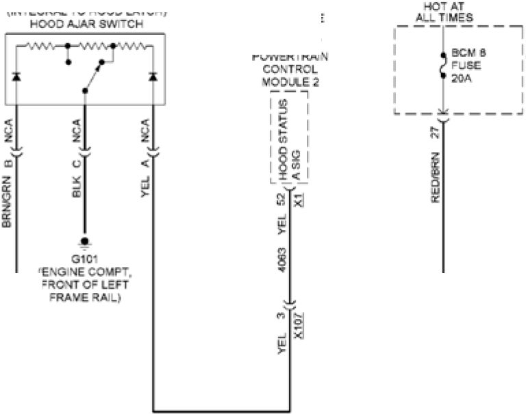
:eng necompt. |
INSTRUMENT |
|
PASS DOOR LOCK SV. PASS DOOR LOCK SV. UNLOCK C"RL | 
-*9 BRWHT |
|
DOOR SIL-TR V BODY CONTROL MODULE | |
LOCK CTRL 2
ACTUATOR CTRL
TRANS S*G
„N-CKSIG
GVLAN SER DATA (■)
GMLAN SER DATA(«)
|
RHHUUP LO CTRL |
|
DOOR LOCK RECE VER
(LUGGAGE CCVPT
BEHIND LEFT SIDE TRIM PANEL)
Fig. 14: Forced Entry Circuit, W/O Passive Keyless Entry (1 of 2)
GRY
(DOOR ASSEMBLY)
DRIVER WINDOW MO’OR

COMPUTER
DATA LINES
SYSTEM

RIGHT REAR
WK DOW SWITCH
COM=UTER
DATA L'MGS
SYSTEM
LOGIC
GRN/GRY 1,1 I-------I
( < - NETWORK BUS 4
g4y 2,1, i
SWSG
|
(BODY HARNESS, COMPUTER DATA L KGS SYSTEM |

IRISH TRIM “ASSENGER LEFT ASSEMBLY STATUS S O |
|
(BOD* HARNESS |
DRIVER WINDCWr
outside rear vew
M RROR SWITCH
’ASSENGER
WINDOW SW ’CH
(BE»OW REAR
fuse block)
Fig. 15: Forced Entry Circuit, W/O Passive Keyless Entry (2 of 2)
|
HOT AT ALL TIMES G202 (ABOVE GLOVE BOX) INSTRUMENT PANEL (INTEGRAL TO HOOD LATCH) | |
|
|^24 BRN/GRN HOOD AJAR SW SIG IMMOBILIZER CTRL IMMOBILIZER LOW REF LOCAL INTERCONNECT NETWORK 11 | 
GRN/GRY |
|
I DISPLAY LOGIC- INSTRUMENT CLUSTER 'ENGINE COMET, IMMOBILIZER ANTENNA COMPUTER ► DATA LINES COMPUTER ► □ATA LINES | |
BATT POSITIVE VOLT
SERIAL DATA
RED/BRN
GRY/BLK
GRN/VIO
BODY CONTROL MODULE
(PASSENGER CENTER CONSOLE)
SERIAL
555662
i---1 HYBRID/EV
POWERTRAIN
I HOOD I control
|STATUS|M0DijLE2
 |
|
IMMOBILIZER CONTROL MODULE |
Fig. 16: Pass-Key Circuit
BODY CONTROL MODULES
|
BAT’ERY POS TIVE BAT'ERY POS TIVE DIMM NO (PASSENGER CENTER CONSO.E! | |
 |
INTERIOR LIGHTS SYSTEM HE AD JG-TS SVSTEV INTERIOR LIGHTS SYSTEM EXTERIOR UGH-3 SYSTEM CR JiSE CON’ROL A EXTER CR LIGHTS S*STEMS ASTI-LOCK BRAKES SYS’EM ANTI "HEFT SYSTEM CRUISE CON’ROL SYS’EM W PERWAS -ER SYSTEM H=AD.IG-I5 SvSIfcV WPERAVAS-ER SYSTEM HEAD-K3-TS SYSTEM COMPUTER DATA LINES SYSTEM INTERIOR LIGHTS SYSTEM INTERIOR LIGHTS SYSTEM INTERIOR LIGHTS SYSTEM INTERIOR LIGHTS SYSTEM CRU SE CONTRO. & EXTERIOR LIGHTS SYSTEMS ANTL’HEFT SYSTEM NAVIGATION SYS’EM EXTERIOR UGh’S SYSTEM HORNS SVSTEV COMPUTER DATA DOOR LOCKS & docr locks a ANTI-’HEFT SYSTEM POWER DiSTR BuTION SYS’EM DOOR LOCKS a POWER D STR BUTION SYSTEM EXTERIOR LIGHTS a CRUISE CON’ROL 4 POWER DBTReUTiON SYSTEM HEADLIGHTS SYSTEM DOOR LOCKS a COMPUTER DATA |
|
\ i ER OR LAMP DEFEAT SW SIG CHARGE INC C’RL HEADLAMP SW ON SIG LED OWING SIG LOW REFERENCE IGN MODE SW START LED SIG HEADLAMP SW PARK LAMP SIG BRAKE APPLY SENS SIGNAL hl SEAM DM CTRL DRIVER CR LK SW LOCK SIG N’ERCONNECT NETWORK BUS 4 '2VREF ACCESSORY GNlTiON VOLTAGE IGN’ON 1 VOLTAGE ACCELERATE SW SIG .OWREF HOLP DIV VER SW и BEAM SIG LF TURN SG SW SIG W1NDSH ELD WIPER SW LOW SIG W NCSH ELD VflPER SW н SIG COMPUTER DA’A LINES SYS’EM TAP UP/ТАР DOWN SW SIG RF TURN SG SW SIG WINDSh E_D WASHER SW SIG 6643V BAT’ERY POS TIVE GROUND BAT’ERY POS TIVE VO.’ INTER OR LAMP .ED BACKLIGHT DIMMING P LAMP DIMMER SW SIG BRAKE APPLY TRAC1ON CONTROL SW SO DRIVER DR LK 8W UNLOCK 8Ю GN MCCE SW MODE LOW S»D GMLAN SERIAL HAZARD SW TCh SIGNAL MMCBIUZER L.P/DOWN SW SIG HOLP SW FLASH "O PASS SIG WPERAVAS-ER SYSTEM REMOTE F-NCTON ACTUA’CR CTRL [LEFT SIDE OF (ABOVE GLOVE • O2C2 REMOTE cwNCTON AMBIENT L GHT NG CTRL 1 HI SPO GMLAN SER DATA (•) 1 HI 8PD GMLAN SER DATA (♦) 1 REMOTE FUNCTION ACTUATOR SHIP" NTERLOCK SYSTEM HORN 9WSK3 NETWORK SER DA’A BUS 15 MMOBIL ZER .OWREF INTERCONNECT NETWORK BUS 11 | |
GROUND
BAT’ERY POS TIVE VO.’
INTERIOR LIGHTS SYSTEM
TRANSMISS ONS SYSTEM
W PE RAVAS-ER SYSTEM
TRANSMISS ONS SYSTEM
|
INTER OR LIGHTS SYSTEM EX'ER OR LIGHTS SYS’EM NTER OR LIGHTS SYSTEM hEADLGHTS SYSTEM NTER OR LAMP CTRL BACKLP LAMP C’RL NADVERTENT POWER CTRL SHIP’ NTERLOCK SYSTEM PARK .OCK SO-ENO D CTRL NTER OR LIGHTS SYS’EM REAR COVPT LID LAMP CTRL RF DRL C’RL N’ER OR LIGHTS SYS’EM LEO BACKUGH" DIMM NG CTRL S I POSITION SIG COURTESY LAMP SW S G NSTRuMEN’ PANEL PUSH BUTTON S’ART |

LO SPDGM_AN SERIAL DATA |
|
INTER OR LIGHTS SYSTEM BODYCONTRO.MCDU.E |
Fig. 17: Body Control Modules Circuit (1 of 2)
£843-8
 |
CHMSL CTRL |
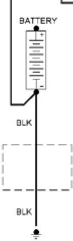 |
3A—ERY CURRENT SENSOR BAT-ERY cable: |
|
G404 | |
"I INSTRUMENT
PANEL
' JSE BLOCK
— BODY CCNTRO-
VOX.E =USE
HOLDER
[NEAR 12VO.T
POSITIVE BATTERY
|
.. 312 |
BLU |
I RT HDLP LOW BEAM CTRL | |
|
Z 712 |
YEL | ||
|
•315 |
GRNIVIO GRN/VIO MIO | ||
|
•2C4 |
WH’/YEL | ||
|
7542 |
GRY/YEL |
—(I LR STOP LAMP CTRL | |
EXTERIOR LGHTS SYSTEM ф
WIPERWASHER SYSTEM ♦
POWER DISTRIBUTION SYSTEM ♦
WIPERWASHER SYSTEM <-
STARTAGKXARGNGSYSTEM < X‘*
SEATS S*S’EM 4—--
4740
B.K/RRN
 |
BIURRN |
START NG/CMARQiNG SYSTEM <-
COMPUTER DATA LINES SYSTEM <■
COMPUTER DA’A L NES SYSTEM <■
DOOR LOCKS t AWLTHEFT SYSTEMS <-
SEATS SYSTEM <■
5C75
5868
4C64
•766
818
EXTERIOR LGHTS 4—--
SYSTEM g 3,4
________________________4*4 j
_____________________414)
HEADLGHTSSYSTEM <
S’ARTING/CHARG NG SYSTEM 4 9377
EXTERIOR LIGHTS SYSTEM 4
INTERIOR LGHTS SYSTEM <
INTERIOR LIGHTS SYSTEM <■
TRUNK. TAILGATE • FUEL DOORS 8Y8’EV <■
CRU ISE CONTROL SYSTEM
AIR CONDITION NO 8*8TEM
HEADL'GHTS system
HORNS SYSTEM <■
57C4
8311
•&89
INTERIOR LIGHTS SYSTEM 4
<R OHT-R M PANEL
Oc CARGO AREA)
G405
. 5811
DOOR LOCKS 4 <
ANTI-THEFT SYSTEMS Л
ЙС.1
DOOR LOCKS 4
ANTI-THEFT SYSTEMS
TRUNK TAILGATE FUEL DOORS 8*STEM
DOOR LOCKS 4
ANTI-THEFT SYSTEMS
245
_ 6133
COMPUTER DATA 4
JNES SYSTEM J 0134
DOOR LOCKS 4
TRmNK. TAILGATE. FUEL DOORS SYSTEM
COMPUTER DATA LINES SYSTEM
TRANSM SSIONS SYSTEM
COMPUTER DATA
LINES SYSTEM
5787
6132
5C54
2503
JSC-
Fig. 18: Body Control Modules Circuit (2 of 2)
COMPUTER DATA LINES
—---4 REAR LICENSE-AM» CTRL
U П Г <I WINDSHIE-D WASHER RE-AY CTRL
GRNA/IO—15^ | 4UVCRANK RE-AY COIL CTRL
4 I WIPER M-R RELAY COIL C’RL
C-Ry
at}.Z2i *< CURREN’SENS SG
-R-TO SEAT SW S G
BAT-ERY POS TivE VOLTAGE
^(ICURREN-SENSCTRL
( ACCESSORY WA4EUP SERIAL DATA
”7^—T"4 SER A-DATA COMM ENABLE
******** -T< -OOD STATUS В SIG
4 * ( RR HEATED SEAT SWSG
VE-/BRN
5. T
RED,GRY
RED/GRN
GRViGLU
Э.ШУ10
WM~/YEL
WHT
< I LR TURN SIG LAMP CTRL
<| LF TURN SO LAMP CTRL
4 BAT’ERY POSITIVE VOLTAGE
41 BATTERY POSITIVE VOLTAGE
<|LF DRLCTRL
■( I CURREN’ SENS .OW REF
■( I RR STOP LAMP CTRL
< I LR HEATED SEAT HIGH IND CTRL
BW4JWbT—1 RR HEATED SEAT HIGH IND CTRL
12 (! “О”*1’ ’-y CO11 CT°-
( CRUISE/ETC/TCC BRAKE SiG
V O/BRN
BRNN-IO
5ЯЧУЛ-Т
B--/GRY
< RUN IGNITION 3 VOLTAGF
4 -EADLAMP HGH BEAV RLY C’RL
■( | HORN RLY CTRL
<l DOME LP OFF IND CTRL
9RN/YEL
VO/GRY
BRNVlO
GRN/BLU
GRN/YEL
< DR LOCK ACTUATOR LOCK CTRL 2
< DR LOCK ACTUATOR CTRL
<!GROUND
< | DR LOCK ACTUATOR UNLOCK CTRL
<| LiFTGATE AJAR SW SIG 1
< | PASS DR LOCK SW LM.OCK CTRL
<l L N SER AL DA’A BUS 2
<l LNSER AL DA’A BUS 3
YELMO 13 PASS DR LOCK SW LOCK CTRL
14 C
YEL/BLU—15, REAR ClOSJRE hasd.E SW OPEN SIG
°RWBRW 18( UN SERUM. DATA BUST
23
GRY 22 ,1
(| SPOR’ MODE SW SIG
,aLU 2i ( - SPEED GMLAN SERIAL DATA (•) 1
- SPEED GMLAN SERIAL DATA (-) 1
BCC* CONTROL VODULE
(PASSENGER CENTER CONSOLE)
|
(LEFT REAR LUGGAGE COMPT) NSTRUMENT PANEL FLSE BLOCK (LEFTSIDE OF INS’RUMENT |
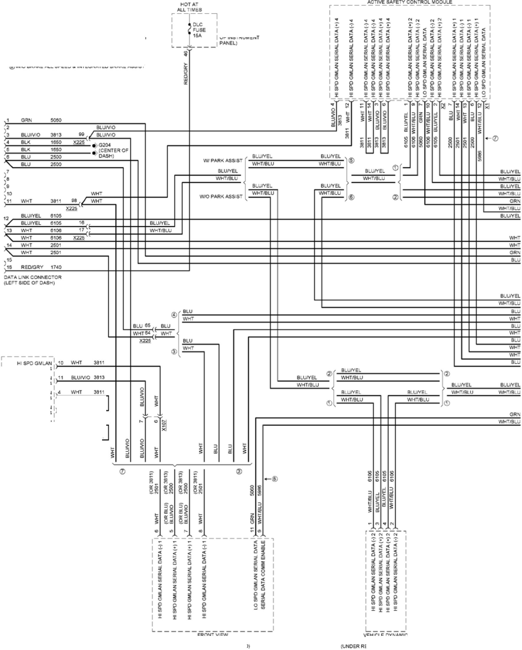 |
|
*64467 SER A. DATA(-) 4 LONG RANGE RACAR Hi SRC GV .AN SERIAL DATA(.)4 hl S»D GV_AN SER Al DATA(•) 4 Hi SRC GV „AN Hl S₽C GV .AN SER A. DATA (•) 4 |- FRONT VIEW VEH OLE DYNAMIC SENSOR EAR OF CENTER CONSOLE) |
Ф W.i BRAKE PREF lL N’EGRA’ED BRAKE ASS S’
ф W.C BRAKE PREFILL NTEGRA’ED BRAKE ASS ST
Ф VW BRAKE LOW SPEED S INTEGRATED BRAKE ASSIST
©WVO BRAKE LOW SPEED S NTCGRATCD BRAKE ASSIST
®W,' PARK ASS ST
© W.C PARK ASSIST
®W.' BRAKE A_. SPEED & INTEGRATED BRAKE ASS ST
®W.C BRAKE ALL SPEED S INTEGRATED BRAKE ASS ST

|
H SRC GMJLN SER A. DATA (-) 4 |
| ||||||||||||
Fig. 19: Computer Data Lines Circuit (1 of 5)
|
(RIGHTS DE TRIV PANEL UNDER SUBWOOFER! ALOO AMPIIH NR (LEFT REAR CORKER | |

WH’/GRN ? г г г г 1 d s s a s JNSR.MENT PANE. HARNESS NEARG2C4) ®W'AMPLIFIER ® WO AMPLIFIER ®VWBRAKE PREFILLS ® WO BRAKE PREF IL. I BRAKE ALL SPEED © WO BRAKE ALL SPEEDS INTEGRATED BRAKE ASSS’ |
(BODY HARNESS. |
|
SENSOR MODULE KEYLESS ENTRY CONTROL VOOU.E PEDESTRIAN ALERT POWER S’EER NG CONTROL VOD..E LO SPD G MLAN SERIA. DATA £ LO SPO GMLAN SERIA. DATA > LEFT S OE OBJECT SENSOR MODULE | |
|
■t. |
L"S |
|
Q |
7 |
|
•• | |
|
£ | |
|
i |
5 |
|
- |
£64468
Fig. 20: Computer Data Lines Circuit (2 of 5)
|
(ABOVE RADO/ ;n=ar eng nE CRANKS"AF” PULLE (CENTER OF DASH) |
 |
|
A/C COMPRESSOR ENG NE CONTROL MODULE BOWER NVER’ER VODJ.E ПОР OF TRANSM SS ON) Ifl S°D OM_AN SERIAL DATA <■) 1 H SPD GMLAN SER AL DATA (♦) 1 ACCESSORY WAKElP SERIAL DATA 2 H SPD GMLAN SER AL DATA (♦) 1 ESSORY WAKEUP SER AL OA’A 2 |
(LEFT SOE OF DASH)
TELEMATICS
COMMON CAT ON INTERFACE
CONTRO- MODULE
(CENTER FLOOR CONSOLE)
'FLATAS-E RESTRAINT
SENSING A
□ AGNOSTIC MODU-E
(INSTRUMENT PANEL
“ARNESS NEAR «ООО
RELEASE “ANCLE NEAR
-EAD_AM° SWITCH
WHT/GRN 6REAK0U')
|
:■/] |
-1 |
Я5 | ||
|
7 |
О |
о |
7 |
О |
|
£ |
? |
i |
1 |
г |
|
I |
s |
E |
i |
£ |
|
1 |
I | |||
; NSTRUMENT PANEL
HARNESS NEAR B-OWER
MO'CR CONNECTOR)
ACCESSORY WAKEUP SER A. DATA 2
Hi SPC GMLAN SERIAL DATA (•) 2
Ml 8PD GMLAN SERIAL DATA(-)2
Hl SPC GMLAN SERIAL DATA(-)2
Hi 8PD GMLAN SERIAL DATA(■)2
Hi SPD GMLAN SERIAL DATA(«)2
Hl 8PD G MLAN SERIAL DATA (*) 2
H: SPD GMLAN SERIAL DATA (-) 1
Hi SPD GMLAN SERIAL DATA(«) 1
Hi SPD GMLAN SERIAL DATA (•) 1
Hi 8PD GMLAN SERIAL DATA(-) 1
Fig. 21: Computer Data Lines Circuit (3 of 5)
[LUGGAGE COMP) RIG»-
ЗОЕ TRIM PANE-)
'JEL pump DR VCR
CONTROL MODULE
|
(BEHIND RGhT SIDE (R OHT SIDE OF DASb) |
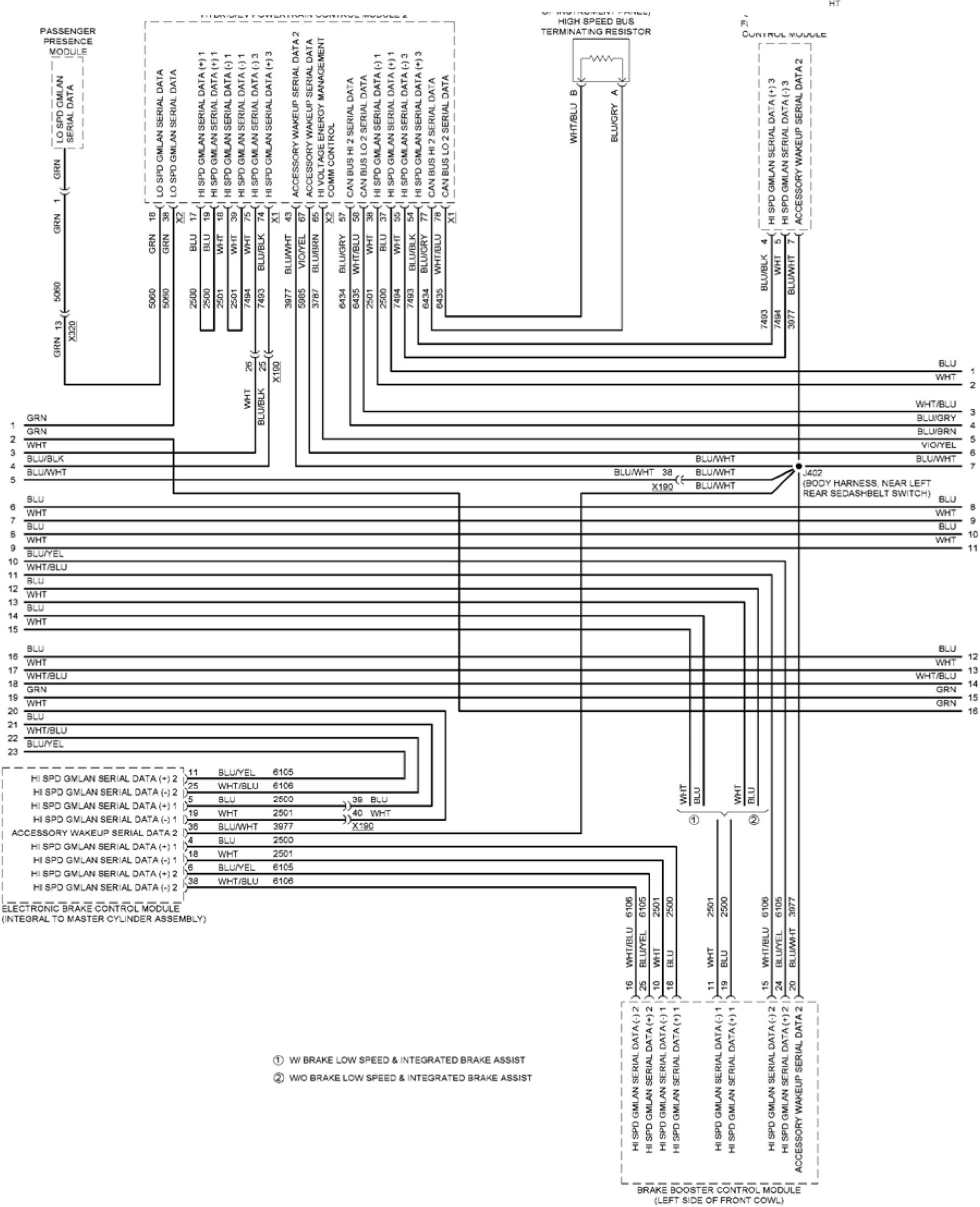 |
|
6644 70 |
Fig. 22: Computer Data Lines Circuit (4 of 5)
|
(DOOR DRIVER WINDOW/ (LEFT FRONT |
 |
|
FRONT SEAT HEAT N3 WNDSHIELC MPER MOTOR AV a ENT UGHT/SUNLOAO REAR SEA HEAT NG BODY CONTROL VODU.E |
(BODY HARNESS. NEAR
TRANSMISS ON 3-IFT
(REAR Oc r-vBR D/EV
BA—ERY PACK COMPT)
(W HEATED SEAT )
ЗА ,ER* ENERu* CONTROL MODULE
HVRRIOFV BATTFRY CONTACTOR ASSFMBlV
HYBR D®V BATTERY PACK
UNDER CENTER OF VEH CLE;
R'GHT REAR
V/ NDOW SWITCH
Fig. 23: Computer Data Lines Circuit (5 of 5)
COOLING FAN
|
TtNCERHOCO F_SESLOCK [NEAR POAER INVERTER VODJ.E ASSEVB | |
|
ENGINE COOLANT RAOATOR 'EVPERATJRE SENSOR |  |
|
[COOL SO FAN jLMrtR HARNESS. NEAR X1C3) COMPUTER data ;BACK OF ENG KE -YBRIO'EV POLVER'RA N CONTROL MODULE 2 ENGINE COOLANT TEV»ERATl.RE SENSOR | |
(R<K FRONT
HEADLAMP
ASSEV9LV;
RIGHT COOL NG FAN MOTOR
REAR OF RGH- SIDE O= RAOATOR)
 |
|
-EF~ COG JNG FAN VO TOR |
Fig. 24: Cooling Fan Circuit
 |
FUSE BLOCK |
|
PR AMc RAIL) G105 3101 ENGINE COMP’, | ||
|
HYBR D<SV ELECTRONICS COOLANT PUM° | 
COMFU'ER DATALNES BATTERY ENERGY |
HYBR Э/EV ELECTRONICS SENSOR |
|
MYBRID'EV EAT ERY HYERlC/EV BA'TERY SACK | ||
HYBRID/EV BATTERY
PACK COO-AN* PUV=
(CENTER OF LOWER
RADIATOR SUPPORT)
-YBR ZJIEVPCWERTRA N
CONTROL VOD-_E 2
(RIGHT SiCE OF DASH;
Е62С'2
Fig. 25: Hybrid Cooling Fan Circuit
CRUISE CONTROL
 |
|
Fig. 26: Cruise Control Circuit |
DEFOGGERS
|
DRIVER OUTSIDE UNDERHOOD | |

REAR |
AUXILIARY J301 (BODY HARNESS, |
|
5587Э1 (RIGHT TRIM PANEL PASSENGER OUTSIDE REAR VIEW MIRROR ф G302 (RIGHT FRONT | |
|
DEFOGGER |
---1 BATTERY
FUSE
BLOCK
(12 VOLT
POSITIVE
BATTERY
POST)
(ENGINE COMPT, FRONT
OF LEFT FRAME RAH
I DRIVER OU"
REARVIEW
1 MIRROR GL
(LEFT
SILL TRIM)
REAR DEFOG IS19 BRN/VIO
RLYCTRL
NETWORKS
X2
HVAC CONTROL MODULE
(CENTER OF DASH)
| ||||||
|
HVAC CONTROLS |
--
PASSENGER
OUTSIDE REAR VIEW
MIRROR GLASS
Fig. 27: Defoggers Circuit
ELECTRONIC POWER STEERING
HOT AT
ALL TIMES
--1-----1 UNDERHOOD
A FUSE
80A
I AUXILIARY
I FUSE BLOCK
(UNDERHOOD
I FUSE BLOCK)
 |
COMPUTER > DATA LINES |
|
INSTRUMENT CLUSTER | |
ci
Q
LU
к
GROUND
BATT POSITIVE VOLT
HI SPD GMLAN SERIAL DATA (+) 2
HI SPD GMLAN SERIAL DATA (-) 2
HI SPD GMLAN SERIAL DATA (+) 1
HI SPD GMLAN SERIAL DATA (-) 1
SERIAL DATA COMM ENABLE
HI SPD GMLAN SERIAL DATA (+) 2
HI SPD GMLAN SERIAL DATA (-) 2
HI SPD GMLAN SERIAL DATA (+) 1
HI SPD GMLAN SERIAL DATA (-) 1
 |
G109 (LEFT FRONT STRUT TOWER) |
|
COMPUTER | ||||||||||||||||||||||||||||||||
|
X2 | |||||||||||||||||||||||||||||||||
POWER STEERING
CONTROL MODULE
(INTEGRAL TO STEERING
GEAR ASSEMBLY)
558961
Fig. 28: Electronic Power Steering Circuit
ENGINE PERFORMANCE
1.5L VIN 5
нот w/
 |
|
(BELOW LEFT HEAOLAMP) ASSEVBL* |
VEST
SO.ESCHD VALVE
(NEAR EVAPORATIVE
EMISSION CAS STERt
Fig. 29: 1.5L VIN 5, Engine Controls Circuit (1 of 7)
 |
|
Fig. 30: 1.5L VIN 5, Engine Controls Circuit (2 of 7) |
 |
|
Fig. 31: 1.5L VIN 5, Engine Controls Circuit (3 of 7) |
 |
|
Fig. 32: 1.5L VIN 5, Engine Controls Circuit (4 of 7) |
|
(TOP OF CYLINDER h€AD) (TOP OF CYLINDER HEAD» (’OP OF CYLINDER HEAD) (TOP OF CYLINDER HEAD) IGNITION COIL 4 IGNITION COU 2 IGNITION COIL 1 IGNITION COIL 3 |
 |
Fig. 33: 1.5L VIN 5, Engine Controls Circuit (5 of 7)
[REAR Oe ENGINE. BElOW
HIGH PRESSURE FlEL PUMP)
ENG NE OIL
|
PRESSURE SENSOR (ABOVE LEFT [RGHT OF FUEL TANK (LEFT FRONT OF CYLINDER MEAD) |
 |
|
EX-AJST CAVSHAF IN AKE CAVS-AA V AMFOLD ABSOLUTE • LEFT SIDE O- PRESSURE CON’ROL POWER NVER’ER (TOP OF TRANSMISSION) |
Fig. 34: 1.5L VIN 5, Engine Controls Circuit (6 of 7)
|
EXHAUSTSOL INTAKE SOL 1 BRN^ED -2-SVREf BLUW-T -3 ~ -5 ( O*™»SENS8VREF №№Яе3 ‘^Rff SR^ED В g Г (I COW RE» BE.VCB-. 23 , | |
 |
Hi SlGBAKK 1 SENS 1 Hi SG BANK 1 SENS 2 LOW CTRL BANK 1 SENS 2 LOW CTRL BANK 1 SENS 1 (I LOW SK3 BANK 1 SENS - Hi VOLT CTRL CYLINDER 2 Hl VOLT CTRL CYLINDER 4 Hl VOLT CTRL CYLINDER 3 Hl VOLT CTRL CYLINDER 1 [ | LOW REF (I OU PRESS SENS SiG [ | 01. PRESS SENS LOW REF (I LOW RE₽ EN3 NE CCNTRO. MODULE REPJCA’EDSG SG GROUND LOW REF BANK 1 * (I ENGINE COOLANT TEMP SENS 3 G |
|
S=ARKPUJG2 5PARK PLUG 3) (INTAKE VAN SOLD INLET) RANSM SSCN | |
?( SCMCTRl,
^^LL-Li^sctrl,
BLUW-T 20 , FUEL L(NE ря Ess SkS
BDWIO 30 “l
--—( CAM PHASER X LOW REF
f1 cam Phaser w low ref
eXHALST^MS.
CRANKSHAFT ecx SENS S О
01. ₽ jm₽ couxsc sra
■“"в"-('китовом»
VEua" ”( очтоксгя..
' SPL* CYLINDER-
ACTUATOR CTRL CLOSE
Fig. 35: 1.5L VIN 5, Engine Controls Circuit (7 of 7)
|
-ОТ W/ IGNITION HOT A” VAIN RELAY ENERG ZED ALL’VES |
 |
|
AUTOMATIC TRAN SV SSION ASSEMBLY |
f«2e32
Fig. 36: 1.5L VIN 5, Hybrid System Circuit (1 of 11)
 |
|
AUTOMATIC TRANSVISSON ASSEMBLY |

SIS ( SENS S₽LV SPLY SPLY (I ri атзкз |
|
CONTROL MOOU-E “POWER NVERTCR MODU-E TRANSMS8I0N) E-ECTRIO7 AUXILARY TRAN SV SSIC |
3461
3462
f 31 SIG
^83 SIG
i' SIG PCS
,L SIG NEG
[ I CLUTCH A
(I CLUTCH 8
[IDRV2SIO
(I CLUTCH C
(I CLUTCH DCTRL
C1 CLUTCH E CTRL
'1 LOW RE₽
[|30CVUPHASE
[| 30CVW Bi“A$E
(I30CVUPHASE
(I30CVVPHASE
(laocvw phase
(k—Imovwi
Fig. 37: 1.5L VIN 5, Hybrid System Circuit (2 of 11)
|
(R G-T FRONT COVOJ’ER DA’A |

* R CONOT ONIKG SYSTEM 7 OF 1) |
|
MYBR DCV PCWCR’RAIN COMPUTER DATA COMPUTER DATA Q W/PARK ASSIST N*BRIC«V POWERTRAIN TRUNK. TA LGATE. FUEL DOORS S*STEM (RIG-T SIDE |
-«YBRC«V
SAIItRY C-ARGfeR
RECEPTACLE
ACCENT
LAMP
(IF EQUIPPED)
GROUND | J
BA’T POS VOLT |)
RELAY CTRL I)
MT LAMP POWER I)
RELAY CTRL I)
TRUNK TALGA’E.
FUEL DOORS SYSTEM
|
TRUNK. TALGA'E. |
|
|
W-T |
2501 J | |
|
!i* |
BLJ |
25CC ’ |
 |
|
“YSRC/EV BATTER* |

|
8LU |
25CC | ||
|
;зв |
WMT |
25C1 | |
|
'39 |
WMT |
25C1 |
h I |
|
BLK/SLU |
«1 |
*- |

(RIGHT S OK OF DASH)
£«25 34
Fig. 38: 1.5L VIN 5, Hybrid System Circuit (3 of 11)
|
COOL NG FANS IK. TALGATE. DOORS SYSTEM | |

YEUVIO 3 5 COMPUTER DATA LINES SYSTEM MOTW/ GN T ON MAN RELAY ENERGIZED (NEAR POWER |
HYBROEV POWERTRAIN |
|
GMLAN SERIAL DATA CHARG NG EMAB-E FAM CTRL SG 3RW.T-T 2 FEEDBACK S О CHARG NG CTRL MOTOR hGH CTRL LOCKAJNLOCK '■ SiG TRUNK. TA LGATE. =UEL DOORS SYS’EM HTSRIC/EV POWERTRAIN CONTROL MODULE 2 LOCK/UNlOCK 1 REF | |
| INSTRUMENT
.PANEL
FUSE
BLOCK
I (LEFT SICE O'
INSTRUMENT
COVPU ER
DA’AL NES
SYSTEM
TOHYBR OEM
JA’TERV PACK
[LEFT F4O\T
DOCR
SLLTRIM)
charge port door
POSITION SWI’CM
(REAR OF LEFT
FRONT FENDER)
(I INDICATOR CTRL
(I MOTOR CTR^
(I INDICATOR CTRL
( COMM CTRL
(1 WAKEUP SERIAL DATA
TRUNK. TA LGATE.
CUEL DOORS SYSTEM
COOLING FANS SYSTEM
COMPUTER DATA
LINES SYS’EM
( MOTOR CTRL
(| MOTOR CTRu
(I MOTOR LOW REF
AMS ENT JGmT/
SUNLOAO SENSOR &
BAT’ERY S’ATE
OF CHARGE
INDICATOR
(’OP CE VER
Fig. 39: 1.5L VIN 5, Hybrid System Circuit (4 of 11)
 |
REAR BOO* |
 |
“YBRIO/EV BA’TERY |
|
BA’TERY BAT'ERV CHARGER BA’TERY CHARGER (UNDER STORAGE | 
(D'AGRAV 7 OF |
|
“YBR urEV BATTERY (0 AGRAM9 0F11) [RIGHT S DE CARGO | |


RIGHT RIM PANE-
OF CARGO area;
BATT PCS VOLT
SENSE SIG
CHARGING ENABLE


AC GROUND
NEUTRAL LINE 2
BATTERY
CONTACTOR
ASSEMBLY
FROM
HYBRID/EV
BATTERY
CONTACTOR
ASSEMB.Y
HY8R1D1EV BATTERY
(0 AGRAV9CF'")
BATER* PACK
(UNDER CEN’ER
O* VEHICLE)
Fig. 40: 1.5L VIN 5, Hybrid System Circuit (5 of 11)
|
(UNDER CENTER OF VE-IC-E) |

MYBR DiEV FYBR DEV BATTERY CONI AC I UK |
|
(DAGKAw 11 OF 11» FYBR DEV BA-TERV SECTION 1 |
HYBR DEV
BATTERY
•EMFERATJRE
LOW REF 4 |)
LOW REF 5 |)
LOW REFS|)
LOW REF 7 |)
-OW REF
CURRENT SENS FINE SK3
BATTERY ENERGY
CONTROL MODULE
© EARLY
HYBRID/EV BAT-ERY
SECTION 2
£S2fi37
Fig. 41: 1.5L VIN 5, Hybrid System Circuit (6 of 11)
|
FROM HYBRID FROM HYBRID |

COMPRESSOR FROM HYBR D/EV CONTROL charger |
|
;4GM FROM ■IYBRIC/EV BA ERV PACK |
FROM
HYBR О POWERTRAIN
CONTROL MOD J-E 2
(D AORAM 3 OF 11;
'ROM HYBRID
POWERTRAM
CONTROL MODULE 2
(DIAGRAMS OF 11)
(3C"TOM 0= HYBRID/
EV BATTERY PACK
CONTACTOR)
(BO~OM OF H*BRC/
EV BATTERv PACK
CON” ACTOR)
CURRENT 3ENSOH
DAGRAV80F 111
Fig. 42: 1.5L VIN 5, Hybrid System Circuit (7 of 11)
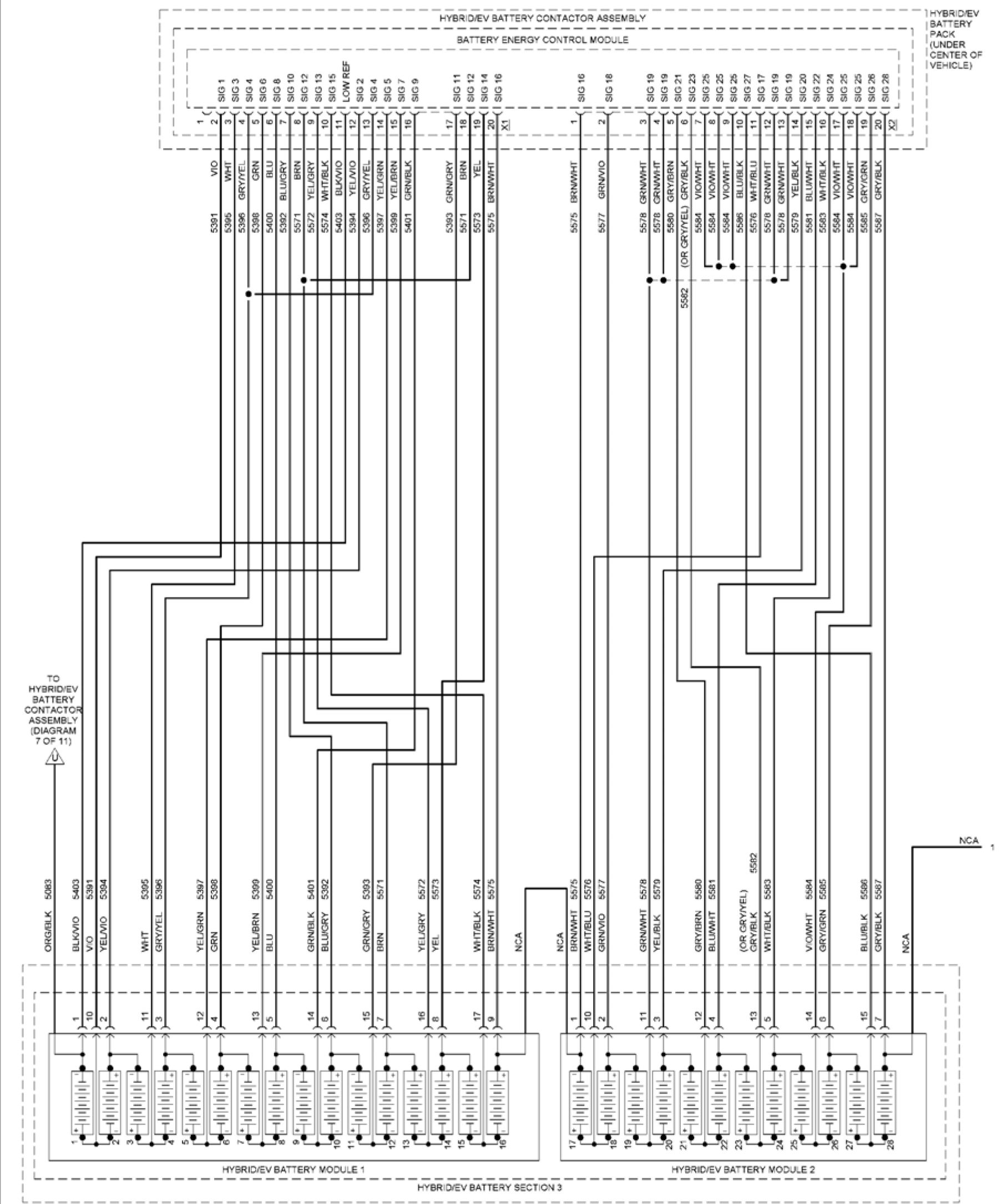 |
|
евгем М*ВНС/ЬУ a*r IbKY PACK Fig. 43: 1.5L VIN 5, Hybrid System Circuit (8 of 11) |
 |
|
682840 HY94C/EV 3*”=RV SACK Fig. 44: 1.5L VIN 5, Hybrid System Circuit (9 of 11) |
 |
|
Fig. 45: 1.5L VIN 5, Hybrid System Circuit (10 of 11) |
 |
|
Fig. 46: 1.5L VIN 5, Hybrid System Circuit (11 of 11) |
EXTERIOR LIGHTS
НО’А’
AL. "IVES
I INSTRUMENT
5 BCM 8 =ANEL
' FUSE CUSE BLOCK
’ *5A .(LEFT SIDE OF
" ---‘INSTRUMENT
20 PANEL)
RFO/GRN

RED/GRN
 |
|
MODULE CENTER CONSOLE) |
 |
|
INSIDE |
|
COMPUTER SATA JNES |
 |
|
POWER INVER’ER MODULE |

| M £ ! i
TRANSM SSION VERNAL MODE SWITCH
AU’CMA-IC TRANSMISSION ASSEMSL*
 |
|
! BE LOW REAR |
(ROT TRIM 3ANEL
OF CARGO AREA)
Fig. 47: Backup Lamps Circuit
 |
|
Fig. 48: Exterior Lamps Circuit (1 of 2) |
 |
|
Fig. 49: Exterior Lamps Circuit (2 of 2) |
GROUND DISTRIBUTION
RIGHT REAR
EXTEROR
DOOR HANDLE
ASSEVB-Y

' = EQUIPPED WINDSHIELD HIGH 8:Av lcRO*i CASC A HARNeSS |
|
(ENGINE COVP’ |
|
1 1 1 1 1 I- ffi Л x |
|'€ X® t; § 11______51______2, | |
|
3 | ||
|
a | ||
(LlrTGA e HA4N=SS
NEAR REAR
DEFOGGER GR 0)
(W N’LLLIGEN"
RRAKF ASSIST)
VEHICLE D*NAM C
TELEMATICS
COMMUNICATION
(4 GM T4 MPANEL
0е CARGO AREA)
(КОС TRIM PANEL
OF CARGO AREA)
PEDES’RiAN
ALERT SO«ND
ELECTRONIC
(FRONT 0₽ LEFT
STRUT TOWER)
(NEAR POY7ER INVERTER
VODL-E ASSEM9LV)
jndcrhood fuse block
Fig. 50: Ground Distribution Circuit (1 of 5)
|
=ASSE\GER PASSENGER OUTS OE | |
|
г | 
CONTACTOR (IF EQL, »»ED H*3RIOtV (IF EQ- °°xC) |
|R GMT FRONT
DOOR HARNESS.
NEAR X81C)
ф W/ INDUCTIVE BORTAB.E
W RELESS DEVICE CHARGER
® WiO NOUCT VE PORTAB-E
W RrlFSS OFV1CF CHARGER
(R GHT FRONT
DOOR Si-LTRIM)
(BOTTOM OF
HYBRICiEV
BA”ERV PACK
CONTACTOR)
ILER’S DE OF NSTRUVENT PANEL)
NSTRuVENT PANEL FJSE BLOCK
RE’A NED
ACCESSORY
(HIGH FRONT DOOR
HARNESS. NEAR XSIOi
(BOTOM O6
H*BR D/EV
BATTERY PACK
CONTACTOR)
AMB€N* LIGHT/
SJN.OAD SENSOR &
BATTERY STA"E OF
CHARGE INC CA’OR
(HeAOLINER HARNESS
NEAR SUNSHADE
VIRROR .AMP)
Fig. 51: Ground Distribution Circuit (2 of 5)
|
DRIVER DR VER W NDOW/OL’S DE |

(W/ OBSTACLE (LE“ "RON JOQR |
|
(LUQQAOE COWPT. (FRONT OF R OhT |
(LEFT FRONT
DOCR HARNESS
NEAR X510)
(LEFT DOOR TRM
-ARNESS NEAR X506)
OR VER О J'SIDE
REAR V EW V RRCR
(W/ FORWARD
COLLISION ALERT)
FRONT VIEW
(LEKI FRONT
900RM1 "Riv;
(IF EQ- «Я)
HV3RIDEV
BATTERY
ChAROER
RECEPTACLE
ACCENT LAMP
664143
Fig. 52: Ground Distribution Circuit (3 of 5)
|
PASSENGER (W SALES |
 |
|
Л |
D |
Й1 |
e |
e? |
hi |
* |
4 |
w |
"Г |
й |
гч | ||||||||||
|
is |
ac |
Si |
!C |
a |
si |
a |
id |
iC |
я |
ас |
!£ | ||||||||||
|
I |
я |
а | |||||||||||||||||||
|
a |
а |
S-IFT LEVER
POSITION
INDICATOR
| |||||||||||||||
|
CONSOLE CONNECTORS) | |||||||||||||||

RIG-Г HEADLAM3 ASSEVBLV |
|
TRANSVISSON ENGINE СО*»'! FRONT OF R GMT |
CEN'ER O₽ 3ASD
664144
Fig. 53: Ground Distribution Circuit (4 of 5)
|
RGHT TRAKS4 SSICK ShiP' =VER | |

(8E> ND LE’T BUMPER COVER) BATTER’ PACK COOlAN" PUMP |
Ф Wl SIDE ACTIVE SA=ETv OBSTAC-E DETECTION WO PARK ASS ST |
|
(EN3 MS COWPT 010® (R GHT FRONT | |
(REAR FASC A
HARNESS. NEAR
BACKUP -AVP)
( = EQUIPPED
(BELOW REAR
FUSE BLOCK)
<W/ INTELL GENT
BRAKE ASS ST)
EXTERIOR
DOOR HAND-E
ASSEMBLY
ф WO SIDE AC’ VE SAFETY OBSTACLE DETECTION &
W/ PARK ASS ST
eNQIN= -ARKE33.
BETWEEN J126SJ131)
Fig. 54: Ground Distribution Circuit (5 of 5)
HEADLIGHTS
|
' INSTR J MEN* PANE. | ||
|
ONO BATT POSC VE VOLT I) LH HEADLAMP .OBEAM CTRL BATT POSITIVE VOLT |. HEADLAMP Ml BEAM RLY CTRL HEADLAMP DMMSWI HEADLAMP SW PARK L₽ SIG |) BAT POSr VE VC.T > | 
A QL5 '5 CUMrLTTeRDA A ’URN SIGNAL) |
AMBIENT LIGHT7SUN.OAD |
|
POSITION NDCA’OR) 658673 FRON OF .EF PARK/DAYT ME ’ARK/DAY ME RUNN NG LAMa ELECTRONC BRAKE GUKTTOL SWITCH | ||
HEADLAMP AUTOMATIC \
HI BEAM DIM CTRL If
|
RM HEADLAMP .OBEAM CTRL |
|
RM DRL CTRL П
DATA
WO PARK
Fig. 55: Headlights Circuit (1 of 2)
 |
|
Fig. 56: Headlights Circuit (2 of 2) |
HORN
|
FUSE I FUSE HOT AT | |

SWITCH |
’UNDERHOOD FUSE BLOCK I (NEAR POWER |
|
(ENGINE COMPT, | |
RLY CTRL|)--
I AO
HORN
SW SIG
BODY
CONTROL
MODULE
(PASSENGER
CENTER
CONSOLE)
UNDERHOOD
AUXILIARY
FUSE BLOCK
(UNDERHOOD
FUSE BLOCK)
HORN
(BEHIND
RIGHT
HEADLAMP)
Fig. 57: Horn Circuit
INSTRUMENT CLUSTER
 |
'17 GRY/VIO ;ia WHT/GRN MOS* SERIAL I . 5 MOS’ SERIAL II — |
COMPUTFR DATA
L NES SYSTEM
 |
REAR BODY |
|
FRONT | 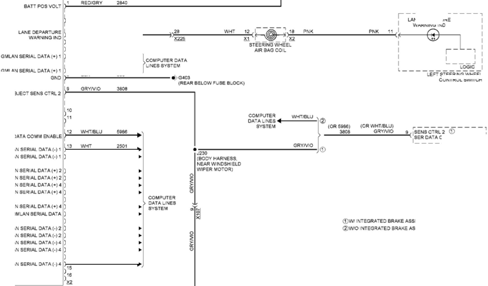
STEER KG WHEEL |
|
GMLAN ENABLE ф GV-AS GV-AS FRONT VIEW | |
|
• г |
3182 | |
|
WH’ | ||
|
blu |
2500 | |
|
r" kz_ |
blu |
P 2500 - |
|
£■ |
Э.К | |
KE DEPARTURE
WARNPsG NC
GM-AS
lowspdg»
|
>77“ |
WH’ |
2501 |
-* |
|
’xT |
BLU/YEL |
6105 |
P |
|
8'05 |
p | ||
|
BLU/V1O |
3813 | ||
|
B-LMO |
3813 |
► | |
|
?= |
BLUARO |
3813 | |
|
JT" |
GRN |
5060 | |
|
L |
WH’iBLJ |
6106 | |
|
WH’®LJ |
6106 | ||
|
WH’ |
3811 | ||
|
WH’ |
3811 |
p | |
|
4- |
WH’ |
3811 |
ACTIVE SAFETY
CONTRO- MODULE
(LEFT REAR LUGGAGE COMP’)
GMLAN SERIAL 0ATA(-)4
GM-AN SERIAL OATA(*) 4
|
GMLAN SERIAL OATA(-)< GKO GMLAN SERIAL DATA (-)* |
|
COMPUTER G102 (ENG NE COMPT FRONT OF RK3-T FRAME RAH) |
.COMPUTER
□ATAL KES
’SYS’EM
-ONG RANGE RADAR
SENSOR MODULE
(LEFT SIDE OF GRilA)
Fig. 58: Collision Avoidance Circuit
HOT W7 IGNITION MAK
RE -AY ENERGIZED
UNDERHOCC
FUSE BLOCK
(NEAR POWER
INVERTER MODULE
 |
|
FORWARD COL. S ON |

|
FORWARD COL. 3 CM |

WIPER/WASHER WH"/3RN 3W7 CCNTltDLR iWA/O 3WS |
|
CHECK ENGINE ND CTRL MOST CTRL •6 ЛУ-' 15 Blu*B-K ERN 14Ю <2 GRN/GRV 333 32 ERHV,4~ 7684 ELEC I NONIC SNAKE CONI4OL MODULE FORWARD COLLIS CN ALERT LED CTRL 6 YEUREC 7683________________ ЭМЖ SER I A. DATA |
|
R JNXRANK ION 1 VOLT |
|
GRN7BLK 3894
BLK
1850
|
INSTRJMEN’ PANEL ELSE |

INSTRJMEN |
|
COMPUTER |
VAR AB.E
=LNC’OKS
» COMPUTER
___________2501 Г ЭАТА LINES
9 BluAAO 11M SYSTEM
бвзвм
Fig. 59: Instrument Cluster Circuit (1 of 3)
RED/GRN 502
GW
(LEFT FRCNT
DOOR SIL. TRIM)
BLK
GRVGR*

BRAKE FLUID
.EVE. SWITCH
(BOTTOM OF BRAKE
FLUID RESERVOIR;
 |
|
PARK BRAKE CONTROL SWTTC" |

V1Q/ORY


COMPUTER DATA LINES |
|
(REARВЕ.ОЛ (LEFT FROKT |
Fig. 60: Instrument Cluster Circuit (2 of 3)
|
vo<gry | |

|(BACK OF ENG NE ■ CONTROL MODULE HARNESS |
ENGINE CONTRO_ MODULE |
|
,• YEUBRN YE-JBRN BLKA-0 'X150 FUEL PUMP* LEVEL SENSOR ASSEMBLY (FUEL TANK ASSEMBLY) (RIG-T TRIM (RIGHT FRONT W"~/RED BLK/VO | |
 |
43 w-t/reo |
EN3 NE O«_
PRESSURE SENSOR
tREAR OF ENGINE,
BE LOA HIGH
PRESSURE
FJE- PLM»)
 |
|
AMBIENT A R |
(Right trim panel
O= CARGO AREA)
[BODY HARNESS I
НЮ- SPEED BUS I
■ATRX2 RESISTOR)
[ SER Al DATA (♦) 1
[|9ERAlDATA(.)1
( PRESS SENS SiG
( PRESS SENS SV REF
( PRESS SENS LOW REF
COMPUTER DATA
LINES SYSTEM
r’BR O/EV POWER RAN
CONTROL MODULE 2
(RIGHT SIDE OF DASH)
RIGH REAR
W’NDOWSWTCH
Fig. 61: Instrument Cluster Circuit (3 of 3)
INTERIOR LIGHTS
|
CO VOL,"ER (DOOR ASSEMBLY) INSTRLMEK’ PANEL -LSE B.OCK | |

DRIVER ■ATT FCS гаст GV-ANSER DATA,-) COMPUTER CATALINES 4 ROHT REAR MSTR^MENI LLLVINATION C RCJIT |
INSTRUMENT |
|
656626 NSTRJMENT РАМЕ | |
DOMPLlbR DAI A
LIMES SYSTEM
(LEFT FRONT
DOOR S LL TRIM)
(R G-T FRONT
DOORSLL"RM|
RIGHT TR V
PANEL O₽ CARGO AREA)
(HEADLINER HARNESS.
NEAR SUNSHADE
MRROR LAMP:
J352
BOCY CONTROL MODULE
(PASSENGER CENTER
CONSOLE)
Fig. 62: Courtesy Lamps Circuit
(HEADLINER
HARNESS
NEAR SUNSHADE
MRROR LAM»)
|
t |
LEFT SUNSHADE MIRROR LAM= |
© |
-RON" DOVE,READING
OVERHEAD CONSOLE
ШЯ TLAUNCTlON SMV TO
REAR DOVE/
READ NO LAM»S
|
REAR BODY ELSE BLOC! ---’ INS’RUMEN! SWC I panel FUSE BLOCK | |
|
GMLAS SER DATA(-) B-~ BODY CONTROL VODL.E | 
(BOO* HARNESS NEAR G3O2I |
|
Б58027 RAD О PRESS'S RIGHT STEERING | |
{STEER SO
WHEEL
HARNESS
( SS’RUMENT °ANE.
COMPUTER CATA
LINES SYSTEM
(“EADL SER
HARNESS NEAR
OVERHEAD CONSOLE
1OVER-EAD
COSSO.E
•MULTI.
'FUNCTION
Fig. 63: Instrument Illumination Circuit (1 of 2)
|
RIG-T REAR LEFT REAR CENTER CONSOLE (LEFT REAR CORNER |

(BELOW REAR OR VER DOOR PASSENGER DOOR (RIGHT RIV |
|
г (BELOW REAR (BELOW REAR (LEFT FRONT DOOR |
DRIVER DOOR
ACCENT LAM=
PASSENGER DOOR
ACCENT LAMP
(W FARKASS ST)
(NSTRUVENT PANEL
HARNESS. NEAR
(PAS5CNGCR COM PT
BOTTOM OF -EFT В PIL-AR)
[LEFT DOOR RIM
HARNESS NEAR
OVTSiOE
REAR Vi EW
(Riot front door
Bill TRIM)
Fig. 64: Instrument Illumination Circuit (2 of 2)
NAVIGATION
LOW SPD GMLAN
SERIAL DATA
560785
|
GRN 2 650 BLK 3 GRY/YEL 5853 GRY 4 RED/GRY 2840 2840 RED/GRY 5 6 GRIN 7 BLK BLK 8 HOT AT ALL TIMES | ||
|
BATT POSVOLT LOW SPD GMLAN SERIAL DATA DRV SIDE OBJECT DETC LED SIG 1 LEFT SIDE OBJECT | 
DRIVER SIDE OBJECI DETECTION IND |
GND BATT POS VOLT PASS SIDE OBJECT DETC LED SIG 1 LOW SPD GMLAN SERIAL DATA RIGHT SIDE OBJECT VEHICLE FASCIA) |
|
(RIGHT FRONT DRIVER PASSENGER DRIVER OUTSIDE PASSENGER OUTSIDE (LEFT FRONT | ||
_„n COMPUTER
5050 > DATA LINES
SYSTEM
(BELOW REAR
FUSE BLOCK)
Fig. 65: Blind Spot Monitoring Circuit
| REAR BODY
OBS ----------
DET
FUSE BLOCK
—. '(FRONT OF
FUSE 42 VOLT
I BATTERY)
(BELOW REAR
FUSE
BLOCK)
G403 ,||fr__?_
J 908
..U 5851
’;X45Q
II»
3403
(below rear
-USE BLOCK)
PASSENGER
SIDE OBJECT
DETECTION IND
 |
|
Fig. 66: Lane Departure Warning Circuit |
|
NSTRJVENT г (OVER-EAC (LEFT ЗЮЕ OF 0AS-) |
 |
|
(СЕМЕЙ OF DAS-9 |
(R Gr“ TRIM
PANEL 0=
CARGO AREA)
(RvS’RUVEN’ PANEL
-ARNESS NEAR
TELEMAT OS
COMMUNCAT on
IN’ERCACE CONTROL
Fig. 67: Navigation Circuit, W/ Amplifier (1 of 4)
 |
|
Fig. 68: Navigation Circuit, W/ Amplifier (2 of 4) |
 |
|
Fig. 69: Navigation Circuit, W/ Amplifier (3 of 4) |
 |
|
Fig. 70: Navigation Circuit, W/ Amplifier (4 of 4) |
|
(LEFT SIDE 0₽ DASH) NS’RLMEN’ PANEL (CVER"EAC |
 |
|
RADIO (CEMER OF DASH) £«0788 MOST SERIA. DATA(-) NETWORK SUS *0 ) LOW REF ) |
|
Г yTc! |
|
? 5 |
IR Gr TRIM
PANEL OF
CARGO AREA)
(•.S’RUMENT PANEL
•ARNESS NEAR
-E.EMA- CS
COMMON CAT ON
IN’ERFACE CONTROL
MODULE)
(RIGH R m panel
O₽ CARGO AREA)
G406
COMPUTER DATA
LINCS SYSTEM

|
MOSTC’RL |
|
NAVIGA’ ON
SYSTEM
(REARVEVi
COMPUTER
DA’A LINES
Fig. 71: Navigation Circuit, W/O Amplifier (1 of 3)
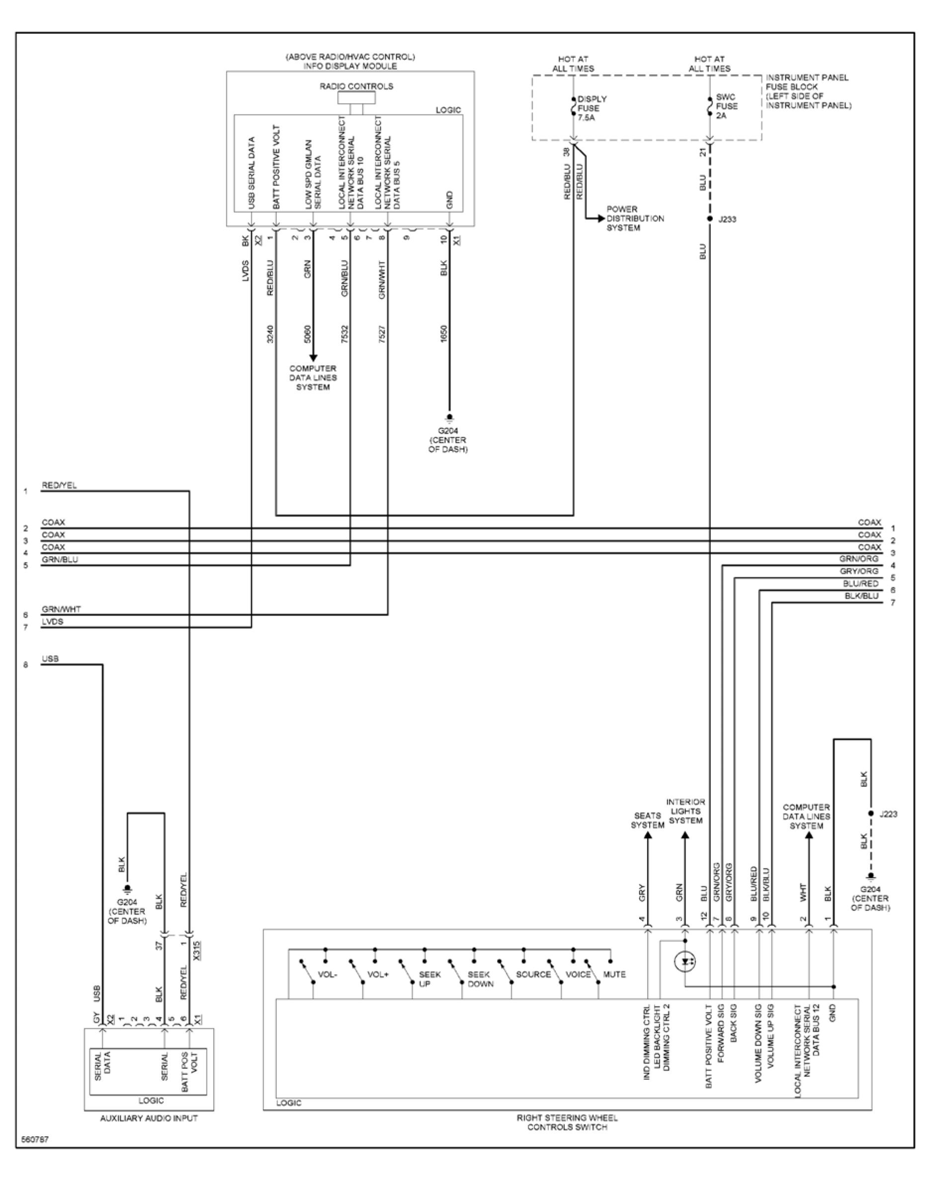 |
|
Fig. 72: Navigation Circuit, W/O Amplifier (2 of 3) |
 |
|
Fig. 73: Navigation Circuit, W/O Amplifier (3 of 3) |
|
LR CORNER OB.EC’ SENS S <3 “RON” =ARK NG SENS LOW REF HI SPO OMLAN SERIAL DATA (-) 2 PARKING ASS ST CONTROL MODULE LR MIDDLE OB.EC’ SENS SG LF SUPPLEMEN’AL OB.EC’ SENS SC RF SUPPLEMEN’AL О6ЛС’ SENS SG | 
■mORN . (INS’RUMFNT PANEL -ARNESS NEAR S W-’rGRy 8 VO/GR* |
|
FRONT FASCIA) REAR PARKING 'REAR FAS. A REAR PARKING REAR PARK KG | |
HtAK PARK ASSIST LED DISABLE SO
HI SPD GMLAN SERIAL DATA (♦) 2
HI SPD GMl AN SFRIAI DATA (♦) 2
GROUND
REAR °ARK ASSIST DSABLE SG
LOW SPO GMLAN SERIAL DATA
PARALLEL ASS S’ DSABlESWSG
RR MIDOLE OB.EC’ SENS SG
PARK ASS ST SENS CTRL PARK
30 VOW-T
>7 vE-/GRy
3b BLK/BLU
11 WWTASRY Sgl
12 VO/GRY 52'
FRONT PARKING
ASSIST SENSOR
(LEFTS DE 0= FRONT
BUMPER FASC A)
FRONT PARKING
ASSIS’ SENSOR
(LEFT END OF FRONT
BUMPER FASCA)

LEFT FRONT SICt
PARKING ASS ST
660782
;frok” FASCIA
-ARKESS NEAR
Fig. 74: Parking Assistant Circuit
right fron” side
PARKING ASS ST
SENSOR
(RIGHT SIDE OF
FRONT FASCIA)
RIGHT MOOLE
FRONT PARK NG
ASSIST SENSOR
(RIGHT SIDE OF FRONT
BUMPER FASCIA)
|
BLIvBLU 3 WH’/GRY 2 REDiBLU ‘ |  |
RIO” OUTER FRONT
PARK NG ASSIST SENSOR
(R GHT END OF froN”
Bumper fasciat
RIGHT OUTER
REAR PARK NG
ASS ST SENSOR
(R»3H- END O= REAR
BUMPER FASCIA)
HOT W/ IGNITION
MAIN RELAY ENERGIZED
----1 UNDERHOOD
RUN .FUSE BLOOR
CRNK3 [NEAR POWER
FUSE I INVERTER
10A | MODULE
_____I ASSEMBLY)
|
VIO/GRN 5 VIO/GRN 439 VIO/GRN 1 | |
|
CAMERA LOW REF CAMERA SIG 2- CAMERA SIG 2+ REAR VIEW CAMERA ® W/SIDE ACTIVE SAFETY OBSTACLE DETECTION @ W/O SIDE ACTIVE SAFETY О W/ PARK ASSIST ® W/O PARK ASSIST RUN/CRANK IGN 1 VOLT GND | 
X450 X45C |
|
GRY/YEL 6972 WHT/BLU 6973 (BELOW REAR | |
WHT/BLU (.2 WHT/BLU 6973
GRY/YEL
GRY/YEL 6972
(REAR FASCIA
HARNESS, NEAR X45T)
CAMERA SIG 2+ |)—
CAMERA SIG 2-|Я—
UK2
(BLUNT CUT
SHIELD)
HUMAN MACHINE
INTERFACE CONTROL MODULE
(CENTER OF DASH)
5607ЭЗ
Fig. 75: Rear View Camera Circuit
POWER DISTRIBUTION
|
NCA (12 VOLT POSITIVE BATTERY POST) (LNOERHCOD FUSE BLOCK) |

ILJG3AGE COVPT |
|
ELECTRONICS |
|
'X5 is' |
' 21 |
|
va-t; |
BLJ' |
|
YEL |
VIO |
|
w-r/ |
BLU |
|
YE. |
VO |
|
3 |
1 |
BRAKE BOOSTER
CCN’RO. MOD JLE
MODULE
BA'TERY
CONTACTOR
ASSEMBLY
l- YBR Di-=V
E64C*4
N3RUMEN
PANEL
CU3E BLOCK
{DIAGRAM
NEAR »OWER INVER ER
MODULE ASSEMBLY)
UNDERHOOD
BAItRY PACK
COOLANT “UMD
E-ECTRONC BRAKE
COhTROL MODULE
WNDS-IE.D
WIPER MOTOR
TO ENGINE CONTROLS
K3NTON RELAY
DIAGRAM 2 OF 5)
RYBRIDiEV
POWERTRAIN
CONTROL.
MODULE 2
Fig. 76: Power Distribution Circuit (1 of 5)
|
(NEAR POWER SVER'ER MODULE ASSEMBLE |

AUX . AR* ENG Nb CONTROLS ASSEMBLY HYBR D/EV BA-’ERY »ACK W/O PARK ASS S’ |
[ENGINE CCMPT FRONT
O* LErT eRAME RAIL!
CCL.ISICN
AlER’
VOCA’ORS
HYBR UitV
POWERTRA N
CONTROL
STEERING WHEE
HEA~iNG CCNTRO.
MODULE
( FEQJPPED)
|
MISC RN |
RUN |
|
iCRNK |
CRNK 3 |
|
FUSE / | |
|
7.SA |
1CA |
BACK OF ENGINE
CONTROL MODULE
HARNESS. NEAR
CONNECTOR X1>
Fig. 77: Power Distribution Circuit (2 of 5)
664C‘6
|
[LEFT S DE OE KS’RUMENT PANEL! |

STEER КО CONTROL S EERIK3 |
|
BODY CONTROL MODULE {RIGHT R V PANE. |
TELEVA ICS
COMMJNICA'ION
INTERFACE
CCNTRO. MODULE
STEER NO Wt-EE.
HARNESS!
KEYLESS ENTRY
CONTROL MODULE
VOB -E DEVICE
W RE .ESS CHARGER MODULE
(IF EOUPPED)
(INSIDE CENTER CONSOLE!
RE AINEC
ACCESSOR*
POWER RELAY
Fig. 78: Power Distribution Circuit (3 of 5)
6640V
|
(FRONT O= 12 VOLT BA’TERY) |

BOJV HARNESS SEAR-GH SPEED BUS PEDESTRIAN (W/SALES DSAB-E |
|
E VARORA' VE EVAPORAT VE EM SS CN |
HEATING CONTROL
MODULE
(IF EQUIPPED!
Fig. 79: Power Distribution Circuit (4 of 5)
RED-
л--
FRONT SEAT
MEA’iNG CONTRO
MODULE
flF EQUIPPED)
(LEFT DOOR TRIM
HARNESS, HEAR Х5Э5)
JHlvER Л \DCW/
OUTSIDE REAR VIEW
MIRROR SW TCH
|
RED/ |
RED.' | ||
|
<_ W. FORWARD |
♦-W/=ORWARD ND CATOR - | ||
|
RED. GRY « | |||
|
RED/ |
RED. | ||
|
J/l |
3 |
5 | |
WSIDE ACTIVE
SAFETY OBSTACLE
DETECTION
;beh NO LEFT side
OF REAR BUMPER
|
FROM BATTERY (LEFT SIDE O= INSTRUMENT PANEL! |

PASSENGER :ROV RETAINED ACCESSORY POWER RELAY |
|
KEY.ES3 ENTRY |
9ODV
CONTRC-
MODULfc
FUSE
HOLDER
(NEAR *2 VOLT
POSITIVE BA”ERY
CU5E B.OCK
(DIAGRAM
евлс-а
Fig. 80: Power Distribution Circuit (5 of 5)
POWER DOOR LOCKS
 |
|
Fig. 81: Power Door Locks Circuit, W/ Passive Keyless Entry (1 of 4) |
 |
|
Fig. 82: Power Door Locks Circuit, W/ Passive Keyless Entry (2 of 4) |

SWSG ) ANT SIG LO I) „ТИН % aRK/rEL K£*LESS ENTRY CONTROL VOCLLE (Right Side LUGGAGE COMP’, |
|
ENTRY ANTENNA DOORHANDLE DOOR HANDLE DOOR HANDLE DRIVER EXTERIOR LEFT REAR EXTER OR PASSENGER EXTERIOR RIGHT REAR EXTERIOR COOR handle ASSEVBLv DOOR HANDLE ASSEMBL* DOOR HANDLE ASSEVB-Y DOOR HAND.E ASSEMBLY |
Fig. 83: Power Door Locks Circuit, W/ Passive Keyless Entry (3 of 4)
|
MOT AT (CENTER (BEHIND REAR SCAT) REAR COMPAR*MEN’ ---' INS’RUVEN’ BASEL |

□OOH LATCH “ASSENQER PASSENGER WINDOW SWITCH ;эсс* HARNESS |
|
(BODY HARNESS, |
CO4PUER DA A
L NES SYSTEM
<^qBLSJ
GRY 2,1. I
( RF OR AJAR
ел eirt
Fig. 84: Power Door Locks Circuit, W/ Passive Keyless Entry (4 of 4)
|
(INTEGRAL TO HOOD LATCH) (RIGHT S DE | |

:eng necompt. |
INSTRUMENT |
|
PASS DOOR LOCK SW PASS DOOR LOCK SW | 
-*9 BRWHT |
|
DOOR SIL-TR V BODY CONTROL MODULE | |
LOCK CTRL 2
ACTUATOR CTRL
TRANS S*G
„N-CKSIG
|
RHHULP LO CTRL |
|
GVLAN SER DATA (■)
GMLAN SER DATA(«)
DOOR LOCK RECE VER
(LUGGAGE CCVPT
BEHIND LEFT SIDE TRIM PANEL)
5556'8
Fig. 85: Power Door Locks Circuit, W/O Passive Keyless Entry (1 of 2)
(DOOR ASSEMBLY)
DRIVER WINDOW MO’OR


COMPUTER
DATA LINES
SYSTEM
RIGHT REAR
WK DOW SWITCH
GRY
LOGIC
GRN/GRY 1,1 I-------I
( < - NETWORK BUS 4
COM=UTER
DATA иNES
SYSTEM
g4y 2,1, i
SWSG
|
(BODY HARNESS, COMPUTER DATA L NES SYSTEM |
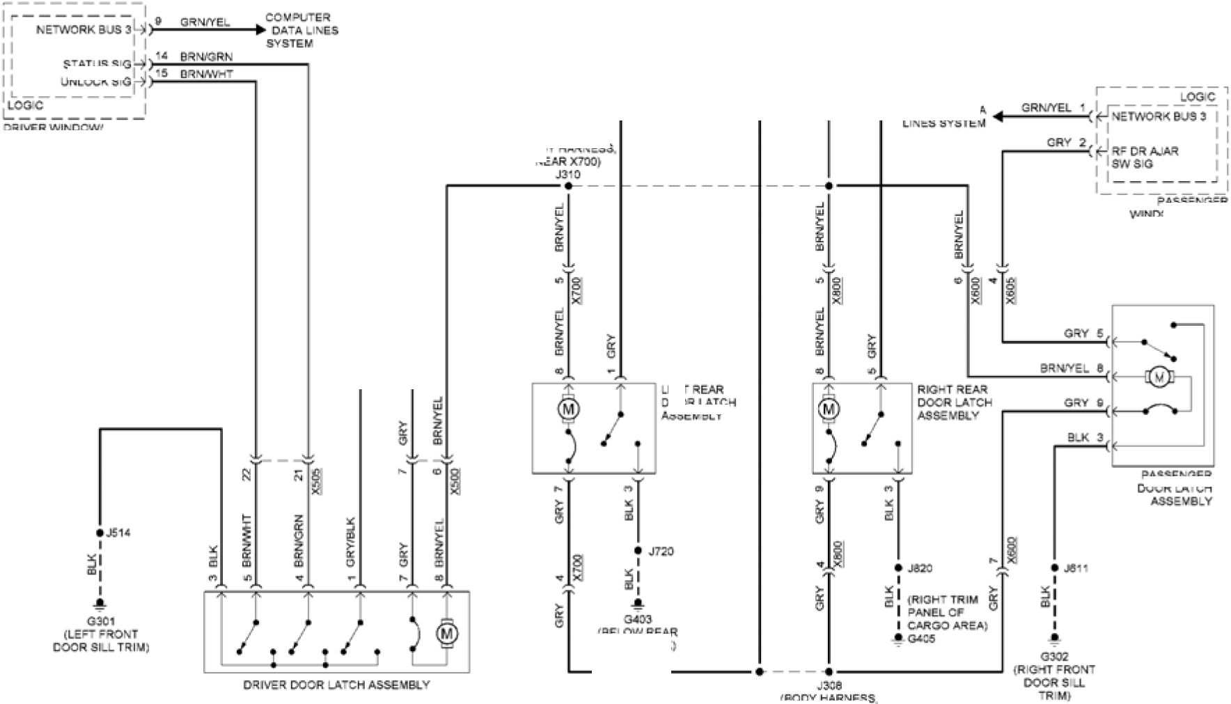
IRISH TRIM “ASSENGER LEFT ASSEMBLY STATUS S O |
|
(BOD* HARNESS |
DRIVER WINDCWr
outside rear vew
M RROR SWITCH
’ASSENGER
WINDOW SW ’CH
(BE»OW REAR
fuse block)
Fig. 86: Power Door Locks Circuit, W/O Passive Keyless Entry (2 of 2)
POWER MIRRORS
EXTERIOR
LIGHTS <
SYSTEM
GRN/WHT
HOT W/
IGNITION MAIN RELAY
ENERGIZED
qUNDERHOOD
I FUSE BLOCK
(NEAR POWER
VARIABLE
FUNCTIONS' INVERTER
FUSE I MODULE
7.5A (ASSEMBLY)
24
Х2
VIO/GRN
102
Х225
VIO/GRN
|
1 GRN/WHT RUN/CRANK IGNITION 1 BACKUP LAMP CTRL |
 |
(LEFT FRONT
DOOR SILL TRIM)
MIRROR
DIMMING
558999
Fig. 87: Electrochromic Mirror Circuit
 |
|
Fig. 88: Power Mirrors Circuit |
POWER SEATS
|
PASS H’O SEAT | ||
|
PASS НТО SEAT NTC SG DRV HTD SEAT NTC 8 G DRV НТО BACK NTC SIG | 
ELEMENT CTRL SEA- SWTCH PASSENGER CUSHION DRIVER CUSH ON |
DRIVER BACK SEAT |
|
COMPUTER DATA HVAC CONTROL MODULE | ||
ELEMENT LO RE₽
DRV НТО BACK
ELEMENT LO REF
BATT PQS VO.T
CRV НТО SEAT
PASS h’O SEAT
SERIAL, data bjs 2
COMPUTER DA A
LINES SYSTEM
FRONT SEAT HEATING
CONTROL VODt.E
(PASSENGER SEA” CUSHION
PASSENGER BACK SEAT
HE A’ING ELEMENT
Fig. 89: Front Heated Seats Circuit
HOTW/IGNITION MAN
RELA* ENERGIZED
“IUNDERHOOO
I FUSE BLOCK
(NEAR POWER
INVERTER VOXuE
|
RIGHT | |
|
STEERRvG WHEEL HEAT NG CON’RO. MODlLE | 
fuse assembly; |
|
LEFT 8TEERNG | |
RUN/CRANK
'GN 1 VOLT
LEO CONTROL
STEER NG WHEEL
STEER NG WHEEL
VOLTAGE REF
STEERING
I WHEEL
i switch
Fig. 90: Heated Steering Wheel Circuit
|
RR HTD SEAT CUSH ON | 
(LE’TSDEOF INSTRJMEN* LECT REAR CUSHION |
|
ONO SER A. OAT A BJS 2 REAR SEAT HEAThO RIGHT REAR CUSHION RR CUSHION NTC S G | |
RR НТО SEAT
CUSH ON ELEMENT CTRL
LR НТО SEAT CUS- ON
ELEMENT LO REF
CUSH ON ELEMENT CTRL
BATT POS VOLT
LR CUSHION NTC LO
rr cushion ntc lo
 |
G4C5 (RIGHT TRIM »ANEL |
COMPUTER DATA
LWvES SYSTEM
RR НТО SEAT . 1C BR4W-'
HIGH NO CTRL. '
LRH'G I
SEA'SW SIG >
UR НТО SEAT I
HIGH NO CTRL )
I й
BODY CONTRO. MODULE
[PASSENGER CEN'ER CONSOLE)
 |
|
;BE.OW REAR |
650182
LEFT REAR SEAT
MEAT NG SWITCH
 |
|
RIGH REAR SEA |
Fig. 91: Rear Heated Seats Circuit
POWER WINDOWS

JN.OCKSI3 (_ |
|
WINDOW MOTOR I BELOW REAR Fu8E BLOCK) G*03 (RIGHT TRIM PANEL |
UNDERWOOD
>w I cnSE block
(NEAR POWER
INVERTER
MODULE
---ASSEMBLY)
R G"T"RONI
LIP SWTCH
RIGHT FRONT
EXPRESS SWTCH
Right FRONT
downswtch
DR VER WINDOW MOTOR
(DOOR ASSEMBLY)
REDHrEL 1
XWS
COMPUTER
DATA L NES SYSTEM
(LEFT FRONT
DOOR Sill TR M)
DOOR LOCKS
(RIGHT FRQ»C
DOORS LL’R V;
’ASSEN3ER
WNDOW MOTOR
(DOOR ASSEMBLY)
WNDOWMO’OR
DOOR ASSEM3.Y;
6554*1
Fig. 92: Power Windows Circuit
RADIO
|
(OVER-EAC (LEFT ЗЮЕ OF 0AS-) |
 |
|
(CENTER OF DAS-9 |
(R Gr“ TRIM
PANEL 0=
CARGO AREA)
(RvS’RUVEN’ PANEL
-ARNESS NEAR
TELEMAT OS
COMMUNCAT on
IN’ERCACE CONTROL
Fig. 93: Radio Circuit, W/ Amplifier (1 of 4)
 |
|
Fig. 94: Radio Circuit, W/ Amplifier (2 of 4) |
 |
|
Fig. 95: Radio Circuit, W/ Amplifier (3 of 4) |
 |
|
Fig. 96: Radio Circuit, W/ Amplifier (4 of 4) |
|
(LEFT SIDE 0₽ DASH) NS’RLMEN’ PANEL (CVER"EAC |
 |
|
RADIO (CEMER OF DASH) 661134 MOST SERIA. DATA(-) NETWORK SUS *0 ) LOW REF ) |
|
Г yTc! |
|
? 5 |
IR Gr TRIM
PANEL OF
CARGO AREA)
(•.S’RUMENT PANEL
•ARNESS NEAR
-E.EMA- CS
COMMON CAT ON
IN’ERFACE CONTROL
MODULE)
(RIGH R m panel
O₽ CARGO AREA)
G406
COMPUTER DATA
LINCS SYSTEM

|
MOSTC’RL |
|
NAVIGA’ ON
SYSTEM
(REAR VEIN
COMPUTER
DA’A LINES
Fig. 97: Radio Circuit, W/O Amplifier (1 of 3)
 |
|
Fig. 98: Radio Circuit, W/O Amplifier (2 of 3) |
 |
|
Fig. 99: Radio Circuit, W/O Amplifier (3 of 3) |
SHIFT INTERLOCK
PARK BRK
(BRAKE
CALIPER
ASSEMBLY)
PARK BRAKE
АСТЦАТрЯ
BRAKE
CALIPER
ASSFMRI V)
RIGHT
PARK BRAKE
AC'UATOR
|
LR PARK BRK V"R APPLY C'RL LR PARK BRK MTR LOW RR PARK BRK MTR LOW REF RR PARK BRK VR A»=LY C’RL h SPDGV.AH | ||
|
PARK BRK PARK PARK |  |
(FROM OF LEFT |

MOT AT
ALL TIMES
• Г “ 1JNCERHOOO
| FUSE
I BLOCK
(NEAR POWER
INVER’ER MODULE
ASSEMBLY)
A9S
iPMP
FUSE
ecA
fa
ELECTRONIC BRAKE CONTROL MODULE
(INTEGRAL '0 MAS’ER CYL NOER ASSEMBLY)
 |
GRN |
COMPUTER
DA’A LINES
SVSTEM

PARK BRAKE CONTROL SWTTC-
(FORWAROOF TRANSMISSION 3-IFT LEVER Р03Г ON NOCATOR)
Fig. 100: Park Brake System Circuit
|
(LEFTS©6 O₽ TRANSMISSION BCM 2 FUSE BLOCK FUSE l|-- ISA I INSTRUMENT ** r, cc ai nrir |
 |
|
BODY СО NT RO_ MODULE ■RANSM SS ON SHIFT LEVER |
ЭАТА(.}1
ЧЕ AR З-.CV»
fuse в.оск
BRK APPLY
SENS LOW REF
 |
|
ENGINE CONTROL MODULE |
’OSI’ION SENSOR
(BRAKE PEOAL BRACKET;
H SPEED GM-AN
SERIAL DATA (♦) 1
Hi SPEED GMlAN
SERIA> DATA (.) 1
I INTERNAL MODE SW VOLT SPLY A
I IN^RNAL MODE SW VOLT SPLY В
TRANS IMS MODE SW R1 BIT $Ю
TRANS IMS MODE SW R2 BIT SIG
TRANS IMS MODE SW DI BIT SIG
TRANS IMS MODE SW D2 BIT SIG
-RANS I MS MODE SW 6 BIT SlG
POWER N VERTER MODU-E
ГОР OF TRANSMISSION)


I
I
I
I
I
I
I
I
I
I
I
AUTOMATIC TRANSMISS ON ASSEMB.Y
Fig. 101: Shift Interlock Circuit
SUPPLEMENTAL RESTRAINTS
|
PASSENGER |

LM SOS MIDDLE IMPACT SENSING MOD 8G |
|
BELT RETRACTOR INFLATABLE RESTRA N’ SENS NG 8 IVPACT SENSOR |
ф PIN SHORT MG BARS ENGAGED
WHEN MODu.E CONNECTOR IS
D SCONNECTED FROM -ARNESS
(SHORT NG BARS ARE CONNECTED
BETWEEN FOLLOWING PINS 1-2 3-4
B-10, 11-12.13-14.15-18,
N18. 37-38 39-40 & 63-84)
.R SICE MPAC" SIR INBLATOR
_R SICE IMPAC’ SIR INFlATDR
(R SICE IMPAC" SIR INFlATOR
IR 8ICC IMPAC’ SIR INFLATDR
DRV SEA’ BE.’ ANCm HI
DRV SEA’ BELT ANCH
PASS SEAT BELT ANCH
PASS SEA" BE.T ANCH HI CTRl
DRV SDE IMPACT MOD HI CTRL
DRV SIDE IMPACT MOD LOCTRL
°ASS SIDE IMPACT MOO lOCTRl
PASS SDE IMPACT MOD HI CTRL
LF HEAD CURTAIN MOD HI CTRL
LF HEAD CURTA N MOD LO CTRL
LF SIDE IMPACT SENSING MOD SG
RF SIDE IMPACT SENSING MOD SG
LF DSCR MINA’ING SENS 8 G
RF D SCR MINATIKG SEMS S G
LSS SEA’ BELT lOCTRl
’ASS SEA’ BELT HI CTRL
DRV SEAT BE.’SWS6
SEAT BELT SW -O REF
»ASS SEAT BE." SW 8 G
esseoe
Fig. 102: Supplemental Restraints Circuit (1 of 3)
 |
|
Fig. 103: Supplemental Restraints Circuit (2 of 3) |
 |
|
Fig. 104: Supplemental Restraints Circuit (3 of 3) |
TRANSMISSION
 |
|
Fig. 105: Transmission Circuit (1 of 3) |
|
| NSTRUMENT PANEL F-SE BLOCK (LEF- SICE OF NSTRUMENT PANEL) | |
|
SENS CTRL RSUSNS^ATIVS ЬХАА GMLAN SER A. OATA(-) 1 | 
1 WHT/ViQ |
|
SW’O GRY/VIC RED/V1O PARK PC81T1ON SW TCH BELOW REAR COi’tR CGNSU.fc MULT -FUNCTION | |
BA i POS VOLT
RAO RELA* CO<L CTRL
LOW REF
COM=JTER
DATA JNES
SYSTEM
KE* CAP"URE/CCLLMN 1
LOCK S- FT POSITION SK3 1
PARK-OCK SOLC-RLl
BODY CONTROL MODULE
(PASSENGER CENTER
CONSOLE)
TRANSMISSION 3-IFT
LOCK CONTROL
SOLENOD ACTUATOR
QANSMISS ON SM*T LEVER

BRAKE PEDAL
POSriCK SENSOR
(BRAKE PEDAL
BRACKET)
|
WHT |
 |
|
EKG NE CON’RC. MCCLLE |
Fig. 106: Transmission Circuit (2 of 3)
 |
|
Fig. 107: Transmission Circuit (3 of 3) |
TRUNK, TAILGATE, FUEL DOOR
HOT AT
ALL TIMES
DRVR
DOOR SW
FUSE
5A
“I REAR BODY
| FUSE BLOCK
I (FRONT OF
12 VOLT BATTERY)
А31
RED/ I
WHT
J517
RED/
WHT
COMPUTER о
DATA LINES 3
SYSTEM

|
ILOSPD |  |
|
LOGIC DISPLAY | |
INSTRUMENT CLUSTER
|
(RIGHT REAR |

BLU/BLK |
|
BLU/BLK YEL/BLK GRY/WHT 1447 BRN/WHT 3827 5060 lCK/UNLCK|) OPEN SIG I) REFUEL REQ SIG LO SPD GMLAN l\38 GRN SERIAL DATA |5(2 |
(RIGHT
TRIM
PANEL
OF CARGO
AREA)
G405'l
|
UNLOCK |
 |
|
BLU/BLK BLU/BLK YEL/BLK YEL/BLK |
FUEL FILL DOOR STATUS
SWITCH ASSEMBLY
(RIGHT REAR
QUARTERPANEL)
|
X50D 31 BRN/WHT COMPUTER DATA LINES SYSTEM INTERIOR | |
|
HYBRID/EV POWERTRAIN CONTROL MODULE 2 |  |
|
DOOR | |
, QLI
G301 >--
(LEFT FRONT
DOOR SILL TRIM)
REFUEL
REQUEST
SWITCH
(DRIVER DOOR
PANEL ABOVE
STORAGE COMPT)
(LEFT FRONT
DOOR SILL
TRIM)
555935
Fig. 108: Fuel Door Release Circuit
|
* NSTRuVENT PANEL I (LEFT SIDE CF |

COMPUTER G.o ve box: COMPUTER DATA |
|
(R GMT TRIM PANE. CF CARGO AREA, MANXE |
OF CARGO AREA)
LEGATE LATCH
ASSEUB-*
BOD* CONTROL MODULE
PASSENGER CENTER CONSOLE,
6S5634
Fig. 109: Liftgate Release Circuit
WARNING SYSTEMS


|
BRK FLUID LV. SENS SIG |
| |||||||||||||
PARK BRK SW SIG >2—е--Л1°—L2f_
PARK BRK REL SW VOLT REF )* YcUR£C 7663
PARK BRK REL SW SIG )'?
PARK BRK APP_v 8W VOLT RE ' BRN/W-T 7684
__|'16 YEL 1492
PARK BRK SW SPLY VOLT |>
hLtCI KONICBRAxL oontrol module
(INTEGRAL ’0 MAS’ER CYu NDER A3SEV3.Y)
 |
|
Level SWITCH PARK BRAKE CON’ROL SWTCH |
COMPUTER
DATA L NES
SYSTEM
664279
Fig. 110: Warning Systems Circuit (1 of 2)
|
CRGteRH 239 3.KW4T 4эез LORES GRN 506C V1CX3RV CC»/°UTER OA’A DR VER SEAT INF-ATABLE RES’RAINT (CF4"CR F COR GONSO-E! LOSPOGMJkK J5_ |
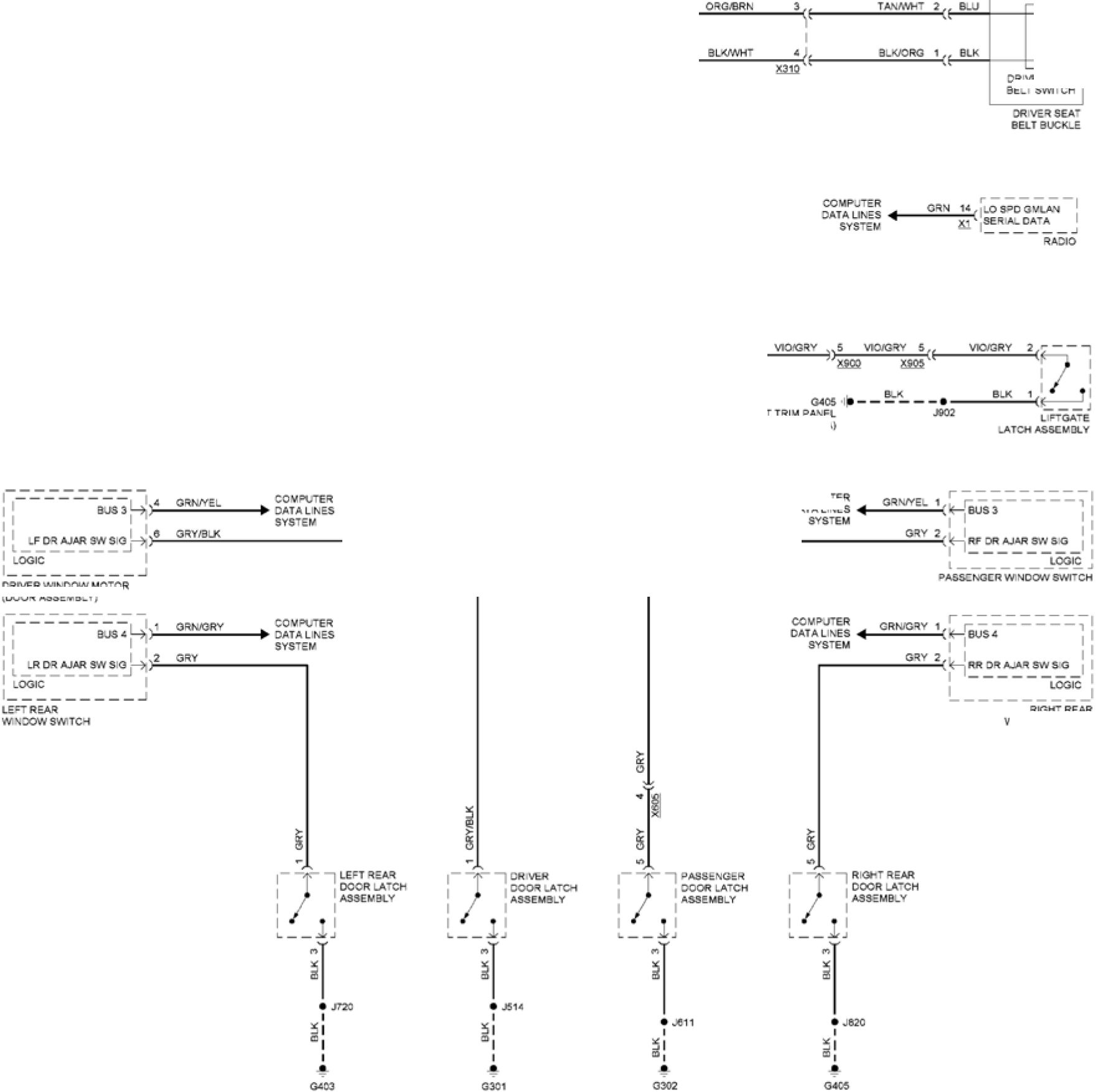 |
|
(RIGHT FRONT :R G-T TR M (LES" FRONT (BE.OW FUSE |
(Right trim panel
Oc CARGO AREA)
COMPUTER
DATALNES
DRIVER WINDOW MOTOR
(DOOR ASSEMB.Y;

DR VER SEAT
BE-’ SWTCH
RlGH RFAR
WNDOWSWTCH
?642SC
Fig. 111: Warning Systems Circuit (2 of 2)
WIPER/WASHER
|
UNDERHOOD •--- FUSE BLOCK | |
 |
NSTRUMETT PANEL FUSE BLOCK |
|
NTERCONNECT | |
|
LOGO ;RIGHT FRONT COMPUTER DATA WNDSHELD WNCSM ELD W»ER MTR (ENG NE COMPT | |

W NDSH№LD WIPER SW SIG |
SIG |
|
BODY CONTROL MODULE | |
(ENGINE COMPT
FRONT OF
RiGhT FRAME;
G'02
(ENGINE COMPT
FRONT OF
R'GmT FRAME;
Fig. 112: Wiper/Washer Circuit
WASHFR Fl UIC
LEVEL SW TCH
I BOT’OV OF WASHER
SO.VEN’ BO”LE)
WASHER PUMP
(WASHER FLUID
RESERVO Ri
W NDSRRLD WIPcR MR
RLVCO LCTR.
ACC WAKEUP SERIAL
SERIAL DATA
COMMUNICATOR El
Article GUID: A00864366
ELECTRICAL
Wiring Systems and Power Management - Component Locator - Wheels/Vehicle Underbody
Component Views - Volt
UNDERBODY - HYBRID/EV BATTERY PACK INTERNALS
 |
|
Fig. 1: Underbody - Hybrid/EV Battery Pack Internals |
Items
1. B32D Hybrid/EV Battery Temperature Sensor 4 B32D Hybrid/EV Battery Temperature Sensor 4
2. C5E Hybrid/EV Battery Module 5 C5E Hybrid/EV Battery Module 5
3. C5B Hybrid/EV Battery Module 2 C5B Hybrid/EV Battery Module 2
4. B32C Hybrid/EV Battery Temperature Sensor 3 B32C Hybrid/EV Battery Temperature Sensor 3
5. S15 Manual Service Disconnect
Items
6. K16 Battery Energy Control Module K16 Battery Energy Control Module X1 K16 Battery Energy
Control Module X2 K16 Battery Energy Control Module X3 K16 Battery Energy Control Module
X4 K16 Battery Energy Control Module X5 K16 Battery Energy Control Module X6 K16 Battery
Energy Control Module X7 K16 Battery Energy Control Module X8
7. B32E Hybrid/EV Battery Temperature Sensor 5 B32E Hybrid/EV Battery Temperature Sensor 5
8. C5F Hybrid/EV Battery Module 6 C5F Hybrid/EV Battery Module 6
9. B32F Hybrid/EV Battery Temperature Sensor 6 B32F Hybrid/EV Battery Temperature Sensor 6
10. C5C Hybrid/EV Battery Module 3 C5C Hybrid/EV Battery Module 3_______________________
11. B32B Hybrid/EV Battery Temperature Sensor 2 B32B Hybrid/EV Battery Temperature Sensor 2
12. C5A Hybrid/EV Battery Module 1 C5A Hybrid/EV Battery Module 1
13. B32A Hybrid/EV Battery Temperature Sensor 1 B32A Hybrid/EV Battery Temperature Sensor 1
UNDERBODY - HYBRID/EV BATTERY PACK CONTACTOR ASSEMBLY COMPONENTS
 |
|
Fig. 2: Underbody - Hybrid/EV Battery Pack Contactor Assembly Components |
Items
1. B30 Hybrid/EV Battery Pack Current Sensor B30 Hybrid/EV Battery Pack Current Sensor ()
2. KR116B Battery Charging System Positive Contactor
3. X55QB Fuse Holder 2 - Hybrid/EV Battery Pack_______________________________________
4. T21 Hybrid/EV Battery Coolant Heater Transistor
5. E54 Hybrid/EV Battery Pack Coolant Heater
6. R25 Hybrid/EV Battery Pre-Charge Resistor
7. KR134 Pre-Charge Contactor
8. KR34A Drive Motor Battery Negative High Voltage Contactor Relay
9. KR34B Drive Motor Battery Positive High Voltage Contactor Relay
UNDERBODY - FUEL SYSTEM COMPONENTS (1 OF 2)
 |
|
Fig. 3: Underbody - Fuel System Components (1 of 2) |
Items
1. M97 Fuel Fill Door Lock Actuator M97 Fuel Fill Door Lock Actuator
2. B208 Fuel Fill Door Status Switch Assembly B208 Fuel Fill Door Status Switch Assembly
UNDERBODY - FUEL SYSTEM COMPONENTS (2 OF 2)
 |
|
Fig. 4: Underbody - Fuel System Components (2 of 2) |
Items
1. B47 Fuel Pressure Sensor B47 Fuel Pressure Sensor
UNDERBODY - STEERING COMPONENTS
 |
|
Fig. 5: Underbody - Steering Components |
Items
1. K43 Power Steering Control Module K43 Power Steering Control Module X1 K43 Power Steering
Control Module X2
UNDERBODY - WHEEL COMPONENTS (1 OF 4)
 |
|
Fig. 6: Underbody - Wheel Components (1 of 4) |
Items
1. B5RF Wheel Speed Sensor - Right Front B5RF Wheel Speed Sensor - Right Front
UNDERBODY - WHEEL COMPONENTS (2 OF 4)
 |
|
2 |
Fig. 7: Underbody - Wheel Components (2 of 4)
Courtesy of GENERAL MOTORS COMPANY
Items
1. B5LR Wheel Speed Sensor - Left Rear B5LR Wheel Speed Sensor - Left Rear
2. M104L Park Brake Actuator - Left M104L Park Brake Actuator - Left
UNDERBODY - WHEEL COMPONENTS (3 OF 4)
 |
|
Fig. 8: Underbody - Wheel Components (3 of 4) |
Items
1. B5LF Wheel Speed Sensor - Left Front B5LF Wheel Speed Sensor - Left Front
UNDERBODY - WHEEL COMPONENTS (4 OF 4)
 |
|
1 |
Fig. 9: Underbody - Wheel Components (4 of 4)
Courtesy of GENERAL MOTORS COMPANY
Items
1. M104R Park Brake Actuator - Right M104R Park Brake Actuator - Right
2. B5RR Wheel Speed Sensor - Right Rear B5RR Wheel Speed Sensor - Right Rear
Article GUID: A00884715
EMISSION APPLICATIONS
GM - Chevrolet Volt
EMISSION APPLICATIONS
|
Volt | |||||||||
| |||||||||
Article GUID: A00768985
Gasoline & Diesel
"A"
A/C
Air Conditioning
A/C-ISUS
A/C Idle Speed-Up Solenoid
A/F
Air/Fuel
AAI
Air Assist Injector
ACL
Air Cleaner (Thermostatic Air Cleaner)
ACL-BMS
ACL Bimetallic Sensor
ACL-CKV
ACL Check Valve
ACL-DV
ACL Delay Valve
ACL-ESC
Electronic Spark Control
ACL-PVS
ACL Ported Vacuum Switch
ACL-RDV
ACL Reverse Delay Valve
ACL-RDVS
ACL Reverse Delay Valve (Single)
ACL-TCV
ACL Thermal Control Valve
ACL-TS
ACL Temperature Sensor
ACL-TSOV
ACL Temperature Sensor Override Valve
ACL-TVS
ACL Thermal Vacuum Switch
ACL-TVV
ACL Thermal Vacuum Valve
ACL-VCDV
ACL Vacuum Control Delay Valve
ACL-VCV
ACL Vacuum Control Valve
ACL-VM
ACL Vacuum Motor
ACL-WP
ACL Wax Pellet Type Motor
ADS
Anti-Dieseling Solenoid
AFR
Air/Fuel Ratio Sensor
AFS
Air/Fuel Ratio Sensor
AIH
Air Intake Heaters
AIH-TS
AIH Temperature Sensor
AIR
Air Injection System
AIS
Air Injection System
AIS-ACV
AIS Air Control Valve
AIS-AF
Air Injection System Air Filter
AIS-AMV
AIS Air Management Valve
AIS-ASV
AIS Air Switching Valve
AIS-BPV
AIS By-Pass Valve
AIS-CC
AIS Computer Controlled
AIS-CKV
AIS Check Valve
AIS-CSV
AIS Control Solenoid Valve
AIS-CV
AIS Combination Valve
AIS-DV
AIS Diverter Valve
AIS-IMCV
AIS Intake Manifold Change-Over Valve
AIS-MCV
AIS Manifold Change-Over Valve
AIS-OWV
AIS One Way Valve
AIS-PAF
AIS Pulse Air Feeder
AIS-PM
AIS Pump Motor
AIS-PV
AIS Pneumatic Valve
AIS-RV
AIS Relief Valve
AIS-SAV
AIS Secondary Air Valve
AIS-SOL
AIS Solenoid
AIS-SV
AIS Solenoid Valve
AIS-VCV
AIS Vacuum Control Valve
AIS-VSV
AIS Vacuum Switching Valve
AIS-VT
AIS Vacuum Tank
AIS-VCV
AIS Vacuum Control Valve
AIS-VSV
AIS Vacuum Switching Valve
AIV
Air Injection Valve
AIV-SOL
Air Injection Valve Solenoid
ALVW
Adjusted Loaded Vehicle Weight
AMV
Air Management Valve
AP
Air Pump Injection System
AP-ABV
Air Pump Air Bypass Valve
AP-ACV
AP Air Control Valve
AP-AMV
AP Air Management Valve
AP-ASRV
AP Air Switching Relief Valve
AP-ASS
AP Air Switching Solenoid
AP-ASV
AP Air Switching Valve
AP-BP
AP By-Pass Valve
AP-BPV
AP By-Pass Valve
AP-CKV
AP Check Valve
AP-CS
AP Control Solenoid
AP-CV
AIR Cut-Off Valve
AP-DCTO
AP Dual Coolant Temperature Override
AP-DLY
AP Delay Valve
AP-DV
AP Diverter Valve
AP-EADV
AP Electric Air Control Diverter Valve
AP-EAMR
AP Electric Air Management Relay
AP-EAMS
AP Electric Air Management Solenoid
AP-EAP
AP Electric Air Pump
AP-EC
AP Electromagnetic Clutch
AP-ERLY
AP Electric Air Pump Relay
AP/PAIR
Pulsed Secondary Air Injection
AP-RDV
AP Reed Valve
AP-RV
AP Relief Valve
AP-SOL
AP Solenoid
AP-SOV
AP Shut-Off Valve
AP-SV
AP Solenoid Valve
AP-SWV
AP Switchover Valve
AP-TV
AP Transmitting Valve
AP-VCS
AP Vacuum Control Solenoid
AP-VCSV
AP Vacuum Controlled Air Shut-Off Valve
AP-VCV
AP Vacuum Control Valve
AP-VSV
AP Vacuum Switching Valve
A/T
Automatic Transmission
ATCV
Air Temperature Control Valve
"B"
BP/EGR
Backpressure EGR System
BP/EGR-BPS
BP/EGR Backpressure Sensor
BP/EGR-BPT
BP/EGR Backpressure Transducer
BP/EGR-BPV
BP/EGR Backpressure Valve
BP/EGR-BS
BP/EGR Bleed Solenoid
BP/EGR-BVSV
BP/EGR Bimetallic Vacuum Switching Valve
BP/EGR-C
BP/EGR Controller
BP/EGR-CLR
BP/EGR Cooler
BP/EGR-CS
BP/EGR Control Solenoid
BP/EGR-CTO
BP/EGR Coolant Temperature Override
BP/EGR-CV
BP/EGR Control Valve
BP/EGR-DCTO
BP/EGR Dual Coolant Temperature Override
BP/EGR-DS
BP/EGR Diagnostic Solenoid
BP/EGR-DSOL
BP/EGR Duty Solenoid
BP/EGR-DTVSW
BP/EGR Distributor Thermal Vacuum Switch
BP/EGR-DV
BP/EGR Delay Valve
BP/EGR-EET
BP/EGR Electric Transducer
BP/EGR-EPV
BP/EGR External Pressure Valve
BP/EGR-FDV
BP/EGR Forward Delay Valve
BP/EGR-LCV
BP/EGR Vacuum Control Valve
BP/EGR-LC
BP/EGR Load Control Valve
BP/EGR-OVS
BP/EGR Orifice Valve Sensing
BP/EGR-PS
BP/EGR Position Sensor
BP/EGR-PT
BP/EGR Pressure Tranducer
BP/EGR-PVS
BP/EGR Ported Vacuum Switch
BP/EGR-RES
BP/EGR Reservoir
BP/EGR-RST
BP/EGR Restrictor
BP/EGR-SOL
BP/EGR Solenoid
BP/EGR-TCTVS
BP/EGR Torque Converter Thermal Vacuum Switch
BP/EGR-TCV
BP/EGR Thermal Control Valve
BP/EGR-TCVLV
BP/EGR Temperature Control Valve
BP/EGR-T
BP/EGR Temperature Sensor
BP/EGR-TS
BP/EGR Temperature Sensor
BP/EGR-TVC
BP/EGR Thermal Control Valve
BP/EGR-TVS
BP/EGR Thermal Vacuum Switch
BP/EGR-TVV
BP/EGR Thermal Vacuum Valve
BP/EGR-VC
BP/EGR Diagnostic Valve
BP/EGR-VCV
BP/EGR Vacuum Control Valve
BP/EGR-VM
BP/EGR Vacuum Modulator
BP/EGR-VRV
BP/EGR Vacuum Regulator Valve
BP/EGR-VS
BP/EGR Vacuum Switch
BP/EGR-VSOL
BP/EGR Vent Solenoid
BP/EGR-VSV
BP/EGR Vacuum Switching Valve
"C"
C-4
Computer Controlled Catalytic Converter
CAC
Charge Air Cooler
CAS
Clean Air System
CB
Crankcase Breather
CB-VC
Crankcase Breather-Vapor Canister
CBPS
Coasting By-Pass System
CBVC
Crankcase Breather Vapor Canister
CCIEV
Coolant Controlled Idle Enrichment Valve
CCO
Computerized Engine Controls
CCS
Controlled Combustion System
CCV
Closed Crankcase Ventilation
CD-REGVLV
Crankcase Depression Regulator Valve
CDRV
Crankcase Depression Relief Valve
CEAB
Cold Engine Air Bleed
CEAB-TVS
CEAB Thermal Vacuum Switch
CEAB-TVV
CEAB Thermal Vacuum Valve
CEC
Computerized Engine Controls
CESS
Cold Engine Sensor Switch
CETS
Cold Engine Temperature Switch
CFI
Continuous Fuel Injection
CMH
Cold Mixture Heater
CNG
Compressed Natural Gas
CO
Carbon Monoxide
CO2
Carbon Dioxide
CPI
Central Port Injection
CRV
Coasting Richer Valve
CSI
Central Sequential Injection
CTAVS
Cold Temperature Activated Vacuum System
CTOX
Continous Trap Oxidizer
CVOT
Crankcase Ventilation Orifice Tube
CVOT-CKV
Crankcase Ventilation Orifice Tube Check Valve
"D"
DCLV
Deceleration Valve
DCS
Deceleration Control System
DDI
Direct Diesel Injection
DFI
Direct Diesel Injection
DI
Direct Injection
DKV
Deceleration Kick Valve
DLCV
Deceleration Mixture Control Valve
DM-TL
Diagnostic Module Tank Leakage
DMS
Dual Manifold System
DOC
Diesel Oxidation Catalyst
DOHC
Dual Overhead Cam
DPD
Dual Point Distributor
DPF
Diesel Particulate Filter
DPF/TWC
Combination Diesel Particulate Filter and Three Way Catalyst
DPFE
Differential Pressure Feedback EGR Valve
DPFEGR
Differential Pressure Feedback EGR Valve
DTM
Deceleration Throttle Modulator
"E"
EAIR
Electric Air Injection System
EAIR-DV
EAIR Diverter Valve
EC
Computerized Engine Controls
ECM
Electronic Control Module
ECU
Electronic Control Unit
EDC
Electronic Diesel Control
EDS
Electronic Diesel System
EEC
Electronic Engine Control
EFE
Early Fuel Evaporation
EFE-CKV
EFE Check Valve
EFE-CV
EFE Control Valve
EFE-DTVS
EFE Delay Thermal Vacuum Switch
EFE-HTR
EFE Heater
EFE-HCV
EFE Heat Control Valve
EFE-OTS
EFE Oil Temperature Switch
EFE-PTC
EFE Positive Temperature Coefficient (Intake Heater Grid)
EFE-PVS
EFE Ported Vacuum Switch
EFE-SOL
EFE Solenoid
EFE-TVS
EFE Thermal Vacuum Switch
EFE-TVV
EFE Thermal Vacuum Valve
EFE-VSV
EFE Vacuum Switching Valve
EFI
Electronic Fuel Injection
EFI-MA
EFI Mass Airflow Sensor
EFI-MAF
EFI Mass Airflow Sensor
EGR
Exhaust Gas Recirculation System
EGR-BCS
EGR Boost Check Solenoid
EGR-BPBV
EGR By-Pass Backpressure Valve
EGR-BPT
EGR Backpressure Transducer
EGR-BPV
EGR By-Pass Valve
EGR-BS
EGR Bleed Solenoid
EGR-BSSV
EGR Boost Sensor Solenoid Valve
EGR-BV
EGR Bypass Valve
EGR-BVSV
EGR Bimetallic Vacuum Switching Valve
EGR-C
EGR Controller
EGR-CC
EGR Coolant Controlled
EGR-CLR
EGR Cooler
EGR-VSOL
EGR Vacuum Solenoid
EGR-CKV
EGR Check Valve
EGR-CS
EGR Control Solenoid
EGR-CSOL
EGR Cut-Off Solenoid
EGR-CSV
EGR Control Solenoid
EGR-CTO
EGR Coolant Temperature Override
EGR-CTS
EGR Charge Temperature Sensor
EGR-CTSW
EGR Charge Temperature Switch
EGR-CTTS
EGR Coolant Temperature Thermoswitch
EGR-CV
EGR Control Valve
EGR-CVCV
EGR Constant Vacuum Control Valve
EGR-CVS
EGR Control Vent Solenoid
EGR-DC
EGR Digital Control
EGR-DCTO
EGR Dual Coolant Temperature Override
EGR-DPFE
Differential Pressure Feedback EGR Sensor
EGR-DPFS
EGR Differential Pressure Feedback Sensor
EGR-DS
EGR-DSOL
EGR Duty Solenoid
EGR-DTVS
EGR Delay Thermal Vacuum Switch
EGR-DTVSW
EGR Distributor Thermal Vacuum Switch
EGR-DV
EGR Delay Valve
EGR-EPRS
EGR Exhaust Pressure Regulator Solenoid
EGR-EPRV
EGR Exhaust Pressure Regulator Valve
EGR-EPV
EGR External Pressure Valve
EGR/EVAP-CSV
EGR/EVAP Control Solenoid Valve
EGR-EVR
EGR Vacuum Regulator
EGR-EVRV
EGR Electronic Vacuum Regulator Valve
EGR-FDV
EGR Forward Delay Valve
EGR-FJS
EGR Floor Jet System
EGR-FPS
EGR Feedback Pressure Sensor
EGR-LCV
EGR-MAP
EGR Manifold Absolute Pressure Sensor
EGR-PFE
EGR-PFE Sensor
EGR-PS
EGR Position Sensor
EGR-PSW
EGR Pulse Switch
EGR-PVS
EGR Ported Vacuum Switch
EGR-REG
EGR Regulator
EGR-RES
EGR Reservoir
EGR-RST
EGR Restrictor
EGR-SC
EGR Signal Converter
EGR-SEC
EGR, Secondary
EGR-SEN
EGR Sensor
EGR-SM
EGR Stepper Motor
EGR-SOL
EGR Solenoid
EGR-SU
EGR Switchover Valve
EGR-SUB
Sub-EGR Valve
EGR-SV
EGR Switchover Valve
EGR-SVV
EGR Solenoid Vacuum Valve
EGR-T
EGR Temperature Sensor
EGR-TC
EGR Transmission Controlled
EGR-TCTVS
EGR Torque Converter Thermal Vacuum Switch
EGR-TCV
EGR Thermal Control Valve
EGR-TCVLV
EGR Temperature Control Valve
EGR-TRANS
EGR Transducer
EGR-TS
EGR Temperature Sensor
EGR-TSW
EGR Temperature Switch
EGR-TV
EGR Thermal Valve
EGR-TVD
EGR Throttle Valve Diaphragm
EGR-TVS
EGR Thermal Vacuum Switch
EGR-TVSOL
EGR Throttle Valve Solenoid
EGR-TVV
EGR Thermal Vacuum Valve
EGR-V
EGR Valve
EGR-VA
EGR Vacuum Amplifier
EGR-VCV
EGR Vacuum Control Valve
EGR-VM
EGR Vacuum Modulator
EGR-VR
EGR Vacuum Regulator
EGR-VRS
EGR Vacuum Regulator Solenoid
EGR-VRSV
EGR Vacuum Regulator Solenoid Valve
EGR-VRV
EGR Vacuum Regulator Valve
EGR-VS
EGR Vacuum Switch
EGR-VSDV
EGR Vacuum Switch Dump Valve
EGR-VSEN
EGR Vacuum Sensor
EGR-VSOL
EGR Vent Solenoid
EGR-VSS
EGR Vacuum Switching Solenoid
EGR-VST
EGR Vacuum Surge Tank
EGR-VSV
EGR Vacuum Switching Valve
EGR-VVCS
EGR Venturi Vacuum Control System
EGRB
EGR Boost Sensor
EGRC
EGR Control Solenoid
EGRC-BPT
EGR Control Backpressure Transducer
EGRC-SV
EGR Control Solenoid Valve
EHOC
Electronically Heated Oxidation Catalyst
EHTWC
Electronically Heated Three-Way Catalyst
EI
Electronic Ignition System
EIS
Electronic Ignition System
ELB
Electronic Lean Burn
EPR
Exhaust Pressure Regulator
EPR-SOL
EPR Solenoid
ESA
Electronic Spark Advance
ESIM
Evaporative System Integrity Monitor
EVAP
Fuel Evaporative System
EVAP-AAC
EVAP Auxiliary Air Control
EVAP-BPSV
EVAP By-Pass Solenoid Valve
EVAP-BVSV
EVAP Bimetallic Vacuum Switching Valve
EVAP-CAV
EVAP Canister Air Valve
EVAP-CCV
EVAP Control Canister Close Valve
EVAP-CCVSV
EVAP Control Canister Vent Shut Valve
EVAP-CCVVSV
EVAP Closed Canister Valve Vacuum Switching Valve
EVAP-CDCV
EVAP Canister Drain Cut Valve
EVAP-CKV
EVAP Check Valve
EVAP-CPCS
EVAP Canister Purge Control Solenoid
EVAP-CPCSV
EVAP Canister Purge Control Solenoid Valve
EVAP-CPCV
EVAP Canister Purge Control Valve
EVAP-CPRV
EVAP Canister Purge Regulator Valve
EVAP-CPSV
EVAP Canister Vent Shut Valve
EVAP-CPT
EVAP Canister Purge Timer
EVAP-CPTVS
EVAP Canister Purge Thermal Vacuum Switch
EVAP-CPV
EVAP Canister Vent Valve
EVAP-CPVCSV
EVAP Canister Purge Volume Control
EVAP-CPVCV
EVAP Canister Purge Volume Control Valve
EVAP-CPVDV
EVAP Canister Purge Vacuum Delay Valve
EVAP-CPVR
EVAP Canister Purge Valve Resonator
EVAP-CS
EVAP Control Solenoid
EVAP-CSPS
EVAP Control System Pressure Sensor
EVAP-CSPV
EVAP Canister Purge Valve
EVAP-CST
EVAP Canister Surge Tank
EVAP-CSV
EVAP Control Solenoid Valve
EVAP-CT
EVAP Catch Tank
EVAP-CV
EVAP Control Solenoid Valve
EVAP-CVCS
EVAP Canister Vent Control Solenoid
EVAP-CVCSV
EVAP Canister Vent Control Solenoid Valve
EVAP-CVCV
EVAP Canister Vent Control Valve
EVAP-CVS
EVAP Canister Vent Solenoid
EVAP-CVSV
EVAP Carburetor Vent Switching Valve
EVAP-CVV
EVAP Canister Vent Valve
EVAP-DCTO
EVAP Dual Coolant Temperature Override
EVAP-DF
EVAP Drain Filter
EVAP-DPS
EVAP Differential Pressure Sensor
EVAP-DV
EVAP-Drain Valve
EVAP-ESIM
Evaporative System Integrity Monitor
EVAP-EV
EVAP Emission Valve
EVAP-FBVV
EVAP Fuel Bowl Vent Valve
EVAP-FBVS
EVAP Fuel Bowl Vent Solenoid
EVAP-FCV
EVAP Fuel Cut Valve
EVAP-FLS
EVAP Fuel Level Sensor
EVAP-FOLV
EVAP Fuel Overflow Limiter Valve
EVAP-FR/FTPS
EVAP Rollover Valve/Fuel Tank
EVAP-FS
EVAP Flow Switch
EVAP-FSV
EVAP Flow Switchover Valve
EVAP-FTCV
EVAP Tank Pressure Control Valve
EVAP-FTEV
EVAP Fuel Tank EVAP Valve
EVAP-FTPCSV
EVAP Fuel Tank Pressure Control Solenoid Valve
EVAP-FTPS
EVAP Fuel Tank Pressure Sensor
EVAP-FTS
EVAP Fuel Temperature Sensor
EVAP-FVCV
EVAP Fuel Vapor Control Valve
EVAP-FVS
EVAP Fuel Vapor Separator
EVAP-FVTS
EVAP Fuel Vapor Temperature Sensor
EVAP-FVV
EVAP Fuel Vent Valve
EVAP-FVVV
EVAP Fuel Vapor Vent Valve
EVAP-FWV
EVAP Fuel Vent Valve
EVAP-IVS
EVAP Inner Vent Solenoid
EVAP-LDAF
EVAP Leak Detection Pump Air Filter
EVAP-LDP
EVAP Leak Detection Pump
EVAP-LDPAF
EVAP Leak Detection Pump Air Filter
EVAP-LDPF
EVAP Leak Detection Pump Filter
EVAP-LDPVV
EVAP Leak Detection Pump Vent Valve
EVAP-LSEP
EVAP Liquid Separator
EVAP-NVLD
EVAP Natural Vacuum Leak Detection
EVAP-ORVR
Evaporative On-Board Refueling Vapor Recovery System
EVAP-ORVRCV
Evaporative On-Board Refueling Vapor Recovery Check Valve
EVAP-ORVRFTVRV
EVAP-ORVR Fuel Tank Vapor Recirculation
EVAP-OVCV
EVAP Outer Vent Control Valve
EVAP-OWV
EVAP One-Way Valve
EVAP-PCDV
EVAP Purge Control Diaphram Valve
EVAP-PCS
EVAP Purge Control Solenoid Valve
EVAP-PCSV
EVAP Purge Cut-Off Solenoid Valve
EVAP-PFS
EVAP Purge Flow Sensor
EVAP-PFSVVSV
EVAP Purge Flow Switching Valve Vacuum Switching Valve
EVAP-PPS
EVAP Proportional Purge Solenoid
EVAP-PR
EVAP Purge Resonator
EVAP-PRRV
EVAP Pressure Relief Rollover Valve
EVAP-PRV
EVAP Pressure Relief Valve
EVAP-PS
EVAP Purge Solenoid
EVAP-PSOL
EVAP Purge Solenoid
EVAP-PSSV
EVAP Pressure Switching Solenoid
EVAP-PSVVSV
EVAP Pressure Switching Valve Vacuum Switching Valve
EVAP-PV
EVAP Purge (Frequency) Valve
EVAP-PVS
EVAP Ported Vacuum Switch
EVAP-RV
EVAP Rollover Valve
EVAP Rollover Valve/Fuel Tank
EVAP-RVSV
EVAP Rollover Vapor Separator Valve
EVAP-SNR
EVAP Canister Sensor
EVAP-SOL
EVAP Solenoid
EVAP-SOV
EVAP Shutoff Valve
EVAP-SSV
EVAP Shut-Off Solenoid Valve
EVAP-SV
EVAP Solenoid Valve
EVAP-TC
EVAP Trap Canister
EVAP-TS
EVAP Temperature Switch
EVAP-TPBPV
EVAP Tank Pressure By-Pass Valve
EVAP-TPCS
EVAP Tank Pressure Control Solenoid
EVAP-TPCV
EVAP Tank Pressure Control Valve
EVAP-TRWV
EVAP Tree-Way Valve
EVAP-TV
EVAP Thermal Valve
EVAP-TVS
EVAP Thermal Vacuum Switch
EVAP-TVV
EVAP Thermal Vacuum Valve
EVAP-TWV
EVAP Two-Way Valve
EVAP-VC
EVAP Vapor Canister
EVAP-VCAT
EVAP Vapor Canister Air Tank
EVAP-VCF
EVAP Vapor Canister Filter
EVAP-VCSV
EVAP Vapor Canister Shut-off Valve
EVAP-VCTV
EVAP Vacuum Control Valve
EVAP-VCV
EVAP Vacuum Canister Valve
EVAP-VCVS
EVAP Vapor Canister Vent Solenoid
EVAP-VLFR
EVAP Vent Line Flow Restrictor
EVAP-VM
EVAP Vacuum Motor
EVAP-VMV
EVAP Vapor Management Valve
EVAP-VPS
EVAP Vapor Pressure Sensor
EVAP-VPSVSV
EVAP Vapor Pressure Sensor Vacuum Switching Valve
EVAP-VS
EVAP Vacuum Sensor
EVAP-VSOL
EVAP Ventilation Solenoid
EVAP-VSOL/LDP
EVAP Ventilation Solenoid/Leak Detection Pump
EVAP-VST
EVAP Vacuum Surge Tank
EVAP-VSV
EVAP Vacuum Switching Valve
EVAP-VV
EVAP Ventilation Valve
EVRS
EGR Vacuum Regulator Solenoid
"F"
FBC
Feedback Carburetor
FCOV
Fuel Change Over Valve
FF
Flex Fuel
FF-CKV
Fuel Fill Check Valve
FF-FCV
Fuel Tank Fuel Cut-Off Valve
FF-FLVV
Fuel Tank Fill Limit Vent Valve
FFC-PVRV
Fuel Fill Cap Pressure Vacuum Relief Valve
FGOV
Fuel Gravity/Overflow Valve
FGVV
Fuel Gravity Vent Valve
FI
Fuel Injected
FICD
Fast Idle Control Device
FISR
Fast Idle Solenoid Relay
FLV
Fill Limit Valve
FLVV
Fill Limiting Vent Valve
FP-CKV
Fill Pipe Check Valve
FP-RV
Fill Pipe Rollover Valve
FR
Fill Pipe Restrictor
FT-FLVV
Fuel Tank Fill Limit Vent Valve
FT-GVV
Fuel Tank Grade Vent Valve
FT-OPRV
Fuel Tank Over Pressure Vent Valve
FT-PCV
Fuel Tank Pressure Control Valve
FT-VCV
Fuel Tank Vapor Control Valve
FT-VRV
Fuel Tank Vapor Recirculation Valve
FTCV
Fuel Tank Check Valve
FTDPS
Fuel Tank Differential Pressure Sensor
FTEV
Fuel Tank EVAP Valve
FTPS
Fuel Tank Pressure Sensor
FTT
Fuel Tank Temperature Sensor
FTTS
Fuel Tank Temperature Sensor
FTV/LSV
Fuel Tank Vapor/Liquid Seperation Valve
FTVCV
Fuel Tank Vapor Control Valve
FTVPRV
Fuel Tank Ventilation Pressure Retention Valve
FVPS
Fuel Vapor Pressure Sensor
FTVV
Fuel Tank Vent Valve
FVV
Fuel Vapor Valve
"G"
GVWR
Gross Vehicle Weight Rating
"H"
HAC
High Altitude Compensator
HAFS
Heated Air Fuel Ratio Sensor
HAI
Hot Air Intake
HAS
High Altitude System
HC
Hydrocarbons
HCAC-VSV
Hydrocarbon Absorber Catalyst Vacuum Switching Valve
HDC
Heavy Duty Cooling
HDC-CTO
HDC Coolant Temperature Override
HFM-SFI
Hot Film Engine Management SFI
HIC
Hot Idle Compensator
HIM
Heated Intake Manifold
HO
High Output
HO2S
Heated Oxygen Sensor
HP
High Performance
HP
Horsepower
HPCA
Housing Pressure Cold Advance
HSC
High Swirl Combustion
"I"
IAC
Idle Air Control Valve
IACV-SW
IACV Switch
ICOM
Idle Compensator
IDI
Indirect Diesel Injection
IES
Idle Enrichment System
IMCO
Improved Combustion System
"K"
KS
Knock Sensor
"L"
LH-SFI
Hot Wire Sequential Multiport Fuel Injection
LVFD
Liquid/Vapor Fuel Discriminator
LVW
Loaded Vehicle Weight
"M"
MD-TICS
Timing & Injection rate Control System
MDP
Manifold Differential Pressure sensor
ME-SFI
Motor Electronics Sequential Fuel Injection
MFI
Multiport Fuel Injection
MFI-MAF
MFI Mass Airflow Sensor
MFLS
Main Fuel Level Sensor
MI
Mechanical Fuel Injection
MIL
Malfunction Indicator Light
M/T
Manual Transmission
"N"
NAC
Nitrogen Oxides (NOx) Adsorbing Catalyst
NLV
Non-Linear Valve
NOS
NOx Sensor
NOx
NOx Emission Control
NOxATWC
NOx Adsorptive TWC
NOxC
Nitrogen Oxide Catalyst
NOxS
Nitrogen Oxide Sensor
NOxTWC
NOx Adsorptive TWC
NSC
Nitrogen Oxides (NOx) Storage Catalyst
"O"
OBD
On-Board Diagnostic System
PBD (F)/(P)
Full/Partial On-Board Diagnostic
OC
Oxidation Catalytic Converter
OHC
Overhead Cam
ORVR
On-Board Refueling Vapor Recovery
ORVR-COV
ORVR Cut-Off Valve
ORVR-CV
ORVR Control Valve
ORVR-FAV
ORVR Fresh Air Valve
ORVR-FMV
ORVR Flow Management Valve
ORVR-FTVCV
ORVR Fuel Tank Vapor Control Valve
ORVR-FTVRV
ORVR Fuel Tank Vapor Recirculation Valve
ORVR-FVRS
ORVR Fuel Vapor Recovery System
ORVR-FVV
ORVR Fuel Vent Valve
ORVR-LV
ORVR Leveling Valve
ORVR-OCKV
ORVR Overfill Check Valve
ORVR-RCV
ORVR Refueling Control Valve
ORVR-VCV
ORVR Vapor Cut Valve
ORVR-VRV
ORVR Vapor Recirculating Valve
ORVR-VSV
ORVR Vent Shut Valve
ORVR-VV
ORVR Vent Valve
OVCV
Outer Vent Control Valve
O2S
Oxygen Sensor
"P"
PAIR
Pulsed Secondary Air Injection
PAIR-ABV
PAIR Anti-Backfire Valve
PAIR-ACOV
PAIR Air Cut-Off Valve
PAIR-ACS
PAIR Air Control Solenoid
PAIR-ACV
PAIR Air Control Valve
PAIR-AIV
PAIR Air Injection Valve
PAIR-ASCS
PAIR Air Suction Control Solenoid
PAIR-ASOV
PAIR Air Shutoff Valve
PAIR-ASS
PAIR Air Switching Solenoid
PAIR-ASV
PAIR Air Switching Valve
PAIR-ASVL
PAIR Air Suction Valve
PAIR-AVCS
PAIR Air Valve Control Solenoid
PAIR-CSV
PAIR Control Solenoid Valve
PAIR-CKV
PAIR Check Valve
PAIR-DV
PAIR Diverter Valve
PAIR-PAF
PAIR Pulse Air Feeder
PAIR-PAV
PAIR Pulse Air Valve
PAIR-RES
PAIR Resonator
PAIR-RV
PAIR Reed Valve
PAIR-SCSV
PAIR Swirl Control Solenoid Valve
PAIR-SCV
PAIR Swirl Control Valve
PAIR-SOL
PAIR Solenoid
PAIR-VSV
PAIR Vacuum Switching Valve
PCM
Powertrain Control Module
PCV
Positive Crankcase Ventilation
PCV-DOV
PCV Dual Orifice Valve
PCV-HCB
PCV Heated Crankcase Breather
PCV-HE
PCV Heating Element
PCV-PRV
PCV Pressure Regulator Valve
PCV-SOL
PCV Solenoid
PEVR
Power Enrichment Vacuum Regulator
PPM
Parts Per Million
PTOX
Periodic Trap Oxidizer
PURCV
Purge Crankcase Ventilation
PVCS
Ported Valve Control System
PVCS-A
PVCS Actuator
PVCS-CS
PVCS Control Solenoid
PVLCS
Power Valve Control System
"R"
RC
NOx Reduction Catalyst
ROV
Rollover Valve
"S"
SAI-SV
Secondary Air Injection Shutoff Valve
SAIR-CV
Secondary Air Injection Control Valve
SC
Supercharged or Super Charger
SC MFI
Supercharged Multiport Fuel Injection
SCR
Selective Catalytic Reduction
SCSV
Swirl Control Solenoid Valve
SCV
Swirl Control Valve
SCV-A
SCV Actuator
SFI
Sequential Multiport Fuel Injection
SFI-MAF
SFI Mass Airflow Sensor
SFLS
Sub-Fuel Level Sensor
SOHC
Single Overhead Cam
SPK
Spark Controls
SPK-AVM
SPK Advance Vacuum Modulator
SPK-BVSV
SPK Bimetal Vacuum Switching Valve
SPK-CC
SPK Computer Controlled
SPK-CKV
SPK Check Valve
SPK-CSSA
SPK Cold Start Spark Advance System
SPK-CSSH
SPK Cold Start Spark Hold System
SPK-CTO
SPK Coolant Temperature Override
SPK-DAVS
SPK Distributor Vacuum Advance Solenoid
SPK-DCKV
SPK Distributor Check Valve
SPK-DCTO
SPK Dual Coolant Temperature Override
SPK-DDD
SPK Dual Diaphragm Distributor
SPK-DMV
SPK Distributor Modulator Valve
SPK-DPD
SPK Dual Point Distributor
SPK-DPVS
SPK Distributor Ported Vacuum Switch
SPK-DRCV
SPK Distributor Retard Control Valve
SPK-DRS
SPK Distributor Retard Solenoid
SPK-DSVMV
SPK Distributor Spark Vacuum Modulator Valve
SPK-DTVS
SPK Distributor Thermal Vacuum Switch
SPK-DTVV
SPK Distributor Thermal Vacuum Valve
SPK-DV
SPK Delay Valve
SPK-DVA
SPK Distributor Vacuum Advance
SPK-DVAS
SPK Distributor Vacuum Advance Solenoid
SPK-DVCS
SPK Distributor Vacuum Control Solenoid
SPK-DVCSW
SPK Distributor Vacuum Controlled Switch
SPK-DVCV
SPK Distributor Vacuum Control Valve
SPK-DVDV
SPK Distributor Vacuum Delay Valve
SPK-DVRS
SPK Distributor Vacuum Retard Switch
SPK-DVRV
SPK Distributor Vacuum Regulating Valve
SPK-DVVV
SPK Distributor Vacuum Vent Valve
SPK-EAVS
SPK Electronically Actuated Vacuum Switch
SPK-EDM
SPK Electronic Distributor Modulator
SPK-EI
SPK Electronic Ignition
SPK-ESA
SPK Electronic Spark Advance
SPK-ESC
SPK Electronic Spark Control (Retard)
SPK-ESS
SPK Electronic Spark Selection
SPK-EST
SPK Electronic Spark Timing
SPK-FDV
SPK Forward Delay Valve
SPK-HPCA
SPK Housing Pressure Cold Advance
SPK-ITCS
SPK Ignition Timing Control System
SPK-ITVS
SPK Ignition Timing Vacuum Switch
SPK-NLVR
SPK Non-Linear Vacuum Regulator
SPK-OSAC
SPK Orifice Spark Advance Control
SPK-PVA
SPK Ported Vacuum Advance
SPK-PVS
SPK Ported Vacuum Switch
SPK-RDO
SPK Retard Delay Orifice
SPK-RDV
SPK Reverse Delay Valve
SPK-RDVD
SPK Reverse Delay Valve (Dual)
SPK-RDVLV
SPK Retard Delay Valve
SPK-RDVS
SPK Reverse Delay Valve (Single)
SPK-RETS
SPK Retard Switch
SPK-SC
SPK Speed Controlled
SPK-SDV
SPK Spark Delay Valve
SPK-SOL
SPK Solenoid
SPK-SRRV
SPK Spark Relay Regulator Valve
SPK-TAVIA
SPK Temperature Activated Vacuum Ignition Advance
SPK-TCS
SPK Transmission Controlled Spark
SPK-TCSYS
SPK Timing Control System
SPK-TIDC
SPK Thermostatic Ignition Distributor Control
SPK-TV
SPK Thermal Valve
SPK-TVS
SPK Thermal Vacuum Switch
SPK-VACTO
SPK Vacuum Advance Coolant Temperature Override
SPK-VAS
SPK Vacuum Advance Solenoid
SPK-VAV
SPK Vacuum Advance Valve
SPK-VR
SPK Vacuum Retard
SPK-VRSW
SPK Vacuum Retard Switch
SPK-VSV
SPK Vacuum Switching Valve
SPK-VTCS
SPK Vacuum Timing Control System
SPL
Smoke Puff Limiter
SRI
Service Reminder Indicator
SSCA
Stepped Speed Control Actuator
SSCS
Stepped Speed Control Solenoid
STS
Service Throttle Soon Light
STVS
Secondary Throttle Valve System
SUB-HO2S
Sub-Heated Oxygen Sensor (after CAT)
SUB-O2S
Sub-Oxygen Sensor
SUB-TWC
Sub Three-Way Catalytic Converter
"T"
TAA
Turbo Air-To-Air
TAA
Throttle Actuator Assembly
TAB
Thermactor Air By-Pass
TAD
Thermactor Air Diverter
TAC
Thermostatic Air Cleaner
TBI
Throttle Body Injection
TBPCS
Throttle By-Pass Control System
TC
Turbo Charger
TCC
Torque Converter Clutch
TCCL
Torque Converter Control
TCD
Throttle Closing Dashpot
TC-DV
TC Delay Valve
TC-TVC
TC Thermal Vacuum Switch
TC-VS
TC Vacuum Switch
TD
Thermactor Diverter
TFT
Tank Fuel Temperature Sensor
THOS2
Third Heated Oxygen Sensor
TICV
Thermal Ignition Control Valve
TIV
Thermal Idle Valve
TK
Throttle Kicker
TLUC
Transmission Lock-Up Converter
TLUC-TVS
TLUC Thermal Vacuum Switch
TLUC-VS
TLUC Vacuum Switch
TM
Throttle Modulator
TOS
Throttle Opener System
TP
Throttle Positioner
TPI
Tuned Port Fuel Injection
TPV
Throttle Poppet Valve
TR
Thermal Reactor
TRC
Throttle Return Control
TRCS
Throttle Return Control Solenoid
TRCTL
Throttle Return Control Throttle Lever Actuator
TRSCV
Throttle Return Solenoid Control Valve
TRTVV
Temperature Regulator Thermal Vacuum Valve
TRVV
Transmission Vacuum Valve
TSOL
Throttle Solenoid
TVISD
Throttle Vacuum Idle Speed Diaphragm
TVM
Transmission Vacuum Modulator
TVS
Thermal Vacuum Switch
TWC
Three-Way Catalytic Converter
TWC+OC
Three-Way + Oxidation Catalytic Converter
"V"
VA
Vacuum Advance Unit
VAC-AMP
Vacuum Amplifier
VA-CTO
VA Coolant Temperature Override
VC
Vapor Canister
VCV
Vacuum Cut Valve
VCV-BV
VCV By-Pass Valve
VLFR
Vent Line Flow Restrictor/Anti-Trickle Fill Valve
"W"
WU
Warm-Up Catalyst
WU-OC
Warm-Up Oxidation Converter
WU-TWC
Warm-Up Three-Way Catalytic Converter
Article GUID: A00158541
Engine Controls and Fuel - 1.5L (L3A) - Description and Operation - Volt
DESCRIPTION AND OPERATION
ENGINE CONTROL MODULE DESCRIPTION
The Engine Control Module (ECM) interacts with many emission related components and systems, and
monitors emission related components and systems for deterioration. OBD II diagnostics monitor the system
performance and a diagnostic trouble code (DTC) sets if the system performance degrades. The ECM is part of
a network and communicates with various other vehicle control modules.
Malfunction indicator lamp (MIL) operation and DTC storage are dictated by the DTC type. A DTC is ranked
as a Type A or Type B if the DTC is emissions related. Type C is a non-emissions related DTC.
The ECM is the control center of the engine controls system. Review the components and wiring diagrams in
order to determine which systems are controlled by the ECM.
The ECM constantly monitors the information from various sensors and other inputs, and controls the systems
that affect engine performance and emissions. The ECM also performs diagnostic tests on various parts of the
system and can turn on the MIL when it recognizes an operational problem that affects emissions. When the
ECM detects a malfunction, the ECM stores a DTC. The condition area is identified by the particular DTC that
is set. This aids the technician in making repairs.
ECM Function
The ECM can supply 5 V or 12 V to various sensors or switches. This is done through pull-up resistors to
regulated power supplies within the ECM. In some cases, even an ordinary shop voltmeter will not give an
accurate reading due to low input resistance. Therefore, a digital multimeter (DMM) with at least 10 megaohms
input impedance is required in order to ensure accurate voltage readings.
The ECM controls the output circuits by controlling the ground or the power feed circuit through transistors or a
device called an output driver module.
EEPROM
The electronically erasable programmable read only memory (EEPROM) is an integral part of the ECM. The
EEPROM contains program and calibration information that the ECM needs in order to control engine
operation.
Special equipment, as well as the correct program and calibration for the vehicle, are required in order to
reprogram the ECM.
Data Link Connector (DLC)
The data link connector (DLC) provides serial data communication for ECM diagnosis. This connector allows
the technician to use a scan tool in order to monitor various serial data parameters, and display DTC
information. The DLC is located inside the driver's compartment, underneath the instrument panel.
Malfunction Indicator Lamp (MIL)
The malfunction indicator lamp (MIL) is inside the instrument panel cluster (IPC). The MIL is controlled by the
ECM and illuminates when the ECM detects a condition that affects vehicle emissions.
ECM Service Precautions
The ECM, by design, can withstand normal current draws that are associated with vehicle operations. However,
care must be used in order to avoid overloading any of these circuits. When testing for opens or shorts, do not
ground or apply voltage to any of the ECM circuits unless the diagnostic procedure instructs you to do so. These
circuits should only be tested with a DMM unless the diagnostic procedure instructs otherwise.
Emissions Diagnosis For State I/M Programs
This OBD II equipped vehicle is designed to diagnose any conditions that could lead to excessive levels of the
following emissions:
• Hydrocarbons (HC)
• Carbon monoxide (CO)
• Oxides of nitrogen (NOx)
• Evaporative emission (EVAP) system losses
Should this vehicle's on-board diagnostic system (ECM) detect a condition that could result in excessive
emissions, the ECM turns ON the MIL and stores a DTC that is associated with the condition.
Aftermarket (Add-On) Electrical And Vacuum Equipment
CAUTION: Do not attach add-on vacuum operated equipment to this vehicle. The use of
add-on vacuum equipment may result in damage to vehicle components or
systems.
CAUTION: Connect any add-on electrically operated equipment to the vehicle's electrical
system at the 12 V battery (power and ground) in order to prevent damage to
the vehicle.
Aftermarket, add-on, electrical and vacuum equipment is defined as any equipment installed on a vehicle after
leaving the factory that connects to the vehicle's electrical or vacuum systems. No allowances have been made
in the vehicle design for this type of equipment.
Add-on electrical equipment, even when installed to these strict guidelines, may still cause the powertrain
system to malfunction. This may also include equipment not connected to the vehicle electrical system, such as
portable telephones and radios. Therefore, the first step in diagnosing any powertrain condition is to eliminate
all of the aftermarket electrical equipment from the vehicle. After this is done, if the problem still exists, the
problem may be diagnosed in the normal manner.
Electrostatic Discharge (ESD) Damage
NOTE: In order to prevent possible electrostatic discharge damage to the ECM, DO
NOT touch the connector pins on the ECM.
The electronic components that are used in the control systems are often designed to carry very low voltage.
These electronic components are susceptible to damage caused by electrostatic discharge. Less than 100 V of
static electricity can cause damage to some electronic components. By comparison, it takes as much as 4,000 V
for a person to even feel a static discharge.
There are several ways for a person to become statically charged. The most common methods of charging are
by friction and by induction. An example of charging by friction is a person sliding across a car seat.
Charging by induction occurs when a person with well insulated shoes stands near a highly charged object and
momentarily touches ground. Charges of the same polarity are drained off leaving the person highly charged
with the opposite polarity. Static charges can cause damage, therefore, it is important to use care when handling
and testing electronic components.
Emissions Control Information Label
The underhood Vehicle Emissions Control Information Label contains important emission specifications. This
identifies the year, the displacement of the engine in liters, and the class of the vehicle.
This label is located in the engine compartment of every General Motors vehicle. If the label has been removed,
it can be ordered from GM service parts operations (GMSPO).
FUEL SYSTEM DESCRIPTION
Fuel System Overview
The fuel system is an electronic returnless on-demand design. The returnless fuel system reduces the internal
temperature of the fuel tank by not returning hot fuel from the engine to the fuel tank. Reducing the internal
temperature of the fuel tank results in lower evaporative emissions.
An electric turbine style fuel pump attaches to the fuel tank fuel pump module inside the fuel tank. The fuel
pump supplies fuel through the fuel filter and the fuel feed pipe to the high pressure fuel pump. The high
pressure fuel pump supplies fuel to a variable-pressure fuel rail. Fuel enters the combustion chamber through
precision multi-hole fuel injectors. The high pressure fuel pump, fuel rail pressure, fuel injection timing, and
injection duration are controlled by the engine control module (ECM).
Electronic Returnless Fuel System
The electronic returnless fuel system is a microprocessor controlled fuel delivery system which transports fuel
from the tank to the fuel rail. It functions as an electronic replacement for a traditional, mechanical fuel pressure
regulator. The pressure relief regulator valve within the fuel tank provides an added measure of over-pressure
protection. Desired fuel pressure is commanded by the engine control module (ECM), and transmitted to the
fuel pump driver control module via a GMLAN serial data message. A fuel pressure sensor located on the fuel
feed pipe provides the feedback the ECM requires for Closed Loop fuel pressure control.
Fuel Pump Driver Control Module
The fuel pump driver control module is a serviceable GMLAN module. The fuel pump driver control module
receives the desired fuel pressure message from the engine control module (ECM) and controls the fuel pump
located within the fuel tank to achieve the desired fuel pressure. The fuel pump driver control module sends a
25 kHz PWM signal to the fuel pump, and pump speed is changed by varying the duty cycle of this signal.
Maximum current supplied to the fuel pump is 15 amps. A fuel pressure sensor located on the fuel feed pipe
provides fuel pressure feedback to the ECM.
Fuel Pressure Sensor
The fuel pressure sensor is a serviceable 5 V, 3-pin device. It is located on the fuel feed pipe forward of the fuel
tank, and receives power and ground from the ECM through a vehicle wiring harness. The sensor provides a
fuel pressure signal to the ECM, which is used to provide Closed Loop fuel pressure control.
Fuel Tank
The fuel tank stores the fuel supply. The fuel tank is located in the rear of the vehicle. The fuel tank is held in
place by 2 metal straps that attach to the underbody of the vehicle. The fuel tank is molded from high-density
polyethylene.
Fuel Fill Pipe
The fuel fill pipe has a built-in restrictor in order to prevent refueling with leaded fuel.
Fuel Tank Fuel Pump Module
The electric turbine style fuel pump attaches to the fuel tank fuel pump module inside the fuel tank and supplies
fuel through the fuel feed pipe to the high pressure fuel pump. The fuel tank fuel pump module contains a
reverse flow check valve. The check valve maintains fuel pressure in the fuel feed pipe in order to prevent long
cranking times.
The fuel tank fuel pump module consists of the following major components:
• The fuel level sensor
• The fuel pump and reservoir assembly
• The fuel filter
• The fuel strainer
• The pressure relief regulator valve
• The jet pump
Fuel Level Sensor
The fuel level sensor consists of a float, a wire float arm, and a ceramic resistor card. The position of the float
arm indicates the fuel level. The fuel level sensor contains a variable resistor which changes resistance in
correspondence with the position of the float arm.
Fuel Pump
The fuel pump is mounted in the fuel tank fuel pump module reservoir. The fuel pump is an electric turbine
style pump which pumps fuel to the high pressure fuel pump at a pressure that is based on feedback from the
fuel feed pipe fuel pressure sensor. The fuel pump delivers a constant flow of fuel even during low fuel
conditions and aggressive vehicle maneuvers. The fuel pump flex pipe acts to dampen the fuel pulses and noise
generated by the fuel pump.
Fuel Filter
The fuel filter is located in the fuel tank fuel pump module. The paper filter element traps particles in the fuel
that may damage the fuel injection system. The filter housing is made to withstand maximum fuel system
pressure, exposure to fuel additives, and changes in temperature.
Fuel Strainer
The fuel strainer attaches to the lower end of the fuel tank fuel pump module. The fuel strainer is made of
woven plastic. The functions of the fuel strainer are to filter contaminants and to wick fuel. The fuel strainer
normally requires no maintenance. Fuel stoppage at this point indicates that the fuel tank contains an abnormal
amount of sediment or contamination.
Jet Pump
The jet pump is located in the fuel tank fuel pump module. Fuel pump flow loss, caused by vapor expulsion in
the pump inlet chamber, is diverted to the jet pump through a restrictive orifice located on the pump cover. The
jet pump fills the reservoir of the fuel tank fuel pump module.
Pressure Relief Regulator Valve
The pressure relief regulator valve replaces the typical fuel pressure regulator used on a mechanical returnless
fuel system. The pressure relief regulator valve is closed during normal vehicle operation. The pressure relief
regulator valve is used to vent pressure during hot soaks and also functions as a fuel pressure regulator in the
event of the fuel pump driver control module defaulting to 100 percent pulse width modulation (PWM) of the
fuel pump. Due to variation in the fuel system pressures, the opening pressure for the pressure relief regulator
valve is set higher than the pressure that is used on a mechanical returnless fuel system pressure regulator.
Nylon Fuel Pipes
WARNING: In order to reduce the risk of fire and personal injury observe the following
items:
• Replace all nylon fuel pipes that are nicked, scratched or damaged during
installation, do not attempt to repair the sections of the nylon fuel pipes
• Do not hammer directly on the fuel harness body clips when installing new
fuel pipes. Damage to the nylon pipes may result in a fuel leak.
• Always cover nylon vapor pipes with a wet towel before using a torch near
them. Also, never expose the vehicle to temperatures higher than 115A°C
(239A°F) for more than one hour, or more than 90A°C (194A°F) for any
extended period.
• Apply a few drops of clean engine oil to the male pipe ends before
connecting fuel pipe fittings. This will ensure proper reconnection and
prevent a possible fuel leak. (During normal operation, the O-rings located
in the female connector will swell and may prevent proper reconnection if
not lubricated.)
Nylon pipes are constructed to withstand maximum fuel system pressure, exposure to fuel additives, and
changes in temperature.
Heat resistant rubber hose or corrugated plastic conduit protect the sections of the pipes that are exposed to
chafing, high temperature, or vibration.
Nylon fuel pipes are somewhat flexible and can be formed around gradual turns under the vehicle. However, if
nylon fuel pipes are forced into sharp bends, the pipes may kink and restrict the fuel flow. Also, once exposed to
fuel, nylon pipes may become stiffer and are more likely to kink if bent too far. Take special care when working
on a vehicle with nylon fuel pipes.
Quick-Connect Fittings
Quick-connect fittings provide a simplified means of installing and connecting fuel system components. The
fittings consist of a unique female connector and a compatible male pipe end. O-rings, located inside the female
connector, provide the fuel seal. Integral locking tabs inside the female connector hold the fittings together.
Fuel Feed Front Pipe Check Valve
The one way in-line check valve is a part of the fuel feed front pipe. The check valve is located just before the
high pressure fuel pump. Fuel flows into the large end of the check valve and unseats a round check ball. Fuel
then flows around the check ball and out the small end and the holes around the small end. The check ball is
seated closed by a spring when the fuel pressure is very low. The spring seats the check ball and keeps the fuel
from draining back when the engine is not operating in order to help prevent long cranking times. The check
valve also acts as a pulse damper to help limit the high pressure fuel pump pressure pulsations from affecting
the low side fuel pressure sensor located by the fuel tank.
High Pressure Fuel Pump
The high fuel pressure necessary for direct injection is supplied by the high pressure fuel pump. The pump is
mounted on the rear of the engine and is driven by a four-lobe cam on the camshaft. This pump also regulates
the fuel pressure using an actuator in the form of an internal solenoid-controlled valve. In order to keep the
engine running efficiently under all operating conditions, the engine control module (ECM) requests pressure
ranging from 2 to 15 MPa (290 to 2176 psi), depending on engine speed and load. Output drivers in the ECM
provide the pump control circuit with a 12 V pulse-width modulated (PWM) signal, which regulates fuel
pressure by closing and opening the control valve at specific times during pump strokes. This effectively
regulates the portion of each pump stroke that is delivered to the fuel rail. When the control solenoid is NOT
powered, the pump operates at maximum flow rate. In the event of pump control failure, the high pressure
system is protected by a relief valve in the pump.
Fuel Rail Assembly
The fuel rail assembly attaches to the cylinder head and distributes the high pressure fuel to the fuel injectors.
The fuel rail assembly consists of the following components:
• The direct fuel injectors
• The fuel rail pressure sensor
Fuel Injectors
The fuel injection system is a high pressure, direct injection, returnless on-demand design. The fuel injectors are
mounted in the cylinder head beneath the intake ports and spray fuel directly into the combustion chamber.
Direct injection requires high fuel pressure due to the fuel injector's location in the combustion chamber. Fuel
pressure must be higher than compression pressure requiring a high pressure fuel pump. The fuel injectors also
require more electrical power due to the high fuel pressure. The ECM supplies a high voltage supply circuit and
a high voltage control circuit for each fuel injector. The injector high voltage supply circuit and the high voltage
control circuit are both controlled by the ECM. The ECM energizes each fuel injector by grounding the control
circuit. The ECM controls each fuel injector with 65 V. This is controlled by a boost capacitor in the ECM.
During the 65 V boost phase, the capacitor is discharged through an injector, allowing for initial injector
opening. The injector is then held open with 12 V.
The fuel injector assembly is an inside opening electrical magnetic injector. The injector has six precision
machined holes that generate a cone shaped oval spray pattern. The fuel injector has a slim extended tip in order
to allow a sufficient cooling jacket in the cylinder head.
Fuel Injection Fuel Rail Fuel Pressure Sensor
The fuel rail pressure sensor detects fuel pressure within the fuel rail. The engine control module (ECM)
provides a 5 V reference voltage on the 5 V reference circuit and ground on the reference ground circuit. The
ECM receives a varying signal voltage on the signal circuit. The ECM monitors the voltage on the fuel rail
pressure sensor circuits. When the fuel pressure is high, the signal voltage is high. When the fuel pressure is
low, the signal voltage is low.
CAMSHAFT ACTUATOR SYSTEM DESCRIPTION
Circuit/System Description
The camshaft position actuator solenoid valve - Intake and camshaft position actuator solenoid valve - exhaust
system enables the engine control module (ECM) to change camshaft timing while the engine is running. The
camshaft position actuator assembly varies camshaft position in response to directional changes in oil pressure.
The camshaft position actuator solenoid valve - Intake and camshaft position actuator solenoid valve - exhaust
controls the oil pressure that is applied to advance or retard the camshaft. Modifying camshaft timing under
changing engine demand provides better balance between the following performance concerns:
• Engine power output
• Fuel economy
• Lower exhaust emissions
The ECM uses information from the following sensors in order to calculate the desired camshaft position:
• The engine coolant temperature (ECT) sensor
• The mass air flow (MAF) sensor
• The throttle position sensor
• The vehicle speed sensor (VSS)
Camshaft Position Actuator System Operation
The ECM operates the camshaft position actuator solenoid valve - Intake and camshaft position actuator
solenoid valve - exhaust by pulse width modulation (PWM) of the solenoid coil. The higher the PWM duty
cycle, the larger the change in camshaft timing. Oil pressure that is applied to the advance side of the fixed
vanes will rotate the camshaft in a clockwise direction. The clockwise movement of the camshaft will advance
the timing up to a maximum of 21A°. When oil pressure is applied to the return side of the vanes, the camshaft
will rotate counterclockwise until returning to 0A°.
Oil flowing to the camshaft position actuator solenoid valve - intake and camshaft position actuator solenoid
valve - exhaust housing from the camshaft position actuator solenoid valve - Intake and camshaft position
actuator solenoid valve - exhaust advance passage applies pressure to the advance side of the vane wheel in the
camshaft position actuator assembly. At the same time the camshaft position actuator solenoid valve - Intake
and camshaft position actuator solenoid valve - exhaust retard passage is open, allowing oil pressure to decrease
on the retard side of the vane wheel. These two simultaneous actions cause the vane wheel to rotate clockwise,
advancing camshaft advance timing.
When the oil flowing to the camshaft position actuator solenoid valve - Intake and camshaft position actuator
solenoid valve - exhaust housing is from the camshaft position actuator solenoid valve - Intake and camshaft
position actuator solenoid valve - exhaust retard passage, oil pressure is applied to the retard side of the vane
wheel. Because the solenoid advance passage is open, allowing oil pressure to decrease on the advance side of
the vane wheel, the camshaft position retards.
The ECM can also command the camshaft position actuator solenoid valve - Intake and camshaft position
actuator solenoid valve - exhaust to stop oil flow from both passages in order to hold the current camshaft
position. The ECM is continuously comparing camshaft position sensor - intake and camshaft position sensor -
exhaust input with camshaft position actuator solenoid valve - Intake and camshaft position actuator solenoid
valve - exhaust input in order to monitor camshaft position and detect any system malfunctions. The following
table provides camshaft phase commands for common driving conditions:
| ||||||||||||||||||||
|
Intake Camshaft Mid Park Lock (if Equipped) |
The intake camshaft position actuator park lock solenoid valve is supplied a dedicated ground control circuit
from the ECM and an ignition voltage supply circuit. The ECM operates the intake camshaft position actuator
park lock solenoid valve by applying ground to the solenoid valve control circuit to control the oil flow that
applies the pressure to disengage the intake camshaft actuator park pin. This allows the ECM to advance or
retard the camshaft. When the ECM determines that cam phasing is not desired, it will command the camshaft
to the lock position at 0A°. At that stage, the ECM control circuit ground is then removed from the solenoid, oil
pressure is unapplied, and the camshaft actuator park pin will re-engage preventing cam phasing. The ECM can
also determine if the park pin is engaged by applying a slight amount of camshaft advance or retard to verify if
movement is present.
EVAPORATIVE EMISSION CONTROL SYSTEM DESCRIPTION
Typical Evaporative Emission (EVAP) System Hose Routing Diagram
 |
|
Fig. 1: Typical Evaporative Emission (EVAP) System Hose Routing Diagram |
|
Callout |
Component Name |
|
1 |
Evaporative Emissions (EVAP) Purge Solenoid Valve |
|
2 |
EVAP Canister |
|
3 |
Fuel Tank Pressure Sensor |
|
4 |
EVAP Vent Solenoid Valve |
|
5 |
Engine Control Module (ECM) |
|
6 |
Accessory Wake-up Line |
|
7 |
Serial Data Communication |
|
8 |
Hybrid Powertrain Control Module 2 with Alarm Clock |
|
9 |
Refuel Request Switch |
|
10 |
Fresh Air Filter |
|
11 |
Fuel Fill Door Lock Solenoid |
|
12 |
Fuel Fill Door Position Sensor |
|
13 |
Fuel Filler Cap |
|
14 |
2.54 mm (0.100 in) Orifice in Fuel Fill Vapor Recirculation Pipe |
| ||||||||||||||||||
|
EVAP System Operation |
The evaporative emission (EVAP) control system limits fuel vapors from escaping into the atmosphere. Fuel
tank vapors are allowed to move from the fuel tank, due to pressure in the tank, through the EVAP vapor tube,
into the EVAP canister. Carbon in the canister adsorbs and stores the fuel vapors. The EVAP canister stores the
fuel vapors until the engine is able to use them.
This vehicles sealed fuel system features a normally sealed fuel tank and canister to reduce canister loading
during daily cycles. Different than the EVAP diagnostic hardware from conventional EVAP systems this vent
solenoid valve is normally closed. This keeps the fuel vapor sealed in the fuel tank and canister. The vent
solenoid valve is only open for canister purge, refueling, fuel tank pressure (FTP) sensor correlation or leak
check with the EVAP leak detection pump. Additional, excessive pressure is vented through the vent hose and
EVAP canister vent solenoid valve to the atmosphere at a predetermined limit. Diagnostics are performed with
the propulsion system ON and OFF.
Propulsion System OFF
The engine control module (ECM) wake-up timer, which is located in the Hybrid Powertrain Control Module 2,
activates the ECM at three predetermined times so that leak detection can occur. This is where the EVAP leak
detection pump hardware is used. The ECM uses several tests to determine if the EVAP system is leaking or
restricted. These tests execute with the engine OFF at 5, 7, or 9.5 hours after the vehicle has been shut OFF.
These soak times allow the fuel temperature and pressure to stabilized.
Propulsion System ON
EVAP purge flow, FTP sensor and EVAP leak detection pump sensor performance diagnostics are conducted.
Purge Solenoid Valve Leak Test
This vehicle does not have a purge solenoid leak test. A leaking purge solenoid will set DTCs P0442 or P0455.
Large Leak Test
This vehicle does not have a engine running version of the large leak diagnostic. The large leak diagnostic only
runs when the propulsion system is not active. This is accomplished by using the EVAP leak detection pump
hardware and a prior refueling event was detected.
Small Leak Test
This vehicle does not use the engine OFF natural vacuum diagnostic for small leak detection. Instead it uses the
EVAP leak detection pump hardware. This test executes when the propulsion is not active at 5, 7, or 9.5 hours
after the vehicle has been shut OFF.
EVAP System Components
The EVAP system consists of the following components:
EVAP Purge Solenoid Valve
The EVAP purge solenoid valve controls the flow of vapors from the EVAP system to the intake manifold. The
purge solenoid valve opens when commanded ON by the ECM. This normally closed valve is pulse width
modulated (PWM) by the ECM to precisely control the flow of fuel vapor to the engine. This valve will also be
opened during some portions of the EVAP testing when the engine is running, allowing engine vacuum to enter
the EVAP system.
EVAP Canister
The canister is filled with carbon pellets used to adsorb and store fuel vapors. Fuel vapor is stored in the canister
until the ECM determines that the vapor can be consumed in the normal combustion process.
Fuel Tank Pressure Sensor
The FTP sensor measures the difference between the pressure or vacuum in the fuel tank and outside air
pressure. The ECM provides 5 V reference, ground and signal circuit to the FTP sensor. Depending on the
vehicle, the sensor can be located in the vapor space on top of the fuel tank, in the vapor tube between the
canister and the tank, or on the EVAP canister. The FTP sensor provides a signal voltage back to the ECM that
can vary between 0.15 - 4.85 V. A high FTP sensor voltage indicates a fuel tank pressure. A low FTP sensor
voltage indicates a fuel tank vacuum.
EVAP Vent Solenoid Valve
The EVAP vent solenoid valve controls fresh airflow into the EVAP canister. The EVAP vent solenoid valve is
normally closed. This keeps vent fuel vapor sealed in the fuel tank and canister. The EVAP vent solenoid valve
is similar to a conventional vent valve, but a conventional vent valve is normally open. This vent solenoid valve
is only open for canister purge, refueling, fuel tank pressure sensor correlation or leak check with the EVAP
leak detection pump.
Relief Valve
This is a mechanical pressure relieve valve that is part of the vent solenoid valve assembly. It protects the fuel
tank by relieving excessive pressure or excessive vacuum that could build up in the sealed fuel tank from
environmental changes.
EVAP Leak Detection Pump Assembly
The leak detection pump assembly consists of three main components. These components are integral parts of
the EVAP leak detection pump assembly and are not serviceable.
• EVAP leak detection pump with reference orifice
• EVAP leak detection pump switching valve
• EVAP leak detection pump pressure sensor
This leak detection pump assembly is used for FTP sensor correlation and leak checking the EVAP system for
small and large system leaks.
• EVAP leak detection pump pressure sensor's primary purpose is to perform leak detection diagnostics.
The sensor itself is diagnosed by a correlation to barometric pressure based off the MAP sensor.
• EVAP leak detection pump 0.51 mm (0.020 in) reference orifice, working in conjunction with the EVAP
leak detection pump and pressure sensor. This orifice is used to establish a vacuum reference baseline for
diagnosing EVAP leaks
• EVAP leak detection pump switching valve switches from a vent position to a pump position depending
on the EVAP diagnostics taking place.
Fresh Air Filter
An in-line 5 micron air filter exists between the EVAP leak detection pump fresh air intake and behind the fuel
tank fill door pocket to keep the pump hardware from becoming contaminated.
Vapor Recirculation Tube
A vapor path between the fuel fill pipe and the fuel tank is necessary to fully diagnose the EVAP system. It also
accommodates service diagnostic procedures by allowing the entire EVAP system to be diagnosed from the
either end of the system.
2.54 mm (0.100 in) Orifice in Fuel Fill Vapor Recirculation Pipe
The orifice aids refueling, onboard refueling vapor recovery (ORVR), to avoid canister overload while still
allowing closed system leak detection and compliance with ORVR emissions standards.
Fuel Fill Door Lock Solenoid
Prevents fuel fill door opening prior to pressing the Refuel Request Switch.
Fuel Fill Door Position Switch
Provides input to the Hybrid Powertrain Control Module 2 to determine if the door position is open or closed.
Fuel Fill Cap, Capless if equipped
The fuel fill cap/capless fuel fill is equipped with a seal and has no relief valve.
Fuel Fill Pipe Check Valve
The check valve on the fuel fill pipe prevents spit-back during refueling.
Refuel Request Switch
NOTE: There is a 30 minute time frame for refueling to occur. If testing the EVAP
system the vent solenoid valve will go back to it's normal closed state after 30
min. and refueling will become difficult.
NOTE: If more time is needed to open the fuel door a second 1 second press of the
switch will be required. Or use the scan tool to command the vent solenoid
open, if necessary, for additional testing.
Located in the driver's door panel, this switch when pressed for 1 second, puts the EVAP diagnostics into an
abort state, opens the vent solenoid valve for refueling and releases the fuel fill door. A message will be
displayed on the driver information center.
ELECTRONIC IGNITION SYSTEM DESCRIPTION
The electronic ignition system produces and controls a high-energy secondary spark. This spark is used to ignite
the compressed air/fuel mixture at precisely the correct time. This provides optimal performance, fuel economy,
and control of exhaust emissions. This ignition system uses an individual coil for each cylinder. The ignition
coils are mounted near each cylinder with short integrated boots or high tension wires connecting the coils to
the spark plugs. The driver modules within each ignition coil are commanded ON/OFF by the Engine Control
Module (ECM). The ECM uses engine speed, the mass air flow (MAF) sensor signal, and position information
from the crankshaft position and the camshaft position sensors to control the sequence, dwell, and timing of the
spark.
The electronic ignition system consists of the following components:
Crankshaft Position Sensor
The crankshaft position sensor works in conjunction with a reluctor wheel on the crankshaft (front mounted
crankshaft position sensor) or a reluctor wheel that is part of the flywheel (rear mounted crankshaft position
sensor). The ECM monitors the voltage frequency on the crankshaft position sensor signal circuit. As each
reluctor wheel tooth rotates past the sensor, the sensor creates a digital ON/OFF pulse. This digital signal is
processed by the ECM. This creates a signature pattern that enables the ECM to determine the crankshaft
position. The ECM uses the signal to determine which pair of cylinders is approaching top dead center based on
the crankshaft position signal alone. The camshaft position sensor signals are used in order to determine which
of these 2 cylinders is on a firing stroke, and which is on the exhaust stroke. The ECM uses this to properly
synchronize the ignition system, the fuel injectors, and the knock control. This sensor is also used in order to
detect misfire.
The ECM also has a dedicated replicated crankshaft position sensor signal output circuit that may be used as an
input signal to other modules for monitoring engine RPM.
Camshaft Position Sensor
This engine uses a camshaft position sensor for each camshaft. The camshaft position sensor signals are a
digital ON/OFF pulse and output 4 times per revolution of the camshaft. The camshaft position sensor does not
directly affect the operation of the ignition system. The camshaft position sensor information is used by the
ECM to determine the position of the camshaft relative to the crankshaft position. By monitoring the camshaft
position and crankshaft position signals the ECM can accurately time the operation of the fuel injectors. The
ECM supplies the camshaft position sensor with a 5 V reference circuit and a low reference circuit. The
camshaft position sensor signals are an input to the ECM. These signals are also used to detect camshaft
alignment with the crankshaft.
The ECM also has a dedicated replicated camshaft position sensor signal output circuit that may be used as an
input signal to other modules for monitoring engine RPM.
Knock Sensor
The knock sensor system enables the ECM to control the ignition timing for the best possible performance
while protecting the engine from potentially damaging levels of detonation, also known as spark knock. The
knock sensor system uses 1 or 2 flat response 2-wire sensors. The sensor uses piezo-electric crystal technology
that produces an AC voltage signal of varying amplitude and frequency based on the engine vibration or noise
level. The amplitude and frequency depend upon the level of knock that the knock sensor detects. The ECM
receives the knock sensor signal through the high and low signal circuits.
The ECM learns a minimum noise level, or background noise, at idle from the knock sensor and uses calibrated
values for the rest of the RPM range. The ECM uses the minimum noise level to calculate a noise channel. A
normal knock sensor signal will ride within the noise channel. As engine speed and load change, the noise
channel upper and lower parameters will change to accommodate the normal knock sensor signal, keeping the
signal within the channel. In order to determine which cylinders are knocking, the ECM only uses knock sensor
signal information when each cylinder is near top dead center (TDC) of the firing stroke. If knock is present, the
signal will range outside of the noise channel.
If the ECM has determined that knock is present, it will retard the ignition timing to attempt to eliminate the
knock. The ECM will always try to work back to a zero compensation level, or no spark retard. An abnormal
knock sensor signal will stay outside of the noise channel or will not be present. Knock sensor diagnostics are
calibrated to detect faults with the knock sensor circuitry inside the ECM, the knock sensor wiring, or the knock
sensor voltage output. Some diagnostics are also calibrated to detect constant noise from an outside influence
such as a loose/damaged component or excessive engine mechanical noise.
Ignition Coils
Each ignition coil has an ignition voltage feed and a ground circuit. The engine control module (ECM) supplies
a low reference and an ignition control (IC) circuit. Each ignition coil contains a solid state driver module. The
ECM will command the IC circuit ON, which allows the current to flow through the primary coil windings.
When the ECM commands the IC circuit OFF, this will interrupt current flow through the primary coil
windings. The magnetic field created by the primary coil windings will collapse across the secondary coil
windings, which induces a high voltage across the spark plug electrodes.
Engine Control Module (ECM)
The ECM controls all ignition system functions and constantly corrects the spark timing. The ECM monitors
information from various sensor inputs that may include the following components, if applicable:
• Throttle position sensor
• Engine coolant temperature (ECT) sensor
• Mass air flow (MAF) sensors
• Intake air temperature (IAT) sensors
• Vehicle speed sensor (VSS)
• Transmission gear position or range information sensors
• Engine knock sensors
• Ambient pressure sensors (BARO)
THROTTLE ACTUATOR CONTROL (TAC) SYSTEM DESCRIPTION
 |
|
Fig. 2: Throttle Actuator Control (TAC) System Description Courtesy of GENERAL MOTORS COMPANY |
Circuit/System Description
The system torque coordination is provided by the hybrid powertrain control module. The engine control
module (ECM) provides the accelerator pedal interface in which the driver requests a vehicle torque. These
driver requests are coordinated and arbitrated within the ECM and the final driver requested torque is sent to the
hybrid powertrain control module. The hybrid powertrain control module then determines how the torque
output will be distributed between the two electric motors and the engine. After the torque distribution has been
determined, torque reductions are imposed based upon system interrupts that are listed below:
• Vehicle stability
• Torque security
• Component overheating protection
The final arbitrated values are distributed to the system. Torque coordination of the system depends directly
upon the high voltage battery pack state of charge.
This system is a distributed control system where the system torque is controlled over a system network. The
system network consists of serial data communications between the controllers listed below:
• Engine control module (ECM)
• Hybrid powertrain control module 1 and 2 (HPCM 1 and 2)
• Transmission control module (TCM)
• Electronic brake control module (EBCM)
• Accessory Power Module (APM)
The hybrid powertrain control module determines the engine speed which is based on the high voltage battery
pack state of charge. The ECM achieves throttle positioning by providing a pulse width modulated voltage to
the throttle actuator motor. The throttle blade is spring loaded in both directions, and the default position is
slightly open.
Modes Of Operation
Normal Mode
During the operation of the TAC system, several modes, or functions, are considered normal. The following
modes may be entered during normal operations:
• Minimum pedal value - At Vehicle ON, the ECM updates the learned minimum pedal value.
• Minimum throttle position values - At Vehicle ON, the ECM updates the learned minimum throttle
position value. In order to learn the minimum throttle position value, the throttle blade is moved to the
closed position.
• Ice break mode - If the throttle blade is not able to reach a predetermined minimum throttle position, the
ice break mode is entered. During the ice break mode, the ECM commands the maximum pulse width
several times to the throttle actuator motor in the closing direction.
• Battery saver mode - After a predetermined time without engine speed, the ECM commands the battery
saver mode. During the battery saver mode, the ECM disables the TAC motor control circuits, which
removes the current draw used to maintain the engine speed and allows the throttle to return to the spring
loaded default position.
Reduced Power Mode
When the ECM detects a condition with the TAC system, the ECM may enter a propulsion power reduced
mode. Propulsion power reduced mode may cause one or more of the following conditions:
• Acceleration limiting - The ECM will continue to use the accelerator pedal for propulsion control,
however, the vehicle acceleration is limited.
• Limited throttle mode - The ECM will continue to use the accelerator pedal for propulsion control,
however, the propulsion power is reduced.
• Throttle default mode - The ECM will turn OFF the throttle actuator motor, and the throttle will return to
the spring loaded default position.
• Forced idle mode - The ECM will ignore the accelerator pedal input.
• Engine shutdown mode - The ECM will disable fuel and de-energize the throttle actuator.
If the throttle blade becomes stuck, a DTC will set. Depending on the position of the throttle blade, the
ECM may enter Engine Shutdown Mode. The ECM will disable fuel and de-energize the throttle actuator.
If the condition remains present during the next ignition cycle, the ECM may disable engine cranking.
Inspect the throttle body assembly for a stuck throttle blade if a throttle actuator DTC is current and the
engine won't crank.
Article GUID: A00884645
Engine Controls and Fuel - 1.5L (L3A) - Diagnostic Information and Procedures - Volt
DIAGNOSTIC INFORMATION AND PROCEDURES
DTC P0010, P0013, OR P2088-P2091: CAMSHAFT POSITION ACTUATOR SOLENOID VALVE
CONTROL
Diagnostic Instructions
• Perform the Diagnostic System Check - Vehicle prior to using this diagnostic procedure.
• Review Strategy Based Diagnosis for an overview of the diagnostic approach.
Diagnostic Procedure Instructions provides an overview of each diagnostic category.
DTC Descriptors
DTC P0010
Intake Camshaft Position Actuator Solenoid Valve Control Circuit
DTC P0013
Exhaust Camshaft Position Actuator Solenoid Valve Control Circuit
DTC P2088
Intake Camshaft Position Actuator Solenoid Valve Control Circuit Low Voltage
DTC P2089
Intake Camshaft Position Actuator Solenoid Valve Control Circuit High Voltage
DTC P2090
Exhaust Camshaft Position Actuator Solenoid Valve Control Circuit Low Voltage
DTC P2091
Exhaust Camshaft Position Actuator Solenoid Valve Control Circuit High Voltage
|
Diagnostic Fault Information | ||||||||||||
|
| ||||||||||||
|
Circuit/System Description |
The camshaft position actuator system enables the engine control module (ECM) to change the timing of the
camshafts while the engine is operating. The camshaft position actuator solenoid valves are each supplied a
dedicated pulse width modulated (PWM) control circuit and low reference circuit from the ECM. The ECM
operates each camshaft position actuator solenoid valve by controlling the amount of solenoid valve duty cycle
to control the oil flow that applies the pressure to advance or retard the camshafts.
Conditions for Running the DTC
• The ignition voltage is greater than 11 V
• The ignition switch is in the crank or run position.
• The ECM has commanded the camshaft position actuator solenoid valve On.
The DTCs run continuously once the above conditions are met.
Conditions for Setting the DTC
The ECM detects that the commanded state of the driver and the actual state of the control circuit do not match
for greater than 5 s.
Actions Taken When the DTC Sets
DTCs listed in the DTC Descriptor Category=Type A DTC - Exceptions listed below
If equipped with a turbocharger=Type A DTC
Conditions for Clearing the DTC
DTCs listed in the DTC Descriptor Category=Type B DTC - Exceptions listed below
If equipped with a turbocharger=Type A DTC
Reference Information
Schematic Reference
Engine Controls Schematics
Connector End View Reference
COMPONENT CONNECTOR END VIEWS - INDEX
Component View Reference
Powertrain Component Views
Description and Operation
Camshaft Actuator System Description
Electrical Information Reference
Circuit Testing
Connector Repairs
Testing for Intermittent Conditions and Poor Connections
Wiring Repairs
DTC Type Reference
Powertrain Diagnostic Trouble Code (DTC) Type Definitions
Scan Tool Reference
Control Module References for scan tool information
Circuit/System Verification
NOTE: If a crankshaft or camshaft position sensor DTC is set, the Camshaft
Position Actuator output control will not function.
1. Ignition On/Vehicle in Service Mode.
2. Verify DTC P0335, P0336, P0340, or P0341 is not set.
• If the DTC is set
Refer to Diagnostic Trouble Code (DTC) List - Vehicle .
• If the DTC is not set
3. Engine Running.
4. Verify the scan tool parameters listed below do not display Malfunction while commanding the
appropriate Camshaft Position Actuator Solenoid Valve On and Off:
• Exhaust Camshaft Position Actuator Solenoid Valve Control Circuit Open Test Status
• Intake Camshaft Position Actuator Solenoid Valve Control Circuit Open Test Status
• Exhaust Camshaft Position Actuator Solenoid Valve Control Circuit Low Voltage Test Status
• Intake Camshaft Position Actuator Solenoid Valve Control Circuit Low Voltage Test Status
• Exhaust Camshaft Position Actuator Solenoid Valve Control Circuit High Voltage Test Status
• Intake Camshaft Position Actuator Solenoid Valve Control Circuit High Voltage Test Status
• If Malfunction is displayed
Refer to Circuit/System Testing.
• If Malfunction is not displayed
5. Verify that none of the scan tool Camshaft Position Actuator Solenoid Valve Control Circuit Test Status
parameters change from OK or Not Run to Malfunction while moving the related harness/connectors of
the Q6 Camshaft Position Actuator Solenoid Valves.
• If Malfunction is displayed
Refer to Circuit/System Testing.
• If Malfunction is not displayed
6. Operate the vehicle within the Conditions for Running the DTC. You may also operate the vehicle within
the conditions that you observed from the Freeze Frame/Failure Records data.
7. Verify the DTC does not set.
• If the DTC sets
Refer to Circuit/System Testing.
• If the DTC does not set
8. All OK.
Circuit/System Testing
1. Ignition/Vehicle Off and all vehicle systems Off, disconnect the harness connector at the appropriate Q6
Camshaft Position Actuator Solenoid Valve. It may take up to 2 min for all vehicle systems to power
down.
2. Test for less than 5 Q between the low reference circuit terminal 2 or B and ground.
• If 5 Q or greater
1. Ignition/Vehicle Off, disconnect the harness connector at the K20 Engine Control Module.
2. Test for less than 2 Q in the low reference circuit end to end.
• If 2 Q or greater, repair the open/high resistance in the circuit.
• If less than 2 Q, replace the K20 Engine Control Module.
• If less than 5 Q
3. Engine Running.
4. Verify the appropriate scan tool Camshaft Position Actuator Solenoid Valve Control Circuit High Voltage
Test Status does not display Malfunction.
• If Malfunction is displayed
1. Ignition/Vehicle Off, disconnect the harness connector at the K20 Engine Control Module, ignition
On/Vehicle in Service Mode.
2. Test for less than 1 V between the control circuit and ground.
• If greater than 1 V, repair the short to voltage on the control circuit.
• If less than 1 V, replace the K20 Engine Control Module.
• If Malfunction is not displayed
5. Ignition/Vehicle Off, install a 5 A fused jumper wire between the control circuit terminal 1 or A and B+,
engine Running.
6. Verify the appropriate scan tool Camshaft Position Actuator Solenoid Valve Control Circuit High Voltage
Test Status displays Malfunction.
• If Malfunction is not displayed
1. Ignition/Vehicle Off, remove the fused jumper, and disconnect the harness connector at the K20
Engine Control Module.
2. Test for infinite resistance between the control circuit and ground.
• If less than infinite resistance, repair the short to ground on the control circuit.
• If infinite resistance
3. Test for less than 2 fi in the control circuit end to end.
• If 2 fi or greater, repair the open/high resistance in the circuit.
• If less than 2 fi, replace the K20 Engine Control Module.
• If Malfunction is displayed
7. Test or replace the Q6 Camshaft Position Actuator Solenoid Valve.
Component Testing
1. Ignition/Vehicle Off, disconnect the harness connector at the appropriate Q6 Camshaft Position Actuator
Solenoid Valve.
2. Test for 7-12 fi between the control terminal 1 or A and the low reference circuit terminal 2 or B.
• If not between 7-12 fi
Replace the Q6 Camshaft Position Actuator Solenoid Valve.
• If between 7-12 fi
3. Test for infinite resistance between each terminal and the Q6 Camshaft Position Actuator Solenoid Valve
housing.
• If not infinite resistance
Replace the Q6 Camshaft Position Actuator Solenoid Valve.
• If infinite resistance
4. All OK.
Repair Instructions
Perform the Diagnostic Repair Verification after completing the repair.
Camshaft Position Actuator Solenoid Valve Replacement - Intake
Camshaft Position Actuator Solenoid Valve Replacement - Exhaust
Control Module References for engine control module replacement, programming, and setup.
DTC P0011 OR P0014: INTAKE/EXHAUST CAMSHAFT POSITION SYSTEM PERFORMANCE
Diagnostic Instructions
• Perform the Diagnostic System Check - Vehicle prior to using this diagnostic procedure.
• Review Strategy Based Diagnosis for an overview of the diagnostic approach.
Diagnostic Procedure Instructions provides an overview of each diagnostic category.
DTC Descriptors
DTC P0011
Intake Camshaft Position System Performance
DTC P0014
Exhaust Camshaft Position System Performance
|
Diagnostic Fault Information | |||||||||||||||||||||||||
| |||||||||||||||||||||||||
|
Circuit/System Description |
The camshaft position actuator system enables the engine control module (ECM) to change the timing of the
camshafts while the engine is operating. The camshaft position actuator solenoid valves are each supplied a
dedicated pulse width modulated (PWM) control circuit and low reference circuit from the ECM. The ECM
operates each camshaft position actuator solenoid valve by controlling the amount of solenoid valve signal duty
cycle to control the oil flow that applies the pressure to advance or retard the camshafts.
Conditions for Running the DTC
• DTC P0010, P0013, P2088, P2089, P2090 or P2091 is not set.
• The engine is running.
• The ignition voltage is greater than 11 V.
• The camshaft position actuator is enabled.
• The desired camshaft position variation is less than 3A° for 4 s.
The DTCs run continuously once the above conditions are met.
Conditions for Setting the DTC
The ECM detects a difference of greater than 8A° between the camshaft position angle position and the desired
camshaft position for greater than 30 s.
Action Taken When the DTC Sets
• DTCs listed in the DTC Descriptor Category=Type B DTC - Exceptions listed below
If equipped with a turbocharger=Type A DTC
• The camshaft position actuator solenoid valve - intake and camshaft position actuator solenoid valve -
exhaust are commanded to the park position.
Conditions for Clearing the DTC
DTCs listed in the DTC Descriptor Category=Type B DTC - Exceptions listed below
If equipped with a turbocharger=Type A DTC
Diagnostic Aids
• A low oil level or condition may set this DTC.
• Inspect the engine for any recent engine mechanical repairs. An incorrectly installed camshaft, camshaft
actuator, or timing chain can cause this DTC to set.
Reference Information
Schematic Reference
Engine Controls Schematics
Connector End View Reference
COMPONENT CONNECTOR END VIEWS - INDEX
Component View Reference
Powertrain Component Views
Description and Operation
Camshaft Actuator System Description
DTC Type Reference
Powertrain Diagnostic Trouble Code (DTC) Type Definitions
|
Circuit/System Verification | ||
|
with the customer when the last oil change was performed. You may also
monitor the scan tool Engine Oil Life Remaining parameter. Advise the
customer an oil change may be required.
1. Verify the engine has the proper oil condition, level, and pressure. Refer to Oil Pressure Diagnosis and
Testing .
• If the oil condition, level, and oil pressure are not correct
Repair as necessary
• If the oil condition, level, and oil pressure are correct
2. Verify DTC P0010, P0011, P0013, P0014, P0016, P0017, P0335, P0336, P0340, P0341, P0365, P0366,
P2088, P2089, P2090 or P2091 is not set.
• If any DTCs other than P0011 or P0014 are set
Refer to Diagnostic Trouble Code (DTC) List - Vehicle for further diagnosis.
• If only DTC P0011 or P0014 is set
1. Operate the vehicle within the Conditions for Running the DTC. You may also operate the vehicle
within the conditions that you observed from the Freeze Frame/Failure Records data.
2. Verify the DTC does not set.
• If the DTC sets, refer to Circuit/System Testing.
• If the DTC does not set, all OK.
• If none of the DTCs are set
3. All OK.
Circuit/System Testing
NOTE: You must complete the Circuit/System Verification before proceeding with
Circuit/System Testing
1. Ignition/Vehicle Off, disconnect the harness connector at the appropriate Q6 Camshaft Position Actuator
Solenoid Valve, ignition On/vehicle in Service Mode.
2. Verify a test lamp illuminates between the control circuit terminal 1 or A and ground when commanding
the appropriate Camshaft Position Actuator Solenoid Valve On with a scan tool.
• If the test lamp does not illuminate
1. Ignition/Vehicle Off, disconnect the harness connector at the K20 Engine Control Module.
2. Test for less than 2 fi in the control circuit end to end.
• If 2 fi or greater, repair the open/high resistance or short to ground in the circuit.
• If less than 2 fi, replace the K20 Engine Control Module.
• If the test lamp illuminates
3. Ignition/Vehicle Off.
4. Remove the appropriate Q6 Camshaft Position Actuator Solenoid Valve. Inspect the Camshaft Position
Actuator Solenoid Valve and mounting area for the following conditions:
• For a torn, restricted, incorrect positioned, or missing screens at the Q6 Camshaft Position Actuator
Solenoid Valve
• For engine oil leaks between the oil sealing lands of the Q6 Camshaft Position Actuator Solenoid
Valve
• For oil seepage at the Q6 Camshaft Position Actuator Solenoid Valve connector
• If a condition is found
Replace the Q6 Camshaft Position Actuator Solenoid Valve.
• If a condition is not found
NOTE: This step is testing the mechanical operation of the camshaft position
actuator solenoid valve that set the DTC.
5. Exchange the suspected Q6 Camshaft Position Actuator Solenoid Valve with a Q6 Camshaft Position
Actuator Solenoid Valve that is operating correctly.
6. Engine Running.
7. Command the appropriate camshaft position actuator from 0 degrees to 20 degrees and back to zero while
observing the appropriate scan tool Intake/Exhaust Camshaft Position Variance parameters. The
Intake/Exhaust Camshaft Position Variance should be less than 2 degrees in each of the commanded
states.
• If the Camshaft Position Variance parameter is greater than 2 degrees
Replace or repair the mechanical camshaft position actuator
• If the Camshaft Position Variance parameter is less than 2 degrees
8. Test or replace the Q6 Camshaft Position Actuator Solenoid Valve.
Component Testing
1. Ignition/Vehicle Off, disconnect the harness connector at the appropriate Q6 Camshaft Position Actuator
Solenoid Valve.
2. Test for 7 - 12 Q between the control terminal 1 or A and the low reference terminal 2 or B.
• If not between 7 - 12 Q
Replace the Q6 Camshaft Position Actuator Solenoid Valve.
• If between 7 - 12 Q
3. Test for infinite resistance between each terminal and the Q6 Camshaft Position Actuator Solenoid Valve
housing.
• If not infinite resistance
Replace the Q6 Camshaft Position Actuator Solenoid Valve.
• If infinite resistance
4. All OK.
Repair Instructions
Perform the Diagnostic Repair Verification after completing the diagnostic procedure.
Camshaft Position Actuator Solenoid Valve Replacement - Intake
Camshaft Position Actuator Solenoid Valve Replacement - Exhaust
Control Module References for engine control module replacement, programming, and setup
DTC P0016 OR P0017: CRANKSHAFT POSITION
Diagnostic Instructions
• Perform the Diagnostic System Check - Vehicle prior to using this diagnostic procedure.
• Review Strategy Based Diagnosis for an overview of the diagnostic approach.
Diagnostic Procedure Instructions provides an overview of each diagnostic category.
DTC Descriptors
DTC P0016
Crankshaft Position - Intake Camshaft Position Not Plausible
DTC P0017
Crankshaft Position - Exhaust Camshaft Position Not Plausible
Circuit/System Description
The engine control module (ECM) uses the crankshaft position sensor, intake camshaft position sensor, and
exhaust camshaft position sensor information to monitor the correlation between the crankshaft, intake
camshaft, and exhaust camshaft position.
Conditions for Running the DTC
• DTC P0335, P0336, P0340, P0341, P0365, P0366, P0641, and P0651 are not set.
• The engine is cranking or running.
• The crankshaft and camshaft position signals are synchronized.
• The camshaft position actuator solenoid valves are in the parked position.
The DTCs run continuously once the above conditions are met.
Conditions for Setting the DTC
The ECM detects a camshaft that is greater than 8 degrees advanced or 9 degrees retarded in relationship to the
crankshaft.
Action Taken When the DTC Sets
DTCs P0016 and P0017 are Type B DTCs.
Conditions for Clearing the DTC
DTCs P0016 and P0017 are Type B DTCs.
Diagnostic Aids
• Inspect the engine for any recent engine mechanical repairs. An incorrectly installed timing chain can
cause this DTC to set.
• A camshaft position actuator solenoid valve that is in the full advance or retard position can cause this
DTC to set.
• The Camshaft Position Variance data parameter can be used to detect a binding camshaft position
mechanical actuator which can cause this DTC to set.
Reference Information
Description and Operation
Camshaft Actuator System Description
DTC Type Reference
Powertrain Diagnostic Trouble Code (DTC) Type Definitions
Scan Tool Reference
Control Module References for scan tool information
Circuit/System Verification
1. Vehicle in Service Mode.
2. Verify DTC P0010, P0013, P0335, P0336, P0340, P0341, P0365, or P0366 is not set.
• If any of the DTCs are set
Refer to Diagnostic Trouble Code (DTC) List - Vehicle .
• If none of the DTCs are set
3. Engine Running at normal operating temperature.
4. Verify DTC P0016 or P0017 is not set.
• If the DTC is set
Inspect for the following and repair as necessary:
• A Q6 Camshaft Position Actuator Solenoid Valve that is stuck in the full advance or retard position.
• The correct installation of the Q6 Camshaft Position Actuator Solenoid Valves.
• The correct installation of the B23 Camshaft Position Sensors.
• The correct installation of the B26 Crankshaft Position Sensor.
• A timing chain tensioner condition.
• An incorrectly installed timing chain.
• Excessive play in the timing chain.
• A timing chain that jumped teeth.
• A crankshaft reluctor wheel that has moved in relationship to top dead center (TDC) on the
crankshaft.
• If the DTC is not set
5. Operate the vehicle within the Conditions for Running the DTC. You may also operate the vehicle within
the conditions that you observed from the Freeze Frame/Failure Records data.
6. Verify the DTC does not set.
• If the DTC sets
A mechanical condition listed above still exists.
• If the DTC does not set
7. All OK.
Repair Instructions
Perform the Diagnostic Repair Verification after completing the repair.
Camshaft Position Actuator Solenoid Valve Replacement - Exhaust
Camshaft Position Actuator Solenoid Valve Replacement - Intake
Camshaft Position Sensor Replacement - Exhaust
Camshaft Position Sensor Replacement - Intake
Crankshaft Position Sensor Replacement
Camshaft Timing Chain and Sprocket Cleaning and Inspection
DTC P0030-P0032, P0036-P0038, P0053, P0054, P0135, OR P0141: HO2S HEATER
Diagnostic Instructions
• Perform the Diagnostic System Check - Vehicle prior to using this diagnostic procedure.
• Review Strategy Based Diagnosis for an overview of the diagnostic approach.
Diagnostic Procedure Instructions provide an overview of each diagnostic category.
DTC Descriptors
DTC P0030
HO2S Heater Control Circuit Sensor 1
DTC P0031
HO2S Heater Control Circuit Low Voltage Sensor 1
DTC P0032
HO2S Heater Control Circuit High Voltage Sensor 1
DTC P0036
HO2S Heater Control Circuit Sensor 2
DTC P0037
HO2S Heater Control Circuit Low Voltage Sensor 2
DTC P0038
HO2S Heater Control Circuit High Voltage Sensor 2
DTC P0053
HO2S Heater Resistance Sensor 1
DTC P0054
HO2S Heater Resistance Sensor 2
DTC P0135
HO2S Heater Performance Sensor 1
DTC P0141
HO2S Heater Performance Sensor 2
|
Diagnostic Fault Information | ||||||||||||||||||||
| ||||||||||||||||||||
|
Circuit/System Description | ||||||||||||||||||||
Heated oxygen sensors (HO2S) are used for fuel control and post-catalyst monitoring. Each HO2S compares the
oxygen content of the surrounding air with the oxygen content in the exhaust stream. Each HO2S must reach
operating temperature to provide an accurate voltage signal. A heating element inside each of the HO2S
minimizes the time required for the sensor to reach operating temperature. Voltage is provided to the heater by
an ignition voltage circuit through a fuse. With the engine running, ground is provided to the heater by the
HO2S heater low control circuit, through a low side driver within the ECM. The ECM uses pulse-width
modulation (PWM) to control the HO2S heater operation to maintain a specific HO2S operating temperature
range.
Conditions for Running the DTC
P0030, P0031, P0032, P0036, P0037 and P0038
• The Ignition voltage is between 11 - 32 V.
• The engine speed is greater than 400 RPM.
• The DTCs run continuously when the above conditions are met for greater than 5 s.
P0053 and P0054
• DTCs P0111, P0112, P0113, P0114, P0116, P0117, P0118, P0119 or P2610 are not set.
• The Ignition voltage is less than 32 V.
• The Ignition is OFF for greater than 8 h.
• The engine is running.
• The engine coolant temperature and the intake air temperature (IAT) are within 8A°C (14A°F).
• The engine coolant temperature is between -30 to +255A°C (-22 to +491A°F).
• The DTCs run once per valid cold start-up when the above conditions are met.
P0135 and P0141
• DTCs P0116, P0117, P0118, P0119 or P0128 are not set.
• The Ignition voltage is between 10 - 32 V.
• The heated oxygen sensor heaters are at operating temperature.
• The scan tool HO2S Heater device control is not active.
• The commanded HO2S heater duty cycle is greater than 0%.
• The DTCs run twice per drive cycle when the above conditions are met for greater than 120 s.
Conditions for Setting the DTC
P0030, P0031, P0032, P0036, P0037 and P0038
The ECM detects that the commanded state of the driver and the actual state of the control circuit do not match
for greater than 5 s.
P0053 and P0054
The ECM detects the HO2S heater is not within a specified resistance range at engine start-up.
P0135 and P0141
The ECM detects the HO2S heater current is less than 0.30 A or greater than 2.5 A for greater than 10 s.
Action Taken When the DTC Sets
DTC P0030, P0031, P0032, P0036, P0037, P0038, P0053, P0054, P0135, and P0141 are Type B DTCs.
Conditions for Clearing the DTC
DTC P0030, P0031, P0032, P0036, P0037, P0038, P0053, P0054, P0135, and P0141 are Type B DTCs.
Diagnostic Aids
• If the condition is intermittent, move the related harnesses and connectors, with the engine operating,
while monitoring the scan tool circuit status parameters for the component. The circuit status parameters
will change from OK or Not Run to Malfunction if there is a condition with the circuit or a connection.
• An open fuse in the HO2S heater circuit may be caused by the heater element in one of the sensors. The
condition may not be present until the sensor operates for a period of time. If no fault is present in the
heater circuit, monitor the amperage of each heater with a scan tool to determine if one of the heater
elements is the cause of the open fuse. Inspect the sensor pigtail or the harness for contacting the exhaust
system.
Reference Information
Schematic Reference
Engine Controls Schematics
Connector End View Reference
COMPONENT CONNECTOR END VIEWS - INDEX
Electrical Information Reference
Circuit Testing
Connector Repairs
Testing for Intermittent Conditions and Poor Connections
Wiring Repairs
DTC Type Reference
Powertrain Diagnostic Trouble Code (DTC) Type Definitions
Scan Tool Reference
Control Module References for scan tool information
Circuit/System Verification
1. Engine running.
2. Verify the parameters listed below do not display Malfunction.
• HO2S 1 or 2 Heater Control Circuit High Voltage Test Status
• HO2S 1 or 2 Heater Control Circuit Open Voltage Test Status
• HO2S 1 or 2 Heater Control Circuit Low Voltage Test Status
• If Malfunction is displayed
Refer to Circuit/System Testing.
• If Malfunction is not displayed
3. Verify the scan tool HO2S 1 Heater or HO2S 2 Heater is between 0.3 - 2.4 A.
• If not between 0.3 - 2.4 A
Refer to Circuit/System Testing.
• If between 0.3 - 2.4 A
4. Operate the vehicle within the Conditions for Running the DTC. You may also operate the vehicle within
the conditions that you observed in the Freeze Frame/Failure Records data.
5. Verify the DTC does not set.
• If the DTC sets
Refer to Circuit/System Testing.
• If the DTC does not set
6. All OK.
Circuit/System Testing
1. Vehicle OFF, disconnect the harness connector at the appropriate B52 Heated Oxygen Sensor, Vehicle in
Service Mode.
2. Verify that a test lamp illuminates between the ignition voltage circuit terminal 2 and ground.
• If the test lamp does not illuminate and the circuit fuse is good
1. Vehicle OFF.
2. Test for less than 2 fi in the ignition circuit end to end.
• If 2 fi or greater, repair the open/high resistance in the circuit.
• If less than 2 fi, verify the fuse is not open and there is voltage at the fuse.
• If the test lamp does not illuminate and the circuit fuse is open
1. Vehicle OFF.
2. Test for infinite resistance between the ignition circuit and ground.
• If less than infinite resistance, repair the short to ground on the circuit.
• If infinite resistance, test all components connected to the fuse and replace as necessary.
• If the test lamp illuminates
3. Verify that a test lamp does not illuminate between the ignition voltage circuit terminal 2 and the control
circuit terminal 1.
• If the test lamp illuminates
1. Vehicle OFF, disconnect the harness connector at the K20 Engine Control Module.
2. Test for infinite resistance between the control circuit and ground.
• If less than infinite resistance, repair the short to ground on the circuit.
• If infinite resistance, replace the K20 Engine Control Module.
• If the test lamp does not illuminate
4. Remove the test lamp.
5. Engine running, verify the scan tool HO2S 1 or 2 Heater Control Circuit Open Test Status parameter
displays Malfunction.
• If Malfunction is not displayed
1. Vehicle OFF, disconnect the harness connector at the K20 Engine Control Module. Vehicle in
Service Mode.
2. Test for less than 1 V between the control circuit and ground.
• If 1 V or greater, repair the short to voltage on the circuit.
• If less than 1 V, replace the K20 Engine Control Module.
• If Malfunction is displayed
|
NOTE: |
|
6. Vehicle OFF, install a 3 A fused jumper wire between the control circuit terminal 1 and ground, engine
running.
7. Verify the scan tool HO2S 1 or 2 Heater Control Circuit Low Voltage Test Status parameter displays
Malfunction.
• If Malfunction is not displayed
1. Vehicle OFF, disconnect the harness connector at the K20 Engine Control Module.
2. Test for less than 2 fi in the control circuit end to end.
• If 2 fi or greater, repair the open/high resistance in the circuit.
• If less than 2 fi, replace the K20 Engine Control Module.
• If Malfunction is displayed
8. Test or replace the B52 Heated Oxygen Sensor.
Repair Instructions
Perform the Diagnostic Repair Verification after completing the repair.
Heated Oxygen Sensor Replacement - Sensor 1
Heated Oxygen Sensor Replacement - Sensor 2
• Perform the scan tool Heated Oxygen Sensor Resistance Learn Reset after replacing a HO2S.
Control Module References for ECM replacement, programming and setup
DTC P0089, P00C6, P228C, OR P228D: FUEL PRESSURE REGULATOR
Diagnostic Instructions
• Perform the Diagnostic System Check - Vehicle prior to using this diagnostic procedure.
• Review Strategy Based Diagnosis for an overview of the diagnostic approach.
Diagnostic Procedure Instructions provides an overview of each diagnostic category.
DTC Descriptors
DTC P0089
Fuel Pressure Regulator Performance
DTC P00C6
Fuel Rail Pressure Low During Engine Cranking
DTC P228C
Fuel Pressure Regulator Control Performance - Low Pressure
DTC P228D
Fuel Pressure Regulator Control Performance - High Pressure
Circuit/System Description
The high fuel pressure necessary for direct injection is supplied by the high pressure fuel pump. The high
pressure fuel pump is mounted on the rear of the engine and is driven by a four-lobe cam on the camshaft. This
high pressure fuel pump also regulates the fuel pressure using an actuator in the form of an internal solenoid-
controlled valve. In order to keep the engine running efficiently under all operating conditions, the engine
control module (ECM) requests pressure ranging from 2 to 15 MPa (290 to 2, 176 PSI), depending on engine
speed and load. Output drivers in the ECM provide the high pressure fuel pump control circuit with a 12 V
pulse-width modulated (PWM) signal, which regulates fuel pressure by opening and closing the control valve at
specific times during pump strokes. This effectively regulates the portion of each pump stroke that is delivered
to the fuel rail. The high pressure fuel pump is normally closed and will not deliver an increase in fuel pressure
when the control solenoid is NOT powered. In the event of pump control failure, the high pressure system is
protected by a relief valve in the pump that prevents the pressure from exceeding 24 MPa (3, 481 PSI).
The fuel rail pressure sensor provides the feedback necessary to the ECM to control the high pressure fuel pump
and the fuel injectors. The sensor is diagnosed separately from the fuel pressure control system.
The ECM monitors the fuel rail pressure sensor and the high pressure fuel pump solenoid to determine if the
commanded and actual pressures are within a predetermined range during engine cranking and at all times while
the engine is running. The ECM also monitors the high pressure fuel pump solenoid to make sure it is operating
within expected limits.
Conditions for Running the DTC
P0089, P228C, or P228D
• DTC P0016, P0017, P0090, P0091, P0092, P00C8, P00C9, P00CA, P0112, P0113, P0114, P0117, P0118,
P0119, P0128, P0335, P0336, P0340, P0341, P0365, P0366, P0627, P0628, P0629, P111E, P128A,
P128B, P128F, P1682, P16E4, or P16E5 are not present.
• Battery voltage is greater than 11 V.
• The engine has been running for greater than or equal to 10 s.
• Low side fuel pressure is greater than 300 kPa (44 PSI).
• Barometric (BARO) pressure is greater than or equal to 70 kPa.
• Intake air temperature (IAT) is warmer than or equal to -10A°C (14A°F).
• Fuel temperature is between -10A°C and +132A°C (14A°F and 270A°F).
• Vehicle is not in a low fuel condition
• The DTCs run continuously when the above conditions are met.
P00C6
• DTC P0016, P0017, P0090, P0091, P0092, P00C8, P00C9, P00CA, P0112, P0113, P0114, P0117, P0118,
P0119, P0128, P0335, P0336, P0340, P0341, P0365, P0366, P0627, P0628, P0629, P111E, P128A,
P128B, P128F, P1682, P16E4, or P16E5 are not present.
• Ignition voltage is greater than 8 V.
• Engine coolant temperature is between -42A°C and +130A°C (43A°F and 266A°F).
• Low side fuel pressure is greater than 0 kPa (0 PSI).
• Barometric (BARO) pressure is greater than or equal to 70 kPa.
• Intake air temperature (IAT) is warmer than or equal to -10A°C (14A°F).
• Vehicle is not in a low fuel condition
• The diagnostic runs once for each engine start.
Conditions for Setting the DTC
P0089
• The high pressure fuel pump has exceeded the control limits. This condition exists when the scan tool
Fuel Rail Pressure Regulator Command parameter is 0A° or greater than 92A°.
• The above condition exists for 750 out of 938 counts, approximately 30 s at idle.
P00C6 Condition 1
• If the fuel rail pressure is less than the target set point before the engine is cranked, the pressure rise
diagnostic is used.
• The pressure rise diagnostic will fail if the fuel rail pressure has not increased to the target set point
within 9 s at -16A°C (3.2A°F) ECT or within 4 s if ECT is greater than 0A°C (32A°F).
P00C6 Condition 2
• If the fuel rail pressure is greater than the target set point before the engine is cranked, the pressure fall
diagnostic is used.
• The pressure fall diagnostic will fail if the fuel rail pressure has dropped below 2 MPa (290 PSI) for 10
engine cycles if the ECT is less than -16A°C (3.2A°F) or 0.6 MPa (87 PSI) for 10 engine cycles if the
ECT is greater than -16A°C (3.2A°F).
P228C
• The fuel rail pressure is 3 MPa (435 PSI) less than the desired fuel rail pressure.
• The above condition exists for 750 out of 938 counts, approximately 30 s at idle.
P228D
• The fuel rail pressure is 3 MPa (435 PSI) greater than the desired fuel rail pressure.
• The above condition exists for 750 out of 938 counts, approximately 30 s at idle.
Action Taken When the DTC Sets
• DTCs P0089 and P00C6 are Type B DTCs.
• DTCs P228C and P228D are Type A DTCs.
• A message center or an indicator displays Propulsion Power is Reduced and Service Stabilitrak.
• Scan tool control of the high pressure fuel pump is inhibited.
Conditions for Clearing the DTC
• DTCs P0089 and P00C6 are Type B DTCs.
• DTCs P228C and P228D are Type A DTCs.
Diagnostic Aids
• Any problem with the camshaft may set fuel pressure DTCs due to the location and design of the high
pressure fuel pump. If camshaft position control DTCs are current or in history, a cam control issue may
be the root cause.
• A faulty valve, plunger, or solenoid in the high pressure fuel pump may set a DTC. High pressure fuel
pump damage will most likely be undetectable upon visual inspection.
• A restricted fuel feed pipe between the fuel feed pipe fuel pressure sensor and the high pressure fuel
pump may set a DTC.
• A leaking or restricted fuel injector may set a DTC.
• A leak in the high pressure fuel system may set a DTC.
• Vapor lock may set DTC P0089.
• For DTC P00C6, park the vehicle outdoors overnight and perform a start in the morning.
Reference Information
Schematic Reference
Engine Controls Schematics
Connector End View Reference
COMPONENT CONNECTOR END VIEWS - INDEX
Description and Operation
Fuel System Description
Electrical Information Reference
• Circuit Testing
Connector Repairs
Testing for Intermittent Conditions and Poor Connections
Wiring Repairs
DTC Type Reference
Powertrain Diagnostic Trouble Code (DTC) Type Definitions
Scan Tool Reference
Control Module References for scan tool information
Circuit/System Verification
1. Engine running.
2. Verify DTCs P0089, P00C6, P228C, and P228D are not set.
• If any of the DTCs are set
Refer to Circuit/System Testing.
• If none of the DTCs are set
3. Verify the scan tool Fuel Rail Pressure Sensor parameter is approximately 1.9 - 5.0 MPa (276 - 725 PSI).
• If not between 1.9 - 5.0 MPa (276 - 725 PSI)
Refer to Circuit/System Testing.
• If between 1.9 - 5.0 MPa (276 - 725 PSI)
4. Operate the vehicle within the Conditions for Running the DTC. You may also operate the vehicle within
the conditions that you observed from the Freeze Frame/Failure Records data.
5. Verify the DTC does not set.
• If the DTC sets
Refer to Circuit/System Testing.
• If the DTC does not set
6. All OK.
Circuit/System Testing
NOTE: Circuit/System Verification must be performed first or misdiagnosis may
result.
1. Remove the G18 High Pressure Fuel Pump.
2. Verify the lobes on the camshaft do not have unusual wear or are worn.
• If the lobes have unusual wear or are worn
Replace the Camshaft.
• If the lobes are OK
3. Test or replace the G18 High Pressure Fuel Pump.
Component Testing
1. Ignition OFF, disconnect the harness connector at the G18 High Pressure Fuel Pump.
NOTE: The DMM and test leads must be calibrated to 0 Q in order to prevent
misdiagnosis.
2. Test for 1.09 - 1.21 fi at 20A°C (68A°F) between the high control circuit terminal 2 and the low control
circuit terminal 1.
• If not between 1.09 - 1.21 fi
Replace the G18 High Pressure Fuel Pump.
• If between 1.09 - 1.21 fi
3. Test for infinite resistance between each terminal and the G18 High Pressure Fuel Pump housing.
• If less than infinite resistance
Replace the G18 High Pressure Fuel Pump.
• If infinite resistance
4. All OK.
Repair Instructions
Perform the Diagnostic Repair Verification after completing the repair.
Fuel Injection Pump Replacement
Intake Camshaft Replacement
DTC P0090-P0092, P00C8, P00C9, OR P00CA: FUEL PRESSURE REGULATOR
Diagnostic Instructions
• Perform the Diagnostic System Check - Vehicle prior to using this diagnostic procedure.
• Review Strategy Based Diagnosis for an overview of the diagnostic approach.
Diagnostic Procedure Instructions provides an overview of each diagnostic category.
DTC Descriptors
DTC P0090
Fuel Pressure Regulator Control Circuit
DTC P0091
Fuel Pressure Regulator Control Circuit Low Voltage
DTC P0092
Fuel Pressure Regulator Control Circuit High Voltage
DTC P00C8
Fuel Pressure Regulator High Control Circuit
DTC P00C9
Fuel Pressure Regulator High Control Circuit Low Voltage
DTC P00CA
Fuel Pressure Regulator High Control Circuit High Voltage
|
Diagnostic Fault Information | |||||||||||||||
| |||||||||||||||
|
Circuit/System Description |
The high fuel pressure necessary for direct injection is supplied by the high pressure fuel pump. The high
pressure fuel pump is mounted on the rear of the engine and is driven by a three-lobe cam on the camshaft. This
high pressure fuel pump also regulates the fuel pressure using an actuator in the form of an internal solenoid-
controlled valve. In order to keep the engine running efficiently under all operating conditions, the engine
control module (ECM) requests pressure ranging from 2 - 15 MPa (290 - 2, 176 psi), depending on engine
speed and load. Output drivers in the ECM provide the pump control circuit with a 12 V pulse-width modulated
(PWM) signal, which regulates fuel pressure by closing and opening the control valve at specific times during
pump strokes. This effectively regulates the portion of each pump stroke that is delivered to the fuel rail.
It is important to note that the high pressure fuel pump is a trailing-edge control system, meaning that if the
control solenoid is NOT powered, the pump operates at maximum flow rate. In the event of pump control
failure, the high pressure system is protected by a relief valve in the pump that prevents the pressure from
exceeding 17.5 MPa (2, 538 psi).
NOTE: The fuel rail pressure sensor is diagnosed separately from the fuel pressure
control system and should not be replaced for any codes referenced in this
document.
The fuel rail fuel pressure sensor operates on a 5 V reference circuit and it provides the feedback necessary to
the ECM to control the high pressure fuel pump and the fuel injectors.
Conditions for Running the DTC
• Battery voltage is greater than or equal to 11 V.
• Engine speed is greater than or equal to 50 RPM.
• The DTCs run continuously when the above conditions are met.
Conditions for Setting the DTC
P0090
The ECM detects an open circuit in the high pressure fuel pump actuator low control circuit for 4 s.
P0091
The ECM detects a short to ground in the high pressure fuel pump actuator low control circuit for 4 s.
P0092
The ECM detects a short to voltage in the high pressure fuel pump actuator low control circuit for 4 s.
P00C8
The ECM detects an open circuit in the high pressure fuel pump actuator high control circuit for 4 s.
P00C9
The ECM detects a short to ground in the high pressure fuel pump actuator high control circuit for 4 s.
P00CA
The ECM detects a short to voltage in the high pressure fuel pump actuator high control circuit for 4 s.
Action Taken When the DTC Sets
DTCs P0090, P0091, P0092, P00C8, P00C9, and P00CA are Type A DTCs.
Conditions for Clearing the DTC
DTCs P0090, P0091, P0092, P00C8, P00C9, and P00CA are Type A DTCs.
Diagnostic Aids
• Before performing any circuit testing, ensure that the harness connector for the G18 High Pressure Fuel
Pump is properly seated.
• Before performing any circuit testing, visually inspect the harness connector and the G18 High Pressure
Fuel Pump connector for damage or bent pins.
• Circuit faults in the high pressure fuel control system may result in performance diagnostic failures, such
as P0089, P00C6, P163A, P228C, or P228D. If any of the circuit DTCs referenced in this document are
active, they take priority over any fuel system performance diagnostic. Always attempt to diagnose and
repair circuit faults first, before reviewing other system DTCs.
Reference Information
Schematic Reference
Engine Controls Schematics
Connector End View Reference
COMPONENT CONNECTOR END VIEWS - INDEX
Description and Operation
Fuel System Description
Electrical Information Reference
Circuit Testing
Connector Repairs
Testing for Intermittent Conditions and Poor Connections
Wiring Repairs
DTC Type Reference
Powertrain Diagnostic Trouble Code (DTC) Type Definitions
Scan Tool Reference
Control Module References for scan tool information
Circuit/System Verification
1. Vehicle in Service Mode.
2. Verify DTC P0685 or P1682 is not set.
• If any of the DTCs are set
Refer to DTC P0685-P0690, P1682, P16A7, P16AF, or P16B3 for further diagnosis.
• If none of the DTCs are set
3. Verify the scan tool parameters listed below do not display Malfunction.
• Fuel Pressure Regulator Control Circuit High Voltage Test Status
• Fuel Pressure Regulator Control Circuit Open Test Status
• Fuel Pressure Regulator Control Circuit Low Voltage Test Status
• Fuel Pressure Regulator High Control Circuit High Voltage Test Status
• Fuel Pressure Regulator High Control Circuit Open Test Status
• Fuel Pressure Regulator High Control Circuit Low Voltage Test Status
• If Malfunction is displayed
Refer to Circuit/System Testing.
• If Malfunction is not displayed
4. Operate the vehicle within the Conditions for Running the DTC. You may also operate the vehicle within
the conditions that you observed from the Freeze Frame/Failure Records data.
5. Verify the DTC does not set.
• If the DTC sets
Refer to Circuit/System Testing.
• If the DTC does not set
6. All OK.
Circuit/System Testing
1. Vehicle OFF, disconnect the harness connector at the G18 High Pressure Fuel Pump, Vehicle in Service
Mode.
2. Verify that a test lamp does not illuminate between the high control circuit terminal 2 and ground.
• If the test lamp illuminates
1. Vehicle OFF, remove the test lamp, disconnect the X3 harness connector at the K20 Engine Control
Module, Vehicle in Service Mode.
2. Test for less than 1 V between the high control circuit and ground.
• If 1 V or greater, repair the short to voltage on the circuit.
• If less than 1 V, replace the K20 Engine Control Module.
• If the test lamp does not illuminate
3. Verify that a test lamp does not illuminate between the low control circuit terminal 1 and ground.
• If the test lamp illuminates
1. Vehicle OFF, remove the test lamp, disconnect the X3 harness connector at the K20 Engine Control
Module, Vehicle in Service Mode.
2. Test for less than 1 V between the low control circuit and ground.
• If 1 V or greater, repair the short to voltage on the circuit.
• If less than 1 V, replace the K20 Engine Control Module.
• If the test lamp does not illuminate
4. Verify that a test lamp does not illuminate between the high control circuit terminal 2 and B+.
• If the test lamp illuminates
1. Vehicle OFF, remove the test lamp, disconnect the X3 harness connector at the K20 Engine Control
Module.
2. Test for infinite resistance between the high control circuit and ground.
• If less than infinite resistance, repair the short to ground on the circuit.
• If infinite resistance, replace the K20 Engine Control Module.
• If the test lamp does not illuminate
5. Verify that a test lamp does not illuminate between the low control circuit terminal 1 and B+.
• If the test lamp illuminates
1. Vehicle OFF, remove the test lamp, disconnect the X3 harness connector at the K20 Engine Control
Module.
2. Test for infinite resistance between the low control circuit and ground.
• If less than infinite resistance, repair the short to ground on the circuit.
• If infinite resistance, replace the K20 Engine Control Module.
• If the test lamp does not illuminate
6. Remove the test lamp, connect a 3 A fused jumper wire between the high control circuit terminal 2 and
ground.
7. Engine Running.
8. Verify the Fuel Pressure Regulator High Control Circuit Low Voltage Test Status transitions from OK to
Malfunction.
• If Malfunction is not displayed
1. Vehicle OFF, remove the fused jumper, disconnect the X3 harness connector at the K20 Engine
Control Module.
2. Test for less than 2 Q in the high control circuit end to end.
• If 2 Q or greater, repair the open/high resistance in the circuit.
• If less than 2 Q, replace the K20 Engine Control Module.
• If Malfunction is displayed
9. Connect a 3 A fused jumper wire between the low control circuit terminal 1 and B+.
10. Verify the Fuel Pressure Regulator Control Circuit High Voltage Test Status transitions from OK to
Malfunction.
• If Malfunction is not displayed
1. Vehicle OFF, remove the fused jumper, disconnect the X3 harness connector at the K20 Engine
Control Module.
2. Test for less than 2 Q in the low control circuit end to end.
• If 2 Q or greater, repair the open/high resistance in the circuit.
• If less than 2 Q, replace the K20 Engine Control Module.
• If Malfunction is displayed
11. Test or replace the G18 High Pressure Fuel Pump.
Component Testing
1. Vehicle OFF, disconnect the harness connector at the G18 High Pressure Fuel Pump.
NOTE: The DMM and test leads must be calibrated to 0 Q in order to prevent
misdiagnosis.
2. Test for 1.09 - 1.21 Q at 20A°C (68A°F) between the high control circuit terminal 2 and the low control
circuit terminal 1.
• If not between 1.09 - 1.21 Q
Replace the G18 High Pressure Fuel Pump.
• If between 1.09 - 1.21 Q
3. Test for infinite resistance between each terminal and the G18 High Pressure Fuel Pump housing.
• If less than infinite resistance
Replace the G18 High Pressure Fuel Pump.
• If infinite resistance
4. All OK.
Repair Instructions
Fuel Injection Pump Replacement
Control Module References for K20 Engine Control Module replacement, setup, and programming
DTC P0096 OR P0111: INTAKE AIR TEMPERATURE (IAT) SENSOR 2 PERFORMANCE
Diagnostic Instructions
• Perform the Diagnostic System Check - Vehicle prior to using this diagnostic procedure.
• Review Strategy Based Diagnosis for an overview of the diagnostic approach.
Diagnostic Procedure Instructions provides an overview of each diagnostic category.
DTC Descriptors
DTC P0096
Intake Air Temperature (IAT) Sensor 2 Performance
DTC P0111
Intake Air Temperature (IAT) Sensor 1 Performance
|
Diagnostic Fault Information IAT Sensor 1 | ||||||||||||||||||||
| ||||||||||||||||||||
|
IAT Sensor 2 and Intake Air Humidity | ||||||||||||||||||||
|
| |||||||||||||||
|
Typical Scan Tool Data | |||||||||||||||
|
IAT Sensor 1 | ||||||||||||||||||||
| ||||||||||||||||||||
|
IAT Sensor 2 and Intake Air Humidity Sensor | ||||||||||||||||||||||||
| ||||||||||||||||||||||||
|
Circuit/System Description | ||||||||||||||||||||||||
The intake air temperature (IAT) sensor 1 is a variable resistor that measures the temperature of the air in the
sensor bore. The engine control module (ECM) supplies 5 V to the IAT sensor 1 signal circuit and a ground for
the IAT sensor 1 low reference circuit. The signal varies with inlet air temperature and is displayed by the scan
tool as A°C (A°F).
The IAT sensor 2 produces a frequency signal, based on the inlet air temperature, which is equal to the humidity
present within the sensor bore. The signal varies with inlet air temperature and is displayed by the scan tool as
A°C (A°F) and Hertz (Hz) and the relative humidity is displayed in percent (%). The ECM supplies a regulated
voltage to the signal circuit. The signal circuit is shared by the IAT sensor 2 and the humidity sensor. Ignition
voltage and ground circuits are also supplied to the multifunction intake air sensor's internal circuits for these
sensors:
• IAT sensor 2
• Humidity sensor
• MAF sensor
The multifunction intake air sensor houses the following:
• IAT sensor 1
• IAT sensor 2
• Humidity sensor
• MAF sensor
• BARO pressure sensor
|
IAT Sensor 1 - Temperature, Resistance, Voltage Table | |||||||||
|
|
IAT Sensor 2 - Temperature, Frequency Table | |||||||||
| |||||||||
|
Conditions for Running the DTCs |
P0096 and P0111
• DTCs P0097, P0098, P0112, P0113, P0114, P0117, P00F4, P00F5, P00F6, P0118, P0119, or P1682 are
not set.
• The vehicle has been OFF at least 8 hours.
• Ignition voltage is at least 11 V.
• The DTCs run once per ignition cycle when the conditions above are met.
Conditions for Setting the DTCs
P0096
• The ECM determines the absolute difference between IAT sensor 1 start-up temperature and the IAT
sensor 2 start-up temperature is greater than 25A°C (45A°F).
AND
• The absolute difference between ECT start-up temperature and the IAT sensor 2 start-up temperature is
greater or equal to the absolute difference between ECT start-up temperature and the IAT sensor 1 start-
up temperature.
• The DTCs run once per ignition cycle when the conditions above are met.
P0111
• The ECM determines the absolute difference between IAT sensor 1 start-up temperature and the IAT
sensor 2 start-up temperature is greater than 25A°C (45A°F).
AND
• The absolute difference between ECT start-up temperature and the IAT sensor 1 start-up temperature is
greater or equal to the absolute difference between ECT start-up temperature and the IAT 2 start-up
temperature.
• The DTCs run once per ignition cycle when the conditions above are met.
Action Taken When the DTC Sets
• DTC P0096 is a Type B DTC.
• DTC P0111 is a Type B DTC.
• The ECM commands the cooling fans ON.
Conditions for Clearing the DTCs
• DTC P0096 is a Type B DTC.
• DTC P0111 is a Type B DTC.
Diagnostic Aids
The humidity sensor and the IAT sensor 2 signals are sent to the ECM on the same circuit. If the IAT Sensor 2
parameter displays the values: 10 Hz; -40A°C (-40A°F), and there are also Humidity Sensor DTCs, check for a
circuit problem.
Reference Information
Schematic Reference
Engine Controls Schematics
Connector End View Reference
COMPONENT CONNECTOR END VIEWS - INDEX
Electrical Information Reference
Circuit Testing
Connector Repairs
Testing for Intermittent Conditions and Poor Connections
Wiring Repairs
Powertrain Component Views
Powertrain Component Views
DTC Type Reference
Powertrain Diagnostic Trouble Code (DTC) Type Definitions
Scan Tool Reference
Control Module References for scan tool information
Special Tools
EL-38522-A Variable Signal Generator
For equivalent regional tools, refer to Special Tools (Diagnostic Tools) Special Tools (Repair Tools) .
Circuit/System Verification
1. Vehicle in Service Mode
2. Verify that DTC DTC P0097, P0098, P0099, P00F4, P00F5, P00F6, P0102, P0103, P0112, P0113, P0114,
P0641, P0651, P0697, P06A3 or P06D2 is not set.
• If any of the DTCs are set
Refer to Diagnostic Trouble Code (DTC) List - Vehicle for further diagnosis.
• If none of the DTCs are set
NOTE: To minimize the effects of residual engine heat and sensor internal heating
elements, perform Steps 3 and 4 of this verification procedure only if the
ignition has been OFF for 8 hours or more.
3. Verify the following scan tool parameters are within 30A°C (54A°F) of each other.
• Start-Up IAT Sensor 1
• IAT Sensor 2
• If not within 30A°C (54A°F)
Refer to Circuit/System Testing.
• If within 30A°C (54A°F)
4. Vehicle ON, verify the following scan tool parameters are between: -38 and +149A°C (-36 and
+300A°F).
• IAT Sensor 1
• IAT Sensor 2
• If not between: -38 and +149A°C (-36 and +300A°F)
Refer to Circuit/System Testing.
• If between: -38 and +149A°C (-36 and +300A°F)
5. Operate the vehicle within the conditions for running the DTC. You may also operate the vehicle within
the conditions that you observed from the freeze frame/failure records data.
6. Verify the DTC does not set.
• If the DTC sets
Refer to Circuit/System Testing.
• If the DTC does not set
7. All OK
Circuit/System Testing
NOTE: You must perform the Circuit/System Verification before proceeding with
Circuit/System Testing.
1. Check the integrity of the entire air induction system and verify that none of the following conditions
exist:
• A restricted or collapsed air intake duct
• An intake manifold leak
• A misaligned or damaged air intake duct
• Any water intrusion in the induction system
• If a condition exists
Repair or replace component as necessary.
• If no condition exists
2. Vehicle OFF, and all vehicle systems OFF, it may take up to 2 min. for all vehicle systems to power
down. Disconnect the harness connector at the B75C Multifunction Intake Air sensor.
3. Test for less than 5 fi between the low reference circuit terminal 3 and ground.
• If 5 fi or greater
1. Vehicle OFF, disconnect the harness connector at the K20 Engine Control Module.
2. Test for less than 2 fi in the low reference circuit end to end.
• If 2 fi or greater, repair the open or high resistance in the circuit.
• If less than 2 fi replace the K20 Engine Control Module.
• If less than 5 fi
4. Vehicle OFF, all vehicle systems OFF, test for less than 5 fi between the ground circuit terminal 7 and
ground.
• If 5 fi or greater
1. Vehicle OFF.
2. Test for less than 2 fi in the ground circuit end to end.
• If 2 fi or greater, repair the open or high resistance in the circuit.
• If less than 2 fi, repair the open/high resistance in the ground connection.
• If less than 5 fi
5. Vehicle in Service Mode.
6. Verify that a test lamp illuminates between the ignition circuit terminal 5 and ground.
• If the test lamp does not illuminate and the circuit fuse is good
1. Vehicle OFF, remove the test lamp and remove the fuse for the ignition voltage circuit.
2. Test for less than 2 fi in the ignition voltage circuit end to end.
• If 2 fi or greater, repair the open/high resistance in the circuit.
• If less than 2 fi, verify the fuse is not open and there is voltage at the fuse.
• If the test lamp does not illuminate and the circuit fuse is open
1. Vehicle OFF, remove the test lamp, the fuse for the ignition voltage circuit, and disconnect all
components on the circuit.
2. Test for infinite resistance between the ignition voltage circuit and ground.
• If less than infinite resistance, repair the short to ground on the circuit.
• If infinite resistance, test all components connected to the ignition circuit, replace as
necessary.
• If a test lamp illuminates
7. Vehicle in Service Mode.
8. Verify the scan tool Intake Air Temperature Sensor 1 parameter is colder than -39A°C (-38A°F).
• If warmer than -39A°C (-38A°F).
1. Vehicle OFF, disconnect the harness connector at the K20 Engine Control Module.
2. Test for infinite resistance between the signal circuit terminal 1 and ground.
• If less than infinite resistance, repair the short to ground on the circuit.
• If infinite resistance, replace the K20 Engine Control Module.
• If colder than -39A°C (-38A°F).
9. Vehicle OFF, install a 3 A fused jumper wire between the IAT 1 signal circuit terminal 1 and the low
reference circuit terminal 3, vehicle in Service Mode.
10. Verify the scan tool Intake Air Temperature Sensor 1 parameter is warmer than 148A°C (298A°F).
• If colder than 148A°C (298A°F).
1. Vehicle OFF, remove the jumper wire, disconnect the harness connector at the K20 Engine Control
Module, vehicle in Service Mode.
2. Test for less than 1 V between the signal circuit and ground.
• If 1 V or greater, repair the short to voltage on the circuit.
• If less than 1 V
3. Vehicle OFF.
4. Test for less than 2 fi in the signal circuit end to end.
• If 2 fi or greater, repair the open/high resistance in the circuit.
• If less than 2 fi, replace the K20 Engine Control Module.
• If warmer than 148A°C (298A°F).
11. Vehicle in Service Mode.
NOTE: The intake air temperature sensor 2 signal circuit is pulled up with low
current voltage within the controller. Normally, a voltage near B+ can be
measured on the circuit with a DMM, but the current will not be high
enough to illuminate a test lamp.
12. Verify the scan tool Intake Air Humidity Sensor parameter is less than 1%.
• If 1% or greater
1. Vehicle OFF, disconnect the harness connector at the K20 Engine Control Module.
2. Test for infinite resistance between the IAT 2 signal circuit terminal 8 and ground.
• If less than infinite resistance, repair the short to ground on the circuit.
• If infinite resistance, replace the K20 Engine Control Module.
• If less than 1%
13. Vehicle OFF, install a 3 A fused jumper wire between the IAT 2 signal circuit terminal 8 and the low
reference circuit terminal 3, vehicle in Service Mode.
14. Verify the scan tool Intake Air Humidity Sensor parameter is greater than 99%.
• If 99% or less
NOTE: If the signal circuit is shorted to a voltage the engine control module
or the sensor may be damaged.
1. Vehicle OFF, remove the jumper wire and disconnect the harness connector at the K20 Engine
Control Module, vehicle in Service Mode.
2. Test for less than 1 V between the IAT 2 signal circuit terminal 8 and ground.
• If 1 V or greater, repair the short to voltage on the circuit.
• If less than 1 V.
3. Vehicle OFF.
4. Test for less than 2 Q in the signal circuit end to end.
• If 2 Q or greater, repair the open/high resistance in the circuit.
• If less than 2 Q, replace the K20 Engine Control Module.
• If greater than 99%
15. Test or replace the B75C Multifunction Intake Air sensor.
Component Testing
Multifunction Intake Air Sensor
1. Vehicle OFF, disconnect the harness connector at the B75C Multifunction Intake Air Sensor.
2. Connect a DMM between the IAT sensor 1 signal terminal 1 and the low reference terminal 3
NOTE: A thermometer can be used to test the sensor off the vehicle.
3. Test the IAT sensor 1 by varying the sensor temperature while monitoring the sensor resistance. Compare
the readings with the Temperature Versus Resistance - Intake Air Temperature Sensor (Hitachi
sensor) table for Hitachi Sensors. The resistance values should be in range of the table values.
• If not within the specified range
Replace the B75C Multifunction Intake Air Sensor.
• If within the specified range
4. All OK.
Multifunction Intake Air Sensor
1. Test the IAT Sensor 2 by varying the sensor temperature while monitoring the air temperature with a
thermometer. Compare the readings with the scan tool IAT Sensor 2 parameter. The values should be
within 5%.
• If not within the specified range
Replace the B75C Multifunction Intake Air Sensor.
• If within the specified range
2. All OK.
Testing with EL-38522-A
NOTE: In-correct diagnosis will result if Circuit/System Testing is not completed
before performing the following test.
1. Perform the following test using a EL-38522-A Variable Signal Generator or equivalent, if available.
2. Vehicle OFF, connect the leads of the EL-38522-A Variable Signal Generator as follows:
1. Red lead to the signal circuit terminal 8 at the harness connector
2. Black leads to ground
3. Battery voltage supply lead to B+
3. Set the EL-38522-A Variable Signal Generator to the following specifications.
• Signal switch to 5 V
• Duty Cycle switch to 50 % (Normal)
• Frequency switch to 250 Hz
4. Vehicle in Service Mode.
5. Verify the scan tool IAT Sensor 2 parameters listed below are within the ranges listed below:
• IAT Sensor 2 is between 248 - 252 Hz
NOTE: Changing the frequency should cause a warmer or colder IAT 2
temperature.
• IAT Sensor 2 is between 70 - 76A°C (160 - 166A°F)
NOTE: Increasing or decreasing the duty cycle should have an inverse affect
on humidity.
• Intake Air Humidity Sensor is between 48 - 52%
• If a parameter is not within the specified range
Replace the K20 Engine Control Module.
• If all the parameters are within the specified range
6. All OK.
Repair Instructions
Mass Airflow Sensor Replacement for multifunction intake air sensor replacement
Control Module References for engine control module replacement, programming, and setup.
DTC P0097, P0098, OR P0099: INTAKE AIR TEMPERATURE (IAT) SENSOR 2
Diagnostic Instructions
• Perform the Diagnostic System Check - Vehicle prior to using this diagnostic procedure.
• Review Strategy Based Diagnosis for an overview of the diagnostic approach.
Diagnostic Procedure Instructions provides an overview of each diagnostic category.
DTC Descriptors
DTC P0097
Intake Air Temperature (IAT) Sensor 2 Circuit Low Voltage
DTC P0098
Intake Air Temperature (IAT) Sensor 2 Circuit High Voltage
DTC P0099
Intake Air Temperature (IAT) Sensor 2 Circuit Intermittent
|
Diagnostic Fault Information IAT Sensor 2 and Intake Air Humidity | |||||||||||||||||||||||||
| |||||||||||||||||||||||||
|
Typical Scan Tool Data | |||||||||||||||||||||||||
IAT Sensor 2
| ||||||||||||||||||||||||
|
Intake Air Humidity Sensor | ||||||||||||||||||||||||
| ||||||||||||||||||||||||
|
Circuit/System Description | ||||||||||||||||||||||||
The IAT sensor 2 produces a frequency signal, based on the inlet air temperature, which is equal to the humidity
present within the sensor bore. The signal varies with inlet air temperature and is displayed by the scan tool as
A°C (A°F) and Hertz (Hz) and the relative humidity is displayed in percent (%). The ECM supplies a regulated
voltage to the signal circuit. The signal circuit is shared by the IAT sensor 2 and the humidity sensor. Ignition
voltage and ground circuits are also supplied to the multifunction intake air sensor's internal circuits for these
sensors:
• IAT sensor 2
• Humidity sensor
• MAF sensor
The multifunction intake air sensor houses the following:
• IAT sensor 1
• IAT sensor 2
• Humidity sensor
• MAF sensor
• BARO pressure sensor
IAT Sensor 2 - Temperature, Frequency Table
| |||||||||
|
Conditions for Running the DTCs |
P0097, P0098, and P0099
• DTCs P0685, P0686, P0687, P0689, P0690 or P1682 are not set.
• The ignition is ON, or the engine is running.
• The Ignition 1 voltage is at least 11 V.
• The DTCs run continuously within the enabling conditions.
Conditions for Setting the DTCs
P0097
NOTE: The scan tool display range is between -40 and +150A°C (-40 and +302A°F).
The ECM detects that the IAT sensor 2 signal is less than 13 Hz, colder than -60A°C (-76A°F), for greater than
5 s.
P0098
The ECM detects that the IAT sensor 2 signal is greater than 390 Hz, warmer than 150A°C (302A°F), for
greater than 5 s.
P0099
The ECM detects that the IAT sensor 2 signal is intermittent or has abruptly changed for longer than 5 s.
Action Taken When the DTC Sets
• DTCs P0097, P0098, and P0099 are Type B DTCs.
• The ECM commands the cooling fans ON.
Conditions for Clearing the MIL/DTC
• DTCs P0097, P0098, and P0099 are Type B DTCs.
Diagnostic Aids
• With the Vehicle in Service Mode, if the engine is cold, a properly functioning IAT sensor 2 will
gradually increase the scan tool IAT Sensor 2 parameter. This is due to the heat that is generated by the
MAF sensor heating elements.
• The humidity sensor and the IAT sensor 2 signals are sent to the ECM on the same circuit. If the IAT
Sensor 2 parameter displays the values: 10 Hz; -40A°C (-40A°F), and there are also Humidity Sensor
DTCs, check for a circuit problem.
Reference Information
Engine Controls Schematics
Connector End View Reference
COMPONENT CONNECTOR END VIEWS - INDEX
Electrical Information Reference
Circuit Testing
Connector Repairs
Testing for Intermittent Conditions and Poor Connections
Wiring Repairs
Powertrain Component Views
Powertrain Component Views
DTC Type Reference
Powertrain Diagnostic Trouble Code (DTC) Type Definitions
Scan Tool Reference
Control Module References for scan tool information
Circuit/System Verification
1. Vehicle in Service Mode.
2. Verify that DTC P00F4, P00F5, P00F6, P0102, P0103, P0641, P0651, P0697, P06A3, or P06D2 is not
set.
• If any of the DTCs are set
Refer to Diagnostic Trouble Code (DTC) List - Vehicle for further diagnosis.
• If none of the DTCs are set
NOTE: To minimize the effects of residual engine heat and sensor internal heating
elements, perform Steps 3 and 4 of this verification procedure only if the
ignition has been OFF for 8 hours or more.
3. Verify the following scan tool parameters are within 30A°C (54A°F) of each other.
• Start-Up IAT Sensor 1
• IAT Sensor 2
• If not within 30A°C (54A°F)
Refer to Circuit/System Testing.
• If within 30A°C (54A°F)
4. Engine running.
5. Verify the following scan tool parameters are between -38 and +149A°C (-36 and +300A°F).
• IAT Sensor 1
• IAT Sensor 2
• If not between: -38 and +149A°C (-36 and +300A°F)
Refer to Circuit System Testing.
• If between: -38 and +149A°C (-36 and +300A°F)
6. Operate the vehicle within the conditions for running the DTC. You may also operate the vehicle within
the conditions that you observed from the freeze frame/failure records data.
7. Verify the DTC does not set.
• If the DTC sets
Refer to Circuit/System Testing.
• If the DTC does not set
8. All OK
Circuit/System Testing
NOTE: You must perform the Circuit/System Verification before proceeding with
Circuit/System Testing.
1. Vehicle OFF, and all vehicle systems OFF, it may take up to 2 min. for all vehicle systems to power
down. Disconnect the harness connector at the B75C Multifunction Intake Air sensor.
2. Test for less than 5 Q between the low reference circuit terminal 3 and ground.
• If 5 Q or greater
1. Vehicle OFF, disconnect the harness connector at the K20 Engine Control Module.
2. Test for less than 2 Q in the low reference circuit end to end.
• If 2 Q or greater, repair the open or high resistance in the circuit.
• If less than 2 Q replace the K20 Engine Control Module.
• If less than 5 Q
3. Test for less than 5 Q between the ground circuit terminal 7 and ground.
• If 5 Q or greater
1. Vehicle OFF.
2. Test for less than 2 Q in the ground circuit end to end.
• If 2 Q or greater, repair the open or high resistance in the circuit.
• If less than 2 Q, repair the open/high resistance in the ground connection.
• If less than 5 Q
4. Vehicle in Service Mode, verify that a test lamp illuminates between the ignition circuit terminal 5 and
ground.
• If the test lamp does not illuminate and the circuit fuse is good
1. Vehicle OFF, remove the test lamp and remove the fuse for the ignition voltage circuit.
2. Test for less than 2 fi in the ignition voltage circuit end to end.
• If 2 fi or greater, repair the open/high resistance in the circuit.
• If less than 2 fi, verify the fuse is not open and there is voltage at the fuse.
• If the test lamp does not illuminate and the circuit fuse is open
NOTE: The ignition circuit may supply voltage to other components. Make
sure to test all circuits and components for a short to ground that
share the ignition circuit.
1. Vehicle OFF, remove the test lamp, the fuse for the ignition voltage circuit, and disconnect all
components on the circuit.
2. Test for infinite resistance between the ignition voltage circuit and ground.
• If less than infinite resistance, repair the short to ground on the circuit.
• If infinite resistance, test all components connected to the ignition circuit, replace as
necessary.
• If a test lamp illuminates
NOTE: The intake air temperature sensor 2 signal circuit is pulled up with low
current voltage within the controller. Normally, a voltage near B+ can be
measured on the circuit with a DMM, but the current will not be high
enough to illuminate a test lamp.
5. Verify the scan tool Intake Air Humidity Sensor parameter is less than 1%.
• If 1% or greater
1. Vehicle OFF, disconnect the harness connector at the K20 Engine Control Module.
2. Test for infinite resistance between the IAT 2 signal circuit terminal 8 and ground.
• If less than infinite resistance, repair the short to ground on the circuit.
• If infinite resistance, replace the K20 Engine Control Module.
• If less than 1%
6. Vehicle OFF, install a 3 A fused jumper wire between the IAT 2 signal circuit terminal 8 and the low
reference circuit terminal 3, vehicle in Service Mode.
7. Verify the scan tool Intake Air Humidity Sensor parameter is greater than 99%.
• If 99% or less
NOTE: If the signal circuit is shorted to a voltage the engine control module
or the sensor may be damaged.
1. Vehicle OFF, remove the jumper wire and disconnect the harness connector at the K20 Engine
Control Module, vehicle in Service Mode.
2. Test for less than 1 V between the IAT 2 signal circuit terminal 8 and ground.
• If 1 V or greater, repair the short to voltage on the circuit.
• If less than 1 V.
3. Vehicle OFF.
4. Test for less than 2 fi in the signal circuit end to end.
• If 2 fi or greater, repair the open/high resistance in the circuit.
• If less than 2 fi, replace the K20 Engine Control Module.
• If greater than 99%
8. Test or replace the B75C Multifunction Intake Air sensor.
Component Testing
Multifunction Intake Air Sensor
1. Vehicle OFF, disconnect the harness connector at the B75C Multifunction Intake Air sensor.
2. Test the IAT Sensor 2 by varying the sensor temperature while monitoring the air temperature with a
thermometer. Compare the readings with the scan tool IAT Sensor 2 parameter. The values should be
within 5%.
• If not within the specified range
Replace the B75C Multifunction Intake Air Sensor.
• If within the specified range
3. All OK.
Testing with EL-38522-A
NOTE: In-correct diagnosis will result if Circuit/System Testing is not completed
before performing the following test.
1. Perform the following test using a EL-38522-A Variable Signal Generator or equivalent, if available.
2. Vehicle OFF, connect the leads of the EL-38522-A Variable Signal Generator as follows:
1. Red lead to the signal circuit terminal 8 at the harness connector
2. Black leads to ground
3. Battery voltage supply lead to B+
3. Set the EL-38522-A Variable Signal Generator to the following specifications.
• Signal switch to 5 V
• Duty Cycle switch to 50 % (Normal)
• Frequency switch to 250 Hz
4. Vehicle in Service Mode, verify the scan tool IAT Sensor 2 parameters listed below are within the ranges
listed below:
• IAT Sensor 2 is between 248 - 252 Hz
NOTE: Changing the frequency should cause a warmer or colder IAT 2
temperature.
• IAT Sensor 2 is between 70 - 76A°C (160 - 166A°F)
NOTE: Increasing or decreasing the duty cycle should have an inverse affect
on humidity.
• Intake Air Humidity Sensor is between 48 - 52%
• If a parameter is not within the specified range
Replace the K20 Engine Control Module.
• If all the parameters are within the specified range
5. All OK.
Repair Instructions
Perform the Diagnostic Repair Verification after completing the repair.
Mass Airflow Sensor Replacement for multifunction intake air sensor replacement
Control Module References for engine control module replacement, programming, and setup.
DTC P00C7: INTAKE AIR PRESSURE MEASUREMENT SYSTEM - MULTIPLE SENSORS NOT
PLAUSIBLE
Diagnostic Instructions
• Perform the Diagnostic System Check prior to using this diagnostic procedure: Diagnostic System
Check - Vehicle
• Review the description of Strategy Based Diagnosis:Strategy Based Diagnosis
• An overview of each diagnostic category can be found here: Diagnostic Procedure Instructions
DTC Descriptor
DTC P00C7
Intake Air Pressure Measurement System - Multiple Sensors Not Plausible
Circuit/System Description
This system consists of the following components:
• B74 Manifold Absolute Pressure Sensor
• B75C Multifunction Intake Air Sensor
This DTC sets when the control module detects an inconsistency between the pressure sensors and cannot
identify which sensor failed.
Conditions for Running the DTC
• DTC P0106, P0107, P0108, P2227, P2228, P2229, P2230 = Not set
• Engine=Not Running
• Time between current ignition cycle and the last time the engine was running=Greater than 10 s
• Manifold Absolute Pressure= 50 to 115 kPa (7.2 to 16.6 PSI)
• Barometric Pressure= 50 to 115 kPa (7.2 to 16.6 PSI)
DTC runs continuously when the above conditions are met.
Conditions for Setting the DTC
Manifold Absolute Pressure & Barometric Pressure= Not within 10 kPa (1.5 PSI) of each other.
Actions Taken When the DTC Sets
DTC P00C7 is a Type B DTC.
Conditions for Clearing the DTC
DTC P00C7 is a Type B DTC.
Reference Information
Schematic Reference
Engine Controls Schematics
Connector End View Reference
COMPONENT CONNECTOR END VIEWS - INDEX
Electrical Information Reference
Circuit Testing
Connector Repairs
Testing for Intermittent Conditions and Poor Connections
Wiring Repairs
DTC Type Reference
Powertrain Diagnostic Trouble Code (DTC) Type Definitions
Scan Tool Reference
Control Module References
Circuit/System Verification
1. Vehicle in Service Mode.
2. Verify DTC P0106, P0107, P0108, P2227, P2228, P2229, P2230 is not set.
• If any of the DTCs are set
Refer to:Diagnostic Trouble Code (DTC) List - Vehicle
• If none of the DTCs are set
3. Verify the scan tool parameter:Throttle Body Idle Air Flow Compensation=Less than 90 %
• If 90 % or greater
Refer to:Throttle Body Inspection and Cleaning
• If less than 90 %
4. Verify the following conditions do not exist:
• Loose clamps, cracks, or other damages to the intake system.
• Clogged air cleaner.
• Vacuum hoses with kinks, leaks, or improper connections.
• Leaks at the intake manifold or throttle body.
• Leaking, missing, or damaged O-ring on the components listed below:
• B74 Manifold Absolute Pressure Sensor
• B75C Multifunction Intake Air Sensor
• If a condition exists
Repair or replace as necessary.
• If no condition exists
5. Verify the scan tool parameter:
• BARO Sensor= Altitude Versus Barometric Pressure - The value should be within the range
listed in the table.
• MAP Sensor= Altitude Versus Barometric Pressure - The value should be within the range listed
in the table.
• If not in the specified range
• {BARO Sensor}Refer to:DTC P2227-P2230 .
• {MAP Sensor}Refer to:DTC P0106.
• If in the specified range
6. All OK.
Repair Instructions
Perform the Diagnostic Repair Verification after completing the repair: Diagnostic Repair Verification
DTC P00F4-P00F6: INTAKE AIR HUMIDITY SENSOR
Diagnostic Instructions
• Perform the Diagnostic System Check - Vehicle prior to using this diagnostic procedure.
• Review Strategy Based Diagnosis for an overview of the diagnostic approach.
• Diagnostic Procedure Instructions provides an overview of each diagnostic category.
DTC Descriptors
DTC P00F4
Intake Air Humidity Sensor Circuit Low Voltage
DTC P00F5
Intake Air Humidity Sensor Circuit High Voltage
DTC P00F6
Intake Air Humidity Sensor Circuit Erratic
|
Diagnostic Fault Information Intake Air Humidity and IAT Sensor 2 | |||||||||||||||||||||||||
| |||||||||||||||||||||||||
|
Typical Scan Tool Data | |||||||||||||||||||||||||
|
Intake Air Humidity Sensor | ||||||||||||||||||||||||
| ||||||||||||||||||||||||
|
IAT Sensor 2 | ||||||||||||
| ||||||||||||
| ||||||||||||||||
|
Circuit/System Description | ||||||||||||||||
The sensors listed below are integrated within the Multifunction Intake Air sensor:
• IAT sensor 1
• IAT sensor 2
• Humidity sensor
• MAF sensor
• BARO pressure sensor
The IAT sensor 2 produces a frequency signal, based on the inlet air temperature, which is equal to the humidity
present within the sensor bore. The signal varies with inlet air temperature and is displayed by the scan tool as
A°C (A°F) and Hertz (Hz) and the relative humidity is displayed in percent (%). The ECM supplies a regulated
voltage to the signal circuit. The signal circuit is shared by the IAT sensor 2 and the intake air humidity sensor.
Ignition voltage and ground circuits are also supplied to the multifunction intake air sensor's internal circuits for
these sensors:
• IAT sensor 2
• Humidity sensor
• MAF sensor
Conditions for Running the DTCs
P00F4, P00F5, and P00F6
• DTC P1682 is not active.
• The ignition is ON.
• The Ignition 1 voltage is at least 11 V for longer than 0.9 s.
• The DTCs run continuously within the enabling conditions.
Conditions for Setting the DTCs
P00F4
The ECM detects that the humidity sensor signal is less than or equal to 5 % for greater than 5 s.
P00F5
The ECM detects that the humidity sensor signal is greater than or equal to 95 % for greater than 5 s.
P00F6
The ECM monitors the humidity sensor signal every 0.1 s, to determine if the signal has changed more than
80%. The DTC sets when the condition exists for greater than 4 s.
Action Taken When the DTC Sets
• DTCs P00F4, P00F5, and P00F6 are Type B DTCs.
Conditions for Clearing the MIL/DTC
• DTCs P00F4, P00F5, and P00F6 are Type B DTCs.
Diagnostic Aids
• The Intake Air Humidity Signal parameter displays the measured humidity within the air intake system
and may differ from atmospheric humidity measured outside the air intake system.
• With the Vehicle in Service Mode, if the engine is cold, a properly functioning humidity sensor will
gradually increase the scan tool Intake Air Humidity Signal parameter. This is due to the heat that is
generated by the multifunction intake air sensor heating elements.
• The humidity sensor and the IAT sensor 2 signals are sent to the ECM on the same circuit. If the Intake
Air Humidity parameter displays the value: 0 % or 100 %, and there are also IAT Sensor 2 DTCs, check
for a circuit problem.
• With the Vehicle in Service Mode, if the engine is cold, a properly functioning IAT sensor 2 will
gradually increase the scan tool IAT Sensor 2 parameter. This is due to the heat that is generated by the
multifunction intake air sensor heating elements.
Reference Information
Schematic Reference
Engine Controls Schematics
Connector End View Reference
COMPONENT CONNECTOR END VIEWS - INDEX
Description and Operation
Hybrid Modes of Operation Description
Electrical Information Reference
Circuit Testing
Connector Repairs
Testing for Intermittent Conditions and Poor Connections
• Wiring Repairs
Powertrain Component Views
Powertrain Component Views
DTC Type Reference
Powertrain Diagnostic Trouble Code (DTC) Type Definitions
Scan Tool Reference
Control Module References for scan tool information
Special Tools
EL-38522-A Variable Signal Generator
For equivalent regional tools, refer to Special Tools (Diagnostic Tools) Special Tools (Repair Tools) .
Circuit/System Verification
NOTE: To minimize the effects of residual engine heat and sensor internal heating
elements, perform Steps 1 and 2 of this verification procedure only if the
ignition has been OFF for 8 hours or more.
1. Vehicle in Service Mode.
2. Verify that DTC P0102, P0103, P0641, P0651, P0697, P06A3, or P06D2 is not set.
• If any of the DTCs are set
Refer to Diagnostic Trouble Code (DTC) List - Vehicle for further diagnosis.
• If none of the DTCs are set
3. Verify the following scan tool parameters are within 30A°C (54A°F) of each other.
• Start-Up IAT Sensor 1
• IAT Sensor 2
• If not within 30A°C (54A°F)
Refer to Circuit/System Testing.
• If within 30A°C (54A°F)
4. Engine Running.
5. Verify the scan tool Intake Air Humidity Sensor parameter is between 5 and 90 %.
• If not between 5 and 90 %
Refer to Circuit/System Testing.
• If between 5 and 90 %
6. Operate the vehicle within the conditions for running the DTC. You may also operate the vehicle within
the conditions that you observed from the freeze frame/failure records data.
7. Verify the DTC does not set.
• If the DTC sets
Refer to Circuit/System Testing.
• If the DTC does not set
8. All OK
Circuit/System Testing
NOTE: You must perform the Circuit/System Verification before proceeding with
Circuit/System Testing.
1. Vehicle OFF, and all vehicle systems OFF, it may take up to 2 min. for all vehicle systems to power
down. Disconnect the harness connector at the B75C Multifunction Intake Air sensor.
2. Test for less than 5 fi between the low reference circuit terminal 3 and ground.
• If 5 fi or greater
1. Vehicle OFF, disconnect the harness connector at the K20 Engine Control Module.
2. Test for less than 2 fi in the low reference circuit end to end.
• If 2 fi or greater, repair the open or high resistance in the circuit.
• If less than 2 fi replace the K20 Engine Control Module.
• If less than 5 fi
3. Test for less than 5 fi between the ground circuit terminal 7 and ground.
• If 5 fi or greater
1. Vehicle OFF.
2. Test for less than 2 fi in the ground circuit end to end.
• If 2 fi or greater, repair the open or high resistance in the circuit.
• If less than 2 fi, repair the open/high resistance in the ground connection.
• If less than 5 fi
4. Vehicle in Service Mode.
5. Verify that a test lamp illuminates between the ignition circuit terminal 5 and ground.
• If the test lamp does not illuminate and the circuit fuse is good
1. Vehicle OFF, remove the test lamp and remove the fuse for the ignition voltage circuit.
2. Test for less than 2 fi in the ignition voltage circuit end to end.
• If 2 fi or greater, repair the open/high resistance in the circuit.
• If less than 2 fi, verify the fuse is not open and there is voltage at the fuse.
• If the test lamp does not illuminate and the circuit fuse is open
NOTE: The ignition circuit may supply voltage to other components. Make
sure to test all circuits and components for a short to ground that
share the ignition circuit.
1. Vehicle OFF, remove the test lamp, the fuse for the ignition voltage circuit, and disconnect all
components on the circuit.
2. Test for infinite resistance between the ignition voltage circuit and ground.
• If less than infinite resistance, repair the short to ground on the circuit.
• If infinite resistance, test all components connected to the ignition circuit, replace as
necessary.
• If a test lamp illuminates
NOTE: The intake air temperature sensor 2 signal circuit is pulled up with low
current voltage within the controller. Normally, a voltage near B+ can be
measured on the circuit with a DMM, but the current will not be high
enough to illuminate a test lamp.
6. Verify the scan tool Intake Air Humidity Sensor parameter is less than 1%.
• If 1% or greater
1. Vehicle OFF, disconnect the harness connector at the K20 Engine Control Module.
2. Test for infinite resistance between the IAT 2 signal circuit terminal 8 and ground.
• If less than infinite resistance, repair the short to ground on the circuit.
• If infinite resistance, replace the K20 Engine Control Module.
• If less than 1%
7. Vehicle OFF, connect a 3 A fused jumper wire between the IAT 2 signal circuit terminal 8 and the low
reference circuit terminal 3, vehicle in Service Mode.
8. Verify the scan tool Intake Air Humidity Sensor parameter is greater than 99%.
• If 99% or less
NOTE: If the signal circuit is shorted to a voltage the engine control module
or the sensor may be damaged.
1. Vehicle OFF, remove the jumper wire and disconnect the harness connector at the K20 Engine
Control Module, vehicle in Service Mode.
2. Test for less than 1 V between the IAT 2 signal circuit terminal 8 and ground.
• If 1 V or greater, repair the short to voltage on the circuit.
• If less than 1 V.
3. Vehicle OFF.
4. Test for less than 2 Q in the signal circuit end to end.
• If 2 Q or greater, repair the open/high resistance in the circuit.
• If less than 2 Q, replace the K20 Engine Control Module.
• If greater than 99%
9. Test or replace the B75C Multifunction Intake Air sensor.
Component Testing
Multifunction Intake Air Sensor
1. Vehicle OFF, disconnect the harness connector at the B75C Multifunction Intake Air sensor.
2. Test the Intake Air Humidity Sensor by varying the air humidity in the intake duct near the sensor, while
observing the scan tool Intake Air Humidity Sensor parameter. The parameter should change and be
within 5 - 95%.
• If not within the specified range
Replace the B75C Multifunction Intake Air Sensor.
• If within the specified range
3. All OK.
Testing with EL-38522-A
NOTE: In-correct diagnosis will result if Circuit/System Testing is not completed
before performing the following test.
1. Perform the following test using a EL-38522-A Variable Signal Generator or equivalent, if available.
2. Vehicle OFF, connect the leads of the EL-38522-A Variable Signal Generator as follows:
1. Red lead to the signal circuit terminal 8 at the harness connector
2. Black leads to ground
3. Battery voltage supply lead to B+
3. Set the EL-38522-A Variable Signal Generator to the following specifications.
• Signal switch to 5 V
• Duty Cycle switch to 50 % (Normal)
• Frequency switch to 250 Hz
4. Vehicle in Service Mode.
5. Verify the scan tool IAT Sensor 2 parameters listed below are within the ranges listed below:
• IAT Sensor 2 is between 248 - 252 Hz
NOTE: Changing the frequency should cause a warmer or colder IAT 2
temperature.
• IAT Sensor 2 is between 70 - 76A°C (160 - 166A°F)
NOTE: Increasing or decreasing the duty cycle should have an inverse affect
on humidity.
• Intake Air Humidity Sensor is between 48 - 52%
• If a parameter is not within the specified range
Replace the K20 Engine Control Module.
• If all the parameters are within the specified range
6. All OK.
Repair Instructions
Perform the Diagnostic Repair Verification after completing the repair.
Mass Airflow Sensor Replacement for multifunction intake air sensor replacement
Control Module References for engine control module replacement, programming, and setup.
DTC P00FF, P069E, P06EC, P0700, P0800, P0AC4, P1E00, P2561, P25A2, P25AF, P25C9, P26C8, OR
P26C9: CONTROL MODULE REQUESTED MIL ILLUMINATION
Diagnostic Instructions
• Perform the Diagnostic System Check - Vehicle prior to using this diagnostic procedure.
• Review Strategy Based Diagnosis for an overview of the diagnostic approach.
Diagnostic Procedure Instructions provides an overview of each of the diagnostic category.
DTC Descriptor
DTC P00FF
Body Control Module Requested MIL Illumination
DTC P069E
Fuel Pump Control Module Requested MIL Illumination
DTC P06EC
Fuel Injector Control Module Requested MIL Illumination
DTC P0700
Transmission Control Module Requested MIL Illumination
DTC P0800
Active Transfer Case Control Module Requested MIL Illumination
DTC P0AC4
Hybrid/EV Powertrain Control Module Requested MIL Illumination
DTC P1E00
Hybrid/EV Powertrain Control Module 2 Requested MIL Illumination
DTC P2561
Air Conditioning (A/C) Control Module Requested MIL Illumination
DTC P25A2
Brake System Control Module Requested MIL Illumination
DTC P25AF
Coolant Temperature Control Module Requested MIL Illumination
DTC P25C9
Brake System Control Module 2 Requested MIL Illumination
DTC P26C8
Chassis Control Module Requested MIL Illumination
DTC P26C9
Auxiliary Chassis Control Module Requested MIL Illumination
Circuit/System Description
Control modules constantly monitor the vehicle for any condition which may adversely affect vehicle
performance. If a condition is detected, the module sets a DTC and sends a serial data message to the engine
control module (ECM). The ECM sets a DTC to inform the technician that the module has set a DTC. The serial
data message sent by the module also contains a request for the ECM to illuminate the malfunction indicator
lamp (MIL).
The technician can observe the DTC that was set by the module by reviewing the ECM Freeze Frame records
on the scan tool. The ECM Freeze Frame records also contain the engine operating conditions present when the
DTC set.
Conditions for Running the DTC
• The ignition is ON or the engine is running.
• These DTCs run continuously.
Conditions for Setting the DTC
The ECM receives a serial data message from a specific module indicating that DTC has set in the module.
Action Taken When the DTC Sets
DTCs P00FF, P069E, P06EC, P0700, P0800, P0AC4, P1E00, P2561, P25A2, P25AF, P25C9, P26C8, and
P26C9 are Type A DTCs.
Conditions for Clearing the MIL/DTC
DTCs P00FF, P069E, P06EC, P0700, P0800, P0AC4, P1E00, P2561, P25A2, P25AF, P25C9, P26C8, and
P26C9 are Type A DTCs.
Diagnostic Aids
Communication codes, U-codes, and P-codes that set in a module can request a DTC to be set in the ECM.
Reference Information
DTC Type Reference
Powertrain Diagnostic Trouble Code (DTC) Type Definitions
Scan Tool Reference
Control Module References for scan tool information
|
Circuit/System Verification | ||
|
1. Vehicle in Service Mode.
2. Verify there are no engine control or communication DTCs set.
• If a DTC is set
Refer to Diagnostic Trouble Code (DTC) List - Vehicle .
• If a DTC is not set
3. Verify there are no DTCs set in any other control module.
• If a DTC is set
Refer to Diagnostic Trouble Code (DTC) List - Vehicle .
• If a DTC is not set
4. Operate the vehicle within the Conditions for Running the DTC. You may also operate the vehicle within
the conditions that you observed from the Freeze Frame/Failure Records data.
5. Verify the DTC does not set.
• If the DTC sets
Refer to Diagnostic Trouble Code (DTC) List - Vehicle .
• If the DTC does not set
6. All OK.
Repair Instructions
Perform the Diagnostic Repair Verification after completing the repair.
DTC P0101: MASS AIR FLOW (MAF) SENSOR PERFORMANCE
Diagnostic Instructions
• Perform the Diagnostic System Check - Vehicle prior to using this diagnostic procedure.
• Review Strategy Based Diagnosis for an overview of the diagnostic approach.
Diagnostic Procedure Instructions provides an overview of each diagnostic category.
DTC Descriptor
DTC P0101
Mass Air Flow (MAF) Sensor Performance
|
Diagnostic Fault Information | ||||||||||||||||||||||||
| ||||||||||||||||||||||||
|
Circuit Description |
The intake flow rationality diagnostic provides the within-range rationality check for the mass air flow (MAF),
manifold absolute pressure (MAP), and the throttle position sensors. This is an explicit model-based diagnostic
containing 4 separate models for the intake system.
The estimates of MAF and MAP obtained from this system of models and calculations are then compared to the
actual measured values from the MAF, MAP, and the throttle position sensors and to each other to determine the
appropriate DTC to fail.
Conditions for Running the DTCs
• DTC P0102, P0103, P0107, P0108, P0111, P0112, P0113, P0116, P0117, P0118, P0128, P0335, or P0336
is not set
• The engine speed is between 0 - 5, 400 RPM.
• The engine coolant temperature (ECT) is between -7 to +125A°C (+19 to +257A°F).
• The intake air temperature (IAT) is between -20 and +125A°C (-4 and +257A°F).
• The DTC runs continuously when the above conditions are met.
Conditions for Setting the DTC
The engine control module (ECM) detects that the actual measured airflow from the MAF, MAP, and throttle
position sensors is not within range of the calculated airflow that is derived from the system of models for
greater than 2 s.
Action Taken When the DTC Sets
DTC P0101 is a Type B DTC.
Conditions for Clearing the MIL/DTC
DTC P0101 is a Type B DTC.
Diagnostic Aids
• Any type of contamination on the MAF sensor heating elements will degrade the proper operation of the
sensor. Certain types of contaminants act as a heat insulator, which will impair the response of the sensor
to airflow changes. Water or snow can create the opposite effect, and cause the signal to increase rapidly.
• Certain aftermarket air filters may cause this DTC to set.
• Certain aftermarket air induction systems may cause this DTC to set.
• Modifications to the air induction system may cause this DTC to set.
Reference Information
Schematic Reference
Engine Controls Schematics
Connector End View Reference
COMPONENT CONNECTOR END VIEWS - INDEX
Electrical Information Reference
Circuit Testing
Connector Repairs
Testing for Intermittent Conditions and Poor Connections
Wiring Repairs
Powertrain Component Views
Powertrain Component Views
DTC Type Reference
Powertrain Diagnostic Trouble Code (DTC) Type Definitions
Scan Tool Reference
Control Module References for scan tool information
Special Tools
EL-38522-A Variable Signal Generator
For equivalent regional tools, refer to Special Tools (Diagnostic Tools) Special Tools (Repair Tools) .
Circuit/System Verification
1. Vehicle in Service Mode.
2. Verify that DTC DTC P0641, P0651, P0697, P06A3, or P06D2 is not set.
• If any of the DTCs are set
Refer to DTC P0641, P0651, P0697, P06A3, or P06D2 for further diagnosis.
• If none of the DTCs are set
3. If you were sent here from DTC P0068, P0106, P0121, or P1101; refer to Circuit/System Testing.
4. Verify the scan tool Throttle Body Idle Airflow Compensation parameter is less than 90 %.
• 90 % or greater
Refer to Throttle Body Inspection and Cleaning .
• If less than 90 %
NOTE: The Sweep Test may need to be commanded manually.
5. Verify the scan tool Throttle Position Sensors 1 and 2 Agree/Disagree parameter displays Agree while
performing the Throttle Sweep Test with a scan tool.
• If Disagree
Refer to DTC P0121-P0123, P0222, P0223, P16A0-P16A2, or P2135 for further diagnosis.
• If Agree
6. Determine the current vehicle testing altitude.
7. Verify the scan tool MAP Sensor pressure parameter is within the range specified in the Altitude Versus
Barometric Pressure table.
• If the MAP Sensor parameter is not in range
Refer to DTC P0106 for further diagnosis.
• If the MAP Sensor parameter is within range
8. Engine running, verify the scan tool MAP Sensor pressure parameter is between 26 - 52 kPa (3.8 - 7.5
PSI) and changes.
• If not between 26 - 52 kPa (3.8 - 7.5 PSI) or does not change
Refer to DTC P0106 for further diagnosis.
• If between 26 - 52 kPa (3.8 - 7.5 PSI) and changes
9. Engine speed between 1, 375 and 1, 425 RPM, and at normal operating temperature.
10. Verify the scan tool MAF Sensor parameter is between 1, 800 and 2, 400 Hz.
• If the MAF Sensor parameter is not between 1, 800 and 2, 400 Hz.
Refer to Circuit/System Testing.
• If the MAF Sensor parameter between 1, 800 and 2, 400 Hz.
11. Operate the vehicle within the Conditions for Running the DTC. You may also operate the vehicle within
the conditions that you observed from the Freeze Frame/Failure Records data.
12. Verify the DTC does not set.
• If the DTC sets
Refer to Circuit/System Testing.
• If the DTC does not set
13. All OK
Circuit/System Testing
NOTE: You must perform the Circuit/System Verification before proceeding with
Circuit/System Testing.
1. Verify the integrity of the entire air induction system by verifying that none of the following conditions
exist:
• Any damaged components
• Improperly installed components
• Collapsed, restricted, or damaged components
• Loose clamps, cracks, or other damage
• An air flow restriction
• Restricted air filter
• Splits, kinks, leaks, or improper connections at the vacuum hoses
• Vacuum leaks at the intake manifold, MAP sensor, and throttle body
• Water intrusion
• Any snow or ice buildup, in cold climates
• Contamination of the Mass Air Flow sensor element
• If a condition is found
Repair or replace component as necessary.
• If no condition is found
2. Vehicle Off, disconnect the harness connector at the B75C Multifunction Intake Air sensor.
3. Test for less than 2 fi between the ground circuit terminal 7 and ground.
• If 2 fi or greater
1. Vehicle Off.
2. Test for less than 2 fi in the ground circuit end to end.
• If 2 fi or greater, repair the open/high resistance in the circuit.
• If less than 2 fi, repair the open/high resistance in the ground connection.
• If less than 2 fi
4. Vehicle in Service Mode.
5. Verify that a test lamp illuminates between the ignition circuit terminal 5 and ground.
• If the test lamp does not illuminate and the circuit fuse is good
1. Vehicle Off, remove the test lamp and remove the fuse for the ignition voltage circuit.
2. Test for less than 2 Q in the ignition voltage circuit end to end.
• If 2 Q or greater, repair the open/high resistance in the circuit.
• If less than 2 Q, verify the fuse is not open and there is voltage at the fuse.
• If the test lamp does not illuminate and the circuit fuse is open
1. Vehicle Off, remove the test lamp, the fuse for the ignition voltage circuit, and disconnect all
components on the circuit.
2. Test for infinite resistance between the ignition voltage circuit and ground.
• If less than infinite resistance, repair the short to ground on the circuit.
• If infinite resistance, test all components connected to the ignition circuit, replace as
necessary.
• If a test lamp illuminates
6. Test for 4.8 - 5.2 volts between the signal circuit terminal 6 and ground.
• If less than 4.8 V
1. Vehicle Off, disconnect the harness connector at the K20 Engine Control Module.
2. Test for infinite resistance between the signal circuit and ground.
• If less than infinite resistance, repair the short to ground on the circuit.
• If infinite resistance
3. Test for less than 2 Q in the signal circuit end to end.
• If 2 Q or greater, repair the open/high resistance in the circuit.
• If less than 2 Q, replace the K20 Engine Control Module.
• If greater than 5.2 V
1. Vehicle Off, disconnect the harness connector at the K20 Engine Control Module, vehicle in
Service Mode.
2. Test for less than 1 V between the signal circuit and ground.
• If 1 V or greater, repair the short to voltage on the circuit.
• If less than 1 V, replace the K20 Engine Control Module.
• If between 4.8 - 5.2 V
7. Determine if EL-38522-A Variable Signal Generator or equivalent is available.
• EL-38522-A Variable Signal Generator; or equivalent is not available
1. Test or replace the B75C Multifunction Intake Air sensor.
2. Operate the vehicle within the Conditions for Running the DTC. You may also operate the vehicle
within the conditions that you observed from the freeze frame/failure records data.
3. Verify the DTC does not set.
• If the DTC sets
Replace the K20 Engine Control Module.
• If no DTCs set
4. All OK.
• EL-38522-A Variable Signal Generator; or equivalent is available
8. Vehicle Off, connect the leads of the EL-38522-A Variable Signal Generator as follows:
• Red lead to the signal circuit terminal 6 at the harness connector
• Black leads to ground
• Battery voltage supply lead to B+
9. Set the EL-38522-A Variable Signal Generator to the following specifications.
• Signal switch to 5 V
• Frequency switch to 5 kHz
• Duty Cycle switch to 50 % (Normal)
10. Engine running.
11. Verify the scan tool MAF Sensor parameter is between 4, 950 - 5, 050 Hz.
• If not between 4, 950 - 5, 050 Hz.
Replace the K20 Engine Control Module.
• If between 4, 950 - 5, 050 Hz.
12. Test or replace the B75C Multifunction Intake Air sensor.
Repair Instructions
Perform the Diagnostic Repair Verification after completing the repair.
Mass Airflow Sensor Replacement for multifunction intake air sensor replacement
Control Module References for engine control module replacement, programming, and setup
DTC P0102 OR P0103: MASS AIR FLOW (MAF) SENSOR
Diagnostic Instructions
• Perform the Diagnostic System Check - Vehicle prior to using this diagnostic procedure.
• Review Strategy Based Diagnosis for an overview of the diagnostic approach.
Diagnostic Procedure Instructions provides an overview of each diagnostic category.
DTC Descriptors
DTC P0102
Mass Air Flow (MAF) Sensor Circuit Low Frequency
DTC P0103
Mass Air Flow (MAF) Sensor Circuit High Frequency
|
Diagnostic Fault Information | ||||||
|
| ||||||||||||||||||||||||||||||
|
Typical Scan Tool Data | ||||||||||||||||||||||||||||||
|
MAF Sensor | ||||||||||||||||||||
| ||||||||||||||||||||
|
Circuit/System Description | ||||||||||||||||||||
The mass air flow (MAF) sensor is integrated with the multifunction intake air sensor. The MAF sensor is an air
flow meter that measures the amount of air in the sensor bore. The engine control module (ECM) uses the MAF
sensor signal to provide the correct fuel delivery for all engine speeds and loads. A small quantity of air entering
the engine indicates a deceleration or idle condition. A large quantity of air entering the engine indicates an
acceleration or high load condition.
The ECM applies 5 V to the MAF sensor on the MAF sensor signal circuit. The sensor uses the voltage to
produce a variable frequency signal based on the inlet air flow through the sensor bore. The signal varies with
engine load and is displayed by the scan tool as Hertz (Hz) and grams per second (g/s). Ignition voltage and
ground circuits are also supplied to the multifunction intake air sensor's internal circuits for these sensors:
• Intake Air Temperature (IAT) sensor 2
• Humidity sensor
• MAF sensor
The multifunction intake air sensor houses the following:
• IAT sensor 1
• IAT sensor 2
• Humidity sensor
• MAF sensor
• BARO pressure sensor
Conditions for Running the DTC
• The engine speed is at least 300 RPM.
• The ignition signal is at least 10 V.
• The above conditions are met for at least 1 s.
• DTC's run continuously when the above conditions are met.
Conditions for Setting the DTC
P0102
The ECM detects that the MAF Sensor signal parameter is less than 1.825 Hz (about 1.46 g/s) for at least 250
cylinder firing events.
P0103
The ECM detects that the MAF Sensor signal parameter is at least 12, 800 Hz (about 257 g/s) for at least 250
cylinder firing events.
Action Taken When the DTCs Set
DTCs P0102 and P0103 are Type B DTCs.
Conditions for Clearing the MIL/DTCs
DTCs P0102 and P0103 are Type B DTCs.
Reference Information
Schematic Reference
Engine Controls Schematics
Connector End View Reference
COMPONENT CONNECTOR END VIEWS - INDEX
Electrical Information Reference
Circuit Testing
Connector Repairs
Testing for Intermittent Conditions and Poor Connections
Wiring Repairs
Powertrain Component Views
Powertrain Component Views
DTC Type Reference
Powertrain Diagnostic Trouble Code (DTC) Type Definitions
Scan Tool Reference
Control Module References for scan tool information
Special Tools
EL-38522-A Variable Signal Generator
For equivalent regional tools, refer to Special Tools (Diagnostic Tools) Special Tools (Repair Tools) .
Circuit/System Verification
1. Engine idling.
2. Verify the scan tool MAF Sensor parameter is between 2.5 - 5.5 g/s.
• If not between 2.5 - 5.5 g/s
Refer to Circuit/System Testing.
• If between 2.5 - 5.5 g/s
3. Engine speed between 1, 375 and 1, 425 RPM, and at normal operating temperature.
4. Verify the scan tool MAF Sensor parameter is between 1, 800 and 2, 400 Hz.
• If the MAF Sensor parameter is not between 1, 800 and 2, 400 Hz.
Refer to Circuit/System Testing.
• If the MAF Sensor parameter between 1, 800 and 2, 400 Hz.
5. Operate the vehicle within the Conditions for Running the DTC. You may also operate the vehicle within
the conditions that you observed from the Freeze Frame/Failure Records data.
6. Verify the DTC does not set.
• If the DTC sets
Refer to Circuit/System Testing.
• If the DTC does not set
7. All OK
Circuit/System Testing
NOTE: You must perform the Circuit/System Verification before proceeding with
Circuit/System Testing.
1. Vehicle OFF, disconnect the harness connector at the B75C Multifunction Intake Air sensor.
2. Test for less than 2 fi between the ground circuit terminal 7 and ground.
• If 2 fi or greater
1. Disconnect the sensor chassis ground.
2. Test for less than 2 fi in the ground circuit end to end.
• If 2 fi or greater, repair the open/high resistance in the circuit.
• If less than 2 fi, repair the open/high resistance in the chassis ground connection.
• If less than 2 fi
3. Vehicle in Service Mode.
4. Verify that a test lamp illuminates between the ignition circuit terminal 5 and ground.
• If the test lamp does not illuminate and the circuit fuse is good
1. Vehicle OFF, remove the test lamp and remove the fuse for the ignition voltage circuit.
2. Test for less than 2 fi in the ignition voltage circuit end to end.
• If 2 fi or greater, repair the open/high resistance in the circuit.
• If less than 2 fi, verify the fuse is not open and there is voltage at the fuse.
• If the test lamp does not illuminate and the circuit fuse is open
1. Vehicle Off, remove the test lamp, the fuse for the ignition voltage circuit, and disconnect all
components on the circuit.
2. Test for infinite resistance between the ignition voltage circuit and ground.
• If less than infinite resistance, repair the short to ground on the circuit.
• If infinite resistance, test all components connected to the ignition circuit, replace as
necessary.
• If a test lamp illuminates
5. Vehicle in Service Mode, test for 4.8 - 5.2 volts between the signal circuit terminal 6 and ground.
• If less than 4.8 V
1. Vehicle OFF, disconnect the harness connector at the K20 Engine Control Module.
2. Test for infinite resistance between the signal circuit and ground.
• If less than infinite resistance, repair the short to ground on the circuit.
• If infinite resistance
3. Test for less than 2 fi in the signal circuit end to end.
• If 2 fi or greater, repair the open/high resistance in the circuit.
• If less than 2 fi, replace the K20 Engine Control Module.
• If greater than 5.2 V
1. Vehicle OFF, disconnect the harness connector at the K20 Engine Control Module.
2. Vehicle in Service Mode, test for less than 1 V between the signal circuit and ground.
• If 1 V or greater, repair the short to voltage on the circuit.
• If less than 1 V, replace the K20 Engine Control Module.
• If between 4.8 - 5.2 V
6. Determine if EL-38522-A Variable Signal Generator or equivalent is available.
• EL-38522-A Variable Signal Generator; or equivalent is not available
1. Test or replace the B75C Multifunction Intake Air sensor.
2. Operate the vehicle within the Conditions for Running the DTC. You may also operate the vehicle
within the conditions that you observed from the freeze frame/failure records data.
3. Verify the DTC does not set.
• If the DTC sets
Replace the K20 Engine Control Module.
• If no DTCs set
4. All OK.
• EL-38522-A Variable Signal Generator; or equivalent is available
7. Vehicle OFF, connect the leads of the EL-38522-A Variable Signal Generator as follows:
• Red lead to the signal circuit terminal 6 at the harness connector
• Black leads to ground
• Battery voltage supply lead to B+
8. Set the EL-38522-A Variable Signal Generator to the following specifications.
• Signal switch to 5 V
• Frequency switch to 5 kHz
• Duty Cycle switch to 50 % (Normal)
9. Engine idling.
10. Verify the scan tool MAF Sensor parameter is between 4, 950 - 5, 050 Hz.
• If not between 4, 950 - 5, 050 Hz.
Replace the K20 Engine Control Module.
• If between 4, 950 - 5, 050 Hz.
11. Test or replace the B75C Multifunction Intake Air sensor.
Repair Instructions
Perform the Diagnostic Repair Verification after completing the diagnostic procedure.
Mass Airflow Sensor Replacement for multifunction intake air sensor replacement
Control Module References for engine control module replacement, programming, and setup
DTC P0106: MANIFOLD ABSOLUTE PRESSURE (MAP) SENSOR PERFORMANCE
Diagnostic Instructions
• Perform the Diagnostic System Check prior to using this diagnostic procedure: Diagnostic System
Check - Vehicle
• Review the description of Strategy Based Diagnosis: Strategy Based Diagnosis
• An overview of each diagnostic category can be found here: Diagnostic Procedure Instructions
DTC Descriptor
DTC P0106
Manifold Absolute Pressure (MAP) Sensor Performance
|
Diagnostic Fault Information | ||||||||||||||||||||
| ||||||||||||||||||||
|
Typical Scan Tool Data |
|
MAP Sensor | ||||||||||||||||||||
| ||||||||||||||||||||
|
Circuit/System Description | ||||||||
|
|
Component |
Description |
|
B74 Manifold Absolute Pressure Sensor |
The sensor is a 3-wire capacitive pressure transducer. |
|
K20 Engine Control Module |
The control module controls a series of actuators to ensure |
The sensor measures the pressure in the intake manifold. The signal is used to determine the engine load.When
the engine is idling or decelerating, the sensor pressure should be low. When the engine is off or under wide-
open throttle conditions the pressure should be the same or close to the barometric pressure.
Conditions for Running the DTC
• DTC P0102, P0103, P0107, P0108, P010C, P010D, P0111, P0112, P0113, P0114, P0116, P0117, P0118,
P0119, P0128, P0335, P0336, P0401, P0405, P0406, P042E = Not set
• Intake Air Temperature = -20 to 125A°C (-4 to 257A°F)
• Engine Coolant Temperature...= -20 to 125A°C (-4 to 257A°F)
• Engine Speed.= 500 to 8000 RPM
or
• DTC P0107, P0108, P2227, P2228, P2229, P2230, P2610 = Not set
• Ignition On - Engine Off
Frequency the DTC runs = Continuously - After the running conditions are met
Conditions for Setting the DTC
The difference between the manifold absolute pressure measured by the manifold absolute pressure sensor and a
calculated value based on the throttle position exceeds the allowed range.
Actions Taken When the DTC Sets
DTCs listed in the DTC Descriptor Category=Type B
Conditions for Clearing the DTC
DTCs listed in the DTC Descriptor Category=Type B
Reference Information
Schematic Reference
Engine Controls Schematics
Connector End View Reference
COMPONENT CONNECTOR END VIEWS - INDEX
Component View Reference
Disassembled Views
Description and Operation
Engine Control Module Description
Electrical Information Reference
• Circuit Testing
Connector Repairs
Testing for Intermittent Conditions and Poor Connections
Wiring Repairs
DTC Type Reference
Powertrain Diagnostic Trouble Code (DTC) Type Definitions
Scan Tool Reference
Control Module References
Special Tools
EN-23738-A Vacuum Pump
Equivalent regional tools: Special Tools (Diagnostic Tools) Special Tools (Repair Tools)
Circuit/System Verification
1. Ignition - On / Vehicle - In Service Mode
2. Verify DTC P0641, P0651, P0697, P06A3, P06D2 is not set.
• If any of the DTCs are set
Refer to:DTC P0641, P0651, P0697, P06A3, or P06D2
• If none of the DTCs are set
3. If you were sent here from DTC P0101, P0121, P1101 - Refer to Circuit/System Testing.
4. Verify the scan tool parameter:Throttle Body Idle Air Flow Compensation=Less than 90 %
• If 90 % or greater
Refer to:Throttle Body Inspection and Cleaning
• If less than 90 %
5. Perform the scan tool control function:Throttle Sweep - Start
Verify the scan tool parameter:Throttle Position Sensors 1 and 2=Agree
• If not the specified state
Refer to:DTC P0121-P0123, P0222, P0223, P16A0-P16A2, or P2135
• If the specified state
6. Determine the current vehicle testing altitude.
7. Verify the scan tool parameter:MAP Sensor=The value should be within the range listed in the table:
Altitude Versus Barometric Pressure
• If not in the specified range
Refer to: Circuit/System Testing
• If in the specified range
8. Engine - Idling - At normal operating temperature
9. Verify the scan tool parameter:MAP Sensor= 26 to 52 kPa (3.8 to 7.6 PSI) and changes
• If not between 26 to 52 kPa (3.8 to 7.6 PSI) or does not change
Refer to: Circuit/System Testing
• If between 26 to 52 kPa (3.8 to 7.6 PSI) and changes
10. Observe the following scan tool parameter:MAF Sensor & Engine Speed.
11. Increase the engine speed slowly to 2000 RPM and then back to idle.
12. Verify the scan tool parameter:MAF Sensor=The value should change smoothly and gradually as the
engine speed is increased and decreased.
• If the value does not change smoothly and gradually
Refer to:DTC P0101
• If the value changes smoothly and gradually
13. Verify the scan tool parameter:MAP Sensor=The value should not spike or drop out.
Perform the action while monitoring the parameter:
• Wiggle the harness and connector:B74 Manifold Absolute Pressure Sensor
• Wiggle the harness and connector:K20 Engine Control Module
• If the value spikes or drops out
Repair as necessary - Wiring / Terminal(s) / Electrical Connector(s)
• If the value does not spike or drop out
14. Operate the vehicle within the Conditions for Running the DTC. You may also operate the vehicle within
the conditions that you observed from the Freeze Frame/Failure Records data.
15. Verify the DTC does not set.
• If the DTC sets
Refer to: Circuit/System Testing
• If the DTC is not set
16. All OK.
Circuit/System Testing
NOTE: It may take up to 2 min for all vehicle systems to power down before an
accurate ground or low reference circuit continuity test can be performed.
1. Ignition/Vehicle - Off
2. Verify the following conditions do not exist:
• Collapsed or restricted intake air duct.
• Leaking or restricted component:Exhaust System
• Leaking, missing, or damaged O-ring on the components listed below:
• B74 Manifold Absolute Pressure Sensor
• Engine vacuum leaks.
• An engine mechanical condition. - Wear of timing chain, tensioner, or sprockets.orIf one or more
cylinders indicate low compression
Refer to:Symptoms - Engine Mechanical
• If a condition exists - Repair or replace as necessary
• If no condition exists
3. Disconnect the electrical connector:
4. Test for less than 10 ohms between the test points:Low Reference circuit terminal 2 & Ground
• If 10 ohms or greater
1. Disconnect the electrical connector:K20 Engine Control Module
2. Test for less than 2 ohms between the test points:Low Reference circuit terminal 2 @Component
harness & Terminal 21 X2 @Control module harness
• If 2 ohms or greater - Repair the open/high resistance in the circuit.
• If less than 2 ohms - Replace the component:K20 Engine Control Module
• If less than 10 ohms
5. Ignition - On / Vehicle - In Service Mode
6. Test for 4.8 to 5.2 V between the test points: 5V Reference circuit terminal 1 & Low Reference circuit
terminal 2
• If less than 4.8 V
1. Ignition/Vehicle - Off
2. Disconnect the electrical connector:K20 Engine Control Module
3. Test for infinite resistance between the test points: 5 V Reference circuit terminal 1 @Component
harness & Ground
• If less than infinite resistance - Repair the short to ground on the circuit.
• If infinite resistance
4. Test for less than 2 ohms between the test points: 5 V Reference circuit terminal 1 @Component
harness & Terminal 5 X2 @Control module harness
• If 2 ohms or greater - Repair the open/high resistance in the circuit.
• If less than 2 ohms - Replace the component:K20 Engine Control Module
• If greater than 5.2 V
1. Ignition/Vehicle - Off
2. Disconnect the electrical connector:K20 Engine Control Module
3. Ignition - On / Vehicle - In Service Mode
4. Test for less than 1 V between the test points: 5 V Reference circuit terminal 1 @Component
harness & Ground
• If 1 V or greater - Repair the short to voltage on the circuit.
• If less than 1 V - Replace the component:K20 Engine Control Module
• If between 4.8 and 5.2 V
7. Verify the scan tool parameter:MAP Sensor=Greater than 4.7 V
• If 4.7 V or less
1. Ignition/Vehicle - Off
2. Disconnect the electrical connector:K20 Engine Control Module
3. Test for infinite resistance between the test points:Signal circuit terminal 3 @Component harness &
Ground
• If less than infinite resistance - Repair the short to ground on the circuit.
• If infinite resistance - Replace the component:K20 Engine Control Module
• If greater than 4.7 V
8. Connect a 3 A fused jumper wire between the test points:Signal circuit terminal 3 & Low Reference
circuit terminal 2
9. Verify the scan tool parameter:MAP Sensor =Less than 0.2 V
• If 0.2 V or greater
1. Ignition/Vehicle - OffRemove - Jumper Wire
2. Disconnect the electrical connector:K20 Engine Control Module
3. Ignition - On / Vehicle - In Service Mode
4. Test for less than 1 V between the test points:Signal circuit terminal 3 @Component harness &
Ground
• If 1 V or greater - Repair the short to voltage on the circuit.
• If less than 1 V
5. Ignition/Vehicle - Off
6. Test for less than 2 ohms between the test points:Signal circuit terminal 3 @Component harness &
Terminal 40 X3 @Control module harness
• If 2 ohms or greater - Repair the open/high resistance in the circuit.
• If less than 2 ohms - Replace the component:K20 Engine Control Module
• If less than 0.2 V
10. Test or replace the component:B74 Manifold Absolute Pressure Sensor
Component Testing
Dynamic Test - Using Vehicle Harness
1. Ignition/Vehicle - Off
2. Remove the component:B74 Manifold Absolute Pressure Sensor - Leave the electrical connector
connected.
3. Install the special tool: EN-23738-A Vacuum Pump @B74 Manifold Absolute Pressure Sensor
4. Use the special tool to achieve a gauge reading between -13 and -21 kPa (-0.13 and -0.21 bar, -3.8 and
-6.2 in Hg).
Verify the scan tool parameter:MAP Sensor=Decreases between 13 and 21 kPa (1.8 and 3.0 PSI)
If the parameter does not decrease between 13 and 21 kPa (1.8 and 3.0 PSI)
Replace the component:B74 Manifold Absolute Pressure Sensor
• If the parameter decreases between 13 and 21 kPa (1.8 and 3.0 PSI)
5. Use the special tool to achieve a gauge reading between -30 and -38 kPa (-0.3 and -0.38 bar, -8.8 and
-11.2 in Hg).
Verify the scan tool parameter:MAP Sensor=Decreases between 30 and 38 kPa (4.4 and 5.5 PSI)
• If the parameter does not decrease between 30 and 38 kPa (4.4 and 5.5 PSI)
Replace the component:B74 Manifold Absolute Pressure Sensor
• If the parameter decreases between 30 and 38 kPa (4.4 and 5.5 PSI)
6. All OK.
Dynamic Test - Using Jumper Wires
1. Ignition/Vehicle - Off
2. Remove the component:B74 Manifold Absolute Pressure Sensor
3. Connect a 3 A fused jumper wire between the test points: 5 V Reference terminal 1 & 5 V
4. Connect a jumper wire between the test points:Low Reference terminal 2 & Ground
5. Connect a DMM between the test points:Signal terminal 3 @B74 Manifold Absolute Pressure Sensor &
Ground
6. Install the special tool:EN-23738-A Vacuum Pump@B74 Manifold Absolute Pressure Sensor
7. Use the special tool to achieve a gauge reading between -55 and -47 kPa (-0.55 and -0.47 bar, -13.8 and
-16.2 in Hg).
Verify the DMM displays between 0.2 and 4.9 V. - The value should not spike or drop out.
• If not between 0.2 and 4.9 V or has spikes or drops out
Replace the component:B74 Manifold Absolute Pressure Sensor
• If between 0.2 and 4.9 V and there are no spikes or drops out
8. All OK.
Repair Instructions
Perform the Diagnostic Repair Verification after completing the repair: Diagnostic Repair Verification
Manifold Absolute Pressure Sensor Replacement
• For control module replacement, programming, and setup refer to: Control Module References
DTC P0107 OR P0108: MANIFOLD ABSOLUTE PRESSURE (MAP) SENSOR
Diagnostic Instructions
• Perform the Diagnostic System Check prior to using this diagnostic procedure: Diagnostic System
Check - Vehicle
• Review the description of Strategy Based Diagnosis: Strategy Based Diagnosis
• An overview of each diagnostic category can be found here: Diagnostic Procedure Instructions
DTC Descriptor
NOTE: This procedure may also diagnose malfunctions that are not detected by a DTC.
DTC P0107
Manifold Absolute Pressure (MAP) Sensor Circuit Low Voltage
DTC P0108
Manifold Absolute Pressure (MAP) Sensor Circuit High Voltage
|
Diagnostic Fault Information | ||||||||||||||||||||
| ||||||||||||||||||||
|
Typical Scan Tool Data |
|
MAP Sensor | ||||||||||||||||||||
| ||||||||||||||||||||
|
Circuit/System Description | ||||||||
|
|
Component |
Description |
|
B74 Manifold Absolute Pressure Sensor |
The sensor is a 3-wire capacitive pressure transducer. |
|
K20 Engine Control Module |
The control module controls a series of actuators to ensure |
The sensor measures the pressure in the intake manifold. The signal is used to determine the engine load.
When the engine is idling or decelerating, the sensor pressure should be low. When the engine is off or under
wide-open throttle conditions the pressure should be the same or close to the barometric pressure.
Conditions for Running the DTC
Ignition=On
DTCs run continuously when the above condition is met.
Conditions for Setting the DTC
P0107
MAP Sensor=Less than 0.2 V - For greater than 4 s
P0108
MAP Sensor=Greater than 0.5 V - For greater than 4 s
Actions Taken When the DTC Sets
DTCs P0107, P0108 are Type B DTCs.
Conditions for Clearing the DTC
DTCs P0107, P0108 are Type B DTCs.
Reference Information
Schematic Reference
Engine Controls Schematics
Connector End View Reference
COMPONENT CONNECTOR END VIEWS - INDEX
Component View Reference
Disassembled Views
Description and Operation
Engine Control Module Description
Electrical Information Reference
Circuit Testing
Connector Repairs
Testing for Intermittent Conditions and Poor Connections
Wiring Repairs
DTC Type Reference
Powertrain Diagnostic Trouble Code (DTC) Type Definitions
Scan Tool Reference
Control Module References
Circuit/System Verification
1. Vehicle in Service Mode.
2. Verify DTC P0641, P0651, P0697, P06A3, P06D2 is not set.
• If any of the DTCs are set
Refer to:DTC P0641, P0651, P0697, P06A3, or P06D2
• If none of the DTCs are set
3. Verify the scan tool parameter:MAP Sensor=The value should be within the range listed in the table:
Altitude Versus Barometric Pressure
• If not in the specified range
Refer to: Circuit/System Testing
• If in the specified range
4. Engine - Idling - At normal operating temperatureAll accessories Off.
5. Verify the scan tool parameter:MAP Sensor= 26 and 52 kPa (3.8 and 7.6 PSI)
• If not between 26 and 52 kPa (3.8 and 7.6 PSI)
Refer to: Circuit/System Testing
• If between 26 and 52 kPa (3.8 and 7.6 PSI)
6. Verify the scan tool parameter:MAP Sensor=The value should not spike or drop out.
Perform the action while monitoring the parameter:
• Wiggle the harness and connector:B74 Manifold Absolute Pressure Sensor
• Wiggle the harness and connector:K20 Engine Control Module
• If the value spikes or drops out
Repair as necessary - Wiring / Terminal(s) / Electrical Connector(s)
• If the value does not spike or drop out
7. Operate the vehicle within the Conditions for Running the DTC. You may also operate the vehicle within
the conditions that you observed from the Freeze Frame/Failure Records data.
8. Verify the DTC does not set.
• If the DTC sets
Refer to: Circuit/System Testing
• If the DTC is not set
9. All OK.
Circuit/System Testing
NOTE: It may take up to 2 min for all vehicle systems to power down before an
accurate ground or low reference circuit continuity test can be performed.
1. Ignition/Vehicle & All vehicle systems - Off
2. Disconnect the electrical connector:B74 Manifold Absolute Pressure Sensor
3. Test for less than 10 ohms between the test points:Low Reference circuit terminal 2 & Ground
• If 10 ohms or greater
1. Disconnect the electrical connector:K20 Engine Control Module
2. Test for less than 2 ohms between the test points:Low Reference circuit terminal 2 @Component
harness & Terminal 21 X2 @Control module harness
• If 2 ohms or greater - Repair the open/high resistance in the circuit.
• If less than 2 ohms - Replace the component:K20 Engine Control Module
• If less than 10 ohms
4. Vehicle in Service Mode.
5. Test for 4.8 to 5.2 V between the test points: 5 V Reference circuit terminal 1 & Low Reference circuit
terminal 2
• If less than 4.8 V
1. Vehicle Off.
2. Disconnect the electrical connector:K20 Engine Control Module
3. Test for infinite resistance between the test points: 5 V Reference circuit terminal 1 @Component
harness & Ground
• If less than infinite resistance - Repair the short to ground on the circuit.
• If infinite resistance
4. Test for less than 2 ohms between the test points:5 V Reference circuit terminal 1 @Component
harness & Terminal 5 X2 @Control module harness
• If 2 ohms or greater - Repair the open/high resistance in the circuit.
• If less than 2 ohms - Replace the component:K20 Engine Control Module
• If greater than 5.2 V
1. Vehicle Off.
2. Disconnect the electrical connector:K20 Engine Control Module
3. Vehicle in Service Mode.
4. Test for less than 1 V between the test points: 5 V Reference circuit terminal 1 @Component
harness & Ground
• If 1 V or greater - Repair the short to voltage on the circuit.
• If less than 1 V - Replace the component:K20 Engine Control Module
• If between 4.8 and 5.2 V
6. Verify the scan tool parameter:MAP Sensor=Greater than 4.7 V
• If 4.7 V or less
1. Vehicle Off.
2. Disconnect the electrical connector:K20 Engine Control Module
3. Test for infinite resistance between the test points:Signal circuit terminal 3 @Component harness &
Ground
• If less than infinite resistance - Repair the short to ground on the circuit.
• If infinite resistance - Replace the component:K20 Engine Control Module
• If greater than 4.7 V
7. Connect a 3 A fused jumper wire between the test points:Signal circuit terminal 3 & Low Reference
circuit terminal 2
8. Verify the scan tool parameter:MAP Sensor =Less than 0.2 V
• If 0.2 V or greater
1. Vehicle Off, remove jumper wire.
2. Disconnect the electrical connector:K20 Engine Control Module
3. Vehicle in Service Mode.
4. Test for less than 1 V between the test points:Signal circuit terminal 3 @Component harness &
Ground
• If 1 V or greater - Repair the short to voltage on the circuit.
• If less than 1 V
5. Vehicle Off.
6. Test for less than 2 ohms between the test points:Signal circuit terminal 3 @Component harness &
Terminal 40 X3 @Control module harness
• If 2 ohms or greater - Repair the open/high resistance in the circuit.
• If less than 2 ohms - Replace the component:K20 Engine Control Module
• If less than 0.2 V
9. Replace the component:B74 Manifold Absolute Pressure Sensor
Repair Instructions
Perform the Diagnostic Repair Verification after completing the repair: Diagnostic Repair Verification
Manifold Absolute Pressure Sensor Replacement
• For control module replacement, programming, and setup refer to: Control Module References
DTC P0112, P0113, OR P0114: INTAKE AIR TEMPERATURE (IAT) SENSOR 1
Diagnostic Instructions
• Perform the Diagnostic System Check - Vehicle prior to using this diagnostic procedure.
• Review Strategy Based Diagnosis for an overview of the diagnostic approach.
Diagnostic Procedure Instructions provides an overview of each diagnostic category.
DTC Descriptors
DTC P0112
Intake Air Temperature (IAT) Sensor 1 Circuit Low Voltage
DTC P0113
Intake Air Temperature (IAT) Sensor 1 Circuit High Voltage
DTC P0114
Intake Air Temperature (IAT) Sensor 1 Circuit Intermittent
|
Diagnostic Fault Information IAT Sensor 1 | ||||||||||||||||||||
| ||||||||||||||||||||
|
Typical Scan Tool Data | ||||||||||||||||||||
|
IAT Sensor 1 | ||||||||||||
| ||||||||||||
| ||||||||||||
|
Circuit/System Description | ||||||||||||
The intake air temperature (IAT) sensor 1 is a variable resistor that measures the temperature of the air in the
sensor bore. The engine control module (ECM) supplies 5 V to the IAT sensor 1 signal circuit and a ground for
the IAT sensor 1 low reference circuit. The signal varies with inlet air temperature and is displayed by the scan
tool as A°C (A°F).
The multifunction intake air sensor houses the following:
• IAT sensor 1
• IAT sensor 2
• Humidity sensor
• Mass Air Flow (MAF) sensor
• BARO pressure sensor
|
IAT Sensor 1 - Temperature, Resistance, Voltage Table | |||||||||
| |||||||||
|
Conditions for Running the DTCs |
P0112, P0113, and P0114
• The ignition is ON, or the engine is running.
• The DTCs run continuously when the above conditions are met.
Conditions for Setting the DTC
NOTE: The scan tool display range is between -40 and +150A°C (-40 and +302A°F).
P0112
The ECM detects that the IAT sensor signal is warmer than 150A°C (302A°F) for at least 5 s.
P0113
The ECM detects that the IAT sensor signal is colder than -60A°C (-76A°F) for at least 5 s.
P0114
Where this DTC is used, the ECM detects that the IAT sensor signal is intermittent or has abruptly changed for
at least 5 s.
• DTCs P0112, P0113, and P0114 are Type B DTCs.
• The ECM commands the cooling fans ON.
Conditions for Clearing the DTCs
DTCs P0112, P0113, and P0114 are Type B DTCs.
Diagnostic Aids
With the Vehicle in Service Mode, the engine OFF, if the engine is cold, a properly functioning IAT sensor 1
will gradually increase the scan tool IAT Sensor 1 parameter. This is due to the heat that is generated by the
MAF sensor heating elements.
Reference Information
Schematic Reference
Engine Controls Schematics
Connector End View Reference
COMPONENT CONNECTOR END VIEWS - INDEX
Electrical Information Reference
Circuit Testing
Connector Repairs
Testing for Intermittent Conditions and Poor Connections
Wiring Repairs
Powertrain Component Views
Powertrain Component Views
DTC Type Reference
Powertrain Diagnostic Trouble Code (DTC) Type Definitions
Scan Tool Reference
Control Module References for scan tool information
Circuit/System Verification
NOTE: To minimize the effects of residual engine heat and sensor internal heating
elements, perform Steps 1 and 2 of this verification procedure only if the
ignition has been OFF for 8 hours or more.
1. Vehicle in Service Mode.
2. Verify the following scan tool parameters are within 30A°C (54A°F) of each other.
• Start-Up IAT Sensor 1
• IAT Sensor 2
• If not within 30A°C (54A°F)
Refer to Circuit/System Testing.
• If within 30A°C (54A°F)
3. Engine idling.
4. Verify the following scan tool parameters are between: -38 and +149A°C (-36 and +300A°F).
• IAT Sensor 1
• IAT Sensor 2
• If not between: -38 and +149A°C (-36 and +300A°F)
Refer to Circuit/System Testing.
• If between: -38 and +149A°C (-36 and +300A°F)
5. Operate the vehicle within the conditions for running the DTC. You may also operate the vehicle within
the conditions that you observed from the freeze frame/failure records data.
6. Verify the DTC does not set.
• If the DTC sets
Refer to Circuit/System Testing.
• If the DTC does not set
7. All OK
Circuit/System Testing
NOTE: You must perform the Circuit/System Verification before proceeding with
Circuit/System Testing.
1. Vehicle OFF, and all vehicle systems OFF, it may take up to 2 min. for all vehicle systems to power
down. Disconnect the harness connector at the B75C Multifunction Intake Air sensor.
2. Test for less than 2 fi between the low reference circuit terminal 3 and ground.
• If 2 fi or greater
1. Vehicle OFF, disconnect the harness connector at the K20 engine control module.
2. Test for less than 2 fi in the low reference circuit end to end.
• If 2 fi or greater, repair the open or high resistance in the circuit.
• If less than 2 fi replace the K20 engine control module.
• If less than 2 fi
3. Vehicle in Service Mode, test for 4.8 - 5.2 V between the intake air temperature sensor 1 signal circuit
terminal 1 and ground.
• If less than 4.8 V
1. Vehicle OFF, disconnect the harness connector at the K20 engine control module.
2. Test for infinite resistance between the signal circuit and ground.
• If less than infinite resistance, repair the short to ground on the circuit.
• If infinite resistance
3. Test for less than 2 fi in the signal circuit end to end.
• If 2 fi or greater, repair the open/high resistance in the circuit.
• If less than 2 fi, replace the K20 engine control module.
• If greater than 5.2 V
NOTE: If the signal circuit is shorted to a voltage the engine control module
or the sensor may be damaged.
1. Vehicle OFF, disconnect the harness connector at the K20 engine control module.
2. Vehicle in Service Mode, test for less than 1 V between the signal circuit and ground.
• If 1 V or greater, repair the short to voltage on the circuit.
• If less than 1 V, replace the K20 engine control module.
• If between 4.8 - 5.2 V
4. Vehicle in Service Mode, verify the scan tool IAT Sensor 1 parameter is colder than -39A°C (-38A°F).
• If warmer than -39A°C (-38A°F).
1. Vehicle OFF, disconnect the harness connector at the K20 Engine Control Module.
2. Test for infinite resistance between the signal circuit terminal 1 and ground.
• If less than infinite resistance, repair the short to ground on the circuit.
• If infinite resistance
3. Test for less than 2 fi in the signal circuit end to end.
• If 2 fi or greater, repair the open/high resistance in the circuit.
• If less than 2 fi, replace the K20 Engine Control Module.
• If colder than -39A°C (-38A°F).
5. Vehicle OFF, install a 3 A fused jumper wire between the signal circuit terminal 1 and the low reference
circuit terminal 3.
6. Verify the scan tool IAT Sensor 1 parameter is warmer than 148A°C (298A°F).
• If colder than 148A°C (298A°F).
1. Vehicle OFF, remove the jumper wire, disconnect the harness connector at the K20 Engine Control
Module, Vehicle in Service Mode.
2. Test for less than 1 V between the signal circuit and ground.
• If 1 V or greater, repair the short to voltage on the circuit.
• If less than 1 V
3. Vehicle OFF.
4. Test for less than 2 fi in the signal circuit end to end.
• If 2 fi or greater, repair the open/high resistance in the circuit.
• If less than 2 fi, replace the K20 Engine Control Module.
• If warmer than 148A°C (298A°F).
7. Test or replace the B75C Multifunction Intake Air sensor.
Component Testing
Multifunction Intake Air Sensor
1. Vehicle OFF, disconnect the harness connector at the B75C Multifunction Intake Air Sensor.
NOTE: A thermometer can be used to test the sensor off the vehicle.
2. Test resistance of the IAT sensor 1, between signal terminal 1 and the low reference terminal 3, by
varying the sensor temperature while monitoring the sensor resistance. Compare the readings with the
Temperature Versus Resistance - Intake Air Temperature Sensor (Hitachi sensor) table for Hitachi
Sensors. The resistance values should be in range of the table values.
• If not within the specified range
Replace the B75C Multifunction Intake Air Sensor.
• If within the specified range
3. All OK.
Repair Instructions
Perform the Diagnostic Repair Verification after completing the repair.
Mass Airflow Sensor Replacement for multifunction intake air sensor replacement
Control Module References for engine control module replacement, programming, and setup.
DTC P0117, P0118, OR P0119: ENGINE COOLANT TEMPERATURE (ECT) SENSOR
Diagnostic Instructions
• Perform the Diagnostic System Check - Vehicle prior to using this diagnostic procedure.
• Review Strategy Based Diagnosis for an overview of the diagnostic approach.
Diagnostic Procedure Instructions provides an overview of each diagnostic category.
DTC Descriptors
DTC P0117
Engine Coolant Temperature (ECT) Sensor Circuit Low Voltage
DTC P0118
Engine Coolant Temperature (ECT) Sensor Circuit High Voltage
DTC P0119
Engine Coolant Temperature (ECT) Sensor Circuit Intermittent
|
Diagnostic Fault Information | ||||||||||||||||||||
| ||||||||||||||||||||
|
Typical Scan Tool Data | ||||||||||||||||||||
|
ECT Sensor | ||||||||||||||||
| ||||||||||||||||
|
Circuit/System Description | ||||||||||||||||
The engine coolant temperature (ECT) sensor is a variable resistor that measures the temperature of the engine
coolant. The engine control module (ECM) supplies 5 V to the ECT sensor signal circuit and a ground for the
low reference circuit. This diagnostic checks for an open, short to ground or an intermittent circuit condition
between the ECM and ECT sensor.
Conditions for Running the DTC
P0117
• Vehicle ON, or the engine is running.
• This DTC runs continuously when the above conditions are met.
P0118
• The engine run time is greater than 10 s.
• The intake air temperature (IAT) sensor is greater than 0A°C (32A°F).
• This DTC runs continuously when the above conditions are met.
P0119
• DTC P0117 or P0118 are not set.
• Vehicle ON, or the engine is running.
• This DTC runs continuously when the above conditions are met.
Conditions for Setting the DTC
P0117
The ECM detects that the ECT sensor signal is warmer than 149A°C (300A°F) for greater than 5 s.
P0118
The ECM detects that the ECT is colder than -39A°C (-38A°F) for greater than 5 s.
P0119
The ECM detects that the ECT is intermittent or has abruptly changed for greater than 4 seconds.
Action Taken When the DTC Sets
• DTCs P0117, P0118 and P0119 are Type B DTCs
• The cooling fans will be commanded ON.
• The engine is forced ON and Autostop is disabled.
Conditions for Clearing the DTC
DTCs P0117, P0118 and P0119 are Type B DTCs
Reference Information
Schematic Reference
Engine Controls Schematics
Connector End View Reference
COMPONENT CONNECTOR END VIEWS - INDEX
Description and Operation
Cooling System Description and Operation
Hybrid Modes of Operation Description
Electrical Information Reference
Circuit Testing
Connector Repairs
Testing for Intermittent Conditions and Poor Connections
Wiring Repairs
DTC Type Reference
Powertrain Diagnostic Trouble Code (DTC) Type Definitions
Scan Tool Reference
Control Module References for scan tool information
Circuit/System Verification
1. Vehicle in Service Mode.
2. Verify the scan tool ECT Sensor parameter is warmer than - 40A° C (- 40A° F) and colder than 150A° C
(302A° F) and changes with engine run time.
• If colder than - 39A° C (- 38A° F) or warmer than 149A° C (300A° F) or does not change
Refer to Circuit/System Testing.
• If warmer than - 40A° C (- 40A°F) and colder than 150A° C (302A° F) and changes
3. Operate the vehicle within the Conditions for Running the DTC. You may also operate the vehicle within
the conditions that you observed from the Freeze Frame/Failure Records data.
4. Verify the DTC does not set.
• If the DTC sets
Refer to Circuit/System Testing.
• If the DTC does not set
5. All OK.
Circuit/System Testing
1. Vehicle Off and all vehicle systems OFF, disconnect the B34 Engine Coolant Temperature sensor harness
connector at the sensor. It may take up to 2 minutes for all vehicle systems to power down.
2. Test for less than 5 Q between the low reference circuit terminal 2 and ground.
• If 5 Q or greater
1. Vehicle Off, disconnect the harness connector at the K20 Engine Control Module.
2. Test for less than 2 Q in the low reference circuit end to end.
• If 2 Q or greater, repair the open/high resistance in the circuit.
• If less than 2 Q, replace the K20 Engine Control Module.
• If less than 5 Q
3. Vehicle in Service Mode.
4. Verify the scan tool ECT Sensor parameter is colder than -39A° C (-38A° F).
• If warmer than -39A° C (-38A° F)
1. Vehicle Off, disconnect the harness connector at the K20 Engine Control Module.
2. Test for infinite resistance between the signal circuit terminal 1 and ground.
• If less than infinite resistance, repair the short to ground on the circuit.
• If infinite resistance, replace the K20 Engine Control Module.
• If colder than -39A° C (-38A° F)
5. Install a 3 A fused jumper wire between the signal circuit terminal 1 and the low reference circuit
terminal 2.
6. Verify the scan tool ECT sensor parameter is warmer than 149A° C (300A° F).
• If 149A° C (300A° F) or colder
1. Vehicle Off, remove the jumper wire, disconnect the harness connector at the K20 Engine Control
Module, vehicle in Service Mode.
2. Test for less than 1 V between the signal circuit and ground.
• If 1 V or greater, repair the short to voltage on the circuit.
• If less than 1 V
3. Vehicle Off.
4. Test for less than 2 Q in the signal circuit end to end.
• If 2 Q or greater, repair the open/high resistance in the circuit.
• If less than 2 Q, replace the K20 Engine Control Module.
• If warmer than 149A° C (300A° F)
7. Test or replace the B34 Engine Coolant Temperature Sensor.
Component Testing
1. Vehicle Off, disconnect the harness connector at the B34 Engine Coolant Temperature Sensor.
2. Test the ECT sensor by varying the sensor temperature while measuring the sensor resistance. Compare
the readings with the Temperature Versus Resistance (Engine Coolant Temperature Sensor) table.
The resistance values should be in range of the table values.
• If not within the specified range
• Replace the B34 Engine Coolant Temperature Sensor.
• If within the specified range
3. Test for infinite resistance between each terminal and the sensor housing.
• If less than infinite resistance
Replace the B34 Engine Coolant Temperature Sensor.
• If infinite resistance
4. All OK.
Repair Instructions
Perform the Diagnostic Repair Verification after completing the repair.
Engine Coolant Temperature Sensor Replacement - Water Outlet
Control Module References for control module replacement, programming, and setup.
DTC P0121-P0123, P0222, P0223, P16A0-P16A2, OR P2135: THROTTLE POSITION
SENSOR/SENSOR COMMUNICATION CIRCUIT
Diagnostic Instructions
• Perform the Diagnostic System Check - Vehicle prior to using this diagnostic procedure.
• Review Strategy Based Diagnosis for an overview of the diagnostic approach.
Diagnostic Procedure Instructions provides an overview of each diagnostic category.
DTC Descriptors
DTC P0121
Throttle Position Sensor 1 Performance
DTC P0122
Throttle Position Sensor 1 Circuit Low Voltage
DTC P0123
Throttle Position Sensor 1 Circuit High Voltage
DTC P0222
Throttle Position Sensor 2 Circuit Low Voltage
DTC P0223
Throttle Position Sensor 2 Circuit High Voltage
DTC P16A0
Sensor Communication Circuit Low Voltage
DTC P16A1
Sensor Communication Circuit High Voltage
DTC P16A2
Sensor Communication Circuit Performance
DTC P2135
Throttle Position Sensors 1-2 Not Plausible
|
Diagnostic Fault Information | |||||||||||||||||||||||||
| |||||||||||||||||||||||||
|
Typical Scan Tool Data | |||||||||||||||||||||||||
Throttle Position Sensor 1
| ||||||||||||||||||||
|
Throttle Position Sensor 2 | ||||||||||||||||||||
| ||||||||||||||||||||
|
Circuit/System Description | ||||||||||||||||||||
The throttle body assembly contains a contact-less inductive throttle position sensing element that is managed
by a customized integrated circuit. The throttle position sensor is mounted within the throttle body assembly
and is not serviceable. The engine control module (ECM) supplies the throttle body with a 5 V reference circuit,
a low reference circuit, an H-bridge motor directional control circuit, and an asynchronous signal/serial data
circuit. The asynchronous signal means communication is only going from the throttle body to the ECM. The
throttle body cannot receive data from the ECM over the signal/serial data circuit. The throttle position sensor
provides a signal voltage that changes relative to throttle blade angle. The customized integrated circuit
translates the voltage based position information into serial data using the Society of Automotive Engineers
(SAE) J2716 Single Edge Nibble Transmission (SENT) protocol. The throttle position sensor information is
transmitted between the throttle body and the ECM on the signal/serial data circuit. The ECM decodes the serial
data signal into separate voltages which are displayed on a scan tool as the voltage inputs from throttle position
sensors 1 and 2.
Conditions for Running the DTC
P0121
• DTCs P0102, P0103, P0107, P0108, P0112, P0113, P0117, P0118, P0335, or P0336 is not set.
• The engine speed is between 0 - 5, 400 RPM.
• The engine coolant temperature (ECT) is -7 to +125A°C (19 - 257A°F).
• The intake air temperature (IAT) is -20 to +125A°C (-4 to +257A°F).
• The DTC runs continuously when the above conditions are met.
P0122, P0123, P0222, P0223
• DTC P06A3 is not set.
• The ignition is ON or the engine is running.
• The run/crank or powertrain relay voltage is greater than 6.41 V and reduced power is not active.
• The DTCs run continuously when the above condition are met.
P16A0, P16A1, or P16A2
• DTC P06A3 is not set.
• The ignition is ON or the engine is operating.
• The run/crank voltage is greater than 6.41 V.
• The DTCs run continuously once the above conditions are met for greater than 1 s.
P2135
• DTCs P0122, P0123, P0222, P0223, or P06A3 are not set.
• The ignition is ON or the engine is running.
• The run/crank or powertrain relay voltage is greater than 6.41 V and reduced power is not active.
• The DTC runs continuously when the above conditions are met.
Conditions for Setting the DTC
P0121
The ECM detects that the throttle position sensor 1 voltage is stuck within normal operating range for greater
than 1 s.
P0122
The ECM detects the throttle position sensor 1 signal voltage is less than 0.32 V for greater than 1 s.
P0123
The ECM detects the throttle position sensor 1 signal voltage is greater than 4.75 V for greater than 1 s.
P0222
The ECM detects the throttle position sensor 2 signal voltage is less than 0.25 V for greater than 1 s.
P0223
The ECM detects the throttle position sensor 2 signal voltage is greater than 4.59 V for greater than 1 s.
P16A0
The ECM detects a low voltage circuit condition on the throttle position sensor signal circuit for greater than 1
s.
P16A1
The ECM detects a high voltage circuit condition on the throttle position sensor signal circuit for greater than 1
s.
P16A2
The ECM detects an incorrect message was received over the throttle position sensor signal circuit for greater
than 1 s.
P2135
The ECM detects that throttle position sensors 1 and 2 disagree greater than 7 - 10 percent for greater than 1 s.
Action Taken When the DTC Sets
• DTCs P0121 is a Type B DTC.
• DTCs P0122, P0123, P0222, P0223, P16A0, P16A1, P16A2, and P2135 are Type A DTCs.
• The ECM commands the throttle actuator control (TAC) system to operate in a Reduced Engine Power
mode.
• A message center or an indicator displays Reduced Engine Power.
• Under certain conditions, the ECM commands the engine OFF.
Conditions for Clearing the DTC
• DTCs P0121 is a Type B DTC.
• DTCs P0122, P0123, P0222, P0223, P16A0, P16A1, P16A2, and P2135 are Type A DTCs.
Diagnostic Aids
• A high resistance condition on the throttle position and throttle actuator control circuits could cause a
DTC to set.
• If the accelerator pedal is pressed to the wide open throttle position, the throttle blade angle or Throttle
Position angle is limited to less than 40 percent.
Reference Information
Schematic Reference
Engine Controls Schematics
Connector End View Reference
COMPONENT CONNECTOR END VIEWS - INDEX
Description and Operation
Throttle Actuator Control (TAC) System Description
Electrical Information Reference
Circuit Testing
Connector Repairs
Testing for Intermittent Conditions and Poor Connections
• Wiring Repairs
DTC Type Reference
Powertrain Diagnostic Trouble Code (DTC) Type Definitions
Scan Tool Reference
Control Module References for scan tool information
Circuit/System Verification
NOTE: If you were sent here from DTC P0068, P0101, P0106, or P1101 refer to
Circuit/System Testing.
1. Vehicle in Service Mode.
2. Verify that DTC P0601 - P0606, P06A3, and P16F3 is not set.
• If a DTC is set
Refer to Diagnostic Trouble Code (DTC) List - Vehicle for further diagnosis.
• If a DTC is not set
3. Verify the scan tool Throttle Body Idle Air flow Compensation parameter is less than 90 %.
• If 90 % or greater
Refer to Throttle Body Inspection and Cleaning .
• If less than 90 %
4. Verify that DTC P0122, P0123, P0222, P0223, P16A0, P16A1, P16A2, or P2135 are not set.
• If DTC P0122, P0123, P0222, P0223, or P2135 are the only DTCs set
Replace the Q38 Throttle Body.
• If DTC P16A0, P16A1, or P16A2 is set with any of the DTCs
Refer to Circuit/System Testing
• If none of the DTCs are set
5. Verify the Throttle Position Sensors 1 and 2 Agree/Disagree parameter displays Agree while performing
the Throttle Sweep Test with a scan tool.
• If Agree is not displayed
Replace the Q38 Throttle Body.
• If Agree is displayed
6. Verify DTC P0122, P0123, P0222, P0223, P16A0, P16A1, P16A2, and P2135 is not set.
• If a DTC is set
Refer to Circuit/System Testing.
• If a DTC is not set
7. Determine the current vehicle testing altitude.
8. Verify the scan tool MAP Sensor pressure parameter is within range specified in the Altitude Versus
Barometric Pressure table.
• If the MAP Sensor pressure is not in range
Refer to DTC P0106.
• If the MAP Sensor pressure is within range
9. Engine idling.
10. Verify the scan tool MAP Sensor pressure parameter is between 26 - 52 kPa (3.8 - 7.5 psi) and changes
with accelerator pedal input.
• If not between 26 - 52 kPa (3.8 - 7.5 psi) or does not change
Refer to DTC P0106.
• If between 26 - 52 kPa (3.8 - 7.5 psi) and changes
11. Engine speed between 1, 375 and 1, 425 RPM, and at normal operating temperature.
12. Verify the scan tool MAF Sensor parameter is between 1, 800 and 2, 400 Hz.
• If the MAF Sensor parameter is not between 1, 800 and 2, 400 Hz.
Refer to DTC P0101..
• If the MAF Sensor parameter between 1, 800 and 2, 400 Hz.
13. Operate the vehicle within the Conditions for Running the DTC. You may also operate the vehicle within
the conditions that you observed from the Freeze Frame/Failure Records data.
14. Verify the DTC does not set.
• If the DTC sets
Refer to Circuit/System Testing.
• If the DTC does not set
15. All OK.
Circuit/System Testing
NOTE: Disconnecting the throttle body harness connector causes additional
DTCs to set.
1. Ignition OFF, and all vehicle systems OFF, disconnect the harness connector at Q38 Throttle Body. It may
take up to 2 minutes for all vehicle systems to power down.
2. Test for less than 5 Q between the low reference circuit terminal 4 and ground.
• If 5 Q or greater
1. Ignition OFF, disconnect the harness connector at the K20 Engine Control Module.
2. Test for less than 2 Q in the low reference circuit end to end.
• If 2 Q or greater, repair the open/high resistance in the circuit.
• If less than 2 Q, replace the K20 Engine Control Module.
• If less than 5 Q
3. Vehicle in Service Mode.
4. Test for 4.8 - 5.2 V between the 5 V reference circuit terminal 5 and ground.
• If less than 4.8 V
1. Ignition OFF, disconnect the harness connector at the K20 Engine Control Module.
2. Test for infinite resistance between the 5 V reference circuit and ground.
• If less than infinite resistance, repair the short to ground on the circuit.
• If infinite resistance
3. Test for less than 2 Q in the 5 V reference circuit end to end.
• If 2 Q or greater, repair the open/high resistance in the circuit.
• If less than 2 Q, replace the K20 Engine Control Module.
• If greater than 5.2 V
1. Ignition OFF, disconnect the harness connector at the K20 Engine Control Module, Vehicle in
Service Mode.
2. Test for less than 1 V between the 5 V reference circuit and ground.
• If 1 V or greater, repair the short to voltage on the circuit.
• If less than 1 V, replace the K20 Engine Control Module.
• If between 4.8 - 5.2 V
5. Test for 4.8 - 5.2 V between the signal circuit terminal 3 and ground.
• If less than 4.8 V
1. Ignition OFF, disconnect the harness connector at the K20 Engine Control Module.
2. Test for infinite resistance between the signal circuit and ground.
• If less than infinite resistance, repair the short to ground on the circuit.
• If infinite resistance
3. Test for less than 2 Q in the signal circuit end to end.
• If 2 Q or greater, repair the open/high resistance in the circuit.
• If less than 2 Q, replace the K20 Engine Control Module.
• If greater than 5.2 V
1. Ignition OFF, disconnect the harness connector at the K20 Engine Control Module, Vehicle in
Service Mode.
2. Test for less than 1 V between the signal circuit and ground.
• If 1 V or greater, repair the short to voltage on the circuit.
• If less than 1 V, replace the K20 Engine Control Module.
• If between 4.8 - 5.2 V
6. Replace the Q38 Throttle Body.
Repair Instructions
Throttle Body Assembly Replacement
Control Module References for engine control module replacement, programming, and setup
Repair Verification
1. Install any components that have been removed or replaced during diagnosis.
2. Perform any adjustments, programming or setup procedures that are required when a component is
removed or replaced.
3. Clear the DTCs with a scan tool.
4. Ignition OFF and all vehicle systems OFF. It may take up to 2 minutes for all vehicle systems to power
down.
5. Vehicle in Service Mode.
6. Verify the Throttle Position Sensors 1 and 2 Agree/Disagree parameter displays Agree while performing
the Throttle Sweep Test with a scan tool.
• If Agree is not displayed
Test or replace the Q38 Throttle Body.
• If Agree is displayed
7. If the repair was related to a DTC, duplicate the Conditions for Running the DTC and use the Freeze
Frame/Failure Records, if applicable, in order to verify the DTC does not set.
• If DTC sets
Refer to Diagnostic Trouble Code (DTC) List - Vehicle for further diagnosis.
• If DTC does not set
8. All OK.
DTC P0128: ENGINE COOLANT TEMPERATURE (ECT) BELOW THERMOSTAT REGULATING
TEMPERATURE
Diagnostic Instructions
• Perform the Diagnostic System Check - Vehicle prior to using this diagnostic procedure.
• Review Strategy Based Diagnosis for an overview of the diagnostic approach.
Diagnostic Procedure Instructions provides an overview of each diagnostic category.
DTC Descriptor
DTC P0128
Engine Coolant Temperature (ECT) Below Thermostat Regulating Temperature
|
Diagnostic Fault Information | |||||||||||||||
|
| ||||||||||
|
Typical Scan Tool Data | ||||||||||
|
ECT Sensor | ||||||||||||||||
| ||||||||||||||||
|
Circuit/System Description | ||||||||||||||||
The engine control module (ECM) monitors the temperature of the engine coolant for engine control and as
enabling criteria for some diagnostics. The ECM monitors the amount of time to reach a predetermined
temperature based on the Start up ECT sensor. The ECM uses this temperature to determine if the engine has
warmed up to the thermostat regulating temperature. If the engine coolant temperature does not increase
normally or does not reach the thermostat regulating temperature, diagnostics that use the ECT as enabling
criteria, may not run when expected. If the engine coolant temperature fails to reach the thermostat regulating
temperature, before a predetermined amount of time, the DTC sets.
Conditions for Running the DTC
• DTCs P0101, P0102, P0103, P0111, P0112, P0113, P0114, P0116, P0117, P0118, P00B3, P00B4, P00B6
or P010C are not set.
• The start-up ECT sensor is between -40 to 69A°C (19 to 156A°F).
• The engine OFF time is greater than 30 min.
• The engine run time is between 10 s and 30 min.
• The thermostat heater duty cycle is less than 50%.
• The fuel ethanol percentage is 87 % or less.
• The DTC runs once per ignition cycle when the above conditions are met.
Conditions for Setting the DTC
• The ECM determines that the modeled ECT has met the calibrated target of 74A° C (165 A°F) and the
measured ECT is less than 63A° C (145A° F) for greater than 1 s.
OR
• The ECM determines that the modeled ECT has met the calibrated target of 55A° C (131 A°F) and the
measured ECT is less than 25A° C (77A° F) for greater than 1 s.
Action Taken When the DTC Sets
• DTC P0128 is a Type B DTC.
• The engine is forced ON and Autostop is disabled.
Conditions for Clearing the DTC
DTC P0128 is a Type B DTC.
Diagnostic Aids
• DTC P0128 can fail when there is a Q66 Passenger Compartment Heater Coolant Control Valve fault.
• Failing DTC P0128 will in turn set an A/C disabled message.
Reference Information
Schematic Reference
Engine Controls Schematics
Connector End View Reference
COMPONENT CONNECTOR END VIEWS - INDEX
Description and Operation
Hybrid Modes of Operation Description
Electrical Information Reference
Circuit Testing
Connector Repairs
Testing for Intermittent Conditions and Poor Connections
Wiring Repairs
DTC Type Reference
Powertrain Diagnostic Trouble Code (DTC) Type Definitions
Scan Tool Reference
Control Module References for scan tool information
Circuit/System Verification
1. Engine Running
2. Verify DTC P00B3, P00B4, P00B6, P0116, P0117 or P0118 is not set.
• If DTC P00B3, P00B4, P00B6, P0116, P0117 or P0118 is set
Refer to Diagnostic Trouble Code (DTC) List - Vehicle for further diagnosis.
• If DTC P00B3, P00B4, P00B6, P0116, P0117 or P0118 is not set
3. Verify the coolant in the radiator surge tank is at the correct level and there are no engine coolant leaks.
• If a condition is found
Refer to Cooling System Draining and Filling , and Loss of Coolant .
• If a condition is not found
4. Engine Running for 15 min with the A/C OFF.
5. Command the Engine Coolant Thermostat Heater to 0 % with a scan tool, engine at 2, 000 RPM.
6. Verify the scan tool ECT Sensor parameter is between 80A° C and 102A° C (176A° F and 215A° F).
• If ECT sensor is not between 80A° C and 102A° C (176A° F and 215A° F)
Replace the engine coolant thermostat.
• If ECT sensor is between 80A° C and 102A° C (176A° F and 215A° F)
7. Operate the vehicle within the Conditions for Running the DTC. You may also operate the vehicle within
the conditions that you observed from the Freeze Frame/Failure Records data.
8. Verify the DTC does not set.
• If the DTC sets
Refer to step 1.
• If the DTC does not set
9. All OK.
Repair Instructions
Perform the Diagnostic Repair Verification after completing the repair.
Engine Coolant Thermostat Housing Replacement for engine coolant thermostat replacement.
Control Module References for control module replacement, programming, and setup.
DTC P0131, P0132, P0137, OR P0138: HO2S CIRCUIT LOW/HIGH VOLTAGE SENSOR
Diagnostic Instructions
• Perform the Diagnostic System Check - Vehicle prior to using this diagnostic procedure.
• Review Strategy Based Diagnosis for an overview of the diagnostic approach.
Diagnostic Procedure Instructions provide an overview of each diagnostic category.
DTC Descriptors
DTC P0131
HO2S Circuit Low Voltage Sensor 1
DTC P0132
HO2S Circuit High Voltage Sensor 1
DTC P0137
HO2S Circuit Low Voltage Sensor 2
DTC P0138
HO2S Circuit High Voltage Sensor 2
|
Diagnostic Fault Information | ||||||||||||||||||||
| ||||||||||||||||||||
|
Typical Scan Tool Data | ||||||||||||||||||||
|
HO2S 1 or 2 | ||||||||||||||||
| ||||||||||||||||
|
Circuit/System Description | ||||||||||||||||
The heated oxygen sensors (HO2S) are used for fuel control and catalyst monitoring. Each HO2S compares the
oxygen content of the surrounding air with the oxygen content of the exhaust stream. When the engine is
started, the control module operates in an open loop mode, ignoring the HO2S signal voltage while calculating
the air to fuel ratio. While the engine runs, the HO2S heats up and begins to generate a voltage within a range of
0 - 1 275 mV. Once sufficient HO2S voltage fluctuation is observed by the control module, closed loop is
entered. The control module uses the HO2S voltage to determine the air to fuel ratio. An HO2S voltage that
increases toward 1 000 mV indicates a rich fuel mixture. An HO2S voltage that decreases toward 0 mV
indicates a lean fuel mixture.
The heating elements inside each HO2S heat the sensor to bring the sensor up to operating conditions faster.
This allows the system to enter closed loop earlier and the control module to calculate the air to fuel ratio
sooner.
Conditions for Running the DTC
DTC P0131 or P0137
• DTCs P0068, P0106, P0108, P0122, P0123, P0201, P0202, P0203, P0204, P0222, P0223, P0442, P0443,
P0449, P0452, P0455, P0496, P0606, P16F3 and P2101 are not set.
• The Ignition voltage is between 10 - 32 V.
• The fuel level is greater than 10%.
• The fuel composition is less than 87% ethanol.
• The fuel system is in Closed Loop.
• The engine is not decelerating.
• DTC P0131 runs continuously when the above conditions are met for greater than 3 s.
• DTC P0137 runs continuously when the above conditions are met for greater than 5 s.
DTC P0132 or P0138
• DTCs P0106, P0108, P0201, P0202, P0203, P0204, P0442, P0443, P0449, P0452, P0453, P0455 and
P0496 are not set.
• The Ignition voltage is between 10 - 32 V.
• The Ignition is OFF for greater than 8 h.
• The fuel level is greater than 10%.
• The fuel composition is less than 87% ethanol.
• The fuel system is in Closed Loop.
• The engine runtime is greater than 5 s.
• The engine is not decelerating.
• DTC P0132 and P0138 run continuously when the above conditions are met for greater than 3 s.
Conditions for Setting the DTC
P0131 or P0137
The engine control module detects that the heated oxygen sensor voltage is less than 40 mV for greater than 40
s.
P0132 or P0138
The engine control module detects that the heated oxygen sensor voltage is greater than 1 050 mV for greater
than 10 s.
Action Taken When the DTC Sets
DTCs P0131, P0132, P0137 and P0138 are Type B DTCs.
Conditions for Clearing the DTC
DTCs P0131, P0132, P0137 and P0138 are Type B DTCs.
Reference Information
Schematic Reference
Engine Controls Schematics
Connector End View Reference
COMPONENT CONNECTOR END VIEWS - INDEX
Electrical Information Reference
Circuit Testing
Connector Repairs
Testing for Intermittent Conditions and Poor Connections
Wiring Repairs
DTC Type Reference
Powertrain Diagnostic Trouble Code (DTC) Type Definitions
Scan Tool Reference
Control Module References for scan tool information
Circuit/System Verification
1. Ignition ON.
2. Verify no HO2S heater DTCs are set.
• If a HO2S heater DTC is set.
Refer to Diagnostic Trouble Code (DTC) List - Vehicle .
• If no HO2S heater DTC is set.
3. Allow the engine to reach operating temperature, engine running.
4. Verify the scan tool HO2S Sensor 1 or 2 voltage parameters are between 50 - 1 050 mV.
• If not between 50 - 1 050 mV.
Refer to Circuit/System Testing.
• If between 50 - 1 050 mV.
5. Operate the vehicle within the Conditions for Running the DTC. You may also operate the vehicle within
the conditions that you observed from the Freeze Frame/Failure Records data.
6. Verify the DTC does not set.
• If the DTC sets.
Refer to Circuit/System Testing.
• If the DTC does not set.
7. All OK.
Circuit/System Testing
1. Ignition OFF, and all vehicle systems OFF, disconnect the harness connector at the appropriate B52
Heated Oxygen Sensor. It may take up to 2 min for all vehicle systems to power down. Ignition ON.
2. Test for 1.7 - 3.0 V between the high signal circuit terminal 4 and ground.
• If less than 1.7 V
1. Ignition OFF, disconnect the harness connector at the K20 Engine Control Module.
2. Test for infinite resistance between the high signal circuit and ground.
• If less than infinite resistance, repair the short to ground on the circuit.
• If infinite resistance
3. Test for less than 2 Q in the high signal circuit end to end.
• If 2 Q or greater, repair the open/high resistance in the circuit.
• If less than 2 Q, replace the K20 Engine Control Module.
• If greater than 3.0 V
1. Ignition OFF, disconnect the harness connector at the K20 Engine Control Module, ignition ON.
2. Test for less than 1 V between the high signal circuit and ground.
• If 1 V or greater, repair the short to voltage on the circuit.
• If less than 1 V, replace the K20 Engine Control Module.
• If between 1.7 - 3.0 V
3. Verify the scan tool heated oxygen sensor Bank 1 or 2 Sensor 1 or 2 parameter is between 1.7 - 2.1 V.
• If less than 1.7 V
1. Ignition OFF, disconnect the harness connector at the K20 Engine Control Module.
2. Test for infinite resistance between the low signal circuit terminal 3 and ground.
• If less than infinite resistance, repair the short to ground on the circuit.
• If infinite resistance, replace the K20 Engine Control Module.
• If between 1.7 - 2.1 V
4. Connect a 3 A fused jumper wire between the high signal circuit terminal 4 and the low signal circuit
terminal 3.
NOTE: The low signal circuit is tied to a pull-up circuit within the engine control
module. A voltage of 0.0 - 1.10 V on the low signal circuit is normal.
5. Verify the scan tool heated oxygen sensor Bank 1 or 2 Sensor 1 or 2 parameter displays 0.0 V.
• If greater than 0.0 V
1. Ignition OFF, disconnect the harness connector at the K20 Engine Control Module, ignition ON.
2. Test for less than 2 Q in the low signal circuit end to end.
• If 2 Q or greater, repair the open/high resistance in the circuit.
• If less than 2 Q.
3. Test for less than 1 V between the low signal circuit terminal 3 and ground.
• If 1 V or greater, repair the short to voltage on the circuit.
• If less than 1 V, replace the K20 Engine Control Module.
• If 0.0 V
6. Verify none of the following conditions exist:
• Lean or rich fuel injectors. Refer to Fuel Injector Diagnosis .
• Water intrusion in the HO2S harness connector
• Low or high fuel system pressure. Refer to Fuel System Diagnosis .
• Fuel that is contaminated. Refer to Alcohol/Contaminants-in-Fuel Diagnosis .
• Fuel saturation of the evaporative emission (EVAP) canister
• Exhaust leaks
• Engine vacuum leaks
• If any of the conditions exist
Repair as necessary.
• If none of the conditions exist
7. Test or replace the B52 Heated Oxygen Sensor.
Repair Instructions
Perform the Diagnostic Repair Verification after completing the repair.
Heated Oxygen Sensor Replacement - Sensor 1
Heated Oxygen Sensor Replacement - Sensor 2
• Perform the scan tool Heated Oxygen Sensor Resistance Learn Reset after replacing a HO2S.
Control Module References for ECM replacement, programming, and setup
DTC P0133, P013A, P013B, P013E, P013F, P015A, P015B, P2270, OR P2271: HO2S SLOW/DELAYED
RESPONSE
Diagnostic Instructions
• Perform the Diagnostic System Check - Vehicle prior to using this diagnostic procedure.
• Review Strategy Based Diagnosis for an overview of the diagnostic approach.
Diagnostic Procedure Instructions provides an overview of each diagnostic category.
DTC Descriptors
DTC P0133
HO2S Slow Response Sensor 1
DTC P013A
HO2S Slow Response Rich to Lean Sensor 2
DTC P013B
HO2S Slow Response Lean to Rich Sensor 2
DTC P013E
HO2S Delayed Response Rich to Lean Sensor 2
DTC P013F
HO2S Delayed Response Lean to Rich Sensor 2
DTC P015A
HO2S Delayed Response Rich to Lean Sensor 1
DTC P015B
HO2S Delayed Response Lean to Rich Sensor 1
DTC P2270
HO2S Signal Stuck Lean Sensor 2
DTC P2271
HO2S Signal Stuck Rich Sensor 2
|
Diagnostic Fault Information | |||||||||||||||
| |||||||||||||||
|
Typical Scan Tool Data |
|
HO2S 1 or 2 | ||||||||||||||||
| ||||||||||||||||
|
Circuit/System Description | ||||||||||||||||
The heated oxygen sensors (HO2S) are used for fuel control and catalyst monitoring. Each HO2S compares the
oxygen content of the surrounding air with the oxygen content of the exhaust stream. When the engine is
started, the control module operates in an Open Loop mode, ignoring the HO2S signal voltage while calculating
the air-to-fuel ratio. While the engine runs, the HO2S heats up and begins to generate a voltage within a range
of 0 - 1, 000 mV. Once sufficient HO2S voltage fluctuation is observed by the control module, Closed Loop is
entered. The control module uses the HO2S voltage to determine the air-to-fuel ratio. An HO2S voltage that
increases toward 1, 000 mV indicates a rich fuel mixture. An HO2S voltage that decreases toward 0 mV
indicates a lean fuel mixture.
The heating elements inside each HO2S heat the sensor to bring the sensor up to operating conditions faster.
This allows the system to enter Closed Loop earlier and the control module to calculate the air-to-fuel ratio
sooner.
Conditions for Running the DTC
P0133
• DTCs P0068, P0101, P0102, P0103, P0106, P0107, P0108, P0111, P0112, P0113, P0116, P0117, P0118,
P0120, P0121, P0122, P0123, P0128, P0131, P0132, P0134, P0201, P0202, P0203, P0204, P0205,
P0206, P0207, P0208, P0220, P0222, P0223, P0261, P0262, P0264, P0265, P0267, P0268, P0270,
P0271, P0273, P0274, P0276, P0277, P0279, P0280, P0282, P0283, P0300 - P0308, P0442, P0443,
P0446, P0449, P0452, P0453, P0455, P0496, P1104, P1248, P1249, P124A, P124B, P124C, P124D,
P124E, P124F, P1516, P16F3, P2100 - P2103, P2119, P2135, P2147, P2148, P2150, P2151, P2153,
P2154, P2156, P2157, P216B, P216C, P216E, P216F, P217B, P217C, P217E, P217F, P2176, P2227 -
P2230 are not set.
• The Ignition voltage is between 10 - 32 V.
• The engine is OFF for greater 8 hours.
• The engine coolant temperature (ECT) is warmer than 60A°C (140A°F)A°C.
• The intake air temperature (IAT) is warmer than -40A°C (-40A°F)
• The fuel level is greater than 10%.
• The engine run time is greater than 30 s.
• The engine speed is between 1, 000 - 3, 500 RPM.
• The barometric (BARO) pressure is greater than 70 kPa.
• The mass airflow (MAF) is between 12 - 60 g/s.
• The fuel system is in Closed Loop.
• Device controls are not active.
• Ethanol content is less than 87%.
• Fuel control is not in power enrichment.
• Decel fuel cut-off is not active.
• The DTCs run once per drive cycle when the above conditions are met for 4 s.
P013A or P013E
• Before the ECM can report DTC P013A, or P013C failed, DTCs P013E, P014A, P2270, and P2272 must
run and pass.
• Before the ECM can report DTC P013E, or P014A failed, DTCs P2270 and P2272 must run and pass.
• DTCs P0030, P0036, P0053, P0054, P0101, P0102, P0103, P0106, P0107, P0108, P0120, P0121, P0122,
P0123, P0131, P0132, P0133, P0134, P0135, P0137, P0138, P013A, P013B, P013E, P013F, P0140,
P0141, P0171, P0172, P0201 - P0208, P0220, P0222, P0223, P0300 - P0308, P0442, P0443, P0446,
P0449, P0455, P0496, P1133, P1174, P1516, P2101, P2119, P2135, P2176, P2270, P2271, P2A00 are not
set.
• The Ignition voltage is between 10 - 32 V.
• The engine is OFF for greater 8 hours.
• The learned heater resistance is valid.
• The fuel level is greater than 10%.
• After the above conditions are met decel fuel cut-off continues without driver initiated pedal input.
• The DTCs run once per ignition cycle, during decel fuel cut-off (DFCO), when the above conditions are
met.
P013B or P013F
• Before the ECM can report DTC P013B, or P013D failed, DTCs P013A, P013C, P013E, P013F, P014A,
P014B, P2270, P2271, P2272, and P2273 must run and pass.
• Before the ECM can report DTC P013F, or P014B failed, DTCs P013A, P013C, P013E, P014A, P2270,
P2271, P2272, and P2273 must run and pass.
• DTCs P0030, P0036, P0053, P0054, P0101, P0102, P0103, P0106, P0107, P0108, P0120, P0121, P0122,
P0123, P0131, P0132, P0133, P0134, P0135, P0137, P0138, P013A, P013B, P013E, P013F, P0140,
P0141, P0171, P0172, P0201 - P0208, P0220, P0222, P0223, P0300 - P0308, P0442, P0443, P0446,
P0449, P0455, P0496, P1133, P1174, P1516, P2101, P2119, P2135, P2176, P2270, P2271, P2A00 are not
set.
• The Ignition voltage is between 10 - 32 V.
• The engine is OFF for greater 8 hours.
• The learned heater resistance is valid.
• The fuel level is greater than 10%.
• After the above conditions are met, fuel enrich mode is continued.
• The DTCs run once per ignition cycle when the above conditions are met.
P015A or P015B
• DTCs P0068, P0101, P0102, P0103, P0106, P0107, P0108, P0112, P0113, P0116, P0117, P0118, P0120,
P0121, P0122, P0123, P0128, P0201, P0202, P0203, P0204, P0205, P0206, P0207, P0208, P0220,
P0222, P0223, P0442, P0443, P0446, P0449, P0455, P0496, P1516, P2101, P2119, P2135, P2176 are not
set.
• The Ignition voltage is between 10 - 32 V.
• The engine is OFF for greater 8 hours.
• The engine coolant temperature (ECT) is warmer than 60A°C (140A°F).
• The intake air temperature (IAT) is warmer than -40A°C (-40A°F)
• The fuel level is greater than 10%.
• The engine run time is greater than 30 s.
• The engine speed is between 1, 100 - 3, 500 RPM.
• The vehicle speed is between 52 - 124 km/h (32 - 77 mph).
• The mass airflow (MAF) is between 2 - 50 g/s.
• The fuel system is in Closed Loop.
• Device controls are not active.
• The evaporative emission (EVAP) diagnostics are not in control of purge.
• The heated oxygen sensor 1 heater is on for greater than 40 s.
• The heated oxygen sensor 2 heater is on for greater than 175 s
• After the above conditions are met for 1 s the fuel mixture is forced rich.
• At the end of the forced rich fuel state, the heated oxygen sensor 1 is greater than 0.690 V and decel fuel
cut-off is active.
• The DTCs run once per drive cycle when the above conditions are met.
P2270
• DTCs P0068, P0101, P0102, P0103, P0106, P0107, P0108, P0112, P0113, P0116, P0117, P0118, P0120,
P0121, P0122, P0123, P0128, P013A, P013B, P013E, P013F, P0171, P0172, P0201, P0202, P0203,
P0204, P0220, P0222, P0223, P0300, P0411, P0412, P0418, P1174, P1516, P2101, P2119, P2135, P2176,
P2270, P2271 are not set.
• The system voltage is between 10 - 32 V.
• The engine is OFF for greater 8 hours.
• The fuel level is greater than 10%.
• The engine speed is between 1, 100 - 3, 500 RPM.
• The engine airflow is between 2 - 50 g/s.
• The vehicle speed is between 52 - 124 km/h (32 - 77 mph).
• The fuel state is in Closed Loop.
• The evaporative emission (EVAP) diagnostics are not in control of purge.
• The HO2S heaters are ON for more than 180 s.
• The predicted catalytic converter temperature is between 550 - 910A°C (1, 022 - 1, 670A°F).
• This DTC runs once per trip when all of the above conditions have been met for 2 s.
P2271
• DTCs P0068, P0101, P0102, P0103, P0106, P0107, P0108, P0112, P0113, P0116, P0117, P0118, P0120,
P0121, P0122, P0123, P0128, P013A, P013B, P013E, P013F, P0171, P0172, P0201, P0202, P0203,
P0204, P0220, P0222, P0223, P0300, P0411, P0412, P0418, P1174, P1516, P2101, P2119, P2135, P2176,
P2270 are not set.
• The system voltage is between 10 - 32 V.
• The engine is OFF for greater 8 hours.
• The fuel level is greater than 10%.
• The engine speed is between 1, 100 - 3, 500 RPM.
• The engine airflow is between 2 - 50 g/s.
• The vehicle speed is between 52 - 124 km/h (32 - 77 mph).
• The fueling state is in Closed Loop.
• The evaporative emission (EVAP) diagnostics are not in control of purge.
• Power take-off is not active.
• The heated oxygen sensor heaters have been on more than 180 s.
• The predicted catalyst temperature is between 550 - 910A°C (1, 022 - 1, 670A°F).
• DTCs P013A, P013E, and P2270 have run and passed.
THEN
• Decel fuel cut-off is active.
• The accelerator pedal position is stable.
• This DTC runs once per trip when the above conditions are met for 3 s.
Conditions for Setting the DTC
P0133, P015A or P015B
• The engine control module detects that the heated oxygen sensor rich-to-lean or lean-to-rich average
response time is greater than a calibrated value.
• The DTCs set within 60 s when the above condition is met.
P013A
The engine control module detects that the accumulated mass air flow monitored during rich-to-lean transitions
between 450 - 150 mV is greater than 75 grams.
P013B
The engine control module detects that the accumulated mass air flow monitored during lean-to-rich transitions
between 300 - 600 mV is greater than 75 grams.
P013E
The engine control module detects that the heated oxygen sensor voltage has not decreased below 450 mV
within a calibrated value of accumulated air flow.
P013F
The engine control module detects that the heated oxygen sensor voltage has not increased above 300 mV
within a calibrated value of accumulated air flow.
P2270
The engine control module does not detect a heated oxygen sensor voltage greater than 825 mV before
accumulated mass air flow exceeds a calibrated value.
P2271
The engine control module does not detect an heated oxygen sensor voltage less than 100 mV before
accumulated mass air flow exceeds a calibrated value.
Action Taken When the DTC Sets
• DTCs P0133, P013E, P013F, P2270, and P2271 are Type B DTCs.
• DTCs P013A, P013B, P015A, and P015B are Type A DTCs.
Conditions for Clearing the DTC
• DTCs P0133, P013E, P013F, P2270, and P2271 are Type B DTCs.
• DTCs P013A, P013B, P015A, and P015B are Type A DTCs.
Reference Information
Schematic Reference
Engine Controls Schematics
Connector End View Reference
COMPONENT CONNECTOR END VIEWS - INDEX
Electrical Information Reference
Circuit Testing
Connector Repairs
Testing for Intermittent Conditions and Poor Connections
Wiring Repairs
DTC Type Reference
Powertrain Diagnostic Trouble Code (DTC) Type Definitions
Scan Tool Reference
Control Module References for scan tool information
Circuit/System Verification
1. Vehicle in Service Mode.
2. Verify no HO2S heater DTCs are set.
• If a DTC is set
Refer to Diagnostic Trouble Code (DTC) List - Vehicle .
• If a DTC is not set
3. Verify none of the conditions listed below exist:
• Lean or rich fuel injectors - Refer to Fuel Injector Diagnosis .
• Water intrusion in the HO2S harness connector
• Low or high fuel system pressure - Refer to Fuel System Diagnosis .
• Fuel that is contaminated - Refer to Alcohol/Contaminants-in-Fuel Diagnosis .
• Fuel saturation of the evaporative emission (EVAP) canister
• Exhaust leaks
• Engine vacuum leaks
• Engine oil consumption - Refer to Oil Consumption Diagnosis .
• Engine coolant consumption - Refer to Loss of Coolant .
• If any of the above conditions exist
Repair as necessary.
• If none of the conditions exist
4. Operate the vehicle within the Conditions for Running the DTC to verify the DTC does not reset. You
may also operate the vehicle within the conditions that you observed from the Freeze Frame/Failure
Records data.
5. Verify the DTC does not set.
• If the DTC sets
Test or replace the appropriate B52 HO2S.
• If the DTC does not set
6. All OK.
Repair Instructions
Perform the Diagnostic Repair Verification after completing the repair.
Heated Oxygen Sensor Replacement - Sensor 1
Heated Oxygen Sensor Replacement - Sensor 2
• Perform the scan tool Heated Oxygen Sensor Resistance Learn Reset after replacing an HO2S.
Control Module References for ECM replacement, programming and setup
DTC P0171 OR P0172: FUEL TRIM SYSTEM
Diagnostic Instructions
• Perform the Diagnostic System Check - Vehicle prior to using this diagnostic procedure.
• Review Strategy Based Diagnosis for an overview of the diagnostic approach.
Diagnostic Procedure Instructions provides an overview of each diagnostic category.
DTC Descriptors
DTC P0171
Fuel Trim System Lean
DTC P0172
Fuel Trim System Rich
Circuit/System Description
The engine control module (ECM) controls a Closed Loop air/fuel metering system in order to provide the best
possible combination of driveability, fuel economy, and emission control. The ECM monitors the heated oxygen
sensor (HO2S) signal voltage, and adjusts the fuel delivery based on the signal voltage while in Closed Loop. A
change made to the fuel delivery changes the long and short term fuel trim values. The short term fuel trim
values change rapidly in response to the HO2S signal voltages. These changes fine tune the engine fueling. The
long term fuel trim values change in response to trends in the short term fuel trim The long term fuel trim makes
coarse adjustments to fueling in order to re-center and restore control to short term fuel trim. The ideal fuel trim
values are around 0 %. A positive fuel trim value indicates that the ECM is adding fuel in order to compensate
for a lean condition. A negative fuel trim value indicates that the ECM is reducing the amount of fuel in order to
compensate for a rich condition.
Conditions for Running the DTC
• DTCs P0030, P0053, P0101, P0102, P0103, P0106, P0107, P0108, P0131 - P0135, P0201 - P0204,
P0236, P0237, P0238, P0261, P0262, P0264, P0265, P0267, P0268, P0270, P0271, P0300 - P0304,
P0458, P1248, P1249, P124A, P124B, P2147, P2148, P2150, P2151, P2153, P2154, P2156, P2157,
P2227, P2228, P2229, or P2230 are not set.
• The engine is in Closed Loop status.
• The catalyst monitor diagnostic intrusive test, post 02 diagnostic intrusive test, device control, and
evaporative emission leak test are not active.
• The engine coolant temperature (ECT) is between -20 and +150A°C (-4 and +302A°F).
• The intake air temperature (IAT) is between -20 and +150A°C (-4 and +302A°F).
• The manifold absolute pressure (MAP) is between 5 - 255 kPa (0.7 - 37 psi).
• The engine speed is between 400 - 6, 100 RPM.
• The mass air flow (MAF) is between 0.5 - 510 g/s.
• The barometric pressure (BARO) is greater than 70 kPa (10.2 psi).
• The fuel level is greater than 10 % and no fuel level sensor fault is present.
• The DTCs run continuously when the above conditions are met.
Conditions for Setting the DTC
• The average long term fuel trim weighted average value is greater or less than a calibrated value.
• The above condition is present for approximately 3 min after the Conditions for Running the DTC have
been met.
Action Taken When the DTC Sets
DTCs P0171 and P0172 are Type B DTCs.
Conditions for Clearing the MIL/DTC
DTCs P0171 and P0172 are Type B DTCs.
Diagnostic Aids
• Allow the engine to reach operating temperature. With the engine running, observe the HO2S parameter
with a scan tool. The HO2S value should vary from approximately 40 mV to approximately 900 mV, and
respond to fueling changes.
• The normal Short Term Fuel Trim and Long Term Fuel Trim parameters should be between +10 and -10
% with 0 % the optimum, with the engine running at operating temperature.
• Any un-metered air into the engine causes this DTC to set. Thoroughly inspect all areas of the engine for
vacuum leaks.
• A MAF sensor condition can cause this DTC without setting a MAF DTC. If there is a MAF sensor
condition, the MAF sensor parameters will appear to be within range.
• Verify that the air filter is the correct one for this application. Verify that the engine oil fill cap is in place
and that it is tight. Verify that the engine oil dip stick is fully seated.
• Certain aftermarket air filters may cause a DTC to set.
• Certain aftermarket air induction systems or modifications to the air induction system may cause a DTC
to set.
• Certain aftermarket exhaust system components may cause a DTC to set.
Reference Information
Component View Reference
Powertrain Component Views
Electrical Information Reference
Circuit Testing
Connector Repairs
Testing for Intermittent Conditions and Poor Connections
Wiring Repairs
DTC Type Reference
Powertrain Diagnostic Trouble Code (DTC) Type Definitions
Scan Tool Reference
Control Module References for scan tool information
Circuit/System Verification
1. Vehicle in Service Mode.
2. Verify no other DTCs are set.
• If any other DTCs are set
Refer to Diagnostic Trouble Code (DTC) List - Vehicle for further diagnosis.
• If no other DTCs are set
3. Verify DTC P0171 or P0172 does not set.
• If the DTC sets
Refer to Circuit/System Testing.
• If the DTC does not set
4. Operate the vehicle within the Conditions for Running the DTC. You may also operate the vehicle within
the conditions that you observed in the Freeze Frame/Failure Records data.
5. Verify DTC P0171 or P0172 does not set.
• If the DTC sets
Refer to Circuit/System Testing.
• If the DTC does not set
6. All OK.
Circuit/System Testing
1. Vehicle in Service Mode.
2. Verify the manifold absolute pressure sensor is within the range specified for your altitude. Refer to
Altitude Versus Barometric Pressure
• If not within the specified range
Refer to DTC P0106
• If within the specified range
3. Engine running at the operating temperature.
4. Verify the Long Term Fuel Trim parameter is between -10 % and +10 %.
• If greater than +10 %
1. Vehicle OFF.
2. Inspect for the conditions listed below:
• Mass air flow (MAF) sensor signal skewed - If the Short Term Fuel Trim parameter changes
greater than 20 % when the MAF sensor is disconnected, refer to DTC P0101.
• Fuel contamination - Refer to Alcohol/Contaminants-in-Fuel Diagnosis .
• Missing, restricted, or leaking exhaust components - Refer to Symptoms - Engine Exhaust .
• Malfunctioning fuel injectors - Refer to Fuel Injector Diagnosis .
• Vacuum hoses for splits, kinks, and improper connections
• Insufficient fuel in the tank
• Low fuel pressure - Refer to Fuel System Diagnosis .
• Vacuum leaks at the intake manifold, the throttle body, and the injector O-rings.
• Leaks in the air induction system and the air intake ducts
• Leaks in the components of the vacuum operated engine mount system
• Missing air filter element
• Cracked EVAP canister
• Evaporative pipes obstructed or leaking
• The crankcase ventilation system for leaks - Refer to Crankcase Ventilation System
Inspection/Diagnosis .
• If a condition is found, repair as necessary.
• If no condition is found, inspect the engine for a mechanical condition. Refer to
Symptoms - Engine Mechanical .
• If less than -10 %
1. Vehicle OFF.
2. Inspect for the conditions listed below:
• Mass air flow (MAF) sensor signal skewed - If the Short Term Fuel Trim parameters for both
banks changes greater than 20 % when the MAF sensor is disconnected, refer to DTC
P0101.
• Fuel contamination - Refer to Alcohol/Contaminants-in-Fuel Diagnosis .
• Missing, restricted, or leaking exhaust components - Refer to Symptoms - Engine Exhaust .
• Malfunctioning fuel injectors - Refer to Fuel Injector Diagnosis
• Collapsed or restricted air intake duct
• Excessive fuel pressure - Refer to Fuel System Diagnosis
• Dirty or restricted air filter
• Objects blocking the throttle body
• Improper operation of the evaporative emissions control system
• Excessive fuel in the crankcase - Change the engine oil as necessary.
• If a condition is found, repair as necessary.
• If no condition is found, inspect the engine for a mechanical condition. Refer to Symptoms -
Engine Mechanical .
• If between -10 % and +10 %
5. Operate the vehicle within the Conditions for Running the DTC. You may also operate the vehicle within
the conditions that you observed in the Freeze Frame/Failure Records data.
6. Verify DTC P0171 or P0172 is not set.
• If any of the DTCs set
Refer to conditions listed above.
• If none of the DTCs set
7. All OK.
Repair Instructions
Perform the Diagnostic Repair Verification after completing the repair.
Perform the scan tool Fuel Trim Reset after completing the repair.
DTC P0191 OR P0192: FUEL RAIL PRESSURE SENSOR PERFORMANCE
Diagnostic Instructions
• Perform the Diagnostic System Check - Vehicle prior to using this diagnostic procedure.
• Review Strategy Based Diagnosis for an overview of the diagnostic approach.
• Diagnostic Procedure Instructions provides an overview of each diagnostic category.
DTC Descriptors
DTC P0191
Fuel Rail Pressure Sensor Performance
DTC P0192
Fuel Rail Pressure Sensor Circuit Low Voltage
|
Diagnostic Fault Information | ||||||||||||||||||||
| ||||||||||||||||||||
|
Circuit/System Description |
The fuel pressure/temperature sensor transmits fuel pressure and temperature information by serial data using
the Society of Automotive Engineers (SAE) J2716 Single Edge Nibble Transmission (SENT) protocol. The fuel
pressure/temperature sensor internal microprocessor allows 4 separate sensor outputs from one 3 wire sensor.
The engine control module (ECM) supplies the fuel pressure/temperature sensor with a 5 V reference circuit, a
low reference circuit, and an asynchronous signal/serial data circuit. The asynchronous signal means
communication is only going from the fuel pressure/temperature sensor to the ECM. The ECM decodes the
serial data signal into separate voltages.
Conditions for Running the DTC
P0191
• The engine is running for greater than 1 min.
• The commanded fuel pressure rate of change, increase or decrease, is less than 3 MPa (435 PSI) for
greater than or equal to 1.25 s.
• The DTC runs continuously within the enabling conditions.
P0192
• The engine is cranking or running.
• The DTC runs continuously within the enabling condition.
Conditions for Setting the DTC
P0191
The difference between the commanded high pressure and the measured high pressure is greater than or less
than a predefined threshold for greater than or equal to 1.5 s.
P0192
The ECM detects that the fuel pressure/temperature sensor signal voltage is low for greater than 30 s with the
engine running or greater than 10 s with the engine cranking.
Action Taken When the DTC Sets
• DTCs P0191, P0192, are Type A DTCs.
• A message center or an indicator may display Reduced Engine Power.
Conditions for Clearing the DTC
DTCs P0191, P0192 are Type A DTCs.
Diagnostic Aids
• A high resistance condition on the fuel pressure/temperature sensor circuits could cause a DTC to set.
• Inspect for a contaminated fuel system.
Reference Information
Schematic Reference
Engine Controls Schematics
Connector End View Reference
COMPONENT CONNECTOR END VIEWS - INDEX
Powertrain Component View
Powertrain Component Views
Description and Operation
Fuel System Description
Electrical Information Reference
Circuit Testing
Connector Repairs
Testing for Intermittent Conditions and Poor Connections
Wiring Repairs
DTC Type Reference
Powertrain Diagnostic Trouble Code (DTC) Type Definitions
Scan Tool Reference
Control Module References for scan tool information
Circuit/System Verification
1. Ignition - On / Vehicle - In Service Mode
2. Verify there are no DTCs set related to the following system/component:5V Reference
• If any of the DTCs are set
Refer to:Diagnostic Trouble Code (DTC) List - Vehicle
• If none of the DTCs are set
3. Verify there are no DTCs set related to the following system/component:B310 Fuel Pressure/Temperature
Sensor
• If other DTCs are set - With DTC P0191 set.set.
Refer to Circuit/System Testing.
• If only DTC P0191 set. is set & No other DTCs related to the concerned component are set.
Replace the component:B310 Fuel Pressure/Temperature Sensor
• If none of the DTCs are set
4. Operate the vehicle within the Conditions for Running the DTC. You may also operate the vehicle within
the conditions that you observed from the Freeze Frame/Failure Records data.
5. Verify that no DTCs are set.
• If any of the DTCs are set
Refer to Circuit/System Testing.
• If none of the DTCs are set
6. All OK.
Circuit/System Testing
NOTE: Disconnecting the fuel pressure/temperature sensor harness connector causes
additional DTCs to set.
1. Ignition OFF, and all vehicle systems OFF, disconnect the harness connector at B310 Fuel
Pressure/Temperature Sensor. It may take up to 2 min for all vehicle systems to power down.
2. Test for less than 5 fi between the low reference circuit terminal 1 and ground.
• If 5 fi or greater
1. Ignition OFF, disconnect the harness connector at the K20 Engine Control Module.
2. Test for less than 2 fi in the low reference circuit end to end.
• If 2 fi or greater, repair the open/high resistance in the circuit.
• If less than 2 fi, replace the K20 Engine Control Module.
• If less than 5 fi
3. Ignition ON.
4. Test for 4.8 - 5.2 V between the 5 V reference circuit terminal 3 and ground.
• If less than 4.8 V
1. Ignition OFF, disconnect the harness connector at the K20 Engine Control Module.
2. Test for infinite resistance between the 5 V reference circuit and ground.
• If less than infinite resistance, repair the short to ground on the circuit.
• If infinite resistance
3. Test for less than 2 fi in the 5 V reference circuit end to end.
• If 2 fi or greater, repair the open/high resistance in the circuit.
• If less than 2 fi, replace the K20 Engine Control Module.
• If greater than 5.2 V
1. Ignition OFF, disconnect the harness connector at the K20 Engine Control Module, ignition ON.
2. Test for less than 1 V between the 5 V reference circuit and ground.
• If 1 V or greater, repair the short to voltage on the circuit.
• If less than 1 V, replace the K20 Engine Control Module.
• If between 4.8 - 5.2 V
5. Test for 4.8 - 5.2 V between the signal circuit terminal 2 and ground.
• If less than 4.8 V
1. Ignition OFF, disconnect the harness connector at the K20 Engine Control Module.
2. Test for infinite resistance between the signal circuit and ground.
• If less than infinite resistance, repair the short to ground on the circuit.
• If infinite resistance
3. Test for less than 2 fi in the signal circuit end to end.
• If 2 fi or greater, repair the open/high resistance in the circuit.
• If less than 2 fi, replace the K20 Engine Control Module.
• If greater than 5.2 V
1. Ignition OFF, disconnect the harness connector at the K20 Engine Control Module, ignition ON.
2. Test for less than 1 V between the signal circuit and ground.
• If 1 V or greater, repair the short to voltage on the circuit.
• If less than 1 V, replace the K20 Engine Control Module.
• If between 4.8 - 5.2 V
6. Replace the B310 Fuel Pressure/Temperature Sensor.
Repair Instructions
Perform the Diagnostic Repair Verification after completing the diagnostic procedure.
• Fuel Injection Fuel Rail Fuel Pressure Sensor Replacement for B310 Fuel Pressure/Temperature
Sensor.
Control Module References for control module replacement, programming and setup.
DTC P0182, P0183, P0187, P0188, P111F, P126E, OR P126F: FUEL TEMPERATURE SENSOR
Diagnostic Instructions
• Perform the Diagnostic System Check - Vehicle prior to using this diagnostic procedure.
• Review Strategy Based Diagnosis for an overview of the diagnostic approach.
Diagnostic Procedure Instructions provides an overview of each diagnostic category.
DTC Descriptors
DTC P0182
Fuel Temperature Sensor Circuit Low Voltage
DTC P0183
Fuel Temperature Sensor Circuit High Voltage
DTC P0187
Fuel Rail Temperature Sensor Circuit Low Voltage
DTC P0188
Fuel Rail Temperature Sensor Circuit High Voltage
DTC P111F
Fuel Temperature Sensor 1 Fuel Temperature Sensor 2 Not Plausible
DTC P126E
Fuel Rail Temperature Sensor 1 Internal Performance
DTC P126F
Fuel Rail Temperature Sensor 2 Internal Performance
|
Diagnostic Fault Information | ||||||||||||||||||||
| ||||||||||||||||||||
|
Circuit/System Description |
The fuel rail pressure sensor transmits fuel pressure and temperature information by serial data using the
Society of Automotive Engineers (SAE) J2716 Single Edge Nibble Transmission (SENT) protocol. The fuel rail
pressure sensor internal microprocessor allows 4 separate sensor outputs from one 3 wire sensor. The engine
control module (ECM) supplies the fuel rail pressure sensor with a 5 V reference circuit, a low reference circuit,
and an asynchronous signal/serial data circuit. The asynchronous signal means communication is only going
from the fuel rail pressure sensor to the ECM.
Conditions for Running the DTC
P0182 or P0183
• DTC P126E, P128C, P16E4, or P16E5 is not set.
• DTC P126E or P128C is not pending.
• Ignition is ON.
• The DTCs run continuously when the above conditions are met.
P0187 or P0188
• DTC P126F, P128D, P16E4, or P16E5 is not set.
• DTC P126F or P128D is not pending.
• Ignition is ON.
• The DTCs run continuously when the above conditions are met.
P111F
• DTC P0182, P0183, P0187, P0188, P126E, P126F, P128C, P128D, P16E4, or P16E5 is not set.
• DTC P128C, P128D, P16E4, or P16E5 is not pending.
• Ignition is ON.
• The DTC runs continuously when the above conditions are met.
P126E
• DTC P128C, P16E4, or P16E5 is not set.
• DTC P128C is not pending.
• Ignition is ON.
• The DTCs run continuously when the above conditions are met.
P126F
• DTC P128D, P16E4, or P16E5 is not set.
• DTC P128D is not pending.
• Ignition is ON.
• The DTCs run continuously when the above conditions are met.
Conditions for Setting the DTC
P0182
The ECM detects the scan tool Fuel Rail Temperature Sensor 1 parameter counts are less than 145 for greater
than 6 s.
P0183
The ECM detects the scan tool Fuel Rail Temperature Sensor 1 parameter counts are greater than 1, 865 for
greater than 6 s.
P0187
The ECM detects the scan tool Fuel Rail Temperature Sensor 2 parameter counts are less than 145 for greater
than 6 s.
P0188
The ECM detects the scan tool Fuel Rail Temperature Sensor 2 parameter counts are greater than 1, 865 for
greater than 6 s.
P111F
The ECM detects the difference between fuel rail temperature sensor 1 and fuel rail temperature sensor 2 is
greater than 20A°C (68A°F) for greater than 12 s.
P126E
The ECM detects the scan tool Fuel Rail Temperature Sensor 1 parameter counts are greater the 4, 089 for
greater than 6 s.
P126F
The ECM detects the scan tool Fuel Rail Temperature Sensor 2 parameter counts are greater the 4, 089 for
greater than 6 s.
Action Taken When the DTC Sets
• DTC P0182, P0183, P0187, P0188, P111F, P126E, and P126F are Type B DTCs.
• A message center or an indicator displays Propulsion Power is Reduced and Service Stabilitrak.
Conditions for Clearing the DTC
DTC P0182, P0183, P0187, P0188, P111F, P126E, and P126F are Type B DTCs.
Diagnostic Aids
A high resistance condition on the fuel rail pressure sensor circuits could cause a DTC to set.
Reference Information
Schematic Reference
Engine Controls Schematics
Connector End View Reference
COMPONENT CONNECTOR END VIEWS - INDEX
Powertrain Component View
Powertrain Component Views
Description and Operation
Fuel System Description
Electrical Information Reference
Circuit Testing
Connector Repairs
Testing for Intermittent Conditions and Poor Connections
Wiring Repairs
DTC Type Reference
Powertrain Diagnostic Trouble Code (DTC) Type Definitions
Scan Tool Reference
Control Module References for scan tool information
Circuit/System Verification
1. Vehicle in Service Mode.
2. Verify that DTC P0641, P0651, P0697, or P06A3 is not set.
• If any of the DTCs are set
Refer to DTC P0641, P0651, P0697, P06A3, or P06D2 for further diagnosis.
• If none of the DTCs are set
3. Verify that DTC P0182, P0183, P0187, P0188, P111F, P126E, P126F, P128A, P128B, P128C, P128D,
P128F, P16E4, or P16E5 is not set.
• If DTC P0182, P0183, P0187, P0188, P111F, P126E, or P126F are the only DTCs set
Test or replace the B47B Fuel Rail Pressure Sensor.
• If DTC P128A, P128B, P128C, P128D, P128F, P16E4, or P16E5 is set with any of the DTCs
Refer to Circuit/System Testing.
• If none of the DTCs are set
4. Operate the vehicle within the Conditions for Running the DTC. You may also operate the vehicle within
the conditions that you observed from the Freeze Frame/Failure Records data.
5. Verify the DTC does not set.
• If the DTC sets
Refer to Circuit/System Testing.
• If the DTC does not set
6. All OK.
Circuit/System Testing
NOTE: Disconnecting the fuel rail pressure sensor harness connector causes
additional DTCs to set.
1. Vehicle OFF, and all vehicle systems OFF, disconnect the harness connector at B47B Fuel Rail Pressure
Sensor. It may take up to 2 mins for all vehicle systems to power down.
2. Test for less than 5 fi between the low reference circuit terminal 1 and ground.
• If 5 fi or greater
1. Vehicle OFF, disconnect the X3 harness connector at the K20 Engine Control Module.
2. Test for less than 2 fi in the low reference circuit end to end.
• If 2 fi or greater, repair the open/high resistance in the circuit.
• If less than 2 fi, replace the K20 Engine Control Module.
• If less than 5 fi
3. Vehicle in Service Mode.
4. Test for 4.8 - 5.2 V between the 5 V reference circuit terminal 3 and ground.
• If less than 4.8 V
1. Vehicle OFF, disconnect the X3 harness connector at the K20 Engine Control Module.
2. Test for infinite resistance between the 5 V reference circuit and ground.
• If less than infinite resistance, repair the short to ground on the circuit.
• If infinite resistance
3. Test for less than 2 fi in the 5 V reference circuit end to end.
• If 2 fi or greater, repair the open/high resistance in the circuit.
• If less than 2 fi, replace the K20 Engine Control Module.
• If greater than 5.2 V
1. Vehicle OFF, disconnect the X3 harness connector at the K20 Engine Control Module, vehicle in
Service Mode.
2. Test for less than 1 V between the 5 V reference circuit and ground.
• If 1 V or greater, repair the short to voltage on the circuit.
• If less than 1 V, replace the K20 Engine Control Module.
• If between 4.8 - 5.2 V
5. Test for 4.8 - 5.2 V between the signal circuit terminal 2 and ground.
• If less than 4.8 V
1. Vehicle OFF, disconnect the X3 harness connector at the K20 Engine Control Module.
2. Test for infinite resistance between the signal circuit and ground.
• If less than infinite resistance, repair the short to ground on the circuit.
• If infinite resistance
3. Test for less than 2 fi in the signal circuit end to end.
• If 2 fi or greater, repair the open/high resistance in the circuit.
• If less than 2 fi, replace the K20 Engine Control Module.
• If greater than 5.2 V
1. Vehicle OFF, disconnect the X3 harness connector at the K20 Engine Control Module, vehicle in
Service Mode.
2. Test for less than 1 V between the signal circuit and ground.
• If 1 V or greater, repair the short to voltage on the circuit.
• If less than 1 V, replace the K20 Engine Control Module.
• If between 4.8 - 5.2 V
6. Replace the B47B Fuel Rail Pressure Sensor.
Repair Instructions
Perform the Diagnostic Repair Verification after completing the repair.
Fuel Injection Fuel Rail Fuel Pressure Sensor Replacement
Control Module References for K20 Engine Control Module replacement, programming, and setup
DTC P018B-P018D: FUEL PRESSURE SENSOR
Diagnostic Instructions
• Perform the Diagnostic System Check - Vehicle prior to using this diagnostic procedure.
• Review Strategy Based Diagnosis for an overview of the diagnostic approach.
Diagnostic Procedure Instructions provides an overview of each diagnostic category.
DTC Descriptors
DTC P018B
Fuel Pressure Sensor Performance
DTC P018C
Fuel Pressure Sensor Circuit Low Voltage
DTC P018D
Fuel Pressure Sensor Circuit High Voltage
Diagnostic Fault Information
| ||||||||||||||||||||
|
Circuit/System Description |
The fuel pressure sensor is located on the chassis fuel pipe. The fuel pressure sensor monitors the fuel pressure
in the fuel line. The engine control module (ECM) monitors the voltage signal from the fuel pressure sensor.
The sensor provides a fuel pressure signal to the ECM, which is used to provide Closed Loop fuel pressure
control.
Conditions for Running the DTC
P018B
• DTC P018C, P018D, P0231, P0232, P023F, P0641, P1255, P129D, or P12A6 is not set.
• Engine is running for greater than or equal to 5 s.
• Fuel pump enable circuit is commanded ON.
• Fuel pressure is greater than 0 kPa (0 PSI)
• Low fuel level warning not present.
• The DTC runs continuously when the above conditions are met.
P018C or P018D
• Engine is cranking or running.
• The DTCs run continuously when the above condition is met.
Conditions for Setting the DTC
P018B
The ECM does not detect a normal fuel pressure change of at least 30 kPa (4.4 PSI) when the fuel pump is
operating. The fuel pressure sensor performance diagnostic provides a means to detect fuel pressure sensor
output that is stuck within the normal operating range of the sensor.
P018C
The ECM detects that the fuel pressure sensor voltage is less than 0.2 V for 1 s.
P018D
The ECM detects that the fuel pressure sensor voltage is greater than 4.8 V for 1 s.
DTC P018B, P018C and P018D are Type B DTCs.
Conditions for Clearing the DTC
DTC P018B, P018C and P018D are Type B DTCs.
Diagnostic Aids
Using the Failure Records data may help locate an intermittent condition. If you cannot duplicate the DTC, the
information in the Failure Records can help determine how many miles since the DTC set. The Fail Counter and
Pass Counter can help determine how many ignition cycles that the diagnostic test reported a pass and/or a fail.
Reference Information
Schematic Reference
Engine Controls Schematics
Connector End View Reference
COMPONENT CONNECTOR END VIEWS - INDEX
Powertrain Component View
Powertrain Component Views
Description and Operation
Fuel System Description
Electrical Information Reference
Circuit Testing
Testing for Intermittent Conditions and Poor Connections
Connector Repairs
Wiring Repairs
DTC Type Reference
Powertrain Diagnostic Trouble Code (DTC) Type Definitions
Scan Tool Reference
Control Module References for scan tool information
Circuit/System Verification
1. Vehicle in Service Mode.
2. Verify DTC U0074 or U18A2 is not set or stored in history.
• If DTC U0074 or U18A2 is set or stored in history
Refer to Diagnostic Trouble Code (DTC) List - Vehicle .
• If DTC U0074 or U18A2 is not set or stored in history
3. Engine Running.
4. Verify the scan tool Fuel Pressure Sensor parameter is between 0.2 - 4.8 V.
• If not between 0.2 - 4.8 V
Refer to Circuit/System Testing.
• If between 0.2 - 4.8 V
5. Verify the scan tool Fuel Pressure Sensor increases or decreases when commanding an increase and
decrease in Fuel Pressure with a scan tool.
• If the pressure does not change
Refer to Circuit/System Testing.
• If the pressure changes
6. Operate the vehicle within the Conditions for Running the DTC. You may also operate the vehicle within
the conditions that you observed from the Freeze Frame/Failure Records data.
7. Verify the DTC does not set.
• If the DTC sets
Refer to Circuit/System Testing.
• If the DTC does not set
8. All OK.
Circuit/System Testing
1. Vehicle OFF and all vehicle systems OFF, disconnect the harness connector at the B47 Fuel Pressure
Sensor. It may take up to 2 min for all vehicle systems to power down.
2. Test for less than 5 Q between the low reference circuit terminal 2 and ground.
• If 5 Q or greater
1. Vehicle OFF, disconnect the harness connector at the K20 Engine Control Module.
2. Test for less than 2 Q in the low reference circuit end to end.
• If 2 Q or greater, repair the open/high resistance in the circuit.
• If less than 2 Q, replace the K20 Engine Control Module.
• If less than 5 Q
3. Vehicle in Service Mode.
4. Test for 4.8 - 5.2 V between the 5 V reference circuit terminal 3 and ground.
• If less than 4.8 V
1. Vehicle OFF, disconnect the harness connector at the K20 Engine Control Module.
2. Test for infinite resistance between the 5 V reference circuit and ground.
• If less than infinite resistance, repair the short to ground on the circuit.
• If infinite resistance
3. Test for less than 2 Q in the 5 V reference circuit end to end.
• If 2 Q or greater, repair the open/high resistance in the circuit.
• If less than 2 Q, replace the K20 Engine Control Module.
• If greater than 5.2 V
1. Vehicle OFF, disconnect the harness connector at the K20 Engine Control Module.
2. Test for less than 1 V between the 5 V reference circuit and ground.
• If 1 V or greater, repair the short to voltage on the circuit.
• If less than 1 V, replace the K20 Engine Control Module.
• If between 4.8 - 5.2 V
5. Verify the scan tool Fuel Pressure Sensor parameter is less than 1 V.
• If 1 V or greater
1. Vehicle OFF, disconnect the harness connector at the K20 Engine Control Module, vehicle in
Service Mode.
2. Test for less than 1 V between the signal circuit terminal 1 and ground.
• If 1 V or greater, repair the short to voltage on the circuit.
• If less than 1 V, replace the K20 Engine Control Module.
• If less than 1 V
6. Install a 3 A fused jumper wire between the signal circuit terminal 1 and the 5 V reference circuit
terminal 3, wait 15 s.
7. Verify the scan tool Fuel Pressure Sensor parameter is greater than 4.8 V.
• If 4.8 V or less
1. Vehicle OFF, disconnect the harness connector at the K20 Engine Control Module.
2. Test for infinite resistance between the signal circuit terminal 1 and ground.
• If less than infinite resistance, repair the short to ground on the circuit.
• If infinite resistance
3. Test for less than 2 Q in the signal circuit end to end.
• If 2 Q or greater, repair the open/high resistance in the circuit.
• If less than 2 Q, replace the K20 Engine Control Module.
• If greater than 4.8 V
8. Replace the B47 Fuel Pressure Sensor.
Repair Instructions
Perform the Diagnostic Repair Verification after completing the repair.
• Fuel Pressure Sensor Replacement
Control Module References for control module replacement, programming and setup
DTC P0201-P0204, P0261, P0262, P0264, P0265, P0267, P0268, P0270, P0271, P1248, P1249, P124A,
P124B, P2147, P2148, P2150, P2151, P2153, P2154, P2156, OR P2157: CYLINDER INJECTOR
CONTROL
Diagnostic Instructions
• Perform the Diagnostic System Check - Vehicle prior to using this diagnostic procedure.
• Review Strategy Based Diagnosis for an overview of the diagnostic approach.
Diagnostic Procedure Instructions provides an overview of each diagnostic category.
DTC Descriptors
DTC P0201
Cylinder 1 Injector Control Circuit
DTC P0202
Cylinder 2 Injector Control Circuit
DTC P0203
Cylinder 3 Injector Control Circuit
DTC P0204
Cylinder 4 Injector Control Circuit
DTC P0261
Cylinder 1 Injector Control Circuit Low Voltage
DTC P0262
Cylinder 1 Injector Control Circuit High Voltage
DTC P0264
Cylinder 2 Injector Control Circuit Low Voltage
DTC P0265
Cylinder 2 Injector Control Circuit High Voltage
DTC P0267
Cylinder 3 Injector Control Circuit Low Voltage
DTC P0268
Cylinder 3 Injector Control Circuit High Voltage
DTC P0270
Cylinder 4 Injector Control Circuit Low Voltage
DTC P0271
Cylinder 4 Injector Control Circuit High Voltage
DTC P1248
Cylinder 1 Injector High Control Circuit Shorted to Control Circuit
DTC P1249
Cylinder 2 Injector High Control Circuit Shorted to Control Circuit
DTC P124A
Cylinder 3 Injector High Control Circuit Shorted to Control Circuit
DTC P124B
Cylinder 4 Injector High Control Circuit Shorted to Control Circuit
DTC P2147
Cylinder 1 Injector High Control Circuit Low Voltage
DTC P2148
Cylinder 1 Injector High Control Circuit High Voltage
DTC P2150
Cylinder 2 Injector High Control Circuit Low Voltage
DTC P2151
Cylinder 2 Injector High Control Circuit High Voltage
DTC P2153
Cylinder 3 Injector High Control Circuit Low Voltage
DTC P2154
Cylinder 3 Injector High Control Circuit High Voltage
DTC P2156
Cylinder 4 Injector High Control Circuit Low Voltage
DTC P2157
Cylinder 4 Injector High Control Circuit High Voltage
|
Diagnostic Fault Information | |||||||||||||||||||||||||||||||||||||||||||||
| |||||||||||||||||||||||||||||||||||||||||||||
|
Circuit/System Description |
The engine control module (ECM) supplies voltage to each fuel injector on the injector high voltage supply
circuits. The ECM energizes each fuel injector by grounding the high voltage control circuit of the fuel injector.
The ECM monitors the status of the injector high voltage supply circuits and the fuel injector high voltage
control circuits. When a fuel injector circuit condition is detected by the ECM, the affected fuel injector(s) is
disabled.
Conditions for Running the DTC
• DTC P062B is not set.
• The engine is running for greater than or equal to 2 s.
• The ignition voltage is greater than or equal to 11 V.
• The DTCs run continuously once the above conditions are met.
Conditions for Setting the DTC
P0201, P0202, P0203, or P0204
The ECM detects the fuel injector control - circuit is open for 2 s.
P0261, P0264, P0267, or P0270
The ECM detects the fuel injector control - circuit is shorted to ground for 2 s.
P0262, P0265, P0268, or P0271
The ECM detects the fuel injector control - circuit is shorted to voltage for 2 s.
P1248, P1249, P124A, or P124B
The ECM detects the fuel injector control + circuit is shorted to the fuel injector control - circuit for 2 s.
P2147, P2150, P2153, or P2156
The ECM detects the fuel injector control + circuit is shorted to ground for 2 s.
P2148, P2151, P2154, or P2157
The ECM detects the fuel injector control + circuit is shorted to voltage for 2 s.
Action Taken When the DTC Sets
DTCs P0201, P0202, P0203, P0204, P0261, P0262, P0264, P0265, P0267, P0268, P0270, P0271, P1248,
P1249, P124A, P124B, P2147, P2148, P2150, P2151, P2153, P2154, P2156, and P2157 are Type A DTCs.
Conditions for Clearing the DTC
DTCs P0201, P0202, P0203, P0204, P0261, P0262, P0264, P0265, P0267, P0268, P0270, P0271, P1248,
P1249, P124A, P124B, P2147, P2148, P2150, P2151, P2153, P2154, P2156, and P2157 are Type A DTCs.
Diagnostic Aids
• Performing the Fuel Injector Diagnosis may help isolate an intermittent condition. Refer to Fuel Injector
Diagnosis .
• If the condition is intermittent, move the related harnesses and connectors, with the engine operating,
while monitoring the scan tool Injector Control Circuit Status parameters. An Injector Control Circuit
Status parameter will change from OK or Not Run to Malfunction if there is a condition with the circuit
or a connection.
Reference Information
Schematic Reference
Engine Controls Schematics
Connector End View Reference
COMPONENT CONNECTOR END VIEWS - INDEX
Description and Operation
Fuel System Description
Electrical Information Reference
Circuit Testing
Connector Repairs
Testing for Intermittent Conditions and Poor Connections
Wiring Repairs
DTC Type Reference
Powertrain Diagnostic Trouble Code (DTC) Type Definitions
Scan Tool Reference
Control Module References for scan tool information
Circuit/System Verification
1. Vehicle in Service Mode.
2. Verify DTC P0685 or P1682 is not set.
• If any of the DTCs are set
Refer to Diagnostic Trouble Code (DTC) List - Vehicle for further diagnosis.
• If none of the DTCs are set
3. Verify DTC P0201, P0202, P0203, P0204, P0261, P0262, P0264, P0265, P0267, P0268, P0270, P0271,
P1248, P1249, P124A, P124B, P2147, P2148, P2150, P2151, P2153, P2154, P2156, or P2157 is not set.
• If any of the DTCs are set
Refer to Circuit/System Testing.
• If none of the DTCs are set
4. Engine running.
5. Verify the scan tool Cylinder 1 - 4 Current Misfire Counter parameters do not increment.
• If the Cylinder 1 - 4 Current Misfire Counters increment
Refer to Circuit/System Testing.
• If the Cylinder 1 - 4 Current Misfire Counters do not increment
6. Verify the scan tool Cylinder 1 - 4 Injector Control Circuit Status parameters display OK.
• If the Cylinder 1 - 4 Injector Control Circuit Status parameters do not display OK
Refer to Circuit/System Testing.
• If the Cylinder 1 - 4 Injector Control Circuit Status parameters display OK
7. Operate the vehicle within the Conditions for Running the DTC. You may also operate the vehicle within
the conditions that you observed from the Freeze Frame/Failure Records data.
8. Verify the DTC does not set.
• If the DTC sets
Refer to Circuit/System Testing.
• If the DTC does not set
9. All OK.
Circuit/System Testing
1. Vehicle OFF, disconnect the harness connector at the appropriate Q17 Fuel Injector, vehicle in Service
Mode.
2. Test for 1/2 of battery voltage A± 0.5 V between the control + circuit terminal 1 and ground.
• If less than 1/2 of battery voltage A± 0.5 V
1. Vehicle OFF, disconnect the X2 harness connector at the K20 Engine Control Module.
2. Test for infinite resistance between the control + circuit and ground.
• If less than infinite resistance, repair the short to ground on the circuit.
• If infinite resistance
3. Test for less than 2 fi in the control + circuit end to end.
• If 2 fi or greater, repair the open/high resistance in the circuit.
• If less than 2 fi
4. Test for infinite resistance between the control + circuit terminal 1 and the control - circuit terminal
2.
• If less than infinite resistance, repair the short between the circuits.
• If infinite resistance, replace the K20 Engine Control Module.
• If 1/2 of battery voltage A± 0.5 V
3. Vehicle OFF, connect a test lamp between the control + circuit terminal 1 and the control - circuit
terminal 2.
4. Vehicle in Service Mode, engine running.
5. Verify the test lamp flashes ON and OFF.
• If the test lamp does not flash
1. Vehicle OFF, disconnect the X2 harness connector at the K20 Engine Control Module.
2. Test for infinite resistance between the control - circuit terminal 2 and ground.
• If less than infinite resistance, repair the short to ground on the circuit.
• If infinite resistance
3. Test for less than 2 fi in the control - circuit end to end.
• If 2 fi or greater, repair the open/high resistance in the circuit.
• If less than 2 fi
4. Vehicle in Service Mode.
5. Test for less than 1 V between the control - circuit terminal 2 and ground.
• If 1 V or greater, repair the short to voltage on the circuit.
• If less than 1 V, replace the K20 Engine Control Module.
• If the test lamp flashes
6. Test or replace the Q17 Fuel Injector.
Repair Instructions
Perform the Diagnostic Repair Verification after completing the repair.
Fuel Injector Replacement
Control Module References for ECM replacement, programming, and setup
DTC P0231, P0232, OR P023F: FUEL PUMP CONTROL
Diagnostic Instructions
• Perform the Diagnostic System Check - Vehicle prior to using this diagnostic procedure.
• Review Strategy Based Diagnosis for an overview of the diagnostic approach.
Diagnostic Procedure Instructions provides an overview of each diagnostic category.
DTC Descriptors
DTC P0231
Fuel Pump Control Circuit Low Voltage
DTC P0232
Fuel Pump Control Circuit High Voltage
DTC P023F
Fuel Pump Control Circuit
|
Diagnostic Fault Information | |||||||||||||||
| |||||||||||||||
|
Circuit/System Description |
The engine control module (ECM) supplies voltage to the fuel pump driver control module when the ECM
detects that the ignition is on. The voltage from the ECM to the fuel pump driver control module remains active
for 2 s, unless the engine is in crank or run. While this voltage is being received, the fuel pump driver control
module supplies a varying voltage to the fuel tank fuel pump module in order to maintain the desired fuel line
pressure. The fuel pump driver control module monitors the fuel pump voltage to determine if the fuel pump is
functioning as commanded.
Conditions for Running the DTC
P0231
• DTC P129E or P12A8 are not present.
• The ignition voltage is between 9 - 32 V.
• The engine is cranking or running.
• The fuel pump enable circuit is commanded ON.
• The fuel pump driver control module output current is less than 75 A.
• The DTC runs continuously when the conditions above are met.
P0232
• DTC P129E or P12A8 are not present.
• The ignition voltage is between 9 - 32 V.
• The fuel pump enable circuit is commanded ON.
• The DTC runs continuously when the conditions above are met.
P023F
• DTC P1255, P129E, or P12A8 are not present.
• The ignition voltage is between 9 - 32 V.
• The fuel pump commanded duty cycle is between 30 - 60 percent.
• The DTC runs continuously when the conditions above are met.
Conditions for Setting the DTC
P0231
The fuel pump driver control module detects that the fuel pump control circuit is shorted to ground for 1 s.
P0232
The fuel pump driver control module detects that the fuel pump output circuit voltage is greater than 4 V for 1 s
when the voltage should be 0 V.
P023F
The fuel pump driver control module detects that the fuel pump control circuit is open for 1 s.
Action Taken When the DTC Sets
DTCs P0231, P0232, and P023F are Type A DTCs.
Conditions for Clearing the DTC
DTCs P0231, P0232, and P023F are Type A DTCs.
Diagnostic Aids
Using the Failure Records data may help locate an intermittent condition. If you cannot duplicate the DTC, the
information in the Failure Records can help determine how many miles since the DTC set. The Fail Counter and
Pass Counter can help determine how many ignition cycles that the diagnostic test reported a pass and/or a fail.
On vehicles equipped with a high pressure mechanical pump on Direct Fuel Injection engines, the vehicle may
continue to run even though the pump in the fuel tank is not operating.
Reference Information
Schematic Reference
Engine Controls Schematics
Connector End View Reference
COMPONENT CONNECTOR END VIEWS - INDEX
Description and Operation
Fuel System Description
Electrical Information Reference
Circuit Testing
Connector Repairs
Testing for Intermittent Conditions and Poor Connections
Wiring Repairs
DTC Type Reference
Powertrain Diagnostic Trouble Code (DTC) Type Definitions
Scan Tool Reference
Control Module References for scan tool information
Circuit/System Verification
1. Vehicle in Service Mode.
2. Verify the fuel pump turns ON and OFF when commanding the Fuel Pump Enable On and Off with a
scan tool.
• If the fuel pump does not turn ON and OFF
Refer to Circuit/System Testing.
• If the fuel pump turns ON and OFF
3. Operate the vehicle within the Conditions for Running the DTC. You may also operate the vehicle within
the conditions that you observed from the Freeze Frame/Failure Records data.
4. Verify the DTC does not set.
• If the DTC sets
Refer to Circuit/System Testing.
• If the DTC does not set
5. All OK.
Circuit/System Testing
1. Vehicle OFF and all vehicle systems OFF, disconnect the harness connector at the K111 Fuel Pump
Driver Control Module and the G12 Fuel Pump inline harness connector X350.
2. Test for less than 2 fi in the low reference circuit end to end between the following terminals:
• X350 terminal 16
• K111 Fuel Pump Driver Control Module terminal 16
• If 2 Q or greater
Repair the open/high resistance in the circuit.
• If less than 2 Q
3. Connect the harness connector at the K111 Fuel Pump Driver Control Module.
4. Vehicle in Service Mode, connect a test lamp between the fuel pump control circuit terminal 1 and the
low reference circuit terminal 16 on the body side of connector X350.
5. Verify the test lamp turns ON and OFF when commanding the Fuel Pump Enable On and Off with a scan
tool.
• If the test lamp is always OFF
1. Vehicle OFF, disconnect the harness connector at the K111 Fuel Pump Driver Control Module.
2. Test for infinite resistance between the fuel pump control circuit and ground.
• If less than infinite resistance, repair the short to ground on the circuit.
• If infinite resistance
3. Test for less than 2 fi in the fuel pump control circuit end to end.
• If 2 fi or greater, repair the open/high resistance in the circuit.
• If less than 2 fi, test or replace the K111 Fuel Pump Driver Control Module.
• If the test lamp is always ON
1. Vehicle OFF, remove the test lamp, disconnect the harness connector at the K111 Fuel Pump Driver
Control Module, vehicle in Service Mode.
2. Test for less than 1 V between the fuel pump control circuit and ground.
• If 1 V or greater, repair the short to voltage on the circuit.
• If less than 1 V, test or replace the K111 Fuel Pump Driver Control Module.
• If the test lamp turns ON and OFF
6. Vehicle OFF and all vehicle systems OFF, disconnect the harness connector at the K111 Fuel Pump
Driver Control Module and at the G12 Fuel Pump. It may take up to 2 minutes for all vehicle systems to
power down.
7. Test for infinite resistance between the low reference circuit and ground.
• If less than infinite resistance
Repair the short to ground on the circuit.
• If infinite resistance
8. Test for less than 2 fi in the low reference circuit end to end.
• If 2 Q or greater
Repair the open/high resistance in the circuit.
• If less than 2 Q
9. Test for infinite resistance between the fuel pump control circuit and ground.
• If less than infinite resistance
Repair the short to ground on the circuit.
• If infinite resistance
10. Test for less than 2 Q in the fuel pump control circuit end to end.
• If 2 Q or greater
Repair the open/high resistance in the circuit.
• If less than 2 Q
11. Replace the G12 Fuel Pump.
Component Testing
Static Test
1. Vehicle OFF, disconnect the harness connector at the K111 Fuel Pump Driver Control Module.
2. Connect a DMM, set on the diode setting, with the positive lead at terminal 16 and the negative lead at
terminal 9 of the K111 Fuel Pump Driver Control Module
3. Test for 0.4 - 0.8 V between terminal 16 and terminal 9.
• If not between 0.4 - 0.8 V
Replace the K111 Fuel Pump Driver Control Module.
• If between 0.4 - 0.8 V
4. Connect a DMM, set on the diode setting, with the positive lead at terminal 9 and the negative lead at
terminal 16 of the K111 Fuel Pump Driver Control Module
5. Test for OL between terminal 9 and terminal 16.
• If not OL
Replace the K111 Fuel Pump Driver Control Module.
• If OL
6. All OK
Repair Instructions
Perform the Diagnostic Repair Verification after completing the repair.
Fuel Tank Fuel Pump Module Replacement
Control Module References for Fuel Pump Driver Control Module replacement, programming and setup
DTC P0300-P0304: ENGINE/CYLINDER MISFIRE DETECTED
Diagnostic Instructions
• Perform the Diagnostic System Check - Vehicle prior to using this diagnostic procedure.
• Review Strategy Based Diagnosis for an overview of the diagnostic approach.
Diagnostic Procedure Instructions provides an overview of each diagnostic category.
DTC Descriptors
DTC P0300
Engine Misfire Detected
DTC P0301
Cylinder 1 Misfire Detected
DTC P0302
Cylinder 2 Misfire Detected
DTC P0303
Cylinder 3 Misfire Detected
DTC P0304
Cylinder 4 Misfire Detected
Circuit/System Description
The engine control module (ECM) uses information from the crankshaft position sensor and the camshaft
position sensor to determine when a engine cylinder misfire is occurring. By monitoring variations in the
crankshaft rotation speed for each cylinder, the ECM can detect individual cylinder misfire events.
Extreme cylinder misfire events can cause catalytic converter damage. The malfunction indicator lamp (MIL)
will flash when the conditions for catalytic converter damage are present. DTCs P0301 through P0304
correspond to cylinders 1 through 4. When the ECM detects that one or more specific cylinders are misfiring,
the DTC for the respective misfiring cylinder will set and up to 2 of the corresponding fuel injectors are
disabled for a minimum of 30 s. The ECM will then re-enable the fuel injector and, after approximately 200
engine revolutions, will determine if the misfire is still present. If the misfire is still present, the ECM will
disable the fuel injector again repeating the process. If the misfire is not present, the fuel injector will remain
enabled by the ECM. In Spark Ignition Direct Injection (SIDI) system applications, if a fuel injector fault DTC
is set during a misfire event, the ECM will not re-enable the injector.
Conditions for Running the DTC
• DTC P0010, P0011, P0013, P0014, P0016, P0017, P0068, P00C8, P00C9, P0101, P0102, P0103, P0106,
P0107, P0108, P0111, P0112, P0113, P0114, P0117, P0118, P0119, P0122, P0123, P0191, P0192, P0193,
P0222, P0223, P0335, P0336, P0340, P0341, P0365, P0366, P0601, P0604, P0606, P0651, P16A0,
P16A1, P16A2, P16F3, P2101, P2135, P2227, P2228, P2229, or P2230 is not set.
• The engine speed is less than 1, 000 RPM and DTC P0315 is set.
• The engine speed is greater than 1, 050 RPM.
• The crankshaft position and camshaft position sensors are synchronized.
• The engine coolant temperature (ECT) is between -12 and 127A°C (10 - 261A°F).
• If the ECT is colder than -12A°C (10A°F) at start-up, this diagnostic will not run until the ECT is
between 21 - 127A°C (70 - 261A°F).
• The battery voltage is between 9 - 32 V.
• The ECM is not detecting a rough road signal.
• The fuel level is at least 11%.
• The ECM is not in fuel cut-off or deceleration fuel cut-off mode.
The DTCs run continuously when the above conditions are met.
Conditions for Setting the DTC
P0300
The ECM detects a crankshaft rotation speed variation indicating a misfire rate sufficient to cause emissions
levels to exceed a predetermined value or a misfire rate high enough to cause catalyst damage.
P0301, P0302, P0303, or P0304
The ECM detects a crankshaft rotation speed variation indicating a single cylinder misfire rate sufficient to
cause emissions levels to exceed mandated standards.
Action Taken When the DTC Sets
• DTCs P0300 - P0304 are Type B DTCs.
• Engine idle speed will increase to 2500 RPM.
• The ECM will flash the malfunction indicator lamp (MIL) when a catalyst damaging level of misfire is
present.
Conditions for Clearing the DTC
DTCs P0300 - P0304 are Type B DTCs.
Diagnostic Aids
• A misfire DTC could be caused by an excessive vibration from sources other than the engine. Inspect for
the conditions listed below:
• A tire or wheel that is out of round or out of balance
• Variable thickness brake rotors
• An unbalanced drive shaft
• Certain rough road conditions
• Transmission operation
• A damaged or defective accessory drive component or belt
• High resistance in the circuits of the injectors may set a misfire DTC without setting an injector DTC.
Test the injector circuits of the affected cylinder(s) for a high resistance if you suspect a condition.
• If the condition is intermittent, observing the scan tool IC Circuit Test and Fuel Injector Circuit Test
Status parameters may help isolate the condition. The circuit test status parameters will change from OK
or Not Run to Fault/Malfunction if a condition exists.
• A condition in the heated O2 sensor (HO2S) heater control circuits may set a DTC P0300.
Reference Information
Description and Operation
Electronic Ignition System Description
Fuel System Description
DTC Type Reference
Powertrain Diagnostic Trouble Code (DTC) Type Definitions
Scan Tool Reference
Control Module References for scan tool information
Special Tools
EL26792 Spark Tester
For equivalent regional tools, refer to Special Tools (Diagnostic Tools) Special Tools (Repair Tools) .
Circuit/System Verification
NOTE: If the hybrid battery is fully charged and the hood is opened, the engine runs at
a very low load since the hybrid battery cannot accept any additional charge. At
this very low engine load, engine misfire may not be detected. Ensure that the
battery state of charge indicator on the IPC is at least 2 bars below fully
charged before proceeding.
Before starting the engine, review the freeze frame failure records data to
determine if the misfire sets during a cold start or at operating temperature. If
there is a cold start condition and the engine is started, the engine will need to
be cooled down before the next attempt to start the engine within the fail
conditions.
1. Perform the scan tool Crankshaft Position Variation Learn procedure.
2. Verify no DTCs are set.
• If any DTCs other than P0300 - P0304 are set
Refer to Diagnostic Trouble Code (DTC) List - Vehicle .
• If DTC P0300 - P0304 is set
Refer to Circuit/System Testing.
• If no DTCs are set
3. Verify the scan tool Cylinder 1 - 4 Current Misfire Counter parameters do not increment.
• If increments
Refer to Circuit/System Testing.
• If does not increment
4. Engine Running, perform the Cylinder Power Balance Test with a scan tool.
5. Verify the engine speed changes when each injector is disabled and then enabled.
• If engine speed does not change
Refer to Circuit/System Testing.
• If engine speed does change
6. Operate the vehicle within the Conditions for Running the DTC. You may also operate the vehicle within
the conditions that you observed from the Freeze Frame/Failure Records data.
7. Verify the DTC does not set.
• If the DTC sets
Refer to Circuit/System Testing.
• If the DTC does not set
8. All OK.
Circuit/System Testing
1. Verify none of the following conditions listed below exist:
• Damage, carbon tracking, or fluid intrusion of the spark plug boots and/or spark plugs
• Vacuum hose splits, kinks, and incorrect connections
• Engine vacuum leaks
• Crankcase ventilation system for vacuum leaks
• Fuel pressure that is too low or too high. Refer to Fuel System Diagnosis .
• Contaminated fuel. Refer to Alcohol/Contaminants-in-Fuel Diagnosis .
• Exhaust system restrictions
• If a condition exists
Repair or replace as necessary.
• If no conditions exist
NOTE: An erratic or weak spark is considered a no spark condition.
2. Vehicle OFF, remove the appropriate T 8 Ignition Coil from the spark plug and connect the EL 26792
HEI Spark Tester to the spark plug boot.
3. Engine Running momentarily.
4. Verify the spark output.
• If no output or the output is weak
Refer to Electronic Ignition System Diagnosis .
• If the output is good
5. Vehicle OFF.
6. Verify the conditions listed below. Refer to Ignition System Specifications .
• The correct spark plug type
• The correct spark plug gap
• The correct spark plug torque
• If a condition exists
Repair or replace as necessary.
• If no conditions exist
7. Exchange the suspect spark plug with another cylinder that is operating correctly.
8. Engine Running.
9. Verify the scan tool Cylinder 1 - 4 Current Misfire Counter does not increment for the cylinder where the
suspect spark plug was installed.
• If increments
Replace the spark plug.
• If does not increment
10. Test or inspect for the conditions listed below:
• A lean or rich Q17 Fuel Injector - Refer to Fuel Injector Diagnosis .
• An engine mechanical condition - Refer to Symptoms - Engine Mechanical .
Repair Instructions
Ignition Coil Replacement
Spark Plug Replacement
Repair Verification
1. Install any components or connectors that have been removed or replaced during diagnosis.
2. Perform any adjustment, programming or setup procedures that are required when a component or
module is removed or replaced.
3. Clear the DTCs.
4. Turn OFF the ignition for 60 s.
5. If the repair was related to a DTC, duplicate the Conditions for Running the DTC and use the Freeze
Frame/Failure Records, if applicable, in order to verify the DTC does not reset. If the DTC resets or
another DTC is present, refer to the Diagnostic Trouble Code (DTC) List - Vehicle and perform the
appropriate diagnostic procedure.
6. Engine Running, verify the scan tool Cylinder 1 - 4 Current Misfire Counter parameters do not increment.
• If the misfire counter parameters increment, a misfire condition still exists.
7. To verify that the performance of the catalytic converter has not been affected by the condition that set
this DTC, perform the Repair Verification for DTC P0420. Refer to DTC P0420.
DTC P0315: CRANKSHAFT POSITION SYSTEM VARIATION NOT LEARNED
Diagnostic Instructions
• Perform the Diagnostic System Check - Vehicle prior to using this diagnostic procedure.
• Review Strategy Based Diagnosis for an overview of the diagnostic approach.
Diagnostic Procedure Instructions provides an overview of each diagnostic category.
DTC Descriptor
DTC P0315
Crankshaft Position System Variation Not Learned
Circuit/System Description
The crankshaft position variation learn feature is used to calculate reference period errors caused by slight
tolerance variations in the crankshaft, and the crankshaft position sensor. The calculated error allows the engine
control module (ECM) to accurately compensate for reference period variations. This enhances the ability of the
ECM to detect misfire events over a wider range of engine speed and load conditions.
The crankshaft position system variation compensating values are stored in ECM memory after a learn
procedure has been performed and the ignition switch is turned to the OFF position for at least 30 s. If the actual
variation is not within the crankshaft position system variation compensating values stored in the ECM, DTC
P0300 may set.
If the crankshaft position system variation values are not stored in the ECM memory or a proper ECM power
down does not occur after completing the Crankshaft Position Learn Procedure, DTC P0315 sets.
Conditions for Running the DTC
Engine is Running.
The DTC runs continuously when the above condition is met.
Conditions for Setting the DTC
The ECM detects that the crankshaft position system variation values are not stored in memory.
Action Taken When the DTC Sets
DTC P0315 is a Type A DTC.
Conditions for Clearing the MIL/DTC
DTC P0315 is a Type A DTC.
Diagnostic Aids
This test procedure requires that the vehicle battery has passed a load test and is completely charged. Refer to
Battery Inspection/Test .
Reference Information
DTC Type Reference
Powertrain Diagnostic Trouble Code (DTC) Type Definitions
Scan Tool Reference
Control Module References for scan tool information
Circuit/System Verification
1. Perform the scan tool Crankshaft Position Variation Learn procedure.
2. Operate the vehicle within the Conditions for Running the DTC. You may also operate the vehicle within
the conditions that you observed in the Freeze Frame/Failure Records data.
3. Verify the DTC is not set.
• If the DTC sets
Replace the K20 Engine Control Module.
• If the DTC does not set
4. All OK
Repair Instructions
Perform the Diagnostic Repair Verification after completing the repair.
Control Module References for engine control module replacement, programming, and setup
DTC P0324, P0326, OR P06B6: KNOCK SENSOR SYSTEM PERFORMANCE/CONTROL MODULE
KNOCK SENSOR PROCESSOR PERFORMANCE
Diagnostic Instructions
• Perform the Diagnostic System Check - Vehicle prior to using this diagnostic procedure.
• Review Strategy Based Diagnosis for an overview of the diagnostic approach.
Diagnostic Procedure Instructions provides an overview of each diagnostic category.
DTC Descriptors
DTC P0324
Knock Sensor System Performance
DTC P0326
Knock Sensor Performance
DTC P06B6
Control Module Knock Sensor Processor Performance
Diagnostic Fault Information
Short to
Open/High
Short to
Signal
Circuit
| ||||||||||||||||||||
|
Circuit/System Description | ||||||||||||||||||||
The knock sensor enables the engine control module (ECM) to control the ignition timing for the best possible
performance while protecting the engine from potentially damaging levels of detonation. The knock sensor
produces an alternating current (AC) voltage signal that varies depending on the vibration level during engine
operation. The ECM adjusts the spark timing based on the amplitude and the frequency of the knock sensor
signal. The ECM learns a minimum knock sensor noise level for all of the engine speed ranges and monitors the
normal knock sensor signal. The ECM monitors the internal knock sensor processor test circuits which perform
the open circuit diagnostic.
Conditions for Running the DTCs
P0324 or P0326
• Engine is running for 2 s or greater.
• The engine coolant temperature (ECT) is -40A°C (-40A°F) or warmer.
• The intake air temperature (IAT) sensor 1 is -40A°C (-40A°F) or warmer.
AND
• Engine speed is 8, 500 RPM or less.
• Engine air flow is 2000 mg or less per cylinder.
OR
• Engine speed is 8500 RPM or greater for 200 or more cumulative revolutions.
• Engine air flow is 2000 mg or greater per cylinder.
OR
• Engine speed is 2250 RPM or greater for 75 or more cumulative revolutions.
• Engine air flow is 30 mg or greater per cylinder.
OR
• Engine speed is 8500 RPM or greater for 100 or more cumulative revolutions.
• Engine air flow is 2000 mg or greater per cylinder.
P06B6
• Engine is running for 2 s or greater.
• Engine speed is between 400 - 8, 500 RPM for 150 or more cumulative revolutions.
• Engine air flow is between 20 - 2000 mg per cylinder.
The DTCs run continuously when the above conditions are met.
Conditions for Setting the DTCs
P0324
The ECM detects that the knock sensor signal performance is out of the normal calibrated range due to
excessive engine knock on a per cylinder basis.
P0326
The ECM detects that the knock sensor signal performance is out of the normal calibrated range due to low
signal level.
P06B6
The ECM has detected a fault in the knock sensor processor open circuit diagnostic internal test circuit.
Action Taken When the DTCs Set
• DTCs P0324, P0326, and P06B6, are Type C DTCs.
• The ignition timing is retarded to reduce the potential of engine damaging spark knock.
Conditions for Clearing the DTCs
DTCs P0324, P0326, and P06B6 are Type C DTCs.
Diagnostic Aids
A malfunction in the exhaust gas recirculation (EGR) system may cause DTC P0324 to set.
Reference Information
Description and Operation
Electronic Ignition System Description
DTC Type Reference
Powertrain Diagnostic Trouble Code (DTC) Type Definitions
Scan Tool Reference
Control Module References for scan tool information
Circuit/System Verification
1. Engine Running
2. Verify DTC P0325, P0327, P0328, P0401, or P06B6 is not set.
• If DTC P0325, P0327, or P0328 is set with P06B6
Refer to DTC P0325, P0327, or P0328.
• If DTC P0401 is set
Refer to DTC P0401.
• If only DTC P06B6 is set
Replace the K20 Engine Control Module.
• If none of the DTCs are set
3. Vehicle OFF.
4. Verify none of the conditions listed below exist:
• B68 Knock Sensor or wiring harness damage.
• Incorrect B68 Knock Sensor installation. Refer to Fastener Specifications .
• B68 Knock Sensor and engine mounting surface burrs, casting flash, and foreign material.
• Close proximity of hoses, brackets, and engine wiring.
• Loose brackets.
• Loose or broken accessory drive belts, brackets, components.
• An engine mechanical condition. Refer to Symptoms - Engine Mechanical .
• Contaminated or poor quality fuel.
• If a condition exists
Repair or replace as necessary.
• If no conditions exist
5. Operate the vehicle within the conditions for running the DTC. You may also operate the vehicle within
the conditions that you observed from the Freeze Frame/Failure Records data.
• If the DTC sets
Test or replace the B68 Knock Sensor.
• If the DTC does not set
6. All OK.
Repair Instructions
Perform the Diagnostic Repair Verification after completing the repair.
Knock Sensor Replacement
Control Module References for engine control module replacement, programming, and setup.
DTC P0325, P0327, OR P0328: KNOCK SENSOR CIRCUIT
Diagnostic Instructions
• Perform the Diagnostic System Check - Vehicle prior to using this diagnostic procedure.
Review Strategy Based Diagnosis for an overview of the diagnostic approach.
Diagnostic Procedure Instructions provides an overview of each diagnostic category.
DTC Descriptors
DTC P0325
Knock Sensor Circuit
DTC P0327
Knock Sensor Circuit Low Voltage
DTC P0328
Knock Sensor Circuit High Voltage
|
Diagnostic Fault Information | ||||||||||||||||||||
| ||||||||||||||||||||
|
Circuit/System Description | ||||||||||||||||||||
The knock sensor enables the engine control module (ECM) to control the ignition timing for the best possible
performance while protecting the engine from potentially damaging levels of detonation. The knock sensor
produces an alternating current (AC) voltage signal that varies depending on the vibration level during engine
operation. The ECM adjusts the spark timing based on the amplitude and the frequency of the knock sensor
signal. The ECM learns a minimum knock sensor noise level for all of the engine speed ranges and monitors the
normal knock sensor signal. The ECM monitors the internal knock sensor processor test circuits which perform
the open circuit diagnostic.
Conditions for Running the DTCs
P0325
• Engine is running for 2 s or greater.
• Engine speed is between 400 - 5, 500 RPM for 75 or more cumulative revolutions.
• Engine air flow is between 20 - 2000 mg per cylinder.
• The engine coolant temperature (ECT) is -40A°C (-40A°F) or warmer.
• The intake air temperature (IAT) sensor 1 is -40A°C (-40A°F) or warmer.
P0327 or P0328
Engine speed is less than 8, 500 RPM.
The DTCs run continuously when the above conditions are met.
Conditions for Setting the DTCs
P0325
The ECM detects that a knock sensor signal circuit is open.
P0327
The ECM detects that the knock sensor low signal circuit is out of the calibrated range.
P0328
The ECM detects that the knock sensor high signal circuit is out of the calibrated range.
Action Taken When the DTCs Set
• DTCs P0325, P0327 and P0328 are Type A DTCs.
• The ignition timing is retarded to reduce the potential of engine damaging spark knock.
Conditions for Clearing the DTCs
DTCs P0325, P0327 and P0328 are Type A DTCs.
Diagnostic Aids
The following conditions listed below may cause a knock sensor DTC to set:
• Sensor damage.
• Knock sensor and engine mounting surface burrs, casting flash, and foreign material.
• Close proximity of hoses, brackets, and engine wiring.
• Loose brackets.
• Loose or broken accessory drive belts, brackets, components.
• An engine mechanical condition. Refer to Symptoms - Engine Mechanical .
Reference Information
Schematic Reference
Engine Controls Schematics
Connector End View Reference
COMPONENT CONNECTOR END VIEWS - INDEX
Description and Operation
Electronic Ignition System Description
Electrical Information Reference
Testing for Intermittent Conditions and Poor Connections
Circuit Testing
Wiring Repairs
Connector Repairs
DTC Type Reference
Powertrain Diagnostic Trouble Code (DTC) Type Definitions
Scan Tool Reference
Control Module References for scan tool information
Circuit/System Verification
1. Engine Running
2. Verify DTC P0325, P0327 or P0328 is not set.
• If the DTC is set
Refer to Circuit/System Testing.
• If the DTC is not set
3. Verify the B68 Knock Sensor mounting bolt is properly tightened. Refer to Fastener Specifications .
• If not tightened to the correct specification
Repair a necessary.
• If tightened to the correct specification
4. Verify the scan tool parameters listed below display No while moving the related harnesses and
connectors of the B68 Knock Sensor.
• Cylinder 1 Knock Detected
• Cylinder 2 Knock Detected
• Cylinder 3 Knock Detected
• Cylinder 4 Knock Detected
• If No is not displayed
Repair the wiring harness or connectors.
• If No is displayed
5. Operate the vehicle within the conditions for running the DTC. You may also operate the vehicle within
the conditions that you observed from the Freeze Frame/Failure Records data.
6. Verify the DTC does not set.
• If the DTC sets
Refer to Circuit/System Testing.
• If the DTC does not set
7. All OK.
Circuit/System Testing
1. Vehicle OFF, disconnect the harness connector at the B68 Knock Sensor, vehicle in Service Mode.
2. Test for 1 - 2 V between the low signal circuit terminal 2 and ground.
• If less than 1 V
1. Vehicle OFF, disconnect the harness connector at the K20 Engine Control Module.
2. Test for infinite resistance between the low signal circuit terminal 2 and ground.
• If less than infinite resistance, repair the short to ground on the circuit.
• If infinite resistance.
3. Test for less than 2 fi in the low signal circuit end to end.
• If 2 fi or greater, repair the open/high resistance in the circuit.
• If less than 2 fi, replace the K20 Engine Control Module.
• If greater than 2 V
1. Vehicle OFF, disconnect the harness connector at the K20 Engine Control Module, vehicle in
Service Mode.
2. Test for less than 1 V between the low signal circuit and ground.
• If 1 V or greater, repair the short to voltage on the circuit.
• If less than 1 V, replace the K20 Engine Control Module.
• If between 1 - 2 V
3. Test for 2 - 4 V between the high signal circuit terminal 1 and ground.
• If less than 2 V
1. Vehicle OFF, disconnect the harness connector at the K20 Engine Control Module.
2. Test for infinite resistance between the high signal circuit terminal 1 and ground.
• If less than infinite resistance, repair the short to ground on the circuit.
• If infinite resistance.
3. Test for less than 2 fi in the high signal circuit end to end.
• If 2 fi or greater, repair the open/high resistance in the circuit.
• If less than 2 fi, replace the K20 Engine Control Module.
• If greater than 4 V
1. Vehicle OFF, disconnect the harness connector at the K20 Engine Control Module, vehicle in
Service Mode.
2. Test for less than 1 V between the high signal circuit and ground.
• If 1 V or greater, repair the short to voltage on the circuit.
• If less than 1 V, replace the K20 Engine Control Module.
• If between 2 - 4 V
4. Test or replace the B68 Knock Sensor.
Repair Instructions
Knock Sensor Replacement
Control Module References for engine control module replacement, programming, and setup.
DTC P0335 OR P0336: CRANKSHAFT POSITION SENSOR
Diagnostic Instructions
• Perform the Diagnostic System Check - Vehicle prior to using this diagnostic procedure.
• Review Strategy Based Diagnosis for an overview of the diagnostic approach.
Diagnostic Procedure Instructions provides an overview of each diagnostic category.
DTC Descriptors
DTC P0335
Crankshaft Position Sensor Circuit
DTC P0336
Crankshaft Position Sensor Performance
|
Diagnostic Fault Information | ||||||||||||||||||||
| ||||||||||||||||||||
|
Circuit/System Description |
The crankshaft position sensor circuits consist of an engine control module (ECM) supplied 5 V reference
circuit, low reference circuit, and an output signal circuit. The crankshaft position sensor is a magnetic biased
digital output integrated circuit sensing device. The sensor detects magnetic flux changes of invisible magnetic
segments on the edge of the crankshaft position reluctor ring mounted on the crankshaft. Each magnetic
segment on the ring is spaced at a 60 segment spacing with 2 missing spaces for a reference gap. The crankshaft
position sensor produces an ON/OFF DC voltage of varying frequency with 58 output pulses per crankshaft
revolution. The frequency of the crankshaft position sensor output depends on the velocity of the crankshaft.
The crankshaft position sensor sends a digital signal which represents an image of the crankshaft position
reluctor ring to the ECM as each segment on the ring rotates past the crankshaft position sensor. The ECM uses
each crankshaft position signal pulse to determine crankshaft speed and decodes the crankshaft position reluctor
ring reference gap to identify crankshaft position. This information is then used to determine the optimum
ignition and injection points of the engine. The ECM also uses crankshaft position sensor output information to
determine the camshaft relative position to the crankshaft to control camshaft phasing and to detect cylinder
misfire.
Conditions for Running the DTC
P0335 Condition 1
• DTCs P0101, P0102 and P0103 are not set.
OR
• The drive motor 1 is engaged and the engine control module detects camshaft position sensor pulses.
AND
• The airflow into the engine is greater than 1.5 g/s.
Condition 2
• The engine is running.
Condition 3
• DTCs P0365 or P0366 are not set.
• The engine is running.
P0336 Condition 1
• DTCs P0335 is not set.
• The airflow into the engine is greater than 1.5 g/s.
• Engine speed is greater than 450 RPM.
Condition 2
• The engine is running.
Condition 3
• DTCs P0101, P0102, and P0103 are not set.
• The airflow into the engine is greater than 1.5 g/s.
OR
• The drive motor 1 is engaged and the engine control module detects camshaft position sensor pulses.
Condition 4
• DTCs P0365 or P0366 are not set.
• The engine is running.
The DTCs run continuously once the above conditions are met.
Conditions for Setting the DTC
P0335 Condition 1
The ECM does not detect a crankshaft position sensor pulse for greater than 4 s.
Condition 2
The ECM does not detect a crankshaft position sensor pulse for greater than 0.3 s.
Condition 3
The ECM does not detect a crankshaft position sensor pulse for 2 out of 10 engine revolutions.
P0336 Condition 1
The ECM detects that 10 or more crankshaft resynchronizations have occurred within 10 s.
Condition 2
The ECM does not detect the synchronization gap on the reluctor ring for greater than 0.4 s.
Condition 3
The ECM does not detect the synchronization gap on the reluctor ring for 1.5 s after the drive motor 1 was
engaged.
Condition 4
The ECM detects less than 51 or greater than 65 crankshaft position sensor pulses during 1 engine revolution
for 8 out of 10 engine revolutions.
Action Taken When the DTC Sets
• DTCs P0335 and P0336 are Type B DTCs.
• The camshaft position sensor is used to determine engine position.
• The camshaft actuators are commanded to the parked position, if applicable.
Conditions for Clearing the DTC
DTCs P0335 and P0336 are Type B DTCs.
Reference Information
Schematic Reference
Engine Controls Schematics
Connector End View Reference
COMPONENT CONNECTOR END VIEWS - INDEX
Description and Operation
Electronic Ignition System Description
Electrical Information Reference
Circuit Testing
Connector Repairs
Testing for Intermittent Conditions and Poor Connections
Wiring Repairs
DTC Type Reference
Powertrain Diagnostic Trouble Code (DTC) Type Definitions
Scan Tool Reference
Control Module References for scan tool information
Circuit/System Verification
1. Vehicle in Service Mode.
2. Verify DTC P0651 is not set.
• If the DTC is set
Refer to DTC P0641, P0651, P0697, P06A3, or P06D2 .
• If the DTC is not set
3. Engine Running.
4. Verify the scan tool Crankshaft Position Active Counter parameter increments.
• If the counter does not increment
Refer to Circuit/System Testing.
• If the counter increments
5. Verify the scan tool Crankshaft Position Resync Counter parameter displays 0 counts and the engine does
not stumble or stall while moving the related harness/connectors of the B26 Crankshaft Position Sensor.
• If greater than 0 counts and the engine stumbles or stalls
Refer to Circuit/System Testing.
• If 0 counts and the engine does not stumble or stall
6. Operate the vehicle within the Conditions for Running the DTC. You may also operate the vehicle within
the conditions that you observed from the Freeze Frame/Failure Records data.
7. Verify the DTC does not set.
• If the DTC sets
Refer to Circuit/System Testing.
• If the DTC does not set
8. All OK.
Circuit/System Testing
1. Vehicle OFF and all vehicle systems OFF, disconnect the harness connector at the B26 Crankshaft
Position Sensor. It may take up to 2 min for all vehicle systems to power down.
2. Test for less than 5 fi between the low reference circuit terminal 2 and ground.
• If 5 fi or greater
1. Vehicle OFF, disconnect the harness connector at the K20 Engine Control Module.
2. Test for less than 2 fi in the low reference circuit end to end.
• If 2 fi or greater, repair the open/high resistance in the circuit.
• If 2 fi or less, replace the K20 Engine Control Module.
• If less than 5 fi
3. Vehicle in Service Mode.
4. Test for 4.8 - 5.2 V between the 5 V reference circuit terminal 1 and ground.
• If less than 4.8 V
1. Vehicle OFF, disconnect the harness connector at the K20 Engine Control Module.
2. Test for infinite resistance between the 5 V reference circuit and ground.
• If less than infinite resistance, repair the short to ground on the circuit.
• If infinite resistance
3. Test for less than 2 fi in the 5 V reference circuit end to end.
• If 2 fi or greater, repair the open/high resistance in the circuit.
• If less than 2 fi, replace the K20 Engine Control Module.
• If greater than 5.2 V
1. Vehicle OFF, disconnect the harness connector at the K20 Engine Control Module, vehicle in
Service Mode.
2. Test for less than 1 V between the 5 V reference and ground.
• If 1 V or greater, repair the short to voltage on the circuit.
• If less than 1 V, replace the K20 Engine Control Module.
• If between 4.8 - 5.2 V
5. Test for 11 - 16 V between the signal circuit terminal 3 and ground.
• If less than 11 V
1. Vehicle OFF, disconnect the harness connector at the K20 Engine Control Module.
2. Test for infinite resistance between the signal circuit and ground.
• If less than infinite resistance, repair the short to ground on the circuit.
• If infinite resistance.
3. Test for less than 2 fi in the signal circuit end to end.
• If 2 fi or greater, repair the open/high resistance in the circuit.
• If less than 2 fi, replace the K20 Engine Control Module.
• If between 11 - 16 V
6. Vehicle OFF, disconnect the harness connector at the K20 Engine Control Module, vehicle in Service
Mode.
7. Test for less than 1 V between the signal circuit and ground.
• If 1 V or greater
Repair the short to voltage on the circuit.
• If less than 1 V
8. Verify DTC P0336 is not set.
• If the DTC is set
NOTE: The crankshaft position reluctor ring is magnetic and may be
functionally damaged if any magnetic object comes in contact with it.
This type of damage is not visually detectable but will set the DTC.
1. Inspect for the conditions listed below:
• Excessive play or looseness of the B26 Crankshaft Position Sensor or the crankshaft position
reluctor ring
• Improper installation of the B26 Crankshaft Position Sensor
• Foreign material passing between the B26 Crankshaft Position Sensor and the crankshaft
position reluctor ring
• Damaged crankshaft position reluctor ring
• Excessive air gap between the B26 Crankshaft Position Sensor and the crankshaft position
reluctor ring
• Timing chain or belt, tensioner, and sprockets for wear or damage
• If a condition is found
Repair or replace as necessary.
• If a condition is not found
2. Replace the B26 Crankshaft Position Sensor.
3. Clear the DTC and test drive the vehicle.
4. Verify the DTC is not set.
• If the DTC is set, replace the crankshaft position reluctor ring.
• If the DTC is not set, all OK.
• If the DTC is not set
9. Test or replace the B26 Crankshaft Position Sensor.
Repair Instructions
Perform the Diagnostic Repair Verification after completing the repair.
Crankshaft Position Sensor Replacement
Control Module References for engine control module replacement, programming, and setup
DTC P0340, P0341, P0365, OR P0366: INTAKE/EXHAUST CAMSHAFT POSITION SENSOR
Diagnostic Instructions
• Perform the Diagnostic System Check - Vehicle prior to using this diagnostic procedure.
• Review Strategy Based Diagnosis for an overview of the diagnostic approach.
Diagnostic Procedure Instructions provides an overview of each diagnostic category.
DTC Descriptors
DTC P0340
Intake Camshaft Position Sensor Circuit
DTC P0341
Intake Camshaft Position Sensor Performance
DTC P0365
Exhaust Camshaft Position Sensor Circuit
DTC P0366
Exhaust Camshaft Position Sensor Performance
|
Diagnostic Fault Information | ||||||||||||||||||||
| ||||||||||||||||||||
|
Circuit/System Description |
The camshaft position sensors each have 3 circuits consisting of an engine control module (ECM) supplied 5 V
reference circuit, low reference circuit, and an output signal circuit. The camshaft position sensor is an
internally magnetic biased digital output integrated circuit sensing device. The sensor detects magnetic flux
changes of the teeth and slots of a 4-tooth reluctor wheel attached to the camshaft. As each reluctor wheel tooth
rotates past the camshaft position sensor, the resulting change in the magnetic field is used by the sensor
electronics to produce a digital output pulse. The sensor returns a digital ON/OFF DC voltage pulse of varying
frequency with 4 varying width output pulses per camshaft revolution that represent an image of the camshaft
reluctor wheel. The frequency of the camshaft position sensor output depends on the velocity of the camshaft.
The ECM decodes the narrow and wide tooth pattern to identify camshaft position. This information is then
used to determine the optimum ignition and injection points of the engine. The ECM uses the cylinder 1 exhaust
camshaft position sensor to determine injector and ignition system synchronization. The intake and exhaust
camshaft position sensors are also used to determine camshaft to crankshaft relationship. The ECM also uses
camshaft position sensor output information to determine the camshaft relative position to the crankshaft to
control camshaft phasing and limp-home operation.
Conditions for Running the DTC
P0340 or P0365 Condition 1
• DTCs P0101, P0102, and P0103 are not set.
• The airflow into the engine is greater than 1.5 g/s.
OR
• The starter is engaged and the engine control module detects camshaft position sensor pulses.
Condition 2
• The engine is running.
• The starter is not engaged.
Condition 3
• DTC P0335, P0336, P0641, or P0651 are not set.
• The crankshaft is synchronized.
• The starter is engaged.
Condition 4
• DTC P0335, P0336, P0641, or P0651 are not set.
• The crankshaft is synchronized.
P0341 or P0366 Condition 1
• DTC P0335, P0336, P0641, or P0651 are not set.
• The crankshaft is synchronized.
• The starter is engaged.
Condition 2
• DTC P0335, P0336, P0641, or P0651 are not set.
• The crankshaft is synchronized.
The DTCs run continuously once the above conditions are met.
Conditions for Setting the DTC
P0340 or P0365 Condition 1
• The ECM does not detect a camshaft position sensor pulse for greater than 5.5 s.
OR
• The ECM does not detect a camshaft position sensor pulse for greater than 4 s since the time the starter
has been engaged.
Condition 2
The ECM detects less than 4 camshaft position sensor pulse for greater than 3 s.
Condition 3
The ECM does not detect a camshaft position sensor pulse during the first 2 engine revolutions.
Condition 4
The ECM does not detect a camshaft position sensor pulse during 200 engine revolutions.
P0341 or P0366 Condition 1
• The ECM detects less than 4 camshaft position sensor pulses during 2 engine revolutions.
OR
• The ECM detects greater than 6 camshaft position sensor pulses during 2 engine revolutions.
Contion 2
The ECM detects less than 398 or greater than 402 camshaft position sensor pulses during 200 engine
revolutions.
Action Taken When the DTC Sets
• DTCs P0340, P0341, P0365, and P0366 are Type B DTCs.
• The camshaft position actuator is commanded to the Home or Parked position.
• The ignition system defaults to a failed camshaft position sensor limp home mode.
Conditions for Clearing the MIL/DTC
DTCs P0340, P0341, P0365, and P0366 are Type B DTCs.
Diagnostic Aids
• With a DTC set, the engine may crank for an extended period of time at start-up
• The exhaust camshaft position sensor is used for injector and ignition system synchronization. A stalling
condition will occur if the camshaft position sensor signal is intermittent and a DTC may not set. Inspect
all camshaft position sensor circuits for poor connections.
Reference Information
Schematic Reference
Engine Controls Schematics
Connector End View Reference
COMPONENT CONNECTOR END VIEWS - INDEX
Description and Operation
Electronic Ignition System Description
Electrical Information Reference
Circuit Testing
Connector Repairs
Testing for Intermittent Conditions and Poor Connections
Wiring Repairs
DTC Type Reference
Powertrain Diagnostic Trouble Code (DTC) Type Definitions
Scan Tool Reference
Control Module References for scan tool information
Circuit/System Verification
1. Vehicle in Service Mode.
2. Verify DTC P0641 or P0651 is not set.
• If any of the DTCs are set
Refer to DTC P0641, P0651, P0697, P06A3, or P06D2 .
• If none of the DTCs are set
3. Engine Running.
4. Verify the scan tool parameters listed below increment:
• Exhaust Camshaft Position Active Counter
• Intake Camshaft Position Active Counter
• If any counter does not increment
Refer to Circuit/System Testing.
• If all counters increment
5. Operate the vehicle within the Conditions for Running the DTC. You may also operate the vehicle within
the conditions that you observed from the Freeze Frame/Failure Records data.
6. Verify the DTC does not set.
• If the DTC sets
Refer to Circuit/System Testing.
• If the DTC does not set
7. All OK.
Circuit/System Testing
1. Vehicle OFF and all vehicle systems OFF, disconnect the harness connector at the appropriate B23
Camshaft Position Sensor. It may take up to 2 minutes for all vehicle systems to power down.
2. Test for less than 5 fi between the low reference circuit terminal 2 and ground.
• If 5 fi or greater
1. Vehicle OFF, disconnect the harness connector at the K20 Engine Control Module.
2. Test for less than 2 fi in the low reference circuit end to end.
• If 2 fi or greater, repair the open/high resistance in the circuit.
• If 2 fi or less, replace the K20 Engine Control Module.
• If less than 5 fi
3. Vehicle in Service Mode.
4. Test for 4.8 - 5.2 V between the 5 V reference circuit terminal 1 and ground.
• If less than 4.8 V
1. Vehicle OFF, disconnect the harness connector at the K20 Engine Control Module.
2. Test for infinite resistance between the 5 V reference circuit and ground.
• If less than infinite resistance, repair the short to ground on the circuit.
• If infinite resistance.
3. Test for less than 2 fi in the 5 V reference circuit end to end.
• If 2 fi or greater, repair the open/high resistance in the circuit.
• If less than 2 fi, replace the K20 Engine Control Module.
• If greater than 5.2 V
1. Vehicle OFF, disconnect the harness connector at the K20 Engine Control Module, vehicle in
Service Mode.
2. Test for less than 1 V between the 5 V reference circuit and ground.
• If 1 V or greater, repair the short to voltage on the circuit.
• If less than 1 V, replace the K20 Engine Control Module.
• If between 4.8 - 5.2 V
5. Test for 4.8 - 5.2 V between the signal circuit terminal 3 and ground.
• If less than 4.8 V
1. Vehicle OFF, disconnect the harness connector at the K20 Engine Control Module.
2. Test for infinite resistance between the signal circuit and ground.
• If less than infinite resistance, repair the short to ground on the circuit.
• If infinite resistance.
3. Test for less than 2 fi in the signal circuit end to end.
• If 2 Q or greater, repair the open/high resistance in the circuit.
• If less than 2 Q, replace the K20 Engine Control Module.
• If greater than 5.2 V
1. Vehicle OFF, disconnect the harness connector at the K20 Engine Control Module, vehicle in
Service Mode.
2. Test for less than 1 V between the signal circuit and ground.
• If 1 V or greater, repair the short to voltage on the circuit.
• If less than 1 V, replace the K20 Engine Control Module.
• If between 4.8 - 5.2 V
6. Verify DTC P0341 or P0366 is not set.
• If any of the DTCs are set
Inspect for the conditions listed below:
• Excessive play or looseness of the B23 Camshaft Position Sensor or the reluctor wheel
• Improper installation of the B23 Camshaft Position Sensor
• Foreign material passing between the B23 Camshaft Position Sensor and the reluctor wheel
• Damaged reluctor wheel
• Excessive air gap between the B23 Camshaft Position Sensor and the reluctor wheel
• Engine oil for debris
• Timing chain or belt, tensioner, and sprockets for wear or damage
• If any of the conditions above are found, repair as necessary.
• If all components test normal, test or replace the B23 Camshaft Position Sensor.
• If none of the DTCs are set
7. Test or replace the B23 Camshaft Position Sensor.
Repair Instructions
Perform the Diagnostic Repair Verification after completing the repair.
Camshaft Position Sensor Replacement - Exhaust
Camshaft Position Sensor Replacement - Intake
Control Module References for engine control module replacement, programming, and setup
DTC P0351-P0354, P2300, P2301, P2303, P2304, P2306, P2307, P2309, OR P2310: IGNITION COIL
CONTROL CIRCUIT
Diagnostic Instructions
• Perform the Diagnostic System Check - Vehicle prior to using this diagnostic procedure.
• Review Strategy Based Diagnosis for an overview of the diagnostic approach.
Diagnostic Procedure Instructions provides an overview of each diagnostic category.
DTC Descriptors
DTC P0351
Ignition Coil 1 Control Circuit
DTC P0352
Ignition Coil 2 Control Circuit
DTC P0353
Ignition Coil 3 Control Circuit
DTC P0354
Ignition Coil 4 Control Circuit
DTC P2300
Ignition Coil 1 Control Circuit Low Voltage
DTC P2301
Ignition Coil 1 Control Circuit High Voltage
DTC P2303
Ignition Coil 2 Control Circuit Low Voltage
DTC P2304
Ignition Coil 2 Control Circuit High Voltage
DTC P2306
Ignition Coil 3 Control Circuit Low Voltage
DTC P2307
Ignition Coil 3 Control Circuit High Voltage
DTC P2309
Ignition Coil 4 Control Circuit Low Voltage
DTC P2310
Ignition Coil 4 Control Circuit High Voltage
|
Diagnostic Fault Information | |||||
|
| |||||||||||||||||||||||||
|
Circuit/System Description |
The ignition system on this engine uses an individual coil for each cylinder. The engine control module (ECM)
controls the spark event for each cylinder through a dedicated ignition control circuit to each coil. When the
ECM commands the ignition control circuit ON, electrical current will flow through the primary winding of the
ignition coil, creating a magnetic field. When a spark event is requested, the ECM will command the ignition
control circuit OFF, interrupting current flow through the primary winding. The magnetic field created by the
primary winding will collapse across the secondary coil windings, producing a high voltage across the spark
plug electrodes. The ECM uses information from the crankshaft position sensor, and the camshaft position
sensor for sequencing and timing of the spark events. The ECM monitors each ignition control circuit for
improper voltage levels.
Conditions for Running the DTC
• The engine is cranking or running.
• Ignition voltage greater than 11 V.
The DTCs run continuously when the above conditions are met.
Conditions for Setting the DTC
The ECM detects that the commanded state of the driver and the actual state of the control circuit do not match.
Action Taken When the DTC Sets
DTCs P0351, P0352, P0353, P0354, P2300, P2301, P2303, P2304, P2306, P2307, P2309, and P2310 are Type
B DTCs.
Conditions for Clearing the MIL/DTC
DTCs P0351, P0352, P0353, P0354, P2300, P2301, P2303, P2304, P2306, P2307, P2309, and P2310 are Type
B DTCs.
Reference Information
Schematic Reference
Engine Controls Schematics
Connector End View Reference
COMPONENT CONNECTOR END VIEWS - INDEX
Description and Operation
Electronic Ignition System Description
Electrical Information Reference
Circuit Testing
Connector Repairs
Testing for Intermittent Conditions and Poor Connections
Wiring Repairs
DTC Type Reference
Powertrain Diagnostic Trouble Code (DTC) Type Definitions
Scan Tool Reference
Control Module References for scan tool information
Special Tools
EL 26792 HEI Spark Tester
For equivalent regional tools, refer to Special Tools (Diagnostic Tools) Special Tools (Repair Tools) .
Circuit/System Verification
1. Engine Running.
2. Verify the scan tool parameters listed below do not display Malfunction:
• Ignition Coil 1 - 4 Control Circuit High Voltage Test Status
• Ignition Coil 1 - 4 Control Circuit Low Voltage Test Status
• Ignition Coil 1 - 4 Control Circuit Open Test Status
• If Malfunction is displayed
Refer to Circuit/System Testing.
• If Malfunction is not displayed
3. Operate the vehicle within the Conditions for Running the DTCs. You may also operate the vehicle within
the conditions that you observed from the Freeze Frame/Failure Records data.
4. Verify the DTC does not set.
• If the DTC sets
Refer to Circuit/System Testing.
• If the DTC does not set
5. All OK.
Circuit/System Testing
NOTE: It may take up to 2 min for all vehicle systems to power down before an
accurate ground or low reference circuit continuity test can be performed.
1. Ignition/Vehicle & All vehicle systems - Off
2. Disconnect the appropriate electrical connector:T8 Ignition Coil
3. Test for less than 10 ohms between the test points: Ground circuit terminal 1/A & Ground
• If 10 ohms or greater
1. Disconnect the ground connection:Ground terminal
2. Test for less than 2 ohms between the test points: Ground circuit terminal 1/ A @Component
harness & The other end of the circuit
• If 2 ohms or greater - Repair the open/high resistance in the circuit.
• If less than 2 ohms - Repair the open/high resistance in the ground connection.
• If less than 10 ohms
4. Engine - Running
5. Verify the appropriate scan tool Ignition Coil Control Circuit Low Voltage Test Status does not display
Malfunction.
• If Malfunction is displayed
1. Vehicle OFF, disconnect the harness connector at the K20 Engine Control Module.
2. Test for infinite resistance between the control circuit and ground.
• If less than infinite resistance, repair the short to ground on the control circuit.
• If infinite resistance, replace the K20 Engine Control Module.
• If Malfunction is not displayed
6. Verify the appropriate scan tool Ignition Coil Control Circuit High Voltage Test Status does not display
Malfunction.
• If Malfunction is displayed
1. Vehicle OFF, disconnect the harness connector at the K20 Engine Control Module.
2. Test for less than 1 V between the control circuit and ground.
• If 1 V or greater, repair the short to voltage in the circuit.
• If less than 1 V, replace the K20 Engine Control Module.
• If Malfunction is not displayed
7. Vehicle OFF, install a 3 A fused jumper wire between the control circuit terminal 3 or C and ground,
engine Running.
8. Verify the appropriate scan tool Ignition Coil Control Circuit Low Voltage Test Status displays
Malfunction.
• If Malfunction is not displayed
1. Vehicle OFF, remove the fused jumper, and disconnect the harness connector at the K20 Engine
Control Module.
2. Test for less than 2 Q in the control circuit end to end.
• If 2 Q or greater, repair the open/high resistance in the circuit.
• If less than 2 Q, replace the K20 Engine Control Module.
• If Malfunction is displayed
9. Test or replace the T8 Ignition Coil.
Component Test
NOTE: You must perform the Circuit/System Testing before proceeding with
Component Testing.
1. Vehicle OFF, connect the EL 26792 HEI spark tester to the appropriate T8 Ignition Coil.
2. Engine Running.
3. Verify the spark output of the T8 Ignition Coil.
• If no output or the output is weak
Replace the T8 Ignition Coil.
• If the output is normal
4. All OK.
Repair Instructions
Perform the Diagnostic Repair Verification after completing the repair.
Ignition Coil Replacement
Control Module References for engine control module replacement, programming, and setup
DTC P0401: EXHAUST GAS RECIRCULATION (EGR) FLOW INSUFFICIENT
Diagnostic Instructions
• Perform the Diagnostic System Check - Vehicle prior to using this diagnostic procedure.
• Review Strategy Based Diagnosis for an overview of the diagnostic approach.
Diagnostic Procedure Instructions provides an overview of each diagnostic category.
DTC Descriptors
DTC P0401
Exhaust Gas Recirculation (EGR) Flow Insufficient
Circuit/System Description
The ECM uses the exhaust gas recirculation (EGR) position sensor to determine the position of the EGR valve.
The engine control module (ECM) sends a pulse width modulated voltage signal to the EGR input signal circuit.
The ECM provides a voltage return path for the sensor through the low reference circuit. A pulse width
modulated signal, based on the EGR valve position, is sent from the sensor to the ECM through the EGR output
signal circuit. The ECM compares the actual EGR position with the desired EGR position when the EGR valve
is commanded open or closed.
Conditions for Running the DTC
• DTC P0068, P0101, P0102, P0103, P010B, P010C, P010D, P0111, P0112, P0113, P0114, P0117, P0118,
P0121, P0178, P0179, P0201, P0202, P0203, P0204, P0205, P0206, P0207, P0208, P0261, P0262,
P0264, P0265, P0267, P0268, P0270, P0271, P0273, P0274, P0276, P0277, P0279, P0280, P0282,
P0283, P0300, P0301, P0302, P0303, P0304, P0335, P0336, P0403, P0404, P0405, P0406, P042E,
P0489, P0490, P0502, P0503, P0506, P0507, P0604, P0641, P0651, P0722, P0723, P1104, P1248, P1249,
P124A, P124B, P124C, P124D, P124E, P124F, P1258, P1426, P1437, P2100, P2101, P2102, P2103,
P2147, P2148, P2150, P2151, P2153, P2154, P2156, P2157, P216B, P216C, P216E, P216F, P217B,
P217C, P217E, P217F, or P2269 is not set.
• Battery voltage is greater than 11 V.
• Barometric pressure (BARO) is greater than 70 kPa (10 PSI).
• Decel fuel cut-off state does not change for 250 ms.
• Mass air pressure (MAP) change is less than 1 kPa (0.15 PSI).
• MAP is between 20 - 50 kPa (3 - 7 PSI).
• The DTCs run continuously when the above conditions are met for 7 s.
Conditions for Setting the DTC
P0401
The ECM detects the EGR flow is below a calibrated amount when the EGR is commanded ON.
Action Taken When the DTC Sets
DTCs P0401, is a Type A DTC.
Conditions for Clearing the DTC
DTCs P0401 is a Type A DTC.
Diagnostic Aids
A stuck EGR valve or a restriction anywhere in the exhaust gas recirculation system due to excessive coking or
debris may cause this DTC to set.
Reference Information
Schematic Reference
Engine Controls Schematics
Connector End View Reference
COMPONENT CONNECTOR END VIEWS - INDEX
Electrical Information Reference
Circuit Testing
• Connector Repairs
Testing for Intermittent Conditions and Poor Connections
Wiring Repairs
DTC Type Reference
Powertrain Diagnostic Trouble Code (DTC) Type Definitions
Scan Tool Reference
Control Module References for scan tool information
Circuit/System Verification
1. Vehicle in Service Mode.
2. Verify no other DTCs are set.
• If any other DTCs are set
Refer to Diagnostic Trouble Code (DTC) List - Vehicle
• If no other DTCs are set
3. Verify none of the conditions listed below exist:
• Restrictions in the EGR cooler, valve, pipes, passages, and intake manifold inlet
• Binding, damaged or restricted EGR valve or pipes.
• Exhaust system leaks.
• Exhaust system restrictions.
• Wet or restricted air filter.
• Loose or improperly connected hoses.
• Damaged or missing components.
• If any of the above conditions exists
Clean the components as necessary.orRepair or replace the components as necessary.
• If none of the conditions exist
4. Operate the vehicle within the Conditions for Running the DTC. You may also operate the vehicle within
the conditions that you observed from the Freeze Frame/Failure Records data.
5. Verify the DTC does not set.
• If the DTC sets
Repair or replace the components as necessary. - Exhaust Gas Recirculation CoolerorExhaust Gas
Recirculation Cooler Inlet PipeorExhaust Gas Recirculation Cooler Outlet Pipe
• If the DTC does not set
6. All OK.
Repair Instructions
Perform the Diagnostic Repair Verification after completing the repair.
Exhaust Gas Recirculation Cooler Replacement
Exhaust Gas Recirculation Cooler Outlet Pipe Replacement
Control Module References for engine control module replacement, programming and setup.
DTC P0403, P0489, OR P0490: EXHAUST GAS RECIRCULATION (EGR) CONTROL
Diagnostic Instructions
• Perform the Diagnostic System Check - Vehicle prior to using this diagnostic procedure.
• Review Strategy Based Diagnosis for an overview of the diagnostic approach.
Diagnostic Procedure Instructions provides an overview of each diagnostic category.
DTC Descriptors
DTC P0403
Exhaust Gas Recirculation (EGR) Control Circuit
DTC P0489
Exhaust Gas Recirculation (EGR) Control Circuit Low Voltage
DTC P0490
Exhaust Gas Recirculation (EGR) Control Circuit High Voltage
|
Diagnostic Fault Information | ||||||||||||||||||||||||||||||
| ||||||||||||||||||||||||||||||
|
Circuit/System Description |
The ECM uses the exhaust gas recirculation (EGR) position sensor to determine the position of the EGR valve.
The engine control module (ECM) sends a pulse width modulated voltage signal to the EGR input signal circuit.
The ECM provides a voltage return path for the sensor through the low reference circuit. A pulse width
modulated signal, based on the EGR valve position, is sent from the sensor to the ECM through the EGR output
signal circuit. The ECM compares the actual EGR position with the desired EGR position when the EGR valve
is commanded open or closed.
Conditions for Running the DTC
P0403, P0489, or P0490
• The engine is cranking or running.
• The battery voltage is greater than 11 V.
• The EGR control circuit is complete.
• The EGR is commanded on.
• The DTCs run continuously when the above conditions are met.
Conditions for Setting the DTC
P0403, P0489
The ECM detects an open circuit of the EGR valve between the signal and controller ground, an open circuit in
the motor ignition circuit, or a signal short to ground condition for greater than 30 s.
P0490
The ECM detects a short to voltage condition of the EGR valve signal circuit for greater than 30 s.
Action Taken When the DTC Sets
DTCs P0403, P0489, and P0490 are Type B DTCs.
Conditions for Clearing the DTC
DTCs P0403, P0489, and P0490 are Type B DTCs.
Reference Information
Schematic Reference
Engine Controls Schematics
Connector End View Reference
COMPONENT CONNECTOR END VIEWS - INDEX
Electrical Information Reference
Circuit Testing
Connector Repairs
Testing for Intermittent Conditions and Poor Connections
Wiring Repairs
DTC Type Reference
Powertrain Diagnostic Trouble Code (DTC) Type Definitions
Scan Tool Reference
Control Module References
Circuit/System Verification
1. Vehicle in Service Mode.
2. Verify the scan tool parameters listed below display OK:
• EGR Control Circuit Low Voltage Test Status
• EGR Control Circuit Open Voltage Test Status
• EGR Control Circuit High Voltage Test Status
• If not OK
Refer to Circuit/System Testing.
• If OK
3. Operate the vehicle within the Conditions for Running the DTCs. You may also operate the vehicle within
the conditions that you observed from the Freeze Frame/Failure Records data.
4. Verify the DTC does not set.
• If the DTC sets
Refer to Circuit/System Testing
• If the DTC does not set
5. All OK.
Circuit/System Testing
1. Vehicle OFF, and all vehicle systems OFF, disconnect the harness connector at the Q14 Exhaust Gas
Recirculation Valve.
2. Test for less than 10 fi between the motor ground circuit terminal 2 and ground.
• If 10 fi or greater
1. Vehicle OFF.
2. Test for less than 2 fi in the motor ground circuit end to end.
• If 2 fi or greater, repair the open/high resistance in the circuit.
• If less than 2 fi, repair the open/high resistance in the ground connection.
• If less than 10 fi
3. Vehicle in Service Mode.
4. Verify a test lamp illuminates between the motor ignition circuit terminal 1 and ground.
• If the test lamp does not illuminate and the circuit fuse is good
1. Vehicle OFF, remove the test lamp.
2. Test for less than 2 fi in the motor ignition circuit end to end.
• If 2 fi or greater, repair the open/high resistance in the circuit.
• If less than 2 fi, verify the fuse is not open and there is voltage at the fuse.
• If the test lamp does not illuminate and the circuit fuse is open
1. Vehicle OFF, remove the test lamp.
NOTE: A short circuit in any component supplied by the fuse may cause the
fuse to open and set a DTC when the component is activated.
2. Disconnect all components on the fused circuit.
3. Test for infinite resistance between the motor ignition circuit and ground.
• If less than infinite resistance, repair the short to ground on the circuit.
• If infinite resistance, test all components supplied by the fuse and replace as necessary.
• If the test lamp illuminates
5. Vehicle OFF, and all vehicle systems OFF. It may take up to 2 min for all vehicle systems to power down.
6. Test for less than 10 fi between the low reference circuit terminal 5 and ground.
• If 10 fi or greater
1. Vehicle OFF, disconnect the harness connector at the K20 Engine Control Module.
2. Test for less than 2 fi in the low reference circuit end to end.
• If 2 fi or greater, repair the open/high resistance in the circuit.
• If less than 2 fi, replace the K20 Engine Control Module.
• If less than 10 fi
7. Vehicle in Service Mode.
8. Test for greater than 1 V between the test points:Signal circuit terminal 3 & Ground
• If less than 1 V
1. Vehicle Off and all vehicle systems Off.
2. Disconnect the harness connector at the K20 Engine Control Module.
3. Test for less than 2 fi in the output signal circuit end to end.
• If 2 fi or greater, repair the open/high resistance in the circuit.
• If less than 2 fi
4. Test for infinite resistance between the test points:Signal circuit terminal 3 & Ground
• If less than infinite resistance, repair the short to ground on the circuit.
• If infinite resistance, replace the K20 Engine Control Module
• If greater than 1 V
9. Vehicle OFF, disconnect the harness connector at the K20 Engine Control Module, vehicle in Service
Mode.
10. Test for less than 1 V between the input signal circuit and ground.
• If 1 V or greater
Repair the short to voltage on the circuit.
• If less than 1 V
11. Vehicle OFF, connect the harness connector at the K20 Engine Control Module, vehicle in Service Mode.
12. Test for greater than 11 V between the test points:Signal circuit terminal 4 & Ground
• If less than 11 V
1. Vehicle Off and all vehicle systems Off.
2. Disconnect the harness connector at the K20 Engine Control Module.
3. Test for less than 2 fi in the output signal circuit end to end.
• If 2 Q or greater, repair the open/high resistance in the circuit.
• If less than 2 Q
4. Test for infinite resistance between the test points:Signal circuit terminal 4 & Ground
• If less than infinite resistance, repair the short to ground on the circuit.
• If infinite resistance, replace the K20 Engine Control Module
• If greater than 1 V
13. Vehicle OFF, disconnect the harness connector at the K20 Engine Control Module, vehicle in Service
Mode.
14. Test for less than 1 V between the output signal circuit and ground.
• If 1 V or greater, repair the short to voltage on the circuit.
• If less than 1 V
15. Test or replace the Q14 Exhaust Gas Recirculation Valve.
Repair Instructions
Perform the Diagnostic Repair Verification after completing the repair.
Exhaust Gas Recirculation Valve Replacement
Control Module References for engine control module replacement, programming and setup
DTC P0404 OR P042E: EXHAUST GAS RECIRCULATION OPEN/CLOSED POSITION
PERFORMANCE
Diagnostic Instructions
• Perform the Diagnostic System Check - Vehicle prior to using this diagnostic procedure.
• Review Strategy Based Diagnosis for an overview of the diagnostic approach.
Diagnostic Procedure Instructions provides an overview of each diagnostic category.
DTC Descriptors
DTC P0404
Exhaust Gas Recirculation (EGR) Open Position Performance
DTC P042E
Exhaust Gas Recirculation (EGR) Closed Position Performance
Circuit/System Description
The ECM uses the exhaust gas recirculation (EGR) position sensor to determine the position of the EGR valve.
The engine control module (ECM) sends a pulse width modulated voltage signal to the EGR input signal circuit.
The ECM provides a voltage return path for the sensor through the low reference circuit. A pulse width
modulated signal, based on the EGR valve position, is sent from the sensor to the ECM through the EGR output
signal circuit. The ECM compares the actual EGR position with the desired EGR position when the EGR valve
is commanded open or closed.
Conditions for Running the DTC
• DTCs P0401, P0403, P0405, P0406, P0489, or P0490 are not set
• The battery voltage is greater than 11 V.
• The engine is running
• The DTCs run continuously when the above conditions are met.
Conditions for Setting the DTC
P0404
The ECM detects the desired position of the EGR valve compared to the actual position value is too large for
greater than 12 s.
P042E
The ECM detects the EGR valve is stuck open when commanded closed for greater than 1 s.
Action Taken When the DTC Sets
DTC P0404 and P042E are Type B DTCs.
Conditions for Clearing the DTC
DTC P0404 and P042E are Type B DTCs.
Reference Information
Schematic Reference
Engine Controls Schematics
Connector End View Reference
COMPONENT CONNECTOR END VIEWS - INDEX
Electrical Information Reference
Circuit Testing
Connector Repairs
Testing for Intermittent Conditions and Poor Connections
Wiring Repairs
DTC Type Reference
Powertrain Diagnostic Trouble Code (DTC) Type Definitions
Scan Tool Reference
Control Module References for scan tool information
1. Vehicle in Service Mode.
2. Verify DTC P0401, P0403, P0489, P0490, or P0641 is not set
• If the DTC is set
Refer to Diagnostic Trouble Code (DTC) List - Vehicle .
• If the DTC is not set
3. Operate the vehicle within the Conditions for Running the DTC. You may also operate the vehicle within
the conditions that you observed from the Freeze Frame/Failure Records data.
4. Verify DTC P0404 or P042E does not set.
• If the DTC sets
Refer to Circuit/System Testing.
• If the DTC does not set
5. All OK.
Circuit/System Testing
1. Verify that the conditions listed below are not present at the Q14 Exhaust Gas Recirculation Valve:
• Stuck Q14 Exhaust Gas Recirculation Valve
• Any coking, soot build up, debris or damage that can cause the EGR valve to stick partially open or
closed
• If a condition is present
Repair as necessary
• If no condition is present
2. Vehicle OFF, disconnect the harness connector at the Q14 Exhaust Gas Recirculation Valve, vehicle in
Service Mode.
3. Verify a test lamp illuminates between the input signal circuit terminal 3 and ground.
• If the test lamp does not illuminate
1. Vehicle OFF, remove the test lamp.
2. Disconnect the harness connector at the K20 Engine Control Module.
3. Test for less than 2 fi in the input signal circuit end to end.
• If 2 fi or greater, repair the open/high resistance in the circuit.
• If less than 2 fi
4. Test for infinite resistance between the input signal circuit and ground.
• If less than infinite resistance, repair the short to ground on the circuit.
• If infinite resistance, replace the K20 Engine Control Module
• If the test lamp illuminates
4. Vehicle OFF, disconnect the harness connector at the K20 Engine Control Module, vehicle in Service
Mode.
5. Test for less than 1 V between the input signal circuit and ground.
• If 1 V or greater
Repair the short to voltage on the circuit.
• If less than 1 V
6. Vehicle OFF, connect the harness connector at the K20 Engine Control Module, vehicle in Service Mode.
7. Verify a test lamp illuminates between the output signal circuit terminal 4 and ground.
• If the test lamp does not illuminate
1. Vehicle OFF, remove the test lamp.
2. Disconnect the harness connector at the K20 Engine Control Module.
3. Test for less than 2 Q in the output signal circuit end to end.
• If 2 Q or greater, repair the open/high resistance in the circuit.
• If less than 2 Q
4. Test for infinite resistance between the output signal circuit and ground.
• If less than infinite resistance, repair the short to ground on the circuit.
• If infinite resistance, replace the K20 Engine Control Module
• If the test lamp illuminates
8. Vehicle OFF, disconnect the harness connector at the K20 Engine Control Module, vehicle in Service
Mode.
9. Test for less than 1 V between the output signal circuit and ground.
• If 1 V or greater
Repair the short to voltage on the circuit.
• If less than 1 V
10. Replace the Q14 Exhaust Gas Recirculation Valve.
Repair Instructions
Perform the Diagnostic Repair Verification after completing the repair.
Exhaust Gas Recirculation Valve Replacement
Control Module References for engine control module replacement, programming, and setup.
DTC P0405 OR P0406: EXHAUST GAS RECIRCULATION (EGR) POSITION SENSOR
Diagnostic Instructions
• Perform the Diagnostic System Check - Vehicle prior to using this diagnostic procedure.
• Review Strategy Based Diagnosis for an overview of the diagnostic approach.
Diagnostic Procedure Instructions provides an overview of each diagnostic category.
DTC Descriptors
DTC P0405
Exhaust Gas Recirculation (EGR) Position Sensor Circuit Low Voltage
DTC P0406
Exhaust Gas Recirculation (EGR) Position Sensor Circuit High Voltage
|
Diagnostic Fault Information | ||||||||||||||||||||
| ||||||||||||||||||||
|
Circuit/System Description |
The ECM uses the exhaust gas recirculation (EGR) position sensor to determine the position of the EGR valve.
The engine control module (ECM) sends a pulse width modulated voltage signal to the EGR input signal circuit.
The ECM provides a voltage return path for the sensor through the low reference circuit. A pulse width
modulated signal, based on the EGR valve position, is sent from the sensor to the ECM through the EGR output
signal circuit. The ECM compares the actual EGR position with the desired EGR position when the EGR valve
is commanded open or closed.
Conditions for Running the DTC
• The engine is running for greater than 12 s.
• Battery voltage is greater than 11 V.
• The DTCs run continuously when the above conditions are met.
Conditions for Setting the DTC
P0405
The EGR valve position sensor output signal circuit is open or shorted to voltage, or the low reference circuit is
open.
P0406
The EGR valve position sensor output signal circuit is shorted to ground.
Action Taken When the DTC Sets
DTCs P0405 and P0406 are Type B DTCs.
Conditions for Clearing the DTC
DTCs P0405 and P0406 are Type B DTCs.
Reference Information
Schematic Reference
Engine Controls Schematics
Connector End View Reference
COMPONENT CONNECTOR END VIEWS - INDEX
Electrical Information Reference
Circuit Testing
Connector Repairs
Testing for Intermittent Conditions and Poor Connections
Wiring Repairs
DTC Type Reference
Powertrain Diagnostic Trouble Code (DTC) Type Definitions
Scan Tool Reference
Control Module References
Circuit/System Verification
1. Vehicle in Service Mode.
2. Verify DTCs P0401, P0403, P0489, P0490, or P0641 is not set.
• If a DTC sets
Refer to Diagnostic Trouble Code (DTC) List - Vehicle .
• If a DTC does not set
3. Operate the vehicle within the Conditions for Running the DTCs. You may also operate the vehicle within
the conditions that you observed from the Freeze Frame/Failure Records data.
4. Verify a DTC does not set.
• If a DTC sets
Refer to Circuit/System Testing
• If a DTC does not set
5. All OK.
Circuit/System Testing
1. Vehicle OFF, disconnect the harness connector at the Q14 Exhaust Gas Recirculation Valve, vehicle in
Service Mode.
2. Test for greater than 4 V between the test points:Signal circuit terminal 4 & Ground
• If less than 11 V
1. Vehicle Off and all vehicle systems Off.
2. Disconnect the harness connector at the K20 Engine Control Module.
3. Test for less than 2 fi in the output signal circuit end to end.
• If 2 fi or greater, repair the open/high resistance in the circuit.
• If less than 2 fi
4. Test for infinite resistance between the output signal circuit and ground.
• If less than infinite resistance, repair the short to ground on the circuit.
• If infinite resistance, replace the K20 Engine Control Module
• If greater than 11 V
3. Vehicle OFF, disconnect the harness connector at the K20 Engine Control Module, vehicle in Service
Mode.
4. Test for less than 1 V between the output signal circuit and ground.
• If 1 V or greater
Repair the short to voltage on the circuit.
• If less than 1 V
5. Test or replace the Q14 Exhaust Gas Recirculation Valve.
Repair Instructions
Perform the Diagnostic Repair Verification after completing the repair.
Exhaust Gas Recirculation Valve Replacement
Control Module References for ECM replacement, programming and setup.
DTC P040B-P040E OR P041B-P041E: EXHAUST GAS RECIRCULATION (EGR) TEMPERATURE
SENSOR
Diagnostic Instructions
• Perform the Diagnostic System Check - Vehicle prior to using this diagnostic procedure.
• Review Strategy Based Diagnosis for an overview of the diagnostic approach.
Diagnostic Procedure Instructions provide an overview of each diagnostic category.
DTC Descriptors
DTC P040B
Exhaust Gas Recirculation (EGR) Temperature Sensor 2 Performance
DTC P040C
Exhaust Gas Recirculation (EGR) Temperature Sensor 2 Circuit Low Voltage
DTC P040D
Exhaust Gas Recirculation (EGR) Temperature Sensor 2 Circuit High Voltage
DTC P040E
Exhaust Gas Recirculation (EGR) Temperature Sensor 2 Circuit Intermittent
DTC P041B
Exhaust Gas Recirculation (EGR) Temperature Sensor 1 Performance
DTC P041C
Exhaust Gas Recirculation (EGR) Temperature Sensor 1 Circuit Low Voltage
DTC P041D
Exhaust Gas Recirculation (EGR) Temperature Sensor 1 Circuit High Voltage
DTC P041E
Exhaust Gas Recirculation (EGR) Temperature Sensor 1 Circuit Intermittent
|
Diagnostic Fault Information | ||||||||||||||||||||
| ||||||||||||||||||||
|
Typical Scan Tool Data | ||||||||||||||||||||
|
EGR Temperature Sensor 1 or 2 | ||||||||||||||||
| ||||||||||||||||
|
Circuit/System Description | ||||||||||||||||
The exhaust gas recirculation (EGR) temperature sensors are variable resistors that measure the temperature of
the exhaust gas. The engine control module (ECM) supplies 5 volts to the EGR temperature sensor signal circuit
and a ground for the low reference circuit. When the EGR temperature sensor is cold, the sensor resistance is
high. When the EGR temperature increases, the sensor resistance decreases. With high sensor resistance, the
ECM detects a higher voltage on the EGR temperature signal circuit. With lower sensor resistance, the ECM
detects a lower voltage on the EGR temperature signal circuit.
Conditions for Running the DTC
P040B and P041B
• DTC P262B is not set
• System voltage is greater than 11 V
• Engine OFF for greater than 8 h
• The DTCs run continuously when the above conditions are met.
P040C, P040D, P040E, P041C, P041D, and P041E
• System voltage is greater than 11 V
• The engine is cranking or running
• The EGR temperature sensor is commanded ON
• The DTCs run continuously when the above conditions are met.
Conditions for Setting the DTC
P040B and P041B
• The ECM detects that the EGR temperature sensor has not changed greater than a calibrated amount for
greater than a calibrated amount of time following a cold start
• Above conditions must be met for 10 s
P040C and P0141C
• The ECM detects that the EGR temperature sensor resistance is less than 100 fi
• Above conditions must be met for 7 s
P040D and P0141D
• The ECM detects that the EGR temperature sensor resistance is greater than 1, 400 fi
• Above conditions must be met for 7 s
P040Eand P0141E
• The ECM detects that the EGR temperature sensor resistance change is greater than 10 fi
• Above conditions must be met for 3 s
Action Taken When the DTC Sets
DTCs P040B, P040C, P040D, P040E, P041B, P041C, P041D, and P041E are Type B DTCs.
Conditions for Clearing the DTC
DTCs P040B, P040C, P040D, P040E, P041B, P041C, P041D, and P041E are Type B DTCs.
Diagnostic Aids
• Inspect the EGR temperature sensor terminals for corrosion.
• If the EGR temperature sensor signal circuit is shorted to a separate 5-volt source, the DTC will set.
• If the engine has cooled for at least 8 hrs, the scan tool EGR Temperature Sensor and the Engine Coolant
Temperature Sensor values should display within 3A°C (5A°F).
• EGR cooler temperature sensors may fail while operating under extreme temperatures. Review the Freeze
Frame/Failure Records to verify the failure criteria.
• With a fault present, the sensor reads a software defaulted value of 200A°C (392A°F) and does not
change with an expected temperature increase or decrease.
Reference Information
Schematic Reference
Engine Controls Schematics
Connector End View Reference
COMPONENT CONNECTOR END VIEWS - INDEX
Electrical Information Reference
Circuit Testing
Connector Repairs
Testing for Intermittent Conditions and Poor Connections
Wiring Repairs
DTC Type Reference
Powertrain Diagnostic Trouble Code (DTC) Type Definitions
Scan Tool Reference
Control Module References for scan tool information
Circuit/System Verification
1. Engine Running.
2. Verify the scan tool EGR Cooler Temperature Sensor parameter is between -39A° to +999A°C (-38A° to
+1, 830A°F) and changes with engine run time.
• If not within the specified range or does not change
Refer to Circuit/System Testing.
• If within the specified range and changes
3. Operate the vehicle within the Conditions for Running the DTC to verify the DTC does not set. You may
also operate the vehicle within the conditions that you observed from the Freeze Frame/Failure Records
data.
4. Verify the DTC does not set.
• If the DTC sets
Refer to Circuit/System Testing.
• If the DTC does not set
5. All OK.
Circuit/System Testing
1. Vehicle Off, exchange the suspect harness connector at the B130 Exhaust Gas Recirculation Temperature
Sensor with the known functioning Exhaust Gas Recirculation Temperature Sensor, Ignition - On /
Vehicle - In Service Mode
2. Verify the DTC related to the known functioning Exhaust Gas Recirculation Temperature Sensor does not
set.
• If the DTC sets
Test or replace the B130 Exhaust Gas Recirculation Temperature Sensor
• If the DTC does not set
3. Vehicle Off, and all vehicle systems Off. Install original harness connector to the known functioning
B130 Exhaust Gas Recirculation Temperature Sensor. It may take up to 2 min for all vehicle systems to
power down.
4. Leave the harness connector at the appropriate B130 Exhaust Gas Recirculation Temperature Sensors
disconnected.
5. Test for less than 10 fi between the low reference circuit terminal 2 and ground.
• If 10 fi or greater
1. Vehicle Off, disconnect the harness connector at the K20 Engine Control Module.
2. Test for less than 2 fi in the low reference circuit end to end.
• If 2 fi or greater, repair the open/high resistance in the circuit.
• If less than 2 fi, replace the K20 Engine Control Module.
• If less than 10 fi
6. Vehicle OFF, disconnect the harness connector at the K20 Engine Control Module.
7. Test for less than 1 V between the signal circuit and ground.
• If 1 V or greater
Repair the short to voltage on the circuit.
• If less than 1 V
8. Test for infinite resistance between the signal circuit terminal 1 and ground.
• If less than infinite resistance
Repair the short to ground on the circuit.
• If infinite resistance
9. Test for less than 2 fi in the signal circuit end to end.
• If 2 fi or greater, repair the open/high resistance in the circuit.
• If less than 2 Q, replace the K20 Engine Control Module.
Repair Instructions
Perform the Diagnostic Repair Verification after completing the repair.
Exhaust Gas Recirculation Cooler Temperature Sensor Replacement - Position 1
Exhaust Gas Recirculation Cooler Temperature Sensor Replacement - Position 2
Control Module References for ECM replacement, programming, and setup
DTC P0420: CATALYST SYSTEM LOW EFFICIENCY
Diagnostic Instructions
• Perform the Diagnostic System Check - Vehicle prior to using this diagnostic procedure.
• Review Strategy Based Diagnosis for an overview of the diagnostic approach.
Diagnostic Procedure Instructions provides an overview of each diagnostic category.
DTC Descriptor
DTC P0420
Catalyst System Low Efficiency
Circuit/System Description
A 3-way catalyst controls emissions of hydrocarbons, carbon monoxide (CO) and nitrogen oxide (NOx). The
catalyst within the converter promotes a chemical reaction, which oxidizes the hydrocarbons and the CO that
are present in the exhaust gas. This process converts the hydrocarbons and the CO into water vapor and carbon
dioxide (CO2), and reduces the NOx, converting the NOx into nitrogen. The catalyst also stores oxygen. The
engine control module (ECM) monitors this process by using heated oxygen sensors (HO2S) that are in the
exhaust stream before and after the 3- way catalyst. The HO2S produces an output signal that the ECM uses to
calculate the oxygen storage capacity of the catalyst. This indicates the ability of the catalyst to convert the
exhaust emissions efficiently. The ECM monitors the efficiency of the catalyst by monitoring the HO2S during
an off-idle, decel fuel cut off (DFCO) event. When the catalyst is functioning properly, the post catalyst HO2S
response to the fuel conditions during the DFCO event is slow compared to the response of the pre catalyst
HO2S. When the post HO2S response is near that of the pre HO2S, the oxygen storage capability and efficiency
of the catalyst may be degraded below an acceptable threshold.
Conditions for Running the DTC
• DTC P0030, P0031, P0032, P0036, P0037, P0038, P0053, P0054, P0068, P0101, P0102, P0103, P0106,
P0107, P0108, P0117, P0118, P0119, P0121, P0122, P0123, P0128, P0131, P0132, P0133, P0135, P0137,
P0138, P0141, P0171, P0172, P0201, P0202, P0203, P0204, P0222, P0223, P0261, P0262, P0264,
P0265, P0267, P0268, P0270, P0271, P0300, P0301, P0302, P0303, P0304, P16F3, P2101, P2135,
P2270, or P2271 is not set.
• Ignition voltage is between 10 - 32 V.
• HO2S heater resistance is learned.
• Accelerator pedal position is no more than 3%.
• Mass air flow (MAF) is between 2 - 20 g/s.
• Fuel level is greater than 10%.
• Fuel system is in closed loop.
• Evaporative emissions (EVAP) diagnostics are not in control of purge.
• Predicted catalyst temperature is between 550 - 910A°C (1, 022 - 1, 670A°F).
• HO2S heater is commanded On for greater than 60 s.
• Engine speed is between 1, 900 - 3, 500 RPM to initially enable the test.
• Engine speed is between 1, 850 - 3, 650 RPM to keep the test enabled.
• Vehicle speed is between 66 - 125 km/h (41 - 78 mph) to initially enable the test.
• Vehicle speed is between 58 - 128 km/h (36 - 80 mph) to keep the test enabled.
• Engine is operating in decel fuel cut off (DFCO).
This diagnostic attempts one test during each valid decel fuel cut off period once the above conditions have
been met. This diagnostic attempts up to 3 tests during each drive cycle.
Conditions for Setting the DTC
The ECM has detected that the catalyst efficiency has degraded below a calibrated threshold.
Action Taken When The DTC Sets
DTC P0420 is a Type A DTC.
Conditions for Clearing the MIL/DTC
DTC P0420 is a Type A DTC.
Diagnostic Aids
Inspect for the conditions listed below, which may cause a catalyst to degrade:
• Engine misfire
• High engine oil or high coolant consumption
• Retarded spark timing
• Weak or poor spark
• Lean fuel mixture
• Rich fuel mixture
• Damaged oxygen sensor or wiring harness
Reference Information
Electrical Information Reference
• Circuit Testing
Connector Repairs
Testing for Intermittent Conditions and Poor Connections
Wiring Repairs
Heated Oxygen Sensor Wiring Repairs
DTC Types Reference
Powertrain Diagnostic Trouble Code (DTC) Type Definitions
Scan Tool Reference
Control Module References for scan tool information
Circuit/System Verification
1. Vehicle in Service Mode.
2. Verify there are no other DTCs set.
• If other DTCs are set
Refer to Diagnostic Trouble Code (DTC) List - Vehicle .
• If no other DTCs are set
3. Operate the vehicle within the Conditions for Running the DTC.
4. Verify the scan tool Catalyst Monitor Not At Idle Test Conditions Met parameter changes to Yes.
• If Yes is not displayed
Refer to step 3.
• If Yes is displayed
5. When the conditions are safe, stop and idle the vehicle in gear if equipped with automatic transmission or
neutral if equipped with manual transmission.
6. Verify the Catalyst Monitor Test Result parameter displays Passed when performing the steps listed
below:
1. Apply the service brake.
2. Monitor the scan tool Catalyst Monitor Test State parameter. When the parameter indicates Active,
the Catalyst Monitor Test is running.
NOTE: When the test has completed, the Catalyst Monitor Test Counter
parameter will increment by one and the Catalyst Monitor Test Result
parameter will indicate Passed, Failed or No Result.
3. Continue to monitor the parameter. When the parameter indicates Inactive, the Catalyst Monitor
Test has completed.
• If No Result is displayed
Repeat steps 3 - 6 until the Test Result parameter indicates Passed or Failed
• If Failed is displayed
Refer to Circuit /System Testing
• If Passed is displayed
7. All OK.
Circuit/System Testing
1. Verify the conditions listed below do not exist with the catalytic converter:
• Dents
• Severe discoloration caused by excessive temperatures
• Road damage
• Internal rattles caused by damaged catalyst substrate
• Restrictions
• If a condition is found
Replace the catalytic converter.
• If no condition is found
2. Verify the conditions listed below do not exist with the exhaust system:
• Leaks
• Physical damage
• Loose or missing hardware
• If a condition is found
Repair or replace the component as necessary.
• If no condition is found
3. Verify the conditions listed below do not exist with the B52B Heated Oxygen Sensor 2:
• Incorrect torque
• Damage
• If a condition is found
Replace the B52B Heated Oxygen Sensor 2 or repair the condition as necessary.
• If no condition is found
4. Replace the catalytic converter.
Repair Instructions
Three-Way Catalytic Converter Replacement
Exhaust Leakage
Heated Oxygen Sensor Replacement - Sensor 2
• Perform the HO2S Heater Learn procedure with a scan tool after replacing a heated oxygen sensor.
• Restricted Exhaust
Repair Verification
1. Install any components that have been removed or replaced during diagnosis.
2. Perform any adjustments, programming or setup procedures that are required when a component is
removed or replaced.
3. Clear the DTCs with a scan tool.
4. Turn Off the ignition for 60 s
5. Operate the vehicle within the Conditions for Running the DTC.
6. Verify the scan tool Catalyst Monitor Not At Idle Test Conditions Met parameter changes to Yes.
• If Yes is not displayed
Refer to step 5.
• If Yes is displayed
7. When the conditions are safe, stop and idle the vehicle in gear if equipped with automatic transmission or
neutral if equipped with manual transmission.
8. Verify the Catalyst Monitor Test Result parameter displays Passed when performing the steps listed
below:
1. Apply the service brake.
2. Monitor the scan tool Catalyst Monitor Test State parameter. When the parameter indicates Active,
the Catalyst Monitor Test is running.
NOTE: When the test has completed, the Catalyst Monitor Test Counter
parameter will increment by one and the Catalyst Monitor Test Result
parameter will indicate Passed, Failed or No Result.
3. Continue to monitor the parameter. When the parameter indicates Inactive, the Catalyst Monitor
Test has completed.
• If No Result is displayed
Repeat steps 5 - 8 until the Test Result parameter indicates Passed or Failed
• If Failed is displayed
Refer to Circuit /System Testing
• If Passed is displayed
9. All OK.
DTC P043E, P043F, OR P145F: EVAPORATIVE EMISSION (EVAP) SYSTEM REFERENCE
Diagnostic Instructions
• Perform the Diagnostic System Check - Vehicle prior to using this diagnostic procedure.
• Review Strategy Based Diagnosis for an overview of the diagnostic approach.
• Diagnostic Procedure Instructions provides an overview of each diagnostic category.
DTC Descriptors
DTC P043E
Evaporative Emission (EVAP) System Reference Orifice Flow Insufficient
DTC P043F
Evaporative Emission (EVAP) System Reference Orifice Flow Excessive
DTC P145F
Evaporative Emission (EVAP) System Reference Orifice Performance
Circuit/System Description
The evaporative emission (EVAP) system uses a EVAP leak detection pump to test for system leaks. The EVAP
leak detection pump assembly consists of the following components:
• EVAP leak detection pump with reference orifice
• EVAP leak detection pump switching valve
• EVAP leak detection pump pressure sensor
The engine control module (ECM) monitors the pressure across the reference orifice with the EVAP leak
detection pump pressure sensor. When all conditions are met, the ECM commands the vacuum pump ON and
monitors the EVAP leak detection pump pressure sensor. If the ECM detects the pressure is too low, too high, or
not stabilized, a DTC sets.
Conditions for Running the DTC
• DTCs P0101, P0102, P0103, P0106, P0107, P0108, P0111, P0112, P0113, P0114, P0116, P0117, P0118,
P0119, P0121, P0122, P0123, P0128, P012B, P012C, P012D, P0222, P0223, P0449, P0451, P0452,
P0453, P0461, P0462, P0463, P0498, P0499, P0502, P0503, P06E4, P0722, P0723, P1221, P1458,
P1459, P145A, P145C, P145D, P145E, P2066, P2067, P2068, P2400, P2401, P2402, P2418, P2419,
P2420, P2421, P2422, P2450, P2537, P2610, U0073, U0074, U0140, or U182D is not set.
• The vehicle is OFF.
• The propulsion system is not active.
• The refueling request button is not pressed
• A service bay test is not active
• The purge valve is closed
• The vent solenoid valve is closed
• The EVAP Leak Detection Pump switching valve is in the vent position
• The EVAP Leak Detection Pump vacuum pump is ON
• The odometer is greater than 16 km (10 mi)
• The barometric pressure (BARO) is between 70 - 110 kPa (10 - 16 PSI)
• The fuel level is between 10 - 90%
• The engine coolant temperature is less than 40A°C (104A°F)
• The intake air temperature is between 4 - 45A°C (39 - 113A°F)
• The system voltage is greater than 10 V
• The vehicle speed less than 1.6 km/h (1 MPH)
• There are three possible time windows for this test to run. Up to that point, and through this time period,
the propulsion system must not be active. These time windows are: 5.0, 7.0 or 9.5 h.
Conditions for Setting the DTC
P043E
• The ECM detects the EVAP leak detection pump pressure is greater than 4 kPa (0.58 PSI) after 6 min.
OR
• The ECM detects the EVAP leak detection pump pressure is greater than 4.5 kPa (0.65 PSI) after 30 s.
P043F
• The ECM detects the EVAP leak detection pump pressure is less than 1.18 kPa (0.17 PSI) after 6 min.
OR
• The ECM detects the EVAP leak detection pump pressure is less than 1.18 kPa (0.17 PSI) after 30 s.
P145F
The ECM detects the difference between the first and second EVAP leak detection pump pressure measurement
is greater than 0.51 kPa (0.073 PSI).
Action Taken When the DTC Sets
DTCs P043E, P043F and P145F are Type B DTCs.
Conditions for Clearing the DTC
DTCs P043E, P043F and P145F are Type B DTCs.
Diagnostic Aids
• Inspect the tube and clamps from the EVAP leak detection pump to the vent solenoid for damage. A
damage/open tube may allow debris to enter the pump and plug the reference orifice.
• Remove the EVAP leak detection pump and look inside the pump opening for any debris that could
restrict or plug the reference orifice. The reference orifice is a small opening at the 2 o'clock position in
the pump vacuum opening. Inspect for missing or damage O-rings.
• With the fresh air tube removed from the EVAP leak detection pump assembly, blow controlled air, 5 - 10
PSI, into this tube. There should be air escaping from behind the fuel fill pocket indicating this tube and
filter are not restricted.
• A switching valve stuck in the pump position can cause insufficient flow.
• This part is not serviceable. It is very important that no debris be found in the pump fresh air inlet or
vacuum openings, the tube between the vent solenoid valve and EVAP leak detection pump assembly as
this could cause a P043E to set.
Reference Information
Schematic Reference
Engine Controls Schematics
Connector End View Reference
COMPONENT CONNECTOR END VIEWS - INDEX
Powertrain Component View
Powertrain Component Views
Description and Operation
Evaporative Emission Control System Description
Hybrid Modes of Operation Description
Electrical Information Reference
Circuit Testing
Connector Repairs
Testing for Intermittent Conditions and Poor Connections
Wiring Repairs
DTC Type Reference
Powertrain Diagnostic Trouble Code (DTC) Type Definitions
Scan Tool Reference
Control Module References for scan tool information
Circuit/System Verification
1. Vehicle in Service Mode, verify the scan tool EVAP Leak Detection Pump Pressure sensor reading is
within the range specified in the Altitude Versus Barometric Pressure table.
2. Record the EVAP Leak Detection Pump Pressure sensor reading.
3. Command the EVAP Leak Detection Pump Command ON with the scan tool and monitor the EVAP Leak
Detection Pump Pressure.
4. After 6 min record the EVAP Leak Detection Pump Pressure sensor reading. The reading should be 1.18 -
4 kPa (0.17-0.58 PSI) less than the initial reading from step 2.
5. Continue monitoring for an additional 5-10 min and then record the EVAP Leak Detection Pump Pressure
sensor reading.
6. The reading should be 1.18 - 4.5 kPa (0.17-0.58 PSI) less than the initial reading from step 2, and the
difference between the step 4 and step 5 readings less than 0.51 kpa (.07 PSI)
7. Operate the vehicle within the Conditions for Running the DTC. You may also operate the vehicle within
the conditions that you observed from the Freeze Frame/Failure Records data.
Circuit/System Testing
NOTE: The reference orifice is a small opening at the 2 o'clock position in the pump
vacuum opening.
1. Vehicle OFF, remove the Q63 Evaporative Emission System Leak Detection Pump Assembly.
2. Inspect the reference orifice within the pump for a restriction/blockage. There should be no restriction.
• If the reference orifice is restricted
Inspect and repair any of the conditions listed below:
• The EVAP leak detection pump to the vent solenoid tube and clamps for damage
• A missing or damage EVAP leak detection pump O-rings
• The fresh air tube near the fuel fill pocket for a restriction
• The fresh air tube for a restriction
• If all components test normal
Replace the Q63 Evaporative Emission System Leak Detection Pump Assembly.
Repair Instructions
Perform the Diagnostic Repair Verification after completing the repair.
Control Module References for ECM replacement, programming and setup
Evaporative Emission System Vacuum Leak Detection Pump Replacement
DTC P0442 OR P0455: EVAPORATIVE EMISSION (EVAP) SYSTEM
Diagnostic Instructions
• Perform the Diagnostic System Check - Vehicle prior to using this diagnostic procedure.
• Review Strategy Based Diagnosis for an overview of the diagnostic approach.
Diagnostic Procedure Instructions provides an overview of each diagnostic category.
DTC Descriptors
DTC P0442
Evaporative Emission (EVAP) System Small Leak Detected
DTC P0455
Evaporative Emission (EVAP) System Large Leak Detected
Circuit/System Description
This DTC tests the evaporative emission (EVAP) system for a small and large leak when the Vehicle is turned
OFF and the correct conditions are met. The propulsion system needs to be OFF for several hours before the
small and large leak tests run. The EVAP leak detection pump creates a vacuum across a 0.51 mm (0.020 in)
reference orifice. This reference vacuum is then compared to the vacuum level created in the fuel tank to
determine if a leak exists
The following table illustrates the relationship between the ON and OFF states, and the OPEN or CLOSED
states of the EVAP components:
| |||||||||||||||
|
Conditions for Running the DTC |
• DTCs P043E, P043F, P06E4, P0111, P0112, P0113, P0114, P0117, P0118, P0116, P0119, P0128, P0449,
P0498, P0499, P1458, P145A, P145C, P145D, P145E, P145F, P0451, P0452, P0453, P0461, P0462,
P0463, P0502, P0503, P0722, P0723, P1459, P2066, P2067, P2068, P2400, P2401, P2402, P2418,
P2419, P2420, P2421, P2422, P2450, P2537, P2610, U0140, U182D, U0073, U0074, is not set.
• The barometric pressure (BARO) is between 70 - 110 kPa (10 - 16 PSI).
• The fuel level is between 10 - 90%.
• The ECT is less than 40A°C (104A°F).
• The IAT is between 4 - 45A°C (39 - 113A°F).
• The system voltage is greater than 10 V.
• Vehicle speed less than 1.6 km/h (1 MPH).
• A refueling event needs to be detected prior to running this test - P0455 only.
• There are three possible time windows for this test to run. Up to that point and through this time period
the propulsion system must not be active. These time windows are: 5.0, 7.0 or 9.5 hours.
Conditions for Setting the DTC
P0442
DTC P0442 sets when the EVAP leak detection pump pressure sensor (gauge) vacuum reading is less than the
0.51 mm (0.020 in) reference orifice vacuum measurement plus a calibrated value for greater than 6 min.
P0455
DTC P0455 sets after a refueling event has been detected and the small/large leak diagnostics have not passed.
If the EVAP leak detection pump pressure sensor (gauge) vacuum reading is less than the 0.51 mm (0.020 in)
reference orifice vacuum measurement and times a calibrated value for greater than 6 min.
Action Taken When the DTC Sets
DTCs P0442 and P0455 are Type B DTCs.
Conditions for Clearing the DTC
DTCs P0442 and P0455 are Type B DTCs.
Diagnostic Aids
• The EVAP system can be filled with smoke more quickly and completely by injecting smoke at the purge
tube and commanding the vent solenoid valve open. For example, when injecting smoke at the purge
tube, remove the filler cap or temporarily leave the vent solenoid valve open until smoke is observed.
Close the system and continue testing. If using a fuel cap adapter at the filler neck, disconnect the purge
tube at the EVAP purge solenoid valve until smoke is observed.
• To help locate intermittent leaks using the GE 41413-A move all EVAP components while observing
smoke with the GE 41413-SPT .
• To improve the visibility of the smoke exiting the EVAP system, observe the suspected leak area from
different angles with a high intensity white light.
• If a small leak is difficult to find, it may be necessary to remove the EVAP components and test them one
at a time using the adapters in the GE 41413-300 .
Reference Information
Schematic Reference
Engine Controls Schematics
Connector End View Reference
COMPONENT CONNECTOR END VIEWS - INDEX
Powertrain Component View
Powertrain Component Views
Description and Operation
Evaporative Emission Control System Description
Hybrid Modes of Operation Description
Electrical Information Reference
Circuit Testing
Connector Repairs
Testing for Intermittent Conditions and Poor Connections
Wiring Repairs
DTC Type Reference
Powertrain Diagnostic Trouble Code (DTC) Type Definitions
Scan Tool Reference
Control Module References for scan tool information
Special Tools
• CH 48096 EVAP Service Access Port Tool
• GE 41413-300 EVAP Cap And Plug Kit
• GE 41413-A Evaporative Emissions System Tester
• GE 41413-SPT High Intensity White Light
• J 41415-30 Fuel Tank Cap Adapter
• J 41413-311 EVAP Plug (Brass Nozzle)
For equivalent regional tools, refer to Special Tools (Diagnostic Tools) Special Tools (Repair Tools) .
Circuit/System Verification
WARNING: Refer to Fuel and Evaporative Emission Pipe Warning .
CAUTION: Refer to Clean, Dry, Low Pressure Gas Source Caution .
1. Verify the following conditions do not exist in the EVAP system:
• Loose, incorrect, missing, or damaged fuel fill cap
• A damaged EVAP purge solenoid
• Disconnected, incorrectly routed, kinked, or damaged EVAP pipes and hoses
• A damaged EVAP vent valve or EVAP canister
• If you find any of the above conditions
Repair as necessary
• If none of the above are found
2. Operate the vehicle within the Conditions for Running the DTC. You may also operate the vehicle within
the conditions that you observed from the Freeze Frame/Failure Records data.
3. Verify the DTC does not set.
• If the DTC sets
Refer to Circuit/System Testing.
• If the DTC does not set
4. All OK.
|
Circuit/System Testing | ||
|
• Ensure that the vehicle underbody temperature is similar to the ambient
temperature and allow the surrounding air to stabilize before starting the
diagnostic procedure. The system flow will be less with higher
temperatures.
• Refer to the GE 41413-A operation manual for detailed instructions in
Evaporative Emission Control System Diagnosis.
1. Disconnect the purge tube at the quick connector on the EVAP canister side of the purge solenoid valve
and install the CH 48096 .
2. Connect the GE 41413-A to the CH 48096 .
3. Vehicle in Service Mode
4. Verify that there is no leak in the EVAP system using the flow meter on the GE 41413-A , calibrated to
0.51 mm (0.020 in).
• If a leak is detected
1. Apply smoke to the EVAP system at the service access port adapter with the GE 41413-A .
2. Locate the leak using the GE 41413-SPT .
• When the leak is located, repair or replace the affected component as necessary.
• If no leak detected
NOTE: The steps below test for a restriction in the purge path.
5. Connect the GE 41413-A nitrogen/smoke hose to the J 41413-311 .
6. Disconnect the hose at the fuel cap end of the GE 41415-30 and connect to the J 41413-311 .
7. Install the GE 41415-30 , filler neck end only, to the vehicle.
8. Vehicle in Service Mode
9. Command the EVAP Test ON with a scan tool.
10. Verify the vacuum/pressure gauge on the GE 41413-A and the scan tool Fuel Tank Pressure Sensor
parameter both show vacuum.
• If the vacuum/pressure gauge shows vacuum but the Fuel Tank Pressure Sensor parameter
does not show vacuum
Replace the B150 Fuel Tank Pressure Sensor.
• If both do not show vacuum
Repair the restriction in the purge path.
• If both show vacuum
11. Verify that the Fuel Tank Pressure Sensor parameter increases to greater than 3.2 V, and the pressure
values are similar between the scan tool Fuel Tank Pressure Sensor and the vacuum/pressure gauge on the
GE 41413-A .
• If not within the specified range
Replace the B150 Fuel Tank Pressure Sensor.
• If within the specified range
12. All OK
Repair Instructions
Perform the Diagnostic Repair Verification after completing the repair.
Evaporative Emission Canister Vent Solenoid Valve Replacement
Evaporative Emission Canister Replacement
Evaporative Emission Canister Purge Solenoid Valve Replacement
Fuel Tank Pressure Sensor Replacement
DTC P0443, P0458, OR P0459: EVAPORATIVE EMISSION (EVAP) PURGE SOLENOID VALVE
CONTROL
Diagnostic Instructions
• Perform the Diagnostic System Check - Vehicle prior to using this diagnostic procedure.
• Review Strategy Based Diagnosis for an overview of the diagnostic approach.
Diagnostic Procedure Instructions provides an overview of each diagnostic category.
DTC Descriptors
DTC P0443
Evaporative Emission (EVAP) Purge Solenoid Valve Control Circuit
DTC P0458
Evaporative Emission (EVAP) Purge Solenoid Valve Control Circuit Low Voltage
DTC P0459
Evaporative Emission (EVAP) Purge Solenoid Valve Control Circuit High Voltage
|
Diagnostic Fault Information | ||||||||||||
| ||||||||||||
|
Circuit/System Description |
The evaporative emission (EVAP) purge solenoid valve is used to purge fuel vapor from the EVAP canister to
the intake manifold. The EVAP purge solenoid valve is pulse width modulated (PWM). Ignition voltage is
supplied directly to the EVAP purge solenoid valve. The engine control module (ECM) controls the solenoid by
grounding the control circuit with a solid state device called a driver. The driver is equipped with a feedback
circuit that is pulled-up to a voltage. The ECM can determine if the control circuit is open, shorted to ground, or
shorted to a voltage by monitoring the feedback voltage.
Conditions for Running the DTC
• The vehicle is ON.
• The powertrain relay voltage is greater than 11 V.
• DTCs P0443, P0458 and P0459 run continuously when the above conditions are met.
Conditions for Setting the DTC
The ECM detects that the commanded state of the driver and the actual state of the control circuit do not match
for a minimum of 5 s.
Action Taken When the DTC Sets
DTCs P0443, P0458 and P0459 are Type B DTCs.
Conditions for Clearing the DTC
DTCs P0443, P0458 and P0459 are Type B DTCs.
Reference Information
Schematic Reference
Engine Controls Schematics
Connector End View Reference
COMPONENT CONNECTOR END VIEWS - INDEX
Powertrain Component View
Powertrain Component Views
Description and Operation
Evaporative Emission Control System Description
Hybrid Modes of Operation Description
Electrical Information Reference
Circuit Testing
Connector Repairs
Testing for Intermittent Conditions and Poor Connections
• Wiring Repairs
DTC Type Reference
Powertrain Diagnostic Trouble Code (DTC) Type Definitions
Scan Tool Reference
Control Module References for scan tool information
Circuit/System Verification
1. Vehicle in Service Mode, command the EVAP Purge Solenoid Valve to 50% with a scan tool. You should
hear the solenoid clicking.
• No clicking heard
Refer to Circuit/ System testing
• Clicking heard
2. Engine running, command the EVAP Purge Solenoid Valve from 0% to 50% and back to 0% with a scan
tool.
3. Verify the scan tool parameters listed below do not display Malfunction.
• EVAP Purge Solenoid Valve Control Circuit High Voltage Test Status
• EVAP Purge Solenoid Valve Control Circuit Open Test Status
• EVAP Purge Solenoid Valve Control Circuit Low Voltage Test Status
• If Malfunction is displayed
Refer to Circuit/System Testing.
• If Malfunction is not displayed
4. Verify the EVAP Purge Solenoid Valve Control Circuit parameters above do not display Malfunction
when moving the related harnesses and connectors of the Q12 Evaporative Emission Purge Solenoid
Valve.
• If Malfunction is displayed
Refer to Circuit/System Testing.
• If Malfunction is not displayed
5. Operate the vehicle within the Conditions for Running the DTC. You may also operate the vehicle within
the conditions that you observed from the Freeze Frame/Failure Records data.
6. Verify the DTC does not set.
• If the DTC sets
Refer to Circuit/System Testing.
• If the DTC does not set
7. All OK.
Circuit/System Testing
1. Vehicle OFF, disconnect the harness connector at the Q12 Evaporative Emission Purge Solenoid Valve,
vehicle in Service Mode.
2. Verify that a test lamp illuminates between the ignition voltage circuit terminal B or 1 and ground.
• If the test lamp does not illuminate and the circuit fuse is good
1. Vehicle OFF, remove the test lamp.
2. Test for less than 2 Q in the ignition circuit end to end.
• If 2 Q or greater, repair the open/high resistance in the circuit.
• If less than 2 Q, verify the fuse is not open and there is voltage at the fuse
• If the test lamp does not illuminate and the circuit fuse is open
1. Vehicle OFF, remove the test lamp.
2. Test for infinite resistance between the ignition circuit and ground.
• If less than infinite resistance, repair the short to ground on the circuit.
• If infinite resistance, test all components connected to the ignition voltage circuit for a short
and replace as necessary.
• If the test lamp illuminates
3. Verify that a test lamp does not illuminate between the ignition circuit terminal B or 1 and the control
circuit terminal A or 2.
• If the test lamp illuminates
1. Vehicle OFF, remove the test lamp, disconnect the harness connector at the K20 Engine Control
Module.
2. Test for infinite resistance between the control circuit and ground.
• If less than infinite resistance, repair the short to ground on the circuit.
• If infinite resistance, replace the K20 Engine Control Module.
• If the test lamp does not illuminate
4. Remove the test lamp.
5. Verify the EVAP Purge Solenoid Valve Control Circuit High Voltage Test Status parameter displays OK
when commanding the EVAP Purge Solenoid Valve to 50% with a scan tool.
• If OK is not displayed
1. Vehicle OFF, disconnect the harness connector at the K20 Engine Control Module, vehicle in
Service Mode.
2. Test for less than 1 V between the control circuit and ground.
• If 1 V or greater, repair the short to voltage on the circuit.
• If less than 1 V, replace the K20 Engine Control Module.
• If OK is displayed
6. Install a 3 A fused jumper wire between the control circuit terminal A or 2 and the ignition circuit
terminal B or 1.
7. Verify the EVAP Purge Solenoid Valve Control Circuit High Voltage Test Status parameter displays
Malfunction when commanding the EVAP Purge Solenoid Valve to 50% with a scan tool.
• If Malfunction is not displayed
1. Vehicle OFF, remove the jumper wire, disconnect the harness connector at the K20 Engine Control
Module.
2. Test for less than 2 Q in the control circuit end to end.
• If 2 Q or greater, repair the open/high resistance in the circuit.
• If less than 2 Q replace the K20 Engine Control Module.
• If Malfunction is displayed
8. Test or replace the Q12 Evaporative Emission Purge Solenoid Valve.
Component Testing
Static Test
1. Vehicle OFF, disconnect the harness connector at the Q12 Evaporative Emission Purge Solenoid Valve.
2. Test for 10-30 Q between the control terminal A or 2 and the ignition, terminal B or 1.
• If not between 10-30 Q
Replace the Q12 Evaporative Emission Purge Solenoid Valve.
• If between 10-30 Q
3. All OK.
Repair Instructions
Perform the Diagnostic Repair Verification after completing the repair.
Evaporative Emission Canister Purge Solenoid Valve Replacement
Control Module References for ECM replacement, programming and setup.
Article GUID: A00884694
Engine Controls and Fuel - 1.5L (L3A) - Diagnostic Information and Procedures - Volt
DIAGNOSTIC INFORMATION AND PROCEDURES
DTC P0446: EVAPORATIVE EMISSION (EVAP) VENT SYSTEM PERFORMANCE
Diagnostic Instructions
• Perform the Diagnostic System Check - Vehicle prior to using this diagnostic procedure.
• Review Strategy Based Diagnosis for an overview of the diagnostic approach.
• Refer to Diagnostic Procedure Instructions to provide an overview of each diagnostic category.
DTC Descriptor
DTC P0446
Evaporative Emission (EVAP) Vent System Performance
|
Typical Scan Tool Data | ||||||||
| ||||||||
|
Circuit/System Description |
This DTC tests the evaporative emission (EVAP) system for a restricted or blocked EVAP vent path. There are
two parts to this test.
• Part one uses the fuel tank pressure sensor to indicate vacuum comes within a calibrated range within a
calibrated time.
• The second part of this test looks for excessive vacuum which would indicate a restriction. The duration
of this second part of is a function of purge volume through the system.
The table listed below illustrates the relationship between the ON and OFF states, and the OPEN or CLOSED
states of the EVAP purge and vent solenoid valves.
| |||||||||
|
Conditions for Running the DTC |
• DTCs P00C8, P00C9, P00CA, P0068, P0071, P0072, P0073 P0090, P0091, P0092, P0442, P0443,
P0449, P0451, P0452, P0453, P0455, P0458, P0459, P0461, P0462, P0463, P0497, P0498, P0499,
P0502, P0503, P0606, P0722, P0723, P0191, P0192, P0193, P06A3, P06DB, P06D2, P06DE, P0A1D,
P0601, P0604, P0697, P145D, P145E, P160D, P160E, P1682, P16A0, P16A1, P16A2, P16A7, P16F3,
P1104, P127A, P127C, P127D, P15F2, P1221, P2066, P2067, P2068, P2100, P2101, P2102, P2103,
P2122, P2123, P2127, P2128, P2135, P2138, P215B, P2176, P2227, P2228, P2229, P2230, P228C,
P228D, P2400, P2401, P2402, P2418, P2419, P2420, P2422, P2450, P24B9, P24BA, P24BB, U0073,
U0074, U0293, U1817 are not set.
• The EVAP purge solenoid is open.
• The EVAP vent solenoid is open.
• The EVAP leak detection pump is OFF.
• The vehicle service mode voltage is greater than 11 V.
• The barometric pressure (BARO) is between 70 - 110 kPa (10 - 16 PSI).
• The outside air temperature is between 4 - 35A°C (39 - 95A°F).
• The engine RPM to enable is between 1500 - 3400.
• The engine RPM to re-enable is between 1500 - 3300.
• The engine vacuum to enable is between 15 - 56 kPa (2.1 - 8.1 PSI).
• The engine vacuum to re-enable is between 16 - 54 kPa (2.3 - 7.8 PSI).
• The engine airflow to enable is between 5 - 29 g/s.
• The engine airflow to re-enable is between 6 - 27 g/s.
• The purge flow to enable is greater than 0.17 g/s.
• The purge flow to re-enable is greater than 0.18 g/s.
• The purge duty cycle to enable is greater than 15%.
• The purge duty cycle to re-enable is greater than 16%.
• The requested purge flow to enable is greater than 2.94%.
• The delivered purge flow to re-enable is greater than 2.89%.
• The delivered purge flow to enable is greater than 2.06%.
• The engine is running.
• The purge is enabled.
• The refueling request button is not pressed.
• The device control is less than 0.5 s.
• The fuel tank protection is not active.
This test will start and run once per trip when propulsion system is active and engine is On.
DTC P0497 has run and passed.
Conditions for Setting the DTC
If fuel tank pressure sensor reading is less than -13 in H2O (-3.24 kPa) of vacuum for 5 s
Action Taken When the DTC Sets
DTC P0446 is a Type B DTC.
Conditions for Clearing the MIL/DTC
DTC P0446 is a Type B DTC.
Diagnostic Aids
An intermittent condition could be caused by:
• A damaged EVAP vent housing
• A temporary blockage at the EVAP vent solenoid valve inlet
• Pinched vent hose
• A blockage in the vent system may also cause a poor fuel fill problem.
Reference Information
Schematic Reference
Engine Controls Schematics
Connector End View Reference
COMPONENT CONNECTOR END VIEWS - INDEX
Powertrain Component View
Powertrain Component Views
Description and Operation
Evaporative Emission Control System Description
Hybrid Modes of Operation Description
Electrical Information Reference
Circuit Testing
Connector Repairs
Testing for Intermittent Conditions and Poor Connections
Wiring Repairs
DTC Type Reference
Powertrain Diagnostic Trouble Code (DTC) Type Definitions
Scan Tool Reference
Control Module References for scan tool information
Special Tools
• CH-41415-30 Fuel Tank Cap Adapter
• GE-41413-A Evaporative Emissions System Tester
For equivalent regional tools, refer to Special Tools (Diagnostic Tools) Special Tools (Repair Tools) .
Circuit/System Verification
1. Vehicle in Service Mode
2. Verify DTC P0449 is not set.
• If the DTC is set
Refer to Diagnostic Trouble Code (DTC) List - Vehicle .
• If the DTC is not set
3. Vehicle OFF, remove the fuel tank filler cap. Vehicle in Service Mode.
4. Verify that the Fuel Tank Pressure Sensor voltage parameter is between 2.0 - 3.0 V.
• If not between the 2.0 - 3.0 V
Refer to DTC P0451-P0453.
• If between the 2.0 - 3.0 V
5. Install the fuel tank filler cap, engine Running at operating temperature for 5 min,
6. Verify the scan tool Fuel Tank Pressure Sensor parameter does not increase to greater than 0.29 V when
commanding the EVAP Purge Solenoid Valve to 50%.
• If greater than 2.5 V
Refer to Circuit/System Testing.
• If 2.5 V or less
7. Operate the vehicle within the Conditions for Running the DTC. You may also operate the vehicle within
the conditions that you observed from the Freeze Frame/Failure Records data.
• If the DTC sets
Refer to Circuit/System Testing.
• If the DTC does not set
8. All OK.
Circuit/System Testing
NOTE: Perform the Circuit/System Verification before proceeding with the
Circuit/System Testing.
1. Verify a blockage or restriction does not exist in the EVAP system components listed below.
• Evaporative Emission Vent System Hoses
• Evaporative Emission Canister
• Q13 Evaporative Emission Vent Solenoid Valve
• Evaporative Emission Vent Filter
• If a condition exists
Repair or replace the component as necessary
• If none of the conditions exist
2. Reconnect all previously disconnected EVAP hardware.
NOTE: Refer to the GE-41413-A operation manual for detailed instructions in
Evaporative Emission Control System Diagnosis.
3. Remove the fuel fill cap and connect the CH-41415-30 to the fuel tank filler neck. Connect the
GE-41413-A to the CH-41415-30 .
4. Turn the nitrogen/smoke valve on the GE-41413-A to nitrogen.
NOTE: DO NOT exceed the specified value in this step. Exceeding the specified
value may produce incorrect test results.
5. Use the remote switch to activate the GE-41413-A and pressurize the fuel tank to 5.0 in H2O (1.24 kPa).
6. Vehicle in Service Mode
7. Verify the scan tool Fuel Tank Pressure Sensor parameter is 0 in H2O (0 kPa) when commanding the
EVAP Vent Solenoid Valve to ON (Venting).
• If not 0 in H2O
Test for a blockage or a restriction in the EVAP vent hose or inlet. If the inlet or hose test normal,
replace the Q13 Evaporative Emission Vent Solenoid Valve.
• If 0 in H2O
8. Operate the vehicle within the Conditions for Running the DTC. You may also operate the vehicle within
the conditions that you observed from the Freeze Frame/Failure Records data.
• If the DTC sets
Refer to step 1 above.
• If the DTC does not set
9. All OK.
Repair Instructions
Perform the Diagnostic Repair Verification after completing the repair.
• Refer to Evaporative Emission Canister Replacement
• Refer to Evaporative Emission Canister Vent Solenoid Valve Replacement
• Refer to Fuel Tank Pressure Sensor Replacement
DTC P0449, P0498, OR P0499: EVAPORATIVE EMISSION (EVAP) VENT SOLENOID VALVE
CONTROL CIRCUIT
Diagnostic Instructions
• Perform the Diagnostic System Check - Vehicle prior to using this diagnostic procedure.
• Review Strategy Based Diagnosis for an overview of the diagnostic approach.
• Refer to Diagnostic Procedure Instructions to provide an overview of each diagnostic category.
DTC Descriptors
DTC P0449
Evaporative Emission (EVAP) Vent Solenoid Valve Control Circuit
DTC P0498
Evaporative Emission (EVAP) Vent Solenoid Valve Control Circuit Low Voltage
DTC P0499
Evaporative Emission (EVAP) Vent Solenoid Valve Control Circuit High Voltage
|
Diagnostic Fault Information | ||||||||||||
| ||||||||||||
|
Circuit/System Description |
The EVAP vent solenoid valve controls fresh airflow into the EVAP canister. Battery voltage is supplied to the
normally closed evaporative emission (EVAP) vent solenoid valve. The ECM grounds the EVAP vent solenoid
valve control circuit through an internal switch called a driver. The ECM monitors the status of the driver. The
driver is equipped with a feedback circuit that is pulled-up to a voltage. The ECM can determine if the control
circuit is open, shorted to ground, or shorted to a voltage by monitoring the feedback voltage.
Conditions for Running the DTC
DTCs P0449, P0498 and P0499 run continuously when the above conditions are met.
Conditions for Setting the DTC
The ECM detects that the commanded state of the driver and the actual state of the control circuit do not match
for greater than 5 s.
Action Taken When the DTC Sets
DTCs P0449, P0498 and P0499 are Type B DTCs.
Conditions for Clearing the DTC
DTCs P0449, P0498 and P0499 are Type B DTCs.
Diagnostic Aids
Where multiple DTCs set look for a common root cause like battery feeds, grounds, splices, etc.
Reference Information
Engine Controls Schematics
Connector End View Reference
COMPONENT CONNECTOR END VIEWS - INDEX
Powertrain Component View
Powertrain Component Views
Description and Operation
Evaporative Emission Control System Description
Hybrid Modes of Operation Description
Electrical Information Reference
Circuit Testing
Connector Repairs
Testing for Intermittent Conditions and Poor Connections
Wiring Repairs
DTC Type Reference
Powertrain Diagnostic Trouble Code (DTC) Type Definitions
Scan Tool Reference
Control Module References for scan tool information
Circuit/System Verification
1. Vehicle in Service Mode, command the EVAP vent solenoid valve to Venting and Not Venting with a scan
tool. Listen or feel for a click when the valve operates.
• No click heard or felt
Refer to Circuit/System testing
• Click heard or felt
2. Command the EVAP Vent Solenoid Valve to Venting and Not Venting with a scan tool
3. Verify the following scan tool parameters listed below do not display Malfunction :
• EVAP Vent Solenoid Valve Output Circuit High Voltage Test Status
• EVAP Vent Solenoid Valve Output Circuit Open Test Status
• EVAP Vent Solenoid Valve Output Circuit Low Voltage Test Status
• If Malfunction is displayed
Refer to Circuit/System Testing.
• If Malfunction is not displayed
4. Operate the vehicle within the Conditions for Running the DTC. You may also operate the vehicle within
the conditions that you observed from the Freeze Frame/Failure Records data.
5. Verify the DTC does not set.
• If the DTC sets
Refer to Circuit/System Testing.
• If the DTC does not set
6. All OK.
Circuit/System Testing
1. Vehicle OFF, disconnect the harness connector at the Q13 Evaporative Emission Vent Solenoid Valve.
2. Vehicle in Service Mode.
3. Verify that a test lamp illuminates between the B+ circuit terminal A or 2 and ground.
• If the test lamp does not illuminate and the circuit fuse is good
1. Vehicle OFF, remove the test lamp.
2. Test for less than 2 fi in the B+ circuit end to end.
• If 2 fi or greater, repair the open/high resistance in the circuit.
• If less than 2 fi, verify the fuse is not open and there is voltage at the fuse.
• If the test lamp does not illuminate and the circuit fuse is open
1. Vehicle OFF, remove the test lamp.
2. Test for infinite resistance between the B+ circuit and ground.
• If less than infinite resistance, repair the short to ground on the circuit.
• If infinite resistance, test all components connected to the B+ circuit for a short and replace
as necessary.
• If the test lamp illuminates
4. Verify that a test lamp does not illuminate between the B+ circuit terminal A or 2 and the control circuit
terminal B or 1.
• If the test lamp illuminates
1. Vehicle OFF, remove the test lamp, disconnect the harness connector at the K20 Engine Control
Module.
2. Test for infinite resistance between the control circuit and ground.
• If less than infinite resistance, repair the short to ground on the circuit.
• If infinite resistance, replace the K20 Engine Control Module.
• If the test lamp does not illuminate
5. Remove the test lamp.
6. Verify the scan tool EVAP Vent Solenoid Valve Control Circuit High Voltage Test Status parameter
displays OK when commanding the EVAP Vent Solenoid Valve to Venting with a scan tool.
• If OK is not displayed
1. Vehicle OFF, disconnect the harness connector at the K20 Engine Control Module, vehicle in
Service Mode.
2. Test for less than 1 V between the control circuit and ground.
• If 1 V or greater, repair the short to voltage on the circuit.
• If less than 1 V, replace the K20 Engine Control Module.
• If OK is displayed
7. Install a 3 A fused jumper wire between the control circuit terminal B or 1 and the B+ circuit terminal A
or 2.
8. Verify the scan tool EVAP Vent Solenoid Valve Control Circuit High Voltage Test Status parameter
displays Malfunction when commanding the EVAP Vent Solenoid Valve to Venting with a scan tool.
• If Malfunction is not displayed
1. Vehicle OFF, remove the jumper wire, disconnect the harness connector at the K20 Engine Control
Module.
2. Test for less than 2 fi in the control circuit end to end.
• If 2 fi or greater, repair the open/high resistance in the circuit.
• If less than 2 fi replace the K20 Engine Control Module.
• If Malfunction is displayed
9. Test or replace the Q13 Evaporative Emission Vent Solenoid Valve.
Component Testing
1. Vehicle OFF, disconnect the harness connector at the Q13 Evaporative Emission Vent Solenoid Valve.
2. Test for 10-30 fi between the control terminal B or 1 and the B+ circuit terminal A or 2.
• If not between 10-30 fi
Replace the Q13 Evaporative Emission Vent Solenoid Valve.
• If between 10-30 fi
3. Test for no air flow through the Q13 Evaporative Emission Vent Solenoid Valve by applying vacuum to
the pump side of the valve. It should hold 1 - 2 in. Hg (3 - 7 kPa) for 30 s.
• If not within the specified range
Replace the Q13 Evaporative Emission Vent Solenoid Valve
• If within the specified range
4. Jumper:
• The control terminal B or 1 to ground
• The B+ circuit terminal A or 2 to 12 V battery voltage
5. Apply vacuum to the pump side of the Q13 Evaporative Emission Vent Solenoid Valve. It should not hold
vacuum.
• If it does hold vacuum
Replace the Q13 Evaporative Emission Vent Solenoid Valve
• If it does not hold vacuum
6. All OK.
Repair Instructions
Perform the Diagnostic Repair Verification after completing the repair.
• Refer to Evaporative Emission Canister Vent Solenoid Valve Replacement
• Refer to Control Module References for ECM replacement, programming and setup.
DTC P0451-P0453: FUEL TANK PRESSURE SENSOR
Diagnostic Instructions
• Perform the Diagnostic System Check - Vehicle prior to using this diagnostic procedure.
• Review Strategy Based Diagnosis for an overview of the diagnostic approach.
• Refer to Diagnostic Procedure Instructions to provide an overview of each diagnostic category.
DTC Descriptors
DTC P0451
Fuel Tank Pressure Sensor Performance
DTC P0452
Fuel Tank Pressure Sensor Circuit Low Voltage
DTC P0453
Fuel Tank Pressure Sensor Circuit High Voltage
|
Diagnostic Fault Information | |||||||||||||||||||||||||
| |||||||||||||||||||||||||
|
Typical Scan Tool Data | |||||||||||||||||||||||||
|
Fuel Tank Pressure Sensor | ||||
| ||||
|
Operating Conditions: Vehicle in Service Mode |
| ||||||||||||||||||||
|
Circuit/System Description | ||||||||||||||||||||
The fuel tank pressure sensor measures the pressure or vacuum in the evaporative emission (EVAP) system. The
engine control module (ECM) supplies a 5 V reference and a low reference circuit to the fuel tank pressure
sensor. The fuel tank pressure sensor signal voltage varies depending on EVAP system pressure or vacuum.
The following tables illustrate relationship examples between the fuel tank pressure sensor and the ON and OFF
states, and the OPEN or CLOSED states of the EVAP components.
|
Fuel Tank Pressure Relationship | ||||||||||||
|
|
Fuel Tank Pressure to EVAP Leak Detection Pump Assembly Relationship | |||||||||||||||||||||||||
| |||||||||||||||||||||||||
|
Conditions for Running the DTC | |||||||||||||||||||||||||
P0451 - Condition 1:
• DTCs P0101, P0102, P0103, P0106, P0107, P0108, P0111, P0112, P0113, P0114, P0116, P0117, P0118,
P0119, P0121, P0122, P0123, P0128, P012B, P012C, P012D, P0222, P0223, P0449, P0452, P0453,
P0461, P0462, P0463, P0498, P0499, P0502, P0503, P06E4, P0722, P0723, P1221, P1459, P145A,
P2066, P2067, P2068, P2400, P2401, P2402, P2418, P2419, P2420, U0140, U182D, U0073, U0074,
P2537 or P2610 is not set.
• DTC P1458 or P145D are not present when the test failed this ignition cycle.
• The barometric pressure (BARO) is between 70 - 110 kPa (10 - 16 PSI).
• The fuel level is between 10 - 90%.
• The engine coolant temperature (ECT) is less than 40A°C (104A°F).
• The intake air temperature (IAT) is between 4A° - 45A°C (39A° - 113A°F).
• The propulsion system is not active.
• The vehicle is OFF.
• The service bay test is not active.
• The refueling request button is not pressed.
• The battery voltage is greater than 10 V.
• The vehicle speed is less than 1.6 km/h (1 MPH).
• There are three possible time windows for this test to run. Up to that point and through this time period
the propulsion system must not be active. These time windows are: 5.0, 7.0 or 9.5 h.
• The DTC runs once per drive cycle and immediately after a code clear when the above conditions are
met.
P0451 - Condition 2:
• DTCs P0068, P0071, P0072, P0073, P010C, P010D, P0101, P0102, P0103, P0106, P0107, P0108, P0111,
P0112, P0113, P0114, P012B, P012C, P012D, P0121, P0122, P0123, P0222, P0223, P0442, P0443,
P0449, P0452, P0453, P0455, P0458, P0459, P0498, P0499, P0502, P0503, P0722, P0723, P0606, P1104,
P1221, P145A, P145D, P145E, P1458, P1459, P16F3, P2100, P2101, P2102, P2103, P2400, P2401,
P2402, P2418, P2419, P2420, P2422 or P2450 is not set.
• The barometric pressure (BARO) is between 70 - 110 kPa (10 - 16 PSI).
• The outside air temperature (OAT) is between 4A° - 35A°C (39 - 102A°F).
• The engine is running.
• The run/crank voltage is greater than 11 V.
• The EVAP Purge solenoid valve is not enabled.
• The refueling request button is not pressed.
• The DTC runs once per drive cycle when the above conditions are met.
P0452 and P0453
• Vehicle ON or the engine is running.
• DTCs P0452 and P0453 run continually when the above conditions are met.
Conditions for Setting the DTC
P0451
The ECM detects the difference between the fuel tank pressure sensor and the EVAP leak detection pump
pressure is greater than 0.747 kPa (0.11 PSI) for greater than 5 s.
P0452
The ECM detects the fuel tank pressure sensor voltage is less than 0.15 V for greater than 8 s.
P0453
The ECM detects the fuel tank pressure sensor voltage is greater than 4.85 V for greater than 8 s.
Action Taken When the DTC Sets
DTCs P0451, P0452 and P0453 are Type B DTCs.
Conditions for Clearing the DTC
DTCs P0451, P0452 and P0453 are Type B DTCs.
Diagnostic Aids
• A restriction in the EVAP canister or vent lines that keeps the fuel tank pressure and EVAP leak detection
pump sensor from comparing each others value.
• Since this is a sealed system there could be a pressure or vacuum existing in the system.
• A vent valve stuck closed will affect performance.
• A switching valve stuck in the vent position will affect performance.
• Ensure that the reference port on the fuel tank pressure sensor is unobstructed.
• In a sealed system a condition where there is a lot of pressure or vacuum in the fuel tank to start with (fuel
tank pressure sensor is outside readable range), in those cases (high vacuum) you will not see any fuel
tank pressure sensor movement after purge is commanded on. On the pressure side, it may eventually get
into the readable range, but could take significant time. Opening/venting the vent solenoid before testing
can relieve any stored pressure or vacuum to help alleviate this.
• A fuel tank pressure sensor that is skewed or does not have a linear transition from low to high may cause
these DTC's to set. Scan tool output controls and Review Stored Data can help detect erratic sensor
response. To test the sensor signal under vacuum conditions, use Review Stored Data and the EVAP Test
function to capture data while commanding purge to 20%, then review stored data to look for erratic
sensor operation. A similar test can be done for the pressure side of the sensor operation by applying
pressure with the GE 41413-A while taking a snapshot.
Reference Information
Schematic Reference
Engine Controls Schematics
Connector End View Reference
COMPONENT CONNECTOR END VIEWS - INDEX
Powertrain Component View
Powertrain Component Views
Description and Operation
Evaporative Emission Control System Description
Hybrid Modes of Operation Description
Electrical Information Reference
Circuit Testing
Connector Repairs
Testing for Intermittent Conditions and Poor Connections
Wiring Repairs
DTC Type Reference
Powertrain Diagnostic Trouble Code (DTC) Type Definitions
Scan Tool Reference
Control Module References for scan tool information
Special Tools
GE 41413-A Evaporative Emissions System Tester
For equivalent regional tools, refer to Special Tools (Diagnostic Tools) Special Tools (Repair Tools) .
|
Circuit/System Verification | ||
|
P0451
1. Verify DTC P0449, P0498 or P0499 is not set
• If the DTC sets
Refer to: DTC P0449, P0498, or P0499
• If the DTC does not set
2. Verify DTC P0452 or P0453 is not set
• If the DTC sets
Refer to Circuit/System Testing
• If the DTC does not set
3. Vehicle in Service Mode.
4. Record the scan tool Fuel Tank Pressure Sensor parameter, pressure or vacuum.
5. Command the EVAP Vent Solenoid Valve to Venting.
6. The Fuel Tank Pressure Sensor parameter should be 0.07 in H2O, 0.01 kPa (0.00 PSI) after 5 s.
• If not within the specified range
Verify the following conditions do not exist:
• A restriction in the EVAP canister or vent lines
• A EVAP vent solenoid valve stuck closed
• The reference port on the fuel tank pressure sensor is obstructed
Repair or replace as necessary
• If within specified range
7. Command the EVAP leak detection pump ON using the scan tool EVAP Test. Get the fuel tank pressure
sensor parameter to -11.56 in H2O, -2.88 kPa (-0.42 PSI) or greater. This may take several seconds.
NOTE: Use of any control function other than EVAP Test will not create a vacuum
in the system.
NOTE: Vacuum will decay exiting the EVAP Test and going to step 8. This is
normal. There should be sufficient vacuum left to perform steps 8 and 9.
8. Record the scan tool EVAP Leak Detection Pump and Fuel Tank Pressure Sensor parameters, reading
one.
9. Perform each step listed below in order:
1. Select scan tool Fuel Tank Pressure Sensor Test.
2. Command the EVAP Leak Detection Pump Switching Valve Command to Not Venting.
3. Wait for 3 s.
4. Command the EVAP Vent Solenoid Valve Command ON.
NOTE: Wait for 15 s while observing the parameters then click the pause button
on the scan tool to retain the parameters.
10. Record the scan tool EVAP Leak Detection Pump and Fuel Tank Pressure Sensor parameters, reading
two.
11. Press the scan tool Release Control button after recording the parameters.
NOTE: The subtraction results and Fuel Tank Pressure parameter should be
negative since a vacuum was pulled on the system.
12. Subtract the EVAP leak detection pump reading 2 from EVAP leak detection pump reading 1. This value
equals what the fuel tank pressure sensor, reading two, should be (EVAP leak detection pump reading 2 -
EVAP leak detection pump reading 1 = fuel tank pressure reading 2). The fuel tank pressure sensor should
be within 3 in H2O, 0.749 kPa (0.11 PSI) of the subtraction just performed.
• If not within the specified range
Verify the following conditions do not exist:
• A restriction in the EVAP canister or vent lines
• A EVAP vent solenoid valve stuck closed
• The reference port on the fuel tank pressure sensor is obstructed
Repair or replace as necessary
• If within the specified range
13. All OK.
P0452 and P0453
1. Request a refueling event.
2. Remove the fuel cap.
3. Vehicle in Service Mode.
4. Verify the scan tool Fuel Tank Pressure Sensor parameter. It should be 2.67 V at 0 kPa (0 PSI).
• If not within the specified range
Refer to circuit/system testing.
• If within the specified range
5. All OK.
Circuit/System Testing
NOTE: Testing for steps 2 - 6 is performed on the ECM side of the harness
connector.
1. Vehicle OFF, all systems OFF. Disconnect the harness connector at the B150 Fuel Tank Pressure Sensor.
It may take up to for 2 min for all vehicle systems to power down.
2. Test for less than 5 fi between the low reference circuit terminal 2 and ground.
• If 5 fi or greater
1. Vehicle OFF, disconnect the harness connector at the K20 Engine Control Module.
2. Test for less than 2 fi in the low reference circuit end to end.
• If 2 fi or greater, repair the open/high resistance in the circuit.
• If less than 2 fi, replace the K20 Engine Control Module.
• If less than 5 fi
3. Vehicle in Service Mode.
4. Test for 4.8 - 5.2 V between the 5 V reference circuit terminal 3 and ground.
• If less than 4.8 V
1. Vehicle OFF, disconnect the harness connector at the K20 Engine Control Module.
2. Test for infinite resistance between the 5 V reference circuit and ground.
• If less than infinite resistance, repair the short to ground on the circuit.
• If infinite resistance
3. Test for less than 2 fi in the 5 V reference circuit end to end.
• If 2 fi or greater, repair the open/high resistance in the circuit.
• If less than 2 fi, replace the K20 Engine Control Module.
• If greater than 5.2 V
1. Vehicle OFF, disconnect the harness connector at the K20 Engine Control Module, Vehicle in
Service Mode.
2. Test for less than 1 V between the 5 V reference circuit and ground.
• If 1 V or greater, repair the short to voltage on the circuit.
• If less than 1 V, replace the K20 Engine Control Module.
• If between 4.8 - 5.2 V
5. Verify the scan tool Fuel Tank Pressure parameter is less than 0.2 V.
• If 0.2 V or greater
1. Vehicle OFF, disconnect the harness connector at the K20 Engine Control Module, Vehicle in
Service Mode
2. Test for less than 1 V between the signal circuit terminal 1 and ground.
• If 1 V or greater, repair the short to voltage on the circuit.
• If less than 1 V, replace the K20 Engine Control Module.
• If less than 0.2 V
6. Install a 3 A fused jumper wire between the signal circuit terminal 1 and the 5 V reference circuit
terminal 3.
7. Verify the scan tool Fuel Tank Pressure Sensor parameter is greater than 4.7 V.
• If 4.7 V or less
1. Vehicle OFF, disconnect the harness connector at the K20 Engine Control Module.
2. Test for infinite resistance between the signal circuit terminal 1 and ground.
• If less than infinite resistance, repair the short to ground on the circuit.
• If infinite resistance
3. Test for less than 2 fi in the signal circuit end to end.
• If 2 fi or greater, repair the open/high resistance in the circuit.
• If less than 2 fi, replace the K20 Engine Control Module.
• If greater than 4.7 V
8. Test or replace the B150 Fuel Tank Pressure Sensor.
Component Testing
1. Remove the Q63 Evaporative Emission System Leak Detection Pump Assembly
2. Verify none of the conditions listed below exist:
• Poor connection at the X350 or X351 harness connectors
• Open or shorted 5 V reference circuit
• Open or shorted sensor signal circuit
• Open low reference circuit
• If a condition exists
Repair as necessary.
• If no conditions exist
3. All OK.
Repair Instructions
Perform the Diagnostic Repair Verification after completing the repair.
• Refer to Fuel Tank Pressure Sensor Replacement
• Refer to Control Module References for ECM replacement, programming and setup.
DTC P0497: EVAPORATIVE EMISSION (EVAP) SYSTEM NO FLOW DURING PURGE
Diagnostic Instructions
• Perform the Diagnostic System Check - Vehicle prior to using this diagnostic procedure.
• Review Strategy Based Diagnosis for an overview of the diagnostic approach.
• Refer to Diagnostic Procedure Instructions to provide an overview of each diagnostic category.
DTC Descriptor
DTC P0497
Evaporative Emission (EVAP) System No Flow During Purge
Circuit/System Description
This DTC tests for proper intake manifold vacuum flow to the evaporative emission (EVAP) system. The
engine control module (ECM) opens the EVAP purge solenoid valve and the EVAP vent solenoid valve. The
ECM then monitors the fuel tank pressure sensor and EVAP leak detection pump pressure sensor to determine if
a vacuum is being drawn on the EVAP system. If vacuum in the EVAP system is less than a predetermined
value within a predetermined time, this DTC sets.
Conditions for Running the DTC
• DTCs P0068, P0071, P0072, P0073, P0106, P0107, P0108, P0122, P0123, P0222, P0223, P0442, P0443,
P0449, P0451, P0452, P0453, P0455, P0458, P0459, P0498, P0499, P0502, P0503, P0606, P0722,
P0723, P16F3, P1104, P145D, P145E, P2100, P2101, P2102, P2103, P2400, P2401, P2402, P2418,
P2419, P2420, P2422, P2450, P24B9, P24BA and P24BB is not set.
• The EVAP purge solenoid is open.
• The EVAP vent solenoid is open.
• The EVAP leak detection pump is OFF.
• The vehicle service mode voltage is greater than 11 V.
• The barometric pressure (BARO) is between 70 - 110 kPa (10 - 16 PSI).
• The outside air temperature is between 4 - 35A°C (39 - 95A°F).
• The engine RPM to enable is between 1500 - 3400.
• The engine RPM to re-enable is between 1500 - 3300.
• The engine vacuum to enable is between 15 - 56 kPa (2.1 - 8.1 PSI).
• The engine vacuum to re-enable is between 16 - 54 kPa (2.3 - 7.8 PSI).
• The engine airflow to enable is between 5 - 29 g/s.
• The engine airflow to re-enable is between 6 - 27 g/s.
• The purge flow to enable is greater than 0.17 g/s.
• The purge flow to re-enable is greater than 0.18 g/s.
• The purge duty cycle to enable is greater than 15%.
• The purge duty cycle to re-enable is greater than 16%.
• The requested purge flow to enable is greater than 2.94%.
• The delivered purge flow to re-enable is greater than 2.89%.
• The delivered purge flow to enable is greater than 2.06%.
• The engine is running.
• The purge is enabled.
• The refueling request button is not pressed.
• The device control is less than 0.5 s.
• The fuel tank protection is not active.
This test will start and run once per trip with propulsion system active and engine is ON.
Conditions for Setting the DTC
• After an initial time delay of 3 s when the fuel tank pressure sensor reading is greater than 0.39 kPa
(0.056 PSI).
Or
• After an initial time delay of 3 s when the fuel tank pressure sensor reading is less than 0.39 kPa (0.056
PSI), plus an EVAP leak detection pump switching valve delay time of 0.2 s.
• If the EVAP leak detection pump pressure sensor, gauge, indicates a vacuum change less than 2 kPa (0.29
PSI) for 20 s, then a low purge flow failure has been detected.
Action Taken When the DTC Sets
DTC P0497 is a Type B DTC.
Conditions for Clearing the MIL/DTC
DTC P0497 is a Type B DTC.
Diagnostic Aids
• A temporary blockage in the components listed below could cause an intermittent condition.
• EVAP purge solenoid valve
• Purge pipe
• EVAP canister
• A EVAP vent solenoid valve stuck closed can cause this DTC to set.
• A EVAP leak detection pump switching valve stuck in the vent or pump position can cause this DTC to
set.
• A fuel tank fuel pump module assembly not fully seated in the fuel tank can cause this DTC to set.
• A loose fuel cap can cause this DTC to set.
Reference Information
Schematic Reference
Engine Controls Schematics
Connector End View Reference
COMPONENT CONNECTOR END VIEWS - INDEX
Powertrain Component View
Powertrain Component Views
Description and Operation
Evaporative Emission Control System Description
Hybrid Modes of Operation Description
Electrical Information Reference
Circuit Testing
Connector Repairs
Testing for Intermittent Conditions and Poor Connections
Wiring Repairs
DTC Type Reference
Powertrain Diagnostic Trouble Code (DTC) Type Definitions
Scan Tool Reference
Control Module References for scan tool information
Special Tools
• CH-48096 EVAP Service Access Port Tool
• GE-41413-A Evaporative Emissions System Tester
• GE-41413-300 EVAP Cap And Plug Kit
• GE-41413-SPT High Intensity White Light
For equivalent regional tools, refer to Special Tools (Diagnostic Tools) Special Tools (Repair Tools) .
Circuit/System Verification
WARNING: Refer to Fuel and Evaporative Emission Pipe Warning .
CAUTION: Refer to Clean, Dry, Low Pressure Gas Source Caution .
NOTE: Refer to GE-41413-A operation manual for detailed instructions in Evaporative
Emission Control System Diagnosis.
1. Verify the following conditions do not exist in the EVAP system:
• A loose, missing, or damaged fuel fill cap.
• A stuck closed, blocked, or restricted EVAP purge solenoid valve.
• A blockage or restriction in the EVAP purge solenoid valve vacuum supply hose, purge pipe, EVAP
canister or vapor pipe.
• If a condition is found
Repair or replace as necessary.
• If no conditions are found
CAUTION: Refer to Fuel and Evaporative Emission Hose/Pipe Connection Cleaning
Caution .
2. Connect the CH-48096 to the EVAP purge solenoid valve.
3. Connect the GE-41413-A to CH-48096
4. Disconnect the fresh air intake tube from the EVAP leak detection pump.
5. Plug the fresh air port of the EVAP leak detection pump
6. Engine running, observe the GE-41413-A vacuum gauge and Fuel Tank Pressure parameter with a scan
tool. There should be vacuum present.
• If no vacuum is detected
Refer to Circuit System Testing
• If vacuum is detected
7. Operate the vehicle within the Conditions for Running the DTC. You may also operate the vehicle within
the conditions that you observed from the Freeze Frame/Failure Records data.
• If the DTC sets
Refer to Circuit System Testing
• If the DTC does not set
8. All OK.
Circuit/System Testing
NOTE: Perform the Circuit/System Verification before proceeding with the
Circuit/System Testing.
1. The GE-41413-A should still be installed from verification.
2. Engine running, observe the vacuum gauge while commanding the EVAP Purge Solenoid Valve to
Increase with the scan tool. Vacuum should be present from 10 - 100%.
• If no vacuum is present
Test or replace the Q12 Evaporative Emission Purge Solenoid Valve.
• If vacuum is present
3. Install the plug in the fresh air port performed in step 5 of circuit system verification.
4. Observe the Fuel Tank Pressure parameter while commanding the EVAP Purge Solenoid Valve to
Increase with the scan tool. The parameter should be greater than 1.50 V within 60 s.
• If less than the specified range
Repair the blocked purge path or test or replace the Q12 Evaporative Emission Purge Solenoid
Valve.
• If within specified range
5. All OK
Repair Instructions
Perform the Diagnostic Repair Verification after completing the repair.
• Refer to Evaporative Emission Canister Purge Solenoid Valve Replacement
• Refer to Evaporative Emission Canister Vent Solenoid Valve Replacement
• Refer to Evaporative Emission Canister Replacement
• Refer to Evaporative Emission System Vacuum Leak Detection Pump Replacement
DTC P050D: COLD START ROUGH IDLE
Diagnostic Instructions
• Perform the Diagnostic System Check - Vehicle prior to using this diagnostic procedure.
• Review Strategy Based Diagnosis for an overview of the diagnostic approach.
• Refer to Diagnostic Procedure Instructions to provide an overview of each diagnostic category.
DTC Descriptor
DTC P050D
Cold Start Rough Idle
Circuit/System Description
During a cold start, the engine control module (ECM) commands dual-pulse mode during Open Loop operation
to improve cold start emissions. In dual-pulse mode, the injectors are energized twice during each injection
event. As with misfire diagnosis, in dual-pulse mode the ECM monitors the crankshaft position sensor and the
camshaft position sensors to calculate crankshaft rotation speed. In normal operation, optimum fuel delivery
during dual-pulse mode produces a steady crankshaft rotation speed. If the variations exceed a calibrated value,
the code will be set.
Conditions for Running the DTC
• DTCs P0010, P0011, P0013, P0014, P0020, P0021, P0023, P0024, P0090, P0091, P0092, P00C8, P00C9,
P00CA, P0101-P0103, P0106-P0108, P010B, P010C, P010D, P0112, P0113, P0117, P0118, P0119,
P0122, P0123, P0128, P0192, P0193, P0201-P0204, P0205, P0206, P0207, P0208, P0222, P0223, P0261,
P0262, P0264, P0265, P0267, P0268, P0270, P0271, P0273, P0274, P0276, P0277, P0279, P0280,
P0282, P0283, P0335, P0336, P0351-P0354, P0355, P0356, P0357, P0358, P0502, P0503, P0506, P0507,
P05CC, P05CD, P05CE, P05CF, P0627, P0628, P0629, P0697, P06A3, P0722, P0723, P0806, P0807,
P0808, P111E, P1248, P1249, P124A, P127C, P127D, P124B, P128A, P128B, P128F, P16A0, P16A1,
P16A2, P16E4, P16E5, P16F3, P182E, P1824, P182A, P182B, P182C, P182D, P182F, P1838, P1839,
P1840, P1841, P18B5, P18B6, P18B7, P18B8, P18B9, P18BA, P18BB, P18BC, P18BD, P18BE, P18BF,
P18C0, P18C1, P18C2, P18C3, P1915, P2088, P2089, P2090, P2091, P2092, P2093, P2094, P2095,
P2122, P2123, P2127, P2128, P2135, P2138, P2147, P2148, P2150, P2151, P2153, P2154, P2156,
P2157, P216B, P216C, P216E, P216F, P217B, P217C, P217E, P217F, P1248, P1249, P124A, P124B,
P124C, P124D, P124E, P124F, P2300, P2301, P2303, P2304, P2306, P2307, P2309, P2310, P2312,
P2313, P2315, P2316, P2318, P2319, P2321, P2322 are not set.
• The catalyst temperature is less than 350A°C (662A°F).
• The engine coolant temperature is between -15 - 56A°C (5 - 132.8A°F).
• The barometric pressure is greater than 76 kPa.
• The engine speed is between 450 - 2200 RPM.
• The accelerator pedal position is less than 110%.
• The engine is running for less than 30 s and a cold start has been detected.
• The DTC runs once per cold start.
Conditions for Setting the DTC
This DTC will set if the ECM detects variations in crankshaft rotation speed caused by the lack of adequate fuel
delivery during dual-pulse mode.
Action Taken When the DTC Sets
• DTC P050D is a Type B DTC.
• The ECM disables dual pulse mode and energizes the fuel injector as it would for a warm engine.
Conditions for Clearing the DTC
DTC P050D is a Type B DTC.
Diagnostic Aids
• This DTC may be set with a misfire DTC, however the existence of this DTC is a higher priority and
indicates the condition to diagnose is related to fuel and/or injectors, not the ignition/spark system.
• A restricted fuel injector may cause this DTC to set.
• High resistance in the circuits of the injectors could set this DTC without setting an injector DTC. Test
the injector circuits of the affected cylinders for a high resistance if you suspect a condition.
• A drop in system voltage during cold start may set this DTC.
Reference Information
Schematic Reference
Engine Controls Schematics
Connector End View Reference
COMPONENT CONNECTOR END VIEWS - INDEX
Powertrain Component View
Powertrain Component Views
Description and Operation
Hybrid Modes of Operation Description
Electrical Information Reference
Circuit Testing
Connector Repairs
Testing for Intermittent Conditions and Poor Connections
Wiring Repairs
DTC Type Reference
Powertrain Diagnostic Trouble Code (DTC) Type Definitions
Scan Tool Reference
Control Module References for scan tool information
Circuit/System Verification
NOTE: Circuit/System Verification requires cold start. Do not start vehicle prior to
connecting scan tool and preparing to evaluate the condition during engine
crank.
1. Engine running.
2. Verify that the scan tool Cylinder 1-4 Current Misfire Counters are not incrementing during first 500
engine cycles.
• If incrementing
Refer to Circuit/System Testing.
• If not incrementing
3. Operate the vehicle within the Conditions for Running the DTC. You may also operate the vehicle within
the conditions that you observed from the Freeze Frame/Failure Records data.
4. Verify the DTC does not set.
• If the DTC sets
Refer to Circuit/System Testing.
• If the DTC does not set
5. All OK.
Circuit/System Testing
1. Verify that the fuel pressure is not too low or too high. Refer to Fuel System Diagnosis.
• If a condition is found
Repair or replace components as necessary
• If a condition is not found
2. Verify that the fuel is not contaminated. Refer to Alcohol/Contaminants-in-Fuel Diagnosis.
• If the fuel is contaminated
Clean the fuel system. Refer to Fuel System Cleaning .
• If the fuel is not contaminated
3. Replace the appropriate fuel injectors as indicated by high misfire counts.
Repair Instructions
NOTE: Repair Verification requires cold start.
Perform the Diagnostic Repair Verification after completing the repair.
Refer to Fuel Injector Replacement
DTC P057B-P057E: BRAKE PEDAL POSITION SENSOR
Diagnostic Instructions
• Perform the Diagnostic System Check - Vehicle prior to using this diagnostic procedure.
• Review Strategy Based Diagnosis for an overview of the diagnostic approach.
• Refer to Diagnostic Procedure Instructions to provide an overview of each diagnostic category.
DTC Descriptors
DTC P057B
Brake Pedal Position Sensor Performance
DTC P057C
Brake Pedal Position Sensor Circuit Low Voltage
DTC P057D
Brake Pedal Position Sensor Circuit High Voltage
DTC P057E
Brake Pedal Position Sensor Circuit Erratic
|
Diagnostic Fault Information | ||||||||||||||||||||
| ||||||||||||||||||||
|
Typical Scan Tool Data |
|
Brake Pedal Position Sensor | ||||||||||||||||||||
| ||||||||||||||||||||
|
Circuit/System Description | ||||||||||||||||||||
The brake pedal position (BPP) sensor is part of the engine brake pedal override feature. The engine control
module (ECM) continuously monitors the vehicle speed and the position of the brake pedal. These two main
inputs, along with other ECM inputs are used to determine if the vehicle is decelerating at the proper speed and
rate with the brake pedal applied. When the engine brake pedal override system is active, the ECM reduces
engine torque to assist in reducing vehicle speed.
The BPP sensor is a six wire sensor, and is part of a dual brake position sensor. One BPP Sensor is used for the
stop lamps and the other BPP Sensor is used for the engine brake pedal override feature. The BPP Sensor for
engine brake pedal override communicates with the ECM. The ECM supplies a 5 V reference circuit, low
reference circuit, and signal circuit to the BPP sensor. The BPP sensor sends a voltage signal to the ECM on the
signal circuit. The voltage on the signal circuit will vary from a voltage greater than 0.25 V when the brake
pedal is released to a voltage less than 4.75 V when the brake pedal is fully applied.
For information on the Stop Lamps side of the BPP Sensor, refer to Exterior Lighting Systems Description
and Operation .
Conditions for Running the DTC
P057B
• DTCs P057C, or P057D are not set.
• Ignition voltage is greater than 10 V.
• Shift lever has been in Park at least once during key ON.
• Shift lever is not in Park.
• Vehicle speed is greater than 8 Km/h (5 mph).
• Accelerator Pedal Position is less than 5%.
• DTC runs once per key cycle when above conditions are met.
P057C, P057D, or P057E
• Ignition voltage is greater than 10 V.
• DTC runs continuously when above condition is met.
Conditions for Setting the DTC
P057B
ECM detects the BPP sensor signal is stuck in a range for greater than 1 s.
P057C
ECM detects the BPP sensor voltage is less than 0.25 V greater than 1 s.
P057D
ECM detects the BPP sensor voltage is greater than 4.75 V greater than 1 s.
P057E
ECM detects the BPP sensor value varies greater than a calibrated value.
Action Taken When the DTC Sets
• P057B, P057C, P057D, and P057E are Type A DTCs.
• Brake Pedal Position Sensor parameter defaults to 0%.
Conditions for Clearing the DTC
P057B, P057C, P057D, and P057E are Type A DTCs
Reference Information
Engine Controls Schematics
Exterior Lights Schematics
Connector End View Reference
COMPONENT CONNECTOR END VIEWS - INDEX
INLINE HARNESS CONNECTOR END VIEWS - INDEX
Electrical Information Reference
Circuit Testing
Connector Repairs
Testing for Intermittent Conditions and Poor Connections
Wiring Repairs
DTC Type Reference
Powertrain Diagnostic Trouble Code (DTC) Type Definitions
Scan Tool Reference
Control Module References for scan tool information
Circuit/System Verification
NOTE: The Brake Pedal Position sensor scan tool data is located in the ECM automatic
transmission data list.
1. Vehicle in Service Mode.
2. Verify DTC P0641, P0651, P0697, or P06A3 is not set.
• If any of the DTCs are set
Refer to Diagnostic Trouble Code (DTC) List - Vehicle .
• If none of the DTCs are set
3. Transmission in Park, and service brake pedal released.
4. Verify the scan tool Brake Pedal Position Sensor parameter in the ECM displays released.
• If released is displayed
Refer to Circuit/System Testing.
• If released is not displayed
5. Verify the scan tool Brake Pedal Position Sensor parameter changes as the brake pedal is applied and
displays applied on a scan tool when the brake pedal is fully applied.
• If applied is displayed
Refer to Circuit/System Testing.
• If applied is not displayed
6. Verify the scan tool Brake Pedal Position Sensor Learned Release Position parameter is within 0.1 V of
the Brake Pedal Position Sensor parameter when the brake pedal is fully released.
• If difference is greater than 0.1 V
Perform the Brake Pedal Position Sensor Learn .
• If difference is 0.1 V or less
7. Verify the Brake Pedal Position Sensor parameter transitions smoothly without any spikes or dropouts
when slowly applying and releasing the brake pedal.
• If parameter does not transition smoothly or has spikes or dropouts
Refer to Circuit/System Testing.
• If parameter transitions smoothly and there are no spikes or dropouts
8. Operate the vehicle within the Conditions for Running the DTC. You may also operate the vehicle within
the conditions that you observed from the Freeze Frame/Failure Records data.
9. Verify the DTC does not set.
• If the DTC sets
Refer to Circuit/System Testing.
• If the DTC does not set
10. All OK.
Circuit/System Testing
NOTE: You must perform the Circuit/System Verification first.
1. Vehicle OFF and all vehicle systems OFF, disconnect the harness connector at the B22 Brake Pedal
Position Sensor. It may take up to 2 minutes for all vehicle systems to power down.
NOTE: All terminal references are for the vehicle harness brake pedal position
sensor connector.
2. Test for less than 10 Q between the low reference circuit terminal 6 and ground.
• If 10 Q or greater
1. Disconnect the harness connector at the K20 Engine Control Module.
2. Test for less than 2 Q in the low reference circuit end to end.
• If 2 Q or greater, repair the open/high resistance in the circuit.
• If less than 2 Q, replace the K20 Engine Control Module.
• If less than 10 Q
3. Vehicle in Service Mode.
4. Test for 4.8 - 5.2 V between the 5 V reference circuit terminal 5 and ground.
• If less than 4.8 V
1. Vehicle OFF, disconnect the harness connector at the K20 Engine Control Module.
2. Test for infinite resistance between the 5 V reference circuit and ground.
• If less than infinite resistance, repair the short to ground on the circuit.
• If infinite resistance.
3. Test for less than 2 fi in the 5 V reference circuit end to end.
• If 2 fi or greater, repair the open/high resistance in the circuit.
• If less than 2 fi, replace the K20 Engine Control Module.
• If greater than 5.2 V
1. Vehicle OFF, disconnect the harness connector at the K20 Engine Control Module, vehicle ON.
2. Test for less than 1 V between the 5 V reference circuit and ground.
• If 1 V or greater, repair the short to voltage on the circuit.
• If less than 1 V, replace the K20 Engine Control Module.
• If between 4.8 - 5.2 V
5. Verify the scan tool Brake Pedal Position Sensor parameter is released.
• If released is not displayed
1. Vehicle OFF, disconnect the harness connector at the K20 Engine Control Module, vehicle ON.
2. Test for less than 0.25 V between the signal circuit terminal 4 and ground.
• If 0.25 V or greater, repair the short to voltage on the circuit.
• If less than 0.25 V, replace the K20 Engine Control Module.
• If released is displayed
6. Install a 3 A fused jumper wire between the signal circuit terminal 4 and the 5 V reference circuit
terminal 5.
7. Verify the scan tool Brake Pedal Position Sensor parameter is applied.
• If applied is not displayed
1. Vehicle OFF, remove the jumper wire, and disconnect the harness connector at the K20 Engine
Control Module.
2. Test for infinite resistance between the signal circuit terminal 4 and ground.
• If less than infinite resistance, repair the short to ground on the circuit.
• If infinite resistance.
3. Test for less than 2 fi in the signal circuit end to end.
• If 2 fi or greater, repair the open/high resistance in the circuit.
• If less than 2 fi, replace the K20 Engine Control Module.
• If applied is displayed
8. Replace the B22 Brake Pedal Position Sensor.
Repair Instructions
Perform the Diagnostic Repair Verification after completing the repair.
• Refer to Brake Pedal Position Sensor Replacement
• Perform the Brake Pedal Position Sensor Learn following the replacement of the ECM or BPP sensor,
or any repair that effects the BPP sensor alignment.
• Refer to Control Module References for Engine Control Module replacement, programming and setup.
DTC P0601-P0604, P0606, P062B, P062F, P0630, P16F3, OR P262B: CONTROL MODULE
Diagnostic Instructions
• Preform the Diagnostic System Check - Vehicle prior to using this diagnostic procedure.
• Review Strategy Based Diagnosis for an overview of the diagnostic approach.
• Refer to Diagnostic Procedure Instructions to provide an overview of each diagnostic category.
DTC Descriptors
DTC P0601
Control Module Read Only Memory Performance
DTC P0602
Control Module Not Programmed
DTC P0603
Control Module Long Term Memory Reset
DTC P0604
Control Module Random Access Memory Performance
DTC P0606
Control Module Processor Performance
DTC P062B
Control Module Fuel Injector Control Performance
DTC P062F
Control Module Long Term Memory Performance
DTC P0630
VIN Not Programmed or Mismatched - Engine Control Module (ECM)
DTC P16F3
Control Module Redundant Memory Performance
DTC P262B
Control Module Power Off Timer Performance
Circuit/System Description
This diagnostic applies to internal microprocessor integrity conditions within the engine control module (ECM).
This diagnostic also addresses if the ECM is not programmed.
The ECM monitors its ability to read and write to the memory. It also monitors a timing function.
Conditions for Running the DTC
P0601, P0602, P0630
• The vehicle is ON.
• These DTCs run continuously when the above condition is met.
P0603, P062F
• The vehicle is ON.
• These DTCs run once per ignition cycle.
P0604
• The vehicle is ON for greater than 30 s.
• DTC P0604 runs continuously when the above condition is met.
P0606, P062B
• The system voltage is greater than 11 V.
• DTC P0606 runs continuously when the above condition is met.
P16F3
• The engine is running.
• DTCs P0101, P0102, P0103, P0106, P0107, or P0108 are not set.
• DTC P16F3 runs continuously when the above conditions are met.
P262B
• Vehicle OFF.
• The ECM is not powered down.
• DTC P262B runs continuously when the above conditions are met.
Conditions for Setting the DTC
The ECM detects an internal failure or incomplete programming for more than 10 s.
Action Taken When the DTC Sets
• DTCs P0601, P0602, P0603, P0604, P0606, P0630, and P16F3 are Type A DTCs.
• DTCs P062F and P262B are Type B DTCs.
Conditions for Clearing the DTC
• DTCs P0601, P0602, P0603, P0604, P0606, P0630, and P16F3 are Type A DTCs.
• DTCs P062B, P062F and P262B are Type B DTCs.
Diagnostic Aids
Low voltage or a momentary loss of power or ground to the ECM may cause a DTC to set. Verify the following:
• The battery cables are clean and tight, and the battery is fully charged. Refer to Battery Inspection/Test
• The ECM ground circuits do not have an open or high resistance.
• The ECM power circuits do not have an open, short to ground, or high resistance.
Reference Information
Schematic Reference
Engine Controls Schematics
Connector End View Reference
COMPONENT CONNECTOR END VIEWS - INDEX
Component View Reference
Powertrain Component Views
Description and Operation
Hybrid Modes of Operation Description
Electrical Information Reference
Circuit Testing
Connector Repairs
Testing for Intermittent Conditions and Poor Connections
Wiring Repairs
DTC Type Reference
Powertrain Diagnostic Trouble Code (DTC) Type Definitions
Scan Tool Reference
Control Module References for scan tool information
Circuit/System Verification
1. Vehicle in Service Mode, clear the DTC information with a scan tool.
2. Verify no other DTCs are set.
• If any other DTCs are set
Refer to Diagnostic Trouble Code (DTC) List - Vehicle for further diagnosis.
• If no other DTCs are set
3. Verify DTC P0602 or P0630 is not set.
• If any of the DTCs are set
1. Program the K20 Engine Control Module. Refer to Control Module References .
2. Verify DTC P0602 or P0630 is not set.
• If any of the DTCs are set, replace the K20 Engine Control Module.
• If none of the DTCs are set
3. All OK.
• If none of the DTCs are set
4. Verify DTC P0601, P0603, P0604, P0606, P062B, P062F, P16F3, or P262B is not set.
• If any of the DTCs are set
Replace the K20 Engine Control Module.
• If none of the DTCs are set
5. All OK.
Repair Instructions
Perform the Diagnostic Repair Verification after completing the repair.
Refer to Control Module References for control module replacement, programming, and setup.
DTC P0627-P0629: FUEL PUMP ENABLE CIRCUIT
Diagnostic Instructions
• Perform the Diagnostic System Check - Vehicle prior to using this diagnostic procedure.
• Review Strategy Based Diagnosis for an overview of the diagnostic approach.
• Refer to Diagnostic Procedure Instructions to provide an overview of each diagnostic category.
DTC Descriptor
DTC P0627
Fuel Pump Enable Circuit
DTC P0628
Fuel Pump Enable Circuit Low Voltage
DTC P0629
Fuel Pump Enable Circuit High Voltage
|
Diagnostic Fault Information | ||||||||||
| ||||||||||
|
Circuit/System Description |
The engine control module (ECM) provides ignition voltage to the fuel pump driver control module whenever
the engine is cranking or running. The ECM enables the fuel pump driver control module as long as the engine
is cranking or running, and ignition system reference pulses are received. While this enable voltage is being
received, the fuel pump driver control module supplies a varying voltage to the in-tank fuel pump module in
order to maintain the desired fuel line pressure.
Conditions for Running the DTC
• The engine speed is greater than 0 RPM.
• The ignition voltage is greater than or equal to 11 V.
• The fuel pump enable circuit is commanded ON.
• The DTCs run continuously when the above conditions are met.
Conditions for Setting the DTC
The ECM detects that the commanded state of the driver and the actual state of the control circuit do not match
for 2.5 s.
Action Taken When the DTC Sets
DTCs P0627, P0628, and P0629 are Type B DTCs.
Conditions for Clearing the DTC
DTCs P0627, P0628, and P0629 are Type B DTCs.
Reference Information
Schematic Reference
Engine Controls Schematics
Connector End View Reference
COMPONENT CONNECTOR END VIEWS - INDEX
Description and Operation
Fuel System Description
Electrical Information Reference
Circuit Testing
Connector Repairs
Testing for Intermittent Conditions and Poor Connections
Wiring Repairs
DTC Type Reference
Powertrain Diagnostic Trouble Code (DTC) Type Definitions
Scan Tool Reference
Control Module References for scan tool information
Circuit/System Verification
1. Vehicle in Service Mode.
2. Verify DTC P0627, P0628, or P0629 is not set.
• If a DTC is set
Refer to Circuit/System Testing.
• If a DTC is not set
3. Verify the parameters listed below do not display Malfunction when commanding the Fuel Pump Enable
On and Off with a scan tool.
• Fuel Pump Enable Circuit Low Voltage Test Status
• Fuel Pump Enable Circuit Open Test Status
• Fuel Pump Enable Circuit High Voltage Test Status
• If Malfunction is displayed
Refer to Circuit/System Testing.
• If Malfunction is not displayed
4. Operate the vehicle within the Conditions for Running the DTC. You may also operate the vehicle within
the conditions that you observed from the Freeze Frame/Failure Records data.
5. Verify the DTC does not set.
• If the DTC sets
Refer to Circuit/System Testing.
• If the DTC does not set
6. All OK.
Circuit/System Testing
1. Vehicle OFF, disconnect the K111 Fuel Pump Driver Control Module harness connector.
2. Vehicle in Service Mode for greater than 10 s.
3. Verify that a test lamp does not illuminate between the control circuit terminal 2 and ground.
• If the test lamp illuminates
1. Vehicle OFF, remove the test lamp, disconnect the harness connector at the K20 Engine Control
Module, vehicle in Service Mode.
2. Test for less than 1 V between the control circuit and ground.
• If 1 V or greater, repair the short to voltage on the circuit.
• If less than 1 V, replace the K20 Engine Control Module.
• If the test lamp does not illuminate
4. Remove the test lamp.
5. Verify the scan tool Fuel Pump Enable Circuit Low Voltage Test Status parameter is OK when
commanding the Fuel Pump Enable On with a scan tool.
• If OK is not displayed
1. Vehicle OFF, disconnect the harness connector at the K20 Engine Control Module.
2. Test for infinite resistance between the control circuit and ground.
• If less than infinite resistance, repair the short to ground on the circuit.
• If infinite resistance, replace the K20 Engine Control Module.
• If OK is displayed
6. Install a 3 A fused jumper wire between the control circuit terminal 2 and ground.
7. Verify the scan tool Fuel Pump Enable Circuit Low Voltage Test Status parameter is Malfunction when
commanding the Fuel Pump Enable On with a scan tool.
• If Malfunction is not displayed
1. Vehicle OFF, remove the jumper wire, disconnect the harness connector at the K20 Engine Control
Module.
2. Test for less than 2 fi in the control circuit end to end.
• If 2 fi or greater, repair the open/high resistance in the circuit.
• If less than 2 fi, replace the K20 Engine Control Module.
• If Malfunction is displayed
8. Test or replace the K111 Fuel Pump Driver Control Module.
Repair Instructions
Perform the Diagnostic Repair Verification after completing the repair.
Refer to Control Module References for Engine Control Module and Fuel Pump Power Control Module
replacement, programming, and setup
DTC P0641, P0651, P0697, P06A3, OR P06D2: 5 V REFERENCE 1-5 CIRCUIT
Diagnostic Instructions
• Perform the Diagnostic System Check - Vehicle prior to using this diagnostic procedure.
• Review Strategy Based Diagnosis for an overview of the diagnostic approach.
• Refer to Diagnostic Procedure Instructions to provide an overview of each diagnostic category.
DTC Descriptors
DTC P0641
5 V Reference 1 Circuit
DTC P0651
5 V Reference 2 Circuit
DTC P0697
5 V Reference 3 Circuit
DTC P06A3
5 V Reference 4 Circuit
DTC P06D2
5 V Reference 5 Circuit
Circuit/System Description
The engine control module (ECM) has 5 internal 5 V reference circuits. Each internal reference circuit provides
external 5 V reference circuits for more than one sensor. A short to ground or short to voltage on one external 5
V reference circuit can affect all the components connected to the same internal 5 V reference circuit.
Conditions for Running the DTC
The DTCs run continuously when the ignition voltage is greater than 6.4 V.
Conditions for Setting the DTC
The ECM detects a short to ground or voltage on any of the 5 V reference circuits for greater than 0.5 s.
Action Taken When the DTC Sets
DTCs P0641, P0651, P0697, P06A3, and P06D2 are Type A DTCs.
Conditions for Clearing the DTC
DTCs P0641, P0651, P0697, P06A3, and P06D2 are Type A DTCs.
Diagnostic Aids
The 5 V reference 1 circuit provides 5 V circuits to the sensors listed below:
• Air conditioning (A/C) refrigerant pressure sensor
• Exhaust camshaft position sensor
• Intake camshaft position sensor
• Fuel tank pressure sensor
The 5 V reference 2 circuit provides 5 V circuits to the sensors listed below:
• Evaporative emission system leak detection pump assembly
• Crankshaft position sensor
The 5 V reference 3 circuit provides 5 V circuits to the sensors listed below:
• Manifold Absolute Pressure Sensor
• Accelerator Pedal Position Sensor 2
The 5 V reference 4 circuit provides 5 V circuits to the sensors listed below:
• Accelerator pedal position sensor 1
• Throttle position sensor 1 and 2
Disconnecting one component at a time from the affected 5 V reference circuit while observing the scan tool 5
V Reference Circuit Status parameter may help locate the fault. The scan tool parameter will change from
Malfunction to OK when the source of the fault is disconnected. If all 5 V reference components have been
disconnected and a fault is still indicated, the fault may exist in the wiring harness.
Reference Information
Schematic Reference
Engine Controls Schematics
Connector End View Reference
COMPONENT CONNECTOR END VIEWS - INDEX
Component View Reference
Powertrain Component Views
Electrical Information Reference
Circuit Testing
Connector Repairs
Testing for Intermittent Conditions and Poor Connections
Wiring Repairs
DTC Type Reference
Powertrain Diagnostic Trouble Code (DTC) Type Definitions
Scan Tool Reference
Control Module References for scan tool information
Circuit/System Verification
1. Vehicle in Service Mode.
2. Verify all scan tool 5 V Reference Circuit Status parameters do not display Malfunction.
• If Malfunction is displayed
Refer to Circuit/System Testing.
• If Malfunction is not displayed
3. Operate the vehicle within the Conditions for Running the DTC. You may also operate the vehicle within
the conditions that you observed from the Freeze Frame/Failure Records data.
4. Verify the DTC does not set.
• If the DTC sets
Refer to Circuit/System Testing.
• If the DTC does not set
5. All OK.
Circuit/System Testing
NOTE: Additional DTCs will set when disconnecting the components.
1. Vehicle OFF, disconnect the harness connector at all appropriate sensors for the applicable DTC. Refer to
Diagnostic Aids.
2. Vehicle in Service Mode.
3. Test for 4.8 - 5.2 V between one of the 5 V reference circuits and ground.
• If less than 4.8 V
1. Vehicle OFF, disconnect the harness connectors at the K20 Engine Control Module.
2. Test for infinite resistance between the 5 V reference circuit for each applicable component and
ground.
• If less than infinite resistance, repair the short to ground on the circuit.
• If infinite resistance, replace the K20 Engine Control Module.
• If greater than 5.2 V
1. Vehicle OFF, disconnect the harness connectors at the K20 Engine Control Module.
2. Test for less than 1 V between the 5 V reference circuit for each applicable component and ground.
• If 1 V or greater, repair the short to voltage on the circuit.
• If less than 1 V, replace the K20 Engine Control Module.
• If between 4.8 - 5.2 V
NOTE: A short to voltage or ground on the signal circuit of certain components
may cause this DTC to set.
4. Vehicle in Service Mode.
5. Verify the appropriate scan tool 5 V Reference 1, 2, 3, or 4 Circuit Status parameter displays OK while
connecting each component associated with the 5 V reference circuit one at a time.
• If OK is not displayed when a component is connected
Test the signal circuit of that component for a short to ground or voltage. If the circuit tests normal,
replace the component.
• If OK is displayed after all components have been connected
6. All OK.
Repair Instructions
Perform the Diagnostic Repair Verification after completing the repair.
• Refer to Accelerator Pedal Replacement
• Refer to Camshaft Position Sensor Replacement - Intake
• Refer to Camshaft Position Sensor Replacement - Exhaust
• Refer to Crankshaft Position Sensor Replacement
• Refer to Fuel Tank Pressure Sensor Replacement
• Refer to Manifold Absolute Pressure Sensor Replacement
• Refer to Throttle Body Assembly Replacement
• Refer to Evaporative Emission System Vacuum Leak Detection Pump Replacement
• Refer to Control Module References for engine control module replacement, programming, and setup.
DTC P0650, P263A, OR P263B: MALFUNCTION INDICATOR LAMP (MIL) CONTROL CIRCUIT
Diagnostic Instructions
• Perform the Diagnostic System Check - Vehicle prior to using this diagnostic procedure.
• Review Strategy Based Diagnosis for an overview of the diagnostic approach.
• Refer to Diagnostic Procedure Instructions to provide an overview of each diagnostic category.
DTC Descriptor
DTC P0650
Malfunction Indicator Lamp (MIL) Control Circuit
DTC P263A
Malfunction Indicator Lamp (MIL) Control Circuit Low Voltage
DTC P263B
Malfunction Indicator Lamp (MIL) Control Circuit High Voltage
|
Diagnostic Fault Information | |||||||||||||||
|
| ||||||||||
|
Circuit/System Description | ||||||||||
The malfunction indicator lamp (MIL) illuminates to inform the driver that an emission system fault has
occurred and the powertrain control system requires service. Ignition voltage is supplied directly to the MIL.
The engine control module (ECM) turns the MIL ON by grounding the MIL control circuit when the emission
system fault occurs. Under normal operating conditions, the MIL should be ON only when the vehicle is ON
and the engine is OFF.
Conditions for Running the DTC
• The ignition is ON or the engine is running.
• The ignition voltage is greater than 11 V.
• The DTCs run continuously when the above conditions are met.
Conditions for Setting the DTC
DTC P0650 or DTC P263A
The ECM detects low voltage during the MIL control circuit driver OFF state. This indicates either a shorted to
ground or an open MIL control circuit.
DTC P263B
The ECM detects high voltage on the MIL control circuit during the driver ON state. This indicates a shorted to
voltage MIL control circuit.
Action Taken When the DTC Sets
DTC P0650, P263A, and P263B are type B DTCs, with no MIL request
Conditions for Clearing the DTC
DTC P0650, P263A, and P263B are type B DTCs, with no MIL request.
Diagnostic Aids
If the ECM detects low voltage on the MIL control circuit during the control circuit driver OFF state, DTCs
P0650 and DTC P263A may set simultaneously.
Reference Information
Schematic Reference
Engine Controls Schematics
Instrument Cluster Schematics
Connector End View Reference
COMPONENT CONNECTOR END VIEWS - INDEX
Electrical Information Reference
Circuit Testing
Connector Repairs
Testing for Intermittent Conditions and Poor Connections
Wiring Repairs
DTC Type Reference
Powertrain Diagnostic Trouble Code (DTC) Type Definitions
Scan Tool Reference
Control Module References for scan tool information
Circuit/System Verification
1. Engine Running.
2. Verify that the malfunction indicator lamp turns ON and OFF when commanding the Malfunction
Indicator Lamp (MIL) On and Off with a scan tool.
• If the malfunction indicator lamp does not turn ON and OFF
Refer to Circuit/System Testing.
• If the malfunction indicator lamp turns ON and OFF
3. Operate the vehicle within the conditions for running the DTC. You may also operate the vehicle within
the conditions you observed from the Freeze Frame/Failure Records data.
• If the DTC sets
Refer to Circuit/System Testing.
• If the DTC does not set
4. All OK.
Circuit/System Testing
1. Vehicle OFF, disconnect the X1 harness connector at the P16 Instrument Cluster, vehicle in Service
Mode.
2. Verify a test lamp illuminates between the control circuit terminal 16 and B+ when commanding the
Malfunction Indicator Lamp (MIL) On and Off with a scan tool.
• If the test lamp is always ON
1. Vehicle OFF, remove the test lamp, disconnect the harness connector at the K20 Engine Control
Module.
2. Test for infinite resistance between the control circuit and ground.
• If less than infinite resistance, repair the short to ground on the circuit.
• If infinite resistance, replace the K20 Engine Control Module.
• If the test lamp is always OFF
1. Vehicle OFF, remove the test lamp, disconnect the harness connector at the K20 Engine Control
Module, vehicle in Service Mode.
2. Test for less than 1 V between the control circuit and ground.
• If 1 V or greater, repair the short to voltage on the circuit.
• If less than 1 V.
3. Vehicle OFF.
4. Test for less than 2 fi between the control circuit end to end.
• If 2 fi or greater, repair the open high resistance in the circuit.
• If less than 2 fi, replace the K20 Engine Control Module.
• If the test lamp turns ON and OFF
3. Replace the P16 Instrument Cluster.
Repair Instructions
Perform the Diagnostic Repair Verification after completing the repair.
• Refer to Instrument Cluster Replacement
• Refer to Control Module References for engine control module replacement, programming, and setup.
DTC P0685-P0690, P1682, P16A7, P16AF, OR P16B3: ENGINE CONTROLS IGNITION
RELAY/IGNITION 1 SWITCH CIRCUIT 2
Diagnostic Instructions
• Perform the Diagnostic System Check prior to using this diagnostic procedure: Diagnostic System
Check - Vehicle
• Review the description of Strategy Based Diagnosis: Strategy Based Diagnosis
• An overview of each diagnostic category can be found here: Diagnostic Procedure Instructions
DTC Descriptor
DTC P0685
Engine Controls Ignition Relay Control Circuit
DTC P0686
Engine Controls Ignition Relay Control Circuit Low Voltage
DTC P0687
Engine Controls Ignition Relay Control Circuit High Voltage
DTC P0689
Engine Controls Ignition Relay Feedback Circuit Low Voltage
DTC P0690
Engine Controls Ignition Relay Feedback Circuit High Voltage
DTC P1682
Ignition 1 Switch Circuit 2
DTC P16A7
Engine Controls Ignition Relay Feedback Circuit 2
DTC P16AF
Engine Controls Ignition Relay Feedback Circuit 2 Low Voltage
DTC P16B3
Engine Controls Ignition Relay Feedback Circuit 2 High Voltage
|
Diagnostic Fault Information | ||||||||||||||||||||||||||||||
| ||||||||||||||||||||||||||||||
|
Circuit/System Description | ||||||||||
|
|
Components | ||
|
|
Component |
Description |
|
KR75 Engine Controls Ignition Relay |
The powertrain relay is controlled by the Engine Control |
|
K20 Engine Control Module |
The control module controls a series of actuators to ensure |
4 ignition voltage circuits supply the ECM. The 4 circuits are supplied by 2 relay(s):
• KR73 Ignition Main Relay
• KR75 Engine Controls Ignition Relay
The ECM monitors and compares the voltages supplied by the relay(s).
Conditions for Running the DTC
P0685, P0686, P0687
Ignition Voltage = Greater than 11 V
DTCs run continuously when the above condition is met.
P0689, P16AF
• Ignition Voltage = Greater than 11 V
• Engine Controls Ignition Relay Command = On
DTC runs continuously when the above conditions are met.
P0690, P16B3
• DTC P0685 = Not set
• Engine Controls Ignition Relay Command = Off - For greater than 2 s
DTC runs continuously when the above conditions are met.
P1682, P16A7
• Engine Controls Ignition Relay Command = On
• Ignition Voltage = Greater than 5.5 V
DTC runs continuously when the above conditions are met.
Conditions for Setting the DTC
P0685, P0686, P0687
The commanded state of the driver and the actual state of the control circuit do not match for greater than 2 s.
P0689
Engine Controls Ignition Relay Feedback Circuit = Less than 5 V - For greater than 5 s
P0690
Engine Controls Ignition Relay Feedback Circuit = Greater than 4 V - For greater than 5 s
P1682, P16A7
The following parameters are not within 3 V of each other:
• Ignition 1 Signal
• Engine Controls Ignition Relay Feedback Signal
• Engine Controls Ignition Relay Feedback 2 Signal
P16AF
Engine Controls Ignition Relay Feedback 2 Signal = Less than 5 V - For greater than 5 s
P16B3
Engine Controls Ignition Relay Feedback 2 Signal = Greater than 4 V - For greater than 5 s
Actions Taken When the DTC Sets
• DTCs P0685, P0686, P0687, P0689, P0690, P16AF, P16B3 are Type C DTCs.
• DTCs P1682, P16A7 are Type A DTCs.
Conditions for Clearing the DTC
• DTCs P0685, P0686, P0687, P0689, P0690, P16AF, P16B3 are Type C DTCs.
• DTCs P1682, P16A7 are Type A DTCs.
Diagnostic Aids
If the condition is intermittent, wiggle the related wiring harnesses and connectors, with the ignition/vehicle on
or engine running, while monitoring the scan tool circuit status parameters for the component. The parameters
will display if there is a condition with the circuit or a connection.
Reference Information
Schematic Reference
Engine Controls Schematics
Power Distribution Schematics
Connector End View Reference
COMPONENT CONNECTOR END VIEWS - INDEX
Electrical Information Reference
Circuit Testing
Connector Repairs
Electrical Center Identification Views
Relay Replacement (Attached to Wire Harness) Relay Replacement (Within an Electrical Center)
Testing for Intermittent Conditions and Poor Connections
Wiring Repairs
DTC Type Reference
Powertrain Diagnostic Trouble Code (DTC) Type Definitions
Scan Tool Reference
Control Module References
Circuit/System Verification
1. Ignition - On/Vehicle - In Service Mode
2. Verify no other DTCs are set.
• If other DTCs are set
Refer to: Diagnostic Trouble Code (DTC) List - Vehicle
• If no other DTCs are set
3. Ignition/Vehicle - Cycle On and Off
Verify the component produces a clicking sound: KR75 Engine Controls Ignition Relay
• If the component does not produce a sound
Refer to: Circuit/System Testing
• If the component produces a sound
4. Verify the following parameters are within 3 V of each other:
• Ignition 1 Signal
• Engine Controls Ignition Relay Feedback Signal
• If not within 3 V of each other
Refer to: Circuit/System Testing
• If within 3 V of each other
5. Operate the vehicle within the Conditions for Running the DTC. You may also operate the vehicle within
the conditions that you observed from the Freeze Frame/Failure Records data.
• If the DTC sets
Refer to: Circuit/System Testing
• If the DTC does not set
6. All OK.
Circuit/System Testing
1. Vehicle Off.
2. Remove the component: KR75 Engine Controls Ignition Relay
3. Verify a test lamp turns On between the test points:
• B+ circuit terminal 30 & Ground
• B+ circuit terminal 85 & Ground
• If the test lamp does not turn On
Replace the component: X50A Fuse Block - Underhood
• If the test lamp turns On
4. Ignition - On/Vehicle - In Service Mode
5. Connect a test lamp between the test points: Control circuit terminal 86 & B+ circuit
6. Perform the scan tool control function: KR75 Engine Controls Ignition Relay - On and Off
Verify the test lamp turns On and Off.
• If the test lamp is always Off
1. Ignition/Vehicle - Off & Remove - Test lamp
2. Disconnect the electrical connector: X1 @ K20 Engine Control Module
3. Ignition - On/Vehicle - In Service Mode
4. Test for less than 1 V between the test points: Control circuit terminal 86 @ Relay Socket &
Terminal 67 @ Control module harness
• If 1 V or greater - Repair the short to voltage on the circuit.
• If less than 1 V
5. Ignition/Vehicle - Off
6. Test for less than 2 ohms between the test points: Control circuit terminal 86 @ Relay Socket &
Terminal 67 @ Control module harness
• If 2 ohms or greater - Repair the open/high resistance in the circuit.
• If less than 2 ohms - Replace the component: K20 Engine Control Module
• If the test lamp is always On
1. Ignition/Vehicle - Off & Remove - Test lamp
2. Disconnect the electrical connector: X1 @ K20 Engine Control Module
3. Test for infinite resistance between the test points: Control circuit terminal 86 @ Relay Socket &
Ground
• If less than infinite resistance - Repair the short to ground on the circuit.
• If infinite resistance - Replace the component: K20 Engine Control Module
• If the test lamp turns On and Off
7. Verify the fuse is not open:
• F4UA Fuse
• F17UA Fuse
• If the fuse is open
1. Vehicle Off.
2. Disconnect the electrical connector: X1 @ K20 Engine Control Module
3. Test for infinite resistance between the test points: Output terminal @ Fuse & Ground
• If less than infinite resistance - Repair the short to ground on the circuit.
• If infinite resistance - Replace the component: K20 Engine Control Module
• If the fuse is not open
8. Ignition - On/Vehicle - In Service Mode
9. Verify a test lamp does not turn On between the test points: KR75 Engine Controls Ignition Relay
Terminal 87 & Ground
• If the test lamp turns On
10. Disconnect the electrical connector: X1 @ K20 Engine Control Module
11. Test for less than 1 V between the test points:
• Control circuit terminal 73 @ Control module harness & Ground
• Control circuit terminal 16 @ Control module harness & Ground
• If 1 V or greater - Repair the short to voltage on the circuit.
• If the test lamp does not turn On
12. Vehicle Off.
13. Connect a 30 A fused jumper wire between the test points: Control circuit terminal 87 & B+ circuit
terminal 30
14. Ignition - On/Vehicle - In Service Mode
15. Verify the scan tool parameter: Engine Controls Ignition Relay Feedback Signal = Within 1 V of the
battery voltage
• If not within 1 V of the battery voltage
1. Ignition/Vehicle - Off & Remove - Jumper wire(s)
2. Disconnect the electrical connector: X1 @ K20 Engine Control Module
3. Test for less than 2 ohms between the test points:
• Control circuit terminal 87 @ Relay Socket & Control circuit terminal 73 @ Control module
harness
• Control circuit terminal 87 @ Relay Socket & Control circuit terminal 16 @ Control module
harness
• If 2 ohms or greater - Repair the open/high resistance in the circuit.
• If less than 2 ohms - Replace the component: K20 Engine Control Module
• If within 1 V of the battery voltage
16. Test or replace the component: KR75 Engine Controls Ignition Relay
Component Testing
Relay Test
1. Vehicle Off.
2. Remove the component: KR75 Engine Controls Ignition Relay
3. Test for 70 to 110 ohms between the test points: Component terminal 85 & 86
• If not between 70 and 110 ohms
Replace the component: KR75 Engine Controls Ignition Relay
• If between 70 and 110 ohms
4. Test for infinite resistance between the test points:
• Component terminal 30 & 85
• Component terminal 30 & 86
• Component terminal 30 & 87
• Component terminal 85 & 87
• If less than infinite resistance
Replace the component: KR75 Engine Controls Ignition Relay
• If infinite resistance
5. Connect a 3 A fused jumper wire between the test points: Component terminal 86 & B+
Connect a jumper wire between the test points: Component terminal 85 & Ground
6. Test for less than 2 ohms between the test points: Component terminal 30 & 87
• If 2 ohms or greater
Replace the component: KR75 Engine Controls Ignition Relay
• If less than 2 ohms
7. All OK.
Repair Instructions
Perform the Diagnostic Repair Verification after completing the repair: Diagnostic Repair Verification
• Refer to Fuse Block Replacement
• Refer to Relay Replacement (Attached to Wire Harness) Relay Replacement (Within an Electrical
Center)
• For control module replacement, programming, and setup refer to: Control Module References
DTC P06E4: CONTROL MODULE WAKE-UP CIRCUIT PERFORMANCE (ECM)
Diagnostic Instructions
• Perform the Diagnostic System Check - Vehicle prior to using this diagnostic procedure.
• Review Strategy Based Diagnosis for an overview of the diagnostic approach.
• Refer to Diagnostic Procedure Instructions to provide an overview of each diagnostic category.
DTC Descriptor
DTC P06E4
Control Module Wake-Up Circuit Performance
Circuit/System Description
This DTC can set in either the engine control module (ECM) or the Hybrid/EV Powertrain Control Module 2.
These modules share the same circuit for this DTC however the criteria and reasons for setting are different.
Whenever the propulsion system goes active, the diagnostic reads its internal timer and evaluates the results
from the wake-up events that could have occurred.
For each wake-up event the status can be:
• Pass - the wake-up event occurred within a window 14 V Power Module
• Indeterminate - the ECM was already awake at the time the wake-up event could have occurred
• Fail - the wake-up event occurred outside a window or did not occur at all
If any of the wake-up events indicate a failure then the DTC fails.
Conditions for Running the DTC
• DTC's P0502, P0503, P0722, P0723, P262B, U182D, U0073, U0074 or P2537 is not set.
• Drive distance of greater than 0.1 mi.
Conditions for Setting the DTC
Whenever the propulsion system goes active, the ECM diagnostic reads its internal timer and evaluates the
results from the wake-up events that could have occurred. The DTC fails if any of the wake-up events did not
occur within a specified window:
• The 5.0 h wake-up event did not occur from 4.3 to 5.8 h.
• The 7.0 h wake-up event did not occur from 6.0 to 8.1 h.
• The 9.5 h wake-up event did not occur from 8.2 to 11.0 h.
Action Taken When the DTC Sets
DTC P06E4 is a type B DTC.
Conditions for Clearing the DTC
DTC P06E4 is a type B DTC.
Reference Information
Scan Tool Reference
Control Module References for scan tool information
Circuit/System Verification
1. Vehicle in Service Mode.
2. Verify DTC P06E4, P24EF, P24F0, or P24F1 is set in the K114B Hybrid/EV Powertrain Control Module
2.
• If any of the DTCs are set
Refer to Diagnostic Trouble Code (DTC) List - Vehicle .
• If none of the DTCs are set
Replace the K20 Engine Control Module and perform repair verification.
Repair Verification
1. Drive the vehicle for greater than 0.1 mi.
2. Park the vehicle and let it set for a minimum of 6 h. This allows the ECM to request a K114B Hybrid/EV
Powertrain Control Module 2 wake-up to occur.
3. Vehicle in Service Mode.
4. Verify DTC P06E4 did not set.
• If DTC is set
Replace the K20 Engine Control Module and repeat steps 1 - 4.
• If no DTC's are set
5. All OK.
Repair Instructions
Perform the Diagnostic Repair Verification after completing the repair.
Refer to Control Module References for control module replacement, programming and setup.
DTC P1101: INTAKE AIR FLOW SYSTEM PERFORMANCE
Diagnostic Instructions
• Perform the Diagnostic System Check prior to using this diagnostic procedure: Diagnostic System
Check - Vehicle
• Review the description of Strategy Based Diagnosis:Strategy Based Diagnosis
An overview of each diagnostic category can be found here: Diagnostic Procedure Instructions
DTC Descriptor
DTC P1101
Intake Air Flow System Performance
Circuit/System Description
This system consists of the following components:
|
Component |
Description |
|
B75C Multifunction Intake Air Sensor |
The assembly has several functions:
|
|
B74 Manifold Absolute Pressure Sensor |
The sensor is a 3-wire capacitive pressure transducer. Electronics in the sensor convert pressure into an analog |
|
K20 Engine Control Module |
The control module controls a series of actuators to ensure |
|
Q38 Throttle Body |
The throttle body contains a contactless inductive position |
|
Component |
Description |
|
serial data circuit to the ECM. |
The ECM compares the measured mass air flow with the calculated air flow based on throttle position and the
calculated air flow based on manifold absolute pressure.
Conditions for Running the DTC
• DTC P0101, P0102, P0103, P0106, P0107, P0108, P0111, P0112, P0113, P0116, P0117, P0118, P0128,
P0335, P0336 = Not set
• Engine Speed = 0 to 5,400 RPM
• Engine Coolant Temperature = -7 to +129A°C (+19 to +264A°F)
• Intake Air Temperature Sensor = -20 to +125A°C (-4 to +257A°F)
DTC runs continuously when the above conditions are met.
Conditions for Setting the DTC
The difference between the air flow measured by the mass air flow sensor and a calculated value based on the
throttle position exceeds the allowed range.
Actions Taken When the DTC Sets
DTC P1101 is a Type B DTC.
Conditions for Clearing the DTC
DTC P1101 is a Type B DTC.
Reference Information
Schematic Reference
Engine Controls Schematics
Connector End View Reference
COMPONENT CONNECTOR END VIEWS - INDEX
Electrical Information Reference
Circuit Testing
Connector Repairs
Testing for Intermittent Conditions and Poor Connections
Wiring Repairs
DTC Type Reference
Powertrain Diagnostic Trouble Code (DTC) Type Definitions
Control Module References
Circuit/System Verification
1. Vehicle in Service Mode.
2. Verify DTC P0641, P0651, P0697, P06A3 is not set.
• If any of the DTCs are set
Refer to: DTC P0641, P0651, P0697, P06A3, or P06D2
• If none of the DTCs are set
3. Verify the scan tool parameter: Throttle Body Idle Air Flow Compensation = Less than 90%
• If 90% or greater
Refer to: Throttle Body Inspection and Cleaning
• If less than 90%
4. Perform a component sweep test: Throttle Sweep
Verify the scan tool parameter: Throttle Position Sensors 1 and 2 = Agree
• If not the specified state
Refer to: DTC P0121-P0123, P0222, P0223, P16A0-P16A2, or P2135
• If the specified state
5. Determine the current vehicle testing altitude.
6. Verify the scan tool parameter: MAP Sensor = Altitude Versus Barometric Pressure
• If not in the specified range
Refer to: DTC P0106
• If in the specified range
7. Verify the following conditions do not exist:
• Vacuum leak at the component:
• Intake Manifold
• B74 Manifold Absolute Pressure Sensor
• Q38 Throttle Body
• An object is blocking the component:
• Q38 Throttle Body
• Restrictions in the intake system.
• Loose clamps, cracks, or other damages to the intake system.
• Water intrusion at the mass air flow sensor.
• Contamination of the measuring element of the mass air flow sensor.
• Missing, restricted or leaking exhaust components. - Refer to: Symptoms - Engine Exhaust
• An engine mechanical condition. - Refer to: Symptoms - Engine Mechanical
• If a condition is found
Repair or replace component as appropriate.
• If no condition is found
8. Engine idling.
9. Verify the scan tool parameter: MAP Sensor = 26 and 52 kPa (3.8 and 7.5 PSI) and changes - The value
should change with accelerator pedal input.
• If not between 26 and 52 kPa (3.8 and 7.5 PSI) or does not change
Refer to: DTC P0106
• If between 26 and 52 kPa (3.8 and 7.5 PSI) and changes
10. Engine = At normal operating temperature.
11. Engine Speed = 1,375 to 1,425 RPM
12. Verify the scan tool parameter: MAF Sensor = 1,800 and 2,400 Hz
• If not between 1,800 and 2,400 Hz
Refer to: DTC P0101
• If between 1,800 and 2,400 Hz
13. Operate the vehicle within the Conditions for Running the DTC. You may also operate the vehicle within
the conditions that you observed from the Freeze Frame/Failure Records data.
14. Verify that no DTCs are set.
• If any DTC is set
Refer to: Diagnostic Trouble Code (DTC) List - Vehicle
• If no DTC is set
15. All OK.
Repair Instructions
Perform the Diagnostic Repair Verification after completing the repair: Diagnostic Repair Verification
For control module replacement, programming, and setup refer to: Control Module References
DTC P111E: ENGINE COOLANT TEMPERATURE SENSOR NOT PLAUSIBLE
Diagnostic Instructions
• Perform the Diagnostic System Check - Vehicle prior to using this diagnostic procedure.
• Review Strategy Based Diagnosis for an overview of the diagnostic approach.
• Refer to Diagnostic Procedure Instructions to provide an overview of each diagnostic category.
DTC Descriptor
DTC P111E
Engine Coolant Temperature Sensor Not Plausible
|
Diagnostic Fault Information | ||||||||||||||||||
| ||||||||||||||||||
|
Typical Scan Tool Data |
|
ECT Sensor Temperature | ||||||||||||||||
| ||||||||||||||||
|
Circuit/System Description | ||||||||||||||||
The engine coolant temperature (ECT) sensor is a variable resistor that measures the temperature of the engine
coolant. The engine control module (ECM) supplies 5 V to the ECT sensor signal circuit and a ground for the
low reference circuit.
The purpose of this diagnostic is to determine if the input from the ECT sensor is skewed warmer than normal.
The internal clock of the ECM will record the amount of time the engine is OFF. If the required engine OFF
time is met at start-up, the ECM will compare the temperature difference between the actual measured ECT and
a calibrated ECT model. The information for this model is derived from the previous drive cycle and includes
the accumulated mass air flow (MAF), the engine run time, the ambient air temperature and the ECT at the end
of the drive cycle.
If the ECM detects that the temperature difference between the measured and modeled ECT is not within an
acceptable operating range of each other, then the ECM will continue to run this diagnostic to determine if a
block heater was active during the engine OFF time.
Conditions for Running the DTC
• DTCs P0111, P0112, P0113, P0114, P0117, P0118, P0128, P0502, P0503, P0601, P1621, or P2610 are
not set.
• The vehicle has had a minimum ignition OFF time of 8 hours.
• The engine is running.
• The start-up modeled ECT is colder than 50A°C (+122A°F).
• The previous accumulated MAF is greater than 6,000 grams.
• The previous engine run time is greater than 600 seconds.
OR
• The vehicle has had a minimum ignition OFF time of 8 hours.
• The engine is running.
• The previous ECT at engine shutdown is warmer than 75A°C (+167A°F).
• The previous accumulated MAF is greater than 6,000 grams.
• The previous engine run time is greater than 600 seconds.
• This DTC runs once per ignition cycle within the enabling conditions.
Conditions for Setting the DTC
P111E
The ECM detects a temperature difference at initial power-up that indicates that the actual measured ECT is
10A°C (18A°F) greater than the modeled ECT, and an active block heater has not been detected.
Action Taken When the DTC Sets
DTC P111E is a Type B DTC.
Conditions for Clearing the MIL/DTC
DTC P111E is a Type B DTC.
Diagnostic Aids
• Engine coolant that is leaking through the sensor will create a high resistance short to ground. This
condition results in less voltage on the ECT sensor signal circuit, which is interpreted by the ECM as a
warmer ECT.
• The ECM memory which includes the ignition OFF timer is maintained by battery power. If the ECM or
the battery are disconnected for less than 15 seconds the proper operation of the ECM memory and the
timer can be disrupted. Always disconnect these components for greater than 30 seconds.
• A failed start due to low battery voltage may cause P111E to set when ambient temperature is below
-7A°C (19A°F) and a block heater has been use. If this occurs clear the DTC and operate the vehicle
within the Conditions for Running the DTC, if P111E sets refer to Circuit/System Verification.
Reference Information
Schematic Reference
Engine Controls Schematics
Connector End View Reference
COMPONENT CONNECTOR END VIEWS - INDEX
Electrical Information Reference
Circuit Testing
Connector Repairs
Testing for Intermittent Conditions and Poor Connections
Wiring Repairs
DTC Type Reference
Powertrain Diagnostic Trouble Code (DTC) Type Definitions
Scan Tool Reference
Control Module References for scan tool information
Circuit/System Verification
1. Verify the cooling system is filled to the correct coolant level. Refer to Cooling System Leak Testing ,
and Cooling System Draining and Filling
• If the coolant level is not filled to the correct level
Repair as necessary.
• If the coolant level is correct
2. Verify that DTC P00B3, P00B4, P0111, P0112, P0113, P0114, P0117, P0118, P0128, P0601, P112F,
P1621, or P2610 is not set.
• If DTC P00B3, P00B4, P0111, P0112, P0113, P0114, P0117, P0118, P0128, P0601, P112F,
P1621, or P2610 is set
Refer to Diagnostic Trouble Code (DTC) List - Vehicle
• If DTC P00B3, P00B4, P0111, P0112, P0113, P0114, P0117, P0118, P0128, P0601, P112F,
P1621, or P2610 is not set
3. Vehicle OFF for a minimum of 8 hours.
4. Vehicle in Service Mode
5. Verify with a scan tool that IAT Sensor 1, Radiator Coolant Temperature Sensor, Ambient Temperature
Sensor and the ECT Sensor are within 15A°C (59A°F) of each other.
• If the Radiator Coolant Temperature Sensor parameter is not within 15A°C (59A°F) of the
ECT Sensor and IAT Sensor 1 or ambient temperature.
Perform the diagnostic for DTC P00B3 or P00B4, Refer to Diagnostic Trouble Code (DTC) List -
Vehicle
• If the IAT Sensor 1 parameter is not within 15A°C (59A°F) of the ECT Sensor and Radiator
Coolant Temperature Sensor or ambient temperature.
Perform the diagnostic for DTC P0112, P0113, or P0114, Refer to Diagnostic Trouble Code
(DTC) List - Vehicle
• If the ECT Sensor parameter is not within 15A°C (59A°F) of the IAT Sensor 1 and Radiator
Coolant Temperature Sensor or ambient temperature.
Refer to Circuit/System Testing.
• If all the parameters are within 15A°C (59A°F) of each other and ambient temperature.
6. Vehicle OFF.
7. Operate the vehicle within the Conditions for Running the DTC. You may also operate the vehicle within
the conditions that you observed from the Freeze Frame/Failure Records data.
8. Verify the DTC does not set.
• If the DTC sets
Refer to Circuit/System Testing.
• If the DTC does not set
9. All OK.
Circuit/System Testing
1. Vehicle OFF and all vehicle systems OFF, disconnect the B34 Engine Coolant Temperature Sensor
harness connector at the sensor. It may take up to 2 minutes for all vehicle systems to power down.
2. Test for less than 5 fi between the low reference circuit terminal 2 and ground.
• If 5 fi or greater
1. Vehicle OFF, disconnect the harness connector at the K20 Engine Control Module.
2. Test for less than 2 fi in the low reference circuit end to end.
• If 2 fi or greater, repair the open/high resistance in the circuit.
• If less than 2 fi, replace the K20 Engine Control Module.
• If less than 5 fi
3. Vehicle in Service Mode.
4. Verify the scan tool ECT Sensor parameter is colder than -39A°C (-38A°F).
• If warmer than -39A°C (-38A°F)
1. Vehicle OFF, disconnect the harness connector at the K20 Engine Control Module.
2. Test for infinite resistance between the signal circuit terminal 1 and ground.
• If less than infinite resistance, repair the short to ground on the circuit.
• If infinite resistance.
3. Test for less than 2 fi in the signal circuit end to end.
• If 2 fi or greater, repair the open/high resistance in the circuit.
• If less than 2 fi, replace the K20 Engine Control Module
• If colder than -39A°C (-38A°F)
5. Install a 3 A fused jumper wire between the signal circuit terminal 1 and the low reference circuit
terminal 2.
6. Verify the scan tool ECT sensor parameter is warmer than 149A°C (300A°F).
• If warmer than 149A°C (300A°F)
1. Vehicle OFF, remove the jumper wire, disconnect the harness connector at the K20 Engine Control
Module, Vehicle in Service Mode.
2. Test for less than 1 V between the signal circuit and ground.
• If 1 V or greater, repair the short to voltage on the circuit.
• If less than 1 V
7. Test or replace the B34 Engine Coolant Temperature Sensor.
Component Testing
1. Vehicle OFF, disconnect the harness connector at the B34 Engine Coolant Temperature Sensor.
2. Test the ECT sensor by varying the sensor temperature while measuring the sensor resistance. Compare
the readings with the Temperature Versus Resistance (Engine Coolant Temperature Sensor) table.
The resistance values should be in range of the table values.
• If not within the specified range
Replace the B34 Engine Coolant Temperature Sensor.
• If within the specified range
3. Test for infinite resistance between each terminal and the sensor housing.
• If less than infinite resistance
Replace the B34 Engine Coolant Temperature Sensor.
• If infinite resistance
4. All OK.
Repair Instructions
Perform the Diagnostic Repair Verification after completing the repair.
• Refer to Engine Coolant Temperature Sensor Replacement - Water Outlet
• Refer to Control Module References for K20 engine control module (ECM) replacement, programming,
and setup.
DTC P1255: FUEL PUMP CONTROL MODULE DRIVER HIGH TEMPERATURE
Diagnostic Instructions
• Perform the Diagnostic System Check - Vehicle prior to using this diagnostic procedure.
• Review Strategy Based Diagnosis for an overview of the diagnostic approach.
• Refer to Diagnostic Procedure Instructions to provide an overview of each diagnostic category.
DTC Descriptors
DTC P1255
Fuel Pump Control Module Driver High Temperature
Circuit/System Description
The engine control module (ECM) supplies voltage to the fuel pump driver control module when the ECM
detects that the ignition is on. The voltage from the ECM to the fuel pump driver control module remains active
for 2 s, unless the engine is in crank or run. While this voltage is being received, the fuel pump driver control
module supplies a varying voltage to the fuel tank fuel pump module in order to maintain the desired fuel
pressure.
Conditions for Running the DTC
• The ignition voltage is between 9 - 32 V.
• The engine is cranking or running.
• The fuel pump enable circuit is commanded ON.
• The DTC runs continuously when the conditions above are met.
Conditions for Setting the DTC
The fuel pump driver control module detects a driver temperature greater than or equal to 320A°F (160A°C) for
less than 0.2 s.
Action Taken When the DTC Sets
DTC P1255 is a Type B DTC.
Conditions for Clearing the DTC
DTC P1255 is a Type B DTC.
Diagnostic Aids
Using the Failure Records data may help locate an intermittent condition. If you cannot duplicate the DTC, the
information in the Failure Records can help determine how many miles since the DTC set. The Fail Counter and
Pass Counter can help determine how many ignition cycles that the diagnostic test reported a pass and/or a fail.
Reference Information
Schematic Reference
Engine Controls Schematics
Connector End View Reference
COMPONENT CONNECTOR END VIEWS - INDEX
Description and Operation
Fuel System Description
Electrical Information Reference
Circuit Testing
Connector Repairs
Testing for Intermittent Conditions and Poor Connections
Wiring Repairs
DTC Type Reference
Powertrain Diagnostic Trouble Code (DTC) Type Definitions
Scan Tool Reference
Control Module References for scan tool information
Circuit/System Verification
1. Vehicle in Service Mode.
2. Verify DTC P0231, P0232, or P023F is not set.
• If any of the DTCs are set
Refer to Diagnostic Trouble Code (DTC) List - Vehicle .
• If none of the DTCs are set
3. Verify that the area where the K111 Fuel Pump Driver Control Module is located is free of debris, clutter,
or any insulating material that would cause the fuel pump driver control module to overheat.
• If any debris, clutter, or other material is found
1. Clear the area where the K111 Fuel Pump Driver Control Module is located.
2. Clear the DTC and test drive the vehicle.
3. Verify the DTC does not set.
• If the DTC sets, replace the K111 Fuel Pump Driver Control Module.
• If the DTC is not set
4. All OK.
• If no debris, clutter, or other material is found
4. Clear the DTC and test drive the vehicle.
5. Verify the DTC does not set.
• If the DTC sets
Replace the K111 Fuel Pump Driver Control Module.
• If the DTC does not set.
6. All OK.
Repair Instructions
Perform the Diagnostic Repair Verification after completing the repair.
Refer to Fuel Pump Power Control Module Replacement
DTC P127C, P128A-P128D, P128F, P16E4, OR P16E5: FUEL RAIL PRESSURE SENSOR 2-1/FUEL
RAIL PRESSURE-TEMPERATURE SENSOR/SENSOR COMMUNICATION CIRCUIT 3 VOLTAGE
Diagnostic Instructions
• Perform the Diagnostic System Check - Vehicle prior to using this diagnostic procedure.
• Review Strategy Based Diagnosis for an overview of the diagnostic approach.
• Refer to Diagnostic Procedure Instructions to provide an overview of each diagnostic category.
DTC Descriptors
DTC P127C
Fuel Rail Pressure Sensor 2 Circuit Low Voltage
DTC P128A
Fuel Rail Pressure Sensor 1 Internal Performance
DTC P128B
Fuel Rail Pressure Sensor 2 Internal Performance
DTC P128C
Fuel Rail Pressure-Temperature Sensor Temperature 1 Message Incorrect
DTC P128D
Fuel Rail Pressure-Temperature Sensor Temperature 2 Message Incorrect
DTC P128F
Fuel Rail Pressure-Temperature Sensor Pressure Message Incorrect
DTC P16E4
Sensor Communication Circuit 3 Low Voltage
DTC P16E5
Sensor Communication Circuit 3 High Voltage
|
Diagnostic Fault Information | ||||||||||||||||||||
| ||||||||||||||||||||
|
Typical Scan Tool Data |
|
Fuel Rail Pressure Sensor | ||||||||||||||||||||
| ||||||||||||||||||||
|
Circuit/System Description | ||||||||||||||||||||
The fuel pressure/temperature sensor transmits fuel pressure and temperature information by serial data using
the Society of Automotive Engineers (SAE) J2716 Single Edge Nibble Transmission (SENT) protocol. The fuel
pressure/temperature sensor internal microprocessor allows 4 separate sensor outputs from one 3 wire sensor.
The engine control module (ECM) supplies the fuel pressure/temperature sensor with a 5 V reference circuit, a
low reference circuit, and an asynchronous signal/serial data circuit. The asynchronous signal means
communication is only going from the fuel pressure/temperature sensor to the ECM. The ECM decodes the
serial data signal into separate voltages.
Conditions for Running the DTC
P127C, P16E4 or P16E5
• Ignition is ON.
• No DTC clear code.
• The DTCs run continuously when the above conditions are met.
P128A or P128B
• DTC P128F, P16E4 or P16E5 is not set.
• Ignition is ON.
• The DTCs run continuously when the above conditions are met.
P128C, P128D, or P128F
• DTC P16E4 or P16E5 is not set.
• Ignition is ON.
• The DTCs run continuously when the above conditions are met.
Conditions for Setting the DTC
P127C
The engine control module detects the fuel pressure sensor 2 SENT digital read value is less than or equal to 76
for greater than 30 s with the engine running or greater than 10 s with the engine cranking.
P128A
The engine control module detects the fuel pressure sensor 1 SENT digital read value is greater than or equal to
4,089 for greater than 3 s.
P128B
The engine control module detects the fuel pressure sensor 2 SENT digital read value is greater than or equal to
4,089 for greater than 3 s.
P128C
The engine control module detects communication errors on the fuel pressure sensor temperature 1 SENT signal
circuit for greater than 1 s.
P128D
The engine control module detects communication errors on the fuel pressure sensor temperature 2 SENT signal
circuit for greater than 1 s.
P128F
The engine control module detects fuel pressure sensor SENT signal discrepancies for greater than 3 s.
P16E4
The engine control module detects the fuel pressure sensor SENT signal shorted low for greater than 3 s.
P16E5
The engine control module detects the fuel pressure sensor SENT signal shorted high for greater than 3 s.
Action Taken When the DTC Sets
• DTCs P127C, P128A, P128B, P128F, P16E4, and P16E5 are Type A DTCs.
• DTCs P128C and P128D are Type B DTCs.
• A message center or an indicator displays Propulsion Power is Reduced and Service Stabilitrak.
Conditions for Clearing the DTC
• DTCs P127C, P128A, P128B, P128F, P16E4, and P16E5 are Type A DTCs.
• DTCs P128C and P128D are Type B DTCs.
Diagnostic Aids
• A high resistance condition on the fuel pressure/temperature sensor circuits could cause a DTC to set.
• Inspect for a contaminated fuel system.
Reference Information
Schematic Reference
Engine Controls Schematics
Connector End View Reference
COMPONENT CONNECTOR END VIEWS - INDEX
Powertrain Component View
Powertrain Component Views
Description and Operation
Fuel System Description
Electrical Information Reference
Circuit Testing
Connector Repairs
Testing for Intermittent Conditions and Poor Connections
Wiring Repairs
DTC Type Reference
Powertrain Diagnostic Trouble Code (DTC) Type Definitions
Scan Tool Reference
Control Module References for scan tool information
Circuit/System Verification
1. Ignition ON/Vehicle in Service Mode.
2. Verify that DTC P0641, P0651, P0697, or P06A3 is not set.
• If any of the DTCs are set
Refer to Diagnostic Trouble Code (DTC) List - Vehicle for further diagnosis.
• If none of the DTCs are set
3. Verify that DTC P0182, P0183, P0187, P0188, P111F, P126E, P126F, P127C, P128A, P128B, P128C,
P128D, P128F, P16E4, or P16E5 are not set.
• If DTC P128A, P128B, P128C, P128D, or P128F are the only DTCs set
Replace the B310 Fuel Pressure/Temperature Sensor.
• If DTC P0183, P0184, P0187, P0188, P111F, P126E, P126F, P127C, P16E4, or P16E5 is set
with any of the DTCs
Refer to Circuit/System Testing.
• If none of the DTCs are set
4. Operate the vehicle within the Conditions for Running the DTC. You may also operate the vehicle within
the conditions that you observed from the Freeze Frame/Failure Records data.
5. Verify the DTC does not set.
• If the DTC sets
Refer to Circuit/System Testing.
• If the DTC does not set
6. All OK.
Circuit/System Testing
NOTE: Disconnecting the fuel pressure/temperature sensor harness connector causes
additional DTCs to set.
1. Ignition/Vehicle OFF, and all vehicle systems OFF, disconnect the harness connector at B310 Fuel
Pressure/Temperature Sensor. It may take up to 2 min for all vehicle systems to power down.
2. Test for less than 5 fi between the low reference circuit terminal 1 and ground.
• If 5 fi or greater
1. Ignition/Vehicle OFF, disconnect the harness connector at the K20 Engine Control Module.
2. Test for less than 2 fi in the low reference circuit end to end.
• If 2 fi or greater, repair the open/high resistance in the circuit.
• If less than 2 fi, replace the K20 Engine Control Module.
• If less than 5 fi
3. Ignition/Vehicle ON.
4. Test for 4.8 - 5.2 V between the 5 V reference circuit terminal 2 and ground.
• If less than 4.8 V
1. Ignition/Vehicle OFF, disconnect the harness connector at the K20 Engine Control Module.
2. Test for infinite resistance between the 5 V reference circuit and ground.
• If less than infinite resistance, repair the short to ground on the circuit.
• If infinite resistance
3. Test for less than 2 fi in the 5 V reference circuit end to end.
• If 2 fi or greater, repair the open/high resistance in the circuit.
• If less than 2 fi, replace the K20 Engine Control Module.
• If greater than 5.2 V
1. Ignition/Vehicle OFF, disconnect the harness connector at the K20 Engine Control Module,
ignition/vehicle ON.
2. Test for less than 1 V between the 5 V reference circuit and ground.
• If 1 V or greater, repair the short to voltage on the circuit.
• If less than 1 V, replace the K20 Engine Control Module.
• If between 4.8 - 5.2 V
5. Test for 4.8 - 5.2 V between the signal circuit terminal 3 and ground.
• If less than 4.8 V
1. Ignition/Vehicle OFF, disconnect the harness connector at the K20 Engine Control Module.
2. Test for infinite resistance between the signal circuit and ground.
• If less than infinite resistance, repair the short to ground on the circuit.
• If infinite resistance
3. Test for less than 2 Q in the signal circuit end to end.
• If 2 Q or greater, repair the open/high resistance in the circuit.
• If less than 2 Q, replace the K20 Engine Control Module.
• If greater than 5.2 V
1. Ignition/Vehicle OFF, disconnect the harness connector at the K20 Engine Control Module,
ignition/vehicle ON.
2. Test for less than 1 V between the signal circuit and ground.
• If 1 V or greater, repair the short to voltage on the circuit.
• If less than 1 V, replace the K20 Engine Control Module.
• If between 4.8 - 5.2 V
6. Replace the B310 Fuel Pressure/Temperature Sensor.
Repair Instructions
Perform the Diagnostic Repair Verification after completing the repair.
• Refer to Fuel Injection Fuel Rail Fuel Pressure Sensor Replacement for B310 Fuel
Pressure/Temperature Sensor
• Refer to Control Module References for K20 Engine Control Module replacement, programming, and
setup
DTC P129E OR P12A8: FUEL PUMP DRIVER CONTROL MODULE SIGNAL MESSAGE
COUNTER INCORRECT/FUEL PUMP CONTROL SIGNAL MESSAGE COUNTER INCORRECT
Diagnostic Instructions
• Perform the Diagnostic System Check - Vehicle prior to using this diagnostic procedure.
• Review Strategy Based Diagnosis for a overview of the diagnostic approach.
• Refer to Diagnostic Procedure Instructions to provide an overview of each diagnostic category.
DTC Descriptors
DTC P129E
Fuel Pump Driver Control Module Signal Message Counter Incorrect
DTC P12A8
Fuel Pump Control Signal Message Counter Incorrect
Circuit/System Description
The fuel pump power control module is in constant communication with the engine control module (ECM)
regarding the operating state of the fuel pump power control system. Serial data messages are sent in a
continuously repeating series of rolling counts with associated password protect samples. Each count/sample is
assigned a value. When the ECM determines that too many of the counts/samples contain an error value, the
ECM sets DTC P129E or P12A8.
Conditions for Running the DTC
• The ignition voltage is greater than 7 V.
• The DTC runs continuously when the above condition is met.
Conditions for Setting the DTC
The ECM detects an error value for over 1 s.
Action Taken When the DTC Sets
DTC P129E and P12A8 are Type A DTCs.
Conditions for Clearing the DTC
DTC P129E and P12A8 are Type A DTCs.
Diagnostic Aids
An intermittent fault in the CAN circuits will cause the ECM to set DTC P129E or P12A8.
Reference Information
DTC Type Reference
Powertrain Diagnostic Trouble Code (DTC) Type Definitions
Scan Tool Reference
Control Module References for scan tool information
Circuit/System Verification
NOTE: • DTC P129E and P12A8 are informational DTCs.
• Diagnose all other engine control module DTCs prior to DTC P129E or
P12A8.
1. Verify that no other DTCs are set except for DTC P129E or P12A8.
• If any other DTCs are set
Refer to Diagnostic Trouble Code (DTC) List - Vehicle .
• If only DTC P129E or P12A8 is set
2. Replace the K111 Fuel Pump Power Control Module.
3. Verify the DTC does not set while operating the vehicle within the Conditions for Running the DTC.
• If DTC sets
Replace the K20 Engine Control Module.
• If DTC does not set
4. All OK.
Repair Instructions
• Refer to Control Module References for K111 Fuel Pump Power Control Module and K20 Engine
Control Module replacement, programming, and setup
DTC P129B OR P129C: FUEL PUMP DRIVER CONTROL MODULE SYSTEM VOLTAGE
Diagnostic Instructions
• Perform the Diagnostic System Check - Vehicle prior to using this diagnostic procedure.
• Review Strategy Based Diagnosis for an overview of the diagnostic approach.
• Refer to Diagnostic Procedure Instructions to provide an overview of each diagnostic category.
DTC Descriptors
DTC P129B
Fuel Pump Driver Control Module System Voltage Low Voltage
DTC P129C
Fuel Pump Driver Control Module System Voltage High Voltage
|
Diagnostic Fault Information | ||||||||
| ||||||||
|
Circuit/System Description |
The fuel pump driver control module monitors the battery positive voltage circuit to verify the voltage is
between the normal operating range. The DTC can set for a circuit or system voltage out of range.
Conditions for Running the DTC
P129B
• The engine is running.
• The ignition voltage is between 9 - 32 V.
• The fuel pump enable circuit is commanded ON.
• The DTC runs continuously when the above conditions are met.
P129C
• The engine is not running.
• The ignition voltage is between 9 - 32 V.
• The fuel pump enable circuit is commanded ON.
• The DTC runs continuously when the above conditions are met.
Conditions for Setting the DTC
P129B
The fuel pump driver control module detects the battery positive voltage is less than 7 V for 1 s.
P129C
The fuel pump driver control module detects the battery positive voltage is greater than 18 V for 1 s.
Action Taken When the DTC Sets
DTC P129B and P129C are Type C DTCs.
Conditions for Clearing the DTC
DTC P129B and P129C are Type C DTCs.
Reference Information
Schematic Reference
Engine Controls Schematics
Connector End View Reference
COMPONENT CONNECTOR END VIEWS - INDEX
Description and Operation
Fuel System Description
Electrical Information Reference
Circuit Testing
Connector Repairs
Electrical Center Identification Views
Testing for Intermittent Conditions and Poor Connections
Wiring Repairs
DTC Type Reference
Powertrain Diagnostic Trouble Code (DTC) Type Definitions
Scan Tool Reference
Control Module References for scan tool information
Circuit/System Verification
1. Vehicle OFF.
2. Test for 12.4 - 12.8 V at the battery terminals and record the reading. The battery voltage should stabilize
after a few minutes of turning the Vehicle OFF.
• If not between 12.4 V - 12.8 V
Refer to Battery Inspection/Test .
• If between 12.4 V - 12.8 V
3. Engine Running, accessories OFF.
4. Test for 13.4 - 15 V at the battery terminals and record the reading.
• If not between 13.4 - 15 V
Refer to Charging System Test .
• If between 13.4 - 15 V
5. Operate the vehicle within the Conditions for Running the DTC. You may also operate the vehicle within
the conditions that you observed from the Freeze Frame/Failure Records data.
6. Verify the DTC does not set.
• If the DTC sets
Refer to Circuit/System Testing.
• If the DTC does not set
7. All OK.
Circuit/System Testing
1. Vehicle OFF and all vehicle systems OFF, disconnect the harness connector at the K111 Fuel Pump
Driver Control Module. It may take up to 2 min for all vehicle systems to power down.
2. Test for less than 5 fi between the ground circuit terminal 9 and ground.
• If 5 fi or greater
1. Vehicle OFF.
2. Test for less than 2 fi in the ground circuit end to end.
• If 2 fi or greater, repair the open/high resistance in the circuit.
• If less than 2 fi, repair the open/high resistance in the ground connection.
• If less than 5 fi
3. Verify a test lamp illuminates between the B+ circuit terminal 1 and ground.
• If the test lamp does not illuminate and the circuit fuse is good
1. Vehicle OFF, remove the test lamp.
2. Test for less than 2 fi in the B+ circuit end to end.
• If 2 fi or greater, repair the open/high resistance in the circuit.
• If less than 2 Q, verify the fuse is not open and there is voltage at the fuse.
• If the test lamp does not illuminate and the circuit fuse is open
1. Vehicle OFF, remove the test lamp.
2. Test for infinite resistance between the B+ circuit and ground.
• If less than infinite resistance, repair the short to ground on the circuit.
• If infinite resistance, replace the K111 Fuel Pump Driver Control Module.
• If the test lamp illuminates
4. Replace the K111 Fuel Pump Driver Control Module.
Repair Instructions
Perform the Diagnostic Repair Verification after completing the repair.
Refer to Control Module References for Fuel Pump Power Control Module replacement, programming, and
setup
DTC P129D: FUEL PUMP DRIVER CONTROL MODULE IGNITION ON/START SWITCH
CIRCUIT LOW VOLTAGE
Diagnostic Instructions
• Perform the Diagnostic System Check - Vehicle prior to using this diagnostic procedure.
• Review Strategy Based Diagnosis for an overview of the diagnostic approach.
• Refer to Diagnostic Procedure Instructions to provide an overview of each diagnostic category.
DTC Descriptor
DTC P129D
Fuel Pump Driver Control Module Ignition On/Start Switch Circuit Low Voltage
|
Diagnostic Fault Information | ||||||||||
| ||||||||||
|
Circuit/System Description |
The fuel pump driver control module monitors the ignition voltage circuit in order to determine if the voltage is
within the normal operating range.
Conditions for Running the DTC
The DTC runs continuously when the modules are awake.
Conditions for Setting the DTC
The fuel pump driver control module Power Mode does not agree with the engine control module (ECM) Power
Mode for 1 s.
DTC P129D is a Type B DTC.
Conditions for Clearing the DTC
DTC P129D is a Type B DTC.
Reference Information
Schematic Reference
Engine Controls Schematics
Connector End View Reference
COMPONENT CONNECTOR END VIEWS - INDEX
Description and Operation
Fuel System Description
Electrical Information Reference
Circuit Testing
Connector Repairs
Testing for Intermittent Conditions and Poor Connections
Wiring Repairs
DTC Type Reference
Powertrain Diagnostic Trouble Code (DTC) Type Definitions
Scan Tool Reference
Control Module References for scan tool information
Circuit/System Verification
1. Vehicle in Service Mode.
2. Verify DTC P0562 is not set.
• If the DTC sets
Refer to DTC B1325, B1330, B1517, C0800, C0899, C0900, C12E1, C12E2, P0561-P0563,
P1A0C, P1A0D, or P1EFC .
• If the DTC does not set
3. Verify DTC P129D is not set.
• If the DTC sets
Refer to Circuit/System Testing.
• If the DTC does not set
4. Operate the vehicle within the Conditions for Running the DTC. You may also operate the vehicle within
the conditions that you observed from the Freeze Frame/Failure Records data.
5. Verify DTC P129D is not set.
• If the DTC sets
Refer to Circuit/System Testing.
• If the DTC does not set
6. All OK.
Circuit/System Testing
NOTE: Circuit/System Verification must be performed first or misdiagnosis may
result.
1. Vehicle OFF, all vehicle systems OFF, disconnect the harness connector at the K111 Fuel Pump Driver
Control Module. It may take up to 2 min for all vehicle systems to power down.
2. Vehicle in Service Mode.
3. Verify a test lamp illuminates between the ignition circuit terminal 6 and ground.
• If the test lamp does not illuminate and the circuit fuse is good
1. Vehicle OFF, remove the test lamp.
2. Test for less than 2 fi in the ignition circuit end to end.
• If 2 fi or greater, repair the open/high resistance in the circuit.
• If less than 2 fi, verify the fuse is not open and there is voltage at the fuse.
• If the test lamp does not illuminate and the circuit fuse is open
1. Vehicle OFF, remove the test lamp, and disconnect all components on the circuit.
2. Test for infinite resistance between the ignition circuit and ground.
• If less than infinite resistance, repair the short to ground on the circuit.
• If infinite resistance
3. Replace the fuse, Vehicle in Service Mode.
4. Verify the fuse is good after connecting each of the components one at a time.
• If the fuse opens, replace the component that opens the fuse when connected.
• If the fuse is good, all OK.
• If the test lamp illuminates
4. Replace the K111 Fuel Pump Driver Control Module.
Repair Instructions
Perform the Diagnostic Repair Verification after completing the repair.
Refer to Control Module References for Fuel Pump Power Control Module replacement, programming, and
setup
DTC P12A6: FUEL PUMP DRIVER CONTROL MODULE ENABLE CIRCUIT PERFORMANCE
Diagnostic Instructions
• Perform the Diagnostic System Check - Vehicle prior to using this diagnostic procedure.
• Review Strategy Based Diagnosis for an overview of the diagnostic approach.
• Refer to Diagnostic Procedure Instructions to provide an overview of each diagnostic category.
DTC Descriptor
DTC P12A6
Fuel Pump Driver Control Module Enable Circuit Performance
|
Diagnostic Fault Information | ||||||||||
| ||||||||||
|
Circuit/System Description |
The engine control module (ECM) provides ignition voltage to the fuel pump driver control module whenever
the engine is cranking or running. The control module enables the fuel pump driver control module as long as
the engine is cranking or running, and ignition system reference pulses are received. While this enable voltage
is being received, the fuel pump driver control module supplies a varying voltage to the in-tank fuel pump
module in order to maintain the desired fuel line pressure.
Conditions for Running the DTC
• The ignition voltage is greater than or equal to 9 V.
• The DTC runs continuously when the above condition is met.
Conditions for Setting the DTC
The ECM state of the fuel pump enable circuit does not match the state of the fuel pump enable circuit sensed
by the fuel pump driver control module for 1 s.
Action Taken When the DTC Sets
DTC P12A6 is a Type A DTC.
Conditions for Clearing the DTC
DTC P12A6 is a Type A DTC.
Reference Information
Schematic Reference
Engine Controls Schematics
Connector End View Reference
COMPONENT CONNECTOR END VIEWS - INDEX
Description and Operation
Fuel System Description
Electrical Information Reference
Circuit Testing
Connector Repairs
Testing for Intermittent Conditions and Poor Connections
Wiring Repairs
DTC Type Reference
Powertrain Diagnostic Trouble Code (DTC) Type Definitions
Scan Tool Reference
Control Module References for scan tool information
Circuit/System Verification
1. Vehicle in Service Mode.
2. Verify DTC P12A6 is not set.
• If the DTC is set
Refer to Circuit/System Testing.
• If the DTC is not set
3. Verify the parameters listed below do not display Malfunction when commanding the Fuel Pump Enable
On and Off with a scan tool.
• Fuel Pump Enable Circuit Low Voltage Test Status
• Fuel Pump Enable Circuit Open Test Status
• Fuel Pump Enable Circuit High Voltage Test Status
• If Malfunction is displayed
Refer to Circuit/System Testing.
• If Malfunction is not displayed
4. Operate the vehicle within the Conditions for Running the DTC. You may also operate the vehicle within
the conditions that you observed from the Freeze Frame/Failure Records data.
5. Verify the DTC does not set.
• If the DTC sets
Refer to Circuit/System Testing.
• If the DTC does not set
6. All OK.
Circuit/System Testing
1. Vehicle OFF, all vehicle systems OFF, disconnect the harness connector at the K111 Fuel Pump Driver
Control Module. It may take up to 2 min for all vehicle systems to power down.
2. Vehicle in Service Mode for greater than 10 s.
3. Verify that a test lamp does not illuminate between the control circuit terminal 2 and ground.
• If the test lamp illuminates
1. Vehicle OFF, remove the test lamp, disconnect the harness connector at the K20 Engine Control
Module, vehicle in Service Mode.
2. Test for less than 1 V between the control circuit and ground.
• If 1 V or greater, repair the short to voltage on the circuit.
• If less than 1 V, replace the K20 Engine Control Module.
• If the test lamp does not illuminate
4. Remove the test lamp.
5. Verify the scan tool Fuel Pump Enable Circuit Low Voltage Test Status parameter is OK when
commanding the Fuel Pump Enable On with a scan tool.
• If OK is not displayed
1. Vehicle OFF, disconnect the harness connector at the K20 Engine Control Module.
2. Test for infinite resistance between the control circuit and ground.
• If less than infinite resistance, repair the short to ground on the circuit.
• If infinite resistance, replace the K20 Engine Control Module.
• If OK is displayed
6. Install a 3 A fused jumper wire between the control circuit terminal 2 and ground.
7. Verify the scan tool Fuel Pump Enable Circuit Low Voltage Test Status parameter is Malfunction when
commanding the Fuel Pump Enable On with a scan tool.
• If Malfunction is not displayed
1. Vehicle OFF, remove the jumper wire, disconnect the harness connector at the K20 Engine Control
Module.
2. Test for less than 2 fi in the control circuit end to end.
• If 2 fi or greater, repair the open/high resistance in the circuit.
• If less than 2 fi, replace the K20 Engine Control Module.
• If Malfunction is displayed
8. Replace the K111 Fuel Pump Driver Control Module.
Repair Instructions
Perform the Diagnostic Repair Verification after completing the repair.
Refer to Control Module References for ECM and Fuel Pump Power Control Module replacement, setup, and
programming
DTC P135A: IGNITION COIL SUPPLY VOLTAGE CIRCUIT BANK 1
Diagnostic Instructions
• Perform the Diagnostic System Check - Vehicle prior to using this diagnostic procedure.
• Review Strategy Based Diagnosis for an overview of the diagnostic approach.
• Refer to Diagnostic Procedure Instructions to provide an overview of each diagnostic category.
DTC Descriptor
DTC P135A
Ignition Coil Supply Voltage Circuit Bank 1
|
Diagnostic Fault Information | ||||||||||
| ||||||||||
|
Circuit/System Description |
The ignition system uses an individual ignition coil for each cylinder. The engine control module (ECM)
monitors the ignition voltage from the fuse to the individual coils.
Conditions for Running the DTC
• Delay starting at ignition On for 5 engine revolutions.
• Ignition Run/Crank relay voltage is greater than 5 V
• PT relay voltage is greater than 11 V
The DTC runs continuously when the above conditions are met.
Conditions for Setting the DTC
The ECM detects less than 2.5 V on the ignition coil supply voltage circuit.
Action Taken When the DTC Sets
DTC P135A is a Type B DTC.
Conditions for Clearing the DTC
DTC P135A is a Type B DTC.
Reference Information
Engine Controls Schematics
Connector End View Reference
COMPONENT CONNECTOR END VIEWS - INDEX
Description and Operation
Electronic Ignition System Description
Electrical Information Reference
Circuit Testing
Connector Repairs
Testing for Intermittent Conditions and Poor Connections
Wiring Repairs
Scan Tool Reference
Control Module References
Circuit/System Verification
1. Vehicle in Service Mode.
2. Verify the scan tool Ignition Coil Supply Voltage parameter displays ON.
• If ON is not displayed
Refer to Circuit/System Testing.
• If ON is displayed
3. Operate the vehicle within the Conditions for Running the DTC. You may also operate the vehicle within
the conditions that you observed from the Freeze Frame/Failure Records data.
4. Verify the DTC does not set.
• If the DTC sets
Refer to Circuit/System Testing.
• If the DTC does not set
5. All OK.
Circuit/System Testing
1. Vehicle OFF, disconnect the X1 harness connector at the K20 Engine Control Module.
2. Connect a 3 A fused jumper wire between the control circuit terminal 67 and ground, vehicle in Service
Mode.
3. Verify a test lamp illuminates between the ignition circuit terminal 51 and ground.
• If the test lamp does not illuminate and the circuit fuse is good
1. Vehicle OFF, remove the test lamp.
2. Test for less than 2 fi in the ignition circuit end to end.
• If 2 fi or greater, repair the open/high resistance in the circuit.
• If less than 2 fi, verify the fuse is not open and there is voltage at the fuse.
• If the test lamp does not illuminate and the circuit fuse is open
NOTE: The ignition circuit may supply voltage to other components. Make
sure to test all circuits and components for a short to ground that
share the ignition circuit.
1. Vehicle OFF, remove the test lamp, and disconnect all components on the circuit.
2. Test for infinite resistance between the ignition circuit and ground.
• If less than infinite resistance, repair the short to ground on the circuit.
• If infinite resistance
3. Replace the fuse, vehicle in Service Mode.
4. Verify the fuse is good after connecting each of the components one at a time.
• If the fuse opens, replace the component that opens the fuse when connected.
• If the fuse is good, all OK.
• If the test lamp illuminates
4. Replace the K20 Engine Control Module.
Repair Instructions
Perform the Diagnostic Repair Verification after completing the repair.
• Refer to Ignition Coil Replacement
• Refer to Control Module References for engine control module replacement, programming, and setup
DTC P1400: COLD START EMISSION REDUCTION CONTROL SYSTEM
Diagnostic Instructions
• Perform the Diagnostic System Check - Vehicle prior to using this diagnostic procedure.
• Review Strategy Based Diagnosis for an overview of the diagnostic approach.
• Refer to Diagnostic Procedure Instructions to provide an overview of each diagnostic category.
DTC Descriptor
DTC P1400
Cold Start Emission Reduction Control System
Circuit/System Description
The catalyst must be warmed to efficiently reduce the emissions. The cold start strategy is to reduce the amount
of time it takes to warm the catalyst. During a cold start, the engine spark timing is altered to allow the catalyst
to warm quickly. This diagnostic monitors the following to build an exhaust energy model:
• Spark advance
• Engine airflow
• Engine coolant temperature
• Engine run time
The actual model is then compared to the expected exhaust energy model.
Conditions for Running the DTC
• DTCs P0101, P0102, P0103, P0106, P0107, P0108, P0112, P0113, P0114, P0116, P0117, P0118, P0121,
P0122, P0123, P0201, P0202, P0203, P0204, P0222, P0223, P0300, P0301, P0302, P0303, P0304,
P0335, P0336, P0351, P0352, P0353, P0354, P0641, P0651, P0697, P06A3, P2122, P2123, P2127,
P2128, P2135, and P2138 are not set.
• The engine coolant temperature (ECT) is between -12 to +56A°C (10 - 132A°F).
• The calculated 3-way catalyst temperature is colder than 500A°C (932A°F).
• The barometric (BARO) pressure is greater than 75 kPa.
• The engine control module (ECM) will exit the diagnostic if the calculated 3-way catalyst temperature is
greater than 1,000A°C (1832A°F) when the engine run time is greater than 17 s.
• Vehicle speed is less than 1.6 km/h (1 mph).
• The accelerator pedal is not depressed.
• The ECM will exit the diagnostic if the engine run time is greater than a calibrated value.
• This DTC runs within the first 15 s of start-up. This diagnostic runs once per trip when a cold start has
been determined.
Conditions for Setting the DTC
The actual exhaust energy model does not match the expected exhaust energy model.
Action Taken When the DTC Sets
DTC P1400 is a Type A DTC.
Conditions for Clearing the DTC
DTC P1400 is a Type A DTC.
Reference Information
Schematic Reference
Engine Controls Schematics
Connector End View Reference
COMPONENT CONNECTOR END VIEWS - INDEX
Electrical Information Reference
Circuit Testing
Connector Repairs
Testing for Intermittent Conditions and Poor Connections
Wiring Repairs
DTC Type Reference
Powertrain Diagnostic Trouble Code (DTC) Type Definitions
Scan Tool Reference
Control Module References for scan tool information
Circuit/System Verification
1. Vehicle OFF, allow the engine to cool to be within the temperatures listed in the Conditions for Running
the DTC.
2. Engine running.
3. Operate the vehicle within the Conditions for Running the DTC to verify the DTC does not set. You may
also operate the vehicle within the conditions that you observed from the Freeze Frame/Failure Records
data.
4. Verify the DTC does not set.
• If the DTC sets
Verify that none of the conditions listed below exists with the air intake system:
• Damage, restriction, or modification
• Dirty or deteriorating air filter element
• Crankcase ventilation system for correct operation
• Water intrusion
• Vacuum leak and other unmetered air downstream of the mass air flow (MAF) sensor
• Intake manifold leak
• If any of the above conditions exist
Repair as necessary.
• If none of the conditions exist
5. Verify that none of the conditions listed below exists with the exhaust system:
• Exhaust leak
• Damaged, restricted, or modified exhaust system - Refer to Symptoms - Engine Exhaust .
• If any of the conditions exist
Repair as necessary.
• If none of the conditions exist
If all of the above conditions test normal, inspect for an engine mechanical condition that could
alter the air flow into the combustion chamber. Refer to Symptoms - Engine Mechanical .
• If the DTC does not set
6. All OK.
Repair Instructions
Perform the Diagnostic Repair Verification after completing the repair.
DTC P145C OR P145D: EVAPORATIVE EMISSION (EVAP) SYSTEM LEAK DETECTION PUMP
STUCK OFF/ON
Diagnostic Instructions
• Perform the Diagnostic System Check - Vehicle prior to using this diagnostic procedure.
• Review Strategy Based Diagnosis for an overview of the diagnostic approach.
• Refer to Diagnostic Procedure Instructions to provide an overview of each diagnostic category.
DTC Descriptors
DTC P145C
Evaporative Emission (EVAP) System Leak Detection Pump Stuck Off
DTC P145D
Evaporative Emission (EVAP) System Leak Detection Pump Stuck On
Circuit/System Description
The evaporative emission (EVAP) system uses a EVAP leak detection pump to test for system leaks. The EVAP
leak detection pump assembly consists of the following components:
• EVAP leak detection pump with reference orifice
• EVAP leak detection pump switching valve
• EVAP leak detection pump pressure sensor
The EVAP leak detection vacuum pump stuck off test is performed by comparing an initial stabilized EVAP
leak detection pump pressure sensor, absolute, reading to a second stabilized reading for a short period of time.
The EVAP leak detection vacuum pump stuck on test is performed after the switching valve transitions from
vent to not venting, pump, position. If after the second EVAP leak detection pump pressure sensor reading, a
difference between the two pressure readings indicates the EVAP leak detection vacuum pump is stuck on.
Conditions for Running the DTC
P145C and P145D
• DTCs P043E, P043F, P0111, P0112, P0113, P0114, P0116, P0117, P0118, P0119, P0128, P0449, P0451,
P0452, P0453, P0461, P0462, P0463, P0498, P0499, P0502, P0503, P06E4, P0722, P0723, P111E,
P1462, P145C, P145D, P145E, P145F, P2066, P2067, P2068, P2227, P2228, P2229, P2230, P2400,
P2401, P2402, P2418, P2419, P2420, P2421, P2422, P2450, P24BA, P24BB, P24B9, P2537, P262B,
U0073, U0074, U0140 and U182D is not set.
• The propulsion system is not active.
• The EVAP purge valve is closed.
• The EVAP vent solenoid valve is closed.
• The EVAP leak detection pump switching valve is in the vent position.
• The EVAP leak detection pump vacuum pump is ON.
• The odometer greater than 16 km (10 mi).
• The barometric pressure (BARO) is between 70 - 110 kPa (10 - 16 PSI).
• The fuel level is between 10 - 90%.
• The engine coolant temperature is less than 40A°C (104A°F).
• The intake air temperature is between 4 - 45A°C (39 - 113A°F).
• The system voltage is greater than 10 V.
• The vehicle speed is less than 1.6 km/h (1 MPH).
• No Vehicle ON during test.
• The refueling request button is not pressed.
• A service bay test is not active.
• The device control is not active.
• There are three possible time windows for this test to run. Up to that point and through this time period
the propulsion system must not be active. These time windows are: 5.0, 7.0 or 9.5 hours.
Conditions for Setting the DTC
P145C
The EVAP leak detection pump is commanded ON during the first reference orifice vacuum measurement and
the stabilized EVAP leak detection pump pressure sensor vacuum reading is less than 0.1 kPa (0.01 PSI) for
greater than 6 min.
Or
The EVAP leak detection pump is commanded ON during the second reference orifice vacuum measurement
and the stabilized EVAP leak detection pump pressure sensor vacuum reading is less than 0.1 kPa (0.01 PSI) for
greater than 30 s.
P145D
The EVAP leak detection pump is commanded OFF for the first time and the EVAP leak detection pump
switching valve has transitioned from vent to not venting, pump position. The difference between an initial
EVAP leak detection pump pressure sensor reading and a second EVAP leak detection pump pressure sensor
reading is greater than 1 kPa (0.14 PSI) for greater than 8 s.
Or
The EVAP leak detection pump is commanded OFF for the second time and the EVAP leak detection pump
pressure sensor vacuum reading is greater than 1.18 kPa (0.17 PSI) for greater than 14 s.
Action Taken When the DTC Sets
DTCs P145C and P145D are Type B DTCs.
Conditions for Clearing the DTC
DTCs P145C and P145D are Type B DTCs.
Reference Information
Schematic Reference
Engine Controls Schematics
Connector End View Reference
COMPONENT CONNECTOR END VIEWS - INDEX
Powertrain Component View
Powertrain Component Views
Description and Operation
Evaporative Emission Control System Description
Hybrid Modes of Operation Description
Electrical Information Reference
Circuit Testing
Connector Repairs
Testing for Intermittent Conditions and Poor Connections
Wiring Repairs
DTC Type Reference
Powertrain Diagnostic Trouble Code (DTC) Type Definitions
Scan Tool Reference
Control Module References for scan tool information
Circuit/System Verification
1. Vehicle in Service Mode.
2. Verify the scan tool EVAP Leak Detection Pump Pressure parameter compared against the conditions for
setting
• If not the specified range
Replace the Q63 Evaporative Emission System Leak Detection Pump Assembly
• If within specified range
3. Verify that DTCs P2400, P2401 or P2402 is not set.
• If any of the DTCs are set
Refer to Diagnostic Trouble Code (DTC) List - Vehicle .
• If no DTCs are set .
4. Inspect for any aftermarket devices added that might have been spliced into the wire harness circuits that
control the EVAP leak detection pump.
• Aftermarket devices found
Remove or repair as necessary
• No aftermarket devices found
5. Operate the vehicle within the Conditions for Running the DTC. You may also operate the vehicle within
the conditions that you observed from the Freeze Frame/Failure Records data.
6. Verify the DTC does not set.
• If the DTCs set
Refer to Circuit System Testing.
• If the DTC do not set
7. All OK.
Repair Instructions
Perform the Diagnostic Repair Verification after completing the repair.
Refer to Evaporative Emission System Vacuum Leak Detection Pump Replacement
DTC P145E: EVAPORATIVE EMISSION (EVAP) SYSTEM LEAK DETECTION PUMP TO VENT
SOLENOID VALVE LEAK DETECTED
Diagnostic Instructions
• Perform the Diagnostic System Check - Vehicle prior to using this diagnostic procedure.
• Review Strategy Based Diagnosis for an overview of the diagnostic approach.
• Refer to Diagnostic Procedure Instructions to provide an overview of each diagnostic category.
DTC Descriptors
DTC P145E
Evaporative Emission (EVAP) System Leak Detection Pump to Vent Solenoid Valve Leak Detected
Circuit/System Description
The EVAP system uses a EVAP leak detection pump to test for system leaks. The EVAP leak detection pump
assembly consists of the following components:
• EVAP leak detection pump with reference orifice
• EVAP leak detection pump switching valve
• EVAP leak detection pump pressure sensor
This DTC sets when the ECM detects a 0.51 mm (0.020 in) external leak between the EVAP leak detection
pump and the EVAP vent solenoid valve or an internal leak through the EVAP vent solenoid valve.
Conditions for Running the DTC
• DTCs P043E, P043F, P0111, P0112, P0113, P0114, P0116, P0117, P0118, P0119, P0128, P0449, P0451,
P0452, P0453, P0461, P0462, P0463, P0498, P0499, P0502, P0503, P06E4, P0722, P0723, P111E,
P1462, P145C, P145D, P145F, P2066, P2067, P2068, P2227, P2228, P2229, P2230, P2400, P2401,
P2402, P2418, P2419, P2420, P2450, P24BA, P24BB, P24B9, P2537, P262B, U0073, U0074, U0140 and
U182D is not set.
• The EVAP purge valve is closed.
• The EVAP vent solenoid valve transitions to closed.
• The EVAP leak detection pump switching valve in not venting, pump position.
• The EVAP leak detection pump vacuum pump is ON.
• The odometer greater than 16 km (10 mi).
• The barometric pressure (BARO) is between 70 - 110 kPa (10 - 16 PSI).
• The fuel level is between 10 - 90%.
• The engine coolant temperature is less than 40A°C (104A°F).
• The intake air temperature is between 4 - 45A°C (39 - 113A°F).
• The system voltage is greater than 10 V
• The vehicle speed is less than 4.8 km/h (3 MPH).
• No Vehicle ON during this test
• The refueling request button is not pressed.
• A service bay test is not active.
• The device control is not active.
• There are three possible time windows for this test to run. Up to that point and through this time period
the propulsion system must not be active. These time windows are: 5.0, 7.0 or 9.5 h.
Conditions for Setting the DTC
The ECM detects the vacuum reading is less than the reference vacuum for greater than 30 s.
Action Taken When the DTC Sets
DTC P145E is a Type B DTC.
Conditions for Clearing the DTC
DTC P145E is a Type B DTC.
Diagnostic Aids
• The EVAP system can be filled with smoke at the fresh air side of the vacuum pump using the adapters in
the GE-41413-300 .
• Smoke seen coming out of the fresh air side of the EVAP leak detection pump assembly is not consider a
failed part. This includes the electrical connection port as diagnostics will not detect a leak on the fresh
air side of the system.
• To help locate intermittent leaks, use the GE-41413-A to introduce smoke into the EVAP system. Move
all the EVAP components while observing for smoke with the GE-41413-SPT .
• To improve the visibility of the smoke exiting the EVAP system, observe the suspected leak area from
different angles with the GE-41413-SPT .
• If a small leak is difficult to find, it may be necessary to remove the EVAP components and test them one
at a time using the adapters in the GE-41413-300 .
• A vent solenoid stuck in the open position will set this DTC. If the solenoid will not respond to the scan
tool command, it may be electrically or mechanically inoperable.
Reference Information
Powertrain Component View
Powertrain Component Views
Description and Operation
Evaporative Emission Control System Description
Hybrid Modes of Operation Description
DTC Type Reference
Powertrain Diagnostic Trouble Code (DTC) Type Definitions
Scan Tool Reference
Control Module References for scan tool information
Special Tools
• GE-41413-300 EVAP Cap And Plug Kit
• GE-41413-A Evaporative Emissions System Tester
• GE-41413-SPT High Intensity White Light
For equivalent regional tools, refer to Special Tools (Diagnostic Tools) Special Tools (Repair Tools) .
Circuit/System Verification
WARNING: Refer to Fuel and Evaporative Emission Pipe Warning .
CAUTION: Refer to Clean, Dry, Low Pressure Gas Source Caution .
1. Verify none of the conditions listed below exist:
• Disconnected, incorrectly routed, kinked, or damaged EVAP pipes, O-rings and hoses
• A damaged EVAP vent solenoid valve - This could be a shorted solenoid or mechanically stuck.
Refer to Component Testing below.
• If a condition exists
Repair as necessary
• If no conditions exist
CAUTION: Refer to Fuel and Evaporative Emission Hose/Pipe Connection Cleaning
Caution .
NOTE: Refer to the GE-41413-A operation manual for detailed instructions in
Evaporative Emission Control System Diagnosis.
2. Disconnect the fresh air tube at the quick connector on the Q63 Evaporative Emission System Leak
Detection Pump.
3. Using adapters in the GE-41413-300 , specifically GE-41413-323 , connect the GE-41413-A .
NOTE: Ensure that the vehicle underbody temperature is similar to the ambient
temperature and allow the surrounding air to stabilize before starting the
diagnostic procedure. The system flow will be less with higher
temperatures.
4. Use the flow meter on the GE-41413-A calibrated to 0.51 mm (0.020 in) determine if there is a leak.
• If a leak is detected
Use the GE-41413-A to apply smoke to the EVAP system until the leak is located.
• If no leak is detected
5. Operate the vehicle within the Conditions for Running the DTC. You may also operate the vehicle within
the conditions that you observed from the Freeze Frame/Failure Records data.
• If the DTC sets
Refer to Circuit System Testing.
• If the DTC does not set
6. All OK.
Circuit/System Testing
NOTE: Ambient and vehicle component temperature must be above 0A°C (32A°F) to
command the switching valve or vacuum pump. This prevents erroneous
results and damage to the EVAP leak detection pump assembly.
1. Record the scan tool EVAP Leak Detection Pump pressure.
2. Command the scan tool EVAP Leak Detection Pump on for 1 min.
1. Record the scan tool EVAP Leak Detection Pump pressure.
2. Subtract the value in step 2.1 from the value in step 1 and record this
3. Command the scan tool EVAP Leak Detection Pump to Vent Solenoid Valve Leak Test for 30 s.
1. Record the scan tool EVAP Leak Detection Pump pressure.
2. Subtract the value in step 3.1 from the value recorded in step 1.
• Example: Step 1 value 96.6 kPa (14 PSI)
• Example: Step 2 value 93.5 kPa (13.6 PSI)
• Example: Step 2.2 value 3.1 kPa (0.4 PSI)
• Example: Step 3 value 90.69 kPa (13.15 PSI)
• Example: Step 3.2 value 5.91 kPa (0.8 PSI)
4. The recommended ratio should be at least 1.50 of the value in step 2.2.
• Example; step 1 minus step 3 = 5.91 kPa (0.85 PSI)
• 5.91 kPa (0.85 PSI) divided by 3.1 (0.44 PSI) = 1.90 ratio.
• If the ratio fails the recommendation
Inspect and repair for any of the conditions noted under Circuit/System Verification, step 1
• If the ratio meets or exceeds the recommendation
5. All OK
Component Testing
1. Connect GE-41413-A using adapter J-41413-323 that is part of GE-41413-300 to the fresh air side of the
Q63 Evaporative Emission System Leak Detection Pump.
1. Test the connection between the Q13 Evaporative Emission Vent Solenoid Valve and the Q63
Evaporative Emission System Leak Detection Pump for a leak.
2. The value should be below the 0.020 in H2O value established above in Circuit/System
Verification, step 4.
NOTE: Smoke seen coming out of the fresh air side of the EVAP leak
detection pump assembly is not consider a failed part. This includes
the electrical connection port as diagnostics will not detect a leak on
the fresh air side of the system.
3.
• If a leak is detected
Repair the affected component
2. Vehicle OFF, disconnect the harness connector at the Q13 Evaporative Emission Vent Solenoid Valve.
3. Test for 25 - 30 Q between the control terminal 1 and the battery voltage terminal 2.
• If not within the specified range
Replace the Q13 Evaporative Emission Vent Solenoid Valve
• If within the specified range
|
NOTE: |
|
4. Connect J 41413-323 to the pump side of the Q13 Evaporative Emission Vent Solenoid Valve
5. Test for no air flow through the Q13 Evaporative Emission Vent Solenoid Valve by applying vacuum to
the pump side of the valve. It should hold 1 - 2 in Hg (3 - 7 kPa) for 30 s.
• If it does not hold vacuum
Replace the Q13 Evaporative Emission Vent Solenoid Valve.
• If it does hold vacuum
6. Reconnect the harness connector at the Q13 Evaporative Emission Vent Solenoid Valve, vehicle in
Service Mode.
7. Command the scan tool EVAP Vent Solenoid Valve ON and apply vacuum to the pump side of the valve.
8. Verify the Q13 Evaporative Emission Vent Solenoid Valve does not hold vacuum.
• If it does hold vacuum
Replace the Q13 Evaporative Emission Vent Solenoid Valve
• If it does not hold vacuum
9. All OK
Repair Instructions
Perform the Diagnostic Repair Verification after completing the repair.
• Refer to Evaporative Emission Canister Control Valve Vacuum Hose Replacement
• Refer to Evaporative Emission System Vacuum Leak Detection Pump Replacement
• Refer to Evaporative Emission Canister Vent Solenoid Valve Replacement
DTC P1461: EVAPORATIVE EMISSION (EVAP) SYSTEM PRESSURE INCORRECT DURING FUEL
FILL DOOR OPEN REQUEST
Diagnostic Instructions
• Perform the Diagnostic System Check - Vehicle prior to using this diagnostic procedure.
• Review Strategy Based Diagnosis for an overview of the diagnostic approach.
• Refer to Diagnostic Procedure Instructions to provide an overview of each diagnostic category.
DTC Descriptor
DTC P1461
Evaporative Emission (EVAP) System Pressure Incorrect During Fuel Fill Door Open Request
Circuit/System Description
The Hybrid/EV Powertrain Control Module 2 (HPCM2) monitors the fuel tank pressure during a fuel fill door
open request. If the fuel tank pressure does not fall within a predetermined range within 30 - 120 s this DTC
sets.
Conditions for Running the DTC
• The HPCM2 is active.
• The fuel fill door open switch is pressed.
Conditions for Setting the DTC
The Hybrid/EV Powertrain Control Module 2 detects the fuel tank pressure sensor reading does not fall within a
predetermined value for greater than 30 - 120 s.
Action Taken When the DTC Sets
The DTC P1461 is a type A DTC.
Conditions for Clearing the DTC
The DTC P1461 is a type A DTC.
Diagnostic Aids
• A restriction in the EVAP canister or vent lines that might hold fuel tank pressure could affect this.
• This DTC will not prevent the fuel fill door from opening.
• A vent valve stuck closed could affect this.
• Ensure that the reference port on the fuel tank pressure sensor is unobstructed.
• Operate the vehicle within the Conditions for Running the DTC. You may also operate the vehicle within
the conditions that you observed from the Freeze Frame/Failure Records data.
Reference Information
Schematic Reference
Engine Controls Schematics
Release Systems Schematics
Connector End View Reference
COMPONENT CONNECTOR END VIEWS - INDEX
Description and Operation
Evaporative Emission Control System Description
Hybrid Modes of Operation Description
Fuel Fill Door Description and Operation (Fuel Door)
Electrical Information Reference
Circuit Testing
Connector Repairs
Testing for Intermittent Conditions and Poor Connections
Wiring Repairs
DTC Type Reference
Powertrain Diagnostic Trouble Code (DTC) Type Definitions
Scan Tool Reference
Control Module References for scan tool information
Circuit Verification
1. Vehicle in Service Mode, observe and note the fuel tank pressure with a scan tool.
2. Request a refueling event. The fuel tank pressure reading should be at 0 inches of H2O.
• If not at specification
Test and repair any vent restriction
• If meets specification
3. All OK
Repair Instructions
• Perform the Diagnostic Repair Verification after completing the repair.
• Refer to Fuel Tank Pressure Sensor Replacement
• Refer to Control Module References for ECM and Hybrid/EV Control Module 2 replacement,
programming and setup.
DTC P1462: EVAPORATIVE EMISSION (EVAP) SYSTEM REFERENCE ORIFICE FLOW ERRATIC
Diagnostic Instructions
• Perform the Diagnostic System Check - Vehicle prior to using this diagnostic procedure.
• Review Strategy Based Diagnosis for an overview of the diagnostic approach.
• Refer to Diagnostic Procedure Instructions to provide an overview of each diagnostic category.
DTC Descriptors
DTC P1462
Evaporative Emission (EVAP) System Reference Orifice Flow Erratic
Circuit/System Description
The evaporative emission (EVAP) system uses a EVAP leak detection pump to test for system leaks. The EVAP
leak detection pump assembly consists of the following components:
• EVAP leak detection pump with reference orifice
• EVAP leak detection pump switching valve
• EVAP leak detection pump pressure sensor
The engine control module (ECM) monitors the pressure across the reference orifice with the EVAP leak
detection pump pressure sensor. When all conditions are met, the ECM commands the vacuum pump ON and
monitors the EVAP leak detection pump pressure sensor. If the ECM detects the pressure is not stabilized, the
DTC will set.
Conditions for Running the DTC
• DTCs P043E, P043F, P0111, P0112, P0113, P0114, P0116, P0117, P0118, P0119, P0128, P0449, P0451,
P0452, P0453, P0461, P0462, P0463, P0498, P0499, P0502, P0503, P06E4, P0722, P0723, P111E,
P145C, P145D, P145E, P2066, P2067, P2068, P2227, P2228, P2229, P2230, P2400, P2401, P2402,
P2418, P2419, P2420, P2421, P2422, P2450, P24BA, P24BB, P24B9, P2537, P262B, U0073, U0074,
U0140 and U182D is not set.
• The vehicle is OFF.
• The propulsion system is not active.
• The refueling request button is not pressed
• A service bay test is not active
• The purge valve is closed
• The vent solenoid valve is closed
• The EVAP Leak Detection Pump switching valve is in the vent position
• The EVAP Leak Detection Pump vacuum pump is ON
• The odometer is greater than 16 km (10 mi)
• The barometric pressure (BARO) is between 70 - 110 kPa (10 - 16 PSI)
• The fuel level is between 10 - 90%
• The engine coolant temperature is less than 40A°C (104A°F)
• The intake air temperature is between 4 - 45A°C (39 - 113A°F)
• The system voltage is greater than 10 V
• The vehicle speed less than 4.8 km/h (3 MPH)
• There are three possible time windows for this test to run. Up to that point, and through this time period,
the propulsion system must not be active. These time windows are: 5.0, 7.0 or 9.5 h.
Conditions for Setting the DTC
The ECM detects the EVAP leak detection pump internal reference test did not successfully complete within a
calibrated value.
Action Taken When the DTC Sets
DTC P1462 is a Type B DTC.
Conditions for Clearing the DTC
DTC P1462 is a Type B DTC.
Diagnostic Aids
• Inspect the tube and clamps from the EVAP leak detection pump to the vent solenoid for damage. A
damage/open tube may allow debris to enter the pump and plug the reference orifice.
• Remove the EVAP leak detection pump and look inside the pump opening for any debris that could
restrict or plug the reference orifice. The reference orifice is a small opening at the 2 o'clock position in
the pump vacuum opening. Inspect for missing or damage O-rings.
• With the fresh air tube removed from the EVAP leak detection pump assembly, blow controlled air, 5 - 10
PSI, into this tube. There should be air escaping from behind the fuel fill pocket indicating this tube and
filter are not restricted.
• A switching valve stuck in the pump position can cause insufficient flow.
• This part is not serviceable. It is very important that no debris be found in the pump fresh air inlet or
vacuum openings, the tube between the vent solenoid valve and EVAP leak detection pump assembly as
this could cause a P043E to set.
Reference Information
Powertrain Component View
Powertrain Component Views
Description and Operation
Evaporative Emission Control System Description
Hybrid Modes of Operation Description
DTC Type Reference
Powertrain Diagnostic Trouble Code (DTC) Type Definitions
Scan Tool Reference
Control Module References for scan tool information
Circuit/System Verification
1. Vehicle in Service Mode.
2. Verify the scan tool EVAP Leak Detection Pump Pressure sensor reading is within the range specified in
the Altitude Versus Barometric Pressure table.
3. Record the EVAP Leak Detection Pump Pressure sensor reading.
4. Command the scan tool EVAP Leak Detection Pump ON.
5. Record the EVAP Leak Detection Pump Pressure sensor reading after 6 min. The reading should be 1.18 -
4 kPa (0.17-0.58 PSI) less than the initial reading from step 2.
• If not within the specified range
Refer to Circuit/System Testing
• If within specified range
6. Record the EVAP Leak Detection Pump Pressure sensor reading after monitoring for an additional 5-10
min.
7. The reading should be 1.18 - 4.5 kPa (0.17-0.58 PSI) less than the initial reading from step 2, and the
difference between the step 4 and step 5 readings less than 0.51 kpa (.07 PSI)
• If not within the specified range
Refer to Circuit/System Testing
• If within specified range
8. Operate the vehicle within the Conditions for Running the DTC. You may also operate the vehicle within
the conditions that you observed from the Freeze Frame/Failure Records data.
9. Verify the DTC does not set.
• If the DTC sets
Refer to Circuit/System Testing.
• If the DTC do not set
10. All OK.
Circuit/System Testing
NOTE: The reference orifice is a small opening at the 2 o'clock position in the pump
vacuum opening.
1. Vehicle OFF, remove the Q63 Evaporative Emission System Leak Detection Pump Assembly.
2. Verify the reference orifice within the pump does not have a restriction.
• If restricted
Inspect and repair any of the conditions listed below:
• The EVAP leak detection pump to the vent solenoid tube and clamps for damage
• A missing or damage EVAP leak detection pump O-rings
• The fresh air tube near the fuel fill pocket for a restriction
• The fresh air tube for a restriction
• If not restricted
Replace the Q63 Evaporative Emission System Leak Detection Pump Assembly.
Repair Instructions
Refer to Evaporative Emission System Vacuum Leak Detection Pump Replacement
DTC P1426: EXHAUST GAS RECIRCULATION (EGR) VALVE INTERNAL PERFORMANCE
Diagnostic Instructions
• Perform the Diagnostic System Check - Vehicle prior to using this diagnostic procedure.
• Review Strategy Based Diagnosis for an overview of the diagnostic approach.
• Refer to Diagnostic Procedure Instructions to provide an overview of each diagnostic category.
DTC Descriptors
DTC P1426
Exhaust Gas Recirculation (EGR) Valve Internal Performance
Circuit/System Description
The exhaust gas recirculation (EGR) valve internal performance DTC indicates that the smart EGR valve has
determined that an internal error exists (internal to the EGR valve).
Conditions for Running the DTC
• Engine speed is between 700 - 5,900 RPM
• The DTC runs continuously when the above conditions are met for greater than 5 s.
Conditions for Setting the DTC
P1426
The EGR valve has broadcast the specific duty cycle to the engine control module to indicate internal error
condition exists.
Action Taken When the DTC Sets
DTC P1426 is a Type B DTC.
Conditions for Clearing the DTC
DTC P1426 is a Type B DTC.
Reference Information
Schematic Reference
Engine Controls Schematics
Connector End View Reference
COMPONENT CONNECTOR END VIEWS - INDEX
Electrical Information Reference
Circuit Testing
Connector Repairs
Testing for Intermittent Conditions and Poor Connections
Wiring Repairs
DTC Type Reference
Powertrain Diagnostic Trouble Code (DTC) Type Definitions
Scan Tool Reference
Control Module References for scan tool information
Circuit/System Verification
1. Vehicle in Service Mode.
2. Verify DTC P1426 is not set.
• If DTC P1426 is set
Replace the Q14 Exhaust Gas Recirculation Valve.
• If DTC P1426 is not set
3. Operate the vehicle within the Conditions for Running the DTC. You may also operate the vehicle within
the conditions that you observed from the Freeze Frame/Failure Records data.
4. Verify DTC P1426 does not set.
• If DTC P1426 sets
Replace the Q14 Exhaust Gas Recirculation Valve.
• If the DTC does not set
5. All OK.
Repair Instructions
Perform the Diagnostic Repair Verification after completing the repair.
• Refer to Exhaust Gas Recirculation Valve Replacement
• Refer to Control Module References for ECM replacement, programming, and setup
DTC P1427-P142A OR P1437: EGR TEMPERATURE SENSOR 1 OR 2 - INTAKE AIR
TEMPERATURE 1 OR 2 NOT PLAUSIBLE/EXHAUST GAS RECIRCULATION TEMPERATURE
SENSOR 1 NOT PLAUSIBLE
Diagnostic Instructions
• Perform the Diagnostic System Check - Vehicle prior to using this diagnostic procedure.
• Review Strategy Based Diagnosis for an overview of the diagnostic approach.
• Refer to Diagnostic Procedure Instructions to provide an overview of each diagnostic category.
DTC Descriptors
DTC P1427
EGR Temperature Sensor 1 - Intake Air Temperature 1 Not Plausible
DTC P1428
EGR Temperature Sensor 1 - Intake Air Temperature 2 Not Plausible
DTC P1429
EGR Temperature Sensor 2 - Intake Air Temperature 1 Not Plausible
DTC P142A
EGR Temperature Sensor 2 - Intake Air Temperature 2 Not Plausible
DTC P1437
Exhaust Gas Recirculation Temperature Sensor 1 Not Plausible
|
Diagnostic Fault Information | ||||||||||||||||||||||||||||||||||||
| ||||||||||||||||||||||||||||||||||||
|
Typical Scan Tool Data | ||||||||||||||||||||||||||||||||||||
|
EGT Sensor 1 - 3 | ||||||||||||
| ||||||||||||
| ||||||||
|
Circuit/System Description |
The exhaust gas temperature sensors are variable resistors that measure the temperature of the exhaust gas. The
Engine Control Module (ECM) supplies a 5 V bias to the exhaust gas temperature sensor (EGT) signal circuit
and supplies a ground to the low reference circuit. When the EGR temperature sensor is cold, the sensor
resistance is high. When the EGR temperature increases, the sensor resistance decreases. With high sensor
resistance, the ECM detects a higher voltage on the EGR temperature signal circuit. With lower sensor
resistance, the ECM detects a lower voltage on the EGR temperature signal circuit. After an 8 hour engine off
soak time, the power up temperature of the exhaust gas temperature sensors are compared to the engine coolant
temperature sensor (ECT) to determine if the temperature is plausible.
The following table illustrates the relationship between the temperature of the exhaust gas, and the resistance
and voltage seen at the EGT sensor.
| |||||||||
|
Conditions for Running the DTC |
P1427, P1428, P1429, and P142A
• DTC P00E9, P010B, P0111, P0114, P0116, P0117, P0118, P0119, P0128, P017B, P017C, P017D, P111E,
P117B, P117C, P117D, P117E, P117F, or P262B is not set.
• Battery voltage is greater than 11 V
• The engine is off for greater than 8 h
• The engine is cranking or running
• The DTCs run once per drive cycle when the above conditions are met
P1437
• Battery voltage is greater than 11 V
• The engine speed is between 700 - 5,900 RPM
• The engine is cranking or running
• The DTC runs continuously when the above conditions are met for 10 s
Conditions for Setting the DTC
P1427, P1428, P1429, and P142A
The ECM detects the difference between the exhaust gas temperature and the engine coolant temperature is
greater than 15A°C (59A°F) after an 8 h engine soak.
P1437
The exhaust gas recirculation valve (EGR) determines that a thermal condition exists where the valve should be
shut down for protection, but the ECM has determined that the condition is not plausible because none of the
other engine hot conditions exist.
Action Taken When the DTC Sets
DTCs P1427, P1428, P1429, P142A, and P1437 are Type B DTCs.
Conditions for Clearing the DTC
DTCs P1427, P1428, P1429, P142A, and P1437 are Type B DTCs.
Diagnostic Aids
• If the engine has cooled overnight, all exhaust gas temperature sensors and the engine coolant
temperature sensor values should display within 3A°C (5A°F).
• After starting a cold engine, the exhaust gas temperature sensors temperature should rise steadily, then
stabilize after the engine reaches operating temperature.
• High resistance in either circuit of an exhaust gas temperature sensor could set a DTC.
• After a code clear, with an existing fault, the EGR temperature sensors briefly display the Typical Scan
Tool Data chart fault values to indicate a fault type, then default to 200A°C (392A°F) after a few seconds.
• With a fault present, the sensor reads a software defaulted value of 200A°C (392A°F) and does not
change with an expected temperature increase or decrease.
Reference Information
Schematic Reference
Engine Controls Schematics
Connector End View Reference
COMPONENT CONNECTOR END VIEWS - INDEX
Component View Reference
Powertrain Component Views
Electrical Information Reference
Circuit Testing
Connector Repairs
Testing for Intermittent Conditions and Poor Connections
Wiring Repairs
DTC Type Reference
Powertrain Diagnostic Trouble Code (DTC) Type Definitions
Scan Tool Reference
Control Module References for scan tool information
Circuit/System Verification
1. Vehicle in Service Mode.
2. Verify no other DTCs are set.
• If any other DTCs are set
Refer to Diagnostic Trouble Code (DTC) List - Vehicle
• If no other DTCs are set
3. Operate the vehicle within the Conditions for Running the DTC. You may also operate the vehicle within
the conditions that you observed from the Freeze Frame/Failure Records data.
4. Verify the DTC does not set.
• If the DTC sets
Refer to Circuit/System Testing.
• If the DTC does not set
5. All OK.
Circuit/System Testing
1. Vehicle OFF, exchange the suspect harness connector at the B130 Exhaust Gas Recirculation Temperature
Sensor with the known functioning B130 Exhaust Gas Recirculation Temperature Sensor, vehicle in
Service Mode.
2. Verify the DTC related to the known functioning B130 Exhaust Gas Recirculation Temperature Sensor
does not set.
• If the DTC sets
Test or replace the B130 Exhaust Gas Recirculation Temperature Sensor
• If the DTC does not set
3. Vehicle OFF, and all vehicle systems OFF, install original harness connector to the known functioning
B130 Exhaust Gas Recirculation Temperature Sensor. It may take up to 2 min for all vehicle systems to
power down.
4. Test for less than 10 fi between the appropriate low reference circuit terminal 2 and ground.
• If 10 fi or greater
1. Vehicle OFF, disconnect the harness connector at the K20 Engine Control Module.
2. Test for less than 2 fi in the low reference circuit end to end.
• If 2 fi or greater, repair the open/high resistance in the circuit.
• If less than 2 fi, replace the K20 Engine Control Module.
• If less than 10 fi
5. Vehicle OFF, disconnect the harness connector at the K20 Engine Control Module.
6. Test for less than 1 V between the signal circuit and ground.
• If 1 V or greater
Repair the short to voltage on the circuit.
• If less than 1 V
7. Test for infinite resistance between the signal circuit terminal 1 and ground.
• If less than infinite resistance
Repair the short to ground on the circuit.
• If infinite resistance
8. Test for less than 2 Q in the signal circuit end to end.
• If 2 Q or greater, repair the open/high resistance in the circuit.
• If less than 2 Q, replace the K20 Engine Control Module.
Repair Instructions
Perform the Diagnostic Repair Verification after completing the diagnostic repair procedure.
• Refer to Exhaust Gas Recirculation Cooler Temperature Sensor Replacement - Position 1
• Refer to Exhaust Gas Recirculation Cooler Temperature Sensor Replacement - Position 2
• Refer to Control Module References for ECM replacement, programming and setup.
DTC P1516, P2101, P2119, OR P2176: THROTTLE ACTUATOR CONTROL (TAC) MODULE
THROTTLE ACTUATOR POSITION PERFORMANCE/THROTTLE CLOSED POSITION
PERFORMANCE/MINIMUM THROTTLE POSITION NOT LEARNED
Diagnostic Instructions
• Perform the Diagnostic System Check prior to using this diagnostic procedure: Diagnostic System
Check - Vehicle
• Review the description of Strategy Based Diagnosis: Strategy Based Diagnosis
• An overview of each diagnostic category can be found here: Diagnostic Procedure Instructions
DTC Descriptor
DTC P1516
Throttle Actuator Control (TAC) Module Throttle Actuator Position Performance
DTC P2101
Throttle Actuator Position Performance
DTC P2119
Throttle Closed Position Performance
DTC P2176
Minimum Throttle Position Not Learned
|
Diagnostic Fault Information | |||||||||||||||
|
|
Circuit/System Description | ||||||
|
|
Component |
Description |
|
K20 Engine Control Module |
The control module controls a series of actuators to ensure |
|
Q38 Throttle Body |
The throttle valve is actuated by a bidirectional DC motor. A |
The engine control module (ECM) provides the accelerator pedal interface in which the driver requests a
vehicle torque. These driver requests are coordinated and arbitrated within the ECM and the final driver
requested torque is sent to the hybrid powertrain control module. The hybrid powertrain control module then
determines how the torque output will be distributed between the two electric motors and the engine. The ECM
achieves throttle positioning by providing a pulse width modulated voltage to the throttle actuator motor.
Conditions for Running the DTC
P1516
• DTC P1682 = Not set
• Ignition Voltage = Greater than 6.4 V
• Throttle Position Learn = Not Activated
DTC runs continuously when the above conditions are met.
P2101 Condition 1
• DTC P1682 = Not set
• Ignition Voltage = Greater than 6.4 V
• Throttle Position Learn = Not Activated
• Engine = Running
Condition 2
• Ignition Voltage = Greater than 6.4 V
• Throttle Position Learn = Active
Condition 3
• Ignition Voltage = Greater than 6.4 V
• Reduced Engine Power = Active
DTC runs continuously when the above conditions are met.
P2119
• DTC P0122, P0123, P0222, P0223, P06A3 = Not set
• Ignition Voltage = Greater than 6.4 V
• Engine = Not Running
DTC runs continuously when the above conditions are met.
P2176
• Ignition Voltage = Greater than 6.4 V
• Throttle Position Learn = Active
DTC runs continuously when the above conditions are met for greater than 2 s.
Conditions for Setting the DTC
P1516
• The following parameters are not within 2% of each other:
• Desired Throttle Position
• Throttle Position
DTC P2101 Condition 1
• The following parameters are not within 10% of each other:
• Desired Throttle Position
• Throttle Position
Condition 2
• Throttle Position Learn = Active
• Throttle Position = Greater than 38%
Condition 3
• Throttle Position Learn = Active
• Throttle Position = Greater than 50%
P2119
The throttle blade has not reached the closed position after the engine has been turned off.
P2176
Minimum Throttle Position Not Learned = Exceeded Number of Attempts
Actions Taken When the DTC Sets
• DTC P1516 is a Type B DTC.
• DTCs P2101, P2176 are Type A DTCs.
• DTC P2119 is a Type C DTC.
• Reduced Engine Power = Active
• P16 Instrument Cluster = Reduced Engine Power
• Under certain conditions, the control module commands the engine Off.
Conditions for Clearing the DTC
• DTC P1516 is a Type B DTC.
• DTCs P2101, P2176 are Type A DTCs.
• DTC P2119 is a Type C DTC.
Diagnostic Aids
• A high resistance condition on the throttle position and throttle actuator control circuits could cause a
DTC to set.
• A weak battery may cause this DTC to set.
• If the throttle blade becomes stuck, a DTC will set. Depending on the position of the throttle blade, the
ECM may enter Engine Shutdown Mode. The ECM will disable fuel and de-energize the throttle actuator.
If the condition remains present during the next ignition cycle, the ECM may disable engine cranking.
Inspect the throttle body assembly for a stuck throttle blade if a throttle actuator DTC is current and the
engine won't crank.
• Inspect for a condition in which the throttle blade may have been held open. For example, ice may have
formed in the throttle bore causing the throttle blade not to close.
• Under cold start conditions, it might happen briefly that the desired and the actual throttle blade position
do not match.
Reference Information
Engine Controls Schematics
Connector End View Reference
COMPONENT CONNECTOR END VIEWS - INDEX
Description and Operation
Throttle Actuator Control (TAC) System Description
Electrical Information Reference
Circuit Testing
Connector Repairs
Testing for Intermittent Conditions and Poor Connections
Wiring Repairs
DTC Type Reference
Powertrain Diagnostic Trouble Code (DTC) Type Definitions
Scan Tool Reference
Control Module References
Circuit/System Verification
1. Vehicle in Service Mode.
2. Verify DTC P0121, P0122, P0123, P0222, P0223, P0562, P0621, P0622, P16A0-P16A2, P2135 is not set.
• If any of the DTCs are set
Refer to: Diagnostic Trouble Code (DTC) List - Vehicle
• If none of the DTCs are set
3. Verify the scan tool parameter: Throttle Body Idle Air Flow Compensation = Less than 90%
• If 90% or greater
Refer to: Throttle Body Inspection and Cleaning .
• If less than 90%
4. Clear the DTCs.
5. Vehicle Off and all vehicle systems Off.
6. Vehicle in Service Mode.
7. Perform the scan tool control function: Throttle Sweep
Verify the scan tool parameter: TAC Motor = Enabled
• If not the specified state
Refer to: Circuit/System Testing
• If the specified state
8. Verify the scan tool parameter: TAC Motor = Enabled
Perform the action while monitoring the parameter:
• Wiggle the harness and connector: Q38 Throttle Body
• Wiggle the harness and connector: K20 Engine Control Module
• If not the specified state
Repair as necessary - Wiring / Terminal(s) / Electrical Connector(s)
• If the specified state
9. Operate the vehicle within the Conditions for Running the DTC. You may also operate the vehicle within
the conditions that you observed from the Freeze Frame/Failure Records data.
10. Verify the DTC does not set.
• If the DTC sets
Refer to: Circuit/System Testing
• If the DTC does not set
11. All OK.
Circuit/System Testing
1. Vehicle Off.
2. Verify the following conditions do not exist:
WARNING: Turn OFF the ignition before inserting fingers into the throttle bore.
Unexpected movement of the throttle blade could cause personal
injury.
• The throttle blade has not reached the closed position after the engine has been turned off.
• The throttle blade is not closed by the spring.
• The throttle blade is binding in open or closed position.
• If a condition exists
Replace the component: Q38 Throttle Body
• If no condition exists
NOTE: Disconnecting the component electrical connector causes additional DTCs
to set.
3. Disconnect the electrical connector: Q38 Throttle Body
4. Vehicle in Service Mode.
5. Test for 6 to 8 V between the test points:
• Control circuit terminal 1 & Ground
• Control circuit terminal 2 & Ground
• If less than 6 V
1. Vehicle Off.
2. Disconnect the electrical connector: X2 @ K20 Engine Control Module
3. Test for infinite resistance between the test points:
• Control circuit terminal 1 @ Component harness & Ground
• Control circuit terminal 2 @ Component harness & Ground
• If less than infinite resistance - Repair the short to ground on the circuit.
• If infinite resistance
4. Test for less than 2 ohms between the test points:
• Control circuit terminal 1 @ Component harness & The other end of the circuit @ Control
module harness
• Control circuit terminal 2 @ Component harness & The other end of the circuit @ Control
module harness
• If 2 ohms or greater - Repair the open/high resistance in the circuit.
• If less than 2 ohms - Replace the component: K20 Engine Control Module
• If greater than 8 V
1. Vehicle Off.
2. Disconnect the electrical connector: X2 @ K20 Engine Control Module
3. Vehicle in Service Mode.
4. Test for less than 1 V between the test points:
• Control circuit terminal 1 @ Component harness & Ground
• Control circuit terminal 2 @ Component harness & Ground
• If 1 V or greater - Repair the short to voltage on the circuit.
• If less than 1 V - Replace the component: K20 Engine Control Module
• If between 6 and 8 V
6. Vehicle Off.
7. Disconnect the electrical connector: X2 @ K20 Engine Control Module
8. Test for less than 2 ohms between the test points:
• Control circuit terminal 1 @ Component harness & The other end of the circuit @ Control module
harness
• Control circuit terminal 2 @ Component harness & The other end of the circuit @ Control module
harness
• If 2 ohms or greater - Repair the open/high resistance in the circuit.
• If less than 2 ohms
9. Test or replace the component: Q38 Throttle Body
Repair Instructions
Perform the Diagnostic Repair Verification after completing the repair: Diagnostic Repair Verification
• Refer to Throttle Body Assembly Replacement
• For control module replacement, programming, and setup refer to: Control Module References
DTC P15F2: ENGINE TORQUE COMMAND SIGNAL MESSAGE COUNTER INCORRECT
Diagnostic Instructions
• Perform the Diagnostic System Check - Vehicle prior to using this diagnostic procedure.
• Review Strategy Based Diagnosis for an overview of the diagnostic approach.
• Refer to Diagnostic Procedure Instructions to provide an overview of each diagnostic category.
DTC Descriptor
DTC P15F2
Engine Torque Command Signal Message Counter Incorrect
Circuit/System Description
This diagnostic applies to internal microprocessor integrity conditions within the engine control module (ECM).
The hybrid/EV powertrain control module 1 is internal to the power inverter module, often referred to as the
drive motor generator power inverter module, and is not serviced separately. The hybrid/EV powertrain control
module 1 sends an engine torque requested message to the ECM over the serial data circuits. The ECM
monitors the data to verify the indicated engine torque requested calculation is correct. The ECM processor
monitors the data to verify that the engine torque command is correct.
Conditions for Running the DTC
• Vehicle ON.
• The system voltage is 8 - 18 V.
• DTC U1817 is not set.
Conditions for Setting the DTC
The control module has detected an internal malfunction.
Action Taken When the DTC Sets
• DTC P15F2 is a Type A DTC.
• The hybrid/EV powertrain control module 1 requests the hybrid/EV powertrain control module 2 to open
the high voltage contactor relays.
Conditions for Clearing the DTC
DTC P15F2 is a Type A DTC.
Reference Information
DTC Type Reference
Powertrain Diagnostic Trouble Code (DTC) Type Definitions
Circuit/System Verification
NOTE: Diagnose and repair any communication DTCs prior to performing this testing.
1. Vehicle in Service Mode.
2. Verify DTC P15F2 is not set.
• If the DTC is set
1. Program the K20 Engine Control Module.
2. Verify the DTC does not set.
• If the DTC sets, replace the K20 Engine Control Module.
• If the DTC does not set.
3. All OK
• If the DTC is not set
3. All OK
Repair Instructions
Perform the Diagnostic Repair Verification after completing the repair.
Refer to Control Module References for K20 Engine Control Module replacement, programming, and setup.
DTC P15F9: HYBRID/EV SYSTEM ENGINE SPEED CONTROL INTERVENTION REQUEST TYPE
SIGNAL MESSAGE COUNTER INCORRECT
Diagnostic Instructions
• Perform the Diagnostic System Check - Vehicle prior to using this diagnostic procedure.
• Review Strategy Based Diagnosis for a overview of the diagnostic approach.
• Refer to Diagnostic Procedure Instructions to provide an overview of each diagnostic category.
DTC Descriptor
DTC P15F9
Hybrid/EV System Engine Speed Control Intervention Request Type Signal Message Counter Incorrect
Circuit/System Description
The hybrid/EV powertrain control module is constantly sending serial data messages to the ECM regarding the
operating state of the powertrain propulsion system. These messages are sent in a continuously repeating series
of rolling counts with associated password protect samples. Each count/sample is assigned a value. The ECM
uses the values, during a propulsion system mode shift, to determine when and at what RPM to idle the internal
combustion engine. When the ECM determines that too many of the counts/samples contain an error value, the
ECM sets DTC P15F9.
Conditions for Running the DTC
• DTC U1817 is not set.
• The engine run time is greater than 0.5 s.
• No other CAN errors are present.
• The DTC runs continuously when the above conditions are met.
Conditions for Setting the DTC
The ECM detects that 10 of 16 counts/samples contain an error value.
Action Taken When the DTC Sets
DTC P15F9 is a Type B DTC
Conditions for Clearing the DTC
DTC P15F9 is a Type B DTC.
Diagnostic Aids
An intermittent fault in the CAN circuits will cause the ECM to set DTC P15F9.
Reference Information
Description and Operation
Hybrid Modes of Operation Description
DTC Type Reference
Powertrain Diagnostic Trouble Code (DTC) Type Definitions
Scan Tool Reference
Control Module References for scan tool information
|
Circuit/System Verification | ||
|
1. Verify there are no engine control or communication DTCs set.
• If a DTC is set
Refer to Diagnostic Trouble Code (DTC) List - Vehicle .
• If a DTC is not set
2. Verify there are no hybrid/EV powertrain control module DTCs set.
• If a DTC is set
Refer to Diagnostic Trouble Code (DTC) List - Vehicle .
• If a DTC is not set
3. Operate the vehicle within the Conditions for Running the DTC. You may also operate the vehicle within
the conditions that you observed from the Freeze Frame/Failure Records data.
4. Verify the DTC does not set.
• If the DTC sets
Refer to Diagnostic Trouble Code (DTC) List - Vehicle .
• If the DTC does not set
5. All OK.
Repair Instructions
Perform the Diagnostic Repair Verification after completing the repair.
DTC P15FB: BRAKE PEDAL POSITION SENSOR SIGNAL MESSAGE COUNTER INCORRECT
Diagnostic Instructions
• Perform the Diagnostic System Check - Vehicle prior to using this diagnostic procedure.
• Review Strategy Based Diagnosis for a overview of the diagnostic approach.
• Refer to Diagnostic Procedure Instructions to provide an overview of each diagnostic category.
DTC Descriptor
DTC P15FB
Brake Pedal Position Sensor Signal Message Counter Incorrect
Circuit/System Description
The electronic brake control module (EBCM) monitors the brake pedal position sensor in order to provide
emission related brake pedal position information to the engine control module (ECM). The EBCM sends the
information, via the serial data circuit, to the ECM in a continuously repeating series of 16 rolling counts, with
each count assigned a value. When the ECM determines that too many of the counts have an incorrect value, the
ECM sets DTC P15FB.
Conditions for Running the DTC
• The vehicle is ON.
• DTC P15FB runs continuously when the above condition is met.
Conditions for Setting the DTC
The ECM detects that too many of the rolling counts have an incorrect value.
Action Taken When the DTC Sets
• DTC P15FB is a Type B DTC.
• Brake pedal position is defaulted to 0 for as long as the fault is active.
Conditions for Clearing the DTC
DTC P15FB is a Type B DTC.
Reference Information
Description and Operation
Hybrid Modes of Operation Description
DTC Type Reference
Powertrain Diagnostic Trouble Code (DTC) Type Definitions
Scan Tool Reference
Control Module References for scan tool information.
Circuit/System Verification
NOTE: • DTC P15FB is an informational DTC.
• Diagnose all other engine control module DTCs prior to DTC P15FB.
1. Verify that no other DTCs are set except for DTC P15FB.
• If any other DTCs are set
Refer to Diagnostic Trouble Code (DTC) List - Vehicle .
• If only DTC P15FB is set
2. Replace the K17 Electronic Brake Control Module.
3. Verify the DTC does not set while operating the vehicle within the Conditions for Running the DTC.
• If DTC sets
Replace the K20 Engine Control Module.
• If DTC does not set
4. All OK.
Repair Instructions
Perform the Diagnostic Repair Verification after completing the diagnostic procedure.
Refer to Control Module References for Electronic Brake Control Module and Engine Control Module
replacement, programming and setup
DTC P162D: EVAPORATIVE EMISSION (EVAP) SYSTEM ALARM CLOCK SIGNAL NOT
RECEIVED
Diagnostic Instructions
• Perform the Diagnostic System Check - Vehicle prior to using this diagnostic procedure.
• Review Strategy Based Diagnosis for an overview of the diagnostic approach.
• Refer to Diagnostic Procedure Instructions to provide an overview of each diagnostic category.
DTC Descriptor
DTC P162D
Evaporative Emission (EVAP) System Alarm Clock Signal Not Received
Circuit/System Description
Whenever the propulsion system goes active, the diagnostic reads its internal timer and evaluates the results
from the wake-up events that could have occurred. If the ECM did not receive feedback from the Hybrid/EV
Powertrain Control Module 2 that the alarm clock was set and the ECM did not wake up, then the DTC will set.
Conditions for Running the DTC
• DTC's P0502, P0503, P0722, P0723, P262B, U0140, U182D, U0073, U0074 or P2537 is not set.
• Drive distance of greater than 0.1 mi
• A service bay test is not active
Conditions for Setting the DTC
The vehicle must sit at least 6 h before the system goes to propulsion system active. At propulsion system
active, if the ECM did not receive feedback from the Hybrid/EV Powertrain Control Module 2 that the alarm
clock was set, and any one of the three wake-up timer events did not occur, then the DTC fails.
Action Taken When the DTC Sets
• The control modules are never signaled; therefore the specific subsystems will not function.
• The MIL will illuminate after the 2nd ignition cycle.
Conditions for Clearing the DTC
DTC P162D is a type B DTC.
Reference Information
Schematic Reference
Data Communication Schematics
Connector End View Reference
COMPONENT CONNECTOR END VIEWS - INDEX
Description and Operation
Data Link Communications Description and Operation
Hybrid Modes of Operation Description
Electrical Information Reference
Circuit Testing
Connector Repairs
Testing for Intermittent Conditions and Poor Connections
Wiring Repairs
DTC Type Reference
Powertrain Diagnostic Trouble Code (DTC) Type Definitions
Scan Tool Reference
Control Module References for scan tool information
Circuit/System Verification
1. Vehicle in Service Mode.
2. Verify that DTC P162D is set.
• If DTC P162D is set along with other DTCs set
Diagnose all other DTCs first. Refer to Diagnostic Trouble Code (DTC) List - Vehicle
• If DTC P162D is set without other DTCs set
Refer to Circuit/System Testing.
• If DTC P162D is not set
3. All OK.
Circuit/System Testing
NOTE: Use the schematics and connector end views to identify the following:
• The control modules that share the K20 Engine Control Module terminals X1 29 and 43 High Speed
GMLAN and X1 1 and 15 High Voltage Management and Powertrain Expansion Buss serial data circuits.
1. Vehicle OFF, all systems OFF, all keys at least 3 meters away from vehicle, all access doors closed. It
may take up to 2 min for all vehicle systems to power down. Disconnect the harness connectors at the
K40 Engine Control Module and K114B Hybrid/EV Powertrain Control Module 2.
2. Test for less than 2 fi in the serial data circuits end to end between the K20 Engine Control Module and
K114B Hybrid/EV Powertrain Control Module 2.
• If 2 fi or greater
Repair the open/high resistance in the serial data circuit.
• If less than 2 Q
Replace the K114B Hybrid/EV Powertrain Control Module 2.
3. Verify that DTC P162D does not set again.
• If the DTC sets
Replace the K20 Engine Control Module.
• If the DTC does not set
4. All OK.
Repair Instructions
Perform the Diagnostic Repair Verification after completing the repair.
• Refer to Serial Data Circuit Wiring Repairs
• Refer to Control Module References for control module replacement, programming and setup
DTC P163A: CONTROL MODULE FUEL PRESSURE REGULATOR 1 CONTROL SYSTEM
CIRCUITRY PERFORMANCE
Diagnostic Instructions
• Perform the Diagnostic System Check - Vehicle prior to using this diagnostic procedure.
• Review Strategy Based Diagnosis for an overview of the diagnostic approach.
• Refer to Diagnostic Procedure Instructions to provide an overview of each diagnostic category.
DTC Descriptor
DTC P163A
Control Module Fuel Pressure Regulator 1 Control System Circuitry Performance
Circuit/System Description
This diagnostic applies to internal microprocessor integrity conditions within the engine control module (ECM).
The ECM monitors the current required to control fuel pressure regulator and compares the current value to
calibrated low and high thresholds.
Conditions for Running the DTC
• DTC P0016, P0017, P0090, P0091, P0092, P00C8, P00C9, P00CA, P0111, P0112, P0113, P0114, P0117,
P0118, P0119, P0128, P0192, P0193, P0335, P0336, P0340, P0341, P0365, P0366, P0627, P0628, P0629,
or P1682 are not present.
• The engine is running for greater than 10 s.
• Battery voltage is greater than or equal to 11 V.
• Low side fuel pressure is greater than 300 kPa (43.5 PSI).
• Intake air temperature (IAT) is warmer than or equal to -10A°C (14A°F).
• Barometric pressure is greater than 70 kPa.
• Fuel temperature is between -10A°C and +132A°C (14A°F and 270A°F).
• The DTC runs continuously when the above conditions are met.
Conditions for Setting the DTC
The ECM detects that the current used to drive the high pressure fuel pump actuator is 0.1 A or less or 11 A or
greater for greater than 11 s.
Action Taken When the DTC Sets
DTC P163A is a Type B DTC.
Conditions for Clearing the DTC
DTC P163A is a Type B DTC.
Reference Information
Schematic Reference
Engine Controls Schematics
Connector End View Reference
COMPONENT CONNECTOR END VIEWS - INDEX
Description and Operation
Fuel System Description
Electrical Information Reference
Circuit Testing
Connector Repairs
Testing for Intermittent Conditions and Poor Connections
Wiring Repairs
DTC Type Reference
Powertrain Diagnostic Trouble Code (DTC) Type Definitions
Scan Tool Reference
Control Module References for scan tool information
Circuit/System Verification
1. Vehicle in Service Mode.
2. Verify no other DTCs are set.
• If any other DTCs are set
Refer to Diagnostic Trouble Code (DTC) List - Vehicle .
• If no other DTCs are set
3. Verify DTC P163A is not set.
• If the DTC is set
Refer to Circuit/System Testing.
• If the DTC is not set
4. Operate the vehicle within the Conditions for Running the DTC. You may also operate the vehicle within
the conditions that you observed from the Freeze Frame/Failure Records data.
5. Verify the DTC does not set.
• If the DTC sets
Refer to Circuit/System Testing.
• If the DTC does not set
6. All OK.
Circuit/System Testing
1. Vehicle OFF and all vehicle systems OFF, disconnect the harness connector at the G18 High Pressure
Fuel Pump. It may take up to 2 min for all vehicle systems to power down.
NOTE: The DMM and test leads must be calibrated to 0 Q in order to prevent
misdiagnosis.
2. Test for 1.09 - 1.21 fi at 20A°C (68A°F) between the high control circuit terminal 2 and the low control
circuit terminal 1 on the G18 High Pressure Fuel Pump.
• If not between 1.09 - 1.21 fi
Replace the G18 High Pressure Fuel Pump.
• If between 1.09 - 1.21 fi
3. Vehicle in Service Mode.
4. Verify that a test lamp does not illuminate between the high control circuit terminal 2 and ground.
• If the test lamp illuminates
1. Vehicle OFF, remove the test lamp, disconnect the X3 harness connector at the K20 Engine Control
Module, Vehicle in Service Mode.
2. Test for less than 1 V between the high control circuit and ground.
• If 1 V or greater, repair the short to voltage on the circuit.
• If less than 1 V, replace the K20 Engine Control Module.
• If the test lamp does not illuminate
5. Verify that a test lamp does not illuminate between the low control circuit terminal 1 and ground.
• If the test lamp illuminates
1. Vehicle OFF, remove the test lamp, disconnect the X3 harness connector at the K20 Engine Control
Module, Vehicle in Service Mode.
2. Test for less than 1 V between the low control circuit and ground.
• If 1 V or greater, repair the short to voltage on the circuit.
• If less than 1 V, replace the K20 Engine Control Module.
• If the test lamp does not illuminate
6. Verify that a test lamp does not illuminate between the high control circuit terminal 2 and B+.
• If the test lamp illuminates
1. Vehicle OFF, remove the test lamp, disconnect the X3 harness connector at the K20 Engine Control
Module.
2. Test for infinite resistance between the high control circuit and ground.
• If less than infinite resistance, repair the short to ground on the circuit.
• If infinite resistance, replace the K20 Engine Control Module.
• If the test lamp does not illuminate
7. Verify that a test lamp does not illuminate between the low control circuit terminal 1 and B+.
• If the test lamp illuminates
1. Vehicle OFF, remove the test lamp, disconnect the X3 harness connector at the K20 Engine Control
Module.
2. Test for infinite resistance between the low control circuit and ground.
• If less than infinite resistance, repair the short to ground on the circuit.
• If infinite resistance, replace the K20 Engine Control Module.
• If the test lamp does not illuminate
8. Remove the test lamp, connect a 3 A fused jumper wire between the high control circuit terminal 2 and
ground.
9. Engine Running.
10. Verify the Fuel Pressure Regulator High Control Circuit Low Voltage Test Status transitions from OK to
Malfunction.
• If Malfunction is not displayed
1. Vehicle OFF, remove the fused jumper, disconnect the X3 harness connector at the K20 Engine
Control Module.
2. Test for less than 2 fi in the high control circuit end to end.
• If 2 fi or greater, repair the open/high resistance in the circuit.
• If less than 2 fi, replace the K20 Engine Control Module.
• If Malfunction is displayed
11. Connect a 3 A fused jumper wire between the low control circuit terminal 1 and B+.
12. Verify the Fuel Pressure Regulator Control Circuit High Voltage Test Status transitions from OK to
Malfunction.
• If Malfunction is not displayed
1. Vehicle OFF, remove the fused jumper, disconnect the X3 harness connector at the K20 Engine
Control Module.
2. Test for less than 2 Q in the low control circuit end to end.
• If 2 Q or greater, repair the open/high resistance in the circuit.
• If less than 2 Q, replace the K20 Engine Control Module.
• If Malfunction is displayed
13. Test or replace the G18 High Pressure Fuel Pump.
Component Testing
Static Test
1. Vehicle OFF, disconnect the harness connector at the G18 High Pressure Fuel Pump.
NOTE: The DMM and test leads must be calibrated to 0 Q in order to prevent
misdiagnosis.
2. Test for 1.09 - 1.21 Q at 20A°C (68A°F) between the high control circuit terminal 2 and the low control
circuit terminal 1.
• If not between 1.09 - 1.21 Q
Replace the G18 High Pressure Fuel Pump.
• If between 1.09 - 1.21 Q
3. Test for infinite resistance between each terminal and the G18 High Pressure Fuel Pump housing.
• If less than infinite resistance
Replace the G18 High Pressure Fuel Pump.
• If infinite resistance
4. All OK.
Repair Instructions
Perform the Diagnostic Repair Verification after completing the repair.
• Refer to Fuel Injection Pump Replacement
• Refer to Control Module References for ECM replacement, programming and setup
DTC P2096 OR P2097: POST CATALYST FUEL TRIM SYSTEM LOW/HIGH LIMIT
Diagnostic Instructions
• Perform the Diagnostic System Check - Vehicle prior to using this diagnostic procedure.
• Review Strategy Based Diagnosis for an overview of the diagnostic approach.
• Refer to Diagnostic Procedure Instructions to provide an overview of each diagnostic category.
DTC Descriptor
DTC P2096
Post Catalyst Fuel Trim System Low Limit
DTC P2097
Post Catalyst Fuel Trim System High Limit
Circuit Description
Fuel trim bias is used to keep the post catalyst air/fuel ratio within a predetermined range. This allows optimal
catalyst efficiency under various operating conditions. The engine control module (ECM) constantly monitors
how lean or rich the fuel trim bias is commanded, to determine if the fuel trim bias is greater than a calibrated
amount.
Conditions for Running the DTC
• DTC P0016, P0017, P0030, P0036, P0053, P0054, P0101, P0102, P0103, P0106, P0107, P0108, P0111,
P0112, P0113, P0114, P0116, P0117, P0118, P0119, P0128, P0131, P0132, P0133, P0134, P0135, P0137,
P0138, P013A, P013B, P013E, P013F, P0140, P0141, P015A, P015B, P0178, P0179, P0201, P0202,
P0203, P0204, P0261, P0262, P0264, P0265, P0267, P0268, P0270, P0271, P0300, P0301, P0302,
P0303, P0304, P0340, P0341, P0365, P0366, P0411, P0442, P0443, P0446, P0449, P0452, P0453, P0455,
P0458, P0459, P0496, P0498, P0499, P111E, P1133, P1248, P1249, P124A, P124B, P2147, P2148,
P2150, P2151, P2153, P2154, P2156, P2157, P219A, P2227, P2228, P2229, P2230, P2269, P2270,
P2271, P2440, P2444, or P2A00 is not set.
• The barometric pressure (BARO) is greater than 70 kPa (10.2 PSI).
• The manifold absolute pressure (MAP) is between 0 - 200 kPa (0 - 29 PSI).
• The intake air temperature (IAT) is between -20A°C and +200A°C (-4 and +392A°F).
• The start up engine coolant temperature is warmer than -20A°C (-4A°F).
• The fuel control intrusive diagnostics are not active.
• The engine is operating under light acceleration, heavy acceleration, or cruise conditions.
• DTCs P2096 and P2097 run continuously when the conditions above have been met.
Conditions for Setting the DTC
The correction limit for a condition causing a lean or rich air/fuel ratio has been exceeded.
Action Taken when the DTC Sets
DTCs P2096 and P2097 are Type B DTCs.
Conditions for Clearing the MIL/DTC
DTCs P2096 and P2097 are Type B DTCs.
Diagnostic Aids
• The post catalyst fuel trim diagnostic is very sensitive to heated oxygen sensor (HO2S) design. A non-OE
sensor or an incorrect part number may cause a DTC to set.
• Certain aftermarket air filters may cause a DTC to set.
• Certain aftermarket air induction systems or modifications to the air induction system may cause a DTC
to set.
• Certain aftermarket exhaust system components may cause a DTC to set.
Reference Information
Schematic Reference
Engine Controls Schematics
Connector End View Reference
COMPONENT CONNECTOR END VIEWS - INDEX
Component View Reference
Powertrain Component Views
Electrical Information Reference
Circuit Testing
Connector Repairs
Testing for Intermittent Conditions and Poor Connections
Wiring Repairs
DTC Type Reference
Powertrain Diagnostic Trouble Code (DTC) Type Definitions
Scan Tool Reference
Control Module References for scan tool information
Circuit/System Verification
1. Vehicle in Service Mode.
2. Verify no other HO2S or fuel trim DTC is set.
• If any other HO2S or fuel trim DTC is set
Refer to Diagnostic Trouble Code (DTC) List - Vehicle for further diagnosis.
• If no other HO2S or fuel trim DTC is set
3. Verify DTC P2096 or P2097 is not set.
• If a DTC is set
Refer to Circuit/System Testing.
• If no DTC is set
4. Operate the vehicle within the Conditions for Running the DTC. You may also operate the vehicle within
the conditions that you observed in the Freeze Frame/Failure Records data.
5. Verify DTC P2096 or P2097 is not set.
• If a DTC is set
Refer to Circuit/System Testing.
• If no DTC is set
6. All OK.
Circuit/System Testing
Inspect for the conditions listed below:
P2096
• Air intake duct collapsed or restricted.
• Air filter dirty or restricted.
• Objects blocking the throttle body.
• Excessive fuel in the crankcase. Change engine oil as necessary.
• Rich fuel injectors. Refer to Fuel Injector Diagnosis.
• Excessive fuel system pressure. Refer to Fuel System Diagnosis.
• Fuel contamination. Refer to Alcohol/Contaminants-in-Fuel Diagnosis.
• Fuel saturation of the evaporative emissions (EVAP) canister
• Stuck open or leaking EVAP purge valve
• Restricted exhaust. Refer to Symptoms - Engine Exhaust .
• Improperly operating crankcase ventilation system. Refer to Crankcase Ventilation System
Inspection/Diagnosis .
P2097
• Exhaust system leaks. Refer to Symptoms - Engine Exhaust .
• Split, kinked, or improperly connected vacuum hoses
• Insufficient fuel in the tank
• Leaks in the air induction system and air intake ducts
• Missing air filter element
• Cracked evaporative canister
• Evaporative pipes plugged, obstructed, or leaking
• Crankcase ventilation system leaking. Refer to Crankcase Ventilation System Inspection/Diagnosis .
• Engine vacuum leaks
• Low fuel system pressure. Refer to Fuel System Diagnosis.
• Contaminated fuel. Refer to Alcohol/Contaminants-in-Fuel Diagnosis.
• Lean fuel injectors. Refer to Fuel Injector Diagnosis.
• If a condition is found
Repair as necessary.
Repair Instructions
Perform the Diagnostic Repair Verification after completing the repair.
Perform the scan tool Fuel Trim Reset after completing the repair.
DTC P2122, P2123, P2127, P2128, OR P2138: ACCELERATOR PEDAL POSITION (APP) SENSOR 1-2
CIRCUIT VOLTAGE/ACCELERATOR PEDAL POSITION (APP) SENSORS 1-2 NOT PLAUSIBLE
Diagnostic Instructions
• Perform the Diagnostic System Check - Vehicle prior to using this diagnostic procedure.
• Review Strategy Based Diagnosis for an overview of the diagnostic approach.
• Refer to Diagnostic Procedure Instructions to provide an overview of each diagnostic category.
DTC Descriptors
DTC P2122
Accelerator Pedal Position (APP) Sensor 1 Circuit Low Voltage
DTC P2123
Accelerator Pedal Position (APP) Sensor 1 Circuit High Voltage
DTC P2127
Accelerator Pedal Position (APP) Sensor 2 Circuit Low Voltage
DTC P2128
Accelerator Pedal Position (APP) Sensor 2 Circuit High Voltage
DTC P2138
Accelerator Pedal Position (APP) Sensors 1 - 2 Not Plausible
|
Diagnostic Fault Information | |||||||||||||||||||||||||
|
| |||||||||||||||
|
Typical Scan Tool Data |
|
APP Sensor 1 | ||||||||||||||||||||
| ||||||||||||||||||||
|
APP Sensor 2 | ||||||||||||||||||||
| ||||||||||||||||||||
|
Circuit/System Description | ||||||||||||||||||||
The accelerator pedal assembly contains 2 accelerator pedal position (APP) sensors. The APP sensors are
mounted to the accelerator pedal assembly and are not serviceable. The APP sensors provide a signal voltage
that changes relative to pedal position. The engine control module (ECM) supplies each APP sensor with a 5 V
reference circuit, a low reference circuit, and a signal circuit. Both the APP sensors 1 and 2 signal percentages
increase as the pedal is depressed, from approximately 0% at rest to above 95% when fully depressed.
The ECM provides the accelerator pedal position or driver torque request to the hybrid powertrain control
module. The hybrid powertrain control module determines how the torque output will be distributed between
the two electric motors and the engine.
Conditions for Running the DTC
P2122, P2123, P2127, P2128
• DTC P0697 is not set - P2127 or P2128.
• DTC P06A3 is not set - P2122 or P2123.
• The ignition is ON or the engine is running.
• The run/crank voltage is greater than 6.4 V.
• The DTCs run continuously when the above conditions are met.
P2138
• DTCs P06A3, P0697, P2122, P2123, P2127, or P2128 are not set.
• The ignition is ON or the engine is running.
• The run/crank voltage is greater than 6.4 V.
• The DTC runs continuously when the above conditions are met.
Conditions for Setting the DTC
P2122
The ECM detects that the APP sensor 1 voltage is less than 0.46 V for greater than 1 s.
P2123
The ECM detects that the APP sensor 1 voltage is greater than 4.7 V for greater than 1 s.
P2127
The ECM detects that the APP sensor 2 voltage is less than 0.32 V for greater than 1 s.
P2128
The ECM detects that APP sensor 2 voltage is greater than 2.6 V for greater than 0.5 s.
P2138
The voltage difference between APP sensor 1 and APP sensor 2 exceeds a predetermined value for greater than
1 s.
Action Taken When the DTC Sets
• DTCs P2122, P2123, P2127, and P2128, and P2138 are Type A DTCs.
• A message center displays Propulsion Power is Reduced.
Conditions for Clearing the DTC
DTCs P2122, P2123, P2127, and P2128, and P2138 are Type A DTCs.
Diagnostic Aids
• A high resistance condition on the accelerator pedal sensor circuits could cause a DTC to set.
• Ensure that the in-line harness connector seals are installed correctly. Improper installation could result in
water intrusion into the connector and cause a DTC to set.
Reference Information
Schematic Reference
Engine Controls Schematics
Connector End View Reference
COMPONENT CONNECTOR END VIEWS - INDEX
Description and Operation
Hybrid Modes of Operation Description
Throttle Actuator Control (TAC) System Description
Electrical Information Reference
Circuit Testing
Connector Repairs
Testing for Intermittent Conditions and Poor Connections
Wiring Repairs
DTC Type Reference
Powertrain Diagnostic Trouble Code (DTC) Type Definitions
Scan Tool Reference
Control Module References for scan tool information
Circuit/System Verification
1. Vehicle in Service Mode.
2. Verify DTC P0697 or P06A3 is not set.
• If any of the DTCs are set
Refer to DTC P0641, P0651, P0697, P06A3, or P06D2 for further diagnosis.
• If none of the DTCs are set
3. Verify the APP Sensor 1 Circuit Status and APP Sensor 2 Circuit Status displays OK.
• If Malfunction is displayed
Refer to Circuit/System Testing
• If OK is displayed
4. Verify the scan tool APP Sensor 1 and 2 Agree/Disagree parameter displays Agree while performing the
tests listed below:
• Rapidly depress the accelerator pedal from the rest position to the wide open throttle position
(WOT) and release pedal. Repeat the procedure several times.
• Slowly depress the accelerator pedal to WOT and then slowly return the pedal to closed throttle.
Repeat the procedure several times.
• If Disagree
Refer to Circuit/System Testing
• If Agree
5. Verify that DTC P2122, P2123, P2127, P2128, or P2138 is not set.
• If any of the DTCs are set
Refer to Circuit/System Testing
• If none of the DTCs set
6. Operate the vehicle within the Conditions for Running the DTC. You may also operate the vehicle within
the conditions that you observed from the Freeze Frame/Failure Records data.
7. Verify DTC P2122, P2123, P2127, P2128, or P2138 is not set.
• If any DTC sets
Refer to Circuit/System Testing
• If no DTCs set
8. All OK
Circuit/System Testing
1. Vehicle OFF and all vehicle systems OFF, disconnect the harness connector at the B107 accelerator pedal
assembly. It may take up to 2 minutes for all vehicle systems to power down.
2. Test for less than 5 fi between each low reference circuit terminal listed below and ground.
• Low reference circuit terminal 4 or A
• Low reference circuit terminal 5 or D
• If 5 fi or greater
1. Vehicle OFF, disconnect the harness connector at the K20 engine control module.
2. Test for less than 2 fi in the low reference circuit end to end.
• If 2 fi or greater, repair the open/high resistance in the circuit.
• If less than 2 fi, replace the K20 engine control module.
• If less than 5 fi
3. Vehicle in Service Mode.
4. Test for 4.8 - 5.2 V between each 5 V reference circuit terminal listed below and ground.
• 5 V reference circuit terminal 1 or C
• 5 V reference circuit terminal 2 or F
• If less than 4.8 V
1. Vehicle OFF, disconnect the harness connector at the K20 engine control module.
2. Test for infinite resistance between the 5 V reference circuit and ground.
• If less than infinite resistance, repair the short to ground on the circuit.
• If infinite resistance
3. Test for less than 2 fi in the 5 V reference circuit end to end.
• If 2 fi or greater, repair the open/high resistance in the circuit.
• If less than 2 fi, replace the K20 engine control module.
• If greater than 5.2 V
1. Vehicle OFF, disconnect the harness connector at the K20 engine control module, vehicle in
Service Mode.
2. Test for less than 1 V between the 5 V reference circuit and ground.
• If 1 V or greater, repair the short to voltage on the circuit.
• If less than 1 V, replace the K20 engine control module.
• If between 4.8 - 5.2 V
5. Verify each APP sensor voltage parameter is less than 0.2 V.
• If 0.2 V or greater
1. Vehicle OFF, disconnect the harness connector at the K20 engine control module, vehicle in
Service Mode.
2. Test for less than 1 V between the signal circuit terminal listed below and ground.
• APP sensor 1 signal circuit terminal 3 or E
• APP sensor 2 signal circuit terminal 6 or B
• If 1 V or greater, repair the short to voltage on the circuit.
• If less than 1 V, replace the K20 engine control module.
• If less than 0.2 V
6. Install a 3 A fused jumper wire between each signal circuit terminal listed below and the 5 V reference
circuit terminal 1.
• APP sensor 1 signal circuit terminal 3 or E
• APP sensor 2 signal circuit terminal 6 or B
7. Verify the scan tool APP sensor voltage parameter is greater than 4.8 V.
• If 4.8 V or less
1. Vehicle OFF, disconnect the harness connector at the K20 engine control module.
2. Test for infinite resistance between the signal circuit terminal and ground.
• If less than infinite resistance, repair the short to ground on the circuit.
• If infinite resistance
3. Test for less than 2 fi in the signal circuit end to end.
• If 2 fi or greater, repair the open/high resistance in the circuit.
• If less than 2 fi, replace the K20 engine control module.
• If greater than 4.8 V
8. Test or replace the B107 accelerator pedal assembly.
Repair Instructions
Perform the Diagnostic Repair Verification after completing the repair.
• Refer to Accelerator Pedal Replacement
• Refer to Control Module References for ECM replacement, programming, and setup
DTC P2199: INTAKE AIR TEMPERATURE (IAT) SENSOR 1-2 NOT PLAUSIBLE
Diagnostic Instructions
• Perform the Diagnostic System Check - Vehicle prior to using this diagnostic procedure.
• Review Strategy Based Diagnosis for an overview of the diagnostic approach.
• Refer to Diagnostic Procedure Instructions to provide an overview of each diagnostic category.
DTC Descriptor
DTC P2199
Intake Air Temperature (IAT) Sensor 1-2 Not Plausible
|
Diagnostic Fault Information IAT Sensor 1 | ||||||||||||||||||||
| ||||||||||||||||||||
|
IAT Sensor 2 and Intake Air Humidity | |||||||||||||||||||||||||
| |||||||||||||||||||||||||
|
Typical Scan Tool Data | |||||||||||||||||||||||||
|
IAT Sensor 1 | ||||||||||||
| ||||||||||||
| ||||||||||||
|
IAT Sensor 2 and Intake Air Humidity | ||||||||||||
| ||||||||||||||||||||||||
|
Circuit/System Description | ||||||||||||||||||||||||
The intake air temperature (IAT) sensor 1 is a variable resistor that measures the temperature of the air in the
sensor bore. The engine control module (ECM) supplies 5 V to the IAT sensor 1 signal circuit and a ground for
the IAT sensor 1 low reference circuit. The signal varies with inlet air temperature and is displayed by the scan
tool as A°C (A°F).
The IAT sensor 2 produces a frequency signal, based on the inlet air temperature, which is equal to the humidity
present within the sensor bore. The signal varies with inlet air temperature and is displayed by the scan tool as
A°C (A°F) and Hertz (Hz) and the relative humidity is displayed in percent (%). The ECM supplies a regulated
voltage to the signal circuit. The signal circuit is shared by the IAT sensor 2 and the humidity sensor. Ignition
voltage and ground circuits are also supplied to the multifunction intake air sensor's internal circuits for these
sensors:
• IAT sensor 2
• Humidity sensor
• MAF sensor
The multifunction intake air sensor houses the following:
• IAT sensor 1
• IAT sensor 2
• Humidity sensor
• MAF sensor
• BARO pressure sensor
|
IAT Sensor 1 - Temperature, Resistance, Voltage Table | |||||||||
|
|
IAT Sensor 2 - Temperature, Frequency Table | |||||||||
| |||||||||
|
Conditions for Running the DTC |
• The ignition is ON.
• Ignition 1 voltage is at least 11 V.
• This DTC runs continuously within the enabling conditions.
Conditions for Setting the DTC
The ECM detects that the absolute difference between the IAT sensor 1 and the IAT sensor 2 temperatures is
greater than 55A°C (99A°F) for longer than 5 s.
Action Taken When the DTC Sets
DTC P2199 is a Type B DTC.
Conditions for Clearing the MIL/DTC
DTC P2199 is a Type B DTC.
Diagnostic Aids
• With the ignition ON, the engine OFF, if the engine is cold, a properly functioning IAT sensor 2 will
gradually increase the scan tool IAT Sensor 2 parameter. This is due to the heat that is generated by the
multifunction intake air sensor heating elements.
• The humidity sensor and the IAT sensor 2 signals are sent to the ECM on the same circuit. If the IAT
Sensor 2 parameter displays the values: 10 Hz; -40A°C (-40A°F), and there are Humidity Sensor DTCs,
check for a circuit problem.
Reference Information
Schematic Reference
Engine Controls Schematics
Connector End View Reference
COMPONENT CONNECTOR END VIEWS - INDEX
Electrical Information Reference
Circuit Testing
Connector Repairs
Testing for Intermittent Conditions and Poor Connections
Wiring Repairs
Powertrain Component Views
Powertrain Component Views
DTC Type Reference
Powertrain Diagnostic Trouble Code (DTC) Type Definitions
Scan Tool Reference
Control Module References for scan tool information
Special Tools
EL-38522-A Variable Signal Generator
For equivalent regional tools, refer to Special Tools (Diagnostic Tools) Special Tools (Repair Tools) .
Circuit/System Verification
1. Vehicle in Service Mode
2. Verify that DTC P0097, P0098, P0099, P00F4, P00F5, P00F6, P0102, P0103, P0112, P0113, P0114,
P0641, P0651, P0697, P06A3 or P06D2 is not set.
• If any of the DTCs are set
Refer to Diagnostic Trouble Code (DTC) List - Vehicle for further diagnosis.
• If none of the DTCs are set
NOTE: To minimize the effects of residual engine heat and sensor internal heating
elements, perform Steps 3 and 4 of this verification procedure only if the
ignition has been OFF for 8 hours or more.
3. Ignition ON.
4. Verify the following scan tool parameters are within 30A°C (54A°F) of each other.
• Start-Up IAT Sensor 1
• IAT Sensor 2
• If not within 30A°C (54A°F)
Refer to Circuit/System Testing.
• If within 30A°C (54A°F)
5. Vehicle ON, verify the following scan tool parameters are between: -38 and +149A°C (-36 and
+300A°F).
• IAT Sensor 1
• IAT Sensor 2
• If not between: -38 and +149A°C (-36 and +300A°F)
Refer to Circuit/System Testing.
• If between: -38 and +149A°C (-36 and +300A°F)
6. Operate the vehicle within the conditions for running the DTC. You may also operate the vehicle within
the conditions that you observed from the freeze frame/failure records data.
7. Verify the DTC does not set.
• If the DTC sets
Refer to Circuit/System Testing.
• If the DTC does not set
8. All OK
Circuit/System Testing
NOTE: You must perform the Circuit/System Verification before proceeding with
Circuit/System Testing.
1. Check the integrity of the entire air induction system and verify that none of the following conditions
exist:
• A restricted or collapsed air intake duct
• An intake manifold leak
• A misaligned or damaged air intake duct
• Any water intrusion in the induction system
• If a condition exists
Repair or replace component as appropriate.
• If no condition exists
2. Vehicle OFF, and all vehicle systems OFF, it may take up to 2 min. for all vehicle systems to power
down. Disconnect the harness connector at the B75C Multifunction Intake Air sensor.
3. Test for less than 5 fi between the low reference circuit terminal 3 and ground.
• If 5 fi or greater
1. Vehicle OFF, disconnect the harness connector at the K20 Engine Control Module.
2. Test for less than 2 fi in the low reference circuit end to end.
• If 2 fi or greater, repair the open or high resistance in the circuit.
• If less than 2 fi replace the K20 Engine Control Module.
• If less than 5 fi
4. Vehicle OFF, all vehicle systems OFF, test for less than 5 fi between the ground circuit terminal 7 and
ground.
• If 5 fi or greater
1. Vehicle OFF.
2. Test for less than 2 fi in the ground circuit end to end.
• If 2 fi or greater, repair the open or high resistance in the circuit.
• If less than 2 fi, repair the open/high resistance in the ground connection.
• If less than 5 fi
5. Vehicle in Service Mode.
6. Verify that a test lamp illuminates between the ignition circuit terminal 5 and ground.
• If the test lamp does not illuminate and the circuit fuse is good
1. Vehicle OFF, remove the test lamp, the fuse for the ignition voltage circuit, and disconnect all
components on the circuit.
2. Test for less than 2 fi in the ignition voltage circuit end to end.
• If 2 fi or greater, repair the open/high resistance in the circuit.
• If less than 2 fi, verify the fuse is not open and there is voltage at the fuse.
• If the test lamp does not illuminate and the circuit fuse is open
1. Vehicle OFF, remove the test lamp and remove the fuse for the ignition voltage circuit.
2. Test for infinite resistance between the ignition voltage circuit and ground.
• If less than infinite resistance, repair the short to ground on the circuit.
• If infinite resistance, test all components connected to the ignition circuit, replace as
necessary.
• If a test lamp illuminates
7. Vehicle in Service Mode.
8. Verify the scan tool Intake Air Temperature Sensor 1 parameter is colder than -39A°C (-38A°F).
• If warmer than -39A°C (-38A°F).
1. Vehicle OFF, disconnect the harness connector at the K20 Engine Control Module.
2. Test for infinite resistance between the signal circuit terminal 1 and ground.
• If less than infinite resistance, repair the short to ground on the circuit.
• If infinite resistance, replace the K20 Engine Control Module.
• If colder than -39A°C (-38A°F).
9. Vehicle OFF, install a 3 A fused jumper wire between the IAT 1 signal circuit terminal 1 and the low
reference circuit terminal 3, vehicle in Service Mode.
10. Verify the scan tool Intake Air Temperature Sensor 1 parameter is warmer than 148A°C (298A°F).
• If colder than 148A°C (298A°F).
1. Vehicle OFF, remove the jumper wire, disconnect the harness connector at the K20 Engine Control
Module, vehicle in Service Mode.
2. Test for less than 1 V between the signal circuit and ground.
• If 1 V or greater, repair the short to voltage on the circuit.
• If less than 1 V
3. Vehicle OFF.
4. Test for less than 2 fi in the signal circuit end to end.
• If 2 fi or greater, repair the open/high resistance in the circuit.
• If less than 2 fi, replace the K20 Engine Control Module.
• If warmer than 148A°C (298A°F).
11. Vehicle in Service Mode.
NOTE: The intake air temperature sensor 2 signal circuit is pulled up with low
current voltage within the controller. Normally, a voltage near B+ can be
measured on the circuit with a DMM, but the current will not be high
enough to illuminate a test lamp.
12. Verify the scan tool Intake Air Humidity Sensor parameter is less than 1%.
• If 1% or greater
1. Vehicle OFF, disconnect the harness connector at the K20 Engine Control Module.
2. Test for infinite resistance between the IAT 2 signal circuit terminal 8 and ground.
• If less than infinite resistance, repair the short to ground on the circuit.
• If infinite resistance, replace the K20 Engine Control Module.
• If less than 1%
13. Vehicle OFF, install a 3 A fused jumper wire between the IAT 2 signal circuit terminal 8 and the low
reference circuit terminal 3, vehicle in Service Mode.
14. Verify the scan tool Intake Air Humidity Sensor parameter is greater than 99%.
• If 99% or less
NOTE: If the signal circuit is shorted to a voltage the engine control module
or the sensor may be damaged.
1. Vehicle OFF, remove the jumper wire and disconnect the harness connector at the K20 Engine
Control Module, vehicle in Service Mode.
2. Test for less than 1 V between the IAT 2 signal circuit terminal 8 and ground.
• If 1 V or greater, repair the short to voltage on the circuit.
• If less than 1 V.
3. Vehicle OFF.
4. Test for less than 2 fi in the signal circuit end to end.
• If 2 fi or greater, repair the open/high resistance in the circuit.
• If less than 2 fi, replace the K20 Engine Control Module.
• If greater than 99%
15. Test or replace the B75C Multifunction Intake Air sensor.
Component Testing
Multifunction Intake Air Sensor
1. Vehicle OFF, disconnect the harness connector at the B75C Multifunction Intake Air Sensor.
2. Connect a DMM between the IAT sensor 1 signal terminal 1 and the low reference terminal 3
NOTE: A thermometer can be used to test the sensor off the vehicle.
3. Test the IAT sensor 1 by varying the sensor temperature while monitoring the sensor resistance. Compare
the readings with the Temperature Versus Resistance - Intake Air Temperature Sensor (Hitachi
sensor) table for Hitachi Sensors. The resistance values should be in range of the table values.
• If not within the specified range
Replace the B75C Multifunction Intake Air Sensor.
• If within the specified range
4. All OK.
Multifunction Intake Air Sensor
1. Test the IAT Sensor 2 by varying the sensor temperature while monitoring the air temperature with a
thermometer. Compare the readings with the scan tool IAT Sensor 2 parameter. The values should be
within 5%.
• If not within the specified range
Replace the B75C Multifunction Intake Air Sensor.
• If within the specified range
2. All OK.
Dynamic Testing
NOTE: In-correct diagnosis will result if Circuit/System Testing is not completed
before performing the following test.
1. Perform the following test using a EL-38522-A Variable Signal Generator or equivalent, if available.
2. Vehicle OFF, connect the leads of the EL-38522-A Variable Signal Generator as follows:
1. Red lead to the signal circuit terminal 8 at the harness connector
2. Black leads to ground
3. Battery voltage supply lead to B+
3. Set the EL-38522-A Variable Signal Generator to the following specifications.
• Signal switch to 5 V
• Duty Cycle switch to 50% (Normal)
• Frequency switch to 250 Hz
4. Vehicle in Service Mode.
5. Verify the scan tool IAT Sensor 2 parameters listed below are within the ranges listed below:
• IAT Sensor 2 is between 248 - 252 Hz
NOTE: Changing the frequency should cause a warmer or colder IAT 2
temperature.
• IAT Sensor 2 is between 70 - 76A°C (160 - 166A°F)
NOTE: Increasing or decreasing the duty cycle should have an inverse affect
on humidity.
• Intake Air Humidity Sensor is between 48 - 52%
• If a parameter is not within the specified range
Replace the K20 Engine Control Module.
• If all the parameters are within the specified range
6. All OK.
Repair Instructions
Perform the Diagnostic Repair Verification after completing the repair.
• Refer to Mass Airflow Sensor Replacement for multifunction intake air sensor replacement
• Refer to Control Module References for engine control module replacement, programming, and setup.
DTC P219A: FUEL TRIM CYLINDER BALANCE
Diagnostic Instructions
• Perform the Diagnostic System Check - Vehicle prior to using this diagnostic procedure.
• Review Strategy Based Diagnosis for an overview of the diagnostic approach.
• Refer to Diagnostic Procedure Instructions to provide an overview of each diagnostic category.
DTC Descriptor
DTC P219A
Fuel Trim Cylinder Balance
Circuit/System Description
The Fuel Trim Cylinder Balance diagnostic detects a rich or lean cylinder to cylinder air/fuel ratio imbalance.
The diagnostic monitors the pre-catalyst heated oxygen sensor (HO2S) signal's frequency and amplitude
characteristics by calculating an accumulated voltage over a predetermined sample period. An imbalance is
indicated when multiple samples of the accumulated voltage are consistently higher than the desired value.
Conditions for Running the DTC
• DTCs P0016, P0017, P0030, P0036, P0053, P0054, P0068, P0101, P0102, P0103, P0106, P0107, P0108,
P0116, P0117, P0118, P0019, P0122, P0123, P0128, P0131-P0135, P0137, P0138, P013A, P013B,
P013E, P013F, P0140, P0141, P0171, P0172, P0201-P0204, P0222, P0223, P0261, P0262, P0264, P0265,
P0267, P0268, P0270, P0271, P0300, P0301-P0304, P0340, P0341, P0365, P0366, P0411, P0442, P0455,
P0458, P0496, P111E, P1133, P1248, P1249, P124A, P124B, P16A0, P16A1, P16A2, P16F3, P2101,
P2135, P2147, P2148, P2150, P2151, P2153, P2154, P2156, P2157, P2270, P2271, P2440, P2444 or
P2A00 are not set.
• The evaporative emission system device control and intrusive diagnostics are not active.
• The engine overspeed protection is not active.
• The engine is in closed loop status.
• The system voltage is greater than 11 V.
• The engine coolant temperature (ECT) is warmer than -20A°C (-4A°F).
• The engine speed is between 1,200 - 4,000 RPM.
• The mass air flow is between 0 - 100 g/s.
• The secondary air injection pump (if equipped) is not ON.
• The Exhaust Camshaft Position and Intake Camshaft Position are between 0 - 35 degrees.
• Engine run time is greater than 30 s.
• Fuel level is greater than 10% and no fuel level sensor fault is present.
• The DTC runs continuously when the above conditions have been met.
Conditions for Setting the DTC
Multiple samples of the pre-catalyst HO2S accumulated voltage are consistently greater than the desired value.
Action Taken When the DTC Sets
DTC P219A is a Type A DTC.
Conditions for Clearing the MIL/DTC
DTC P219A is a Type A DTC.
Diagnostic Aids
• The fuel trim cylinder balance diagnostic is very sensitive to heated oxygen sensor (HO2S) design. A
non-OE sensor or an incorrect part number may cause a DTC to set.
• Monitoring the misfire current counters, or misfire graph, may help to isolate the cylinder that is causing
the condition.
• Certain aftermarket air filters may cause a DTC to set.
• Certain aftermarket air induction systems or modifications to the air induction system may cause a DTC
to set.
• Certain aftermarket exhaust system components may cause a DTC to set.
Reference Information
Schematic Reference
Engine Controls Schematics
Connector End View Reference
COMPONENT CONNECTOR END VIEWS - INDEX
Component View Reference
Powertrain Component Views
Electrical Information Reference
Circuit Testing
Troubleshooting with a Test Lamp
Testing for Intermittent Conditions and Poor Connections
Wiring Repairs
Connector Repairs
DTC Type Reference
Powertrain Diagnostic Trouble Code (DTC) Type Definitions
Scan Tool Reference
Control Module References for scan tool information
Circuit/System Verification
1. Vehicle in Service Mode.
2. Verify no other DTCs are set.
• If any other DTCs are set
Refer to Diagnostic Trouble Code (DTC) List - Vehicle for further diagnosis.
• If no other DTCs are set
3. Verify DTC P219A is not set.
• If the DTC is set
Refer to Circuit/System Testing.
• If the DTC is not set
4. Operate the vehicle within the Conditions for Running the DTC. You may also operate the vehicle within
the conditions that you observed in the Freeze Frame/Failure Records data.
5. Verify DTC P219A is not set.
• If the DTC sets
Refer to Circuit/System Testing.
• If the DTC does not set
6. All OK.
Circuit/System Testing
1. Engine running, transmission in Park or Neutral.
2. Verify the manifold absolute pressure (MAP) sensor parameter is between 20 - 48 kPa.
• If not within the specified range .
Refer to DTC P0106 .
• If within the specified range
3. Inspect for the conditions listed below:
• Modified, damaged, leaking, or restricted air induction system components.
• Improperly operating crankcase ventilation system. Refer to Crankcase Ventilation System
Inspection/Diagnosis .
• Split, kinked, or improperly connected vacuum hoses.
• Restricted, damaged, leaking, or modified exhaust system from the catalytic converter forward.
Refer to Symptoms - Engine Exhaust .
• Improperly operating fuel injectors. Refer to Fuel Injector Diagnosis.
• Fuel contamination. Refer to Alcohol/Contaminants-in-Fuel Diagnosis.
• Excessive fuel in the crankcase due to leaking injectors. Change engine oil as necessary.
• Improperly operating ignition system. Refer to Electronic Ignition System Diagnosis.
• If a condition is found
Repair as necessary.
• If no condition is found
Test the engine for any mechanical conditions such as sticking valves, lifters, etc., which could alter
the flow into the combustion chamber. Refer to Symptoms - Engine Mechanical .
Repair Instructions
Perform the Diagnostic Repair Verification after completing the repair.
Perform the scan tool Fuel Trim Reset after completing the repair.
DTC P2227-P2230: BAROMETRIC PRESSURE (BARO) SENSOR
Diagnostic Instructions
• Perform the Diagnostic System Check prior to using this diagnostic procedure: Diagnostic System
Check - Vehicle
• Review the description of Strategy Based Diagnosis: Strategy Based Diagnosis
• An overview of each diagnostic category can be found here: Diagnostic Procedure Instructions
DTC Descriptor
NOTE: This procedure may also diagnose malfunctions that are not detected by a DTC.
DTC P2227
Barometric Pressure (BARO) Sensor Performance
DTC P2228
Barometric Pressure (BARO) Sensor Circuit Low Voltage
DTC P2229
Barometric Pressure (BARO) Sensor Circuit High Voltage
DTC P2230
Barometric Pressure (BARO) Sensor Circuit Erratic
|
Diagnostic Fault Information | ||||||||||||||||||||
| ||||||||||||||||||||
|
Typical Scan Tool Data |
|
BARO | ||||||||||||||||||||
| ||||||||||||||||||||
|
Circuit/System Description | ||||||||
|
|
Component |
Description |
|
B75C Multifunction Intake Air Sensor |
The assembly has several functions: |
|
Component |
Description |
| |
|
K20 Engine Control Module |
The control module controls a series of actuators to ensure |
| ||||||
|
The barometric pressure sensor is integrated into the multifunction intake air sensor. |
Conditions for Running the DTC
P2227 Condition 1
• DTC P0068, P0101, P0102, P0103, P0106, P0107, P0108, P0111, P0112, P0113, P0114, P0117, P0118,
P0119, P0121, P0122, P0123, P0222, P0223, P1516, P2101, P2135, P2228, P2229 = Not set
• Engine Running = For greater than 30 s
Condition 2
• DTC P0106, P0107, P0108, P2228, P2229, P2230, P2610 = Not set
• Ignition = On
• Engine Off = For greater than 6 min
DTC runs continuously when the above conditions are met.
P2228, P2229
Engine Running = For greater than 30 s
DTC runs continuously when the above condition is met.
P2230
• DTC P0068, P0101, P0102, P0103, P0106, P0107, P0108, P0111, P0112, P0113, P0114, P0117, P0118,
P0119, P0121, P0122, P0123, P0222, P0223, P1516, P2101, P2135, P2228, P2229 = Not set
• Ignition = On
DTC runs continuously when the above conditions are met.
Conditions for Setting the DTC
P2227 Condition 1
BARO & Calculated BARO = Not within 15 kPa (2.2 PSI) of each other.
Condition 2
BARO & Calculated BARO = Not within 20 kPa (3.0 PSI) of each other.
P2228
BARO = Less than 2 V - For greater than 5 s
P2229
BARO = Greater than 4.5 V - For greater than 5 s
P2230
BARO = Signal noisy or erratic - For greater than 5 s
Actions Taken When the DTC Sets
DTCs P2227, P2228, P2229, P2230 are Type B DTCs.
Conditions for Clearing the DTC
DTCs P2227, P2228, P2229, P2230 are Type B DTCs.
Reference Information
Schematic Reference
Engine Controls Schematics
Connector End View Reference
COMPONENT CONNECTOR END VIEWS - INDEX
Component View Reference
Disassembled Views
Description and Operation
Engine Control Module Description
Electrical Information Reference
Circuit Testing
Connector Repairs
Testing for Intermittent Conditions and Poor Connections
Wiring Repairs
DTC Type Reference
Powertrain Diagnostic Trouble Code (DTC) Type Definitions
Scan Tool Reference
Control Module References
Circuit/System Verification
1. Vehicle in Service Mode.
2. Verify DTC P0106, P0107, P0108, P0641, P0651, P0697, P06A3 is not set.
• If any of the DTCs are set
Refer to: Diagnostic Trouble Code (DTC) List - Vehicle
• If none of the DTCs are set
3. Determine the current vehicle testing altitude.
4. Verify the scan tool parameter: MAP Sensor = The value should be within the range listed in the table:
Altitude Versus Barometric Pressure
• If not in the specified range
Refer to: DTC P0106
• If in the specified range
5. Verify the scan tool parameter: BARO = The value should be within the range listed in the table: Altitude
Versus Barometric Pressure
• If not in the specified range
Refer to: Circuit/System Testing
• If in the specified range
6. Verify the scan tool parameter: BARO = The value should not spike or drop out.
Perform the action while monitoring the parameter:
• Wiggle the harness and connector: B75C Multifunction Intake Air Sensor
• Wiggle the harness and connector: K20 Engine Control Module
• If the value spikes or drops out
Repair as necessary - Wiring / Terminal(s) / Electrical Connector(s)
• If the value does not spike or drop out
7. Operate the vehicle within the Conditions for Running the DTC. You may also operate the vehicle within
the conditions that you observed from the Freeze Frame/Failure Records data.
8. Verify the DTC does not set.
• If the DTC sets
Refer to: Circuit/System Testing
• If the DTC is not set
9. All OK.
Circuit/System Testing
NOTE: It may take up to 2 min for all vehicle systems to power down before an
accurate ground or low reference circuit continuity test can be performed.
1. Vehicle Off and all vehicle systems Off.
2. Disconnect the electrical connector: B75C Multifunction Intake Air Sensor
3. Test for less than 10 ohms between the test points: Low Reference circuit terminal 3 & Ground
• If 10 ohms or greater
1. Disconnect the electrical connector: K20 Engine Control Module
2. Test for less than 2 ohms between the test points: Low Reference circuit terminal 3 @ Component
harness & Terminal 43 X2 @ Control module harness
• If 2 ohms or greater - Repair the open/high resistance in the circuit.
• If less than 2 ohms - Replace the component: K20 Engine Control Module
• If less than 10 ohms
4. Vehicle in Service Mode.
5. Test for 4.8 to 5.2 V between the test points: 5 V Reference circuit terminal 2 & Low Reference circuit
terminal 3
• If less than 4.8 V
1. Vehicle Off.
2. Disconnect the electrical connector: K20 Engine Control Module
3. Test for infinite resistance between the test points: 5 V Reference circuit terminal 2 @ Component
harness & Ground
• If less than infinite resistance - Repair the short to ground on the circuit.
• If infinite resistance
4. Test for less than 2 ohms between the test points: 5 V Reference circuit terminal 2 @ Component
harness & Terminal 14 X3 @ Control module harness
• If 2 ohms or greater - Repair the open/high resistance in the circuit.
• If less than 2 ohms - Replace the component: K20 Engine Control Module
• If greater than 5.2 V
1. Vehicle Off.
2. Disconnect the electrical connector: K20 Engine Control Module
3. Vehicle in Service Mode.
4. Test for less than 1 V between the test points: 5 V Reference circuit terminal 2 @ Component
harness & Ground
• If 1 V or greater - Repair the short to voltage on the circuit.
• If less than 1 V - Replace the component: K20 Engine Control Module
• If between 4.8 and 5.2 V
6. Verify the scan tool parameter: BARO = Greater than 4.7 V
• If 4.7 V or less
1. Vehicle Off.
2. Disconnect the electrical connector: K20 Engine Control Module
3. Test for infinite resistance between the test points: Signal circuit terminal 4 @ Component harness
& Ground
• If less than infinite resistance - Repair the short to ground on the circuit.
• If infinite resistance - Replace the component: K20 Engine Control Module
• If greater than 4.7 V
7. Connect a 3 A fused jumper wire between the test points: Signal circuit terminal 4 & Low Reference
circuit terminal 3
8. Verify the scan tool parameter: BARO = Less than 0.2 V
• If 0.2 V or greater
1. Vehicle Off, remove jumper wire.
2. Disconnect the electrical connector: K20 Engine Control Module
3. Vehicle in Service Mode.
4. Test for less than 1 V between the test points: Signal circuit terminal 4 @ Component harness &
Ground
• If 1 V or greater - Repair the short to voltage on the circuit.
• If less than 1 V
5. Vehicle Off.
6. Test for less than 2 ohms between the test points: Signal circuit terminal 4 @ Component harness &
Terminal 46 X3 @ Control module harness
• If 2 ohms or greater - Repair the open/high resistance in the circuit.
• If less than 2 ohms - Replace the component: K20 Engine Control Module
• If less than 0.2 V
9. Test or replace the component: B75C Multifunction Intake Air Sensor
Repair Instructions
Perform the Diagnostic Repair Verification after completing the repair: Diagnostic Repair Verification
• Refer to Mass Airflow Sensor Replacement - B75C Multifunction Intake Air Sensor
• For control module replacement, programming, and setup refer to: Control Module References
DTC P2400-P2402: EVAPORATIVE EMISSION (EVAP) SYSTEM LEAK DETECTION PUMP
CONTROL CIRCUIT
Diagnostic Instructions
• Perform the Diagnostic System Check - Vehicle prior to using this diagnostic procedure.
• Review Strategy Based Diagnosis for an overview of the diagnostic approach.
• Refer to Diagnostic Procedure Instructions to provide an overview of each diagnostic category.
DTC Descriptors
DTC P2400
Evaporative Emission (EVAP) System Leak Detection Pump Control Circuit
DTC P2401
Evaporative Emission (EVAP) System Leak Detection Pump Control Circuit Low Voltage
DTC P2402
Evaporative Emission (EVAP) System Leak Detection Pump Control Circuit High Voltage
|
Diagnostic Fault Information | ||||||||||||
| ||||||||||||
|
Circuit/System Description |
The evaporative emission (EVAP) system uses an EVAP leak detection pump to test for system leaks. The
EVAP leak detection pump assembly consists of the following components:
• EVAP leak detection pump with reference orifice
• EVAP leak detection pump switching valve
• EVAP leak detection pump pressure sensor
The ECM commands the EVAP leak detection pump control circuit through an internal switch called a driver.
The ECM monitors the commanded and actual status of the driver. If the ECM detects they do not match a DTC
sets.
Conditions for Running the DTC
P2400, P2401
• Voltage low during driver OFF state
• The DTC's run continuously when the above conditions are met
P2402
• Voltage high during driver ON state
• The DTC's run continuously when the above conditions are met
Conditions for Setting the DTC
The ECM detects that the commanded state of the driver and the actual state of the control circuit do not match
for a minimum of 0.25 s.
Action Taken When the DTC Sets
DTCs P2400, P2401 and P2402 are Type B DTCs.
Conditions for Clearing the DTC
DTCs P2400, P2401 and P2402 are Type B DTCs.
Diagnostic Aids
• The EVAP leak detection pump is very quiet. You might feel it running rather than hear it.
• The devices have to be in their commanded state.
• Where multiple DTCs set look for a common root cause like battery feeds, grounds, splices, etc.
Reference Information
Schematic Reference
Engine Controls Schematics
Connector End View Reference
COMPONENT CONNECTOR END VIEWS - INDEX
Powertrain Component View
Powertrain Component Views
Description and Operation
Evaporative Emission Control System Description
Hybrid Modes of Operation Description
Electrical Information Reference
Circuit Testing
Connector Repairs
Testing for Intermittent Conditions and Poor Connections
Wiring Repairs
DTC Type Reference
Powertrain Diagnostic Trouble Code (DTC) Type Definitions
Scan Tool Reference
Control Module References for scan tool information
Circuit/System Verification
NOTE: This EVAP leak detection pump is very quiet. You might feel it running rather
than hear it.
1. Vehicle in Service Mode.
2. Verify the parameters listed below do not display Malfunction when commanding EVAP Leak Detection
Pump ON and OFF with a scan tool.
• EVAP Leak Detection Pump Output Circuit High Voltage Test Status
• EVAP Leak Detection Pump Output Circuit Open Test Status
• EVAP Leak Detection Pump Output Circuit Low Voltage Test Status
• If Malfunction is displayed
Refer to Circuit/System Testing.
• If Malfunction is not displayed
3. Operate the vehicle within the Conditions for Running the DTC. You may also operate the vehicle within
the conditions that you observed from the Freeze Frame/Failure Records data.
4. Verify the DTC does not set.
• If the DTC sets
Refer to Circuit/System Testing.
• If the DTC does not set
5. All OK.
Circuit/System Testing
1. Vehicle OFF, disconnect the harness connector at the Q63 Evaporative Emission System Leak Detection
Pump Assembly.
2. Vehicle in Service Mode,
3. Verify a test lamp illuminates between the B+ circuit terminal 3 and ground.
• If the test lamp does not illuminate and the circuit fuse is good
1. Vehicle OFF, remove the test lamp.
2. Test for less than 2 Q in the B+ circuit end to end.
• If 2 Q or greater, repair the open/high resistance in the circuit.
• If less than 2 Q, verify the fuse is not open and there is voltage at the fuse
• If the test lamp does not illuminate and the circuit fuse is open
1. Vehicle OFF, remove the test lamp.
2. Test for infinite resistance between the B+ circuit and ground.
• If less than infinite resistance, repair the short to ground on the circuit.
• If infinite resistance, test all components connected to the B+ voltage circuit for a short and
replace as necessary.
• If the test lamp illuminates
1. Vehicle OFF, remove the test lamp, disconnect the harness connector at the K20 Engine Control
Module.
2. Test for infinite resistance between the control circuit and ground.
• If less than infinite resistance, repair the short to ground on the circuit.
• If infinite resistance, replace the K20 Engine Control Module.
• If the test lamp does not illuminate
4. Remove the test lamp.
5. Verify the EVAP Leak Detection Pump Output Circuit High Voltage Test Status is OK when commanding
the EVAP Leak Detection Pump ON and OFF with a scan tool.
• If OK is not displayed
1. Vehicle OFF, disconnect the harness connector at the K20 Engine Control Module, vehicle in
Service Mode.
2. Test for less than 1 V between the control circuit and ground.
• If 1 V or greater, repair the short to voltage on the circuit.
• If less than 1 V, replace the K20 Engine Control Module.
• If OK is displayed
6. Install a 3 A fused jumper wire between the control circuit terminal 4 and the B+ circuit terminal 3.
7. Verify the EVAP Leak Detection Pump Output Circuit High Voltage Test Status parameter displays
Malfunction when commanding the EVAP Leak Detection Pump ON with a scan tool.
• If Malfunction is not displayed
1. Vehicle OFF, remove the jumper wire, disconnect the harness connector at the K20 Engine Control
Module.
2. Test for less than 2 Q in the control circuit end to end.
• If 2 Q or greater, repair the open/high resistance in the circuit.
• If less than 2 Q replace the K20 Engine Control Module.
• If Malfunction is displayed
8. Test or replace the Q63 Evaporative Emission System Leak Detection Pump Assembly.
Repair Instructions
Perform the Diagnostic Repair Verification after completing the repair.
• Refer to Evaporative Emission System Vacuum Leak Detection Pump Replacement
• Refer to Control Module References for ECM replacement, programming and setup.
DTC P2418-P2420: EVAPORATIVE EMISSION (EVAP) SYSTEM LEAK DETECTION PUMP
SWITCHING VALVE CONTROL CIRCUIT
Diagnostic Instructions
• Perform the Diagnostic System Check - Vehicle prior to using this diagnostic procedure.
• Review Strategy Based Diagnosis for an overview of the diagnostic approach.
• Refer to Diagnostic Procedure Instructions to provide an overview of each diagnostic category.
DTC Descriptors
DTC P2418
Evaporative Emission (EVAP) System Leak Detection Pump Switching Valve Control Circuit
DTC P2419
Evaporative Emission (EVAP) System Leak Detection Pump Switching Valve Control Circuit Low
Voltage
DTC P2420
Evaporative Emission (EVAP) System Leak Detection Pump Switching Valve Control Circuit High
Voltage
|
Diagnostic Fault Information | ||||||||||||
| ||||||||||||
|
Circuit/System Description |
The evaporative emission (EVAP) system uses an EVAP Leak Detection Pump to test for system leaks. The
EVAP Leak Detection Pump assembly consists of the following components:
• EVAP Leak Detection Pump with reference orifice
• EVAP Leak Detection Pump pressure sensor
• EVAP Leak Detection Pump switching valve
The engine control module (ECM) commands the EVAP leak detection pump switching valve to vent or not
venting, pumping, position by a switch called a driver. The ECM monitors the commanded state of the driver
and the actual state of the control circuit. If they do not match it sets a DTC. The switching valve is located
inside the EVAP leak detection pump and is non-serviceable.
Conditions for Running the DTC
The DTCs P2418, P2419 and P2420 run continuously when the above conditions are met.
Conditions for Setting the DTC
The ECM detects that the commanded state of the driver and the actual state of the control circuit do not match
for a minimum of 5 s.
Action Taken When the DTC Sets
DTCs P2418, P2419 and P2420 are Type B DTCs.
Conditions for Clearing the DTC
DTCs P2418, P2419 and P2420 are Type B DTCs.
Diagnostic Aids
• Where multiple DTCs set look for a common root cause like battery feeds, grounds, splices, etc.
• Indeterminate state will display if the device is not in a commanded state. This is not to be considered a
failure. Use the scan tool to exercise the device.
Reference Information
Schematic Reference
Engine Controls Schematics
Connector End View Reference
COMPONENT CONNECTOR END VIEWS - INDEX
Powertrain Component View
Powertrain Component Views
Description and Operation
Evaporative Emission Control System Description
Hybrid Modes of Operation Description
Electrical Information Reference
Circuit Testing
Connector Repairs
Testing for Intermittent Conditions and Poor Connections
Wiring Repairs
DTC Type Reference
Powertrain Diagnostic Trouble Code (DTC) Type Definitions
Scan Tool Reference
Control Module References for scan tool information
Circuit/System Verification
1. Vehicle in Service Mode.
2. Verify the parameters listed below do not display Malfunction when commanding the EVAP Leak
Detection Pump Switching Valve On and Off with a scan tool.
• EVAP Leak Detection Pump Switching Valve Output Circuit High Voltage Test Status
• EVAP Leak Detection Pump Switching Valve Output Circuit Open Test Status
• EVAP Leak Detection Pump Switching Valve Output Circuit Low Voltage Test Status
• If Malfunction is displayed
Refer to Circuit/System Testing
• If Malfunction is not displayed
3. Operate the vehicle within the Conditions for Running the DTC. You may also operate the vehicle within
the conditions that you observed from the Freeze Frame/Failure Records data.
4. Verify the DTCs do not set.
• If the DTC sets
Refer to Circuit/System Testing.
• If the DTC does not set
5. All OK.
Circuit/System Testing
1. Vehicle OFF, disconnect the harness connector at the Q63 Evaporative Emission System Leak Detection
Pump Assembly, vehicle in Service Mode.
2. Verify that a test lamp illuminates between the B+ circuit terminal 5 and ground.
• If the test lamp does not illuminate and the circuit fuse is good
1. Vehicle OFF, remove the test lamp.
2. Test for less than 2 fi in the B+ circuit end to end.
• If 2 fi or greater, repair the open/high resistance in the circuit.
• If less than 2 fi, verify the fuse is not open and there is voltage at the fuse.
• If the test lamp does not illuminate and the circuit fuse is open
1. Vehicle OFF, remove the test lamp.
2. Test for infinite resistance between the B+ circuit and ground.
• If less than infinite resistance, repair the short to ground on the circuit.
• If infinite resistance, test all components connected to this voltage circuit for a short and replace as
necessary.
• If the test lamp illuminates
3. Verify that a test lamp does not illuminate between the B+ circuit terminal 5 and the control circuit
terminal 1.
• If the test lamp illuminates
1. Vehicle OFF, remove the test lamp, disconnect the harness connector at the K20 Engine Control
Module.
2. Test for infinite resistance between the control circuit and ground.
• If less than infinite resistance, repair the short to ground on the circuit.
• If infinite resistance, replace the K20 Engine Control Module.
• If the test lamp does not illuminate
4. Remove the test lamp.
5. Verify the scan tool EVAP Leak Detection Pump Switching Valve Output Circuit High Voltage Test
Status parameter displays OK when commanding the EVAP Leak Detection Pump Switching Valve On
with a scan tool.
• If OK is not displayed
1. Vehicle OFF, disconnect the harness connector at the K20 Engine Control Module, vehicle ON.
2. Test for less than 1 V between the control circuit and ground.
• If 1 V or greater, repair the short to voltage on the circuit.
• If less than 1 V, replace the K20 Engine Control Module.
• If OK is displayed
6. Install a 3 A fused jumper wire between the control circuit terminal 1 and the B+ circuit terminal 5.
7. Verify the scan tool EVAP Leak Detection Pump Switching Valve Control Circuit High Voltage Test
Status parameter is Malfunction when commanding the EVAP Leak Detection Pump Switching Valve On
with a scan tool.
• If Malfunction is not displayed
1. Vehicle OFF, remove the jumper wire, disconnect the harness connector at the K20 Engine Control
Module.
2. Test for less than 2 fi in the control circuit end to end.
• If 2 fi or greater, repair the open/high resistance in the circuit.
• If less than 2 fi replace the K20 Engine Control Module.
• If Malfunction is displayed
8. Test or replace the Q63 Evaporative Emission System Leak Detection Pump Assembly.
Repair Instructions
Perform the Diagnostic Repair Verification after completing the repair.
• Refer to Evaporative Emission System Vacuum Leak Detection Pump Replacement
• Refer to Control Module References for ECM replacement, programming and setup.
DTC P2422: EVAPORATIVE EMISSION (EVAP) VENT SOLENOID VALVE STUCK CLOSED
Diagnostic Instructions
• Perform the Diagnostic System Check - Vehicle prior to using this diagnostic procedure.
• Review Strategy Based Diagnosis for an overview of the diagnostic approach.
• Refer to Diagnostic Procedure Instructions to provide an overview of each diagnostic category.
DTC Descriptors
DTC P2422
Evaporative Emission (EVAP) Vent Solenoid Valve Stuck Closed
Circuit/System Description
The EVAP vent solenoid valve controls fresh airflow into the EVAP canister. Battery voltage is supplied to the
normally closed evaporative emission (EVAP) vent solenoid valve. The ECM commands the solenoid valve
open (venting) or closed (not venting) by grounding the EVAP vent solenoid valve output circuit through an
internal switch called a driver. The ECM monitors the EVAP leak detection pump pressure sensor, gauge, to
determine if a EVAP system pressure (vacuum) is near or above the reference pressure (vacuum) after a
calibrated period of time. The ECM uses this reference to determine if the valve is stuck and sets the DTC when
the vacuum exceeds a calibrated threshold.
Conditions for Running the DTC
• DTCs P043E, P043, P0101, P0102, P0103, P0106, P0107, P0108, P0111, P0112, P0113, P0114, P0116,
P0117, P0118, P0119, P0121, P0122, P0123, P0128, P012B, P012C, P012D, P145C, P145D, P145E,
P0222, P0223, P0449, P0451 P0452, P0453, P0461, P0462, P0463, P0498, P0499, P0502, P0503, P06E4,
P0722, P0723, P1221, P1458, P1459, P145A, P2066, P2067, P2068, P2400, P2401, P2402, P2418,
P2419, P2420, P2421, P2422, P2450, P2537, P2610, U0073, U0074, U0140, U182D is not set.
• The EVAP purge valve is closed
• The EVAP vent solenoid transitions from closed to open to closed
• The EVAP leak detection pump switching valve in not venting, pump position
• The EVAP leak detection pump is ON
• The odometer greater than 15.9 km (9.9 mi)
• The barometric pressure (BARO) is between 70 - 110 kPa (10 - 16 PSI)
• The fuel level is between 10 - 90%
• The engine coolant temperature less than 40A°C (104A°F)
• The intake air temperature is between 4 - 45A°C (39 - 113A°F)
• The system voltage greater than 10 V
• The vehicle speed less than 4.8 km/h (3 MPH)
• There is no key up during test
• The refueling request button is not pressed
• The service bay test is not active
• The device control exceeds 0.5 s
• There are three possible time windows for this test to run. Up to that point and through this time period
the propulsion system must not be active. These time windows are: 6.0, 8.0 or 11.0 hours.
Conditions for Setting the DTC
Sufficient pressure or vacuum exist in the fuel tank system.
• The fuel tank pressure sensor indicates a pressure greater than 0.697 kPa (0.1 PSI) or a vacuum less than
-0.697 kPa (-0.1 PSI) and the vent solenoid is commanded OPEN.
• The change in the fuel tank pressure sensor reading is less than 1 kPa (0.15 PSI) after 10 s.
Or
• No pressure or vacuum exists in the fuel tank system
• The fuel tank pressure sensor indicates a pressure less than 0.697 kPa (0.1 PSI) or a vacuum greater than
-0.697 kPa (-0.1 PSI) and the vent solenoid is commanded OPEN
• The EVAP leak detection pump is commanded ON
• The 0.020" reference orifice vacuum measurement minus the EVAP leak detection pump sensor, gauge,
vacuum reading is less than 0.3 kPa (0.04 PSI) after 5 s.
Action Taken When the DTC Sets
DTC P2422 is a Type B DTCs.
Conditions for Clearing the DTC
DTC P2422 is a Type B DTCs.
Diagnostic Aids
• A P0451 or P0497 can set with the Vehicle ON, the engine running and a stuck valve.
• A P0451 or P2422 can set with the Vehicle in Service Mode and a stuck valve.
Reference Information
Schematic Reference
Engine Controls Schematics
Connector End View Reference
COMPONENT CONNECTOR END VIEWS - INDEX
Powertrain Component View
Powertrain Component Views
Description and Operation
Evaporative Emission Control System Description
Hybrid Modes of Operation Description
Electrical Information Reference
Circuit Testing
Connector Repairs
Testing for Intermittent Conditions and Poor Connections
Wiring Repairs
DTC Type Reference
Powertrain Diagnostic Trouble Code (DTC) Type Definitions
Scan Tool Reference
Control Module References for scan tool information
Special Tools
• CH 41415-30 Fuel Tank Cap Adapter
• GE 41413-A Evaporative Emissions System Tester
For equivalent regional tools, refer to Special Tools (Diagnostic Tools) Special Tools (Repair Tools) .
Circuit/System Verification
1. Vehicle in Service Mode.
2. Verify DTC P0449, P0498, or P0499 is not set
• If any of the DTCs are set
Refer to DTC P0449, P0498, or P0499.
• If none of the DTCs are set
3. Verify the parameters listed below do not display Malfunction when commanding the EVAP Vent
Solenoid Valve On and Off with a scan tool.
• EVAP Vent Solenoid Valve Output Circuit High Voltage Test Status
• EVAP Vent Solenoid Valve Output Circuit Open Test Status
• EVAP Vent Solenoid Valve Output Circuit Low Voltage Test Status
• If Malfunction is displayed
Refer to Circuit/System Testing
• If Malfunction is not displayed
4. Operate the vehicle within the Conditions for Running the DTC. You may also operate the vehicle within
the conditions that you observed from the Freeze Frame/Failure Records data.
5. Verify the DTC does not set.
• If the DTC sets
Refer to Circuit/System Testing.
• If the DTC does not set
6. All OK.
Circuit/System Testing
NOTE: Perform the Circuit/System Verification before proceeding with the
Circuit/System Testing.
1. Verify a blockage or restriction does not exist in the EVAP system components listed below.
• Evaporative Emission Vent System Hoses
• Evaporative Emission Canister
• Q13 Evaporative Emission Vent Solenoid Valve
• Evaporative Emission Vent Filter
• If a condition exists
Repair or replace the component as necessary
• If none of the conditions exist
2. Reconnect all previously disconnected EVAP hardware.
NOTE: Refer to the GE 41413-A operation manual for detailed instructions in
Evaporative Emission Control System Diagnosis.
3. Remove the fuel fill cap and connect the CH 41415-30 to the fuel tank filler neck. Connect the GE
41413-A to the CH 41415-30 .
4. Command the EVAP Test function with a scan tool to seal the EVAP system.
5. Turn the nitrogen/smoke valve on the GE 41413-A to nitrogen.
NOTE: DO NOT exceed the specified value in this step. Exceeding the specified
value may produce incorrect test results.
6. Use the remote switch to activate the GE 41413-A and pressurize the fuel tank to 5.0 in H2O (1.24 kPa).
7. Verify the scan tool Fuel Tank Pressure Sensor parameter is 0 in H2O (0 kPa) when commanding the
EVAP Vent Solenoid Valve to ON.
• If not 0 in H2O
Test for a blockage or a restriction in the EVAP vent hose or inlet. If the inlet or hose test normal,
replace the Q13 Evaporative Emission Vent Solenoid Valve.
• If 0 in H2O
8. Operate the vehicle within the Conditions for Running the DTC. You may also operate the vehicle within
the conditions that you observed from the Freeze Frame/Failure Records data.
• If the DTC sets
Refer to step 1 above.
• If the DTC does not set
9. All OK.
Component Testing
1. Vehicle OFF, disconnect the harness connector at the Q13 Evaporative Emission Vent Solenoid Valve.
2. Test for 25.0-30.0 fi between the control terminal 1 and the B+ voltage terminal 2.
• If not within the specified range
Replace the Q13 Evaporative Emission Vent Solenoid Valve
• If within the specified range
3. Verify there is no air flow through the Q13 Evaporative Emission Vent Solenoid Valve by applying
vacuum to the pump side of the valve. It should hold 1-2 in. Hg (3-7 kPa) for 30 s.
• If not within the specified range
Replace the Q13 Evaporative Emission Vent Solenoid Valve
• If within the specified range
4. Reconnect the harness connector at the Q13 Evaporative Emission Vent Solenoid Valve.
5. Command the Q13 Evaporative Emission Vent Solenoid Valve ON with a scan tool.
6. Apply vacuum to the pump side of the valve. It should not hold vacuum
• If not within the specified range
Replace the Q13 Evaporative Emission Vent Solenoid Valve
• If within the specified range
7. All OK.
Repair Instructions
Perform the Diagnostic Repair Verification after completing the repair.
• Refer to Evaporative Emission Canister Vent Solenoid Valve Replacement
• Refer to Control Module References for ECM replacement, setup, and programming
DTC P2450: EVAPORATIVE EMISSION (EVAP) SYSTEM LEAK DETECTION PUMP SWITCHING
VALVE PERFORMANCE
Diagnostic Instructions
• Perform the Diagnostic System Check - Vehicle prior to using this diagnostic procedure.
• Review Strategy Based Diagnosis for an overview of the diagnostic approach.
• Refer to Diagnostic Procedure Instructions to provide an overview of each diagnostic category.
DTC Descriptors
DTC P2450
Evaporative Emission (EVAP) System Leak Detection Pump Switching Valve Performance
Circuit/System Description
The evaporative emission (EVAP) system uses a EVAP leak detection pump to test for system leaks. The EVAP
leak detection pump assembly consists of the following components:
• EVAP leak detection pump with reference orifice
• EVAP leak detection pump switching valve
• EVAP leak detection pump pressure sensor
When the EVAP leak detection vacuum pump is ON, and the EVAP leak detection pump switching valve
transitions from vent to not venting, pump, position, there should be an initial vacuum drop followed by a
vacuum increase on a good system. The diagnostic looks for a difference relative to the reference vacuum,
either an increase or decrease. No vacuum change indicates a problem with the EVAP leak detection pump
switching valve and a P2450 is set. The switching valve is integral to the EVAP leak detection pump assembly
and is non serviceable.
Conditions for Running the DTC
• DTCs P043E, P043F, P0451, P1458, P145C, P145D, P0101, P0102, P0103, P0106, P0107, P0108,
P0111, P0112, P0113, P0114, P0116, P0117, P0118, P0119, P0121, P0122, P0123, P0128, P012B,
P012C, P012D, P0222, P0223, P0449, P0452, P0453, P0461, P0462, P0463, P0498, P0499, P0502,
P0503, P06E4, P0722, P0723, P1221, P1459, P145A, P2066, P2067, P2068, P2400, P2401, P2402,
P2418, P2419, P2420, P2537, P2610, U0073, U0074, U0140, U182D and P2422 is not set.
• The purge solenoid valve is closed.
• The vent solenoid valve is closed.
• The vehicle is OFF.
• The refueling request button pressed.
• A service bay test is not active.
• The EVAP leak detection pump switching valve transitions from vent to not venting, pump position.
• The EVAP leak detection vacuum pump is ON.
• The odometer greater than 16 km (10 mi).
• The barometric pressure (BARO) is between 70 - 110 kPa (10 - 16 PSI).
• The fuel level is between 10 - 90%.
• The engine coolant temperature is less than 40A°C (104A°F).
• The intake air temperature is between 4 - 45A°C (39 - 113A°F).
• The system voltage is greater than 10 V.
• The vehicle speed less than 4.8 km/h (3 MPH).
• There are three possible time windows for this test to run. Up to that point, and through this time period,
the propulsion system must not be active. These time windows are: 5.0, 8.0 or 11.0 h.
Conditions for Setting the DTC
The EVAP leak detection pump is commanded ON, and the EVAP leak detection pump switching valve
transitions from vent to not venting, pump, position. If all conditions are not met after 5 s, then the EVAP leak
detection pump switching value is stuck and the P2450 sets.
Action Taken When the DTC Sets
DTC P2450 is a Type B DTC.
Conditions for Clearing the DTC
DTC P2450 is a Type B DTC.
Reference Information
Schematic Reference
Engine Controls Schematics
Connector End View Reference
COMPONENT CONNECTOR END VIEWS - INDEX
Powertrain Component View
Powertrain Component Views
Description and Operation
Evaporative Emission Control System Description
Hybrid Modes of Operation Description
Electrical Information Reference
Circuit Testing
Connector Repairs
Testing for Intermittent Conditions and Poor Connections
Wiring Repairs
DTC Type Reference
Powertrain Diagnostic Trouble Code (DTC) Type Definitions
Scan Tool Reference
Control Module References for scan tool information
Circuit/System Verification
1. Vehicle in Service Mode.
2. Verify the scan tool EVAP Leak Detection Pump Switching Valve parameter does not display
Malfunction when commanded to Venting or Not Venting.
• If Malfunction is displayed
Refer to Circuit/System Testing.
• If Malfunction is not displayed
3. Operate the vehicle within the Conditions for Running the DTC. You may also operate the vehicle within
the conditions that you observed from the Freeze Frame/Failure Records data.
4. Verify the DTC does not set.
• If the DTC sets
Refer to Circuit/System Testing.
• If the DTC does not set
5. All OK.
Circuit/System Testing
NOTE: Ensure that the vehicle underbody temperature is similar to the ambient
temperature and allow the surrounding air to stabilize before starting the
diagnostic procedure.
1. Vehicle in Service Mode.
2. Verify the following scan tool parameters when commanding the EVAP Test ON.
• The EVAP Leak Detection Pump Command should show ON.
• The EVAP Leak Detection Pump Switching Valve Command should change from Venting to Not
Venting.
• If not within specified range
Replace the Q63 Evaporative Emission System Leak Detection Pump Assembly
• If within specified range
3. Verify and record the EVAP leak detection pump pressure and fuel tank pressure. Both pressures should
drop
• If status changes, but no pressure drop
4. Remove the vent pipe and the fresh air pipe from the EVAP leak detection pump assembly
5. Verify the pump openings for any of the conditions listed below
• The EVAP leak detection pump to the vent solenoid tube and clamps for damage or restriction
• Missing or damaged EVAP leak detection pump O-rings
• The fresh air tube near the fuel fill pocket for a restriction
• The fresh air tube for a restriction
Repair or replace any of the above components.
• If all components test normal
Replace the Q63 Evaporative Emission System Leak Detection Pump Assembly.
Repair Instructions
Perform the Diagnostic Repair Verification after completing the repair.
• Refer to Evaporative Emission System Vacuum Leak Detection Pump Replacement
• Refer to Control Module References for ECM replacement, programming and setup.
DTC P2457: EXHAUST GAS RECIRCULATION (EGR) COOLER LOW EFFICIENCY
Diagnostic Instructions
• Perform the Diagnostic System Check - Vehicle prior to using this diagnostic procedure.
• Review Strategy Based Diagnosis for an overview of the diagnostic approach.
• Refer to Diagnostic Procedure Instructions to provide an overview of each diagnostic category.
DTC Descriptor
DTC P2457
Exhaust Gas Recirculation (EGR) Cooler Low Efficiency
Circuit/System Description
The exhaust gas recirculation (EGR) cooler has internal coolant passages and metal fins between the passages to
help carry away excessive exhaust gas heat. Engine coolant flowing through the EGR cooler helps cool the
exhaust gases flowing to the EGR valve. The EGR cooler must remain within a specific temperature range to
efficiently reduce emissions. The engine control module (ECM) determines the efficiency of the EGR cooler by
monitoring both EGR temperature sensors while the EGR valve is active.
Conditions for Running the DTC
• DTC P0117, P0118, P011B, P01F0, P0128, P0403, P040C, P040D, P040F, P041C, P041D, P046C,
P245A, P245B, P245C, P24A5, or P2228 is not set.
• Battery voltage is greater than 11 V.
• Engine speed is between 1,000 - 4,000 RPM.
• Ambient temperature is greater than -7A°C (19A°F).
• Up stream exhaust gas temperature is between 200 - 370A°C (392 - 698A°F).
• Barometric pressure (BARO) is greater than 70 kPa (10 psi).
• DTC P2457 runs continuously when the above conditions are met for at least 80 s.
Conditions for Setting the DTC
The ECM detects that the ratio of the downstream EGR cooler temperature and the upstream EGR cooler
temperature is not within a calibrated range.
Action Taken When the DTC Sets
DTC P2457 is a Type B DTC.
Conditions for Clearing the MIL/DTC
DTC P2457 is a Type B DTC.
Reference Information
Schematic Reference
Engine Controls Schematics
Connector End View Reference
COMPONENT CONNECTOR END VIEWS - INDEX
Electrical Information Reference
Circuit Testing
Connector Repairs
Testing for Intermittent Conditions and Poor Connections
Wiring Repairs
Scan Tool Reference
Control Module References for scan tool information
Circuit/System Verification
1. Vehicle in Service Mode.
2. Verify only DTC P2457 is set.
• If any other DTCs are set
Refer to Diagnostic Trouble Code (DTC) List - Vehicle .
• If no other DTCs are set
3. Verify none of the conditions listed below exist:
• Low engine coolant level.
• Damaged, restricted, or leaking radiator, coolant pipes or hoses.
• Contaminated engine coolant.
• Damaged, restricted or leaking EGR cooler or cooler pipes/hoses.
• If any of the conditions exist
Repair or replace the component as necessary.
• If none of the conditions exist
4. Operate the vehicle within the Conditions for Running the DTC. You may also operate the vehicle within
the conditions that you observed from the Freeze Frame/Failure Records data.
5. Verify the DTC does not set.
• If the DTC sets
6. Clean or replace the EGR cooler.
• If the DTC does not set
7. All OK
Repair Instructions
Perform the Diagnostic Repair Verification after completing the repair.
• Refer to Exhaust Gas Recirculation Valve Replacement
• Refer to Exhaust Gas Recirculation Cooler Replacement
DTC P24B9-P24BB: EVAPORATIVE EMISSION (EVAP) SYSTEM LEAK DETECTION PUMP
PRESSURE SENSOR
Diagnostic Instructions
• Perform the Diagnostic System Check - Vehicle prior to using this diagnostic procedure.
• Review Strategy Based Diagnosis for an overview of the diagnostic approach.
• Refer to Diagnostic Procedure Instructions to provide an overview of each diagnostic category.
DTC Descriptors
DTC P24B9
Evaporative Emission (EVAP) System Leak Detection Pump Pressure Sensor Performance
DTC P24BA
Evaporative Emission (EVAP) System Leak Detection Pump Pressure Sensor Circuit Low Voltage
DTC P24BB
Evaporative Emission (EVAP) System Leak Detection Pump Pressure Sensor Circuit High Voltage
Circuit/System Description
The evaporative emission (EVAP) system uses a EVAP leak detection pump to test for system leaks. The EVAP
leak detection pump assembly consists of three main components:
• EVAP leak detection pump with reference orifice
• EVAP leak detection pump switching valve
• EVAP leak detection pump pressure sensor
The EVAP leak detection pump pressure sensor performs a correlation to barometric pressure (BARO). After a
short delay period, the EVAP leak detection pump pressure sensor, absolute, reading is compared to the BARO.
Large deviations will increment the fail counter threshold and sets a P24B9.
There are two different threshold calibrations used in the comparison to the BARO. A smaller threshold is used
when there has been a recent BARO update and then a larger threshold value is used when there has not been a
recent BARO update.
Conditions for Running the DTC
P24B9 - Condition 1:
• DTCs P043E, P043F, P0101, P0102, P0103, P0106, P0107, P0108, P0111, P0112, P0113, P0114, P0116,
P0117, P0118, P0119, P0121, P0122, P0123, P0128, P24BB, P145C, P145D, P145E, P145F, P012B,
P012C, P012D, P0222, P0223, P0443, P0449, P0451, P0452, P0453, P0458, P0459, P0461, P0462,
P0463, P0498, P0499, P0502, P0503, P06E4, P0722, P0723, P1221, P24B9, P24BA, P2066, P2067,
P2068, P2400, P2401, P2402, P2418, P2419, P2420, P2421, P2422, P2450, P2537, P2610, U0073,
U0074, U0140, U182D is not set.
• The barometric pressure (BARO) is between than 70 - 110 kPa (10 - 16 PSI).
• The fuel level is between 10 - 90%.
• The propulsion system is not active.
• The engine coolant temperature (ECT) is less than 40A°C (104A°F).
• The intake air temperature (IAT) is between 4 - 45A°C (39 - 113A°F).
• The battery voltage is greater than 10 V.
• Vehicle speed is less than 1.6 km/h (1 MPH).
• No Vehicle ON during this test.
• No refueling request button is pressed.
• A service bay test is not active.
• The device control exceeds 0.5 s
• There are three possible time windows for this test to run. Up to that point and through this time period
the propulsion system must not be active. These time windows are: 5.0, 7.0 or 9.5 h.
P24B9 - Condition 2:
• DTCs P0068, P0071, P0072, P0073, P0101, P0102, P0103, P0106, P0107, P0108, P010C, P010D, P0111,
P0112, P0113, P0114, P0121, P0122, P0123, P012B, P012C, P012D, P0222, P0223, P0442, P0443,
P0449, P0452, P0453, P0455, P0458, P0459, P0498, P0499, P0502, P0503, P0606, P0722, P0723,
P16F3, P1104, P1221, P24B9, P24BA, P24BB, P145D, P145E, P2100, P2101, P2102, P2103, P2400,
P2401, P2402, P2418, P2419, P2420, P2422, P2450 is not set.
• The barometric pressure (BARO) is between 70 - 110 kPa (10 - 16 PSI).
• The outside air temperature is between 4 - 35A°C (39 - 102A°F).
• The propulsion system is active and the engine is running.
• The system voltage is greater than 11 V.
• The purge is not enabled.
• A refueling request button is not pressed.
• The device control exceeds 0.5 s.
• The fuel tank pressure sensor performance diagnostic P0451 is running.
• The EVAP system no purge flow diagnostic P0497 is running.
P24BA and P24BB
Runs any time the engine control module (ECM) is awake and the propulsion system is active or not active.
Conditions for Setting the DTC
P24B9
• When the propulsion system is not active - If the difference between the EVAP system leak detection
pump pressure sensor, absolute reading and the BARO value is 3 kPa (0.44 PSI) for 14 s.
• When the propulsion system is active, and after a stabilization time of 10 s - When a recent BARO update
has occurred within the last 0.1 km (0.06 mi), if the difference between the EVAP system leak detection
pump pressure sensor, absolute, reading and the BARO value from the MAP sensor is 15 kPa (2.17 PSI).
• When a recent BARO update has not occurred within the last 0.1 km (0.06 mi) - If the difference between
the EVAP system leak detection pump pressure sensor, absolute, reading and the BARO value from the
MAP sensor is 20 kPa (2.9 PSI).
P24BA
The ECM detects that the EVAP system leak detection pump pressure sensor signal is less than 0.7 V for greater
than 8 s.
P24BB
The ECM detects that the EVAP system leak detection pump pressure sensor signal is greater than 4.85 V for
greater than 8 s.
Action Taken When the DTC Sets
DTCs P24B9, P24BA and P24BB are Type B DTCs.
Conditions for Clearing the DTC
DTCs P24B9, P24BA and P24BB are Type B DTCs.
Diagnostic Aids
• A normal BARO reading of the vehicle's geographic location will help to determine if a BARO sensor is
significantly off its reading.
• The diagnostic does not run when purge is enabled because it can influence the EVAP leak detection
pump pressure sensor reading if there is any restriction in the fresh air plumbing.
• Test for a plugged 5 micron in-line vent filter between the EVAP system leak detection pump and the fuel
fill neck.
• This diagnostic is disabled when P0451 or P0497 is currently running.
Reference Information
Schematic Reference
Engine Controls Schematics
Connector End View Reference
COMPONENT CONNECTOR END VIEWS - INDEX
Powertrain Component View
Powertrain Component Views
Description and Operation
Evaporative Emission Control System Description
Hybrid Modes of Operation Description
Electrical Information Reference
Circuit Testing
Connector Repairs
Testing for Intermittent Conditions and Poor Connections
Wiring Repairs
DTC Type Reference
Powertrain Diagnostic Trouble Code (DTC) Type Definitions
Scan Tool Reference
Control Module References for scan tool information
Circuit/System Verification
1. Vehicle in Service Mode.
2. Verify the BARO reading against the EVAP leak detection pump sensor reading with a scan tool.
Compare this to the Altitude vs. Barometric Pressure Table referenced here Altitude Versus Barometric
Pressure
• A variance of greater than 3 kPa (0.44 PSI)
Indicates a skewed BARO or EVAP leak detection pump sensor. Refer to: DTC P2227-P2230
• A variance of less than 3 kPa (0.44 PSI)
3. Operate the vehicle within the Conditions for Running the DTC. You may also operate the vehicle within
the conditions that you observed from the Freeze Frame/Failure Records data.
4. Verify the DTC does not set.
• If the DTC sets
Refer to Circuit/System Testing.
• If the DTC does not set
5. All OK.
Circuit/System Testing
1. Vehicle OFF, disconnect the harness connector Q63 Evaporative Emission System Leak Detection Pump
Assembly.
NOTE: Test steps 2 - 6 are performed on the ECM side of the harness connector.
2. Vehicle OFF, all systems OFF, disconnect the harness connector at the Q63 Evaporative Emission System
Leak Detection Pump Assembly.
3. Test for less than 5 fi of resistance between the low reference circuit terminal 8 and ground.
• If 5 fi or greater
1. Vehicle OFF, disconnect the harness connector at the K20 Engine Control Module.
2. Test for less than 2 fi in the low reference circuit end to end.
• If 2 fi or greater, repair the open/high resistance in the circuit.
• If less than 2 fi, replace the K20 Engine Control Module.
• If less than 5 fi
4. Vehicle in Service Mode.
5. Test for 4.8 - 5.2 V between the 5 V reference circuit terminal 6 and ground.
• If less than 4.8 V
1. Vehicle OFF, disconnect the harness connector at the K20 Engine Control Module.
2. Test for infinite resistance between the 5 V reference circuit and ground.
• If less than infinite resistance, repair the short to ground on the circuit.
• If infinite resistance
3. Test for less than 2 fi in the 5 V reference circuit end to end.
• If 2 fi or greater, repair the open/high resistance in the circuit.
• If less than 2 fi, replace the K20 Engine Control Module.
• If greater than 5.2 V
1. Vehicle OFF, disconnect the harness connector at the K20 Engine Control Module, Vehicle in
Service Mode.
2. Test for less than 1 V between the 5 V reference circuit and ground.
• If 1 V or greater, repair the short to voltage on the circuit.
• If less than 1 V, replace the K20 Engine Control Module.
• If between 4.8 - 5.2 V
6. Verify the scan tool EVAP Leak Detection Pump Pressure parameter is less than 0.2 V.
• If 0.2 V or greater
1. Vehicle OFF, disconnect the harness connector at the K20 Engine Control Module, Vehicle in
Service Mode
2. Test for less than 1 V between the signal circuit terminal 7 and ground.
• If 1 V or greater, repair the short to voltage on the circuit.
• If less than 1 V, replace the K20 Engine Control Module.
• If less than 0.2 V
7. Install a 3 A fused jumper wire between the signal circuit terminal 7 and the 5 V reference circuit
terminal 6.
8. Verify the scan tool EVAP Leak Detection Pump Pressure parameter is greater than 4.7 V.
• If 4.7 V or less
1. Vehicle OFF, disconnect the harness connector at the K20 Engine Control Module.
2. Test for infinite resistance between the signal circuit terminal 7 and ground.
• If less than infinite resistance, repair the short to ground on the circuit
• If infinite resistance
3. Test for less than 2 Q in the signal circuit end to end.
• If 2 Q or greater, repair the open/high resistance in the circuit.
• If less than 2 Q, replace the K20 Engine Control Module.
• If greater than 4.7 V
9. Remove the EVAP assembly.
10. Verify none of the conditions listed below exist:
• Poor connections at the X350 or X351 harness connectors
• Open or shorted 5 V reference circuit
• Open or shorted sensor signal circuit
• Open low reference circuit
• If a condition exists
Repair as necessary.
• If no conditions exist
11. Test or replace the Q63 Evaporative Emission System Leak Detection Pump Assembly.
Repair Instructions
Perform the Diagnostic Repair Verification after completing the repair.
• Refer to Evaporative Emission System Vacuum Leak Detection Pump Replacement
• Refer to Control Module References for ECM replacement, programming and setup.
DTC P2618: CRANKSHAFT POSITION SIGNAL OUTPUT CIRCUIT LOW/HIGH VOLTAGE
Diagnostic Instructions
• Perform the Diagnostic System Check prior to using this diagnostic procedure: Diagnostic System
Check - Vehicle
• Review the description of Strategy Based Diagnosis: Strategy Based Diagnosis
• An overview of each diagnostic category can be found here: Diagnostic Procedure Instructions
DTC Descriptor
DTC P2618
Crankshaft Position Signal Output Circuit Low Voltage
DTC P2619
Crankshaft Position Signal Output Circuit High Voltage
Conditions for Running the DTC
• Ignition Voltage = Greater than 11 V
• Ignition = On
• Crankshaft Position Sensor Circuit = Active
Frequency the DTC runs = Continuously - After the running conditions are met
Conditions for Setting the DTC
P2618
Crankshaft Position Signal Output Circuit = Short to Ground or Open - For greater than 5 s
P2619
Crankshaft Position Signal Output Circuit = Short to Voltage - For greater than 5 s
Actions Taken When the DTC Sets
DTCs listed in the DTC Descriptor Category = Type C DTC
Conditions for Clearing the DTC
DTCs listed in the DTC Descriptor Category = Type C DTC
Reference Information
DTC Type Reference
Powertrain Diagnostic Trouble Code (DTC) Type Definitions
Circuit/System Verification
1. Engine - Running
2. Verify there are no DTCs/symptoms related to the following system/component, if equipped:
• K71 Transmission Control Module
• K103 Fuel Injector Control Module
• T3 Audio Amplifier
• T6 Power Inverter Module
• If a DTC or symptom exists
Refer to:
Diagnostic Trouble Code (DTC) List - Vehicle
Symptoms - Vehicle
• If no DTC or symptom exists
3. All OK.
DTC P2635: FUEL PUMP FLOW PERFORMANCE
Diagnostic Instructions
• Perform the Diagnostic System Check - Vehicle prior to using this diagnostic procedure.
• Review Strategy Based Diagnosis for an overview of the diagnostic approach.
• Refer to Diagnostic Procedure Instructions to provide an overview of each diagnostic category.
DTC Descriptor
DTC P2635
Fuel Pump Flow Performance
Circuit/System Description
The engine control module (ECM) supplies voltage to the fuel pump driver control module when the ECM
detects that the ignition is on. The voltage from the ECM to the fuel pump driver control module remains active
for 2 seconds, unless the engine is in crank or run. While this voltage is being received, the fuel pump driver
control module closes the ground switch of the fuel pump. The fuel pump driver control module maintains
correct fuel pressure based on the information from the fuel pressure sensor and varying the pulse width
modulated controlled current to the fuel pump.
Conditions for Running the DTC
• DTC P018B, P018C, P018D, P0231, P0232, P023F, P0641, or P1255 are not active.
• Fuel pump control is enabled and the fuel pump control state is normal.
• The ignition voltage is between 11 - 32 V.
• The engine has been running for greater than or equal to 30 seconds.
• The engine fuel flow is not 0.
• Low fuel level warning not present.
• The DTC runs continuously when the above conditions are met.
Conditions for Setting the DTC
The fuel pump driver control module detects a difference of A± 60 kPa at 400 kPa request or A±45 kPa at 300
kPa request between the desired fuel pressure and the actual fuel pressure for approximately 10 s.
Action Taken When the DTC Sets
DTC P2635 is a Type B DTC.
Conditions for Clearing the DTC
DTC P2635 is a Type B DTC.
Diagnostic Aids
Using the Failure Records data may help locate an intermittent condition. If you cannot duplicate the DTC, the
information in the Failure Records can help determine how many miles since the DTC set. The Fail Counter and
Pass Counter can help determine how many ignition cycles that the diagnostic test reported a pass and/or a fail.
On vehicles equipped with a high pressure mechanical pump on Direct Fuel Injection engines, the vehicle may
continue to run even though the pump in the fuel tank is not operating.
Reference Information
Schematic Reference
Engine Controls Schematics
Connector End View Reference
COMPONENT CONNECTOR END VIEWS - INDEX
Description and Operation
Fuel System Description
Electrical Information Reference
Circuit Testing
Connector Repairs
Testing for Intermittent Conditions and Poor Connections
Wiring Repairs
DTC Type Reference
Powertrain Diagnostic Trouble Code (DTC) Type Definitions
Scan Tool Reference
Control Module References for scan tool information
Circuit/System Verification
1. Vehicle in Service Mode.
2. Verify DTC U0074 or U18A2 is not set or stored in history.
• If DTC U0074 or U18A2 is set or stored in history
Refer to Diagnostic Trouble Code (DTC) List - Vehicle .
• If DTC U0074 or U18A2 is not set or stored in history
3. Verify that DTC P018B, P018C, P018D, P0231, P0232, or P023F is not set.
• If any of the DTCs are set
Refer to Diagnostic Trouble Code (DTC) List - Vehicle .
• If none of the DTCs are set
4. Verify the scan tool Short Term Fuel Pump Trim and the Long Term Fuel Pump Trim when multiplied
together are less than 1.5.
• If greater than 1.5
Refer to Circuit/System Testing.
• If less than 1.5
5. Command the fuel pressure to 300 kPa (43.5 psi) using the scan tool Control Function: Fuel Pressure
Increase/Decrease.
6. Verify the scan tool parameter: Fuel Pressure Sensor & Desired Fuel Pressure are within 45 kPa (6.5 psi)
of each other at 300 kPa (43.5 psi) request.
• If greater than 45 kPa (6.5 psi)
Refer to Circuit/System Testing.
• If less than 45 kPa (6.5 psi)
7. Command the Fuel Pressure to 400 kPa (58 psi) using the scan tool Control Function: Fuel Pressure
Increase/Decrease.
8. Verify the scan tool parameter: Fuel Pressure Sensor & Desired Fuel Pressure are within 60 kPa (8.7 psi)
of each other at 400 kPa (58 psi) request.
• If greater than 60 kPa (8.7 psi)
Refer to Circuit/System Testing.
• If less than 60 kPa (8.7 psi)
9. Operate the vehicle within the Conditions for Running the DTC. You may also operate the vehicle within
the conditions that you observed from the Freeze Frame/Failure Records data.
10. Verify the DTC does not set.
• If the DTC sets
Refer to Circuit/System Testing.
• If the DTC does not set
11. All OK.
Circuit/System Testing
NOTE: Do not replace the fuel pump driver control module based on a history DTC
P2635. DTC P2635 may be stored but that does not indicate a failure of the fuel
pump driver control module. Refer to Strategy Based Diagnosis for further
history DTC diagnostics.
1. Verify the proper fuel system pressure. Refer to Fuel System Diagnosis.
• If the fuel pressure is not normal
Repair the fuel system as necessary.
• If the fuel pressure is normal
2. All OK.
Repair Instructions
Perform the Diagnostic Repair Verification after completing the repair.
• Refer to Fuel Feed Pipe Replacement
• Refer to Fuel Feed Intermediate Pipe Replacement
• Refer to Fuel Injector Replacement
• Refer to Fuel Pump Fuel Feed Hose Replacement
• Refer to Fuel Tank Fuel Pump Module Replacement
• Perform the Fuel Pump Trim Reset procedure with a scan tool after the repair.
Repair Verification
1. Install any components that have been removed or replaced during diagnosis.
2. Perform any adjustments, programming or setup procedures that are required when a component is
removed or replaced.
3. Clear the DTCs with a scan tool.
4. Turn OFF the ignition for 60 s.
5. Operate the vehicle within the Conditions for Running the DTC.
6. Verify the scan tool Short Term Fuel Pump Trim and the Long Term Fuel Pump Trim when multiplied
together are less than 1.5.
• If greater than 1.5
Refer to Circuit/System Testing.
• If less than 1.5
7. Command the Fuel Pressure to 300 kPa (43.5 psi) using the scan tool Control Function: Fuel Pressure
Increase/Decrease.
8. Verify the scan tool parameter: Fuel Pressure Sensor & Desired Fuel Pressure are within 45 kPa (6.5 psi)
of each other at 300 kPa (43.5 psi) request.
• If greater than 45 kPa (6.5 psi)
Refer to Circuit/System Testing.
• If less than 45 kPa (6.5 psi)
9. Command the Fuel Pressure to 400 kPa (58 psi) using the scan tool Control Function: Fuel Pressure
Increase/Decrease.
10. Verify the scan tool parameter: Fuel Pressure Sensor & Desired Fuel Pressure are within 60 kPa (8.7 psi)
of each other at 400 kPa (58 psi) request.
• If greater than 60 kPa (8.7 psi)
Refer to Circuit/System Testing.
• If less than 60 kPa (8.7 psi)
11. All OK.
SYMPTOMS - ENGINE CONTROLS
Diagnostic Instructions
• Perform the Diagnostic System Check - Vehicle prior to using this diagnostic procedure.
• Review Strategy Based Diagnosis for an overview of the diagnostic approach.
• Refer to Diagnostic Procedure Instructions to provide an overview of each diagnostic category.
Symptoms Description
Symptoms cover conditions that are not covered by DTCs. Certain conditions can cause multiple symptoms.
These conditions are listed together under Symptoms Testing. Conditions that may only cause specific
symptoms are listed separately under Additional Symptoms Tests.
However, symptoms which affect the internal combustion engine (ICE) of a typical gas powered vehicle may
not be noticeable on the Volt ICE. For the Volt ICE, symptoms such as, hesitation, sag, stumble, sluggishness,
surging, and even engine stalling, are buffered by the Voltec propulsion system, which is designed to smooth
out ICE irregularities. Even when the battery pack is depleted and the ICE is forced to run in order to sustain the
charge, the battery pack should still have enough retained power to perform this buffering function. Refer to
Hybrid Modes of Operation Description for more information.
Perform the symptoms testing before using the additional symptoms testing.
Symptoms Definition
Backfire
Fuel ignites in the intake manifold or in the exhaust system, making a loud popping noise.
Cuts Out, Misses
A steady pulsation or jerking that follows engine speed. The exhaust has a steady spitting sound.
Detonation/Spark Knock
A mild to severe ping which usually gets worse while under load. The engine makes sharp metallic
knocks that change with throttle opening.
Dieseling, Run-On
The engine continues to run after the vehicle is turned OFF.
Engine Control Module (ECM) Commanded Reduced Engine Power
The ECM illuminates the Reduced Engine Power lamp and will limit engine power under potential
engine damaging or emissions related conditions. A DTC may be not be set.
Fuel Odor
A noticeable smell of unburned fuel.
Hard Start
Engine does not start for a long time. The engine does eventually run, or may start but immediately stall.
Poor Fuel Economy
Fuel economy, as measured by an actual road test, is noticeably lower than expected. Also, the fuel
economy is noticeably lower than it was on this vehicle at one time, as previously shown by an actual
road test.
Rough, Unstable Idle and/or Stalling
The engine runs unevenly. If severe, the engine or the vehicle may shake and the engine may stall.
Symptoms Verification
Before using the Symptom tables, perform the following inspections
• Verify the engine control module (ECM) and the malfunction indicator lamp (MIL) are operating
correctly.
• Verify there are no DTCs stored.
• Verify the scan tool data is within the normal operating range.
• Verify there are no Bulletins available for the current symptom.
• Verify the vehicle tires are correctly inflated and meet original equipment specifications.
• Verify the Hybrid/EV Battery Pack state of charge. A low state of charge will force the engine to idle at a
higher RPM. Refer to Plug-In Charging System Description and Operation .
• Perform the Visual/Physical Inspection in this section. The visual/physical inspection is extremely
important, and can lead to correcting a condition without additional testing. It may also help to reveal the
cause of an intermittent condition.
Identifying Intermittent Conditions
Many intermittent conditions occur with harness or connector movement due to engine torque, rough pavement,
vibration or physical movements of a component. Refer to the following for a list of issues that may cause an
intermittent condition:
• Moisture and water intrusion in connectors, terminals, and components
• Incomplete connector mating
• Poor terminal contact
• High circuit or component resistance - High resistance can include any resistance, regardless of the
amount, which can interrupt the operation of the component.
• Harness that is too short or tight
• Wire insulation that is chaffed or cut
• High or low ambient temperature
• High or low engine coolant temperature
• High underhood temperature
• Excessive heat in a component or in a circuit due to circuit resistance, poor terminal contact, or high
electrical load
• High or low system voltage
• High vehicle load conditions
• Rough road surfaces
• Electro-magnetic interference (EMI)/circuit interference from relays, solenoids or other electrical surge
• Incorrect installation of aftermarket, add on accessories
Visual/Physical Check
• Verify that the control module grounds are clean, tight, and correctly located.
• Verify that the vacuum hoses are not split or kinked, and are properly routed and connected.
• Verify that the air filter is clean and free from restrictions.
• Verify that there is no water intrusion in connectors, terminals, and components.
• Inspect the air intake ducts for the conditions listed below:
• Collapsed
• Damaged areas
• Looseness
• Incorrect installation
• Leaking
If any condition listed above has allowed non-metered air to enter the air induction system, the Q38
THROTTLE BODY: THROTTLE/IDLE LEARN procedure must be performed after the repair is
complete.
• Inspect for air leaks at the throttle body mounting area, the mass air flow (MAF) sensor and intake
manifold sealing surfaces.
• Inspect the wiring harness for the following conditions:
• Poor connections
• Pinches
• Cuts
• Inspect for loose, damaged, unseated, or missing sensors/components.
• Inspect the terminals for corrosion and correct contact.
Symptoms Testing
Backfire, Cuts-Out, Misses, Detonation/Spark Knock, Dieseling/Run-On, ECM Commanded Reduced
Engine Power, Fuel Odor, Hard Start, Poor Fuel Economy, or Rough, Unstable, or Incorrect Idle and
Stalling.
• Test/inspect the fuel system for the conditions listed below:
• Incorrect system operation or fuel pressure. Refer to Fuel System Diagnosis.
• Contaminated or poor quality fuel. Refer to Alcohol/Contaminants-in-Fuel Diagnosis.
• Test/inspect the ignition system for the conditions listed below:
NOTE: Observe the scan tool Cylinder 1 - 4 Current Misfire Counters and the
Ignition Coil Control Circuit Status parameters to help isolate an ignition
system condition.
• Spark plugs with incorrect heat range, coolant or oil fouling, or an abnormal condition. Refer to
Spark Plug Inspection , and Spark Plug Replacement .
• Secondary ignition system component susceptible to moisture. Wet down the secondary ignition
system with water from a spray bottle. This may help locate damaged or deteriorated ignition
system components. Look/listen for arcing or misfiring as the water is applied.
• Weak spark. Use the J-26792 HEI Spark Tester for testing and refer to Electronic Ignition System
Diagnosis. For equivalent regional tools, refer to Special Tools (Diagnostic Tools) Special Tools
(Repair Tools) .
• Test/inspect for the conditions listed below:
• Non-metered air flow into the air induction system. If a leak is found, repair as necessary. The Q38
THROTTLE BODY: THROTTLE/IDLE LEARN procedure must be performed when the repair is
complete.
• Items that can cause an engine to run lean or rich. Refer to DTC P0171 or P0172 for additional
information.
• An intermittent crankshaft position sensor condition. Observe the scan tool Crankshaft Position
Resync Counter parameter. The Resync Counter parameter should remain at 0 during all operating
conditions, and when moving the related harnesses and connectors between the crankshaft position
sensor and the ECM.
• Excessive knock sensor system spark retard activity. Observe the scan tool Knock Retard parameter
for activity greater than 0A° and refer to DTC P0324, P0326, or P06B6 , and DTC P0325, P0327,
or P0328 for further diagnosis.
• Electromagnetic interference on the reference circuit, which can cause a misfire condition. You can
usually detect electromagnetic interference with a scan tool by monitoring the engine speed
parameter. A sudden increase in the engine speed parameter with little change in actual engine
speed may be an indication that electromagnetic interference is present. Inspect the high voltage
components near the ignition control circuit if a condition exists.
• A heated oxygen sensors (HO2S) that is contaminated from fuel, silicon, or from the incorrect use
of RTV sealant. The sensors may have a white powdery coating resulting in a high, but false, signal
voltage, which gives a rich exhaust indication.
• A leaking or restricted positive crankcase ventilation system.
• Inspect the exhaust system components for the conditions listed below:
• Physical damage or possible internal malfunction.
• Restricted 3-way catalysts.
For additional information, refer to Symptoms - Engine Exhaust
• Inspect the engine cooling system for the conditions listed below:
• A thermostat with incorrect heat range. Refer to Thermostat Diagnosis .
• Incorrectly operating engine cooling fans. Refer to DTC P1485-P1487 .
• Incorrectly operating engine coolant thermostat heater. Refer to DTC P0597-P0599 .
• Low engine coolant level. Refer to Cooling System Draining and Filling .
For additional information, refer to Symptoms - Engine Cooling .
• Inspect the engine for the mechanical conditions listed below:
• Excessive oil in the combustion chamber or leaking valve seals
• Incorrect cylinder compression
• Sticking or leaking valves
• Worn camshaft lobes
• Incorrect valve timing
• Broken valve springs
• Excessive carbon buildup in the combustion chambers. Clean the chambers with Top Engine
Cleaner, if necessary. Follow the instructions on the can.
• Incorrect engine parts
For additional information, refer to Symptoms - Engine Mechanical
• If the above conditions do not address the symptom, refer to the additional symptoms tests.
Additional Symptoms Tests
Detonation/Spark Knock
• Test the engine for an overheating condition. Refer to Engine Overheating .
• Inspect for excessive carbon buildup in the combustion chambers. Clean the chambers with Top Engine
Cleaner, if necessary. Follow the instructions on the can.
ECM Commanded Reduced Engine Power
Under certain conditions the ECM may limit engine power by reducing engine torque and, for some vehicles,
fuel pressure as well. For most, but not all of the conditions, the ECM will illuminate the reduced engine power
lamp on the instrument panel cluster, however a DTC may not be set.
A repair may not be necessary. Observe the scan tool Reduced Engine Power History parameter or refer to K20
Engine Control Module: Scan Tool Information to determine the reason for the reduced engine power.
Verify or inspect for the following:
• Vehicle being driven inappropriately. Towing heavy loads up an incline for an extended period of time or
operating the vehicle at sustained, excessively high engine speeds may cause the engine oil or coolant to
overheat. Inspect the airflow passageways in front of the engine for obstructions and clear away any
debris or foreign material that is found. If no obstructions are found, review approved driving habits with
the customer. The customer may need to operate the vehicle at a higher engine speed to improve cooling
system performance, or, at a slower engine speed to reduce engine load.
• If the vehicle is equipped with the OnStarA® feature, reduced engine power may be due to OnStarA®
remote command. Verify the vehicle is not in the OnStarA® initiated Stolen Vehicle Slowdown mode.
• A cooling system condition which may cause the engine coolant to overheat. Refer to Hybrid/EV
Cooling System Description and Operation to verify correct operation of the cooling system.
• High pressure fuel system condition. Refer to Fuel System Diagnosis, and Fuel System Description to
verify high pressure fuel system operation.
• Intake air temperature too high. Engine running, observe the scan tool IAT Sensor parameter. The
readings should be between -40A°C and +149A°C (-40A°F and +300A°F). Refer to DTC P0112, P0113,
or P0114 for additional information
• Fuel temperature too high.
• A hybrid/EV propulsion system malfunction. Inspect for the following conditions:
• Hybrid/EV battery pack charge too low. Review the scan tool Hybrid/EV Battery Pack Charge
Remaining parameter for a Battery Power Low condition.
• Drive motor or inverter temperature too high.
• Engine powered Hybrid/EV battery charging unavailable. The Internal combustion engine (ICE)
may be unable to charge the Hybrid/EV battery. Refer to the conditions listed below for a possible
cause:
• ICE has been run out of fuel. Review the scan tool Remaining Fuel in Tank parameter to
verify that the engine has an adequate supply of fuel in the fuel tank.
• Any ICE performance malfunction, such as an incorrectly operating ignition or fuel system.
Review the appropriate scan tool parameters to help diagnose the condition.
• A Hybrid/EV drive motor 1 (A) or 2 (B) malfunction.
• An incorrectly operating transmission clutch.
• An incorrectly operating transmission fluid pump. Inspect for the following conditions:
• Incorrect transmission fluid level
• Plugged or restricted transmission fluid coolers or pipes
• For additional information, refer to Hybrid Modes of Operation Description .
Fuel Odor
• Inspect for leaking, damaged, or deteriorated fuel lines.
• Inspect for a Saturated EVAP canister. Refer to Evaporative Emission Control System Description .
• Inspect for a condition with the internal components of the fuel tank assembly. Refer to Fuel System
Description .
Hard Start
• Observe the Throttle Body Idle Airflow Compensation parameter with a scan tool. A value greater than
90% may indicate an excessive accumulation of deposits in the throttle bore. Inspect the throttle body and
bore and clean, if necessary. Refer to Throttle Body Inspection and Cleaning .
• Test the engine coolant temperature (ECT) sensor. Compare the ECT sensor value to the intake air
temperature (IAT) sensor value on a cold engine. The ECT and IAT sensor values should be within
approximately 3A°C (5A°F). If the ECT sensor is out of range with the IAT sensor, test the resistance of
the ECT sensor. Refer to Temperature Versus Resistance (Engine Coolant Temperature Sensor) for
resistance specifications. Replace the ECT sensor if the resistance is not within specification. If the sensor
is within the specification, test the ECT circuits for a high resistance.
• Test the fuel pump operation. The fuel pump should turn ON for 2 s when attempting to start the engine.
Refer to Fuel System Diagnosis.
Poor Fuel Economy
• Inspect for heavy loads being carried or towed.
• Observe the Throttle Body Idle Airflow Compensation parameter with a scan tool. A value greater than
90% may indicate an excessive accumulation of deposits in the throttle bore. Inspect the throttle body and
bore and clean, if necessary. Refer to Throttle Body Inspection and Cleaning .
Rough, Unstable Idle and/or Stalling
• Engine idle speed may be unstable or the engine may stall if the ECM has learned an incorrect
idle/airflow compensation value. A DTC may also set. Observe the scan tool Throttle Body Idle Airflow
Compensation parameter. A value greater than 90% may indicate an excessive accumulation of deposits
in the throttle bore. If the throttle body needs cleaning, refer to Throttle Body Inspection and Cleaning .
The actions listed below may also cause the ECM to learn an incorrect idle value.
• The engine control module has been replaced
• The throttle body has been replaced
• The throttle body has been cleaned but the idle learn procedure was not performed after completing
the cleaning
• The air induction system was leaking, allowing non-metered air to enter the combustion chamber.
The leak was repaired but the idle learn procedure was not performed after repairing the leak
If any of the actions listed above have occurred, the Q38 THROTTLE BODY: THROTTLE/IDLE
LEARN procedure must be performed.
• Inspect the engine mounts for looseness, wear, and damage.
ENGINE CRANKS BUT DOES NOT RUN
Diagnostic Instructions
• Perform the Diagnostic System Check - Vehicle prior to using this diagnostic procedure.
• Review Strategy Based Diagnosis for an overview of the diagnostic approach.
• Refer to Diagnostic Procedure Instructions to provide an overview of each diagnostic category.
Circuit/System Description
The engine cranks but does not run is an organized approach to identify a condition which prevents the engine
from starting. This diagnostic directs the technician to the appropriate system diagnosis.
Diagnostic Aids
• When the engine is started, it is cranked by the 300 V drive motor/generator, which can rotate the engine
to operating speed within just a few hundred milliseconds. However, it may be difficult to determine the
running state of the engine. Observe the scan tool ICE Status parameter to determine the running state of
the engine. The parameter will display one of the following values:
• Engine Stalled
• Invalid
• OFF
• Running
• Silent Start
• Stop
• Start
• Some failure conditions can make the engine appear to start, run briefly, then stall, which results in the
following two DIC messages being displayed:
• Engine Not Available, Service Vehicle Soon
• Propulsion Power Reduced
• Inspect the engine for good secure electrical grounds.
• Insufficient fuel can prevent the engine from starting. Thoroughly inspect the fuel delivery system for
sufficient fuel volume to the fuel injectors. Inspect the fuel supply components for partial blockage or
restrictions.
• Fuel injectors with partially blocked and restricted nozzles, or a malfunctioning solenoid, can prevent the
engine from starting.
• There may be fuel spray at the fuel injectors and the indicated fuel pressure may be correct, yet there may
not be enough fuel for combustion to take place. If the fuel injectors and the injector circuit are OK, and
fuel spray is detected, the fuel injector ON time may be inadequate. If the engine control module (ECM)
receives incorrect inputs from the various information sensors, the fuel delivered by the fuel injectors may
be inadequate for the engine to start. Check all the engine data parameters with a scan tool and compare
the values indicated with the expected values or the values from a known vehicle in good condition.
• Inspect the engine for good secure electrical grounds.
• Water or foreign material in the fuel can prevent the engine from starting. During freezing weather, the
water can freeze inside the fuel system. After 30 min in a heated repair shop, the water may melt and
allow the engine to start. The malfunction may not recur until parked overnight in freezing temperatures.
• Under extreme weather conditions, or over a period of time, the ignition system may become susceptible
to moisture. This condition may become serious enough to prevent the engine from starting. Bring the
vehicle into a dry, heated garage and allow it to dry out for several hours. If the engine then starts, inspect
for an ignition system that is susceptible to moisture.
Reference Information
Schematic Reference
Engine Controls Schematics
Connector End View Reference
COMPONENT CONNECTOR END VIEWS - INDEX
Description and Operation
Hybrid Modes of Operation Description
Electrical Information Reference
Circuit Testing
Connector Repairs
Testing for Intermittent Conditions and Poor Connections
Wiring Repairs
Scan Tool Reference
Control Module References for scan tool information.
Special Tools
• CH-48027 Digital Pressure Gauge
• J 26792 HEI Spark Tester
• J 34730-2C Injector Tester
• J 36012-A Ignition System Diagnostic Harness
For equivalent regional tools, refer to Special Tools (Diagnostic Tools) Special Tools (Repair Tools) .
Circuit/System Verification
NOTE: This diagnostic assumes the following:
• The battery is completely charged. See Battery Inspection/Test .
• There is adequate fuel in the fuel tank.
1. Attempt to start the engine while observing the DTC information with a scan tool.
2. Verify that DTC P0117, P0118, P018B, P018C, P018D, P0119, P0121, P0122, P0123, P0222, P0223,
P0231, P0232, P023F, P025A, P0335, P0336, P0513, P0562, P0563, P0601, P0602, P0603, P0604,
P0606, P062F, P0628, P0629, P0633, P0641, P064A, P0685, P0689, P0690, P06A6, P1255, P1516,
P1631, P1682, P16F3, P2101, P2119, P2135, P2176, P2610 or P2635 is not set.
• If any of the DTCs are set
Refer to Diagnostic Trouble Code (DTC) List - Vehicle .
• If none of the DTCs are set
3. Verify the scan tool Engine Speed parameter displays greater than 0 RPM while attempting to start the
engine.
• If 0 RPM
Refer to DTC P0335 or P0336 .
• If greater than 0 RPM
4. Vehicle in Service Mode, command the Fuel Pump Enable ON several times with a scan tool.
5. Verify the scan tool circuit parameters listed below do not display Malfunction:
• Fuel Pump Enable Circuit High Voltage Test Status
• Fuel Pump Enable Circuit Open Test Status
• Fuel Pump Enable Circuit Low Voltage Test Status
• If Malfunction is displayed
Refer to Fuel System Diagnosis.
• If Malfunction is not displayed
6. Vehicle OFF, install the CH-48027 digital pressure gauge.
NOTE:
• If the engine is too hot, high fuel pressure readings may result due to
hot soak fuel boiling. Allow the engine coolant temperature to cool to
less than 60A°C (150A°F) before attempting to record fuel pressure.
• The fuel pump may need to be commanded ON a few times, in order
to obtain the highest possible fuel pressure.
• Do NOT start the engine for this test.
7. Vehicle in Service Mode, command the Fuel Pump Enable ON several times with a scan tool.
Verify the fuel pressure is between 379 - 427 kPa (55 - 62 PSI) with the fuel pump running.
• If not within the specified range
Refer to Fuel System Diagnosis.
• If within the specified range
8. Vehicle OFF, disconnect the harness connector at a Q17 Fuel Injector.
9. Connect the J 34730-2C injector tester to the fuel injector harness connector.
10. Verify the injector tester flashes or illuminates while attempting to start the engine.
• If the injector tester does not flash or illuminate
Refer to DTC P0201-P0204, P0261, P0262, P0264, P0265, P0267, P0268, P0270, P0271, P1248,
P1249, P124A, P124B, P2147, P2148, P2150, P2151, P2153, P2154, P2156, or P2157 .
• If the injector tester flashes or illuminates
NOTE: It may be necessary to secure the J 36012-A ignition system diagnostic
harness to the spark plug boots with electrical tape.
11. Install the J 36012-A ignition system diagnostic harness to the spark plug boots.
12. Connect the J 26792 HEI spark tester between the boot of a spark plug wire and ground.
13. Connect the remaining wires to the appropriate cylinders.
NOTE:
• Perform the spark test on at least 3 of the 4 cylinders.
• An erratic or weak spark is considered a no spark condition.
14. Verify the spark tester sparks while attempting to start the engine.
• If the spark tester does not spark
Refer to Electronic Ignition System Diagnosis.
• If the spark tester sparks
15. Verify none of the conditions listed below exist:
• Air intake duct to the throttle body collapsed
• Air filter and air intake system restricted/obstructed
• Spark plugs gas or coolant fouled
• Skewed manifold absolute pressure (MAP) sensor
• Skewed engine coolant temperature (ECT) sensor
• Restricted exhaust system. Refer to Restricted Exhaust .
• Fuel contamination. Refer to Alcohol/Contaminants-in-Fuel Diagnosis.
• Engine mechanical condition, for example, worn timing chain or low compression. Refer to
Symptoms - Engine Mechanical .
• If a condition exists
Repair as necessary.
• If no conditions exist
16. All OK.
Repair Verification
Perform the Diagnostic Repair Verification after completing the repair.
• Refer to Ignition Coil Replacement
• Refer to Spark Plug Replacement
MALFUNCTION INDICATOR LAMP (MIL) DIAGNOSIS
Diagnostic Instructions
• Perform the Diagnostic System Check - Vehicle prior to using this diagnostic procedure.
• Review Strategy Based Diagnosis for an overview of the diagnostic approach.
• Refer to Diagnostic Procedure Instructions to provide an overview of each diagnostic category.
Circuit/System Description
The malfunction indicator lamp (MIL) illuminates to inform the driver that an emission system fault has
occurred and the powertrain control system requires service. Ignition voltage is supplied directly to the MIL.
The engine control module (ECM) turns the MIL ON by grounding the MIL control circuit when the emission
system fault occurs. Under normal operating conditions, the MIL should be ON only when the vehicle is ON
and the engine is OFF.
Reference Information
Schematic Reference
Instrument Cluster Schematics
Connector End View Reference
COMPONENT CONNECTOR END VIEWS - INDEX
Description and Operation
Engine Control Module Description
Hybrid Modes of Operation Description
Electrical Information Reference
Circuit Testing
Connector Repairs
Testing for Intermittent Conditions and Poor Connections
Wiring Repairs
Scan Tool Reference
Control Module References for scan tool information
Circuit/System Verification
NOTE: Any MIL requesting DTCs that may be set should be diagnosed first.
1. Vehicle Running.
2. Verify the Malfunction Indicator Lamp turns ON and OFF while commanding the Malfunction Indicator
Lamp (MIL) On and Off with a scan tool.
• If the MIL does not turn ON and OFF
Refer to Circuit/System Testing.
• If the MIL turns ON and OFF
3. All OK.
Circuit/System Testing
1. Vehicle OFF, disconnect the harness connector at the P16 Instrument Cluster.
2. Vehicle in Service Mode.
3. Verify a test lamp illuminates between the ignition voltage circuit terminal 8 and ground.
• If the test lamp does not illuminate and the circuit fuse is good
1. Vehicle OFF.
2. Test for less than 2 Q in the ignition voltage circuit end to end.
• If 2 Q or greater, repair the open/high resistance in the circuit.
• If less than 2 Q, verify the fuse is not open and there is voltage at the fuse.
• If the test lamp does not illuminate and the circuit fuse is open
1. Vehicle OFF, disconnect all components on the circuit.
2. Test for infinite resistance between the ignition voltage circuit and ground.
• If less than infinite resistance, repair the short to ground on the circuit.
• If infinite resistance, test all components connected to the ignition voltage circuit and replace
as necessary.
• If the test lamp illuminates
4. Replace the P16 Instrument Cluster.
Repair Instructions
Perform the Diagnostic Repair Verification after completing the repair.
Refer to Control Module References for instrument panel cluster replacement, programming, and setup.
FUEL SYSTEM DIAGNOSIS
Diagnostic Instructions
• Perform the Diagnostic System Check - Vehicle prior to using this diagnostic procedure.
• Review Strategy Based Diagnosis for an overview of the diagnostic approach.
• Refer to Diagnostic Procedure Instructions to provide an overview of each diagnostic category.
Circuit/System Description
The engine control module (ECM) supplies voltage to the fuel pump driver control module when power up is
commanded. The voltage signal from the ECM to the fuel pump driver control module remains active for 2 s,
unless the vehicle is ON or the vehicle is in Service Mode. While this voltage is being received, the fuel pump
driver control module closes the ground switch of the fuel pump and also supplies a varying voltage to the fuel
tank fuel pump module in order to maintain the desired fuel line pressure.
The fuel system is an electronic returnless on-demand design. A returnless fuel system reduces the internal
temperature of the fuel tank by not returning hot fuel from the engine to the fuel tank. Reducing the internal
temperature of the fuel tank results in lower evaporative emissions.
The fuel tank stores the fuel supply. An electric turbine style fuel pump attaches to the fuel tank fuel pump
module inside the fuel tank. The fuel pump supplies fuel through the fuel feed pipe to the high pressure fuel
pump. The fuel pump also supplies fuel to a venturi pump located on the bottom of the fuel tank fuel pump
module. The function of the venturi pump is to fill the fuel tank fuel pump module reservoir. The fuel tank fuel
pump module contains a reverse flow check valve. The check valve maintains fuel pressure in the fuel feed pipe
in order to prevent long cranking times.
Diagnostic Aids
Observe the Misfire Counters or perform the Fuel Injector Balance Test to help identify a leaking fuel injector.
Reference Information
Description and Operation
Fuel System Description
Electrical Information Reference
Circuit Testing
Connector Repairs
Testing for Intermittent Conditions and Poor Connections
Wiring Repairs
Scan Tool Reference
Control Module References for scan tool information
Special Tools
• CH 41769 Fuel Line Quick Disconnect Tool
• EN 37287 Fuel Line Shut-off Adapter
For equivalent regional tools, refer to Special Tools (Diagnostic Tools) Special Tools (Repair Tools) .
|
Circuit/System Verification | ||
|
1. Vehicle in Service Mode, command the Fuel Pump Enable On and Off several times with a scan tool.
2. Verify that the scan tool Fuel Pressure Sensor parameter is between 345 - 650 kPa (50 - 94 psi).
• If less than 345 kPa (50 psi)
Refer to Circuit/System Testing - Fuel Pressure Low.
• If greater than 650 kPa (94 psi)
Replace the G12 Fuel Pump.
• If between 345 - 650 kPa (50 - 94 psi)
3. Verify that the scan tool Fuel Pressure Sensor parameter, after the fuel pump is turned off, decreases to
less than 600 kPa (87 psi).
• If greater than 600 kPa (87 psi)
Replace the G12 Fuel Pump.
• If less than 600 kPa (87 psi)
4. Verify that the scan tool Fuel Pressure Sensor parameter does not decrease greater than 34 kPa (5 psi) in 1
minute.
• If greater than 34 kPa (5 psi)
Refer to Circuit/System Testing - Fuel Pressure Leaks Down.
• If less than 34 kPa (5 psi)
5. Engine running.
6. Verify that the scan tool Fuel Pressure Sensor parameter is between 379 - 427 kPa (55 - 62 psi).
• If less than 379 kPa (55 psi)
Refer to Circuit/System Testing - Fuel Pressure Low.
• If greater than 427 kPa (62 psi)
Replace the G12 Fuel Pump.
• If between 379 - 427 kPa (55 - 62 psi)
7. Verify that the scan tool Short Term Fuel Pump Trim and the Long Term Fuel Pump Trim when
multiplied together are less than 1.5.
• If greater than 1.5
Refer to Circuit/System Testing - Fuel Pressure Low.
• If less than 1.5
8. Verify that the scan tool Fuel Pressure Sensor and the Desired Fuel Pressure are within 45 kPa (6.5 psi) at
300 kPa (43.5 psi) request or 60 kPa (8.7 psi) at 400 kPa (58 psi) request of each other while operating
the vehicle.
• If greater than 45 kPa (6.5 psi)/60 kPa (8.7 psi)
Refer to Circuit/System Testing - Fuel Pressure Drops Off.
• If less than 45 kPa (6.5 psi)/60 kPa (8.7 psi)
9. If the fuel system components test normal, refer to Symptoms - Engine Controls, and Fuel Injector
Diagnosis.
Circuit/System Testing
Fuel Pressure Low
1. Verify none of the conditions listed below exist:
• Restricted fuel feed pipe
• Inspect the harness connectors and the ground circuits of the fuel pump for poor connections.
• If a condition exists
Repair as necessary.
• If no conditions exist
Replace the G12 Fuel Pump.
Fuel Pressure Leaks Down
1. Vehicle OFF, relieve the fuel pressure. Refer to Fuel Pressure Relief .
2. Install the EN 37287 Adapter between the chassis fuel feed hose and the engine compartment fuel feed
pipe.
3. Open the valve on the EN 37287 Adapter.
4. Vehicle in Service Mode, command the Fuel Pump Enable On and then Off with a scan tool.
5. Close the valve on the EN 37287 Adapter.
6. Verify that the scan tool Fuel Pressure Sensor parameter does not decrease more than 34 kPa (5 psi) in 1
min.
• If greater than 34 kPa (5 psi)
Replace the G12 Fuel Pump.
• If less than 34 kPa (5 psi)
Locate and replace the leaking Q17 Fuel Injector.
Fuel Pressure Drops Off
1. Verify none of the conditions listed below exist:
• Restricted fuel feed pipe
• Inspect the harness connectors and the ground circuits of the fuel pump for poor connections.
• If a condition exists
Repair as necessary.
• If no conditions exist
Replace the G12 Fuel Pump.
Repair Instructions
• Refer to Fuel Feed Pipe Replacement
• Refer to Fuel Feed Intermediate Pipe Replacement
• Refer to Fuel Injector Replacement
• Refer to Fuel Pump Fuel Feed Hose Replacement
• Refer to Fuel Tank Fuel Pump Module Replacement
• Perform the Fuel Pump Trim Reset procedure with a scan tool after the repair.
FUEL LEAK DIAGNOSIS
Reference Information
Special Tools
• J-28428-E High Intensity Black Light Kit
• J-42220 Leak Detection Lamp
CAUTION: When performing a Fuel Leak Diagnosis, it is VERY IMPORANT to use only GM
approved Oil Dye, Part Number 88861206. If any other oil dye is used, it will
cause damage to the fuel injection system components, as well as the emission
control components. This will result in necessary replacement of the damaged
components.
1. Clean all of the fuel lines in the suspected area using brake cleaning solvent, and let dry.
2. Add 8 ounces of oil dye 88861206 to the fuel tank.
3. Start and idle the engine for 3 - 5 minutes.
4. Using a scan tool, increase the Fuel Rail Pressure, if applicable.
5. Verify there are no fuel leaks with J-28428-E or J-42220 around the:
• Fuel pump
• Fuel rails
• Fuel injector supply lines
• Fuel supply lines
• Fuel return lines, if equipped,
• High pressure or supply side fuel leak is found
Repair or replace the leaking component
• If equipped, return side fuel leak is found.
1. Verify that the fuel return line is not restricted
• If the fuel return line is restricted, repair or replace as necessary
• If the fuel return line is not restricted, repair or replace the leaking component
• No fuel leak is found
6. All OK.
FUEL INJECTOR DIAGNOSIS
Diagnostic Instructions
• Perform the Diagnostic System Check - Vehicle prior to using this diagnostic procedure.
• Review Strategy Based Diagnosis for an overview of the diagnostic approach.
• Refer to Diagnostic Procedure Instructions to provide an overview of each diagnostic category.
Circuit/System Description
The engine control module (ECM) supplies a separate high voltage supply circuit and a high voltage control
circuit for each fuel injector. The injector high voltage supply circuit and the high voltage control circuit are
both controlled by the ECM. The ECM energizes each fuel injector by grounding the control circuit. The ECM
controls each fuel injector with 65 V. This is controlled by a boost capacitor in the ECM. During the 65 V boost
phase, the capacitor is discharged through the injector high voltage supply circuit, allowing for initial injector
opening. The injector is then held open with 12 V. A fuel injector coil winding resistance that is too high or too
low will affect the engine driveability. The fuel injector coil windings are affected by temperature. The
resistance of the fuel injector coil windings will increase as the temperature of the fuel injector increases.
Diagnostic Aids
• Monitoring the scan tool Cylinder 1-4 Current Misfire Counters may help to isolate the fuel injector that
is causing the condition.
• Operating the vehicle over a wide temperature range may help isolate the fuel injector that is causing the
condition.
Reference Information
Schematic Reference
Engine Controls Schematics
Electrical Information Reference
Circuit Testing
Connector Repairs
Testing for Intermittent Conditions and Poor Connections
Wiring Repairs
|
Fuel Injector Coil Test | ||
|
1. Vehicle OFF, disconnect the appropriate Q17 Fuel Injector.
2. Test for 1.35 - 1.65 fi at 20A°C (68A°F) between the control + circuit terminal 1 and the control - circuit
terminal 2 at the Q17 Fuel Injector.
• If not between 1.35 - 1.65 Q
Replace the Q17 Fuel Injector.
• If between 1.35 - 1.65 Q
3. Test for infinite resistance between each terminal at the Q17 Fuel Injector and the Q17 Fuel Injector
housing/case.
• If less than infinite resistance
Replace the Q17 Fuel Injector.
• If infinite resistance
4. All OK.
Repair Instructions
Perform the Diagnostic Repair Verification after completing the repair.
Refer to Fuel Injector Replacement
FUEL INJECTOR CIRCUIT DIAGNOSIS
Diagnostic Instructions
• Perform the Diagnostic System Check - Vehicle prior to using this diagnostic procedure.
• Review Strategy Based Diagnosis for an overview of the diagnostic approach.
• Refer to Diagnostic Procedure Instructions to provide an overview of each diagnostic category.
|
Diagnostic Fault Information | |||||||||||||||||||||||||||||||||||||||||||||
| |||||||||||||||||||||||||||||||||||||||||||||
|
Circuit/System Description |
The engine control module (ECM) supplies voltage to each fuel injector on the injector high voltage supply
circuits. The ECM energizes each fuel injector by grounding the high voltage control circuit of the fuel injector.
The ECM monitors the status of the injector high voltage supply circuits and the injector high voltage control
circuits. When a fuel injector circuit condition is detected by the ECM, the affected fuel injector(s) is disabled.
Diagnostic Aids
• Performing the Fuel Injector Diagnosis may help isolate an intermittent condition. Refer to Fuel Injector
Diagnosis.
• If the condition is intermittent, move the related harnesses and connectors, with the engine operating,
while monitoring the scan tool Injector Control Circuit Status parameters. An Injector Control Circuit
Status parameter will change from OK or Not Run to Malfunction if there is a condition with the circuit
or a connection.
Reference Information
Schematic Reference
Engine Controls Schematics
Connector End View Reference
COMPONENT CONNECTOR END VIEWS - INDEX
Description and Operation
Fuel System Description
Electrical Information Reference
Circuit Testing
Connector Repairs
Testing for Intermittent Conditions and Poor Connections
Wiring Repairs
Scan Tool Reference
Control Module References for scan tool information
Circuit/System Verification
NOTE: Do Not perform this procedure unless directed here from the Fuel Injector
Balance Test.
1. Vehicle in Service Mode, engine running.
2. Verify the scan tool Cylinder 1 - 4 Current Misfire Counter parameters do not increment.
• If the Cylinder 1 - 4 Current Misfire Counters increment
Refer to Circuit/System Testing.
• If the Cylinder 1 - 4 Current Misfire Counters do not increment
3. Verify the scan tool Cylinder 1 - 4 Injector Control Circuit Status parameters display OK.
• If the Cylinder 1 - 4 Injector Control Circuit Status parameters do not display OK
Refer to Circuit/System Testing.
• If the Cylinder 1 - 4 Injector Control Circuit Status parameters display OK
4. All OK.
Circuit/System Testing
1. Vehicle OFF, all vehicle systems OFF, disconnect the X2 harness connector at the K20 Engine Control
Module. It may take up to 2 min for all vehicle systems to power down.
2. Test for infinite resistance between the appropriate Q17 Fuel Injector control + circuit and ground.
• If less than infinite resistance
1. Disconnect the harness connector of the Q17 Fuel Injector.
2. Test for infinite resistance between the Q17 Fuel Injector control + circuit and ground.
• If less than infinite, repair the short to ground in the circuit.
• If infinite resistance
3. Test for infinite resistance between the Q17 Fuel Injector control - circuit and ground.
• If less than infinite, repair the short to ground in the circuit.
• If infinite, replace the Q17 Fuel Injector.
• If infinite resistance
3. Vehicle in Service Mode.
4. Test for less than 1 V between the Q17 Fuel Injector control + circuit and ground.
• If 1 V or greater
1. Disconnect the harness connector of the Q17 Fuel Injector, vehicle in Service Mode.
2. Test for less than 1 V between the Q17 Fuel Injector control + circuit and ground.
• If 1 V or greater, repair the short to voltage on the circuit.
• If less than 1 V, repair the short to voltage on the control - circuit.
• If less than 1 V
5. Vehicle OFF.
6. Test for less than 3 fi between the Q17 Fuel Injector control + circuit and control - circuit.
• If 3 fi or greater
1. Disconnect the harness connector of the Q17 Fuel Injector.
2. Test for less than 2 fi on the control + circuit end to end.
• If 2 fi or greater, repair the open/high resistance in the circuit.
• If less than 2 fi
3. Test for less than 2 fi on the control - circuit end to end.
• If 2 fi or greater, repair the open/high resistance in the circuit.
• If less than 2 fi, replace the Q17 Fuel Injector.
• If less than 3 fi
7. Replace the K20 Engine Control Module.
Repair Instructions
• Refer to Fuel Injector Replacement
• Refer to Control Module References for K20 Engine Control Module replacement, programming, and
setup
ALCOHOL/CONTAMINANTS-IN-FUEL DIAGNOSIS
Diagnostic Instructions
• Perform the Diagnostic System Check - Vehicle prior to using this diagnostic procedure.
• Review Strategy Based Diagnosis for an overview of the diagnostic approach.
• Refer to Diagnostic Procedure Instructions to provide an overview of each diagnostic category.
Circuit/System Description
Water contamination in the fuel system may cause driveability conditions such as hesitation, stalling, no start, or
misfires in one or more cylinders. Water may collect near a single fuel injector at the lowest point in the fuel
injection system and cause a misfire in that cylinder. If the fuel system is contaminated with water, inspect the
fuel system components for rust or deterioration.
Ethanol concentrations of greater than 10% in non-blended gasoline or greater than 85% with E85 blended
gasoline for flexible fuel applications can cause driveability conditions such as hesitation, lack of power,
stalling, or no start. Excessive concentrations of ethanol used in vehicles not designed for it may cause fuel
system corrosion, deterioration of rubber components, and fuel filter restriction.
Reference Information
Special Tool
CH 44175-A Alcohol Tester Kit, if available
For equivalent regional tools, refer to Special Tools (Diagnostic Tools) Special Tools (Repair Tools) .
Circuit/System Verification
1. Remove a sample of fuel from the bottom of the fuel tank and place in a clean, clear container.
2. Place the sample on a level surface for 2 min.
3. Verify the sample is clear and bright in color.
• If the sample appears cloudy, or contaminated with water, as indicated by a water layer at the
bottom of the sample
Refer to Circuit/System Testing - Particulate Contaminants in Fuel.
• If alcohol contamination is suspected
Refer to Circuit/System Testing - Alcohol in Fuel Testing.
• If the sample remains clear and bright
4. All OK.
Alcohol in Fuel Testing with Special Tool, if Available
1. Test the fuel composition using CH 44175 - A Alcohol Tester Kit and Instruction Manual.
2. Verify no water appears in the fuel sample.
• If water appears in the fuel sample
Clean the fuel system.
• If no water appears in the fuel sample
3. Subtract 50 from the reading on the DMM in order to obtain the percentage of alcohol in the fuel sample.
4. Verify the non-blended gasoline fuel sample does not measure greater than 15% or an E85 blended
gasoline fuel sample measures greater than 91% ethanol.
• If greater than the specified value
1. Add fresh regular gasoline to the vehicle's fuel tank.
2. Remove a new sample of fuel from the tank.
3. Test the fuel composition using CH 44175 - A Alcohol Tester Kit and Instruction Manual.
4. Subtract 50 from the reading on the DMM in order to obtain the percentage of alcohol in the fuel
sample.
5. Verify the non-blended gasoline fuel sample does not measure greater than 15% or an E85 blended
gasoline fuel sample measures greater than 91% ethanol.
• If additional testing indicates that the ethanol percentage is still above 15% for a non-blended
gasoline sample, drain and replace the vehicle's fuel. Refer to Fuel Tank Draining .
• If additional testing indicates that the E85 blended gasoline sample still measures above 91%,
continue adding fresh, regular gasoline until the ethanol content is 85% or less.
• If the specified value or less
5. All OK.
Alcohol in Fuel Testing without Special Tool
NOTE: This procedure is for non-blended gasoline only. If excessive alcohol
content is suspected with E85 fuel add 15% tank volume of fresh, regular
gasoline to the fuel tank.
1. Using a 100 ml (3.38 oz) specified cylinder with 1 ml (0.034 oz) graduation marks, fill the cylinder with
fuel to the 90 ml (3.04 oz) mark.
2. Add 10 ml (0.34 oz) of water in order to bring the total fluid volume to 100 ml (3.38 oz) and install a
stopper.
3. Shake the cylinder vigorously for 10 - 15 s.
4. Carefully loosen the stopper in order to release the pressure.
5. Re-install the stopper and shake the cylinder vigorously again for 10 - 15 s.
6. Put the cylinder on a level surface for approximately 5 min in order to allow adequate liquid separation. If
alcohol is present in the fuel, the volume of the lower layer, which would now contain both alcohol and
water, will be more than 10 ml (0.34 oz). For example, if the volume of the lower layer is increased to 15
ml (0.51 oz), this indicates at least 5% alcohol in the fuel. The actual amount of alcohol may be somewhat
more because this procedure does not extract all of the alcohol from the fuel.
7. Verify the non-blended gasoline fuel sample does not measure greater than 15%.
• If greater than the specified value
1. Add fresh regular gasoline to the vehicle's fuel tank.
2. Remove a new sample of fuel from the tank.
3. Test the fuel composition of the new sample.
4. Verify the non-blended gasoline fuel sample does not measure greater than 15%.
• If greater than the specified value, drain and replace the vehicle's fuel. Refer to Fuel Tank
Draining .
• If the specified value or less, all OK.
• If the specified value or less
8. All OK.
Particulate Contaminants in Fuel
1. Using an approved fuel container, draw approximately 0.5 liter (0.53 qt) of fuel from the bottom of the
fuel tank.
2. Place the container on a level surface for approximately 5 min in order to allow settling of the particulate
contamination. Particulate contamination will show up in various shapes and colors. Sand will typically
be identified by a white or light brown crystals. Rubber will appear as black and irregular particles.
3. Verify there are no physical contaminants or water present in the fuel sample.
• If any physical contaminants or water are present
Clean the fuel system.
• If no physical contaminants or water are present
4. All OK.
Repair Instructions
Perform the Diagnostic Repair Verification after completing the diagnostic procedure.
• Refer to Fuel System Cleaning
• Refer to Fuel Tank Draining
EVAPORATIVE EMISSION CONTROL SYSTEM DIAGNOSIS
Reference Information
Special Tools
• EN 41413-VLV EVAP Service Port Vent Fitting
• GE 41413-A Evaporative Emission System Tester (EEST)
For equivalent regional tools, refer to Special Tools (Diagnostic Tools) Special Tools (Repair Tools) .
Operating Instructions for the Evaporative Emission System Tester (EEST)
Vehicle Setup
WARNING: In order to reduce the risk of fire and personal injury observe the following
items:
• Replace all nylon fuel pipes that are nicked, scratched or damaged
during installation, do not attempt to repair the sections of the nylon
fuel pipes
• Do not hammer directly on the fuel harness body clips when
installing new fuel pipes. Damage to the nylon pipes may result in a
fuel leak.
• Always cover nylon vapor pipes with a wet towel before using a torch
near them. Also, never expose the vehicle to temperatures higher
than 115A°C (239A°F) for more than one hour, or more than 90A°C
(194A°F) for any extended period.
• Apply a few drops of clean engine oil to the male pipe ends before
connecting fuel pipe fittings. This will ensure proper reconnection
and prevent a possible fuel leak. (During normal operation, the
O-rings located in the female connector will swell and may prevent
proper reconnection if not lubricated.)
CAUTION: Use the Evaporative Emission (EVAP) System Tester GE 41413-A in order
to provide a clean, dry, low pressure nitrogen gas source. Do not
substitute any other pressurized source, gas or otherwise. Damage may
result to the EVAP system, test equipment or cause a safety risk.
NOTE: A large difference between the vehicle temperature and shop temperature
will seriously affect the accuracy of the tests. Always allow enough time,
at least 15 m, for the vehicle temperature to adjust to the shop
temperature.
NOTE: If the refueling request button is pushed then the vent solenoid valve will
remain open for 30 min. The scan tool will be required to manually close
the vent solenoid valve prior to testing and before the 30 min time expires.
After 30 min the vent solenoid returns to it's natural closed state.
NOTE: If fuel level is 90% or greater it will take longer to fill the system with
smoke because the fuel fill tube check valve will be closed and force any
smoke to pass through the Onboard Refueling Vapor Recovery (ORVR)
pipe and orifice.
1. Vehicle in Service Mode, open the hood. Position a large fan to blow air under the vehicle onto the fuel
tank area.
2. Connect the red battery clip from the tester to the positive battery terminal at the underhood auxiliary fuse
block X50B.
NOTE: The vehicle 12 V battery must be fully charged for optimal tester
performance and because every module will be awake in this powered
mode.
3. Connect the black battery clip of the tester to chassis ground.
Flow Meter Test - Leak Detection
CAUTION: Clean all of the following areas before performing any disconnections in order
to avoid possible contamination in the system:
• The fuel pipe connections
• The hose connections
• The areas surrounding the connections
1. Open the nitrogen tank valve and turn the nitrogen/smoke valve on the front control panel to nitrogen.
2. Connect the hose to the correct test orifice on the bottom front of the tester. For orifice size, refer to the
vehicle specific information found in the service procedures for DTCs that relate to EVAP system leaks.
3. Press and release the remote switch to activate the tester.
|
NOTE: |
The tester will time out after about 15 min. You may press the remote |
4. Position the sliding red flag on the flow meter to align with the floating indicator. When the red flag is
set, press and release the remote switch to deactivate the tester.
5. Remove the hose from the test orifice and install the hose onto the vehicle. For proper connection
location, and the special tool numbers for any adapters that may be required, refer to the service manual
for the vehicle being tested. The vehicle specific information can be found in service procedures for
DTCs that relate to EVAP system leaks.
6. Seal the EVAP system per instructions in the service manual. Most systems can be sealed using a scan
tool output control for the EVAP canister vent solenoid valve. Other systems require that the system be
plugged. Refer to the service manual for the vehicle being tested for specific instructions.
|
NOTE: |
|
7. Press and release the remote switch to activate the nitrogen flow and fill the system.
8. Compare the stable floating indicator position to the red flag.
• Below the red flag, the result is acceptable, Pass. Test complete
• Above the red flag, the result is unacceptable, Fail. Go to the Smoke Procedure
9. Press and release the remote switch to deactivate the tester.
NOTE: It is not recommended to use the tester in an outside repair bay area
because wind and sunlight may affect temperature and your ability to see
the smoke.
1. Turn OFF any fans that may cause air movement around or near the vehicle.
NOTE: Completely unwind the nitrogen/smoke hose from the bracket for optimal
tester performance.
2. Connect the nitrogen/smoke hose to the vehicle as directed in the service manual. Some vehicles require
that the nitrogen/smoke hose be connected at the front of the EVAP system at the EVAP service port. An
adapter may be necessary. Other vehicles require the connection be made at the rear of the system using
an adapter at the fuel fill cap. Consult the service manual for vehicle specific instructions regarding
connection location and adapters.
3. Open the nitrogen tank valve and turn the nitrogen/smoke valve on the control panel to smoke.
NOTE: The remote switch operates in a push ON, push OFF fashion.
4. Press and release the remote switch to activate the tester and inject smoke into the EVAP system.
5. Verify smoke has filled the EVAP system by opening the system opposite the end where smoke is
injected. When injecting smoke at the service port, remove the fuel fill cap and temporarily leave the
EVAP canister vent solenoid valve open, and EVAP leak detection pump switching valve in the vent
position, until smoke is observed. Then close the system and continue testing. If using a special tool fuel
fill cap adapter at the filler neck, use the EN 41413-VLV at the service port until smoke is observed, then
remove the EN 41413-VLV and continue with the test.
NOTE: Inject smoke in less than 2 min cycles for optimal tester performance.
6. Press and release the remote switch to deactivate the tester.
NOTE: For optimal visual smoke performance, deactivate the smoke flow and
allow the system pressure to drop. Allowing the smoke to exit through
small holes at a low flow rate greatly enhances visibility.
7. Introduce smoke into the system for an additional 60 s. Continue introducing smoke at 15 s intervals, as
necessary.
8. Using a high-intensity white light, inspect the entire EVAP system path, and look for the source of the
leak indicated by the exiting smoke. Introduce smoke at 15 s intervals, as needed, until the source of the
leak is identified.
Temperature Variation Instructions
The Concern
Ideal circumstances for conducting the EVAP flow meter test require equal temperatures between the nitrogen
gas and the vehicle EVAP system. Significant differences in temperature between them can result in a flow or
pressure change during testing, causing misleading results. Typically, the evaporative emissions system tester is
stored indoors, approximately 21A°C (70A°F). Vehicles brought in for diagnosis may have an EVAP system at
significantly different temperatures -40 to +43A°C (-40 to +110A°F).
For Example
NOTE: With no temperature difference between the nitrogen gas and EVAP system, the
resulting vehicle EVAP system pressure will remain stable at 3.2 kPa, 13 in.
H2O, (0.5 PSI) once pressurized, providing no leaks are present.
When the EVAP flow meter tests are performed with significant differences in temperature between the nitrogen
gas and the vehicle EVAP system, the following results can occur:
• An increase in flow during the flow meter test can be caused by a vehicle's warm EVAP system cooling
down.
• A decrease in flow during the flow meter test can be caused by a vehicle's cool EVAP system warming
up.
The Solution
When working on a vehicle with significant differences in temperature between the vehicle EVAP system and
the nitrogen gas, allow the vehicle EVAP system temperature to stabilize as close as possible to the temperature
of the nitrogen gas before conducting the Flow Meter Test.
INSPECTION/MAINTENANCE SYSTEM CHECK
Diagnostic Instructions
• Perform the Diagnostic System Check - Vehicle prior to using this diagnostic procedure.
• Review Strategy Based Diagnosis for an overview of the diagnostic approach.
• Refer to Diagnostic Procedure Instructions to provide an overview of each diagnostic category.
Description
Several states require that a vehicle pass on-board diagnostic (OBD) system tests and inspection/maintenance
(I/M) emission inspections in order to renew license plates. This is accomplished by viewing the
Inspection/Maintenance System Status or Data display on a scan tool. Using a scan tool, the technician can
observe the I/M status in order to verify that the vehicle meets the criteria that complies with the local area
requirements.
While testing in the I/M System Status mode, some diagnostic trouble codes (DTCs) may occur that are called
I/M Test DTCs. An I/M Test DTC is defined as a DTC that is currently commanding the malfunction indicator
lamp (MIL) ON, and is stored in non-volatile memory. The intended use of this data is to prevent vehicles from
passing I/M inspection without proper repair to the vehicle. These DTCs are not erasable from any scan tool
command or by disconnecting power to the controller. I/M Test DTCs are supported by all emissions related
electronic control units (ECUs). For example, engine control modules (ECMs), transmission control modules
(TCMs), and fuel pump control modules (FPCMs). An I/M Test DTC will not be stored or erased from the
control module except at the end of trip processing which occurs 5 s after vehicle OFF.
Conditions for Updating the I/M System Status
NOTE: New vehicles may not report an Inspection/Maintenance System Check pass or
fail status for certain post catalyst oxygen sensor or heated oxygen sensor 2
diagnostics prior to 700 miles. After replacing a catalytic converter on a vehicle
with greater than 700 miles, it may require up to an additional 700 miles to
prevent a false failure status.
Each system requires at least one, and sometimes several, diagnostic tests. The results of these tests are reported
by a DTC. A system monitor is complete when either all of the DTCs comprising the monitor have Run and
Passed, or any one of the DTCs comprising the monitor have illuminated the MIL. Once all of the tests are
completed, the Inspection/Maintenance System Status or Data will indicate YES in the Completed or Value
column.
For example, when the HO2S Heater Status indicates YES, either all of the oxygen sensor heater tests have
passed or one of the tests has illuminated the MIL. If the vehicle has four heated oxygen sensors, either all four
heater circuit tests have passed or one of the heater circuit tests has illuminated the MIL. The
Inspection/Maintenance System Status or Data will indicate NO under the Completed or Value column when
any of the required tests for that system have not run. The following is a list of conditions that would set the
Inspection/Maintenance System Status or Data indicator to NO:
• The vehicle is new from the factory and has not yet been driven through the necessary drive conditions to
complete the tests.
• The 12 V battery has been disconnected or discharged below operating voltage.
• The control module power or ground has been interrupted.
• The control module has been reprogrammed.
• The control module DTCs have been cleared as part of a service procedure.
Conditions for Clearing I/M Test DTCs
1. Only the OBD II System can erase I/M Test DTCs. The OBD II system must determine that the
malfunction that caused the I/M Test DTC to be stored is no longer present and is not commanding the
MIL. Each of the following represents ways to clear an I/M Test DTC:
• If the MIL goes off due to 3 passing drive cycles, and the scan tool code clear is not used, the I/M
Test DTC is erased at power down of the last drive cycle.
• If a scan tool code clear is used to turn OFF the MIL, the I/M Test DTC is not erased, therefore the
DTC must PASS and not FAIL during the drive cycle. The I/M Test DTC is erased at power down
of the drive cycle.
• If the controller is reflashed/reprogrammed, all I/M Test DTCs are erased.
2. For the OBD II System to run a single drive cycle for clearing an I/M Test DTC, all of the following
conditions must occur:
• Vehicle ON, engine run time greater than 600 s.
• Cumulative vehicle speed is greater than 41 km/h (25 mph) greater than 300 s.
• Continuous engine running, and vehicle speed is 0 km/h (0 mph) greater than 30 s.
• Vehicle OFF for 5 s.
Monitored Emission Control Systems
The OBD II system monitors all emission control systems that are on-board, but not all vehicles need every
possible emission control system. For example, a vehicle may not be equipped with secondary air injection
(AIR) or exhaust gas recirculation (EGR). The OBD II regulations require monitoring of the following; if
equipped:
• The air conditioning system
• The catalytic converter efficiency
• Comprehensive component monitoring - Emission related inputs and outputs
• The evaporative emission (EVAP) system
• The fuel delivery system
• Heated catalyst monitoring
• Misfire monitoring
• The oxygen sensor system (O2S or HO2S)
• The oxygen sensor heater system (HO2S heater)
For the specific DTCs required for each system, refer to Inspection/Maintenance (I/M) System DTC Table.
Systems such as misfire and comprehensive components may not be listed in a system status list. These tests
run continuously and do not require an I/M System Status indicator.
Diagnostic Aids
The Inspection/Maintenance System Status or Data display provides an indication of when the control module
has completed the required tests. This does not necessarily mean that the test has passed, only that a decision
was made. If the diagnostic fails, a DTC will indicate the failure. If a failure indication is present for a DTC
associated with one of the I/M regulated systems, it may prevent other required tests from running. For
example, a DTC for the control circuit of the EVAP purge solenoid may not be listed in the
Inspection/Maintenance System DTC Table because it is a continuous test. If this DTC is set, the Active Tests
for the EVAP system may not run.
The Inspection/Maintenance System Status or Data information may be useful for a technician to determine if
diagnostics have run when verifying repairs.
Circuit/System Verification
Vehicle in Service Mode, observe the scan tool Inspection/Maintenance System Status or Data indicators, and
the I/M Test DTCs. All I/M System Status indicators should display YES, and no I/M Test DTCs should be
present.
Circuit/System Testing
NOTE: Many DTC related repairs will instruct the technician to clear the DTC
information. Clearing the DTC will reset the Inspection/Maintenance
System Status or Data indicators to NO. Performing the I/M Complete
System Set Procedure will set each of the I/M System Status indicators to
YES.
1. Observe the Engine DTC information with a scan tool. Verify no I/M DTCs are present.
• If an I/M DTC is set that would prevent the I/M System Status tests from completing, diagnose that
DTC before continuing. Refer to Inspection/Maintenance (I/M) System DTC Table.
2. Review applicable service bulletins for software updates that would prevent the I/M System Status tests
from completing.
• If a control module re-program or other repair is required, perform the Inspection/Maintenance
Complete System Set Procedure.
3. Observe the Inspection/Maintenance System Status or Data indicators.
• If any Inspection/Maintenance System Status or Data indicators report NO, perform the
Inspection/Maintenance Complete System Set Procedure.
INSPECTION/MAINTENANCE COMPLETE SYSTEM SET PROCEDURE
Diagnostic Instructions
• Perform the Diagnostic System Check - Vehicle prior to using this diagnostic procedure.
• Review Strategy Based Diagnosis for an overview of the diagnostic approach.
• Refer to Diagnostic Procedure Instructions to provide an overview of each diagnostic category.
Description
The purpose of the Inspection/Maintenance (I/M) complete system set procedure is to satisfy the enable criteria
necessary to execute all of the I/M readiness diagnostics and complete the trips for those particular diagnostics.
When all I/M monitored diagnostic tests are completed, the I/M System Monitor Indicators are set to YES.
Perform the Inspection/Maintenance (I/M) Complete System Set Procedure if any I/M System Monitor
indicators are set to NO.
Conditions for Meeting a Cold Start
• Ignition voltage between 10 - 32 V.
• Barometric pressure (BARO) between 10 - 16 psi.
• Engine coolant temperature (ECT) less than 40A°C (104A°F).
• Intake air temperature (IAT) between 4 - 45A°C (39 - 113A°F).
• Fuel level between 10 and 90%.
Circuit/System Verification
1. Verify that all I/M System Status indicators report YES, and that no I/M Test DTCs are present.
• If any I/M Test DTCs are set
Refer to Diagnostic Trouble Code (DTC) List - Vehicle .
• If no I/M Test DTCs are set
2. All OK.
Inspection/Maintenance (I/M) System Set Procedure
WARNING: Refer to Road Test Warning .
NOTE: Since the internal combustion engine must run in order for the I/M
monitors to execute, it is suggested that the vehicle state of charge be
depleted prior to performing the road test.
1. Vehicle ON, accelerate to a speed greater than 40 km/h (25 MPH) with engine speed greater than 1800
RPM.
2. Maintain the vehicle speed and engine speed until the engine reaches normal operating temperatures.
3. Park vehicle and ensure that the vehicle meets the conditions for a cold start listed above.
4. Allow vehicle to sit undisturbed for a minimum of 8 hours.
5. Vehicle in Service Mode, observe the Inspection/Maintenance (I/M) Monitors with a scan tool. All of the
I/M System Monitors should display YES.
• If any of the I/M System Monitors display NO, refer to the Inspection/Maintenance (I/M) System
DTC Table for the monitor which did not display YES. The I/M System DTC Table identifies the
DTCs associated with each I/M System Monitor.
NOTE: An I/M Test DTC will not be stored or erased from the ECU except at the
end of trip processing, which occurs 5 s after Vehicle OFF.
6. Observe the I/M Test DTC information with a scan tool. Verify there are no I/M Test DTCs present.
• If an I/M Test DTC is set, diagnose the DTC using the Diagnostic Trouble Code (DTC) List -
Vehicle , and refer to Inspection/Maintenance System Check.
7. Observe the ECM DTC information with a scan tool. Verify no DTCs are present.
• If a DTC is set, diagnose using the Diagnostic Trouble Code (DTC) List - Vehicle . After repairs,
perform the Inspection/Maintenance Complete System Set Procedure to verify no further DTCs
are set.
|
INSPECTION/MAINTENANCE (I/M) SYSTEM DTC TABLE | ||||||||||||
| ||||||||||||
|
System |
DTCs Required to Set System Status to YES |
|
Oxygen Sensor Heater |
DTC P0030-P0032, P0036-P0038, P0053, P0054, P0135, or P0141 |
|
Camshaft Position |
DTC P0011 or P0014 |
ELECTRONIC IGNITION SYSTEM DIAGNOSIS
Diagnostic Instructions
• Perform the Diagnostic System Check - Vehicle prior to using this diagnostic procedure.
• Review Strategy Based Diagnosis for an overview of the diagnostic approach.
• Refer to Diagnostic Procedure Instructions to provide an overview of each diagnostic category.
Circuit/System Description
This ignition system uses an individual coil for each cylinder. The engine control module (ECM) controls the
spark events by transmitting the timing pulses on the ignition control (IC) circuits to the individual ignition coils
in firing order sequence.
Diagnostic Aids
• An open/high resistance on the low reference circuit to the ignition coil may cause a misfire.
• An erratic or weak spark is considered a no spark condition.
Reference Information
Schematic Reference
Engine Controls Schematics
Connector End View Reference
COMPONENT CONNECTOR END VIEWS - INDEX
Description and Operation
Electronic Ignition System Description
Electrical Information Reference
Circuit Testing
Connector Repairs
Testing for Intermittent Conditions and Poor Connections
Wiring Repairs
Scan Tool Reference
Control Module References
Special Tools
EL 26792 HEI Spark Tester
For equivalent regional tools, refer to Special Tools (Diagnostic Tools) Special Tools (Repair Tools) .
Circuit/System Testing
NOTE: Do not perform this diagnostic procedure unless you were sent here from a
misfire DTC or the Engine Cranks But Does Not Run diagnostic.
1. Vehicle OFF and all vehicle systems OFF, disconnect the harness connector at the appropriate T8 Ignition
Coil. It may take up to 2 min for all vehicle systems to power down.
2. Test for less than 5 Q between the ground circuit terminal 1 or A and ground.
• If 5 Q or greater
1. Vehicle OFF.
2. Test for less than 2 Q in the ground circuit end to end.
• If 2 Q or greater, repair the open/high resistance in the circuit.
• If less than 2 Q, repair the open/high resistance in the ground connection.
• If less than 5 Q
3. Test for less than 5 Q between the low reference circuit terminal 2 or B and ground.
• If 5 Q or greater
1. Vehicle OFF, disconnect the harness connector at the K20 Engine Control Module.
2. Test for less than 2 Q in the low reference circuit end to end.
• If 2 Q or greater, repair the open/high resistance in the circuit.
• If less than 2 Q, replace the K20 Engine Control Module.
• If less than 5 Q
4. Vehicle in Service Mode.
5. Verify a test lamp illuminates between the ignition circuit terminal 4 or D and ground.
• If the test lamp does not illuminate
1. Vehicle OFF, remove the test lamp.
2. Test for less than 2 Q in the ignition circuit end to end.
• If 2 Q or greater, repair the open/high resistance in the circuit.
• If less than 2 Q, verify the fuse is not open and there is voltage at the fuse.
• If the test lamp illuminates
6. Vehicle OFF, exchange the suspect T8 Ignition Coil with the T8 Ignition Coil of a known functioning
cylinder.
7. Engine Running.
8. Verify the scan tool Cylinder 1 - 4 Current Misfire Counter does not increment for the same cylinder that
the suspect T8 Ignition Coil was removed from.
• If increments
Replace the K20 Engine Control Module.
• If does not increment
9. Test or replace the T8 Ignition Coil.
Component Testing
NOTE: You must perform the Circuit/System Testing before proceeding with
Component Testing.
1. Vehicle OFF, connect the EL 26792 HEI Spark Tester to the appropriate T8 Ignition Coil.
2. Engine Running.
3. Verify the spark output of the T8 Ignition Coil.
• If no output or the output is weak
Replace the T8 Ignition Coil
• If the output is good
4. All OK.
Repair Instructions
Perform the Diagnostic Repair Verification after completing the repair.
• Refer to Ignition Coil Replacement
• Refer to Control Module References for engine control module replacement, programming, and setup.
Article GUID: A00884687
Engine Controls and Fuel - 1.5L (L3A) - Repair Instructions - Volt
REPAIR INSTRUCTIONS
WIRE TO WIRE REPAIR - ENGINE CONTROLS AND FUEL
Special Tools
• EL-38125-10 Splice Sleeve Crimping Tool (non GMNA)
• J-38125-5A Ultra Torch Special Tool
• J-38125-8 Splice Sleeve Crimping Tool (GMNA)
For equivalent regional tools, refer to Special Tools .
WARNING: In order to reduce the risk of personal injury, loss of high voltage isolation to
ground and higher system impedance, do not attempt to repair any HV wiring,
connector, or terminal that is damaged. High voltage coaxial type cables are not
repairable. Never attempt to repair a coaxial type cable. The entire
cable/harness or component must be replaced. In order to maintain system
integrity and personal safety, never attempt to repair any high voltage wiring,
cables, or terminals. Performing this procedure on high voltage circuits may
result in serious injury or death.
NOTE: If the wiring harness internal to the transmission is damaged, the wiring
harness must be replaced. The use of splice sleeves in an attempt to repair the
internal transmission wires, connectors, or terminals could result in
performance issues.
NOTE: Do not splice wires in Door Harness Grommets.
NOTE: The DuraSeal splice sleeves have the following 2 critical features:
• A special heat shrink sleeve environmentally seals the splice. The heat
shrink sleeve contains a sealing adhesive inside.
• A cross hatched (knurled) core crimp provides the necessary low
resistance contact integrity for these sensitive, low energy circuits.
|
Use only DuraSeal splice sleeves to form a one-to-one splice on all types of insulation except high voltage and Splice Sleeve Selection | ||||||
| ||||||
|
Splice Sleeve Color |
Crimp Tool Nest Color |
Wire Gauge mm2 / | |
|
3 Crimp Nests |
4 Crimp Nests | ||
|
Salmon (Yellow-Pink) |
Red (1) or Red/Green (1) |
Red (2) |
0.22 - 0.8/(18 - 26) |
|
Blue 19168447 |
Blue (2) |
Blue (3) |
1.0 - 2.0/(14 - 16) |
|
Yellow |
Yellow (3) |
Yellow (4) |
3.0 - 5.0/(10 - 12) |
NOTE: You must perform the following procedures in the listed order. Repeat the
procedure if any wire strands are damaged. You must obtain a clean strip
with all of the wire strands intact.
1. Open the harness by removing any tape:
• Use a sewing seam ripper, available from sewing supply stores, in order to cut open the harness in
order to avoid wire insulation damage.
• Use the DuraSeal splice sleeves on all types of insulation except Tefzel and coaxial.
• Do not use the crimp and DuraSeal splice sleeve to form a splice with more than 2 wires coming
together.
2. Cut as little wire off the harness as possible. You may need the extra length of wire in order to change the
location of a splice.
Adjust splice locations so that each splice is at least 40 mm (1.5 in) away from the other splices, harness
branches, or connectors.
3. Strip the insulation:
• When adding a length of wire to the existing harness, use the same size wire as the original wire.
• Perform one of the following items in order to find the correct wire size:
• Find the wire on the schematic and convert to regional wiring gauge size.
• If you are unsure of the wire size, begin with the largest opening in the wire stripper and
work down until achieving a clean strip of the insulation.
• Strip approximately 5.0 mm (0.20 in) of insulation from each wire to be spliced.
• Do not nick or cut any of the strands. Inspect the stripped wire for nicks or cut strands.
• If the wire is damaged, repeat this procedure after removing the damaged section.
4. For high temperature wiring, slide a section of high temperature SCT1 shrink tubing down the length of
wire to be spliced. Ensure that the shrink tubing will not interfere with the splice procedure.
5. Select the proper DuraSeal splice sleeve according to the wire size. Refer to the above table at the
beginning of the repair procedure for the color coding of the DuraSeal splice sleeves and the crimp tool
nests.
 |
|
Fig. 1: Splice Sleeve Crimping Tool With 4 Crimp Nests |
6. The EL-38125-10 splice sleeve crimping tool has four crimp nests. The largest crimp nest (4) is used for
crimping 10 and 12 gauge wires. The second largest crimp nest (3) is used for crimping 14 and 16 gauge
wires. The third largest crimp nest (2) is used for crimping 18 and 20 gauge wires. The smallest crimp
nest (1) is used for crimping 22 to 26 gauge wires. The crimp nests are referenced in the table (farther
above) under the crimp tool nest color.
 |
|
Fig. 2: Splice Sleeve Crimping Tool With 3 Crimp Nests |
7. The J-38125-8 splice sleeve crimping tool has three crimp nests. The largest crimp nest (3) is used for
crimping 10 and 12 gauge wires. The second largest crimp nest (2) is used for crimping 14 and 16 gauge
wires. The smallest crimp nest (1) is used for crimping 18 to 20 gauge wires. The crimp nests are
referenced in the table (farther above) under the crimp tool nest color.
8. Use the splice sleeve crimp tool in order to position the DuraSeal splice sleeve in the proper color nest of
the splice sleeve crimp tool. For the four crimp nest tool, use the three largest crimp nests to crimp the
splice sleeves. For the three crimp nest tool, use all three crimp nests to crimp the splice sleeves. Use the
four and three crimp tool diagrams (above) and the table (farther above) to match the splice sleeve with
the correct crimp nest. The crimp tool diagram callout numbers match the numbers in the table (under
crimp tool nest color).

Fig. 3: Identifying Duraseal Splice Sleeve
Courtesy of GENERAL MOTORS COMPANY
9. Place the DuraSeal splice sleeve in the nest. Ensure that the crimp falls midway between the end of the
barrel and the stop. The sleeve has a stop (3) in the middle of the barrel (2) in order to prevent the wire (1)
from going further. Close the hand crimper handles slightly in order to firmly hold the DuraSeal splice
sleeve in the proper nest.
 |
|
Fig. 4: Crimped Duraseal Splice Sleeve Courtesy of GENERAL MOTORS COMPANY |
10. Insert the wire into the splice sleeve barrel until the wire hits the barrel stop. Refer to Folded-Over Wire
Repair for splicing wires of 0.35 mm or less (22, 24, 26 gauge sizes) and for splicing wires of different
gauges.
11. Tightly close the handles of the crimp tool until the crimper handles open when released.
The crimper handles will not open until you apply the proper amount of pressure to the DuraSeal splice
sleeve. Repeat steps 4 and 6 for the opposite end of the splice.
 |
|
Fig. 5: Crimped Duraseal Splice Sleeve |
12. Using the heat torch, apply heat to the crimped area of the barrel.
13. Start in the middle and gradually move the heat barrel to the open ends of the tubing:
• The tubing will shrink completely as the heat is moved along the insulation.
• A small amount of sealant will come out of the end of the tubing when sufficient shrinkage is
achieved.
Weatherpack™ Wiring Repair
NOTE: Some replacement pigtail connectors may be delivered without the terminated
leads installed into the connector. For Weatherpack™ connectors, all
terminated leads included in the package should to be installed into the
connector. If the connector end view shows that a terminal is not occupied, the
extra terminated lead(s) need to be installed and the end(s) sealed using a
DuraSeal splice sleeve and taped back into the harness.
1. Insert the wire into the splice sleeve barrel until the wire hits the barrel stop. Refer to Folded-Over Wire
Repair for splicing wires of 0.35 mm or less (22, 24, 26 gauge sizes) and for splicing wires of different
gauges.
 |
|
Fig. 6: Tightly Close Handles Of Crimp Tool |
2. Tightly close the handles of the crimp tool until the crimper handles open when released.
The crimper handles will not open until you apply the proper amount of pressure to the DuraSeal splice
sleeve. Holding the DuraSEAL with one hand gently tug on the wire to ensure it is crimped in the
DuraSeal.
3. Using the heat torch, apply heat to the crimped area of the barrel.
 |
|
Fig. 7: Heat To Crimped Area Of Barrel Courtesy of GENERAL MOTORS COMPANY |
4. Start in the middle and gradually move the heat barrel to the open ends of the tubing:
• The tubing will shrink completely as the heat is moved along the insulation.
• A small amount of sealant will come out of the end of the tubing when sufficient shrinkage is
achieved.

Fig. 8: Taping Extra Terminated Leads Back Into Harness
Courtesy of GENERAL MOTORS COMPANY
5. Tape the extra terminated lead(s) back into the harness.
High Temperature Wiring Repairs
Use the following procedures to perform high temperature wiring repairs:
1. Center the high temperature SCT1 shrink tube over the DuraSeal splice sleeve.
2. Using the heat torch, apply heat to the high temperature heat shrink tubing.
3. Gradually move the heat from the center to the open end of the tubing:
• The tubing will shrink completely as the heat is moved along the insulation.
• A small amount of sealant will come out of the end of the tubing when sufficient shrinkage is
achieved.
4. Replace any reflective tape and clips that may have been removed during the repair.
CONNECTOR RECONNECTION - ENGINE CONTROLS AND FUEL
Special Tools
EL-35616 Terminal Test Probe Kit
For equivalent regional tools, refer to Special Tools .
When the condition is not currently present, but is indicated in DTC history, the cause may be intermittent. An
intermittent may also be the cause when there is a customer complaint, but the symptom cannot be duplicated.
Refer to the Symptom Table of the system that is suspect of causing the condition before trying to locate an
intermittent condition.
Most intermittent conditions are caused by faulty electrical connections or wiring. Inspect for the following
items:
• Loose, corroded, or painted terminal stud/fastener
• Wiring broken inside the insulation
• Poor connection between the male and female terminal at a connector
• A terminal not seated all the way into the connector body
• Poor terminal to wire connection - Some conditions which fall under this description are poor crimps,
poor solder joints, crimping over the wire insulation rather than the wire itself, and corrosion in the wire
to terminal contact area, etc.
• Pierced or damaged insulation can allow moisture to enter the wiring causing corrosion. The conductor
can corrode inside the insulation, with little visible evidence. Look for swollen and stiff sections of wire
in the suspect circuits.
• Wiring which has been pinched, cut, or its insulation rubbed through may cause an intermittent open or
short as the bare area touches other wiring or parts of the vehicle.
• Wiring that comes in contact with hot or exhaust components
• Refer to Inducing Intermittent Fault Conditions in order to duplicate the conditions required, in order
to verify the customer concern.
• Refer to Testing for Electrical Intermittents for test procedures to detect intermittent open, high
resistance, short to ground, and short to voltage conditions.
• Refer to Scan Tool Snapshot Procedure for advanced intermittent diagnosis and Vehicle Data Recorder
operation.
Testing for Terminal Fretting
Some intermittent conditions can be caused by wire terminal fretting corrosion. Fretting corrosion is a build-up
of insulating, oxidized wear debris that can form when there is a small motion between electrical contacts. The
oxidized wear debris can pile up enough at the electrical contact spots that the electrical resistance across the
connection increases. Movement between the contacting surfaces as small as 10 to 100 microns can cause
fretting. To put this in perspective, a sheet of paper is about 100 microns thick, so fretting motion is small and
hard to see. Vibration and thermal expansion/contraction are the main sources that create fretting motion. Since
vehicles vibrate and can experience large temperature swings, they are a good source for fretting motion. Tin,
copper, nickel, and iron surfaces are all susceptible to fretting corrosion. Fretting corrosion can be difficult to
see but it looks like small, dark smudges on the terminals contact surface.
To correct a fretting condition disconnect the suspect connector and add dielectric grease / lubricant (Nyogel
760G or equivalent, meeting GM specification 9986087) to both sides of the connector terminals. Then
reconnect the connector and wipe away any excess lubricant. This will correct the additional terminal contact
resistance due to the terminal fretting corrosion.
Testing for Proper Terminal Contact
It is important to test terminal contact at the component and any inline connectors before replacing a suspect
component. Mating terminals must be inspected to ensure good terminal contact. A poor connection between
the male and female terminal at a connector may be the result of contamination or deformation.
Contamination may be caused by the connector halves being improperly connected. A missing or damaged
connector seal, damage to the connector itself, or exposing the terminals to moisture and dirt can also cause
contamination. Contamination, usually in the underhood or underbody connectors, leads to terminal corrosion,
causing an open circuit or intermittently open circuit.
Deformation is caused by probing the mating side of a connector terminal without the proper adapter. Always
use the EL-35616 kit when probing connectors. Other causes of terminal deformation are improperly joining
the connector halves, or repeatedly separating and joining the connector halves. Deformation, usually to the
female terminal contact tang, can result in poor terminal contact causing an open or intermittently open circuit.
Testing for Proper Terminal Contact in Bussed Electrical Centers
It is very important to use the correct test adapter when testing for proper terminal contact of fuses and relays in
a bussed electrical center. Use the EL-35616 kit to test for proper terminal contact. Failure to use the EL-35616
kit can result in improper diagnosis of the bussed electrical center.
Follow the procedure below in order to test terminal contact:
1. Separate the connector halves.
2. Visually inspect the connector halves for contamination. Contamination may result in a white or green
build-up within the connector body or between terminals. This causes high terminal resistance,
intermittent contact, or an open circuit. An underhood or underbody connector that shows signs of
contamination should be replaced in its entirety: terminals, seals, and connector body.
3. Using an equivalent male terminal/terminated lead, verify that the retention force is significantly different
between a known good terminal and the suspect terminal. Replace the female terminal in question.
Flat Wire Connectors
There are no serviceable parts for flat wire connectors on the harness side or the component side.
Follow the procedure below in order to test terminal contact:
1. Remove the component in question.
2. Visually inspect each side of the connector for signs of contamination. Avoid touching either side of the
connector as oil from your skin may be a source of contamination as well.
3. Visually inspect the terminal bearing surfaces of the flat wire circuits for splits, cracks, or other
imperfections that could cause poor terminal contact. Visually inspect the component side connector to
ensure that all of the terminals are uniform and free of damage or deformation.
4. Insert the appropriate adapter into the flat wire harness connector in order to test the circuit in question.
Control Module/Component Voltage and Grounds
Poor voltage or ground connections can cause widely varying symptoms.
• Test all control module voltage supply circuits. Many vehicles have multiple circuits supplying voltage to
a control module. Other components in the system may have separate voltage supply circuits that may
also need to be tested. Inspect connections at the module/component connectors, fuses, and any
intermediate connections between the voltage source and the module/component. A test lamp or a DMM
may indicate that voltage is present, but neither tests the ability of the circuit to carry sufficient current.
Operate the component to test the ability of the circuit to carry sufficient current. Refer to Circuit Testing
, and Power Distribution Schematics .
• Test all control module ground and system ground circuits. The control module may have multiple ground
circuits. Other components in the system may have separate grounds that may also need to be tested.
Inspect grounds for clean and tight connections at the grounding point (screw or stud). Inspect the
connections at the component and in splice packs, where applicable. Operate the component to test the
ability of the circuit to carry sufficient current. Refer to Circuit Testing , and Ground Distribution
Schematics .
Temperature Sensitivity
• An intermittent condition may occur when a component/connection reaches normal operating
temperature. The condition may occur only when the component/connection is cold, or only when the
component/connection is hot.
• Freeze Frame, Failure Records, Snapshot, or Vehicle Data Recorder data may help with this type of
intermittent condition, where applicable.
• If the intermittent is related to heat, review the data for a relationship with the following:
• High ambient temperatures
• Underhood/engine generated heat
• Circuit generated heat due to a poor connection, or high electrical load
• Higher than normal load conditions, towing, etc.
• If the intermittent is related to cold, review the data for the following:
• Low ambient temperatures - In extremely low temperatures, ice may form in a connection or
component. Inspect for water intrusion.
• The condition only occurs on a cold start.
• The condition goes away when the vehicle warms up.
• Information from the customer may help to determine if the trouble follows a pattern that is temperature
related.
• If temperature is suspected of causing an intermittent fault condition, attempt to duplicate the condition.
Refer to Inducing Intermittent Fault Conditions in order to duplicate the conditions required.
Electromagnetic Interference and Electrical Noise
Some electrical components/circuits are sensitive to electromagnetic interference or other types of electrical
noise. Inspect for the following conditions:
• A mis-routed harness that is too close to high voltage/high current devices such as secondary ignition
components, motors, generator etc. - These components may induce electrical noise on a circuit that could
interfere with normal circuit operation.
• Electrical system interference caused by a malfunctioning relay, or a control module driven solenoid or
switch - These conditions can cause a sharp electrical surge. Normally, the condition will occur when the
malfunctioning component is operating.
• Installation of non-factory or aftermarket add on accessories such as lights, 2-way radios, amplifiers,
electric motors, remote starters, alarm systems, cell phones, etc. - These accessories may create
interference in other circuits while operating and the interference would disappear when the accessory is
not operating. Refer to Checking Aftermarket Accessories .
• Test for an open diode across the A/C compressor clutch and for other open diodes. Some relays may
contain a clamping diode.
• The generator may be allowing AC noise into the electrical system.
Incorrect Control Module
• There are only a few situations where reprogramming a control module is appropriate:
• A new service control module is installed.
• A control module from another vehicle is installed.
• Revised software/calibration files have been released for this vehicle.
NOTE: DO NOT re-program the control module with the SAME
software/calibration files that are already present in the control module.
This is not an effective repair for any type of concern.
• Verify that the control module contains the correct software/calibration. If incorrect programming is
found, reprogram the control module with the most current software/calibration. Refer to Control
Module References for replacement, setup, and programming.
BRAKE PEDAL POSITION SENSOR LEARN
Calibration Criteria
NOTE: Do not apply the brake pedal during the brake pedal position sensor calibration
procedure. Any movement of the brake pedal during this procedure will cause
the calibration procedure to fail. If this occurs, the brake pedal position sensor
calibration must be repeated.
Brake pedal position sensor calibration must be performed after the brake pedal position sensor, body control
module (BCM), or engine control module (ECM) have been serviced. The calibration procedure will set the
brake pedal position sensor home value. This value is used by the BCM and ECM to determine the action of the
driver applying the brake system and to provide this information to the vehicle subsystems via serial data.
Calibration Procedure
1. Apply the parking brake.
2. Vehicle in Service Mode, transmission in Park.
3. Clear all DTCs.
4. Perform the scan tool Body Control Module Brake Pedal Position Sensor Learn procedure and follow the
on-screen instructions.
5. Verify the scan tool Brake Pedal Position Sensor Learned Released Position parameter displays Yes when
Learn is completed.
• If Yes is not displayed
Repeat the procedure.
• If Yes is displayed
6. Perform the scan tool Engine Control Module Brake Pedal Position Sensor Learn procedure and follow
the on-screen instructions.
7. Verify the scan tool Brake Pedal Position Fully Released Position Learned parameter displays Yes when
Learn is completed.
• If Yes is not displayed
Repeat the procedure.
• If Yes is displayed
8. All OK.
THROTTLE OR IDLE LEARN
Description
The engine control module (ECM) learns the airflow through the throttle body to ensure the correct engine
speed. The learned airflow values are stored within the ECM. These values are learned to adjust for production
variation and will continuously learn during the life of the vehicle to compensate for reduced airflow due to
throttle body coking. Anytime the throttle body airflow rate changes, for example due to cleaning or replacing,
the values must be relearned.
An engine that had a heavily coked throttle body that has been cleaned or replaced may take several drive
cycles to learn out the coking. To accelerate the process, the scan tool has the ability to reset all learned values
back to zero. A new ECM will also have values set to zero.
The engine speed may be unstable or a DTC may set if the learned values do not match the actual airflow.
Conditions for Running the Throttle Learn Procedure
Reset Procedure
• DTCs P0101, P0102, P0103, P0106, P0107, P0108, P0116, P0117, P0118, P0121, P0122, P0123, P0128,
P0171, P0172, P0201, P0202, P0203, P0204, P0222, P0223, P0300, P0351, P0352, P0353, P0354,
P0601, P0604, P0606, P060D, P0641, P0651, P0697, P06A3, P1101, P1516, P2101, P2119, P2122,
P2123, P2127, P2128, P2135, P2138, or P2176 are not set.
• Vehicle in Service Mode.
• The vehicle speed sensor (VSS) is 0 km/h (0 mph).
Learn Procedure
• DTCs P0101, P0102, P0103, P0106, P0107, P0108, P0116, P0117, P0118, P0121, P0122, P0123, P0128,
P0171, P0172, P0201, P0202, P0203, P0204, P0222, P0223, P0300, P0351, P0352, P0353, P0354,
P0601, P0604, P0606, P060D, P0641, P0651, P0697, P06A3, P1101, P1516, P2101, P2119, P2122,
P2123, P2127, P2128, P2135, P2138, or P2176 are not set.
• The engine speed is between 1, 400 - 4, 000 RPM.
• The manifold absolute pressure (MAP) is greater than 5 kPa.
• The mass air flow (MAF) is greater than 2 g/s.
• The ignition voltage is greater than 10 V.
Throttle Learn
Reset Procedure - Performed after the throttle body is cleaned or replaced
1. Vehicle in Service Mode, perform the Idle Learn Reset with a scan tool.
2. Engine running, monitor the Throttle Body Idle Airflow Compensation parameter with a scan tool. The
Throttle Body Idle Airflow Compensation value should equal 0 %.
3. Clear the DTCs and return to the diagnostic that referred you here.
Learn Procedure - Performed after the ECM is programmed or replaced
NOTE: Do NOT perform this procedure if DTCs are set. Refer to Diagnostic
Trouble Code (DTC) List - Vehicle .
1. Engine running for 3 minutes.
2. Monitor the Engine Speed with a scan tool.
3. The ECM will start to learn the new idle cells and the Engine Speed should start to decrease.
4. Vehicle OFF for 60 s.
5. Engine running for 3 minutes.
6. After the 3 minute run time the engine speed should be normal.
7. Once the engine speed has returned to normal, clear DTCs and return to the diagnostic that referred you
here.
METAL COLLAR QUICK CONNECT FITTING SERVICE
Special Tools
• CH-41769 Fuel Line Disconnect Tool Set
• CH-44581 Fuel Line Disconnect Tool
For equivalent regional tools, refer to Special Tools (Diagnostic Tools) Special Tools (Repair Tools) .
Removal Procedure
WARNING: Refer to Diesel/Gasoline Vapors Warning .
1. Relieve the fuel system pressure. Refer to Fuel Pressure Relief.
 |
|
Fig. 9: View Of Quick-Connect Fitting Retainer |
2. Remove the retainer from the quick-connect fitting.

Fig. 10: Blowing Dirt Out Of Fitting (Metal Collar)
Courtesy of GENERAL MOTORS COMPANY
WARNING: Wear safety glasses when using compressed air, as flying dirt particles
may cause eye injury.
3. Blow dirt out of the fitting using compressed air.
 |
|
Fig. 11: View Of Quick Connect Locking Tabs (Metal Collar) Courtesy of GENERAL MOTORS COMPANY |
4. Depending on the fuel line size and ability to access the fitting, choose the appropriate tool: CH-41769
fuel line disconnect tool set or CH-44581 fuel line disconnect tool. Insert the CH-41769 fuel line
disconnect tool set or CH-44581 fuel line disconnect tool into the female connector, then push inward to
release the locking tabs.

Fig. 12: View Of Quick Connect Locking Tabs (Metal Collar)
Courtesy of GENERAL MOTORS COMPANY
5. Pull the connection apart.
CAUTION: If necessary, remove rust or burrs from the fuel pipes with an emery cloth.
Use a radial motion with the fuel pipe end in order to prevent damage to
the O-ring sealing surface. Use a clean shop towel in order to wipe off the
male tube ends. Inspect all the connections for dirt and burrs. Clean or
replace the components and assemblies as required.
6. Using a clean shop towel, wipe off the male pipe end.
7. Inspect both ends of the fitting for dirt and burrs.
8. Clean or replace the components as required.
Installation Procedure

Fig. 13: Oiling Male Pipe Ends (Metal Collar)
Courtesy of GENERAL MOTORS COMPANY
WARNING: In order to reduce the risk of fire and personal injury, before connecting
fuel pipe fittings, always apply a few drops of clean engine oil to the male
pipe ends.
This will ensure proper reconnection and prevent a possible fuel leak.
During normal operation, the O-rings located in the female connector will
swell and may prevent proper reconnection if not lubricated.
1. Apply a few drops of clean engine oil to the male pipe end.
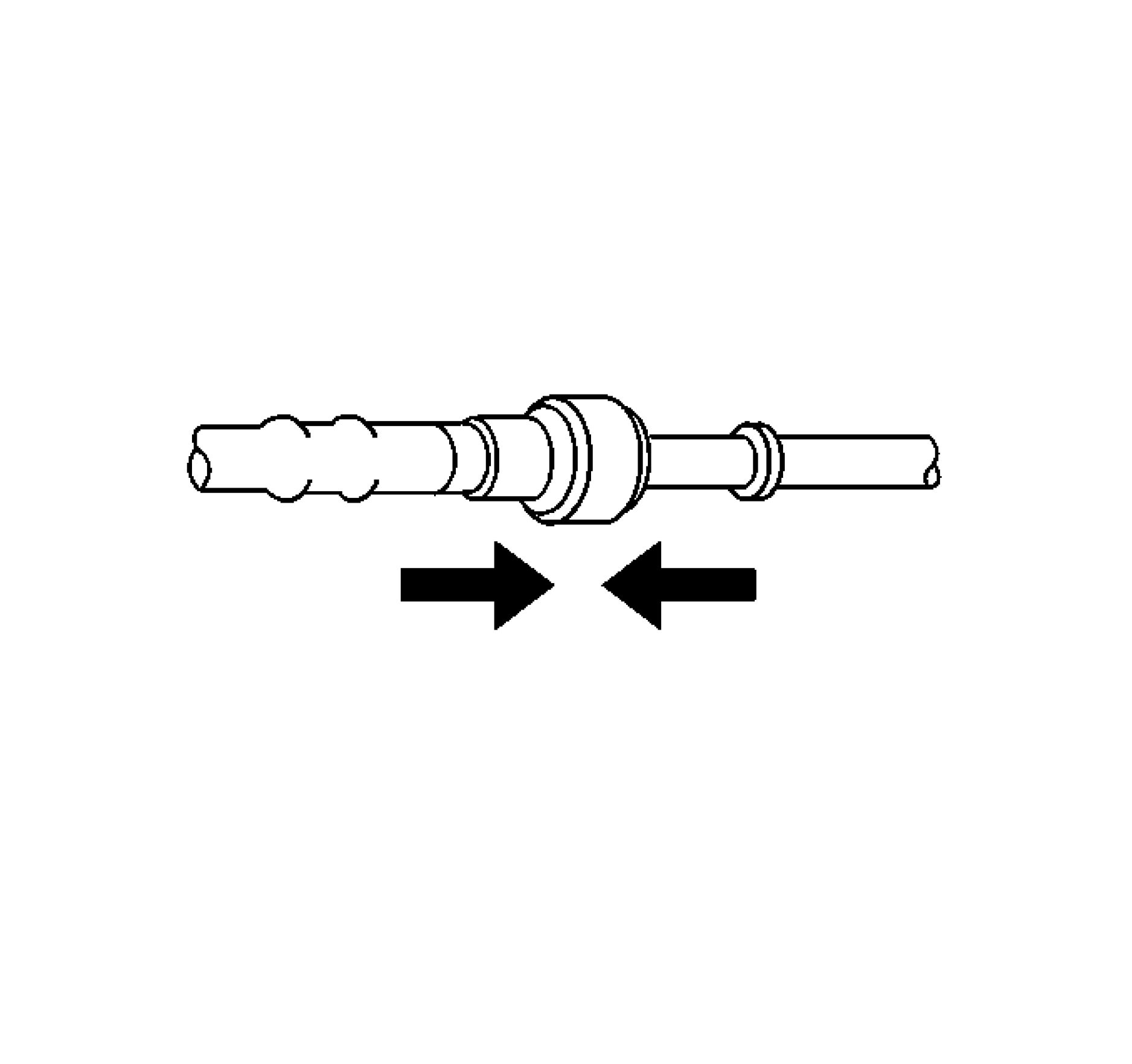 |
|
Fig. 14: View Of Connectors (Metal Collar) Courtesy of GENERAL MOTORS COMPANY |
2. Push both sides of the quick-connect fitting together to cause the retaining tabs to snap into place.
 |
|
Fig. 15: Ensuring Connection (Metal Collar) Is Secure Courtesy of GENERAL MOTORS COMPANY |
3. Pull on both sides of the quick-connect fitting to make sure the connection is secure.
 |
|
Fig. 16: View Of Fuel Pipe Retainer Courtesy of GENERAL MOTORS COMPANY |
4. Install the retainer to the quick-connect fitting.
5. Inspect for leaks using the following procedure:
1. Turn the ignition ON, with the engine OFF for 2 seconds.
2. Turn the ignition OFF, for 10 seconds.
3. Turn the ignition ON, with the engine OFF for 2 seconds.
4. Turn the ignition OFF.
5.Inspect for leaks.
PLASTIC COLLAR QUICK CONNECT FITTING SERVICE
Removal Procedure
WARNING: Refer to Diesel/Gasoline Vapors Warning .
NOTE: If servicing a fuel system, insure the fuel pressure has been relieved.
 |
|
Fig. 17: Plastic Collar Quick Connect Fitting Service |
NOTE: There are several types of plastic collar fuel and evaporative emission quick
connect fittings used on this vehicle.
• Bartholomew (1)
• Q Release (2)
• Squeeze to Release (3)
• Sliding Retainer (4)
• Global Connect (5)
• TI Loc (6)
• Safe Lock (7)
• Plastic Connector (8)
The following instructions apply to all of these types of plastic collar quick
connect fittings except where indicated.

Fig. 18: Blowing Dirt Out Of Fitting (Plastic Collar)
Courtesy of GENERAL MOTORS COMPANY
WARNING: Always apply a few drops of clean engine oil to the male pipe ends before
connecting the fuel pipe fittings. This will ensure proper reconnection and
prevent a possible fuel leak. Always replace O-rings.
1. Using compressed air, blow any dirt out of the quick-connect fitting.

Fig. 19: View Of Quick Connect Fitting Release Tabs (Plastic Collar)
Courtesy of GENERAL MOTORS COMPANY
2. This step applies to Bartholomew style connectors ONLY. Squeeze the plastic quick-connect fitting
release tabs.
 |
|
Fig. 20: Releasing Q Release Style Connectors (Plastic Collar) Courtesy of GENERAL MOTORS COMPANY |
3. This step applies to Q Release style connectors ONLY. Release the fitting by Pushing the tab toward the
other side of the slot in the fitting.

Fig. 21: Disengaging Quick Connect Fitting (Plastic Collar)
Courtesy of GENERAL MOTORS COMPANY
4. This step applies to Squeeze to Release style connectors ONLY. Squeeze where indicated by arrows on
both sides of the plastic ring surrounding the quick-connect fitting.

Fig. 22: Pushing In Male Side Of Connector
Courtesy of GENERAL MOTORS COMPANY
5. This step applies to Squeeze to Release style connectors ONLY. Push in the male side slightly in order to
slide the retainer away from the retainers, squeeze where indicated by arrows on both sides of the plastic
ring surrounding the quick-connect fitting.
 |
|
Fig. 23: Variants Of Sliding Retainer Style Connectors |
NOTE: There are two variants of sliding retainer style connectors shown above,
both have the same release and installation procedure.
6. This step applies to Sliding Retainer style connectors ONLY. Release the fitting by pressing on one side
of the release tab causing it to push in slightly. If the tab doesn't move try pressing the tab in from the
opposite side. The tab will only move in one direction.

Fig. 24: Global Connector Style
Courtesy of GENERAL MOTORS COMPANY
7. This step applies to the Global Connector style only. Push the connector toward the tube in order to
release the pressure. Press and hold down the release mechanism, and pull the connector straight out.

Fig. 25: TI Loc style
Courtesy of GENERAL MOTORS COMPANY
8. This step applies to the TI Loc style only. Push the connector toward the tube in order to release the
pressure. Release the redundant latch (1) with two fingers or a flat bladed tool. Then press and hold down
the bottom release mechanism (2) and pull the connector straight out.

Fig. 26: Safe Lock Style
Courtesy of GENERAL MOTORS COMPANY
WARNING: Refer to Relieving Fuel Pressure Warning .
9. This step applies to the Safe Lock style only. Push the connector toward the tube in order to release the
pressure. Release the second latch (1) with two fingers. Then press and hold down the bottom release
mechanism (2) and pull the connector straight out.
 |
|
Fig. 27: Latch And Connector Straight Out Courtesy of GENERAL MOTORS COMPANY |
10. This step applies to the Plastic Connector style 8, push the connector toward the tube in order to release
the pressure. Press the latch (1) inward in order to release the pipe, while pulling the connector (2)
straight out.
11. Using a clean shop towel, wipe off the male pipe end.
12. Inspect both ends of the fitting for dirt and burrs.
13. Clean or replace components as necessary.
Installation Procedure

Fig. 28: Lubricating Male Pipe End
Courtesy of GENERAL MOTORS COMPANY
WARNING: Always apply a few drops of clean engine oil to the male pipe ends before
connecting the fuel pipe fittings. This will ensure proper reconnection and
prevent a possible fuel leak. Always replace O-rings.
1. Apply a few drops of clean engine oil to the male pipe end.
 |
|
Fig. 29: Connecting Quick-Connect Fittings Courtesy of GENERAL MOTORS COMPANY |
2. Push both sides of the quick-connect fitting together in order to cause the retaining feature to snap into
place.

Fig. 30: View Of Quick-Connect Fitting
Courtesy of GENERAL MOTORS COMPANY
3. Pull on both sides of the quick-connect fitting to make sure the connection is secure.

Fig. 31: TI Loc style
Courtesy of GENERAL MOTORS COMPANY
4. Insert the tube in the connector until the retainer snaps in place.
5. Push down on the redundant latch (1) until it is fully engaged and snapped into position.

Fig. 32: Redundant Latch
Courtesy of GENERAL MOTORS COMPANY
6. Insert the tube in the connector until the retainer snaps in place.
7. Push down on the second latch (1) in order to secure the connection.

Fig. 33: Latch And Connector
Courtesy of GENERAL MOTORS COMPANY
8. For the plastic connector type 8, depress the latch (1) while inserting the connector (3) on to the pipe (2).
9. Move the latch (1) upward in order to secure the connection.
10. Inspect for leaks using the following procedure:
1. Turn the ignition ON, with the engine OFF for 2 seconds.
2. Turn the ignition OFF, for 10 seconds.
3. Turn the ignition ON, with the engine OFF for 2 seconds.
4. Turn the ignition OFF.
5.Inspect for leaks.
EVAPORATIVE EMISSION SYSTEM CLEANING
Special Tools
GE 41413 Evaporative Pressure and Purge Station
For equivalent regional tools, refer to Special Tools (Diagnostic Tools) Special Tools (Repair Tools) .
Inspection Procedure
CAUTION: Use the Evaporative Emission (EVAP) System Tester GE 41413-A in order to
provide a clean, dry, low pressure nitrogen gas source. Do not substitute any
other pressurized source, gas or otherwise. Damage may result to the EVAP
system, test equipment or cause a safety risk.
NOTE: Proceed with the following procedure only if referenced by an evaporative
emission diagnostic or repair procedure.
1. Turn OFF the ignition.
2. Remove the evaporative canister purge solenoid valve. Refer to Evaporative Emission Canister Purge
Solenoid Valve Replacement.
3. Lightly tap the evaporative canister purge valve on a hard surface.
4. Inspect for carbon particles exiting either of the vacuum ports.
• If no carbon particles were detected, but a blockage was detected during a diagnostic procedure,
install the original evaporative canister purge valve. Continue with the cleaning procedure.
• If carbon particles are found during the inspection procedure, continue with the cleaning procedure.
• If a diagnostic procedure directed you to replace the evaporative canister purge valve and no carbon
particles were detected, replace the evaporative canister purge valve. Return to the published
service procedure.
Cleaning Procedure
1. Remove the evaporative canister. Refer to Evaporative Emission Canister Replacement.
2. Turn OFF the main valve on the GE 41413 purge station.
3. Disconnect the hose from the diagnostic station pressure regulator.
4. Using a section of vacuum hose, connect one end onto the evaporative pressure/purge diagnostic station
pressure regulator.
5. Connect the other end of the vacuum hose to the canister side of the purge pipe.
6. Turn ON the main nitrogen cylinder valve and continue to discharge nitrogen for 15 seconds.
7. If the nitrogen does not clear the blockage, replace the purge pipe.
8. Return the evaporative pressure/purge diagnostic station to the stations original condition.
9. Install a new evaporative canister. Refer to Evaporative Emission Canister Replacement.
10. Install a new evaporative canister purge valve. Refer to Evaporative Emission Canister Purge Solenoid
Valve Replacement.
11. Return to the diagnostic table that sent you here.
ENGINE CONTROL MODULE REPLACEMENT
|
Removal Procedure | ||
|
module (ECM)/transaxle control module (TCM) pigtail, control module fuse,
jumper cables, etc.) in order to prevent internal control module damage.
• Control module damage may result when the metal case contacts battery
voltage. DO NOT contact the control module metal case with battery
voltage when servicing a control module, using battery booster cables, or
when charging the vehicle battery.
• In order to prevent any possible electrostatic discharge damage to the
control module, do no touch the connector pins or the soldered
components on the circuit board.
• Remove any debris from around the control module connector surfaces
before servicing the control module. Inspect the control module connector
gaskets when diagnosing or replacing the control module. Ensure that the
gaskets are installed correctly. The gaskets prevent contaminant intrusion
into the control module.
• The replacement control module must be programmed.
NOTE: It is necessary to record the engine oil life percentage remaining. Use the
scan tool to reset the engine oil life remaining back to the original
percentage recorded.
1. Prepare the engine control module (ECM) for the replacement. Refer to Control Module References .
2. Using a scan tool, retrieve the percentage of remaining engine oil. Record the remaining life engine oil
life.
3. Disconnect Battery Negative Cable Disconnection and Connection
4. Remove Front Bumper Fascia Removal and Installation

Fig. 34: ECM Electrical Connectors
Courtesy of GENERAL MOTORS COMPANY
CAUTION: In order to prevent any possible electrostatic discharge damage to the
ECM, do not touch the connector pins.
5. Disconnect the electrical connectors.(l)
 |
|
Fig. 35: Engine Control Module And Retaining Tabs |
6. Remove Engine Control Module (1) - Unlock the retaining tabs.
Installation Procedure
 |
|
Fig. 36: Engine Control Module And Retaining Tabs |
1. Install Engine Control Module (1)

Fig. 37: ECM Electrical Connectors
Courtesy of GENERAL MOTORS COMPANY
2. Connect the electrical connectors.(l)
3. Install Front Bumper Fascia Removal and Installation
4. Connect Battery Negative Cable Disconnection and Connection
5. Program the ECM. Control Module References
ENGINE CONTROL MODULE BRACKET REPLACEMENT
Removal Procedure
1. Remove Engine Control Module Replacement
 |
|
Fig. 38: Engine Control Module Bracket, Wiring Harness And Retainers |
2. Unclip Wiring Harness(1) @Engine Control Module Bracket (2)
Release Retainer (3)
 |
|
Fig. 39: Engine Control Module Bracket And Nuts |
3. Remove Nut (2)
4. Remove Engine Control Module Bracket (1)
Installation Procedure
 |
|
Fig. 40: Engine Control Module Bracket And Nuts |
1. Install Engine Control Module Bracket (1)
CAUTION: Fastener Caution
2. Install Nut (2) and tighten 9 N.m (80 lb in).
 |
|
Fig. 41: Engine Control Module Bracket, Wiring Harness And Retainers |
3. Install Wiring Harness (1) @Engine Control Module Bracket (2)
Tighten Retainer (3)
4. Install Engine Control Module Replacement
CRANKSHAFT POSITION VARIATION LEARN
The Crankshaft Position Variation Learn procedure is required when the following service procedures have been
performed, regardless of whether DTC P0315 is set:
• An engine replacement.
• A engine control module (ECM) replacement.
• A crankshaft balancer replacement.
• A crankshaft replacement.
• A crankshaft position sensor replacement.
• Any engine repairs which disturb the crankshaft to crankshaft position sensor relationship.
The ECM monitors certain component signals to determine if all the conditions are met to continue with the
Crankshaft Position Variation Learn procedure. The scan tool only displays the condition that inhibits the
procedure. The scan tool displays the signals of the components listed below:
• Crankshaft position sensors activity: If there is a crankshaft position sensor condition, refer to the
applicable DTC set.
• Camshaft position sensor signal activity: If there is a camshaft position sensor signal condition, refer to
the applicable DTC set.
• Engine coolant temperature (ECT): If the engine coolant temperature is not warm enough, idle the engine
until the engine coolant temperature reaches the correct temperature.
1. Verify no DTCs are set.
• If any DTCs other than P0300 - P0308, or P0315 are set
Refer to Diagnostic Trouble Code (DTC) List - Vehicle .
• If DTC P0300 - P0308, P0315, or no DTCs are set
NOTE: The Crankshaft Position Variation Learn may have to be repeated up to 5
times before the procedure is successful.
2. Engine Running at normal operating temperature, perform the scan tool Crankshaft Position Variation
Learn procedure and follow the on screen instructions.
3. Verify the scan tool displays Test Passed Successfully when completed.
• If Test Passed Successfully is not displayed
Verify that none of the conditions listed below exist:
• The ignition switch is in the ON position until there is insufficient system voltage.
• An ECM power disconnect with the ignition ON that may have erased the crankshaft position
system variation values and set DTC P0315.
• Interference in the signal circuit of the crankshaft position sensor.
• Debris between the crankshaft position sensor and the reluctor wheel.
• A damaged or misaligned reluctor wheel.
• Worn crankshaft main bearings.
• Excessive crankshaft runout.
• A damaged crankshaft.
• If a condition is exists, repair or replace as necessary.
• If no conditions exist, replace the K20 Engine Control Module.
• If Test Passed Successfully is displayed
4. Clear all DTCs.
5. Engine Running.
6. Verify a DTC is not set.
• If a DTC is set
Refer to Diagnostic Trouble Code (DTC) List - Vehicle .
• If a DTC is not set
7. All OK.
Repair Instructions
Perform the Diagnostic Repair Verification after completing the repair.
Control Module References for engine control module replacement, programming, and setup.
ENGINE COOLANT TEMPERATURE SENSOR REPLACEMENT - WATER OUTLET
1. Drain the cooling system. Cooling System Draining and Filling
2. Remove Heater Outlet Hose Vapor Vent Hose Replacement
3. Remove Radiator Inlet Hose@Water Outlet Radiator Inlet Hose Replacement
 |
|
Fig. 42: Heater Outlet Hose Clamp Courtesy of GENERAL MOTORS COMPANY |
4. Loosen Heater Outlet Hose Clamp (2)
5. Disconnect Heater Outlet Hose (1)
 |
|
Fig. 43: Engine Coolant Temperature Sensor, Electrical Connector, Retainer And Seal |
6. Disconnect the engine coolant temperature sensor electrical connector.(3)
7. Remove Engine Coolant Temperature Sensor Retainer (4)
8. Remove the engine coolant temperature sensor.(2)
9. Remove and DISCARD the seal.(1)
Installation Procedure
 |
|
Fig. 44: Engine Coolant Temperature Sensor, Electrical Connector, Retainer And Seal |
1. Install a NEW seal.(1)
2. Install the engine coolant temperature sensor.(2)
3. Install Engine Coolant Temperature Sensor Retainer (4)
4. Connect the engine coolant temperature sensor electrical connector.(3)
 |
|
Fig. 45: Heater Outlet Hose Clamp Courtesy of GENERAL MOTORS COMPANY |
5. Connect Heater Outlet Hose (1)
6. Tighten Heater Outlet Hose Clamp (2)
7. Install Radiator Inlet Hose@Water Outlet Radiator Inlet Hose Replacement
8. Install Heater Outlet Hose Vapor Vent Hose Replacement
9. Fill the cooling system. Cooling System Draining and Filling
MANIFOLD ABSOLUTE PRESSURE SENSOR REPLACEMENT
Removal Procedure
1. Relieve the fuel system pressure. Fuel Pressure Relief
2. Disconnect Battery Negative Cable Disconnection and Connection
3. Remove Air Inlet Grille Panel Replacement
4. Remove Intake Manifold Cover Replacement
5. Remove Air Cleaner Outlet Duct Replacement
 |
|
Fig. 46: Air Cleaner Resonator Bracket, Bolt And Wiring Harness Clip |
6. Unclip Wiring Harness Clip (3)
7. Remove Air Cleaner Resonator Bracket Bolt (1)
8. Remove Air Cleaner Resonator Bracket (2)
 |
|
Fig. 47: Fuel Feed Front Pipe And Fuel Injection Pump |
9. Disconnect Fuel Feed Front Pipe (2) @Fuel Injection Pump (1)
10. Close all open connections with the EN-6015 plugs.
11. Remove Fuel Feed Front Pipe (2)
 |
|
Fig. 48: Manifold Absolute Pressure Sensor, Electrical Connector, Bolt And Seal Ring |
12. Disconnect the electrical connector.(1)
13. Remove the manifold absolute pressure sensor bolt.(2)
14. Remove the manifold absolute pressure sensor.(3)
15. Remove the seal ring.(4)
Installation Procedure
 |
|
Fig. 49: Manifold Absolute Pressure Sensor, Electrical Connector, Bolt And Seal Ring |
1. Install Seal Ring (4)
2. Install Manifold Absolute Pressure Sensor (3)
CAUTION: Fastener Caution
3. Install Manifold Absolute Pressure Sensor Bolt (2) and tighten 10 N.m (89 lb in)
4. Connect the electrical connector.(1)
 |
|
Fig. 50: Fuel Feed Front Pipe And Fuel Injection Pump |
Courtesy of GENERAL MOTORS COMPANY
5. Install Fuel Feed Front Pipe (2)
6. Remove all EN-6015 plugs from the connections.
7. Connect Fuel Feed Front Pipe (2) @Fuel Injection Pump (1)
 |
|
Fig. 51: Air Cleaner Resonator Bracket, Bolt And Wiring Harness Clip |
8. Install Air Cleaner Resonator Bracket (2)
9. Install Air Cleaner Resonator Bracket Bolt (1) and tighten 9 N.m (80 lb in)
10. Install Wiring Harness Clip (3)
11. Install Air Inlet Grille Panel Replacement
12. Install Intake Manifold Cover Replacement
13. Install Air Cleaner Outlet Duct Replacement
14. Connect the negative battery cable. Battery Negative Cable Disconnection and Connection
KNOCK SENSOR REPLACEMENT
 |
|
Fig. 52: Knock Sensor |
|
Courtesy of GENERAL MOTORS COMPANY | ||
|
|
Preliminary Procedure | ||||
|
EXHAUST GAS RECIRCULATION VALVE REPLACEMENT
Removal Procedure
1. Remove Exhaust Gas Recirculation Cooler Temperature Sensor Replacement - Position 1
2. Drain the cooling system. Cooling System Draining and Filling
 |
|
Fig. 53: Engine Wiring Harness Bracket, Bolt, Nut And Electrical Connector |
3. Remove Engine Wiring Harness Bracket Bolt (1)
4. Remove Engine Wiring Harness Bracket Nut (3)
5. Position aside Engine Wiring Harness Bracket (4) -
6. Disconnect the electrical connector.(2)
 |
|
Fig. 54: EGR Valve Bolts, Cooling Return Hose, Clamp And EGR Cooler Bolts |
7. Loosen Clamp (6)
8. Disconnect Exhaust Gas Recirculation Valve Cooling Return Hose (5)
9. Remove Exhaust Gas Recirculation Cooler Bolt (4)
10. Exhaust Gas Recirculation Valve Bolt (2, 3)
 |
|
Fig. 55: Exhaust Gas Recirculation Valve And Gaskets |
11. Remove Exhaust Gas Recirculation Valve (1)
12. Remove Gasket (2, 3)
Installation Procedure
 |
|
Fig. 56: Exhaust Gas Recirculation Valve And Gaskets |
1. Install Gasket (2, 3)
2. Install Exhaust Gas Recirculation Valve (1)
 |
|
Fig. 57: EGR Valve Bolts, Cooling Return Hose, Clamp And EGR Cooler Bolts |
3. Install Exhaust Gas Recirculation Valve Bolt (2, 3)
4. Install Exhaust Gas Recirculation Cooler Bolt (4)
CAUTION: Fastener Caution
5. Exhaust Gas Recirculation Valve Bolt (2, 3) - Tighten 10 N.m (89 lb in)
6. Exhaust Gas Recirculation Cooler Bolt (4) - Tighten 10 N.m (89 lb in)
7. Connect Exhaust Gas Recirculation Valve Cooling Return Hose (5)
8. Tighten Clamp (6)
 |
|
Fig. 58: Engine Wiring Harness Bracket, Bolt, Nut And Electrical Connector |
9. Install Engine Wiring Harness Bracket (4)
10. Connect the electrical connector.(2)
11. Install Engine Wiring Harness Bracket Nut (3) and tighten 9 N.m (80 lb in)
12. Install Engine Wiring Harness Bracket Bolt (1) and tighten 9 N.m (80 lb in)
13. Fill the cooling system. Cooling System Draining and Filling
14. Install Exhaust Gas Recirculation Cooler Temperature Sensor Replacement - Position 1
EXHAUST GAS RECIRCULATION COOLER TEMPERATURE SENSOR REPLACEMENT -
POSITION 1
Removal Procedure
WARNING: Exhaust Service Warning
1. Disconnect Battery Negative Cable Disconnection and Connection
2. Remove Intake Manifold Cover Replacement
 |
|
Fig. 59: EGR Cooler Temperature Sensor, Wiring Harness, EGR Cooler, Camshaft Cover Bracket Courtesy of GENERAL MOTORS COMPANY |
3. Disconnect the electrical connector.(1)
4. Remove Exhaust Gas Recirculation Cooler Temperature Sensor Wiring Harness@Camshaft Cover
Bracket (2)
5. Remove Exhaust Gas Recirculation Cooler Temperature Sensor (4) @Exhaust Gas Recirculation Cooler
(3)
Installation Procedure
 |
|
Fig. 60: EGR Cooler Temperature Sensor, Wiring Harness, EGR Cooler, Camshaft Cover Bracket Courtesy of GENERAL MOTORS COMPANY |
CAUTION: Fastener Caution
1. Install Exhaust Gas Recirculation Cooler Temperature Sensor (4) and tighten 42 N.m (31 lb ft)
2. Install Exhaust Gas Recirculation Cooler Temperature Sensor Wiring Harness@Camshaft Cover Bracket
(2)
3. Connect the electrical connector.(1)
4. Install Intake Manifold Cover Replacement
5. Connect Battery Negative Cable Disconnection and Connection
EXHAUST GAS RECIRCULATION COOLER TEMPERATURE SENSOR REPLACEMENT -
POSITION 2
Removal Procedure
WARNING: Exhaust Service Warning
1. Disconnect Battery Negative Cable Disconnection and Connection
2. Remove Intake Manifold Cover Replacement
3. Remove Three-Way Catalytic Converter Replacement
 |
|
Fig. 61: EGR Cooler Temperature Sensor, EGR Cooler, Wiring Harness Clip And Electrical Courtesy of GENERAL MOTORS COMPANY |
4. Disconnect the electrical connector.(l)
5. Unclip Exhaust Gas Recirculation Cooler Temperature Sensor (2) @Wiring Harness Clip (4)
6. Remove Exhaust Gas Recirculation Cooler Temperature Sensor (2) @Exhaust Gas Recirculation Cooler
(3)
Installation Procedure
 |
|
Fig. 62: EGR Cooler Temperature Sensor, EGR Cooler, Wiring Harness Clip And Electrical Courtesy of GENERAL MOTORS COMPANY |
CAUTION: Fastener Caution
1. Install Exhaust Gas Recirculation Cooler Temperature Sensor (2) and tighten 42 N.m (31 lb ft)
2. Exhaust Gas Recirculation Cooler Temperature Sensor (2) @Wiring Harness Clip (4)
3. Connect the electrical connector.(1)
4. Install Three-Way Catalytic Converter Replacement
5. Install Intake Manifold Cover Replacement
6. Connect Battery Negative Cable Disconnection and Connection
EXHAUST GAS RECIRCULATION COOLER OUTLET PIPE REPLACEMENT
Removal Procedure
1. Remove Dash Upper Extension Panel Opening Cover Replacement
2. Remove Air Cleaner Outlet Duct Replacement
3. Remove Water Outlet Replacement
4. Remove Three-Way Catalytic Converter Replacement
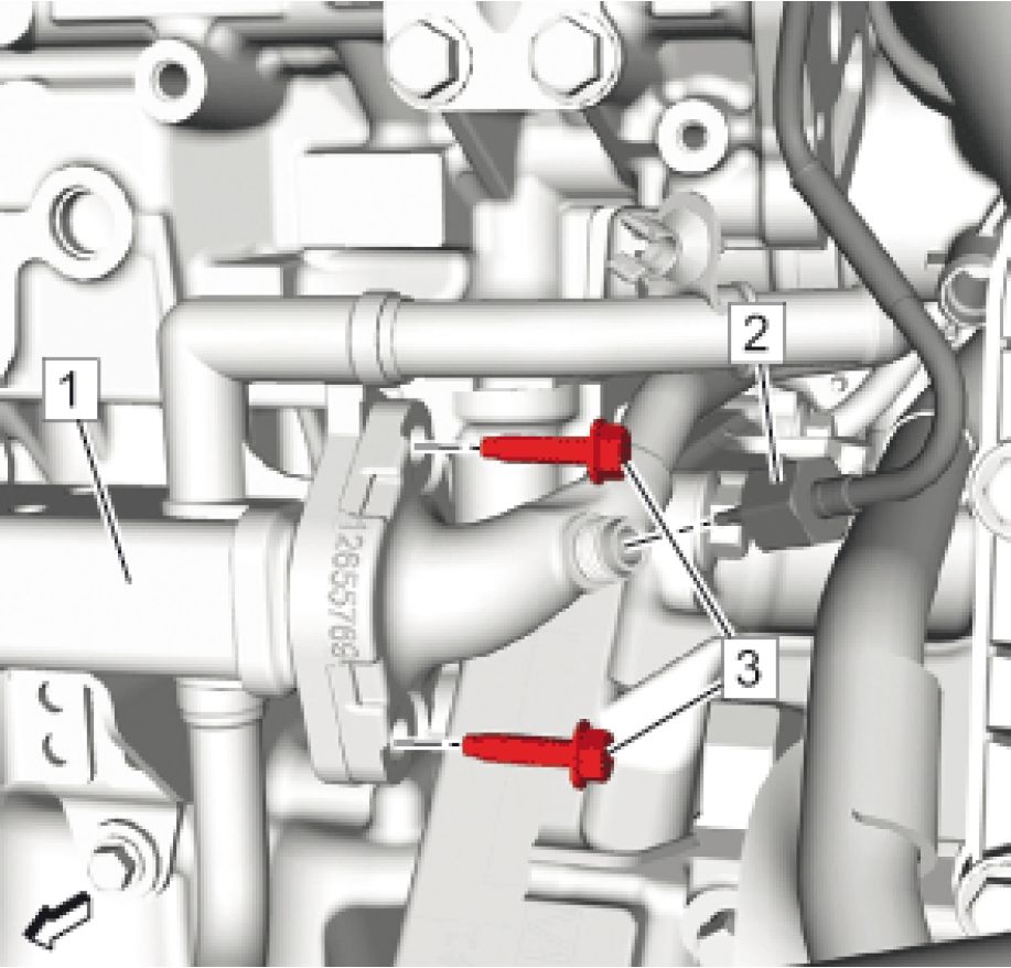 |
|
Fig. 63: EGR Temperature Sensor - Position 2, EGR Cooler And Bolts |
5. Remove the exhaust gas recirculation temperature sensor - position 2 (2).
6. Remove Exhaust Gas Recirculation Cooler Bolt (3) @Exhaust Gas Recirculation Cooler (1)
 |
|
Fig. 64: Exhaust Gas Recirculation Pipe Bolts |
7. Remove Exhaust Gas Recirculation Pipe Bolt (1)
 |
|
Fig. 65: Exhaust Gas Recirculation Cooler Outlet Pipe And Seals |
8. Remove Exhaust Gas Recirculation Cooler Outlet Pipe (2)
9. Remove Exhaust Gas Recirculation Cooler Outlet Pipe Seal (1, 3) and DISCARD
Installation Procedure
 |
|
Fig. 66: Exhaust Gas Recirculation Cooler Outlet Pipe And Seals |
1. Install a NEW seal.(1, 3)
2. Install Exhaust Gas Recirculation Cooler Outlet Pipe (3)
 |
|
Fig. 67: Exhaust Gas Recirculation Pipe Bolts |
NOTE: Do NOT tighten.
3. Install Exhaust Gas Recirculation Pipe Bolt (1)
 |
|
Fig. 68: EGR Temperature Sensor - Position 2, EGR Cooler And Bolts |
NOTE: Do NOT tighten.
4. Install Exhaust Gas Recirculation Pipe Bolt (3) @Exhaust Gas Recirculation Cooler (1)
CAUTION: Fastener Caution
5. Exhaust Gas Recirculation Pipe Bolt (3) - Tighten 10 N.m (89 lb in)
 |
|
Fig. 69: Exhaust Gas Recirculation Pipe Bolts |
6. Exhaust Gas Recirculation Cooler Bolt (1) - Tighten 10 N.m (89 lb in)
 |
|
Fig. 70: EGR Temperature Sensor - Position 2, EGR Cooler And Bolts Courtesy of GENERAL MOTORS COMPANY |
7. Install the exhaust gas recirculation temperature sensor - position 2 (2) and tighten to 42 N.m (31 lb ft).
8. Install Three-Way Catalytic Converter Replacement
9. Install Water Outlet Replacement
10. Install Air Cleaner Outlet Duct Replacement
11. Install Dash Upper Extension Panel Opening Cover Replacement
EXHAUST GAS RECIRCULATION VALVE COOLING RETURN HOSE REPLACEMENT

Fig. 71: Exhaust Gas Recirculation Valve Cooling Return Hose
Courtesy of GENERAL MOTORS COMPANY
|
Callout |
Component Name |
|
Preliminary Procedure Cooling System Draining and Filling | |
|
1 |
Clamp (Qty: 2) |
|
2 |
Exhaust Gas Recirculation Valve Cooling Return Hose |
EXHAUST GAS RECIRCULATION COOLER REPLACEMENT
Removal Procedure
1. Drain the cooling system. Cooling System Draining and Filling
2. Remove Three-Way Catalytic Converter Replacement
 |
|
Fig. 72: EGR Cooler, EGR Cooler Water Bypass Outlet Hose, Heater Inlet Hose And Clamps |
3. Loosen Clamp(3)
4. Disconnect Heater Inlet Hose (2)@Exhaust Gas Recirculation Cooler (1)
5. Disconnect Exhaust Gas Recirculation Cooler Water Bypass Outlet Hose (4) @Exhaust Gas Recirculation
Cooler (1)
 |
|
Fig. 73: Thermostat Bypass Hose Clamp Courtesy of GENERAL MOTORS COMPANY |
6. Loosen Thermostat Bypass Hose Clamp (1)
7. Disconnect Thermostat Bypass Hose (2)
 |
|
Fig. 74: EGR Temperature Sensor - Position 1, EGR Cooler And Bolts |
8. Remove the exhaust gas recirculation temperature sensor - position 1 (1) from exhaust gas recirculation
cooler (3).
9. Remove Exhaust Gas Recirculation Cooler Bolt (2)
 |
|
Fig. 75: EGR Temperature Sensor - Position 2, EGR Cooler And Bolts |
10. Remove the exhaust gas recirculation temperature sensor - position 2 (2).
11. Remove Exhaust Gas Recirculation Cooler Bolt (3) @Exhaust Gas Recirculation Cooler (1)
 |
|
Fig. 76: EGR Cooler, Bolts And Gaskets Courtesy of GENERAL MOTORS COMPANY |
12. Remove Exhaust Gas Recirculation Cooler Bolt (3)
13. Remove Exhaust Gas Recirculation Cooler (4)
14. Remove Gasket (1, 2) and DISCARD
Installation Procedure
 |
|
Fig. 77: EGR Cooler, Bolts And Gaskets Courtesy of GENERAL MOTORS COMPANY |
1. Install a NEW gasket.(1, 2)
2. Install Exhaust Gas Recirculation Cooler (4)
NOTE: Do NOT tighten.
3. Install Exhaust Gas Recirculation Cooler Bolt (3)
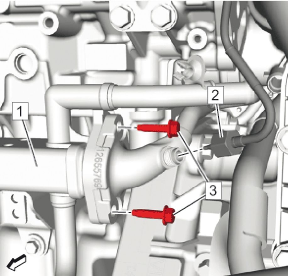 |
|
Fig. 78: EGR Temperature Sensor - Position 2, EGR Cooler And Bolts |
NOTE: Do NOT tighten.
4. Install Exhaust Gas Recirculation Cooler Bolt (3) @Exhaust Gas Recirculation Cooler(1)
CAUTION: Fastener Caution
5. Install the exhaust gas recirculation temperature sensor - position 2 (2) and tighten to 42 N.m (31 lb ft).
 |
|
Fig. 79: EGR Temperature Sensor - Position 1, EGR Cooler And Bolts |
NOTE: Do NOT tighten.
6. Install Exhaust Gas Recirculation Cooler Bolt (2)
7. Install the exhaust gas recirculation temperature sensor - position 1 (1) to the exhaust gas recirculation
cooler (3) and tighten to 42 N.m (31 lb ft).
8. Tighten all 6 exhaust gas recirculation cooler bolts to 10 N.m (89 lb in)
 |
|
Fig. 80: Thermostat Bypass Hose Clamp Courtesy of GENERAL MOTORS COMPANY |
9. Connect Thermostat Bypass Hose (2) -
10. Tighten Thermostat Bypass Hose Clamp (1) - Tighten
 |
|
Fig. 81: EGR Cooler, EGR Cooler Water Bypass Outlet Hose, Heater Inlet Hose And Clamps |
11. Connect Heater Inlet Hose (2) @Exhaust Gas Recirculation Cooler (1)
12. Connect Exhaust Gas Recirculation Cooler Water Bypass Outlet Hose (4) @Exhaust Gas Recirculation
Cooler (1)
13. Clamp (3) - Tighten
14. Install Three-Way Catalytic Converter Replacement
15. Fill the cooling system. Cooling System Draining and Filling
EXHAUST GAS RECIRCULATION PIPE REPLACEMENT

Fig. 82: Exhaust Gas Recirculation Pipe
Courtesy of GENERAL MOTORS COMPANY
|
Callout |
Component Name |
|
Preliminary Procedure Air Cleaner Outlet Duct Replacement | |
|
1 |
Exhaust Gas Recirculation Pipe Bolt (Qty: 5) CAUTION: Refer to Caution . Tighten 10 N.m (89 lb in) |
|
2 |
Exhaust Gas Recirculation Pipe |
|
3 |
Exhaust Gas Recirculation Pipe Gasket (Qty: 2) |
THROTTLE BODY ASSEMBLY REPLACEMENT
Removal Procedure
1. Disable the high voltage system. High Voltage Disabling
2. Remove Dash Upper Extension Panel Opening Cover Dash Upper Extension Panel Opening Cover
Replacement
3. Remove Air Cleaner Outlet Duct Air Cleaner Outlet Duct Replacement
 |
|
Fig. 83: Throttle Body, Electrical Connector And Bolts |
4. Disconnect Electrical Connector (2)
5. Remove Throttle Body Bolt (1)
6. Remove Throttle Body (3)
 |
|
Fig. 84: Gasket And Intake Manifold Courtesy of GENERAL MOTORS COMPANY |
7. Remove Throttle Body Gasket (1)and DISCARD
Installation Procedure
 |
|
Fig. 85: Gasket And Intake Manifold Courtesy of GENERAL MOTORS COMPANY |
1. Clean the intake manifold mating surfaces.(2)
2. Install NEW Throttle Body Gasket (1)
 |
|
Fig. 86: Throttle Body, Electrical Connector And Bolts Courtesy of GENERAL MOTORS COMPANY |
3. Install Throttle Body (3)
CAUTION: Refer to Fastener Caution .
4. Install Throttle Body Bolt (1) and tighten 10 N.m (89 lb in)
5. Connect Electrical Connector (2)
6. Install Air Cleaner Outlet Duct Air Cleaner Outlet Duct Replacement
7. Install Dash Upper Extension Panel Opening Cover Dash Upper Extension Panel Opening Cover
Replacement
8. Enable the high voltage system. High Voltage Disabling
9. Perform the throttle or idle learn. Throttle or Idle Learn
THROTTLE BODY INSPECTION AND CLEANING
1. Remove Throttle Body Assembly Replacement
WARNING: Turn OFF the ignition before inserting fingers into the throttle bore.
Unexpected movement of the throttle blade could cause personal injury.
CAUTION: Do not insert any tools into the throttle body bore in order to avoid
damage to the throttle valve plate.
NOTE: Open the throttle valve in order to inspect all surfaces.
2. Inspect the throttle body bore and the throttle valve plate for deposits.
CAUTION: Do not use any solvent that contains Methyl Ethyl Ketone (MEK). This
solvent may damage fuel system components.
3. Clean the throttle body bore and the throttle valve plate using a clean shop towel with an appropriate
cleaner.
4. Install Throttle Body Assembly Replacement.
5. Throttle or Idle Learn
FUEL PRESSURE RELIEF
WARNING: Fuel that flows out at high pressure can cause serious injury to the skin and
eyes. ALWAYS depressurize the fuel system before removing components that
are under high fuel pressure.
WARNING: Remove the fuel tank cap and relieve the fuel system pressure before servicing
the fuel system in order to reduce the risk of personal injury. After you relieve
the fuel system pressure, a small amount of fuel may be released when
servicing the fuel lines, the fuel injection pump, or the connections. In order to
reduce the risk of personal injury, cover the fuel system components with a
shop towel before disconnection. This will catch any fuel that may leak out.
Place the towel in an approved container when the disconnection is complete.
Scan Tool Method - Preferred
1. Install a scan tool and turn the ignition ON.
2. Using the scan tool, command the fuel pump OFF allowing the low pressure fuel pump to shut off.
3. Start the vehicle and allow the engine to idle until the engine stops. The engine will stop in approximately
5-20 seconds.
4. Repeat step 3. Using the scan tool, verify pressure has dropped to a minimal level.
5. Turn the ignition OFF.
Alternate Method - If a scan tool is not available
1. Disable the fuel pump by removing the B+ fuel pump control module fuse. Refer to Electrical Center
Identification Views .
2. Start the vehicle and allow the engine to idle until the engine stops. The engine will stop in approximately
5-20 seconds.
3. Attempt to restart the vehicle to ensure pressure has dropped to a minimal level.
4. Turn the ignition OFF.
FUEL TANK DRAINING
Special Tool
CH 45004 Fuel Tank Drain Hose
WARNING: Never drain or store fuel in an open container. Always use an approved fuel
storage container in order to reduce the chance of fire or explosion.
WARNING: Place a dry chemical (Class B) fire extinguisher nearby before performing any
on-vehicle service procedures. Failure to follow these precautions may result in
personal injury.
1. Remove the fuel fill cap.

Fig. 87: Draining Fuel Tank
Courtesy of GENERAL MOTORS COMPANY
NOTE: Lubricate the fuel drain hose with Transjel Lubricant or equivalent to aid in
hose insertion.
2. Insert the CH 45004 hose into the fuel tank until the bottom is reached.
3. Use a hand or air operated pump device in order to drain as much fuel through the fuel fill pipe as
possible.
FUEL TANK FILLER PIPE REPLACEMENT
Special Tools
EN-6015 Closure Plugs
Equivalent regional tools:Special Tools (Diagnostic Tools) Special Tools (Repair Tools)
Removal Procedure
WARNING: Diesel/Gasoline Vapors Warning
WARNING: Safety Goggles and Fuel Warning
1. Disconnect Battery Negative Cable Disconnection and Connection
2. Drain the fuel tank. Fuel Tank Draining
3. Remove Fuel Tank Filler Pipe Housing Replacement
 |
|
Fig. 88: Fuel Tank Filler Pipe Bolt Courtesy of GENERAL MOTORS COMPANY |
4. Remove Fuel Tank Filler Pipe Bolt (1)
5. Raise and support the vehicle. Lifting and Jacking the Vehicle
6. Remove Rear Wheelhouse Liner Replacement - Right Side

Fig. 89: Fuel Tank Filler Pipe Ground Bolt And Wiring Harness Clip
Courtesy of GENERAL MOTORS COMPANY
7. Remove Fuel Tank Filler Pipe Ground Bolt (1)
8. Remove Wiring Harness Clip (2)
 |
|
Fig. 90: Evaporative Emission System Vacuum Leak Pump Filter Pipe, Fuel Tank Filler Hose, Vent Pipe, Clamp And Retainer Courtesy of GENERAL MOTORS COMPANY |
9. Disconnect the evaporative emission system vacuum leak pump filter pipe (6). Refer to Plastic Collar
Quick Connect Fitting Service.
10. Close all open connections with the EN-6015 plugs.
11. Disconnect the fuel tank vent pipe (3). Refer to Plastic Collar Quick Connect Fitting Service.
12. Close all open connections with the EN-6015 plugs.
13. Loosen the clamp.(4)
14. Remove Retainer (1)

Fig. 91: Fuel Tank Filler Pipe
Courtesy of GENERAL MOTORS COMPANY
15. Fuel Tank Filler Pipe (1)
Installation Procedure
 |
|
Fig. 92: Fuel Tank Filler Pipe Courtesy of GENERAL MOTORS COMPANY |
1. Install Fuel Tank Filler Pipe (1)
 |
|
Fig. 93: Evaporative Emission System Vacuum Leak Pump Filter Pipe, Fuel Tank Filler Hose, Vent Courtesy of GENERAL MOTORS COMPANY |
2. Install the fuel tank filler hose (5) onto the fuel tank.
 |
|
Fig. 94: Ensure Filler Hose Is Fully Seated And Installed Correctly |
3. Make sure that the hose is fully seated on the fuel tank. Filler hose is correctly installed when the end of
the hose is even with where the fill spud on the tank increases in diameter. The gap (1) between the tank
and the end of hose will be (a) 6 mm (1/4 in) when hose is correctly installed.
 |
|
Fig. 95: Evaporative Emission System Vacuum Leak Pump Filter Pipe, Fuel Tank Filler Hose, Vent Courtesy of GENERAL MOTORS COMPANY |
CAUTION: Fastener Caution
4. Tighten the clamp.(4) 3.5 N.m (31 lb in)
5. Remove all EN-6015 plugs from the connections.
6. Connect the fuel tank vent pipe (3). Refer to Plastic Collar Quick Connect Fitting Service.
7. Remove all EN-6015 plugs from the connections.
8. Connect the evaporative emission system vacuum leak pump filter pipe (6). Refer to Plastic Collar
Quick Connect Fitting Service.
9. Install Retainer (1)
 |
|
Fig. 96: Fuel Tank Filler Pipe Ground Bolt And Wiring Harness Clip |
10. Install Fuel Tank Filler Pipe Ground Bolt (1) and tighten 9 N.m (80 lb in)
11. Install Wiring Harness Clip (2)
12. Install Rear Wheelhouse Liner Replacement - Right Side
13. Lower the vehicle.
 |
|
Fig. 97: Fuel Tank Filler Pipe Bolt Courtesy of GENERAL MOTORS COMPANY |
14. Install Fuel Tank Filler Pipe Bolt (1) and tighten 9 N.m (80 lb in)
15. Connect Fuel Tank Filler Pipe Housing Replacement
16. Refill the fuel tank.
17. Connect Battery Negative Cable Disconnection and Connection
FUEL FEED PIPE REPLACEMENT
Special Tools
EN-6015 Closure Plugs
Equivalent regional tools:Special Tools (Diagnostic Tools) Special Tools (Repair Tools)
Removal Procedure
WARNING: Diesel/Gasoline Vapors Warning
WARNING: Safety Goggles and Fuel Warning
1. Relieve the fuel system pressure. Fuel Pressure Relief
2. Disconnect Battery Negative Cable Disconnection and Connection
 |
|
Fig. 98: Fuel Feed Front Pipe, Fuel Feed Pipe And Retainer Courtesy of GENERAL MOTORS COMPANY |
3. Disconnect Fuel Feed Front Pipe (3) @Fuel Feed Pipe (2) -Metal Collar Quick Connect Fitting Service
4. Close all open connections with the EN-6015 plugs.
5. Open the retainer (1).
6. Remove Fuel Feed Pipe (2) @Retainer (1)
7. Raise and support the vehicle. Lifting and Jacking the Vehicle
8. Remove Underbody Rear Air Deflector Replacement
9. Remove Underbody Front Air Deflector Replacement - Left Side
10. Remove Drivetrain and Front Suspension Cradle Replacement
 |
|
Fig. 99: Fuel Feed Pipe And Retainers Courtesy of GENERAL MOTORS COMPANY |
11. Open the 2 retainers (1).
12. Remove Fuel Feed Pipe (2) @Retainer (1)
 |
|
Fig. 100: Fuel Feed Pipe, Retainer And Electrical Connector |
13. Open the retainer (1).
14. Fuel Feed Pipe (3) @Retainer (1)
15. Disconnect the electrical connector.(2)
 |
|
Fig. 101: Fuel Feed Pipe, Fuel Pump Fuel Feed Hose And Retainer |
16. Open the retainer (2).
17. Disconnect Fuel Feed Pipe (1) @Fuel Pump Fuel Feed Hose (3) Plastic Collar Quick Connect Fitting
Service
18. Close all open connections with the EN-6015 plugs.
19. Remove Fuel Feed Pipe (1) @Retainer (2)
 |
|
Fig. 102: Fuel Feed Pipe And Retainers Courtesy of GENERAL MOTORS COMPANY |
20. Open the 3 retainers (1).
21. Remove Fuel Feed Pipe (2) @Retainer (1)
22. Remove the fuel feed pipe (2) from the vehicle.
Installation Procedure
 |
|
Fig. 103: Fuel Feed Pipe And Retainers Courtesy of GENERAL MOTORS COMPANY |
1. Install the fuel feed pipe (2) to the vehicle.
2. Install Fuel Feed Pipe (2) @Retainer(1)
3. Close the 3 retainers (1).
 |
|
Fig. 104: Fuel Feed Pipe, Fuel Pump Fuel Feed Hose And Retainer |
4. Install Fuel Feed Pipe(1)@Retainer(2)
5. Remove all EN-6015 plugs from the connections.
6. Connect Fuel Feed Pipe(1)@Fuel Pump Fuel Feed Hose(3)Plastic Collar Quick Connect Fitting
Service
7. Close the retainer (2).
 |
|
Fig. 105: Fuel Feed Pipe, Retainer And Electrical Connector |
8. Connect the electrical connector.(2)
9. Install Fuel Feed Pipe(3)@Retainer(1)
10. Close the retainer (1).
 |
|
Fig. 106: Fuel Feed Pipe And Retainers Courtesy of GENERAL MOTORS COMPANY |
11. Install Fuel Feed Pipe(2)@Retainer(1)
12. Close the 2 retainers (1).
13. Install Drivetrain and Front Suspension Cradle Replacement
14. Install Underbody Front Air Deflector Replacement - Left Side
15. Install Underbody Rear Air Deflector Replacement
16. Lower the vehicle.
 |
|
Fig. 107: Fuel Feed Front Pipe, Fuel Feed Pipe And Retainer |
17. Install Fuel Feed Pipe (2) @Retainer (1)
18. Close the retainer (1).
19. Remove all EN-6015 plugs from the connections.
20. Connect Fuel Feed Front Pipe (3) @Fuel Feed Pipe (2)Metal Collar Quick Connect Fitting Service
21. Connect Battery Negative Cable Disconnection and Connection
22. Cycle the ignition to run the fuel pump and check for fuel leaks.
FUEL TANK FUEL PUMP MODULE REPLACEMENT
Special Tools
CH-45722 Fuel Sender Lock Ring Wrench
Equivalent regional tools:Special Tools (Diagnostic Tools) Special Tools (Repair Tools)
Removal Procedure
WARNING: Safety Goggles and Fuel Warning
WARNING: Diesel/Gasoline Vapors Warning
WARNING: Fuel Vapors in Evaporative Emission Components Warning
1. Remove Fuel Tank Replacement
 |
|
Fig. 108: Fuel Pump Feed Hose, Evaporative Emission Canister Hose, Evaporative Emission Rear Courtesy of GENERAL MOTORS COMPANY |
2. Remove Retainer (2, 5, 7)
3. Remove Fuel Pump Fuel Feed Hose (8) Plastic Collar Quick Connect Fitting Service
4. Remove the evaporative emission canister hose (1). Refer to Plastic Collar Quick Connect Fitting
Service.
5. Remove Evaporative Emission Rear Hose (3) Plastic Collar Quick Connect Fitting Service
6. Disconnect the electrical connector (6) and remove the fuel tank fuel pump module wiring harness (4).
 |
|
Fig. 109: Fuel Pump Module Lock Ring And Wrench |
7. Install the CH-45722 wrench (1) to the fuel pump module lock ring (2).
NOTE: DO NOT use impact tools. Significant force will be required to release the
lock ring. The use of a hammer and screwdriver is not recommended.
Secure the fuel tank in order to prevent fuel tank rotation.
8. Using the CH-45722 wrench (1) and a long breaker-bar, rotate the lock ring in a counterclockwise
direction in order to unlock the lock ring.
9. Remove the CH-45722 wrench (1).
10. Remove the fuel pump module lock ring (2).
 |
|
Fig. 110: Fuel Pump Module And Vent Valve Connector |
11. Partially raise the fuel pump module (1) and disconnect the vent valve connector (2). Refer to Plastic
Collar Quick Connect Fitting Service.
 |
|
Fig. 111: Fuel Tank Fuel Pump Module And Seal |
NOTE: Lift the fuel tank fuel pump module up slightly. Pay attention to the fuel
level sensor.
12. Remove Fuel Tank Fuel Pump Module (1)
13. Remove and DISCARD the fuel pump module seal (2).
Installation Procedure
 |
|
Fig. 112: Fuel Tank Fuel Pump Module And Seal |
1. Install a NEW fuel pump module seal (2).
NOTE: Pay attention to the fuel level sensor.
2. Install Fuel Tank Fuel Pump Module (1)
 |
|
Fig. 113: Fuel Pump Module And Vent Valve Connector |
3. Connect the vent valve connector (2). Refer to Plastic Collar Quick Connect Fitting Service.
 |
|
Fig. 114: Fuel Pump Module Lock Ring And Wrench |
4. Install the fuel pump module lock ring (2).
5. Install the CH-45722 wrench (1) to the fuel pump module lock ring (2).
NOTE: DO NOT use impact tools. Significant force will be required to release the
lock ring. The use of a hammer and screwdriver is not recommended.
Secure the fuel tank in order to prevent fuel tank rotation.
6. Using the CH-45722 wrench (1) and a long breaker bar, rotate the lock ring in a clockwise direction in
order to lock the lock ring.
7. Remove the CH-45722 wrench (1).
 |
|
Fig. 115: Fuel Pump Feed Hose, Evaporative Emission Canister Hose, Evaporative Emission Rear |
8. Connect the electrical connector (6).
9. Install Evaporative Emission Rear Hose (3) -Plastic Collar Quick Connect Fitting Service
10. Install the evaporative emission canister hose (1). Refer to Plastic Collar Quick Connect Fitting
Service.
11. Install Fuel Pump Fuel Feed Hose (8) - Plastic Collar Quick Connect Fitting Service
12. Install Retainer(2, 5, 7)
13. Install Fuel Tank Replacement
FUEL TANK REPLACEMENT
Special Tools
EN-6015 Closure Plugs
Equivalent regional tools:Special Tools (Diagnostic Tools) Special Tools (Repair Tools)
Removal Procedure
WARNING: Ensure all High Voltage safety procedures are followed. Failure to follow the
procedure exactly as written may result in serious injury or death.
WARNING: Fuel Vapors in Evaporative Emission Components Warning
WARNING: Diesel/Gasoline Vapors Warning
WARNING: Safety Goggles and Fuel Warning
1. Relieve the fuel pressure:Fuel Pressure Relief
2. Disconnect Battery Negative Cable Disconnection and Connection
3. Fuel Tank Draining
4. Raise and support the vehicle. Lifting and Jacking the Vehicle
5. Remove Underbody Rear Air Deflector Replacement
6. Remove Underbody Front Air Deflector Replacement - Left Side
 |
|
Fig. 116: Evaporative Emission Rear Hose, Fuel Tank Filler Hose, Vent Pipe, Electrical Connector, Courtesy of GENERAL MOTORS COMPANY |
7. Disconnect Evaporative Emission Rear Hose (1) - Plastic Collar Quick Connect Fitting Service
8. Close all open connections with the EN-6015 plugs.
9. Disconnect the fuel tank fuel pump module wiring harness electrical connector (2).
10. Open the retainer (6).
11. Disconnect Fuel Tank Filler Vent Pipe (3) - Plastic Collar Quick Connect Fitting Service
12. Close all open connections with the EN-6015 plugs.
13. Loosen Clamp (5)
 |
|
Fig. 117: Fuel Tank Filler Pipe Ground Bolt And Wiring Harness Clip |
14. Remove Fuel Tank Filler Pipe Ground Bolt (1)
 |
|
Fig. 118: Evaporative Emission Rear Hose, Fuel Tank Filler Hose, Vent Pipe, Electrical Connector, Courtesy of GENERAL MOTORS COMPANY |
15. Remove Fuel Tank Filler Hose (4)
 |
|
Fig. 119: Fuel Feed Pipe Courtesy of GENERAL MOTORS COMPANY |
16. Disconnect Fuel Feed Pipe (1) -Plastic Collar Quick Connect Fitting Service
17. Close all open connections with the EN-6015 plugs.
18. Remove rear coil springs. Refer to Rear Coil Spring Replacement
 |
|
Fig. 120: Shock And Lower Shock Fasteners Courtesy of GENERAL MOTORS COMPANY |
19. Reinstall the lower shock fasteners (2) to the shock (1) without the coil springs.
20. Support the rear axle with a suitable jack stand.
 |
|
Fig. 121: Right Side Axle Bracket Bolts Courtesy of GENERAL MOTORS COMPANY |
21. Remove and DISCARD the 3 right side axle bracket bolts (1).
 |
|
Fig. 122: Left Side Rear Axle Bracket Bolts |
22. Loosen the 3 left side axle bracket bolts (1). Do not remove the bolts at this time.
 |
|
Fig. 123: Front Of Axle Courtesy of GENERAL MOTORS COMPANY |
23. Lower the front (1) of the axle and position rearward enough to allow the fuel tank to be removed.
 |
|
Fig. 124: Fuel Tank Straps Courtesy of GENERAL MOTORS COMPANY |
24. Support the fuel tank with a suitable jack.(3)
25. Remove the 4 fuel tank strap bolts (2, 4).
26. Remove Fuel Tank Strap (1)
 |
|
Fig. 125: Fuel Tank And Suitable Jack |
NOTE: A second technician is required.
27. Move the fuel tank (1) rearwards until there is enough space between the fuel tank (1) and the fuel tank
strap bracket (2).
28. Lower the fuel tank (1) slowly using the suitable adjustable jack (3).
Disassemble Procedure
 |
|
Fig. 126: Fuel Pump Feed Hose, Evaporative Emission Canister Hose, Evaporative Emission Rear |
1. Remove Retainer (2, 5, 7)
2. Remove Fuel Pump Fuel Feed Hose (8) -Plastic Collar Quick Connect Fitting Service
3. Remove the evaporative emission canister hose (1). Refer to Plastic Collar Quick Connect Fitting
Service.
4. Remove Evaporative Emission Rear Hose (3) Plastic Collar Quick Connect Fitting Service
5. Disconnect the electrical connector (6) and remove the fuel tank fuel pump module wiring harness (4).
6. Remove Fuel Tank Fuel Pump Module Replacement

Fig. 127: Fuel Tank Heat Shield
Courtesy of GENERAL MOTORS COMPANY
7. Remove Fuel Tank Heat Shield (1)
Assemble Procedure

Fig. 128: Fuel Tank Heat Shield
Courtesy of GENERAL MOTORS COMPANY
1. Install Fuel Tank Heat Shield (1)
2. Install Fuel Tank Fuel Pump Module Replacement
 |
|
Fig. 129: Fuel Pump Feed Hose, Evaporative Emission Canister Hose, Evaporative Emission Rear Courtesy of GENERAL MOTORS COMPANY |
3. Connect the electrical connector (6).
4. Install Evaporative Emission Rear Hose (3) Plastic Collar Quick Connect Fitting Service
5. Install the evaporative emission canister hose (1). Refer to Plastic Collar Quick Connect Fitting
Service.
6. Install Fuel Pump Fuel Feed Hose (8) Plastic Collar Quick Connect Fitting Service
7. Install Retainer (2, 5, 7)
Installation Procedure
 |
|
Fig. 130: Fuel Tank And Suitable Jack Courtesy of GENERAL MOTORS COMPANY |
NOTE: A second technician is required.
1. Raise the fuel tank (1) slowly using the suitable adjustable jack (3).
2. Move the fuel tank (1) forwards.
 |
|
Fig. 131: Fuel Tank Straps Courtesy of GENERAL MOTORS COMPANY |
3. Install Fuel Tank Strap (1)
CAUTION: Fastener Caution
4. Install the 4 fuel tank strap bolts (2, 4) and tighten to 22 N.m (16 lb ft).
5. Remove the suitable jack (3) from the fuel tank.
6. Return the rear axle to its original position.
7. Support the rear axle with a suitable jack stand.
 |
|
Fig. 132: Right Side Axle Bracket Bolts |
WARNING: Refer to Torque-to-Yield Fastener Warning .
CAUTION: Fastener Caution
8. Install 3 NEW right side axle bracket bolts (1). Rear Axle Bracket Replacement
 |
|
Fig. 133: Left Side Axle Bracket Bolts Courtesy of GENERAL MOTORS COMPANY |
9. Remove and DISCARD the left side axle bracket bolts. Install 3 NEW left side axle bracket bolts (1).
Rear Axle Bracket Replacement
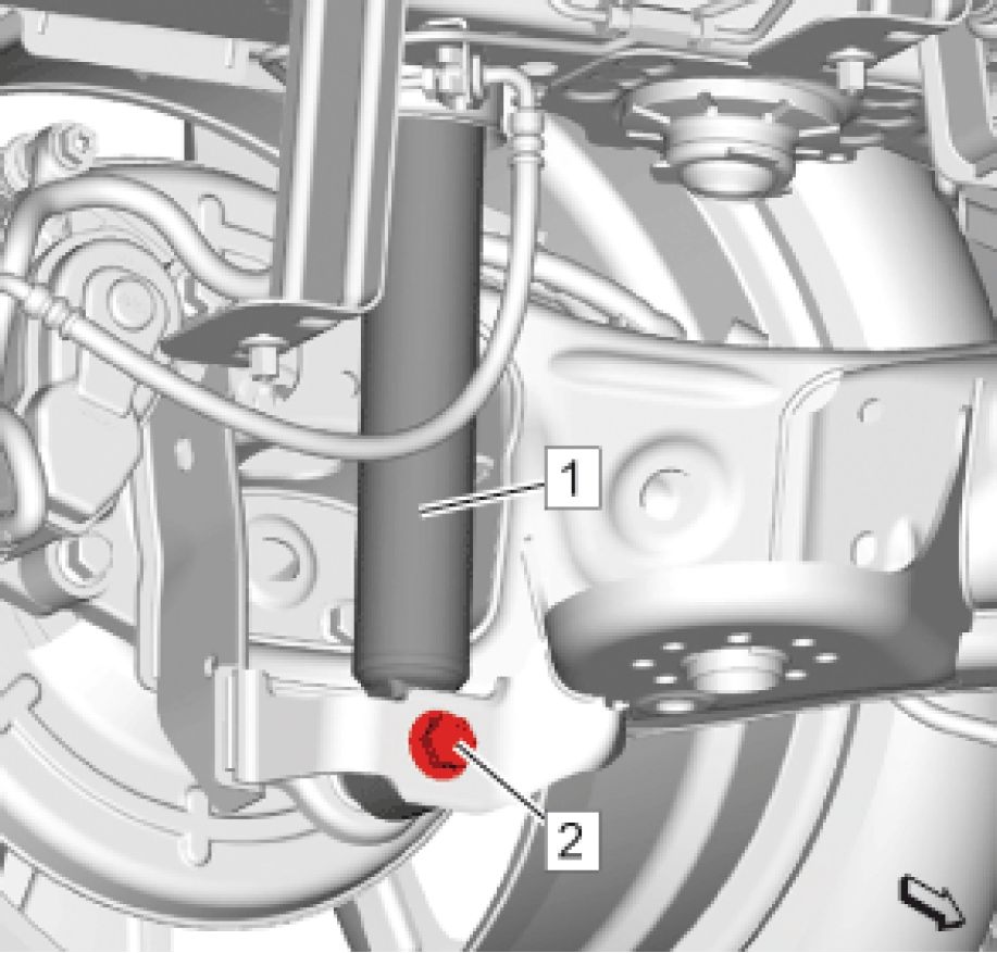 |
|
Fig. 134: Shock And Lower Shock Fasteners |
10. Support the rear axle and remove the lower shock bolt (2).
11. Install the rear coil springs. Refer to Rear Coil Spring Replacement .
12. Remove the EN-6015 plugs.
 |
|
Fig. 135: Fuel Feed Pipe Courtesy of GENERAL MOTORS COMPANY |
13. Connect Fuel Feed Pipe (1) Plastic Collar Quick Connect Fitting Service
 |
|
Fig. 136: Evaporative Emission Rear Hose, Fuel Tank Filler Hose, Vent Pipe, Electrical Connector, Retainer And Clamp Courtesy of GENERAL MOTORS COMPANY |
14. Install Fuel Tank Filler Hose (4)
 |
|
Fig. 137: Ensure Filler Hose Is Fully Seated And Installed Correctly |
15. Make sure that the hose is fully seated on the fuel tank. Filler hose is correctly installed when the end of
the hose is even with where the fill spud on the tank increases in diameter. The gap (1) between the tank
and the end of hose will be (a) 6 mm (1/4 in) when hose is correctly installed.
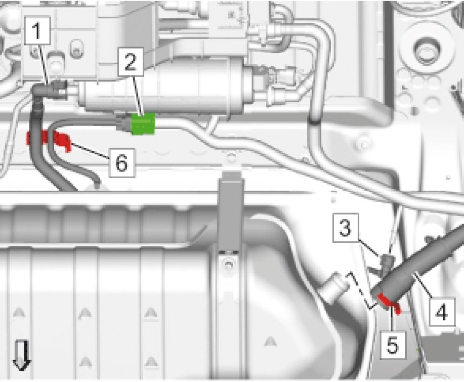 |
|
Fig. 138: Evaporative Emission Rear Hose, Fuel Tank Filler Hose, Vent Pipe, Electrical Connector, Courtesy of GENERAL MOTORS COMPANY |
16. Clamp (5) - Tighten 3.5 N.m (31 lb in)
 |
|
Fig. 139: Fuel Tank Filler Pipe Ground Bolt And Wiring Harness Clip |
17. Install Fuel Tank Filler Pipe Ground Bolt (1) and tighten 9 N.m (80 lb in)
 |
|
Fig. 140: Evaporative Emission Rear Hose, Fuel Tank Filler Hose, Vent Pipe, Electrical Connector, Courtesy of GENERAL MOTORS COMPANY |
18. Remove the EN-6015 plugs.
19. Connect Fuel Tank Filler Vent Pipe (3)Plastic Collar Quick Connect Fitting Service
20. Close the retainer (6).
21. Connect the fuel tank fuel pump module wiring harness electrical connector (2).
22. Remove the EN-6015 plugs.
23. Connect Evaporative Emission Rear Hose (1)Plastic Collar Quick Connect Fitting Service
24. Install Underbody Front Air Deflector Replacement - Left Side
25. Install Underbody Rear Air Deflector Replacement
26. Lower the vehicle.
27. Refill the fuel tank.
28. Connect Battery Negative Cable Disconnection and Connection
29. Cycle the ignition to run the fuel pump and check for fuel leaks.
FUEL TANK PRESSURE SENSOR REPLACEMENT
 |
|
Fig. 141: Fuel Tank Pressure Sensor Courtesy of GENERAL MOTORS COMPANY |
|
Callout |
Component Name |
|
Preliminary Procedures 1. Battery Negative Cable Disconnection and Connection | |
|
2. Underbody Rear Air Deflector Replacement | |
|
1 |
Fuel Tank Pressure Sensor Procedure Disconnect the electrical connector. |
FUEL PUMP FUEL FEED HOSE REPLACEMENT
Special Tools
EN-6015 Closure Plugs
Equivalent regional tools:Special Tools (Diagnostic Tools) Special Tools (Repair Tools)
WARNING: Diesel/Gasoline Vapors Warning
WARNING: Safety Goggles and Fuel Warning
1. Relieve the fuel system pressure. Fuel Pressure Relief
2. Battery Negative Cable Disconnection and Connection - Disconnect
3. Lower the fuel tank, to get enough space to remove the fuel pipe. Refer to Fuel Tank Replacement.
 |
|
Fig. 142: Fuel Tank Fuel Pump Module, Fuel Pump Fuel Feed Hose And Retainer Courtesy of GENERAL MOTORS COMPANY |
4. Disconnect Fuel Pump Fuel Feed Hose (2) @Fuel Tank Fuel Pump Module (1) -Plastic Collar Quick
Connect Fitting Service
5. Close all open connections with the EN-6015 plugs.
6. Unclip Fuel Pump Fuel Feed Hose (2) @Retainer (3)
Installation Procedure
 |
|
Fig. 143: Fuel Tank Fuel Pump Module, Fuel Pump Fuel Feed Hose And Retainer Courtesy of GENERAL MOTORS COMPANY |
1. Install Fuel Pump Fuel Feed Hose (2) @Retainer (3)
2. Remove the EN-6015 plugs from all connections.
3. Connect Fuel Pump Fuel Feed Hose (2) @Fuel Tank Fuel Pump Module (1) -Plastic Collar Quick
Connect Fitting Service
4. Install Fuel Tank Replacement
5. Connect Battery Negative Cable Disconnection and Connection
6. Cycle the ignition to run the fuel pump and check for fuel leaks.
FUEL INJECTION FUEL RAIL ASSEMBLY REPLACEMENT
Special Tools
EN-51146 Fuel Injector Removal / Installation Kit
Equivalent regional tools: Special Tools (Diagnostic Tools) Special Tools (Repair Tools) .
Removal Procedure
WARNING: Diesel/Gasoline Vapors Warning
WARNING: Safety Goggles and Fuel Warning
CAUTION: When working on the fuel rail and fuel injectors, always maintain a clean work
surface. Failure to maintain a clean work surface can result in contaminant on
the injector seals and cause leaks.
1. Remove Fuel Injection Fuel Rail Assembly Removal and Installation
 |
|
Fig. 144: Plate, Bolts And Supports Courtesy of GENERAL MOTORS COMPANY |
NOTE: The EN-51146 - 2 - 5 calibrations tools must be installed.
2. Remove the 8 plate bolts (1) and remove the EN-51146-1-2 plate (2), counterhold with a wrench (4) at
the EN-51146-1-1 supports (3).
3. Remove the 8 EN-51146-1-1 supports (3).
 |
|
Fig. 145: Fuel Injection Fuel Rail, Fuel Injector And Wiring Harness |
4. Disconnect Fuel Injector Wiring Harness (2)
5. Remove Fuel Injector (3) @Fuel Injection Fuel Rail (1)
 |
|
Fig. 146: Fuel Injector And O-Ring Courtesy of GENERAL MOTORS COMPANY |
6. Remove O-Ring (1) @Fuel Injector (2) and DISCARD
Cleaning Procedure
Clean the fuel injector bores. If the fuel injectors will be reused, clean the fuel injectors. Fuel Injection Fuel
Rail Assembly Removal and Installation.
Installation Procedure
 |
|
Fig. 147: Fuel Injector And O-Ring Courtesy of GENERAL MOTORS COMPANY |
1. Coat the fuel injector seals with engine oil.(1)
NOTE: The EN-51146 - 2 - 5 calibrations tools must be installed.
2. Install O-Ring (1) @Fuel Injector (2)
 |
|
Fig. 148: Fuel Injection Fuel Rail, Fuel Injector Wiring Harness Connectors, Fuel Injectors And Bolts Courtesy of GENERAL MOTORS COMPANY |
NOTE: Do NOT reuse the old bolt.
3. Install Fuel Injector (3) @Fuel Injection Fuel Rail (1)
4. Apply thread locking adhesive to the NEW fuel injector bolts.(4)Adhesives, Fluids, Lubricants, and
Sealers
CAUTION: Fastener Caution
NOTE: Install NEW bolts.
5. Install Fuel Injector Bolt (4) @Fuel Injector(3) and tighten 5 N.m (44 lb in)
6. Connect Fuel Injector Wiring Harness (2)
7. Install Fuel Injection Fuel Rail Assembly Removal and Installation
FUEL INJECTOR REPLACEMENT
Special Tools
EN-51146 Fuel Injector Removal / Installation Kit
Equivalent regional tools:Special Tools (Diagnostic Tools) Special Tools (Repair Tools) .
Removal Procedure
WARNING: Diesel/Gasoline Vapors Warning
WARNING: Safety Goggles and Fuel Warning
CAUTION: When working on the fuel rail and fuel injectors, always maintain a clean work
surface. Failure to maintain a clean work surface can result in contaminant on
the injector seals and cause leaks.
1. Remove Fuel Injection Fuel Rail Assembly Removal and Installation
 |
|
Fig. 149: Plate, Bolts And Supports Courtesy of GENERAL MOTORS COMPANY |
NOTE: The EN-51146 - 2 - 5 calibrations tools must be installed.
2. Remove the 8 plate bolts (1) and remove the EN-51146-1-2 plate (2), counterhold with a wrench (4) at
the EN-51146-1-1 supports (3).
3. Remove the 8 EN-51146-1-1 supports (3).
 |
|
Fig. 150: Fuel Injection Fuel Rail, Fuel Injector And Wiring Harness |
4. Disconnect Fuel Injector Wiring Harness (2)
5. Remove Fuel Injector(3)@Fuel Injection Fuel Rail(1)
 |
|
Fig. 151: Fuel Injector And O-Ring Courtesy of GENERAL MOTORS COMPANY |
6. Remove O-Ring (1) @Fuel Injector (2) and DISCARD
Cleaning Procedure
1. Clean the fuel injector bores. If the fuel injectors will be reused, clean the fuel injectors. Fuel Injection
Fuel Rail Assembly Removal and Installation.
2. Inspect the NEW fuel injector. Fuel Injection Fuel Rail Assembly Removal and Installation.
Installation Procedure
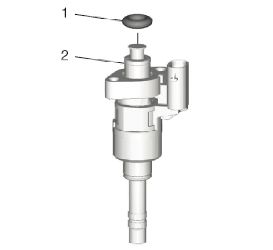 |
|
Fig. 152: Fuel Injector And O-Ring Courtesy of GENERAL MOTORS COMPANY |
1. Coat the fuel injector seals with engine oil.(1)
NOTE: The EN-51146 - 2 - 5 calibrations tools must be installed.
2. Install O-Ring (1) @ Fuel Injector (2)
 |
|
Fig. 153: Fuel Injection Fuel Rail, Fuel Injector Wiring Harness Connectors, Fuel Injectors And Courtesy of GENERAL MOTORS COMPANY |
NOTE: Do NOT reuse the old bolt.
3. Install Fuel Injector(3) @Fuel Injection Fuel Rail (1)
4. Apply thread locking adhesive to the NEW fuel injector bolts.(4)Adhesives, Fluids, Lubricants, and
Sealers
CAUTION: Fastener Caution
NOTE: Install NEW bolts.
5. Install Fuel Injector Bolt (4) @Fuel Injector (3) and tighten 5 N.m (44 lb in)
6. Connect Fuel Injector Wiring Harness(2)
7. Install Fuel Injection Fuel Rail Assembly Removal and Installation
FUEL INJECTOR WIRING HARNESS REPLACEMENT
Removal Procedure
1. Remove Fuel Injection Fuel Rail Assembly Replacement
 |
|
Fig. 154: Fuel Injector Wiring Harness Components |
2. Cut the cable tie (3).
3. Disconnect the fuel injection fuel rail fuel pressure sensor wiring harness electrical connector (2) from the
fuel rail fuel pressure sensor (4).
4. Remove and DISCARD the 4 insulating tape stripes (1, 5).
5. Disconnect the 4 fuel injector wiring harness electrical connectors (9, 11) from the fuel injectors (10).
6. Clip out the fuel injector wiring harness (6) from the fuel rail (7).
7. Cut the 4 cable ties (8, 12).
Installation Procedure
 |
|
Fig. 155: Fuel Injector Wiring Harness Components |
1. Connect the 4 fuel injector wiring harness electrical connectors (9, 11) to the 4 fuel injectors (10).
2. Clip in the fuel injector wiring harness (6) to the fuel rail (7).
3. Install NEW 4 cable ties (8, 12) to the position where they have been removed.
4. Connect the fuel injection fuel rail fuel pressure sensor wiring harness plug (2) to the fuel rail fuel
pressure sensor (4).
5. Install a NEW cable tie (3) to the position where it have been removed.
6. Install 4 NEW insulating tape stripes (1, 5) to the position where it have been removed.
7. Install Fuel Injection Fuel Rail Assembly Replacement
FUEL INJECTION FUEL RAIL ASSEMBLY REMOVAL AND INSTALLATION
Special Tools
• EN-51146 Fuel Injector Removal/ Installation Kit
• EN-51146-100 Adapter Plate
• EN-51146-150 Injector Remover/Installer Adapters
Equivalent regional tools:Special Tools (Diagnostic Tools) Special Tools (Repair Tools)
Removal Procedure
WARNING: The noise cancelling foam component MUST be replaced if it has been exposed
to engine fluids. Failure to replace the noise cancelling foam component that
has been exposed to engine fluids may result in an engine fire resulting in
catastrophic engine damage, and possible injury or death.
WARNING: Diesel/Gasoline Vapors Warning
WARNING: Safety Goggles and Fuel Warning
CAUTION: When working on the fuel rail and fuel injectors, always maintain a clean work
surface. Failure to maintain a clean work surface can result in contaminant on
the injector seals and cause leaks.
1. Remove Ignition Coil Replacement
2. Remove Fuel Feed Intermediate Pipe Replacement
 |
|
Fig. 156: Fuel Injection Fuel Rail Wiring Harness And Fuel Rail Bolts |
3. Disconnect Fuel Injection Fuel Rail Wiring Harness(l)
NOTE: The fuel rail bolts remain with decoupling elements and retainer at the fuel
rail assembly.
4. Loosen the 4 fuel rail bolts (2) from the cylinder head completely, but do not remove the bolts.
 |
|
Fig. 157: fuel injector cylinder 1 Courtesy of GENERAL MOTORS COMPANY |
| ||||
|
5. Remove the fuel injector bolt (1) from the fuel injector cylinder 1 (2) at the rail side. |
 |
|
Fig. 158: Demounting Screw And Support |
6. Install the EN-51146 - 1-150 demounting screw to the EN-51146-1-1 support (1) and tighten to 7N.m (62
lb in).
 |
|
Fig. 159: Support And Cylinder 1 Fuel Injector |
7. Install the EN-51146-1-1 support (1) to the fuel injector cylinder 1 (2) and tighten to 5 N.m (44 lb in).
 |
|
Fig. 160: Fuel Injector Cylinder Courtesy of GENERAL MOTORS COMPANY |
8. Remove the fuel injector bolt (1) from the fuel injector cylinder 1 (2).
9. Install the EN-51146-1-6 demounting screw or EN-51146-150 demounting screw to the EN-51146-1-1
support and tighten to 7 N.m (62 lb in).
 |
|
Fig. 161: Support And Cylinder 1 Fuel Injector Courtesy of GENERAL MOTORS COMPANY |
10. Install the EN-51146-1-1 support (1) to the fuel injector cylinder 1 (2) and tighten to 5 N.m (44 lb in).
11. Repeat the steps 5 - 10 for the other 3 injectors.
 |
|
Fig. 162: Fuel Rail Bolts Courtesy of GENERAL MOTORS COMPANY |
NOTE: The fuel rail bolts remain with decoupling elements and retainer at the fuel
rail assembly.
12. Loosen the 4 fuel rail bolts (1) completely from the cylinder head, but do not remove the bolts.
 |
|
Fig. 163: Plates, Supports And Bolts Courtesy of GENERAL MOTORS COMPANY |
NOTE: Mind the arrow on the EN-51146-100 plate. The arrow must show in driving
direction.
13. Install the EN-51146-100 plate (2) to the 8 EN-51146-1-1 supports (4).
14. Install the 8 plate bolts (3).
15. Tighten the 8 plate bolts (3) and counterhold with a wrench (1) at the EN-51146-1-1 supports (4).
 |
|
Fig. 164: Slide Hammers And Plate Courtesy of GENERAL MOTORS COMPANY |
16. Install the 2 EN-51146-1-3 sliding hammers (1) to the EN-51146-1-2 plate (2).

Fig. 165: Removing Injectors
Courtesy of GENERAL MOTORS COMPANY
NOTE: Ensure that the fuel injectors do not become tilted. Failure to follow this
caution can tilt or bend the injectors and could cause leaks or malfunction
after installation.
17. Use the 2 EN-51146-1-3 sliding hammers at first equally to remove the fuel injector rail assembly, if
necessary apply additional force to either side as necessary to release the rail evenly.
18. Ensure that the angle of the 2 EN-51146-1-3 sliding hammers (1) accord to the angle of the fuel injectors
(2), while removing.
CAUTION: After removal of the fuel injection fuel rail assembly, check the
completeness of the assembly. Check that no decoupling elements, fuel
rail bolts or fuel injector seals remain near the fuel injector bores on the
cylinder head. Failure to perform this can result in poor engine
performance or engine damage.
19. Remove the fuel injector rail assembly.
 |
|
Fig. 166: Plate Installed In Vise Courtesy of GENERAL MOTORS COMPANY |
CAUTION: After removing the fuel rail and injector assembly, do not allow the weight
of the assembly to rest on the fuel injectors. Always position the assembly
on a clean work surface with the fuel injectors on top. Failure to follow this
caution could cause leaks or malfunction after installation.
20. Install the EN-51146-1-2 plate (1) with the fuel injector assembly to a bench vise (2).

NOTE: The EN-51146-2-5 calibration tools are also used to protect the fuel
injectors.
21. Install the 4 EN-51146-2-5 calibration tools (2) rotary to the fuel injectors (1), as shown in the graphic.
22. Cover the fuel injector bores at the cylinder head, to prevent for dirt.
23. Remove the 2 EN-51146-1-3 sliding hammers.
24. Remove the 4 EN-51146-2-5 calibration tools.
 |
|
Fig. 168: Combustion Seals And Stylus Courtesy of GENERAL MOTORS COMPANY |
CAUTION: Always use the stylus from the EN-51146 fuel injector kit. Never use a
metal tool in place of the stylus. Use of another tool can damage the fuel
injector and may cause a leak.
25. Remove the 2 combustion seals (2) each fuel injector, use EN-51146-2-1 stylus (1).
26. Inspect all fuel injectors for damage.
Installation Procedure
1. Clean and inspect the fuel injectors and the fuel injector rail. Do not remove the fuel injector from the fuel
rail. Refer to Fuel Injector and Fuel Injector Bore Cleaning and Inspection .
 |
|
Fig. 169: Combustion Fuel Injector Seal And Long Mounting Sleeve |
2. Install a NEW combustion fuel injector seal (1) to the EN-51146-2-2 mounting sleeve-long (2).
 |
|
Fig. 170: Installing Combustion Seals Courtesy of GENERAL MOTORS COMPANY |
3. Use the EN-51146-2-6-1 slider outside (1) to push down the combustion fuel injector seal (2) on the
EN-51146-2-2 mounting sleeve-long (3).

Fig. 171: Installing Combustion Seals
Courtesy of GENERAL MOTORS COMPANY
4. Push the combustion fuel injector seal (2) over the EN-51146-2-2 mounting sleeve-long, use the
EN-51146-2-6-1 slider outside (1) to the fuel injector (3).
5. Remove the EN-51146-2-2 mounting sleeve-long with the EN-51146-2-1 stylus from the
EN-51146-2-6-1 slider outside.
6. Install a NEW combustion fuel injector seal to the EN-51146-2-3 mounting sleeve-short.
7. Use the EN-51146-2-6-1 slider outside to push down the combustion fuel injector seal on the
EN-51146-2-2 mounting sleeve-short.
8. Push the combustion fuel injector seal over the EN-51146-2-3 mounting sleeve-short, use the
EN-51146-2-6-1 slider outside to the fuel injector.
9. Remove the EN-51146-2-3 mounting sleeve-short with the EN-51146-2-1 stylus from the
EN-51146-2-6-1 slider outside.
 |
|
Fig. 172: Fuel Injector Limiter Courtesy of GENERAL MOTORS COMPANY |
10. Before using the EN-51146-2-4 pre-sizing tool (1), check if the fuel injector limiter (2) is in the right
position.
 |
|
Fig. 173: Pre-Sizing Tool And Fuel Iniector |
NOTE: First form the combustion fuel injector seals a bit with finger and thumb.
11. Push the EN-51146-2-4 pre-sizing tool (1) over the fuel injector (2).
 |
|
Fig. 174: Pre-Sizing Tool Courtesy of GENERAL MOTORS COMPANY |
12. Tighten the nut (2) and counterhold at the spanner flat of the EN-51146-2-4 pre-sizing tool thread (1)
until the measure (a) of 4.5 mm (0.177 in) is reached.
13. Loosen the nut (2) of the EN-51146-2-4 pre-sizing tool.
 |
|
Fig. 175: Take Off Chassis And Pre-Sizing Tool |
14. Install the EN-51146-2-4-7 take off chassis (2) to the EN-51146-2-4 pre-sizing tool (3).
15. Install the EN-51146-2-4-6 screw M10 (1) to the EN-51146-2-4-7 take off chassis (2), and tighten until
the EN-51146-2-4 pre-sizing tool (3) is loosened.
 |
|
Fig. 176: Calibration Tool And Fuel Injector Courtesy of GENERAL MOTORS COMPANY |
16. Install the EN-51146-2-5 calibration tool (2) rotary to the fuel injector (1), as shown in the graphic.
17. Remove the EN-51146-2-5 calibration tool from the fuel injector.
 |
|
Fig. 177: Installing Seal Courtesy of GENERAL MOTORS COMPANY |
WARNING: The fuel injector seals must fit properly in the relative groove. Overlapping
of the fuel injector seals with the external surface of the injector must be
avoided. If the seals are installed incorrectly, it could cause leaks and risk
of injury.
18. Check the combustion fuel injector seals (2 seals each fuel injector) for correct seat:
• The seal must not be too large, buckled or corrugated (1).
• The seal must be fixed tight and accurate (2).
19. If the seals are installed not correctly, repeat the steps 27 - 29 of the removal procedure and the steps 1 -
19 of the installation procedure.
 |
|
Fig. 178: Calibration Tools And Fuel Injectors |
20. Install the 4 EN-51146-2-5 calibration tools (2) rotary to the fuel injectors (1).
21. Remove the fuel injector assembly with the EN-51146-100 plate from the bench vise.
 |
|
Fig. 179: Plate, Bolts And Supports Courtesy of GENERAL MOTORS COMPANY |
22. Remove the 8 plate bolts (1) and remove EN-51146-100 plate (2), counterhold with a wrench (4) at the
EN-51146-1-1 supports (3).
 |
|
Fig. 180: Support, Fuel Injector And Bolt |
NOTE: Never loosen both EN-51146-1-1 supports at the same time. Failure to
follow this caution could cause leaks or malfunction after installation. It is
only possible, when the fuel injector will be replaced.
23. Remove one EN-51146-1-1 support (2) from the fuel injector (3).
NOTE: DO NOT reuse the old fuel injector bolt.
24. Apply thread lock agent to the NEW fuel injector bolt (1).
25. Install NEW fuel injector bolt to the fuel injector and tighten to 5 N.m (44 lb in).

Fig. 181: Support, Fuel Iniector And Bolt
Courtesy of GENERAL MOTORS COMPANY
26. Remove the EN-51146-1-1 support (1) from the fuel injector (3).
NOTE: DO NOT reuse the old fuel injector bolt.
27. Apply thread lock agent to the NEW fuel injector bolt (2).
28. Install a NEW fuel injector bolt to the fuel injector and tighten to 5 N.m (44 lb in).
29. Repeat the steps 22 - 27 for the other 3 injectors.
30. Clean the fuel injector bores at the cylinder head. Refer to Fuel Injector and Fuel Injector Bore
Cleaning and Inspection .
 |
|
Fig. 182: Fuel Injector Rail Assembly Bolts, Decoupling Elements And Retainer |
31. Inspect the fuel injector rail assembly:
• Check the 4 fuel injector for damage.
• Check the 8 fuel injector seals for correct seat.
• Check if all bolts (3) with decoupling elements (1) and retainer (2) are complete.
32. Remove the 4 EN-51146-2-5 calibration tools from the fuel injector.
 |
|
Fig. 183: Fuel Rail Assembly Courtesy of GENERAL MOTORS COMPANY |
CAUTION: During the installation of the fuel rail and injector assembly, ensure that
the fuel injectors are positioned straight into the injector opening. Failure
to follow this caution can tilt or bend the injectors and could cause leaks
or malfunction after installation.
33. Install carefully the fuel rail assembly (1).
34. Push the fuel injectors slightly in their seats.

Fig. 184: Fuel Rail Bolt Tightening Sequence
Courtesy of GENERAL MOTORS COMPANY
35. Tighten the 8 fuel rail bolts in the sequence as shown to 10 N.m (89 lb in).

Fig. 185: Fuel Injection Fuel Rail Wiring Harness And Fuel Rail Bolts
Courtesy of GENERAL MOTORS COMPANY
36. Connect Fuel Injection Fuel Rail Wiring Harness(l)
37. Install Fuel Feed Intermediate Pipe Replacement
38. Install Ignition Coil Replacement
39. After replacement of any components of the fuel injection systems, use a scan tool to reset functions.
Refer to Control Module References .
WARNING: Fuel escapes - observe safety measures and national legislation. Failure to
comply could result in personal injury.
NOTE: Ensure that all work at the engine is finished.
40. Perform a fuel rail assembly leak test.
1. Start the engine.
2. Check the fuel system for leaks.
FUEL INJECTION FUEL RAIL FUEL PRESSURE SENSOR REPLACEMENT
Removal Procedure
WARNING: The noise cancelling foam component MUST be replaced if it has been exposed
to engine fluids. Failure to replace the noise cancelling foam component that
has been exposed to engine fluids may result in an engine fire resulting in
catastrophic engine damage, and possible injury or death.
WARNING: Fuel/gasoline vapors are highly flammable. A fire could occur if an ignition
source is present. Never drain or store gasoline or diesel fuel in an open
container, due to the possibility of fire or explosion. Have a dry chemical (Class
B) fire extinguisher nearby.
WARNING: Wear safety glasses in order to avoid eye damage.
CAUTION: Refer to Fuel and Evaporative Emission Hose/Pipe Connection Cleaning
Caution .
1. Relieve the fuel system pressure. Fuel Pressure Relief
2. Disconnect the battery negative cable. Battery Negative Cable Disconnection and Connection
3. Remove Intake Manifold Cover - Intake Manifold Cover Replacement
 |
|
Fig. 186: Fuel Injection Fuel Rail Assembly, Fuel Injection Fuel Rail Pressure Sensor And Courtesy of GENERAL MOTORS COMPANY |
|
4. Disconnect the electrical connector (2). | ||
| ||
|
5. Remove and DISCARD the fuel injection fuel rail fuel pressure sensor (1). |
Installation Procedure

Fig. 187: Fuel Injection Fuel Rail Assembly, Fuel Injection Fuel Rail Pressure Sensor And
Electrical Connector
|
Courtesy of GENERAL MOTORS COMPANY | ||||
|
1. To install the NEW fuel injection fuel rail fuel pressure sensor (1) properly, perform the following steps:
1. Lubricate the sensor threads and sealing surface with one drop of clean engine oil.
2. Install the sensor and hand tighten.
3. Remove the sensor.
4. Re-lubricate the sensor threads and sealing surface with one drop of clean engine oil.
5. Install the sensor and tighten to 32 N.m (24 lb ft).
2. Connect the electrical connector (2).
3. Connect the battery negative cable. Battery Negative Cable Disconnection and Connection
NOTE: If a fuel leak occurs at the fuel injection fuel rail, the fuel rail will need to be
replaced.
4. Inspect for leaks using the following procedure:
1. Turn ON the ignition with the engine OFF for 2 seconds.
2. Turn OFF the ignition for 10 seconds.
3. Turn ON the ignition with the engine OFF.
4. Inspect for fuel leaks.
5. Install Intake Manifold Cover Intake Manifold Cover Replacement
6. When the replacement is completed, use a scan tool to perform the appropriate reset functions. Control
Module References
FUEL PRESSURE SENSOR REPLACEMENT
Removal Procedure
WARNING: Diesel/Gasoline Vapors Warning
WARNING: Safety Goggles and Fuel Warning
1. Relieve the fuel system pressure. Fuel Pressure Relief
2. Remove Underbody Front Air Deflector Replacement - Left Side
 |
|
Fig. 188: Fuel Pressure Sensor, Seal Ring And Electrical Connector |
3. Disconnect the electrical connector.(l)
4. Place a drain pan under the vehicle.
5. Remove Fuel Pressure Sensor(2)
6. Remove Seal Ring(3) and DISCARD
Installation Procedure
 |
|
Fig. 189: Fuel Pressure Sensor, Seal Ring And Electrical Connector |
1. Install a NEW seal.(3)
CAUTION: Component Fastener Tightening Caution
2. Install Fuel Pressure Sensor (2) and tighten 15 N.m (11 lb ft)
3. Connect the electrical connector.(l)
4. Remove the drain pan.
5. Install Underbody Front Air Deflector Replacement - Left Side
6. Cycle the ignition to run the fuel pump and check for fuel leaks.
FUEL INJECTION PUMP REPLACEMENT
Special Tools
• BO-38185 Hose Clamp Pliers
• EN-51365 High Pressure Fuel Pump Installation Alignment Gauge
Equivalent regional tools:Special Tools (Diagnostic Tools) Special Tools (Repair Tools)
Removal Procedure
WARNING: The noise cancelling foam component MUST be replaced if it has been exposed
to engine fluids. Failure to replace the noise cancelling foam component that
has been exposed to engine fluids may result in an engine fire resulting in
catastrophic engine damage, and possible injury or death.
WARNING: Refer to Diesel/Gasoline Vapors Warning .
WARNING: Refer to Safety Goggles and Fuel Warning .
1. Relieve the fuel system pressure. Fuel Pressure Relief
2. Disconnect the battery negative cable. Battery Negative Cable Disconnection and Connection
3. Drain the cooling system. Cooling System Draining and Filling
4. Remove Air Inlet Grille Panel Air Inlet Grille Panel Replacement
5. Remove Intake Manifold Cover Intake Manifold Cover Replacement
6. Remove Air Cleaner Outlet Duct Air Cleaner Outlet Duct Replacement

Fig. 190: Air Cleaner Resonator Bracket And Bolt
Courtesy of GENERAL MOTORS COMPANY
7. Remove the engine wiring harness clip (1) from the bracket.
8. Remove the air cleaner resonator bracket bolt (2).
9. Remove the air cleaner resonator bracket (3).
 |
|
Fig. 191: Fuel Feed Front Pipe Bracket And Nut Courtesy of GENERAL MOTORS COMPANY |
10. Remove the fuel feed front pipe bracket nut (1).
11. Remove the fuel feed front pipe bracket (2) from the stud.
12. Disconnect the fuel feed front pipe (3) from the fuel pump and reposition pipe and bracket as necessary.
Fuel Feed Front Pipe Replacement
 |
|
Fig. 192: Fuel Feed Intermediate Pipe Courtesy of GENERAL MOTORS COMPANY |
NOTE:
High pressure fuel feed pipes are one time use only. ALWAYS install a
NEW high pressure fuel feed pipe if the pipe is removed OR the fittings are
loosened.
13. Remove and DISCARD the fuel feed intermediate pipe. Fuel Feed Intermediate Pipe Replacement
14. Close all open connections with the EN-6015 plugs.
 |
|
Fig. 193: Heater Water Auxiliary Pump Hose And Clip |
15. Use the BO-38185 pliers to disengage the heater water auxiliary pump hose clamp (1).
16. Remove the heater water auxiliary pump hose (2) from the water outlet.
17. Remove the heater water auxiliary pump hose (2) from the clip (3) and reposition the hose as necessary.
 |
|
Fig. 194: Electrical Connector Courtesy of GENERAL MOTORS COMPANY |
18. Disconnect the electrical connector (1).
 |
|
Fig. 195: Engine Wiring Harness Ground Bolt And Harness Clips Courtesy of GENERAL MOTORS COMPANY |
19. Remove the engine wiring harness ground bolt (1).
20. Remove the engine wiring harness clips (2) from the engine wiring harness bracket.
NOTE: Disconnect any engine wiring harness electrical connectors from sensors,
including the fuel pump, as necessary, to provide enough space to work in
the area around the fuel pump.
21. Reposition the engine wiring harness (3) as necessary.
 |
|
Fig. 196: Engine Wiring Harness Bracketand Bolts |
22. Remove the engine wiring harness bracket bolts (1).
23. Remove the engine wiring harness bracket (2).
 |
|
Fig. 197: Fuel Pump Insulator Courtesy of GENERAL MOTORS COMPANY |
24. Remove the fuel pump insulator (1).
 |
|
Fig. 198: Fuel Pump Bolts Courtesy of GENERAL MOTORS COMPANY |
CAUTION: Alternately loosen the fuel pump bolts one turn at a time until the pump is
fully disengaged from fuel pump lifter follower. Trying to remove the pump
bolts without even side-to-side loosening may result in pump plunger
damage
25. Remove and DISCARD the fuel pump bolts (1).
NOTE: Ensure that during removal of the fuel pump that the valve lifter follower
does NOT fall apart.
26. Remove the fuel pump (2).
NOTE:
• The valve lifter follower MAY remain in the cylinder head bore after
removing the fuel pump.
• If the valve lifter follower does NOT pull out of the cylinder head bore
with the fuel pump, then remove it afterwards.
27. Remove the valve lifter follower (3).
 |
|
Fig. 199: Fuel Pump Housing Seal Courtesy of GENERAL MOTORS COMPANY |
28. Remove and DISCARD the fuel pump housing seal (1).
Installation Procedure
1. Before continuing, lubricate the cylinder head bore with clean engine oil.

Fig. 200: Valve Lifter Follower
Courtesy of GENERAL MOTORS COMPANY
2. Lubricate the valve lifter follower (1) with clean engine oil and install it into the cylinder head bore.
NOTE:
• The camshaft MUST be at the base circle position before the fuel
pump is installed.
• At the base circle position, the EN-51365 alignment gauge will sit
flush with the cylinder head.
3. Install the EN-51365 alignment gauge (2) and turn the crankshaft until the camshaft lobe is at the base
circle position.
4. Remove the EN-51365 alignment gauge (2) and valve lifter follower (1).


Fig. 201: Fuel Pump Housing Seal
Courtesy of GENERAL MOTORS COMPANY
5. Lubricate the NEW fuel pump housing seal (1) with clean engine oil and install it on the fuel pump.

2 |

Fig. 202: Fuel Pump Bolts And Fuel Pump Bolt Retainers
Courtesy of GENERAL MOTORS COMPANY
| ||||
|
6. Install the NEW fuel pump bolts (1) through the fuel pump bolt retainers (2). |
 |
|
Fig. 203: Valve Lifter Follower Courtesy of GENERAL MOTORS COMPANY |
7. Lubricate the valve lifter follower (1) again with clean engine oil, if necessary, and install it into the
cylinder head bore.
8. Install the fuel pump assembly (2) into the cylinder head and start the NEW fuel pump bolts (3) by hand.
CAUTION: Refer to Fastener Caution .
CAUTION: Alternately hand-tighten the fuel pump bolts one turn at a time until the
pump is fully seated. Trying to draw down the pump without even side-to-
side tightening may result in pump plunger damage.
9. Tighten the NEW fuel pump bolts (3) to 25 N.m (18 lb ft).
 |
|
Fig. 204: Fuel Pump Insulator Courtesy of GENERAL MOTORS COMPANY |
10. Install the fuel pump insulator (1).
 |
|
Fig. 205: Engine Wiring Harness Bracketand Bolts |
11. Position the engine wiring harness bracket (2).
12. Install the engine wiring harness bracket bolts (1) and tighten to 25 N.m (18 lb ft).
 |
|
Fig. 206: Engine Wiring Harness Ground Bolt And Harness Clips |
NOTE: Connect any engine wiring harness electrical connectors to sensors,
including the fuel pump, that were previously disconnected.
13. Position the engine wiring harness (3).
14. Install the engine wiring harness clips (2) in the engine wiring harness bracket.
15. Install the engine wiring harness ground bolt (1) and tighten to 10 N.m (89 lb in).

Fig. 207: Electrical Connector
Courtesy of GENERAL MOTORS COMPANY
16. Connect the electrical connector (1).
 |
|
Fig. 208: Heater Water Auxiliary Pump Hose And Clip |
17. Install the heater water auxiliary pump hose (2) to the water outlet.
18. Use the BO-38185 pliers to engage the heater water auxiliary pump hose clamp (1).
19. Install the heater water auxiliary pump hose (2) in the clip (3).
20. Remove all EN-6015 plugs.
 |
|
Fig. 209: Fuel Feed Intermediate Pipe Courtesy of GENERAL MOTORS COMPANY |
| ||
|
21. Install the NEW fuel feed intermediate pipe. Fuel Feed Intermediate Pipe Replacement |
 |
|
Fig. 210: Fuel Feed Front Pipe Bracket And Nut |
22. Position fuel feed front pipe and bracket as necessary and connect the fuel feed front pipe (3) to the fuel
pump. Fuel Feed Front Pipe Replacement
23. Position the fuel feed front pipe bracket (2) on the stud.
24. Install the fuel feed front pipe bracket nut (1) and tighten to 9 N.m (80 lb in).
 |
|
Fig. 211: Air Cleaner Resonator Bracket And Bolt Courtesy of GENERAL MOTORS COMPANY |
25. Position the air cleaner resonator bracket (3).
26. Install the air cleaner resonator bracket bolt (2) and tighten to 9 N.m (80 lb in).
27. Install the engine wiring harness clip (1) to the bracket.
28. Connect the battery negative cable. Battery Negative Cable Disconnection and Connection
29. Inspect for leaks using the following procedure:
1. Turn ON the ignition with the engine OFF for 2 seconds.
2. Turn OFF the ignition for 10 seconds.
3. Turn ON the ignition with the engine OFF.
4. Inspect for fuel leaks.
30. Install Air Cleaner Outlet Duct Air Cleaner Outlet Duct Replacement
31. Install Intake Manifold Cover Intake Manifold Cover Replacement
32. Install Air Inlet Grille Panel Air Inlet Grille Panel Replacement
33. Fill the cooling system. Cooling System Draining and Filling
34. When the replacement is completed, use a scan tool to perform the appropriate reset functions. Control
Module References
FUEL SYSTEM CLEANING
WARNING: Diesel/Gasoline Vapors Warning
The following procedure covers the disassembly and the inspection of the complete fuel supply system. If the
fuel system is contaminated, the fuel system can be cleaned. You can usually determine the extent of the fuel
system contamination during the disassembly.
1. Remove the fuel tank pump module. Refer to Fuel Tank Fuel Pump Module Replacement.
2. Locate the tank in a suitable work area away from any heat, any flame, or any other source of ignition.
3. Perform the following procedures:
• Inspect the fuel tank pump module strainer. Replace the fuel tank pump module if the strainer is
contaminated.
WARNING: Wear safety glasses when using compressed air, as flying dirt
particles may cause eye injury.
NOTE: Only use oil-free compressed air to blow out the fuel pipes.
• Use compressed air in order to apply air pressure to the transfer tube.
NOTE: When flushing the fuel tank, handle the fuel and water mixture as a
hazardous material. Handle the fuel and water in accordance with all
applicable local, state, and federal laws and regulations.
4. Flush the fuel tank with running hot water for at least five minutes. Pour the water out of the fuel pump
module opening. Rock the fuel tank in order to ensure that the removal of the water from the fuel tank is
complete.
5. Refer to Metal Collar Quick Connect Fitting Service in order to disconnect the fuel feed hose/pipe.
6. Use compressed air in order to apply air pressure to the fuel lines in the opposite direction from the
normal fuel flow.
7. Remove the fuel rail and the fuel injectors. Refer to Fuel Injection Fuel Rail Assembly Replacement.
8. Clean and inspect the fuel injectors and the fuel rail.
Installation Procedure
Assemble the fuel system as follows:
1. Install the direct fuel injectors and the fuel rail. Refer to Fuel Injection Fuel Rail Assembly
Replacement.
2. Install the fuel tank pump module. Refer to Fuel Tank Fuel Pump Module Replacement.
3. Refer to Metal Collar Quick Connect Fitting Service in order to connect the fuel feed hose/pipe.
FUEL FEED FRONT PIPE REPLACEMENT
Special Tools
EN-6015 Closure Plugs
Equivalent regional tools:Special Tools (Diagnostic Tools) Special Tools (Repair Tools)
Removal Procedure
1. Relieve the fuel system pressure. Fuel Pressure Relief
2. Disconnect Battery Negative Cable Disconnection and Connection
3. Remove Air Cleaner Outlet Duct Replacement
 |
|
Fig. 212: Fuel Feed Pipe, Fuel Feed Front Pipe And Retainer |
4. Remove Fuel Feed Front Pipe (2) @Retainer(3)
5. Disconnect Fuel Feed Front Pipe(2)@Fuel Feed Pipe(1)Metal Collar Quick Connect Fitting Service
6. Close all open connections with the EN-6015 plugs.
 |
|
Fig. 213: Fuel Feed Front Pipe And Fuel Injection Pump |
7. Disconnect Fuel Feed Front Pipe(2)@Fuel Injection Pump(1)Metal Collar Quick Connect Fitting
Service
8. Close all open connections with the EN-6015 plugs.
9. Remove Fuel Feed Front Pipe(2)
Installation Procedure
 |
|
Fig. 214: Fuel Feed Front Pipe And Fuel Injection Pump |
1. Install Fuel Feed Front Pipe (2)
2. Remove all EN-6015 plugs from the connections.
3. Connect Fuel Feed Front Pipe (2) @Fuel Injection Pump(1) Metal Collar Quick Connect Fitting
Service
 |
|
Fig. 215: Fuel Feed Pipe, Fuel Feed Front Pipe And Retainer |
4. Remove all EN-6015 plugs from the connections.
5. Connect Fuel Feed Front Pipe(2)@Fuel Feed Pipe(1)Metal Collar Quick Connect Fitting Service
6. Install Fuel Feed Front Pipe(2)@Retainer(3)
7. Install Air Cleaner Outlet Duct Replacement
8. Connect Battery Negative Cable Disconnection and Connection
9. Cycle the ignition to run the fuel pump and check for fuel leaks.
FUEL FEED INTERMEDIATE PIPE REPLACEMENT
Removal Procedure
WARNING: Refer to Diesel/Gasoline Vapors Warning .
WARNING: Refer to Safety Goggles and Fuel Warning .
1. Relieve the fuel system pressure. Fuel Pressure Relief
2. Disconnect the battery negative cable. Battery Negative Cable Disconnection and Connection
3. Remove Intake Manifold Cover Intake Manifold Cover Replacement
4. Remove Air Cleaner Outlet Duct Air Cleaner Outlet Duct Replacement
 |
|
Fig. 216: Air Cleaner Resonator Bracket, Bolt And Wiring Harness Clip |
5. Unclip Wiring Harness Clip (1)
6. Remove the air cleaner resonator bracket bolt (1).
7. Remove the air cleaner resonator bracket (2).
 |
|
Fig. 217: Fuel Feed Intermediate Pipe, Bolt And Nuts |
NOTE: Lay a lint-free cloth under the fuel feed intermediate pipe to absorb any
excess fuel spillage.
8. Remove the fuel feed intermediate pipe bolt (1).
9. Loosen the fuel feed intermediate pipe fittings (2, 5) at the fuel injection fuel rail (3) and the fuel pump
(4).
NOTE: High pressure fuel feed pipes are one time use only. ALWAYS install a
NEW high pressure fuel feed pipe if the pipe is removed OR the fittings are
loosened.
10. Remove and DISCARD the fuel feed intermediate pipe (6).
Installation Procedure
 |
|
Fig. 218: Fuel Feed Intermediate Pipe, Bolt And Nuts |
CAUTION: Refer to Component Fastener Tightening Caution .
NOTE: High pressure fuel feed pipes are one time use only. ALWAYS install a
NEW high pressure fuel feed pipe if the pipe is removed OR the fittings are
loosened.
1. To install the NEW fuel feed intermediate pipe (6) perform the following steps:
1. Hand tighten the fuel feed intermediate pipe fitting (2) to the fuel injection fuel rail (3).
2. Hand tighten the fuel feed intermediate pipe fitting (5) to the fuel pump (4).
3. Tighten the fuel feed intermediate pipe fittings (2, 5) to 30 N.m (22 lb ft).
CAUTION: Refer to Fastener Caution .
2. Install the fuel feed intermediate pipe bolt (1) and tighten to 10 N.m (89 lb in).
 |
|
Fig. 219: Air Cleaner Resonator Bracket, Bolt And Wiring Harness Clip |
3. Position the air cleaner resonator bracket (2).
4. Install the air cleaner resonator bracket bolt (1) and tighten to 9 N.m (80 lb in).
5. Install Wiring Harness Clip (1)
6. Connect the battery negative cable. Battery Negative Cable Disconnection and Connection
WARNING: Fuel escapes - observe safety measures and national legislation. Failure to
comply could result in personal injury.
7. Inspect for leaks using the following procedure:
1. Turn ON the ignition with the engine OFF for 2 seconds.
2. Turn OFF the ignition for 10 seconds.
3. Turn ON the ignition with the engine OFF.
4. Inspect for fuel leaks.
8. Install Air Cleaner Outlet Duct Air Cleaner Outlet Duct Replacement
9. Install Intake Manifold Cover Intake Manifold Cover Replacement
EVAPORATIVE EMISSION CANISTER REPLACEMENT
Removal Procedure
WARNING: Safety Goggles and Fuel Warning
WARNING: Fuel Vapors in Evaporative Emission Components Warning
1. Remove Evaporative Emission Canister Bracket Replacement
 |
|
Fig. 220: Evaporative Emission Canister, Control Valve Hose, Electrical Connector And Retaining Courtesy of GENERAL MOTORS COMPANY |
2. Disconnect the evaporative emission canister control valve hose (4). Refer to Plastic Collar Quick
Connect Fitting Service.
3. Disconnect the electrical connector.(5)
4. Release the retaining tab (2) using a flat bladed tool (1) while simultaneously sliding the canister in
direction of arrow.
5. Remove Evaporative Emission Canister(3)
Installation Procedure
 |
|
Fig. 221: Evaporative Emission Canister, Control Valve Hose, Electrical Connector And Retaining Courtesy of GENERAL MOTORS COMPANY |
1. Install Evaporative Emission Canister(3) -
2. Slide the evaporative emission canister (3) against the direction of arrow until the retaining tab (2) is
locked.
3. Connect the electrical connector.(5)
4. Connect the evaporative emission canister control valve hose (4). Refer to Plastic Collar Quick Connect
Fitting Service.
5. Install Evaporative Emission Canister Bracket Replacement
EVAPORATIVE EMISSION CANISTER BRACKET REPLACEMENT
Special Tools
EN-6015 Closure Plugs
Equivalent regional tools:Special Tools (Diagnostic Tools) Special Tools (Repair Tools)
Removal Procedure
WARNING: Safety Goggles and Fuel Warning
WARNING: Safety Goggles and Fuel Warning
1. Disconnect Battery Negative Cable Disconnection and Connection
2. Raise and support the vehicle. Lifting and Jacking the Vehicle
3. Remove Underbody Rear Air Deflector Replacement
 |
|
Fig. 222: Electrical Connectors, Evaporative Emission Rear Hose, Evaporative Emission Pipe, |
4. Disconnect the electrical connector:
1. Evaporative Emission System Vacuum Leak Detection Pump (1)
2. Fuel Tank Pressure Sensor (3)
3. Fuel Tank Fuel Pump Module Wiring Harness (5).
5. Disconnect Evaporative Emission Rear Hose (6)Plastic Collar Quick Connect Fitting Service
6. Disconnect Evaporative Emission Pipe (7)Plastic Collar Quick Connect Fitting Service
7. Disconnect the evaporative emission system vacuum leak pump filter pipe (2). Refer to Plastic Collar
Quick Connect Fitting Service.
8. Close all open connection with the EN-6015 plugs.
9. Remove Retainer (4)
 |
|
Fig. 223: Evaporative Emission Canister Bracket And Nuts |
10. Remove the 4 evaporative emission canister bracket nuts (2).
NOTE: A second technician is required.
11. Lower the evaporative emission canister bracket (1) until the evaporative emission canister control valve
wiring harness is accessible.
 |
|
Fig. 224: Electrical Connector And Retainers |
12. Disconnect the electrical connector.(2)
13. Remove Retainer(l)
14. Lay the evaporative emission canister bracket on a bench.
Disassemble Procedure
 |
|
Fig. 225: Evaporative Emission Canister And Vacuum Leak Pump Components |
1. Remove Retainer(1)
2. Remove the evaporative emission system vacuum leak pump cover (4).
NOTE: Use a flat bladed tool to release the 2 retaining tabs.
3. Remove the evaporative emission system vacuum leak pump (3).
4. Remove the evaporative emission canister control valve vacuum hose (6). Refer to Plastic Collar Quick
Connect Fitting Service.
5. Remove the 2 evaporative emission canister vent solenoid valve bolts (1).
6. Remove the evaporative emission canister (2) along with the evaporative emission canister vent solenoid
valve (7) and the evaporative emission canister hose. Refer to Evaporative Emission Canister
Replacement.
Assemble Procedure
 |
|
Fig. 226: Evaporative Emission Canister And Vacuum Leak Pump Components |
1. Install the evaporative emission canister (2) along with the evaporative emission canister vent solenoid
valve (7) and the evaporative emission canister hose. Refer to Evaporative Emission Canister
Replacement.
CAUTION: Fastener Caution
2. Install the 2 evaporative emission canister vent solenoid valve bolts (1) and tighten to 7 N.m (62 lb in).
3. Install the evaporative emission canister control valve vacuum hose (6). Refer to Plastic Collar Quick
Connect Fitting Service.
NOTE: There must be 2 noticeable click noises.
4. Install the evaporative emission system vacuum leak pump (3).
5. Install the evaporative emission system vacuum leak pump cover (4).
6. Install Retainer(5)
Installation Procedure
NOTE: A second technician is required.
1. Raise the evaporative emission canister bracket until the evaporative emission canister control valve
wiring harness is accessible.
 |
|
Fig. 227: Electrical Connector And Retainers |
2. Install Retainer(l)
3. Connect the electrical connector.(2)
 |
|
Fig. 228: Evaporative Emission Canister Bracket And Nuts Courtesy of GENERAL MOTORS COMPANY |
4. Raise the evaporative emission canister bracket (1) completely.
5. Install the 4 evaporative emission canister bracket nuts (2) and tighten to 9 N.m (80 lb in).
 |
|
Fig. 229: Electrical Connectors, Evaporative Emission Rear Hose, Evaporative Emission Pipe, |
6. Install Retainer(4)
7. Remove the EN-6015 plugs from all connections.
8. Connect the evaporative emission system vacuum leak pump filter pipe (2). Refer to Plastic Collar
Quick Connect Fitting Service.
9. Connect Evaporative Emission Pipe (7)Plastic Collar Quick Connect Fitting Service
10. Connect Evaporative Emission Rear Hose (6)Plastic Collar Quick Connect Fitting Service
11. Connect the electrical connector:
1. Evaporative Emission System Vacuum Leak Detection Pump (1)
2. Fuel Tank Pressure Sensor (3)
3. Fuel Tank Fuel Pump Module Wiring Harness (5).
12. Install Underbody Rear Air Deflector Replacement
13. Lower the vehicle.
14. Connect Battery Negative Cable Disconnection and Connection
EVAPORATIVE EMISSION CANISTER HOSE REPLACEMENT
Special Tools
EN-6015 Closure Plugs
Equivalent regional tools:Special Tools (Diagnostic Tools) Special Tools (Repair Tools)
Removal Procedure
WARNING: Diesel/Gasoline Vapors Warning
WARNING: Safety Goggles and Fuel Warning
1. Disconnect Battery Negative Cable Disconnection and Connection
2. Lower the fuel tank, to get enough space to remove the fuel pipe. Refer to Fuel Tank Replacement.
 |
|
Fig. 230: Evaporative Emission Canister Hose, Fuel Tank Fuel Pump Module And Retainer |
3. Disconnect the evaporative emission canister hose (3) from the fuel tank fuel pump module (1). Refer to
Plastic Collar Quick Connect Fitting Service.
4. Close all open connections with the EN-6015 plugs.
5. Unclip the evaporative emission canister hose (3) from the retainer (2).
Installation Procedure
 |
|
Fig. 231: Evaporative Emission Canister Hose, Fuel Tank Fuel Pump Module And Retainer |
1. Install the evaporative emission canister hose (3) to the retainer (2).
2. Remove the EN-6015 plugs from all connections.
3. Connect the evaporative emission canister hose (3) to the fuel tank fuel pump module (1). Refer to Plastic
Collar Quick Connect Fitting Service.
4. Install Fuel Tank Replacement
5. Connect Battery Negative Cable Disconnection and Connection
EVAPORATIVE EMISSION CANISTER CONTROL VALVE VACUUM HOSE REPLACEMENT
 |
|
Fig. 232: Evaporative Emission Canister Control Valve Vacuum Hose |
|
Callout |
Component Name |
|
Preliminary Procedures
| |
|
1 |
Evaporative Emission Canister Control Valve Vacuum Hose Plastic Collar Quick Connect Fitting Service |
EVAPORATIVE EMISSION CANISTER PURGE SOLENOID VALVE REPLACEMENT
Special Tools
EN-6015 Closure Plugs
Equivalent regional tools:Special Tools (Diagnostic Tools) Special Tools (Repair Tools)
WARNING: Safety Goggles and Fuel Warning
WARNING: Fuel Vapors in Evaporative Emission Components Warning
1. Disconnect Battery Negative Cable Disconnection and Connection
2. Remove Air Cleaner Outlet Duct Replacement
 |
|
Fig. 233: Evaporative Emission Pipe, Evaporative Emission Canister Purge Solenoid Valve, Bolt |
And Electrical Connector
Courtesy of GENERAL MOTORS COMPANY
3. Disconnect the electrical connector.(l)
4. Disconnect Evaporative Emission Pipe (2)Plastic Collar Quick Connect Fitting Service
5. Close all open connection with the EN-6015 plugs.
6. Remove Evaporative Emission Canister Purge Solenoid Valve Bolt (3)
7. Remove Evaporative Emission Canister Purge Solenoid Valve (4)
Installation Procedure
 |
|
Fig. 234: Evaporative Emission Pipe, Evaporative Emission Canister Purge Solenoid Valve, Bolt Courtesy of GENERAL MOTORS COMPANY |
1. Install Evaporative Emission Canister Purge Solenoid Valve (4)
CAUTION: Fastener Caution
2. Install Evaporative Emission Canister Purge Solenoid Valve Bolt (3) and tighten 10 N.m (89 lb in)
3. Remove all EN-6015 plugs.
4. Connect Evaporative Emission Pipe (2) Plastic Collar Quick Connect Fitting Service
5. Connect the electrical connector.(1)
6. Install Air Cleaner Outlet Duct Replacement
7. Connect Battery Negative Cable Disconnection and Connection
EVAPORATIVE EMISSION CANISTER VENT SOLENOID VALVE REPLACEMENT
Removal Procedure
WARNING: Safety Goggles and Fuel Warning
WARNING: Fuel Vapors in Evaporative Emission Components Warning
1. Remove Evaporative Emission Canister Bracket Replacement
 |
|
Fig. 235: Evaporative Emission Canister Control Valve Vacuum Hose And Evaporative Emission Courtesy of GENERAL MOTORS COMPANY |
2. Disconnect the evaporative emission canister control valve vacuum hose (1) from the evaporative
emission canister vent solenoid valve (2). Refer to Plastic Collar Quick Connect Fitting Service.
3. Disconnect the evaporative emission canister hose (3) from the evaporative emission canister vent
solenoid valve (2). Refer to Plastic Collar Quick Connect Fitting Service.
 |
|
Fig. 236: Evaporative Emission Canister Vent Solenoid Valve, Canister Bracket And Bolts |
4. Remove the 2 evaporative emission canister vent solenoid valve bolts (2).
5. Remove the evaporative emission canister vent solenoid valve (1) from the evaporative emission canister
bracket (3).
Installation Procedure
 |
|
Fig. 237: Evaporative Emission Canister Vent Solenoid Valve, Canister Bracket And Bolts |
1. Install the evaporative emission canister vent solenoid valve (1) to the evaporative emission canister
bracket (3).
CAUTION: Fastener Caution
2. Install the 2 evaporative emission canister vent solenoid valve bolts (2) and tighten to 7 N.m (62 lb in).
 |
|
Fig. 238: Evaporative Emission Canister Control Valve Vacuum Hose And Evaporative Emission Courtesy of GENERAL MOTORS COMPANY |
3. Connect the evaporative emission canister hose (3) to the evaporative emission canister vent solenoid
valve (2). Refer to Plastic Collar Quick Connect Fitting Service.
4. Connect the evaporative emission canister control valve vacuum hose (1) to the evaporative emission
canister vent solenoid valve (2). Refer to Plastic Collar Quick Connect Fitting Service.
5. Install Evaporative Emission Canister Bracket Replacement
EVAPORATIVE EMISSION PIPE REPLACEMENT
Special Tools
EN-6015 Closure Plugs
Equivalent regional tools:Special Tools (Diagnostic Tools) Special Tools (Repair Tools)
Removal Procedure
WARNING: Ensure all High Voltage safety procedures are followed. Failure to follow the
procedure exactly as written may result in serious injury or death.
WARNING: Fuel Vapors in Evaporative Emission Components Warning
WARNING: Safety Goggles and Fuel Warning
1. Disconnect Battery Negative Cable Battery Negative Cable Disconnection and Connection
2. Remove Air Cleaner Outlet Duct Air Cleaner Outlet Duct Replacement
 |
|
Fig. 239: Evaporative Emission Pipe And Evaporative Emission Canister Purge Solenoid Valve |
3. Disconnect Evaporative Emission Pipe (1)@Evaporative Emission Canister Purge Solenoid Valve(3)
Plastic Collar Quick Connect Fitting Service
4. Close all open connections with the EN-6015 plugs.
5. Open Retainer(2)
6. Remove Evaporative Emission Pipe(1)@Retainer (2)
7. Raise and support the vehicle. Lifting and Jacking the Vehicle
8. Remove Drivetrain and Front Suspension Cradle Drivetrain and Front Suspension Cradle
Replacement
 |
|
Fig. 240: Evaporative Emission Pipe And Retainers |
9. Open the 2 retainers (1).
10. Remove Evaporative Emission Pipe (2) @Retainer (1)
11. Remove Rear Axle Rear Axle Replacement
12. Remove Floor Panel Number 4 Cross Bar Floor Panel Number 4 Cross Bar Replacement
 |
|
Fig. 241: Drive Motor Generator Control Module Cooling Outlet Hose |
13. Remove Drive Motor Generator Control Module Cooling Outlet Hose(4)Drive Motor Generator
Control Module Cooling Outlet Hose Replacement (Underbody Line) Drive Motor Generator
Control Module Cooling Outlet Hose Replacement (Underbody Line to Traction Power Inverter
Module Inlet)
14. Open the retainer (3).
15. Remove Evaporative Emission Pipe (1) @Retainer (3)
16. Disconnect Evaporative Emission Pipe(1)@Evaporative Emission Canister(2) Plastic Collar Quick
Connect Fitting Service
17. Close all open connections with the EN-6015 plugs.
 |
|
Fig. 242: Evaporative Emission Pipe And Retainers |
18. Open the 5 retainers (1).
19. Remove Evaporative Emission Pipe (2) @Retainer (1)
NOTE: Manipulate the line removing the rear first to remove from the vehicle.
20. Remove the evaporative emission pipe (2) from the vehicle.
Installation Procedure
 |
|
Fig. 243: Bumper Courtesy of GENERAL MOTORS COMPANY |
1. If replacing the evaporative emissions pipe with a new pipe, position the new bumper (1) on the new
replacement pipe, after installation, as shown. If the old pipe is being reinstalled, position a new bumper
(1) on the existing pipe, after installation, as shown.
 |
|
Fig. 244: Evaporative Emission Pipe Sleeve |
NOTE: Check sleeve for proper position after pipe installation.
2. If replacing the evaporative emissions pipe with a new pipe and the new pipe does not have a sleeve (1)
on it, transfer the sleeve (1) from the old pipe to the new one.
 |
|
Fig. 245: Evaporative Emission Pipe And Retainers |
3. Install the evaporative emission pipe (2) to the vehicle.
4. Install Evaporative Emission Pipe(2)@Retainer(1)
5. Close the 5 retainers (1).
 |
|
Fig. 246: Drive Motor Generator Control Module Cooling Outlet Hose Courtesy of GENERAL MOTORS COMPANY |
6. Remove all EN-6015 plugs from the connections.
7. Connect Evaporative Emission Pipe (1) @Evaporative Emission Canister(2)Plastic Collar Quick
Connect Fitting Service
8. Install Drive Motor Generator Control Module Cooling Outlet Hose(4)Drive Motor Generator Control
Module Cooling Outlet Hose Replacement (Underbody Line) Drive Motor Generator Control
Module Cooling Outlet Hose Replacement (Underbody Line to Traction Power Inverter Module
Inlet)
9. Install Evaporative Emission Pipe (1) @Retainer (3)
10. Close the retainer (3).
11. Install Floor Panel Number 4 Cross Bar Floor Panel Number 4 Cross Bar Replacement
12. Install Rear Axle Rear Axle Replacement
 |
|
Fig. 247: Evaporative Emission Pipe And Retainers |
NOTE: Inspect bulkhead cross car brake line and retainers as required after line
installation.
13. Install Evaporative Emission Pipe(2)@Retainer(1)
14. Close the 2 retainers (31).
15. Install Drivetrain and Front Suspension Cradle Drivetrain and Front Suspension Cradle Replacement
16. Lower the vehicle.
 |
|
Fig. 248: Evaporative Emission Pipe And Evaporative Emission Canister Purge Solenoid Valve |
17. Install Evaporative Emission Pipe(1)@Retainer(2)
18. Close Retainer(2)
19. Remove all EN-6015 plugs from the connections.
20. Connect Evaporative Emission Pipe(1)@Evaporative Emission Canister Purge Solenoid Valve(3) Plastic
Collar Quick Connect Fitting Service
21. Install Air Cleaner Outlet Duct Air Cleaner Outlet Duct Replacement
22. Connect Battery Negative Cable Battery Negative Cable Disconnection and Connection
EVAPORATIVE EMISSION REAR HOSE REPLACEMENT
Special Tools
EN-6015 Closure Plugs
Equivalent regional tools:Special Tools (Diagnostic Tools) Special Tools (Repair Tools)
Removal Procedure
WARNING: Diesel/Gasoline Vapors Warning
WARNING: Safety Goggles and Fuel Warning
1. Disconnect Battery Negative Cable Disconnection and Connection
2. Lower the fuel tank, to get enough space to remove the evaporative emission pipe. Refer to Fuel Tank
Replacement.
 |
|
Fig. 249: Evaporative Emission Rear Hose And Fuel Tank Fuel Pump Module |
3. Disconnect Evaporative Emission Rear Hose(2)@Fuel Tank Fuel Pump Module(1)Plastic Collar Quick
Connect Fitting Service
4. Close all open connections with the EN-6015 plugs.
Installation Procedure
 |
|
Fig. 250: Evaporative Emission Rear Hose And Fuel Tank Fuel Pump Module |
1. Remove all EN-6015 plugs.
2. Connect Evaporative Emission Rear Hose(2)@Fuel Tank Fuel Pump Module(1) Plastic Collar Quick
Connect Fitting Service
3. Install Fuel Tank Replacement
4. Connect Battery Negative Cable Disconnection and Connection
EVAPORATIVE EMISSION SYSTEM VACUUM LEAK PUMP SHIELD REPLACEMENT
 |
|
Fig. 251: Evaporative Emission System Vacuum Leak Pump Shield |
|
Callout |
Component Name |
|
Preliminary Procedure Underbody Rear Air Deflector Replacement | |
|
1 |
Retainer (Qty: 3) |
|
2 |
Evaporative Emission System Vacuum Leak Pump Shield |
EVAPORATIVE EMISSION CANISTER VACUUM LEAK PUMP HARNESS REPLACEMENT
Special Tools
EN-6015 Closure Plugs
Equivalent regional tools:Special Tools (Diagnostic Tools) Special Tools (Repair Tools)
Removal Procedure
WARNING: Safety Goggles and Fuel Warning
WARNING: Fuel Vapors in Evaporative Emission Components Warning
1. Disconnect Battery Negative Cable Disconnection and Connection
2. Raise and support the vehicle. Lifting and Jacking the Vehicle
3. Remove Rear Wheelhouse Liner Replacement
 |
|
Fig. 252: Electrical Connectors And Wiring Harness Clips |
4. Disconnect the electrical connectors.(l)
5. Unclip Wiring Harness Clip(2, 3)
6. Remove Underbody Rear Air Deflector Replacement
 |
|
Fig. 253: Wiring Harness Clips Courtesy of GENERAL MOTORS COMPANY |
7. UnclipWiring Harness Clip(1)
 |
|
Fig. 254: Electrical Connectors, Evaporative Emission Rear Hose, Evaporative Emission Pipe, |
8. Disconnect the electrical connector:
1. Evaporative Emission System Vacuum Leak Detection Pump (1)
2. Fuel Tank Pressure Sensor(3)
3. Fuel Tank Fuel Pump Module Wiring Harness (5).
9. Disconnect Evaporative Emission Rear Hose (6)Plastic Collar Quick Connect Fitting Service
10. Disconnect Evaporative Emission Pipe(7) Plastic Collar Quick Connect Fitting Service
11. Disconnect the evaporative emission system vacuum leak pump filter pipe (2). Refer to Plastic Collar
Quick Connect Fitting Service.
12. Close all open connection with the EN-6015 plugs.
13. Remove Retainer(4)
 |
|
Fig. 255: Evaporative Emission Canister Bracket And Nuts |
14. Remove the 4 evaporative emission canister bracket nuts (2).
15. Remove the evaporative emission canister bracket (1) and put it on a workbench.
 |
|
Fig. 256: Electrical Connector And Retainers |
16. Disconnect the electrical connector.(2)
17. Remove Retainer(1)
18. Remove the evaporative emission canister vacuum leak pump wiring harness.
Installation Procedure
 |
|
Fig. 257: Electrical Connector And Retainers |
1. Install the evaporative emission canister vacuum leak pump wiring harness.
2. Install Retainer
3. Connect the electrical connector.
 |
|
Fig. 258: Evaporative Emission Canister Bracket And Nuts |
4. Install the evaporative emission canister bracket (1).
CAUTION: Fastener Caution
5. Install the 4 evaporative emission canister bracket nuts (2) and tighten to 9 N.m (80 lb in).
 |
|
Fig. 259: Electrical Connectors, Evaporative Emission Rear Hose, Evaporative Emission Pipe, Vacuum Leak Pump Filter Pipe And Retainer Courtesy of GENERAL MOTORS COMPANY |
6. Install Retainer(4)
7. Remove the EN-6015 plugs from all connections.
8. Connect the evaporative emission system vacuum leak pump filter pipe (2). Refer to Plastic Collar
Quick Connect Fitting Service.
9. Connect Evaporative Emission Pipe (7) Plastic Collar Quick Connect Fitting Service
10. Connect Evaporative Emission Rear Hose (6)Plastic Collar Quick Connect Fitting Service
11. Connect the electrical connector:
1. Evaporative Emission System Vacuum Leak Detection Pump (1)
2. Fuel Tank Pressure Sensor(3)
3. Fuel Tank Fuel Pump Module Wiring Harness (5).
 |
|
Fig. 260: Wiring Harness Clips Courtesy of GENERAL MOTORS COMPANY |
12. Install Wiring Harness Clip(1)
13. Install Underbody Rear Air Deflector Replacement
 |
|
Fig. 261: Electrical Connectors And Wiring Harness Clips |
14. Install Wiring Harness Clip(2, 3)
15. Connect the electrical connectors.(1)
16. Install Rear Wheelhouse Liner Replacement
17. Lower the vehicle.
18. Connect Battery Negative Cable Disconnection and Connection
EVAPORATIVE EMISSION SYSTEM VACUUM LEAK PUMP FILTER REPLACEMENT
Removal Procedure
1. Remove Fuel Tank Filler Pipe Replacement

Fig. 262: Evaporative Emission System Vacuum Leak Pump Filter, Bracket, Cable Straps And Clip
Courtesy of GENERAL MOTORS COMPANY
2. Remove the 3 cable straps (1, 4).
3. Remove Clip (3)
4. Unclip the evaporative emission system vacuum leak pump filter (2) from the bracket (5).
Installation Procedure
 |
|
Fig. 263: Evaporative Emission System Vacuum Leak Pump Filter, Bracket, Cable Straps And Clip |
1. Install the evaporative emission system vacuum leak pump filter (2) to the bracket (5).
2. Install Clip (3)
3. Install the 3 cable straps (1, 4).
4. Install Fuel Tank Filler Pipe Replacement
EVAPORATIVE EMISSION SYSTEM VACUUM LEAK DETECTION PUMP REPLACEMENT
Removal Procedure
WARNING: Safety Goggles and Fuel Warning
WARNING: Fuel Vapors in Evaporative Emission Components Warning
1. Disconnect Battery Negative Cable Disconnection and Connection
2. Raise and support the vehicle. Lifting and Jacking the Vehicle
3. Remove Underbody Rear Air Deflector Replacement
 |
|
Fig. 264: Evaporative Emission System Vacuum Leak Pump Cover, Filter Pipe, Retainers And Courtesy of GENERAL MOTORS COMPANY |
4. Remove Retainer (4)
5. Remove the evaporative emission system vacuum leak pump cover (3).
6. Disconnect the evaporative emission system vacuum leak pump filter pipe (1). Refer to Plastic Collar
Quick Connect Fitting Service.
7. Disconnect the electrical connector.(2)
 |
|
Fig. 265: Evaporative Emission System Vacuum Leak Pump And Retaining Tabs |
NOTE: Use a flat bladed tool to release the 2 retaining tabs (2).
8. Remove the evaporative emission system vacuum leak pump (1).
Installation Procedure
 |
|
Fig. 266: Evaporative Emission System Vacuum Leak Pump And Retaining Tabs |
NOTE: There must be 2 noticeable click noises.
1. Install the evaporative emission system vacuum leak pump (1).
 |
|
Fig. 267: Evaporative Emission System Vacuum Leak Pump Cover, Filter Pipe, Retainers And Courtesy of GENERAL MOTORS COMPANY |
2. Connect the electrical connector.(2)
3. Connect the evaporative emission system vacuum leak pump filter pipe (1). Refer to Plastic Collar
Quick Connect Fitting Service.
4. Install the evaporative emission system vacuum leak pump cover (3).
5. Install Retainer(4)
6. Lower the vehicle.
7. Install Underbody Rear Air Deflector Replacement
8. Connect Battery Negative Cable Disconnection and Connection
IGNITION COIL REPLACEMENT
Removal Procedure
1. Remove Intake Manifold Cover Intake Manifold Cover Replacement
 |
|
Fig. 268: Ignition Coil Electrical Connectors |
2. Disconnect Ignition Coil Electrical Connector (1)
 |
|
Fig. 269: Ignition Coils And Bolts Courtesy of GENERAL MOTORS COMPANY |
3. Remove Ignition Coil Bolt (1)
4. Remove Ignition Coil (2)
1. Inspect the inside of the ignition coil boot for a thin, even coat of dielectric grease. If there is no grease
present or additional grease is necessary, continue to the next step.
2. Apply a thin coating of dielectric grease to the inside of the ignition coil boot up to a depth of 15 mm
(0.60 in) from the end of the boot.
3. Remove any excess dielectric grease from around the end of the ignition coil boot and ensure there is not
an excessive amount within the boot.
 |
|
Fig. 270: Ignition Coils And Bolts Courtesy of GENERAL MOTORS COMPANY |
4. Install Ignition Coil (2)
CAUTION: Refer to Fastener Caution .
5. Install Ignition Coil Bolt (1) and tighten 10 N.m (89 lb in)
 |
|
Fig. 271: Ignition Coil Electrical Connectors |
6. Connect Ignition Coil Electrical Connector (1)
7. Install Intake Manifold Cover Intake Manifold Cover Replacement
SPARK PLUG INSPECTION
Spark Plug Usage
1. Ensure that the correct spark plug is installed. An incorrect spark plug causes driveability conditions.
Refer to Ignition System Specifications for the correct spark plug.
2. Ensure that the spark plug has the correct heat range. An incorrect heat range causes the following
conditions:
• Spark plug fouling - Colder plug
• Pre-ignition causing spark plug and/or engine damage - Hotter plug
Spark Plug Inspection
 |
|
Fig. 272: Cross Sectional View Of Spark Plug |
1. Inspect the terminal post (1) for damage.
• Inspect for a bent or broken terminal post (1).
• Test for a loose terminal post (1) by twisting and pulling the post. The terminal post (1) should
NOT move.
 |
|
Fig. 273: Inspecting Spark Plug For Flashover Or Carbon Tracking Soot Courtesy of GENERAL MOTORS COMPANY |
2. Inspect the insulator (2) for flashover or carbon tracking, soot. This is caused by the electrical charge
traveling across the insulator (2) between the terminal post (1) and ground. Inspect for the following
conditions:
• Inspect the spark plug boot for damage.
• Inspect the spark plug recess area of the cylinder head for moisture, such as oil, coolant, or water. A
spark plug boot that is saturated causes arcing to ground.
 |
|
Fig. 274: Inspecting Spark Plug Insulator |
3. Inspect the insulator (2) for cracks. All or part of the electrical charge may arc through the crack instead
of the electrodes (3, 4).
 |
|
Fig. 275: Cutaway/Description View Of Spark Plug Courtesy of GENERAL MOTORS COMPANY |
4. Inspect for evidence of improper arcing.
• Measure the gap between the center electrode (4) and the side electrode (3) terminals. Refer to
Ignition System Specifications . An excessively wide electrode gap can prevent correct spark plug
operation.
• Inspect for the correct spark plug torque. Insufficient torque can prevent correct spark plug
operation. An over torqued spark plug, causes the insulator (2) to crack.
• Inspect for signs of tracking that occurred near the insulator tip instead of the center electrode (4).
• Inspect for a broken or worn side electrode (3).
• Inspect for a broken, worn, or loose center electrode (4) by shaking the spark plug.
5. A rattling sound indicates internal damage.
6. A loose center electrode (4) reduces the spark intensity.
• Inspect for bridged electrodes (3, 4). Deposits on the electrodes (3, 4) reduce or eliminates the gap.
• Inspect for worn or missing platinum pads on the electrodes (3, 4) If equipped.
• Inspect for excessive fouling.
• Inspect the spark plug recess area of the cylinder head for debris. Dirty or damaged threads can
cause the spark plug not to seat correctly during installation.
Spark Plug Visual Inspection
1. Normal operation - Brown to grayish-tan with small amounts of white powdery deposits are normal
combustion by-products from fuels with additives.
2. Carbon Fouled - Dry, fluffy black carbon, or soot caused by the following conditions:
• Rich fuel mixtures
• Leaking fuel injectors
• Excessive fuel pressure
• Restricted air filter element
• Incorrect combustion
• Reduced ignition system voltage output
• Weak coils
• Worn ignition wires
• Incorrect spark plug gap
• Excessive idling or slow speeds under light loads can keep spark plug temperatures so low that
normal combustion deposits may not burn off.
• Deposit Fouling - Oil, coolant, or additives that include substances such as silicone, very white
coating, reduces the spark intensity. Most powdery deposits will not effect spark intensity unless
they form into a glazing over the electrode.
SPARK PLUG REPLACEMENT
 |
|
Fig. 276: Spark Plugs Courtesy of GENERAL MOTORS COMPANY |
| ||||||
|
CAMSHAFT POSITION ACTUATOR SOLENOID VALVE REPLACEMENT - INTAKE | ||||||
 |
|
Fig. 277: Camshaft Position Actuator Solenoid Valve - Intake |
| ||
|
Preliminary Procedure |
| ||||
|
CAMSHAFT POSITION ACTUATOR SOLENOID VALVE REPLACEMENT - EXHAUST |
 |
|
Fig. 278: Camshaft Position Actuator Solenoid Valve - Exhaust |
|
Callout |
Component Name |
Preliminary Procedure
Intake Manifold Cover Replacement
|
1 |
Camshaft Position Actuator Solenoid Valve Bolt CAUTION: Refer to Caution . |
|
2 |
Tighten 10 N.m (89 lb in) Camshaft Position Actuator Solenoid Valve Procedure
|
CRANKSHAFT POSITION SENSOR REPLACEMENT
 |
|
Fig. 279: Crankshaft Position Sensor (FWD) |
| ||
|
Preliminary Procedures |
1. Raise and support the vehicle. Lifting and Jacking the Vehicle
2. Disconnect the electrical connector.
| ||||
|
CAMSHAFT POSITION SENSOR REPLACEMENT - INTAKE |
 |
|
Fig. 280: Camshaft Position Sensor - Intake |
| ||||||||
|
CAMSHAFT POSITION SENSOR REPLACEMENT - EXHAUST | ||||||||
 |
|
Fig. 281: Camshaft Position Sensor - Exhaust |
|
Callout |
Component Name |
Preliminary Procedure
Intake Manifold Cover Replacement
|
1 |
Camshaft Position Sensor Bolt CAUTION: Fastener |
|
2 |
Tighten 10 N.m (89 lb in) Camshaft Position Sensor Procedure Disconnect the electrical connector. |
AIR CLEANER ASSEMBLY REPLACEMENT
Removal Procedure
 |
|
Fig. 282: Air Cleaner Outlet Duct, Air Cleaner Assembly, Clamp And Electrical Connector |
1. Disconnect the electrical connector.(l)
2. Loosen Air Cleaner Outlet Duct Clamp (2)
3. Remove Air Cleaner Outlet Duct (3) @Air Cleaner Assembly (4)
 |
|
Fig. 283: Air Cleaner Assembly Courtesy of GENERAL MOTORS COMPANY |
4. Remove Air Cleaner Assembly (1)
5. Transfer parts as necessary.
Installation Procedure
 |
|
Fig. 284: Air Cleaner Assembly Courtesy of GENERAL MOTORS COMPANY |
1. Install Air Cleaner Assembly (1)
 |
|
Fig. 285: Air Cleaner Outlet Duct, Air Cleaner Assembly, Clamp And Electrical Connector |
2. Install Air Cleaner Outlet Duct (3) @Air Cleaner Assembly (4)
CAUTION: Refer to:Fastener Caution
3. Air Cleaner Outlet Duct Clamp (2) - Tighten 2.5 N.m (22 lb in)
4. Connect the electrical connector.(1)
AIR CLEANER ELEMENT REPLACEMENT
Removal Procedure
 |
|
Fig. 286: Air Cleaner Outlet Duct, Air Cleaner Assembly, Clamp And Electrical Connector |
1. Disconnect the electrical connector.(l)
2. Loosen Air Cleaner Outlet Duct Clamp (2)
3. Remove Air Cleaner Outlet Duct (3) @Air Cleaner Assembly (4)
 |
|
Fig. 287: Air Cleaner Upper Housing, Air Cleaner Element And Bolt |
4. Remove Air Cleaner Upper Housing Bolt (1)
5. Remove Air Cleaner Upper Housing (2)
6. Remove Air Cleaner Element (3)
Installation Procedure
 |
|
Fig. 288: Air Cleaner Upper Housing, Air Cleaner Element And Bolt |
1. Install Air Cleaner Element(3)
2. Install Air Cleaner Upper Housing(2)
CAUTION: Fastener Caution
3. Install Air Cleaner Upper Housing Bolt(1) and tighten 2.5 N.m (22 lb in)
 |
|
Fig. 289: Air Cleaner Outlet Duct, Air Cleaner Assembly, Clamp And Electrical Connector |
4. Install Air Cleaner Outlet Duct (3)@Air Cleaner Assembly (4)
5. Air Cleaner Outlet Duct Clamp (2) - Tighten 2.5 N.m (22 lb in)
6. Connect the electrical connector.(1)
AIR CLEANER OUTLET DUCT REPLACEMENT
1. Remove Intake Manifold Cover Replacement
2. Remove Dash Upper Extension Panel Opening Cover Replacement
 |
|
Fig. 290: Air Cleaner Outlet Duct Clamp |
3. Loosen Air Cleaner Outlet Duct Clamp (1, 4)
4. Remove Air Cleaner Outlet Duct Fastener (2)
5. Loosen Air Cleaner Outlet Duct Bracket Bolt (5)
6. Disconnect Positive Crankcase Ventilation Tube (3)Plastic Collar Quick Connect Fitting Service
 |
|
Fig. 291: Air Cleaner Outlet Duct, Air Cleaner Assembly And Throttle Body |
7. Remove Air Cleaner Outlet Duct (2) @Air Cleaner Assembly (3)
8. Remove Air Cleaner Outlet Duct (2) @Throttle Body (1)
Installation Procedure
 |
|
Fig. 292: Air Cleaner Outlet Duct, Air Cleaner Assembly And Throttle Body |
1. Install Air Cleaner Outlet Duct(2)@Throttle Body(1)
2. Install Air Cleaner Outlet Duct(2)@Air Cleaner Assembly(3)
 |
|
Fig. 293: Air Cleaner Outlet Duct Clamp |
3. Connect Positive Crankcase Ventilation Tube(3) Plastic Collar Quick Connect Fitting Service
CAUTION: Fastener Caution
NOTE: Ensure the outlet duct is fully seated to the mating surfaces before
clamping. Verify that the cuff is not rolled under.
4. Air Cleaner Outlet Duct Clamp(1, 4) - Tighten 2.5 N.m (22 lb in)
5. Air Cleaner Outlet Duct Bracket Bolt(5) - Tighten 9 N.m (80 lb in)
6. Install Air Cleaner Outlet Duct Fastener (2) and tighten 9 N.m (80 lb in)
7. Install Dash Upper Extension Panel Opening Cover Replacement
8. Install Intake Manifold Cover Replacement
ACCELERATOR PEDAL REPLACEMENT
 |
|
Fig. 294: Accelerator Pedal |
|
Courtesy of GENERAL MOTORS COMPANY | ||||||
|
|
Callout |
Component Name |
|
Tighten 6 N.m (53 lb in) | |
|
2 |
Accelerator Pedal Assembly Procedure Disconnect the electrical connector. |
FUEL LEVEL SENSOR REPLACEMENT
Removal Procedure
1. Remove Fuel Tank Fuel Pump Module Replacement
 |
|
Fig. 295: Fuel Level Sensor, Fuel Pump Module, Retaining Brackets And Electrical Connector |
2. Disconnect the electrical connector.(l)
3. Push the 2 retaining brackets (3) in direction of arrows.
4. While holding the 2 retaining brackets (3) move the fuel level sensor (2) upwards and remove the fuel
level sensor (2) from the fuel pump module (4).
Installation Procedure
 |
|
Fig. 296: Fuel Level Sensor, Fuel Pump Module, Retaining Brackets And Electrical Connector |
NOTE: There must be 2 noticeable click noises.
1. Install the fuel level sensor (2) to the fuel pump module (4).
2. Connect the electrical connector.(1)
3. Install Fuel Tank Fuel Pump Module Replacement
FUEL PUMP POWER CONTROL MODULE REPLACEMENT
 |
|
Fig. 297: Fuel Pump Power Control Module |
| ||||||||||
|
HEATED OXYGEN SENSOR REPLACEMENT - SENSOR 1 | ||||||||||
 |
|
Fig. 298: Heated Oxygen Sensor-Sensor 1 |
|
Callout |
Component Name |
WARNING:
In order to
avoid being
burned, do
not service
the exhaust
system while
it is still hot.
Service the
system
when it is
cool.
WARNING:
Avoid
contact with
HOT
components.
Wear safety
glasses and
protective
gloves to
avoid
personal
injury.
Preliminary Procedure Disconnect the battery negative cable. Battery Negative Cable Disconnection
and Connection
Heated Oxygen Sensor
CAUTION:
Refer to
Component
Fastener
Tightening
Caution .
1
CAUTION:
Refer to
Heated
Oxygen and
Oxygen
Sensor
Caution .
| ||||
|
HEATED OXYGEN SENSOR REPLACEMENT - SENSOR 2 |
 |
|
Fig. 299: Heated Oxygen Sensor-Sensor 2 |
Callout Component Name
WARNING:
In order to
avoid being
burned, do
not service
the exhaust
system while
it is still hot.
Service the
system
when it is
cool.
WARNING:
Avoid
contact with
HOT
components.
Wear safety
glasses and
protective
gloves to
|
Callout |
Component Name |
|
avoid injury. Preliminary Procedure Disconnect the battery negative cable. Battery Negative Cable Disconnection | |
|
1 |
Heated Oxygen Sensor CAUTION: Refer to |
|
Fastener | |
|
Tightening | |
|
Caution . | |
|
CAUTION: Refer to | |
|
Oxygen | |
|
Sensor | |
|
CAUTION: | |
|
Sensor | |
|
Learn Reset | |
|
Caution . | |
|
CAUTION: The use of Procedure
| |
Tighten
42 N.m (31 lb ft)
Special Tools
J-39194 Oxygen Sensor Wrench
Equivalent regional tools:Special Tools (Diagnostic Tools) Special Tools (Repair Tools)
MASS AIRFLOW SENSOR REPLACEMENT
Removal Procedure
 |
|
Fig. 300: Air Cleaner Outlet Duct, Air Cleaner Assembly, Clamp And Electrical Connector |
1. Disconnect the electrical connector.(1)
2. Loosen Air Cleaner Outlet Duct Clamp(2)
3. Remove Air Cleaner Outlet Duct(3)@Air Cleaner Assembly(4)

Fig. 301: Air Cleaner Upper Housing And Bolts
Courtesy of GENERAL MOTORS COMPANY
4. Remove Air Cleaner Upper Housing Bolt(1)
5. Remove Air Cleaner Upper Housing(2)
 |
|
Fig. 302: Mass Airflow Sensor And Bolts |
6. Remove Mass Airflow Sensor Bolt(2)
7. Remove Mass Airflow Sensor(1)
Installation Procedure
 |
|
Fig. 303: Mass Airflow Sensor And Bolts Courtesy of GENERAL MOTORS COMPANY |
1. Install Mass Airflow Sensor(1)
CAUTION: Fastener Caution
2. Install Mass Airflow Sensor Bolt (2) and tighten 2.5 N.m (22 lb in)
 |
|
Fig. 304: Air Cleaner Upper Housing And Bolts |
3. Install Air Cleaner Upper Housing(2)
4. Install Air Cleaner Upper Housing Bolt(1) and tighten 2.5 N.m (22 lb in)
 |
|
Fig. 305: Air Cleaner Outlet Duct, Air Cleaner Assembly, Clamp And Electrical Connector |
5. Install Air Cleaner Outlet Duct(3)@Air Cleaner Assembly(4)
6. Air Cleaner Outlet Duct Clamp(2) - Tighten 2.5 N.m (22 lb in)
7. Connect the electrical connector.(1)
8. When the replacement is completed, use a scan tool to perform the appropriate reset functions. Control
Module References
ENGINE OIL PRESSURE SENSOR REPLACEMENT
 |
|
Fig. 306: Engine Oil Pressure Sensor Courtesy of GENERAL MOTORS COMPANY |
| ||||||||
|
FRONT INTAKE AIR DUCT REPLACEMENT | ||||||||
 |
|
Fig. 307: Front Intake Air Duct |
|
Courtesy of GENERAL MOTORS COMPANY | ||||||||
| ||||||||
Article GUID: A00884685
ENGINE PERFORMANCE
Engine Controls and Fuel - 1.5L (L3A) - Schematic and Routing Diagrams - Engine Controls
Schematics - Volt
SCHEMATIC WIRING DIAGRAMS
ENGINE CONTROLS WIRING SCHEMATICS
|
Power, Ground, MIL and Data Communication |
 |
|
Fig. 1: Power, Ground, MIL and Data Communication |
Engine Data Sensors - Oxygen Sensors
 |
|
Fig. 2: Engine Data Sensors - Oxygen Sensors |
Fuel Controls - Evaporative Emission Controls
 |
|
Fig. 3: Fuel Controls - Evaporative Emission Controls |
5-Volt and Low Reference Busses
 |
|
Fig. 4: 5-Volt and Low Reference Busses Courtesy of GENERAL MOTORS COMPANY |
Ignition Controls - Ignition System
 |
|
Fig. 5: Ignition Controls - Ignition System |
Fuel Controls - Fuel Injectors

Fig. 6: Fuel Controls - Fuel Injectors
Courtesy of GENERAL MOTORS COMPANY
Ignition Controls - Sensors and Camshaft Actuators
 |
|
Fig. 7: Ignition Controls - Sensors and Camshaft Actuators |
Engine Data Sensors - Throttle Controls
 |
|
Fig. 8: Engine Data Sensors - Throttle Controls |
Fuel Controls - Fuel Pump Controls
 |
|
Fig. 9: Fuel Controls - Fuel Pump Controls Courtesy of GENERAL MOTORS COMPANY |
Engine Data Sensors - Pressure and Temperature
 |
|
Fig. 10: Engine Data Sensors - Pressure and Temperature |
Controlled/Monitored Subsystem References
 |
|
Fig. 11: Controlled/Monitored Subsystem References |
Article GUID: A00884684
Engine Controls and Fuel - 1.5L (L3A) - Special Tools and Equipment - Volt
SPECIAL TOOLS AND EQUIPMENT
|
SPECIAL TOOLS (DIAGNOSTIC TOOLS) | ||||
|
|
Illustration |
Tool |
|
* CT о ° /axA V\ о 1 /Zz \ U _^s ________ H \v< ПП |
CH-48027 Fuel Pressure Gauge |

|
Illustration |
Tool |
|
EL-43244 J-43244 |
|
Illustration |
Tool |
|
EN-41413-311 | |
|
J-41413-311 | |
|
EVAP Plug |
|
Illustration |
Tool |
|
GE-23738-A |
|
Illustration |
Tool |
|
GE-41413-300 EN-41413-300 J-41413-300 |
Tool
Number/Description

GE-41413-A
EN-41413-A
J-41413-A
Evaporative
Emissions System
Tester (EEST)
|
Illustration |
Tool |
|
GE-41415-50 |
|
Illustration |
Tool |
|
J-41769 | |
|
Quick Connect | |
|
Release Tool |
|
Illustration |
Tool |
|
J-42982 Adapter |
|
SPECIAL TOOLS (REPAIR TOOLS) | ||
|
|
Illustration |
Tool |
|
ДЬ A |
CH-48279 EN-48279 J-45722 CH-797 |

|
Illustration |
Tool |
|
4 I ЛГ / ' 1L |
EN-6015 KM-6015 Closure Plugs |
|
Illustration |
Tool |
|
EN-6179 KM-6179 J-44626 |
 |
EN-34730-91 KM-34730-91 J-34730-91 Pressure Tester |
 |
EN-51146 Fuel Injector Kit |

Tool
 |
EN-51146-150 |
 |
EN-51365 High Pressure Fuel |
Article GUID: A00884658
Engine Controls and Fuel - 1.5L (L3A) - Specifications - Volt
SPECIFICATIONS
TEMPERATURE VERSUS RESISTANCE (ENGINE COOLANT TEMPERATURE SENSOR)
|
Temperature |
Resistance |
|
150A°C (302A°F) |
47 to 49 ohms |
|
140A°C (284A°F) |
58 to 62 ohms |
|
130A°C (266A°F) |
76 to 80 ohms |
|
120A°C (248A°F) |
98 to 104 ohms |
|
110A°C (230A°F) |
130 to 136 ohms |
|
100A°C (212A°F) |
174 to 182 ohms |
|
90A°C (194A°F) |
237 to 247 ohms |
|
80A°C (176A°F) |
327 to 341 ohms |
|
70A°C (158A°F) |
459 to 479 ohms |
|
60A°C (140A°F) |
656 to 686 ohms |
|
50A°C (122A°F) |
958 to 1002 ohms |
|
45A°C (113A°F) |
1167 to 1223 ohms |
|
40A°C (104A°F) |
1430 to 1500 ohms |
|
35A°C (95A°F) |
1763 to 1849 ohms |
|
30A°C (86A°F) |
2185 to 2295 ohms |
|
25A°C (77A°F) |
2725 to 2865 ohms |
|
20A°C (68A°F) |
3418 to 3604 ohms |
|
15A°C (59A°F) |
4318 to 4564 ohms |
|
10A°C (50A°F) |
5493 to 5823 ohms |
|
5A°C (41A°F) |
7041 to 7485 ohms |
|
0A°C (32A°F) |
9097 to 9701 ohms |
|
-5A°C (23A°F) |
11844 to 12678 ohms |
|
-10A°C (14A°F) |
15540 to 16700 ohms |
|
-15A°C (5A°F) |
20559 to 22183 ohms |
|
-20A°C (-4A°F) |
27439 to 29725 ohms |
|
-30A°C (-22A°F) |
50264 to 54924 ohms |
|
-40A°C (-40A°F) |
95953 to 105777 ohms |
TEMPERATURE VERSUS RESISTANCE - INTAKE AIR TEMPERATURE SENSOR (HITACHI
SENSOR)
|
Temperature CA°/FA° |
Resistance Minimum |
Resistance Maximum |
|
Hitachi Intake Air Temperature (IAT) Sensor | ||
| |||||||||||||||||||||||||||||||||||||||||||||
|
ALTITUDE VERSUS BAROMETRIC PRESSURE | |||||||||||||||||||||||||||||||||||||||||||||
|
Altitude Measured in |
Altitude Measured in |
Barometric Pressure |
Barometric Pressure |
|
Determine your altitude by contacting a local weather station or by using another reference source. | |||
|
4, 267 |
14, 000 |
56 - 64 |
8.1 - 9.3 |
|
3, 962 |
13, 000 |
58 - 66 |
8.4 - 9.6 |
|
3, 658 |
12, 000 |
61 - 69 |
8.8 - 10.0 |
|
3, 353 |
11, 000 |
64 - 72 |
9.3 - 10.4 |
|
3, 048 |
10, 000 |
66 - 74 |
9.6 - 10.7 |
|
2, 743 |
9, 000 |
69 - 77 |
10.0 - 11.2 |
|
2, 438 |
8, 000 |
71 - 79 |
10.3 - 11.5 |
|
2, 134 |
7, 000 |
74 - 82 |
10.7 - 11.9 |
|
1, 829 |
6, 000 |
77 - 85 |
11.2 - 12.3 |
|
1, 524 |
5, 000 |
80 - 88 |
11.6 - 12.8 |
|
1, 219 |
4, 000 |
83 - 91 |
12.0 - 13.2 |
|
914 |
3, 000 |
87 - 95 |
12.6 - 13.8 |
|
610 |
2, 000 |
90 - 98 |
13.1 - 14.2 |
|
305 |
1, 000 |
94 - 102 |
13.6 - 14.8 |
|
0 |
0 Sea Level |
96 - 104 |
13.9 - 15.1 |
|
-305 |
-1, 000 |
101 - 105 |
14.6 - 15.2 |
|
IGNITION SYSTEM SPECIFICATIONS | ||
|
| ||||||||||||
|
FASTENER SPECIFICATIONS |
|
Single Use Non-Threaded Fasteners/Components | |||||||||||||||
|
|
Single Use Threaded Fastener/Component Tightening Specifications | |||||
| |||||
|
NOTE: All | |
|
Application |
Specification |
|
Metric (English) | |
|
Fuel Feed Intermediate Pipe/Fitting |
30 N.m (22 lb ft) |
|
Fuel Injection Fuel Rail Fuel Pressure Sensor (In Sequence) |
32 N.m (24 lb ft) |
|
Fuel Injector Bolt (In Sequence) |
5 N.m (44 lb in) |
|
Fuel Pump Bolt (In Sequence) |
25 N.m (18 lb ft) |
|
Reusable Threaded Fastener Tightening Specifications | |||||||||||||||||||||||||||||||||||||
| |||||||||||||||||||||||||||||||||||||
| |||||||||||||||||||||||||||||||||||||||||||||||||||
|
APPROXIMATE FLUID CAPACITIES | |||||||||||||||||||||||||||||||||||||||||||||||||||
|
Application |
Specification | |
|
Metric |
English | |
|
Fuel Tank Capacity |
33.7 liters |
8.9 gallons |
Article GUID: A00884696
ENGINE PERFORMANCE
Firing Order & Cylinder Identification - GM, & Saturn - All Models
FIRING ORDER & CYLINDER IDENTIFICATION
NOTE: This information is intended as a quick reference for firing order and cylinder
identification only. The information provided covers many vehicles and may
include some information that does not apply to the vehicle you have currently
selected.
Engine Configuration
Firing Order
Cylinder Identification
|
3 CYLINDER ENGINE | |||||||||
|
|
4 CYLINDER ENGINE | |||||||||
| |||||||||
|
5 CYLINDER ENGINE |
| ||||||
|
IN-LINE 6 ENGINE |
| ||||||
|
V6 ENGINE |
3.5L VIN 4 V6 Engine
Firing Order
1-4-2-5-3-6
Cylinder Identification
Engine Configuration
3.5L VIN 4
FRONT
 |
|
G00016204 |
3.8L & 4.3L V6 Engines
Engine Configuration
Firing Order
Cylinder Identification
| ||||||
|
All Other V6 Engines Except 3.5L (VIN 4), 3.8L & 4.3L |
Engine Configuration
Firing Order
Cylinder Identification
FRONT
 |
|
G00016203 |
All Others
1-2-3-4-5-6
8 CYLINDER ENGINE
4.0L, 4.4L & 4.6L V8 Engines
Engine Configuration
Firing Order
Cylinder Identification
Engine Configuration
4.0L, 4.4L, 4.6L
Firing Order
1-2-7-3-4-5-6-8
5.0L, 5.7L (VIN R & VIN K) & 7.4L V8 Engines
Engine Configuration
5.0L, 5.7L (VIN R & K), 7.4L
6.6L Diesel V8 Engine
Engine Configuration
Firing Order
1-8-4-3-6-5-7-2
Firing Order
Cylinder Identification
FRONT

Cylinder Identification
FRONT

Cylinder Identification
FRONT
 |
|
G00016206 |
6.6L Diesel
1-2-7-8-4-5-6-3
|
All Other V8 Engines Except 4.0L, 4.4L, 4.6L, 5.0L, 5.7L (VIN R & K), 7.4L & 6.6L | ||||||
|
Article GUID: A00342330
GENERAL INFORMATION
ALASKA
NOTE: Because of frequent revisions in state emission standards, the emission
standards listed in this article should only be used as a guide.
NOTE: As of March 1, 2012, Alaska is not testing for tailpipe emissions.
|
ALASKA EMISSION STANDARDS - ANCHORAGE & FAIRBANKS (2-SPEED IDLE TEST) | |||||||||||||||||||||||||||||||||||||||||||||||||||||||||
| |||||||||||||||||||||||||||||||||||||||||||||||||||||||||
ARIZONA
NOTE: Curb idle only test are for vehicles with full-time 4WD, non-defeatable traction
control and motorcycles. Curb idle and loaded cruise tests are performed on
1967-80 light-duty gasoline powered vehicles and all heavy-duty gasoline
powered vehicles.
ARIZONA EMISSION STANDARDS - PHOENIX AREA (CURB IDLE & LOADED CRUISE TESTS)
(2) Loaded/Cruise HC
Application (1)
Idle HC ppm (CO %)
|
ppm (CO %) | ||||||||||||||||||||||||||||||||||||||||||||||||||||||||||||||||||||||||||||||||||||
| ||||||||||||||||||||||||||||||||||||||||||||||||||||||||||||||||||||||||||||||||||||
|
ARIZONA EMISSION STANDARDS - PHOENIX AREA (IM147 TEST) | ||||||||||||||||||||||||
| ||||||||||||||||||||||||
|
Application |
HC gpm (CO gpm) |
NOx gpm |
|
1981-85 |
4.0 (40.0) |
5.5 |
|
1986-89 |
3.0 (25.0) |
4.5 |
|
1990-93 |
2.0 (20.0) |
4.0 |
|
1994 & Newer |
1.6 (20.0) |
3.0 |
|
Light Duty Trucks (6000-8500 GVWR) | ||
|
1981-85 |
4.4 (48.0) |
7.0 |
|
1986-87 |
4.0 (40.0) |
5.5 |
|
1988-89 |
3.0 (25.0) |
5.5 |
|
1990-93 |
3.0 (25.0) |
5.0 |
|
1994 & Newer |
2.4 (25.0) |
4.0 |
NOTE: Curb idle test only for 1967-80 light-duty gasoline vehicles, all vehicles with full-
time 4WD and/or non-defeatable traction control and motorcycles. Curb idle and
loaded cruise tests are performed on all 1981 and later vehicles except those
with full-time 4WD and/or non-defeatable traction control.
|
ARIZONA EMISSION STANDARDS - TUCSON AREA (CURB IDLE & LOADED CRUISE TESTS) | ||||||||||||||||||||||||||||||||||||||||||||||||||||||||||||||||||||||||
| ||||||||||||||||||||||||||||||||||||||||||||||||||||||||||||||||||||||||
|
Application (1) |
Idle HC ppm (CO %) |
(2) Loaded/Cruise HC |
|
1975-78 |
350 (4.00) |
..... |
|
1979-80 |
300 (4.00) |
..... |
|
1981 & Newer |
300 (4.00) |
300 (3.00) |
|
Motorcycles | ||
|
1967 & Newer |
1800 (5.50) |
..... |
| ||
CALIFORNIA
CALIFORNIA EMISSION STANDARDS ASM TESTS
Specific vehicle cutpoints are available on the California BAR web site at www.bar.ca.gov under the Industry
tab, then Cutpoints Application.
|
ESC |
MODEL |
VEHICLE TYPE |
PASS/FAIL EMISSION STANDARD |
GROSS POLLUTER STANDARD | ||||||||||||||
|
ASM 5015 |
ASM 2525 |
ASM 5015 |
ASM 2525 | |||||||||||||||
|
PC |
LDT1 |
LDT2 |
MDV |
HC |
CO |
NO |
HC |
CO |
NO |
HC |
CO |
NO |
HC |
CO |
NO | |||
|
1 |
1974- |
X |
X |
X |
A |
235.4 |
2.56 |
1301.5 |
1854 |
2.36 |
1161.5 |
435.4 |
4.26 |
2659.3 |
385.4 |
4.06 |
2459.3 | |
|
В |
436041.7 |
4453.19 |
1192593.0 |
436041.7 |
4453.19 |
1192593.0 |
436041.7 |
4453.19 |
1703703.7 |
436041.7 |
4453.19 |
1703703.7 | ||||||
|
2 |
1975-1980 |
X |
A |
123.0 |
0.91 |
1016.3 |
90.3 |
0.71 |
876.3 |
315.3 |
2.51 |
2051.9 |
265.3 |
2.31 |
1851.9 | |||
|
0 |
273316.7 |
1362.96 |
1043519.0 |
273316.7 |
1362.96 |
1043519.0 |
273316.7 |
1362.96 |
1490740.7 |
273316.7 |
1362.96 |
1490740.7 | ||||||
|
З |
1981-1983 |
X |
A |
63.2 |
0.64 |
850.0 |
42.1 |
0.44 |
680.0 |
253.1 |
2.14 |
1844.4 |
192.4 |
1.94 |
1644.4 | |||
|
0 |
234259.3 |
1064.81 |
894444.5 |
212963.0 |
1064.81 |
894444.5 |
234259.3 |
1064.81 |
1277777.8 |
212963.0 |
1064.81 |
1277777.8 | ||||||
|
4 |
1984-1986 |
X |
A |
67.0 |
0.52 |
850.0 |
42.1 |
0.32 |
680.0 |
242.4 |
2.02 |
1744.4 |
192.4 |
1.82 |
1544.4 | |||
|
0 |
212963.0 |
979.63 |
894444.5 |
212963.0 |
979.63 |
894444.5 |
212963.0 |
979.63 |
1277777.8 |
212963.0 |
979.63 |
1277777.8 | ||||||
|
5 |
1987-1992 |
X |
A |
57.0 |
0.48 |
608.0 |
31.7 |
0.32 |
547.0 |
231.7 |
1.98 |
1729.6 |
181.7 |
1.82 |
1529.6 | |||
|
0 |
191666.7 |
851.85 |
596296.3 |
191666.7 |
979.63 |
596296.3 |
191666.7 |
851.85 |
851851.9 |
191666.7 |
979.63 |
851851.9 | ||||||
|
6 |
1993-1995 |
X |
A |
59.0 |
0.29 |
617.1 |
24.3 |
0.23 |
547.0 |
234.3 |
1.79 |
1759.3 |
184.3 |
1.73 |
1559.3 | |||
|
В |
89951.3 |
724.07 |
271314.8 |
89951.3 |
851.85 |
596296.3 |
128501.9 |
724.07 |
553703.7 |
128501.9 |
851.85 |
553703.7 | ||||||
|
7 |
1996-2000 |
X |
A |
16.8 |
029 |
260.0 |
0.5 |
0.23 |
547.0 |
234.3 |
1.79 |
1759.3 |
184.3 |
1.73 |
1559.3 | |||
|
0 |
128501.9 |
72407 |
596296.3 |
128501.9 |
851 85 |
596296.3 |
128501.9 |
724 07 |
553703.7 |
128501.9 |
851.85 |
553703.7 | ||||||
|
8 |
2001-2003 |
X |
A |
16.8 |
0.29 |
260.0 |
0.5 |
0.23 |
547.0 |
234.3 |
1.79 |
1759.3 |
184.3 |
1.73 |
1559.3 | |||
|
В |
128501.9 |
724.07 |
596296.3 |
128501.9 |
851.85 |
596296.3 |
128501.9 |
724.07 |
553703.7 |
128501.9 |
851.85 |
553703.7 | ||||||
|
9 |
2004+ |
X |
A |
16.8 |
029 |
260.0 |
0.5 |
0.23 |
547.0 |
234.3 |
1.79 |
1759.3 |
184.3 |
1.73 |
1559.3 | |||
|
0 |
128501.9 |
724.07 |
596296.3 |
128501.9 |
851.85 |
596296.3 |
128501.9 |
724.07 |
553703.7 |
128501.9 |
851.85 |
553703.7 | ||||||
|
10 |
1975-1978 |
X |
A |
139.4 |
1.08 |
1320.9 |
105.0 |
0.88 |
1180.9 |
330.0 |
2.58 |
2487.0 |
280.0 |
2.38 |
2287.0 | |||
|
0 |
225000.0 |
2025.00 |
745370.4 |
225000.0 |
2025.00 |
745370.4 |
225000.0 |
2025.00 |
1064814.8 |
225000.0 |
2025.00 |
1064814.8 | ||||||
|
11 |
1979-1983 |
X |
A |
139.4 |
0.88 |
1315.7 |
80.0 |
0 68 |
1175.7 |
320.0 |
2.38 |
2479 6 |
255.0 |
2.18 |
2279.6 | |||
|
В |
225000.0 |
2025.00 |
596296.3 |
150000.0 |
2025.00 |
596296.3 |
225000.0 |
2025.00 |
851851.9 |
150000.0 |
2025.00 |
851851.9 | ||||||
|
12 |
1984-1987 |
X |
A |
91.3 |
0.41 |
945.0 |
63.1 |
0.50 |
840.0 |
280.0 |
1.71 |
1850.0 |
230.0 |
1.80 |
1700.0 | |||
|
0 |
150000.0 |
1725 00 |
525000.0 |
150000.0 |
2250.00 |
1050000.0 |
150000.0 |
1725.00 |
750000.0 |
150000.0 |
2250.00 |
1500000.0 | ||||||
|
13 |
1988-1992 |
X |
A |
83.0 |
0.27 |
875.0 |
63.1 |
0.43 |
735.0 |
270.0 |
1.57 |
1600.0 |
220.0 |
1.73 |
1400.0 | |||
|
В |
150000.0 |
1725.00 |
525000.0 |
150000.0 |
1875.00 |
525000.0 |
150000.0 |
1725.00 |
750000.0 |
150000.0 |
1875.00 |
750000.0 | ||||||
|
14 |
1993-1995 |
X |
A |
68.3 |
0.30 |
377.0 |
33.3 |
0.40 |
630.0 |
247.5 |
1.60 |
1350.0 |
197.5 |
1.70 |
1400.0 | |||
|
В |
78750.0 |
1350.00 |
525000.0 |
78750.0 |
1500.00 |
525000.0 |
112500.0 |
1350.00 |
750000.0 |
112500.0 |
1500.00 |
750000.0 | ||||||
|
15 |
1996-2000 |
X |
A |
22.1 |
0.30 |
377.0 |
5.8 |
0.40 |
630.0 |
247.5 |
1.60 |
1350.0 |
197.5 |
1.70 |
1400.0 | |||
|
0 |
112500.0 |
1350.00 |
525000.0 |
112500.0 |
1500.00 |
525000.0 |
112500.0 |
1350.00 |
750000.0 |
112500.0 |
1500.00 |
750000.0 | ||||||
|
16 |
2001-2003 |
X |
A |
22.1 |
030 |
377.0 |
5.8 |
0 40 |
630.0 |
247.5 |
1 60 |
13500 |
197.5 |
1.70 |
1400.0 | |||
|
В |
112500.0 |
1350.00 |
525000.0 |
112500.0 |
1500.00 |
525000.0 |
112500.0 |
1350.00 |
750000.0 |
112500.0 |
1500.00 |
750000.0 | ||||||
|
17 |
2004+ |
X |
A |
22.1 |
0.30 |
377.0 |
5.8 |
0.40 |
630.0 |
247.5 |
1.60 |
1350.0 |
197.5 |
1.70 |
1400.0 | |||
|
0 |
112500.0 |
1350 00 |
525000.0 |
112500.0 |
1500.00 |
525000.0 |
112500.0 |
1350 00 |
750000.0 |
112500.0 |
1500.00 |
750000.0 | ||||||
|
18 |
1975-1978 |
X |
A |
139.4 |
1.08 |
1320.9 |
105.0 |
0.88 |
1180.9 |
330.0 |
2.58 |
2487.0 |
280.0 |
2.38 |
2287.0 | |||
|
В |
225000.0 |
2025.00 |
745370.4 |
225000.0 |
2025.00 |
745370.4 |
225000.0 |
2025.00 |
1064814.8 |
225000.0 |
2025.00 |
1064814.8 | ||||||
|
19 |
1979-1983 |
X |
A |
139.4 |
0.88 |
1315.7 |
80.0 |
0.68 |
1175.7 |
320.0 |
2.38 |
2479.6 |
255.0 |
2.18 |
2279.6 | |||
|
В |
225000.0 |
2025 00 |
596296.3 |
150000.0 |
2025 00 |
596296 3 |
225000.0 |
2025 00 |
851851.9 |
150000.0 |
2025 00 |
851851.9 | ||||||
|
20 |
1984-1987 |
X |
A |
91.3 |
0.41 |
945.0 |
63.1 |
0.50 |
840.0 |
280.0 |
1.71 |
1850.0 |
230.0 |
1.80 |
1700.0 | |||
|
0 |
150000.0 |
1725.00 |
525000.0 |
150000.0 |
2250.00 |
1050000.0 |
150000.0 |
1725.00 |
750000.0 |
150000.0 |
2250.00 |
1500000.0 | ||||||
|
21 |
1988-1992 |
X |
A |
83.0 |
0.27 |
875.0 |
63.1 |
043 |
735 0 |
270.0 |
1 57 |
1600.0 |
220.0 |
1.73 |
1400.0 | |||
|
В |
150000.0 |
1725.00 |
525000.0 |
150000.0 |
1875.00 |
525000.0 |
150000.0 |
1725.00 |
750000.0 |
150000.0 |
1875.00 |
750000.0 | ||||||
|
22 |
1993-1995 |
X |
A |
68.3 |
0.30 |
377.0 |
33.3 |
0.40 |
630.0 |
247.5 |
1.60 |
1350.0 |
197.5 |
1.70 |
1400.0 | |||
|
0 |
78750.0 |
1350.00 |
525000.0 |
78750.0 |
1500.00 |
525000.0 |
112500.0 |
1350.00 |
750000.0 |
112500.0 |
1500.00 |
750000.0 | ||||||
|
23 |
1996-2000 |
X |
A |
22.1 |
0.30 |
377.0 |
5.8 |
0.40 |
630.0 |
247.5 |
1.60 |
1350.0 |
197.5 |
1.70 |
1400.0 | |||
|
В |
112500.0 |
1350.00 |
525000.0 |
112500.0 |
1500.00 |
525000.0 |
112500.0 |
1350.00 |
750000.0 |
112500.0 |
1500.00 |
750000.0 | ||||||
|
24 |
2001-2003 |
X |
A |
22.1 |
0.30 |
377.0 |
5.8 |
0.40 |
630.0 |
247.5 |
1.60 |
1350.0 |
197.5 |
1.70 |
1400.0 | |||
|
В |
112500.0 |
1350 00 |
525000.0 |
112500.0 |
1500 00 |
525000.0 |
112500.0 |
1350 00 |
750000.0 |
112500.0 |
1500.00 |
750000.0 | ||||||
|
25 |
2004+ |
X |
A |
22.1 |
0.30 |
377.0 |
5.8 |
0.40 |
630.0 |
247.5 |
1.60 |
1350.0 |
197.5 |
1.70 |
1400.0 | |||
|
0 |
112500.0 |
1350.00 |
525000.0 |
112500.0 |
1500.00 |
525000.0 |
112500.0 |
1350.00 |
750000.0 |
112500.0 |
1500.00 |
750000.0 | ||||||
|
26 |
1978- |
X |
A |
173.3 |
290 |
1703.3 |
123.3 |
2 70 |
1563 3 |
423.3 |
5.40 |
3233.3 |
373.3 |
5 20 |
3033.3 | |||
|
В |
583333.3 |
3500.00 |
1633333.3 |
583333.3 |
3500.00 |
1633333.3 |
583333.3 |
3500.00 |
2333333.3 |
583333.3 |
3500.00 |
2333333.3 | ||||||
|
27 |
1979-1983 |
X |
A |
139.4 |
0.88 |
1315.7 |
80.0 |
0.68 |
1175.7 |
320.0 |
2.38 |
2479.6 |
255.0 |
2.18 |
2279.6 | |||
|
0 |
225000.0 |
2025.00 |
596296.3 |
150000.0 |
2025.00 |
596296.3 |
225000.0 |
2025.00 |
851851.9 |
150000.0 |
2025.00 |
851851.9 | ||||||
|
28 |
1984-1987 |
X |
A |
91.3 |
0.41 |
945.0 |
63.1 |
0.50 |
840.0 |
280.0 |
1.71 |
1850.0 |
230.0 |
1.80 |
1700.0 | |||
|
В |
150000.0 |
1725.00 |
525000.0 |
150000.0 |
2250.00 |
1050000.0 |
150000.0 |
1725.00 |
750000.0 |
150000.0 |
2250.00 |
1500000.0 | ||||||
|
29 |
1988-1992 |
X |
A |
83.0 |
027 |
875.0 |
63.1 |
0.43 |
735.0 |
270.0 |
1.57 |
1600.0 |
220.0 |
1.73 |
1400.0 | |||
|
0 |
150000.0 |
1725 00 |
525000.0 |
150000.0 |
1875.00 |
525000.0 |
150000.0 |
1725.00 |
750000.0 |
150000.0 |
1875 00 |
750000.0 | ||||||
|
30 |
1993-1995 |
X |
A |
83.0 |
0.30 |
875.0 |
60.0 |
0.70 |
735.0 |
300.0 |
1.60 |
1750.0 |
250.0 |
2.00 |
1550.0 | |||
|
0 |
150000.0 |
1350.00 |
525000.0 |
150000.0 |
1500.00 |
525000.0 |
150000.0 |
1350.00 |
750000.0 |
150000.0 |
1500.00 |
750000.0 | ||||||
|
31 |
1996-2000 |
X |
A |
71.2 |
0.30 |
875.0 |
60.0 |
0.70 |
735.0 |
300.0 |
1.60 |
1750.0 |
250.0 |
2.00 |
1550.0 | |||
|
В |
150000.0 |
1350.00 |
525000.0 |
150000.0 |
1500.00 |
525000.0 |
150000.0 |
1350.00 |
750000.0 |
150000.0 |
1500.00 |
750000.0 | ||||||
|
32 |
2001-2003 |
X |
A |
71.2 |
0.30 |
875.0 |
60.0 |
0.70 |
735.0 |
300.0 |
1.60 |
1750.0 |
250.0 |
2.00 |
1550.0 | |||
|
0 |
150000.0 |
1350.00 |
525000.0 |
150000.0 |
1500.00 |
525000.0 |
150000.0 |
1350.00 |
750000.0 |
150000.0 |
1500.00 |
750000.0 | ||||||
|
33 |
2004+ |
X |
A |
71.2 |
□ 30 |
875.0 |
60.0 |
0.70 |
735.0 |
300.0 |
1.60 |
1750.0 |
250.0 |
2.00 |
1550.0 | |||
|
В |
150000.0 |
1350.00 |
525000.0 |
150000.0 |
1500.00 |
525000.0 |
150000.0 |
1350.00 |
750000.0 |
150000.0 |
1500.00 |
750000.0 | ||||||
Fig. 1: California Emission Standards - Enhanced & Partially Enhanced Program Areas - Light &
Medium Duty Vehicles (ASM Test)
|
ESC |
MODEL |
VEHICLE TYPE |
PASS/FAJL EMISSION STANDARD |
GROSS POLLUTER STANDARD | |||||||||||||||
|
PC |
LDT1 |
LDT2 |
MDV |
HDV |
ASM 5015 |
ASM 2525 |
ASM 5015 |
ASM 2525 | |||||||||||
|
HC |
CO |
NO |
HC |
CO |
NO |
HC |
CO |
NO |
HC |
CO |
NO | ||||||||
|
46 |
1970- |
X |
A |
243.8 |
3.92 |
2015 8 |
199 8 |
3.92 |
2770.8 |
594.9 |
7Z9 |
4970.0 |
605.4 |
7.57 |
5375.4 | ||||
|
В |
583333.3 |
3500.00 |
1033333.3 |
583333.3 |
3500.00 |
1633333.3 |
583333.3 |
35CO 00 |
1633333.3 |
583333.3 |
3500 CO |
1633333.3 | |||||||
|
47 |
1979 - 1983 |
X |
A |
205.5 |
Z16 |
2250 6 |
106.0 |
1.96 |
2400.6 |
454.2 |
6-62 |
4231.1 |
338.1 |
6.54 |
4657.2 | ||||
|
R |
225000.0 |
2025.00 |
593295 3 |
150000.0 |
2025.00 |
596296.3 |
225000.0 |
2025.00 |
596296.3 |
15COOO.O |
2025.00 |
596296 3 | |||||||
|
48 |
1984- 1987 |
X |
A |
143.0 |
1.60 |
2102.5 |
78.0 |
1.S0 |
1975.0 |
307.5 |
6.67 |
4238.5 |
250.0 |
6.48 |
3989.5 | ||||
|
В |
150000.0 |
1725.00 |
525000.0 |
150000.0 |
2250.00 |
1050000.0 |
150000.0 |
1725.00 |
525000.0 |
15COGO.O |
2250 CO |
1050000 0 | |||||||
|
40 |
1988 - 1992 |
X |
A |
105.0 |
1.01 |
211Z5 |
78.0 |
1.24 |
2062.5 |
300.0 |
5.87 |
3865.9 |
250.0 |
4.98 |
3929 9 | ||||
|
В |
150000.0 |
1725.00 |
525000.0 |
150000 0 |
1875.00 |
525000.0 |
150000.0 |
1725.00 |
525000.0 |
150000.0 |
1875.00 |
525000.0 | |||||||
|
50 |
1993 - 1995 |
X |
A |
105.0 |
0.49 |
1912.5 |
75.0 |
1.22 |
1862.5 |
300.0 |
2.61 |
3825.0 |
250.0 |
3.49 |
3929.9 | ||||
|
В |
150000.0 |
1350 00 |
525000.0 |
150000 0 |
1500.00 |
525000.0 |
150000.0 |
1350.00 |
525000.0 |
15COOO.O |
1500 CO |
525000.0 | |||||||
|
51 |
1996 - 2000 |
X |
A |
105.0 |
0.49 |
1662.5 |
75.0 |
1.16 |
1462.5 |
300.0 |
2.61 |
3325.0 |
250.0 |
3.32 |
3085.9 | ||||
|
В |
150000.0 |
1350 00 |
525000.0 |
150000 0 |
1500.00 |
525000.0 |
150000.0 |
1350.00 |
525000.0 |
15COCO.O |
1500 CO |
525000.0 | |||||||
|
52 |
2001* |
X |
A |
105.0 |
049 |
1662 5 |
75.0 |
1.16 |
1462 5 |
300.0 |
2.61 |
3325 0 |
260.0 |
3.32 |
3085.9 | ||||
|
В |
150000.0 |
1350 00 |
525000.0 |
150000.0 |
1500.00 |
525000.0 |
150000.0 |
1350 00 |
525000.0 |
15COOO.O |
1500 CO |
525000.0 | |||||||
Fig. 2: California Emission Standards - Enhanced & Partially Enhanced Program Areas - Heavy Duty
Vehicles (ASM Test)
LEGEND
ESC - Emission Standard Category
GVWR - Manufacture's Gross Vehicle Weight Rating
LVW - Loaded Vehicle Weight
PC - Passenger Car
LDT1 - Light-Duty Truck up through 3750 LVW and GVWR no greater than 6000 lbs.
LDT2 - Light-Duty Truck greater than 3750 LVW and GVWR no greater than 6000 lbs.
MDV - Medium-Duty Vehicle, GVWR from 6001 to 8500 lbs.
HC - Hydrocarbon, ppm
CO - Carbon Monoxide, %
NO - Nitric Oxide, ppm
PASS/FAIL EMISSION STANDARDS = A+B / VTW
PASS/FAIL STANDARDS - Emission standards used to determine if a vehicle passes the emission inspection.
A vehicle passes if the emission levels are equal to or less than the standards for HC, CO and NO for ASM
5015 and ASM 2525.
GROSS POLLUTER STANDARDS - Emission standards used to designate a vehicle as a gross polluter. A
vehicle is designated as a gross polluter if the emission levels at the time of the initial inspection, before repairs
are greater than the gross polluter standards for HC, CO or NO for ASM 5015 or ASM 2525.
NOTE: If test data on emission pass/fail rates or gross polluter identification rates
indicate adjustments are required, the emission standards may be increased or
decreased by the bureau by 30% or by the following tolerances, or standards
may be set for any specific vehicle and engine configuration which the bureau
determines has excessive errors of commission of omission, whichever is
necessary to comply with Section 44001.5 of the Health and Safety Code.
COLORADO
|
COLORADO EMISSION STANDARDS - ENHANCED PROGRAM (IM240) | ||||||||||||||||||||||||||||||||||||||||||||||||||||||||||||||||||||||||||||||||||||||||||||||||||||||||||||||||||||||||||||||||||||||||||||||||
|
|
COLORADO EMISSION STANDARDS - 2-SPEED IDLE TEST | |||||||||
| |||||||||
|
Application |
HC ppm |
CO % |
|
1971 |
1000 |
3.0 |
|
1972 |
1000 |
3.0 |
|
1973 |
1000 |
3.0 |
|
1974 |
1000 |
3.0 |
|
1975 |
600 |
2.0 |
|
1976 |
600 |
2.0 |
|
1977 |
400 |
1.5 |
|
1978 |
400 |
1.5 |
|
1979 |
400 |
1.5 |
|
1980 |
400 |
1.5 |
|
1981 & Newer |
220 |
1.2 |
|
Heavy Duty Trucks (6000 GVWR Or Greater) | ||
|
1967 Or Earlier |
1500 |
7.0 |
|
1968-69 |
1200 |
6.5 |
|
1969 |
1200 |
6.5 |
|
1970 |
1000 |
5.5 |
|
1971 |
1000 |
5.5 |
|
1972 |
1000 |
5.5 |
|
1973 |
1000 |
5.5 |
|
1974 |
1000 |
5.5 |
|
1975 |
1000 |
5.5 |
|
1976 |
1000 |
5.5 |
|
1977 |
1000 |
5.5 |
|
1978 |
1000 |
5.5 |
|
Heavy Duty Trucks (8501 GVWR Or Greater) | ||
|
1979 |
800 |
4.0 |
|
1980 |
800 |
3.5 |
|
1981 |
600 |
3.0 |
|
1982 |
600 |
3.0 |
|
1983 |
600 |
3.0 |
|
1984 |
600 |
3.0 |
|
1985 |
600 |
3.0 |
|
1986 & Newer |
300 |
2.0 |
CONNECTICUT
|
CONNECTICUT EMISSION STANDARDS - IDLE TEST | ||||||||
| ||||||||
|
Application |
HC ppm (CO) |
|
1981-82 |
200 (1.2) |
|
1983 |
175 (1.0) |
|
1984-87 |
150 (1.0) |
|
1988 & Newer |
125 (1.0) |
DELAWARE
|
DELAWARE EMISSION STANDARDS - KENT, NEW CASTLE & SUSSEX COUNTIES (IDLE TEST) | ||||||||||||||||||||||||
| ||||||||||||||||||||||||
DISTRICT OF COLUMBIA
|
DISTRICT OF COLUMBIA EMISSION STANDARDS - IDLE TEST | ||||||||||||||
| ||||||||||||||
GEORGIA
NOTE: The Georgia program incorporates original U.S. EPA recommended start-up
ASM2525 and ASM5015 standards for 1995 and older model year vehicles. Refer
to appropriate model year range in appropriate table. See U. S. EPA ASM2525 &
ASM5015 START-UP EMISSION STANDARDS.
|
GEORGIA EMISSION STANDARDS - 2-SPEED IDLE TEST | ||||||
|
|
Application (1) |
HC ppm (CO %) |
|
1981-83 |
250 (1.5) |
|
1984 & Newer |
220 (1.2) |
|
(1) 8500 GVWR or less. | |
IDAHO
|
IDAHO EMISSION STANDARDS - 2-SPEED IDLE TEST | ||||||||||||||||||||||||
| ||||||||||||||||||||||||
ILLINOIS
|
ILLINOIS EMISSION STANDARDS - IM240 TEST | ||||||||||||||||||||||||||||||||||||||||||||||||||||||
| ||||||||||||||||||||||||||||||||||||||||||||||||||||||
|
Application |
HC gpm |
CO gpm |
|
(1) Loaded Vehicle Weight (LVW) is vehicle curb weight plus 300 lbs. | ||
|
ILLINOIS EMISSION STANDARDS - IDLE TEST | ||||||||||||||||||||||||||||||||||||||||
| ||||||||||||||||||||||||||||||||||||||||
INDIANA
|
INDIANA EMISSION STANDARDS - IM93 TEST | ||||||||||||||||||||||||||||||||||||||||||
| ||||||||||||||||||||||||||||||||||||||||||
|
Application |
HC gpm (CO gpm) |
NOx (gpm) |
|
1981-83 |
5.0 (80) |
7.0 |
|
1984-86 |
3.2 (70) |
7.0 |
|
1987-90 |
2.2 (55) |
5.0 |
|
1991-96 |
1.6 (40) |
4.5 |
|
1997 & Newer |
0.8 (20) |
4.5 |
|
Heavy Duty Trucks (8501-9000 GVWR) | ||
|
1981-82 |
7.5 (100) |
8.0 |
|
1983-84 |
6.0 (100) |
8.0 |
|
1985-86 |
5.0 (75) |
8.0 |
|
1987-90 |
3.0 (60) |
8.0 |
|
1991-97 |
2.4 (40) |
8.0 |
|
1998 & Newer |
2.0 (30) |
6.0 |
|
INDIANA EMISSION STANDARDS - IDLE TEST | ||||||||||||||||||||||||||
| ||||||||||||||||||||||||||
KENTUCKY
NOTE: Currently, there is no emission testing in Kentucky.
|
KENTUCKY EMISSION STANDARDS - BOONE, CAMPBELL & KENTON COUNTIES (IDLE TEST)______________________________________________________________________ | ||||||||||||||||
| ||||||||||||||||
|
Application |
HC ppm (CO) |
|
1975 |
700 (7.5) |
|
1976 |
700 (6.5) |
|
1977 |
650 (6.3) |
|
1978 |
600 (5.5) |
|
1979 |
600 (4.5) |
|
1980 |
250 (2.5) |
|
1981 & Newer |
220 (1.2) |
|
Light Duty Trucks (6000 GVWR Or Less) | |
|
1968 |
1300 (8.0) |
|
1969 |
1200 (8.0) |
|
1970-71 |
1100 (8.0) |
|
1972-73 |
1000 (7.8) |
|
1974 |
950 (7.8) |
|
1975 |
900 (7.0) |
|
1976-77 |
700 (7.0) |
|
1978 |
700 (6.3) |
|
1979 |
450 (5.5) |
|
1980 |
450 (4.0) |
|
1981 |
350 (1.7) |
|
1982 & Newer |
220 (1.2) |
|
Light Duty Trucks (6001-10,000 GVWR) | |
|
1969 |
1500 (9.0) |
|
1970 |
1100 (8.0) |
|
1971 |
1000 (8.0) |
|
1972-75 |
950 (7.5) |
|
1976 |
900 (7.5) |
|
1977 |
850 (7.5) |
|
1978 |
700 (6.0) |
|
1979 |
650 (5.5) |
|
1980 |
550 (5.0) |
|
1981 |
450 (4.0) |
|
1982 |
400 (2.5) |
|
1983 |
350 (2.0) |
|
1984 |
220 (1.5) |
|
1985 & Newer |
220 (1.2) |
|
Heavy Duty Trucks (10,001-18,000 GVWR) | |
|
1968 |
1500 (9.0) |
|
1969-70 |
1300 (8.5) |
|
1971 |
1200 (8.5) |
|
1972-76 |
1000 (7.0) |
|
1977-80 |
900 (6.5) |
|
Application |
HC ppm (CO) |
|
1982-83 |
400 (3.0) |
|
1984 & Newer |
250 (1.5) |
MARYLAND
|
MARYLAND EMISSION STANDARDS - IM240 TEST | |||||||||||||||||||||||||||||||||||||||||||||||||||||||||||||||||||||
|
|
MARYLAND EMISSION STANDARDS - IDLE TEST | ||||||||||||||||||||||
| ||||||||||||||||||||||
|
Application |
HC ppm (CO %) |
|
1980 |
350 (5.0) |
|
1981 |
250 (3.0) |
|
1982 |
220 (2.5) |
|
1983 |
220 (1.5) |
|
1984 & Newer |
220 (1.2) |
|
Heavy Duty Trucks (10,000-26,000 GVWR) | |
|
1977-78 |
650 (7.0) |
|
1979 |
650 (6.5) |
|
1980-82 |
500 (6.0) |
|
1983 |
500 (3.5) |
|
1984-85 |
440 (3.0) |
|
1986 |
280 (2.5) |
|
1987 & Newer |
220 (1.2) |
MASSACHUSETTS
|
MASSACHUSETTS EMISSION STANDARDS - MA31 TEST | ||||||||||||||||||||||||||||||||||||||||||||||||||||||||||||||||||
| ||||||||||||||||||||||||||||||||||||||||||||||||||||||||||||||||||
|
Application |
HC gpm (CO gpm) |
NOx gpm |
|
(U Loaded Vehicle Weight (LVW). (2) Adjusted Loaded Vehicle Weight (ALVW). | ||
|
MASSACHUSETTS EMISSION STANDARDS - 2-SPEED IDLE TEST | ||||||||
| ||||||||
MISSOURI
|
MISSOURI EMISSION STANDARDS - JEFFERSON, ST. CHARLES & ST. LOUIS COUNTIES - | |||||||||||||||||||||||||||||||||||||||||||||||||||
| |||||||||||||||||||||||||||||||||||||||||||||||||||
|
MISSOURI EMISSION STANDARDS - FRANKLIN, JEFFERSON, ST. CHARLES & ST. LOUIS | |||||||||||||||||||||||||||||||||||||||||||||||||||
|
COUNTIES - IDLE TEST | ||||||||||||
| ||||||||||||
MISSOURI EMISSION STANDARDS - FRANKLIN, JEFFERSON, ST. CHARLES & ST. LOUIS
COUNTIES - REMOTE SENSING CLEAN SCREEN TEST
|
Application (1) |
HC ppm (CO %) |
NOx ppm |
|
All Vehicles (8500 GVWR Or Less) | ||
|
1971 & Newer |
200 (0.5) |
2000 |
|
(1) 8500 GVWR or less. | ||
NEVADA
|
NEVADA EMISSION STANDARDS - 2-SPEED IDLE TEST | ||||||||||||||||||||||||||
| ||||||||||||||||||||||||||
NEW JERSEY
NOTE: The New Jersey program incorporates original U.S. EPA recommended start-up
ASM5015 standards for 1981 and newer model year vehicles. Refer to
appropriate model year range in appropriate table. See U. S. EPA ASM2525 &
ASM5015 START-UP EMISSION STANDARDS.
|
NEW JERSEY EMISSION STANDARDS - 2-SPEED IDLE TEST | |||||||||||||||||||||||||||||||||||||||
| |||||||||||||||||||||||||||||||||||||||
NEW MEXICO
|
NEW MEXICO EMISSION STANDARDS - 2-SPEED IDLE TEST | |||||||||||||||||||||||||||||||||||||||||||||
| |||||||||||||||||||||||||||||||||||||||||||||
NEW YORK
|
NEW YORK EMISSION STANDARDS - IM240 TEST | ||||||||||||||||||||||||||||||||||||||||||||||||||||||||||||||||||||||||||||||||||||||||||||||||
| ||||||||||||||||||||||||||||||||||||||||||||||||||||||||||||||||||||||||||||||||||||||||||||||||
|
Application |
HC gpm |
HC gpm Phase 2 |
CO gpm |
CO gpm Phase 2 |
NOx gpm Both |
|
1996 & Newer (5751 |
0.80 |
0.50 |
15.0 |
12.0 |
2.0 |
|
NEW YORK EMISSION STANDARDS - IDLE TEST | ||||||||||||||||
| ||||||||||||||||
NORTH CAROLINA
|
NORTH CAROLINA EMISSION STANDARDS - IDLE TEST | ||||||||||||||||||
| ||||||||||||||||||
OHIO
NOTE: The Ohio program incorporates original U.S. EPA recommended start-up
ASM2525 standards for all model year vehicles. Refer to appropriate model year
range in appropriate table. See U. S. EPA ASM2525 & ASM5015 START-UP
EMISSION STANDARDS.
|
OHIO EMISSION STANDARDS - 2-SPEED IDLE TEST | ||||||||||
|
OREGON
|
OREGON EMISSION STANDARDS - METROPOLITAN PORTLAND ENHANCED AREA - BAR31 | ||||||||||||||||||||||||||||||||||||||||||||||||||||||
| ||||||||||||||||||||||||||||||||||||||||||||||||||||||
|
OREGON EMISSION STANDARDS - METROPOLITAN PORTLAND & ROGUE VALLEY AREA | |||||||||||||||||||||||||||||||||||||||||||||||||||||||||
| |||||||||||||||||||||||||||||||||||||||||||||||||||||||||
|
OREGON EMISSION STANDARDS - METROPOLITAN PORTLAND & ROGUE VALLEY AREA | ||||||||||||
| ||||||||||||
PENNSYLVANIA
NOTE: The Pennsylvania (in Philadelphia area) program incorporates original U.S. EPA
recommended start-up ASM5015 standards for 1981 and newer model year
vehicles. Refer to appropriate model year range in appropriate table. See U. S.
EPA ASM2525 & ASM5015 START-UP EMISSION STANDARDS.
|
PENNSYLVANIA EMISSION STANDARDS - PITTSBURGH & OLDER PHILADELPHIA VEHICLES - IDLE TEST | ||||||||||||||||||||||||
| ||||||||||||||||||||||||
RHODE ISLAND
|
RHODE ISLAND EMISSION STANDARDS - RI2000 TEST | ||||||||||||||||||||||||||||||||||||
| ||||||||||||||||||||||||||||||||||||
|
Application |
HC gpm (CO gpm) |
NOx gpm |
|
1979-83 |
7.55 (103.45) |
7.42 |
|
1984-87 |
3.88 (59.97) |
7.42 |
|
1988-90 |
3.88 (59.97) |
4.09 |
|
1991-95 |
3.88 (59.97) |
4.09 |
|
1996 & Newer (3750 LVW Or Less) |
1.84 (16.50) |
2.42 |
|
1996 & Newer (3751 LVW Or More) |
2.25 (20.84) |
2.92 |
|
Light Duty Trucks (6001-8500 GVWR) | ||
|
1974 & Earlier |
16.94 (175.92) |
14.92 |
|
1975-78 |
8.78 (117.95) |
9.92 |
|
1979-83 |
7.55 (103.45) |
7.42 |
|
1984-87 |
3.88 (59.97) |
7.42 |
|
1989-90 |
3.88 (59.97) |
5.75 |
|
1991-95 |
3.88 (59.97) |
5.75 |
|
1996 & Newer (5750 LVW Or Less) |
2.25 (20.84) |
2.92 |
|
1996 & Newer (5751 LVW or More) |
5.51 (23.74) |
3.25 |
|
RHODE ISLAND EMISSION STANDARDS - 2-SPEED IDLE TEST | ||||||||||||||
| ||||||||||||||
TENNESSEE
|
TENNESSEE EMISSION STANDARDS - MEMPHIS - IDLE TEST | ||||||||||||||||||||||||||
| ||||||||||||||||||||||||||
|
TENNESSEE EMISSION STANDARDS - DAVIDSON & NASHVILLE COUNTIES - IDLE TEST | ||||||||||||||||||||||
| ||||||||||||||||||||||
|
TENNESSEE EMISSION STANDARDS - FOUR COUNTY AREA SURROUNDING NASHVILLE - | ||||||||||||||||||||||
| ||||||||||||||||||||||
TEXAS
NOTE: The Texas program incorporates original U.S. EPA recommended start-up
ASM2525 and ASM5015 standards for 1995 and newer model year vehicles.
Refer to appropriate model year range in appropriate table. See U. S. EPA
ASM2525 & ASM5015 START-UP EMISSION STANDARDS.
|
TEXAS EMISSION STANDARDS - 2-SPEED IDLE TEST | ||||||||||||||||
| ||||||||||||||||
|
Application |
HC ppm (CO %) |
|
1985 & Newer |
300 (3.0) |
UTAH
|
UTAH EMISSION STANDARDS - DAVIS COUNTY - DC98 TEST | ||||||||||||||||||||||||||||||
| ||||||||||||||||||||||||||||||
|
UTAH EMISSION STANDARDS - DAVIS COUNTY - 2-SPEED IDLE TEST | ||||||||||||||||||||||||||||||||||||||
|
NOTE: The Salt Lake County program incorporates California style ASM2525 and
ASM5015 standards for 1968 and newer model year vehicles; however, actual
cutpoints are unique to this program and current information is not available at
this time.
UTAH EMISSION STANDARDS - SALT LAKE COUNTY - 2-SPEED IDLE TEST
|
Application |
HC ppm (CO %) |
|
Light Duty Vehicles (6000 GVWR Or Less) | |
|
1968-69 |
800 (6.0) |
|
1970-74 |
700 (5.0) |
|
1975-76 |
600 (4.0) |
|
1977-79 |
500 (3.0) |
|
1980 |
300 (2.0) |
|
1981 & Newer |
220 (1.2) |
|
Light Duty Trucks (6000 GVWR Or Less) | |
|
1968-99 |
800 (6.0) |
|
1970-74 |
700 (5.0) |
|
1975-76 |
600 (4.0) |
|
1977-79 |
500 (3.0) |
|
1980 |
300 (2.0) |
|
1981 & Newer |
220 (1.2) |
|
Light Duty Trucks (6001-8500 GVWR) | |
|
1968-69 |
1500 (7.0) |
|
1970-78 |
1200 (5.0) |
|
1979 |
500 (3.0) |
|
1980 |
300 (2.0) |
|
1981 & Newer |
220 (1.2) |
|
Heavy Duty Trucks (8500 GVWR Or More) | |
|
1968-69 |
1500 (7.0) |
|
1970-78 |
1200 (5.0) |
|
1979-80 |
1000 (4.0) |
|
1981 & Newer |
800 (3.5) |
|
UTAH EMISSION STANDARDS - UTAH & WEBER COUNTIES - 2-SPEED IDLE TEST | ||||||||||||||||||||||||||||
| ||||||||||||||||||||||||||||
|
Application |
HC ppm (CO %) |
|
1981 & Newer |
220 (1.2) |
|
Light Duty Trucks (6001-8500 GVWR) | |
|
1968-69 |
1500 (7.0) |
|
1970-78 |
1200 (5.0) |
|
1979 |
500 (3.0) |
|
1980 |
300 (2.0) |
|
1981 & Newer |
220 (1.2) |
|
Heavy Duty Trucks (8500 GVWR Or More) | |
|
1968-69 |
1500 (7.0) |
|
1970-78 |
1200 (5.0) |
|
1979-80 |
1000 (4.0) |
|
1981 & Newer |
800 (3.5) |
VIRGINIA
NOTE: The Virginia program incorporates original U.S. EPA recommended start-up
ASM2525 and ASM5015 standards for 1981 and newer model year vehicles.
Refer to appropriate model year range in appropriate table. See U. S. EPA
ASM2525 & ASM5015 START-UP EMISSION STANDARDS.
|
VIRGINIA EMISSION STANDARDS - 2-SPEED IDLE TEST | ||||||||||||||||||||||||||
| ||||||||||||||||||||||||||
WASHINGTON
|
WASHINGTON EMISSION STANDARDS - ASM2525 TEST | ||||||||
| ||||||||
|
Application |
HC ppm (CO %) |
|
2000 GVWR |
350 (3.8) |
|
2125 GVWR |
340 (3.6) |
|
2250 GVWR |
320 (3.4) |
|
2375 GVWR |
300 (3.2) |
|
2500 GVWR |
290 (3.0) |
|
2625 GVWR |
270 (2.9) |
|
2750 GVWR |
260 (2.8) |
|
2875 GVWR |
250 (2.7) |
|
3000 GVWR |
240 (2.6) |
|
3125 GVWR |
230 (2.5) |
|
3250 GVWR |
220 (2.4) |
|
3375 GVWR |
220 (2.3) |
|
3500 GVWR |
210 (2.2) |
|
3625 GVWR |
200 (2.1) |
|
3750 Or Greater GVWR (Passenger Cars Only) |
200 (2.1) |
|
3750 Or Greater GVWR (Light Duty Trucks) |
300 (2.5) |
|
1981 & Newer (Light-Duty Vehicles) | |
|
1750 GVWR |
250 (1.8) |
|
1875 GVWR |
240 (1.7) |
|
2000 GVWR |
220 (1.6) |
|
2125 GVWR |
210 (1.5) |
|
2250 GVWR |
200 (1.5) |
|
2375 GVWR |
190 (1.4) |
|
2500 GVWR |
180 (1.3) |
|
2625 GVWR |
180 (1.3) |
|
2750 GVWR |
171 (1.2) |
|
2875 GVWR |
160 (1.2) |
|
3000 GVWR |
160 (1.1) |
|
3125 GVWR |
150 (1.1) |
|
3250 GVWR |
150 (1.0) |
|
3375 GVWR |
150 (1.0) |
|
3500 GVWR |
150 (1.0) |
|
3625 GVWR |
150 (1.0) |
|
3750 Or Greater GVWR (Passenger Cars Only) |
150 (1.0) |
|
3750 Or Greater GVWR (Light Duty Trucks) |
300 (2.5) |
|
WASHINGTON EMISSION STANDARDS - 2-SPEED IDLE TEST | ||||||||
| ||||||||
|
Application |
Idle/2500 RPM HC ppm (CO %) |
|
Heavy Duty Trucks (8500 GVWR Or More) | |
|
1981 & Newer |
400 (3.0) |
WISCONSIN
|
WISCONSIN EMISSION STANDARDS - IM240 TEST | |||||||||||||||||||||||||||||||||||||||||||||||||||||||||||||||||||||||||||||||||||||||||||||||||||||||||
|
|
Application |
HC gpm (CO gpm) |
NOx gpm |
|
1979-84 |
7.5 (100) |
8.0 |
|
1985-86 |
5.0 (80) |
8.0 |
|
1987-90 |
2.0 (40) |
6.0 |
|
1991-97 |
2.0 (40) |
5.0 |
|
1998 & Newer |
2.0 (30) |
4.0 |
|
Heavy Duty Trucks (10,001 GVWR or More) | ||
|
1968-69 |
24.0 (250) |
30.0 |
|
1970-73 |
13.0 (175) |
20.0 |
|
1974-78 |
13.0 (150) |
20.0 |
|
1979-84 |
11.5 (150) |
16.0 |
|
1985-86 |
10.0 (150) |
16.0 |
|
1987-90 |
3.5 (70) |
11.0 |
|
1991-97 |
3.5 (70) |
9.0 |
|
1998 & Newer |
3.5 (60) |
7.0 |
|
WISCONSIN EMISSION STANDARDS - 2-SPEED IDLE TEST | ||||||||||||||||||||||||||||||||||||||||||||||||||
|
|
Application |
HC ppm (CO %) |
|
1980 |
275 (2.5) |
|
1981-84 |
250 (2.0) |
|
1985 & Newer |
220 (1.2) |
|
Heavy Duty Trucks (8501 GVWR Or More) | |
|
1968-71 |
1500 (9.5) |
|
1972-78 |
900 (9.0) |
|
1979-84 |
700 (7.0) |
|
1985 & Newer |
300 (3.0) |
U. S. EPA ASM2525 & ASM5015 START-UP EMISSION STANDARDS
|
U.S. EPA ASM EMISSION STANDARDS - 1968-72 LIGHT DUTY VEHICLES | ||||||||||||||||||||||||||||||||||||||||||||||||||||||||||||||||||||||||||||||||||||||||||||||||||||||||||||||||||||||||||||||||||||||||||||
| ||||||||||||||||||||||||||||||||||||||||||||||||||||||||||||||||||||||||||||||||||||||||||||||||||||||||||||||||||||||||||||||||||||||||||||
|
Test Weight |
ASM5015 |
ASM2525 | ||
|
HC ppm (CO %) |
NOx ppm |
HC ppm (CO |
NOx ppm | |
|
5000 |
412 (3.03) |
2833 |
405 (4.28) |
2540 |
|
5125 |
402 (2.97) |
2760 |
395 (4.18) |
2573 |
|
5250 |
393 (2.90) |
2690 |
386 (4.08) |
2507 |
|
5375 |
383 (2.83) |
2621 |
376 (3.98) |
2443 |
|
5500 |
374 (2.77) |
2554 |
367 (3.89) |
2381 |
|
5625 |
365 (2.70) |
2489 |
359 (3.80) |
2321 |
|
5750 |
357 (2.64) |
2426 |
350 (3.71) |
2262 |
|
5875 |
348 (2.59) |
2366 |
342 (3.62) |
2206 |
|
6000 |
341 (2.53) |
2308 |
334 (3.54) |
2152 |
|
6125 |
333 (2.48) |
2254 |
327 (3.47) |
2102 |
|
6250 |
326 (2.43) |
2204 |
320 (3.40) |
2056 |
|
6375 |
320 (2.39) |
2159 |
314 (3.34) |
2014 |
|
6500 |
315 (2.35) |
2119 |
309 (3.28) |
1977 |
|
6625 |
310 (2.32) |
2087 |
304 (3.23) |
1947 |
|
6750 |
307 (2.29) |
2062 |
301 (3.20) |
1924 |
|
6875 |
305 (2.28) |
2046 |
299 (3.17) |
1909 |
|
7000 |
304 (2.27) |
2040 |
298 (3.17) |
1904 |
|
7125 Or More |
304 (2.27) |
2045 |
298 (3.17) |
1904 |
|
U.S. EPA ASM EMISSION STANDARDS - 1973-74 LIGHT DUTY VEHICLES | ||||||||||||||||||||||||||||||||||||||||||||||||||||||||||||||||||||||||||||||||||||||||||
| ||||||||||||||||||||||||||||||||||||||||||||||||||||||||||||||||||||||||||||||||||||||||||
|
Test Weight |
ASM5015 |
ASM2525 | ||
|
HC ppm (CO |
NOx ppm |
HC ppm (CO |
NOx ppm | |
|
3750 |
537 (3.91) |
3429 |
527 (5.55) |
3195 |
|
3875 |
521 (3.80) |
3323 |
512 (5.39) |
3096 |
|
4000 |
506 (3.70) |
3224 |
497 (5.24) |
3003 |
|
4125 |
492 (3.60) |
3131 |
484 (5.09) |
2917 |
|
4250 |
479 (3.51) |
3044 |
471 (4.96) |
2836 |
|
4375 |
467 (3.42) |
2961 |
459 (4.83) |
2759 |
|
4500 |
455 (3.34) |
2883 |
447 (4.71) |
2686 |
|
4625 |
444 (3.26) |
2807 |
436 (4.60) |
2616 |
|
4750 |
433 (3.18) |
2735 |
425 (4.49) |
2549 |
|
4875 |
423 (3.11) |
2665 |
415 (4.38) |
2483 |
|
5000 |
412 (3.03) |
2597 |
405 (4.28) |
2420 |
|
5125 |
402 (2.97) |
2530 |
395 (4.18) |
2359 |
|
5250 |
393 (2.90) |
2466 |
386 (4.08) |
2298 |
|
5375 |
383 (2.83) |
2403 |
376 (3.98) |
2240 |
|
5500 |
374 (2.77) |
2341 |
367 (3.89) |
2183 |
|
5625 |
365 (2.70) |
2282 |
359 (3.80) |
2127 |
|
5750 |
357 (2.64) |
2224 |
350 (3.71) |
2074 |
|
5875 |
348 (2.59) |
2168 |
342 (3.62) |
2022 |
|
6000 |
341 (2.53) |
2116 |
334 (3.54) |
1973 |
|
6125 |
333 (2.48) |
2066 |
327 (3.47) |
1927 |
|
6250 |
326 (2.43) |
2020 |
320 (3.40) |
1884 |
|
6375 |
320 (2.39) |
1979 |
314 (3.34) |
1846 |
|
6500 |
315 (2.35) |
1943 |
309 (3.28) |
1813 |
|
6625 |
310 (2.32) |
1913 |
304 (3.23) |
1785 |
|
6750 |
307 (2.29) |
1890 |
301 (3.20) |
1764 |
|
6875 |
305 (2.28) |
1875 |
299 (3.17) |
1750 |
|
7000 |
304 (2.27) |
1870 |
298 (3.17) |
1745 |
|
7125 Or More |
304 (2.27) |
1874 |
298 (3.17) |
1745 |
|
U.S. EPA ASM EMISSION STANDARDS - 1975-76 LIGHT DUTY VEHICLES | ||||||||||||||||||||||||||||||||||||||||
| ||||||||||||||||||||||||||||||||||||||||
|
Test Weight |
ASM5015 |
ASM2525 | ||
|
HC ppm (CO |
NOx ppm |
HC ppm (CO |
NOx ppm | |
|
2500 |
554 (2.83) |
4685 |
544 (3.91) |
4620 |
|
2625 |
528 (2.70) |
4639 |
518 (3.73) |
4577 |
|
2750 |
503 (2.58) |
4596 |
495 (3.56) |
4374 |
|
2875 |
481 (2.47) |
4484 |
473 (3.41) |
4176 |
|
3000 |
461 (2.37) |
4290 |
453 (3.27) |
3996 |
|
3125 |
443 (2.28) |
4114 |
435 (3.14) |
3832 |
|
3250 |
426 (2.20) |
3952 |
419 (3.02) |
3681 |
|
3375 |
411 (2.12) |
3804 |
404 (2.91) |
3544 |
|
3500 |
397 (2.05) |
3669 |
390 (2.82) |
3418 |
|
3625 |
384 (1.99) |
3544 |
377 (2.73) |
3302 |
|
3750 |
372 (1.93) |
3429 |
365 (2.64) |
3195 |
|
3875 |
361 (1.87) |
3323 |
355 (2.57) |
3096 |
|
4000 |
351 (1.82) |
3224 |
345 (2.49) |
3003 |
|
4125 |
341 (1.77) |
3131 |
335 (2.43) |
2917 |
|
4250 |
332 (1.73) |
3044 |
326 (2.36) |
2836 |
|
4375 |
323 (1.68) |
2961 |
318 (2.31) |
2759 |
|
4500 |
315 (1.64) |
2883 |
310 (2.25) |
2686 |
|
4625 |
308 (1.61) |
2807 |
302 (2.19) |
2616 |
|
4750 |
300 (1.57) |
2735 |
295 (2.14) |
2549 |
|
4875 |
293 (1.53) |
2665 |
288 (2.09) |
2483 |
|
5000 |
286 (1.50) |
2597 |
281 (2.04) |
2420 |
|
5125 |
279 (1.46) |
2530 |
274 (2.00) |
2359 |
|
5250 |
272 (1.43) |
2466 |
267 (1.95) |
2298 |
|
5375 |
266 (1.40) |
2403 |
261 (1.90) |
2240 |
|
5500 |
259 (1.37) |
2341 |
255 (1.86) |
2183 |
|
5625 |
253 (1.34) |
2282 |
248 (1.82) |
2127 |
|
5750 |
247 (1.31) |
2224 |
243 (1.78) |
2074 |
|
5875 |
241 (1.28) |
2168 |
237 (1.74) |
2022 |
|
6000 |
236 (1.25) |
2116 |
232 (1.70) |
1973 |
|
6125 |
231 (1.23) |
2066 |
227 (1.66) |
1927 |
|
6250 |
226 (1.20) |
2020 |
222 (1.63) |
1884 |
|
6375 |
222 (1.18) |
1979 |
218 (1.60) |
1846 |
|
6500 |
218 (1.16) |
1943 |
214 (1.57) |
1813 |
|
6625 |
215 (1.15) |
1913 |
211 (1.55) |
1785 |
|
6750 |
213 (1.14) |
1890 |
209 (1.54) |
1764 |
|
6875 |
211 (1.13) |
1875 |
207 (1.52) |
1750 |
|
7000 |
211 (1.12) |
1870 |
207 (1.52) |
1745 |
|
7125 Or More |
211 (1.12) |
1874 |
206 (1.52) |
1745 |
|
U.S. EPA ASM EMISSION STANDARDS - 1977-79 LIGHT DUTY VEHICLES | ||||||||||||||||||||||||||||||||||||||||||||||||||||||||||||||||||||||||||||||||||||||||||||||||||||||||||||||||||||||||||||||||||||||||||||||||||||||||||||||||||||||||||||||||||||||||||||||||||||||||
| ||||||||||||||||||||||||||||||||||||||||||||||||||||||||||||||||||||||||||||||||||||||||||||||||||||||||||||||||||||||||||||||||||||||||||||||||||||||||||||||||||||||||||||||||||||||||||||||||||||||||
|
Test Weight |
ASM5015 |
ASM2525 | ||
|
HC ppm (CO |
NOx ppm |
HC ppm (CO |
NOx ppm | |
|
6500 |
218 (1.16) |
1413 |
214 (1.57) |
1318 |
|
6625 |
215 (1.15) |
1391 |
211 (1.55) |
1298 |
|
6750 |
213 (1.14) |
1374 |
209 (1.54) |
1283 |
|
6875 |
211 (1.13) |
1364 |
207 (1.52) |
1273 |
|
7000 Or More |
211 (1.12) |
1360 |
207 (1.52) |
1269 |
|
U.S. EPA ASM EMISSION STANDARDS - 1980 LIGHT DUTY VEHICLES | |||||||||||||||||||||||||||||||||||||||||||||||||||||||||||||||||||||||||||||||||||||||||||||||||||||||||||||||||||||||||||||||||||||||||||||||||||||||||||
| |||||||||||||||||||||||||||||||||||||||||||||||||||||||||||||||||||||||||||||||||||||||||||||||||||||||||||||||||||||||||||||||||||||||||||||||||||||||||||
|
Test Weight |
ASM5015 |
ASM2525 | ||
|
HC ppm (CO |
NOx ppm |
HC ppm (CO |
NOx ppm | |
|
5375 |
110 (1.01) |
1747 |
107 (1.29) |
1629 |
|
5500 |
108 (0.99) |
1703 |
105 (1.26) |
1587 |
|
5625 |
106 (0.97) |
1659 |
103 (1.24) |
1547 |
|
5750 |
104 (0.94) |
1617 |
101 (1.21) |
1508 |
|
5875 |
102 (0.92) |
1577 |
99 (1.18) |
1471 |
|
6000 |
100 (0.91) |
1539 |
97 (1.16) |
1435 |
|
6125 |
98 (0.89) |
1503 |
95 (1.13) |
1401 |
|
6250 |
96 (0.87) |
1469 |
94 (1.11) |
1371 |
|
6375 |
95 (0.86) |
1439 |
92 (1.09) |
1343 |
|
6500 |
93 (0.84) |
1413 |
91 (1.08) |
1318 |
|
6625 |
92 (0.83) |
1391 |
90 (1.06) |
1298 |
|
6750 |
91 (0.82) |
1374 |
89 (1.05) |
1283 |
|
6875 |
91 (0.82) |
1364 |
89 (1.04) |
1273 |
|
7000 |
91 (0.82) |
1360 |
88 (1.04) |
1269 |
|
7125 Or More |
90 (0.81) |
1360 |
88 (1.04) |
1269 |
|
U.S. EPA ASM EMISSION STANDARDS - 1981-82 LIGHT DUTY VEHICLES | |||||||||||||||||||||||||||||||||||||||||||||||||||||||||||||||||||||||||||||||||||||||||||||||||||||||||
| |||||||||||||||||||||||||||||||||||||||||||||||||||||||||||||||||||||||||||||||||||||||||||||||||||||||||
|
Test Weight |
ASM5015 |
ASM2525 | ||
|
HC ppm (CO |
NOx ppm |
HC ppm (CO |
NOx ppm | |
|
4125 |
137 (1.27) |
1017 |
133 (1.64) |
930 |
|
4250 |
134 (1.24) |
990 |
130 (1.60) |
905 |
|
4375 |
131 (1.21) |
964 |
127 (1.56) |
882 |
|
4500 |
128 (1.18) |
939 |
124 (1.52) |
859 |
|
4625 |
125 (1.15) |
916 |
122 (1.48) |
838 |
|
4750 |
122 (1.13) |
893 |
119 (1.45) |
818 |
|
4875 |
120 (1.10) |
872 |
117 (1.42) |
798 |
|
5000 |
117 (1.08) |
850 |
114 (1.38) |
778 |
|
5125 |
115 (1.05) |
830 |
112 (1.35) |
760 |
|
5250 |
112 (1.03) |
810 |
110 (1.32) |
741 |
|
5375 |
110 (1.01) |
790 |
107 (1.29) |
723 |
|
5500 |
108 (0.99) |
771 |
105 (1.26) |
706 |
|
5625 |
106 (0.97) |
752 |
103 (1.24) |
689 |
|
5750 |
104 (0.94) |
734 |
101 (1.21) |
673 |
|
5875 |
102 (0.92) |
717 |
99 (1.18) |
657 |
|
6000 |
100 (0.91) |
701 |
97 (1.16) |
642 |
|
6125 |
98 (0.89) |
685 |
95 (1.13) |
628 |
|
6250 |
96 (0.87) |
671 |
94 (1.11) |
615 |
|
6375 |
95 (0.86) |
658 |
92 (1.09) |
604 |
|
6500 |
93 (0.84) |
647 |
91 (1.08) |
593 |
|
6625 |
92 (0.83) |
638 |
90 (1.06) |
585 |
|
6750 |
91 (0.82) |
631 |
89 (1.05) |
578 |
|
6875 |
91 (0.82) |
626 |
89 (1.04) |
574 |
|
7000 |
91 (0.82) |
624 |
88 (1.04) |
573 |
|
7125 Or More |
90 (0.81) |
625 |
88 (1.04) |
573 |
|
U.S. EPA ASM EMISSION STANDARDS - 1983-90 LIGHT DUTY VEHICLES | |||||||||||||||||||||||||||||||||||||||||||||||||||||||
| |||||||||||||||||||||||||||||||||||||||||||||||||||||||
|
Test Weight |
ASM5015 |
ASM2525 | ||
|
HC ppm (CO |
NOx ppm |
HC ppm (CO |
NOx ppm | |
|
2875 |
187 (1.05) |
1438 |
181 (1.16) |
1313 |
|
3000 |
180 (1.01) |
1378 |
174 (1.12) |
1258 |
|
3125 |
173 (0.98) |
1323 |
168 (1.08) |
1208 |
|
3250 |
167 (0.94) |
1273 |
162 (1.04) |
1163 |
|
3375 |
162 (0.91) |
1227 |
157 (1.00) |
1121 |
|
3500 |
157 (0.88) |
1184 |
152 (0.97) |
1082 |
|
3625 |
152 (0.86) |
1146 |
148 (0.94) |
1047 |
|
3750 |
148 (0.83) |
1110 |
144 (0.92) |
1014 |
|
3875 |
144 (0.81) |
1077 |
140 (0.89) |
984 |
|
4000 |
140 (0.79) |
1046 |
137 (0.87) |
956 |
|
4125 |
137 (0.77) |
1017 |
133 (0.85) |
930 |
|
4250 |
134 (0.75) |
990 |
130 (.83) |
905 |
|
4375 |
131 (0.74) |
964 |
127 (0.81) |
882 |
|
4500 |
128 (0.72) |
939 |
124 (0.79) |
859 |
|
4625 |
125 (0.70) |
916 |
122 (0.77) |
838 |
|
4750 |
122 (0.69) |
893 |
119 (0.76) |
818 |
|
4875 |
120 (0.67) |
872 |
117 (0.74) |
798 |
|
5000 |
117 (0.66) |
850 |
114 (0.73) |
778 |
|
5125 |
115 (0.65) |
830 |
112 (0.71) |
760 |
|
5250 |
112 (0.63) |
810 |
110 (0.70) |
741 |
|
5375 |
110 (0.62) |
790 |
107 (0.68) |
723 |
|
5500 |
108 (0.61) |
771 |
105 (0.67) |
706 |
|
5625 |
106 (0.59) |
752 |
103 (0.65) |
689 |
|
5750 |
104 (0.58) |
734 |
101 (0.64) |
673 |
|
5875 |
102 (0.57) |
717 |
99 (0.63) |
657 |
|
6000 |
100 (0.56) |
701 |
97 (0.62) |
642 |
|
6125 |
98 (0.55) |
685 |
95 (0.61) |
628 |
|
6250 |
96 (0.54) |
671 |
94 (0.60) |
615 |
|
6375 |
95 (0.53) |
658 |
92 (0.59) |
604 |
|
6500 |
93 (0.52) |
647 |
91 (0.58) |
593 |
|
6625 |
92 (0.52) |
638 |
90 (0.57) |
585 |
|
6750 |
91 (0.51) |
631 |
89 (0.57) |
578 |
|
6875 |
91 (0.51) |
626 |
89 (0.56) |
574 |
|
7000 |
91 (0.51) |
624 |
88 (0.56) |
573 |
|
7125 |
90 (0.51) |
625 |
88 (0.56) |
573 |
|
7250 Or More |
90 (0.50) |
625 |
88 (0.56) |
573 |
U.S. EPA ASM EMISSION STANDARDS - 1991-95 LIGHT DUTY VEHICLES_____
|
Test Weight |
ASM5015 |
ASM2525 |
Test Weight ASM5015 ASM2525
|
HC ppm (CO |
NOx ppm |
HC ppm (CO |
NOx ppm | |
|
1750 |
224 (1.26) |
1819 |
216 (1.22) |
1642 |
|
1875 |
212 (1.19) |
1713 |
205 (1.16) |
1547 |
|
2000 |
201 (1.13) |
1616 |
194 (1.09) |
1460 |
|
2125 |
191 (1.07) |
1527 |
184 (1.04) |
1380 |
|
2250 |
182 (1.02) |
1446 |
175 (0.99) |
1307 |
|
2375 |
173 (0.97) |
1372 |
167 (0.94) |
1240 |
|
2500 |
166 (0.93) |
1304 |
160 (0.90) |
1179 |
|
2625 |
159 (0.89) |
1242 |
153 (0.86) |
1123 |
|
2750 |
152 (0.85) |
1186 |
147 (0.82) |
1072 |
|
2875 |
146 (0.82) |
1134 |
141 (0.79) |
1026 |
|
3000 |
141 (0.79) |
1088 |
136 (0.76) |
984 |
|
3125 |
136 (0.76) |
1045 |
132 (0.73) |
945 |
|
3250 |
132 (0.73) |
1006 |
127 (0.71) |
910 |
|
3375 |
128 (0.71) |
970 |
123 (0.69) |
878 |
|
3500 |
124 (0.69) |
937 |
120 (0.67) |
848 |
|
3625 |
120 (0.67) |
907 |
117 (0.65) |
821 |
|
3750 |
117 (0.65) |
879 |
114 (0.63) |
796 |
|
3875 |
114 (0.63) |
853 |
111 (0.61) |
773 |
|
4000 |
112 (0.62) |
829 |
108 (0.60) |
751 |
|
4125 |
109 (0.60) |
807 |
106 (0.58) |
731 |
|
4250 |
107 (0.59) |
786 |
103 (0.57) |
712 |
|
4375 |
104 (0.58) |
766 |
101 (0.56) |
694 |
|
4500 |
102 (0.57) |
747 |
99 (0.55) |
677 |
|
4625 |
100 (0.55) |
728 |
97 (0.54) |
661 |
|
4750 |
98 (0.54) |
711 |
95 (0.53) |
645 |
|
4875 |
96 (0.53) |
694 |
93 (0.52) |
630 |
|
5000 |
94 (0.52) |
677 |
92 (0.51) |
615 |
|
5125 |
93 (0.51) |
661 |
90 (0.50) |
600 |
|
5250 |
91 (0.50) |
646 |
88 (0.49) |
586 |
|
5375 |
89 (0.49) |
631 |
86 (0.48) |
573 |
|
5500 |
87 (0.48) |
616 |
85 (0.47) |
559 |
|
5625 |
86 (0.47) |
601 |
83 (0.46) |
546 |
|
5750 |
84 (0.46) |
587 |
82 (0.45) |
534 |
|
5875 |
83 (0.45) |
574 |
80 (0.44) |
522 |
|
6000 |
81 (0.44) |
561 |
79 (0.44) |
510 |
|
6125 |
80 (0.44) |
549 |
78 (0.43) |
499 |
|
6250 |
79 (0.43) |
538 |
76 (0.42) |
489 |
|
6375 |
77 (0.42) |
528 |
75 (0.42) |
480 |
|
6500 |
76 (0.42) |
519 |
74 (0.41) |
473 |
|
6625 |
76 (0.41) |
512 |
74 (0.41) |
466 |
|
6750 |
75 (0.41) |
507 |
73 (0.41) |
461 |
|
6875 |
75 (0.40) |
503 |
73 (0.40) |
458 |
|
7000 Or More |
74 (0.40) |
502 |
72 (0.40) |
457 |
|
U.S. EPA ASM EMISSION STANDARDS - 1994 & NEWER + TIER 1 LIGHT DUTY VEHICLES | ||||||||||||||||||||||||||||||||||||||||||||||||||||||||||||||||||||||||||||||||||||||||||||||||||||||||||||||||||||||||||||||||||||||||||||||||||||||||||||||||||||||||||||||||||||
| ||||||||||||||||||||||||||||||||||||||||||||||||||||||||||||||||||||||||||||||||||||||||||||||||||||||||||||||||||||||||||||||||||||||||||||||||||||||||||||||||||||||||||||||||||||
|
Test Weight |
ASM5015 |
ASM2525 | ||
|
HC ppm (CO |
NOx ppm |
HC ppm (CO |
NOx ppm | |
|
6000 |
51 (0.28) |
374 |
50 (0.28) |
340 |
|
6125 |
50 (0.28) |
366 |
49 (0.27) |
333 |
|
6250 |
50 (0.27) |
359 |
48 (0.27) |
326 |
|
6375 |
49 (0.27) |
352 |
48 (0.26) |
320 |
|
6500 |
48 (0.26) |
346 |
47 (0.26) |
315 |
|
6625 |
48 (0.26) |
341 |
46 (0.26) |
311 |
|
6750 |
47 (0.26) |
338 |
46 (0.26) |
307 |
|
6875 |
47 (0.26) |
335 |
46 (0.25) |
305 |
|
7000 Or More |
47 (0.25) |
335 |
46 (0.25) |
305 |
|
U.S. EPA ASM EMISSION STANDARDS - 1968-72 LIGHT DUTY TRUCKS (6000 GVWR OR LESS) | |||||||||||||||||||||||||||||||||||||||||||||||||||||||||||||||||||||||||||||||||||||||||||||||||||||||||||||||||||||||||||||||||||||||
| |||||||||||||||||||||||||||||||||||||||||||||||||||||||||||||||||||||||||||||||||||||||||||||||||||||||||||||||||||||||||||||||||||||||
|
Test Weight |
ASM5015 |
ASM2525 | ||
|
HC ppm (CO |
NOx ppm |
HC ppm (CO |
NOx ppm | |
|
4875 |
423 (3.11) |
2907 |
415 (4.38) |
2709 |
|
5000 |
412 (3.03) |
2833 |
405 (4.28) |
2540 |
|
5125 |
402 (2.97) |
2760 |
395 (4.18) |
2573 |
|
5250 |
393 (2.90) |
2690 |
386 (4.08) |
2507 |
|
5375 |
383 (2.83) |
2621 |
376 (3.98) |
2443 |
|
5500 |
374 (2.77) |
2554 |
367 (3.89) |
2381 |
|
5625 |
365 (2.70) |
2489 |
359 (3.80) |
2321 |
|
5750 |
357 (2.64) |
2426 |
350 (3.71) |
2262 |
|
5875 |
348 (2.59) |
2366 |
342 (3.62) |
2206 |
|
6000 |
341 (2.53) |
2308 |
334 (3.54) |
2152 |
|
6125 |
333 (2.48) |
2254 |
327 (3.47) |
2102 |
|
6250 |
326 (2.43) |
2204 |
320 (3.40) |
2056 |
|
6375 |
320 (2.39) |
2159 |
314 (3.34) |
2014 |
|
6500 |
315 (2.35) |
2119 |
309 (3.28) |
1977 |
|
6625 |
310 (2.32) |
2087 |
304 (3.23) |
1947 |
|
6750 |
307 (2.29) |
2062 |
301 (3.20) |
1924 |
|
6875 |
305 (2.28) |
2046 |
299 (3.17) |
1909 |
|
7000 |
304 (2.27) |
2040 |
298 (3.17) |
1904 |
|
7125 Or More |
304 (2.27) |
2045 |
298 (3.17) |
1904 |
|
U.S. EPA ASM EMISSION STANDARDS - 1973-74 LIGHT DUTY TRUCKS (6000 GVWR OR LESS) | |||||||||||||||||||||||||||||||||||||||||||||||||||||||||||||||||||||||||||||||||||||
| |||||||||||||||||||||||||||||||||||||||||||||||||||||||||||||||||||||||||||||||||||||
|
Test Weight |
ASM5015 |
ASM2525 | ||
|
HC ppm (CO |
NOx ppm |
HC ppm (CO %) |
NOx ppm | |
|
3625 |
554 (4.04) |
3544 |
544 (5.73) |
3302 |
|
3750 |
537 (3.91) |
3429 |
527 (5.55) |
3195 |
|
3875 |
521 (3.80) |
3323 |
512 (5.39) |
3096 |
|
4000 |
506 (3.70) |
3224 |
497 (5.24) |
3003 |
|
4125 |
492 (3.60) |
3131 |
484 (5.09) |
2917 |
|
4250 |
479 (3.51) |
3044 |
471 (4.96) |
2836 |
|
4375 |
467 (3.42) |
2961 |
459 (4.83) |
2759 |
|
4500 |
455 (3.34) |
2883 |
447 (4.71) |
2686 |
|
4625 |
444 (3.26) |
2807 |
436 (4.60) |
2616 |
|
4750 |
433 (3.18) |
2735 |
425 (4.49) |
2549 |
|
4875 |
423 (3.11) |
2665 |
415 (4.38) |
2483 |
|
5000 |
412 (3.03) |
2597 |
405 (4.28) |
2420 |
|
5125 |
402 (2.97) |
2530 |
395 (4.18) |
2359 |
|
5250 |
393 (2.90) |
2466 |
386 (4.08) |
2298 |
|
5375 |
383 (2.83) |
2403 |
376 (3.98) |
2240 |
|
5500 |
374 (2.77) |
2341 |
367 (3.89) |
2183 |
|
5625 |
365 (2.70) |
2282 |
359 (3.80) |
2127 |
|
5750 |
357 (2.64) |
2224 |
350 (3.71) |
2074 |
|
5875 |
348 (2.59) |
2168 |
342 (3.62) |
2022 |
|
6000 |
341 (2.53) |
2116 |
334 (3.54) |
1973 |
|
6125 |
333 (2.48) |
2066 |
327 (3.47) |
1927 |
|
6250 |
326 (2.43) |
2020 |
320 (3.40) |
1884 |
|
6375 |
320 (2.39) |
1979 |
314 (3.34) |
1846 |
|
6500 |
315 (2.35) |
1943 |
309 (3.28) |
1813 |
|
6625 |
310 (2.32) |
1913 |
304 (3.23) |
1785 |
|
6750 |
307 (2.29) |
1890 |
301 (3.20) |
1764 |
|
6875 |
305 (2.28) |
1875 |
299 (3.17) |
1750 |
|
7000 |
304 (2.27) |
1870 |
298 (3.17) |
1745 |
|
7125 Or More |
304 (2.27) |
1874 |
298 (3.17) |
1745 |
|
U.S. EPA ASM EMISSION STANDARDS - 1975-78 LIGHT DUTY TRUCKS (6000 GVWR OR LESS) | |||||||||||||||||||||||||||||||||||
| |||||||||||||||||||||||||||||||||||
|
Test Weight |
ASM5015 |
ASM2525 | ||
|
HC ppm (CO |
NOx ppm |
HC ppm (CO %) |
NOx ppm | |
|
2375 |
635 (3.83) |
4736 |
624 (5.48) |
4668 |
|
2500 |
603 (3.65) |
4685 |
593 (5.21) |
4620 |
|
2625 |
574 (3.48) |
4639 |
564 (4.96) |
4577 |
|
2750 |
548 (3.32) |
4596 |
539 (4.73) |
4374 |
|
2875 |
524 (3.18) |
4484 |
515 (4.53) |
4176 |
|
3000 |
502 (3.05) |
4290 |
493 (4.34) |
3996 |
|
3125 |
482 (2.93) |
4114 |
474 (4.17) |
3832 |
|
3250 |
464 (2.82) |
3952 |
456 (4.01) |
3681 |
|
3375 |
447 (2.72) |
3804 |
440 (3.87) |
3544 |
|
3500 |
432 (2.63) |
3669 |
424 (3.74) |
3418 |
|
3625 |
418 (2.55) |
3544 |
411 (3.62) |
3302 |
|
3750 |
405 (2.47) |
3429 |
398 (3.51) |
3195 |
|
3875 |
393 (2.40) |
3323 |
386 (3.40) |
3096 |
|
4000 |
382 (2.33) |
3224 |
375 (3.31) |
3003 |
|
4125 |
371 (2.27) |
3131 |
365 (3.22) |
2917 |
|
4250 |
361 (2.21) |
3044 |
355 (3.13) |
2836 |
|
4375 |
352 (2.16) |
2961 |
346 (3.05) |
2759 |
|
4500 |
343 (2.11) |
2883 |
337 (2.98) |
2686 |
|
4625 |
335 (2.06) |
2807 |
329 (2.90) |
2616 |
|
4750 |
327 (2.01) |
2735 |
321 (2.83) |
2549 |
|
4875 |
319 (1.96) |
2665 |
313 (2.77) |
2483 |
|
5000 |
311 (1.92) |
2597 |
305 (2.70) |
2420 |
|
5125 |
304 (1.87) |
2530 |
298 (2.64) |
2359 |
|
5250 |
296 (1.83) |
2466 |
291 (2.58) |
2298 |
|
5375 |
289 (1.79) |
2403 |
284 (2.51) |
2240 |
|
5500 |
282 (1.75) |
2341 |
277 (2.46) |
2183 |
|
5625 |
276 (1.71) |
2282 |
271 (2.40) |
2127 |
|
5750 |
269 (1.67) |
2224 |
264 (2.34) |
2074 |
|
5875 |
263 (1.63) |
2168 |
258 (2.29) |
2022 |
|
6000 |
257 (1.60) |
2116 |
252 (2.24) |
1973 |
|
6125 |
251 (1.57) |
2066 |
247 (2.19) |
1927 |
|
6250 |
246 (1.54) |
2020 |
242 (2.15) |
1884 |
|
6375 |
242 (1.51) |
1979 |
237 (2.11) |
1846 |
|
6500 |
238 (1.48) |
1943 |
233 (2.07) |
1813 |
|
6625 |
234 (1.46) |
1913 |
230 (2.04) |
1785 |
|
6750 |
232 (1.45) |
1890 |
227 (2.02) |
1764 |
|
6875 |
230 (1.44) |
1875 |
225 (2.00) |
1750 |
|
7000 |
229 (1.43) |
1870 |
225 (2.00) |
1745 |
|
7125 Or More |
229 (1.43) |
1874 |
225 (2.00) |
1745 |
|
U.S. EPA ASM EMISSION STANDARDS - 1979-83 LIGHT DUTY TRUCKS (6000 GVWR OR LESS) | ||||||||||||||||||||||||||||||||||||||||||||||||||||||||||||||||||||||||||||||||||||||||||||||||||||||||||||||||||||||||||||||||||||||||||||||||||||||||||||||||||||||||||||||||||||||||||||||||||||||||
| ||||||||||||||||||||||||||||||||||||||||||||||||||||||||||||||||||||||||||||||||||||||||||||||||||||||||||||||||||||||||||||||||||||||||||||||||||||||||||||||||||||||||||||||||||||||||||||||||||||||||
|
Test Weight |
ASM5015 |
ASM2525 | ||
|
HC ppm (CO |
NOx ppm |
HC ppm (CO %) |
NOx ppm | |
|
6500 |
218 (1.27) |
1590 |
214 (1.74) |
1483 |
|
6625 |
215 (1.25) |
1565 |
211 (1.72) |
1460 |
|
6750 |
213 (1.24) |
1546 |
209 (1.70) |
1443 |
|
6875 |
211 (1.23) |
1534 |
207 (1.68) |
1432 |
|
7000 |
211 (1.23) |
1530 |
207 (1.68) |
1428 |
|
7125 Or More |
211 (1.22) |
1531 |
206 (1.68) |
1428 |
|
U.S. EPA ASM EMISSION STANDARDS - 1984-87 LIGHT DUTY TRUCKS (6000 GVWR OR LESS) | ||||||||||||||||||||||||||||||||||||||||||||||||||||||||||||||||||||||||||||||||||||||||||||||||||||||||||||||||||||||||||||||||||||||||||||||||||||||
| ||||||||||||||||||||||||||||||||||||||||||||||||||||||||||||||||||||||||||||||||||||||||||||||||||||||||||||||||||||||||||||||||||||||||||||||||||||||
|
Test Weight |
ASM5015 |
ASM2525 | ||
|
HC ppm (CO |
NOx ppm |
HC ppm (CO %) |
NOx ppm | |
|
5250 |
145 (1.30) |
2017 |
142 (1.74) |
1881 |
|
5375 |
142 (1.27) |
1966 |
139 (1.70) |
1833 |
|
5500 |
139 (1.24) |
1916 |
136 (1.66) |
1786 |
|
5625 |
136 (1.12) |
1867 |
133 (1.62) |
1740 |
|
5750 |
133 (1.19) |
1820 |
130 (1.59) |
1697 |
|
5875 |
130 (1.16) |
1774 |
127 (1.55) |
1654 |
|
6000 |
127 (1.14) |
1731 |
124 (1.52) |
1614 |
|
6125 |
125 (1.11) |
1690 |
122 (1.49) |
1577 |
|
6250 |
123 (1.09) |
1653 |
120 (1.46) |
1542 |
|
6375 |
120 (1.07) |
1619 |
118 (1.43) |
1510 |
|
6500 |
119 (1.06) |
1590 |
116 (1.41) |
1483 |
|
6625 |
117 (1.04) |
1565 |
114 (1.39) |
1460 |
|
6750 |
116 (1.03) |
1546 |
113 (1.37) |
1443 |
|
6875 |
115 (1.02) |
1534 |
113 (1.36) |
1432 |
|
7000 |
115 (1.02) |
1530 |
112 (1.36) |
1428 |
|
7125 Or More |
115 (1.02) |
1531 |
112 (1.36) |
1428 |
|
U.S. EPA ASM EMISSION STANDARDS - 1988-90 LIGHT DUTY TRUCKS (6000 GVWR OR LESS) | ||||||||||||||||||||||||||||||||||||||||||||||||||||||||||||||||||||||||||||||||||||||||||||||||||||
| ||||||||||||||||||||||||||||||||||||||||||||||||||||||||||||||||||||||||||||||||||||||||||||||||||||
|
Test Weight |
ASM5015 |
ASM2525 | ||
|
HC ppm (CO |
NOx ppm |
HC ppm (CO %) |
NOx ppm | |
|
4000 |
183 (1.65) |
1262 |
179 (2.22) |
1161 |
|
4125 |
179 (1.61) |
1227 |
175 (2.16) |
1126 |
|
4250 |
174 (1.56) |
1194 |
170 (2.11) |
1098 |
|
4375 |
170 (1.53) |
1162 |
166 (2.06) |
1069 |
|
4500 |
166 (1.49) |
1132 |
162 (2.01) |
1042 |
|
4625 |
162 (1.46) |
1104 |
159 (1.96) |
1015 |
|
4750 |
159 (1.42) |
1076 |
155 (1.91) |
990 |
|
4875 |
155 (1.39) |
1049 |
152 (1.87) |
966 |
|
5000 |
152 (1.36) |
1023 |
148 (1.82) |
942 |
|
5125 |
148 (1.33) |
998 |
145 (1.78) |
919 |
|
5250 |
145 (1.30) |
974 |
142 (1.74) |
896 |
|
5375 |
142 (1.27) |
950 |
139 (1.70) |
874 |
|
5500 |
139 (1.24) |
926 |
136 (1.66) |
853 |
|
5625 |
136 (1.12) |
904 |
133 (1.62) |
832 |
|
5750 |
133 (1.19) |
882 |
130 (1.59) |
812 |
|
5875 |
130 (1.16) |
860 |
127 (1.55) |
793 |
|
6000 |
127 (1.14) |
840 |
124 (1.52) |
774 |
|
6125 |
125 (1.11) |
822 |
122 (1.49) |
757 |
|
6250 |
123 (1.09) |
804 |
120 (1.46) |
741 |
|
6375 |
120 (1.07) |
788 |
118 (1.43) |
727 |
|
6500 |
119 (1.06) |
775 |
116 (1.41) |
714 |
|
6625 |
117 (1.04) |
763 |
114 (1.39) |
704 |
|
6750 |
116 (1.03) |
755 |
113 (1.37) |
696 |
|
6875 |
115 (1.02) |
749 |
113 (1.36) |
691 |
|
7000 Or More |
115 (1.02) |
747 |
112 (1.36) |
689 |
|
U.S. EPA ASM EMISSION STANDARDS - 1991-95 LIGHT DUTY TRUCKS (6000 GVWR OR LESS) | |||||||||||||||||||||||||||||||||||||||||||||||||||||||
| |||||||||||||||||||||||||||||||||||||||||||||||||||||||
|
Test Weight |
ASM5015 |
ASM2525 | ||
|
HC ppm (CO |
NOx ppm |
HC ppm (CO %) |
NOx ppm | |
|
2875 |
207 (1.76) |
1438 |
210 (2.29) |
1313 |
|
3000 |
199 (1.69) |
1378 |
194 (2.19) |
1258 |
|
3125 |
191 (1.63) |
1323 |
186 (2.11) |
1208 |
|
3250 |
185 (1.57) |
1273 |
180 (2.03) |
1163 |
|
3375 |
179 (1.52) |
1227 |
174 (1.96) |
1121 |
|
3500 |
173 (1.47) |
1184 |
169 (1.89) |
1082 |
|
3625 |
168 (1.42) |
1146 |
164 (1.84) |
1047 |
|
3750 |
163 (1.38) |
1110 |
159 (1.78) |
1014 |
|
3875 |
159 (1.34) |
1077 |
155 (1.73) |
984 |
|
4000 |
155 (1.31) |
1046 |
151 (1.68) |
956 |
|
4125 |
151 (1.27) |
1017 |
147 (1.64) |
930 |
|
4250 |
147 (1.24) |
990 |
143 (1.60) |
905 |
|
4375 |
144 (1.21) |
964 |
140 (1.56) |
882 |
|
4500 |
141 (1.18) |
939 |
137 (1.52) |
859 |
|
4625 |
137 (1.15) |
916 |
134 (1.48) |
838 |
|
4750 |
134 (1.13) |
893 |
131 (1.45) |
818 |
|
4875 |
132 (1.10) |
872 |
128 (1.42) |
798 |
|
5000 |
129 (1.08) |
850 |
126 (1.38) |
778 |
|
5125 |
126 (1.05) |
830 |
123 (1.35) |
760 |
|
5250 |
123 (1.03) |
810 |
120 (1.32) |
741 |
|
5375 |
121 (1.01) |
790 |
118 (1.29) |
723 |
|
5500 |
118 (0.99) |
771 |
115 (1.26) |
706 |
|
5625 |
116 (0.97) |
752 |
113 (1.24) |
689 |
|
5750 |
113 (0.94) |
734 |
111 (1.21) |
673 |
|
5875 |
111 (0.92) |
717 |
108 (1.18) |
657 |
|
6000 |
109 (0.91) |
701 |
106 (1.16) |
642 |
|
6125 |
107 (0.89) |
685 |
104 (1.13) |
628 |
|
6250 |
105 (.087) |
671 |
102 (1.11) |
615 |
|
6375 |
103 (0.86) |
658 |
101 (1.09) |
604 |
|
6500 |
102 (0.84) |
647 |
99 (1.08) |
593 |
|
6625 |
101 (0.83) |
638 |
98 (1.06) |
585 |
|
6750 |
100 (0.82) |
631 |
97 (1.05) |
578 |
|
6875 |
99 (0.82) |
626 |
97 (1.04) |
574 |
|
7000 |
99 (0.82) |
624 |
96 (1.04) |
573 |
|
7125 Or More |
98 (0.81) |
625 |
96 (1.04) |
573 |
U.S. EPA ASM EMISSION STANDARDS - 1994 + TIER 1 LIGHT DUTY TRUCKS (3750 LVW OR
LESS)_________________________________________________________________________
|
Test Weight |
ASM5015 |
ASM2525 |
Test Weight ASM5015 ASM2525
|
HC ppm (CO |
NOx ppm |
HC ppm (CO %) |
NOx ppm | |
|
1750 |
142 (0.80) |
1212 |
136 (0.77) |
1095 |
|
1875 |
134 (0.75) |
1142 |
129 (0.73) |
1031 |
|
2000 |
127 (0.71) |
1077 |
123 (0.69) |
973 |
|
2125 |
121 (0.68) |
1018 |
116 (0.66) |
920 |
|
2250 |
115 (0.64) |
964 |
111 (0.62) |
871 |
|
2375 |
109 (0.61) |
915 |
106 (0.59) |
827 |
|
2500 |
105 (0.59) |
869 |
101 (0.57) |
786 |
|
2625 |
100 (0.56) |
828 |
97 (0.54) |
749 |
|
2750 |
96 (0.54) |
791 |
93 (0.52) |
715 |
|
2875 |
92 (0.52) |
756 |
89 (0.50) |
684 |
|
3000 |
89 (0.50) |
725 |
86 (0.48) |
656 |
|
3125 |
86 (0.48) |
696 |
83 (0.46) |
630 |
|
3250 |
83 (0.46) |
670 |
80 (0.45) |
607 |
|
3375 |
81 (0.45) |
647 |
78 (0.43) |
585 |
|
3500 |
78 (0.44) |
625 |
76 (0.42) |
566 |
|
3625 |
76 (0.42) |
605 |
74 (0.41) |
547 |
|
3750 |
74 (0.41) |
586 |
72 (0.40) |
531 |
|
3875 |
72 (0.40) |
569 |
70 (0.39) |
515 |
|
4000 |
71 (0.39) |
553 |
68 (0.38) |
501 |
|
4125 |
69 (0.38) |
538 |
67 (0.37) |
487 |
|
4250 |
67 (0.37) |
524 |
65 (0.36) |
475 |
|
4375 |
66 (0.36) |
510 |
64 (0.35) |
463 |
|
4500 |
65 (0.36) |
498 |
63 (0.35) |
440 |
|
4625 |
63 (0.35) |
486 |
61 (0.34) |
440 |
|
4750 |
62 (0.34) |
474 |
60 (0.33) |
430 |
|
4875 |
61 (0.34) |
463 |
59 (0.33) |
420 |
|
5000 |
60 (0.33) |
452 |
58 (0.32) |
410 |
|
5125 |
58 (0.32) |
441 |
57 (0.31) |
400 |
|
5250 |
57 (0.32) |
431 |
56 (0.31) |
391 |
|
5375 |
56 (0.31) |
420 |
55 (0.30) |
382 |
|
5500 |
55 (0.30) |
410 |
54 (0.30) |
373 |
|
5625 |
54 (0.30) |
401 |
53 (0.29) |
364 |
|
5750 |
53 (0.29) |
391 |
52 (0.29) |
356 |
|
5875 |
52 (0.29) |
383 |
51 (0.28) |
348 |
|
6000 |
51 (0.28) |
374 |
50 (0.28) |
340 |
|
6125 |
50 (0.28) |
366 |
49 (0.27) |
333 |
|
6250 |
50 (0.27) |
359 |
48 (0.27) |
326 |
|
6375 |
49 (0.27) |
352 |
48 (0.26) |
320 |
|
6500 |
48 (0.26) |
346 |
47 (0.26) |
315 |
|
6625 |
48 (0.26) |
341 |
46 (0.26) |
311 |
|
6750 |
47 (0.26) |
338 |
46 (0.26) |
307 |
|
6875 |
47 (0.26) |
335 |
46 (0.25) |
305 |
|
7000 Or More |
47 (0.25) |
335 |
46 (0.25) |
305 |
|
U.S. EPA ASM EMISSION STANDARDS - 1994 + TIER 1 LIGHT DUTY TRUCKS (3751 LVW OR MORE)_________________________________________________________ | |||||||||||||||||||||||||||||||||||||||||||||||||||||||||||||||||||||||||||||||||||||||||||||||||||||||||||||||||||||||||||||||||||||||||||||||||||||||||||||||||||||||||||||||
| |||||||||||||||||||||||||||||||||||||||||||||||||||||||||||||||||||||||||||||||||||||||||||||||||||||||||||||||||||||||||||||||||||||||||||||||||||||||||||||||||||||||||||||||
|
Test Weight |
ASM5015 |
ASM2525 | ||
|
HC ppm (CO |
NOx ppm |
HC ppm (CO %) |
NOx ppm | |
|
5875 |
83 (0.45) |
574 |
80 (0.44) |
522 |
|
6000 |
81 (0.44) |
561 |
79 (0.44) |
510 |
|
6125 |
80 (0.44) |
549 |
78 (0.43) |
499 |
|
6250 |
79 (0.43) |
538 |
76 (0.42) |
489 |
|
6375 |
77 (0.42) |
528 |
75 (0.42) |
480 |
|
6500 |
76 (0.42) |
519 |
74 (0.41) |
473 |
|
6625 |
76 (0.41) |
512 |
74 (0.41) |
466 |
|
6750 |
75 (0.41) |
507 |
73 (0.41) |
461 |
|
6875 |
75 (0.40) |
503 |
73 (0.40) |
458 |
|
7000 Or More |
74 (0.40) |
502 |
72 (0.40) |
457 |
|
U.S. EPA ASM EMISSION STANDARDS - 1968-72 LIGHT DUTY TRUCKS (6001 GVWR OR MORE) | ||||||||||||||||||||||||||||||||||||||||||||||||||||||||||||||||||||||||||||||||||||||||||||||||||||||||||||||||||||||||||||||||||
| ||||||||||||||||||||||||||||||||||||||||||||||||||||||||||||||||||||||||||||||||||||||||||||||||||||||||||||||||||||||||||||||||||
|
Test Weight |
ASM5015 |
ASM2525 | ||
|
HC ppm (CO |
NOx ppm |
HC ppm (CO %) |
NOx ppm | |
|
4750 |
433 (3.18) |
2983 |
425 (4.49) |
2780 |
|
4875 |
423 (3.11) |
2907 |
415 (4.38) |
2709 |
|
5000 |
412 (3.03) |
2833 |
405 (4.28) |
2640 |
|
5125 |
402 (2.97) |
2760 |
395 (4.18) |
2573 |
|
5250 |
393 (2.90) |
2690 |
386 (4.08) |
2507 |
|
5375 |
383 (2.83) |
2621 |
376 (3.98) |
2443 |
|
5500 |
374 (2.77) |
2554 |
367 (3.89) |
2381 |
|
5625 |
365 (2.70) |
2489 |
359 (3.80) |
2321 |
|
5750 |
357 (2.64) |
2426 |
350 (3.71) |
2262 |
|
5875 |
348 (2.59) |
2366 |
342 (3.62) |
2206 |
|
6000 |
341 (2.53) |
2308 |
334 (3.54) |
2152 |
|
6125 |
333 (2.48) |
2254 |
327 (3.47) |
2102 |
|
6250 |
326 (2.43) |
2204 |
320 (3.40) |
2056 |
|
6375 |
320 (2.39) |
2159 |
314 (3.34) |
2014 |
|
6500 |
315 (2.35) |
2119 |
309 (3.28) |
1977 |
|
6625 |
310 (2.32) |
2087 |
304 (3.23) |
1947 |
|
6750 |
307 (2.29) |
2062 |
301 (3.20) |
1924 |
|
6875 |
305 (2.28) |
2046 |
299 (3.17) |
1909 |
|
7000 |
304 (2.27) |
2040 |
298 (3.17) |
1904 |
|
7125 Or More |
304 (2.27) |
2045 |
298 (3.17) |
1904 |
|
U.S. EPA ASM EMISSION STANDARDS - 1973-74 LIGHT DUTY TRUCKS (6001 GVWR OR MORE) | ||||||||||||||||||||||||||||||||||||||||||||||||||||||||||||||||||||||||||||||||
| ||||||||||||||||||||||||||||||||||||||||||||||||||||||||||||||||||||||||||||||||
|
Test Weight |
ASM5015 |
ASM2525 | ||
|
HC ppm (CO |
NOx ppm |
HC ppm (CO %) |
NOx ppm | |
|
3500 |
573 (4.17) |
3669 |
563 (5.92) |
3418 |
|
3625 |
554 (4.04) |
3544 |
544 (5.73) |
3302 |
|
3750 |
537 (3.91) |
3429 |
527 (5.55) |
3195 |
|
3875 |
521 (3.80) |
3323 |
512 (5.39) |
3096 |
|
4000 |
506 (3.70) |
3224 |
497 (5.24) |
3003 |
|
4125 |
492 (3.60) |
3131 |
484 (5.09) |
2917 |
|
4250 |
479 (3.51) |
3044 |
471 (4.96) |
2836 |
|
4375 |
467 (3.42) |
2961 |
459 (4.83) |
2759 |
|
4500 |
455 (3.34) |
2883 |
447 (4.71) |
2686 |
|
4625 |
444 (3.26) |
2807 |
436 (4.60) |
2616 |
|
4750 |
433 (3.18) |
2735 |
425 (4.49) |
2549 |
|
4875 |
423 (3.11) |
2665 |
415 (4.38) |
2483 |
|
5000 |
412 (3.03) |
2597 |
405 (4.28) |
2420 |
|
5125 |
402 (2.97) |
2530 |
395 (4.18) |
2359 |
|
5250 |
393 (2.90) |
2466 |
386 (4.08) |
2298 |
|
5375 |
383 (2.83) |
2403 |
376 (3.98) |
2240 |
|
5500 |
374 (2.77) |
2341 |
367 (3.89) |
2183 |
|
5625 |
365 (2.70) |
2282 |
359 (3.80) |
2127 |
|
5750 |
357 (2.64) |
2224 |
350 (3.71) |
2074 |
|
5875 |
348 (2.59) |
2168 |
342 (3.62) |
2022 |
|
6000 |
341 (2.53) |
2116 |
334 (3.54) |
1973 |
|
6125 |
333 (2.48) |
2066 |
327 (3.47) |
1927 |
|
6250 |
326 (2.43) |
2020 |
320 (3.40) |
1884 |
|
6375 |
320 (2.39) |
1979 |
314 (3.34) |
1846 |
|
6500 |
315 (2.35) |
1943 |
309 (3.28) |
1813 |
|
6625 |
310 (2.32) |
1913 |
304 (3.23) |
1785 |
|
6750 |
307 (2.29) |
1890 |
301 (3.20) |
1764 |
|
6875 |
305 (2.28) |
1875 |
299 (3.17) |
1750 |
|
7000 |
304 (2.27) |
1870 |
298 (3.17) |
1745 |
|
7125 Or More |
304 (2.27) |
1874 |
298 (3.17) |
1745 |
|
U.S. EPA ASM EMISSION STANDARDS - 1975-78 LIGHT DUTY TRUCKS (6001 GVWR OR MORE) | ||||||||||||||||||||||||||||||
| ||||||||||||||||||||||||||||||
|
Test Weight |
ASM5015 |
ASM2525 | ||
|
HC ppm (CO |
NOx ppm |
HC ppm (CO %) |
NOx ppm | |
|
2250 |
669 (4.04) |
4792 |
658 (5.78) |
4720 |
|
2375 |
635 (3.83) |
4736 |
624 (5.48) |
4668 |
|
2500 |
603 (3.65) |
4685 |
593 (5.21) |
4620 |
|
2625 |
574 (3.48) |
4639 |
564 (4.96) |
4577 |
|
2750 |
548 (3.32) |
4596 |
539 (4.73) |
4374 |
|
2875 |
524 (3.18) |
4484 |
515 (4.53) |
4176 |
|
3000 |
502 (3.05) |
4290 |
493 (4.34) |
3996 |
|
3125 |
482 (2.93) |
4114 |
474 (4.17) |
3832 |
|
3250 |
464 (2.82) |
3952 |
456 (4.01) |
3681 |
|
3375 |
447 (2.72) |
3804 |
440 (3.87) |
3544 |
|
3500 |
432 (2.63) |
3669 |
424 (3.74) |
3418 |
|
3625 |
418 (2.55) |
3544 |
411 (3.62) |
3302 |
|
3750 |
405 (2.47) |
3429 |
398 (3.51) |
3195 |
|
3875 |
393 (2.40) |
3323 |
386 (3.40) |
3096 |
|
4000 |
382 (2.33) |
3224 |
375 (3.31) |
3003 |
|
4125 |
371 (2.27) |
3131 |
365 (3.22) |
2917 |
|
4250 |
361 (2.21) |
3044 |
355 (3.13) |
2836 |
|
4375 |
352 (2.16) |
2961 |
346 (3.05) |
2759 |
|
4500 |
343 (2.11) |
2883 |
337 (2.98) |
2686 |
|
4625 |
335 (2.06) |
2807 |
329 (2.90) |
2616 |
|
4750 |
327 (2.01) |
2735 |
321 (2.83) |
2549 |
|
4875 |
319 (1.96) |
2665 |
313 (2.77) |
2483 |
|
5000 |
311 (1.92) |
2597 |
305 (2.70) |
2420 |
|
5125 |
304 (1.87) |
2530 |
298 (2.64) |
2359 |
|
5250 |
296 (1.83) |
2466 |
291 (2.58) |
2298 |
|
5375 |
289 (1.79) |
2403 |
284 (2.51) |
2240 |
|
5500 |
282 (1.75) |
2341 |
277 (2.46) |
2183 |
|
5625 |
276 (1.71) |
2282 |
271 (2.40) |
2127 |
|
5750 |
269 (1.67) |
2224 |
264 (2.34) |
2074 |
|
5875 |
263 (1.63) |
2168 |
258 (2.29) |
2022 |
|
6000 |
257 (1.60) |
2116 |
252 (2.24) |
1973 |
|
6125 |
251 (1.57) |
2066 |
247 (2.19) |
1927 |
|
6250 |
246 (1.54) |
2020 |
242 (2.15) |
1884 |
|
6375 |
242 (1.51) |
1979 |
237 (2.11) |
1846 |
|
6500 |
238 (1.48) |
1943 |
233 (2.07) |
1813 |
|
6625 |
234 (1.46) |
1913 |
230 (2.04) |
1785 |
|
6750 |
232 (1.45) |
1890 |
227 (2.02) |
1764 |
|
6875 |
230 (1.44) |
1875 |
225 (2.00) |
1750 |
|
7000 |
229 (1.43) |
1870 |
225 (2.00) |
1745 |
|
Test Weight |
ASM5015 |
ASM2525 | ||
|
HC ppm (CO |
NOx ppm |
HC ppm (CO %) |
NOx ppm | |
|
7125 Or More |
229 (1.43) |
1874 |
225 (2.00) |
1745 |
|
U.S. EPA ASM EMISSION STANDARDS - 1979-83 LIGHT DUTY TRUCKS (6001 GVWR OR MORE) | |||||||||||||||||||||||||||||||||||||||||||||||||||||||||||||||||||||||||||||||||||||||||||||||||||||||||||||||||||||||||||||||||||||||||||||||||||||||||||||||||||||||||||||||
| |||||||||||||||||||||||||||||||||||||||||||||||||||||||||||||||||||||||||||||||||||||||||||||||||||||||||||||||||||||||||||||||||||||||||||||||||||||||||||||||||||||||||||||||
|
Test Weight |
ASM5015 |
ASM2525 | ||
|
HC ppm (CO |
NOx ppm |
HC ppm (CO %) |
NOx ppm | |
|
5875 |
241 (1.40) |
1774 |
237 (1.92) |
1654 |
|
6000 |
236 (1.37) |
1731 |
232 (1.88) |
1614 |
|
6125 |
231 (1.34) |
1690 |
227 (1.84) |
1577 |
|
6250 |
226 (1.31) |
1653 |
222 (1.80) |
1542 |
|
6375 |
222 (1.29) |
1619 |
218 (1.77) |
1510 |
|
6500 |
218 (1.27) |
1590 |
214 (1.74) |
1483 |
|
6625 |
215 (1.25) |
1565 |
211 (1.72) |
1460 |
|
6750 |
213 (1.24) |
1546 |
209 (1.70) |
1443 |
|
6875 |
211 (1.23) |
1534 |
207 (1.68) |
1432 |
|
7000 |
211 (1.23) |
1530 |
207 (1.68) |
1428 |
|
7125 Or More |
211 (1.22) |
1531 |
206 (1.68) |
1428 |
|
U.S. EPA ASM EMISSION STANDARDS - 1984-87 LIGHT DUTY TRUCKS (6001 GVWR OR MORE) | |||||||||||||||||||||||||||||||||||||||||||||||||||||||||||||||||||||||||||||||||||||||||||||||||||||||||||||||||||||||||||||
| |||||||||||||||||||||||||||||||||||||||||||||||||||||||||||||||||||||||||||||||||||||||||||||||||||||||||||||||||||||||||||||
|
Test Weight |
ASM5015 |
ASM2525 | ||
|
HC ppm (CO |
NOx ppm |
HC ppm (CO %) |
NOx ppm | |
|
4625 |
162 (1.46) |
2297 |
159 (1.96) |
2140 |
|
4750 |
159 (1.42) |
2238 |
155 (1.91) |
2085 |
|
4875 |
155 (1.39) |
2180 |
152 (1.87) |
2032 |
|
5000 |
152 (1.36) |
2125 |
148 (1.82) |
1980 |
|
5125 |
148 (1.33) |
2070 |
145 (1.78) |
1930 |
|
5250 |
145 (1.30) |
2017 |
142 (1.74) |
1881 |
|
5375 |
142 (1.27) |
1966 |
139 (1.70) |
1833 |
|
5500 |
139 (1.24) |
1916 |
136 (1.66) |
1786 |
|
5625 |
136 (1.12) |
1867 |
133 (1.62) |
1740 |
|
5750 |
133 (1.19) |
1820 |
130 (1.59) |
1697 |
|
5875 |
130 (1.16) |
1774 |
127 (1.55) |
1654 |
|
6000 |
127 (1.14) |
1731 |
124 (1.52) |
1614 |
|
6125 |
125 (1.11) |
1690 |
122 (1.49) |
1577 |
|
6250 |
123 (1.09) |
1653 |
120 (1.46) |
1542 |
|
6375 |
120 (1.07) |
1619 |
118 (1.43) |
1510 |
|
6500 |
119 (1.06) |
1590 |
116 (1.41) |
1483 |
|
6625 |
117 (1.04) |
1565 |
114 (1.39) |
1460 |
|
6750 |
116 (1.03) |
1546 |
113 (1.37) |
1443 |
|
6875 |
115 (1.02) |
1534 |
113 (1.36) |
1432 |
|
7000 |
115 (1.02) |
1530 |
112 (1.36) |
1428 |
|
7125 Or More |
115 (1.02) |
1531 |
112 (1.36) |
1428 |
|
U.S. EPA ASM EMISSION STANDARDS - 1988-90 LIGHT DUTY TRUCKS (6001 GVWR OR MORE) | |||||||||||||||||||||||||||||||||||||||||||||||||||||||||||||||||||||||||||
| |||||||||||||||||||||||||||||||||||||||||||||||||||||||||||||||||||||||||||
|
Test Weight |
ASM5015 |
ASM2525 | ||
|
HC ppm (CO |
NOx ppm |
HC ppm (CO %) |
NOx ppm | |
|
3375 |
213 (1.92) |
2253 |
208 (2.60) |
2092 |
|
3500 |
206 (1.86) |
2174 |
201 (2.51) |
2018 |
|
3625 |
200 (1.80) |
2100 |
195 (2.43) |
1950 |
|
3750 |
194 (1.74) |
2033 |
189 (2.36) |
1887 |
|
3875 |
188 (1.69) |
1970 |
184 (2.29) |
1829 |
|
4000 |
183 (1.65) |
1912 |
179 (2.22) |
1775 |
|
4125 |
179 (1.61) |
1857 |
175 (2.16) |
1724 |
|
4250 |
174 (1.56) |
1806 |
170 (2.11) |
1677 |
|
4375 |
170 (1.53) |
1757 |
166 (2.06) |
1632 |
|
4500 |
166 (1.49) |
1711 |
162 (2.01) |
1589 |
|
4625 |
162 (1.46) |
1666 |
159 (1.96) |
1548 |
|
4750 |
159 (1.42) |
1624 |
155 (1.91) |
1508 |
|
4875 |
155 (1.39) |
1583 |
152 (1.87) |
1470 |
|
5000 |
152 (1.36) |
1542 |
148 (1.82) |
1433 |
|
5125 |
148 (1.33) |
1503 |
145 (1.78) |
1397 |
|
5250 |
145 (1.30) |
1465 |
142 (1.74) |
1362 |
|
5375 |
142 (1.27) |
1428 |
139 (1.70) |
1327 |
|
5500 |
139 (1.24) |
1392 |
136 (1.66) |
1294 |
|
5625 |
136 (1.12) |
1357 |
133 (1.62) |
1261 |
|
5750 |
133 (1.19) |
1323 |
130 (1.59) |
1230 |
|
5875 |
130 (1.16) |
1290 |
127 (1.55) |
1199 |
|
6000 |
127 (1.14) |
1259 |
124 (1.52) |
1171 |
|
6125 |
125 (1.11) |
1230 |
122 (1.49) |
1144 |
|
6250 |
123 (1.09) |
1203 |
120 (1.46) |
1119 |
|
6375 |
120 (1.07) |
1179 |
118 (1.43) |
1096 |
|
6500 |
119 (1.06) |
1158 |
116 (1.41) |
1077 |
|
6625 |
117 (1.04) |
1140 |
114 (1.39) |
1060 |
|
6750 |
116 (1.03) |
1127 |
113 (1.37) |
1048 |
|
6875 |
115 (1.02) |
1118 |
113 (1.36) |
1040 |
|
7000 Or More |
115 (1.02) |
1115 |
112 (1.36) |
1037 |
|
U.S. EPA ASM EMISSION STANDARDS - 1991-95 LIGHT DUTY TRUCKS (6001 GVWR OR MORE) | ||||||||||||||||||||||||||||||
| ||||||||||||||||||||||||||||||
|
Test Weight |
ASM5015 |
ASM2525 | ||
|
HC ppm (CO |
NOx ppm |
HC ppm (CO %) |
NOx ppm | |
|
2250 |
260 (2.23) |
3018 |
253 (2.90) |
2794 |
|
2375 |
247 (2.12) |
2859 |
241 (2.76) |
2646 |
|
2500 |
236 (2.02) |
2714 |
230 (2.62) |
2512 |
|
2625 |
225 (1.92) |
2581 |
219 (2.50) |
2389 |
|
2750 |
216 (1.84) |
2460 |
210 (2.39) |
2277 |
|
2875 |
207 (1.76) |
2350 |
210 (2.29) |
2175 |
|
3000 |
199 (1.69) |
2249 |
194 (2.19) |
2082 |
|
3125 |
191 (1.63) |
2157 |
186 (2.11) |
1997 |
|
3250 |
185 (1.57) |
2073 |
180 (2.03) |
1920 |
|
3375 |
179 (1.52) |
1997 |
174 (1.96) |
1849 |
|
3500 |
173 (1.47) |
1926 |
169 (1.89) |
1784 |
|
3625 |
168 (1.42) |
1862 |
164 (1.84) |
1724 |
|
3750 |
163 (1.38) |
1802 |
159 (1.78) |
1669 |
|
3875 |
159 (1.34) |
1747 |
155 (1.73) |
1618 |
|
4000 |
155 (1.31) |
1695 |
151 (1.68) |
1570 |
|
4125 |
151 (1.27) |
1647 |
147 (1.64) |
1526 |
|
4250 |
147 (1.24) |
1602 |
143 (1.60) |
1484 |
|
4375 |
144 (1.21) |
1559 |
140 (1.56) |
1444 |
|
4500 |
141 (1.18) |
1518 |
137 (1.52) |
1406 |
|
4625 |
137 (1.15) |
1479 |
134 (1.48) |
1370 |
|
4750 |
134 (1.13) |
1441 |
131 (1.45) |
1336 |
|
4875 |
132 (1.10) |
1405 |
128 (1.42) |
1302 |
|
5000 |
129 (1.08) |
1369 |
126 (1.38) |
1269 |
|
5125 |
126 (1.05) |
1335 |
123 (1.35) |
1237 |
|
5250 |
123 (1.03) |
1031 |
120 (1.32) |
1206 |
|
5375 |
121 (1.01) |
1269 |
118 (1.29) |
1176 |
|
5500 |
118 (0.99) |
1237 |
115 (1.26) |
1147 |
|
5625 |
116 (0.97) |
1206 |
113 (1.24) |
1118 |
|
5750 |
113 (0.94) |
1176 |
111 (1.21) |
1090 |
|
5875 |
111 (0.92) |
1147 |
108 (1.18) |
1064 |
|
6000 |
109 (0.91) |
1120 |
106 (1.16) |
1039 |
|
6125 |
107 (0.89) |
1094 |
104 (1.13) |
1015 |
|
6250 |
105 (.087) |
1070 |
102 (1.11) |
993 |
|
6375 |
103 (0.86) |
1049 |
101 (1.09) |
973 |
|
6500 |
102 (0.84) |
1030 |
99 (1.08) |
956 |
|
6625 |
101 (0.83) |
1014 |
98 (1.06) |
941 |
|
6750 |
100 (0.82) |
1003 |
97 (1.05) |
931 |
|
6875 |
99 (0.82) |
995 |
97 (1.04) |
924 |
|
7000 |
99 (0.82) |
992 |
96 (1.04) |
921 |
|
Test Weight |
ASM5015 |
ASM2525 | ||
|
HC ppm (CO |
NOx ppm |
HC ppm (CO %) |
NOx ppm | |
|
7125 Or More |
98 (0.81) |
992 |
96 (1.04) |
921 |
|
U.S. EPA ASM EMISSION STANDARDS - 1994 + TIER 1 LIGHT DUTY TRUCKS (5750 LVW OR LESS)__________________________________________________________________________ | ||||||||||||||||||||||||||||||||||||||||||||||||||||||||||||||||||||||||||||||||||||||||||||||||||||||||||||||||||||||||||||||||||||||||||||||||||||||||||||||||||||||||||
| ||||||||||||||||||||||||||||||||||||||||||||||||||||||||||||||||||||||||||||||||||||||||||||||||||||||||||||||||||||||||||||||||||||||||||||||||||||||||||||||||||||||||||
|
Test Weight |
ASM5015 |
ASM2525 | ||
|
HC ppm (CO |
NOx ppm |
HC ppm (CO %) |
NOx ppm | |
|
5750 |
84 (0.46) |
587 |
82 (0.45) |
534 |
|
5875 |
83 (0.45) |
574 |
80 (0.44) |
522 |
|
6000 |
81 (0.44) |
561 |
79 (0.44) |
510 |
|
6125 |
80 (0.44) |
549 |
78 (0.43) |
499 |
|
6250 |
79 (0.43) |
538 |
76 (0.42) |
489 |
|
6375 |
77 (0.42) |
528 |
75 (0.42) |
480 |
|
6500 |
76 (0.42) |
519 |
74 (0.41) |
473 |
|
6625 |
76 (0.41) |
512 |
74 (0.41) |
466 |
|
6750 |
75 (0.41) |
507 |
73 (0.41) |
461 |
|
6875 |
75 (0.40) |
503 |
73 (0.40) |
458 |
|
7000 Or More |
74 (0.40) |
502 |
72 (0.40) |
457 |
|
U.S. EPA ASM EMISSION STANDARDS - 1994 + TIER 1 LIGHT DUTY TRUCKS (5751 LVW OR MORE)_________________________________________________________ | ||||||||||||||||||||||||||||||||||||||||||||||||||||||||||||||||||||||||||||||||||||||||||||||||||||||||||||||||||||||||
| ||||||||||||||||||||||||||||||||||||||||||||||||||||||||||||||||||||||||||||||||||||||||||||||||||||||||||||||||||||||||
|
Test Weight |
ASM5015 |
ASM2525 | ||
|
HC ppm (CO |
NOx ppm |
HC ppm (CO %) |
NOx ppm | |
|
4500 |
141 (1.18) |
1325 |
137 (1.52) |
1224 |
|
4625 |
137 (1.15) |
1291 |
134 (1.48) |
1193 |
|
4750 |
134 (1.13) |
1259 |
131 (1.45) |
1163 |
|
4875 |
132 (1.10) |
1227 |
128 (1.42) |
1134 |
|
5000 |
129 (1.08) |
1196 |
126 (1.38) |
1106 |
|
5125 |
126 (1.05) |
1167 |
123 (1.35) |
1078 |
|
5250 |
123 (1.03) |
1138 |
120 (1.32) |
1051 |
|
5375 |
121 (1.01) |
1109 |
118 (1.29) |
1025 |
|
5500 |
118 (0.99) |
1082 |
115 (1.26) |
1000 |
|
5625 |
116 (0.97) |
1055 |
113 (1.24) |
975 |
|
5750 |
113 (0.94) |
1029 |
111 (1.21) |
951 |
|
5875 |
111 (0.92) |
1004 |
108 (1.18) |
928 |
|
6000 |
109 (0.91) |
980 |
106 (1.16) |
906 |
|
6125 |
107 (0.89) |
958 |
104 (1.13) |
886 |
|
6250 |
105 (.087) |
937 |
102 (1.11) |
867 |
|
6375 |
103 (0.86) |
919 |
101 (1.09) |
850 |
|
6500 |
102 (0.84) |
902 |
99 (1.08) |
835 |
|
6625 |
101 (0.83) |
889 |
98 (1.06) |
823 |
|
6750 |
100 (0.82) |
879 |
97 (1.05) |
813 |
|
6875 |
99 (0.82) |
872 |
97 (1.04) |
807 |
|
7000 |
99 (0.82) |
870 |
96 (1.04) |
805 |
|
7125 Or More |
98 (0.81) |
870 |
96 (1.04) |
805 |
U. S. EPA REVISED FINAL ASM EMISSION STANDARDS (ASM5015 &
ASM2525)
NOTE: EPA has not published a revised final standards for High Altitude, Light Duty
Trucks 2 (6000-8500 GVWR), or vehicles older than 1980 model year. EPA
guidance as of February 2003 states that a program may choose to use
combinations of the Original and the Revised Final Standards.
|
U.S. EPA REVISED FINAL ASM EMISSION STANDARDS | |||||||||||||||||||||||||
| |||||||||||||||||||||||||
|
Application |
ASM5015 |
ASM2525 | ||
|
HC ppm (CO %) |
NOx ppm |
HC ppm (CO |
NOx ppm | |
|
1983-89 |
275 (1.1) |
3600 |
500 (1.6) |
3500 |
|
1990 & |
275 (1.1) |
3600 |
300 (1.6) |
3500 |
|
Light Duty Trucks (Less Than 6000 GVWR) | ||||
|
1980-83 |
1140 (9.7) |
14,145 |
340 (23.28) |
32,200 |
|
1984-87 |
537 (5.4) |
14,145 |
160 (12.96) |
32,200 |
|
1988-95 |
537 (5.4) |
7380 |
160 (12.96) |
16,800 |
|
1996 & |
275 (1.1) |
6150 |
82 (4.40) |
14,000 |
U.S. EPA IM240 EMISSION STANDARDS
START-UP STANDARDS
Start-up standards should be used during the first 2 years of program operation. Tier 1 standards are
recommended for all 1996 and newer vehicles and may be used for 1994 and newer vehicles certified to Tier 1
standards as well.
|
U.S. EPA IM240 HYDROCARBONS EMISSION START-UP STANDARDS | ||||||||||||||||||||||||||||||||||||||||||||||||||||||
| ||||||||||||||||||||||||||||||||||||||||||||||||||||||
|
Application |
Hydrocarbons (Grams/Mile) | |
|
Composite |
Phase 2 | |
|
1975-78 |
8.00 |
5.00 |
|
1968-74 |
10.0 |
6.00 |
|
High Altitude Light Duty Trucks (0-6000 Lbs. GVWR) | ||
|
1991 & Newer |
3.00 |
2.00 |
|
1984-90 |
4.00 |
2.50 |
|
1982-83 |
8.00 |
5.00 |
|
Light Duty Trucks (6001-8500 Lbs. GVWR) | ||
|
1996 & Newer (Less Than 5750 ALVW) |
1.00 |
0.63 |
|
1996 & Newer (More Than 5750 ALVW) |
2.40 |
1.50 |
|
1991-95 |
2.40 |
1.50 |
|
1984-90 |
3.20 |
2.00 |
|
1979-83 |
7.50 |
5.00 |
|
1975-78 |
8.00 |
5.00 |
|
1968-74 |
10.0 |
6.00 |
|
High Altitude Light Duty Trucks (6001-8500 Lbs. GVWR) | ||
|
1991 & Newer |
3.00 |
2.00 |
|
1984-90 |
4.00 |
2.50 |
|
1982-83 |
8.00 |
5.00 |
|
Heavy Duty Trucks (Greater Than 8500 Lbs. GVWR) | ||
|
1998 & Newer |
2.00 |
1.30 |
|
1987-97 |
3.00 |
1.90 |
|
1985-86 |
5.00 |
3.10 |
|
1979-84 |
6.00 |
3.80 |
|
1970-78 |
10.0 |
6.30 |
|
1969 & Earlier |
20.0 |
12.50 |
|
U.S. EPA IM240 CARBON MONOXIDE EMISSION START-UP STANDARDS | |||||||||||||||||||||||||||||||||||||||
| |||||||||||||||||||||||||||||||||||||||
|
Application |
Carbon Monoxide (Grams/Mile) | |
|
Composite |
Phase 2 | |
|
1996 & Newer (Less Than 3750 LVW) |
15.0 |
12.0 |
|
1996 & Newer (More Than 3750 LVW) |
20.0 |
16.0 |
|
1991-95 |
60.0 |
48.0 |
|
1984-90 |
80.0 |
64.0 |
|
1979-83 |
100.0 |
80.0 |
|
1975-78 |
120.0 |
96.0 |
|
1968-74 |
150.0 |
120.0 |
|
High Altitude Light Duty Trucks (0-6000 Lbs. GVWR) | ||
|
1991 & Newer |
70.0 |
56.0 |
|
1984-90 |
90.0 |
72.0 |
|
1982-83 |
130.0 |
104.0 |
|
Light Duty Trucks (6001-8500 Lbs. GVWR) | ||
|
1996 & Newer (Less Than 5750 ALVW) |
20.0 |
16.0 |
|
1996 & Newer (More Than 5750 ALVW) |
60.0 |
48.0 |
|
1991-95 |
60.0 |
48.0 |
|
1984-90 |
80.0 |
64.0 |
|
1979-83 |
100.0 |
80.0 |
|
1975-78 |
120.0 |
96.0 |
|
1968-74 |
150.0 |
120.0 |
|
High Altitude Light Duty Trucks (6001-8500 Lbs. GVWR) | ||
|
1991 & Newer |
70.0 |
56.0 |
|
1984-90 |
90.0 |
72.0 |
|
1982-83 |
130.0 |
104.0 |
|
Heavy Duty Trucks (Greater Than 8500 Lbs. GVWR) | ||
|
1998 & Newer |
30.0 |
24.0 |
|
1987-97 |
60.0 |
48.0 |
|
1985-86 |
75.0 |
60.0 |
|
1979-84 |
100.0 |
80.0 |
|
1974-78 |
150.00 |
120.0 |
|
1970-73 |
175.00 |
140.00 |
|
1969 & Earlier |
200.0 |
160.0 |
|
U.S. EPA IM240 OXIDES OF NITROGEN EMISSION START-UP STANDARDS | |||||||||||||||||||||
| |||||||||||||||||||||
|
Application |
Oxides Of Nitrogen (Grams/Mile) | |
|
Composite |
Phase 2 | |
|
1973-76 |
9.0 |
9.0 |
|
1968-72 |
10.0 |
10.0 |
|
High Altitude Light Duty Vehicles | ||
|
1982-84 |
3.0 |
3.0 |
|
Light Duty Trucks (0-6000 Lbs. GVWR) | ||
|
1996 & Newer (Less Than 3750 LVW) |
2.0 |
2.0 |
|
1996 & Newer (More Than 3750 LVW) |
2.5 |
2.5 |
|
1991-95 |
3.0 |
3.0 |
|
1988-90 |
3.5 |
3.5 |
|
1979-87 |
7.0 |
7.0 |
|
1973-78 |
9.0 |
9.0 |
|
1968-72 |
10.0 |
10.0 |
|
High Altitude Light Duty Trucks (0-6000 Lbs. GVWR) | ||
|
1991 & Newer |
3.0 |
3.0 |
|
1988-90 |
3.5 |
3.5 |
|
1982-87 |
7.0 |
7.0 |
|
Light Duty Trucks (6001-8500 Lbs. GVWR) | ||
|
1996 & Newer (Less Than 5750 ALVW) |
2.5 |
2.5 |
|
1996 & Newer (More Than 5750 ALVW) |
4.0 |
4.0 |
|
1991-95 |
4.5 |
4.5 |
|
1988-90 |
5.0 |
5.0 |
|
1979-87 |
7.0 |
7.0 |
|
1973-78 |
9.0 |
9.0 |
|
1968-72 |
10.0 |
10.0 |
|
High Altitude Light Duty Trucks (6001-8500 Lbs. GVWR) | ||
|
1991 & Newer |
4.5 |
4.5 |
|
1988-90 |
5.0 |
5.0 |
|
1982-87 |
7.0 |
7.0 |
|
Heavy Duty Trucks (Greater Than 8500 Lbs. GVWR) | ||
|
1998 & Newer |
4.0 |
4.0 |
|
1991-97 |
6.0 |
6.0 |
|
1979-90 |
8.0 |
8.0 |
|
1970-78 |
10.0 |
10.0 |
|
1969 & Earlier |
15.0 |
15.0 |
FINAL STANDARDS
Final standards are recommended for vehicles tested in calendar years 1997 and later. Tier 1 standards are
recommended for all 1996 and newer vehicles and may be used for 1994 and newer vehicles.
U.S. EPA IM240 HYDROCARBONS EMISSION FINAL STANDARDS
|
Application |
Hydrocarbons (Grams/Mile) | |
|
Composite |
Phase 2 | |
|
Light Duty Vehicles | ||
|
1996 & Newer |
0.60 |
0.40 |
|
1980-95 |
0.80 |
0.50 |
|
1975-79 |
3.00 |
2.00 |
|
1968-74 |
7.00 |
4.50 |
|
High Altitude Light Duty Vehicles | ||
|
1982-84 |
1.20 |
0.75 |
|
Light Duty Trucks (0-6000 Lbs. GVWR) | ||
|
1996 & Newer (Less Than 3750 LVW) |
0.60 |
0.40 |
|
1996 & Newer (More Than 3750 LVW) |
0.80 |
0.50 |
|
1984-95 |
1.60 |
1.00 |
|
1979-83 |
3.40 |
2.00 |
|
1975-78 |
4.00 |
2.50 |
|
1968-74 |
7.00 |
4.50 |
|
High Altitude Light Duty Trucks (0-6000 Lbs. GVWR) | ||
|
1988 & Newer |
2.00 |
1.25 |
|
1984-87 |
2.00 |
1.25 |
|
1982-83 |
4.00 |
2.50 |
|
Light Duty Trucks (6001-8500 Lbs. GVWR) | ||
|
1996 & Newer (Less Than 5750 ALVW) |
0.80 |
0.50 |
|
1996 & Newer (More Than 5750 ALVW) |
0.80 |
0.50 |
|
1984-95 |
1.60 |
1.00 |
|
1979-83 |
3.40 |
2.00 |
|
1975-78 |
4.00 |
2.50 |
|
1968-74 |
7.00 |
4.50 |
|
High Altitude Light Duty Trucks (6001-8500 Lbs. GVWR) | ||
|
1988 & Newer |
2.00 |
1.25 |
|
1984-87 |
2.00 |
1.25 |
|
1982-83 |
4.00 |
2.50 |
|
Heavy Duty Trucks (Greater Than 8500 Lbs. GVWR) | ||
|
1998 & Newer |
2.00 |
1.30 |
|
1987-97 |
2.00 |
1.30 |
|
1985-86 |
3.00 |
1.90 |
|
1979-84 |
5.00 |
3.10 |
|
1970-78 |
10.0 |
6.30 |
|
1969 & Earlier |
20.0 |
12.50 |
|
U.S. EPA IM240 CARBON MONOXIDE EMISSION FINAL STANDARDS | ||||||
| ||||||
| ||||||||||||||||||||||||||||||||||||||||||||||||||||||||||||||||||||||||||||||||||||||||||||||||||||||||||||||||||||||||
|
U.S. EPA IM240 OXIDES OF NITROGEN EMISSION FINAL STANDARDS | ||||||||||||||||||||||||||||||||||||||||||||||||||||||||||||||||||||||||||||||||||||||||||||||||||||||||||||||||||||||||
|
Application |
Oxides Of Nitrogen (Grams/Mile) | |
|
Composite |
Phase 2 | |
|
Light Duty Vehicles | ||
|
1996 & Newer |
1.5 |
1.5 |
|
1981-95 |
2.0 |
2.0 |
|
1977-80 |
4.0 |
4.0 |
|
1973-76 |
6.0 |
6.0 |
|
1968-72 |
7.0 |
7.0 |
|
High Altitude Light Duty Vehicles | ||
|
1982-84 |
2.0 |
2.0 |
|
Light Duty Trucks (0-6000 Lbs. GVWR) | ||
|
1996 & Newer (Less Than 3750 LVW) |
1.5 |
1.5 |
|
1996 & Newer (More Than 3750 LVW) |
1.8 |
1.8 |
|
1988-95 |
2.5 |
2.5 |
|
1979-87 |
4.5 |
4.5 |
|
1973-78 |
6.0 |
6.0 |
|
1968-72 |
7.0 |
7.0 |
|
High Altitude Light Duty Trucks (0-6000 Lbs. GVWR) | ||
|
1988 & Newer |
2.5 |
2.5 |
|
1982-87 |
4.5 |
4.5 |
|
Light Duty Trucks (6001-8500 Lbs. GVWR) | ||
|
1996 & Newer (Less Than 5750 ALVW) |
1.8 |
1.8 |
|
1996 & Newer (More Than 5750 ALVW) |
2.0 |
2.0 |
|
1988-95 |
3.5 |
3.5 |
|
1979-87 |
4.5 |
4.5 |
|
1973-78 |
6.0 |
6.0 |
|
1968-72 |
7.0 |
7.0 |
|
High Altitude Light Duty Trucks (6001-8500 Lbs. GVWR) | ||
|
1988 & Newer |
3.5 |
3.5 |
|
1982-87 |
4.5 |
4.5 |
|
Heavy Duty Trucks (Greater Than 8500 Lbs. GVWR) | ||
|
1998 & Newer |
4.0 |
4.0 |
|
1991-97 |
5.0 |
5.0 |
|
1979-90 |
6.0 |
6.0 |
|
1970-78 |
10.0 |
10.0 |
|
1969 & Earlier |
15.0 |
15.0 |
Article GUID: A00157750
GENERAL INFORMATION
ARIZONA
NOTE: Because of frequent revisions in state emission standards, the emission
standards listed in this article should only be used as a guide.
|
ARIZONA EMISSION STANDARDS - PHOENIX & TUCSON AREA (DIESEL OPACITY LOADED | |||||||||||||||
| |||||||||||||||
|
ARIZONA EMISSION STANDARDS - PHOENIX & TUCSON AREA (DIESEL J1667 SNAP IDLE | ||||||||||||
| ||||||||||||
COLORADO
|
COLORADO EMISSION STANDARDS - DIESEL OPACITY | ||||||||||||||
| ||||||||||||||
CONNECTICUT
|
CONNECTICUT EMISSION STANDARDS - DIESEL OPACITY | ||||||||
| ||||||||
|
Application |
Opacity % |
|
1974 & Earlier |
70 |
|
1974-90 |
55 |
|
1991 & Newer |
40 |
IDAHO
|
IDAHO EMISSION STANDARDS - DIESEL OPACITY | ||||||||||
| ||||||||||
KENTUCKY
|
KENTUCKY EMISSION STANDARDS - BOONE, CAMPBELL & KENTON COUNTIES (DIESEL | ||||||
| ||||||
MASSACHUSETTS
|
MASSACHUSETTS EMISSION STANDARDS - DIESEL OPACITY | ||||||||||||||||||||||
| ||||||||||||||||||||||
NEW YORK
|
NEW YORK EMISSION STANDARDS - DIESEL OPACITY TEST | ||||||||
|
|
Application |
Opacity % |
|
1991 & Newer |
40 |
OHIO
|
OHIO EMISSION STANDARDS - DIESEL OPACITY TEST | ||||
|
RHODE ISLAND
|
RHODE ISLAND EMISSION STANDARDS - DIESEL OPACITY TEST | ||||
|
UTAH
|
UTAH EMISSION STANDARDS - DAVIS COUNTY - DIESEL OPACITY TEST | ||||||||
|
|
UTAH EMISSION STANDARDS - SALT LAKE COUNTY - DIESEL OPACITY TEST | ||||||||
|
|
UTAH EMISSION STANDARDS - UTAH COUNTY - DIESEL OPACITY TEST | ||||||||
|
WASHINGTON
|
WASHINGTON EMISSION STANDARDS - DIESEL OPACITY TEST | ||||||||||||
| ||||||||||||
Article GUID: A00338854
ELECTRICAL
SPECIFICATIONS
FASTENER SPECIFICATIONS
|
Reusable Threaded Fastener Tightening Specifications | |||||||||||||||||||||||||||||||||
| |||||||||||||||||||||||||||||||||
SCHEMATIC WIRING DIAGRAMS
STARTING AND CHARGING WIRING SCHEMATICS
12V Battery Management
 |
|
Fig. 1: 12 V Battery Management Courtesy of GENERAL MOTORS COMPANY |
DIAGNOSTIC INFORMATION AND PROCEDURES
DTC B1325, B1330, B1517, C0800, C0899, C0900, C12E1, C12E2, P0561-P0563, P1A0C, P1A0D, OR P1EFC:
DEVICE POWER CIRCUIT/BATTERY VOLTAGE/SYSTEM VOLTAGE/BATTERY/ ENERGY
CONTROL MODULE SYSTEM
Diagnostic Instructions
• Perform the Diagnostic System Check - Vehicle prior to using this diagnostic procedure.
• Review Strategy Based Diagnosis for an overview of the diagnostic approach.
Diagnostic Procedure Instructions provides an overview of each diagnostic category.
DTC Descriptors
DTC B1325 03
Device Power Circuit Voltage Below Threshold
DTC B1325 07
Device Power Circuit Voltage Above Threshold
DTC B1330 03
Device Power 2 Circuit Voltage Below Threshold
DTC B1330 04
Device Power 2 Circuit Voltage Open Circuit
DTC B1517 03
Battery Voltage Below Threshold
DTC B1517 07
Battery Voltage Above Threshold
DTC B1517 5A
Battery Voltage Plausibility Failure
DTC C0800 03
Device Power 1 Circuit Voltage Below Threshold
DTC C0800 07
Device Power 1 Circuit Voltage Above Threshold
DTC C0800 11
Device Power 1 Circuit High Input
DTC C0800 0D
Device Power 1 Circuit High Resistance
DTC C0899 00
Device Voltage Low
DTC C0899 03
Device Voltage Low
DTC C0900 00
Device Voltage High
DTC C0900 07
Device Voltage Above Threshold
DTC C12E1
Electronic Brake Control Module Supply Circuit Low Voltage
DTC C12E2
Electronic Brake Control Module Supply Circuit High Voltage
DTC P0561
System Voltage Performance
DTC P0562
System Voltage Low Voltage
DTC P0563
System Voltage High Voltage
DTC P1A0C
Battery Energy Control Module System Voltage Low Voltage
DTC P1A0D
Battery Energy Control Module System Voltage High Voltage
DTC P1EFC
Battery Charger Control Module System Voltage Low Voltage
Circuit/System Description
The vehicle control modules or sensors monitor the system voltage to verify the system voltage is within the normal
operating range.
Conditions for Running the DTC
The vehicle is ON.
Conditions for Setting the DTC
The control module or sensor detects a system voltage of less than approximately 9 V or greater than 18 V for
approximately 5 seconds.
Action Taken When the DTC Sets
• A driver information center message and/or warning indicator may be displayed.
• The control module may be temporarily disabled.
Conditions for Clearing the DTC
The system voltage returns to normal operating range.
Diagnostic Aids
• A high or low voltage DTC set or voltage value in multiple modules/sensors indicates a concern in the 12 V
charging system.
• A possible cause of this DTC could be overcharging with a 12 V battery charger or jump starting.
Reference Information
Control Module References
Connector End View Reference
COMPONENT CONNECTOR END VIEWS - INDEX
Description and Operation
Charging System Description and Operation
Electrical Information Reference
Circuit Testing
Connector Repairs
Testing for Intermittent Conditions and Poor Connections
Wiring Repairs
DTC Type Reference
Powertrain Diagnostic Trouble Code (DTC) Type Definitions
Scan Tool Reference
Control Module References for scan tool information
Circuit/System Verification
1. Ignition OFF, disconnect the drive motor battery charger cable from the X98 Hybrid/EV Battery Charger
Receptacle.Measure and record the battery voltage at the battery terminals.
2. Verify the battery voltage stabilizes between 12.4 and 12.8 V within a few minutes of turning the ignition OFF.
• If battery voltage is less than 12.4 V or more than 12.8 V
Refer to Battery Inspection/Test.
• If battery voltage is between 12.4 and 12.8 V
3. Engine running, headlights ON, measure and record the battery voltage at the battery terminals.
4. Verify the voltage is at least 1 V greater than the voltage measured in step 1, but less than 15 V.
• If the voltage is not at least 1 V greater than the voltage measured in step 1 or is greater than 15 V.
Refer to DC Power Conversion Test .
• If the voltage is at least 1 V greater than the voltage measured in step 1, but less than 15 V.
5. Verify the appropriate control module battery voltage and ignition voltage parameters are available in the scan
tool.
• If parameters are not available in the scan tool
Refer to Circuit/System Testing
• If parameters are available in the scan tool
6. Verify the appropriate control module scan tool battery voltage and ignition voltage parameters are within 1 V
of the battery voltage.
• If not within 1 V of the battery voltage
Refer to Circuit/System Testing
• If within 1 V of the battery voltage
7. All OK.
Circuit/System Testing
NOTE: Use the schematic to identify the following:
• Control modules the vehicle is equipped with
• The control module's ground, B+, and Ignition circuit terminal IDs and
connectors
NOTE: Some control module ground circuits may require up to 20 min after the ignition is
turned off before achieving a resistance reading of less than 10 O. In most cases the
readings will drop below 20 О within 1 min indicating the control module is going to
sleep.
1. Ignition OFF and all vehicle systems OFF, disconnect the harness connectors at the appropriate control
module. It may take up to 2 min for all vehicle systems to power down.
2. Test for less than 10 Q between each ground circuit terminal and ground.
• If 10 fi or greater
1. Ignition OFF.
2. Test for less than 2 Q in the ground circuit end to end.
• If 2 Q or greater, repair the open/high resistance in the circuit.
• If less than 2 Q, repair the open/high resistance in the ground connection.
• If less than 10 fi
3. If equipped, verify a test lamp illuminates between each B+ circuit terminal and ground.
• If the test lamp does not illuminate and the circuit fuse is good
1. Ignition OFF.
2. Test for less than 2 Q in the B+ circuit end to end.
• If 2 Q or greater, repair the open/high resistance in the circuit.
• If less than 2 Q, verify the fuse is not open and there is voltage at the fuse.
• If the test lamp does not illuminate and the circuit fuse is open
1. Ignition OFF.
2. Test for infinite resistance between the B+ circuit and ground.
• If less than infinite resistance, repair the short to ground on the circuit.
• If infinite resistance, replace the appropriate control module.
• If the test lamp illuminates
4. Ignition ON.
5. If equipped, verify a test lamp illuminates between each ignition circuit terminal and ground.
• If the test lamp does not illuminate and the circuit fuse is good
1. Ignition OFF.
2. Test for less than 2 Q in the ignition circuit end to end.
• If 2 Q or greater, repair the open/high resistance in the circuit.
• If less than 2 Q, verify the fuse is not open and there is voltage at the fuse.
• If the test lamp does not illuminate and the circuit fuse is open
1. Ignition OFF.
2. Test for infinite resistance between the ignition circuit and ground.
• If less than infinite resistance, repair the short to ground on the circuit.
• If infinite resistance, replace the appropriate control module.
• If the test lamp illuminates
6. Replace the control module.
Repair Instructions
Perform the Diagnostic Repair Verification after completing the repair.
Control Module References for control module replacement, programming and setup
DTC B1516: BATTERY CURRENT SENSOR
Diagnostic Instructions
• Perform the Diagnostic System Check - Vehicle prior to using this diagnostic procedure.
• Review Strategy Based Diagnosis for an overview of the diagnostic approach.
Diagnostic Procedure Instructions provides an overview of each diagnostic category.
DTC Descriptors
DTC B1516 08
Battery Current Sensor Signal Invalid
DTC B1516 66
Battery Current Sensor Wrong Mounting Position
|
Diagnostic Fault Information | ||||||||||||||||||||
| ||||||||||||||||||||
|
Circuit/System Description |
The battery current sensor is a 3-wire hall effect current sensor. The body control module (BCM) supplies 5 V and
ground to the battery current sensor. The battery current sensor measures the amount of current flowing to or from
the battery, and supplies a pulse width modulation (PWM) signal to the BCM.
Conditions for Running the DTC
B1516 08
The BCM is awake.
B1516 66
• The BCM is awake.
• The engine is OFF.
Conditions for Setting the DTC
B1516 08
The battery current signal is less than 4 percent or greater than 96 percent duty cycle for 2 minutes.
B1516 66
The battery current polarity is positive for 2 minutes.
Action Taken When the DTC Sets
The regulated voltage control (RVC) is disabled.
Conditions for Clearing the DTC
The DTC passes when the battery current returns to the normal range for 15 seconds.
Diagnostic Aids
DTC B1516 08 could be set by overcharging with a battery charger or jump starting.
Reference Information
Schematic Reference
Starting and Charging Schematics
Connector End View Reference
COMPONENT CONNECTOR END VIEWS - INDEX
Description and Operation
Charging System Description and Operation
Electrical Information Reference
Circuit Testing
Connector Repairs
Testing for Intermittent Conditions and Poor Connections
Wiring Repairs
Scan Tool Reference
Control Module References for scan tool information
Circuit/System Testing
B1516 08
1. Vehicle OFF, and all vehicle systems OFF, disconnect the harness connector at the B18 Battery Current Sensor.
It may take up to 2 minutes for all vehicle systems to power down.
2. Test for less than 30 Q between the low reference circuit terminal 2 and ground.
• If 30 fi or greater
1. Vehicle OFF, disconnect the X5 harness connector at the K9 Body Control Module.
2. Test for less than 2 Q in the low reference circuit end to end.
• If 2 Q or greater, repair the open/high resistance in the circuit.
• If less than 2 Q, replace the K9 Body Control Module.
• If less than 30 fi
3. Vehicle in Service Mode.
4. Test for 4.8 - 5.2 V between the 5 V reference circuit terminal 1 and ground.
• If less than 4.8 V
1. Vehicle OFF, disconnect the X4 harness connector at the K9 Body Control Module.
2. Test for infinite resistance between the 5 V reference circuit and ground.
• If less than infinite resistance, repair the short to ground on the circuit.
• If infinite resistance
3. Test for less than 2 Q in the 5 V reference circuit end to end.
• If 2 Q or greater, repair the open/high resistance in the circuit.
• If less than 2 Q, replace the K9 Body Control Module.
• If greater than 5.2 V
1. Vehicle OFF, disconnect the X4 harness connector at the K9 Body Control Module, Vehicle in Service
Mode.
2. Test for less than 1 V between the 5 V reference circuit and ground.
• If 1 V or greater, repair the short to voltage on the circuit.
• If less than 1 V, replace the K9 Body Control Module.
• If between 4.8 - 5.2 V
5. Test for 4.8 - 5.2 V between the signal circuit terminal 3 and ground.
• If less than 4.8 V
1. Vehicle OFF, disconnect the X4 harness connector at the K9 Body Control Module.
2. Test for infinite resistance between the signal circuit and ground.
• If less than infinite resistance, repair the short to ground on the circuit.
• If infinite resistance
3. Test for less than 2 Q in the signal circuit end to end.
• If 2 Q or greater, repair the open/high resistance in the circuit.
• If less than 2 Q, replace the K9 Body Control Module.
• If greater than 5.2 V
1. Vehicle OFF, disconnect the X4 harness connector at the K9 Body Control Module, Vehicle in Service
Mode.
2. Test for less than 1 V between the signal circuit and ground.
• If 1 V or greater, repair the short to voltage on the circuit.
• If less than 1 V, replace the K9 Body Control Module.
• If between 4.8 - 5.2 V
6. Test or replace the B18 Battery Current Sensor.
B1516 66
1. Verify that the B18 Battery Current Sensor is installed securely around the negative battery cable, with the tape
tab pointing away from the negative terminal on the C1 Battery.
• If the B18 Battery Current sensor is not installed correctly
Remove and reinstall the B18 Battery Current Sensor properly.
• If the B18 Battery Current Sensor is installed correctly
2. Replace the B18 Battery Current Sensor.
Repair Instructions
Perform the Diagnostic Repair Verification after completing the diagnostic procedure.
Control Module References for BCM replacement, setup, and programming
DTC B151A: LOW BATTERY CAPACITY DETECTED
Diagnostic Instructions
• Perform the Diagnostic System Check - Vehicle prior to using this diagnostic procedure.
• Review Strategy Based Diagnosis for an overview of the diagnostic approach.
Diagnostic Procedure Instructions provides an overview of each diagnostic category.
DTC Descriptor
DTC B151A 58
Low Battery Capacity Detected
Circuit/System Description
The body control module (BCM) monitors the battery voltage level during an engine crank event to detect a low
battery voltage condition.
Conditions for Running the DTC
The vehicle is ON
Conditions for Setting the DTC
A minimum crank battery voltage is less than the minimum crank battery voltage threshold for 16 consecutive crank
events.
Action Taken When the DTC Sets
A driver information center message is displayed.
Conditions for Clearing the DTC
The DTC will clear if the minimum crank voltage is greater than the minimum crank voltage threshold during a
crank event.
Reference Information
Schematic Reference
Starting and Charging Schematics
Connector End View Reference
COMPONENT CONNECTOR END VIEWS - INDEX
Description and Operation
Charging System Description and Operation
Electrical Information Reference
Circuit Testing
Connector Repairs
Testing for Intermittent Conditions and Poor Connections
Wiring Repairs
Scan Tool Reference
Control Module References for scan tool information
Circuit/System Verification
• Refer to the Battery Inspection/Test.
• Refer to the Charging System Test.
DTC B1527: PARASITIC LOAD
Diagnostic Instructions
• Perform the Diagnostic System Check - Vehicle prior to using this diagnostic procedure.
• Review Strategy Based Diagnosis for an overview of the diagnostic approach.
• Diagnostic Procedure Instructions provides an overview of each diagnostic category.
DTC Descriptor
DTC B1527 00
Parasitic Load
Circuit/System Description
The body control module (BCM) monitors the state of charge of the electrical system.
Conditions for Running the DTC
The ignition is in Accessory or Run mode.
Conditions for Setting the DTC
The state of charge at ignition ON is 30% lower than when the engine was running and battery drain is more than 2
A.
Action Taken When the DTC Sets
There is no battery telltale illuminated or DIC message displayed.
Conditions for Clearing the DTC
• The DTC will clear if the fault does not return after 50 consecutive ignition cycles.
• The DTC will clear when run state of charge is greater than or equal to 80%.
Reference Information
Schematic Reference
Starting and Charging Schematics
Connector End View Reference
COMPONENT CONNECTOR END VIEWS - INDEX
Description and Operation
Charging System Description and Operation
Electrical Information Reference
Circuit Testing
Connector Repairs
Testing for Intermittent Conditions and Poor Connections
Wiring Repairs
Scan Tool Reference
Control Module References for scan tool information
Circuit/System Verification
Refer to Battery Electrical Drain/Parasitic Load Test.
DTC P0A8D: 14V POWER MODULE SYSTEM VOLTAGE LOW VOLTAGE
Diagnostic Instructions
• Perform the Diagnostic System Check - Vehicle prior to using this diagnostic procedure.
• Review Strategy Based Diagnosis for an overview of the diagnostic approach.
Diagnostic Procedure Instructions provides an overview of each diagnostic category.
DTC Descriptors
DTC P0A8D
14V Power Module System Voltage Low Voltage
Circuit/System Description
The 14V power module, often referred to as the accessory DC power control module, converts the high voltage
(360V) direct current (DC) to low voltage (14V) DC to charge the 12V battery and to operate the power accessories.
The ECM controls the 14V power module by supplying a 5 V pulse width modulated (PWM) signal through a control
circuit. The ECM monitors 12V battery voltage to ensure the 14V power module is maintaining the desired voltage.
Conditions for Running the DTC
14V power module is commanded ON.
Conditions for Setting the DTC
The ECM monitored battery voltage is less than or equal to 11V for 8 s within a 10 s window.
Action Taken When the DTC Sets
• The charge indicator is illuminated.
• The 14V power module stops supplying power to the 12V system.
• DTC P0A8D is a Type C DTC.
Conditions for Clearing the DTC
DTC P0A8D is a Type C DTC.
Diagnostic Aids
An improperly fastened 200-amp in-line mega-fuse may cause this DTC to set.
Reference Information
DTC Type Reference
Powertrain Diagnostic Trouble Code (DTC) Type Definitions
Circuit/System Testing
1. Verify DTC P1F59, P1F5A, P1F5B, P1F5D, or P1F5E is not set.
• If the DTC is set
Refer to Diagnostic Trouble Code (DTC) List - Vehicle .
• If the DTC is not set
2. Perform the DC Power Conversion Test .
DTC P1F5D OR P1F5E: 14 VOLT POWER MODULE L-TERMINAL CIRCUIT
Diagnostic Instructions
• Perform the Diagnostic System Check - Vehicle prior to using this diagnostic procedure.
• Review Strategy Based Diagnosis for an overview of the diagnostic approach.
Diagnostic Procedure Instructions provides an overview of each diagnostic category.
DTC Descriptor
DTC P1F5D
14 Volt Power Module L-Terminal Circuit Low Voltage
DTC P1F5E
14 Volt Power Module L-Terminal Circuit High Voltage
|
Diagnostic Fault Information | ||||||||||
| ||||||||||
|
Circuit/System Description |
The ECM uses two circuits to control and monitor the state of the 14V power module, often referred to as the
accessory DC power control module. The control circuit functions much like the L Terminal circuit on a generator
equipped vehicle. A high side driver in the ECM applies a duty cycled voltage to the 14V power module. The duty
cycle controls the 14V power module output. The ECM monitors the state of the 14V power module control circuit.
The ECM will detect faults on the 14V power module control circuit when the vehicle is ON.
Conditions for Running the DTC
The vehicle is ON.
Conditions for Setting the DTC
• P1F5D: The ECM detects a low voltage on the 14V power module control circuit for 8 seconds out of a 10
second window.
• P1F5E: The ECM detects a high voltage on the 14V power module control circuit for 8 seconds out of a 10
second window.
Action Taken When the DTC Sets
DTCs P1F5D and P1F5E are type C DTCs.
Conditions for Clearing the DTC
DTCs P1F5D and P1F5E are type C DTCs.
Reference Information
Schematic Reference
Starting and Charging Schematics
Hybrid/EV Controls Schematics
Connector End View Reference
COMPONENT CONNECTOR END VIEWS - INDEX
Electrical Information Reference
Circuit Testing
Connector Repairs
Testing for Intermittent Conditions and Poor Connections
Wiring Repairs
DTC Type Reference
Powertrain Diagnostic Trouble Code (DTC) Type Definitions for Powertrain Diagnostic Trouble Code (DTC)
Type Defenitions
Scan Tool Reference
Control Module References for scan tool information
Circuit/System Verification
NOTE: Do not have a 12V battery charger connected during the testing.
1. Operate the vehicle within the Conditions for Running the DTC. You may also operate the vehicle within the
conditions that you observed from the Freeze Frame/Failure Records data.
2. Verify the DTC does not set.
• If the DTC sets
Refer to Circuit/System Testing.
• If the DTC does not set
3. All OK.
Circuit/System Testing
1. Vehicle OFF, disconnect the X1 harness connector at the K1 14V Power Module, Vehicle On
2. Test for 3.0 - 5.5 V between the signal circuit terminal 1 X1 and ground.
• If less than 3.0 V
1. Vehicle OFF, disconnect the harness connector at the K20 Engine Control Module.
2. Test for infinite resistance between the signal circuit and ground.
• If less than infinite resistance, repair the short to ground on the circuit.
• If infinite resistance
3. Test for less than 2 Q in the signal circuit end to end.
• If greater the 2 Q, repair the open/high resistance in the circuit.
• If less than 2 Q, replace the K20 Engine Control Module.
• If greater than 5.5 V
1. Vehicle OFF, disconnect the harness connector at the K20 Engine Control Module, Vehicle in Service
Mode.
2. Test for less than 1 V between the signal circuit 1 X1 and ground.
• If greater than 1 V, repair the short to voltage on the circuit.
• If less than 1 V, replace the K20 Engine Control Module.
• If between 3.0 - 5.5 V
3. Test or replace the K1 14V Power Module.
Repair Instructions
Perform the Diagnostic Repair Verification after completing the repair.
Control Module References for control module replacement, programming, and setup
DTC P1F59, P1F5A, OR P1F5B: 14 VOLT POWER MODULE STATUS TERMINAL CIRCUIT
Diagnostic Instructions
• Perform the Diagnostic System Check - Vehicle prior to using this diagnostic procedure.
• Review Strategy Based Diagnosis for an overview of the diagnostic approach.
Diagnostic Procedure Instructions provides an overview of each diagnostic category.
DTC Descriptor
DTC P1F59
14 Volt Power Module Status Terminal Circuit Performance
DTC P1F5A
14 Volt Power Module Status Terminal Circuit Low Voltage
DTC P1F5B
14 Volt Power Module Status Terminal Circuit High Voltage
|
Diagnostic Fault Information | |||||||||||||||
| |||||||||||||||
|
Circuit/System Description |
The ECM uses two circuits to control and monitor the state of the 14V power module, often referred to as the
accessory DC power control module.
The status circuit functions much like the F Terminal circuit on a generator equipped vehicle. A high side driver in
the 14V power module applies a duty cycled voltage to the ECM. The duty cycle indicates 14V power module
internal temperature and operational condition. The ECM will detect faults on the 14V power module status circuit
when the vehicle is ON.
Conditions for Running the DTC
The vehicle is ON.
Conditions for Setting the DTC
• P1F5A: The ECM detects a 5% or lower PWM signal on the 14V power module status circuit for 8 seconds
out of a 10 second window.
• P1F5B: The ECM detects a 96% or higher PWM signal on the 14V power module status circuit for 8 seconds
out of a 10 second window.
• P1F59: The status circuit PWM signal is not in a valid range.
Action Taken When the DTC Sets
DTCs P1F59, P1F5A and P1F5B are type C DTCs.
Conditions for Clearing the DTC
DTCs P1F59, P1F5A and P1F5B are type C DTCs.
Reference Information
Schematic Reference
Starting and Charging Schematics
Hybrid/EV Controls Schematics
Hybrid/EV Energy Storage Schematics
Connector End View Reference
COMPONENT CONNECTOR END VIEWS - INDEX
Electrical Information Reference
Circuit Testing
Connector Repairs
Testing for Intermittent Conditions and Poor Connections
Wiring Repairs
DTC Type Reference
Powertrain Diagnostic Trouble Code (DTC) Type Definitions
Scan Tool Reference
Control Module References for scan tool information
Circuit/System Verification
1. Vehicle OFF. Connect the vehicle to an AC supply to begin charging
2. Vehicle in Service Mode
3. Verify that DTC P0D26 is not set and that the vehicle will charge
• If the DTC is set or the vehicle will not charge
Refer to DTC P0D26
• If the DTC is not set
NOTE: Do not have a 12V battery charger connected during the testing.
4.
5. Operate the vehicle within the Conditions for Running the DTC. You may also operate the vehicle within the
conditions that you observed from the Freeze Frame/Failure Records data.
6. Verify the DTC does not set.
• If the DTC sets
Refer to Circuit/System Testing, specific to the DTC(s) set
• If the DTC does not set
7. All OK.
Circuit/System Testing
WARNING: Always perform the High Voltage Disabling procedure prior to servicing any
High Voltage component or connection. Personal Protection Equipment (PPE)
and proper procedures must be followed.
The High Voltage Disabling procedure will perform the following tasks:
• Identify how to disable high voltage.
• Identify how to test for the presence of high voltage.
• Identify condition under which high voltage is always present and
personal protection equipment (PPE) and proper procedures must be
followed.
Failure to follow the procedures exactly as written may result in serious injury
or death.
1.
DTC P1F5A or P1F5B, without P1F59 Diagnosis
1. Vehicle OFF, disconnect the X3 harness connector at the K20 Engine Control Module, Vehicle On
2. Test for 4.6 V - 7.0 V between the signal circuit terminal 19 X3 and ground.
• If less than 4.6 V
1. Vehicle OFF, disconnect the harness connector at the K1 14V Power Module.
2. Test for infinite resistance between the signal circuit and ground.
• If less than infinite resistance, repair the short to ground on the circuit.
• If infinite resistance
3. Test for less than 2 Q in the signal circuit end to end.
• If greater the 2 Q, repair the open/high resistance in the circuit.
• If less than 2 Q, replace the K1 14V Power Module.
• If greater than 7.0 V
1. Vehicle OFF, disconnect the harness connector at the K1 14V Power Module, Vehicle in Service Mode.
2. Test for less than 1 V between the signal circuit 19 X3 and ground.
• If greater than 1 V, repair the short to voltage on the circuit.
• If less than 1 V, replace the K1 14V Power Module..
• If between 4.6 V - 7.0 V
3. Test or replace the K20 Engine Control Module.
DTC P1F59 Diagnosis
NOTE: You must perform Circuit/System Verification first
1. Disable the high voltage system for servicing the T18 Battery Charger, K1 14V Power Module and the A4
Hybrid/EV Battery Pack. Refer to High Voltage Disabling
2. Disconnect the X3 connector at the T18 Battery Charger, the X4 connector at the K1 14V Power Module and
the X6 connector at the A28 Hybrid/EV Battery Contactor Assembly
3. Verify that all HV harness connector and the mating module connector terminals are free from moisture,
corrosion, and arc flash damage.
• If any terminals show signs of damage
Replace the HV wiring harness and affected modules as necessary
• If no arc flash damage, moisture, or corrosion is found
4. Test the following HV harness terminals for less than 2 Q end to end:
• X6-1 to X4-B
• X6-1 to X3-1
• X6-2 to X4-A
• X6-2 to X3-2
• If greater than 2 fi
Replace the HV wiring harness
• If less than 2 fi
Replace the K1 14V Power Module
5. Enable high voltage. Refer to High Voltage Enabling
6. Verify the DTC does not set
• If the DTC sets
Replace the K20 Engine Control Module
• If the DTC does not set
7. All OK
Repair Instructions
Perform the Diagnostic Repair Verification after completing the repair.
Battery 300-Volt Positive and Negative Cable Replacement - High Voltage Battery to Charger Receptacle,
Accessory DC Power Control Module, and Drive Motor Battery Charger
Control Module References for control module replacement, programming, and setup
DTC U3001, U3003, U3006-U3009, U3013, U3014, U3018, U3019, OR U3500-U350B: BATTERY
VOLTAGE/CONTROL MODULE
Diagnostic Instructions
• Perform the Diagnostic System Check - Vehicle prior to using this diagnostic procedure.
• Review Strategy Based Diagnosis for an overview of the diagnostic approach.
Diagnostic Procedure Instructions provides an overview of each diagnostic category.
DTC Descriptors
DTC U3001
Control Module Improper Shutdown
DTC U3003
Battery Voltage
DTC U3006
Control Module Input Power 1
DTC U3007
Control Module Supply Circuit 2
DTC U3008
Control Module Ground 1
DTC U3009
Control Module Ground 2
DTC U3013
Control Module Input Power 3
DTC U3014
Control Module Input Power 4
DTC U3018
Control Module Supply Circuit 1-2 Not Plausible
DTC U3019
Control Module Supply Circuit 3-4 Not Plausible
DTC U3500
Control Module Input Power "A" Circuit Range/Performance
DTC U3501
Control Module Supply Circuit 1 Low Voltage
DTC U3502
Control Module Supply Circuit 1 High Voltage
DTC U3503
Control Module Input Power "A" Circuit Intermittent/Erratic
DTC U3504
Control Module Input Power "B" Circuit Range/Performance
DTC U3505
Control Module Supply Circuit 2 Low Voltage
DTC U3506
Control Module Supply Circuit 2 High Voltage
DTC U3507
Control Module Input Power "B" Circuit Intermittent/Erratic
DTC U3508
Control Module Input Power "C" Circuit Range/Performance
DTC U3509
Control Module Supply Circuit 3 Low Voltage
DTC U350A
Control Module Supply Circuit High Voltage
DTC U350B
Control Module Input Power "C" Circuit Intermittent/Erratic
Circuit/System Description
The vehicle control module monitors the system voltage to verify the system voltage is within the normal operating
range.
Conditions for Running the DTC
The vehicle is ON.
Conditions for Setting the DTC
The control module or sensor detects a system voltage of less than approximately 7.5 V or greater than 16 V for
approximately 5 seconds.
Action Taken When the DTC Sets
• A driver information center message and/or warning indicator may be displayed.
• The control module may be temporarily disabled.
Conditions for Clearing the DTC
The system voltage returns to normal operating range.
Diagnostic Aids
• A high or low voltage DTC set or voltage value in multiple modules/sensors indicates a concern in the 12 V
charging system.
• A possible cause of this DTC could be overcharging with a 12 V battery charger or jump starting.
Reference Information
Schematic Reference
Power Distribution Schematics
Connector End View Reference
COMPONENT CONNECTOR END VIEWS - INDEX
Description and Operation
Charging System Description and Operation
Electrical Information Reference
Circuit Testing
Connector Repairs
Testing for Intermittent Conditions and Poor Connections
Wiring Repairs
Scan Tool Reference
Control Module References for scan tool information
1. Vehicle OFF, disconnect the drive motor battery charger cable from the X98 Hybrid/EV Battery Charger
Receptacle. Measure and record the 12 V battery voltage at the battery terminals. The battery voltage should
stabilize between 12.4 and 12.8 V within a few minutes of turning the Vehicle OFF.
• If battery voltage is not between 12.4 and 12.8 V
Refer to Battery Inspection/Test.
• If battery voltage is between 12.4 and 12.8 V
2. Vehicle ON, accessories OFF, measure and record the battery voltage at the battery terminals.
3. Verify the voltage is at least 1 V greater than the minimum voltage measured in step 1, but less than 15 V.
• If the voltage is not at least 1 V greater than the minimum voltage measured in step 1 or is greater
than 15 V.
Refer to DC Power Conversion Test .
• If the voltage is at least 1 V greater than the minimum voltage measured in step 1, but less than 15
V.
4. Verify the appropriate control module scan tool battery voltage and ignition voltage parameters are within 1 V
of the battery voltage.
• If not within 1 V of the battery voltage
Refer to Circuit/System Testing.
• If within 1 V of the battery voltage
5. All OK.
Circuit/System Testing
NOTE: Use the schematic to identify the following:
• Which control modules the vehicle is equipped with
• The control modules ground, B+, and Ignition circuit terminal IDs and
connectors
1. Vehicle OFF, and all vehicle systems off, disconnect the scantool and harness connectors at the appropriate
control module. It may take up to 2 min for all vehicle systems to power down.
2. Test for less than 10 Q between each ground circuit terminal and ground.
• If 10 fi or greater
1. Vehicle OFF.
2. Test for less than 2 Q in the ground circuit end to end.
• If 2 Q or greater, repair the open/high resistance in the circuit.
• If less than 2 Q, repair the open/high resistance in the ground connection.
• If less than 10 fi
3. Verify a test lamp illuminates between each B+ circuit terminal and ground.
• If the test lamp does not illuminate and the circuit fuse is good
1. Vehicle OFF.
2. Test for less than 2 Q in the B+ circuit end to end.
• If 2 Q or greater, repair the open/high resistance in the circuit.
• If less than 2 Q, verify the fuse is not open and there is voltage at the fuse.
• If the test lamp does not illuminate and the circuit fuse is open
1. Vehicle OFF.
2. Test for infinite resistance between the B+ circuit and ground.
• If less than infinite resistance, repair the short to ground on the circuit.
• If infinite resistance, replace the appropriate control module.
• If the test lamp illuminates
4. Vehicle ON.
5. If equipped, verify a test lamp illuminates between each ignition circuit terminal and ground.
• If the test lamp does not illuminate and the circuit fuse is good
1. Vehicle OFF.
2. Test for less than 2 Q in the ignition circuit end to end.
• If 2 Q or greater, repair the open/high resistance in the circuit.
• If less than 2 Q, refer to Power Mode Mismatch .
• If the test lamp does not illuminate and the circuit fuse is open
1. Vehicle OFF.
2. Test for infinite resistance between the ignition circuit and ground.
• If less than infinite resistance, repair the short to ground on the circuit.
• If infinite resistance, replace the appropriate control module.
• If the test lamp illuminates
6. Replace the appropriate control module.
Repair Instructions
Perform the Diagnostic Repair Verification after completing the repair.
Control Module References for control module replacement, programming and setup.
SYMPTOMS - ENGINE ELECTRICAL
The following steps must be completed before using the symptom tables.
• Perform Diagnostic System Check - Vehicle before using the Symptom Tables in order to verify that all of the
following are true:
• The power modes are correct.
• The control modules can communicate via the serial data link.
• There are no DTCs set.
• Review the system descriptions and operations in order to familiarize yourself with the system functions. Refer
to one of the following system operations:
Battery Description and Operation
Charging System Description and Operation
Starting System Description and Operation
Visual/Physical Inspection
• Inspect for aftermarket devices which could affect the operation of the 12 V charging system. Refer to
Checking Aftermarket Accessories .
• Inspect the easily accessible or visible system components for obvious damage or conditions which could
cause the symptom.
Intermittent
Faulty electrical connections or wiring may be the cause of intermittent conditions. Refer to Testing for
Intermittent Conditions and Poor Connections .
Symptom List
Refer to a symptom diagnostic procedure from the following list in order to diagnose the symptom:
Battery Inspection/Test
Battery Charging
Battery Electrical Drain/Parasitic Load Test
Charging System Test
BATTERY INSPECTION/TEST
Diagnostic Instructions
• Perform the Diagnostic System Check - Vehicle prior to using this diagnostic procedure.
• Review Strategy Based Diagnosis for an overview of the diagnostic approach.
Diagnostic Procedure Instructions provides an overview of each diagnostic category.
Diagnostic Aids
NOTE: For Warranty repairs -
You must use regionally required battery test equipment for warranty repairs.
For accurate test results the battery must be disconnected from the vehicle and the
equipment connected directly to the battery posts. When setting up the equipment,
select "Out of Vehicle" and then the correct battery type (Flooded, AGM or
Stop/Start AGM) and rated CCA (both from the battery label) must be entered.
• Failure to obtain the correct connections during the test may result in a failed
test on a good battery.
• Use the Out of Vehicle test (battery disconnected with test equipment
connected directly to the posts) for each battery when testing a vehicle with
dual batteries.
Reference Information
Schematic Reference
Starting and Charging Schematics
Connector End View Reference
COMPONENT CONNECTOR END VIEWS - INDEX
Description and Operation
Starting System Description and Operation
Electrical Information Reference
Circuit Testing
Connector Repairs
Testing for Intermittent Conditions and Poor Connections
Wiring Repairs
Scan Tool Reference
Control Module References for scan tool information
Special Tools
EL 50313 Battery Tester For equivalent regional tools, refer to Special Tools
Circuit/System Testing
WARNING: Unless directed otherwise, the ignition must be OFF with the key removed, and all
electrical loads must be OFF before servicing any electrical component. Disconnect
the negative battery cable to prevent an electrical spark should a tool or equipment
come in contact with an exposed electrical terminal. Failure to follow these
precautions may result in personal injury and/or damage to the vehicle or its
components.
For Vehicles equipped with OnStarA® (UE1) with Back Up Battery:
The Back Up Battery is a redundant power supply to allow limited OnStarA®
functionality in the event of a main vehicle battery power disruption to the VCIM
(OnStarA®module). Do not disconnect the main vehicle battery or remove the
OnStarA® fuse with the ignition key in any position other than OFF. Retained
accessory power should be allowed to time out or be disabled (simply opening the
driver door should disable retained accessory power) before disconnecting power.
Disconnecting power to the OnStarA® module in any way while the ignition is On or
with retained accessory power activated may cause activation of the OnStarA®
Back-Up Battery system and will discharge and permanently damage the back-up
battery. Once the Back-Up Battery is activated it will stay on until it has completely
discharged. The back-up battery is not rechargeable and once activated the back-up
battery must be replaced.
1. Verify the C1 Battery or C1B Battery - Auxiliary (if equipped) case is not cracked, broken, or damaged, which
may be indicated by battery acid leakage.
• If there is any apparent damage
Replace the C1 Battery or C1B Battery - Auxiliary.
• If there is no damage
2. Verify that the battery cables are clean and tight. The battery terminal bolts should be torqued as specified in
Fastener Specifications.
• If the battery cables need to be cleaned or tightened
Clean as required and tighten as specified.
• If the battery cables are clean and tight
3. Disconnect battery from the vehicle. There is no need to remove the battery from the vehicle.
4. Connect the EL-50313 directly to the battery terminal posts.
5. Select "Charging," "Diagnostic" and "Out of Vehicle" when setting up the test.
6. Select the proper battery type, Flooded, AGM or Stop/Start AGM.
7. Enter the CCA as shown on the battery label.
8. Verify the test result is not REPLACE BATTERY or BAD CELL-REPLACE
NOTE: Always write the test code displayed by the tester on the repair order for any
warranty purposes. The number is a unique code that describes the test data
for a particular battery at a particular time. The test code may occasionally
repeat when you retest the same battery. More often, each test will result in a
different code. Use the test code from the Out of Vehicle test.
• If the test result is REPLACE BATTERY or BAD CELL-REPLACE
Replace the C1 Battery or C1B Battery - Auxiliary.
• If the test result is not REPLACE BATTERY or BAD CELL-REPLACE
9. All OK.
Repair Instructions
Perform the Diagnostic Repair Verification after completing the repair.
Battery Replacement
BATTERY CHARGING
12 V Battery
The following procedure is for the 12 V battery only.
Special Tools
EL 50313 Midtronics GR8 Battery Tester Charger
For equivalent regional tools, refer to Special Tools.
Diagnostic Aids
NOTE: This vehicle is equipped with an Absorbent Glass Matt Battery. This type of battery
requires different charging and testing parameters than the more common regular
flooded lead acid type battery. ANY time you perform charging and or testing you
MUST set up the charging/testing equipment or permanent damage to the battery
may result.
• The charging area should be well ventilated.
• Do not charge a battery that appears to be frozen. Allow the battery to warm to room temperature and test it
using the EL 50313 before charging.
• An AGM battery may be damaged if charged to more than 14.5 V.
• A Flooded Cell battery may be damaged if charged to more than 16.5 V.
• Vehicles with dual batteries must be charged individually which will result in two printouts.
Battery State of Charge
NOTE: Using voltage to determine the battery's state of charge is only accurate after the
battery has been at rest for 24 hours. This is enough time for the acid in each cell to
equalize. If the battery has been charged or discharged in the past 24 hours, the
battery state of charge will only be an estimate.
The maintenance-free batteries state of charge is estimated by reading the voltage of the battery across the battery
terminals. Because the voltage is affected by current flow into or out of the battery, the engine must be stopped and
all electrical loads turned OFF, including parasitic loads, when checking the voltage. The voltage can also be affected
if the battery has just been charged or discharged, so it is important to consider what has happened to the battery in
the time just before testing. Use the following procedure to determine the battery's state of charge:
1. Be sure all electrical loads are turned OFF.
2. Determine whether the battery has been used in a vehicle or charged within the past 12 hours.
• If the answer is no, the terminal voltage will be stabilized and no action is necessary before reading the
voltage. Skip to step 3.
• If the answer is yes, terminal voltage will not be stabilized and you should wait 12 hours since the last
time the battery was used.
3. Estimate the battery temperature by determining the average temperature to which the battery has been
exposed for the past 12 hours.
NOTE: The table is accurate to 10 percent only after the battery has been at rest for 12
hours.
4. Measure the battery voltage at the battery terminals. Refer to the following table to determine the state of
charge according to the estimated battery temperature:
|
Battery Voltage |
% Charge at 0A°C (32A°F) |
% Charge at 25A°C (75A°F) |
|
12.75 V |
100% |
100% |
|
12.7 V |
100% |
90% |
|
12.6 V |
90% |
75% |
|
12.45 V |
75% |
65% |
|
12.2 V |
65% |
45% |
|
12.0 V |
40% |
20% |
Use the state of charge information as follows:
• A battery with a state of charge that is below 65 percent must always be recharged before returning it to
service or continuing storage.
• A battery with a state of charge that is 65 percent or greater is generally considered to be charged enough in
order to be returned to normal service or in order to continue storage. However, if the battery is being used in
slow traffic or with short drive times, or if the temperature is very hot or very cold, the battery should be fully
charged, to at least 90 percent, before returning it to service or continuing storage.
Charging Time Required
The time required to charge a battery will vary depending upon the following factors:
• The battery charger capacity - The higher the charger amperage, the less time it will take to charge the battery.
• The state of charge of the battery - A completely discharged battery requires more than twice as much charging
time as a half charged battery. In a discharged battery with a voltage below 11 V, the battery has a very high
internal resistance and may only accept a very low current at first. Later, as the charging current causes the
acid content to increase in the electrolyte, the charging current will increase. Extremely discharged batteries
may not activate the reversed voltage protection in some chargers. Refer to the manufacturer's instructions for
operating this circuitry.
• The temperature of the battery - The colder the battery is, the more time it takes to recharge the battery. The
charging current accepted by a cold battery is very low at first. As the battery warms, the charging current will
increase.
Charging Procedure
CAUTION: Turn OFF the ignition when connecting or disconnecting the battery cables, the
battery charger or the jumper cables. Failure to do so may damage the ECM/PCM or
other electronic components.
CAUTION: Refer to Fastener Caution .
When charging side-terminal batteries with the battery cables connected, connect the charger to the positive cable
bolt and to a ground located away from the battery. When charging side-terminal batteries with the battery cables
disconnected, install the battery side terminal adapters and connect the charger to the adapters.
Use the following procedure to charge the battery:
1. Ensure that all of the battery terminal connections are clean and tight.
2. Connect the charger positive lead to the battery positive terminal on the battery or the remote jumper stud
underhood.
CAUTION: Do not connect the negative charger lead to the housings of other vehicle
electrical accessories or equipment. The action of the battery charger may
damage such equipment.
3. Connect the negative charger lead to a solid engine ground or to a ground stud in the engine compartment that
is connected directly to the battery negative terminal, but away from the battery. If the negative battery cable is
disconnected and a terminal adapter is being used, connect directly to the adapter.
4. Select "Charging," "PDI" and "In Vehicle" when setting up the charger.
5. Select the proper battery type, Flooded, AGM, Spiral AGM or Stop/Start AGM.
6. Enter the CCA as shown on the battery label.
BATTERY ELECTRICAL DRAIN/PARASITIC LOAD TEST
12 V Battery
The following procedure is for the 12 V battery only.
Diagnostic Instructions
• Perform the Diagnostic System Check - Vehicle prior to using this diagnostic procedure.
• Review Strategy Based Diagnosis for an overview of the diagnostic approach.
Diagnostic Procedure Instructions provides an overview of each diagnostic category.
Circuit/System Description
Components most likely to cause a parasitic draw on the vehicle's battery are switches, relays, and control modules.
After the vehicle is turned OFF the control modules will begin to go to sleep (shut OFF). All control modules do not
go to sleep at the same time, some may take up to 30 minutes or longer after turning the Vehicle OFF before going to
sleep, like the HVAC and body control modules. Others such as the telematics communication interface control
module and remote control door lock receiver may periodically wake up then go back to sleep. These are all normal
conditions.
Diagnostic Aids
• Rule out any possible aftermarket equipment causing an unacceptable parasitic current drain. Aftermarket
accessories installed into the courtesy lamp circuit can cause the inadvertent power timer in the body control
module (BCM) to keep resetting. This would cause the BCM to remain awake and cause a current drain on the
battery.
• Rule out customer driving habits such as regular short trips that do not allow enough time to properly charge
the battery. Refer to Battery Description and Operation.
• Verify that the battery and charging system are in proper working order. Refer to Battery Charging, and
Charging System Test.
• A battery discharging for no apparent reason while the vehicle is parked can be caused by an intermittent draw,
such as a module waking up, or a continuous draw, such as a dome light or stuck relay.
• Some systems and modules such as OnStarA®, and regulated voltage control, if equipped, are designed to
wake-up, perform a task, and go back asleep at regular intervals. Refer to Body Control System Description
and Operation for the system or modules description and operation.
• An engine off natural vacuum evaporative test can occur if the engine control module (ECM) determines the
drive cycle has met the appropriate criteria immediately after key off. The ECM will stay awake and the vent
solenoid will stay energized for as long as 45 minutes. The typical current draw for this is about 1 A.
• The telematics communication interface control module current draw is very low, less than 40 mA, so the
OnStar system is left in that "awake" state for up to the first 48 hours. Parasitic draw of up to 40 mA with an
occasional spike as high as 80 mA through the telematics communication interface control module for the first
48 hours is normal.
• Some automatic climate control systems can remain in a semi-awake state for up to three hours, actual draw
amounts vary by vehicle platform but are typically not greater than 50 mA.
• An extremely low mA current level is consumed by the RKE receiver for monitoring purposes, actual system
wake up only occurs when the fobs for the vehicle are used. When other devices on the same RKE operating
frequency are activated, such as the 4 tire pressure monitoring sensors and other vehicle transmitters in the
vicinity, the RKE receiver will have a 100 mA spike. These spikes are normal and occur too briefly to have a
significant effect on battery drain. Competing signals may cause RKE performance issues such as jamming but
should not cause excessive battery draw.
• If an excessive current draw is not present during initial testing, continue periodic testing over a 1-2 hour
period to see if the current draw increases and stays above an unacceptable level.
NOTE: The battery specification listed below is a generic specification. Refer to the
label on the original battery when testing the battery.
• The battery run down time will vary depending on the batteries reserve capacity. If the reserve capacity is
higher, then the battery run down time would be longer. If the reserve capacity is lower, then the battery run
down time would be shorter. The graph below indicates roughly how many days a 690 cold cranking amp
battery with a 110 minute reserve capacity starting at 80 percent state of charge will last with a constant current
draw until it reaches 50 percent state of charge. Differences in battery reserve capacity and temperature will
affect the results.
| ||||||||||||||||||||
|
Reference Information |
Schematic Reference
Control Module References
Connector End View Reference
COMPONENT CONNECTOR END VIEWS - INDEX
Electrical Information Reference
Circuit Testing
Testing for Intermittent Conditions and Poor Connections
Connector Repairs
Wiring Repairs
Scan Tool Reference
Control Module References for scan tool information
Special Tools
EL 38758 Parasitic Draw Test Switch
For equivalent regional tools, refer to Special Tools.
|
Circuit/System Verification | ||
| ||
|
Using an Inductive Pickup Probe |
1. Connect an inductive pickup probe to the negative battery cable that can read down to 1 mA.
2. Vehicle OFF, as the vehicle systems shut down test for less than 30 mA of parasitic current drain.
• If greater than the specified range, refer to Circuit/System Testing.
Using the EL 38758 Parasitic Draw Test Switch
WARNING: Refer to Battery Disconnect Warning .
CAUTION: When a fused jumper wire or digital multimeter is connected to the test switch
terminals, always turn the test switch ON before opening any access door,
turning the ignition on, or turning any accessory on. This is to prevent
damaging the jumper wire or digital multimeter fuse.
NOTE:
The switch knob on the EL 38758 switch is marked ON and OFF. When the
switch knob is in the ON position, the circuit is closed and electrical current
will pass through the switch. When the switch knob is in the OFF position, the
circuit is open and electrical current will not pass through the switch.
1. Vehicle OFF, disconnect the battery negative cable from the battery. Refer to Battery Negative Cable
Disconnection and Connection.
2. Turn the EL 38758 switch knob to the OFF position.
3. Install the male end of the EL 38758 switch to the battery ground terminal.
4. Install the battery negative cable to the female end of the EL 38758 switch.
5. Turn the EL 38758 switch knob to the ON position.
6. Road test the vehicle and activate all of the accessories such as the radio and air conditioning.
7. Vehicle OFF, connect a 10 A fused jumper wire to the test switch tool terminals.
8. Turn the EL 38758 switch knob to the OFF position. The current now flows through the jumper wire.
9. Check the fuse in the jumper wire. The fuse should be OK.
• Failed: If the jumper wire fuse is blown, refer to Circuit/System Testing.
• Passed
10. Turn the EL 38758 switch knob to the ON position. Remove the fused jumper wire.
11. Connect a digital multimeter set to the 10 A DC scale between the test switch tool terminals.
12. Turn the EL 38758 switch knob to the OFF position. The current now flows through the DMM.
13. As the vehicle systems shut down test for less than 30 mA of parasitic current drain.
• If greater than the specified range, refer to Circuit/System Testing.
|
Circuit/System Testing | ||
|
If the vehicle has an unacceptable amount of parasitic current draw, remove each fuse one at a time until the current
draw falls to an acceptable level. A drop of more than 10-20 mA, when disabling a single system or circuit, is an
indication of an overly high current draw that could be causing the battery drain. Refer to Power Distribution
Schematics to diagnose exactly which circuit of the suspect system is causing the high parasitic drain. The follow is
a list of common components that could cause a high current draw:
• Stuck switch
• Stuck relay
• Control module
Repair Instructions
Perform the Diagnostic Repair Verification after completing the diagnostic procedure.
Control Module References for control module replacement, programming and setup
CHARGING SYSTEM TEST
The accessory power module (APM) supplies the energy that flows between the high voltage (300 volt) direct
current (DC) and low voltage (14 volt) DC to charge the 12 volt battery and power accessories. To test the charging
system, refer to DC Power Conversion Test .
REPAIR INSTRUCTIONS
BATTERY NEGATIVE CABLE DISCONNECTION AND CONNECTION
Removal Procedure
1. Ensure that all lamps and accessories are turned off.
2. Turn the ignition OFF and remove the ignition key.
3. Disconnect and remove all 12V battery chargers and the AC charger cable from the hybrid battery charger
receptacle.
 |
|
Fig. 2: Rear Compartment Floor Panel Trim Courtesy of GENERAL MOTORS COMPANY |
4. Remove Rear Compartment Floor Panel Trim (1)Rear Compartment Floor Panel Trim Replacement
 |
|
Fig. 3: Battery Negative Post Clamp And Nut |
WARNING: Battery Disconnect Warning
5. Loosen the battery negative post clamp nut (1).
6. Disconnect the battery negative post clamp (2).
Installation Procedure
 |
|
Fig. 4: Battery Negative Post Clamp And Nut |
NOTE: Clean any existing corrosion from the battery terminal and the battery cable
end.
1. Connect the battery negative post clamp (2).
CAUTION: Fastener Caution
2. Tighten the battery negative post clamp nut (1) to 9 N.m (80 lb in)
 |
|
Fig. 5: Rear Compartment Floor Panel Trim Courtesy of GENERAL MOTORS COMPANY |
3. Install Rear Compartment Floor Panel Trim (1)Rear Compartment Floor Panel Trim Replacement
BATTERY POSITIVE AND NEGATIVE CABLE REPLACEMENT (12 V BATTERY TO ACCESSORY DC
POWER CONTROL MODULE)
Removal Procedure
WARNING: Always perform the High Voltage Disabling procedure prior to servicing any
High Voltage component or connection. Personal Protection Equipment (PPE)
and proper procedures must be followed.
The High Voltage Disabling procedure will perform the following tasks:
• Identify how to disable high voltage.
• Identify how to test for the presence of high voltage.
• Identify condition under which high voltage is always present and
personal protection equipment (PPE) and proper procedures must be
followed.
Failure to follow the procedures exactly as written may result in serious injury
or death.
1. Disable the high voltage system. High Voltage Disabling
2. Remove Rear Compartment Floor Stowage Trim Compartment Rear Compartment Floor Stowage Trim
Compartment Replacement
3. Disconnect Battery Negative Cable Battery Negative Cable Disconnection and Connection
 |
|
Fig. 6: Panel Trim And Nuts Courtesy of GENERAL MOTORS COMPANY |
4. Remove the 3 panel trim nuts (1).
5. Remove the panel trim (2).
 |
|
Fig. 7: Battery Fuse Block Cover And Retaining Tabs |
6. Release the retaining tabs.(1)
7. Remove Battery Fuse Block Cover(2)
 |
|
Fig. 8: Battery Positive Cable And Nut |
8. Remove Battery Positive Cable Nut (4) @Battery Distribution Fuse Block (5)
9. Remove Battery Positive Cable Nut (1) @Accessory DC Power Control Module (2)
10. Disengage Retainer (3)
 |
|
Fig. 9: Battery Negative Cable Ground Fastener |
11. Remove Battery Negative Cable Ground Fastener (1) @Battery Tray (3)
12. Remove Battery Positive and Negative Cable (2)
 |
|
Fig. 10: Battery Negative Cable Ground Fastener |
1. Install Battery Positive and Negative Cable (2)
CAUTION: Fastener Caution
2. Install Battery Negative Cable Ground Fastener (1) @Battery Tray (3) and tighten 22 N.m (16 lb ft)
 |
|
Fig. 11: Battery Positive Cable And Nut Courtesy of GENERAL MOTORS COMPANY |
3. Install Battery Positive Cable Nut (4) @Battery Distribution Fuse Block (5) and tighten 15 N.m (133 lb in)
4. Install Battery Positive Cable Nut (1) @Accessory DC Power Control Module and tighten 22 N.m (16 lb ft)
5. Engage Retainer (3)
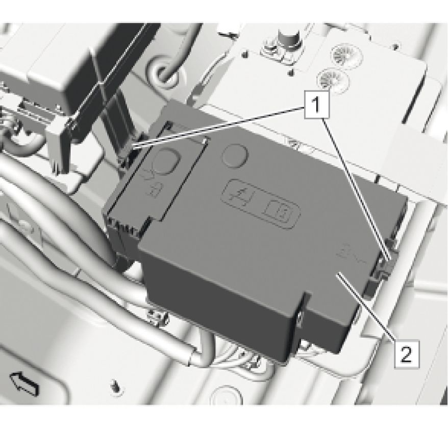 |
|
Fig. 12: Battery Fuse Block Cover And Retaining Tabs |
6. Install Battery Fuse Block Cover (2)
7. Check the 2 locked retaining tabs (1).
 |
|
Fig. 13: Panel Trim And Nuts Courtesy of GENERAL MOTORS COMPANY |
8. Install the panel trim (2).
9. Install the 3 panel trim nuts (1) and tighten to 6 N.m (53 lb in).
10. Connect Battery Negative Cable Battery Negative Cable Disconnection and Connection
11. Install Rear Compartment Floor Stowage Trim Compartment Rear Compartment Floor Stowage Trim
Compartment Replacement
12. Enable the high voltage system. High Voltage Enabling
BATTERY NEGATIVE CABLE REPLACEMENT
Removal Procedure
1. Record all of the radio station presets.
2. Ensure that all lamps and accessories are turned off.
3. Turn the ignition OFF and remove the ignition key.
4. Remove Rear Compartment Floor Panel Trim Replacement
 |
|
Fig. 14: Battery Negative Pole Clamp Nut And Electrical Connector |
WARNING: Battery Disconnect Warning
5. Loosen the battery negative pole clamp nut (4).
6. Disconnect the battery negative pole clamp.
7. Disconnect Electrical Connector (3)
8. Remove the battery negative ground cable bolt (1).
9. Remove Battery Negative Cable (2)
Installation Procedure
 |
|
Fig. 15: Battery Negative Pole Clamp Nut And Electrical Connector |
NOTE: Clean any existing corrosion from the battery terminal and the battery cable
end.
1. Install Battery Negative Cable (2)
CAUTION: Fastener Caution
2. Install the battery negative ground cable bolt (1) and tighten to 22 N.m (16 lb ft).
3. Connect Electrical Connector (3)
4. Connect the battery negative pole clamp.
5. Tighten the battery negative pole clamp nut (4) to 9 N.m (80 lb in).
6. Install Rear Compartment Floor Panel Trim Replacement
7. Insert the ignition key and turn the ignition to the ON position.
8. Program all of the customer's radio station presets and set the radio clock to the current time.
BATTERY POSITIVE CABLE REPLACEMENT
Removal Procedure
1. Remove Rear Compartment Floor Stowage Trim Compartment Replacement
2. Disconnect Battery Negative Cable Disconnection and Connection
 |
|
Fig. 16: Panel Trim And Nuts Courtesy of GENERAL MOTORS COMPANY |
3. Remove the 3 panel trim nuts (1).
4. Remove the panel trim (2).
 |
|
Fig. 17: Battery Fuse Block Cover And Retaining Tabs |
5. Release the retaining tabs.(1)
6. Remove Battery Fuse Block Cover (2)
 |
|
Fig. 18: Battery Positive Cable Fuse Block Nut Courtesy of GENERAL MOTORS COMPANY |
7. Remove the battery positive cable fuse block nut (2).
8. Unclip Retainer(1)
9. Remove Quarter Lower Rear Trim Panel Replacement (Left Side) Quarter Lower Rear Trim Panel
Replacement (Right Side)
 |
|
Fig. 19: Retainer Courtesy of GENERAL MOTORS COMPANY |
10. Unclip Retainer (1)
11. Unclip Center Pillar Lower Trim Panel Replacement
 |
|
Fig. 20: Retainer Courtesy of GENERAL MOTORS COMPANY |
12. Unclip Retainer (1)
 |
|
Fig. 21: Battery Positive Cable And Floor Carpet |
Courtesy of GENERAL MOTORS COMPANY
13. For a better access, fold the floor carpet (2) aside.
14. Remove the battery positive cable (1) from the left channel.
 |
|
Fig. 22: Retainer Courtesy of GENERAL MOTORS COMPANY |
15. For a better access, fold the floor carpet aside.
16. Unclip Retainer (1)
17. Remove Dash Upper Extension Panel Opening Cover Replacement
18. Remove Windshield Wiper System Module Replacement
19. Remove Engine Wiring Harness Junction Block Replacement
 |
|
Fig. 23: Battery Positive Cable And Retaining Tabs |
20. Release the 2 retaining tabs to open the cover (1).
21. Pull the battery positive cable (2) through the harness grommet into the passenger compartment.
22. Separate the battery positive cable from the body harness.
23. Remove the battery positive cable from the vehicle.
Installation Procedure
1. Position the battery positive cable to the vehicle.
2. Insert the battery positive cable to the body harness.
3. Push the battery positive cable terminal through the grommet into the front engine compartment.
 |
|
Fig. 24: Battery Positive Cable And Retaining Tabs |
4. Close the cover (1).
5. Install Engine Wiring Harness Junction Block Replacement
6. Install Windshield Wiper System Module Replacement
7. Install Dash Upper Extension Panel Opening Cover Replacement
 |
|
Fig. 25: Retainer Courtesy of GENERAL MOTORS COMPANY |
8. For a better access, fold the floor carpet aside.
9. Install Retainer (1)
 |
|
Fig. 26: Battery Positive Cable And Floor Carpet |
10. For a better access, fold the floor carpet (2) aside.
11. Install the battery positive cable (1) to the left channel.
 |
|
Fig. 27: Retainer Courtesy of GENERAL MOTORS COMPANY |
12. Install Retainer (1)
13. Install Center Pillar Lower Trim Panel Replacement
 |
|
Fig. 28: Retainer Courtesy of GENERAL MOTORS COMPANY |
14. Install Retainer (1)
15. Install Quarter Lower Rear Trim Panel Replacement (Left Side) Quarter Lower Rear Trim Panel
Replacement (Right Side)
 |
|
Fig. 29: Battery Positive Cable Fuse Block Nut |
16. Install Retainer (1)
CAUTION: Fastener Caution
17. Install the battery positive cable fuse block nut (2) and tighten to 9 N.m (80 lb in).
 |
|
Fig. 30: Battery Fuse Block Cover And Retaining Tabs |
18. Install Battery Fuse Block Cover (2)
19. Lock the 2 retaining tabs (1).
 |
|
Fig. 31: Panel Trim And Nuts Courtesy of GENERAL MOTORS COMPANY |
20. Install the panel trim (2).
21. Install the 3 panel trim nuts (1) and tighten to 6 N.m (53 lb in).
22. Connect Battery Negative Cable Disconnection and Connection
23. Rear Compartment Floor Stowage Trim Compartment Replacement
ENGINE WIRING HARNESS JUNCTION BLOCK REPLACEMENT
Removal Procedure
1. Disconnect Battery Negative Cable Disconnection and Connection
 |
|
Fig. 32: Plastic Quick Connect Fitting Release Tabs And Cover |
2. Squeeze the 3 plastic quick connect fitting release tabs (1) to remove the cover (2).
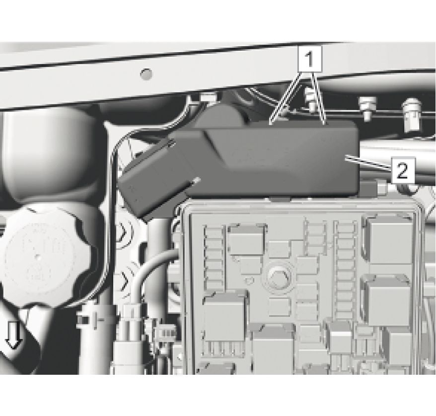 |
|
Fig. 33: Fitting Release Tabs And Cover |
3. Release the 2 tabs (1).
4. Remove the cover (2).
 |
|
Fig. 34: Engine Wiring Harness Junction Block Supply Nuts |
5. Remove the 2 engine wiring harness junction block supply nuts (1, 3).
6. Remove the 2 engine wiring harness junction block supply (2).
 |
|
Fig. 35: Engine Wiring Harness Junction Block Bolts And Retaining Tabs |
NOTE: Bolts (3) are encapsulated on the end of threads so that they can not be
removed from the fuse block.
7. Loosen the 3 engine wiring harness junction block bolts (3).
8. Unlock the 3 retaining tabs (1) and the retaining tabs (4) and remove the engine wiring harness junction block
(2).
Installation Procedure
 |
|
Fig. 36: Electrical Connectors Courtesy of GENERAL MOTORS COMPANY |
1. Push down the 3 electrical connectors (1) before installation of the engine wiring harness junction block.
 |
|
Fig. 37: Engine Wiring Harness Junction Block Bolts And Retaining Tabs |
2. Install the engine wiring harness junction block (2):
1. Lock the 3 retaining tabs (1) and the retaining tabs (4).
CAUTION: Fastener Caution
2. Tighten the 3 engine wiring harness junction block bolts (3) to 7 N.m (62 lb in).
 |
|
Fig. 38: Engine Wiring Harness Junction Block Supply Nuts |
3. Install the 2 engine wiring harness junction block supply (2).
4. Install the engine wiring harness junction block supply nut (1) and tighten to 15 N.m (11 lb ft).
5. Install the engine wiring harness junction block supply nut (3) and tighten to 5 N.m (44 lb in).
 |
|
Fig. 39: Fitting Release Tabs And Cover Courtesy of GENERAL MOTORS COMPANY |
6. Install the cover (2).
7. Check the locked tabs (1).
 |
|
Fig. 40: Plastic Quick Connect Fitting Release Tabs And Cover |
8. Install the cover (2). Check the locked 3 plastic quick connect fitting tabs (1).
9. Connect Battery Negative Cable Disconnection and Connection
BATTERY REPLACEMENT
Removal Procedure
1. Remove Rear Compartment Floor Stowage Trim Compartment Replacement
2. Disconnect Battery Negative Cable Disconnection and Connection
 |
|
Fig. 41: Panel Trim And Nuts Courtesy of GENERAL MOTORS COMPANY |
3. Remove the 3 panel trim nuts (1).
4. Remove the panel trim (2).
 |
|
Fig. 42: Battery Fuse Block Cover And Retaining Tabs |
5. Remove Release the retaining tabs.(1)
6. Remove Battery Fuse Block Cover (2)
 |
|
Fig. 43: Battery Positive Pole Clamp Nut |
7. Loosen the battery positive pole clamp nut (2).
8. Use a screwdriver (1) to unclip the 2 battery fuse block retainer tabs from the battery and remove the battery
fuse block (3) along with the battery positive cables.
 |
|
Fig. 44: Battery Hold Down Retainer Bolt |
9. Remove the battery hold down retainer bolt (3).
10. Remove the battery retainer strap (2).
11. Remove Battery Hold Down Retainer(1)
 |
|
Fig. 45: View Of Battery Courtesy of GENERAL MOTORS COMPANY |
12. Remove the battery (1) from the rear compartment area along with their vent hose.
Installation Procedure
 |
|
Fig. 46: View Of Battery Courtesy of GENERAL MOTORS COMPANY |
NOTE: Clean any existing corrosion from the battery terminal and the battery cable
end.
1. Position the battery (1) onto the tray to the rear of the vehicle as shown in the graphic.
2. Install the vent hose through the body.
 |
|
Fig. 47: Battery Hold Down Retainer Bolt |
3. Install Battery Hold Down Retainer (1)
4. Install the battery retainer strap (2).
CAUTION: Fastener Caution
5. Install the battery hold down retainer bolt (3) and tighten to 18 N.m (13 lb ft).
 |
|
Fig. 48: Battery Fuse Block Courtesy of GENERAL MOTORS COMPANY |
6. Install the battery fuse block (2) along with the battery positive cables to the battery:
1. Align the rear side of the battery fuse block exactly to the battery housing.
2. Clip in the 2 battery fuse block retainer tabs (3).
3. Tighten the battery positive pole clamp nut (1) to 9 N.m (80 lb in).
 |
|
Fig. 49: Battery Fuse Block Cover And Retaining Tabs |
7. Install Battery Fuse Block Cover (2)
8. Check the locked 2 retaining tabs (1).
 |
|
Fig. 50: Panel Trim And Nuts Courtesy of GENERAL MOTORS COMPANY |
9. Install the panel trim (2).
10. Install the 3 panel trim nuts (1) and tighten to 6 N.m (53 lb in).
11. Connect Battery Negative Cable Disconnection and Connection
12. Install Rear Compartment Floor Stowage Trim Compartment Replacement
ENGINE GROUND STRAP REPLACEMENT
Removal Procedure
1. Disconnect Battery Negative Cable Disconnection and Connection
2. Raise and support the vehicle. Lifting and Jacking the Vehicle
 |
|
Fig. 51: Engine Ground Strap Bolt And Retainer |
3. Remove the engine ground strap bolt (1).
4. Unclip Retainer(2)
 |
|
Fig. 52: Retainer Courtesy of GENERAL MOTORS COMPANY |
5. Unclip Retainer(l)
6. Remove Front Wheelhouse Liner Replacement (Left Side) Front Wheelhouse Liner Replacement (Right
Side)
 |
|
Fig. 53: Engine Ground Strap Bolt Courtesy of GENERAL MOTORS COMPANY |
NOTE: The bolt is behind the body plate.
7. Remove the engine ground strap bolt (1).
Installation Procedure
 |
|
Fig. 54: Engine Ground Strap Bolt Courtesy of GENERAL MOTORS COMPANY |
CAUTION: Fastener Caution
NOTE: The bolt is behind the body plate.
1. Install the engine ground strap bolt (1) and tighten to 25 N.m (18 lb ft).
2. Install Front Wheelhouse Liner Replacement (Left Side) Front Wheelhouse Liner Replacement (Right
Side)
 |
|
Fig. 55: Retainer Courtesy of GENERAL MOTORS COMPANY |
3. Install Retainer(1)
 |
|
Fig. 56: Engine Ground Strap Bolt And Retainer |
4. Install the engine ground strap bolt (1) and tighten to 25 N.m (18 lb ft).
5. Install Retainer(2)
6. Lower the vehicle.
7. Connect Battery Negative Cable Disconnection and Connection
DESCRIPTION AND OPERATION
BATTERY DESCRIPTION AND OPERATION
300 V Battery
For information about the 355 V hybrid drive motor battery, refer to Drive Motor Battery System Description .
Absorbent Glass Mat Battery
This vehicle is equipped with an absorbent glass mat battery. This is similar to current vehicle lead acid flood
batteries, except they use glass mats that absorb electrolytes that are pressed between the plates instead of immersing
the plates in electrolytes. This allows a smaller, lighter battery with the same amount of power and is less susceptible
to heat.
The maximum permissible voltage allowed for the absorbent glass mat battery is 14.8 V (at room temperature).
12 V Battery
WARNING: Batteries produce explosive gases, contain corrosive acid, and supply levels of
electrical current high enough to cause burns. Therefore, to reduce the risk of
personal injury when working near a battery:
• Always shield your eyes and avoid leaning over the battery whenever possible.
• Do not expose the battery to open flames or sparks.
• Do not allow the battery electrolyte to contact the eyes or the skin. Flush
immediately and thoroughly any contacted areas with water and get medical
help.
• Follow each step of the jump starting procedure in order.
• Treat both the booster and the discharged batteries carefully when using the
jumper cables.
NOTE: Because of the materials used in the manufacture of automotive lead-acid batteries,
dealers and service shops that handle them are subject to various regulations
issued by OSHA, EPA, DOT, and various state or local agencies. Other regulations
may also apply in other locations. Always know and follow these regulations when
handling batteries.
Batteries that are no longer wanted must be disposed of by an approved battery recycler and must never be thrown in
the trash or sent to a landfill.
Batteries that are not part of the vehicle itself, not the battery under the hood, must only be transported on public
streets for business purposes via approved hazardous material transportation procedures.
Battery storage, charging and testing facilities in repair shops must meet various requirements for ventilation, safety
equipment, material segregation, etc.
The maintenance free battery is standard. There are no vent plugs in the cover. The battery is completely sealed
except for 2 small vent holes in the side. These vent holes allow the small amount of gas that is produced in the
battery to escape.
Battery Ratings
A battery has 2 ratings:
• Cold cranking amperage
• Amp hours
When a battery is replaced use a battery with similar ratings. Refer to the battery specification label on the original
battery.
Amp Hours
The amp hour rating tells you how much amperage is available when discharged evenly over a 20 hour period. The
amp hour rating is cumulative, so in order to know how many constant amps the battery will output for 20 hours, you
have to divide the amp hour rating by 20. Example: If a battery has an amp hour rating of 74, dividing by 20 = 3.75.
Such a battery can carry a 3.75 A load for 20 hours before dropping to 10.5 V (10.5 V is the fully discharged level,
at which point the battery needs to be recharged.) A battery with an amp hour rating of 55 will carry a 2.75 A load
for 20 hours before dropping to 10.5 V
Cold Cranking Amperage
The cold cranking amperage is an indication of the ability of the battery to crank the engine at cold temperatures. The
cold cranking amperage rating is the minimum amperage the battery must maintain for 30 seconds at - 18A°C
(0A°F) while maintaining at least 7.2 V. Refer to the battery specification label on the original battery for the cold
cranking amperage rating for this vehicle.
CHARGING SYSTEM DESCRIPTION AND OPERATION
12 V Battery
The following information is for the 12 V battery only.
For information about charging the high voltage drive motor batteries, refer to Drive Motor Battery System
Description .
Electrical Power Management Overview
The electrical power management system is designed to monitor and control the charging system and send diagnostic
messages to alert the driver of possible problems. This electrical power management system primarily utilizes
existing on-board computer capability to maximize the effectiveness of the charging system, manage the load,
improve battery state of charge and life, and minimize the system's impact on fuel economy. The electrical power
management system performs 3 functions:
• It monitors the battery voltage and estimates the battery condition.
• It takes corrective actions by adjusting the regulated voltage.
• It performs diagnostics and driver notification.
The battery condition is estimated during Vehicle OFF and during Vehicle in Service Mode. During Vehicle OFF the
state of charge of the battery is determined by measuring the open-circuit voltage. The state of charge is a function of
the acid concentration and the internal resistance of the battery, and is estimated by reading the battery open circuit
voltage when the battery has been at rest for several hours.
The state of charge can be used as a diagnostic tool to tell the customer or the dealer the condition of the battery.
During Vehicle ON mode, the algorithm continuously estimates state of charge based on adjusted net amp hours,
battery capacity, initial state of charge, and temperature.
While running, the battery degree of discharge is primarily determined by a battery current sensor, which is
integrated to obtain net amp hours.
In addition, the electrical power management function is designed to perform regulated voltage control to improve
battery state of charge, battery life, and fuel economy. This is accomplished by using knowledge of the battery state
of charge and temperature to set the charging voltage to an optimum battery voltage level for recharging without
detriment to battery life.
 |
|
Ч B18 ■ Battery ' Current I Sensor |
1 К9
■ Body
Control
I Module
Fig. 57: Charging Block Diagram
Courtesy of GENERAL MOTORS COMPANY
| ||||||||||||
|
Charging System Components |
Drive Motor/Generators
The drive motor/generators are serviceable components located within the transmission housing. When the rotors are
spun, an alternating current (AC) is induced into the stator windings. This AC voltage is then sent to the drive motor
generator power inverter module (PIM) where it is converted to high voltage direct current (DC) power. The output
of the PIM is converted into low voltage electrical power by the accessory DC power converter module (APM) for
use by the vehicle's electrical system to maintain electrical loads and battery charge.
Body Control Module (BCM)
The body control module (BCM) is a GMLAN device. It communicates with the engine control module (ECM) and
the instrument panel cluster for electrical power management operation. The BCM determines the desired voltage set
point and sends the information to the APM. The BCM monitors a battery current sensor, the battery positive voltage
circuit, and estimated battery temperature to determine battery state of charge.
Battery Current Sensor
The battery current sensor is a serviceable component that is connected to the negative battery cable at the battery.
The battery current sensor is a 3-wire hall effect current sensor. The battery current sensor monitors the battery
current. It directly inputs to the BCM. It creates a 5 V pulse width modulation (PWM) signal of 128 Hz with a duty
cycle of 0 - 100 percent. Normal duty cycle is between 5 - 95 percent. Between 0 - 5 percent and 95 - 100 percent are
for diagnostic purposes.
Engine Control Module (ECM)
The ECM receives control decisions based on messages from the BCM.
Instrument Panel Cluster
The instrument panel cluster provides a means of customer notification in case of a failure and a voltmeter. There are
2 means of notification, a charge indicator and a driver information center message of SERVICE BATTERY
CHARGING SYSTEM.
Charging System Operation
The purpose of the charging system is to maintain the battery charge and vehicle loads. There are 6 modes of
operation and they include:
• Battery Sulfation Mode
• Normal Mode
• Fuel Economy Mode
• Headlamp Mode
• Voltage Reduction Mode
• Plant Assembly Mode
Battery Sulfation Mode
Battery sulfation mode is used to help maintain the battery life. The charging system will enter a battery sulfation
mode which tries to increase the vehicle charging when the charging system voltage is less than 13.2 V for about 30
minutes. Once in this mode, the BCM will set a targeted output voltage between 13.9 - 15.5 V for about 5 minutes.
Following this 5 minutes, the BCM will then determine which mode to enter depending on the system voltage
requirements.
Normal Mode
The BCM will enter Normal Mode whenever one of the following conditions are met.
• The wipers are ON for more than 3 seconds.
• GMLAN Climate Control Voltage Boost Mode Request is true, as sensed by the HVAC control head. High
speed cooling fan, rear defogger and HVAC high speed blower operation can cause the BCM to enter the
Charge Mode.
• The estimated battery temperature is less than 0A°C (32A°F).
• Vehicle Speed is greater than 145 km/h (90 mph)
• Current Sensor Fault Exists
• System Voltage was determined to be below 12.56 V
• Tow/Haul Mode is enabled
When any one of these conditions is met, the system will set targeted generator output voltage to a charging voltage
between 13.9 - 15.5 V, depending on the battery state of charge and estimated battery temperature.
Fuel Economy Mode
The BCM will enter Fuel Economy Mode when the ambient air temperature is at least 0A°C (32A°F) but less than or
equal to 80A°C (176A°F), the calculated battery current is greater than -8 A but less than 5 A, and the battery state of
charge is greater than or equal to 85 percent. Its targeted APM set-point voltage is the open circuit voltage of the
battery and can be between 12.6 - 13.2 V The BCM will exit this mode and enter Normal Mode when any of the
conditions described above are present.
Headlamp Mode
The BCM will enter Headlamp Mode whenever the high or low beam headlamps are ON. Voltage will be regulated
between 13.9 - 14.5 V
Voltage Reduction Mode
The BCM will enter Voltage Reduction Mode when the calculated battery temperature is above 0A°C (32A°F) and
the calculated battery current is greater than -7 A but less than 1 A. Its targeted APM set-point voltage is 12.9 - 13.2
V. The BCM will exit this mode once the criteria are met for Normal Mode.
Plant Assembly Mode
The BCM will increase charging voltage for the first 500 miles of operation in an effort to ensure that the 12 V
battery is fully charged when the vehicle is delivered to the customer.
Instrument Panel Cluster Operation
Charge Indicator Operation
The instrument panel cluster illuminates the charge indicator and displays a charging system warning message in the
driver information center when the one or more of the following occurs:
• The engine control module (ECM) detects system voltage less than 11 V or greater than 16 V. The instrument
panel cluster receives a GMLAN message from the ECM requesting illumination.
• The BCM determines that the system voltage is less than 11 V or greater than 16 V.
• The instrument panel cluster receives a GMLAN message from the BCM indicating there is a system voltage
range concern.
• The instrument panel cluster performs the displays test at the start of each Vehicle ON cycle. The indicator
illuminates for approximately 3 seconds.
• Vehicle ON, with the engine OFF.
Battery Voltage Gauge Operation
The instrument panel cluster displays the system voltage as received from the BCM over the GMLAN serial data
circuit. If there is no communication with the BCM then the gauge will indicate minimum.
This vehicle is equipped with a regulated voltage control system. This will cause the voltmeter to fluctuate between
12 - 14 V, as opposed to non-regulated systems which usually maintain a more consistent reading of 14 V This
fluctuation with the regulated voltage control system is normal system operation and NO repairs should be
attempted.
SERVICE BATTERY CHARGING SYSTEM
The BCM and the ECM will send a GMLAN message to the driver information center for the SERVICE BATTERY
CHARGING SYSTEM message to be displayed. It is displayed whenever the charge indicator is commanded ON
due to a failure.
STARTING SYSTEM DESCRIPTION AND OPERATION
The HQ1 hybrid system does not use a conventional starter. Refer to Hybrid Modes of Operation Description for
information about the starting system.
SPECIAL TOOLS AND EQUIPMENT

|
Illustration |
Tool |
|
/ fff&! Ы |
J 42000 |
Tool
Number/Description

EL 50313
EL 42000
EL 50076
Battery Tester
|
Illustration |
Tool |
|
EL-48900 | |
|
HEV Safety Kit |
|
Illustration |
Tool |
|
v/ JhI Iz |
GE-49379 |
Article GUID: A00884656
ENGINE
SPECIFICATIONS
TEMPERATURE VERSUS RESISTANCE (RADIATOR COOLANT TEMPERATURE SENSOR)
| ||||||||||||||||||||||||||||||||||||||||||||||||||||||||
|
FASTENER SPECIFICATIONS |
Single Use Non-Threaded Fasteners/Components
NOTE:
All
fasteners/components
listed in this table
MUST BE
DISCARDED and
replaced with NEW
after removal.
Application
Engine Coolant Thermostat Housing Gasket
Water Outlet Gasket
Water Pump Gasket
Water Pump Housing Gasket
|
Single Use Threaded Fastener/Component Tightening Specifications | |||||||
| |||||||
|
Reusable Threaded Fastener Tightening Specifications | |||||||||||||||||||||||||||
| |||||||||||||||||||||||||||
|
APPROXIMATE FLUID CAPACITIES | |||||||||||||||||
| |||||||||||||||||
|
ADHESIVES, FLUIDS, LUBRICANTS, AND SEALERS | ||||||||||
| ||||||||||
SCHEMATIC WIRING DIAGRAMS
ENGINE HEATING/COOLING WIRING SCHEMATICS
Engine Cooling Fans
 |
|
Fig. 1: Engine Cooling Fans Courtesy of GENERAL MOTORS COMPANY |
DIAGNOSTIC INFORMATION AND PROCEDURES
DTC P00B3 OR P00B4: RADIATOR COOLANT TEMPERATURE (RCT) SENSOR CIRCUIT
LOW/HIGH VOLTAGE
Diagnostic Instructions
• Perform the Diagnostic System Check - Vehicle prior to using this diagnostic procedure.
• Review Strategy Based Diagnosis for an overview of the diagnostic approach.
Diagnostic Procedure Instructions provides an overview of each diagnostic category.
DTC Descriptors
DTC P00B3
Radiator Coolant Temperature (RCT) Sensor Circuit Low Voltage
DTC P00B4
Radiator Coolant Temperature (RCT) Sensor Circuit High Voltage
|
Diagnostic Fault Information | ||||||||||||||||||||
| ||||||||||||||||||||
|
Typical Scan Tool Data | ||||||||||||||||||||
|
Radiator Coolant Temperature Sensor | ||||||||||||||||||||
| ||||||||||||||||||||
|
Circuit/System Description | ||||||||||||||||||||
NOTE: The radiator coolant temperature sensor is referred to as B203 Engine Coolant
Temperature Sensor 2 in schematics and other areas.
The radiator coolant temperature (RCT) sensor is a variable resistor that measures the temperature of the engine
coolant in the radiator. The engine control module (ECM) supplies 5 volts to the RCT signal circuit and supplies
a ground to the low reference circuit.
|
The following table illustrates the difference between temperature, resistance, and voltage: | |||||||||
| |||||||||
|
Conditions for Running the DTC |
P00B3
• The engine run time is greater than 10 s.
• The intake air temperature (IAT) is colder than 70A°C (158A°F).
• The DTC runs continuously when the above conditions are met.
P00B4
• The engine run time is greater than 60 s.
• The intake air temperature (IAT) is warmer than -7A°C (19A°F).
• The DTC runs continuously when the above conditions are met.
Conditions for Setting the DTC
P00B3
The ECM detects that the RCT sensor is warmer than 149A°C (300A°F) for greater than 10 s.
P00B4
NOTE: The scan tool only displays to -40A°C (-40A°F).
The ECM detects that the RCT sensor is colder than -60A°C (-76A°F) for greater than 10 s.
Action Taken When the DTC Sets
• DTCs P00B3 and P00B4 are Type B DTCs.
• The cooling fans will be commanded ON by the ECM.
• The Engine Coolant Temperature Gauge is inoperative.
• The AC compressor will be commanded OFF.
Conditions for Clearing the MIL/DTC
DTC P00B3 and P00B4 are Type B DTCs.
Diagnostic Aids
NOTE: The engine coolant temperature (ECT) sensor is mounted on the engine and the
radiator coolant temperature (RCT) sensor is mounted on the radiator.
• As the thermostat opens, the RCT sensor temperature should rise steadily, then stabilize once the
thermostat opens completely.
• Test the RCT sensor at various temperature levels in order to evaluate the possibility of a skewed sensor.
• If the vehicle has sat for greater than 8 hours, the RCT sensor and the ECT sensor values should display
within 3A°C (5A°F).
Reference Information
Schematic Reference
Engine Controls Schematics
Connector End View Reference
COMPONENT CONNECTOR END VIEWS - INDEX
Description and Operation
Hybrid Modes of Operation Description
Electrical Information Reference
Circuit Testing
Connector Repairs
Testing for Intermittent Conditions and Poor Connections
Wiring Repairs
DTC Type Reference
Powertrain Diagnostic Trouble Code (DTC) Type Definitions
Scan Tool Reference
Control Module References for scan tool information
Circuit/System Verification
1. Engine Running.
2. Verify the scan tool Radiator Coolant Temperature Sensor parameter is between -39 to + 120A°C (-38 to
+248A°F) and changes with engine run time.
• If not between -39 to + 120A°C (-38 to +248A°F) or does not change
Refer to Circuit/System Testing.
• If between -39 to + 120A°C (-38 to +248A°F) and changes
3. Operate the vehicle within the Conditions for Running the DTC. You may also operate the vehicle within
the conditions that you observed from the Freeze Frame/Failure Records data.
4. Verify the DTC does not set.
• If the DTC sets
Refer to Circuit/System Testing.
• If the DTC does not set
5. All OK.
Circuit/System Testing
1. Vehicle Off, disconnect the harness connector at the B203 Engine Coolant Radiator Temperature Sensor.
It may take up to 2 min for all vehicle systems to power down.
2. Test for less than 2 fi between the low reference circuit terminal 2 and ground.
• If 2 fi or greater
1. Vehicle Off, disconnect the X1 harness connector at the K20 Engine Control Module.
2. Test for less than 2 fi in the low reference circuit end to end.
• If 2 fi or greater, repair the open/high resistance in the circuit.
• If less than 2 fi, replace the K20 Engine Control Module.
• If less than 2 fi
3. Vehicle in Service Mode.
4. Verify the scan tool Radiator Coolant Temperature Sensor parameter is colder than -39A°C (-38A°F).
• If warmer than -39A°C (-38A°F)
1. Vehicle Off, disconnect the X1 harness connector at the K20 Engine Control Module.
2. Test for infinite resistance between the signal circuit terminal 1 and ground.
• If less than infinite resistance, repair the short to ground on the circuit.
• If infinite resistance, replace the K20 Engine Control Module.
• If colder than -39A°C (-38A°F)
5. Install a 3 A fused jumper wire between the signal circuit terminal 1 and the low reference circuit
terminal 2.
6. Verify the scan tool Radiator Coolant Temperature Sensor parameter is warmer than 140A°C (284A°F).
• If colder than the 140A°C (284A°F)
1. Vehicle Off, disconnect the X1 harness connector at the K20 Engine Control Module, Vehicle in
Service Mode.
2. Test for less than 1 V between the signal circuit and ground.
• If 1 V or greater, repair the short to voltage on the circuit.
• If less than 1 V
3. Vehicle Off.
4. Test for less than 2 fi in the signal circuit end to end.
• If 2 fi or greater, repair the open/high resistance in the circuit.
• If less than 2 fi, replace the K20 Engine Control Module.
• If warmer than 140A°C (284A°F)
7. Test or replace the B203 Engine Coolant Radiator Temperature Sensor.
Component Testing
1. Vehicle Off, remove the B203 Engine Coolant Radiator Temperature Sensor.
NOTE: A thermometer can be used to test the sensor off the vehicle.
2. Test the B203 Engine Coolant Radiator Temperature Sensor by varying the sensor temperature while
measuring the sensor resistance. Compare the readings with the Temperature Versus Resistance
(Radiator Coolant Temperature Sensor) table and verify that the resistance is within 5 percent of the
specification.
• If not within the specified range, replace the B203 Engine Coolant Radiator Temperature Sensor.
Repair Instructions
Perform the Diagnostic Repair Verification after completing the repair.
Engine Coolant Temperature Sensor Replacement - Water Outlet
for Radiator Coolant Temperature Sensor replacement.
Control Module References for ECM replacement, programming, and setup.
DTC P00B7: ENGINE COOLANT FLOW INSUFFICIENT
Diagnostic Instructions
• Perform the Diagnostic System Check - Vehicle prior to using this diagnostic procedure.
• Review Strategy Based Diagnosis for an overview of the diagnostic approach.
Diagnostic Procedure Instructions provides an overview of each diagnostic category.
DTC Descriptors
DTC P00B7
Engine Coolant Flow Insufficient
Circuit Description
The engine control module (ECM) monitors the temperature of the engine radiator coolant. The ECM controls
the thermostat with a pulse width modulated (PWM) signal. The ECM compares the radiator coolant
temperature to the engine coolant temperature in order to determine if there sufficient coolant flow through the
thermostat.
Conditions for Running the DTC
• DTCs P00B3, P00B4, P00B6, P0116, P0117, and P0118 are not set.
• The engine run time is greater than 45 s.
• The engine coolant temperature is greater than 70A°C (158A°F).
• The DTC runs continuously when the above conditions are met.
Conditions for Setting the DTC
NOTE: The scan tool display range is between -40 and + 150A°C (-40 and +302A°F).
The ECM detects the difference between the RCT sensor and the ECT sensor is greater than 45A°C (81A°F)
when the ECT sensor is warmer than 117A°C (242A°F) for greater than 5 s.
Action Taken When the DTC Sets
DTC P00B7 is a Type B DTC.
Conditions for Clearing the MIL/DTC
DTC P00B7 is a Type B DTC.
Diagnostic Aids
• The thermostat has a mechanical fail-safe in case of an electrical condition with the thermostat heater.
The mechanical thermostat will open at approximately 80A°C (176A°F). The mechanical thermostat will
cycle from approximately 85A°C (185A°F) to approximately 102A°C (215A°F).
• A resistance condition in the RCT sensor circuits may cause this DTC. This condition results in a greater
voltage on the RCT sensor signal circuit, which is interpreted by the ECM as a colder RCT.
Reference Information
DTC Type Reference
Powertrain Diagnostic Trouble Code (DTC) Type Definitions
Scan Tool Reference
Control Module References for scan tool information
Circuit/System Verification
1. Engine Running.
2. Verify DTC P00B3, P00B4, P00B6, P0116, P0117 or P0118 is not set.
• If the DTC is set.
Refer to Diagnostic Trouble Code (DTC) List - Vehicle for further diagnosis.
• If the DTC is not set.
3. Verify the coolant in the radiator surge tank is at the correct level and there are no engine coolant leaks.
• If a condition is found.
Refer to Cooling System Draining and Filling, and Loss of Coolant.
• If a condition is not found.
4. Verify the engine cooling fan operates when commanding the cooling fan to 90% and back to 20% with a
scan tool.
• If the cooling fan does not operate
Refer to DTC P1485-P1487.
• If the cooling fan operates
5. Engine Running for 15 min with the A/C OFF.
NOTE: Depending on ambient temperature, it may take up to 4 minutes for the
temperature to decrease less than the specified value.
6. Command the Engine Coolant Thermostat Heater to 100 percent with a scan tool, depress the accelerator
pedal.
7. Verify the scan tool ECT Sensor parameter decreases to less than 85A°C (185A°F).
• If ECT is warmer than 85A°C (185A°F)
Refer to Circuit/System Testing.
• If ECT is colder than 85A°C (185A°F)
8. Operate the vehicle within the Conditions for Running the DTC. You may also operate the vehicle within
the conditions that you observed from the Freeze Frame/Failure Records data.
9. Verify the DTC does not set.
• If the DTC sets
Refer to Circuit/System Testing.
• If the DTC does not set
10. All OK.
Circuit/System Testing
1. Vehicle OFF, inspect the cooling system for the conditions below. Refer to Symptoms - Engine Cooling.
• Weak coolant solution
• Obstructed radiator air flow or bent radiator fins
• Blocked cooling system passages
• Radiator hoses that are restricted, collapsed, or deteriorated
• Damaged water pump and or belt
• Loss of cooling system pressure
• Leaking surge tank cap
• Radiator hoses
• Cylinder head or an engine block that is cracked or plugged
• If a condition is found
Repair as necessary.
• If a condition is not found
2. Replace the Engine Coolant Thermostat.
Repair Instructions
Engine Coolant Thermostat Housing Replacement for engine coolant thermostat replacement.
DTC P0597-P0599: ENGINE COOLANT THERMOSTAT HEATER CONTROL CIRCUIT
Diagnostic Instructions
• Perform the Diagnostic System Check - Vehicle prior to using this diagnostic procedure.
• Review Strategy Based Diagnosis for an overview of the diagnostic approach.
Diagnostic Procedure Instructions provides an overview of each diagnostic category.
DTC Descriptor
DTC P0597
Engine Coolant Thermostat Heater Control Circuit
DTC P0598
Engine Coolant Thermostat Heater Control Circuit Low Voltage
DTC P0599
Engine Coolant Thermostat Heater Control Circuit High Voltage
|
Diagnostic Fault Information | ||||||||||||||||||||
| ||||||||||||||||||||
|
Circuit/System Description | ||||||||||||||||||||
A wax pellet-type thermostat controls the flow of the engine coolant through the engine cooling system. The
wax element of the thermostat expands and opens the thermostat when it is heated. The engine coolant
thermostat heater uses an electric heating element to help heat the wax pellet opening the thermostat to increase
cooling system performance during certain operation conditions. Ignition voltage is supplied directly to the
thermostat heater through a fuse. If certain driving conditions are met the engine control module (ECM)
controls the thermostat heater by providing a pulse width modulated (PWM) ground.
Conditions for Running the DTCs
• The ignition is ON, or the engine is running.
• The DTCs run continuously once the above condition is met
Conditions for Setting the DTC
The ECM detects that the commanded state of the driver and the actual state of the control circuit do not match
for greater than 15 seconds.
Action Taken When the DTC Sets
• DTCs P0597, P0598, and P0599 are Type B DTCs.
• The engine control module commands the engine cooling fans ON.
Conditions for Clearing the DTC
DTCs P0597, P0598, and P0599 are Type B DTCs.
Diagnostic Aids
• A low engine coolant level could cause the thermostat heater to overheat and set a DTC.
• Without electric assist the wax pellet thermostat begins to open at 103A° C (217A° F) and is fully open at
117A° C (243A° F) when the electric energy not assisted.
The mechanical thermostat will open at approximately 80A°C (176A°F). The mechanical thermostat will cycle
from approximately 85A°C (185A°F) to approximately 102A°C (215A°F).
Reference Information
Schematic Reference
Engine Controls Schematics
Connector End View Reference
COMPONENT CONNECTOR END VIEWS - INDEX
Description and Operation
Hybrid Modes of Operation Description
Electrical Information Reference
Circuit Testing
Connector Repairs
Testing for Intermittent Conditions and Poor Connections
Wiring Repairs
DTC Type Reference
Powertrain Diagnostic Trouble Code (DTC) Type Definitions
Control Module References for scan tool information
Circuit/System Verification
1. Verify the coolant in the radiator surge tank is at the correct level and there are no engine coolant leaks.
• If a condition is found
Refer to Cooling System Draining and Filling, and Loss of Coolant.
• If a condition is not found
2. Vehicle in Service Mode.
3. Verify the parameters listed below do not display Malfunction when commanding the Engine Coolant
Thermostat Heater 0% - 100% with a scan tool.
• Engine Coolant Thermostat Heater Control Circuit Low Voltage Test Status
• Engine Coolant Thermostat Heater Control Circuit Open Test Status
• Engine Coolant Thermostat Heater Control Circuit High Voltage Test Status
• If Malfunction is displayed
Refer to Circuit/System Testing.
• If Malfunction is not displayed
4. Operate the vehicle within the conditions for running the DTC. You may also operate the vehicle within
the conditions that you observed from the freeze frame/failure records data.
5. Verify the DTC does not set.
• If any DTC sets
Refer to Circuit/System Testing.
• If the DTC does not set
6. All OK.
Circuit/System Testing
1. Vehicle OFF, disconnect the harness connector at the E41 Engine Coolant Thermostat Heater.
2. Vehicle in Service Mode
3. Verify that a test lamp illuminates between the ignition circuit terminal 1 and ground.
• If the test lamp does not illuminate and the circuit fuse is good
1. Vehicle OFF, remove the test lamp.
2. Test for less than 2 Q in the ignition circuit end to end.
• If 2 Q or greater, repair the open/high resistance in the circuit.
• If less than 2 Q verify the fuse is not open and there is voltage at the fuse.
• If the test lamp does not illuminate and the circuit fuse is open
NOTE: The ignition circuit may supply voltage to other components. Make
sure to test all circuits and components for a short to ground that
share the ignition circuit.
•
1. Vehicle OFF, remove the test lamp, and disconnect all components on the circuit.
2. Test for infinite resistance between the ignition circuit and ground
• If less than infinite resistance, repair the short to ground in the circuit.
• If infinite resistance
3. Replace the fuse, vehicle in Service Mode.
4. Verify the fuse is good after connecting each of the components one at a time.
• If the fuse opens, replace the component that opens the fuse when connected.
• If the fuse is good, all OK.
• If the test lamp illuminates
4. Connect a test lamp between the ignition circuit terminal 1 and the control circuit terminal 2, command
the Engine Coolant Thermostat Heater to Increase to 100 % and Decrease to 0 % with a scan tool.
5. Verify that a test lamp turns ON and OFF.
• If the test lamp is always ON
1. Vehicle OFF, disconnect the harness connector at the K20 Engine Control Module.
2. Test for infinite resistance between the control circuit and ground.
• If less than infinite resistance, repair the short to ground on the circuit.
• If infinite resistance, replace the K20 Engine Control Module.
• If the test lamp is always OFF
1. Vehicle OFF, disconnect the harness connector at the K20 Engine Control Module, vehicle in
Service Mode.
2. Test for less than 1 V between the control circuit and ground.
• If 1 V or greater, repair the short to voltage on the circuit.
• If less than 1 V.
3. Test for less than 2 fi in the control circuit end to end.
• If 2 fi or greater, repair the open/high resistance in the circuit.
• If less than 2 fi replace the K20 Engine Control Module
• If the test lamp turns ON and OFF
6. Test or replace the E41 Engine Coolant Thermostat Heater.
Repair Instructions
Perform the Diagnostic Repair Verification after completing the repair.
• Engine Coolant Thermostat Housing Replacement
Control Module References for control module replacement, programming, and setup
DTC P112F: RADIATOR COOLANT TEMPERATURE SENSOR NOT PLAUSIBLE
Diagnostic Instructions
• Perform the Diagnostic System Check - Vehicle prior to using this diagnostic procedure.
• Review Strategy Based Diagnosis for an overview of the diagnostic approach.
Diagnostic Procedure Instructions provides an overview of each diagnostic category.
DTC Descriptor
DTC P112F
Radiator Coolant Temperature Sensor Not Plausible
|
Diagnostic Fault Information | ||||||||||||||||||||
| ||||||||||||||||||||
|
Typical Scan Tool Data | ||||||||||||||||||||
|
Radiator Coolant Temperature Sensor | ||||||||||||||||||||
| ||||||||||||||||||||
|
Circuit Description | ||||||||||||||||||||
The engine coolant radiator temperature sensor is a variable resistor that measures the temperature of the engine
coolant in the radiator. The engine control module (ECM) supplies 5 volts to the engine coolant radiator
temperature signal circuit and supplies a ground to the low reference circuit. The purpose of this diagnostic is to
determine if the input from the RCT sensor is skewed warmer than normal. The internal clock of the ECM will
record the amount of time the engine is OFF. If the required engine OFF time is met at start-up, the ECM will
compare the temperature difference between the actual measured RCT and ECT sensors.
|
The following table illustrates the difference between temperature, resistance, and voltage: | |||||||||
| |||||||||
|
Conditions for Running the DTC |
• The engine is running.
• The intake air temperature (IAT) is warmer than -7A°C (19A°F).
• The fuel level is greater than 10 percent.
• The DTC runs once per ignition cycle when the above conditions are met.
Conditions for Setting the DTC
The ECM determines the absolute difference of temperature between the RCT start up temperature and ECT
start up temperature is greater than 20A°C (68A°F).
Action Taken When the DTC Sets
DTC P112F is a Type B DTC.
Conditions for Clearing the MIL/DTC
DTC P112F is a Type B DTC.
Diagnostic Aids
• As the thermostat opens, the radiator coolant temperature sensor signal should rise steadily, then stabilize
once the thermostat opens completely.
• Inspect for the correct operation of the engine cooling system and verify the correct coolant level.
Reference Information
Schematic Reference
Engine Controls Schematics
Connector End View Reference
COMPONENT CONNECTOR END VIEWS - INDEX
Electrical Information Reference
Circuit Testing
Connector Repairs
Testing for Intermittent Conditions and Poor Connections
Wiring Repairs
DTC Type Reference
Powertrain Diagnostic Trouble Code (DTC) Type Definitions
Scan Tool Reference
Control Module References for scan tool information
Circuit/System Verification
1. Vehicle in Service Mode.
2. Verify the scan tool Radiator Coolant Temperature Sensor parameter is between -39 to + 120A°C (-38 to
+248A°F) and changes with engine run time.
• If not between -39 to + 120A°C (-38 to +248A°F) or does not change
Refer to Circuit/System Testing.
• If between -39 to + 120A°C (-38 to +248A°F) and changes
3. Operate the vehicle within the Conditions for Running the DTC. You may also operate the vehicle within
the conditions that you observed from the Freeze Frame/Failure Records data.
4. Verify the DTC does not set.
• If the DTC sets
Refer to Circuit/System Testing.
• If the DTC does not set
5. All OK.
Circuit/System Testing
1. Vehicle OFF and all vehicle systems OFF, disconnect the harness connector at the B203 Engine Coolant
Radiator Temperature Sensor. It may take up to 2 minutes for all vehicle systems to power down.
2. Test for less than 5 Q between the low reference terminal 2 and ground.
• If 5 Q or greater
1. Vehicle OFF, disconnect the harness connector at the K20 Engine Control Module.
2. Test for less than 2 Q in the low reference circuit end to end.
• If 2 Q or greater, repair the open/high resistance in the circuit.
• If less than 2 Q, replace the K20 Engine Control Module.
• If less than 5 Q
3. Vehicle in Service Mode.
4. Verify the scan tool Radiator Coolant Temperature Sensor parameter is colder than -39A°C (-38A°F).
• If warmer than -39A°C (-38A°F)
1. Vehicle OFF, disconnect the harness connector at the K20 Engine Control Module.
2. Test for infinite resistance between the signal circuit terminal 1 and ground.
• If less than infinite resistance, repair the short to ground on the circuit.
• If infinite resistance, replace the K20 Engine Control Module.
• If colder than -39A°C (-38A°F)
5. Install a 3 A fused jumper wire between the signal circuit terminal 1 and the low reference circuit
terminal 2, Vehicle in Service Mode.
6. Verify the scan tool Radiator Coolant Temperature Sensor parameter is warmer than 140A°C (284A°F).
• If colder than the 140A°C (284A°F)
1. Vehicle OFF, disconnect the harness connector at the K20 Engine Control Module, Vehicle in
Service Mode.
2. Test for less than 1 V between the signal circuit and ground.
• If 1 V or greater, repair the short to voltage on the circuit.
• If less than 1 V
3. Vehicle OFF
4. Test for less than 2 Q in the signal circuit end to end.
• If 2 Q or greater, repair the open/high resistance in the circuit.
• If less than 2 Q, replace the K20 Engine Control Module.
• If warmer than 140A°C (284A°F)
7. Test or replace the B203 Engine Coolant Radiator Temperature Sensor.
Component Testing
1. Vehicle OFF, remove the B203 Engine Coolant Radiator Temperature Sensor.
NOTE: A thermometer can be used to the used to test the sensor off the vehicle.
2. Test the engine coolant radiator temperature sensor by varying the sensor temperature while measuring
the sensor resistance. Compare the readings with the Temperature Versus Resistance (Radiator
Coolant Temperature Sensor) table and verify that the resistance is within 5 percent of the specification.
• If not within the specified range, replace the B203 Engine Coolant Radiator Temperature Sensor.
Repair Instructions
Perform the Diagnostic Repair Verification after completing the repair.
Engine Coolant Temperature Sensor Replacement - Radiator
Control Module References for control module replacement, setup, and programming
DTC P1485-P1487: COOLING FAN OUTPUT CIRCUIT
Diagnostic Instructions
• Perform the Diagnostic System Check - Vehicle prior to using this diagnostic procedure.
• Review Strategy Based Diagnosis for an overview of the diagnostic approach.
Diagnostic Procedure Instructions provides an overview of each diagnostic category.
DTC Descriptors
DTC P1485
Cooling Fan Output Circuit
DTC P1486
Cooling Fan Output Circuit Low Voltage
DTC P1487
Cooling Fan Output Circuit High Voltage
|
Diagnostic Fault Information | ||||||||||
| ||||||||||
|
Circuit/System Description |
The hybrid/EV powertrain control module 2 indirectly controls the radiator fans. When propulsion is active, the
engine control module (ECM) processes all requests for the cooling fans to be turned ON regardless of which
module originates the request. The ECM decides if and at what speed the cooling fans should operate. The ECM
sends the cooling fan command to the hybrid/EV powertrain control module 2. The hybrid/EV powertrain
control module 2 sends the signal to the cooling fans to operate and at what speed. If the vehicle is in Charge
Mode and the hybrid/EV powertrain control module 2 requests the cooling fans to operate and the ECM is not
awake, the hybrid/EV powertrain control module 2 will control the cooling fans without ECM intervention.
The ECM communicates the fan command PWM signal to the hybrid/EV powertrain control module 2 through
the cooling fan speed signal circuit/hardwire circuit and also sends a redundant serial data signal. Since the
hardwire circuit is an output from the ECM but an input to the hybrid/EV powertrain control module 2, each
module has unique DTCs to monitor the same circuit.
Conditions for Running the DTC
• DTC P2537 is not set.
• The 12 V battery voltage is equal to or greater than 11 V.
• The accessory circuit is active for greater than 5 s.
• The DTCs run continuously when the conditions above are met.
Conditions for Setting the DTC
The ECM detects that the commanded state of the driver and the actual state of the output circuit do not match
for greater than 5 s.
Action Taken When the DTC Sets
DTCs P1485, P1486 and P1487 are Type B DTCs.
Conditions for Clearing the DTC
DTCs P1485, P1486 and P1487 are Type B DTCs.
Diagnostic Aids
DTCs P1485, P1486 and P1487 will not keep the cooling fans from operating. If one of these DTCs is set the
HPCM 2 will command the cooling fans to 90%. If the cooling fans do not operate, refer to DTC P148A-
P148C for further diagnosis.
Reference Information
Engine Heating/Cooling Schematics
Connector End View Reference
COMPONENT CONNECTOR END VIEWS - INDEX
Description and Operation
Hybrid Modes of Operation Description
Hybrid/EV Cooling System Description and Operation
Electrical Information Reference
Circuit Testing
Connector Repairs
Testing for Intermittent Conditions and Poor Connections
Wiring Repairs
DTC Type Reference
Powertrain Diagnostic Trouble Code (DTC) Type Definitions
Scan Tool Reference
Control Module References for scan tool information
Circuit/System Verification
1. Vehicle ON.
2. Verify DTC P1485, P1486, P1487, P148A, P148B, or P148C is not set.
• If the DTC is set
Refer to Circuit/System Testing.
• If the DTC is not set
3. All OK.
Circuit/System Testing
1. Vehicle OFF, disconnect the X2 harness connector at the K114B Hybrid/EV Powertrain Control Module
2, vehicle in Service Mode.
NOTE: The cooling fan circuit is pulled up to a voltage within the ECM. 3 - 4 V
measured on this circuit with the hybrid/EV powertrain control module 2
disconnected is normal.
2. Test for 3 - 4 V between the cooling fan circuit terminal 9 and ground.
• If less than 3 V
1. Vehicle OFF, disconnect the X1 harness connector at the K20 Engine Control Module.
2. Test for infinite resistance between the cooling fan circuit and ground.
• If less than infinite resistance, repair the short to ground on the circuit.
• If infinite resistance
3. Test for less than 2 fi in the signal circuit end to end.
• If 2 fi or greater, repair the open/high resistance in the circuit.
• If less than 2 fi, replace the K20 Engine Control Module.
• If 4V or greater
1. Vehicle OFF. Disconnect the X1 harness connector at the K20 Engine Control Module, vehicle in
Service Mode.
2. Test for less than 1 V between the cooling fan circuit and ground.
• If greater than 1 V, repair the short to voltage on the circuit.
• If 1 V or less, replace the K20 Engine Control Module.
• If 3 - 4 V
3. Vehicle OFF, disconnect the X1 harness connector at the K20 Engine Control Module.
4. Reconnect the K114B Hybrid/EV Powertrain Control Module 2 connector X2.
5. Vehicle in Service Mode. Test for greater than 10 V between the signal circuit and ground.
• If 10 V or less
Replace the Hybrid/EV Powertrain Control Module 2.
• If greater than 10 V
6. Replace the K20 Engine Control Module.
Repair Instructions
Perform the Diagnostic Repair Verification after completing the repair.
Control Module References for engine control module or hybrid powertrain control module 2 replacement,
programming and setup
DTC P2181: ENGINE COOLING SYSTEM PERFORMANCE
Diagnostic Instructions
• Perform the Diagnostic System Check - Vehicle prior to using this diagnostic procedure.
• Review Strategy Based Diagnosis for an overview of the diagnostic approach.
Diagnostic Procedure Instructions provides an overview of each diagnostic category.
DTC Descriptor
DTC P2181
Engine Cooling System Performance
Circuit/System Description
The engine control module (ECM) monitors temperature difference between the engine coolant temperature
(ECT) sensor and the radiator coolant temperature (RCT) sensor during a cold start-up. The purpose of this
diagnostic is to analyze the engine coolant thermostat for being stuck open.
Conditions for Running the DTC
• DTCs P00B3, P00B4, P00B6, P0101, P0102, P0103, P0111, P0112, P0113, P0114, P0116, P0117 or
P0118 are not set.
• The vehicle has had a minimum ignition OFF time of 7 h.
• The engine run time is between 50 s and 23 min.
• The engine coolant temperature (ECT) sensor at start-up is between -10A° C and 59A° C (14A° F and
138A° F).
• The intake air temperature (IAT) sensor is between -7A° C and 60A° C (19A° F and 140A° F).
• The Engine Coolant Thermostat Heater Command is less than 50 %.
• The Ethanol in the fuel is less than 87 %.
• The airflow into the engine is between 1 and 100 g/s.
• The DTC runs once per ignition cycle when the above conditions are met.
Conditions for Setting the DTC
The ECM detects the engine coolant thermostat is stuck open for at least 2.5 min.
Action Taken When the DTC Sets
DTC P2181 is a Type B DTC
Conditions for Clearing the DTC
DTC P2181 is a Type B DTC
Diagnostic Aids
• Insufficient vehicle interior heating is an indication of improper thermostat operation.
• The scan tool Desired ECT Sensor and the ECT Sensor parameters should be within 5A° C (41A° F)
when the engine is at operating temperature.
• A resistance condition in the ECT sensor circuits may cause this DTC. This condition results in a greater
voltage on the ECT sensor signal circuit, which is interpreted by the ECM as a colder ECT.
Reference Information
Schematic Reference
Engine Controls Schematics
Connector End View Reference
COMPONENT CONNECTOR END VIEWS - INDEX
Description and Operation
Cooling System Description and Operation
Hybrid Modes of Operation Description
Electrical Information Reference
Circuit Testing
Connector Repairs
Testing for Intermittent Conditions and Poor Connections
Wiring Repairs
DTC Type Reference
Powertrain Diagnostic Trouble Code (DTC) Type Definitions
Scan Tool Reference
Control Module References for scan tool information
Circuit/System Verification
1. Engine Running.
2. Verify DTC P00B3, P00B4, P00B6, P0116, P0117, P0118, or P0119 is not set.
• If the DTC is set
Refer to Diagnostic Trouble Code (DTC) List - Vehicle for further diagnosis.
• If the DTC is not set
3. Verify the coolant in the radiator surge tank is at the correct level and there are no engine coolant leaks.
• If a condition is found
Refer to Cooling System Draining and Filling, and Loss of Coolant.
• If a condition is not found
4. Engine Running for 15 min with the A/C OFF.
5. Command the Engine Coolant Thermostat Heater to 0 % with a scan tool, depress the accelerator pedal
for 5 min.
6. Verify the scan tool ECT Sensor parameter is between 80A° C and 102A° C (176A° F and 215A° F).
• If ECT sensor parameter is not between 80A° C and 102A° C (176A° F and 215A° F)
Replace the engine coolant thermostat.
• If ECT sensor parameter is between 80A° C and 102A° C (176A° F and 215A° F)
7. Operate the vehicle within the Conditions for Running the DTC. You may also operate the vehicle within
the conditions that you observed from the Freeze Frame/Failure Records data.
8. Verify the DTC does not set.
• If the DTC sets
Refer to step 1.
• If the DTC does not set
9. All OK.
Repair Instructions
Perform the Diagnostic Repair Verification after completing the repair.
Engine Coolant Thermostat Housing Replacement for engine coolant thermostat replacement.
SYMPTOMS - ENGINE COOLING
Important Preliminary Inspections Before Starting
Before using the Symptom diagnosis, perform the following:
• Perform Diagnostic System Check - Vehicle and verify all of the following items:
• Ensure that the engine control module (ECM) and indicator lamp are operating correctly.
• Ensure that there are no diagnostic trouble codes (DTCs) that are stored.
• Scan tool data is within a normal operating range.
• Verify the customer concern.
• Perform the Visual/Physical Inspection in this section. The visual/physical inspection is extremely
important, and can lead to correcting a condition without additional testing. It may also help reveal the
cause of an intermittent condition.
• Locate the correct symptom. Perform the tests and inspections associated with the symptom.
Review the entire cooling system operation in order to familiarize yourself with the system functions. Refer to
Cooling System Description and Operation, and Hybrid/EV Cooling System Description and Operation .
Visual/Physical Inspection
CAUTION: Use the connector test adapter kit EL-35616-F for any test that requires probing
the following items:
• The control module harness connectors
• The electrical center fuse/relay cavities
• The component terminals
• The component harness connector
Using this kit will prevent damage caused by the improper probing of connector
terminals.
Several of the symptom procedures call for a careful visual and physical inspection. This can lead to correcting
a condition without further tests and can save time. This inspection should include the following areas:
• Ensure that all control module grounds are clean, tight, and correctly located.
• Inspect cooling system hoses and pipes for splits, kinks, and proper connections. Inspect thoroughly for
any type of a leak or a restriction.
• Inspect for a dirty or restricted engine cooling radiator and HVAC condenser.
• Inspect for aftermarket devices which could affect the operation of the Cooling System.
• Inspect the easily accessible or visible system components for obvious damage or conditions which could
cause the symptom.
• Inspect the surge tank reservoirs for the proper coolant level.
Identifying Intermittent Conditions
Many intermittent conditions occur with harness or connector movement due to engine torque, rough pavement,
vibration or physical movement of a component. Refer to the following for a list to help isolate an intermittent
condition:
• Moisture and water intrusion in connectors, terminals, and components
• Connector mating
• Terminal contact
• High circuit or component resistance - High resistance can include any resistance, regardless of the
amount, which can interrupt the operation of the component.
• Harness' that are routed too tight, or chaffed circuits
• High or low ambient temperature
• High or low engine coolant temperatures
• High underhood temperatures
• Heat build up in component or circuit due to circuit resistance, poor terminal contact, or high electrical
load
• High or low system voltage
• High vehicle load conditions
• Rough road surface
• Electro-magnetic interference (EMI)/circuit interference from relays, solenoids or other electrical surge
• Incorrect installation of non-factory, aftermarket, and after factory add on accessories
If an intermittent is detected, refer to Testing for Intermittent Conditions and Poor Connections for specific
strategies in diagnosing intermittent conditions.
Symptom List
Refer to a symptom diagnostic procedure from the following list in order to diagnose the symptom:
DTC P148A-P148C
Engine Overheating
Loss of Coolant
• Thermostat Diagnosis
Engine Fails To Reach Normal Operating Temperature
COOLING FAN INOPERATIVE
Diagnostic Instructions
• Perform the Diagnostic System Check - Vehicle prior to using this diagnostic procedure.
• Review Strategy Based Diagnosis for an overview of the diagnostic approach.
Diagnostic Procedure Instructions provides an overview of each diagnostic category.
Circuit/System Description
The engine cooling fan system is composed of one electric cooling fan and a cooling fan control module. The
engine control module (ECM) controls the fan speed by sending a pulse width modulated (PWM) signal to the
cooling fan control module. The cooling fan control module varies the voltage drop across the cooling fan
motor in relation to the pulse width modulated signal, which enables cooling fan operation at variable speeds.
The ECM will only operate the cooling fan at certain percentages to prevent undesirable noise and vibration.
The cooling fan control module is thermally protected to prevent module damage in the case of a short circuit
condition in the cooling fan motor.
Diagnostic Aids
• The cooling fan will not operate when the scan tool Cooling Fan Motor Command parameter displays less
than 4 %. This is a normal condition.
• A delay or ramp up of approximately 12 seconds may occur before the cooling fan activates or changes
speed when being commanded with a scan tool.
• The cooling fan Control Function operates as described below when the ignition is ON, and engine is
OFF:
• Command State 1 operates the cooling fan at approximately 18 %
• Command State 2 operates the cooling fan at approximately 54 %
• Command State 3 operates the cooling fan at approximately 67 %
• Command State 4 operates the cooling fan at approximately 85 %
• Command State 5 operates the cooling fan at approximately 90 %
• During normal operating conditions the ECM may initially activate the cooling fan at 4 or 5 % and then
increase to the percentages indicated above, as needed, to satisfy powertrain cooling requirements.
Generally, the ECM will operate the cooling fan at the specified percentages but, may scale the
percentages either higher or lower in response to generator demand.
• When operating the cooling fan with a scan tool, the Commanded States 1 - 5 should be exercised in
order, from OFF to High or High to OFF. The cooling fan control module may disable the cooling fan if a
Commanded State is skipped.
Reference Information
Schematic Reference
Engine Heating/Cooling Schematics
Connector End View Reference
COMPONENT CONNECTOR END VIEWS - INDEX
Description and Operation
Cooling Fan Description and Operation
Electrical Information Reference
Circuit Testing
Connector Repairs
Testing for Intermittent Conditions and Poor Connections
Wiring Repairs
Scan Tool Reference
Control Module References for scan tool information
Circuit/System Verification
1. Ignition ON.
2. Verify that DTC P01485 - P1487
• If a DTC is set
Refer to DTC P1485-P1487.
• If no DTC is set.
NOTE: A slight delay may occur before the cooling fan activates.
3. Verify the G10 Cooling Fan Motor activates and increases in speed with each command using a scan tool.
• The cooling fan does not activate or increase in speed
Refer to Circuit/System Testing
• The cooling fan activates and increases in speed
4. All OK.
Circuit/System Testing
1. Ignition OFF, disconnect the harness connector G10 Cooling Fan Motor.
2. Verify that a test lamp illuminates between the ground circuit terminal 2 and B+.
• If the test lamp does not illuminate
1. Ignition OFF, and all vehicle systems OFF, it may take up to 2 minutes for all vehicle systems to
power down.
2. Test for less than 2 fi in the ground circuit end to end.
• If 2 fi or greater, repair the open/high resistance in the circuit.
• If less than 2 fi, repair the open/high resistance in the ground connection.
• If the test lamp illuminates
3. Test or replace the G10 Cooling Fan Motor.
Repair Instructions
Perform the Diagnostic Repair Verification after completing the diagnostic procedure.
Engine Coolant Fan Shroud Replacement for G10 Cooling Fan Motor replacement.
Control Module References
|
ENGINE OVERHEATING | ||||||||||||||||||||||||||||||||||||||||||||
| ||||||||||||||||||||||||||||||||||||||||||||
|
Step |
Action |
Yes |
No |
|
10 |
Using GE-26568 Coolant and Battery Fluid Tester, Does the coolant concentration test correctly? |
Go to Step 12 |
Go to Step 11 |
|
11 |
Replace the coolant, if necessary. Refer to Cooling Does the engine still overheat? |
Go to Step 12 |
System OK |
|
12 |
Check for any blocked cooling system passages. |
Go to Step 13 |
Go to Step 14 |
|
13 |
Remove any obstructions by flushing the cooling Does the engine still overheat? |
Go to Step 14 |
Go to Step 19 |
|
14 |
Inspect the water pump drive belt. |
Go to Step 15 |
System OK |
|
15 |
Check for a faulty thermostat. Refer to Thermostat Diagnosis. Does the engine still overheat? |
Go to Step 16 |
System OK |
|
16 |
Replace the radiator. Refer to Radiator Replacement. |
Go to Step 17 |
System OK |
|
17 |
Check for a faulty water pump. The impeller blades Is the water pump faulty? |
Go to Step 18 |
- |
|
18 |
Replace the water pump. Refer to Water Pump Replacement. Does the engine still overheat? |
Go to Step 19 |
- |
|
19 |
Operate the system to verify the repair. |
System OK |
- |
|
LOSS OF COOLANT | |||||||||||||||||||||||||||||
| |||||||||||||||||||||||||||||
|
Step |
Action |
Yes |
No |
|
6 |
Engine overheating can cause a loss of coolant. |
Go to Step 28 |
Go to Step 7 |
|
7 |
Extended operation with a low coolant level can cause Is the engine knocking? |
Go to Step 30 |
Go to Step 8 |
|
8 |
Is a heavy white smoke present from the exhaust pipe? |
Go to Step 9 |
Go to Step 10 |
|
9 |
Coolant in the exhaust system creates a distinctive, Condensation in the exhaust system can cause an |
Go to Step 29 |
Go to Step 10 |
|
10 |
WARNING: Refer to Moving Parts and With the engine idling, inspect the coolant recovery |
Go to Step 15 |
Go to Step 11 |
|
11 |
Visually inspect the hoses, pipes and hose clamps at
Are any of the hoses, clamps or pipes leaking? |
Go to Step 21 |
Go to Step 12 |
|
12 |
Visually inspect the following components:
|
Go to Step 21 |
Go to Step 13 |
|
Step |
Action |
Yes |
No |
|
• The water pump Are any of the listed components leaking? | |||
|
13 |
Cooling System Leak Testing.
Are any leaks present? |
Go to Step 21 |
Go to Step 14 |
|
14 |
Pressure test the coolant pressure cap. |
Go to Step 16 |
Go to Step 22 |
|
15 |
Pressure test the coolant pressure cap. |
Go to Step 31 |
Go to Step 22 |
|
16 |
Inspect for the following conditions:
Is coolant present? |
Go to Step 23 |
Go to Step 17 |
|
17 |
Check the carbon dioxide in the cooling water. Refer Are any leaks present? |
Go to Step 29 |
Go to Step 18 |
|
18 |
Inspect the underside of the engine oil fill cap for a Is a milky substance under the oil fill cap? |
Go to Step 19 |
Go to Step 20 |
|
19 |
Inspect the engine oil fluid level indicator for a Is a milky substance on the engine oil fluid level |
Go to Step 29 |
Go to Step 20 |
|
20 |
Inspect the automatic transmission oil fluid level Is there a milky substance on the automatic |
Go to Step 24 |
Go to Step 32 |
|
21 |
Repair or replace the leaking component. Refer to the Is the repair complete? |
Go to Step 32 |
- |
|
22 |
Replace the coolant pressure cap. |
Go to Step 32 |
- |
|
Step |
Action |
Yes |
No |
|
23 |
Replace the heater core. Refer to Heater Core Replacement . Is the repair complete? |
Go to Step 32 |
- |
|
24 |
Is coolant present? |
Go to Step 25 |
Go to Step 26 |
|
25 |
Is the repair complete? |
Go to Step 32 |
- |
|
26 |
Install the cooler lines to the radiator. |
Go to Step 32 |
- |
|
27 |
Repair the engine no crank condition. |
Go to Step 32 |
- |
|
28 |
Repair the engine overheating condition. |
Go to Step 32 |
- |
|
29 |
Repair the engine internal coolant leak. |
Go to Step 32 |
- |
|
30 |
Repair the engine knock. |
Go to Step 32 |
- |
|
31 |
Repair the combustion pressure in the cooling system Is the repair complete? |
Go to Step 32 |
- |
|
32 |
Operate the system in order to verify the repair. |
System OK |
Go to Step 2 |
|
THERMOSTAT DIAGNOSIS | |||||||||||||||
| |||||||||||||||
|
Step |
Action |
Values |
Yes |
No |
Is the engine coolant temperature (ECT) between | ||||
|
2 |
Is the ECT below 97A°C (207A°F)? |
- |
Go to Step 3 |
Go to Step 4 |
|
3 |
The thermostat is opening early, or the Replace the thermostat and the thermostat seal. |
- |
System OK |
- |
|
4 |
Is the ECT over 112A°C (234A°F)? |
- |
Go to Step 5 |
- |
|
5 |
Is the radiator inlet hot? |
- |
Go to Step 6 |
Go to Step 7 |
|
6 |
Is the air hot? |
- |
Go to Step 11 |
Go to Step 12 |
|
7 |
There may be air in the system.
Is the inlet hose hot? |
- |
Go to Step 6 |
Go to Step 8 |
|
8 |
Inspect for blockage in the following areas:
Is there a blockage? |
- |
Go to Step 9 |
Go to Step 10 |
|
9 |
Is the repair complete? |
- |
System OK |
- |
|
10 |
1. Replace the thermostat housing. Refer to Engine Coolant Thermostat Housing |
- |
System OK |
- |
|
Step |
Action |
Values |
Yes |
No |
|
Replacement. 2. Recheck the coolant temperature with the Is the repair complete? | ||||
|
11 |
Inspect for blockage in the radiator. |
- |
Go to Step 9 |
Go to Step 10 |
|
12 |
Is there any blockage? |
- |
Go to Step 9 |
Go to Step 13 |
|
13 |
Is the repair complete? |
A |
System OK |
- |
ELECTRICALLY HEATED THERMOSTAT DIAGNOSIS
Diagnostic Instructions
• Perform the Diagnostic System Check - Vehicle prior to using this diagnostic procedure.
• Review Strategy Based Diagnosis for an overview of the diagnostic approach.
Diagnostic Procedure Instructions provides an overview of each diagnostic category.
Circuit/System Description
The engine cooling system electrically heated thermostat is an integrated part of the thermostat housing. It is not
serviced separately. The thermostat contains a wax pellet which expands when electrically energized. The ECM
energizes the wax pellet during full load driving, or, when the engine coolant or the ambient temperature is
higher. This causes the thermostat to open earlier than it would without electrical assistance.
During normal engine operation, the thermostat begins to open mechanically at 78A° C (172A° F). When
coolant temperature reaches or exceeds 80A° C (176A° F), the ECM begins to energize the wax pellet to try to
maintain coolant temperature at 78A° C (172A° F).
Diagnostic Aids
• A radiator or AC condenser with bent fins or obstructed air flow passages may cause the engine coolant
temperature to be too hot.
• An incorrect engine coolant mixture may cause the engine coolant to boil at low temperature.
• An engine coolant mixture that is contaminated with debris may adversely affect the operation of the
cooling system components. Verify that the coolant mixture is not contaminated.
• An engine cooling system that has been incorrectly filled or serviced may have air trapped within the
system. If the system contains air, the coolant level may appear to be correct while it is actually incorrect.
To avoid misdiagnosis, it may be necessary to verify that no conditions have occurred that may cause the
cooling system to contain trapped air.
• For accurate test results, allow the vehicle to stabilize in an environment where ambient temperature is
between 10 - 27A° C (50 - 80A° F) for 8 hours prior to testing.
Reference Information
Schematic Reference
Engine Controls Schematics
Engine Heating/Cooling Schematics
Connector End View Reference
COMPONENT CONNECTOR END VIEWS - INDEX
Description and Operation
Cooling System Description and Operation
Electrical Information Reference
Circuit Testing
Connector Repairs
Testing for Intermittent Conditions and Poor Connections
Wiring Repairs
Scan Tool Reference
Control Module References
Circuit/System Verification
1. Ignition ON/ Vehicle in Service Mode.
2. Verify that DTC P00B3, P00B4, P00B6, P00B7, P0116, P0117, P0018, P0119, P0128, P0597, P0598,
P0599, or P2181 is not set.
• If DTC P00B3, P00B4, P00B6, P00B7, P0116, P0117, P0018, P0119, P0128, P0597, P0598,
P0599, or P2181 is set.
Refer to Diagnostic Trouble Code (DTC) List - Vehicle for further diagnosis.
• If DTC P00B3, P00B4, P00B6, P00B7, P0116, P0117, P0018, P0119, P0128, P0597, P0598,
P0599, or P2181 is not set.
3. Verify the coolant reservoir contains the correct level of engine coolant.
• If the coolant level is low
Fill the coolant reservoir to the correct level and pressure test the cooling system and the coolant
reservoir cap for a leak. Refer to Cooling System Draining and Filling, and Cooling System
Leak Testing. If a leak is found, repair as necessary.
• If the coolant level is not low
4. Verify the G10 Cooling Fan Motor activates in each available speed when commanding the cooling fan
ON with a scan tool. The cooling fan speed should increase with each command.
• If the cooling fan does not activate or increase in speed as commanded
Refer to Cooling Fan Inoperative
• If the cooling fan activates and increases in speed as commanded
5. Close the hood and set the HVAC controls to the OFF position.
6. Start the engine and warm the engine up to operating temperature.
7. Verify the scan tool ECT Sensor parameter displays between 101 - 120A° C (214 - 248A° F) while the
engine is running.
• If 121A° C (249A° F) or greater
Refer to Circuit/System Testing - Engine Coolant Temperature too High.
• If 90A° C (194A° F) or less.
Refer to Circuit/System Testing - Engine Coolant Temperature too Low.
• If between 101 - 120A° C (214 - 248A° F).
8. All OK.
Circuit/System Testing
NOTE: For accurate test results, allow the vehicle to stabilize in an environment where
ambient temperature is between 10 - 27A° C (50 - 80A° F) for 8 hours prior to
testing.
Engine Coolant Temperature too High
1. Start the engine and verify the HVAC controls are set to the OFF position.
NOTE: The cooling fan should automatically turn ON when you select Engine
Coolant Thermostat Heater.
2. With the scan tool, navigate to Control Functions and select Engine Coolant Thermostat Heater and
Cooling Fan. Verify the engine cooling fan turns ON when Engine Coolant Thermostat is selected.
3. Verify the hood is closed.
4. Engine running at 1, 600 RPM, note or record the ECT Sensor parameter value.
|
NOTE: |
|
• The ECT Sensor parameter value may increase between 3 - 5A° C (2 -
9A° F) at first. It should then decrease 10A°C (18A°F) or greater and
stabilize.
5. Engine at 2, 000 RPM, verify the ECT Sensor parameter decreases by 10A°C (18A°F) or greater while
commanding the scan tool Engine Coolant Thermostat Heater to 100 %.
• If the parameter does not decrease by 10A°C (18A°F) or greater
Inspect for the conditions listed below and repair as necessary. Refer to Symptoms - Engine
Cooling for additional information.
• Restricted/plugged radiator
• Restricted/plugged radiator hoses
• Restricted/plugged cylinder head
• Restricted/plugged heater core or heater hoses
• If none of the conditions listed above exist, replace the E41 Engine Coolant Thermostat.
NOTE: If the thermostat is intermittently sticking closed, it may be
necessary to repeat the Circuit/System Verification and
Circuit/System Testing.
• If the parameter decreases by 10A° C (18A° F) or greater
6. All OK.
Engine Coolant Temperature too Low
NOTE: For accurate test results, allow the vehicle to stabilize in an environment
where ambient temperature is between 10 - 27A° C (50 - 80A° F) for 8 hours
prior to testing.
NOTE: Information for the following test may be in GDS stored data from the
Circuit/System Verification.
1. Verify the hood is closed.
2. Start the engine and set the HVAC controls to the OFF position.
3. Engine idling, verify the scan tool ECT Sensor parameter reaches between 90 - 100A° C (194 - 212A° F)
within the guidelines listed below:
• At 27A° C (80A° F) ambient temperature, the parameter should reach 85A° C (185A° F) in 18
minutes or less.
• At 20A° C (68A° F) ambient temperature, the parameter should reach 85A° C (185A° F) in 22
minutes or less.
• At 10A° C (50A° F) ambient temperature, the parameter should reach 85A° C (185A° F) in 26
minutes or less.
• If the parameter does not display 85A° C (185A° F) within the guidelines listed above
Replace the E41 Engine Coolant Thermostat.
• If the parameter displays between 85A° C (185A° F) within the guidelines listed above
4. All OK.
Repair Instructions
Perform the Diagnostic Repair Verification after completing the repair.
Engine Coolant Thermostat Housing Replacement
ENGINE FAILS TO REACH NORMAL OPERATING TEMPERATURE
| |||||||||||||||||||||||||||||
|
PRESSURE CAP TESTING |
Special Tools
• GE-42401-A Radiator Cap and Surge Tank Test Adapter
• EN-24460-A Cooling System Pressure Tester
Equivalent regional tools: Special Tools
WARNING: To avoid being burned, do not remove the radiator cap or surge tank cap
while the engine is hot. The cooling system will release scalding fluid and
steam under pressure if radiator cap or surge tank cap is removed while
the engine and radiator are still hot.
1. Remove the pressure cap.
2. Wash the pressure cap sealing surface with water.

Fig. 2: Identifying Pressure Cap Tester
Courtesy of GENERAL MOTORS COMPANY
NOTE: Lubricate GE-42401-A radiator cap and surge tank test adapter and
pressure cap O-rings with coolant and press cap to seat O-ring on
GE-42401-A radiator cap and surge tank test adapter before turning to
engage threads.
3. Use the EN-24460-A cooling system pressure tester (1) with GE-42401-A radiator cap and surge tank
test adapter (2) in order to test the pressure cap.
4. Test the pressure cap for the following conditions:
• Pressure release when the EN-24460-A cooling system pressure tester exceeds the pressure rating
of the pressure cap.
• Maintain the rated pressure for at least 10 seconds.
Note the rate of pressure loss.
5. Replace the pressure cap under the following conditions:
• The pressure cap does not release pressure which exceeds the rated pressure of the cap.
• The pressure cap does not hold the rated pressure.
COOLING SYSTEM LEAK TESTING
Special Tools
GE-42401-A Radiator Cap and Surge Tank Test Adapter
For equivalent regional tools, refer to Special Tools.
WARNING: Under pressure, the temperature of the solution in the radiator can be
considerably higher, without boiling. Removing the radiator cap while the
engine is hot (pressure is high), will cause the solution to boil
instantaneously, with explosive force. The solution will spew out over the
engine, fenders, and the person removing the cap. Serious bodily injury
may result. Flammable antifreeze, such as alcohol, is not recommended
for use at any time. Flammable antifreeze could cause a serious fire.
WARNING: In order to help avoid being burned, do not remove the radiator cap while
the engine and the radiator are hot. Scalding fluid and steam can be blown
out under pressure if the cap is removed too soon.
1. Remove the pressure cap.
2. Test the operation of the pressure cap. Refer to Pressure Cap Testing.
3. Wash the pressure cap mating surface with water.
 |
|
Fig. 3: J-42401-2 Pressure Test Adapter And Coolant Recovery Reservoir |
4. Install the GE-42401-2 pressure test adapter (1) to the coolant recovery reservoir (2) to plug the reservoir
bleeder gallery.
 |
|
Fig. 4: Cooling System Pressure Adapter Courtesy of GENERAL MOTORS COMPANY |
5. Use a commercial cooling system pressure adapter (1) and moisten the rubber with coolant fluid.
 |
|
Fig. 5: Commercial Adapter And Adapter |
6. Install the commercial adapter (1) to the GE-42401-3 adapter (2). Use a suitable underlay to be able to
use enough force. Inspect the assembly for proper seat then.
 |
|
Fig. 6: Commercial Cooling System Pressure Tester, Assembled Adapters and Coolant Recovery Courtesy of GENERAL MOTORS COMPANY |
7. Install the assembled adapters (3, 4) to the coolant recovery reservoir (5).
8. Install a commercial cooling system pressure tester (1, 2) to the commercial adapter.
NOTE: Do NOT exceed the pressure cap rating.
9. Using the pressure tester apply pressure to the cooling system.
10. Observe the gage of the pressure tester for any loss.
11. The cooling system should hold the rated pressure for at least 2 minutes.
12. Repair any leaks as required.
REPAIR INSTRUCTIONS
HOSE CLAMP REPLACEMENT GUIDELINES - SPRING TYPE
Special Tools
• BO-38185 Hose Clamp Pliers
• GE-47622 Hose Clamp Pliers.
Equivalent regional tools: Special Tools
Spring Type Hose Clamp Replacement Guidelines
 |
|
Fig. 7: Spring Type Hose Clamps Courtesy of GENERAL MOTORS COMPANY |
Vehicles utilize spring type hose clamps (1) to secure joints in which fluids, gases, or engine vacuum can travel
to various vehicle systems. Spring type hose clamps are engineered to provide the proper amount of tension to
maintain a leak & maintenance free joint for the life of the vehicle.
Spring type hose clamps have a special coating applied to the exterior of the clamp that is engineered to resist
rust/corrosion, improve durability and increase the life of the hose clamp. If the coating is damaged,
rust/corrosion could form resulting in the need to replace the hose clamp.
Many spring type hose clamps within GM utilize a small amount of adhesive placed directly on the hose clamp
to secure the clamp to the mating hose for manufacturing purposes. Over time the strength of the adhesive will
deteriorate. It is extremely important when a technician is attempting to service a joint or remove the hose
clamp, that the clamp is not rotated or repositioned so that is tears and/or damages the hose. In this case, the
hose and clamp must both be replaced.
When repairing a vehicle it is very important to observe the condition of both the hose and the spring type hose
clamp as well as the orientation of the clamp to the hose.
If the spring type hose clamp(s) have any of the following conditions on any area of the clamp, replace the
clamp(s) immediately.
• Rust/Corrosion
• Cracks
• Physical damage
• Leakage attributed to the retention of the clamp
Removing The Spring Type Hose Clamp
While keeping the hose stationary, use BO-38185 Hose Clamp Pliers or GE-47622 Hose Clamp Pliers and
release the spring type hose clamp tension while attempting to separate the hose clamp from the hose.
• If the spring type hose clamp will not easily separate from the hose and/or the clamp tears or damages the
hose, both the hose and hose clamp must be replaced
• If the spring type hose clamp is easily removed from the hose, the clamp can be reused provided that the
clamp does not have any of the conditions as noted above.
If The Spring Type Hose Clamp Is Being Reused
It is extremely important that the spring type hose clamp is orientated to the hose in the exact same position as it
was installed during vehicle assembly so that the hose clamp is not damaged or the hose clamp does not contact
or damage any adjacent components. Do not use any type of adhesive on the hose clamp prior to installation.
When Reusing The Spring Type Hose Clamp and Replacing The Hose
• The inside and outside hose diameter must be identical between the new hose and the existing hose to
guarantee proper hose clamp tension and joint integrity.
• Always place the existing spring type hose clamp in the same orientation as it was positioned prior to
separating the joint. The new hose might have a marking on the hose indicating the correct position of a
hose clamp, which should re-confirm the correct hose clamp position. The hose clamp should not contact
any adjacent components after installation.
When Reusing The Spring Type Hose Clamp with an Existing Hose
Always place the existing spring type hose clamp in the same orientation as it was positioned prior to separating
the joint. The existing hose might have an indentation or compression mark on the hose from where the hose
clamp was installed previously. The hose clamp should identically overlay this position. The existing hose
might also have a marking on the hose indicating the correct position of the hose clamp, which should re-
confirm the correct hose clamp position. The hose clamp should not contact any adjacent components after
installation.
If The Spring Type Hose Clamp Is Being Replaced
If the hose clamp needs to be replaced, always replace the hose as part of the service repair. It is extremely
important that a new spring type hose clamp is orientated to the hose in the exact same position as it was
installed during vehicle assembly so that the hose clamp is not damaged or the hose clamp does not contact or
damage any adjacent components. Do not use any type of adhesive on the hose clamp prior to installation.
When Replacing The Spring Type Hose Clamp and Replacing The Hose
• The inside and outside hose diameter must be identical between the new hose and the existing hose to
guarantee proper hose clamp tension and joint integrity.
• Always place the new spring type hose clamp in the same orientation as it was positioned prior to
separating the joint. The new hose might have a marking on the hose indicating the correct position of a
hose clamp, which should re-confirm the correct hose clamp position. The hose clamp should not contact
any adjacent components after installation.
When Replacing The Spring Type Hose Clamp with an Existing Hose
Always place the new spring type hose clamp in the same orientation as it was positioned prior to separating the
joint. The existing hose might have an indentation or compression mark on the hose from where a hose clamp
was installed previously. The hose clamp should identically overlay this position. The existing hose might also
have a marking on the hose indicating the correct position of the hose clamp, which should re-confirm the
correct hose clamp position. The hose clamp should not contact any adjacent components after installation.
COOLING SYSTEM DRAINING AND FILLING
Special Tools
• GE-26568 Coolant and Battery Tester
• GE-47716 Vac-N-Fill Coolant Refill Tool
• GE-42401-A Radiator Cap and Surge Tank Test Adapter
Equivalent regional tools: Special Tools
Draining Procedure
WARNING: To avoid being burned, do not remove the radiator cap or surge tank cap while
the engine is hot. The cooling system will release scalding fluid and steam
under pressure if radiator cap or surge tank cap is removed while the engine
and radiator are still hot.
1. To drain the engine radiator, remove the radiator drain cook from the radiator. Refer to Radiator Drain
Cock Replacement.
 |
|
Fig. 8: View Of Venturi Assembly & Vacuum Tank |
2. Attach the venturi assembly to the vacuum tank.
 |
|
Fig. 9: View Of Shop Air Hose & Venturi Assembly |
3. Attach a shop air hose to the venturi assembly.
Ensure the valve on the venturi assembly is closed.
4. Attach the vacuum hose to the vacuum tank.
 |
|
Fig. 10: Attaching Extraction Hose To Vacuum Hose Courtesy of GENERAL MOTORS COMPANY |
5. Attach the extraction hose to the vacuum hose.
6. Insert the extraction hose into the radiator outlet front hose until the extraction hose contacts the bottom
of the radiator outlet hose.
 |
|
Fig. 11: Identifying Valve On Venturi Assembly Courtesy of GENERAL MOTORS COMPANY |
7. Open the valve on the venturi assembly to start a vacuum draw.
8. Use the extraction hose to draw out coolant until the radiator is empty.
9. The vacuum tank has a drain valve on the bottom of the tank. Open the valve to drain coolant from the
vacuum tank into a suitable container for disposal.
10. If a complete engine block drain is required, remove the engine block drain plug.
11. To drain the heater cooling loop, remove the heater inlet hose from the heater cooling heater. Refer to
Heater Inlet Hose Replacement .
12. Inspect the coolant.
13. Follow the appropriate procedure based on the condition of the coolant.
• Normal in appearance--Follow the filling procedure.
• Discolored--Follow the flush procedure. Refer to Flushing
14. After draining the system:
1. Install Radiator Drain Cock Replacement
2. Install Heater Inlet Hose Replacement
Vac-N-Fill Procedure
WARNING: To avoid being burned, do not remove the radiator cap or surge tank cap while
the engine is hot. The cooling system will release scalding fluid and steam
under pressure if radiator cap or surge tank cap is removed while the engine
and radiator are still hot.
NOTE: To prevent boiling of the coolant/water mixture in the vehicles cooling system,
do not apply vacuum to a cooling system above 49A°C (120A°F). The tool will
not operate properly when the coolant is boiling.
 |
|
Fig. 12: Identifying Vac-N-Fill Cap Courtesy of GENERAL MOTORS COMPANY |
1. Install GE-42401-2 Radiator Cap and Surge Tank Test Adapter into the surge tank fill neck.
2. Install GE-42401-3 Radiator Cap and Surge Tank Test Adapter to the surge tank fill neck.
3. Attach the Vac N Fill cap to the GE-42401-3 Radiator Cap and Surge Tank Test Adapter.
 |
|
Fig. 13: Attaching The Vacuum Gage Assembly To The Vac-N-Fill Cap |
4. Attach the vacuum gauge assembly to the Vac N Fill cap.
 |
|
Fig. 14: Attaching Fill Hose To Barb Fitting On Vacuum Gage Assembly |
5. Attach the fill hose to the barb fitting on the vacuum gauge assembly.
Ensure that the valve is closed.
 |
|
Fig. 15: View Of Graduated Reservoir & Hose Courtesy of GENERAL MOTORS COMPANY |
NOTE: Use a 50/50 mixture of DEX-COOL antifreeze and de-ionized water.
Always use more coolant than necessary. This will eliminate air from being
drawn into the cooling system.
6. Pour the coolant mixture into the graduated reservoir.
7. Place the fill hose in the graduated reservoir.
NOTE: Prior to installing the vacuum tank onto the graduated reservoir, ensure
that the drain valve located on the bottom of the tank is closed.
8. Install the vacuum tank on the graduated reservoir with the fill hose routed through the cut-out area in the
vacuum tank.
 |
|
Fig. 16: View Of Venturi Assembly & Vacuum Tank |
9. Attach the venturi assembly to the vacuum tank.
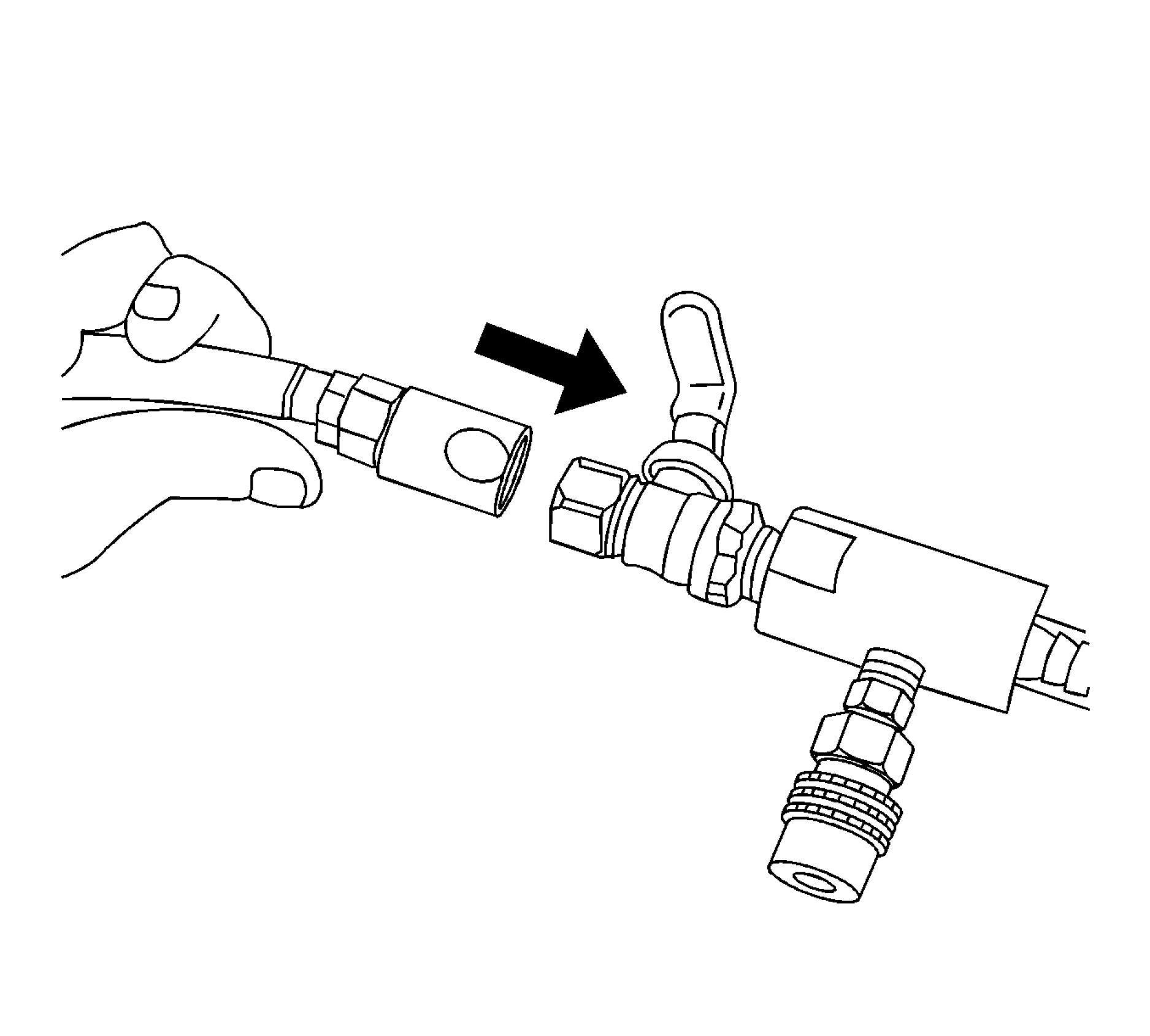 |
|
Fig. 17: View Of Shop Air Hose & Venturi Assembly |
10. Attach a shop air hose to the venturi assembly.
Ensure the valve on the venturi assembly is closed.
 |
|
Fig. 18: Attaching Vacuum Hose To Vacuum Gauge Assembly & Vacuum Tank |
11. Attach the vacuum hose to the vacuum gauge assembly and the vacuum tank.
12. Position the passenger compartment heater coolant control solenoid valve to normal using GDS. The
hybrid powertrain control module 2 controls the passenger compartment heater coolant control solenoid
Valve

Fig. 19: Identifying Valve On Venturi Assembly
Courtesy of GENERAL MOTORS COMPANY
13. Open the valve on the venturi assembly. The vacuum gauge will begin to rise and a hissing noise will be
present.
 |
|
Fig. 20: View Of Vacuum Gauge Courtesy of GENERAL MOTORS COMPANY |
14. Continue to draw vacuum until the needle stops rising. This should be 610-660 mm Hg (24-26 in Hg).
Cooling hoses may start to collapse. This is normal due to vacuum draw.
15. To aid in the fill process, position the graduated reservoir above the coolant fill port.
 |
|
Fig. 21: Identifying Valve On Vacuum Gage Assembly Courtesy of GENERAL MOTORS COMPANY |
16. Slowly open the valve on the vacuum gauge assembly. When the coolant reaches the top of the fill hose,
close the valve. This will eliminate air from the fill hose.
17. Close the valve on the venturi assembly.
18. If there is a suspected leak in the cooling system, allow the system to stabilize under vacuum and monitor
for vacuum loss.
If vacuum loss is observed, refer to Loss of Coolant.
19. Open the valve on the vacuum gauge assembly. The vacuum gauge will drop as coolant is drawn into the
system.

Fig. 22: View Of Vacuum Gauge & Radiator
Courtesy of GENERAL MOTORS COMPANY
20. Once the vacuum gauge reaches zero, close the valve on the vacuum gauge.
21. Repeat steps 14-21 twice.
 |
|
Fig. 23: Attaching Extraction Hose To Vacuum Hose Courtesy of GENERAL MOTORS COMPANY |
22. Detach the Vac N Fill cap from the GE-42401-3 Radiator Cap and Surge Tank Test Adapter.
23. Remove GE-42401-2 Radiator Cap and Surge Tank Test Adapter from the surge tank fill neck.
24. Add coolant to the system as necessary.
25. Turn on the auxiliary coolant pump for 2 minutes using the GDS. The remote HVAC module controls the
auxiliary coolant pump.
26. Start the engine.
27. Using GDS, increase the speed to 2000 rpm until the thermostat opens (approximately 100C).
NOTE: Do not allow engine coolant temperature to exceed 110C or damage to the
Coolant Heater Control Module could occur.
28. Turn engine off.
29. Turn on the auxiliary coolant pump for 1 minute using GDS.
30. Turn off the auxiliary coolant pump and wait 5 minutes.
31. Repeat steps 24-30, three times.
32. Inspect the concentration of the coolant mixture using GE-26568 Coolant and Battery Tester.
NOTE: After filling the cooling system, the extraction hose can be used to remove
excess coolant to achieve the proper coolant level.
33. Detach the vacuum hose form the vacuum gauge assembly.
34. Attach the extraction hose to the vacuum hose.
 |
|
Fig. 24: Identifying Valve On Venturi Assembly Courtesy of GENERAL MOTORS COMPANY |
35. Open the valve on the venturi assembly to start a vacuum draw.

Fig. 25: Using Extraction Hose To Draw Out Coolant
Courtesy of GENERAL MOTORS COMPANY
FLUSHING | ||
|
system flow diagrams to identify components that may need replacement
to restore proper system flow.
• Do not use chemical flush agents.
• Store used coolant in the proper manner, such as in a used engine coolant
holding tank. Do not pour used coolant down a drain. Ethylene glycol
antifreeze is a very toxic chemical. Do not dispose of coolant into the
sewer system or ground water. This is illegal and ecologically unsound.
• Various methods and equipment can be used to flush the cooling system.
If special equipment is used, such as a back flusher, follow the
manufacturer's instruction. Always remove the thermostat before flushing
the cooling system.
1. Drain the cooling system. Cooling System Draining and Filling
2. Remove Radiator Surge Tank Replacement
3. Clean and flush the coolant recovery reservoir with clean, drinkable water.
4. Install Radiator Surge Tank Replacement
5. Follow the drain and fill procedure using only clean, drinkable water. Refer to Cooling System Draining
and Filling.
6. Run the engine for 20 minutes.
7. Stop the engine.
8. Drain the cooling system. Cooling System Draining and Filling
9. Repeat the procedure if necessary, until the fluid is nearly colorless.
10. Fill the cooling system. Cooling System Draining and Filling
RADIATOR CLEANING
WARNING: NEVER spray water on a hot heat exchanger. The resulting steam could cause
personal injury.
CAUTION: The heat exchanger fins are necessary for good heat transfer. Do not brush the
fins. This may cause damage to the fins, reducing heat transfer.
NOTE: Remove bugs, leaves, dirt and other debris by blowing compressed air
through the engine side of the radiator.
• Some conditions may require the use of warm water and a mild detergent.
• Clean the A/C condenser fins.
• Clean between the A/C condenser and radiator.
• Clean the radiator cooling fins.
• Straighten any damaged cooling fins.
RADIATOR SURGE TANK REPLACEMENT
Special Tools
BO-38185 Hose Clamp Pliers
Equivalent regional tools: Special Tools
Removal Procedure
1. Drain the cooling system. Cooling System Draining and Filling
 |
|
Fig. 26: Coolant Hose And Wiring Harness Clip |
2. Loosen Clamp (1, 3) BO-38185 pliers
3. Remove Coolant Hose (4)
4. Unclip Wiring Harness Clip(2)
 |
|
Fig. 27: Radiator Surge Tank, Bracket And Clips |
5. Remove Radiator Surge Tank Clip(1)
NOTE: To remove the radiator surge tank from the radiator surge tank bracket
move it in driving direction.
6. Move the radiator surge tank (4) in arrow direction to release the radiator surge tank clip (2) from the
radiator surge tank bracket (3).
Installation Procedure
 |
|
Fig. 28: Radiator Surge Tank, Bracket And Clips |
NOTE: To install the radiator surge tank to the radiator surge tank bracket move it
against driving direction.
1. Move the radiator surge tank (4) in arrow direction to clip in the radiator surge tank clip (2) into the
radiator surge tank bracket (3).
2. Install Radiator Surge Tank Clip (1)
 |
|
Fig. 29: Coolant Hose And Wiring Harness Clip Courtesy of GENERAL MOTORS COMPANY |
3. Install Wiring Harness Clip (2)
4. Install Coolant Hose(4)
5. Install Clamp(1, 3) BO-38185 pliers
6. Fill the cooling system. Cooling System Draining and Filling
RADIATOR INLET HOSE REPLACEMENT
Special Tools
BO-38185 Hose Clamp Pliers
Equivalent regional tools: Special Tools
1. Drain the cooling system. Cooling System Draining and Filling
 |
|
Fig. 30: Radiator Surge Tank Bracket Bolts |
NOTE: Do not remove any coolant hoses from the surge tanks.
2. Remove the 2 radiator surge tank bracket bolts (2).
3. To gain access to the second radiator inlet hose clamp, lay the radiator surge tank assembly (1) aside.
 |
|
Fig. 31: Radiator Inlet Hose Clamp And Radiator Inlet Hose |
4. Remove Radiator Inlet Hose Clamp (1, 2) BO-38185 pliers
5. Remove Radiator Inlet Hose (3)
Installation Procedure
 |
|
Fig. 32: Radiator Inlet Hose Clamp And Radiator Inlet Hose |
1. Install Radiator Inlet Hose (3)
2. Install Radiator Inlet Hose Clamp (1, 2)BO-38185 pliers
 |
|
Fig. 33: Radiator Surge Tank Bracket Bolts |
3. Reposition the radiator surge tank assembly (1).
CAUTION: Fastener Caution
4. Install the 2 radiator surge tank bracket bolts (2) and tighten to 22 N.m (16 lb ft).
5. Fill the cooling system. Cooling System Draining and Filling
RADIATOR OUTLET HOSE REPLACEMENT
 |
|
Fig. 34: Radiator Outlet Hose |
|
Courtesy of GENERAL MOTORS COMPANY | ||||||||
| ||||||||
|
RADIATOR VENT OUTLET HOSE REPLACEMENT | ||||||||
 |
|
Fig. 35: Radiator Vent Outlet Hose |
|
Courtesy of GENERAL MOTORS COMPANY | ||||||
|
EXHAUST GAS RECIRCULATION COOLER WATER BYPASS OUTLET HOSE REPLACEMENT
Removal Procedure
1. Drain the cooling system. Cooling System Draining and Filling
2. Remove Three-Way Catalytic Converter Replacement
 |
|
Fig. 36: Exhaust Gas Recirculation Cooler Water Bypass Outlet Hose |
3. Remove Clamp (4)
4. Disconnect Exhaust Gas Recirculation Cooler Water Bypass Outlet Hose (3) @Water Pump (1)
5. Disconnect Exhaust Gas Recirculation Cooler Water Bypass Outlet Hose (3) @Exhaust Gas Recirculation
Cooler (2)
6. Remove Exhaust Gas Recirculation Cooler Water Bypass Outlet Hose (3)
Installation Procedure
 |
|
Fig. 37: Exhaust Gas Recirculation Cooler Water Bypass Outlet Hose |
1. Install Exhaust Gas Recirculation Cooler Water Bypass Outlet Hose (3)
2. Connect Exhaust Gas Recirculation Cooler Water Bypass Outlet Hose (3) @Exhaust Gas Recirculation
Cooler (2)
3. Connect Exhaust Gas Recirculation Cooler Water Bypass Outlet Hose(3)@Water Pump(1)
4. Install Clamp (4)
5. Install Three-Way Catalytic Converter Replacement
6. Fill the cooling system. - Cooling System Draining and Filling
THERMOSTAT BYPASS HOSE REPLACEMENT
Special Tools
BO-38185 Hose Clamp Pliers
Equivalent regional tools: Special Tools
Removal Procedure
1. Drain the cooling system. Cooling System Draining and Filling
2. Remove Heater Outlet Hose Vapor Vent Hose Replacement
3. Remove Radiator Inlet Hose@Water Outlet Radiator Inlet Hose Replacement
 |
|
Fig. 38: Thermostat Bypass Hose Clamp Courtesy of GENERAL MOTORS COMPANY |
4. Loosen Thermostat Bypass Hose Clamp (1) BO-38185 pliers
5. Disconnect Thermostat Bypass Hose(2)
 |
|
Fig. 39: Heater Outlet Hose Clamp Courtesy of GENERAL MOTORS COMPANY |
6. Loosen Heater Outlet Hose Clamp(2) BO-38185 pliers
7. Disconnect Heater Outlet Hose (1)
 |
|
Fig. 40: Engine Coolant Temperature Sensor Electrical Connector And Water Outlet Bolts |
8. Disconnect the engine coolant temperature sensor electrical connector.(1)
9. Remove the water outlet bolts.(2)
 |
|
Fig. 41: Water Outlet And Gasket Courtesy of GENERAL MOTORS COMPANY |
10. Remove the water outlet.(2)
11. Remove Water Outlet Gasket (1) and DISCARD
 |
|
Fig. 42: Thermostat Bypass Hose And Clamp Courtesy of GENERAL MOTORS COMPANY |
12. Remove Thermostat Bypass Hose Clamp (2) BO-38185 pliers
13. Remove Thermostat Bypass Hose(1)
Installation Procedure
 |
|
Fig. 43: Thermostat Bypass Hose And Clamp |
1. Install Thermostat Bypass Hose (1)
2. Install Thermostat Bypass Hose Clamp (2)BO-38185 pliers
 |
|
Fig. 44: Water Outlet And Gasket Courtesy of GENERAL MOTORS COMPANY |
3. Install a NEW gasket to the water outlet.(1)
4. Install the water outlet.(2)
 |
|
Fig. 45: Engine Coolant Temperature Sensor Electrical Connector And Water Outlet Bolts |
CAUTION: Fastener Caution
5. Install Water Outlet Bolt (2) and tighten 12 N.m (106 lb in)
6. Connect the engine coolant temperature sensor electrical connector.(1)
 |
|
Fig. 46: Heater Outlet Hose Clamp Courtesy of GENERAL MOTORS COMPANY |
7. Install Heater Outlet Hose (1)
8. Install Heater Outlet Hose Clamp (2) BO-38185 pliers
 |
|
Fig. 47: Thermostat Bypass Hose Clamp Courtesy of GENERAL MOTORS COMPANY |
9. Install Thermostat Bypass Hose (2)
10. Install Thermostat Bypass Hose Clamp (1) BO-38185 pliers
11. Install Radiator Inlet Hose@Water Outlet Radiator Inlet Hose Replacement
12. Install Heater Outlet Hose Vapor Vent Hose Replacement
13. Fill the cooling system. Cooling System Draining and Filling
WATER PUMP INLET ADAPTER REPLACEMENT

Fig. 48: Water Pump Inlet Adapter
Courtesy of GENERAL MOTORS COMPANY
|
Callout |
Component Name |
|
Preliminary Procedure
| |
|
1 |
Clamp |
|
2 |
Exhaust Gas Recirculation Valve Cooling Return Hose |
|
3 |
Water Pump Inlet Adapter Bolt (Qty: 2) CAUTION: Fastener Tighten 10 N.m (89 lb in) |
|
4 |
Water Pump Inlet Adapter |
|
5 |
Water Pump Inlet Adapter Gasket |
ENGINE COOLANT THERMOSTAT HOUSING REPLACEMENT
Removal Procedure
1. Drain the cooling system. Cooling System Draining and Filling
2. Remove Radiator Outlet Hose@Engine Coolant Thermostat Housing Radiator Outlet Hose
Replacement

Fig. 49: Electrical Connector And Engine Coolant Thermostat Housing Bolt
Courtesy of GENERAL MOTORS COMPANY
3. Disconnect Electrical Connector (2) @Engine Coolant Thermostat Housing (4)
4. Remove Engine Coolant Thermostat Housing Bolt (1)
5. Remove Engine Coolant Thermostat Housing (4)
6. Remove Engine Coolant Thermostat Gasket (3) and DISCARD
Installation Procedure
 |
|
Fig. 50: Electrical Connector And Engine Coolant Thermostat Housing Bolt |
1. Install a NEW gasket.(3)
2. Install Engine Coolant Thermostat Housing (4)
CAUTION: Fastener Caution
3. Install Engine Coolant Thermostat Housing Bolt (1) and tighten 10 N.m (89 lb in)
4. Connect Electrical Connector(2)@Engine Coolant Thermostat Housing(4)
5. Radiator Outlet Hose@Engine Coolant Thermostat Housing Radiator Outlet Hose Replacement
6. Fill the cooling system. Cooling System Draining and Filling
WATER OUTLET REPLACEMENT
Special Tools
BO-38185 Hose Clamp Pliers
Equivalent regional tools: Special Tools
Removal Procedure
1. Drain the cooling system. Cooling System Draining and Filling
2. Remove Heater Outlet Hose Vapor Vent Hose Replacement
3. Remove Radiator Inlet Hose@Water Outlet Radiator Inlet Hose Replacement
 |
|
Fig. 51: Thermostat Bypass Hose Clamp Courtesy of GENERAL MOTORS COMPANY |
4. Loosen Thermostat Bypass Hose Clamp (1) BO-38185 pliers
5. Disconnect Thermostat Bypass Hose (2)
 |
|
Fig. 52: Heater Outlet Hose Clamp Courtesy of GENERAL MOTORS COMPANY |
6. Loosen Heater Outlet Hose Clamp (2)BO-38185 pliers
7. Disconnect Heater Outlet Hose (1)
 |
|
Fig. 53: Engine Coolant Temperature Sensor Electrical Connector And Water Outlet Bolts |
8. Disconnect the engine coolant temperature sensor electrical connector.(l)
9. Remove the water outlet bolts.(2)
 |
|
Fig. 54: Water Outlet And Gasket Courtesy of GENERAL MOTORS COMPANY |
10. Remove the water outlet.(2)
11. Remove Water Outlet Gasket (1) and DISCARD

Fig. 55: Thermostat Bypass Hose And Clamp
Courtesy of GENERAL MOTORS COMPANY
12. Remove Thermostat Bypass Hose Clamp (4) BO-38185 pliers
13. Remove Thermostat Bypass Hose (1)
14. Remove Engine Coolant Temperature Sensor Retainer(2)
15. Remove the engine coolant temperature sensor.(3)
Installation Procedure

Fig. 56: Thermostat Bypass Hose And Clamp
Courtesy of GENERAL MOTORS COMPANY
1. Install the engine coolant temperature sensor.(3)
2. Install Engine Coolant Temperature Sensor Retainer(2)
3. Install Thermostat Bypass Hose (1)
4. Install Thermostat Bypass Hose Clamp (4)BO-38185 pliers

Fig. 57: Water Outlet And Gasket
Courtesy of GENERAL MOTORS COMPANY
5. Install a NEW gasket to the water outlet.(l)
6. Install the water outlet.(2)
 |
|
Fig. 58: Engine Coolant Temperature Sensor Electrical Connector And Water Outlet Bolts |
CAUTION: Fastener Caution
7. Install Water Outlet Bolt (2) and tighten 12 N.m (106 lb in)
8. Connect the engine coolant temperature sensor electrical connector.(1)
 |
|
Fig. 59: Heater Outlet Hose Clamp Courtesy of GENERAL MOTORS COMPANY |
9. Install Heater Outlet Hose (1)
10. Install Heater Outlet Hose Clamp (2) BO-38185 pliers
 |
|
Fig. 60: Thermostat Bypass Hose Clamp Courtesy of GENERAL MOTORS COMPANY |
11. Install Thermostat Bypass Hose (2)
12. Install Thermostat Bypass Hose Clamp (1)BO-38185 pliers
13. Install Radiator Inlet Hose@Water Outlet Radiator Inlet Hose Replacement
14. Install Heater Outlet Hose Vapor Vent Hose Replacement
15. Fill the cooling system. Cooling System Draining and Filling
WATER PUMP BELT REPLACEMENT
Removal Procedure
1. Remove Front Compartment Air Deflector Replacement
2. Remove Front Wheelhouse Liner Replacement (Left Side) Front Wheelhouse Liner Replacement
(Right Side) - Right Side
3. Remove Heater Inlet Hose@Heater Coolant Heater Heater Inlet Hose Replacement
4. Remove Heater Inlet and Outlet Pipe@Heater Coolant Heater Heater Inlet And Outlet Pipe
Replacement
 |
|
Fig. 61: Water Pump Belt Courtesy of GENERAL MOTORS COMPANY |
5. Cut the water pump belt (2) with a appropriate cutting tool at position (1).
6. Remove Water Pump Belt (2) and DISCARD
Installation Procedure
 |
|
Fig. 62: Water Pump Belt Courtesy of GENERAL MOTORS COMPANY |
1. Position a NEW water pump belt (3) on the water pump pulley (2) and partially install it on the crankshaft
balancer (1) in preparation to walk the belt on the crankshaft pulley.
2. Rotate the crankshaft on the crankshaft balancer bolt (4) slowly clockwise until the belt is fully installed
on the crankshaft balancer (1).
3. After the belt is on the crankshaft balancer, rotate the crankshaft an additional complete revolution and
ensure the water pump belt is fully seated on the crankshaft balancer and water pump pulley.
4. Install Heater Inlet and Outlet Pipe@Heater Coolant Heater Heater Inlet And Outlet Pipe Replacement
5. Install Heater Inlet Hose@Heater Coolant Heater Heater Inlet Hose Replacement
6. Install Front Wheelhouse Liner Replacement (Left Side) Front Wheelhouse Liner Replacement
(Right Side) - Right Side
7. Install Front Compartment Air Deflector Replacement
WATER PUMP REPLACEMENT
Removal Procedure
1. Remove Water Pump Belt Replacement
2. Remove Exhaust Gas Recirculation Cooler Replacement
3. Remove Water Pump Inlet Adapter Replacement
4. Remove Radiator Outlet Hose Replacement
5. Disconnect Electrical Connector@Heated Oxygen Sensor Heated Oxygen Sensor Replacement -
Sensor 1
 |
|
Fig. 63: Electrical Connector And Retainer |
6. Remove Retainer (1)
7. Disconnect Electrical Connector (2) @Engine Coolant Thermostat Housing
 |
|
Fig. 64: Exhaust Gas Recirculation Cooler Water Bypass Outlet Hose And Water Pump |
8. Remove Clamp (5)
9. Remove the exhaust gas recirculation cooler water bypass outlet hose (6) from the water pump (1).
NOTE: Take note that there are different bolt lengths.
10. Remove Water Pump Bolt (2, 8)
11. Remove the 3 bolt retainers (3, 7).
12. Remove Water Pump (1)
13. Remove Water Pump Gasket (4) and DISCARD
Installation Procedure
 |
|
Fig. 65: Exhaust Gas Recirculation Cooler Water Bypass Outlet Hose And Water Pump |
1. Install a NEW gasket.(4)
2. Install Water Pump (1)
NOTE: Take note that there are different bolt lengths.
3. Install Water Pump Bolt(2, 8)
CAUTION: Fastener Caution
4. Tighten the NEW water pump bolts.25 N.m (18 lb ft)
5. Install the exhaust gas recirculation cooler water bypass outlet hose (6) to the water pump (1).
6. Install Clamp (5)
 |
|
Fig. 66: Electrical Connector And Retainer |
7. Install Retainer(1)
8. Connect Electrical Connector (2) @Engine Coolant Thermostat Housing
9. Connect Electrical Connector@Heated Oxygen Sensor Heated Oxygen Sensor Replacement - Sensor 1
10. Install Exhaust Gas Recirculation Cooler Replacement
11. Install Water Pump Inlet Adapter Replacement
12. Install Radiator Outlet Hose Replacement
13. Install Water Pump Belt Replacement
WATER PUMP HOUSING REPLACEMENT
Removal Procedure
1. Drain the cooling system. Cooling System Draining and Filling
2. Remove Water Pump Belt Replacement
 |
|
Fig. 67: Water Pump Housing And Water Pump Bolt |
3. Remove Water Pump Bolt (1)
4. Remove Water Pump Housing (2)
5. Remove Water Pump Housing Gasket (3) and DISCARD
6. Remove the old gasket material from the water pump sealing surfaces.
Installation Procedure
 |
|
Fig. 68: Water Pump Housing And Water Pump Bolt |
1. Install a New Water Pump Housing Gasket (3).
2. Install Water Pump Housing (2)
CAUTION: Fastener Caution
3. Install Water Pump Bolt (1) and tighten 10 N.m (89 lb in)
4. Install Water Pump Belt Replacement
5. Fill the cooling system. Cooling System Draining and Filling
ENGINE COOLANT TEMPERATURE SENSOR REPLACEMENT - RADIATOR
 |
|
Fig. 69: Engine Coolant Temperature Sensor |
| ||||||||
|
RADIATOR DRAIN COCK REPLACEMENT | ||||||||
 |
|
Fig. 70: Radiator Drain Cock Courtesy of GENERAL MOTORS COMPANY |
|
Callout |
Component Name |
|
Preliminary Procedures
| |
|
1 |
Radiator Drain Cock |
ENGINE COOLANT FAN SHROUD REPLACEMENT
Special Tools
BO-38185 Hose Clamp Pliers
Equivalent regional tools: Special Tools
Removal Procedure
1. Drain the cooling system. Cooling System Draining and Filling
2. Remove Hood Primary and Secondary Latch Replacement
3. Remove Front Intake Air Duct Replacement
4. Remove Transmission Fluid Auxiliary Cooler Replacement
5. Remove Radiator Inlet Hose@Radiator Radiator Inlet Hose Replacement
6. Remove Radiator Outlet Hose@Radiator Radiator Outlet Hose Replacement
 |
|
Fig. 71: Ground Cable Nut And Ground Cable |
7. Remove Ground Cable Nut (2)
8. Remove Ground Cable (1)
9. Unclip Wiring Harness Clip (3)
 |
|
Fig. 72: Electrical Connector And Cable Tie |
10. Disconnect the electrical connector.(1, 3, 4)
11. Remove Cable Tie (2)
 |
|
Fig. 73: Heat Shield Courtesy of GENERAL MOTORS COMPANY |
12. Remove Heat Shield Nut (2)
13. Remove Heat Shield (1)
 |
|
Fig. 74: Drive Motor Battery Coolant Pump Bracket Studs |
NOTE: Mind the position of the pump and the bracket.
14. Remove the 2 drive motor battery coolant pump bracket studs (1).
NOTE: It is not necessary to remove any coolant hoses from the drive motor
battery coolant pump.
15. Remove the drive motor battery coolant pump (3) and hang aside.
16. Remove the 2 drive motor battery coolant pump brackets (2, 4).
 |
|
Fig. 75: Radiator Upper Insulator And Bolt |
NOTE: Graphic shows the radiator upper insulator right side. Procedure is also
valid for the left side.
17. Remove the radiator upper insulator bolt (1).
18. Remove the radiator upper insulator (2) by rotating in arrow direction.
19. Repeat the procedure for the other side.
 |
|
Fig. 76: Radiator Vent Hose And Clamp Courtesy of GENERAL MOTORS COMPANY |
20. Remove Clamp (1)- BO-38185 pliers
21. Remove the radiator vent hose (2) from the radiator.
 |
|
Fig. 77: Radiator And Radiator Insulators |
22. Remove the radiator (1) along with the fan shroud carefully in top direction from the radiator support
brackets.
23. Remove the 2 radiator insulators (2).
 |
|
Fig. 78: Wiring Harness Clip And Engine Coolant Fan Shroud Bolt |
24. Unclip Wiring Harness Clip (2, 5)
25. Remove Engine Coolant Fan Shroud Bolt (1, 3)
26. Unclip Retainer(4)
27. Remove Engine Coolant Fan Shroud (6) @Radiator
 |
|
Fig. 79: Wiring Harness Clip And Electrical Connector |
28. Disconnect the electrical connector.(2, 4)
29. Unclip Wiring Harness Clip (1, 3, 5)
30. Remove Wiring Harness (6) @Engine Coolant Fan Shroud
Installation Procedure
 |
|
Fig. 80: Wiring Harness Clip And Electrical Connector |
1. Install Wiring Harness (6) @Engine Coolant Fan Shroud
2. Install Wiring Harness Clip (1, 3, 5)
3. Connect the electrical connector.(2, 4)
 |
|
Fig. 81: Wiring Harness Clip And Engine Coolant Fan Shroud Bolt |
4. Install Engine Coolant Fan Shroud (6) @Radiator
5. Install Retainer(4)
CAUTION: Fastener Caution
6. Install Engine Coolant Fan Shroud Bolt (1, 3) and tighten 5 N.m (44 lb in)
7. Install Wiring Harness Clip
 |
|
Fig. 82: Radiator And Radiator Insulators |
8. Install the 2 radiator insulators (2).
9. Install the radiator (1) along with the fan shroud carefully to the radiator support brackets.
 |
|
Fig. 83: Radiator Upper Insulator And Bolt |
NOTE: Graphic shows the radiator upper insulator right side. Procedure is also
valid for the left side.
10. Install the radiator upper insulator (2) by rotating against arrow direction.
11. Install the radiator upper insulator bolt (1) and tighten to 22 N.m (16 lb ft).
12. Repeat the procedure for the other side.
 |
|
Fig. 84: Radiator Vent Hose And Clamp Courtesy of GENERAL MOTORS COMPANY |
13. Install the radiator vent hose (2) to the radiator.
14. Install Clamp (1) BO-38185 pliers
 |
|
Fig. 85: Drive Motor Battery Coolant Pump Bracket Studs |
15. Install the drive motor battery coolant pump bracket (4).
16. Install the drive motor battery coolant pump (3).
NOTE: Check the pump and the bracket for the correct original position.
17. Install the drive motor battery coolant pump bracket (2).
18. Install the 2 drive motor battery coolant pump bracket studs (1) and tighten to 9 N.m (80 lb in).
 |
|
Fig. 86: Heat Shield Courtesy of GENERAL MOTORS COMPANY |
19. Install Heat Shield (1)
20. Install Heat Shield Nut (2) and tighten 9 N.m (80 lb in)
 |
|
Fig. 87: Electrical Connector And Cable Tie |
21. Connect the electrical connector.(1, 3, 4)
22. Install NEW cable ties.(2)
 |
|
Fig. 88: Ground Cable Nut And Ground Cable Courtesy of GENERAL MOTORS COMPANY |
23. Install Ground Cable (1)
24. Install Ground Cable Nut (2) and tighten 9 N.m (80 lb in)
25. Install Wiring Harness Clip (3)
26. Install Radiator Outlet Hose@Radiator Radiator Outlet Hose Replacement
27. Install Radiator Inlet Hose@Radiator Radiator Inlet Hose Replacement
28. Install Transmission Fluid Auxiliary Cooler Replacement
29. Install Hood Primary and Secondary Latch Replacement
30. Install Front Intake Air Duct Replacement
31. Fill the cooling system. Cooling System Draining and Filling
RADIATOR REPLACEMENT
Special Tools
BO-38185 Hose Clamp Pliers
Equivalent regional tools: Special Tools
Removal Procedure
1. Drain the cooling system. Cooling System Draining and Filling.
2. Remove Hood Primary and Secondary Latch Replacement
3. Remove Front Intake Air Duct Replacement
4. Remove Transmission Fluid Auxiliary Cooler Replacement
5. Remove Radiator Inlet Hose@Radiator Radiator Inlet Hose Replacement
6. Remove Radiator Outlet Hose@Radiator Radiator Outlet Hose Replacement
 |
|
Fig. 89: Ground Cable Nut And Ground Cable |
7. Remove Ground Cable Nut (2)
8. Remove Ground Cable (1)
9. Unclip Wiring Harness Clip (3)
 |
|
Fig. 90: Electrical Connector And Cable Tie |
10. Disconnect the electrical connector.(1, 3, 4)
11. Remove Cable Tie (2)
 |
|
Fig. 91: Heat Shield Courtesy of GENERAL MOTORS COMPANY |
12. Remove Heat Shield Nut (2)
13. Remove Heat Shield (1)
 |
|
Fig. 92: Drive Motor Battery Coolant Pump Bracket Studs |
NOTE: Mind the position of the pump and the bracket.
14. Remove the 2 drive motor battery coolant pump bracket studs (1).
NOTE: It is not necessary to remove any coolant hoses from the drive motor
battery coolant pump.
15. Remove the drive motor battery coolant pump (3) and hang aside.
16. Remove the 2 drive motor battery coolant pump brackets (2, 4).
 |
|
Fig. 93: Radiator Upper Insulator And Bolt |
NOTE: Graphic shows the radiator upper insulator right side. Procedure is also
valid for the left side.
17. Remove the radiator upper insulator bolt (1).
18. Remove the radiator upper insulator (2) by rotating in arrow direction.
19. Repeat the procedure for the other side.
 |
|
Fig. 94: Radiator Vent Hose And Clamp |
20. Remove Clamp (1) BO-38185 pliers
21. Remove the radiator vent hose (2) from the radiator.
 |
|
Fig. 95: Radiator And Radiator Insulators |
22. Remove the radiator (1) along with the fan shroud carefully in top direction from the radiator support
brackets.
23. Remove the 2 radiator insulators (2).
 |
|
Fig. 96: Wiring Harness Clip And Engine Coolant Fan Shroud Bolt |
24. Unclip Wiring Harness Clip (2, 5)
25. Remove Engine Coolant Fan Shroud Bolt (1, 3)
26. Unclip Retainer(4)
27. Remove Engine Coolant Fan Shroud (6) @Radiator
Disassemble Procedure
1. Remove Engine Coolant Temperature Sensor Replacement - Radiator
2. Remove Radiator Drain Cock Replacement
Assemble Procedure
1. Install Radiator Drain Cock Replacement
2. Install Engine Coolant Temperature Sensor Replacement - Radiator
Installation Procedure
 |
|
Fig. 97: Wiring Harness Clip And Engine Coolant Fan Shroud Bolt |
1. Install Engine Coolant Fan Shroud (6) @Radiator
2. Install Retainer(4)
CAUTION: Fastener Caution
3. Install Engine Coolant Fan Shroud Bolt (1, 3) and tighten 5 N.m (44 lb in)
4. Install Wiring Harness Clip
 |
|
Fig. 98: Radiator And Radiator Insulators |
5. Install the 2 radiator insulators (2).
6. Install the radiator (1) along with the fan shroud carefully to the radiator support brackets.
 |
|
Fig. 99: Radiator Upper Insulator And Bolt |
NOTE: Graphic shows the radiator upper insulator right side. Procedure is also
valid for the left side.
7. Install the radiator upper insulator (2) by rotating against arrow direction.
8. Install the radiator upper insulator bolt (1) and tighten to 22 N.m (16 lb ft).
9. Repeat the procedure for the other side.
 |
|
Fig. 100: Radiator Vent Hose And Clamp |
10. Install the radiator vent hose (2) to the radiator.
11. Install Clamp (1) BO-38185 pliers
 |
|
Fig. 101: Drive Motor Battery Coolant Pump Bracket Studs |
12. Install the drive motor battery coolant pump bracket (4).
13. Install the drive motor battery coolant pump (3).
NOTE: Check the pump and the bracket for the correct original position.
14. Install the drive motor battery coolant pump bracket (2).
15. Install the 2 drive motor battery coolant pump bracket studs (1) and tighten to 9 N.m (80 lb in).
 |
|
Fig. 102: Heat Shield Courtesy of GENERAL MOTORS COMPANY |
16. Install Heat Shield (1)
17. Install Heat Shield Nut (2) and tighten 9 N.m (80 lb in)
 |
|
Fig. 103: Electrical Connector And Cable Tie |
18. Connect the electrical connector.(1, 3, 4)
19. Install NEW cable ties.(2)
 |
|
Fig. 104: Ground Cable Nut And Ground Cable Courtesy of GENERAL MOTORS COMPANY |
20. Install Ground Cable (1)
21. Install Ground Cable Nut (2) and tighten 9 N.m (80 lb in)
22. Install Wiring Harness Clip (3)
23. Install Radiator Outlet Hose@Radiator Radiator Outlet Hose Replacement
24. Install Radiator Inlet Hose@Radiator Radiator Inlet Hose Replacement
25. Install Transmission Fluid Auxiliary Cooler Replacement
26. Hood Primary and Secondary Latch Replacement
27. Front Intake Air Duct Replacement
28. Fill the cooling system. Cooling System Draining and Filling
RADIATOR UPPER INSULATOR REPLACEMENT
Removal Procedure
1. Remove Front Intake Air Duct Replacement
 |
|
Fig. 105: Radiator Upper Insulator And Bolt |
NOTE: Graphic shows the radiator upper insulator right side. Procedure is also
valid for the left side.
2. Remove Radiator Upper Insulator Bolt (1)
3. Remove the radiator upper insulator (2) by rotating in arrow direction.
Installation Procedure

Fig. 106: Radiator Upper Insulator And Bolt
Courtesy of GENERAL MOTORS COMPANY
NOTE: Graphic shows the radiator upper insulator right side. Procedure is also
valid for the left side.
1. Install the radiator upper insulator (2) by rotating it against arrow direction.
CAUTION: Fastener Caution
2. Install Radiator Upper Insulator Bolt (1) and tighten 22 N.m (16 lb ft)
3. Install Front Intake Air Duct Replacement
RADIATOR AIR LOWER BAFFLE AND DEFLECTOR REPLACEMENT
Removal Procedure
1. Remove Front Bumper Fascia Removal and Installation
2. Remove Front Bumper Shutter Replacement
 |
|
Fig. 107: Wiring Harness Clip Courtesy of GENERAL MOTORS COMPANY |
3. Unclip Wiring Harness Clip (1)
 |
|
Fig. 108: Clip Courtesy of GENERAL MOTORS COMPANY |
4. Unclip Clip (1, 2)
 |
|
Fig. 109: Radiator Air Lower Baffle Bolt |
5. Remove the 4 radiator air lower baffle bolts (1, 2).
6. Remove Radiator Air Lower Baffle (3)
Installation Procedure
 |
|
Fig. 110: Radiator Air Lower Baffle Bolt Courtesy of GENERAL MOTORS COMPANY |
CAUTION: Fastener Caution
1. Install Radiator Air Lower Baffle (3)
Install the 4 radiator air lower baffle bolts (1, 2) and tighten to 9 N.m (80 lb in).
 |
|
Fig. 111: Clip Courtesy of GENERAL MOTORS COMPANY |
2. Install Clip (1, 2)
 |
|
Fig. 112: Wiring Harness Clip Courtesy of GENERAL MOTORS COMPANY |
3. Install Wiring Harness Clip (1)
4. Install Front Bumper Shutter Replacement
5. Install Front Bumper Fascia Removal and Installation
RADIATOR AIR UPPER BAFFLE AND DEFLECTOR REPLACEMENT
Removal Procedure
1. Remove Front Intake Air Duct Replacement
2. Remove Pedestrian Sound Alert Speaker Replacement
 |
|
Fig. 113: Clip Courtesy of GENERAL MOTORS COMPANY |
NOTE: Graphic shows the radiator air upper baffle and deflector right side.
Procedure is also valid for the left side.
3. Unclip Clip (1)
4. Repeat the procedure for the other side.
 |
|
Fig. 114: Clip Courtesy of GENERAL MOTORS COMPANY |
NOTE: Mind the different clip size.
5. Unclip Clip (1)
6. Remove Radiator Air Upper Baffle and Deflector (2)
Installation Procedure
 |
|
Fig. 115: Clip Courtesy of GENERAL MOTORS COMPANY |
1. Install Radiator Air Upper Baffle and Deflector (2)
NOTE: Mind the different clip size.
2. Install Clip (1)
 |
|
Fig. 116: Clip Courtesy of GENERAL MOTORS COMPANY |
NOTE: Graphic shows the radiator air upper baffle and deflector right side.
Procedure is also valid for the left side.
3. Install Clip (1)
4. Repeat the procedure for the other side.
5. Install Pedestrian Sound Alert Speaker Replacement
6. Install Front Intake Air Duct Replacement
DESCRIPTION AND OPERATION
COOLING FAN DESCRIPTION AND OPERATION
Cooling Fan Control
The engine cooling fan(s) system is composed of 2 electric cooling fan(s), 2 fan motor(s) and 2 control module.
The Hybrid/EV Powertrain Control Module 2 controls the fan speed by sending a pulse width modulated
(PWM) signal to the cooling fan control module(s). The cooling fan control module(s) varies the voltage drop
across the cooling fan motor(s) in relation to the pulse width modulated signal, which allows the cooling fan(s)
to operate at variable speeds.
The cooling fan speed is effected by many different conditions and the Hybrid/EV Powertrain Control Module 2
will adjust the duty cycle from 0 - 100 percent based on cooling system requirements. The scan tool output
control is only capable of operating the cooling fan(s) increments, between 10 - 90 percent. 90 percent is
considered high speed fan. When multiple cooling fan speed requests are received, the Hybrid/EV Powertrain
Control Module 2 operates the fan(s) at the highest of speed requests. The ECM commands the fans ON under
the following conditions:
• The engine coolant temperature is warmer than a predetermined temperature.
• The engine oil temperature is warmer than a predetermined temperature.
• The A/C pressure reaches a predetermined pressure.
• If the engine coolant temperature at key-off is warmer than a predetermined value, or the A/C pressure is
greater than a predetermined value, the cooling fan(s) will operate at a low speed. The fan(s) will shut
OFF if the temperature or pressure drops below the predetermined value, but will only operate for 2
minutes, regardless of the coolant temperature or A/C pressure.
Cooling System Electronic Component Description and Operation
Engine or Radiator Coolant Temperature Sensor
The engine coolant temperature (ECT) sensor or radiator coolant temperature (RCT) sensor is a variable resistor
that measures the temperature of the engine or radiator coolant. The ECM supplies 5 V to the sensor signal
circuit and a ground for the low reference circuit.
Engine Coolant Thermostat Heater
The ECM controls the pulse width modulated (PWM) thermostat heater circuit. The engine coolant thermostat
heater helps control coolant flow and regulates the engine operating temperature. The ignition relay supplies 12
V to the thermostat through a fuse. The ECM controls the engine coolant thermostat heater by grounding the
control circuit with a solid state device called a driver. The driver is equipped with a feedback circuit that is
pulled-up to a voltage. The ECM can determine if the control circuit is open, shorted to ground, or shorted to a
voltage by monitoring the feedback voltage.
COOLING SYSTEM DESCRIPTION AND OPERATION
This vehicle is equipped with three fully independent cooling systems. The power electronics cooling system is
dedicated to cooling the battery charger and the power inverter module. The battery cooling system is dedicated
to cooling and heating the high voltage battery. The engine cooling system is dedicated to cooling the engine
and providing heat to the passenger compartment.
Engine Cooling System Description and Operation
The engine cooling system consists of a radiator, two 12 volt pulse width modulated (PWM) radiator fans, a 12
volt coolant pump, a coolant flow control valve, a high voltage heater and a heater core.
 |
|
Fig. 117: Hybrid Cooling System Chart Courtesy of GENERAL MOTORS COMPANY |
The hybrid/EV powertrain control module 2 controls the radiator cooling fans. The cooling fans are controlled
with a Pulse Width Modulated (PWM) signal. The hybrid/EV powertrain control module 2 diagnoses any faults
with the hardwire circuit to the engine control module. The engine control module sends a fan request PWM
signal to the hybrid/EV powertrain control module 2 through a hardwire circuit. The hybrid/EV powertrain
control module 2 operates in a pass-through mode for the engine control module fan request. The higher the
duty cycle the higher the cooling fan speed.
The hybrid/EV powertrain control module 2 sends a request to the engine control module for the cooling fans to
be turned on. The engine control module uses this request and other vehicle inputs to decide if and what speed
the cooling fans should operate. The engine control module sends the cooling fan command to the hybrid/EV
powertrain control module 2. The hybrid/EV powertrain control module 2 sends the signal to the cooling fans to
operate and at what speed.
If the vehicle is in Charge Mode and the hybrid/EV powertrain control module 2 requests the cooling fans to
operate, if the engine control module is not awake, the hybrid/EV powertrain control module 2 will control the
cooling fans. If active cooling is needed, the engine control module wakes up to operate the air conditioning
control module and then the engine control module is the master controller for the fans.

Fig. 118: Engine Cooling System Flow Chart
Courtesy of GENERAL MOTORS COMPANY
The HVAC Control Module turns on the coolant pump and monitors the temperature sensors in the passenger
compartment, engine radiator, high voltage heater and the engine to determine the position of the coolant flow
control valve and if the high voltage heater is needed. Passenger compartment heat is provided by air flowing
through the heater core. The heater core is heated by coolant from either the engine or the high voltage heater.
The engine cooling system circulates a 50/50 mixture of DEX-COOL and distilled water.
SPECIAL TOOLS AND EQUIPMENT
SPECIAL TOOLS
Illustration
Tool
Number/
Description
 |
BO-38185 |
|
Illustration |
Tool |
|
^3 q |
EN-24460-A System Tester |
|
Illustration |
Tool |
|
/ / О"7© GJ / |
EN-45059 Torque Angle Sensor Kit |
|
Illustration |
Tool |
|
GE-26568 | |
|
Tester |
|
Illustration |
Tool |
|
GE-42401-A Test Adapter |

GE-47622
Hose Clamp
Pliers
|
Illustration |
Tool |
|
GE-47716 Vac-N-Fill Coolant |
Article GUID: A00884663
ENGINE
SPECIFICATIONS
FASTENER SPECIFICATIONS
|
Single Use Non-Threaded Fasteners/Components | |||||||||||||||||
|
|
Single Use Threaded Fastener/Component Tightening Specifications | |||||||||
| |||||||||
|
NOTE: All | |
|
Application |
Specification |
|
Metric (English (USA)) | |
|
• Final Pass: |
70 Degrees |
|
Camshaft Position Actuator Bolt | |
|
• First Pass: |
20 N.m (15 lb ft) |
|
• Final Pass: |
90 Degrees |
|
Catalytic Converter Stud1 |
10 N.m (89 lb in)1 |
|
Connecting Rod Bolt | |
|
• First Pass: |
25 N.m (18 lb ft) |
|
• Final Pass: |
75 Degrees |
|
Crankshaft Balancer Bolt | |
|
• First Pass: |
100 N.m (74 lb ft) |
|
• Final Pass: |
180 Degrees |
|
Cylinder Head Bolt | |
|
• First Pass: |
30 N.m (22 lb ft) |
|
• Final Pass: |
240 Degrees |
|
Engine Mount Bracket Bolt | |
|
• First Pass: |
58 N.m (43 lb ft) |
|
• Final Pass: |
90 - 105 Degrees |
|
Engine Mount Bolt | |
|
• First Pass: |
100 N.m (74 lb ft) |
|
• Final Pass: |
60 - 75 Degrees |
|
Fuel Feed Intermediate Pipe |
30 N.m (22 lb ft) |
|
Fuel Pump Bolt |
25 N.m (18 lb ft) |
|
Lower Crankcase Bolt | |
|
NOTE: All | |
|
Application |
Specification |
|
Metric (English (USA)) | |
|
• First Pass: |
15 N.m (11 lb ft) |
|
• Final Pass: |
180 Degrees |
|
Oil Filter |
3/4 to 1 full turn after gasket makes contact |
|
Positive Crankcase Ventilation Valve Bolt |
10 N.m (89 lb in) |
|
Reusable Threaded Fastener Tightening Specifications | |||||||||||||||||||||||||||||||||||||||||||
| |||||||||||||||||||||||||||||||||||||||||||
|
Application |
Specification |
|
Metric (English) | |
|
Crankshaft Position Sensor Bolt |
10 N.m (89 lb in) |
|
Cylinder Head Core Hole Plug |
25 N.m (18 lb ft) |
|
Cylinder Head Core Hole Plug |
75 N.m (55 lb ft) |
|
Engine Block Oil Gallery Plug |
45 N.m (33 lb ft) |
|
Engine Block Oil Gallery Plug |
65 N.m (48 lb ft) |
|
Engine Block Coolant Drain Hole Plug |
60 N.m (44 lb ft) |
|
Engine Coolant Thermostat Housing Bolt |
10 N.m (89 lb in) |
|
Engine Control Module (ECM) Wiring Harness Ground Bolt |
10 N.m (89 lb in) |
|
Engine Front Cover Bolt - M6 |
15 N.m (11 lb ft) |
|
Engine Front Cover Bolt - M10 |
58 N.m (43 lb ft) |
|
Engine Front Cover Bolt - M14 |
58 N.m (43 lb ft) |
|
Engine Front Cover Hole Plug |
50 N.m (37 lb ft) |
|
Engine Front Cover Stud |
15 N.m (11 lb ft) |
|
Engine Lift Bracket Bolt |
25 N.m (18 lb ft) |
|
Engine Oil Pressure Sensor |
35 N.m (29 lb ft) |
|
Engine Wiring Harness Bracket Bolt |
25 N.m (18 lb ft) |
|
Engine Wiring Harness - Wiring Harness Connector Bolt |
10 N.m (89 lb in) |
|
Evaporative Emission Canister Purge Solenoid Valve Bolt |
10 N.m (89 lb in) |
|
Exhaust Gas Recirculation Cooler Bolt |
10 N.m (89 lb in) |
|
Exhaust Gas Recirculation Cooler Inlet Pipe Bolt |
10 N.m (89 lb in) |
|
Exhaust Gas Recirculation Cooler Outlet Pipe Bolt |
10 N.m (89 lb in) |
|
Exhaust Gas Recirculation Cooler Temperature Sensor |
42 N.m (31 lb ft) |
|
Exhaust Gas Recirculation Valve Bolt |
10 N.m (89 lb in) |
|
Fuel Feed Intermediate Pipe Bolt |
10 N.m (89 lb in) |
|
Fuel Injection Fuel Rail Bolt |
10 N.m (89 lb in) |
|
Ignition Coil Bolt |
10 N.m (89 lb in) |
|
Intake Manifold Bolt |
12 N.m (106 lb in) |
|
Intake Manifold Cover Bolt |
7 N.m (62 lb in) |
|
Intake Manifold - Upper Intake Manifold Cover Bolt |
8 N.m (71 lb in) |
|
Knock Sensor Bolt |
25 N.m (18 lb ft) |
|
Lower Crankcase Bolt - Perimeter | |
|
• First Pass: |
5 N.m (44 lb in) |
|
• Final Pass: |
10 N.m (89 lb in) |
|
Manifold Absolute Pressure Sensor Bolt |
10 N.m (89 lb in) |
|
Oil Filter Fitting |
55 N.m (41 lb ft) |
|
Oil Pan Drain Plug |
25 N.m (18 lb ft) |
|
Oil Pan - Lower Oil Pan Bolt |
10 N.m (89 lb in) |
|
Oil Pan - Upper Oil Pan Bolt |
10 N.m (89 lb in) |
|
Oil Pump Bolt |
10 N.m (89 lb in) |
|
Oil Pump Drive Chain Tensioner Bolt |
10 N.m (89 lb in) |
|
Oil Pump Sprocket Bolt | |
| |||||||||||||||||||||||||||||||||
|
APPROXIMATE FLUID CAPACITIES |
| |||||||||||
|
ENGINE MECHANICAL SPECIFICATIONS | |||||||||||
|
Application |
Specification | |
|
Metric |
English | |
|
General Data | ||
|
• Engine Type |
4-Cylinder Inline | |
|
• Displacement |
1.5L |
92 CID |
|
• RPO |
L3A | |
|
• Valves |
16 | |
|
• Bore |
74 mm |
2.91 in |
|
• Stroke |
86.6 mm |
3.409 in |
|
• Compression Ratio |
12.5:1 | |
|
• Spark Plug Gap |
0.60 - 0.70 mm |
0.024 - 0.028 in |
|
Application |
Specification | |
|
Metric |
English | |
|
• Firing Order |
1 - 3 |
- 4 - 2 |
|
Block | ||
|
• Crankshaft Main Bearing Bore Diameter |
51.868 - 51.882 mm |
2.0420 - 2.0426 in |
|
• Cylinder Bore Diameter |
73.992 - 74.008 mm |
2.913 - 2.914 in |
|
• Cylinder Bore Out-of-Round - Maximum |
0.013 mm |
0.0005 in |
|
• Cylinder Head Deck Surface Flatness - over 25 mm |
0.025 mm |
0.0010 in |
|
• Cylinder Head Deck Surface Flatness - over 150 mm |
0.050 mm |
0.0020 in |
|
Engine Block to Bedplate Flatness - overall |
0.1 mm |
0.004 in |
|
Engine Block to Bedplate Flatness - straightness |
0.050 - 0.100 mm |
0.0020 - 0.0040 in |
|
Piston Deck Height - Below Deck |
0.54 - 0.74 mm |
0.021 - 0.029 in |
|
Camshaft | ||
|
• Camshaft End Play |
0.040 - 0.660 mm |
0.0016 - 0.0260 in |
|
• Camshaft Journal Clearance |
0.040 - 0.085 mm |
0.0016 - 0.0033 in |
|
• Camshaft Journal Diameter - Journal 1 |
30.935 - 30.960 mm |
1.2179 - 1.2189 in |
|
• Camshaft Journal Diameter - Journal 2 - 6 |
23.935 - 23.960 mm |
0.9423 - 0.9433 in |
|
• Camshaft Thrust Width - Camshaft with Phaser installed |
33.175 - 33.525 mm |
1.3061 - 1.3199 in |
|
• Camshaft Thrust Width - Cylinder Head |
32.865 - 33.135 mm |
1.2939 - 1.3045 in |
|
Connecting Rod | ||
|
• Connecting Rod Bearing to Crankpin Clearance |
0.013 - 0.068 mm |
0.0005 - 0.0027 in |
|
• Connecting Rod Bore Diameter - Bearing End |
47.186 - 47.202 mm |
1.8577 - 1.8583 in |
|
• Connecting Rod Bore Diameter - Pin End w/Bushing |
18.007 - 18.017 mm |
0.7089 - 0.7093 in |
|
• Connecting Rod Side Clearance |
0.090 - 0.350 mm |
0.0035 - 0.0138 in |
|
• Connecting Rod Straightness - Bend - Maximum |
0.017 mm |
0.0007 in |
|
• Connecting Rod Straightness - Twist - Maximum |
0.040 mm |
0.0016 in |
|
Crankshaft | ||
|
Application |
Specification | |
|
Metric |
English | |
|
• Connecting Rod Journal Diameter |
43.992 - 44.008 mm |
1.7320 - 1.7326 in |
|
• Connecting Rod Journal Out-of-Round |
0.005 mm |
0.0002 in |
|
• Crankshaft End Play |
0.15 - 0.38 mm |
0.0059 - 0.0150 in |
|
• Crankshaft Main Bearing Clearance #1 Bearing |
0.011 - 0.070 mm |
0.0004 - 0.0028 in |
|
• Crankshaft Main Bearing Clearance # 2, 3, 4 and 5 |
0.012 - 0.067 mm |
0.0005 - 0.0026 in |
|
• Crankshaft Main Journal Diameter |
46.992 - 47.008 mm |
1.8501 - 1.8507 in |
|
• Crankshaft Main Journal Out-of-Round |
0.005 mm |
0.0002 in |
|
Cylinder Head | ||
|
• Surface Flatness - Block Deck - in 25 mm |
0.025 mm |
0.0010 in |
|
• Surface Flatness - Block Deck - in 150 mm |
0.050 mm |
0.0020 in |
|
• Surface Flatness - Block Deck - between bolts |
0.030 mm |
0.0012 in |
|
• Surface Flatness - Block Deck - Overall |
0.100 mm |
0.0039 in |
|
• Valve Guide Bore - Exhaust |
5.000 - 5.020 mm |
0.1968 - 0.1976 in |
|
• Valve Guide Bore - Intake |
5.000 - 5.020 mm |
0.1968 - 0.1976 in |
|
• Valve Lifter Bore Diameter - Stationary Lash Adjusters |
12.008 - 12.030 mm |
0.4728 - 0.4736 in |
|
• Valve Seat Angle - Relief Surface |
50 Degrees | |
|
• Valve Seat Angle - Seating Surface |
90 Degrees | |
|
• Valve Seat Angle - Undercut Surface |
120 Degrees | |
|
• Valve Seat Runout - Maximum |
0.080 mm |
0.0031 in |
|
Lubrication System | ||
|
• Oil Pressure - @ 1500 RPM 100A°C |
200 - 250 kPa |
29 - 36 psi |
|
Piston Rings | ||
|
• Piston Ring End Gap - Top |
0.25 - 0.40 mm |
0.010 - 0.016 in |
|
Application |
Specification | |
|
Metric |
English | |
|
• Piston Ring End Gap - Second |
0.40 - 0.60 mm |
0.016 - 0.024 in |
|
• Piston Ring End Gap - Oil Control |
0.25 - 0.75 mm |
0.010 - 0.030 in |
|
• Piston Ring to Groove Clearance - Top |
0.03 - 0.08 mm |
0.001 - 0.003 in |
|
• Piston Ring to Groove Clearance - Second |
0.03 - 0.07 mm |
0.001 - 0.003 in |
|
• Piston Ring to Groove Clearance - Oil Control |
0.050 - 0.190 mm |
0.0020 - 0.0075 in |
|
• Piston Ring Thickness - Top |
1.17 - 1.19 mm |
0.046 - 0.047 in |
|
• Piston Ring Thickness - Second |
1.17 - 1.19 mm |
0.046 - 0.047 in |
|
• Piston Ring Thickness - Oil Control - Rail |
0.045 - 0.47 mm |
0.0018 - 0.0019 in |
|
• Piston Ring Thickness - Oil Control - Spacer |
1.67 - 1.79 mm |
0.066 - 0.071 in |
|
Pistons and Pins | ||
|
• Pin - Piston Pin Clearance to Connecting Rod Bore |
0.007 - 0.020 mm |
0.0003 - 0.0008 in |
|
• Pin - Piston Pin Clearance to Piston Pin Bore |
0.002 - 0.010 mm |
0.0001 - 0.0004 in |
|
• Pin - Piston Pin Diameter |
17.997 - 18.000 mm |
0.7085 - 0.7087 in |
|
• Pin - Piston Pin End Play |
0.18 - 0.79 mm |
0.0071 - 0.0311 in |
|
• Piston - Piston Diameter - @ 38 mm up from crown |
73.957 - 73.971 mm |
2.9117 - 2.9122 in |
|
• Piston - Piston Pin Bore Diameter |
18.002 - 18.010 mm |
0.7087 - 0.7091 in |
|
• Piston - Piston Ring Groove Width - Top |
1.23 - 1.25 mm |
0.0484 - 0.0492 in |
|
• Piston - Piston Ring Groove Width - Second |
1.23 - 1.25 mm |
0.0484 - 0.0492 in |
|
• Piston - Piston Ring Groove Width - Oil Control |
2.03 - 2.05 mm |
0.0799 - 0.0807 in |
|
• Piston - Piston to Bore Clearance - w/Polymer |
-0.017 mm to +0.029 |
-0.0007 in to +0.0011 |
|
Valve System | ||
|
• Valves - Valve Face Angle |
90 Degrees | |
|
• Valves - Valve Face Runout - Maximum |
0.050 mm |
0.0020 in |
|
Application |
Specification | |
|
Metric |
English | |
|
• Valves - Valve Seat Runout - Maximum |
0.080 mm |
0.0031 in |
|
• Valves - Valve Seat Gauge Ball Height - Exhaust |
8.85 - 9.09 mm |
0.3484 - 0.3579 in |
|
• Valves - Valve Seat Gauge Ball Height - Intake |
9.47 - 9.71 mm |
0.3728 - 0.3823 in |
|
• Valves - Valve Stem Diameter - Exhaust |
4.945 - 4.965 mm |
0.1947 - 0.1955 in |
|
• Valves - Valve Stem Diameter - Intake |
4.955 - 4.975 mm |
0.1951 - 0.1959 in |
|
• Valves - Valve Stem Installed Height |
Check and Record | |
|
• Valves - Valve Stem to Guide Clearance - Exhaust |
0.035 - 0.075 mm |
0.0014 - 0.0030 in |
|
• Valves - Valve Stem to Guide Clearance - Intake |
0.025 - 0.065 mm |
0.0010 - 0.0026 in |
|
• Valve Lash Adjusters - Valve Lash Adjuster Diameter - |
11.986 - 12.000 mm |
0.4719 - 0.4724 in |
|
• Valve Lash Adjusters - Valve Lash-Adjuster-to-Bore |
0.008 - 0.044 mm |
0.0003 - 0.0017 in |
|
• Valve Springs - Valve Spring Installed Height |
34.50 - 35.50 mm |
1.358 - 1.398 in |
|
• Valve Springs - Valve Spring Load - Closed - @ 35 mm |
215 - 255 N |
48 - 57 lb |
|
• Valve Springs - Valve Spring Load - Open - @ 24 mm |
405 - 445 N |
91 - 100 lb |
|
ADHESIVES, FLUIDS, LUBRICANTS, AND SEALERS | ||||||||||||||||||||||||||||||||||||||||||||||||||||||
| ||||||||||||||||||||||||||||||||||||||||||||||||||||||
| ||||||||||||||||||||||||||||||||||||||||||||||||||||||||||||||||||||||||||||||||||
|
*0W-20 is an approved alternate engine oil for 5W-20, see Engine Oil - Alternate 1 Ensure proper use of room temperature vulcanizing (RTV) sealant. Refer to Use of Room Temperature Vulcanizing (RTV) and Anaerobic Sealant | ||||||||||||||||||||||||||||||||||||||||||||||||||||||||||||||||||||||||||||||||||
THREAD REPAIR SPECIFICATIONS
Engine Block - Front View
 |
|
Fig. 1: Engine Block - Front View |
|
Engine Block - Front View | ||||||||||||||||||||||||||||||||||||||||||||||||||||||||||||||||||
| ||||||||||||||||||||||||||||||||||||||||||||||||||||||||||||||||||
|
Engine Block - Rear View | ||||||||||||||||||||||||||||||||||||||||||||||||||||||||||||||||||
 |
|
Fig. 2: Engine Block - Rear View Courtesy'of GENERAL'MOTORS COMPANY |
|
Engine Block - Rear View | |||||||||||||||||||||||||||||||||||||||||||||||||||||||
| |||||||||||||||||||||||||||||||||||||||||||||||||||||||
|
Engine Block - Right Side View | |||||||||||||||||||||||||||||||||||||||||||||||||||||||
|
2 |
 |
|
Fig. 3: Engine Block - Right Side View |
|
Engine Block - Right Side View | |||||||||||||||||||||||||||||||||||||||||||||||||||||||
| |||||||||||||||||||||||||||||||||||||||||||||||||||||||
|
Engine Block - Left Side View | |||||||||||||||||||||||||||||||||||||||||||||||||||||||
 |
|
Fig. 4: Engine Block - Left Side View |
|
Engine Block - Left Side View | |||||||||||||||||||||||||||||||||||||||||||||||||||||||
| |||||||||||||||||||||||||||||||||||||||||||||||||||||||
|
Engine Block - Bottom View | |||||||||||||||||||||||||||||||||||||||||||||||||||||||
 |
|
Fig. 5: Engine Block - Bottom View |
|
Engine Block - Bottom View | ||||||||||||||||||||||||||||||||||||||||||||
| ||||||||||||||||||||||||||||||||||||||||||||
|
Engine Block - Top View | ||||||||||||||||||||||||||||||||||||||||||||
 |
|
Fig. 6: Engine Block - Top View Courtesy'of GENERAL'MOTORS COMPANY |
|
Engine Block - Top View | |||||||||||||||||||||||||||||||||
| |||||||||||||||||||||||||||||||||
|
Lower Crankcase - Front View | |||||||||||||||||||||||||||||||||

Fig. 7: Lower Crankcase - Front View
Courtesy'of GENERAL'MOTORS'COMPANY
|
Lower Crankcase - Front View | |||||||||||||||||||||||||||||||||
| |||||||||||||||||||||||||||||||||
|
Lower Crankcase - Bottom View | |||||||||||||||||||||||||||||||||
 |
|
Fig. 8: Lower Crankcase - Bottom View |
Courtesy of GENERAL MOTORS COMPANY
|
Lower Crankcase - Bottom View | ||||||||||||||||||||||||||||||||||||||||||||
| ||||||||||||||||||||||||||||||||||||||||||||
|
Lower Crankcase - Right Side View | ||||||||||||||||||||||||||||||||||||||||||||
 |
|
2 Fig. 9: Lower Crankcase - Right Side View |
|
Lower Crankcase - Right Side View | ||||||||||||||||||||||||||||||||||||||||||||
| ||||||||||||||||||||||||||||||||||||||||||||
|
Lower Crankcase - Left Side View | ||||||||||||||||||||||||||||||||||||||||||||

Fig. 10: Lower Crankcase - Left Side View
Courtesy'of GENERAL'MOTORS'COMPANY
|
Lower Crankcase - Left Side View | ||||||||||||||||||||||||||||||||||||||||||||
| ||||||||||||||||||||||||||||||||||||||||||||
|
Cylinder Head - Top View | ||||||||||||||||||||||||||||||||||||||||||||
 |
|
Fig. 11: Cylinder Head - Top View Courtesy'of GENERAL'MOTORS COMPANY |
|
Cylinder Head - View | |||||||||||||||||||||||||||||||||||||||||||||||||||||||
| |||||||||||||||||||||||||||||||||||||||||||||||||||||||
|
Cylinder Head - Intake Manifold Deck View | |||||||||||||||||||||||||||||||||||||||||||||||||||||||
 |
|
Fig. 12: Cylinder Head - Intake Manifold Deck View |
|
Cylinder Head - Intake Manifold Deck View | |||||||||||||||||||||||||||||||||||||||||||||||||||||||
| |||||||||||||||||||||||||||||||||||||||||||||||||||||||
|
Cylinder Head - Exhaust Side View | |||||||||||||||||||||||||||||||||||||||||||||||||||||||
 |
|
Fig. 13: Cylinder Head - Exhaust Side View |
|
Cylinder Head - Exhaust Side View | |||||||||||||||||||||||||||||||||||||||||||||||||||||||
| |||||||||||||||||||||||||||||||||||||||||||||||||||||||
|
Cylinder Head - Front View | |||||||||||||||||||||||||||||||||||||||||||||||||||||||
 |
|
Fig. 14: Cylinder Head - Front View |
|
Cylinder Head - Front View | ||||||||||||||||||||||||||||||||||||||||||||||||||||||||||||||||||
| ||||||||||||||||||||||||||||||||||||||||||||||||||||||||||||||||||
|
Cylinder Head - Back View | ||||||||||||||||||||||||||||||||||||||||||||||||||||||||||||||||||
 |
|
Fig. 15: Cylinder Head - Back View |
|
Cylinder Head - Back View | |||||||||||||||||||||||||||||||||||||||||||||||||||||||
| |||||||||||||||||||||||||||||||||||||||||||||||||||||||
SCHEMATIC WIRING DIAGRAMS
ENGINE MECHANICAL WIRING SCHEMATICS
Engine Oil Pressure Control Solenoid Valve
 |
|
Fig. 16: Engine Oil Pressure Control Solenoid Valve |
COMPONENT LOCATOR
DISASSEMBLED VIEWS
Camshaft Cover and Components


Fig. 17: Camshaft Cover And Components
Courtesy'of GENERAL'MOTORS COMPANY
|
Callout |
Component Name |
|
1 |
Positive Crankcase Ventilation Tube |
|
2 |
Fuel Injection Fuel Rail Bolt (Qty: 4) |
|
3 |
Fuel Feed Intermediate Pipe |
|
4 |
Fuel Feed Intermediate Pipe Bolt |
|
5 |
Fuel Injection Fuel Rail Fuel Pressure Sensor |
|
6 |
Fuel Injection Fuel Rail |
|
7 |
Fuel Injection Fuel Rail Bolt (Qty: 4) |
|
8 |
Ignition Coil Bolt (Qty: 4) |
|
9 |
Ignition Coil (Qty: 4) |
|
10 |
Oil Level Indicator |
|
11 |
Positive Crankcase Ventilation Valve Bolt |
|
12 |
Positive Crankcase Ventilation Valve |
|
13 |
Camshaft Position Sensor Bolt |
|
14 |
Exhaust Camshaft Position Sensor |
|
15 |
Camshaft Cover Bolt |
|
16 |
Camshaft Cover |
|
17 |
Camshaft Cover Locating Pin |
| ||||||||||||||||||||||||||||||||||||
|
Cylinder Head and Components |
 |
|
Fig. 18: Cylinder Head And Components |
| ||||||||||||||||||||||||||||||||||||||||||||||||||||||||||||||||||||||||||||
|
Engine Block and Components |
 |
|
Fig. 19: Engine Block And Components |
|
Callout |
Component Name |
|
1 |
Connecting Rod Bolt (Qty: 8) |
|
2 |
Connecting Rod Cap |
|
3 |
Connecting Rod |
|
4 |
Connecting Rod Bearing (Qty: 4) |
|
5 |
Piston Pin Retainer |
|
6 |
Piston Pin |
|
7 |
Piston |
|
8 |
Piston Oil Ring Rail |
|
9 |
Piston Oil Ring Rail Spacer |
|
10 |
Piston Oil Ring Rail |
|
11 |
Piston Compression Lower Ring |
|
12 |
Piston Compression Upper Ring |
|
13 |
Engine Block Oil Gallery Plug |
|
14 |
Transmission Locating Pin (Qty: 2) |
|
15 |
Engine Block |
|
16 |
Engine Block Oil Gallery Plug (Qty: 2) |
|
17 |
Cylinder Head Locating Pin (Qty: 2) |
| ||||||||||||||||||||||||||||||||||||||||||||||||||
|
Engine Front Cover and Components |
 |
|
Fig. 20: Engine Front Cover and Components |
| ||||||||||||||||||||
|
Catalytic Converter and Components |
 |
|
Fig. 21: Catalytic Converter And Components |
| ||||||||||||||||||||||||||||||
|
Exhaust Gas Recirculation Components |
 |
|
Fig. 22: Exhaust Gas Recirculation Components Courtesy'of GENERAL'MOTORS'COMPANY |
| ||||||||||||||||||||||||||||||||||||
|
Water Pump and Components |
 |
|
Fig. 23: Water Pump And Components |
| ||||||||||||||||||||||||||||||||
|
Intake Manifold and Components |
 |
|
Fig. 24: Intake Manifold And Components |
| ||||||||||||||||||||||||||||
|
Oil Pan and Components |
 |
|
Fig. 25: Oil Pan and Components Courtesy'of GENERAL'MOTORS COMPANY |
|
Callout |
Component Name |
|
1 |
Lower Crankcase |
|
2 |
Crankshaft Oil Deflector |
|
3 |
Crankshaft Oil Deflector Bolts (Qty: 3) |
|
4 |
Oil Pump Gasket |
|
5 |
Oil Pump Assembly Locating Pin |
|
6 |
Oil Pump Gasket |
|
7 |
Oil Pump Assembly Bolt (Qty: 4) |
|
8 |
Oil Pump Assembly |
|
9 |
Oil Pump Flow Control Solenoid Valve |
|
10 |
Oil Pump Flow Control Solenoid Valve Retainer |
|
11 |
Positive Crankcase Ventilation Oil Separator Drain Pipe O-ring |
|
12 |
Positive Crankcase Ventilation Oil Separator Drain Pipe Bolt |
|
13 |
Positive Crankcase Ventilation Oil Separator Drain Pipe |
|
14 |
Upper Oil Pan Locating Pin (Qty: 2) |
|
15 |
Upper Oil Pan Assembly |
|
16 |
Lower Oil Pan Locating Pin (Qty: 2) |
|
17 |
Upper Oil Pan Bolt (Qty: 12) |
| ||||||||||||||
|
Timing Chain and Components |
 |
|
12 Fig. 26: Timing Chain and Components |
|
Callout |
Component Name |
|
1 |
Timing Chain |
|
2 |
Timing Chain Guide - to Cylinder Head |
|
3 |
Timing Chain Guide Bolt |
|
4 |
Camshaft Position Actuator Bolt |
|
5 |
Camshaft Position Actuator Assembly - Intake |
|
6 |
Camshaft Position Actuator Assembly - Exhaust |
|
7 |
Camshaft Position Actuator Bolt |
|
8 |
Timing Chain Guide - Exhaust Side |
| ||||||||||||||||||||||||
|
ENGINE IDENTIFICATION |
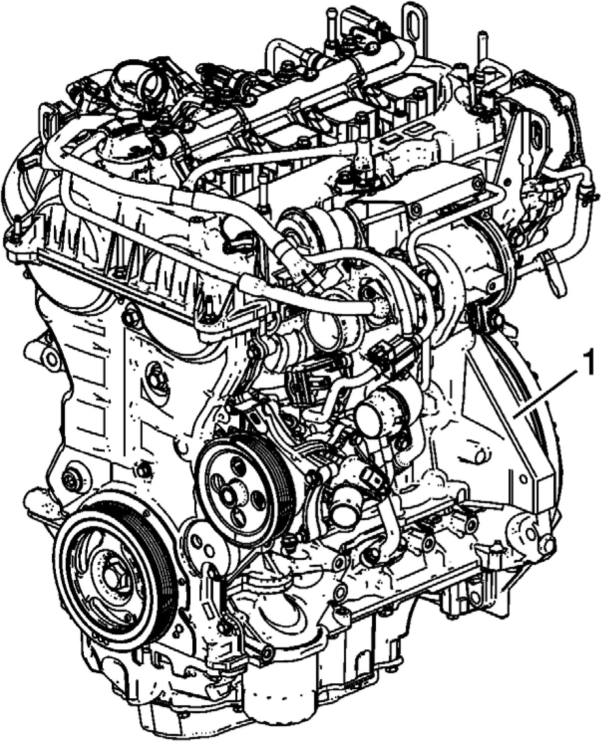 |
|
Fig. 27: Engine Identification Code Courtesy'of GENERAL'MOTORS’ COMPANY |
NOTE: The engine identification number must be stamped to the cylinder block in case of
engine replacement.
The engine identification code (1) is stamped on the flattened area of the cylinder block, at the transmission side.
DIAGNOSTIC INFORMATION AND PROCEDURES
DTC P06DA-P06DE: ENGINE OIL PRESSURE CONTROL SOLENOID VALVE
Diagnostic Instructions
• Perform the Diagnostic System Check prior to using this diagnostic procedure: Diagnostic System Check -
Vehicle
• Review the description of Strategy Based Diagnosis: Strategy Based Diagnosis
• An overview of each diagnostic category can be found here: Diagnostic Procedure Instructions
DTC Descriptor
DTC P06DA
Engine Oil Pressure Control Solenoid Valve Control Circuit
DTC P06DB
Engine Oil Pressure Control Solenoid Valve Control Circuit Low Voltage
DTC P06DC
Engine Oil Pressure Control Solenoid Valve Control Circuit High Voltage
DTC P06DD
Engine Oil Pressure Control Solenoid Valve Stuck Off
DTC P06DE
Engine Oil Pressure Control Solenoid Valve Stuck On
|
Diagnostic Fault Information | ||||||||||||||||||||
| ||||||||||||||||||||
|
Circuit/System Description | ||||||
|
|
Component |
Description |
|
K20 Engine Control Module |
The control module controls a series of actuators to ensure |
|
Component |
Description |
|
Q44 Engine Oil Pressure Control Solenoid |
A solenoid valve is an electro-mechanically operated valve. |
The engine oil pressure control solenoid valve is used to control engine oil pressure inside the mechanical engine oil
pump. The control module controls the commanded state of the solenoid valve based on the following inputs:
• Engine Speed
• Calculated Engine Oil Temperature
• Engine Oil Pressure
• Engine Run Time
When the solenoid valve is commanded Off, oil pressure is higher. When the solenoid valve is commanded On, oil
pressure is lower.
Conditions for Running the DTC
DTC P06DA, P06DB, P06DC
• Ignition Voltage = Greater than 11 V
• Engine = Running
DTCs run continuously when the above conditions are met.
DTC P06DD
• DTC P0101, P0102, P0103, P0106, P0107, P0108, P0111, P0112, P0113, P0114, P0117, P0118, P0119, P0128,
P0335, P0336, P0521, P0522, P0523, P06DA, P06DB, P06DC, P06DD, P06DE, P111E, P2227, P2228,
P2229, P2230 = Not set
• Engine Speed = 1,500 to 2,500 RPM
DTCs run continuously when the above conditions are met.
DTC P06DE
• DTC P0101, P0102, P0103, P0106, P0107, P0108, P0111, P0112, P0113, P0114, P0117, P0118, P0119, P0128,
P0335, P0336, P0521, P0522, P0523, P06DA, P06DB, P06DC, P06DD, P06DE, P111E, P2227, P2228,
P2229, P2230 = Not set
• Engine = Running - For greater than 1.5 s
• Engine Speed = 1,500 to 2,500 RPM
• Engine Oil Pressure Control Solenoid Valve = On - For greater than 1.5 s
DTCs run continuously when the above conditions are met.
Conditions for Setting the DTC
DTC P06DA, P06DB, P06DC
Control Circuit = Commanded state does not match the actual state - For 1 s
DTC P06DD
Engine Oil Pressure = Less than a predefined threshold
DTC P06DE
Engine Oil Pressure = Greater than a predefined threshold
Actions Taken When the DTC Sets
• DTCs P06DB, P06DE are Type A DTCs.
• DTCs P06DA, P06DC, P06DD are Type B DTCs.
• Engine Oil Pressure Control Solenoid Valve = Off
• Reduced Engine Power = Active
Conditions for Clearing the DTC
• DTCs P06DA, P06DC, P06DD are Type B DTCs.
• DTCs P06DB, P06DE are Type A DTCs.
Reference Information
Schematic Reference
Engine Mechanical Schematics
Connector End View Reference
COMPONENT CONNECTOR END VIEWS - INDEX
Component View Reference
Powertrain Component Views
Electrical Information Reference
Circuit Testing
Connector Repairs
Testing for Intermittent Conditions and Poor Connections
Wiring Repairs
DTC Type Reference
Powertrain Diagnostic Trouble Code (DTC) Type Definitions
Scan Tool Reference
Control Module References
Circuit/System Verification
NOTE: The engine oil level and condition is critical to the correct operation of the system.
1. Ignition - On/Vehicle - In Service Mode
2. Verify there are no DTCs set related to the following system/component:
• B35B Engine Oil Level Sensor
• B37B Engine Oil Pressure Sensor
• B37 Engine Oil Pressure Switch
• If other DTCs are set
Refer to Diagnostic Trouble Code (DTC) List - Vehicle
• If no other DTCs are set
3. Verify the condition does not exist:
• Low Engine Oil Level
• Dirty or contaminated oil
• If a condition exists
Repair as necessary
• If no condition exists
4. Perform the scan tool control function: Engine Oil Pressure Control Solenoid Valve - Low Pressure - High
Pressure
Verify the scan tool parameter:
• Engine Oil Pressure Control Solenoid Valve Control Circuit Low Voltage Test Status = OK or Not Run
• Engine Oil Pressure Control Solenoid Valve Control Circuit Open Test Status = OK or Not Run
• Engine Oil Pressure Control Solenoid Valve Control Circuit High Voltage Test Status = OK or Not Run
• If not the specified state
Refer to: Circuit/System Testing
• If the specified state
5. Engine running.
6. Perform the following steps:
1. Increase the engine speed slowly to 1,800 RPM.
NOTE: Using the scan tool line graph function may make it easier to identify if
the value changes.
2. Perform the scan tool control function: Engine Oil Pressure Control Solenoid Valve - Low Pressure
Verify the scan tool parameter: Engine Oil Pressure = Change is greater than 30 kPa (4 PSI)
• If the change is 30 kPa (4 PSI) or less - Replace the component: Q44 Engine Oil Pressure Control
Solenoid Valve
• If the change is greater than 30 kPa (4 PSI)
7. Operate the vehicle within the Conditions for Running the DTC. You may also operate the vehicle within the
conditions that you observed from the Freeze Frame/Failure Records data.
Verify the DTC does not set.
• If the DTC sets
Refer to: Circuit/System Testing
• If the DTC is not set
8. All OK.
Circuit/System Testing
1. Ignition/Vehicle & All vehicle systems - Off
2. Disconnect the appropriate electrical connector: Inline Harness Connector
3. Ignition - On/Vehicle - In Service Mode
NOTE: Testing for steps 4 to 9 is performed on the control module K20 side of the
inline harness connector.
4. Verify a test lamp turns On between the test points: Ignition circuit terminal 5 & Ground
• If the test lamp does not turn On and the circuit fuse is OK
1. Ignition/Vehicle - Off & Remove - Test lamp
2. Test for less than 2 ohms between the test points: Ignition circuit terminal 5 & Fuse
• If 2 ohms or greater - Repair the open/high resistance in the circuit.
• If less than 2 ohms - Verify the fuse is OK and there is voltage at the fuse.
• If the test lamp does not turn On and the circuit fuse is open
1. Ignition/Vehicle - Off & Remove - Test lamp
NOTE: The ignition circuit supplies voltage to other components. Test all circuits
for a short to ground or test all components for being shorted.
2. Test for infinite resistance between the test points: Ignition circuit terminal 5 & Ground
• If less than infinite resistance - Repair the short to ground on the circuit.
• If infinite resistance - Refer to: Step 10
• If the test lamp turns On
5. Verify a test lamp does not turn On between the test points: Control circuit terminal 4 & B+
• If the test lamp turns On
1. Ignition/Vehicle - Off & Remove - Test lamp
2. Disconnect the electrical connector: K20 Engine Control Module
3. Test for infinite resistance between the test points: Inline Harness Connector Control circuit terminal 4 &
Ground
• If less than infinite resistance - Repair the short to ground on the circuit.
• If infinite resistance - Replace the component: K20 Engine Control Module
• If the test lamp does not turn On
6. Remove - Test Lamp
7. Perform the scan tool control function: Engine Oil Pressure Control Solenoid Valve - Low Pressure
Verify the scan tool parameter: Engine Oil Pressure Control Solenoid Valve Control Circuit High Voltage Test
Status = OK or Not Run
• If not the specified state
1. Ignition/Vehicle - Off
2. Disconnect the electrical connector: K20 Engine Control Module
3. Test for less than 1 V between the test points: Inline Harness Connector Control circuit terminal 4 &
Ground
• If 1 V or greater - Repair the short to voltage on the circuit.
• If less than 1 V - Replace the component: K20 Engine Control Module
• If the specified state
8. Connect a 3 A fused jumper wire between the test points: Control circuit terminal 4 & Ignition circuit terminal
5
9. Perform the scan tool control function: Engine Oil Pressure Control Solenoid Valve - Low Pressure
Verify the scan tool parameter: Engine Oil Pressure Control Solenoid Valve Control Circuit High Voltage Test
Status = Malfunction
• If not the specified state
1. Ignition/Vehicle - Off & Remove - Jumper wire(s)
2. Disconnect the electrical connector: K20 Engine Control Module
3. Test for less than 2 ohms between the test points: Inline Harness Connector Control circuit terminal 4 &
The other end of the circuit
• If 2 ohms or greater - Repair the open/high resistance in the circuit.
• If less than 2 ohms - Replace the component: K20 Engine Control Module
• If the specified state
NOTE: Testing for steps 10 to 12 is performed on the component side of the inline
harness connector: Q44 Engine Oil Pressure Control Solenoid Valve
10. Test for 10 to 30 ohms between the test points: Control circuit terminal 4 & Ignition circuit terminal 5
• If not between 10 and 30 ohms
1. Disconnect the electrical connector: Q44 Engine Oil Pressure Control Solenoid Valve
2. Test for less than 2 ohms between the test points:
• Ignition circuit terminal 5 & The other end of the circuit
• Control circuit terminal 4 & The other end of the circuit
• If 2 ohms or greater - Repair the open/high resistance in the circuit.
• If less than 2 ohms - Test or replace the component: Q44 Engine Oil Pressure Control Solenoid
Valve
• If between 10 and 30 ohms
11. Test for infinite resistance between the test points:
• Ignition circuit terminal 5 & Ground
• Control circuit terminal 4 & Ground
• If less than infinite resistance
Repair the short to ground on the circuit.
• If infinite resistance
12. Test for less than 1 V between the test points:
• Ignition circuit terminal 5 & Ground
• Control circuit terminal 4 & Ground
• If 1 V or greater
Repair the short to voltage on the circuit.
• If less than 1 V
13. Test or replace the component: Q44 Engine Oil Pressure Control Solenoid Valve
Component Testing
Static Test
1. Ignition/Vehicle - Off
2. Disconnect the electrical connector: Q44 Engine Oil Pressure Control Solenoid Valve
3. Test for 10 to 30 ohms between the test points: Control terminal 2/B & Ignition terminal 1/A
• If not between 10 and 30 ohms
Replace the component: Q44 Engine Oil Pressure Control Solenoid Valve
• If between 10 and 30 ohms
4. Test for infinite resistance between the test points: Each terminal of the component & The component's
housing
• If less than infinite resistance
Replace the component: Q44 Engine Oil Pressure Control Solenoid Valve
• If infinite resistance
5. All OK.
Dynamic Test
1. Ignition/Vehicle - Off
2. Disconnect the electrical connector: Q44 Engine Oil Pressure Control Solenoid Valve
3. Connect a 10 A fused jumper wire between the test points: Ignition terminal 1/A & 12 V
CAUTION: Complete the testing as quickly as possible in order to prevent overheating
and damaging the component.
4. Momentarily connect a jumper wire between the test points: Control terminal 2/B & Ground
Verify the component turns On and Off when connecting and disconnecting the jumper wire: Q44 Engine Oil
Pressure Control Solenoid Valve
• If the component does not turn On and Off
Replace the component: Q44 Engine Oil Pressure Control Solenoid Valve
• If the component turns On and Off
5. All OK.
Repair Instructions
Perform the Diagnostic Repair Verification after completing the repair: Diagnostic Repair Verification
• Refer to Oil Pump Flow Control Solenoid Valve Replacement - Q44 Engine Oil Pressure Control Solenoid
Valve
• For control module replacement, programming, and setup refer to: Control Module References
SYMPTOMS - ENGINE MECHANICAL
Strategy Based Diagnostics
Perform the Diagnostic System Check - Vehicle .
All diagnosis on a vehicle should follow a logical process. Strategy based diagnostics is a uniform approach for
repairing all systems. The diagnostic flow may always be used in order to resolve a system condition. The diagnostic
flow is the place to start when repairs are necessary.
Visual/Physical Inspection
• Inspect for aftermarket devices which could affect the operation of the engine.
• Inspect the easily accessible or visible system components for obvious damage or conditions which could
cause the symptom.
• Inspect for the correct oil level, proper oil viscosity, and correct filter application.
• Verify the exact operating conditions under which the concern exists. Note factors such as engine RPM,
ambient temperature, engine temperature, amount of engine warm-up time, and other specifics.
• Compare the engine sounds, if applicable, to a known good engine and make sure you are not trying to correct
a normal condition.
Intermittent
Test the vehicle under the same conditions that the customer reported in order to verify the system is operating
properly.
Symptom List
Refer to a symptom diagnostic procedure from the following list in order to diagnose the symptom:
Engine Noise Under Load
Base Engine Misfire without Internal Engine Noises
Base Engine Misfire with Abnormal Internal Lower Engine Noises
Base Engine Misfire with Abnormal Valve Train Noise
Base Engine Misfire with Coolant Consumption
Base Engine Misfire with Excessive Oil Consumption
Engine Noise on Start-Up, but Only Lasting a Few Seconds
Upper Engine Noise, Regardless of Engine Speed
Lower Engine Noise, Regardless of Engine Speed
Engine Will Not Crank - Crankshaft Will Not Rotate
Coolant in Engine Oil
Engine Compression Test
Oil Consumption Diagnosis
Oil Pressure Diagnosis and Testing
Oil Leak Diagnosis
OIL PRESSURE DIAGNOSIS AND TESTING
Special Tools
• CH-48027 Digital Pressure Gauge
• EN-21867-850 Oil Pressure Gauge Adapter
For equivalent regional tools, refer to Special Tools.
Procedure
 |
|
Fig. 28: Engine Oil Pressure Sensor |
1. Remove the engine oil pressure sensor (1).
 |
|
Fig. 29: Adapter And Gauge Courtesy'of GENERAL'MOTORS COMPANY |
2. Install the EN-21867-850 adapter (1).
3. Install the CH-48027 gauge (2).
4. Start the engine.
5. Check oil pressure.
6. At idling speed, the oil pressure must be greater than 180 kPa (26.11 psi) and the oil temperature must be
85A°C (185 A°F) or more.
7. Remove the CH-48027 gauge (2).
8. Remove the EN-21867-850 adapter (1).
9. Turn off the engine.
 |
|
Fig. 30: Engine Oil Pressure Sensor |
10. Install the engine oil pressure sensor (1).
11. Tighten the sensor to 35 N.m (26 lb ft).
12. Check the engine oil level.
OIL LEAK DIAGNOSIS
|
Step |
Action |
Yes |
No |
|
DEFINITION: You can repair most fluid leaks by first, visually locating the leak, repairing or replacing the | |||
|
1 |
Are drippings present? |
Go to Step 2 |
System OK |
|
Step |
Action |
Yes |
No |
|
2 |
Can you identify the type of fluid and the approximate |
Go to Step 10 |
Go to Step 3 |
|
3 |
Can you identify the type of fluid and the approximate |
Go to Step 10 |
Go to Step 4 |
|
4 |
Can you identify the type of fluid and the approximate |
Go to Step 10 |
Go to Step 5 |
|
5 |
Can you identify the type of fluid and the approximate |
Go to Step 10 |
Go to Step 6 |
|
6 |
Can you identify the type of fluid and the approximate |
Go to Step 10 |
Go to Step 7 |
|
7 |
1. Visually inspect the suspected area. Use a small mirror |
Go to Step 10 |
Go to Step 8 |
|
Step |
Action |
Yes |
No |
|
2. Inspect for leaks at the following locations:
Can you identify the type of fluid and the approximate | |||
|
8 |
Identify the type of fluid and the approximate location of the Can you identify the type of fluid and the approximate |
Go to Step 10 |
Go to Step 9 |
|
9 |
Can you identify the type of fluid and the approximate |
Go to Step 10 |
System OK |
|
10 |
Is there mechanical damage or customer modifications to the |
Go to Step 11 |
System OK |
|
11 |
Repair or replace all damaged or modified components. |
Go to Step 1 |
- |
OIL CONSUMPTION DIAGNOSIS
Excessive oil consumption, not due to leaks, is the use of 0.9 L (1 quart) or greater of engine oil within 3,200
kilometers (2,000 miles). The causes of excessive oil consumption include the following conditions:
• External oil leaks
Tighten bolts and/or replace gaskets and oil seals as necessary.
• Incorrect oil level or improper reading of oil level indicator
With the vehicle on a level surface, allow adequate drain down time and inspect for the correct oil level.
• Improper oil viscosity
Use recommended SAE viscosity for the prevailing temperatures.
• Continuous high speed driving and/or severe usage
• Crankcase ventilation system restrictions or malfunctioning components
• Valve guides and/or valve stem oil seals worn, or the seal omitted
Ream guides and install oversize service valves and/or new valve stem oil seals.
• Piston rings broken, improperly installed, worn, or not seated properly
Allow adequate time for rings to seat. Replace broken or worn rings, as necessary.
• Piston improperly installed or mis-fitted.
COOLANT IN COMBUSTION CHAMBER
___________________Cause_____________________________________Correction__________________
DEFINITION: Excessive white smoke and/or coolant type odor coming from the exhaust pipe may indicate
coolant in the combustion chamber. Low coolant levels, an inoperative cooling fan, or a faulty thermostat may
lead to an overheating condition which may cause engine component damage.
NOTE:
While not
always
conclusive,
use of
hydrocarbon
block test
kits may
reveal
hydrocarbons
indicating
combustion
chamber
gases in
cooling
system. It is
important to
follow the kit
instructions.
This is not a
substitute for
service
information.
Combustion
| ||||||||||||||||
|
COOLANT IN ENGINE OIL | ||||||||||||||||
|
Cause |
Correction |
|
DEFINITION: Foamy or discolored oil or an engine oil overfill condition may indicate coolant entering the
| |
|
Faulty cylinder head gasket |
Replace the head gasket and components as required. Refer to Cylinder Head Replacement. |
|
Warped cylinder head |
Replace the cylinder head and gasket. Refer to |
|
Cracked cylinder head |
Replace the cylinder head and gasket. Refer to |
|
Cracked cylinder liner |
Replace the components as required. |
|
Cylinder head or block porosity |
Replace the components as required. |
|
ENGINE NOISE UNDER LOAD | ||||||||||||||
|
|
ENGINE NOISE ON START-UP, BUT ONLY LASTING A FEW SECONDS | ||||||||||||||
|
|
Cause |
Correction |
|
actuator. 3. Replace the camshaft actuator, oil and filter. |
|
BASE ENGINE MISFIRE WITHOUT INTERNAL ENGINE NOISES | ||||||||||||||||||||||||||||||
|
|
Cause |
Correction |
|
Coolant consumption may or may not cause the engine |
• Repair or replace as required. |
|
Worn piston rings Oil consumption may or may not cause the engine to |
Refer to Engine Compression Test.
|
|
A damaged crankshaft reluctor wheel A damaged crankshaft reluctor wheel can result in
|
Replace the sensor and/or crankshaft as required. |
|
BASE ENGINE MISFIRE WITH ABNORMAL INTERNAL LOWER ENGINE NOISES | ||||||||
|
| ||||||
|
BASE ENGINE MISFIRE WITH ABNORMAL VALVE TRAIN NOISE |
| ||||||||||||
|
BASE ENGINE MISFIRE WITH COOLANT CONSUMPTION |
|
Cause |
Correction |
|
Faulty cylinder head gasket and/or cracking, or other |
• Inspect for spark plugs saturated by coolant. |
| ||||
|
BASE ENGINE MISFIRE WITH EXCESSIVE OIL CONSUMPTION |
|
Cause |
Correction |
|
Worn valves, valve guides, and/or valve stem oil |
|
|
Worn piston rings Oil consumption may or may not cause the engine to |
Refer to Engine Compression Test.
|
|
UPPER ENGINE NOISE, REGARDLESS OF ENGINE SPEED | ||||||||||||||||||
|
|
Cause |
Correction |
|
Worn valve guides or valve stems |
Inspect the following components, and repair as
|
|
Stuck valves Carbon on the valve stem or valve seat may cause the |
Inspect the following components and repair as
|
|
LOWER ENGINE NOISE, REGARDLESS OF ENGINE SPEED | ||||||||||||||||||||||
|
|
ENGINE WILL NOT CRANK - CRANKSHAFT WILL NOT ROTATE | ||||||||||||||||||||||||||
|
|
Cause |
Correction |
|
Seized automatic transmission - hybrid |
Seized Engine or Transmission Separation |
ENGINE COMPRESSION TEST
Special Tools
EN-51749 Compression Gauge Tester Kit
For equivalent regional tools, refer to Special Tools.
Removal Procedure
NOTE: DO NOT leave vehicle connected to charge port or theft deterrent system will
be active and compression test will not run.
1. Bring vehicle into service bay and make sure vehicle has at least 50% charge.
2. Remove the ignition coils. Refer to Ignition Coil Replacement .
3. Remove the spark plugs. Refer to Spark Plug Replacement .
Diagnostic Procedure
NOTE: In order to perform the compression test it will be necessary to use GDS in
order to crank engine.
1. Place vehicle into service mode and connect GDS.
NOTE: The drivers door must remain open and vehicle is turned off. This will ensure
that the theft deterrent feature is not active.
2. Once vehicle VIN is recorded and you are at the vehicle selection screen select "Enter" and then select
"Module Diagnostics" - "Engine Control Module" then "Control Functions" on the menu screens DO NOT
select "Compression Test" at this time. When you reach this point stop an turn off vehicle and leave the drivers
door open.
NOTE: You must select crank on the compression test diagnostic screen within 10
seconds of turning key on or the theft deterrent feature will be enabled and the
compression test will not run. If this occurs it will be necessary to turn off
vehicle for at least one minute and then back on to reset this feature.
3. Without compression gauge attached put vehicle back into service mode then select compression test and then
select crank on the GDS menu screens. The engine will now crank to allow any foreign substances to be
removed from the cylinders. Once vehicle has performed crank function turn vehicle off.
4. After one minute the "Lost Communication with Vehicle" screen will now be displayed.
5. Install EN-51749 gauge in the spark plug bore for the cylinder that is being checked.
6. Put vehicle into service mode then select OK and then select crank on the GDS menu screens. The engine will
now crank and then stop. Turn vehicle off.
7. Record the compression reading for the cylinder just tested.
NOTE: It is important to wait at least one minute with key off between checking each
cylinder to ensure the theft deterrent feature is not active and the "lost
Communication with Vehicle" screen appears.
8. Repeat starting at step 7 for all remaining cylinders. All 4 cylinders must be tested to obtain valid test results.
Record the readings.
Installation Procedure
1. Remove EN-51749 gauge.
2. Install the spark plugs. Refer to Spark Plug Replacement .
3. Install the ignition coils. Refer to Ignition Coil Replacement .
CYLINDER LEAKAGE TEST
Special Tools
EN-51749 Compression Gauge Tester Kit
For equivalent regional tools, refer to Special Tools.
NOTE: A leakage test may be performed in order to measure cylinder/combustion chamber
leakage. High cylinder leakage may indicate one or more of the following
conditions:
• Worn or burnt valves
• Broken valve springs
• Stuck valve lifters
• Incorrect valve lash
• Damaged piston
• Worn piston rings
• Worn or scored cylinder bore
• Damaged cylinder head gasket
• Cracked or damaged cylinder head
• Cracked or damaged engine block
WARNING: Refer to Battery Disconnect Warning .
1. Disconnect the battery ground negative cable.
2. Remove the spark plugs. Refer to Spark Plug Replacement .
3. Rotate the crankshaft to place the piston in the cylinder being tested at top dead center (TDC) of the
compression stroke.
4. Install the EN-51749 gauge according to the manufacturers instructions.
NOTE: It may be necessary to hold the crankshaft balancer bolt to prevent the
crankshaft from rotating.
5. Apply shop air pressure and adjust according to the manufacturers instructions.
6. Record the cylinder leakage value. Cylinder leakage that exceeds 25 percent is considered excessive and may
require component service. In excessive leakage situations, inspect for the following conditions:
• Air leakage noise at the throttle body or air inlet hose that may indicate a worn or burnt intake valve or a
broken valve spring.
• Air leakage noise at the exhaust system tailpipe that may indicate a worn or burnt exhaust valve or a
broken valve spring.
• Air leakage noise from the crankcase, oil level indicator tube, or oil fill tube that may indicate worn
piston rings, a damaged piston, a worn or scored cylinder bore, a damaged engine block or a damaged
cylinder head.
• Air bubbles in the cooling system may indicate a damaged cylinder head or a damaged cylinder head
gasket.
7. Perform the leakage test on the remaining cylinders and record the values.
CRANKCASE VENTILATION SYSTEM INSPECTION/DIAGNOSIS
|
Symptom |
Correction |
|
External oil leak |
Inspect for any of the following conditions:
|
|
Rough Idle |
Inspect for any of the following conditions:
|
|
Stalling or slow idle speed |
Inspect for any of the following conditions:
|
|
High idle speed |
Inspect for a leaking (damaged) PCV hose |
|
Sludge in the engine |
Inspect for restricted or kinked PCV hose or engine vent hose |
REPAIR INSTRUCTIONS - ON VEHICLE
CAMSHAFT COVER REPLACEMENT
Removal Procedure
WARNING: Always perform the High Voltage Disabling procedure prior to servicing any High
Voltage component or connection. Personal Protection Equipment (PPE) and proper
procedures must be followed.
The High Voltage Disabling procedure will perform the following tasks:
• Identify how to disable high voltage.
• Identify how to test for the presence of high voltage.
• Identify condition under which high voltage is always present and personal
protection equipment (PPE) and proper procedures must be followed.
Failure to follow the procedures exactly as written may result in serious injury or
death.
1. Disable the high voltage system. Refer to High Voltage Disabling
 |
|
Fig. 31: Camshaft Cover, Air Cleaner Outlet Duct And Positive Crankcase Ventilation Pipe |
CAUTION: The Positive Crankcase Ventilation (PCV) line is tamper resistant and must
always be replaced once it is removed. The fittings connected to the PCV line
must also be replaced if they are damaged when the PCV line is removed. To
reduce the risk of damage to the fittings, use a suitable cutting tool and
carefully cut the connections away.
NOTE: If reinstalling the camshaft cover (3), DO NOT cut the PCV line (1). The air
cleaner outlet duct (2), camshaft cover (3) and positive crankcase ventilation
pipe (1) should be removed together as shown.
2. If replacing the camshaft cover, remove and discard the positive crankcase ventilation tube. Refer to Positive
Crankcase Ventilation Tube Replacement
3. Remove Fuel Feed Intermediate Pipe. Refer to Fuel Feed Intermediate Pipe Replacement
4. Remove Fuel Injection Fuel Rail Assembly. Refer to Fuel Injection Fuel Rail Assembly Replacement
 |
|
Fig. 32: Bolt, Electrical Connectors, Retainer, Nut And Wiring Harness Bracket |
5. Remove Bolt (1) @ Camshaft Cover
6. Disconnect Electrical Connector (2) @ Exhaust Gas Recirculation Cooler Temperature Sensor
7. Unclip the exhaust gas recirculation cooler temperature sensor from the camshaft cover retainer (3).
8. Disconnect Electrical Connector (5) @ Camshaft Position Actuator Solenoid Valve
9. Remove Nut (7) @ Engine Wiring Harness Bracket (6)
10. Position aside Engine Wiring Harness Bracket (6)
 |
|
Fig. 33: Bolts, Electrical Connectors, Nut, Fuel Pipe Bracket, Engine Stud, Clip And Engine Wiring Courtesy of GENERAL MOTORS COMPANY |
11. Remove the 3 engine wiring harness support bolts (6, 11)
12. Remove Engine Wiring Harness Bracket Bolt (1)
13. Disconnect Electrical Connector (2) @ Intake Camshaft Position Sensor
14. Remove Nut (4)
15. Lay fuel pipe bracket (3) aside.
16. Remove the engine wiring harness stud (5).
17. Disconnect Electrical Connector (7) @ Exhaust Gas Recirculation Cooler Temperature Sensor
18. Remove the exhaust temperature sensor clip (10).
19. Disconnect Electrical Connector (9) @ Exhaust Camshaft Position Sensor
20. Position aside Engine Wiring Harness (8)
 |
|
Fig. 34: Electrical Connector And Retainer |
21. Disconnect Electrical Connector (1) @ Camshaft Position Actuator Solenoid Valve
22. Remove Retainer (2)
 |
|
Fig. 35: Oil Filler Cap And Oil Level Indicator Handle |
23. Remove Oil Filler Cap (1)
24. Remove the oil level indicator handle (2).
 |
|
Fig. 36: Camshaft Cover, Studs, Bolts And Gaskets |
25. Remove Camshaft Cover Studs (1) (Qty: 2)
26. Remove Camshaft Cover Bolts (4) (Qty: 18)
27. Remove Camshaft Cover (2)
28. Remove and DISCARD the outer camshaft cover gasket (7).
29. Remove and DISCARD the inner camshaft cover gasket (8).
30. Remove and DISCARD the 2 camshaft position actuator solenoid valve gaskets (10).
31. Remove Camshaft Cover Studs (2, 3) (Qty: 2)
Disassemble Procedure
1. Remove Camshaft Position Sensor - Exhaust. Refer to Camshaft Position Sensor Replacement - Exhaust
2. Remove Camshaft Position Sensor - Intake. Refer to Camshaft Position Sensor Replacement - Intake
3. Remove Camshaft Position Actuator Solenoid Valve - Intake. Refer to Camshaft Position Actuator Solenoid
Valve Replacement - Intake
4. Remove Camshaft Position Actuator Solenoid Valve - Exhaust. Refer to Camshaft Position Actuator
Solenoid Valve Replacement - Exhaust
5. Remove Positive Crankcase Ventilation Valve - Fresh Air. Refer to Positive Crankcase Ventilation Valve
Replacement - Fresh Air
6. Remove Positive Crankcase Ventilation Valve - Secondary. Refer to Positive Crankcase Ventilation Valve
Replacement - Secondary
Assemble Procedure
1. Install Positive Crankcase Ventilation Valve - Fresh Air. Refer to Positive Crankcase Ventilation Valve
Replacement - Fresh Air
2. Install Positive Crankcase Ventilation Valve - Secondary. Refer to Positive Crankcase Ventilation Valve
Replacement - Secondary
3. Install Camshaft Position Actuator Solenoid Valve - Exhaust. Refer to Camshaft Position Actuator Solenoid
Valve Replacement - Exhaust
4. Install Camshaft Position Actuator Solenoid Valve - Intake. Refer to Camshaft Position Actuator Solenoid
Valve Replacement - Intake
5. Install Camshaft Position Sensor - Intake. Refer to Camshaft Position Sensor Replacement - Intake
6. Install Camshaft Position Sensor - Exhaust. Refer to Camshaft Position Sensor Replacement - Exhaust
Installation Procedure
1. Clean all camshaft cover sealing surfaces.
 |
|
Fig. 37: Camshaft Cover, Studs, Bolts And Gaskets |
CAUTION: Refer to Fastener Caution .
2. Install and tighten Camshaft Cover Studs (2, 3) (Qty: 2) to 10 N.m (89 lb in)
NOTE: Ensure that the gaskets are located in the retaining grooves in the camshaft
cover.
3. Apply approximately a 5 mm (0.2 in) thick bead of camshaft cover sealant (11) on both sides between the
cylinder head and the engine front cover. Refer to Adhesives, Fluids, Lubricants, and Sealers.
4. Install 2 NEW camshaft position actuator solenoid valve gaskets (10).
5. Install a NEW camshaft cover inner gasket (8).
6. Install a NEW camshaft cover outer gasket (7).
NOTE: If reinstalling the original camshaft cover, install the camshaft cover, air
cleaner outlet duct and positive crankcase ventilation tube as an assembly.
7. Install the camshaft cover (5) along with the pins (6, 9).
8. Hand tighten the 2 camshaft cover double end studs (1).
9. Tighten the Camshaft Cover Bolts (4) (Qty: 18) bolts by hand.
 |
|
Fig. 38: Camshaft Cover Stud And Bolt Tightening Sequence |
10. Tighten the 2 camshaft cover double end studs (1) and the 18 camshaft cover bolts (2) in sequence as shown to
15 N.m (11 lb ft).
 |
|
Fig. 39: Oil Filler Cap And Oil Level Indicator Handle |
11. Install the oil level indicator handle (2).
12. Install Oil Filler Cap (1)
 |
|
Fig. 40: Electrical Connector And Retainer |
13. Connect Electrical Connector (1) @ Camshaft Position Actuator Solenoid Valve
14. Install Retainer (2)
 |
|
Fig. 41: Bolts, Electrical Connectors, Nut, Fuel Pipe Bracket, Engine Stud, Clip And Engine Wiring Courtesy of GENERAL MOTORS COMPANY |
15. Position the engine wiring harness (8).
16. Connect Electrical Connector (9) @ Exhaust Camshaft Position Sensor
17. Install the exhaust temperature sensor clip (10).
18. Connect Electrical Connector (7) @ Exhaust Gas Recirculation Cooler Temperature Sensor
19. Install the engine wiring harness stud (5) and tighten to 9 N.m (80 lb in).
20. Install fuel pipe bracket (3).
21. Install and tighten Nut (4) to 9 N.m (80 lb in)
22. Install the 3 engine wiring harness support bolts (6, 11) and tighten to 9 N.m (80 lb in).
23. Install and tighten Engine Wiring Harness Bracket Bolt (1) to 9 N.m (80 lb in)
24. Connect Electrical Connector (2) @ Intake Camshaft Position Sensor
 |
|
Fig. 42: Bolt, Electrical Connectors, Retainer, Nut And Wiring Harness Bracket |
25. Install the engine wiring harness bracket (6).
26. Connect Electrical Connector (2) @ Exhaust Gas Recirculation Cooler Temperature Sensor
27. Clip in exhaust gas recirculation cooler temperature sensor to the camshaft cover retainer (3).
28. Connect Electrical Connector (5) @ Camshaft Position Actuator Solenoid Valve
29. Install and tighten Nut (7) @ Engine Wiring Harness Bracket (6) to 9 N.m (80 lb in)
30. Install and tighten Bolt (1) @ Camshaft Cover to 9 N.m (80 lb in)
31. Install Positive Crankcase Ventilation Tube. Refer to Positive Crankcase Ventilation Tube Replacement
32. Install Fuel Injection Fuel Rail Assembly. Refer to Fuel Injection Fuel Rail Assembly Replacement
33. Install Fuel Feed Intermediate Pipe. Refer to Fuel Feed Intermediate Pipe Replacement
34. Enable high voltage system. Refer to High Voltage Enabling
CAMSHAFT POSITION ACTUATOR REPLACEMENT
Special Tools
• EN-45059 Angle Meter
• EN-51367 Camshaft Holder
• EN-51397-1 Timing Chain Retainer
• EN-51397-2 Timing Chain Retainer
Equivalent regional tools: Special Tools
Removal Procedure
1. Remove Air Cleaner Assembly. Refer to Air Cleaner Assembly Replacement
2. Drain the cooling system. Refer to Cooling System Draining and Filling -
3. Remove Camshaft Cover. Refer to Camshaft Cover Replacement
4. Remove Front Wheelhouse Liner (Right Side). Refer to Front Wheelhouse Liner Replacement (Right Side)
 |
|
Fig. 43: Heater Coolant Heater, Heater Inlet Hose And Quick Connect |
5. Disconnect Heater Inlet Hose Quick Connect (2) @ Heater Inlet Hose (3)
6. Disconnect Heater Inlet Hose (3) @ Heater Coolant Heater (1)
7. Remove Heater Inlet Hose (3)
 |
|
Fig. 44: Crankshaft Balancer Markings |
8. Adjust the engine to cylinder 1 top dead center (TDC) of combustion stroke. Set crankshaft in direction of
engine rotation until the markings (1, 2) line up. Rotate at the crankshaft balancer bolt (3).
9. Lower the vehicle.
 |
|
Fig. 45: Camshaft Holder Courtesy'of GENERAL'MOTORS COMPANY |
10. Install the EN-51367 holder (1).
11. Remove Timing Chain Upper Guide. Refer to Timing Chain Upper Guide Replacement
 |
|
Fig. 46: Camshaft Position Actuator Marks And Timing Chain Marks |
NOTE: The actuator marks stands at 12 o'clock, if the cylinder 1 are on top dead
center.
12. Check camshaft position actuator marks (1).
13. Apply a color marking to the camshaft timing chain (1) marking to corresponding timing chain link.
 |
|
Fig. 47: Camshaft Timing Chain, Retainers, Thumb Wheels And Bolts |
14. Pre-Install the EN-51397-2 retainer (2) to the intake side of the camshaft timing chain (3).
15. Install the EN-51397-1 retainer (5) to the exhaust side of the camshaft timing chain.
16. Hand tighten the thumb wheels (1, 4) securely.
CAUTION: Refer to Fastener Caution
17. Tighten Bolts (6) (Qty: 2) to 5 N.m (44 lb in)
 |
|
Fig. 48: Camshaft Position Actuator Bolts |
18. Loosen Bolts (1) (Qty: 2) @ Camshaft Position Actuator
19. Remove the EN-51367 holder.
 |
|
Fig. 49: Engine Front Cover, Hole Plug And Seal Ring |
20. Remove Engine Front Cover Hole Plug (1) @ Engine Front Cover
21. Remove Seal Ring (2)
 |
|
Fig. 50: Releasing Tension From Piston |
NOTE: Step 22 - 26 explain how to adjust and fix the timing chain tensioner in the
service position and should be used for reference.
22. Slightly release tension from the piston (2) until bar (1) can be unlocked by rotating the lever (3) in direction
of arrow.
 |
|
Fig. 51: Piston And Tensioner Lever |
23. Entirely push back the piston (1) until the tensioner Lever (2) cannot be locked in this position.

Fig. 52: Piston
Courtesy'of GENERAL MOTORS COMPANY
24. Release tension from the piston (1) until it releases for three ratchets. The three ratchets can be noticed by the
click noises.
 |
|
Fig. 53: Lever And Fixing Pin Courtesy'of GENERAL'MOTORS COMPANY |
25. Apply tension to the piston until the lever (1) is rotated back into the locking position where the bore in the
lever aligns with the bore in the tensioner housing.
26. Fix the lever in this position with a suitable fixing pin (2).

Fig. 54: Wrench On Camshaft
Courtesy of GENERAL MOTORS COMPANY
CAUTION: The tightening force must be applied gently to the wrench. Using too much
force will lead to an overlap of the timing chain that will cause severe engine
damages.
|
NOTE: |
A second technician is required. Follow Step 22 - 26 during rotation of the intake camshaft |
27. Install a suitable wrench (1) to the intake camshaft.
28. Apply tension to the chain tensioner by slightly rotating the intake camshaft clockwise.
 |
|
Fig. 55: Timing Chain Tensioner In Lock Position |
NOTE: The timing chain tensioner has now the lock position (1).
29. Secure the timing chain tensioner design 1 with a suitable fixing pin 3 mm (0.118 in).

Fig. 56: Bolt And Retainer
Courtesy of GENERAL MOTORS COMPANY
30. Fix the EN-51397-2 retainer (1) to the intake side of the camshaft timing chain.
31. Tighten the bolt (2) of the EN-51397-2 retainer to 5 N.m (44 lb in).
32. Remove the wrench.
 |
|
Fig. 57: Checking Chain Slack Courtesy'of GENERAL'MOTORS COMPANY |
NOTE: The timing chain can be moved up and down between both camshaft position
actuators.
33. Check chain slack, if not enough slack is gained, refer to detailed chain tensioner description from step 22 to
26. Apply and release tension to the chain tensioner.
 |
|
Fig. 58: Intake Camshaft Position Actuator And Bolt |
| ||
|
34. Remove and DISCARD the intake camshaft position actuator bolt (1). |
| ||
|
35. Remove the intake camshaft position actuator (2). |
 |
|
Fig. 59: Exhaust Camshaft Position Actuator And Bolt |
36. Remove and DISCARD the exhaust camshaft position actuator bolt (1).
NOTE: The camshaft timing chain will be hold by EN-51397-1 retainer.
37. Remove the exhaust camshaft position actuator (2).
Installation Procedure
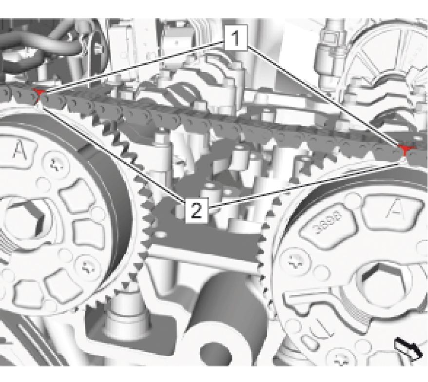 |
|
Fig. 60: Camshaft Position Actuator Marks And Timing Chain Marks |
1. The marks of the camshaft position actuators (2) must be set to the marks of the camshaft timing chain (1).
 |
|
Fig. 61: Exhaust Camshaft Position Actuator, Dowel Pin, Camshaft And Bolt |
2. Install the exhaust camshaft position actuator (1).
3. Readjust the camshaft until the dowel pin (2) engage to camshaft (3).
 |
|
Fig. 62: Intake Camshaft Position Actuator, Dowel Pin, Camshaft And Bolt |
4. Install the exhaust camshaft position actuator (1).
5. Readjust the camshaft until the dowel pin (2) engage to camshaft (3).
NOTE: Counterhold the camshaft with a suitable tool.
6. Install the intake camshaft position actuator bolt (4) but do not tighten yet.
 |
|
Fig. 63: Camshaft Holder Courtesy'of GENERAL'MOTORS COMPANY |
7. Install the EN-51367 holder (1).
 |
|
Fig. 64: Camshaft Position Actuator Bolts |
CAUTION: Refer to Fastener Caution
CAUTION: Refer to Torque-to-Yield Fastener Caution
NOTE: Counterhold the camshaft with a suitable tool.
8. Tighten the 2 to camshaft position actuator bolts (1) to:
1. First Pass: 20 N.m (15 lb ft).
2. Final Pass: 90 degrees use the EN-45059 meter.
9. Remove the EN-51367 holder (1).
 |
|
Fig. 65: Camshaft Timing Chain, Retainers, Thumb Wheels And Bolts |
10. Loosen the bolts. (6) (Qty: 2)
11. Loosen the bolts. (1, 4) (Qty: 2)
12. Remove EN-51397-2 retainer (2).
13. Remove EN-51397-1 retainer (5).
 |
|
Fig. 66: Timing Chain Tensioner In Lock Position |
NOTE: The following step shows the tensioner design 1.
14. Remove the pin from the timing chain tensioner (1).
15. Install Timing Chain Upper Guide. Refer to Timing Chain Upper Guide Replacement
16. Check the position of the crankshaft, camshaft and camshaft position actuator.
 |
|
Fig. 67: Crankshaft Balancer Markings |
17. Turn crankshaft 720 degrees in the direction of engine rotation by the crankshaft balancer bolt (3).
18. Adjust the engine to cylinder 1 TDC of combustion stroke. Set crankshaft in direction of engine rotation until
the markings (1, 2) line up. Rotate at the crankshaft balancer bolt (3).

Fig. 68: Camshaft Holder
Courtesy of GENERAL MOTORS COMPANY
19. Install the EN-51367 holder (1).
20. If the EN-51367 holder (1) can be installed, the engine timing is properly adjusted.
 |
|
Fig. 69: Engine Front Cover, Hole Plug And Seal Ring |
21. Install Seal Ring (2)
22. Install and tighten Engine Front Cover Hole Plug (1) to 50 N.m (37 lb ft)
23. Raise the vehicle.
 |
|
Fig. 70: Heater Coolant Heater, Heater Inlet Hose And Quick Connect |
24. Install Heater Inlet Hose (3) @ Heater Coolant Heater (1)
25. Connect Heater Inlet Hose Quick Connect (2) @ Heater Inlet Hose (3)
26. Install Front Wheelhouse Liner (Right Side). Refer to Front Wheelhouse Liner Replacement (Right Side)
27. Install Camshaft Cover. Refer to Camshaft Cover Replacement
28. Fill the cooling system. Refer to Cooling System Draining and Filling
29. Install Air Cleaner Assembly. Refer to Air Cleaner Assembly Replacement
EXHAUST CAMSHAFT REPLACEMENT
Removal Procedure
1. Remove Camshaft Position Actuator. Refer to Camshaft Position Actuator Replacement
 |
|
Fig. 71: Exhaust Camshaft, Bearing Caps And Bolts Courtesy'of GENERAL'MOTORS COMPANY |
NOTE: Many internal engine components will develop specific wear patterns on their
friction surfaces.
2. Components MUST be separated, marked, or organized in a way to ensure installation to their original location
and position. Take precautions in order to prevent interchanging of parts.
3. Tag or mark each part immediately when removed. Indicate location, direction, or orientation when necessary.
4. Loosen the 12 camshaft bearing cap bolts (1, 2, 7, 8), working from outside to inside in a spiral in steps of 1/2
turn.
NOTE: Observe the markings on the bearing caps. Each bearing cap is marked in
order to identify its location.
5. Remove the 12 camshaft bearing cap bolts (1, 2, 7, 8).
6. Remove Camshaft Bearing Cap (3, 4, 6) (Qty: 6) @ Cylinder Head Assembly
7. Remove Exhaust Camshaft (5)
 |
|
Fig. 72: Exhaust Camshaft, Bearing Caps And Bolts |
1. Coat the intake camshaft with lubricant. Refer to Adhesives, Fluids, Lubricants, and Sealers.
2. Install Exhaust Camshaft (5)
3. Ensure that the camshaft notch at the front of the camshaft is in the 12 o'clock position before installing the
camshaft caps.
4. Rotate the oil seal in the groove of the number one camshaft journal so the split line is at approximately the 12
o'clock position before installing the camshaft caps.
NOTE: Observe the markings on the bearing caps. Each bearing cap is market in
order to identify its location. Ensure the caps are installed in the original
location and position.
5. Lubricate the 6 camshaft bearing caps (3, 4, 6) and the 12 camshaft bearing cap bolts (1, 2, 7, 8). Refer to
Adhesives, Fluids, Lubricants, and Sealers.
6. Install Camshaft Bearing Caps (4) (Qty: 4)
7. Install the camshaft bearing rear cap (3).
8. Install the camshaft bearing front cap (6).
9. Loosely install the 12 camshaft bearing cap bolts (1, 2, 7, 8).
 |
|
Fig. 73: Exhaust Camshaft Bearing Cap Bolt Tightening Sequence |
CAUTION: Refer to Fastener Caution .
10. Tighten the camshaft bearing cap bolts (1, 2, 7, 8) in increments of 3 turns until they are seated.
11. Tighten the bearing cap bolts in sequence as shown to 12 N.m (106 lb in).
12. Install Camshaft Position Actuator. Refer to Camshaft Position Actuator Replacement
INTAKE CAMSHAFT REPLACEMENT
Removal Procedure
1. Remove Camshaft Position Actuator. Refer to Camshaft Position Actuator Replacement
2. Remove Fuel Injection Pump. Refer to Fuel Injection Pump Replacement
 |
|
Fig. 74: Intake Camshaft, Bearing Caps And Bolts |
NOTE: Many internal engine components will develop specific wear patterns on their
friction surfaces.
3. Components MUST be separated, marked, or organized in a way to ensure installation to their original location
and position. Take precautions in order to prevent interchanging of parts.
4. Tag or mark each part immediately when removed. Indicate location, direction, or orientation when necessary.
5. Loosen the 12 camshaft bearing cap bolts (1, 2, 7, 8), working from outside to inside in a spiral in steps of 1/2
turn.
NOTE: Observe the markings on the bearing caps. Each bearing cap is marked in
order to identify its location.
6. Remove the 12 camshaft bearing cap bolts (1, 2, 7, 8).
7. Remove Camshaft Bearing Caps (3, 4, 6) (Qty: 6) @ Cylinder Head Assembly
8. Remove Intake Camshaft (5)
Installation Procedure
 |
|
Fig. 75: Intake Camshaft, Bearing Caps And Bolts |
1. Coat the intake camshaft with lubricant. Refer to Adhesives, Fluids, Lubricants, and Sealers.
2. Install Intake Camshaft (5)
3. Ensure that the camshaft notch at the front of the camshaft is in the 12 o'clock position before installing the
camshaft caps.
4. Rotate the oil seal in the groove of the number one camshaft journal so the split line is at approximately the 12
o'clock position before installing the camshaft caps.
NOTE: Observe the markings on the bearing caps. Each bearing cap is market in
order to identify its location. Ensure the caps are installed in the original
location and position.
5. Lubricate the 6 camshaft bearing caps (3, 4, 6) and the 12 camshaft bearing cap bolts (1, 2, 7, 8). Refer to
Adhesives, Fluids, Lubricants, and Sealers.
6. Install the 4 camshaft bearing caps (4).
7. Install the camshaft bearing rear cap (3).
8. Install the camshaft bearing front cap (6).
9. Loosely install the 12 camshaft bearing cap bolts (1, 2, 7, 8).
 |
|
Fig. 76: Intake Camshaft Bearing Cap Bolt Tightening Sequence Courtesy'of GENERAL'MOTORS'COMPANY |
CAUTION: Refer to Fastener Caution .
10. Tighten the camshaft bearing cap bolts (1, 2, 7, 8) in increments of 3 turns until they are seated.
11. Tighten the bearing cap bolts in sequence as shown to 12 N.m (106 lb in).
12. Install Fuel Injection Pump. Refer to Fuel Injection Pump Replacement
13. Install Camshaft Position Actuator. Refer to Camshaft Position Actuator Replacement
CAMSHAFT TIMING CHAIN REPLACEMENT
Special Tools
EN-51367 Camshaft Holder
Equivalent regional tools: Special Tools
Removal Procedure
1. Drain the cooling system. Refer to Cooling System Draining and Filling
2. Remove Camshaft Cover. Refer to Camshaft Cover Replacement
3. Remove Front Wheelhouse Liner (Right Side). Refer to Front Wheelhouse Liner Replacement (Right Side)
 |
|
Fig. 77: Heater Coolant Heater, Heater Inlet Hose And Quick Connect |
4. Disconnect Heater Inlet Hose Quick Connect (2) @ Heater Inlet Hose (3)
5. Disconnect Heater Inlet Hose (3) @ Heater Coolant Heater (1)
 |
|
Fig. 78: Crankshaft Balancer Markings |
6. Adjust the engine to cylinder 1 top dead center (TDC) of combustion stroke. Set crankshaft in direction of
engine rotation until the markings (1, 2) line up. Rotate at the crankshaft balancer bolt (3).

Fig. 79: Camshaft Holder
Courtesy of GENERAL MOTORS COMPANY
7. Install the EN-51367 holder (1).
8. Remove Engine Front Cover. Refer to Engine Front Cover Replacement
9. Remove Timing Chain Upper Guide. Refer to Timing Chain Upper Guide Replacement
 |
|
Fig. 80: Timing Chain Tensioner In Service Position |
10. Fix the timing chain tensioner (1) in service position:
 |
|
Fig. 81: Releasing Tension From Piston Courtesy'of GENERAL'MOTORS'COMPANY |
1. Slightly release tension from the piston (2) until bar (1) can be unlocked by rotating the lever (3) in
direction of arrow.
 |
|
Fig. 82: Piston And Tensioner Lever |
2. Entirely push back the piston (1) until the tensioner lever (2) cannot be locked in this position.
 |
|
Fig. 83: Piston Courtesy'of GENERAL MOTORS COMPANY |
3. Release tension from the piston (1) until it releases for three ratchets. The three ratchets can be noticed
by the click noises.
 |
|
Fig. 84: Lever And Fixing Pin Courtesy'of GENERAL'MOTORS COMPANY |
4. Apply tension to the piston until the lever (1) is rotated back into the locking position where the bore in
the lever aligns with the bore in the tensioner housing.
5. Fix the lever in this position with a suitable fixing pin (2).
 |
|
Fig. 85: Timing Chain Tensioner Shoe And Bolt |
11. Remove Timing Chain Tensioner Shoe Bolt (1)
12. Remove Timing Chain Tensioner Shoe (2)
 |
|
Fig. 86: Timing Chain Tensioner Tool, Timing Chain Tensioner, Bolts And Gasket |
13. Ensure the correct fixation of the tool (3).
14. Remove Timing Chain Tensioner Bolts (4) (Qty: 2)
15. Remove Timing Chain Tensioner (1)
16. Remove and DISCARD the gasket. (2)

Fig. 87: Timing Chain
Courtesy'of GENERAL MOTORS COMPANY
17. Remove Timing Chain (1)
Installation Procedure

Fig. 88: Timing Chain
Courtesy'of GENERAL MOTORS COMPANY
NOTE: Ensure the actuator timing marks are approximately the 12 o'clock position.
1. Install Timing Chain (1) - Install
 |
|
Fig. 89: Timing Chain Marks Courtesy'of GENERAL'MOTORS COMPANY |
2. Ensure that the colored link (3) matches to the arrow on the crankshaft sprocket.
3. Ensure that the colored links (1, 2) match to the marks on the camshaft position adjuster actuators.
 |
|
Fig. 90: Timing Chain Tensioner Tool, Timing Chain Tensioner, Bolts And Gasket |
4. Install a NEW gasket. (2)
5. Install Timing Chain Tensioner (1)
CAUTION: Refer to Fastener Caution
6. Install and tighten Timing Chain Tensioner Bolts (4) (Qty: 2) to 25 N.m (18 lb ft)
7. Remove the suitable tool (3) from the timing chain tensioner.
 |
|
Fig. 91: Timing Chain Tensioner Shoe And Bolt |
8. Install Timing Chain Tensioner Shoe (2)
9. Install and tighten Timing Chain Tensioner Shoe Bolt (1) to 25 N.m (18 lb ft)
 |
|
Fig. 92: Camshaft Holder Courtesy'of GENERAL'MOTORS COMPANY |
10. Remove the EN-51367 holder (1).
11. Install Timing Chain Upper Guide. Refer to Timing Chain Upper Guide Replacement
12. Check the position of the crankshaft, camshaft and camshaft position actuator adjuster.
1. Install the engine front cover with 4 bolts and the crankshaft balancer.
 |
|
Fig. 93: Crankshaft Balancer Markings |
2. Turn crankshaft 720 degrees in the direction of engine rotation by the crankshaft balancer bolt (2).

Fig. 94: Camshaft Holder
Courtesy of GENERAL MOTORS COMPANY
13. Install the EN-51367 holder (1).
14. If the EN-51367 holder (1) can be installed, the engine timing is properly adjusted.
15. Remove the EN-51367 holder.
16. Remove the engine front cover and crankshaft balancer.
 |
|
Fig. 95: Heater Coolant Heater, Heater Inlet Hose And Quick Connect |
17. Install Heater Inlet Hose (3) @ Heater Coolant Heater (1)
18. Connect Heater Inlet Hose Quick Connect (2) @ Heater Inlet Hose (3)
19. Install Front Wheelhouse Liner (Right Side). Refer to Front Wheelhouse Liner Replacement (Right Side)
20. Install Engine Front Cover. Refer to Engine Front Cover Replacement
21. Install Camshaft Cover. Refer to Camshaft Cover Replacement
22. Fill the cooling system. Refer to Cooling System Draining and Filling
TIMING CHAIN OIL NOZZLE REPLACEMENT
 |
|
Fig. 96: Timing Chain Oil Nozzle Courtesy'of GENERAL'MOTORS COMPANY |
|
Callout |
Component Name |
|
Preliminary Procedure Remove Timing Chain Guide - Right Side. Refer to Timing Chain Guide Replacement - Right Side | |
|
1 |
Timing Chain Oil Nozzle CAUTION: Refer to Caution . Tighten 15 N.m (11 lb ft) |
HYDRAULIC VALVE LASH ADJUSTER ARM REPLACEMENT
Removal Procedure
1. Remove Intake Camshaft. Refer to Intake Camshaft Replacement
2. Remove Exhaust Camshaft. Refer to Exhaust Camshaft Replacement
 |
|
Fig. 97: Hydraulic Valve Lash Adjuster Arms |
NOTE: Many internal engine components will develop specific wear patterns on their
friction surfaces.
3. Components MUST be separated, marked, or organized in a way to ensure installation to their original location
and position. Take precautions in order to prevent interchanging of parts.
4. Tag or mark each part immediately when removed. Indicate location, direction, or orientation when necessary.
5. Remove Hydraulic Valve Lash Adjuster Arms (1) (Qty: 16)
Installation Procedure
 |
|
Fig. 98: Hydraulic Valve Lash Adjuster Arms |
NOTE: Used lash adjuster arms must be returned to the original position on the
camshaft. If the camshaft is being replaced, the lash adjuster arms actuated by
the camshaft must also be replaced.
1. Apply lubricant to the valve tips. Refer to Adhesives, Fluids, Lubricants, and Sealers.
2. Position the 16 hydraulic lash adjuster arms (1) on the tip of the valve stems and on the lash adjusters.
3. Apply lubricant to the 16 hydraulic lash adjuster arms (1). Refer to Adhesives, Fluids, Lubricants, and
Sealers.
4. Install Exhaust Camshaft. Refer to Exhaust Camshaft Replacement
5. Install Intake Camshaft. Refer to Intake Camshaft Replacement
HYDRAULIC VALVE LASH ADJUSTER REPLACEMENT
Removal Procedure
1. Remove Hydraulic Valve Lash Adjuster Arm. Refer to Hydraulic Valve Lash Adjuster Arm Replacement
 |
|
Fig. 99: Hydraulic Valve Lash Adjusters |
NOTE: Many internal engine components will develop specific wear patterns on their
friction surfaces.
2. Components MUST be separated, marked, or organized in a way to ensure installation to their original location
and position. Take precautions in order to prevent interchanging of parts.
3. Tag or mark each part immediately when removed. Indicate location, direction, or orientation when necessary.
4. Remove the 16 hydraulic valve lash adjusters (1).
Installation Procedure
 |
|
Fig. 100: Hydraulic Valve Lash Adjusters Courtesy'of GENERAL'MOTORS COMPANY |
1. Install the 16 hydraulic valve lash adjusters (1) in the bores in the cylinder head.
2. Apply lubricant to the 16 hydraulic valve lash adjusters (1). Refer to Adhesives, Fluids, Lubricants, and
Sealers.
3. Install Hydraulic Valve Lash Adjuster Arm. Refer to Hydraulic Valve Lash Adjuster Arm Replacement
VALVE STEM OIL SEAL AND VALVE SPRING REPLACEMENT
Special Tools
• EN-46116 Valve Stem Seal Remover
• EN-50717 Universal Valve Spring Compressor Kit
• EN-51511 Injector Port Service Plug
Equivalent regional tools: Special Tools.
Removal Procedure
1. Remove Camshaft Cover. Refer to Camshaft Cover Replacement
2. Remove Spark Plugs (Qty: 4). Refer to Spark Plug Replacement
3. Remove Hydraulic Valve Lash Adjuster Arm. Refer to Hydraulic Valve Lash Adjuster Arm Replacement
 |
|
Fig. 101: Injector Port Service Plug |
4. Install the EN-51511 Plug (2) into the injector bore to prevent air leaks in the cylinder.
5. Tighten Bolt (1)
 |
|
Fig. 102: Valve Spring Compressor Kit, Cross Bars And Locks |
6. Install the EN-50717 compressor kit (1) to the front and rear of the cylinder head as shown.
7. Install the cross bars and locks (2) of the EN-50717 compressor kit to the valve spring compressor adapters.
8. Install an air hose adapter into the spark plug hole.
9. Position the EN-50717-2 compressor (3) so that its adapter proper contacts the valve spring retainer and
pretension the compressor.
 |
|
Fig. 103: Valve Spring, Retainer And Valve Key Courtesy'of GENERAL'MOTORS'COMPANY |
WARNING: Valve springs can be tightly compressed. Use care when removing the
retainers and plugs. Personal injury could result.
10. Apply pressure to the EN-50717-2 compressor to push down the vale spring retainer (2) and compress the
valve spring (3) until the valve keys (1) are free from tension.
11. Carefully remove the valve keys then.
12. Release the tension from the EN-50717-2 compressor.
 |
|
Fig. 104: Valve Spring And Retainer Courtesy'of GENERAL'MOTORS'COMPANY |
13. Remove the valve spring retainer (1) and the exhaust valve spring or intake valve spring (2).
 |
|
Fig. 105: Valve Stem Oil Seal And Special Tool Courtesy'of GENERAL'MOTORS'COMPANY |
14. Remove and DISCARD the valve stem oil seal (2). Use the EN-46116 remover (1).
Installation Procedure
 |
|
Fig. 106: Valve Stem Oil Seal And Special Tool Courtesy'of GENERAL'MOTORS'COMPANY |
NOTE: Valve stem oil seal sets will contain 2 different colored seals, black and green.
The set of 8 seals that are green have to installed to the exhaust valves.
1. Install NEW valve stem oil seal (2). Use the EN-46116 installer (1).
 |
|
Fig. 107: Valve Spring And Retainer Courtesy'of GENERAL'MOTORS'COMPANY |
NOTE: Make sure that the valve springs and the valve spring retainers will be installed
in their original position.
2. Install the exhaust or the intake valve spring (2) and the upper valve spring retainer (1). Which valve spring is
to be installed, depends on the installation progress.
 |
|
Fig. 108: Valve Spring, Retainer And Valve Key Courtesy'of GENERAL'MOTORS'COMPANY |
CAUTION: The valve stem keys must correctly seat in the valve spring cap. Engine
damage may occur by not installing properly.
3. Using the EN-50717-2 compressor, push down the valve spring retainer (2) and compress the valve spring (3)
until the valve keys (1) can be inserted. Carefully insert the valve keys then, so that they are proper installed to
the valve stem grooves.
4. Carefully release the tension from the EN-50717-2 compressor.
5. Inspect the valve keys and valve spring retainer for proper seat.
 |
|
Fig. 109: Valve Spring Compressor Kit, Cross Bars And Locks |
6. Repeat the procedure with the remaining valves and cylinders.
7. Transfer the EN-50717 compressor kit (1, 2, 3) and the EN-51511 plug as needed.
8. Take care that air pressure is always applied to the combustion chamber of the treated cylinder.
9. Remove EN-50717 compressor kit from the cylinder head.
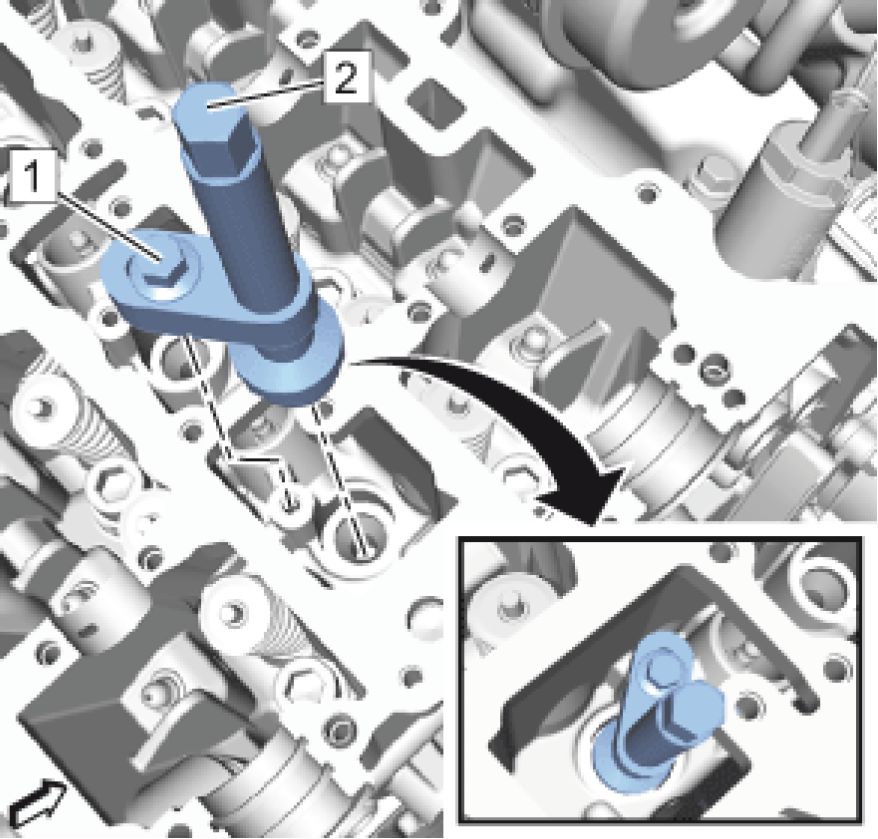 |
|
Fig. 110: Injector Port Service Plug |
10. Loosen the bolt. (1)
11. Remove the EN-51511 plug (2) from the injector bores.
12. Install Hydraulic Valve Lash Adjuster Arm. Refer to Hydraulic Valve Lash Adjuster Arm Replacement
13. Install Spark Plugs (Qty: 4). Refer to Spark Plug Replacement
14. Install Camshaft Cover. Refer to Camshaft Cover Replacement
POSITIVE CRANKCASE VENTILATION TUBE REPLACEMENT
 |
|
Fig. 111: Positive Crankcase Ventilation Tube |
|
Callout |
Component Name |
|
Preliminary Procedure Remove Intake Manifold Cover. Refer to Intake Manifold Cover Replacement | |
|
Positive Crankcase Ventilation Tube | |
|
1 |
CAUTION: |
Component Name
damaged
when the
PCV line is
removed. To
reduce the
risk of
damage to
the fittings,
use a
suitable
cutting tool
and carefully
cut the
connections
away.
Procedure
Using a suitable cutting tool, carefully cut the PCV tube away from the fittings at the air cleaner
outlet duct and the camshaft cover. If any damage occurs to either the air cleaner outlet duct or
camshaft cover fitting, they must be replaced. Refer to Air Cleaner Outlet Duct Replacement
POSITIVE CRANKCASE VENTILATION VALVE REPLACEMENT - FRESH AIR
Special Tools
EN-50956 Tamper Proof Drive Bit
Equivalent regional tools: Special Tools
Removal Procedure
 |
|
Fig. 112: Positive Crankcase Ventilation Valve, Tube And Bolt |
1. Remove and DISCARD Positive Crankcase Ventilation Tube (2). Refer to Positive Crankcase Ventilation
Tube Replacement
2. Using a suitable tool, cut a slot in the tamper-resistant positive crankcase ventilation fresh air bolt head (1) and
remove with a flat-bladed tool. DISCARD the bolt.
3. Remove Positive Crankcase Ventilation Valve (3)
Installation Procedure
 |
|
Fig. 113: Positive Crankcase Ventilation Valve, Tube, Bolt And Special Tool |
1. Install Positive Crankcase Ventilation Valve (4)
CAUTION: Refer to Fastener Caution
2. Install the NEW positive crankcase ventilation valve fresh air bolt (1) using EN-50956 bit (2), and tighten to
10 N.m (89 lb in).
NOTE: Install a new tube.
3. Install NEW Positive Crankcase Ventilation Tube (3). Refer to Positive Crankcase Ventilation Tube
Replacement
POSITIVE CRANKCASE VENTILATION VALVE REPLACEMENT - SECONDARY
Special Tools
EN-50956 Tamper Proof Drive Bit
Equivalent regional tools: Special Tools
Removal Procedure
 |
|
Fig. 114: Positive Crankcase Ventilation Valve, Tube And Bolt |
1. Remove and DISCARD Positive Crankcase Ventilation Tube (3). Refer to Positive Crankcase Ventilation
Tube Replacement
2. Using a suitable tool, cut a slot in the tamper-resistant positive crankcase ventilation fresh air bolt head (1) and
remove with a flat-bladed tool. DISCARD the bolt.
3. Remove Positive Crankcase Ventilation Valve (2)
Installation Procedure
 |
|
Fig. 115: Positive Crankcase Ventilation Valve, Tube, Bolt And Special Tool |
1. Install Positive Crankcase Ventilation Valve (2)
CAUTION: Refer to Fastener Caution
2. Install the NEW positive crankcase ventilation valve fresh air bolt (1) using EN-50956 bit (4), and tighten to
10 N.m (89 lb in).
NOTE: Install a new tube.
3. Install NEW Positive Crankcase Ventilation Tube (3). Refer to Positive Crankcase Ventilation Tube
Replacement
TIMING CHAIN UPPER GUIDE REPLACEMENT
 |
|
Fig. 116: Timing Chain Upper Guide Courtesy'of GENERAL'MOTORS'COMPANY |
|
Callout |
Component Name |
|
Preliminary Procedure Remove Camshaft Cover. Refer to Camshaft Cover Replacement | |
|
1 |
Timing Chain Guide Fastener (Qty: 2) CAUTION: Refer to Caution . Tighten 10 N.m (89 lb in) |
Upper Timing Chain Guide
2
TIMING CHAIN GUIDE REPLACEMENT - RIGHT SIDE
Removal Procedure
1. Remove Camshaft Timing Chain. Refer to Camshaft Timing Chain Replacement
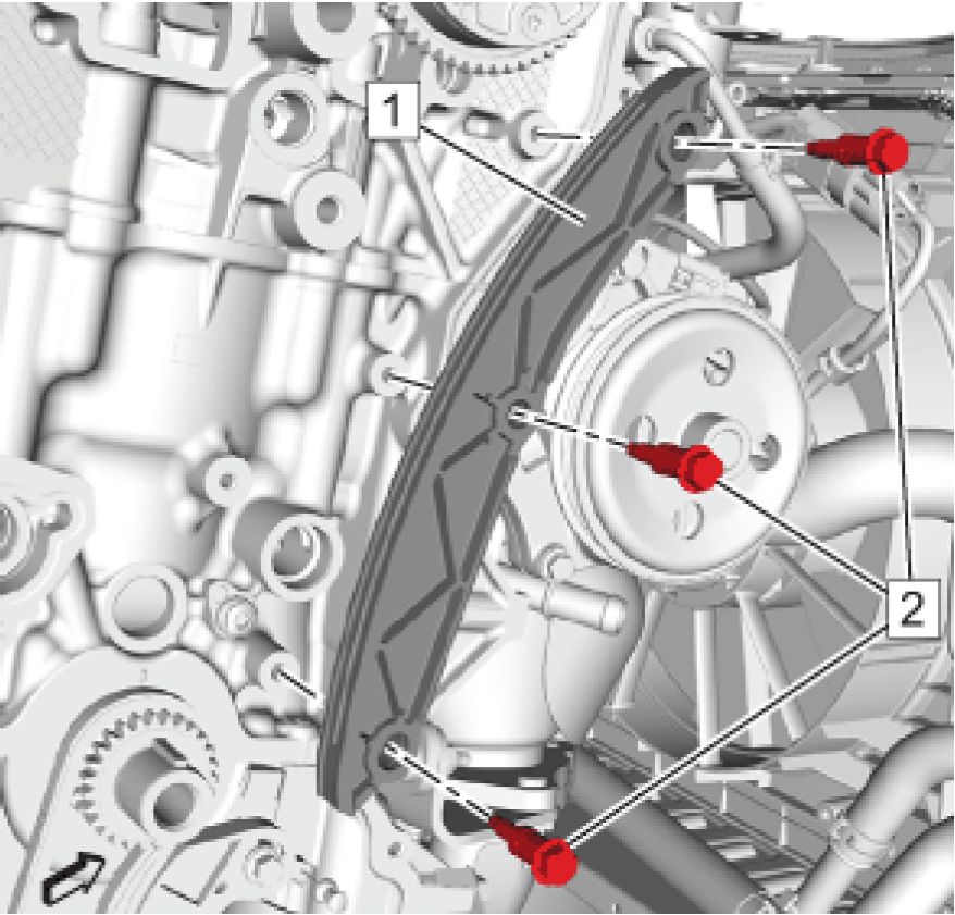 |
|
Fig. 117: Right Side Timing Chain Guide And Bolts |
2. Remove the 3 timing chain guide bolts (2).
3. Remove the timing chain guide - right side (1).
Installation Procedure
 |
|
Fig. 118: Right Side Timing Chain Guide And Bolts |
1. Install the timing chain guide - right side (1).
CAUTION: Refer to Fastener Caution .
2. Install the 3 timing chain guide bolts (2) and tighten to 10 N.m (89 lb in).
3. Install Camshaft Timing Chain. Refer to Camshaft Timing Chain Replacement
TIMING CHAIN TENSIONER REPLACEMENT
Special Tools
EN-51367 Camshaft Holder
Equivalent regional tools: Special Tools
Removal Procedure
1. Remove Camshaft Cover. Refer to Camshaft Cover Replacement
 |
|
Fig. 119: Crankshaft Balancer Markings |
2. Adjust the engine to cylinder 1 top dead center (TDC) of combustion stroke. Set crankshaft in direction of
engine rotation until the markings (1, 2) line up. Rotate at the crankshaft balancer bolt (3).

Fig. 120: Camshaft Holder
3. Install the EN-51367 holder (1).
4. Remove Engine Front Cover. Refer to Engine Front Cover Replacement
5. Remove Timing Chain Upper Guide. Refer to Timing Chain Upper Guide Replacement
 |
|
Fig. 121: Timing Chain Tensioner In Service Position |
6. Fix the timing chain tensioner with design 1 (1) in service position:
 |
|
Fig. 122: Releasing Tension From Piston |
1. Slightly release tension from the piston (2) until bar (1) can be unlocked by rotating the lever (3) in
direction of arrow.
 |
|
Fig. 123: Piston And Tensioner Lever |
2. Entirely push back the piston (1) until the tensioner lever (2) cannot be locked in this position.
 |
|
Fig. 124: Piston Courtesy'of GENERAL MOTORS COMPANY |
3. Release tension from the piston (1) until it releases for three ratchets. The three ratchets can be noticed
by the click noises.
 |
|
Fig. 125: Lever And Fixing Pin Courtesy'of GENERAL'MOTORS COMPANY |
4. Apply tension to the piston until the lever (1) is rotated back into the locking position where the bore in
the lever aligns with the bore in the tensioner housing.
5. Fix the lever in this position with a suitable fixing pin (2).
 |
|
Fig. 126: Timing Chain Tensioner Shoe And Bolt |
7. Remove Timing Chain Tensioner Shoe Bolt (1)
8. Remove Timing Chain Tensioner Shoe (2)
 |
|
Fig. 127: Timing Chain Tensioner Tool, Timing Chain Tensioner, Bolts And Gasket |
9. Ensure the correct fixation of the tool (3).
10. Remove Timing Chain Tensioner Bolts (4) (Qty: 2)
11. Remove Timing Chain Tensioner (1)
12. Remove and DISCARD the gasket. (2)
Installation Procedure
 |
|
Fig. 128: Timing Chain Tensioner Tool, Timing Chain Tensioner, Bolts And Gasket |
1. Install a NEW gasket. (2)
2. Install Timing Chain Tensioner (1)
CAUTION: Fastener Caution
3. Install and tighten Timing Chain Tensioner Bolts (4) (Qty:) to 25 N.m (18 lb ft)
 |
|
Fig. 129: Timing Chain Tensioner Shoe And Bolt |
4. Install Timing Chain Tensioner Shoe (2)
5. Install and tighten Timing Chain Tensioner Shoe Bolt (1) to 25 N.m (18 lb ft)
6. Remove the suitable tool from the timing chain tensioner.

Fig. 130: Camshaft Holder
Courtesy of GENERAL MOTORS COMPANY
7. Remove the EN-51367 holder (1).
8. Install Timing Chain Upper Guide. Refer to Timing Chain Upper Guide Replacement
9. Check the position of the crankshaft, camshaft and camshaft position actuator adjuster:
1. Install the engine front cover with 4 bolts and the crankshaft balancer.
 |
|
Fig. 131: Crankshaft Balancer Markings |
2. Turn crankshaft 720 degrees in the direction of engine rotation by the crankshaft balancer bolt (3).
 |
|
Fig. 132: Camshaft Holder Courtesy'of GENERAL'MOTORS COMPANY |
10. Install the EN-51367 holder (1).
11. If the EN-51367 holder (1) can be installed, the engine timing is properly adjusted.
12. Remove the EN-51367 holder.
13. Remove the engine front cover and crankshaft balancer.
14. Install Engine Front Cover. Refer to Engine Front Cover Replacement
15. Install Camshaft Cover. Refer to Camshaft Cover Replacement
TIMING CHAIN TENSIONER SHOE REPLACEMENT
Removal Procedure
1. Release tension from the timing chain tensioner. Refer to Timing Chain Tensioner Replacement.
 |
|
Fig. 133: Timing Chain Tensioner Shoe And Bolt |
2. Remove Timing Chain Tensioner Shoe Bolt (1)
3. Remove Timing Chain Tensioner Shoe (2)
Installation Procedure
 |
|
Fig. 134: Timing Chain Tensioner Shoe And Bolt |
1. Install Timing Chain Tensioner Shoe (2)
CAUTION: Refer to Fastener Caution .
2. Install and tighten Timing Chain Tensioner Shoe Bolt (1) to 25 N.m (18 lb ft)
3. Unlock the timing chain tensioner. Refer to Timing Chain Tensioner Replacement.
INTAKE MANIFOLD COVER REPLACEMENT
 |
|
Fig. 135: Intake Manifold Cover Courtesy'of GENERAl'mOTORS COMPANY |
|
Callout |
Component Name |
|
1 |
Upper Intake Manifold Cover Bolt CAUTION: Refer to Caution Tighten 10 N.m (89 lb in) |
|
2 |
Engine Oil Filler Cap |
|
3 |
Upper Intake Manifold Cover Procedure Release the upper intake manifold cover retainers by pulling the upper intake manifold cover |
UPPER INTAKE MANIFOLD COVER REPLACEMENT
Removal Procedure
WARNING: Always perform the High Voltage Disabling procedure prior to servicing any High
Voltage component or connection. Personal Protection Equipment (PPE) and proper
procedures must be followed.
The High Voltage Disabling procedure will perform the following tasks:
• Identify how to disable high voltage.
• Identify how to test for the presence of high voltage.
• Identify condition under which high voltage is always present and personal
protection equipment (PPE) and proper procedures must be followed.
Failure to follow the procedures exactly as written may result in serious injury or
death.
1. Disable the high voltage system. Refer to High Voltage Disabling
2. Remove Dash Upper Extension Panel Opening Cover. Refer to Dash Upper Extension Panel Opening Cover
Replacement
3. Remove Air Cleaner Outlet Duct. Refer to Air Cleaner Outlet Duct Replacement
4. Remove Exhaust Gas Recirculation Pipe. Refer to Exhaust Gas Recirculation Pipe Replacement
 |
|
Fig. 136: Upper Intake Manifold Cover And Bolts |
5. Remove Upper Intake Manifold Cover Bolts (2) (Qty: 3)
6. Remove Upper Intake Manifold Cover (1)
Installation Procedure
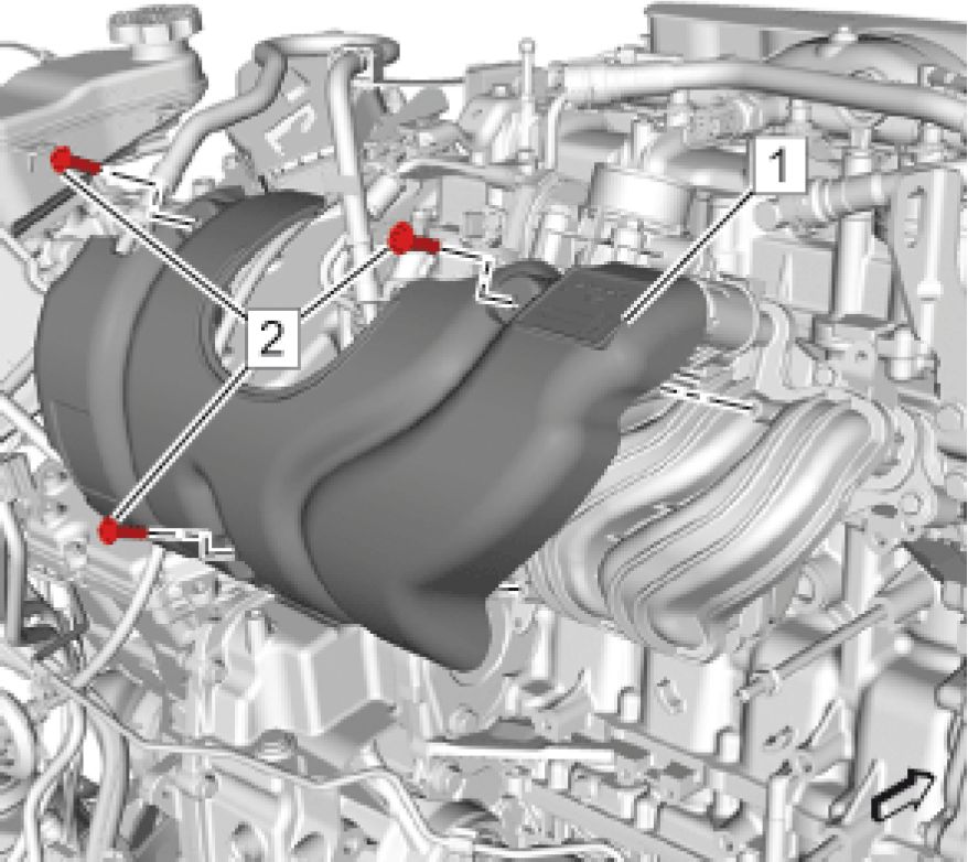 |
|
Fig. 137: Upper Intake Manifold Cover And Bolts |
1. Install Upper Intake Manifold Cover (1)
CAUTION: Refer to Fastener Caution
2. Install and tighten Upper Intake Manifold Cover Bolts (2) (Qty: 3) to 2.5 N.m (22 lb in)
3. Install Exhaust Gas Recirculation Pipe. Refer to Exhaust Gas Recirculation Pipe Replacement
4. Install Air Cleaner Outlet Duct. Refer to Air Cleaner Outlet Duct Replacement
5. Install Dash Upper Extension Panel Opening Cover. Refer to Dash Upper Extension Panel Opening Cover
Replacement
6. Enable the high voltage system. Refer to High Voltage Enabling
LOWER INTAKE MANIFOLD COVER REPLACEMENT
Removal Procedure
1. Remove Intake Manifold. Refer to Intake Manifold Replacement

Fig. 138: Lower Intake Manifold Cover And Bolts
Courtesy'of GENERAL'MOTORS'COMPANY
2. Remove Upper Intake Manifold Cover Bolts (1) (Qty: 3)
3. Remove Lower Intake Manifold Cover (2)
Installation Procedure
 |
|
Fig. 139: Lower Intake Manifold Cover And Bolts |
1. Install Lower Intake Manifold Cover (2)
CAUTION: Refer to Fastener Caution
2. Install and tighten Upper Intake Manifold Cover Bolts (1) (Qty: 3) to 2.5 N.m (22 lb in)
3. Install Intake Manifold. Refer to Intake Manifold Replacement
INTAKE MANIFOLD REPLACEMENT
Special Tools
EN-6015 Closure Plugs
Equivalent regional tools: Special Tools (Diagnostic Tools) Special Tools (Repair Tools)
Removal Procedure
WARNING: Always perform the High Voltage Disabling procedure prior to servicing any High
Voltage component or connection. Personal Protection Equipment (PPE) and proper
procedures must be followed.
The High Voltage Disabling procedure will perform the following tasks:
• Identify how to disable high voltage.
• Identify how to test for the presence of high voltage.
• Identify condition under which high voltage is always present and personal
protection equipment (PPE) and proper procedures must be followed.
Failure to follow the procedures exactly as written may result in serious injury or
death.
1. Disable the high voltage system. Refer to High Voltage Disabling
2. Remove Dash Upper Extension Panel Opening Cover. Refer to Dash Upper Extension Panel Opening Cover
Replacement
3. Remove Air Cleaner Outlet Duct. Refer to Air Cleaner Outlet Duct Replacement
4. Remove Evaporative Emission Canister Purge Solenoid Valve. Refer to Evaporative Emission Canister
Purge Solenoid Valve Replacement
5. Remove Throttle Body Assembly. Refer to Throttle Body Assembly Replacement
6. Remove Manifold Absolute Pressure Sensor. Refer to Manifold Absolute Pressure Sensor Replacement
7. Remove Exhaust Gas Recirculation Pipe. Refer to Exhaust Gas Recirculation Pipe Replacement

Fig. 140: Fuel Feed Front Pipe And Fuel Injection Pump
Courtesy'of GENERAL'MOTORS'COMPANY
8. Disconnect Fuel Feed Front Pipe (2) @ Fuel Injection Pump (1)
9. Close all open connections with the EN-6015 plugs.
 |
|
Fig. 141: Air Cleaner Resonator Bracket, Retainers And Bolt |
10. Unclip Retainers (1) (Qty: 2)
11. Remove Bolt (3)
12. Remove the air cleaner resonator bracket (2).
 |
|
Fig. 142: A/C High Pressure Cutoff Switch, Electrical Connector, Retainer And Engine Wiring Harness |
13. Disconnect the electrical connector (2) from the air conditioning high pressure cutoff switch (1).
14. Unclip Retainer (3)
15. Position aside Engine Wiring Harness (4)

Fig. 143: Intake Manifold And Bolts
Courtesy of GENERAL MOTORS COMPANY
NOTE: Keep the fasteners in position on the assembly.
16. Loosen Bolts (2) (Qty: 5) @ Intake Manifold (1)
 |
|
Fig. 144: Intake Manifold And Gasket Courtesy'of GENERAL'MOTORS'COMPANY |
17. Remove Intake Manifold (1)
18. Remove and DISCARD the gasket. (2)
Disassemble Procedure
1. Remove Upper Intake Manifold Cover. Refer to Upper Intake Manifold Cover Replacement
2. Remove Lower Intake Manifold Cover. Refer to Lower Intake Manifold Cover Replacement
Assemble Procedure
1. Install Upper Intake Manifold Cover. Refer to Upper Intake Manifold Cover Replacement
2. Install Lower Intake Manifold Cover. Refer to Lower Intake Manifold Cover Replacement

Fig. 145: Intake Manifold And Gasket
Courtesy of GENERAL MOTORS COMPANY
1. Install a NEW gasket. (2)
2. Install Intake Manifold (1)

Fig. 146: Intake Manifold And Bolts
Courtesy of GENERAL MOTORS COMPANY
NOTE: Keep the fasteners in position on the assembly.
3. Install Bolts (2) (Qty: 5) @ Intake Manifold
 |
|
Fig. 147: Intake Manifold Bolt Tightening Sequence |
CAUTION: Refer to:Fastener Caution
4. Tighten the 5 intake Manifold Bolts to 12 N.m (106 lb in) in the sequence as shown.
 |
|
Fig. 148: A/C High Pressure Cutoff Switch, Electrical Connector, Retainer And Engine Wiring Harness |
5. Reposition Engine Wiring Harness (4)
6. Install Retainer (3)
7. Connect the electrical connector (2) to the air conditioning high pressure cutoff switch (1).
 |
|
Fig. 149: Air Cleaner Resonator Bracket, Retainers And Bolt |
8. Install the air cleaner resonator bracket (2).
9. Install and tighten Bolt (3) to 9 N.m (80 lb in)
10. Install Retainers (1) (Qty: 2)
 |
|
Fig. 150: Fuel Feed Front Pipe And Fuel Injection Pump |
11. Remove all EN-6015 plugs from the connections.
12. Connect Fuel Feed Front Pipe (2) @ Fuel Injection Pump (1)
13. Install Exhaust Gas Recirculation Pipe. Refer to Exhaust Gas Recirculation Pipe Replacement
14. Install Manifold Absolute Pressure Sensor. Refer to Manifold Absolute Pressure Sensor Replacement
15. Install Throttle Body Assembly. Refer to Throttle Body Assembly Replacement
16. Install Evaporative Emission Canister Purge Solenoid Valve. Refer to Evaporative Emission Canister Purge
Solenoid Valve Replacement
17. Install Air Cleaner Outlet Duct. Refer to Air Cleaner Outlet Duct Replacement
18. Install Dash Upper Extension Panel Opening Cover. Refer to Dash Upper Extension Panel Opening Cover
Replacement
19. Enable the high voltage system. Refer to High Voltage Enabling
CATALYTIC CONVERTER BRACE BRACKET REPLACEMENT
Removal Procedure
1. Remove Three-Way Catalytic Converter. Refer to Three-Way Catalytic Converter Replacement
 |
|
Fig. 151: Catalytic Converter Brace Bracket And Bolts |
2. Remove Catalytic Converter Brace Bracket Bolts (2) (Qty: 2)
3. Remove Catalytic Converter Brace Bracket (1)
Installation Procedure
 |
|
Fig. 152: Catalytic Converter Brace Bracket And Bolts |
1. Install Catalytic Converter Brace Bracket (1)
CAUTION: Refer to Fastener Caution
2. Install and tighten Catalytic Converter Brace Bracket Bolts (2) (Qty: 2) to 22 N.m (16 lb ft)
3. Install Three-Way Catalytic Converter. Refer to Three-Way Catalytic Converter Replacement
CATALYTIC CONVERTER BRACKET REPLACEMENT - LOWER
Removal Procedure
1. Remove Three-Way Catalytic Converter. Refer to Three-Way Catalytic Converter Replacement
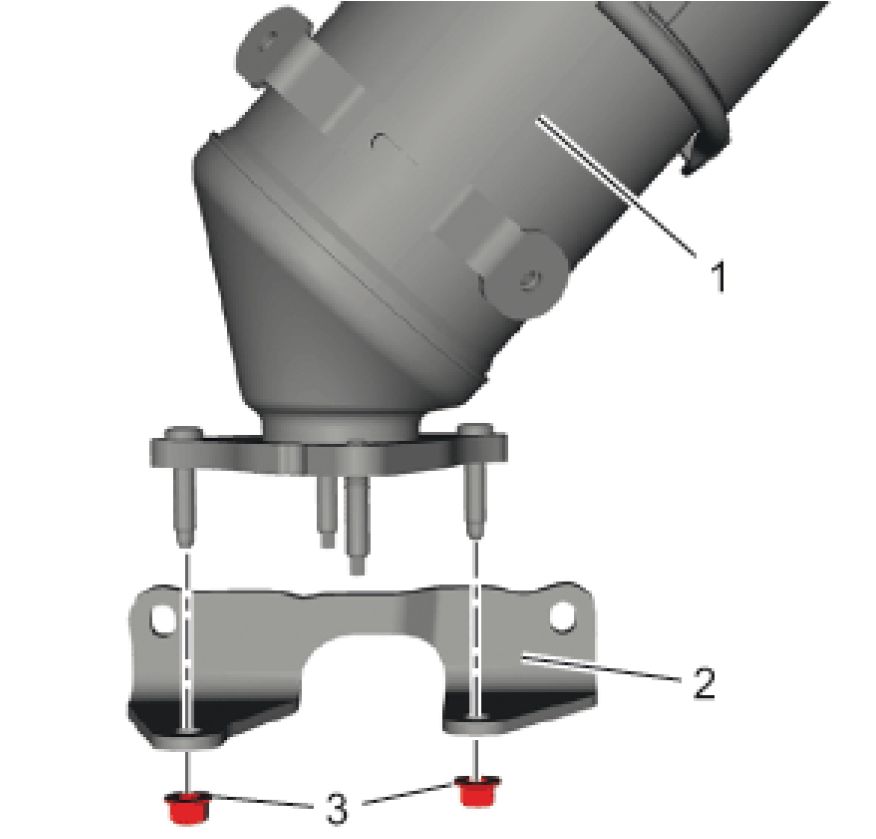 |
|
Fig. 153: Catalytic Converter, Bracket And Nuts |
2. Remove the 2 catalytic converter bracket nuts (3).
3. Remove the catalytic converter bracket (2) from the catalytic converter (1).
Installation Procedure
 |
|
Fig. 154: Catalytic Converter, Bracket And Nuts Courtesy of GENERAL MOTORS COMPANY |
1. Install the catalytic converter bracket (2) to the catalytic converter (1).
CAUTION: Refer to Fastener Caution
2. Install the catalytic converter bracket nuts (3) (Qty: 2) and tighten to 22 N.m (16 lb ft)
3. Install Three-Way Catalytic Converter. Refer to Three-Way Catalytic Converter Replacement
CRANKSHAFT BALANCER REPLACEMENT
Special Tools
• EN-44226 Crankshaft Balancer Remover
• EN-44226-5 Crankshaft Protector
• EN-45059 Angle Meter
• EN-51368 Front Crankshaft Seal Installer
Equivalent regional tools: Special Tools
Removal Procedure
1. Remove Water Pump Belt. Refer to Water Pump Belt Replacement
 |
|
Fig. 155: Crankshaft Balancer, Special Tools And Bolt |
2. Install the EN-44226-1 remover (2) to the crankshaft balancer (1).
3. Loosen the crankshaft balancer bolt (3) by counter holding the crankshaft balancer (1) with the EN-44226-1
remover (3) and suitable tool.
4. Remove the EN-44226-1 remover.
5. Remove Crankshaft Balancer Bolt

Fig. 156: Protector And Crankshaft
Courtesy of GENERAL MOTORS COMPANY
6. Install the EN-44226-5 protector (1) to the crankshaft (2).
 |
|
Fig. 157: Remover Plate Assembly And Balancer |
7. Install EN-44226-1 remover (2) and EN-44226-2 remover plate (3) onto the balancer (4).
8. Install the EN-44226-3 remover screw (1) through the EN-44226-2 remover plate and against the EN-44226-5
protector.
9. Counter hold the EN-44226-2 remover plate and turn the EN-51368 installer screw to remove the balancer.
10. Remove the EN-44226 remover.
11. Remove the crankshaft balancer (4).
12. Remove the EN-44226-5 protector.
Installation Procedure
 |
|
Fig. 158: Crankshaft Balancer And Installer Tool |
1. Install Crankshaft Balancer (1) @ Crankshaft (2)
2. Install the EN-51368 installer (3).
3. Install the crankshaft balancer by screwing the flange from EN-51368 installer.
4. Remove the EN-51368 installer.
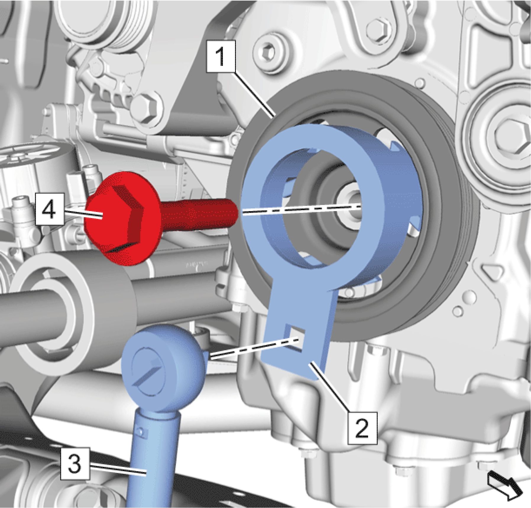 |
|
Fig. 159: Crankshaft Balancer, Special Tools And Bolt |
5. Install and hand tighten the crankshaft balancer bolt (3).
6. Install the EN-44226-1 remover (2) to the crankshaft balancer (1).
CAUTION: Refer to Fastener Caution
CAUTION: Refer to Torque-to-Yield Fastener Caution
7. Tighten the crankshaft balancer bolt (3) by counter holding the crankshaft balancer (1) with the EN-44226-1
(3) and torque wrench.
1. First pass to 100 N.m (74 lb ft).
2. Loosen the bolt to 360 degrees.
3. Final pass to an additional 180 degrees, using the EN-45059 meter.
8. Remove EN-44226-1 remover (2) from the crankshaft balancer (1).
9. Install Water Pump Belt. Refer to Water Pump Belt Replacement
CRANKSHAFT POSITION SENSOR RELUCTOR RING REPLACEMENT
Removal Procedure
1. Remove Automatic Transmission Flex Plate. Refer to Automatic Transmission Flex Plate Replacement
 |
|
Fig. 160: Crankshaft Position Sensor Reluctor Ring |
2. Remove the crankshaft position sensor reluctor ring. (2)
Installation Procedure
 |
|
Fig. 161: Crankshaft Position Sensor Reluctor Ring |
CAUTION: Refer to Crankshaft Position Sensor Reluctor Ring Caution .
1. Install the crankshaft position sensor reluctor ring. (2)
2. Install the pin (3) into the correct hole (1).
3. Install Automatic Transmission Flex Plate. Refer to Automatic Transmission Flex Plate Replacement
CRANKSHAFT FRONT OIL SEAL REPLACEMENT
Special Tools
• EN-51368 Front Crankshaft Seal Installer
• DT-6125-B Slide Hammer
• DT-23129 Seal Remover
Equivalent regional tools: Special Tools
Removal Procedure
1. Remove Crankshaft Balancer. Refer to Crankshaft Balancer Replacement
 |
|
Fig. 162: Identifying Crankshaft Front Oil Seal Designs |
NOTE: The engine can be equipped with two different front oil seal designs.
2. Check which one of crankshaft front oil seals (1, 2) is installed.
 |
|
Fig. 163: Crankshaft Front Oil Seal And Removal Tool |
3. Install the DT-6125-B hammer (3) to DT-23129 seal remover (1).
4. Install the DT-6125-B hammer with the DT-23129 seal remover behind the crankshaft front oil seal (2).
5. Remove the crankshaft front oil seal (2), use the DT-6125-B hammer.
Installation Procedure
 |
|
Fig. 164: Identifying Crankshaft Front Oil Seal Designs Courtesy'of GENERAL'MOTORS'COMPANY |
NOTE: The engine can be equipped with two different front oil seal designs.
1. Check which one of crankshaft front oil seals (1, 2) is installed.
 |
|
Fig. 165: Crankshaft Front Oil Seal And Installer Tool (First Design) Courtesy'of GENERAL'MOTORS'COMPANY |
2. For front oil seal first design, use the following procedure:
NOTE: The special tool EN-51368 seal installer can be used in two positions,
depending which crankshaft front oil seal type is used.
3. Install the crankshaft front oil seal (1) to the EN-51368 seal installer (2) with the notch on the surface (3).
|
1 2 |
 |
|
3 |
Fig. 166: Crankshaft Front Oil Seal And Installer Tool (Second Design)
Courtesy'of GENERAL'MOTORS'COMPANY
4. For front oil seal second design, use the following procedure:
NOTE: The special tool EN-51368 seal installer can be used in two positions,
depending which crankshaft front oil seal type is used.
5. Install the crankshaft front oil seal (1) to the EN-51368 seal installer (2) with the plane surface (3).
 |
|
Fig. 167: Installing Crankshaft Front Oil Seal Courtesy'of GENERAL'MOTORS'COMPANY |
CAUTION: Be careful that the crankshaft front oil seal does not deform while installing.
Failing to do so may reduce the leak-tightness and could cause damage to the
crankshaft.
6. Press the crankshaft front oil seal into the correct seat, by tightening the nut (2) from the EN-51368 seal
installer (1).
7. Remove the EN-51368 seal installer.
8. Check the correct seat of the crankshaft front oil seal.
9. Install Crankshaft Balancer. Refer to Crankshaft Balancer Replacement
CRANKSHAFT REAR OIL SEAL REPLACEMENT
Special Tools
EN-51369 Rear Crankshaft Seal Installer
Equivalent regional tools: Special Tools
Removal Procedure
1. Remove Crankshaft Position Sensor Reluctor Ring. Refer to Crankshaft Position Sensor Reluctor Ring
Replacement
 |
|
Fig. 168: Identifying Crankshaft Rear Oil Seals Courtesy'of GENERAL'MOTORS'COMPANY |
NOTE: The engine could be equipped with two different rear oil seal designs.
2. Check which of the crankshaft rear oil seals (1, 2) are installed.

Fig. 169: Removing Crankshaft Rear Oil Seal
CAUTION: Be careful that the crankshaft will not be damaged while the crankshaft rear oil
seal is pulled out. Failing to do so may reduce the leak-tightness and could
cause damage to the crankshaft.
3. Use a suitable tool to remove the seal.
4. Remove Crankshaft Rear Oil Seal (1)
Installation Procedure
 |
|
Fig. 170: RTV Sealant Application Points |
1. Inspect the seal recess (1) for excess sealer material at the lower crankcase to engine block mating location.
2. Remove excess sealer, if present.
3. Add RTV sealer at the 2 locations (1) where the bed plate and block join prior to installing the oil seal. Refer to
Adhesives, Fluids, Lubricants, and Sealers.
 |
|
Fig. 171: Oil Seal And Installer Courtesy'of GENERAL'MOTORS COMPANY |
NOTE: The oil seal must be installed in the correct direction. The side that faces out
will have "this side out" printed on it. Depending on seal design, the way the
seal is installed on the EN-51369 installer is opposite. Either the seal is
installed over the back of the installer, or the seal is installed over the front of
the installer. Match the seal design as shown above and install the seal onto
the installer in the correct direction.
4. Install the oil seal (1, 2) in the correct direction on the EN-51369 installer.
NOTE: If the seal is improperly installed on the special tool, it will not install correctly.
5. Inspect the seal on EN-51369 installer, and ensure that the seal lip is not deformed. If necessary, remove the
seal and reinstall on the special tool.
NOTE: The special tool installs and establishes the proper depth of the seal in the
crankshaft seal bore.
6. Use EN-51369 installer to press the new crankshaft seal into the housing.
 |
|
Fig. 172: Crankshaft Rear Oil Seal Installed Properly Courtesy'of GENERAL'MOTORS'COMPANY |
7. Ensure that the crankshaft rear oil seal (1) is installed in the crankshaft seal bore flush to 0.5 mm (0.2 in) depth
(2).
CRANKSHAFT SPROCKET REPLACEMENT
Removal Procedure
1. Remove Oil Pump Drive Chain. Refer to Oil Pump Drive Chain Replacement
 |
|
Fig. 173: Crankshaft Sprocket And Balancer Key |
2. Remove Crankshaft Sprocket (1)
3. Remove the crankshaft balancer key. (2)
Installation Procedure
 |
|
Fig. 174: Crankshaft Sprocket And Balancer Key |
1. Install the crankshaft balancer key (2).
2. Align the keyway of the crankshaft sprocket with the crankshaft balancer key.
3. Install Crankshaft Sprocket (1).
4. Install Oil Pump Drive Chain. Refer to Oil Pump Drive Chain Replacement
CRANKSHAFT OIL DEFLECTOR REPLACEMENT
Removal Procedure
1. Remove Upper Oil Pan. Refer to Upper Oil Pan Replacement
 |
|
Fig. 175: Positive Crankcase Ventilation Oil Separator Drain Pipe, Bolt And Seal |
2. Remove and DISCARD the positive crankcase ventilation oil separator drain pipe bolt (4).
3. Remove the positive crankcase ventilation oil separator drain pipe (2).
4. Remove and the positive crankcase ventilation oil separator seal (1). Check for damage.
 |
|
Fig. 176: Crankshaft Oil Deflector And Bolts |
5. Remove and DISCARD the 3 crankshaft oil deflector bolts (3).
6. Remove the crankshaft oil deflector. (1)
Installation Procedure
 |
|
Fig. 177: Crankshaft Oil Deflector And Bolts Courtesy'of GENERAL'MOTORS'COMPANY |
1. Install the crankshaft oil deflector (1).
CAUTION: Refer to Fastener Caution .
2. Install the 3 NEW crankshaft oil deflector bolts (3) and tighten to 10 N.m (89 lb in).
 |
|
Fig. 178: Positive Crankcase Ventilation Oil Separator Drain Pipe, Bolt And Seal |
3. Install the positive crankcase ventilation oil separator seal (1).
4. Install the positive crankcase ventilation oil separator drain pipe (2).
5. Install the NEW positive crankcase ventilation oil separator drain pipe bolt (4) and tighten to 10 N.m (89 lb
in).
6. Install Upper Oil Pan. Refer to Upper Oil Pan Replacement
ENGINE LIFT FRONT BRACKET REPLACEMENT
Removal Procedure
1. Remove Air Cleaner Outlet Duct. Refer to Air Cleaner Outlet Duct Replacement
 |
|
Fig. 179: Engine Wiring Harness And Retainer |
2. Remove the retainer that secures the cable to the bracket. (1)
3. Position aside Engine Wiring Harness (2).
 |
|
Fig. 180: Engine Lift Bracket Bolt And Bolts |
4. Remove Engine Lift Bracket Bolts (2) (Qty: 2)
5. Remove Engine Lift Bracket (1)
Installation Procedure
 |
|
Fig. 181: Engine Lift Bracket Bolt And Bolts |
1. Install Engine Lift Bracket (1)
CAUTION: Refer to Fastener Caution
2. Install and tighten Engine Lift Bracket Bolts (2) (Qty: 2) to 25 N.m (18 lb ft)
 |
|
Fig. 182: Engine Wiring Harness And Retainer Courtesy'of GENERAL MOTORS'COMPANY |
3. Reposition Engine Wiring Harness (2)
4. Install the retainer. (1)
5. Install Air Cleaner Outlet Duct. Refer to Air Cleaner Outlet Duct Replacement
ENGINE LIFT REAR BRACKET REPLACEMENT
 |
|
Fig. 183: Engine Lift Rear Bracket Courtesy'of GENERAL'MOTORS COMPANY |
|
Callout |
Component Name |
|
Preliminary Procedure Remove Three-Way Catalytic Converter. Refer to Three-Way Catalytic Converter Replacement | |
|
1 |
Engine Lift Bracket Bolt (Qty: 2) CAUTION: Refer to Caution Tighten 25 N.m (18 lb ft) |
|
2 |
Engine Lift Rear Bracket |
CYLINDER HEAD REPLACEMENT
Special Tools
• EN-6015 Closure Plugs
• EN-36857 Engine Lift Bracket
• EN-45059 Angle Meter
• EN-51367 Camshaft Holder
Equivalent regional tools: Special Tools
Removal Procedure
WARNING: Always perform the High Voltage Disabling procedure prior to servicing any High
Voltage component or connection. Personal Protection Equipment (PPE) and proper
procedures must be followed.
The High Voltage Disabling procedure will perform the following tasks:
• Identify how to disable high voltage.
• Identify how to test for the presence of high voltage.
• Identify condition under which high voltage is always present and personal
protection equipment (PPE) and proper procedures must be followed.
Failure to follow the procedures exactly as written may result in serious injury or
death.
1. Disable the high voltage system. Refer to High Voltage Disabling
2. Remove Air Cleaner Assembly. Refer to Air Cleaner Assembly Replacement
3. Remove Exhaust Gas Recirculation Valve. Refer to Exhaust Gas Recirculation Valve Replacement
4. Remove Camshaft Cover. Refer to Camshaft Cover Replacement
5. Remove Intake Manifold. Refer to Intake Manifold Replacement
6. Remove Three-Way Catalytic Converter. Refer to Three-Way Catalytic Converter Replacement
7. Remove Water Outlet. Refer to Water Outlet Replacement
8. Drain the engine oil. Refer to Draining Fluids and Oil Filter Removal
 |
|
Fig. 184: Electrical Connector And Fuel Injection Pump |
9. Disconnect Electrical Connector (1) @ Fuel Injection Pump
10. Remove Water Pump Belt. Refer to Water Pump Belt Replacement
 |
|
Fig. 185: Crankshaft Balancer Markings Courtesy'of GENERAL'MOTORS'COMPANY |
11. Adjust the engine to cylinder 1 top dead center (TDC) of combustion stroke. Set crankshaft in direction of
engine rotation until the markings (1, 2) line up. Rotate at the crankshaft balancer bolt (3).
12. Remove Crankshaft Balancer. Refer to Crankshaft Balancer Replacement
13. Lower the vehicle.
14. Remove Engine Mount Bracket. Refer to Engine Mount Bracket Replacement
 |
|
Fig. 186: Oil Pan Bolts And Upper Oil Pan |
15. Remove the 3 oil pan bolts (1) from the upper oil pan.
 |
|
Fig. 187: Engine Front Cover Bolts |
16. Remove Engine Front Cover Bolts (2, 4) (Qty: 12)
17. Remove Engine Front Cover Bolt (1)
18. Remove Engine Front Cover Bolt (3)
 |
|
Fig. 188: Engine Front Cover Pry Points |
19. Loosen the engine front carefully from the engine, use a suitable tool at the location as shown to pry (1, 2, 3).
 |
|
Fig. 189: Engine Front Cover And Crankshaft Front Oil Seal |
20. Remove Engine Front Cover (1)
21. Remove Crankshaft Front Oil Seal (2)
 |
|
Fig. 190: Camshaft Holder Courtesy'of GENERAL'MOTORS COMPANY |
22. Install the EN-51367 holder (1).
23. Remove Timing Chain Upper Guide. Refer to Timing Chain Upper Guide Replacement
 |
|
Fig. 191: Timing Chain Tensioner In Service Position |
24. Fix the timing chain tensioner with design (1) in service position:
 |
|
Fig. 192: Releasing Tension From Piston |
1. Slightly release tension from the piston (2) until bar (1) can be unlocked by rotating the lever (3) in
direction of arrow.
 |
|
Fig. 193: Piston And Tensioner Lever |
2. Entirely push back the piston (1) until the tensioner lever (2) cannot be locked in this position.
 |
|
Fig. 194: Piston Courtesy'of GENERAL MOTORS COMPANY |
3. Release tension from the piston (1) until it releases for three ratchets. The three ratchets can be noticed
by the click noises.
 |
|
Fig. 195: Lever And Fixing Pin Courtesy'of GENERAl'mOTORS COMPANY |
4. Apply tension to the piston until the lever (1) is rotated back into the locking position where the bore in
the lever aligns with the bore in the tensioner housing.
5. Fix the lever in this position with a suitable fixing pin (2).
 |
|
Fig. 196: Timing Chain Tensioner Shoe And Bolt |
25. Remove Timing Chain Tensioner Shoe Bolt (1)
26. Remove Timing Chain Tensioner Shoe (2)
 |
|
Fig. 197: Timing Chain Tensioner Tool, Timing Chain Tensioner, Bolts And Gasket |
27. Ensure the correct fixation of the tool (3).
28. Remove Timing Chain Tensioner Bolt (4) (Qty: 2)
29. Remove Timing Chain Tensioner (1)
30. Remove and DISCARD the gasket. (2)
 |
|
Fig. 198: Timing Chain Courtesy'of GENERAL MOTORS COMPANY |
31. Remove Timing Chain (1)
 |
|
Fig. 199: Right Side Timing Chain Guide And Bolts |
32. Remove Timing Chain Guide Bolts (2) (Qty: 3)
33. Remove Timing Chain Guide (1)
 |
|
Fig. 200: Engine Lift Bracket, Fixture Hook And Bolt |
NOTE: Use a device to support the engine while repositioning the lift hook.
34. Install the EN-36857 engine lift bracket (2) then install the fastener (1).
35. Reposition the engine support fixture hook (3) to the newly installed EN-36857 engine lift bracket (2).
 |
|
Fig. 201: Cylinder Head Bolt Loosening/Tightening Sequence |
36. Loosen the 10 cylinder head bolts in sequence as shown.
 |
|
Fig. 202: Cylinder Head, Bolts And Gasket |
CAUTION: In order to prevent damage to the valves and injectors during cylinder head
removal, set the cylinder head on blocks.
37. Remove and DISCARD Cylinder Head Bolts (2) (Qty: 10)
38. Remove Cylinder Head (1)
39. Remove and DISCARD Cylinder Head Gasket (3).
40. In case of re-use, then clean and inspect the cylinder head. Refer to Cylinder Head Cleaning and Inspection.
Disassemble Procedure
1. Remove Fuel Injection Pump. Refer to Fuel Injection Pump Replacement
2. Remove Engine Lift Front Bracket. Refer to Engine Lift Front Bracket Replacement
3. Remove Engine Lift Rear Bracket. Refer to Engine Lift Rear Bracket Replacement
4. Remove Exhaust Camshaft. Refer to Exhaust Camshaft Replacement
5. Remove Intake Camshaft. Refer to Intake Camshaft Replacement
6. Remove Hydraulic Valve Lash Adjuster Arm. Refer to Hydraulic Valve Lash Adjuster Arm Replacement
7. Remove Hydraulic Valve Lash Adjuster. Refer to Hydraulic Valve Lash Adjuster Replacement
8. Disassembly cylinder head. Refer to Cylinder Head Disassemble
Assemble Procedure
1. Assemble cylinder head. Refer to Cylinder Head Assemble
2. Install Hydraulic Valve Lash Adjuster. Refer to Hydraulic Valve Lash Adjuster Replacement
3. Install Hydraulic Valve Lash Adjuster Arm. Refer to Hydraulic Valve Lash Adjuster Arm Replacement
4. Install Intake Camshaft. Refer to Intake Camshaft Replacement
5. Install Exhaust Camshaft. Refer to Exhaust Camshaft Replacement
6. Install Engine Lift Rear Bracket. Refer to Engine Lift Rear Bracket Replacement
7. Install Engine Lift Front Bracket. Refer to Engine Lift Front Bracket Replacement
8. Install Fuel Injection Pump. Refer to Fuel Injection Pump Replacement
Installation Procedure
1. Clean all sealing surfaces.
2. Inspect the flatness of cylinder head and the engine block sealing surfaces.
 |
|
Fig. 203: Cylinder Head, Bolts And Gasket |
NOTE: Ensure that the cylinder head and the cylinder block sealing surfaces are clear
of oil, grease and old gasket material.
3. Install a NEW cylinder head gasket (3).
4. Install Cylinder Head (1)
5. Install, but do NOT tighten NEW Cylinder Head Bolts (2) (Qty: 10) - Use NEW bolts.

Fig. 204: Cylinder Head Bolt Tightening Sequence
Courtesy'of GENERAL'MOTORS'COMPANY
CAUTION: Refer to Fastener Caution
CAUTION: Refer to Torque-to-Yield Fastener Caution
6. Tighten Cylinder Head Bolts (2) (Qty: 10) in sequence
1. First Pass: 25 N.m (18 lb ft).
2. Second Pass: 30 N.m (22 lb ft)
3. Final Pass: 240 degrees, use the EN-45059 meter.
 |
|
Fig. 205: Engine Lift Bracket, Fixture Hook And Bolt |
NOTE: Use a device to support the engine while repositioning the lift hook.
7. Remove Bolt (1)
8. Reposition the lift hook (3) from the EN-36857 engine lift bracket (2) to the cylinder head lift bracket.
9. Remove EN-36857 engine lift bracket
10. Remove the suitable device holding the engine during lift hook repositioning.
 |
|
Fig. 206: Right Side Timing Chain Guide And Bolts |
11. Install Timing Chain Guide (1)
12. Install and tighten Timing Chain Guide Bolts (2) (Qty: 3) to 10 N.m (89 lb in)

Fig. 207: Timing Chain
Courtesy'of GENERAL MOTORS COMPANY
NOTE: Ensure the actuator timing marks are approximately the 12 o'clock position.
13. Install Timing Chain (1)
 |
|
Fig. 208: Timing Chain Marks Courtesy'of GENERAl'mOTORS COMPANY |
14. Ensure that the colored link (3) matches to the arrow on the crankshaft sprocket.
15. Ensure that the colored links (1, 2) match to the marks on the camshaft position adjuster actuators.
 |
|
Fig. 209: Timing Chain Tensioner Tool, Timing Chain Tensioner, Bolts And Gasket |
16. Install a NEW gasket. (2)
17. Install Timing Chain Tensioner (1)
18. Install and tighten Timing Chain Tensioner Bolts (4) (Qty: 2) 25 N.m (18 lb ft)
 |
|
Fig. 210: Timing Chain Tensioner Shoe And Bolt |
19. Install Timing Chain Tensioner Shoe (2)
20. Install and tighten Timing Chain Tensioner Shoe Bolt (1) to 25 N.m (18 lb ft)
21. Remove the suitable tool (3) from the timing chain tensioner.

Fig. 211: Camshaft Holder
Courtesy of GENERAL MOTORS COMPANY
22. Remove the EN-51367 holder (1).
23. Install Timing Chain Upper Guide. Refer to Timing Chain Upper Guide Replacement
24. Check the position of the crankshaft, camshaft and camshaft position actuator adjuster:
1. Install the engine front cover with 4 bolts and the crankshaft balancer.
 |
|
Fig. 212: Crankshaft Balancer Markings |
2. Turn crankshaft 720 degrees in the direction of engine rotation by the crankshaft balancer bolt (3).

Fig. 213: Camshaft Holder
Courtesy of GENERAL MOTORS COMPANY
25. Install the EN-51367 holder (1).
26. If the EN-51367 holder (1) can be installed, the engine timing is properly adjusted.
27. Remove the EN-51367 holder.
28. Remove the engine front cover and crankshaft balancer.
 |
|
Fig. 214: Coiled Spring Pins And Engine Front Cover |
29. Gently tap coiled spring pins (1) back into front cover so they are flush with front cover sealing surface.
 |
|
Fig. 215: Engine Front Cover Sealant Application Areas |
NOTE: The lower crankcase and oil pan mating surfaces must be free of
contamination prior to applying the sealer.
Install and align the oil pan to block within 20 minutes of applying the sealer.
The oil pan must be fastened to final torque specification within 60 minutes of
applying the sealer.
Additional sealant is necessary to reduce the possibility of leakage where the
cylinder head to engine block interface along the bead path flange on the front
cover.
30. Apply approximately a 4 mm (0.16 in) thick bead of engine front cover sealant (2) to the engine lower front
cover. Refer to Adhesives, Fluids, Lubricants, and Sealers for the recommended sealant.
31. Apply a 3 mm (0.12 in) bead of sealer circling 3 locations (1) on the interior of the engine front cover.
 |
|
Fig. 216: Oil Pan Sealant Application Areas |
32. Apply a 3 mm (0.12 in) bead of sealer circling 3 locations (1) on the oil pan. Refer to Adhesives, Fluids,
Lubricants, and Sealers for the recommended sealant.
 |
|
Fig. 217: Engine Front Cover And Bolts |
33. Install Engine Front Cover (1)
34. Install Engine Front Cover Bolts (2) (Qty: 2)
35. Hand tighten the bolts.
 |
|
Fig. 218: Coiled Spring Pins And Engine Front Cover |
36. Gently tap coiled spring pins (1) back into cover until pins are flush with front cover (2).
 |
|
Fig. 219: Engine Front Cover Bolts |
37. Install Engine Front Cover Bolt (2, 4) (Qty: 10)
38. Install Engine Front Cover Bolt (1)
39. Install Engine Front Cover Bolt (3)
 |
|
Fig. 220: Engine Front Cover Bolt Tightening Sequence |
40. Tighten the bolts in the sequence shown.
41. Tighten Engine Front Cover Bolt (2) to 58 N.m (43 lb ft)
42. Tighten all other engine front cover bolts to 15 N.m (11 lb ft).
 |
|
Fig. 221: Oil Pan Bolts And Upper Oil Pan |
43. Install and tighten Oil Pan Bolts (1) (Qty: 3) to 10 N.m (89 lb in).
44. Install Crankshaft Balancer. Refer to Crankshaft Balancer Replacement
45. Install Water Pump Belt. Refer to Water Pump Belt Replacement
46. Lower the vehicle.
47. Install Engine Mount Bracket. Refer to Engine Mount Bracket Replacement
 |
|
Fig. 222: Electrical Connector And Fuel Injection Pump Courtesy'of GENERAL'MOTORS'COMPANY |
48. Connect Electrical Connector (1) @ Fuel Injection Pump
49. Install Water Outlet. Refer to Water Outlet Replacement
50. Install Three-Way Catalytic Converter. Refer to Three-Way Catalytic Converter Replacement
51. Install Intake Manifold. Refer to Intake Manifold Replacement
52. Install Camshaft Cover. Refer to Camshaft Cover Replacement
53. Install Exhaust Gas Recirculation Valve. Refer to Exhaust Gas Recirculation Valve Replacement
54. Install Air Cleaner Assembly. Refer to Air Cleaner Assembly Replacement
55. Fill the engine oil to the proper level with NEW engine oil. Refer to Approximate Fluid Capacities
56. Enable the high voltage system. Refer to High Voltage Enabling
ENGINE FRONT COVER REPLACEMENT
Removal Procedure
1. Remove Camshaft Cover. Refer to Camshaft Cover Replacement
2. Remove Front Compartment Splash Shield. Refer to Front Compartment Splash Shield Replacement
3. Remove Front Wheelhouse Liner (Right Side). Refer to Front Wheelhouse Liner Replacement (Right Side)
4. Remove Crankshaft Balancer. Refer to Crankshaft Balancer Replacement
NOTE: Remove the air conditioning and drive motor battery cooling compressor
replacement without disconnect any hoses and lines.
5. Reposition away Air Conditioning and Drive Motor Battery Cooling Compressor. Refer to Air Conditioning
and Drive Motor Battery Cooling Compressor Replacement
6. Drain the engine oil. Refer to Draining Fluids and Oil Filter Removal
7. Remove Engine Mount Bracket. Refer to Engine Mount Bracket Replacement
 |
|
Fig. 223: Oil Pan Bolts And Upper Oil Pan |
8. Remove Oil Pan Bolts (1) (Qty: 3) @ Upper Oil Pan
 |
|
Fig. 224: Engine Front Cover Bolts |
9. Remove Engine Front Cover Bolts (2, 4) (Qty: 12)
10. Remove Engine Front Cover Bolt (1)
11. Remove Engine Front Cover Bolt (3)
 |
|
Fig. 225: Engine Front Cover Pry Points |
12. Loosen the engine front cover carefully from the engine, use a suitable tool at the location as shown to pry (1,
2, 3).
 |
|
Fig. 226: Engine Front Cover And Crankshaft Front Oil Seal |
13. Remove Engine Front Cover (1)
14. Remove Crankshaft Front Oil Seal (2)
15. Clean all sealing surfaces.
Installation Procedure
 |
|
Fig. 227: Coiled Spring Pins And Engine Front Cover |
1. Gently tap coiled spring pins (1) back into front cover so they are flush with front cover sealing surface.
 |
|
Fig. 228: Engine Front Cover Sealant Application Areas Courtesy'of GENERAL'MOTORS'COMPANY |
NOTE: The lower crankcase and oil pan mating surfaces must be free of
contamination prior to applying the sealer.
Install and align the oil pan to block within 20 minutes of applying the sealer.
The oil pan must be fastened to final torque specification within 20 minutes of
applying the sealer.
Additional sealant is necessary to reduce the possibility of leakage where the
cylinder head to engine block interface along the bead path flange on the front
cover.
2. Apply approximately a 4 mm (0.16 in) thick bead of engine front cover sealant (2) to the engine lower front
cover. Refer to Adhesives, Fluids, Lubricants, and Sealers for the recommended sealant.
3. Apply a 3 mm (0.12 in) bead of sealer circling 3 locations (1) on the interior of the engine front cover.
 |
|
Fig. 229: Oil Pan Sealant Application Areas |
4. Apply a 3 mm (0.12 in) bead of sealer circling 3 locations (1) on the oil pan. Refer to Adhesives, Fluids,
Lubricants, and Sealers for the recommended sealant.
 |
|
Fig. 230: Engine Front Cover And Bolts |
5. Install Engine Front Cover (1)
6. Install Engine Front Cover Bolts (2) (Qty: 2)
7. Hand tighten the bolts.
 |
|
Fig. 231: Coiled Spring Pins And Engine Front Cover |
8. Gently tap coiled spring pins (1) back into cover until pins are flush with front cover (2).
 |
|
Fig. 232: Engine Front Cover Bolts |
9. Install Engine Front Cover Bolts (2, 4) (Qty: 10)
10. Install Engine Front Cover Bolt (1)
11. Install Engine Front Cover Bolt (3)
 |
|
Fig. 233: Engine Front Cover Bolt Tightening Sequence |
CAUTION: Refer to Fastener Caution
12. Tighten the bolts in the sequence shown.
13. Tighten Engine Front Cover Bolt (2) to 58 N.m (43 lb ft)
14. Tighten all other engine front cover bolts to 15 N.m (11 lb ft).
 |
|
Fig. 234: Oil Pan Bolts And Upper Oil Pan |
15. Install and tighten Oil Pan Bolts (1) (Qty: 3) to 10 N.m (89 lb in)
16. Install Crankshaft Front Oil Seal. Refer to Crankshaft Front Oil Seal Replacement
17. Lower the vehicle.
18. Install Engine Mount Bracket. Refer to Engine Mount Bracket Replacement
19. Install Air Conditioning and Drive Motor Battery Cooling Compressor. Refer to Air Conditioning and Drive
Motor Battery Cooling Compressor Replacement
20. Install Crankshaft Balancer. Refer to Crankshaft Balancer Replacement
21. Install Front Wheelhouse Liner (Right Side). Refer to Front Wheelhouse Liner Replacement (Right Side)
22. Install Front Compartment Splash Shield. Refer to Front Compartment Splash Shield Replacement
23. Install Camshaft Cover. Refer to Camshaft Cover Replacement
24. Check and correct the engine oil level. Refer to Approximate Fluid Capacities
ENGINE MOUNT BRACKET REPLACEMENT
Special Tools
EN-45059 Angle Meter
Equivalent regional tools: Special Tools
Removal Procedure
1. Raise and support the vehicle. Refer to Lifting and Jacking the Vehicle
2. Remove Front Wheelhouse Liner (Right Side). Refer to Front Wheelhouse Liner Replacement (Right Side)
3. Lower the vehicle.
4. Install Engine Support Fixture. Refer to Engine Support Fixture
5. Remove Engine Mount. Refer to Engine Mount Replacement
6. Adjust the engine support fixture to position the engine as necessary to gain access the engine mount bracket
bolts.
 |
|
Fig. 235: Engine Mount Bracket And Bolt |
7. Remove and DISCARD Engine Mount Bracket Bolt (1) @ Engine Mount Bracket (2)
 |
|
Fig. 236: Engine Mount Bracket And Bolts |
8. Remove and DISCARD Engine Mount Bracket Bolts (2) (Qty: 2)
9. Remove Engine Mount Bracket (1)
Installation Procedure
 |
|
Fig. 237: Engine Mount Bracket And Bolts |
1. Install Engine Mount Bracket (1)
2. Install NEW Engine Mount Bracket Bolts (2) (Qty: 2). Use NEW bolts.
 |
|
Fig. 238: Engine Mount Bracket And Bolt |
3. Install NEW Engine Mount Bracket Bolt (1). Install a NEW bolt.
CAUTION: Refer to Fastener Caution
CAUTION: Refer to Torque-to-Yield Fastener Caution
4. Tighten Engine Mount Bracket Bolts (Qty: 3)
1. First Pass: 58 N.m (43 lb ft).
2. Final Pass: 90 - 105 degrees, use the EN-45059 meter.
5. Install Engine Mount. Refer to Engine Mount Replacement
6. Remove Engine Support Fixture. Refer to Engine Support Fixture
7. Raise the vehicle.
8. Install Front Wheelhouse Liner (Right Side). Refer to Front Wheelhouse Liner Replacement (Right Side)
9. Lower the vehicle.
ENGINE MOUNT REPLACEMENT
Special Tools
J-36857 Engine Lift Bracket
Equivalent regional tools: Special Tools
Removal Procedure
1. Remove Air Cleaner Assembly. Refer to Air Cleaner Assembly Replacement
 |
|
Fig. 239: Engine Lift Bracket And Bolt |
2. Install the J-36857 Bracket (2) into the engine block bore.
CAUTION: Refer to Fastener Caution
3. Install and tighten Engine Lift Bracket Bolt (1) to 25 N.m (18 lb ft)
4. Using a hydraulic engine lifter, support the engine at the J-36857 Bracket Apply tension to the hydraulic lifter.
 |
|
Fig. 240: Engine Mount, Engine Mount Bracket And Bolts |
5. Remove and DISCARD the 2 engine mount to engine mount bracket bolts (2).
6. Remove and DISCARD the 3 engine mount to body bolts (1, 3).
7. Remove Engine Mount (4)
Installation Procedure
 |
|
Fig. 241: Engine Mount, Engine Mount Bracket And Bolts |
1. Install Engine Mount (4)
2. Install 3 NEW engine mount to body bolts (1, 3) and tighten in two passes:
CAUTION: Refer to Fastener Caution
CAUTION: Refer to Torque-to-Yield Fastener Caution
1. First Pass: 100 N.m (74 lb ft)
2. Final Pass: 60 - 75 degrees - EN-45059 meter
3. Install 2 NEW engine mount to engine mount bracket bolts (2) and tighten in two passes:
CAUTION: Refer to Torque-to-Yield Fastener Caution
1. First Pass: 100 N.m (74 lb ft)
2. Final Pass: 60 - 75 degrees - EN-45059 meter
4. Remove the hydraulic engine lifter from the J-36857 Bracket.

Fig. 242: Engine Lift Bracket And Bolt
Courtesy'of GENERAL'MOTORS'COMPANY
5. Remove Engine Lift Bracket Bolt (1)
6. Remove the J-36857 Bracket (2).
7. Install Air Cleaner Assembly. Refer to Air Cleaner Assembly Replacement
UPPER OIL PAN REPLACEMENT
Removal Procedure
1. Raise and support the vehicle. Refer to Lifting and Jacking the Vehicle
2. Remove Front Compartment Air Deflector. Refer to Front Compartment Air Deflector Replacement
3. Remove Front Compartment Splash Shield. Refer to Front Compartment Splash Shield Replacement
 |
|
Fig. 243: Lower Oil Pan And Locating Pins |
4. Remove Lower Oil Pan (2). Refer to Lower Oil Pan Replacement
5. Remove Transmission Mount Strut Bracket. Refer to Transmission Mount Strut Bracket Replacement
6. Remove Exhaust Muffler. Refer to Exhaust Muffler Replacement
7. Drain the engine oil. Refer to Engine Oil and Oil Filter Replacement
 |
|
Fig. 244: Drivetrain And Front Suspension Cradle, Brace And Bolts |
8. Remove the drivetrain and front suspension brace bolts (3).
9. Remove the drivetrain and front suspension brace (2) from the drivetrain and front suspension cradle (1).
 |
|
Fig. 245: Engine Oil Level Indicator Control Module Wiring Harness And Electrical Connector |
10. Disconnect Electrical Connector (1) @ Engine Oil Level Indicator Control Module Wiring Harness (2)
 |
|
Fig. 246: Oil Pump Flow Control Solenoid Valve And Electrical Connector |
11. Disconnect Electrical Connector (2) @ Oil Pump Flow Control Solenoid Valve (1)
 |
|
Fig. 247: Engine Oil Level Indicator Control Module, Wiring Harness And Bolt |
12. Remove the oil level indicator control module bolt. (1)
13. Remove Engine Oil Level Indicator Control Module Wiring Harness (2)
 |
|
Fig. 248: Transmission Converter Cover And Transmission Bolts |
14. Remove Transmission Bolts (1, 2) (Qty: 3)
15. Remove the transmission converter cover (3).
 |
|
Fig. 249: Heater Inlet And Outlet Hose Bracket And Bolt |
16. Remove Heater Inlet and Outlet Hose Bracket Bolt (1)
17. Position aside Heater Inlet and Outlet Hose Bracket (2)
18. Lower the vehicle.
19. Remove Air Cleaner Assembly. Refer to Air Cleaner Assembly Replacement
20. Install Engine Support Fixture. Refer to Engine Support Fixture
 |
|
Fig. 250: Engine Mount, Engine Mount Bracket And Bolts |
21. Remove and DISCARD the 2 engine mount to engine mount bracket bolts (2).
22. Remove and DISCARD the 3 engine mount to body bolts (1, 3).
23. Remove Engine Mount (4)
24. Raise the engine with the engine support fixture to gain enough space for the removal of the upper oil pan.
25. Raise the vehicle.

Fig. 251: Oil Pan Bolts
Courtesy of GENERAL MOTORS COMPANY
NOTE: Take note that there are different bolt lengths.
26. Remove the oil pan bolts. (4) (Qty: 2)
27. Remove the oil pan bolts. (3) (Qty: 2)
28. Remove the oil pan bolts. (1, 2) (Qty: 12)
 |
|
Fig. 252: Upper Oil Pan Courtesy'of GENERAL MOTORS COMPANY |
29. Loosen the upper oil pan (2) carefully from the engine block, use a suitable tool at the location as shown to pry
(1, 3).
30. Remove Upper Oil Pan (2)
Installation Procedure
NOTE: The lower crankcase and oil pan mating surfaces must be free of
contamination prior to applying the sealer.
Install and align the oil pan to block within 20 minutes of applying the sealer.
The oil pan must be fastened to final torque specification within 60 minutes of
applying the sealer.
Additional sealant is necessary to reduce the possibility of leakage where the
cylinder head to engine block interface along the bead path flange on the front
cover.
1. Clean the oil pan sealing surface.

Fig. 253: Upper Oil Pan Sealer Application Areas
Courtesy'of GENERAL'MOTORS COMPANY
2. Apply a 2.25 mm (0.088 in) bead of sealer (1) around the perimeter of the upper oil pan. Refer to Adhesives,
Fluids, Lubricants, and Sealers.
 |
|
Fig. 254: Upper Oil Pan Courtesy'of GENERAL MOTORS COMPANY |
3. Install Upper Oil Pan (2)
 |
|
Fig. 255: Oil Pan Bolts Courtesy of GENERAL MOTORS COMPANY |
NOTE: Take note that there are different bolt lengths.
4. Coat the oil pan bolts (1) (2) (3) and (4) with teflon pipe sealant prior to installation. Refer to Adhesives,
Fluids, Lubricants, and Sealers
5. Hand tighten Oil Pan Bolts (4) (Qty: 2)
6. Hand tighten Oil Pan Bolts (1) (Qty: 2)
7. Hand tighten Oil Pan Bolts (2, 3) (Qty: 12)
 |
|
Fig. 256: Upper Oil Pan Bolt Tightening Sequence |
CAUTION: Refer to Fastener Caution
NOTE: Inspect for excessive sealer around the oil filter mounting area. If extra sealer
is present remove and clean accordingly.
8. Tighten Oil Pan Bolts in sequence (Qty: 16) to 10 N.m (89 lb in)
9. Lower the vehicle.
10. Move back the engine into original position.
 |
|
Fig. 257: Engine Mount, Engine Mount Bracket And Bolts |
11. Install Engine Mount (4)
12. Install 3 NEW engine mount to body bolts (1, 3) and tighten in two passes:
CAUTION: Refer to Torque-to-Yield Fastener Caution
1. First Pass: 100 N.m (74 lb ft)
2. Final Pass: 60 - 75 degrees - EN-45059 meter
13. Install 2 NEW engine mount to engine mount bracket bolts (2) and tighten in two passes:
1. First Pass: 100 N.m (74 lb ft)
2. Final Pass: 60 - 75 degrees - EN-45059 meter
14. Install Air Cleaner Assembly. Refer to Air Cleaner Assembly Replacement
15. Remove Engine Support Fixture. Refer to Engine Support Fixture
16. Raise the vehicle.
 |
|
Fig. 258: Heater Inlet And Outlet Hose Bracket And Bolt |
17. Install Heater Inlet and Outlet Hose Bracket (2)
18. Install and tighten Heater Inlet and Outlet Hose Bracket Bolt (1) to 58 N.m (43 lb ft)
 |
|
Fig. 259: Transmission Converter Cover And Transmission Bolts |
19. Install the transmission converter cover (3).
20. Install and tighten Transmission Bolts (1, 2) (Qty: 3) to 58 N.m (43 lb ft)
 |
|
Fig. 260: Engine Oil Level Indicator Control Module, Wiring Harness And Bolt |
21. Install Engine Oil Level Indicator Control Module Wiring Harness (2)
22. Install and tighten the drivetrain and front suspension brace bolts (3) to 10 N.m (89 lb in)
 |
|
Fig. 261: Oil Pump Flow Control Solenoid Valve And Electrical Connector |
23. Connect Electrical Connector (2) @ Oil Pump Flow Control Solenoid Valve (1)
 |
|
Fig. 262: Engine Oil Level Indicator Control Module Wiring Harness And Electrical Connector |
24. Connect Electrical Connector (1) @ Engine Oil Level Indicator Control Module Wiring Harness (2)
 |
|
Fig. 263: Drivetrain And Front Suspension Cradle, Brace And Bolts |
25. Install the drivetrain and front suspension brace (2) to the drivetrain and front suspension cradle (1).
26. Install and tighten the drivetrain and front suspension brace bolts (3) to 58 N.m (43 lb ft)
27. Install Exhaust Muffler. Refer to Exhaust Muffler Replacement
28. Install Transmission Mount Strut Bracket. Refer to Transmission Mount Strut Bracket Replacement
 |
|
Fig. 264: Lower Oil Pan And Locating Pins |
29. Install Lower Oil Pan (2). Refer to Lower Oil Pan Replacement
30. Install Front Compartment Splash Shield. Refer to Front Compartment Splash Shield Replacement
31. Install Front Compartment Air Deflector. Refer to Front Compartment Air Deflector Replacement
32. Lower the vehicle.
33. Fill the engine oil to the proper level with NEW engine oil. Refer to Engine Oil and Oil Filter Replacement.
LOWER OIL PAN REPLACEMENT
Removal Procedure
1. Raise and support the vehicle. Refer to Lifting and Jacking the Vehicle
2. Drain the engine oil. Refer to Engine Oil and Oil Filter Replacement

Fig. 265: Lower Oil Pan And Bolts
Courtesy of GENERAL MOTORS COMPANY
3. Remove the oil pan bolts. (3) (Qty: 12)
4. Loosen the lower oil pan (1) carefully from the upper oil pan, use a suitable tool to pry at the location as
shown (2).
 |
|
Fig. 266: Lower Oil Pan And Locating Pins Courtesy'of GENERAL'MOTORS'COMPANY |
5. Remove and DISCARD Lower Oil Pan (2)
Installation Procedure
NOTE: The complete installation procedure of the lower oil pan should be completed
within 20 minutes.
1. Clean the oil pan sealing surface.
 |
|
Fig. 267: Lower Oil Pan Sealer Application Areas Courtesy'of GENERAL'MOTORS COMPANY |
2. Apply a 2.25 mm (0.088 in) bead of sealer (1) around the perimeter of the oil pan. Refer to Adhesives, Fluids,
Lubricants, and Sealers
 |
|
Fig. 268: Lower Oil Pan And Locating Pins |
NOTE: Install a NEW oil pan.
3. Install NEW Lower Oil Pan (2)
4. The Pins (1) must fit into the holes.

Fig. 269: Lower Oil Pan And Bolts
Courtesy of GENERAL MOTORS COMPANY
5. Install and hand tighten the 12 oil pan bolts (3) to the lower oil pan (1).
 |
|
Fig. 270: Lower Oil Pan Bolt Tightening Sequence |
Courtesy of GENERAL MOTORS COMPANY
CAUTION: Refer to Fastener Caution .
6. Tighten the 12 lower oil pan bolts in sequence as shown to 10 N.m (89 lb in).
7. Lower the vehicle.
8. Fill and check the engine oil level. Refer to Engine Oil and Oil Filter Replacement.
ENGINE OIL AND OIL FILTER REPLACEMENT
Special Tools
EN-726-A Oil Filter Wrench
Equivalent regional tools: Special Tools
Removal Procedure
1. Raise and support the vehicle. Refer to Lifting and Jacking the Vehicle
2. Remove Front Compartment Splash Shield. Refer to Front Compartment Splash Shield Replacement
3. Place a drain pan under the vehicle.

Fig. 271: Oil Pan Drain Plug And Seal
Courtesy'of GENERAL'MOTORS'COMPANY
4. Remove the oil pan drain plug. (2)
NOTE: Inspect the oil drain plug seal ring, replace only if damaged.
5. Remove Oil Pan Drain Plug Seal (1)
6. Drain the engine oil into a suitable container.
 |
|
Fig. 272: Oil Filter And Wrench Courtesy'of GENERAL'MOTORS COMPANY |
7. Install the EN-726-A wrench (2) to the oil filter (1).
NOTE: Ensure that the old oil filter seal has been removed.
8. Remove and DISCARD the oil filter. (1)
Installation Procedure

Fig. 273: Oil Pan Drain Plug And Seal
NOTE: Clean and inspect the oil pan drain plug, replace if necessary.
1. Install Oil Pan Drain Plug Seal (1)
CAUTION: Refer to Component Fastener Tightening Caution
2. Install and tighten Oil Pan Drain Plug (2) to 25 N.m (18 lb ft)

Fig. 274: Oil Filter And Wrench
Courtesy of GENERAL MOTORS COMPANY
3. Clean the engine block sealing surface.
4. Lubricate the NEW oil filter gasket with clean engine oil.
5. Install the EN-726-A wrench (2) to the oil filter (1).
6. Install a NEW oil filter and tighten 3/4 to 1 full turn after the gasket makes contact with the sealing surface on
the filter mounting flange. (1)
7. Remove the EN-762-A wrench (2) from the oil filter (1).
8. Install Front Compartment Splash Shield. Refer to Front Compartment Splash Shield Replacement
9. Lower the vehicle.
CAUTION: Using engine oils of any viscosity other than those viscosities recommended
could result in engine damage.
10. Fill in NEW engine oil. Refer to Approximate Fluid Capacities.
11. Start the engine and allow it to run until the oil pressure control indicator goes off.
12. Check and correct the engine oil level.
13. Reset the GM oil life system. Refer to GM Oil Life System Resetting GM Oil Life System Resetting (With
Scan Tool) .
OIL PUMP FLOW CONTROL SOLENOID VALVE REPLACEMENT
Removal Procedure
1. Remove Lower Oil Pan. Refer to Lower Oil Pan Replacement
 |
|
Fig. 275: Oil Pump Flow Control Solenoid Valve, Wiring Harness Plug, Retainer Clamp And Seals |
2. Disconnect the wiring harness plug (4) from the oil pump flow control solenoid valve (3)
3. Remove the oil pump flow control solenoid valve retainer clamp (2).
4. Remove the oil pump flow control solenoid valve (3).
5. Remove and DISCARD the 2 oil pump flow control solenoid valve seals (1)
Installation Procedure
 |
|
Fig. 276: Oil Pump Flow Control Solenoid Valve, Wiring Harness Plug, Retainer Clamp And Seals |
1. Install 2 NEW oil pump flow control solenoid valve seals (1)
2. Install the oil pump flow control solenoid valve (3).
3. Install the oil pump flow control solenoid valve retainer clamp (2).
4. Connect the wiring harness plug (4) to the oil pump flow control solenoid valve (3)
5. Install Lower Oil Pan. Refer to Lower Oil Pan Replacement
OIL PUMP DRIVE CHAIN REPLACEMENT
Removal Procedure
1. Remove Camshaft Timing Chain. Refer to Camshaft Timing Chain Replacement
2. Remove Oil Pump. Refer to Oil Pump Replacement
 |
|
Fig. 277: Oil Pump Drive Chain Tensioner |
3. Tension the oil pump drive chain tensioner (1) in direction of the arrow.
4. Install a suitable locking pin tool into the hole of the oil pump drive chain tensioner (1) as shown in pry (2).
 |
|
Fig. 278: Oil Pump Drive Chain And Crankshaft Sprocket Courtesy'of GENERAL'MOTORS'COMPANY |
5. Remove the oil pump drive chain (1) from the crankshaft sprocket (2).
Installation Procedure
 |
|
Fig. 279: Oil Pump Drive Chain And Crankshaft Sprocket |
1. Install the oil pump drive chain (1) to the crankshaft sprocket (2).
 |
|
Fig. 280: Oil Pump Drive Chain Tensioner |
2. Remove the suitable locking pin tool from the oil pump drive chain tensioner (1).
3. Install Oil Pump. Refer to Oil Pump Replacement
4. Install Camshaft Timing Chain. Refer to Camshaft Timing Chain Replacement
OIL PUMP DRIVE CHAIN TENSIONER REPLACEMENT
Removal Procedure
1. Remove Engine Front Cover. Refer to Engine Front Cover Replacement
2. Remove Upper Oil Pan. Refer to Upper Oil Pan Replacement
 |
|
Fig. 281: Oil Pump Drive Chain Tensioner |
3. Tension the oil pump drive chain tensioner (1) in direction of the arrow.
4. Install a suitable locking pin tool into the hole of the oil pump drive chain tensioner as shown in pry (2).
 |
|
Fig. 282: Oil Pump Drive Chain Tensioner And Bolt |
5. Remove the oil pump drive chain tensioner bolt (2).
6. Remove the oil pump drive chain tensioner (1).
Installation Procedure
 |
|
Fig. 283: Oil Pump Drive Chain Tensioner And Bolt |
1. Install the oil pump drive chain tensioner (1).
CAUTION: Refer to Fastener Caution .
2. Install the oil pump drive chain tensioner bolt (2) and tighten to 10 N.m (89 lb in).
3. Remove the suitable locking pin tool from the oil pump drive chain tensioner.
4. Install Upper Oil Pan. Refer to Upper Oil Pan Replacement
5. Install Engine Front Cover. Refer to Engine Front Cover Replacement
OIL PUMP REPLACEMENT
Removal Procedure
1. Remove Upper Oil Pan. Refer to Upper Oil Pan Replacement
 |
|
Fig. 284: Oil Pump, Bolts, Retainers, Oil Pump Drive Chain And Tensioner |
2. Disconnect the wiring harness plug from the oil pump flow control solenoid valve.
3. Remove Oil Pump Bolts (3) (Qty: 4)
4. Remove and DISCARD the 4 oil pump bolt retainers (2, 4).
5. Release the oil pump drive chain tensioner (6).
NOTE:
• A second technician is required.
• Inspect the correct seat of the oil pump drive chain on the crankshaft
sprocket.
6. Move the oil pump assembly (1) in the arrow direction to separate it from the oil pump drive chain (5).
 |
|
Fig. 285: Oil Pump And Gaskets Courtesy'of GENERAL'MOTORS COMPANY |
7. Remove and DISCARD the oil pump gasket (2).
8. Remove and DISCARD the oil pump gasket (4).
Disassemble Procedure
Remove Oil Pump Flow Control Solenoid Valve. Refer to Oil Pump Flow Control Solenoid Valve Replacement
Assemble Procedure
Install Oil Pump Flow Control Solenoid Valve. Refer to Oil Pump Flow Control Solenoid Valve Replacement
Installation Procedure
 |
|
Fig. 286: Oil Pump And Gaskets Courtesy'of GENERAL'MOTORS COMPANY |
1. Install a NEW oil pump gasket (4)
2. Install a NEW oil pump gasket (2)
3. Release the oil pump drive chain tensioner.
NOTE:
• A second technician is required.
• Inspect the correct seat of the oil pump drive chain on the crankshaft
sprocket.
4. Install the oil pump assembly (3) with the pins (1).
 |
|
Fig. 287: Oil Pump, Bolts, Retainers, Oil Pump Drive Chain And Tensioner |
CAUTION: Refer to Fastener Caution .
5. Install 4 NEW oil pump bolt retainers (2, 4).
6. Install and tighten Oil Pump Bolts (3) (Qty: 4) to 10 N.m (89 lb in).
7. Connect the wiring harness plug to the oil pump flow control solenoid valve.
8. Install Upper Oil Pan. Refer to Upper Oil Pan Replacement
ENGINE REPLACEMENT
Special Tools
• CH-42188-B Ball Joint Separator
• CH-51034 Cradle Alignment Guide Pin
• EN-45059 Angel Meter
Equivalent regional tools: Special Tools
Removal Procedure
WARNING: Always perform the High Voltage Disabling procedure prior to servicing any
High Voltage component or connection. Personal Protection Equipment (PPE)
and proper procedures must be followed.
The High Voltage Disabling procedure will perform the following tasks:
• Identify how to disable high voltage.
• Identify how to test for the presence of high voltage.
• Identify condition under which high voltage is always present and
personal protection equipment (PPE) and proper procedures must be
followed.
Failure to follow the procedures exactly as written may result in serious injury
or death.
1. Disable the high voltage system. Refer to High Voltage Disabling
2. Remove Intermediate Steering Shaft Lower Bolt. Refer to Intermediate Steering Shaft Replacement
3. Recover the refrigerant. Refer to Refrigerant Recovery and Recharging
4. Drain the drive motor battery cooling system. Refer to Drive Motor Battery Cooling System Draining and
Filling
5. Drain the drive motor generator power inverter module cooling system. Refer to Drive Motor Generator
Power Inverter Module Cooling System Draining and Filling
6. Drain the coolant. Refer to Cooling System Draining and Filling
7. Remove Intake Manifold Cover. Refer to Intake Manifold Cover Replacement
8. Remove the air cleaner assembly. Refer to Air Cleaner Assembly Replacement
9. Remove the air cleaner outlet duct. Refer to Air Cleaner Outlet Duct Replacement
10. Remove the radiator surge tank. Refer to Radiator Surge Tank Replacement
11. Remove 300-Volt Battery Positive and Negative Cable @ Transmission. Refer to Battery 300-Volt Positive
and Negative Cable Replacement - High Voltage Battery to Power Inverter Module and A/C
Compressor
12. Remove Engine Wiring Harness Junction Block. Refer to Engine Wiring Harness Junction Block
Replacement
 |
|
Fig. 288: Ground Cable, Nut, Engine Wiring Harness, Clips And Electrical Connectors |
13. Remove Ground Cable Nut (2)
14. Remove Ground Cable (1)
15. Remove the electrical connector (3) in top direction from the front compartment fuse block housing.
16. Unclip Engine Wiring Harness (5) @ Clips (4) (Qty: 2)
17. Disconnect the electrical connectors. (6, 7) (Qty: 2)
 |
|
Fig. 289: Fuel Feed Pipe, Fuel Feed Front Pipe And Retainer |
18. Remove Fuel Feed Front Pipe (2) @ Retainer (3)
19. Disconnect Fuel Feed Front Pipe (2) @ Fuel Feed Pipe (1). Refer to Plastic Collar Quick Connect Fitting
Service
20. Close all open connections with the EN-6015 plugs.
 |
|
Fig. 290: Evaporative Emission Canister Purge Solenoid Valve And Evaporative Emission Pipe |
21. Disconnect Evaporative Emission Pipe (1) @ Evaporative Emission Canister Purge Solenoid Valve (3). Refer
to Plastic Collar Quick Connect Fitting Service
22. Close all open connections with the EN-6015 plugs.
23. Remove Heater Water Shutoff Valve Inlet Hose. Refer to Heater Water Shutoff Valve Inlet Hose
Replacement
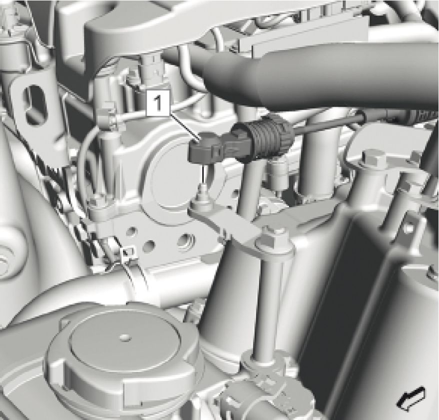 |
|
Fig. 291: Range Selector Lever Cable And Range Selector Lever Cable Lever |
24. Remove Range Selector Lever Cable (1) @ Range Selector Lever Cable Lever
 |
|
Fig. 292: Range Selector Lever Cable And Transmission Range Selector Lever Cable Bracket |
25. Remove Range Selector Lever Cable (1) @ Transmission Range Selector Lever Cable Bracket
26. Release the cable from the bracket by pushing the retainer (arrow).
 |
|
Fig. 293: Engine Coolant Thermostat Housing, Radiator Outlet Hose And Clamp |
27. Remove Radiator Outlet Hose Clamp (2)
28. Remove Radiator Outlet Hose (3) @ Engine Coolant Thermostat Housing (1)
 |
|
Fig. 294: Water Outlet, Radiator Inlet Hose And Clamp |
29. Remove Radiator Inlet Hose Clamp (2)
30. Remove Radiator Inlet Hose (1) @ Water Outlet (3)
31. Install the engine support fixture. Refer to Engine Support Fixture
32. Remove the left side headlamp assembly. Refer to Headlamp Replacement
 |
|
Fig. 295: Engine Wiring Harness And Clips |
33. Unclip Engine Wiring Harness (1) @ Wiring Harness Clips (2) (Qty: 2)
 |
|
Fig. 296: Wiring Harness Clip And Electrical Connectors |
34. Unclip Wiring Harness Clip (2)
CAUTION: In order to prevent any possible electrostatic discharge damage to the ECM,
do not touch the connector pins.
35. Disconnect the electrical connectors. (1) (Qty: 3)
36. Place the engine wiring harness at the top of the engine assembly.
 |
|
Fig. 297: Engine Ground Strap Bolt And Retainer |
37. Remove the engine ground strap bolt (1).
38. Unclip Wiring Harness Clip (2)
39. Remove Exhaust Muffler. Refer to Exhaust Muffler Replacement
 |
|
Fig. 298: Exhaust Front Pipe, Nuts And Gasket Courtesy'of GENERAL'MOTORS'COMPANY |
CAUTION: Do not bend the exhaust flex pipe more than 10 degrees in any direction.
Bending of more than 10 degrees or twisting in a range of A±0.5 degrees will
damage the exhaust flex decoupler.
40. Remove Exhaust Front Pipe Nuts (3) (Qty: 2)
41. Remove Exhaust Front Pipe (2)
42. Remove and DISCARD the gasket. (1)
43. Remove Clamp (1)
44. Remove Heater Inlet Hose (2)
45. Remove Clamp (2)
46. Remove Heater Inlet Hose (1)
 |
|
Fig. 299: Heater Inlet Hose And Clamp |
 |
|
Fig. 300: Heater Inlet Hose And Clamp |
 |
|
Fig. 301: Heater Inlet Hose, Clamp And Clip |
47. Remove Clamp (1)
48. Remove Heater Inlet Hose (2)
49. Unclip Heater Inlet Hose @ Clip (3)
50. Remove Generator Control Module Coolant Pump. Refer to Generator Control Module Coolant Pump
Replacement
51. Remove Heater Inlet and Outlet Pipe. Refer to Heater Inlet And Outlet Pipe Replacement
52. Remove Heater Coolant Pump. Refer to Heater Coolant Pump Replacement
53. Remove Heater Coolant Heater. Refer to Heater Coolant Heater Replacement
54. Remove Heater Water Shutoff Valve. Refer to Heater Water Shutoff Valve Replacement
 |
|
Fig. 302: Coolant Hose And Clips Courtesy'of GENERAL'MOTORS COMPANY |
55. Remove Clip (1) (Qty: 2)
56. Remove Coolant Hose (2)
 |
|
Fig. 303: Drive Motor Battery Coolant Cooler Inlet Hose And Retainer |
57. Remove the drive motor battery coolant cooler inlet hose (1) from the retainer (2) and reposition.
 |
|
Fig. 304: Air Conditioning Evaporator Tube, Condenser Tube And Nut |
58. Remove the condenser tube nut (3).
59. Remove the air conditioning evaporator tube (1) along with the condenser tube (2) from the condenser.
 |
|
Fig. 305: Air Conditioning Compressor, Condenser Hose And Bolt |
60. Remove the air conditioning compressor and condenser hose bolt (1).
61. Remove the air conditioning compressor and condenser hose (2) from the air conditioning compressor (3).
 |
|
Fig. 306: A/C Compressor And Condenser Hose Tube, Retainer, Wiring Harness And Cycling Switch Courtesy'of GENERAL MOTORS COMPANY |
62. Unclip the retainer (1) holding the air conditioning compressor and condenser hose tube to the engine bracket.
63. Unclip the wiring harness (2) from the air conditioning compressor and condenser hose tube.
64. Disconnect the air conditioning cycling switch electrical connector (3).
65. Remove the air conditioning compressor and condenser hose tube (1).
 |
|
Fig. 307: Air Conditioning Compressor Hose Bolt And Air Conditioning Evaporator Hose |
66. Remove the air conditioning compressor hose bolt (1) from the air conditioning evaporator hose (2).
67. Remove Air Conditioning Compressor Hose
 |
|
Fig. 308: Radiator And Lashing Straps |
68. Secure the radiator (2) using 2 lashing straps (1)
69. Remove Underbody Front Air Deflector-Left Side. Refer to Underbody Front Air Deflector Replacement -
Left Side
70. Drain the transmission. Refer to Transmission Fluid Drain and Fill
 |
|
Fig. 309: Transmission Fluid Cooler Outlet Pipe, Bolt And Sealing Washer |
71. Place a container beneath the transmission fluid cooler outlet pipe (2) to catch spilling transmission fluid.
72. Remove Transmission Fluid Cooler Pipe Bolt (1)
73. Disconnect Transmission Fluid Cooler Outlet Pipe (2)
74. Remove and DISCARD Sealing Washer (3)
 |
|
Fig. 310: Transmission Fluid Cooler Inlet Pipe, Bolt And Sealing Washer |
75. Place a container beneath the transmission fluid cooler inlet pipe (3) to catch spilling transmission fluid.
76. Remove Transmission Fluid Cooler Pipe Bolt (1)
77. Disconnect Transmission Fluid Cooler Inlet Pipe (3)
78. Remove and DISCARD Sealing Washer (2)
 |
|
Fig. 311: Drive Motor Generator Control Module Cooling Outlet Hose And Bolts |
79. Remove Drive Motor Generator Control Module Cooling Outlet Hose Bolt (1) (Qty: 2)
80. Remove and DISCARD Seal (2)
 |
|
Fig. 312: Stabilizer Shaft Link, Stabilizer Shaft And Nut |
NOTE: Hold against the hex of the threaded stud to release the nuts. Use a suitable
tool.
81. Remove and DISCARD Stabilizer Shaft Link Nuts (2) (Qty: 2)
82. Disconnect Stabilizer Shaft Links (1) (Qty: 2) @ Stabilizer Shaft (3)
 |
|
Fig. 313: Steering Knuckle, Lower Ball Joint And Nut |
NOTE: Support the front suspension under the front lower control arm ball joint with a
hydraulic jack to release the nut.
83. Remove and DISCARD Nuts (1) (Qty: 2)
84. Separate the steering knuckle from the lower ball joint. (Qty: 2)
85. Disconnect the outer tie rod from the steering knuckle (Qty: 2). Refer to Steering Linkage Outer Tie Rod
Replacement
86. Reposition away Front Wheel Drive Shaft @ Transmission. Refer to Front Wheel Drive Shaft Replacement
 |
|
Fig. 314: Transmission Mount Strut Bolt And Transmission Mount Strut |
87. Remove and DISCARD Transmission Mount Strut Bolt (1) @ Transmission Mount Strut (2).
 |
|
Fig. 315: Drivetrain And Front Suspension Cradle Supported With Suitable Hydraulic Jack |
88. Support the drivetrain and front suspension cradle (1) with a suitable hydraulic jack (2).
 |
|
Fig. 316: Drivetrain And Front Suspension Cradle, Crossmember Extension And Bolts |
NOTE: A second technician is required.
89. Remove and DISCARD Bolts (2, 5, 9) (Qty: 6) @ Drivetrain and Front Suspension Cradle (1)
90. Remove and DISCARD Bolts (4, 7) (Qty: 2) @ Drivetrain and Front Suspension Crossmember Extension (6)
91. Lower the drivetrain and front suspension cradle along with drivetrain and front suspension crossmember
extension and both lower control arm (3, 8) as far as necessary to disconnect the wiring harness.
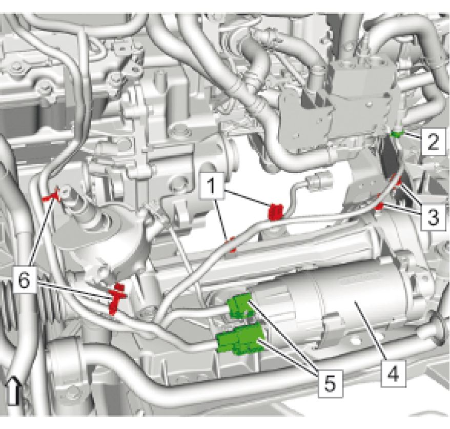 |
|
Fig. 317: Power Steering Assist Motor, Electrical Connectors And Wiring Harness Clips |
92. Disconnect Electrical Connectors (5) (Qty: 2) @ Power Steering Assist Motor (4)
93. Disconnect the electrical connector. (2)
94. Unclip Wiring Harness Clip (1, 3, 6) (Qty: 6)
NOTE: A second technician is required.
95. Carefully lower the drivetrain and front suspension cradle along with drivetrain and front suspension
crossmember extension and both lower control arm
96. Remove the drivetrain and front suspension cradle along with drivetrain and front suspension crossmember
extension and both lower control arm.
97. Lower the vehicle.
98. Position an engine support table under the powertrain assembly
99. Blocks of wood can be used between the front of the frame and the oil pan in order to level the powertrain
during the removal.
100. With the table positioned, fully raise the table to contact with the powertrain assembly.

Fig. 318: Transmission Mount And Bolts
101. Remove and DISCARD Transmission Mount Bolts (1) (Qty: 3) @ Transmission Mount (2)
 |
|
Fig. 319: Engine Mount Bolts Courtesy'of GENERAL'MOTORS COMPANY |
102. Remove Engine Mount Bolts (1) (Qty: 2)
103. Remove the engine support fixture. Refer to Engine Support Fixture
104. Slowly and carefully raise the vehicle, ensure the powertrain assembly are free from wiring, hoses and other
engine compartment components
 |
|
Fig. 320: Starter Opening Cover And Bolts |
105. Remove Bolts (2) (Qty: 2)
106. Remove the starter opening cover (1).
 |
|
Fig. 321: Torque Converter Bolts Courtesy'of GENERAL'MOTORS COMPANY |
107. Remove the torque converter bolts. (1) (Qty: 4)
108. Remove the water outlet. Refer to Water Outlet Replacement
109. Remove Heater Inlet Hose. Refer to Heater Inlet Hose Replacement

Fig. 322: Transmission Bolts
Courtesy of GENERAL MOTORS COMPANY
110. Remove the transmission bolts. (1) (Qty: 3)

Fig. 323: Transmission Bolt
Courtesy of GENERAL MOTORS COMPANY
111. Remove Transmission Bolt (1)

Fig. 324: Transmission Cover And Bolts
Courtesy of GENERAL MOTORS COMPANY
112. Remove Transmission Bolts (1) (Qty: 2)
113. Remove Transmission Cover (2)
114. Properly support engine and transmission as necessary.
 |
|
Fig. 325: Transmission Bolts Courtesy'of GENERAL'MOTORS COMPANY |
NOTE: These are the last transmission bolts.
115. Remove Transmission Bolts (1) (Qty: 2)
116. Separate the engine from the transmission.
117. Disconnect Engine Coolant Hose as necessary.
118. Disconnect all electrical connectors.
119. Transfer components as necessary.
Installation Procedure
1. Connect all electrical connectors.
2. Connect engine coolant hoses as necessary
Do not tighten bell housing bolts at this time. There must be a small 1 mm (0.039 in) to 2 mm
IMPORTANT: (0.079 in) mm gap between the engine and transmission to allow rotation for input flange
alignment
3. Install two appropriate guide pins into the engine to aid aligning the transmission to the engine.
NOTE: A second technician is required.
4. Align the transmission to the engine leaving a 2 millimeter gap between both.

Fig. 326: Transmission Bolts
Courtesy of GENERAL MOTORS COMPANY
5. Remove the guide pin, then install the 2 transmission bolt (1) and hand tighten, allowing a small 1 mm (0.039
in) to 2 mm (0.079 in) gap between the engine and transmission.

Fig. 327: Transmission Cover And Bolts
Courtesy of GENERAL MOTORS COMPANY
6. Install Transmission Cover (2)
7. Install and hand tighten Transmission Bolts (1) (Qty: 2)
Fig. 328: Transmission Bolt

Courtesy of GENERAL MOTORS COMPANY
8. Install and hand tighten Transmission Bolt (1)
 |
|
Fig. 329: Transmission Bolts Courtesy'of GENERAL'MOTORS COMPANY |
9. Install and hand tighten Transmission Bolts (1) (Qty: 3)
 |
|
Fig. 330: Torque Converter Bolts Courtesy'of GENERAL'MOTORS COMPANY |
10. Set the engine to TDC allowing the master oblong flexplate bolt hole to appear in the starter hole opening.
11. Install and perform final tightening of the ALL remaining torque convertor bolts and transmission housing to
engine bolts as specified in the transmission replacement procedure. Refer to Transmission Replacement
 |
|
Fig. 331: Starter Opening Cover And Bolts |
12. Install the starter opening cover (1).
13. Install and tighten Bolts (2) (Qty: 2). Refer to Transmission Replacement
14. Install the water outlet. Refer to Water Outlet Replacement
15. Install Heater Inlet Hose. Refer to Heater Inlet Hose Replacement
16. Slowly and carefully lower the vehicle, ensure the powertrain assembly are free from wiring, hoses and other
engine compartment components
 |
|
Fig. 332: Engine Mount Bolts Courtesy'of GENERAL'MOTORS COMPANY |
CAUTION: Refer to Fastener Caution
CAUTION: Refer to Torque-to-Yield Fastener Caution
17. Install and tighten Engine Mount Bolts (1) (Qty: 2). Refer to Engine Mount Replacement
 |
|
Fig. 333: Transmission Mount And Bolts |
18. Install and tighten Transmission Mount Bolts (1) (Qty: 3) @ Transmission Mount (2). Refer to Transmission
Mount Replacement
19. Install the engine support fixture. Refer to Engine Support Fixture
20. Raise the vehicle.
 |
|
Fig. 334: Drivetrain And Front Suspension Cradle Supported With Suitable Hydraulic Jack |
NOTE: A second technician is required.
21. Raise the drivetrain and front suspension cradle along with drivetrain and front suspension crossmember
extension and both lower control arm (1) with a suitable jack (2) as far as necessary to connect the wiring
harness.
 |
|
Fig. 335: Power Steering Assist Motor, Electrical Connectors And Wiring Harness Clips |
22. Install Wiring Harness Clips (1, 3, 6) (Qty: 6)
23. Connect the electrical connector. (2)
24. Connect Electrical Connectors (5) (Qty: 2) @ Power Steering Assist Motor (4)
 |
|
Fig. 336: Drivetrain And Front Suspension Cradle, Crossmember Extension And Bolts |
NOTE: A second technician is required.
25. Install the drivetrain and front suspension cradle (1) along with the drivetrain and front suspension
crossmember extension (6) and the lower control arm (3, 8) to the vehicle. Refer to Drivetrain and Front
Suspension Cradle Replacement
 |
|
Fig. 337: Transmission Mount Strut Bolt And Transmission Mount Strut |
WA RNING: Refer to Torque-to-Yield Fastener Warning
26. Install and tighten NEW Transmission Mount Strut Bolt (1) @ Transmission Mount Strut (2). Refer to
Transmission Mount Strut Bracket Replacement
27. Install Front Wheel Drive Shaft @ Transmission. Refer to Front Wheel Drive Shaft Replacement
28. Connect the outer tie rod to the steering knuckle (Qty: 2). Refer to Steering Linkage Outer Tie Rod
Replacement
 |
|
Fig. 338: Steering Knuckle, Lower Ball Joint And Nut |
NOTE: Support the lower control arm under the ball joint with a hydraulic jack to
tighten the nut.
29. Install the 2 lower ball joint (3) to the steering knuckle (2).
30. Install and tighten Nuts (1) (Qty: 2). Refer to Lower Control Arm Replacement
 |
|
Fig. 339: Stabilizer Shaft Link, Stabilizer Shaft And Nut |
NOTE: Hold against the hex of the threaded stud to tighten the nuts. Use a suitable
tool.
31. Connect Stabilizer Shaft Links (1) (Qty: 2) @ Stabilizer Shaft (3)
32. Install and tighten Stabilizer Shaft Link Nuts (2) (Qty: 2) @ Stabilizer Shaft Link (1). Refer to Lower Control
Arm Replacement
 |
|
Fig. 340: Drive Motor Generator Control Module Cooling Outlet Hose And Bolts |
33. Install NEW Seal (2). Install a NEW seal.
34. Install and tighten Drive Motor Generator Control Module Cooling Outlet Hose Bolts (1) (Qty: 2). Refer to
Drive Motor Generator Control Module Cooling Outlet Hose Replacement (Underbody Line) Drive
Motor Generator Control Module Cooling Outlet Hose Replacement (Underbody Line to Traction
Power Inverter Module Inlet)
 |
|
Fig. 341: Transmission Fluid Cooler Inlet Pipe, Bolt And Sealing Washer |
35. Install NEW Sealing Washer (2). Install a NEW seal.
36. Connect Transmission Fluid Cooler Inlet Pipe (3)
37. Install and tighten Transmission Fluid Cooler Pipe Bolt (1). Refer to Transmission Fluid Cooler Inlet Pipe
Replacement
 |
|
Fig. 342: Transmission Fluid Cooler Outlet Pipe, Bolt And Sealing Washer |
38. Install NEW Sealing Washer (3). Install a NEW seal.
39. Connect Transmission Fluid Cooler Outlet Pipe (2)
40. Install and tighten Transmission Fluid Cooler Pipe Bolt (1). Refer to Transmission Fluid Cooler Outlet Pipe
Replacement
41. Fill Transmission. Refer to Transmission Fluid Drain and Fill
42. Install Underbody Front Air Deflector-Left Side. Refer to Underbody Front Air Deflector Replacement -
Left Side
 |
|
Fig. 343: Radiator And Lashing Straps |
43. Loosen the radiator (2) from the body and remove the ropes (1).
 |
|
Fig. 344: Air Conditioning Compressor Hose Bolt And Air Conditioning Evaporator Hose |
44. Install Air Conditioning Compressor Hose
45. Install the air conditioning compressor hose bolt (1) to the air conditioning evaporator hose (2) and tighten.
Refer to Air Conditioning Compressor Hose Replacement
 |
|
Fig. 345: A/C Compressor And Condenser Hose Tube, Retainer, Wiring Harness And Cycling Switch Courtesy'of GENERAL MOTORS COMPANY |
46. Install the air conditioning compressor and condenser hose tube (1).
47. Connect the air conditioning cycling switch electrical connector (3).
48. Install the wiring harness (2) to the air conditioning compressor and condenser hose tube.
49. Install the retainer (1).
 |
|
Fig. 346: Air Conditioning Compressor, Condenser Hose And Bolt |
50. Install the air conditioning compressor and condenser hose (2) to the air conditioning compressor (3).
51. Install the air conditioning compressor and condenser hose bolt (1) and tighten. Refer to Air Conditioning
Compressor and Condenser Hose Replacement
 |
|
Fig. 347: Air Conditioning Evaporator Tube, Condenser Tube And Nut |
52. Install the air conditioning evaporator tube (1) along with the condenser tube (2) to the condenser.
53. Install the condenser tube nut (3) and tighten. Refer to Air Conditioning Compressor and Condenser Hose
Replacement
 |
|
Fig. 348: Drive Motor Battery Coolant Cooler Inlet Hose And Retainer |
54. Install the drive motor battery coolant cooler inlet hose (1) to the retainer (2).
 |
|
Fig. 349: Coolant Hose And Clips Courtesy'of GENERAL'MOTORS COMPANY |
55. Install Coolant Hose (2)
56. Install Clips (1) (Qty: 2)
57. Install Heater Water Shutoff Valve. Refer to Heater Water Shutoff Valve Replacement
58. Install Heater Coolant Heater. Refer to Heater Coolant Heater Replacement
59. Install Heater Coolant Pump. Refer to Heater Coolant Pump Replacement
60. Install Heater Inlet and Outlet Pipe. Refer to Heater Inlet And Outlet Pipe Replacement
61. Install Generator Control Module Coolant Pump. Refer to Generator Control Module Coolant Pump
Replacement
 |
|
Fig. 350: Heater Inlet Hose, Clamp And Clip |
62. Install Heater Inlet Hose (2)
63. Install Clamp (1)
64. Install Heater Inlet Hose @ Clip (3)
 |
|
Fig. 351: Heater Inlet Hose And Clamp |
65. Install Heater Inlet Hose (1)
66. Install Clamp (2)
 |
|
Fig. 352: Exhaust Front Pipe, Nuts And Gasket Courtesy'of GENERAL'MOTORS'COMPANY |
67. Install a NEW gasket. (1)
68. Install Exhaust Front Pipe (2)
69. Install and tighten Exhaust Front Pipe Nuts (3) (Qty: 2). Refer to Exhaust Front Pipe Replacement
70. Install Exhaust Muffler. Refer to Exhaust Muffler Replacement
 |
|
Fig. 353: Engine Ground Strap Bolt And Retainer |
71. Install the engine ground strap bolt (1) and tighten to 25 N.m (18 lb ft).
72. Install Wiring Harness Clip (2)
 |
|
Fig. 354: Wiring Harness Clip And Electrical Connectors |
73. Connect the electrical connectors. (1) (Qty: 3)
74. Install Wiring Harness Clip (2)
 |
|
Fig. 355: Engine Wiring Harness And Clips |
75. Install Engine Wiring Harness (2) @ Wiring Harness Clips (1) (Qty: 2)
76. Install Headlamp Left Side. Refer to Headlamp Replacement
77. Lower the vehicle.
78. Remove the engine support fixture. Refer to Engine Support Fixture
 |
|
Fig. 356: Water Outlet, Radiator Inlet Hose And Clamp |
79. Install Radiator Inlet Hose (1) @ Water Outlet (3)
80. Install Radiator Inlet Hose Clamp (2)
 |
|
Fig. 357: Engine Coolant Thermostat Housing, Radiator Outlet Hose And Clamp |
81. Install Radiator Outlet Hose (3) @ Engine Coolant Thermostat Housing (1)
82. Install Radiator Outlet Hose Clamp (2)
 |
|
Fig. 358: Range Selector Lever Cable And Transmission Range Selector Lever Cable Bracket |
83. Install the range selector lever cable (1) to the range selector lever cable bracket.
The retainer snaps automatically in.
 |
|
Fig. 359: Range Selector Lever Cable And Range Selector Lever Cable Lever |
84. Install Range Selector Lever Cable (1) @ Range Selector Lever Cable Lever
85. Install Heater Water Shutoff Valve Inlet Hose. Refer to Heater Water Shutoff Valve Inlet Hose Replacement
 |
|
Fig. 360: Evaporative Emission Canister Purge Solenoid Valve And Evaporative Emission Pipe |
86. Remove all EN-6015 plugs from the connections.
87. Connect Evaporative Emission Pipe (1) @ Evaporative Emission Canister Purge Solenoid Valve (3). Refer to
Plastic Collar Quick Connect Fitting Service
 |
|
Fig. 361: Fuel Feed Pipe, Fuel Feed Front Pipe And Retainer |
88. Remove all EN-6015 plugs from the connections.
89. Connect Fuel Feed Front Pipe (2) @ Fuel Feed Pipe (1). Refer to Plastic Collar Quick Connect Fitting
Service
90. Install Fuel Feed Front Pipe (2) @ Retainer (3)
 |
|
Fig. 362: Ground Cable, Nut, Engine Wiring Harness, Clips And Electrical Connectors |
91. Install the electrical connector (3) to the front compartment fuse block housing.
92. Install Ground Cable (1)
93. Install and tighten Ground Cable Nut (2) to 9 N.m (80 lb in)
94. Connect the electrical connectors. (6, 7) (Qty: 2)
95. Install Engine Wiring Harness (5) @ Clips (4) (Qty: 2)
96. Install Engine Wiring Harness Junction Block. Refer to Engine Wiring Harness Junction Block
Replacement
97. Install 300-Volt Battery Positive and Negative Cable @ Transmission. Refer to Battery 300-Volt Positive and
Negative Cable Replacement - High Voltage Battery to Power Inverter Module and A/C Compressor
98. Install the radiator surge tank. Refer to Radiator Surge Tank Replacement
99. Install the air cleaner outlet duct. Refer to Air Cleaner Outlet Duct Replacement
100. Install the air cleaner assembly. Refer to Air Cleaner Assembly Replacement
101. Install Intake Manifold Cover. Refer to Intake Manifold Cover Replacement
102. Adjust Range Selector Lever Cable. Refer to Range Selector Lever Cable Adjustment
103. Install Intermediate Steering Shaft Lower Bolt. Refer to Intermediate Steering Shaft Replacement
104. Fill the cooling system. Refer to Cooling System Draining and Filling
105. Fill the drive motor generator power inverter module cooling system. Refer to Drive Motor Generator Power
Inverter Module Cooling System Draining and Filling
106. Fill the drive motor battery cooling system. Refer to Drive Motor Battery Cooling System Draining and
Filling -
107. Connect the battery negative cable. Refer to Battery Negative Cable Disconnection and Connection
108. Recharge the refrigerant. Refer to Refrigerant Recovery and Recharging
109. Enable the high voltage system. Refer to High Voltage Enabling
AUTOMATIC TRANSMISSION FLEX PLATE REPLACEMENT
Special Tools
• EN-45059 Angle Meter
• EN-51398 Flywheel Holder
Equivalent regional tools: Special Tools
Removal Procedure
1. Remove Transmission. Refer to Transmission Replacement
 |
|
Fig. 363: Flywheel Holder And Bolts Courtesy'of GENERAL'MOTORS'COMPANY |
2. Install the EN-51398 holder (1), lock the automatic transmission flex plate via the starter ring gear.
3. Ensure that the EN-51398 holder is engaged into a robust portion of the flex plate (3).
4. Install and tighten the 2 starter opening cover bolts (2).
 |
|
Fig. 364: Automatic Transmission Flex Plate And Bolts |
5. Remove and DISCARD the 8 automatic transmission flex plate bolts (1).
6. Remove Automatic Transmission Flex Plate (2)
Installation Procedure
 |
|
Fig. 365: Automatic Transmission Flex Plate And Bolts |
1. Install Automatic Transmission Flex Plate (2)
2. Install 8 NEW automatic transmission flex plate bolts (1).
3. Hand tighten the bolts.
 |
|
Fig. 366: Automatic Transmission Flex Plate Bolt Tightening Sequence |
CAUTION: Refer to Fastener Caution .
CAUTION: Refer to Torque-to-Yield Fastener Caution .
NOTE: The bolts have adhesive patch and must be tightened to final torque within 5
minutes.
4. Tighten Automatic Transmission Flex Plate Bolts in the sequence shown.
1. First Pass: 20 N.m (15 lb ft).
2. Second Pass: 30 N.m (22 lb ft).
3. Final Pass: 70 degrees, using the EN 45059 meter.
 |
|
Fig. 367: Flywheel Holder And Bolts Courtesy'of GENERAL'MOTORS'COMPANY |
5. Remove the 2 starter opening cover bolts (2).
6. Remove the EN-51398 holder (1).
7. Install Transmission. Refer to Transmission Replacement
ENGINE SUPPORT FIXTURE
 |
|
Fig. 368: Engine Support Fixture Components |
|
Callout |
Component Name |
|
Callout |
Component Name |
|
Preliminary Procedures
Special Tools
Equivalent regional tools: Special Tools | |
|
1 |
Engine Support Fixture Adapter Leg (Qty: 2) Procedure Install the bracket to fender frame. Do not install on top of fender lip. |
|
2 |
Main Support Beam |
|
3 |
Cross Bracket (Qty: 2) |
|
4 |
Strut Tower Support Assembly (Qty: 2) Procedure Adjust the length of the strut tower support assembly. |
|
5 |
Radiator Tube Shelf Assembly (Qty: 2) |
|
6 |
Engine Lift Bracket Procedure Use a grade 10.9 bolt to install the EN-36857 Engine Lift Bracket. |
|
7 |
Hook Assembly (Qty: 2) |
REPAIR INSTRUCTIONS - OFF VEHICLE
DRAINING FLUIDS AND OIL FILTER REMOVAL
 |
|
Fig. 369: Draining Fluids and Oil Filter |
| ||||||||
|
CRANKSHAFT BALANCER REMOVAL |
 |
|
Fig. 370: Crankshaft Balancer Courtesy'of GENERAL'MOTORS COMPANY |
| ||||||||
|
AUTOMATIC TRANSMISSION FLEX PLATE REMOVAL | ||||||||
 |
|
Fig. 371: Automatic Transmission Flex Plate |
| ||||||||||
|
EXHAUST GAS RECIRCULATION PIPE REMOVAL | ||||||||||
 |
|
Fig. 372: Exhaust Gas Recirculation Pipe |
| ||||||||||||||
|
EXHAUST GAS RECIRCULATION COOLER OUTLET PIPE REMOVAL |
 |
|
Fig. 373: Exhaust Gas Recirculation Cooler Outlet Pipe |
| ||||||||||
|
EXHAUST GAS RECIRCULATION COOLER REMOVAL |
 |
|
Fig. 374: Exhaust Gas Recirculation Cooler Courtesy'of GENERAL'MOTORS'COMPANY |
|
Callout |
Component Name |
|
1 |
Exhaust Gas Recirculation Cooler Temperature Sensor Procedure Disconnect the temperature sensor nut at the inlet pipe. |
|
2 |
Exhaust Gas Recirculation Cooler Water Bypass Outlet Hose Procedure Disconnect the bypass outlet hose at the water pump. |
|
3 |
Thermostat Bypass Hose Procedure Disconnect the bypass hose at the water outlet. |
|
4 |
Exhaust Gas Recirculation Cooler Bolt (Qty: 2) |
|
5 |
Exhaust Gas Recirculation Cooler Bolt |
|
6 |
Exhaust Gas Recirculation Cooler |
|
7 |
Exhaust Gas Recirculation Cooler Inlet Pipe Gasket NOTE: |
EXHAUST GAS RECIRCULATION VALVE REMOVAL
 |
|
Fig. 375: Exhaust Gas Recirculation Valve |
| ||||||||||
|
WATER PUMP REMOVAL |
 |
|
Fig. 376: Water Pump Courtesy'of GENERAL MOTORS COMPANY |
| ||||||||||||||||
|
ENGINE WIRING HARNESS ASSEMBLY REMOVAL |
 |
|
Fig. 377: Engine Wiring Harness Assembly |
| ||||||||
|
THROTTLE BODY ASSEMBLY REMOVAL |
 |
|
Fig. 378: Throttle Body Assembly Courtesy'of GENERAL'MOTORS COMPANY |
| ||||||||
|
INTAKE MANIFOLD REMOVAL |
 |
|
Fig. 379: Intake Manifold |
|
Courtesy of GENERAL MOTORS COMPANY | ||||||||
| ||||||||
|
FUEL PUMP REMOVAL |
 |
|
Fig. 380: Fuel Pump Courtesy'of GENERAL MOTORS COMPANY |
|
Callout |
Component Name |
|
1 |
Fuel Feed Intermediate Pipe Bolt (Qty: 1) |
|
2 |
Fuel Feed Intermediate Pipe WARNING: Fuel that ALWAYS |
|
Callout |
Component Name |
|
components NOTE: | |
|
3 |
Fuel Pump Insulator WARNING: |
|
4 |
Fuel Pump Bolt (Qty: 2) CAUTION: Alternately |
| ||||||||
|
ENGINE LIFT AND SIGHT SHIELD BRACKET REMOVAL |

Fig. 381: Engine Lift And Sight Shield Bracket
Courtesy'of GENERAL'MOTORS'COMPANY
| ||||||||||
|
WATER OUTLET REMOVAL |
 |
|
Fig. 382: Water Outlet Courtesy'of GENERAL MOTORS COMPANY |
| ||||||||
|
IGNITION COIL REMOVAL |
 |
|
Fig. 383: Ignition Coil Courtesy'of GENERAL MOTORS COMPANY |
Callout
1
Component Name
Ignition Coil Assembly (Qty: 4)
FUEL RAIL AND INJECTORS REMOVAL
Special Tools
• EN-51146 Fuel Injector Removal/Installation Kit
• EN-51146-100 Fuel Injector Removal Plate
• EN-51146-150 Fuel Injector Removal Adapters
For equivalent regional tools, refer to Special Tools.
WARNING: Refer to Diesel/Gasoline Vapors Warning .
WARNING: Refer to Safety Goggles and Fuel Warning .
NOTE: Maintain a clean work surface when working with fuel rail and fuel injectors.
Use care to avoid contaminants on the injector seals.
 |
|
Fig. 384: Fuel Injector Screw And Adapters Courtesy'of GENERAL'MOTORS'COMPANY |
NOTE: Remove only one fuel injector screw (2) to perform the length check.
1. Ensure the EN-51146-150 fuel injector removal adapters (1) are used with non-turbocharger applications.
Match the length (a) of the EN-51146-150 adapters (1) to the length of the fuel injector screw (2). If the length
does not match, refer to the Turbocharger procedure.
 |
|
Fig. 385: Adapters And Supports |
2. Install the EN-51146-150 adapters (2) to the EN-51146-1-1 supports (1) and tighten to 7 N.m (62 lb in).
 |
|
Fig. 386: Inner Fuel Injector Screw Courtesy'of GENERAl'mOTORS' COMPANY |
| ||
|
 |
|
Fig. 387: Outer Fuel Injector Screw |
5. Remove the outer fuel injector screw (1).
6. Install a second EN-51146-150 adapter and EN-51146-1-1 support (2) and tighten to 5 N.m (44 lb in).
 |
|
Fig. 388: Supports Courtesy'of GENERAL MOTORS COMPANY |
7. Using the same procedure, install the remaining EN-51146-150 adapters and EN-51146-1-1 supports (1) for
each fuel injector and tighten to 5 N.m (44 lb in).
 |
|
Fig. 389: Upper And Lower Fuel Rail Assembly Bolts |
NOTE: The fuel rail bolts may remain with the decoupling elements and retainer at the
fuel rail assembly.
8. Loosen the 4 upper fuel rail assembly bolts (1) completely from the cylinder head, but do not remove the bolts.
9. Loosen the 4 lower fuel rail assembly bolts (2) completely from the cylinder head, but do not remove the bolts.
 |
|
Fig. 390: Plate, Supports, Bolts And Slide Hammers Courtesy'of GENERAL'MOTORS'COMPANY |
10. Install EN-51146-100 plate (2) to the EN-51146-1-1 supports (1) using the eight plate bolts (3). Counterhold
each support with a wrench while tightening the bolt.
11. Install the EN-51146-1-3 slide hammers (4) onto the EN-51146-100 plate (2) using the outer holes.
 |
|
Fig. 391: Removing Fuel Injectors Courtesy'of GENERAL'MOTORS COMPANY |
NOTE: The alignment of the fuel injectors within the cylinder bores is critical for fuel
injection system function. Use equal force on each slide hammer to ensure the
fuel injectors are removed without tilting in the injector bore.
12. Using the EN-51146-1-3 slide hammers (1, 2), begin to remove the fuel injectors by applying slight force
equally on both hammers. Observe the alignment of the fuel injectors, and allocate force on the hammers as
necessary.
NOTE: After removing the fuel rail and injector assembly, position the assembly on a
clean work surface with the fuel injectors on top. Do not allow the weight of the
assembly to rest on the fuel injectors.
13. Complete the removal of the fuel rail and injector assembly with the EN-51146 remover. The slide hammers
may then be removed from the plate.
14. Install the EN-51146-2-5 calibration tools onto the fuel injector tips to protect the injectors.
15. Cover the fuel injector bores at the cylinder head to prevent contamination.
CAMSHAFT COVER REMOVAL
Camshaft Cover and Gasket Removal
 |
|
Fig. 392: Camshaft Cover And Gasket |
Courtesy of GENERAL MOTORS COMPANY
|
Camshaft Cover and Gasket Removal | ||||||||||||
| ||||||||||||
|
Camshaft Cover Components Removal |
 |
|
Fig. 393: Camshaft Cover Components Courtesy'of GENERAL'MOTORS'COMPANY |
|
Camshaft Cover Components Removal | ||||||
|
|
Callout |
Component Name |
|
flat-bladed tool. 2. Discard the bolts. | |
|
2 |
Positive Crankcase Ventilation Tube with Positive Crankcase Ventilation Valve - Fresh Air NOTE: Procedure
|
|
3 |
Camshaft Position Sensor Bolt |
|
4 |
Intake Camshaft Position Sensor |
|
5 |
Camshaft Position Sensor Bolt |
|
6 |
Exhaust Camshaft Position Sensor |
|
7 |
Camshaft Cover Locating Pin (Qty: 2) |
|
8 |
Camshaft Position Actuator Solenoid Valve Bolt |
|
9 |
Camshaft Position Actuator Solenoid Valve |
|
10 |
Camshaft Position Actuator Solenoid Valve Bolt |
OIL PAN REMOVAL
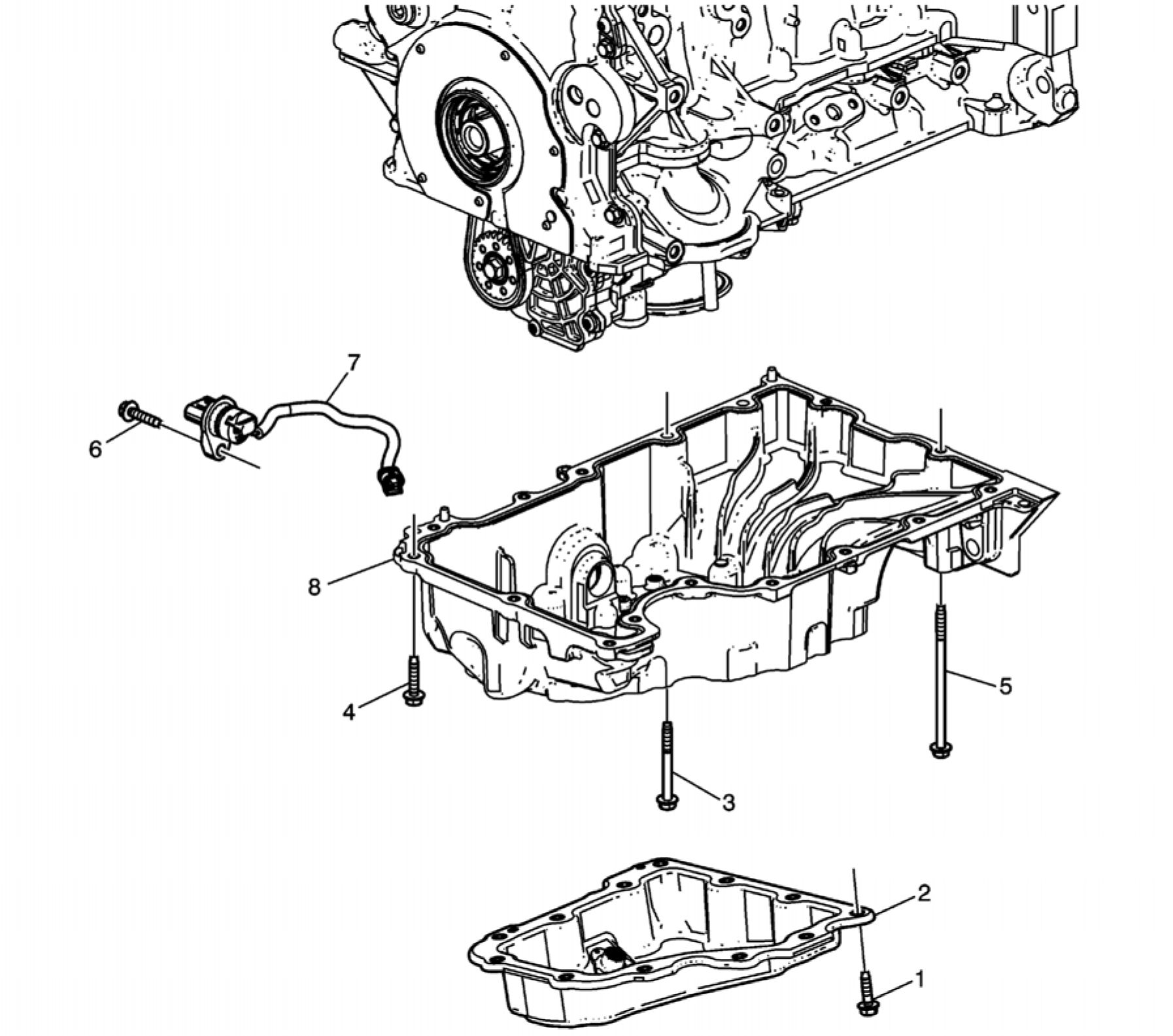 |
|
Fig. 394: Oil Pan Courtesy of GENERAL MOTORS COMPANY |
| ||||||||||||||||||
|
ENGINE FRONT COVER REMOVAL |
 |
|
Fig. 395: Engine Front Cover Courtesy'of GENERAL'MOTORS COMPANY |
|
Callout |
Component Name |
|
1 |
Engine Front Cover Bolt (Qty: 1) |
|
2 |
Engine Front Cover Bolt (Qty: 1) |
|
3 |
Engine Front Cover Bolt (Qty: 11) |
|
4 |
Engine Front Cover Stud (Qty: 1) |
|
5 |
Engine Front Cover Procedure
Temperature Vulcanizing (RTV) and Anaerobic Sealant
|
|
6 |
Crankshaft Front Oil Seal Procedure Discard the seal. Special Tools EN-51096 Crankshaft Seal Remover For equivalent regional tools, refer to Special Tools. |
7
Engine Front Cover Hole Plug
CAMSHAFT TIMING CHAIN REMOVAL
 |
|
Fig. 396: Camshaft Timing Chain Courtesy'of GENERAL'MOTORS COMPANY |
| ||||||||||||||||||||||||
|
INTAKE AND EXHAUST CAMSHAFT, BEARING CAP, AND LASH ADJUSTER REMOVAL |
 |
|
Fig. 397: Camshaft Actuator |
Courtesy of GENERAL MOTORS COMPANY
|
Camshaft Actuator Removal | ||||||||||||
| ||||||||||||
 |
|
Fig. 398: Camshaft Bearings and Camshaft |
Camshaft Bearings and Camshaft Removal__________________________________________________
Callout Component Name
Preliminary Procedure
NOTE:
Many
internal
engine
components
will develop
specific
wear
patterns on
their friction
surfaces.
1. Components MUST be separated, marked, or organized in a way to ensure installation to their original
location and position. Take precautions in order to prevent interchanging of parts.
| ||||||||||||||||||||||
|
Valve Rocker Arm and Lash Adjuster Removal | ||||||||||||||||||||||
 |
|
Fig. 399: Valve Rocker Arm and Lash Adjuster |
|
Valve Rocker Arm and Lash Adjuster Removal | ||||
| ||||
CYLINDER HEAD REMOVAL
 |
|
Fig. 400: Cylinder Head (With Loosening/Tightening Sequence) |
|
Callout |
Component Name |
|
1 |
Cylinder Head Bolt (Qty: 10) Procedure Remove the bolts in sequence. Discard the bolts. |
|
2 |
Cylinder Head Assembly |
|
3 |
Cylinder Head Gasket |
OIL PUMP DRIVE CHAIN AND OIL PUMP REMOVAL
Oil Pump Drive Chain and Crankshaft Sprocket Removal
 |
|
Fig. 401: Oil Pump Drive Chain and Crankshaft Sprocket |
|
Oil Pump Drive Chain and Crankshaft Sprocket Removal | ||||||||||||
| ||||||||||||
|
Oil Pump Assembly Removal |
 |
|
Fig. 402: Oil Pump Assembly Courtesy'of GENERAL'MOTORS COMPANY |
|
Oil Pump Assembly Removal | ||||||||||||||
| ||||||||||||||
|
CRANKSHAFT OIL DEFLECTOR REMOVAL |

Fig. 403: Crankshaft Oil Deflector
|
Courtesy of GENERAL MOTORS COMPANY | ||||||||||
| ||||||||||
|
LOWER CRANKCASE REMOVAL |
 |
|
Fig. 404: Lower Crankcase (With Bolt Removal Sequence) |
| ||||||||
|
PISTON, CONNECTING ROD, AND BEARING REMOVAL |
 |
|
Fig. 405: Piston, Connecting Rod and Bearing |
Callout
Preliminary Procedure
Component Name
NOTE:
Many
internal
engine
components
will develop
specific
wear
patterns on
their friction
surfaces.
1. Components MUST be separated, marked, or organized in a way to ensure installation to their original
location and position. Take precautions in order to prevent interchanging of parts.
2. Tag or mark each part immediately when removed. Indicate location, direction, or orientation when
necessary.
3. Before removing the connecting rods, check the connecting rod side clearance using the following
Callout |_______________________________Component Name______________________________
procedure:
1. Tap the connecting rod to one end of the crankshaft journal with a dead-blow or wooden hammer.
2. Using feeler gauges, measure the clearance between the crankshaft counterweight and the
connecting rod.
3. The connecting rod side clearance should not exceed specifications. Refer to Engine Mechanical
Specifications
4. If the end play exceeds the specified limits, measure the width of the crankpin end of the
connecting rod. Refer to Piston, Connecting Rod, and Bearing Cleaning and Inspection.
5. If the connecting rod width is significantly smaller than specified and severe wear is present on
the side of the connecting rod, replace the connecting rod.
6. If the connecting rod width is within specification and excessive scoring is present on the
crankshaft journals, replace the crankshaft.
NOTE:
An arrow/dot
showing
proper
piston
orientation
is located on
the top of
the piston.
4. Using a marker, number each piston face. Draw an arrow along the centerline of the piston pointing
toward the front of the engine.
CAUTION:
Do not use a
stamp,
punch or
any other
method that
may distort
or stress the
connecting
rod or
connecting
rod cap.
Extensive
engine
damage may
result from a
connecting
rod that is
distorted or
stressed.
5. Mark the cylinder number on the connecting rod and the connecting rod cap with a scribe, paint stick or
permanent marker.
Connecting Rod Bolt (Qty: 8)
CAUTION:
Powdered
metal
connecting
rods have
rod bolts
which yield
when
torqued. If
the rod bolts
are loosened
or removed
the rod bolts
must be
replaced.
Rod bolts
that are not
replaced will
not torque to
the correct
clamp load
and can lead
to serious
engine
damage.
Procedure
DO NOT use the bolts for reinstallation. The bolts may be used to keep the parts together and for
inspection and specification measurements.
Connecting Rod Assembly (Qty: 4)
NOTE:
The
connecting
rod caps
must remain
with the
original
connecting
rod. The
caps must
be oriented
identical to
original
installation.
Procedure
|
Callout |
Component Name |
|
Mark the side of the rod with a line that crosses the interface of the rod and cap. Use this line to | |
|
3 |
Connecting Rod Bearing (Qty: 4) NOTE: |
|
4 |
Connecting Rod Bearing (Qty: 4) NOTE: |
|
5 |
Connecting Rod Assembly (Qty: 4) NOTE: Piston Procedure Using the EN-51454 guides, push the connecting rod and piston assembly through the top of the Special Tools EN-51454 Connecting Rod Guides |
| ||||
|
CRANKSHAFT AND BEARING REMOVAL |
 |
|
Fig. 406: Crankshaft and Bearing Courtesy'of GENERAL'MOTORS COMPANY |
|
Callout |
Component Name |
|
Crankshaft Lower Bearing (Qty: 5) NOTE: • Crankshaft | |
|
1 |
separated, |
| ||||||||||||
|
CYLINDER HEAD DISASSEMBLE |
Special Tools
• EN-8062 Valve Spring Compressor
• EN-43963 Valve Spring Compressor - Off-Car Adapter
• EN-46116 Valve Seal Remover
• EN-46122 Camshaft Position Actuator Check-Ball Valve Remover/Installer
For equivalent regional tools, refer to Special Tools.
Intake and Exhaust Valve Components Removal

Fig. 407: Spark Plugs
Courtesy'of GENERAL MOTORS COMPANY
1. Remove the spark plugs (1).
 |
|
Fig. 408: Special Tool To Remove/Install Valve Stem Keys |
WARNING: Compressed valve springs have high tension against the valve spring
compressor. Valve springs that are not properly compressed by or released
from the valve spring compressor can be ejected from the valve spring
compressor with intense force. Use care when compressing or releasing the
valve spring with the valve spring compressor and when removing or installing
the valve stem keys. Failing to use care may cause personal injury.
CAUTION: Do not compress the valve springs less than 25.0 mm (0.984 in). Contact
between the valve spring retainer and the valve stem oil seal can cause
potential valve stem oil seal damage.
| ||
|
2. Using EN-8062 compressor and EN-43963 adapter, compress the upper valve spring retainer down until the |
 |
|
Fig. 409: Valve Spring Retainer, Valve Spring And Oil Seal |
3. Slowly release the EN-8062 compressor from the valve spring assembly. Remove the valve spring retainer (1)
and the valve spring (2).
4. Repeat the procedure for all valve stem keys, valve spring retainers, and valve springs.
CAUTION: Do not damage the valve guide. Remove any burrs that have formed at the key
groove by chamfering the valve stem with an oil stone or a file.
5. Using EN-46116 remover, remove the valve stem oil seals (3). Discard all used seals and replace with new.
 |
|
Fig. 410: Exhaust And Intake Valves Courtesy'of GENERAL'MOTORS'COMPANY |
NOTE: Components MUST be separated, marked, or organized in a way to ensure
installation to their original location and position. Take precautions in order to
prevent interchanging of parts.
6. Remove the 8 exhaust valves (1) and the 8 intake valves (2) from the cylinder head.
Engine Oil Manifold Check Valve Removal
1. Inspect the oil manifold check valves. Damaged, restricted or clogged check valves must be replaced. If check
valves are OK, disregard the remaining steps which detail replacing the check valves.
 |
|
Fig. 411: Oil Manifold Check Valve, Check Ball Spring And Check Ball |
2. Insert a punch or drift into the check valve. With moderate pressure, seat the punch into the inner body of the
check valve, and remove the upper part of the valve (1).
3. Remove the check ball spring (2) and check ball (3) from inside of the check valve.
 |
|
Fig. 412: Setting Depth Gauge On Drill Bit |
4. Using EN-46122-3 drill bit (1), drill the remainder of check valve sleeve to a depth of approximately 19 mm
(0.75 in) (a) by placing tape on drill bit as a depth gauge. It is not necessary or desirable to drill completely
through the bottom of the check valve.
 |
|
Fig. 413: Tapping Drilled Out Portion Of Oil Manifold Check Valve |
5. Lubricate EN-46122-4 tap (1) with lubricant. Tap drilled out portion of check valve remaining in cylinder
head. Tap to full depth possible until tap bottoms out in head.
 |
|
Fig. 414: Special Tool To Remove Oil Manifold Check Valve Sleeve From Cylinder Head |
6. Assemble EN-46122-2 bolt, nut, washers, and collar (1). Position collar with slightly-larger inside diameter
DOWN toward the cylinder head.
7. Screw bolt by hand fully down into threaded check valve sleeve, then lightly tighten nut against washer.
8. Hold bolt with one wrench, and use another to tighten the nut until the check valve sleeve is removed from the
cylinder head.
9. Clean check valve bore and related passages thoroughly to remove any drilling chips or other debris.
Cylinder Head Disassemble
 |
|
Fig. 415: Cylinder Head Core Hole Plugs, Oil Gallery Plugs And Oil Gallery Restrictor |
1. Remove 4 cylinder head core hole plugs (1) from the top of the cylinder head.
2. Remove 2 cylinder head oil gallery plugs (3).
3. Remove the cylinder head oil gallery restrictor (2).
4. Remove the cylinder head core hole plug (4) from the front of the cylinder head.
 |
|
Fig. 416: Side Cylinder Head Oil Gallery Plugs And Studs |
5. Remove 2 cylinder head oil gallery plugs (1) from the side of the cylinder head.
6. Remove 4 catalytic converter studs (2). Discard the studs.
 |
|
Fig. 417: Cylinder Head Core Hole Plugs |
7. Remove the 2 cylinder head core hole plugs (1) from the rear of the cylinder head.
CYLINDER HEAD CLEANING AND INSPECTION
Special Tools
• EN-22738-B Valve Spring Tester
• EN-28410 Gasket Remover
• GE-7872 Magnetic Base Dial Indicator
For equivalent regional tools, refer to Special Tools.
Valve Cleaning and Inspection
 |
|
Fig. 418: Valve Inspection Areas Courtesy'of GENERAL'MOTORS COMPANY |
NOTE: Do not use a wire brush on any part of the valve stem.
NOTE: Do not grind or condition the intake valve. If the intake valve is out of
specification, replace the valve.
1. Clean the valves of carbon, oil and varnish. Use a soft bristle wire brush to clean any carbon build-up from the
valve head. Varnish can be removed by soaking in Parts Immersion Solvent or equivalent. Refer to Adhesives,
Fluids, Lubricants, and Sealers.
2. Clean the valve guides.
3. Inspect the valve stem for pitting or wear (4).
4. Inspect the valve key groove for chipping or wear (5). Replace the valve if chipped or worn.
5. Inspect the valve face for burning or cracking (1). If pieces are broken off, inspect the corresponding piston
and cylinder head area for damage.
6. Inspect the valve stem for burrs and scratches. Burrs and minor scratches may be removed with an oil stone.
7. Inspect the valve stem for straightness (3) and the valve head for bending or distortion using V blocks. Bent or
distorted valves must be replaced.
8. Clean the deposits from the valve face. Inspect the valve face for grooving.
9. Replace the valve if the face is grooved. Valve faces cannot be machined. If worn, or damaged, the valves must
be replaced.
10. Replace the valve if the valve head O.D. and chamfer (2) is worn or out of specification. Refer to Valve and
Seat Grinding.
11. The valves may be lightly lapped to the valve seats.
12. Replace the valve if the valve tip (6) is worn.
13. If no apparent wear, pitting, grooving, or distortion is present, perform the valve measurement and
reconditioning procedure to verify valve specification. Refer to Valve and Seat Grinding.
Valve Guide Measurement
 |
|
Fig. 419: Inspecting For Excessive Valve Stem To Guide Clearance |
1. Measure the valve stem (1) to-guide (2) clearance. Excessive valve stem-to-guide clearance may cause an
excessive oil consumption and may also cause a valve to break. Insufficient clearance will result in noisy and
sticky functioning of the valve and will disturb the engine assembly smoothness.
2. Clamp the GE-7872 indicator to the cylinder head at the camshaft cover rail.
3. Locate the dial indicator so that the movement of the valve stem from side to side, crossways to the cylinder
head, will cause a direct movement of the indicator stem. The dial indicator stem must contact the side of the
valve stem just above the valve guide.
4. Drop the valve head about 0.064 mm (0.0025 in) off the valve seat.
5. Use light pressure when moving the valve stem from side to side in order to obtain a clearance reading. Refer
to Engine Mechanical Specifications for proper clearance.
NOTE: Valve guide wear at the bottom 10 mm (0.390 in) of the valve guide is not
significant to normal operation.
6. If the clearance for the valve is greater than specifications and a new standard diameter valve stem will not
bring the clearance within specifications, replace the cylinder head.
Valve Spring Cleaning and Inspection
1. Clean the valve springs in solvent.
WARNING: Refer to Safety Glasses Warning .
2. Dry the valve springs with compressed air.
3. Inspect the valve springs for broken coils or coil ends.
 |
|
Fig. 420: Measuring Valve Spring Tension Courtesy'of GENERAL'MOTORS'COMPANY |
4. Measure the valve spring tension using the EN-22738-B tester. Refer to Engine Mechanical Specifications
5. If low valve spring load is found, replace the valve springs. DO NOT use shims to increase spring load. The
use of shims can cause the valve spring to bottom out before the camshaft lobe is at peak lift.
|
Valve Rocker Arm Cleaning and Inspection |
 |
|
Fig. 421: Inspecting Valve Rocker Arms Courtesy'of GENERAL'MOTORS'COMPANY |
1. Inspect the camshaft follower roller (1) for the following:
• Flat spots
• Excessive scoring and pitting
• Ensure the roller spins freely
2. Inspect the camshaft follower valve tip area (2).
3. Inspect the camshaft follower stationary hydraulic lash adjuster (SHLA) pivot area (3).
4. Replace the camshaft follower or followers as necessary.
Cylinder Head and Gasket Surface Cleaning and Inspection
1. Inspect the cylinder head gasket and mating surfaces for leaks, corrosion and blow-by. If the gasket has failed,
use the following faults to determine the cause:
1. Improper installation
2. Loose or warped cylinder head
3. Missing, off location or not fully seated dowel pins
4. Corrosion in the seal area around the coolant passages
5. Chips or debris in the cylinder head bolt holes
6. Bolt holes in the cylinder block not drilled or tapped deep enough
 |
|
Fig. 422: Inspecting Fuel Injector Bores |
2. Inspect the fuel injector bores and clean, if required. Refer to Fuel Injector and Fuel Injector Bore Cleaning
and Inspection.
3. Inspect the cylinder head gasket surface.
• Cylinder head may be reused if corrosion is found only outside a 4 mm (0.375 in) band around each
combustion chamber (1).
• Replace the cylinder head if the area between the valve seats is cracked (2).
• Replace the cylinder head if corrosion has been found inside a 4 mm (0.375 in) band around each
combustion chamber (3).
4. Ensure proper use of room temperature vulcanizing (RTV) sealant. Refer to Use of Room Temperature
Vulcanizing (RTV) and Anaerobic Sealant
NOTE: Do not use a wire brush on any gasket sealing surface.
5. Clean the cylinder head. Remove all varnish, soot and carbon to the bare metal.
6. Remove any old thread sealant, gasket material or sealant using EN-28410 remover.
7. Clean all cylinder head surfaces with non-corrosive solvent.
8. Blow out all the oil galleries using compressed air.
9. Clean any debris or build-up from the lifter pockets.
10. Clean the valve guides.
11. Clean the threaded holes. Use a nylon bristle brush.
12. Clean the remains of the sealer from the plug holes.
13. Inspect the cylinder head for cracks. Check between the valve seats and in the exhaust ports.
NOTE: Do not attempt to weld the cylinder head, replace it.
14. Inspect the cylinder head deck for corrosion, sand inclusions and blow holes.
15. Inspect all the threaded holes for damage. Threads may be reconditioned with thread inserts.
16. Inspect the sealing surfaces.
17. Inspect the cylinder head plugs and verify the oil orifice is clear and free of debris.
|
Cylinder Head Deck Flatness Inspection |
 |
|
Fig. 423: Inspecting Cylinder Head Deck Surface For Flatness |
1. Ensure the cylinder head decks are clean and free of gasket material.
2. Inspect the surface for any imperfections or scratches that could inhibit proper cylinder head gasket sealing.
3. Using a straight-edge placed diagonally across the deck surface, inspect the cylinder head deck surface for
flatness.
4. Measure the clearance between the straight-edge and the cylinder head deck face using a feeler gauge at 4
points along the straight-edge.
5. Refer to Engine Mechanical Specifications If the cylinder head deck flatness is more than the specified
amount, replace the cylinder head.
Camshaft Journal Clearance
1. Install the camshaft bearing cap in the cylinder head without the camshaft.
CAUTION: Refer to Fastener Caution .
2. Install the camshaft cap bolts and tighten to 10 N.m (89 lb in).
3. Measure the camshaft bearings using an inside micrometer.
4. Subtract the camshaft journal diameter from the camshaft bearing diameter. This will provide the running
clearance. If the running clearance exceeds specifications and the camshaft journals are within specification,
replace the cylinder head. Refer to Engine Mechanical Specifications
5. Remove the camshaft bearing caps when measurement is complete.
Camshaft Journal Alignment
1. Ensure the camshafts are serviceable.
2. Inspect the cylinder head camshaft bearing surfaces for any imperfections or scratches that could inhibit proper
camshaft clearances. Repair minor imperfections or scratches.
3. Install the camshafts in the cylinder head.
4. Install the camshaft bearing caps.
5. Install the camshaft cap bolts and tighten to 10 N.m (89 lb in).
6. Ensure the camshafts spin freely in the cylinder head. If the camshaft does not run freely, replace the cylinder
head.
VALVE AND SEAT GRINDING
Valve Measurement and Reconditioning Overview
• Proper valve service is critical to engine performance. Therefore, all detailed measurement procedures must be
followed to identify components that are out of specification.
• If the measurement procedures reveal that the valve or valve seat must be reconditioned, it is critical to
perform the measurement procedures after reconditioning.
Valve Seat Width Measurement Procedure
 |
|
Fig. 424: Measuring Valve Seat Width In Cylinder Head |
1. Measure the valve seat width in the cylinder head using a proper scale.

Fig. 425: Measuring Valve Length Using Slide Gauge
Courtesy'of GENERAL'MOTORS'COMPANY
2. Measure the valve length (2). Use a slide gauge (1). Refer to Engine Mechanical Specifications.
 |
|
Fig. 426: Measuring Valve Stem Diameter Using Micrometer Gauge Courtesy'of GENERAL'MOTORS'COMPANY |
3. Measure the valve stem diameter (1). Use a micrometer gauge (2). Refer to Engine Mechanical
Specifications.
 |
|
Fig. 427: Valve Face Seat Width Courtesy of GENERAL MOTORS COMPANY |
4. Measure the seat width (b) on the valve face (1) using a proper scale.
NOTE: The seat contact area must be at least 0.5 mm (0.020 in) from the outer
diameter, margin (a), of the valve. If the contact area is too close to the
margins, the seat must be reconditioned to move the contact area away from
the margin.
5. Compare your measurements with the specifications listed in Engine Mechanical Specifications.
6. If the seat widths are acceptable, check the valve seat roundness using the Valve Seat Roundness Measurement
Procedure.
7. If the seat width is not acceptable, you must grind the valve seat using the Valve and Seat Reconditioning
Procedure to bring the width back into specification. Proper valve seat width is critical to providing the correct
amount of valve heat dissipation.
Valve Seat Roundness Measurement Procedure
1. Measure the valve seat roundness using a dial indicator attached to a tapered pilot installed in the guide. The
pilot should have a slight bind when installed in the guide.
CAUTION: The correct size pilot must be used. Do not use adjustable diameter pilots.
Adjustable pilots may damage the valve guides.
2. Compare your measurements with the specifications listed in Engine Mechanical Specifications.
3. If the valve seat exceeds the roundness specification, you must grind the valve and valve seat using the Valve
and Seat Reconditioning Procedure.
4. If new valves are being used, the valve seat roundness must be within 0.05 mm (0.002 in).
|
Valve Head O.D. and Chamfer Measurement Procedure |
 |
|
Fig. 428: View Of Valve Head O.D. & Chamfer Courtesy'of GENERAL'MOTORS'COMPANY |
1. Measure the valve head O.D. and chamfer (a) using an appropriate scale. Refer to Engine Mechanical
Specifications.
2. If the valve head O.D. and chamfer is within specification, test the valve (1) for seat concentricity using the
Valve-to-Seat Concentricity Measurement Procedure. Reinspect the valve head O.D. and chamfer after
completing the concentricity measurement if valve seat reconditioning is performed.
|
Valve-to-Seat Concentricity Measurement Procedure | ||
|
valve sealing.
 |
|
Fig. 429: Inspecting Valve Face Courtesy'of GENERAL'MOTORS COMPANY |
1. Coat the valve face (3) lightly with blue dye (1).
2. Install the valve in the cylinder head.
3. Turn the valve against the seat with enough pressure to wear off the dye.
4. Remove the valve from the cylinder head.
5. Inspect the valve face.
• If the valve face is concentric, providing a proper seal, with the valve stem, a continuous mark (2) will
be made around the entire face.
NOTE: The wear mark MUST be at least 0.5 mm (0.020 in) from the outer
diameter, the margin (a), of the valve. If the wear mark is too close to the
margin, the seat must be reconditioned to move the contact area away
from the margin.
NOTE: Do not grind or condition the intake valve. If the intake valve is out of
specification, replace the valve.
• If the face is not concentric with the stem, the mark will NOT be continuous around the valve face. The
valve should be refaced or replaced and the seat must be reconditioned using the Valve and Seat
Reconditioning Procedure.
|
Valve and Seat Reconditioning Procedure |
 |
|
Fig. 430: Valve Seating Surface Angle Courtesy'of GENERAL'MOTORS COMPANY |
|
NOTE: |
|
1. Grind the valve seating surface (a) to the proper angle specification (2). Refer to Engine Mechanical
Specifications.
2. Grind the valve relief surface to the proper angle specification (1) to correctly position the valve seating
surface (a) to the valve. Refer to Engine Mechanical Specifications.
3. Grind the valve undercut surface to the proper angle specification (3) to narrow the valve seating surface width
(a). Refer to Engine Mechanical Specifications.
NOTE: Do not grind or condition the intake valve. If the intake valve seat has been
reconditioned, replace the corresponding intake valve.
4. Replace the intake valve if it is out of specification. Refer to Engine Mechanical Specifications.
5. If the original exhaust valve is being used, grind the valve to the specifications listed in Engine Mechanical
Specifications. Measure the valve head O.D. and chamfer again after grinding using the Valve Head O.D. and
Chamfer Measurement Procedure. Replace the exhaust valve if it is out of specification. New valves do not
require grinding.
6. When grinding the valves and seats, grind off as little material as possible. Cutting valve seat results in
lowering the valve spring pressure.
7. Install the valve in the cylinder head.
• If you are using refaced exhaust valves, lap the valves into the seats with a fine grinding compound. The
refacing and reseating operations should leave the refinished surfaces smooth and true so that minimal
lapping is required. Excessive lapping will groove the valve face and prevent a good seat when hot.
• Be sure to clean any remaining lapping compound from the valve and seat with solvent and compressed
air prior to final assembly.
8. After obtaining the proper valve seat width in the cylinder head, you must re-measure the valve stem height
using the Valve Stem Height Measurement Procedure.
9. If the valve stem height is acceptable, test the seats for concentricity using the Valve-to-Seat Concentricity
Measurement Procedure.
|
Valve Stem Height Measurement Procedure |
 |
Fig. 431: Valve Stem Height Measurement
Courtesy'of GENERAL'MOTORS'COMPANY
NOTE: To determine the valve stem height measurement, measure from the valve
spring seat to the valve spring retainer.
1. Install the valve (1) into the valve guide in the cylinder head (2).
2. Ensure the valve is seated to the cylinder head valve seat.
3. Install the valve stem oil seal.
4. Install the valve spring retainer and valve stem locks.
5. Measure the distance (a) between the valve seal lip to the bottom of the valve spring retainer. Refer to Engine
Mechanical Specifications.
6. If the maximum height specification is exceeded, a new valve should be installed and the valve stem height re-
measured.
CAUTION: DO NOT grind the valve stem tip. The tip of the valve is hardened and grinding
the tip will eliminate the hardened surface causing premature wear and
possible engine damage.
CAUTION: DO NOT use shims in order to adjust valve stem height. The use of shims will
cause the valve spring to bottom out before the camshaft lobe is at peak lift
and engine damage could result.
7. If the valve stem height still exceeds the maximum height specification, the cylinder head must be replaced.
CYLINDER HEAD ASSEMBLE
Special Tools
• EN-8062 Valve Spring Compressor
• EN-43963 Valve Spring Compressor - Off-Car Adapter
• EN-46116 Valve Seal Remover
• EN-46122 Camshaft Position Actuator Check-Ball Valve Remover/Installer
For equivalent regional tools, refer to Special Tools.
Cylinder Head Assemble
1. Apply sealant to all plugs prior to installation. Refer to Adhesives, Fluids, Lubricants, and Sealers.
 |
|
Fig. 432: Cylinder Head Core Hole Plugs |
CAUTION: Refer to Component Fastener Tightening Caution .
2. Install 2 NEW cylinder head core hole plugs (1) in the rear of the cylinder head. Tighten the plug to 25 N.m
(18 lb ft).
 |
|
Fig. 433: Side Cylinder Head Oil Gallery Plugs And Studs Courtesy'of GENERAL'MOTORS'COMPANY |
3. Install 2 NEW cylinder head oil gallery plugs (1) in the side of the cylinder head.
CAUTION: Refer to Torque-to-Yield Fastener Caution .
4. Install 4 NEW catalytic converter studs (2). Tighten the studs to 10 N.m (89 lb in)
 |
|
Fig. 434: Cylinder Head Core Hole Plugs, Oil Gallery Plugs And Oil Gallery Restrictor |
Courtesy of GENERAL MOTORS COMPANY
5. Install 4 NEW cylinder head core hole plugs (1) in the top of the cylinder head. Tighten the plugs to 25 N.m
(18 lb ft).
6. Install a NEW cylinder head oil restrictor (2).
7. Install 2 NEW cylinder head oil gallery plugs (3).
8. Install a NEW cylinder head core hole plug (4). Tighten the plug to 75 N.m (55 lb ft).
 |
|
Fig. 435: Engine Oil Manifold Check Valve Courtesy'of GENERAL'MOTORS'COMPANY |
9. If necessary, install new engine oil manifold check valves (3):
1. Use lubricant included with EN-46122 remover/installer to lubricate the outside of the new check valve
(3).
2. With the check ball end of the check valve facing DOWN, towards the head, insert the NEW check
valve into the check valve bore in the cylinder head.
3. Place EN-46122-2 collar (2) over the new check valve with the slightly-larger inside diameter of the
collar DOWN toward the cylinder head.
4. Using the EN-46122-1 driver (1), lightly tap the new check valve into place until the driver stops against
the top of the collar.
Intake and Exhaust Valve Components Installation

Fig. 436: Exhaust And Intake Valves
Courtesy of GENERAL MOTORS COMPANY
NOTE: Components MUST be separated, marked, or organized in a way to ensure
installation to their original location and position. Take precautions in order to
prevent interchanging of parts.
1. Ensure that the valve train components will be installed in their original position.
2. Lubricate the valve guides and the valve stems with engine oil.
3. Install the exhaust valves (1) and the intake valves (2) in the cylinder head.
 |
|
Fig. 437: Valve Spring Retainer, Valve Spring And Oil Seal |
|
NOTE: |
|
• Force should only be applied to the valve spring contact area of the new
valve stem oil seal during installation.
4. Using EN-46116 installer, carefully push the NEW valve stem oil seals (3) into position, until the seal
positively locks on the guide.
5. Lubricate the valve stem and valve guide ID with clean engine oil. Refer to Adhesives, Fluids, Lubricants,
and Sealers.
6. Install the valve spring (2) and the valve spring retainer (1).
 |
|
Fig. 438: Special Tool To Remove/Install Valve Stem Keys |
7. Using EN-8062 compressor, position EN-43963 adapter properly to the valve spring retainer.
WARNING: Compressed valve springs have high tension against the valve spring
compressor. Valve springs that are not properly compressed by or released
from the valve spring compressor can be ejected from the valve spring
compressor with intense force. Use care when compressing or releasing the
valve spring with the valve spring compressor and when removing or installing
the valve stem keys. Failing to use care may cause personal injury.
CAUTION: Do not compress the valve springs less than 25.0 mm (0.984 in). Contact
between the valve spring retainer and the valve stem oil seal can cause
potential valve stem oil seal damage.
8. Using EN-8062 compressor, compress the valve spring and scale the upper valve spring retainer down until
the valve stem keys can be installed. Use a suitable tool and a bit of grease to install the valve stem keys (1).
9. Slowly release the tension on the valve spring.
10. Inspect for proper valve key seating.
11. Repeat the procedure for the remaining valves.
 |
|
Fig. 439: Spark Plugs Courtesy'of GENERAL MOTORS COMPANY |
12. Install the spark plugs (1) and tighten to 17 N.m (13 lb ft).
ENGINE BLOCK DISASSEMBLE
|
Upper Engine Block Disassemble |
 |
|
Fig. 440: Upper Engine Block Components |
|
Upper Engine Block Disassemble 1 | ||||
|
| ||||||||||||||||||
|
Upper Engine Block Disassemble |
 |
|
Fig. 441: Upper Engine Block Components |
|
Upper Engine Block Disassemble 2 | ||||||||||
|
5
Piston Oil Nozzle (Qty: 4)
Lower Crankcase Disassemble
 |
|
Fig. 442: Lower Crankcase Components |
|
Lower Crankcase Disassemble | ||||||
|
ENGINE BLOCK CLEANING AND INSPECTION
Special Tools
• EN-8087 Cylinder Bore Gauge
• EN-28410 Gasket Remover
For equivalent regional tools, refer to Special Tools.
Cleaning Procedure
1. Ensure proper use of room temperature vulcanizing (RTV) sealant. Refer to Use of Room Temperature
Vulcanizing (RTV) and Anaerobic Sealant
2. Remove any old thread sealant, gasket material or sealant using EN-28410 remover.
3. Clean all the following areas with solvent:
• Sealing surfaces
• Cooling passages
• Oil passages
• Bearing journals
4. Clean all threaded and through holes with solvent.
WARNING: Refer to Safety Glasses Warning .
5. Dry the engine block with compressed air.
Visual Inspection
 |
|
Fig. 443: Block Courtesy of GENERAL MOTORS COMPANY |
1. Inspect the crankshaft bearings journals for damage or spun bearings. The crankshaft bearing journals are not
repairable, if the crankshaft bearing journals are damaged the cylinder block assembly must be replaced.
2. Inspect the primary camshaft drive chain tensioner mounting surface on the engine block for burrs or any
defects that would degrade the sealing of the NEW primary camshaft drive chain tensioner gasket.
3. Inspect all sealing and mating surfaces for damage, repair or replace the cylinder block assembly if necessary.
4. Inspect all threaded and through holes for damage or excessive debris.
5. Inspect all bolts for damage, if damaged replace with NEW bolts only.
6. Check the cylinder condition. Some light vertical marks may be visible on the cylinder wall. In these areas,
check that the honing marks are still visible in this marked area. If they are, the cylinder surface has not been
compromised and the engine block can be used.
7. Inspect the cylinder walls for cracks or damage. The cylinder sleeves are not serviced separately, if the
cylinders are damaged the cylinder block assembly must be replaced.
8. Inspect the engine block for cracks. Do not repair any cracks. If cracks are found, the cylinder block assembly
must be replaced.
9. Repair any damaged threaded holes. Refer to Thread Repair Specifications and Thread Repair.
Measuring Cylinder Bore Diameter
 |
|
Fig. 444: Measuring Cylinder Bore |
1. Measure the cylinder bore diameter 37 mm (1.457 in) from the deck face using the EN-8087 gauge.
2. Compare your results with the Engine Mechanical Specifications. If the cylinder diameter exceeds the
specifications, the cylinder block may be oversized to 0.25 mm (0.010 in). There is only one size of oversized
pistons and rings available for service.
Measuring Cylinder Bore Taper
1. Measure the cylinder bore along the thrust surfaces, perpendicular to the crankshaft centerline, at 10 mm
(0.397 in) below the deck surface and record your measurement.
2. Measure the cylinder bore along the thrust surfaces, perpendicular to the crankshaft centerline, at 100 mm
(3.976 in) below the deck surface and record your measurement.
3. Calculate the difference between the 2 measurements. The result will be the cylinder taper.
4. Compare your results with the Engine Mechanical Specifications. If the cylinders exceed the specifications,
the cylinder block may be oversized to 0.25 mm (0.010 in). There is only one size of oversized pistons and
rings available for service.
Measuring Cylinder Bore Out-of-Round
1. Measure both the thrust and non-thrust cylinder diameter at 10 mm (0.397 in) below the deck. Record your
measurements.
2. Calculate the difference between the 2 measurements. The result will indicate out-of-round at the upper end of
the cylinder.
3. Measure both the thrust and non-thrust cylinder diameter at 100 mm (3.976 in) below the deck surface. Record
your measurements.
4. Calculate the difference between the 2 measurements. The result will indicate out-of-round at the lower end of
the cylinder.
5. Compare your results with the Engine Mechanical Specifications. If the cylinders exceed these
specifications, the cylinder block may be oversized to 0.25 mm (0.010 in). There is only one size of oversized
pistons and rings available for service.
Deck Flatness Inspection
 |
|
Fig. 445: Checking Deck Flatness Courtesy'of GENERAL'MOTORS COMPANY |
1. Ensure the engine block decks are clean and free of gasket material.
2. Inspect the surface for any imperfections or scratches that could inhibit proper cylinder head gasket sealing.
3. Place a straight-edge diagonally across the cylinder block deck face surface.
4. Measure the clearance between the straight-edge and the cylinder block deck face using a feeler gauge at 4
points along the straight-edge.
5. If the warpage is less than 0.05 mm (0.002 in), the cylinder block deck surface does not require resurfacing.
6. If the warpage is between 0.05 - 0.20 mm (0.002 - 0.008 in) or any imperfections or scratches that could
inhibit proper cylinder head gasket sealing are present, the cylinder block deck surface requires resurfacing.
7. If resurfacing is required the maximum amount that can be removed is 0.25 mm (0.010 in).
8. If the cylinder block deck surface requires more than 0.25 mm (0.010 in) material removal the block must be
replaced.
ENGINE BLOCK ASSEMBLE
Lower Crankcase Assemble
 |
|
Fig. 446: Lower Crankcase Components |
|
Lower Crankcase Assemble | ||||||
|
| ||||||
|
Upper Engine Block Assemble |
 |
|
Fig. 447: Upper Engine Block Components |
|
Upper Engine Block Assemble 1 | ||||||||||||
| ||||||||||||
| ||||
|
Upper Engine Block Assemble |
 |
|
Fig. 448: Upper Engine Block Components |
|
Upper Engine Block Assemble 2 | ||||||||||||||
| ||||||||||||||
| ||||||||||||||
|
FUEL INJECTOR AND FUEL INJECTOR BORE CLEANING AND INSPECTION |
 |
|
Fig. 449: Fuel Iniector and Fuel Iniector Bore |
Callout |_______________________________Component Name______________________________
Preliminary Procedure
1. Use EN-47909 cleaning kit to clean the fuel injector bores.
NOTE:
Do not soak
or immerse
the fuel rail
or injectors
in solvent.
2. Clean the exterior of the fuel rail and injectors with solvent.
Special Tools EN-47909 Injector Bore and Sleeve Cleaning KitFor equivalent regional tools, refer to Special
Tools.
Fuel Rail Assembly
1 NOTE:
| ||||||
|
PISTON AND CONNECTING ROD DISASSEMBLE |
 |
|
Fig. 450: Piston and Connecting Rod Courtesy'of GENERAL'MOTORS'COMPANY |
Callout
Component Name
Preliminary Procedure
NOTE:
Many
internal
engine
components
will develop
specific
wear
patterns on
their friction
surfaces.
1. Components MUST be separated, marked, or organized in a way to ensure installation to their original
location and position. Take precautions in order to prevent interchanging of parts.
2. Tag or mark each part immediately when removed. Indicate location, direction, or orientation when
necessary.
PISTON, CONNECTING ROD, AND BEARING CLEANING AND INSPECTION
Piston Cleaning Procedure
NOTE: DO NOT wire brush any part of the piston.
1. Clean the piston skirts and the pins with a cleaning solvent.
2. Clean the piston ring grooves with a groove cleaner. Ensure that the oil ring holes and slots are clean.
WARNING: Refer to Safety Glasses Warning .
3. Dry the piston with compressed air.
Piston Inspection Procedure
 |
|
Fig. 451: Identifying Piston Inspection Areas |
1. Inspect the pistons for the following conditions:
• Cracked ring lands, skirts or pin bosses
• Ring grooves for nicks, burrs that may cause binding (5)
• Warped or worn ring lands (5)
• Piston pin retainer grooves for burrs (2)
• Eroded areas at the top of the piston (1)
• Scuffed or damaged skirt coating (4)
• Worn piston pin bores or worn piston pins (3)
2. Replace pistons that show any signs of damage or excessive wear.
Piston Measurement Procedure
 |
|
Fig. 452: Measuring Piston Width Courtesy'of GENERAL'MOTORS COMPANY |
1. Measure piston width using the following procedure:
1. Using an outside micrometer, measure the width of the piston at 30 mm (1.181 in) below the crown, top,
(1) at the thrust surfaces of the piston, perpendicular to the piston pin centerline.
2. Compare the measurement of the piston to its original cylinder by subtracting the piston width from the
cylinder diameter.
3. Check your measurements. Refer to Engine Mechanical Specifications.
4. If the clearance obtained through measurement is greater than the provided specifications and the
cylinder bores are within specification, replace the piston.
 |
|
Fig. 453: Measuring Piston Pin Diameter |
2. Measure the piston pin bore to piston pin clearances using the following procedure:
1. Piston pin bores and pins must be free of varnish or scuffing.
2. Use an outside micrometer to measure the piston pin in the piston contact areas.

Fig. 454: Measuring Piston Pin Bore
Courtesy'of GENERAL'MOTORS'COMPANY
3. Using an inside micrometer, measure the piston pin bore. Compare your result with the piston pin diameter and
piston pin to piston pin bore clearance specification. Refer to Engine Mechanical Specifications.
4. If the clearance is excessive, determine which piece is out of specification and replace as necessary.
5. You must replace the piston if any of its dimensions are out of specification.
6. If the new piston does not meet clearance specifications, the cylinder block may need to be oversized to 0.25
mm (0.010 in). There is only one size of oversized pistons and rings available for service.
Piston Ring Measurement Procedure
 |
|
Fig. 455: Measuring Piston Ring End Gap |
1. Measure the piston ring end gap using the following procedure:
1. Place the piston ring in the area of the bore where the piston ring will travel approximately 25 mm (1 in)
down from the deck surface. Ensure that the ring is square with the cylinder bore by positioning the ring
with the piston head.
2. Measure the end gap of the piston ring with feeler gauges. Refer to Engine Mechanical Specifications.
3. If the clearance exceeds the provided specifications, the piston rings must be replaced.
4. Repeat the procedure for all the piston rings.
 |
|
Fig. 456: Measuring Piston Ring Side Clearance Courtesy'of GENERAL'MOTORS'COMPANY |
2. Measure the piston ring side clearance using the following procedure:
1. Roll the piston ring entirely around the piston ring groove. If any binding is caused by the ring groove,
dress the groove with a fine file. If any binding is caused by a distorted piston ring, replace the ring.
2. With the piston ring on the piston, use feeler gauges to check clearance at multiple locations.
3. Compare the measurements with piston ring side clearance specification. Refer to Engine Mechanical
Specifications.
4. If the clearance is greater than specifications, replace the piston rings.
 |
|
Fig. 457: Compression Ring Locating Dimple Courtesy'of GENERAL'MOTORS'COMPANY |
3. There is a locating dimple (1) on the compression rings near the end for identification. Install the compression
rings with the dimple facing up.
4. If the new ring does not reduce the clearance to the proper specification, install a new piston.
5. If the new piston does not meet clearance specifications, the cylinder block may need to be oversized to 0.25
mm (0.010 in). There is only 1 size of oversized pistons and rings available for service.
Connecting Rod Cleaning Procedure
1. Clean the connecting rods in solvent.
WARNING: Refer to Safety Glasses Warning .
2. Dry the connecting rod using compressed air.
3. Remove the connecting rod cap and clean the threads.
4. Remove the connecting rod bearing and discard. Never reuse a connecting rod bearing used in a running
engine.
Connecting Rod Visual Inspection Procedure
 |
|
Fig. 458: Inspecting Connecting Rod Components |
1. Inspect the piston pin bushing (4) for scoring or damage.
2. Inspect the connecting rod beam (1) for twisting or bending.
3. Inspect the rod cap (2) for any nicks or damage caused by possible interference.
4. Inspect for scratches or abrasion on the rod bearing seating surface.
NOTE: DO NOT scrape the rod or rod cap.
5. If the connecting rod bores contain minor scratches or abrasions, clean the bores in a circular direction with a
light emery paper. Thoroughly clean the parts and perform a high-pressure wash if an abrasive is used on the
bores.
Connecting Rod Measurement Procedure
Piston Pin End
 |
|
Fig. 459: Measuring Piston Pin Diameter Courtesy'of GENERAL'MOTORS'COMPANY |
NOTE: Measurements of all components should be taken with the components at
normal room temperature.
1. Using an outside micrometer, take 2 measurements of the piston pin in the area of the connecting rod contact.
 |
|
Fig. 460: Checking Connecting Rod Piston Pin Bore Dimensions Courtesy'of GENERAL'MOTORS'COMPANY |
2. Using an inside micrometer, measure the connecting rod piston pin bore.
3. Subtract the piston pin diameter from the piston pin bore.
4. Compare the clearance measurements to the proper specifications. Refer to Engine Mechanical
Specifications.
5. If the clearance is excessive, replace the piston pin. If a new pin does not resolve the clearance problem,
replace the connecting rod.
Connecting Rod Crankshaft Bearing End
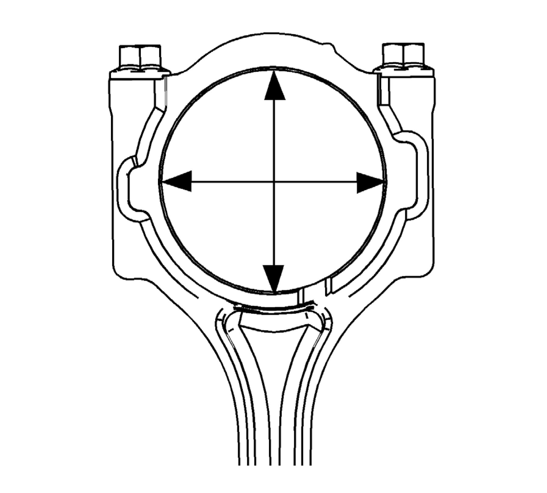 |
|
Fig. 461: Measuring Connecting Rod Crankshaft Bearing Bore Courtesy'of GENERAL'MOTORS'COMPANY |
NOTE: Measurements of all components should be taken with the components at
normal room temperature.
NOTE: The bore specifications are based on connecting rod bolts at full torque
specification.
1. Using the old bolts, tighten the connecting rod cap bolts to 25 N.m (18 lb ft) plus 75 degrees.
2. Using an inside micrometer, measure the connecting rod crankshaft bearing bore.
3. Compare the bore measurements to the proper specifications. Refer to Engine Mechanical Specifications.
4. Replace the connecting rod if the bore is out of specifications. DO NOT recondition the connecting rod.
PISTON AND CONNECTING ROD ASSEMBLE

|
Fig. 462: Piston and Connecting Rod Courtesy'of GENERAL'MOTORS'COMPANY | ||||||
|
|
Callout |
Component Name |
|
2 |
Piston Procedure
|
|
3 |
Piston Pin |
|
4 |
Piston Pin Retainer CAUTION: Procedure
Special Tools EN-49941 Piston Pin Retainer Remover and Installer |
|
5 |
Piston Oil Ring Rail CAUTION: Use a piston |
| ||||||||||||
|
CAMSHAFT CLEANING AND INSPECTION |
Special Tools
GE-7872 Magnetic Base Dial Indicator
For equivalent regional tools, refer to Special Tools.
Cleaning Procedure
1. Clean the camshaft in solvent.
WARNING: Refer to Safety Glasses Warning .
2. Dry the camshaft with compressed air.
Visual Inspection

Fig. 463: Identifying Camshaft Inspection Areas
Courtesy'of GENERAL'MOTORS COMPANY
1. Inspect the camshaft oil feed holes (1) to the camshaft position actuator for dirt, debris or blockage.
2. Inspect the threaded hole (2) for damage.
3. Inspect the camshaft position actuator locating notch (3) for damage or wear.
4. Inspect the camshaft sealing grooves (4) for damage.
5. Inspect the camshaft thrust surface (5) for damage.
6. Inspect the camshaft lobes (6) and journals (7) for the following conditions:
• Excessive scoring or pitting
• Discoloration from overheating
• Deformation from excessive wear, especially the camshaft lobes
7. If any of the above conditions exist on the camshaft, replace the camshaft.
Camshaft Measurement
У \> <7 У
Fig. 464: Supporting Camshaft In Fixture
Courtesy'of GENERAL'MOTORS'COMPANY
1. With the camshaft in a suitable fixture, measure the camshaft for wear.

Fig. 465: Measuring Camshaft Journals
Courtesy'of GENERAL'MOTORS'COMPANY
2. Measure the camshaft journals for diameter and out-of-round using an outside micrometer. Refer to Engine
Mechanical Specifications.
• If the diameter is smaller than specifications, replace the camshaft.
• If the out-of-round exceeds specifications, replace the camshaft.

J 7872
Fig. 466: Checking Camshaft Runout
Courtesy'of GENERAL'MOTORS'COMPANY
3. Measure the camshaft runout using the GE-7872 indicator. Refer to Engine Mechanical Specifications.
 |
|
Fig. 467: Measuring Camshaft Thrust Width Courtesy'of GENERAL'MOTORS'COMPANY |
4. Measure the camshaft thrust width for wear using a depth micrometer. Refer to Engine Mechanical
Specifications.

J 7872
Fig. 468: Measuring Camshaft Thrust Wall Surface For Runout
Courtesy'of GENERAL'MOTORS'COMPANY
5. Measure the camshaft thrust wall surface for runout using GE-7872 indicator. Refer to Engine Mechanical
Specifications.
6. If the camshaft is damaged or worn beyond specifications, replace the camshaft. No machining of the camshaft
is allowed.

J 7872
Fig. 469: Measuring Camshaft Lobes For Wear
Courtesy'of GENERAL'MOTORS'COMPANY
7. Measure the camshaft lobes for wear using the GE-7872 indicator.
 |
|
Fig. 470: Measuring Lift Of Camshaft Lobe Courtesy'of GENERAL'MOTORS'COMPANY |
8. Place the GE-7872 indicator with the indicator tip on the base circle (1) of the camshaft lobe.
1. Place the GE-7872 indicator at zero.
2. Rotate the camshaft until the indicator tip is at the highest point (3) on the lobe. This reading is the lift of
the camshaft lobe. Refer to Engine Mechanical Specifications.
3. If the indicated measurement is significantly lower than these specifications, replace the camshaft or
engine performance will be reduced.
CAMSHAFT TIMING CHAIN AND SPROCKET CLEANING AND INSPECTION
 |
|
Fig. 471: Camshaft Timing Chain and Sprocket Courtesy'of GENERAL'MOTORS'COMPANY |
|
Callout |
Component Name |
|
1 |
Timing Chain Procedure
|
|
2 |
Timing Chain Guide Procedure
|
|
Callout |
Component Name |
|
3 |
Camshaft Position Actuator Assembly - Exhaust Procedure
|
|
4 |
Timing Chain Guide Procedure
|
|
5 |
Timing Chain Oil Nozzle Procedure
|
|
6 |
Timing Chain Tensioner Shoe Procedure
|
|
7 |
Timing Chain Tensioner Procedure
|
| ||||||
|
INTAKE MANIFOLD CLEANING AND INSPECTION |
 |
|
Fig. 472: Intake Manifold |
Courtesy of GENERAL MOTORS COMPANY
Callout |_______________________________Component Name
Preliminary Procedure
1. Remove all components prior to cleaning and inspection.
2. Inspect each component.
Manifold Absolute Pressure Sensor Bolt
CAUTION:
1 Refer to
Fastener
Caution .
|
Callout |
Component Name |
|
Tighten 10 N.m (89 lb in) | |
|
2 |
Manifold Absolute Pressure Sensor |
|
3 |
Evaporative Emission Canister Purge Solenoid Valve Bolt Tighten 10 N.m (89 lb in) |
|
4 |
Evaporative Emission Canister Purge Solenoid Valve |
|
5 |
Upper Intake Manifold Cover Bolt (Qty: 3) Tighten 8 N.m (71 lb in) |
|
6 |
Upper Intake Manifold Cover |
|
7 |
Intake Manifold Cover Bolt (Qty: 3) Tighten 7 N.m (62 lb in) |
|
8 |
Lower Intake Manifold Cover |
CRANKSHAFT AND BEARING CLEANING AND INSPECTION
Special Tools
• EN-8087 Cylinder Bore Checking Gauge
• EN-45059 Angle Meter
• GE-7872 Magnetic Base Dial Indicator Set
For equivalent regional tools, refer to Special Tools.
Crankshaft Cleaning and Inspection

Fig. 473: Crankshaft
Courtesy'of GENERAL MOTORS COMPANY
NOTE: Use care when handling the crankshaft. Avoid damage to the bearing surfaces
or the lobes of the crankshaft position reluctor ring. Damage to the teeth of the
crankshaft position reluctor ring may affect on-board diagnostic (OBD) II
system performance.
1. Clean the crankshaft (1) with solvent.
2. Thoroughly clean all oil passages and inspect for restrictions or burrs.
WARNING: Refer to Safety Glasses Warning .
3. Dry the crankshaft with compressed air.
NOTE: Reluctor ring teeth should not have imperfections on the rising or falling
edges. Imperfections of the reluctor ring teeth may effect OBD II system
performance.
4. Perform a visual inspection of the crankshaft for damage.

Fig. 474: Identifying Different Crankshaft Journal Wear Patterns
Courtesy'of GENERAL'MOTORS'COMPANY
5. Inspect the crankshaft journals for wear (1). The journals should be smooth, with no signs of scoring, wear, or
damage.
6. Inspect the crankshaft journals for grooves or scoring (2).
7. Inspect the crankshaft journals for scratches or wear (3).
8. Inspect the crankshaft journals for pitting or imbedded bearing material (4).
Crankshaft Measurements
 |
|
Fig. 475: Measure Crankshaft Journals For Out-Of-Round |
1. Measure the crankshaft journals (1) for out-of-round.
2. Measure the crankshaft journals for taper.

Fig. 476: Measuring Crankshaft Runout
Courtesy'of GENERAL'MOTORS'COMPANY
3. Measure the crankshaft runout.
Using wooden V-blocks, support the crankshaft on the front and rear journals.
4. Use the GE-7872 indicator (1) in order to measure the crankshaft runout at the front and rear intermediate
journals.
5. Use the GE-7872 indicator in order to measure the runout of the crankshaft rear flange.
6. Replace the crankshaft if the measurements are not within specifications. Refer to Engine Mechanical
Specifications.
Crankshaft Bearings Cleaning and Inspection
 |
|
Fig. 477: Identifying Crankshaft Bearing Damage |
|
NOTE: |
|
1. Inspect crankshaft bearings for craters or pockets (1). Flattened sections on the bearing halves also indicate
fatigue.
2. Inspect the crankshaft bearings for excessive scoring or discoloration (2).
3. Inspect the crankshaft bearings for dirt or debris imbedded into the bearing material.
4. Inspect the crankshaft bearings for improper seating indicated by bright, polished sections of the bearing (3).
If the lower half of the bearing is worn or damaged, both upper and lower halves should be replaced.
Generally, if the lower half is suitable for use, the upper half should also be suitable for use.
 |
|
Fig. 478: Measuring Crankshaft Main Bearing Bores Courtesy'of GENERAL'MOTORS'COMPANY |
5. Inspect the connecting rod bearing bores or crankshaft main bearing bores using the following procedure:
1. Tighten the bedplate to specification using the EN-45059 meter.
2. Measure the bearing bore for taper and out-of-round using the EN-8087 gauge (1).
3. No taper or out-of-round should exist.
Bearing Selection
1. Measure the bearing clearance to determine the correct replacement bearing insert size. There are 2 methods to
measure bearing clearance. Method A gives more reliable results and is preferred.
• Method A yields measurement from which the bearing clearance can be computed.
• Method B yields the bearing clearance directly. Method B does not give any indication of bearing run-
out.

Fig. 479: Measuring Crankshaft Bearing Journal Using Method A
Courtesy'of GENERAL'MOTORS'COMPANY
NOTE: Do not mix inserts of different nominal size in the same bearing bore.
2. To measure bearing clearance using Method A, use the following procedure:
1. Measure the crankshaft bearing journal diameter with a micrometer (1) in several places, 90 degrees
apart. Average the measurements.
2. Measure the crankshaft bearing journal taper and runout.
3. Install the lower crankcase and tighten the bearing cap bolts to specification.
4. Measure bearing inside diameter (ID) in several places 90 degrees apart, average measurements.
5. Subtract journal measurement from bearing ID measurement to determine clearance.
6. Determine whether clearance is within specification.
7. If out of specification, choose different inserts.
8. Measure the connecting rod inside diameter in the same direction as the length of the rod with an inside
micrometer.
9. Measure the crankshaft main bearing inside diameter with an inside micrometer.
 |
|
Fig. 480: Measuring Bearing Clearance With Gaging Plastic Using Method B |
3. To measure bearing clearance using Method B, use the following procedure:
1. Clean the used bearing inserts.
2. Install the used bearing inserts.
3. Place a piece of gaging plastic across the entire bearing width.
4. Install the bearing caps.
CAUTION: In order to prevent the possibility of cylinder block or crankshaft bearing
cap damage, the crankshaft bearing caps are tapped into the cylinder
block cavity using a brass, lead, or a leather mallet before the attaching
bolts are installed. Do not use attaching bolts to pull the crankshaft
bearing caps into the seats. Failure to use this process may damage a
cylinder block or a bearing cap.
5. Install the bearing cap bolts to specification.
NOTE: Do not rotate the crankshaft.
6. Remove the bearing cap, leaving the gauging plastic in place. It does not matter whether the gauging
plastic adheres to the journal or to the bearing cap.
7. Measure the gauging plastic at its widest point with the scale (1) printed on the gauging plastic package.
8. Remove the gauging plastic.
OIL PUMP DRIVE CHAIN TENSIONER AND OIL PUMP DRIVE CHAIN CLEANING AND
INSPECTION
 |
|
Fig. 481: Oil Pump Drive Chain Tensioner and Oil Pump Drive Chain Cleaning and Inspection |
| ||||||||||
|
OIL PUMP CLEANING AND INSPECTION | ||||||||||
 |
|
Fig. 482: Oil Pump Cleaning and Inspection |
| ||||||||||||||
|
OIL PAN CLEANING AND INSPECTION | ||||||||||||||


Fig. 483: Oil Pan Cleaning and Inspection
Courtesy'of GENERAL'MOTORS COMPANY
|
Callout |
Component Name |
|
Preliminary Procedure
| |
|
Vulcanizing (RTV) and Anaerobic Sealant
| |
|
1 |
Upper Oil Pan Locating Pin (Qty: 2) |
|
2 |
Upper Oil Pan |
|
3 |
Lower Oil Pan Locating Pin (Qty: 2) |
|
4 |
Lower Oil Pan NOTE: Use a NEW |
|
5 |
Oil Pan Drain Plug |
THREAD REPAIR
Special Tools
• EN 42385-307 Drill Bushing
• EN 42385-308 Alignment Pin
• EN 42385-510 Main Attachment Bolt
• EN 42385-900 Head Bolt Thread Repair Kit
• EN 42385-904 Thread Insert
For equivalent regional tools, refer to Special Tools.
General Thread Repair
 |
|
Fig. 484: Bushing Type Insert And Base Material |
The thread repair process involves a solid, thin walled, self-locking, carbon steel, bushing type insert (1). During the
bushing installation process, the driver tool expands the bottom external threads of the insert into the base material
(2). This action mechanically locks the insert in place. Also, when installed to the proper depth, the flange of the
insert will be seated against the counterbore of the repaired hole.
 |
|
Fig. 485: Drilling And Tapping Threads Courtesy'of GENERAL'MOTORS'COMPANY |
NOTE: The use of a cutting fluid, WD 40A®, or equivalent, is recommended when
performing the drilling, counterboring, and tapping procedures. Refer to
Adhesives, Fluids, Lubricants, and Sealers.
Driver oil MUST be used on the installer driver tool.
The tool kits are designed for use with either a suitable tap wrench or drill
motor.
1. Drill out the threads of the damaged hole (1).
• M6 inserts require a minimum drill depth of 15 mm (0.59 in).
• M8 inserts require a minimum drill depth of 20 mm (0.79 in).
• M10 inserts require a minimum drill depth of 23.5 mm (0.93 in).
WARNING: Refer to Safety Glasses and Compressed Air Warning .
2. Using compressed air, clean out any chips.

Fig. 486: Identifying Tool Used To Counterbore Hole
Courtesy'of GENERAL'MOTORS'COMPANY
3. Counterbore the hole to the full depth permitted by the tool (1).
4. Using compressed air, clean out any chips.
 |
|
Fig. 487: Drilling And Tapping Threads |
5. Using a tap wrench (2), tap the threads of the drilled hole.
• M6 inserts require a minimum tap depth of 15 mm (0.59 in).
• M8 inserts require a minimum tap depth of 20 mm (0.79 in).
• M10 inserts require a minimum tap depth of 23.5 mm (0.93 in).
WARNING: Refer to Safety Glasses and Compressed Air Warning .
WARNING: Refer to Cleaning Solvent Warning .
6. Using compressed air, clean out any chips.
7. Spray cleaner into the hole. Refer to Adhesives, Fluids, Lubricants, and Sealers.
8. Using compressed air, clean any cutting oil and chips out of the hole.
 |
|
Fig. 488: Lubricating Installer Tool Threads Courtesy'of GENERAL'MOTORS'COMPANY |
NOTE: Do not allow oil or other foreign material to contact the outside diameter (OD)
of the insert.
9. Lubricate the threads of the installer tool (2) with the driver oil (1).
 |
|
Fig. 489: Driver Tool And Insert Courtesy'of GENERAL'MOTORS COMPANY |
10. Install the insert (2) onto the driver tool (1).
 |
|
Fig. 490: Applying Threadlock To Insert OD Threads |
11. Apply threadlock LOCTITE™ 277, EN 42385 - 109 (1) loctite, or equivalent to the insert OD threads (2).
 |
|
Fig. 491: Installing Insert Into Bolt Hole Using Installer Tool Courtesy'of GENERAL'MOTORS'COMPANY |
12. Install the insert (2) into the hole.
Install the insert until the flange of the insert contacts the counterbored surface. Continue to rotate the installer
tool (1) through the insert.
The installer tool will tighten up before screwing completely through the insert. This is acceptable. You are
forming the bottom threads of the insert and mechanically locking the insert to the base material threads.
 |
|
Fig. 492: Bushing Type Insert And Base Material |
13. Inspect the insert for proper installation into the hole.
A properly installed insert (1) will be either flush or slightly below flush with the surface of the base material
(2).
Cylinder Head Bolt Hole Thread Repair
 |
|
Fig. 493: Cylinder Head Bolt Hole Thread Repair Kit Courtesy'of GENERAL'MOTORS'COMPANY |
NOTE: The tools listed may not necessarily represent the exact tools used for the
procedure.
1. The cylinder head bolt hole thread repair kit consists of the following items:
• Drill (1)
• Tap (2)
• Installer (3)
• Sleeve (4)
• Alignment Pin (5)
• Bushing (6)
• Bolts (7)
• Fixture Plate (8)
 |
|
Fig. 494: Fixture Plate, Bolts And Bushing Courtesy'of GENERAL'MOTORS'COMPANY |
WARNING: Refer to Safety Glasses and Compressed Air Warning .
NOTE: The use of a cutting fluid, WD 40A®, or equivalent, is recommended when
performing the drilling and tapping procedures. Refer to Adhesives, Fluids,
Lubricants, and Sealers.
Driver oil MUST be used on the installer driver tool.
The tool kits are designed for use with either a suitable tap wrench or drill
motor.
2. Install the fixture plate (3), bolts (1), and bushing (2) onto the engine block deck.
Position the fixture plate and bushing over the hole that is to be repaired (4).
 |
|
Fig. 495: Alignment Pin & Fixture Retaining Bolts |
3. Position the alignment pin (1) through the bushing and into the hole.
4. With the alignment pin in the desired hole, tighten the fixture retaining bolts (2).
5. Remove the alignment pin from the hole.
 |
|
Fig. 496: Installing Sleeve Onto Drill |
6. Install the sleeve (2) onto the drill (1), if required.
 |
|
Fig. 497: Drilling Out Threads Of Damaged Hole |
NOTE: During the reaming process, it is necessary to repeatedly remove the drill and
clean the chips from the hole.
7. Drill out the threads of the damaged hole.
Drill the hole until the stop collar of the drill bit or the sleeve contacts the bushing.
WARNING: Refer to Safety Glasses and Compressed Air Warning .
8. Using compressed air, clean out any chips.
 |
|
Fig. 498: Tapping Threads Of Drilled Hole With Tap Wrench |
9. Using a tap wrench, tap the threads of the drilled hole.
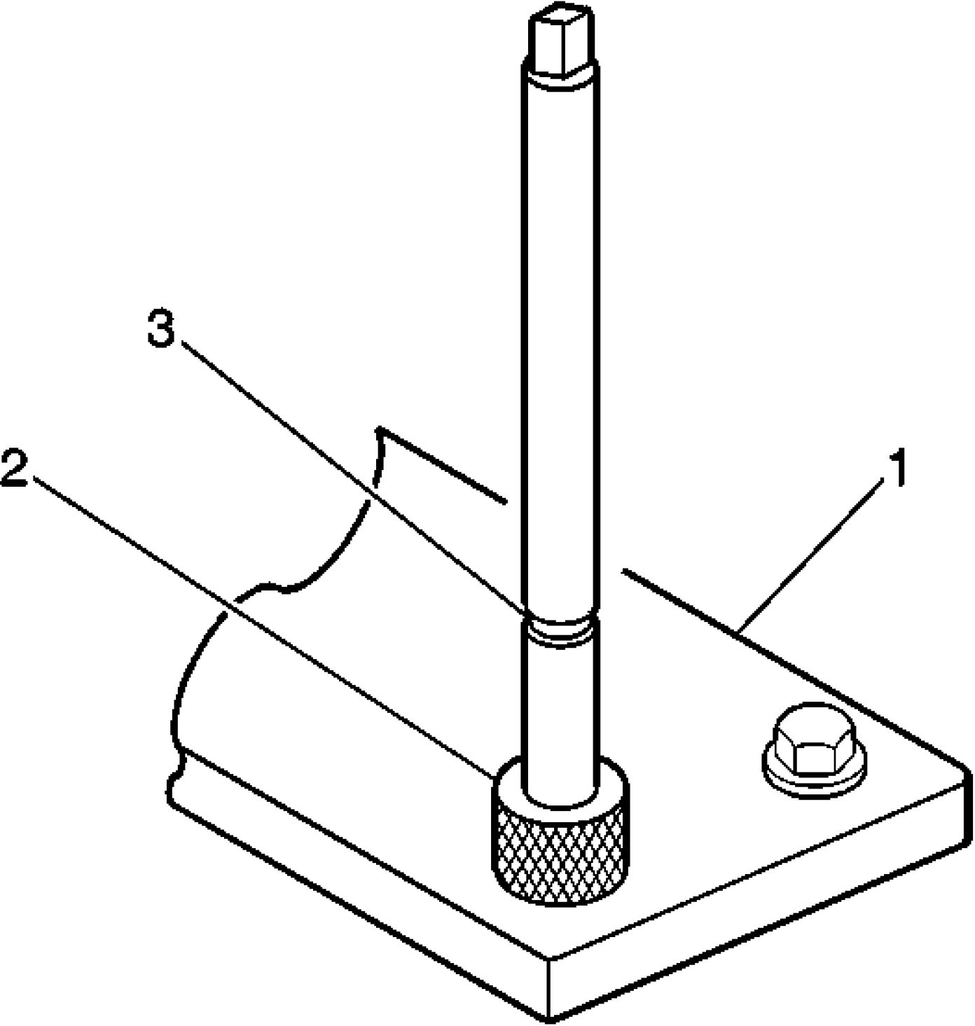 |
|
Fig. 499: Fixture Plate, Drill Bushing And Tool Marking Courtesy'of GENERAL'MOTORS'COMPANY |
10. Using a TAP wrench, tap the threads of the drilled hole.
In order to tap the new threads to the proper depth, rotate the tap into the hole until the mark (3) on the tap
align with the top of the drill bushing (2).
11. Remove the fixture plate (1), bushing (2), and bolts.
WARNING: Refer to Safety Glasses and Compressed Air Warning .
WARNING: Refer to Cleaning Solvent Warning .
12. Using compressed air, clean out any chips.
13. Spray cleaner into the hole. Refer to Adhesives, Fluids, Lubricants, and Sealers.
14. Using compressed air, clean any cutting oil and chips out of the hole.
 |
|
Fig. 500: Lubricating Installer Tool Threads Courtesy'of GENERAL'MOTORS'COMPANY |
NOTE: Do not allow oil or other foreign material to contact the outside diameter (OD)
of the insert.
15. Lubricate the threads of the installer tool (2) with the driver oil (1).
 |
|
Fig. 501: Driver Tool And Insert Courtesy'of GENERAL'MOTORS COMPANY |
16. Install the insert (2) onto the driver tool (1).
 |
|
Fig. 502: Applying Threadlock To Insert OD Threads |
17. Apply threadlock LOCTITE™ 277, EN 42385 - 109 loctite (1), or equivalent to the insert OD threads (2).
 |
|
Fig. 503: Installing Insert And Driver Into Hole Courtesy'of GENERAL'MOTORS'COMPANY |
18. Install the insert and driver (1) into the hole.
Rotate the driver tool until the mark on the tool aligns with the deck surface of the engine block.
The installer tool will tighten up before screwing completely through the insert. This is acceptable. You are
forming the bottom threads of the insert and mechanically locking the insert to the base material threads.
SERVICE PRIOR TO ASSEMBLY
The importance of cleanliness during assembly cannot be overstated. Dirt or debris will cause engine damage. An
automobile engine is a combination of many machined, honed, polished and lapped surfaces with tolerances that are
measured in ten thousandths of an inch. When any internal engine parts are serviced, care and cleanliness are
important. A liberal coating of engine oil should be applied to friction areas during assembly in order to protect and
lubricate the surfaces on initial operation. Throughout this section, it should be understood that proper cleaning and
protection of machined surfaces and friction areas are part of the repair procedure. This is considered standard shop
practice even if not specifically stated.
Lubricate all moving parts with engine oil or a specified assembly lubricant. This will provide lubrication for initial
start up.
CRANKSHAFT AND BEARING INSTALLATION

|
Fig. 504: Crankshaft and Bearing Courtesy'of GENERAL'MOTORS COMPANY | ||||||
|
| ||||||||
|
LOWER CRANKCASE INSTALLATION |
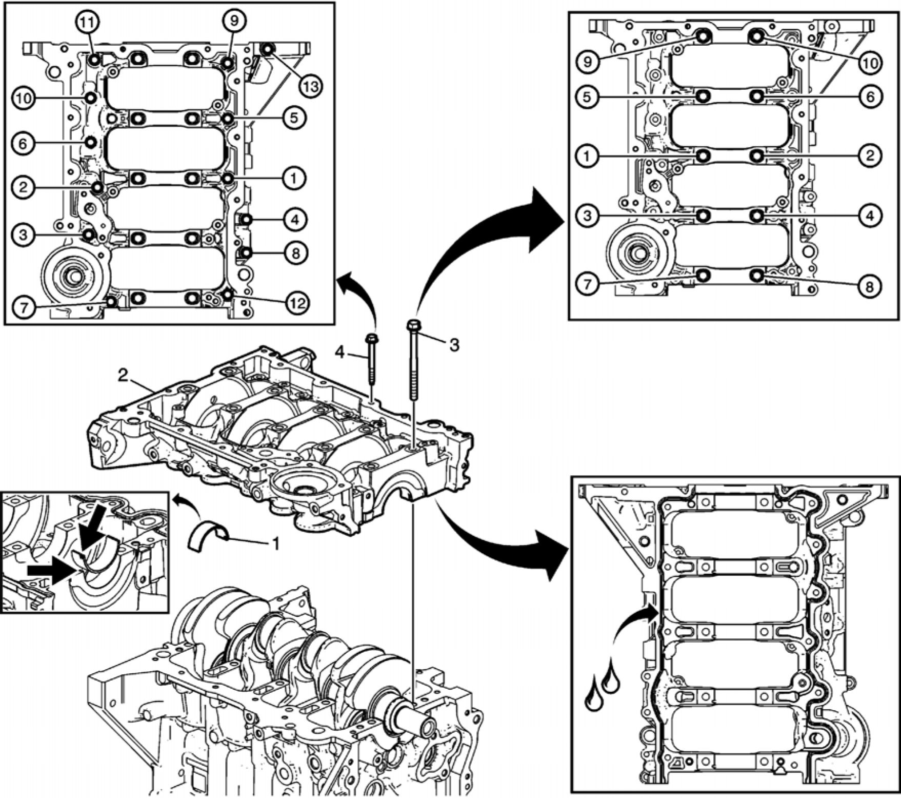 |
|
Fig. 505: Lower Crankcase With Bolt Tightening Sequences |
|
Callout |
Component Name |
|
1 |
Crankshaft Lower Bearing (Qty: 5) Procedure Install the bearings in the lower crankcase, and ensure that the guide lug on the bearing is |
|
2 |
Lower Crankcase Procedure 1. Ensure proper use of room temperature vulcanizing (RTV) sealant. Refer to Use of Room NOTE: • The block |
|
Callout |
Component Name |
|
applying the
| |
|
3 |
Lower Crankcase Bolts (Qty: 10) CAUTION: Refer to Caution . CAUTION: Refer to Torque-to- Yield Procedure Tighten the NEW lower crankcase bolts in the sequence shown.
Special Tools EN-45059 Angle Meter For equivalent regional tools, refer to Special Tools. |
Lower Crankcase Bolts (Qty: 13)
Procedure
1. Apply sealant to the lower crankcase perimeter bolts. Refer to Adhesives, Fluids,
Lubricants, and Sealers.
2. Tighten the lower crankcase bolts in the sequence shown.
3. Tighten the bolts in sequence a first pass to 5 N.m (44 lb in).
4. Tighten the bolts in sequence a final pass to 10 N.m (89 lb in).
PISTON, CONNECTING ROD, AND BEARING INSTALLATION
 |
|
Fig. 506: Piston, Connecting Rod and Bearing |
Callout
Component Name
Preliminary Procedure
NOTE:
Many
internal
engine
|
Callout |
Component Name |
|
components specific
| |
|
1 |
Connecting Rod Bearing (Qty: 4) NOTE: The Procedure Install NEW bearings to the connecting rods and lubricate each bearing with engine oil. |
|
2 |
Piston and Connecting Rod Assembly (Qty: 4) NOTE: |
|
Callout |
Component Name |
|
and the upper Procedure 1. Install the EN-51454 guides into the connecting rod bolt holes. This protects the NOTE: NOTE: When installing a
anodized
|
|
Callout |
Component Name |
If a ring
NOTE: The piston
|
|
Callout |
Component Name |
|
10. Remove the connecting rod guides from the connecting rod bolt holes. Special Tools EN-51454 Connecting Rod Guides For equivalent regional tools, refer to Special Tools. | |
|
3 |
Connecting Rod Bearing (Qty: 4) Procedure Install NEW bearings to the connecting rod caps and lubricate each bearing with engine oil. |
|
4 |
Connecting Rod Cap (Qty: 4) Procedure Ensure that the connecting rod cap is properly oriented on the connecting rod. |
|
5 |
Connecting Rod Bolts (Qty: 8) CAUTION: Refer to CAUTION: Refer to Procedure
NOTE: Rotate the
Special Tools For equivalent regional tools, refer to Special Tools. |
CRANKSHAFT OIL DEFLECTOR INSTALLATION
 |
|
Fig. 507: Crankshaft Oil Deflector (With Bolt Tightening Sequence) |
|
Callout |
Component Name |
|
1 |
Crankshaft Oil Deflector |
|
2 |
Crankshaft Oil Deflector Bolt (Qty: 3) CAUTION: Refer to Caution . Procedure Tighten the bolts in the sequence shown. Tighten 10 N.m (89 lb in) |
|
3 |
Positive Crankcase Ventilation Oil Separator Drain Pipe |
|
4 |
Positive Crankcase Ventilation Oil Separator Drain Pipe Bolt Tighten 10 N.m (89 lb in) |
CRANKSHAFT REAR OIL SEAL INSTALLATION
 |
|
Fig. 508: Crankshaft Rear Oil Seal Courtesy'of GENERAL'MOTORS COMPANY |
|
Callout |
Component Name |
|
Crankshaft Rear Oil Seal Procedure
Temperature Vulcanizing (RTV) and Anaerobic Sealant | |
|
1 |
3. Add RTV sealer at 2 locations where the bedplate and block join prior to installing the oil NOTE: The oil seal |
|
Callout |
Component Name |
|
The side that
NOTE: If the seal is
|
| ||||
|
seal bore. OIL PUMP DRIVE CHAIN AND OIL PUMP INSTALLATION |
Oil Pump Assembly Installation
 |
|
Fig. 509: Oil Pump Assembly Courtesy'of GENERAL'MOTORS COMPANY |
|
Oil Pump Assembly Installation | ||||||||
|
| ||||||||
|
Crankshaft Sprocket and Oil Pump Drive Chain Installation |
 |
|
Fig. 510: Crankshaft Sprocket and Oil Pump Drive Chain |
|
Crankshaft Sprocket and Oil Pump Drive Chain Installation | ||||||||||||||
| ||||||||||||||
|
CYLINDER HEAD INSTALLATION |
 |
|
Fig. 511: Cylinder Head With Bolt Tightening Sequence |
|
Callout |
Component Name |
|
1 |
Cylinder Head Gasket NOTE: |
|
2 |
Cylinder Head Assembly |
|
3 |
Cylinder Head Bolt (Qty: 10) CAUTION: |
|
Callout |
Component Name |
|
Refer to CAUTION: Refer to Torque-to- Procedure Tighten the NEW cylinder head bolts in the sequence shown.
Special Tools EN-45059 Angle Meter For equivalent regional tools, refer to Special Tools. |
INTAKE AND EXHAUST CAMSHAFT, BEARING CAP, AND LASH ADJUSTER INSTALLATION
Valve Rocker Arm and Lash Adjuster Installation
 |
|
Fig. 512: Valve Rocker Arm and Lash Adjuster |
|
Valve Rocker Arm and Lash Adjuster Installation | ||||||
|
| ||||
|
Camshaft Bearings and Camshaft Installation |
 |
|
Fig. 513: Camshaft Bearings and Camshaft |
Camshaft Bearings and Camshaft Installation
|
Callout |
Component Name |
|
1 |
Exhaust Camshaft Assembly Procedure
|
|
2 |
Camshaft Bearing Cap - Exhaust Side (Qty: 5) NOTE: Observe the Procedure Install the cap and start the cap bolts by hand. |
|
3 |
Camshaft Bearing Front Exhaust Cap Procedure Install the cap and start the cap bolts by hand. |
|
4 |
Camshaft Bearing Cap Bolt - Exhaust Side (Qty: 12) CAUTION: Refer to Procedure
Tighten 12 N.m (106 lb in) |
| ||||||||||||
|
Camshaft Actuator Installation |
 |
|
Fig. 514: Camshaft Actuator |
Courtesy of GENERAL MOTORS COMPANY
|
Camshaft Actuator Installation | ||||||||
| ||||||||
| ||||||||
|
CAMSHAFT TIMING CHAIN INSTALLATION |
 |
|
Fig. 515: Camshaft Timing Chain Components Courtesy'of GENERAL'MOTORS'COMPANY |
|
Callout |
Component Name |
|
1 |
Timing Chain Oil Nozzle CAUTION: Refer to |
|
Fastener | |
|
Tightening | |
|
Caution . | |
|
Tighten 15 N.m (11 lb ft) | |
|
2 |
Timing Chain NOTE: Ensure the |
|
Callout |
Component Name |
|
crankshaft Procedure NOTE:
| |
|
3 |
Timing Chain Guide - Exhaust Side |
|
4 |
Timing Chain Guide Bolt (Qty: 3) CAUTION: Refer to Caution . Tighten 10 N.m (89 lb in) |
|
5 |
Timing Chain Tensioner Shoe Assembly |
|
6 |
Timing Chain Tensioner Shoe Bolt Tighten 25 N.m (18 lb ft) |
|
7 |
Timing Chain Tensioner Gasket |
| ||||||||||
|
ENGINE FRONT COVER INSTALLATION |
Engine Front Cover and Components Installation
 |
|
Fig. 516: Engine Front Cover and Components With Bolt Tightening Sequence |
|
Engine Front Cover and Components Installation | ||||||
|
| ||||
|
Engine Front Cover Bolt - M6 (Qty: 11) |
NOTE:
| ||||||||||
|
Crankshaft Front Oil Seal Installation |
 |
|
Fig. 517: Crankshaft Front Oil Seal |
|
Crankshaft Front Oil Seal Installation | ||||||
|
| ||||
|
OIL PAN INSTALLATION |
 |
|
Fig. 518: Oil Pan With Bolt Tightening Sequences |
|
Callout |
Component Name |
|
Callout |
Component Name |
|
1 |
Engine Oil Level Indicator Control Wiring Harness |
|
Wiring Harness Connector Bolt | |
|
2 |
CAUTION: Refer to |
|
Caution . | |
|
Tighten 10 N.m (89 lb in) | |
|
Upper Oil Pan Assembly | |
|
Procedure | |
|
1. Ensure proper use of room temperature vulcanizing (RTV) sealant. Refer to Use of Room Temperature Vulcanizing (RTV) and Anaerobic Sealant | |
|
3 |
NOTE:
|
|
Callout |
Component Name |
|
leakage
| |
|
4 |
Oil Pan Bolt (Qty: 12) Procedure
Tighten 10 N.m (89 lb in) |
|
5 |
Oil Pan Bolt (Qty: 2) Procedure
Tighten 10 N.m (89 lb in) |
|
6 |
Oil Pan Bolt (Qty: 2) Procedure
Tighten 10 N.m (89 lb in) |
| ||||||
|
CAMSHAFT COVER INSTALLATION |
|
Camshaft Cover Components Installation - Bottom |
 |
|
Fig. 519: Camshaft Cover Components - Bottom |
|
Camshaft Cover Components Installation - Bottom | ||||
|
| ||||||||||
|
Camshaft Cover Components Installation - Top |
 |
|
Fig. 520: Camshaft Cover Components - Top |
|
Camshaft Cover Components Installation - Top | ||||||||||||
|
| ||||||
|
Camshaft Cover Installation |
 |
|
Fig. 521: Camshaft Cover With Bolt Tightening Sequence |
Camshaft Cover Installation
|
Callout |
Component Name |
|
1 |
Camshaft Cover Gasket NOTE: Use a NEW Procedure Assemble the camshaft cover and a NEW gasket. Ensure that the gasket is located in the |
|
2 |
Camshaft Cover Procedure
|
|
3 |
Camshaft Cover Bolt (Qty: 18) Procedure: Tighten the engine front cover bolts and studs in sequence. |
|
4 |
Camshaft Cover Stud (Qty: 2) CAUTION: Refer to Caution . Procedure: Tighten the engine front cover bolts and studs in sequence. Tighten 15 N.m (11 lb ft) |
|
5 |
Oil Level Indicator |
FUEL RAIL AND INJECTORS INSTALLATION
Special Tools
• EN-49245 Fuel Injector Seal Installer/Sizer
• EN-51105 Injector Seal Installer Adapters
• EN-51146 Fuel Injector Removal/Installation Kit
• EN-51146-100 Fuel Injector Removal Plate
• EN-51146-150 Fuel Injector Removal Adapters
For equivalent regional tools, refer to Special Tools.
Fuel Injector Installation Procedure
 |
|
Fig. 522: Installing Fuel Injectors Using Removal/Installation Kit Courtesy'of GENERAL'MOTORS'COMPANY |
NOTE: Do not remove the fuel injectors unless inspection indicates replacement is
necessary. Do not remove the EN-51146-150 adapter and EN-51146-1-1 support
unless the fuel injector is being replaced.
1. If one or more fuel injectors are being replaced, remove the EN-51146-100 plate (2) and bolts (1).
2. Remove the EN-51146-150 adapters and EN-51146-1-1 supports (3) for all fuel injectors that are being
replaced.
3. Remove and discard the fuel injectors (5) that are being replaced.
4. Lubricate the O-ring with one drop of clean engine oil. Install a new fuel injector (5).
CAUTION: Refer to Fastener Caution .
5. Install the NEW fuel injector screws (4) to the NEW fuel injectors (5) and tighten to 5 N.m (44 lb in).
6. Connect the fuel injector wiring harness plugs.
Fuel Injector Combustion Seal Installation Procedure
 |
|
Fig. 523: Installing Combustion Seals Courtesy'of GENERAL'MOTORS'COMPANY |
|
NOTE: |
DO NOT use any type of lubricant when installing the NEW combustion seals |
|
NOTE: |
The injector tip protectors in the EN-49245 set are too small for some injectors. |
1. Install EN-51105-1 long protector (1) onto the fuel injector tip, covering the first recessed area closest to the
tip. Place a NEW seal (2) on EN-51105-1 long protector (1).
2. Using EN-49245-3 pusher (3), install the seal (2) into the recessed area of the fuel injector.
3. Compress the seal (2) with your fingers.
4. Install EN-51105-2 short protector (4) onto the fuel injector tip. Place a NEW seal (5) on EN-51105-2 short
protector (4).
5. Using EN-49245-3 pusher (3), install the seal (5) into the last recessed area of the fuel injector.
6. Compress the seal (5) with your fingers.
 |
|
Fig. 524: Pre-Sizing Tool Courtesy'of GENERAL'MOTORS COMPANY |
7. Push the EN-51146-2-4 pre-sizing tool (1) over the fuel injector tip.
8. Tighten the nut (2) and counterhold at the spanner flat (3) of the EN-51146-2-4 pre-sizing tool (1) until the
measure (a) of 4.5 mm (0.177 in) is reached.
9. Loosen the nut (2) of the EN-51146-2-4 pre-sizing tool.
10. Install the EN-51146-2-4-7 take off chassis (4) to the EN-51146-2-4 pre-sizing tool (1).
11. Install the EN-51146-2-4-6 screw M10 (5) to the EN-51146-2-4-7 take off chassis (4) and tighten until the
EN-51146-2-4 pre-sizing tool (1) is loosened.
 |
|
Fig. 525: Sizer Courtesy'of GENERAL MOTORS COMPANY |
12. Install the EN-49245-4 sizer (1) in a rotary motion to the fuel injector tip in order to complete the combustion
seal final sizing.
 |
|
Fig. 526: Ensure Seals Are Installed Correctly |
NOTE: The fuel injector seals must fit properly in the relative groove. Overlapping of
the fuel injector seals with the external surface of the injector must be avoided.
13. Check both of the fuel injector combustion seals on each fuel injector for correct seat:
• The seal must not be too large, buckled, or corrugated (1)
• The seal must be fixed tight and accurate (2)
14. If the seals are not installed correctly, remove the incorrect seal and replace with a NEW seal.
Fuel Rail Assembly Installation Procedure
 |
|
Fig. 527: Installing Fuel Rail Assembly Using Special Tools Courtesy'of GENERAL'MOTORS'COMPANY |
1. If any components of EN-51146 remover are installed to the fuel rail, perform the following procedure:
NOTE: If the plate is not installed on the supports, it is likely one or more fuel
injectors have been replaced. Disregard the following steps for fuel
injectors that have already been replaced.
1. Remove the bolts (1) and EN-51146-100 plate (2).
2. Remove only the front EN-51146-150 adapter and EN-51146-1-1 support (3) for the first fuel injector.
CAUTION: Refer to Fastener Caution .
3. Install the fuel injector screw (4) and tighten to 5 N.m (44 lb in).
4. Remove the rear EN-51146-150 adapter and EN-51146-1-1 support (6) for the first fuel injector.
5. Install the fuel injector screw (5) and tighten to 5 N.m (44 lb in).
6. Repeat the same procedure for the remaining fuel injectors with EN-51146-150 adapters and
EN-51146-1-1 supports still attached.
7. Connect the fuel injector wiring harness plugs, if necessary.
2. Ensure the fuel rail assembly and fuel injector bores have been cleaned prior to installation.
 |
|
Fig. 528: Fuel Rail Assembly Courtesy'of GENERAL'MOTORS COMPANY |
NOTE: During the installation of the fuel rail and injector assembly, ensure that the
fuel injectors are positioned straight into the injector opening. Failure to follow
this caution can tilt or bend the injectors and could cause leaks or malfunction
after installation.
3. Carefully install the fuel rail assembly (1).
4. Push the fuel injectors slightly in their seats.

Fig. 529: Fuel Rail Bolt Tightening Sequence
Courtesy'of GENERAL'MOTORS'COMPANY
5. Tighten the 4 lower fuel rail bolts in increments of 1 turn until they are seated.
6. Tighten the 4 lower fuel rail bolts in sequence to 10 N.m (89 lb in).
7. Tighten the 4 upper fuel rail bolts in sequence to 10 N.m (89 lb in).
IGNITION COIL INSTALLATION
 |
|
Fig. 530: Ignition Coil Courtesy'of GENERAL MOTORS COMPANY |
|
Callout |
Component Name |
|
Preliminary Procedure
| |
|
1 |
Ignition Coil Assembly (Qty: 4) CAUTION: Refer to Caution . Tighten 10 N.m (89 lb in) |
WATER OUTLET INSTALLATION
 |
|
Fig. 531: Water Outlet Courtesy'of GENERAL MOTORS COMPANY |
| ||||||||
|
ENGINE LIFT AND SIGHT SHIELD BRACKET INSTALLATION |
 |
|
Fig. 532: Engine Lift And Sight Shield Bracket Courtesy'of GENERAL'MOTORS'COMPANY |
| ||||||||||
|
FUEL PUMP INSTALLATION |
 |
|
Fig. 533: Fuel Pump Courtesy'of GENERAL MOTORS COMPANY |
|
Callout |
Component Name |
|
Valve Lifter Follower NOTE: The | |
|
1 |
position high pressure Procedure 1. Lubricate the valve lifter follower with engine oil, refer to Adhesives, Fluids, Lubricants, |
|
Callout |
Component Name |
|
NOTE: At the base
Special Tools EN-51365 Fuel Pump Installation Gauge | |
|
2 |
Fuel Pump NOTE: |
|
3 |
Fuel Pump Bolt (Qty: 2) CAUTION: CAUTION: |
Yield
Fastener
Caution .
CAUTION:
Alternately
hand-tighten
the fuel
pump bolts
one turn at a
time until the
pump is fully
seated.
Trying to
draw down
the pump
without even
side-to-side
tightening
may result in
pump
plunger
damage.
Procedure
Install NEW fuel injection pump bolts alternating in steps of one turn each until seated to
specified torque.
Tighten
25 N.m (18 lb ft)
Fuel Pump Insulator
WARNING:
The noise
cancelling
foam
component
MUST be
replaced if it
has been
exposed to
engine
fluids.
Failure to
replace the
noise
cancelling
foam
component
that has
been
|
Callout |
Component Name |
|
exposed to | |
|
5 |
Fuel Feed Intermediate Pipe NOTE: Use a NEW Procedure NOTE:
NOTE: Tightening |
| ||||||
|
INTAKE MANIFOLD INSTALLATION |
 |
|
Fig. 534: Intake Manifold With Bolt Tightening Sequence |
|
Callout |
Component Name |
|
Intake Manifold Gasket NOTE: | |
|
1 |
Use a NEW |
| ||||||||
|
THROTTLE BODY ASSEMBLY INSTALLATION |
 |
|
Fig. 535: Throttle Body Assembly Courtesy'of GENERAL'MOTORS COMPANY |
|
Callout |
Component Name |
|
1 |
Throttle Body Gasket NOTE: Use a NEW Ensure the |
|
2 |
Throttle Body |
|
3 |
Throttle Body Bolt (Qty: 4) NOTE: Tighten the 4 |
| ||||
|
ENGINE WIRING HARNESS ASSEMBLY INSTALLATION |
 |
|
Fig. 536: Engine Wiring Harness Assembly |
|
Callout |
Component Name |
|
1 |
Engine Wiring Harness |
|
2 |
Engine Wiring Harness Bracket Bolt (Qty: 2) CAUTION: Refer to Caution . Tighten 25 N.m (18 lb ft) |
| ||||
|
WATER PUMP INSTALLATION |
 |
|
Fig. 537: Water Pump Courtesy'of GENERAL MOTORS COMPANY |
|
Callout |
Component Name |
|
1 |
Water Pump Housing Gasket NOTE: Use a NEW Ensure the |
|
2 |
Water Pump |
| ||||||||||||
|
EXHAUST GAS RECIRCULATION VALVE INSTALLATION |

Fig. 538: Exhaust Gas Recirculation Valve
Courtesy'of GENERAL'MOTORS'COMPANY
| ||||||||||
|
EXHAUST GAS RECIRCULATION COOLER INSTALLATION |
 |
|
Fig. 539: Exhaust Gas Recirculation Cooler Courtesy'of GENERAL'MOTORS'COMPANY |
|
Callout |
Component Name |
|
1 |
Exhaust Gas Recirculation Cooler Inlet Pipe Gasket NOTE: |
|
2 |
Exhaust Gas Recirculation Cooler |
|
3 |
Exhaust Gas Recirculation Cooler Bolt CAUTION: Refer to Caution . Tighten 10 N.m (89 lb in) |
| ||||||||||
|
EXHAUST GAS RECIRCULATION COOLER OUTLET PIPE INSTALLATION |
 |
|
Fig. 540: Exhaust Gas Recirculation Cooler Outlet Pipe |
| ||||||||||
|
EXHAUST GAS RECIRCULATION PIPE INSTALLATION |
 |
|
Fig. 541: Exhaust Gas Recirculation Pipe |
|
Callout |
Component Name |
|
1 |
Exhaust Gas Recirculation Pipe Gasket NOTE: |
|
2 |
Exhaust Gas Recirculation Pipe Gasket NOTE: |
|
3 |
Exhaust Gas Recirculation Pipe |
| ||||||||
|
AUTOMATIC TRANSMISSION FLEX PLATE INSTALLATION |
 |
|
Fig. 542: Automatic Transmission Flex Plate With Bolt Tightening Sequence |
|
Callout |
Component Name |
|
Crankshaft Position Sensor Reluctor Ring | |
|
1 |
CAUTION: |
|
Callout |
Component Name |
|
Position ■ | |
|
2 |
Automatic Transmission Flex Plate Procedure
Special Tools EN-51760 Flywheel Holder Equivalent regional tools: Special Tools. |
|
3 |
Automatic Transmission Flex Plate Bolt (Qty: 8) CAUTION: Refer to CAUTION: Refer to NOTE: Bolts have Procedure Tighten the NEW flex plate bolts in the sequence shown.
|
| ||||
|
CRANKSHAFT BALANCER INSTALLATION |
 |
|
Fig. 543: Crankshaft Balancer |
|
Courtesy of GENERAL MOTORS COMPANY | ||||||||
| ||||||||
| ||||
|
OIL FILTER INSTALLATION |
 |
|
Fig. 544: Oil Filter, Fitting Adapter And Drain Plug |
| ||||||||
|
ENGINE PRELUBING |
Special Tools
EN-45299 Engine Preluber
For equivalent regional tools, refer to Special Tools.
 |
|
Fig. 545: Oil Pressure Switch Courtesy'of GENERAL'MOTORS COMPANY |
NOTE: A constant and continuous flow of clean engine oil is required in order to
properly prime the engine. Ensure an approved engine oil is used, as specified
in the owners manual.
1. Remove the oil pressure switch.
2. Install the M12 x 1.75 adapter (1) P/N 509376.
 |
|
Fig. 546: Flexible Hose, Adapter And Preluber Courtesy'of GENERAL'MOTORS'COMPANY |
3. Install the flexible hose to the adapter and open the valve.
4. Pump the handle on the EN-45299 preluber (1) in order to flow a minimum of 1 - 1.9 liters (1 - 2 quarts) of
engine oil. Observe the flow of engine oil through the flexible hose and into the engine assembly.
5. Close the valve and remove the flexible hose and adapter from the engine.
CAUTION: Refer to Fastener Caution .
6. Install the oil pressure switch to the engine and tighten to 26 N.m (19 lb ft).
7. Top-off the engine oil to the proper level.
DESCRIPTION AND OPERATION
CRANKCASE VENTILATION SYSTEM DESCRIPTION
Positive Crankcase Ventilation System
The crankcase ventilation system is used to consume crankcase vapors in the combustion process instead of venting
vapors to the atmosphere. Fresh air from the intake system is supplied to the crankcase and mixed with blow-by
gases inside the crankcase. Blow-by gases rise to the top of the engine and are picked up into the oil separation
chamber in the camshaft cover, where oil is separated from the gases. Blow-by gases are then passed to the intake
manifold to be consumed by normal combustion, through a calibrated orifice inside of the camshaft cover.
Operation
 |
|
Fig. 547: Crankcase Ventilation System Diagram Courtesy'of GENERAL'MOTORS'COMPANY |
Fresh air is brought into the engine through the positive crankcase ventilation (PCV) valve (4) as long as the
crankcase is under vacuum. The primary control is through the PCV orifice (3) which meters the flow into intake
manifold, at a rate depending on manifold vacuum. The PCV orifice is an integral part of the camshaft cover. Under
certain operating conditions, the system is designed to allow excessive amounts of blow by gases to flow through the
PCV valves (1 or 2) depending on if the engine is in boost mode or excessive crankcase pressure is detected and then
routed into the intake system to be consumed by normal combustion.
Turbo Applications:
During normal operating conditions the PCV gases are routed using PCV valve (3) and the internal passage within
the camshaft cover. When the Turbo is active, check valve (3) is closed and check valve (1) opens and PCV gases are
routed back to the turbocharger to be consumed by normal combustion. If the engine sees excessive positive
crankcase pressure check valve (2) opens and the pressure is routed to the air inlet to be reintroduced into the engine.
Non-Turbo Applications:
During normal operating conditions the PCV gases are routed using check valve (3) and the internal passage within
the camshaft cover. If the engine sees excessive positive crankcase pressure check valve (2) opens and the pressure is
In any application check valve (2) is only used if the engine sees excessive crankcase pressure.
Results of Incorrect Operation
A plugged orifice may cause the following conditions:
• Rough idle
• Stalling or slow idle speed
• Oil leaks
• Sludge in engine
A leaking orifice may cause the following conditions:
• Rough idle
• Stalling
• High idle speed
ENGINE COMPONENT DESCRIPTION
Engine Description
Cylinder Block
The cylinder block is constructed of aluminum alloy by high-pressure die casting with 4 cast-in-place iron cylinder
liners arranged in-line. The block has 5 crankshaft bearings with the thrust bearing located on the second bearing
from the rear of the engine. The cylinder block incorporates a bedplate design that forms an upper and lower
crankcase. This design promotes cylinder block rigidity and reduced noise and vibration.
Crankshaft
The crankshaft is forged micro alloy steel. It is supported in 5 main journals with main bearings which have oil
clearance for lubricating. The thrust bearing is located in the 4th position which controls proper crankshaft axial end
play. The crankshaft is also comprised of 8 counterweights that have been scalloped for mass reduction and topped
for precise engine balance. A harmonic balancer is used to control torsional vibration.
Piston and Connecting Rod
The pistons are cast aluminum. The pistons use 2 compression rings and 1 oil control ring assembly. The piston is a
low friction, lightweight design with a recessed top and barrel shaped skirt. The piston pins are chromium steel and
are a full-floating design. The connecting rods are powdered metal. The connecting rods are fractured at the
connecting rod journal and then machined for the proper clearance. All applications use a piston with a graphite
coated skirt. The piston and pin are to be serviced as an assembly.
Upper Oil Pan
The oil pan is a structural aluminum oil pan with transmission attachment. It includes the oil suction pipe, this pipe is
connected with the oil pump. The oil pan is attached at the lower crankcase.
Oil Pump
The oil pump is a crankshaft driven oil pump integrated in pump module. The oil pump draws engine oil from the oil
pan and feeds it under pressure to the various parts of the engine. An oil strainer is mounted before the inlet of the oil
pump to remove impurities which could clog or damage the oil pump or other engine components. When the
crankshaft rotates, the oil pump driven gear rotates. This causes the space between the gears to constantly open and
narrow, pulling oil in from the oil pan when the space opens and pumping the oil out to the engine as it narrows. At
high engine speeds, the oil pump supplies a much higher amount of oil than required for lubrication of the engine.
The oil pressure regulator prevents too much oil from entering the engine lubrication passages.
Cylinder Head
This cylinder head is double over head camshaft (DOHC) type and has 2 camshafts that open 4 valves per cylinder
with hydraulic valve lash adjuster. The camshaft sprocket wheels are installed in front of the camshafts. The cylinder
head is made of cast aluminum alloy for better strength in hardness with light weight. The combustion chamber of
the cylinder head is designed for increasing of squish and swirl efficiency and then this is maximized to gasoline
combustion efficiency. The exhaust manifold is integrated into the cylinder head.
Valves
There are 2 intake and 2 exhaust valves per cylinder. Positive valve stem seals are used on all valves.
Valve Lash Adjusters
The valve train uses a roller finger follower acted on by a hydraulic lash adjuster. The roller finger follower reduces
friction and noise.
Camshaft Cover
The camshaft cover has a steel crankcase ventilation baffling incorporated. The camshaft cover has mounting
locations for the ignition system.
Camshaft/Camshaft Drive
Two camshafts are used, one for all intake valves, the other for all exhaust valves. The camshafts are assembled with
steel lobes.
This engine design uses a chain to drive the dual overhead camshafts. The chain is an inverted tooth or silent design
with a 6.35 mm pitch to ensure quiet operation and is hydraulically tensioned to be maintenance-free. The tensioner
has a ratchet mechanism to reduce chain movement during engine starts to eliminate noise. The lightweight
plastic/composite chain guides have a unique grooved face design to reduce friction for optimum efficiency. Both the
crank sprocket and cam sprockets are hardened to prevent wear even with extended oil change intervals.
Intake Manifold
The intake manifold is the air flow passage to the cylinder combustion chamber through the throttle body and has an
effect on engine torque, power, noise, driveability, emission, fuel economy and performance. It is made of composite
plastic. The intake manifold incorporates a distribution and control system for positive crankcase ventilation (PCV)
gases.
Turbocharger, If Equipped
The turbocharger consists of turbine and compressor on a common shaft. The shaft bearing is constructed to higher
rotation speed and lubricated by engine oil. The turbocharger is water cooled for improved durability. The turbine
wheel is driven by exhaust emissions. The compressor wheel compresses the intake air. A wastegate bypass valve
regulates the charging pressure for generating a high pressure at low speed as well. At a defined charging pressure it
regulates the way of the exhaust emission on bypassing the turbine wheel. The wastegate valve is controlled
pneumatic and electric from the pressure in the intake manifold. The pressure of exhaust emission is reduced by
opening the wastegate thereby reducing the intake pressure.
Fuel Injection System
The engine is equipped with a central direct injection system. The fuel system consists of 4 separate direct injection
fuel injectors, one high pressure fuel rail, and a high pressure fuel feed pipe that connects the high pressure fuel
pump to the fuel rail. The injectors are each seated into their individual bores in the cylinder head with two
combustion seals to provide sealing. The high pressure fuel pump mounts to the rear of the cylinder head and is
driven by the intake camshaft. Motion is transmitted to the pump from a tri-lobe on the rear of the camshaft through
a hydraulic roller lifter. Due to the location of the central direct injection system injector location this provides an
increase in fuel economy and performance.
SEPARATING PARTS
|
NOTE: |
|
Separate, mark, or organize the following components:
• Piston and the piston pin
• Piston to the specific cylinder bore
• Piston rings to the piston
• Connecting rod to the crankshaft journal
• Connecting rod to the bearing cap
A paint stick or etching/engraving type tool are recommended. Stamping the connecting rod or cap near the
bearing bore may affect component geometry.
• Crankshaft main and connecting rod bearings
• Camshaft and valve lash adjusters
• Valve lash adjusters, lash adjuster guides, pushrods and rocker arm assemblies
• Valve to the valve guide
• Valve spring and shim to the cylinder head location
• Engine block main bearing cap location and direction
• Oil pump drive and driven gears
LUBRICATION DESCRIPTION
 |
|
Fig. 548: Cutaway View Of Lubrication System Courtesy'of GENERAL'MOTORS'COMPANY |
Engine lubrication is supplied by a variable displacement two-stage vane-type oil pump assembly. An oil control
solenoid valve, controlled by the engine control module (ECM), mounted to the oil pump provides two stage
functionality. The oil pump is mounted off-axis on the front of the engine.
All oil passing through the oil pump goes through the oil filter, where contaminants are removed. The oil filter is
located on the left front side of the engine block. The oil filter is a spin-on type that mounts directly to the engine
block. A bypass valve is incorporated into the oil filter, which permits oil flow in the event the filter becomes
restricted.
Oil then enters the gallery where it is distributed to the crankshaft, piston oil nozzles, and timing chain oil nozzle.
For turbo applications, oil is also distributed through the turbocharger oil feed and return pipes (3) and engine oil
cooler. The connecting rod bearings are oiled by passages through the crankshaft connecting the main journals to the
rod journals. A groove around each upper main bearing furnishes oil to the drilled crankshaft passages. The
pressurized oil passes through the cylinder head restrictor orifice into the cylinder head and then into each camshaft
feed gallery. Passages feed each hydraulic lash adjuster.
The front feed off the main oil gallery also feeds the timing chain tensioner (1) and the intake and exhaust side
phasers and oil control valves.
NOTE: A mechanical vacuum pump is not used on hybrid engine.
On the exhaust side, drilled passages feed each camshaft journal surface and the exhaust side head gallery feeds the
mechanical vacuum pump. On the intake side, the oil is fed through the hollow camshaft to each camshaft journal
surface, and a separate connected gallery feeds the intake side hydraulic lash adjusters.
An engine oil pressure sensor (2) is located on the intake rear side of the engine just below the head gasket interface.
Oil returns to the oil pan through passages cast into the cylinder head. The phasers and timing chain drive lubrication
drains directly into the oil pan behind the front cover.
CLEANLINESS AND CARE
An automobile engine is a combination of many machined, honed, polished, and lapped surfaces with tolerances that
are measured in ten thousandths of an inch. When any internal engine parts are serviced, care and cleanliness are
important. A liberal coating of engine oil should be applied to friction areas during assembly to protect and lubricate
the surfaces during initial operation. Throughout this section, it should be understood that proper cleaning and
protection of machined surfaces and friction areas are part of the repair procedure. This is considered standard shop
practice even if not specifically stated.
When valve train components are removed for service, they should be retained in order. At the time of installation,
they should be installed in the same locations and with the same mating surfaces as when removed.
REPLACING ENGINE GASKETS
Special Tools
J 28410 Gasket Remover
For equivalent regional tools, refer to Special Tools.
Gasket Use and Applying Sealants
• Do not use any gasket again unless specified.
• Gaskets that can be used again will be identified in the service procedure.
• Do not apply sealant to any gasket or sealing surface unless called out in the service information.
Separating Components
• Use a rubber mallet to separate components.
• Bump the part sideways to loosen the components.
• Bumping should be done at bends or reinforced areas to prevent distortion of parts.
Cleaning Gasket Surfaces
• Remove all gasket and sealing material from the part using the J 28410 remover or equivalent.
• Care must be used to avoid gouging or scraping the sealing surfaces.
• Do not use any other method or technique to remove sealant or gasket material from a part.
• Do not use abrasive pads, sand paper, or power tools to clean the gasket surfaces.
• These methods of cleaning can cause damage to the component sealing surfaces.
• Abrasive pads also produce a fine grit that the oil filter cannot remove from the oil.
• This grit is abrasive and has been known to cause internal engine damage.
Assembling Components
CAUTION: Refer to Sealant Caution .
• When assembling components, use only the sealant specified or equivalent in the service procedure.
• Sealing surfaces should be clean and free of debris or oil.
• Specific components such as crankshaft oil seals or valve stem oil seals may require lubrication during
assembly.
• Components requiring lubrication will be identified in the service procedure.
• When applying sealant to a component, apply the amount specified in the service procedure.
• Tighten bolts to specifications. Do not overtighten.
USE OF ROOM TEMPERATURE VULCANIZING (RTV) AND ANAEROBIC SEALANT
Cleaning Mating Part Surfaces for RTV Joints
RTV sealant depends greatly on adhesion to the mating parts in order to form and maintain a robust sealed joint. As
with any adhesion system, proper surface preparation of the bonded parts is extremely important to ensure good
adhesion over the life of the product.
CAUTION: When cleaning the sealing surfaces of engine components, DO NOT use bristle
discs, abrasive pads, wire wheels or surface conditioning discs. These types of
devices should not be used because they produce a very fine grit that is abrasive
and known to cause internal engine damage. The bristle discs and pads are
embedded with abrasive material and wear down as they clean, continually
exposing fresh abrasive to the surface of the component.
Abrasive pads, wire wheels and bristle discs can remove enough metal to affect the engine front cover, cylinder head,
engine block, oil pan rail, and intake manifold runner surface flatness, which can then result in engine coolant leaks,
engine oil leaks and air leaks. It takes about 15 seconds to remove 0.203 mm (0.008 in) of metal with an abrasive
pad.
Abrasive pads, wire wheels and bristle discs used with high speed grinders produce airborne debris that can travel
throughout the shop contaminating other work being performed outside of the immediate work area.
When cleaning engine gasket sealing surfaces and/or cleaning parts from an engine that are to be reused, surface
conditioning discs, typically constructed of woven fiber or molded bristles that contain abrasives, such as a high
amount of aluminum oxide, should NOT be used. The use of such surface conditioning discs dislodges aluminum
oxide from the disk and metal component particles, which can lead to premature engine bearing failure. The presence
of aluminum oxide in engine oil has been shown to cause premature engine bearing failure. In some cases, this
failure occurs in as little as 1,600 km (1,000 mi) or less after the repair has been made.
Surface conditioning discs may grind the component material and embed it into the disc. This can result when more
aggressive grinding of the gasket surface takes place.
General Motors strongly recommends using a plastic razor blade, plastic gasket scraper, a wood scraper or a non-
metallic scraper to remove all sealer/gasket material on the surface of engine components that are to be reused. Do
not use any other method or technique to remove the sealant or the gasket material from a part.
• Do not gouge or scratch any engine sealing surface during the cleaning process.
• It is not necessary to remove every speck of the old sealer.
To remove the old RTV sealant from the sealing surface, spray GM Low VOC Cleaner or an equivalent, on the
mating surfaces and allow it to soak to loosen the old gasket material. Use care to avoid getting GM Low VOC
Cleaner in any area other than the mating surface to be cleaned.
Use a plastic razor blade, that mounts in a scraper device or a hand held plastic razor blade, to remove old RTV
sealant from a sealing surface. Use a new blade for each corresponding engine component surface. Hold the blade as
parallel to the flat surface as possible.
To properly clean the sealing surfaces prior to reassembly, spray GM Low VOC Cleaner on a folded lint free shop
cloth. Wipe the mating surfaces on the engine and front cover and rotate the shop cloth until there are no more visible
signs of contamination on the cloth.
After the final cleaning of the parts, allow up to 5 minutes for the components to dry before applying new RTV
sealant.
NOTE: After the final cleaning with GM Low VOC Cleaner and before reassembly, DO NOT
touch the cleaned surfaces with your hand. Oils from your skin WILL
CONTAMINATE the surface and prevent proper bonding of the new RTV sealant.
Typical Applications
This procedure is intended for use in the following operations:
• Building of engines in a manual low volume build process where the use of assembly lubricants and other
typical conditions exist which may contaminate the component sealing surfaces in an RTV joint.
• Cleaning of surfaces contaminated with oil or other substance during the assembly operation as a special case
event.
In the typical situation, both the part being assembled, and the assembly to which it is to be sealed will be cleaned.
An example is an oil pan assembled to a block/front cover/rear cover assembly using an RTV seal applied to the pan
or the block. Both the pan and the block assembly should be cleaned prior to RTV application.
Any loose gaskets that are part of the RTV joint should not be cleaned unless it is known that they have been
contaminated during the build process. Examples of loose gaskets are intake side and end seals which contact RTV
used to seal a T-joint.
Assemblies supplied to GM with gaskets in place should not be cleaned unless they are known to be contaminated
during the build process. Examples are rocker/cam covers with press in place gaskets using RTV at corners or
T-joints.
Materials Needed
Use clean dry lint free cloths to wipe surface with approved solvent based cleaner. Examples are:
• GM Good Wrench Service Low VOC Brake Parts Cleaner
• AC Delco Non-Chlorinated Brake Parts Cleaner
• Loctite ODC - Free Cleaner & Degreaser
Procedure:
1. Identify the surfaces to which the RTV will come into contact in the assembled joint.
2. Using an approved solvent based cleaner, thoroughly soak an appropriate portion of a clean, dry cloth.
Immediately wipe the surfaces with the cloth to remove any residue of oil, soap, etc.
3. Repeat step 2 using a clean portion of the cloth as many times as required until the cleanliness of the cloth
after wiping the surface becomes constant in appearance. There is typically some discoloration of the cloth
after wiping however a clean surface should produce the same level of discoloration with successive wiping
with a clean cloth and solvent.
4. If crevices exist in the joint such that wiping the surface would not be sufficient to clean the crevice, the
approved solvent based cleaner should be directly sprayed on the joint to ensure wetting of the surfaces and
removal of the contaminant. DO NOT spray rubber components directly. Care must be used to avoid getting
solvent in areas other than necessary to clean the joint. Then continue with step 3.
5. Allow the surfaces to dry for a minimum of 1 minute or longer if necessary for the solvent to evaporate from
the surface.
6. Do not touch the cleaned surface with anything prior to RTV application.
7. The surface is now prepared for RTV application.
Sealant Types
NOTE: The correct sealant and amount of sealant must be used in the proper location to
prevent oil leaks, coolant leaks, or the loosening of the fasteners. DO NOT
interchange the sealants. Use only the sealant, or equivalent, as specified in the
service procedure.
The following two major types of sealant are commonly used in engines:
• Room Temperature Vulcanizing (RTV)
• Anaerobic sealant, which include the following:
• Gasket Eliminator
• Pipe Sealant
• Threadlock
Room Temperature Vulcanizing (RTV) Sealer
This type of sealant is used where two components, such as the intake manifold and the engine block, are assembled
together.
Use the following information when using RTV sealant:
• Do not use RTV sealant in areas where extreme temperatures are expected. These areas include:
• The exhaust manifold
• The head gasket
• Any other surfaces where a different type of sealant is specified in the service procedure
• Do not use RTV sealant unless the ambient air temperature is at least 18A°C (65A°F) degrees or higher.
• Always follow all the safety recommendations and the directions that are on the RTV sealant container.
• Use a plastic or wood scraper in order to remove all the RTV sealant from the components.
CAUTION: Do not allow the RTV sealant to enter any blind threaded hole. RTV sealant that
is allowed to enter a blind threaded hole can cause hydraulic lock of the
fastener when the fastener is tightened. Hydraulic lock of a fastener can lead
to damage to the fastener and/or the components. Hydraulic lock of a fastener
can also prevent the proper clamping loads to be obtained when the fastener
is tightened. Improper clamping loads can prevent proper sealing of the
components allowing leakage to occur. Preventing proper fastener tightening
can allow the components to loosen or separate leading to extensive engine
damage.
• The surfaces to be sealed must be clean and dry.
NOTE: The bead size is critical and is easier to maintain consistency and application
with a RTV dispensing tool. This also helps to eliminate waste.
• Use a RTV sealant bead size as specified in the service procedure.
• Apply the RTV sealant bead to the inside of any bolt holes areas.
NOTE: Do not wait for the RTV sealant to skin over.
• Assemble the components while the RTV sealant is still wet to the touch, within 10 minutes.
NOTE: Do not overtighten the fasteners.
• Tighten the fasteners in sequence, if specified, and to the proper torque specifications.
Anaerobic Type Gasket Eliminator Sealant
Anaerobic type gasket eliminator sealant cures in the absence of air. This type of sealant is used where two rigid
parts, such as castings, are assembled together. When two rigid parts are disassembled and no sealant or gasket is
readily noticeable, then the two parts were probably assembled using an anaerobic type gasket eliminator sealant.
Use the following information when using gasket eliminator sealant:
• Always follow all the safety recommendations and directions that are on the gasket eliminator sealant
container.
• Apply a continuous bead of gasket eliminator sealant to one flange.
• The surfaces to be sealed must be clean and dry.
CAUTION: Do not allow the sealant to enter a blind hole. The sealant may prevent the
fastener from achieving proper clamp load, cause component damage when
the fastener is tightened, or lead to component failure.
• Do not allow the gasket eliminator sealed joint to cure more than 5 minutes before torquing to specification.
This will result in an incorrect clamp load of assembled components.
• Do not overtighten the fasteners.
• Apply the gasket eliminator sealant evenly to get a uniform thickness of the gasket eliminator sealant on
the sealing surface.
• Tighten the fasteners in sequence, if specified, and to the proper torque specifications.
• After properly tightening the fasteners, remove the excess gasket eliminator sealant from the outside of
the joint.
Anaerobic Type Threadlock Sealant
Anaerobic type threadlock sealant cures in the absence of air. This type of sealant is used for threadlocking and
sealing of bolts, fittings, nuts, and studs. This type of sealant cures only when confined between two close fitting
metal surfaces.
Use the following information when using threadlock sealant:
• Always follow all safety recommendations and directions that are on the threadlock sealant container.
• The threaded surfaces to be sealed must be clean and dry.
• Apply the threadlock sealant as specified on the threadlock sealant container.
|
NOTE: |
|
• Tighten the fasteners in sequence, if specified, and to the proper torque specifications.
Anaerobic Type Pipe Sealant
Anaerobic type pipe sealant cures in the absence of air and remains pliable when cured. This type of sealant is used
where two parts are assembled together and require a leak proof joint.
Use the following information when using pipe sealant:
• Do not use pipe sealant in areas where extreme temperatures are expected. These areas include:
• The exhaust manifold
• The head gasket
• Surfaces where a different sealant is specified
• Always follow all the safety recommendations and the directions that are on the pipe sealant container.
• The surfaces to be sealed must be clean and dry.
• Use a pipe sealant bead of the size or quantity as specified in the service procedure.
CAUTION: Do not allow the sealant to enter a blind hole. The sealant may prevent the
fastener from achieving proper clamp load, cause component damage when
the fastener is tightened, or lead to component failure.
• Apply the pipe sealant bead to the inside of any bolt hole areas.
• Apply a continuous bead of pipe sealant to one sealing surface.
NOTE: Do not overtighten the fasteners.
• Tighten the fasteners in sequence, if specified, and to the proper torque specifications.
SPECIAL TOOLS AND EQUIPMENT
SPECIAL TOOLS
|
Illustration |
Tool |
 |
CH-42188-B |
|
Illustration |
Tool |
|
* CT о ° /axA V\ о 1 /Zz \ U _^s ________ H \v< ПП |
CH-48027 |


 |
DT-23129 J-23129 KM-586 Universal Seal |

|
Illustration |
Tool |
|
EN-498-B | |
|
Oil Pressure Gauge |
|
Illustration |
Tool |
|
Л<^ЙХ |
EN-8062 J-8062 KM-348 |
|
Illustration |
Tool |
|
EN-8087 |

EN-21867-850
J-21867-850
KM-498-B
KM-6106
83 93 852
Oil Pressure Gauge
Adapter
|
Illustration |
Tool |
|
EN-22738-B GE-22738-B J-22738-B J-9666 | |
|
Illustration |
Tool |
|
EN-23951 J-23951 | |
|
Illustration |
Tool |
|
EN-28410 J-28410 Gasket Remover |
 |
EN-28467-B J-28467-B Universal Engine |
 |
EN-28467-501 |
|
Illustration |
Tool |
|
£___ |
EN-36462-A |
|
J-36462-A | |
|
Engine Support |
 |
EN-36857 J-36857 |
 |
EN-38185 |
 |
EN-41816 J-41816 Crankshaft Balancer |
|
Illustration |
Tool |
|
EN-42385-850 |
|
Illustration |
Tool |
|
EN-43963 J-43963 KM-6149 |
|
Illustration |
Tool |
|
EN-44226 J-44226 |
 |
EN-44226-5 Crankshaft Protector |
|
Illustration |
Tool |
|
SL © |
EN-45059 |

 |
EN-46116 |
|
Illustration |
Tool |
|
п А_ ’<>11?? 1 В ев в II’W ® |
EN-46122 |
 |
EN-47909 |
|
Illustration |
Tool |
|
EN-48248 Cylinder |
 |
EN-49245 |

 |
Valve Spring |
EN-50717
 |
EN-50956 |
 |
EN-51007 |
 |
EN-51096 |
 |
EN-51105 |
 |
EN-51146 |

 |
EN-51146-150 |
 |
EN-51365 Fuel Pump |
 |
EN-51367 |
Tool
 |
EN-51368 |
 |
EN-51369 |
 |
EN-51397 |

|
Illustration |
Tool |
|
EN-51749 |
 |
EN-51760 |
|
Illustration |
Tool |
|
—1= |
GE-7872 J-7872 |
|
1 J ■ _________________! |
|
Illustration |
Tool |
|
■..... |
GE-42220 J-28428-E J-42220 Universal 12V Leak Detection Lamp |
Article GUID: A00884686
ENGINE
Exhaust - Volt
SPECIFICATIONS
FASTENER SPECIFICATIONS
Single Use Non-Threaded Fasteners/Components
NOTE:
All
fasteners/components
listed in this table
MUST BE
DISCARDED and
replaced with NEW
after removal.
Application
Catalytic Converter Gasket
Exhaust Front Pipe Gasket
Exhaust Hanger Insulator
Intermediate Exhaust Hanger Insulator
Rear Exhaust Hanger Insulator
|
Single Use Threaded Fastener/Component Tightening Specifications | |||||||
| |||||||
|
Reusable Threaded Fastener Tightening Specifications | ||||
| ||||
|
Metric (English) | |
|
Catalytic Converter Brace Bracket Bolt |
22 N.m (16 lb ft) |
|
Catalytic Converter Brace Bracket Nut |
22 N.m (16 lb ft) |
|
Catalytic Converter Bracket Nut |
22 N.m (16 lb ft) |
|
Catalytic Converter Heat Shield Bolt |
9 N.m (80 lb in) |
|
Catalytic Converter Rear Heat Shield Bolt |
9 N.m (80 lb in) |
|
Exhaust Front Pipe Nut |
22 N.m (16 lb ft) |
|
Exhaust Muffler Insulator Bolt |
22 N.m (16 lb ft) |
|
Exhaust Pipe Clamp |
55 N.m (41 lb ft) |
|
Rear Body Exhaust Heat Shield Nut |
3 N.m (27 lb in) |
|
Underbody Front Air Deflector Nut |
3 N.m (27 lb in) |
DIAGNOSTIC INFORMATION AND PROCEDURES
SYMPTOMS - ENGINE EXHAUST
• Review the Exhaust System Description and Operation in order to familiarize yourself with the system
functions. Refer to Exhaust System Description.
• All diagnostics on a vehicle should follow a logical process. Strategy Based Diagnostics is a uniform
approach for repairing all systems. The diagnostic flow is the place to start when repairs are necessary
and may always be used in order to resolve a system problem.
Visual/Physical Inspection
• Inspect for aftermarket or non-OEM devices such as, but not including; tailpipe extensions, headers, and
exhaust cutouts. This could affect the operation and proper performance of the exhaust system.
• Verify the exact operating conditions under which the concern exists. Note factors such as engine RPM,
engine temperature, engine load, and frequency of concern.
• Inspect the easily accessible or visible system components for obvious damage or conditions, which could
cause any symptom.
Intermittents
Test the vehicle under the same conditions that the customer reported in order to verify the system is operating
as designed.
Symptom List
• Loss of power - Refer to Restricted Exhaust.
• Poor acceleration - Refer to Restricted Exhaust.
• Poor fuel economy - Refer to Restricted Exhaust.
• Excessive smoke-diesel - Refer to Restricted Exhaust.
• Exhaust hissing noise - Refer to Exhaust Leakage.
• Exhaust popping noise - Refer to Exhaust Leakage.
• Exhaust rattle noise - Refer to Exhaust Noise.
• Loud Exhaust noise - Refer to Exhaust Noise.
• Exhaust buzz, groan, hum noise - Refer to Exhaust Noise.
RESTRICTED EXHAUST
Diagnostic Aids
A quick check of exhaust flow will help determine for gasoline engines.
Test Description
The numbers below refer to the step numbers on the diagnostic table.
3
The exhaust system has very low back pressure under normal conditions. If the exhaust system is
restricted, a significant increase in the exhaust pressure is noticed on the exhaust back pressure gauge.
Removing the heated oxygen sensor may set a DTC. When finishing this diagnostic table, be sure to clear
all codes.
4
This step will isolate the catalytic converter from the remainder of the exhaust system.
7
Confirming that the condition has been fixed is essential. If the symptom still exists and the vehicle has a
dual exhaust system, proceed to Step 2 and repeat diagnostic procedure on the opposite exhaust pipe.
|
Step |
Action |
Value(s) |
Yes |
No |
|
1 |
Did you verify the customers complaint? |
- |
Go to Step 2 |
- |
|
2 |
Did you review the exhaust symptoms |
- |
Go to Step 3 |
Go to Symptoms - Engine |
|
3 |
Refer to Heated Oxygen Sensor
Does the reading exceed the specified value? |
14 kPa (2 psi) |
Go to Step 4 |
Go to Step 7 |
|
4 |
|
- |
Go to Step 5 |
Go to Step 6 |
| |||||||||||||||||||||||||
|
EXHAUST LEAKAGE |
Problem Action
WARNING:
| ||||||||||||||||
|
EXHAUST NOISE | ||||||||||||||||
|
Conditions |
Action |
|
DEFINITION: An audible or physical noise due to a faulty component or damaged components causing a | |
|
Popping or hissing noise |
Exhaust leak. Refer to Exhaust Leakage. |
|
Loud exhaust |
Replacement, or Exhaust Front Pipe Replacement. |
|
External rattle or |
|
|
Internal rattle |
|
REPAIR INSTRUCTIONS
EXHAUST FRONT PIPE REPLACEMENT
Removal Procedure
WARNING: Protective Goggles and Glove Warning
WARNING: Exhaust Service Warning
1. Raise and support the vehicle. Lifting and Jacking the Vehicle
 |
|
Fig. 1: Exhaust Pipe And Gasket Courtesy of GENERAL MOTORS COMPANY |
CAUTION: Do not bend the exhaust flex pipe more than 10 degrees in any direction.
Bending of more than 10 degrees or twisting in a range of A±0.5 degrees
will damage the exhaust flex decoupler.
2. Remove Exhaust Front Pipe Nut (5)
3. Loosen Exhaust Pipe Clamp (4)
4. Remove Exhaust Front Pipe (2)
5. Remove and DISCARD the gasket.(1)
Installation Procedure
 |
|
Fig. 2: Exhaust Pipe And Gasket Courtesy of GENERAL MOTORS COMPANY |
1. Install a NEW gasket.(1)
NOTE: The knob on the exhaust pipe (4) has to be in the gap of the exhaust front
pipe.
2. Install Exhaust Front Pipe (2)
CAUTION: Fastener Caution
3. Install Exhaust Front Pipe Nut (3) and tighten 22 N.m (16 lb ft)
4. Exhaust Pipe Clamp (4) - Tighten 55 N.m (41 lb ft)
5. Lower the vehicle.
THREE-WAY CATALYTIC CONVERTER REPLACEMENT
Removal Procedure
WARNING: Protective Goggles and Glove Warning
WARNING: Exhaust Service Warning
1. Remove Heated Oxygen Sensor Replacement - Sensor 1
2. Remove Heated Oxygen Sensor Replacement - Sensor 2
3. Remove Catalytic Converter Heat Shield Replacement
4. Raise and support the vehicle. Lifting and Jacking the Vehicle
 |
|
Fig. 3: Exhaust Front Pipe, Nuts And Gasket |
CAUTION: Do not bend the exhaust flex pipe more than 10 degrees in any direction.
Bending of more than 10 degrees or twisting in a range of A±0.5 degrees
will damage the exhaust flex decoupler.
5. Remove Exhaust Front Pipe Nut (3)
6. Remove Exhaust Front Pipe (2)
7. Remove and DISCARD the gasket.(1)
 |
|
Fig. 4: Catalytic Converter Bracket Nut And Bolt |
8. Remove Catalytic Converter Bracket Nut (2)
9. Remove Catalytic Converter Brace Bracket Bolt (1)
 |
|
Fig. 5: Catalytic Converter And Catalytic Converter Rear Heat Shield |
10. Lower the vehicle.
11. Remove Catalytic Converter Nut (4) and DISCARD
12. Remove Catalytic Converter (3) & Catalytic Converter Bracket (6)
13. Remove Catalytic Converter Rear Heat Shield Bolt (2)
14. Remove Catalytic Converter Rear Heat Shield (1)
15. Remove the catalytic converter gasket.(6)
 |
|
Fig. 6: Catalytic Converter, Bracket And Nuts |
16. Remove Catalytic Converter Brace Bracket Nut (3)
17. Remove Catalytic Converter Bracket (2) @Catalytic Converter (1)
Installation Procedure
 |
|
Fig. 7: Catalytic Converter, Bracket And Nuts |
1. Install Catalytic Converter Bracket (2) @Catalytic Converter (1)
CAUTION: Fastener Caution
2. Install Catalytic Converter Brace Bracket Nut (3) and tighten 22 N.m (16 lb ft)
 |
|
Fig. 8: Catalytic Converter And Catalytic Converter Rear Heat Shield |
3. Install a NEW catalytic converter gasket.(6)
4. Install Catalytic Converter Rear Heat Shield (1)
5. Install Catalytic Converter Rear Heat Shield Bolt (2) and tighten 9 N.m (80 lb in)
6. Install Catalytic Converter (3) & Catalytic Converter Bracket (6)
NOTE: Install NEW nuts.
7. Install Catalytic Converter Nut (4) and tighten 22 N.m (16 lb ft)
8. Raise the vehicle.
 |
|
Fig. 9: Catalytic Converter Bracket Nut And Bolt |
9. Install Catalytic Converter Bracket Nut (2) and tighten 22 N.m (16 lb ft)
10. Install Catalytic Converter Brace Bracket Bolt (1) and tighten 22 N.m (16 lb ft)
 |
|
Fig. 10: Exhaust Front Pipe, Nuts And Gasket |
11. Install a NEW gasket.(1)
12. Install Exhaust Front Pipe (2)
13. Install Exhaust Front Pipe Nut (3) and tighten 22 N.m (16 lb ft)
14. Lower the vehicle.
15. Install Catalytic Converter Heat Shield Replacement
16. Install Heated Oxygen Sensor Replacement - Sensor 2
17. Install Heated Oxygen Sensor Replacement - Sensor 1
EXHAUST MUFFLER REPLACEMENT
Removal Procedure
WARNING: Protective Goggles and Glove Warning
WARNING: Exhaust Service Warning
1. Raise and support the vehicle. Lifting and Jacking the Vehicle
 |
|
Fig. 11: Exhaust Pipe Clamp And Exhaust Hanger Insulator |
2. Loosen Exhaust Pipe Clamp (1)
NOTE: Inspect the exhaust hanger insulator for cracks or excessive wear.
Replace the insulator if cracked or has excessive wear.
3. Install Exhaust Hanger Insulator (2)
4. Support the exhaust muffler.
 |
|
Fig. 12: Exhaust Muffler Insulator Bolt |
5. Remove the 2 exhaust muffler insulator bolts (1).
 |
|
Fig. 13: Intermediate Exhaust Hanger Insulator |
NOTE: Inspect the exhaust hanger insulator for cracks or excessive wear.
Replace the insulator if cracked or has excessive wear.
6. Remove the intermediate exhaust hanger insulator (3).
NOTE: A second technician is required.
7. Install Exhaust Muffler (4)
NOTE: Inspect the exhaust hanger insulator for cracks or excessive wear.
Replace the insulator if cracked or has excessive wear.
8. Remove the rear exhaust hanger insulator (2).
Installation Procedure

Fig. 14: Intermediate Exhaust Hanger Insulator
Courtesy of GENERAL MOTORS COMPANY
1. Install the rear exhaust hanger insulator (2).
NOTE: A second technician is required.
2. Install Exhaust Muffler (4)
3. Install the intermediate exhaust hanger insulator (3).
NOTE: The knob on the exhaust pipe (1) has to be in the gap of the exhaust front
pipe.
4. Align the exhaust system.
 |
|
Fig. 15: Exhaust Muffler Insulator Bolt Courtesy of GENERAL MOTORS COMPANY |
CAUTION: Fastener Caution
5. Install the 2 exhaust muffler insulator bolts (1) and tighten to 22 N.m (16 lb ft).
 |
|
Fig. 16: Exhaust Pipe Clamp And Exhaust Hanger Insulator |
6. Install the exhaust hanger insulator (2).
7. Exhaust Pipe Clamp (1) - Tighten 55 N.m (41 lb ft)
8. Remove the support from the exhaust muffler.
9. Lower the vehicle.
CATALYTIC CONVERTER HEAT SHIELD REPLACEMENT
Removal Procedure
WARNING: Refer to Exhaust Service Warning .
WARNING: Refer to Protective Goggles and Glove Warning .
 |
|
Fig. 17: Heated Oxygen Sensor-Sensor 2 Courtesy of GENERAL MOTORS COMPANY |
1. Remove Heated Oxygen Sensor-Sensor 2 (1) Heated Oxygen Sensor Replacement - Sensor 2

Fig. 18: Heated Oxygen Sensor-Sensor 1
Courtesy of GENERAL MOTORS COMPANY
2. Remove Heated Oxygen Sensor-Sensor 1 (1)Heated Oxygen Sensor Replacement - Sensor 1
 |
|
Fig. 19: Catalytic Converter Heat Shield Bolt |
3. Remove Catalytic Converter Heat Shield Bolt (1)
 |
|
Fig. 20: Catalytic Converter Heat Shield-Rear |
4. Remove Catalytic Converter Heat Shield-Rear (1)
5. Remove Catalytic Converter Heat Shield-Front (2)
Installation Procedure
 |
|
Fig. 21: Catalytic Converter Heat Shield-Rear |
1. Install Catalytic Converter Heat Shield-Front (2)
2. Install Catalytic Converter Heat Shield-Rear (1)

Fig. 22: Catalytic Converter Heat Shield Bolt
Courtesy of GENERAL MOTORS COMPANY
CAUTION: Refer to Fastener Caution .
3. Install Catalytic Converter Heat Shield Bolt (1) and tighten 9 N.m (80 lb in)
 |
|
Fig. 23: Heated Oxygen Sensor-Sensor 1 Courtesy of GENERAL MOTORS COMPANY |
4. Install Heated Oxygen Sensor-Sensor 1 (1)Heated Oxygen Sensor Replacement - Sensor 1
 |
|
Fig. 24: Heated Oxygen Sensor-Sensor 2 Courtesy of GENERAL MOTORS COMPANY |
5. Install Heated Oxygen Sensor-Sensor 2 (1)Heated Oxygen Sensor Replacement - Sensor 2
REAR BODY EXHAUST HEAT SHIELD REPLACEMENT
 |
|
Fig. 25: Rear Body Exhaust Heat Shield |
|
Callout |
Component Name |
|
Preliminary Procedure | |
|
1 |
Rear Body Exhaust Heat Shield Nut (Qty: 2) CAUTION: Fastener Tighten 3 N.m (27 lb in) |
|
2 |
Rear Body Exhaust Heat Shield |
EXHAUST FRONT UNDERBODY HEAT SHIELD REPLACEMENT
Removal Procedure
1. Raise and support the vehicle. Lifting and Jacking the Vehicle
2. Remove Exhaust Muffler Replacement
 |
|
Fig. 26: Underbody Front Air Deflector And Nut |
3. Remove Underbody Front Air Deflector Nut (2)
4. Remove Underbody Front Air Deflector (1)
 |
|
Fig. 27: Exhaust Front Underbody Heat Shield And Retainer |
5. Remove Exhaust Front Underbody Heat Shield Retainer (2)
6. Remove Exhaust Front Underbody Heat Shield (1)
Installation Procedure
 |
|
Fig. 28: Exhaust Front Underbody Heat Shield And Retainer |
1. Install Exhaust Front Underbody Heat Shield (1)
2. Install Exhaust Front Underbody Heat Shield Retainer (2)
 |
|
Fig. 29: Underbody Front Air Deflector And Nut |
3. Install Underbody Front Air Deflector (1)
CAUTION: Fastener Caution
4. Install Underbody Front Air Deflector Nut (2) and tighten 3 N.m (27 lb in)
5. Install Exhaust Muffler Replacement
6. Lower the vehicle.
DESCRIPTION AND OPERATION
EXHAUST SYSTEM DESCRIPTION
NOTE: Use of non-OEM parts may cause driveability concerns.
The exhaust system carries exhaust gases, treated by the catalytic converter, through a resonator, if applicable
and into the exhaust muffler where exhaust noise is lessened.
In order to secure the exhaust pipe to the exhaust manifold, a flange and seal-joint coupling is utilized. The
exhaust system may utilize a slip-joint coupling design with a clamp and a U-bolt or a flange connection with a
gasket.
Exhaust hangers and rubber insulators help to support the weight of the exhaust pipe along with insulating any
exhaust system vibration, rattle, or noise.
Exhaust hangers also space the exhaust system away from the underbody of the vehicle and allows the exhaust
system to expand as the exhaust system warms up.
Exhaust heat shields are used to protect the body and other components from damage due to the heat from the
exhaust system.
The exhaust system may be comprised of the following components:
• Exhaust manifold with Catalytic Converter
• Exhaust pipes
• Catalytic converter
• Exhaust hangers
• Exhaust heat shields
• Exhaust isolators and rods
• Exhaust muffler
• Exhaust resonator, if equipped
• Exhaust tail pipe, if equipped
Resonator
Some exhaust systems are equipped with a resonator. The resonator, located either before or after the muffler,
allows the use of mufflers with less back pressure. Resonators are used when vehicle characteristics require
specific exhaust tuning.
Catalytic Converter
The catalytic converter is an emission control device added to the engine exhaust system in order to reduce
hydrocarbons (HC), carbon monoxide (CO), and oxides of nitrogen (NOx) pollutants from the exhaust gas.
The catalytic converter is comprised of a ceramic monolith substrate, supported in insulation and housed within
a sheet metal shell. The substrate may be washcoated with 3 noble metals:
• Platium (Pt)
• Palladium (Pd)
• Rhodium (Rh)
The catalyst in the converter is not serviceable.
Muffler
The exhaust muffler reduces the noise levels of the engine exhaust by the use of tuning tubes. The tuning tubes
create channels inside the exhaust muffler that lower the sound levels created by the combustion of the engine.
SPECIAL TOOLS AND EQUIPMENT
SPECIAL TOOLS
Illustration

Tool
Number/
Description
EN-35314-A
J-35314-A
Exhaust
Back
Pressure
Gauge
|
Illustration |
Tool |
|
SL © |
EN-45059 |
Article GUID: A00884653
GENERAL INFORMATION
SPECIFICATIONS
|
APPROXIMATE FLUID CAPACITIES | ||||||||||||||||
| ||||||||||||||||
|
FLUID AND LUBRICANT RECOMMENDATIONS |
| ||||||||||||||||||||||
|
MAINTENANCE ITEMS |
|
Maintenance Procedure |
Link |
|
Approximate Fluid Capacities |
Approximate Fluid Capacities |
|
Fluid and Lubricant Recommendations |
Fluid and Lubricant Recommendations |
|
Maintenance Replacement Parts |
Maintenance Replacement Parts |
|
GM Oil Life System Resetting |
GM Oil Life System ResettingGM Oil Life |
|
System Resetting (With Scan Tool) | |
|
Tire Pressure Indicator Sensor Learn |
Tire Pressure Indicator Sensor Learn |
|
Passenger Compartment Air Filter Replacement |
Passenger Compartment Air Filter Replacement |
|
Brake Pad Inspection |
Brake Pad Inspection |
|
Cooling System Draining and Filling |
Cooling System Draining and Filling |
|
Air Cleaner Element Replacement - 1.5L (L3A) |
Air Cleaner Element Replacement - 1.5L (L3A) |
|
Spark Plug Replacement - 1.5L (L3A) |
Spark Plug Replacement - 1.5L (L3A) |
|
Automatic Transmission Fluid Drain and Fill - |
Transmission Fluid Drain and Fill |
MAINTENANCE REPLACEMENT PARTS
Replacement parts identified below by name, part number, or specification can be obtained from your dealer.
|
Part |
GM Part Number |
ACDelco Part Number |
|
Engine Air Cleaner/Filter |
20871244 |
A3148C |
|
Cabin Air Filter |
13508023 |
CF185 |
|
Engine Oil Filter |
12670058 |
UPF64R |
|
Spark Plugs |
12637197 |
41-124 |
|
Wiper Blades | ||
|
• Left - 65 cm (25.6 in) |
23251330 |
- |
|
• Right - 65 cm (25.6 in) |
23251332 |
- |
MAINTENANCE
MAINTENANCE SCHEDULE
The Maintenance Schedule information will only be found in the Owner's Manual.
Refer to the Maintenance Schedule subsection of the Owner's Manual, or you may be able to use the Search
information function using the words Scheduled Maintenance.
GM OIL LIFE SYSTEM RESETTING
This vehicle has a computer system that indicates when to change the engine oil and filter. This is based on a
combination of factors which includes engine revolutions and engine temperature, and miles driven. Based on
driving conditions, the mileage at which an oil change is indicated can vary considerably. For the oil life system
to work properly, the system must be reset every time the oil is changed.
When the system has calculated that oil life has been diminished, it indicates that an oil change is necessary. A
CHANGE ENGINE OIL SOON message comes on. Change the oil as soon as possible within the next 1 000
km (600 miles). It is possible that, if driving under the best conditions, the oil life system might indicate that an
oil change is not necessary for up to two years. The engine oil and filter must be changed at least once every
two years and, at this time, the system must be reset. Your dealer has trained service people who will perform
this work using genuine parts and reset the system. It is also important to check the oil regularly over the course
of an oil drain interval and keep it at the proper level.
If the system is ever reset accidentally, the oil must be changed at 5 000 km (3, 000 miles) since the last oil
change. Remember to reset the oil life system whenever the oil is changed.
How to Reset the Engine Oil Life System
Reset the system whenever the engine oil change is changed so that the system can calculate the next engine oil
change. To reset the system:
1. Use the SELECT knob to select OIL LIFE on the DIC menu.
2. Press SELECT to start the OIL LIFE reset procedure.
3. The DIC menu will display "Are you sure that you want to reset?" Use SELECT to choose YES to reset
oil life or NO to exit and return to the previous menu.
4. If YES is selected, the DIC menu will display RESET OIL LIFE for a short time and then 100% OIL
LIFE will be display when OIL LIFE is successfully reset.
If the Change Engine Oil Soon message comes back on when the vehicle is started, the engine oil life system
has not reset. Repeat the procedure.
GM OIL LIFE SYSTEM RESETTING (WITH SCAN TOOL)
When the system has calculated that oil life has been diminished, it will indicate that an oil change is necessary.
A ENGINE OIL light message will come on. Change the engine oil as soon as possible within the next 600
miles (1 000 km). It is possible that, if driving under the best conditions, the oil life system may not indicate
that an oil change is necessary for over a year. However, the engine oil and filter must be changed at least once
a year and at this time the system must be reset.
(If applicable)With Scan Tool
1. Ignition - On / Vehicle - In Service Mode
2. Select:Module Diagnostics
3. Select:K20 Engine Control Module
4. Select:Configuration/Reset Functions
5. Select:Reset Functions
6. Select:Engine Oil Life Reset
7. Enter the desired value
8. Select:Continue
Article GUID: A00884697
* PLEASE READ THIS FIRST *
This article is intended for general information purposes only. This information may not apply to all makes and
models. If vehicle is equipped with Anti-Lock Brake System (ABS), refer to appropriate ANTI-LOCK BRAKE
SYSTEM article in the BRAKES section for description, operation, depressurizing, testing, system bleeding,
trouble shooting and servicing of specific system.
ANTI-LOCK BRAKE SAFETY PRECAUTIONS
WARNING: Failure to depressurize ABS could lead to physical injury.
• NEVER open a bleeder valve or loosen a hydraulic line while ABS is pressurized.
• NEVER disconnect or reconnect any electrical connectors while ignition is on. Damage to ABS control
unit may result.
• DO NOT attempt to bleed hydraulic system without first referring to the appropriate ANTI-LOCK
BRAKE SYSTEM article in the BRAKES section.
• Only use specially designed brake hoses/lines on ABS equipped vehicles.
• DO NOT tap on speed sensor components (sensor, sensor rings). Sensor rings must be pressed into hubs,
NOT hammered into hubs. Striking these components can cause demagnetization or a loss of polarization,
affecting the accuracy of the speed signal returning to the ABS control unit.
• DO NOT mix tire sizes. Increasing the width, as long as tires remain close to the original diameter, is
acceptable. Rolling diameter must be identical for all 4 tires. Some manufacturers recommend tires of the
same brand, style and type. Failure to follow this precaution may cause inaccurate wheel speed readings.
• DO NOT contaminate speed sensor components with grease. Only use recommended coating, when
system calls for an anti-corrosion coating.
• When speed sensor components have been removed, ALWAYS check sensor-to-ring air gaps when
applicable. These specifications can be found in each appropriate article.
• ONLY use recommended brake fluids. DO NOT use silicone brake fluids in an ABS equipped vehicle.
• When installing transmission devices (CB's, telephones, etc.) on ABS equipped vehicles, DO NOT locate
the antenna near the ABS control unit (or any control unit).
• Disconnect all on-board computers, when using electric welding equipment.
• DO NOT expose the ABS control unit to prolonged periods of high heat (185 A°F/85A°C for 2 hours is
generally considered a maximum limit).
Article GUID: A00044069
GM - Procedure 28
ATEQ TPMS RESET PROCEDURE
NOTE: Unless otherwise stated, on most tire pressure sensor equipped vehicles, low
tire pressure indicator lights and messages can be cleared by inflating tires to
the specified pressure and driving at least 25 mph or more for a few minutes. A
sensor activation tool (TPMS3) can be used in place of driving.
1. Set the tire pressure of all wheels to pressure specified on the tire and loading information label.
2. Set the parking brake.
3. Turn the ignition to ON/ RUN with the engine OFF or place the vehicle power mode in ON/ RUN/
START. See Fig. 1.
4. Make sure the Tire Pressure info page option is turned on. The info pages on the Driver Information
Center (DIC) can be turned on and off through the Settings menu.
5. Use the DIC controls on the right side of the steering wheel to scroll to the Tire Pressure screen under the
DIC info page.
6. Press and hold the SET/RESET (check mark symbol) button located in the center of the DIC controls.
7. The horn sounds twice to signal the receiver is in relearn mode and the TIRE LEARNING ACTIVE
message displays on the DIC screen.
8. Starting with left front tire, hold the TPMS3 against the side wall of the tire, within 3 inches of the valve
stem. Press TEST button on the TPMS3 until a horn chirp sounds.
9. After horn chirp has sounded and the right turn signal has illuminated, proceed to the next 3 sensors in the
following order: right front, right rear and left rear.
10. After left rear sensor has been learned, a double horn chirp will sound, indicating all 4 sensor IDs have
been learned. Turn ignition switch to OFF position to exit Learn Mode.

Key Access Pressing the button cycles it through The ignition switch has four different Ignition Positions |
|
Fig. 1: Ignition Positions (Key & Keyless) |
Article GUID: A00859879
Canadian-To-U.S. Model Reference Tables
* PLEASE READ THIS FIRST *
NOTE: This GENERAL INFORMATION article is displayed for all vehicles. Data
contained in this article may not apply to the specific vehicle selected.
ACURA
NOTE: All information in this product, unless otherwise noted, is written specifically
for vehicles built for the United States market and may or may not apply to
vehicles built for the Canadian market. The purpose of this article is to show the
relationships between Canadian and U.S. vehicles and should not be used to
determine which repair information applies to vehicles built for the Canadian
market.
|
ACURA MODEL CROSS-REFERENCE | ||||||||||
| ||||||||||
|
ASUNA |
NOTE: All information in this product, unless otherwise noted, is written specifically
for vehicles built for the United States market and may or may not apply to
vehicles built for the Canadian market. The purpose of this article is to show the
relationships between Canadian and U.S. vehicles and should not be used to
determine which repair information applies to vehicles built for the Canadian
market.
|
ASUNA MODEL CROSS-REFERENCE | ||||||||
| ||||||||
|
AUDI |
NOTE: All information in this product, unless otherwise noted, is written specifically
for vehicles built for the United States market and may or may not apply to
vehicles built for the Canadian market. The purpose of this article is to show the
relationships between Canadian and U.S. vehicles and should not be used to
determine which repair information applies to vehicles built for the Canadian
market.
|
AUDI MODEL CROSS-REFERENCE | ||||||
| ||||||
|
CHRYSLER CORP. |
CHRYSLER
NOTE: All information in this product, unless otherwise noted, is written specifically
for vehicles built for the United States market and may or may not apply to
vehicles built for the Canadian market. The purpose of this article is to show the
relationships between Canadian and U.S. vehicles and should not be used to
determine which repair information applies to vehicles built for the Canadian
market.
|
CHRYSLER MODEL CROSS-REFERENCE | ||||||||||
| ||||||||||
|
DODGE |
NOTE: All information in this product, unless otherwise noted, is written specifically
for vehicles built for the United States market and may or may not apply to
vehicles built for the Canadian market. The purpose of this article is to show the
relationships between Canadian and U.S. vehicles and should not be used to
determine which repair information applies to vehicles built for the Canadian
market.
|
DODGE MODEL CROSS-REFERENCE | ||||||||||||||
|
EAGLE
NOTE: All information in this product, unless otherwise noted, is written specifically
for vehicles built for the United States market and may or may not apply to
vehicles built for the Canadian market. The purpose of this article is to show the
relationships between Canadian and U.S. vehicles and should not be used to
determine which repair information applies to vehicles built for the Canadian
market.
|
EAGLE MODEL CROSS-REFERENCE | ||||||||||
| ||||||||||
|
PLYMOUTH |
NOTE: All information in this product, unless otherwise noted, is written specifically
for vehicles built for the United States market and may or may not apply to
vehicles built for the Canadian market. The purpose of this article is to show the
relationships between Canadian and U.S. vehicles and should not be used to
determine which repair information applies to vehicles built for the Canadian
market.
|
PLYMOUTH MODEL CROSS-REFERENCE | ||||||||||||||
| ||||||||||||||
|
GENERAL MOTORS |
BUICK
NOTE: All information in this product, unless otherwise noted, is written specifically
for vehicles built for the United States market and may or may not apply to
vehicles built for the Canadian market. The purpose of this article is to show the
relationships between Canadian and U.S. vehicles and should not be used to
determine which repair information applies to vehicles built for the Canadian
market.
|
BUICK MODEL CROSS-REFERENCE | ||||||
| ||||||
|
CHEVROLET |
NOTE: All information in this product, unless otherwise noted, is written specifically
for vehicles built for the United States market and may or may not apply to
vehicles built for the Canadian market. The purpose of this article is to show the
relationships between Canadian and U.S. vehicles and should not be used to
determine which repair information applies to vehicles built for the Canadian
market.
|
CHEVROLET MODEL CROSS-REFERENCE | ||||||||||||||||
| ||||||||||||||||
|
GMC |
NOTE: All information in this product, unless otherwise noted, is written specifically
for vehicles built for the United States market and may or may not apply to
vehicles built for the Canadian market. The purpose of this article is to show the
relationships between Canadian and U.S. vehicles and should not be used to
determine which repair information applies to vehicles built for the Canadian
market.
|
GMC MODEL CROSS-REFERENCE | ||||||
| ||||||
|
OLDSMOBILE |
NOTE: All information in this product, unless otherwise noted, is written specifically
for vehicles built for the United States market and may or may not apply to
vehicles built for the Canadian market. The purpose of this article is to show the
relationships between Canadian and U.S. vehicles and should not be used to
determine which repair information applies to vehicles built for the Canadian
market.
|
OPTIMA/PASSPORT MODEL CROSS-REFERENCE | ||||
| ||||
|
OPTIMA |
NOTE: All information in this product, unless otherwise noted, is written specifically
for vehicles built for the United States market and may or may not apply to
vehicles built for the Canadian market. The purpose of this article is to show the
relationships between Canadian and U.S. vehicles and should not be used to
determine which repair information applies to vehicles built for the Canadian
market.
|
OPTIMA/PASSPORT MODEL CROSS-REFERENCE | ||||
| ||||
|
PONTIAC |
NOTE: All information in this product, unless otherwise noted, is written specifically
for vehicles built for the United States market and may or may not apply to
vehicles built for the Canadian market. The purpose of this article is to show the
relationships between Canadian and U.S. vehicles and should not be used to
determine which repair information applies to vehicles built for the Canadian
market.
|
PONTIAC MODEL CROSS-REFERENCE | ||||||||||||||||||
|
| ||||||||||||
|
HYUNDAI |
NOTE: All information in this product, unless otherwise noted, is written specifically
for vehicles built for the United States market and may or may not apply to
vehicles built for the Canadian market. The purpose of this article is to show the
relationships between Canadian and U.S. vehicles and should not be used to
determine which repair information applies to vehicles built for the Canadian
market.
|
HYUNDAI MODEL CROSS-REFERENCE | ||||||
| ||||||
|
JAGUAR |
NOTE: All information in this product, unless otherwise noted, is written specifically
for vehicles built for the United States market and may or may not apply to
vehicles built for the Canadian market. The purpose of this article is to show the
relationships between Canadian and U.S. vehicles and should not be used to
determine which repair information applies to vehicles built for the Canadian
market.
|
JAGUAR MODEL CROSS-REFERENCE | ||||
| ||||
|
KIA |
NOTE: All information in this product, unless otherwise noted, is written specifically
for vehicles built for the United States market and may or may not apply to
vehicles built for the Canadian market. The purpose of this article is to show the
relationships between Canadian and U.S. vehicles and should not be used to
determine which repair information applies to vehicles built for the Canadian
market.
|
KIA MODEL CROSS-REFERENCE | ||||
|
| ||||||||
|
MAZDA |
NOTE: All information in this product, unless otherwise noted, is written specifically
for vehicles built for the United States market and may or may not apply to
vehicles built for the Canadian market. The purpose of this article is to show the
relationships between Canadian and U.S. vehicles and should not be used to
determine which repair information applies to vehicles built for the Canadian
market.
|
MAZDA MODEL CROSS-REFERENCE | ||||||||||||||||
| ||||||||||||||||
|
MERCEDES-BENZ |
NOTE: All information in this product, unless otherwise noted, is written specifically
for vehicles built for the United States market and may or may not apply to
vehicles built for the Canadian market. The purpose of this article is to show the
relationships between Canadian and U.S. vehicles and should not be used to
determine which repair information applies to vehicles built for the Canadian
market.
|
MERCEDES-BENZ MODEL CROSS-REFERENCE | ||||||||||||
|
| ||||||||
|
MERCURY |
NOTE: All information in this product, unless otherwise noted, is written specifically
for vehicles built for the United States market and may or may not apply to
vehicles built for the Canadian market. The purpose of this article is to show the
relationships between Canadian and U.S. vehicles and should not be used to
determine which repair information applies to vehicles built for the Canadian
market.
|
MERCURY MODEL CROSS-REFERENCE | ||||
| ||||
|
MERKUR |
NOTE: All information in this product, unless otherwise noted, is written specifically
for vehicles built for the United States market and may or may not apply to
vehicles built for the Canadian market. The purpose of this article is to show the
relationships between Canadian and U.S. vehicles and should not be used to
determine which repair information applies to vehicles built for the Canadian
market.
|
MERKUR MODEL CROSS-REFERENCE | ||||
| ||||
|
MITSUBISHI |
NOTE: All information in this product, unless otherwise noted, is written specifically
for vehicles built for the United States market and may or may not apply to
vehicles built for the Canadian market. The purpose of this article is to show the
relationships between Canadian and U.S. vehicles and should not be used to
determine which repair information applies to vehicles built for the Canadian
market.
|
MITSUBISHI MODEL CROSS-REFERENCE | ||||||
|
NISSAN
NOTE: All information in this product, unless otherwise noted, is written specifically
for vehicles built for the United States market and may or may not apply to
vehicles built for the Canadian market. The purpose of this article is to show the
relationships between Canadian and U.S. vehicles and should not be used to
determine which repair information applies to vehicles built for the Canadian
market.
|
NISSAN MODEL CROSS-REFERENCE | ||||||||||
| ||||||||||
|
RENAULT |
NOTE: All information in this product, unless otherwise noted, is written specifically
for vehicles built for the United States market and may or may not apply to
vehicles built for the Canadian market. The purpose of this article is to show the
relationships between Canadian and U.S. vehicles and should not be used to
determine which repair information applies to vehicles built for the Canadian
market.
|
RENAULT MODEL CROSS-REFERENCE | ||||
| ||||
|
SATURN |
NOTE: All information in this product, unless otherwise noted, is written specifically
for vehicles built for the United States market and may or may not apply to
vehicles built for the Canadian market. The purpose of this article is to show the
relationships between Canadian and U.S. vehicles and should not be used to
determine which repair information applies to vehicles built for the Canadian
market.
|
SATURN MODEL CROSS-REFERENCE | ||||
| ||||
|
SMART |
NOTE: All information in this product, unless otherwise noted, is written specifically
for vehicles built for the United States market and may or may not apply to
vehicles built for the Canadian market. The purpose of this article is to show the
relationships between Canadian and U.S. vehicles and should not be used to
determine which repair information applies to vehicles built for the Canadian
market.
|
SMART MODEL CROSS-REFERENCE | ||||
| ||||
|
SUBARU |
NOTE: All information in this product, unless otherwise noted, is written specifically
for vehicles built for the United States market and may or may not apply to
vehicles built for the Canadian market. The purpose of this article is to show the
relationships between Canadian and U.S. vehicles and should not be used to
determine which repair information applies to vehicles built for the Canadian
market.
|
SUBARU MODEL CROSS-REFERENCE | ||||
| ||||
|
SUZUKI |
NOTE: All information in this product, unless otherwise noted, is written specifically
for vehicles built for the United States market and may or may not apply to
vehicles built for the Canadian market. The purpose of this article is to show the
relationships between Canadian and U.S. vehicles and should not be used to
determine which repair information applies to vehicles built for the Canadian
market.
|
SUZUKI MODEL CROSS-REFERENCE | ||||||||||
| ||||||||||
|
TOYOTA |
NOTE: All information in this product, unless otherwise noted, is written specifically
for vehicles built for the United States market and may or may not apply to
vehicles built for the Canadian market. The purpose of this article is to show the
relationships between Canadian and U.S. vehicles and should not be used to
determine which repair information applies to vehicles built for the Canadian
market.
|
TOYOTA MODEL CROSS-REFERENCE | ||||||||
|
VOLKSWAGEN
NOTE: All information in this product, unless otherwise noted, is written specifically
for vehicles built for the United States market and may or may not apply to
vehicles built for the Canadian market. The purpose of this article is to show the
relationships between Canadian and U.S. vehicles and should not be used to
determine which repair information applies to vehicles built for the Canadian
market.
|
VOLKSWAGEN MODEL CROSS-REFERENCE | ||||||||||||||||||||||
|
VOLVO
NOTE: All information in this product, unless otherwise noted, is written specifically
for vehicles built for the United States market and may or may not apply to
vehicles built for the Canadian market. The purpose of this article is to show the
relationships between Canadian and U.S. vehicles and should not be used to
determine which repair information applies to vehicles built for the Canadian
market.
|
VOLVO MODEL CROSS-REFERENCE | ||||||
| ||||||
|
ALL OTHERS |
| ||||
|
Information for other vehicles is not available or known. |
Article GUID: A00159969
GENERAL INFORMATION
* PLEASE READ THIS FIRST *
NOTE: This is GENERAL information. This article is not intended to be specific to any
unique situation or individual vehicle configuration. For model-specific
information see appropriate articles where available.
ALL MODELS
NOTE: This is GENERAL information. This article is not intended to be specific to any
unique situation or individual vehicle configuration. For model-specific
information see appropriate articles where available.
|
CLUTCH TROUBLE SHOOTING | ||||||||||||||||||||||||||||||||||||||||||||||||
|
|
Problem & Possible Cause |
Action |
|
Sticky Throw-Out Bearing Sleeve |
Clean/Lube Sleeve |
|
Clutch Cable Binding |
Replace Clutch Cable |
|
Broken/Loose Bellhousing |
Check Bellhousing |
|
Rattling/Squeaking | |
|
Broken Throw-Out Lever Return Spring |
Replace Return Spring |
|
Faulty Throw-Out Bearing |
Replace Throw-Out Bearing |
|
Faulty Clutch Disc |
Replace Clutch Disc |
|
Faulty Pilot Bearing |
Replace Pilot Bearing |
|
Worn Throw-Out Bearing |
Replace Throw-Out Bearing |
|
Dry Bearing Retainer Slide For Throw-Out Bearing |
Lubricate Slide |
|
Slipping | |
|
Faulty Pressure Plate |
Replace Clutch Assembly |
|
Worn Clutch Disc |
Replace Clutch Assembly |
|
Incorrect Alignment |
Realign Clutch Assembly |
|
Faulty Clutch Slave Cylinder |
Replace Slave Cylinder |
|
No Pedal Pressure | |
|
Leaky Hydraulic System |
Check Clutch Master Cylinder, Check |
|
Check Clutch Hose | |
|
Broken Clutch Cable |
Replace Clutch Cable |
|
Faulty Throw-Out Lever |
Replace Throw-Out Lever |
|
Broken Clutch Linkage |
Repair Clutch Linkage |
|
Noisy Clutch Pedal | |
|
Faulty Safety Switch |
Check/Replace Switch |
|
Noisy Self-Adj. Ratchet |
Replace Ratchet |
|
Dry Throw-Out Bearing |
Replace Throw-Out Bearing |
|
Dry Pilot Bearing |
Replace Pilot Bearing |
|
Worn Input Shaft |
Replace Input Shaft |
Article GUID: A00091461
GENERAL INFORMATION
* PLEASE READ THIS FIRST *
NOTE: This article is intended for general information purposes only. This information
may not apply to all makes and models. Not all abbreviations are covered as
manufacturers add new ones every day.
"A"
A
Amperes
ABS
Anti-Lock Brakes
ABRS
Air Bag Restraint System
AC
Alternating Current
A/C
Air Conditioning
ACCS
A/C Cycling Switch
ACCUM
Accumulator
ACCY
Accessory
ACT
Air Charge Temperature Sensor
ADJ
Adjust or Adjustable
ADV
Advance
AFS
Airflow Sensor
AI
Air Injection
AIR or A.I.R.
Air Injection Reactor
AIS
Air Injection System
Alt.
Alternator or Altitude
Amp./amp/amps
Ampere
ASCS
Air Suction Control Solenoid
ASD
Auto Shutdown
ASDM
Air Bag System Diagnostic Module
ASV
Air Suction Valve
A/T
Automatic Transmission/Transaxle
ATC
Automatic Temperature Control
ATDC
After Top Dead Center
ATF
Automatic Transmission Fluid
ATS
Air Temperature Sensor
Aux.
Auxiliary
Avg.
Average
AXOD
Automatic Transaxle Overdrive (Ford Models Only)
"B"
BAC
By-Pass Air Control
BAP
Barometric Absolute Pressure Sensor
BARO
Barometric
Batt.
Battery
Bbl.
Barrel (Example: 4-Bbl.)
BCM
Body Control Module
BHP
Brake Horsepower
BMAP
Barometric and Manifold Absolute Pressure Sensor
BOO
Brake On-Off Switch
B/P
Backpressure
BPS
Barometric Pressure Sensor
BPT
Backpressure Transducer
BTDC
Before Top Dead Center
BTSI
Brake Transmission Shift Interlock
BTU
British Thermal Unit
BVSV
Bimetallic Vacuum Switching Valve
"C"
A° C
Celsius (Degrees)
Calif.
California
CANP
Canister Purge
CARB
California Air Resources Board
CAT
Catalytic Converter
CB
Circuit Breaker
CBD
Closed Bowl Distributor
cc
cubic centimeter
CCC
Close Coupled Catalyst
CCC
Computer Command Control
CCD
Computer Controlled Dwell
CCOT
Cycling Clutch Orifice Tube
CCW
Counterclockwise
CDI
Capacitor Discharge Ignition
CEC
Computerized Engine Control
CID
Cubic Inch Displacement
cm
Centimeter
CMP
Camshaft Position Sensor
CO
Carbon Monoxide
CO2
Carbon Dioxide
Cont.
Continued
CONV
Convertible
CP
Canister Purge
CKP
Crankshaft Position Sensor
CTS
Coolant Temperature Sensor
Cu. In.
Cubic Inch
CVC
Constant Vacuum Control
CV
Check Valve or Constant Velocity
CW
Clockwise
CYL or Cyl.
Cylinder
C3 I
Computer Controlled Coil Ignition
C4
Computer Controlled Catalytic Converter
"D"
"D"
Drive
DC
Direct Current Or Discharge
DDD
Dual Diaphragm Distributor
Def.
Defrost
Defog.
Defogger
DERM
Diagnostic Energy Reserve Module
DFI
Digital Fuel Injection
Diag.
Diagnostic
DTC
Diagnostic Trouble Code
DIC
Driver Information Center
DIS
Distributorless Ignition System
DIST
Distribution
DLC
Data Link Connector
DOC
Diesel Oxidation Catalyst
DOHC
Double Overhead Cam
DOT
Department of Transportation
DPF
Diesel Particulate Filter
DRB-II
Diagnostic Readout Box
DVOM
Digital Volt-Ohmmeter
"E"
EACV
Electric Air Control Valve
EATX
Electronic Automatic Transaxle
EBCM
Electronic Brake Control Module
EBL
Electronic Back Light
ECM
Engine Control Module
ECT
Engine Coolant Temperature Sensor
EDIS
Electronic Distributorless Ignition System
EEC
Electronic Engine Control
EECS
Evaporative Emission Control System
EEPROM
Electronically Erasable PROM
EFE
Early Fuel Evaporation
EGO
Exhaust Gas Oxygen Sensor
EGR
Exhaust Gas Recirculation
EOT
Engine Oil Temperature
ESA
Electronic Spark Advance
ESC
Electronic Spark Control
EST
Electronic Spark Timing
EVAP
Fuel Evaporative System
EVIC
Electronic Vehicle Information Center
EVP
EGR Valve Position Sensor
EWMA
Exponentially Weighted Moving Average (MODE 6)
Exc.
Except
"F"
A° F
Fahrenheit (Degrees)
F/B
Fuse Block
Fed.
Federal
FI
Fuel Injection
FICU
Fuel Injection Control Unit
FIPL
Fuel Injector Pump Lever
FLI
Fuel Level Indicator
FPR-VSV
Fuel Pressure Regulator Vacuum Switching Valve
Ft. Lbs.
Foot Pounds
FWD
Front Wheel Drive
"G"
g
grams
Gals.
gallons
GND or GRND
Ground
"H"
HAC
High Altitude Compensation
HC
Hydrocarbons
H/D
Heavy Duty
HO2S
Heated Exhaust Gas Oxygen Sensor
Hg
Mercury
Hgt.
Height
HLDT
Headlight
HO
High Output
HO2S
Heated Oxygen Sensor
HP
High Performance
HSC
High Swirl Combustion
HSO
High Specific Output
HTR
Heater
Hz
Hertz (Cycles Per Second)
"I"
IAC
Idle Air Control
IACV
Idle Air Control Valve
IAT
Intake Air Temperature
IC
Integrated Circuit
ID
Identification
I.D.
Inside Diameter
IFS
Independant Front Suspension
IFS
Inertia Fuel Shutoff (Ford)
Ign.
Ignition
IMRC
Intake Manifold Runner Control
In.
Inches
INCH Lbs.
Inch Pounds
m. Hg
Inches of Mercury
Inj.
Injector
IP
Instrument Panel
IRS
Independant Rear Suspension
ISC
Idle Speed Control
IVD
Interactive Vehicle Dynamics (Ford)
IVSV
Idle Vacuum Switching Valve
"J"
J/B
Junction Block
"K"
KAPWR
Keep Alive Power
k/ohms
kilo-ohms (1000 ohms)
kg
Kilograms (weight)
kg/cm2
Kilograms Per Square Centimeter
KM/H
Kilometers Per Hour
KOEO
Key On, Engine Off
KOER
Key On, Engine Running
KS
Knock Sensor
kW
Kilowatt
kV
Kilovolt
"L"
L
Liter
lbs. (Lbs. when used in table)
Pounds
LCD
Liquid Crystal Display
L/D
Light Duty
LDP
Leak Detection Pump (Part of EVAP system.)
LED
Light Emitting Diode
LH
Left Hand
"M"
mA
Milliamps
MA or MAF
Mass Airflow
MAFS
Mass Airflow Sensor
MAP
Manifold Absolute Pressure
MAT
Manifold Air Temperature
Mem.
Memory
MEM-CAL
Memory Calibration Chip
mfd.
Microfarads
MFI
Multiport Fuel Injection
MICU
Multiplex Integrated Control Unit (Acura/Honda)
MIL
Malfunction Indicator Light
MPI
Multi-Point (Fuel) Injection
mm
Millimeters
MPH
Miles Per Hour
mV
Millivolts
"N"
NA
Not Available
NAC
NOx Adsorber Catalyst
NCA
No Color Available (Wiring Diagrams)
NGS
New Generation Star
N. m
Newton Meter
No.
Number
Nos.
Numbers
NOx
Oxides of Nitrogen
"O"
O2
Oxygen
OBD
On-Board Diagnostics
OC
Oxidation Catalyst
OD
Overdrive
O. D.
Outside Diameter
OHC
Overhead Camshaft
OSS
Output Speed Sensor
O/S
Oversize
oz.
Ounce
ozs.
Ounces
"P"
"P"
Park
P/C
Printed Circuit
PCM
Powertrain Control Module
PCS
Purge Control Solenoid
PC-SOL
Purge Control Solenoid
PCV
Positive Crankcase Ventilation
PFI
Port Fuel Injection
PGM-FI
Programmed Fuel Injection
PID
Parameter Identification
PIP
Profile Ignition Pick-up
PNP
Park Neutral Position Switch
P/N
Park/Neutral
PRNDL
Park Reverse Neutral Drive Low
PROM
Programmable Read-Only Memory
psi
Pounds Per Square Inch
P/S
Power Steering
PSPS
Power Steering Pressure Switch
PTC
Positive Temperature Coefficient
PTO
Power Take-Off
Pts.
Pints
Pwr.
Power
"Q"
Qts.
Quarts
"R"
RABS
Rear Anti-Lock Brake System
RECIRC
Recirculation
RH
Right Hand
RPM
Revolutions Per Minute
RWAL
Rear Wheel Anti-Lock Brake
RWD
Rear Wheel Drive
"S"
SAS
Steering Angle Sensor
SBC
Single Bed Converter
SBEC
Single Board Engine Controller
SDARS
Satellite Digital Audio Radio Service
SES
Service Engine Soon
SFI
Sequential (Port) Fuel Injection
SIL
Shift Indicator Light
SIR
Supplemental Inflatable Restraint
SOHC
Single Overhead Cam
SOL or Sol.
Solenoid
SPFI
Sequential Port Fuel Injection
SPK
Spark Control
SPOUT
Spark Output
SRI
Service Reminder Indicator
SRS
Supplemental Restraint System (Air Bag)
STAR
Self-Test Automatic Readout
STO
Self-Test Output
SUB-O2
Sub Oxygen Sensor
Sw.
Switch
Sys.
System
"T"
TAB
Thermactor Air By-Pass
TAC
Throttle Actuator Module
TAD
Thermactor Air Diverter
TBC
Body Control Module (General Motors)
TBI
Throttle Body Injection
TCC
Torque Converter Clutch
TDC
Top Dead Center
Temp.
Temperature
TFI
Thick Film Ignition
THERMAC
Thermostatic Air Cleaner
TPM
Tire Pressure Monitor
TPMS
Tire Pressure Monitor System
TPS
Throttle Position Sensor/Switch
TS
Temperature Sensor
TV
Thermovalve
TWC
Three-Way Catalyst
"V"
V
Valve
Vac.
Vacuum
VAF
Vane Airflow
VAPS
Variable Assist Power Steering
VCC
Viscous Converter Clutch
VCRM
Variable Control Relay Module
VIN
Vehicle Identification Number
VM
Vacuum Modulator
Volt.
Voltage
VOM
Volt-Ohmmeter (Analog)
VRV
Vacuum Regulator Valve
VSS
Vehicle Speed Sensor
VSV
Vacuum Switching Valve
"W"
W/
With
W/O
Without
WAC
Wide Open Throttle A/C Switch
WOT
Wide Open Throttle
Article GUID: A00002370
GENERAL INFORMATION
INTRODUCTION
DEFINITION OF DANGER, WARNING, CAUTION, AND NOTE
The diagnosis and repair procedures in a GM Service Manual contain both general and specific Dangers,
Warnings, Cautions, Notes or Importants. GM is dedicated to the presentation of service information that helps
the technician to diagnose and repair the systems necessary for the proper operation of the vehicle, however,
certain procedures may present a hazard to the technician if they are not followed in the recommended manner.
Dangers, Warnings, Cautions and Notes or Importants are elements designed to prevent these hazards, however,
not all hazards can be foreseen. This information is placed at strategic locations within the service manual. This
information is designed to prevent the following from occurring:
• Serious bodily injury or death to the technician
• Damage to the vehicle
• Unnecessary vehicle repairs
• Unnecessary component replacement
• Improper repair or replacement of vehicle components.
• Any warning or caution that appears in this service category is referenced from the individual service
categories.
DANGER Defined
When encountering a DANGER, you will be asked to take a necessary action or not to take a prohibited action.
If a DANGER is not heeded, the following consequences may occur:
• Serious bodily injury or death to the technician
• Serious bodily injury or death to other technicians in the workplace area
WARNING Defined
When encountering a WARNING, you will be asked to take a necessary action or not to take a prohibited
action. If a WARNING is not heeded, the following consequences may occur:
• Serious bodily injury to the technician
• Serious bodily injury to other technicians in the workplace area
• Serious bodily injury to the driver and/or passenger(s) of the vehicle, if the vehicle has been improperly
repaired
CAUTION Defined
CAUTIONS call special attention to a necessary action or to a prohibited action. If a CAUTION is not heeded,
the following consequences may occur:
• Damage to the vehicle
• Unnecessary vehicle repairs
• Unnecessary component replacement
• Improper operation or performance of the system or component under repair
• Damage to any systems or components which are dependent upon the proper operation of the system or
component under repair
• Improper operation or performance of any systems or components which are dependent upon the proper
operation or performance of the system or component under repair
• Damage to fasteners, basic tools, or special tools
• The leakage of coolant, lubricant, or other vital fluids
NOTE or IMPORTANT Defined
NOTE and IMPORTANT statements emphasize a necessary characteristic of a diagnostic or repair procedure.
NOTE or IMPORTANT statements are designed to do the following:
• Clarify a procedure
• Present additional information for accomplishing a procedure
• Give insight into the reason or reasons for performing a procedure in the manner recommended
• Present information that will help to accomplish a procedure in a more effective manner
• Present information that gives the technician the benefit of past experience in accomplishing a procedure
with greater ease
ABS COMPONENT HANDLING WARNING
WARNING: Certain components in the Antilock Brake System (ABS) are not intended to be
serviced individually. Attempting to remove or disconnect certain system
components may result in personal injury and/or improper system operation.
Only those components with approved removal and installation procedures
should be serviced.
ACTIONS TO TAKE WHEN WORKING WITH FUEL WARNING
WARNING: Fuel Vapors can collect while servicing fuel system parts in enclosed areas
such as a trunk. To reduce the risk of fire and increased exposure to vapors:
• Use forced air ventilation such as a fan set outside of the trunk.
• Plug or cap any fuel system openings in order to reduce fuel vapor
formation.
• Clean up any spilled fuel immediately.
• Avoid sparks and any source of ignition.
• Use signs to alert others in the work area that fuel system work is in
process.
APPROVED EQUIPMENT FOR COLLISION REPAIR WARNING
WARNING: To avoid personal injury when exposed to welding flashes or to galvanized
(Zinc Oxide) metal toxic fumes while grinding/cutting on any type of metal or
sheet molded compound, you must work in a properly ventilated area, wearing
an approved respirator, eye protection, earplugs, welding gloves, and protective
clothing. In addition when grinding aluminum components, always use an
extraction system to remove high dust concentration due to risk of explosion.
ASSISTANT DRIVING WARNING
WARNING: An assistant should drive the vehicle while the technician checks for the
location of the reported condition. Otherwise, personal injury could result.
BATTERY DISCONNECT WARNING
WARNING: Unless directed otherwise, the ignition must be OFF with the key removed, and
all electrical loads must be OFF before servicing any electrical component.
Disconnect the negative battery cable to prevent an electrical spark should a
tool or equipment come in contact with an exposed electrical terminal. Failure
to follow these precautions may result in personal injury and/or damage to the
vehicle or its components.
For Vehicles equipped with OnStarA® (UE1) with Back Up Battery:
The Back Up Battery is a redundant power supply to allow limited OnStarA®
functionality in the event of a main vehicle battery power disruption to the VCIM
(OnStarA®module). Do not disconnect the main vehicle battery or remove the
OnStarA® fuse with the ignition key in any position other than OFF. Retained
accessory power should be allowed to time out or be disabled (simply opening
the driver door should disable retained accessory power) before disconnecting
power. Disconnecting power to the OnStarA® module in any way while the
ignition is On or with retained accessory power activated may cause activation
of the OnStarA® Back-Up Battery system and will discharge and permanently
damage the back-up battery. Once the Back-Up Battery is activated it will stay
on until it has completely discharged. The back-up battery is not rechargeable
and once activated the back-up battery must be replaced.
BRAKE DUST WARNING
WARNING: Avoid taking the following actions when you service wheel brake parts:
• Do not grind brake linings.
• Do not sand brake linings.
• Do not clean wheel brake parts with a dry brush or with compressed air.
Some models or aftermarket brake parts may contain asbestos fibers which can
become airborne in dust. Breathing dust with asbestos fibers may cause
serious bodily harm. Use a water-dampened cloth in order to remove any dust
on brake parts. Equipment is available commercially in order to perform this
washing function. These wet methods prevent fibers from becoming airborne.
BRAKE FLUID IRRITANT WARNING
WARNING: Brake fluid may irritate eyes and skin. In case of contact, take the following
actions:
• Eye contact - rinse thoroughly with water.
• Skin contact - wash with soap and water.
• If ingested - consult a physician immediately.
CHECKING HOT TRANSMISSION FLUID THROUGH DRAIN PLUG HOLE WARNING
WARNING: The engine must be running when the transmission fluid fill plug is removed, or
excessive fluid loss will occur. Transmission fluid may be hot. Since the actual
fluid level is unknown, stand clear when removing the fill plug. Have a container
ready to capture any lost fluid. Do not turn the engine off with the fill plug
removed, as you can be injured by hot transmission fluid being expelled out of
the oil fill opening.
CLEANING SOLVENT WARNING
WARNING: Bodily injury may occur if the cleaning solvent is inhaled or exposed to the
skin.
COLLISION SECTIONING WARNING
WARNING: Sectioning should be performed only in the recommended areas. Failure to do
so may compromise the structural integrity of the vehicle and cause personal
injury if the vehicle is in a collision.
CRACKED WINDOW WARNING
WARNING: If a window is cracked but still intact, crisscross the window with masking tape
in order to reduce the risk of damage or personal injury.
DEFROSTER OUTLET WARNING
WARNING: If broken glass falls into the defroster outlets, it can be blown into the
passenger compartment and cause personal injury.
DIESEL/GASOLINE VAPORS WARNING
WARNING: Fuel/gasoline vapors are highly flammable. A fire could occur if an ignition
source is present. Never drain or store gasoline or diesel fuel in an open
container, due to the possibility of fire or explosion. Have a dry chemical (Class
B) fire extinguisher nearby.
EXHAUST SERVICE WARNING
WARNING: In order to avoid being burned, do not service the exhaust system while it is still
hot. Service the system when it is cool.
EXPRESS WINDOW DOWN WARNING
WARNING: Disconnect the power window switch when working inside the door. When
operated, the Express Up/Down Feature allows the door window to move very
quickly, without stopping, which could cause personal injury.
EYE PROTECTION WARNING
WARNING: Approved safety glasses and gloves should be worn when performing this
procedure to reduce the chance of personal injury.
FOAM SOUND DEADENERS WARNING
WARNING: Foam sound deadeners must be removed from areas within 152.4 mm (6 in) of
where flame is to be used for body repairs. When reinstalling foam sound
deadeners, avoid inhaling fumes as bodily injury may result.
FUEL AND EVAPORATIVE EMISSION PIPE WARNING
WARNING: In order to reduce the risk of fire and personal injury observe the following
items:
• Replace all nylon fuel pipes that are nicked, scratched or damaged during
installation, do not attempt to repair the sections of the nylon fuel pipes
• Do not hammer directly on the fuel harness body clips when installing new
fuel pipes. Damage to the nylon pipes may result in a fuel leak.
• Always cover nylon vapor pipes with a wet towel before using a torch near
them. Also, never expose the vehicle to temperatures higher than 115A°C
(239A°F) for more than one hour, or more than 90A°C (194A°F) for any
extended period.
• Apply a few drops of clean engine oil to the male pipe ends before
connecting fuel pipe fittings. This will ensure proper reconnection and
prevent a possible fuel leak. (During normal operation, the O-rings located
in the female connector will swell and may prevent proper reconnection if
not lubricated.)
FUEL GAUGE LEAK WARNING
WARNING: Wrap a shop towel around the fuel pressure connection in order to reduce the
risk of fire and personal injury. The towel will absorb any fuel leakage that
occurs during the connection of the fuel pressure gauge. Place the towel in an
approved container when the connection of the fuel pressure gauge is
complete.
FUEL PIPE FITTING WARNING
WARNING: Always apply a few drops of clean engine oil to the male pipe ends before
connecting the fuel pipe fittings. This will ensure proper reconnection and
prevent a possible fuel leak. Always replace O-rings.
FUEL STORAGE WARNING
WARNING: Do not drain the fuel into an open container. Never store the fuel in an open
container due to the possibility of a fire or an explosion.
FUEL VAPORS IN EVAPORATIVE EMISSION COMPONENTS WARNING
WARNING: Do not breathe the air through the EVAP component tubes or hoses. The fuel
vapors inside the EVAP components may cause personal injury.
GLASS AND SHEET METAL HANDLING WARNING
WARNING: When working with any type of glass or sheet metal with exposed or rough
edges, wear approved safety glasses and gloves in order to reduce the chance
of personal injury.
HALOGEN BULB WARNING
WARNING: Halogen bulbs contain gas under pressure. Handling a bulb improperly could
cause it to shatter into flying glass fragments. To help avoid personal injury:
• Turn off the lamp switch and allow the bulb to cool before changing the
bulb.
• Leave the lamp switch OFF until the bulb change is complete.
• Always wear eye protection when changing a halogen bulb.
• Handle the bulb only by its base. Avoid touching the glass.
• Keep dirt and moisture off the bulb.
• Properly dispose of the used bulb.
• Keep halogen bulbs out of the reach of children.
HOOD HOLD-OPEN DEVICE WARNING
WARNING: When a hood hold open device is being removed or installed, provide alternate
support to avoid the possibility of damage to the vehicle or personal injury.
HOT EXHAUST SYSTEM WARNING
WARNING: While engine is operating, the exhaust system will become extremely hot. To
prevent burns avoid contacting a hot exhaust system.
MOVING PARTS AND HOT SURFACES WARNING
WARNING: Avoid contact with moving parts and hot surfaces while working around a
running engine in order to prevent physical injury.
PROTECTIVE GOGGLES AND GLOVE WARNING
WARNING: Always wear protective goggles and gloves when removing exhaust parts as
falling rust and sharp edges from worn exhaust components could result in
serious personal injury.
RELIEVING FUEL PRESSURE WARNING
WARNING: Remove the fuel tank cap and relieve the fuel system pressure before servicing
the fuel system in order to reduce the risk of personal injury. After you relieve
the fuel system pressure, a small amount of fuel may be released when
servicing the fuel lines, the fuel injection pump, or the connections. In order to
reduce the risk of personal injury, cover the fuel system components with a
shop towel before disconnection. This will catch any fuel that may leak out.
Place the towel in an approved container when the disconnection is complete.
ROAD TEST WARNING
WARNING: Road test a vehicle under safe conditions and while obeying all traffic laws. Do
not attempt any maneuvers that could jeopardize vehicle control. Failure to
adhere to these precautions could lead to serious personal injury and vehicle
damage.
SAFETY GLASSES AND COMPRESSED AIR WARNING
WARNING: Wear safety glasses when using compressed air in order to prevent eye injury.
SAFETY GLASSES WARNING
WARNING: Wear safety glasses in order to avoid eye damage.
SAFETY GOGGLES AND FUEL WARNING
WARNING: Always wear safety goggles when working with fuel in order to protect the eyes
from fuel splash.
SIR DEPLOYED INFLATOR MODULES ARE HOT WARNING
WARNING: After deployment, the metal surfaces of the SIR component may be very hot. To
help avoid a fire or personal injury:
• Allow sufficient time for cooling before touching any metal surface of the
SIR component.
• Do not place the deployed SIR component near any flammable objects.
SIR INFLATABLE MODULE DEPLOYMENT OUTSIDE VEHICLE WARNING
WARNING: When you are deploying an inflator module for disposal, perform the
deployment procedures in the order listed. Failure to follow the procedures in
the order listed may result in personal injury.
SIR INFLATOR MODULE DISPOSAL WARNING
WARNING: In order to prevent accidental deployment and the risk of personal injury, do not
dispose of an undeployed inflator module as normal shop waste. Undeployed
inflator modules contain substances that could cause severe illness or
personal injury if their sealed containers are damaged during disposal. Use the
following deployment procedures to safely dispose of an undeployed inflator
module. Failure to observe the following disposal methods may be a violation of
appropriate country, regional or local laws.
SIR INFLATOR MODULE HANDLING AND STORAGE WARNING
WARNING: When carrying an undeployed inflator module:
• Do not carry the inflator module by the wires or connector.
• Make sure the air bag opening points away from you.
When storing an undeployed inflator module:
• Make sure the air bag opening points away from the surface on which the
inflator module rests.
• Provide free space for the air bag to expand in case of an accidental
deployment.
• When storing a steering column, do not rest the column with the air bag
opening facing down and the column vertical. Lay the column on its side.
Failure to observe these guidelines may result in personal injury.
SIR SEATBELT PRETENSIONER HANDLING WARNING
WARNING: When carrying an undeployed inflatable restraint seat belt retractor
pretensioner:
• Do not carry the seat belt pretensioner by the seat belt webbing or pigtail
connector, if equipped.
• Carry the seat belt pretensioner by the housing, keeping hands and
fingers away from the seat belt webbing.
• Make sure the opening, from which the seat belt webbing extends, faces
downward and the seat belt webbing hangs freely.
Failure to observe these guidelines may result in personal injury.
SIR SPECIAL TOOL WARNING
WARNING: Failure to observe the special tool recommendations and instructions could
cause SIR deployment, personal injury, or unnecessary SIR system repairs.
SIR WARNING
WARNING: This vehicle is equipped with a Supplemental Inflatable Restraint (SIR) System.
Failure to follow the correct procedure could cause the following conditions:
• Air bag deployment
• Personal injury
• Unnecessary SIR system repairs
In order to avoid the above conditions, observe the following guidelines:
• Refer to Master Electrical Components List in order to determine if you are
performing service on or near the SIR components or the SIR wiring.
• If you are performing service on or near the SIR components or the SIR
wiring, disable the SIR system. Refer to Disabling the SIR System.
STEERING ANGLE SENSOR INITIALIZATION WARNING
WARNING: For vehicles with electric power steering (EPS) and without a vehicle stability
enhancement program, the steering angle sensor MUST always be initialized
after the battery has been disconnected. Failure to initialize the steering angle
sensor could limit the operation of the EPS system and result in personal injury.
To ensure proper initialization of the EPS system, do the following:
1. The engine should be on with the vehicle stationary.
2. Turn the steering wheel counterclockwise until it stops.
3. Turn the steering wheel clockwise until it stops.
TORQUE-TO-YIELD FASTENER WARNING
WARNING: This vehicle is equipped with torque-to-yield or single use fasteners. Install a
NEW torque-to-yield or single use fastener when installing this component.
Failure to replace the torque-to-yield or single use fasteners could cause
damage to the vehicle, component, or bodily injury.
TRANSMISSION SHIFT CONTROL WARNING
WARNING: After installing the transmission range selector shift cable, pull up and push
down on ALL connections to verify that the connections are fully seated and
properly engaged. Failure to perform this task can result in the vehicle not
being able to shift into PARK causing potential vehicle damage and bodily
injury.
WINDOW RETENTION WARNING
WARNING: When replacing stationary windows, only use a single component adhesive kit,
or an adhesive system meeting GM Specifications, to maintain original
installation integrity. Failure to use the single component adhesive kit will result
in poor retention of the window which may allow unrestrained occupants to be
ejected from the vehicle resulting in personal injury.
WORK STALL TEST WARNING
WARNING: One or more of the following guidelines may apply when performing specific
required tests in the work stall:
• When a test requires spinning the drive wheels with the vehicle jacked up,
adhere to the following precautions:
• Do not exceed 56 km/h (35 mph) when spinning one drive wheel with
the other drive wheel stopped. This limit is necessary because the
speedometer indicates only one-half the actual vehicle speed under
these conditions. Personal injury may result from excessive wheel
spinning.
• If all of the drive wheels are spinning at the same speed, do not
exceed 112 km/h (70 mph). Personal injury may result from excessive
wheel spinning.
• All persons should stay clear of the rotating components and the
balance weight areas in order to avoid possible personal injury.
• When running an engine in the repair stall for an extended period of
time, use care not to overheat the engine and the transmission.
• When a test requires jacking up the vehicle and running with the wheels
and brake rotors removed, adhere to the following precautions:
• Support the suspension at normal ride height.
• Do not apply the brake with the brake rotors removed.
• Do not place the transmission in PARK with the drive axles spinning.
• Turn Off the ignition in order to stop the powertrain components from
spinning.
• When running an engine in the work stall, use the exhaust removal system
to prevent breathing dangerous gases.
AIR IN THE POWER STEERING SYSTEM CAUTION
CAUTION: If the power steering system has been serviced, an accurate fluid level reading
cannot be obtained unless air is bled from the steering system. The air in the
fluid may cause pump cavitation noise and may cause pump damage over a
period of time.
AVOID CHIPPING OR SCRATCHING THE COATING CAUTION
CAUTION: Care should be taken to avoid chipping or scratching the coating when
handling the suspension coil spring. Damage to the coating can cause
premature failure.
BALL STUD REMOVAL CAUTION
CAUTION: Do not free the ball stud by using a pickle fork or a wedge-type tool. Damage to
the seal or bushing may result.
BATTERY ENERGY CONTROL MODULE CONNECTOR CAUTION
CAUTION: The battery energy control modules internal cell balancing circuitry is powered
by the cell group voltage sense circuits. In order to prevent an unrecoverable,
unbalanced Hybrid/EV battery section or internal control module damage,
always take the following actions:
1. Disconnect ALL of the battery energy control module connectors prior to
disconnecting any Hybrid/EV battery section connector.
2. Reconnect all the Hybrid/EV battery section connectors prior to
reconnecting the battery energy control module connectors.
3. Disconnect and reconnect the battery energy control module connectors
ONLY in the sequence provided in Repair Instructions.
BELT DRESSING CAUTION
CAUTION: Do not use belt dressing on the drive belt. Belt dressing causes the breakdown
of the composition of the drive belt. Failure to follow this recommendation will
damage the drive belt.
BRAKE CALIPER CAUTION
CAUTION: Support the caliper with a piece of wire to prevent damage to the brake line.
BRAKE FLUID EFFECTS ON PAINT AND ELECTRICAL COMPONENTS CAUTION
CAUTION: Avoid spilling brake fluid onto painted surfaces, electrical connections, wiring,
or cables. Brake fluid will damage painted surfaces and cause corrosion to
electrical components. If any brake fluid comes in contact with painted
surfaces, immediately flush the area with water. If any brake fluid comes in
contact with electrical connections, wiring, or cables, use a clean shop cloth to
wipe away the fluid.
CLEAN, DRY, LOW PRESSURE GAS SOURCE CAUTION
CAUTION: Use the Evaporative Emission (EVAP) System Tester GE 41413-A in order to
provide a clean, dry, low pressure nitrogen gas source. Do not substitute any
other pressurized source, gas or otherwise. Damage may result to the EVAP
system, test equipment or cause a safety risk.
CLEARCOAT/ULTRAVIOLET SCREENERS CAUTION
CAUTION: Removing more than 0.5 mils of the clearcoat can result in early paint failure.
The clearcoat contains ultraviolet screeners. Do not finesse sand more than
what is required to remove the defect.
COLLISION REPAIR ANCHORING CAUTION
CAUTION: Proper anchoring of the vehicle is required before pulling on the vehicle
structure. The vehicle must be properly anchored at all four corners of the
passenger compartment, to keep the HV battery pack from being damaged
during the repair. Removal of the HV battery pack is recommended, if the
vehicle can not be properly anchored.
COMPONENT FASTENER TIGHTENING CAUTION
CAUTION: Replacement components must be the correct part number for the application.
Components requiring the use of the thread locking compound, lubricants,
corrosion inhibitors, or sealants are identified in the service procedure. Some
replacement components may come with these coatings already applied. Do not
use these coatings on components unless specified. These coatings can affect
the final torque, which may affect the operation of the component. Use the
correct torque specification when installing components in order to avoid
damage.
CRANKSHAFT POSITION SENSOR RELUCTOR RING CAUTION
CAUTION: Do not allow the crankshaft position sensor reluctor ring to come into contact
with external magnetic fields or sharp metal objects. Do not drop the crankshaft
position sensor reluctor ring. Do not damage the rubberized encoder track.
Failure to follow these precautions may cause damage to the component.
DRIVE AXLE CAUTION
CAUTION: Support the lower control arms in the normal horizontal position in order to
avoid damage to the drive axles. Do not operate the vehicle in gear with the
wheels hanging down at full travel.
ENGINE COOLANT THERMOSTAT HOUSING CAUTION
CAUTION: Use care when performing this procedure. Use of excessive force may damage
the coolant thermostat.
EXTERIOR TRIM EMBLEM REMOVAL CAUTION
CAUTION: Use a plastic, flat-bladed tool to prevent paint damage when removing an
emblem/name plate.
FASTENER CAUTION
CAUTION: Use the correct fastener in the correct location. Replacement fasteners must be
the correct part number for that application. Do not use paints, lubricants, or
corrosion inhibitors on fasteners, or fastener joint surfaces, unless specified.
These coatings affect fastener torque and joint clamping force and may damage
the fastener. Use the correct tightening sequence and specifications when
installing fasteners in order to avoid damage to parts and systems. When using
fasteners that are threaded directly into plastic, use extreme care not to strip
the mating plastic part(s). Use hand tools only, and do not use any kind of
impact or power tools. Fastener should be hand tightened, fully seated, and not
stripped.
FUEL AND EVAPORATIVE EMISSION HOSE/PIPE CONNECTION CLEANING CAUTION
CAUTION: Clean all of the following areas before performing any disconnections in order
to avoid possible contamination in the system:
• The fuel pipe connections
• The hose connections
• The areas surrounding the connections
HEATED OXYGEN AND OXYGEN SENSOR CAUTION
CAUTION: Do not remove the pigtail from either the heated oxygen sensor (HO2S) or the
oxygen sensor (O2S). Removing the pigtail or the connector will affect sensor
operation.
Handle the oxygen sensor carefully. Do not drop the HO2S. Keep the in-line
electrical connector and the louvered end free of grease, dirt, or other
contaminants. Do not use cleaning solvents of any type.
Do not repair the wiring, connector or terminals. Replace the oxygen sensor if
the pigtail wiring, connector, or terminal is damaged..
This external clean air reference is obtained by way of the oxygen sensor signal
and heater wires. Any attempt to repair the wires, connectors, or terminals
could result in the obstruction of the air reference and degraded sensor
performance.
The following guidelines should be used when servicing the heated oxygen
sensor:
• Do not apply contact cleaner or other materials to the sensor or vehicle
harness connectors. These materials may get into the sensor causing
poor performance.
• Do not damage the sensor pigtail and harness wires in such a way that the
wires inside are exposed. This could provide a path for foreign materials
to enter the sensor and cause performance problems.
• Ensure the sensor or vehicle lead wires are not bent sharply or kinked.
Sharp bends or kinks could block the reference air path through the lead
wire.
• Do not remove or defeat the oxygen sensor ground wire, where applicable.
Vehicles that utilize the ground wired sensor may rely on this ground as
the only ground contact to the sensor. Removal of the ground wire will
cause poor engine performance.
• Ensure that the peripheral seal remains intact on the vehicle harness
connector in order to prevent damage due to water intrusion. The engine
harness may be repaired using an appropriate crimp and splice seals
terminal repair kit. Under no circumstances should repairs be soldered
since this could result in the air reference being obstructed.
HEATED OXYGEN SENSOR RESISTANCE LEARN RESET CAUTION
CAUTION: When replacing the HO2S perform the following:
• A code clear with a scan tool, regardless of whether or not a DTC is set
• HO2S heater resistance learn reset with a scan tool, where available
Perform the above in order to reset the HO2S resistance learned value and
avoid possible HO2S failure.
HVAC MODULE DRAIN TUBE CAUTION
CAUTION: Always ensure the HVAC module drain tube is properly installed and secure
following a repair. Residual moisture/water can collect inside the HVAC module.
The residual moisture or water should not contact electrical modules, electrical
connections, wiring, cables or carpeting. Use clean and absorbent shop clothes
to protect these components while removing or installing the HVAC module
drain tube and/or HVAC module. Moisture/water is a by-product of normal A/C
system operation and can result in interior odors or corrosion/damage to
electrical components.
INSTALLING HOSES WITHOUT TWISTS OR BENDS CAUTION
CAUTION: The inlet and outlet hoses must not be twisted during installation. Do not bend
or distort the inlet or outlet hoses to make installation easier. Failure to follow
these procedures could result in component damage.
PAINT DAMAGE CAUTION
CAUTION: To avoid paint damage, protect the area surrounding the part which you are
removing or installing.
PIPE WRENCH POSITIONING CAUTION
CAUTION: The pipe wrench must be placed at the valve end of the steering gear and
positioned up against the inner tie rod housing. Placing the pipe wrench in any
other location will cause damage to the steering gear.
POWER STEERING HOSE DISCONNECTED CAUTION
CAUTION: Do not start the vehicle with any power steering gear inlet or outlet hoses
disconnected. When disconnected, plug or cap all openings of components.
Failure to do so could result in contamination or loss of power steering fluid
and damage to the system.
RETAINING RING REUSE CAUTION
CAUTION: Do not reuse the retaining ring. Install a NEW retaining ring. Reusing the old
retaining ring may cause damage to the clutch assembly.
SEALANT CAUTION
CAUTION: Do not allow the RTV sealant to enter any blind threaded hole. RTV sealant that
is allowed to enter a blind threaded hole can cause hydraulic lock of the
fastener when the fastener is tightened. Hydraulic lock of a fastener can lead to
damage to the fastener and/or the components. Hydraulic lock of a fastener can
also prevent the proper clamping loads to be obtained when the fastener is
tightened. Improper clamping loads can prevent proper sealing of the
components allowing leakage to occur. Preventing proper fastener tightening
can allow the components to loosen or separate leading to extensive engine
damage.
SEAL REUSE CAUTION
CAUTION: Do not reuse the seals. Replace with NEW seals. Reusing old seals may cause
transmission damage.
SILICON CONTAMINATION OF HEATED OXYGEN SENSORS CAUTION
CAUTION: Contamination of the oxygen sensor can result from the use of an inappropriate
RTV sealant (not oxygen sensor safe) or excessive engine coolant or oil
consumption. Remove the HO2S and visually inspect the portion of the sensor
exposed to the exhaust stream in order to check for contamination. If
contaminated, the portion of the sensor exposed to the exhaust stream will
have a white powdery coating. Silicon contamination causes a high but false
HO2S signal voltage (rich exhaust indication). The control module will then
reduce the amount of fuel delivered to the engine, causing a severe driveability
problem. Eliminate the source of contamination before replacing the oxygen
sensor.
STEERING COLUMN IN LOCK POSITION CAUTION
CAUTION: With wheels of the vehicle facing straight ahead, secure the steering wheel
utilizing steering column anti-rotation pin, steering column lock, or a strap to
prevent rotation. Locking of the steering column will prevent damage and a
possible malfunction of the SIR system. The steering wheel must be secured in
position before disconnecting the following components:
• The steering column
• The steering shaft coupling
• The intermediate shaft(s)
After disconnecting these components, do not rotate the steering wheel or
move the front tires and wheels. Failure to follow this procedure may cause the
SIR coil assembly to become un-centered and cause possible damage to the
SIR coil. If you think the SIR coil has became un-centered, refer to your specific
SIR coil's centering procedure to re-center SIR Coil.
STEERING GEAR PRELOAD ADJUSTMENT CAUTION
CAUTION: Do not change the steering gear preload adjustment before moving the inner tie
rod from the steering gear. Changing the steering gear preload adjustment
before moving the inner tie rod could result in damage to the pinion and the
steering gear.
STEERING WHEEL IN THE FULL TURN POSITION CAUTION
CAUTION: Do not hold the steering wheel in the full turn position longer than 5 seconds,
as damage to the steering pump may result.
STEERING WHEEL STRAIGHT AND COLUMN LOCKED CAUTION
CAUTION: With wheels of the vehicle facing straight ahead, secure the steering wheel
utilizing steering column anti-rotation pin, steering column lock, or a strap to
prevent rotation. Locking of the steering column will prevent damage and a
possible malfunction of the SIR system. The steering wheel must be secured in
position before disconnecting the following components:
• The steering column
• The intermediate shaft(s)
• The steering gear
After disconnecting these components, do not rotate the steering wheel or
move the front tires and wheels. Failure to follow this procedure may cause the
SIR coil assembly to become un-centered and cause possible damage to the
SIR coil. If you think the SIR coil has became un-centered, refer to your specific
SIR coil's centering procedure to re-center SIR Coil.
TAPE CORNERS OF PANEL CAUTION
CAUTION: When removing body panels, apply tape to corners of panel and adjacent
surfaces to help prevent paint damage.
TEST PROBE CAUTION
CAUTION: Do not insert test equipment probes (DMM etc.) into any connector or fuse
block terminal. The diameter of the test probes will deform most terminals. A
deformed terminal will cause a poor connection, which will result in a system
failure. Always use the EL-35616 GM Approved Terminal Test Probe Kit in order
to front probe terminals. Do not use paper clips or other substitutes to probe
terminals.
When using the EL-35616 GM Approved Terminal Test Probe Kit, ensure the
terminal test adapter choice is the correct size for the connector terminal. Do
not visually choose the terminal test adapter because some connector terminal
cavities may appear larger than the actual terminal in the cavity. Using a larger
terminal test adapter will damage the terminal. Refer to the EL-35616 GM
Approved Terminal Test Probe Kit label on the inside of the EL-35616 GM
Approved Terminal Test Probe Kit for the correct adapter along with the
connector end view.
THREE-WAY CATALYTIC CONVERTER DAMAGE CAUTION
CAUTION: In order to avoid damaging the replacement three-way catalytic converter,
correct the engine misfire or mechanical fault before replacing the three-way
catalytic converter.
TORQUE REACTION AGAINST TIMING DRIVE CHAIN CAUTION
CAUTION: A wrench must be used on the hex of the camshaft when loosening or
tightening in order to prevent component damage. Failure to prevent the torque
reaction against the timing drive chain can lead to timing drive chain failure.
TORQUE-TO-YIELD FASTENER CAUTION
CAUTION: This vehicle is equipped with torque-to-yield or single use fasteners. Install a
NEW torque-to-yield or single use fastener when installing this component.
Failure to replace the torque-to-yield or single use fastener could cause damage
to the vehicle or component.
TRANSMISSION FLUID VENT CAP REMOVAL CAUTION
CAUTION: The fluid vent cap must be removed before checking the fluid level, in order to
ensure the proper level. Improper fluid level may damage the transmission.
TRANSMISSION OVERFILL CAUTION
CAUTION: Check the transmission fluid level immediately after adding fluid and before
vehicle operation. Do not overfill the transmission. An overfilled transmission
may result in foaming or fluid to be expelled out the vent tube when the vehicle
is operated. Overfilling will result in possible damage to the transmission.
USING PROPER POWER STEERING FLUID CAUTION
CAUTION: When adding fluid or making a complete fluid change, always use the proper
power steering fluid. Failure to use the proper fluid will cause hose and seal
damage and fluid leaks.
VALVE LIFTER PRIMING CAUTION
CAUTION: Ensure each valve lifter is filled with clean engine oil and the valve lifter does
not tip over (plunger down) before the installation of the valve lifters. The loss
of oil in the valve lifter lower pressure chamber or the dry stroking/cycling of
the valve lifter plunger will allow air to travel into the high pressure chamber of
the valve lifter. Air in the high pressure chamber of the valve lifter may not be
purged causing extensive engine component damage.
WINDOW EDGE DAMAGE CAUTION
CAUTION: Avoid damage to the window from impacting objects due to an exposed edge.
The window must be 1 mm (0.025 in) below the surface of the sheet metal to
avoid window damage.
Article GUID: A00884631
GENERAL INFORMATION
* PLEASE READ THIS FIRST *
NOTE: This is GENERAL information. This article is not intended to be specific to any
unique situation or individual vehicle configuration. For model-specific
information see appropriate articles where available.
UNRELATED NOISES
NOTE: This is GENERAL information. This article is not intended to be specific to any
unique situation or individual vehicle configuration. For model-specific
information see appropriate articles where available.
Some driveline trouble symptoms are also common to the engine, transmission, wheel bearings, tires and other
parts of the vehicle. Make sure that cause of trouble actually is in the drive axle before adjusting, repairing, or
replacing any parts.
NON-DRIVE AXLE NOISES
NOTE: This is GENERAL information. This article is not intended to be specific to any
unique situation or individual vehicle configuration. For model-specific
information see appropriate articles where available.
A few conditions can sound just like drive axle noise and have to be considered in pre-diagnosis. The 4 most
common noises are exhaust, tires, CV/universal joints and trim moldings.
In certain conditions, the pitch of exhaust gases may sound like gear whine. At other times, it may be mistaken
for a wheel bearing rumble.
Tires, especially radial and snow tires, can have a high-pitched tread whine or roar, similar to gear noise. Also,
some non-standard tires with an unusual tread construction may emit a roar or whine.
Defective CV/universal joints may cause clicking noises or excessive driveline play that can be improperly
diagnosed as drive axle problems.
Trim and moldings can also cause a whistling or whining noise. Ensure that none of these components are
causing the noise before disassembling the drive axle.
GEAR NOISE
NOTE: This is GENERAL information. This article is not intended to be specific to any
unique situation or individual vehicle configuration. For model-specific
information see appropriate articles where available.
A "howling" or "whining" noise from the ring and pinion gear can be caused by an improper gear pattern, gear
damage, or improper bearing preload. It can occur at various speeds and driving conditions, or it can be
continuous.
Before disassembling axle to diagnose and correct gear noise, make sure that tires, exhaust, and vehicle trim
have been checked as possible causes.
CHUCKLE
NOTE: This is GENERAL information. This article is not intended to be specific to any
unique situation or individual vehicle configuration. For model-specific
information see appropriate articles where available.
This is a particular rattling noise that sounds like a stick against the spokes of a spinning bicycle wheel. It
occurs while decelerating from 40 MPH and usually can be heard until vehicle comes to a complete stop. The
frequency varies with the speed of the vehicle.
A chuckle that occurs on the driving phase is usually caused by excessive clearance due to differential gear
wear, or by a damaged tooth on the coast side of the pinion or ring gear. Even a very small tooth nick or a ridge
on the edge of a gear tooth is enough to cause the noise.
This condition can be corrected simply by cleaning the gear tooth nick or ridge with a small grinding wheel. If
either gear is damaged or scored badly, the gear set must be replaced. If metal has broken loose, the carrier and
housing must be cleaned to remove particles that could cause damage.
KNOCK
NOTE: This is GENERAL information. This article is not intended to be specific to any
unique situation or individual vehicle configuration. For model-specific
information see appropriate articles where available.
This is very similar to a chuckle, though it may be louder, and occur on acceleration of deceleration. Knock can
be caused by a gear tooth that is damaged on the drive side of the ring and pinion gears. Ring gear bolts that are
hitting the carrier casting can cause knock. Knock can also be due to excessive end play in the axle shafts.
CLUNK
NOTE: This is GENERAL information. This article is not intended to be specific to any
unique situation or individual vehicle configuration. For model-specific
information see appropriate articles where available.
Clunk is a metallic noise heard when an automatic transmission is engaged in Reverse or Drive, or when throttle
is applied or released. It is caused by backlash somewhere in the driveline, but not necessarily in the axle. To
determine whether driveline clunk is caused by the axle, check the total axle backlash as follows:
1. Raise vehicle on a frame or twinpost hoist so that drive wheels are free. Clamp a bar between axle
companion flange and a part of the frame or body so that flange cannot move.
2. On conventional drive axles, lock the left wheel to keep it from turning. On all models, turn the right
wheel slowly until it is felt to be in drive condition. Hold a chalk marker on side of tire about 12" from
center of wheel. Turn wheel in the opposite direction until it is again felt to be in drive condition.
3. Measure the length of the chalk mark, which is the total axle backlash. If backlash is one inch or less,
clunk will not be eliminated by overhauling drive axle.
BEARING WHINE
NOTE: This is GENERAL information. This article is not intended to be specific to any
unique situation or individual vehicle configuration. For model-specific
information see appropriate articles where available.
Bearing whine is a high-pitched sound similar to a whistle. It is usually caused by malfunctioning pinion
bearings. Pinion bearings operate at driveshaft speed. Roller wheel bearings may whine in a similar manner if
they run completely dry of lubricant. Bearing noise will occur at all driving speeds. This distinguishes it from
gear whine, which usually comes and goes as speed changes.
BEARING RUMBLE
NOTE: This is GENERAL information. This article is not intended to be specific to any
unique situation or individual vehicle configuration. For model-specific
information see appropriate articles where available.
Bearing rumble sounds like marbles being tumbled. It is usually caused by a malfunctioning wheel bearing. The
lower pitch is because the wheel bearing turns at only about 1/3 of driveshaft speed.
CHATTER ON TURNS
NOTE: This is GENERAL information. This article is not intended to be specific to any
unique situation or individual vehicle configuration. For model-specific
information see appropriate articles where available.
This is a condition where the whole front or rear vibrates when vehicle is moving. The vibration is easily felt
and heard. Extra differential thrust washers installed during axle repair can cause a condition of partial lock-up
that creates the chatter.
AXLE SHAFT NOISE
NOTE: This is GENERAL information. This article is not intended to be specific to any
unique situation or individual vehicle configuration. For model-specific
information see appropriate articles where available.
Axle shaft noise is similar to gear noise and pinion bearing whine. Axle shaft bearing noise will normally
distinguish itself from gear noise by occurring in all driving modes. Noise will persist with transmission in
neutral while vehicle is moving at problem speed.
If vehicle displays this noise condition, remove suspect axle shafts and replace axle bearings. Re-evaluate
vehicle for noise before removing any internal components.
VIBRATION
NOTE:
This is GENERAL information. This article is not intended to be specific to any
unique situation or individual vehicle configuration. For model-specific
information see appropriate articles where available.
Vibration is a high-frequency trembling, shaking or grinding condition (felt or heard) that may be constant or
variable in level and con occur during the total operating speed range of the vehicle.
The types of vibrations that can be felt in the vehicle can be divided into 3 main groups:
• Vibrations of various unbalanced rotating parts of the vehicle.
• Resonance vibrations of the body and frame structures caused by rotating of unbalance parts.
• Tip-in moans of resonance vibrations from stressed engine or exhaust system mounts or driveline flexing
modes.
Article GUID: A00002193
Electrostatic Discharge (ESD) Warning - Basic Information
* PLEASE READ THIS FIRST *
NOTE: This article is intended for general information purposes only. Contents are
generic in nature and all information may or may not apply to all vehicles.
INTRODUCTION
NOTE: This article is intended for general information purposes only. Contents are
generic in nature and all information may or may not apply to all vehicles.
All Electrostatic Discharge (ESD) sensitive components contain solid state circuits (transistors, diodes,
semiconductors) that may become damaged when contacted with an electrostatic charge. The following
information applies to all ESD sensitive devices. The ESD symbol shown in Fig. Fig. 1 may be used on
schematics to indicate which components are ESD sensitive. See Fig. 1. Although different manufactures may
display different symbols to represent ESD sensitive devices, the handling and measuring precautions and
procedures are the same.

50112680
Fig. 1: Sample ESD Symbol
HANDLING STATIC-SENSITIVE CIRCUITS/DEVICES
NOTE: This article is intended for general information purposes only. Contents are
generic in nature and all information may or may not apply to all vehicles.
When handling an electronic part that is ESD sensitive, the technician should follow these guidelines to reduce
any possible electrostatic charge build-up on the technician's body and the electronic part.
1. Always touch a known good ground source before handling the part. This should be repeated while
handling the part and more frequently after sitting down from a standing position, sliding across the seat
or walking a distance.
2. Avoid touching electrical terminals of the part, unless instructed by a diagnostic procedure.
3. DO NOT open the package of a new part until it is time to install the part.
4. Before removing the part from its package, ground the package to a known good ground source.
CHECKING STATIC-SENSITIVE CIRCUITS/DEVICES
NOTE: This article is intended for general information purposes only. Contents are
generic in nature and all information may or may not apply to all vehicles.
1. Solid State circuits in electronic devices are shown greatly simplified in schematics. See Fig. 2. Due to
the simplification of the electronic devices on the schematic, resistance measurements could be
misleading or could lead to an electrostatic discharge. Always follow the recommended diagnostic
procedure.
 |
|
Fig. 2: Sample Schematic Showing Typical ESD Sensitive Device |
2. Only measure resistance at the terminals of the devices when instructed by the recommended diagnostic
procedure.
3. When using a voltmeter, be sure to connect the ground lead first.
Article GUID: A00130228
Gasoline & Diesel
"A"
A/C
Air Conditioning
A/C-ISUS
A/C Idle Speed-Up Solenoid
A/F
Air/Fuel
AAI
Air Assist Injector
ACL
Air Cleaner (Thermostatic Air Cleaner)
ACL-BMS
ACL Bimetallic Sensor
ACL-CKV
ACL Check Valve
ACL-DV
ACL Delay Valve
ACL-ESC
Electronic Spark Control
ACL-PVS
ACL Ported Vacuum Switch
ACL-RDV
ACL Reverse Delay Valve
ACL-RDVS
ACL Reverse Delay Valve (Single)
ACL-TCV
ACL Thermal Control Valve
ACL-TS
ACL Temperature Sensor
ACL-TSOV
ACL Temperature Sensor Override Valve
ACL-TVS
ACL Thermal Vacuum Switch
ACL-TVV
ACL Thermal Vacuum Valve
ACL-VCDV
ACL Vacuum Control Delay Valve
ACL-VCV
ACL Vacuum Control Valve
ACL-VM
ACL Vacuum Motor
ACL-WP
ACL Wax Pellet Type Motor
ADS
Anti-Dieseling Solenoid
AFR
Air/Fuel Ratio Sensor
AFS
Air/Fuel Ratio Sensor
AIH
Air Intake Heaters
AIH-TS
AIH Temperature Sensor
AIR
Air Injection System
AIS
Air Injection System
AIS-ACV
AIS Air Control Valve
AIS-AF
Air Injection System Air Filter
AIS-AMV
AIS Air Management Valve
AIS-ASV
AIS Air Switching Valve
AIS-BPV
AIS By-Pass Valve
AIS-CC
AIS Computer Controlled
AIS-CKV
AIS Check Valve
AIS-CSV
AIS Control Solenoid Valve
AIS-CV
AIS Combination Valve
AIS-DV
AIS Diverter Valve
AIS-IMCV
AIS Intake Manifold Change-Over Valve
AIS-MCV
AIS Manifold Change-Over Valve
AIS-OWV
AIS One Way Valve
AIS-PAF
AIS Pulse Air Feeder
AIS-PM
AIS Pump Motor
AIS-PV
AIS Pneumatic Valve
AIS-RV
AIS Relief Valve
AIS-SAV
AIS Secondary Air Valve
AIS-SOL
AIS Solenoid
AIS-SV
AIS Solenoid Valve
AIS-VCV
AIS Vacuum Control Valve
AIS-VSV
AIS Vacuum Switching Valve
AIS-VT
AIS Vacuum Tank
AIS-VCV
AIS Vacuum Control Valve
AIS-VSV
AIS Vacuum Switching Valve
AIV
Air Injection Valve
AIV-SOL
Air Injection Valve Solenoid
ALVW
Adjusted Loaded Vehicle Weight
AMV
Air Management Valve
AP
Air Pump Injection System
AP-ABV
Air Pump Air Bypass Valve
AP-ACV
AP Air Control Valve
AP-AMV
AP Air Management Valve
AP-ASRV
AP Air Switching Relief Valve
AP-ASS
AP Air Switching Solenoid
AP-ASV
AP Air Switching Valve
AP-BP
AP By-Pass Valve
AP-BPV
AP By-Pass Valve
AP-CKV
AP Check Valve
AP-CS
AP Control Solenoid
AP-CV
AIR Cut-Off Valve
AP-DCTO
AP Dual Coolant Temperature Override
AP-DLY
AP Delay Valve
AP-DV
AP Diverter Valve
AP-EADV
AP Electric Air Control Diverter Valve
AP-EAMR
AP Electric Air Management Relay
AP-EAMS
AP Electric Air Management Solenoid
AP-EAP
AP Electric Air Pump
AP-EC
AP Electromagnetic Clutch
AP-ERLY
AP Electric Air Pump Relay
AP/PAIR
Pulsed Secondary Air Injection
AP-RDV
AP Reed Valve
AP-RV
AP Relief Valve
AP-SOL
AP Solenoid
AP-SOV
AP Shut-Off Valve
AP-SV
AP Solenoid Valve
AP-SWV
AP Switchover Valve
AP-TV
AP Transmitting Valve
AP-VCS
AP Vacuum Control Solenoid
AP-VCSV
AP Vacuum Controlled Air Shut-Off Valve
AP-VCV
AP Vacuum Control Valve
AP-VSV
AP Vacuum Switching Valve
A/T
Automatic Transmission
ATCV
Air Temperature Control Valve
"B"
BP/EGR
Backpressure EGR System
BP/EGR-BPS
BP/EGR Backpressure Sensor
BP/EGR-BPT
BP/EGR Backpressure Transducer
BP/EGR-BPV
BP/EGR Backpressure Valve
BP/EGR-BS
BP/EGR Bleed Solenoid
BP/EGR-BVSV
BP/EGR Bimetallic Vacuum Switching Valve
BP/EGR-C
BP/EGR Controller
BP/EGR-CLR
BP/EGR Cooler
BP/EGR-CS
BP/EGR Control Solenoid
BP/EGR-CTO
BP/EGR Coolant Temperature Override
BP/EGR-CV
BP/EGR Control Valve
BP/EGR-DCTO
BP/EGR Dual Coolant Temperature Override
BP/EGR-DS
BP/EGR Diagnostic Solenoid
BP/EGR-DSOL
BP/EGR Duty Solenoid
BP/EGR-DTVSW
BP/EGR Distributor Thermal Vacuum Switch
BP/EGR-DV
BP/EGR Delay Valve
BP/EGR-EET
BP/EGR Electric Transducer
BP/EGR-EPV
BP/EGR External Pressure Valve
BP/EGR-FDV
BP/EGR Forward Delay Valve
BP/EGR-LCV
BP/EGR Vacuum Control Valve
BP/EGR-LC
BP/EGR Load Control Valve
BP/EGR-OVS
BP/EGR Orifice Valve Sensing
BP/EGR-PS
BP/EGR Position Sensor
BP/EGR-PT
BP/EGR Pressure Tranducer
BP/EGR-PVS
BP/EGR Ported Vacuum Switch
BP/EGR-RES
BP/EGR Reservoir
BP/EGR-RST
BP/EGR Restrictor
BP/EGR-SOL
BP/EGR Solenoid
BP/EGR-TCTVS
BP/EGR Torque Converter Thermal Vacuum Switch
BP/EGR-TCV
BP/EGR Thermal Control Valve
BP/EGR-TCVLV
BP/EGR Temperature Control Valve
BP/EGR-T
BP/EGR Temperature Sensor
BP/EGR-TS
BP/EGR Temperature Sensor
BP/EGR-TVC
BP/EGR Thermal Control Valve
BP/EGR-TVS
BP/EGR Thermal Vacuum Switch
BP/EGR-TVV
BP/EGR Thermal Vacuum Valve
BP/EGR-VC
BP/EGR Diagnostic Valve
BP/EGR-VCV
BP/EGR Vacuum Control Valve
BP/EGR-VM
BP/EGR Vacuum Modulator
BP/EGR-VRV
BP/EGR Vacuum Regulator Valve
BP/EGR-VS
BP/EGR Vacuum Switch
BP/EGR-VSOL
BP/EGR Vent Solenoid
BP/EGR-VSV
BP/EGR Vacuum Switching Valve
"C"
C-4
Computer Controlled Catalytic Converter
CAC
Charge Air Cooler
CAS
Clean Air System
CB
Crankcase Breather
CB-VC
Crankcase Breather-Vapor Canister
CBPS
Coasting By-Pass System
CBVC
Crankcase Breather Vapor Canister
CCIEV
Coolant Controlled Idle Enrichment Valve
CCO
Computerized Engine Controls
CCS
Controlled Combustion System
CCV
Closed Crankcase Ventilation
CD-REGVLV
Crankcase Depression Regulator Valve
CDRV
Crankcase Depression Relief Valve
CEAB
Cold Engine Air Bleed
CEAB-TVS
CEAB Thermal Vacuum Switch
CEAB-TVV
CEAB Thermal Vacuum Valve
CEC
Computerized Engine Controls
CESS
Cold Engine Sensor Switch
CETS
Cold Engine Temperature Switch
CFI
Continuous Fuel Injection
CMH
Cold Mixture Heater
CNG
Compressed Natural Gas
CO
Carbon Monoxide
CO2
Carbon Dioxide
CPI
Central Port Injection
CRV
Coasting Richer Valve
CSI
Central Sequential Injection
CTAVS
Cold Temperature Activated Vacuum System
CTOX
Continous Trap Oxidizer
CVOT
Crankcase Ventilation Orifice Tube
CVOT-CKV
Crankcase Ventilation Orifice Tube Check Valve
"D"
DCLV
Deceleration Valve
DCS
Deceleration Control System
DDI
Direct Diesel Injection
DFI
Direct Diesel Injection
DI
Direct Injection
DKV
Deceleration Kick Valve
DLCV
Deceleration Mixture Control Valve
DM-TL
Diagnostic Module Tank Leakage
DMS
Dual Manifold System
DOC
Diesel Oxidation Catalyst
DOHC
Dual Overhead Cam
DPD
Dual Point Distributor
DPF
Diesel Particulate Filter
DPF/TWC
Combination Diesel Particulate Filter and Three Way Catalyst
DPFE
Differential Pressure Feedback EGR Valve
DPFEGR
Differential Pressure Feedback EGR Valve
DTM
Deceleration Throttle Modulator
"E"
EAIR
Electric Air Injection System
EAIR-DV
EAIR Diverter Valve
EC
Computerized Engine Controls
ECM
Electronic Control Module
ECU
Electronic Control Unit
EDC
Electronic Diesel Control
EDS
Electronic Diesel System
EEC
Electronic Engine Control
EFE
Early Fuel Evaporation
EFE-CKV
EFE Check Valve
EFE-CV
EFE Control Valve
EFE-DTVS
EFE Delay Thermal Vacuum Switch
EFE-HTR
EFE Heater
EFE-HCV
EFE Heat Control Valve
EFE-OTS
EFE Oil Temperature Switch
EFE-PTC
EFE Positive Temperature Coefficient (Intake Heater Grid)
EFE-PVS
EFE Ported Vacuum Switch
EFE-SOL
EFE Solenoid
EFE-TVS
EFE Thermal Vacuum Switch
EFE-TVV
EFE Thermal Vacuum Valve
EFE-VSV
EFE Vacuum Switching Valve
EFI
Electronic Fuel Injection
EFI-MA
EFI Mass Airflow Sensor
EFI-MAF
EFI Mass Airflow Sensor
EGR
Exhaust Gas Recirculation System
EGR-BCS
EGR Boost Check Solenoid
EGR-BPBV
EGR By-Pass Backpressure Valve
EGR-BPT
EGR Backpressure Transducer
EGR-BPV
EGR By-Pass Valve
EGR-BS
EGR Bleed Solenoid
EGR-BSSV
EGR Boost Sensor Solenoid Valve
EGR-BV
EGR Bypass Valve
EGR-BVSV
EGR Bimetallic Vacuum Switching Valve
EGR-C
EGR Controller
EGR-CC
EGR Coolant Controlled
EGR-CLR
EGR Cooler
EGR-VSOL
EGR Vacuum Solenoid
EGR-CKV
EGR Check Valve
EGR-CS
EGR Control Solenoid
EGR-CSOL
EGR Cut-Off Solenoid
EGR-CSV
EGR Control Solenoid
EGR-CTO
EGR Coolant Temperature Override
EGR-CTS
EGR Charge Temperature Sensor
EGR-CTSW
EGR Charge Temperature Switch
EGR-CTTS
EGR Coolant Temperature Thermoswitch
EGR-CV
EGR Control Valve
EGR-CVCV
EGR Constant Vacuum Control Valve
EGR-CVS
EGR Control Vent Solenoid
EGR-DC
EGR Digital Control
EGR-DCTO
EGR Dual Coolant Temperature Override
EGR-DPFE
Differential Pressure Feedback EGR Sensor
EGR-DPFS
EGR Differential Pressure Feedback Sensor
EGR-DS
EGR-DSOL
EGR Duty Solenoid
EGR-DTVS
EGR Delay Thermal Vacuum Switch
EGR-DTVSW
EGR Distributor Thermal Vacuum Switch
EGR-DV
EGR Delay Valve
EGR-EPRS
EGR Exhaust Pressure Regulator Solenoid
EGR-EPRV
EGR Exhaust Pressure Regulator Valve
EGR-EPV
EGR External Pressure Valve
EGR/EVAP-CSV
EGR/EVAP Control Solenoid Valve
EGR-EVR
EGR Vacuum Regulator
EGR-EVRV
EGR Electronic Vacuum Regulator Valve
EGR-FDV
EGR Forward Delay Valve
EGR-FJS
EGR Floor Jet System
EGR-FPS
EGR Feedback Pressure Sensor
EGR-LCV
EGR-MAP
EGR Manifold Absolute Pressure Sensor
EGR-PFE
EGR-PFE Sensor
EGR-PS
EGR Position Sensor
EGR-PSW
EGR Pulse Switch
EGR-PVS
EGR Ported Vacuum Switch
EGR-REG
EGR Regulator
EGR-RES
EGR Reservoir
EGR-RST
EGR Restrictor
EGR-SC
EGR Signal Converter
EGR-SEC
EGR, Secondary
EGR-SEN
EGR Sensor
EGR-SM
EGR Stepper Motor
EGR-SOL
EGR Solenoid
EGR-SU
EGR Switchover Valve
EGR-SUB
Sub-EGR Valve
EGR-SV
EGR Switchover Valve
EGR-SVV
EGR Solenoid Vacuum Valve
EGR-T
EGR Temperature Sensor
EGR-TC
EGR Transmission Controlled
EGR-TCTVS
EGR Torque Converter Thermal Vacuum Switch
EGR-TCV
EGR Thermal Control Valve
EGR-TCVLV
EGR Temperature Control Valve
EGR-TRANS
EGR Transducer
EGR-TS
EGR Temperature Sensor
EGR-TSW
EGR Temperature Switch
EGR-TV
EGR Thermal Valve
EGR-TVD
EGR Throttle Valve Diaphragm
EGR-TVS
EGR Thermal Vacuum Switch
EGR-TVSOL
EGR Throttle Valve Solenoid
EGR-TVV
EGR Thermal Vacuum Valve
EGR-V
EGR Valve
EGR-VA
EGR Vacuum Amplifier
EGR-VCV
EGR Vacuum Control Valve
EGR-VM
EGR Vacuum Modulator
EGR-VR
EGR Vacuum Regulator
EGR-VRS
EGR Vacuum Regulator Solenoid
EGR-VRSV
EGR Vacuum Regulator Solenoid Valve
EGR-VRV
EGR Vacuum Regulator Valve
EGR-VS
EGR Vacuum Switch
EGR-VSDV
EGR Vacuum Switch Dump Valve
EGR-VSEN
EGR Vacuum Sensor
EGR-VSOL
EGR Vent Solenoid
EGR-VSS
EGR Vacuum Switching Solenoid
EGR-VST
EGR Vacuum Surge Tank
EGR-VSV
EGR Vacuum Switching Valve
EGR-VVCS
EGR Venturi Vacuum Control System
EGRB
EGR Boost Sensor
EGRC
EGR Control Solenoid
EGRC-BPT
EGR Control Backpressure Transducer
EGRC-SV
EGR Control Solenoid Valve
EHOC
Electronically Heated Oxidation Catalyst
EHTWC
Electronically Heated Three-Way Catalyst
EI
Electronic Ignition System
EIS
Electronic Ignition System
ELB
Electronic Lean Burn
EPR
Exhaust Pressure Regulator
EPR-SOL
EPR Solenoid
ESA
Electronic Spark Advance
ESIM
Evaporative System Integrity Monitor
EVAP
Fuel Evaporative System
EVAP-AAC
EVAP Auxiliary Air Control
EVAP-BPSV
EVAP By-Pass Solenoid Valve
EVAP-BVSV
EVAP Bimetallic Vacuum Switching Valve
EVAP-CAV
EVAP Canister Air Valve
EVAP-CCV
EVAP Control Canister Close Valve
EVAP-CCVSV
EVAP Control Canister Vent Shut Valve
EVAP-CCVVSV
EVAP Closed Canister Valve Vacuum Switching Valve
EVAP-CDCV
EVAP Canister Drain Cut Valve
EVAP-CKV
EVAP Check Valve
EVAP-CPCS
EVAP Canister Purge Control Solenoid
EVAP-CPCSV
EVAP Canister Purge Control Solenoid Valve
EVAP-CPCV
EVAP Canister Purge Control Valve
EVAP-CPRV
EVAP Canister Purge Regulator Valve
EVAP-CPSV
EVAP Canister Vent Shut Valve
EVAP-CPT
EVAP Canister Purge Timer
EVAP-CPTVS
EVAP Canister Purge Thermal Vacuum Switch
EVAP-CPV
EVAP Canister Vent Valve
EVAP-CPVCSV
EVAP Canister Purge Volume Control
EVAP-CPVCV
EVAP Canister Purge Volume Control Valve
EVAP-CPVDV
EVAP Canister Purge Vacuum Delay Valve
EVAP-CPVR
EVAP Canister Purge Valve Resonator
EVAP-CS
EVAP Control Solenoid
EVAP-CSPS
EVAP Control System Pressure Sensor
EVAP-CSPV
EVAP Canister Purge Valve
EVAP-CST
EVAP Canister Surge Tank
EVAP-CSV
EVAP Control Solenoid Valve
EVAP-CT
EVAP Catch Tank
EVAP-CV
EVAP Control Solenoid Valve
EVAP-CVCS
EVAP Canister Vent Control Solenoid
EVAP-CVCSV
EVAP Canister Vent Control Solenoid Valve
EVAP-CVCV
EVAP Canister Vent Control Valve
EVAP-CVS
EVAP Canister Vent Solenoid
EVAP-CVSV
EVAP Carburetor Vent Switching Valve
EVAP-CVV
EVAP Canister Vent Valve
EVAP-DCTO
EVAP Dual Coolant Temperature Override
EVAP-DF
EVAP Drain Filter
EVAP-DPS
EVAP Differential Pressure Sensor
EVAP-DV
EVAP-Drain Valve
EVAP-ESIM
Evaporative System Integrity Monitor
EVAP-EV
EVAP Emission Valve
EVAP-FBVV
EVAP Fuel Bowl Vent Valve
EVAP-FBVS
EVAP Fuel Bowl Vent Solenoid
EVAP-FCV
EVAP Fuel Cut Valve
EVAP-FLS
EVAP Fuel Level Sensor
EVAP-FOLV
EVAP Fuel Overflow Limiter Valve
EVAP-FR/FTPS
EVAP Rollover Valve/Fuel Tank
EVAP-FS
EVAP Flow Switch
EVAP-FSV
EVAP Flow Switchover Valve
EVAP-FTCV
EVAP Tank Pressure Control Valve
EVAP-FTEV
EVAP Fuel Tank EVAP Valve
EVAP-FTPCSV
EVAP Fuel Tank Pressure Control Solenoid Valve
EVAP-FTPS
EVAP Fuel Tank Pressure Sensor
EVAP-FTS
EVAP Fuel Temperature Sensor
EVAP-FVCV
EVAP Fuel Vapor Control Valve
EVAP-FVS
EVAP Fuel Vapor Separator
EVAP-FVTS
EVAP Fuel Vapor Temperature Sensor
EVAP-FVV
EVAP Fuel Vent Valve
EVAP-FVVV
EVAP Fuel Vapor Vent Valve
EVAP-FWV
EVAP Fuel Vent Valve
EVAP-IVS
EVAP Inner Vent Solenoid
EVAP-LDAF
EVAP Leak Detection Pump Air Filter
EVAP-LDP
EVAP Leak Detection Pump
EVAP-LDPAF
EVAP Leak Detection Pump Air Filter
EVAP-LDPF
EVAP Leak Detection Pump Filter
EVAP-LDPVV
EVAP Leak Detection Pump Vent Valve
EVAP-LSEP
EVAP Liquid Separator
EVAP-NVLD
EVAP Natural Vacuum Leak Detection
EVAP-ORVR
Evaporative On-Board Refueling Vapor Recovery System
EVAP-ORVRCV
Evaporative On-Board Refueling Vapor Recovery Check Valve
EVAP-ORVRFTVRV
EVAP-ORVR Fuel Tank Vapor Recirculation
EVAP-OVCV
EVAP Outer Vent Control Valve
EVAP-OWV
EVAP One-Way Valve
EVAP-PCDV
EVAP Purge Control Diaphram Valve
EVAP-PCS
EVAP Purge Control Solenoid Valve
EVAP-PCSV
EVAP Purge Cut-Off Solenoid Valve
EVAP-PFS
EVAP Purge Flow Sensor
EVAP-PFSVVSV
EVAP Purge Flow Switching Valve Vacuum Switching Valve
EVAP-PPS
EVAP Proportional Purge Solenoid
EVAP-PR
EVAP Purge Resonator
EVAP-PRRV
EVAP Pressure Relief Rollover Valve
EVAP-PRV
EVAP Pressure Relief Valve
EVAP-PS
EVAP Purge Solenoid
EVAP-PSOL
EVAP Purge Solenoid
EVAP-PSSV
EVAP Pressure Switching Solenoid
EVAP-PSVVSV
EVAP Pressure Switching Valve Vacuum Switching Valve
EVAP-PV
EVAP Purge (Frequency) Valve
EVAP-PVS
EVAP Ported Vacuum Switch
EVAP-RV
EVAP Rollover Valve
EVAP Rollover Valve/Fuel Tank
EVAP-RVSV
EVAP Rollover Vapor Separator Valve
EVAP-SNR
EVAP Canister Sensor
EVAP-SOL
EVAP Solenoid
EVAP-SOV
EVAP Shutoff Valve
EVAP-SSV
EVAP Shut-Off Solenoid Valve
EVAP-SV
EVAP Solenoid Valve
EVAP-TC
EVAP Trap Canister
EVAP-TS
EVAP Temperature Switch
EVAP-TPBPV
EVAP Tank Pressure By-Pass Valve
EVAP-TPCS
EVAP Tank Pressure Control Solenoid
EVAP-TPCV
EVAP Tank Pressure Control Valve
EVAP-TRWV
EVAP Tree-Way Valve
EVAP-TV
EVAP Thermal Valve
EVAP-TVS
EVAP Thermal Vacuum Switch
EVAP-TVV
EVAP Thermal Vacuum Valve
EVAP-TWV
EVAP Two-Way Valve
EVAP-VC
EVAP Vapor Canister
EVAP-VCAT
EVAP Vapor Canister Air Tank
EVAP-VCF
EVAP Vapor Canister Filter
EVAP-VCSV
EVAP Vapor Canister Shut-off Valve
EVAP-VCTV
EVAP Vacuum Control Valve
EVAP-VCV
EVAP Vacuum Canister Valve
EVAP-VCVS
EVAP Vapor Canister Vent Solenoid
EVAP-VLFR
EVAP Vent Line Flow Restrictor
EVAP-VM
EVAP Vacuum Motor
EVAP-VMV
EVAP Vapor Management Valve
EVAP-VPS
EVAP Vapor Pressure Sensor
EVAP-VPSVSV
EVAP Vapor Pressure Sensor Vacuum Switching Valve
EVAP-VS
EVAP Vacuum Sensor
EVAP-VSOL
EVAP Ventilation Solenoid
EVAP-VSOL/LDP
EVAP Ventilation Solenoid/Leak Detection Pump
EVAP-VST
EVAP Vacuum Surge Tank
EVAP-VSV
EVAP Vacuum Switching Valve
EVAP-VV
EVAP Ventilation Valve
EVRS
EGR Vacuum Regulator Solenoid
"F"
FBC
Feedback Carburetor
FCOV
Fuel Change Over Valve
FF
Flex Fuel
FF-CKV
Fuel Fill Check Valve
FF-FCV
Fuel Tank Fuel Cut-Off Valve
FF-FLVV
Fuel Tank Fill Limit Vent Valve
FFC-PVRV
Fuel Fill Cap Pressure Vacuum Relief Valve
FGOV
Fuel Gravity/Overflow Valve
FGVV
Fuel Gravity Vent Valve
FI
Fuel Injected
FICD
Fast Idle Control Device
FISR
Fast Idle Solenoid Relay
FLV
Fill Limit Valve
FLVV
Fill Limiting Vent Valve
FP-CKV
Fill Pipe Check Valve
FP-RV
Fill Pipe Rollover Valve
FR
Fill Pipe Restrictor
FT-FLVV
Fuel Tank Fill Limit Vent Valve
FT-GVV
Fuel Tank Grade Vent Valve
FT-OPRV
Fuel Tank Over Pressure Vent Valve
FT-PCV
Fuel Tank Pressure Control Valve
FT-VCV
Fuel Tank Vapor Control Valve
FT-VRV
Fuel Tank Vapor Recirculation Valve
FTCV
Fuel Tank Check Valve
FTDPS
Fuel Tank Differential Pressure Sensor
FTEV
Fuel Tank EVAP Valve
FTPS
Fuel Tank Pressure Sensor
FTT
Fuel Tank Temperature Sensor
FTTS
Fuel Tank Temperature Sensor
FTV/LSV
Fuel Tank Vapor/Liquid Seperation Valve
FTVCV
Fuel Tank Vapor Control Valve
FTVPRV
Fuel Tank Ventilation Pressure Retention Valve
FVPS
Fuel Vapor Pressure Sensor
FTVV
Fuel Tank Vent Valve
FVV
Fuel Vapor Valve
"G"
GVWR
Gross Vehicle Weight Rating
"H"
HAC
High Altitude Compensator
HAFS
Heated Air Fuel Ratio Sensor
HAI
Hot Air Intake
HAS
High Altitude System
HC
Hydrocarbons
HCAC-VSV
Hydrocarbon Absorber Catalyst Vacuum Switching Valve
HDC
Heavy Duty Cooling
HDC-CTO
HDC Coolant Temperature Override
HFM-SFI
Hot Film Engine Management SFI
HIC
Hot Idle Compensator
HIM
Heated Intake Manifold
HO
High Output
HO2S
Heated Oxygen Sensor
HP
High Performance
HP
Horsepower
HPCA
Housing Pressure Cold Advance
HSC
High Swirl Combustion
"I"
IAC
Idle Air Control Valve
IACV-SW
IACV Switch
ICOM
Idle Compensator
IDI
Indirect Diesel Injection
IES
Idle Enrichment System
IMCO
Improved Combustion System
"K"
KS
Knock Sensor
"L"
LH-SFI
Hot Wire Sequential Multiport Fuel Injection
LVFD
Liquid/Vapor Fuel Discriminator
LVW
Loaded Vehicle Weight
"M"
MD-TICS
Timing & Injection rate Control System
MDP
Manifold Differential Pressure sensor
ME-SFI
Motor Electronics Sequential Fuel Injection
MFI
Multiport Fuel Injection
MFI-MAF
MFI Mass Airflow Sensor
MFLS
Main Fuel Level Sensor
MI
Mechanical Fuel Injection
MIL
Malfunction Indicator Light
M/T
Manual Transmission
"N"
NAC
Nitrogen Oxides (NOx) Adsorbing Catalyst
NLV
Non-Linear Valve
NOS
NOx Sensor
NOx
NOx Emission Control
NOxATWC
NOx Adsorptive TWC
NOxC
Nitrogen Oxide Catalyst
NOxS
Nitrogen Oxide Sensor
NOxTWC
NOx Adsorptive TWC
NSC
Nitrogen Oxides (NOx) Storage Catalyst
"O"
OBD
On-Board Diagnostic System
PBD (F)/(P)
Full/Partial On-Board Diagnostic
OC
Oxidation Catalytic Converter
OHC
Overhead Cam
ORVR
On-Board Refueling Vapor Recovery
ORVR-COV
ORVR Cut-Off Valve
ORVR-CV
ORVR Control Valve
ORVR-FAV
ORVR Fresh Air Valve
ORVR-FMV
ORVR Flow Management Valve
ORVR-FTVCV
ORVR Fuel Tank Vapor Control Valve
ORVR-FTVRV
ORVR Fuel Tank Vapor Recirculation Valve
ORVR-FVRS
ORVR Fuel Vapor Recovery System
ORVR-FVV
ORVR Fuel Vent Valve
ORVR-LV
ORVR Leveling Valve
ORVR-OCKV
ORVR Overfill Check Valve
ORVR-RCV
ORVR Refueling Control Valve
ORVR-VCV
ORVR Vapor Cut Valve
ORVR-VRV
ORVR Vapor Recirculating Valve
ORVR-VSV
ORVR Vent Shut Valve
ORVR-VV
ORVR Vent Valve
OVCV
Outer Vent Control Valve
O2S
Oxygen Sensor
"P"
PAIR
Pulsed Secondary Air Injection
PAIR-ABV
PAIR Anti-Backfire Valve
PAIR-ACOV
PAIR Air Cut-Off Valve
PAIR-ACS
PAIR Air Control Solenoid
PAIR-ACV
PAIR Air Control Valve
PAIR-AIV
PAIR Air Injection Valve
PAIR-ASCS
PAIR Air Suction Control Solenoid
PAIR-ASOV
PAIR Air Shutoff Valve
PAIR-ASS
PAIR Air Switching Solenoid
PAIR-ASV
PAIR Air Switching Valve
PAIR-ASVL
PAIR Air Suction Valve
PAIR-AVCS
PAIR Air Valve Control Solenoid
PAIR-CSV
PAIR Control Solenoid Valve
PAIR-CKV
PAIR Check Valve
PAIR-DV
PAIR Diverter Valve
PAIR-PAF
PAIR Pulse Air Feeder
PAIR-PAV
PAIR Pulse Air Valve
PAIR-RES
PAIR Resonator
PAIR-RV
PAIR Reed Valve
PAIR-SCSV
PAIR Swirl Control Solenoid Valve
PAIR-SCV
PAIR Swirl Control Valve
PAIR-SOL
PAIR Solenoid
PAIR-VSV
PAIR Vacuum Switching Valve
PCM
Powertrain Control Module
PCV
Positive Crankcase Ventilation
PCV-DOV
PCV Dual Orifice Valve
PCV-HCB
PCV Heated Crankcase Breather
PCV-HE
PCV Heating Element
PCV-PRV
PCV Pressure Regulator Valve
PCV-SOL
PCV Solenoid
PEVR
Power Enrichment Vacuum Regulator
PPM
Parts Per Million
PTOX
Periodic Trap Oxidizer
PURCV
Purge Crankcase Ventilation
PVCS
Ported Valve Control System
PVCS-A
PVCS Actuator
PVCS-CS
PVCS Control Solenoid
PVLCS
Power Valve Control System
"R"
RC
NOx Reduction Catalyst
ROV
Rollover Valve
"S"
SAI-SV
Secondary Air Injection Shutoff Valve
SAIR-CV
Secondary Air Injection Control Valve
SC
Supercharged or Super Charger
SC MFI
Supercharged Multiport Fuel Injection
SCR
Selective Catalytic Reduction
SCSV
Swirl Control Solenoid Valve
SCV
Swirl Control Valve
SCV-A
SCV Actuator
SFI
Sequential Multiport Fuel Injection
SFI-MAF
SFI Mass Airflow Sensor
SFLS
Sub-Fuel Level Sensor
SOHC
Single Overhead Cam
SPK
Spark Controls
SPK-AVM
SPK Advance Vacuum Modulator
SPK-BVSV
SPK Bimetal Vacuum Switching Valve
SPK-CC
SPK Computer Controlled
SPK-CKV
SPK Check Valve
SPK-CSSA
SPK Cold Start Spark Advance System
SPK-CSSH
SPK Cold Start Spark Hold System
SPK-CTO
SPK Coolant Temperature Override
SPK-DAVS
SPK Distributor Vacuum Advance Solenoid
SPK-DCKV
SPK Distributor Check Valve
SPK-DCTO
SPK Dual Coolant Temperature Override
SPK-DDD
SPK Dual Diaphragm Distributor
SPK-DMV
SPK Distributor Modulator Valve
SPK-DPD
SPK Dual Point Distributor
SPK-DPVS
SPK Distributor Ported Vacuum Switch
SPK-DRCV
SPK Distributor Retard Control Valve
SPK-DRS
SPK Distributor Retard Solenoid
SPK-DSVMV
SPK Distributor Spark Vacuum Modulator Valve
SPK-DTVS
SPK Distributor Thermal Vacuum Switch
SPK-DTVV
SPK Distributor Thermal Vacuum Valve
SPK-DV
SPK Delay Valve
SPK-DVA
SPK Distributor Vacuum Advance
SPK-DVAS
SPK Distributor Vacuum Advance Solenoid
SPK-DVCS
SPK Distributor Vacuum Control Solenoid
SPK-DVCSW
SPK Distributor Vacuum Controlled Switch
SPK-DVCV
SPK Distributor Vacuum Control Valve
SPK-DVDV
SPK Distributor Vacuum Delay Valve
SPK-DVRS
SPK Distributor Vacuum Retard Switch
SPK-DVRV
SPK Distributor Vacuum Regulating Valve
SPK-DVVV
SPK Distributor Vacuum Vent Valve
SPK-EAVS
SPK Electronically Actuated Vacuum Switch
SPK-EDM
SPK Electronic Distributor Modulator
SPK-EI
SPK Electronic Ignition
SPK-ESA
SPK Electronic Spark Advance
SPK-ESC
SPK Electronic Spark Control (Retard)
SPK-ESS
SPK Electronic Spark Selection
SPK-EST
SPK Electronic Spark Timing
SPK-FDV
SPK Forward Delay Valve
SPK-HPCA
SPK Housing Pressure Cold Advance
SPK-ITCS
SPK Ignition Timing Control System
SPK-ITVS
SPK Ignition Timing Vacuum Switch
SPK-NLVR
SPK Non-Linear Vacuum Regulator
SPK-OSAC
SPK Orifice Spark Advance Control
SPK-PVA
SPK Ported Vacuum Advance
SPK-PVS
SPK Ported Vacuum Switch
SPK-RDO
SPK Retard Delay Orifice
SPK-RDV
SPK Reverse Delay Valve
SPK-RDVD
SPK Reverse Delay Valve (Dual)
SPK-RDVLV
SPK Retard Delay Valve
SPK-RDVS
SPK Reverse Delay Valve (Single)
SPK-RETS
SPK Retard Switch
SPK-SC
SPK Speed Controlled
SPK-SDV
SPK Spark Delay Valve
SPK-SOL
SPK Solenoid
SPK-SRRV
SPK Spark Relay Regulator Valve
SPK-TAVIA
SPK Temperature Activated Vacuum Ignition Advance
SPK-TCS
SPK Transmission Controlled Spark
SPK-TCSYS
SPK Timing Control System
SPK-TIDC
SPK Thermostatic Ignition Distributor Control
SPK-TV
SPK Thermal Valve
SPK-TVS
SPK Thermal Vacuum Switch
SPK-VACTO
SPK Vacuum Advance Coolant Temperature Override
SPK-VAS
SPK Vacuum Advance Solenoid
SPK-VAV
SPK Vacuum Advance Valve
SPK-VR
SPK Vacuum Retard
SPK-VRSW
SPK Vacuum Retard Switch
SPK-VSV
SPK Vacuum Switching Valve
SPK-VTCS
SPK Vacuum Timing Control System
SPL
Smoke Puff Limiter
SRI
Service Reminder Indicator
SSCA
Stepped Speed Control Actuator
SSCS
Stepped Speed Control Solenoid
STS
Service Throttle Soon Light
STVS
Secondary Throttle Valve System
SUB-HO2S
Sub-Heated Oxygen Sensor (after CAT)
SUB-O2S
Sub-Oxygen Sensor
SUB-TWC
Sub Three-Way Catalytic Converter
"T"
TAA
Turbo Air-To-Air
TAA
Throttle Actuator Assembly
TAB
Thermactor Air By-Pass
TAD
Thermactor Air Diverter
TAC
Thermostatic Air Cleaner
TBI
Throttle Body Injection
TBPCS
Throttle By-Pass Control System
TC
Turbo Charger
TCC
Torque Converter Clutch
TCCL
Torque Converter Control
TCD
Throttle Closing Dashpot
TC-DV
TC Delay Valve
TC-TVC
TC Thermal Vacuum Switch
TC-VS
TC Vacuum Switch
TD
Thermactor Diverter
TFT
Tank Fuel Temperature Sensor
THOS2
Third Heated Oxygen Sensor
TICV
Thermal Ignition Control Valve
TIV
Thermal Idle Valve
TK
Throttle Kicker
TLUC
Transmission Lock-Up Converter
TLUC-TVS
TLUC Thermal Vacuum Switch
TLUC-VS
TLUC Vacuum Switch
TM
Throttle Modulator
TOS
Throttle Opener System
TP
Throttle Positioner
TPI
Tuned Port Fuel Injection
TPV
Throttle Poppet Valve
TR
Thermal Reactor
TRC
Throttle Return Control
TRCS
Throttle Return Control Solenoid
TRCTL
Throttle Return Control Throttle Lever Actuator
TRSCV
Throttle Return Solenoid Control Valve
TRTVV
Temperature Regulator Thermal Vacuum Valve
TRVV
Transmission Vacuum Valve
TSOL
Throttle Solenoid
TVISD
Throttle Vacuum Idle Speed Diaphragm
TVM
Transmission Vacuum Modulator
TVS
Thermal Vacuum Switch
TWC
Three-Way Catalytic Converter
TWC+OC
Three-Way + Oxidation Catalytic Converter
"V"
VA
Vacuum Advance Unit
VAC-AMP
Vacuum Amplifier
VA-CTO
VA Coolant Temperature Override
VC
Vapor Canister
VCV
Vacuum Cut Valve
VCV-BV
VCV By-Pass Valve
VLFR
Vent Line Flow Restrictor/Anti-Trickle Fill Valve
"W"
WU
Warm-Up Catalyst
WU-OC
Warm-Up Oxidation Converter
WU-TWC
Warm-Up Three-Way Catalytic Converter
Article GUID: A00158541
GENERAL INFORMATION
CONVERSION TABLE
|
LITER/CID CONVERSION | ||||||||||||||||||||||||||||||||||||||||||||||||||||||||||||||||||||||
|
|
Liter |
CID |
|
1.8 |
111 |
|
1.8 |
112 |
|
1.9 |
113 |
|
1.9 |
114 |
|
1.9 |
116 |
|
1.9 |
119 |
|
2.0 |
119 |
|
2.0 |
120 |
|
2.0 |
121 |
|
2.0 |
122 |
|
2.1 |
125 |
|
2.1 |
126 |
|
2.1 |
128 |
|
2.1 |
129 |
|
2.1 |
130 |
|
2.1 |
131 |
|
2.2 |
132 |
|
2.2 |
133 |
|
2.2 |
134 |
|
2.2 |
135 |
|
2.2 |
136 |
|
2.2 |
137 |
|
2.3 |
138 |
|
2.3 |
140 |
|
2.3 |
141 |
|
2.3 |
143 |
|
2.4 |
143 |
|
2.4 |
144 |
|
2.4 |
145 |
|
2.4 |
146 |
|
2.4 |
147 |
|
2.4 |
149 |
|
2.5 |
150 |
|
2.5 |
151 |
|
2.5 |
152 |
|
2.5 |
153 |
|
2.6 |
155 |
|
2.6 |
156 |
|
2.6 |
157 |
|
2.6 |
158 |
|
2.6 |
159 |
|
Liter |
CID |
|
2.7 |
162 |
|
2.7 |
163 |
|
2.7 |
164 |
|
2.7 |
167 |
|
2.8 |
168 |
|
2.8 |
170 |
|
2.8 |
171 |
|
2.8 |
173 |
|
2.9 |
174 |
|
2.9 |
179 |
|
3.0 |
180 |
|
3.0 |
181 |
|
3.0 |
182 |
|
3.0 |
183 |
|
3.0 |
184 |
|
3.1 |
191 |
|
3.1 |
192 |
|
3.2 |
193 |
|
3.2 |
194 |
|
3.2 |
195 |
|
3.2 |
196 |
|
3.2 |
197 |
|
3.2 |
198 |
|
3.3 |
199 |
|
3.3 |
200 |
|
3.3 |
201 |
|
3.3 |
204 |
|
3.4 |
206 |
|
3.4 |
207 |
|
3.4 |
209 |
|
3.5 |
210 |
|
3.5 |
211 |
|
3.5 |
212 |
|
3.5 |
213 |
|
3.5 |
214 |
|
3.5 |
215 |
|
3.6 |
219 |
|
3.6 |
220 |
|
3.7 |
225 |
|
3.7 |
226 |
|
3.7 |
229 |
|
Liter |
CID |
|
3.8 |
229 |
|
3.8 |
230 |
|
3.8 |
231 |
|
3.8 |
232 |
|
3.8 |
234 |
|
3.8 |
238 |
|
3.9 |
239 |
|
3.9 |
240 |
|
3.9 |
241 |
|
4.0 |
241 |
|
4.0 |
242 |
|
4.0 |
243 |
|
4.0 |
244 |
|
4.1 |
250 |
|
4.1 |
252 |
|
4.2 |
255 |
|
4.2 |
258 |
|
4.3 |
259 |
|
4.3 |
260 |
|
4.3 |
262 |
|
4.3 |
263 |
|
4.3 |
266 |
|
4.4 |
266 |
|
4.4 |
267 |
|
4.4 |
268 |
|
4.5 |
273 |
|
4.5 |
274 |
|
4.5 |
276 |
|
4.6 |
278 |
|
4.6 |
279 |
|
4.6 |
281 |
|
4.6 |
283 |
|
4.7 |
284 |
|
4.7 |
285 |
|
4.7 |
287 |
|
4.7 |
289 |
|
4.8 |
290 |
|
4.8 |
292 |
|
4.9 |
300 |
|
4.9 |
301 |
|
4.9 |
302 |
|
Liter |
CID |
|
5.0 |
302 |
|
5.0 |
304 |
|
5.0 |
305 |
|
5.0 |
307 |
|
5.1 |
310 |
|
5.2 |
315 |
|
5.2 |
318 |
|
5.3 |
326 |
|
5.4 |
327 |
|
5.4 |
328 |
|
5.4 |
330 |
|
5.5 |
334 |
|
5.5 |
335 |
|
5.6 |
340 |
|
5.6 |
343 |
|
5.7 |
345 |
|
5.7 |
348 |
|
5.7 |
350 |
|
5.8 |
351 |
|
5.8 |
352 |
|
5.9 |
359 |
|
5.9 |
360 |
|
5.9 |
361 |
|
5.9 |
362 |
|
6.0 |
366 |
|
6.0 |
368 |
|
6.1 |
370 |
|
6.1 |
372 |
|
6.2 |
379 |
|
6.2 |
381 |
|
6.3 |
383 |
|
6.4 |
389 |
|
6.4 |
390 |
|
6.4 |
392 |
|
6.5 |
396 |
|
6.6 |
400 |
|
6.6 |
401 |
|
6.6 |
402 |
|
6.6 |
403 |
|
6.7 |
410 |
|
6.8 |
412 |
|
Liter |
CID |
|
6.8 |
413 |
|
6.8 |
414 |
|
6.8 |
415 |
|
6.9 |
420 |
|
6.9 |
421 |
|
7.0 |
425 |
|
7.0 |
426 |
|
7.0 |
427 |
|
7.0 |
428 |
|
7.0 |
429 |
|
7.0 |
430 |
|
7.1 |
432 |
|
7.2 |
440 |
|
7.4 |
454 |
|
7.5 |
455 |
|
7.5 |
460 |
|
7.6 |
462 |
|
8.0 |
488 |
|
8.2 |
500 |
|
8.8 |
534 |
|
8.8 |
537 |
|
8.8 |
538 |
|
8.9 |
540 |
|
9.0 |
549 |
|
9.1 |
555 |
|
9.3 |
568 |
|
9.3 |
570 |
|
9.6 |
588 |
|
9.8 |
600 |
|
9.9 |
605 |
|
10.0 |
611 |
Article GUID: A00158561
GENERAL INFORMATION
* PLEASE READ THIS FIRST *
NOTE: Examples used in this article are general in nature and do not necessarily relate
to a specific engine or system. Illustrations and procedures have been chosen
to guide mechanic through engine overhaul process. Descriptions of processes
of cleaning, inspection, assembly and machine shop practice are included.
Always refer to appropriate engine overhaul article, if available, in the ENGINES
section for complete overhaul procedures and specifications for the vehicle
being repaired.
DESCRIPTION
Examples used in this article are general in nature and do not necessarily relate to a specific engine or system.
Illustrations and procedures have been chosen to guide mechanic through engine overhaul process. Descriptions
of cleaning, inspection, and assembly processes are included.
ENGINE IDENTIFICATION
Engine may be identified from Vehicle Identification Number (VIN) stamped on a metal tab. Metal tab may be
located in different locations depending on manufacturer. Engine identification number or serial number is
located on cylinder block. Location varies with each manufacturer.
INSPECTION PROCEDURES
* PLEASE READ THIS FIRST *
NOTE: Examples used in this article are general in nature and do not necessarily relate
to a specific engine or system. Illustrations and procedures have been chosen
to guide mechanic through engine overhaul process. Descriptions of processes
of cleaning, inspection, assembly and machine shop practice are included.
Always refer to appropriate engine overhaul article, if available, in the ENGINES
section for complete overhaul procedures and specifications for the vehicle
being repaired.
GENERAL
NOTE: Examples used in this article are general in nature and do not necessarily relate
to a specific engine or system. Illustrations and procedures have been chosen
to guide mechanic through engine overhaul process. Descriptions of processes
of cleaning, inspection, assembly and machine shop practice are included.
Always refer to appropriate engine overhaul article, if available, in the ENGINES
section for complete overhaul procedures and specifications for the vehicle
being repaired.
Engine components must be inspected to meet manufacturer's specifications and tolerances during overhaul.
Proper dimensions and tolerances must be met to obtain proper performance and maximum engine life.
Micrometers, depth gauges and dial indicator are used for checking tolerances during engine overhaul.
Magnaflux, Magnaglo, dye-check, ultrasonic and x-ray inspection procedures are used for parts inspection.
MAGNETIC PARTICLE INSPECTION
NOTE: Examples used in this article are general in nature and do not necessarily relate
to a specific engine or system. Illustrations and procedures have been chosen
to guide mechanic through engine overhaul process. Descriptions of processes
of cleaning, inspection, assembly and machine shop practice are included.
Always refer to appropriate engine overhaul article, if available, in the ENGINES
section for complete overhaul procedures and specifications for the vehicle
being repaired.
Magnaflux & Magnaglo
Magnaflux is an inspection technique used to locate material flaws and stress cracks. Component is subjected to
a strong magnetic field. Entire component or a localized area can be magnetized. Component is coated with
either a wet or dry material that contains fine magnetic particles.
Cracks which are outlined by the particles cause an interruption of magnetic field. Dry powder method of
Magnaflux can be used in normal lighting and crack appears as a bright line.
Fluorescent liquid is used along with a Black light in the Magnaglo Magnaflux system. Darkened room is
required for this procedure. The crack will appear as a glowing line. Complete demagnetizing of component
upon completion is required on both procedures. Magnetic particle inspection applies to ferrous materials only.
PENETRANT INSPECTION
NOTE: Examples used in this article are general in nature and do not necessarily relate
to a specific engine or system. Illustrations and procedures have been chosen
to guide mechanic through engine overhaul process. Descriptions of processes
of cleaning, inspection, assembly and machine shop practice are included.
Always refer to appropriate engine overhaul article, if available, in the ENGINES
section for complete overhaul procedures and specifications for the vehicle
being repaired.
Zygto
The Zyglo process coats material with a fluorescent dye penetrant. Component is often warmed to expand
cracks that will be penetrated by the dye. Using darkened room and Black light, component is inspected for
cracks. Crack will glow brightly.
Developing solution is often used to enhance results. Parts made of any material, such as aluminum cylinder
heads or plastics, may be tested using this process.
Dye Check
Penetrating dye is sprayed on the previously cleaned component. Dye is left on component for 5-45 minutes,
depending upon material density. Component is then wiped clean and sprayed with a developing solution.
Surface cracks will show up as a bright line.
ULTRASONIC INSPECTION
NOTE: Examples used in this article are general in nature and do not necessarily relate
to a specific engine or system. Illustrations and procedures have been chosen
to guide mechanic through engine overhaul process. Descriptions of processes
of cleaning, inspection, assembly and machine shop practice are included.
Always refer to appropriate engine overhaul article, if available, in the ENGINES
section for complete overhaul procedures and specifications for the vehicle
being repaired.
If an expensive part is suspected of internal cracking, ultrasonic testing is used. Sound waves are used for
component inspection.
X-RAY INSPECTION
NOTE: Examples used in this article are general in nature and do not necessarily relate
to a specific engine or system. Illustrations and procedures have been chosen
to guide mechanic through engine overhaul process. Descriptions of processes
of cleaning, inspection, assembly and machine shop practice are included.
Always refer to appropriate engine overhaul article, if available, in the ENGINES
section for complete overhaul procedures and specifications for the vehicle
being repaired.
This form of inspection is used on highly stressed components. X-ray inspection may be used to detect internal
and external flaws in any material.
PRESSURE TESTING
NOTE: Examples used in this article are general in nature and do not necessarily relate
to a specific engine or system. Illustrations and procedures have been chosen
to guide mechanic through engine overhaul process. Descriptions of processes
of cleaning, inspection, assembly and machine shop practice are included.
Always refer to appropriate engine overhaul article, if available, in the ENGINES
section for complete overhaul procedures and specifications for the vehicle
being repaired.
Cylinder heads can be tested for cracks using a pressure tester. Pressure testing is performed by plugging all but
one of the holes of cylinder head and injecting air or water into the open passage.
Leaks are indicated by the appearance of wet or damp areas when using water. When air is used, it is necessary
to spray the head surface with a soap solution. Bubbles will indicate a leak. Cylinder head may also be
submerged in water heated to specified temperature to check for cracks created during heat expansion.
CLEANING PROCEDURES
* PLEASE READ THIS FIRST *
NOTE: Examples used in this article are general in nature and do not necessarily relate
to a specific engine or system. Illustrations and procedures have been chosen
to guide mechanic through engine overhaul process. Descriptions of processes
of cleaning, inspection, assembly and machine shop practice are included.
Always refer to appropriate engine overhaul article, if available, in the ENGINES
section for complete overhaul procedures and specifications for the vehicle
being repaired.
GENERAL
NOTE: Examples used in this article are general in nature and do not necessarily relate
to a specific engine or system. Illustrations and procedures have been chosen
to guide mechanic through engine overhaul process. Descriptions of processes
of cleaning, inspection, assembly and machine shop practice are included.
Always refer to appropriate engine overhaul article, if available, in the ENGINES
section for complete overhaul procedures and specifications for the vehicle
being repaired.
All components of an engine do not have the same cleaning requirements. Physical methods include bead
blasting and manual removal. Chemical methods include solvent blast, solvent tank, hot tank, cold tank and
steam cleaning of components.
BEAD BLASTING
NOTE: Examples used in this article are general in nature and do not necessarily relate
to a specific engine or system. Illustrations and procedures have been chosen
to guide mechanic through engine overhaul process. Descriptions of processes
of cleaning, inspection, assembly and machine shop practice are included.
Always refer to appropriate engine overhaul article, if available, in the ENGINES
section for complete overhaul procedures and specifications for the vehicle
being repaired.
Manual removal of deposits may be required prior to bead blasting, followed by some other cleaning method.
Carbon, paint and rust may be removed using bead blasting method. Components must be free of oil and grease
prior to bead blasting. Beads will stick to grease or oil soaked areas causing area not to be cleaned.
Use air pressure to remove all trapped residual beads from component after cleaning. After cleaning internal
engine parts made of aluminum, wash thoroughly with hot soapy water. Component must be thoroughly cleaned
as glass beads will enter engine oil resulting in bearing damage.
CHEMICAL CLEANING
NOTE: Examples used in this article are general in nature and do not necessarily relate
to a specific engine or system. Illustrations and procedures have been chosen
to guide mechanic through engine overhaul process. Descriptions of processes
of cleaning, inspection, assembly and machine shop practice are included.
Always refer to appropriate engine overhaul article, if available, in the ENGINES
section for complete overhaul procedures and specifications for the vehicle
being repaired.
Solvent tank is used for cleaning oily residue from components. Solvent blasting sprays solvent through a
siphon gun using compressed air.
The hot tank, using heated caustic solvents, is used for cleaning ferrous materials only. DO NOT clean
aluminum parts such as cylinder heads, bearings or other soft metals using the hot tank. After cleaning, flush
parts with hot water.
A non-ferrous part will be ruined and caustic solution will be diluted if placed in the hot tank. Always use eye
protection and gloves when using the hot tank.
Use of a cold tank is for cleaning aluminum cylinder heads, carburetors and other soft metals. A less caustic and
unheated solution is used. Parts may be left in the tank for several hours without damage. After cleaning, flush
parts with hot water.
Steam cleaning, with boiling hot water sprayed at high pressure, is recommended as the final cleaning process
when using either hot or cold tank cleaning.
COMPONENT CLEANING
* PLEASE READ THIS FIRST *
NOTE: Examples used in this article are general in nature and do not necessarily relate
to a specific engine or system. Illustrations and procedures have been chosen
to guide mechanic through engine overhaul process. Descriptions of processes
of cleaning, inspection, assembly and machine shop practice are included.
Always refer to appropriate engine overhaul article, if available, in the ENGINES
section for complete overhaul procedures and specifications for the vehicle
being repaired.
SHEET METAL PARTS
NOTE: Examples used in this article are general in nature and do not necessarily relate
to a specific engine or system. Illustrations and procedures have been chosen
to guide mechanic through engine overhaul process. Descriptions of processes
of cleaning, inspection, assembly and machine shop practice are included.
Always refer to appropriate engine overhaul article, if available, in the ENGINES
section for complete overhaul procedures and specifications for the vehicle
being repaired.
Examples of sheet metal parts are rocker covers, front and side covers, oil pan and bellhousing dust cover. Glass
bead blasting or hot tank may be used for cleaning.
Ensure all mating surfaces are flat. Deformed surfaces should be straightened. Check all sheet metal parts for
cracks and dents.
INTAKE & EXHAUST MANIFOLDS
NOTE: Examples used in this article are general in nature and do not necessarily relate
to a specific engine or system. Illustrations and procedures have been chosen
to guide mechanic through engine overhaul process. Descriptions of processes
of cleaning, inspection, assembly and machine shop practice are included.
Always refer to appropriate engine overhaul article, if available, in the ENGINES
section for complete overhaul procedures and specifications for the vehicle
being repaired.
Using solvent cleaning or bead blasting, clean manifolds for inspection. If intake manifold has an exhaust
crossover, all carbon deposits must be removed. Inspect manifolds for cracks, burned or eroded areas, corrosion
and damage to fasteners.
Exhaust heat and products of combustion cause threads of fasteners to corrode. Replace studs and bolts as
necessary. On "V" type intake manifolds, sheet metal oil shield must be removed for proper cleaning and
inspection. Ensure all manifold parting surfaces are flat and free of burrs.
CYLINDER HEAD REPLACEMENT
* PLEASE READ THIS FIRST *
NOTE: Examples used in this article are general in nature and do not necessarily relate
to a specific engine or system. Illustrations and procedures have been chosen
to guide mechanic through engine overhaul process. Descriptions of processes
of cleaning, inspection, assembly and machine shop practice are included.
Always refer to appropriate engine overhaul article, if available, in the ENGINES
section for complete overhaul procedures and specifications for the vehicle
being repaired.
REMOVAL
NOTE: Examples used in this article are general in nature and do not necessarily relate
to a specific engine or system. Illustrations and procedures have been chosen
to guide mechanic through engine overhaul process. Descriptions of processes
of cleaning, inspection, assembly and machine shop practice are included.
Always refer to appropriate engine overhaul article, if available, in the ENGINES
section for complete overhaul procedures and specifications for the vehicle
being repaired.
Remove intake and exhaust manifolds and valve cover. Cylinder head and camshaft carrier bolts (if equipped)
should be removed only when engine is cold. On many aluminum cylinder heads, removal while hot will cause
cylinder head warpage. Mark rocker arm or overhead cam components for location.
Remove rocker arm components or overhead cam components. Components must be installed in original
location. Individual design rocker arms may utilize shafts, ball-type pedestal mounts or no rocker arms. For all
design types, wire components together and identify according to corresponding valve. Remove cylinder head
bolts. Note length and location. Some applications require cylinder head bolts be removed in proper sequence to
prevent cylinder head damage. See Fig. 1. Remove cylinder head.
INSTALLATION
NOTE: Examples used in this article are general in nature and do not necessarily relate
to a specific engine or system. Illustrations and procedures have been chosen
to guide mechanic through engine overhaul process. Descriptions of processes
of cleaning, inspection, assembly and machine shop practice are included.
Always refer to appropriate engine overhaul article, if available, in the ENGINES
section for complete overhaul procedures and specifications for the vehicle
being repaired.
Ensure all surfaces and head bolts are clean. Check that head bolt holes of cylinder block are clean and dry to
prevent block damage when bolts are tightened. Clean threads with tap to ensure accurate bolt torque.
Install head gasket on cylinder block. Some manufacturers may recommend sealant be applied to head gasket
prior to installation. Note that all holes are aligned. Some gasket applications may be marked so that certain area
faces upward. Install cylinder head using care not to damage head gasket. Ensure cylinder head is fully seated
on cylinder block.
Some applications require head bolts be coated with sealant prior to installation. This is done if head bolts are
exposed to coolant passages. Some applications require head bolts be coated with light coat of engine oil.
Install head bolts. Head bolts should be tightened in proper steps and sequence to specification. See Fig. 1.
Install remaining components. Tighten all bolts to specification. Adjust valves if required. See VALVE
ADJUSTMENT.
NOTE: Some manufacturers require that head bolts be retightened after specified
amount of operation. This must be done to prevent head gasket failure.

95Е12991 * FRONT OF VEHICLE
Fig. 1: Typical Cylinder Head Tightening or Loosening Sequence
VALVE ADJUSTMENT
NOTE: Examples used in this article are general in nature and do not necessarily relate
to a specific engine or system. Illustrations and procedures have been chosen
to guide mechanic through engine overhaul process. Descriptions of processes
of cleaning, inspection, assembly and machine shop practice are included.
Always refer to appropriate engine overhaul article, if available, in the ENGINES
section for complete overhaul procedures and specifications for the vehicle
being repaired.
Engine specifications will indicate valve train clearance and temperature at which adjustment is to be made on
most models. In most cases, adjustment will be made with a cold engine. In some cases, both a cold and a hot
clearance will be given for maintenance convenience.
On some models, adjustment is not required. Rocker arms are tightened to specification and valve lash is
automatically set. On some models with push rod actuated valve train, adjustment is made at push rod end of
rocker arm while other models do not require adjustment.
Clearance will be checked between tip of rocker arm and tip of valve stem in proper sequence using a feeler
gauge. Adjustment is made by rotating adjusting screw until proper clearance is obtained. Lock nut is then
tightened. Engine will be rotated to obtain all valve adjustments to manufacturer's specifications.
Some models require hydraulic lifter to be bled down and clearance measured. Push rods of different length can
be used to obtain proper clearance. Clearance will be checked between tip of rocker arm and tip of valve stem in
proper sequence using a feeler gauge.
Overhead cam engines designed without rocker arms actuate valves directly on a cam follower. A hardened,
removable disc is installed between the cam lobe and lifter. Clearance will be checked between cam heel and
adjusting disc in proper sequence using a feeler gauge. Engine will be rotated to obtain all valve adjustments.
On overhead cam engines designed with rocker arms, adjustment is made at valve end of rocker arm. Ensure
valve to be adjusted is riding on heel of cam on all engines. Clearance will be checked between tip of rocker
arm and tip of valve stem in proper sequence using a feeler gauge. Adjustment is made by rotating adjusting
screw until proper clearance is obtained. Lock nut is then tightened. Engine will be rotated to obtain all valve
adjustments to manufacturer's specifications.
CYLINDER HEAD OVERHAUL
* PLEASE READ THIS FIRST *
NOTE: Examples used in this article are general in nature and do not necessarily relate
to a specific engine or system. Illustrations and procedures have been chosen
to guide mechanic through engine overhaul process. Descriptions of processes
of cleaning, inspection, assembly and machine shop practice are included.
Always refer to appropriate engine overhaul article, if available, in the ENGINES
section for complete overhaul procedures and specifications for the vehicle
being repaired.
CYLINDER HEAD DISASSEMBLY
NOTE: Examples used in this article are general in nature and do not necessarily relate
to a specific engine or system. Illustrations and procedures have been chosen
to guide mechanic through engine overhaul process. Descriptions of processes
of cleaning, inspection, assembly and machine shop practice are included.
Always refer to appropriate engine overhaul article, if available, in the ENGINES
section for complete overhaul procedures and specifications for the vehicle
being repaired.
Mark valves for location. Using valve spring compressor, compress valve springs. Remove valve locks.
Carefully release spring compressor. Remove retainer or rotator, valve spring, spring seat and valve. See Fig. 2.
 |
|
95F12992 |
Fig. 2: Exploded View of Valve Assemblies
CYLINDER HEAD CLEANING & INSPECTION
NOTE: Examples used in this article are general in nature and do not necessarily relate
to a specific engine or system. Illustrations and procedures have been chosen
to guide mechanic through engine overhaul process. Descriptions of processes
of cleaning, inspection, assembly and machine shop practice are included.
Always refer to appropriate engine overhaul article, if available, in the ENGINES
section for complete overhaul procedures and specifications for the vehicle
being repaired.
Clean cylinder head and valve components using approved cleaning methods. Inspect cylinder head for cracks,
damage or warped gasket surface. Place straightedge across gasket surface. Determine clearance at center of
straightedge. Measure across both diagonals, longitudinal center line and across cylinder head at several points.
See Fig. 3.
On cast iron cylinder heads, if warpage exceeds .003" (.08 mm) in a 6" span, or .006" (.15 mm) over total
length, cylinder head must be resurfaced. On most aluminum cylinder heads, if warpage exceeds .002" (.05
mm) in any area, cylinder head must be resurfaced. Warpage specification may vary by manufacturer. If
warpage exceeds specification on some cylinder heads, cylinder head must be replaced.
Cylinder head thickness should be measured to determine amount of material which can be removed before
replacement is required. Cylinder head thickness must not be less than the manufacturer's specification.
If cylinder head required resurfacing, it may not align properly with intake manifold. On "V" type engines,
misalignment is corrected by machining intake manifold surface that contacts cylinder head. Cylinder head may
be machined on surface that contacts intake manifold. Using oil stone, remove burrs or scratches from all
sealing surfaces.
Check Angles Across
Surfaces As Shown
 |
|
95G12993 |
Fig. 3: Checking Cylinder Head for Warpage
VALVE SPRINGS
NOTE: Examples used in this article are general in nature and do not necessarily relate
to a specific engine or system. Illustrations and procedures have been chosen
to guide mechanic through engine overhaul process. Descriptions of processes
of cleaning, inspection, assembly and machine shop practice are included.
Always refer to appropriate engine overhaul article, if available, in the ENGINES
section for complete overhaul procedures and specifications for the vehicle
being repaired.
Inspect valve springs for corroded or pitted valve spring surfaces which may lead to breakage. Polished spring
ends caused by a rotating spring indicate that spring surge has occurred. Replace springs showing evidence of
these conditions.
Inspect valve springs for squareness using a 90-degree straightedge. See Fig. 4. Replace valve spring if out-of-
square exceeds manufacturer's specification.

95Н12994
Fig. 4: Checking Valve Spring Squareness
Using vernier caliper, measure free length of all valve springs. Replace springs if not within specification. Using
valve spring tester, test valve spring pressure at installed and compressed heights. See Fig. 5.
Usually compressed height is installed height minus valve lift. Replace valve spring if not within specification.
It is recommended to replace all valve springs when overhauling cylinder head. Valve springs may need to be
installed with color coded end or small coils at specified area according to manufacturer.
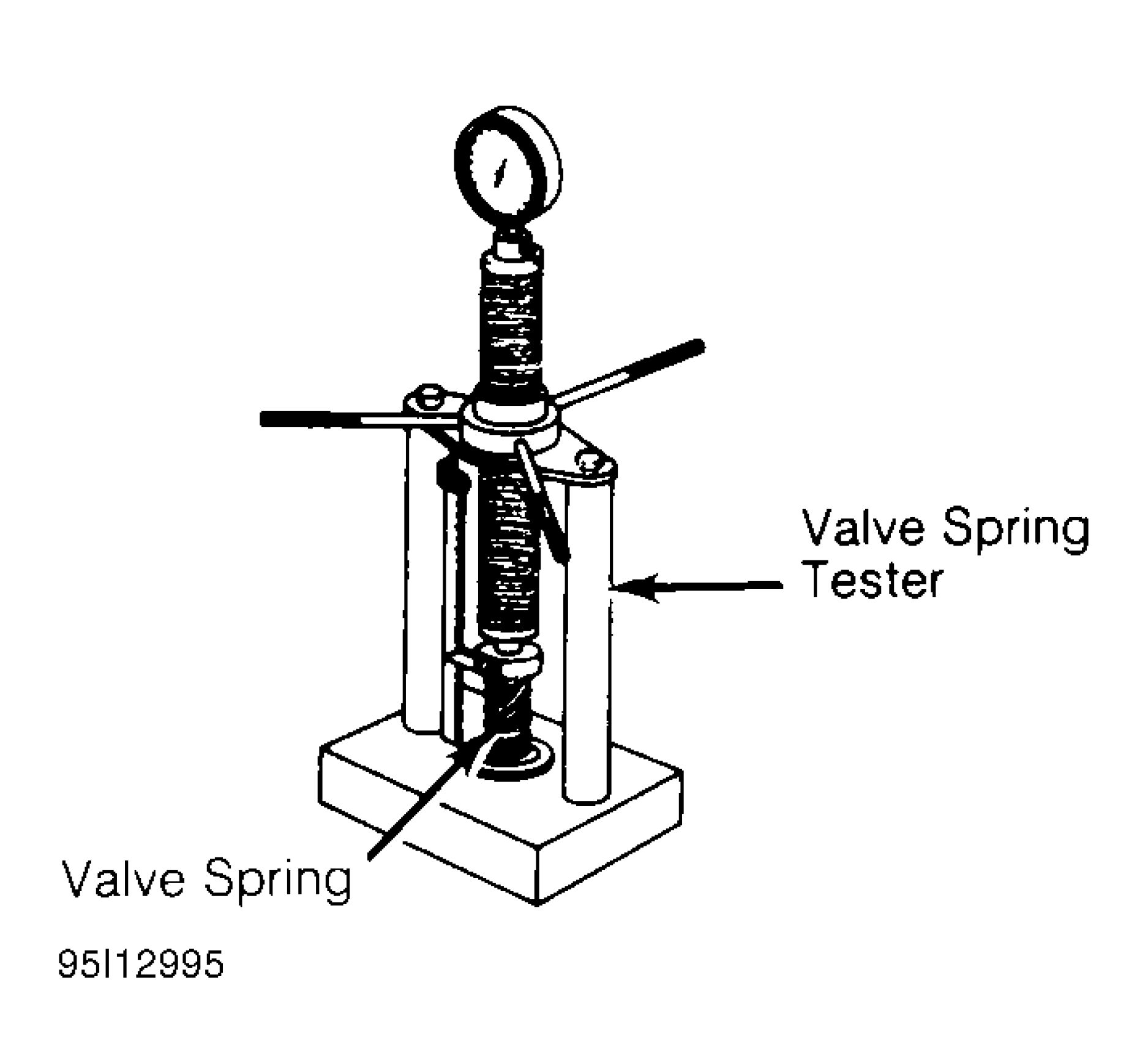 |
|
Fig. 5: Checking Valve Spring Pressure |
VALVE GUIDE
NOTE: Examples used in this article are general in nature and do not necessarily relate
to a specific engine or system. Illustrations and procedures have been chosen
to guide mechanic through engine overhaul process. Descriptions of processes
of cleaning, inspection, assembly and machine shop practice are included.
Always refer to appropriate engine overhaul article, if available, in the ENGINES
section for complete overhaul procedures and specifications for the vehicle
being repaired.
Measuring Valve Guide Clearance
Check valve stem-to-guide clearance. Ensure valve stem diameter is within specification. Install valve in valve
guide. Install dial indicator assembly on cylinder head with tip resting against valve stem just above valve
guide. See Fig. 6.

95J12996
Fig. 6: Measuring Valve Stem-to-Guide Clearance
Lower valve approximately 1/16" below valve seat. Push valve stem against valve guide as far as possible.
Adjust dial indicator to zero. Push valve stem in opposite direction and note reading. Clearance must be within
specification.
If valve guide clearance exceeds specification, valves with oversize stems may be used and valve guides are
reamed to larger size or valve guide must be replaced. On some applications, a false guide is installed, then
reamed to proper specification. Valve guide reamer set is used to ream valve guide to obtain proper clearance
for new valve.
Reaming Valve Guide
Select proper reamer for size of valve stem. Reamer must be of proper length to provide clean cut through entire
length of valve guide. Install reamer in valve guide and rotate to cut valve guide. See Fig. 7.

95A12997
Fig. 7: Reaming Valve Guides
Replacing Valve Guide
Replace valve guide if clearance exceeds specification. Valve guides are either pressed, hammered or shrunk in
place, depending upon cylinder head design and type of metal used.
Remove valve guide from cylinder head by pressing or tapping on a stepped drift. See Fig. 8. Once valve guide
is installed, distance from cylinder head to top of valve guide must be checked. This distance must be within
specification.
Aluminum heads are often heated before installing valve guide. Valve guide is sometimes cooled in dry ice prior
to installation. Combination of a heated cylinder head and cooled valve guide ensures a tight guide fit upon
assembly. The new guide must be reamed to specification.

Specified Diameter
For Valve Guide
95B12998
Fig. 8: Typical Valve Guide Remover & Installer
VALVES & VALVE SEATS
NOTE: Examples used in this article are general in nature and do not necessarily relate
to a specific engine or system. Illustrations and procedures have been chosen
to guide mechanic through engine overhaul process. Descriptions of processes
of cleaning, inspection, assembly and machine shop practice are included.
Always refer to appropriate engine overhaul article, if available, in the ENGINES
section for complete overhaul procedures and specifications for the vehicle
being repaired.
Valve Grinding
Valve stem O.D. should be measured in several areas to indicate amount of wear. Replace valve if not within
specification. Valve margin area should be measured to ensure that valve can be ground. See Fig. 9.
If valve margin is less than specification, the valves will be burned. Valve must be replaced. Due to minimum
margin dimensions during manufacture, some new type valves cannot be reground. Some manufacturers use
stellite coated valves that must NOT be machined. Valves can only be lapped into valve seat.
CAUTION: Some valves are sodium filled. Extreme care must be used when disposing of
damaged or worn sodium-filled valves.
 |
|
Fig. 9: Measuring Valve Head Margin |
Resurface valve to proper angle specification using valve grinding machine. Follow manufacturer's instructions
for valve grinding machine. Specifications may indicate a different valve face angle than seat angle. Measure
valve margin after grinding. Replace valve if not within specification. Valve stem tip can be refinished using
valve grinding machine.
Valve Lapping
During valve lapping of recently designed valves, be sure to follow manufacturer's recommendations. Surface
hardening and materials used with some valves do not permit lapping. Lapping process will remove excessive
amounts of the hardened surface.
Valve lapping is done to ensure adequate sealing between valve face and seat. Use either a hand drill or lapping
stick with suction cup attached.
Moisten and attach suction cup to valve. Lubricate valve stem and guide. Apply a thin coat of fine valve
grinding compound between valve and seat. Rotate lapping tool between the palms or with hand drill.
Lift valve upward off the seat and change position often. This is done to prevent grooving of valve seat. Lap
valve until a smooth polished seat is obtained. Thoroughly clean grinding compound from components. Valve-
to-valve seat concentricity should be checked. See VALVE SEAT CONCENTRICITY.
CAUTION: Valve guides must be in good condition and free of carbon deposits prior to
valve seat grinding. Some engines contain an induction hardened valve seat.
Excessive material removal will damage valve seats.
Valve Seat Grinding
Select coarse stone of correct size and angle for seat to be ground. Ensure stone is true and has a smooth
surface. Select correct size pilot for valve guide dimension. Install pilot in valve guide. Lightly lubricate pilot
shaft. Install stone on pilot. Move stone off and on the seat approximately 2 times per second during grinding
operation.
Select a fine stone to finish grinding operation. Various angle grinding stones are used to center and narrow the
valve seat as required. See Fig. 10.
 |
|
Fig. 10: Adjusting Valve Seat Width |
Valve Seat Replacement
Replacement of valve seat inserts is done by cutting out the old insert and machining an oversize insert bore.
Replacement oversize insert is usually cooled and the cylinder head is sometimes warmed. Valve seat is pressed
into the head. This operation requires specialized machine shop equipment.
Valve Seat Concentricity
Using dial gauge, install gauge pilot in valve guide. Position gauge arm on the valve seat. Adjust dial indicator
to zero. Rotate arm 360 degrees and note reading. Runout should not exceed specification.
To check valve-to-valve seat concentricity, coat valve face lightly with Prussian Blue dye. Install valve and
rotate it on valve seat. If pattern is even and entire seat is coated at valve contact point, valve is concentric with
the valve seat.
CYLINDER HEAD REASSEMBLY
NOTE: Examples used in this article are general in nature and do not necessarily relate
to a specific engine or system. Illustrations and procedures have been chosen
to guide mechanic through engine overhaul process. Descriptions of processes
of cleaning, inspection, assembly and machine shop practice are included.
Always refer to appropriate engine overhaul article, if available, in the ENGINES
section for complete overhaul procedures and specifications for the vehicle
being repaired.
Valve Stem Installed Height
Valve stem installed height must be checked when new valves are installed or when valves or valve seats have
been ground. Install valve in valve guide. Measure distance from tip of valve stem to spring seat. See Fig. 11.
Distance must be within specification to allow sufficient clearance for valve operation.
Remove valve and grind valve stem tip if height exceeds specification. Valve tips are surface hardened. DO
NOT remove more than .010" (.25 mm) from tip. Chamfer sharp edge of reground valve tip. Recheck valve
stem installed height.
 |
|
Fig. 11: Measuring Valve Stem Installed Height |
VALVE STEM OIL SEALS
NOTE: Examples used in this article are general in nature and do not necessarily relate
to a specific engine or system. Illustrations and procedures have been chosen
to guide mechanic through engine overhaul process. Descriptions of processes
of cleaning, inspection, assembly and machine shop practice are included.
Always refer to appropriate engine overhaul article, if available, in the ENGINES
section for complete overhaul procedures and specifications for the vehicle
being repaired.
Valve stem oil seals must be installed on valve stem. See Fig. 2. Seals are needed due to pressure differential at
the ends of valve guides. Atmospheric pressure above intake guide, combined with manifold vacuum below
guide, causes oil to be drawn into the cylinder.
Exhaust guides also have pressure differential created by exhaust gas flowing past the guide, creating a low
pressure area. This low pressure area draws oil into the exhaust system.
Some manufacturers require that special color code or specified height valve stem oil seal be installed in
designated area.
Replacement (On-Vehicle)
Mark rocker arm or overhead cam components for location. Remove rocker arm components or overhead cam
components. Components must be installed in original location. Remove spark plugs. Valve stem oil seals may
be replaced by holding valves against seats using air pressure.
Air pressure must be installed in cylinder using an adapter for spark plug hole. An adapter can be constructed by
welding air hose connection to spark plug body with porcelain removed.
Rotate engine until piston is at top of stroke. Install adapter in spark plug hole. Apply a minimum of 140 psi
(9.8 kg/cm2 ) line pressure to adapter. Air pressure should hold valve closed. If air pressure does not hold valve
closed, check for damaged or bent valve. Cylinder head must be removed for service.
Using valve spring compressor, compress valve springs. Remove valve locks. Carefully release spring
compressor. Remove retainer or rotator and valve spring. Remove valve stem oil seal.
If oversize valves have been installed, oversize oil seals must be used. Coat valve stem with engine oil. Install
protective sleeve over end of valve stem. Install new oil seal over valve stem and seat on valve guide. Remove
protective sleeve. Install spring seat, valve spring and retainer or rotator. Compress spring and install valve
locks. Remove spring compressor. Ensure valve locks are fully seated.
Install rocker arms or overhead cam components. Tighten all bolts to specification. Adjust valves if required.
Remove adapter. Install spark plugs, valve cover and gasket.
VALVE SPRING INSTALLED HEIGHT
NOTE: Examples used in this article are general in nature and do not necessarily relate
to a specific engine or system. Illustrations and procedures have been chosen
to guide mechanic through engine overhaul process. Descriptions of processes
of cleaning, inspection, assembly and machine shop practice are included.
Always refer to appropriate engine overhaul article, if available, in the ENGINES
section for complete overhaul procedures and specifications for the vehicle
being repaired.
|
Valve spring installed height should be checked during reassembly. Measure height from lower edge of valve 12. |
 |
|
Fig. 12: Measuring Valve Spring Installed Height |
ROCKER ARMS & ASSEMBLIES
NOTE: Examples used in this article are general in nature and do not necessarily relate
to a specific engine or system. Illustrations and procedures have been chosen
to guide mechanic through engine overhaul process. Descriptions of processes
of cleaning, inspection, assembly and machine shop practice are included.
Always refer to appropriate engine overhaul article, if available, in the ENGINES
section for complete overhaul procedures and specifications for the vehicle
being repaired.
Rocker Studs
Rocker studs are either threaded or pressed in place. Threaded studs are removed by locking 2 nuts on the stud.
Unscrew the stud by turning the jam nut. Coat new stud threads with Loctite and install. Tighten to
specification.
Pressed-in stud can be removed using a stud puller. Ream stud bore to proper specification and press in a new
oversize stud. Pressed-in studs are often replaced by cutting threads in the stud bore to accept a threaded stud.
Rocker Arms & Shafts
Mark rocker arms for location. Remove rocker arm retaining bolts. Remove rocker arms. Inspect rocker arms,
shafts, bushings and pivot balls (if equipped) for excessive wear. Inspect rocker arms for wear in valve stem
contact area. Measure rocker arm bushing I.D. Replace bushings if excessively worn.
The rocker arm valve stem contact point may be reground, using special fixture for valve grinding machine.
Remove minimum amount of material as possible. Ensure all oil passages are clear. Install rocker arm
components in original location. Ensure rocker arm is properly seated in push rod. Tighten bolts to
specification. Adjust valves if required. See VALVE ADJUSTMENT.
PUSH RODS
NOTE: Examples used in this article are general in nature and do not necessarily relate
to a specific engine or system. Illustrations and procedures have been chosen
to guide mechanic through engine overhaul process. Descriptions of processes
of cleaning, inspection, assembly and machine shop practice are included.
Always refer to appropriate engine overhaul article, if available, in the ENGINES
section for complete overhaul procedures and specifications for the vehicle
being repaired.
Remove rocker arms. Mark push rods for location. Remove push rods. Push rods can be steel or aluminum,
solid or hollow. Hollow push rods must be internally cleaned to ensure oil passage to rocker arms is cleaned.
Check push rods for damage, such as loose ends on steel tipped aluminum types.
Check push rod for straightness. Roll push rod on a flat surface. Using feeler gauge, check clearance at center.
Replace push rod if bent. The push rod can also be supported at each end and rotated. A dial indicator is used to
detect a bent area in the push rod.
Lubricate ends of push rod and install push rod in original location. Ensure push rod is properly seated in lifter.
Install rocker arm. Tighten bolts to specification. Adjust valves if required. See VALVE ADJUSTMENT.
LIFTERS
NOTE: Examples used in this article are general in nature and do not necessarily relate
to a specific engine or system. Illustrations and procedures have been chosen
to guide mechanic through engine overhaul process. Descriptions of processes
of cleaning, inspection, assembly and machine shop practice are included.
Always refer to appropriate engine overhaul article, if available, in the ENGINES
section for complete overhaul procedures and specifications for the vehicle
being repaired.
Hydraulic Lifters
Before replacing a hydraulic lifter for noisy operation, ensure noise is not caused by worn rocker arms or valve
tips. Also ensure sufficient oil pressure exists. Hydraulic lifters must be installed in original location. Remove
rocker arm assembly and push rod. Mark components for location. Some applications require intake manifold,
cylinder head or lifter cover removal. Remove lifter retainer plate (if used). To remove lifters, use a hydraulic
lifter remover or magnet. Different type lifters are used. See Fig. 13.
On sticking lifters, disassemble and clean lifter. DO NOT mix lifter components or positions. Parts are select-
fitted and are not interchangeable. Inspect all components for wear. Note amount of wear in lifter body-to-
camshaft contact area. Surface must have smooth and convex contact face. If wear is apparent, carefully inspect
cam lobe.
Inspect push rod contact area and lifter body for scoring or signs of wear. If body is scored, inspect lifter bore
for damage and lack of lubrication. On roller type lifters, inspect roller for flaking, pitting, loss of needle
bearings and roughness during rotation.
Measure lifter body O.D. in several areas. Measure lifter bore I.D. Ensure components or oil clearance is within
specification. Some models offer oversize lifters. Replace lifter if damaged.
If lifter check valve is not operating, obstructions may be preventing it from closing or valve spring may be
broken. Clean or replace components as necessary.
Check plunger operation. Plunger should drop to bottom of the body by its own weight when assembled dry. If
plunger is not free, soak lifter in solvent to dissolve deposits.
Lifter leak-down test can be performed on lifter. Lifter must be filled with special test oil. New lifters contain
special test oil. Using lifter leak-down tester, perform leak-down test following manufacturer's instructions. If
leak-down time is not within specifications, replace lifter assembly.
Lifters should be soaked in clean engine oil several hours prior to installation. Coat lifter base, roller (if
equipped) and lifter body with ample amount of Molykote or camshaft lubricant. See Fig. 13. Install lifter in
original location. Install remaining components. Valve lash adjustment is not required on most hydraulic lifters.
Preload of hydraulic lifter is automatic. Some models may require adjustment.
NOTE: Some manufacturers require that a crankcase conditioner be added to engine
oil and engine operated for specified amount of time to aid in lifter break-in
procedure if new lifters or camshaft are installed.
 |
|
Fig. 13: Typical Hydraulic Valve Lifter Assemblies |
Mechanical Lifters
Lifter assemblies must be installed in original locations. Remove rocker arm assembly and push rod. Mark
components for location. Some applications require intake manifold or lifter cover removal. Remove lifter
retainer plate (if used). To remove lifters, use lifter remover or magnet.
Inspect push rod contact area and lifter body for scoring or signs of wear. If body is scored, inspect lifter bore
for damage and lack of lubrication. Note amount of wear in lifter body-to-camshaft contact area. Surface must
have smooth and convex contact face. If wear is apparent, carefully inspect cam lobe.
Coat lifter base, roller (if equipped) and lifter body with ample amount of Molykote or camshaft lubricant.
Install lifter in original location. Install remaining components. Tighten bolts to specification. Adjust valves.
See VALVE ADJUSTMENT.
PISTONS, CONNECTING RODS & BEARINGS
* PLEASE READ THIS FIRST *
NOTE: Examples used in this article are general in nature and do not necessarily relate
to a specific engine or system. Illustrations and procedures have been chosen
to guide mechanic through engine overhaul process. Descriptions of processes
of cleaning, inspection, assembly and machine shop practice are included.
Always refer to appropriate engine overhaul article, if available, in the ENGINES
section for complete overhaul procedures and specifications for the vehicle
being repaired.
RIDGE REMOVAL
NOTE: Examples used in this article are general in nature and do not necessarily relate
to a specific engine or system. Illustrations and procedures have been chosen
to guide mechanic through engine overhaul process. Descriptions of processes
of cleaning, inspection, assembly and machine shop practice are included.
Always refer to appropriate engine overhaul article, if available, in the ENGINES
section for complete overhaul procedures and specifications for the vehicle
being repaired.
Ridge in cylinder wall must be removed prior to piston removal. Failure to remove ridge prior to removing
pistons will cause piston damage in piston ring lands or grooves.
With piston at bottom dead center, place rag in bore to trap metal chips. Install ridge reamer in cylinder bore.
Adjust ridge reamer using manufacturer's instructions. Remove ridge using ridge reamer. DO NOT remove an
excessive amount of material. Ensure ridge is completely removed.
PISTON & CONNECTING ROD REMOVAL
NOTE: Examples used in this article are general in nature and do not necessarily relate
to a specific engine or system. Illustrations and procedures have been chosen
to guide mechanic through engine overhaul process. Descriptions of processes
of cleaning, inspection, assembly and machine shop practice are included.
Always refer to appropriate engine overhaul article, if available, in the ENGINES
section for complete overhaul procedures and specifications for the vehicle
being repaired.
Note top of piston. Some pistons may contain a notch, arrow or be marked FRONT. Piston must be installed in
proper direction to prevent damage with valve operation.
Check that connecting rod and cap are numbered for cylinder location and which side of cylinder block the
number faces. Proper cap and connecting rod must be installed together. Connecting rod cap must be installed
on connecting rod in proper direction to ensure bearing lock procedure. Mark connecting rod and cap if
necessary. Pistons must be installed in original location.
Remove cap retaining nuts or bolts. Remove bearing cap. Install tubing protectors on connecting rod bolts. This
protects cylinder walls from scoring during removal. Ensure proper removal of ridge. Push piston and
connecting rod from cylinder. Connecting rod boss can be tapped with a wooden dowel or hammer handle to aid
in removal.
PISTON & CONNECTING ROD
NOTE: Examples used in this article are general in nature and do not necessarily relate
to a specific engine or system. Illustrations and procedures have been chosen
to guide mechanic through engine overhaul process. Descriptions of processes
of cleaning, inspection, assembly and machine shop practice are included.
Always refer to appropriate engine overhaul article, if available, in the ENGINES
section for complete overhaul procedures and specifications for the vehicle
being repaired.
Disassembly
Using ring expander, remove piston rings. Remove piston pin retaining rings (if equipped). Note direction of
piston installation on connecting rod. On pressed type piston pins, special fixtures and procedures according to
manufacturer must be used to remove piston pins. Follow manufacturer's recommendations to avoid piston
distortion or breakage.
Cleaning
Remove all carbon and varnish from piston. Pistons and connecting rods may be cleaned in cold type chemical
tank. Using ring groove cleaner, clean all deposits from ring grooves. Ensure all deposits are cleaned from ring
grooves to prevent ring breakage or sticking. DO NOT attempt to clean pistons with wire brush.
Inspection
Inspect pistons for nicks, scoring, cracks or damage in ring areas. Connecting rod should be checked for cracks
using Magnaflux procedure. Piston diameter must be measured in manufacturer's specified area.
Using telescopic gauge and micrometer, measure piston pin bore of piston in 2 areas, 90 degrees apart. This is
done to check diameter and out-of-round.
Install proper bearing cap on connecting rod. Ensure bearing cap is installed in proper location. Tighten bolts or
nuts to specification. Using inside micrometer, measure inside diameter in 2 areas, 90 degrees apart.
Connecting rod I.D. and out-of-round must be within specification. Measure piston pin bore I.D. and piston pin
O.D. All components must be within specification. Subtract piston pin diameter from piston pin bore in piston
and connecting rod to determine proper fit.
Connecting rod length must be measured from center of crankshaft journal inside diameter to center of piston
pin bushing using proper caliper. Connecting rods must be the same length. Connecting rods should be checked
on an alignment fixture for bent or twisted condition. Replace all components which are damaged or not within
specification.
PISTON & CYLINDER BORE FIT
NOTE: Examples used in this article are general in nature and do not necessarily relate
to a specific engine or system. Illustrations and procedures have been chosen
to guide mechanic through engine overhaul process. Descriptions of processes
of cleaning, inspection, assembly and machine shop practice are included.
Always refer to appropriate engine overhaul article, if available, in the ENGINES
section for complete overhaul procedures and specifications for the vehicle
being repaired.
Ensure cylinder is checked for taper, out-of-round and properly honed prior to checking piston and cylinder
bore fit. See CYLINDER BLOCK. Using dial bore gauge, measure cylinder bore.
Measure piston skirt diameter at 90 degree angle to piston pin at specified area by manufacturer. Subtract piston
diameter from cylinder bore diameter to determine piston-to-cylinder clearance. Clearance must be within
specification. Mark piston for proper cylinder location.
ASSEMBLING PISTON & CONNECTING ROD
NOTE: Examples used in this article are general in nature and do not necessarily relate
to a specific engine or system. Illustrations and procedures have been chosen
to guide mechanic through engine overhaul process. Descriptions of processes
of cleaning, inspection, assembly and machine shop practice are included.
Always refer to appropriate engine overhaul article, if available, in the ENGINES
section for complete overhaul procedures and specifications for the vehicle
being repaired.
Install piston on connecting rod for corresponding cylinder. Ensure reference marking on top of piston
corresponds with connecting rod and cap number. See Fig. 14.
Lubricate piston pin and install in connecting rod. Ensure piston pin retainers are fully seated (if equipped). On
pressed type piston pins, follow manufacturer's recommended procedure to avoid distortion or breakage.
 |
|
Fig. 14: Installing Typical Piston Pin |
CHECKING PISTON RING CLEARANCES
NOTE: Examples used in this article are general in nature and do not necessarily relate
to a specific engine or system. Illustrations and procedures have been chosen
to guide mechanic through engine overhaul process. Descriptions of processes
of cleaning, inspection, assembly and machine shop practice are included.
Always refer to appropriate engine overhaul article, if available, in the ENGINES
section for complete overhaul procedures and specifications for the vehicle
being repaired.
Piston rings must be checked for side clearance and end gap. To check end gap, install piston ring in cylinder in
which it is to be installed. Using an inverted piston, push ring to bottom of cylinder in smallest cylinder
diameter.
Using feeler gauge, check ring end gap. See Fig. 15. Piston ring end gap must be within specification. Ring
breakage will occur if insufficient ring end gap exists.
Some manufacturers permit correcting insufficient ring end gap by using a fine file while other manufacturers
recommend using another ring set. Mark rings for proper cylinder installation after checking end gap.

Measure Ring Gap Clearance
With Ring Positioned At
Bottom of Ring Travel
Fig. 15: Checking Piston Ring End Gap
For checking side clearance, install rings on piston. Using feeler gauge, measure clearance between piston ring
and piston ring land. Check side clearance in several areas around piston. Side clearance must be within
specification.
If side clearance is excessive, piston ring grooves can be machined to accept oversize piston rings (if available).
Normal practice is to replace piston.
PISTON & CONNECTING ROD INSTALLATION
NOTE: Examples used in this article are general in nature and do not necessarily relate
to a specific engine or system. Illustrations and procedures have been chosen
to guide mechanic through engine overhaul process. Descriptions of processes
of cleaning, inspection, assembly and machine shop practice are included.
Always refer to appropriate engine overhaul article, if available, in the ENGINES
section for complete overhaul procedures and specifications for the vehicle
being repaired.
Cylinders must be honed prior to piston installation. See CYLINDER HONING under CYLINDER BLOCK.
Install upper connecting rod bearings. Lubricate upper bearings with engine oil. Install lower bearings in rod
caps. Ensure bearing tabs are properly seated. Position piston ring gaps according to manufacturer's
recommendations. See Fig. 16. Lubricate pistons, rings and cylinder walls.
|
Top Compression Ring |
 |
|
95J14646 Fig. 16: Positioning Typical Piston Ring End Gap |
Position Ring End Gaps
As Shown With Notch In
Piston Toward Front Of Engine
Install ring compressor. Use care not to rotate piston rings. Compress rings with ring compressor. Install plastic
tubing protectors over connecting rod bolts. Install piston and connecting rod assembly. Ensure piston notch,
arrow or FRONT mark is toward front of engine. See Fig. 17.
Check That
Piston Indicator
Faces Front
Of Engine
 |
|
Fig. 17: Installing Piston & Connecting Rod Assembly |
Carefully tap piston into cylinder until rod bearing is seated on crankshaft journal. Remove protectors. Install
rod cap and bearing. Lightly tighten connecting rod bolts. Repeat procedure for remaining cylinders. Check
bearing clearance. See MAIN & CONNECTING ROD BEARING CLEARANCE.
Once clearance is checked, lubricate journals and bearings. Install bearing caps. Ensure marks are aligned on
connecting rod and cap. Tighten rod nuts or bolts to specification. Ensure rod moves freely on crankshaft.
Check connecting rod side clearance. See CONNECTING ROD SIDE CLEARANCE.
CONNECTING ROD SIDE CLEARANCE
NOTE: Examples used in this article are general in nature and do not necessarily relate
to a specific engine or system. Illustrations and procedures have been chosen
to guide mechanic through engine overhaul process. Descriptions of processes
of cleaning, inspection, assembly and machine shop practice are included.
Always refer to appropriate engine overhaul article, if available, in the ENGINES
section for complete overhaul procedures and specifications for the vehicle
being repaired.
Position connecting rod toward one side of crankshaft as far as possible. Using feeler gauge, measure clearance
between side of connecting rod and crankshaft. See Fig. 18. Clearance must be within specification.
Check for improper bearing installation, wrong bearing cap or insufficient bearing clearance if side clearance is
insufficient. Connecting rod may require machining to obtain proper clearance. Excessive clearance usually
indicates excessive wear at crankshaft. Crankshaft must be repaired or replaced.
 |
|
Fig. 18: Measuring Connecting Rod Side Clearance |
MAIN & CONNECTING ROD BEARING CLEARANCE
NOTE: Examples used in this article are general in nature and do not necessarily relate
to a specific engine or system. Illustrations and procedures have been chosen
to guide mechanic through engine overhaul process. Descriptions of processes
of cleaning, inspection, assembly and machine shop practice are included.
Always refer to appropriate engine overhaul article, if available, in the ENGINES
section for complete overhaul procedures and specifications for the vehicle
being repaired.
Plastigage Method
Plastigage method may be used to determine bearing clearance. Plastigage can be used with an engine in service
or during reassembly. Plastigage material is oil soluble.
Ensure journals and bearings are free of oil or solvent. Oil or solvent will dissolve material and false reading
will be obtained. Install small piece of Plastigage along full length of bearing journal. Install bearing cap in
original location. Tighten bolts to specification.
CAUTION: DO NOT rotate crankshaft while Plastigage is installed. Bearing clearance will
not be obtained if crankshaft is rotated.
Remove bearing cap. Compare Plastigage width with scale on Plastigage container to determine bearing
clearance. See Fig. 19. Rotate crankshaft 90 degrees. Repeat procedure. This is done to check journal
eccentricity. This procedure can be used to check oil clearance on both connecting rod and main bearings.
 |
|
Fig. 19: Measuring Bearing Clearance |
Micrometer & Telescopic Gauge Method
A micrometer is used to determine journal diameter, taper and out-of-round dimensions of the crankshaft. See
CLEANING & INSPECTION under CRANKSHAFT & MAIN BEARINGS in this article.
With crankshaft removed, install bearings and caps in original location on cylinder block. Tighten bolts to
specification. On connecting rods, install bearings and caps on connecting rods. Install proper connecting rod
cap on corresponding rod. Ensure bearing cap is installed in original location. Tighten bolts to specification.
Using a telescopic gauge and micrometer or inside micrometer, measure inside diameter of connecting rod and
main bearings bores. Subtract each crankshaft journal diameter from the corresponding inside bearing bore
diameter. This is the bearing clearance.
CRANKSHAFT & MAIN BEARINGS
* PLEASE READ THIS FIRST *
NOTE: Examples used in this article are general in nature and do not necessarily relate
to a specific engine or system. Illustrations and procedures have been chosen
to guide mechanic through engine overhaul process. Descriptions of processes
of cleaning, inspection, assembly and machine shop practice are included.
Always refer to appropriate engine overhaul article, if available, in the ENGINES
section for complete overhaul procedures and specifications for the vehicle
being repaired.
REMOVAL
NOTE: Examples used in this article are general in nature and do not necessarily relate
to a specific engine or system. Illustrations and procedures have been chosen
to guide mechanic through engine overhaul process. Descriptions of processes
of cleaning, inspection, assembly and machine shop practice are included.
Always refer to appropriate engine overhaul article, if available, in the ENGINES
section for complete overhaul procedures and specifications for the vehicle
being repaired.
Ensure all main bearing caps are marked for location on cylinder block. Some main bearing caps have an arrow
stamped on them. The arrow must face timing belt or timing chain end of engine. Remove main bearing cap
bolts. Remove main bearing caps. Carefully remove crankshaft. Use care not to bind crankshaft in cylinder
block during removal.
CLEANING & INSPECTION
NOTE: Examples used in this article are general in nature and do not necessarily relate
to a specific engine or system. Illustrations and procedures have been chosen
to guide mechanic through engine overhaul process. Descriptions of processes
of cleaning, inspection, assembly and machine shop practice are included.
Always refer to appropriate engine overhaul article, if available, in the ENGINES
section for complete overhaul procedures and specifications for the vehicle
being repaired.
Thoroughly clean crankshaft using solvent. Dry with compressed air. Ensure all oil passages are clear and free
of sludge, rust, dirt and metal chips.
Inspect crankshaft for scoring and nicks. Inspect crankshaft for cracks using Magnaflux procedure. Inspect rear
seal area for grooving or damage. Inspect bolt hole threads for damage. If pilot bearing or bushing is used,
check pilot bearing or bushing fit in crankshaft. Inspect crankshaft gear for damaged or cracked teeth. Replace
gear if damaged. Ensure oil passage plugs are tight (if equipped).
Using micrometer, measure all journals in 4 areas to determine journal taper, out-of-round and undersize. See
Fig. 20. Some crankshafts can be reground to the next largest undersize, depending on the amount of wear or
damage. Crankshafts with rolled fillet cannot be reground and must be replaced.
A - В = Vertical Taper
C - D = Horizontal Taper
A - С & В - D Out-Of-Round
Check For Out-Of-Round At Each End Of Journal

95G14650
Fig. 20: Measuring Crankshaft Journals
Crankshaft journal runout should be checked. Install crankshaft in "V" blocks or bench center. Position dial
indicator with tip resting on the main bearing journal area. See Fig. 21. Rotate crankshaft and note reading.
Journal runout must not exceed specification. Repeat procedure on all main bearing journals. Crankshaft must
be replaced if runout exceeds specification.
 |
|
Fig. 21: Measuring Crankshaft Main Bearing Journal Runout |
INSTALLATION
NOTE: Examples used in this article are general in nature and do not necessarily relate
to a specific engine or system. Illustrations and procedures have been chosen
to guide mechanic through engine overhaul process. Descriptions of processes
of cleaning, inspection, assembly and machine shop practice are included.
Always refer to appropriate engine overhaul article, if available, in the ENGINES
section for complete overhaul procedures and specifications for the vehicle
being repaired.
Install upper main bearing in cylinder block. Ensure lock tab is properly located in cylinder block. Install
bearings in main bearing caps. Ensure all oil passages are aligned. Install rear seal (if removed).
Ensure crankshaft journals are clean. Lubricate upper main bearings with clean engine oil. Carefully install
crankshaft. Check each main bearing clearance using Plastigage method. See MAIN & CONNECTING ROD
BEARING CLEARANCE.
Once clearance is checked, lubricate lower main bearing and journals. Install main bearing caps in original
location. Install rear seal in rear main bearing cap (if removed). Some rear main bearing caps require sealant to
be applied in corners to prevent oil leakage.
Install and tighten all bolts except thrust bearing cap to specification. Tighten thrust bearing cap bolts finger
tight only. Some models require that thrust bearing be aligned. On most applications, crankshaft must be moved
rearward then forward. Procedure may vary with manufacturer. Thrust bearing cap is then tightened to
specification. Ensure crankshaft rotates freely. Crankshaft end play should be checked. See CRANKSHAFT
END PLAY.
CRANKSHAFT END PLAY
NOTE: Examples used in this article are general in nature and do not necessarily relate
to a specific engine or system. Illustrations and procedures have been chosen
to guide mechanic through engine overhaul process. Descriptions of processes
of cleaning, inspection, assembly and machine shop practice are included.
Always refer to appropriate engine overhaul article, if available, in the ENGINES
section for complete overhaul procedures and specifications for the vehicle
being repaired.
Dial Indicator Method
Crankshaft end play can be checked using dial indicator. Mount dial indicator on rear of cylinder block. Position
dial indicator tip against rear of crankshaft. Ensure tip is resting against flat surface.
Pry crankshaft rearward. Adjust dial indicator to zero. Pry crankshaft forward and note reading. Crankshaft end
play must be within specification. If end play is not within specification, check for faulty thrust bearing
installation or worn crankshaft. Some applications offer oversize thrust bearings.
Feeler Gauge Method
Crankshaft end play can be checked using feeler gauge. Pry crankshaft rearward. Pry crankshaft forward. Using
feeler gauge, measure clearance between crankshaft and thrust bearing surface. See Fig. 22.

Fig. 22: Checking Crankshaft End Play
Crankshaft end play must be within specification. If end play is not within specification, check for faulty thrust
bearing installation or worn crankshaft. Some applications offer oversize thrust bearings.
CYLINDER BLOCK
NOTE: Examples used in this article are general in nature and do not necessarily relate
to a specific engine or system. Illustrations and procedures have been chosen
to guide mechanic through engine overhaul process. Descriptions of processes
of cleaning, inspection, assembly and machine shop practice are included.
Always refer to appropriate engine overhaul article, if available, in the ENGINES
section for complete overhaul procedures and specifications for the vehicle
being repaired.
Block Cleaning
Only cast cylinder blocks should be hot tank cleaned. Aluminum cylinder blocks should be cleaned using cold
tank method. Cylinder block is cleaned in order to remove carbon deposits, gasket residue and water jacket
scale. Remove oil gallery plugs, freeze plugs and cam bearings before cleaning block.
Block Inspection
Visually inspect the block. Check suspected areas for cracks using the Dye Penetrant inspection method. Block
may be checked for cracks using the Magnaflux method.
Cracks are most commonly found at the bottom of cylinders, main bearing saddles, near expansion plugs and
between cylinders and water jackets. Inspect lifter bores for damage. Inspect all head bolt holes for damaged
threads. Threads should be cleaned using tap to ensure proper head bolt torque. Consult machine shop
concerning possible welding and machining (if required).
Cylinder Bore Inspection
Inspect bore for scoring or roughness. Cylinder bore is dimensionally checked for out-of-round and taper using
dial bore gauge. For determining out-of-round, measure cylinder parallel and perpendicular to the block center
line. Difference in the 2 readings is the bore out-of-round. Cylinder bore must be checked at top, middle and
bottom of piston travel area.
Bore taper is obtained by measuring bore at the top and bottom. If wear has exceeded allowable limits, block
must be honed or bored to next available oversize piston dimension.
Cylinder Honing
Cylinder must be properly honed to allow new piston rings to properly seat. Cross-hatching at correct angle and
depth is critical to lubrication of cylinder walls and pistons.
A flexible drive hone and power drill are commonly used. Drive hone must be lubricated during operation. Mix
equal parts of kerosene and SAE 20W engine oil for lubrication.
Apply lubrication to cylinder wall. Operate cylinder hone from top to bottom of cylinder using even strokes to
produce 45 degree cross-hatch pattern on the cylinder wall. DO NOT allow cylinder hone to extend below
cylinder during operation.
Recheck bore dimension after final honing. Wash cylinder wall with hot soapy water to remove abrasive
particles. Blow dry with compressed air. Coat cleaned cylinder walls with lubricating oil.
Deck Warpage
Check deck for damage or warped gasket surface. Place a straightedge across gasket surface of the deck. Using
feeler gauge, measure clearance at center of straightedge. Measure across width and length of cylinder block at
several points.
If warpage exceeds specifications, deck must be resurfaced. If warpage exceeds manufacturer's maximum
tolerance for material removal, replace block.
NOTE: Some manufacturers recommend that a total amount of material (cylinder head
and cylinder block) can only be removed before components must be replaced.
Deck Height
Distance from crankshaft center line to block deck is called the deck height. Measure and record front and rear
main journals of crankshaft. To compute this distance, install crankshaft and retain with center main bearing and
cap only. Measure distance from crankshaft journal to block deck, parallel to cylinder center line.
Add one half of main bearing journal diameter to distance from crankshaft journal to block deck. This
dimension should be checked at front and rear of cylinder block. Both readings should be the same.
If difference exceeds specification, cylinder block must be repaired or replaced. Deck height and warpage
should be corrected at the same time.
Main Bearing Bore & Alignment
For checking main bearing bore, remove all bearings from cylinder block and main bearing caps. Install main
bearing caps in original location. Tighten bolts to specification. Using inside micrometer, measure main bearing
bore in 2 areas 90 degrees apart. Determine bore size and out-of-round. If diameter is not within specification,
block must be align-bored.
For checking alignment, place a straightedge along center line of main bearing saddles. Check for clearance
between straightedge and main bearing saddles. Block must be align-bored if clearance exists.
Expansion Plug Removal
Drill hole in center of expansion plug. Remove with screwdriver or punch. Use care not to damage sealing
surface.
Expansion Plug Installation
Ensure sealing surface is free of burrs. Coat expansion plug with sealer. Using wooden dowel or pipe of slightly
smaller diameter, install expansion plug. Ensure expansion plug is evenly located.
Oil Gallery Plug Removal
Remove threaded oil gallery plugs using appropriate wrench. Soft press-in plugs are removed by drilling into
plug and installing a sheet metal screw. Remove plug with slide hammer or pliers.
Oil Gallery Plug Installation
Ensure threads or sealing surface is clean. Coat threaded oil gallery plugs with sealer and install. Replacement
soft press-in plugs are installed with a hammer and drift.
CAMSHAFT
* PLEASE READ THIS FIRST *
NOTE: Examples used in this article are general in nature and do not necessarily relate
to a specific engine or system. Illustrations and procedures have been chosen
to guide mechanic through engine overhaul process. Descriptions of processes
of cleaning, inspection, assembly and machine shop practice are included.
Always refer to appropriate engine overhaul article, if available, in the ENGINES
section for complete overhaul procedures and specifications for the vehicle
being repaired.
CLEANING & INSPECTION
NOTE: Examples used in this article are general in nature and do not necessarily relate
to a specific engine or system. Illustrations and procedures have been chosen
to guide mechanic through engine overhaul process. Descriptions of processes
of cleaning, inspection, assembly and machine shop practice are included.
Always refer to appropriate engine overhaul article, if available, in the ENGINES
section for complete overhaul procedures and specifications for the vehicle
being repaired.
Clean camshaft with solvent. Ensure all oil passages are clear. Inspect cam lobes and bearing journals for
pitting, flaking or scoring. Using micrometer, measure bearing journal O.D.
Support camshaft at each end with "V" blocks. Position dial indicator with tip resting on center bearing journal.
Rotate camshaft and note camshaft runout reading. If reading exceeds specification, replace camshaft.
Check cam lobe lift by measuring base circle of camshaft using micrometer. Measure again at 90-degree angle
to tip of cam lobe. Cam lift can be determined by subtracting base circle diameter from tip of cam lobe
measurement.
Different lift dimensions are given for intake and exhaust cam lobes. Reading must be within specification.
Replace camshaft if cam lobes or bearing journals are not within specification.
Inspect camshaft gear for chipped, eroded or damaged teeth. Replace gear if damaged. On camshafts using
thrust plate, measure distance between thrust plate and camshaft shoulder. Replace thrust plate if not within
specification.
CAMSHAFT BEARINGS
NOTE: Examples used in this article are general in nature and do not necessarily relate
to a specific engine or system. Illustrations and procedures have been chosen
to guide mechanic through engine overhaul process. Descriptions of processes
of cleaning, inspection, assembly and machine shop practice are included.
Always refer to appropriate engine overhaul article, if available, in the ENGINES
section for complete overhaul procedures and specifications for the vehicle
being repaired.
Removal & Installation
Remove camshaft rear plug. Camshaft bearing remover is assembled with shoulder resting against bearing to be
removed according to manufacturer's instructions. Tighten puller nut until bearing is removed. Remove
remaining bearings, leaving front and rear bearings until last. These bearings act as a guide for camshaft bearing
remover.
To install new bearings, puller is rearranged to pull bearings toward the center of block. Ensure all lubrication
passages of bearing are aligned with cylinder block. Coat new camshaft rear plug with sealant. Install camshaft
rear plug. Ensure plug is even in cylinder block.
CAMSHAFT INSTALLATION
NOTE: Examples used in this article are general in nature and do not necessarily relate
to a specific engine or system. Illustrations and procedures have been chosen
to guide mechanic through engine overhaul process. Descriptions of processes
of cleaning, inspection, assembly and machine shop practice are included.
Always refer to appropriate engine overhaul article, if available, in the ENGINES
section for complete overhaul procedures and specifications for the vehicle
being repaired.
Lubricate bearing surfaces and cam lobes with ample amount of Molykote or camshaft lubricant. Carefully
install camshaft. Use care not to damage bearing journals during installation. Install thrust plate retaining bolts
(if equipped). Tighten bolts to specification. On overhead camshafts, install bearing caps in original location.
Tighten bolts to specification. On all applications, check camshaft end play.
CAMSHAFT END PLAY
NOTE: Examples used in this article are general in nature and do not necessarily relate
to a specific engine or system. Illustrations and procedures have been chosen
to guide mechanic through engine overhaul process. Descriptions of processes
of cleaning, inspection, assembly and machine shop practice are included.
Always refer to appropriate engine overhaul article, if available, in the ENGINES
section for complete overhaul procedures and specifications for the vehicle
being repaired.
Using dial indicator, check camshaft end play. Position dial indicator on front of engine block or cylinder head.
Position indicator tip against camshaft. Push camshaft toward rear of cylinder head or engine and adjust
indicator to zero.
Move camshaft forward and note reading. Camshaft end play must be within specification. End play may be
adjusted by relocating gear, shimming thrust plate or replacing thrust plate depending on each manufacturer.
TIMING CHAINS & BELTS
* PLEASE READ THIS FIRST *
NOTE: Examples used in this article are general in nature and do not necessarily relate
to a specific engine or system. Illustrations and procedures have been chosen
to guide mechanic through engine overhaul process. Descriptions of processes
of cleaning, inspection, assembly and machine shop practice are included.
Always refer to appropriate engine overhaul article, if available, in the ENGINES
section for complete overhaul procedures and specifications for the vehicle
being repaired.
TIMING CHAINS
NOTE: Examples used in this article are general in nature and do not necessarily relate
to a specific engine or system. Illustrations and procedures have been chosen
to guide mechanic through engine overhaul process. Descriptions of processes
of cleaning, inspection, assembly and machine shop practice are included.
Always refer to appropriate engine overhaul article, if available, in the ENGINES
section for complete overhaul procedures and specifications for the vehicle
being repaired.
Timing chains will stretch during operation. Limits are placed upon amount of stretch before replacement is
required. Timing chain stretch will alter ignition timing and valve timing.
To check timing chain stretch, rotate crankshaft to eliminate slack from one side of timing chain. Mark
reference point on cylinder block. Rotate crankshaft in opposite direction to eliminate slack from remaining side
of timing chain. Force other side of chain outward and measure distance between reference point and timing
chain. See Fig. 23. Replace timing chain and gears if not within specification.
 |
|
Fig. 23: Measuring Timing Chain Stretch |
Timing chains must be installed so timing marks on camshaft gear and crankshaft gear are aligned according to
manufacturer. See Fig. 24.
 |
|
Fig. 24: Typical Gear Timing Mark Alignment |
TIMING BELTS
NOTE: Examples used in this article are general in nature and do not necessarily relate
to a specific engine or system. Illustrations and procedures have been chosen
to guide mechanic through engine overhaul process. Descriptions of processes
of cleaning, inspection, assembly and machine shop practice are included.
Always refer to appropriate engine overhaul article, if available, in the ENGINES
section for complete overhaul procedures and specifications for the vehicle
being repaired.
Cogged tooth belts are commonly used on overhead cam engines. Inspect belt teeth for rounded corners or
cracking. Replace belt if it is cracked, damaged, missing teeth or oil soaked.
Used timing belt must be installed in original direction of rotation. Inspect all sprocket teeth for wear. Replace
all worn sprockets. Sprockets are marked for timing purposes. Engine is positioned so that crankshaft sprocket
mark will be upward. Camshaft sprocket is aligned with reference mark on cylinder head or timing belt cover
and then timing belt can be installed. See Fig. 25.
 |
|
Fig. 25: Typical Camshaft Belt Sprocket Alignment |
TENSION ADJUSTMENT
NOTE: Examples used in this article are general in nature and do not necessarily relate
to a specific engine or system. Illustrations and procedures have been chosen
to guide mechanic through engine overhaul process. Descriptions of processes
of cleaning, inspection, assembly and machine shop practice are included.
Always refer to appropriate engine overhaul article, if available, in the ENGINES
section for complete overhaul procedures and specifications for the vehicle
being repaired.
If guide rails are used with spring loaded tensioners, ensure at least half of original rail thickness remains.
Spring loaded tensioner should be inspected for damage.
Ensure all timing marks are aligned. Adjust belt tension using manufacturer's recommendations. Belt tension
may require checking using tension gauge. See Fig. 26.
 |
|
Fig. 26: Adjusting Typical Timing Belt Tension |
TIMING GEARS
* PLEASE READ THIS FIRST *
NOTE: Examples used in this article are general in nature and do not necessarily relate
to a specific engine or system. Illustrations and procedures have been chosen
to guide mechanic through engine overhaul process. Descriptions of processes
of cleaning, inspection, assembly and machine shop practice are included.
Always refer to appropriate engine overhaul article, if available, in the ENGINES
section for complete overhaul procedures and specifications for the vehicle
being repaired.
TIMING GEAR BACKLASH & RUNOUT
NOTE: Examples used in this article are general in nature and do not necessarily relate
to a specific engine or system. Illustrations and procedures have been chosen
to guide mechanic through engine overhaul process. Descriptions of processes
of cleaning, inspection, assembly and machine shop practice are included.
Always refer to appropriate engine overhaul article, if available, in the ENGINES
section for complete overhaul procedures and specifications for the vehicle
being repaired.
On engines where camshaft gear operates directly on crankshaft gear, gear backlash and runout must be
checked. To check backlash, install dial indicator with tip resting on tooth of camshaft gear. Rotate camshaft
gear as far as possible. Adjust indicator to zero. Rotate camshaft gear in opposite direction as far as possible and
note reading.
To determine timing gear runout, mount dial indicator with tip resting on face edge of camshaft gear. Adjust
indicator to zero. Rotate camshaft gear 360 degrees and note reading. If backlash or runout exceeds
specification, replace camshaft and/or crankshaft gear.
REAR MAIN OIL SEAL INSTALLATION
NOTE: Examples used in this article are general in nature and do not necessarily relate
to a specific engine or system. Illustrations and procedures have been chosen
to guide mechanic through engine overhaul process. Descriptions of processes
of cleaning, inspection, assembly and machine shop practice are included.
Always refer to appropriate engine overhaul article, if available, in the ENGINES
section for complete overhaul procedures and specifications for the vehicle
being repaired.
One-Piece Type Seal
For one-piece type oil seal installation, coat block contact surface of seal with sealer if seal is not factory
coated. Ensure seal surface is free of burrs. Lubricate seal lip with engine oil and press seal into place using
proper oil seal installer. See Fig. 27.
|
Alignment Hole Dust Lip on sea| |
 |
|
95D14657 Screws Mandrel Collar |
Fig. 27: Installing Typical One-Piece Oil Seal
Rope Type Seal
For rope type rear main oil seal installation, press seal lightly into seat area. Using seal installer, fully seat seal
in bearing cap or cylinder block.
Trim seal ends even with cylinder block parting surface. Some applications require sealer to be applied on main
bearing cap before installing. See Fig. 28.
Apply Sealer Here
|
Seal Installer |  |
Cut Excess Seal
At Parting Line
95E14658
Fig. 28: Installing Typical Rope Seal
Split-Rubber Type Seal
Follow manufacturer's procedures when installing split-rubber type rear main oil seals. Installation procedures
vary with manufacturer and engine type. See Fig. 29.
 |
|
Fig. 29: Installing Typical Split-Rubber Seal |
OIL PUMP
* PLEASE READ THIS FIRST *
NOTE: Examples used in this article are general in nature and do not necessarily relate
to a specific engine or system. Illustrations and procedures have been chosen
to guide mechanic through engine overhaul process. Descriptions of processes
of cleaning, inspection, assembly and machine shop practice are included.
Always refer to appropriate engine overhaul article, if available, in the ENGINES
section for complete overhaul procedures and specifications for the vehicle
being repaired.
ROTOR TYPE
NOTE: Examples used in this article are general in nature and do not necessarily relate
to a specific engine or system. Illustrations and procedures have been chosen
to guide mechanic through engine overhaul process. Descriptions of processes
of cleaning, inspection, assembly and machine shop practice are included.
Always refer to appropriate engine overhaul article, if available, in the ENGINES
section for complete overhaul procedures and specifications for the vehicle
being repaired.
Mark oil pump rotor locations before removing. See Fig. 30. Remove outer rotor and measure thickness and
diameter. Measure inner rotor thickness. Inspect shaft for scoring or wear. Inspect rotors for pitting or damage.
Inspect cover for grooving or wear. Replace worn or damaged components.
Measure outer rotor-to-body clearance. Replace pump assembly if clearance exceeds specification. Measure
clearance between rotors. See Fig. 31. Replace shaft and both rotors if clearance exceeds specification.
Install rotors in pump body. Position straightedge across pump body. Using feeler gauge, measure clearance
between rotors and straightedge. Pump cover wear is measured using a straightedge and feeler gauge. Replace
pump if clearance exceeds specification.
 |
|
Fig. 30: Typical Rotor Type Oil Pump |
 |
|
Fig. 31: Measuring Rotor Clearance |
GEAR TYPE
NOTE: Examples used in this article are general in nature and do not necessarily relate
to a specific engine or system. Illustrations and procedures have been chosen
to guide mechanic through engine overhaul process. Descriptions of processes
of cleaning, inspection, assembly and machine shop practice are included.
Always refer to appropriate engine overhaul article, if available, in the ENGINES
section for complete overhaul procedures and specifications for the vehicle
being repaired.
Mark oil pump gear location before removing. See Fig. 32. Remove gears from pump body. Inspect gears for
pitting or damage. Inspect cover for grooving or wear. Measure gear diameter and length. Measure gear housing
cavity depth and diameter. See Fig. 33. Replace worn or damaged components.
Pump cover wear is measured using a straightedge and feeler gauge. Replace pump or components if warpage
or wear exceeds specification, or mating surface of pump cover is scratched or grooved.
 |
|
Fig. 32: Typical Gear Type Oil Pump |

95В14663
Fig. 33: Measuring Oil Pump Gear Cavity
BREAK-IN PROCEDURE
|
* PLEASE READ THIS FIRST * | ||
| ||
|
ENGINE PRE-OILING |
NOTE: Examples used in this article are general in nature and do not necessarily relate
to a specific engine or system. Illustrations and procedures have been chosen
to guide mechanic through engine overhaul process. Descriptions of processes
of cleaning, inspection, assembly and machine shop practice are included.
Always refer to appropriate engine overhaul article, if available, in the ENGINES
section for complete overhaul procedures and specifications for the vehicle
being repaired.
Pre-oil engine prior to operation to prevent engine damage. Lightly oiled oil pump will cavitate unless oil pump
cavities are filled with engine oil or petroleum jelly.
Engine pre-oiling can be done using pressure oiler (if available). Connect pressure oiler to cylinder block oil
passage such as oil pressure sending unit. Operate pressure oiler long enough to ensure correct amount of oil
has filled crankcase. Check oil level while pre-oiling.
If pressure oiler is not available, disconnect ignition system. Remove oil pressure sending unit and replace with
oil pressure test gauge. Using starter motor, rotate engine starter until gauge shows normal oil pressure for
several seconds. DO NOT crank engine for more than 30 seconds to avoid starter motor damage. Ensure oil
pressure has reached the most distant point from the oil pump.
NOTE: If new lifters or camshaft are installed, some manufacturers require that a
crankcase conditioner be added to engine oil. The engine should be operated
for specified amount of time to aid in lifter break-in procedure.
INITIAL START-UP
NOTE: Examples used in this article are general in nature and do not necessarily relate
to a specific engine or system. Illustrations and procedures have been chosen
to guide mechanic through engine overhaul process. Descriptions of processes
of cleaning, inspection, assembly and machine shop practice are included.
Always refer to appropriate engine overhaul article, if available, in the ENGINES
section for complete overhaul procedures and specifications for the vehicle
being repaired.
Start engine and operate engine at low speed while checking for coolant, fuel and oil leaks. Stop engine.
Recheck coolant and oil level. Adjust if necessary.
CAMSHAFT
NOTE: Examples used in this article are general in nature and do not necessarily relate
to a specific engine or system. Illustrations and procedures have been chosen
to guide mechanic through engine overhaul process. Descriptions of processes
of cleaning, inspection, assembly and machine shop practice are included.
Always refer to appropriate engine overhaul article, if available, in the ENGINES
section for complete overhaul procedures and specifications for the vehicle
being repaired.
Break-in procedure is required when new or reground camshaft has been installed. Operate and maintain engine
speed between 1500-2500 RPM for approximately 30 minutes. Procedure may vary due to manufacturer's
recommendations.
PISTON RINGS
NOTE: Examples used in this article are general in nature and do not necessarily relate
to a specific engine or system. Illustrations and procedures have been chosen
to guide mechanic through engine overhaul process. Descriptions of processes
of cleaning, inspection, assembly and machine shop practice are included.
Always refer to appropriate engine overhaul article, if available, in the ENGINES
section for complete overhaul procedures and specifications for the vehicle
being repaired.
Piston rings require a break-in procedure to ensure seating of rings to cylinder walls. Serious damage may occur
to rings if correct procedures are not followed.
Extremely high piston ring temperatures are obtained during break-in process. If rings are exposed to
excessively high RPM or high cylinder pressures, ring damage can occur. Follow piston ring manufacturer's
recommended break-in procedure.
FINAL ADJUSTMENTS
NOTE: Examples used in this article are general in nature and do not necessarily relate
to a specific engine or system. Illustrations and procedures have been chosen
to guide mechanic through engine overhaul process. Descriptions of processes
of cleaning, inspection, assembly and machine shop practice are included.
Always refer to appropriate engine overhaul article, if available, in the ENGINES
section for complete overhaul procedures and specifications for the vehicle
being repaired.
Check or adjust ignition timing and dwell (if applicable). Adjust valves (if necessary). Adjust idle speed and
mixture. Retighten cylinder heads (if required). If cylinder head or block is aluminum, retighten bolts when
engine is cold. Follow the engine manufacturer's recommended break-in procedure and maintenance schedule
for new engines.
NOTE: Some manufacturers require that head bolts be retightened after specified
amount of operation. This must be done to prevent head gasket failure.
Article GUID: A00025128
GENERAL INFORMATION
* PLEASE READ THIS FIRST *
NOTE: This article is generic in nature and all information does not apply to all
vehicles. For vehicle specific information, see the appropriate articles in the
ENGINE PERFORMANCE category.
WHERE DOES DRIVEABILITY DIAGNOSIS START?
PERFORM BASIC INSPECTION
NOTE: This article is generic in nature and all information does not apply to all
vehicles. For vehicle specific information, see the appropriate articles in the
ENGINE PERFORMANCE category.
1. Verify Customer Complaint
2. Check for Relevant Technical Service Bulletins (TSBs)
3. Perform Visual Inspection (See Basic Diagnostic Procedures)
4. Test Engine Sub-Systems (See Basic Diagnostic Procedures)
• Mechanical Condition (Compression)
• Ignition Output
• Fuel Delivery
5. Check Air Induction System For Leaks
6. Check & Adjust Basic Engine Settings(See On-Vehicle Adjustments)
• Ignition Timing
• Idle Speed
CHECK FOR TROUBLE CODES
NOTE: This article is generic in nature and all information does not apply to all
vehicles. For vehicle specific information, see the appropriate articles in the
ENGINE PERFORMANCE category.
1. Check for Diagnostic Trouble Codes (DTCs).(See Self-Diagnostics)
2. Repair cause of DTCs.
3. Clear PCM memory and repeat self-test.
DIAGNOSE SYMPTOM
NOTE: This article is generic in nature and all information does not apply to all
vehicles. For vehicle specific information, see the appropriate articles in the
ENGINE PERFORMANCE category.
1. If no self-diagnostics available, or no trouble codes present, identify symptom.
2. See trouble shooting procedure to identify problem. (See Trouble Shooting - No Codes)
TEST SYSTEM
NOTE: This article is generic in nature and all information does not apply to all
vehicles. For vehicle specific information, see the appropriate articles in the
ENGINE PERFORMANCE category.
1. Perform required tests. (See Systems & Component Testing)
2. Verify complaint is repaired.
Article GUID: A00002341
GENERAL INFORMATION
• Always refer to Emission Decal in engine compartment before servicing vehicle. If manual and decal
differ, always use decal specifications.
• Do not allow or create a condition of misfire in more than one cylinder for an extended period of time.
Damage to converter may occur due to loading converter with unburned air/fuel mixture.
• Always turn ignition off and disconnect negative battery cable BEFORE disconnecting or connecting
computer or other electrical components.
• DO NOT drop or shock electrical components such as computer, airflow meter, etc.
• DO NOT use fuel system cleaning compounds that are not recommended by the manufacturer. Damage to
gaskets, diaphragm materials and catalytic converter may result.
• Before performing a compression test or cranking engine using a remote starter switch, disconnect coil
wire from distributor and secure it to a good engine ground, or disable ignition.
• Before disconnecting any fuel system component, ensure fuel system pressure is released.
• Use a shop towel to absorb any spilled fuel to prevent fire.
• DO NOT create sparks or have an open flame near battery.
• If any fuel system components such as hoses or clamps are replaced, ensure they are replaced with
components designed for fuel system use.
• Always reassemble throttle body components with new gaskets, "O" rings and seals.
• If equipped with an inertia switch, DO NOT reset switch until fuel system has been inspected for leaks.
• Wear safety goggles when drilling or grinding.
• Wear proper clothing which protects against chemicals and other hazards.
Article GUID: A00002342
GENERAL INFORMATION
METRIC CONVERSIONS
Metric conversions are making life more difficult for the mechanic. In addition to increasing the number of
tools required, metric-dimensioned nuts and bolts are used alongside English components in many new
vehicles. The mechanic has to decide which tool to use, slowing down the job. The tool problem can be solved
by trial and error, but some metric conversions aren't so simple.
Converting temperature, lengths or volumes requires a calculator and conversion charts, or else a very nimble
mind. Conversion charts are only part of the answer though, because they don't help you "think" metric, or
"visualize" what you are converting. The following examples are intended to help you "see" metric sizes:
LENGTH
Meters are the standard unit of length in the metric system. The smaller units are 10ths (decimeter), 100ths
(centimeter), and 1000ths (millimeter) of a meter. These common examples might help you to visualize the
metric units:
• A meter is slightly longer than a yard (about 40 inches).
• An aspirin tablet is about one centimeter across (.4 inches).
• A millimeter is about the thickness of a dime.
VOLUME
The metric weight system is based on the gram, with the most common unit being the kilogram (1000 grams).
Our comparable units are ounces and pounds:
• A kilogram is about 2.2 pounds.
• A kilogram is about 2.2 pounds.
TORQUE
Torque is somewhat complicated. The term describes the amount of effort exerted to turn something. A chosen
unit of weight or force is applied to a lever of standard length. The resulting leverage is called torque. In our
standard system, we use the weight of one pound applied to a lever a foot long, resulting in the unit called a
foot-pound. A smaller unit is the inch-pound (the lever is one inch long). Metric units include the meter
kilogram (lever one meter long with a kilogram of weight applied) and the Newton-meter (lever one meter long
with force of one Newton applied). Some conversions are:
• A meter kilogram is about 7.2 foot pounds.
• A foot pound is about 1.4 Newton-meters.
• A centimeter kilogram (cmkg) is equal to .9 inch pounds.
PRESSURE
Pressure is another complicated measurement. Pressure is described as a force or weight applied to a given area.
Our common unit is pounds per square inch. Metric units can be expressed in several ways. One is the kilogram
per square centimeter (kg/cm2 ). Another unit of pressure is the Pascal (force of one Newton on an area of one
square meter), which equals about 4 ounces on a square yard. Since this is a very small amount of pressure, we
usually see the kiloPascal, or kPa (1000 Pascals). Another common automotive term for pressure is the bar
(used by German manufacturers), which equals 10 Pascals. Thoroughly confused? Try the examples below:
• Atmospheric pressure at sea level is about 14.7 psi.
• Atmospheric pressure at sea level is about 1 bar.
• Atmospheric pressure at sea level is about 1 kg/cm2 .
• One pound per square inch is about 7 kPa.
CONVERSION FACTORS
|
CONVERSION FORMULA | ||||||||||||||||||||||||||||||||||||||||||||||||||||||||||||||||||||||||||||||||||||
| ||||||||||||||||||||||||||||||||||||||||||||||||||||||||||||||||||||||||||||||||||||
|
To Convert |
To |
Multiply By |
|
Centimeter Kilograms |
Inch Pounds |
.8676 |
|
Pounds/Sq. Inch |
Kilograms/Sq. Centimeter |
.07031 |
|
Bar |
Pounds/Sq. Inch |
14.504 |
|
Pounds/Sq. Inch |
Bar |
.06895 |
|
Atmosphere |
Pounds/Sq. Inch |
14.696 |
|
Pounds/Sq. Inch |
Atmosphere |
.06805 |
|
TEMPERATURE | ||
|
Centigrade Degrees |
Fahrenheit Degrees |
(CA°x9 /5 )+32 |
|
Fahrenheit Degrees |
Centigrade Degrees |
(FA°-32)x5 /9 |
|
EQUIVALENCIES | ||||||||||||||||||||||||||||||||||||||||||||||||||||||||||||||||||||||||||||||||||||||||||
|
| ||||||||||||||||||||||||||||||||||||||||||||||||||||||||||||||||||||||||||||||||||||||||||||||||||||||||||||
|
Release August 2018 |
GENERAL INFORMATION
* PLEASE READ THIS FIRST *
NOTE: This is GENERAL information. This article is not intended to be specific to any
unique situation or individual vehicle configuration. For model-specific
information see appropriate articles where available.
INSPECTION
NOTE: This is GENERAL information. This article is not intended to be specific to any
unique situation or individual vehicle configuration. For model-specific
information see appropriate articles where available.
Wipe lubricant from internal parts. Rotate gears and inspect for wear or damage. Mount dial indicator to
housing and check backlash at several points around ring gear. Backlash must be within specification at all
points. If no defects are found, check gear tooth pattern contact.
NOTE: Drive pattern should be well centered on ring gear teeth. Coast pattern should
be centered, but may be slightly toward toe of ring gear teeth.
GEAR TOOTH CONTACT PATTERN
NOTE: This is GENERAL information. This article is not intended to be specific to any
unique situation or individual vehicle configuration. For model-specific
information see appropriate articles where available.
1. Paint ring gear teeth with marking compound. Wrap cloth or rope around drive pinion flange to act as
brake. Rotate gear until clear contact pattern is obtained.
2. Contact pattern will indicate whether correct pinion bearing mounting shim has been installed and if drive
gear backlash has been set properly. Backlash between drive gear pinion must be maintained within
specified limits until correct tooth pattern is obtained.
ADJUSTMENTS
NOTE: This is GENERAL information. This article is not intended to be specific to any
unique situation or individual vehicle configuration. For model-specific
information see appropriate articles where available.
GEAR BACKLASH & PINION SHIM CHANGES
NOTE: This is GENERAL information. This article is not intended to be specific to any
unique situation or individual vehicle configuration. For model-specific
information see appropriate articles where available.
1. With no change in backlash, moving pinion further from ring gear moves drive pattern toward heel and
top of tooth, and moves coast pattern toward toe and top of tooth.
2. With no change in backlash, moving pinion closer to ring gear moves drive pattern toward toe and bottom
of tooth, and moves coast pattern toward heel and bottom of tooth.
3. With no change in pinion shim thickness, an increase in backlash moves ring gear further from pinion.
Both drive and coast patterns move toward heel and top of tooth.
4. With no change in pinion shim thickness, a decrease in backlash moves ring gear closer to pinion gear.
Both drive and coast patterns move toward toe and bottom of tooth.
 |
|
Fig. 1: Drive Axle Gear Tooth Patterns |
Article GUID: A00091462
GENERAL INFORMATION
* PLEASE READ THIS FIRST *
This article is generic in nature and all information does not apply to all vehicles including those without a
liquid cooling system. For vehicle specific information, see the appropriate articles in the ENGINE category.
DESCRIPTION
The liquid cooling system consists of a radiator, water pump, thermostat, electric or belt-driven cooling fan,
pressure cap, heater, and various connecting hoses and cooling passages in the engine block and cylinder head.
MAINTENANCE
DRAINING
Remove radiator cap and open heater control valve to maximum heat position. Open drain cocks or remove
plugs in bottom of radiator and engine block. In-line engines usually have one plug or drain cock, while "V"
type engines have 2, one in each bank of cylinders.
FLUSHING
CAUTION: Some manufacturers use an aluminum and plastic radiator. Flushing solution
must be compatible with aluminum.
Radiator
Connect flushing gun to water outlet of radiator. Disconnect water inlet hose. To prevent flooding engine, use a
hose connected to radiator inlet. Use air in short bursts to prevent damage to radiator. Continue flushing until
water runs clear.
Engine Block
To flush engine, remove thermostat. Connect flushing gun to water outlet of radiator. Use air in short bursts to
prevent damage to radiator. Continue flushing until water runs clear.
REFILLING
To prevent air from being trapped in engine block, engine should be running when refilling cooling system.
After system is full, continue running engine until thermostat is open, then recheck fill level. Do not overfill
system.
TESTING
THERMOSTAT
1. Remove and inspect thermostat for corrosion and proper seating of valve. If okay, suspend thermostat and
thermometer in a 50/50 mixture of coolant and water. See Fig. 1. DO NOT allow thermostat or
thermometer to touch bottom or container. Heat water until thermostat begins to open.
2. Read temperature on thermometer. This is the initial opening temperature and should be within
specification. Continue heating water until thermostat is fully open and note temperature. This is the fully
open temperature. If either reading is not to specification, replace thermostat.
 |
|
Fig. 1: Testing Thermostat in Coolant/Water Solution |
PRESSURE TESTING
A pressure tester is used to check both radiator cap and complete cooling system. Follow pressure tester
manufacturer instructions and test components as follows:
Radiator Cap
Visually inspect radiator cap. If cap looks okay, connect pressure tester to cap. See Fig. 2. Pressurize tester to
full radiator cap specification. Replace cap if it fails to hold pressure.

95014672
Fig. 2: Pressure Testing Radiator Cap
Cooling System
1. Turn ignition off and allow engine to cool. Ensure radiator if filled to correct level. Remove cap and
attach pressure tester to radiator. Pressurize tester to full radiator rating specification.
2. If pressure drops, check for external leaks. If no leaks are found, start engine and allow to idle. If pressure
builds up immediately, check cylinder head and block for cracks. If pressure does not build up
immediately, go to next step.
CAUTION: DO NOT allow excess pressure to build in cooling system or damage may
result.
3. Using pressure tester, pump cooling system up to pressure specified on radiator cap. If pump gauge
pointer vibrates, compression or combustion leak into cooling system is indicated. Isolate leak by
shorting each spark plug wire to cylinder block. Gauge pointer vibration will stop or decrease when
leaking cylinder is shorted.
GENERAL INFORMATION
General Information - Volt
INTRODUCTION
ARROWS AND SYMBOLS
This service manual uses various symbols in order to describe different service operations.
 |
|
Fig. 1: Identifying Different Service Operations Symbols |
|
Callout |
Component Name |
|
1 |
Front of Vehicle |
|
2 |
View Detail |
| ||||||||||||||||||||||||||
|
ACRONYMS AND UNITS |
|
Acronyms | ||||||||||||||||||||||||||||||
|
|
Acronym |
Meaning |
Definition |
|
AWG |
American Wire Gauge |
American wire gauge is a standardized wire gauge E.g. a wire of AWG10 has a diameter of 2.588mm, |
|
B+ |
Battery Positive Voltage |
The electrical potential on the positive terminal of the |
|
BARO |
Barometric Pressure |
Atmospheric pressure as measured by a barometer. |
|
BCM |
Body Control Module |
This module supplies vehicle occupants with visual |
|
BECM |
Battery Energy Control Module |
Control module used to regulate the battery voltage. |
|
BPP |
Brake Pedal Position |
Position of the foot pedal that moves a piston in the |
|
CAN |
Controller Area Network |
Serial data connection between control modules by |
|
CCM |
Chassis Control Module |
The module that controls various vehicle functions on |
|
CD |
Compact Disc |
A small optical disk on which data such as music, |
|
CNG |
Compressed Natural Gas |
This a substitute for gasoline or diesel fuel. It is made |
|
CO |
Carbon Monoxide |
This is a product of the incomplete combustion of |
|
CO2 |
Carbon Dioxide |
Chemical compound composed of two oxygen atoms |
|
CPA |
Connector Position Assurance |
Part of an electrical connector that prevents the |
|
CPP |
Clutch Pedal Position |
A lever operated with the foot that controls the |
|
CV |
Constant Velocity |
Used in conjunction with CV joints, which connect |
|
CVT |
Continuously Variable Transmission |
A transmission in which the ratio of the rotational |
|
Acronym |
Meaning |
Definition |
|
shaft of a vehicle or other machine, can be varied | ||
|
D |
Drive |
D on the transmission gear selector lever. |
|
DAB |
Digital Audio Broadcast |
Technology for broadcasting of audio using digital |
|
DC |
Direct Current |
Continuous current, constant flow of electric charge. |
|
DLC |
Data Link Connector |
This is an electronic connector typically located |
|
DMM |
Digital Multimeter |
Electronic measuring instrument that combines |
|
DOHC |
Dual Overhead Camshaft |
Dual overhead camshafts (DOHC) are higher Each camshaft operates two of the valves, one |
|
DPF |
Diesel Particulate Filter |
Device designed to remove diesel particulate matter |
|
DRL |
Daytime Running Lamps |
White lights mounted on the front of an automobile |
|
DSCC |
Distance Sensing Cruise Control |
A type of cruise control that automatically maintains |
|
DSP |
Digital Signal Processor |
A specialized microprocessor designed specifically |
|
DTC |
Diagnostic Trouble Code |
An electronic signal stored in an automotive |
|
DVD |
DVD |
A popular optical disc storage media format the size |
|
EBCM |
Electronic Brake Control Module |
This module contains a microprocessor and software |
|
Acronym |
Meaning |
Definition |
|
ECM |
Engine Control Module |
This electronic module works with a vehicle's sensors |
|
ECT |
Engine Coolant Temperature |
A measure of how hot or cold the fluid which flows |
|
EEPROM |
Electrically Erasable Programmable Read-Only Memory |
A non-volatile storage chip used in computers and |
|
EGR |
Exhaust Gas Recirculation |
Is an NOx (nitrogen oxide and nitrogen dioxide) |
|
EMI |
Electromagnetic Interference |
Electromagnetic interference (also called radio |
|
ESD |
Electrostatic Discharge |
The sudden and momentary electric current that flows |
|
EV |
Electric Vehicle |
A category of vehicles that only have an electric drive |
|
EVAP |
Evaporative Emission |
A system that controls the fuel fumes in the fuel tank. |
|
FM |
Frequency Modulation |
In telecommunication this is a way to convey |
|
FWD |
Front-Wheel Drive |
A form of engine/transmission layout used in motor |
|
GMLAN |
General Motors Local Area |
A local-area network is a computer network covering |
|
GPS |
Global Positioning System |
Satellite-based navigation system made up of a |
|
Acronym |
Meaning |
Definition |
|
GSM |
Global System for Mobile Communications |
Globally accepted standard for digital cellular |
|
GVW |
Gross Vehicle Weight |
Maximum total weight of a road vehicle or trailer that |
|
HD |
Heavy Duty |
Robust design to accommodate large work loads. |
|
HID |
High Intensity Discharge |
A type of light that produces a bright light by using |
|
HO2S |
Heated Oxygen Sensor |
Heated oxygen sensors have an internal heater circuit |
|
HVAC |
Heating Ventilation Air |
This system is sometimes referred to as climate |
|
I2 C |
Inter-Integrated Circuit |
Serial data connection between Integrated Circuits |
|
IAT |
Intake Air Temperature |
Temperature of the air entering intake air flow system |
|
ICE |
Internal Combustion Engine |
An engine in which the combustion of fuel and an |
|
ID |
Identification |
Number or Code that identifies a component or |
|
ISP |
Internet Service Provider |
A company that furnishes corporations and individual |
|
ISS |
Input Shaft Speed |
Rotational speed of the input shaft of a transmission. |
|
LAN |
Local Area Network |
Standard network connection PC's. |
|
LCD |
Liquid Crystal Display |
A thin, flat display device made up of any number of |
|
LED |
Light Emitting Diode |
Small light bulbs that fit easily into an electrical |
|
Acronym |
Meaning |
Definition |
|
illuminated solely by the movement of electrons in a | ||
|
LIN |
Local Interconnect Network |
Computer networking bus system used within |
|
LPG |
Liquefied Petroleum Gas |
A mixture of mainly propane and butane, produced |
|
MAF |
Mass Air Flow |
The amount of air drawn into the engine |
|
MAP |
Manifold Absolute Pressure |
Pressure in the engine intake system after the throttle |
|
MDI |
Multiple Diagnostics Interface |
A device used by GM dealers that enables a PC to |
|
MIL |
Malfunction Indicator Lamp |
An indicator of the internal status of a car engine. |
|
MOST |
Media Oriented Systems Transport |
Serial communication bus to transmit audio and video |
|
N |
Neutral |
A state of the transmission in which it is not engaged. |
|
NiMH |
Nickel Metal Hydride |
A type of rechargeable battery that uses a hydrogen |
|
NOx |
Nitrogen Oxides |
Refers to any of the following oxygen compounds of |
|
O2 |
Oxygen |
A colorless, odorless, tasteless, gaseous chemical |
|
O2S |
Oxygen Sensor |
An electronic device that measures the proportion of |
|
OBD |
On-Board Diagnostic |
A generic term referring to a vehicle's self-diagnostic |
|
OEM |
Original Equipment Manufacturer |
A producer that provides a product to its customers, |
|
OSS |
Output Shaft Speed |
Rotational speed of the output shaft of a transmission. |
|
P |
Park |
A state in which the transmission is set so one can |
|
PCB |
Printed Circuit Board |
A thin plate on which chips and other electronic |
|
PCM |
Powertrain Control Module |
A control module that features the functions of both, |
|
PCMCIA |
Personal Computer Memory Card |
An international standards body and trade association |
|
Acronym |
Meaning |
Definition |
|
mobile computers where ruggedness, low power, and | ||
|
PIN |
Personal Identification Number |
A secret numeric password shared between a user and |
|
PPE |
Personal Protective Equipment |
Protective clothing, helmets, goggles, or other |
|
PRNDL |
Park, Reverse, Neutral, Drive, Low |
Park, Reverse, Neutral, Drive, Low (automatic |
|
PTC |
Positive Temperature Coefficient |
Refers to materials that experience an increase in |
|
PTO |
Power Take-Off |
A splined driveshaft, usually on a tractor or truck that |
|
PVC |
Polyvinyl Chloride |
A thermoplastic copolymer. |
|
PWM |
Pulse Width Modulation |
Square shaped type of signal that carries the |
|
R |
Reverse |
Rearward: directed or moving toward the rear; |
|
RAM |
Random Access Memory |
A type of computer data storage. It today takes the |
|
RCT |
Radiator Coolant Temperature |
This is the heat intensity of the radiator coolant |
|
RDS |
Radio Data System |
A standard from the European Broadcasting Union |
|
RF |
Radio Frequency |
A frequency or rate of oscillation within the range of |
|
ROM |
Read-Only Memory |
A class of storage media used in computers and other |
|
RPO |
Regular Production Option |
A three digit/letter code given to parts, assemblies, |
|
Acronym |
Meaning |
Definition |
|
RSA |
Rear Seat Audio |
An auxiliary set of controls that operate the main |
|
RWD |
Rear-Wheel Drive |
A common engine/transmission layout in which the |
|
SCV |
Speed Controlled Volume |
The volume control is set for a desired sound level in |
|
SDM |
Sensing and Diagnostic Module |
The name given to air bag modules used in General |
|
SIM |
Subscriber Identity Module |
Part of a removable smart card Integrated Circuit |
|
SIR |
Supplemental Inflatable Restraint |
Technical term for the air bag. Air bag is a stretchable |
|
SPI |
Serial Peripheral Interface |
This is an interface that enables the serial (one bit at a |
|
SPS |
Service Programming System |
System that enables repair facilities to update the |
|
SUV |
Sport Utility Vehicle |
A passenger vehicle which combines the towing |
|
SVS |
Service Vehicle Soon |
Indicator lamp or symbol for a malfunction related to |
|
TA |
Traffic Announcement |
Message spoken on radio regarding the movement of |
|
TAC |
Throttle Actuator Control |
A motor which moves the engine throttle plate or |
|
Acronym |
Meaning |
Definition |
|
TAP |
Transmission Adaptive Pressure |
The transmission control module learns each |
|
TCC |
Torque Converter Clutch |
Resides in a torque converter to connect an engine to |
|
TCM |
Transmission Control Module |
A module that controls electronic automatic |
|
TDC |
Top Dead Center |
The piston is in its highest position relative to the |
|
TIS |
Techline Information System |
The PC-based global dealership diagnostic software |
|
TPA |
Terminal Position Assurance |
An additional locking mechanism inside an electric |
|
TV |
Television |
A telecommunication system for broadcasting and |
|
USB |
Universal Serial Bus |
A type of communication bus connection between a |
|
VCI |
Vehicle Communications Interface |
A diagnostic tool that communicates to modules of |
|
VIN |
Vehicle Identification Number |
Used by manufacturers to uniquely identify motor |
|
VSCM |
Vehicle Stability Control Module |
This module uses information from several sensors to |
|
VSS |
Vehicle Speed Sensor |
Sends data regarding how fast the car is traveling at |
|
WOT |
Wide Open Throttle |
When the throttle blade or valve is at its maximum |
|
WLAN |
Wireless Local Area Network |
Standard to transmit digital data via radio frequency. |
|
Acronym |
Meaning |
Definition |
|
XM |
XM (Satellite Radio) |
XM Satellite Radio Holdings (XM) is one of two |
|
XML |
Extensible Markup Language |
A markup language that defines a set of rules for |
|
Units | |||||||||||||||||||||||||||||||||||||||||||||||||||||||||||||||||||||||||||||||||||||||
|
|
Unit |
Meaning |
Definition |
|
m |
Meter |
Length |
|
mi |
Mile |
Length |
|
bar |
Bar |
Mechanical |
|
bar/min |
Bars per Minute |
Mechanical |
|
in. H2O |
Inches of Water |
Mechanical |
|
in. H2O/s |
Inches of Water per second |
Mechanical |
|
kPa/s |
Kilopascals per Second |
Mechanical |
|
N |
Newton |
Mechanical |
|
A |
Newton Meter |
Mechanical |
|
Pa |
Pascal |
Mechanical |
|
Pa/s |
Pascals per Second |
Mechanical |
|
lb ft |
Pound Foot |
Mechanical |
|
PSI |
Pound-Force per Square Inch |
Mechanical |
|
Counts |
Counts |
Misc. |
|
Cycles |
Cycles |
Misc. |
|
dB |
Decibel |
Misc. |
|
A° |
Degree |
Misc. |
|
A°C |
Degree Centigrade |
Misc. |
|
A°CA |
Degree Crankshaft Angle |
Misc. |
|
A°F |
Degree Fahrenheit |
Misc. |
|
A°/s |
Degree per Second |
Misc. |
|
Hz |
Hertz |
Misc. |
|
kbit/s |
Kilobit per second |
Misc. |
|
lx |
Lux |
Misc. |
|
PPm |
Parts per Million |
Misc. |
|
% |
Percent |
Misc. |
|
%/min |
Percents per Minute |
Misc. |
|
%/sec |
Percents per Second |
Misc. |
|
Pulses |
Pulses |
Misc. |
|
:1 |
Ratio |
Misc. |
|
RPM |
Revolutions per Minute |
Misc. |
|
StePs |
Steps |
Misc. |
|
W/m2 |
Watts per Square Meter |
Misc. |
|
g |
g (Acceleration) |
Movement |
|
km/h |
Kilometers per Hour |
Movement |
|
m/s |
Meters per Second |
Movement |
|
m/s3 |
Meters per Second Cubed |
Movement |
|
m/s2 |
Meters per Second Squared |
Movement |
|
MPH |
Miles per Hour |
Movement |
|
mm/s |
Millimeters per Second |
Movement |
| ||||||||||||||||||||||||||||||||||||||||||||||||||||||
|
TEXT FORMATS AND SYMBOLS |
These punctuation marks and symbols are used in the service information to separate information, values, data,
and text.
NOTE: In the examples, the punctuation marks and symbols are bold only to highlight
them; in the service information, they are not bold.
|
Punctuation/Symbol |
Description |
|
: |
Colon separates the "what to do" statement from the "where to do it, how to do Example:
|
|
& |
Ampersand separates two test points or two or more conditions Example: • Test for less than 10 fi between the test points: Signal circuit terminal 1 & |
|
Punctuation/Symbol |
Description |
|
Ground • Throttle Angle = Greater than 0% & Engine Speed = Less than 1000 RPM | |
|
@ |
At sign separates location information relative to a component. Replaces "from Example:
|
|
- |
Chevron separates the action/condition/function/object from the object/task Example:
|
|
= |
Equal sign separates the observed object from the nominal value or when stating Example:
|
|
- |
Hyphen separates the component name from the location information relative to Example: Cylinder Head - Left - Remove |
|
- |
Minus sign used for negative values Example: Engine Coolant Temperature= Between- 10 and - 5A°C (14 and 23A°F) |
|
- |
Ndash separates a consecutive numeric range Example: Cylinder 1- 8 Injector |
|
- |
Mdash separates additional information at the end of the subject matter |
| ||||||||||||
|
GRAPHIC COLORS AND GRAPHIC SYMBOLS |
Graphic Colors - General
 |
|
Fig. 2: Graphic Colors - General Courtesy of GENERAL MOTORS COMPANY |
| ||||||||||||||
|
Graphic Symbols - Collision Repair |
 |
|
Fig. 3: Graphic Symbols - Collision Repair |
| ||||||||||||||||||||||
|
CUSTOMER CONCERN VERIFICATION SHEETS |
The GM Customer Concern Verification Sheets have been designed to improve communications between the
service customer and the technician. The more clearly the technician understands the concern and its symptoms,
the more likely the concern will be fixed right the first time.
The GM-wide Customer Concern Verification Sheets are available in GM GlobalConnect. The Customer
Concern Verification Sheets may be printed and reproduced locally.
TRAINING
Dealers
All U.S. GM Dealers participating in the Center of Learning / GM Service Technical College (STC) Programs
can enroll through the Center of Learning website at https://www.centerlearning.com. Within the website, there
are individual training paths that are designed to assist in planning the training needs for each individual and
their job role. Dealers who have questions about Center of Learning Training should contact the Center of
Learning help desk at 1-888-748-2687. The help desk is available Monday through Friday, 8:00 am - 9:00 pm
Eastern Standard Time, excluding holidays. For GM Access support, contact the GM Access Help Desk at
1-888-337-1010.
Fleets
GM Fleet customers with GM Warranty In-Shop agreements are able to participate in service technical training
through the Center of Learning/GM Service Technical College (STC).
Assistance for GM fleet registered customers using GM STC training is provided by the Center of Learning
help desk at 1-888-748-2687. The help desk is available Monday through Friday, 8:00 am - 9:00 pm Eastern
Standard Time, excluding holidays. For GM Access support, contact the GM Access Help Desk at
1-888-337-1010.
Most GM STC course materials have associated charges.
To purchase authentic GM STC Training Materials, contact the GM Training Materials Headquarters at
1-800-393-4831.
Non-GM Dealer Technicians
Technician training for non-GM dealers is available through ACDelco. This training is for ACDelco PSC and
Fleet program members employed in the automotive or truck service industry.
ACDelco courses are available at approved GM STC Training Centers. Availability and schedules can be
obtained by calling 1-800-825-5886 (prompt 1) or contact us via the web at www.acdelcotechconnect.com and
select the Training tab. Seminars are also offered through the ACDelco Warehouse Distribution channel.
Contact your Local ACDelco representative or distributor directly for more information.
VEHICLE, ENGINE AND TRANSMISSION ID AND VIN LOCATION, DERIVATIVE AND USAGE
VIN Plate
 |
|
Fig. 4: View Of VIN Plate Location |
Courtesy of GENERAL MOTORS COMPANY
The vehicle identification number (VIN) plate (1) is the legal identifier of the vehicle. The VIN plate is located
on the upper left corner of the instrument panel (I/P) and can be seen through the windshield from the outside of
the vehicle.
VIN Body Stamping
 |
|
Fig. 5: VIN Body Stamping Courtesy of GENERAL MOTORS COMPANY |
The stamping is located on the front floor panel under the front right-hand floor mat. It can be seen under the
VIN Plate Opening Access Cover (1).
|
Position |
Definition |
Character |
Description |
|
1 |
Region of Build |
1 |
United States |
|
2 |
Manufacturer |
G |
General Motors |
|
3 |
Make |
1 |
Chevrolet Passenger Car |
|
4-5 |
Vehicle Line/Series |
R/A |
Volt LT, Standard Emissions Package |
|
R/B |
Volt Premier, Standard Emissions Package | ||
|
R/C |
Volt LT, Low Emissions Package | ||
|
R/D |
Volt Premier, Low Emissions Package | ||
|
R/9 |
Volt (Non US, Non Canada) | ||
|
6 |
Body Style |
68 |
Sedan, 4 - Door, 6 Window, Plain Back, |
|
Position |
Definition |
Character |
Description |
|
7 |
Restraint System |
S |
AYF - Active Manual Belts, Airbags - Driver |
|
8 |
Engine Type |
5 |
L3A - ENGINE GAS, 4 CYL, 1.5L, DI, |
|
9 |
VIN Check Digit |
Varies |
Calculated Check Digit |
|
10 |
Model Year |
H |
2017 |
|
11 |
Plant Location |
U |
Detroit Hamtramack |
|
12 - 17 |
Production Sequence |
- |
Production Sequence Number |
1.5L (L3A) Engine ID and VIN Derivative Location
Refer to Engine Identification .
Transmission ID and VIN Derivative Location
Refer to Transmission Identification Information .
VEHICLE CERTIFICATION, TIRE PLACARD, ANTI-THEFT, AND SERVICE PARTS ID LABEL
|
Callout |
Description |
|
Vehicle Certification Label The vehicle certification label is located on the driver side B pillar and displays the following
| |
|
1 |
Name of Manufacturer |
|
Callout |
Description |
|
2 |
Gross Vehicle Weight Rating |
|
3 |
Gross Axle Weight Rating (Front, Rear) |
|
4 |
Canadian Safety Mark (w/RPO Z49) |
|
5 |
Certification Statement |
|
6 |
Vehicle Class Type (Pass Car, etc.) |
|
7 |
Vehicle Identification Number |
|
8 |
Date of Manufacture (Mo/Yr) |
|
Tire Placard The tire placard label is located on the driver side B pillar and displays the following assessments: | |
|
9 |
Specified Occupant Seating Positions |
|
10 |
Maximum Vehicle Capacity Weight |
|
11 |
Tire Pressure, Front, Rear, and Spare (Cold) |
|
12 |
Original Equipment Tires Size |
|
Service Parts ID Label The vehicle service parts identification label is located in the rear compartment in the right hand quarter | |
|
13 |
Vehicle Identification Number |
|
14 |
Engineering Model Number (Vehicle Division, Line, and Body Style) |
|
15 |
Interior Trim Level and Decor |
|
16 |
Exterior (Paint Color) WA Number |
|
17 |
Paint Technology |
|
18 |
Special Order Paint Colors and Numbers |
|
19 |
Vehicle Option Content |
|
Anti-Theft Label | |
|
20 |
The Federal law requires that General Motors label certain body parts on this vehicle with Labels are permanently affixed to an interior surface of the part. The label on the |
|
RPO CODE DESCRIPTION | ||||||||||||
|
|
RPO |
Description |
|
5GP |
TIRE ALL-215/50R17 SL 91 H BW ALS |
|
5XB |
ACCESSORY-CHARGE CORD SET - 110/120V - STANDARD |
|
62G |
ACCESSORY-ACCENT LIGHTING - FRONT EXTERIOR |
|
9L3 |
TIRE SPARE-NONE |
|
A51 |
SEAT-FRT BKT, CUSTOM |
|
ACO |
IDENTIFICATION-ACCESSORY CATALOG OFFERING |
|
AG6 |
ADJUSTER PASS ST-MANUAL, 4 WAY |
|
AH3 |
ADJUSTER FRT ST-MANUAL, 4 WAY, DRIVER |
|
AJC |
RESTRAINT-HEAD, FRT SEAT, UP/DOWN ADJUSTMENT |
|
AL0 |
SENSOR INDICATOR-INFLATABLE RESTRAINT, FRT PASS/CHILD |
|
AXJ |
VEHICLE TYPE-PASSENGER CAR |
|
AYF |
RESTRAINT SYSTEM-SEAT, INFLATABLE, DRIVER & PASS FRT, FRT |
|
BTT |
ALARM-REMOTE PANIC |
|
C68 |
HVAC SYSTEM-AIR CONDITIONER FRT, AUTO, ELECTRONIC |
|
CV3 |
COUNTRY-MEXICO |
|
CW1 |
COUNTRY-KOREA |
|
D31 |
MIRROR I/S R/V-TILT |
|
D71 |
MIRROR O/S-LH & RH, REMOTE CONTROL, ELECTRIC, MANUAL |
|
DD8 |
MIRROR I/S R/V-LT SENSITIVE |
|
DEH |
PLANT CODE-DETROIT/HAMTRAMCK, MI, USA |
|
DLW |
MIRROR O/S-LH & RH, REMOTE CONTROL, ELECTRIC, MANUAL |
|
EF7 |
COUNTRY-UNITED STATES OF AMERICA (USA) |
|
EVS |
PROP ENGY STOR PACK-PROPULSION BATTERY, LI, 370V, 50AH, |
|
EXP |
EXPORT- |
|
FE2 |
SUSPENSION SYSTEM-RIDE, HANDLING |
|
FE9 |
CERTIFICATION-EMISSION, FEDERAL |
|
FHO |
VEHICLE FUEL-GASOLINE E10 |
|
FXJ |
RATIO-TRANSAXLE FINAL DRIVE 2.64 |
|
G1E |
PRIMARY COLOR-EXTERIOR, LIMITED ADDICTION RED TINT (405Y) |
|
G1W |
PRIMARY COLOR-EXTERIOR, ABALONE WHITE TRICOAT(140X) |
|
GA1 |
PRIMARY COLOR-EXTERIOR, JADED MET (378A). |
|
GA6 |
PRIMARY COLOR-EXTERIOR, YOU DRIVE ME GRAZY MET (380A) |
|
GAN |
PRIMARY COLOR-EXTERIOR, SWITCHBLADE SILVER MET (G) 636R |
|
GAZ |
PRIMARY COLOR-EXTERIOR, SUMMIT WHITE (G) 8624 |
|
GB8 |
PRIMARY COLOR-EXTERIOR, BLACK MEET KETTLE MET (384A) |
|
RPO |
Description |
|
GDI |
PRIMARY COLOR-BLUE ME AWAY MET (388A) |
|
GMU |
PRIMARY COLOR-EXTERIOR, PEPPERDUST MET-2 (441B) |
|
H0Y |
INTERIOR TRIM CONFIG-LEATHER, LEVEL 1, JET BLACK |
|
HIT |
INTERIOR TRIM CONFIG-CLOTH, LEVEL 1, JET BLACK |
|
H81 |
INTERIOR TRIM CONFIG-CLOTH, LEVEL 1, DARK ASH GRAY/LIGHT |
|
H82 |
INTERIOR TRIM CONFIG-LEATHER LEVEL 1, DARK ASH GRAY/LIGHT |
|
H83 |
INTERIOR TRIM CONFIG-LEATHER LEVEL 1, JET BLACK/BRANDY |
|
I17 |
ENGINEERING YEAR-2017 |
|
IO5 |
RADIO-INFOTAINMENT SYSTEM - UPLEVEL HMI, ENHANCED |
|
IO6 |
RADIO-INFOTAINMENT SYSTEM - UPLEVEL HMI, ENHANCED |
|
J67 |
BRAKE SYSTEM-POWER, FRT & RR DISC, ABS, 15" |
|
K34 |
CRUISE CONTROL-AUTOMATIC, ELECTRONIC |
|
K4C |
CHARGER-INDUCTIVE PORTABLE WIRELESS DEVICE |
|
KA1 |
HEATER SEAT FRT-DRVR & PASS |
|
KA6 |
HEATER SEAT-REAR |
|
KSG |
CRUISE CONTROL-AUTOMATIC, ADAPTIVE, WITH STOP/GO |
|
KTI |
KIT, TIRE-INFLATOR |
|
L3A |
ENGINE-GAS, 4 CYL, 1.5L, DI, DOHC, VVT, HYBRID, GEN 1 |
|
LHD |
VEHICLE DRIVE-LEFTHAND DRIVE |
|
MKV |
TRANSMISSION-AUTO, ELECTRIC MOTOR, GM, GFE E REV DRIVE |
|
N30 |
STEERING WHEEL-DELUXE |
|
NE1 |
CERTIFICATION-EMISSION, GEOGRAPHICALLY RESTRICTED |
|
NTB |
EMISSION SYSTEM-FEDERAL, TIER 3 |
|
NU6 |
EMISSION SYSTEM-CALIFORNIA, PZEV |
|
NUF |
EMISSION SYSTEM-CALIFORNIA, ULEV125 |
|
NUL |
EMISSION SYSTEM-KOREAN, SULEV30 |
|
RSB |
WHEEL-17 X 7.0, J, ALUMINUM, DESIGN 1 |
|
RTN |
WHEEL-17 X 7.0, J, ALUMINUM, DESIGN 2 |
|
RVW |
ACCESSORY-BAG - TRUNK/CARGO AREA ORGANIZER |
|
RWJ |
ACCESSORY-COVER - VEHICLE - OUTDOOR, DESIGN 1 |
|
RWS |
ACCESSORY-FLOOR MATS - CARPET |
|
RWU |
ACCESSORY-CARGO AREA ORGANIZER - COLLAPSIBLE |
|
RYT |
ACCESSORY-FIRST AID KIT |
|
S08 |
ACCESSORY-HIGHWAY SAFETY KIT |
|
RPO |
Description |
|
S4X |
ACCESSORY-MIRROR COVERS/SKULL CAPS - ALTERNATE FINISH - |
|
SBZ |
ACCESSORY-SPORT PEDAL KIT |
|
SDI |
ACCESSORY-TRIANGLE - REFLECTIVE |
|
SFE |
ACCESSORY-WHEEL LOCKS |
|
SFJ |
ACCESSORY-WINDOW SHADES - REFLECTIVE |
|
SFS |
ACCESSORY-SUN SHADES - REAR WINDOW |
|
SFZ |
ACCESSORY-EMBLEM - EXTERIOR - DESIGN 1 |
|
SH4 |
ACCESSORY-ILLUMINATED CUPHOLDERS AND FOOT WELLS |
|
SIF |
ACCESSORY-RSE - PORTABLE MEDIA CONNECTIVITY PACKAGE |
|
SJH |
ACCESSORY-WHEEL - 17 X 7.0 - J - ALUMINUM - DESIGN 1 |
|
TDM |
MODE-TEEN DRIVER SETTINGS |
|
TQ5 |
HEADLAMP HIGH BEAM-AUTO CONTROL |
|
U2K |
DIGITAL AUDIO SYSTEM-S-BAND |
|
UE1 |
COMMUNICATION SYSTEM-VEHICLE, ONSTAR |
|
UE4 |
SENSOR INDICATOR-FOLLOWING DISTANCE |
|
UEU |
SENSOR INDICATOR-FORWARD COLLISION ALERT |
|
UFG |
SENSOR INDICATOR-REAR CROSS TRAFFIC ALERT |
|
UFQ |
PARK ASSIST-FRONT, REAR, LATERAL-FRONT (SEMIAUTOMATIC |
|
UGN |
COLL IMMINENT BRK-ALL SPEED, VEH FWD MOVEMENT, BRAKE |
|
UHS |
DISPLAY INSTRUMENT-DRIVER INFO ENHANCED (MULTI COLOR |
|
UHX |
LANE ACTIVE SAFETY-KEEP ASSIST |
|
UHY |
COLL IMMINENT BRK-LOW SPEED, VEH FWD MOVEMENT, BRAKE |
|
UJM |
TIRE PRESS INDICATOR-MANUAL LEARN |
|
UKC |
SIDE ACTIVE SAFETY-OBSTACLE DETECTION ENHANCED |
|
UQA |
SPEAKER SYSTEM-PREMIUM AUDIO BRANDED WITH AMPLIFIER |
|
UVC |
VISION-REAR VIEW, MONO, ANALOG |
|
UVD |
STEERING WHEEL HEAT-MANUAL |
|
UZ6 |
SPEAKER SYSTEM-6, PREMIUM |
|
V7X |
SALES PACKAGE-#1 |
|
V7Y |
SALES PACKAGE-#2 |
|
V8C |
VEHICLE STATEMENT-MEXICO |
|
V8D |
VEHICLE STATEMENT-US |
|
V8E |
VEHICLE STATEMENT-CANADA |
|
V8Y |
VEHICLE STATEMENT-KOREA-FTA |
|
VAV |
ACCESSORY-FLOOR MATS - ALL WEATHER |
|
VJQ |
HOOK-TOW, FRT |
|
RPO |
Description |
|
VK3 |
LICENSE PLATE FRONT-FRT MOUNTING PKG |
|
VKX |
ACCESSORY-SPARE WHEEL & TIRE |
|
VLI |
ACCESSORY-MAT - TRUNK / CARGO AREA |
|
VMA |
LICENSE PLATE FRONT-FRT MOUNTING PKG, KOREA |
|
VPH |
VEHICLE PREPARATION-OVERSEAS DELIVERY |
|
VST |
ACCESSORY-SILL PLATES - ALTERNATE DESIGN 1 |
|
VV4 |
COMMUNICATION EQUIP-MOBILE INTERNET CONNECTIVITY |
|
VY7 |
KNOB-TRANS CONT LEVER, LEATHER |
|
VYW |
ACCESSORY-FLOOR MATS - PREMIUM CARPET - DESIGN 1 |
|
W2D |
ACCESSORY-CARGO NET |
|
WMH |
VIN MODEL YEAR-2017 |
|
XL8 |
FREQUENCIES RATING-433 MHZ |
|
YF5 |
CERTIFICATION-EMISSION, CALIFORNIA |
|
YM8 |
IDENTIFICATION-LIMITED PERSONALIZATION OPTION (LPO) |
|
Z49 |
COUNTRY-CANADA |
|
Z49 |
COUNTRY-CANADA |
FASTENERS
Metric Fasteners
This vehicle provides fastener dimensions using the metric system. Most metric fasteners are approximate in
diameter to equivalent English fasteners. Make replacements using fasteners of the same nominal diameter,
thread pitch, and strength.
A number marking identifies the OE metric fasteners except cross-recess head screws. The number also
indicates the strength of the fastener material. A PosidriveA® or Type 1A cross-recess identifies a metric cross-
recess screw. For best results, use a Type 1A cross-recess screwdriver, or equivalent, in PosidriveA® recess
head screws.
GM Engineering Standards and North American Industries have adopted a portion of the ISO-defined standard
metric fastener sizes. The purpose was to reduce the number of fastener sizes used while retaining the best
thread qualities in each thread size. For example, the metric M6.0 X 1 screw, with nearly the same diameter and
25.4 threads per inch replaced the English 1/4 - 20 and 1/4 - 28 screws. The thread pitch is midway between the
English coarse and fine thread pitches.
Fastener Strength Identification
|
MFD. BY GENERAL MOTORS CORP. CORP. GVWR \WR RR GAWR FRT GAWR RR |

DO NOT REMOVE |
|
SEE OWNER'S Fig. 6: Identifying Vehicle Certification, Tire Place Card, Anti-Theft & Service Parts ID Labels |
THIS VEHICLE CONFORMS TO ALL APPLICABLE U.S.
FEDERAL MOTOR VEHICLE SAFETY, BUMPER AND
THEFT PREVENTION STANDARDS IN EFFECT ON
THE DATE OF MANUFACTURE SHOWN ABOVE.
THIS VEHICLE CONFORMS TO ALL
APPLICABLE CANADA MOTOR
VEHICLE SAFETY. BUMPER AND
THEFT PREVENTION STANDARDS
IN EFFECT ON THE DATE OF
MANUFACTURE SHOWN ABOVE.
SEVICE PARTS IDENTIRCATION
LISTE DES OPTIONS
| ||||||||||||
|
11 | ||||||||||||
 |
|
Fig. 7: Identifying Fastener Strength Marks |
|
Callout |
Component Name |
|
1 |
English Bolt, Grade 2 (Strength Class) |
|
2 |
English Bolt, Grade 5 (Strength Class) |
|
3 |
English Bolt, Grade 7 (Strength Class) |
|
4 |
English Bolt, Grade 8 (Strength Class) |
|
5 |
Metric Nut, Strength Class 9 |
|
6 |
Metric Bolts, Strength Class Increases as Numbers Increase |
The most commonly used metric fastener strength property classes are 9.8 and 10.9. The class identification is
embossed on the head of each bolt. The English, inch strength classes range from grade 2 to grade 8. Radial
lines are embossed on the head of each bolt in order to identify the strength class. The number of lines on the
head of the bolt is 2 lines less than the actual grade. For example, a grade 8 bolt will have 6 radial lines on the
bolt head. Some metric nuts are marked with a single digit strength identification number on the nut face.
The correct fasteners are available through GM SPO. Many metric fasteners available in the aftermarket parts
channels are designed to metric standards of countries other than the United States, and may exhibit the
following:
• Lower strength
• No numbered head marking system
• Wrong thread pitch
The metric fasteners on GM products are designed to new, international standards. The following are the
common sizes and pitches, except for special applications:
• M6.0 X 1
• M8 X 1.25
• M10 X 1.5
• M12 X 1.75
• M14 X 2.00
• M16 X 2.00
Prevailing Torque Fasteners
Prevailing torque fasteners create a thread interface between the fastener and the fastener counterpart in order to
prevent the fastener from loosening.
All Metal Prevailing Torque Fasteners
These fasteners accomplish the thread interface by a designed distortion or deformation in the fastener.
Nylon Interface Prevailing Torque Fasteners
These fasteners accomplish the thread interface by the presence of a nylon material on the fastener threads.
Adhesive Coated Fasteners
These fasteners accomplish the thread interface by the presence of a thread-locking compound on the fastener
threads. Refer to the appropriate repair procedure in order to determine if the fastener may be reused and the
applicable thread-locking compound to apply to the fastener.


Fig. 8: Identifying Adhesive Coated Fasteners
Courtesy of GENERAL MOTORS COMPANY
|
Callout |
Component Name |
|
1 |
Prevailing Torque Nut, Center Lock Type |
|
2 |
Prevailing Torque Nut, Top Lock Type |
|
3 |
Prevailing Torque Nut, Nylon Patch Type |
|
4 |
Prevailing Torque Nut, Nylon Washer Insert Type |
|
5 |
Prevailing Torque Nut, Nylon Insert Type |
|
6 |
Prevailing Torque Bolt, Dry Adhesive Coating Type |
|
7 |
Prevailing Torque Bolt, Thread Profile Deformed Type |
|
8 |
Prevailing Torque Bolt, Nylon Strip Type |
|
9 |
Prevailing Torque Bolt, Out-of-Round Thread Area Type |
A prevailing torque fastener may be reused ONLY if:
• The fastener and the fastener counterpart are clean and not damaged
• There is no rust on the fastener
• The fastener develops the specified minimum torque against its counterpart prior to the fastener seating
|
Metric Prevailing Torque Fastener Minimum Torque Development | |||||||||||||||||||||||||||||||||||||||||||||||||||||||||||
| |||||||||||||||||||||||||||||||||||||||||||||||||||||||||||
|
English Prevailing Torque Fastener Minimum Torque Development | |||||
| |||||
|
Application |
Specification | |
|
Metric |
English | |
|
All Metal Prevailing Torque Fasteners | ||
|
• 1/4 in |
0.5 N.m |
4.5 lb in |
|
• 5/16 in |
0.8 N.m |
7.5 lb in |
|
• 3/8 in |
1.3 N.m |
11.5 lb in |
|
• 7/16 in |
1.8 N.m |
16 lb in |
|
• 1/2 in |
2.3 N.m |
20 lb in |
|
• 9/16 in |
3.2 N.m |
28 lb in |
|
• 5/8 in |
4 N.m |
36 lb in |
|
• 3/4 in |
7 N.m |
62 lb in |
|
Nylon Interface Prevailing Torque Fasteners | ||
|
• 1/4 in |
0.3 N.m |
3 lb in |
|
• 5/16 in |
0.6 N.m |
5 lb in |
|
• 3/8 in |
1 N.m |
9 lb in |
|
• 7/16 in |
1.3 N.m |
12 lb in |
|
• 1/2 in |
1.8 N.m |
16 lb in |
|
• 9/16 in |
2.5 N.m |
22 lb in |
|
• 5/8 in |
3.4 N.m |
30 lb in |
|
• 3/4 in |
5 N.m |
45 lb in |
THREAD INSERTS
General Purpose Thread Repair Kits.
These kits are available commercially.
Repair Procedure
 |
|
Fig. 9: Drilling & Tapping Damaged Threads Courtesy of GENERAL MOTORS COMPANY |
WARNING: Refer to Safety Glasses Warning .
NOTE: Refer to the thread repair kit manufacturer's instructions regarding the
size of the drill and tap to use.
Avoid any buildup of chips. Back out the tap every few turns and remove
the chips.
1. Determine the size, the pitch, and the depth of the damaged thread. If necessary, adjust the stop collars on
the cutting tool and tap to the required depth.
2. Drill out the damaged threads. Clean out any chips.
3. Lubricate the tap with light engine oil. Tap the hole. Clean the threads.
 |
|
Fig. 10: View Of Thread Insert Courtesy of GENERAL MOTORS COMPANY |
4. Thread the thread insert onto the mandrel of the installer. Engage the tang of the insert onto the end of the
mandrel.
NOTE: The insert should be flush to one turn below the surface.
5. Lubricate the insert with light engine oil, except when installing in aluminum and install the insert.
6. If the tang of the insert does not break off when backing out the installer, break the tang off with a drift.
REGISTERED AND NON-REGISTERED TRADEMARKS
Listed below are Registered Trademarks (A®) or Non-Registered Trademarks (™) which may appear in this
service manual.
_____________________________A
ACA®
ACCUTURNA®
|
ACDelcoA® |
|
Active Fuel Management™ |
|
AcuzincA® |
|
AirbankA® |
|
AllisonA® |
|
AMMCOA® |
|
AUTOFUSEA® |
|
AUTOTRACA® |
|
B |
|
BendixA® |
|
BluetoothA® |
|
BON-AMIA® |
|
BoschA® |
|
BoseA® |
|
C |
|
CaterpillarA® |
|
CATA® |
|
C-QuamA® |
|
D |
|
DelcoA® |
|
Delco BoseA® |
|
Delco ElectronicsA® |
|
Delco FreedomA® |
|
Delco LOC IIA® |
|
Delco MoraineA® |
|
Delco RemyA® |
|
Delco SoundA® |
|
Delco SupremeA® |
|
Delco TechA® |
|
DELCOREA® |
|
DelphiA® |
|
DEX-COOLA® |
|
DEXOILA® |
|
DEXRONA® |
|
DEXSTEER™ |
|
DNRA® |
|
DolbyA® |
|
DRA® |
|
DuracellA® |
|
DuraguardA® |
|
DurastopA® |
|
Duramax™ |
|
E |
|
Eaton CorporationA® |
|
EMDA® |
|
ETRA® |
|
F |
|
FLO-LITEA® |
|
G |
|
General MotorsA® |
|
GMA® |
|
GM Goodwrench ServiceA® |
|
GM OptikleenA® |
|
GM Parts™ |
|
GM PassA® |
|
GM UltraliteA® |
|
GMACA® |
|
GoodwrenchA® |
|
GTPA® |
|
H |
|
Homelink™ |
|
HYDRA-MATICA® |
|
I |
|
IlluminationA® |
|
INSTA-TRACA® |
|
IntuneA® |
|
L |
|
LOCTITE™ |
|
Lord Fusor™ |
|
M |
|
MAGNASTEERA® |
|
MaxifuseA® |
|
MetripackA® |
|
MicropackA® |
|
MinifuseA® |
|
Mr GoodwrenchA® |
|
N |
|
NorthstarA® |
|
O |
|
OnStarA® |
|
OptikleenA® |
|
P |
|
PASS-KEYA® |
|
PASS-KEYIIA® |
| ||||||||||||||||||||||||||||||||||||||
|
DOOR LOCK AND IGNITION LOCK FOLDING AND NON-FOLDING KEY CUTTING |
High Security keys are available from the service parts system.
Obtain the key code from the security card or from the GM Dealer World, Parts, Key Code Look Up system.
If you have the key code and access to a Triax-E., BD Laser or other code key cutting machine from the GM
Dealer Equipment Catalog, you may cut a new key.
If you have the original key and access to a Matrix S, BD Laser or other key duplicating machine, you may
duplicate the key.
If you do not have a high security key cutting machine, order the side cut key from the service parts system.
Include the key code in the NOTE field. Indicate the timing and the method of the shipment.
Inspect the new key operation in the lock cylinder. Ensure the new key operates effectively.
FRONT SIDE DOOR LOCK CYLINDER CODING
Special Tools
BO-49753 Assembly Tool

10
Fig. 11: Identifying Lock Components
Courtesy of GENERAL MOTORS COMPANY
The door lock cylinder uses 8 of the 8 cut positions. The tumbler positions are staggered from side to side, 4 on
one side and 4 on the other, are not self-retaining, and are not snap in.
NOTE: All lock cylinders for side milled keys have right and left tumblers. The
location of the tooth of the tumbler determines whether it is right of left.
Illustrations in this procedure show the right tumblers on the top and the
left tumblers on the bottom. All tumblers are marked 1R, 1L, 2R, or 2L. The
number being cut depth and the letter meaning right or left.
1. Hold the door lock cylinder (1) so the side with the 4 tumbler spring pockets faces up, pocket nearest to
the cylinder head.
2. Insert the tumbler springs (2) into the 4 spring pockets. This side uses left tumblers.
3. Install the tumbler (3) for key cut position one in the slot nearest to the front of the lock cylinder. Install
the remaining tumblers, key cut positions 3, 5, and 7, following the key code and same process. Press the
tumblers in place until they are secure.
4. Check the correct loading of the tumblers by inserting the key into the cylinder. All tumblers should be
flush with the lock cylinder body.
5. Turn the cylinder so the side with the 4 tumbler spring wells faces up. This side uses right tumblers.
6. Insert the tumbler springs into the 4 spring pockets.
7. The first tumbler closest to the front of the lock cylinder to be loaded will be the second key cut position,
the second number in the key code. Install the remaining tumblers for the key cut positions 4, 6, and 8.
Press the tumblers in place until they are secure.
8. Check the correct loading of the tumblers by inserting the key into the cylinder. All tumblers should be
flush with the lock cylinder body.
9. Insert the key and lightly lubricate the cylinder body diameter and tumbler surfaces and a small amount in
the head of the cylinder using the supplied grease.
10. Insert the sleeve (4) onto the cylinder assembly.
11. Insert the clutch (5) and driver (6) onto the cylinder (1).

Fig. 12: Loading Cylinder Into Special Tool
Courtesy of GENERAL MOTORS COMPANY
12. Load the cylinder into the BO-49753 assembly tool so that the clutch (1) indexes with the notch in the
opening of the tool (2).

Fig. 13: Loading Assembly Tool Into Vise
Courtesy of GENERAL MOTORS COMPANY
13. Load the assembly tool with the lock cylinder into a vice and tighten the vice ONLY enough to hold the
tool and lock the cylinder in place.

10
Fig. 14: Identifying Lock Components
Courtesy of GENERAL MOTORS COMPANY
14. Insert the roll pin (7) into the driver (6) and install it using a 1/16 inch pin punch.
15. Insert the buffer (8) in the case (9), verify the buffer is properly seated.
16. Install the free wheel pin (11) in the sleeve (4) and clutch (5) and insert the assembly into the case (9).
17. With the lock cylinder assembly installed in the case (9), install the retainer (10) and stake the retainer in
place using a small punch and hammer to peen the case material onto the exposed ends of the installed
retainer (10).
18. Insert the key into the lock and function the lock to check for proper assembly and smooth operation.
LIFTING AND JACKING THE VEHICLE
NOTE: The use of a LOW PROFILE LIFT ARMS SYSTEM may be required to avoid
unwanted contact with the vehicle's body and structure depending on lifting
equipment used. Refer to the manufacture's recommendation for their
applications of low profile lift arms system for their lifting equipment.
 |
|
Fig. 15: Lifting And Jacking Points Courtesy of GENERAL MOTORS COMPANY |
CAUTION: Lifting the vehicle improperly can damage the vehicle and result in costly
repairs not covered by the warranty.
CAUTION: Perform the following steps before beginning any vehicle lifting or jacking
procedure:
• Remove or secure all of the vehicle contents in order to avoid any shifting
or any movement that may occur during the vehicle lifting or jacking
procedure.
• The lifting equipment or the jacking equipment weight rating must meet or
exceed the weight of the vehicle and any vehicle contents.
• The lifting equipment or the jacking equipment must meet the operational
standards of the lifting equipment or jacking equipment manufacturer.
• Perform the vehicle lifting or jacking procedure on a clean, hard, dry, level
surface.
• Perform the vehicle lifting or jacking procedure only at the identified lift
points. DO NOT allow the lifting equipment or jacking equipment to
contact any other vehicle components.
Failure to perform the previous steps could result in damage to the lifting
equipment or the jacking equipment, the vehicle, and/or the vehicle contents.
Vehicle Lifting - Frame Contact Lift
WARNING: To avoid any vehicle damage, serious personal injury or death:
• When major components are removed from the vehicle and the vehicle is
supported by a hoist, support the vehicle with jack stands at the opposite
end from which the components are being removed and strap the vehicle
to the hoist.
• When performing work in the engine compartment or under the vehicle,
ensure that the hood is fully open, or opened to its secondary latch. When
the hood is opened to the secondary latch, the vehicle will disable the
remote start features from the key fob and OnStar mobile app. Failure to
open the hood, or open the hood to the secondary latch while doing a
repair in the engine compartment or under the vehicle can result in
inadvertent vehicle starting which could result in personal injury or
damage to a vehicle.
NOTE: The hoist pads must not contact the rocker panel moldings or the underbody air
deflectors. Additional clearance may be required for the lifting points.
Front Lift Pads
When lifting the vehicle with a frame-contact lift, place the front lift pads in the recessed area of the rocker
flange (1), as shown
Rear Lift Pads
When lifting the vehicle with a frame-contact lift, place the rear lift pads front lift pads in the recessed area of
the rocker flange (2), as shown.
Vehicle Lifting - Service Jack
 |
|
Fig. 16: Service Jack Pad Locations Courtesy of GENERAL MOTORS COMPANY |
WARNING: Do not use a service jack in locations other than those specified to lift this
vehicle. Lifting the vehicle with a jack in those other locations could cause the
vehicle to slip off the jack and roll; this could cause injury or death.
WARNING: To avoid any vehicle damage, serious personal injury or death, always use the
jackstands to support the vehicle when lifting the vehicle with a jack.
CAUTION: Lifting the vehicle improperly can damage the vehicle and result in costly
repairs not covered by the warranty.
CAUTION: When you are jacking the vehicle at the front locations, be certain that the jack
or the jack lift pad does not contact the front fascia, front fascia air dam, rocker
molding, or the front fenders. If such contact occurs, vehicle damage may
result. When jacking at selected front locations additional clearance may be
required for the jacking points.
NOTE: It may be necessary to put ramps under the Volt's front tires in order to provide
necessary clearance for certain service jacks.
Front Service Jack
When lifting the Front of the vehicle with a service jack, only lift the vehicle on the pad location (1), as shown
Rear Service Jack
When lifting the Rear of the vehicle with a service jack, only lift the vehicle on the pad location (2), as shown
SPECIAL TOOLS AND EQUIPMENT
SPECIAL TOOLS ORDERING INFORMATION
Special Tools
The special service tools shown in this service manual that have product numbers beginning with J, BO, GE,
CH, DT, EN, EL, SA, OR KM are available for worldwide distribution.
US, Canada and Caribbean only:
NOTE: For Special Service tools only - see different location below for diagnostic tools
& equipment.
Bosch Automotive Service Solutions
28635 Mound Road
Warren
MI
48092-3499
U.S.A
Phone: 1-800-GM-TOOLS
Monday through Friday
8:00 am - 7:00 pm Eastern Standard Time
Fax: 1-800-578-7375 or 586-578-7321
gmspecialservicetools.service-solutions.com
Mexico, Including Central America:
Bosch Automotive Service Solutions
Mitla No. 442 Col. Vertiz Narvarte
03600 Mexico City
Mexico
Phone: +5255 2595 1630
Fax: +5255 2595 1639
Inquiries can be sent to: herramientas@service-solutions.com
South America, Excluding Brazil:
Bosch Automotive Service Solutions
Mitla No. 442 Col. Vertiz Narvarte
03600 Mexico City
Mexico
Phone: +5255 2595 1630
Fax: +5255 2595 1639
Inquiries can be sent to: herramientas@service-solutions.com
Brazil:
Bosch Automotive Service Solutions
Av. Maria Coelho de Aguiar, 573 - G10
05805-000 Sao Paulo
Brasil
Phone: +55 11 5851-7477
Fax: +55 11 5853-7479
Inquiries can be sent to: ferramentas@service-solutions.com
Korea, Thailand, Vietnam, Laos, Cambodia:
Robert Bosch Korea Ltd, Service Solution
689-17 Geumjeong-dong, Gunpo-si, Gyeonggi-do, 435-862
Korea
Phone: 82-31-457-9520
sales.korea@servicesolutions.com
Fax: 82-31-427-9522
Greater China, SGM, SGMW, FAW-GM, GM OPEL China:
Bosch Automotive Service Solutions China
333 Fuquan Road North IBP, Changning District
Shanghai 200335 P.R.
Phone: 86-21-22182668
sales.cn@service-solutions.com
Fax: 0086 21 2218 2677
Australia:
Bosch Automotive Service Solutions Australia
1555 Centre Road,
Clayton
Vic. 3168
Phone: 1300 783 031
Fax: (3) 9541 6138
Inquiries can be sent to: customerservice.au@service-solutions.com
Iberica S.A.
Dealers based in Spain, Portugal and Canary Islands:
Bosch Automotive Service Solutions Europe
Nave 72 (Nudo Oeste), 19004 Guadalajara,
Spain
Phone: 34 949 208 337
Fax: 34 949 208 327
shop.service-solutions.com
Europe GmbH
Dealers based in The Netherlands, Belgium and Luxemburg:
Bosch Automotive Service Solutions Europe
Albert Tijsstraat 12, 6471 WX Kerkrade,
Netherlands
Phone: 31 -45 567 8870
Fax: 31-45 567 8871
shop.service-solutions.com
United Kingdom Limited
Dealers based in UK:
Bosch Automotive Service Solutions Europe
Ironstone Way; Brixworth, Northants, NN6 9UD,
Great Britain
Phone: 44 -1327 303 400
Fax: 44 -1327 303 499
shop.service-solutions.com
Italy
Dealers based in Italy:
Bosch Automotive Service Solutions Europe
Via provinciale, 12, 43038 Sala Baganza-PR,
Italy
Phone: 39 -521 837 508
Fax: 39 - 521 335 385
shop.service-solutions.com
Tech 2, MDI Diagnostic Tools and Accessories, Dealer Equipment
US and Canada
Dealer Equipment and Services
5775 Enterprise Drive
Warren
MI, U.S.A
48092-3463
Phone: 1-800-GM-TOOLS
Monday through Friday
8:00 am - 6:00 pm EST
Fax:1-586-578-7205
www.GMDEsolutions.net (US only) or www.des-canada.ca (Canada only)
Article GUID: A00884652
GENERAL INFORMATION
SPECIFICATIONS
|
APPROXIMATE FLUID CAPACITIES | ||||||||||||||||
| ||||||||||||||||
|
FLUID AND LUBRICANT RECOMMENDATIONS |
| ||||||||||||||||||||||
|
MAINTENANCE ITEMS |
|
Maintenance Procedure |
Link |
|
Approximate Fluid Capacities |
Approximate Fluid Capacities |
|
Fluid and Lubricant Recommendations |
Fluid and Lubricant Recommendations |
|
Maintenance Replacement Parts |
Maintenance Replacement Parts |
|
GM Oil Life System Resetting |
GM Oil Life System ResettingGM Oil Life |
|
System Resetting (With Scan Tool) | |
|
Tire Pressure Indicator Sensor Learn |
Tire Pressure Indicator Sensor Learn |
|
Passenger Compartment Air Filter Replacement |
Passenger Compartment Air Filter Replacement |
|
Brake Pad Inspection |
Brake Pad Inspection |
|
Cooling System Draining and Filling |
Cooling System Draining and Filling |
|
Air Cleaner Element Replacement - 1.5L (L3A) |
Air Cleaner Element Replacement - 1.5L (L3A) |
|
Spark Plug Replacement - 1.5L (L3A) |
Spark Plug Replacement - 1.5L (L3A) |
|
Automatic Transmission Fluid Drain and Fill - |
Transmission Fluid Drain and Fill |
MAINTENANCE REPLACEMENT PARTS
Replacement parts identified below by name, part number, or specification can be obtained from your dealer.
|
Part |
GM Part Number |
ACDelco Part Number |
|
Engine Air Cleaner/Filter |
20871244 |
A3148C |
|
Cabin Air Filter |
13508023 |
CF185 |
|
Engine Oil Filter |
12670058 |
UPF64R |
|
Spark Plugs |
12637197 |
41-124 |
|
Wiper Blades | ||
|
• Left - 65 cm (25.6 in) |
23251330 |
- |
|
• Right - 65 cm (25.6 in) |
23251332 |
- |
MAINTENANCE
MAINTENANCE SCHEDULE
The Maintenance Schedule information will only be found in the Owner's Manual.
Refer to the Maintenance Schedule subsection of the Owner's Manual, or you may be able to use the Search
information function using the words Scheduled Maintenance.
GM OIL LIFE SYSTEM RESETTING
This vehicle has a computer system that indicates when to change the engine oil and filter. This is based on a
combination of factors which includes engine revolutions and engine temperature, and miles driven. Based on
driving conditions, the mileage at which an oil change is indicated can vary considerably. For the oil life system
to work properly, the system must be reset every time the oil is changed.
When the system has calculated that oil life has been diminished, it indicates that an oil change is necessary. A
CHANGE ENGINE OIL SOON message comes on. Change the oil as soon as possible within the next 1 000
km (600 miles). It is possible that, if driving under the best conditions, the oil life system might indicate that an
oil change is not necessary for up to two years. The engine oil and filter must be changed at least once every
two years and, at this time, the system must be reset. Your dealer has trained service people who will perform
this work using genuine parts and reset the system. It is also important to check the oil regularly over the course
of an oil drain interval and keep it at the proper level.
If the system is ever reset accidentally, the oil must be changed at 5 000 km (3, 000 miles) since the last oil
change. Remember to reset the oil life system whenever the oil is changed.
How to Reset the Engine Oil Life System
Reset the system whenever the engine oil change is changed so that the system can calculate the next engine oil
change. To reset the system:
1. Use the SELECT knob to select OIL LIFE on the DIC menu.
2. Press SELECT to start the OIL LIFE reset procedure.
3. The DIC menu will display "Are you sure that you want to reset?" Use SELECT to choose YES to reset
oil life or NO to exit and return to the previous menu.
4. If YES is selected, the DIC menu will display RESET OIL LIFE for a short time and then 100% OIL
LIFE will be display when OIL LIFE is successfully reset.
If the Change Engine Oil Soon message comes back on when the vehicle is started, the engine oil life system
has not reset. Repeat the procedure.
GM OIL LIFE SYSTEM RESETTING (WITH SCAN TOOL)
When the system has calculated that oil life has been diminished, it will indicate that an oil change is necessary.
A ENGINE OIL light message will come on. Change the engine oil as soon as possible within the next 600
miles (1 000 km). It is possible that, if driving under the best conditions, the oil life system may not indicate
that an oil change is necessary for over a year. However, the engine oil and filter must be changed at least once
a year and at this time the system must be reset.
(If applicable)With Scan Tool
1. Ignition - On / Vehicle - In Service Mode
2. Select:Module Diagnostics
3. Select:K20 Engine Control Module
4. Select:Configuration/Reset Functions
5. Select:Reset Functions
6. Select:Engine Oil Life Reset
7. Enter the desired value
8. Select:Continue
Article GUID: A00884697
GM: Buick / Cadillac / Chevrolet / GMC / Olds / Pontiac - 1980-18
ENGINE OIL REPLACEMENT REMINDER
NOTE: Most 1981-88 General Motors vehicles do not use a Service Reminder Indicator
(SRI).
NOTE: To determine the appropriate reset procedure, refer to ENGINE OIL
REPLACEMENT REMINDER RESET INDEX. Only vehicles listed in this index
have an oil change reminder reset.
|
ENGINE OIL REPLACEMENT REMINDER RESET INDEX | ||||||||||||||||||||||||||||||||||||||||||||||||||||||||||
| ||||||||||||||||||||||||||||||||||||||||||||||||||||||||||
|
Model & Year |
Reset Procedure |
|
Camaro | |
|
1998-02 |
Engine Oil Replacement Reminder Reset - Procedure 01 |
|
2010-15 |
Engine Oil Replacement Reminder Reset - Procedure 18 |
|
2016-18 |
Engine Oil Replacement Reminder Reset - Procedure 33 |
|
Canyon | |
|
2004-12 |
Engine Oil Replacement Reminder Reset - Procedure 10 |
|
2015-18 |
Engine Oil Replacement Reminder Reset - Procedure 18 |
|
Caprice | |
|
1994 |
Engine Oil Replacement Reminder Reset - Procedure 02 |
|
1995-96 |
Engine Oil Replacement Reminder Reset - Procedure 03 |
|
2011-17 |
Engine Oil Replacement Reminder Reset - Procedure 18 |
|
Captiva Sport | |
|
2012-15 |
Engine Oil Replacement Reminder Reset - Procedure 06 |
|
Century | |
|
1997-04 |
Engine Oil Replacement Reminder Reset - Procedure 06 |
|
City Express | |
|
2015-18 |
Engine Oil Replacement Reminder Reset - Procedure 03 |
|
Classic | |
|
2005 |
Engine Oil Replacement Reminder Reset - Procedure 04 |
|
Cobalt & G5 Pursuit (Canadian) | |
|
2005-10 |
Engine Oil Replacement Reminder Reset - Procedure 04 |
|
Colorado | |
|
2004-12 |
Engine Oil Replacement Reminder Reset - Procedure 10 |
|
2015-18 |
Engine Oil Replacement Reminder Reset - Procedure 18 |
|
Corvette | |
|
1990-96 |
Engine Oil Replacement Reminder Reset - Procedure 05 |
|
1997-13 |
Engine Oil Replacement Reminder Reset - Procedure 06 |
|
2014-18 |
Engine Oil Replacement Reminder Reset - Procedure 33 |
|
Cruze | |
|
2011-18 |
Engine Oil Replacement Reminder Reset - Procedure 18 |
|
Cruze Limited | |
|
2016 |
Engine Oil Replacement Reminder Reset - Procedure 18 |
|
CT6 | |
|
2016-18 |
Engine Oil Replacement Reminder Reset - Procedure 33 |
|
CTS | |
|
2003-04 |
Engine Oil Replacement Reminder Reset - Procedure 20 |
|
2005-08 |
Engine Oil Replacement Reminder Reset - Procedure 22 |
|
2009 |
Engine Oil Replacement Reminder Reset - Procedure 06 |
|
2010-11 |
Engine Oil Replacement Reminder Reset - Procedure 03 |
|
or Engine Oil Replacement Reminder Reset - Procedure 19 | |
|
Model & Year |
Reset Procedure |
|
2012-15 |
Engine Oil Replacement Reminder Reset - Procedure 06 |
|
2016-18 |
Engine Oil Replacement Reminder Reset - Procedure 33 |
|
Cutlass Calais, Cutlass Supreme, Cutlass Ciera, Cutlass Cruiser | |
|
1990-91 |
Engine Oil Replacement Reminder Reset - Procedure 28 |
|
DeVille | |
|
1991-93 |
Engine Oil Replacement Reminder Reset - Procedure 25 |
|
1994-99 |
Engine Oil Replacement Reminder Reset - Procedure 19 |
|
2000-05 |
Engine Oil Replacement Reminder Reset - Procedure 16 |
|
DeVille Concours | |
|
1994-96 |
Engine Oil Replacement Reminder Reset - Procedure 19 |
|
1997-99 |
Engine Oil Replacement Reminder Reset - Procedure 06 |
|
DTS | |
|
2006-11 |
Engine Oil Replacement Reminder Reset - Procedure 06 |
|
Eighty Eight & Ninety Eight | |
|
1990-91 |
Engine Oil Replacement Reminder Reset - Procedure 28 |
|
1992-94 |
Engine Oil Replacement Reminder Reset - Procedure 29 |
|
1995-97 |
Engine Oil Replacement Reminder Reset - Procedure 30 |
|
Eldorado | |
|
1989-91 |
Engine Oil Replacement Reminder Reset - Procedure 24 |
|
1992-93 |
Engine Oil Replacement Reminder Reset - Procedure 26 |
|
1994-97 |
Engine Oil Replacement Reminder Reset - Procedure 19 |
|
1997-02 |
Engine Oil Replacement Reminder Reset - Procedure 06 |
|
ELR | |
|
2014-16 |
Engine Oil Replacement Reminder Reset - Procedure 33 |
|
Enclave | |
|
2008-18 |
Engine Oil Replacement Reminder Reset - Procedure 16 |
|
Encore | |
|
2013-18 |
Engine Oil Replacement Reminder Reset - Procedure 18 |
|
Envision | |
|
2016-18 |
Engine Oil Replacement Reminder Reset - Procedure 33 |
|
Envoy Series | |
|
2002-06 |
Engine Oil Replacement Reminder Reset - Procedure 06 |
|
2007-09 |
Engine Oil Replacement Reminder Reset - Procedure 04 |
|
Equinox | |
|
2005-09 |
Engine Oil Replacement Reminder Reset - Procedure 03 |
|
2010-14 |
Engine Oil Replacement Reminder Reset - Procedure 06 |
|
2015-18 |
Engine Oil Replacement Reminder Reset - Procedure 34 |
|
Escalade Series | |
|
2002-06 |
Engine Oil Replacement Reminder Reset - Procedure 03 |
|
2007-14 |
Engine Oil Replacement Reminder Reset - Procedure 06 |
|
2015-18 |
Engine Oil Replacement Reminder Reset - Procedure 33 |
|
Model & Year |
Reset Procedure |
|
Express/ Chevy Express/ Cutaway/ RV | |
|
2003-17 |
Engine Oil Replacement Reminder Reset - Procedure 03 |
|
2018 |
Engine Oil Replacement Reminder Reset - Procedure 33 |
|
Firebird | |
|
1998-02 |
Engine Oil Replacement Reminder Reset - Procedure 06 |
|
Fleetwood | |
|
1991-92 |
Engine Oil Replacement Reminder Reset - Procedure 25 |
|
1993-96 |
Engine Oil Replacement Reminder Reset - Procedure 03 |
|
Grand Am | |
|
1999-02 |
Engine Oil Replacement Reminder Reset - Procedure 02 |
|
2003-05 |
Engine Oil Replacement Reminder Reset - Procedure 03 |
|
Grand Prix | |
|
1998-03 |
Engine Oil Replacement Reminder Reset - Procedure 03 |
|
2004-08 |
Engine Oil Replacement Reminder Reset - Procedure 06 |
|
GTO | |
|
2004-06 |
Engine Oil Replacement Reminder Reset - Procedure 03 |
|
G5 | |
|
2007-10 |
Engine Oil Replacement Reminder Reset - Procedure 04 |
|
G6 | |
|
2005-10 |
Engine Oil Replacement Reminder Reset - Procedure 32 |
|
G8 | |
|
2008-09 |
Engine Oil Replacement Reminder Reset - Procedure 09 |
|
HHR | |
|
2006-11 |
Engine Oil Replacement Reminder Reset - Procedure 04 |
|
Impala | |
|
2000-06 |
Engine Oil Replacement Reminder Reset - Procedure 08 |
|
2007-13 |
Engine Oil Replacement Reminder Reset - Procedure 06 |
|
2014-18 |
Engine Oil Replacement Reminder Reset - Procedure 33 |
|
Impala Limited | |
|
2014-16 |
Engine Oil Replacement Reminder Reset - Procedure 16 |
|
Intrigue | |
|
1998-02 |
Engine Oil Replacement Reminder Reset - Procedure 03 |
|
LaCrosse & Allure | |
|
2005-13 |
Engine Oil Replacement Reminder Reset - Procedure 18 |
|
2014-18 |
Engine Oil Replacement Reminder Reset - Procedure 33 |
|
LeSabre | |
|
1994-99 |
Engine Oil Replacement Reminder Reset - Procedure 12 |
|
2000-05 |
Engine Oil Replacement Reminder Reset - Procedure 14 |
|
Lucerne | |
|
2006-10 |
Engine Oil Replacement Reminder Reset - Procedure 06 |
|
2011 |
Engine Oil Replacement Reminder Reset - Procedure 18 |
|
Model & Year |
Reset Procedure |
|
Lumina | |
|
1997-01 |
Engine Oil Replacement Reminder Reset - Procedure 06 |
|
Malibu | |
|
2004-07 |
Engine Oil Replacement Reminder Reset - Procedure 13 |
|
2008-12 |
Engine Oil Replacement Reminder Reset - Procedure 04 |
|
2013-18 |
Engine Oil Replacement Reminder Reset - Procedure 18 |
|
Malibu Limited | |
|
2016 |
Engine Oil Replacement Reminder Reset - Procedure 18 |
|
Montana | |
|
2000-05 |
Engine Oil Replacement Reminder Reset - Procedure 03 |
|
Monte Carlo | |
|
1997-99 |
Engine Oil Replacement Reminder Reset - Procedure 06 |
|
2000-06 |
Engine Oil Replacement Reminder Reset - Procedure 08 |
|
2007 |
Engine Oil Replacement Reminder Reset - Procedure 06 |
|
Park Avenue | |
|
1991-94 |
Engine Oil Replacement Reminder Reset - Procedure 15 |
|
1995-96 |
Engine Oil Replacement Reminder Reset - Procedure 12 |
|
1997-05 |
Engine Oil Replacement Reminder Reset - Procedure 14 |
|
Pickup/ C3500/ Cab & Chassis (C/K) | |
|
1996-00 |
Engine Oil Replacement Reminder Reset - Procedure 03 |
|
Rainier | |
|
2004-07 |
Engine Oil Replacement Reminder Reset - Procedure 17 |
|
Regal (All Versions) | |
|
1997-04 |
Engine Oil Replacement Reminder Reset - Procedure 06 |
|
2011-13 |
Engine Oil Replacement Reminder Reset - Procedure 18 |
|
2014-18 |
Engine Oil Replacement Reminder Reset - Procedure 33 |
|
Rendezvous | |
|
2002-07 |
Engine Oil Replacement Reminder Reset - Procedure 17 |
|
Roadmaster | |
|
1994 |
Engine Oil Replacement Reminder Reset - Procedure 15 |
|
or Engine Oil Replacement Reminder Reset - Procedure 02 | |
|
1995-96 |
Engine Oil Replacement Reminder Reset - Procedure 03 |
|
Savana Series/ Cutaway/ RV | |
|
2003-17 |
Engine Oil Replacement Reminder Reset - Procedure 03 |
|
2018 |
Engine Oil Replacement Reminder Reset - Procedure 33 |
|
Seville | |
|
1989-91 |
Engine Oil Replacement Reminder Reset - Procedure 24 |
|
1992-93 |
Engine Oil Replacement Reminder Reset - Procedure 26 |
|
1994-97 |
Engine Oil Replacement Reminder Reset - Procedure 19 |
|
1998-04 |
Engine Oil Replacement Reminder Reset - Procedure 16 |
|
Model & Year |
Reset Procedure |
|
Sierra Series | |
|
1999-06 |
Engine Oil Replacement Reminder Reset - Procedure 03 |
|
2007-18 |
Engine Oil Replacement Reminder Reset - Procedure 06 |
|
Silhouette | |
|
2000-01 |
Engine Oil Replacement Reminder Reset - Procedure 03 |
|
2002-04 |
Engine Oil Replacement Reminder Reset - Procedure 06 |
|
Silverado Series | |
|
2001-06 |
Engine Oil Replacement Reminder Reset - Procedure 03 |
|
2007-15 |
Engine Oil Replacement Reminder Reset - Procedure 06 |
|
2016-18 |
Engine Oil Replacement Reminder Reset - Procedure 33 |
|
Solstice | |
|
2006-10 |
Engine Oil Replacement Reminder Reset - Procedure 04 |
|
Sonic | |
|
2012-18 |
Engine Oil Replacement Reminder Reset - Procedure 18 |
|
Spark | |
|
2013-16 |
Engine Oil Replacement Reminder Reset - Procedure 35 |
|
2017-18 |
Engine Oil Replacement Reminder Reset - Procedure 18 |
|
SRX | |
|
2004 |
Engine Oil Replacement Reminder Reset - Procedure 20 |
|
2005-06 |
Engine Oil Replacement Reminder Reset - Procedure 22 |
|
2007-09 |
Engine Oil Replacement Reminder Reset - Procedure 06 |
|
2010-12 |
Engine Oil Replacement Reminder Reset - Procedure 18 |
|
2013-16 |
Engine Oil Replacement Reminder Reset - Procedure 33 |
|
SS | |
|
2014-17 |
Engine Oil Replacement Reminder Reset - Procedure 18 |
|
SSR | |
|
2004 |
Engine Oil Replacement Reminder Reset - Procedure 03 |
|
2005-06 |
Engine Oil Replacement Reminder Reset - Procedure 06 |
|
STS | |
|
2005-11 |
Engine Oil Replacement Reminder Reset - Procedure 07 |
|
Suburban | |
|
2000-06 |
Engine Oil Replacement Reminder Reset - Procedure 03 |
|
2007-18 |
Engine Oil Replacement Reminder Reset - Procedure 06 |
|
Tahoe | |
|
2000-06 |
Engine Oil Replacement Reminder Reset - Procedure 03 |
|
2007-18 |
Engine Oil Replacement Reminder Reset - Procedure 06 |
|
Terrain | |
|
2011-18 |
Engine Oil Replacement Reminder Reset - Procedure 34 |
|
Toronado | |
|
1989-92 |
Engine Oil Replacement Reminder Reset - Procedure 31 |
|
Torrent | |
|
Model & Year |
Reset Procedure |
|
2006-09 |
Engine Oil Replacement Reminder Reset - Procedure 03 |
|
Trailblazer | |
|
2002-09 |
Engine Oil Replacement Reminder Reset - Procedure 11 |
|
Traverse | |
|
2009-18 |
Engine Oil Replacement Reminder Reset - Procedure 06 |
|
Trax | |
|
2013-18 |
Engine Oil Replacement Reminder Reset - Procedure 18 |
|
Uplander, Montana SV6 (Canadian) | |
|
2005-08 |
Engine Oil Replacement Reminder Reset - Procedure 06 |
|
Venture | |
|
2000-04 |
Engine Oil Replacement Reminder Reset - Procedure 03 |
|
2005 |
Engine Oil Replacement Reminder Reset - Procedure 06 |
|
Verano | |
|
2012-17 |
Engine Oil Replacement Reminder Reset - Procedure 18 |
|
Volt | |
|
2011-15 |
Engine Oil Replacement Reminder Reset - Procedure 21 |
|
2016-18 |
Engine Oil Replacement Reminder Reset - Procedure 33 |
|
XLR | |
|
2004 |
Engine Oil Replacement Reminder Reset - Procedure 06 |
|
2005-09 |
Engine Oil Replacement Reminder Reset - Procedure 19 |
|
XT5 | |
|
2017-18 |
Engine Oil Replacement Reminder Reset - Procedure 33 |
|
XTS | |
|
2013-18 |
Engine Oil Replacement Reminder Reset - Procedure 33 |
|
Yukon Series | |
|
2000-06 |
Engine Oil Replacement Reminder Reset - Procedure 03 |
|
2007-18 |
Engine Oil Replacement Reminder Reset - Procedure 06 |
ENGINE OIL REPLACEMENT REMINDER RESET - PROCEDURE 01
1. The CHANGE OIL (or CHANGE ENGINE OIL) message is displayed when its time to change engine
oil, usually between 3000 and 7500 miles since last oil change.
2. To reset the oil life monitor, turn the ignition switch to RUN position, with engine off. Press the
TRIP/OIL RESET button on the instrument panel for 12 seconds. The OIL CHANGE light will start to
flash to confirm that system is reset (on some models a chime will also sound). Reset is complete when
OIL CHANGE light goes out.
ENGINE OIL REPLACEMENT REMINDER RESET - PROCEDURE 02
Engine oil life monitor calculates engine oil temperature and RPM. It indicates when the engine oil is nearly
worn out. A CHANGE OIL light on the instrument cluster is illuminated when it is time to change the engine
oil. To reset CHANGE OIL light:
1. Remove IP fuse block cover (cover can be seen when driver's door is open).
2. Turn ignition ON, engine OFF.
3. Press OIL RESET button and hold for 5 seconds.
4. If Oil Life light does not reset, repeat procedure with ignition OFF.
ENGINE OIL REPLACEMENT REMINDER RESET - PROCEDURE 03
Engine oil life monitor calculates engine oil temperature and RPM. It indicates when the engine oil is nearly
worn out. A CHANGE OIL light on the instrument cluster is illuminated when it is time to change the engine
oil.
1. To reset oil life monitor and turn off CHANGE OIL light (or message), turn ignition to ON position with
engine off.
2. Depress accelerator pedal to wide open throttle 3 times within 5 seconds.
3. Turn ignition to LOCK/OFF
4. If light (or message) does not turn off, turn ignition OFF and repeat procedure.
ENGINE OIL REPLACEMENT REMINDER RESET - PROCEDURE 04
When the system has calculated that oil life has been diminished, it will indicate that an oil change is necessary.
A CHANGE ENGINE OIL SOON message will come on. Change the engine oil as soon as possible within the
next 600 miles (1, 000 km). It is possible that, if driving under the best conditions, the oil life system may not
indicate that an oil change is necessary for over a year. However, the engine oil and filter must be changed at
least once a year and at this time the system must be reset.
Reset Procedure
1. Turn the ignition key to RUN with the engine OFF.
2. Press the INFO and RESET buttons on the Driver Information Center (DIC) at the same time to enter the
personalization menu.
3. Press the INFO button to scroll through the available personalization menu modes until the DIC display
shows OIL-LIFE RESET.
4. Press the INFO and RESET buttons at the same time for one second and release.
5. Press and hold the reset button until the DIC display shows ACKNOWLEDGED. This will tell you the
system has been reset.
6. Turn the key to LOCK/OFF.
Alternate Method (Some Models)
1. Turn the ignition key to RUN with the engine off.
2. Fully press the release the accelerator pedal 3 times within 5 seconds. Several beeps sound. This confirms
the oil life system has been reset.
3. If the CHANGE/OIL message comes back on when you start the engine, the engine oil life system has
not been reset. Repeat the procedure.
ENGINE OIL REPLACEMENT REMINDER RESET - PROCEDURE 05
Engine oil life monitor calculates engine oil temperature and RPM. It indicates when the oil is nearly worn out.
A CHANGE OIL light on left side of instrument cluster is illuminated when it is time to change oil. To reset oil
life monitor:
1. Turn ignition on.
2. Depress ENG MET button on trip monitor and release.
3. Within 5 seconds, depress and release ENG MET button again.
4. Within 5 seconds, depress and hold the ENG MET or GAUGES button again. The CHANGE OIL light
should flash.
5. Depress and hold the RANGE or GAUGES button until the CHANGE OIL light stops flashing and goes
out. When the light goes out, the engine oil life monitor is reset. This should take about 10 seconds.
NOTE: If the light does not reset, turn ignition off and repeat the procedure.
ENGINE OIL REPLACEMENT REMINDER RESET - PROCEDURE 06
The Driver Information Center (DIC) will display a CHANGE OIL message when an oil change is due. The
instrument cluster may also have a CHANGE OIL light. To reset the oil life monitor:
Reset Procedure
1. Turn ignition switch to RUN position, with engine off.
2. Press the TRIP (on some models SELECT or SET/RESET) button, located on the DIC, until the OIL
LIFE display appears. Message will display percentage of oil life remaining.
NOTE: On models without DIC buttons, use the TRIP/ODOMETER reset stem.
3. Press and hold SET/RESET button (on some models, the check-symbol button) on DIC for at least 5
seconds. The message will change to indicate that the Oil Life has been reset. On some models, 3 chimes
will also sound.
4. Turn ignition off.
5. Turn the key to OFF. If the light or message comes back on when you start your vehicle, the oil life
system has not reset. Repeat the procedure.
NOTE: On some models, if oil life system does not reset, try turning ignition OFF after
displaying oil life message. Then press and hold reset button.
Alternate Method (Some Models)
1. Turn the ignition key to RUN with the engine off.
2. Fully press the release the accelerator pedal 3 times within 5 seconds. Several beeps sound. This confirms
the oil life system has been reset.
3. If the CHANGE/OIL message comes back on when you start the engine, the engine oil life system has
not been reset. Repeat the procedure.
ENGINE OIL REPLACEMENT REMINDER RESET - PROCEDURE 07
When the system has calculated that oil life has been diminished, it indicates that an oil change is necessary. A
CHANGE ENGINE OIL SOON message in the DIC comes on. Reset the system whenever the engine oil is
changed so that the system can calculate the next engine oil change. To reset the system:
1. Press the up or down arrow to scroll the DIC to show OIL LIFE.
2. Once the XXX% ENGINE OIL LIFE menu item is highlighted, press and hold the RESET button until
the percentage shows 100%
ENGINE OIL REPLACEMENT REMINDER RESET - PROCEDURE 08
The CHANGE ENGINE OIL message is displayed when its time to change engine oil, usually between 3000
and 7500 miles since last oil change. The oil change interval is not based on mileage, but on engine revolutions
and engine operating temperature.
1. There are 2 ways to reset the engine oil life monitor. To reset the engine oil life monitor using the
accelerator pedal, go to step 4. To reset the engine oil life monitor using the radio, turn the radio off. Turn
ignition to ACC or ON, with the engine off. Press and hold the DISP (on some models, TUNE DISP)
button (or knob) on the radio for at least 5 seconds until SETTINGS is displayed.
2. Press the SEEK (on some models, SEEK PTYPE or SEEK PSCAN) up or down arrow to scroll through
the main menu. Scroll until OIL LIFE appears on the display. Press the PREV or NEXT button to enter
the sub-menu. RESET will be displayed.
3. Press the DISP/TUNE DISP button to reset. A chime will sound to verify the new setting and DONE will
be displayed for one second. Once the message indicator has been reset, scroll through the menu until
EXIT appears on the display. Press the DISP/TUNE DISP button to exit the program. A chime will sound
to verify the exit.
4. To reset the engine oil life monitor using the accelerator pedal, turn ignition on with engine off. Fully
depress and release the accelerator pedal slowly 3 times within 5 seconds. If CHANGE ENGINE OIL
light flashes, oil life monitor is reset. If the CHANGE ENGINE OIL light comes back on and stays on, oil
life monitor has not reset. Repeat reset procedure.
ENGINE OIL REPLACEMENT REMINDER RESET - PROCEDURE 09
When the system has calculated that oil life has been diminished, it will indicate that an oil change is necessary.
A CHANGE message will come on. Change the engine oil as soon as possible within the next 600 miles (1000
km). It is possible that, if driving under the best conditions, the oil life may not indicate that an oil change is
necessary for over a year. However, the engine oil and filter must be changed at least once a year and at this
time the system must be reset.
To reset the Engine Oil Life System, do the following:
1. Press and hold the TRIP button on the steering wheel while turning on the ignition. Do not start the
engine.
2. The instrument panel cluster will prompt to clear the service code.
3. Release the button.
4. Press and hold ENTER Switch on the left side of the steering wheel for approximately one second.
5. Turn off the ignition.
If the CHANGE ENGINE OIL SOON message comes back on when you start the vehicle, the engine oil life
system has not reset. Repeat the procedure.
ENGINE OIL REPLACEMENT REMINDER RESET - PROCEDURE 10
1. Turn ignition ON, with engine off.
2. Press and release reset stem on instrument panel while OIL LIFE message is displayed.
3. Once the alternating OIL LIFE and RESET messages appear, press and hold stem in until several beeps
will sound. This confirms that oil life system has been reset. Turn ignition off or full LOCK position. If
CHANGE OIL messages comes back after starting engine, repeat reset procedure.
ENGINE OIL REPLACEMENT REMINDER RESET - PROCEDURE 11
Reset Procedure
If vehicle is equipped with a Driver Information Center (DIC), reset oil life monitor by pressing the Driver
Information Center SELECT button for 5 seconds while ENGINE OIL LIFE is displayed.
Alternate Method
To reset the oil life monitor, turn ignition switch to ON or RUN position with engine off. Depress accelerator
pedal slowly to wide open throttle 3 times within 5 seconds. If CHANGE ENG OIL light flashes for 5 seconds,
oil life monitor is reset. If the CHANGE ENG OIL light does not flash, oil life monitor has not reset. Repeat
this step.
ENGINE OIL REPLACEMENT REMINDER RESET - PROCEDURE 12
1. CHANGE OIL SOON light will come on when engine oil has broken down enough to require changing.
After changing oil, reset oil life display.
2. To reset light, turn ignition on. Open glove box to access oil reset button. Press and hold oil reset button
in glove box for at least 5 seconds, but not longer than 60 seconds. The CHANGE OIL SOON light will
flash 4 times to indicate light has been reset.
ENGINE OIL REPLACEMENT REMINDER RESET - PROCEDURE 13
GM Oil Life System calculates when to change your engine oil and filter based on vehicle use. Anytime oil is
changed, reset the system so it can calculate when the next oil change is required. If a situation occurs where
you change your oil prior to a Change Oil Soon message being turned on, reset the system. After changing the
engine oil, reset the system.
1. Display OIL LIFE RESET on the DIC.
2. Press and hold ENTER button for at least one second. An ACKNOWLEDGED display message will
appear for 3 seconds or until the next button is pressed. This will tell you the system has been reset.
3. Turn key to OFF.
4. If Change Oil Soon message comes back on when you start your vehicle, engine oil life system has not
reset. Repeat the procedure.
ENGINE OIL REPLACEMENT REMINDER RESET - PROCEDURE 14
1. To display this light, press the GAGE INFO or GAGES button on the Driver Information Center (DIC).
When oil life index is less than 10 percent, display will show OIL LIFE INDEX CHANGE OIL. After
changing oil, reset system.
2. To reset light, display OIL LIFE INDEX. Hold RESET button for more than 5 seconds. After reset, oil
life will change to 100 percent.
ENGINE OIL REPLACEMENT REMINDER RESET - PROCEDURE 15
1. CHANGE OIL SOON light will come on when engine oil has broken down enough to require changing.
After changing oil, reset oil life display.
2. To reset light, locate reset button hole under the dash near passenger door. Use a pencil or similar object
to push and hold button (inside hole) for 5 seconds. The CHANGE OIL SOON light will flash 4 times to
indicate light has been reset.
ENGINE OIL REPLACEMENT REMINDER RESET - PROCEDURE 16
Vehicles WITHOUT Driver Information Center (DIC) Buttons
1. Turn the ignition to ON/RUN, with the engine off. The vehicle must be in P (Park) to access this display.
Press the trip odometer reset stem until OIL LIFE REMAINING displays.
2. Press and hold the trip odometer reset stem until OIL LIFE REMAINING shows "100%." Three chimes
sound and the CHANGE ENGINE OIL SOON message goes off.
3. Turn the key to LOCK/OFF. If the CHANGE ENGINE OIL SOON message comes back on when the
vehicle is started, the engine oil life system has not been reset. Repeat the procedure.
Vehicles WITH Driver Information Center (DIC) Buttons
1. Turn the ignition to ON/RUN position, with the engine off.
2. Press the VEHICLE INFORMATION BUTTON (i) until OIL LIFE REMAINING displays.
3. Press and hold the SET/RESET button (check-mark symbol) until "100%" is displayed. Three chimes
sound (on some models) and the CHANGE ENGINE OIL SOON message goes off.
4. Turn ignition to LOCK/OFF position. If the CHANGE ENGINE OIL SOON message comes back on
when engine is started, repeat reset procedure.
ENGINE OIL REPLACEMENT REMINDER RESET - PROCEDURE 17
Reset Procedure
1. Turn the ignition to ON, with the engine off.
2. Press the MODE button until the Driver Information Center (DIC) reads OIL LIFE LEFT/HOLD SET
TO RESET.
3. Press and hold the SET button until 100% is displayed. You will hear three chimes and the CHANGE
ENGINE OIL message will go off. Turn the key to OFF.
4. If the CHANGE ENGINE OIL message comes back on when engine is started, the engine oil life system
has not reset. Repeat the procedure.
Alternate Method (Some Models)
1. Turn the ignition key to RUN with the engine off.
2. Fully press the release the accelerator pedal 3 times within 5 seconds. Several beeps sound. This confirms
the oil life system has been reset.
3. If the CHANGE/OIL message comes back on when you start the engine, the engine oil life system has
not been reset. Repeat the procedure.
ENGINE OIL REPLACEMENT REMINDER RESET - PROCEDURE 18
When the system has calculated that oil life has been diminished, it will indicate that an oil change is necessary.
A CHANGE ENGINE OIL message or light will come on. Change the engine oil as soon as possible within the
next 600 miles (1 000 km). It is possible that, if driving under the best conditions, the oil life system may not
indicate that an oil change is necessary for over a year. However, the engine oil and filter must be changed at
least once a year and at this time the system must be reset.
NOTE: Be careful not to reset the oil life display accidentally at any time other than
after the oil is changed. It cannot be reset accurately until the next oil change.
Vehicles with DIC (& Steering Wheel Controls)
1. Using the DIC controls on the right side of the steering wheel (see Fig. 1), display REMAINING OIL
LIFE on the driver information center (DIC).
2. Press SEL or SET/CLR (check mark icon on some systems) on the DIC controls and hold down for a few
seconds to clear the CHANGE ENGINE OIL SOON message and reset the oil life at 100%.
NOTE: Be careful not to reset the oil life display accidentally at any time other
than after the oil is changed. It cannot be reset accurately until the next oil
change.
NOTE: If the CHANGE OIL message comes back on when the vehicle is started, the
engine oil life system has not been reset. Repeat the procedure.
 |
|
Fig. 1: Identifying DIC Controls (Steering Wheel - Typical) Courtesy of GENERAL MOTORS COMPANY |
Vehicles with DIC (& Turn Signal Lever Controls)
1. Turn the ignition to ON/RUN with the engine off.
2. Press the DIC MENU button on the turn signal lever to enter the Vehicle Information Menu. Use the
thumbwheel to scroll through the menu items until you reach REMAINING OIL LIFE. See Fig. 2.
NOTE: On vehicles with an Uplevel DIC, the controls are at the right-hand side of
the steering wheel.
3. Press the SET/CLR button (on some models, the check-symbol button) while the oil life display is active.
After a few seconds, there will be a single chime (on some models) and the oil life will be reset to 100%
4. Turn the ignition to LOCK/OFF.
The system is reset when the CHANGE OIL message is off and the REMAINING OIL LIFE 100% message is
displayed.
NOTE: If the CHANGE OIL message comes back on or Code 82 DIC message comes on
when the vehicle is started, the engine oil life system has not been reset.
Repeat the procedure.
 |
|
Fig. 2: Identifying DIC Controls (Turn Signal Lever) Courtesy of GENERAL MOTORS COMPANY |
Vehicles without DIC (Some Models)
1. With the engine OFF, turn the ignition key to RUN.
2. Fully press and release the accelerator pedal slowly three times within five seconds.
3. Turn the key to OFF, than start the vehicle.
Reset Using Diagnostic Scan Tool (Some Models)
1. Turn on ignition.
2. Connect scan tool.
3. Select Module Diagnosis.
4. Select Engine Control Module.
5. Select Configuration/Reset function.
6. Select Engine Oil System Reset.
7. Push Enter button to run function.
8. Confirm Executed successfully.
9. Turn ignition of and confirm.
10. Turn ignition on and confirm.
ENGINE OIL REPLACEMENT REMINDER RESET - PROCEDURE 19
1. The Driver Information Center (DIC) will display remaining oil life as a percentage estimate of the useful
life of oil.
2. When remaining oil life is 10 percent or less, the system will display CHANGE OIL SOON. When oil
life expires, display will show CHANGE ENGINE OIL. After changing oil, reset oil life display.
3. To reset oil life display, press INFORMATION (or INFORMATION SKIP) button to display OIL LIFE
LEFT. Press and hold RESET (or RESET NO) button until 100 OIL LIFE LEFT (0.0 OIL LIFE LEFT on
some early models) is displayed.
ENGINE OIL REPLACEMENT REMINDER RESET - PROCEDURE 20
With Base Audio System
Press up or down arrow on the INFO button located to right of Driver Information Center (DIC) display to
access DIC menu. Once 100 percent ENGINE OIL LIFE menu item is highlighted, press and hold the CLR
button. Percentage will return to 100 and oil life indicator will be reset. Repeat procedure if the percentage does
not return to 100.
With Navigation System
Turn the system on by pressing PWR/VOL knob once. PWR/VOL knob is located to lower left of DIC display.
Press INFO button located to left of the display to access Vehicle Information menu. Turn TUNE/SEL knob
located to lower right of the display until ENGINE OIL LIFE is highlighted. Press TUNE/SEL knob once to
select it. When 100 percent Engine Oil Life is displayed, press multifunction button next to reset prompt in
upper right corner of the display. Percentage will return to 100 and the oil life indicator will be reset. Repeat
procedure if the percentage does not return to 100.
ENGINE OIL REPLACEMENT REMINDER RESET - PROCEDURE 21
1. Use the SELECT knob to select OIL LIFE on the DIC menu.
2. Press SELECT to start the OIL LIFE reset procedure.
3. The DIC menu will display "Are you sure that you want to reset?" Use SELECT to choose YES to reset
oil life or NO to exit and return to the previous menu.
4. If YES is selected, the DIC menu will display RESET OIL LIFE for a short time and then 100% OIL
LIFE will be display when OIL LIFE is successfully reset.
ENGINE OIL REPLACEMENT REMINDER RESET - PROCEDURE 22
With Base Audio System
1. Press the CLR button located to the right of the driver information center (DIC) display to acknowledge
the Change Engine Oil message. This will clear the message from the display and reset it.
2. Press the up or down arrow on the INFO button located to the right of the Driver Information Center
(DIC) display to access the DIC menu.
3. Once 100% ENGINE OIL LIFE menu item is highlighted, press and hold the CLR button. The
percentage will return to 100 and the oil life indicator will be reset. Repeat the steps if the percentage
does not return to 100.
4. Turn OFF the key. If the Change Engine Oil message comes back on when you start the vehicle, the
engine oil life system has not reset. Repeat the procedure.
Without DIC
1. With the engine OFF, turn the ignition key to RUN.
2. Fully press and release the accelerator pedal slowly three times within five seconds.
3. Turn the key to OFF, then start the vehicle.
With Navigation System
1. Press the multifunction button, next to the OK prompt in the upper right of the display to acknowledge
the Change Engine Oil message. This will clear the message from the display and reset it.
2. Turn the system on by pressing the PWR/VOL knob once. The PWR/VOL knob is located to the lower
left of the driver information center (DIC) display.
3. Press the INFO button located to the left of the display to access the Vehicle Information menu.
4. Turn the TUNE/SEL knob located to the lower right of the display until Engine Oil Life is highlighted.
Press the knob once to select it.
5. Once the 100% Engine Oil Life is displayed, press the multifunction button next to the Reset prompt in
the upper right corner of the display. The percentage will return to 100 and the oil life indicator will be
reset. Repeat the steps if the percentage does not return to 100.
6. Turn OFF the key. If the Change Engine Oil message comes back on when you start the vehicle, the
engine oil life system has not reset. Repeat the procedure.
ENGINE OIL REPLACEMENT REMINDER RESET - PROCEDURE 23
1. An OIL LIFE INDEX is one of the displays on Driver Information Center (DIC). It will display
remaining oil life as a percentage estimate of the useful life of oil.
2. It will show 100 percent when the system is reset. When the oil life is 0 percent, the display will show
CHANGE ENGINE OIL. After changing oil, reset oil life display.
3. To reset service reminder on 1989 models, press RANGE button until OIL LIFE INDEX appears on
display. Depress and hold in AVG ECON and RANGE buttons for more than 5 seconds or until 100 is
displayed. This will reset remaining oil life to 100 percent.
4. On 1990-93 models, press RANGE button until OIL LIFE INDEX appears on DIC display. Depress and
hold in AVG SPEED and RANGE buttons for more than 5 seconds or until 100 is displayed. This will
reset remaining oil life to 100 percent.
ENGINE OIL REPLACEMENT REMINDER RESET - PROCEDURE 24
1. An OIL LIFE INDEX is one of 4 displays on Driver Information Center (DIC). It will display remaining
oil life as a percentage estimate of the useful life of oil.
2. Display will show 100 percent when the system is reset. When remaining oil life is 10 percent or less, the
system will display CHANGE OIL SOON. When the oil life expires, the display will show CHANGE
ENGINE OIL. After changing oil, reset oil life display.
3. To reset oil life display, press ENG DATA button until OIL LIFE INDEX appears on DIC display.
Depress and hold in ENG DATA and RANGE buttons until 100 is displayed. This will reset remaining oil
life to 100 percent.
ENGINE OIL REPLACEMENT REMINDER RESET - PROCEDURE 25
1. An OIL LIFE INDEX is one of the displays on Driver Information Center (DIC). It will display
remaining oil life as a estimated percentage of the useful life of oil.
2. It will show 100 percent when the system is reset. When the oil life is 0 percent, the display will show
CHANGE ENGINE OIL. After performing necessary services, reset service reminder.
3. To reset service reminder, turn ignition to on position. Do not start engine. Depress and hold RANGE and
FUEL USED buttons until OIL LIFE INDEX appears on DIC display. Depress and hold RANGE and
RESET buttons for 5-60 seconds.
4. When CHANGE OIL SOON light flashes 4 times, remaining oil life index is reset to 100 percent. If
CHANGE OIL SOON comes on and stays on for 5 seconds, display did not reset. Repeat step 3.
ENGINE OIL REPLACEMENT REMINDER RESET - PROCEDURE 26
1. Oil change reminder display on the Driver Information Center (DIC) is similar to 1990-91 models, but
reset procedures are different. After changing oil, reset oil life display.
2. To reset, press INFORMATION button to display OIL LIFE INDEX. Press and hold STORE/RECALL
button until 100 is displayed. This will reset oil life display to 100 percent.
ENGINE OIL REPLACEMENT REMINDER RESET - PROCEDURE 27
1. The Driver Information Center (DIC) displays estimated percentage of the remaining useful life of engine
oil or transaxle fluid. When remaining oil or fluid life is 0 percent, the display will show CHANGE OIL
NOW or CHANGE TRNS FLUID NOW. After changing engine oil or transaxle fluid, reset oil life
display.
2. To reset the display, turn ignition on with engine off. Press ENG button to select the OIL LIFE or TRNS
FLUID LIFE percentage display. Then, press and hold in RESET for at least 5 seconds.
3. The word RESET will appear. Then, OIL LIFE 100 or TRNS FLUID 100 will be displayed.
ENGINE OIL REPLACEMENT REMINDER RESET - PROCEDURE 28
1. An oil change reminder displays estimated percentage of the remaining useful life of the oil. When engine
is started, a tone will sound and approximate distance to next oil change will be displayed.
2. When remaining oil life is 10 percent or less, the system will calculate distance to next oil change. When
the oil life is 0 percent, the display will show CHANGE OIL NOW. After changing oil, reset oil life
display.
3. To reset the display, press and hold in OIL button to select the oil life display. Then, press and hold in
RESET and OIL buttons for at least 5 seconds. This will reset oil life display to 100 percent.
ENGINE OIL REPLACEMENT REMINDER RESET - PROCEDURE 29
1. To reset the display, press and release the TEST button.
2. Press and release the OIL button.
3. Press and hold the RESET button for at least 7 seconds. This will reset oil life display to 100 percent.
ENGINE OIL REPLACEMENT REMINDER RESET - PROCEDURE 30
1. To reset the display, press and release RESET button on Driver Information Center (DIC).
2. Press SEL button (with down arrow) to select OIL.
3. Press SEL button (with left and right arrows) to display oil life.
4. Press and hold RESET button for about 5 seconds.
5. A reset message will display, then oil life will display 100 percent.
ENGINE OIL REPLACEMENT REMINDER RESET - PROCEDURE 31
With Information Center Display
OIL LIFE INDEX is one of 4 engine data displays used on models with Information Center display. It will
display remaining oil life as estimated percentage of the useful life of oil. It will show 100 percent when the
system is reset. After changing oil, reset oil life display.
1. To reset the display, press ENG DATA button (1989-90) or OPTIONS button (1991-92) until oil life
index is displayed.
2. Then, press and hold in ENG DATA and GAGE buttons (1989) or RESET/ENTER button (1990-92) for
at least 5 seconds. This will reset remaining oil life to 100 percent.
With Visual Information Center
OIL LIFE is one of the displays used on models with a Visual Information Center (VIC). It will display data
regarding previous oil change. A bar graph display shows full when oil is changed. Bar graph will go down as
vehicle is driven and oil ages. When bar graph reaches CHANGE OIL mark, oil should be changed. After
changing oil, reset oil life display.
1. To reset the display, press INFO hard key and then OIL LIFE soft key to display oil life index.
2. Press RESET soft key.
3. A reset confirmation page will appear and ask if oil has been changed. Press YES soft key to reset bar
graph, and update last oil change date and mileage information.
ENGINE OIL REPLACEMENT REMINDER RESET - PROCEDURE 32
When the system has calculated that oil life has been diminished, it will indicate that an oil change is necessary.
A CHANGE ENGINE OIL SOON message will come on. Change the engine oil as soon as possible within the
next 600 miles (1000 km). It is possible that, if driving under the best conditions, the oil life system may not
indicate that an oil change is necessary for over a year. However, the engine oil and filter must be changed at
least once a year and at this time the system must be reset.
To reset the Engine Oil Life System, do the following:
1. With the CHANGE OIL SOON message displayed, press any of the three driver information center (DIC)
buttons to clear the CHANGE OIL SOON message.
2. Display OIL LIFE RESET on the DIC.
3. Press and hold the ENTER button for at least one second. An ACKNOWLEDGED display message will
appear for three seconds or until the next button is pressed. This will tell you the system has reset.
4. Turn the ignition to OFF.
If the CHANGE ENGINE OIL message comes back on when you start the vehicle the Engine Oil Life System
has not reset. Repeat the procedure.
ENGINE OIL REPLACEMENT REMINDER RESET - PROCEDURE 33
This vehicle has a computer system that indicates when to change the engine oil and filter. This is based on a
combination of factors which include engine revolutions, engine temperature, and miles driven. Based on
driving conditions, the mileage at which an oil change is indicated can vary considerably. For the oil life system
to work properly, the system must be reset every time the oil is changed. To reset the system:
Reset Procedure
1. Using the DIC controls on the right side of the steering wheel, display REMAINING OIL LIFE on the
driver information center (DIC).
2. Press SEL (check mark icon on some systems) on the DIC controls and hold down for a few seconds to
clear the CHANGE ENGINE OIL SOON message and reset the oil life at 100%.
NOTE: Be careful not to reset the oil life display accidentally at any time other
than after the oil is changed. It cannot be reset accurately until the next oil
change.
Alternate Method (Some Models)
1. Turn the ignition key to RUN with the engine off.
2. Fully press the release the accelerator pedal 3 times within 5 seconds. Several beeps sound. This confirms
the oil life system has been reset.
3. If the CHANGE/OIL message comes back on when you start the engine, the engine oil life system has
not been reset. Repeat the procedure.
ENGINE OIL REPLACEMENT REMINDER RESET - PROCEDURE 34
Vehicles with Driver Information Center (DIC)
1. Turn the ignition to ON/RUN with the engine off.
2. Press the DIC MENU button, on the center console or right-hand steering wheel controls, to enter the
Vehicle Information Menu.
3. Press either the up or down arrows to view REMAINING OIL LIFE.
4. Press the SET/CLR button until 100% is displayed.
5. Turn the ignition to LOCK/OFF.
The system is reset when the CHANGE ENGINE OIL SOON message goes off.
NOTE: If the CHANGE OIL message comes back on when the vehicle is started, the
engine oil life system has not been reset. Repeat the procedure.
Alternate Method
1. With the engine OFF, turn the ignition key to RUN.
2. Fully press and release the accelerator pedal slowly three times within five seconds.
3. Turn the key to OFF, than start the vehicle.
ENGINE OIL REPLACEMENT REMINDER RESET - PROCEDURE 35
Reset the system whenever the engine oil is changed so that the system can calculate the next engine oil change.
Always reset the engine oil life to 100% after every oil change. It will not reset itself. Use the DIC controls at
the right side of the instrument cluster to reset the system.
1. Display remaining oil life (oil can w/ %) on the DIC
2. Press and hold SET/CLR on the DIC for more than five seconds. The oil life will change to 100%.
If the OIL CHANGE DIC message comes back on when the vehicle is started, the engine oil life system has not
reset. Repeat the procedure.
EMISSIONS MAINTENANCE REMINDER (REMINDER FLAG)
NOTE: To determine the appropriate reset procedure, refer to EMISSIONS
MAINTENANCE REMINDER RESET. Only vehicles listed in this index have an
Oxygen Sensor Reminder Flag reset.
|
EMISSIONS MAINTENANCE REMINDER RESET INDEX | ||||||
| ||||||
|
EMISSIONS MAINTENANCE REMINDER RESET PROCEDURE | ||||||
1. Every 30, 000 miles, a reminder flag appears in speedometer face, indicating service of oxygen sensor is
necessary. See Fig. 3. Inspect and service oxygen sensor as necessary and reset flag.
2. To reset flag, remove instrument panel trim plate. Remove instrument cluster lens. Using pointed tool,
apply light downward pressure on notches of flag until it is reset. An alignment mark will appear in left
center of odometer window when flag is fully reset.
 |
|
Fig. 3: Resetting Reminder Flag Courtesy of GENERAL MOTORS CORP. |
EMISSIONS MAINTENANCE REMINDER (WARNING LIGHT)
NOTE: To determine the appropriate reset procedure, refer to EMISSIONS
MAINTENANCE REMINDER RESET INDEX. Only vehicles listed in this index
have an oxygen sensor warning light reset.
|
EMISSIONS MAINTENANCE REMINDER RESET INDEX | ||||||
| ||||||
EMISSIONS MAINTENANCE REMINDER RESET PROCEDURE
At 30, 000 mile intervals, a SENSOR light in dash will start flashing, indicating oxygen sensor needs
replacement. To reset mileage counter (after sensor replacement), locate SENSOR light cancel switch on right
side of fuse box. Return cancel switch to OFF position. Start engine to ensure light remains off.
EMISSIONS MAINTENANCE REMINDER (CHECK ENGINE LIGHT)
NOTE: To determine the appropriate reset procedure, refer to EMISSIONS
MAINTENANCE REMINDER RESET INDEX. Only vehicles listed in this index
have a check engine light reset.
|
EMISSIONS MAINTENANCE REMINDER RESET INDEX | ||||||
| ||||||
EMISSIONS MAINTENANCE REMINDER RESET PROCEDURE
Federal Emissions
1. CHECK ENGINE light functions as a service reminder indicator and emission system service. CHECK
ENGINE light will come on each 50, 000 miles (PCV and EGR), each 80, 000 miles (oxygen sensor) and
each 100, 000 miles (charcoal canister) to indicate needed emission system service.
2. After servicing and/or replacing components, reset CHECK ENGINE light by sliding cancel switch to its
opposite position. See CHECK ENGINE LIGHT RESET SWITCH LOCATION (GEO
TRACKER)for switch location.
|
CHECK ENGINE LIGHT RESET SWITCH LOCATION (GEO TRACKER) | ||||||||
| ||||||||
Cancel Switch
 |
|
G50F12299 |
Fig. 4: Check Engine Light Reset Switch Location (1992-94 Geo Tracker - Federal Emissions)
Courtesy of GENERAL MOTORS CORP.
California Emissions
CHECK ENGINE light indicates when it is necessary to have emission system serviced, regardless of mileage.
CHECK ENGINE light comes on briefly when starting as a bulb check. If light does not come on or stays on
constantly, repair as necessary.
FUEL FILTER REPLACEMENT REMINDER
NOTE: To determine the appropriate reset procedure, refer to Fuel Filter Life Reset
Index. Only vehicles listed in this index have a fuel filter life reset.
|
FUEL FILTER REPLACEMENT REMINDER RESET INDEX | ||||
| ||||
|
FUEL FILTER REPLACEMENT REMINDER RESET PROCEDURE |
NOTE: This procedure applies to some diesel models. Manufacturer does not specify
which vehicles are equipped with a Fuel Filter Replacement Reminder.
NOTE: ALWAYS reset the FUEL FILTER LIFE system (if equipped) after a fuel filter
change.
"FUEL FILTER LIFE" message will appear when a reset is performed either by using the steering wheel
controls or performing manual reset procedure.
1. On vehicles with steering wheel controls, press and hold the select button for 5 seconds while the FUEL
FILTER LIFE message is displayed. This message will appear on the Driver Information Center (DIC)
for 10 seconds.
2. On vehicles without steering wheel controls, go to next step.
3. Without pressing the pedals, turn the ignition key to the ON position, engine off. Wait 5 seconds.
4. Completely depress the brake and accelerator pedals simultaneously and hold for 10 seconds. The system
is now reset. Turn ignition key OFF.
5. On all vehicles, the next time engine is started, the message will no longer be displayed.
MAINTENANCE SERVICE REMINDER
NOTE: To determine the appropriate reset procedure, refer to MAINTENANCE SERVICE
REMINDER RESET INDEX. Only vehicles listed in this index have a Service
Reminder reset.
|
MAINTENANCE SERVICE REMINDER RESET INDEX | ||||||||||||||
| ||||||||||||||
MAINTENANCE SERVICE REMINDER RESET - PROCEDURE 01
The SERVICE REMINDER message light is used on models with a Driver Information Center (DIC). After
performing necessary services, reset service reminder light.
1. To reset service reminder, push DIC button until desired service item is displayed.
2. Press and hold down the DIC button. With button pressed, the distance display will decrease in
increments of 500 miles.
3. Release button when desired distance is displayed on the DIC.
MAINTENANCE SERVICE REMINDER RESET - PROCEDURE 02
The displayed service reminder is reset using a scan tool or by the following procedure:
1. Turn the ignition to the OFF position.
2. Press and hold the TRIP button.
3. Turn the ignition to the ON position.
4. Release the TRIP button.
5. Once in the Service Reset screen, press and hold the ENTER switch for 3-5 seconds. A confirmation beep
will sound upon reset.
6. Turn the ignition to the OFF position.
NOTE: If the service reminder comes back on when you start the vehicle, the Service
Reminder Display has not reset. Repeat the procedure.
TIMING BELT REPLACEMENT REMINDER
NOTE: To determine the appropriate reset procedure, refer to TIMING BELT
REPLACEMENT REMINDER INDEX. Only the vehicles listed in this index have a
Timing Belt Replacement Reminder Reset.
|
CHANGE TIMING BELT MESSAGE INDEX | ||||||||
| ||||||||
|
TIMING BELT REPLACEMENT REMINDER RESET PROCEDURE |
NOTE: Applies to 1.8L LUW and LWE engines.
Description
On LUW and LWE engines, the Instrument Cluster monitors the odometer mileage to determine when a timing
belt (if equipped) replacement may be necessary. After the vehicle has accumulated approximately 100, 000
miles (160, 000 kilometers), the Instrument Cluster may display the CHANGE TIMING BELT message.
Message Reset
After the engine timing belt has been replaced, reset the CHANGE TIMING BELT message by locating and
removing the fuses that supply power to the Instrument Cluster, for two minutes.
• 2011-16 Cruze : Fuse #21 (F21DA) Underhood (Fig. 5)
• 2012-16 Sonic : Fuse #F26 (F26DA) Under Dash (lower-left of dash - Fig. 6)
 |
|
Fig. 5: Underhood Fuses (Cruze) Courtesy of GENERAL MOTORS CORP. |


Fig. 6: Instrument Panel Fuses (Sonic)
Courtesy of GENERAL MOTORS CORP.
TRANSMISSION FLUID REPLACEMENT REMINDER
NOTE: To determine the appropriate reset procedure, refer to TRANSMISSION FLUID
REPLACEMENT REMINDER RESET INDEX. Only the vehicles listed in this index
have a CHANGE TRANS FLUID MESSAGE reset.
|
TRANSMISSION FLUID REPLACEMENT REMINDER RESET INDEX | ||||||||||||||||||||||||||||||||||||||||||
| ||||||||||||||||||||||||||||||||||||||||||
TRANSMISSION FLUID REPLACEMENT REMINDER RESET - PROCEDURE 01
The CHANGE TRANS FLUID message will appear on the Driver Information Center (DIC) when trans fluid
change is due. Change fluid in both the oil pan and side cover.
1. To reset display, turn ignition ON with engine OFF.
2. On the climate control panel, press and hold OFF and REAR DEFOG buttons until TRANS FLUID
RESET message appears in DIC (about 5-20 seconds).
TRANSMISSION FLUID REPLACEMENT REMINDER RESET - PROCEDURE 02
The CHANGE TRANS FLUID message will appear on the Driver Information Center (DIC) when trans fluid
change is due. Percentage of transaxle fluid life remaining may be checked at any time by pressing INFO button
several times until TRANS FLUID LIFE message appears.
1. To reset display, turn ignition key ON with engine OFF.
2. Press the INFO button until TRANS FLUID LIFE message appears.
3. Press and hold INFO RESET button until display shows 100 percent TRANS FLUID LIFE. Transaxle
fluid life index is now reset.
TRANSMISSION FLUID REPLACEMENT REMINDER RESET - PROCEDURE 03
NOTE: The CHANGE TRANS FLUID message will appear on the Driver Information
Center (DIC) when trans fluid change is due.
Resetting With Base Audio System
Press CLR button located to the right of the DIC display to acknowledge the CHANGE TRANS FLUID
message. This will clear the message from the display and reset it. To reset transmission fluid life indicator,
press up or down arrow on INFO button located to the right of the DIC display to access the DIC menu. Once
percentage TRANS FLUID LIFE menu item is highlighted, press and hold CLR button. Percentage will return
to 100, and transmission fluid life indicator will be reset. Repeat if percentage does not return to 100.
Resetting With Navigation System
Press multifunction button located to the right of the DIC display, next to the OK prompt to acknowledge the
CHANGE TRANS FLUID message. This will clear the message form the display and reset it. To reset
transmission fluid life indicator, turn system on by pressing PWR/VOL knob once. PWR/VOL knob is located
to the lower left of the DIC display. Press INFO button located to the left of the DIC display to access the
VEHICLE INFO menu. Turn TUNE/SEL knob located to the lower right of the DIC display until TRANS
FLUID LIFE is highlighted. Press knob once to select it. Once percentage TRANS FLUID LIFE is displayed,
press multifunction button next to the RESET prompt in the upper right corner of the display. Percentage will
return to 100, and transmission fluid life indicator will be reset. Repeat if percentage does not return to 100.
TRANSMISSION FLUID REPLACEMENT REMINDER RESET - PROCEDURE 04
1. The Driver Information Center (DIC) displays estimated percentage of the remaining useful life of
transaxle fluid. When remaining fluid life is 0 percent, the display will show CHANGE TRNS FLUID
NOW. After changing transaxle fluid, reset oil life display.
2. To reset the display, turn ignition on with engine off. Press ENG button to select the TRNS FLUID LIFE
percentage display. Then, press and hold in RESET for at least 5 seconds.
3. The word RESET will appear. Then, TRNS FLUID 100 will be displayed.
TIRE PRESSURE MONITOR SYSTEM REMINDER
NOTE: To determine the appropriate reset procedure, refer to TPMS REMINDER RESET
INDEX. Only vehicles listed in this index have a TPMS Reminder Reset.
|
TPMS REMINDER RESET INDEX | ||||||
| ||||||
|
Model |
Application |
Procedure |
|
Allure |
2006-09 |
TPMS Reminder Reset - Procedure 02 |
|
A |
2008-09 |
TPMS Reminder Reset - Procedure 02 |
|
Cascada |
2016-18 |
TPMS Reminder Reset - Procedure 25 |
|
Century |
1999-05 |
(1) TPMS Reminder Reset - Procedure 21 |
|
Enclave |
2008-12 |
TPMS Reminder Reset - Procedure 02 |
|
A |
2013-18 |
TPMS Reminder Reset - Procedure 09 |
|
Encore |
2013-18 |
TPMS Reminder Reset - Procedure 25 |
|
Envision |
2016-18 |
TPMS Reminder Reset - Procedure 26 |
|
LaCrosse |
2006-09 |
TPMS Reminder Reset - Procedure 02 |
|
A |
2010-12 |
TPMS Reminder Reset - Procedure 11 |
|
A |
2013-18 |
TPMS Reminder Reset - Procedure 26 |
|
LaSabre |
2002-05 |
(1) TPMS Reminder Reset - Procedure 20 |
|
Lucerne |
2006 |
(1) TPMS Reminder Reset - Procedure 22 |
|
A |
2007-11 |
TPMS Reminder Reset - Procedure 02 |
|
Park Avenue |
1998-05 |
(1) TPMS Reminder Reset - Procedure 20 |
|
Rainier |
2006-07 |
TPMS Reminder Reset - Procedure 01 |
|
Regal |
1999-04 |
(1) TPMS Reminder Reset - Procedure 21 |
|
A |
2011-12 |
TPMS Reminder Reset - Procedure 11 |
|
A |
2013-18 |
TPMS Reminder Reset - Procedure 26 |
|
Regal TourX |
2018 |
TPMS Reminder Reset - Procedure 26 |
|
Rendezvous |
2003-07 |
(1) TPMS Reminder Reset - Procedure 24 |
|
Verano |
2012 |
TPMS Reminder Reset - Procedure 11 |
|
A |
2013-17 |
TPMS Reminder Reset - Procedure 25 |
|
Cadillac | ||
|
ATS |
2013-18 |
TPMS Reminder Reset - Procedure 11 |
|
CT6 |
2016-18 |
TPMS Reminder Reset - Procedure 11 |
|
CTS |
2004-12 |
With RPO UH3: TPMS Reminder Reset - Procedure 09 |
|
W/O RPO UH3: TPMS Reminder Reset - Procedure 10 | ||
|
A |
2013-14 |
TPMS Reminder Reset - Procedure 09 |
|
A |
2015-18 |
TPMS Reminder Reset - Procedure 11 |
|
Deville |
2001-05 |
TPMS Reminder Reset - Procedure 04 |
|
DTS |
2006-11 |
TPMS Reminder Reset - Procedure 02 |
|
ELR |
2014-16 |
TPMS Reminder Reset - Procedure 11 |
|
Escalade Series |
2004-06 |
TPMS Reminder Reset - Procedure 01 |
|
A |
2008-12 |
TPMS Reminder Reset - Procedure 02 |
|
A |
2013-14 |
TPMS Reminder Reset - Procedure 09 |
|
A |
2015-18 |
TPMS Reminder Reset - Procedure 11 |
|
Seville |
2001-04 |
TPMS Reminder Reset - Procedure 04 |
|
Model |
Application |
Procedure |
|
SRX |
2008-11 |
TPMS Reminder Reset - Procedure 02 |
|
A |
2012-16 |
TPMS Reminder Reset - Procedure 11 |
|
STS |
2005-11 |
TPMS Reminder Reset - Procedure 03 |
|
XLR |
2008-09 |
TPMS Reminder Reset - Procedure 02 |
|
XT5 |
2017-18 |
TPMS Reminder Reset - Procedure 11 |
|
XTS |
2013-18 |
TPMS Reminder Reset - Procedure 11 |
|
Chevrolet | ||
|
Avalanche |
2004-07 |
TPMS Reminder Reset - Procedure 01 |
|
A |
2008-11 |
TPMS Reminder Reset - Procedure 02 |
|
A |
2012 |
TPMS Reminder Reset - Procedure 03 |
|
A |
2013 |
TPMS Reminder Reset - Procedure 09 |
|
Aveo / Wave |
2008-11 |
(2) TPMS Reminder Reset - Procedure 07 |
|
Bolt EV |
2017-18 |
TPMS Reminder Reset - Procedure 28 |
|
Camaro |
2010-11 |
TPMS Reminder Reset - Procedure 02 |
|
A |
2012 |
TPMS Reminder Reset - Procedure 11 |
|
A |
2013-15 |
TPMS Reminder Reset - Procedure 25 |
|
A |
2016-18 |
TPMS Reminder Reset - Procedure 11 |
|
Caprice |
2011-13 |
TPMS Reminder Reset - Procedure 31 |
|
A |
2014-17 |
TPMS Reminder Reset - Procedure 25 |
|
Captiva Sport |
2012-15 |
TPMS Reminder Reset - Procedure 02 |
|
City Express |
2015-18 |
TPMS Reminder Reset - Procedure 32 |
|
Cobalt |
2008-10 |
TPMS Reminder Reset - Procedure 03 |
|
Colorado |
2006-12 |
TPMS Reminder Reset - Procedure 01 |
|
2015-18 |
Base DIC TPMS Reminder Reset - Procedure 25 | |
|
Uplevel DIC TPMS Reminder Reset - Procedure 11 | ||
|
Corvette |
1987-96 |
(1) TPMS Reminder Reset - Procedure 20 |
|
A |
1997-04 |
TPMS Reminder Reset - Procedure 06 |
|
A |
2005-06 |
TPMS Reminder Reset - Procedure 03 |
|
A |
2007-13 |
TPMS Reminder Reset - Procedure 09 |
|
A |
2014-18 |
TPMS Reminder Reset - Procedure 08 |
|
Cruze |
2011-12 |
TPMS Reminder Reset - Procedure 11 |
|
2013-18 |
Base DIC TPMS Reminder Reset - Procedure 25 | |
|
Uplevel DIC TPMS Reminder Reset - Procedure 11 | ||
|
Cruze Limited |
2016 |
TPMS Reminder Reset - Procedure 25 |
|
Equinox |
2007 |
TPMS Reminder Reset - Procedure 05 |
|
A |
2008-11 |
TPMS Reminder Reset - Procedure 02 |
|
A |
2012 |
TPMS Reminder Reset - Procedure 11 |
|
Model |
Application |
Procedure |
|
A |
2013-14 |
TPMS Reminder Reset - Procedure 25 |
|
A |
2015-18 |
TPMS Reminder Reset - Procedure 33 |
|
Express Van |
2008-12 |
TPMS Reminder Reset - Procedure 02 |
|
A |
2013-18 |
TPMS Reminder Reset - Procedure 27 |
|
HHR |
2008-11 |
TPMS Reminder Reset - Procedure 03 |
|
Impala |
2000-02 |
(1) TPMS Reminder Reset - Procedure 13 |
|
A |
2003-05 |
(1) TPMS Reminder Reset - Procedure 14 |
|
A |
2006-07 |
TPMS Reminder Reset - Procedure 05 |
|
A |
2008-12 |
TPMS Reminder Reset - Procedure 02 |
|
A |
2013 |
TPMS Reminder Reset - Procedure 09 |
|
A |
2014-18 |
TPMS Reminder Reset - Procedure 28 |
|
Impala Limited |
2014-16 |
TPMS Reminder Reset - Procedure 09 |
|
Malibu / Classic |
2008-11 |
TPMS Reminder Reset - Procedure 03 |
|
A |
2012 |
TPMS Reminder Reset - Procedure 02 |
|
A |
2013-14 |
TPMS Reminder Reset - Procedure 25 |
|
A |
2015-18 |
TPMS Reminder Reset - Procedure 28 |
|
Malibu Limited |
2016 |
TPMS Reminder Reset - Procedure 25 |
|
Monte Carlo |
2000-02 |
(1) TPMS Reminder Reset - Procedure 13 |
|
A |
2003-05 |
(1) TPMS Reminder Reset - Procedure 14 |
|
A |
2006-07 |
TPMS Reminder Reset - Procedure 05 |
|
Orlando (Canada) |
2012 |
TPMS Reminder Reset - Procedure 11 |
|
Silverado Series |
2006-07 |
TPMS Reminder Reset - Procedure 01 |
|
A |
2008-11 |
TPMS Reminder Reset - Procedure 02 |
|
A |
2012 |
TPMS Reminder Reset - Procedure 03 |
|
A |
2013 |
TPMS Reminder Reset - Procedure 27 |
|
A |
2014-18 |
TPMS Reminder Reset - Procedure 26 |
|
Sonic |
2012 |
TPMS Reminder Reset - Procedure 11 |
|
A |
2013-18 |
TPMS Reminder Reset - Procedure 25 |
|
Spark |
2013-15 |
TPMS Reminder Reset - Procedure 29 |
|
A |
2016-18 |
TPMS Reminder Reset - Procedure 25 |
|
Spark EV |
2014-16 |
TPMS Reminder Reset - Procedure 30 |
|
SS |
2014-17 |
TPMS Reminder Reset - Procedure 25 |
|
Suburban |
2004-07 |
TPMS Reminder Reset - Procedure 01 |
|
A |
2008-11 |
TPMS Reminder Reset - Procedure 02 |
|
A |
2012 |
TPMS Reminder Reset - Procedure 03 |
|
A |
2013-14 |
TPMS Reminder Reset - Procedure 09 |
|
A |
2015-18 |
TPMS Reminder Reset - Procedure 26 |
|
Tahoe |
2004-07 |
TPMS Reminder Reset - Procedure 01 |
|
A |
2008-11 |
TPMS Reminder Reset - Procedure 02 |
|
A |
2012 |
TPMS Reminder Reset - Procedure 03 |
|
Model |
Application |
Procedure |
|
A |
2013-14 |
TPMS Reminder Reset - Procedure 09 |
|
A |
2015-18 |
TPMS Reminder Reset - Procedure 26 |
|
TrailBlazer |
2006-09 |
TPMS Reminder Reset - Procedure 01 |
|
Traverse |
2009-12 |
TPMS Reminder Reset - Procedure 02 |
|
A |
2013-18 |
TPMS Reminder Reset - Procedure 09 |
|
Trax |
2013-18 |
TPMS Reminder Reset - Procedure 25 |
|
Uplander |
2008 |
TPMS Reminder Reset - Procedure 03 |
|
Volt |
2011-12 |
TPMS Reminder Reset - Procedure 11 |
|
A |
2013-15 |
TPMS Reminder Reset - Procedure 30 |
|
A |
2016-18 |
TPMS Reminder Reset - Procedure 11 |
|
GMC | ||
|
Acadia |
2007-11 |
TPMS Reminder Reset - Procedure 03 |
|
A |
2012 |
TPMS Reminder Reset - Procedure 02 |
|
A |
2013-16 |
TPMS Reminder Reset - Procedure 09 |
|
A |
2017-18 |
TPMS Reminder Reset - Procedure 11 |
|
Acadia Limited |
2017 |
TPMS Reminder Reset - Procedure 09 |
|
Canyon |
2006-12 |
TPMS Reminder Reset - Procedure 01 |
|
A |
2015-18 |
TPMS Reminder Reset - Procedure 34 |
|
Envoy |
2006-09 |
TPMS Reminder Reset - Procedure 01 |
|
Savana Series |
2008-12 |
TPMS Reminder Reset - Procedure 02 |
|
A |
2013-18 |
TPMS Reminder Reset - Procedure 27 |
|
Sierra Series |
2006-07 |
TPMS Reminder Reset - Procedure 01 |
|
A |
2008-11 |
TPMS Reminder Reset - Procedure 02 |
|
A |
2012 |
TPMS Reminder Reset - Procedure 03 |
|
A |
2013 |
TPMS Reminder Reset - Procedure 09 |
|
A |
2014-18 |
TPMS Reminder Reset - Procedure 26 |
|
Terrain |
2010-11 |
TPMS Reminder Reset - Procedure 02 |
|
A |
2012-18 |
TPMS Reminder Reset - Procedure 12 |
|
Yukon Series |
2004-07 |
TPMS Reminder Reset - Procedure 01 |
|
A |
2008-11 |
TPMS Reminder Reset - Procedure 02 |
|
A |
2012 |
TPMS Reminder Reset - Procedure 03 |
|
A |
2013-14 |
TPMS Reminder Reset - Procedure 09 |
|
A |
2015-18 |
TPMS Reminder Reset - Procedure 26 |
|
Oldsmobile | ||
|
Alero |
1999-00 |
(1) TPMS Reminder Reset - Procedure 16 |
|
Aurora |
2001-03 |
(1) TPMS Reminder Reset - Procedure 17 |
|
Pontiac | ||
|
Aztek |
2003-05 |
(1) TPMS Reminder Reset - Procedure 23 |
|
Bonneville |
2000-05 |
(1) TPMS Reminder Reset - Procedure 15 |
|
G3 |
2009 |
TPMS Reminder Reset - Procedure 02 |
| ||||||||||||||||||||||||||||||||||||
|
TPMS REMINDER RESET - PROCEDURE 01 | ||||||||||||||||||||||||||||||||||||
NOTE: When the wheels have been rotated, or a tire pressure sensor or EGM/LGM has
been replaced, retrain tire pressure sensors.
NOTE: The DIC will display the "SERVICE TIRE MONITOR" message if one or more of
the tire pressure sensors has malfunctioned or if all of the sensors have not
been programmed successfully. If, after the relearn procedure, the warning
indicators are still on, there is a problem in the TPM system.
NOTE: If this procedure is performed following replacement and reprogramming of the
Liftgate Module (LGM), DIC may display a low tire pressure fault and all tire
pressures read 0 psi. If this problem occurs, see appropriate manufacturer
service information.
NOTE: The TPM system will cancel the learn mode if more than 2 minutes have passed
and no sensors have been learned, or if the system has been in learn mode for
more than 5 minutes. If the learn mode is canceled before any sensor has been
learned, the EGM/LGM will remember all current sensor IDs and their locations.
As soon as the first sensor ID code is learned, all other IDs are erased from the
EGM/LGM's memory. On models that display the individual tire pressure on DIC,
updated tire pressures will not be displayed until EGM/LGM receives 2 more
valid transmissions from each sensor.
NOTE: Before proceeding with the steps below, ensure that no other sensor learn
procedure is being performed simultaneously, or that tire pressures are not
being adjusted on a TPM equipped vehicle within close proximity.
1. Set the tire pressure of all wheels to pressure specified on the tire and loading information label.
2. Turn ignition ON with engine OFF. Apply parking brake.
| ||
|
|
TPMS REMINDER RESET - PROCEDURE 02 | ||||||||||||
|
• DTC C0775 will be set.
These conditions will now require the learn procedure to be repeated for the
system to function properly.
Ensure that no other learn procedure is being performed simultaneously or that tire pressures
are not being adjusted on another TPM equipped vehicle within close proximity. Stray signals
from other TPM equipped vehicles just driving by can be inadvertently learned. If any random
horn chirps are heard from the vehicle while performing the learn procedure, most likely a stray
IMPORTANT: sensor has been learned and the procedure will need to be cancelled and repeated. Under these
circumstances, performing the TPM Learn Procedure away from other vehicles would be
highly recommended. In the event a particular sensor activation does not cause the horn to
chirp, it may be necessary to rotate the wheel valve stem to a different position due to the
sensor signal is being blocked by another component.
1. Turn ignition switch to ACC position. Apply parking brake.
2. Set the tire pressure of all wheels to pressure specified on the tire and loading information label.
3. To enable Learn Mode:
• On vehicles equipped with keyless entry, simultaneously press the keyless entry transmitters lock
and unlock buttons until a double horn chirp sounds indicating the Learn Mode has been enabled.
On vehicles with DIC, a TIRE LEARN message may be displayed. The left front turn signal will
also be illuminated.
• On vehicles not equipped with keyless entry, press and release the driver information center (DIC)
INFO button until the TIRE LEARN message appears on the DIC display. Press and hold the
SET/RESET button until a double horn chirp sounds indicating the Learn Mode has been enabled.
The left front turn signal will also be illuminated.
4. Ignition ON.
5. Starting with left front tire, hold a tire sensor activation tool against the side wall of the tire, within 3
inches of the valve stem. Activate tool until a horn chirp sounds.
6. After horn chirp has sounded, proceed to the next 3 sensors in the following order: right front, right rear
and left rear.
7. After left rear sensor has been learned, turn ignition switch to OFF position to exit Learn Mode.
TPMS REMINDER RESET - PROCEDURE 03
NOTE: If a tire pressure sensor or the Remote Control Door Lock Receiver (RCDLR) is
replaced, or if wheels have been rotated, tire pressure sensor must be
relearned.
NOTE: When the tire pressure warning light illuminates and warning message appears
on DIC, immediately check air pressure of all tires and adjust to the specified
pressure. If warning indicators are still on or display shows dashes instead of a
value, there is a problem in the TPM system. See appropriate manufacturer
service information.
NOTE: In vehicles without the "UH3" option, each turn signal will illuminate one at a
time indicating which location is to be learn.
NOTE: The TPM system will cancel the learn mode if more then 2 minutes have passed
and no sensors have been learned, or if the ignition switch is turn to the OFF
position. If the learn mode is canceled before the first ID is learned, the RCDLR
will remember all previously stored IDs and their locations. As soon as the first
sensor ID is learned, all other IDs are erased from the RCDLR's memory. If the
learn mode is canceled after the first ID is learned, the RCDLR will store the IDs
as invalid and the DIC will display dashes instead of tire pressures.
NOTE: Before proceeding with the registration procedure, ensure that no other sensor
learn procedure is being performed simultaneously, or that no tire pressures
are being adjusted on another TPM equipped vehicle within close proximity.
1. Set the tire pressure of all wheels to pressure specified on the tire and loading information label.
2. Turn ignition switch to ACC position. Apply parking brake.
3. Simultaneously press the keyless entry transmitter's lock and unlock buttons until a double horn chirp
sounds, indicating the Learn Mode has been enabled.
NOTE: The left front turn signal will also illuminate to indicate the learn mode has
been enabled.
4. Starting with left front tire, hold a tire sensor activation tool against the side wall of the tire, within 3
inches of the valve stem. Activate tool until a horn chirp sounds.
5. After horn chirp has sounded and the right turn signal has illuminated, proceed to the next 3 sensors in the
following order: right front, right rear and left rear.
6. After left rear sensor has been learned, a double horn chirp will sound, indicating all 4 sensor IDs have
been learned. Turn ignition switch to OFF position to exit Learn Mode.
TPMS REMINDER RESET - PROCEDURE 04
NOTE: If the wheels have been rotated, or tire pressure sensor or Remote Control Door
Lock Receiver (RCDLR) is replaced, the TPM system needs to relearn tire
pressure sensor IDs.
NOTE: When the tire pressure warning light illuminates and warning message appears
on DIC, immediately check air pressure of all tires and adjust to the specified
pressure. If warning indicators are still on, there is a problem in the TPM
system. See appropriate manufacturer service information.
NOTE: The TPM system will cancel Learn Mode if ignition is turned off, if more than 1
or 2 minutes has passed and no sensors have been learned, vehicle battery
voltage is less than 8 volts, all 4 sensors have been learned, or if the RCDLR
has been in Learn Mode for more than 5 minutes. If Learn Mode is cancelled
before any IDs are learned, the RCDLR will remember all previously stored IDs
and their locations. As soon as the first sensor ID is learned, all other IDs are
|
erased from the RCDLR's memory. | ||
|
| ||
|
|
3. Simultaneously press the keyless entry transmitter's lock and unlock buttons until a horn chirp sounds, | ||
| ||
|
|
TPMS REMINDER RESET - PROCEDURE 05 | ||||||||
|
1. Set the tire pressure of all wheels to pressure specified on the tire and loading information label.
2. Turn ignition ON with engine OFF.
3. Simultaneously press the keyless entry transmitter's lock and unlock buttons until a horn chirp sounds,
indicating Learn Mode has been enabled.
4. Starting with left front tire, hold a tire sensor activation tool against the side wall of the tire, within 3
inches of the valve stem. Activate tool until a horn chirp sounds.
5. After the horn chirp sounds, proceed to the next 3 sensors in the following order: right front, right rear,
then left rear.
6. After the left rear sensor ID is learned, a double horn chirp will sound, indicating all 4 sensor IDs have
been learned. Turn the ignition switch to OFF position to exit Learn Mode.
TPMS REMINDER RESET - PROCEDURE 06
NOTE: If the wheels have been rotated, or tire pressure sensor or Remote Control Door
Lock Receiver (RCDLR) is replaced, the TPM system needs to relearn tire
pressure sensor IDs.
NOTE: When the tire pressure warning light illuminates and warning message appears
on DIC, immediately check air pressure of all tires and adjust to the specified
pressure. If warning indicators are still on, there is a problem in the TPM
system. See appropriate manufacturer service information.
NOTE: The TPM system will cancel Learn Mode if ignition is turned off, if more than 1
or 2 minutes has passed and no sensors have been learned, vehicle battery
voltage is less than 8 volts, all 4 sensors have been learned, or if the RCDLR
has been in Learn Mode for more than 5 minutes. If Learn Mode is cancelled
before any IDs are learned, the RCDLR will remember all previously stored IDs
and their locations. As soon as the first sensor ID is learned, all other IDs are
erased from the RCDLR's memory.
1. Set the tire pressure of all wheels to pressure specified on the tire and loading information label.
2. Turn ignition ON with engine OFF.
3. Press RESET button on DIC in order to clear any warning messages.
4. Press and release OPTIONS button until display is blank.
5. Press and hold RESET button for 3 seconds.
NOTE: If the DIC does not display "TIRE TRAINING" message, ensure TPM option
is enabled in the RCDLR. See appropriate manufacturer service
information.
6. Press and release OPTIONS button until "TIRE TRAINING" is displayed.
7. Press and release RESET button. The DIC should display "LEARN L FRONT TIRE", verifying Learn
Mode has been enabled.
8. Starting with left front tire, hold a tire sensor activation tool against the side wall of the tire, within 3
inches of the valve stem. Activate tool until a horn chirp sounds.
9. After the horn chirp sounds, proceed to the next 3 sensors in the following order: right front, right rear,
then left rear.
10. Turn the ignition switch to OFF position to exit the learn mode.
TPMS REMINDER RESET - PROCEDURE 07
NOTE: An OEM scan tool or Pressure Increase/Decrease Method is used to perform
this procedure.
NOTE: Before proceeding with this process, ensure that no other learn procedure is
being performed simultaneously or that tire pressures are not being adjusted
on another TPM equipped vehicle within close proximity. Stray signals from
other TPM equipped vehicles just driving by can be inadvertently learned. If any
random horn chirps are heard from the vehicle while performing the learn
procedure, most likely a stray sensor has been learned and the procedure will
need to be cancelled and repeated. Under these circumstances, performing the
TPM Learn Procedure away from other vehicles would be highly recommended.
In the event a particular sensor activation does not cause the horn to chirp, it
may be necessary to rotate the wheel valve stem to a different position due to
the sensor signal is being blocked by another component.
1. Ignition ON with engine OFF, apply the parking brake.
2. Using a scan tool, initiate the TPM Learn Mode.
3. Perform the procedure by following the menu selections. A double horn chirp will sound and the IPC tire
pressure monitor indicator warning lamp icon will flash indicating Learn Mode is enabled.
4. Starting with the left front tire, active the sensors by one of the following methods:
• Hold the antenna of the scan tool, aimed upward, against the tire sidewall close to the wheel rim at
the valve stem location. Press and release the activate button and wait for a horn chirp. Once the
horn chirp has sounded, the sensor information is learned.
• Increase/decrease the tire pressure for 8-10 seconds then wait for a horn chirp. The horn chirp may
occur before or up to 30 seconds after the 8-10 second pressure increase/decrease time period has
been reached. Once the horn chirp has sounded, the sensor information has been learned.
5. After the horn chirp has sounded, repeat step 4 for the remaining 3 sensors in the following order: Right
front, Right rear, Left rear.
6. After the left rear sensor is learned, a double horn chirp will sound indicating all sensor IDs have been
learned and the tire pressure module will exit the Learn mode turning OFF the IPC tire pressure monitor
warning indicator lamp icon.
7. Ignition OFF, adjust all tires to the recommended pressures. Refer to the tire placard label.
TPMS REMINDER RESET - PROCEDURE 08
Automatic Sensor Learn Process
Each TPMS sensor has a unique identification code. The identification code needs to be matched to a new
tire/wheel position after rotating the tires or replacing one or more of the TPMS sensors. When a tire is
installed, the vehicle must be stationary for about 20 minutes before the system recalculates. The following
relearn process takes up to 10 minutes, driving at a minimum speed of 12 mph (19 km/h). A dash (-) or pressure
value will display in the DIC. A warning message displays in the DIC if a problem occurs during the relearn
process.
|
TPMS REMINDER RESET - PROCEDURE 09 | ||||||||||
| ||||||||||
|
|
TPMS REMINDER RESET - PROCEDURE 10 | ||
|
NOTE: If a tire pressure sensor or the Remote Control Door Lock Receiver (RCDLR) is
replaced, or if wheels have been rotated, tire pressure sensor must be
relearned.
NOTE: When the tire pressure warning light illuminates and warning message appears
on DIC, immediately check air pressure of all tires and adjust to the specified
pressure. If warning indicators are still on or display shows dashes instead of a
value, there is a problem in the TPM system. See appropriate manufacturer
service information.
NOTE: The TPM system will cancel the learn mode if more then 2 minutes have passed
and no sensors have been learned, or if the ignition switch is turn to the OFF
position. If the learn mode is canceled before the first ID is learned, the RCDLR
will remember all previously stored IDs and their locations. As soon as the first
sensor ID is learned, all other IDs are erased from the RCDLR's memory. If the
learn mode is canceled after the first ID is learned, the RCDLR will store the IDs
as invalid and the DIC will display dashes instead of tire pressures.
NOTE: Before proceeding with the registration procedure, ensure that no other sensor
learn procedure is being performed simultaneously, or that no tire pressures
are being adjusted on another TPM equipped vehicle within close proximity.
1. Set the tire pressure of all wheels to pressure specified on the tire and loading information label.
2. Depending on ignition type:
• With standard ignition switch, place the switch in the RUN position.
• With electronic keyless ignition, place the switch in the ACC position.
3. Simultaneously press the keyless entry transmitter's lock and unlock buttons until a double horn chirp
sounds, indicating the Learn Mode has been enabled.
4. Starting with left front tire, hold a tire sensor activation tool against the side wall of the tire, within 3
inches of the valve stem. Activate tool until a horn chirp sounds.
5. After horn chirp has sounded and the right turn signal has illuminated, proceed to the next 3 sensors in the
following order: right front, right rear and left rear.
6. After left rear sensor has been learned, a double horn chirp will sound, indicating all 4 sensor IDs have
been learned. Turn ignition switch to OFF position to exit Learn Mode.
TPMS REMINDER RESET - PROCEDURE 11
NOTE: This procedure is for vehicles with an Uplevel DIC.
When a low tire pressure condition is detected, the TPMS illuminates the low tire pressure warning light on the
instrument cluster. A message to check the pressure in a specific tire displays in the Driver Information Center
(DIC). The low tire pressure warning light and the DIC warning message come on at each ignition cycle until
the tires are inflated to the correct inflation pressure. Each TPMS sensor has a unique identification code. The
identification code needs to be matched to a new tire/wheel position after rotating the vehicle's tires or replacing
one or more of the TPMS sensors. The TPMS sensor matching process should also be performed after replacing
a spare tire with a road tire containing the TPMS sensor. The malfunction light and the DIC message should go
off at the next ignition cycle. The sensors are matched to the tire/wheel positions, using a TPMS relearn tool.
1. Set the tire pressure of all wheels to pressure specified on the tire and loading information label.
2. Set the parking brake.
3. Place the vehicle power mode in ON/RUN/START.
4. Make sure the Tire Pressure info display option is turned on. The info displays on the DIC can be turned
on and off through the Settings menu.
5. Use the five-way DIC control on the right side of the steering wheel to scroll to the Tire Pressure screen
under the DIC info page.
6. Press and hold the SEL button located in the center of the five-way DIC control. The horn sounds twice to
signal the receiver is in relearn mode and the TIRE LEARNING ACTIVE message displays on the DIC
screen
7. Start with the driver side front tire. Place a tire sensor activation tool against the tire sidewall, near the
valve stem. Then press the button to activate the TPMS sensor. A horn chirp confirms that the sensor
identification code has been matched to this tire and wheel position.
8. After horn chirp has sounded, proceed to the next 3 sensors in the following order: right front, right rear
and left rear.
9. After left rear sensor has been learned, the horn sounds two times to indicate the sensor identification
code has been matched to the driver side rear tire, and the TPMS sensor matching process is no longer
active. The TIRE LEARNING ACTIVE message on the DIC display screen goes off.
10. Press STOP to turn the ignition off.
TPMS REMINDER RESET - PROCEDURE 12
If refilling a low tire, no specific reset procedure is required. All warnings are extinguished once the TPMS
receives a signal that all tires are properly inflated.
Each TPMS sensor has a unique identification code. The identification code needs to be matched to a new
tire/wheel position after rotating the tires or replacing one or more of the TPMS sensors. The TPMS sensor
matching process should also be performed after replacing a spare tire with a road tire containing the TPMS
sensor. The malfunction light and the DIC message should go off at the next ignition cycle. The sensors are
matched to the tire/ wheel positions, using a TPMS relearn tool.
1. Set the tire pressure of all wheels to pressure specified on the tire and loading information label.
2. Set the parking brake.
3. Turn the ignition to ON/RUN with the engine off.
4. Use the MENU button (center console) to select the Vehicle Information Menu in the Driver Information
Center (DIC). Use the arrow keys to scroll to the Tire Pressure screen
5. Press the SET/CLR button to begin the sensor matching process. A message requesting acceptance of the
process should display.
6. Press the SET/CLR button again to confirm the selection. The horn sounds twice to signal the receiver is
in relearn mode and the TIRE LEARNING ACTIVE message displays on the DIC screen.
7. Start with the driver side front tire. Place a tire sensor activation tool against the tire sidewall, near the
valve stem. Then press the button to activate the TPMS sensor. A horn chirp confirms that the sensor
identification code has been matched to this tire and wheel position.
8. After horn chirp has sounded, proceed to the next 3 sensors in the following order: right front, right rear
and left rear.
9. After left rear sensor has been learned, the horn sounds two times to indicate the sensor identification
code has been matched to the driver side rear tire, and the TPMS sensor matching process is no longer
active. The TIRE LEARNING ACTIVE message on the DIC display screen goes off.
10. Turn the ignition to LOCK/OFF.
TPMS REMINDER RESET - PROCEDURE 13
LOW TIRE PRESSURE light comes on if air pressure in one tire drops to 12 psi (kPa) less than the other 3
tires, if tires are rotated, if tire(s) are repaired or replaced, if air pressure is adjusted or when vehicle battery is
disconnected. Light will stay on until ignition is turned off or RESET button is pressed. Check and adjust air
pressure in all 4 tires before resetting system.
1. There are 2 ways to reset the tire inflation monitor. To reset the tire inflation monitor using the exterior or
interior lamp controls, go to step 4. To reset tire inflation monitor using the radio, turn the radio off. Turn
ignition to ACC or ON, with the engine OFF. Press and hold the TUNE DISP button on the radio for at
least 5 seconds until settings is displayed.
2. To scroll through the main menu:
• On Impala, press the SEEK PTYPE up or down arrow.
• On Monte Carlo, press the SEEK PSCAN up or down arrow.
On all models, scroll until TIRE MON appears on the display. Press the 1 PREV or 2 NEXT button to
enter the sub-menu. RESET will be displayed.
3. Press the TUNE DISP button to reset. A chime will sound to verify the new setting and DONE will be
displayed for one second. Once the message has been reset, scroll through the menu until EXIT appears
on the display. Press the TUNE DISP button to exit the program. A chime will sound to verify the exit.
4. Reset the tire inflation monitor:
• On Impala, using the interior lighting controls, turn the switch from OFF to ON position 3 times
with ignition switch in ON position.
• On Monte Carlo, using the exterior lighting controls, turn the switch from OFF to parking lamps 3
times with ignition switch in ON position.
TPMS REMINDER RESET - PROCEDURE 14
NOTE: There are 3 different ways to reset the Tire Pressure Monitor (TPM) system.
After resetting, the TPM system requires up to 30 minutes of straight line
driving in each of the 3 speed ranges to complete the calibration process.
Using Exterior Lamp Switch
1. Adjust all tire pressures to the recommended kPa/psi.
2. Turn ignition ON with engine OFF.
3. Cycle the exterior lamp switch from OFF to parking lamps 3 times within 5 seconds.
4. Use the scan tool in order to clear the TPM DTC.
Using RDS Radio, If Equipped
1. Adjust all tire pressures to the recommended kPa/psi.
2. Turn the ignition to ACC or ON, with the engine OFF.
3. Turn the radio OFF.
4. Press and hold the DISP button until SETTINGS is displayed.
5. Press the SEEK up or down arrows until TIRE MON is displayed.
6. Press the PREV or NEXT button to enter the sub-menu. RESET will be displayed.
7. Press the DISP button, A chime will sound and DONE will be displayed.
8. Scroll until EXIT is displayed.
9. Press the DISP button to exit the TPM reset mode. A chime will sound to verify exit.
10. Use the scan tool in order to clear the TPM DTC.
Using Scan Tool
1. Adjust all tire pressures to the recommended kPa/psi.
2. Install the scan tool.
3. Turn ignition ON with engine OFF.
4. With the scan tool select Special Functions.
5. Select TIM Reset.
6. Press the Reset soft key.
7. Use the scan tool in order to clear the TPM DTC.
TPMS REMINDER RESET - PROCEDURE 15
CHECK TIRE PRESSURE or TIRE PRESS message will come on if air pressure in one tire is lower than the
other 3 tires, if tires are rotated, if tire(s) are repaired or replaced, or if air pressure is adjusted. Message will
stay on until system is recalibrated. Check and adjust air pressure in all 4 tires before recalibrating system.
NOTE: If vehicle is equipped with Systems Monitor, go to step 2.
1. To recalibrate vehicle equipped with Driver Information Center (DIC), turn ignition ON with engine OFF.
Using the MODE and SELECT button on DIC, change display until TIRE PRESSURE appears. Press
and hold RESET button for 5 seconds. TIRE PRESSURE RESET should now appear on display. If TIRE
PRESSURE RESET does not appear on display after 5 seconds, repair system as necessary. Using a scan
tool, clear TPM DTC.
2. To recalibrate vehicle equipped with Systems Monitor, turn ignition ON with engine OFF. Press and hold
TIRE PRESS RESET button for 5 seconds. TIRE PRESS light on the Systems Monitor should begin to
flash. Release the TIRE PRESS RESET button. TIRE PRESS light should go out and system is now
reset. If TIRE PRESS light does not begin to flash after 5 seconds, repair system as necessary. Using a
scan tool, clear TPM DTC.
TPMS REMINDER RESET - PROCEDURE 16
CHECK TIRE PRESSURE light comes on if air pressure in one tire drops to 12 psi (kPa) less than the other 3
tires, if tires are rotated, if tire(s) are repaired or replaced, or if air pressure is adjusted. Light will stay on until
ignition is turned off or RESET button is pressed. Check and adjust air pressure in all 4 tires before resetting
system.
1. To reset tire inflation monitor, turn ignition ON with engine OFF. Press and release the RESET button.
RESET button is located inside of driver's side instrument panel fuse block (left end of instrument panel).
The CHANGE OIL indicator light will begin to flash.
2. Press and release the RESET button again. The CHANGE OIL indicator light will turn off, and the
CHECK TIRE PRESSURE indicator light will begin to flash. While the CHECK TIRE PRESSURE
indicator light is flashing, press and hold the RESET button until the chime sounds indicating system is
reset. If CHECK TIRE PRESSURE light does not go out, repeat reset procedure. If system still will not
reset, repair system as necessary.
TPMS REMINDER RESET - PROCEDURE 17
NOTE: When a spare tire is mounted, a wheel is replaced or rotated, or tire pressure
has been adjusted, TPM system will need to be recalibrated.
NOTE: When the low tire pressure warning messages appear, immediately check air
pressure of all tires and adjust to the specified pressure. If warning messages
are still displayed, there is a malfunction in the TPM system. See appropriate
manufacturer service information.
NOTE: Under the following conditions, the system may not function properly:
• More than one tire is low.
• Only one tire is replaced with a new tire during service.
• Vehicle is moving faster than 65 mph (105 km/h).
• The system is not yet calibrated.
• Tire treadwear is uneven.
• Compact spare tire is installed.
• Tire chains are being used.
• Vehicle is being driven on a rough or frozen road.
• If ABS warning light is on.
CAUTION: DO NOT recalibrate TPM system until all problems are fixed and tire pressure in
all 4 tires has been adjusted. If recalibration is done when tire pressures are
incorrect, TPM system will not work properly and may not set an alert when a
tire pressure is low or high.
NOTE: There are 2 ways to recalibrate the Tire Pressure Monitor (TPM) system:
• Using DIC Reset Button (if no scan tool is available)
• Using Scan Tool (if an OBD-II compatible scan tool is available).
Using DIC Reset Button
1. Turn ignition switch to OFF position.
2. Ensure all tire pressures are adjusted to the pressure recommended on tire pressure label.
3. Turn ignition ON with engine OFF.
4. Press SELECT right arrow button until "GAGE" is displayed.
5. Press SELECT down arrow button until "TIRE PRESSURE" is displayed.
6. Press and hold RESET button until "TIRE PRESSURE RESET" is displayed.
7. Release RESET button. DIC should display "TIRE PRESSURE NORMAL".
8. After resetting, the TPM system requires up to 30 minutes of straight line driving in each of the following
speed ranges to complete calibration process:
• 15-40 mph (24-64 km/h).
• 40-70 mph (64-113 km/h).
• 70-90 mph (113-145 km/h).
NOTE: The EBCM learns tire pressure calibration for each speed range
independently. In Monitor Mode 1, EBCM has only partially learned tire
pressure calibration for speed range and has limited detection capability
for a tire pressure condition. In Monitor Mode 2, EBCM has fully learned
tire pressure calibration for speed range and has full detection capability
for a tire pressure condition.
NOTE: Learning process does not need to be completed during a single trip.
Using Scan Tool
1. Turn ignition switch to OFF position.
2. Ensure all tire pressures are adjusted to the pressure recommended on tire pressure label.
3. Connect scan tool. Turn ignition ON with engine OFF.
4. Using scan tool, select "SPECIAL FUNCTIONS".
5. Select "TIRE PRESSURE RESET".
6. Press RESET soft key. A "TIRE PRESSURE NORMAL" message should appear on display.
7. If necessary, use scan tool to clear any TPM Diagnostic Trouble Codes (DTCs).
8. After resetting, the TPM system requires up to 30 minutes of straight line driving in each of the following
speed ranges to complete calibration process:
• 15-40 mph (24-64 km/h).
• 40-70 mph (64-113 km/h).
• 70-90 mph (113-145 km/h).
NOTE: The EBCM learns tire pressure calibration for each speed range
independently. In Monitor Mode 1, EBCM has only partially learned tire
pressure calibration for speed range and has limited detection capability
for a tire pressure condition. In Monitor Mode 2, EBCM has fully learned
tire pressure calibration for speed range and has full detection capability
for a tire pressure condition.
NOTE: Learning process does not need to be completed during a single trip.
TPMS REMINDER RESET - PROCEDURE 18
The Tire Pressure Monitor (TPM) system alerts the driver when a large change in the pressure of one tire exists,
while the vehicle is being driven. The TPM system uses the Electronic Brake Control Module (EBCM), ABS
wheel speed sensor inputs, class 2 serial data circuit, and the Driver Information Center (DIC) to perform the
system functions. The EBCM contains software to calculate relative tire pressure differences. The software
requires approximately 30 minutes of straight line driving in 3 different speed ranges to complete the calibration
process to have full capability for detecting a tire pressure condition. The speed ranges are 15-40 mph, 40-70
mph and 70-90 mph.
1. LOW TIRE PRESSURE light comes on if air pressure in one tire drops to 12 psi less than the other 3
tires, if tires are rotated, if tire(s) are repaired or replaced, if air pressure is adjusted or if vehicle battery is
disconnected. Light will stay on until ignition is turned off or RESET button is pressed. Check and adjust
air pressure in all 4 tires before resetting system.
2. To reset tire inflation monitor, turn ignition ON with engine OFF. Press and release the RESET button.
RESET button is located inside of driver's side instrument panel fuse block (left end of instrument panel).
The CHANGE OIL indicator light will begin to flash.
3. Press and release the RESET button again. The CHANGE OIL indicator light will turn off, and the LOW
TIRE PRESSURE indicator light will begin to flash. While the LOW TIRE PRESSURE indicator light is
flashing, press and hold the RESET button until the chime sounds indicating system is reset. If the LOW
TIRE PRESSURE indicator light does not go out, repeat reset procedure. If system still will not reset,
repair system as necessary.
TPMS REMINDER RESET - PROCEDURE 19
NOTE: After resetting, the tire pressure monitoring (TPM) system requires 60 minutes
or more of driving at a speed of 30 km/h (19 mph) or above to complete the
calibration process to have full capability for detecting a tire pressure
condition.
1. Adjust all tire pressures to the recommended kPa/psi.
2. Turn ignition ON with engine OFF.
3. Press and hold the tire pressure warning reset switch until the tire pressure warning indicator blinks 3
times at one second intervals.
4. If the tire pressure warning indicator does not blink, repeat the procedure starting at step 2.
5. Drive the vehicle for 60 minutes or more at a speed of 30 km/h (19 mph).
6. Verify the system has initialized. Turn ignition ON with engine OFF and observe the tire pressure
warning indicator.
• System Initialized: light on for 3 seconds.
• System not initialized: light on for 4 seconds.
TPMS REMINDER RESET - PROCEDURE 20
NOTE: When a spare tire is mounted, a wheel is replaced or rotated, or tire pressure
has been adjusted, TPM system will need to be recalibrated.
CAUTION: DO NOT recalibrate TPM system until all problems are fixed and tire pressure in
all 4 tires has been adjusted. If recalibration is done when tire pressures are
incorrect, TPM system will not work properly and may not set an alert when a
tire pressure is low or high.
NOTE: When the tire pressure warning message appears on DIC, immediately check air
pressure of all tires and adjust to the specified pressure. If warning message is
still displayed, there is a malfunction in the TPM system. See appropriate
manufacturer service information.
NOTE: Under the following conditions, the system may not function properly:
• More than one tire is low.
• Vehicle is moving faster than 65 mph (105 km/h).
• The system is not yet calibrated.
• Tire treadwear is uneven.
• Compact spare tire is installed.
• Tire chains are being used.
• Vehicle is being driven on a rough or frozen road.
• If ABS warning light is on.
NOTE: There are 2 ways to recalibrate the Tire Pressure Monitor (TPM) system:
• Using DIC Reset Button (if no scan tool is available)
• Using Scan Tool (if an OBD-II compatible scan tool is available).
Using DIC Reset Button
1. Turn ignition switch to OFF position.
2. Ensure all tire pressures are adjusted to the pressure recommended on tire pressure label.
3. Turn ignition ON with engine OFF.
4. Press and hold appropriate button (located on left side of steering column) until "TIRE PRESSURE"
message appears on display:
• 1997-99 models: Press and hold GAGES button
• 2000-05 models: Press and hold GAGES INFO button
5. Press and hold RESET button for 5 seconds. After 5 seconds, "TIRE PRESSURE RESET" message
should appear on display.
6. Release RESET button. A "TIRE PRESSURE NORMAL" message should appear on display.
7. After resetting, the TPM system requires up to 30 minutes of straight line driving in each of the following
speed ranges to complete calibration process:
• 15-40 mph (24-64 km/h).
• 40-70 mph (64-113 km/h).
• 70-90 mph (113-145 km/h).
NOTE: The EBCM learns tire pressure calibration for each speed range
independently. In Monitor Mode 1, EBCM has only partially learned tire
pressure calibration for speed range and has limited detection capability
for a tire pressure condition. In Monitor Mode 2, EBCM has fully learned
tire pressure calibration for speed range and has full detection capability
for a tire pressure condition.
NOTE: Learning process does not need to be completed during a single trip.
Using Scan Tool
1. Turn ignition switch to OFF position.
2. Ensure all tire pressures are adjusted to the pressure recommended on tire pressure label.
3. Connect scan tool. Turn ignition ON with engine OFF.
4. Using scan tool, select SPECIAL FUNCTIONS.
5. Select TIM RESET.
6. Press RESET soft key. A "TIRE PRESSURE NORMAL" message should appear on display.
7. If necessary, use scan tool to clear any TPM Diagnostic Trouble Codes (DTCs).
8. After resetting, the TPM system requires up to 30 minutes of straight line driving in each of the following
speed ranges to complete calibration process:
• 15-40 mph (24-64 km/h).
• 40-70 mph (64-113 km/h).
• 70-90 mph (113-145 km/h).
NOTE: The EBCM learns tire pressure calibration for each speed range
independently. In Monitor Mode 1, EBCM has only partially learned tire
pressure calibration for speed range and has limited detection capability
for a tire pressure condition. In Monitor Mode 2, EBCM has fully learned
tire pressure calibration for speed range and has full detection capability
for a tire pressure condition.
NOTE: Learning process does not need to be completed during a single trip.
TPMS REMINDER RESET - PROCEDURE 21
Using Reset Button (1999-05 Models)
1. Adjust all tire pressures to the recommended Psi (kPa). See vehicle's Loading Information Label for
recommended tire pressure. Turn ignition ON with engine OFF.
2. Press and hold the red RESET button located in the passenger side instrument panel fuse block.
3. The LOW TIRE indicator will flash 3 times, then turn off.
4. Use scan tool to clear the TPM DTC.
Using Scan Tool (2003-05 Models)
1. Adjust all tire pressures to the recommended Psi (kPa). See vehicle's Loading Information Label for
recommended tire pressure. Turn ignition ON with engine OFF.
2. Install scan tool. Turn ignition ON with engine OFF.
3. With scan tool, select Special Functions.
4. Select TIM Reset.
5. Press Reset soft key.
6. LOW TIRE indicator will flash 3 times, then turn OFF.
7. Clear the TPM DTC.
TPMS REMINDER RESET - PROCEDURE 22
NOTE: When a spare tire is mounted, a wheel is replaced or rotated, or tire pressure
has been adjusted, TPM system will need to be recalibrated.
CAUTION: DO NOT recalibrate TPM system until all problems are fixed and tire pressure in
all 4 tires has been adjusted. If recalibration is done when tire pressures are
incorrect, TPM system will not work properly and may not set an alert when a
tire pressure is low or high.
1. Turn ignition switch to OFF position.
2. Ensure all tire pressures are adjusted to the pressure recommended on tire pressure label.
3. Turn ignition ON with engine OFF.
4. Press and hold the MODE button until DIC display reads "LOW TIRE PRESSURE HOLD SET TO
RESET".
5. Press and hold SET button chime sounds and "TIRE PRESSURE RESET" is displayed and a chime
sounds 3 times.
6. Release SET button and DIC will display "TIRE PRESSURE NORMAL".
NOTE: If low tire pressure warning message is still set, TPM system has not reset.
Repeat procedure. If it does not work after two tries, refer to appropriate
service information.
7. After resetting, the TPM system requires up to 5 miles of driving in each of the following speed ranges to
complete the calibration process:
• 25-40 mph (40-64 km/h).
• 40-60 mph (65-96 km/h).
• 60-85 mph (96-136 km/h).
NOTE: Learning process does not need to be completed during a single trip.
TPMS REMINDER RESET - PROCEDURE 23
1. Check and adjust air pressure in all 4 tires before resetting system. Refer to tire placard located on the
inside edge of the driver's door. Turn ignition ON, with engine OFF.
2. Press the MODE button on the Driver Information System until LOW TIRE PRESSURE HOLD SET TO
RESET is displayed.
3. Press and hold the SET button until a chime sounds and TIRE PRESSURE RESET is displayed and a
chime sounds 3 times.
4. Release the SET button and TIRE PRESSURE NORMAL will be displayed.
TPMS REMINDER RESET - PROCEDURE 24
NOTE: When a spare tire is mounted, a wheel is replaced or rotated, or tire pressure
has been adjusted, TPM system will need to be recalibrated.
CAUTION: DO NOT recalibrate TPM system until all problems are fixed and tire pressure in
all 4 tires has been adjusted. If recalibration is done when tire pressures are
incorrect, TPM system will not work properly and may not set an alert when a
tire pressure is low or high.
1. Turn ignition switch to OFF position.
2. Ensure all tire pressures are adjusted to the pressure recommended on tire pressure label.
3. Turn ignition ON with engine OFF.
4. Press and hold the MODE button until DIC display reads "LOW TIRE PRESSURE HOLD SET TO
RESET".
5. Press and hold SET button until a chime sounds and "TIRE PRESSURE RESET" is displayed.
6. System will now sound a chime 3 times, and DIC will display "TIRE PRESSURE NORMAL".
NOTE: If low tire pressure warning message is still set, TPM system has not reset.
Repeat procedure.
7. After resetting, the TPM system requires up to 5 miles (8 km) of flat, smooth road, straight line driving in
each of the 4 speed ranges (about 10-20 minutes in each range) to complete the calibration process:
• 19-40 mph (31-65 km/h).
• 40-59 mph (65-95 km/h).
• 59-74.5 mph (95-120 km/h).
• 74.5-90 mph (120-145 km/h).
NOTE: The EBCM learns tire pressure calibration for each speed range
independently. In Calibration Mode, EBCM has only partially learned
tire pressure calibration for speed range and has limited detection
capability for a tire pressure condition. In Detection Mode, EBCM has
fully learned tire pressure calibration for speed range and has full
detection capability for a tire pressure condition.
NOTE: Learning process does not need to be completed during a single trip.
TPMS REMINDER RESET - PROCEDURE 25
NOTE: This procedure is for vehicles with a Base DIC.
If refilling a low tire, no specific reset procedure is required. All warnings are extinguished once the TPMS
receives a signal that all tires are properly inflated.
Each TPMS sensor identification code needs to be matched to a new tire/wheel position after rotating the
vehicle's tires or replacing one or more of the TPMS sensors. The TPMS sensor matching process should also
be performed after replacing a spare tire with a road tire containing the TPMS sensor. The malfunction light and
the DIC message should go off at the next ignition cycle. The sensors are matched to the tire/wheel positions
using a TPMS relearn tool. There are two minutes to match the first tire/wheel position, and five minutes overall
to match all four tire/wheel positions. If it takes longer, the matching process stops and must be restarted.
1. Set the tire pressure of all wheels to pressure specified on the tire and loading information label.
2. Set the parking brake.
3. Turn the ignition to ON/ RUN with the engine OFF or place the vehicle power mode in ON/ RUN/
START. See Fig. 7.
4. Use the MENU button to select the VEHICLE INFORMATION MENU in the Driver Information Center
(DIC). See Fig. 8.
5. Use the thumbwheel (or up and down arrows) to scroll to the TIRE PRESSURE MENU item screen.
6. Press the SET/CLR button to begin the sensor matching process. A message requesting acceptance of the
process should display.
7. Press the SET/CLR button again to confirm the selection. The horn sounds twice to signal the receiver is
in relearn mode and the TIRE LEARNING ACTIVE message displays on the DIC screen.
8. Starting with left front tire, hold a tire sensor activation tool against the side wall of the tire, within 3
inches of the valve stem. Activate tool until a horn chirp sounds.
9. After horn chirp has sounded and the right turn signal has illuminated, proceed to the next 3 sensors in the
following order: right front, right rear and left rear.
10. After left rear sensor has been learned, a double horn chirp will sound, indicating all 4 sensor IDs have
been learned. Turn ignition switch to OFF position to exit Learn Mode.

Key Access Pressing the button cycles it through The ignition switch has four different Ignition Positions |
|
Fig. 7: Ignition Positions (Key & Keyless) |
 |
|
Fig. 8: Identifying DIC Controls (Turn Signal Lever) |
TPMS REMINDER RESET - PROCEDURE 26
If refilling a low tire, no specific reset procedure is required. All warnings are extinguished once the TPMS
receives a signal that all tires are properly inflated.
Each TPMS sensor has a unique identification code. The identification code needs to be matched to a new
tire/wheel position after rotating the tires or replacing one or more of the TPMS sensors. The TPMS sensor
matching process should also be performed after replacing a spare tire with a road tire containing the TPMS
sensor. The malfunction light and the DIC message should go off at the next ignition cycle. The sensors are
matched to the tire/ wheel positions, using a TPMS relearn tool.
1. Set the tire pressure of all wheels to pressure specified on the tire and loading information label.
2. Set the parking brake.
3. Turn the ignition to ON/RUN with the engine OFF.
4. Up-level Driver Information Center (DIC) Only: Make sure the TIRE PRESSURE INFO page option is
turned on. The info pages on the DIC can be turned on and off through the SETTINGS menu.
5. • Up-Level DIC : Use the DIC controls (arrow buttons) on the right side of the steering wheel to
scroll to the TIRE PRESSURE screen under the DIC info page.
• Base-Level DIC : Use the TRIP ODOMETER RESET stem to scroll to the TIRE PRESSURE
screen.
6. • Up-Level DIC : Press and hold the SET/RESET button (check-mark symbol) located in the center
of the DIC controls.
• Base-Level DIC : Press and hold the TRIP ODOMETER RESET stem for about five seconds. A
message asking if the process should begin should appear. Select YES and press the TRIP
ODOMETER RESET stem to confirm the selection.
7. The horn sounds twice to signal the receiver is in relearn mode and the TIRE LEARNING ACTIVE
message displays on the DIC screen.
8. Starting with left front tire, hold a tire sensor activation tool against the side wall of the tire, within 3
inches of the valve stem. Activate tool until a horn chirp sounds.
9. After horn chirp has sounded and the right turn signal has illuminated, proceed to the next 3 sensors in the
following order: right front, right rear and left rear.
10. After left rear sensor has been learned, a double horn chirp will sound, indicating all 4 sensor IDs have
been learned. Turn ignition switch to OFF position to exit Learn Mode.
TPMS REMINDER RESET - PROCEDURE 27
If refilling a low tire, no specific reset procedure is required. All warnings are extinguished once the TPMS
receives a signal that all tires are properly inflated.
Each TPMS sensor has a unique identification code. The identification code needs to be matched to a new
tire/wheel position after rotating the tires or replacing one or more of the TPMS sensors. The TPMS sensor
matching process should also be performed after replacing a spare tire with a road tire containing the TPMS
sensor. The malfunction light and the DIC message should go off at the next ignition cycle. The sensors are
matched to the tire/ wheel positions, using a TPMS relearn tool.
1. Set the tire pressure of all wheels to pressure specified on the tire and loading information label.
2. Turn ignition switch to ON/RUN position, with engine OFF.
3. Simultaneously press the keyless entry transmitter's lock and unlock buttons until a horn chirp sounds,
indicating Learn Mode has been enabled. The TIRE LEARNING ACTIVE message displays on the DIC
screen.
NOTE: If the vehicle does not have RKE, press the Driver Information Center (DIC)
vehicle information button until the PRESS (check mark symbol) TO
RELEARN TIRE POSITIONS message displays. The horn sounds twice to
signal the receiver is in relearn mode and TIRE LEARNING ACTIVE
message displays on the DIC screen. If the vehicle does not have RKE or
DIC buttons, press the trip odometer reset stem on the instrument cluster
until the PRESS (check mark symbol) TO RELEARN TIRE POSITIONS
message displays. The horn sounds twice to signal the receiver is in
relearn mode and TIRE LEARNING ACTIVE message displays on the DIC
screen.
4. Starting with left front tire, hold a tire sensor activation tool against the side wall of the tire, within 3
inches of the valve stem. Activate tool until a horn chirp sounds.
5. After horn chirp has sounded and the right turn signal has illuminated, proceed to the next 3 sensors in the
following order: right front, right rear and left rear.
6. After left rear sensor has been learned, a double horn chirp will sound, indicating all 4 sensor IDs have
been learned. Turn ignition switch to OFF position to exit Learn Mode.
TPMS REMINDER RESET - PROCEDURE 28
If refilling a low tire, no specific reset procedure is required. All warnings are extinguished once the TPMS
receives a signal that all tires are properly inflated.
TPMS sensors are mounted onto each tire and wheel assembly, excluding the spare tire and wheel assembly.
Each TPMS sensor has a unique identification code. The identification code needs to be matched to a new
tire/wheel position after rotating the vehicle's tires or replacing one or more of the TPMS sensors. The TPMS
sensor matching process should also be performed after replacing a spare tire with a road tire containing the
TPMS sensor. The malfunction light and the DIC message should go off at the next ignition cycle. The sensors
are matched to the tire/wheel positions, using a TPMS relearn tool.
1. Set the tire pressure of all wheels to pressure specified on the tire and loading information label.
2. Set the parking brake.
3. Turn the ignition to ON/ RUN with the engine OFF or place the vehicle power mode in ON/ RUN/
START. See Fig. 7.
4. Make sure the Tire Pressure info page option is turned on. The info pages on the Driver Information
Center (DIC) can be turned on and off through the Settings menu.
5. Use the DIC controls on the right side of the steering wheel to scroll to the Tire Pressure screen under the
DIC info page.
6. Press and hold the SET/RESET button (check mark symbol) located in the center of the DIC controls.
7. The horn sounds twice to signal the receiver is in relearn mode and the TIRE LEARNING ACTIVE
message displays on the DIC screen.
8. Starting with left front tire, hold a tire sensor activation tool against the side wall of the tire, within 3
inches of the valve stem. Activate tool until a horn chirp sounds.
9. After horn chirp has sounded and the right turn signal has illuminated, proceed to the next 3 sensors in the
following order: right front, right rear and left rear.
10. After left rear sensor has been learned, a double horn chirp will sound, indicating all 4 sensor IDs have
been learned. Turn ignition switch to OFF position to exit Learn Mode.
TPMS REMINDER RESET - PROCEDURE 29
If refilling a low tire, no specific reset procedure is required. All warnings are extinguished once the TPMS
receives a signal that all tires are properly inflated.
TPMS sensors are mounted onto each tire and wheel assembly, excluding the spare tire and wheel assembly.
Each TPMS sensor has a unique identification code. The identification code needs to be matched to a new
tire/wheel position after rotating the vehicle's tires or replacing one or more of the TPMS sensors. The TPMS
sensor matching process should also be performed after replacing a spare tire with a road tire containing the
TPMS sensor. The malfunction light and the DIC message should go off at the next ignition cycle. The sensors
are matched to the tire/wheel positions, using a TPMS relearn tool.
1. Set the tire pressure of all wheels to pressure specified on the tire and loading information label.
2. Set the parking brake.
3. Turn the ignition to ON/RUN with the engine OFF.
4. Press the MENU button (right-hand side of instrument cluster) once on the Driver Information Center
(DIC).
5. Press the up or down arrow button until the Tire Learn screen is displayed.
6. Press and hold the SET/CLR button to begin the sensor matching process.
7. The horn sounds twice to signal the receiver is in relearn mode and the TIRE LEARNING ACTIVE
message displays on the DIC screen.
8. Starting with left front tire, hold a tire sensor activation tool against the side wall of the tire, within 3
inches of the valve stem. Activate tool until a horn chirp sounds.
9. After horn chirp has sounded and the right turn signal has illuminated, proceed to the next 3 sensors in the
following order: right front, right rear and left rear.
10. After left rear sensor has been learned, a double horn chirp will sound, indicating all 4 sensor IDs have
been learned. Turn ignition switch to OFF position to exit Learn Mode.
TPMS REMINDER RESET - PROCEDURE 30
If refilling a low tire, no specific reset procedure is required. All warnings are extinguished once the TPMS
receives a signal that all tires are properly inflated.
TPMS sensors are mounted onto each tire and wheel assembly, excluding the spare tire and wheel assembly.
Each TPMS sensor has a unique identification code. The identification code needs to be matched to a new
tire/wheel position after rotating the vehicle's tires or replacing one or more of the TPMS sensors. The TPMS
sensor matching process should also be performed after replacing a spare tire with a road tire containing the
TPMS sensor. The malfunction light and the DIC message should go off at the next ignition cycle. The sensors
are matched to the tire/wheel positions, using a TPMS relearn tool.
1. Set the tire pressure of all wheels to pressure specified on the tire and loading information label.
2. Set the parking brake.
3. Put the vehicle in ON/ RUN and place the vehicle in P (Park).
4. If the Driver Information Center (DIC) display is minimized, press the SELECT knob to maximize it. See
Fig. 9.
5. Use the SELECT knob to scroll to the Tire Pressure display screen.
6. Press and hold the SELECT knob for five seconds to begin the sensor matching process. A message
displays confirming to begin the process.
7. Use the SELECT knob to select YES with the highlighted selection, and press the SELECT knob again to
confirm the selection.
8. The horn sounds twice to signal the receiver is in relearn mode and the TIRE LEARNING ACTIVE
message displays on the DIC screen.
9. Starting with left front tire, hold a tire sensor activation tool against the side wall of the tire, within 3
inches of the valve stem. Activate tool until a horn chirp sounds.
10. After horn chirp has sounded and the right turn signal has illuminated, proceed to the next 3 sensors in the
following order: right front, right rear and left rear.
11. After left rear sensor has been learned, a double horn chirp will sound, indicating all 4 sensor IDs have
been learned. Turn ignition switch to OFF position to exit Learn Mode.
 |
|
Fig. 9: Identifying DIC Controls (Spark EV) |
TPMS REMINDER RESET - PROCEDURE 31
NOTE: You have two minutes to match the first tire/wheel position, and five minutes
overall to match all four tire/wheel positions. If it takes longer, the matching
process stops and must be restarted.
1. Set the tire pressure of all wheels to pressure specified on the tire and loading information label.
2. Set the parking brake.
3. Turn the ignition to ON/RUN with the engine off.
4. Enter the learn sequence from the TPM Learn screen, located under the Customization Menu in the
instrument panel cluster. Press SRCE button until you see Customize Options and then press ENTER (left
pointing arrow). Move the thumbwheel up or down to scroll through the available options. Press ENTER
to select an item. To exit the current menu, or go back, use the thumbwheel to select BACK (left arrow) at
the top of the screen and then press ENTER.
5. Start with the driver side front tire. The driver side front indicator lamp also comes on to indicate that
corner's sensor is ready to be learned. Place a tire sensor activation tool against the tire sidewall, near the
valve stem. Then press the button to activate the TPMS sensor. A horn chirp confirms that the sensor
identification code has been matched to this tire and wheel position
6. After horn chirp has sounded and the right turn signal has illuminated, proceed to the next 3 sensors in the
following order: right front, right rear and left rear.
7. After the driver side rear TPMS sensor has been learned the horn chirps two times. The driver side rear
indicator lamp turns off and the TPMS sensor matching process is done. Turn the ignition switch to
LOCK/OFF.
 |
|
Fig. 10: Identifying DIC Controls Courtesy of GENERAL MOTORS CORP. |
|
TPMS REMINDER RESET - PROCEDURE 32 | ||||
| ||||
|
3. Starting with the left front tire, active the sensor by holding the antenna of the tire pressure sensor
activation tool aimed upward against the tire sidewall close to the wheel rim at the valve stem location.
Press and release the activate button. Ensure that the transmit indicator on the special tool indicates that
the sensor activation signal is being transmitted. Wait for the front and back turn signals to flash twice. If
the front and back turn signals do not flash, repeat the sensor activation sequence with the tool. Once the
front and back turn signals have flashed twice, the sensor information is learned.
NOTE: Follow the sensor order listed here since there is no visual indicator on
the vehicle for the sensor learn order.
4. After the front and back turn signals have flashed twice, repeat step 2 for the remaining 3 sensors in the
following order: Right front, Right rear, Left rear.
5. When the left rear sensor has been learned, the front and back turn signals will flash twice, the learn
process is complete and the tire pressure indicator module exits the Learn mode.
TPMS REMINDER RESET - PROCEDURE 33
If refilling a low tire, no specific reset procedure is required. All warnings are extinguished once the TPMS
receives a signal that all tires are properly inflated.
Each TPMS sensor has a unique identification code. The identification code needs to be matched to a new
tire/wheel position after rotating the tires or replacing one or more of the TPMS sensors. The TPMS sensor
matching process should also be performed after replacing a spare tire with a road tire containing the TPMS
sensor. The malfunction light and the DIC message should go off at the next ignition cycle. The sensors are
matched to the tire/ wheel positions, using a TPMS relearn tool.
1. Set the tire pressure of all wheels to pressure specified on the tire and loading information label.
2. Set the parking brake.
3. Turn the ignition to ON/RUN with the engine OFF.
4. Press the MENU button (center console) to select the Vehicle Information Menu in the Driver
Information Center (DIC).
5. Use the arrow keys to scroll to the Tire Pressure screen.
6. Press the SET/CLR button to begin the sensor matching process. A message should display requesting
acceptance of the process.
7. Press the SET/CLR button again to confirm the selection. The horn sounds twice to signal the receiver is
in relearn mode and the TIRE LEARNING ACTIVE message displays on the DIC screen.
8. Starting with left front tire, hold a tire sensor activation tool against the side wall of the tire, within 3
inches of the valve stem. Activate tool until a horn chirp sounds.
9. After horn chirp has sounded, proceed to the next 3 sensors in the following order: right front, right rear
and left rear.
10. After left rear sensor has been learned, a double horn chirp will sound, indicating all 4 sensor IDs have
been learned. Turn ignition switch to OFF position to exit Learn Mode.
TPMS REMINDER RESET - PROCEDURE 34
If refilling a low tire, no specific reset procedure is required. All warnings are extinguished once the TPMS
receives a signal that all tires are properly inflated.
Each TPMS sensor has a unique identification code. The identification code needs to be matched to a new
tire/wheel position after rotating the tires or replacing one or more of the TPMS sensors. The TPMS sensor
matching process should also be performed after replacing a spare tire with a road tire containing the TPMS
sensor. The malfunction light and the DIC message should go off at the next ignition cycle. The sensors are
matched to the tire/ wheel positions, using a TPMS relearn tool.
1. Set the tire pressure of all wheels to pressure specified on the tire and loading information label.
2. Turn the ignition to ON/RUN with the engine OFF. Set the parking brake.
3. Up-level Driver Information Center (DIC) Only: Make sure the TIRE PRESSURE INFO page option is
turned on. The info pages on the DIC can be turned on and off through the SETTINGS menu.
4. • Up-Level DIC : Use the DIC controls (arrow buttons) on the right side of the steering wheel to
scroll to the TIRE PRESSURE screen under the DIC info page.
• Base-Level DIC : Use the MENU button to select the Vehicle Information menu in the DIC. Use
the thumbwheel to scroll to the Tire Pressure Menu item screen. See Fig. 8.
5. • Up-Level DIC : Press and hold the SET/RESET button (check-mark symbol) located in the center
of the DIC controls.
• Base-Level DIC : Press the SET/CLR button to begin the sensor matching process. A message
asking if the process should begin should appear. Press the SET/CLR button again to confirm the
selection.
6. The horn sounds twice to signal the receiver is in relearn mode and the TIRE LEARNING ACTIVE
message displays on the DIC screen.
7. Starting with left front tire, hold a tire sensor activation tool against the side wall of the tire, within 3
inches of the valve stem. Activate tool until a horn chirp sounds.
8. After horn chirp has sounded and the right turn signal has illuminated, proceed to the next 3 sensors in the
following order: right front, right rear and left rear.
9. After left rear sensor has been learned, the horn sounds two times to indicate the sensor identification
code has been matched to the driver side rear tire, and the TPMS sensor matching process is no longer
active. The TIRE LEARNING ACTIVE message on the DIC display screen goes off.
10. Turn the ignition switch to LOCK/OFF.
11. Set all four tires to the recommended air pressure level as indicated on the Tire and Loading Information
label.
Article GUID: A00161620
GENERAL INFORMATION
* PLEASE READ THIS FIRST *
|
NOTE: |
This is GENERAL information. This article is not intended to be specific to any |
INTRODUCTION
NOTE: This is GENERAL information. This article is not intended to be specific to any
unique situation or individual vehicle configuration. For model-specific
information see appropriate articles where available.
There are many times when the transmission is incorrectly blamed for shifting problems or noises that are
actually caused by other reasons. Shift difficulties are frequently caused by conditions outside of the
transmission or transaxle. Typical conditions include: shift linkage, shift cables, alignment of engine to
transmission, worn engine mounts or clutch problems. Drive train noises may come from many sources such as
tires, road surfaces, wheel bearings, differentials, engine or exhaust system. Repairing or overhauling
transmission will not cure these problems.
No manufacturer makes a perfectly quiet transmission. Gear rollover noise is present in most constant mesh
transmissions and will tend to disappear when the clutch is disengaged or transmission is placed in gear. If
clutch is properly adjusted, clutch release bearing noise will disappear when release bearing is moved enough to
slide release bearing away from pressure plate.
Trouble shooting can be helped by driving vehicle on a smooth level road to help eliminate tire and body noise.
Note whether noise occurs on acceleration, coasting, deceleration or steady driving conditions. Some problems
may only occur when transmission is either hot or cold. Gear lubricant that is too thick can cause hard shifting
on cold mornings before engine is warm and vehicle has been driven.
|
MANUAL TRANSMISSION/TRANSAXLE TROUBLE SHOOTING | ||||||||||||
|
|
Condition |
Possible Cause |
|
Steady Ticking At Idle (Increases With RPM) |
Broken Tooth On A Gear |
|
Gear Clash When Shifting Forward Gears |
Worn Or Broken Synchronizers, Faulty Clutch |
|
Loud Whine In Reverse |
Normal Condition (1) |
|
Noise When Stepping On Clutch |
Faulty Release Bearing, Worn Pilot Bearing |
|
Ticking Or Screeching As Clutch Is Engaged |
Faulty Release Bearing, Uneven Pressure Plate |
|
Click Or Snap When Clutch Is Engaged |
Worn Clutch Fork, Worn Pivot Ball, Worn Or |
|
Transmission Shifts Hard |
Clutch Not Releasing, Incorrect Gear Oil, Shift |
|
Will Not Shift Into One Gear, Shifts Into All Others |
Bent Shift Fork, Worn Detent Balls |
|
Locked Into Gear, Cannot Shift |
Clutch Adjustment, Worn Detent Balls |
|
Transmission Jumps Out Of Gear |
Pilot Bearing Worn, Bent Shift Fork, Worn Gear |
|
Shift Lever Rattle |
Worn Detents Or Shift Lever, Worn Shift Fork, |
|
Shift Lever Hops Under Acceleration |
Worn Engine Or Transmission Mounts |
|
(1) Most units use spur cut gears in Reverse and are naturally noisy. | |
Article GUID: A00010942
Parasitic Load Explanation & Test Procedures
* PLEASE READ THIS FIRST *
NOTE: This is GENERAL information. This article is not intended to be specific to any
unique situation or individual vehicle configuration. For model-specific
information see appropriate articles where available.
GENERAL INFORMATION
NOTE: This is GENERAL information. This article is not intended to be specific to any
unique situation or individual vehicle configuration. For model-specific
information see appropriate articles where available.
The term Parasitic Load refers to electrical devices that continue to use or draw current after the ignition switch
is turned to OFF position. This small amount of continuous battery draw is expressed in milliamps (mA). On
Chrysler vehicles, a typical Parasitic Load should be no more than 30 milliamps (0.030 amps). On Ford Motor
Co. and General Motors vehicles produced after 1980, a typical Parasitic Load should be no more than 50
milliamps (0.050 amps).
Vehicles produced since 1980 have memory devices that draw current with ignition off for as long as 20
minutes before shutting down the Parasitic Drain. When Parasitic Load exceeds normal specifications, the
vehicle may exhibit dead battery and no-start condition.
Follow test procedure for checking Parasitic Loads to completion. A brief overview of a suggested test
procedure is included along with some typical Parasitic Load specifications. Refer to GENERAL MOTORS
PARASITIC LOAD TABLE chart.
TESTING FOR PARASITIC LOAD
NOTE: This is GENERAL information. This article is not intended to be specific to any
unique situation or individual vehicle configuration. For model-specific
information see appropriate articles where available.
CAUTION: Always turn ignition off when connecting or disconnecting battery cables,
battery chargers or jumper cables. DO NOT turn test switch to OFF position
(which causes current to run through ammeter or vehicle electrical system).
NOTE: Memory functions of various accessories must be reset after the battery is
reconnected.
The battery circuit must be opened to connect test switch (shunt) and ammeter into the circuit. When a battery
cable is removed, timer circuits within the vehicle computer are interrupted and immediately begin to discharge.
If in doubt about the condition of the ammeter fuse, test it with an ohmmeter prior to beginning test. An open
fuse will show the same reading (00.00) as no parasitic drain. Begin test sequence with the meter installed and
on the 10-amp scale. Select lower scale to read parasitic draw.
CHRYSLER IGNITION OFF DRAW (IOD) TEST
To test for excessive IOD, verify that all electrical accessories are OFF. Turn off all lights, remove ignition key,
and close all doors and decklid. If the vehicle is equipped with electronic accessories (illuminated entry,
automatic load leveler, body computer, or high line radio), allow the system to automatically shut off (time out),
up to 3 minutes.
1. Raise the hood and disconnect both battery cables, negative first.
CAUTION: IOD greater than 3 amps may damage millampmeter.
2. Reconnect the negative cable and connect a typical 12-volt test light (low wattage bulb) between the
positive cable clamp and the positive battery post. Remove the engine compartment lamp bulb. If the test
light does not light, proceed to step 3. If the test light does light, proceed to step, 4. The test light will
indicate IOD greater than 3 amps. After higher amperage IOD has been corrected, proceed to step 3.
3. ith 12-volt test light still connected (not lit), connect an ammeter (milliampere scale) between the positive
cable clamp and the positive battery post, disconnect test light, refer to instructions provided with
ammeter being used. A reading of 30 milliamperes or less indicates normal electrical draw. If ammeter
reads more than 30 milliamperes, excessive IOD must be corrected.
4. Locate the fuse panel and remove fuses or circuit breakers one at a time, and observe ammeter after each
fuse or circuit breaker is removed. If test light goes out and the reading drops below 30 milliamperes
when a certain fuse or circuit breaker is removed, that circuit may have a defect.
5. If IOD is detected after all fuses and circuit breakers have been removed, disconnect the 60-way
connector at the Single Module Engine Control (SMEC), located outboard of the battery.
6. If excessive IOD is detected after all fused circuits and SMEC have been verified, disconnect the B+
terminal from the alternator. If reading drops below 30 milliamperes, reinstall all fuses and circuit
breakers, reconnect B+ terminal at alternator, reconnect battery, and perform alternator diagnostics.
7. Install engine compartment lamp bulb.
TEST PROCEDURE USING TEST SWITCH
1. Turn ignition off. Remove negative battery terminal cable. Install Disconnect Tool (J-38758) test switch
male end to negative battery cable. Turn test switch knob to OFF position (current through meter). Install
negative battery cable to the female end of test switch.
2. Turn test switch knob to ON position (current through switch). Road test vehicle with vehicle accessories
on (radio, air conditioner, etc). After road test, turn ignition switch to LOCKED position and remove key.
Connect ammeter terminals to test switch terminals. See Fig. 1. Select 10-amp scale.
3. Turn off all electrical accessories. Turn off interior lights, underhood lamp, trunk light, illuminated entry,
etc. To avoid damaging ammeter or obtaining a false meter reading, all accessories must be off before
turning test switch knob to OFF position.
4. Turn test switch knob to OFF position to allow current to flow through ammeter. If meter reads wrong
polarity, turn test switch to ON position and reverse leads. Turn test switch to OFF position. Observe
current reading. If reading is less than 2 amps, turn test switch to ON position to keep electrical circuits
powered-up.
5. Select low amp scale. Switch lead to the correct meter position. Turn test switch to OFF position and
compare results to normal current draw. See GENERAL MOTORS PARASITIC LOAD TABLE
(MILLIAMPS). If current draw is unusually high for the vehicle's overall electrical system, remove
system fuses one at a time until current draw returns to normal.
6. Turn test switch to ON position each time door is opened or fuse is removed. Turn switch to OFF position
to read current draw value through meter. When the cause of excessive current drain has been located and
repaired, remove test switch and reconnect negative battery cable to the negative battery terminal.
INTERMITTENT PARASITIC LOAD PROBLEMS
Intermittent parasitic load can occur because of a memory device that does not power down with ignition off.
With an intermittent parasitic load, battery draw can be greater than 1.0 amp.
To find an intermittent problem requires that an ammeter and Disconnect Tool (J-38758) test switch be
connected and left in the circuit. See Fig. 1. Road test vehicle. After road test, turn ignition off and remove key.
Monitor the milliamps scale for 15-20 minutes after ignition is turned off. This allows monitoring memory
devices to determine if they time out and stop drawing memory current. The test switch is needed to protect
ammeter when the vehicle is started.
 |
|
Fig. 1: Connecting Kent-Moore Disconnect Tool (J-38758) |
|
GENERAL MOTORS PARASITIC LOAD | ||||||||||||||||||||||||||||||||
|
| ||||||||||||||||||||||||||||||||||||||||||||||||
|
DIODE CHECK & SOLENOID TEST |
 |
|
Fig. 2: Diode Check & Solenoid Test |
QUAD DRIVER TEST
 |
|
Fig. 3: Quad Driver Test Courtesy of GENERAL MOTORS CORP. |
Article GUID: A00002347
ACCESSORIES & EQUIPMENT
Programming and Setup - Volt
DIAGNOSTIC INFORMATION AND PROCEDURES
CONTROL MODULE REFERENCES
Reference Information
Data Link References
Diagnostic System Check - Vehicle
Diagnostic Trouble Code (DTC) List - Vehicle
Symptoms - Vehicle
|
Code |
Control Module/Scan |
Schematic |
Repair Instruction |
Programming and |
|
A11 |
Radio Scan Tool |
Radio/Navigation |
Radio Replacement |
Radio Programming |
|
Information |
System Schematics |
and Setup | ||
|
B218L/R |
Side Object Sensor |
Object Detection |
Side Object Sensing |
Side Object Sensor |
|
Module Scan Tool |
Alert Module | |||
|
Schematics |
Programming and | |||
|
Information |
Replacement | |||
|
Setup | ||||
|
E54 |
Hybrid/EV Battery Pack |
Hybrid/EV Cooling |
Heater Coolant |
Coolant Heater Control Module |
|
Schematics |
Heater Replacement |
Programming and | ||
|
Setup | ||||
|
G1 |
A/C Compressor |
HVAC Schematics |
Air Conditioning |
Air Conditioning |
|
Battery Cooling |
Module | |||
|
Compressor Replacement |
Programming and | |||
|
K1 |
14 Volt Power Module |
Starting and Charging |
Accessory DC Power |
14 Volt Power Module Accessory DC Power |
|
Control Module |
Control Module | |||
|
K9 |
Body Control Module |
Body Control System |
Body Control |
Body Control |
|
Scan Tool Information |
Schematics |
Module Replacement |
Programming and | |
|
Setup | ||||
|
K16 |
Battery Energy |
Hybrid/EV Energy |
Battery Energy |
Battery Energy Control Module |
|
Control Module Scan |
Control Module | |||
|
Storage Schematics |
Programming and | |||
|
Tool Information |
Replacement | |||
|
Setup | ||||
|
K17 |
Electronic Brake |
Antilock Brake System |
Electronic Brake |
Electronic Brake |
|
Control Module Scan |
Control Module |
Control Module | ||
|
Tool Information |
Replacement |
Programming and |
|
Code |
Control Module/Scan Tool Information |
Schematic |
Repair Instruction |
Programming and |
|
Setup | ||||
|
K20 |
K20 Engine Control |
Engine Controls |
Engine Control |
K20 Engine Control |
|
Schematics |
Module Replacement |
Programming and | ||
|
Setup | ||||
|
K29 |
Driver Seat and |
Heated/Cooled Seat |
Front Seat Heater Replacement |
Seat Heating Control |
|
Schematics |
Programming and | |||
|
Setup | ||||
|
K29R |
Rear Seat Heater Control Module |
Heated/Cooled Seat |
Rear Seat Heater Control Module |
Rear Seat Heater Control Module |
|
Schematics |
Programming and | |||
|
Setup | ||||
|
K33 |
Heating, Ventilation |
HVAC Schematics |
Heater and Air |
HVAC Control |
|
and Air Conditioning |
Module | |||
|
Control Module Scan |
Programming and | |||
|
Control Replacement | ||||
|
Tool Information |
Setup | |||
|
K36 |
Inflatable Restraint Module Scan Tool |
SIR Schematics |
Airbag Sensing and |
Inflatable Restraint Sensing and |
|
Replacement |
Programming and | |||
|
K41 |
Parking Assist Control |
Object Detection |
Parking Assist |
Parking Assist Control Module |
|
Module Scan Tool |
Control Module | |||
|
Schematics |
Programming and | |||
|
Information |
Replacement | |||
|
Setup | ||||
|
K43 |
Power Steering |
Power Steering |
Electric Belt Drive |
Power Steering |
|
Schematics |
Steering Gear |
Programming and | ||
|
Replacement |
Setup | |||
|
K73 |
Telematics Communication |
OnStar/Telematics |
Communication |
Telematics Communication Interface Control Module Programming and Setup (with |
|
Interface Control |
Interface Module | |||
|
Schematics |
UKF)Telematics | |||
|
Module Scan Tool |
Replacement | |||
|
Communication | ||||
|
Information | ||||
|
K74 |
Human Machine Interface Control |
Radio/Navigation |
Human Machine |
Human Machine Interface Control Module Programming and |
|
Module Scan Tool |
System Schematics | |||
|
Information | ||||
|
Code |
Control Module/Scan |
Schematic |
Repair Instruction |
Programming and |
|
Setup | ||||
|
K77 |
Remote Control Door |
Remote Function |
Remote Control |
Remote Control |
|
Schematics |
Programming and | |||
|
Setup | ||||
|
K84 |
Keyless Entry Control |
Remote Function |
Keyless Entry Control Module |
Keyless Entry Control Module |
|
Schematics |
Programming and | |||
|
Setup | ||||
|
K85 |
Inflatable Restraint |
SIR Schematics |
Airbag Front Passenger Presence |
Passenger Presence |
|
Passenger Presence |
System | |||
|
System Scan Tool |
Programming and | |||
|
Module Replacement | ||||
|
Information |
Setup | |||
|
K89 |
Immobilizer Control |
Immobilizer |
Theft Deterrent |
Immobilizer Control |
|
Schematics |
Module Replacement |
Programming and | ||
|
Setup | ||||
|
K109 |
Front View Camera Module |
Object Detection |
Front View Camera |
Front View Camera |
|
Schematics |
Replacement |
Programming and | ||
|
Setup | ||||
|
K111 |
Fuel Pump Power |
Engine Controls |
Fuel Pump Power |
Fuel Pump Power |
|
Control Module Scan |
Control Module | |||
|
Schematics |
Programming and | |||
|
Tool Information |
Replacement | |||
|
Setup | ||||
|
K114B |
Hybrid Powertrain |
Hybrid/EV Cooling |
Hybrid Powertrain |
Hybrid Powertrain |
|
Control Module 2 Scan |
or Hybrid/EV Energy |
Control Module 2 | ||
|
Tool Information |
Replacement | |||
|
Storage Schematics | ||||
|
K132 |
Pedestrian Alert |
Horn Schematics |
Pedestrian Sound |
Pedestrian Alert |
|
Sound Control Module |
Alert Module |
Module | ||
|
Scan Tool Information |
Replacement |
Programming and | ||
|
Setup | ||||
|
K177 |
Brake Booster Control |
Hydraulic Brake |
Power Brake Master |
Brake Booster |
|
Cylinder Booster |
Control Module | |||
|
Schematics |
Assembly |
Programming and | ||
|
Replacement |
Setup | |||
|
P16 |
Instrument Cluster |
Instrument Cluster |
Instrument Cluster |
Instrument Cluster |
|
Scan Tool Information |
Schematics |
Replacement | ||
|
T3 |
Audio Amplifier |
Radio/Navigation |
Radio Speaker |
Audio Amplifier Setup |
| |||||||||||||||||||||
|
REPAIR INSTRUCTIONS |
K20 ENGINE CONTROL MODULE: PROGRAMMING AND SETUP
Special Tools
EL-49642 SPS Programming Support Tool
|
For equivalent regional tools, refer to Special Tools. | ||
|
the Inspection/Maintenance (I/M) system status indicators to NO.
• Note the engine oil life remaining percentage.
Replace and Program Control Module
To program a replacement K20 Engine Control Module (ECM), perform the following procedure:
1. Install EL-49642 SPS programming support tool.
2. Access the Service Programming System (SPS) and follow the on-screen instructions.
3. Before removing the old control module, perform the SPS function Prepare Control Module for Removal, if
available.
NOTE: The Prepare Control Module for Removal function can only be performed when
communication with the old control module is still possible.
4. Replace the ECM.
5. Perform one of the following SPS Programming functions:
NOTE: If both controller options below are listed, select K20/K71 Engine and
Transmission Control Modules.
• K20/K71 Engine and Transmission Control Modules and follow the on-screen instructions.
• K20 Engine Control Module and follow on-screen instructions.
6. Clear the DTCs after completing the Programming procedure.
7. If equipped, Perform the SPS function Immobilizer Learn and follow the on-screen instructions. Refer to
Immobilizer System Component Programming .
8. Perform the following SPS function:
1. Setup
NOTE: If both controller options below are listed, select K20 Engine Control
Module.
• K20/K71 Engine and Transmission Control Modules and follow the on-screen instructions.
• K20 Engine Control Module and follow on-screen instructions.
2. Configuration - If applicable
9. Clear DTCs.
Reprogram Control Module
To reprogram an existing K20 Engine Control Module, perform the following procedure:
1. Install EL-49642 SPS programming support tool.
2. Access the Service Programming System (SPS) and follow the on-screen instructions.
3. Perform one of the following SPS Programming functions:
NOTE: If both controller options below are listed, select K20/K71 Engine and
Transmission Control Modules.
• K20/K71 Engine and Transmission Control Modules and follow the on-screen instructions.
• K20 Engine Control Module and follow on-screen instructions.
4. Clear DTCs after completing the Programming procedure.
NOTE: If vehicle fails to start during Configuration and Setup, perform the SPS
Function Immobilizer Learn and follow the on-screen instructions.
5. Perform the following SPS function:
1. Setup
NOTE: If both controller options below are listed, select K20 Engine Control
Module.
• K20/K71 Engine and Transmission Control Modules and follow the on-screen instructions.
• K20 Engine Control Module and follow on-screen instructions.
2. Configuration - If applicable
6. Clear DTCs.
Unsuccessful Programming Recovery
If programming a control module is not successful, perform the following procedure:
1. Verify the control module, data link connector and programming tool connections are secure and the tool
software is up to date.
2. Ignition - On/Vehicle - In Service Mode
3. Perform one of the following SPS Programming functions:
NOTE: If both controller options below are listed, select K20/K71 Engine and
Transmission Control Modules.
• K20/K71 Engine and Transmission Control Modules and follow the on-screen instructions.
• K20 Engine Control Module and follow on-screen instructions.
4. Verify the control module programming is successful.
• If the programming is not successful
1. Ignition/Vehicle - Off - For greater than 1 min
2. Ignition - On/Vehicle - In Service Mode
3. Perform one of the following SPS Programming functions:
NOTE: If both controller options below are listed, select K20/K71 Engine and
Transmission Control Modules.
• K20/K71 Engine and Transmission Control Modules and follow the on-screen instructions.
• K20 Engine Control Module and follow on-screen instructions.
• If the programming is not successful, replace the appropriate component: K20 Engine Control
Module or K71 Transmission Control Module
• If the programming is successful
4. All OK.
• If the programming is successful
5. All OK.
Repair Instructions
Perform the Diagnostic Repair Verification after completing the repair.
Refer to Control Module References for ECM replacement, programming and setup
ACCESSORY DC POWER CONTROL MODULE PROGRAMMING AND SETUP
This device requires no programming or setup.
|
ACTIVE SAFETY CONTROL MODULE PROGRAMMING AND SETUP | ||
| ||
|
Replace and Program Active Safety Control Module or Reprogram Active Safety Control Module |
To program a replacement or an existing active safety control module, perform the following procedure:
1. Access the Service Programming System (SPS) and follow the on-screen instructions.
2. On the SPS Supported Controllers screen, select Active Safety Control Module - Programming and follow the
on-screen instructions.
3. At the end of programming, choose the "Clear All DTCs" function on the SPS screen.
Unsuccessful Programming Recovery
In the event of an interrupted or unsuccessful programming event, perform the following steps:
1. Ignition ON. Ensure the active safety control module, DLC and programming tool connections are secure and
the SPS software is up to date.
2. Verify the active safety control module can be reprogrammed.
• If the active safety control module cannot be reprogrammed
1. Ignition OFF for one minute, ignition ON.
2. Verify the active safety control module can be reprogrammed.
• If the active safety control module cannot be reprogrammed, replace the K124 Active Safety
Control Module.
• If the active safety control module can be reprogrammed.
3. All OK.
• If the active safety control module can be reprogrammed
3. All OK.
|
AIR CONDITIONING COMPRESSOR CONTROL MODULE PROGRAMMING AND SETUP | ||
| ||
|
Reference Information |
Special Tools
EL-49642 SPS Programming Support Tool
For equivalent regional tools, refer to Special Tools.
Replace and Program Control Module or Reprogram Control Module
To program a replacement or an existing control module, perform the following procedure:
1. Access the Service Programming System (SPS) and follow the on-screen instructions.
2. On the SPS Supported Controllers screen, select Electric A/C Compressor Control Module - Programming and
follow the on-screen instructions.
3. At the end of programming, choose the "Clear All DTCs" function on the SPS screen.
Unsuccessful Programming Recovery
In the event of an interrupted or unsuccessful programming event, perform the following steps:
1. Vehicle in Service Mode. Ensure the control module, DLC and programming tool connections are secure and
the SPS software is up to date.
2. Verify the control module can be reprogrammed.
• If the control module cannot be reprogrammed
1. Vehicle OFF for one minute, vehicle in Service Mode.
2. Verify the control module can be reprogrammed.
• If the control module cannot be reprogrammed, replace the control module.
• If the control module can be reprogrammed.
3. All OK.
• If the control module can be reprogrammed
3. All OK.
Repair Instructions
Perform the Diagnostic Repair Verification after completing the repair.
Refer to Control Module References for control module replacement, programming and setup
|
AUDIO AMPLIFIER PROGRAMMING AND SETUP | ||
|
Diagnostic Aids
During programming you may be required to select multiple calibrations dependent upon vehicle equipment. Have
the vehicle build/RPO information available during the following procedure to ensure the correct calibrations are
selected.
Reference Information
Special Tools
EL-49642 SPS Programming Support Tool
For equivalent regional tools, refer to Special Tools.
Replace and Program Control Module or Reprogram Control Module
To program a replacement or an existing control module, perform the following procedure:
1. Install the EL-49642 SPS Programming Support Tool.
2. Access the Service Programming System (SPS) and follow the on-screen instructions.
3. On the SPS Supported Controllers screen, select T3 Audio Amplifier - Programming and follow the on-screen
instructions.
4. At the end of programming, choose the "Clear DTCs" function on the SPS screen.
Unsuccessful Programming Recovery
In the event of an interrupted or unsuccessful programming event, perform the following steps:
1. Vehicle in Service Mode. Ensure the control module, DLC and programming tool connections are secure and
the SPS software is up to date.
2. Verify the control module can be reprogrammed.
• If the control module cannot be reprogrammed
1. Vehicle OFF for one minute, ignition ON.
2. Verify the control module can be reprogrammed.
• If the control module cannot be reprogrammed, replace the control module.
• If the control module can be reprogrammed.
3. All OK.
• If the control module can be reprogrammed
3. All OK.
BATTERY CHARGER PROGRAMMING AND SETUP
This device requires no programming or setup.
BATTERY ENERGY CONTROL MODULE PROGRAMMING AND SETUP
|
NOTE: |
• DO NOT program a control module unless directed to by a service procedure |
• Ensure the programming tool is equipped with the latest software and is
securely connected to the data link connector. If there is an interruption during
programming, programming failure or ECU damage may occur.
• Stable battery voltage is critical during programming. Any fluctuation, spiking,
over voltage or loss of voltage will interrupt programming. Install the EL-49642
SPS Programming Support Tool to maintain system voltage. If not available,
connect a fully charged 12 V jumper or booster pack disconnected from the AC
voltage supply. DO NOT connect a battery charger.
• Turn OFF or disable systems that may put a load on the vehicles battery such
as; interior lights, exterior lights (including daytime running lights), HVAC,
radio, etc.
• During the programming procedure, follow the SPS prompts for the correct
ignition switch position.
• Clear DTCs after programming is complete. Clearing powertrain DTCs will set
the Inspection/Maintenance (I/M) system status indicators to NO.
Replace and Program ECU or Reprogram ECU
To program a replacement or an existing ECU, perform the following procedure:
1. Install EL-49642 SPS programming support tool.
2. Access the Service Programming System (SPS) and follow the on-screen instructions.
3. On the SPS Supported Controllers screen, select Battery Energy Control Module - Programming and follow
the on-screen instructions.
4. At the end of programming, choose the "Clear All DTCs" function on the SPS screen.
Unsuccessful Programming Recovery
In the event of an interrupted or unsuccessful programming event, perform the following steps:
1. DO NOT turn the Vehicle OFF. Ensure that all ECU, DLC and programming tool connections are secure and
the TIS terminal operating software is up to date.
2. Attempt to reprogram the ECU.
3. If the ECU can still not be programmed, turn the Vehicle OFF for at least one minute.
4. Turn the Vehicle in Service Mode and attempt to reprogram the ECU. The ECU should program.
• If the ECU still cannot be programmed, replace the ECU.
|
BODY CONTROL MODULE PROGRAMMING AND SETUP | ||
|
over voltage or loss of voltage will interrupt programming. When required
install the EL-49642 SPS Programming Support Tool to maintain system
voltage. If not available, connect a fully charged 12 V jumper or booster pack
disconnected from the AC voltage supply. DO NOT connect a battery charger.
• Turn OFF or disable systems that may put a load on the vehicles battery such
as; interior lights, exterior lights (including daytime running lights), HVAC,
radio, etc.
• During the programming procedure, follow the SPS prompts for the correct
ignition switch position.
• Clear DTCs after programming is complete. Clearing powertrain DTCs will set
the Inspection/Maintenance (I/M) system status indicators to NO.
Reference Information
Special Tools
• EL-49642 SPS Programming Support Tool
• EL-46079 Tire Pressure Monitor Diagnostic Tool or EL-50448 Tire Pressure Monitor Sensor Activation Tool
For equivalent regional tools, refer to Special Tools.
Replace and Program Control Module
To program a replacement K9 Body Control Module (BCM), perform the following procedure:
1. Install EL-49642 SPS programming support tool.
NOTE: Make sure the vehicle ignition switch state is in appropriate position for the
following step.
• For Key Ignition System, begin with the ignition in the RUN position.
• For Push Button Start System, begin with the vehicle in vehicle OFF
power mode. The Service Programming System will power mode the
vehicle.
2. Access the Service Programming System (SPS) and follow the on-screen instructions.
3. On the SPS Supported Controllers screen, select K9 Body Control Module - Programming and follow the on-
screen instructions.
4. Perform the following for the appropriate ignition type prior to proceeding with the next step:
• Key Ignition System: Key in the ignition and any additional keys must be away from the vehicle at least
3 m.
• Push Button Start System: Keyless entry transmitter must be in the programming pocket. Refer to the
owner manual for the exact pocket location. All additional transmitters must be away from the vehicle at
least 3 m.
NOTE: The following programming step may take between 10 - 12 min and progress
will appear to have stopped during this process. This is a normal security
timer response and a restart should not be performed. If the DTC B389A set
immediately after programming a replacement BCM, the Immobilizer Learn
procedure was not properly completed. The Immobilizer Learn procedure
needs to be performed again.
5. On the SPS Supported Controllers screen, select Z1 Immobilizer Learn. On the next screen, select Body
Control Module IMMO Learn with Existing Transponder or Remote Key and follow the on-screen
instructions. When Immobilizer Learn is complete, press the Unlock button on the keyless entry transmitter to
allow the keyless entry transmitter to exit the Immobilizer Learn mode.
NOTE: When performing the Tire Pressure Monitor Sensor Learn during BCM setup,
the EL-46079 tire pressure monitor diagnostic tool must be used to activate
each tire pressure sensor for vehicles with UJM.
• For Key Ignition System, begin with the ignition in the RUN position.
• For Push Button Start System, begin with the vehicle in vehicle ON power
mode.
6. On the SPS Supported Controllers screen, select K9 Body Control Module - Setup (or K9 Body Control
Module - Configuration & Setup) and follow the on-screen instructions.
7. Check the driver information center display for additional messages regarding further calibration instructions.
If there are no additional driver information center instructions present, programming is complete.
8. At the end of programming, choose the "Clear DTCs" function on the SPS screen.
9. If ABS, Traction Control and/or Stabilitrak indicators are ON and DTC C0161 is set in the K17 Electronic
Brake Control Module after performing BCM programming and setup, do the following:
1. Disconnect the scan tool from the X84 Data Link Connector.
2. Ignition/Vehicle OFF, all access doors closed, all vehicle systems OFF, and all keys at least 3 m (9.8 ft)
away from the vehicle. It may take up to 2 min to power down.
3. Ignition ON/Vehicle In Service Mode, verify DTC C0161 is in history. If not, repeat the above step to
make sure the vehicle is in sleep mode.
4. Use the scan tool to clear the DTCs.
Reprogram Control Module
To program an existing K9 Body Control Module, perform the following procedure:
1. Install EL-49642 SPS programming support tool.
NOTE: Make sure the vehicle ignition switch state is in appropriate position for the
following step.
• For Key Ignition System, begin with the ignition in the RUN position.
• For Push Button Start System, begin with the vehicle in vehicle ON power
mode.
2. Access the Service Programming System (SPS) and follow the on-screen instructions.
3. On the SPS Supported Controllers screen, select K9 Body Control Module - Programming and follow the on-
screen instructions.
NOTE: When performing the Tire Pressure Monitor Sensor Learn during BCM setup,
the EL-46079 tire pressure monitor diagnostic tool must be used to activate
each tire pressure sensor for vehicles with UJM.
4. On the SPS Supported Controllers screen, select K9 Body Control Module - Setup (or K9 Body Control
Module - Configuration & Setup) and follow the on-screen instructions.
5. Check the driver information center display for additional messages regarding further calibration instructions.
If there are no additional driver information center instructions present, programming is complete.
6. At the end of programming, choose the "Clear DTCs" function on the SPS screen.
7. If ABS, Traction Control and/or Stabilitrak indicators are ON and DTC C0161 is set in the K17 Electronic
Brake Control Module after performing BCM programming and setup, do the following:
1. Disconnect the scan tool from the X84 Data Link Connector.
2. Ignition/Vehicle OFF, all access doors closed, all vehicle systems OFF, and all keys at least 3 m (9.8 ft)
away from the vehicle. It may take up to 2 min to power down.
3. Ignition ON/Vehicle In Service Mode, verify DTC C0161 is in history. If not, repeat the above step to
make sure the vehicle is in sleep mode.
4. Use the scan tool to clear the DTCs.
Unsuccessful Programming Recovery
In the event of an interrupted or unsuccessful programming event, perform the following steps:
1. Ignition ON/Vehicle In Service Mode. Ensure the control module, DLC and programming tool connections are
secure and the SPS software is up to date.
2. Verify the control module can be reprogrammed.
• If the control module cannot be reprogrammed
1. Ignition/Vehicle OFF for one minute, ignition ON/Vehicle In Service Mode.
2. Verify the control module can be reprogrammed.
• If the control module cannot be reprogrammed, replace the control module.
• If the control module can be reprogrammed.
3. All OK.
• If the control module can be reprogrammed
3. All OK.
Repair Instructions
Perform the Diagnostic Repair Verification after completing the repair.
Refer to Control Module References for Control Module replacement, programming and setup
BRAKE BOOSTER CONTROL MODULE PROGRAMMING AND SETUP
|
NOTE: |
|
programming, programming failure or control module damage may occur.
• Stable battery voltage is critical during programming. Any fluctuation, spiking,
over voltage or loss of voltage will interrupt programming. When required
install the EL-49642 SPS Programming Support Tool to maintain system
voltage. If not available, connect a fully charged 12 V jumper or booster pack
disconnected from the AC voltage supply. DO NOT connect a battery charger.
• Turn OFF or disable systems that may put a load on the vehicles battery such
as; interior lights, exterior lights (including daytime running lights), HVAC,
radio, etc.
• During the programming procedure, follow the SPS prompts for the correct
ignition switch position.
• Clear DTCs after programming is complete. Clearing powertrain DTCs will set
the Inspection/Maintenance (I/M) system status indicators to NO.
Replace and Program Control Module or Reprogram Control Module
1. Install EL-49642 SPS Programming Support Tool.
2. Access the Service Programming System (SPS) and follow the on-screen instructions.
3. On the SPS Supported Controllers screen, select Brake Booster Control Module - Programming and follow the
on-screen instructions.
4. At the end of programming, choose the "Clear All DTCs" function on the SPS screen.
Unsuccessful Programming Recovery
In the event of an interrupted or unsuccessful programming event, perform the following steps:
1. Ignition ON. Ensure the control module, DLC and programming tool connections are secure and the SPS
software is up to date.
2. Verify the control module can be reprogrammed.
• If the control module cannot be reprogrammed
1. Ignition OFF for one minute, ignition ON.
2. Verify the control module can be reprogrammed.
• If the control module cannot be reprogrammed, replace the control module.
• If the control module can be reprogrammed.
3. All OK.
• If the control module can be reprogrammed
3. All OK.
Repair Instructions
Perform the Diagnostic Repair Verification after completing the repair.
Refer to Control Module References for Control Module replacement, programming and setup
COOLANT HEATER CONTROL MODULE PROGRAMMING AND SETUP
Replace and Program Control Module or Reprogram Control Module
This control module does not require SPS programming or any setup procedures.
DRIVE MOTOR POWER INVERTER MODULE PROGRAMMING AND SETUP
Special Tools
EL-49642 SPS Programming Support Tool
|
For equivalent regional tools, refer to Special Tools. | ||
| ||
|
Replace and Program ECU or Reprogram ECU |
To program a replacement or an existing ECU, perform the following procedure:
1. Install EL-49642 SPS programming support tool.
2. Access the Service Programming System (SPS) and follow the on-screen instructions.
3. On the SPS Supported Controllers screen, select Power Inverter Module - Programming and follow the on-
screen instructions.
4. On the SPS Supported Controllers screen, select Immobilizer Learn - Setup and follow the on-screen
instructions.
5. At the end of programming, choose the "Clear All DTCs" function on the SPS screen.
Power Inverter Module - MCVM Operations
To program a replacement or an existing ECU, perform the following procedure:
1. Install EL-49642 SPS programming support tool.
2. Access the Service Programming System (SPS) and follow the on-screen instructions.
3. On the SPS Supported Controllers screen, select Power Inverter Module MCVM Operations and follow the
on-screen instructions. Refer to Solenoid Valve Characterization Reprogramming for additional
information.
4. At the end of programming, choose the "Clear All DTCs" function on the SPS screen.
Unsuccessful Programming Recovery
In the event of an interrupted or unsuccessful programming event, perform the following steps:
1. DO NOT turn the vehicle OFF. Ensure that all ECU, DLC and programming tool connections are secure and
the TIS terminal operating software is up to date.
2. Attempt to reprogram the ECU.
3. If the ECU can still not be programmed, turn the vehicle OFF for at least 1 minute.
4. Turn the vehicle ON and attempt to reprogram the ECU. The ECU should program.
• If the ECU still cannot be programmed, replace the ECU.
|
ELECTRONIC BRAKE CONTROL MODULE PROGRAMMING AND SETUP | ||
| ||
|
Reference Information |
Special Tools
EL-49642 SPS Programming Support Tool
Replace and Program Control Module or Reprogram Control Module
To program a replacement or an existing control module, perform the following procedure:
1. Install EL-49642 SPS Programming Support Tool.
2. Access the Service Programming System (SPS) and follow the on-screen instructions.
3. On the SPS Supported Controllers screen, select K17 Electronic Brake Control Module - Programming and
follow the on-screen instructions.
4. On the SPS Supported Controllers screen, select K17 Electronic Brake Control Module - Setup while
following the on-screen instructions.
5. At the end of programming, choose the "Clear All DTCs" function on the SPS screen.
Unsuccessful Programming Recovery
In the event of an interrupted or unsuccessful programming event, perform the following steps:
1. Ignition ON. Ensure the control module, DLC and programming tool connections are secure and the SPS
software is up to date.
2. Verify the control module can be reprogrammed.
• If the control module cannot be reprogrammed
1. Ignition OFF for one minute, ignition ON.
2. Verify the control module can be reprogrammed.
• If the control module cannot be reprogrammed, replace the control module.
• If the control module can be reprogrammed.
3. All OK.
• If the control module can be reprogrammed
3. All OK.
Repair Instructions
Perform the Diagnostic Repair Verification after completing the repair.
Refer to Control Module References for Control Module replacement, programming and setup
FRONT VIEW CAMERA MODULE PROGRAMMING AND SETUP
|
NOTE: |
|
the Inspection/Maintenance (I/M) system status indicators to NO.
• If the windshield was replaced, the Frontview camera module must be
calibrated.
• If the Frontview camera module was removed and reinstalled, no action is
necessary.
Following Replacement of Windshield
Do not reprogram the frontview camera module when only the windshield is replaced, unless directed by a service
procedure, or a service bulletin.
The K109 Frontview Camera Module must be calibrated, refer to Front View Camera Module Learn .
Front View Camera Module Replacement
If the Front View Camera Module needs to be replaced, the following procedures must be performed:
1. Connect a scan tool to the vehicle and access Service Programming System (SPS).
2. Perform the SPS function Front View Camera Module - Programming and follow the on-screen instructions.
3. Clear DTCs after completing the programming procedure.
4. Following programming, the module will require calibration. Refer to Front View Camera Module Learn .
Front View Camera Module Reprogramming
Do not reprogram the Front View Camera Module, unless directed by a service procedure, or a service bulletin.
1. Connect a scan tool to the vehicle and access Service Programming System (SPS).
2. Perform the SPS function Front View Camera Module - Programming and follow the on-screen instructions.
3. Clear DTCs after completing the programming procedure.
4. Following programming, the module will require calibration. Refer to Front View Camera Module Learn .
FUEL PUMP POWER CONTROL MODULE PROGRAMMING AND SETUP
Replace and Program ECU or Reprogram ECU
This ECU does not require SPS programming or any setup procedures.
GARAGE DOOR OPENER PROGRAMMING AND SETUP
Replace and Program ECU or Reprogram ECU
This ECU does not require SPS programming but does require the following setup procedures after a new ECU is
installed:
The customer must learn the device they wish to control. This must be done at the device (garage door opener,
electric gate, etc.) and cannot be performed at a dealership. Refer to the vehicle owner's manual for programming
instructions.
SEAT HEATING CONTROL MODULE PROGRAMMING AND SETUP
This device does not require programming or setup.
|
HUMAN MACHINE INTERFACE CONTROL MODULE PROGRAMMING AND SETUP | ||
| ||
|
Diagnostic Aids |
• During programming you may be required to select multiple calibrations dependent upon vehicle equipment.
Have the vehicle build/RPO information available during the following procedure to ensure the correct
calibrations are selected.
• Dependent upon the current software level of the module, or the release of updates, USB programming may
not be required when replacing/reprogramming the control module. If USB files for the application are not
available via SPS, or have not been received from General Motors in another manner of distribution, the USB
update process will not need to be performed.
Reference Information
Special Tools
EL-49642 SPS Programming Support Tool
For equivalent regional tools, refer to Special Tools.
Replace and Program Control Module
To program a replacement control module, perform the following procedure:
NOTE: The vehicle must remain in PARK during the programming procedure.
1. Install the EL-49642 SPS Programming Support Tool.
2. Access the Service Programming System (SPS) and follow the on-screen instructions.
3. On the SPS Supported Controllers screen, select K74 Human Machine Interface Control Module -
|
Programming and follow the on-screen instructions. | ||
|
4. Connect a USB drive to the computer.
5. Access the Service Programming System (SPS) and follow the on-screen instructions.
6. On the SPS Supported Controllers screen, select K74 Human Machine Interface Control Module - USB File
Transfer.
|
NOTE: |
|
7. Upon completion of the file transfer, remove the USB drive from the computer.
8. Vehicle in Service Mode, infotainment system ON.
9. Connect the USB drive to the USB port in the vehicle.
10. The infotainment system will recognize that update files are available. Follow the infotainment display on-
screen instructions and select Update when prompted. Programming will take several minutes.
11. Upon completion of programming, remove the USB drive. Follow the infotainment display on-screen
instructions.
12. At the end of programming, choose the "Clear DTCs" function on the SPS screen.
13. Vehicle OFF, Retained Accessory Power (RAP) OFF, remove the key fob from range of the vehicle, and let the
vehicle sit for five minutes. Retest system operation to verify the repair.
Reprogram Control Module
To program an existing control module, perform the following procedure:
NOTE: The vehicle must remain in PARK during the programming procedure.
|
1. Install the EL-49642 SPS Programming Support Tool. | ||
|
2. Connect a USB drive to the computer.
3. Access the Service Programming System (SPS) and follow the on-screen instructions.
4. On the SPS Supported Controllers screen, select K74 Human Machine Interface Control Module - USB File
Transfer.
|
NOTE: |
|
5. Upon completion of the file transfer, remove the USB drive from the computer.
6. Vehicle in Service Mode, infotainment system ON.
7. Connect the USB drive to the USB port in the vehicle.
8. The infotainment system will recognize that update files are available. Follow the infotainment display on-
screen instructions and select Update when prompted. Programming will take several minutes.
9. Upon completion of programming, remove the USB drive. Follow the infotainment display on-screen
instructions.
10. Access the Service Programming System (SPS) and follow the on-screen instructions.
11. On the SPS Supported Controllers screen, select K74 Human Machine Interface Control Module -
Programming and follow the on-screen instructions.
12. At the end of programming, choose the "Clear DTCs" function on the SPS screen.
13. Vehicle OFF, Retained Accessory Power (RAP) OFF, remove the key fob from range of the vehicle, and let the
vehicle sit for five minutes. Retest system operation to verify the repair.
Unsuccessful Programming Recovery
In the event of an interrupted or unsuccessful programming event, perform the following steps:
NOTE: If USB programming was interrupted, a 5 minute recovery time period may be
necessary before the software will reinitialize. Wait 3 minutes with the vehicle
OFF, all access doors closed, and all vehicle systems OFF. Upon restarting the
USB portion of the programming, the display will show a countdown timer for
up to 5 minutes before proceeding with the USB File Transfer.
1. Vehicle in Service Mode. Ensure the control module, DLC and programming tool connections are secure and
the SPS software is up to date.
2. Verify the control module can be reprogrammed.
• If the control module cannot be reprogrammed
1. Vehicle OFF, all access doors closed, all vehicle systems OFF for one minute, Vehicle in Service Mode.
2. Verify the control module can be reprogrammed.
• If the control module cannot be reprogrammed, replace the control module.
• If the control module can be reprogrammed.
3. All OK.
• If the control module can be reprogrammed
3. All OK.
HVAC CONTROL MODULE PROGRAMMING AND SETUP
Diagnostic Instructions
• Perform the Diagnostic System Check prior to using this diagnostic procedure: Diagnostic System Check -
Vehicle
• Review the description of Strategy Based Diagnosis: Strategy Based Diagnosis
|
NOTE: |
|
securely connected to the data link connector. If there is an interruption during
programming, programming failure or control module damage may occur.
• Stable battery voltage is critical during programming. Any fluctuation, spiking,
over voltage or loss of voltage will interrupt programming. When required
install the below mentioned special tool to maintain system voltage. If not
available, connect a fully charged 12 V jumper or booster pack disconnected
from the AC voltage supply.
• Turn Off or disable systems that may put a load on the vehicle's battery. For
example, interior lights, daytime running lights, HVAC, and radio.
• During the programming procedure, follow the Service Programming System
(SPS) prompts for the correct ignition switch position.
• Clear DTCs after programming is complete. Clearing powertrain DTCs will set
the Inspection/Maintenance (I/M) system status indicators to No.
Reference Information
Special Tools
EL-49642 SPS Programming Support Tool
For equivalent regional tools, refer to Special Tools.
Programming an Existing or New Control Module
To program an existing or new control module, perform the following procedure:
1. Install the special tool: EL-49642 SPS Programming Support Tool
2. Ignition - On/Vehicle - In Service Mode
3. Access SPS and follow the on-screen instructions for the control module: K33 HVAC Control Module
4. Perform the SPS function: Programming
Unsuccessful Programming Recovery
If programming a control module is not successful, perform the following procedure:
1. Verify the control module, data link connector and programming tool connections are secure and the tool
software is up to date.
2. Ignition - On/Vehicle - In Service Mode
3. Perform the SPS function: Programming
Verify the control module programming is successful.
• If the programming is not successful
1. Ignition/Vehicle - Off - For greater than 1 min
2. Ignition - On/Vehicle - In Service Mode
3. Perform the SPS function: Programming
• If the programming is not successful - Replace the component: K33 HVAC Control Module
• If the programming is successful
4. All OK.
• If the programming is successful
4. All OK.
Repair Instructions
Perform the Diagnostic Repair Verification after completing the repair: Diagnostic Repair Verification
For control module replacement, programming, and setup refer to: Control Module References
HVAC CONTROLS PROGRAMMING AND SETUP
Diagnostic Instructions
| ||
| ||
|
Programming an Existing or New Control Module |
This control module does not require SPS programming or any setup procedures.
Repair Instructions
Perform the Diagnostic Repair Verification after completing the repair: Diagnostic Repair Verification
For control module replacement, programming, and setup refer to: Control Module References
|
HYBRID POWERTRAIN CONTROL MODULE 2 PROGRAMMING AND SETUP | ||
|
or a service bulletin. If the control module is not properly configured with the
correct calibration software, the control module will not control all of the
vehicle features properly.
• Ensure the programming tool is equipped with the latest software and is
securely connected to the data link connector. If there is an interruption during
programming, programming failure or control module damage may occur.
• Stable battery voltage is critical during programming. Any fluctuation, spiking,
over voltage or loss of voltage will interrupt programming. When required
install the EL-49642 SPS Programming Support Tool to maintain system
voltage. If not available, connect a fully charged 12 V jumper or booster pack
disconnected from the AC voltage supply. DO NOT connect a battery charger.
• Turn OFF or disable systems that may put a load on the vehicles battery such
as; interior lights, exterior lights (including daytime running lights), HVAC,
radio, etc.
• During the programming procedure, follow the SPS prompts for the correct
ignition switch position.
• Clear DTCs after programming is complete. Clearing powertrain DTCs will set
the Inspection/Maintenance (I/M) system status indicators to NO.
Reference Information
Special Tools
EL-49642 SPS Programming Support Tool
For equivalent regional tools, refer to Special Tools.
Replace and Program Control Module
To program a replacement control module, perform the following procedure:
CAUTION: DO NOT program the hybrid powertrain control module 2 with the drive motor
battery charger cable connected to the vehicle. Charging while programming
may result in damage to the High Voltage Battery Disconnect Relays.
1. Install EL-49642 SPS programming support tool.
2. Access the Service Programming System (SPS) and follow the on-screen instructions.
3. On the SPS Supported Controllers screen, select Hybrid Powertrain Control Module 2 - Programming and
follow the on-screen instructions.
4. At the end of programming, choose the "Clear All DTCs"
5. With a scan tool, perform the Hybrid/EV Battery Pack Capacity Learn and follow the on-screen
instructions.
6. With a scan tool, select the Passenger Compartment Heater Coolant Control Solenoid Valve Learn Procedure
and follow the on-screen instructions.
7. With a scan tool, perform the Clear Secured High Voltage DTCs and follow the on-screen instructions.
8. With a scan tool, Clear All DTCs.
9. With a scan tool, select Hybrid/EV Battery Pack Charging Adaptive Learn Reset in the Hybrid Powertrain
Control Module 2 Reset Functions menu and follow the on-screen instructions.
Reprogram Control Module
To program an existing control module, perform the following procedure:
CAUTION: DO NOT program the hybrid powertrain control module 2 with the drive motor
battery charger cable connected to the vehicle. Charging while programming
may result in damage to the High Voltage Battery Disconnect Relays.
1. Install EL-49642 SPS programming support tool.
2. Access the Service Programming System (SPS) and follow the on-screen instructions.
3. On the SPS Supported Controllers screen, select Hybrid Powertrain Control Module 2 - Programming and
follow the on-screen instructions.
4. At the end of programming, choose the "Clear All DTCs"
Unsuccessful Programming Recovery
In the event of an interrupted or unsuccessful programming event, perform the following steps:
1. Ignition ON. Ensure the control module, DLC and programming tool connections are secure and the SPS
software is up to date.
2. Verify the control module can be reprogrammed.
• If the control module cannot be reprogrammed
1. Ignition OFF for one minute, ignition ON.
2. Verify the control module can be reprogrammed.
• If the control module cannot be reprogrammed, replace the control module.
• If the control module can be reprogrammed.
3. All OK.
• If the control module can be reprogrammed
3. All OK.
Repair Instructions
Perform the Diagnostic Repair Verification after completing the repair.
Refer to Control Module References for hybrid/EV powertrain control module 2 replacement, programming and
setup.
IMMOBILIZER CONTROL MODULE PROGRAMMING AND SETUP
Replace and Program ECU or Reprogram ECU
This ECU does not require SPS programming or any setup procedures.
INFLATABLE RESTRAINT SENSING AND DIAGNOSTIC MODULE PROGRAMMING AND SETUP
Special Tools
EL-49642 SPS Programming Support Tool
For equivalent regional tools, refer to Special Tools.
| ||
|
Diagnostic Aids |
The air bag indicator light may remain ON after the body control module (BCM), or SDM is replaced, and during the
programming procedure for the BCM until after the procedure is completed. When installing a new SDM, there may
be several DTCs set prior to programming. Once programmed, these DTCs should be history and can be cleared.
Replace and Program ECU or Reprogram ECU
To program a replacement or an existing Inflatable Restraint Sensing and Diagnostic Module, perform the following
procedure:
1. Access the Service Programming System (SPS) and follow the on-screen instructions.
2. On the SPS Supported Controllers screen, select K36 Inflatable Restraint Sensing and Diagnostic Module -
Programming and Setup and follow the on-screen instructions.
3. At the end of programming, choose the "Clear All DTCs" function on the SPS screen.
Unsuccessful Programming Recovery
NOTE: GMNA Regions: When SPS failure message E4489 occurs during programming or
calibration, do not call TCSC immediately. Record at which point the failure
occurred before it displayed the E4489 message. When this occurs, proceed to
GDS2. Download the appropriate vehicle configuration and select the Inflatable
Restraint Sensing and Diagnostic Module. Under Identification Information, look at
parameters: Software Module 1 Identifier and Software Module 2 Identifier. If either
of these are populated with a value of 1 or more, replace the Inflatable Restraint
Sensing and Diagnostic Module. Record these parameter values on the back of the
job card.
Non GMNA Regions: When SPS displays message indicating that programming may
| ||
|
In the event of an interrupted or unsuccessful programming event, perform the following steps: |
1. DO NOT turn the vehicle OFF. Ensure that all ECU, DLC and programming tool connections are secure and
the TIS terminal operating software is up to date.
2. Attempt to reprogram the ECU.
3. If the ECU can still not be programmed, turn the vehicle OFF for at least one minute.
4. Vehicle in Service Mode, attempt to reprogram the ECU. The ECU should program.
• If the ECU still cannot be programmed, replace the ECU.
|
INSTRUMENT CLUSTER PROGRAMMING AND SETUP | ||
| ||
|
Replace and Program ECU or Reprogram ECU |
To program a replacement or an existing ECU, perform the following procedure:
1. Install EL-49642 SPS programming support tool.
2. Access the Service Programming System (SPS) and follow the on-screen instructions.
3. On the SPS Supported Controllers screen, select Instrument Cluster - Prepare Control Module for
Programming and follow the on-screen instructions.
4. On the SPS Supported Controllers screen, select Instrument Cluster - Programming and follow the on-screen
instructions.
5. On the SPS Supported Controllers screen, select Instrument Cluster - Setup and Configuration and follow the
on-screen instructions.
6. At the end of programming, choose the "Clear All DTCs" function on the SPS screen.
Unsuccessful Programming Recovery
In the event of an interrupted or unsuccessful programming event, perform the following steps:
1. DO NOT turn the vehicle OFF. Ensure that all ECU, DLC and programming tool connections are secure and
the TIS terminal operating software is up to date.
2. Attempt to reprogram the ECU.
3. If the ECU can still not be programmed, turn the vehicle OFF for at least one minute.
4. Vehicle in Service Mode, attempt to reprogram the ECU. The ECU should program.
• If the ECU still cannot be programmed, replace the ECU.
KEYLESS ENTRY CONTROL MODULE PROGRAMMING AND SETUP
Special Tools
EL-49642 SPS Programming Support Tool
For equivalent regional tools, refer to Special Tools.
| ||
|
Replace and Program ECU or Reprogram ECU |
To program a replacement or an existing ECU, perform the following procedure:
1. Install EL-49642 SPS programming support tool.
2. Access the Service Programming System (SPS) and follow the on-screen instructions.
3. On the SPS Supported Controllers screen, select Keyless Entry Control Module - Programming and follow the
on-screen instructions.
4. At the end of programming, choose the "Clear All DTCs" function on the SPS screen.
Unsuccessful Programming Recovery
In the event of an interrupted or unsuccessful programming event, perform the following steps:
1. DO NOT turn the vehicle OFF. Ensure that all ECU, DLC and programming tool connections are secure and
the TIS terminal operating software is up to date.
2. Attempt to reprogram the ECU.
3. If the ECU can still not be programmed, turn the vehicle OFF for at least one minute.
4. Turn the vehicle to Service Mode and attempt to reprogram the ECU. The ECU should program.
• If the ECU still cannot be programmed, replace the ECU.
|
RADAR SENSOR MODULE - LONG RANGE PROGRAMMING AND SETUP | ||
| ||
|
Replace and Program Radar Sensor Module - Long Range or Reprogram Radar Sensor Module - Long Range |
To program a replacement or an existing Long Range Radar Sensor Module, perform the following procedure:
1. Access the Service Programming System (SPS) and follow the on-screen instructions.
2. On the SPS Supported Controllers screen, select B233B Radar Sensor Module - Long Range - Programming
and follow the on-screen instructions.
3. Ignition OFF and all vehicle systems OFF. It may take up to 2 minutes for all vehicle systems to power down.
4. Following programming, the module alignment must be calibrated.
Refer to Radar Sensor Module - Long Range Learn .
Unsuccessful Programming Recovery
In the event of an interrupted or unsuccessful programming event, perform the following steps:
1. Ignition ON. Ensure the control module, DLC and programming tool connections are secure and the SPS
software is up to date.
2. Verify the control module can be reprogrammed.
• If the control module cannot be reprogrammed
1. Ignition OFF for one minute, ignition ON.
2. Verify the control module can be reprogrammed.
• If the control module cannot be reprogrammed, replace the control module.
• If the control module can be reprogrammed.
3. All OK.
• If the control module can be reprogrammed
3. All OK.
Repair Instructions
Perform the Diagnostic Repair Verification after completing the repair.
Refer to Control Module References for radar sensor module - long range replacement, programming and setup.
|
PARKING ASSIST CONTROL MODULE PROGRAMMING AND SETUP | ||
| ||
|
Sensor Replacement |
Following Parking Assist Sensor replacement, the sensors must be calibrated. Refer to Parking Assist Sensor Learn
Calibration .
Replace and Program Control Module
To program a replacement control module, perform the following procedure:
1. Access the Service Programming System (SPS) and follow the on-screen instructions.
2. On the SPS Supported Controllers screen, select K182 Parking Assist Control Module - Programming and
follow the on-screen instructions.
3. On the SPS Supported Controllers screen, select K182 Parking Assist Control Module - Configuration and
follow the on-screen instructions.
4. At the end of programming, choose the "Clear All DTCs" function on the SPS screen.
5. Following Parking Assist Control Module replacement, the sensors must be calibrated. Refer to Parking
Assist Sensor Learn Calibration .
Reprogram Control Module
Do not reprogram the parking assist control module, unless directed by a service procedure, or a service bulletin.
To reprogram an existing control module, perform the following procedure:
1. Access the Service Programming System (SPS) and follow the on-screen instructions.
2. On the SPS Supported Controllers screen, select K182 Parking Assist Control Module - Programming and
follow the on-screen instructions.
3. At the end of programming, choose the "Clear All DTCs" function on the SPS screen.
Unsuccessful Programming Recovery
In the event of an interrupted or unsuccessful programming event, perform the following steps:
1. Ignition ON. Ensure the K182 Parking Assist Control Module, DLC and programming tool connections are
secure and the SPS software is up to date.
2. Verify the parking assist control module can be reprogrammed.
• If the K182 Parking Assist Control Module cannot be reprogrammed
1. Ignition OFF for one minute, ignition ON.
2. Verify the parking assist control module can be reprogrammed.
• If the K182 Parking Assist Control Module cannot be reprogrammed, replace the parking assist
control module.
• If the K182 Parking Assist Control Module can be reprogrammed.
3. All OK.
• If the K182 Parking Assist Control Module can be reprogrammed
3. All OK.
Repair Instructions
Perform the Diagnostic Repair Verification after completing the repair.
Refer to Control Module References for control module replacement, programming and setup
PASSENGER PRESENCE SYSTEM PROGRAMMING AND SETUP
When the passenger presence system is replaced or serviced, perform the rezeroing procedure for the passenger
presence system. Refer to Passenger Presence System Rezeroing for the rezeroing procedure.
|
PEDESTRIAN ALERT SOUND CONTROL MODULE PROGRAMMING AND SETUP | ||
| ||
|
Reference Information |
Special Tools
EL-49642 SPS Programming Support Tool
Replace and Program ECU
To program a replacement control module, perform the following procedure:
1. Install EL-49642 SPS Programming Support Tool.
2. Access the Service Programming System (SPS) and follow the on-screen instructions.
3. On the SPS Supported Controllers screen, select K132 Pedestrian Alert Sound Control Module - Configuration
and follow the on-screen instructions.
4. At the end of programming, choose the "Clear All DTCs" function on the SPS screen.
Reprogram ECU
To reprogram an existing control module, perform the following procedure:
1. Install EL-49642 SPS Programming Support Tool.
2. Access the Service Programming System (SPS) and follow the on-screen instructions.
3. On the SPS Supported Controllers screen, select K132 Pedestrian Alert Sound Control Module - Configuration
and follow the on-screen instructions.
4. At the end of programming, choose the "Clear All DTCs" function on the SPS screen.
Repair Instructions
Refer to Control Module References for pedestrian alert sound control module replacement, programming and
setup
POWER STEERING CONTROL MODULE PROGRAMMING AND SETUP
The following service procedures require either a programming or a setup event performed for a complete repair.
The electronic power steering control module is part of the power steering assist motor assembly and is
electronically paired with the steering gear's sensors.
• If the complete steering gear INCLUDING the assist motor assembly was replaced, or for reprogramming of
an existing power steering system WITHOUT replacement, refer to the POWER STEERING CONTROL
MODULE REPROGRAMMING instructions in this article.
• If ONLY the Power Steering Assist Motor assembly is replaced, follow the POWER STEERING CONTROL
MODULE REPLACEMENT instructions.
Replace and Program Control Module
NOTE: During the procedures listed below, critical data is retrieved from vehicle
components and stored in the scan tool computer's hard drive. This data is needed
during the programming and setup sequences.
Ensure the same scan tool is used and capable of reading, storing, and writing the
vehicle's system data.
1. Access the Service Programming System (SPS) and follow the on-screen instructions.
2. Replace the Power Steering Assist Motor containing the Power Steering Control Module. Refer to Electric
Belt Drive Rack and Pinion Steering Gear Replacement .
3. With the Power Steering Assist Motor replaced and reconnected, on the SPS Supported Controllers screen,
select Electronic Power Steering - Programming and follow the on-screen instructions.
4. On the SPS Supported Controllers screen, select Electronic Power Steering - Configuration & Setup and
follow the on-screen instructions.
5. Ignition OFF and all vehicle systems OFF. It may take up to 2 minutes for all vehicle systems to power down.
6. Ignition ON.
7. At the end of programming, choose the "Clear All DTCs" function on the SPS screen.
Power Steering Control Module Reprogramming
Do not program or reprogram the electronic power steering control module unless directed by a service procedure or
a service bulletin.
NOTE: This procedure applies to reprogramming of the existing steering gear or the initial
programming if the complete steering gear assembly including the assist motor was
replaced. If only the power steering control module is replaced, follow the Power
Steering Control Module Replacement instructions above.
1. Access the Service Programming System (SPS) and follow the on-screen instructions.
2. On the SPS Supported Controllers screen, select Electronic Power Steering - Programming and follow the on-
screen instructions.
3. On the SPS Supported Controllers screen, select Electronic Power Steering - Configuration & Setup and
follow the on-screen instructions.
4. Ignition OFF and all vehicle systems OFF. It may take up to 2 minutes for all vehicle systems to power down.
5. Ignition ON.
6. At the end of programming, choose the "Clear All DTCs" function on the SPS screen.
Steering Angle Sensor Centering and Software Endstop Learning
For the steering angle sensor centering and software endstop learning, refer to Power Steering Control Module
Calibration .
Unsuccessful Programming Recovery
In the event of an interrupted or unsuccessful programming event, perform the following steps:
1. Ignition ON. Ensure the control module, DLC and programming tool connections are secure and the SPS
software is up to date.
2. Verify the control module can be reprogrammed.
• If the control module cannot be reprogrammed
1. Ignition OFF for one minute, ignition ON.
2. Verify the control module can be reprogrammed.
• If the control module cannot be reprogrammed, replace the control module.
• If the control module can be reprogrammed.
3. All OK.
• If the control module can be reprogrammed
3. All OK.
RADIO CONTROL PROGRAMMING AND SETUP
Replace and Program ECU or Reprogram ECU
This ECU does not require SPS programming or any setup procedures.
RADIO PROGRAMMING AND SETUP
|
NOTE: |
|
• Turn OFF or disable systems that may put a load on the vehicles battery such
as; interior lights, exterior lights (including daytime running lights), HVAC,
radio, etc.
• During the programming procedure, follow the SPS prompts for the correct
ignition switch position.
• Clear DTCs after programming is complete. Clearing powertrain DTCs will set
the Inspection/Maintenance (I/M) system status indicators to NO.
Diagnostic Aids
• If programming of the control module is being performed at the direction of a bulletin or PI, follow the
instructions provided in that document.
• During audio system programming you may be required to select multiple calibrations dependent upon vehicle
equipment. Have the vehicle build/RPO information available during the following procedure to ensure the
correct calibrations are selected.
• Dependant upon vehicle equipment, the current software level of the module, or the release of updates, USB
programming may not be required when replacing/reprogramming the control module. If USB files for the
application are not available via SPS, or have not been received from General Motors in another manner of
distribution, the USB update process will not need to be performed.
• The length of time for the USB programming to complete will vary depending on the number and size of the
files in the update.
• All data will be erased from the USB device BEFORE the calibration is downloaded onto the device. To
ensure important information is NOT erased, always verify that NO information is stored on the device
BEFORE beginning the calibration download. If required, transfer important files to another storage device
BEFORE beginning the calibration download.
• The XM satellite radio (if equipped) is integrated into the radio. If XM was activated in the previous radio, the
replacement radio will require additional activation steps after programming to transfer customer subscription
information.
Reference Information
Special Tools
• EL-49642 SPS Programming Support Tool
• USB 2.0 flash drive with a minimum capacity of 4 GB.
For equivalent regional tools, refer to Special Tools.
Replace and Program Control Module
To program a replacement control module, perform the following procedure:
1. Install the EL-49642 SPS Programming Support Tool.
2. Access the Service Programming System (SPS) and follow the on-screen instructions.
3. On the SPS Supported Controllers screen, select A11 Radio - Programming, and follow the on-screen
instructions.
4. When programming is complete, access the Service Programming System (SPS) and follow the on-screen
instructions.
|
5. Connect a USB drive to the computer. | ||
|
6. On the SPS Supported Controllers screen, select A11 Radio - USB File Transfer, and follow the on-screen
instructions.
|
NOTE: |
|
7. Upon completion of the file transfer, remove the USB drive from the computer.
8. Vehicle in Service Mode, radio ON.
9. Connect the USB drive to the USB port in the vehicle.
10. Using the radio controls, select the following: Config>Radio Settings>Software Versions Menu>Update Radio
Software. Follow the infotainment display on-screen instructions and select Update when prompted.
Programming will take several minutes.
11. When programming is complete, remove the USB device from the vehicle USB port.
12. Access the Service Programming System (SPS) and follow the on-screen instructions.
13. On the SPS Supported Controllers screen, select A11 Radio - Programming, and follow the on-screen
instructions.
14. At the end of programming, choose the "Clear DTCs" function on the SPS screen.
Reprogram Control Module
To reprogram an existing control module, perform the following procedure:
1. Install the EL-49642 SPS Programming Support Tool.
2. Connect a USB drive to the computer.
NOTE: If using a pre-configured USB drive supplied by General Motors, proceed to
step 6.
3. Access the Service Programming System (SPS) and follow the on-screen instructions.
4. On the SPS Supported Controllers screen, select A11 Radio - USB File Transfer, and follow the on-screen
instructions.
NOTE:
• If there are no files available for USB transfer via SPS, proceed to step 11.
• All existing files on the USB drive will be erased when the new files are
copied.
5. Upon completion of the file transfer, remove the USB drive from the computer.
6. Vehicle in Service Mode, radio ON.
7. Connect the USB drive to the USB port in the vehicle.
8. Using the radio controls, select the following: Config>Radio Settings>Software Versions Menu>Update Radio
Software. Follow the infotainment display on-screen instructions and select Update when prompted.
Programming will take several minutes.
9. When programming is complete, remove the USB device from the vehicle USB port.
10. Access the Service Programming System (SPS) and follow the on-screen instructions.
11. On the SPS Supported Controllers screen, select A11 Radio - Programming, and follow the on-screen
instructions.
12. At the end of programming, choose the "Clear DTCs" function on the SPS screen.
XM Activation (If Equipped)
IMPORTANT:
After replacement of an XM receiver, call XM radio to deactivate the receiver that has been removed
from the vehicle.
1. Turn the radio ON, tune to the XM channel 0, and record the radio ID. The radio ID will be needed for
activation of the receiver.
2. From the USA, Call XM radio at 1-800-556-3600 to activate the receiver. From Canada, call 1-877-438-9677.
3. Park the vehicle outside in an area with an unobstructed view of the southern sky.
4. Leave the vehicle outside with the ignition switch in the ACC position and the radio on for 30 minutes to
activate XM service.
5. Once activated, the radio will receive the remaining XM channels.
Unsuccessful Programming Recovery
In the event of an interrupted or unsuccessful programming event, perform the following steps:
1. Vehicle in Service Mode. Ensure the control module, DLC and programming tool connections are secure and
the SPS software is up to date.
2. Verify the control module can be reprogrammed.
• If the control module cannot be reprogrammed
1. Vehicle OFF for one minute, ignition ON.
2. Verify the control module can be reprogrammed.
• If the control module cannot be reprogrammed, replace the control module.
• If the control module can be reprogrammed.
3. All OK.
• If the control module can be reprogrammed
3. All OK.
REAR SEAT HEATER CONTROL MODULE PROGRAMMING AND SETUP
This device does not require programming or setup.
REMOTE CONTROL DOOR LOCK RECEIVER PROGRAMMING AND SETUP
Diagnostic Aids
The remote control door lock receiver only functions as an antenna, receiving the signals sent by the keyless entry
transmitter and forwarding them to the body control module (BCM). The keyless entry software is contained wholly
within the BCM.
Replace and Program ECU or Reprogram ECU
This ECU does not require SPS programming or any setup procedures.
SIDE OBJECT SENSOR MODULE PROGRAMMING AND SETUP
| ||
|
Replace and Program ECU or Reprogram ECU |
To program a replacement or an existing ECU, perform the following procedure:
1. Access the Service Programming System (SPS) and follow the on-screen instructions.
2. On the SPS Supported Controllers screen, select B218R Right Side Object Sensor Module or B218L Left Side
Object Detection - Programming and follow the on-screen instructions.
3. At the end of programming, choose the "Clear DTCs" function on the SPS screen.
Unsuccessful Programming Recovery
In the event of an interrupted or unsuccessful programming event, perform the following steps:
1. DO NOT turn the ignition OFF. Ensure that all ECU, DLC and programming tool connections are secure and
the TIS terminal operating software is up to date.
2. Attempt to reprogram the ECU.
3. If the ECU can still not be programmed, turn the ignition OFF for at least one minute.
4. Turn the ignition ON and attempt to reprogram the ECU. The ECU should program.
• If the ECU still cannot be programmed, replace the ECU.
TELEMATICS COMMUNICATION INTERFACE CONTROL MODULE PROGRAMMING AND SETUP
(WITH UKF)
Special Tools
EL-49642 SPS Programming Support Tool
For equivalent regional tools, refer to Special Tools.
Each of the following service procedures require programming or setup procedures to be performed on the telematics
communication interface control module.
|
Communication Interface Module Replacement | ||
| ||
|
|
TELEMATICS COMMUNICATION INTERFACE CONTROL MODULE PROGRAMMING AND SETUP | ||
| ||
|
Diagnostic Aids |
• Before beginning any programming first determine which Generation of the Telematics Communication
Interface Control Module you are working with. One way to accomplish this is by using a scan tool. The
Telematics Communication Interface Control Module Generation will be listed under the Selected Vehicle
Configuration section, in addition the Generation (9 or 10) can be determined from the Module ID data table.
Additional programming steps may be necessary depending on the generation of the module.
• It is critical to use the service replacement Communication Interface Module only in the vehicle for which it
was ordered.
• Failure to perform the following procedures will result in a red LED, DTC(s) being set, and limited or
incomplete OnStarA® services.
• An OnStarA® button press to the OnStarA® call center is required to complete the procedure.
• To fully activate an OnStarA® module, both the setup and activation request procedures must be completed on
all vehicles with and without an active OnStarA® subscription to insure the unit has been setup properly for
the vehicle it has been installed into and also to update the OnStarA® with the correct unit information.
• To initialize the Turn-by-Turn feature, the vehicle must first be driven In open sky condition at speeds greater
than 10 mph (16 kph) or more for a minimum of 5 miles (8 km), and perform at least 2 left and 2 right 90
degree turns coming to complete stops prior to each turn.
• On vehicles up fitted with TTY capabilities, it is necessary to perform a power cycle of the OnStarA®
Interface Module (OTIM), and toggle the TTY mode after completing the Communication Interface Module
installation and setup procedures.
Reference Information
Special Tools
EL-49642 SPS Programming Support Tool
For equivalent regional tools, refer to Special Tools.
Replace and Program Control Module or Reprogram Control Module
To program a replacement or an existing control module, perform the following procedure:
1. Install EL-49642 SPS programming support tool.
2. Access the Service Programming System (SPS) and follow the on-screen instructions.
|
NOTE: |
|
3. In the SPS Supported Controllers screen, select Telematics Communication Interface Control Module
Programming and Service Activation and follow the on-screen instructions.
4. At the end of programming, choose the "Clear All DTCs" function on the SPS screen.
5. After Telematics Communication Interface Control Module Programming and Service Activation, if the
vehicle is equipped with RPO VV4, on the Supported Controllers screen select 'OnStar WiFi Enable (Gen 10
only) Programming' and follow the on-screen instructions.
6. Press the OnStarA® Blue Button to call OnStarA® and have the system activated. If the customer refused
OnStarA® services (terms and conditions) and the vehicle is equipped with RPO VV4 have the OnStarA®
consultant turn off the WiFi demo message that occurs after every ignition on event.
Unsuccessful Programming Recovery
In the event of an interrupted or unsuccessful programming event, perform the following steps:
1. Ignition ON. Ensure the control module, DLC and programming tool connections are secure and the SPS
software is up to date.
2. Verify the control module can be reprogrammed.
• If the control module cannot be reprogrammed
1. Ignition OFF for one minute, ignition ON.
2. Verify the control module can be reprogrammed.
• If the control module cannot be reprogrammed, replace the control module.
• If the control module can be reprogrammed.
3. All OK.
• If the control module can be reprogrammed
3. All OK.
SPECIAL TOOLS AND EQUIPMENT
SPECIAL TOOLS
|
Illustration |
Tool Number/Description |
 |
EL 46079 |
|
Illustration |
Tool |
|
( • j EL-5044S 1 0rangp Д OEC-T5 _JJ |
EL 50448 Tire Pressure |

EL 49642
EL 50113
Europe - Use
recommended
equivalent workshop
equipment
SPS Programming
Support Tool
Article GUID: A00884642
GENERAL INFORMATION
ALASKA
NOTE: Because of frequent revisions in state emission standards, the emission
standards listed in this article should only be used as a guide.
NOTE: As of March 1, 2012, Alaska is not testing for tailpipe emissions.
|
ALASKA EMISSION STANDARDS - ANCHORAGE & FAIRBANKS (2-SPEED IDLE TEST) | |||||||||||||||||||||||||||||||||||||||||||||||||||||||||
| |||||||||||||||||||||||||||||||||||||||||||||||||||||||||
ARIZONA
NOTE: Curb idle only test are for vehicles with full-time 4WD, non-defeatable traction
control and motorcycles. Curb idle and loaded cruise tests are performed on
1967-80 light-duty gasoline powered vehicles and all heavy-duty gasoline
powered vehicles.
ARIZONA EMISSION STANDARDS - PHOENIX AREA (CURB IDLE & LOADED CRUISE TESTS)
(2) Loaded/Cruise HC
Application (1)
Idle HC ppm (CO %)
|
ppm (CO %) | ||||||||||||||||||||||||||||||||||||||||||||||||||||||||||||||||||||||||||||||||||||
| ||||||||||||||||||||||||||||||||||||||||||||||||||||||||||||||||||||||||||||||||||||
|
ARIZONA EMISSION STANDARDS - PHOENIX AREA (IM147 TEST) | ||||||||||||||||||||||||
| ||||||||||||||||||||||||
|
Application |
HC gpm (CO gpm) |
NOx gpm |
|
1981-85 |
4.0 (40.0) |
5.5 |
|
1986-89 |
3.0 (25.0) |
4.5 |
|
1990-93 |
2.0 (20.0) |
4.0 |
|
1994 & Newer |
1.6 (20.0) |
3.0 |
|
Light Duty Trucks (6000-8500 GVWR) | ||
|
1981-85 |
4.4 (48.0) |
7.0 |
|
1986-87 |
4.0 (40.0) |
5.5 |
|
1988-89 |
3.0 (25.0) |
5.5 |
|
1990-93 |
3.0 (25.0) |
5.0 |
|
1994 & Newer |
2.4 (25.0) |
4.0 |
NOTE: Curb idle test only for 1967-80 light-duty gasoline vehicles, all vehicles with full-
time 4WD and/or non-defeatable traction control and motorcycles. Curb idle and
loaded cruise tests are performed on all 1981 and later vehicles except those
with full-time 4WD and/or non-defeatable traction control.
|
ARIZONA EMISSION STANDARDS - TUCSON AREA (CURB IDLE & LOADED CRUISE TESTS) | ||||||||||||||||||||||||||||||||||||||||||||||||||||||||||||||||||||||||
| ||||||||||||||||||||||||||||||||||||||||||||||||||||||||||||||||||||||||
|
Application (1) |
Idle HC ppm (CO %) |
(2) Loaded/Cruise HC |
|
1975-78 |
350 (4.00) |
..... |
|
1979-80 |
300 (4.00) |
..... |
|
1981 & Newer |
300 (4.00) |
300 (3.00) |
|
Motorcycles | ||
|
1967 & Newer |
1800 (5.50) |
..... |
| ||
CALIFORNIA
CALIFORNIA EMISSION STANDARDS ASM TESTS
Specific vehicle cutpoints are available on the California BAR web site at www.bar.ca.gov under the Industry
tab, then Cutpoints Application.
|
ESC |
MODEL |
VEHICLE TYPE |
PASS/FAIL EMISSION STANDARD |
GROSS POLLUTER STANDARD | ||||||||||||||
|
ASM 5015 |
ASM 2525 |
ASM 5015 |
ASM 2525 | |||||||||||||||
|
PC |
LDT1 |
LDT2 |
MDV |
HC |
CO |
NO |
HC |
CO |
NO |
HC |
CO |
NO |
HC |
CO |
NO | |||
|
1 |
1974- |
X |
X |
X |
A |
235.4 |
2.56 |
1301.5 |
1854 |
2.36 |
1161.5 |
435.4 |
4.26 |
2659.3 |
385.4 |
4.06 |
2459.3 | |
|
В |
436041.7 |
4453.19 |
1192593.0 |
436041.7 |
4453.19 |
1192593.0 |
436041.7 |
4453.19 |
1703703.7 |
436041.7 |
4453.19 |
1703703.7 | ||||||
|
2 |
1975-1980 |
X |
A |
123.0 |
0.91 |
1016.3 |
90.3 |
0.71 |
876.3 |
315.3 |
2.51 |
2051.9 |
265.3 |
2.31 |
1851.9 | |||
|
0 |
273316.7 |
1362.96 |
1043519.0 |
273316.7 |
1362.96 |
1043519.0 |
273316.7 |
1362.96 |
1490740.7 |
273316.7 |
1362.96 |
1490740.7 | ||||||
|
З |
1981-1983 |
X |
A |
63.2 |
0.64 |
850.0 |
42.1 |
0.44 |
680.0 |
253.1 |
2.14 |
1844.4 |
192.4 |
1.94 |
1644.4 | |||
|
0 |
234259.3 |
1064.81 |
894444.5 |
212963.0 |
1064.81 |
894444.5 |
234259.3 |
1064.81 |
1277777.8 |
212963.0 |
1064.81 |
1277777.8 | ||||||
|
4 |
1984-1986 |
X |
A |
67.0 |
0.52 |
850.0 |
42.1 |
0.32 |
680.0 |
242.4 |
2.02 |
1744.4 |
192.4 |
1.82 |
1544.4 | |||
|
0 |
212963.0 |
979.63 |
894444.5 |
212963.0 |
979.63 |
894444.5 |
212963.0 |
979.63 |
1277777.8 |
212963.0 |
979.63 |
1277777.8 | ||||||
|
5 |
1987-1992 |
X |
A |
57.0 |
0.48 |
608.0 |
31.7 |
0.32 |
547.0 |
231.7 |
1.98 |
1729.6 |
181.7 |
1.82 |
1529.6 | |||
|
0 |
191666.7 |
851.85 |
596296.3 |
191666.7 |
979.63 |
596296.3 |
191666.7 |
851.85 |
851851.9 |
191666.7 |
979.63 |
851851.9 | ||||||
|
6 |
1993-1995 |
X |
A |
59.0 |
0.29 |
617.1 |
24.3 |
0.23 |
547.0 |
234.3 |
1.79 |
1759.3 |
184.3 |
1.73 |
1559.3 | |||
|
В |
89951.3 |
724.07 |
271314.8 |
89951.3 |
851.85 |
596296.3 |
128501.9 |
724.07 |
553703.7 |
128501.9 |
851.85 |
553703.7 | ||||||
|
7 |
1996-2000 |
X |
A |
16.8 |
029 |
260.0 |
0.5 |
0.23 |
547.0 |
234.3 |
1.79 |
1759.3 |
184.3 |
1.73 |
1559.3 | |||
|
0 |
128501.9 |
72407 |
596296.3 |
128501.9 |
851 85 |
596296.3 |
128501.9 |
724 07 |
553703.7 |
128501.9 |
851.85 |
553703.7 | ||||||
|
8 |
2001-2003 |
X |
A |
16.8 |
0.29 |
260.0 |
0.5 |
0.23 |
547.0 |
234.3 |
1.79 |
1759.3 |
184.3 |
1.73 |
1559.3 | |||
|
В |
128501.9 |
724.07 |
596296.3 |
128501.9 |
851.85 |
596296.3 |
128501.9 |
724.07 |
553703.7 |
128501.9 |
851.85 |
553703.7 | ||||||
|
9 |
2004+ |
X |
A |
16.8 |
029 |
260.0 |
0.5 |
0.23 |
547.0 |
234.3 |
1.79 |
1759.3 |
184.3 |
1.73 |
1559.3 | |||
|
0 |
128501.9 |
724.07 |
596296.3 |
128501.9 |
851.85 |
596296.3 |
128501.9 |
724.07 |
553703.7 |
128501.9 |
851.85 |
553703.7 | ||||||
|
10 |
1975-1978 |
X |
A |
139.4 |
1.08 |
1320.9 |
105.0 |
0.88 |
1180.9 |
330.0 |
2.58 |
2487.0 |
280.0 |
2.38 |
2287.0 | |||
|
0 |
225000.0 |
2025.00 |
745370.4 |
225000.0 |
2025.00 |
745370.4 |
225000.0 |
2025.00 |
1064814.8 |
225000.0 |
2025.00 |
1064814.8 | ||||||
|
11 |
1979-1983 |
X |
A |
139.4 |
0.88 |
1315.7 |
80.0 |
0 68 |
1175.7 |
320.0 |
2.38 |
2479 6 |
255.0 |
2.18 |
2279.6 | |||
|
В |
225000.0 |
2025.00 |
596296.3 |
150000.0 |
2025.00 |
596296.3 |
225000.0 |
2025.00 |
851851.9 |
150000.0 |
2025.00 |
851851.9 | ||||||
|
12 |
1984-1987 |
X |
A |
91.3 |
0.41 |
945.0 |
63.1 |
0.50 |
840.0 |
280.0 |
1.71 |
1850.0 |
230.0 |
1.80 |
1700.0 | |||
|
0 |
150000.0 |
1725 00 |
525000.0 |
150000.0 |
2250.00 |
1050000.0 |
150000.0 |
1725.00 |
750000.0 |
150000.0 |
2250.00 |
1500000.0 | ||||||
|
13 |
1988-1992 |
X |
A |
83.0 |
0.27 |
875.0 |
63.1 |
0.43 |
735.0 |
270.0 |
1.57 |
1600.0 |
220.0 |
1.73 |
1400.0 | |||
|
В |
150000.0 |
1725.00 |
525000.0 |
150000.0 |
1875.00 |
525000.0 |
150000.0 |
1725.00 |
750000.0 |
150000.0 |
1875.00 |
750000.0 | ||||||
|
14 |
1993-1995 |
X |
A |
68.3 |
0.30 |
377.0 |
33.3 |
0.40 |
630.0 |
247.5 |
1.60 |
1350.0 |
197.5 |
1.70 |
1400.0 | |||
|
В |
78750.0 |
1350.00 |
525000.0 |
78750.0 |
1500.00 |
525000.0 |
112500.0 |
1350.00 |
750000.0 |
112500.0 |
1500.00 |
750000.0 | ||||||
|
15 |
1996-2000 |
X |
A |
22.1 |
0.30 |
377.0 |
5.8 |
0.40 |
630.0 |
247.5 |
1.60 |
1350.0 |
197.5 |
1.70 |
1400.0 | |||
|
0 |
112500.0 |
1350.00 |
525000.0 |
112500.0 |
1500.00 |
525000.0 |
112500.0 |
1350.00 |
750000.0 |
112500.0 |
1500.00 |
750000.0 | ||||||
|
16 |
2001-2003 |
X |
A |
22.1 |
030 |
377.0 |
5.8 |
0 40 |
630.0 |
247.5 |
1 60 |
13500 |
197.5 |
1.70 |
1400.0 | |||
|
В |
112500.0 |
1350.00 |
525000.0 |
112500.0 |
1500.00 |
525000.0 |
112500.0 |
1350.00 |
750000.0 |
112500.0 |
1500.00 |
750000.0 | ||||||
|
17 |
2004+ |
X |
A |
22.1 |
0.30 |
377.0 |
5.8 |
0.40 |
630.0 |
247.5 |
1.60 |
1350.0 |
197.5 |
1.70 |
1400.0 | |||
|
0 |
112500.0 |
1350 00 |
525000.0 |
112500.0 |
1500.00 |
525000.0 |
112500.0 |
1350 00 |
750000.0 |
112500.0 |
1500.00 |
750000.0 | ||||||
|
18 |
1975-1978 |
X |
A |
139.4 |
1.08 |
1320.9 |
105.0 |
0.88 |
1180.9 |
330.0 |
2.58 |
2487.0 |
280.0 |
2.38 |
2287.0 | |||
|
В |
225000.0 |
2025.00 |
745370.4 |
225000.0 |
2025.00 |
745370.4 |
225000.0 |
2025.00 |
1064814.8 |
225000.0 |
2025.00 |
1064814.8 | ||||||
|
19 |
1979-1983 |
X |
A |
139.4 |
0.88 |
1315.7 |
80.0 |
0.68 |
1175.7 |
320.0 |
2.38 |
2479.6 |
255.0 |
2.18 |
2279.6 | |||
|
В |
225000.0 |
2025 00 |
596296.3 |
150000.0 |
2025 00 |
596296 3 |
225000.0 |
2025 00 |
851851.9 |
150000.0 |
2025 00 |
851851.9 | ||||||
|
20 |
1984-1987 |
X |
A |
91.3 |
0.41 |
945.0 |
63.1 |
0.50 |
840.0 |
280.0 |
1.71 |
1850.0 |
230.0 |
1.80 |
1700.0 | |||
|
0 |
150000.0 |
1725.00 |
525000.0 |
150000.0 |
2250.00 |
1050000.0 |
150000.0 |
1725.00 |
750000.0 |
150000.0 |
2250.00 |
1500000.0 | ||||||
|
21 |
1988-1992 |
X |
A |
83.0 |
0.27 |
875.0 |
63.1 |
043 |
735 0 |
270.0 |
1 57 |
1600.0 |
220.0 |
1.73 |
1400.0 | |||
|
В |
150000.0 |
1725.00 |
525000.0 |
150000.0 |
1875.00 |
525000.0 |
150000.0 |
1725.00 |
750000.0 |
150000.0 |
1875.00 |
750000.0 | ||||||
|
22 |
1993-1995 |
X |
A |
68.3 |
0.30 |
377.0 |
33.3 |
0.40 |
630.0 |
247.5 |
1.60 |
1350.0 |
197.5 |
1.70 |
1400.0 | |||
|
0 |
78750.0 |
1350.00 |
525000.0 |
78750.0 |
1500.00 |
525000.0 |
112500.0 |
1350.00 |
750000.0 |
112500.0 |
1500.00 |
750000.0 | ||||||
|
23 |
1996-2000 |
X |
A |
22.1 |
0.30 |
377.0 |
5.8 |
0.40 |
630.0 |
247.5 |
1.60 |
1350.0 |
197.5 |
1.70 |
1400.0 | |||
|
В |
112500.0 |
1350.00 |
525000.0 |
112500.0 |
1500.00 |
525000.0 |
112500.0 |
1350.00 |
750000.0 |
112500.0 |
1500.00 |
750000.0 | ||||||
|
24 |
2001-2003 |
X |
A |
22.1 |
0.30 |
377.0 |
5.8 |
0.40 |
630.0 |
247.5 |
1.60 |
1350.0 |
197.5 |
1.70 |
1400.0 | |||
|
В |
112500.0 |
1350 00 |
525000.0 |
112500.0 |
1500 00 |
525000.0 |
112500.0 |
1350 00 |
750000.0 |
112500.0 |
1500.00 |
750000.0 | ||||||
|
25 |
2004+ |
X |
A |
22.1 |
0.30 |
377.0 |
5.8 |
0.40 |
630.0 |
247.5 |
1.60 |
1350.0 |
197.5 |
1.70 |
1400.0 | |||
|
0 |
112500.0 |
1350.00 |
525000.0 |
112500.0 |
1500.00 |
525000.0 |
112500.0 |
1350.00 |
750000.0 |
112500.0 |
1500.00 |
750000.0 | ||||||
|
26 |
1978- |
X |
A |
173.3 |
290 |
1703.3 |
123.3 |
2 70 |
1563 3 |
423.3 |
5.40 |
3233.3 |
373.3 |
5 20 |
3033.3 | |||
|
В |
583333.3 |
3500.00 |
1633333.3 |
583333.3 |
3500.00 |
1633333.3 |
583333.3 |
3500.00 |
2333333.3 |
583333.3 |
3500.00 |
2333333.3 | ||||||
|
27 |
1979-1983 |
X |
A |
139.4 |
0.88 |
1315.7 |
80.0 |
0.68 |
1175.7 |
320.0 |
2.38 |
2479.6 |
255.0 |
2.18 |
2279.6 | |||
|
0 |
225000.0 |
2025.00 |
596296.3 |
150000.0 |
2025.00 |
596296.3 |
225000.0 |
2025.00 |
851851.9 |
150000.0 |
2025.00 |
851851.9 | ||||||
|
28 |
1984-1987 |
X |
A |
91.3 |
0.41 |
945.0 |
63.1 |
0.50 |
840.0 |
280.0 |
1.71 |
1850.0 |
230.0 |
1.80 |
1700.0 | |||
|
В |
150000.0 |
1725.00 |
525000.0 |
150000.0 |
2250.00 |
1050000.0 |
150000.0 |
1725.00 |
750000.0 |
150000.0 |
2250.00 |
1500000.0 | ||||||
|
29 |
1988-1992 |
X |
A |
83.0 |
027 |
875.0 |
63.1 |
0.43 |
735.0 |
270.0 |
1.57 |
1600.0 |
220.0 |
1.73 |
1400.0 | |||
|
0 |
150000.0 |
1725 00 |
525000.0 |
150000.0 |
1875.00 |
525000.0 |
150000.0 |
1725.00 |
750000.0 |
150000.0 |
1875 00 |
750000.0 | ||||||
|
30 |
1993-1995 |
X |
A |
83.0 |
0.30 |
875.0 |
60.0 |
0.70 |
735.0 |
300.0 |
1.60 |
1750.0 |
250.0 |
2.00 |
1550.0 | |||
|
0 |
150000.0 |
1350.00 |
525000.0 |
150000.0 |
1500.00 |
525000.0 |
150000.0 |
1350.00 |
750000.0 |
150000.0 |
1500.00 |
750000.0 | ||||||
|
31 |
1996-2000 |
X |
A |
71.2 |
0.30 |
875.0 |
60.0 |
0.70 |
735.0 |
300.0 |
1.60 |
1750.0 |
250.0 |
2.00 |
1550.0 | |||
|
В |
150000.0 |
1350.00 |
525000.0 |
150000.0 |
1500.00 |
525000.0 |
150000.0 |
1350.00 |
750000.0 |
150000.0 |
1500.00 |
750000.0 | ||||||
|
32 |
2001-2003 |
X |
A |
71.2 |
0.30 |
875.0 |
60.0 |
0.70 |
735.0 |
300.0 |
1.60 |
1750.0 |
250.0 |
2.00 |
1550.0 | |||
|
0 |
150000.0 |
1350.00 |
525000.0 |
150000.0 |
1500.00 |
525000.0 |
150000.0 |
1350.00 |
750000.0 |
150000.0 |
1500.00 |
750000.0 | ||||||
|
33 |
2004+ |
X |
A |
71.2 |
□ 30 |
875.0 |
60.0 |
0.70 |
735.0 |
300.0 |
1.60 |
1750.0 |
250.0 |
2.00 |
1550.0 | |||
|
В |
150000.0 |
1350.00 |
525000.0 |
150000.0 |
1500.00 |
525000.0 |
150000.0 |
1350.00 |
750000.0 |
150000.0 |
1500.00 |
750000.0 | ||||||
Fig. 1: California Emission Standards - Enhanced & Partially Enhanced Program Areas - Light &
Medium Duty Vehicles (ASM Test)
|
ESC |
MODEL |
VEHICLE TYPE |
PASS/FAJL EMISSION STANDARD |
GROSS POLLUTER STANDARD | |||||||||||||||
|
PC |
LDT1 |
LDT2 |
MDV |
HDV |
ASM 5015 |
ASM 2525 |
ASM 5015 |
ASM 2525 | |||||||||||
|
HC |
CO |
NO |
HC |
CO |
NO |
HC |
CO |
NO |
HC |
CO |
NO | ||||||||
|
46 |
1970- |
X |
A |
243.8 |
3.92 |
2015 8 |
199 8 |
3.92 |
2770.8 |
594.9 |
7Z9 |
4970.0 |
605.4 |
7.57 |
5375.4 | ||||
|
В |
583333.3 |
3500.00 |
1033333.3 |
583333.3 |
3500.00 |
1633333.3 |
583333.3 |
35CO 00 |
1633333.3 |
583333.3 |
3500 CO |
1633333.3 | |||||||
|
47 |
1979 - 1983 |
X |
A |
205.5 |
Z16 |
2250 6 |
106.0 |
1.96 |
2400.6 |
454.2 |
6-62 |
4231.1 |
338.1 |
6.54 |
4657.2 | ||||
|
R |
225000.0 |
2025.00 |
593295 3 |
150000.0 |
2025.00 |
596296.3 |
225000.0 |
2025.00 |
596296.3 |
15COOO.O |
2025.00 |
596296 3 | |||||||
|
48 |
1984- 1987 |
X |
A |
143.0 |
1.60 |
2102.5 |
78.0 |
1.S0 |
1975.0 |
307.5 |
6.67 |
4238.5 |
250.0 |
6.48 |
3989.5 | ||||
|
В |
150000.0 |
1725.00 |
525000.0 |
150000.0 |
2250.00 |
1050000.0 |
150000.0 |
1725.00 |
525000.0 |
15COGO.O |
2250 CO |
1050000 0 | |||||||
|
40 |
1988 - 1992 |
X |
A |
105.0 |
1.01 |
211Z5 |
78.0 |
1.24 |
2062.5 |
300.0 |
5.87 |
3865.9 |
250.0 |
4.98 |
3929 9 | ||||
|
В |
150000.0 |
1725.00 |
525000.0 |
150000 0 |
1875.00 |
525000.0 |
150000.0 |
1725.00 |
525000.0 |
150000.0 |
1875.00 |
525000.0 | |||||||
|
50 |
1993 - 1995 |
X |
A |
105.0 |
0.49 |
1912.5 |
75.0 |
1.22 |
1862.5 |
300.0 |
2.61 |
3825.0 |
250.0 |
3.49 |
3929.9 | ||||
|
В |
150000.0 |
1350 00 |
525000.0 |
150000 0 |
1500.00 |
525000.0 |
150000.0 |
1350.00 |
525000.0 |
15COOO.O |
1500 CO |
525000.0 | |||||||
|
51 |
1996 - 2000 |
X |
A |
105.0 |
0.49 |
1662.5 |
75.0 |
1.16 |
1462.5 |
300.0 |
2.61 |
3325.0 |
250.0 |
3.32 |
3085.9 | ||||
|
В |
150000.0 |
1350 00 |
525000.0 |
150000 0 |
1500.00 |
525000.0 |
150000.0 |
1350.00 |
525000.0 |
15COCO.O |
1500 CO |
525000.0 | |||||||
|
52 |
2001* |
X |
A |
105.0 |
049 |
1662 5 |
75.0 |
1.16 |
1462 5 |
300.0 |
2.61 |
3325 0 |
260.0 |
3.32 |
3085.9 | ||||
|
В |
150000.0 |
1350 00 |
525000.0 |
150000.0 |
1500.00 |
525000.0 |
150000.0 |
1350 00 |
525000.0 |
15COOO.O |
1500 CO |
525000.0 | |||||||
Fig. 2: California Emission Standards - Enhanced & Partially Enhanced Program Areas - Heavy Duty
Vehicles (ASM Test)
LEGEND
ESC - Emission Standard Category
GVWR - Manufacture's Gross Vehicle Weight Rating
LVW - Loaded Vehicle Weight
PC - Passenger Car
LDT1 - Light-Duty Truck up through 3750 LVW and GVWR no greater than 6000 lbs.
LDT2 - Light-Duty Truck greater than 3750 LVW and GVWR no greater than 6000 lbs.
MDV - Medium-Duty Vehicle, GVWR from 6001 to 8500 lbs.
HC - Hydrocarbon, ppm
CO - Carbon Monoxide, %
NO - Nitric Oxide, ppm
PASS/FAIL EMISSION STANDARDS = A+B / VTW
PASS/FAIL STANDARDS - Emission standards used to determine if a vehicle passes the emission inspection.
A vehicle passes if the emission levels are equal to or less than the standards for HC, CO and NO for ASM
5015 and ASM 2525.
GROSS POLLUTER STANDARDS - Emission standards used to designate a vehicle as a gross polluter. A
vehicle is designated as a gross polluter if the emission levels at the time of the initial inspection, before repairs
are greater than the gross polluter standards for HC, CO or NO for ASM 5015 or ASM 2525.
NOTE: If test data on emission pass/fail rates or gross polluter identification rates
indicate adjustments are required, the emission standards may be increased or
decreased by the bureau by 30% or by the following tolerances, or standards
may be set for any specific vehicle and engine configuration which the bureau
determines has excessive errors of commission of omission, whichever is
necessary to comply with Section 44001.5 of the Health and Safety Code.
COLORADO
|
COLORADO EMISSION STANDARDS - ENHANCED PROGRAM (IM240) | ||||||||||||||||||||||||||||||||||||||||||||||||||||||||||||||||||||||||||||||||||||||||||||||||||||||||||||||||||||||||||||||||||||||||||||||||
|
|
COLORADO EMISSION STANDARDS - 2-SPEED IDLE TEST | |||||||||
| |||||||||
|
Application |
HC ppm |
CO % |
|
1971 |
1000 |
3.0 |
|
1972 |
1000 |
3.0 |
|
1973 |
1000 |
3.0 |
|
1974 |
1000 |
3.0 |
|
1975 |
600 |
2.0 |
|
1976 |
600 |
2.0 |
|
1977 |
400 |
1.5 |
|
1978 |
400 |
1.5 |
|
1979 |
400 |
1.5 |
|
1980 |
400 |
1.5 |
|
1981 & Newer |
220 |
1.2 |
|
Heavy Duty Trucks (6000 GVWR Or Greater) | ||
|
1967 Or Earlier |
1500 |
7.0 |
|
1968-69 |
1200 |
6.5 |
|
1969 |
1200 |
6.5 |
|
1970 |
1000 |
5.5 |
|
1971 |
1000 |
5.5 |
|
1972 |
1000 |
5.5 |
|
1973 |
1000 |
5.5 |
|
1974 |
1000 |
5.5 |
|
1975 |
1000 |
5.5 |
|
1976 |
1000 |
5.5 |
|
1977 |
1000 |
5.5 |
|
1978 |
1000 |
5.5 |
|
Heavy Duty Trucks (8501 GVWR Or Greater) | ||
|
1979 |
800 |
4.0 |
|
1980 |
800 |
3.5 |
|
1981 |
600 |
3.0 |
|
1982 |
600 |
3.0 |
|
1983 |
600 |
3.0 |
|
1984 |
600 |
3.0 |
|
1985 |
600 |
3.0 |
|
1986 & Newer |
300 |
2.0 |
CONNECTICUT
|
CONNECTICUT EMISSION STANDARDS - IDLE TEST | ||||||||
| ||||||||
|
Application |
HC ppm (CO) |
|
1981-82 |
200 (1.2) |
|
1983 |
175 (1.0) |
|
1984-87 |
150 (1.0) |
|
1988 & Newer |
125 (1.0) |
DELAWARE
|
DELAWARE EMISSION STANDARDS - KENT, NEW CASTLE & SUSSEX COUNTIES (IDLE TEST) | ||||||||||||||||||||||||
| ||||||||||||||||||||||||
DISTRICT OF COLUMBIA
|
DISTRICT OF COLUMBIA EMISSION STANDARDS - IDLE TEST | ||||||||||||||
| ||||||||||||||
GEORGIA
NOTE: The Georgia program incorporates original U.S. EPA recommended start-up
ASM2525 and ASM5015 standards for 1995 and older model year vehicles. Refer
to appropriate model year range in appropriate table. See U. S. EPA ASM2525 &
ASM5015 START-UP EMISSION STANDARDS.
|
GEORGIA EMISSION STANDARDS - 2-SPEED IDLE TEST | ||||||
|
|
Application (1) |
HC ppm (CO %) |
|
1981-83 |
250 (1.5) |
|
1984 & Newer |
220 (1.2) |
|
(1) 8500 GVWR or less. | |
IDAHO
|
IDAHO EMISSION STANDARDS - 2-SPEED IDLE TEST | ||||||||||||||||||||||||
| ||||||||||||||||||||||||
ILLINOIS
|
ILLINOIS EMISSION STANDARDS - IM240 TEST | ||||||||||||||||||||||||||||||||||||||||||||||||||||||
| ||||||||||||||||||||||||||||||||||||||||||||||||||||||
|
Application |
HC gpm |
CO gpm |
|
(1) Loaded Vehicle Weight (LVW) is vehicle curb weight plus 300 lbs. | ||
|
ILLINOIS EMISSION STANDARDS - IDLE TEST | ||||||||||||||||||||||||||||||||||||||||
| ||||||||||||||||||||||||||||||||||||||||
INDIANA
|
INDIANA EMISSION STANDARDS - IM93 TEST | ||||||||||||||||||||||||||||||||||||||||||
| ||||||||||||||||||||||||||||||||||||||||||
|
Application |
HC gpm (CO gpm) |
NOx (gpm) |
|
1981-83 |
5.0 (80) |
7.0 |
|
1984-86 |
3.2 (70) |
7.0 |
|
1987-90 |
2.2 (55) |
5.0 |
|
1991-96 |
1.6 (40) |
4.5 |
|
1997 & Newer |
0.8 (20) |
4.5 |
|
Heavy Duty Trucks (8501-9000 GVWR) | ||
|
1981-82 |
7.5 (100) |
8.0 |
|
1983-84 |
6.0 (100) |
8.0 |
|
1985-86 |
5.0 (75) |
8.0 |
|
1987-90 |
3.0 (60) |
8.0 |
|
1991-97 |
2.4 (40) |
8.0 |
|
1998 & Newer |
2.0 (30) |
6.0 |
|
INDIANA EMISSION STANDARDS - IDLE TEST | ||||||||||||||||||||||||||
| ||||||||||||||||||||||||||
KENTUCKY
NOTE: Currently, there is no emission testing in Kentucky.
|
KENTUCKY EMISSION STANDARDS - BOONE, CAMPBELL & KENTON COUNTIES (IDLE TEST)______________________________________________________________________ | ||||||||||||||||
| ||||||||||||||||
|
Application |
HC ppm (CO) |
|
1975 |
700 (7.5) |
|
1976 |
700 (6.5) |
|
1977 |
650 (6.3) |
|
1978 |
600 (5.5) |
|
1979 |
600 (4.5) |
|
1980 |
250 (2.5) |
|
1981 & Newer |
220 (1.2) |
|
Light Duty Trucks (6000 GVWR Or Less) | |
|
1968 |
1300 (8.0) |
|
1969 |
1200 (8.0) |
|
1970-71 |
1100 (8.0) |
|
1972-73 |
1000 (7.8) |
|
1974 |
950 (7.8) |
|
1975 |
900 (7.0) |
|
1976-77 |
700 (7.0) |
|
1978 |
700 (6.3) |
|
1979 |
450 (5.5) |
|
1980 |
450 (4.0) |
|
1981 |
350 (1.7) |
|
1982 & Newer |
220 (1.2) |
|
Light Duty Trucks (6001-10,000 GVWR) | |
|
1969 |
1500 (9.0) |
|
1970 |
1100 (8.0) |
|
1971 |
1000 (8.0) |
|
1972-75 |
950 (7.5) |
|
1976 |
900 (7.5) |
|
1977 |
850 (7.5) |
|
1978 |
700 (6.0) |
|
1979 |
650 (5.5) |
|
1980 |
550 (5.0) |
|
1981 |
450 (4.0) |
|
1982 |
400 (2.5) |
|
1983 |
350 (2.0) |
|
1984 |
220 (1.5) |
|
1985 & Newer |
220 (1.2) |
|
Heavy Duty Trucks (10,001-18,000 GVWR) | |
|
1968 |
1500 (9.0) |
|
1969-70 |
1300 (8.5) |
|
1971 |
1200 (8.5) |
|
1972-76 |
1000 (7.0) |
|
1977-80 |
900 (6.5) |
|
Application |
HC ppm (CO) |
|
1982-83 |
400 (3.0) |
|
1984 & Newer |
250 (1.5) |
MARYLAND
|
MARYLAND EMISSION STANDARDS - IM240 TEST | |||||||||||||||||||||||||||||||||||||||||||||||||||||||||||||||||||||
|
|
MARYLAND EMISSION STANDARDS - IDLE TEST | ||||||||||||||||||||||
| ||||||||||||||||||||||
|
Application |
HC ppm (CO %) |
|
1980 |
350 (5.0) |
|
1981 |
250 (3.0) |
|
1982 |
220 (2.5) |
|
1983 |
220 (1.5) |
|
1984 & Newer |
220 (1.2) |
|
Heavy Duty Trucks (10,000-26,000 GVWR) | |
|
1977-78 |
650 (7.0) |
|
1979 |
650 (6.5) |
|
1980-82 |
500 (6.0) |
|
1983 |
500 (3.5) |
|
1984-85 |
440 (3.0) |
|
1986 |
280 (2.5) |
|
1987 & Newer |
220 (1.2) |
MASSACHUSETTS
|
MASSACHUSETTS EMISSION STANDARDS - MA31 TEST | ||||||||||||||||||||||||||||||||||||||||||||||||||||||||||||||||||
| ||||||||||||||||||||||||||||||||||||||||||||||||||||||||||||||||||
|
Application |
HC gpm (CO gpm) |
NOx gpm |
|
(U Loaded Vehicle Weight (LVW). (2) Adjusted Loaded Vehicle Weight (ALVW). | ||
|
MASSACHUSETTS EMISSION STANDARDS - 2-SPEED IDLE TEST | ||||||||
| ||||||||
MISSOURI
|
MISSOURI EMISSION STANDARDS - JEFFERSON, ST. CHARLES & ST. LOUIS COUNTIES - | |||||||||||||||||||||||||||||||||||||||||||||||||||
| |||||||||||||||||||||||||||||||||||||||||||||||||||
|
MISSOURI EMISSION STANDARDS - FRANKLIN, JEFFERSON, ST. CHARLES & ST. LOUIS | |||||||||||||||||||||||||||||||||||||||||||||||||||
|
COUNTIES - IDLE TEST | ||||||||||||
| ||||||||||||
MISSOURI EMISSION STANDARDS - FRANKLIN, JEFFERSON, ST. CHARLES & ST. LOUIS
COUNTIES - REMOTE SENSING CLEAN SCREEN TEST
|
Application (1) |
HC ppm (CO %) |
NOx ppm |
|
All Vehicles (8500 GVWR Or Less) | ||
|
1971 & Newer |
200 (0.5) |
2000 |
|
(1) 8500 GVWR or less. | ||
NEVADA
|
NEVADA EMISSION STANDARDS - 2-SPEED IDLE TEST | ||||||||||||||||||||||||||
| ||||||||||||||||||||||||||
NEW JERSEY
NOTE: The New Jersey program incorporates original U.S. EPA recommended start-up
ASM5015 standards for 1981 and newer model year vehicles. Refer to
appropriate model year range in appropriate table. See U. S. EPA ASM2525 &
ASM5015 START-UP EMISSION STANDARDS.
|
NEW JERSEY EMISSION STANDARDS - 2-SPEED IDLE TEST | |||||||||||||||||||||||||||||||||||||||
| |||||||||||||||||||||||||||||||||||||||
NEW MEXICO
|
NEW MEXICO EMISSION STANDARDS - 2-SPEED IDLE TEST | |||||||||||||||||||||||||||||||||||||||||||||
| |||||||||||||||||||||||||||||||||||||||||||||
NEW YORK
|
NEW YORK EMISSION STANDARDS - IM240 TEST | ||||||||||||||||||||||||||||||||||||||||||||||||||||||||||||||||||||||||||||||||||||||||||||||||
| ||||||||||||||||||||||||||||||||||||||||||||||||||||||||||||||||||||||||||||||||||||||||||||||||
|
Application |
HC gpm |
HC gpm Phase 2 |
CO gpm |
CO gpm Phase 2 |
NOx gpm Both |
|
1996 & Newer (5751 |
0.80 |
0.50 |
15.0 |
12.0 |
2.0 |
|
NEW YORK EMISSION STANDARDS - IDLE TEST | ||||||||||||||||
| ||||||||||||||||
NORTH CAROLINA
|
NORTH CAROLINA EMISSION STANDARDS - IDLE TEST | ||||||||||||||||||
| ||||||||||||||||||
OHIO
NOTE: The Ohio program incorporates original U.S. EPA recommended start-up
ASM2525 standards for all model year vehicles. Refer to appropriate model year
range in appropriate table. See U. S. EPA ASM2525 & ASM5015 START-UP
EMISSION STANDARDS.
|
OHIO EMISSION STANDARDS - 2-SPEED IDLE TEST | ||||||||||
|
OREGON
|
OREGON EMISSION STANDARDS - METROPOLITAN PORTLAND ENHANCED AREA - BAR31 | ||||||||||||||||||||||||||||||||||||||||||||||||||||||
| ||||||||||||||||||||||||||||||||||||||||||||||||||||||
|
OREGON EMISSION STANDARDS - METROPOLITAN PORTLAND & ROGUE VALLEY AREA | |||||||||||||||||||||||||||||||||||||||||||||||||||||||||
| |||||||||||||||||||||||||||||||||||||||||||||||||||||||||
|
OREGON EMISSION STANDARDS - METROPOLITAN PORTLAND & ROGUE VALLEY AREA | ||||||||||||
| ||||||||||||
PENNSYLVANIA
NOTE: The Pennsylvania (in Philadelphia area) program incorporates original U.S. EPA
recommended start-up ASM5015 standards for 1981 and newer model year
vehicles. Refer to appropriate model year range in appropriate table. See U. S.
EPA ASM2525 & ASM5015 START-UP EMISSION STANDARDS.
|
PENNSYLVANIA EMISSION STANDARDS - PITTSBURGH & OLDER PHILADELPHIA VEHICLES - IDLE TEST | ||||||||||||||||||||||||
| ||||||||||||||||||||||||
RHODE ISLAND
|
RHODE ISLAND EMISSION STANDARDS - RI2000 TEST | ||||||||||||||||||||||||||||||||||||
| ||||||||||||||||||||||||||||||||||||
|
Application |
HC gpm (CO gpm) |
NOx gpm |
|
1979-83 |
7.55 (103.45) |
7.42 |
|
1984-87 |
3.88 (59.97) |
7.42 |
|
1988-90 |
3.88 (59.97) |
4.09 |
|
1991-95 |
3.88 (59.97) |
4.09 |
|
1996 & Newer (3750 LVW Or Less) |
1.84 (16.50) |
2.42 |
|
1996 & Newer (3751 LVW Or More) |
2.25 (20.84) |
2.92 |
|
Light Duty Trucks (6001-8500 GVWR) | ||
|
1974 & Earlier |
16.94 (175.92) |
14.92 |
|
1975-78 |
8.78 (117.95) |
9.92 |
|
1979-83 |
7.55 (103.45) |
7.42 |
|
1984-87 |
3.88 (59.97) |
7.42 |
|
1989-90 |
3.88 (59.97) |
5.75 |
|
1991-95 |
3.88 (59.97) |
5.75 |
|
1996 & Newer (5750 LVW Or Less) |
2.25 (20.84) |
2.92 |
|
1996 & Newer (5751 LVW or More) |
5.51 (23.74) |
3.25 |
|
RHODE ISLAND EMISSION STANDARDS - 2-SPEED IDLE TEST | ||||||||||||||
| ||||||||||||||
TENNESSEE
|
TENNESSEE EMISSION STANDARDS - MEMPHIS - IDLE TEST | ||||||||||||||||||||||||||
| ||||||||||||||||||||||||||
|
TENNESSEE EMISSION STANDARDS - DAVIDSON & NASHVILLE COUNTIES - IDLE TEST | ||||||||||||||||||||||
| ||||||||||||||||||||||
|
TENNESSEE EMISSION STANDARDS - FOUR COUNTY AREA SURROUNDING NASHVILLE - | ||||||||||||||||||||||
| ||||||||||||||||||||||
TEXAS
NOTE: The Texas program incorporates original U.S. EPA recommended start-up
ASM2525 and ASM5015 standards for 1995 and newer model year vehicles.
Refer to appropriate model year range in appropriate table. See U. S. EPA
ASM2525 & ASM5015 START-UP EMISSION STANDARDS.
|
TEXAS EMISSION STANDARDS - 2-SPEED IDLE TEST | ||||||||||||||||
| ||||||||||||||||
|
Application |
HC ppm (CO %) |
|
1985 & Newer |
300 (3.0) |
UTAH
|
UTAH EMISSION STANDARDS - DAVIS COUNTY - DC98 TEST | ||||||||||||||||||||||||||||||
| ||||||||||||||||||||||||||||||
|
UTAH EMISSION STANDARDS - DAVIS COUNTY - 2-SPEED IDLE TEST | ||||||||||||||||||||||||||||||||||||||
|
NOTE: The Salt Lake County program incorporates California style ASM2525 and
ASM5015 standards for 1968 and newer model year vehicles; however, actual
cutpoints are unique to this program and current information is not available at
this time.
UTAH EMISSION STANDARDS - SALT LAKE COUNTY - 2-SPEED IDLE TEST
|
Application |
HC ppm (CO %) |
|
Light Duty Vehicles (6000 GVWR Or Less) | |
|
1968-69 |
800 (6.0) |
|
1970-74 |
700 (5.0) |
|
1975-76 |
600 (4.0) |
|
1977-79 |
500 (3.0) |
|
1980 |
300 (2.0) |
|
1981 & Newer |
220 (1.2) |
|
Light Duty Trucks (6000 GVWR Or Less) | |
|
1968-99 |
800 (6.0) |
|
1970-74 |
700 (5.0) |
|
1975-76 |
600 (4.0) |
|
1977-79 |
500 (3.0) |
|
1980 |
300 (2.0) |
|
1981 & Newer |
220 (1.2) |
|
Light Duty Trucks (6001-8500 GVWR) | |
|
1968-69 |
1500 (7.0) |
|
1970-78 |
1200 (5.0) |
|
1979 |
500 (3.0) |
|
1980 |
300 (2.0) |
|
1981 & Newer |
220 (1.2) |
|
Heavy Duty Trucks (8500 GVWR Or More) | |
|
1968-69 |
1500 (7.0) |
|
1970-78 |
1200 (5.0) |
|
1979-80 |
1000 (4.0) |
|
1981 & Newer |
800 (3.5) |
|
UTAH EMISSION STANDARDS - UTAH & WEBER COUNTIES - 2-SPEED IDLE TEST | ||||||||||||||||||||||||||||
| ||||||||||||||||||||||||||||
|
Application |
HC ppm (CO %) |
|
1981 & Newer |
220 (1.2) |
|
Light Duty Trucks (6001-8500 GVWR) | |
|
1968-69 |
1500 (7.0) |
|
1970-78 |
1200 (5.0) |
|
1979 |
500 (3.0) |
|
1980 |
300 (2.0) |
|
1981 & Newer |
220 (1.2) |
|
Heavy Duty Trucks (8500 GVWR Or More) | |
|
1968-69 |
1500 (7.0) |
|
1970-78 |
1200 (5.0) |
|
1979-80 |
1000 (4.0) |
|
1981 & Newer |
800 (3.5) |
VIRGINIA
NOTE: The Virginia program incorporates original U.S. EPA recommended start-up
ASM2525 and ASM5015 standards for 1981 and newer model year vehicles.
Refer to appropriate model year range in appropriate table. See U. S. EPA
ASM2525 & ASM5015 START-UP EMISSION STANDARDS.
|
VIRGINIA EMISSION STANDARDS - 2-SPEED IDLE TEST | ||||||||||||||||||||||||||
| ||||||||||||||||||||||||||
WASHINGTON
|
WASHINGTON EMISSION STANDARDS - ASM2525 TEST | ||||||||
| ||||||||
|
Application |
HC ppm (CO %) |
|
2000 GVWR |
350 (3.8) |
|
2125 GVWR |
340 (3.6) |
|
2250 GVWR |
320 (3.4) |
|
2375 GVWR |
300 (3.2) |
|
2500 GVWR |
290 (3.0) |
|
2625 GVWR |
270 (2.9) |
|
2750 GVWR |
260 (2.8) |
|
2875 GVWR |
250 (2.7) |
|
3000 GVWR |
240 (2.6) |
|
3125 GVWR |
230 (2.5) |
|
3250 GVWR |
220 (2.4) |
|
3375 GVWR |
220 (2.3) |
|
3500 GVWR |
210 (2.2) |
|
3625 GVWR |
200 (2.1) |
|
3750 Or Greater GVWR (Passenger Cars Only) |
200 (2.1) |
|
3750 Or Greater GVWR (Light Duty Trucks) |
300 (2.5) |
|
1981 & Newer (Light-Duty Vehicles) | |
|
1750 GVWR |
250 (1.8) |
|
1875 GVWR |
240 (1.7) |
|
2000 GVWR |
220 (1.6) |
|
2125 GVWR |
210 (1.5) |
|
2250 GVWR |
200 (1.5) |
|
2375 GVWR |
190 (1.4) |
|
2500 GVWR |
180 (1.3) |
|
2625 GVWR |
180 (1.3) |
|
2750 GVWR |
171 (1.2) |
|
2875 GVWR |
160 (1.2) |
|
3000 GVWR |
160 (1.1) |
|
3125 GVWR |
150 (1.1) |
|
3250 GVWR |
150 (1.0) |
|
3375 GVWR |
150 (1.0) |
|
3500 GVWR |
150 (1.0) |
|
3625 GVWR |
150 (1.0) |
|
3750 Or Greater GVWR (Passenger Cars Only) |
150 (1.0) |
|
3750 Or Greater GVWR (Light Duty Trucks) |
300 (2.5) |
|
WASHINGTON EMISSION STANDARDS - 2-SPEED IDLE TEST | ||||||||
| ||||||||
|
Application |
Idle/2500 RPM HC ppm (CO %) |
|
Heavy Duty Trucks (8500 GVWR Or More) | |
|
1981 & Newer |
400 (3.0) |
WISCONSIN
|
WISCONSIN EMISSION STANDARDS - IM240 TEST | |||||||||||||||||||||||||||||||||||||||||||||||||||||||||||||||||||||||||||||||||||||||||||||||||||||||||
|
|
Application |
HC gpm (CO gpm) |
NOx gpm |
|
1979-84 |
7.5 (100) |
8.0 |
|
1985-86 |
5.0 (80) |
8.0 |
|
1987-90 |
2.0 (40) |
6.0 |
|
1991-97 |
2.0 (40) |
5.0 |
|
1998 & Newer |
2.0 (30) |
4.0 |
|
Heavy Duty Trucks (10,001 GVWR or More) | ||
|
1968-69 |
24.0 (250) |
30.0 |
|
1970-73 |
13.0 (175) |
20.0 |
|
1974-78 |
13.0 (150) |
20.0 |
|
1979-84 |
11.5 (150) |
16.0 |
|
1985-86 |
10.0 (150) |
16.0 |
|
1987-90 |
3.5 (70) |
11.0 |
|
1991-97 |
3.5 (70) |
9.0 |
|
1998 & Newer |
3.5 (60) |
7.0 |
|
WISCONSIN EMISSION STANDARDS - 2-SPEED IDLE TEST | ||||||||||||||||||||||||||||||||||||||||||||||||||
|
|
Application |
HC ppm (CO %) |
|
1980 |
275 (2.5) |
|
1981-84 |
250 (2.0) |
|
1985 & Newer |
220 (1.2) |
|
Heavy Duty Trucks (8501 GVWR Or More) | |
|
1968-71 |
1500 (9.5) |
|
1972-78 |
900 (9.0) |
|
1979-84 |
700 (7.0) |
|
1985 & Newer |
300 (3.0) |
U. S. EPA ASM2525 & ASM5015 START-UP EMISSION STANDARDS
|
U.S. EPA ASM EMISSION STANDARDS - 1968-72 LIGHT DUTY VEHICLES | ||||||||||||||||||||||||||||||||||||||||||||||||||||||||||||||||||||||||||||||||||||||||||||||||||||||||||||||||||||||||||||||||||||||||||||
| ||||||||||||||||||||||||||||||||||||||||||||||||||||||||||||||||||||||||||||||||||||||||||||||||||||||||||||||||||||||||||||||||||||||||||||
|
Test Weight |
ASM5015 |
ASM2525 | ||
|
HC ppm (CO %) |
NOx ppm |
HC ppm (CO |
NOx ppm | |
|
5000 |
412 (3.03) |
2833 |
405 (4.28) |
2540 |
|
5125 |
402 (2.97) |
2760 |
395 (4.18) |
2573 |
|
5250 |
393 (2.90) |
2690 |
386 (4.08) |
2507 |
|
5375 |
383 (2.83) |
2621 |
376 (3.98) |
2443 |
|
5500 |
374 (2.77) |
2554 |
367 (3.89) |
2381 |
|
5625 |
365 (2.70) |
2489 |
359 (3.80) |
2321 |
|
5750 |
357 (2.64) |
2426 |
350 (3.71) |
2262 |
|
5875 |
348 (2.59) |
2366 |
342 (3.62) |
2206 |
|
6000 |
341 (2.53) |
2308 |
334 (3.54) |
2152 |
|
6125 |
333 (2.48) |
2254 |
327 (3.47) |
2102 |
|
6250 |
326 (2.43) |
2204 |
320 (3.40) |
2056 |
|
6375 |
320 (2.39) |
2159 |
314 (3.34) |
2014 |
|
6500 |
315 (2.35) |
2119 |
309 (3.28) |
1977 |
|
6625 |
310 (2.32) |
2087 |
304 (3.23) |
1947 |
|
6750 |
307 (2.29) |
2062 |
301 (3.20) |
1924 |
|
6875 |
305 (2.28) |
2046 |
299 (3.17) |
1909 |
|
7000 |
304 (2.27) |
2040 |
298 (3.17) |
1904 |
|
7125 Or More |
304 (2.27) |
2045 |
298 (3.17) |
1904 |
|
U.S. EPA ASM EMISSION STANDARDS - 1973-74 LIGHT DUTY VEHICLES | ||||||||||||||||||||||||||||||||||||||||||||||||||||||||||||||||||||||||||||||||||||||||||
| ||||||||||||||||||||||||||||||||||||||||||||||||||||||||||||||||||||||||||||||||||||||||||
|
Test Weight |
ASM5015 |
ASM2525 | ||
|
HC ppm (CO |
NOx ppm |
HC ppm (CO |
NOx ppm | |
|
3750 |
537 (3.91) |
3429 |
527 (5.55) |
3195 |
|
3875 |
521 (3.80) |
3323 |
512 (5.39) |
3096 |
|
4000 |
506 (3.70) |
3224 |
497 (5.24) |
3003 |
|
4125 |
492 (3.60) |
3131 |
484 (5.09) |
2917 |
|
4250 |
479 (3.51) |
3044 |
471 (4.96) |
2836 |
|
4375 |
467 (3.42) |
2961 |
459 (4.83) |
2759 |
|
4500 |
455 (3.34) |
2883 |
447 (4.71) |
2686 |
|
4625 |
444 (3.26) |
2807 |
436 (4.60) |
2616 |
|
4750 |
433 (3.18) |
2735 |
425 (4.49) |
2549 |
|
4875 |
423 (3.11) |
2665 |
415 (4.38) |
2483 |
|
5000 |
412 (3.03) |
2597 |
405 (4.28) |
2420 |
|
5125 |
402 (2.97) |
2530 |
395 (4.18) |
2359 |
|
5250 |
393 (2.90) |
2466 |
386 (4.08) |
2298 |
|
5375 |
383 (2.83) |
2403 |
376 (3.98) |
2240 |
|
5500 |
374 (2.77) |
2341 |
367 (3.89) |
2183 |
|
5625 |
365 (2.70) |
2282 |
359 (3.80) |
2127 |
|
5750 |
357 (2.64) |
2224 |
350 (3.71) |
2074 |
|
5875 |
348 (2.59) |
2168 |
342 (3.62) |
2022 |
|
6000 |
341 (2.53) |
2116 |
334 (3.54) |
1973 |
|
6125 |
333 (2.48) |
2066 |
327 (3.47) |
1927 |
|
6250 |
326 (2.43) |
2020 |
320 (3.40) |
1884 |
|
6375 |
320 (2.39) |
1979 |
314 (3.34) |
1846 |
|
6500 |
315 (2.35) |
1943 |
309 (3.28) |
1813 |
|
6625 |
310 (2.32) |
1913 |
304 (3.23) |
1785 |
|
6750 |
307 (2.29) |
1890 |
301 (3.20) |
1764 |
|
6875 |
305 (2.28) |
1875 |
299 (3.17) |
1750 |
|
7000 |
304 (2.27) |
1870 |
298 (3.17) |
1745 |
|
7125 Or More |
304 (2.27) |
1874 |
298 (3.17) |
1745 |
|
U.S. EPA ASM EMISSION STANDARDS - 1975-76 LIGHT DUTY VEHICLES | ||||||||||||||||||||||||||||||||||||||||
| ||||||||||||||||||||||||||||||||||||||||
|
Test Weight |
ASM5015 |
ASM2525 | ||
|
HC ppm (CO |
NOx ppm |
HC ppm (CO |
NOx ppm | |
|
2500 |
554 (2.83) |
4685 |
544 (3.91) |
4620 |
|
2625 |
528 (2.70) |
4639 |
518 (3.73) |
4577 |
|
2750 |
503 (2.58) |
4596 |
495 (3.56) |
4374 |
|
2875 |
481 (2.47) |
4484 |
473 (3.41) |
4176 |
|
3000 |
461 (2.37) |
4290 |
453 (3.27) |
3996 |
|
3125 |
443 (2.28) |
4114 |
435 (3.14) |
3832 |
|
3250 |
426 (2.20) |
3952 |
419 (3.02) |
3681 |
|
3375 |
411 (2.12) |
3804 |
404 (2.91) |
3544 |
|
3500 |
397 (2.05) |
3669 |
390 (2.82) |
3418 |
|
3625 |
384 (1.99) |
3544 |
377 (2.73) |
3302 |
|
3750 |
372 (1.93) |
3429 |
365 (2.64) |
3195 |
|
3875 |
361 (1.87) |
3323 |
355 (2.57) |
3096 |
|
4000 |
351 (1.82) |
3224 |
345 (2.49) |
3003 |
|
4125 |
341 (1.77) |
3131 |
335 (2.43) |
2917 |
|
4250 |
332 (1.73) |
3044 |
326 (2.36) |
2836 |
|
4375 |
323 (1.68) |
2961 |
318 (2.31) |
2759 |
|
4500 |
315 (1.64) |
2883 |
310 (2.25) |
2686 |
|
4625 |
308 (1.61) |
2807 |
302 (2.19) |
2616 |
|
4750 |
300 (1.57) |
2735 |
295 (2.14) |
2549 |
|
4875 |
293 (1.53) |
2665 |
288 (2.09) |
2483 |
|
5000 |
286 (1.50) |
2597 |
281 (2.04) |
2420 |
|
5125 |
279 (1.46) |
2530 |
274 (2.00) |
2359 |
|
5250 |
272 (1.43) |
2466 |
267 (1.95) |
2298 |
|
5375 |
266 (1.40) |
2403 |
261 (1.90) |
2240 |
|
5500 |
259 (1.37) |
2341 |
255 (1.86) |
2183 |
|
5625 |
253 (1.34) |
2282 |
248 (1.82) |
2127 |
|
5750 |
247 (1.31) |
2224 |
243 (1.78) |
2074 |
|
5875 |
241 (1.28) |
2168 |
237 (1.74) |
2022 |
|
6000 |
236 (1.25) |
2116 |
232 (1.70) |
1973 |
|
6125 |
231 (1.23) |
2066 |
227 (1.66) |
1927 |
|
6250 |
226 (1.20) |
2020 |
222 (1.63) |
1884 |
|
6375 |
222 (1.18) |
1979 |
218 (1.60) |
1846 |
|
6500 |
218 (1.16) |
1943 |
214 (1.57) |
1813 |
|
6625 |
215 (1.15) |
1913 |
211 (1.55) |
1785 |
|
6750 |
213 (1.14) |
1890 |
209 (1.54) |
1764 |
|
6875 |
211 (1.13) |
1875 |
207 (1.52) |
1750 |
|
7000 |
211 (1.12) |
1870 |
207 (1.52) |
1745 |
|
7125 Or More |
211 (1.12) |
1874 |
206 (1.52) |
1745 |
|
U.S. EPA ASM EMISSION STANDARDS - 1977-79 LIGHT DUTY VEHICLES | ||||||||||||||||||||||||||||||||||||||||||||||||||||||||||||||||||||||||||||||||||||||||||||||||||||||||||||||||||||||||||||||||||||||||||||||||||||||||||||||||||||||||||||||||||||||||||||||||||||||||
| ||||||||||||||||||||||||||||||||||||||||||||||||||||||||||||||||||||||||||||||||||||||||||||||||||||||||||||||||||||||||||||||||||||||||||||||||||||||||||||||||||||||||||||||||||||||||||||||||||||||||
|
Test Weight |
ASM5015 |
ASM2525 | ||
|
HC ppm (CO |
NOx ppm |
HC ppm (CO |
NOx ppm | |
|
6500 |
218 (1.16) |
1413 |
214 (1.57) |
1318 |
|
6625 |
215 (1.15) |
1391 |
211 (1.55) |
1298 |
|
6750 |
213 (1.14) |
1374 |
209 (1.54) |
1283 |
|
6875 |
211 (1.13) |
1364 |
207 (1.52) |
1273 |
|
7000 Or More |
211 (1.12) |
1360 |
207 (1.52) |
1269 |
|
U.S. EPA ASM EMISSION STANDARDS - 1980 LIGHT DUTY VEHICLES | |||||||||||||||||||||||||||||||||||||||||||||||||||||||||||||||||||||||||||||||||||||||||||||||||||||||||||||||||||||||||||||||||||||||||||||||||||||||||||
| |||||||||||||||||||||||||||||||||||||||||||||||||||||||||||||||||||||||||||||||||||||||||||||||||||||||||||||||||||||||||||||||||||||||||||||||||||||||||||
|
Test Weight |
ASM5015 |
ASM2525 | ||
|
HC ppm (CO |
NOx ppm |
HC ppm (CO |
NOx ppm | |
|
5375 |
110 (1.01) |
1747 |
107 (1.29) |
1629 |
|
5500 |
108 (0.99) |
1703 |
105 (1.26) |
1587 |
|
5625 |
106 (0.97) |
1659 |
103 (1.24) |
1547 |
|
5750 |
104 (0.94) |
1617 |
101 (1.21) |
1508 |
|
5875 |
102 (0.92) |
1577 |
99 (1.18) |
1471 |
|
6000 |
100 (0.91) |
1539 |
97 (1.16) |
1435 |
|
6125 |
98 (0.89) |
1503 |
95 (1.13) |
1401 |
|
6250 |
96 (0.87) |
1469 |
94 (1.11) |
1371 |
|
6375 |
95 (0.86) |
1439 |
92 (1.09) |
1343 |
|
6500 |
93 (0.84) |
1413 |
91 (1.08) |
1318 |
|
6625 |
92 (0.83) |
1391 |
90 (1.06) |
1298 |
|
6750 |
91 (0.82) |
1374 |
89 (1.05) |
1283 |
|
6875 |
91 (0.82) |
1364 |
89 (1.04) |
1273 |
|
7000 |
91 (0.82) |
1360 |
88 (1.04) |
1269 |
|
7125 Or More |
90 (0.81) |
1360 |
88 (1.04) |
1269 |
|
U.S. EPA ASM EMISSION STANDARDS - 1981-82 LIGHT DUTY VEHICLES | |||||||||||||||||||||||||||||||||||||||||||||||||||||||||||||||||||||||||||||||||||||||||||||||||||||||||
| |||||||||||||||||||||||||||||||||||||||||||||||||||||||||||||||||||||||||||||||||||||||||||||||||||||||||
|
Test Weight |
ASM5015 |
ASM2525 | ||
|
HC ppm (CO |
NOx ppm |
HC ppm (CO |
NOx ppm | |
|
4125 |
137 (1.27) |
1017 |
133 (1.64) |
930 |
|
4250 |
134 (1.24) |
990 |
130 (1.60) |
905 |
|
4375 |
131 (1.21) |
964 |
127 (1.56) |
882 |
|
4500 |
128 (1.18) |
939 |
124 (1.52) |
859 |
|
4625 |
125 (1.15) |
916 |
122 (1.48) |
838 |
|
4750 |
122 (1.13) |
893 |
119 (1.45) |
818 |
|
4875 |
120 (1.10) |
872 |
117 (1.42) |
798 |
|
5000 |
117 (1.08) |
850 |
114 (1.38) |
778 |
|
5125 |
115 (1.05) |
830 |
112 (1.35) |
760 |
|
5250 |
112 (1.03) |
810 |
110 (1.32) |
741 |
|
5375 |
110 (1.01) |
790 |
107 (1.29) |
723 |
|
5500 |
108 (0.99) |
771 |
105 (1.26) |
706 |
|
5625 |
106 (0.97) |
752 |
103 (1.24) |
689 |
|
5750 |
104 (0.94) |
734 |
101 (1.21) |
673 |
|
5875 |
102 (0.92) |
717 |
99 (1.18) |
657 |
|
6000 |
100 (0.91) |
701 |
97 (1.16) |
642 |
|
6125 |
98 (0.89) |
685 |
95 (1.13) |
628 |
|
6250 |
96 (0.87) |
671 |
94 (1.11) |
615 |
|
6375 |
95 (0.86) |
658 |
92 (1.09) |
604 |
|
6500 |
93 (0.84) |
647 |
91 (1.08) |
593 |
|
6625 |
92 (0.83) |
638 |
90 (1.06) |
585 |
|
6750 |
91 (0.82) |
631 |
89 (1.05) |
578 |
|
6875 |
91 (0.82) |
626 |
89 (1.04) |
574 |
|
7000 |
91 (0.82) |
624 |
88 (1.04) |
573 |
|
7125 Or More |
90 (0.81) |
625 |
88 (1.04) |
573 |
|
U.S. EPA ASM EMISSION STANDARDS - 1983-90 LIGHT DUTY VEHICLES | |||||||||||||||||||||||||||||||||||||||||||||||||||||||
| |||||||||||||||||||||||||||||||||||||||||||||||||||||||
|
Test Weight |
ASM5015 |
ASM2525 | ||
|
HC ppm (CO |
NOx ppm |
HC ppm (CO |
NOx ppm | |
|
2875 |
187 (1.05) |
1438 |
181 (1.16) |
1313 |
|
3000 |
180 (1.01) |
1378 |
174 (1.12) |
1258 |
|
3125 |
173 (0.98) |
1323 |
168 (1.08) |
1208 |
|
3250 |
167 (0.94) |
1273 |
162 (1.04) |
1163 |
|
3375 |
162 (0.91) |
1227 |
157 (1.00) |
1121 |
|
3500 |
157 (0.88) |
1184 |
152 (0.97) |
1082 |
|
3625 |
152 (0.86) |
1146 |
148 (0.94) |
1047 |
|
3750 |
148 (0.83) |
1110 |
144 (0.92) |
1014 |
|
3875 |
144 (0.81) |
1077 |
140 (0.89) |
984 |
|
4000 |
140 (0.79) |
1046 |
137 (0.87) |
956 |
|
4125 |
137 (0.77) |
1017 |
133 (0.85) |
930 |
|
4250 |
134 (0.75) |
990 |
130 (.83) |
905 |
|
4375 |
131 (0.74) |
964 |
127 (0.81) |
882 |
|
4500 |
128 (0.72) |
939 |
124 (0.79) |
859 |
|
4625 |
125 (0.70) |
916 |
122 (0.77) |
838 |
|
4750 |
122 (0.69) |
893 |
119 (0.76) |
818 |
|
4875 |
120 (0.67) |
872 |
117 (0.74) |
798 |
|
5000 |
117 (0.66) |
850 |
114 (0.73) |
778 |
|
5125 |
115 (0.65) |
830 |
112 (0.71) |
760 |
|
5250 |
112 (0.63) |
810 |
110 (0.70) |
741 |
|
5375 |
110 (0.62) |
790 |
107 (0.68) |
723 |
|
5500 |
108 (0.61) |
771 |
105 (0.67) |
706 |
|
5625 |
106 (0.59) |
752 |
103 (0.65) |
689 |
|
5750 |
104 (0.58) |
734 |
101 (0.64) |
673 |
|
5875 |
102 (0.57) |
717 |
99 (0.63) |
657 |
|
6000 |
100 (0.56) |
701 |
97 (0.62) |
642 |
|
6125 |
98 (0.55) |
685 |
95 (0.61) |
628 |
|
6250 |
96 (0.54) |
671 |
94 (0.60) |
615 |
|
6375 |
95 (0.53) |
658 |
92 (0.59) |
604 |
|
6500 |
93 (0.52) |
647 |
91 (0.58) |
593 |
|
6625 |
92 (0.52) |
638 |
90 (0.57) |
585 |
|
6750 |
91 (0.51) |
631 |
89 (0.57) |
578 |
|
6875 |
91 (0.51) |
626 |
89 (0.56) |
574 |
|
7000 |
91 (0.51) |
624 |
88 (0.56) |
573 |
|
7125 |
90 (0.51) |
625 |
88 (0.56) |
573 |
|
7250 Or More |
90 (0.50) |
625 |
88 (0.56) |
573 |
U.S. EPA ASM EMISSION STANDARDS - 1991-95 LIGHT DUTY VEHICLES_____
|
Test Weight |
ASM5015 |
ASM2525 |
Test Weight ASM5015 ASM2525
|
HC ppm (CO |
NOx ppm |
HC ppm (CO |
NOx ppm | |
|
1750 |
224 (1.26) |
1819 |
216 (1.22) |
1642 |
|
1875 |
212 (1.19) |
1713 |
205 (1.16) |
1547 |
|
2000 |
201 (1.13) |
1616 |
194 (1.09) |
1460 |
|
2125 |
191 (1.07) |
1527 |
184 (1.04) |
1380 |
|
2250 |
182 (1.02) |
1446 |
175 (0.99) |
1307 |
|
2375 |
173 (0.97) |
1372 |
167 (0.94) |
1240 |
|
2500 |
166 (0.93) |
1304 |
160 (0.90) |
1179 |
|
2625 |
159 (0.89) |
1242 |
153 (0.86) |
1123 |
|
2750 |
152 (0.85) |
1186 |
147 (0.82) |
1072 |
|
2875 |
146 (0.82) |
1134 |
141 (0.79) |
1026 |
|
3000 |
141 (0.79) |
1088 |
136 (0.76) |
984 |
|
3125 |
136 (0.76) |
1045 |
132 (0.73) |
945 |
|
3250 |
132 (0.73) |
1006 |
127 (0.71) |
910 |
|
3375 |
128 (0.71) |
970 |
123 (0.69) |
878 |
|
3500 |
124 (0.69) |
937 |
120 (0.67) |
848 |
|
3625 |
120 (0.67) |
907 |
117 (0.65) |
821 |
|
3750 |
117 (0.65) |
879 |
114 (0.63) |
796 |
|
3875 |
114 (0.63) |
853 |
111 (0.61) |
773 |
|
4000 |
112 (0.62) |
829 |
108 (0.60) |
751 |
|
4125 |
109 (0.60) |
807 |
106 (0.58) |
731 |
|
4250 |
107 (0.59) |
786 |
103 (0.57) |
712 |
|
4375 |
104 (0.58) |
766 |
101 (0.56) |
694 |
|
4500 |
102 (0.57) |
747 |
99 (0.55) |
677 |
|
4625 |
100 (0.55) |
728 |
97 (0.54) |
661 |
|
4750 |
98 (0.54) |
711 |
95 (0.53) |
645 |
|
4875 |
96 (0.53) |
694 |
93 (0.52) |
630 |
|
5000 |
94 (0.52) |
677 |
92 (0.51) |
615 |
|
5125 |
93 (0.51) |
661 |
90 (0.50) |
600 |
|
5250 |
91 (0.50) |
646 |
88 (0.49) |
586 |
|
5375 |
89 (0.49) |
631 |
86 (0.48) |
573 |
|
5500 |
87 (0.48) |
616 |
85 (0.47) |
559 |
|
5625 |
86 (0.47) |
601 |
83 (0.46) |
546 |
|
5750 |
84 (0.46) |
587 |
82 (0.45) |
534 |
|
5875 |
83 (0.45) |
574 |
80 (0.44) |
522 |
|
6000 |
81 (0.44) |
561 |
79 (0.44) |
510 |
|
6125 |
80 (0.44) |
549 |
78 (0.43) |
499 |
|
6250 |
79 (0.43) |
538 |
76 (0.42) |
489 |
|
6375 |
77 (0.42) |
528 |
75 (0.42) |
480 |
|
6500 |
76 (0.42) |
519 |
74 (0.41) |
473 |
|
6625 |
76 (0.41) |
512 |
74 (0.41) |
466 |
|
6750 |
75 (0.41) |
507 |
73 (0.41) |
461 |
|
6875 |
75 (0.40) |
503 |
73 (0.40) |
458 |
|
7000 Or More |
74 (0.40) |
502 |
72 (0.40) |
457 |
|
U.S. EPA ASM EMISSION STANDARDS - 1994 & NEWER + TIER 1 LIGHT DUTY VEHICLES | ||||||||||||||||||||||||||||||||||||||||||||||||||||||||||||||||||||||||||||||||||||||||||||||||||||||||||||||||||||||||||||||||||||||||||||||||||||||||||||||||||||||||||||||||||||
| ||||||||||||||||||||||||||||||||||||||||||||||||||||||||||||||||||||||||||||||||||||||||||||||||||||||||||||||||||||||||||||||||||||||||||||||||||||||||||||||||||||||||||||||||||||
|
Test Weight |
ASM5015 |
ASM2525 | ||
|
HC ppm (CO |
NOx ppm |
HC ppm (CO |
NOx ppm | |
|
6000 |
51 (0.28) |
374 |
50 (0.28) |
340 |
|
6125 |
50 (0.28) |
366 |
49 (0.27) |
333 |
|
6250 |
50 (0.27) |
359 |
48 (0.27) |
326 |
|
6375 |
49 (0.27) |
352 |
48 (0.26) |
320 |
|
6500 |
48 (0.26) |
346 |
47 (0.26) |
315 |
|
6625 |
48 (0.26) |
341 |
46 (0.26) |
311 |
|
6750 |
47 (0.26) |
338 |
46 (0.26) |
307 |
|
6875 |
47 (0.26) |
335 |
46 (0.25) |
305 |
|
7000 Or More |
47 (0.25) |
335 |
46 (0.25) |
305 |
|
U.S. EPA ASM EMISSION STANDARDS - 1968-72 LIGHT DUTY TRUCKS (6000 GVWR OR LESS) | |||||||||||||||||||||||||||||||||||||||||||||||||||||||||||||||||||||||||||||||||||||||||||||||||||||||||||||||||||||||||||||||||||||||
| |||||||||||||||||||||||||||||||||||||||||||||||||||||||||||||||||||||||||||||||||||||||||||||||||||||||||||||||||||||||||||||||||||||||
|
Test Weight |
ASM5015 |
ASM2525 | ||
|
HC ppm (CO |
NOx ppm |
HC ppm (CO |
NOx ppm | |
|
4875 |
423 (3.11) |
2907 |
415 (4.38) |
2709 |
|
5000 |
412 (3.03) |
2833 |
405 (4.28) |
2540 |
|
5125 |
402 (2.97) |
2760 |
395 (4.18) |
2573 |
|
5250 |
393 (2.90) |
2690 |
386 (4.08) |
2507 |
|
5375 |
383 (2.83) |
2621 |
376 (3.98) |
2443 |
|
5500 |
374 (2.77) |
2554 |
367 (3.89) |
2381 |
|
5625 |
365 (2.70) |
2489 |
359 (3.80) |
2321 |
|
5750 |
357 (2.64) |
2426 |
350 (3.71) |
2262 |
|
5875 |
348 (2.59) |
2366 |
342 (3.62) |
2206 |
|
6000 |
341 (2.53) |
2308 |
334 (3.54) |
2152 |
|
6125 |
333 (2.48) |
2254 |
327 (3.47) |
2102 |
|
6250 |
326 (2.43) |
2204 |
320 (3.40) |
2056 |
|
6375 |
320 (2.39) |
2159 |
314 (3.34) |
2014 |
|
6500 |
315 (2.35) |
2119 |
309 (3.28) |
1977 |
|
6625 |
310 (2.32) |
2087 |
304 (3.23) |
1947 |
|
6750 |
307 (2.29) |
2062 |
301 (3.20) |
1924 |
|
6875 |
305 (2.28) |
2046 |
299 (3.17) |
1909 |
|
7000 |
304 (2.27) |
2040 |
298 (3.17) |
1904 |
|
7125 Or More |
304 (2.27) |
2045 |
298 (3.17) |
1904 |
|
U.S. EPA ASM EMISSION STANDARDS - 1973-74 LIGHT DUTY TRUCKS (6000 GVWR OR LESS) | |||||||||||||||||||||||||||||||||||||||||||||||||||||||||||||||||||||||||||||||||||||
| |||||||||||||||||||||||||||||||||||||||||||||||||||||||||||||||||||||||||||||||||||||
|
Test Weight |
ASM5015 |
ASM2525 | ||
|
HC ppm (CO |
NOx ppm |
HC ppm (CO %) |
NOx ppm | |
|
3625 |
554 (4.04) |
3544 |
544 (5.73) |
3302 |
|
3750 |
537 (3.91) |
3429 |
527 (5.55) |
3195 |
|
3875 |
521 (3.80) |
3323 |
512 (5.39) |
3096 |
|
4000 |
506 (3.70) |
3224 |
497 (5.24) |
3003 |
|
4125 |
492 (3.60) |
3131 |
484 (5.09) |
2917 |
|
4250 |
479 (3.51) |
3044 |
471 (4.96) |
2836 |
|
4375 |
467 (3.42) |
2961 |
459 (4.83) |
2759 |
|
4500 |
455 (3.34) |
2883 |
447 (4.71) |
2686 |
|
4625 |
444 (3.26) |
2807 |
436 (4.60) |
2616 |
|
4750 |
433 (3.18) |
2735 |
425 (4.49) |
2549 |
|
4875 |
423 (3.11) |
2665 |
415 (4.38) |
2483 |
|
5000 |
412 (3.03) |
2597 |
405 (4.28) |
2420 |
|
5125 |
402 (2.97) |
2530 |
395 (4.18) |
2359 |
|
5250 |
393 (2.90) |
2466 |
386 (4.08) |
2298 |
|
5375 |
383 (2.83) |
2403 |
376 (3.98) |
2240 |
|
5500 |
374 (2.77) |
2341 |
367 (3.89) |
2183 |
|
5625 |
365 (2.70) |
2282 |
359 (3.80) |
2127 |
|
5750 |
357 (2.64) |
2224 |
350 (3.71) |
2074 |
|
5875 |
348 (2.59) |
2168 |
342 (3.62) |
2022 |
|
6000 |
341 (2.53) |
2116 |
334 (3.54) |
1973 |
|
6125 |
333 (2.48) |
2066 |
327 (3.47) |
1927 |
|
6250 |
326 (2.43) |
2020 |
320 (3.40) |
1884 |
|
6375 |
320 (2.39) |
1979 |
314 (3.34) |
1846 |
|
6500 |
315 (2.35) |
1943 |
309 (3.28) |
1813 |
|
6625 |
310 (2.32) |
1913 |
304 (3.23) |
1785 |
|
6750 |
307 (2.29) |
1890 |
301 (3.20) |
1764 |
|
6875 |
305 (2.28) |
1875 |
299 (3.17) |
1750 |
|
7000 |
304 (2.27) |
1870 |
298 (3.17) |
1745 |
|
7125 Or More |
304 (2.27) |
1874 |
298 (3.17) |
1745 |
|
U.S. EPA ASM EMISSION STANDARDS - 1975-78 LIGHT DUTY TRUCKS (6000 GVWR OR LESS) | |||||||||||||||||||||||||||||||||||
| |||||||||||||||||||||||||||||||||||
|
Test Weight |
ASM5015 |
ASM2525 | ||
|
HC ppm (CO |
NOx ppm |
HC ppm (CO %) |
NOx ppm | |
|
2375 |
635 (3.83) |
4736 |
624 (5.48) |
4668 |
|
2500 |
603 (3.65) |
4685 |
593 (5.21) |
4620 |
|
2625 |
574 (3.48) |
4639 |
564 (4.96) |
4577 |
|
2750 |
548 (3.32) |
4596 |
539 (4.73) |
4374 |
|
2875 |
524 (3.18) |
4484 |
515 (4.53) |
4176 |
|
3000 |
502 (3.05) |
4290 |
493 (4.34) |
3996 |
|
3125 |
482 (2.93) |
4114 |
474 (4.17) |
3832 |
|
3250 |
464 (2.82) |
3952 |
456 (4.01) |
3681 |
|
3375 |
447 (2.72) |
3804 |
440 (3.87) |
3544 |
|
3500 |
432 (2.63) |
3669 |
424 (3.74) |
3418 |
|
3625 |
418 (2.55) |
3544 |
411 (3.62) |
3302 |
|
3750 |
405 (2.47) |
3429 |
398 (3.51) |
3195 |
|
3875 |
393 (2.40) |
3323 |
386 (3.40) |
3096 |
|
4000 |
382 (2.33) |
3224 |
375 (3.31) |
3003 |
|
4125 |
371 (2.27) |
3131 |
365 (3.22) |
2917 |
|
4250 |
361 (2.21) |
3044 |
355 (3.13) |
2836 |
|
4375 |
352 (2.16) |
2961 |
346 (3.05) |
2759 |
|
4500 |
343 (2.11) |
2883 |
337 (2.98) |
2686 |
|
4625 |
335 (2.06) |
2807 |
329 (2.90) |
2616 |
|
4750 |
327 (2.01) |
2735 |
321 (2.83) |
2549 |
|
4875 |
319 (1.96) |
2665 |
313 (2.77) |
2483 |
|
5000 |
311 (1.92) |
2597 |
305 (2.70) |
2420 |
|
5125 |
304 (1.87) |
2530 |
298 (2.64) |
2359 |
|
5250 |
296 (1.83) |
2466 |
291 (2.58) |
2298 |
|
5375 |
289 (1.79) |
2403 |
284 (2.51) |
2240 |
|
5500 |
282 (1.75) |
2341 |
277 (2.46) |
2183 |
|
5625 |
276 (1.71) |
2282 |
271 (2.40) |
2127 |
|
5750 |
269 (1.67) |
2224 |
264 (2.34) |
2074 |
|
5875 |
263 (1.63) |
2168 |
258 (2.29) |
2022 |
|
6000 |
257 (1.60) |
2116 |
252 (2.24) |
1973 |
|
6125 |
251 (1.57) |
2066 |
247 (2.19) |
1927 |
|
6250 |
246 (1.54) |
2020 |
242 (2.15) |
1884 |
|
6375 |
242 (1.51) |
1979 |
237 (2.11) |
1846 |
|
6500 |
238 (1.48) |
1943 |
233 (2.07) |
1813 |
|
6625 |
234 (1.46) |
1913 |
230 (2.04) |
1785 |
|
6750 |
232 (1.45) |
1890 |
227 (2.02) |
1764 |
|
6875 |
230 (1.44) |
1875 |
225 (2.00) |
1750 |
|
7000 |
229 (1.43) |
1870 |
225 (2.00) |
1745 |
|
7125 Or More |
229 (1.43) |
1874 |
225 (2.00) |
1745 |
|
U.S. EPA ASM EMISSION STANDARDS - 1979-83 LIGHT DUTY TRUCKS (6000 GVWR OR LESS) | ||||||||||||||||||||||||||||||||||||||||||||||||||||||||||||||||||||||||||||||||||||||||||||||||||||||||||||||||||||||||||||||||||||||||||||||||||||||||||||||||||||||||||||||||||||||||||||||||||||||||
| ||||||||||||||||||||||||||||||||||||||||||||||||||||||||||||||||||||||||||||||||||||||||||||||||||||||||||||||||||||||||||||||||||||||||||||||||||||||||||||||||||||||||||||||||||||||||||||||||||||||||
|
Test Weight |
ASM5015 |
ASM2525 | ||
|
HC ppm (CO |
NOx ppm |
HC ppm (CO %) |
NOx ppm | |
|
6500 |
218 (1.27) |
1590 |
214 (1.74) |
1483 |
|
6625 |
215 (1.25) |
1565 |
211 (1.72) |
1460 |
|
6750 |
213 (1.24) |
1546 |
209 (1.70) |
1443 |
|
6875 |
211 (1.23) |
1534 |
207 (1.68) |
1432 |
|
7000 |
211 (1.23) |
1530 |
207 (1.68) |
1428 |
|
7125 Or More |
211 (1.22) |
1531 |
206 (1.68) |
1428 |
|
U.S. EPA ASM EMISSION STANDARDS - 1984-87 LIGHT DUTY TRUCKS (6000 GVWR OR LESS) | ||||||||||||||||||||||||||||||||||||||||||||||||||||||||||||||||||||||||||||||||||||||||||||||||||||||||||||||||||||||||||||||||||||||||||||||||||||||
| ||||||||||||||||||||||||||||||||||||||||||||||||||||||||||||||||||||||||||||||||||||||||||||||||||||||||||||||||||||||||||||||||||||||||||||||||||||||
|
Test Weight |
ASM5015 |
ASM2525 | ||
|
HC ppm (CO |
NOx ppm |
HC ppm (CO %) |
NOx ppm | |
|
5250 |
145 (1.30) |
2017 |
142 (1.74) |
1881 |
|
5375 |
142 (1.27) |
1966 |
139 (1.70) |
1833 |
|
5500 |
139 (1.24) |
1916 |
136 (1.66) |
1786 |
|
5625 |
136 (1.12) |
1867 |
133 (1.62) |
1740 |
|
5750 |
133 (1.19) |
1820 |
130 (1.59) |
1697 |
|
5875 |
130 (1.16) |
1774 |
127 (1.55) |
1654 |
|
6000 |
127 (1.14) |
1731 |
124 (1.52) |
1614 |
|
6125 |
125 (1.11) |
1690 |
122 (1.49) |
1577 |
|
6250 |
123 (1.09) |
1653 |
120 (1.46) |
1542 |
|
6375 |
120 (1.07) |
1619 |
118 (1.43) |
1510 |
|
6500 |
119 (1.06) |
1590 |
116 (1.41) |
1483 |
|
6625 |
117 (1.04) |
1565 |
114 (1.39) |
1460 |
|
6750 |
116 (1.03) |
1546 |
113 (1.37) |
1443 |
|
6875 |
115 (1.02) |
1534 |
113 (1.36) |
1432 |
|
7000 |
115 (1.02) |
1530 |
112 (1.36) |
1428 |
|
7125 Or More |
115 (1.02) |
1531 |
112 (1.36) |
1428 |
|
U.S. EPA ASM EMISSION STANDARDS - 1988-90 LIGHT DUTY TRUCKS (6000 GVWR OR LESS) | ||||||||||||||||||||||||||||||||||||||||||||||||||||||||||||||||||||||||||||||||||||||||||||||||||||
| ||||||||||||||||||||||||||||||||||||||||||||||||||||||||||||||||||||||||||||||||||||||||||||||||||||
|
Test Weight |
ASM5015 |
ASM2525 | ||
|
HC ppm (CO |
NOx ppm |
HC ppm (CO %) |
NOx ppm | |
|
4000 |
183 (1.65) |
1262 |
179 (2.22) |
1161 |
|
4125 |
179 (1.61) |
1227 |
175 (2.16) |
1126 |
|
4250 |
174 (1.56) |
1194 |
170 (2.11) |
1098 |
|
4375 |
170 (1.53) |
1162 |
166 (2.06) |
1069 |
|
4500 |
166 (1.49) |
1132 |
162 (2.01) |
1042 |
|
4625 |
162 (1.46) |
1104 |
159 (1.96) |
1015 |
|
4750 |
159 (1.42) |
1076 |
155 (1.91) |
990 |
|
4875 |
155 (1.39) |
1049 |
152 (1.87) |
966 |
|
5000 |
152 (1.36) |
1023 |
148 (1.82) |
942 |
|
5125 |
148 (1.33) |
998 |
145 (1.78) |
919 |
|
5250 |
145 (1.30) |
974 |
142 (1.74) |
896 |
|
5375 |
142 (1.27) |
950 |
139 (1.70) |
874 |
|
5500 |
139 (1.24) |
926 |
136 (1.66) |
853 |
|
5625 |
136 (1.12) |
904 |
133 (1.62) |
832 |
|
5750 |
133 (1.19) |
882 |
130 (1.59) |
812 |
|
5875 |
130 (1.16) |
860 |
127 (1.55) |
793 |
|
6000 |
127 (1.14) |
840 |
124 (1.52) |
774 |
|
6125 |
125 (1.11) |
822 |
122 (1.49) |
757 |
|
6250 |
123 (1.09) |
804 |
120 (1.46) |
741 |
|
6375 |
120 (1.07) |
788 |
118 (1.43) |
727 |
|
6500 |
119 (1.06) |
775 |
116 (1.41) |
714 |
|
6625 |
117 (1.04) |
763 |
114 (1.39) |
704 |
|
6750 |
116 (1.03) |
755 |
113 (1.37) |
696 |
|
6875 |
115 (1.02) |
749 |
113 (1.36) |
691 |
|
7000 Or More |
115 (1.02) |
747 |
112 (1.36) |
689 |
|
U.S. EPA ASM EMISSION STANDARDS - 1991-95 LIGHT DUTY TRUCKS (6000 GVWR OR LESS) | |||||||||||||||||||||||||||||||||||||||||||||||||||||||
| |||||||||||||||||||||||||||||||||||||||||||||||||||||||
|
Test Weight |
ASM5015 |
ASM2525 | ||
|
HC ppm (CO |
NOx ppm |
HC ppm (CO %) |
NOx ppm | |
|
2875 |
207 (1.76) |
1438 |
210 (2.29) |
1313 |
|
3000 |
199 (1.69) |
1378 |
194 (2.19) |
1258 |
|
3125 |
191 (1.63) |
1323 |
186 (2.11) |
1208 |
|
3250 |
185 (1.57) |
1273 |
180 (2.03) |
1163 |
|
3375 |
179 (1.52) |
1227 |
174 (1.96) |
1121 |
|
3500 |
173 (1.47) |
1184 |
169 (1.89) |
1082 |
|
3625 |
168 (1.42) |
1146 |
164 (1.84) |
1047 |
|
3750 |
163 (1.38) |
1110 |
159 (1.78) |
1014 |
|
3875 |
159 (1.34) |
1077 |
155 (1.73) |
984 |
|
4000 |
155 (1.31) |
1046 |
151 (1.68) |
956 |
|
4125 |
151 (1.27) |
1017 |
147 (1.64) |
930 |
|
4250 |
147 (1.24) |
990 |
143 (1.60) |
905 |
|
4375 |
144 (1.21) |
964 |
140 (1.56) |
882 |
|
4500 |
141 (1.18) |
939 |
137 (1.52) |
859 |
|
4625 |
137 (1.15) |
916 |
134 (1.48) |
838 |
|
4750 |
134 (1.13) |
893 |
131 (1.45) |
818 |
|
4875 |
132 (1.10) |
872 |
128 (1.42) |
798 |
|
5000 |
129 (1.08) |
850 |
126 (1.38) |
778 |
|
5125 |
126 (1.05) |
830 |
123 (1.35) |
760 |
|
5250 |
123 (1.03) |
810 |
120 (1.32) |
741 |
|
5375 |
121 (1.01) |
790 |
118 (1.29) |
723 |
|
5500 |
118 (0.99) |
771 |
115 (1.26) |
706 |
|
5625 |
116 (0.97) |
752 |
113 (1.24) |
689 |
|
5750 |
113 (0.94) |
734 |
111 (1.21) |
673 |
|
5875 |
111 (0.92) |
717 |
108 (1.18) |
657 |
|
6000 |
109 (0.91) |
701 |
106 (1.16) |
642 |
|
6125 |
107 (0.89) |
685 |
104 (1.13) |
628 |
|
6250 |
105 (.087) |
671 |
102 (1.11) |
615 |
|
6375 |
103 (0.86) |
658 |
101 (1.09) |
604 |
|
6500 |
102 (0.84) |
647 |
99 (1.08) |
593 |
|
6625 |
101 (0.83) |
638 |
98 (1.06) |
585 |
|
6750 |
100 (0.82) |
631 |
97 (1.05) |
578 |
|
6875 |
99 (0.82) |
626 |
97 (1.04) |
574 |
|
7000 |
99 (0.82) |
624 |
96 (1.04) |
573 |
|
7125 Or More |
98 (0.81) |
625 |
96 (1.04) |
573 |
U.S. EPA ASM EMISSION STANDARDS - 1994 + TIER 1 LIGHT DUTY TRUCKS (3750 LVW OR
LESS)_________________________________________________________________________
|
Test Weight |
ASM5015 |
ASM2525 |
Test Weight ASM5015 ASM2525
|
HC ppm (CO |
NOx ppm |
HC ppm (CO %) |
NOx ppm | |
|
1750 |
142 (0.80) |
1212 |
136 (0.77) |
1095 |
|
1875 |
134 (0.75) |
1142 |
129 (0.73) |
1031 |
|
2000 |
127 (0.71) |
1077 |
123 (0.69) |
973 |
|
2125 |
121 (0.68) |
1018 |
116 (0.66) |
920 |
|
2250 |
115 (0.64) |
964 |
111 (0.62) |
871 |
|
2375 |
109 (0.61) |
915 |
106 (0.59) |
827 |
|
2500 |
105 (0.59) |
869 |
101 (0.57) |
786 |
|
2625 |
100 (0.56) |
828 |
97 (0.54) |
749 |
|
2750 |
96 (0.54) |
791 |
93 (0.52) |
715 |
|
2875 |
92 (0.52) |
756 |
89 (0.50) |
684 |
|
3000 |
89 (0.50) |
725 |
86 (0.48) |
656 |
|
3125 |
86 (0.48) |
696 |
83 (0.46) |
630 |
|
3250 |
83 (0.46) |
670 |
80 (0.45) |
607 |
|
3375 |
81 (0.45) |
647 |
78 (0.43) |
585 |
|
3500 |
78 (0.44) |
625 |
76 (0.42) |
566 |
|
3625 |
76 (0.42) |
605 |
74 (0.41) |
547 |
|
3750 |
74 (0.41) |
586 |
72 (0.40) |
531 |
|
3875 |
72 (0.40) |
569 |
70 (0.39) |
515 |
|
4000 |
71 (0.39) |
553 |
68 (0.38) |
501 |
|
4125 |
69 (0.38) |
538 |
67 (0.37) |
487 |
|
4250 |
67 (0.37) |
524 |
65 (0.36) |
475 |
|
4375 |
66 (0.36) |
510 |
64 (0.35) |
463 |
|
4500 |
65 (0.36) |
498 |
63 (0.35) |
440 |
|
4625 |
63 (0.35) |
486 |
61 (0.34) |
440 |
|
4750 |
62 (0.34) |
474 |
60 (0.33) |
430 |
|
4875 |
61 (0.34) |
463 |
59 (0.33) |
420 |
|
5000 |
60 (0.33) |
452 |
58 (0.32) |
410 |
|
5125 |
58 (0.32) |
441 |
57 (0.31) |
400 |
|
5250 |
57 (0.32) |
431 |
56 (0.31) |
391 |
|
5375 |
56 (0.31) |
420 |
55 (0.30) |
382 |
|
5500 |
55 (0.30) |
410 |
54 (0.30) |
373 |
|
5625 |
54 (0.30) |
401 |
53 (0.29) |
364 |
|
5750 |
53 (0.29) |
391 |
52 (0.29) |
356 |
|
5875 |
52 (0.29) |
383 |
51 (0.28) |
348 |
|
6000 |
51 (0.28) |
374 |
50 (0.28) |
340 |
|
6125 |
50 (0.28) |
366 |
49 (0.27) |
333 |
|
6250 |
50 (0.27) |
359 |
48 (0.27) |
326 |
|
6375 |
49 (0.27) |
352 |
48 (0.26) |
320 |
|
6500 |
48 (0.26) |
346 |
47 (0.26) |
315 |
|
6625 |
48 (0.26) |
341 |
46 (0.26) |
311 |
|
6750 |
47 (0.26) |
338 |
46 (0.26) |
307 |
|
6875 |
47 (0.26) |
335 |
46 (0.25) |
305 |
|
7000 Or More |
47 (0.25) |
335 |
46 (0.25) |
305 |
|
U.S. EPA ASM EMISSION STANDARDS - 1994 + TIER 1 LIGHT DUTY TRUCKS (3751 LVW OR MORE)_________________________________________________________ | |||||||||||||||||||||||||||||||||||||||||||||||||||||||||||||||||||||||||||||||||||||||||||||||||||||||||||||||||||||||||||||||||||||||||||||||||||||||||||||||||||||||||||||||
| |||||||||||||||||||||||||||||||||||||||||||||||||||||||||||||||||||||||||||||||||||||||||||||||||||||||||||||||||||||||||||||||||||||||||||||||||||||||||||||||||||||||||||||||
|
Test Weight |
ASM5015 |
ASM2525 | ||
|
HC ppm (CO |
NOx ppm |
HC ppm (CO %) |
NOx ppm | |
|
5875 |
83 (0.45) |
574 |
80 (0.44) |
522 |
|
6000 |
81 (0.44) |
561 |
79 (0.44) |
510 |
|
6125 |
80 (0.44) |
549 |
78 (0.43) |
499 |
|
6250 |
79 (0.43) |
538 |
76 (0.42) |
489 |
|
6375 |
77 (0.42) |
528 |
75 (0.42) |
480 |
|
6500 |
76 (0.42) |
519 |
74 (0.41) |
473 |
|
6625 |
76 (0.41) |
512 |
74 (0.41) |
466 |
|
6750 |
75 (0.41) |
507 |
73 (0.41) |
461 |
|
6875 |
75 (0.40) |
503 |
73 (0.40) |
458 |
|
7000 Or More |
74 (0.40) |
502 |
72 (0.40) |
457 |
|
U.S. EPA ASM EMISSION STANDARDS - 1968-72 LIGHT DUTY TRUCKS (6001 GVWR OR MORE) | ||||||||||||||||||||||||||||||||||||||||||||||||||||||||||||||||||||||||||||||||||||||||||||||||||||||||||||||||||||||||||||||||||
| ||||||||||||||||||||||||||||||||||||||||||||||||||||||||||||||||||||||||||||||||||||||||||||||||||||||||||||||||||||||||||||||||||
|
Test Weight |
ASM5015 |
ASM2525 | ||
|
HC ppm (CO |
NOx ppm |
HC ppm (CO %) |
NOx ppm | |
|
4750 |
433 (3.18) |
2983 |
425 (4.49) |
2780 |
|
4875 |
423 (3.11) |
2907 |
415 (4.38) |
2709 |
|
5000 |
412 (3.03) |
2833 |
405 (4.28) |
2640 |
|
5125 |
402 (2.97) |
2760 |
395 (4.18) |
2573 |
|
5250 |
393 (2.90) |
2690 |
386 (4.08) |
2507 |
|
5375 |
383 (2.83) |
2621 |
376 (3.98) |
2443 |
|
5500 |
374 (2.77) |
2554 |
367 (3.89) |
2381 |
|
5625 |
365 (2.70) |
2489 |
359 (3.80) |
2321 |
|
5750 |
357 (2.64) |
2426 |
350 (3.71) |
2262 |
|
5875 |
348 (2.59) |
2366 |
342 (3.62) |
2206 |
|
6000 |
341 (2.53) |
2308 |
334 (3.54) |
2152 |
|
6125 |
333 (2.48) |
2254 |
327 (3.47) |
2102 |
|
6250 |
326 (2.43) |
2204 |
320 (3.40) |
2056 |
|
6375 |
320 (2.39) |
2159 |
314 (3.34) |
2014 |
|
6500 |
315 (2.35) |
2119 |
309 (3.28) |
1977 |
|
6625 |
310 (2.32) |
2087 |
304 (3.23) |
1947 |
|
6750 |
307 (2.29) |
2062 |
301 (3.20) |
1924 |
|
6875 |
305 (2.28) |
2046 |
299 (3.17) |
1909 |
|
7000 |
304 (2.27) |
2040 |
298 (3.17) |
1904 |
|
7125 Or More |
304 (2.27) |
2045 |
298 (3.17) |
1904 |
|
U.S. EPA ASM EMISSION STANDARDS - 1973-74 LIGHT DUTY TRUCKS (6001 GVWR OR MORE) | ||||||||||||||||||||||||||||||||||||||||||||||||||||||||||||||||||||||||||||||||
| ||||||||||||||||||||||||||||||||||||||||||||||||||||||||||||||||||||||||||||||||
|
Test Weight |
ASM5015 |
ASM2525 | ||
|
HC ppm (CO |
NOx ppm |
HC ppm (CO %) |
NOx ppm | |
|
3500 |
573 (4.17) |
3669 |
563 (5.92) |
3418 |
|
3625 |
554 (4.04) |
3544 |
544 (5.73) |
3302 |
|
3750 |
537 (3.91) |
3429 |
527 (5.55) |
3195 |
|
3875 |
521 (3.80) |
3323 |
512 (5.39) |
3096 |
|
4000 |
506 (3.70) |
3224 |
497 (5.24) |
3003 |
|
4125 |
492 (3.60) |
3131 |
484 (5.09) |
2917 |
|
4250 |
479 (3.51) |
3044 |
471 (4.96) |
2836 |
|
4375 |
467 (3.42) |
2961 |
459 (4.83) |
2759 |
|
4500 |
455 (3.34) |
2883 |
447 (4.71) |
2686 |
|
4625 |
444 (3.26) |
2807 |
436 (4.60) |
2616 |
|
4750 |
433 (3.18) |
2735 |
425 (4.49) |
2549 |
|
4875 |
423 (3.11) |
2665 |
415 (4.38) |
2483 |
|
5000 |
412 (3.03) |
2597 |
405 (4.28) |
2420 |
|
5125 |
402 (2.97) |
2530 |
395 (4.18) |
2359 |
|
5250 |
393 (2.90) |
2466 |
386 (4.08) |
2298 |
|
5375 |
383 (2.83) |
2403 |
376 (3.98) |
2240 |
|
5500 |
374 (2.77) |
2341 |
367 (3.89) |
2183 |
|
5625 |
365 (2.70) |
2282 |
359 (3.80) |
2127 |
|
5750 |
357 (2.64) |
2224 |
350 (3.71) |
2074 |
|
5875 |
348 (2.59) |
2168 |
342 (3.62) |
2022 |
|
6000 |
341 (2.53) |
2116 |
334 (3.54) |
1973 |
|
6125 |
333 (2.48) |
2066 |
327 (3.47) |
1927 |
|
6250 |
326 (2.43) |
2020 |
320 (3.40) |
1884 |
|
6375 |
320 (2.39) |
1979 |
314 (3.34) |
1846 |
|
6500 |
315 (2.35) |
1943 |
309 (3.28) |
1813 |
|
6625 |
310 (2.32) |
1913 |
304 (3.23) |
1785 |
|
6750 |
307 (2.29) |
1890 |
301 (3.20) |
1764 |
|
6875 |
305 (2.28) |
1875 |
299 (3.17) |
1750 |
|
7000 |
304 (2.27) |
1870 |
298 (3.17) |
1745 |
|
7125 Or More |
304 (2.27) |
1874 |
298 (3.17) |
1745 |
|
U.S. EPA ASM EMISSION STANDARDS - 1975-78 LIGHT DUTY TRUCKS (6001 GVWR OR MORE) | ||||||||||||||||||||||||||||||
| ||||||||||||||||||||||||||||||
|
Test Weight |
ASM5015 |
ASM2525 | ||
|
HC ppm (CO |
NOx ppm |
HC ppm (CO %) |
NOx ppm | |
|
2250 |
669 (4.04) |
4792 |
658 (5.78) |
4720 |
|
2375 |
635 (3.83) |
4736 |
624 (5.48) |
4668 |
|
2500 |
603 (3.65) |
4685 |
593 (5.21) |
4620 |
|
2625 |
574 (3.48) |
4639 |
564 (4.96) |
4577 |
|
2750 |
548 (3.32) |
4596 |
539 (4.73) |
4374 |
|
2875 |
524 (3.18) |
4484 |
515 (4.53) |
4176 |
|
3000 |
502 (3.05) |
4290 |
493 (4.34) |
3996 |
|
3125 |
482 (2.93) |
4114 |
474 (4.17) |
3832 |
|
3250 |
464 (2.82) |
3952 |
456 (4.01) |
3681 |
|
3375 |
447 (2.72) |
3804 |
440 (3.87) |
3544 |
|
3500 |
432 (2.63) |
3669 |
424 (3.74) |
3418 |
|
3625 |
418 (2.55) |
3544 |
411 (3.62) |
3302 |
|
3750 |
405 (2.47) |
3429 |
398 (3.51) |
3195 |
|
3875 |
393 (2.40) |
3323 |
386 (3.40) |
3096 |
|
4000 |
382 (2.33) |
3224 |
375 (3.31) |
3003 |
|
4125 |
371 (2.27) |
3131 |
365 (3.22) |
2917 |
|
4250 |
361 (2.21) |
3044 |
355 (3.13) |
2836 |
|
4375 |
352 (2.16) |
2961 |
346 (3.05) |
2759 |
|
4500 |
343 (2.11) |
2883 |
337 (2.98) |
2686 |
|
4625 |
335 (2.06) |
2807 |
329 (2.90) |
2616 |
|
4750 |
327 (2.01) |
2735 |
321 (2.83) |
2549 |
|
4875 |
319 (1.96) |
2665 |
313 (2.77) |
2483 |
|
5000 |
311 (1.92) |
2597 |
305 (2.70) |
2420 |
|
5125 |
304 (1.87) |
2530 |
298 (2.64) |
2359 |
|
5250 |
296 (1.83) |
2466 |
291 (2.58) |
2298 |
|
5375 |
289 (1.79) |
2403 |
284 (2.51) |
2240 |
|
5500 |
282 (1.75) |
2341 |
277 (2.46) |
2183 |
|
5625 |
276 (1.71) |
2282 |
271 (2.40) |
2127 |
|
5750 |
269 (1.67) |
2224 |
264 (2.34) |
2074 |
|
5875 |
263 (1.63) |
2168 |
258 (2.29) |
2022 |
|
6000 |
257 (1.60) |
2116 |
252 (2.24) |
1973 |
|
6125 |
251 (1.57) |
2066 |
247 (2.19) |
1927 |
|
6250 |
246 (1.54) |
2020 |
242 (2.15) |
1884 |
|
6375 |
242 (1.51) |
1979 |
237 (2.11) |
1846 |
|
6500 |
238 (1.48) |
1943 |
233 (2.07) |
1813 |
|
6625 |
234 (1.46) |
1913 |
230 (2.04) |
1785 |
|
6750 |
232 (1.45) |
1890 |
227 (2.02) |
1764 |
|
6875 |
230 (1.44) |
1875 |
225 (2.00) |
1750 |
|
7000 |
229 (1.43) |
1870 |
225 (2.00) |
1745 |
|
Test Weight |
ASM5015 |
ASM2525 | ||
|
HC ppm (CO |
NOx ppm |
HC ppm (CO %) |
NOx ppm | |
|
7125 Or More |
229 (1.43) |
1874 |
225 (2.00) |
1745 |
|
U.S. EPA ASM EMISSION STANDARDS - 1979-83 LIGHT DUTY TRUCKS (6001 GVWR OR MORE) | |||||||||||||||||||||||||||||||||||||||||||||||||||||||||||||||||||||||||||||||||||||||||||||||||||||||||||||||||||||||||||||||||||||||||||||||||||||||||||||||||||||||||||||||
| |||||||||||||||||||||||||||||||||||||||||||||||||||||||||||||||||||||||||||||||||||||||||||||||||||||||||||||||||||||||||||||||||||||||||||||||||||||||||||||||||||||||||||||||
|
Test Weight |
ASM5015 |
ASM2525 | ||
|
HC ppm (CO |
NOx ppm |
HC ppm (CO %) |
NOx ppm | |
|
5875 |
241 (1.40) |
1774 |
237 (1.92) |
1654 |
|
6000 |
236 (1.37) |
1731 |
232 (1.88) |
1614 |
|
6125 |
231 (1.34) |
1690 |
227 (1.84) |
1577 |
|
6250 |
226 (1.31) |
1653 |
222 (1.80) |
1542 |
|
6375 |
222 (1.29) |
1619 |
218 (1.77) |
1510 |
|
6500 |
218 (1.27) |
1590 |
214 (1.74) |
1483 |
|
6625 |
215 (1.25) |
1565 |
211 (1.72) |
1460 |
|
6750 |
213 (1.24) |
1546 |
209 (1.70) |
1443 |
|
6875 |
211 (1.23) |
1534 |
207 (1.68) |
1432 |
|
7000 |
211 (1.23) |
1530 |
207 (1.68) |
1428 |
|
7125 Or More |
211 (1.22) |
1531 |
206 (1.68) |
1428 |
|
U.S. EPA ASM EMISSION STANDARDS - 1984-87 LIGHT DUTY TRUCKS (6001 GVWR OR MORE) | |||||||||||||||||||||||||||||||||||||||||||||||||||||||||||||||||||||||||||||||||||||||||||||||||||||||||||||||||||||||||||||
| |||||||||||||||||||||||||||||||||||||||||||||||||||||||||||||||||||||||||||||||||||||||||||||||||||||||||||||||||||||||||||||
|
Test Weight |
ASM5015 |
ASM2525 | ||
|
HC ppm (CO |
NOx ppm |
HC ppm (CO %) |
NOx ppm | |
|
4625 |
162 (1.46) |
2297 |
159 (1.96) |
2140 |
|
4750 |
159 (1.42) |
2238 |
155 (1.91) |
2085 |
|
4875 |
155 (1.39) |
2180 |
152 (1.87) |
2032 |
|
5000 |
152 (1.36) |
2125 |
148 (1.82) |
1980 |
|
5125 |
148 (1.33) |
2070 |
145 (1.78) |
1930 |
|
5250 |
145 (1.30) |
2017 |
142 (1.74) |
1881 |
|
5375 |
142 (1.27) |
1966 |
139 (1.70) |
1833 |
|
5500 |
139 (1.24) |
1916 |
136 (1.66) |
1786 |
|
5625 |
136 (1.12) |
1867 |
133 (1.62) |
1740 |
|
5750 |
133 (1.19) |
1820 |
130 (1.59) |
1697 |
|
5875 |
130 (1.16) |
1774 |
127 (1.55) |
1654 |
|
6000 |
127 (1.14) |
1731 |
124 (1.52) |
1614 |
|
6125 |
125 (1.11) |
1690 |
122 (1.49) |
1577 |
|
6250 |
123 (1.09) |
1653 |
120 (1.46) |
1542 |
|
6375 |
120 (1.07) |
1619 |
118 (1.43) |
1510 |
|
6500 |
119 (1.06) |
1590 |
116 (1.41) |
1483 |
|
6625 |
117 (1.04) |
1565 |
114 (1.39) |
1460 |
|
6750 |
116 (1.03) |
1546 |
113 (1.37) |
1443 |
|
6875 |
115 (1.02) |
1534 |
113 (1.36) |
1432 |
|
7000 |
115 (1.02) |
1530 |
112 (1.36) |
1428 |
|
7125 Or More |
115 (1.02) |
1531 |
112 (1.36) |
1428 |
|
U.S. EPA ASM EMISSION STANDARDS - 1988-90 LIGHT DUTY TRUCKS (6001 GVWR OR MORE) | |||||||||||||||||||||||||||||||||||||||||||||||||||||||||||||||||||||||||||
| |||||||||||||||||||||||||||||||||||||||||||||||||||||||||||||||||||||||||||
|
Test Weight |
ASM5015 |
ASM2525 | ||
|
HC ppm (CO |
NOx ppm |
HC ppm (CO %) |
NOx ppm | |
|
3375 |
213 (1.92) |
2253 |
208 (2.60) |
2092 |
|
3500 |
206 (1.86) |
2174 |
201 (2.51) |
2018 |
|
3625 |
200 (1.80) |
2100 |
195 (2.43) |
1950 |
|
3750 |
194 (1.74) |
2033 |
189 (2.36) |
1887 |
|
3875 |
188 (1.69) |
1970 |
184 (2.29) |
1829 |
|
4000 |
183 (1.65) |
1912 |
179 (2.22) |
1775 |
|
4125 |
179 (1.61) |
1857 |
175 (2.16) |
1724 |
|
4250 |
174 (1.56) |
1806 |
170 (2.11) |
1677 |
|
4375 |
170 (1.53) |
1757 |
166 (2.06) |
1632 |
|
4500 |
166 (1.49) |
1711 |
162 (2.01) |
1589 |
|
4625 |
162 (1.46) |
1666 |
159 (1.96) |
1548 |
|
4750 |
159 (1.42) |
1624 |
155 (1.91) |
1508 |
|
4875 |
155 (1.39) |
1583 |
152 (1.87) |
1470 |
|
5000 |
152 (1.36) |
1542 |
148 (1.82) |
1433 |
|
5125 |
148 (1.33) |
1503 |
145 (1.78) |
1397 |
|
5250 |
145 (1.30) |
1465 |
142 (1.74) |
1362 |
|
5375 |
142 (1.27) |
1428 |
139 (1.70) |
1327 |
|
5500 |
139 (1.24) |
1392 |
136 (1.66) |
1294 |
|
5625 |
136 (1.12) |
1357 |
133 (1.62) |
1261 |
|
5750 |
133 (1.19) |
1323 |
130 (1.59) |
1230 |
|
5875 |
130 (1.16) |
1290 |
127 (1.55) |
1199 |
|
6000 |
127 (1.14) |
1259 |
124 (1.52) |
1171 |
|
6125 |
125 (1.11) |
1230 |
122 (1.49) |
1144 |
|
6250 |
123 (1.09) |
1203 |
120 (1.46) |
1119 |
|
6375 |
120 (1.07) |
1179 |
118 (1.43) |
1096 |
|
6500 |
119 (1.06) |
1158 |
116 (1.41) |
1077 |
|
6625 |
117 (1.04) |
1140 |
114 (1.39) |
1060 |
|
6750 |
116 (1.03) |
1127 |
113 (1.37) |
1048 |
|
6875 |
115 (1.02) |
1118 |
113 (1.36) |
1040 |
|
7000 Or More |
115 (1.02) |
1115 |
112 (1.36) |
1037 |
|
U.S. EPA ASM EMISSION STANDARDS - 1991-95 LIGHT DUTY TRUCKS (6001 GVWR OR MORE) | ||||||||||||||||||||||||||||||
| ||||||||||||||||||||||||||||||
|
Test Weight |
ASM5015 |
ASM2525 | ||
|
HC ppm (CO |
NOx ppm |
HC ppm (CO %) |
NOx ppm | |
|
2250 |
260 (2.23) |
3018 |
253 (2.90) |
2794 |
|
2375 |
247 (2.12) |
2859 |
241 (2.76) |
2646 |
|
2500 |
236 (2.02) |
2714 |
230 (2.62) |
2512 |
|
2625 |
225 (1.92) |
2581 |
219 (2.50) |
2389 |
|
2750 |
216 (1.84) |
2460 |
210 (2.39) |
2277 |
|
2875 |
207 (1.76) |
2350 |
210 (2.29) |
2175 |
|
3000 |
199 (1.69) |
2249 |
194 (2.19) |
2082 |
|
3125 |
191 (1.63) |
2157 |
186 (2.11) |
1997 |
|
3250 |
185 (1.57) |
2073 |
180 (2.03) |
1920 |
|
3375 |
179 (1.52) |
1997 |
174 (1.96) |
1849 |
|
3500 |
173 (1.47) |
1926 |
169 (1.89) |
1784 |
|
3625 |
168 (1.42) |
1862 |
164 (1.84) |
1724 |
|
3750 |
163 (1.38) |
1802 |
159 (1.78) |
1669 |
|
3875 |
159 (1.34) |
1747 |
155 (1.73) |
1618 |
|
4000 |
155 (1.31) |
1695 |
151 (1.68) |
1570 |
|
4125 |
151 (1.27) |
1647 |
147 (1.64) |
1526 |
|
4250 |
147 (1.24) |
1602 |
143 (1.60) |
1484 |
|
4375 |
144 (1.21) |
1559 |
140 (1.56) |
1444 |
|
4500 |
141 (1.18) |
1518 |
137 (1.52) |
1406 |
|
4625 |
137 (1.15) |
1479 |
134 (1.48) |
1370 |
|
4750 |
134 (1.13) |
1441 |
131 (1.45) |
1336 |
|
4875 |
132 (1.10) |
1405 |
128 (1.42) |
1302 |
|
5000 |
129 (1.08) |
1369 |
126 (1.38) |
1269 |
|
5125 |
126 (1.05) |
1335 |
123 (1.35) |
1237 |
|
5250 |
123 (1.03) |
1031 |
120 (1.32) |
1206 |
|
5375 |
121 (1.01) |
1269 |
118 (1.29) |
1176 |
|
5500 |
118 (0.99) |
1237 |
115 (1.26) |
1147 |
|
5625 |
116 (0.97) |
1206 |
113 (1.24) |
1118 |
|
5750 |
113 (0.94) |
1176 |
111 (1.21) |
1090 |
|
5875 |
111 (0.92) |
1147 |
108 (1.18) |
1064 |
|
6000 |
109 (0.91) |
1120 |
106 (1.16) |
1039 |
|
6125 |
107 (0.89) |
1094 |
104 (1.13) |
1015 |
|
6250 |
105 (.087) |
1070 |
102 (1.11) |
993 |
|
6375 |
103 (0.86) |
1049 |
101 (1.09) |
973 |
|
6500 |
102 (0.84) |
1030 |
99 (1.08) |
956 |
|
6625 |
101 (0.83) |
1014 |
98 (1.06) |
941 |
|
6750 |
100 (0.82) |
1003 |
97 (1.05) |
931 |
|
6875 |
99 (0.82) |
995 |
97 (1.04) |
924 |
|
7000 |
99 (0.82) |
992 |
96 (1.04) |
921 |
|
Test Weight |
ASM5015 |
ASM2525 | ||
|
HC ppm (CO |
NOx ppm |
HC ppm (CO %) |
NOx ppm | |
|
7125 Or More |
98 (0.81) |
992 |
96 (1.04) |
921 |
|
U.S. EPA ASM EMISSION STANDARDS - 1994 + TIER 1 LIGHT DUTY TRUCKS (5750 LVW OR LESS)__________________________________________________________________________ | ||||||||||||||||||||||||||||||||||||||||||||||||||||||||||||||||||||||||||||||||||||||||||||||||||||||||||||||||||||||||||||||||||||||||||||||||||||||||||||||||||||||||||
| ||||||||||||||||||||||||||||||||||||||||||||||||||||||||||||||||||||||||||||||||||||||||||||||||||||||||||||||||||||||||||||||||||||||||||||||||||||||||||||||||||||||||||
|
Test Weight |
ASM5015 |
ASM2525 | ||
|
HC ppm (CO |
NOx ppm |
HC ppm (CO %) |
NOx ppm | |
|
5750 |
84 (0.46) |
587 |
82 (0.45) |
534 |
|
5875 |
83 (0.45) |
574 |
80 (0.44) |
522 |
|
6000 |
81 (0.44) |
561 |
79 (0.44) |
510 |
|
6125 |
80 (0.44) |
549 |
78 (0.43) |
499 |
|
6250 |
79 (0.43) |
538 |
76 (0.42) |
489 |
|
6375 |
77 (0.42) |
528 |
75 (0.42) |
480 |
|
6500 |
76 (0.42) |
519 |
74 (0.41) |
473 |
|
6625 |
76 (0.41) |
512 |
74 (0.41) |
466 |
|
6750 |
75 (0.41) |
507 |
73 (0.41) |
461 |
|
6875 |
75 (0.40) |
503 |
73 (0.40) |
458 |
|
7000 Or More |
74 (0.40) |
502 |
72 (0.40) |
457 |
|
U.S. EPA ASM EMISSION STANDARDS - 1994 + TIER 1 LIGHT DUTY TRUCKS (5751 LVW OR MORE)_________________________________________________________ | ||||||||||||||||||||||||||||||||||||||||||||||||||||||||||||||||||||||||||||||||||||||||||||||||||||||||||||||||||||||||
| ||||||||||||||||||||||||||||||||||||||||||||||||||||||||||||||||||||||||||||||||||||||||||||||||||||||||||||||||||||||||
|
Test Weight |
ASM5015 |
ASM2525 | ||
|
HC ppm (CO |
NOx ppm |
HC ppm (CO %) |
NOx ppm | |
|
4500 |
141 (1.18) |
1325 |
137 (1.52) |
1224 |
|
4625 |
137 (1.15) |
1291 |
134 (1.48) |
1193 |
|
4750 |
134 (1.13) |
1259 |
131 (1.45) |
1163 |
|
4875 |
132 (1.10) |
1227 |
128 (1.42) |
1134 |
|
5000 |
129 (1.08) |
1196 |
126 (1.38) |
1106 |
|
5125 |
126 (1.05) |
1167 |
123 (1.35) |
1078 |
|
5250 |
123 (1.03) |
1138 |
120 (1.32) |
1051 |
|
5375 |
121 (1.01) |
1109 |
118 (1.29) |
1025 |
|
5500 |
118 (0.99) |
1082 |
115 (1.26) |
1000 |
|
5625 |
116 (0.97) |
1055 |
113 (1.24) |
975 |
|
5750 |
113 (0.94) |
1029 |
111 (1.21) |
951 |
|
5875 |
111 (0.92) |
1004 |
108 (1.18) |
928 |
|
6000 |
109 (0.91) |
980 |
106 (1.16) |
906 |
|
6125 |
107 (0.89) |
958 |
104 (1.13) |
886 |
|
6250 |
105 (.087) |
937 |
102 (1.11) |
867 |
|
6375 |
103 (0.86) |
919 |
101 (1.09) |
850 |
|
6500 |
102 (0.84) |
902 |
99 (1.08) |
835 |
|
6625 |
101 (0.83) |
889 |
98 (1.06) |
823 |
|
6750 |
100 (0.82) |
879 |
97 (1.05) |
813 |
|
6875 |
99 (0.82) |
872 |
97 (1.04) |
807 |
|
7000 |
99 (0.82) |
870 |
96 (1.04) |
805 |
|
7125 Or More |
98 (0.81) |
870 |
96 (1.04) |
805 |
U. S. EPA REVISED FINAL ASM EMISSION STANDARDS (ASM5015 &
ASM2525)
NOTE: EPA has not published a revised final standards for High Altitude, Light Duty
Trucks 2 (6000-8500 GVWR), or vehicles older than 1980 model year. EPA
guidance as of February 2003 states that a program may choose to use
combinations of the Original and the Revised Final Standards.
|
U.S. EPA REVISED FINAL ASM EMISSION STANDARDS | |||||||||||||||||||||||||
| |||||||||||||||||||||||||
|
Application |
ASM5015 |
ASM2525 | ||
|
HC ppm (CO %) |
NOx ppm |
HC ppm (CO |
NOx ppm | |
|
1983-89 |
275 (1.1) |
3600 |
500 (1.6) |
3500 |
|
1990 & |
275 (1.1) |
3600 |
300 (1.6) |
3500 |
|
Light Duty Trucks (Less Than 6000 GVWR) | ||||
|
1980-83 |
1140 (9.7) |
14,145 |
340 (23.28) |
32,200 |
|
1984-87 |
537 (5.4) |
14,145 |
160 (12.96) |
32,200 |
|
1988-95 |
537 (5.4) |
7380 |
160 (12.96) |
16,800 |
|
1996 & |
275 (1.1) |
6150 |
82 (4.40) |
14,000 |
U.S. EPA IM240 EMISSION STANDARDS
START-UP STANDARDS
Start-up standards should be used during the first 2 years of program operation. Tier 1 standards are
recommended for all 1996 and newer vehicles and may be used for 1994 and newer vehicles certified to Tier 1
standards as well.
|
U.S. EPA IM240 HYDROCARBONS EMISSION START-UP STANDARDS | ||||||||||||||||||||||||||||||||||||||||||||||||||||||
| ||||||||||||||||||||||||||||||||||||||||||||||||||||||
|
Application |
Hydrocarbons (Grams/Mile) | |
|
Composite |
Phase 2 | |
|
1975-78 |
8.00 |
5.00 |
|
1968-74 |
10.0 |
6.00 |
|
High Altitude Light Duty Trucks (0-6000 Lbs. GVWR) | ||
|
1991 & Newer |
3.00 |
2.00 |
|
1984-90 |
4.00 |
2.50 |
|
1982-83 |
8.00 |
5.00 |
|
Light Duty Trucks (6001-8500 Lbs. GVWR) | ||
|
1996 & Newer (Less Than 5750 ALVW) |
1.00 |
0.63 |
|
1996 & Newer (More Than 5750 ALVW) |
2.40 |
1.50 |
|
1991-95 |
2.40 |
1.50 |
|
1984-90 |
3.20 |
2.00 |
|
1979-83 |
7.50 |
5.00 |
|
1975-78 |
8.00 |
5.00 |
|
1968-74 |
10.0 |
6.00 |
|
High Altitude Light Duty Trucks (6001-8500 Lbs. GVWR) | ||
|
1991 & Newer |
3.00 |
2.00 |
|
1984-90 |
4.00 |
2.50 |
|
1982-83 |
8.00 |
5.00 |
|
Heavy Duty Trucks (Greater Than 8500 Lbs. GVWR) | ||
|
1998 & Newer |
2.00 |
1.30 |
|
1987-97 |
3.00 |
1.90 |
|
1985-86 |
5.00 |
3.10 |
|
1979-84 |
6.00 |
3.80 |
|
1970-78 |
10.0 |
6.30 |
|
1969 & Earlier |
20.0 |
12.50 |
|
U.S. EPA IM240 CARBON MONOXIDE EMISSION START-UP STANDARDS | |||||||||||||||||||||||||||||||||||||||
| |||||||||||||||||||||||||||||||||||||||
|
Application |
Carbon Monoxide (Grams/Mile) | |
|
Composite |
Phase 2 | |
|
1996 & Newer (Less Than 3750 LVW) |
15.0 |
12.0 |
|
1996 & Newer (More Than 3750 LVW) |
20.0 |
16.0 |
|
1991-95 |
60.0 |
48.0 |
|
1984-90 |
80.0 |
64.0 |
|
1979-83 |
100.0 |
80.0 |
|
1975-78 |
120.0 |
96.0 |
|
1968-74 |
150.0 |
120.0 |
|
High Altitude Light Duty Trucks (0-6000 Lbs. GVWR) | ||
|
1991 & Newer |
70.0 |
56.0 |
|
1984-90 |
90.0 |
72.0 |
|
1982-83 |
130.0 |
104.0 |
|
Light Duty Trucks (6001-8500 Lbs. GVWR) | ||
|
1996 & Newer (Less Than 5750 ALVW) |
20.0 |
16.0 |
|
1996 & Newer (More Than 5750 ALVW) |
60.0 |
48.0 |
|
1991-95 |
60.0 |
48.0 |
|
1984-90 |
80.0 |
64.0 |
|
1979-83 |
100.0 |
80.0 |
|
1975-78 |
120.0 |
96.0 |
|
1968-74 |
150.0 |
120.0 |
|
High Altitude Light Duty Trucks (6001-8500 Lbs. GVWR) | ||
|
1991 & Newer |
70.0 |
56.0 |
|
1984-90 |
90.0 |
72.0 |
|
1982-83 |
130.0 |
104.0 |
|
Heavy Duty Trucks (Greater Than 8500 Lbs. GVWR) | ||
|
1998 & Newer |
30.0 |
24.0 |
|
1987-97 |
60.0 |
48.0 |
|
1985-86 |
75.0 |
60.0 |
|
1979-84 |
100.0 |
80.0 |
|
1974-78 |
150.00 |
120.0 |
|
1970-73 |
175.00 |
140.00 |
|
1969 & Earlier |
200.0 |
160.0 |
|
U.S. EPA IM240 OXIDES OF NITROGEN EMISSION START-UP STANDARDS | |||||||||||||||||||||
| |||||||||||||||||||||
|
Application |
Oxides Of Nitrogen (Grams/Mile) | |
|
Composite |
Phase 2 | |
|
1973-76 |
9.0 |
9.0 |
|
1968-72 |
10.0 |
10.0 |
|
High Altitude Light Duty Vehicles | ||
|
1982-84 |
3.0 |
3.0 |
|
Light Duty Trucks (0-6000 Lbs. GVWR) | ||
|
1996 & Newer (Less Than 3750 LVW) |
2.0 |
2.0 |
|
1996 & Newer (More Than 3750 LVW) |
2.5 |
2.5 |
|
1991-95 |
3.0 |
3.0 |
|
1988-90 |
3.5 |
3.5 |
|
1979-87 |
7.0 |
7.0 |
|
1973-78 |
9.0 |
9.0 |
|
1968-72 |
10.0 |
10.0 |
|
High Altitude Light Duty Trucks (0-6000 Lbs. GVWR) | ||
|
1991 & Newer |
3.0 |
3.0 |
|
1988-90 |
3.5 |
3.5 |
|
1982-87 |
7.0 |
7.0 |
|
Light Duty Trucks (6001-8500 Lbs. GVWR) | ||
|
1996 & Newer (Less Than 5750 ALVW) |
2.5 |
2.5 |
|
1996 & Newer (More Than 5750 ALVW) |
4.0 |
4.0 |
|
1991-95 |
4.5 |
4.5 |
|
1988-90 |
5.0 |
5.0 |
|
1979-87 |
7.0 |
7.0 |
|
1973-78 |
9.0 |
9.0 |
|
1968-72 |
10.0 |
10.0 |
|
High Altitude Light Duty Trucks (6001-8500 Lbs. GVWR) | ||
|
1991 & Newer |
4.5 |
4.5 |
|
1988-90 |
5.0 |
5.0 |
|
1982-87 |
7.0 |
7.0 |
|
Heavy Duty Trucks (Greater Than 8500 Lbs. GVWR) | ||
|
1998 & Newer |
4.0 |
4.0 |
|
1991-97 |
6.0 |
6.0 |
|
1979-90 |
8.0 |
8.0 |
|
1970-78 |
10.0 |
10.0 |
|
1969 & Earlier |
15.0 |
15.0 |
FINAL STANDARDS
Final standards are recommended for vehicles tested in calendar years 1997 and later. Tier 1 standards are
recommended for all 1996 and newer vehicles and may be used for 1994 and newer vehicles.
U.S. EPA IM240 HYDROCARBONS EMISSION FINAL STANDARDS
|
Application |
Hydrocarbons (Grams/Mile) | |
|
Composite |
Phase 2 | |
|
Light Duty Vehicles | ||
|
1996 & Newer |
0.60 |
0.40 |
|
1980-95 |
0.80 |
0.50 |
|
1975-79 |
3.00 |
2.00 |
|
1968-74 |
7.00 |
4.50 |
|
High Altitude Light Duty Vehicles | ||
|
1982-84 |
1.20 |
0.75 |
|
Light Duty Trucks (0-6000 Lbs. GVWR) | ||
|
1996 & Newer (Less Than 3750 LVW) |
0.60 |
0.40 |
|
1996 & Newer (More Than 3750 LVW) |
0.80 |
0.50 |
|
1984-95 |
1.60 |
1.00 |
|
1979-83 |
3.40 |
2.00 |
|
1975-78 |
4.00 |
2.50 |
|
1968-74 |
7.00 |
4.50 |
|
High Altitude Light Duty Trucks (0-6000 Lbs. GVWR) | ||
|
1988 & Newer |
2.00 |
1.25 |
|
1984-87 |
2.00 |
1.25 |
|
1982-83 |
4.00 |
2.50 |
|
Light Duty Trucks (6001-8500 Lbs. GVWR) | ||
|
1996 & Newer (Less Than 5750 ALVW) |
0.80 |
0.50 |
|
1996 & Newer (More Than 5750 ALVW) |
0.80 |
0.50 |
|
1984-95 |
1.60 |
1.00 |
|
1979-83 |
3.40 |
2.00 |
|
1975-78 |
4.00 |
2.50 |
|
1968-74 |
7.00 |
4.50 |
|
High Altitude Light Duty Trucks (6001-8500 Lbs. GVWR) | ||
|
1988 & Newer |
2.00 |
1.25 |
|
1984-87 |
2.00 |
1.25 |
|
1982-83 |
4.00 |
2.50 |
|
Heavy Duty Trucks (Greater Than 8500 Lbs. GVWR) | ||
|
1998 & Newer |
2.00 |
1.30 |
|
1987-97 |
2.00 |
1.30 |
|
1985-86 |
3.00 |
1.90 |
|
1979-84 |
5.00 |
3.10 |
|
1970-78 |
10.0 |
6.30 |
|
1969 & Earlier |
20.0 |
12.50 |
|
U.S. EPA IM240 CARBON MONOXIDE EMISSION FINAL STANDARDS | ||||||
| ||||||
| ||||||||||||||||||||||||||||||||||||||||||||||||||||||||||||||||||||||||||||||||||||||||||||||||||||||||||||||||||||||||
|
U.S. EPA IM240 OXIDES OF NITROGEN EMISSION FINAL STANDARDS | ||||||||||||||||||||||||||||||||||||||||||||||||||||||||||||||||||||||||||||||||||||||||||||||||||||||||||||||||||||||||
|
Application |
Oxides Of Nitrogen (Grams/Mile) | |
|
Composite |
Phase 2 | |
|
Light Duty Vehicles | ||
|
1996 & Newer |
1.5 |
1.5 |
|
1981-95 |
2.0 |
2.0 |
|
1977-80 |
4.0 |
4.0 |
|
1973-76 |
6.0 |
6.0 |
|
1968-72 |
7.0 |
7.0 |
|
High Altitude Light Duty Vehicles | ||
|
1982-84 |
2.0 |
2.0 |
|
Light Duty Trucks (0-6000 Lbs. GVWR) | ||
|
1996 & Newer (Less Than 3750 LVW) |
1.5 |
1.5 |
|
1996 & Newer (More Than 3750 LVW) |
1.8 |
1.8 |
|
1988-95 |
2.5 |
2.5 |
|
1979-87 |
4.5 |
4.5 |
|
1973-78 |
6.0 |
6.0 |
|
1968-72 |
7.0 |
7.0 |
|
High Altitude Light Duty Trucks (0-6000 Lbs. GVWR) | ||
|
1988 & Newer |
2.5 |
2.5 |
|
1982-87 |
4.5 |
4.5 |
|
Light Duty Trucks (6001-8500 Lbs. GVWR) | ||
|
1996 & Newer (Less Than 5750 ALVW) |
1.8 |
1.8 |
|
1996 & Newer (More Than 5750 ALVW) |
2.0 |
2.0 |
|
1988-95 |
3.5 |
3.5 |
|
1979-87 |
4.5 |
4.5 |
|
1973-78 |
6.0 |
6.0 |
|
1968-72 |
7.0 |
7.0 |
|
High Altitude Light Duty Trucks (6001-8500 Lbs. GVWR) | ||
|
1988 & Newer |
3.5 |
3.5 |
|
1982-87 |
4.5 |
4.5 |
|
Heavy Duty Trucks (Greater Than 8500 Lbs. GVWR) | ||
|
1998 & Newer |
4.0 |
4.0 |
|
1991-97 |
5.0 |
5.0 |
|
1979-90 |
6.0 |
6.0 |
|
1970-78 |
10.0 |
10.0 |
|
1969 & Earlier |
15.0 |
15.0 |
Article GUID: A00157750
GENERAL INFORMATION
ARIZONA
NOTE: Because of frequent revisions in state emission standards, the emission
standards listed in this article should only be used as a guide.
|
ARIZONA EMISSION STANDARDS - PHOENIX & TUCSON AREA (DIESEL OPACITY LOADED | |||||||||||||||
| |||||||||||||||
|
ARIZONA EMISSION STANDARDS - PHOENIX & TUCSON AREA (DIESEL J1667 SNAP IDLE | ||||||||||||
| ||||||||||||
COLORADO
|
COLORADO EMISSION STANDARDS - DIESEL OPACITY | ||||||||||||||
| ||||||||||||||
CONNECTICUT
|
CONNECTICUT EMISSION STANDARDS - DIESEL OPACITY | ||||||||
| ||||||||
|
Application |
Opacity % |
|
1974 & Earlier |
70 |
|
1974-90 |
55 |
|
1991 & Newer |
40 |
IDAHO
|
IDAHO EMISSION STANDARDS - DIESEL OPACITY | ||||||||||
| ||||||||||
KENTUCKY
|
KENTUCKY EMISSION STANDARDS - BOONE, CAMPBELL & KENTON COUNTIES (DIESEL | ||||||
| ||||||
MASSACHUSETTS
|
MASSACHUSETTS EMISSION STANDARDS - DIESEL OPACITY | ||||||||||||||||||||||
| ||||||||||||||||||||||
NEW YORK
|
NEW YORK EMISSION STANDARDS - DIESEL OPACITY TEST | ||||||||
|
|
Application |
Opacity % |
|
1991 & Newer |
40 |
OHIO
|
OHIO EMISSION STANDARDS - DIESEL OPACITY TEST | ||||
|
RHODE ISLAND
|
RHODE ISLAND EMISSION STANDARDS - DIESEL OPACITY TEST | ||||
|
UTAH
|
UTAH EMISSION STANDARDS - DAVIS COUNTY - DIESEL OPACITY TEST | ||||||||
|
|
UTAH EMISSION STANDARDS - SALT LAKE COUNTY - DIESEL OPACITY TEST | ||||||||
|
|
UTAH EMISSION STANDARDS - UTAH COUNTY - DIESEL OPACITY TEST | ||||||||
|
WASHINGTON
|
WASHINGTON EMISSION STANDARDS - DIESEL OPACITY TEST | ||||||||||||
| ||||||||||||
Article GUID: A00338854
GENERAL INFORMATION
* PLEASE READ THIS FIRST 4
NOTE: This article is intended for general information purposes only. It does not apply
specifically to one make or model.
PURPOSE
NOTE: This article is intended for general information purposes only. It does not apply
specifically to one make or model.
WHY USE THE SYMPTOM CHECK LIST WORKSHEETS?
One of the most difficult and critical lines of communication is between the service customer and the
technician. The clearer the technician understands the customer's concerns, the more likely the problem will be
"fixed right the first time".
The Symptom Check List Worksheets in this article are designed to improve this communication. When used
consistently, they can be helpful in reducing shop comebacks, increasing technician productivity, and producing
satisfied customers. They also provide other benefits:
• Reduce "No Trouble Found" problems
• Increase customer involvement
• Customer perceive that "they really care and listen"
• Save time during peak write-up periods
• Reduce recontacting customers for additional information
• Improve night drop information
• Insure all the right questions are asked at write-up
MAKING THE WORKSHEETS A PART OF YOUR NORMAL ROUTINE
The following information contains ideas that may be helpful in forming habits that promote daily use of the
Symptom Check Lists:
• Put a new worksheet in the glovebox of all departing customers.
• Require that you personally see a copy of all worksheets filled out for shop comebacks.
• Hold a shop meeting to get employee buy-in and their ideas on how to make it effective in your shop.
There are many other ways to utilize the concept, but as with every other idea, successful implementation
depends on employee involvement and buy-in.
SYMPTOM CHECK LIST WORKSHEETS
CONDENSED VERSION - ALL ON ONE PAGE
NOTE: Have the service adviser fill out this form with the customer whenever possible.
DRIVEABILITY WORKSHEET
( To Be Filled Out By Vehicle Owner )
Name: Date: Make:-----------------
Model: Year: Engine: Mileage:-----------
|
I Нм» Ch.<k All That Apply In All Cavort.. | | ||||||||||||||||||||||||||||||
|
Fig. 1: Entire Vehicle - Symptom Check List For Customer
FULL VERSION - ALL ON FOUR PAGES
NOTE: Have the service adviser fill out these forms with the customer whenever
possible.
Dear Valued Customer:
Our goal is to fix your problem correctly and get you back on the road as soon as possible in the unlikely event you experience a prob-
lem with your vehicle. Help us identify the exact nature of the concern by taking a few moments to complete the appropriate section of
this diagnostic worksheet. Thank you.
CUSTOMER NAME:
REPAIR ORDER NO.:
PHONE NO.:
DIAGNOSTIC WORKSHEET
DRIVEABILITY - ENGINE - AUTOMATIC TRANSMISSION
OPERATING CONDITIONS (CHECK ALL THAT APPLY)
HOW OFTEN DOES IT OCCUR? (Engine and/or Transmission)
SYMPTOM (CHECK ALL THAT APPLY)
ENGINE
□ "Service Engine Soon'TMalfunction Indicator Light" on
□ Hard start/nc start (cranks OK)
□ Won't crank
□ Engine stalls
□ Engine miss
□ Miss while driving
□ Hesitates, stumbles or sags
О Rough idle
□ Idle is too high □ Idle is too low
□ Poor power/pertormance
□ Surge or chuggle. buck - jerk - skip
□ Poor gas mileage □ Highway □ City
□ Pings, detonates
□ Suphur, rotten egg odor
□ Backfires (popping noise) - underhood/tailpipe
□ Exhaust smoke □ Increased oil consumption
□ Runs on after key is turned off
□ Speed fluctuates without moving accelerator
О Engine noise (explain). _____________________________________
(whine, rattle groan, clunk, etc )
□ Other --------------------------------------------
TRANSMISSION
□ Does not shift properly □ Hard shift
□ Will not shift □ Up □ Down
□ Will not shift into overdrive
□ Engine starts in other than "P" or “N"
□ Noise (descr.be) -----------------------------------------
П Always □ Few seconds □ Few minutes
□ Few hours □ Few days □ Few weeks
□ Few months □ Variable □ Only during aent
□ Every to ___miles □ Unknown
□ Other (explain): _________________________________________
□ Just started □ Getting better □ Getting worse
О Since new
WHEN DOES ГГ OCCUR? (Engine and/or Transmission)
When Engine Temperature is:
|
□ Hot |
|
Weather Conditions:
Q Raining 0 Dry
|
О Any environment D Humid
|
|
Driving Conditions: D Light throttle □ Medium throttle О Hard throttle
0 Cruising steady at _________ MPH D While braking
О Between _______ MPH and _________ MPH 0 Only with A/C or Defrost on | |
|
What Type of Fuel?
|
What Brand? ___________ О Premium Unleaded
|
|
When Gear Selector is in О Park/Neutral □ Reverse □ Overdrive □ Drive/3 □ Drive/2 □ 0rive/1 | |
|
Between Gears: □ Park to R or D □ Rev/Drive □ First/Second 0 Second/Tnird Q Third/Overdnve | |
(whine, radio, groan, clunk, ouzz. etc.)
□ Shifts into gear too early
О Overdrive doesn t work with speed control, but is otherwise OK
□ Highway speed • shudder, surge, etc
□ Other ____________________________________________
EXPLAIN:____________________________________________
50G15061
Fig. 2: Symptom Check List - Page 1
|
I BRAKES-STEERING-SUSPENSION | ||
|
SYMPTOM D Vehicle pulls right - When________________
|
D Suspension bottoms out D Sits uneven
| |
|
Hard to steer
|
Shimmy/vibration (check box below for location) | |
| ||
| ||||||||||
|
EXPLAIN: | ||||||||||
SQUEAK - RATTLE - NOISE CONDITIONS
PHONE NO.:
REPAIR ORDER NO:
CUSTOMER NAME:
SHOP USE ONLY:
VIN#:
MILES:
TECHNICIAN:
ADVISOR#:
|
AREA OF NOISE | |||||||||||||||||||||||||||||||||||
|
|
NOISE SOUNDS LIKE | ||||
|
|
WHEN DOES IT OCCUR? | ||
| ||
|
EXPLAIN: |
50H15062
Fig. 3: Symptom Check List - Page 2
AIR CONDITIONING - HEATER - VENTILATION
|
SYSTEM OR AREA AFFECTED | ||||||||||||||||||||||||||||||
| ||||||||||||||||||||||||||||||
|
EXPLAIN: | ||||||||||||||||||||||||||||||
ELECTRICAL - RADIO - ТАРЕ/CD PLAYER
|
SYMPTOM - MUSIC SYSTEM | ||||||||||||||||||
|
О Won’t load □ Won't eject О Poor reception
□ Other (explain below)
О FM stereo О Graphic equalizer
□ Steering wheel buttons □ Phone
□ Left □ Right
controls О Rear seat controls
ALL OTHER ELECTRICAL ITEMS OR ACCESSORIES
Please list the complaint accessory or item and check any applicable symptom(s) from the list that follows:
|
________________________________ □ Inoperable □ Noisy □ No control О Erratic | ||
| ||
LJ Check light on or flashing □ Works improperly (explain below)
|
|
□ Inoperable □ Noisy □ No control О Erratic | ||
|
□ All the time □ Hot □ Cold □ Just after starting - malfunctions for a while
□ Intermittent □ After runs for minutes □ Rough roads or bumps only
□ Other (explain below)
EXPLAIN:______________________________________________________________________________________
|
CUSTOMER NAME: PHONE NO.: |
REPAIR ORDER NO: |
|
SHOP USE ONLY: |
ADVISOR#: |
50115063
Fig. 4: Symptom Check List - Page 3
WATER LEAK - WINDNOISE
WATER LEAK
Leak Occurs When?
□ Setting level □ Any time it rains
О Back lower than front (facing uphill)
□ While driving in the rain □ Car wash only
□ Front lower than back (facing downhill)
|
Location of Leak (where water appears): | |||||||||||||||||||||||||||
| |||||||||||||||||||||||||||
|
EXPLAIN: ________________________________________________________________________________ | |||||||||||||||||||||||||||
MANUAL TRANSMISSION - CLUTCH
SYMPTOM - MANUAL GEAR SHIFT
□ Hard to shift □ Doesn’t shift
□ Grinds going into_____gear
□ Noisy when in gear or neutral______
LJ Slips/pops out of gear
□ Noise (describe): _______________________________
LJ Upshift light stays on
□ Upshift light doesn't light
WHEN DOES IT OCCUR?
□ All the time □ Light load
LJ Heavy load
SYMPTOM ■ CLUTCH
LJ Hard to push LJ Fail to release
□ Noise when pressing pedal down (describe):
□ Sips □ Chattering (grabbing)
LJ Odor present LJ Pedal stays on the floor
LJ Squealing sound
WHEN DOES IT OCCUR?
When Engine Temperature is:
□ Cold □ Hot
LJ Accelerating LJ Decelerating
EXPLAIN: _____________________________________________________________________________________
COMMENTS:
|
CUSTOMER NAME: PHONE NO.: |
REPAIR ORDER NO: |
|
SHOP USE ONLY: |
ADVISOR#: |
50J1S064
Fig. 5: Symptom Check List - Page 4
INDIVIDUAL SYSTEM-BASED CHECK LISTS
NOTE: Have the service adviser fill out these forms with the customer whenever
possible.
DRIVEABILITY - ENGINE - AUTOMATIC TRANSMISSION
OPERATING CONDITIONS (CHECK ALL THAT APPLY)
HOW OFTEN DOES IT OCCUR? (Engine &/or Transmission)
SYMPTOM (CHECK ALL THAT APPLY)
ENGINE
□
□
□
□
□ Few Seconds
□ Few days
□ Few minutes
□ Few weeks
□ Only during event
□ Unknown
Always
Few hours
Few months □ Variable
Every to_____miles
□ “Service Engine Soon’/MaHunction Indicator Light" on
О Hard start/no start (cranks OK)
□ Won't crank
LJ Engine stalls
□ Engine miss
□ Miss while driving
□ Hesitates, stumbles or sags
LJ Rough idle
LJ Idle is too high LJ Idle is too low
□ Poor power/performance
О Surge or chuggle, buck - jerk - skip
□ Poor gas mileage □ Highway □ City
□ Ping, detonates
□ Sulphur/rotten egg odor
□ Backfires (popping noise) - underhood/tailpipe
□ Exhaust smoke □ Increased oil consumption
□ Runs on after key is turned off
□ Speed fluctuates without moving accelerator
□ Engine noise (explain):________________________________
LJ Other (explain):_____________________
□ Just started □ Getting better
□ Since new
□ Getting worse
WHEN DOES IT OCCUR? (Engine and/or Transmission)
When Engine Temperature is:
□ Cold □ Warm □ Hot
□ All the time LJ Only during warmup
Weather Conditions:
□ Very cold - below 0”F
□ Cool - 32 to 60’F
□ Hot - above 80°F
□ Raining □ Dry
□ Snow/lce □ Wet roads
□ Other (explain):___________
□ Cold - 0 to 32° F
□ Warm - 60 to 80“F
□ Any environment
LJ Humid
(whine, rattle, groan, clunk, etc.)
□ Other:____________________________________________
TRANSMISSION
□ Does not shift properly □ Hard shift
□ Will not shift □ Up □ Down
О Will not shift into overdrive
□ Engine starts in other than “P" or “N”
□ Noise (describe):______________________________________
Driving Conditions:
□ Light throttle □ Medium throttle
□ Starting □ At idle
□ Over bumps □ When shifting
□ Cruising - steady at MPH
□ Anytime □ Uphill
LJ Highway LJ City/town
□ Between___MPH and MPH
□ Only with A/C or Defrost on
□ Hard throttle
LJ Decelerating
□ While turning
□ While braking
□ Downh.ll
□ Stop and go
|
What Type of Fuel? What Brand? | |||||||||||||||||||||||||||||||||
| |||||||||||||||||||||||||||||||||
(whine, rattle, groan, clunk, buzz, etc.)
LJ Shifts into next gear too early
□ Overdrive doesn’t work with speed control, but is
otherwise OK
D Highway speed - shudder, surge, etc.
□ Other:____________________________________________
EXPLAIN:____________________________________
CUSTOMER NAME:
VIN#: MILES:
50H15054
Fig. 6: Engine Driveability & Automatic Transmission
| ||||||||||
|
Brake pedal | ||||||||||
| |||||||||||||||
|
EXPLAIN: | |||||||||||||||
|
CUSTOMER NAME: PHONE NO.: |
REPAIR ORDER NO: |
|
SHOP USE ONLY: |
ADVISOR#: |
50C15059
Fig. 7: Brakes, Steering, & Suspension
|
I |
AIR CONDITIONING |
- HEATER - VENTILATION | |
|
SYSTEM OR AREA AFFECTED | |||
|
|
|
|
|
SYMPTOM | |||
|
D Insufficient heat or cool |
|
|
WHEN DOES IT OCCUR?
□ All the time □ Hot □ Cold □ Intermittent □ Right after startup
□ When change controls only □ Other (explain below) □ Fan blower speed High / Med / Low
EXPLAIN:______________________________________________________________________________________
CUSTOMER NAME: PHONE NO.: REPAIR ORDER NO:
SHOP USE ONLY:
VIN#: MILES: TECHNICIAN: ADVISOR#:
50A15057
Fig. 8: Air Conditioning, Heater & Ventilation
|
1 |
ELECTRICAL - RADIO |
- ТАРЕ/CD PLAYER 1 | |
|
SYMPTOM - MUSIC SYSTEM О Does not work D Noisy |
□ Static |
LJ Won't load LJ Won’t eject LJ Poor reception | |
|
LJ Controls do not work |
LJ Blows fuse |
LJ Other (explain below) | |
|
SYSTEM AFFECTED LJ Radio only |
□ AM |
□ FM |
LJ FM stereo LJ Graphic equalizer |
|
□ Tape player |
□ CD player |
□ Whole system |
LJ Steering wheel buttons LJ Phone |
|
LJ Speakers |
□ Front |
□ Rear |
LJ Left □ Right |
|
□ Antenna |
□ Clock |
LJ Radio or player controls LJ Rear seat controls | |
ALL OTHER ELECTRICAL ITEMS OR ACCESSORIES
Please list the complaint accessory or item and check any applicable symptom(s) from the list that follows:
|
___________________________________ LJ Inoperable LJ Noisy LJ No control О Erratic | ||
| ||
|
LJ Inoperable LJ Noisy LJ No control LJ Erratic
|
|
_ LJ Inoperable |
LJ Noisy |
□ No control D Erratic | |
|
□ Check light on or flashing |
LJ Works improperly (explain below) | ||
|
WHEN DOES IT OCCUR? |
LJ Blows fuse |
□ Intermittent |
LJ Related system affected (explain below) |
□ All the time □ Hot □ Cold
LJ Just after starting - malfunctions for a while
LJ Rough roads or bumps only
□ Intermittent □ After runs for minutes
□ Other (explain below)
EXPLAIN:
CUSTOMER NAME:
PHONE NO.:
REPAIR ORDER NO:
SHOP USE ONLY;
VIN#:
ADVISOR#:
MILES:
TECHNICIAN:
50B15058
Fig. 9: Electrical, Radio & Tape/CD Player
MANUAL TRANSMISSION - CLUTCH
SYMPTOM - MANUAL GEAR SHIFT
□ Hard to shift □ Doesn't shift
□ Grinds going into_____gear
□ Noisy when in gear or neutral
□ Slips/pops out of gear
□ Noise (describe): ________________________________
SYMPTOM - CLUTCH
□ Hard to push □ Fail to release
□ Noise when pressing pedal down (describe):
□ Slips О Chattering (grabbing)
□ Odor present О Pedal stays on the floor
□ Squealing sound
WHEN DOES IT OCCUR?
When Engine Temperature is:
□ Cold □ Hot
□ Accelerating □ Decelerating
О Upshift light stays on
□ Upshift light doesn't light
WHEN DOES IT OCCUR?
□ All the time □ Light load
□ Heavy load
EXPLAIN:
CUSTOMER NAME:
SHOP USE ONLY:
VIN#:
50J15056
PHONE NO.: REPAIR ORDER NO:
MILES: TECHNICIAN: ADVISOR#:
Fig. 10: Manual Transmission & Clutch
SQUEAK - RATTLE - NOISE CONDITIONS
|
AREA OF NOISE | |||||||||||||||||||||||||||||||||||
|
|
NOISE SOUNDS LIKE | ||||||||||||||||||
| ||||||||||||||||||
|
EXPLAIN: _____________________________________________________________________________________ | ||||||||||||||||||
|
CUSTOMER NAME: PHONE NO.: |
REPAIR ORDER NO: |
|
SHOP USE ONLY: VIN#: MILES: TECHNICIAN: |
ADVISOR#: |
50F15060
Fig. 11: Squeak, Rattle, & Noise Conditions
WATER LEAK - WINDNOISE
WATER LEAK
Leak Occurs When?
| ||||||||||||||||||||||||||||
|
EXPLAIN: | ||||||||||||||||||||||||||||
|
CUSTOMER NAME: PHONE NO.: |
REPAIR ORDER NO: |
|
SHOP USE ONLY; VIN#: MILES: TECHNICIAN: |
ADVISOR#: |
50115055
Fig. 12: Water Leak & Wind Noise
Article GUID: A00130105
GM - Chevrolet - Volt - 2011-18
DESCRIPTION & OPERATION
NOTE: If a tire pressure sensor or the RCDLR is replaced, or if wheels have been
rotated, tire pressure sensor must be relearned. See RESET PROCEDURES.
TIRE PRESSURE MONITOR (TPM) SYSTEM
The tire pressure monitor system uses the instrument cluster, body control module (BCM), 4?radio frequency
transmitting pressure sensors, and the serial data circuit to perform the tire pressure monitor learn mode
functions. The sensor Learn procedure must be performed after every tire rotation, BCM replacement, or sensor
replacement. Once the Learn mode has been enabled, each of the sensors unique identification codes can be
learned into the BCM memory. When a sensor ID has been learned, the BCM sounds a horn chirp indicating the
sensor has transmitted its ID and the BCM has received and learned it. The BCM must learn the sensor ID's in
the proper sequence to determine correct sensor location. The first learned ID is assigned to the left front
location, the second to right front, the third to right rear and the fourth to left rear. The turn signals will
individually illuminate indicating which location is to be learned in the proper sequence.
Each sensor has an internal low frequency coil. When the tire pressure monitor special tools are used in activate
mode, it produces a low frequency transmission that activates the sensor. The sensor responds to a low
frequency activation by transmitting in Learn Mode-Remotely Triggered. When the BCM receives a Learn
Mode-Remotely Triggered transmission while in tire pressure monitor Learn mode, it will assign that sensors
ID to the location on the vehicle relative to the order in which it was learned.
The learn mode will cancel if the ignition is cycled to OFF or if more than 2 minutes has elapsed for any sensor
that has not been learned. If the learn mode is cancelled before the first sensor is learned, the original sensor IDs
will be maintained. If the learn mode is canceled after the first sensor is learned, the following will occur:
• All stored sensor IDs will be invalidated in the RCDLR memory.
• If equipped, the DIC will display dashes instead of tire pressures.
• DTC C0775 will be set.
These conditions will now require the learn procedure to be repeated for the system to function properly.
TIRE PRESSURE MONITOR WARNING INDICATORS
When the TPM system detects a significant loss of tire pressure, the "CHECK TIRE PRESSURE" message is
displayed on the DIC and the low tire pressure indicator is displayed on the instrument panel. Both the message
and indicator can be cleared by adjusting the tires to their recommended pressures and driving the vehicle above
25 mph (40 km/h) for at least 2 minutes.
The RCDLR has the ability to detect malfunctions within the TPM system. Any malfunctions detected will
cause the DIC to display a "SERVICE TIRE MONITOR" warning message. If warning indicators are still on or
display shows dashes instead of a value after a completed Relearn procedure, there is a problem in the TPM
system. See appropriate manufacturer service information.
TPMS RESET PROCEDURES
NOTE: If a tire pressure sensor or the RCDLR is replaced, or if wheels have been
rotated, tire pressure sensor must be relearned.
When the TPM system detects a significant loss of tire pressure, the "CHECK TIRE PRESSURE" message is
displayed on the DIC and the low tire pressure indicator is displayed on the instrument panel. Both the message
and indicator can be cleared by adjusting the tires to their recommended pressures and driving the vehicle above
25 mph (40 km/h) for at least 2 minutes.
TIRE PRESSURE SENSOR LEARN
NOTE: Once the learn mode has been enabled, each of the sensor's unique
identification (ID) codes can be learned into the RCDLR's memory. The RCDLR
must learn the sensor IDs in the proper order to determine correct sensor
location. The first learned ID is assigned to left front, the second to right front,
third to right rear and forth to left rear.
NOTE: In the following procedures, a TPM Special Tool (EL-46079 or EL-50448) may be
used in place of increasing/decreasing pressures to enable sensor. To use,
place activator antenna against the tire sidewall close to the wheel rim at the
valve stem location, then press and release the ACTIVATE button.
NOTE: If TPM Special Tool (EL-46079 or EL-50448) is used, and vehicle is having
trouble entering relearn mode, check batteries in activation tool. Low batteries
may allow some functions to work, but not allow vehicle to perform learn
function. When the internal battery is fresh (fully charged), the indicator is "full"
or all dark. When the battery is depleted, the indicator shows "empty" or all
light. The placement of the TPM Sensor Activation Tool (J-46079) is critical. If
the scan tool antenna is not placed perpendicular to the wheel wall and close to
tire pressure valve stem, it may not properly activate the tire pressure sensor.
NOTE: The TPM Special Tool (EL-46079 or EL-50448) can be used during the learn
procedure. Press and release the "ACTIVATE" key button 1 second, this is will
activate the activation cycle. The Activation cycle will force the tire pressure
sensor to transmit their IDs.
NOTE: Before proceeding with the steps below, ensure that no other sensor learn
procedure is being performed simultaneously and that no tire pressures are
being adjusted on another TPM equipped vehicle within close proximity.
In the event that a particular sensor's information is displayed on the special tool upon
IMPORTANT: activation, but the horn does not chirp, it may be necessary to rotate the wheel valve stem to a
different position due to the sensor signal is being blocked by another component.
1. Ignition ON, initiate the TPM Learn Mode using one of the following procedures:
• Using a scan tool, initiate the TPM Learn Mode. A double horn chirp will sound indicating the
Learn Mode has been enabled. The left front turn signal will also be illuminated.
• Using the Driver Information Center (DIC):
2011-15 :
a. Set the parking brake.
b. Put the vehicle in ON/RUN and place the vehicle in P (Park).
c. If the DIC display is minimized, press the SELECT knob to maximize it. See Fig. 1.
d. Use the SELECT knob to scroll to the Tire Pressure display screen.
e. Press and hold the SELECT knob for five seconds to begin the sensor matching
process. A message displays confirming to begin the process.
f Use the SELECT knob to select YES with the highlighted selection, and press the
SELECT knob again to confirm the selection. The horn sounds twice to signal the
receiver is in relearn mode and the TIRE LEARNING ACTIVE message displays on
the DIC screen.
g. Proceed to next step.
2016-:
a. Set the parking brake.
b. Place the vehicle in ON/RUN.
c. Make sure the Tire Pressure info page option is turned on. The info pages on the DIC
can be turned on and off through the Settings menu.
d. Use the DIC controls on the right side of the steering wheel to scroll to the Tire
Pressure screen under the DIC info page. See Fig. 2.
e. Press and hold the Check Mark (Set/ Reset) button located in the center of the DIC
controls. The horn sounds twice to signal the receiver is in relearn mode and the TIRE
LEARNING ACTIVE message displays on the DIC screen.
f. Proceed to next step.
2. Starting with the left front tire, active the sensor by holding the antenna of the TPM Sensor Activation
Tool aimed upward against the tire sidewall close to the wheel rim at the valve stem location. Press and
release the Activate button. Ensure that the transmit indicator on the special tool indicates that the sensor
activation signal is being transmitted. Wait for a horn chirp. If the horn does not chirp, repeat the sensor
activation sequence with the tool. Once the horn chirp has sounded, the sensor information is learned and
the turn signal in the next location to be learned will illuminate.
3. After the horn chirp has sounded and the right front turn signal is illuminated, repeat procedure for the
remaining 3 sensors in the following order: Right Front, Right Rear, Left Rear.
4. When the left rear sensor has been learned and a double horn chirp has sounded, the learn process is
complete and the RCDLR exits the learn mode.

CONFIG: Press to select either the
Simple or Enhanced instrument
cluster configuration display.
+ BACK: Press to return to the
previous screen, exit a screen,
or return to the main menu. Press
♦ BACK to minimize the DIC menu
display.
SELECT: Press the center of the
knob to select the highlighted item.
Turn the knob to scroll through the
menu items.
Fig. 1: Identifying Driver Information Center (DIC) Controls (2011-15)
Courtesy of GENERAL MOTORS CORP.
 |
|
Fig. 2: Identifying Driver Information Center (DIC) Controls (2016-) |
|
DISMOUNTING/MOUNTING PROCEDURES | ||||||
| ||||||
|
TIRE PRESSURE SENSOR |
CAUTION: DO NOT inject any tire liquid or aerosol tire sealant into tires, as this may cause
a malfunction of the tire pressure sensors. If any tire sealant is noted upon tire
dismounting, replace the sensor. Also remove all residual liquid sealant from
the inside of the tire and wheel surfaces.
1. Raise vehicle on a suitable support. Remove tire/wheel assembly from vehicle.
2. Dismount tire from wheel following tire changer manufacturer's instructions while paying special
attention to the following to avoid damaging tire pressure sensor:
• Place the sensor's cap and valve on a dry, clean surface after removal. The cap is aluminum and the
valve is nickel-plated to prevent corrosion. DO NOT substitute a cap or valve made of any other
material.
• Position the bead breaking fixture 90 degrees from valve stem when separating tire bead from
wheel.
• Position the mounting/dismounting head so tire iron (or pry bar) can be inserted slightly clockwise
of sensor body when prying tire bead up and over the mounting/dismounting head.
• Using tire machine, rotate tire/wheel assembly clockwise when transferring the tire bead to the
outside of the wheel rim.
• Repeat items for inner bead.
3. Remove the TORX screw (3) from the tire pressure sensor (2) and pull it straight off the tire pressure
valve stem (1). See Fig. 3.
4. Remove the tire pressure valve stem by pulling it through the rim.
5. Follow Installation below, to replace the sensor.
 |
|
Fig. 3: Exploded View Of Tire Pressure Sensor |
Installation
1. Assemble the tire pressure sensor (2) to the valve stem and install the new TORX screw (3). See Fig. 3.
2. Apply tire soap to the rubber portion of the valve stem.
3. Using a tire valve stem mounting tool, pull the valve stem through in a direction parallel to the valve hole
on the rim. See Fig. 4.
4. Before installing tire on the wheel, note the following items to avoid tire pressure sensor damage upon
tire mounting:
• Position the mounting/dismounting head 180 degrees from valve stem.
• Position the bead transition area 45 degrees counterclockwise of valve stem.
• Using tire machine, rotate tire/wheel assembly clockwise when transferring tire bead to the inside
of the wheel rim.
• Repeat items for outer bead.
5. Install tire on wheel. Install tire/wheel assembly on vehicle. Retrain tire pressure sensor. See RESET
PROCEDURES.
NOTE:
TPM sensors are still shipped in the OFF mode. However, the TPM sensor no
 |
|
Fig. 4: Installation Of Sensor/Valve Assembly |
TORQUE SPECIFICATIONS
|
TORQUE SPECIFICATIONS | ||||||||
| ||||||||
Article GUID: A00470429
TRACTION CONTROL, 4WD, & AWD
Chevrolet - 1980-18
TRACTION CONTROL DISABLE
WARNING: Placing a non-compatible vehicle on a single-axle dynamometer could result in
a safety hazard to technicians and damage to vehicle. Vehicles which use All-
Wheel Drive (AWD) or traction control may not be clearly marked. Use common
sense and take all necessary precautions when placing any vehicle on the
dynamometer. Determine between full-time 4WD and All-Wheel Drive (AWD) for
testing purposes. The following tables include information related to full-time
4WD and AWD vehicles, and how to disable the traction control system (if
disengageable).
WARNING: DO NOT operate vehicle on a 2-wheel dynamometer if the DO NOT TEST column
is marked.
|
CHEVROLET - CARS | ||||||||||||||||||||||||||||||||||||||||||||||||||||||||||||||||||||||||||||||||||||||||||||||||||||||||||||||||||||||||||||||||||||||||||||||||||||||||||||||||||||||||
| ||||||||||||||||||||||||||||||||||||||||||||||||||||||||||||||||||||||||||||||||||||||||||||||||||||||||||||||||||||||||||||||||||||||||||||||||||||||||||||||||||||||||
|
Application |
FWD |
RWD |
Part Time |
Full Time 4WD |
AWD |
TCS |
Do Not Test |
|
2011-13 |
X |
... |
... |
... |
... |
X (12) |
... |
|
2014-17 |
... |
X |
... |
... |
... |
X (9) |
... |
|
Impala Limited | |||||||
|
2014-16 |
X |
... |
... |
... |
... |
X (12) |
... |
|
Malibu | |||||||
|
2004-07 (& 2008 |
X |
... |
... |
... |
... |
X (7) |
... |
|
2008-12 |
X |
... |
... |
... |
... |
X (12) |
... |
|
2013-17 |
X |
... |
... |
... |
... |
X (9) |
... |
|
Monte Carlo | |||||||
|
2000-07 |
X |
... |
... |
... |
... |
X (8) |
... |
|
Sonic | |||||||
|
2012-17 |
X |
... |
... |
... |
... |
X (9) |
... |
|
Spark | |||||||
|
2013-15 |
X |
... |
... |
... |
... |
X (9) |
... |
|
2016-17 |
X |
... |
... |
... |
... |
X (14) |
... |
|
SS | |||||||
|
2014-15 |
... |
X |
... |
... |
... |
X (9) |
... |
|
2016-17 |
... |
X |
... |
... |
... |
X (15) |
... |
|
Volt | |||||||
|
2011 |
X |
... |
... |
... |
... |
X (13) |
X |
|
2012-15 |
X |
... |
... |
... |
... |
X (14) |
... |
|
2016-17 |
X |
... |
... |
... |
... |
X (9) |
... |
(1) Press ASR button, located on console. ASR OFF indicator light will illuminate when system is
disabled.
(2) ETS system will not operate when A/T selector is in 1 or 2 position. ETS indicator light will stay on
when system is disabled.
(3) Traction control is disabled when transaxle is in 1st or 2nd gear only. TRAC OFF indicator light will
illuminate when system is disabled.
(4) To turn the ETS off, shift to L (Low) or R (Reverse). The ETS indicator/warning light will come on
and stay on and the TRACTION OFF message will be displayed when the gear shift is in L (Low).
(5) Press sliding car icon on the console. The TCS indicator will illuminate when system is disabled.
(6) Press TRAC OFF button on left side of dash. Chime will sound. SERVICE TRACTION SYSTEM
indicator light will illuminate when system is disabled.
(7) Press TC button near A/C-heater controls or in front of the shift lever. Indicator light will illuminate
when system is disabled.
(8) Press TRAC ON/OFF button on instrument panel or center console. TRACTION CONTROL
|
Application |
FWD |
RWD |
Part Time |
Full Time 4WD |
AWD |
TCS |
Do Not Test |
|
indicator light will illuminate when system is disabled.
| |||||||
|
CHEVROLET - TRUCKS | ||||||||||||||||||||||||||||||||||||||||||||||||||||||||||||||||||||||||||||||||||||||||||||||||
| ||||||||||||||||||||||||||||||||||||||||||||||||||||||||||||||||||||||||||||||||||||||||||||||||
|
Application |
FWD |
RWD |
Part Time |
Full Time 4WD |
AWD |
TCS |
Do Not |
|
2012-15 (FWD) |
X |
... |
... |
... |
... |
X (10) |
... |
|
City Express | |||||||
|
2015-17 |
X |
... |
... |
... |
... |
X (13) |
... |
|
Colorado | |||||||
|
2004-12 |
... |
X |
X (4) |
... |
... |
X (3) |
... |
|
2015-17 |
... |
X |
X (4) |
... |
... |
X (12) |
... |
|
Equinox | |||||||
|
2005-17 (AWD) |
... |
... |
... |
... |
X |
... |
X |
|
2005-17 (FWD) |
X |
... |
... |
... |
... |
X (9) |
... |
|
Express (Chevy Express/ Cutaway/ RV) | |||||||
|
2004-11 (RWD) |
... |
X |
... |
... |
... |
X (9) |
... |
|
2003-14 (AWD) |
... |
... |
... |
... |
X |
... |
X |
|
2012-17 (RWD) |
... |
X |
... |
... |
... |
X (10) |
... |
|
HHR | |||||||
|
2008-10 |
X |
... |
... |
... |
... |
X (7) |
... |
|
K10-30 & K1500-3500 Series | |||||||
|
1980-00 |
... |
X |
X (4) |
... |
... |
... |
... |
|
LUV | |||||||
|
1980-82 |
... |
X |
X (4) |
... |
... |
... |
... |
|
Silverado (All Configurations) | |||||||
|
2003-05 (AWD) |
... |
... |
... |
... |
X |
... |
X |
|
1999-17 |
... |
X |
X (4) |
... |
... |
X (7) |
... |
|
SSR | |||||||
|
2003-06 |
... |
X |
... |
... |
... |
X (5) |
... |
|
Suburban | |||||||
|
1980-99 |
... |
X |
X (4) |
... |
... |
... |
... |
|
2000-17 |
... |
X |
X (4) |
... |
... |
X (7) |
... |
|
Tahoe | |||||||
|
1995-99 |
... |
X |
X (4) |
... |
... |
... |
... |
|
2000-17 |
... |
X |
X (4) |
... |
... |
X (7) |
... |
|
Tracker | |||||||
|
1998-04 |
... |
X |
X (4) |
... |
... |
... |
... |
|
TrailBlazer | |||||||
|
2002-09 |
... |
X |
X (4) |
... |
... |
X (8) |
... |
|
2006-09 (AWD) |
... |
... |
... |
... |
X |
... |
X |
|
Traverse | |||||||
|
2009-17 (AWD) |
... |
... |
... |
... |
X |
... |
X |
|
Application |
FWD |
RWD |
Part Time |
Full Time 4WD |
AWD |
TCS |
Do Not Test |
|
2009-17 (FWD) |
X |
... |
... |
... |
... |
X (8) |
... |
|
Trax | |||||||
|
2015-17 |
... |
... |
... |
... |
X |
... |
X |
|
2015-17 |
X |
... |
... |
... |
... |
X (12) |
... |
|
T10 & T15 Pickup | |||||||
|
1982-01 |
... |
X |
X (4) |
... |
... |
... |
... |
|
Uplander & Montana SV6 | |||||||
|
2006-08 (AWD) |
... |
... |
... |
... |
X |
... |
X |
|
Venture | |||||||
|
1997-05 |
X |
... |
... |
... |
... |
X (8) |
... |
|
2002-05 (AWD) |
... |
... |
... |
... |
X |
... |
X |
(1) All wheel drive is optional.
(2) Press switch with sliding car icon, located left of steering wheel on instrument panel. TRACTION
OFF will illuminate when system is disabled.
(3) Traction Assist (TAS) or Traction Control (TCS) can be turned off by pressing TAS or TCS button on
instrument panel. TCS light on instrument panel will illuminate.
(4) 4WD With Shift Lever Selector: Shift transfer case to 2WD or 2H mode. 4WD With A/T or M/T
Push Button Shift Selector: Press button on instrument panel to select 2HI position. Switch indicator
light will flash until new position is active. Indicator light will stay on.
(5) Information from manufacturer is not available.
(6) Press TRACTION ASSIST switch located on dashboard, left of steering wheel. TRACTION OFF
indicator light will illuminate when system is disabled.
(7) To turn off both TCS and StabiliTrak, press and hold the TRACTION OFF button until the traction
off light and the StabiliTrak OFF light come on and stay on in the instrument cluster.
(8) Press traction control switch located on instrument panel or center console. When the TCS is turned
off, the StabiliTrak light goes on, and an appropriate traction control off message will be displayed on
the DIC.
(9) Press the TRACTION OFF button (located on the instrument panel or center console) for more than
five seconds to turn off StabiliTrak and TCS. The StabiliTrak light comes on the instrument panel
cluster when the system is turned off.
(10) Press the TRACTION OFF button (located on the instrument panel) once to turn off the Traction
Control System (TCS). Press and hold the StabiliTrak button for more than five seconds to turn off
StabiliTrak and TCS. The StabiliTrak light comes on the instrument panel cluster when the system is
turned off.
(11) Press TRACTION OFF button located on instrument panel. The appropriate message displays on
Driver Information Center (DCI).
(12) The button for TCS and StabiliTrak is on the center stack. To turn off only TCS, press and release
the TRACTION OFF button. The Traction Off Light displays in the instrument cluster. To turn off
both TCS and StabiliTrak, press and hold the TRACTION OFF button until the Traction Off Light
|
Application |
FWD |
RWD |
Part Time |
Full Time 4WD |
AWD |
TCS |
Do Not |
|
and StabiliTrak Off Light come on and stay on in the instrument cluster. To turn TCS and (13) To turn off TCS and Electronic Stability Control, press and release the TRACTION OFF button. The | |||||||
Article GUID: A00164026
GENERAL INFORMATION
* PLEASE READ THIS FIRST *
NOTE: This is GENERAL information. This article is not intended to be specific to any
unique situation or individual vehicle configuration. The purpose of this Trouble
Shooting information is to provide a list of common causes to problem
symptoms. For model-specific Trouble Shooting, refer to SUBJECT,
DIAGNOSTIC, or TESTING articles available in the section(s) you are accessing.
ACCESSORIES & ELECTRICAL
CHARGING SYSTEM TROUBLE SHOOTING
NOTE: This is GENERAL information. This article is not intended to be specific to any
unique situation or individual vehicle configuration. The purpose of this Trouble
Shooting information is to provide a list of common causes to problem
symptoms. For model-specific Trouble Shooting, refer to SUBJECT,
DIAGNOSTIC, or TESTING articles available in the section(s) you are accessing.
|
BASIC CHARGING SYSTEM TROUBLE SHOOTING CHART | ||||||||||||||||||||||||
| ||||||||||||||||||||||||
|
CONDITION & POSSIBLE CAUSE |
CORRECTION |
|
Blown fuse |
See WIRING DIAGRAMS |
|
Defective alternator |
See Testing in ALTERNATOR article |
|
Defective indicator light bulb or socket |
See Indicator Warning Lights in STANDARD |
|
Alternator Light Stays OFF With Ignition Switch ON | |
|
Short in alternator wiring |
See On-Vehicle Tests in ALTERNATOR article |
|
Defective rectifier bridge |
See Bench Tests in ALTERNATOR article |
|
Lights or Fuses Burn Out Frequently | |
|
Defective alternator wiring |
See On-Vehicle Tests in ALTERNATOR article |
|
Defective regulator |
See Regulator Check in ALTERNATOR article |
|
Defective battery |
Check and replace as necessary |
|
Ammeter Gauge Shows Discharge | |
|
Loose or worn drive belt |
Check alternator drive belt tension and condition. See Belt Adjustment in TUNE-UP article in the |
|
Defective wiring |
Check all wires and wire connections |
|
Defective alternator or regulator |
See Bench Tests and On-Vehicle Tests in |
|
Defective ammeter, or improper ammeter |
See Testing in STANDARD INSTRUMENTS in |
|
Noisy Alternator | |
|
Loose drive pulley |
Tighten drive pulley attaching nut |
|
Loose mounting bolts |
Tighten all alternator mounting bolts |
|
Worn or dirty bearings |
See Bearing Replacement ALTERNATOR article |
|
Defective diodes or stator |
See Bench Test in ALTERNATOR article |
|
Battery Does Stay Charged | |
|
Loose or worn drive belt |
Check alternator drive belt tension and condition. See Belt Adjustment in appropriate TUNE-UP |
|
Loose or corroded battery connections |
Check all charging system connections |
|
Loose alternator connections |
Check all charging system connections |
|
Defective alternator or battery |
See On-Vehicle Tests and Bench Tests in |
|
Add-on electrical accessories exceeding |
Install larger alternator |
|
Battery Overcharged-Uses Too Much Water | |
|
Defective battery |
Check alternator output and repair as necessary |
|
Defective alternator |
See On-Vehicle Test and Bench Tests in |
|
Excessive alternator voltage |
Check alternator output and repair as necessary |
IGNITION SYSTEM TROUBLE SHOOTING
NOTE: This is GENERAL information. This article is not intended to be specific to any
unique situation or individual vehicle configuration. The purpose of this Trouble
Shooting information is to provide a list of common causes to problem
symptoms. For model-specific Trouble Shooting, refer to SUBJECT,
DIAGNOSTIC, or TESTING articles available in the section(s) you are accessing.
 |
|
Fig. 1: Ignition Secondary Trouble Shooting Chart |
 |
|
Fig. 2: Ignition Primary Trouble Shooting Chart |
STARTER TROUBLE SHOOTING
NOTE: This is GENERAL information. This article is not intended to be specific to any
unique situation or individual vehicle configuration. The purpose of this Trouble
Shooting information is to provide a list of common causes to problem
symptoms. For model-specific Trouble Shooting, refer to SUBJECT,
DIAGNOSTIC, or TESTING articles available in the section(s) you are accessing.
|
BASIC STARTER TROUBLE SHOOTING CHART | ||||||||||||||||||||||||||||||||||||||||||||||||||||||||||||||||
| ||||||||||||||||||||||||||||||||||||||||||||||||||||||||||||||||
|
CONDITION & POSSIBLE CAUSE |
CORRECTION |
|
Poor battery-to-starter connections |
Check that all between battery and starter are |
|
Current draw too low or too high |
See Bench Tests in STARTER article |
|
Bent armature, loose pole shoes screws or worn |
See STARTER article |
|
Burned solenoid contacts |
Replace solenoid |
|
Faulty starter |
Replace starter |
|
Starter Engages Engine Only Momentarily | |
|
Engine timing too far advanced |
See Ignition Timing in TUNE-UP article |
|
Overrunning clutch not engaging properly |
Replace overrunning clutch. See STARTER article |
|
Broken starter clutch |
See STARTER article |
|
Broken teeth on engine flywheel |
Replace flywheel and check starter pinion gear for |
|
Weak drive assembly thrust spring |
See STARTER article |
|
Weak hold-in coil |
See Bench Tests in STARTER article |
|
Starter Drive Will Not Engage | |
|
Defective point assembly |
See Testing in STARTER article |
|
Poor point assembly ground |
See Testing in STARTER article |
|
Defective pull-in coil |
Replace starter solenoid |
|
Starter Relay Does Not Close | |
|
Dead battery |
Charge or replace battery as necessary |
|
Faulty wiring |
Check all wiring and connections leading to relay |
|
Neutral safety switch faulty |
Replace neutral safety switch |
|
Starter relay faulty |
Replace starter relay |
|
Starter Drive Will Not Disengage | |
|
Starter motor loose on mountings |
Tighten starter attach bolts |
|
Worn drive end bushing |
See STARTER article |
|
Damaged engine flywheel teeth |
Replace flywheel and starter pinion gear for |
|
Drive yolk return spring broken or missing |
Replace return spring |
|
Faulty ignition switch |
Replace ignition switch |
|
Insufficient clearance between winding leads to |
Replace starter solenoid |
|
Starter clutch not disengaging |
Replace starter clutch |
|
Ignition starter switch |
Replace ignition switch contacts sticking |
|
Starter Relay Operates but Solenoid Does Not | |
|
Faulty solenoid switch, switch connections or |
Check all wiring between relay and solenoid or |
|
Broken lead or loose soldered connections |
Repair wire or wire connections as necessary |
|
Solenoid Plunger Vibrates When Switch is Engaged | |
|
Weak battery |
Charge or replace battery as necessary |
|
CONDITION & POSSIBLE CAUSE |
CORRECTION |
|
Solenoid contacts corroded |
Clean contacts or replace solenoid |
|
Faulty wiring |
Check all wiring leading to solenoid |
|
Broken connections inside switch cover |
Repair connections or replace solenoid |
|
Open hold-in wire |
solenoid |
|
Low Current Draw | |
|
Worn brushes or weak brush springs |
Replace brushes or brush springs as necessary |
|
High Pitched Whine During Cranking Before Engine Fires but Engine Fires and Cranks Normally | |
|
Distance too great between starter pinion and |
Align starter or check that correct starter and |
|
High Pitched Whine After Engine Fires With Key released. Engine Fires and Cranks Normally | |
|
Distance too small between starter pinion and |
Flywheel runout contributes to the intermittent |
AIR CONDITIONING & HEAT
AIR CONDITIONING TROUBLE SHOOTING
WARNING: This is GENERAL information. This article is not intended to be specific to any
unique situation or individual vehicle configuration. The purpose of this Trouble
Shooting information is to provide a list of common causes to problem
symptoms. For model-specific Trouble Shooting, refer to SUBJECT,
DIAGNOSTIC, or TESTING articles available in the section(s) you are accessing.
|
BASIC AIR CONDITIONING TROUBLE SHOOTING CHART | ||||||||||||||||||||||||||||||||||||
|
|
CONDITION |
POSSIBLE CAUSE |
|
Insufficient or No Cooling; Compressor Working |
Expansion valve inoperative. |
|
..... |
Heater control valve stuck open. |
|
..... |
Low system pressure. |
|
..... |
Blocked condenser fins. |
|
..... |
Blocked evaporator fins. |
|
..... |
Vacuum system leak. |
|
..... |
Vacuum motors inoperative. |
|
..... |
Control cables improperly adjusted. |
|
..... |
Restricted air inlet. |
|
..... |
Mode doors binding. |
|
..... |
Blower motor inoperative. |
|
..... |
Temperature above system capacity. |
HEATER SYSTEM TROUBLE SHOOTING
NOTE: This is GENERAL information. This article is not intended to be specific to any
unique situation or individual vehicle configuration. The purpose of this Trouble
Shooting information is to provide a list of common causes to problem
symptoms. For model-specific Trouble Shooting, refer to DIAGNOSTIC, or
TESTING articles available in the section(s) you are accessing.
|
BASIC HEATER SYSTEM TROUBLE SHOOTING CHART | ||||||||||||||||||||||||||||||||||||
|
|
CONDITION |
POSSIBLE CAUSE |
|
Air Flow Changes During |
Vacuum system leak. |
|
..... |
Bad check valve or reservoir. |
|
Air From Defroster At All Times |
Vacuum system leak. |
|
..... |
Improperly adjusted control cables. |
|
..... |
Inoperative vacuum motor. |
|
Blower Does Not Operate Correctly |
Blown fuse. |
|
..... |
Blower motor windings open. |
|
..... |
Resistors burned out. |
|
..... |
Motor ground connection loose. |
|
..... |
Wiring harness connections loose. |
|
..... |
Blower motor switch inoperative. |
|
..... |
Blower relay inoperative. |
|
..... |
Fan binding or foreign object in housing. |
|
..... |
Fan blades broken or bent. |
BRAKES
BRAKE SYSTEM TROUBLE SHOOTING
NOTE: This is GENERAL information. This article is not intended to be specific to any
unique situation or individual vehicle configuration. The purpose of this Trouble
Shooting information is to provide a list of common causes to problem
symptoms. For model-specific Trouble Shooting, refer to SUBJECT,
DIAGNOSTIC, or TESTING articles available in the section(s) you are accessing.
|
BRAKE SYSTEM TROUBLE SHOOTING CHART | ||||||||||||||||||||||||||||
| ||||||||||||||||||||||||||||
|
CONDITION & POSSIBLE CAUSE |
CORRECTION |
|
Insulator on outboard shoe damaged |
See DISC BRAKES or BRAKE SYSTEM |
|
Incorrect pads or linings |
Replace pads or linings |
|
Brake Rough, Chatters or Pulsates | |
|
Excessive lateral runout |
Check rotor runout |
|
Parallelism not to specifications |
Reface or replace rotor |
|
Wheel bearings not adjusted |
See SUSPENSION |
|
Rear drums out-of-round |
Reface or replace drums |
|
Disc pad reversed, steel against rotor |
Remove and reinstall pad |
|
Excessive Pedal Effort | |
|
Malfunctioning power unit |
See POWER BRAKES or BRAKE SYSTEM |
|
Partial system failure |
Check fluid and pipes |
|
Worn disc pad or lining |
Replace pad or lining |
|
Caliper piston stuck or sluggish |
See DISC BRAKES or BRAKE SYSTEM |
|
Master cylinder piston stuck |
See MASTER CYLINDERS or BRAKE SYSTEM |
|
Brake fade due to incorrect pads for linings |
Replace pads or linings |
|
Linings or pads glazed |
Replace pads or linings |
|
Worn drums |
Reface or replace drums |
|
Excessive Pedal Travel | |
|
Partial brake system failure |
Check fluid and pipes |
|
Insufficient fluid in master cylinder |
See MASTER CYLINDERS or BRAKE SYSTEM |
|
Air trapped in system |
See BRAKE BLEEDING or BRAKE SYSTEM |
|
Rear brakes not adjusted |
See Adjustments in DRUM BRAKES or BRAKE SYSTEM |
|
Bent shoe or lining |
See DRUM BRAKES or BRAKE SYSTEM |
|
Plugged master cylinder cap |
See MASTER CYLINDERS or BRAKE SYSTEM |
|
Improper brake fluid |
Replace brake fluid |
|
Pedal Travel Decreasing | |
|
Compensating port plugged |
See MASTER CYLINDERS or BRAKE SYSTEM |
|
Swollen cup in master cylinder |
See MASTER CYLINDERS or BRAKE SYSTEM |
|
Master cylinder piston not returning |
See MASTER CYLINDERS or BRAKE SYSTEM |
|
Weak shoe retracting springs |
See DRUM BRAKES BRAKE SYSTEM |
|
Wheel cylinder piston sticking |
See DRUM BRAKES or BRAKE SYSTEM |
|
Dragging Brakes | |
|
Master cylinder pistons not returning |
See MASTER CYLINDERS BRAKE SYSTEM |
|
Restricted brake lines or hoses |
Check line routing |
|
Incorrect parking brake adjustment |
See DRUM BRAKES BRAKE SYSTEM |
|
CONDITION & POSSIBLE CAUSE |
CORRECTION |
|
Parking Brake cables frozen |
See DRUM BRAKES BRAKE SYSTEM |
|
Incorrect installation of inboard disc pad |
Remove and replace correctly |
|
Power booster output rod too long |
See POWER BRAKE UNITS BRAKE SYSTEM |
|
Brake pedal not returning freely |
See DISC, DRUM BRAKES BRAKE SYSTEM |
|
Brakes Grab or Uneven Braking Action | |
|
Malfunction of combination valve |
See CONTROL VALVE or BRAKE SYSTEM |
|
Malfunction of power brake unit |
See POWER BRAKE UNITS or BRAKE SYSTEM |
|
Binding brake pedal |
See DISC, DRUM BRAKES or BRAKE SYSTEM |
|
Pulsation or Roughness | |
|
Uneven pad wear caused by caliper |
See DISC BRAKES or BRAKE SYSTEM |
|
Uneven rotor wear |
See DISC BRAKES or BRAKE SYSTEM |
|
Drums out-of-round |
Reface or replace drums |
ENGINE MECHANICAL
COOLING SYSTEM TROUBLE SHOOTING
NOTE: This is GENERAL information. This article is not intended to be specific to any
unique situation or individual vehicle configuration. The purpose of this Trouble
Shooting information is to provide a list of common causes to problem
symptoms. For model-specific Trouble Shooting, refer to SUBJECT,
DIAGNOSTIC, or TESTING articles available in the section(s) you are accessing.
|
COOLING SYSTEM TROUBLE SHOOTING | ||||||||||||||||||||||||||||||||||
| ||||||||||||||||||||||||||||||||||
|
CONDITION & POSSIBLE CAUSE |
CORRECTION |
|
Impurities In Coolant |
Clean/Flush System |
|
Coolant Leakage | |
|
Damaged hose |
Replace Hose |
|
Leaky Water Pump |
Replace Water Pump |
|
Damaged Radiator Seam |
Replace/Repair Radiator |
|
Leaky Thermostat Cover |
Replace Thermostat Cover |
|
Cylinder Head Problem |
Check Head/Head Gasket |
|
Leaky Freeze Plugs |
Replace Freeze Plugs |
|
Recovery System Inoperative | |
|
Loose and/or Defective Radiator Cap |
Replace Radiator Cap |
|
Overflow Tube Clogged and/or Leaking |
Repair Tube |
|
Recovery Bottle Vent Restricted |
Clean Vent |
|
No Heater Core Flow | |
|
Collapsed Heater Hose |
Replace Heater Hose |
|
Plugged Heater Core |
Clean/Replace Heater Core |
|
Faulty Heater Valve |
Replace Heater Valve |
GASOLINE ENGINE - MECHANICAL TROUBLE SHOOTING
NOTE: This is GENERAL information. This article is not intended to be specific to any
unique situation or individual vehicle configuration. The purpose of this Trouble
Shooting information is to provide a list of common causes to problem
symptoms. For model-specific Trouble Shooting, refer to SUBJECT,
DIAGNOSTIC, or TESTING articles available in the section(s) you are accessing.
|
BASIC GASOLINE ENGINE - MECHANICAL TROUBLE SHOOTING CHART | ||||||||||||||||||||||||||||||||
|
|
CONDITION & POSSIBLE CAUSE |
CORRECTION |
|
Blown head gasket |
Replace head gasket. See ENGINES. |
|
Clutch slipping |
Adjust pedal and/or replace components, See ENGINES |
|
Engine overheating |
Check cooling system, See COOLING |
|
Auto. Trans. pressure regulator valve faulty |
Replace pressure regulator valve |
|
Auto. Trans. fluid level too low |
Add fluid as necessary |
|
Improper vacuum diverter valve operation |
Replace vacuum diverter valve |
|
Vacuum leaks |
Inspect vacuum system and repair as required |
|
Leaking piston rings |
Replace piston rings, See ENGINES |
|
Faulty High Speed Operation | |
|
Low fuel pump volume |
Replace fuel pump |
|
Leaking valves or worn |
Replace valves and/or springs, See ENGINES |
|
Incorrect valve timing |
Reset valve timing,See ENGINES |
|
Intake manifold restricted |
Remove restriction |
|
Worn distributor shaft |
Replace distributor |
|
Faulty Acceleration | |
|
Improper fuel pump stroke |
Remove pump and reset pump stroke |
|
Incorrect ignition timing |
Reset ignition timing, See TUNE-UP |
|
Leaking valves |
Replace valves, See ENGINES |
|
Worn fuel pump diaphragm or piston |
Replace diaphragm or piston |
|
Intake Backfire | |
|
Improper ignition timing |
Reset ignition timing, See TUNE-UP |
|
Faulty accelerator pump discharge |
Replace accelerator pump |
|
Improper choke operation |
Check choke and adjust as required |
|
Defective EGR valve |
Replace EGR valve |
|
Fuel mixture too lean |
Reset air/fuel mixture, See TUNE-UP |
|
Choke valve initial clearance too large |
Reset choke valve initial clearance |
|
Exhaust Backfire | |
|
Vacuum leak |
Inspect and repair vacuum system |
|
Faulty vacuum diverter valve |
Replace vacuum diverter valve |
|
Faulty choke operation |
Check choke and adjust as required |
|
Exhaust system leak |
repair exhaust system leak |
|
Engine Detonation | |
|
Ignition timing too far advanced |
Reset ignition timing, See TUNE-UP |
|
Faulty ignition system |
Check ignition timing, See TUNE-UP |
|
Spark plugs loose or faulty |
Retighten or replace plugs |
|
Fuel delivery system clogged |
Inspect lines, pump and filter for clog |
|
EGR valve inoperative |
Replace EGR valve |
|
PCV system inoperative |
Inspect and/or replace hoses or valve |
|
Vacuum leaks |
Check vacuum system and repair leaks |
|
Excessive combustion chamber deposits |
Remove built-up deposits |
|
CONDITION & POSSIBLE CAUSE |
CORRECTION |
|
Leaking, sticking or broken valves |
Inspect and/or replace valves |
|
External Oil Leakage | |
|
Fuel pump improperly seated or worn gasket |
Remove pump, replace gasket and seat properly |
|
Oil pan gasket broken or pan bent |
Straighten pan and replace gasket |
|
Timing chain cover gasket broken |
Replace timing chain cover gasket |
|
Rear main oil seal worn |
Replace rear main oil seal |
|
Oil pan drain plug not seated properly |
Remove and reinstall drain plug |
|
Camshaft bearing drain hole blocked |
Remove restriction |
|
Oil pressure sending switch leaking |
Remove and reinstall sending switch |
|
Excessive Oil Consumption | |
|
Worn valve stems or guides |
Replace stems or guides, See ENGINES |
|
Valve "O" ring seals damaged |
Replace "O" ring seals, See ENGINES |
|
Plugged oil drain back holes |
Remove restrictions |
|
Improper PCV valve operation |
Replace PCV valve |
|
Engine oil level too high |
Remove excess oil |
|
Engine oil too thin |
Replace thicker oil |
|
Valve stem oil deflectors damaged |
Replace oil deflectors |
|
Incorrect piston rings |
Replace piston rings, See ENGINES |
|
Piston ring gaps not staggered |
Reinstall piston rings, See ENGINES |
|
Insufficient piston ring tension |
Replace rings, See ENGINES |
|
Piston ring grooves or oil return |
slots clogged Replace piston rings, See ENGINES |
|
Piston rings sticking in grooves |
Replace piston rings, See ENGINES |
|
Piston ring grooves excessively worn |
Replace piston and rings, See ENGINES |
|
Compression rings installed upside down |
Replace compression rings correctly, See ENGINES |
|
Worn or scored cylinder walls |
Rebore cylinders or replace block |
|
Mismatched oil ring expander and rail |
Replace oil ring expander and rail, See ENGINES |
|
Intake gasket dowels too long |
Replace intake gasket dowels |
|
Excessive main or connecting rod bearing |
Replace main or connecting rod bearings, See ENGINES |
|
No Oil Pressure | |
|
Low oil level |
Add oil to proper level |
|
Oil pressure sender or gauge broken |
Replace sender or gauge |
|
Oil pump malfunction |
Remove and overhaul oil pump, See ENGINES |
|
Oil pressure relief valve sticking |
Remove and reinstall valve |
|
Oil pump passages blocked |
Overhaul oil pump, See ENGINES |
|
Oil pickup screen or tube blocked |
Remove restriction |
|
Loose oil inlet tube |
Tighten oil inlet tube |
|
Loose camshaft bearings |
Replace camshaft bearings, See ENGINES |
|
CONDITION & POSSIBLE CAUSE |
CORRECTION |
|
Internal leakage at oil passages |
Replace block or cylinder head |
|
Low Oil Pressure | |
|
Low engine oil level |
Add oil to proper level |
|
Engine oil too thin |
Remove and replace with thicker oil |
|
Excessive oil pump clearance |
Reduce oil pump clearance, See ENGINES |
|
Oil pickup tube or screen blocked |
Remove restrictions |
|
Main, rod or cam bearing clearance excessive |
Replace bearing to reduce clearance, See ENGINES |
|
High Oil Pressure | |
|
Improper grade of oil |
Replace with proper oil |
|
Oil pressure relief valve stuck closed |
Eliminate binding |
|
Oil pressure sender or gauge faulty |
Replace sender or gauge |
|
Noisy Main Bearings | |
|
Inadequate oil supply |
Check oil delivery to main bearings |
|
Excessive main bearing clearance |
Replace main bearings, See ENGINES |
|
Excessive crankshaft end play |
Replace crankshaft, See ENGINES |
|
Loose flywheel or torque converter |
Tighten attaching bolts |
|
Loose or damaged vibration damper |
Tighten or replace vibration damper |
|
Crankshaft journals out-of-round |
Re-grind crankshaft journals |
|
Excessive belt tension |
Loosen belt tension |
|
Noisy Connecting Rods | |
|
Excessive bearing clearance or missing bearing |
Replace bearing, See ENGINES |
|
Crankshaft rod journal out-of-round |
Re-grind crankshaft journal |
|
Misaligned connecting rod or cap |
Remove rod or cap and realign |
|
Incorrectly tightened rod bolts |
Remove and re-tighten rod bolts |
|
Noisy Pistons and Rings | |
|
Excessive piston-to-bore clearance |
Install larger pistons, See ENGINES |
|
Bore tapered or out-of-round |
Rebore block |
|
Piston ring broken |
Replace piston rings, See ENGINES |
|
Piston pin loose or seized |
Replace piston pin, See ENGINES |
|
Connecting rods misaligned |
Realign connecting rods |
|
Ring side clearance too loose or tight |
Replace with larger or smaller rings |
|
Carbon build-up on piston |
Remove carbon |
|
Noisy Valve Train | |
|
Worn or bent push rods |
Replace push rods, See ENGINES |
|
Worn rocker arms or bridged pivots |
Replace push rods, See ENGINES |
|
Dirt or chips in valve lifters |
Remove lifters and remove dirt/chips |
|
Excessive valve lifter leak-down |
Replace valve lifters, See ENGINES |
|
Valve lifter face worn |
Replace valve lifters, See ENGINES |
|
Broken or cocked valve springs |
Replace or reposition springs |
|
Too much valve stem-to-guide clearance |
Replace valve guides, See ENGINES |
|
CONDITION & POSSIBLE CAUSE |
CORRECTION |
|
Valve bent |
Replace valve, See ENGINES |
|
Loose rocker arms |
Retighten rocker arms, See ENGINES |
|
Excessive valve seat run-out |
Reface valve seats, See ENGINES |
|
Missing valve lock |
Install new valve lock |
|
Excessively worn camshaft lobes |
Replace camshaft, See ENGINES |
|
Plugged valve lifter oil holes |
Eliminate restriction or replace lifter |
|
Faulty valve lifter check ball |
Replace lifter check ball, See ENGINES |
|
Rocker arm nut installed upside down |
Remove and reinstall correctly |
|
Valve lifter incorrect for engine |
Remove and replace valve lifters |
|
Faulty push rod seat or lifter plunger |
Replace plunger or push rod |
|
Noisy Valves | |
|
Improper valve lash |
Re-adjust valve lash, See ENGINES |
|
Worn or dirty valve lifters |
Clean and/or replace lifters |
|
Worn valve guides |
Replace valve guides, See ENGINES |
|
Excessive valve seat or face run-out |
Reface seats or valve face |
|
Worn camshaft lobes |
Replace camshaft, See ENGINES |
|
Loose rocker arm studs |
Re-tighten rocker arm studs, See ENGINES |
|
Bent push rods |
Replace push rods, See ENGINES |
|
Broken valve springs |
Replace valve springs, See ENGINES |
|
Burned,Sticking or Broken Valves | |
|
Weak valve springs or warped valves |
Replace valves and/or springs, See ENGINES |
|
Improper lifter clearance |
Re-adjust clearance or replace lifters |
|
Worn guides or improper guide clearance |
Replace valve guides, See ENGINES |
|
Out-of-round valve seats or improper seat width |
Re-grind valve seats |
|
Gum deposits on valve stems, seats or guide |
Remove deposits |
|
Improper spark timing |
Re-adjust spark timing |
|
Broken Pistons/Rings | |
|
Undersize pistons |
Replace with larger pistons, See ENGINES |
|
Wrong piston rings |
Replace with correct rings, See ENGINES |
|
Out-of-round cylinder bore |
Re-bore cylinder bore |
|
Improper connecting rod alignment |
Remove and realign connecting rods |
|
Excessively worn ring grooves |
Replace pistons, See ENGINES |
|
Improperly assembled piston pins |
Re-assemble pin-to-piston, See ENGINES |
|
Insufficient ring gap clearance |
Install new rings, See ENGINES |
|
Engine overheating |
Check cooling system |
|
Incorrect ignition timing |
Re-adjust ignition timing, See TUNE-UP |
|
Excessive Exhaust Noise | |
|
Leaks at manifold to head, or to pipe |
Replace manifold or pipe gasket |
|
Exhaust manifold cracked or broken |
Replace exhaust manifold, See ENGINES |
ENGINE PERFORMANCE
CARBURETOR TROUBLE SHOOTING:
NOTE: This is GENERAL information. This article is not intended to be specific to any
unique situation or individual vehicle configuration. The purpose of this Trouble
Shooting information is to provide a list of common causes to problem
symptoms. For model-specific Trouble Shooting, refer to SUBJECT,
DIAGNOSTIC, or TESTING articles available in the section(s) you are accessing.
|
BASIC COLD START SYMPTOMS TROUBLE SHOOTING CHART | ||||||||||||||||||||||||||||||||||||||
| ||||||||||||||||||||||||||||||||||||||
|
BASIC HOT START SYMPTOMS TROUBLE SHOOTING CHART | ||||||
| ||||||
|
BASIC COLD ENGINE DRIVEABILITY SYMPTOMS TROUBLE SHOOTING CHART | ||||||||||||||||||
| ||||||||||||||||||
| ||||||||||||||||||
|
BASIC WARM ENGINE DRIVEABILITY SYMPTOMS TROUBLE SHOOTING CHART | ||||||||||||||||||
| ||||||||||||||||||||||||||||||
|
DIESEL ENGINE TROUBLE SHOOTING | ||||||||||||||||||||||||||||||
NOTE: This is GENERAL information. This article is not intended to be specific to any
unique situation or individual vehicle configuration. The purpose of this Trouble
Shooting information is to provide a list of common causes to problem
symptoms. For model-specific Trouble Shooting, refer to SUBJECT,
DIAGNOSTIC, or TESTING articles available in the section(s) you are accessing.
NOTE: Diesel engines mechanical diagnosis is the same as gasoline engines for items
such as noisy valves, bearings, pistons, etc. The following trouble shooting
covers only items pertaining to diesel engines.
|
BASIC DIESEL ENGINE TROUBLE SHOOTING CHART | ||||||
| ||||||
|
CONDITION & POSSIBLE CAUSE |
CORRECTION |
|
Bad starter connections or bad starter |
Check connections and/or replace starter |
|
Engine Cranks Slowly, Won't Start | |
|
Bad battery connections or dead batteries |
Check connections and/or replace batteries |
|
Engine oil too heavy |
Replace engine oil |
|
Engine Cranks Normally, But Will Not Start | |
|
Glow plugs not functioning |
Check glow plug system, see FUEL SYSTEMS |
|
Glow plug control not functioning |
Check controller, see FUEL SYSTEMS |
|
Fuel not injected into cylinders |
Check fuel injectors, see FUEL SYSTEMS |
|
No fuel to injection pump |
Check fuel delivery system |
|
Fuel filter blocked |
Replace fuel filter |
|
Fuel tank filter blocked |
Replace fuel tank filter |
|
Fuel pump not operating |
Check pump operation and/or replace pump |
|
Fuel return system blocked |
Inspect system and remove restriction |
|
No voltage to fuel solenoid |
Check solenoid and connections |
|
Incorrect or contaminated fuel |
Replace fuel |
|
Incorrect injection pump timing |
Re-adjust pump timing, see FUEL SYSTEMS |
|
Low compression |
Check valves, pistons, rings, see ENGINES |
|
Injection pump malfunction |
Inspect and/or replace injection pump |
|
Engine Starts, Won't Idle | |
|
Incorrect slow idle adjustment |
Reset idle adjustment, see TUNE-UP |
|
Fast idle solenoid malfunctioning |
Check solenoid and connections |
|
Fuel return system blocked |
Check system and remove restrictions |
|
Glow plugs go off too soon |
See glow plug diagnosis in FUEL SYSTEMS |
|
Injection pump timing incorrect |
Reset pump timing, see FUEL SYSTEMS |
|
No fuel to injection pump |
Check fuel delivery system |
|
Incorrect or contaminated fuel |
Replace fuel |
|
Low compression |
Check valves, piston, rings, see ENGINES |
|
Injection pump malfunction |
Replace injection pump, see FUEL SYSTEMS |
|
Fuel solenoid closes in RUN position |
Check solenoid and connections |
|
Engines Starts/Idles Rough W/out Smoke or Noise | |
|
Incorrect slow idle adjustment |
Reset slow idle, see TUNE-UP |
|
Injection line fuel leaks |
Check lines and connections |
|
Fuel return system blocked |
Check lines and connections |
|
Air in fuel system |
Bleed air from system |
|
Incorrect or contaminated fuel |
Replace fuel |
|
Injector nozzle malfunction |
Check nozzles, see FUEL SYSTEMS |
|
Engines Starts and Idles Rough W/out Smoke or Noise, But Clears After Warm-Up | |
|
Injection pump timing incorrect |
Reset pump timing, see FUEL SYSTEMS |
|
Engine not fully broken in |
Put more miles on engine |
|
Air in system |
Bleed air from system |
|
Injector nozzle malfunction |
Check nozzles, see FUEL SYSTEMS |
|
CONDITION & POSSIBLE CAUSE |
CORRECTION |
|
Engine Idles Correctly, Misfires Above Idle | |
|
Blocked fuel filter |
Replace fuel filter |
|
Injection pump timing incorrect |
Reset pump timing, see FUEL SYSTEMS |
|
Incorrect or contaminated fuel |
Replace fuel |
|
Engine Won't Return To Idle | |
|
Fast idle adjustment incorrect |
Reset fast idle, see TUNE-UP |
|
Internal injection pump malfunction |
Replace injection pump, see FUEL SYSTEMS |
|
External linkage binding |
Check linkage and remove binding |
|
Fuel Leaks On Ground | |
|
Loose or broken fuel line |
Check lines and connections |
|
Internal injection pump seal leak |
Replace injection pump, see FUEL SYSTEMS |
|
Cylinder Knocking Noise | |
|
Injector nozzles sticking open |
Test injectors, see FUEL SYSTEMS |
|
Very low nozzle opening pressure |
Test injectors and/or replace |
|
Loss of Engine Power | |
|
Restricted air intake |
Remove restriction |
|
EGR valve malfunction |
Replace EGR valve |
|
Blocked or damaged exhaust system |
Remove restriction and/or replace components |
|
Blocked fuel tank filter |
Replace filter |
|
Restricted fuel filter |
Remove restriction and/or replace filter |
|
Block vent in gas cap |
Remove restriction and/or replace cap |
|
Tank-to-injection pump fuel supply blocked |
Check fuel lines and connections |
|
Blocked fuel return system |
Remove restriction |
|
Incorrect or contaminated fuel |
Replace fuel |
|
Blocked injector nozzles |
Check nozzle for blockage, see FUEL SYSTEMS |
|
Low compression |
Check valves, rings, pistons, see ENGINES |
|
Loud Engine Noise With Black Smoke | |
|
Basic timing incorrect |
Reset timing, see FUEL SYSTEMS |
|
EGR valve malfunction |
Replace EGR valve |
|
Internal injection pump malfunction |
Replace injection pump, see FUEL SYSTEMS |
|
Incorrect injector pump housing pressure |
Check pressure, see FUEL SYSTEMS |
|
Engine Overheating | |
|
Cooling system leaks |
Check cooling system and repair leaks |
|
Belt slipping or damaged |
Check tension and/or replace belt |
|
Thermostat stuck closed |
Remove and replace thermostat, see ENGINE COOLING |
|
Head gasket leaking |
Replace head gasket |
|
Oil Light on at Idle | |
|
Low oil pump pressure |
Check oil pump operation, see ENGINES |
|
Oil cooler or line restricted |
Remove restriction and/or replace cooler |
|
Engine Won't Shut Off |
|
CONDITION & POSSIBLE CAUSE |
CORRECTION |
|
Injector pump fuel solenoid does not return fuel |
Remove and check solenoid and replace if needed |
|
VACUUM PUMP DIAGNOSIS | |
|
CONDITION & POSSIBLE CAUSE |
CORRECTION |
|
Excessive Noise | |
|
Loose pump-to-drive assembly screws |
Tighten screws |
|
Loose tube on pump assembly |
Tighten tube |
|
Valves not functioning properly |
Replace valves |
|
Oil Leakage | |
|
Loose end plug |
Tighten end plug |
|
Bad seal crimp |
Remove and re-crimp seal |
FUEL INJECTION TROUBLE SHOOTING
NOTE: This is GENERAL information. This article is not intended to be specific to any
unique situation or individual vehicle configuration. The purpose of this Trouble
Shooting information is to provide a list of common causes to problem
symptoms. For model-specific Trouble Shooting, refer to SUBJECT,
DIAGNOSTIC, or TESTING articles available in the section(s) you are accessing.
|
BASIC FUEL INJECTION TROUBLE SHOOTING CHART | ||||||||||||||||||||||||||||||||||||||||
|
|
CONDITION & POSSIBLE CAUSE |
CORRECTION |
|
Poor High Speed Operation | |
|
Low fuel pump volume |
Faulty pump or restricted fuel lines or filters |
|
Poor MAP sensor signal |
Test MAP sensor, vacuum hose and wiring |
|
Poor Oxygen sensor signal |
Test for shorted or open sensor or circuit |
|
Open coolant temperature sensor circuit |
Test sensor and wiring |
|
Faulty ignition operation |
Check wires for cracks or poor con- nections, test |
|
Contaminated fuel |
Test fuel for water or alcohol |
|
Intermittent ECM ground |
Test ECM ground connection for resistance |
|
Restricted air cleaner |
Replace air cleaner |
|
Restricted exhaust system |
Test for exhaust manifold back pressure |
|
Poor MAF sensor signal |
Check leakage between sensor and manifold |
|
Poor VSS signal |
If tester for ALCL hook-up is available check |
|
Ping or Knock on Acceleration | |
|
Poor Knock sensor signal |
Test for shorted or open sensor or circuit |
|
Poor Baro sensor signal |
Test for shorted or open sensor or circuit |
|
Improper ignition timing |
See VEHICLE EMISSION CONTROL LABEL |
|
Check for engine overheating problems |
Low coolant, loose belts or electric cooling fan |
NOTE: For additional electronic fuel injection trouble shooting information, see the
appropriate article in the ENGINE PERFORMANCE section (not all vehicles have
Computer Engine Control articles). Information is provided there for diagnosing
fuel system problems on vehicles with electronic fuel injection.
IGNITION SYSTEM TROUBLE SHOOTING
NOTE: This is GENERAL information. This article is not intended to be specific to any
unique situation or individual vehicle configuration. The purpose of this Trouble
Shooting information is to provide a list of common causes to problem
symptoms. For model-specific Trouble Shooting, refer to SUBJECT,
DIAGNOSTIC, or TESTING articles available in the section(s) you are accessing.
 |
|
Fig. 3: Ignition Secondary Trouble Shooting Chart |
 |
|
Fig. 4: Ignition Primary Trouble Shooting Chart |
STARTER TROUBLE SHOOTING
NOTE: This is GENERAL information. This article is not intended to be specific to any
unique situation or individual vehicle configuration. The purpose of this Trouble
Shooting information is to provide a list of common causes to problem
symptoms. For model-specific Trouble Shooting, refer to SUBJECT,
DIAGNOSTIC, or TESTING articles available in the section(s) you are accessing.
|
BASIC STARTER TROUBLE SHOOTING CHART | ||||||||||||||||||||||||||||||||||||||||||||||||||||||||||||||||
| ||||||||||||||||||||||||||||||||||||||||||||||||||||||||||||||||
|
CONDITION & POSSIBLE CAUSE |
CORRECTION |
|
Poor battery-to-starter connections |
Check that all between battery and starter are |
|
Current draw too low or too high |
See Bench Tests in STARTER article |
|
Bent armature, loose pole shoes screws or worn |
See STARTER article |
|
Burned solenoid contacts |
Replace solenoid |
|
Faulty starter |
Replace starter |
|
Starter Engages Engine Only Momentarily | |
|
Engine timing too far advanced |
See Ignition Timing in TUNE-UP article |
|
Overrunning clutch not engaging properly |
Replace overrunning clutch. See STARTER |
|
Broken starter clutch |
See STARTER article |
|
Broken teeth on engine flywheel |
Replace flywheel and check starter pinion gear |
|
Weak drive assembly thrust spring |
See STARTER article |
|
Weak hold-in coil |
See Bench Tests in STARTER article |
|
Starter Drive Will Not Engage | |
|
Defective point assembly |
See Testing in STARTER article |
|
Poor point assembly ground |
See Testing in STARTER article |
|
Defective pull-in coil |
Replace starter solenoid |
|
Starter Relay Does Not Close | |
|
Dead battery |
Charge or replace battery as necessary |
|
Faulty wiring |
Check all wiring and connections leading to |
|
Neutral safety switch faulty |
Replace neutral safety switch |
|
Starter relay faulty |
Replace starter relay |
|
Starter Drive Will Not Disengage | |
|
Starter motor loose on mountings |
Tighten starter attach bolts |
|
Worn drive end bushing |
See STARTER article |
|
Damaged engine flywheel teeth |
Replace flywheel and starter pinion gear for |
|
Drive yolk return spring broken or missing |
Replace return spring |
|
Faulty ignition switch |
Replace ignition switch |
|
Insufficient clearance between winding leads to |
Replace starter solenoid |
|
Starter clutch not disengaging |
Replace starter clutch |
|
Ignition starter switch contacts sticking |
Replace ignition switch |
|
Starter Relay Operates but Solenoid Does Not | |
|
Faulty solenoid switch, switch connections or relay |
Check all wiring between relay and solenoid or |
|
Broken lead or loose soldered connections |
Repair wire or wire connections as necessary |
|
Solenoid Plunger Vibrates When Switch is Engaged | |
|
CONDITION & POSSIBLE CAUSE |
CORRECTION |
|
Weak battery |
Charge or replace battery as necessary |
|
Solenoid contacts corroded |
Clean contacts or replace solenoid |
|
Faulty wiring |
Check all wiring leading to solenoid |
|
Broken connections inside switch cover |
Repair connections or replace solenoid |
|
Open hold-in wire |
Replace solenoid |
|
Low Current Draw | |
|
Worn brushes or weak |
Replace brushes or brush springs as necessary |
|
High Pitched Whine During Cranking Before Engine Fires but Engine Fires and Cranks Normally | |
|
Distance too great between starter pinion and |
Align starter or check that correct starter and |
|
High Pitched Whine After Engine Fires With Key released. Engine Fires and Cranks Normally | |
|
Distance too small between starter pinion and |
Flywheel runout contributes to the intermittent |
TUNE-UP TROUBLE SHOOTING - GAS ENGINE VEHICLES
NOTE: This is GENERAL information. This article is not intended to be specific to any
unique situation or individual vehicle configuration. The purpose of this Trouble
Shooting information is to provide a list of common causes to problem
symptoms. For model-specific Trouble Shooting, refer to SUBJECT,
DIAGNOSTIC, or TESTING articles available in the section(s) you are accessing.
|
BASIC SPARK PLUG TROUBLE SHOOTING CHARTS | ||||||||||||||||||||||||||||||||||||
| ||||||||||||||||||||||||||||||||||||
|
CONDITION & POSSIBLE CAUSE |
CORRECTION |
|
Deposits in combustion chamber becoming |
Clean combustion chamber of deposits |
|
Blistered Electrode | |
|
Engine overheating |
Check cooling system |
|
Wrong type of fuel |
Replace with correct fuel |
|
Loose spark plugs |
Retighten spark plugs |
|
Over-advanced ignition timing |
Reset ignition timing see ENGINE PERFORMANCE |
|
Pre-Ignition or Melted Electrodes | |
|
Incorrect type of fuel |
Replace with correct fuel |
|
Incorrect ignition timing |
Reset ignition timing see ENGINE PERFORMANCE |
|
Burned valves |
Replace valves |
|
Engine Overheating |
Check cooling system |
|
Wrong type of spark plug, too hot |
Replace with correct spark plug, see ENGINE PERFORMANCE |
|
Chipped Insulators | |
|
Severe detonation |
Check for over-advanced timing or combustion |
|
Improper gapping procedure |
Re-gap spark plugs |
|
Rust Colored Deposits | |
|
Additives in unleaded fuel |
Try different fuel brand |
|
Water In Combustion Chamber | |
|
Blown head gasket or cracked head |
Repair or replace head or head gasket |
NOTE: Before diagnosing an electronic ignition system, ensure that all wiring is
connected properly between distributor, wiring connector and spark plugs.
Ignition problem will show up either as: Engine Will Not Start or Engine Runs
Rough.
|
BASIC ELECTRONIC IGNITION TROUBLE SHOOTING CHARTS | ||||||||||||||||||
| ||||||||||||||||||
|
CONDITION & POSSIBLE CAUSE |
CORRECTION |
|
Defective spark plugs or wiring |
Replace plugs or plug wiring |
|
Component Failure | |
|
Spark arc-over on cap, rotor or coil |
Replace cap, rotor or or coil |
|
Defective pick-up coil |
Replace pick-up coil |
|
Defective ignition coil |
Replace ignition coil |
|
Defective vacuum unit |
Replace vacuum unit |
|
Defective control module |
Replace control module |
|
BASIC ELECTRONIC IGNITION TROUBLE SHOOTING CHARTS - USING OSCILLOSCOPE | ||||||||||||||||||||||||||||||||||||||||||||||||||||||
| ||||||||||||||||||||||||||||||||||||||||||||||||||||||
|
CONDITION & POSSIBLE CAUSE |
CORRECTION |
|
Corroded spark plugs |
Replace spark plugs |
|
Cylinders Not Firing | |
|
Cracked distributor cap terminals |
Replace distributor cap |
|
Shorted spark plug wire |
Determine cause and repair |
|
Mechanical problem in engine |
Determine cause and repair |
|
Defective spark plugs |
Replace spark plugs |
|
Spark plugs fouled |
Replace spark plugs |
|
BASIC DRIVEABILITY PROBLEMS TROUBLE SHOOTING | ||||||||||||||||||||||||||||||||||||||||||||||||||||
| ||||||||||||||||||||||||||||||||||||||||||||||||||||
|
CONDITION & POSSIBLE CAUSE |
CORRECTION |
|
Defective idle solenoid |
Replace idle solenoid see ENGINE PERFORMANCE |
|
Improper base idle speed |
Reset idle speed, see see ENGINE PERFORMANCE |
|
Incorrect ignition timing |
Reset ignition timing see ENGINE PERFORMANCE |
|
Incorrect idle mixture setting |
Reset idle mixture, see ENGINE PERFORMANCE |
|
Faulty Acceleration | |
|
Incorrect ignition timing |
Reset ignition timing see ENGINE PERFORMANCE |
|
Engine cold and choke too lean |
Adjust choke and allow engine to warm-up |
|
Defective spark plugs |
Replace spark plugs |
|
Defective coil |
Replace coil |
|
Faulty Low Speed Operation | |
|
Clogged idle transfer slots |
Clean idle transfer slots, see FUEL |
|
Restricted idle air bleeds and passages |
Disassemble and clean carburetor, see FUEL |
|
Clogged air cleaner |
Replace air filter |
|
Defective spark plugs |
Replace spark plugs |
|
Defective ignition wires |
Replace ignition wire see ENGINE PERFORMANCE |
|
Defective distributor cap |
Replace distributor cap |
|
Faulty High Speed Operation | |
|
Incorrect ignition timing |
Reset ignition timing see ENGINE PERFORMANCE |
|
Defective distributor centrifugal advance |
Replace advance mechanism |
|
Defective distributor vacuum advance |
Replace advance unit |
|
Incorrect spark plugs or plug gap |
Check gap and/or replace spark plugs |
|
Faulty choke operation |
Check choke and repair as required |
|
Clogged vacuum passages |
Remove restrictions |
|
Improper size or clogged main jet |
Check jet size and clean, see FUEL |
|
Restricted air cleaner |
Check filter and replace as necessary |
|
Defective distributor cap, rotor or coil |
Replace cap, rotor or coil |
|
Misfire at All Speeds | |
|
Defective spark plugs |
Replace spark plugs |
|
Defective spark plug wires |
Replace spark plug wires |
|
Defective distributor cap, rotor, or coil |
Replace cap, rotor, or coil |
|
Cracked or broken vacuum hoses |
Replace vacuum hoses |
|
Vacuum leaks |
Repair vacuum leaks |
|
Fuel lines clogged |
Remove restriction |
|
Hesitation | |
|
Cracked or broken vacuum |
Replace vacuum hoses hoses |
|
CONDITION & POSSIBLE CAUSE |
CORRECTION |
|
Vacuum leaks |
Repair Vacuum leaks |
|
Binding carburetor linkage |
Eliminate binding |
|
Binding throttle linkage |
Eliminate binding |
|
Binding choke linkage or fast idle cam |
Eliminate binding |
|
Improper float setting |
Readjust float setting, see FUEL |
|
Cracked or broken ignition wires |
Replace ignition wires |
|
Rough Idle, Missing or Stalling | |
|
Incorrect curb idle or fast idle speed |
Reset idle speed, see see ENGINE PERFORMANCE |
|
Incorrect basic timing |
Reset ignition timing see ENGINE PERFORMANCE |
|
Improper idle mixture adjustment |
Reset idle mixture, see ENGINE PERFORMANCE |
|
Improper feedback system operation |
Check feedback system see ENGINE PERFORMANCE |
|
Incorrect spark plug gap |
Reset spark plug gap, see ENGINE PERFORMANCE |
|
Moisture in ignition components |
Dry components |
|
Loose or broken ignition wires |
Replace ignition wires |
|
Damaged distributor cap or or rotor |
Replace distributor cap or rotor |
|
Faulty ignition coil |
Replace ignition coil |
|
Fuel filter clogged or worn |
Replace fuel filter |
|
Damaged idle mixture screw |
Replace idle mixture screw, see FUEL |
|
Improper fast idle cam adjustment |
Reset fast idle cam adjustment, see TUNE- see |
|
Improper EGR valve operation |
Replace EGR valve |
|
Faulty PCV valve air flow |
Replace PCV valve |
|
Choke binding or improper choke setting |
Reset choke or eliminate binding |
|
Vacuum leak |
Repair vacuum leak |
|
Improper float bowl fuel level |
Reset float adjustment, see FUEL |
|
Clogged air bleed or idle passages |
Clean carburetor passages, see FUEL |
|
Clogged or worn air cleaner filter |
Replace air filter |
|
Faulty choke vacuum diaphragm |
Replace diaphragm, see ENGINE PERFORMANCE |
|
Exhaust manifold heat valve inoperative |
Replace heat valve |
|
Improper distributor spark advance |
Check distributor operation |
|
Leaking valves or valve components |
Check and repair valvetrain |
|
Improper carburetor mounting |
Remove and remount carburetor |
|
Excessive play in distributor shaft |
Replace distributor |
|
Loose or corroded wiring connections |
Repair or replace as required |
|
Engine Surges | |
|
Improper PCV valve airflow |
Replace PCV valve |
|
CONDITION & POSSIBLE CAUSE |
CORRECTION |
|
Vacuum leaks |
Repair vacuum leaks |
|
Clogged air bleeds |
Remove restriction |
|
EGR valve malfunction |
Replace EGR valve |
|
Restricted air cleaner filter |
Replace air filter |
|
Cracked or broken vacuum hoses |
Replace vacuum hoses |
|
Cracked or broken ignition wires |
Replace ignition wires |
|
Vacuum advance malfunction |
Check unit and replace as necessary |
|
Defective or fouled spark plugs |
Replace spark plugs |
|
Ping or Spark Knock | |
|
Incorrect ignition timing |
Reset ignition timing see ENGINE PERFORMANCE |
|
Distributor centrifugal or vacuum advance |
Check operation and replace as necessary |
|
Carburetor setting too lean |
Readjust mixture setting, see ENGINE PERFORMANCE |
|
Vacuum leak |
Eliminate vacuum leak |
|
EGR valve malfunction |
Replace EGR valve |
|
Poor Gasoline Mileage | |
|
Cracked or broken vacuum |
Replace vacuum hoses hoses |
|
Vacuum leaks |
Repair vacuum leaks |
|
Defective ignition wires |
Replace wires |
|
Incorrect choke setting |
Readjust setting, see ENGINE PERFORMANCE |
|
Defective vacuum advance |
Replace vacuum advance |
|
Defective spark plugs |
Replace spark plugs |
|
Binding carburetor power piston |
Eliminate binding |
|
Dirt in carburetor jets |
Clean and/or replace jets |
|
Incorrect float adjustment |
Readjust float setting, see FUEL |
|
Defective power valve |
Replace power valve, see ENGINE PERFORMANCE |
|
Incorrect idle speed |
Readjust idle speed |
|
Engine Stalls | |
|
Improper float level |
Readjust float level |
|
Leaking needle valve and seat |
Replace needle valve and seat |
|
Vacuum leaks |
Eliminate vacuum leaks |
VACUUM PUMP - DIESEL TROUBLE SHOOTING
NOTE: This is GENERAL information. This article is not intended to be specific to any
unique situation or individual vehicle configuration. The purpose of this Trouble
Shooting information is to provide a list of common causes to problem
symptoms. For model-specific Trouble Shooting, refer to SUBJECT,
DIAGNOSTIC, or TESTING articles available in the section(s) you are accessing.
NOTE:
Diesel engines mechanical diagnosis is the same as gasoline engines for items
such as noisy valves, bearings, pistons, etc. The following trouble shooting
covers only items pertaining to diesel engines.
|
VACUUM PUMP (DIESEL) TROUBLE SHOOTING CHART | ||||||||||||||||
| ||||||||||||||||
MANUAL TRANSMISSION
MANUAL TRANSMISSION TROUBLE SHOOTING
NOTE: This is GENERAL information. This article is not intended to be specific to any
unique situation or individual vehicle configuration. The purpose of this Trouble
Shooting information is to provide a list of common causes to problem
symptoms. For model-specific Trouble Shooting, refer to SUBJECT,
DIAGNOSTIC, or TESTING articles available in the section(s) you are accessing.
|
MANUAL TRANSMISSION/TRANSAXLE TROUBLE SHOOTING | ||||||||||||||||||||||
|
|
Condition |
Possible Cause |
|
Click Or Snap When Clutch Is Engaged |
Worn clutch fork, Worn or broken front bearing |
|
Transmission Shifts Hard |
Clutch not releasing, Shift mechanism binding, |
|
Will Not Shift Into One Gear, Shifts Into All Others |
Bent shift fork, Worn detent balls |
|
Locked Into Gear, Cannot Shift |
Clutch adjustment, Worn detent balls |
|
Transmission Jumps Out Of Gear |
Pilot bearing worn, Bent shift fork, Worn gear teeth |
|
Shift Lever Rattle |
Worn shift lever or detents, Worn shift forks, Worn |
|
Shift Lever Hops Under Acceleration |
Worn engine or transmission mounts |
|
(1) Most units use spur cut gears in reverse and are noisy | |
POWERTRAIN
CLUTCH TROUBLE SHOOTING
NOTE: This is GENERAL information. This article is not intended to be specific to any
unique situation or individual vehicle configuration. The purpose of this Trouble
Shooting information is to provide a list of common causes to problem
symptoms. For model-specific Trouble Shooting, refer to SUBJECT,
DIAGNOSTIC, or TESTING articles available in the section(s) you are accessing.
|
BASIC CLUTCH TROUBLE SHOOTING CHART | ||||||||||||||||||||||||||||||
|
|
CONDITION & POSSIBLE CAUSE |
CORRECTION |
|
Incorrect clutch disc facing |
Replace clutch disc |
|
Engine loose in chassis |
Tighten all mounting bolts |
|
Failure to Release | |
|
Oil or grease on clutch facings |
Clean or replace clutch clutch disc |
|
Incorrect release lever or pedal adjustment |
See CLUTCH article |
|
Worn or broken clutch facings |
Replace clutch disc |
|
Bent clutch disc or pressure plate |
Replace damaged components |
|
Clutch disc hub binding on input shaft |
Clean or replace clutch disc and/or input shaft |
|
Binding pilot bearing |
Replace pilot bearing |
|
Sticking release bearing sleeve |
Replace release bearing and/or sleeve |
|
Binding clutch cable |
See CLUTCH article |
|
Defective clutch master |
Replace master cylinder |
|
Defective clutch slave |
Replace slave cylinder |
|
Air in hydraulic system |
Bleed hydraulic system |
|
Rattling | |
|
Weak or broken release lever spring |
Replace spring and check alignment |
|
Damaged pressure plate |
Replace pressure plate |
|
Broken clutch return spring |
Replace return spring |
|
Worn splines on clutch disc or input shaft |
Replace clutch disc and/or input shaft |
|
Worn clutch release bearing |
Replace release bearing |
|
Dry or worn pilot bearing |
Lubricate or replace pilot bearing |
|
Unequal release lever contact |
Align or replace release lever |
|
Incorrect pedal free play |
Adjust free play |
|
Warped or damaged clutch disc |
Replace damaged components |
|
Slipping | |
|
Pressure springs worn or |
Release pressure plate |
|
Oily, greasy or worn facings |
Clean or replace clutch disc |
|
Incorrect clutch alignment |
Realign clutch assembly |
|
Warped clutch disc or pressure plate |
Replace damaged components |
|
Binding release levers or clutch pedal |
Lubricate and/or replace release components |
|
Squeaking | |
|
Worn or damaged release |
Replace release bearing |
|
Dry or worn pilot or release bearing |
Lubricate or replace assembly |
|
Pilot bearing turning in crankshaft |
Replace pilot bearing and/or crankshaft |
|
Worn input shaft bearing |
Replace bearing and seal |
|
Incorrect transmission alignment |
Realign transmission |
|
Dry release fork between pivot |
Lubricate release fork and pivot |
|
Heavy and/or Stiff Pedal | |
|
Sticking release bearing sleeve |
Replace release bearing and/or sleeve |
|
Dry or binding clutch pedal hub |
Lubricate and align components |
|
Floor mat interference with pedal |
Lay mat flat in proper area |
|
CONDITION & POSSIBLE CAUSE |
CORRECTION |
|
Dry or binding ball/fork pivots |
Lubricate and align components |
|
Faulty clutch cable |
Replace clutch cable |
|
Noisy Clutch Pedal | |
|
Faulty interlock switch |
Replace interlock switch |
|
Self-adjuster ratchet noise |
Lubricate or replace self-adjuster |
|
Speed control interlock switch |
Lubricate or replace interlock switch |
|
Clutch Pedal Sticks Down | |
|
Binding clutch cable |
See CLUTCH article |
|
Springs weak in pressure plate |
Replace pressure plate |
|
Binding in clutch linkage |
Lubricate and free linkage |
|
Noisy | |
|
Dry release bearing |
Lubricate or replace release bearing |
|
Dry or worn pilot bearing |
Lubricate or replace bearing |
|
Worn input shaft bearing |
Replace bearing |
|
Transmission Click | |
|
Weak springs in pressure |
Replace pressure plate plate |
|
Release fork loose on ball stud |
Replace release fork and/or ball stud |
|
Oil on clutch disc damper |
Replace clutch disc |
|
Broken spring in slave cylinder |
Replace slave cylinder |
DRIVE AXLE - NOISE DIAGNOSIS
Unrelated Noises
Some driveline trouble symptoms are also common to the engine, transmission, wheel bearings, tires, and other
parts of the vehicle. Ensure cause of trouble actually is in the drive axle before adjusting, repairing, or replacing
any of its parts.
Non-Drive Axle Noises
A few conditions can sound just like drive axle noise and have to be considered in pre-diagnosis. The 4 most
common noises are exhaust, tires, CV/universal joints and wheel trim rings.
In certain conditions, the pitch of the exhaust gases may e gear whine. At other times, it may be mistaken for a
wheel bearing rumble.
Tires, especially radial and snow, can have a high-pitched tread whine or roar, similar to gear noise. Also, some
non-standard tires with an unusual tread construction may emit a roar or whine.
Defective CV/universal joints may cause clicking noises or excessive driveline play that can be improperly
diagnosed as drive axle problems.
Trim and moldings also can cause a whistling or whining noise. Ensure none of these components are causing
the noise before disassembling the drive axle.
Gear Noise
A "howling" or "whining" noise from the ring and pinion gear can be caused by an improper gear pattern, gear
damage, or improper bearing preload. It can occur at various speeds and driving conditions, or it can be
continuous.
Before disassembling axle to diagnose and correct gear ke sure that tires, exhaust, and vehicle trim have been
checked as possible causes.
Chuckle
This is a particular rattling noise that sounds like a stick against the spokes of a spinning bicycle wheel. It
occurs while decelerating from 40 MPH and usually can be heard until vehicle comes to a complete stop. The
frequency varies with the speed of the vehicle.
A chuckle that occurs on the driving phase is usually caused ive clearance due to differential gear wear, or by a
damaged tooth on the coast side of the pinion or ring gear. Even a very small tooth nick or a ridge on the edge
of a gear tooth is enough the cause the noise.
This condition can be corrected simply by cleaning the gear tooth nick or ridge with a small grinding wheel. If
either gear is damaged or scored badly, the gear set must be replaced. If metal has broken loose, the carrier and
housing must be cleaned to remove particles that could cause damage.
Knock
This is very similar to a chuckle, though it may be louder, and occur on acceleration or deceleration. Knock can
be caused by a gear tooth that is damaged on the drive side of the ring and pinion gears. Ring gear bolts that are
hitting the carrier casting can cause knock. Knock can also be due to excessive end play in the axle shafts.
Clunk
Clunk is a metallic noise heard when an automatic transmission is engaged in Reverse or Drive, or when throttle
is applied or released. It is caused by backlash somewhere in the driveline, but not necessarily in the axle. To
determine whether driveline clunk is caused by the axle, check the total axle backlash as follows:
1. Raise vehicle on a frame or twinpost hoist so that drive wheels are free. Clamp a bar between axle
companion flange and a part of the frame or body so that flange cannot move.
2. On conventional drive axles, lock the left wheel to keep it from turning. On all models, turn the right
wheel slowly until it is felt to be in Drive condition. Hold a chalk marker on side of tire about 12" from
center of wheel. Turn wheel in the opposite direction until it is again felt to be in Drive condition.
3. Measure the length of the chalk mark, which is the total axle backlash. If backlash is one inch or less,
drive axle is not the source of clunk noise.
Bearing Whine
Bearing whine is a high-pitched sound similar to a whistle. It is usually caused by malfunctioning pinion
bearings. Pinion bearings operate at drive shaft speed. Roller wheel bearings may whine in a similar manner if
they run completely dry of lubricant. Bearing noise will occur at all driving speeds. This distinguishes it from
gear whine, which usually comes and goes as speed changes.
Bearing Rumble
Bearing rumble sounds like marbles being tumbled. It is usually caused by a malfunctioning wheel bearing. The
lower pitch is because the wheel bearing turns at only about 1/3 of drive shaft speed.
Chatter On Turns
This is a condition where the entire front or rear of vehicle vibrates when vehicle is moving. The vibration is
plainly felt as well as heard. Extra differential thrust washers installed during axle repair can cause a condition
of partial lock-up that creates this chatter.
Axle Shaft Noise
Axle shaft noise is similar to gear noise and pinion bearing whine. Axle shaft bearing noise will normally
distinguish itself from gear noise by occurring in all driving modes (Drive, cruise, coast and float), and will
persist with transmission in Neutral while vehicle is moving at problem speed.
If vehicle displays this noise condition, remove suspect parts, replace wheel seals and install a new set of
bearings. Re-evaluate vehicle for noise before removing any internal components.
Vibration
Vibration is a high-frequency trembling, shaking or grinding condition (felt or heard) that may be constant or
variable in level and can occur during the total operating speed range of the vehicle.
The types of vibrations that can be felt in the vehicle can d into 3 main groups:
• Vibrations of various unbalanced rotating parts of the vehicle.
• Resonance vibrations of the body and frame structures caused by rotating of unbalanced parts.
• Tip-in moans of resonance vibrations from stressed engine or exhaust system mounts or driveline flexing
modes.
DRIVE AXLE - RWD TROUBLE SHOOTING
NOTE: This is GENERAL information. This article is not intended to be specific to any
unique situation or individual vehicle configuration. The purpose of this Trouble
Shooting information is to provide a list of common causes to problem
symptoms. For model-specific Trouble Shooting, refer to SUBJECT,
DIAGNOSTIC, or TESTING articles available in the section(s) you are accessing.
For definitions of listed noises or sounds, see DRIVE AXLE - NOISE DIAGNOSIS
under POWERTRAIN.
|
DRIVE AXLE (RWD) TROUBLE SHOOTING | ||||||||||||||||||
| ||||||||||||||||||
|
CONDITION & POSSIBLE CAUSE |
CORRECTION |
|
Side Gear Clearance |
Check Clearance |
|
Ring and Pinion Backlash |
Check Backlash |
|
Worn/Loose Pinion Shaft |
Replace Shaft/Bearing |
|
Bad "U" Joint |
Replace "U" Joint |
|
Sticking Slip Yoke |
Lube Slip Yoke |
|
Broken Rear Axle Mount |
Replace Mount |
|
Loose Drive Shaft Flange |
Check Flange |
|
Click/Chatter On Turns | |
|
Differential Side Gear Clearance |
Check Clearance |
|
Wrong Turn On Plates (1) |
Replace Clutch Plates |
|
Wrong Differential Lubricant (1) |
Change Lubricant |
|
Knock Or Click | |
|
Flat Spot on Rear Wheel Bearing |
Replace Wheel Bearing |
|
Low Vibration At All Speeds | |
|
Faulty Wheel Bearing |
Replace Wheel Bearing |
|
Faulty "U" Joint |
Replace "U" Joint |
|
Faulty Drive Shaft |
Balance Drive Shaft |
|
Faulty Companion Flange |
Replace Flange |
|
Faulty Slip Yoke Flange |
Replace Flange |
|
(1) Limited slip differential only. | |
FWD AXLE SHAFTS & CV JOINTS TROUBLE SHOOTING
NOTE: This is GENERAL information. This article is not intended to be specific to any
unique situation or individual vehicle configuration. The purpose of this Trouble
Shooting information is to provide a list of common causes to problem
symptoms. For model-specific Trouble Shooting, refer to SUBJECT,
DIAGNOSTIC, or TESTING articles available in the section(s) you are accessing.
|
BASIC FWD AXLE SHAFTS & CV JOINTS TROUBLE SHOOTING CHART | ||||||||||
|
STEERING & SUSPENSION
MANUAL STEERING GEAR TROUBLE SHOOTING
NOTE: This is GENERAL information. This article is not intended to be specific to any
unique situation or individual vehicle configuration. The purpose of this Trouble
Shooting information is to provide a list of common causes to problem
symptoms. For model-specific Trouble Shooting, refer to SUBJECT,
DIAGNOSTIC, or TESTING articles available in the section(s) you are accessing.
|
BASIC MANUAL STEERING GEAR TROUBLE SHOOTING CHART | ||||||||||||||||||||||||||||||||||||||||||||||||||||||||||||||||||||||||
|
|
CONDITION & POSSIBLE CAUSE |
CORRECTION |
|
Brakes dragging |
See BRAKES article |
|
Instability | |
|
Low or uneven tire pressure |
Inflate to proper pressure |
|
Loose or worn wheel bearings |
See FRONT SUSPENSION article |
|
Loose or worn idler arm bushing |
See FRONT SUSPENSION article |
|
Loose or worn strut bushings |
See FRONT SUSPENSION article |
|
Incorrect front wheel alignment |
See WHEEL ALIGNMENT article |
|
Steering gear not centered |
See MANUAL STEERING GEARS article |
|
Springs or shock |
Check and replace if necessary |
|
Improper cross shaft |
See MANUAL STEERING GEARS article |
POWER STEERING TROUBLE SHOOTING
NOTE: This is GENERAL information. This article is not intended to be specific to any
unique situation or individual vehicle configuration. The purpose of this Trouble
Shooting information is to provide a list of common causes to problem
symptoms. For model-specific Trouble Shooting, refer to SUBJECT,
DIAGNOSTIC, or TESTING articles available in the section(s) you are accessing.
|
BASIC POWER STEERING TROUBLE SHOOTING CHART | ||||||||||||||||||||||||||||||||||||||||||
|
|
CONDITION & POSSIBLE CAUSE |
CORRECTION |
|
Air in fluid |
See POWER STEERING PUMP article |
|
Poor pressure hose connection |
Tighten and check, replace if necessary |
|
Squawk When Turning | |
|
Damper "O" ring on valve spool cut |
See POWER STEERING PUMP article |
|
Moan or Whine in Pump | |
|
Pump shaft bearing scored |
Replace bearing and fluid |
|
Air in fluid or fluid level low |
See POWER STEERING PUMP article |
|
Hose or column grounded |
Check and replace if necessary |
|
Cover "O" ring missing or damaged |
See POWER STEERING PUMP article |
|
Valve cover baffle missing or damaged |
See POWER STEERING PUMP article |
|
Interference of components in pump |
See POWER STEERING PUMP article |
|
Loose or poor bracket alignment |
Correct or replace if necessary |
|
Hissing When Parking | |
|
Internal leakage in steering gear |
Check valved assembly first |
|
Chirp in Steering Pump | |
|
Loose or worn power steering belt |
Adjust or replace if necessary |
|
Buzzing When Not Steering | |
|
Noisy pump |
See POWER STEERING PUMP article |
|
Free play in steering shaft bearing |
See STEERING COLUMN article |
|
Bearing loose on shaft serrations |
See STEERING COLUMN article |
|
Clicking Noise in Pump | |
|
Pump slippers too long |
See POWER STEERING PUMP article |
|
Broken slipper springs |
See POWER STEERING PUMP article |
|
Excessive wear or nicked rotors |
See POWER STEERING PUMP article |
|
Damaged cam contour |
See POWER STEERING PUMP article |
|
Poor Return of Wheel | |
|
Wheel rubbing against turn signal |
See STEERING COLUMN SWITCHES article |
|
Flange rubbing steering gear adjuster |
See STEERING COLUMN article |
|
Tight or frozen steering shaft bearing |
See STEERING COLUMN article |
|
Steering gear out of adjustment |
See POWER STEERING GEAR article |
|
Sticking or plugged spool valve |
See POWER STEERING PUMP article |
|
Improper front end alignment |
See WHEEL ALIGNMENT article |
|
Wheel bearings worn or loose |
See FRONT SUSPENSION article |
|
Ties rods or ball joints binding |
Check and replace if necessary |
|
Intermediate shaft joints binding |
See STEERING COLUMN article |
|
Kinked pressure hoses |
Correct or replace if necessary |
|
Loose housing head spanner nut |
See POWER STEERING GEAR article |
|
Damaged valve lever |
See POWER STEERING GEAR article |
|
Sector shaft adjusted too tight |
See ADJUSTMENTS in POWER STEERING GEAR article |
|
CONDITION & POSSIBLE CAUSE |
CORRECTION |
|
Worm thrust bearing adjusted too tight |
See ADJUSTMENTS in POWER STEERING GEAR article |
|
Reaction ring sticking in cylinder |
See POWER STEERING GEAR article |
|
Reaction ring sticking in housing head |
See POWER STEERING GEAR article |
|
Steering pump internal leakage |
See POWER STEERING PUMP article |
|
Steering gear-to-column misalignment |
See STEERING COLUMN article |
|
Lack of lubrication in linkage |
Service front suspension |
|
Lack of lubrication in ball joints |
Service front suspension |
|
Increased Effort When Turning Wheel Fast Foaming, Milky Power Steering Fluid, Low Fluid Level or | |
|
High internal pump leakage |
See POWER STEERING PUMP article |
|
Power steering pump belt slipping |
Adjust or replace if necessary |
|
Low fluid level |
Check and fill to proper level |
|
Engine idle speed to low |
Adjust to correct setting |
|
Air in pump fluid system |
See POWER STEERING PUMP article |
|
Pump output low |
See POWER STEERING PUMP article |
|
Steering gear malfunctioning |
See POWER STEERING GEAR article |
|
Wheel Surges or Jerks | |
|
Low fluid level |
Check and fill to proper level |
|
Loose fan belt |
Adjust or replace if necessary |
|
Insufficient pump pressure |
See POWER STEERING PUMP article |
|
Sticky flow control valve |
See POWER STEERING PUMP article |
|
Linkage hitting oil pan at full turn |
Replace bent components |
|
Kick Back or Free Play | |
|
Air in pump fluid system |
See POWER STEERING PUMP article |
|
Worn poppet valve in steering gear |
See POWER STEERING PUMP article |
|
Excessive over center lash |
See POWER STEERING GEAR article |
|
Thrust bearing out of adjustment |
See POWER STEERING GEAR article |
|
Free play in pot coupling |
See POWER STEERING PUMP article |
|
Steering gear coupling loose on shaft |
See POWER STEERING PUMP article |
|
Steering disc mounting bolts loose |
Tighten or replace if necessary |
|
Coupling loose on worm shaft |
Tighten or replace if necessary |
|
Improper sector shaft adjustment |
See POWER STEERING GEAR article |
|
Excessive worm piston side play |
See POWER STEERING GEAR article |
|
Damaged valve lever |
See POWER STEERING GEAR article |
|
Universal joint loose |
Tighten or replace if necessary |
|
Defective rotary valve |
See POWER STEERING GEAR article |
|
No Power When Parking | |
|
Sticking flow control valve |
See POWER STEERING PUMP article |
|
Insufficient pump pressure output |
See POWER STEERING PUMP article |
|
Excessive internal pump leakage |
See POWER STEERING PUMP article |
|
CONDITION & POSSIBLE CAUSE |
CORRECTION |
|
Excessive internal gear leakage |
See POWER STEERING PUMP article |
|
Flange rubs against gear adjust plug |
See STEERING COLUMN article |
|
Loose pump belt |
Adjust or replace if necessary |
|
Low fluid level |
Check and add proper amount of fluid |
|
Engine idle too low |
Adjust to correct setting |
|
Steering gear-to-column misaligned |
See STEERING COLUMN article |
|
No Power, Left Turn | |
|
Left turn reaction seal "O" ring worn |
See POWER STEERING GEAR article |
|
Left turn reaction seal damaged/missing |
See POWER STEERING GEAR article |
|
Cylinder head "O" ring damaged |
See POWER STEERING PUMP article |
|
No Power, Right Turns | |
|
Column pot coupling bottomed |
See STEERING COLUMN article |
|
Right turn reaction seal "O" ring worn |
See POWER STEERING GEAR article |
|
Right turn reaction seal damaged |
See POWER STEERING GEAR article |
|
Internal leakage through piston end plug |
See POWER STEERING GEAR article |
|
Internal leakage through side plugs |
See POWER STEERING GEAR article |
|
Lack of Effort in Turning | |
|
Left and/or right reaction seal sticking in cylinder |
Replace, see POWER STEERING GEAR article |
|
Wanders to One Side | |
|
Front end alignment incorrect |
See WHEEL ALIGNMENT article |
|
Unbalanced steering gear valve |
See POWER STEERING GEAR article |
|
Low Pressure Due to Steering Pump | |
|
Flow control valve stuck or inoperative |
See POWER STEERING PUMP article |
|
Pressure plate not flat against cam ring |
See POWER STEERING PUMP article |
|
Extreme wear of cam ring |
Replace and check adjustments |
|
Scored plate, thrust plate or rotor |
See POWER STEERING PUMP article |
|
Vanes not installed properly |
See POWER STEERING PUMP article |
|
Vanes sticking in rotor slots |
See POWER STEERING PUMP article |
|
Cracked/broken thrust or pressure plate |
See POWER STEERING PUMP article |
STEERING COLUMN TROUBLE SHOOTING
NOTE: This is GENERAL information. This article is not intended to be specific to any
unique situation or individual vehicle configuration. The purpose of this Trouble
Shooting information is to provide a list of common causes to problem
symptoms. For model-specific Trouble Shooting, refer to SUBJECT,
DIAGNOSTIC, or TESTING articles available in the section(s) you are accessing.
|
BASIC STEERING COLUMN TROUBLE SHOOTING CHART | ||||
| ||||
|
CONDITION & POSSIBLE CAUSE |
CORRECTION |
|
Coupling pulled apart |
See STEERING COLUMNS article |
|
Column not correctly aligned |
See STEERING COLUMNS article |
|
Broken lower joint |
Replace joint |
|
Horn contact ring not |
See STEERING COLUMN article |
|
Bearing not lubricated |
See STEERING COLUMN article |
|
Shaft snap ring not properly seated |
Reseat or replace snap ring |
|
Plastic spherical joint not lubricated |
See STEERING COLUMN article |
|
Shroud or housing loose |
Tighten holding screws |
|
Lock plate retaining ring not seated |
See STEERING COLUMN article |
|
Loose sight shield |
Tighten holding screws |
|
High Steering Shaft Effort | |
|
Column assembly misaligned |
See STEERING COLUMN article |
|
Improperly installed dust shield |
Adjust or replace |
|
Tight steering universal joint |
See STEERING COLUMN article |
|
High Shift Effort | |
|
Column is out of alignment |
See STEERING COLUMN article |
|
Improperly installed dust shield |
Adjust or replace |
|
Seals or bearings not lubricated |
See STEERING COLUMNS article |
|
Mounting bracket screws too long |
Replace with new shorter screws |
|
Burrs on shift tube |
Remove burrs or replace tube |
|
Lower bowl bearing assembled wrong |
See STEERING COLUMN article |
|
Shift tube bent or broken |
Replace as necessary |
|
Improper adjustment of shift levers |
See STEERING COLUMN article |
|
Improper Trans. Shifting | |
|
Sheared shift tube joint |
Replace as necessary |
|
Sheared lower shaft lever |
Replace as necessary |
|
Improper shift lever adjustment |
See STEERING COLUMN article |
|
Improper gate plate adjustment |
See STEERING COLUMN article |
|
Excess Play in Column | |
|
Instrument panel bracket bolts loose |
Tighten bolts and check bracket |
|
Broken weld nut on jacket |
See STEERING COLUMN article |
|
Instrument bracket capsule sheared |
See STEERING COLUMN article |
|
Column bracket/jacket bolts loose |
Tighten bolts and check bracket |
|
Steering Locks in Gear | |
|
Release lever mechanism |
See STEERING COLUMN article |
SUSPENSION TROUBLE SHOOTING
NOTE: This is GENERAL information. This article is not intended to be specific to any
unique situation or individual vehicle configuration. The purpose of this Trouble
Shooting information is to provide a list of common causes to problem
symptoms. For model-specific Trouble Shooting, refer to SUBJECT,
DIAGNOSTIC, or TESTING articles available in the section(s) you are accessing.
|
BASIC SUSPENSION TROUBLE SHOOTING CHART | ||||||||||||||||||||||||||||||||||||||||||||||||||||||||||||||||||||||||||
|
|
CONDITION & POSSIBLE CAUSE |
CORRECTION |
|
Frame misalignment |
Check frame for damage |
|
Spring Noises | |
|
Loose "U" Bolts |
See SUSPENSION |
|
Loose or worn bushings |
See SUSPENSION |
|
Worn or missing interliners |
See SUSPENSION |
|
Shock Absorber Noise | |
|
Loose shock mountings |
Check & tighten mountings |
|
Worn bushings |
Replace bushings |
|
Air in system |
Bleed air from system |
|
Undercoating on shocks |
Remove undercoating |
|
Car Leans or Sways on Corners | |
|
Loose stabilizer bar |
See SUSPENSION |
|
Faulty shocks or mountings |
Replace shocks or mountings |
|
Broken or sagging springs |
See SUSPENSION |
|
Shock Absorbers Leaking | |
|
Worn seals or reservoir tube crimped |
See SUSPENSION |
|
Broken Springs | |
|
Loose "U" bolts |
See SUSPENSION |
|
Inoperative shock absorbers |
Replace shock absorbers |
WHEEL ALIGNMENT TROUBLE SHOOTING
NOTE: This is GENERAL information. This article is not intended to be specific to any
unique situation or individual vehicle configuration. The purpose of this Trouble
Shooting information is to provide a list of common causes to problem
symptoms. For model-specific Trouble Shooting, refer to SUBJECT,
DIAGNOSTIC, or TESTING articles available in the section(s) you are accessing.
|
BASIC WHEEL ALIGNMENT TROUBLE SHOOTING CHART | ||||||||||||||||||||||
| ||||||||||||||||||||||
|
CONDITION & POSSIBLE CAUSE |
CORRECTION |
|
Worn or defective shock |
Replace shock absorbers |
|
Tires out of balance |
Check tire balance |
|
Pulls to One Side | |
|
Improper tire inflation |
Check tire pressure |
|
Brake dragging |
See BRAKE section |
|
Mismatched tires |
See WHEEL ALIGNMENT |
|
Broken or sagging spring |
See SUSPENSION section |
|
Broken torsion bar |
See SUSPENSION section |
|
Power steering valve not centered |
See STEERING section |
|
Front alignment out of tolerance |
See WHEEL ALIGNMENT section |
|
Defective wheel bearing |
See WHEEL BEARINGS in SUSPENSION |
|
Uneven sway bar links |
See SUSPENSION section |
|
Frame bent |
Check for frame damage |
|
Steering system bushing worn |
See STEERING section |
|
Hard Steering | |
|
Idler arm bushing too tight |
See STEERING LINKAGE in STEERING |
|
Ball joint tight or seized |
See SUSPENSION section |
|
Steering linkage too tight |
See STEERING LINKAGE in STEERING |
|
Power steering fluid low |
Add proper amount of fluid |
|
Power steering drive belt loose |
See STEERING section |
|
Power steering pump defective |
See STEERING section |
|
Steering gear out of adjustment |
See STEERING section |
|
Incorrect wheel alignment |
See WHEEL ALIGNMENT |
|
Damaged steering gear |
See STEERING section |
|
Damaged suspension |
See SUSPENSION section |
|
Bent steering knuckle or supports |
See SUSPENSION section |
|
Vehicle "Wanders" | |
|
Strut rod or control arm bushing worn |
See SUSPENSION section |
|
Loose or worn wheel bearings |
See WHEEL BEARINGS in SUSPENSION |
|
Improper tire inflation |
Check tire pressure |
|
Stabilizer bar missing or defective |
See SUSPENSION section |
|
Wheel alignment out of tolerance |
See Adjustment in WHEEL ALIGNMENT |
|
Broken spring |
See SUSPENSION section |
|
Defective shock absorber |
Replace shock absorbers |
|
Worn steering & suspension components |
See SUSPENSION section |
|
Front End Shimmy |
|
CONDITION & POSSIBLE CAUSE |
CORRECTION |
|
Tire out of balance/round |
Check tire balance |
|
Excessive wheel runout |
See WHEEL ALIGNMENT |
|
Insufficient or improper caster |
See WHEEL ALIGNMENT section |
|
Worn suspension or steering components |
See SUSPENSION section |
|
Defective shock absorbers |
Replace shock absorber |
|
Wheel bearings worn or loose |
See WHEEL BEARING ADJ. in SUSPENSION |
|
Power steering reaction Bracket loose |
See STEERING section |
|
Steering gear box (rack) mounting loose |
See STEERING section |
|
Steering gear adjustment loose |
See STEERING section |
|
Worn spherical joints |
See SUSPENSION section |
|
Toe-In Not Adjustable | |
|
Lower control arm bent |
See SUSPENSION section |
|
Frame bent |
Check frame for damage |
|
Camber Not Adjustable | |
|
Control arm bent |
See SUSPENSION section |
|
Frame bent |
Check frame for damage |
|
Hub & bearing not seated properly |
See SUSPENSION section |
Article GUID: A00027342
GENERAL INFORMATION
* PLEASE READ THIS FIRST *
|
NOTE: |
This article is generic in nature and all information does not apply to all |
ENGINE PERFORMANCE
|
NOTE: |
This article is generic in nature and all information does not apply to all |
|
TUNE-UP TROUBLE SHOOTING | ||||||||||||||||||||||||||||||||||||||||||||||||||||
|
|
Problem & Possible Cause |
Action |
|
Engine Runs Rough | |
|
Leaky/Clogged Fuel Injectors |
Repair Fuel Injectors |
|
Leaky/Clogged Fuel Lines |
Repair Fuel Lines |
|
Clogged Fuel Filter |
Replace Fuel Filter |
|
Incorrect Timing |
Reset Timing/Check Advance |
|
Faulty Plugs/Wires |
Replace Plugs/Wires |
|
Uneven Compression |
Overhaul/Replace Engine |
|
Poor Acceleration | |
|
Incorrect Ignition Timing |
Reset Timing |
|
Leaky Valves |
Check Compression |
|
Component Failure | |
|
Spark Arcing |
Replace Faulty Part |
|
Defective Pick-Up Coil |
Replace Pick-Up Coil |
|
Defective Ignition Coil |
Replace Ignition Coil |
|
Defective Control Unit |
Replace Control Unit |
|
Ignition Diagnosis By Scope Pattern | |
|
All Firing Lines Abnormally High | |
|
Retarded Ignition Timing |
Reset Ignition Timing |
|
Lean Air/Fuel Mixture |
Adjust Fuel Mixture |
|
High Secondary Resistance |
Repair Secondary Ignition |
|
All Firing Lines Abnormally Low | |
|
Rich Air/Fuel Mixture |
Adjust Air/Fuel Mixture |
|
Arcing Coil Wire |
Replace Coil Wire |
|
Cracked Coil |
Replace Coil |
|
Low Coil Output |
Replace Coil |
|
Low Compression |
Check/Repair Engine |
|
Several High Firing Lines | |
|
Fuel Mixture Unbalanced |
Check Fuel System |
|
EGR Valve Stuck Open |
Clean/Replace EGR Valve |
|
High Plug Wire Resistance |
Replace Plug Wire |
|
Cracked/Broken Plugs |
Replace Plugs |
|
Intake Vacuum Leak |
Repair Leak |
|
Several Low Firing Lines | |
|
Fuel Mixture Unbalanced |
Adjust Fuel Mixture |
|
Plug Wires Arcing |
Replace Plug Wires |
|
Cracked Coil Arcing |
Replace Coil |
|
Uneven Compression |
Check/Repair Engine |
|
Faulty Spark Plugs |
Replace Plugs |
|
Cylinders Not Firing | |
|
Cracked Distributor Cap |
Replace Cap |
|
Shorted Plug Wires |
Replace Plug Wires |
|
Problem & Possible Cause |
Action |
|
Mechanical Engine Fault |
Check/Repair Engine |
|
Spark Plugs Fouled |
Replace Plugs |
|
Carbon Track in Distributor Cap |
Replace Cap |
|
Hard Starting | |
|
Defective Ignition Coil(s) |
Replace Coil(s) |
|
Fouled Spark Plugs |
Replace Plugs |
|
Incorrect Timing |
Reset Ignition Timing |
NOTE: This article is generic in nature and all information does not apply to all
vehicles. For vehicle specific information, see the appropriate articles in the
ENGINE PERFORMANCE category.
|
FUEL INJECTION TROUBLE SHOOTING | ||||||||||||||||||||||||||||||||||||||||||||||||||||||||
|
|
Problem & Possible Cause |
Action |
|
Low Fuel Pump Volume |
Faulty Fuel Pump/Filter |
|
Poor MAP Sensor Signal |
Test Speed Sensor/Circuit |
|
Acceleration Ping/Knock | |
|
Faulty EGR System |
Check EGR Valve and Hoses |
|
Poor Knock Sensor Signal |
Test Knock Sensor/Circuit |
|
Poor Baro Sensor Signal |
Test Baro Sensor/Circuit |
|
Improper Ignition Timing |
Adjust Timing |
|
Engine Overheating |
Check Cooling System |
|
Poor Quality Fuel |
Use Different Fuel |
|
Carbon Build-Up |
Decarbon Engine |
Article GUID: A00002343
Vehicle Diagnostic Information - Diagnostic Information and Procedures - Volt
DIAGNOSTIC INFORMATION AND PROCEDURES
STRATEGY BASED DIAGNOSIS
The goal of Strategy Based Diagnosis is to provide guidance when you create a plan of action for each specific
diagnostic situation. Following a similar plan for each diagnostic situation, you will achieve maximum
efficiency when you diagnose and repair vehicles. Although each of the Strategy Based Diagnosis steps are
numbered, you are not required to complete every step in order to successfully diagnose a customer concern.
The first step of your diagnostic process should always be Understand and Verify the Customer's Concern. The
final step of your diagnostic process should be to Repair and verify the Fix. Refer to the steps listed below for
the correct Strategy Based Diagnosis.
NOTE: For additional information on the following steps refer to the corresponding
numbered paragraphs listed below.
1. Understand and verify the customers concern.
2. Verify the vehicle is not operating as designed:
• If the vehicle is operating as designed review the suggestions listed below:
• Check Identical Vehicle
• Customer Misunderstanding of System - Explain operation to customer or refer to owners or
service manual
• Customer dissatisfaction - Submit a Field Product Report
• If the vehicle is not operating as designed
3. Perform preliminary checks - Visual inspections and operational
• If the customers concern is found, refer to step 7
• If the customers concern is not found
4. Perform the Diagnostic System Check - Vehicle, determine the diagnostic service category to perform.
• If the customers concern is found, refer to step 7
• If the customers concern is not found
5. Check for related Bulletins, Recalls and Preliminary Information.
• If the customers concern is found, refer to step 7
• If the customers concern is not found
6. Follow the diagnostic path listed below:
1. Current DTC - Follow DTC Diagnostics
2. Symptom no DTC - Follow Symptom Diagnostics
3. No published diagnostic - Analyze and develop diagnostics or call Technical Assistance
4. Intermittent/History DTC - See diagnostic detail below
7. Isolate the root cause then repair and verify the fix.
8. Re-examine the concern.
• If the vehicle is not repaired, refer to step 1
• If the vehicle is repaired
9. All OK.
Additional Information
1. Understand and Verify the Customer's Concern: The first part of this step is to obtain as much information
as possible from the customer. Are there aftermarket accessories on the vehicle? When does the condition
occur? Where does the condition occur? How long does the condition last? How often does the condition
occur? In order to verify the concern, the technician should be familiar with the normal operation of the
system and refer to the owner or service manual for any information needed.
2. Vehicle Operating as Designed: This condition exists when the vehicle is found to operate normally. The
condition described by the customer may be normal. Compare with another like vehicle that is operating
normally under the same conditions described by the customer. Explain your findings and the operation of
the system to the customer. If the customer is dissatisfied submit a Field Product Report.
3. Preliminary Checks: Conduct a thorough visual inspection. Review the service history. Detect unusual
sounds or odors. Gather diagnostic trouble code (DTC) information in order to achieve an effective repair.
4. Perform Published Diagnostic System Check - Vehicle: The Diagnostic System Check - Vehicle verifies
the proper operation of the system. This will lead the technician in an organized approach to diagnostics
and identify what category of diagnostic to perform.
5. Check for related Bulletins, Recalls and Preliminary Information (PI).
6. Diagnostic categories:
1. Current DTC: Follow the designated DTC diagnostic in order to make an effective repair. Refer to
Diagnostic Trouble Code (DTC) List - Vehicle.
2. Symptom - No DTC: Select the appropriate symptom diagnostic. Follow the diagnostic steps or
suggestions in order to complete the repair. Refer to Symptoms - Vehicle.
3. No Published Diagnostics: Analyze the Concern. Develop a plan for the diagnostics. The service
manual schematics will help you to see system power, ground, input, and output circuits. You can
also identify splices and other areas where multiple circuits are tied together. Look at component
locations to see if components, connectors or harnesses may be exposed to extreme temperature,
moisture, or corrosives (road salt, battery acid, oil or other fluids). Utilize the wiring diagrams,
system description and operation, and system circuit description.
4. Intermittent/History DTC: An intermittent condition is one that does not occur continuously, may
be difficult to duplicate, and will only occur when certain conditions are met. Generally, an
intermittent is caused by faulty electrical connections and wiring, malfunctioning components,
electromagnetic/radio frequency interference, driving conditions, or aftermarket equipment. The
following approaches/tools may prove to be beneficial in locating and repairing an intermittent
condition or history DTC.
• Combining technicians knowledge with the available service information.
• Evaluate the symptoms and conditions described by the customer.
North America - The GM Customer Concern Verification Sheets have been designed to
improve communications between the service customer and the technician. The more clearly
the technician understands the concern and its symptoms, the more likely the concern will be
fixed right the first time. The blank CCVS can be found in GM Global Connect under
Service, Service Forms.
• Follow the suggestions on Testing for Intermittent Conditions and Poor Connections .
• Use a tool with data capturing capabilities like scan tool, digital multi-meter, or (if available)
a vehicle data recorder.
7. Isolate the Root Cause then Repair and Verify Fix: After isolating the root cause, make the repairs and
validate for the correct operation by performing the Diagnostic Repair Verification. Verifying that the
DTC or symptom has been corrected may involve road testing the vehicle.
8. Re-examine the Concern: If a technician cannot successfully find or isolate the concern, a re-evaluation is
necessary. Re-verify the concern. The concern could be an intermittent or normal condition.
DIAGNOSTIC PROCEDURE INSTRUCTIONS
The following is an overview of instructions for all 16 categories which may be included in a diagnostic
procedure.
Diagnostic Instructions
A link to the Diagnostic System Check - Vehicle is provided here. This procedure should be performed prior to
performing other diagnostic procedures, as this prevents misdiagnosis where there are integrated system
dependencies.
A link to the Strategy Based Diagnosis is provided here. This provides an overview on how a technician
should diagnose a vehicle.
A link to the Diagnostic Procedure Instructions is provided here. This information is an overview of
instructions for all 16 categories which may be included in a diagnostic procedure.
DTC Descriptor
Describes what DTCs are diagnosed in this procedure. The DTC number, with Symptom Description when
applicable, and descriptor are written out.
Diagnostic Fault Information
The diagnostic Fault Information table identifies each circuit that makes up an electrical subsystem and the
associated circuit faults. DTCs and symptoms are listed in the table for all circuit fault modes. This information
can be used to diagnose an electrical fault, or as a quick visual aid showing how the different symptoms and
DTCs apply for the subsystem being diagnosed.
Even though all the DTCs and symptoms are shown in this table it does not mean they will all be diagnosed in
the same procedure.
|
An example table from an engine coolant temperature (ECT) procedure: | |||||||||||||||
|
Typical Scan Tool Data
The Typical Scan Tool Data table identifies a scan tool data parameter and its value in reference to potential
circuit faults.
An example table from an ECT procedure:
|
ECT Sensor Temperature - PCM_____________________________________________________ | ||||||||||||||||||||
| ||||||||||||||||||||
|
Circuit/System Description | ||||||||||||||||||||
Circuit/System Description identifies how a circuit/system normally functions.
Conditions for Running the DTC
Conditions for Running the DTC, identifies what conditions must be present to allow the diagnostic to run.
Conditions for Setting the DTC
Conditions for Setting the DTC, identifies the condition(s) that must be present in order to fail the diagnostic
and when to set the DTC.
Action Taken When the DTC Sets
Actions Taken When the DTC sets, identifies the default actions taken when a control module sets a DTC.
Conditions for Clearing the DTC
Conditions for Clearing the DTC, identifies the conditions that must be met in order to clear the DTC.
Diagnostic Aids
Diagnostic Aids are suggestions which explain other methods to diagnose the condition. It also provides unique
information about the system used to assist the technician in finding and repairing a vehicle condition.
Reference Information
Reference Information includes links providing additional information for the diagnostic procedure.
For example:
• Schematic Reference
• Connector End View Reference
• Description and Operation
• Electrical Information Reference
• DTC Type Reference
• Scan Tool Reference
• Special Tools Required
Circuit/System Verification
The diagnostic format does not force a technician to any of the 3 diagnostic categories (Circuit/System
Verification, Circuit/System Testing and Component Testing). However, performing the Circuit/System
Verification category first, aids in determining if a vehicle condition is current. Some diagnostic categories may
state that another category must be performed first when there are testing dependencies.
This category also serves to route the technician to other diagnostic procedures which should be performed first;
for example, a DTC with a higher priority.
NOTE: Any diagnostic step that asks if a DTC is set is referring to a Set, Current,
Present, Active DTC status. This does not include any other DTC status. For
example History, Not Run, Passed and Failed.
Circuit/System Verification is a non-intrusive procedure outlining how to verify that a system or a portion of a
system is functioning correctly. During the verification process, the vehicle is kept intact and tested as a
complete system. This verification is used to assist the technician in determining whether a condition is current
or intermittent. When a condition is determined to be intermittent, a technician can use the link in Electrical
Information Reference: Testing for Intermittent Conditions and Poor Connections for additional testing
information.
The technician should be able to identify if the fault is occurring on the input circuit - signal or on the output
circuit - control when applicable. The technician will need to decide from the verification results if the system is
working correctly or if further diagnosis needs to be performed in either Circuit/System Testing and/or
Component Testing.
To assist the technician in identifying a common part a component code is used. These codes are not translated
so they will always be the same even though the part name may have slight variance. The component codes will
always be the same once assigned to a unique part name and will be found on the schematics and in the
diagnostic procedure categories Circuit/System Verification, Circuit/System Testing, and Component Testing
categories.
Component Codes
The component codes used on the schematics will have the base code with an extension to identify location or
quantity. For example the ABS wheel speed sensors are identified on the schematic with a base code (B5) and a
location extension (LF, RF, LR, and RR) as seen below:
• B5LF Wheel Speed Sensor (WSS)-Left Front
• B5RF Wheel Speed Sensor (WSS)-Right Front
• B5LR Wheel Speed Sensor (WSS)-Left Rear
• B5RR Wheel Speed Sensor (WSS)-Right Rear
B5 is the base code for the wheel speed sensor and the LF, RF, LR, and RR indicate the on vehicle location.
The diagnostic procedures will use the base code (B5) for a wheel speed sensor but may or may not use the
extension identifying location (LF, RF, LR, and RR). Example: Vehicle OFF, disconnect the harness connector
at the appropriate B5 wheel speed sensor. This is done so the diagnostic procedure can be common for all four
wheel speed sensors and not have to take into account part location or quantity.
Where the diagnostic states "the appropriate" it is up to the technician to identify which component is being
diagnosed by the symptom stated on the RO (drivers door lock is inoperative) or by the DTC descriptor (DTC
C0585 04: Left Rear Actuator Circuit Open).
Circuit/System Testing
The diagnostic format does not force a technician to any of the 3 diagnostic categories (Circuit/System
Verification, Circuit/System Testing and Component Testing). However, beginning with the Circuit/System
Verification category aids in determining if a vehicle condition is current. Some diagnostic categories may state
that another category must be performed first when there are testing dependencies.
Circuit/System Testing is a step by step, positive-flow, testing sequence which allows the technician to perform
each test step, in sequence, until a fault is detected. If the result of a numbered test step is achieved, the normal
flow is to proceed to the next numbered test step (indicated by the down pass arrow). If the result of a numbered
test step is NOT achieved, the right repair arrow bullet below the failed test will identify what actions need to
take place.
Intrusive diagnostics are performed to locate the system fault. System harness connections are disconnected
from the module or component to test individual circuit functions. The module or component will be used to
assist in verifying the circuit function. When a test does not pass, the repair steps () will indicate what circuit
faults to test for example, short to voltage, short to ground or open/high resistance.
When testing for individual circuit faults, the technician is expected to include terminal inspections such as
connection surfaces and terminal tension at both the harness and component/module. Additionally, a technician
can use the links in Electrical Information Reference: Testing for Intermittent Conditions and Poor
Connections , or Circuit Testing for additional information.
The control modules and components will also be diagnosed during these test steps. A retest of a control
module or component should always be performed before replacement. For example, re-connect all components
and modules and retest the system to verify the condition still exists before replacing modules or components.
Component Testing
The diagnostic format does not force a technician to any of the 3 diagnostic categories (Circuit/System
Verification, Circuit/System Testing and Component Testing). However, beginning with the Circuit/System
Verification category aids in determining if a vehicle condition is current. Some diagnostic categories may state
that another category must be performed first when there are testing dependencies.
Component Testing can offer static and/or dynamic component tests. These tests can be used to verify if a
component is operating correctly to avoid unnecessary replacement.
Testing modules in this category will not be offered. In most cases, the module is used to verify the harness
circuits in the Circuit/System Testing category and a retest of the module should always be performed before
replacement.
Repair Instructions
Repair Instructions provides a link to Diagnostic Repair Verification. This link describes how to verify the
vehicle is repaired.
All links to Repair or Replacement procedures are located here.
Repair Verification
Repair Verification describes how to verify the vehicle is repaired when additional instructions are needed
beyond what is in Diagnostic Repair Verification.
DIAGNOSTIC SYSTEM CHECK INSTRUCTIONS
The following is an overview of instructions for the general information and 14 step System Verification
included in the Diagnostic System Check - Vehicle procedure.
Diagnostic Instructions
A link to Strategy Based Diagnosis is provided as an overview on how a technician should diagnose a vehicle.
A link to the Diagnostic System Check Instructions is provided. This provides an overview of instructions and
examples for the general information and 14 step System Verification included in the Diagnostic System Check
- Vehicle procedure. The examples in this document are intended to give the technician a general idea of what
the test step is referring to. They are not intended to list every possible condition or situation.
Diagnostic Systems Check steps are listed by priority to guide the technician to the appropriate diagnostic
procedure to correct the customer concern. There are many ways to determine the priority of diagnosing a
vehicle concern. Some faults can cause customer perceived symptoms in areas unrelated to the fault. Using an
example from the System Check, after reading DTCs, the technician is asked to verify there are no Electronic
Control Unit Internal Performance Faults present. It is important that any internal performance issues are
addressed prior to continuing through the System Check. There is no benefit addressing other DTCs that could
be set due to an internal fault to a control module. If the fault is present, performing the diagnostic procedure for
that fault will likely correct the customer perceived concern and possibly eliminate other DTCs that may be set.
Not all steps of the Diagnostic System Check have to be performed. The Diagnostic System Check tries to
prioritize the test steps with the highest priority faults first. The technician is then lead to another document to
do the actual diagnosis or repair. The strategy is to repair higher level faults that may be the cause of other
system or component level symptoms. Additionally, the Diagnostic System Check can only be used for a single
fault at a time. If additional faults are present, the technician must perform the diagnostic system check for each
concern until all customer concerns are corrected.
Once a repair has been completed, General Motors diagnostic strategy is to always have the technician verify
that the customer concern has been corrected. This is to prevent comebacks and to ensure customer satisfaction
with their dealership experience. Therefore a link has been provided to Diagnostic Repair Verification
procedure for the technician to verify the customer concern has been corrected.
There are some assumptions made when General Motors prepares service information. They include the
following areas which are presumed to function as designed:
• The 12 V battery is fully charged. General Motors assumes the majority of vehicles brought in for repair
will be able to start and be driven into the service stall. If the vehicle has a dead battery, it is slow
cranking or for any other reason the technician feels the customer concern may be battery related, a link is
provided to Battery Inspection/Test . This procedure will guide the technician through inspecting and
verifying the battery functions properly.
• Fuses should not be open. General Motors does not call out in diagnostic procedures to verify a fuse. The
technician is expected to find an open fuse when the diagnostic test step states to check for an open circuit
condition. Therefore a link has been provided to Power Distribution Schematics , and Electrical Center
Identification Views for technicians to reference power sources and fuse locations if they feel there may
be loss of power due to an open fuse condition.
• Ground circuits are clean, tight, and in the correct location. General Motors assumes that the original
ground circuits have not been compromised. The technician is expected to find a poor ground connection
when the diagnostic test step states to test the ground circuit for an open/high resistance. Therefore a link
has been provided to Ground Distribution Schematics , and Harness Routing Views for technicians to
reference ground locations and which ground circuits may be related to the customer concern.
• All connectors/terminals fully seated in the area of concern. General Motors assumes that all connections
are properly installed. The technician is expected to find an open or poor connection when the diagnostic
test step asks to test the circuit for an open/high resistance. Therefore a link has been provided to
COMPONENT CONNECTOR END VIEWS - INDEX for technicians to reference which connections
may be related to the customer concern.
• There are no aftermarket devices that affect the operation of the system. General Motors can only author
diagnostic and repair information for vehicle systems and components that are original equipment or
genuine GM Accessories. Aftermarket equipment can negatively affect original equipment operation and
lead a technician's diagnosis of a concern in the wrong direction. Therefore a link has been provided to
Checking Aftermarket Accessories that guides a technician through the possible causes of vehicle
problems related to aftermarket accessories.
• The scan tool powers up. General Motors assumes that power is available at the Data Link Connector and
the scan tool will power on. Therefore a link has been provided to Scan Tool Does Not Power Up if the
technician finds that the scan tool does not power on.
Diagnostic System Check
1. VERIFY CUSTOMER CONCERN - This step is to obtain as much information as possible from the
customer. Are there aftermarket accessories on the vehicle? When does the condition occur? Where does
the condition occur? How long does the condition last? How often does the condition occur? Review the
service history of the vehicle for previous repairs that could help diagnose the current concern.
Now that the technician understands the customer concern, they should validate the concern on the
vehicle. In order to verify the concern, the technician should be familiar with the normal operation of the
system and refer to the owner or service manual for any information needed. Inspect the visible system
components for obvious damage or conditions that could cause the concern. Conduct a thorough visual
inspection. Detect unusual sounds or odors.
The condition described by the customer may be normal. If the technician finds the vehicle to operate
normally, compare with another like vehicle that is operating normally, under the same conditions
described by the customer. If this is the case, explain your findings and the operation of the system to the
customer. If the customer is dissatisfied, submit a Field Product Report.
2. BULLETIN SEARCH - By searching for related bulletins, recall/field actions and preliminary
information documents, a procedure for a known field issue may resolve the customer concern with little
or no diagnosis necessary saving the technician diagnostic time.
3. MECHANICAL CONCERNS - This step is designed to take the technician directly to a list of symptom
diagnostic procedures. The technician is asked to verify the symptoms exhibited by the system are
mechanical in nature and not related to an electrical system, see some examples below. If the technician
feels the concern could be related to an electrical system, they should continue through the Diagnostic
System Check to verify the electrical functionality of vehicle. If the technician feels the concern is
exclusively related to a mechanical system, a link to Symptoms - Vehicle is provided to select the
appropriate symptom diagnostic procedure for the customer concern.
Examples:
• Brake noise or diagnosing irregular pad wear
• Water leak diagnosis
• Engine or transmission fluid leak diagnosis
• Manual window or door lock diagnosis
• Vehicle vibration diagnosis
• Exhaust noise or leak diagnosis
4. VEHICLE POWER UP VERIFICATION - The technician is asked in this step to turn the ignition key
ON and verify that the vehicle powers up. The technician should look for clues that multiple vehicle
systems are receiving vehicle power mode messages, such as the cluster waking up, the radio powers on,
the HVAC blower is operational, windshield wipers turn on, etc, with the key ON. This would be a rare
condition as both the power mode master and back-up power mode master would have to be inoperable,
however, if the vehicle does not power up, a link to Power Mode Mismatch is provided.
5. CONTROL MODULE COMMUNICATION and DTC CHECK - The technician is asked in this step to
record the following three pieces of data on the Repair Order; any control module that the scan tool
determined is not communicating, any DTC and symptom byte set current or history, and the control
module that has set the DTC.
This is considered a setup step for the rest of the Diagnostic System Check. The technician is not
expected to do anything other than record the three pieces of data provided by the scan tool on the Repair
Order. This provides the information needed to complete the rest of the diagnostic system check.
To complete this step, the technician is asked to utilize the scan tool function called Vehicle DTC
Information located in Vehicle Control Systems. This function will query every possible control module
on the vehicle requesting all DTCs. During the DTC query, the scan tool will try to establish
communication with each control module. If the scan tool can communicate with the control module
during the DTC request, it will display PRESENT and provide the number of DTCs set in the control
module. If the scan tool cannot communicate with a control module, it will only display NOT
COMMUNICATING. Since the scan tool cannot determine if a given control module should be present or
not, the technician is asked in a future step to verify that the vehicle was not built with control modules
listed as NOT COMMUNICATING.
If the scan tool cannot establish communications with ALL of the vehicles control modules, a link to
Data Link References is provided. A faulty control module or fault with the serial data circuit can cause
no communication with all of the control modules on the vehicle. If any control module communicates on
the serial data circuit, continue through the Diagnostic System check, as a future step will address any
specific non communicating or group of non communicating control modules.
Once the scan tool has completed the routine, the technician should review each control module that has
set a DTC and document them on the Repair Order. When reviewing the DTCs, the technician should
take notice if any DTCs are powertrain related, and if so, navigate in the scan tool to the Powertrain area
and utilize the Capture Info function. This will upload any Freeze Frame/Failure Records stored in the
control module to the scan tool in case the data is lost from the control module. As an example, if the
technician commands a Clear DTCs function on a powertrain controller, all diagnostic information stored
in the controller is erased. This includes Freeze Frame/Failure Records and Inspection/Maintenance
System Status indicators, if required for your region.
6. CONTROL MODULE INTERNAL PERFORMANCE FAULTS - The technician is asked to review the
DTCs recorded in step 4 and verify there are no control module internal performance faults set current.
This type of fault may be the cause of other symptoms or DTCs displayed by the vehicle. By addressing
this fault first, the technician may find the other concerns are resolved. The technician should always
follow the diagnostic procedure for these types of faults prior to replacing any control module. If the
technician finds a control module has an internal performance fault, a link is provided to Diagnostic
Trouble Code (DTC) List - Vehicle to select the appropriate DTC diagnostic procedure.
Examples:
• B1000 Electronic Control Unit Performance
• B101D ECU Hardware Performance
• C0550 Electronic Control Unit Performance
• C056D ECU Hardware Performance
• C0570 Auxiliary Electronic Control Unit Performance
• P0606 Control Module Internal Performance
• P0607 Control Module Performance
7. CONTROL MODULE COMMUNICATION VERIFICATION - This step is used to ensure the control
modules that are NOT COMMUNICATING were not built on the vehicle. To understand if the vehicle
was built with that option, we provide a link to the Data Link References , document where Regular
Production Options (RPOs) are listed next to ECU names and can be compared to those the vehicle was
built with. If the technician determines that a control that is NOT COMMUNICATING should be present,
the technician is asked to follow the appropriate diagnostic procedure listed in the Data Link References
document.
8. COMMUNICATION and POWER MODE FAULTS - This step is asking the technician to look for
communication DTCs or DTCs related to control modules powering up based on power mode,
communication enable or wake-up circuits. See in the below table some examples of the DTCs the
technician should diagnose prior to continuing through the Diagnostic System Check. The technician
should review the list of DTCs recorded in step 4 and verify that none of these type of DTCs are present.
If so, the technician is referred to the Diagnostic Trouble Code (DTC) List - Vehicle to select the
appropriate DTC diagnostic procedure.
Examples:
• U0140 Lost Communication With Body Control Module
• U0164 Lost Communication With HVAC Control Module
• U0170 Lost Communication With Passenger Presence Detection Module
• U0402 Invalid Data Received From Transmission Control Module
• U0452 Invalid Data Received From Inflatable Restraint Sensing and Diagnostic Module
• U1814 Powertrain High Speed Communication Enable Circuit
• B1428 Ignition Switched Power Run/Crank Relay Circuit
• B137B Accessory Power Module Wake Up Circuit
• C0897 Control Module Power Moding
• P2536 Ignition Accessory Switch Circuit
9. POWER MODE VERIFICATION - This step verifies the Power Mode Master is receiving the proper
output state of the push button switch. The technician should use the main power mode input, which is the
push button switch. The test should not be performed using a key fob, if the MIL is illuminated the
powertrain controller may disable this input. The technician is asked to perform the test with the driver
door open. This ensures the retained accessory power mode is inactive during this test which could result
in different scan tool readings. The technician is only asked to verify the current Power Mode parameter
in the power mode data display list. If the parameter does not match the actual vehicle power mode state,
a link is provided to perform the Power Mode Mismatch diagnostic procedure.
10. REMAINING DTC REVIEW - Here the technician is asked to review any remaining DTCs that were not
addressed in previous steps. The technician is asked first to verify there are no control module supply
voltage, system voltage or 5 V circuit DTCs present. Control modules, systems or components with
insufficient or zero voltage can cause one or multiple symptoms to exist on the vehicle. Control module
voltage issues could also be the cause of failures during a programming event. The technician should
correct voltage issues prior to addressing any programming or configuration DTCs. The technician should
then check for any ECU programming, setup or configuration DTCs. By programming software or
configuring a control module, the technician could correct the customer concern unobtrusively. The
remaining DTCs, which are usually specific system or component faults, are diagnosed last. They can
include ECU input and output circuit DTCs or individual circuit faults that usually cause single symptoms
or failure modes on the vehicle and can be fixed following the proper DTC diagnostic procedure. In
general, the technician should think about what DTCs or faults could be caused by another DTC or fault.
A failed sensor may set a component DTC and then the system may set a DTC indicating the system
cannot operate properly. By correcting the sensor fault, the system may now operate properly and the
system level DTC will transition to history. Refer to the examples within each category below to
understand the differences between these DTCs. If DTCs of these type are current, the technician is
referred to Diagnostic Trouble Code (DTC) List - Vehicle to choose the correct DTC diagnostic
procedure.
1. Voltage DTCs
• B1325 Device Power 1 Circuit
• C0875 Device Voltage Reference Input 2 Circuit
• C1001 Adaptive Cruise Control Indicators Supply Voltage Circuit
• P0641 5 V Reference Circuit
• P0787 Downshift Timing Solenoid Control Circuit Low Voltage
2. Programming, Setup, Configuration or Software Performance DTCs
• B3943 Steering Column Lock has Not Learned Column Integration Module
• B101E ECU Software Performance
• B1019 System Configuration Error
• C0558 Calibration Data Not Programmed
• P0630 VIN Not Programmed or Mismatched - Powertrain Control Module (PCM)
3. Component related DTCs
• B0013 Driver Frontal Deployment Loop Stage 2
• B0163 Passenger Compartment Temp Sensor Circuit
• C0045 Left Rear Wheel Speed Sensor Circuit
• P0565 Cruise Control Switch Circuit
• P0751 1-2 Shift Solenoid (SS) Valve Performance
4. System related DTCs
• B1010 System Sensors Data Mismatch
• C0176 System Thermal Error
• C0561 System Disabled Information Stored
• P1564 Vehicle Acceleration Too High - Cruise Control Disabled
• P1625 Transmission Control Module (TCM) System Reset
5. Any other remaining DTCs - The technician should diagnose and correct any other DTCs that are
left that were not from the categories above.
11. EMISSION RELATED INSPECTION/MAINTENANCE TESTING CONCERNS - Several regions
require that a vehicle pass on-board diagnostic system tests and the inspection/maintenance emission tests
in order to renew license plates or vehicle registration. This is accomplished by viewing the
Inspection/Maintenance System Status display on a scan tool. Using a scan tool, the technician can
observe the Inspection/Maintenance System Status in order to verify that the vehicle meets the criteria
that comply with the local area requirements. If inspection and maintenance checks are required in your
region, and the customer concern is related to not passing an Inspection/Maintenance test, a link is
provided to Inspection/Maintenance System Check where the technician can choose the appropriate
Inspection/Maintenance System Check for the actual engine application being used.
12. SYMPTOM DIAGNOSIS - At this step, the diagnostics are assuming that the only information the
technician has available to diagnose the customer concern are symptoms of a problem. There are no
DTCs set current or history. There may be a Driver Information Center display message or a system
indicator to aid in identifying the root cause. The technician should evaluate the symptoms and conditions
described by the customer and perform the symptoms diagnostics for the area of customer concern. A link
is provided to Symptoms - Vehicle which contains a list of all symptoms related to this service manual
publication.
DIAGNOSTIC STARTING POINT - VEHICLE
Begin the system diagnosis with Diagnostic System Check - Vehicle. The Diagnostic System Check - Vehicle
will provide a complete strategy to locate and repair a mechanical or electrical vehicle fault. Not following this
strategy may cause additional diagnostic time and/or misdiagnosis.
The Diagnostic System Check - Vehicle will provide the following strategy:
• When to verify the customer concern and identify related bulletins, recalls and preliminary information
• When to identify a control module that is not communicating, a control module that has set a DTC, and
the DTC diagnostic priority
• When to address power mode concerns
• When to verify the engine cranks and runs
• When to diagnose symptom related concerns
DIAGNOSTIC SYSTEM CHECK - VEHICLE
Diagnostic Instructions
• Review Strategy Based Diagnosis for an overview of the diagnostic approach.
• Refer to Diagnostic System Check Instructions to provide an overview of each diagnostic category.
• Continue through the Diagnostic System Check until you are directed to follow a particular diagnostic or
repair procedure. Once a repair has been completed, perform the Diagnostic Repair Verification and
verify the customer concern has been corrected.
The diagnostic procedures within this manual are developed on the assumption that the following areas function
as designed:
• The 12 V battery is fully charged and cables are clean and tight. Refer to Battery Inspection/Test .
• Fuses are not open. Refer to Power Distribution Schematics , and Electrical Center Identification
Views .
• Ground circuits for the area of customer concern are clean, tight, and in the correct location. Refer to
Ground Distribution Schematics , and Harness Routing Views .
• All connectors/terminals fully seated in the area of concern. Refer to COMPONENT CONNECTOR
END VIEWS - INDEX .
• There are no aftermarket devices that affect the operation of the system. Refer to Checking Aftermarket
Accessories .
• The scan tool powers up. Refer to Scan Tool Does Not Power Up .
Diagnostic System Check
1. VERIFY CUSTOMER CONCERN - Understand and validate the customer concern. Inspect the visible
system components for obvious damage or conditions that may cause the concern.
2. BULLETIN SEARCH - Check for related bulletins, recalls/field actions, and preliminary information.
3. MECHANICAL CONCERNS - Verify the symptom is not exclusively a mechanical concern.
• If the symptom is exclusively a mechanical concern
Refer to Symptoms - Vehicle.
• If the symptom is not a mechanical concern
NOTE: Do not clear any DTCs unless instructed to do so by a diagnostic
procedure. If any DTC is Powertrain related, select Capture Info to store
DTC and Freeze Frame/Failure Records to the scan tool.
4. VEHICLE POWER UP VERIFICATION - Vehicle in Service Mode, verify the vehicle powers up.
• If the vehicle does not power up
Refer to Power Mode Mismatch .
• If the vehicle powers up
5. CONTROL MODULE COMMUNICATION and DTC CHECK - Using a scan tool, perform the
Vehicle DTC Information function and verify at least one control module communicates with the scan
tool. Record on the Repair Order the following information:
• Any control module that is not communicating.
• Any DTC, including symptom byte, and the control module that has set the DTC.
• If the scan tool does not communicate with any control module on the vehicle
Refer to Data Link References .
• If the scan tool communicates with any control module
6. CONTROL MODULE INTERNAL PERFORMANCE FAULTS - Verify there is no current control
module Internal Performance DTCs set.
• If any DTC of this type is set
Refer to Diagnostic Trouble Code (DTC) List - Vehicle.
• If no DTC of this type is set
7. CONTROL MODULE COMMUNICATION VERIFICATION - Verify the vehicle is not built with
any control module listed as not communicating with the scan tool; refer to Data Link References .
• If the vehicle is built with a control module that is not communicating
Refer to Data Link References .
• If all control modules the vehicle is built with are communicating
8. COMMUNICATION and POWERMODE FAULTS - Verify there are no current control module
Power Mode or Communication DTCs set.
• If any DTC of this type is set
Refer to Diagnostic Trouble Code (DTC) List - Vehicle.
• If no DTC of this type is set
NOTE: The electric propulsion system will be active in the vehicle ON state during
this test. Ensure the vehicle is out of gear and the parking brake is applied.
Turn the vehicle power mode to vehicle OFF as soon as the vehicle ON
power mode parameter has been observed.
9. POWER MODE VERIFICATION - Driver door open, observe the scan tool Power Mode parameter
while cycling the push button switch through all the power modes. Verify the current Power Mode
parameter matches the actual vehicle power mode states.
• If the Power Mode parameter does not match the vehicle power mode states
Refer to Power Mode Mismatch .
• If the Power Mode parameter matches the vehicle power mode states
10. REMAINING DTC REVIEW - Verify there are no other DTCs set.
• If other DTCs are set
Diagnose them in the order listed below. Refer to Diagnostic Trouble Code (DTC) List - Vehicle.
1. Voltage DTCs
2. Programming, Setup or Configuration or Software Performance DTCs
3. Component related DTCs
4. System related DTCs
5. Any remaining DTCs
• If no other DTCs are set
11. EMISSION RELATED INSPECTION/MAINTENANCE TESTING CONCERNS - If inspection
and maintenance checks are required in your region, verify the customer concern is not related to
inspection/maintenance testing.
• If the customer concern is related to inspection/maintenance testing
Refer to Inspection/Maintenance System Check.
• If the customer concern is not related to inspection/maintenance testing
12. SYMPTOM DIAGNOSIS - Diagnose any remaining customer concern. Refer to Symptoms - Vehicle.
POWERTRAIN DIAGNOSTIC TROUBLE CODE (DTC) TYPE DEFINITIONS
Emissions Related DTCs
Action Taken When the DTC Sets - Type A
• The control module illuminates the malfunction indicator lamp (MIL) when the diagnostic runs and fails.
• The control module records the operating conditions at the time the diagnostic fails. The control module
stores this information in the Freeze Frame/Failure Records.
Action Taken When the DTC Sets - Type B
• The control module illuminates the MIL on the second or third consecutive ignition cycle that the
diagnostic runs and fails.
• The control module records the operating conditions at the time the diagnostic fails. The first time the
diagnostic fails, the control module stores this information in the Failure Records. If the diagnostic
reports a failure on the second consecutive ignition cycle, the control module records the operating
conditions at the time of the failure. The control module writes the operating conditions to the Freeze
Frame and updates the Failure Records.
• The following applies to misfire DTCs - North America Emissions Only:
• If the control module detects a low level or an emission level misfire condition during 2
consecutive trips, the control module illuminates the MIL.
• If the control module detects a high level or catalyst damaging misfire, the control module flashes
the MIL at a rate of once per second.
• If the control module detects a misfire during 2 non-consecutive trips, the stored conditions are
compared with the current conditions. The control module illuminates the MIL when the following
conditions occur:
• The engine load is within 20 percent of the previous test that failed.
• The engine speed is within 375 RPM of the previous test that failed.
• The engine coolant temperature is in the same range of the previous test that failed.
• The following applies to fuel trim DTCs - North America Emissions Only:
• If the control module detects a fuel trim condition during 2 consecutive trips, the control module
illuminates the MIL.
• If the control module detects a fuel trim condition during 2 non-consecutive trips, the stored
conditions are compared with the current conditions. The control module illuminates the MIL when
the following conditions occur:
• The engine load is within 20 percent of the previous test that failed.
• The engine speed is within 375 RPM of the previous test that failed.
• The engine coolant temperature is in the same range of the previous test that failed.
Conditions for Clearing the MIL/DTC - Type A or Type B
• The control module turns OFF the MIL after 3 or 4 consecutive ignition cycles that the diagnostic runs
and does not fail.
• A current DTC, Last Test Failed, clears when the diagnostic runs and passes.
• A history DTC clears after 40 Drive Cycles. The Drive Cycle consist of the following requirements:
• Propulsion System Active.
• Engine Idling for greater than 30 sec.
• Vehicle Speed is greater than 25 MPH (40 KPH) for greater than 5 min.
• Engine operating for greater than 10 min.
• Clear the MIL and the DTC with a scan tool.
Non-Emissions Related DTCs
Action Taken When the DTC Sets - Type C
• The control module stores the DTC information into memory when the diagnostic runs and fails.
• The MIL will not illuminate.
• The control module records the operating conditions at the time the diagnostic fails. The control module
stores this information in the Failure Records.
• The driver information center, if equipped, may display a message.
Conditions for Clearing the DTC - Type C
• A current DTC Last Test Failed clears when the diagnostic runs and passes.
• A history DTC clears after 40 Drive Cycles. The drive cycle consist of the following requirements:
• Propulsion System Active.
• Engine Idling for greater than 30 sec.
• Vehicle Speed is greater than 25 MPH (40 KPH) for greater than 5 min.
• Engine operating for greater than 10 min.
• Clear the DTC with a scan tool.
DIAGNOSTIC TROUBLE CODE (DTC) LIST - VEHICLE
|
This master list includes all applicable diagnostic trouble codes in alphanumeric order. | ||||||||||||||||||||||||||||||||||||||||||||||||||||||||||||||||||
|
|
DTC |
Diagnostic Procedure |
|
B0173 |
HVAC - Automatic - DTC B0173 or B0178 |
|
B0178 |
HVAC - Automatic - DTC B0173 or B0178 |
|
B0183 |
HVAC - Automatic - DTC B0183 |
|
B018A |
HVAC - Automatic - DTC B018A, B048C, B048F, or B1395 |
|
B0193 |
HVAC - Automatic - DTC B0193 |
|
B0223 |
HVAC - Automatic - DTC B0223, B0233, B023A, or B0408 |
|
B0233 |
HVAC - Automatic - DTC B0223, B0233, B023A, or B0408 |
|
B023A |
HVAC - Automatic - DTC B0223, B0233, B023A, or B0408 |
|
B0283 |
Fixed and Moveable Windows - DTC B0283 |
|
B0408 |
HVAC - Automatic - DTC B0223, B0233, B023A, or B0408 |
|
B048C |
HVAC - Automatic - DTC B018A, B048C, B048F, or B1395 |
|
B048E |
HVAC - Automatic - DTC B048E |
|
B048F |
HVAC - Automatic - DTC B018A, B048C, B048F, or B1395 |
|
B0550 |
Displays and Gauges - DTC B0550 |
|
B059A |
Seat Belts - DTC B059A |
|
B067F |
Supplemental Restraints - DTC B067F or B0680 |
|
B0680 |
Supplemental Restraints - DTC B067F or B0680 |
|
B071F |
Displays and Gauges - DTC B071F |
|
B094B |
Object Detection and Pedestrian Protection - DTC B094B or B094C |
|
B094C |
Object Detection and Pedestrian Protection - DTC B094B or B094C |
|
B0954 |
Object Detection and Pedestrian Protection - DTC B0954, B0955, B0956, or B0957 |
|
B0955 |
Object Detection and Pedestrian Protection - DTC B0954, B0955, B0956, or B0957 |
|
B0956 |
Object Detection and Pedestrian Protection - DTC B0954, B0955, B0956, or B0957 |
|
B0957 |
Object Detection and Pedestrian Protection - DTC B0954, B0955, B0956, or B0957 |
|
B0958 |
Object Detection and Pedestrian Protection - DTC B0958, B0959, B0960, or B0961 |
|
B0959 |
Object Detection and Pedestrian Protection - DTC B0958, B0959, B0960, or B0961 |
|
B0960 |
Object Detection and Pedestrian Protection - DTC B0958, B0959, B0960, or B0961 |
|
B0961 |
Object Detection and Pedestrian Protection - DTC B0958, B0959, B0960, or B0961 |
|
B0967 |
Object Detection and Pedestrian Protection - DTC B0967 or B0968 |
|
B0968 |
Object Detection and Pedestrian Protection - DTC B0967 or B0968 |
|
B096B |
Object Detection and Pedestrian Protection - DTC B096B |
|
B096C |
Object Detection and Pedestrian Protection - DTC B096C or B096D |
|
B096D |
Object Detection and Pedestrian Protection - DTC B096C or B096D |
|
B097B |
Wiring Systems and Power Management - DTC B097B DTC B097B |
|
B097C |
Wiring Systems and Power Management - DTC B097C |
|
B0987 |
Object Detection and Pedestrian Protection - DTC B0987 |
|
B0997 |
Cellular, Entertainment, and Navigation - DTC B0997 |
|
B1000 |
Data Communications - DTC B1000 |
|
B1001 |
Data Communications - DTC B1001 |
|
B1001 |
Supplemental Restraints - DTC B1001 (Inflatable Restraint Sensing and Diagnostic |
|
DTC |
Diagnostic Procedure |
|
B1011 |
Object Detection and Pedestrian Protection - DTC B1011 |
|
B1015 |
Object Detection and Pedestrian Protection - DTC B1015 |
|
B1016 |
Data Communications - DTC B1016 |
|
B1019 |
Supplemental Restraints - DTC B1019 |
|
B101D |
Data Communications - DTC B101D |
|
B101E |
Data Communications - DTC B101E |
|
B1024 |
Cellular, Entertainment, and Navigation - DTC B1024 (Audio Amplifier) DTC B1024 |
|
B1025 |
Cellular, Entertainment, and Navigation - DTC B1025-B1135 |
|
B1026 |
Cellular, Entertainment, and Navigation - DTC B1025-B1135 |
|
B1027 |
Cellular, Entertainment, and Navigation - DTC B1025-B1135 |
|
B1028 |
Cellular, Entertainment, and Navigation - DTC B1025-B1135 |
|
B1029 |
Cellular, Entertainment, and Navigation - DTC B1025-B1135 |
|
B1030 |
Cellular, Entertainment, and Navigation - DTC B1025-B1135 |
|
B1031 |
Cellular, Entertainment, and Navigation - DTC B1025-B1135 |
|
B1032 |
Cellular, Entertainment, and Navigation - DTC B1025-B1135 |
|
B1033 |
Cellular, Entertainment, and Navigation - DTC B1025-B1135 |
|
B1034 |
Cellular, Entertainment, and Navigation - DTC B1025-B1135 |
|
B1035 |
Cellular, Entertainment, and Navigation - DTC B1025-B1135 |
|
B1036 |
Cellular, Entertainment, and Navigation - DTC B1025-B1135 |
|
B1037 |
Cellular, Entertainment, and Navigation - DTC B1025-B1135 |
|
B1038 |
Cellular, Entertainment, and Navigation - DTC B1025-B1135 |
|
B1039 |
Cellular, Entertainment, and Navigation - DTC B1025-B1135 |
|
B1040 |
Cellular, Entertainment, and Navigation - DTC B1025-B1135 |
|
B1041 |
Cellular, Entertainment, and Navigation - DTC B1025-B1135 |
|
B1042 |
Cellular, Entertainment, and Navigation - DTC B1025-B1135 |
|
B1043 |
Cellular, Entertainment, and Navigation - DTC B1025-B1135 |
|
B1044 |
Cellular, Entertainment, and Navigation - DTC B1025-B1135 |
|
B1045 |
Cellular, Entertainment, and Navigation - DTC B1025-B1135 |
|
B1046 |
Cellular, Entertainment, and Navigation - DTC B1025-B1135 |
|
B1047 |
Cellular, Entertainment, and Navigation - DTC B1025-B1135 |
|
B1048 |
Cellular, Entertainment, and Navigation - DTC B1025-B1135 |
|
B1049 |
Cellular, Entertainment, and Navigation - DTC B1025-B1135 |
|
B1050 |
Cellular, Entertainment, and Navigation - DTC B1025-B1135 |
|
B1051 |
Cellular, Entertainment, and Navigation - DTC B1025-B1135 |
|
B1052 |
Cellular, Entertainment, and Navigation - DTC B1025-B1135 |
|
B1053 |
Cellular, Entertainment, and Navigation - DTC B1025-B1135 |
|
B1054 |
Cellular, Entertainment, and Navigation - DTC B1025-B1135 |
|
B1055 |
Cellular, Entertainment, and Navigation - DTC B1025-B1135 |
|
B1056 |
Cellular, Entertainment, and Navigation - DTC B1025-B1135 |
|
B1057 |
Cellular, Entertainment, and Navigation - DTC B1025-B1135 |
|
DTC |
Diagnostic Procedure |
|
B1058 |
Cellular, Entertainment, and Navigation - DTC B1025-B1135 |
|
B1059 |
Cellular, Entertainment, and Navigation - DTC B1025-B1135 |
|
B1060 |
Cellular, Entertainment, and Navigation - DTC B1025-B1135 |
|
B1061 |
Cellular, Entertainment, and Navigation - DTC B1025-B1135 |
|
B1062 |
Cellular, Entertainment, and Navigation - DTC B1025-B1135 |
|
B1063 |
Cellular, Entertainment, and Navigation - DTC B1025-B1135 |
|
B1064 |
Cellular, Entertainment, and Navigation - DTC B1025-B1135 |
|
B1065 |
Cellular, Entertainment, and Navigation - DTC B1025-B1135 |
|
B1066 |
Cellular, Entertainment, and Navigation - DTC B1025-B1135 |
|
B1067 |
Cellular, Entertainment, and Navigation - DTC B1025-B1135 |
|
B1068 |
Cellular, Entertainment, and Navigation - DTC B1025-B1135 |
|
B1069 |
Cellular, Entertainment, and Navigation - DTC B1025-B1135 |
|
B1070 |
Cellular, Entertainment, and Navigation - DTC B1025-B1135 |
|
B1071 |
Cellular, Entertainment, and Navigation - DTC B1025-B1135 |
|
B1072 |
Cellular, Entertainment, and Navigation - DTC B1025-B1135 |
|
B1073 |
Cellular, Entertainment, and Navigation - DTC B1025-B1135 |
|
B1074 |
Cellular, Entertainment, and Navigation - DTC B1025-B1135 |
|
B1075 |
Cellular, Entertainment, and Navigation - DTC B1025-B1135 |
|
B1085 |
Cellular, Entertainment, and Navigation - DTC B1025-B1135 |
|
B1095 |
Cellular, Entertainment, and Navigation - DTC B1025-B1135 |
|
B1105 |
Cellular, Entertainment, and Navigation - DTC B1025-B1135 |
|
B124B |
Cellular, Entertainment, and Navigation - DTC B124B |
|
B124F |
Cellular, Entertainment, and Navigation - DTC B124F |
|
B124F |
Displays and Gauges - DTC B124F |
|
B125A |
Cellular, Entertainment, and Navigation - DTC B125A |
|
B125C |
Cellular, Entertainment, and Navigation - DTC B125C |
|
B1271 |
Cellular, Entertainment, and Navigation - DTC B1271 |
|
B127B |
Object Detection and Pedestrian Protection - DTC B127B |
|
B127E |
Cellular, Entertainment, and Navigation - DTC B127E |
|
B12A8 |
Cellular, Entertainment, and Navigation - DTC B12A8 |
|
B1325 |
12 V Starting and Charging - DTC B1325, B1330, B1517, C0800, C0899, C0900, C12E1, |
|
B1330 |
12 V Starting and Charging - DTC B1325, B1330, B1517, C0800, C0899, C0900, C12E1, |
|
B1370 |
Wiring Systems and Power Management - DTC B1370 |
|
B1395 |
Lighting - DTC B1395 |
|
B1395 |
HVAC - Automatic - DTC B018A, B048C, B048F, or B1395 |
|
B1405 |
Object Detection and Pedestrian Protection - DTC B1405 |
|
B1446 |
Cellular, Entertainment, and Navigation - DTC B1446 or B1447 |
|
B1447 |
Cellular, Entertainment, and Navigation - DTC B1446 or B1447 |
|
B144A |
Wiring Systems and Power Management - DTC B144A |
|
DTC |
Diagnostic Procedure |
|
B144B |
Wiring Systems and Power Management - DTC B144B |
|
B1451 |
Wiring Systems and Power Management - DTC B1451 |
|
B1474 |
Vehicle Access - DTC B1474 or B3849 |
|
B1480 |
Lighting - DTC B1480 |
|
B1516 |
12 V Starting and Charging - DTC B1516 |
|
B1517 |
12 V Starting and Charging - DTC B1325, B1330, B1517, C0800, C0899, C0900, C12E1, |
|
B151A |
12 V Starting and Charging - DTC B151A |
|
B1527 |
12 V Starting and Charging - DTC B1527 |
|
B1534 |
Vehicle Access - DTC B1534 or B1535 |
|
B1535 |
Vehicle Access - DTC B1534 or B1535 |
|
B191A |
Seat Heating and Cooling - DTC B191A or B191B |
|
B191B |
Seat Heating and Cooling - DTC B191A or B191B |
|
B2455 |
Cellular, Entertainment, and Navigation - DTC B2455 |
|
B2462 |
Cellular, Entertainment, and Navigation - DTC B2462 |
|
B2470 |
Cellular, Entertainment, and Navigation - DTC B2470 |
|
B2476 |
Cellular, Entertainment, and Navigation - DTC B2476 or B2482 |
|
B2482 |
Cellular, Entertainment, and Navigation - DTC B2476 or B2482 |
|
B2545 |
Lighting - DTC B2545 |
|
B255D |
Lighting - DTC B255D |
|
B2570 |
Lighting - DTC B2570 |
|
B2575 |
Lighting - DTC B2575 or B2699 |
|
B257A |
Lighting - DTC B257A |
|
B2580 |
Lighting - DTC B2580 |
|
B2585 |
Lighting - DTC B2585 or B3867 |
|
B2600 |
Lighting - DTC B2600 or B2605 |
|
B2605 |
Lighting - DTC B2600 or B2605 |
|
B2610 |
Lighting - DTC B2610 |
|
B2615 |
Lighting - DTC B2615 |
|
B2625 |
Lighting - DTC B2625 |
|
B2699 |
Lighting - DTC B2575 or B2699 |
|
B270A |
Shift Lock Control - DTC B270A |
|
B2745 |
Antilock Brake System - DTC B2745 |
|
B274E |
Horns - DTC B274E or B274F |
|
B274F |
Horns - DTC B274E or B274F |
|
B291A |
Theft Deterrent - DTC B291A |
|
B291B |
Theft Deterrent - DTC B291B |
|
B2955 |
Immobilizer - DTC B2955 |
|
B297B |
Vehicle Access - DTC B297B or B297C |
|
B297C |
Vehicle Access - DTC B297B or B297C |
|
B3006 |
Bolted Exterior Body Panels and Closures - DTC B3006 |
|
DTC |
Diagnostic Procedure |
|
B302A |
Immobilizer - DTC B302A |
|
B3031 |
Immobilizer - DTC B3031 |
|
B3055 |
Immobilizer - DTC B3055 |
|
B305C |
Immobilizer - DTC B305C |
|
B305D |
Remote Functions - DTC B305D |
|
B305E |
Wiring Systems and Power Management - DTC B305E |
|
B3060 |
Immobilizer - DTC B3060 |
|
B3101 |
Remote Functions - DTC B3101 |
|
B3105 |
Remote Functions - DTC B3105 |
|
B3106 |
Remote Functions - DTC B3106 |
|
B3109 |
Remote Functions - DTC B3109-B3113 |
|
B310D |
Remote Functions - DTC B310D-B310F |
|
B310E |
Remote Functions - DTC B310D-B310F |
|
B310F |
Remote Functions - DTC B310D-B310F |
|
B3110 |
Remote Functions - DTC B3109-B3113 |
|
B3111 |
Remote Functions - DTC B3109-B3113 |
|
B3112 |
Remote Functions - DTC B3109-B3113 |
|
B3113 |
Remote Functions - DTC B3109-B3113 |
|
B3119 |
Remote Functions - DTC B3119 |
|
B3120 |
Remote Functions - DTC B3120 |
|
B3121 |
Remote Functions - DTC B3121 |
|
B3122 |
Remote Functions - DTC B3122 |
|
B3123 |
Remote Functions - DTC B3123 |
|
B3124 |
Remote Functions - DTC B3124 |
|
B3125 |
Vehicle Access - DTC B3125, B3130, or B3135 |
|
B3130 |
Vehicle Access - DTC B3125, B3130, or B3135 |
|
B3135 |
Vehicle Access - DTC B3125, B3130, or B3135 |
|
B3140 |
Vehicle Access - DTC B3140, B3145, B3150, or B3155 |
|
B3145 |
Vehicle Access - DTC B3140, B3145, B3150, or B3155 |
|
B3150 |
Vehicle Access - DTC B3140, B3145, B3150, or B3155 |
|
B3155 |
Vehicle Access - DTC B3140, B3145, B3150, or B3155 |
|
B316B |
Fixed and Moveable Windows - DTC B316B, B317A, B318A, or B319A |
|
B317A |
Fixed and Moveable Windows - DTC B316B, B317A, B318A, or B319A |
|
B318A |
Fixed and Moveable Windows - DTC B316B, B317A, B318A, or B319A |
|
B319A |
Fixed and Moveable Windows - DTC B316B, B317A, B318A, or B319A |
|
B3205 |
Fixed and Moveable Windows - DTC B3205 |
|
B3265 |
Vehicle Access - DTC B3265 |
|
B356A |
Object Detection and Pedestrian Protection - DTC B356A |
|
B3596 |
Lighting - DTC B3596 |
|
B3600 |
Lighting - DTC B3600 |
|
B3618 |
Vehicle Access - DTC B3618 |
|
DTC |
Diagnostic Procedure |
|
B3622 |
Secondary and Configurable Customer Controls - DTC B3622 |
|
B3650 |
Lighting - DTC B3650 |
|
B3715 |
Wipers and Washers - DTC B3715 |
|
B371A |
Wipers and Washers - DTC B371A |
|
B371C |
Wipers and Washers - DTC B371C |
|
B3794 |
Cruise Control - Cruise Control Malfunction - DTC B3794, P0564, P0565, P0567, |
|
B3806 |
Lighting - DTC B3806 |
|
B3844 |
HVAC - Automatic - DTC B3844 |
|
B3849 |
Vehicle Access - DTC B1474 or B3849 |
|
B3867 |
Lighting - DTC B2585 or B3867 |
|
B3873 |
Wipers and Washers - DTC B3873 |
|
B3881 |
Lighting - DTC B3881 or B3882 |
|
B3882 |
Lighting - DTC B3881 or B3882 |
|
B3883 |
Lighting - DTC B3883 |
|
B3884 |
Lighting - DTC B3884 |
|
B389A |
Immobilizer - DTC B389A |
|
B3902 |
Immobilizer - DTC B3902 |
|
B390D |
Object Detection and Pedestrian Protection - DTC B390D |
|
B3924 |
Immobilizer - DTC B3924-B3928 |
|
B3925 |
Immobilizer - DTC B3924-B3928 |
|
B3926 |
Immobilizer - DTC B3924-B3928 |
|
B3927 |
Immobilizer - DTC B3924-B3928 |
|
B3928 |
Immobilizer - DTC B3924-B3928 |
|
B3935 |
Immobilizer - DTC B3935 |
|
B3948 |
Lighting - DTC B3948 or B3949 |
|
B3949 |
Lighting - DTC B3948 or B3949 |
|
B3950 |
Lighting - DTC B3950 or B3951 |
|
B3951 |
Lighting - DTC B3950 or B3951 |
|
B3976 |
Immobilizer - DTC B3976 |
|
B3978 |
Immobilizer - DTC B3978-B3982 |
|
B3979 |
Immobilizer - DTC B3978-B3982 |
|
B3980 |
Immobilizer - DTC B3978-B3982 |
|
B3981 |
Immobilizer - DTC B3978-B3982 |
|
B3982 |
Immobilizer - DTC B3978-B3982 |
|
B3984 |
Immobilizer - DTC B3984 |
|
C0010 |
Antilock Brake System - DTC C0010-C0019, C001C, or C001D |
|
C0011 |
Antilock Brake System - DTC C0010-C0019, C001C, or C001D |
|
C0012 |
Antilock Brake System - DTC C0010-C0019, C001C, or C001D |
|
C0013 |
Antilock Brake System - DTC C0010-C0019, C001C, or C001D |
|
C0014 |
Antilock Brake System - DTC C0010-C0019, C001C, or C001D |
|
DTC |
Diagnostic Procedure |
|
C0015 |
Antilock Brake System - DTC C0010-C0019, C001C, or C001D |
|
C0016 |
Antilock Brake System - DTC C0010-C0019, C001C, or C001D |
|
C0017 |
Antilock Brake System - DTC C0010-C0019, C001C, or C001D |
|
C0018 |
Antilock Brake System - DTC C0010-C0019, C001C, or C001D |
|
C0019 |
Antilock Brake System - DTC C0010-C0019, C001C, or C001D |
|
C001C |
Antilock Brake System - DTC C0010-C0019, C001C, or C001D |
|
C001D |
Antilock Brake System - DTC C0010-C0019, C001C, or C001D |
|
C0051 |
Antilock Brake System DTC C0051 |
|
C006B |
Antilock Brake System - DTC C006B |
|
C0075 |
Hydraulic Brakes - DTC C0075 |
|
C0176 |
Power Steering - DTC C0176 |
|
C0186 |
Antilock Brake System - DTC C0186, C018B, C0196, C019B, C027E, or C0287 (with |
|
C018B |
Antilock Brake System - DTC C0186, C018B, C0196, C019B, C027E, or C0287 (with |
|
C0196 |
Antilock Brake System - DTC C0186, C018B, C0196, C019B, C027E, or C0287 (with |
|
C019B |
Antilock Brake System - DTC C0186, C018B, C0196, C019B, C027E, or C0287 (with |
|
C0277 |
Lighting - DTC C0277 or C0890 |
|
C027E |
Antilock Brake System - DTC C0186, C018B, C0196, C019B, C027E, or C0287 (with |
|
C0287 |
Antilock Brake System - DTC C0186, C018B, C0196, C019B, C027E, or C0287 (with |
|
C0297 |
Lighting - DTC C0297 |
|
C0460 |
Power Steering - DTC C0460 |
|
C0475 |
Power Steering - DTC C0475 |
|
C0500 |
Antilock Brake System - DTC C0500-C0504, C0506-C0510, or C0512-C0516 |
|
C0501 |
Antilock Brake System - DTC C0500-C0504, C0506-C0510, or C0512-C0516 |
|
C0502 |
Antilock Brake System - DTC C0500-C0504, C0506-C0510, or C0512-C0516 |
|
C0503 |
Antilock Brake System - DTC C0500-C0504, C0506-C0510, or C0512-C0516 |
|
C0504 |
Antilock Brake System - DTC C0500-C0504, C0506-C0510, or C0512-C0516 |
|
C0506 |
Antilock Brake System - DTC C0500-C0504, C0506-C0510, or C0512-C0516 |
|
C0507 |
Antilock Brake System - DTC C0500-C0504, C0506-C0510, or C0512-C0516 |
|
C0508 |
Antilock Brake System - DTC C0500-C0504, C0506-C0510, or C0512-C0516 |
|
C0509 |
Antilock Brake System - DTC C0500-C0504, C0506-C0510, or C0512-C0516 |
|
C0510 |
Antilock Brake System - DTC C0500-C0504, C0506-C0510, or C0512-C0516 |
|
C0512 |
Antilock Brake System - DTC C0500-C0504, C0506-C0510, or C0512-C0516 |
|
C0513 |
Antilock Brake System - DTC C0500-C0504, C0506-C0510, or C0512-C0516 |
|
C0514 |
Antilock Brake System - DTC C0500-C0504, C0506-C0510, or C0512-C0516 |
|
C0515 |
Antilock Brake System - DTC C0500-C0504, C0506-C0510, or C0512-C0516 |
|
DTC |
Diagnostic Procedure |
|
C0516 |
Antilock Brake System - DTC C0500-C0504, C0506-C0510, or C0512-C0516 |
|
C052B |
Antilock Brake System - DTC C052B, C052D, C052F, C055B, or C05AE |
|
C052D |
Antilock Brake System - DTC C052B, C052D, C052F, C055B, or C05AE |
|
C052F |
Antilock Brake System - DTC C052B, C052D, C052F, C055B, or C05AE |
|
C0545 |
Power Steering - DTC C0545 |
|
C0552 |
Antilock Brake System - DTC C0552, C10C0, C10C4, or C1251 (Without UGN) |
|
C0555 |
Antilock Brake System - DTC C0555-C0558 |
|
C0556 |
Antilock Brake System - DTC C0555-C0558 |
|
C0557 |
Antilock Brake System - DTC C0555-C0558 |
|
C0558 |
Antilock Brake System - DTC C0555-C0558 |
|
C055B |
Antilock Brake System - DTC C052B, C052D, C052F, C055B, or C05AE |
|
C055C |
Power Steering - DTC C055C |
|
C0560 |
Antilock Brake System - DTC C059B or C0560 |
|
C0569 |
Power Steering - DTC C0569 |
|
C0569 |
Tire Pressure Monitoring - DTC C0569 |
|
C056D |
Data Communications - DTC C056D |
|
C056D |
Power Steering - DTC C056D (Power Steering Control Module) |
|
C056E |
Data Communications - DTC C056E |
|
C056E |
Power Steering - DTC C056E |
|
C0571 |
Antilock Brake System - DTC C0571, C0572, or C0574 |
|
C0572 |
Antilock Brake System - DTC C0571, C0572, or C0574 |
|
C0574 |
Antilock Brake System - DTC C0571, C0572, or C0574 |
|
C0575 |
Antilock Brake System - DTC C0575, C0576, or C0578 |
|
C0576 |
Antilock Brake System - DTC C0575, C0576, or C0578 |
|
C0578 |
Antilock Brake System - DTC C0575, C0576, or C0578 |
|
C0579 |
Hydraulic Brakes - DTC C0579, C057A, or C057E |
|
C057A |
Hydraulic Brakes - DTC C0579, C057A, or C057E |
|
C057E |
Hydraulic Brakes - DTC C0579, C057A, or C057E |
|
C057F |
Hydraulic Brakes - DTC C057F, C0582, C058A, C0590, C0591, C0595, C0596, or |
|
C0580 |
Hydraulic Brakes - DTC C0580 or C0594 |
|
C0582 |
Hydraulic Brakes - DTC C057F, C0582, C058A, C0590, C0591, C0595, C0596, or |
|
C058A |
Hydraulic Brakes - DTC C057F, C0582, C058A, C0590, C0591, C0595, C0596, or |
|
C0590 |
Hydraulic Brakes - DTC C057F, C0582, C058A, C0590, C0591, C0595, C0596, or |
|
C0591 |
Hydraulic Brakes - DTC C057F, C0582, C058A, C0590, C0591, C0595, C0596, or |
|
C0594 |
Hydraulic Brakes - DTC C0580 or C0594 |
|
DTC |
Diagnostic Procedure |
|
C0595 |
Hydraulic Brakes - DTC C057F, C0582, C058A, C0590, C0591, C0595, C0596, or |
|
C0596 |
Hydraulic Brakes - DTC C057F, C0582, C058A, C0590, C0591, C0595, C0596, or |
|
C059B |
Antilock Brake System - DTC C059B or C0560 |
|
C05A3 |
Antilock Brake System - DTC C05A3, C05A4, or C10EE |
|
C05A4 |
Antilock Brake System - DTC C05A3, C05A4, or C10EE |
|
C05AD |
Antilock Brake System - DTC C05AD |
|
C05AE |
Antilock Brake System - DTC C052B, C052D, C052F, C055B, or C05AE |
|
C05B0 |
Antilock Brake System - DTC C05B0 or C05B1 |
|
C05B1 |
Antilock Brake System - DTC C05B0 or C05B1 |
|
C05B2 |
Antilock Brake System - DTC C05B2 |
|
C0750 |
Tire Pressure Monitoring - DTC C0750, C0755, C0760, or C0765 |
|
C0755 |
Tire Pressure Monitoring - DTC C0750, C0755, C0760, or C0765 |
|
C0760 |
Tire Pressure Monitoring - DTC C0750, C0755, C0760, or C0765 |
|
C0765 |
Tire Pressure Monitoring - DTC C0750, C0755, C0760, or C0765 |
|
C0775 |
Tire Pressure Monitoring - DTC C0775 |
|
C0800 |
12 V Starting and Charging - DTC B1325, B1330, B1517, C0800, C0899, C0900, C12E1, |
|
C0890 |
Lighting - DTC C0277 or C0890 |
|
C0899 |
12 V Starting and Charging - DTC B1325, B1330, B1517, C0800, C0899, C0900, C12E1, |
|
C0900 |
12 V Starting and Charging - DTC B1325, B1330, B1517, C0800, C0899, C0900, C12E1, |
|
C106A |
Antilock Brake System - DTC C106A or C106B |
|
C106B |
Antilock Brake System - DTC C106A or C106B |
|
C106D |
Antilock Brake System - DTC C106D-C106F or C1070 |
|
C106E |
Antilock Brake System - DTC C106D-C106F or C1070 |
|
C106F |
Antilock Brake System - DTC C106D-C106F or C1070 |
|
C1070 |
Antilock Brake System - DTC C106D-C106F or C1070 |
|
C1072 |
Hydraulic Brakes - DTC C1072 |
|
C10AC |
Antilock Brake System - DTC C10AC |
|
C10C0 |
Antilock Brake System - DTC C0552, C10C0, C10C4, or C1251 (Without UGN) |
|
C10C4 |
Antilock Brake System - DTC C0552, C10C0, C10C4, or C1251 (Without UGN) |
|
C10EA |
Antilock Brake System - DTC C10EA |
|
C10EB |
Antilock Brake System - DTC C10EB |
|
C10EE |
Antilock Brake System - DTC C05A3, C05A4, or C10EE |
|
C111C |
Hydraulic Brakes - DTC C111C |
|
C112B |
Antilock Brake System - DTC C112B |
|
C112F |
Antilock Brake System - DTC C112F |
|
C1138 |
Park Brake - DTC C1138 |
|
DTC |
Diagnostic Procedure |
|
C1148 |
Park Brake - DTC C1148 |
|
C114C |
Park Brake - DTC C114C |
|
C1200 |
Antilock Brake System - DTC C1200 |
|
C1203 |
Antilock Brake System - DTC C1203 |
|
C124C |
Antilock Brake System - DTC C124C-C124E or C1269 |
|
C124D |
Antilock Brake System - DTC C124C-C124E or C1269 |
|
C124E |
Antilock Brake System - DTC C124C-C124E or C1269 |
|
C1251 |
Antilock Brake System - DTC C0552, C10C0, C10C4, or C1251 (Without UGN) |
|
C1259 |
Antilock Brake System - DTC C1259 |
|
C1268 |
Antilock Brake System - DTC C1268 |
|
C1269 |
Antilock Brake System - DTC C124C-C124E or C1269 |
|
C1275 |
Hydraulic Brakes - DTC C057F, C0582, C058A, C0590, C0591, C0595, C0596, or |
|
C1276 |
Hydraulic Brakes - DTC C057F, C0582, C058A, C0590, C0591, C0595, C0596, or |
|
C1277 |
Hydraulic Brakes - DTC C057F, C0582, C058A, C0590, C0591, C0595, C0596, or |
|
C1278 |
Hydraulic Brakes - DTC C1278 or C1279 |
|
C1279 |
Hydraulic Brakes - DTC C1278 or C1279 |
|
C1284 |
Antilock Brake System DTC C1284 or C1285 |
|
C1285 |
Antilock Brake System DTC C1284 or C1285 |
|
C1286 |
Antilock Brake System DTC C1286 |
|
C1287 |
Antilock Brake System DTC C1287 |
|
C1288 |
Antilock Brake System - DTC C1288 |
|
C1289 |
Antilock Brake System - DTC C1289 |
|
C12E1 |
12 V Starting and Charging - DTC B1325, B1330, B1517, C0800, C0899, C0900, C12E1, |
|
C12E2 |
12 V Starting and Charging - DTC B1325, B1330, B1517, C0800, C0899, C0900, C12E1, |
|
C1436 |
Power Steering - DTC C1436 |
|
C1445 |
Antilock Brake System - DTC C1445 |
|
C1449 |
Hydraulic Brakes - DTC C1449 |
|
C144B |
Antilock Brake System - DTC C144B |
|
C1586 |
Park Brake - DTC C1586 |
|
C1587 |
Park Brake - DTC C1587 |
|
C1588 |
Park Brake - DTC C1588 |
|
C158F |
Antilock Brake System - DTC C158F or C1590-C1592 |
|
C1590 |
Antilock Brake System - DTC C158F or C1590-C1592 |
|
C1591 |
Antilock Brake System - DTC C158F or C1590-C1592 |
|
C1592 |
Antilock Brake System - DTC C158F or C1590-C1592 |
|
C1594 |
Antilock Brake System - DTC C1594 |
|
DTC |
Diagnostic Procedure |
|
P0010 |
Engine Controls and Fuel - 1.5L (L3A) - DTC P0010, P0013, or P2088-P2091 |
|
P0011 |
Engine Controls and Fuel - 1.5L (L3A) - DTC P0011 or P0014 |
|
P0013 |
Engine Controls and Fuel - 1.5L (L3A) - DTC P0010, P0013, or P2088-P2091 |
|
P0014 |
Engine Controls and Fuel - 1.5L (L3A) - DTC P0011 or P0014 |
|
P0016 |
Engine Controls and Fuel - 1.5L (L3A) - DTC P0016 or P0017 |
|
P0017 |
Engine Controls and Fuel - 1.5L (L3A) - DTC P0016 or P0017 |
|
P0030 |
Engine Controls and Fuel - 1.5L (L3A) - DTC P0030-P0032, P0036-P0038, P0053, P0054, P0135, or P0141 |
|
P0031 |
Engine Controls and Fuel - 1.5L (L3A) - DTC P0030-P0032, P0036-P0038, P0053, P0054, P0135, or P0141 |
|
P0032 |
Engine Controls and Fuel - 1.5L (L3A) - DTC P0030-P0032, P0036-P0038, P0053, P0054, P0135, or P0141 |
|
P0036 |
Engine Controls and Fuel - 1.5L (L3A) - DTC P0030-P0032, P0036-P0038, P0053, P0054, P0135, or P0141 |
|
P0037 |
Engine Controls and Fuel - 1.5L (L3A) - DTC P0030-P0032, P0036-P0038, P0053, P0054, P0135, or P0141 |
|
P0038 |
Engine Controls and Fuel - 1.5L (L3A) - DTC P0030-P0032, P0036-P0038, P0053, P0054, P0135, or P0141 |
|
P0053 |
Engine Controls and Fuel - 1.5L (L3A) - DTC P0030-P0032, P0036-P0038, P0053, P0054, P0135, or P0141 |
|
P0054 |
Engine Controls and Fuel - 1.5L (L3A) - DTC P0030-P0032, P0036-P0038, P0053, P0054, P0135, or P0141 |
|
P0071 |
Displays and Gauges - DTC P0071-P0074 |
|
P0072 |
Displays and Gauges - DTC P0071-P0074 |
|
P0073 |
Displays and Gauges - DTC P0071-P0074 |
|
P0074 |
Displays and Gauges - DTC P0071-P0074 |
|
P0089 |
Engine Controls and Fuel - 1.5L (L3A) - DTC P0089, P00C6, P228C, or P228D |
|
P0090 |
Engine Controls and Fuel - 1.5L (L3A) - DTC P0090-P0092, P00C8, P00C9, or P00CA |
|
P0091 |
Engine Controls and Fuel - 1.5L (L3A) - DTC P0090-P0092, P00C8, P00C9, or P00CA |
|
P0092 |
Engine Controls and Fuel - 1.5L (L3A) - DTC P0090-P0092, P00C8, P00C9, or P00CA |
|
P0096 |
Engine Controls and Fuel - 1.5L (L3A) - DTC P0096 or P0111 |
|
P0097 |
Engine Controls and Fuel - 1.5L (L3A) - DTC P0097, P0098, or P0099 |
|
P0098 |
Engine Controls and Fuel - 1.5L (L3A) - DTC P0097, P0098, or P0099 |
|
P0099 |
Engine Controls and Fuel - 1.5L (L3A) - DTC P0097, P0098, or P0099 |
|
P00B3 |
Engine Heating and Cooling - DTC P00B3 or P00B4 |
|
P00B4 |
Engine Heating and Cooling - DTC P00B3 or P00B4 |
|
P00B7 |
Engine Heating and Cooling - DTC P00B7 |
|
P00C6 |
Engine Controls and Fuel - 1.5L (L3A) - DTC P0089, P00C6, P228C, or P228D |
|
P00C7 |
Engine Controls and Fuel - 1.5L (L3A) - DTC P00C7 |
|
P00C8 |
Engine Controls and Fuel - 1.5L (L3A) - DTC P0090-P0092, P00C8, P00C9, or P00CA |
|
P00C9 |
Engine Controls and Fuel - 1.5L (L3A) - DTC P0090-P0092, P00C8, P00C9, or P00CA |
|
P00CA |
Engine Controls and Fuel - 1.5L (L3A) - DTC P0090-P0092, P00C8, P00C9, or P00CA |
|
DTC |
Diagnostic Procedure |
|
P00F4 |
Engine Controls and Fuel - 1.5L (L3A) - DTC P00F4-P00F6 |
|
P00F5 |
Engine Controls and Fuel - 1.5L (L3A) - DTC P00F4-P00F6 |
|
P00F6 |
Engine Controls and Fuel - 1.5L (L3A) - DTC P00F4-P00F6 |
|
P00FF |
Engine Controls and Fuel - 1.5L (L3A) - DTC P00FF, P069E, P06EC, P0700, P0800, |
|
P0101 |
Engine Controls and Fuel - 1.5L (L3A) - DTC P0101 |
|
P0102 |
Engine Controls and Fuel - 1.5L (L3A) - DTC P0102 or P0103 |
|
P0103 |
Engine Controls and Fuel - 1.5L (L3A) - DTC P0102 or P0103 |
|
P0106 |
Engine Controls and Fuel - 1.5L (L3A) - DTC P0106 |
|
P0107 |
Engine Controls and Fuel - 1.5L (L3A) - DTC P0107 or P0108 |
|
P0108 |
Engine Controls and Fuel - 1.5L (L3A) - DTC P0107 or P0108 |
|
P0111 |
Engine Controls and Fuel - 1.5L (L3A) - DTC P0096 or P0111 |
|
P0112 |
Engine Controls and Fuel - 1.5L (L3A) - DTC P0112, P0113, or P0114 |
|
P0113 |
Engine Controls and Fuel - 1.5L (L3A) - DTC P0112, P0113, or P0114 |
|
P0114 |
Engine Controls and Fuel - 1.5L (L3A) - DTC P0112, P0113, or P0114 |
|
P0117 |
Engine Controls and Fuel - 1.5L (L3A) - DTC P0117, P0118, or P0119 |
|
P0118 |
Engine Controls and Fuel - 1.5L (L3A) - DTC P0117, P0118, or P0119 |
|
P0119 |
Engine Controls and Fuel - 1.5L (L3A) - DTC P0117, P0118, or P0119 |
|
P0121 |
Engine Controls and Fuel - 1.5L (L3A) - DTC P0121-P0123, P0222, P0223, P16A0- P16A2, or P2135 |
|
P0122 |
Engine Controls and Fuel - 1.5L (L3A) - DTC P0121-P0123, P0222, P0223, P16A0- P16A2, or P2135 |
|
P0123 |
Engine Controls and Fuel - 1.5L (L3A) - DTC P0121-P0123, P0222, P0223, P16A0- P16A2, or P2135 |
|
P0128 |
Engine Controls and Fuel - 1.5L (L3A) - DTC P0128 |
|
P0131 |
Engine Controls and Fuel - 1.5L (L3A) - DTC P0131, P0132, P0137, or P0138 |
|
P0132 |
Engine Controls and Fuel - 1.5L (L3A) - DTC P0131, P0132, P0137, or P0138 |
|
P0133 |
Engine Controls and Fuel - 1.5L (L3A) - DTC P0133, P013A, P013B, P013E, P013F, P015A, P015B, P2270, or P2271 |
|
P0135 |
Engine Controls and Fuel - 1.5L (L3A) - DTC P0030-P0032, P0036-P0038, P0053, P0054, P0135, or P0141 |
|
P0137 |
Engine Controls and Fuel - 1.5L (L3A) - DTC P0131, P0132, P0137, or P0138 |
|
P0138 |
Engine Controls and Fuel - 1.5L (L3A) - DTC P0131, P0132, P0137, or P0138 |
|
P013A |
Engine Controls and Fuel - 1.5L (L3A) - DTC P0133, P013A, P013B, P013E, P013F, |
|
P013B |
Engine Controls and Fuel - 1.5L (L3A) - DTC P0133, P013A, P013B, P013E, P013F, |
|
P013E |
Engine Controls and Fuel - 1.5L (L3A) - DTC P0133, P013A, P013B, P013E, P013F, P015A, P015B, P2270, or P2271 |
|
P013F |
Engine Controls and Fuel - 1.5L (L3A) - DTC P0133, P013A, P013B, P013E, P013F, |
|
DTC |
Diagnostic Procedure |
|
P0141 |
Engine Controls and Fuel - 1.5L (L3A) - DTC P0030-P0032, P0036-P0038, P0053, P0054, P0135, or P0141 |
|
P015A |
Engine Controls and Fuel - 1.5L (L3A) - DTC P0133, P013A, P013B, P013E, P013F, P015A, P015B, P2270, or P2271 |
|
P015B |
Engine Controls and Fuel - 1.5L (L3A) - DTC P0133, P013A, P013B, P013E, P013F, |
|
P0171 |
Engine Controls and Fuel - 1.5L (L3A) - DTC P0171 or P0172 |
|
P0172 |
Engine Controls and Fuel - 1.5L (L3A) - DTC P0171 or P0172 |
|
P0182 |
Engine Controls and Fuel - 1.5L (L3A) - DTC P0182, P0183, P0187, P0188, P111F, P126E, or P126F |
|
P0183 |
Engine Controls and Fuel - 1.5L (L3A) - DTC P0182, P0183, P0187, P0188, P111F, P126E, or P126F |
|
P0187 |
Engine Controls and Fuel - 1.5L (L3A) - DTC P0182, P0183, P0187, P0188, P111F, P126E, or P126F |
|
P0188 |
Engine Controls and Fuel - 1.5L (L3A) - DTC P0182, P0183, P0187, P0188, P111F, P126E, or P126F |
|
P018B |
Engine Controls and Fuel - 1.5L (L3A) - DTC P018B-P018D |
|
P018C |
Engine Controls and Fuel - 1.5L (L3A) - DTC P018B-P018D |
|
P018D |
Engine Controls and Fuel - 1.5L (L3A) - DTC P018B-P018D |
|
P0191 |
Engine Controls and Fuel - 1.5L (L3A) - DTC P0191 or P0192 |
|
P0192 |
Engine Controls and Fuel - 1.5L (L3A) - DTC P0191 or P0192 |
|
P0201 |
Engine Controls and Fuel - 1.5L (L3A) - DTC P0201-P0204, P0261, P0262, P0264, |
|
P2150, P2151, P2153, P2154, P2156, or P2157 | |
|
P0202 |
Engine Controls and Fuel - 1.5L (L3A) - DTC P0201-P0204, P0261, P0262, P0264, |
|
P2150, P2151, P2153, P2154, P2156, or P2157 | |
|
P0203 |
Engine Controls and Fuel - 1.5L (L3A) - DTC P0201-P0204, P0261, P0262, P0264, |
|
P2150, P2151, P2153, P2154, P2156, or P2157 | |
|
P0204 |
Engine Controls and Fuel - 1.5L (L3A) - DTC P0201-P0204, P0261, P0262, P0264, |
|
P2150, P2151, P2153, P2154, P2156, or P2157 | |
|
P0222 |
Engine Controls and Fuel - 1.5L (L3A) - DTC P0121-P0123, P0222, P0223, P16A0- P16A2, or P2135 |
|
P0223 |
Engine Controls and Fuel - 1.5L (L3A) - DTC P0121-P0123, P0222, P0223, P16A0- P16A2, or P2135 |
|
P0231 |
Engine Controls and Fuel - 1.5L (L3A) - DTC P0231, P0232, or P023F |
|
P0232 |
Engine Controls and Fuel - 1.5L (L3A) - DTC P0231, P0232, or P023F |
|
P023F |
Engine Controls and Fuel - 1.5L (L3A) - DTC P0231, P0232, or P023F |
|
P0261 |
Engine Controls and Fuel - 1.5L (L3A) - DTC P0201-P0204, P0261, P0262, P0264, |
|
P2150, P2151, P2153, P2154, P2156, or P2157 |
|
DTC |
Diagnostic Procedure |
|
P0262 |
Engine Controls and Fuel - 1.5L (L3A) - DTC P0201-P0204, P0261, P0262, P0264, |
|
P2150, P2151, P2153, P2154, P2156, or P2157 | |
|
P0264 |
Engine Controls and Fuel - 1.5L (L3A) - DTC P0201-P0204, P0261, P0262, P0264, |
|
P2150, P2151, P2153, P2154, P2156, or P2157 | |
|
P0265 |
Engine Controls and Fuel - 1.5L (L3A) - DTC P0201-P0204, P0261, P0262, P0264, |
|
P2150, P2151, P2153, P2154, P2156, or P2157 | |
|
P0267 |
Engine Controls and Fuel - 1.5L (L3A) - DTC P0201-P0204, P0261, P0262, P0264, |
|
P2150, P2151, P2153, P2154, P2156, or P2157 | |
|
P0268 |
Engine Controls and Fuel - 1.5L (L3A) - DTC P0201-P0204, P0261, P0262, P0264, |
|
P2150, P2151, P2153, P2154, P2156, or P2157 | |
|
P0270 |
Engine Controls and Fuel - 1.5L (L3A) - DTC P0201-P0204, P0261, P0262, P0264, |
|
P2150, P2151, P2153, P2154, P2156, or P2157 | |
|
P0271 |
Engine Controls and Fuel - 1.5L (L3A) - DTC P0201-P0204, P0261, P0262, P0264, |
|
P2150, P2151, P2153, P2154, P2156, or P2157 | |
|
P0300 |
Engine Controls and Fuel - 1.5L (L3A) - DTC P0300-P0304 |
|
P0301 |
Engine Controls and Fuel - 1.5L (L3A) - DTC P0300-P0304 |
|
P0302 |
Engine Controls and Fuel - 1.5L (L3A) - DTC P0300-P0304 |
|
P0303 |
Engine Controls and Fuel - 1.5L (L3A) - DTC P0300-P0304 |
|
P0304 |
Engine Controls and Fuel - 1.5L (L3A) - DTC P0300-P0304 |
|
P0315 |
Engine Controls and Fuel - 1.5L (L3A) - DTC P0315 |
|
P0324 |
Engine Controls and Fuel - 1.5L (L3A) - DTC P0324, P0326, or P06B6 |
|
P0325 |
Engine Controls and Fuel - 1.5L (L3A) - DTC P0325, P0327, or P0328 |
|
P0326 |
Engine Controls and Fuel - 1.5L (L3A) - DTC P0324, P0326, or P06B6 |
|
P0327 |
Engine Controls and Fuel - 1.5L (L3A) - DTC P0325, P0327, or P0328 |
|
P0328 |
Engine Controls and Fuel - 1.5L (L3A) - DTC P0325, P0327, or P0328 |
|
P0335 |
Engine Controls and Fuel - 1.5L (L3A) - DTC P0335 or P0336 |
|
P0335 |
Hybrid/EV Controls - DTC P0335 or P0336 |
|
P0336 |
Engine Controls and Fuel - 1.5L (L3A) - DTC P0335 or P0336 |
|
P0336 |
Hybrid/EV Controls - DTC P0335 or P0336 |
|
P0340 |
Engine Controls and Fuel - 1.5L (L3A) - DTC P0340, P0341, P0365, or P0366 |
|
P0341 |
Engine Controls and Fuel - 1.5L (L3A) - DTC P0340, P0341, P0365, or P0366 |
|
P0351 |
Engine Controls and Fuel - 1.5L (L3A) - DTC P0351-P0354, P2300, P2301, P2303, P2304, P2306, P2307, P2309, or P2310 |
|
P0352 |
Engine Controls and Fuel - 1.5L (L3A) - DTC P0351-P0354, P2300, P2301, P2303, P2304, P2306, P2307, P2309, or P2310 |
|
DTC |
Diagnostic Procedure |
|
P0353 |
Engine Controls and Fuel - 1.5L (L3A) - DTC P0351-P0354, P2300, P2301, P2303, P2304, P2306, P2307, P2309, or P2310 |
|
P0354 |
Engine Controls and Fuel - 1.5L (L3A) - DTC P0351-P0354, P2300, P2301, P2303, P2304, P2306, P2307, P2309, or P2310 |
|
P0365 |
Engine Controls and Fuel - 1.5L (L3A) - DTC P0340, P0341, P0365, or P0366 |
|
P0366 |
Engine Controls and Fuel - 1.5L (L3A) - DTC P0340, P0341, P0365, or P0366 |
|
P0401 |
Engine Controls and Fuel - 1.5L (L3A) - DTC P0401 |
|
P0403 |
Engine Controls and Fuel - 1.5L (L3A) - DTC P0403, P0489, or P0490 |
|
P0404 |
Engine Controls and Fuel - 1.5L (L3A) - DTC P0404 or P042E |
|
P0405 |
Engine Controls and Fuel - 1.5L (L3A) - DTC P0405 or P0406 |
|
P0406 |
Engine Controls and Fuel - 1.5L (L3A) - DTC P0405 or P0406 |
|
P040B |
Engine Controls and Fuel - 1.5L (L3A) - DTC P040B-P040E or P041B-P041E |
|
P040C |
Engine Controls and Fuel - 1.5L (L3A) - DTC P040B-P040E or P041B-P041E |
|
P040D |
Engine Controls and Fuel - 1.5L (L3A) - DTC P040B-P040E or P041B-P041E |
|
P040E |
Engine Controls and Fuel - 1.5L (L3A) - DTC P040B-P040E or P041B-P041E |
|
P041B |
Engine Controls and Fuel - 1.5L (L3A) - DTC P040B-P040E or P041B-P041E |
|
P041C |
Engine Controls and Fuel - 1.5L (L3A) - DTC P040B-P040E or P041B-P041E |
|
P041D |
Engine Controls and Fuel - 1.5L (L3A) - DTC P040B-P040E or P041B-P041E |
|
P041E |
Engine Controls and Fuel - 1.5L (L3A) - DTC P040B-P040E or P041B-P041E |
|
P0420 |
Engine Controls and Fuel - 1.5L (L3A) - DTC P0420 |
|
P042E |
Engine Controls and Fuel - 1.5L (L3A) - DTC P0404 or P042E |
|
P043E |
Engine Controls and Fuel - 1.5L (L3A) - DTC P043E, P043F, or P145F |
|
P043F |
Engine Controls and Fuel - 1.5L (L3A) - DTC P043E, P043F, or P145F |
|
P0442 |
Engine Controls and Fuel - 1.5L (L3A) - DTC P0442 or P0455 |
|
P0443 |
Engine Controls and Fuel - 1.5L (L3A) - DTC P0443, P0458, or P0459 |
|
P0446 |
Engine Controls and Fuel - 1.5L (L3A) - DTC P0446 |
|
P0449 |
Engine Controls and Fuel - 1.5L (L3A) - DTC P0449, P0498, or P0499 |
|
P0451 |
Engine Controls and Fuel - 1.5L (L3A) - DTC P0451-P0453 |
|
P0452 |
Engine Controls and Fuel - 1.5L (L3A) - DTC P0451-P0453 |
|
P0453 |
Engine Controls and Fuel - 1.5L (L3A) - DTC P0451-P0453 |
|
P0455 |
Engine Controls and Fuel - 1.5L (L3A) - DTC P0442 or P0455 |
|
P0458 |
Engine Controls and Fuel - 1.5L (L3A) - DTC P0443, P0458, or P0459 |
|
P0459 |
Engine Controls and Fuel - 1.5L (L3A) - DTC P0443, P0458, or P0459 |
|
P0461 |
Displays and Gauges - DTC P0461-P0464 |
|
P0462 |
Displays and Gauges - DTC P0461-P0464 |
|
P0463 |
Displays and Gauges - DTC P0461-P0464 |
|
P0464 |
Displays and Gauges - DTC P0461-P0464 |
|
P0480 |
Hybrid/EV System Heating and Cooling - DTC P0480 |
|
P0489 |
Engine Controls and Fuel - 1.5L (L3A) - DTC P0403, P0489, or P0490 |
|
P0490 |
Engine Controls and Fuel - 1.5L (L3A) - DTC P0403, P0489, or P0490 |
|
P0497 |
Engine Controls and Fuel - 1.5L (L3A) - DTC P0497 |
|
DTC |
Diagnostic Procedure |
|
P0498 |
Engine Controls and Fuel - 1.5L (L3A) - DTC P0449, P0498, or P0499 |
|
P0499 |
Engine Controls and Fuel - 1.5L (L3A) - DTC P0449, P0498, or P0499 |
|
P04B6 |
Vehicle Access - DTC P04B6 |
|
P04B8 |
Vehicle Access - DTC P04B8-P04BA |
|
P04B9 |
Vehicle Access - DTC P04B8-P04BA |
|
P04BA |
Vehicle Access - DTC P04B8-P04BA |
|
P04BB |
Vehicle Access - DTC P04BB, P04BC, or P04C0 |
|
P04BC |
Vehicle Access - DTC P04BB, P04BC, or P04C0 |
|
P04C0 |
Vehicle Access - DTC P04BB, P04BC, or P04C0 |
|
P04C8 |
Vehicle Access - DTC P04C8, P04CA, or P04CB |
|
P04CA |
Vehicle Access - DTC P04C8, P04CA, or P04CB |
|
P04CB |
Vehicle Access - DTC P04C8, P04CA, or P04CB |
|
P0506 |
Hybrid/EV Controls - DTC P0506 or P0507 |
|
P0507 |
Hybrid/EV Controls - DTC P0506 or P0507 |
|
P050D |
Engine Controls and Fuel - 1.5L (L3A) - DTC P050D |
|
P0513 |
Immobilizer - DTC P0513 |
|
P0521 |
Displays and Gauges - DTC P0521, P0522, or P0523 |
|
P0522 |
Displays and Gauges - DTC P0521, P0522, or P0523 |
|
P0523 |
Displays and Gauges - DTC P0521, P0522, or P0523 |
|
P0531 |
HVAC - Automatic - DTC P0531, P0532, or P0533 |
|
P0532 |
HVAC - Automatic - DTC P0531, P0532, or P0533 |
|
P0533 |
HVAC - Automatic - DTC P0531, P0532, or P0533 |
|
P0534 |
HVAC - Automatic - DTC P0534 |
|
P0560 |
Antilock Brake System - DTC P0560, P0562, or P0563 |
|
P0561 |
12 V Starting and Charging - DTC B1325, B1330, B1517, C0800, C0899, C0900, C12E1, |
|
P0562 |
12 V Starting and Charging - DTC B1325, B1330, B1517, C0800, C0899, C0900, C12E1, |
|
P0562 |
Antilock Brake System - DTC P0560, P0562, or P0563 |
|
P0563 |
12 V Starting and Charging - DTC B1325, B1330, B1517, C0800, C0899, C0900, C12E1, |
|
P0563 |
Antilock Brake System - DTC P0560, P0562, or P0563 |
|
P0564 |
Cruise Control - Cruise Control Malfunction - DTC B3794, P0564, P0565, P0567, |
|
P0565 |
Cruise Control - Cruise Control Malfunction - DTC B3794, P0564, P0565, P0567, |
|
P0567 |
Cruise Control - Cruise Control Malfunction - DTC B3794, P0564, P0565, P0567, |
|
P0568 |
Cruise Control - Cruise Control Malfunction - DTC B3794, P0564, P0565, P0567, |
|
P056C |
Cruise Control - Cruise Control Malfunction - DTC B3794, P0564, P0565, P0567, |
|
DTC |
Diagnostic Procedure |
|
P0571 |
Cruise Control - DTC P0571 |
|
P0572 |
Cruise Control - DTC P0572 or P0573 |
|
P0573 |
Cruise Control - DTC P0572 or P0573 |
|
P0575 |
Cruise Control - DTC P0575 |
|
P057B |
Hydraulic Brakes - DTC P057B-P057E, P05DC-P05DF, or P05E0 |
|
P057B |
Engine Controls and Fuel - 1.5L (L3A) - DTC P057B-P057E |
|
P057C |
Hydraulic Brakes - DTC P057B-P057E, P05DC-P05DF, or P05E0 |
|
P057C |
Engine Controls and Fuel - 1.5L (L3A) - DTC P057B-P057E |
|
P057D |
Hydraulic Brakes - DTC P057B-P057E, P05DC-P05DF, or P05E0 |
|
P057D |
Engine Controls and Fuel - 1.5L (L3A) - DTC P057B-P057E |
|
P057E |
Hydraulic Brakes - DTC P057B-P057E, P05DC-P05DF, or P05E0 |
|
P057E |
Engine Controls and Fuel - 1.5L (L3A) - DTC P057B-P057E |
|
P0580 |
Cruise Control - Cruise Control Malfunction - DTC B3794, P0564, P0565, P0567, |
|
P0581 |
Cruise Control - Cruise Control Malfunction - DTC B3794, P0564, P0565, P0567, |
|
P0597 |
Engine Heating and Cooling - DTC P0597-P0599 |
|
P0598 |
Engine Heating and Cooling - DTC P0597-P0599 |
|
P0599 |
Engine Heating and Cooling - DTC P0597-P0599 |
|
P059F |
Bumpers and Fascias - DTC P059F or P151E |
|
P05DC |
Hydraulic Brakes - DTC P057B-P057E, P05DC-P05DF, or P05E0 |
|
P05DD |
Hydraulic Brakes - DTC P057B-P057E, P05DC-P05DF, or P05E0 |
|
P05DE |
Hydraulic Brakes - DTC P057B-P057E, P05DC-P05DF, or P05E0 |
|
P05DF |
Hydraulic Brakes - DTC P057B-P057E, P05DC-P05DF, or P05E0 |
|
P05E0 |
Hydraulic Brakes - DTC P057B-P057E, P05DC-P05DF, or P05E0 |
|
P05FF |
Antilock Brake System - DTC P05FF |
|
P0601 |
Antilock Brake System - DTC P0601-P0604, P0606, P060B, or P062F (Electronic Brake |
|
Control Module) | |
|
P0601 |
Engine Controls and Fuel - 1.5L (L3A) - DTC P0601-P0604, P0606, P062B, P062F, P0630, P16F3, or P262B |
|
P0601 |
Hybrid/EV Controls - DTC P0601-P0604, P0606, P062F, P1EB6, or P1EB7 (Hybrid/EV |
|
Powertrain Control Module 1) | |
|
P0601 |
Data Communications - DTC P0601-P0607, P060A-P060C, P0610, P062F, P16E9- P16F0, or P262B |
|
P0601 |
Hydraulic Brakes - DTC P0601, P0603, P0604, P0606, P060B, or P062F |
|
P0602 |
Antilock Brake System - DTC P0601-P0604, P0606, P060B, or P062F (Electronic Brake |
|
Control Module) | |
|
P0602 |
Engine Controls and Fuel - 1.5L (L3A) - DTC P0601-P0604, P0606, P062B, P062F, P0630, P16F3, or P262B |
|
P0602 |
Hybrid/EV Controls - DTC P0601-P0604, P0606, P062F, P1EB6, or P1EB7 (Hybrid/EV |
|
Powertrain Control Module 1) |
|
DTC |
Diagnostic Procedure |
|
P0602 |
Data Communications - DTC P0601-P0607, P060A-P060C, P0610, P062F, P16E9- P16F0, or P262B |
|
P0603 |
Antilock Brake System - DTC P0601-P0604, P0606, P060B, or P062F (Electronic Brake |
|
Control Module) | |
|
P0603 |
Engine Controls and Fuel - 1.5L (L3A) - DTC P0601-P0604, P0606, P062B, P062F, P0630, P16F3, or P262B |
|
P0603 |
Hybrid/EV Controls - DTC P0601-P0604, P0606, P062F, P1EB6, or P1EB7 (Hybrid/EV |
|
Powertrain Control Module 1) | |
|
P0603 |
Data Communications - DTC P0601-P0607, P060A-P060C, P0610, P062F, P16E9- P16F0, or P262B |
|
P0603 |
Hydraulic Brakes - DTC P0601, P0603, P0604, P0606, P060B, or P062F |
|
P0604 |
Antilock Brake System - DTC P0601-P0604, P0606, P060B, or P062F (Electronic Brake |
|
Control Module) | |
|
P0604 |
Engine Controls and Fuel - 1.5L (L3A) - DTC P0601-P0604, P0606, P062B, P062F, P0630, P16F3, or P262B |
|
P0604 |
Hybrid/EV Controls - DTC P0601-P0604, P0606, P062F, P1EB6, or P1EB7 (Hybrid/EV |
|
Powertrain Control Module 1) | |
|
P0604 |
Data Communications - DTC P0601-P0607, P060A-P060C, P0610, P062F, P16E9- P16F0, or P262B |
|
P0604 |
Hydraulic Brakes - DTC P0601, P0603, P0604, P0606, P060B, or P062F |
|
P0605 |
Data Communications - DTC P0601-P0607, P060A-P060C, P0610, P062F, P16E9- P16F0, or P262B |
|
P0606 |
Data Communications - DTC P0601-P0607, P060A-P060C, P0610, P062F, P16E9- P16F0, or P262B |
|
P0606 |
Antilock Brake System - DTC P0601-P0604, P0606, P060B, or P062F (Electronic Brake |
|
Control Module) | |
|
P0606 |
Engine Controls and Fuel - 1.5L (L3A) - DTC P0601-P0604, P0606, P062B, P062F, P0630, P16F3, or P262B |
|
P0606 |
Hybrid/EV Controls - DTC P0601-P0604, P0606, P062F, P1EB6, or P1EB7 (Hybrid/EV |
|
Powertrain Control Module 1) | |
|
P0606 |
Hydraulic Brakes - DTC P0601, P0603, P0604, P0606, P060B, or P062F |
|
P0607 |
Data Communications - DTC P0601-P0607, P060A-P060C, P0610, P062F, P16E9- P16F0, or P262B |
|
P060A |
Data Communications - DTC P0601-P0607, P060A-P060C, P0610, P062F, P16E9- P16F0, or P262B |
|
P060B |
Data Communications - DTC P0601-P0607, P060A-P060C, P0610, P062F, P16E9- P16F0, or P262B |
|
P060B |
Antilock Brake System - DTC P0601-P0604, P0606, P060B, or P062F (Electronic Brake |
|
Control Module) | |
|
P060B |
Hydraulic Brakes - DTC P0601, P0603, P0604, P0606, P060B, or P062F |
|
P060C |
Data Communications - DTC P0601-P0607, P060A-P060C, P0610, P062F, P16E9- P16F0, or P262B |
|
P061A |
Hybrid/EV Controls - DTC P061A or P061B |
|
DTC |
Diagnostic Procedure |
|
P061B |
Hybrid/EV Controls - DTC P061A or P061B |
|
P0627 |
Engine Controls and Fuel - 1.5L (L3A) - DTC P0627-P0629 |
|
P0628 |
Engine Controls and Fuel - 1.5L (L3A) - DTC P0627-P0629 |
|
P0629 |
Engine Controls and Fuel - 1.5L (L3A) - DTC P0627-P0629 |
|
P062B |
Engine Controls and Fuel - 1.5L (L3A) - DTC P0601-P0604, P0606, P062B, P062F, P0630, P16F3, or P262B |
|
P062F |
Hybrid/EV Controls - DTC P0601-P0604, P0606, P062F, P1EB6, or P1EB7 (Hybrid/EV |
|
Powertrain Control Module 1) | |
|
P062F |
Data Communications - DTC P0601-P0607, P060A-P060C, P0610, P062F, P16E9- P16F0, or P262B |
|
P062F |
Antilock Brake System - DTC P0601-P0604, P0606, P060B, or P062F (Electronic Brake |
|
Control Module) | |
|
P062F |
Engine Controls and Fuel - 1.5L (L3A) - DTC P0601-P0604, P0606, P062B, P062F, P0630, P16F3, or P262B |
|
P062F |
Hydraulic Brakes - DTC P0601, P0603, P0604, P0606, P060B, or P062F |
|
P0630 |
Engine Controls and Fuel - 1.5L (L3A) - DTC P0601-P0604, P0606, P062B, P062F, P0630, P16F3, or P262B |
|
P0633 |
Immobilizer - DTC P0633 |
|
P0641 |
Engine Controls and Fuel - 1.5L (L3A) - DTC P0641, P0651, P0697, P06A3, or P06D2 |
|
P0642 |
Hydraulic Brakes - DTC P0642, P06A6, or P06A7 |
|
P0650 |
Engine Controls and Fuel - 1.5L (L3A) - DTC P0650, P263A, or P263B |
|
P0651 |
Engine Controls and Fuel - 1.5L (L3A) - DTC P0641, P0651, P0697, P06A3, or P06D2 |
|
P0658 |
Automatic Transmission - 5ET50 (MKV) - DTC P0658 or P0659 |
|
P0959 |
Automatic Transmission - 5ET50 (MKV) - DTC P0658 or P0659 |
|
P0685 |
Engine Controls and Fuel - 1.5L (L3A) - DTC P0685-P0690, P1682, P16A7, P16AF, or P16B3 |
|
P0686 |
Engine Controls and Fuel - 1.5L (L3A) - DTC P0685-P0690, P1682, P16A7, P16AF, or P16B3 |
|
P0687 |
Engine Controls and Fuel - 1.5L (L3A) - DTC P0685-P0690, P1682, P16A7, P16AF, or P16B3 |
|
P0688 |
Engine Controls and Fuel - 1.5L (L3A) - DTC P0685-P0690, P1682, P16A7, P16AF, or P16B3 |
|
P0689 |
Engine Controls and Fuel - 1.5L (L3A) - DTC P0685-P0690, P1682, P16A7, P16AF, or P16B3 |
|
P0690 |
Engine Controls and Fuel - 1.5L (L3A) - DTC P0685-P0690, P1682, P16A7, P16AF, or P16B3 |
|
P0697 |
Engine Controls and Fuel - 1.5L (L3A) - DTC P0641, P0651, P0697, P06A3, or P06D2 |
|
P069E |
Engine Controls and Fuel - 1.5L (L3A) - DTC P00FF, P069E, P06EC, P0700, P0800, |
|
P06A3 |
Engine Controls and Fuel - 1.5L (L3A) - DTC P0641, P0651, P0697, P06A3, or P06D2 |
|
P06A6 |
Hydraulic Brakes - DTC P0642, P06A6, or P06A7 |
|
P06A7 |
Hydraulic Brakes - DTC P0642, P06A6, or P06A7 |
|
DTC |
Diagnostic Procedure |
|
P06AF |
Hybrid/EV Controls - DTC P06AF |
|
P06B1 |
Hybrid/EV Controls - DTC P06B1, P06B2, P06B4, P06B5, P06E7, or P06E8 |
|
P06B2 |
Hybrid/EV Controls - DTC P06B1, P06B2, P06B4, P06B5, P06E7, or P06E8 |
|
P06B4 |
Hybrid/EV Controls - DTC P06B1, P06B2, P06B4, P06B5, P06E7, or P06E8 |
|
P06B5 |
Hybrid/EV Controls - DTC P06B1, P06B2, P06B4, P06B5, P06E7, or P06E8 |
|
P06B6 |
Engine Controls and Fuel - 1.5L (L3A) - DTC P0324, P0326, or P06B6 |
|
P06D2 |
Engine Controls and Fuel - 1.5L (L3A) - DTC P0641, P0651, P0697, P06A3, or P06D2 |
|
P06DA |
Engine Mechanical - 1.5L (L3A) - DTC P06DA-P06DE |
|
P06DB |
Engine Mechanical - 1.5L (L3A) - DTC P06DA-P06DE |
|
P06DC |
Engine Mechanical - 1.5L (L3A) - DTC P06DA-P06DE |
|
P06DD |
Engine Mechanical - 1.5L (L3A) - DTC P06DA-P06DE |
|
P06DE |
Engine Mechanical - 1.5L (L3A) - DTC P06DA-P06DE |
|
P06E4 |
Data Communications - DTC P06E4 (Hybrid/EV Powertrain Control Module 2) |
|
P06E7 |
Hybrid/EV Controls - DTC P06B1, P06B2, P06B4, P06B5, P06E7, or P06E8 |
|
P06E8 |
Hybrid/EV Controls - DTC P06B1, P06B2, P06B4, P06B5, P06E7, or P06E8 |
|
P06EC |
Engine Controls and Fuel - 1.5L (L3A) - DTC P00FF, P069E, P06EC, P0700, P0800, |
|
P0700 |
Engine Controls and Fuel - 1.5L (L3A) - DTC P00FF, P069E, P06EC, P0700, P0800, |
|
P0703 |
Cruise Control - DTC P0703 |
|
P0711 |
Automatic Transmission - 5ET50 (MKV) - DTC P0711-P0713 |
|
P0712 |
Automatic Transmission - 5ET50 (MKV) - DTC P0711-P0713 |
|
P0713 |
Automatic Transmission - 5ET50 (MKV) - DTC P0711-P0713 |
|
P0721 |
Automatic Transmission - 5ET50 (MKV) - DTC P0721 |
|
P077B |
Automatic Transmission - 5ET50 (MKV) - DTC P077B-P077D |
|
P077C |
Automatic Transmission - 5ET50 (MKV) - DTC P077B-P077D |
|
P077D |
Automatic Transmission - 5ET50 (MKV) - DTC P077B-P077D |
|
P079A |
Automatic Transmission - 5ET50 (MKV) - DTC P079A |
|
P079B |
Automatic Transmission - 5ET50 (MKV) - DTC P079B |
|
P079C |
Automatic Transmission - 5ET50 (MKV) - DTC P079C |
|
P07A3 |
Automatic Transmission - 5ET50 (MKV) - DTC P07A3 |
|
P07A5 |
Automatic Transmission - 5ET50 (MKV) - DTC P07A5 |
|
P07A7 |
Automatic Transmission - 5ET50 (MKV) - DTC P07A7 |
|
P0800 |
Engine Controls and Fuel - 1.5L (L3A) - DTC P00FF, P069E, P06EC, P0700, P0800, |
|
P0856 |
Antilock Brake System - DTC P0856 |
|
P0960 |
Automatic Transmission - 5ET50 (MKV) - DTC P0960, P0962, or P0963 |
|
P0962 |
Automatic Transmission - 5ET50 (MKV) - DTC P0960, P0962, or P0963 |
|
P0963 |
Automatic Transmission - 5ET50 (MKV) - DTC P0960, P0962, or P0963 |
|
P0964 |
Automatic Transmission - 5ET50 (MKV) - DTC P0964, P0966-P0968, P0970, P0971, |
|
DTC |
Diagnostic Procedure |
|
P0966 |
Automatic Transmission - 5ET50 (MKV) - DTC P0964, P0966-P0968, P0970, P0971, |
|
P0967 |
Automatic Transmission - 5ET50 (MKV) - DTC P0964, P0966-P0968, P0970, P0971, |
|
P0968 |
Automatic Transmission - 5ET50 (MKV) - DTC P0964, P0966-P0968, P0970, P0971, |
|
P0970 |
Automatic Transmission - 5ET50 (MKV) - DTC P0964, P0966-P0968, P0970, P0971, |
|
P0971 |
Automatic Transmission - 5ET50 (MKV) - DTC P0964, P0966-P0968, P0970, P0971, |
|
P0A0C |
Hybrid/EV Energy Storage - DTC P0A0C or P0A0D |
|
P0A0D |
Hybrid/EV Energy Storage - DTC P0A0C or P0A0D |
|
P0A1B |
Hybrid/EV Controls - DTC P0A1B or P0A1C |
|
P0A1C |
Hybrid/EV Controls - DTC P0A1B or P0A1C |
|
P0A1F |
Data Communications - DTC P0A1F, P1A01, P1A05, or P1A06 |
|
P0A3F |
Hybrid/EV Controls - DTC P0A3F, P0A40, P0C52, P0C53, P0C5C, P0C5D, or P1B03 |
|
P0A40 |
Hybrid/EV Controls - DTC P0A3F, P0A40, P0C52, P0C53, P0C5C, P0C5D, or P1B03 |
|
P0A45 |
Hybrid/EV Controls - DTC P0A45, P0A46, P0C57, P0C58, P0C61, P0C62, or P1B04 |
|
P0A46 |
Hybrid/EV Controls - DTC P0A45, P0A46, P0C57, P0C58, P0C61, P0C62, or P1B04 |
|
P0A5E |
Hybrid/EV Controls - DTC P0A5E, P0A61, P0A64, P0A67, P0A6A, or P0A6D |
|
P0A61 |
Hybrid/EV Controls - DTC P0A5E, P0A61, P0A64, P0A67, P0A6A, or P0A6D |
|
P0A64 |
Hybrid/EV Controls - DTC P0A5E, P0A61, P0A64, P0A67, P0A6A, or P0A6D |
|
P0A67 |
Hybrid/EV Controls - DTC P0A5E, P0A61, P0A64, P0A67, P0A6A, or P0A6D |
|
P0A6A |
Hybrid/EV Controls - DTC P0A5E, P0A61, P0A64, P0A67, P0A6A, or P0A6D |
|
P0A6D |
Hybrid/EV Controls - DTC P0A5E, P0A61, P0A64, P0A67, P0A6A, or P0A6D |
|
P0A78 |
Hybrid/EV Controls - DTC P0A78 or P0A79 |
|
P0A79 |
Hybrid/EV Controls - DTC P0A78 or P0A79 |
|
P0A7E |
Hybrid/EV System Heating and Cooling - DTC P0A7E |
|
P0A7F |
Hybrid/EV Energy Storage - DTC P0A7F |
|
P0A8D |
12 V Starting and Charging - DTC P0A8D |
|
P0A9C |
Hybrid/EV System Heating and Cooling - DTC P0A9C-P0A9E, P0AC6-P0ACD, P0AE9-P0AEB, P0BC3-P0BC5, or P0C34-P0C36 |
|
P0A9D |
Hybrid/EV System Heating and Cooling - DTC P0A9C-P0A9E, P0AC6-P0ACD, P0AE9-P0AEB, P0BC3-P0BC5, or P0C34-P0C36 |
|
P0A9E |
Hybrid/EV System Heating and Cooling - DTC P0A9C-P0A9E, P0AC6-P0ACD, P0AE9-P0AEB, P0BC3-P0BC5, or P0C34-P0C36 |
|
P0AA1 |
Hybrid/EV Energy Storage - DTC P0AA1, P0AA4, P0AD9, P0ADD, P0AE3, P0AE4, |
|
P0AA4 |
Hybrid/EV Energy Storage - DTC P0AA1, P0AA4, P0AD9, P0ADD, P0AE3, P0AE4, |
|
P0AA6 |
Hybrid/EV Energy Storage - DTC P0AA6 or P1AE6 |
|
P0AB9 |
Hybrid/EV Controls - DTC P0AB9 |
|
DTC |
Diagnostic Procedure |
|
P0ABB |
Hybrid/EV Energy Storage - DTC P0ABB, P0ABC, or P0ABD |
|
P0ABC |
Hybrid/EV Energy Storage - DTC P0ABB, P0ABC, or P0ABD |
|
P0ABD |
Hybrid/EV Energy Storage - DTC P0ABB, P0ABC, or P0ABD |
|
P0AC1 |
Hybrid/EV Energy Storage - DTC P0AC1, P0AC2, P0B10, P0B11, P0B13, P1EBA, or P1EBB |
|
P0AC2 |
Hybrid/EV Energy Storage - DTC P0AC1, P0AC2, P0B10, P0B11, P0B13, P1EBA, or P1EBB |
|
P0AC4 |
Engine Controls and Fuel - 1.5L (L3A) - DTC P00FF, P069E, P06EC, P0700, P0800, |
|
P0AC6 |
Hybrid/EV System Heating and Cooling - DTC P0A9C-P0A9E, P0AC6-P0ACD, P0AE9-P0AEB, P0BC3-P0BC5, or P0C34-P0C36 |
|
P0AC7 |
Hybrid/EV System Heating and Cooling - DTC P0A9C-P0A9E, P0AC6-P0ACD, P0AE9-P0AEB, P0BC3-P0BC5, or P0C34-P0C36 |
|
P0AC8 |
Hybrid/EV System Heating and Cooling - DTC P0A9C-P0A9E, P0AC6-P0ACD, P0AE9-P0AEB, P0BC3-P0BC5, or P0C34-P0C36 |
|
P0ACB |
Hybrid/EV System Heating and Cooling - DTC P0A9C-P0A9E, P0AC6-P0ACD, P0AE9-P0AEB, P0BC3-P0BC5, or P0C34-P0C36 |
|
P0ACC |
Hybrid/EV System Heating and Cooling - DTC P0A9C-P0A9E, P0AC6-P0ACD, P0AE9-P0AEB, P0BC3-P0BC5, or P0C34-P0C36 |
|
P0ACD |
Hybrid/EV System Heating and Cooling - DTC P0A9C-P0A9E, P0AC6-P0ACD, P0AE9-P0AEB, P0BC3-P0BC5, or P0C34-P0C36 |
|
P0AD9 |
Hybrid/EV Energy Storage - DTC P0AA1, P0AA4, P0AD9, P0ADD, P0AE3, P0AE4, |
|
P0ADD |
Hybrid/EV Energy Storage - DTC P0AA1, P0AA4, P0AD9, P0ADD, P0AE3, P0AE4, P0D09, P0D0A, P1EBD, P1EC0, or P1EC3 |
|
P0AE3 |
Hybrid/EV Energy Storage - DTC P0AA1, P0AA4, P0AD9, P0ADD, P0AE3, P0AE4, |
|
P0AE4 |
Hybrid/EV Energy Storage - DTC P0AA1, P0AA4, P0AD9, P0ADD, P0AE3, P0AE4, |
|
P0AE9 |
Hybrid/EV System Heating and Cooling - DTC P0A9C-P0A9E, P0AC6-P0ACD, P0AE9-P0AEB, P0BC3-P0BC5, or P0C34-P0C36 |
|
P0AEA |
Hybrid/EV System Heating and Cooling - DTC P0A9C-P0A9E, P0AC6-P0ACD, P0AE9-P0AEB, P0BC3-P0BC5, or P0C34-P0C36 |
|
P0AEB |
Hybrid/EV System Heating and Cooling - DTC P0A9C-P0A9E, P0AC6-P0ACD, P0AE9-P0AEB, P0BC3-P0BC5, or P0C34-P0C36 |
|
P0AEE |
Hybrid/EV Controls - DTC P0AEE, P0AEF, P0AF0, P0AF3-P0AF5, P0BD2-P0BD4, P0BD7-P0BD9, P0BDC-P0BDE, or P0BE1-P0BE3 |
|
P0AEF |
Hybrid/EV Controls - DTC P0AEE, P0AEF, P0AF0, P0AF3-P0AF5, P0BD2-P0BD4, |
|
P0AF0 |
Hybrid/EV Controls - DTC P0AEE, P0AEF, P0AF0, P0AF3-P0AF5, P0BD2-P0BD4, |
|
P0AF3 |
Hybrid/EV Controls - DTC P0AEE, P0AEF, P0AF0, P0AF3-P0AF5, P0BD2-P0BD4, P0BD7-P0BD9, P0BDC-P0BDE, or P0BE1-P0BE3 |
|
DTC |
Diagnostic Procedure |
|
P0AF4 |
Hybrid/EV Controls - DTC P0AEE, P0AEF, P0AF0, P0AF3-P0AF5, P0BD2-P0BD4, |
|
P0AF5 |
Hybrid/EV Controls - DTC P0AEE, P0AEF, P0AF0, P0AF3-P0AF5, P0BD2-P0BD4, |
|
P0AF8 |
Hybrid/EV Energy Storage - DTC P0AF8 |
|
P0AFA |
Hybrid/EV Energy Storage - DTC P0AFA or P0AFB |
|
P0AFB |
Hybrid/EV Energy Storage - DTC P0AFA or P0AFB |
|
P0B01 |
Hybrid/EV Controls - DTC P0B01, P0B04, or P0B07 |
|
P0B04 |
Hybrid/EV Controls - DTC P0B01, P0B04, or P0B07 |
|
P0B07 |
Hybrid/EV Controls - DTC P0B01, P0B04, or P0B07 |
|
P0B10 |
Hybrid/EV Energy Storage - DTC P0AC1, P0AC2, P0B10, P0B11, P0B13, P1EBA, or P1EBB |
|
P0B11 |
Hybrid/EV Energy Storage - DTC P0AC1, P0AC2, P0B10, P0B11, P0B13, P1EBA, or P1EBB |
|
P0B13 |
Hybrid/EV Energy Storage - DTC P0AC1, P0AC2, P0B10, P0B11, P0B13, P1EBA, or P1EBB |
|
P0B3B |
Hybrid/EV Energy Storage - DTC P0B3B-P0BBB, P1B16-P1B2D, P1B45-P1BFE, |
|
P0B3C |
Hybrid/EV Energy Storage - DTC P0B3B-P0BBB, P1B16-P1B2D, P1B45-P1BFE, |
|
P0B3D |
Hybrid/EV Energy Storage - DTC P0B3B-P0BBB, P1B16-P1B2D, P1B45-P1BFE, |
|
P0B3E |
Hybrid/EV Energy Storage - DTC P0B3B-P0BBB, P1B16-P1B2D, P1B45-P1BFE, |
|
P0B40 |
Hybrid/EV Energy Storage - DTC P0B3B-P0BBB, P1B16-P1B2D, P1B45-P1BFE, |
|
P0B41 |
Hybrid/EV Energy Storage - DTC P0B3B-P0BBB, P1B16-P1B2D, P1B45-P1BFE, |
|
P0B42 |
Hybrid/EV Energy Storage - DTC P0B3B-P0BBB, P1B16-P1B2D, P1B45-P1BFE, |
|
P0B43 |
Hybrid/EV Energy Storage - DTC P0B3B-P0BBB, P1B16-P1B2D, P1B45-P1BFE, |
|
P0B45 |
Hybrid/EV Energy Storage - DTC P0B3B-P0BBB, P1B16-P1B2D, P1B45-P1BFE, |
|
P0B46 |
Hybrid/EV Energy Storage - DTC P0B3B-P0BBB, P1B16-P1B2D, P1B45-P1BFE, |
|
P0B47 |
Hybrid/EV Energy Storage - DTC P0B3B-P0BBB, P1B16-P1B2D, P1B45-P1BFE, |
|
P0B48 |
Hybrid/EV Energy Storage - DTC P0B3B-P0BBB, P1B16-P1B2D, P1B45-P1BFE, |
|
P0B4A |
Hybrid/EV Energy Storage - DTC P0B3B-P0BBB, P1B16-P1B2D, P1B45-P1BFE, |
|
DTC |
Diagnostic Procedure |
|
P0B4B |
Hybrid/EV Energy Storage - DTC P0B3B-P0BBB, P1B16-P1B2D, P1B45-P1BFE, |
|
P0B4C |
Hybrid/EV Energy Storage - DTC P0B3B-P0BBB, P1B16-P1B2D, P1B45-P1BFE, |
|
P0B4D |
Hybrid/EV Energy Storage - DTC P0B3B-P0BBB, P1B16-P1B2D, P1B45-P1BFE, |
|
P0B4F |
Hybrid/EV Energy Storage - DTC P0B3B-P0BBB, P1B16-P1B2D, P1B45-P1BFE, |
|
P0B50 |
Hybrid/EV Energy Storage - DTC P0B3B-P0BBB, P1B16-P1B2D, P1B45-P1BFE, |
|
P0B51 |
Hybrid/EV Energy Storage - DTC P0B3B-P0BBB, P1B16-P1B2D, P1B45-P1BFE, |
|
P0B52 |
Hybrid/EV Energy Storage - DTC P0B3B-P0BBB, P1B16-P1B2D, P1B45-P1BFE, |
|
P0B54 |
Hybrid/EV Energy Storage - DTC P0B3B-P0BBB, P1B16-P1B2D, P1B45-P1BFE, |
|
P0B55 |
Hybrid/EV Energy Storage - DTC P0B3B-P0BBB, P1B16-P1B2D, P1B45-P1BFE, |
|
P0B56 |
Hybrid/EV Energy Storage - DTC P0B3B-P0BBB, P1B16-P1B2D, P1B45-P1BFE, |
|
P0B57 |
Hybrid/EV Energy Storage - DTC P0B3B-P0BBB, P1B16-P1B2D, P1B45-P1BFE, |
|
P0B59 |
Hybrid/EV Energy Storage - DTC P0B3B-P0BBB, P1B16-P1B2D, P1B45-P1BFE, |
|
P0B5A |
Hybrid/EV Energy Storage - DTC P0B3B-P0BBB, P1B16-P1B2D, P1B45-P1BFE, |
|
P0B5B |
Hybrid/EV Energy Storage - DTC P0B3B-P0BBB, P1B16-P1B2D, P1B45-P1BFE, |
|
P0B5C |
Hybrid/EV Energy Storage - DTC P0B3B-P0BBB, P1B16-P1B2D, P1B45-P1BFE, |
|
P0B5E |
Hybrid/EV Energy Storage - DTC P0B3B-P0BBB, P1B16-P1B2D, P1B45-P1BFE, |
|
P0B5F |
Hybrid/EV Energy Storage - DTC P0B3B-P0BBB, P1B16-P1B2D, P1B45-P1BFE, |
|
P0B60 |
Hybrid/EV Energy Storage - DTC P0B3B-P0BBB, P1B16-P1B2D, P1B45-P1BFE, |
|
P0B61 |
Hybrid/EV Energy Storage - DTC P0B3B-P0BBB, P1B16-P1B2D, P1B45-P1BFE, |
|
P0B63 |
Hybrid/EV Energy Storage - DTC P0B3B-P0BBB, P1B16-P1B2D, P1B45-P1BFE, |
|
P0B64 |
Hybrid/EV Energy Storage - DTC P0B3B-P0BBB, P1B16-P1B2D, P1B45-P1BFE, |
|
DTC |
Diagnostic Procedure |
|
P0B65 |
Hybrid/EV Energy Storage - DTC P0B3B-P0BBB, P1B16-P1B2D, P1B45-P1BFE, |
|
P0B66 |
Hybrid/EV Energy Storage - DTC P0B3B-P0BBB, P1B16-P1B2D, P1B45-P1BFE, |
|
P0B68 |
Hybrid/EV Energy Storage - DTC P0B3B-P0BBB, P1B16-P1B2D, P1B45-P1BFE, |
|
P0B69 |
Hybrid/EV Energy Storage - DTC P0B3B-P0BBB, P1B16-P1B2D, P1B45-P1BFE, |
|
P0B6A |
Hybrid/EV Energy Storage - DTC P0B3B-P0BBB, P1B16-P1B2D, P1B45-P1BFE, |
|
P0B6B |
Hybrid/EV Energy Storage - DTC P0B3B-P0BBB, P1B16-P1B2D, P1B45-P1BFE, |
|
P0B6D |
Hybrid/EV Energy Storage - DTC P0B3B-P0BBB, P1B16-P1B2D, P1B45-P1BFE, |
|
P0B6E |
Hybrid/EV Energy Storage - DTC P0B3B-P0BBB, P1B16-P1B2D, P1B45-P1BFE, |
|
P0B6F |
Hybrid/EV Energy Storage - DTC P0B3B-P0BBB, P1B16-P1B2D, P1B45-P1BFE, |
|
P0B70 |
Hybrid/EV Energy Storage - DTC P0B3B-P0BBB, P1B16-P1B2D, P1B45-P1BFE, |
|
P0B72 |
Hybrid/EV Energy Storage - DTC P0B3B-P0BBB, P1B16-P1B2D, P1B45-P1BFE, |
|
P0B73 |
Hybrid/EV Energy Storage - DTC P0B3B-P0BBB, P1B16-P1B2D, P1B45-P1BFE, |
|
P0B74 |
Hybrid/EV Energy Storage - DTC P0B3B-P0BBB, P1B16-P1B2D, P1B45-P1BFE, |
|
P0B75 |
Hybrid/EV Energy Storage - DTC P0B3B-P0BBB, P1B16-P1B2D, P1B45-P1BFE, |
|
P0B77 |
Hybrid/EV Energy Storage - DTC P0B3B-P0BBB, P1B16-P1B2D, P1B45-P1BFE, |
|
P0B78 |
Hybrid/EV Energy Storage - DTC P0B3B-P0BBB, P1B16-P1B2D, P1B45-P1BFE, |
|
P0B79 |
Hybrid/EV Energy Storage - DTC P0B3B-P0BBB, P1B16-P1B2D, P1B45-P1BFE, |
|
P0B7A |
Hybrid/EV Energy Storage - DTC P0B3B-P0BBB, P1B16-P1B2D, P1B45-P1BFE, |
|
P0B7C |
Hybrid/EV Energy Storage - DTC P0B3B-P0BBB, P1B16-P1B2D, P1B45-P1BFE, |
|
P0B7D |
Hybrid/EV Energy Storage - DTC P0B3B-P0BBB, P1B16-P1B2D, P1B45-P1BFE, |
|
P0B7E |
Hybrid/EV Energy Storage - DTC P0B3B-P0BBB, P1B16-P1B2D, P1B45-P1BFE, |
|
DTC |
Diagnostic Procedure |
|
P0B7F |
Hybrid/EV Energy Storage - DTC P0B3B-P0BBB, P1B16-P1B2D, P1B45-P1BFE, |
|
P0B81 |
Hybrid/EV Energy Storage - DTC P0B3B-P0BBB, P1B16-P1B2D, P1B45-P1BFE, |
|
P0B82 |
Hybrid/EV Energy Storage - DTC P0B3B-P0BBB, P1B16-P1B2D, P1B45-P1BFE, |
|
P0B83 |
Hybrid/EV Energy Storage - DTC P0B3B-P0BBB, P1B16-P1B2D, P1B45-P1BFE, |
|
P0B84 |
Hybrid/EV Energy Storage - DTC P0B3B-P0BBB, P1B16-P1B2D, P1B45-P1BFE, |
|
P0B86 |
Hybrid/EV Energy Storage - DTC P0B3B-P0BBB, P1B16-P1B2D, P1B45-P1BFE, |
|
P0B87 |
Hybrid/EV Energy Storage - DTC P0B3B-P0BBB, P1B16-P1B2D, P1B45-P1BFE, |
|
P0B88 |
Hybrid/EV Energy Storage - DTC P0B3B-P0BBB, P1B16-P1B2D, P1B45-P1BFE, |
|
P0B89 |
Hybrid/EV Energy Storage - DTC P0B3B-P0BBB, P1B16-P1B2D, P1B45-P1BFE, |
|
P0B8B |
Hybrid/EV Energy Storage - DTC P0B3B-P0BBB, P1B16-P1B2D, P1B45-P1BFE, |
|
P0B8C |
Hybrid/EV Energy Storage - DTC P0B3B-P0BBB, P1B16-P1B2D, P1B45-P1BFE, |
|
P0B8D |
Hybrid/EV Energy Storage - DTC P0B3B-P0BBB, P1B16-P1B2D, P1B45-P1BFE, |
|
P0B8E |
Hybrid/EV Energy Storage - DTC P0B3B-P0BBB, P1B16-P1B2D, P1B45-P1BFE, |
|
P0B90 |
Hybrid/EV Energy Storage - DTC P0B3B-P0BBB, P1B16-P1B2D, P1B45-P1BFE, |
|
P0B91 |
Hybrid/EV Energy Storage - DTC P0B3B-P0BBB, P1B16-P1B2D, P1B45-P1BFE, |
|
P0B92 |
Hybrid/EV Energy Storage - DTC P0B3B-P0BBB, P1B16-P1B2D, P1B45-P1BFE, |
|
P0B93 |
Hybrid/EV Energy Storage - DTC P0B3B-P0BBB, P1B16-P1B2D, P1B45-P1BFE, |
|
P0B95 |
Hybrid/EV Energy Storage - DTC P0B3B-P0BBB, P1B16-P1B2D, P1B45-P1BFE, |
|
P0B96 |
Hybrid/EV Energy Storage - DTC P0B3B-P0BBB, P1B16-P1B2D, P1B45-P1BFE, |
|
P0B97 |
Hybrid/EV Energy Storage - DTC P0B3B-P0BBB, P1B16-P1B2D, P1B45-P1BFE, |
|
P0B98 |
Hybrid/EV Energy Storage - DTC P0B3B-P0BBB, P1B16-P1B2D, P1B45-P1BFE, |
|
DTC |
Diagnostic Procedure |
|
P0B9A |
Hybrid/EV Energy Storage - DTC P0B3B-P0BBB, P1B16-P1B2D, P1B45-P1BFE, |
|
P0B9B |
Hybrid/EV Energy Storage - DTC P0B3B-P0BBB, P1B16-P1B2D, P1B45-P1BFE, |
|
P0B9C |
Hybrid/EV Energy Storage - DTC P0B3B-P0BBB, P1B16-P1B2D, P1B45-P1BFE, |
|
P0B9D |
Hybrid/EV Energy Storage - DTC P0B3B-P0BBB, P1B16-P1B2D, P1B45-P1BFE, |
|
P0B9F |
Hybrid/EV Energy Storage - DTC P0B3B-P0BBB, P1B16-P1B2D, P1B45-P1BFE, |
|
P0BA0 |
Hybrid/EV Energy Storage - DTC P0B3B-P0BBB, P1B16-P1B2D, P1B45-P1BFE, |
|
P0BA1 |
Hybrid/EV Energy Storage - DTC P0B3B-P0BBB, P1B16-P1B2D, P1B45-P1BFE, |
|
P0BA2 |
Hybrid/EV Energy Storage - DTC P0B3B-P0BBB, P1B16-P1B2D, P1B45-P1BFE, |
|
P0BA4 |
Hybrid/EV Energy Storage - DTC P0B3B-P0BBB, P1B16-P1B2D, P1B45-P1BFE, |
|
P0BA5 |
Hybrid/EV Energy Storage - DTC P0B3B-P0BBB, P1B16-P1B2D, P1B45-P1BFE, |
|
P0BA6 |
Hybrid/EV Energy Storage - DTC P0B3B-P0BBB, P1B16-P1B2D, P1B45-P1BFE, |
|
P0BA7 |
Hybrid/EV Energy Storage - DTC P0B3B-P0BBB, P1B16-P1B2D, P1B45-P1BFE, |
|
P0BA9 |
Hybrid/EV Energy Storage - DTC P0B3B-P0BBB, P1B16-P1B2D, P1B45-P1BFE, |
|
P0BAA |
Hybrid/EV Energy Storage - DTC P0B3B-P0BBB, P1B16-P1B2D, P1B45-P1BFE, |
|
P0BAB |
Hybrid/EV Energy Storage - DTC P0B3B-P0BBB, P1B16-P1B2D, P1B45-P1BFE, |
|
P0BAC |
Hybrid/EV Energy Storage - DTC P0B3B-P0BBB, P1B16-P1B2D, P1B45-P1BFE, |
|
P0BAE |
Hybrid/EV Energy Storage - DTC P0B3B-P0BBB, P1B16-P1B2D, P1B45-P1BFE, |
|
P0BAF |
Hybrid/EV Energy Storage - DTC P0B3B-P0BBB, P1B16-P1B2D, P1B45-P1BFE, |
|
P0BB0 |
Hybrid/EV Energy Storage - DTC P0B3B-P0BBB, P1B16-P1B2D, P1B45-P1BFE, |
|
P0BB1 |
Hybrid/EV Energy Storage - DTC P0B3B-P0BBB, P1B16-P1B2D, P1B45-P1BFE, |
|
P0BB3 |
Hybrid/EV Energy Storage - DTC P0B3B-P0BBB, P1B16-P1B2D, P1B45-P1BFE, |
|
DTC |
Diagnostic Procedure |
|
P0BB4 |
Hybrid/EV Energy Storage - DTC P0B3B-P0BBB, P1B16-P1B2D, P1B45-P1BFE, |
|
P0BB5 |
Hybrid/EV Energy Storage - DTC P0B3B-P0BBB, P1B16-P1B2D, P1B45-P1BFE, |
|
P0BB6 |
Hybrid/EV Energy Storage - DTC P0B3B-P0BBB, P1B16-P1B2D, P1B45-P1BFE, |
|
P0BB8 |
Hybrid/EV Energy Storage - DTC P0B3B-P0BBB, P1B16-P1B2D, P1B45-P1BFE, |
|
P0BB9 |
Hybrid/EV Energy Storage - DTC P0B3B-P0BBB, P1B16-P1B2D, P1B45-P1BFE, |
|
P0BBA |
Hybrid/EV Energy Storage - DTC P0B3B-P0BBB, P1B16-P1B2D, P1B45-P1BFE, |
|
P0BBB |
Hybrid/EV Energy Storage - DTC P0B3B-P0BBB, P1B16-P1B2D, P1B45-P1BFE, |
|
P0BC3 |
Hybrid/EV System Heating and Cooling - DTC P0A9C-P0A9E, P0AC6-P0ACD, P0AE9-P0AEB, P0BC3-P0BC5, or P0C34-P0C36 |
|
P0BC4 |
Hybrid/EV System Heating and Cooling - DTC P0A9C-P0A9E, P0AC6-P0ACD, P0AE9-P0AEB, P0BC3-P0BC5, or P0C34-P0C36 |
|
P0BC5 |
Hybrid/EV System Heating and Cooling - DTC P0A9C-P0A9E, P0AC6-P0ACD, P0AE9-P0AEB, P0BC3-P0BC5, or P0C34-P0C36 |
|
P0BD2 |
Hybrid/EV Controls - DTC P0AEE, P0AEF, P0AF0, P0AF3-P0AF5, P0BD2-P0BD4, |
|
P0BD3 |
Hybrid/EV Controls - DTC P0AEE, P0AEF, P0AF0, P0AF3-P0AF5, P0BD2-P0BD4, |
|
P0BD4 |
Hybrid/EV Controls - DTC P0AEE, P0AEF, P0AF0, P0AF3-P0AF5, P0BD2-P0BD4, |
|
P0BD7 |
Hybrid/EV Controls - DTC P0AEE, P0AEF, P0AF0, P0AF3-P0AF5, P0BD2-P0BD4, |
|
P0BD8 |
Hybrid/EV Controls - DTC P0AEE, P0AEF, P0AF0, P0AF3-P0AF5, P0BD2-P0BD4, |
|
P0BD9 |
Hybrid/EV Controls - DTC P0AEE, P0AEF, P0AF0, P0AF3-P0AF5, P0BD2-P0BD4, |
|
P0BDC |
Hybrid/EV Controls - DTC P0AEE, P0AEF, P0AF0, P0AF3-P0AF5, P0BD2-P0BD4, |
|
P0BDD |
Hybrid/EV Controls - DTC P0AEE, P0AEF, P0AF0, P0AF3-P0AF5, P0BD2-P0BD4, |
|
P0BDE |
Hybrid/EV Controls - DTC P0AEE, P0AEF, P0AF0, P0AF3-P0AF5, P0BD2-P0BD4, |
|
P0BE1 |
Hybrid/EV Controls - DTC P0AEE, P0AEF, P0AF0, P0AF3-P0AF5, P0BD2-P0BD4, |
|
P0BE2 |
Hybrid/EV Controls - DTC P0AEE, P0AEF, P0AF0, P0AF3-P0AF5, P0BD2-P0BD4, |
|
DTC |
Diagnostic Procedure |
|
P0BE3 |
Hybrid/EV Controls - DTC P0AEE, P0AEF, P0AF0, P0AF3-P0AF5, P0BD2-P0BD4, |
|
P0BE6 |
Hybrid/EV Controls - DTC P0BE6-P0BE8, P0BEA-P0BEC, P0BEE, P0BEF, P0BF0, |
|
P0BE7 |
Hybrid/EV Controls - DTC P0BE6-P0BE8, P0BEA-P0BEC, P0BEE, P0BEF, P0BF0, |
|
P0BE8 |
Hybrid/EV Controls - DTC P0BE6-P0BE8, P0BEA-P0BEC, P0BEE, P0BEF, P0BF0, |
|
P0BEA |
Hybrid/EV Controls - DTC P0BE6-P0BE8, P0BEA-P0BEC, P0BEE, P0BEF, P0BF0, |
|
P0BEB |
Hybrid/EV Controls - DTC P0BE6-P0BE8, P0BEA-P0BEC, P0BEE, P0BEF, P0BF0, |
|
P0BEC |
Hybrid/EV Controls - DTC P0BE6-P0BE8, P0BEA-P0BEC, P0BEE, P0BEF, P0BF0, |
|
P0BEE |
Hybrid/EV Controls - DTC P0BE6-P0BE8, P0BEA-P0BEC, P0BEE, P0BEF, P0BF0, |
|
P0BEF |
Hybrid/EV Controls - DTC P0BE6-P0BE8, P0BEA-P0BEC, P0BEE, P0BEF, P0BF0, |
|
P0BF0 |
Hybrid/EV Controls - DTC P0BE6-P0BE8, P0BEA-P0BEC, P0BEE, P0BEF, P0BF0, |
|
P0BF2 |
Hybrid/EV Controls - DTC P0BE6-P0BE8, P0BEA-P0BEC, P0BEE, P0BEF, P0BF0, |
|
P0BF3 |
Hybrid/EV Controls - DTC P0BE6-P0BE8, P0BEA-P0BEC, P0BEE, P0BEF, P0BF0, |
|
P0BF4 |
Hybrid/EV Controls - DTC P0BE6-P0BE8, P0BEA-P0BEC, P0BEE, P0BEF, P0BF0, |
|
P0BF6 |
Hybrid/EV Controls - DTC P0BE6-P0BE8, P0BEA-P0BEC, P0BEE, P0BEF, P0BF0, |
|
P0BF7 |
Hybrid/EV Controls - DTC P0BE6-P0BE8, P0BEA-P0BEC, P0BEE, P0BEF, P0BF0, |
|
P0BF8 |
Hybrid/EV Controls - DTC P0BE6-P0BE8, P0BEA-P0BEC, P0BEE, P0BEF, P0BF0, |
|
P0BFA |
Hybrid/EV Controls - DTC P0BE6-P0BE8, P0BEA-P0BEC, P0BEE, P0BEF, P0BF0, |
|
P0BFB |
Hybrid/EV Controls - DTC P0BE6-P0BE8, P0BEA-P0BEC, P0BEE, P0BEF, P0BF0, |
|
P0BFC |
Hybrid/EV Controls - DTC P0BE6-P0BE8, P0BEA-P0BEC, P0BEE, P0BEF, P0BF0, |
|
P0BFD |
Hybrid/EV Controls - DTC P0BFD or P0BFE |
|
P0BFE |
Hybrid/EV Controls - DTC P0BFD or P0BFE |
|
P0C01 |
Hybrid/EV Controls - DTC P0C01 or P0C04 |
|
P0C04 |
Hybrid/EV Controls - DTC P0C01 or P0C04 |
|
P0C0B |
Hybrid/EV Controls - DTC P0C0B or P0C0E |
|
DTC |
Diagnostic Procedure |
|
P0C0E |
Hybrid/EV Controls - DTC P0C0B or P0C0E |
|
P0C11 |
Hybrid/EV Controls - DTC P0C11-P0C16 |
|
P0C12 |
Hybrid/EV Controls - DTC P0C11-P0C16 |
|
P0C13 |
Hybrid/EV Controls - DTC P0C11-P0C16 |
|
P0C14 |
Hybrid/EV Controls - DTC P0C11-P0C16 |
|
P0C15 |
Hybrid/EV Controls - DTC P0C11-P0C16 |
|
P0C16 |
Hybrid/EV Controls - DTC P0C11-P0C16 |
|
P0C17 |
Hybrid/EV Controls - DTC P0C17, P0C18, P1B0F, or P1B10 |
|
P0C18 |
Hybrid/EV Controls - DTC P0C17, P0C18, P1B0F, or P1B10 |
|
P0C19 |
Hybrid/EV Controls - DTC P0C19 |
|
P0C1A |
Hybrid/EV Controls - DTC P0C1A |
|
P0C28 |
Hybrid/EV Controls - DTC P0C28 |
|
P0C34 |
Hybrid/EV System Heating and Cooling - DTC P0A9C-P0A9E, P0AC6-P0ACD, P0AE9-P0AEB, P0BC3-P0BC5, or P0C34-P0C36 |
|
P0C35 |
Hybrid/EV System Heating and Cooling - DTC P0A9C-P0A9E, P0AC6-P0ACD, P0AE9-P0AEB, P0BC3-P0BC5, or P0C34-P0C36 |
|
P0C36 |
Hybrid/EV System Heating and Cooling - DTC P0A9C-P0A9E, P0AC6-P0ACD, P0AE9-P0AEB, P0BC3-P0BC5, or P0C34-P0C36 |
|
P0C43 |
Hybrid/EV System Heating and Cooling - DTC P0C43-P0C46 |
|
P0C44 |
Hybrid/EV System Heating and Cooling - DTC P0C43-P0C46 |
|
P0C45 |
Hybrid/EV System Heating and Cooling - DTC P0C43-P0C46 |
|
P0C46 |
Hybrid/EV System Heating and Cooling - DTC P0C43-P0C46 |
|
P0C47 |
Hybrid/EV System Heating and Cooling - DTC P0C47, P1E8C, or P1E8D |
|
P0C4E |
Hybrid/EV Controls - DTC P0C4E |
|
P0C4F |
Hybrid/EV Controls - DTC P0C4F |
|
P0C52 |
Hybrid/EV Controls - DTC P0A3F, P0A40, P0C52, P0C53, P0C5C, P0C5D, or P1B03 |
|
P0C53 |
Hybrid/EV Controls - DTC P0A3F, P0A40, P0C52, P0C53, P0C5C, P0C5D, or P1B03 |
|
P0C57 |
Hybrid/EV Controls - DTC P0A45, P0A46, P0C57, P0C58, P0C61, P0C62, or P1B04 |
|
P0C58 |
Hybrid/EV Controls - DTC P0A45, P0A46, P0C57, P0C58, P0C61, P0C62, or P1B04 |
|
P0C5C |
Hybrid/EV Controls - DTC P0A3F, P0A40, P0C52, P0C53, P0C5C, P0C5D, or P1B03 |
|
P0C5D |
Hybrid/EV Controls - DTC P0A3F, P0A40, P0C52, P0C53, P0C5C, P0C5D, or P1B03 |
|
P0C61 |
Hybrid/EV Controls - DTC P0A45, P0A46, P0C57, P0C58, P0C61, P0C62, or P1B04 |
|
P0C62 |
Hybrid/EV Controls - DTC P0A45, P0A46, P0C57, P0C58, P0C61, P0C62, or P1B04 |
|
P0C76 |
Hybrid/EV Controls - DTC P0C76 |
|
P0C78 |
Hybrid/EV Energy Storage - DTC P0C78 or P3061 |
|
P0CCC |
Vehicle Access - DTC P0CCC, P0CCE, or P0CCF |
|
P0CCE |
Vehicle Access - DTC P0CCC, P0CCE, or P0CCF |
|
P0CCF |
Vehicle Access - DTC P0CCC, P0CCE, or P0CCF |
|
P0CE9 |
Hybrid/EV System Heating and Cooling - DTC P0CE9, P1F44, or P1F45 |
|
P0CEF |
Hybrid/EV System Heating and Cooling - DTC P0CEF-P0CF2 |
|
P0CF0 |
Hybrid/EV System Heating and Cooling - DTC P0CEF-P0CF2 |
|
DTC |
Diagnostic Procedure |
|
P0CF1 |
Hybrid/EV System Heating and Cooling - DTC P0CEF-P0CF2 |
|
P0CF2 |
Hybrid/EV System Heating and Cooling - DTC P0CEF-P0CF2 |
|
P0CF4 |
Plug-In Charging - DTC P0CF4-P0CF6 |
|
P0CF5 |
Plug-In Charging - DTC P0CF4-P0CF6 |
|
P0CF6 |
Plug-In Charging - DTC P0CF4-P0CF6 |
|
P0CF9 |
Plug-In Charging - DTC P0CF9 or P0D01 |
|
P0D01 |
Plug-In Charging - DTC P0CF9 or P0D01 |
|
P0D09 |
Hybrid/EV Energy Storage - DTC P0AA1, P0AA4, P0AD9, P0ADD, P0AE3, P0AE4, P0D09, P0D0A, P1EBD, P1EC0, or P1EC3 |
|
P0D0A |
Hybrid/EV Energy Storage - DTC P0AA1, P0AA4, P0AD9, P0ADD, P0AE3, P0AE4, |
|
P0D1F |
Plug-In Charging - DTC P0D1F |
|
P0D26 |
Plug-In Charging - DTC P0D26 |
|
P0D2B |
Plug-In Charging - DTC P0D2B or P0D2C |
|
P0D2C |
Plug-In Charging - DTC P0D2B or P0D2C |
|
P0D3E |
Plug-In Charging - DTC P0D3E-P0D40 |
|
P0D3F |
Plug-In Charging - DTC P0D3E-P0D40 |
|
P0D40 |
Plug-In Charging - DTC P0D3E-P0D40 |
|
P0D4D |
Plug-In Charging - DTC P0D4D-P0D4F |
|
P0D4E |
Plug-In Charging - DTC P0D4D-P0D4F |
|
P0D4F |
Plug-In Charging - DTC P0D4D-P0D4F |
|
P0D58 |
Plug-In Charging - DTC P0D58 or P0D59 |
|
P0D59 |
Plug-In Charging - DTC P0D58 or P0D59 |
|
P0D5A |
Plug-In Charging - DTC P0D5A |
|
P0D5C |
Plug-In Charging - DTC P0D5C |
|
P0D5E |
Plug-In Charging - DTC P0D5E |
|
P0D69 |
HVAC - Automatic - DTC P0D69-P0D7F |
|
P0D6A |
HVAC - Automatic - DTC P0D69-P0D7F |
|
P0D6B |
HVAC - Automatic - DTC P0D69-P0D7F |
|
P0D71 |
HVAC - Automatic - DTC P0D69-P0D7F |
|
P0D72 |
HVAC - Automatic - DTC P0D69-P0D7F |
|
P0D73 |
HVAC - Automatic - DTC P0D69-P0D7F |
|
P0D76 |
HVAC - Automatic - DTC P0D69-P0D7F |
|
P0D77 |
HVAC - Automatic - DTC P0D69-P0D7F |
|
P0D78 |
HVAC - Automatic - DTC P0D69-P0D7F |
|
P0E61 |
Plug-In Charging - DTC P0E61 or P0E65 |
|
P0E65 |
Plug-In Charging - DTC P0E61 or P0E65 |
|
P1101 |
Engine Controls and Fuel - 1.5L (L3A) - DTC P1101 |
|
P111E |
Engine Controls and Fuel - 1.5L (L3A) - DTC P111E |
|
P111F |
Engine Controls and Fuel - 1.5L (L3A) - DTC P0182, P0183, P0187, P0188, P111F, P126E, or P126F |
|
DTC |
Diagnostic Procedure |
|
P112F |
Engine Heating and Cooling - DTC P112F |
|
P1248 |
Engine Controls and Fuel - 1.5L (L3A) - DTC P0201-P0204, P0261, P0262, P0264, |
|
P2150, P2151, P2153, P2154, P2156, or P2157 | |
|
P1249 |
Engine Controls and Fuel - 1.5L (L3A) - DTC P0201-P0204, P0261, P0262, P0264, |
|
P2150, P2151, P2153, P2154, P2156, or P2157 | |
|
P124A |
Engine Controls and Fuel - 1.5L (L3A) - DTC P0201-P0204, P0261, P0262, P0264, |
|
P2150, P2151, P2153, P2154, P2156, or P2157 | |
|
P124B |
Engine Controls and Fuel - 1.5L (L3A) - DTC P0201-P0204, P0261, P0262, P0264, |
|
P2150, P2151, P2153, P2154, P2156, or P2157 | |
|
P1255 |
Engine Controls and Fuel - 1.5L (L3A) - DTC P1255 |
|
P126E |
Engine Controls and Fuel - 1.5L (L3A) - DTC P0182, P0183, P0187, P0188, P111F, P126E, or P126F |
|
P126F |
Engine Controls and Fuel - 1.5L (L3A) - DTC P0182, P0183, P0187, P0188, P111F, P126E, or P126F |
|
P127C |
Engine Controls and Fuel - 1.5L (L3A) - DTC P127C, P128A-P128D, P128F, P16E4, or P16E5 |
|
P128A |
Engine Controls and Fuel - 1.5L (L3A) - DTC P127C, P128A-P128D, P128F, P16E4, or P16E5 |
|
P128B |
Engine Controls and Fuel - 1.5L (L3A) - DTC P127C, P128A-P128D, P128F, P16E4, or P16E5 |
|
P128C |
Engine Controls and Fuel - 1.5L (L3A) - DTC P127C, P128A-P128D, P128F, P16E4, or P16E5 |
|
P128D |
Engine Controls and Fuel - 1.5L (L3A) - DTC P127C, P128A-P128D, P128F, P16E4, or P16E5 |
|
P128F |
Engine Controls and Fuel - 1.5L (L3A) - DTC P127C, P128A-P128D, P128F, P16E4, or P16E5 |
|
P129B |
Engine Controls and Fuel - 1.5L (L3A) - DTC P129B or P129C |
|
P129C |
Engine Controls and Fuel - 1.5L (L3A) - DTC P129B or P129C |
|
P129D |
Engine Controls and Fuel - 1.5L (L3A) - DTC P129D |
|
P129E |
Engine Controls and Fuel - 1.5L (L3A) - DTC P129E or P12A8 |
|
P12A6 |
Engine Controls and Fuel - 1.5L (L3A) - DTC P12A6 |
|
P12A8 |
Engine Controls and Fuel - 1.5L (L3A) - DTC P129E or P12A8 |
|
P135A |
Engine Controls and Fuel - 1.5L (L3A) - DTC P135A |
|
P1400 |
Engine Controls and Fuel - 1.5L (L3A) - DTC P1400 |
|
P1426 |
Engine Controls and Fuel - 1.5L (L3A) - DTC P1426 |
|
P1427 |
Engine Controls and Fuel - 1.5L (L3A) - DTC P1427-P142A or P1437 |
|
P1428 |
Engine Controls and Fuel - 1.5L (L3A) - DTC P1427-P142A or P1437 |
|
P1429 |
Engine Controls and Fuel - 1.5L (L3A) - DTC P1427-P142A or P1437 |
|
P142A |
Engine Controls and Fuel - 1.5L (L3A) - DTC P1427-P142A or P1437 |
|
DTC |
Diagnostic Procedure |
|
P1437 |
Engine Controls and Fuel - 1.5L (L3A) - DTC P1427-P142A or P1437 |
|
P145C |
Engine Controls and Fuel - 1.5L (L3A) - DTC P145C or P145D |
|
P145D |
Engine Controls and Fuel - 1.5L (L3A) - DTC P145C or P145D |
|
P145E |
Engine Controls and Fuel - 1.5L (L3A) - DTC P145E |
|
P145F |
Engine Controls and Fuel - 1.5L (L3A) - DTC P043E, P043F, or P145F |
|
P1461 |
Engine Controls and Fuel - 1.5L (L3A) - DTC P1461 |
|
P1462 |
Engine Controls and Fuel - 1.5L (L3A) - DTC P1462 |
|
P1485 |
Engine Heating and Cooling - DTC P1485-P1487 |
|
P1486 |
Engine Heating and Cooling - DTC P1485-P1487 |
|
P1487 |
Engine Heating and Cooling - DTC P1485-P1487 |
|
P148A |
Hybrid/EV System Heating and Cooling - DTC P148A-P148C |
|
P148B |
Hybrid/EV System Heating and Cooling - DTC P148A-P148C |
|
P148C |
Hybrid/EV System Heating and Cooling - DTC P148A-P148C |
|
P150D |
Hybrid/EV Controls - DTC P150D or P150E |
|
P150E |
Hybrid/EV Controls - DTC P150D or P150E |
|
P1516 |
Engine Controls and Fuel - 1.5L (L3A) - DTC P1516, P2101, P2119, or P2176 |
|
P151C |
HVAC - Automatic - DTC P151C or P2516-P2518 |
|
P151E |
Bumpers and Fascias - DTC P059F or P151E |
|
P152A |
Automatic Transmission - 5ET50 (MKV) - DTC P152A or P152D |
|
P152C |
Automatic Transmission - 5ET50 (MKV) - DTC P152C |
|
P152D |
Automatic Transmission - 5ET50 (MKV) - DTC P152A or P152D |
|
P154F |
HVAC - Automatic - DTC P154F |
|
P155A |
Cruise Control - Cruise Control Malfunction - DTC B3794, P0564, P0565, P0567, |
|
P155B |
Cruise Control - Cruise Control Malfunction - DTC B3794, P0564, P0565, P0567, |
|
P155C |
Cruise Control - Cruise Control Malfunction - DTC B3794, P0564, P0565, P0567, |
|
P156A |
HVAC - Automatic - DTC P156A-P156C |
|
P156B |
HVAC - Automatic - DTC P156A-P156C |
|
P156C |
HVAC - Automatic - DTC P156A-P156C |
|
P15B9 |
Wiring Systems and Power Management - DTC P15B9 or P15BA |
|
P15BA |
Wiring Systems and Power Management - DTC P15B9 or P15BA |
|
P15C5 |
HVAC - Automatic - DTC P15C5, P2682, P2683, P26A5-P26A7, P26A9, P26AD, or |
|
P15C6 |
HVAC - Automatic - DTC P15C6 or P15C8-P15CB |
|
P15C8 |
HVAC - Automatic - DTC P15C6 or P15C8-P15CB |
|
P15C9 |
HVAC - Automatic - DTC P15C6 or P15C8-P15CB |
|
P15CA |
HVAC - Automatic - DTC P15C6 or P15C8-P15CB |
|
P15CB |
HVAC - Automatic - DTC P15C6 or P15C8-P15CB |
|
P15F0 |
Hybrid/EV Controls - DTC P15F0 |
|
DTC |
Diagnostic Procedure |
|
P15F1 |
Hybrid/EV Controls - DTC P15F1 |
|
P15F2 |
Engine Controls and Fuel - 1.5L (L3A) - DTC P15F2 |
|
P15F2 |
Hybrid/EV Controls - DTC P15F2 |
|
P15F6 |
Object Detection and Pedestrian Protection - DTC P15F6 |
|
P15F8 |
Antilock Brake System - DTC P15F8 |
|
P15FB |
Engine Controls and Fuel - 1.5L (L3A) - DTC P15FB |
|
P15FC |
Hybrid/EV Controls - DTC P15FC |
|
P162B |
Immobilizer - DTC P162B |
|
P162C |
Cruise Control - Cruise Control Malfunction - DTC B3794, P0564, P0565, P0567, |
|
P162D |
Engine Controls and Fuel - 1.5L (L3A) - DTC P162D |
|
P1631 |
Immobilizer - DTC P1631 |
|
P163A |
Engine Controls and Fuel - 1.5L (L3A) - DTC P163A |
|
P1649 |
Immobilizer - DTC P1649 |
|
P1682 |
Engine Controls and Fuel - 1.5L (L3A) - DTC P0685-P0690, P1682, P16A7, P16AF, or P16B3 |
|
P169D |
Vehicle Access - DTC P169D |
|
P16A0 |
Engine Controls and Fuel - 1.5L (L3A) - DTC P0121-P0123, P0222, P0223, P16A0- P16A2, or P2135 |
|
P16A1 |
Engine Controls and Fuel - 1.5L (L3A) - DTC P0121-P0123, P0222, P0223, P16A0- P16A2, or P2135 |
|
P16A2 |
Engine Controls and Fuel - 1.5L (L3A) - DTC P0121-P0123, P0222, P0223, P16A0- P16A2, or P2135 |
|
P16A7 |
Engine Controls and Fuel - 1.5L (L3A) - DTC P0685-P0690, P1682, P16A7, P16AF, or P16B3 |
|
P16AF |
Engine Controls and Fuel - 1.5L (L3A) - DTC P0685-P0690, P1682, P16A7, P16AF, or P16B3 |
|
P16B3 |
Engine Controls and Fuel - 1.5L (L3A) - DTC P0685-P0690, P1682, P16A7, P16AF, or P16B3 |
|
P16B7 |
Data Communications - DTC P16B7 |
|
P16B8 |
Data Communications - DTC P16B8-P16BA |
|
B16B9 |
Data Communications - DTC P16B8-P16BA |
|
P16BA |
Data Communications - DTC P16B8-P16BA |
|
P16E0 |
Hybrid/EV Controls - DTC P16E0 |
|
P16E4 |
Engine Controls and Fuel - 1.5L (L3A) - DTC P127C, P128A-P128D, P128F, P16E4, or P16E5 |
|
P16E5 |
Engine Controls and Fuel - 1.5L (L3A) - DTC P127C, P128A-P128D, P128F, P16E4, or P16E5 |
|
P16E9 |
Data Communications - DTC PO6O1-PO607, PO6OA-PO60C, P0610, P062F, P16E9- P16F0, or P262B |
|
P16F0 |
Data Communications - DTC PO6O1-PO607, PO6OA-PO60C, P0610, P062F, P16E9- P16F0, or P262B |
|
DTC |
Diagnostic Procedure |
|
P16F3 |
Hybrid/EV Controls - DTC P16F3 (Hybrid/EV Powertrain Control Module 1) |
|
P16F3 |
Engine Controls and Fuel - 1.5L (L3A) - DTC P0601-P0604, P0606, P062B, P062F, P0630, P16F3, or P262B |
|
P16F4 |
Hybrid/EV Controls - DTC P16F4 (Hybrid/EV Powertrain Control Module 1) |
|
P16F6 |
Hybrid/EV Controls - DTC P16F6 (Hybrid/EV Powertrain Control Module 1) |
|
P16F7 |
Automatic Transmission - 5ET50 (MKV) - DTC P16F7 |
|
P179A |
Hybrid/EV Controls - DTC P179A |
|
P179C |
Automatic Transmission - 5ET50 (MKV) - DTC P179C |
|
P179D |
Automatic Transmission - 5ET50 (MKV) - DTC P179D |
|
P1824 |
Automatic Transmission - 5ET50 (MKV) - DTC P1824, P182A-P182F, P1838-P1841, |
|
P182A |
Automatic Transmission - 5ET50 (MKV) - DTC P1824, P182A-P182F, P1838-P1841, |
|
P182B |
Automatic Transmission - 5ET50 (MKV) - DTC P1824, P182A-P182F, P1838-P1841, |
|
P182C |
Automatic Transmission - 5ET50 (MKV) - DTC P1824, P182A-P182F, P1838-P1841, |
|
P182D |
Automatic Transmission - 5ET50 (MKV) - DTC P1824, P182A-P182F, P1838-P1841, |
|
P182E |
Automatic Transmission - 5ET50 (MKV) - DTC P1824, P182A-P182F, P1838-P1841, |
|
P182F |
Automatic Transmission - 5ET50 (MKV) - DTC P1824, P182A-P182F, P1838-P1841, |
|
P1838 |
Automatic Transmission - 5ET50 (MKV) - DTC P1824, P182A-P182F, P1838-P1841, |
|
P1839 |
Automatic Transmission - 5ET50 (MKV) - DTC P1824, P182A-P182F, P1838-P1841, |
|
P1840 |
Automatic Transmission - 5ET50 (MKV) - DTC P1824, P182A-P182F, P1838-P1841, |
|
P1841 |
Automatic Transmission - 5ET50 (MKV) - DTC P1824, P182A-P182F, P1838-P1841, |
|
P18B5 |
Automatic Transmission - 5ET50 (MKV) - DTC P1824, P182A-P182F, P1838-P1841, |
|
P18B6 |
Automatic Transmission - 5ET50 (MKV) - DTC P1824, P182A-P182F, P1838-P1841, |
|
P18B7 |
Automatic Transmission - 5ET50 (MKV) - DTC P1824, P182A-P182F, P1838-P1841, |
|
P18B8 |
Automatic Transmission - 5ET50 (MKV) - DTC P1824, P182A-P182F, P1838-P1841, |
|
P18B9 |
Automatic Transmission - 5ET50 (MKV) - DTC P1824, P182A-P182F, P1838-P1841, |
|
P18BA |
Automatic Transmission - 5ET50 (MKV) - DTC P1824, P182A-P182F, P1838-P1841, P18B5-P18BA, P18BC, P18BF, P18C0, P18C2, or P18C3 |
|
DTC |
Diagnostic Procedure |
|
P18BC |
Automatic Transmission - 5ET50 (MKV) - DTC P1824, P182A-P182F, P1838-P1841, P18B5-P18BA, P18BC, P18BF, P18C0, P18C2, or P18O |
|
P18BF |
Automatic Transmission - 5ET50 (MKV) - DTC P1824, P182A-P182F, P1838-P1841, |
|
P18C0 |
Automatic Transmission - 5ET50 (MKV) - DTC P1824, P182A-P182F, P1838-P1841, |
|
P18C2 |
Automatic Transmission - 5ET50 (MKV) - DTC P1824, P182A-P182F, P1838-P1841, P18B5-P18BA, P18BC, P18BF, P18C0, P18C2, or P18O |
|
P18C3 |
Automatic Transmission - 5ET50 (MKV) - DTC P1824, P182A-P182F, P1838-P1841, |
|
P190A |
Hybrid/EV Controls - DTC P190A-P190F |
|
P190B |
Hybrid/EV Controls - DTC P190A-P190F |
|
P190C |
Hybrid/EV Controls - DTC P190A-P190F |
|
P190D |
Hybrid/EV Controls - DTC P190A-P190F |
|
P190E |
Hybrid/EV Controls - DTC P190A-P190F |
|
P190F |
Hybrid/EV Controls - DTC P190A-P190F |
|
P19FA |
Hybrid/EV System Heating and Cooling - DTC P19FA-P19FC |
|
P19FB |
Hybrid/EV System Heating and Cooling - DTC P19FA-P19FC |
|
P19FC |
Hybrid/EV System Heating and Cooling - DTC P19FA-P19FC |
|
P19FD |
Hybrid/EV System Heating and Cooling - DTC P19FD-P19FF |
|
P19FE |
Hybrid/EV System Heating and Cooling - DTC P19FD-P19FF |
|
P19FF |
Hybrid/EV System Heating and Cooling - DTC P19FD-P19FF |
|
P1A01 |
Data Communications - DTC P0A1F, P1A01, P1A05, or P1A06 |
|
P1A05 |
Data Communications - DTC P0A1F, P1A01, P1A05, or P1A06 |
|
P1A06 |
Data Communications - DTC P0A1F, P1A01, P1A05, or P1A06 |
|
P1A07 |
Hybrid/EV Energy Storage - DTC P1A07, P1E93, P1E99, P1E9F, P1EA5, P1FC3- |
|
P1A0C |
12 V Starting and Charging - DTC B1325, B1330, B1517, CO800, C0899, C0900, C12E1, |
|
P1A0D |
12 V Starting and Charging - DTC B1325, B1330, B1517, CO800, C0899, C0900, C12E1, |
|
P1A4F |
Hybrid/EV Controls - DTC P1A4F, P1A50-P1A54, P1ADC, or P1ADD |
|
P1A50 |
Hybrid/EV Controls - DTC P1A4F, P1A50-P1A54, P1ADC, or P1ADD |
|
P1A51 |
Hybrid/EV Controls - DTC P1A4F, P1A50-P1A54, P1ADC, or P1ADD |
|
P1A52 |
Hybrid/EV Controls - DTC P1A4F, P1A50-P1A54, P1ADC, or P1ADD |
|
P1A53 |
Hybrid/EV Controls - DTC P1A4F, P1A50-P1A54, P1ADC, or P1ADD |
|
P1A54 |
Hybrid/EV Controls - DTC P1A4F, P1A50-P1A54, P1ADC, or P1ADD |
|
P1A5E |
Wiring Systems and Power Management - DTC P1A5E or P1A5F |
|
P1A5F |
Wiring Systems and Power Management - DTC P1A5E or P1A5F |
|
P1A60 |
Wiring Systems and Power Management - DTC P1A60 |
|
P1ADC |
Hybrid/EV Controls - DTC P1A4F, P1A50-P1A54, P1ADC, or P1ADD |
|
P1ADD |
Hybrid/EV Controls - DTC P1A4F, P1A50-P1A54, P1ADC, or P1ADD |
|
DTC |
Diagnostic Procedure |
|
P1ADE |
Hybrid/EV Controls - DTC P1ADE, P1ADF, P1AE0, or P1AE1 |
|
P1ADF |
Hybrid/EV Controls - DTC P1ADE, P1ADF, P1AE0, or P1AE1 |
|
P1AE0 |
Hybrid/EV Controls - DTC P1ADE, P1ADF, P1AE0, or P1AE1 |
|
P1AE1 |
Hybrid/EV Controls - DTC P1ADE, P1ADF, P1AE0, or P1AE1 |
|
P1AE6 |
Hybrid/EV Energy Storage - DTC P0AA6 or P1AE6 |
|
P1AEE |
Hybrid/EV Controls - DTC P1AEE or P1AEF |
|
P1AEF |
Hybrid/EV Controls - DTC P1AEE or P1AEF |
|
P1AF0 |
Hybrid/EV Controls - DTC P1AF0 or P1AF2 |
|
P1AF2 |
Hybrid/EV Controls - DTC P1AF0 or P1AF2 |
|
P1AF4 |
Hybrid/EV Controls - DTC P1AF4-P1AF7 |
|
P1AF5 |
Hybrid/EV Controls - DTC P1AF4-P1AF7 |
|
P1AF6 |
Hybrid/EV Controls - DTC P1AF4-P1AF7 |
|
P1AF7 |
Hybrid/EV Controls - DTC P1AF4-P1AF7 |
|
P1B03 |
Hybrid/EV Controls - DTC P0A3F, P0A40, P0C52, P0C53, P0C5C, P0C5D, or P1B03 |
|
P1B04 |
Hybrid/EV Controls - DTC P0A45, P0A46, P0C57, P0C58, P0C61, P0C62, or P1B04 |
|
P1B0B |
Hybrid/EV Controls - DTC P1B0B or P1B0C |
|
P1B0C |
Hybrid/EV Controls - DTC P1B0B or P1B0C |
|
P1B0D |
Hybrid/EV Controls - DTC P1B0D or P1B0E |
|
P1B0E |
Hybrid/EV Controls - DTC P1B0D or P1B0E |
|
P1B0F |
Hybrid/EV Controls - DTC P0C17, P0C18, P1B0F, or P1B10 |
|
P1B10 |
Hybrid/EV Controls - DTC P0C17, P0C18, P1B0F, or P1B10 |
|
P1B12 |
Antilock Brake System - DTC P1B12 |
|
P1B15 |
Hybrid/EV Controls - DTC P1B15 |
|
P1B16 |
Hybrid/EV Energy Storage - DTC P0B3B-P0BBB, P1B16-P1B2D, P1B45-P1BFE, |
|
P1B17 |
Hybrid/EV Energy Storage - DTC P0B3B-P0BBB, P1B16-P1B2D, P1B45-P1BFE, |
|
P1B18 |
Hybrid/EV Energy Storage - DTC P0B3B-P0BBB, P1B16-P1B2D, P1B45-P1BFE, |
|
P1B19 |
Hybrid/EV Energy Storage - DTC P0B3B-P0BBB, P1B16-P1B2D, P1B45-P1BFE, |
|
P1B1A |
Hybrid/EV Energy Storage - DTC P0B3B-P0BBB, P1B16-P1B2D, P1B45-P1BFE, |
|
P1B1B |
Hybrid/EV Energy Storage - DTC P0B3B-P0BBB, P1B16-P1B2D, P1B45-P1BFE, |
|
P1B1C |
Hybrid/EV Energy Storage - DTC P0B3B-P0BBB, P1B16-P1B2D, P1B45-P1BFE, |
|
P1B1D |
Hybrid/EV Energy Storage - DTC P0B3B-P0BBB, P1B16-P1B2D, P1B45-P1BFE, |
|
P1B1E |
Hybrid/EV Energy Storage - DTC P0B3B-P0BBB, P1B16-P1B2D, P1B45-P1BFE, |
|
DTC |
Diagnostic Procedure |
|
P1B1F |
Hybrid/EV Energy Storage - DTC P0B3B-P0BBB, P1B16-P1B2D, P1B45-P1BFE, |
|
P1B20 |
Hybrid/EV Energy Storage - DTC P0B3B-P0BBB, P1B16-P1B2D, P1B45-P1BFE, |
|
P1B21 |
Hybrid/EV Energy Storage - DTC P0B3B-P0BBB, P1B16-P1B2D, P1B45-P1BFE, |
|
P1B22 |
Hybrid/EV Energy Storage - DTC P0B3B-P0BBB, P1B16-P1B2D, P1B45-P1BFE, |
|
P1B23 |
Hybrid/EV Energy Storage - DTC P0B3B-P0BBB, P1B16-P1B2D, P1B45-P1BFE, |
|
P1B24 |
Hybrid/EV Energy Storage - DTC P0B3B-P0BBB, P1B16-P1B2D, P1B45-P1BFE, |
|
P1B25 |
Hybrid/EV Energy Storage - DTC P0B3B-P0BBB, P1B16-P1B2D, P1B45-P1BFE, |
|
P1B26 |
Hybrid/EV Energy Storage - DTC P0B3B-P0BBB, P1B16-P1B2D, P1B45-P1BFE, |
|
P1B27 |
Hybrid/EV Energy Storage - DTC P0B3B-P0BBB, P1B16-P1B2D, P1B45-P1BFE, |
|
P1B28 |
Hybrid/EV Energy Storage - DTC P0B3B-P0BBB, P1B16-P1B2D, P1B45-P1BFE, |
|
P1B29 |
Hybrid/EV Energy Storage - DTC P0B3B-P0BBB, P1B16-P1B2D, P1B45-P1BFE, |
|
P1B2A |
Hybrid/EV Energy Storage - DTC P0B3B-P0BBB, P1B16-P1B2D, P1B45-P1BFE, |
|
P1B2B |
Hybrid/EV Energy Storage - DTC P0B3B-P0BBB, P1B16-P1B2D, P1B45-P1BFE, |
|
P1B2C |
Hybrid/EV Energy Storage - DTC P0B3B-P0BBB, P1B16-P1B2D, P1B45-P1BFE, |
|
P1B2D |
Hybrid/EV Energy Storage - DTC P0B3B-P0BBB, P1B16-P1B2D, P1B45-P1BFE, |
|
P1B41 |
Hybrid/EV Controls - DTC P1B41 or P1B42 |
|
P1B42 |
Hybrid/EV Controls - DTC P1B41 or P1B42 |
|
P1B43 |
Hybrid/EV Controls - DTC P1B43 or P1B44 |
|
P1B44 |
Hybrid/EV Controls - DTC P1B43 or P1B44 |
|
P1B45 |
Hybrid/EV Energy Storage - DTC P0B3B-P0BBB, P1B16-P1B2D, P1B45-P1BFE, |
|
P1B46 |
Hybrid/EV Energy Storage - DTC P0B3B-P0BBB, P1B16-P1B2D, P1B45-P1BFE, |
|
P1B47 |
Hybrid/EV Energy Storage - DTC P0B3B-P0BBB, P1B16-P1B2D, P1B45-P1BFE, |
|
P1B48 |
Hybrid/EV Energy Storage - DTC P0B3B-P0BBB, P1B16-P1B2D, P1B45-P1BFE, |
|
DTC |
Diagnostic Procedure |
|
P1B49 |
Hybrid/EV Energy Storage - DTC P0B3B-P0BBB, P1B16-P1B2D, P1B45-P1BFE, |
|
P1B4A |
Hybrid/EV Energy Storage - DTC P0B3B-P0BBB, P1B16-P1B2D, P1B45-P1BFE, |
|
P1B4B |
Hybrid/EV Energy Storage - DTC P0B3B-P0BBB, P1B16-P1B2D, P1B45-P1BFE, |
|
P1B4C |
Hybrid/EV Energy Storage - DTC P0B3B-P0BBB, P1B16-P1B2D, P1B45-P1BFE, |
|
P1B4D |
Hybrid/EV Energy Storage - DTC P0B3B-P0BBB, P1B16-P1B2D, P1B45-P1BFE, |
|
P1B4E |
Hybrid/EV Energy Storage - DTC P0B3B-P0BBB, P1B16-P1B2D, P1B45-P1BFE, |
|
P1B4F |
Hybrid/EV Energy Storage - DTC P0B3B-P0BBB, P1B16-P1B2D, P1B45-P1BFE, |
|
P1B50 |
Hybrid/EV Energy Storage - DTC P0B3B-P0BBB, P1B16-P1B2D, P1B45-P1BFE, |
|
P1B51 |
Hybrid/EV Energy Storage - DTC P0B3B-P0BBB, P1B16-P1B2D, P1B45-P1BFE, |
|
P1B52 |
Hybrid/EV Energy Storage - DTC P0B3B-P0BBB, P1B16-P1B2D, P1B45-P1BFE, |
|
P1B53 |
Hybrid/EV Energy Storage - DTC P0B3B-P0BBB, P1B16-P1B2D, P1B45-P1BFE, |
|
P1B54 |
Hybrid/EV Energy Storage - DTC P0B3B-P0BBB, P1B16-P1B2D, P1B45-P1BFE, |
|
P1B55 |
Hybrid/EV Energy Storage - DTC P0B3B-P0BBB, P1B16-P1B2D, P1B45-P1BFE, |
|
P1B56 |
Hybrid/EV Energy Storage - DTC P0B3B-P0BBB, P1B16-P1B2D, P1B45-P1BFE, |
|
P1B57 |
Hybrid/EV Energy Storage - DTC P0B3B-P0BBB, P1B16-P1B2D, P1B45-P1BFE, |
|
P1B58 |
Hybrid/EV Energy Storage - DTC P0B3B-P0BBB, P1B16-P1B2D, P1B45-P1BFE, |
|
P1B59 |
Hybrid/EV Energy Storage - DTC P0B3B-P0BBB, P1B16-P1B2D, P1B45-P1BFE, |
|
P1B5A |
Hybrid/EV Energy Storage - DTC P0B3B-P0BBB, P1B16-P1B2D, P1B45-P1BFE, |
|
P1B5B |
Hybrid/EV Energy Storage - DTC P0B3B-P0BBB, P1B16-P1B2D, P1B45-P1BFE, |
|
P1B5C |
Hybrid/EV Energy Storage - DTC P0B3B-P0BBB, P1B16-P1B2D, P1B45-P1BFE, |
|
P1B5D |
Hybrid/EV Energy Storage - DTC P0B3B-P0BBB, P1B16-P1B2D, P1B45-P1BFE, |
|
DTC |
Diagnostic Procedure |
|
P1B5E |
Hybrid/EV Energy Storage - DTC P0B3B-P0BBB, P1B16-P1B2D, P1B45-P1BFE, |
|
P1B5F |
Hybrid/EV Energy Storage - DTC P0B3B-P0BBB, P1B16-P1B2D, P1B45-P1BFE, |
|
P1B60 |
Hybrid/EV Energy Storage - DTC P0B3B-P0BBB, P1B16-P1B2D, P1B45-P1BFE, |
|
P1B61 |
Hybrid/EV Energy Storage - DTC P0B3B-P0BBB, P1B16-P1B2D, P1B45-P1BFE, |
|
P1B62 |
Hybrid/EV Energy Storage - DTC P0B3B-P0BBB, P1B16-P1B2D, P1B45-P1BFE, |
|
P1B63 |
Hybrid/EV Energy Storage - DTC P0B3B-P0BBB, P1B16-P1B2D, P1B45-P1BFE, |
|
P1B64 |
Hybrid/EV Energy Storage - DTC P0B3B-P0BBB, P1B16-P1B2D, P1B45-P1BFE, |
|
P1B65 |
Hybrid/EV Energy Storage - DTC P0B3B-P0BBB, P1B16-P1B2D, P1B45-P1BFE, |
|
P1B66 |
Hybrid/EV Energy Storage - DTC P0B3B-P0BBB, P1B16-P1B2D, P1B45-P1BFE, |
|
P1B67 |
Hybrid/EV Energy Storage - DTC P0B3B-P0BBB, P1B16-P1B2D, P1B45-P1BFE, |
|
P1B68 |
Hybrid/EV Energy Storage - DTC P0B3B-P0BBB, P1B16-P1B2D, P1B45-P1BFE, |
|
P1B69 |
Hybrid/EV Energy Storage - DTC P0B3B-P0BBB, P1B16-P1B2D, P1B45-P1BFE, |
|
P1B6A |
Hybrid/EV Energy Storage - DTC P0B3B-P0BBB, P1B16-P1B2D, P1B45-P1BFE, |
|
P1B6B |
Hybrid/EV Energy Storage - DTC P0B3B-P0BBB, P1B16-P1B2D, P1B45-P1BFE, |
|
P1B6C |
Hybrid/EV Energy Storage - DTC P0B3B-P0BBB, P1B16-P1B2D, P1B45-P1BFE, |
|
P1B6D |
Hybrid/EV Energy Storage - DTC P0B3B-P0BBB, P1B16-P1B2D, P1B45-P1BFE, |
|
P1B6E |
Hybrid/EV Energy Storage - DTC P0B3B-P0BBB, P1B16-P1B2D, P1B45-P1BFE, |
|
P1B6F |
Hybrid/EV Energy Storage - DTC P0B3B-P0BBB, P1B16-P1B2D, P1B45-P1BFE, |
|
P1B70 |
Hybrid/EV Energy Storage - DTC P0B3B-P0BBB, P1B16-P1B2D, P1B45-P1BFE, |
|
P1B71 |
Hybrid/EV Energy Storage - DTC P0B3B-P0BBB, P1B16-P1B2D, P1B45-P1BFE, |
|
P1B72 |
Hybrid/EV Energy Storage - DTC P0B3B-P0BBB, P1B16-P1B2D, P1B45-P1BFE, |
|
DTC |
Diagnostic Procedure |
|
P1B73 |
Hybrid/EV Energy Storage - DTC P0B3B-P0BBB, P1B16-P1B2D, P1B45-P1BFE, |
|
P1B74 |
Hybrid/EV Energy Storage - DTC P0B3B-P0BBB, P1B16-P1B2D, P1B45-P1BFE, |
|
P1B75 |
Hybrid/EV Energy Storage - DTC P0B3B-P0BBB, P1B16-P1B2D, P1B45-P1BFE, |
|
P1B76 |
Hybrid/EV Energy Storage - DTC P0B3B-P0BBB, P1B16-P1B2D, P1B45-P1BFE, |
|
P1B77 |
Hybrid/EV Energy Storage - DTC P0B3B-P0BBB, P1B16-P1B2D, P1B45-P1BFE, |
|
P1B78 |
Hybrid/EV Energy Storage - DTC P0B3B-P0BBB, P1B16-P1B2D, P1B45-P1BFE, |
|
P1B79 |
Hybrid/EV Energy Storage - DTC P0B3B-P0BBB, P1B16-P1B2D, P1B45-P1BFE, |
|
P1B7A |
Hybrid/EV Energy Storage - DTC P0B3B-P0BBB, P1B16-P1B2D, P1B45-P1BFE, |
|
P1B7B |
Hybrid/EV Energy Storage - DTC P0B3B-P0BBB, P1B16-P1B2D, P1B45-P1BFE, |
|
P1B7C |
Hybrid/EV Energy Storage - DTC P0B3B-P0BBB, P1B16-P1B2D, P1B45-P1BFE, |
|
P1B7D |
Hybrid/EV Energy Storage - DTC P0B3B-P0BBB, P1B16-P1B2D, P1B45-P1BFE, |
|
P1B7E |
Hybrid/EV Energy Storage - DTC P0B3B-P0BBB, P1B16-P1B2D, P1B45-P1BFE, |
|
P1B7F |
Hybrid/EV Energy Storage - DTC P0B3B-P0BBB, P1B16-P1B2D, P1B45-P1BFE, |
|
P1B80 |
Hybrid/EV Energy Storage - DTC P0B3B-P0BBB, P1B16-P1B2D, P1B45-P1BFE, |
|
P1B81 |
Hybrid/EV Energy Storage - DTC P0B3B-P0BBB, P1B16-P1B2D, P1B45-P1BFE, |
|
P1B82 |
Hybrid/EV Energy Storage - DTC P0B3B-P0BBB, P1B16-P1B2D, P1B45-P1BFE, |
|
P1B83 |
Hybrid/EV Energy Storage - DTC P0B3B-P0BBB, P1B16-P1B2D, P1B45-P1BFE, |
|
P1B84 |
Hybrid/EV Energy Storage - DTC P0B3B-P0BBB, P1B16-P1B2D, P1B45-P1BFE, |
|
P1B85 |
Hybrid/EV Energy Storage - DTC P0B3B-P0BBB, P1B16-P1B2D, P1B45-P1BFE, |
|
P1B86 |
Hybrid/EV Energy Storage - DTC P0B3B-P0BBB, P1B16-P1B2D, P1B45-P1BFE, |
|
P1B87 |
Hybrid/EV Energy Storage - DTC P0B3B-P0BBB, P1B16-P1B2D, P1B45-P1BFE, |
|
DTC |
Diagnostic Procedure |
|
P1B88 |
Hybrid/EV Energy Storage - DTC P0B3B-P0BBB, P1B16-P1B2D, P1B45-P1BFE, |
|
P1B89 |
Hybrid/EV Energy Storage - DTC P0B3B-P0BBB, P1B16-P1B2D, P1B45-P1BFE, |
|
P1B8A |
Hybrid/EV Energy Storage - DTC P0B3B-P0BBB, P1B16-P1B2D, P1B45-P1BFE, |
|
P1B8B |
Hybrid/EV Energy Storage - DTC P0B3B-P0BBB, P1B16-P1B2D, P1B45-P1BFE, |
|
P1B8C |
Hybrid/EV Energy Storage - DTC P0B3B-P0BBB, P1B16-P1B2D, P1B45-P1BFE, |
|
P1B8D |
Hybrid/EV Energy Storage - DTC P0B3B-P0BBB, P1B16-P1B2D, P1B45-P1BFE, |
|
P1B8E |
Hybrid/EV Energy Storage - DTC P0B3B-P0BBB, P1B16-P1B2D, P1B45-P1BFE, |
|
P1B8F |
Hybrid/EV Energy Storage - DTC P0B3B-P0BBB, P1B16-P1B2D, P1B45-P1BFE, |
|
P1B90 |
Hybrid/EV Energy Storage - DTC P0B3B-P0BBB, P1B16-P1B2D, P1B45-P1BFE, |
|
P1B91 |
Hybrid/EV Energy Storage - DTC P0B3B-P0BBB, P1B16-P1B2D, P1B45-P1BFE, |
|
P1B92 |
Hybrid/EV Energy Storage - DTC P0B3B-P0BBB, P1B16-P1B2D, P1B45-P1BFE, |
|
P1B93 |
Hybrid/EV Energy Storage - DTC P0B3B-P0BBB, P1B16-P1B2D, P1B45-P1BFE, |
|
P1B94 |
Hybrid/EV Energy Storage - DTC P0B3B-P0BBB, P1B16-P1B2D, P1B45-P1BFE, |
|
P1B95 |
Hybrid/EV Energy Storage - DTC P0B3B-P0BBB, P1B16-P1B2D, P1B45-P1BFE, |
|
P1B96 |
Hybrid/EV Energy Storage - DTC P0B3B-P0BBB, P1B16-P1B2D, P1B45-P1BFE, |
|
P1B97 |
Hybrid/EV Energy Storage - DTC P0B3B-P0BBB, P1B16-P1B2D, P1B45-P1BFE, |
|
P1B98 |
Hybrid/EV Energy Storage - DTC P0B3B-P0BBB, P1B16-P1B2D, P1B45-P1BFE, |
|
P1B99 |
Hybrid/EV Energy Storage - DTC P0B3B-P0BBB, P1B16-P1B2D, P1B45-P1BFE, |
|
P1B9A |
Hybrid/EV Energy Storage - DTC P0B3B-P0BBB, P1B16-P1B2D, P1B45-P1BFE, |
|
P1B9B |
Hybrid/EV Energy Storage - DTC P0B3B-P0BBB, P1B16-P1B2D, P1B45-P1BFE, |
|
P1B9C |
Hybrid/EV Energy Storage - DTC P0B3B-P0BBB, P1B16-P1B2D, P1B45-P1BFE, |
|
DTC |
Diagnostic Procedure |
|
P1B9D |
Hybrid/EV Energy Storage - DTC P0B3B-P0BBB, P1B16-P1B2D, P1B45-P1BFE, |
|
P1B9E |
Hybrid/EV Energy Storage - DTC P0B3B-P0BBB, P1B16-P1B2D, P1B45-P1BFE, |
|
P1B9F |
Hybrid/EV Energy Storage - DTC P0B3B-P0BBB, P1B16-P1B2D, P1B45-P1BFE, |
|
P1BA0 |
Hybrid/EV Energy Storage - DTC P0B3B-P0BBB, P1B16-P1B2D, P1B45-P1BFE, |
|
P1BA1 |
Hybrid/EV Energy Storage - DTC P0B3B-P0BBB, P1B16-P1B2D, P1B45-P1BFE, |
|
P1BA2 |
Hybrid/EV Energy Storage - DTC P0B3B-P0BBB, P1B16-P1B2D, P1B45-P1BFE, |
|
P1BA3 |
Hybrid/EV Energy Storage - DTC P0B3B-P0BBB, P1B16-P1B2D, P1B45-P1BFE, |
|
P1BA4 |
Hybrid/EV Energy Storage - DTC P0B3B-P0BBB, P1B16-P1B2D, P1B45-P1BFE, |
|
P1BA5 |
Hybrid/EV Energy Storage - DTC P0B3B-P0BBB, P1B16-P1B2D, P1B45-P1BFE, |
|
P1BA6 |
Hybrid/EV Energy Storage - DTC P0B3B-P0BBB, P1B16-P1B2D, P1B45-P1BFE, |
|
P1BA7 |
Hybrid/EV Energy Storage - DTC P0B3B-P0BBB, P1B16-P1B2D, P1B45-P1BFE, |
|
P1BA8 |
Hybrid/EV Energy Storage - DTC P0B3B-P0BBB, P1B16-P1B2D, P1B45-P1BFE, |
|
P1BA9 |
Hybrid/EV Energy Storage - DTC P0B3B-P0BBB, P1B16-P1B2D, P1B45-P1BFE, |
|
P1BAA |
Hybrid/EV Energy Storage - DTC P0B3B-P0BBB, P1B16-P1B2D, P1B45-P1BFE, |
|
P1BAB |
Hybrid/EV Energy Storage - DTC P0B3B-P0BBB, P1B16-P1B2D, P1B45-P1BFE, |
|
P1BAC |
Hybrid/EV Energy Storage - DTC P0B3B-P0BBB, P1B16-P1B2D, P1B45-P1BFE, |
|
P1BAD |
Hybrid/EV Energy Storage - DTC P0B3B-P0BBB, P1B16-P1B2D, P1B45-P1BFE, |
|
P1BAE |
Hybrid/EV Energy Storage - DTC P0B3B-P0BBB, P1B16-P1B2D, P1B45-P1BFE, |
|
P1BAF |
Hybrid/EV Energy Storage - DTC P0B3B-P0BBB, P1B16-P1B2D, P1B45-P1BFE, |
|
P1BB0 |
Hybrid/EV Energy Storage - DTC P0B3B-P0BBB, P1B16-P1B2D, P1B45-P1BFE, |
|
P1BB1 |
Hybrid/EV Energy Storage - DTC P0B3B-P0BBB, P1B16-P1B2D, P1B45-P1BFE, |
|
DTC |
Diagnostic Procedure |
|
P1BB2 |
Hybrid/EV Energy Storage - DTC P0B3B-P0BBB, P1B16-P1B2D, P1B45-P1BFE, |
|
P1BB3 |
Hybrid/EV Energy Storage - DTC P0B3B-P0BBB, P1B16-P1B2D, P1B45-P1BFE, |
|
P1BB4 |
Hybrid/EV Energy Storage - DTC P0B3B-P0BBB, P1B16-P1B2D, P1B45-P1BFE, |
|
P1BB5 |
Hybrid/EV Energy Storage - DTC P0B3B-P0BBB, P1B16-P1B2D, P1B45-P1BFE, |
|
P1BB6 |
Hybrid/EV Energy Storage - DTC P0B3B-P0BBB, P1B16-P1B2D, P1B45-P1BFE, |
|
P1BB7 |
Hybrid/EV Energy Storage - DTC P0B3B-P0BBB, P1B16-P1B2D, P1B45-P1BFE, |
|
P1BB8 |
Hybrid/EV Energy Storage - DTC P0B3B-P0BBB, P1B16-P1B2D, P1B45-P1BFE, |
|
P1BB9 |
Hybrid/EV Energy Storage - DTC P0B3B-P0BBB, P1B16-P1B2D, P1B45-P1BFE, |
|
P1BBA |
Hybrid/EV Energy Storage - DTC P0B3B-P0BBB, P1B16-P1B2D, P1B45-P1BFE, |
|
P1BBB |
Hybrid/EV Energy Storage - DTC P0B3B-P0BBB, P1B16-P1B2D, P1B45-P1BFE, |
|
P1BBC |
Hybrid/EV Energy Storage - DTC P0B3B-P0BBB, P1B16-P1B2D, P1B45-P1BFE, |
|
P1BBD |
Hybrid/EV Energy Storage - DTC P0B3B-P0BBB, P1B16-P1B2D, P1B45-P1BFE, |
|
P1BBE |
Hybrid/EV Energy Storage - DTC P0B3B-P0BBB, P1B16-P1B2D, P1B45-P1BFE, |
|
P1BBF |
Hybrid/EV Energy Storage - DTC P0B3B-P0BBB, P1B16-P1B2D, P1B45-P1BFE, |
|
P1BC0 |
Hybrid/EV Energy Storage - DTC P0B3B-P0BBB, P1B16-P1B2D, P1B45-P1BFE, |
|
P1BC1 |
Hybrid/EV Energy Storage - DTC P0B3B-P0BBB, P1B16-P1B2D, P1B45-P1BFE, |
|
P1BC2 |
Hybrid/EV Energy Storage - DTC P0B3B-P0BBB, P1B16-P1B2D, P1B45-P1BFE, |
|
P1BC3 |
Hybrid/EV Energy Storage - DTC P0B3B-P0BBB, P1B16-P1B2D, P1B45-P1BFE, |
|
P1BC4 |
Hybrid/EV Energy Storage - DTC P0B3B-P0BBB, P1B16-P1B2D, P1B45-P1BFE, |
|
P1BC5 |
Hybrid/EV Energy Storage - DTC P0B3B-P0BBB, P1B16-P1B2D, P1B45-P1BFE, |
|
P1BC6 |
Hybrid/EV Energy Storage - DTC P0B3B-P0BBB, P1B16-P1B2D, P1B45-P1BFE, |
|
DTC |
Diagnostic Procedure |
|
P1BC7 |
Hybrid/EV Energy Storage - DTC P0B3B-P0BBB, P1B16-P1B2D, P1B45-P1BFE, |
|
P1BC8 |
Hybrid/EV Energy Storage - DTC P0B3B-P0BBB, P1B16-P1B2D, P1B45-P1BFE, |
|
P1BC9 |
Hybrid/EV Energy Storage - DTC P0B3B-P0BBB, P1B16-P1B2D, P1B45-P1BFE, |
|
P1BCA |
Hybrid/EV Energy Storage - DTC P0B3B-P0BBB, P1B16-P1B2D, P1B45-P1BFE, |
|
P1BCB |
Hybrid/EV Energy Storage - DTC P0B3B-P0BBB, P1B16-P1B2D, P1B45-P1BFE, |
|
P1BCC |
Hybrid/EV Energy Storage - DTC P0B3B-P0BBB, P1B16-P1B2D, P1B45-P1BFE, |
|
P1BCD |
Hybrid/EV Energy Storage - DTC P0B3B-P0BBB, P1B16-P1B2D, P1B45-P1BFE, |
|
P1BCE |
Hybrid/EV Energy Storage - DTC P0B3B-P0BBB, P1B16-P1B2D, P1B45-P1BFE, |
|
P1BCF |
Hybrid/EV Energy Storage - DTC P0B3B-P0BBB, P1B16-P1B2D, P1B45-P1BFE, |
|
P1BD0 |
Hybrid/EV Energy Storage - DTC P0B3B-P0BBB, P1B16-P1B2D, P1B45-P1BFE, |
|
P1BD1 |
Hybrid/EV Energy Storage - DTC P0B3B-P0BBB, P1B16-P1B2D, P1B45-P1BFE, |
|
P1BD2 |
Hybrid/EV Energy Storage - DTC P0B3B-P0BBB, P1B16-P1B2D, P1B45-P1BFE, |
|
P1BD3 |
Hybrid/EV Energy Storage - DTC P0B3B-P0BBB, P1B16-P1B2D, P1B45-P1BFE, |
|
P1BD4 |
Hybrid/EV Energy Storage - DTC P0B3B-P0BBB, P1B16-P1B2D, P1B45-P1BFE, |
|
P1BD5 |
Hybrid/EV Energy Storage - DTC P0B3B-P0BBB, P1B16-P1B2D, P1B45-P1BFE, |
|
P1BD6 |
Hybrid/EV Energy Storage - DTC P0B3B-P0BBB, P1B16-P1B2D, P1B45-P1BFE, |
|
P1BD7 |
Hybrid/EV Energy Storage - DTC P0B3B-P0BBB, P1B16-P1B2D, P1B45-P1BFE, |
|
P1BD8 |
Hybrid/EV Energy Storage - DTC P0B3B-P0BBB, P1B16-P1B2D, P1B45-P1BFE, |
|
P1BD9 |
Hybrid/EV Energy Storage - DTC P0B3B-P0BBB, P1B16-P1B2D, P1B45-P1BFE, |
|
P1BDA |
Hybrid/EV Energy Storage - DTC P0B3B-P0BBB, P1B16-P1B2D, P1B45-P1BFE, |
|
P1BDB |
Hybrid/EV Energy Storage - DTC P0B3B-P0BBB, P1B16-P1B2D, P1B45-P1BFE, |
|
DTC |
Diagnostic Procedure |
|
P1BDC |
Hybrid/EV Energy Storage - DTC P0B3B-P0BBB, P1B16-P1B2D, P1B45-P1BFE, |
|
P1BDD |
Hybrid/EV Energy Storage - DTC P0B3B-P0BBB, P1B16-P1B2D, P1B45-P1BFE, |
|
P1BDE |
Hybrid/EV Energy Storage - DTC P0B3B-P0BBB, P1B16-P1B2D, P1B45-P1BFE, |
|
P1BDF |
Hybrid/EV Energy Storage - DTC P0B3B-P0BBB, P1B16-P1B2D, P1B45-P1BFE, |
|
P1BE0 |
Hybrid/EV Energy Storage - DTC P0B3B-P0BBB, P1B16-P1B2D, P1B45-P1BFE, |
|
P1BE1 |
Hybrid/EV Energy Storage - DTC P0B3B-P0BBB, P1B16-P1B2D, P1B45-P1BFE, |
|
P1BE2 |
Hybrid/EV Energy Storage - DTC P0B3B-P0BBB, P1B16-P1B2D, P1B45-P1BFE, |
|
P1BE3 |
Hybrid/EV Energy Storage - DTC P0B3B-P0BBB, P1B16-P1B2D, P1B45-P1BFE, |
|
P1BE4 |
Hybrid/EV Energy Storage - DTC P0B3B-P0BBB, P1B16-P1B2D, P1B45-P1BFE, |
|
P1BE5 |
Hybrid/EV Energy Storage - DTC P0B3B-P0BBB, P1B16-P1B2D, P1B45-P1BFE, |
|
P1BE6 |
Hybrid/EV Energy Storage - DTC P0B3B-P0BBB, P1B16-P1B2D, P1B45-P1BFE, |
|
P1BE7 |
Hybrid/EV Energy Storage - DTC P0B3B-P0BBB, P1B16-P1B2D, P1B45-P1BFE, |
|
P1BE8 |
Hybrid/EV Energy Storage - DTC P0B3B-P0BBB, P1B16-P1B2D, P1B45-P1BFE, |
|
P1BE9 |
Hybrid/EV Energy Storage - DTC P0B3B-P0BBB, P1B16-P1B2D, P1B45-P1BFE, |
|
P1BEA |
Hybrid/EV Energy Storage - DTC P0B3B-P0BBB, P1B16-P1B2D, P1B45-P1BFE, |
|
P1BEB |
Hybrid/EV Energy Storage - DTC P0B3B-P0BBB, P1B16-P1B2D, P1B45-P1BFE, |
|
P1BEC |
Hybrid/EV Energy Storage - DTC P0B3B-P0BBB, P1B16-P1B2D, P1B45-P1BFE, |
|
P1BED |
Hybrid/EV Energy Storage - DTC P0B3B-P0BBB, P1B16-P1B2D, P1B45-P1BFE, |
|
P1BEE |
Hybrid/EV Energy Storage - DTC P0B3B-P0BBB, P1B16-P1B2D, P1B45-P1BFE, |
|
P1BEF |
Hybrid/EV Energy Storage - DTC P0B3B-P0BBB, P1B16-P1B2D, P1B45-P1BFE, |
|
P1BF0 |
Hybrid/EV Energy Storage - DTC P0B3B-P0BBB, P1B16-P1B2D, P1B45-P1BFE, |
|
DTC |
Diagnostic Procedure |
|
P1BF1 |
Hybrid/EV Energy Storage - DTC P0B3B-P0BBB, P1B16-P1B2D, P1B45-P1BFE, |
|
P1BF2 |
Hybrid/EV Energy Storage - DTC P0B3B-P0BBB, P1B16-P1B2D, P1B45-P1BFE, |
|
P1BF3 |
Hybrid/EV Energy Storage - DTC P0B3B-P0BBB, P1B16-P1B2D, P1B45-P1BFE, |
|
P1BF4 |
Hybrid/EV Energy Storage - DTC P0B3B-P0BBB, P1B16-P1B2D, P1B45-P1BFE, |
|
P1BF5 |
Hybrid/EV Energy Storage - DTC P0B3B-P0BBB, P1B16-P1B2D, P1B45-P1BFE, |
|
P1BF6 |
Hybrid/EV Energy Storage - DTC P0B3B-P0BBB, P1B16-P1B2D, P1B45-P1BFE, |
|
P1BF7 |
Hybrid/EV Energy Storage - DTC P0B3B-P0BBB, P1B16-P1B2D, P1B45-P1BFE, |
|
P1BF8 |
Hybrid/EV Energy Storage - DTC P0B3B-P0BBB, P1B16-P1B2D, P1B45-P1BFE, |
|
P1BF9 |
Hybrid/EV Energy Storage - DTC P0B3B-P0BBB, P1B16-P1B2D, P1B45-P1BFE, |
|
P1BFA |
Hybrid/EV Energy Storage - DTC P0B3B-P0BBB, P1B16-P1B2D, P1B45-P1BFE, |
|
P1BFB |
Hybrid/EV Energy Storage - DTC P0B3B-P0BBB, P1B16-P1B2D, P1B45-P1BFE, |
|
P1BFC |
Hybrid/EV Energy Storage - DTC P0B3B-P0BBB, P1B16-P1B2D, P1B45-P1BFE, |
|
P1BFD |
Hybrid/EV Energy Storage - DTC P0B3B-P0BBB, P1B16-P1B2D, P1B45-P1BFE, |
|
P1BFE |
Hybrid/EV Energy Storage - DTC P0B3B-P0BBB, P1B16-P1B2D, P1B45-P1BFE, |
|
P1E00 |
Engine Controls and Fuel - 1.5L (L3A) - DTC P00FF, P069E, P06EC, P0700, P0800, |
|
P1E01 |
Hybrid/EV Energy Storage - DTC P0B3B-P0BBB, P1B16-P1B2D, P1B45-P1BFE, |
|
P1E02 |
Hybrid/EV Energy Storage - DTC P0B3B-P0BBB, P1B16-P1B2D, P1B45-P1BFE, |
|
P1E03 |
Hybrid/EV Energy Storage - DTC P0B3B-P0BBB, P1B16-P1B2D, P1B45-P1BFE, |
|
P1E04 |
Hybrid/EV Energy Storage - DTC P0B3B-P0BBB, P1B16-P1B2D, P1B45-P1BFE, |
|
P1E05 |
Hybrid/EV Energy Storage - DTC P0B3B-P0BBB, P1B16-P1B2D, P1B45-P1BFE, |
|
P1E06 |
Hybrid/EV Energy Storage - DTC P0B3B-P0BBB, P1B16-P1B2D, P1B45-P1BFE, |
|
P1E0A |
Hybrid/EV Controls - DTC P1E0A or P1E0B |
|
DTC |
Diagnostic Procedure |
|
P1E0B |
Hybrid/EV Controls - DTC P1E0A or P1E0B |
|
P1E1B |
Hybrid/EV Controls - DTC P1E1B-P1E1F |
|
P1E1C |
Hybrid/EV Controls - DTC P1E1B-P1E1F |
|
P1E1D |
Hybrid/EV Controls - DTC P1E1B-P1E1F |
|
P1E1E |
Hybrid/EV Controls - DTC P1E1B-P1E1F |
|
P1E1F |
Hybrid/EV Controls - DTC P1E1B-P1E1F |
|
P1E22 |
Hybrid/EV Controls - DTC P1E22 |
|
P1E29 |
Hybrid/EV Controls - DTC P1E29 |
|
P1E2A |
Hybrid/EV Controls - DTC P1E2A-P1E2F |
|
P1E2B |
Hybrid/EV Controls - DTC P1E2A-P1E2F |
|
P1E2C |
Hybrid/EV Controls - DTC P1E2A-P1E2F |
|
P1E2D |
Hybrid/EV Controls - DTC P1E2A-P1E2F |
|
P1E2E |
Hybrid/EV Controls - DTC P1E2A-P1E2F |
|
P1E2F |
Hybrid/EV Controls - DTC P1E2A-P1E2F |
|
P1E34 |
Hybrid/EV Controls - DTC P1E34-P1E36 |
|
P1E35 |
Hybrid/EV Controls - DTC P1E34-P1E36 |
|
P1E36 |
Hybrid/EV Controls - DTC P1E34-P1E36 |
|
P1E37 |
Hybrid/EV Controls - DTC P1E37 |
|
P1E38 |
Hybrid/EV Controls - DTC P1E38 |
|
P1E39 |
Hybrid/EV Controls - DTC P1E39 |
|
P1E3A |
Hybrid/EV Controls - DTC P1E3A |
|
P1E4A |
Hybrid/EV Controls - DTC P1E4A or P1E4B |
|
P1E4B |
Hybrid/EV Controls - DTC P1E4A or P1E4B |
|
P1E4C |
Hybrid/EV Energy Storage - DTC P0B3B-P0BBB, P1B16-P1B2D, P1B45-P1BFE, |
|
P1E4D |
Hybrid/EV Energy Storage - DTC P0B3B-P0BBB, P1B16-P1B2D, P1B45-P1BFE, |
|
P1E4E |
Hybrid/EV Energy Storage - DTC P0B3B-P0BBB, P1B16-P1B2D, P1B45-P1BFE, |
|
P1E4F |
Hybrid/EV Energy Storage - DTC P0B3B-P0BBB, P1B16-P1B2D, P1B45-P1BFE, |
|
P1E4G |
Hybrid/EV Energy Storage - DTC P0B3B-P0BBB, P1B16-P1B2D, P1B45-P1BFE, |
|
P1E4H |
Hybrid/EV Energy Storage - DTC P0B3B-P0BBB, P1B16-P1B2D, P1B45-P1BFE, |
|
P1E4I |
Hybrid/EV Energy Storage - DTC P0B3B-P0BBB, P1B16-P1B2D, P1B45-P1BFE, |
|
P1E4J |
Hybrid/EV Energy Storage - DTC P0B3B-P0BBB, P1B16-P1B2D, P1B45-P1BFE, |
|
P1E4K |
Hybrid/EV Energy Storage - DTC P0B3B-P0BBB, P1B16-P1B2D, P1B45-P1BFE, |
|
DTC |
Diagnostic Procedure |
|
P1E4L |
Hybrid/EV Energy Storage - DTC P0B3B-P0BBB, P1B16-P1B2D, P1B45-P1BFE, |
|
P1E4M |
Hybrid/EV Energy Storage - DTC P0B3B-P0BBB, P1B16-P1B2D, P1B45-P1BFE, |
|
P1E4N |
Hybrid/EV Energy Storage - DTC P0B3B-P0BBB, P1B16-P1B2D, P1B45-P1BFE, |
|
P1E4O |
Hybrid/EV Energy Storage - DTC P0B3B-P0BBB, P1B16-P1B2D, P1B45-P1BFE, |
|
P1E4P |
Hybrid/EV Energy Storage - DTC P0B3B-P0BBB, P1B16-P1B2D, P1B45-P1BFE, |
|
P1E4Q |
Hybrid/EV Energy Storage - DTC P0B3B-P0BBB, P1B16-P1B2D, P1B45-P1BFE, |
|
P1E4R |
Hybrid/EV Energy Storage - DTC P0B3B-P0BBB, P1B16-P1B2D, P1B45-P1BFE, |
|
P1E4S |
Hybrid/EV Energy Storage - DTC P0B3B-P0BBB, P1B16-P1B2D, P1B45-P1BFE, |
|
P1E4T |
Hybrid/EV Energy Storage - DTC P0B3B-P0BBB, P1B16-P1B2D, P1B45-P1BFE, |
|
P1E4U |
Hybrid/EV Energy Storage - DTC P0B3B-P0BBB, P1B16-P1B2D, P1B45-P1BFE, |
|
P1E4V |
Hybrid/EV Energy Storage - DTC P0B3B-P0BBB, P1B16-P1B2D, P1B45-P1BFE, |
|
P1E4W |
Hybrid/EV Energy Storage - DTC P0B3B-P0BBB, P1B16-P1B2D, P1B45-P1BFE, |
|
P1E4X |
Hybrid/EV Energy Storage - DTC P0B3B-P0BBB, P1B16-P1B2D, P1B45-P1BFE, |
|
P1E4Y |
Hybrid/EV Energy Storage - DTC P0B3B-P0BBB, P1B16-P1B2D, P1B45-P1BFE, |
|
P1E4Z |
Hybrid/EV Energy Storage - DTC P0B3B-P0BBB, P1B16-P1B2D, P1B45-P1BFE, |
|
P1E50 |
Hybrid/EV Energy Storage - DTC P0B3B-P0BBB, P1B16-P1B2D, P1B45-P1BFE, |
|
P1E51 |
Hybrid/EV Energy Storage - DTC P0B3B-P0BBB, P1B16-P1B2D, P1B45-P1BFE, |
|
P1E52 |
Hybrid/EV Energy Storage - DTC P0B3B-P0BBB, P1B16-P1B2D, P1B45-P1BFE, |
|
P1E53 |
Hybrid/EV Energy Storage - DTC P0B3B-P0BBB, P1B16-P1B2D, P1B45-P1BFE, |
|
P1E54 |
Hybrid/EV Energy Storage - DTC P0B3B-P0BBB, P1B16-P1B2D, P1B45-P1BFE, |
|
P1E55 |
Hybrid/EV Energy Storage - DTC P0B3B-P0BBB, P1B16-P1B2D, P1B45-P1BFE, |
|
DTC |
Diagnostic Procedure |
|
P1E56 |
Hybrid/EV Energy Storage - DTC P0B3B-P0BBB, P1B16-P1B2D, P1B45-P1BFE, |
|
P1E57 |
Hybrid/EV Energy Storage - DTC P0B3B-P0BBB, P1B16-P1B2D, P1B45-P1BFE, |
|
P1E58 |
Hybrid/EV Energy Storage - DTC P0B3B-P0BBB, P1B16-P1B2D, P1B45-P1BFE, |
|
P1E59 |
Hybrid/EV Energy Storage - DTC P0B3B-P0BBB, P1B16-P1B2D, P1B45-P1BFE, |
|
P1E5A |
Hybrid/EV Energy Storage - DTC P0B3B-P0BBB, P1B16-P1B2D, P1B45-P1BFE, |
|
P1E5B |
Hybrid/EV Energy Storage - DTC P0B3B-P0BBB, P1B16-P1B2D, P1B45-P1BFE, |
|
P1E5C |
Hybrid/EV Energy Storage - DTC P0B3B-P0BBB, P1B16-P1B2D, P1B45-P1BFE, |
|
P1E5D |
Hybrid/EV Energy Storage - DTC P0B3B-P0BBB, P1B16-P1B2D, P1B45-P1BFE, |
|
P1E5E |
Hybrid/EV Energy Storage - DTC P0B3B-P0BBB, P1B16-P1B2D, P1B45-P1BFE, |
|
P1E5F |
Hybrid/EV Energy Storage - DTC P0B3B-P0BBB, P1B16-P1B2D, P1B45-P1BFE, |
|
P1E60 |
Hybrid/EV Energy Storage - DTC P0B3B-P0BBB, P1B16-P1B2D, P1B45-P1BFE, |
|
P1E61 |
Hybrid/EV Energy Storage - DTC P0B3B-P0BBB, P1B16-P1B2D, P1B45-P1BFE, |
|
P1E62 |
Hybrid/EV Energy Storage - DTC P0B3B-P0BBB, P1B16-P1B2D, P1B45-P1BFE, |
|
P1E63 |
Hybrid/EV Energy Storage - DTC P0B3B-P0BBB, P1B16-P1B2D, P1B45-P1BFE, |
|
P1E64 |
Hybrid/EV Energy Storage - DTC P0B3B-P0BBB, P1B16-P1B2D, P1B45-P1BFE, |
|
P1E65 |
Hybrid/EV Energy Storage - DTC P0B3B-P0BBB, P1B16-P1B2D, P1B45-P1BFE, |
|
P1E66 |
Hybrid/EV Energy Storage - DTC P0B3B-P0BBB, P1B16-P1B2D, P1B45-P1BFE, |
|
P1E67 |
Hybrid/EV Energy Storage - DTC P0B3B-P0BBB, P1B16-P1B2D, P1B45-P1BFE, |
|
P1E68 |
Hybrid/EV Energy Storage - DTC P0B3B-P0BBB, P1B16-P1B2D, P1B45-P1BFE, |
|
P1E69 |
Hybrid/EV Energy Storage - DTC P0B3B-P0BBB, P1B16-P1B2D, P1B45-P1BFE, |
|
P1E6A |
Hybrid/EV Energy Storage - DTC P0B3B-P0BBB, P1B16-P1B2D, P1B45-P1BFE, |
|
DTC |
Diagnostic Procedure |
|
P1E6B |
Hybrid/EV Energy Storage - DTC P0B3B-P0BBB, P1B16-P1B2D, P1B45-P1BFE, |
|
P1E6C |
Hybrid/EV Energy Storage - DTC P0B3B-P0BBB, P1B16-P1B2D, P1B45-P1BFE, |
|
P1E6D |
Hybrid/EV Energy Storage - DTC P0B3B-P0BBB, P1B16-P1B2D, P1B45-P1BFE, |
|
P1E6E |
Hybrid/EV Energy Storage - DTC P0B3B-P0BBB, P1B16-P1B2D, P1B45-P1BFE, |
|
P1E6F |
Hybrid/EV Energy Storage - DTC P0B3B-P0BBB, P1B16-P1B2D, P1B45-P1BFE, |
|
P1E70 |
Hybrid/EV Energy Storage - DTC P0B3B-P0BBB, P1B16-P1B2D, P1B45-P1BFE, |
|
P1E71 |
Hybrid/EV Energy Storage - DTC P0B3B-P0BBB, P1B16-P1B2D, P1B45-P1BFE, |
|
P1E72 |
Hybrid/EV Energy Storage - DTC P0B3B-P0BBB, P1B16-P1B2D, P1B45-P1BFE, |
|
P1E73 |
Hybrid/EV Energy Storage - DTC P0B3B-P0BBB, P1B16-P1B2D, P1B45-P1BFE, |
|
P1E74 |
Hybrid/EV Energy Storage - DTC P0B3B-P0BBB, P1B16-P1B2D, P1B45-P1BFE, |
|
P1E75 |
Hybrid/EV Energy Storage - DTC P0B3B-P0BBB, P1B16-P1B2D, P1B45-P1BFE, |
|
P1E76 |
Hybrid/EV Energy Storage - DTC P0B3B-P0BBB, P1B16-P1B2D, P1B45-P1BFE, |
|
P1E77 |
Hybrid/EV Energy Storage - DTC P0B3B-P0BBB, P1B16-P1B2D, P1B45-P1BFE, |
|
P1E78 |
Hybrid/EV Energy Storage - DTC P0B3B-P0BBB, P1B16-P1B2D, P1B45-P1BFE, |
|
P1E79 |
Hybrid/EV Energy Storage - DTC P0B3B-P0BBB, P1B16-P1B2D, P1B45-P1BFE, |
|
P1E7A |
Hybrid/EV Energy Storage - DTC P0B3B-P0BBB, P1B16-P1B2D, P1B45-P1BFE, |
|
P1E7B |
Hybrid/EV Energy Storage - DTC P0B3B-P0BBB, P1B16-P1B2D, P1B45-P1BFE, |
|
P1E7C |
Hybrid/EV Energy Storage - DTC P0B3B-P0BBB, P1B16-P1B2D, P1B45-P1BFE, |
|
P1E7D |
Hybrid/EV Energy Storage - DTC P0B3B-P0BBB, P1B16-P1B2D, P1B45-P1BFE, |
|
P1E7E |
Hybrid/EV Energy Storage - DTC P0B3B-P0BBB, P1B16-P1B2D, P1B45-P1BFE, |
|
P1E7F |
Hybrid/EV Energy Storage - DTC P0B3B-P0BBB, P1B16-P1B2D, P1B45-P1BFE, |
|
DTC |
Diagnostic Procedure |
|
P1E80 |
Hybrid/EV Energy Storage - DTC P0B3B-P0BBB, P1B16-P1B2D, P1B45-P1BFE, |
|
P1E81 |
Hybrid/EV Energy Storage - DTC P0B3B-P0BBB, P1B16-P1B2D, P1B45-P1BFE, |
|
P1E82 |
Hybrid/EV Energy Storage - DTC P0B3B-P0BBB, P1B16-P1B2D, P1B45-P1BFE, |
|
P1E83 |
Hybrid/EV Energy Storage - DTC P0B3B-P0BBB, P1B16-P1B2D, P1B45-P1BFE, |
|
P1E84 |
Hybrid/EV Energy Storage - DTC P0B3B-P0BBB, P1B16-P1B2D, P1B45-P1BFE, |
|
P1E85 |
Hybrid/EV Energy Storage - DTC P0B3B-P0BBB, P1B16-P1B2D, P1B45-P1BFE, |
|
P1E86 |
Hybrid/EV Energy Storage - DTC P0B3B-P0BBB, P1B16-P1B2D, P1B45-P1BFE, |
|
P1E87 |
Hybrid/EV Energy Storage - DTC P0B3B-P0BBB, P1B16-P1B2D, P1B45-P1BFE, |
|
P1E88 |
Hybrid/EV Energy Storage - DTC P0B3B-P0BBB, P1B16-P1B2D, P1B45-P1BFE, |
|
P1E89 |
Hybrid/EV Energy Storage - DTC P0B3B-P0BBB, P1B16-P1B2D, P1B45-P1BFE, |
|
P1E8A |
Hybrid/EV Energy Storage - DTC P0B3B-P0BBB, P1B16-P1B2D, P1B45-P1BFE, |
|
P1E8B |
Hybrid/EV Energy Storage - DTC P0B3B-P0BBB, P1B16-P1B2D, P1B45-P1BFE, |
|
P1E8C |
Hybrid/EV System Heating and Cooling - DTC P0C47, P1E8C, or P1E8D |
|
P1E8D |
Hybrid/EV System Heating and Cooling - DTC P0C47, P1E8C, or P1E8D |
|
P1E8E |
Data Communications - DTC P1E8E-P1E91, P1E94-P1E97, P1E9A-P1E9D, P1EA0- |
|
P1E8F |
Data Communications - DTC P1E8E-P1E91, P1E94-P1E97, P1E9A-P1E9D, P1EA0- |
|
P1E90 |
Data Communications - DTC P1E8E-P1E91, P1E94-P1E97, P1E9A-P1E9D, P1EA0- |
|
P1E91 |
Data Communications - DTC P1E8E-P1E91, P1E94-P1E97, P1E9A-P1E9D, P1EA0- |
|
P1E92 |
Hybrid/EV Energy Storage - DTC P1E92, P1E98, P1E9E, P1EA4, P1FC9, P1FCA- |
|
P1E93 |
Hybrid/EV Energy Storage - DTC P1A07, P1E93, P1E99, P1E9F, P1EA5, P1FC3- |
|
DTC |
Diagnostic Procedure |
|
P1E94 |
Data Communications - DTC P1E8E-P1E91, P1E94-P1E97, P1E9A-P1E9D, P1EA0- |
|
P1E95 |
Data Communications - DTC P1E8E-P1E91, P1E94-P1E97, P1E9A-P1E9D, P1EA0- |
|
P1E96 |
Data Communications - DTC P1E8E-P1E91, P1E94-P1E97, P1E9A-P1E9D, P1EA0- |
|
P1E97 |
Data Communications - DTC P1E8E-P1E91, P1E94-P1E97, P1E9A-P1E9D, P1EA0- |
|
P1E98 |
Hybrid/EV Energy Storage - DTC P1E92, P1E98, P1E9E, P1EA4, P1FC9, P1FCA- |
|
P1E99 |
Hybrid/EV Energy Storage - DTC P1A07, P1E93, P1E99, P1E9F, P1EA5, P1FC3- |
|
P1E9A |
Data Communications - DTC P1E8E-P1E91, P1E94-P1E97, P1E9A-P1E9D, P1EA0- |
|
P1E9B |
Data Communications - DTC P1E8E-P1E91, P1E94-P1E97, P1E9A-P1E9D, P1EA0- |
|
P1E9C |
Data Communications - DTC P1E8E-P1E91, P1E94-P1E97, P1E9A-P1E9D, P1EA0- |
|
P1E9D |
Data Communications - DTC P1E8E-P1E91, P1E94-P1E97, P1E9A-P1E9D, P1EA0- |
|
P1E9E |
Hybrid/EV Energy Storage - DTC P1E92, P1E98, P1E9E, P1EA4, P1FC9, P1FCA- |
|
P1E9F |
Hybrid/EV Energy Storage - DTC P1A07, P1E93, P1E99, P1E9F, P1EA5, P1FC3- |
|
P1EA0 |
Data Communications - DTC P1E8E-P1E91, P1E94-P1E97, P1E9A-P1E9D, P1EA0- |
|
P1EA1 |
Data Communications - DTC P1E8E-P1E91, P1E94-P1E97, P1E9A-P1E9D, P1EA0- |
|
P1EA2 |
Data Communications - DTC P1E8E-P1E91, P1E94-P1E97, P1E9A-P1E9D, P1EA0- |
|
P1EA2 |
Data Communications - DTC P1E8E-P1E91, P1E94-P1E97, P1E9A-P1E9D, P1EA0- |
|
DTC |
Diagnostic Procedure |
|
P1EA3 |
Data Communications - DTC P1E8E-P1E91, P1E94-P1E97, P1E9A-P1E9D, P1EA0- |
|
P303C-P303F, or P3042 | |
|
P1EA3 |
Data Communications - DTC P1E8E-P1E91, P1E94-P1E97, P1E9A-P1E9D, P1EA0- |
|
P303C-P303F, or P3042 | |
|
P1EA4 |
Hybrid/EV Energy Storage - DTC P1E92, P1E98, P1E9E, P1EA4, P1FC9, P1FCA- |
|
P1EA5 |
Hybrid/EV Energy Storage - DTC P1A07, P1E93, P1E99, P1E9F, P1EA5, P1FC3- |
|
P1EAB |
Hybrid/EV Energy Storage - DTC P1EAB or P1EAC |
|
P1EAC |
Hybrid/EV Energy Storage - DTC P1EAB or P1EAC |
|
P1EB1 |
Data Communications - DTC P1EB1 |
|
P1EB2 |
Data Communications - DTC P1EB2-P1EB5, P1FA6-P1FAB, P3030, or P303B |
|
P1EB3 |
Data Communications - DTC P1EB2-P1EB5, P1FA6-P1FAB, P3030, or P303B |
|
P1EB4 |
Data Communications - DTC P1EB2-P1EB5, P1FA6-P1FAB, P3030, or P303B |
|
P1EB5 |
Data Communications - DTC P1EB2-P1EB5, P1FA6-P1FAB, P3030, or P303B |
|
P1EB6 |
Hybrid/EV Controls - DTC P0601-P0604, P0606, P062F, P1EB6, or P1EB7 (Hybrid/EV |
|
Powertrain Control Module 1) | |
|
P1EB7 |
Hybrid/EV Controls - DTC P0601-P0604, P0606, P062F, P1EB6, or P1EB7 (Hybrid/EV Powertrain Control Module 1) |
|
P1EB9 |
Data Communications - DTC P1EB9 |
|
P1EBA |
Hybrid/EV Energy Storage - DTC P0AC1, P0AC2, P0B10, P0B11, P0B13, P1EBA, or P1EBB |
|
P1EBB |
Hybrid/EV Energy Storage - DTC P0AC1, P0AC2, P0B10, P0B11, P0B13, P1EBA, or P1EBB |
|
P1EBD |
Hybrid/EV Energy Storage - DTC P0AA1, P0AA4, P0AD9, P0ADD, P0AE3, P0AE4, |
|
P1EC0 |
Hybrid/EV Energy Storage - DTC P0AA1, P0AA4, P0AD9, P0ADD, P0AE3, P0AE4, |
|
P1EC1 |
Data Communications - DTC P1EC1 or P1EC2 |
|
P1EC2 |
Data Communications - DTC P1EC1 or P1EC2 |
|
P1EC3 |
Hybrid/EV Energy Storage - DTC P0AA1, P0AA4, P0AD9, P0ADD, P0AE3, P0AE4, |
|
P1EC6 |
Hybrid/EV System Heating and Cooling - DTC P1EC6 |
|
P1EE6 |
Plug-In Charging - DTC P1EE6 |
|
P1EFC |
12 V Starting and Charging - DTC B1325, B1330, B1517, C0800, C0899, C0900, C12E1, |
|
P1F00 |
Hybrid/EV Controls - DTC P1F00 |
|
P1F06 |
Data Communications - DTC P1E8E-P1E91, P1E94-P1E97, P1E9A-P1E9D, P1EA0- |
|
P303C-P303F, or P3042 |
|
DTC |
Diagnostic Procedure |
|
P1F07 |
Data Communications - DTC P1E8E-P1E91, P1E94-P1E97, P1E9A-P1E9D, P1EA0- |
|
P1F08 |
Data Communications - DTC P1E8E-P1E91, P1E94-P1E97, P1E9A-P1E9D, P1EA0- |
|
P1F09 |
Data Communications - DTC P1E8E-P1E91, P1E94-P1E97, P1E9A-P1E9D, P1EA0- |
|
P1F0A |
HVAC - Automatic - DTC P1F0A-P1F0D |
|
P1F0B |
HVAC - Automatic - DTC P1F0A-P1F0D |
|
P1F0C |
HVAC - Automatic - DTC P1F0A-P1F0D |
|
P1F0D |
HVAC - Automatic - DTC P1F0A-P1F0D |
|
P1F17 |
Hybrid/EV Energy Storage - DTC P1F17 |
|
P1F44 |
Hybrid/EV System Heating and Cooling - DTC P0CE9, P1F44, or P1F45 |
|
P1F45 |
Hybrid/EV System Heating and Cooling - DTC P0CE9, P1F44, or P1F45 |
|
P1F59 |
12 V Starting and Charging - DTC P1F59, P1F5A, or P1F5B |
|
P1F5A |
12 V Starting and Charging - DTC P1F59, P1F5A, or P1F5B |
|
P1F5B |
12 V Starting and Charging - DTC P1F59, P1F5A, or P1F5B |
|
P1F5D |
12 V Starting and Charging - DTC P1F5D or P1F5E |
|
P1F5E |
12 V Starting and Charging - DTC P1F5D or P1F5E |
|
P1F63 |
Hybrid/EV Controls - DTC P1F63-P1F65 |
|
P1F64 |
Hybrid/EV Controls - DTC P1F63-P1F65 |
|
P1F65 |
Hybrid/EV Controls - DTC P1F63-P1F65 |
|
P1FA6 |
Data Communications - DTC P1EB2-P1EB5, P1FA6-P1FAB, P3030, or P303B |
|
P1FA7 |
Data Communications - DTC P1EB2-P1EB5, P1FA6-P1FAB, P3030, or P303B |
|
P1FA8 |
Data Communications - DTC P1EB2-P1EB5, P1FA6-P1FAB, P3030, or P303B |
|
P1FA9 |
Data Communications - DTC P1EB2-P1EB5, P1FA6-P1FAB, P3030, or P303B |
|
P1FAA |
Data Communications - DTC P1EB2-P1EB5, P1FA6-P1FAB, P3030, or P303B |
|
P1FAB |
Data Communications - DTC P1EB2-P1EB5, P1FA6-P1FAB, P3030, or P303B |
|
P1FAC |
Data Communications - DTC P1E8E-P1E91, P1E94-P1E97, P1E9A-P1E9D, P1EA0- |
|
P1FAD |
Data Communications - DTC P1E8E-P1E91, P1E94-P1E97, P1E9A-P1E9D, P1EA0- |
|
P1FAE |
Data Communications - DTC P1E8E-P1E91, P1E94-P1E97, P1E9A-P1E9D, P1EA0- |
|
P1FAF |
Data Communications - DTC P1E8E-P1E91, P1E94-P1E97, P1E9A-P1E9D, P1EA0- |
|
DTC |
Diagnostic Procedure |
|
P1FB0 |
Data Communications - DTC P1E8E-P1E91, P1E94-P1E97, P1E9A-P1E9D, P1EA0- |
|
P303C-P303F, or P3042 | |
|
P1FB1 |
Data Communications - DTC P1E8E-P1E91, P1E94-P1E97, P1E9A-P1E9D, P1EA0- |
|
P303C-P303F, or P3042 | |
|
P1FB2 |
Data Communications - DTC P1E8E-P1E91, P1E94-P1E97, P1E9A-P1E9D, P1EA0- |
|
P303C-P303F, or P3042 | |
|
P1FB3 |
Data Communications - DTC P1E8E-P1E91, P1E94-P1E97, P1E9A-P1E9D, P1EA0- |
|
P303C-P303F, or P3042 | |
|
P1FB4 |
Data Communications - DTC P1E8E-P1E91, P1E94-P1E97, P1E9A-P1E9D, P1EA0- |
|
P303C-P303F, or P3042 | |
|
P1FB5 |
Data Communications - DTC P1E8E-P1E91, P1E94-P1E97, P1E9A-P1E9D, P1EA0- |
|
P303C-P303F, or P3042 | |
|
P1FB6 |
Data Communications - DTC P1E8E-P1E91, P1E94-P1E97, P1E9A-P1E9D, P1EA0- |
|
P303C-P303F, or P3042 | |
|
P1FB7 |
Data Communications - DTC P1E8E-P1E91, P1E94-P1E97, P1E9A-P1E9D, P1EA0- |
|
P303C-P303F, or P3042 | |
|
P1FB8 |
Data Communications - DTC P1E8E-P1E91, P1E94-P1E97, P1E9A-P1E9D, P1EA0- |
|
P303C-P303F, or P3042 | |
|
P1FB9 |
Data Communications - DTC P1E8E-P1E91, P1E94-P1E97, P1E9A-P1E9D, P1EA0- |
|
P303C-P303F, or P3042 | |
|
P1FBA |
Data Communications - DTC P1E8E-P1E91, P1E94-P1E97, P1E9A-P1E9D, P1EA0- |
|
P303C-P303F, or P3042 | |
|
P1FBB |
Data Communications - DTC P1E8E-P1E91, P1E94-P1E97, P1E9A-P1E9D, P1EA0- |
|
P303C-P303F, or P3042 | |
|
P1FBC |
Data Communications - DTC P1E8E-P1E91, P1E94-P1E97, P1E9A-P1E9D, P1EA0- |
|
P303C-P303F, or P3042 | |
|
P1FBD |
Data Communications - DTC P1E8E-P1E91, P1E94-P1E97, P1E9A-P1E9D, P1EA0- |
|
P303C-P303F, or P3042 | |
|
P1FBE |
Data Communications - DTC P1E8E-P1E91, P1E94-P1E97, P1E9A-P1E9D, P1EA0- |
|
DTC |
Diagnostic Procedure |
|
P303C-P303F, or P3042 | |
|
P1FBF |
Data Communications - DTC P1E8E-P1E91, P1E94-P1E97, P1E9A-P1E9D, P1EA0- |
|
P303C-P303F, or P3042 | |
|
P1FC0 |
Data Communications - DTC P1E8E-P1E91, P1E94-P1E97, P1E9A-P1E9D, P1EA0- |
|
P303C-P303F, or P3042 | |
|
P1FC1 |
Data Communications - DTC P1E8E-P1E91, P1E94-P1E97, P1E9A-P1E9D, P1EA0- |
|
P303C-P303F, or P3042 | |
|
P1FC2 |
Data Communications - DTC P1E8E-P1E91, P1E94-P1E97, P1E9A-P1E9D, P1EA0- |
|
P303C-P303F, or P3042 | |
|
P1FC3 |
Hybrid/EV Energy Storage - DTC P1A07, P1E93, P1E99, P1E9F, P1EA5, P1FC3- |
|
P1FC4 |
Hybrid/EV Energy Storage - DTC P1A07, P1E93, P1E99, P1E9F, P1EA5, P1FC3- |
|
P1FC5 |
Hybrid/EV Energy Storage - DTC P1A07, P1E93, P1E99, P1E9F, P1EA5, P1FC3- P1FC8, P3035, or P3040 |
|
P1FC6 |
Hybrid/EV Energy Storage - DTC P1A07, P1E93, P1E99, P1E9F, P1EA5, P1FC3- |
|
P1FC7 |
Hybrid/EV Energy Storage - DTC P1A07, P1E93, P1E99, P1E9F, P1EA5, P1FC3- |
|
P1FC8 |
Hybrid/EV Energy Storage - DTC P1A07, P1E93, P1E99, P1E9F, P1EA5, P1FC3- P1FC8, P3035, or P3040 |
|
P1FC9 |
Hybrid/EV Energy Storage - DTC P1E92, P1E98, P1E9E, P1EA4, P1FC9, P1FCA- |
|
P1FCA |
Hybrid/EV Energy Storage - DTC P1E92, P1E98, P1E9E, P1EA4, P1FC9, P1FCA- |
|
P1FCB |
Hybrid/EV Energy Storage - DTC P1E92, P1E98, P1E9E, P1EA4, P1FC9, P1FCA- |
|
P1FCC |
Hybrid/EV Energy Storage - DTC P1E92, P1E98, P1E9E, P1EA4, P1FC9, P1FCA- |
|
P1FCD |
Hybrid/EV Energy Storage - DTC P1E92, P1E98, P1E9E, P1EA4, P1FC9, P1FCA- |
|
P1FCE |
Hybrid/EV Energy Storage - DTC P1E92, P1E98, P1E9E, P1EA4, P1FC9, P1FCA- |
|
P1FCF |
Data Communications - DTC P1E8E-P1E91, P1E94-P1E97, P1E9A-P1E9D, P1EA0- |
|
P303C-P303F, or P3042 | |
|
P1FD0 |
Data Communications - DTC P1E8E-P1E91, P1E94-P1E97, P1E9A-P1E9D, P1EA0- |
|
P303C-P303F, or P3042 |
|
DTC |
Diagnostic Procedure |
|
P1FD1 |
Data Communications - DTC P1E8E-P1E91, P1E94-P1E97, P1E9A-P1E9D, P1EA0- |
|
P303C-P303F, or P3042 | |
|
P1FD2 |
Data Communications - DTC P1E8E-P1E91, P1E94-P1E97, P1E9A-P1E9D, P1EA0- |
|
P303C-P303F, or P3042 | |
|
P1FD3 |
Data Communications - DTC P1E8E-P1E91, P1E94-P1E97, P1E9A-P1E9D, P1EA0- |
|
P303C-P303F, or P3042 | |
|
P1FD4 |
Data Communications - DTC P1E8E-P1E91, P1E94-P1E97, P1E9A-P1E9D, P1EA0- |
|
P303C-P303F, or P3042 | |
|
P1FD5 |
Hybrid/EV Energy Storage - DTC P1FD5-P1FF2, P3038-P303A, or P3043-P3045 |
|
P1FD6 |
Hybrid/EV Energy Storage - DTC P1FD5-P1FF2, P3038-P303A, or P3043-P3045 |
|
P1FD7 |
Hybrid/EV Energy Storage - DTC P1FD5-P1FF2, P3038-P303A, or P3043-P3045 |
|
P1FD8 |
Hybrid/EV Energy Storage - DTC P1FD5-P1FF2, P3038-P303A, or P3043-P3045 |
|
P1FD9 |
Hybrid/EV Energy Storage - DTC P1FD5-P1FF2, P3038-P303A, or P3043-P3045 |
|
P1FE0 |
Hybrid/EV Energy Storage - DTC P1FD5-P1FF2, P3038-P303A, or P3043-P3045 |
|
P1FE1 |
Hybrid/EV Energy Storage - DTC P1FD5-P1FF2, P3038-P303A, or P3043-P3045 |
|
P1FE2 |
Hybrid/EV Energy Storage - DTC P1FD5-P1FF2, P3038-P303A, or P3043-P3045 |
|
P1FE3 |
Hybrid/EV Energy Storage - DTC P1FD5-P1FF2, P3038-P303A, or P3043-P3045 |
|
P1FE4 |
Hybrid/EV Energy Storage - DTC P1FD5-P1FF2, P3038-P303A, or P3043-P3045 |
|
P1FE5 |
Hybrid/EV Energy Storage - DTC P1FD5-P1FF2, P3038-P303A, or P3043-P3045 |
|
P1FE6 |
Hybrid/EV Energy Storage - DTC P1FD5-P1FF2, P3038-P303A, or P3043-P3045 |
|
P1FE7 |
Hybrid/EV Energy Storage - DTC P1FD5-P1FF2, P3038-P303A, or P3043-P3045 |
|
P1FE8 |
Hybrid/EV Energy Storage - DTC P1FD5-P1FF2, P3038-P303A, or P3043-P3045 |
|
P1FE9 |
Hybrid/EV Energy Storage - DTC P1FD5-P1FF2, P3038-P303A, or P3043-P3045 |
|
P1FF0 |
Hybrid/EV Energy Storage - DTC P1FD5-P1FF2, P3038-P303A, or P3043-P3045 |
|
P1FF1 |
Hybrid/EV Energy Storage - DTC P1FD5-P1FF2, P3038-P303A, or P3043-P3045 |
|
P1FF2 |
Hybrid/EV Energy Storage - DTC P1FD5-P1FF2, P3038-P303A, or P3043-P3045 |
|
P1FF3 |
Data Communications - DTC P1E8E-P1E91, P1E94-P1E97, P1E9A-P1E9D, P1EA0- |
|
P303C-P303F, or P3042 | |
|
P1FFB |
Hybrid/EV System Heating and Cooling - DTC P1FFB-P1FFE |
|
P1FFC |
Hybrid/EV System Heating and Cooling - DTC P1FFB-P1FFE |
|
P1FFD |
Hybrid/EV System Heating and Cooling - DTC P1FFB-P1FFE |
|
P1FFE |
Hybrid/EV System Heating and Cooling - DTC P1FFB-P1FFE |
|
P1FFF |
Hybrid/EV System Heating and Cooling - DTC P1FFF |
|
P2088 |
Engine Controls and Fuel - 1.5L (L3A) - DTC P0010, P0013, or P2088-P2091 |
|
P2089 |
Engine Controls and Fuel - 1.5L (L3A) - DTC P0010, P0013, or P2088-P2091 |
|
P2090 |
Engine Controls and Fuel - 1.5L (L3A) - DTC P0010, P0013, or P2088-P2091 |
|
P2091 |
Engine Controls and Fuel - 1.5L (L3A) - DTC P0010, P0013, or P2088-P2091 |
|
DTC |
Diagnostic Procedure |
|
P2096 |
Engine Controls and Fuel - 1.5L (L3A) - DTC P2096 or P2097 |
|
P2097 |
Engine Controls and Fuel - 1.5L (L3A) - DTC P2096 or P2097 |
|
P2101 |
Engine Controls and Fuel - 1.5L (L3A) - DTC P1516, P2101, P2119, or P2176 |
|
P2119 |
Engine Controls and Fuel - 1.5L (L3A) - DTC P1516, P2101, P2119, or P2176 |
|
P2122 |
Engine Controls and Fuel - 1.5L (L3A) - DTC P2122, P2123, P2127, P2128, or P2138 |
|
P2123 |
Engine Controls and Fuel - 1.5L (L3A) - DTC P2122, P2123, P2127, P2128, or P2138 |
|
P2127 |
Engine Controls and Fuel - 1.5L (L3A) - DTC P2122, P2123, P2127, P2128, or P2138 |
|
P2128 |
Engine Controls and Fuel - 1.5L (L3A) - DTC P2122, P2123, P2127, P2128, or P2138 |
|
P2135 |
Engine Controls and Fuel - 1.5L (L3A) - DTC P0121-P0123, P0222, P0223, P16A0- P16A2, or P2135 |
|
P2138 |
Engine Controls and Fuel - 1.5L (L3A) - DTC P2122, P2123, P2127, P2128, or P2138 |
|
P2147 |
Engine Controls and Fuel - 1.5L (L3A) - DTC P0201-P0204, P0261, P0262, P0264, |
|
P2148 |
Engine Controls and Fuel - 1.5L (L3A) - DTC P0201-P0204, P0261, P0262, P0264, |
|
P2150 |
Engine Controls and Fuel - 1.5L (L3A) - DTC P0201-P0204, P0261, P0262, P0264, |
|
P2151 |
Engine Controls and Fuel - 1.5L (L3A) - DTC P0201-P0204, P0261, P0262, P0264, |
|
P2153 |
Engine Controls and Fuel - 1.5L (L3A) - DTC P0201-P0204, P0261, P0262, P0264, |
|
P2154 |
Engine Controls and Fuel - 1.5L (L3A) - DTC P0201-P0204, P0261, P0262, P0264, |
|
P2156 |
Engine Controls and Fuel - 1.5L (L3A) - DTC P0201-P0204, P0261, P0262, P0264, |
|
P2157 |
Engine Controls and Fuel - 1.5L (L3A) - DTC P0201-P0204, P0261, P0262, P0264, |
|
P215A |
Antilock Brake System - DTC P215A |
|
P215B |
Automatic Transmission - 5ET50 (MKV) - DTC P215B |
|
P215C |
Automatic Transmission - 5ET50 (MKV) - DTC P215C |
|
P2176 |
Engine Controls and Fuel - 1.5L (L3A) - DTC P1516, P2101, P2119, or P2176 |
|
P2181 |
Engine Heating and Cooling - DTC P2181 |
|
P2199 |
Engine Controls and Fuel - 1.5L (L3A) - DTC P2199 |
|
P219A |
Engine Controls and Fuel - 1.5L (L3A) - DTC P219A |
|
P2227 |
Engine Controls and Fuel - 1.5L (L3A) - DTC P2227-P2230 |
|
DTC |
Diagnostic Procedure |
|
P2228 |
Engine Controls and Fuel - 1.5L (L3A) - DTC P2227-P2230 |
|
P2229 |
Engine Controls and Fuel - 1.5L (L3A) - DTC P2227-P2230 |
|
P2230 |
Engine Controls and Fuel - 1.5L (L3A) - DTC P2227-P2230 |
|
P2270 |
Engine Controls and Fuel - 1.5L (L3A) - DTC P0133, P013A, P013B, P013E, P013F, P015A, P015B, P2270, or P2271 |
|
P2271 |
Engine Controls and Fuel - 1.5L (L3A) - DTC P0133, P013A, P013B, P013E, P013F, P015A, P015B, P2270, or P2271 |
|
P228C |
Engine Controls and Fuel - 1.5L (L3A) - DTC P0089, P00C6, P228C, or P228D |
|
P228D |
Engine Controls and Fuel - 1.5L (L3A) - DTC P0089, P00C6, P228C, or P228D |
|
P2299 |
Antilock Brake System - DTC P2299 |
|
P2300 |
Engine Controls and Fuel - 1.5L (L3A) - DTC P0351-P0354, P2300, P2301, P2303, P2304, P2306, P2307, P2309, or P2310 |
|
P2301 |
Engine Controls and Fuel - 1.5L (L3A) - DTC P0351-P0354, P2300, P2301, P2303, |
|
P2303 |
Engine Controls and Fuel - 1.5L (L3A) - DTC P0351-P0354, P2300, P2301, P2303, P2304, P2306, P2307, P2309, or P2310 |
|
P2304 |
Engine Controls and Fuel - 1.5L (L3A) - DTC P0351-P0354, P2300, P2301, P2303, P2304, P2306, P2307, P2309, or P2310 |
|
P2306 |
Engine Controls and Fuel - 1.5L (L3A) - DTC P0351-P0354, P2300, P2301, P2303, P2304, P2306, P2307, P2309, or P2310 |
|
P2307 |
Engine Controls and Fuel - 1.5L (L3A) - DTC P0351-P0354, P2300, P2301, P2303, P2304, P2306, P2307, P2309, or P2310 |
|
P2309 |
Engine Controls and Fuel - 1.5L (L3A) - DTC P0351-P0354, P2300, P2301, P2303, P2304, P2306, P2307, P2309, or P2310 |
|
P2310 |
Engine Controls and Fuel - 1.5L (L3A) - DTC P0351-P0354, P2300, P2301, P2303, P2304, P2306, P2307, P2309, or P2310 |
|
P2400 |
Engine Controls and Fuel - 1.5L (L3A) - DTC P2400-P2402 |
|
P2401 |
Engine Controls and Fuel - 1.5L (L3A) - DTC P2400-P2402 |
|
P2402 |
Engine Controls and Fuel - 1.5L (L3A) - DTC P2400-P2402 |
|
P2418 |
Engine Controls and Fuel - 1.5L (L3A) - DTC P2418-P2420 |
|
P2419 |
Engine Controls and Fuel - 1.5L (L3A) - DTC P2418-P2420 |
|
P2420 |
Engine Controls and Fuel - 1.5L (L3A) - DTC P2418-P2420 |
|
P2422 |
Engine Controls and Fuel - 1.5L (L3A) - DTC P2422 |
|
P2450 |
Engine Controls and Fuel - 1.5L (L3A) - DTC P2450 |
|
P2457 |
Engine Controls and Fuel - 1.5L (L3A) - DTC P2457 |
|
P24B9 |
Engine Controls and Fuel - 1.5L (L3A) - DTC P24B9-P24BB |
|
P24BA |
Engine Controls and Fuel - 1.5L (L3A) - DTC P24B9-P24BB |
|
P24BB |
Engine Controls and Fuel - 1.5L (L3A) - DTC P24B9-P24BB |
|
P2516 |
HVAC - Automatic - DTC P151C or P2516-P2518 |
|
P2517 |
HVAC - Automatic - DTC P151C or P2516-P2518 |
|
P2518 |
HVAC - Automatic - DTC P151C or P2516-P2518 |
|
P2534 |
Wiring Systems and Power Management - DTC P2534 or P2535 |
|
DTC |
Diagnostic Procedure |
|
P2535 |
Wiring Systems and Power Management - DTC P2534 or P2535 |
|
P2537 |
Wiring Systems and Power Management - DTC P2537 |
|
P2561 |
Engine Controls and Fuel - 1.5L (L3A) - DTC P00FF, P069E, P06EC, P0700, P0800, |
|
P257D |
Bolted Exterior Body Panels and Closures - DTC P257D-P257F |
|
P257E |
Bolted Exterior Body Panels and Closures - DTC P257D-P257F |
|
P257F |
Bolted Exterior Body Panels and Closures - DTC P257D-P257F |
|
P25A2 |
Engine Controls and Fuel - 1.5L (L3A) - DTC P00FF, P069E, P06EC, P0700, P0800, |
|
P25AF |
Engine Controls and Fuel - 1.5L (L3A) - DTC P00FF, P069E, P06EC, P0700, P0800, |
|
P25C6 |
Hydraulic Brakes - DTC P25C6 or P25C7 |
|
P25C7 |
Hydraulic Brakes - DTC P25C6 or P25C7 |
|
P25C9 |
Engine Controls and Fuel - 1.5L (L3A) - DTC P00FF, P069E, P06EC, P0700, P0800, |
|
P2618 |
Engine Controls and Fuel - 1.5L (L3A) - DTC P2618 |
|
P262B |
Data Communications - DTC P0601-P0607, P060A-P060C, P0610, P062F, P16E9- P16F0, or P262B |
|
P262B |
Engine Controls and Fuel - 1.5L (L3A) - DTC P0601-P0604, P0606, P062B, P062F, P0630, P16F3, or P262B |
|
P2635 |
Engine Controls and Fuel - 1.5L (L3A) - DTC P2635 |
|
P2670 |
Automatic Transmission - 5ET50 (MKV) - DTC P2670 or P2671 |
|
P2671 |
Automatic Transmission - 5ET50 (MKV) - DTC P2670 or P2671 |
|
P263A |
Engine Controls and Fuel - 1.5L (L3A) - DTC P0650, P263A, or P263B |
|
P263B |
Engine Controls and Fuel - 1.5L (L3A) - DTC P0650, P263A, or P263B |
|
P2682 |
HVAC - Automatic - DTC P15C5, P2682, P2683, P26A5-P26A7, P26A9, P26AD, or |
|
P2683 |
HVAC - Automatic - DTC P15C5, P2682, P2683, P26A5-P26A7, P26A9, P26AD, or |
|
P26A5 |
HVAC - Automatic - DTC P15C5, P2682, P2683, P26A5-P26A7, P26A9, P26AD, or |
|
P26A6 |
HVAC - Automatic - DTC P15C5, P2682, P2683, P26A5-P26A7, P26A9, P26AD, or |
|
P26A7 |
HVAC - Automatic - DTC P15C5, P2682, P2683, P26A5-P26A7, P26A9, P26AD, or |
|
P26A9 |
HVAC - Automatic - DTC P15C5, P2682, P2683, P26A5-P26A7, P26A9, P26AD, or |
|
P26AD |
HVAC - Automatic - DTC P15C5, P2682, P2683, P26A5-P26A7, P26A9, P26AD, or |
|
P26AE |
HVAC - Automatic - DTC P15C5, P2682, P2683, P26A5-P26A7, P26A9, P26AD, or |
|
P26C8 |
Engine Controls and Fuel - 1.5L (L3A) - DTC P00FF, P069E, P06EC, P0700, P0800, |
|
DTC |
Diagnostic Procedure |
|
P26C9 |
Engine Controls and Fuel - 1.5L (L3A) - DTC P00FF, P069E, P06EC, P0700, P0800, |
|
P2718 |
Automatic Transmission - 5ET50 (MKV) - DTC P0964, P0966-P0968, P0970, P0971, |
|
P2720 |
Automatic Transmission - 5ET50 (MKV) - DTC P0964, P0966-P0968, P0970, P0971, |
|
P2721 |
Automatic Transmission - 5ET50 (MKV) - DTC P0964, P0966-P0968, P0970, P0971, |
|
P2727 |
Automatic Transmission - 5ET50 (MKV) - DTC P0964, P0966-P0968, P0970, P0971, |
|
P2729 |
Automatic Transmission - 5ET50 (MKV) - DTC P0964, P0966-P0968, P0970, P0971, |
|
P2730 |
Automatic Transmission - 5ET50 (MKV) - DTC P0964, P0966-P0968, P0970, P0971, |
|
P2797 |
Hybrid/EV Controls - DTC P2797 |
|
P27A7 |
Automatic Transmission - 5ET50 (MKV) - DTC P27A7 |
|
P3030 |
Data Communications - DTC P1EB2-P1EB5, P1FA6-P1FAB, P3030, or P303B |
|
P3031 |
Data Communications - DTC P1E8E-P1E91, P1E94-P1E97, P1E9A-P1E9D, P1EA0- |
|
P303C-P303F, or P3042 | |
|
P3032 |
Data Communications - DTC P1E8E-P1E91, P1E94-P1E97, P1E9A-P1E9D, P1EA0- |
|
P303C-P303F, or P3042 | |
|
P3033 |
Data Communications - DTC P1E8E-P1E91, P1E94-P1E97, P1E9A-P1E9D, P1EA0- |
|
P303C-P303F, or P3042 | |
|
P3034 |
Data Communications - DTC P1E8E-P1E91, P1E94-P1E97, P1E9A-P1E9D, P1EA0- |
|
P303C-P303F, or P3042 | |
|
P3035 |
Hybrid/EV Energy Storage - DTC P1A07, P1E93, P1E99, P1E9F, P1EA5, P1FC3- |
|
P3036 |
Hybrid/EV Energy Storage - DTC P1E92, P1E98, P1E9E, P1EA4, P1FC9, P1FCA- |
|
P3037 |
Data Communications - DTC P1E8E-P1E91, P1E94-P1E97, P1E9A-P1E9D, P1EA0- |
|
P303C-P303F, or P3042 | |
|
P3038 |
Hybrid/EV Energy Storage - DTC P1FD5-P1FF2, P3038-P303A, or P3043-P3045 |
|
P3039 |
Hybrid/EV Energy Storage - DTC P1FD5-P1FF2, P3038-P303A, or P3043-P3045 |
|
P303A |
Hybrid/EV Energy Storage - DTC P1FD5-P1FF2, P3038-P303A, or P3043-P3045 |
|
P303B |
Data Communications - DTC P1EB2-P1EB5, P1FA6-P1FAB, P3030, or P303B |
|
P303C |
Data Communications - DTC P1E8E-P1E91, P1E94-P1E97, P1E9A-P1E9D, P1EA0- |
|
P303C-P303F, or P3042 |
|
DTC |
Diagnostic Procedure |
|
P303D |
Data Communications - DTC P1E8E-P1E91, P1E94-P1E97, P1E9A-P1E9D, P1EA0- |
|
P303C-P303F, or P3042 | |
|
P303E |
Data Communications - DTC P1E8E-P1E91, P1E94-P1E97, P1E9A-P1E9D, P1EA0- |
|
P303C-P303F, or P3042 | |
|
P303F |
Data Communications - DTC P1E8E-P1E91, P1E94-P1E97, P1E9A-P1E9D, P1EA0- |
|
P303C-P303F, or P3042 | |
|
P3040 |
Hybrid/EV Energy Storage - DTC P1A07, P1E93, P1E99, P1E9F, P1EA5, P1FC3- P1FC8, P3035, or P3040 |
|
P3041 |
Hybrid/EV Energy Storage - DTC P1E92, P1E98, P1E9E, P1EA4, P1FC9, P1FCA- |
|
P3042 |
Data Communications - DTC P1E8E-P1E91, P1E94-P1E97, P1E9A-P1E9D, P1EA0- |
|
P303C-P303F, or P3042 | |
|
P3043 |
Hybrid/EV Energy Storage - DTC P1FD5-P1FF2, P3038-P303A, or P3043-P3045 |
|
P3044 |
Hybrid/EV Energy Storage - DTC P1FD5-P1FF2, P3038-P303A, or P3043-P3045 |
|
P3045 |
Hybrid/EV Energy Storage - DTC P1FD5-P1FF2, P3038-P303A, or P3043-P3045 |
|
P3061 |
Hybrid/EV Energy Storage - DTC P0C78 or P3061 |
|
P3260 |
Hybrid/EV Controls - DTC P3260 |
|
U0020 |
Data Communications - DTC U0020 |
|
U0028 |
Data Communications - DTC U0028 |
|
U0029 |
Data Communications - DTC U0029 |
|
U0073 |
Data Communications - DTC U0073 or U2100 |
|
U0074 |
Data Communications - DTC U0074 |
|
U0075 |
Data Communications - DTC U0075 |
|
U0077 |
Data Communications - DTC U0077 |
|
U0078 |
Data Communications - DTC U0078 |
|
U007A |
Data Communications - DTC U007A |
|
U0100- U02FF |
Data Communications - DTC U0100-U02FF |
|
U0300- U0336 |
Data Communications - DTC U0300-U0336 |
|
U0400- U05FF |
Data Communications - DTC U0400-U05FF |
|
U1340- U135F |
Data Communications - DTC U1340-U135F |
|
U1500- U15FF |
Data Communications - DTC U1500-U15FF |
|
U179A |
Data Communications - DTC U179A |
|
U179D |
Data Communications - DTC U179D |
|
U1803 |
Data Communications - DTC U1803 |
|
DTC |
Diagnostic Procedure |
|
U1806 |
Data Communications - DTC U1806 |
|
U180B |
Data Communications - DTC U180B |
|
U1814 |
Data Communications - DTC U1814 |
|
U1817 |
Data Communications - DTC U1817 |
|
U1818 |
Data Communications - DTC U1818 |
|
U182D |
Data Communications - DTC U182D |
|
U182E |
Data Communications - DTC U182E or U182F |
|
U182F |
Data Communications - DTC U182E or U182F |
|
U1833 |
Data Communications - DTC U1833 |
|
U183E |
Data Communications - DTC U183E |
|
U1845 |
Data Communications - DTC U1845 or U1846 |
|
U1846 |
Data Communications - DTC U1845 or U1846 |
|
U184A |
Data Communications - DTC U184A |
|
U184B |
Data Communications - DTC U184B |
|
U184C |
Data Communications - DTC U184C |
|
U184D |
Data Communications - DTC U184D |
|
U184E |
Data Communications - DTC U184E |
|
U185A |
Data Communications - DTC U185A |
|
U185B |
Data Communications - DTC U185B |
|
U1860 |
Data Communications - DTC U1860 |
|
U1876 |
Data Communications - DTC U1876 |
|
U1879 |
Data Communications - DTC U1879 |
|
U1885 |
Data Communications - DTC U1885 |
|
U18A2 |
Data Communications - DTC U18A2 |
|
U18B5 |
Data Communications - DTC U18B5 |
|
U18B9- U18BF |
Data Communications - DTC U18B9-U18BF |
|
U2098 |
Data Communications - DTC U2098 |
|
U2099 |
Data Communications - DTC U2099 |
|
U2100 |
Data Communications - DTC U0073 or U2100 |
|
U2160- U2231 |
Data Communications - DTC U2160-U2231 |
|
U2401 |
Data Communications - DTC U2401 |
|
U2602 |
Data Communications - DTC U2602 |
|
U2603- U2606 |
Data Communications - DTC U2603-U2606 or U2617-U2624 |
|
U2616 |
Data Communications - DTC U2616 |
|
U2617- U2624 |
Data Communications - DTC U2603-U2606 or U2617-U2624 |
|
U3000 |
Data Communications - DTC U3000 |
| ||||||||||||||||||||
|
SYMPTOM BYTE LIST |
|
Symptom Byte |
Symptom Byte Description |
Symptom Byte Definition |
|
(00 - 0F) General Electrical Failures This category includes standard wiring failure modes (for example, shorts and opens), direct current (DC) | ||
|
00 |
- |
This sub type is used for failures that cannot be |
|
01 |
Short to Battery |
This sub type is used for failures where the |
|
02 |
Short to Ground |
This sub type is used for failures where the |
|
03 |
Low Voltage |
This sub type is used for failures where the |
|
04 |
Open |
This sub type is used for failures where the |
|
Symptom Byte |
Symptom Byte Description |
Symptom Byte Definition |
|
circuit via lack of bias voltage, low current | ||
|
05 |
High Voltage/Open |
This sub type is used for failures where the |
|
06 |
Low Voltage/Open |
This sub type is used for failures where the |
|
07 |
High Voltage |
This sub type is used for failures where the |
|
08 |
Performance - Signal Invalid |
This sub type is used for failures where the |
|
09 |
Too Fast Transitions |
This sub type is used for failures where the |
|
0A |
Too Slow Transitions |
This sub type is used for failures where the |
|
0B |
High Current |
This sub type is used for failures where the |
|
0C |
Low Current |
This sub type is used for failures where the |
|
0D |
High Resistance |
This sub type is used for failures where the |
|
0E |
Low Resistance |
This sub type is used for failures where the |
|
0F |
Signal Erratic |
This sub type is used for failures where the |
|
(10 - 1F) Additional General Electrical Failures This category includes the overflow from category 0. | ||
|
10 |
- |
Currently not used. |
|
11 |
High Input |
This sub type is used for failures where some |
|
Symptom Byte |
Symptom Byte Description |
Symptom Byte Definition |
|
12 |
Low Input |
This sub type is used for failures where some |
|
13 |
Low Voltage/High Temperature |
This sub type is used for failures where a |
|
14 |
High Voltage/Low Temperature |
This sub type is used for failures where a |
|
15 |
Performance - Signal Rising Time |
This sub type is used for failures where the |
|
16 |
Performance - Signal Falling Time |
This sub type is used for failures where the |
|
17 |
Performance - Signal |
This sub type is used for failures where the |
|
18 |
Low Signal Amplitude |
This sub type is used for failures where the |
|
19 |
High Signal Amplitude |
This sub type is used for failures where the |
|
1A |
Performance - Bias Level Out of |
This sub type is used for failures where the |
|
1B |
Signal Cross Coupled |
This sub type is used for failures where the |
|
1C |
- |
Currently not used. |
|
1D |
- |
Currently not used. |
|
1E |
- |
Currently not used. |
|
1F |
Erratic |
This sub type is used for failures where the |
|
Symptom Byte |
Symptom Byte Description |
Symptom Byte Definition |
|
(20 - 2F) FM/PWM Failures This category includes faults related to Frequency Modulated (FM) and Pulse Width Modulated (PWM) | ||
|
20 |
- |
Currently not used. |
|
21 |
Incorrect Period |
This sub type is used for failures where the |
|
22 |
Too Short Low-Time |
This sub type is used for failures where the |
|
23 |
Too Long Low-Time |
This sub type is used for failures where the |
|
24 |
Too Short High-Time |
This sub type is used for failures where the |
|
25 |
Too Long High-Time |
This sub type is used for failures where the |
|
26 |
Low Frequency |
This sub type is used for failures where the |
|
27 |
High Frequency |
This sub type is used for failures where the |
|
28 |
Incorrect Frequency |
This sub type is used for failures where the |
|
29 |
Too Few Pulses |
This sub type is used for failures where the |
|
2A |
Too Many Pulses |
This sub type is used for failures where the |
|
2B |
Missing Reference |
This sub type is used for failures where the |
|
2C |
- |
Currently not used. |
|
2D |
- |
Currently not used. |
|
2E |
- |
Currently not used. |
|
2F |
- |
Currently not used. |
|
Symptom Byte |
Symptom Byte Description |
Symptom Byte Definition |
|
(30 - 3F) Electronic Control Unit Internal Failures This category includes faults related to memory, software, and internal electrical circuitry; requiring | ||
|
30 |
- |
Currently not used. |
|
31 |
Internal Checksum Error |
This sub type is used by the Electronic Control |
|
32 |
General Memory Malfunction |
This sub type is used by the Electronic Control |
|
33 |
Special Memory Malfunction |
This sub type is used by the Electronic Control |
|
34 |
RAM Malfunction |
This sub type is used by the Electronic Control |
|
35 |
ROM Malfunction |
This sub type is used by the Electronic Control |
|
36 |
EEPROM Performance/Malfunction |
This sub type is used by the Electronic Control |
|
37 |
Software Malfunction |
This sub type is used by the Electronic Control |
|
38 |
Supervision Software Malfunction |
This sub type is used by the Electronic Control |
|
39 |
Internal Malfunction |
This sub type is used by the Electronic Control |
|
3A |
Incorrect Component Installed |
This sub type is used by the Electronic Control |
|
3B |
Self-Test Malfunction |
This sub type is used by the Electronic Control |
|
Symptom Byte |
Symptom Byte Description |
Symptom Byte Definition |
|
3C |
Internal Communication Malfunction |
This sub type is used by the Electronic Control |
|
3D |
- |
Currently not used. |
|
3E |
- |
Currently not used. |
|
3F |
- |
Currently not used. |
|
(40 - 4F) Electronic Control Unit Programming Failures This category includes faults related to operational software, calibrations, and options; remedied by | ||
|
40 |
- |
Currently not used. |
|
41 |
Not Programmed |
This sub type is used to indicate that only boot |
|
42 |
Calibration Not Programmed |
This sub type is used to indicate that |
|
43 |
EEPROM Incorrect Programming |
This sub type is used to indicate an EEPROM |
|
44 |
Security Access Not Activated |
This sub type is used to indicate that |
|
45 |
Variant Not Programmed |
This sub type is used to indicate the need to |
|
46 |
Configuration Not Programmed |
This sub type is used to indicate the need to |
|
47 |
VIN Not Programmed |
This sub type is used to indicate the need to |
|
48 |
Security Code Not Programmed |
This sub type is used to indicate the need to |
|
49 |
RAM Incorrect Programming |
This sub type is used by the Electronic Control |
|
4A |
Programming Checksum Error |
This sub type is used by the Electronic Control |
|
4B |
Calibration Not Learned |
This sub type is used by the Electronic Control |
|
Symptom Byte |
Symptom Byte Description |
Symptom Byte Definition |
|
4C |
DTC Memory Full |
This sub type is used by the Electronic Control |
|
4D |
Stack Overflow |
This subtype is used by the Electronic Control |
|
4E |
- |
Currently not used. |
|
4F |
- |
Currently not used. |
|
(50 - 5F) Algorithm Based Failures This category includes faults based on comparing two or more input parameters for plausibility or | ||
|
50 |
- |
Currently not used. |
|
51 |
- |
Currently not used. |
|
52 |
- |
Currently not used. |
|
53 |
Low Temperature |
This sub type is used for failures where the |
|
54 |
High Temperature |
This sub type is used for failures where the |
|
55 |
Too Few Transitions |
This sub type is used for failures where the |
|
56 |
Too Many Transitions |
This sub type is used for failures where the |
|
57 |
- |
Currently not used. |
|
58 |
Performance |
This sub type is used for failures where the |
|
59 |
Protection Time-Out |
This sub type is used for failures where the |
|
5A |
Not Plausible |
This sub type is used for failures where the |
|
5B |
- |
Currently not used. |
|
5C |
- |
Currently not used. |
|
Symptom Byte |
Symptom Byte Description |
Symptom Byte Definition |
|
5D |
- |
Currently not used. |
|
5E |
- |
Currently not used. |
|
5F |
- |
Currently not used. |
|
(60 - 6F) Mechanical Failures This category includes faults detected by inappropriate motion in response to an Electronic Control Unit | ||
|
60 |
- |
Currently not used. |
|
61 |
Stuck |
This sub type is used for failures where the |
|
62 |
Stuck Open |
This sub type is used for failures where the |
|
63 |
Stuck Closed |
This sub type is used for failures where the |
|
64 |
Slip Detected |
This sub type is used for failures where the |
|
65 |
Emergency Position Not |
This sub type is used for failures where the |
|
66 |
Incorrect Mounting |
This sub type is used for failures where the |
|
67 |
Incorrect Assembly |
This sub type is used for failures where the |
|
68 |
- |
Currently not used. |
|
69 |
- |
Currently not used. |
|
6A |
- |
Currently not used. |
|
6B |
- |
Currently not used. |
|
6C |
- |
Currently not used. |
|
Symptom Byte |
Symptom Byte Description |
Symptom Byte Definition |
|
6D |
- |
Currently not used. |
|
6E |
- |
Currently not used. |
|
6F |
- |
Currently not used. |
|
(70 - 7F) Bus Signal/Message Failures This category includes faults related to bus hardware and signal integrity. This category is also used when | ||
|
70 |
- |
Currently not used. |
|
71 |
Invalid Data |
This sub type is used by the Electronic Control |
|
72 |
Message Counter Incorrect |
This sub type is used by the Electronic Control |
|
73 |
Parity Error |
This sub type is used by the Electronic Control |
|
74 |
Bus Signal Checksum Error |
This sub type is used by the Electronic Control |
|
75 |
Serial Data Link High Input |
This sub type is used for failures where some |
|
76 |
Serial Data Link Low Input |
This sub type is used for failures where some |
|
77 |
- |
Currently not used. |
|
78 |
- |
Currently not used. |
|
79 |
- |
Currently not used. |
|
7A |
- |
Currently not used. |
|
7B |
- |
Currently not used. |
|
7C |
- |
Currently not used. |
|
7D |
- |
Currently not used. |
|
7E |
- |
Currently not used. |
|
7F |
Bus Signal Erratic |
This sub type is used for failures where the |
|
(80 - FF) Reserved Unique System Specific - See specific diagnostic procedures for symptom byte information if these | ||
SYMPTOMS - VEHICLE
Body Repair
Symptoms - Bolted Exterior Body Panels and Closures
Symptoms - Active Grille Air Shutter
Body Systems
Symptoms - Fixed and Moveable Windows
Symptoms - Horns
Symptoms - Lighting
Symptoms - Mirrors
Symptoms - Vehicle Access
Symptoms - Wiper/Washer Systems
Brakes
Symptoms - Antilock Brake System
Symptoms - Hydraulic Brakes
Symptoms - Park Brake
Driveline/Axle
Symptoms - Wheel Drive Shafts
Driver Information and Entertainment
Symptoms - Cellular Communication
Symptoms - Entertainment
Symptoms - Displays and Gauges
Symptoms - Secondary and Configurable Customer Controls
Engine
Symptoms - Engine Electrical
Symptoms - Cruise Control
Symptoms - Engine Controls
Symptoms - Engine Cooling
Symptoms - Engine Mechanical
Symptoms - Engine Exhaust
Symptoms - Hybrid Controls
General Information
Symptoms - Vibration Diagnosis and Correction
HVAC
Symptoms - HVAC Systems - Automatic
Power and Signal Distribution
Symptoms - Data Communications
Symptoms - Mobile Device Wireless Charger
Symptoms - Power Outlets
Symptoms - Wiring Systems
Safety and Security
Symptoms - Immobilizer
Symptoms - Object Detection
Symptoms - Remote Functions
Symptoms - Seat Belts
Symptoms - SIR
Symptoms - Theft Deterrent
Seats
Symptoms - Seat Heating and Cooling
Steering
Symptoms - Power Steering System
Symptoms - Steering Wheel and Column
Suspension
Symptoms - Suspension General Diagnosis
Symptoms - Tire Pressure Monitoring
Transmission
Symptoms - Automatic Transmission
Symptoms - Automatic Transmission Shift Lock Control
ENGINE CRANKS BUT DOES NOT RUN
Refer to the appropriate diagnostic procedure below for the vehicle being serviced.
Engine Cranks But Does Not Run - 1.5L (L3A L3G LFV) engine
INSPECTION/MAINTENANCE SYSTEM CHECK
Refer to the appropriate diagnostic procedure below for the vehicle being serviced.
Inspection/Maintenance System Check - 1.5L (L3A L3G LFV) engine
DIAGNOSTIC REPAIR VERIFICATION
NOTE: After a repair has been made, some DTCs require the ignition to be turned OFF
then back ON before the scan tool function will clear the DTC.
1. Vehicle OFF.
2. Install any components or connectors that have been removed or replaced during diagnosis.
3. Perform any adjustment, programming or setup procedures that are required when a component or
module is removed or replaced.
4. Vehicle in Service Mode.
5. Clear the DTCs.
6. Vehicle OFF for 60 seconds.
7. If the repair was related to a DTC, duplicate the Conditions for Running the DTC and use the Freeze
Frame/Failure Records, if applicable, in order to verify the DTC does not reset. If the DTC resets or
another DTC is present, refer to the Diagnostic Trouble Code (DTC) List - Vehicle and perform the
appropriate diagnostic procedure.
Or
If the repair was symptom related, duplicate the conditions under which the customer concern occurred to
verify the repair. If the customer concern reoccurs or another symptom is present, return to Symptoms -
Vehicle and perform the appropriate symptom diagnostic.
Article GUID: A00884635
Vehicle Diagnostic Information - Specifications - Volt
SPECIFICATIONS
K20 ENGINE CONTROL MODULE: SCAN TOOL INFORMATION
The engine control module scan tool data list contains all engine related parameters that are available on the
scan tool. The list is arranged in alphabetical order. A given parameter may appear in any one of the data lists,
and in some cases may appear more than once, or in more than one data list in order to group certain related
parameters together.
Use the engine scan tool data list only after the following is determined:
• The Diagnostic System Check - Vehicle is completed.
• No diagnostic trouble codes (DTCs)
• On-board diagnostics are functioning properly
The scan tool values from a properly running engine may be used for comparison with the engine you are
diagnosing. The engine scan tool data list represents values that may be seen on a normally running engine.
NOTE: A scan tool that displays faulty data should not be used. The scan tool concern
should be reported to the manufacturer. Use of a faulty scan tool can result in
misdiagnosis and unnecessary parts replacement.
Only the parameters listed below are referenced in this service manual for use in diagnosis. If all values are
within the typical range described below, refer to Symptoms - Engine Controls for engine diagnosis.
|
Engine Control Module Scan Tool Data Parameters | ||||||||||||||||||||
| ||||||||||||||||||||
|
Parameter |
System State |
Expected Value |
Description |
|
Accelerator |
100 % |
sensors. | |
|
Accelerator Pedal Position |
- |
% |
This parameter displays the angle of |
|
Accelerator Pedal Position |
- |
% |
This parameter displays the accelerator |
|
A/C Compressor Clutch |
A/C ON |
ON |
This parameter displays the state of the |
|
A/C Compressor Clutch |
A/C ON or |
OK/Not Run |
This parameter displays the state of the |
|
A/C Compressor Clutch |
A/C ON or |
OK/Not Run |
This parameter displays the state of the |
|
A/C Compressor Clutch |
A/C ON or |
OK/Not Run |
This parameter displays the state of the |
|
A/C Disable - A/C Pressure |
A/C ON |
No |
This parameter displays whether the |
|
A/C Disengage 1 - 8 |
A/C ON |
Reason for A/C Disengagement |
The parameter displays the reason the |
|
Parameter |
System State |
Expected Value |
Description |
|
Accelerator Pedal Position (APP), Air | |||
|
A/C High Side Pressure |
A/C OFF |
0.75 - 1.5 V* |
This parameter displays the voltage |
|
Sensor |
A/C ON |
1.3 - 2.5 V* | |
|
A/C High Side Pressure |
A/C OFF |
450 - 650 kPa* (65 - 95 (PSI)* |
This parameter displays the pressure |
|
Sensor |
Engine Speed |
900 - 2 350 kPa* | |
|
A/C OFF for WOT |
A/C ON |
No |
This parameter displays whether the |
|
A/C Request Signal |
A/C ON |
Yes |
This parameter displays the state of the |
|
A/C System Refrigerant Ignition Cycle |
- |
Yes |
The scan tool displays Yes when the |
|
Air/Fuel Equivalence Ratio |
- |
Varies |
This parameter displays the ratio of air |
|
Ambient Air Temperature |
- |
A°C (A°F) Varies |
This parameter displays the |
|
APP Sensor 1 |
Accelerator |
0.88 - 1.08 V |
This parameter displays the actual |
|
Parameter |
System State |
Expected Value |
Description |
|
Accelerator |
4.17 - 4.37 V |
as measured by the control module. | |
|
APP Sensor 1 and 2 |
- |
Agree |
This parameter displays the results of a |
|
APP Sensor 1 Circuit Status |
Vehicle ON |
OK |
APP Sensor 1 Out of Range indicates |
|
APP Sensor 1 Position |
Accelerator |
0 % |
This parameter displays the angle of |
|
Accelerator |
100 % | ||
|
APP Sensor 2 |
Accelerator |
0.39 - 0.59 V |
This parameter displays the actual |
|
Accelerator |
2.02 - 2.22 V | ||
|
APP Sensor 2 Circuit Status |
Vehicle ON |
OK |
APP Sensor 2 Out of Range indicates |
|
APP Sensor 2 Position |
Accelerator |
0 % |
This parameter displays the angle of |
|
Parameter |
System State |
Expected Value |
Description |
|
actuated |
control module using the signal from | ||
|
Accelerator |
100 % | ||
|
APP Sensors |
- |
0 % |
This parameter displays the average of |
|
Autostart Inhibit Reason Autostart/Autostop Malfunction |
- |
No |
This parameter displays that a |
|
Autostart Inhibit Reason |
- |
No |
The scan tool displays Yes if one of the |
|
Autostart Reason |
- |
No |
This parameter displays Yes if one of |
|
Parameter |
System State |
Expected Value |
Description |
|
Charge Low, Hybrid/EV Battery Pack | |||
|
Autostop Disable Reason |
- |
No |
The scan tool displays Yes if one of the |
|
Parameter |
System State |
Expected Value |
Description |
|
Voltage Battery State of Function Low, | |||
|
Average Fuel Age |
- |
Days |
This parameter displays the average |
|
Axle Torque Command |
- |
Y |
This parameter displays the torque |
|
BARO |
- |
65 - 104 kPa (8 - 16 |
This parameter displays the barometric |
|
Brake Pedal Position Signal |
- |
Released |
This parameter displays the serial data |
|
Calculated Air Flow |
- |
g/s Varies |
This parameter displays the air flow of |
|
Calculated Catalyst |
- |
A°C (A°F) Varies |
This parameter displays the catalyst |
|
Calculated Engine Oil |
- |
A°C (A°F) |
This parameter displays the |
|
Parameter |
System State |
Expected Value |
Description |
|
calculated by the control module using | |||
|
Calculated Time Until Next |
- |
Days |
This parameter displays the estimated |
|
Calculated Time Until Next |
- |
0 to 255 Days |
Estimated time remaining until next |
|
Calculated Time Until Next Fuel Maintenance Mode |
- |
Days |
This parameter displays the estimated |
|
Calculated Time Until Next Fuel Maintenance Mode |
- |
0 to 255 Days |
Estimated time remaining until next |
|
Camshaft Position |
- |
Varies |
This parameter displays the position of |
|
Camshaft Position Active |
- |
0 - 255 Counts |
This parameter displays an |
|
Camshaft Position Command |
- |
% |
This parameter displays the |
|
Camshaft Position Sensor |
- |
Engine Speed |
This parameter displays the speed of |
|
Catalyst Monitor Complete |
- |
Yes/No |
This parameter displays the monitor |
|
Catalyst Monitor Enabled |
- |
Yes/No |
This parameter displays the monitor |
|
Catalyst Monitor Not At |
- |
Yes/No |
This parameter displays the status of |
|
Parameter |
System State |
Expected Value |
Description |
|
monitor diagnostic test to run. | |||
|
Catalyst Monitor Test |
- |
0 Counts |
This parameter displays the number of |
|
Catalyst Monitor Test |
- |
Varies |
This parameter displays the status of |
|
Catalyst Monitor Test State |
- |
Varies |
This parameter displays when the |
|
Charging Mode |
- |
Depleting or |
This parameter displays the currently |
|
Cold Start Up |
- |
Varies |
This parameter displays whether the |
|
Component Monitor |
- |
No |
This parameter displays Yes when the |
|
Component Monitor |
- |
No |
This parameter displays Yes when |
|
Parameter |
System State |
Expected Value |
Description |
|
Cooling Fan Control Circuit |
- |
Not Run |
This parameter displays the diagnostic |
|
Cooling Fan Control Circuit |
- |
Not Run |
This parameter displays the diagnostic |
|
Cooling Fan Control Circuit |
- |
Not Run |
This parameter displays the diagnostic |
|
Cooling Fan Motor |
- |
% |
This parameter displays the amount of |
|
CPP Learned Apply |
- |
Volts |
This parameter displays the position |
|
CPP Learned Release |
- |
Volts |
This parameter displays the position |
|
CPP Sensor |
- |
Volts |
This parameter displays the clutch |
|
% |
This parameter displays the | ||
|
Crank Request Signal |
- |
No |
This parameter displays Yes or No |
|
Crankshaft Position Active |
- |
0 - 255 Counts |
This parameter displays an |
|
Parameter |
System State |
Expected Value |
Description |
|
Crankshaft Position Resynchronization Counter |
- |
0 Counts |
This parameter displays the number of |
|
Crankshaft Position Sensor |
- |
Engine Speed |
This parameter displays the engine |
|
Cruise Control |
Cruise Control ON |
Enabled/Disabled |
This parameter displays the status of |
|
Cruise Control Accelerate |
Cruise Control ON |
Active/ Inactive/ Invalid |
The scan tool displays ON, when the |
|
Cruise Control Cancel |
Cruise Control ON |
Active/ Inactive/ Invalid |
This parameter displays the status of |
|
Cruise Control Coast |
Cruise Control ON |
Active/ Inactive/ Invalid |
The scan tool displays ON, when the |
|
Cruise Control Disengage History 1 - 8 |
Cruise Control ON |
Reason for Cruise |
The parameter displays the last 8 cruise |
|
Cruise Control Inhibit |
Cruise Control ON |
Varies |
The parameter displays the reason why |
|
Cruise Control ON/OFF |
Cruise Control ON |
ON/OFF |
The engine control module (ECM) |
|
Cruise Control Resume |
Cruise Control ON |
Active/ Inactive/ Invalid |
The scan tool displays ON, when the |
|
Cruise Control Set Switch |
Cruise Control ON |
Active/ Inactive/ Invalid |
The scan tool displays ON, when the |
|
Parameter |
System State |
Expected Value |
Description |
|
Current Gear |
- |
1 |
This parameter displays the current |
|
Current Gear When Engine |
- |
Varies |
This parameter displays the |
|
Cylinder 1 - 4 Current Misfire Counter |
- |
0 Counts |
The scan tool displays 0 - 255 Counts. |
|
Cylinder 1 - 4 History Misfire Counter |
- |
0 Counts |
The scan tool displays 0 - 255 Counts. |
|
Cylinder 1 - 4 Injector |
- |
OK |
This parameter displays the state of the |
|
Cylinder 1 - 4 Injector |
- |
OK |
This parameter displays the state of the |
|
Cylinder 1 - 4 Injector |
- |
OK |
This parameter displays the state of the |
|
Cylinder 1 - 4 Injector Disabled - Misfire Detected |
- |
No |
This parameter displays the status of |
|
Parameter |
System State |
Expected Value |
Description |
|
module due to a misfire. | |||
|
Cylinder 1 - 4 Knock |
- |
No |
This parameter displays the status of |
|
Deceleration Fuel Cut-Off |
- |
Inactive |
This parameter displays the status of |
|
Desired ECT |
- |
A°C (A°F) |
This parameter displays the desired |
|
Desired Exhaust Camshaft |
- |
Varies |
This parameter displays the desired |
|
Desired Intake Camshaft |
- |
Varies |
This parameter displays the desired |
|
Desired Intake Manifold |
- |
Opened or Closed |
This parameter displays the |
|
Desired Throttle Position |
- |
2 - 6 % |
This parameter displays the desired |
|
Distance Since DTC |
- |
Varies |
This parameter displays the distance |
|
Distance Since First |
Vehicle ON |
0 km/h (0 MPH) |
This parameter displays in kilometers |
|
Parameter |
System State |
Expected Value |
Description |
|
Distance Since Last |
- |
Varies |
This parameter displays the distance |
|
Distance Since Last Oil Pressure Warning |
Vehicle ON |
0 km/h (0 MPH) |
This parameter displays in kilometers |
|
Drive Motor No Crank At |
- |
No |
Starting System indicates that a |
|
Driver Requested Axle |
- |
Varies |
This parameter displays the drivers |
|
Driver Selected Autostart/Autostop Disable Mode Active |
- |
No |
This parameter displays if the Driver |
|
Driver Selected Autostart/Autostop Disable Mode Available |
- |
Yes |
This parameter displays if the Driver |
|
Driver Selected Economy |
- |
No |
This parameter displays if the Driver |
|
Driver Selected Economy |
- |
Yes |
This parameter displays if the Driver |
|
Driver Selected Hold Mode |
- |
No |
This parameter displays if the Driver |
|
Driver Selected Hold Mode |
- |
Yes |
This parameter displays if the Driver |
|
Driver Selected Mountain Mode Active |
- |
No |
This parameter displays if the Driver |
|
Driver Selected Mountain |
- |
Yes |
This parameter displays if the Driver |
|
Driver Selected Sport Mode |
- |
No |
This parameter displays if the Driver |
|
Driver Selected Sport Mode |
- |
No |
This parameter displays if the Driver |
|
DTC Present |
- |
No |
This parameter displays that a |
|
Parameter |
System State |
Expected Value |
Description |
|
been set that prevents Autostops. | |||
|
ECM Authentication Status |
Vehicle ON |
Unknown/ Incorrect/ |
ECM Authentication Status indicates |
|
ECM Challenge Status |
- |
Valid |
This parameter displays the |
|
ECM Response Source |
Vehicle ON |
Ignition Switch |
ECM Response Source indicates the |
|
ECT Sensor |
- |
-39 to +140A°C (-38 |
This parameter displays the |
|
ECT vs. IAT Sensor |
- |
Agree |
The ECT/RCT rationality diagnostic |
|
EGR/Camshaft Position Monitor Complete |
- |
Yes/No |
This parameter displays the status of |
|
EGR/Camshaft Position |
- |
Yes/No |
This parameter displays the status of |
|
EGR/Camshaft Position Monitor Enabled |
- |
Yes/No |
This parameter displays the status of |
|
Parameter |
System State |
Expected Value |
Description |
|
EGR/Camshaft Position Ignition Cycle |
- |
Yes/No |
This parameter displays the status of |
|
Engine Controls Ignition |
- |
ON |
This parameter displays the |
|
Engine Controls Ignition Relay Control Circuit High Voltage Test Status |
- |
Not Run |
This parameter displays the state of the |
|
Engine Controls Ignition Relay Control Circuit Low Voltage Test Status |
- |
OK |
This parameter displays the state of the |
|
Engine Controls Ignition |
- |
Not Run |
This parameter displays the state of the |
|
Engine Controls Ignition |
- |
B+ |
This parameter displays the voltage |
|
Engine Coolant Thermostat |
- |
% |
This parameter displays the |
|
Engine Coolant Thermostat |
- |
OK |
This parameter displays the state of the |
|
Parameter |
System State |
Expected Value |
Description |
|
Thermostat Heater control circuit is | |||
|
Engine Coolant Thermostat Heater Control Circuit Low Voltage Test Status |
- |
OK |
This parameter displays the state of the |
|
Engine Coolant Thermostat |
- |
OK |
This parameter displays the state of the |
|
Engine Load |
Engine Idling |
11 - 30 % |
This parameter displays the calculated |
|
Engine speed |
25 - 40 % | ||
|
Engine Maintenance Mode |
- |
Active/Inactive |
This parameter displays that an Engine |
|
Engine Maintenance Mode |
- |
True/False |
This parameter displays that an Engine |
|
Engine Maintenance Mode |
- |
% |
This parameter displays a percent |
|
Engine Maintenance Mode |
- |
Varies |
This parameter displays the |
|
Engine OFF Time |
Ignition |
Varies |
This parameter displays the amount of |
|
Engine Oil Pressure Switch |
- |
OK |
This parameter displays the state of the |
|
Parameter |
System State |
Expected Value |
Description |
|
is sufficient. The scan tool displays | |||
|
Engine Oil Temperature |
- |
Varies |
This parameter displays the engine oil |
|
Engine Run Time |
Engine |
Varies |
This parameter displays the time |
|
Engine Speed |
Engine |
Greater than 60 RPM |
This parameter displays the speed of |
|
Engine Idling |
Approximately 650 - | ||
|
Engine Speed When Engine |
- |
RPM |
This parameter displays the engine |
|
EVAP Leak Check Pump |
- |
OK |
This parameter displays the state of the |
|
EVAP Leak Detection Pump Command |
- |
OFF |
This parameter displays the |
|
EVAP Leak Detection |
- |
OK |
This parameter displays the state of the |
|
EVAP Leak Detection |
- |
OK |
This parameter displays the state of the |
|
Parameter |
System State |
Expected Value |
Description |
|
EVAP Leak Detection |
- |
kPa |
This parameter displays EVAP Leak |
|
EVAP Leak Detection |
- |
Volts |
This parameter displays the EVAP |
|
EVAP Leak Detection |
- |
Varies |
This parameter displays the EVAP |
|
EVAP Leak Detection |
- |
Varies |
This parameter displays the reason the |
|
EVAP Leak Detection |
- |
Varies |
This parameter displays the result of |
|
EVAP Leak Detection |
- |
Off |
This parameter displays the |
|
EVAP Leak Detection |
- |
Not Venting/ Venting |
This parameter displays the |
|
EVAP Leak Detection Pump Switching Valve |
- |
OK |
This parameter displays the state of the |
|
EVAP Leak Detection |
- |
OK |
This parameter displays the state of the |
|
EVAP Leak Detection Pump Switching Valve |
- |
OK |
This parameter displays the state of the |
|
EVAP Leak Detection Pump Switching Valve |
- |
OK |
This parameter displays the state of the |
|
Parameter |
System State |
Expected Value |
Description |
|
EVAP Leak Detection |
- |
OK |
This parameter displays the state of the |
|
EVAP Monitor Complete |
- |
Yes/No |
This parameter displays the diagnostic |
|
EVAP Monitor Enabled |
- |
Yes/No |
This parameter displays the diagnostic |
|
EVAP Purge Solenoid Valve |
- |
10 - 20 % |
This parameter displays the on-time or |
|
EVAP Purge Solenoid Valve |
- |
OK |
This parameter displays the status of |
|
EVAP Purge Solenoid Valve |
- |
OK |
This parameter displays the status of |
|
EVAP Purge Solenoid Valve |
- |
OK |
This parameter displays the status of |
|
EVAP Test |
- |
Varies |
This parameter displays the state of the |
|
EVAP Vent Solenoid Valve |
- |
OFF |
This parameter displays the state of the |
|
Parameter |
System State |
Expected Value |
Description |
|
EVAP Vent Solenoid Valve |
- |
OK |
This parameter displays the diagnostic |
|
EVAP Vent Solenoid Valve |
- |
OK |
This parameter displays the diagnostic |
|
EVAP Vent Solenoid Valve |
- |
OK |
This parameter displays the diagnostic |
|
Exhaust Camshaft Position |
- |
Engine Idling: 5 Engine Speed at 2, |
This parameter displays the actual |
|
Exhaust Camshaft Position Active Counter |
- |
0 - 255 Counts |
This parameter displays an |
|
Exhaust Camshaft Position |
- |
OK |
This parameter displays the state of the |
|
Exhaust Camshaft Position |
- |
OK |
This parameter displays the state of the |
|
Parameter |
System State |
Expected Value |
Description |
|
Exhaust Camshaft Position |
- |
OK |
This parameter displays the state of the |
|
Exhaust Camshaft Position |
- |
45 - 51 % |
This parameter displays the on-time or |
|
Exhaust Camshaft Position |
- |
0.0 - 0.2 Degrees |
This parameter displays in degrees, the |
|
Freeze Frame DTC |
- |
# |
This parameter displays the diagnostic |
|
Fuel Alcohol Content |
- |
% |
This parameter displays the percentage |
|
Fuel Control Loop Status |
- |
Closed Loop |
This parameter displays the state of the |
|
Fuel Economy |
Engine Idling |
Liters per Hour |
This Parameter displays the instant fuel |
|
Fuel Enrichment - Hot |
- |
No |
This parameter displays Yes if the |
|
Fuel Enrichment - Hot |
- |
Inactive |
This parameter displays the status of |
|
Parameter |
System State |
Expected Value |
Description |
|
Fuel Level Sensor |
- |
Varies |
This parameter displays the |
|
Fuel Maintenance Mode |
- |
Inactive |
This parameter displays if the Fuel |
|
Fuel Maintenance Mode |
- |
0 - 255 |
This parameter displays the number of |
|
Fuel Pump Enable Circuit |
- |
OK/Not Run |
This parameter displays the state of the |
|
Fuel Pump Enable Circuit |
- |
OK/Not Run |
This parameter displays the state of the |
|
Fuel Pump Enable Circuit |
- |
OK/Not Run |
This parameter displays the state of the |
|
Fuel Pump Enable |
- |
ON |
This parameter displays the control |
|
Fuel System Monitor |
- |
No |
This parameter displays Yes when the |
|
Fuel System Monitor |
- |
No |
This parameter displays Yes when the |
|
Fuel System Monitor |
- |
No |
This parameter displays Yes when the |
|
Fuel System Monitor |
- |
No |
This parameter displays Yes when the |
|
Fuel Tank Pressure Sensor |
- |
1.3 - 1.7 V |
This parameter displays the voltage |
|
Parameter |
System State |
Expected Value |
Description |
|
Fuel Tank Pressure Sensor |
- |
Varies |
This parameter displays the |
|
Fuel Tank Rated Capacity |
- |
70 L (18.4 Gal) |
This parameter displays the rated |
|
Fuel Trim Memory Cell |
- |
Varies |
This parameter displays the fuel trim |
|
Fuel Trim System Test State |
- |
Monitoring |
This parameter indicates the status of |
|
HO2S 1 or HO2S 2 |
Vehicle ON, |
50 - 900 mV |
This parameter indicates the heated |
|
Engine |
Varies | ||
|
HO2S 1 or HO2S 2 Heater |
- |
0.42 - 0.62 A |
This parameter displays the amperage |
|
HO2S 1 or HO2S 2 Heater |
- |
0 - 99 % |
This parameter displays the |
|
HO2S 1 or HO2S 2 Heater |
- |
ON |
This parameter displays the |
|
Parameter |
System State |
Expected Value |
Description |
|
HO2S 1 or HO2S 2 Heater |
- |
OK |
This parameter displays the status of |
|
HO2S 1 or HO2S 2 Heater |
- |
OK |
This parameter displays the status of |
|
HO2S 1 or HO2S 2 Heater |
- |
OK |
This parameter displays the status of |
|
HO2S Heater Monitor |
Engine Idling |
Yes/No |
This parameter displays the diagnostic |
|
HO2S Heater Monitor |
- |
Yes/No |
This parameter displays the diagnostic |
|
HO2S Heater Monitor |
Engine Idling |
Yes/No |
This parameter displays the diagnostic |
|
HO2S Heater Monitor |
- |
Yes/No |
This parameter displays the diagnostic |
|
Hood Ajar Switch 1 |
- |
Ajar |
This parameter displays the Hood Ajar |
|
Hood Ajar Switch 2 |
- |
Ajar |
This parameter displays the Hood Ajar |
|
Hood Position |
- |
Open |
This parameter displays the Hood |
|
Hybrid/EV Battery Pack |
- |
Varies |
This parameter displays the amount of |
|
Parameter |
System State |
Expected Value |
Description |
|
Hybrid Transmission Mode |
- |
Park/Neutral |
This parameter displays the current
|
|
IAT Sensor |
- |
-39 to +140A°C (-38 |
This parameter displays the |
|
ICE Status |
- |
Running |
This parameter displays the status of |
|
Ignition 1 Signal |
- |
B+ |
This parameter displays B+ when the |
|
Ignition Accessory Signal |
- |
ON |
This parameter displays the state of the |
|
Ignition Coil 1, 2, 3 and 4 |
- |
OK |
This parameter displays the state of the |
|
Ignition Coil 1, 2, 3 and 4 |
- |
OK |
This parameter displays the state of the |
|
Ignition Coil 1, 2, 3 and 4 |
- |
OK |
This parameter displays the state of the |
|
Parameter |
System State |
Expected Value |
Description |
|
Ignition Coil 2 and 3 |
- |
OK |
This parameter displays the state of the |
|
Ignition Cycles Since Last |
- |
Days |
This parameter displays the elapsed |
|
Ignition Cycles with |
Vehicle ON |
Counts |
This Parameter displays the number of |
|
Ignition Cycles without |
- |
Counts |
This Parameter displays the number of |
|
Ignition Cycles without |
Vehicle ON |
Counts |
This Parameter displays the number of |
|
Ignition Timing |
- |
-4 to +15 Degrees |
This parameter displays the amount of |
|
Ignition Timing |
- |
Degrees |
This parameter displays the final spark |
|
Immobilizer Password |
- |
Yes |
This parameter displays Yes when a |
|
Immobilizer Security |
- |
Yes |
This parameter displays if the |
|
Immobilizer System Status |
- |
Varies |
This parameter displays the current |
|
Injector Duty Cycle |
- |
1.5 - 3 ms |
This parameter displays the average |
|
Parameter |
System State |
Expected Value |
Description |
|
Intake Camshaft Position Active Counter |
- |
0 - 255 Counts |
This parameter displays an |
|
Intake Camshaft Position |
- |
OK |
This parameter displays the state of the |
|
Intake Camshaft Position |
- |
OK |
This parameter displays the state of the |
|
Intake Camshaft Position |
- |
OK |
This parameter displays the state of the |
|
Intake Camshaft Position Variance |
- |
Degrees |
This parameter displays in degrees, the |
|
Intake Manifold Pressure |
- |
32 - 53 kPa (4.6 - 7.6 |
This parameter displays the pressure |
|
Intake Manifold Runner |
- |
OK |
This parameter displays the state of the |
|
Intake Manifold Runner |
- |
OK |
This parameter displays the state of the |
|
Intake Manifold Runner Control Valve Control |
- |
OK |
This parameter displays the state of the |
|
Parameter |
System State |
Expected Value |
Description |
|
Circuit Open Test Status |
control circuit. The parameter displays | ||
|
Knock Retard |
- |
0A° |
This parameter displays the amount of |
|
Last Engine Maintenance |
- |
Incomplete |
This parameter displays the status of |
|
Long Term Fuel Trim |
- |
-10 to +10 % |
The scan tool range is -99 to +99 %. |
|
Long Term Fuel Trim Test |
- |
0.98 % |
This parameter is the average long term |
|
Parameter |
System State |
Expected Value |
Description |
|
indicates no compensation is required | |||
|
Long Term Fuel Trim Test |
- |
1.02 % |
This parameter is calculated by the |
|
Low Voltage Battery |
- |
No |
This parameter displays the state of the |
|
MAF Performance Test |
- |
OK |
This parameter displays the status of |
|
MAF Sensor |
Engine Idling |
1.7 - 3.7 g/s |
This parameter indicates the quantity |
|
Engine speed |
5.5 - 7.5 g/s | ||
|
MAF Sensor |
- |
1 700 - 2 100 Hz |
This parameter indicates the frequency |
|
MAF Sensor Supply |
- |
ON |
This parameter displays the |
|
MAF Sensor Supply |
- |
OK or Not Run |
This parameter displays the status of |
|
Parameter |
System State |
Expected Value |
Description |
|
High Voltage Test Status |
the MAF Sensor. The scan tool | ||
|
MAF Sensor Supply |
- |
OK or Not Run |
This parameter displays the status of |
|
MAF Sensor Supply |
- |
OK or Not Run |
This parameter displays the status of |
|
MAF When Engine |
- |
g/s |
This parameter displays the intake |
|
Maintenance Mode Disabled Low Fuel Level |
- |
No |
This parameter displays Maintenance |
|
Maintenance Mode Status |
- |
Varies |
This parameter displays the current |
|
MAP Performance Test 1 |
- |
OK |
This parameter displays the status of |
|
MAP Performance Test 2 |
- |
OK |
This parameter displays the status of |
|
Parameter |
System State |
Expected Value |
Description |
|
the test. | |||
|
MAP Sensor |
- |
26 - 52 kPa (3.7 - 7.6 |
This parameter displays the pressure |
|
MAP Sensor |
- |
0.98 - 1.42 V |
This parameter displays the signal |
|
Maximum Engine Speed |
- |
RPM |
This parameter displays the maximum |
|
MIL Command |
Vehicle ON |
ON/OFF |
This parameter displays the |
|
MIL Control Circuit High |
- |
OK |
This parameter displays the status of |
|
MIL Control Circuit Low |
- |
OK |
This parameter displays the status of |
|
MIL Control Circuit Open |
- |
OK |
This parameter displays the status of |
|
MIL Requested |
Vehicle ON |
Yes/No |
This parameter displays the reason the |
|
Parameter |
System State |
Expected Value |
Description |
|
MIL Requested by DTC |
- |
No |
This parameter indicates the reason the |
|
Misfire Monitor Complete |
- |
No |
This parameter displays the status of |
|
Misfire Monitor Complete |
- |
Yes/No |
This parameter displays the diagnostic |
|
Misfire Monitor Enabled |
- |
Yes/No |
This parameter displays the status of |
|
Misfire Monitor Enabled |
- |
Yes/No |
This parameter displays the diagnostic |
|
Not in Run Mode |
- |
No |
This parameter displays Yes or No if |
|
Number of DTC(s) |
- |
0 |
This parameter indicates the number of |
|
O2S/HO2S Monitor |
Engine Idling |
Yes/No |
This Parameter displays the enable and |
|
O2S/HO2S Monitor |
- |
Yes/No |
This parameter displays the diagnostic |
|
O2S/HO2S Monitor Enabled |
Engine Idling |
Yes/No |
This Parameter displays the enable and |
|
O2S/HO2S Monitor |
- |
Yes/No |
This parameter displays the diagnostic |
|
Parameter |
System State |
Expected Value |
Description |
|
Odometer When Engine |
- |
km/miles |
This parameter displays the vehicle |
|
Output Shaft Speed Sensor |
Vehicle needs |
RPM |
This Parameter displays the |
|
Power Enrichment |
- |
Inactive |
This parameter indicates if the control |
|
Power Mode |
Vehicle ON |
OFF/ Accessory/ |
This Parameter displays the state of the |
|
Radiator Coolant Temperature Sensor |
- |
88 - 105A°C (190 - |
The temperature of the engine coolant |
|
RCT vs. IAT Sensor |
- |
Agree, Disagree, |
RCT/IAT Sensors Disagree indicates |
|
Reduced Engine Power |
- |
Inactive |
This parameter displays the status of |
|
Parameter |
System State |
Expected Value |
Description |
|
Reduced Engine Power |
- |
OK |
This parameter displays the last reason
|
|
Remaining Fuel in Tank |
- |
0 - 100 % |
This parameter displays the amount of |
|
Remaining Fuel in Tank |
- |
Liters (Gallons) |
This parameter displays the amount of |
|
Secondary Air Injection |
- |
No |
This parameter displays the state of the |
|
Secondary Air Injection |
- |
No |
This parameter displays the status of |
|
Secondary Air Injection |
- |
Yes |
This parameter displays if the |
|
Secondary Air Injection |
- |
No |
This parameter displays if the |
|
Secondary Air Injection |
- |
kPa |
This parameter displays the normalized |
|
Parameter |
System State |
Expected Value |
Description |
|
Secondary Air Injection |
- |
kPa |
This parameter displays the unfiltered |
|
Secondary Air Injection |
- |
Volts |
This parameter displays the secondary |
|
Secondary Air Injection |
- |
kPa |
This parameter displays the weighted |
|
Secondary Air Injection |
- |
Off |
This parameter displays the |
|
Secondary Air Injection |
- |
OK |
This parameter displays the state of the |
|
Secondary Air Injection |
- |
OK |
This parameter displays the state of the |
|
Secondary Air Injection |
- |
OK |
This parameter displays the state of the |
|
Secondary Air Injection |
- |
Off |
This parameter displays the |
|
Secondary Air Injection |
- |
OK |
This parameter displays the state of the |
|
Parameter |
System State |
Expected Value |
Description |
|
Secondary Air Injection |
- |
OK |
This parameter displays the state of the |
|
Secondary Air Injection |
- |
OK |
This parameter displays the state of the |
|
Short Term Fuel Trim |
- |
-10 to +10 % |
The Short Term values change rapidly |
|
Short Term Fuel Trim Test |
- |
-3 to +99 % |
This parameter displays the short term |
|
Starter Relay Command |
- |
OFF |
The scan tool displays ON or OFF. The |
|
Starter Relay Control |
- |
OK |
This parameter displays the status of |
|
Parameter |
System State |
Expected Value |
Description |
|
Starter Relay Control |
- |
Not Run |
This parameter displays the status of |
|
Starter Relay Control |
- |
OK |
This parameter displays the status of |
|
Start Up ECT |
- |
-39 to +140A°C (-38 |
This parameter displays the |
|
Start Up IAT |
- |
-39 to +140A°C (-38 |
This parameter displays the |
|
SVS Indicator Command |
- |
OFF |
This parameter displays that the |
|
TAC Forced Engine |
- |
No |
This parameter displays the status of |
|
TAC Motor |
- |
Disabled |
This parameter displays the status of |
|
TAC Motor Command |
- |
0 - 100 % |
This parameter displays the percentage |
|
Throttle Body Idle Air Flow |
- |
0 - 100 % |
This parameter displays the amount of |
|
Parameter |
System State |
Expected Value |
Description |
|
engine intake air flow restrictions. | |||
|
Throttle Position |
- |
2 - 9 % |
This parameter displays the actual |
|
Throttle Position |
- |
OK |
This parameter displays the status of |
|
Throttle Position Sensor 1 |
Accelerator |
4.14 - 4.34 V |
This parameter displays the voltage |
|
Accelerator |
3.50 - 3.37 V | ||
|
Throttle Position Sensor 1 Learned Minimum |
- |
0.5 - 0.71 V |
This parameter displays the learned |
|
Throttle Position Sensor 1 |
- |
2 - 6 % |
This parameter displays the angle of |
|
Throttle Position Sensor 2 |
Accelerator |
0.68 - 0.88 V |
This parameter displays the voltage |
|
Accelerator |
1.35 - 1.55 V | ||
|
Throttle Position Sensor 2 Learned Minimum |
- |
0.55 - 0.75 V |
This parameter displays the learned |
|
Parameter |
System State |
Expected Value |
Description |
|
Throttle Position Sensor 2 |
- |
2 - 6 % |
This parameter displays the angle of |
|
Throttle Position Sensors 1 |
- |
Agree |
This parameter displays the results of a |
|
Time Since Last Refuel |
- |
Days |
This parameter displays the amount of |
|
Torque Management |
- |
15 - 25 Degrees |
This parameter displays how much the |
|
Torque Request Inhibit - |
Engine Idling |
Yes/No |
This Parameter displays the existing |
|
Torque Request Inhibit - |
Engine Idling |
Yes/No |
This Parameter displays the existing |
|
Torque Request Inhibit - |
Engine Idling |
Yes/No |
This Parameter displays the existing |
|
Parameter |
System State |
Expected Value |
Description |
|
Torque Request Inhibit - |
Engine Idling |
Yes/No |
This Parameter displays the existing |
|
Torque Request Inhibit - |
Engine Idling |
Yes/No |
This Parameter displays the existing |
|
Torque Request Inhibit - |
Engine Idling |
Yes/No |
This Parameter displays the existing |
|
Torque Request Inhibit - |
Engine Idling |
Yes/No |
This Parameter displays the existing |
|
Total Knock Retard |
- |
0A° |
This parameter displays how much |
|
Vehicle Speed Sensor |
- |
0 km/h (0 MPH) |
This parameter displays the speed of |
|
Vehicle Speed When Engine |
- |
km/MPH |
This parameter displays the vehicle |
|
Warm-Ups Since DTC |
- |
Varies |
This parameter displays the number of |
|
Warm-Ups without |
- |
Varies |
This parameter displays the number of |
|
Parameter |
System State |
Expected Value |
Description |
|
malfunction. | |||
|
Warm-Ups without Non- |
- |
Varies |
This parameter displays the number of |
|
Wide Open Throttle |
- |
No |
This parameter displays the throttle |
|
Engine Control Module (ECM) Scan Tool Output Controls | ||||||||||||||||||||
|
|
Output Control |
Description |
|
If the fuel injector is disabled after 30 s, fuel injector control is not | |
|
Engine Controls Ignition Relay |
This device control is used to override the state of the Powertrain Relay. |
|
Engine Coolant Thermostat |
This device control is used to override the state of the Engine Coolant |
|
Engine Oil Life Reset |
This device control may be used to reset the engine oil remaining life to |
|
Engine Speed |
This function controls the idle speed override in 25 RPM, 100 RPM, and
|
|
EVAP Leak Detection Pump |
This function turns the EVAP Leak Detection Pump ON and OFF. |
|
EVAP Leak Detection Pump |
This device control is used to change the state of the canister vent control |
|
EVAP Purge Solenoid Valve |
This function controls the EVAP purge solenoid valve. The normal
|
|
EVAP Test |
This device control commands EVAP pump "ON" and opens DCV valve |
|
EVAP Vent Solenoid Valve |
This function controls the EVAP vent solenoid. The normal commanded
|
|
Exhaust Camshaft Position |
This device control is used to override the state of the exhaust cam phase |
|
Output Control |
Description |
|
Exhaust Camshaft Position Actuator Solenoid Valve |
This device control is used to override the state of the exhaust cam phase |
|
Fuel Control Loop Status |
This device control is used to enable or disable closed loop fuel control. |
|
Fuel Filter Life Reset |
This device control is used to reset the Fuel Life in the ECM after |
|
Fuel Injector Balance |
This function enables the fuel injector in order to verify proper fuel
The selected fuel injector can only be flowed or pulsed once per ignition |
|
Fuel Pump Enable |
This function controls the fuel pump. The normal commanded state is
When commanded ON/OFF, the engine control module (ECM) turns the |
|
Fuel Trim Enable |
This function enables or disables the ECM fuel trim learning. The normal |
|
Fuel Trim Reset |
This function is used to reset the learned fuel trim values to their initial |
|
HO2S Heater Learn |
This function is used to trigger the reset of the learned resistances for the |
|
HO2S Heater Sensor 1 or 2 |
This function controls the selected HO2S heater. The normal commanded
|
|
Output Control |
Description |
| |
|
HO2S Test |
This device control is used to trigger a service bay procedure to execute |
|
Idle Ignition Timing |
Disables and enables idle spark advance with the engine running. |
|
Idle Learn |
This device control is used to reset the learned airflow adaptive values to |
|
Ignition Timing Retard |
This function is used to control the amount of spark retard. The normal |
|
Intake Camshaft Position Actuator |
This device control is used to override the state of the intake cam phase |
|
Intake Camshaft Position Actuator Solenoid Valve |
This device control is used to override the state of the intake cam phase |
|
MAF Sensor Supply Voltage Low Side Driver Command |
This device control is used to override the state of the mass air flow Engine must be running. |
|
Malfunction Indicator Lamp |
This function controls the malfunction indicator lamp (MIL). The normal |
|
Misfire Graphic |
This function is used to graph the accumulated misfires occurring in each |
|
Programming History |
This function displays the history buffer entries for the primary |
|
Secondary Air Injection Pump |
This device control is used to turn the AIR Pump on or off. |
|
Secondary Air Injection |
This device control is used to turn the AIR Valve on or off. |
|
Secondary Air Injection |
This device control is used to activate the secondary air injection system. |
|
Secondary Air Injection Test |
This device control is used to trigger the secondary air injection (SAI) |
|
Throttle Position |
This function controls the throttle valve in 10 % increments. The scan |
| ||||||
|
ACTIVE SAFETY CONTROL MODULE SCAN TOOL INFORMATION |
|
Active Safety Control Module Scan Tool Data Parameters | ||||||||||||||||||||||||||||||||||||||||||||
| ||||||||||||||||||||||||||||||||||||||||||||
|
Adaptive Cruise Control Inhibit History | ||||||||||||||||
|
|
Parameter |
System State |
Expected Value |
Description |
|
Automatic Transmission in Reverse or Neutral |
- |
No |
The transmission is in R or N. |
|
Brake Pedal Applied |
- |
No |
Verify the brakes are not applied while |
|
Chime Not Available |
- |
No |
The infotainment system is not able to |
|
Clutch Pedal Applied |
- |
No |
Verify the clutch is not pressed while |
|
Cruise Control Switch |
- |
No |
Cruise control switch malfunction. Check |
|
Electric Park Brake Not |
- |
No |
Electric park brake malfunction. Verify no |
|
Frontview Camera Not |
- |
No |
The frontview camera module is |
|
Instrument Cluster Not |
- |
No |
Verify no DTCs are set in the instrument |
|
Long Range Radar Not |
- |
No |
The long range radar module is |
|
Manual Transmission in |
- |
No |
The transmission is in R or N. Ensure the |
|
Torque Command Denied |
- |
No |
An active safety control module torque |
|
Traction Control Active |
- |
No |
The traction control system has been |
|
Vehicle Speed Too High |
- |
No |
The vehicle speed is too fast to activate |
|
Parameter |
System State |
Expected Value |
Description |
|
Vehicle Speed Too Low |
- |
No |
The vehicle speed is too slow to activate |
|
Vehicle Stability System |
- |
No |
The electronic stability control has been |
|
Odometer |
- |
- |
Odometer reading in km when inhibit |
|
Adaptive Cruise Control Disengage History | ||||||||||||||||||||||||||||||||
|
|
Parameter |
System State |
Normal Value |
Description |
|
Automatic Braking Time |
- |
No |
The EBCM has detected an issue with the |
|
Brake Pedal Position Signal |
- |
No |
The brake pedal position signal not valid. |
|
Brake Pedal Pressure Signal |
- |
No |
Check the EBCM and active safety control |
|
Brake Request Denied |
- |
No |
Check for DTCs in the EBCM and verify |
|
Cancel Switch Pressed While |
- |
No |
Cruise control turned off. Ensure cruise |
|
Cancel Switch Pressed While |
- |
No |
Cruise control turned off. Ensure cruise |
|
Cruise Control Switched Off |
- |
No |
Cruise control was turned off. Ensure the |
|
Desired Speed Cannot Be |
- |
No |
Verify the vehicle was not operated in hilly |
|
Desired Speed Cannot Be |
- |
No |
Verify the vehicle was not operated in hilly |
|
Distance Sensing Cruise |
- |
No |
Check for DTCs and software and |
|
Door Ajar |
- |
No |
While at an auto stop, the driver door was |
|
Parameter |
System State |
Normal Value |
Description |
|
Electric Park Brake Not |
- |
No |
Verify proper operation of electric park |
|
Engine Stopped Running |
- |
No |
Ensure the engine remains running while |
|
Excessive Latitudinal |
- |
No |
Poor driving conditions or aggressive |
|
Excessive Longitudinal |
- |
No |
Poor driving conditions or aggressive |
|
Excessive Yaw Detected |
- |
No |
Poor driving conditions or aggressive |
|
Frontview Camera Not |
- |
No |
Verify properly alignment of the frontview Frontview camera module temporarily |
|
Left Non-Driven Wheel |
- |
No |
Invalid signal from the wheel speed sensor. |
|
Long Range Radar Not |
- |
No |
Verify properly alignment of the long Long range radar temporarily unavailable |
|
Manual Transmission in |
- |
No |
The transmission is in R or N. Ensure the |
|
Park Brake Active |
- |
No |
Ensure the parking brake is not applied |
|
Parameter |
System State |
Normal Value |
Description |
|
Park Brake Signal Invalid |
- |
No |
The electric park brake malfunction. |
|
Parking Lot Driving Detected |
- |
No |
The active safety control module has |
|
Power Mode Set to Accessory |
- |
No |
Verify the power mode is not changed |
|
Power Mode Set to Crank |
- |
No |
Verify the power mode is not changed |
|
Power Mode Set to Off |
- |
No |
Verify the power mode is not changed |
|
Right Non-Driven Wheel |
- |
No |
Invalid signal from the wheel speed sensor. |
|
Set/Resume Pressed Simultaneously |
- |
No |
Verify set and resume switches were not |
|
Steering Wheel Angle Sensor |
- |
No |
The steering wheel angle sensor is not |
|
Traction Control Active |
- |
No |
The traction control system has been |
|
Traction Control Set to Off |
- |
No |
Cruise control will not function if traction |
|
Traction Control Set to Off- Road |
- |
No |
Cruise control will not function if traction |
|
Traction Control System |
- |
No |
Verify there are no DTCs set in the EBCM. |
|
Transfer Case in 4WD |
- |
No |
Ensure the transfer case is not shifted into |
|
Transfer Case Range Invalid |
- |
No |
The transfer case range could not be |
| ||||||||||||||||||||||||||||||||||||
|
Active Safety Control Module Output Controls |
| ||||||
|
BODY CONTROL MODULE SCAN TOOL INFORMATION |
|
Body Control Module Scan Tool Data Parameters | ||||||||||||||||
| ||||||||||||||||
|
Parameter |
System State |
Expected Value |
Definition |
|
Accent Lighting 2 Command |
- |
Varies |
This parameter displays the interior |
|
Accessory |
- |
Active |
The scan tool displays Active or Inactive. |
|
Accessory Power Mode |
- |
Varies |
This parameter displays ignition switch |
|
Accessory Relay Command |
- |
Active |
The scan tool displays Active or Inactive. |
|
Accessory/Retained |
- |
Active |
The scan tool displays Active or Inactive. |
|
All Doors Lock Command |
- |
Inactive |
The scan tool displays Active or Inactive. |
|
Ambient Light Sensor |
- |
Varies |
The scan tool displays volts. This |
|
Ambient Light Status |
- |
Night |
The scan tool displays Unknown, Night, |
|
Automatic Headlamps Disable Switch |
- |
Inactive |
The scan tool displays Active or Inactive. |
|
Automatic Transmission Manual Shift Switch |
- |
Off |
The scan tool displays Off or On. This |
|
Backup Lamps Relay |
- |
Inactive |
The scan tool displays Active or Inactive. |
|
Battery Current Sensor |
- |
Varies |
The scan tool displays the battery current |
|
Battery Low at Start |
- |
Inactive |
The scan tool displays Active or Inactive. |
|
Battery Reconnect Detected |
- |
No |
The scan tool displays No or Yes when a |
|
Battery Voltage |
- |
Varies |
The scan tool displays the current battery |
|
BCM-Controlled Charging |
- |
Active |
The scan tool displays Active or Inactive. |
|
Parameter |
System State |
Expected Value |
Definition |
|
BCM-Requested Charging |
- |
Inactive |
The scan tool displays Active or Inactive. |
|
Boot Software Part Number |
- |
Varies |
The scan tool displays the boot software |
|
Brake Lamp Command |
- |
Inactive |
The scan tool displays Active or Inactive. |
|
Brake Pedal Applied |
- |
Inactive |
The scan tool displays Active or Inactive. |
|
Brake Pedal Initial Travel |
- |
No |
The scan tool displays No or Yes. |
|
Brake Pedal Position Sensor |
- |
Varies |
This displays Counts. This numeric value |
|
Brake Pedal Position Sensor |
- |
No |
The scan tool displays No or Yes. |
|
Brake Pedal Position Sensor |
- |
No |
The scan tool displays No or Yes. This |
|
Brake Pedal Position Sensor |
- |
Yes |
The scan tool displays No or Yes. This |
|
Brake Pedal Position Sensor |
- |
Yes |
The scan tool displays No or Yes. This |
|
Brake Pedal Position Sensor |
- |
Varies |
The scan tool displays volts. |
|
Brake Pedal Position Sensor |
- |
Varies |
The scan tool displays percentage. |
|
Brake Pedal Position Sensor |
- |
No |
The scan tool displays No or Yes. |
|
Brake Pedal Position Sensor |
- |
No |
The scan tool displays No or Yes. This |
|
Brake Pedal Position Sensor |
- |
No |
The scan tool displays No or Yes. |
|
Brake Pedal Position Sensor |
- |
Varies |
The scan tool displays the brake pedal |
|
Parameter |
System State |
Expected Value |
Definition |
|
Brake Pedal Pulled Up from |
- |
No |
The scan tool displays No or Yes. |
|
Brake Pedal Pulled Up from |
- |
No |
The scan tool displays No or Yes. |
|
Brake Transmission Shift Interlock Solenoid Actuator |
- |
Inactive |
The scan tool displays Active or Inactive. |
|
Brake Transmission Shift |
- |
Inactive |
The scan tool displays Active or Inactive. |
|
Calculated Brake Pedal |
- |
Varies |
The scan tool displays volts. |
|
Calculated Brake Pedal |
- |
Varies |
The scan tool displays percentage. |
|
Calibration Part Number |
- |
Varies |
The scan tool displays the software |
|
Center Brake Lamp |
- |
Inactive |
The scan tool displays Active or Inactive. |
|
Center Stop Lamp |
- |
Inactive |
The scan tool displays Active or Inactive. |
|
Central Door Lock Switch |
- |
Inactive |
The scan tool displays Active or Inactive. |
|
Child Security Lock |
- |
Inactive |
The scan tool displays Active or Inactive. |
|
Child Security Lock Motors |
- |
Inactive |
The scan tool displays Active or Inactive. |
|
Child Security |
- |
Inactive |
The scan tool displays Active or Inactive. |
|
Child Security |
- |
Inactive |
The scan tool displays Active or Inactive. |
|
Content Theft Deterrent Alarm Status |
- |
Disarmed |
The scan tool displays Off, Armed, or |
|
Content Theft Deterrent |
- |
No |
The scan tool displays No or Yes. This |
|
Parameter |
System State |
Expected Value |
Definition |
|
Content Theft Deterrent |
- |
Inactive |
The scan tool displays Active or Inactive. |
|
Content Theft Deterrent Trigger History 1-3 |
- |
None |
The scan tool displays None, Driver door, |
|
Courtesy Lamps Duty Cycle |
- |
Varies |
This parameter displays the interior lights |
|
Crank Abort |
- |
Inactive |
This parameter displays the remote start |
|
Cruise Charging Set Level |
- |
Varies |
This parameter displays cruise charging |
|
Cruise Control Switch Status |
- |
OFF |
The scan tool displays CANCEL, OFF, |
|
Current Content Theft |
- |
None |
The scan tool displays None, Driver door, |
|
Current Driver |
- |
1-8 |
This parameter displays the current driver |
|
Disable Battery Saver Relay |
- |
Inactive |
The scan tool displays Active or Inactive. |
|
Dome Lamp Switch |
- |
Inactive |
The scan tool displays Active or Inactive. |
|
Door Lock Switch |
- |
Inactive |
The scan tool displays Active or Inactive. |
|
Parameter |
System State |
Expected Value |
Definition |
|
Driver Door Ajar Switch |
- |
Inactive |
The scan tool displays Active or Inactive. |
|
Driver Door Key Unlock |
- |
Inactive |
The scan tool displays Active or Inactive. |
|
Driver Door Lock Switch |
- |
Inactive |
The scan tool displays Active or Inactive. |
|
Driver Door Unlatch |
- |
Inactive |
The scan tool displays Active or Inactive. |
|
Driver Door Unlock |
- |
Inactive |
The scan tool displays Active or Inactive. |
|
Driver Seat Heating Switch |
- |
Inactive |
The scan tool displays Active or Inactive. |
|
Driver Seat Heating/Venting |
- |
Off |
The scan tool displays On or Off. |
|
Driver Seat Ventilation |
- |
Inactive |
The scan tool displays Active or Inactive. |
|
Driver Window Learned |
- |
Yes |
The scan tool displays No or Yes. |
|
Driver Window Main |
- |
Inactive |
The scan tool displays Active or Inactive. |
|
Driver Window Main |
- |
Inactive |
The scan tool displays Active or Inactive. |
|
Driver Window Main |
- |
Inactive |
The scan tool displays Active or Inactive. |
|
Driver Window Motor Mode |
- |
Local Switch |
The scan tool displays Down, Express |
|
Driver Window Motor |
- |
No |
The scan tool displays No or Yes. |
|
Driver Window Motor Sensing System Fault Status |
- |
No |
The scan tool displays No or Yes. |
|
Driver Window Motor Undervoltage Status |
- |
No |
The scan tool displays No or Yes. |
|
Enable Battery Saver Relay |
- |
Inactive |
The scan tool displays Active or Inactive. |
|
End Model Part Number |
- |
Varies |
This parameter displays the end model |
|
Parameter |
System State |
Expected Value |
Definition |
|
Engine Stalled |
- |
Inactive |
This parameter displays the remote start |
|
Environment Identification |
- |
Unknown |
The parameter displays the vehicle |
|
Front Fog Lamps Relay |
- |
Inactive |
The scan tool displays Active or Inactive. |
|
Front Fog Lamps Switch |
- |
Inactive |
The scan tool displays Active or Inactive. |
|
Front Passenger Window Main Control Down Switch |
- |
Inactive |
The scan tool displays Active or Inactive. |
|
Front Passenger Window Main Control Express |
- |
Inactive |
The scan tool displays Active or Inactive. |
|
Front Passenger Window Main Control Up Switch |
- |
Inactive |
The scan tool displays Active or Inactive. |
|
Front Tire Pressure on |
- |
Varies |
The scan tool displays kPa or PSI. This |
|
Fuel Economy Mode |
- |
Inactive |
The scan tool displays Active or Inactive. |
|
Generator Regulator |
- |
Varies |
The scan tool displays percentage. |
|
Glove Box Unlatch Switch |
- |
Inactive |
The scan tool displays Active or Inactive. |
|
Hazard Lamps Switch |
- |
Inactive |
The scan tool displays Active or Inactive. |
|
Hazard Lamps Switch |
- |
Varies |
The scan tool displays percentage. This |
|
Headlamps On Switch |
- |
Inactive |
The scan tool displays Active or Inactive. |
|
Headlamps Flash Switch |
- |
Inactive |
The scan tool displays Active or Inactive. This parameter displays the headlamps |
|
Parameter |
System State |
Expected Value |
Definition |
|
flash to pass switch status. | |||
|
Headlamp Washer Relay |
- |
Inactive |
The scan tool displays Active or Inactive. |
|
High Beam Select Switch |
- |
Inactive |
The scan tool displays Active or Inactive. |
|
High Beam Command |
- |
Inactive |
The scan tool displays Active or Inactive. |
|
Hood Ajar Switch |
- |
Inactive |
This parameter display the remote start |
|
Hood Ajar Switch Signal 1 |
- |
Inactive |
This parameter display the remote start |
|
Hood Position |
- |
CLOSED |
The scan tool displays CLOSED, AJAR, |
|
Horn Relay Command |
- |
Inactive |
The scan tool displays Active or Inactive. |
|
Horn Switch |
- |
Inactive |
The scan tool displays Active or Inactive. |
|
Idle Boost Level 2-3 Counter |
- |
Varies |
This parameter displays the state of the |
|
Idle Charging Set Level |
- |
Varies |
This parameter displays idle charging set |
|
Ignition Mode Switch |
- |
Varies |
The scan tool displays percentage. |
|
Ignition Switch Reference |
- |
Varies |
This parameter displays the ignition |
|
Ignition Switch Signal |
- |
Varies |
This parameter displays the ignition |
|
Ignition Switch Status |
- |
Inactive |
This parameter displays the ignition |
|
Immobilizer Allows Engine |
- |
Unknown |
The scan tool displays Unknown, |
|
Immobilizer Automatic Learn Timer |
- |
Inactive |
The scan tool displays Active or Inactive. |
|
Immobilizer Environment Device 1-4 |
- |
Unknown |
The scan tool displays Incorrect, Correct, |
|
Parameter |
System State |
Expected Value |
Definition |
|
Immobilizer Password Learn |
- |
Inactive |
The scan tool displays Active or Inactive. |
|
Immobilizer Password Learn Scan Tool Delay |
- |
Varies |
This parameter displays the auto learn |
|
Immobilizer Security Code |
- |
No |
The scan tool displays No or Yes. |
|
Immobilizer Security Code |
- |
No |
The scan tool displays No or Yes. |
|
Immobilizer Security Code |
- |
Yes |
The scan tool displays No or Yes. |
|
In Park Switch Status |
- |
On |
The scan tool displays On or Off. This |
|
Inadvertent Load Command |
- |
Active |
The scan tool displays Active or Inactive. |
|
Indicator Dimming Duty |
- |
Varies |
The scan tool displays percentage. This |
|
Interior/Courtesy Lighting Master Switch |
- |
Door |
The scan tool displays Door or other |
|
Interior Trunk Lid/Liftgate |
- |
Inactive |
The scan tool displays Active or Inactive. |
|
Key Capture Solenoid |
- |
Active |
The scan tool display Active or Inactive. |
|
Key Fob 1-4 Battery Status |
- |
OK |
The scan tool displays OK or other key |
|
Key Fob 1-4 Function |
- |
Undefined |
The scan tool displays Inactive, Lock, |
|
Parameter |
System State |
Expected Value |
Definition |
|
Key Fob in Vehicle |
- |
Inactive |
This parameter displays the current key |
|
Key In Cylinder Switch |
- |
Active |
The scan tool displays Active or Inactive. |
|
Key In Cylinder Switch/Key Fob in Vehicle |
- |
Yes |
The scan tool displays No or Yes. |
|
Key in Ignition Status |
- |
Inactive |
The scan tool displays Key Out or Key In. |
|
Key Part Number |
- |
Varies |
This parameter displays the key part |
|
Key Type |
- |
Master Key |
The scan tool displays Unknown, Master |
|
Last Door Lock Function |
- |
All Doors Lock |
The scan tool displays NO Action, PC |
|
LED Backlight Dimming |
- |
Varies |
The scan tool displays as a percentage. |
|
Left Brake Lamp Command |
- |
Varies |
The scan tool displays percentage. This |
|
Left Dedicated Daytime |
- |
Varies |
The scan tool displays percentage. This |
|
Left Front Tire Pressure |
- |
Varies |
This parameter displays left front tire |
|
Left Front Tire Pressure |
- |
Varies |
This parameter displays left front tire |
|
Left Front Tire Pressure |
- |
Yes |
The scan tool displays No or Yes. This |
|
Left Front Tire Pressure |
- |
Learn Mode - |
The scan tool parameter displays Learn |
|
Left Front Tire Pressure |
- |
Normal |
The scan tool displays Unknown, Normal, |
|
Parameter |
System State |
Expected Value |
Definition |
|
High. | |||
|
Left Front Turn Signal Bulb |
- |
Inactive |
The scan tool displays Active or Inactive. |
|
Left Front Turn |
- |
Inactive |
The scan tool displays Active or Inactive. |
|
Left Low Beam/Daytime |
- |
Varies |
The scan tool displays percentage. This |
|
Left Park Lamps Command |
- |
Varies |
The scan tool displays percentage. This |
|
Left Rear Child Security |
- |
Inactive |
This parameter displays Active or |
|
Left Rear Door Ajar Switch |
- |
Inactive |
This parameter displays Active or |
|
Left Rear Tire Pressure |
- |
Varies |
This parameter displays left rear tire |
|
Left Rear Tire Pressure |
- |
Varies |
This parameter displays left rear tire |
|
Left Rear Tire Pressure |
- |
Yes |
The scan tool displays No or Yes. This |
|
Left Rear Tire Pressure |
- |
Stationary |
The scan tool displays Learn Mode, |
|
Left Rear Tire Pressure |
- |
Normal |
The scan tool displays Unknown, Normal, |
|
Left Rear Turn Signal Bulb |
- |
Inactive |
The scan tool displays Active or Inactive. |
|
Left Rear Turn |
- |
Inactive |
The scan tool displays Active or Inactive. |
|
Left Rear Window Learned |
- |
Yes |
The scan tool displays No or Yes. |
|
Left Rear Window Main |
- |
Inactive |
The scan tool display Active or Inactive. |
|
Left Rear Window Main |
- |
Inactive |
The scan tool display Active or Inactive. |
|
Parameter |
System State |
Expected Value |
Definition |
|
Left Rear Window Main |
- |
Inactive |
The scan tool displays Active or Inactive. |
|
Left Rear Window Motor |
- |
Local Switch |
The scan tool displays Down, Express, |
|
Left Rear Window Switch at |
- |
Inactive |
The scan tool displays Active or Inactive. |
|
Left Stop Lamp Command |
- |
Varies |
The scan tool display percentage. |
|
Left Turn Signal Switch |
- |
Inactive |
The scan tool displays Active or Inactive. |
|
License Plate Lamps |
- |
Inactive |
The scan tool displays Active or Inactive. |
|
Load Reduction Level 2-3 |
- |
Varies |
The scan tool display as counts. |
|
Low Beam Relay Command |
- |
Inactive |
The scan tool displays Active or Inactive. |
|
Manufacturers Enable |
- |
Varies |
This parameter tool displays various |
|
Master Keys Learned |
- |
Varies |
This parameter displays the total number |
|
Module Diagnostic Address |
- |
Varies |
This parameter displays module |
|
Number of Key Fobs In |
- |
1 |
This parameter displays the number of |
|
Odometer |
- |
Varies |
This parameter displays the vehicle |
|
Outside Rear View Mirror |
- |
Inactive |
The scan tool displays Active or Inactive. |
|
Park Brake Switch |
- |
Active |
The scan tool displays Active or Inactive. |
|
Park Lamps Switch |
- |
Inactive |
The scan tool displays Active or Inactive. |
|
Passenger Door Ajar Switch |
- |
Inactive |
The scan tool displays Active or Inactive. |
|
Passenger Door Lock Switch |
- |
Inactive |
The scan tool displays Active or Inactive. |
|
Parameter |
System State |
Expected Value |
Definition |
|
Passenger Door Unlock |
- |
Inactive |
The scan tool displays Active or Inactive. |
|
Passenger Door(s) Unlatch |
- |
Inactive |
The scan tool displays Active or Inactive. |
|
Passenger Door(s) Unlock |
- |
Inactive |
The scan tool displays Active or Inactive. |
|
Passenger Seat Heating |
- |
Inactive |
The scan tool displays Active or Inactive. |
|
Passenger Seat Heating/Venting/Cooling |
- |
Off |
The scan tool displays On or Off. |
|
Passenger Seat Ventilation |
- |
Inactive |
The scan tool displays Active or Inactive. |
|
Passenger Window Learned |
- |
Yes |
The scan tool displays No or Yes. This |
|
Passenger Window Motor |
- |
Local Switch |
The scan tool displays Down, Express, |
|
Passenger Window Switch at |
- |
Inactive |
The scan tool displays Active or Inactive. |
|
Pickup Bed Cargo Lamp |
- |
Varies |
The scan tool displays percentage. This |
|
Previous Key Type |
- |
Unknown |
This parameter displays previous driver |
|
Primary Key Status |
- |
Yes |
The scan tool displays No or Yes. |
|
Push Button Ignition Switch |
- |
Inactive |
The scan tool displays Active or Inactive. |
|
Push Button Ignition Switch |
- |
Varies |
This parameter displays the push button |
|
Rain Sensor |
- |
Inactive |
The scan tool displays Active or Inactive. |
|
Rear Closure Ajar Switch |
- |
Active |
The scan tool displays Active or Inactive. |
|
Rear Closure Cylinder Lock |
- |
Inactive |
The scan tool displays Active or Inactive. |
|
Rear Closure Cylinder |
- |
Inactive |
The scan tool displays Active or Inactive. |
|
Rear Tire Pressure on |
- |
Varies |
This parameter displays the rear tire |
|
Parameter |
System State |
Expected Value |
Definition |
|
Regulated Voltage Control |
- |
Voltage |
The scan tool displays voltage. |
|
Remote Vehicle Start |
- |
Varies |
This parameter displays the remote start |
|
Remote Vehicle Start Crank |
- |
Inactive |
This parameter displays the remote start |
|
Remote Vehicle Start Disabled by Driver |
- |
Inactive |
This parameter displays the remote start |
|
Remote Vehicle Start Source |
- |
Ignition Switch |
The scan tool displays Ignition Switch |
|
Remote Vehicle Starts |
- |
Varies |
This parameter displays the remote start |
|
Right Brake Lamp |
- |
Varies |
The scan tool display percentage. This |
|
Right Dedicated Daytime Running Lamp Command |
- |
Varies |
The scan tool display percentage. This |
|
Right Front Tire Pressure |
- |
Varies |
This parameter displays right front tire |
|
Right Front Tire Pressure |
- |
Varies |
This parameter displays right front tire |
|
Right Front Tire Pressure |
- |
Yes |
The scan tool displays No or Yes. |
|
Right Front Tire Pressure |
- |
Stationary |
The scan tool displays Learn Mode, |
|
Right Front Tire Pressure |
- |
Normal |
The scan tool displays Unknown, Normal, |
|
Right Front Turn Signal |
- |
Inactive |
The scan tool displays Active or Inactive. |
|
Right Front Turn |
- |
Inactive |
The scan tool displays Active or Inactive. |
|
Right Low Beam/Daytime |
- |
Varies |
The scan tool displays percentage. This |
|
Parameter |
System State |
Expected Value |
Definition |
|
beam/daytime running lamp status. | |||
|
Right Park Lamps Command |
- |
Varies |
The scan tool displays percentage. This |
|
Right Rear Child Security |
- |
Inactive |
The scan tool displays Active or Inactive. |
|
Right Rear Door Ajar Switch |
- |
Inactive |
The scan tool displays Active or Inactive. |
|
Right Rear Tire Pressure |
- |
Varies |
This parameter displays right rear tire |
|
Right Rear Tire Pressure |
- |
Varies |
This parameter displays right rear tire |
|
Right Rear Tire Pressure |
- |
Yes |
The scan tool displays No or Yes. |
|
Right Rear Tire Pressure |
- |
Learn Mode - |
The scan tool displays Learn Mode, |
|
Right Rear Tire Pressure |
- |
Normal |
The scan tool displays Unknown, Normal, |
|
Right Rear Turn Signal Bulb |
- |
Inactive |
The scan tool displays Active or Inactive. |
|
Right Rear Turn |
- |
Inactive |
The scan tool displays Active or Inactive. |
|
Right Rear Window Main |
- |
Inactive |
The scan tool displays Active or Inactive. |
|
Right Rear Window Main |
- |
Inactive |
The scan tool displays Active or Inactive. |
|
Right Rear Window Main |
- |
Inactive |
The scan tool displays Active or Inactive. |
|
Right Rear Window Motor |
- |
Local Switch |
The scan tool displays Down, Express, |
|
Right Rear Window Switch |
- |
Inactive |
The scan tool displays Active or Inactive. |
|
Right Stop Lamp Command |
- |
Varies |
The scan tool displays percentage. |
|
Right Turn Signal Switch |
- |
Inactive |
The scan tool displays Active or Inactive. |
|
Parameter |
System State |
Expected Value |
Definition |
|
Run Abort |
- |
Inactive |
This parameter displays the remote start |
|
Run Relay Command |
- |
Active |
The scan tool displays Active or Inactive. |
|
Run/Crank |
- |
Inactive |
The scan tool displays Active or Inactive. |
|
Run/Crank Relay Command |
- |
Active |
The scan tool displays Active or Inactive. |
|
Run/Crank Power Mode Indicator Command |
- |
Varies |
The scan tool displays percentage. This |
|
Secondary Key Status |
- |
No |
The scan tool displays No or Yes. |
|
Security Indicator Command |
- |
Varies |
The scan tool displays percentage. This |
|
Selected Front Tire Type |
- |
Standard Load |
The scan tool displays No Tire Type, |
|
Selected Rear Tire Type |
- |
Standard Load |
The scan tool displays No Tire Type, |
|
Start-Up State of Charge |
- |
Varies |
The scan tool displays percentage. This |
|
State of Charge |
- |
Varies |
The scan tool displays percentage. This |
|
Sunroof Enabled |
- |
Active |
The scan tool displays Active or Inactive. |
|
Sunroof Motor |
- |
Inactive |
The scan tool displays Active or Inactive. |
|
Sunroof Not Learned |
- |
Inactive |
The scan tool displays Active or Inactive. |
|
Sunroof Position |
- |
Closed |
The scan tool displays Closed, Open, |
|
Sunroof Remote Command |
- |
Inactive |
The scan tool displays Sunroof Secure |
|
Sunroof Slide Switch |
- |
Inactive |
The scan tool displays Inactive, Express |
|
Parameter |
System State |
Expected Value |
Definition |
|
switch status. | |||
|
Sunroof Tilt Switch |
- |
Inactive |
The scan tool displays Inactive, Open, |
|
Sunroof/Sunshade Motor Overtemperature |
- |
Inactive |
The scan tool displays Active or Inactive. |
|
Sunroof/Sunshade Switch |
- |
Inactive |
The scan tool displays Inactive, Express |
|
Sunshade Enabled |
- |
Active |
The scan tool displays Active or Inactive. |
|
Sunshade Not Learned |
- |
Inactive |
The scan tool displays Active or Inactive. |
|
Sunshade Position |
- |
Closed |
The scan tool displays Ajar, Closed, |
|
Sunshade Remote Command |
- |
Inactive |
The scan tool displays Close or Open. This parameter displays the last sunshade |
|
Tamper Status |
- |
No |
The scan tool displays No or Yes. |
|
Telematics Enhanced Service Override Active |
- |
No |
The scan tool displays No or Yes. This |
|
Total Keys Learned |
- |
Varies |
This parameter displays the number of |
|
Traction Control Switch |
- |
Inactive |
The scan tool displays Active or Inactive. |
|
Transponder Authentication |
- |
Initializing |
The scan tool displays Inactive, |
|
Transponder Key Status |
- |
OK |
The scan tool displays OK, LIN Bus |
|
Parameter |
System State |
Expected Value |
Definition |
|
Malfunction. This parameter displays the | |||
|
Trunk Lamp Command |
- |
Varies |
The scan tool displays as percentage. |
|
Trunk Lid/Liftgate Window Exterior Unlatch Switch |
- |
Inactive |
The scan tool displays Active or Inactive. |
|
Trunk Lid/Liftgate Window Unlatch Command |
- |
Inactive |
The scan tool displays Active or Inactive. |
|
Valet Keys Learned |
- |
Varies |
This parameter displays the number of |
|
Valet Mode Status |
- |
Inactive |
This parameter displays the remote start |
|
Valet switch |
- |
Inactive |
The scan tool displays Active or Inactive. |
|
Vehicle Identification Number (VIN) |
- |
Varies |
This parameter displays the vehicle |
|
Window Lockout Switch |
- |
Inactive |
The scan tool displays Active or Inactive. |
|
Window Lockout Switch Indicator Command |
- |
Inactive |
The scan tool displays Active or Inactive. |
|
Windshield Washer Relay |
- |
Inactive |
The scan tool displays Active or Inactive. |
|
Windshield Washer Switch |
- |
Inactive |
The scan tool displays Active or Inactive. |
|
Windshield Wiper Park |
- |
Active |
The scan tool displays Active or Inactive. |
|
Windshield Wiper High |
- |
Inactive |
The scan tool displays Active or Inactive. |
|
Windshield Wiper High |
- |
Inactive |
The scan tool displays Active or Inactive. |
|
Windshield Wiper Motor |
- |
Inactive |
The scan tool displays Active or Inactive. |
|
Windshield Wiper Stalled |
- |
Inactive |
The scan tool displays Active or Inactive. |
|
Windshield Wiper Stalled in |
- |
Inactive |
The scan tool displays Active or Inactive. |
|
Windshield Wiper Switch |
- |
Off |
The scan tool displays Off, Delay 1, |
|
Parameter |
System State |
Expected Value |
Definition |
|
windshield wiper switch status. |
|
Body Control Module Scan Tool Output Controls | ||||||||||||||||||||||||||||||||||||
|
|
Scan Tool Output |
Description |
|
Child Security |
The BCM activates the child security lock/window lockout switch indicator when |
|
Clear Driver Window Learned Values |
When you select Clear the clear driver window learn procedure should start. |
|
Clear Passenger |
When you select Clear the clear left rear window learn procedure should start. |
|
Courtesy Lamps |
The BCM activates the courtesy lamps when you select On. The value should be |
|
Driver Door Unlatch |
The BCM activates the output circuit to unlatch the driver door with a passive |
|
Driver Door Unlock |
The BCM pulses the driver door unlock motor when you select Unlock. The |
|
Driver Window Motor |
The BCM activates the driver window motor when you select Up/Down |
|
Driver Window Motor |
The BCM activates the driver window motor when you select Up/Down |
|
Front Fog Lamps |
The BCM actuates the front fog lamps relay when you select On. The front fog |
|
Generator Regulator |
The BCM changes the output of the generator. |
|
Hazard Lamps Switch |
The BCM activates the hazard lamps switch when you select On. The value |
|
High Beams |
The BCM activates the high beam command when you select On. The high beam |
|
Horn Relay |
The BCM activates the horn when you select On. The horn should sound. |
|
Inadvertent Load |
The BCM activates the inadvertent load command when you select On. (It is an |
|
Incandescent Dimming |
The BCM activates the incandescent light dimming when you select On. The |
|
Indicator Dimming |
The BCM activates the indicator dimming when you select On. The values |
|
Scan Tool Output |
Description |
|
LED Backlight |
The BCM activates the LED backlight dimming when you select On. The values |
|
Left Brake Lamp |
The BCM activates the left brake lamp when you select On. The values should be |
|
Left Dedicated |
The BCM activates the left dedicated daytime running lamp when you select ON. |
|
Left Front Park Lamp |
The BCM activates the left front park lamp when you select ON with a value of |
|
Left Front Park |
The BCM activates the left front park lamp/daytime running lamp when you |
|
Left Front Turn Signal |
The BCM activates the left front turn signal lamp when you select On. The left |
|
Left Headlamp Lamp Low Beam |
The BCM activates the left headlamp low beam when you select On. The values |
|
Left Park Lamps |
The BCM activates the left park lamps when you select ON with a value of |
|
Left Rear Park Lamp |
The BCM activates the left rear park lamp when you select ON with a value of |
|
Left Rear Stop/Park |
The BCM activates the left rear stop/park lamp when you select ON with a value |
|
Left Rear Turn Signal |
The BCM activates the left rear turn signal lamp when you select On. The left |
|
Left Rear Turn Signal/Stop Lamp |
The BCM activates the left rear turn signal/stop lamp when you select On. The |
|
Left Rear Window |
The BCM activates the left rear window motor when you select Up/Down |
|
Left Stop Lamp |
The BCM activates the left stop lamp when you select ON with a value of 100%. |
|
Left Trailer Turn |
The BCM activates the left trailer turn signal lamp when you select ON with a |
|
License Plate Lamps |
The BCM activates the license plate lamps when you select On. The license plate |
|
Liftgate Unlatch |
The BCM actuates the rear compartment lid release actuator when you select |
|
LIN Bus Device |
When you select Update the LIN Bus Device part number and calibration part |
|
Low Beam Lamps |
The BCM activates the low beam lamps when you select On. The low beam |
|
Scan Tool Output |
Description |
|
Low Beam Relay |
The BCM activates the low beams when you select On. The low beam lights |
|
Outside Rear View Mirror Courtesy Lamp |
The BCM activates the outside rear view mirror courtesy lamp when you select |
|
Passenger Door(s) |
The BCM activates the output circuit to unlatch the passenger door with a |
|
Passenger Door(s) |
The BCM pulses the passenger door unlock motor when you select Unlock. The |
|
Passenger Window |
The BCM activates the passenger window motor when you select Up/Down |
|
Pickup Bed Cargo |
The BCM activates the pickup bed cargo lamp when you select On. The values |
|
Rear Fog Lamp(s) |
The BCM activates the rear fog lamps when you select On. The rear fog lamps |
|
Right Brake Lamp |
The BCM activates the right brake lamp when you select On. The value should |
|
Right Dedicated Daytime Running Lamp |
The BCM activates the right dedicated daytime running lamp when you select |
|
Right Front Park Lamp |
The BCM activates the right front park lamp when you select ON with a value of |
|
Right Front Park |
The BCM activates the right front park lamp/daytime running lamp when you |
|
Right Front Turn |
The BCM activates the right front turn signal lamp when you select On. The right |
|
Right Headlamp Low |
The BCM activates the right headlamp low beam when you select On. The right |
|
Right Park Lamps |
The BCM activates the right park lamps when you select ON with a value of |
|
Right Rear Park Lamp |
The BCM activates the right rear park lamp when you select ON with a value of |
|
Right Rear Stop/Park |
The BCM activates the right rear stop/park lamp when you select ON with a |
|
Right Rear Turn Signal |
The BCM activates the right rear turn signal/hazard lamp when you select On. |
|
Right Rear Turn |
The BCM activates the right rear turn signal/stop lamp when you select On. The |
|
Scan Tool Output |
Description |
|
Right Rear Window |
The BCM activates the right rear window motor when you select Up/Down |
|
Right Stop Lamp |
The BCM activates the right stop lamp when you select ON with a value of |
|
Right Trailer Turn |
The BCM activates the right trailer turn signal lamp when you select ON with a |
|
Run Relay |
The BCM actuates the run relay when you select On. The run relay should turn |
|
Run/Crank Relay |
The BCM actuates the run/crank relay when you select On. The run/crank relay |
|
Run/Start Power Mode |
The BCM activates the run/start lamp when you select On. The value should be |
|
Security Indicator |
The BCM activates the security indicator command when you select On. The |
|
Stop Lamps |
The BCM activates the stop lamps when you select ON with a value of 100%. |
|
Tire Pressure Sensors |
The BCM activates the tire pressure sensor learn procedure when you select |
|
Tire Type/Pressure |
When you select OK, you can change tire type and load range. |
|
Trailer Backup Lamps |
The BCM activates the trailer backup lamps when you select ON with a value of |
|
Trailer Park Lamps |
The BCM activates the trailer park lamps when you select ON with a value of |
|
Transmission Range |
The BCM activates the transmission range indicator when you select On. The |
|
Trunk Lamp |
The BCM activates the trunk lamp when you select On. The value should be |
|
Trunk Lid Unlatch |
The BCM activates the trunk lid unlatch when you select On. The trunk lid |
|
Window Lockout |
The BCM activates the window lockout switch indicator when you select On. |
|
Windshield Washer |
The BCM actuates the windshield washer relay when you select On. The |
|
Windshield Wiper |
The BCM actuates the windshield wiper high speed relay when you select On. |
|
Windshield Wiper |
The BCM actuates the windshield wiper motor relay when you select On. The |
BRAKE BOOSTER CONTROL MODULE SCAN TOOL INFORMATION
The electronic brake booster control module (EBBCM) scan tool data parameters list contains all EBBCM
related parameters that are available on the scan tool. The list is arranged in alphabetical order. A given
parameter may appear in any one of the data lists.
|
Electronic Brake Booster Control Module Scan Tool Data Parameters | ||||||||||||||||||||||||||||||||||||||||||||||||||||
| ||||||||||||||||||||||||||||||||||||||||||||||||||||
|
ELECTRONIC BRAKE CONTROL MODULE SCAN TOOL INFORMATION | ||||||||||||||||||||||||||||||||||||||||||||||||||||
The electronic brake control module (EBCM) scan tool data parameters list contains all ABS related parameters
that are available on the scan tool. The list is arranged in alphabetical order. A given parameter may appear in
any one of the data lists.
Electronic Brake Control Module Scan Tool Data Parameters
|
Parameter |
System State |
Expected Value |
Description |
|
Operating Conditions: Vehicle in Service Mode | |||
|
ABS Pump Motor Voltage |
- |
Varies |
The scan tool displays the pump motor |
|
Antilock Braking System |
- |
Inactive |
The scan tool displays Inactive or Active. |
|
Antilock Braking System |
- |
No |
The scan tool displays No or Yes. If there |
|
Brake Booster Electric |
- |
Varies |
This displays voltage of the Electric |
|
Brake Controls Brake Pedal |
- |
Varies |
This displays mm. This is the value used |
|
Brake Controls Brake Pedal |
- |
Varies |
This displays volts. This is the voltage |
|
Brake Controls Brake Pedal |
- |
Varies |
The scan tool displays the brake pedal |
|
Brake Boost Power Status |
- |
Enabled |
The scan tool displays Enabled or |
|
Brake Master Cylinder |
- |
Varies |
This displays psi/kpa. This is the current |
|
Brake Fluid Level Sensor |
- |
Varies |
This displays volts. This is the voltage |
|
Brake Pedal Position Sensor |
Brake pedal |
Released |
The scan tool displays Applied or Release |
|
Brake pedal |
Applied | ||
|
Brake Pressure Sensor |
Brake pedal |
0 - 1.55 V |
The scan tool displays 0 - 5 V depending |
|
Brake pedal |
1.55 - 5 V | ||
|
Dynamic Rear Proportioning |
- |
No |
The scan tool displays No or Yes. If the |
|
Engine Drag Control Status |
- |
No |
The scan tool displays No or Yes. If the |
|
Parameter |
System State |
Expected Value |
Description |
|
power and Yes is displayed on the scan | |||
|
High Pressure Accumulator |
- |
Varies |
This displays the pressure of the |
|
Ignition Voltage |
- |
Varies |
This displays volts. This is the voltage |
|
Lateral Acceleration |
- |
Varies |
The scan tool displays the current lateral |
|
Left Front Inlet Solenoid |
- |
Off |
The scan tool displays Off or On. On is |
|
Left Front Outlet Solenoid |
- |
Off |
The scan tool displays Off or On. On is |
|
Left Front Wheel Speed |
- |
0 km/h (0 MPH) |
The scan tool displays km/h (MPH) |
|
Left Rear Inlet Solenoid |
- |
Off |
The scan tool displays Off or On. On is |
|
Left Rear Outlet Solenoid |
- |
Off |
The scan tool displays Off or On. On is |
|
Left Rear Wheel Speed |
- |
0 km/h (0 MPH) |
The scan tool displays km/h (MPH) |
|
Longitudinal Acceleration |
- |
Varies |
The scan tool displays the current |
|
Panic Brake Assist Status |
- |
No |
The scan tool displays No or Yes. If the |
|
Regenerative Braking Status |
- |
Active |
The scan tool displays Active or Inactive. |
|
Right Front Inlet Solenoid Valve Command |
- |
Off |
The scan tool displays Off or On. On is |
|
Right Front Outlet Solenoid Valve Command |
- |
Off |
The scan tool displays Off or On. On is |
|
Right Front Wheel Speed |
- |
0 km/h (0 MPH) |
The scan tool displays km/h (MPH) |
|
Parameter |
System State |
Expected Value |
Description |
|
Right Rear Inlet Solenoid |
- |
Off |
The scan tool displays Off or On. On is |
|
Right Rear Outlet Solenoid |
- |
Off |
The scan tool displays Off or On. On is |
|
Right Rear Wheel Speed |
- |
0 km/h (0 MPH) |
The scan tool displays km/h (MPH) |
|
Steering Wheel Angle Sensor |
Steering wheel |
-5 to +5A° |
The scan tool displays A°. This is the |
|
Steering wheel |
450 - 550A° | ||
|
Steering wheel |
-550 to -450A° | ||
|
System Voltage |
- |
11 - 14 V |
The scan tool displays V. This is the |
|
Traction Control System |
- |
No |
The scan tool displays No or Yes. If there |
|
Vehicle Stability System |
- |
No |
The scan tool displays No or Yes. If there |
|
Yaw Rate |
- |
Varies |
The scan tool displays the current yaw |
|
Electronic Brake Control Module Scan Tool Output Controls | ||||||||||||||||
|
| ||||||||||||||||
|
Electronic Brake Control Module Configuration/Reset Functions |
| ||||||||
|
FUEL PUMP POWER CONTROL MODULE SCAN TOOL INFORMATION |
Refer to K20 Engine Control Module: Scan Tool Information.
BATTERY ENERGY CONTROL MODULE SCAN TOOL INFORMATION
|
Battery Energy Control Module Data | ||||||||||||||||||
| ||||||||||||||||||
|
Parameter |
Expected Value |
Definition |
|
Hybrid/EV Battery Pack Terminal 1 |
Volts |
Hybrid/EV Battery DC Voltage Sensor 1 |
|
Power Mode |
OFF/ Accessory/ |
Display the status of the ignition switch on/off. |
|
Temperature Data | |||||||||||||||||||||||||||
| |||||||||||||||||||||||||||
|
Voltage Data 1 | |||||||||||||||||||||||||||||||||
| |||||||||||||||||||||||||||||||||
|
Parameter |
Expected Value |
Definition |
|
measured by the battery energy control | ||
|
Hybrid/EV Battery 10 |
Volts |
Hybrid/EV Battery Voltage Sensor represents |
|
Hybrid/EV Battery 11 |
Volts |
Hybrid/EV Battery Voltage Sensor represents |
|
Hybrid/EV Battery 12 |
Volts |
Hybrid/EV Battery Voltage Sensor represents |
|
Hybrid/EV Battery 13 |
Volts |
Hybrid/EV Battery Voltage Sensor represents |
|
Hybrid/EV Battery 14 |
Volts |
Hybrid/EV Battery Voltage Sensor represents |
|
Hybrid/EV Battery 15 |
Volts |
Hybrid/EV Battery Voltage Sensor represents |
|
Hybrid/EV Battery 16 |
Volts |
Hybrid/EV Battery Voltage Sensor represents |
|
Hybrid/EV Battery 17 |
Volts |
Hybrid/EV Battery Voltage Sensor represents |
|
Hybrid/EV Battery 18 |
Volts |
Hybrid/EV Battery Voltage Sensor represents |
|
Parameter |
Expected Value |
Definition |
|
measured by the battery energy control | ||
|
Hybrid/EV Battery 19 |
Volts |
Hybrid/EV Battery Voltage Sensor represents |
|
Hybrid/EV Battery 20 |
Volts |
Hybrid/EV Battery Voltage Sensor represents |
|
Hybrid/EV Battery 21 |
Volts |
Hybrid/EV Battery Voltage Sensor represents |
|
Hybrid/EV Battery 22 |
Volts |
Hybrid/EV Battery Voltage Sensor represents |
|
Hybrid/EV Battery 23 |
Volts |
Hybrid/EV Battery Voltage Sensor represents |
|
Hybrid/EV Battery 24 |
Volts |
Hybrid/EV Battery Voltage Sensor represents |
|
Hybrid/EV Battery 25 |
Volts |
Hybrid/EV Battery Voltage Sensor represents |
|
Hybrid/EV Battery 26 |
Volts |
Hybrid/EV Battery Voltage Sensor represents |
|
Hybrid/EV Battery 27 |
Volts |
Hybrid/EV Battery Voltage Sensor represents |
|
Parameter |
Expected Value |
Definition |
|
measured by the battery energy control | ||
|
Hybrid/EV Battery 28 |
Volts |
Hybrid/EV Battery Voltage Sensor represents |
|
Hybrid/EV Battery 29 |
Volts |
Hybrid/EV Battery Voltage Sensor represents |
|
Hybrid/EV Battery 30 |
Volts |
Hybrid/EV Battery Voltage Sensor represents |
|
Hybrid/EV Battery 31 |
Volts |
Hybrid/EV Battery Voltage Sensor represents |
|
Hybrid/EV Battery 32 |
Volts |
Hybrid/EV Battery Voltage Sensor represents |
|
Voltage Data 2 | |||||||||||||||
| |||||||||||||||
|
Parameter |
Expected Value |
Definition |
|
module. | ||
|
Hybrid/EV Battery 36 |
Volts |
Hybrid/EV Battery Voltage Sensor represents |
|
Hybrid/EV Battery 37 |
Volts |
Hybrid/EV Battery Voltage Sensor represents |
|
Hybrid/EV Battery 38 |
Volts |
Hybrid/EV Battery Voltage Sensor represents |
|
Hybrid/EV Battery 39 |
Volts |
Hybrid/EV Battery Voltage Sensor represents |
|
Hybrid/EV Battery 40 |
Volts |
Hybrid/EV Battery Voltage Sensor represents |
|
Hybrid/EV Battery 41 |
Volts |
Hybrid/EV Battery Voltage Sensor represents |
|
Hybrid/EV Battery 42 |
Volts |
Hybrid/EV Battery Voltage Sensor represents |
|
Hybrid/EV Battery 43 |
Volts |
Hybrid/EV Battery Voltage Sensor represents |
|
Hybrid/EV Battery 44 |
Volts |
Hybrid/EV Battery Voltage Sensor represents |
|
Parameter |
Expected Value |
Definition |
|
module. | ||
|
Hybrid/EV Battery 45 |
Volts |
Hybrid/EV Battery Voltage Sensor represents |
|
Hybrid/EV Battery 46 |
Volts |
Hybrid/EV Battery Voltage Sensor represents |
|
Hybrid/EV Battery 47 |
Volts |
Hybrid/EV Battery Voltage Sensor represents |
|
Hybrid/EV Battery 48 |
Volts |
Hybrid/EV Battery Voltage Sensor represents |
|
Hybrid/EV Battery 49 |
Volts |
Hybrid/EV Battery Voltage Sensor represents |
|
Hybrid/EV Battery 50 |
Volts |
Hybrid/EV Battery Voltage Sensor represents |
|
Hybrid/EV Battery 51 |
Volts |
Hybrid/EV Battery Voltage Sensor represents |
|
Hybrid/EV Battery 52 |
Volts |
Hybrid/EV Battery Voltage Sensor represents |
|
Hybrid/EV Battery 53 |
Volts |
Hybrid/EV Battery Voltage Sensor represents |
|
Parameter |
Expected Value |
Definition |
|
module. | ||
|
Hybrid/EV Battery 54 |
Volts |
Hybrid/EV Battery Voltage Sensor represents |
|
Hybrid/EV Battery 55 |
Volts |
Hybrid/EV Battery Voltage Sensor represents |
|
Hybrid/EV Battery 56 |
Volts |
Hybrid/EV Battery Voltage Sensor represents |
|
Hybrid/EV Battery 57 |
Volts |
Hybrid/EV Battery Voltage Sensor represents |
|
Hybrid/EV Battery 58 |
Volts |
Hybrid/EV Battery Voltage Sensor represents |
|
Hybrid/EV Battery 59 |
Volts |
Hybrid/EV Battery Voltage Sensor represents |
|
Hybrid/EV Battery 60 |
Volts |
Hybrid/EV Battery Voltage Sensor represents |
|
Hybrid/EV Battery 61 |
Volts |
Hybrid/EV Battery Voltage Sensor represents |
|
Hybrid/EV Battery 62 |
Volts |
Hybrid/EV Battery Voltage Sensor represents |
|
Parameter |
Expected Value |
Definition |
|
module. | ||
|
Hybrid/EV Battery 63 |
Volts |
Hybrid/EV Battery Voltage Sensor represents |
|
Hybrid/EV Battery 64 |
Volts |
Hybrid/EV Battery Voltage Sensor represents |
|
Voltage Data 3 | ||||||||||||||||||||||||
| ||||||||||||||||||||||||
|
Parameter |
Expected Value |
Definition |
|
Hybrid/EV Battery 71 |
Volts |
Hybrid/EV Battery Voltage Sensor represents |
|
Hybrid/EV Battery 72 |
Volts |
Hybrid/EV Battery Voltage Sensor represents |
|
Hybrid/EV Battery 73 |
Volts |
Hybrid/EV Battery Voltage Sensor represents |
|
Hybrid/EV Battery 74 |
Volts |
Hybrid/EV Battery Voltage Sensor represents |
|
Hybrid/EV Battery 75 |
Volts |
Hybrid/EV Battery Voltage Sensor represents |
|
Hybrid/EV Battery 76 |
Volts |
Hybrid/EV Battery Voltage Sensor represents |
|
Hybrid/EV Battery 77 |
Volts |
Hybrid/EV Battery Voltage Sensor represents |
|
Hybrid/EV Battery 78 |
Volts |
Hybrid/EV Battery Voltage Sensor represents |
|
Hybrid/EV Battery 79 |
Volts |
Hybrid/EV Battery Voltage Sensor represents |
|
Parameter |
Expected Value |
Definition |
|
Hybrid/EV Battery 80 |
Volts |
Hybrid/EV Battery Voltage Sensor represents |
|
Hybrid/EV Battery 81 |
Volts |
Hybrid/EV Battery Voltage Sensor represents |
|
Hybrid/EV Battery 82 |
Volts |
Hybrid/EV Battery Voltage Sensor represents |
|
Hybrid/EV Battery 83 |
Volts |
Hybrid/EV Battery Voltage Sensor represents |
|
Hybrid/EV Battery 84 |
Volts |
Hybrid/EV Battery Voltage Sensor represents |
|
Hybrid/EV Battery 85 |
Volts |
Hybrid/EV Battery Voltage Sensor represents |
|
Hybrid/EV Battery 86 |
Volts |
Hybrid/EV Battery Voltage Sensor represents |
|
Hybrid/EV Battery 87 |
Volts |
Hybrid/EV Battery Voltage Sensor represents |
|
Hybrid/EV Battery 88 |
Volts |
Hybrid/EV Battery Voltage Sensor represents |
|
Parameter |
Expected Value |
Definition |
|
Hybrid/EV Battery 89 |
Volts |
Hybrid/EV Battery Voltage Sensor represents |
|
Hybrid/EV Battery 90 |
Volts |
Hybrid/EV Battery Voltage Sensor represents |
|
Hybrid/EV Battery 91 |
Volts |
Hybrid/EV Battery Voltage Sensor represents |
|
Hybrid/EV Battery 92 |
Volts |
Hybrid/EV Battery Voltage Sensor represents |
|
Hybrid/EV Battery 93 |
Volts |
Hybrid/EV Battery Voltage Sensor represents |
|
Hybrid/EV Battery 94 |
Volts |
Hybrid/EV Battery Voltage Sensor represents |
|
Hybrid/EV Battery 95 |
Volts |
Hybrid/EV Battery Voltage Sensor represents |
|
Hybrid/EV Battery 96 |
Volts |
Hybrid/EV Battery Voltage Sensor represents |
HEATING, VENTILATION AND AIR CONDITIONING CONTROL MODULE SCAN TOOL
INFORMATION
Heating Ventilation and Air Conditioning Control Module Scan Tool Data Parameters
|
Parameter |
System State |
Expected |
Description |
|
Operating Conditions: Ignition ON/ Vehicle in Service Mode | |||
|
A/C Button/Switch |
A/C Button |
Inactive |
The scan tool displays Active or Inactive |
|
A/C Button |
Active | ||
|
A/C Compressor |
- |
0 - 100% |
The scan tool displays % depending on |
|
A/C Indicator |
A/C Off |
Off |
The scan tool displays On or Off |
|
A/C On |
On | ||
|
A/C Evaporator |
- |
-40 to +80A°C |
The scan tool displays A°C (A°F). This |
|
A/C Request Signal |
A/C Off |
Inactive |
The scan tool displays Active or Inactive |
|
A/C On |
Active | ||
|
Air Inlet Door Actuator |
- |
Varies |
The scan tool displays Counts. This is the |
|
Air Inlet Door Actuator |
- |
Stop |
The scan toll displays Stop, Outside Air, |
|
Air Inlet Door Actuator Learn Status |
- |
Complete |
The scan tool displays Not Running, In |
|
Air Inlet Door Actuator |
- |
Varies |
The scan tool displays Counts. This is the |
|
Air Quality Sensor / Odor |
Button released |
Inactive |
The scan tool displays Active or Inactive |
|
Button pressed |
Active | ||
|
Air Quality / Odor (AQS) |
- |
Varies |
The scan tool displays counts. The value |
|
Air Quality Sensor / Odor |
AQS Off |
Off |
The scan tool displays On or Off |
|
AQS On |
On | ||
|
Air Recirculation |
Button released |
Inactive |
The scan tool displays Active or Inactive |
|
Button pressed |
Active | ||
|
Parameter |
System State |
Expected |
Description |
|
Air Recirculation Door |
- |
Varies |
The scan tool displays Counts. This is the |
|
Air Recirculation Door |
- |
Stop |
The scan toll displays Stop, Outside Air, |
|
Air Recirculation Door Actuator Learn Status |
- |
Complete |
The scan tool displays Not Running, In |
|
Air Recirculation Door |
- |
Varies |
The scan tool displays Counts. This is the |
|
Air Recirculation Indicator |
Recirculation Off |
Off |
The scan tool displays On or Off |
|
Recirculation On |
On | ||
|
Air Recirculation LED |
Recirculation Off |
Off |
The scan tool displays On or Off |
|
Recirculation On |
On | ||
|
Air Recirculation Mode |
Air recirculation |
Inactive |
The scan tool displays Active or Inactive |
|
Air recirculation |
Active | ||
|
Auto HVAC Button/ Switch |
Auto HVAC |
Inactive |
The scan tool displays On or Off |
|
Auto HVAC |
Active | ||
|
Auto HVAC Indicator |
Auto mode is |
Off |
The scan tool displays On or Off |
|
Auto mode is |
On | ||
|
Auto HVAC Switch |
Auto HVAC |
Inactive |
The scan tool displays On or Off |
|
Auto HVAC |
Active | ||
|
Auto Recirculation Button/ |
- |
Inactive |
The scan tool displays Up, Down, or |
|
Auto Recirculation |
Auto |
Off |
The scan tool displays On or Off |
|
Parameter |
System State |
Expected |
Description |
|
Auto |
On | ||
|
Auxiliary Blower Motor |
- |
Varies |
The scan tool displays AUTO, OFF, 1, 2, |
|
Auxiliary Blower Motor |
- |
0 - 100% |
The scan tool displays % depending on |
|
Auxiliary Blower Motor |
- |
0 - 100% |
The scan tool displays % depending on |
|
Auxiliary Blower Motor |
- |
Varies |
The scan tool displays On or Off |
|
Auxiliary Blower Motor |
- |
Varies |
The scan tool displays AUTO, OFF, 1, 2, |
|
Auxiliary Coolant Pump |
- |
Varies |
The scan tool displays Active or Inactive |
|
Auxiliary Coolant Pump |
- |
Varies |
The scan tool displays Active or Inactive |
|
Auxiliary Coolant Pump |
- |
0 - 100% |
The scan tool displays % depending on |
|
Auxiliary Coolant Pump |
- |
0 - 100% |
The scan tool displays % depending on |
|
Auxiliary Heater Coolant |
- |
Normal |
The scan tool displays Normal, |
|
Auxiliary Heater Output |
- |
OK |
The scan tool displays OK, or |
|
Parameter |
System State |
Expected |
Description |
|
Auxiliary Mode Door |
- |
Varies |
The scan tool displays Counts. This is the |
|
Auxiliary Mode Door |
- |
Stop |
The scan toll displays Stop, Increase, or |
|
Auxiliary Mode Door Actuator Learn Status |
- |
Complete |
The scan tool displays Not Running, In |
|
Auxiliary Mode Door |
- |
Varies |
The scan tool displays Counts. This is the |
|
Auxiliary Mode Switch |
Auxiliary Mode |
Off |
The scan tool displays On or Off |
|
Auxiliary Mode |
On | ||
|
Auxiliary Mode Switch Position - Knob |
- |
Varies |
The scan tool displays Auto, Floor, Bi- |
|
Auxiliary Mode Switch |
- |
Varies |
The scan tool displays Auto, Floor, Bi- |
|
Base Model Part Number |
- |
Varies |
Displays the currently installed part |
|
Battery Voltage |
- |
Varies |
The scan tool displays V. This is the |
|
Bi-Level Button/ Switch |
Bi-Level Switch |
Inactive |
The scan tool displays Active or Inactive |
|
Bi-Level Switch |
Active | ||
|
Bi-Level Indicator |
Bi-Level mode |
Off |
The scan tool displays On or Off |
|
Bi-Level mode |
On | ||
|
Blower Motor Speed |
- |
0 - 100% |
The scan tool displays % depending on |
|
Blower Motor Speed 1 |
- |
Varies |
The scan tool displays On or Off |
|
Parameter |
System State |
Expected |
Description |
|
command. | |||
|
Blower Motor Speed 2 |
- |
Varies |
The scan tool displays On or Off |
|
Blower Motor Speed 3 |
- |
Varies |
The scan tool displays On or Off |
|
Blower Motor Speed 4 |
- |
Varies |
The scan tool displays On or Off |
|
Blower Motor Speed 5 |
- |
Varies |
The scan tool displays On or Off |
|
Blower Motor Speed 6 |
- |
Varies |
The scan tool displays On or Off |
|
Blower Motor Speed |
- |
0 - 100% |
The scan tool displays % depending on |
|
Blower Motor Switch- |
- |
Inactive |
The scan tool displays Up, Down or |
|
Date Programmed |
- |
Varies |
The scan tool displays the date the |
|
Desired Left Temperature |
- |
Varies |
The scan tool displays A°C (A°F). This |
|
Desired Rear Temperature |
- |
Varies |
The scan tool displays A°C (A°F). This |
|
Desired Right Temperature |
- |
Varies |
The scan tool displays A°C (A°F). This |
|
Diagnostic Data Identifier |
- |
Varies |
The scan tool displays the 4 character |
|
End Model Part Number |
- |
Varies |
The scan tool displays the end software |
|
Enhanced Defrost Button/ |
Enhanced defrost |
Inactive |
The scan tool displays On or Off |
|
Enhanced defrost |
Active |
|
Parameter |
System State |
Expected |
Description |
|
Enhanced Defrost Indicator |
Enhanced defrost |
Off |
The scan tool displays On or Off |
|
Enhanced defrost |
On | ||
|
Floor Mode Button/ Switch |
Floor mode |
Inactive |
The scan tool displays Active or Inactive |
|
Floor mode |
Active | ||
|
Floor Mode Indicator |
Floor mode Not |
Off |
The scan tool displays On or Off |
|
Floor mode |
On | ||
|
Fresh Air Button/Switch |
Fresh air switch |
Inactive |
The scan tool displays Active or Inactive |
|
Fresh air switch |
Active | ||
|
Fresh Air Indicator |
Fresh air not |
Off |
The scan tool displays On or Off |
|
Fresh air selected |
On | ||
|
Front Defog Button/Switch |
Front defog |
Inactive |
The scan tool displays Active or Inactive |
|
Front defog |
Active | ||
|
Front Defog Indicator |
Front defog not |
Off |
The scan tool displays On or Off |
|
Front defog |
On | ||
|
Front Defrost Button/ |
Defrost switch |
Inactive |
The scan tool displays Active or Inactive |
|
Defrost switch |
Active | ||
|
Front Defrost Indicator |
Front defrost not |
Off |
The scan tool displays On or Off |
|
Front defrost |
On | ||
|
Front HVAC System Status |
- |
Varies |
The scan tool displays Comfort, ECO, or |
|
Front HVAC System Status |
- |
Varies |
The scan tool displays: Link Active, |
|
Parameter |
System State |
Expected |
Description |
|
Active, FR Fahrenheit Active, FR | |||
|
Heat Mode Button/Switch |
Heat switch |
Inactive |
The scan tool displays Active or Inactive |
|
Heat switch |
Active | ||
|
Heat Mode Indicator |
Heat not selected |
Off |
The scan tool displays On or Off |
|
Heat selected |
On | ||
|
Heater Core Coolant |
- |
-40 to |
The scan tool displays A°C (A°F). This |
|
Heating Element 1 Duty |
- |
Varies |
The scan tool displays % from 0 - 100, |
|
High Voltage Heater Pump |
- |
Varies |
The scan tool displays % from 0 - 100, |
|
HVAC Indicator |
- |
Varies |
The scan tool displays On or Off |
|
HVAC Actuators Supply |
- |
Active |
The scan tool displays Active or Inactive. |
|
HVAC Control Switch |
- |
Inactive |
The scan tool displays Active or Inactive. |
|
HVAC Heater Coolant |
- |
Varies |
The scan tool displays % from 0 - 100, |
|
HVAC Heater Coolant |
- |
Varies |
The scan tool displays % from 0 - 100, |
|
Parameter |
System State |
Expected |
Description |
|
HVAC Mode Status |
- |
Varies |
The scan tool displays: Peak |
|
Hybrid/EV Battery Pack |
- |
Varies |
The scan tool displays % from 0 - 100, |
|
Hybrid/EV Battery Pack |
- |
Varies |
The scan tool displays % from 0 - 100, |
|
Hydrocarbon Air Quality |
- |
Varies |
The scan tool displays counts. The value |
|
Ignition Voltage |
- |
11 - 14 V |
The scan tool displays the current |
|
Instrument Panel Vents |
Instrument Panel Vent switch |
Inactive |
The scan tool displays Active or Inactive |
|
Instrument Panel |
Active | ||
|
Instrument Panel Vents |
Panel Vents not |
Off |
The scan tool displays On or Off |
|
Panel Vents |
On | ||
|
Left / Single Solar Sensor |
- |
Varies |
The scan tool displays W/m2 . This is the |
|
Left Temperature Button/ |
- |
Inactive |
The scan tool displays Up, Down, or |
|
Left Temperature Door |
- |
Varies |
The scan tool displays Counts. This is the |
|
Left Temperature Door |
- |
Varies |
The scan tool displays stop, increase, or |
|
Left Temperature Door |
- |
Complete |
The scan tool displays Not Running, In |
|
Left Temperature Door |
- |
Varies |
The scan tool displays Counts. This is the |
|
Left Temperature Knob |
- |
Varies |
The scan tool displays Increase or |
|
Parameter |
System State |
Expected |
Description |
|
Lower Left Duct Air |
- |
-40 to +80A°C |
The scan tool displays A°C (A°F). This |
|
Lower Rear Duct Air |
- |
-40 to +80A°C |
The scan tool displays A°C (A°F). This |
|
Lower Right Duct Air |
- |
-40 to +80A°C |
The scan tool displays A°C (A°F). This |
|
Manufacturing Enable |
- |
0 |
The scan toll displays 0 - 255 counts. |
|
Manufacturing Traceability |
- |
Varies |
This parameter displays the diagnostic |
|
Mode Door Actuator |
- |
Varies |
The scan tool displays Counts. This is the |
|
Mode Door Actuator |
- |
Stop |
The scan tool displays stop, increase, or |
|
Mode Door Actuator Learn |
- |
Complete |
The scan tool displays Not Running, In |
|
Mode Door Actuator |
- |
Varies |
The scan tool displays Counts. This is the |
|
Mode Switch - Toggle |
- |
Inactive |
The scan tool displays Up, Down, or |
|
Mode Switch Knob Position |
- |
Varies |
The scan tool displays: Rear, Sync, |
|
MULTI-ZONE Button/ |
MULTI-ZONE |
Inactive |
The scan tool displays Active or Inactive |
|
Parameter |
System State |
Expected |
Description |
|
MULTI-ZONE |
Active | ||
|
MULTI-ZONE Indicator |
MULTI-ZONE |
Off |
The scan tool displays On or Off |
|
MULTI-ZONE |
On | ||
|
Outside Air Temperature |
- |
-40 to +80A°C |
The scan tool displays A°C (A°F). This |
|
Passenger Compartment Air |
- |
-40 to +80A°C |
The scan tool displays A°C (A°F). This |
|
Passenger Compartment Air |
- |
-40 to +80A°C |
The scan tool displays A°C (A°F). This |
|
Passenger Compartment |
- |
3 - 100% |
The scan tool displays %. This is the |
|
Passenger Compartment Humidity Sensor Temperature |
- |
-40 to +80A°C |
The scan tool displays A°C (A°F). This |
|
Rear Defogger Button/ |
Rear Defogger |
Inactive |
The scan tool displays Active or Inactive |
|
Rear Defogger |
Active | ||
|
Rear Defogger Deactivation Reason |
- |
Varies |
The scan tool displays: Auto Start |
|
Rear Defogger Indicator |
Rear defogger is |
Off |
The scan tool displays On or Off |
|
Rear defogger is |
On | ||
|
Rear Defogger Status |
Rear defogger is |
Off |
The scan tool displays On or Off |
|
Vehicle ON/ Rear |
On | ||
|
Rear In Vehicle Temperature Sensor |
- |
-40 to +80A°C |
The scan tool displays A°C (A°F). This |
|
Parameter |
System State |
Expected |
Description |
|
(Filtered) |
+176A°F) |
passenger compartment air temperature | |
|
Rear In Vehicle |
- |
-40 to +80A°C |
The scan tool displays A°C (A°F). This |
|
Rear Temperature |
- |
Inactive |
The scan tool displays Up, Down or |
|
Rear Temperature Door |
- |
Varies |
The scan tool displays Counts. This is the |
|
Rear Temperature Door |
- |
Stop |
The scan tool displays stop, increase, or |
|
Rear Temperature Door |
- |
Complete |
The scan tool displays Not Running, In |
|
Rear Temperature Door |
- |
Varies |
The scan tool displays Counts. This is the |
|
Rear Temperature Knob |
- |
Varies |
The scan tool displays Increase or |
|
Repair Shop Code or Tester |
- |
Varies |
This number may be used in certain |
|
Right Solar Load |
- |
Varies |
The scan tool displays W/m2 . This is the |
|
Right Solar Sensor |
- |
Varies |
The scan tool displays W/m2 . This is the |
|
Right Temperature Button/ |
- |
Inactive |
The scan tool displays Up, Down or |
|
Right Temperature Door |
- |
Varies |
The scan tool displays Counts. This is the |
|
Right Temperature Door |
- |
Stop |
The scan tool displays stop, increase, or |
|
Right Temperature Door |
- |
Complete |
The scan tool displays Not Running, In |
|
Right Temperature Door |
- |
Varies |
The scan tool displays Counts. This is the |
|
Parameter |
System State |
Expected |
Description |
|
Right Temperature Knob |
- |
Varies |
The scan tool displays Increase or |
|
Security Code Accepted |
- |
Yes |
The scan tool displays Yes or No |
|
Security Code Lockout |
- |
Security Code |
The scan tool displays Tool Learn Delay |
|
Security Code Lockout |
- |
Inactive |
When active, the scan tool displays a |
|
Security Code Programmed |
- |
Yes |
The scan tool displays Yes or No |
|
Security Code |
- |
Varies |
This parameter indicates the number of |
|
Security Code Reset |
- |
Varies |
This parameter indicates the number of |
|
Software Module 1 Identifier |
- |
Varies |
The scan tool displays the software |
|
Software Module 2 Identifier |
- |
Varies |
The scan tool displays the software |
|
Software Module 3 Identifier |
- |
Varies |
The scan tool displays the software |
|
Sun Azimuth |
- |
0 - 90A° |
The scan tool displays degrees. This is |
|
Parameter |
System State |
Expected |
Description |
|
Sun Elevation |
- |
0 -360A° |
The scan tool displays degrees. This is |
|
Sunload / Sun Intensity |
- |
0 - 1200 W/m2 |
The scan tool displays W/m2 . This is the |
|
Upper Left Duct Air |
- |
-40 to +80A°C |
The scan tool displays A°C (A°F). This |
|
Upper Rear Duct Air |
- |
-40 to +80A°C |
The scan tool displays A°C (A°F). This |
|
Upper Right Duct Air |
- |
-40 to +80A°C |
The scan tool displays A°C (A°F). This |
|
Vehicle Identification Number (VIN) |
- |
Varies |
The scan tool displays the learned |
|
Windshield Temperature |
- |
-40 to +80A°C |
The scan tool displays A°C (A°F). This |
|
Heating Ventilation and Air Conditioning Control Module Scan Tool Output Controls | ||||||||||||||||
|
|
Output Control |
Description |
|
Auxiliary Heater Output |
This control function increases or decreases the command to the Auxiliary The scan tool displays amperage in % depending on the state of the |
|
Auxiliary Mode Door |
This control function commands the door position to increase or decrease. |
|
Blower Motor Speed/ |
This control function commands the blower motor speed from 0 to 100% |
|
Heater Core Pump Relay |
This control function commands the heater core pump relay On and Off. |
|
Illuminate All Indicators |
The HVAC control module illuminates all the indicators when commanded |
|
Left Temperature Door |
This control function commands the door position to increase or decrease. |
|
Mode Door Position Control |
This control function commands the door position to increase or decrease. |
|
Rear Defogger |
This control function enables or disables the Rear Defogger. The scan tool displays Active or Not Active depending on the state of the |
|
Rear Temperature Door |
This control function commands the door position to increase or decrease. |
|
Right Temperature Door |
This control function commands the door position to increase or decrease. |
|
Single Zone Temperature |
This control function commands the door position to increase or decrease. |
|
Heating Ventilation and Air Conditioning Control Module Configuration/Reset Functions | ||||
|
| ||||||
|
HEATING, VENTILATION, AND AIR CONDITIONING CONTROLS SCAN TOOL INFORMATION |
|
HVAC Controls Scan Tool Data Parameters | ||||||||||||||||||||||||||||||||||||||||||||||||||||
| ||||||||||||||||||||||||||||||||||||||||||||||||||||
|
Parameter |
System State |
Expected |
Description |
|
LEDs Activated depending on the | |||
|
End Model Part Number |
- |
Varies |
End Model Part Number is the part |
|
HVAC Controls |
No HVAC |
No Button |
The scan tool displays No Button |
|
Any HVAC |
Button Pressed | ||
|
HVAC Controls Dimming |
- |
Varies |
The scan tool displays % from 0 - 100 |
|
HVAC Display Dimming |
- |
Varies |
The scan tool displays % from 0 - 100 |
|
HVAC Indicator Dimming |
- |
Varies |
The scan tool displays % from 0 - 100 |
|
Left Temperature Knob |
- |
Varies |
The scan tool displays counts from 0 - |
|
Passenger HVAC Temperature |
- |
Varies |
The scan tool displays A°C (A°F). This |
|
Passenger Seat Heating/Venting/Cooling |
Passenger Seat |
No LEDs |
The scan tool displays No LED |
|
Passenger Seat Heating/Venting/Cooling |
Passenger Seat |
No LEDs |
The scan tool displays No LED |
|
Programming Date |
- |
Varies |
The scan tool displays the date the |
|
Right Temperature Knob |
- |
Varies |
The scan tool displays counts from 0 - |
| ||||||||
|
HUMAN MACHINE INTERFACE CONTROL MODULE SCAN TOOL INFORMATION |
|
Human Machine Interface Control Module Scan Tool Data Parameters | |||||||||||||||||||||||||||||||||
| |||||||||||||||||||||||||||||||||
|
Parameter |
Expected Value |
Definition |
|
Front Touch Screen |
Varies based on |
The scan tool displays Present or Not Present. Calibration indication that the system is calibrated for |
|
USB Receptacle 1 |
Varies based on |
The scan tool displays Present or Not Present. |
|
USB Receptacle 2 |
Varies based on |
The scan tool displays Present or Not Present. |
|
Memory Card Receptacle |
Varies based on |
The scan tool displays Present or Not Present. |
|
USB Hub 1 |
Varies based on |
The scan tool displays Present or Not Present. Calibration indication that a hub device is connected to |
|
USB Hub 2 |
Varies based on |
The scan tool displays Present or Not Present. Calibration indication that a hub device is connected to |
|
USB Hub 1 Number of |
Varies based on |
The scan tool displays the number of receptacles (USB |
|
USB Hub 2 Number of |
Varies based on |
The scan tool displays the number of receptacles (USB |
|
Valet Mode |
Inactive |
The scan tool displays Active or Inactive. Actual |
|
Human Machine Interface Control Module Theft |
VIN Learned |
The scan tool displays VIN Learned or No VIN |
|
Human Machine Interface Control Module Theft |
Inactive |
The scan tool displays Active or Inactive. Actual |
|
Parameter |
Expected Value |
Definition |
|
Cooling Fan Speed |
Varies |
The scan tool displays OFF, or displays the current |
|
Control Module Temperature Sensor 1 |
Varies |
The scan tool displays the actual value of the human |
|
Control Module Temperature Sensor 2 |
Varies |
The scan tool displays the actual value of the human |
|
End Model Part Number |
Varies |
The scan tool displays the end software module part |
|
Boot Software Part |
Varies |
The scan tool displays the boot software ID number. |
|
Calibration Part Number 1 |
Varies |
The scan tool displays the software calibration part |
|
Calibration Part Number 2 |
Varies |
The scan tool displays the software calibration part |
|
Calibration Part Number 3 |
Varies |
The scan tool displays the software calibration part |
|
Calibration Part Number 4 |
Varies |
The scan tool displays the software calibration part |
|
Calibration Part Number 5 |
Varies |
The scan tool displays the software calibration part |
|
Calibration Part Number 6 |
Varies |
The scan tool displays the software calibration part |
|
Calibration Part Number 7 |
Varies |
The scan tool displays the software calibration part |
|
Calibration Part Number 8 |
Varies |
The scan tool displays the software calibration part |
|
Calibration Part Number 9 |
Varies |
The scan tool displays the software calibration part |
|
Calibration Part Number |
Varies |
The scan tool displays the software calibration part |
|
Calibration Part Number 11 |
Varies |
The scan tool displays the software calibration part |
|
Software Module 11 Identifier Alpha Code |
Varies |
The scan tool displays a two character software |
|
Calibration Part Number |
Varies |
The scan tool displays the software calibration part |
|
Software Module 12 Identifier Alpha Code |
Varies |
The scan tool displays a two character software |
|
Calibration Part Number |
Varies |
The scan tool displays the software calibration part |
|
Parameter |
Expected Value |
Definition |
|
Calibration Part Number |
Varies |
The scan tool displays the software calibration part |
|
Software Module 14 Identifier Alpha Code |
Varies |
The scan tool displays a two character software |
|
Calibration Part Number |
Varies |
The scan tool displays the software calibration part |
|
Calibration Part Number |
Varies |
The scan tool displays the software calibration part |
|
Calibration Part Number |
Varies |
The scan tool displays the software calibration part |
|
Calibration Part Number |
Varies |
The scan tool displays the software calibration part |
|
Calibration Part Number |
Varies |
The scan tool displays the software calibration part |
|
Software Freeze Date |
Varies |
The scan tool displays the software date in |
|
Hardware Production Date |
Varies |
The scan tool displays the ECU hardware production |
|
Manufacturer Enable |
0 |
The scan tool displays the counter value. This counter |
|
VIN Digits 2-17 |
Varies |
The scan tool displays the learned VIN digits 2-17. |
|
Diagnostic Data Identifier |
Varies |
The scan tool displays the 4 character alphanumeric |
|
Wireless Access Data Scan Tool Data Parameters | |||||||||||||||||||||
| |||||||||||||||||||||
|
Parameter |
Expected Value |
Definition |
|
Bluetooth Device Supports |
Varies |
The scan tool displays Yes or No. Indicates if the |
|
Bluetooth Device Supports |
Varies |
The scan tool displays Yes or No. Indicates if the |
|
Bluetooth Device Supports |
Varies |
The scan tool displays Yes or No. Indicates if the |
|
Bluetooth Device Supports |
Varies |
The scan tool displays Yes or No. Indicates if the |
|
Bluetooth Device Supports |
Varies |
The scan tool displays Yes or No. Indicates if the |
|
Bluetooth Device Supports |
Varies |
The scan tool displays Yes or No. Indicates if the |
|
Bluetooth Device Supports |
Varies |
The scan tool displays Yes or No. Indicates if the |
|
Bluetooth Device Supports |
Varies |
The scan tool displays Yes or No. Indicates if the |
|
Bluetooth Device Supports |
Varies |
The scan tool displays Yes or No. Indicates if the |
|
Bluetooth Device Supports |
Varies |
The scan tool displays Yes or No. Indicates if the |
|
Bluetooth Device Class - |
Varies |
The scan tool displays Yes or No. Indicates if the |
|
Parameter |
Expected Value |
Definition |
|
Bluetooth Device Class - |
Varies |
The scan tool displays Yes or No. Indicates if the |
|
Bluetooth Device Class - |
Varies |
The scan tool displays Yes or No. Indicates if the |
|
Bluetooth Device Class - |
Varies |
The scan tool displays Yes or No. Indicates if the |
|
WLAN Link Quality |
Counts |
The scan tool displays the connection quality in counts, |
|
App 1 Identifier |
Varies |
The scan tool displays the numeric identifier for the |
|
App 1 Version |
Varies |
The scan tool displays the version number for the |
|
App 2 Identifier |
Varies |
The scan tool displays the numeric identifier for the |
|
App 2 Version |
Varies |
The scan tool displays the version number for the |
|
App 3 Identifier |
Varies |
The scan tool displays the numeric identifier for the |
|
App 3 Version |
Varies |
The scan tool displays the version number for the |
|
App 4 Identifier |
Varies |
The scan tool displays the numeric identifier for the |
|
App 4 Version |
Varies |
The scan tool displays the version number for the |
|
App 5 Identifier |
Varies |
The scan tool displays the numeric identifier for the |
|
App 5 Version |
Varies |
The scan tool displays the version number for the |
|
App 6 Identifier |
Varies |
The scan tool displays the numeric identifier for the |
|
App 6 Version |
Varies |
The scan tool displays the version number for the |
|
App 7 Identifier |
Varies |
The scan tool displays the numeric identifier for the |
|
App 7 Version |
Varies |
The scan tool displays the version number for the |
|
App 8 Identifier |
Varies |
The scan tool displays the numeric identifier for the |
|
App 8 Version |
Varies |
The scan tool displays the version number for the |
|
Human Machine Interface Scan Tool Output Controls | ||||||||||
| ||||||||||
|
HYBRID POWERTRAIN CONTROL MODULE SCAN TOOL INFORMATION |
The hybrid powertrain control module is a non-serviceable module within the power inverter module, often
referred to as the drive motor generator power inverter module assembly. The Hybrid Powertrain Control
Module Scan Tool Data Parameters list contains hybrid controls-related parameters. The list is arranged in
alphabetical order. A given parameter may appear in any one of the data lists, and in some cases may appear
more than once, or in more than one data list in order to group certain related parameters together.
Use the Hybrid Powertrain Control Module Scan Tool Data Parameters list only after the following is
determined:
• The Diagnostic System Check - Vehicle is completed.
• No diagnostic trouble codes (DTCs)
• On-board diagnostics are functioning properly
The scan tool values from a properly running vehicle may be used for comparison with the vehicle you are
diagnosing. The Hybrid Powertrain Control Module Scan Tool Data Parameters list represents values that
would be seen on a normally running vehicle.
NOTE: A scan tool that displays faulty data should not be used. The scan tool concern
should be reported to the manufacturer. Use of a faulty scan tool can result in
misdiagnosis and unnecessary parts replacement.
Only the parameters listed below are referenced in this service manual for use in diagnosis. If all values are
within the typical range described below, refer to Symptoms - Hybrid Controls for diagnosis.
|
Hybrid Powertrain Control Module Scan Tool Data Parameters | ||||||||||||||||
| ||||||||||||||||
|
Parameter |
System State |
Expected Value |
Description |
|
(12V) DC for accessory electrical | |||
|
14V Power Module |
- |
Varies |
This is the target voltage the |
|
14V Power Module |
- |
Varies |
This is the target, expressed in |
|
14V Power Module Status |
- |
Normal |
The accessory power module |
|
14V Power Module |
- |
Varies |
This parameter displays the value |
|
14V Power Module |
- |
Varies |
This parameter displays the value |
|
Parameter |
System State |
Expected Value |
Description |
|
A/C Auto Air |
- |
Varies |
Air Conditioning Recirculation |
|
A/C Compressor Clutch |
- |
Varies |
Air Conditioning Compressor |
|
A/C Compressor Power |
- |
Varies |
This parameter contains the Air |
|
A/C Compressor Power |
- |
Varies |
This parameter contains the Air |
|
A/C Compressor Power |
- |
Varies |
This parameter contains the Air |
|
A/C Disabled - A/C Pressure Out of Range |
- |
Varies |
Air Conditioning Compressor |
|
A/C Disengage History 1 |
- |
None |
The air conditioning (A/C) |
|
A/C Disengage History 2 |
- |
None | |
|
A/C Disengage History 3 |
- |
None | |
|
A/C Disengage History 4 |
- |
None | |
|
A/C Disengage History 5 |
- |
None | |
|
A/C Disengage History 6 |
- |
None | |
|
A/C Disengage History 7 |
- |
None | |
|
A/C Disengage History 8 |
- |
None | |
|
A/C Mode Request Signal |
- |
No |
This parameter displays Yes if the |
|
Parameter |
System State |
Expected Value |
Description |
|
parameter display range is Yes, | |||
|
A/C Off for WOT |
- |
No |
Air Conditioning Compressor |
|
A/C Request Signal |
- |
Varies |
Air Conditioning Request On |
|
Accelerator Pedal Position |
- |
No |
This parameter indicates that an |
|
Autostart/Autostop Fault |
- |
No |
This parameter displays the status |
|
Autostart/Autostop |
- |
No |
This parameter displays the status |
|
Auxiliary Transmission |
- |
Varies |
This parameter displays auxiliary |
|
Auxiliary Transmission |
- |
Varies |
This parameter displays the actual |
|
Auxiliary Transmission |
- |
No |
Auxiliary Transmission Pump |
|
Parameter |
System State |
Expected Value |
Description |
|
Auxiliary Transmission |
- |
Varies |
This parameter displays the actual |
|
Auxiliary Transmission |
- |
Varies |
This parameter contains the |
|
Auxiliary Transmission |
- |
Varies |
This parameter indicates the high |
|
Auxiliary Transmission |
- |
Varies |
This parameter displays the |
|
Auxiliary Transmission |
- |
Varies |
This parameter displays the |
|
Auxiliary Transmission |
- |
Varies |
This parameter contains the |
|
Auxiliary Transmission |
- |
Varies |
This parameter indicates the high |
|
Auxiliary Transmission |
- |
Varies |
This parameter indicates the DC |
|
Auxiliary Transmission Fluid Pump Inverter DC Voltage |
- |
Varies |
This indicates the voltage on the |
|
Auxiliary Transmission |
- |
Varies |
This indicates the actual state of |
|
Auxiliary Transmission |
- |
Varies |
This indicates the auxiliary |
|
Auxiliary Transmission V Current |
- |
Varies |
This indicates the auxiliary |
|
Auxiliary Transmission |
- |
Varies |
This indicates the auxiliary |
|
Parameter |
System State |
Expected Value |
Description |
|
Auxiliary Transmission |
- |
Varies |
This indicates the actual torque |
|
Auxiliary Transmission |
- |
Varies |
This indicates the temperature of |
|
Axle Torque |
- |
Varies |
This parameter displays actual |
|
Axle Torque Command |
- |
Varies |
This parameter displays |
|
Axle Torque Immediate |
- |
Varies |
This parameter displays the |
|
Brake Booster Weak |
- |
No |
This parameter indicates that an |
|
Brake Pedal Position |
- |
No |
Brake Pedal Apply Active |
|
Brake Pedal Position |
- |
Yes |
Brake Pedal Fully Released |
|
Brake Pedal Position |
- |
No |
Indicates that an autostop was |
|
Calculated Line Pressure |
- |
Varies |
This indicates the expected actual |
|
Parameter |
System State |
Expected Value |
Description |
|
Calculated Throttle Position |
Pedal Released |
0% |
This parameter displays the |
|
Pedal Fully Depressed |
100% | ||
|
Calculated Clutch 1 |
- |
Varies |
This parameter contains the |
|
Calculated Clutch 2 |
- |
Varies | |
|
Calculated Clutch 3 |
- |
Varies | |
|
Clutch 1 Fill Time |
- |
Varies |
This indicates the estimated |
|
Clutch 2 Fill Time |
- |
Varies | |
|
Clutch 3 Fill Time |
- |
Varies | |
|
Clutch 1 Maximum |
- |
Varies |
This indicates the calculated |
|
Clutch 2 Maximum |
- |
Varies | |
|
Clutch 3 Maximum |
- |
Varies | |
|
Crank Request |
- |
Varies |
This indicates that the ECM has |
|
Crank Abort |
- |
Varies |
This parameter displays the status |
|
Crankshaft Position Resync Counter |
- |
Varies |
This parameter contains a rolling |
|
Distance Since DTC |
- |
Varies |
This parameter displays the |
|
Parameter |
System State |
Expected Value |
Description |
|
tool. | |||
|
Distance Since First |
- |
Varies |
This parameter displays the |
|
Distance Since Last |
- |
Varies |
This parameter displays the |
|
Distance with MIL On |
- |
Varies |
This parameter displays the |
|
Drive Motor No Crank at |
- |
No |
Indicates that autostops have been |
|
Driver Axle Torque |
- |
No |
Indicates that the last autostart |
|
Driver Requested Axle |
- |
No |
This parameter displays the status |
|
DTC Present |
- |
Varies |
This parameter displays the status |
|
ECM Challenge Status |
- |
Varies |
Indicates if the engine control |
|
Parameter |
System State |
Expected Value |
Description |
|
ECM Malfunction |
- |
No |
This parameter indicates an |
|
ECM Request |
- |
No |
This parameter displays the status |
|
ECT Sensor |
- |
Near thermostat set- |
This parameter displays the |
|
Engine Coolant |
- |
No |
This parameter displays the status |
|
Engine Speed |
- |
Varies |
This parameter displays the |
|
Engine Speed Command |
- |
Varies |
This parameter displays the |
|
Parameter |
System State |
Expected Value |
Description |
|
combustion engine (ICE) by the | |||
|
Engine Speed High |
- |
No |
Engine Speed indicates that an |
|
Engine Torque |
- |
Varies |
This parameter displays actual |
|
Engine Torque Command |
- |
Varies |
This parameter displays |
|
Extended Travel Brake |
- |
Varies |
Indicates the brake pedal travel |
|
Extended Travel Brake Pedal Switch |
- |
Varies |
Indicates the state of the extended |
|
Free Start Active |
- |
Varies |
Indicates that the free start |
|
Gear Ratio |
- |
Varies |
Transmission Gear Ratio |
|
High Voltage Circuit Enable Command |
- |
Varies |
Indicates if high voltage circuit |
|
Hood Position |
- |
No |
This parameter displays the status An autostart will be initiated if the |
|
HVAC System |
- |
Varies |
The A/C System indicates that the |
|
Parameter |
System State |
Expected Value |
Description |
|
conditioning system is the only | |||
|
Hybrid/EV Battery Pack |
- |
Varies |
Indicates the percent remaining |
|
Hybrid/EV Battery Pack |
- |
Varies |
Indicates an immediate stop was |
|
Hybrid/EV Battery Pack |
- |
Varies |
This parameter displays the actual |
|
Hybrid/EV Battery Pack |
- |
No |
This parameter displays the status |
|
Hybrid/EV Battery Pack |
- |
Varies |
This parameter displays the state |
|
Parameter |
System State |
Expected Value |
Description |
|
Hybrid/EV Battery Pack |
- |
No |
This parameter displays the status |
|
Hybrid/EV Battery Pack |
- |
No |
Indicates that an Autostart Entry |
|
Hybrid/EV Battery Pack |
- |
Varies |
Indicates that the last autostart |
|
Hybrid/EV Battery Pack |
- |
Varies |
This parameter indicates that an |
|
Hybrid/EV Battery Pack |
- |
No |
This parameter displays the status |
|
Hybrid/EV Powertrain Control Module Authentication Status |
- |
Varies |
This indicates the result of the |
|
Hybrid/EV Powertrain |
- |
Varies |
This displays the high voltage |
|
Hybrid/EV Powertrain |
- |
Varies |
This will match the ECM |
|
Parameter |
System State |
Expected Value |
Description |
|
response. The sources include | |||
|
Hybrid/EV System |
- |
No |
This parameter displays the status |
|
Hybrid/EV System Shutdown Commanded |
- |
Varies |
Indicates that an immediate stop |
|
Hybrid/EV Transmission |
- |
Varies |
Indicates the currently |
|
IAT Sensor |
- |
Varies |
This parameter displays the |
|
ICE Autostop Timer |
- |
Varies |
Indicates that an autostop was |
|
ICE Run Time |
- |
No |
This indicates an autostop was |
|
ICE Status |
- |
Varies |
This parameter displays the status |
|
Parameter |
System State |
Expected Value |
Description |
|
Running, Stop and Stalled. | |||
|
Idle Increase Command |
- |
Varies |
Indicates that an autostop was |
|
Ignition 1 Signal |
- |
Varies |
This parameter displays the |
|
Ignition Input Accessory |
- |
Varies |
This parameter displays the |
|
Ignition Input Off/On |
- |
Varies |
This parameter displays the |
|
Ignition Voltage |
- |
Varies |
Run/Crank Voltage |
|
Immobilizer Auto Learn |
- |
Varies |
This indicates the number of |
|
Immobilizer Automatic Learn Timer |
- |
Varies |
This indicates the time elapsed |
|
Immobilizer ECM Identifier |
- |
Varies |
Powertrain Device Unknown |
|
Immobilizer Environment Device 1 |
- |
Varies |
Environment Device 1 Unknown |
|
Immobilizer Environment Device 2 |
- |
Varies |
Environment Device 2 Unknown |
|
Immobilizer Environment Device 3 |
- |
Varies |
Environment Device 3 Unknown |
|
Immobilizer Environment Device 4 |
- |
Varies |
Environment Device 4 Unknown |
|
Immobilizer Module Environment Identification |
- |
Varies |
This indicates that the vehicle |
|
Parameter |
System State |
Expected Value |
Description |
|
themselves to the immobilizer. If | |||
|
Immobilizer Module Fuel |
- |
Varies |
Vehicle Immobilized by ICM |
|
Immobilizer Module Identification |
- |
Varies |
ICM Identification Completed |
|
Immobilizer Module |
- |
Varies |
Security Code Programmed in |
|
Immobilizer Password |
- |
Varies |
The vehicle theft deterrent (VTD) |
|
Immobilizer Password |
- |
Varies |
Tool Learn Delay Active indicates |
|
Immobilizer Security |
- |
Varies |
Security Code Accepted indicates |
|
Immobilizer Security |
- |
Varies |
Security Code Lockout Active |
|
Parameter |
System State |
Expected Value |
Description |
|
Immobilizer Security |
- |
Varies |
This indicates the time elapsed |
|
Immobilizer Security |
- |
Varies |
Indicates that the security code |
|
Immobilizer Security |
- |
Varies |
Indicates the number of times a |
|
Immobilizer Security |
- |
Varies |
Indicates the number of times the |
|
Immobilizer Security Information Programmed |
- |
Varies |
This indicates that the |
|
Immobilizer System |
- |
Varies |
Indicates the current state of the |
|
Immobilizer Transponder Identification |
- |
Varies |
Indicates that the transponder |
|
Immobilizer Transponder |
- |
Varies |
Indicates that the transponder is |
|
Immobilizer Valid Response Received Time |
- |
Varies |
Indicates the actual time needed |
|
Intake Manifold Pressure |
- |
No |
Intake Manifold Pressure |
|
Internal Mode Switch |
- |
Park or Neutral |
This parameter displays the |
|
Parameter |
System State |
Expected Value |
Description |
|
The internal mode switch contains | |||
|
Internal Mode Switch |
Park/Neutral/ Drive |
No |
This parameter displays the status |
|
Manual/ Reverse |
Yes | ||
|
Internal Mode Switch 2 |
- |
High/ Low |
Indicates the status of the |
|
Internal Mode Switch 2 - D1 |
- |
High/ Low |
Indicates the status of the |
|
Internal Mode Switch 2 - D2 |
- |
High/ Low |
Indicates the status of the |
|
Internal Mode Switch 2 - R1 |
- |
High/ Low |
Indicates the status of the |
|
Internal Mode Switch 2 - R2 |
- |
High/ Low |
Indicates the status of the |
|
Internal Mode Switch 2 - |
- |
High/ Low |
Indicates the status of the |
|
Invalid Data |
- |
Varies |
Indicates Internal Mode Switch |
|
Parameter |
System State |
Expected Value |
Description |
|
austostart entry or autostop may | |||
|
Invalid Signal Received |
- |
Varies |
Indicates that the last autostart |
|
ISS/OSS Supply Voltage |
- |
Varies |
Indicates the TISS/TOSS supply |
|
Low-Voltage Battery |
- |
Varies |
Indicates that the last autostart |
|
Low-Voltage Battery |
- |
Varies |
Indicates that an autostop was |
|
Low-Voltage Battery State |
- |
Varies |
Indicates that the last autostart |
|
Low-Voltage Battery State |
- |
Varies |
Indicates that the last autostart |
|
Low-Voltage Battery State |
- |
Varies |
Indicates that an autostop was |
|
Low-Voltage Battery State |
- |
Varies |
Indicates that the last autostart |
|
Low-Voltage Battery State |
- |
Varies |
Indicates that an autostop was |
|
Parameter |
System State |
Expected Value |
Description |
|
Low-Voltage Battery |
- |
Varies |
Indicates that an autostop was |
|
Low-Voltage Battery |
- |
Varies |
Indicates that the last autostart |
|
Low-Voltage Battery |
- |
No |
This parameter displays the status |
|
Low-Voltage Circuit |
- |
Varies |
Indicates the status of the low |
|
Low-Voltage Circuit |
- |
Varies |
Displays the value low voltage |
|
Low-Voltage Enable |
- |
Varies |
Indicates if the low voltage circuit |
|
Malfunction Counter |
- |
Varies |
Indicates the number of ignition |
|
Maximum Hybrid/EV |
- |
Varies |
Indicates the temperature of the |
|
MIL Command |
- |
Varies |
Indicates the commanded state of |
|
MIL Requested by DTC |
- |
Varies |
Indicates that the malfunction |
|
Minimum Hybrid/EV |
- |
Varies |
Indicates the temperature of the |
|
Minimum Hybrid/EV |
- |
Varies |
Indicates that the last autostart |
|
Parameter |
System State |
Expected Value |
Description |
|
Minimum Hybrid/EV |
- |
Varies |
Indicates that an autostop was |
|
Minimum Hybrid/EV |
- |
Varies |
Indicates that an autostart was |
|
Motor 1 Torque |
- |
Varies |
Indicates the electric motor actual |
|
Motor 1 Torque Command |
- |
Varies |
Indicates the electric motor |
|
Motor 2 Torque |
- |
Varies |
Indicates the electric motor actual |
|
Motor 2 Torque Command |
- |
Varies |
Indicates the electric motor |
|
Motor Temperature |
- |
Varies |
Indicates that an autostop was |
|
Not in Run Mode |
- |
Varies |
Indicates the vehicle is not in run. |
|
Not Requested |
- |
Varies |
Indicates that none of the Start |
|
Not Run Counter |
- |
Varies |
Indicates the number of ignition |
|
Operating Conditions |
- |
Varies |
Indicates the last autostart was |
|
Operating Conditions |
- |
Varies |
Indicates an autostart was |
|
Output Shaft Direction |
- |
Varies |
Indicates the direction of a |
|
Output Shaft Speed |
- |
Varies |
Indicates the directionally signed, |
|
Parameter |
System State |
Expected Value |
Description |
|
Pass Counter |
- |
Varies |
Indicates the number of ignition |
|
Power Mode |
- |
Varies |
Displays system power mode |
|
Propulsion Not Active |
- |
Varies |
Indicates an immediate stop was |
|
Reduced Engine Power |
- |
Varies |
Indicates that the last autostart |
|
Regenerative Braking |
- |
Varies |
Indicates the Regenerative |
|
Regenerative Braking |
- |
Varies |
Indicates the Regenerative |
|
Remote Vehicle Start |
- |
Varies |
Indicates that the last autostart |
|
Remote Vehicle Start |
- |
Varies |
Internal combustion engine has |
|
Requested Engine Torque |
- |
Varies |
Indicates the commanded engine |
|
Parameter |
System State |
Expected Value |
Description |
|
controller's engine torque | |||
|
Reverse |
- |
Varies |
Indicates that the last autostart |
|
Reverse Inhibit Command |
- |
Varies |
Indicates an AutoStart while in |
|
Run/Crank Mode |
- |
Varies |
Indicates a driver forced |
|
Security Code Lockout |
- |
Varies |
Indicates the time elapsed since |
|
Starter/Generator Control |
- |
Varies |
Electric Motor Inverter |
|
System Voltage |
- |
Varies |
Indicates that the last autostart |
|
Torque Delivered Signal |
- |
Varies |
Indicates engine steady state |
|
Total Brake Torque |
- |
Varies |
Indicates the actual state of |
|
Traction Control |
- |
Varies |
Indicates that an autostop was |
|
Parameter |
System State |
Expected Value |
Description |
|
Transmission Fluid |
- |
Varies |
Indicates that the last autostart |
|
Transmission Fluid Temperature Sensor |
- |
Varies |
Transmission Oil Temperature. |
|
Transmission Input Speed |
- |
Varies |
The RPM at the transmission |
|
Transmission OSS |
- |
Varies |
Transmission Output Speed. |
|
Transmission Range |
- |
Varies |
This PID contains the actual |
|
Transmission Torque |
- |
Varies |
Indicates the commanded |
|
Vehicle on Incline |
- |
Varies |
Indicates that the last autostart |
|
Vehicle Speed |
- |
Varies |
Indicates vehicle speed calculated |
|
VIN Programming |
- |
Varies |
Indicates the number of times the |
|
Warm-Ups Since DTC |
- |
Varies |
Indicates the number of OBD |
|
Warm-Ups without Emission Malfunctions |
- |
Varies |
The scan tool displays a range of |
|
Parameter |
System State |
Expected Value |
Description |
|
fault is corrected. Clearing the | |||
|
Warm-Ups without Non- |
- |
Varies |
The scan tool displays a range of |
|
Hybrid Powertrain Control Module Scan Tool Output Controls | ||||||||
|
|
Output Control |
Description |
|
hood while
|
|
Output Control |
Description |
|
68A°C (154A°F) and 109A°C (228A°F). • When operating in the Autostart mode, the following control limits Vehicle ON | |
|
Aux. Trans. Pump Speed |
|
|
Clear Secured High Voltage |
NOTE:
|
|
Continuous Charge Mode |
The hybrid powertrain control module allows selection of the battery |
|
Regenerative Braking |
• The hybrid powertrain control module will enable or disable blended |
| ||||
|
HYBRID POWERTRAIN CONTROL MODULE 2 SCAN TOOL INFORMATION |
|
Charge History Scan Tool Data Parameters | ||||||||||||||||||||||||||||||||||||||||||
| ||||||||||||||||||||||||||||||||||||||||||
|
Parameter |
Expected Value |
Definition |
|
Charge History (1 thru 5) - Low |
No |
This parameter displays if the 12V accessory |
|
Charge History (1 thru 5) - |
No |
This parameter displays if the maximum voltage for |
|
Charge History (1 thru 5) - |
No |
This parameter displays if the maximum charge |
|
Charge History (1 thru 5) - |
No |
This parameter displays if high voltage battery |
|
Charge History (1 thru 5) - |
No |
This parameter displays if that several charge cord |
|
Charge History (1 thru 5) - |
No |
This parameter displays if that several charge cord |
|
Charge History (1 thru 5) - Time of |
Varies |
This parameter displays if programmable charging |
|
Charge History (1 thru 5) - |
Varies |
This parameter displays if the charge event was |
|
Charge History (1 thru 5) - |
Varies |
This parameter displays if the charge event was |
|
Charge History (1 thru 5) - Utility |
Varies |
This parameter displays if smart charging had |
|
Charge History (1 thru 5) - Vehicle |
Yes |
This parameter displays if the required vehicle |
|
Hybrid Powertrain Control Module 2 Scan Tool Data Parameters | ||||||||||||
| ||||||||||||
|
Parameter |
System State |
Expected Value |
Description |
|
Hybrid/EV Battery |
kW the Hybrid/EV battery pack | ||
|
A/C Compressor Power |
- |
No |
This parameter displays if the |
|
A/C Compressor Speed |
- |
Varies |
This parameter displays the |
|
A/C High Side Pressure |
Compressor OFF |
Equal to low side |
This parameter displays the |
|
Compressor ON |
Higher than low side | ||
|
A/C Low Side Pressure |
Compressor OFF |
Equal to high side |
This parameter displays the |
|
Compressor ON |
Lower than high side | ||
|
A/C Low Side Pressure |
- |
Varies |
This parameter displays the |
|
Airbag Deployed |
- |
No |
This parameter displays if the |
|
Ambient Air |
- |
Varies |
This parameter displays the |
|
Average Hybrid/EV |
- |
Varies |
This parameter displays the |
|
Battery Charger High |
- |
Varies |
This parameter displays the |
|
Battery Charger High |
- |
Varies |
This parameter displays the |
|
Battery Charger High |
- |
Varies |
This parameter displays the |
|
Parameter |
System State |
Expected Value |
Description |
|
Battery Charger High |
- |
Varies |
This parameter displays the |
|
Battery Charger Input |
- |
Varies |
This parameter displays the |
|
Battery Charger Input |
- |
Varies |
This parameter displays the |
|
Battery Charger Input |
- |
Varies |
This parameter displays the |
|
Battery Charger Input |
- |
Varies |
This parameter displays the |
|
Battery Charger Power |
- |
Varies |
This parameter displays the |
|
Battery Charging |
- |
OK |
This parameter displays if the |
|
Battery Charging |
- |
Varies |
This parameter displays the |
|
Battery Charging |
- |
OK |
This parameter displays if the |
|
Battery Charging |
Propulsion Activeor |
Closed |
This parameter displays the |
|
Not in Charge Mode |
Open |
|
Parameter |
System State |
Expected Value |
Description |
|
Charge Port Door |
- |
Varies |
This parameter displays the state |
|
Cooling Fan Motor |
- |
Varies |
This parameter displays the |
|
Crash Event Detected |
- |
No |
This parameter displays if the |
|
Discharging |
- |
No |
This parameter displays if the |
|
Distance Since DTC |
- |
Varies |
This parameter displays the |
|
Distance with MIL On |
- |
Varies |
This parameter displays the |
|
Fuel Door Indicator |
Fuel Door Closed |
Off |
This parameter displays the |
|
Fuel Door Open |
On | ||
|
Fuel Door Lock |
Fuel system vent |
Locked |
This parameter displays the state |
|
Fuel system vented |
Unlocked | ||
|
Fuel Door Position |
- |
Varies |
This parameter displays the state |
|
Fuel Tank Pressure |
- |
Varies |
This parameter displays the |
|
Parameter |
System State |
Expected Value |
Description |
|
High Voltage Interlock |
- |
No |
This parameter displays if the |
|
High Voltage System |
HV Enabled |
Energized |
The high voltage interlock |
|
HV Not Enabled |
De-Energized | ||
|
High Voltage System |
HV Enabled |
Pass |
The high voltage interlock |
|
HV Not Enabled |
Unknown | ||
|
High Voltage System |
HV Enabled |
Not Running |
Vehicles equipped with high |
|
HV Not Enabled |
Running/Complete | ||
|
Hood Position |
- |
Varies |
This parameter displays the |
|
Hybrid/EV Battery |
- |
Varies |
This parameter displays the |
|
Parameter |
System State |
Expected Value |
Description |
|
Hybrid/EV Battery |
- |
Varies |
This parameter displays the |
|
Hybrid/EV Battery |
- |
Varies |
This parameter displays the |
|
Hybrid/EV Battery |
- |
Varies |
This parameter displays the |
|
Hybrid/EV Battery |
- |
45 - 55% |
This parameter displays the |
|
Hybrid/EV Battery |
- |
Varies |
This parameter displays the |
|
Hybrid/EV Battery Pack Coolant Temperature Sensor 1 |
- |
Varies |
A sensor monitors the |
|
Hybrid/EV Battery |
- |
Varies |
This parameter displays the |
|
Hybrid/EV Battery |
- |
Varies |
This parameter displays the |
|
Parameter |
System State |
Expected Value |
Description |
|
Hybrid/EV Battery |
- |
Varies |
This parameter displays the |
|
Hybrid/EV Battery |
- |
No |
This parameter displays if the |
|
Hybrid/EV Battery Request |
- |
Varies |
This parameter displays the |
|
Hybrid/EV Battery |
- |
Passed |
Vehicles equipped with high |
|
Hybrid/EV Battery Pack Maximum Voltage |
- |
Varies |
This parameter displays the total |
|
Hybrid/EV Battery |
- |
Varies |
This parameter displays the |
|
Hybrid/EV Battery Pack Minimum Voltage |
- |
Varies |
This parameter displays the total |
|
Parameter |
System State |
Expected Value |
Description |
|
during the current ignition cycle. | |||
|
Hybrid/EV Battery |
HV Enabled |
Closed |
This parameter displays the |
|
HV Not Enabled |
Open | ||
|
Hybrid/EV Battery |
HV Enabled |
Closed |
This parameter displays the |
|
HV Not Enabled |
Open | ||
|
Hybrid/EV Battery |
HV Enable Initiated |
Closed |
This parameter displays the |
|
HV Fully Enabled |
Open | ||
|
Hybrid/EV Battery Pack Resistance |
- |
Varies |
This parameter displays the |
|
Hybrid/EV Battery |
- |
Varies |
This parameter displays the |
|
Hybrid/EV Battery Pack State of Charge Gauge |
- |
Varies |
This parameter displays the |
|
Hybrid/EV Battery Pack Voltage |
- |
Varies |
This parameter displays the |
|
Hybrid/EV Battery |
- |
No |
Precharge occurs in the |
|
Parameter |
System State |
Expected Value |
Description |
|
a resistor, precharge prevents | |||
|
Hybrid/EV Battery |
- |
No |
Precharge occurs in the |
|
Hybrid/EV Battery |
- |
No |
Precharge occurs in the |
|
Hybrid/EV Battery |
- |
Varies |
The Hybrid/EV battery pack |
|
Hybrid/EV Battery |
- |
Varies |
The Hybrid/EV battery pack |
|
Parameter |
System State |
Expected Value |
Description |
|
the minimum temperature value. | |||
|
Hybrid/EV Battery |
- |
Varies |
The Hybrid/EV battery pack |
|
Hybrid/EV Battery |
- |
Varies |
The Hybrid/EV battery pack |
|
Hybrid/EV Battery Voltage Sensors Average |
- |
Varies |
The Hybrid/EV battery pack |
|
Hybrid/EV Electronics |
- |
Varies |
This parameter displays the |
|
Hybrid/EV Electronics |
- |
45 - 55% |
This parameter displays the |
|
Hybrid/EV Electronics |
- |
Varies |
This parameter displays the |
|
Hybrid/EV Electronics |
- |
Varies |
This parameter displays the |
|
Hybrid/EV Powertrain |
- |
No |
This parameter displays if the |
|
Parameter |
System State |
Expected Value |
Description |
|
Ignition 1 Signal |
- |
Varies |
This parameter displays the |
|
Isolation Test Resistance |
- |
Varies |
Vehicles equipped with high |
|
Maximum Hybrid/EV |
- |
Varies |
The Hybrid/EV battery pack |
|
Maximum Hybrid/EV |
- |
Varies |
The Hybrid/EV battery pack |
|
Minimum Hybrid/EV |
- |
Varies |
The Hybrid/EV battery pack |
|
Minimum Hybrid/EV |
- |
Varies |
The Hybrid/EV battery pack |
|
Overtemperature |
- |
No |
This parameter displays if the |
|
Parameter |
System State |
Expected Value |
Description |
|
from overheating. The contactors | |||
|
Passenger Compartment |
- |
Varies |
This parameter displays the |
|
Passenger Compartment |
- |
Varies |
This parameter displays the |
|
Passenger Compartment |
- |
Learned |
This parameter displays the |
|
Passenger Compartment |
- |
No |
This parameter displays if the |
|
Power Delivered to Electric A/C Compressor from Hybrid/EV Battery Pack |
- |
Varies |
This parameter displays the |
|
Power Delivered to |
- |
Varies |
This parameter displays the |
|
Parameter |
System State |
Expected Value |
Description |
|
Battery Pack |
the passenger compartment | ||
|
Power Requested by |
- |
Varies |
This parameter displays the |
|
Power Requested by |
- |
Varies |
This parameter displays the |
|
Power Mode |
- |
Run |
This parameter displays the |
|
Proximity Detection |
- |
Varies |
The proximity detection circuit |
|
Refuel Request |
- |
Varies |
This parameter displays if the |
|
Refuel Request Switch |
- |
Varies |
This parameter displays the state |
|
Refuel System Status |
- |
Varies |
This parameter displays the |
|
Refuel System Vent |
- |
Varies |
This parameter displays if the |
|
Refuel System Vented |
- |
Varies |
This parameter displays if the |
|
Parameter |
System State |
Expected Value |
Description |
|
Service Refuel System |
- |
Off |
This parameter displays status of |
|
Shutdown Mode |
- |
No |
Shutdown Mode is the semi- |
|
Stuck Open |
- |
No |
This parameter displays the |
|
Warm-Ups Since DTC |
- |
Varies |
This parameter displays the |
|
Hybrid Powertrain Control Module 2 Configuration/Reset Functions | ||||||||||
|
|
Functions |
Description |
|
that commanded contactors open. This reset function is used to set all | |
|
Hybrid/EV Battery Pack Data |
This reset function is used to reset certain engineering data parameters. |
|
Passenger Compartment |
This reset function is used to learn the end-stop positions of the coolant |
|
Hybrid Powertrain Control Module 2 Scan Tool Output Controls | ||||||||||
|
|
Output Control |
Description |
|
High Voltage Disabling |
This output control initiates the on-vehicle control module software to |
|
Hybrid/EV Battery |
This output control is used to energize the high voltage contactors for |
|
Hybrid/EV Battery Pack |
This output control is used to enable Active Cooling of the Hybrid/EV |
|
Hybrid/EV Battery Pack Active Isolation Test |
Depress and hold the brake pedal while the vehicle power mode is OFF to |
|
Hybrid/EV Battery Pack |
This output control is used to vary the coolant pump speed between 20% |
|
Hybrid/EV Battery Pack Heater Passive Isolation Test |
This output control is used to energize the Battery Pack Heater while |
|
Hybrid/EV Battery Pack Heater Power |
This output control is used to energize the Battery Pack Heater to confirm |
|
Hybrid/EV Electronics |
This output control is used to vary the coolant pump speed between 20% |
|
Passenger Compartment |
This output control is used to energize the Q66 Passenger Compartment |
|
Vent Refuel System |
• This vehicles sealed fuel system features a normally sealed fuel tank |
| ||||
|
INFLATABLE RESTRAINT PASSENGER PRESENCE SYSTEM SCAN TOOL INFORMATION |
|
Sensing and Diagnostic Module Scan Tool Data Parameters | |||||||||||||||||||||||||||||||||
| |||||||||||||||||||||||||||||||||
| |||||||||||||||
|
INFLATABLE RESTRAINT SENSING AND DIAGNOSTIC MODULE SCAN TOOL INFORMATION |
|
Sensing and Diagnostic Module Scan Tool Data Parameters | ||||||||||||||||||||||||||||||
| ||||||||||||||||||||||||||||||
|
Parameter |
Expected Value |
Definition |
|
2nd Row Right Seat Belt |
Buckled/Unbuckled |
The scan tool displays Buckled or Unbuckled. |
|
Air Bag Malfunction |
On/Off/Flashes |
The scan tool will display On or Flashes if |
|
Base Model Part Number |
Varies, 8 Digit Number |
The scan tool displays the part number of the |
|
Calibration Part Number |
Varies, 8 Digit Number |
The scan tool displays the part number of the |
|
Deployment Loop 1-18 |
Enabled/Disabled |
The scan tool displays Enabled or Disabled. |
|
Deployment Loop 1-18 |
Learned/Not Learned |
The scan tool displays Learned or Not learned. |
|
Deployment Loop 1-18 |
1.44 - 4.25 Ohms |
The scan tool displays the resistance of the |
|
Deployment Loop 1-18 Type |
Varies |
The scan tool displays the name of the air bag |
|
Driver Seat Belt Reminder |
On/Off |
The scan tool displays On if this indicator is |
|
Driver Seat Belt Sensor Enable Status |
Enabled/Disabled |
The scan tool displays if the seat belt sensor in |
|
Driver Seat Belt Sensor Learn Status |
Learned/Not learned |
The scan tool displays Learned or Not |
|
Driver Seat Belt Status |
Buckled/Unbuckled |
The scan tool displays Buckled or Unbuckled. |
|
Driver Seat Position Sensor |
Rearward/Forward |
The scan tool will display if the driver seat is |
|
Driver Seat Position Sensor Enable Status |
Enabled/Disabled |
The scan tool displays if the seat position |
|
Driver Seat Position Sensor Learn Status |
Learned/Not Learned |
The scan tool displays Learned or Not |
|
Parameter |
Expected Value |
Definition |
|
End Model Part Number |
Varies, 8 Digit Number |
The scan tool displays the part number of the |
|
Impact Sensor 1-8 Enable |
Enabled/Disabled |
The scan tool displays Enabled or Disabled |
|
Impact Sensor 1-8 Learn |
Learned/Not Learned |
The scan tool displays Learned or Not learned. |
|
Impact Sensor 1-8 Type |
Equipped/Not Equipped |
The scan tool displays the name of the impact |
|
Inflatable Restraint Sensing |
Hex Value |
The scan tool indicates the primary key Hex |
|
Manufacturer's Traceability |
Varies, 16 Digit Number |
The scan tool displays the 16 digit traceability |
|
Module Setup |
Incomplete/Complete |
The scan tool indicates if the SDM is set up. |
|
Passenger Air Bag Disabled |
On/Off |
The scan tool displays Off when the customer |
|
Passenger Air Bag Off |
On/Off |
The scan tool displays Off when the passenger |
|
Passenger Air Bag On |
On/Off |
The scan tool displays On when the passenger |
|
Passenger Air Bag Status |
Enabled/Disabled |
The scan tool displays if the passenger air bag |
|
Passenger Air Bag Disable |
Enabled/Disabled |
The scan tool displays if the passenger air bag |
|
Passenger Air Bag Disable |
Learned/Not Learned |
The scan tool displays Learned or Not |
|
Passenger Air Bag Disable |
Enabled/Disabled |
The scan tool displays if the passenger air bag |
|
Passenger Air Bag Disable |
Learned/Not Learned |
The scan tool displays Learned or Not |
|
Passenger Air Bag Enable |
Enabled/Disabled |
The scan tool displays if the passenger air bag |
|
Parameter |
Expected Value |
Definition |
|
Passenger Air Bag Enable |
Learned/Not Learned |
The scan tool displays Learned or Not |
|
Passenger Classification |
00 - 07 |
The scan tool will display what type of |
|
Passenger Presence |
Enabled/Disabled |
The scan tool displays if the passenger |
|
Passenger Presence |
Learned/Not Learned |
The scan tool displays Learned or Not |
|
Passenger Presence Detection System Reporting |
Yes/No |
The SDM will report if there are DTCs set in |
|
Passenger Seat Belt |
On/Off |
The scan tool displays On if this indicator is |
|
Passenger Seat Belt |
Disabled/Enabled |
The scan tool displays if the passenger seat |
|
Passenger Seat Belt |
Learned/Not Learned |
The scan tool displays Learned or Not |
|
Passenger Seat Belt |
Disabled/Enabled |
The scan tool displays if the passenger seat |
|
Passenger Seat Belt |
Learned/Not Learned |
The scan tool displays Learned or Not |
|
Passenger Seat Belt Sensor Enable Status |
Enabled/Disabled |
The scan tool displays if the seat position |
|
Passenger Seat Belt Sensor |
Learned/Not learned |
The scan tool displays Learned or Not |
|
Passenger Seat Belt Status |
Buckled/Unbuckled |
The scan tool displays Buckled or Unbuckled. |
|
Passenger Seat Occupancy |
Empty Seat/Occupied |
The scan tool displays Occupied if someone is |
|
Parameter |
Expected Value |
Definition |
|
Passenger Seat Position |
Rearward/Forward |
The scan tool will display if the passenger seat |
|
Passenger Seat Position |
Disabled/Enabled |
The scan tool displays if the passenger seat |
|
Passenger Seat Position |
Learned/Not Learned |
The scan tool displays Learned or Not |
|
Power Mode |
Off/Accessory/Run/Crank |
The scan tool will display the power mode of |
|
Primary Key Status |
Valid/Invalid |
The scan tool displays Valid if the primary key |
|
Primary Key Status Last |
Invalid/Valid |
The SDM checks to see if the primary key |
|
Received Primary Key |
Hex Value |
The scan tool displays a Hex value indicating |
|
Rollover Sensor Enable |
Disabled/Enabled |
The scan tool displays if the rollover sensor is |
|
Rollover Sensor Learn Status |
Learn/Unlearn |
The scan tool displays Learned or Not |
|
Security Code Accepted |
Yes/No |
The SDM either accepts the security code or it |
|
Security Code Lockout |
Yes/No |
The scan tool displays Yes if the SDM has |
|
Security Code Lockout |
Random Value |
The SDM uses a timer before the security |
|
Security Code Programmed |
Yes/No |
The scan tool displays Yes if the SDM has |
|
Security Code Programming |
Random Value |
The SDM uses a counter for the value of the |
|
Security Code Reset Counter |
Random Value |
The SDM uses a counter to reset the value of |
|
Software Part Number |
Varies, 8 Digit Number |
The scan tool displays the software part |
|
Vehicle Identification |
Varies, 17 Digit Number |
The VIN number of the vehicle programmed |
|
VIN Programmed |
Yes/No |
The scan tool displays Yes if the VIN has been |
| ||||||
|
INSTRUMENT CLUSTER SCAN TOOL INFORMATION |
|
Instrument Cluster Scan Tool Data Parameters | |||||||||||||||||||||||||||||||||||
| |||||||||||||||||||||||||||||||||||
|
Instrument Cluster Scan Tool Output Controls | ||||||||||||||
| ||||||||||||||
|
MOTOR CONTROL MODULE 1 SCAN TOOL INFORMATION |
Motor control module 1 is a non-serviceable module within the power inverter module, often referred to as the
drive motor generator power inverter module assembly. The Motor Control Module 1 Scan Tool Data
Parameters list contains hybrid controls-related parameters. The list is arranged in alphabetical order.
Use the Motor Control Module 1 Scan Tool Data Parameters list only after the following is determined:
• The Diagnostic System Check - Vehicle is completed.
• No diagnostic trouble codes (DTCs)
• On-board diagnostics are functioning properly
The scan tool values from a properly running vehicle may be used for comparison with the vehicle you are
diagnosing. The Motor Control Module 1 Scan Tool Data Parameters list represents values that would be seen
on a normally running vehicle.
NOTE: A scan tool that displays faulty data should not be used. The scan tool concern
should be reported to the manufacturer. Use of a faulty scan tool can result in
misdiagnosis and unnecessary parts replacement.
Only the parameters listed below are referenced in this service manual for use in diagnosis. If all values are
within the typical range described below, refer to Symptoms - Hybrid Controls for diagnosis.
|
Motor Control Module 1 Scan Tool Data Parameters | ||||||||||||||||||||||||||||||||||||||||
| ||||||||||||||||||||||||||||||||||||||||
| ||||||||||||||||||||||||||||
|
MOTOR CONTROL MODULE 2 SCAN TOOL INFORMATION |
Motor control module 2 is a non-serviceable module within the power inverter module, often referred to as the
drive motor generator power inverter module assembly. The Motor Control Module 2 Scan Tool Data
Parameters list contains hybrid controls-related parameters. The list is arranged in alphabetical order.
Use the Motor Control Module 2 Scan Tool Data Parameters list only after the following is determined:
• The Diagnostic System Check - Vehicle is completed.
• No diagnostic trouble codes (DTCs)
• On-board diagnostics are functioning properly
The scan tool values from a properly running vehicle may be used for comparison with the vehicle you are
diagnosing. The Motor Control Module 2 Scan Tool Data Parameters list represents values that would be seen
on a normally running vehicle.
NOTE: A scan tool that displays faulty data should not be used. The scan tool concern
should be reported to the manufacturer. Use of a faulty scan tool can result in
misdiagnosis and unnecessary parts replacement.
Only the parameters listed below are referenced in this service manual for use in diagnosis. If all values are
within the typical range described below, refer to Symptoms - Hybrid Controls for diagnosis.
|
Motor Control Module 2 Scan Tool Data Parameters | ||||||||||||||||||||||||||||||||||||||||||||||||||||||||||||
| ||||||||||||||||||||||||||||||||||||||||||||||||||||||||||||
| ||||||||||||
|
PARKING ASSIST CONTROL MODULE SCAN TOOL INFORMATION |
NOTE: Due to software and hardware variations, not all information may be applicable.
|
Parking Assist Control Module Scan Tool Data Parameters - Identification Information | ||||||||||||||||||||||||||||||||||||||||||||||||||||||||||||||||||||
| ||||||||||||||||||||||||||||||||||||||||||||||||||||||||||||||||||||
|
Parameter |
System State |
Expected Value |
Description |
|
GMLAN Identification Data - |
- |
Varies |
The scan tool displays the GMLAN |
|
GMLAN Identification Data - GMLAN Kernel 1 Version |
- |
Varies |
The scan tool displays the GMLAN |
|
Date Programmed |
- |
Varies |
The scan tool displays the date the |
|
Parking Assist Control Module Scan Tool Data Parameters - Park Assist System Data | ||||||||||||||||||||||||||||||||||||||||||||||||||||
| ||||||||||||||||||||||||||||||||||||||||||||||||||||
|
Parameter |
System State |
Expected Value |
Description |
|
command status. | |||
|
Left Side Object Detection |
- |
Varies |
The scan tool displays a blank, On or |
|
Advanced Parking Assist |
- |
Standby |
The scan tool displays Standby, |
|
Parking Assist Control Module Scan Tool Data Parameters - Parking Assist Sensor Data | ||||||||||||||||||||||||||||||||||||||||||||||||||||||||
| ||||||||||||||||||||||||||||||||||||||||||||||||||||||||
|
Parameter |
System State |
Expected Value |
Description |
|
Sensor |
and the nearest object. | ||
|
Right Rear Outer Object |
- |
32767 mm |
The scan tool displays mm. This is the |
|
Right Rear Inner Object |
- |
32767 mm |
The scan tool displays mm. This is the |
|
Parking Assist Control Module Scan Tool Data Parameters - Parking Assist Disable History 1 - 4 Data | ||||||||||||||||||||||||
| ||||||||||||||||||||||||
|
Parking Assist Control Module Scan Tool Data Parameters - Parking Assist Disable History 5 - 7 Data | ||||||||
| ||||||||
| ||||||||||||||||
|
Parking Assist Control Module Scan Tool Output Controls |
| ||||||||||||
|
PEDESTRIAN ALERT SOUND CONTROL MODULE SCAN TOOL INFORMATION |
|
Scan Tool Data Parameters | ||||||||||||
| ||||||||||||
| ||||||||||||||||||
|
POWER STEERING CONTROL MODULE SCAN TOOL INFORMATION |
The power steering control module scan tool data parameters list contains all power steering related parameters
that are available on the scan tool. The list is arranged in alphabetical order. A given parameter may appear in
any one of the data lists.
|
Power Steering Control Module Scan Tool Data Parameters | ||||||||||||||||||||||||||||||||||||||||||||||||||||
| ||||||||||||||||||||||||||||||||||||||||||||||||||||
|
Power Steering Control Module Scan Tool Output Controls | ||||
|
| ||||||||||
|
RADAR SENSOR MODULE - LONG RANGE SCAN TOOL INFORMATION |
|
Scan Tool Data Parameters | ||||||||||||||||||||||||||||||||||||||||||||
| ||||||||||||||||||||||||||||||||||||||||||||
|
Scan Tool Output Controls | ||||
| ||||
|
RADIO SCAN TOOL INFORMATION |
|
Radio Scan Tool Data Parameters | ||||||||||||||||||||||||||||||||||||||||||||||||||||||||||||||||||
| ||||||||||||||||||||||||||||||||||||||||||||||||||||||||||||||||||
|
Parameter |
Expected Value |
Definition |
|
Calibration Part Number 6 |
Varies |
The scan tool displays the software module ID 6. |
|
Calibration Part Number 7 |
Varies |
The scan tool displays the software module ID 7. |
|
Calibration Part Number 8 |
Varies |
The scan tool displays the software module ID 8. |
|
Calibration Part Number 9 |
Varies |
The scan tool displays the software module ID 9. |
|
Calibration Part Number |
Varies |
The scan tool displays the software module ID 10. |
|
Calibration Part Number |
Varies |
The scan tool displays the software module ID 11. |
|
Calibration Part Number |
Varies |
The scan tool displays the software module ID 12. |
|
Calibration Part Number |
Varies |
The scan tool displays the software module ID 13. |
|
Calibration Part Number |
Varies |
The scan tool displays the software module ID 14. |
|
Calibration Part Number |
Varies |
The scan tool displays the software module ID 15. |
|
Calibration Part Number |
Varies |
The scan tool displays the software module ID 16. |
|
Vin Digits 2-17 |
Varies |
The scan tool displays the vin digits 2-17. |
|
Digital Radio Receiver ID |
Varies |
The scan tool displays the Digital Audio Broadcast |
|
DVD Region Code |
Varies |
The scan tool displays the DVD region code. |
|
DVD Region Code |
Varies |
The scan tool displays the number DVD region code |
|
Radio Scan Tool Output Controls | ||||||||||||
|
| ||||||||||
|
SIDE OBJECT SENSOR MODULE SCAN TOOL INFORMATION |
|
Scan Tool Output Controls | ||||||||||
|
TELEMATICS COMMUNICATION INTERFACE CONTROL MODULE SCAN TOOL
INFORMATION
|
Telematics Communication Interface Control Module Scan Tool Data Parameters | ||||||||||||||||||||
| ||||||||||||||||||||
|
Parameter |
System State |
Expected Value |
Description |
|
• Month |
- |
MM |
This displays the current month. |
|
• Day |
- |
DD |
This displays the current day of the |
|
• Year |
- |
YY |
This displays the current year. |
|
• Hour |
- |
HH |
This displays the GPS current hour (24 |
|
• Minute |
- |
MM |
This displays the GPS current minute. |
|
• Second |
- |
SS |
This displays the GPS current second. |
|
• Number of Satellites Tracked |
- |
Varies |
The scan tool displays the number of |
|
Signal Strength Data | |||
|
• GSM Signal Strength |
- |
Varies |
The scan tool displays 0 - 127. This is |
|
• Current Public Land Mobile Network |
- |
Varies |
Identifies the cellular communications |
|
Bluetooth Data | |||
|
• Bluetooth |
- |
Enabled |
Indicates if the Bluetooth system is |
|
• Bluetooth Link Status |
- |
Varies |
Indicates the current link status. (0) |
|
• Bluetooth Link Quality |
- |
Varies |
The scan tool displays a decimal value |
|
• Bluetooth Phone to |
- |
Active or Inactive |
Displays the bluetooth phone to |
|
• Bluetooth Phone to |
- |
Active or Inactive |
Displays the bluetooth phone to |
|
Parameter |
System State |
Expected Value |
Description |
|
Communication Interface Control Module Communication | |||
|
• Bluetooth Phone Voice |
- |
Active or Inactive |
Displays the bluetooth phone to voice |
|
WLAN Device Data | |||
|
Off-Board Navigation |
- |
Enabled or |
Indicates if Off-Board Navigation is |
|
Wireless LAN |
- |
Enabled or |
Indicates the capability of the wireless |
|
Number of WLAN Devices |
- |
Varies |
Indicates the number of Wireless |
|
Active WLAN 2.4GHz |
- |
Varies |
Indicates the active Wireless channel |
|
WLAN Link Status |
- |
Radio System - |
Indicates the link status of the |
|
GSM Signal Strength |
- |
Varies |
State for Received Signal Strength |
|
Mobile Communication |
- |
2G, 3G, 4G or 4G |
State for Cellular Data Connection. |
|
WLAN Password |
- |
Varies |
Indicates the Telematics |
|
WLAN SSID (Service Set |
- |
Varies |
Indicates the Telematics |
|
WLAN Encryption - WPA (Wi |
- |
Active or Inactive |
Indicates if the WLAN Encryption - |
|
WLAN Encryption - WPA2 |
- |
Active or Inactive |
Indicates if the WLAN Encryption - |
|
WLAN Encryption - AES |
- |
Active or Inactive |
Indicates if the WLAN Encryption - |
|
Parameter |
System State |
Expected Value |
Description |
|
WLAN Encryption - TKIP |
- |
Active or Inactive |
Indicates if the WLAN Encryption - |
|
Telematics Communication Interface Control Module Scan Tool Output Controls | ||||||||||||||
|
Article GUID: A00884730
GENERAL INFORMATION
SPECIFICATIONS
TIRE AND WHEEL RUNOUT SPECIFICATIONS
|
Application |
Specification | |
|
Metric |
English | |
|
Tire and Wheel Assembly - Lateral and Radial | ||
|
• Off-Vehicle |
1.27 mm |
0.050 in |
|
• On-Vehicle |
1.52 mm |
0.060 in |
|
Wheel, Aluminum | ||
|
• Lateral |
0.762 mm |
0.030 in |
|
• Radial |
0.762 mm |
0.030 in |
|
Wheel, Steel | ||
|
• Lateral |
1.143 mm |
0.045 in |
|
• Radial |
1.015 mm |
0.040 in |
|
Wheel Hub/Axle Flange - Guideline |
0.132 mm |
0.0052 in |
|
Wheel Stud - Guideline |
0.25 mm |
0.010 in |
DIAGNOSTIC INFORMATION AND PROCEDURES
VIBRATION DIAGNOSIS, STARTING POINT, AND CORRECTION
The information contained in this Vibration Diagnosis and Correction section is designed to cover various vehicle
designs and configurations. Not all content will apply to all vehicles.
NOTE: The following steps must be completed before using the analysis tables or the
symptom tables.
1. Perform the Vibration Analysis - Road Testing (EL-38792-A Electronic Vibration Analyzer)Vibration
Analysis - Road Testing (CH-51450-NVH Oscilloscope) table before using the other Vibration Analysis
tables or the Symptom tables in order to effectively diagnose the customer's concern.
The use of Vibration Analysis - Road Testing will first provide duplication of virtually any vibration concern
and then identify the correct procedure for diagnosing the area of concern which has been duplicated.
2. Review the following Vibration Diagnostic Process.
3. Review the general descriptions to familiarize yourself with vibration theory and terminology, the CH-51450-
NVH Oscilloscope Diagnostic Kit (w/NVH), or the EL-38792 - A Electronic Vibration Analyzer (EVA) 2, and
the EL-38792 - VS Vibrate Software. Reviewing this information will help you determine whether the
condition described by the customer is a potential operating characteristic or not.
Refer to the following:
Vibration Theory and Terminology
Oscilloscope Diagnostic Kit Description and Operation
Electronic Vibration Analyzer (EVA) Description and Operation
Vibrate Software Description and Operation
Reed Tachometer Description
Vibration Diagnostic Process
NOTE: Using the following steps of the vibration diagnostic process will help you to
effectively narrow-down and pin-point the search for the specific source of a
vibration concern and to arrive at an accurate repair.
1. Gather specific information on the customer's vibration concern.
2. Perform the road testing steps in sequence as identified in Vibration Analysis - Road Testing in order to
duplicate the customer's concern and evaluate the symptoms of the concern under changing conditions. Observe
what the vibration feels like and what it sounds like. Observe when the symptoms first appear, when they
change, and when they cease.
3. Determine if the customer's vibration concern is truly an abnormal condition or something that is potentially an
operating characteristic of the vehicle.
4. Systematically eliminate or "rule-out" possible vehicle systems.
5. Focus diagnostic efforts on the remaining vehicle system and systematically eliminate or "rule-out" possible
components of that system.
6. Make a repair on the remaining component, or components, which have not been eliminated systematically, and
must therefore be the cause of the vibration.
7. Verify that the customer's concern has been eliminated or at least brought to an acceptable level.
8. Again perform the road testing steps in sequence as identified in Vibration Analysis - Road Testing in order to
verify that the vehicle did not have more than one vibration occurring.
Preliminary Visual/Physical Inspection
• Inspect for aftermarket equipment and modifications which could affect the operation of the vehicle rotating
component systems.
• Inspect the easily accessible or visible components of the vehicle rotating component systems for obvious
damage or conditions which could cause the symptom.
• Inspect the tire inflation pressures for the proper pressure.
Diagnostic Aids
Improper component routing or isolation, or components which are worn or faulty may be the cause of intermittent
conditions that are difficult to duplicate. If the vibration concern could not be duplicated by following the steps of the
Vibration Diagnostic Process, refer to Vibration Diagnostic Aids.
VIBRATION ANALYSIS - ROAD TESTING (EL-38792-A ELECTRONIC VIBRATION ANALYZER)
Special Tools
EL-38792-A Electronic Vibration Analyzer (EVA) 2
For equivalent regional tools, refer to Special Tools and Equipment.
Test Description
The numbers below refer to the step numbers on the diagnostic table.
5
Obtaining rotational speed for the components rotating at tire/wheel speed is critical to systematically
eliminating specific vehicle component groups. These component rotational speeds can be generated by using
an electronic vibration analyzer, or through calculating them manually.
10
NOTE: Be certain to OBSERVE for disturbances that match the customer's description
FIRST, then look at the vibration analyzer frequency which corresponds with
that disturbance.
Proper location of the vibration analyzer sensor onto the component which is most excited by the vibration
disturbance is critical to obtaining an accurate frequency reading.
This test will duplicate virtually any disturbance which occurs while the vehicle is in motion.
11
Accelerate to a speed high enough above the speed of the disturbance to allow for the time needed to shift into
NEUTRAL and for the engine to decrease in RPM to idle speed, before coasting down through the disturbance
range.
12
This test will either eliminate or confirm the engine as a contributing cause of the customer concern.
|
Step |
Action |
Yes |
No |
|
WARNING: | |||
|
1 |
Did you review the Diagnostic Starting Point - Vibration |
Go to Step 2 |
Go to Diagnostic |
|
2 |
Did the customer concern indicate that the vibration |
Go to Step 6 |
Go to Step 3 |
|
3 |
Visually inspect the tire and wheel assemblies, steering Are the tire and wheel assemblies, steering components |
Go to Step 5 |
Go to Step 4 |
|
Step |
Action |
Yes |
No |
|
4 |
NOTE: Do NOT Correct the faults with the tire and wheel assemblies, |
Go to Step 5 |
Go to Step 3 |
|
5 |
Did you obtain the powertrain ratios for use with the |
Go to Step 6 |
- |
|
6 |
Is the scan tool operating properly? |
Go to Step 7 |
Go to Diagnostic |
|
7 |
Using a vibration analyzer is the preferred method for If a vibration analyzer is not available, the necessary |
Go to Step 8 |
Go to Step 9 |
|
become familiar with the possible frequency ranges. Review Symptoms - Vibration Diagnosis and Correction, | |||
|
8 |
Install the EL-38792-A Electronic Vibration Analyzer 2 Is the vibration analyzer operating properly? |
Go to Step 9 |
Go to Electronic |
|
9 |
Did the customer concern indicate that the vibration |
Go to Vibration Analysis - Engine |
Go to Step 10 |
|
10 |
1. Install the vibration analyzer sensor, if available, to |
Go to Step 11 |
Go to Vibration Diagnostic Aids |
|
Step |
Action |
Yes |
No |
|
identified, install the vibration analyzer sensor, if
Were you able to duplicate the customer's concern? | |||
|
11 |
NOTE: If the vehicle
Does the disturbance still occur while coasting-down in |
Go to Step 13 |
Go to Step 12 |
|
12 |
1. Select a smooth, level road and slowly accelerate |
Go to Vibration |
Go to Vibration Analysis - Engine |
|
Step |
Action |
Yes |
No |
Does the same disturbance still occur while going the | |||
|
13 |
If the vibration analyzer is not available, refer to |
Go to Step 14 |
Go to Symptoms - |
|
Did the vibration analyzer detect a dominant frequency? |
and Correction | ||
|
14 |
Does the frequency data clearly fall within the tire/wheel |
Go to Vibration |
Go to Symptoms - |
|
Wheel |
and Correction |
VIBRATION ANALYSIS - ROAD TESTING (CH-51450-NVH OSCILLOSCOPE)
Special Tools
• CH-51450-NVH Oscilloscope Diagnostic Kit (w/NVH)
• EL-47955 Multi Diagnostic Interface (MDI)
For equivalent regional tools, refer to Special Tools and Equipment.
Test Description
The numbers below refer to the step numbers on the diagnostic table.
NOTE: Be certain to OBSERVE for disturbances that match the customers description
FIRST, then look at the CH-51450-NVH Oscilloscope Diagnostic Kit (w/NVH)
frequency which corresponds with that disturbance.
10
Proper location of the CH-51450-NVH oscilloscope accelerometer onto the component which is most excited
by the vibration disturbance is critical to obtaining an accurate frequency reading.
This test will duplicate virtually any disturbance which occurs while the vehicle is in motion.
11
Accelerate to a speed high enough above the speed of the disturbance to allow for the time needed to shift into
NEUTRAL and for the engine to decrease in RPM to idle speed before coasting down through the disturbance
range.
12
|
This test will either eliminate or confirm the engine as a contributing cause of the customer concern. | ||||||||||||||||||||||||||||||||||||||||
|
|
Step |
Action |
Yes |
No |
NOTE:
Were you able to duplicate the customer concern? | |||
|
10 |
|
Go to Step 11 |
Go to Vibration Diagnostic Aids |
|
Step |
Action |
Yes |
No |
4. If the vibration seems to excite a particular Were you able to duplicate the customer concern? | |||
|
11 |
NOTE: If the vehicle
Does the disturbance still occur while coasting down in |
Go to Step 13 |
Go to Step 12 |
|
12 |
Does the same disturbance still occur while going the |
Go to Vibration |
Go to Vibration |
|
13 |
If the CH-51450-NVH Oscilloscope is not available, |
Go to Step 14 |
Go to Symptoms - |
|
Step |
Action |
Yes |
No |
|
Did the CH-51450-NVH Oscilloscope detect a dominant | |||
|
14 |
Does the frequency data clearly fall within the tire/wheel |
Go to Vibration |
Go to Symptoms - |
COMPONENT ROTATIONAL SPEED CALCULATION
Special Tools
• CH-51450-NVH Oscilloscope Diagnostic Kit (w/NVH)
• EL-38792-A Electronic Vibration Analyzer (EVA) 2
• EL-47955 Multi Diagnostic Interface (MDI)
For equivalent regional tools, refer to Special Tools and Equipment.
NOTE: If using the CH-51450-NVH Oscilloscope Diagnostic Kit (w/NVH), the component
rotation is integrated into the tool. The diameter of the pulley will need to be
measured and manually entered into the NVH software.
Tire Rotational Speed
Determining Tire Revolutions Per Second at 8 km/h (5 mph) - Using EVA
Tire and wheel assembly rotational speed can be obtained through using the EL-38792-A Electronic Vibration
Analyzer (EVA) 2. Perform the following steps using the EL-38792-A Electronic Vibration Analyzer (EVA) 2 to
obtain the rotational speed at 8 km/h (5 mph). Use the Enter key to advance and the Exit key to backup.
1. On the Main Menu screen, select Auto Mode.
2. On the Suspected Source screen, select Vehicle Speed.
3. On the Tire Info Source screen, select Manual Entry.
4. On the Tire Width screen, enter the specific width of the tires.
For example: For a P245/45/R18 tire, enter 245.
5. On the Aspect Ratio screen, enter the specific aspect ratio of the tires.
For example: For a P245/45/R18 tire, enter 0.45.
6. On the Rim Diameter screen, enter the specific rim diameter size.
For example: For a P245/45/R18 tire, enter 18.0.
7. On the Driveshaft Configuration screen, enter FWD, even if the vehicle is a rear wheel drive.
8. The next screen will display the tire size just entered for confirmation.
For example: 245 0.45 18.0 - Front Wheel Drive. If the tire size displayed is correct, press Enter.
9. On the Vehicle Speed Units screen, press Enter, disregard mph or km/h.
10. Press the Exit key several times slowly while watching the backwards progression of the screens. Stop at the
Tire Info Source screen.
11. On the Tire Info Source screen, select RPS at 5 mph.
12. The next screen will display the revolutions per second (RPS) at 8 km/h (5 mph) for that specific tire size.
For example: The P245/45/R18 will display 1.08 RPS.
Calculating Tire Revolutions Per Second at 8 km/h (5 mph) - Without Ocilloscope or EVA
If the EL-38792-A Electronic Vibration Analyzer (EVA) 2 is not available, the tire and wheel assembly rotational
speed can be calculated approximately by performing the following steps.
1. Convert the rim diameter size from inches to centimeters.
For example: For a P245/45/R18 tire, the rim diameter of 18 in X 2.54 converts to 45.72 cm.
2. Calculate the radius of the rim by dividing the rim diameter by 2.
For example: For a P245/45/R18 tire, the rim diameter of 18 is converted to 45.72 cm divided by 2 = rim radius
22.86 cm.
3. Calculate the approximate tire sidewall height by multiplying the specific tire tread width by the aspect ratio,
then reduce 7 percent from the amount by multiplying by 93 percent to approximate load on the tire reducing
the sidewall height.
For example: For a P245/45/R18 tire, tread width 245 mm X aspect ratio as a decimal 0.45 = 110 mm X 0.93 =
approximate sidewall height 102.30 mm.
4. Convert the calculated approximate tire sidewall height from millimeters to centimeters.
For example: For a P245/45/R18 tire, approximate sidewall height 102.30 mm converts to 10.23 cm.
5. Calculate the approximate tire and wheel assembly radius by adding the rim radius and approximate sidewall
height, both in cm.
For example: For a P245/45/R18 tire, rim radius 22.86 cm + 10.23 cm = approximate tire and wheel assembly
radius 33.09 cm.
6. Calculate the approximate circumference of the tire and wheel assembly by multiplying 2 X pi, or 6.283185 X
the approximate tire and wheel assembly radius.
For example: For a P245/45/R18 tire, 6.283185 X approximate tire and wheel assembly radius 33.09 cm =
approximate tire and wheel assembly circumference 207.911 cm.
7. Calculate the approximate revolutions per kilometer by dividing the number of cm in 1 km, 100, 000 cm by the
approximate tire and wheel assembly circumference.
For example: For a P245/45/R18 tire, 100, 000 cm divided by approximate tire and wheel assembly
circumference 207.911 cm = approximate revolutions per kilometer 480.975.
8. Calculate the approximate revolutions per second (RPS), or Hz, by dividing the approximate revolutions per
kilometer by the number of seconds to travel 1 km at a speed of 8 km per hour, 450 seconds.
For example: For a P245/45/R18 tire, approximate revolutions per kilometer 480.975 divided by the number of
seconds to travel 1 km at a speed of 8 km per hour, 450 seconds = approximate RPS, or Hz 1.069 rounded to
1.07.
Calculating Tire Revolutions Per Second, or Hz at Concern Speed
A size P235/75R15 tire rotates ONE complete revolution per second (RPS), or 1 Hz, at a vehicle speed of 8 km/h (5
mph). This means that at 16 km/h (10 mph), the same tire will make TWO complete revolutions in one second, 2 Hz,
and so on.
1. Determine the rotational speed of the tires in revolutions per second (RPS), or Hertz (Hz), at 8 km/h (5 mph),
based on the size of the tires. Refer to the preceding Tire Rotational Speed information.
For example: According to the Tire Rotational Speed information, a P245/45R18 tire makes 1.08 revolutions
per second (Hz) at a vehicle speed of 8 km/h (5 mph). This means that for every increment of 8 km/h (5 mph) in
vehicle speed, the tire's rotation increases by 1.08 revolutions per second, or Hz.
2. Determine the number of increments of 8 km/h (5 mph) that are present, based on the vehicle speed in km/h
(mph) at which the disturbance occurs.
For example: Assume that a disturbance occurs at a vehicle speed of 96 km/h (60 mph). A speed of 96 km/h (60
mph) has 12 INCREMENTS of 8 km/h (5 mph):
96 km/h (60 mph) divided by 8 km/h (5 mph) = 12 increments
3. Determine the rotational speed of the tires in revolutions per second, or Hz, at the specific vehicle speed in
km/h (mph) at which the disturbance occurs.
For example: To determine the tire rotational speed at 96 km/h (60 mph), multiply the number of increments of
8 km/h (5 mph) by the revolutions per second, or Hz, for one increment:
12 increments X 1.08 Hz = 12.96 Hz, rounded to 13 Hz
NOTE: If the EL-38792-A Electronic Vibration Analyzer (EVA) 2 is not available,
compare the calculated rotational speed to the frequency range associated with
the symptoms of the vibration concern. Refer to Symptoms - Vibration
Diagnosis and Correction.
4. Compare the rotational speed of the tires at the specific vehicle speed at which the disturbance occurs, to the
dominant frequency recorded on the EL-38792-A Electronic Vibration Analyzer (EVA) 2 during testing. If the
frequencies match, then a first-order disturbance related to the rotation of the tire/wheel assemblies is present.
If the frequencies do not match, then the disturbance may be related to a higher order of tire/wheel assembly
rotation.
5. To compute higher order tire/wheel assembly rotation related disturbances, multiply the rotational speed of the
tires at the specific vehicle speed at which the disturbance occurs, by the order number:
13 Hz X 2, for second order = 26 Hz second-order tire/wheel assembly rotation related
13 Hz X 3, for third order = 39 Hz third-order tire/wheel assembly rotation related
If any of these computations match the frequency of the disturbance, a disturbance of that particular order,
relating to the rotation of the tire/wheel assemblies and/or driveline components, also rotating at the same
speed, is present.
Component Rotational Speed Worksheet
Utilize the following worksheet as an aid in calculating the first, second and third order of tire/wheel assembly
rotational speed related disturbances that may be present in the vehicle.
If after completing the Tire/Wheel Rotation Worksheet, the frequencies calculated do NOT match the dominant
frequency of the disturbance recorded during testing, either recheck the data, or attempt to rematch the figures
allowing for 1 1/2 - 8 km/h (1 - 5 mph) of speedometer error.
If the possible tire/wheel assembly rotational speed related frequencies still do not match the dominant frequency of
the disturbance, the disturbance is most likely torque/load sensitive.
If after completing the Tire/Wheel Rotation Worksheet, one of the frequencies calculated DOES match the dominant
frequency of the disturbance, the disturbance is related to the rotation of that component group - tire/wheel assembly
related.
TIRE/WHEEL ROTATION WORKSHEET
Vehicle Information
|
Complaint Speed:__________________ mph Symptom:_______________________ Frequency:_________________________ |
Year:_______________________Model:___________________ VIN:___________________________________________________ Engine:_____________________T rans:___________________ |
|
Engine Speed:_____________________ rpm Gear:______________________________ |
Tire Size:____________________Axle Ratio:___________:__ TPC Spec:_____________________________________ |
Tire/Wheel Speed
Vibration
Occurs at:
8 km/h
/5 mph
increments
1 st order
1st order
 |
2nd order 3rd order increments of 8 km/h Tire/Wheel Speed, 1st order |
•RPS чглЖЛола pw weoond. vcuulw to cyckw cer oecotd (Hz).
Fig. 1: Tire/Wheel Rotation Worksheet
Courtesy of GENERAL MOTORS COMPANY
VIBRATION ANALYSIS - TIRE AND WHEEL
Test Description
The numbers below refer to the step numbers in the diagnostic table:
4
A build-up of foreign material on a tire and wheel assembly and/or a damaged, abnormally or excessively worn
tire and wheel assembly could cause a vibration disturbance.
6
Tire and wheel assemblies that exhibit excessive runout when measured while mounted on the vehicle, may or
may not be contributing to, or causing a vibration disturbance. On-vehicle runout, if present, could contribute
to, or cause a vibration disturbance, but the cause of the on-vehicle runout may not be the tire and wheel
assemblies.
7
Tire and wheel assemblies that exhibit excessive runout when measured off of the vehicle could cause a
vibration disturbance.
9
Tire and wheel assemblies that exhibit marginal runout - within acceptable limits, but close to the maximum -
when measured off of the vehicle could still be contributing to a vibration disturbance, if its mating hub/axle
flange also exhibits marginal runout. When the tire and wheel assembly and the hub axle flange are mounted to
each other, the combined stack-up of their marginal amounts of runout could combine to produce an excessive
amount of runout, which could cause a vibration disturbance.
14
Brake rotors and/or brake drums, if equipped, that exhibit excessive imbalance could contribute to, or possibly
cause a vibration disturbance.
15
A hub/axle flange and/or wheel studs that exhibit excessive runout could cause a vibration disturbance.
16
When the tire and wheel assembly and the hub axle flange are mounted to each other, the combined stack-up of
their marginal amounts of runout could combine to produce an excessive amount of runout, which could cause
a vibration disturbance. Match-mounting or vectoring the tire and wheel assembly to the hub/axle flange will
modify the amount of combined runout.
18
Force variation may be present in a tire and wheel assembly that exhibited acceptable balance and runout. Force
variation, if present, could contribute to, or cause a vibration disturbance.
20
Vibration disturbances could be affected by, or possibly caused by, components that are susceptible to steering
input and/or torque-load input.
22
On-vehicle balancing, or finish-balancing can be used to reduce small amounts of imbalance which may be
present as a result of the combined stack-up of the tire and wheel assembly with other components which may
exhibit marginal balance.
|
Step |
Action |
Yes |
No |
|
1 |
Has the Vibration Analysis - Road Testing table been |
Go to Step 2 |
Go to Vibration Analysis |
|
2 |
Based on the Vibration Analysis - Road Testing table, is |
Go to Step 4 |
Go to Step 3 |
|
3 |
Based on the Vibration Analysis - Road Testing table, is |
Go to Step 18 |
Go to Vibration Analysis |
|
4 |
Visually inspect the tire and wheel assemblies for the
Refer to Tire and Wheel Inspection. Do any of the tire and wheel assemblies exhibit any of |
Go to Step 5 |
Go to Step 6 |
|
5 |
Did you complete the repair or replacement? |
Go to Step 23 |
- |
|
6 |
Measure the on-vehicle runout of the tire and wheel Does the runout measurement indicate a runout concern? |
Go to Step 7 |
Go to Step 12 |
|
7 |
Measure the off-vehicle runout of the tire and wheel Does the runout measurement indicate a runout concern? |
Go to Step 19 |
Go to Step 8 |
|
8 |
Is the vehicle equipped with run-flat tires? |
Go to Step 12 |
Go to Step 9 |
|
Step |
Action |
Yes |
No |
|
9 |
Are any of the tire and wheel assembly runout |
Go to Step 10 |
Go to Step 15 |
|
10 |
NOTE:
Were you able to significantly reduce the amount of tire |
Go to Step 11 |
Go to Step 19 |
|
11 |
Re-measure the on-vehicle runout of the tire and wheel Does the measurement indicate a runout concern? |
Go to Step 15 |
Go to Step 23 |
|
12 |
Inspect the balance of the tire and wheel assemblies. Refer to Tire and Wheel Assembly Balancing - Off Are any or the tire and wheel assemblies out of balance? |
Go to Step 13 |
Go to Step 14 |
|
13 |
Balance the tire and wheel assemblies as necessary. Refer to Tire and Wheel Assembly Balancing - Off Were you able to achieve balance? |
Go to Step 23 |
Go to Vibration |
|
14 |
Did you find and correct a condition? |
Go to Step 23 |
Go to Step 17 |
|
Step |
Action |
Yes |
No |
|
15 |
Did you find and correct a condition? |
Go to Step 23 |
Go to Step 16 |
|
16 |
Were you able to significantly reduce the amount of on- |
Go to Step 23 |
Go to Step 2 |
|
17 |
Inspect for radial and lateral force variation. Refer to |
Go to Step 19 |
Go to Step 20 |
|
Were you able to isolate one or more of the tire and | |||
|
18 |
Inspect for radial and lateral force variation. Refer to |
Go to Step 19 |
Go to Step 21 |
|
Were you able to isolate one or more of the tire and | |||
|
19 |
Replace any tires and/or wheels that were isolated as the Did you complete the replacement? |
Go to Step 23 |
- |
|
20 |
Perform the Vibration Analysis - Hub/Axle Input table. Refer to Vibration Analysis - Hub and/or Axle Input. Did you find and correct a condition? |
Go to Step 23 |
Go to Step 22 |
|
21 |
Perform the Vibration Analysis - Hub/Axle Input table. Refer to Vibration Analysis - Hub and/or Axle Input. Did you find and correct a condition? |
Go to Step 23 |
Go to Vibration |
|
22 |
Finish-balance the tire and wheel assemblies on-vehicle. Refer to Tire and Wheel Assembly Balancing - On- Did you complete the on-vehicle finish balancing? |
Go to Step 23 |
- |
|
Step |
Action |
Yes |
No |
|
23 |
Is the vibration still present? |
Go to Step 2 |
System OK |
VIBRATION ANALYSIS - HUB AND/OR AXLE INPUT
Test Description
The numbers below refer to the step numbers on the diagnostic table:
2
This test will determine the effect of turning input on the vibration.
6
This test will determine the effect of an initial heavy torque load on the vibration.
7
Damaged or worn wheel drive shafts may cause a noise or vibration that may be transferred into the passenger
compartment.
8
Damaged or worn wheel bearings may cause a noise or vibration that may be transferred into the passenger
compartment.
9
Damaged or worn suspension components may cause a noise or vibration that may be transferred into the
passenger compartment.
10
Damaged or worn powertrain mounts and/or exhaust mounts may cause a noise or vibration that may be
transferred into the passenger compartment.
11
Incorrect trim height may cause binding and/or interference between components that may produce a vibration.
|
Step |
Action |
Yes |
No |
WARNING:
|
Step |
Action |
Yes |
No |
|
Refer to | |||
|
1 |
Has the Vibration Analysis - Road Testing table been |
Go to Step 2 |
Go to Vibration Analysis |
|
2 |
Did the characteristics of the vibration change |
Go to Step 3 |
Go to Step 6 |
|
3 |
Did you hear a clicking noise and/or feel a shudder |
Go to Step 7 |
Go to Step 4 |
|
4 |
Did you hear a growling noise during these steps? |
Go to Step 8 |
Go to Step 5 |
|
5 |
Did you hear a popping noise during these steps? |
Go to Step 9 |
Go to Step 12 |
|
6 |
1. With the vehicle at a stand-still, apply the regular NOTE: Do not |
Go to Step 7 |
Go to Vibration Diagnostic Aids |
|
Step |
Action |
Yes |
No |
|
this would
Did you feel a shudder or shaking during these steps? | |||
|
7 |
Did you find and correct a condition? |
Go to Step 12 |
Go to Step 9 |
|
8 |
Did you find and correct a condition? |
Go to Step 12 |
Go to Vibration |
|
9 |
Did you find and correct a condition? |
Go to Step 12 |
Go to Step 10 |
|
10 |
1. Inspect the powertrain mounts - engine,
|
Go to Step 12 |
Go to Step 11 |
|
Step |
Action |
Yes |
No |
Nuts, bolts, studs, clamps, straps
Inspect with the exhaust system both COLD
Did you find and correct a condition? | |||
|
11 |
Inspect the vehicle trim height and adjust as necessary. Refer to Trim Height Inspection . Did you find and correct a condition? |
Go to Step 12 |
Go to Vibration |
|
12 |
Is the vibration still present? |
Go to Step 2 |
System OK |
VIBRATION ANALYSIS - ENGINE
Special Tools
• CH-51450-NVH Oscilloscope Diagnostic Kit (w/NVH), or
• EL-38792-A Electronic Vibration Analyzer (EVA) 2
For equivalent regional tools, refer to Special Tools and Equipment.
Test Description
The numbers below refer to the step numbers on the diagnostic table.
2
If powertrain related DTCs are present, there may be a powertrain performance condition present which could
be a contributing cause to the customer's concern.
5
Making comparisons of the customer's vehicle with an equally equipped, same model year and type, KNOWN
GOOD vehicle will help determine if certain disturbances may be characteristic of a vehicle design.
|
Step |
Action |
Yes |
No |
|
WARNING: ■ | |||
|
1 |
Has the Vibration Analysis - Road Testing table |
Go to Step 2 |
Go to Vibration Analysis |
|
2 |
Using a scan tool, determine if any DTCs are set. |
Go to Diagnostic Starting Point - Vehicle |
Go to Step 3 |
|
3 |
|
Go to Step 4 |
Go to Vibration Diagnostic Aids |
|
Step |
Action |
Yes |
No |
|
scan tool and the most dominant frequency
Were you able to duplicate the customer's concern? | |||
|
4 |
Did the CH-51450-NVH Oscilloscope Diagnostic |
Go to Vibration Analysis - Engine/Accessory Isolation |
Go to Step 5 |
|
5 |
Compare the test results of the customer's vehicle |
Go to Vibration Diagnostic Aids |
Go to Vibration Analysis - Engine/Accessory |
place the sensor in exactly the same location
|
|
Step |
Action |
Yes |
No |
Did both of the vehicles exhibit the same |
ENGINE ORDER CLASSIFICATION
Engine First Order Classification
1. Convert the engine speed in revolutions per minute (RPM), recorded during duplication of the disturbance into
Hertz, revolutions per second (RPS), by dividing the RPM by 60 seconds. Refer to the following example:
1, 200 RPM divided by 60 = 20 Hz (or RPS)
2. Compare the dominant frequency in Hz, recorded during duplication of the disturbance with the engine speed
just converted into Hz, to determine if they are related.
3. If the dominant frequency in Hz, recorded during duplication of the disturbance and the engine speed,
converted into Hz, ARE related, then an engine FIRST ORDER related disturbance is present. Engine first
order disturbances are usually related to an imbalanced component. Refer to the Engine Order Related
Disturbances table.
4. If the dominant frequency in Hz, recorded during duplication of the disturbance and the engine speed,
converted into Hz, are NOT related, then determine if the disturbance is related to the engine's firing frequency.
Proceed to Engine Firing Frequency Classification.
Engine Firing Frequency Classification
Engine firing frequency is a term used to describe the number of firing pulses (one firing pulse = one cylinder firing)
that occur during ONE complete revolution of the crankshaft, multiplied by the number of crankshaft revolutions per
second, Hz.
1. Calculate the engine firing frequency.
• To determine the firing frequency of a 4-stroke engine during ONE complete revolution of the crankshaft,
multiply the engine speed, converted into Hz, by HALF of the total number of cylinders in the engine.
• For example: The engine speed, converted into Hz, was 20 Hz; if the vehicle was equipped with a V8
engine, 4 of the 8 cylinders would actually fire during ONE complete revolution of the crankshaft.
• Multiply the converted engine speed (20 Hz) by 4 cylinders firing.
20 Hz X 4 = 80 Hz
• The engine firing frequency for a V8 engine at the original engine speed of 1, 200 RPM, recorded
during duplication of the disturbance, would be 80 Hz.
• In like manner, a 6-cylinder engine would have a firing frequency of 60 Hz at the same engine
speed of 1, 200 RPM.
20 Hz X 3 = 60 Hz
2. Compare the dominant frequency in Hz, recorded during duplication of the disturbance with the engine firing
frequency in Hz, just calculated, to determine if they are related.
3. If the dominant frequency in Hz, recorded during duplication of the disturbance and the engine firing frequency
in Hz, just calculated ARE related, then an engine FIRING FREQUENCY related disturbance is present.
Engine firing frequency disturbances are usually related to improper isolation of a component. Refer to the
Engine Order Related Disturbances table.
4. If the dominant frequency in Hz, recorded during duplication of the disturbance and the engine firing frequency
in Hz, just calculated are NOT related, then determine if the disturbance is related to another engine order
classification. Proceed to Other Engine Order Classification.
Other Engine Order Classification
1. Multiply the engine speed, converted into Hz, recorded during duplication of the disturbance by different
possible order-numbers, other than 1 (first order) or the number used to determine the firing frequency of the
engine.
2. Compare the dominant frequency in Hz, recorded during duplication of the disturbance with the other possible
engine orders just calculated, to determine if they are related.
3. If the dominant frequency in Hz, recorded during duplication of the disturbance and one of the other engine
order frequencies in Hz, just calculated ARE related, then an engine related disturbance of that order is present.
If an engine related disturbance is present that is NOT related to first order or firing frequency, then it could be
related to an engine driven accessory system. Proceed to Engine Driven Accessories Related to Engine Order.
Engine Driven Accessories Related to Engine Order
Engine driven accessory systems can be related to specific engine orders depending upon the relationship of the
accessory pulley diameter to the crankshaft pulley diameter. For example:
• If the crankshaft pulley measured 20 cm (8 in) in diameter and one of the engine driven accessory pulleys
measured 10 cm (4 in) in diameter, then that accessory pulley would rotate 2 times for every one rotation of the
crankshaft pulley. If that accessory system was not isolated properly, or was not operating properly, it would be
identifiable as a 2nd order engine related disturbance.
• In like manner, if an engine driven accessory pulley measured 5 cm (2 in) in diameter, then that accessory
pulley would rotate 4 times for every one rotation of the crankshaft pulley. If that accessory system was not
isolated properly, or was not operating properly, it would be identifiable as a 4th order engine related
disturbance.
Engine driven accessories that contribute to, are excited by, or are the sole cause of a disturbance are usually doing so
because of improper isolation that causes a transfer path into the passenger compartment or to another major
component of the vehicle body.
Using the EL-38792-VS Vibrate Software, accurately measuring the diameters of the accessory pulleys and the
crankshaft pulley, and performing the appropriate diagnostic procedures completely will lead to the specific accessory
system which is either contributing to, or causing the customer's concern.
|
Engine Order Related Disturbances | |||||||||||||||||||||||||||||||||||||||||||||||||
| |||||||||||||||||||||||||||||||||||||||||||||||||
|
Engine |
Engine Arrangement | ||||||
|
L4 |
L4 |
L5 |
L6 |
60 Degree V6 |
90 Degree V6 With Balance Shaft |
90 Degree V8 | |
|
Sensitive |
Powertrain Isolation Related |
Powertrain Isolation Related |
Powertrain Isolation Related | ||||
|
2nd Order |
Characteristic
FREQUENCY
|
Characteristic
FREQUENCY
|
Possible Engine Driven Accessory Related |
Possible Engine Driven |
Possible Engine Driven |
Possible Engine Driven Accessory Related |
Abnormal - |
|
Possible Engine Driven Accessory Related |
Possible Engine Driven |
Possible Engine Driven | |||||
|
2 1/2 Order |
Possible Engine Driven Accessory Related |
Possible Engine Driven |
Characteristic
FREQUENCY
|
Possible Engine Driven |
Possible Engine Driven |
Possible Engine Driven |
Possible Engine Driven |
|
Possible Engine Driven | |||||||
|
3rd Order |
Possible Engine Driven Accessory Related |
Possible Engine Driven |
Possible Engine Driven Accessory Related |
Characteristic
FREQUENCY
|
Characteristic
FREQUENCY
|
Characteristic
FREQUENCY
|
Possible Engine Driven |
|
Possible Engine Driven |
Possible Engine Driven |
Possible Engine Driven Accessory Related | |||||
|
4th Order |
Characteristic
Engine
|
Characteristic
Engine
|
Possible Engine Driven Accessory Related |
Possible Engine Driven |
Possible Engine Driven |
Possible Engine Driven Accessory Related |
Characteristic
FREQUENCY
Powertrain |
| ||||||||||||||||||||||||||
|
VIBRATION ANALYSIS - ENGINE/ACCESSORY ISOLATION | ||||||||||||||||||||||||||
Special Tools
• CH-51450-NVH Oscilloscope Diagnostic Kit (w/NVH)
• EL-38792-A Electronic Vibration Analyzer (EVA) 2
• EL-38792-25 Inductive Pickup Timing Light
• EL-47955 Multi Diagnostic Interface MDI
For equivalent regional tools, refer to Special Tools and Equipment.
Test Description
The numbers below refer to the step numbers on the diagnostic table.
5
A loose, damaged, misaligned, or defective powertrain insulator and/or bracket may create a transfer path into
the passenger compartment.
6
A loose, damaged, misaligned, or defective exhaust system insulator and/or bracket may create a transfer path
into the passenger compartment.
7
Incorrectly seated and/or aligned powertrain components and/or exhaust system components may create a
transfer path into the passenger compartment.
When loosening powertrain mounts in order to re-bed the powertrain observe the following:
Do not loosen the mount bracket-to-engine bolts/nuts, do not loosen the mount bracket-to-vehicle frame
bolts/nuts if mount brackets are used.
Loosen the mount-to-mount bracket bolts/nuts if mount brackets are used, or loosen the mount-to-slotted holes
in vehicle frame bolts/nuts if a direct-mount design is used.
8
Non-rotating engine driven accessory component systems can no longer produce a unique disturbance.
Non-rotating engine driven accessory components can no longer produce a unique disturbance. If a disturbance
is still present, but the characteristics have been altered, it is possible that these component systems are acting
as a transfer path for engine firing frequency or a first order engine disturbance.
If a disturbance is still present, but the characteristics have NOT been altered, it is NOT likely that these
component systems are acting as a transfer path for engine firing frequency or a first order engine disturbance.
12
If the mark placed on the face of an engine driven accessory pulley seems to stand still while running this test,
then that accessory system is either responding to an existing frequency, such as engine firing pulses, or
creating a disturbance.
13
A loose, damaged, misaligned, or defective engine driven accessory system insulator and/or bracket may create
a transfer path into the passenger compartment.
15
Removing the engine driven accessory and bracket, or brackets from the engine allows a thorough inspection to
determine if any conditions are present that may create a transfer path into the passenger compartment.
|
Step |
Action |
Yes |
No |
|
WARNING: ■ | |||
|
1 |
Were you sent here from the Vibration Analysis - Engine |
Go to Step 2 |
Go to Vibration Analysis - Engine |
|
2 |
Is the CH-51450-NVH Oscilloscope Diagnostic Kit |
Go to Step 3 |
Go to Step 5 |
|
3 |
Refer to Engine Order Classification.Does the Engine |
Go to Step 5 |
Go to Step 4 |
|
4 |
Does the Engine Order Classification table indicate that |
Go to Step 8 |
Go to Step 5 |
|
5 |
Inspect the powertrain mounts - engine, transmission, |
Go to Step 15 |
Go to Step 6 |
|
Step |
Action |
Yes |
No |
|
and any powertrain braces for the following conditions:
Realign or replace powertrain mounts as indicated by the Did you find and correct a condition? | |||
|
6 |
Inspect the exhaust system components for the following:
Nuts, bolts, studs, clamps, straps
Inspect with the exhaust system both COLD and
Repair, replace, and/or realign exhaust system components Did you find and correct a condition? |
Go to Step 15 |
Go to Step 7 |
|
7 |
Perform the Powertrain Mount Balance Procedure if
|
Go to Step 15 |
- |
|
Step |
Action |
Yes |
No |
Did you complete the operation? | |||
|
8 |
CAUTION:
Was the disturbance significantly reduced or eliminated? |
Go to Step 10 |
Go to Step 9 |
|
9 |
Were the characteristics of the disturbance altered but still |
Go to Step 13 |
Go to Step 17 |
|
10 |
Is the CH-51450-NVH Oscilloscope Diagnostic Kit |
Go to Step 11 |
Go to Step 12 |
|
Step |
Action |
Yes |
No |
|
11 |
Did you identify an engine driven accessory system as |
Go to Step 13 |
Go to Vibration Diagnostic Aids |
|
12 |
For information on the use of the EVA features,
|
Go to Step 13 |
Go to Vibration Diagnostic Aids |
|
Step |
Action |
Yes |
No |
Check each of the accessory systems, both engaged
Check each of the accessory systems, both engaged
Did you identify an engine driven accessory system as | |||
|
13 |
Inspect the components of the engine driven accessory
Nuts, bolts, studs, clamps, straps
Inspect with the accessory system both under a
|
Go to Step 15 |
Go to Step 14 |
|
Step |
Action |
Yes |
No |
Repair, replace, and/or realign the engine driven accessory Did you find and correct a condition? | |||
|
14 |
Bent, twisted, cracked and/or deformed conditions
Did you find and correct a condition? |
Go to Step 15 |
Go to Step 19 |
|
15 |
Check the vehicle to determine if the disturbance is now
|
Go to Step 20 |
Go to Step 16 |
|
Step |
Action |
Yes |
No |
|
which the disturbance was most noticeable.
Has the disturbance been significantly reduced or | |||
|
16 |
Have you investigated powertrain isolation as a possible |
Go to Step 17 |
Go to Step 5 |
|
17 |
Have you investigated engine driven accessories as a |
Go to Vibration |
Go to Step 18 |
|
18 |
Is the CH-51450-NVH Oscilloscope Diagnostic Kit |
Go to Step 8 |
Go to Vibration |
|
19 |
Replace the engine driven accessory component causing Did you complete the replacement? |
Go to Step 20 |
- |
|
20 |
Is the disturbance still present? |
Go to Step 2 |
System OK |
VIBRATION ANALYSIS - ENGINE BALANCE
Special Tools
• CH-51450-NVH Oscilloscope Diagnostic Kit (w/NVH)
• EL-38792-A Electronic Vibration Analyzer (EVA) 2
• EL-47955 Multi Diagnostic Interface MDI
For equivalent regional tools, refer to Special Tools and Equipment.
Test Description
The numbers below refer to the step numbers on the diagnostic table.
4
If sufficient clearance exists to separate the transmission torque converter from the engine flywheel/flexplate,
then further tests can be used to isolate the transmission from the engine.
5
An engine flywheel/flexplate that has excessive lateral runout, when combined with the mass of the
transmission torque converter, can produce a disturbance.
6
An engine flywheel/flexplate that is loose at the engine crankshaft or that is cracked or damaged, when
combined with the mass of the transmission torque converter, can produce a disturbance.
7
This step is designed to isolate the transmission from the engine to determine if the disturbance is related to the
engine ONLY
9
Re-indexing the transmission torque converter to the engine flywheel/flexplate alters the balance relationship
between the torque converter and the rear of the engine.
11
Placing the CH-51450-NVH Oscilloscope Diagnostic Kit (w/NVH) or the EL-38792-A Electronic Vibration
Analyzer (EVA) 2 sensor onto the underside of the engine oil pan along the FRONT and the REAR edge allows
for a determination to be made, which will help to narrow down the cause of the disturbance.
13
An engine flywheel that has excessive lateral runout, when combined with the extra mass of the clutch pressure
plate and clutch driven plate, can produce a disturbance.
14
The clutch pressure plate and the engine flywheel are marked for proper indexing of the heavy-spot of one to
the light-spot of the other. Improper indexing of the pressure plate to the flywheel can produce a disturbance.
15
An engine flywheel that is loose at the engine crankshaft or that is cracked, damaged and/or missing balance
weights; and/or a clutch pressure plate and clutch driven plate that has loose springs, cracks, warpage, damage
and/or missing balance weights - can produce a disturbance when their mass is combined.
16
An engine flywheel that is loose at the engine crankshaft or that is cracked, damaged and/or missing balance
weights; and/or a clutch pressure plate and clutch driven plate that has loose springs, cracks, warpage, damage
and/or missing balance weights - can produce a disturbance when their mass is combined.
17
Re-indexing the pressure plate to the engine flywheel alters the balance relationship between the pressure
plate/flywheel assembly and the rear of the engine.
18
An engine flywheel/flexplate that is damaged, misaligned, and/or imbalanced, can produce a disturbance.
19
|
An engine crankshaft balancer that is damaged, misaligned, and/or imbalanced, can produce a disturbance. | ||||||||||||||||||||||||
| ||||||||||||||||||||||||
|
Step |
Action |
Yes |
No |
Is there sufficient clearance to separate and safely | |||
|
5 |
Did the flywheel/flexplate exhibit excessive lateral |
Go to Step 8 |
Go to Step 6 |
|
6 |
Did the flywheel/flexplate exhibit any of the conditions |
Go to Step 8 |
Go to Step 7 |
|
Step |
Action |
Yes |
No |
|
7 |
Has the disturbance been significantly reduced or |
Go to Step 9 |
Go to Step 11 |
|
8 |
Did you complete the tightening or replacement? |
Go to Step 20 |
- |
|
9 |
|
Go to Step 20 |
Go to Step 10 |
|
Step |
Action |
Yes |
No |
|
and the EL-38792-A Electronic Vibration
Has the disturbance been significantly reduced or | |||
|
10 |
Replace the out-of-balance transmission torque Did you complete the replacement? |
Go to Step 20 |
- |
|
11 |
|
Go to Step 19 |
Go to Step 12 |
|
Step |
Action |
Yes |
No |
|
NVH Oscilloscope Diagnostic Kit (w/NVH) Is the disturbance greater along the FRONT of the | |||
|
12 |
Is the vehicle equipped with an automatic |
Go to Step 18 |
Go to Step 13 |
|
13 |
Does the engine flywheel clutch surface exhibit |
Go to Step 18 |
Go to Step 14 |
|
14 |
Inspect the clutch pressure plate to engine flywheel Is the clutch pressure plate properly indexed to the |
Go to Step 16 |
Go to Step 15 |
|
15 |
Do any of the above conditions exist? |
Go to Step 18 |
Go to Step 17 |
|
16 |
|
Go to Step 18 |
Go to Vibration Diagnostic Aids |
|
Step |
Action |
Yes |
No |
3. Inspect the clutch pressure plate and clutch
Do any of the above conditions exist? | |||
|
17 |
Re-index the pressure plate to the engine flywheel. |
Go to Step 20 |
- |
|
18 |
Replace the engine flywheel/flexplate. |
Go to Step 20 |
- |
|
19 |
Replace the engine crankshaft balancer. |
Go to Step 20 |
- |
|
20 |
Check the vehicle to determine if the disturbance is
|
Go to Step 21 |
Go to Vibration Diagnostic Aids |
| |||||||||||||
|
VIBRATION DIAGNOSTIC AIDS |
NOTE: If you have not reviewed the Diagnostic Starting Point - Vehicle and completed the
Vibration Analysis tables as indicated, refer to Diagnostic Starting Point - Vehicle
BEFORE proceeding.
The diagnostic information contained in this Diagnostic Aids section will help you determine the correct course of
action to take for the following 4 main conditions. Refer to the appropriate condition from this list:
Vibration Diagnostic Aids - Vibration Intermittent or Not Duplicated
Vibration Diagnostic Aids - Vibration Duplicated, Component Not Identified
Vibration Diagnostic Aids - Vibration Duplicated, Difficult to Isolate/Balance Component
Vibration Diagnostic Aids - Vibration Duplicated, Appears to Be Potential Operating Characteristic
VIBRATION DIAGNOSTIC AIDS - VIBRATION INTERMITTENT OR NOT DUPLICATED
NOTE: If you have not completed the Vibration Analysis tables as indicated and reviewed
Vibration Diagnostic Aids, refer to Vibration Diagnostic Aids BEFORE proceeding.
If you have not been able to duplicate the vibration concern or have only been able to duplicate the concern
intermittently, review the following information.
Most vibration concerns that cannot be duplicated are due to either specific conditions that are not present during the
duplicating attempts, or due to not following the procedures designed to duplicate concerns properly and in the
sequence indicated.
Specific Conditions Can Affect the Condition
Consider the following conditions which may not have been present while attempts were made to duplicate the
vibration concern. Attempt to obtain more specific information from the customer as to the EXACT conditions that
are present when they experience the vibration which they are concerned about. Attempt to duplicate the vibration
concern again while recreating the EXACT conditions necessary, except those which pose a safety concern or are
outside the boundaries of normal operating conditions, such as loading the vehicle beyond its designed weight ratings,
etc.
Most attempts to duplicate a vibration concern are made after the vehicle has been driven to the repair facility and
perhaps even sat inside the building for a time; the vehicle may be too warm to detect the concern during duplication
efforts. The opposite could also occur; perhaps the vehicle has sat out in the cold for a time and fails to reach full
operating temperatures during attempts to duplicate the concern.
Temperature, Ground-Out, Accessory Load
Flat Spots on Tires
Tires which have sat and been cool for a time can develop flat spots.
Irregular Wear on Tire Treads
Tires which have sat and been cool for a time will be stiffer and any irregular wear conditions will be more noticeable
than they will be once the tires have warmed and softened.
Exhaust System Growth
Exhaust systems may exhibit a ground-out condition when cool which goes away once the system is hot. The opposite
may be true that the exhaust system is fine when cool but a ground-out condition occurs once the system reaches
operating temperatures. Exhaust systems can grow by 2 1/2 - 5 cm (1 - 2 in) when hot.
Engine-Driven Accessory Noises
NOTE: When a stethoscope equipped with a probe is used to assist in identifying possible
vibrating components, the results must be compared to the sound quality of the
same accessory, in a equally-equipped, same model year and type, KNOWN GOOD
vehicle, and under the same conditions. Refer to Vehicle-to-Vehicle Diagnostic
Comparison.
A stethoscope equipped with a probe can be used as an additional means to assist in identifying accessories which
may be causing or contributing to a vibration concern.
• Belt Whipping
An engine accessory drive belt, or belts could exhibit a whipping condition if a belt is deteriorating and deposits
are building up on the underside of the belt.
• Loose Mounting Brackets or Component Ground-Out
Engine-driven accessories such as a generator, a power steering pump, or an air conditioning compressor could
exhibit noise conditions due to either loose mounting brackets or due to related components of the system in a
ground-out condition during certain operation of that accessory system.
• Cold or Hot
Accessories could exhibit noise conditions when cool which go away once they are fully warmed-up, or the
opposite may be true.
• Load on an Accessory Component
Accessories could exhibit a noise condition while under a heavy load - perhaps when combined with a cool or
fully warmed-up condition.
• Bent or Misaligned Pulleys
Bent or mis-aligned pulleys in one or more engine-driven accessory systems could contribute to a noise or
vibration condition.
• Fluid Level in Accessory Systems
Accessories could exhibit a noise condition due to an abnormal amount of fluid contained in the system of
which the accessory is a part. For example:
• An improper power steering fluid level could produce noises in the power steering system.
• An improper air conditioning refrigerant level or an excessive amount of refrigerant oil could produce
noises or possibly vibrations in the air conditioning system.
• Incorrect Fluid Type in Accessory Systems
Accessories could exhibit a noise condition due to the incorrect type of fluid contained in the system of which
the accessory is a part.
Vehicle Payload
The vibration concern may only occur when the vehicle is carrying heavy payloads or towing a trailer; the vehicle
may have been empty during duplication efforts.
Heavy Payload
The vehicle may have been empty during attempts to duplicate the vibration concern, but the customer may actually
experience the vibration concern while the vehicle is carrying a large payload.
Trailer Towing
The customer may experience the vibration concern only while towing a trailer.
Roadway Selection
The selection of roadways used to perform the vibration duplication procedures is likely to be in the near vicinity of
the repair facility and may not provide a road surface that is similar enough to the surface on which the customer
usually drives the vehicle.
The customer may only experience the vibration on a particular roadway. Perhaps the roadway is overly crowned or is
very bumpy or rough.
VIBRATION DIAGNOSTIC AIDS - VIBRATION DUPLICATED, COMPONENT NOT IDENTIFIED
NOTE: If you have not completed the Vibration Analysis tables as indicated and reviewed
Vibration Diagnostic Aids, refer to Vibration Diagnostic Aids BEFORE proceeding.
Aftermarket Add-On Accessories
Aftermarket accessories which have been added to the vehicle can actually transmit and magnify INHERENT
component rotational frequencies, if the accessories were not installed correctly.
An accessory should be installed in such a way that it is isolated from becoming a possible transfer path into the rest
of the vehicle. For example, if a set of running boards has been installed improperly and they are sensitive to a
particular frequency of a rotating component, the running boards could begin to respond to the frequency and actually
create a disturbance once the amplitude of the frequency reaches a high enough point, probably at a higher vehicle
speed.
If the same set of running boards were installed properly - isolated properly - the transfer path would be removed and
the disturbance would no longer be present.
VIBRATION DIAGNOSTIC AIDS - VIBRATION DUPLICATED, DIFFICULT TO ISOLATE/BALANCE
COMPONENT
NOTE: If you have not completed the Vibration Analysis tables as indicated and reviewed
Vibration Diagnostic Aids, refer to Vibration Diagnostic Aids BEFORE proceeding.
If you have duplicated the vibration concern but have had difficulty in balancing a component or isolating a
component, refer to the following information.
Most vibration concerns are corrected or eliminated through correcting excessive runout of a component, correcting
balance of a component or isolating a component which has come into abnormal contact with another
object/component.
Components which can generate a lot of energy and are experiencing excessive runout, imbalance or ground-out can
produce a vibration with a strong enough amplitude that the vibration can transmit to components which are closely
related. This type of a condition is usually related to and sensitive to torque-load. The most likely system that could
exhibit this type of a condition is the driveline.
VIBRATION DIAGNOSTIC AIDS - VIBRATION DUPLICATED, APPEARS TO BE POTENTIAL
OPERATING CHARACTERISTIC
NOTE: If you have not completed the Vibration Analysis tables as indicated and reviewed
Vibration Diagnostic Aids, refer to Vibration Diagnostic Aids BEFORE proceeding.
Check Service Bulletins
If BOTH of the following statements are TRUE, then check service bulletins for the condition identified. If the
condition has already been identified and investigated prior to this vehicle, and has been determined to be something
that is not truly an operating characteristic or that perhaps is not design-intent, there will likely be adjustments or
corrections identified which will address the condition.
• You CAREFULLY followed the steps indicated through reviewing the Diagnostic Starting Point - Vibration
Diagnosis and completing the Vibration Analysis tables identified and you have duplicated the vibration
concern.
• You have come to the conclusion through comparison with a very equally-equipped, same model year and type,
KNOWN GOOD vehicle that the customer's concern is a condition that appears to be a potential operating
characteristic of the vehicle.
SYMPTOMS - VIBRATION DIAGNOSIS AND CORRECTION
NOTE: Perform the following steps in sequence BEFORE using these symptom tables.
1. Begin the diagnosis of a vibration concern by reviewing Diagnostic Starting Point - Vehicle to become
familiar with the diagnostic process used to properly diagnose vibration concerns.
2. Perform the Vibration Analysis - Road Testing (EL-38792-A Electronic Vibration Analyzer)Vibration
Analysis - Road Testing (CH-51450-NVH Oscilloscope) table before using these symptom tables in order to
duplicate and effectively diagnose the customer's concern.
Symptom Tables
Refer to a Vibration Analysis table as indicated in the following symptom tables, based on the most dominant
characteristic of the customer's vibration concern, felt or heard, that is evident during the appropriate condition of the
occurrence.
|
Vibration Symptoms that are Felt | |||||||||||||||||||||||||||||||||||||
| |||||||||||||||||||||||||||||||||||||
|
Vibration Symptoms that are Heard |
| |||||||||||||||||||||||||||||||
|
VEHICLE-TO-VEHICLE DIAGNOSTIC COMPARISON |
Comparing the customer's vehicle to a KNOWN GOOD vehicle that is essentially identical will help determine if the
customer's concern may be characteristic of a vehicle design. To arrive at a valid conclusion, the comparison must be
performed under the same conditions, using the same criteria, on a vehicle that has the same option content as the
customer's vehicle.
The comparison vehicle must match the customer's vehicle in the following areas:
• Model Year
• Make
• Model
• Body style
• Powertrain configuration
• Driveline configuration
• Final drive ratio
• Tire/wheel size and type
• Suspension package
• Trailering package
• GVW rating
• Performance options
• Luxury options
TIRE AND WHEEL INSPECTION

Fig. 2: Identifying Tire Performance Criteria (TPC) Rating Markings
Courtesy of GENERAL MOTORS COMPANY
The tires on all new production models have a tire performance criteria (TPC) rating number molded on the sidewall.
The TPC rating will appear as a 4-digit number preceded by the letters TPC SPEC on the tire wall near the tire size. A
replacement tire should have the same TPC rating.
Tire Wear
 |
|
Fig. 3: Identifying Types Of Tire Wear |
|
Callout |
Component Name |
|
1 |
Hard Cornering/Underinflation |
|
2 |
Incorrect Alignment/Lack of Rotation |
|
3 |
Incorrect Alignment/Non-uniform Tire |
|
4 |
Heavy Acceleration/Over inflation |
|
5 |
Wear Indicator |
Inspect the tire and wheel assemblies for the following conditions:
• Unusual wear such as cupping, flat spots, and/or heel-and-toe wear
These conditions can cause tire growl, tire howl, slapping noises, and/or vibrations throughout the vehicle.
• Proper inflation to specifications for the vehicle
• Bulges in the sidewalls
Do not confuse bulges, which are an abnormal condition, with normal ply splices which are commonly seen as
indentations in the sidewall.
• Bent rim flanges
TIRE AND WHEEL ASSEMBLY RUNOUT MEASUREMENT - ON-VEHICLE
1. Raise and support the vehicle.
2. Closely inspect each tire for proper and even bead seating.
3. If any of the tire beads were not properly or evenly seated, reseat the tire bead, then proceed to step 4. Refer to
Tire and Wheel Removal and Installation .
4. Following the tire inflation placard on the drivers door, inspect and if necessary adjust the tire inflation
pressures.
 |
|
Fig. 4: Measuring Tire & Wheel Assembly Radial Runout Courtesy of GENERAL MOTORS COMPANY |
5. Wrap the circumference of each tire with tape (1) in the center tread area.
Wrapping the tread with tape allows for a smooth and accurate reading of radial runout to be obtained.
6. Position the dial indicator on the taped portion of the tire tread such that the dial indicator is perpendicular to
the tire tread surface.
7. Slowly rotate the tire and wheel assembly one complete revolution in order to find the low spot.
8. Set the dial indicator to zero at the low spot.
9. Slowly rotate the tire and wheel assembly one more complete revolution and measure the total amount of radial
runout.
Specification
Maximum tire and wheel assembly radial runout - measured on-vehicle: 1.52 mm (0.060 in)
 |
|
Fig. 5: Measuring Tire & Wheel Assembly Lateral Runout Courtesy of GENERAL MOTORS COMPANY |
10. Position the dial indicator on a smooth portion of the tire sidewall, as close to the tread as possible, such that the
dial indicator is perpendicular to the tire sidewall surface.
11. Slowly rotate the tire and wheel assembly one complete revolution in order to find the low spot. Ignore any
jumps or dips due to sidewall splices.
12. Set the dial indicator to zero at the low spot.
13. Slowly rotate the tire and wheel assembly one more complete revolution and measure the total amount of lateral
runout. Ignore any jumps or dips due to sidewall splices and attain an average runout measurement.
Specification
Maximum tire and wheel assembly lateral runout - measured on-vehicle: 1.52 mm (0.060 in)
14. Repeat steps 4 through 12 until all of the tire and wheel assembly radial and lateral runout measurements have
been taken.
15. Lower the vehicle.
TIRE AND WHEEL ASSEMBLY RUNOUT MEASUREMENT - OFF VEHICLE
1. Raise and support the vehicle.
2. Mark the location of the wheels to the wheel studs and mark the specific vehicle position on each tire and wheel
- LF, LR, RF, RR.
3. Remove the tire and wheel assemblies from the vehicle.
4. Closely inspect each tire for proper and even bead seating.
5. If any of the tire beads were not properly or evenly seated, reseat the tire bead, then proceed to step 6. Refer to
Tire and Wheel Removal and Installation .
6. Mount a tire and wheel assembly on a spin-type wheel balancer.
Locate the tire and wheel assembly on the balancer with a cone through the back side of the center pilot hole.
 |
|
Fig. 6: Measuring Tire & Wheel Assembly Radial Runout Courtesy of GENERAL MOTORS COMPANY |
7. Wrap the outer circumference of each tire with tape (1) in the center tread area.
Wrapping the tread with tape allows for a smooth and accurate reading of radial runout to be obtained.
8. Position the dial indicator on the taped portion of the tire tread such that the dial indicator is perpendicular to
the tire tread surface.
9. Slowly rotate the tire and wheel assembly one complete revolution in order to find the low spot.
10. Set the dial indicator to zero at the low spot.
11. Slowly rotate the tire and wheel assembly one more complete revolution and measure the total amount of radial
runout.
Specification
Maximum tire and wheel assembly radial runout - measured off-vehicle: 1.27 mm (0.050 in)
 |
|
Fig. 7: Measuring Tire & Wheel Assembly Lateral Runout Courtesy of GENERAL MOTORS COMPANY |
12. Position the dial indicator on a smooth portion of the tire sidewall, as close to the tread as possible, such that the
dial indicator is perpendicular to the tire sidewall surface.
13. Slowly rotate the tire and wheel assembly one complete revolution in order to find the low spot. Ignore any
jumps or dips due to sidewall splices.
14. Set the dial indicator to zero at the low spot.
15. Slowly rotate the tire and wheel assembly one more complete revolution and measure the total amount of lateral
runout. Ignore any jumps or dips due to sidewall splices and attain an average runout measurement.
Specification
Maximum tire and wheel assembly lateral runout - measured off-vehicle: 1.27 mm (0.050 in)
16. Repeat steps 6 through 15 until all of the tire and wheel assembly radial and lateral runout measurements have
been taken.
17. If ANY of the tire and wheel assembly runout measurements were NOT within specifications, proceed to step
19.
18. If ALL of the tire and wheel assembly runout measurements WERE within specifications, then the off-vehicle
tire and wheel assembly runout is considered acceptable.
 |
|
Fig. 8: Measuring Wheel Radial Runout (Off-Vehicle, Tire Mounted) Courtesy of GENERAL MOTORS COMPANY |
19. Position the dial indicator on the horizontal outer surface of the wheel rim flange - with the tire still mounted -
such that the dial indicator is perpendicular to the rim flange surface.
Wheel runout should be measured on both the inboard and outboard rim flanges, unless wheel design will not
permit. Ignore any jumps or dips due to paint drips, chips, or welds.
20. Slowly rotate the tire and wheel assembly one complete revolution in order to find the low spot.
21. Set the dial indicator to zero at the low spot.
22. Slowly rotate the tire and wheel assembly one more complete revolution and measure the total amount of wheel
radial runout.
Specification
• Maximum aluminum wheel radial runout - measured off-vehicle, tire mounted: 0.762 mm (0.030 in)
• Maximum steel wheel radial runout - measured off-vehicle, tire mounted: 1.015 mm (0.040 in)
 |
|
Fig. 9: Measuring Wheel Lateral Runout (Off-Vehicle, Tire Mounted) Courtesy of GENERAL MOTORS COMPANY |
23. Position the dial indicator on the vertical outer surface of the wheel rim flange - with the tire still mounted -
such that the dial indicator is perpendicular to the rim flange surface.
Wheel runout should be measured on both the inboard and outboard rim flanges, unless wheel design will not
permit. Ignore any jumps or dips due to paint drips, chips, or welds.
24. Slowly rotate the tire and wheel assembly one complete revolution in order to find the low spot.
25. Set the dial indicator to zero at the low spot.
26. Slowly rotate the tire and wheel assembly one more complete revolution and measure the total amount of wheel
lateral runout.
Specification
• Maximum aluminum wheel lateral runout - measured off-vehicle, tire mounted: 0.762 mm (0.030 in)
• Maximum steel wheel lateral runout - measured off-vehicle, tire mounted: 1.143 mm (0.045 in)
27. Repeat steps 19 through 26 until all of the wheel radial and lateral runout measurements have been taken on
each of the - tire and wheel - assemblies with assembly runout measurements which were NOT within
specifications.
28. If any of the wheel runout measurements were NOT within specifications, proceed to Measuring Wheel Runout
- Tire Dismounted.
29. For any of the wheel runout measurements which WERE within specifications, while the - tire and wheel -
assembly runout measurements were NOT within specifications, replace the tire, then balance the assembly.
Refer to Tire and Wheel Assembly Balancing - Off Vehicle.
30. After replacement of any tires, always re-measure the runout of the affected tire and wheel assembly, or
assemblies.
31. Using the matchmarks made prior to removal, install the tire and wheel assemblies to the vehicle.
32. Lower the vehicle.
Wheel Runout Measurement - Tire Dismounted
1. On the tire and wheel assembly, or assemblies with wheel runout measurements - tire mounted - which were
NOT within specifications, mark each tire and wheel in relation to each other.
2. Dismount the tire from the wheel.
3. Mount the wheel on a spin-type wheel balancer.
4. Locate the wheel on the balancer with a cone through the back side of the center pilot hole.

Fig. 10: Measuring Wheel Radial Runout (Off-Vehicle, Tire Dismounted)
Courtesy of GENERAL MOTORS COMPANY
5. Position the dial indicator on the horizontal inner surface of the wheel rim flange - with the tire dismounted -
such that the dial indicator is perpendicular to the rim flange surface.
Wheel runout should be measured on both the inboard and outboard rim flanges. Ignore any jumps or dips due
to paint drips, chips, or welds.
6. Slowly rotate the wheel one complete revolution in order to find the low spot.
7. Set the dial indicator to zero at the low spot.
8. Slowly rotate the wheel one more complete revolution and measure the total amount of wheel radial runout.
Specification
• Maximum aluminum wheel radial runout - measured off-vehicle, tire dismounted: 0.762 mm (0.030 in)
• Maximum steel wheel radial runout - measured off-vehicle, tire dismounted: 1.015 mm (0.040 in)
 |
|
Fig. 11: Measuring Wheel Lateral Runout (Off-Vehicle, Tire Dismounted) Courtesy of GENERAL MOTORS COMPANY |
9. Position the dial indicator on the vertical inner surface of the wheel rim flange - with the tire dismounted - such
that the dial indicator is perpendicular to the rim flange surface.
Wheel runout should be measured on both the inboard and outboard rim flanges. Ignore any jumps or dips due
to paint drips, chips, or welds.
10. Slowly rotate the wheel one complete revolution in order to find the low spot.
11. Set the dial indicator to zero at the low spot.
12. Slowly rotate the wheel one more complete revolution and measure the total amount of wheel lateral runout.
Specification
• Maximum aluminum wheel lateral runout - measured off-vehicle, tire dismounted: 0.762 mm (0.030 in)
• Maximum steel wheel lateral runout - measured off-vehicle, tire dismounted: 1.143 mm (0.045 in)
13. Repeat steps 2 through 12 until all of the wheel radial and lateral runout measurements - tire dismounted - have
been taken on each wheel with runout measurements - tire mounted - which were NOT within specifications.
14. If any of the wheel runout measurements - tire dismounted - were NOT within specifications, replace the wheel.
Always measure the runout of any replacement wheels.
15. For any of the wheel runout measurements which WERE within specifications, while the - tire and wheel -
assembly runout measurements were NOT within specifications, replace the tire, then balance the assembly.
Refer to Tire and Wheel Assembly Balancing - Off Vehicle.
16. Using the matchmarks made prior to dismounting the tire, or tires, mount the tire, or tires to the wheel, or
wheels, then balance the assembly, or assemblies. Refer to Tire and Wheel Assembly Balancing - Off
Vehicle.
Always measure the runout of any of the tire and wheel assemblies which have had the tires dismounted and
mounted.
17. Using the matchmarks made prior to removal, install the tire and wheel assemblies to the vehicle.
18. Lower the vehicle.
BRAKE ROTOR/DRUM BALANCE INSPECTION
WARNING: Do not use a service jack in locations other than those specified to lift this
vehicle. Lifting the vehicle with a jack in those other locations could cause the
vehicle to slip off the jack and roll; this could cause injury or death.
1. Support the vehicle drive axle on a suitable hoist. Refer to Lifting and Jacking the Vehicle .
2. Remove the tire and wheel assemblies from the drive axle. Refer to Tire and Wheel Removal and Installation
.
WARNING: Refer to Work Stall Test Warning .
3. Reinstall the wheel nuts in order to retain the brake rotors.
4. Run the vehicle at the concern speed while inspecting for the presence of the vibration.
CAUTION: Do not depress the brake pedal with the brake rotors and/or the brake drums
removed, or with the brake calipers repositioned away from the brake rotors, or
damage to the brake system may result.
5. If the vibration is still present, remove the rotors from the drive axle, then run the vehicle back to the concern
speed.
6. If the vibration is eliminated when the brake rotors are removed from the drive axle, repeat the test with one
rotor installed at a time. Replace the rotor that is causing or contributing to the vibration concern.
 |
|
Fig. 12: Balancing Brake Drum Courtesy of GENERAL MOTORS COMPANY |
7. If a brake rotor was replaced as a result of following the previous steps, or if necessary to confirm the results
obtained during the previous steps, and/or to check the non-drive axle components, perform the following:
1. Mount the brake rotor/drum on a balancer in the same manner as a tire and wheel assembly.
NOTE: Check brake rotors/drums for static imbalance only; ignore the dynamic
imbalance readings.
2. Inspect the rotor/drum for static imbalance.
There is not a set tolerance for brake rotor/drum static imbalance. However, any brake rotor/drum measured in this
same manner which is over 21 g (3/4 oz) may have the potential to cause or contribute to a vibration. Rotors/drums
suspected of causing or contributing to a vibration should be replaced. Any rotor/drum that is replaced should be
checked for imbalance in the same manner.
HUB/AXLE FLANGE AND WHEEL STUD RUNOUT INSPECTION
Special Tools
GE-8001 Dial Indicator Set, or equivalent
WARNING: Do not use a service jack in locations other than those specified to lift this
vehicle. Lifting the vehicle with a jack in those other locations could cause the
vehicle to slip off the jack and roll; this could cause injury or death.
1. Raise and support the vehicle. Refer to Lifting and Jacking the Vehicle .
2. Mark the location of the wheels to the wheel studs and mark the specific vehicle position on each tire and wheel
- LF, LR, RF, RR.
3. Remove the tire and wheel assemblies from the vehicle. Refer to Tire and Wheel Removal and Installation .
4. Remove the brake rotors and/or brake drums from the vehicle. Clean the mounting surfaces of the brake rotors,
the brake drums, if equipped, and the hub/axle flanges of any loose debris, rust, and corrosion.

Fig. 13: Measuring Wheel Hub/Axle Flange Runout
Courtesy of GENERAL MOTORS COMPANY
5. Position the GE-8001 Dial Indicator Set, or equivalent, on the machined surface of the wheel hub/axle flange
outside of the wheel studs.
6. Rotate the hub one complete revolution in order to find the low spot.
7. Set the GE-8001 Dial Indicator Set, or equivalent, to zero at the low spot.
8. Rotate the hub one more complete revolution and measure the total amount of wheel hub/axle flange runout.
Specification - Guideline
Wheel hub/axle flange runout tolerance guideline: 0.132 mm (0.005 in)
9. If the runout of the wheel hub/axle flange IS within specification and the vehicle is equipped with wheel studs,
proceed to step 13.
10. If the runout of the wheel hub/axle flange IS within specification and the vehicle is equipped with wheel bolts,
proceed to step 19.
11. If the runout of the wheel hub/axle flange is marginal, the wheel hub may or may not be the source of the
disturbance.
12. If the runout of the wheel hub/axle flange is excessive, replace the wheel hub/axle flange. Measure the runout
of the new wheel hub/axle flange.
 |
|
Fig. 14: Measuring Wheel Stud Runout |
13. Position the GE-8001 Dial Indicator Set, or equivalent, in order to contact the wheel mounting studs.
Measure the stud runout as close to the flange as possible.
14. Turn the hub one complete revolution to register on each of the wheel studs.
15. Zero the GE-8001 Dial Indicator Set, or equivalent, on the lowest stud.
16. Rotate the hub one more complete revolution and measure the total amount of wheel stud - stud circle - runout.
Specification - Guideline
Wheel stud runout tolerance guideline: 0.254 mm (0.010 in)
17. If the runout of the wheel studs - stud circle - is marginal, the wheel studs may or may not be contributing to the
disturbance.
18. If the runout of the wheel studs - stud circle - is excessive, replace the wheel studs as necessary. Measure the
runout of the new wheel studs.
19. Inspect the threads and the tapered seat portion on each of the wheel bolts for damage.
20. Wheel bolts exibiting damaged threads and/or damaged tapered seats require replacement.
21. Place the threaded portion of each wheel bolt along a straight edge to inspect for straightness.
22. Wheel bolts that are not straight require replacement.
TIRE AND WHEEL ASSEMBLY ISOLATION TEST
Force Variation
Force variation refers to a radial or lateral movement of the tire and wheel assembly which acts much like runout,
however, force variation has to do with variations in the construction of the tire. These variations in tire construction
may actually cause vibration in a vehicle, even though the tire and wheel assembly runout and balance may be within
specifications.
Radial Force Variation

Fig. 15: Identifying Radial Force Variation
Courtesy of GENERAL MOTORS COMPANY
Radial force variation refers to the difference in the stiffness of a tire sidewall as the tire rotates and contacts the road.
Tire sidewalls have some stiffness due to splices in the different plies of the tire, but these stiffness differences do not
cause a problem unless the force variation is excessive. Stiff spots (1) in a tire sidewall can deflect a tire and wheel
assembly upward as the assembly contacts the road.
Lateral Force Variation

Fig. 16: Identifying Tire Wobble/Waddle
Courtesy of GENERAL MOTORS COMPANY
Lateral force variation refers to the difference in the stiffness or conformity of the belts within a tire as the tire rotates
and contacts the road. Tire belts may have some stiffness or conformity differences, but these differences do not cause
a problem unless the force variation is excessive. These variations in the belts of the tire can deflect the vehicle
sideways or laterally. A shifted belt inside a tire may cause lateral force variation.
In most cases where excessive lateral force variation exists, the vehicle will display a wobble or waddle at low speeds,
8 - 40 km/h (5 - 25 mph), on a smooth road surface.
Isolation Test Procedure
Perform the following test in order to determine if force variation is present in the vehicle.
1. Substitute a set of KNOWN GOOD, pre-tested tire and wheel assemblies of the same size and type for the
suspected original assemblies. Refer to Tire and Wheel Removal and Installation .
2. Road test the vehicle to determine if the vibration is still present. Refer to Vibration Analysis - Road Testing
(EL-38792-A Electronic Vibration Analyzer)Vibration Analysis - Road Testing (CH-51450-NVH
Oscilloscope).
3. If the vibration is still present while using the known good set of tire and wheel assemblies, then force variation
is not the cause of the vibration.
4. If the vibration is eliminated when using the known good set of tire and wheel assemblies, install one of the
original tire and wheel assemblies using the matchmarks made prior to removal. Refer to Tire and Wheel
Removal and Installation . Road test the vehicle to determine if the vibration has returned. Refer to Vibration
Analysis - Road Testing (EL-38792-A Electronic Vibration Analyzer)Vibration Analysis - Road Testing
(CH-51450-NVH Oscilloscope).
5. Continue the process of installing the original tire and wheel assemblies one at a time, then road testing the
vehicle, until the tire and wheel assembly, or assemblies which is causing the vibration has been identified.
6. Replace the tire, or tires on the vibration-causing tire and wheel assembly, or assemblies, then balance the
assembly, or assemblies. Refer to Tire and Wheel Assembly Balancing - Off Vehicle.
REPAIR INSTRUCTIONS
TIRE AND WHEEL ASSEMBLY BALANCING - OFF VEHICLE
WARNING: Failure to adhere to the following precautions before tire balancing can result in
personal injury or damage to components:
• Clean away any dirt or deposits from the inside of the wheels.
• Remove any stones from the tread.
• Wear eye protection.
• Use coated weights on aluminum wheels.
Tire and Wheel Assembly Balancer Calibration
Tire and wheel balancers can drift out of calibration over time, or can become inaccurate as a result of heavy use.
There will likely not be any visual evidence that a calibration problem exists. If a balancer is not calibrated within
specifications, and a tire and wheel assembly is balanced on that machine, the assembly may actually be imbalanced.
Tire and wheel assembly balancer calibration should be checked approximately every 2 weeks, if the machine is used
frequently, and/or whenever the balance readings are questionable.
Tire and Wheel Assembly Balancer Calibration Test
NOTE: If the balancer fails any of the steps in this calibration test, the balancer should be
calibrated according to the manufacturer's instructions. If the balancer cannot be
calibrated, contact the manufacturer for assistance.
Inspect the calibration of the tire and wheel assembly balancer according to the manufacturer's recommendations, or
perform the following test.
 |
|
Fig. 17: View Of Tire & Wheel Assembly Balancer Courtesy of GENERAL MOTORS COMPANY |
1. Spin the balancer without a wheel or any of the adapters on the shaft.
2. Inspect the balancer readings.
Specification
Zero within 7 g (1/4 oz)
3. If the balancer is within the specification range, balance a tire and wheel assembly - that is within radial and
lateral runout tolerances - to ZERO, using the same balancer.
4. After the tire and wheel assembly has been balanced, add an 85 g (3 oz) test weight to the wheel at any location.
5. Spin the tire and wheel assembly again. Note the readings.
• In the static and dynamic modes, the balancer should call for 85 g (3 oz) of weight, 180 degrees opposite
the test weight.
• In the dynamic mode, the weight should be called for on the flange of the wheel opposite the test weight.
6. With the assembly imbalanced to 85 g (3 oz), cycle the balancer 5 times.
7. Inspect the balancer readings:
Specification
Maximum variation: 7 g (1/4 oz)
8. Index the tire and wheel assembly on the balancer shaft, 90 degrees from the previous location.
9. Cycle the balancer with the assembly at the new location.
10. Inspect the balancer readings:
Specification
Maximum variation: 7 g (1/4 oz)
11. Repeat steps 8 through 10 until the tire and wheel assembly has been cycled and checked at each of the 4
locations on the balancer shaft.
Tire and Wheel Assembly Balancing Guidelines
NOTE: Tire and wheel assemblies which exhibit excessive runout can produce vibrations
even if the assemblies are balanced.
It is strongly recommended that the tire and wheel assembly runout be measured
and corrected if necessary BEFORE the assemblies are balanced.
If the runout of the tire and wheel assemblies has not yet been measured, refer to Tire and Wheel Assembly Runout
Measurement - Off Vehicle before proceeding.
There are 2 types of tire and wheel balance:
Static Balance
 |
|
Fig. 18: View Of Static Balance Courtesy of GENERAL MOTORS COMPANY |
Static balance is the equal distribution of weight around the wheel circumference. The wheel balance weights (2) are
positioned on the wheel in order to offset the effects of a heavy spot (3). Wheels that have static imbalance can
produce a bouncing action called tramp.
Dynamic Balance
 |
|
Fig. 19: View Of Dynamic Balance Courtesy of GENERAL MOTORS COMPANY |
Dynamic balance is the equal distribution of weight on each side of the tire and wheel assembly centerline. The wheel
balance weights (2) are positioned on the wheel in order to offset the effects of a heavy spot (3). Wheels that have
dynamic imbalance have a tendency to move from side to side and can cause an action called shimmy.
Most off-vehicle balancers are capable of checking both types of balance simultaneously.
As a general rule, most vehicles are more sensitive to static imbalance than to dynamic imbalance; however, vehicles
equipped with low profile, wide tread path, high performance tires and wheels are susceptible to small amounts of
dynamic imbalance. As little as 14 - 21 g (1/2 - 3/4 oz) imbalance is capable of inducing a vibration in some vehicle
models.
Balancing Procedure
NOTE: When balancing tire and wheel assemblies, use a known good, recently calibrated,
off-vehicle, two-plane dynamic balancer set to the finest balance mode available.
WARNING: Do not use a service jack in locations other than those specified to lift this
vehicle. Lifting the vehicle with a jack in those other locations could cause the
vehicle to slip off the jack and roll; this could cause injury or death.
1. Raise and support the vehicle. Refer to Lifting and Jacking the Vehicle .
2. Mark the location of the wheels to the wheel studs and mark the specific vehicle position on each tire and wheel
- LF, LR, RF, RR.
3. Remove the tire and wheel assemblies one at a time and mount on a spin-type wheel balancer. Refer to Tire
and Wheel Removal and Installation .
4. Carefully follow the wheel balancer manufacturer's instructions for proper mounting techniques to be used on
different types of wheels.
Regard aftermarket wheels, especially those incorporating universal lug patterns, as potential sources of runout
and mounting concerns.
5. Be sure to use the correct type of wheel balance weights for the type of wheel rim being balanced. Be sure to
use the correct type of coated wheel balance weights on aluminum wheels. Refer to Wheel Weight Usage.
6. Balance all four tire and wheel assemblies as close to zero as possible.
7. Using the matchmarks made prior to removal, install the tire and wheel assemblies to the vehicle. Refer to Tire
and Wheel Removal and Installation .
8. Lower the vehicle.
Wheel Weight Usage
Tire and wheel assemblies can be balanced using either the static or dynamic method.
Clip-on Weights
 |
|
Fig. 20: Identifying Clip-On Wheel Weight Types |
NOTE: When balancing factory aluminum wheels with clip-on wheel balance weights, be
sure to use special polyester-coated weights. These coated weights reduce the
potential for corrosion and damage to aluminum wheels.
These coated weights reduce the potential for corrosion and damage to aluminum wheels.
• MC (1) and AW (2) series weights are approved for use on aluminum wheels.
• P (3) series weights are approved for use on steel wheels only.
• T (4) series coated weights are approved for use on both steel and aluminum wheels.
 |
|
Fig. 21: Attaching Clip-On Wheel Weight Courtesy of GENERAL MOTORS COMPANY |
NOTE: Use a nylon or plastic-tipped hammer when installing coated clip-on wheel balance
weights to minimize the possibility of damage to the polyester coating.
The contour and style of the wheel rim flange will determine which type of clip-on wheel weight (1) should be used.
The weight should follow the contour of the rim flange. The weight clip should firmly grip the rim flange.
Wheel Weight Placement - Clip-on Weights
 |
|
Fig. 22: Clip-On Weight Placement Courtesy of GENERAL MOTORS COMPANY |
When static balancing, locate the wheel balance weights on the inboard flange (2) if only 28 g (1 oz) or less is called
for. If more than 28 g (1 oz) is called for, split the weights as equally as possible between the inboard (2) and outboard
(1) flanges.
When dynamic balancing, locate the wheel balance weights on the inboard (2) and outboard (1) rim flanges at the
positions specified by the wheel balancer.
Adhesive Weights
 |
|
Fig. 23: Identifying Adhesive Weight Wheel Placement Courtesy of GENERAL MOTORS COMPANY |
NOTE: When installing adhesive balance weights on flangeless wheels, do NOT install the
weight on the outboard surface of the rim.
Adhesive wheel balance weights may be used on factory aluminum wheels. Perform the following procedure to install
adhesive wheel balance weights.
1. Determine the correct areas for placement of the wheel weights on the wheel.
• When static balancing, locate the wheel balance weights along the wheel centerline (1) on the inner
wheel surface if only 28 g (1 oz) or less is called for. If more than 28 g (1 oz) is called for, split the
weights as equally as possible between the wheel centerline and the inboard edge of the inner wheel
surface (2).
• When dynamic balancing, locate the wheel balance weights along the wheel centerline and the inboard
edge of the inner wheel surface (2) at the positions specified by the wheel balancer.
2. Ensure that there is sufficient clearance between the wheel weights and brake system components.
NOTE: Do not use abrasives to clean any surface of the wheel.
3. Using a clean cloth or paper towel with a general purpose cleaner, thoroughly clean the designated balance
weight attachment areas of any corrosion, overspray, dirt or any other foreign material.
4. To ensure there is no remaining residue, wipe the balance weight attachment areas again, using a clean cloth or
paper towel with a mixture of half isopropyl alcohol and half water.
5. Dry the attachment areas with hot air until the wheel surface is warm to the touch.
6. Warm the adhesive backing on the wheel balance weights to room temperature.
7. Remove the protective covering from the adhesive backing on the back of the balance weights. DO NOT touch
the adhesive surface.
8. Apply the wheel balance weights to the wheel, press into place with hand pressure.
9. Secure the wheel balance weights to the wheel with a 90 N (21 lb) force applied with a roller.
TIRE AND WHEEL ASSEMBLY BALANCING - ON-VEHICLE
Special Tools
EL-38792-A Electronic Vibration Analyzer (EVA) 2
If after following the tire and wheel vibration diagnostic process, some amount of tire and wheel vibration is still
evident, an on-vehicle high-speed spin balancer may be used to perform an on-vehicle balance in an attempt to finish
balance the tire and wheel assemblies, wheel hubs, brake rotors, brake drums, if equipped, and wheel trim, if
equipped, simultaneously. On-vehicle balancing can also compensate for minor amounts of residual runout
encountered as a result of mounting the tire and wheel assembly on the vehicle, as opposed to the balance which was
achieved on the off-vehicle balancer.
In order to perform an on-vehicle balancing procedure, carefully follow the on-vehicle balancer manufacturer's
specific operating instructions and carefully consider the following information before proceeding:
• Vehicles equipped with low profile, wide tread path, high performance tires and wheels are susceptible to small
amounts of dynamic imbalance.
• When performing an on-vehicle balance, great care must be taken when placing the wheel balance weights on
the wheels. If the wheel balance weights are not placed accurately, they can actually induce dynamic imbalance
and thus increase the severity of the vibration.
• Inspect the vehicle wheel bearings to ensure that they are in good condition.
• Thoroughly inspect all on-vehicle balancing equipment and ensure that it is fully within the manufacturer's
recommended specifications.
• Do not remove the off-vehicle balance weights. The purpose of on-vehicle balance is to fine tune the assembly
balance already achieved off-vehicle, not to start over.
• Leave all wheel trim installed whenever possible.
• If the on-vehicle balancer calls for more than 56 g (2 oz) of additional weight, split the weight between the
inboard and outboard flanges of the wheel, so as not to upset the dynamic balance of the assembly achieved in
the off-vehicle balance. For wheel balance weight information, refer to Tire and Wheel Assembly Balancing -
Off Vehicle.
• If available, tape-off an area on top of the fenders and the quarter panels, then place the vibration sensor of the
EL-38792-A Electronic Vibration Analyzer (EVA) 2 on the fender or quarter panel above the specific tire and
wheel assembly while it is being on-vehicle balanced.
The EL-38792-A Electronic Vibration Analyzer (EVA) 2 will provide a visual indication of the amplitude of
the vibration, and the effect that the on-vehicle balance has on it.
TIRE-TO-WHEEL MATCH-MOUNTING (VECTORING)

Fig. 24: View Of Tire-to-Wheel Match-Mounting
Courtesy of GENERAL MOTORS COMPANY
NOTE: After remounting a tire to a wheel or after replacing a tire and/or a wheel, remeasure
the tire and wheel assembly runout in order to verify that the amount of runout has
been reduced and brought to within tolerances. Ensure that the tire and wheel
assembly is properly balanced before reinstalling to the vehicle.
1. Mark the location of the high spot (3) on the tire as determined during the off-vehicle tire and wheel assembly
runout measurement.
2. Place a reference mark (2) on the tire sidewall at the location of the valve stem (5).
• Always refer to the valve stem as the 12 o'clock position.
• Refer to the location of the high spot (3) by its clock position on the wheel, relative to the valve stem.
3. Mount the tire and wheel assembly on a tire machine and break down the bead. Do not dismount the tire from
the wheel at this time.
4. Rotate the tire 180 degrees on the rim so that the valve stem reference mark (8) is now at the 6 o'clock position
in relation to the valve stem (6). You may need to lubricate the bead in order to easily rotate the tire on the
wheel.
5. Reinflate the tire and seat the bead properly.
6. Mount the assembly on the tire balancer and remeasure the runout. Mark the new location of the assembly
runout high spot on the tire.
7. If the assembly runout has been reduced and is within tolerance, no further steps are necessary. Balance the tire
and wheel assembly, then install the assembly to the vehicle. Refer to the following:
Tire and Wheel Assembly Balancing - Off Vehicle
Tire and Wheel Removal and Installation
8. If the clock location of the high spot remained at or near the original clock location of the high spot (7) and the
assembly runout has NOT been reduced, the wheel is the major contributor to the assembly runout concern.

Fig. 25: View Of Match-Mounting Tire-To-Wheel
Courtesy of GENERAL MOTORS COMPANY
9. If the clock location of the high spot has moved, however the assembly runout has NOT been reduced, perform
the following steps:
1. If the clock location of the high spot (7) is now at or near a position 180 degrees from the original clock
location of the high spot, the tire is the major contributor to the assembly runout concern.
2. If the clock location of the high spot is now in-between the 2 extremes, then both the tire and the wheel
are both contributing to the assembly runout concern. Rotate the tire an additional 90 degrees in both the
clockwise and the counterclockwise directions to obtain the lowest amount of assembly runout.
TIRE AND WHEEL ASSEMBLY-TO-HUB/AXLE FLANGE MATCH-MOUNTING
NOTE: After remounting a tire and wheel assembly to a hub/axle flange, remeasure the tire
and wheel assembly on-vehicle runout in order to verify that the amount of runout
has been reduced and brought to within tolerances.
1. Mark the location of the high spot on the tire and wheel assembly as determined during the on-vehicle tire and
wheel assembly runout measurement.
2. Place a reference mark on the wheel stud that is located closest to the wheel valve stem.
• Always refer to the reference mark on the wheel stud as the 12 o'clock position.
• Refer to the location of the high spot by its clock position on the tire and wheel assembly, relative to the
marked wheel stud.
3. Remove the tire and wheel assembly from the hub/axle flange. Refer to Tire and Wheel Removal and
Installation .
4. Rotate the tire and wheel assembly as close to 180 degrees as possible on the hub/axle flange, so that the wheel
valve stem is now approximately at the 6 o'clock position in relation to the marked wheel stud.
5. Reinstall the wheel lug nuts to secure the tire and wheel assembly in the new position. Refer to Tire and Wheel
Removal and Installation .
6. Remeasure the tire and wheel assembly on-vehicle runout. Mark the new location of the assembly on-vehicle
runout high spot on the tire. Refer to Tire and Wheel Assembly Runout Measurement - On-Vehicle.
7. If the assembly on-vehicle runout has been reduced and is within tolerance, no further steps are necessary.
8. If the assembly runout has NOT been reduced, perform the following steps:
1. If the clock location of the high spot remained at or near the original clock location of the high spot, the
hub/axle flange and/or the brake rotor/drum mounting flange is the major contributor to the assembly on-
vehicle runout concern.
2. If the clock location of the high spot is now at or near a position 180 degrees from the original clock
location of the high spot, the tire and wheel assembly is the major contributor to the assembly on-vehicle
runout concern.
3. If the clock location of the high spot is now in-between the 2 extremes, then both the tire and wheel
assembly and the hub/axle flange are contributing to the assembly on-vehicle runout concern. Rotate the
tire and wheel assembly as close to an additional 90 degrees as possible in both the clockwise and the
counterclockwise directions to obtain the lowest amount of assembly on-vehicle runout.
DESCRIPTION AND OPERATION
VIBRATION THEORY AND TERMINOLOGY
Vibration Theory
The designs and engineering requirements of vehicles have undergone drastic changes over the last several years.
Vehicles are stiffer and provide more isolation from road input than they did previously. The structures of today's
stiffer vehicles are less susceptible to many of the vibrations which could be present in vehicles of earlier designs,
however, vibrations can still be detected in a more modern vehicle if a transfer path is created between a rotating
component and the body of the vehicle.
There are not as many points of isolation from the road in many vehicles today. If a component produces a strong
enough vibration, it may overcome the existing isolation and the component needs to be repaired or replaced.
The presence/absence of unwanted noise and vibration is linked to the customer's perception of the overall quality of
the vehicle.
Vibration is the repetitive motion of an object, back and forth, or up and down. The following components cause most
vehicle vibrations:
• A rotating component
• The engine combustion process firing impulses
Rotating components will cause vibrations when excessive imbalance or runout is present. During vibration diagnosis,
the amount of allowable imbalance or runout should be considered a TOLERANCE and not a SPECIFICATION. In
other words, the less imbalance or runout the better.
Rotating components will cause a vibration concern when they are not properly isolated from the passenger
compartment: Engine firing pulses can be detected as a vibration if a motor mount is collapsed.
A vibrating component operates at a consistent rate (km/h, mph, or RPM). Measure the rate of vibration in question.
When the rate/speed is determined, relate the vibration to a component that operates at an equal rate/speed in order to
pinpoint the source. Vibrations also tend to transmit through the body structure to other components. Therefore, just
because the seat vibrates does not mean the source of vibration is in the seat.
Vibrations consist of the following three elements:
• The source - the cause of the vibration
• The transfer path - the path the vibration travels through the vehicle
• The responder - the component where the vibration is felt
 |
|
Fig. 26: Identifying Unbalanced Tire Vibration |
In the preceding picture, the source is the unbalanced tire. The transfer path is the route the vibrations travels through
the vehicle's suspension system into the steering column. The responder is the steering wheel, which the customer
reports as vibrating. Eliminating any one of these three elements will usually correct the condition. Decide, from the
gathered information, which element makes the most sense to repair. Adding a brace to the steering column may keep
the steering wheel from vibrating, but adding a brace is not a practical solution. The most direct and effective repair
would be to properly balance the tire.
 |
|
Fig. 27: Identifying Exhaust Pipe Noise Courtesy of GENERAL MOTORS COMPANY |
Vibration can also produce noise. As an example, consider a vehicle that has an exhaust pipe grounded to the frame.
The source of the vibration is the engine firing impulses traveling through the exhaust. The transfer path is a grounded
or bound-up exhaust hanger. The responder is the frame. The floor panel vibrates, acting as a large speaker, which
produces noise. The best repair would be to eliminate the transfer path. Aligning the exhaust system and correcting
the grounded condition at the frame would eliminate the transfer path.
Basic Vibration Terminology
The following are the 2 primary components of vibration diagnosis:
• The physical properties of objects
• The object's properties of conducting mechanical energy
The repetitive up and down or back and forth movement of a component cause most customer vibration complaints.
The following are the common components that vibrate:
• The steering wheel
• The seat cushion
• The frame
• The IP
Vibration diagnosis involves the following simple outline:
1. Measure the repetitive motion and assign a value to the measurement in cycles per second or cycles per minute.
2. Relate the frequency back on terms of the rotational speed of a component that is operating at the same rate or
speed.
3. Inspect and test the components for conditions that cause vibration.
For example, performing the following steps will help demonstrate the vibration theory:

Fig. 28: Demonstrating Vibration Theory
Courtesy of GENERAL MOTORS COMPANY
1. Clamp a yardstick to the edge of a table, leaving about 50 cm (20 in) hanging over the edge of the table.
2. Pull down on the edge of the stick and release while observing the movement of the stick.
The motion of the stick occurs in repetitive cycles. The cycle begins at midpoint, continues through the lowest
extreme of travel, then back past the midpoint, through the upper extreme of travel, and back to the midpoint where
the cycle begins again.
The cycle occurs over and over again at the same rate, or frequency. In this case, about 10 cycles in one second. If we
measure the frequency to reflect the number of complete cycles that the yardstick made in one minute, the measure
would be 10 cycles x 60 seconds = 600 cycles per minute (cpm).
We have also found a specific amount of motion, or amplitude, in the total travel of the yardstick from the very top to
the very bottom. Redo the experiment as follows:
1. Reclamp the yardstick to the edge of a table, leaving about 25 cm (10 in) hanging over the edge of the table.
2. Pull down on the edge of the stick and release while observing the movement of the stick.
The stick vibrates at a much faster frequency: 30 cycles per second (1, 800 cycles per minute).
Cycle
 |
|
Fig. 29: Identifying Powertrain Vibration Cycles |
| ||||||||||
|
Vibration Cycles in Powertrain Components |

Fig. 30: Identifying Vibration Cycles In Powertrain Components
Courtesy of GENERAL MOTORS COMPANY
|
Callout |
Component Name |
|
1 |
Spindle |
|
2 |
Pinion Nose |
The word cycle comes from the same root as the word circle. A circle begins and ends at the same point, as thus, so
does a cycle. All vibrations consist of repetitive cycles.
Frequency
 |
|
Fig. 31: Identifying Vibration Frequency Courtesy of GENERAL MOTORS COMPANY |
|
Callout |
Component Name |
|
1 |
Amplitude |
|
2 |
Reference |
|
3 |
Time in Seconds |
|
4 |
1 Second |
Frequency is defined as the rate at which an event occurs during a given period of time. With a vibration, the event is
a cycle, and the period of time is 1 second. Thus, frequency is expressed in cycles per second.
The proper term for cycles per seconds is Hertz (Hz). This is the most common way to measure frequency. Multiply
the Hertz by 60 to get the cycles or revolutions per minute (RPM).
Amplitude

Fig. 32: Identifying Vibration Amplitude
Courtesy of GENERAL MOTORS COMPANY
|
Callout |
Component Name |
|
1 |
Maximum |
|
2 |
Minimum |
|
3 |
Zero-to-Peak Amplitude |
|
4 |
Peak-to-Peak Amplitude |
Amplitude is the maximum value of a periodically varying quantity. Used in vibration diagnostics, we are referring it
to the magnitude of the disturbance. A severe disturbance would have a high amplitude; a minor disturbance would
have a low amplitude.
Amplitude is measured by the amount of actual movement, or the displacement. For example, consider the vibration
caused by an out-of-balance wheel at 80 km/h (50 mph) as opposed to 40 km/h (25 mph). As the speed increases, the
amplitude increases.
Free Vibration
Free vibration is the continued vibration in the absence of any outside force. In the yardstick example, the yardstick
continued to vibrate even after the end was released.
Forced Vibration
Forced vibration is when an object is vibrating continuously as a result of an outside force.
Centrifugal Force Due to an Imbalance
90 180 270 360 90
Fig. 33: Identifying Centrifugal Force Components
Courtesy of GENERAL MOTORS COMPANY
|
Callout |
Component Name |
|
1 |
Location of Imbalance (Degrees) |
|
2 |
Centrifugal Force Acting on Spindle |
A spinning object with an imbalance generates a centrifugal force. Performing the following steps will help to
demonstrate centrifugal force:
1. Tie a nut to a string.
2. Hold the string. The nut hangs vertically due to gravity.
3. Spin the string. The nut will spin in a circle.
Centrifugal force is trying to make the nut fly outward, causing the pull you feel on your hand. An unbalanced tire
follows the same example. The nut is the imbalance in the tire. The string is the tire, wheel, and suspension assembly.
As the vehicle speed increases, the disturbing force of the unbalanced tire can be felt in the steering wheel, the seat,
and the floor. This disturbance will be repetitive (Hz) and the amplitude will increase. At higher speeds, both the
frequency and the amplitude will increase. As the tire revolves, the imbalance, or the centrifugal force, will alternately
lift the tire up and force the tire downward, along with the spindle, once for each revolution of the tire.
Natural or Resonant Frequency
 |
|
Fig. 34: View Of Natural Frequency Courtesy of GENERAL MOTORS COMPANY |
The natural frequency is the frequency at which an object tends to vibrate. Bells, guitar strings, and tuning forks are
all examples of objects that tend to vibrate at specific frequencies when excited by an external force.
Suspension systems, and even engines within the mounts, have a tendency to vibrate at certain frequencies. This is
why some vibration complaints occur only at specific vehicle speeds or engine RPM.
The stiffness and the natural frequency of a material have a relationship. Generally, the stiffer the material, the higher
the natural frequency. The opposite is also true. The softer a material, the lower the natural frequency. Conversely, the
greater the mass, the lower the natural frequency.
Resonance
 |
|
Fig. 35: Natural Frequency Of A Typical Automotive Front Suspension |
|
Callout |
Component Name |
|
1 |
Frequency - cps |
|
2 |
Suspension Frequency |
|
3 |
Unbalanced Excitation |
|
4 |
Point of Resonance |
|
5 |
Problem Speed |
All objects have natural frequencies. The natural frequency of a typical automotive front suspension is in the 10 - 15
Hz range. This natural frequency is the result of the suspension design. The suspension's natural frequency is the same
at all vehicle speeds. As the tire speed increases along with the vehicle speed, the disturbance created by the tire
increases in frequency. Eventually, the frequency of the unbalanced tire will intersect with the natural frequency of the
suspension. This causes the suspension to vibrate. The intersecting point is called the resonance.
The amplitude of a vibration will be greatest at the point of resonance. While the vibration may be felt above and
below the problem speed, the vibration may be felt the most at the point of resonance.
Damping
 |
|
Fig. 36: Identifying Low & High Damping |
|
Callout |
Component Name |
|
1 |
Low Damping |
|
2 |
High Damping |
Damping is the ability of an object or material to dissipate or absorb vibration. The automotive shock absorber is a
good example. The function of the shock absorber is to absorb or dampen the oscillations of the suspension system.
Beating (Phasing)
 |
|
Fig. 37: Identifying Beating Or Phasing Courtesy of GENERAL MOTORS COMPANY |
Two separate disturbances that are relatively close together in frequency will lead to a condition called beating, or
phasing. A beating vibration condition will increase in intensity or amplitude in a repetitive fashion as the vehicle
travels at a steady speed. This beating vibration can produce the familiar droning noise heard in some vehicles.
Beating occurs when 2 vibrating forces are adding to each other's amplitude. However, 2 vibrating forces can also
subtract from each other's amplitude. The adding and subtracting of amplitudes in similar frequencies is called
beating. In many cases, eliminating either one of the disturbances can correct the condition.
Order
Order refers to how many times an event occurs during 1 revolution of a rotating component.
 |
|
Fig. 38: Identifying First-Order Vibration Courtesy of GENERAL MOTORS COMPANY |
For example, a tire with 1 high spot would create a disturbance once for every revolution of the tire. This is called
first-order vibration.
 |
|
Fig. 39: Identifying Second-Order Vibration |
An oval-shaped tire with 2 high spots would create a disturbance twice for every revolution. This is called second-
order vibration. Three high spots would be third-order, and so forth. Two first-order vibrations may add or subtract
from the overall amplitude of the disturbance, but that is all. Two first-order vibrations do not equal a second-order.
Due to centrifugal force, an unbalanced component will always create at least a first-order vibration.
ELECTRONIC VIBRATION ANALYZER (EVA) DESCRIPTION AND OPERATION
Special Tools
• EL-38792-25 Inductive Pickup Timing Light
• EL-38792-A Electronic Vibration Analyzer 2 (EVA 2)
For equivalent regional tools, refer to Special Tools and Equipment.
The EL-38792-A Electronic Vibration Analyzer 2 (EVA 2), is a 12 - volt powered hand-held device, similar to a scan
tool, which receives input from an attached vibration sensor or accelerometer and displays the most dominate input
frequency(ies) (up to three) on its liquid crystal display. The vibration concern frequency(ies) are obtained through the
use of the EL-38792-A Electronic Vibration Analyzer 2 (EVA 2) while following the Vibration Analysis Diagnostic
Tables. The frequency(ies) obtained, when applied to the Vibration Analysis Diagnostic Tables, are used as a primary
input to help determine the source of the vibration concern.
EVA Vibration Sensor
The EL-38792-A Electronic Vibration Analyzer 2 (EVA 2) vibration sensor incorporates a 6.1 m (20 ft) cord, that
allows the sensor to be placed on virtually any component of the vehicle where a vibration concern is felt.
The EL-38792-A Electronic Vibration Analyzer 2 (EVA 2) contains 2 sensor input ports which can be activated
individually to allow for 2 individual vibration sensor inputs. The vibration sensors can then be placed in 2 different
locations in the vehicle and their individual inputs can be read without having to stop a test, move the sensor and
resume the test. The use of 2 vibration sensors can help in more quickly finding and recording an accurate frequency
of the vibration concern, and in more quickly making comparisons between 2 different areas of a single component,
or a vehicle system, during the diagnostic process.
EVA Vibration Sensor Placement
Proper placement of the EL-38792-A Electronic Vibration Analyzer 2 (EVA 2) vibration sensor (accelerometer) is
critical to ensure that proper vibration readings are obtained by the EL-38792-A Electronic Vibration Analyzer 2
(EVA 2). The vibration sensor should be placed on the specific vehicle component identified as being the most
respondent to the vibration. If no component has been identified, install the sensor to the steering column as a starting
point.
EVA Vibration Sensor-to-Component Attachment
NOTE: The EL-38792-A Electronic Vibration Analyzer 2 (EVA 2) vibration sensor must be
attached to vehicle components in the manner indicated in order to achieve accurate
frequency readings of the vibration disturbance.
The vibration sensor of the EL-38792-A Electronic Vibration Analyzer 2 (EVA 2) is designed to pickup disturbances
which primarily occur in the vertical plane, since most vibrations are felt in that same up-and-down direction. The
EL-38792-A Electronic Vibration Analyzer 2 (EVA 2) vibration sensor is therefore directional sensitive and must be
attached to vehicle components such that the side of the sensor marked UP is always facing upright and the sensor
body is as close to horizontal as possible. The sensor must be installed in the exact same position each time tests are
repeated or comparisons are made to other vehicles.
The EL-38792-A Electronic Vibration Analyzer 2 (EVA 2) vibration sensor can be attached to vehicle components in
various ways. For non-ferrous surfaces, such as the shroud of a steering column, the sensor can be attached using
putty, or hook and loop fasteners. For ferrous surfaces, the sensor can be attached using a magnet supplied with the
sensor.
EVA Software Cartridge
The EL-38792-A Electronic Vibration Analyzer 2 (EVA 2) uses a software cartridge, the GE-38792-60, which
provides various information to the EL-38792-A Electronic Vibration Analyzer 2 (EVA 2). The GE-38792-60
provides the EL-38792-A Electronic Vibration Analyzer 2 (EVA 2) with an additional feature which can be selected
and utilized to assist in diagnosing vibration concerns.
NOTE: The Auto-Mode function of the EL-38792-A Electronic Vibration Analyzer 2 (EVA 2)
cartridge, GE-38792-60, is designed to be used in SUPPORT of the Vibration Analysis
Diagnostic Tables ONLY.
This support-feature is available through the EL-38792-A Electronic Vibration Analyzer 2 (EVA 2) Auto-Mode
function. When selected, the EL-38792-A Electronic Vibration Analyzer 2 (EVA 2) will prompt the user to select
which one of 2 vehicle systems (vehicle speed or engine speed), is the SUSPECTED source of the vibration concern.
Using the inputted vehicle data parameters along with the most dominate vibration frequency obtained, it will identify
a SUSPECTED source of the vibration concern, such as first-order tire and wheel. This can be a useful feature when
used in conjunction with the Vibration Analysis Diagnostic Tables, to confirm results obtained through the diagnostic
process.
EVA Smart Strobe Function
The EL-38792-A Electronic Vibration Analyzer 2 (EVA 2) can be used to identify some rotating components/systems
which exhibit imbalance IF the component rotational speed is the dominant frequency of the vibration concern. The
EL-38792-A Electronic Vibration Analyzer 2 (EVA 2) is equipped with a strobe light trigger wire which can be used
with an inductive pickup timing light, EL-38792-25 Inductive Pickup Timing Light, or equivalent included with the
GE-38792-25 - KIT, or available separately. Using the Smart Strobe function enables the user to input the vibration
frequency to which the strobe will flash. By marking the suspected rotating component, such as a pulley, adjusting the
strobe frequency to match the dominant vibration frequency at the engine RPM noted during diagnosis, and then
operating the engine at that specific RPM, the mark on the object will appear to be stationary if that object is
imbalanced.
EVA Strobe Balancing Function
The EL-38792-A Electronic Vibration Analyzer 2 (EVA 2) can be used to identify the light spot on a propeller shaft
IF the propeller shaft rotational speed is the dominant frequency of the vibration concern. The EL-38792-A
Electronic Vibration Analyzer 2 (EVA 2) is equipped with a strobe light trigger wire which can be used with an
inductive pickup timing light, GE-38792-25 Inductive Pickup Timing Light, or equivalent included with the
J-38792-25 - KIT, or available separately, and in conjunction with the EL-38792-A Electronic Vibration Analyzer 2
(EVA 2) vibration sensor to identify the light spot on a propeller shaft and to help in making a determination as to
when propeller shaft balance is obtained.
Averaging/Non-Averaging Modes
The EVA provides 2 modes of displaying the most dominate frequencies which the EVA vibration sensor
(accelerometer) detects; averaging and non-averaging (instantaneous).
The averaging mode uses multiple vibration samples taken over a period of time and then displays the most dominant
frequencies which have been averaged-out. Using the averaging mode minimizes the distractions caused by a sudden
vibration frequency being displayed that is not related to the concern vibration, such as from pot holes or from uneven
road surfaces.
The non-averaging (instantaneous) mode is more sensitive to vibration disturbances than the averaging mode. Using
the non-averaging mode will generate instantaneous frequency displays which are not averaged across multiple
samples over a period of time; the specific vibration frequencies that occur at a specific moment during diagnostic
testing will be displayed at that moment. The non-averaging (instantaneous) mode is useful when measuring a
vibration disturbance that exists for only a short period of time or during acceleration/deceleration testing.
When operating the EVA in the averaging mode along with the Auto Mode, "A" will be displayed along the top of the
screen to the left of the vibration sensor input port being used. When operating the EVA in the averaging mode and
the Manual Mode, "AVG" will be displayed along the top center of the screen.
When operating the EVA in the non-averaging (instantaneous) mode along with the Auto Mode, "I" will be displayed
along the top of the screen to the left of the vibration sensor input port being used. When operating the EVA in the
non-averaging (instantaneous) mode and the Manual Mode, the top center of the screen will be blank.
EVA Display

|
YES |
NO |
STROBE | ||||||||
|
0 RPM/HZ |
1 |
2 |
3 |
RECORD | ||||||
|
4 |
5 |
6 |
7 |
PLAY | ||||||
|
a AVG |
9 |
ENTER |
EXIT |
FREEZE | ||||||
Fig. 40: View Of EVA Display
Courtesy of GENERAL MOTORS COMPANY
The most dominant input frequencies, up to three, received from the EL-38792-A Electronic Vibration Analyzer 2
(EVA 2) vibration sensor, are displayed in descending order of amplitude strength.
The frequency readings are displayed along the left side of the screen, followed to the right by either a bar graph or
the suspected source of the vibration - depending upon the mode selected, then the amplitude reading for each
frequency along the right side of the screen. The top row of the screen indicates the units of measure being displayed
for the frequencies along the left side and for the amplitudes along the right side. The top row also indicates the
vibration sensor input port which was selected on the keypad (A or B) and which mode was selected: averaging or
non-averaging (instantaneous).
The frequency(ies) can be displayed in either revolutions per minute (RPM) or revolutions per second; Hertz (Hz).
The selected display type (RPM or Hz) will be indicated at the left side of the screen, above the frequency readings.
When the AUTO MODE function is not in use, a bar graph is displayed next to each frequency to provide a quick
visual indication of the relative amplitude strength.
When the AUTO MODE function is being used, the suspected source of the vibration is displayed next to each
frequency to provide support to the diagnostic process.
The actual amplitude strength of each frequency is displayed at the right side of the screen and shown in G's-of-
acceleration force.
OSCILLOSCOPE DIAGNOSTIC KIT DESCRIPTION AND OPERATION
Special Tools
• CH-51450-NVH Oscilloscope Diagnostic Kit (w/NVH)
• EL-47966 Multi Diagnostic Interface MDI
For equivalent regional tools, refer to Special Tools and Equipment.
The CH-51450-NVH Oscilloscope Diagnostic Kit (w/NVH) is an automotive oscilloscope which receives input from
an attached accelerometer and displays all input frequencies on a laptop or tablet computer. The vibration concern
frequency(ies) are obtained through the use of the CH-51450-NVH Oscilloscope Diagnostic Kit (w/NVH) hardware,
while vehicle component speed data is gathered through the EL-47966 Multi Diagnostic Interface MDI. The MDI
data is integrated into the Oscilloscope software so that vibration(s) can be tied to specific vehicle components based
on their speed to determine the source of the vibration concern.
Oscilloscope Inputs
The CH-51450-TA183 accelerometer incorporates a 3 m (9.8 ft) cord that allows the sensor to be placed on virtually
any component of the vehicle where a vibration concern is felt. The accelerometer uses a self-powered NVH interface
module. The NVH interface module uses a replaceable battery. Input B is the default port for a single accelerometer.
The cord used to connect the NVH interface module to the CH-51450-NVH Oscilloscope is 5 m (16.4 ft) long.
Input D is used for the CH-51450-TA186 optical tachometer sensor which is used during driveline balancing. It
incorporates a 2.5 m (8.2 ft) cord and a 5 m (16.4 ft) cord.
There is also an optional microphone that can be used with the CH-51450-NVH Oscilloscope.
Oscilloscope Accelerometer Placement
Proper placement of the CH-51450-TA183 accelerometer is critical to ensure that proper vibration readings are
obtained by the CH-51450-NVH Oscilloscope. The accelerometer should be placed on the drivers side inboard seat
track. Once a baseline reading has been taken, the accelerometer can be placed on the point of the customer concern
to verify what the customer is hearing or feeling.
Oscilloscope Accelerometer-to-Component Attachment
NOTE: The CH-51450-TA183 accelerometer must be attached to vehicle components in the
manner indicated in order to achieve accurate frequency readings of the vibration
disturbance.
The accelerometer of the CH-51450-NVH Oscilloscope is designed to pick up disturbances which primarily occur in
the vertical plane, since most vibrations are felt in that same up-and-down direction. The CH-51450-TA183
accelerometer is therefore directionally sensitive, and must be attached to vehicle components such that the cord end
is always facing upright, and the sensor body is as close to horizontal as possible. The sensor must be installed in the
exact same position each time tests are repeated, or comparisons are made to other vehicles.
The CH-51450-TA183 accelerometer can be attached to vehicle components in various ways. For non-ferrous
surfaces, such as the shroud of a steering column, the sensor can be attached using putty, or hook and loop fasteners.
For ferrous surfaces, the sensor can be attached using the CH-51450-TA096 magnet supplied with the sensor. For
hard aluminum surfaces, a ferrous washer can be glued on using a cyanoacrylate (super glue) and then the magnet can
be used.
NVH Software Set-up
 |
|
Fig. 41: Identifying NVH Software Set-Up Display Screen |
When the NVH software is first opened and the NVH tab is selected, there is a set-up wizard within the CH-51450-
NVH NVH software which has a step-by-step guide to ensure the CH-51450-NVH Oscilloscope and MDI are
connected correctly, and to input the vehicle information.
Oscilloscope NVH Display
The CH-51450-NVH Oscilloscope display consists of three tabs:
 |
|
Fig. 42: Identifying Oscilloscope NVH Set-Up Display Screen Courtesy of GENERAL MOTORS COMPANY |
The first tab is set-up. The set-up information can be entered here if not already done through the set-up wizard. It can
also be updated here, if necessary. A laptop or desktop computer, EL-47966 Multi Diagnostic Interface MDI,
CH-51450-NVH Oscilloscope, CH-51450-TA148 NVH interface, and CH-51450-TA183 accelerometer are needed
to do a vibration analysis.
 |
|
Fig. 43: Identifying Oscilloscope NVH Vehicle Information Display Screen |
The second tab is vehicle information. The vehicle information can be entered here if not already done through the
set-up wizard. It can also be updated here, if necessary.
|
GM NVH NVH [berrepddaU] View Tert* Option* |
 |
|
Vibration |
Frequency |
Amplitude (g) |
|
Tee Vibration (1) |
142Hz |
14.5 mg |
|
Tire V4xa»on(2) |
284Hz |
2 35 mg |
|
Tee Vibration (3) |
426Hz |
2.81 mg |
|
Engine Speed (1) |
323Hz |
1.65 mg |
|
Engine Speed (2 5) |
819Hz |
957 pg |
|
Propshaft (1) |
526Hz |
1.67 mg |
|
Propshaft (2) |
1069Hz |
190 pg |
 |
|
Fig. 44: Identifying Oscilloscope NVH Record And Analyze Display Screen |
The third tab is the record and analyze tab. The standard display will show the known input frequencies received from
the CH-51450-TA183 accelerometer as a bar graph at the top of the screen. At the middle of the screen, the input
frequencies are listed as text. The frequency(ies) are displayed in Hertz (Hz). If desired, the frequency(ies) can be
displayed in RPM by clicking Options, then Advanced Options. The actual amplitude strength of each frequency is
displayed and shown in g's of acceleration (expressed to the thousandth of a force of gravity, or "milli-g"). At the
bottom of the screen, it also shows a plot of all frequency inputs along with engine speed in blue, and vehicle speed in
red. The data can be saved in 50 second increments. The data can then be saved by clicking File, then Save. Files that
are saved can then be loaded into the software by clicking File, then Load.
Oscilloscope Balancing
The CH-51450-NVH Oscilloscope with balancing software can be used to identify some rotating component/systems
which exhibit imbalance IF the component rotational speed is the dominant frequency of the vibration concern. The
CH-51450-NVH Oscilloscope is used with the CH-51450-TA186 optical tachometer sensor. The optical tachometer
sensor directly measures component rotational speed so a known weight can be added for a baseline reading. Then the
oscilloscope will determine where to add a specific amount of weight to the component.
For example, the CH-51450-NVH Oscilloscope can be used to balance the driveline on rear wheel drive and all
wheel drive vehicles. The methods that can be employed are a tuned weight approach for drivelines that use couplers
and a dual hose clamp approach for drivelines that use CV or two-axis universal joints. The balancing process
consists of the CH-51450-TA186 optical tachometer sensor to directly read the driveline speed and software that
directs where the weights should be placed depending on the type of driveline/propeller shaft being balanced.
Oscilloscope Balancing Software Set-up
 |
|
Fig. 45: Identifying Oscilloscope Balancing Software Set-Up Display Screen Courtesy of GENERAL MOTORS COMPANY |
When the NVH software is first opened and the Balancing tab is selected, a pop-up box within the CH-51450-NVH
balancing software will ask which type of balancing method is to be used. The two methods are pinion flange or hose
clamp. Then either the wizard (which will walk through the connections and input data) or advanced configuration
can be chosen to input the initial information and start the balancing procedure.
Oscilloscope Balancing Display
The propeller shaft balancing will consist of an initial run, three calibration runs, and a verification run. The software
will walk through what is required for each run.
 |
|
Fig. 46: Identifying Pinion Flange Balancing Screen |
An example of the pinion flange balancing screen is shown above.
 |
|
Fig. 47: Identifying Hose Clamp Balancing Screen |
An example of the hose clamp balancing screen is shown above.
VIBRATE SOFTWARE DESCRIPTION AND OPERATION
The EL-38792-VS Vibrate Software, is a computer software program which is designed to be used in support of the
Vibration Analysis diagnostic tables, along with the EL-38792-A Electronic Vibration Analyzer (EVA) 2, and a scan
tool, to help in determining the source of a vibration concern. The EL-38792-VS Vibrate Software is designed to
provide quick calculations and produce a chart of the rotational speeds and frequency ranges for specific vehicle
systems and components, based upon vehicle data parameters inputted by the user.
The EL-38792-VS Vibrate Software uses the vehicle data parameters, such as axle ratio, number of engine cylinders,
etc. to create the base chart, depicting the relationships of the various vehicle systems and/or components. The chart
view can be modified to show data related to vehicle speed only, engine speed only, or both vehicle speed and engine
speed. The user can then plot the dominant frequency reading obtained on the EL-38792-A Electronic Vibration
Analyzer (EVA) 2 which correlates with the vibration concern, and the engine RPM obtained on a scan tool which
correlates with the concern. Once these pieces of data are correctly plotted, the chart will point to the source of the
vibration concern, which should confirm the results obtained through the Vibration Analysis diagnostic tables.
The CH-51450-NVH Oscilloscope Diagnostic Kit (w/NVH) includes a version of the vibrate software within its help
file.
REED TACHOMETER DESCRIPTION

Fig. 48: Identifying Reed Tachometer
Courtesy of GENERAL MOTORS COMPANY
The reed tachometer consists of 2 rows of reeds arranged side-by-side. Each reed is tuned to vibrate or resonate when
it is excited by a specific frequency. The reeds are arranged by their specific resonant frequency, increasing from left
to right, ranging from 10 - 80 Hz. This arrangement allows for a visual display of the most dominate frequencies
which fall within this range.
The reed tachometer can be a helpful diagnostic tool, however it is extremely sensitive to external inputs that are not
related to the vibration concern, such as rough road surfaces, etc., and it is difficult to master its use. Due to these
conditions, the reed tachometer has limited diagnostic capability.
Due to the limited diagnostic capability, limited availability and increasing costs of the reed tachometer, it is NOT
recommended as the primary tool to use in diagnosing a vibration concern.
When diagnosing a vibration concern, use the CH-51450-NVH Oscilloscope Diagnostic Kit (w/NVH) or the
EL-38792-A Electronic Vibration Analyzer (EVA) 2. The CH-51450-NVH Oscilloscope Diagnostic Kit (w/NVH) or
the EL-38792-A Electronic Vibration Analyzer (EVA) 2 have been designed to overcome the shortcomings to the
reed tachometer. Refer to Oscilloscope Diagnostic Kit Description and Operation, or Electronic Vibration
Analyzer (EVA) Description and Operation.
SPECIAL TOOLS AND EQUIPMENT
|
Illustration |
Tool |

CH 51450-NVH
Oscilloscope
Diagnostic Kit
(w/NVH)
 |
EL 38792-A J38792-A |
|
Illustration |
Tool |
|
EL 38792-VS J 38792-VS | |
|
Vibration Software |
|
Illustration |
Tool |
|
/ <=> O f-X, / X w Z f Z |
EL 47955 |
|
Illustration |
Tool |
|
EN 38792-25 |
 |
GE 8001 J 8001 |
Article GUID: A00884690
GENERAL INFORMATION
* PLEASE READ THIS FIRST *
NOTE: This is GENERAL information. This article is not intended to be specific to any
unique situation or individual vehicle configuration. For model-specific
information see appropriate articles where available.
PURPOSE OF THIS ARTICLE
NOTE: This is GENERAL information. This article is not intended to be specific to any
unique situation or individual vehicle configuration. For model-specific
information see appropriate articles where available.
Learning how to interpret injector drive patterns from a Lab Scope can be like learning ignition patterns all over
again. This article exists to ease you into becoming a skilled injector pattern interpreter.
You will learn:
• How a DVOM and noid light fall short of a lab scope.
• The two types of injector driver circuits, voltage controlled & current controlled.
• The two ways injector circuits can be wired, constant ground/switched power & constant power/switched
ground.
• The two different pattern types you can use to diagnose with, voltage & current.
• All the valuable details injector patterns can reveal.
SCOPE OF THIS ARTICLE
This is NOT a manufacturer specific article. All different types of systems are covered here, regardless of the
specific year/make/model/engine.
The reason for such broad coverage is because there are only a few basic ways to operate a solenoid-type
injector. By understanding the fundamental principles, you will understand all the major points of injector
patterns you encounter. Of course there are minor differences in each specific system, but that is where a
waveform library helps out.
If this is confusing, consider a secondary ignition pattern. Even though there are many different
implementations, each still has a primary voltage turn-on, firing line, spark line, etc.
If specific waveforms are available in On Demand for the engine and vehicle you are working on, you will find
them in the Engine Performance section under the Engine Performance category.
IS A LAB SCOPE NECESSARY?
INTRODUCTION
You probably have several tools at your disposal to diagnose injector circuits. But you might have questioned
"Is a lab scope necessary to do a thorough job, or will a set of noid lights and a multifunction DVOM do just as
well?"
In the following text, we are going to look at what noid lights and DVOMs do best, do not do very well, and
when they can mislead you. As you might suspect, the lab scope, with its ability to look inside an active circuit,
comes to the rescue by answering for the deficiencies of these other tools.
OVERVIEW OF NOID LIGHT
The noid light is an excellent "quick and dirty" tool. It can usually be hooked to a fuel injector harness fast and
the flashing light is easy to understand. It is a dependable way to identify a no-pulse situation.
However, a noid light can be very deceptive in two cases:
• If the wrong one is used for the circuit being tested. Beware: Just because a connector on a noid light fits
the harness does not mean it is the right one.
• If an injector driver is weak or a minor voltage drop is present.
Use the Right Noid Light
In the following text we will look at what can happen if the wrong noid light is used, why there are different
types of noid lights (besides differences with connectors), how to identify the types of noid lights, and how to
know the right type to use.
First, let's discuss what can happen if the incorrect type of noid light is used. You might see:
• A dimly flashing light when it should be normal.
• A normal flashing light when it should be dim.
A noid light will flash dim if used on a lower voltage circuit than it was designed for. A normally operating
circuit would appear underpowered, which could be misinterpreted as the cause of a fuel starvation problem.
Here are the two circuit types that could cause this problem:
• Circuits with external injector resistors. Used predominately on some Asian & European systems, they
are used to reduce the available voltage to an injector in order to limit the current flow. This lower voltage
can cause a dim flash on a noid light designed for full voltage.
• Circuits with current controlled injector drivers (e.g. "Peak and Hold"). Basically, this type of driver
allows a quick burst of voltage/current to flow and then throttles it back significantly for the remainder of
the pulse width duration. If a noid light was designed for the other type of driver (voltage controlled, e.g.
"Saturated"), it will appear dim because it is expecting full voltage/current to flow for the entire duration
of the pulse width.
Let's move to the other situation where a noid light flashes normally when it should be dim. This could occur if
a more sensitive noid light is used on a higher voltage/amperage circuit that was weakened enough to cause
problems (but not outright broken). A circuit with an actual problem would thus appear normal.
Let's look at why. A noid light does not come close to consuming as much amperage as an injector solenoid. If
there is a partial driver failure or a minor voltage drop in the injector circuit, there can be adequate amperage to
fully operate the noid light BUT NOT ENOUGH TO OPERATE THE INJECTOR.
If this is not clear, picture a battery with a lot of corrosion on the terminals. Say there is enough corrosion that
the starter motor will not operate; it only clicks. Now imagine turning on the headlights (with the ignition in the
RUN position). You find they light normally and are fully bright. This is the same idea as noid light: There is a
problem, but enough amp flow exists to operate the headlights ("noid light"), but not the starter motor
("injector").
How do you identify and avoid all these situations? By using the correct type of noid light. This requires that
you understanding the types of injector circuits that your noid lights are designed for. There are three. They are:
• Systems with a voltage controlled injector driver. Another way to say it: The noid light is designed for a
circuit with a "high" resistance injector (generally 12 ohms or above).
• Systems with a current controlled injector driver. Another way to say it: The noid light is designed for a
circuit with a low resistance injector (generally less than 12 ohms) without an external injector resistor.
• Systems with a voltage controlled injector driver and an external injector resistor. Another way of saying
it: The noid light is designed for a circuit with a low resistance injector (generally less than 12 ohms) and
an external injector resistor.
NOTE: Some noid lights can meet both the second and third categories
simultaneously.
If you are not sure which type of circuit your noid light is designed for, plug it into a known good car and check
out the results. If it flashes normally during cranking, determine the circuit type by finding out injector
resistance and if an external injector resistor is used. You now know enough to identify the type of injector
circuit. Label the noid light appropriately.
Next time you need to use a noid light for diagnosis, determine what type of injector circuit you are dealing
with and select the appropriate noid light.
Of course, if you suspect a no-pulse condition you could plug in any one whose connector fit without fear of
misdiagnosis. This is because it is unimportant if the flashing light is dim or bright. It is only important that it
flashes.
In any cases of doubt regarding the use of a noid light, a lab scope will overcome all inherent weaknesses.
OVERVIEW OF DVOM
A DVOM is typically used to check injector resistance and available voltage at the injector. Some techs also use
it check injector on-time either with a built-in feature or by using the dwell/duty function.
There are situations where the DVOM performs these checks dependably, and other situations where it can
deceive you. It is important to be aware of these strengths and weaknesses. We will cover the topics above in
the following text.
Checking Injector Resistance
If a short in an injector coil winding is constant, an ohmmeter will accurately identify the lower resistance. The
same is true with an open winding. Unfortunately, an intermittent short is an exception. A faulty injector with an
intermittent short will show "good" if the ohmmeter cannot force the short to occur during testing.
Alcohol in fuel typically causes an intermittent short, happening only when the injector coil is hot and loaded by
a current high enough to jump the air gap between two bare windings or to break down any oxides that may
have formed between them.
When you measure resistance with an ohmmeter, you are only applying a small current of a few milliamps. This
is nowhere near enough to load the coil sufficiently to detect most problems. As a result, most resistance checks
identify intermittently shorted injectors as being normal.
There are two methods to get around this limitation. The first is to purchase an tool that checks injector coil
windings under full load. The Kent-Moore J-39021 is such a tool, though there are others. The Kent-Moore
costs around $240 at the time of this writing and works on many different manufacturer's systems.
The second method is to use a lab scope. Remember, a lab scope allows you to see the regular operation of a
circuit in real time. If an injector is having an short or intermittent short, the lab scope will show it.
Checking Available Voltage At the Injector
Verifying a fuel injector has the proper voltage to operate correctly is good diagnostic technique. Finding an
open circuit on the feed circuit like a broken wire or connector is an accurate check with a DVOM.
Unfortunately, finding an intermittent or excessive resistance problem with a DVOM is unreliable.
Let's explore this drawback. Remember that a voltage drop due to excessive resistance will only occur when a
circuit is operating? Since the injector circuit is only operating for a few milliseconds at a time, a DVOM will
only see a potential fault for a few milliseconds. The remaining 90+% of the time the unloaded injector circuit
will show normal battery voltage.
Since DVOMs update their display roughly two to five times a second, all measurements in between are
averaged. Because a potential voltage drop is visible for such a small amount of time, it gets "averaged out",
causing you to miss it.
Only a DVOM that has a "min-max" function that checks EVERY MILLISECOND will catch this fault
consistently (if used in that mode). The Fluke 87 among others has this capability.
A "min-max" DVOM with a lower frequency of checking (100 millisecond) can miss the fault because it will
probably check when the injector is not on. This is especially true with current controlled driver circuits. The
Fluke 88, among others fall into this category.
Outside of using a Fluke 87 (or equivalent) in the 1 mS "min-max" mode, the only way to catch a voltage drop
fault is with a lab scope. You will be able to see a voltage drop as it happens.
One final note. It is important to be aware that an injector circuit with a solenoid resistor will always show a
voltage drop when the circuit is energized. This is somewhat obvious and normal; it is a designed-in voltage
drop. What can be unexpected is what we already covered--a voltage drop disappears when the circuit is
unloaded. The unloaded injector circuit will show normal battery voltage at the injector. Remember this and do
not get confused.
Checking Injector On-Time With Built-In Function
Several DVOMs have a feature that allows them to measure injector on-time (mS pulse width). While they are
accurate and fast to hookup, they have three limitations you should be aware of:
• They only work on voltage controlled injector drivers (e.g "Saturated Switch"), NOT on current
controlled injector drivers (e.g. "Peak & Hold").
• A few unusual conditions can cause inaccurate readings.
• Varying engine speeds can result in inaccurate readings.
Regarding the first limitation, DVOMs need a well-defined injector pulse in order to determine when the
injector turns ON and OFF. Voltage controlled drivers provide this because of their simple switch-like
operation. They completely close the circuit for the entire duration of the pulse. This is easy for the DVOM to
interpret.
The other type of driver, the current controlled type, start off well by completely closing the circuit (until the
injector pintle opens), but then they throttle back the voltage/current for the duration of the pulse. The DVOM
understands the beginning of the pulse but it cannot figure out the throttling action. In other words, it cannot
distinguish the throttling from an open circuit (de-energized) condition.
Yet current controlled injectors will still yield a millisecond on-time reading on these DVOMs. You will find it
is also always the same, regardless of the operating conditions. This is because it is only measuring the initial
completely-closed circuit on-time, which always takes the same amount of time (to lift the injector pintle off its
seat). So even though you get a reading, it is useless.
The second limitation is that a few erratic conditions can cause inaccurate readings. This is because of a
DVOM's slow display rate; roughly two to five times a second. As we covered earlier, measurements in
between display updates get averaged. So conditions like skipped injector pulses or intermittent long/short
injector pulses tend to get "averaged out", which will cause you to miss important details.
The last limitation is that varying engine speeds can result in inaccurate readings. This is caused by the quickly
shifting injector on-time as the engine load varies, or the RPM moves from a state of acceleration to
stabilization, or similar situations. It too is caused by the averaging of all measurements in between DVOM
display periods. You can avoid this by checking on-time when there are no RPM or load changes.
A lab scope allows you to overcome each one of these limitations.
Checking Injector On-Time With Dwell Or Duty
If no tool is available to directly measure injector millisecond on-time measurement, some techs use a simple
DVOM dwell or duty cycle functions as a replacement.
While this is an approach of last resort, it does provide benefits. We will discuss the strengths and weaknesses
in a moment, but first we will look at how a duty cycle meter and dwell meter work.
How A Duty Cycle Meter and Dwell Meter Work
All readings are obtained by comparing how long something has been OFF to how long it has been ON in a
fixed time period. A dwell meter and duty cycle meter actually come up with the same answers using different
scales. You can convert freely between them. See RELATIONSHIP BETWEEN DWELL & DUTY CYCLE
READINGS TABLE.
The DVOM display updates roughly one time a second, although some DVOMs can be a little faster or slower.
All measurements during this update period are tallied inside the DVOM as ON time or OFF time, and then the
total ratio is displayed as either a percentage (duty cycle) or degrees (dwell meter).
For example, let's say a DVOM had an update rate of exactly 1 second (1000 milliseconds). Let's also say that it
has been measuring/tallying an injector circuit that had been ON a total of 250 mS out of the 1000 mS. That is a
ratio of one-quarter, which would be displayed as 25% duty cycle or 15A° dwell (six-cylinder scale). Note that
most duty cycle meters can reverse the readings by selecting the positive or negative slope to trigger on. If this
reading were reversed, a duty cycle meter would display 75%.
Strengths of Dwell/Duty Meter
The obvious strength of a dwell/duty meter is that you can compare injector on-time against a known-good
reading. This is the only practical way to use a dwell/duty meter, but requires you to have known-good values to
compare against.
Another strength is that you can roughly convert injector mS on-time into dwell reading with some
computations.
A final strength is that because the meter averages everything together it does not miss anything (though this is
also a severe weakness that we will look at later). If an injector has a fault where it occasionally skips a pulse,
the meter registers it and the reading changes accordingly.
Let's go back to figuring out dwell/duty readings by using injector on-time specification. This is not generally
practical, but we will cover it for completeness. You NEED to know three things:
• Injector mS on-time specification.
• Engine RPM when specification is valid.
• How many times the injectors fire per crankshaft revolution.
The first two are self-explanatory. The last one may require some research into whether it is a bank-fire type
that injects every 360A° of crankshaft rotation, a bank-fire that injects every 720A°, or an SFI that injects every
720A°. Many manufacturers do not release this data so you may have to figure it out yourself with a frequency
meter.
Here are the four complete steps to convert millisecond on-time:
1. Determine the injector pulse width and RPM it was obtained at. Let's say the specification is for one
millisecond of on-time at a hot idle of 600 RPM.
2. Determine injector firing method for the complete 4 stroke cycle. Let's say this is a 360A° bank-fired,
meaning an injector fires each and every crankshaft revolution.
3. Determine how many times the injector will fire at the specified engine speed (600 RPM) in a fixed time
period. We will use 100 milliseconds because it is easy to use. Six hundred crankshaft Revolutions Per
Minute (RPM) divided by 60 seconds equals 10 revolutions per second. Multiplying 10 times .100 yields
one; the crankshaft turns one time in 100 milliseconds. With exactly one crankshaft rotation in 100
milliseconds, we know that the injector fires exactly one time.
4. Determine the ratio of injector on-time vs. off-time in the fixed time period, then figure duty cycle and/or
dwell. The injector fires one time for a total of one millisecond in any given 100 millisecond period. One
hundred minus one equals 99. We have a 99% duty cycle. If we wanted to know the dwell (on 6 cylinder
scale), multiple 99% times .6; this equals 59.4A° dwell.
Weaknesses of Dwell/Duty Meter
The weaknesses are significant. First, there is no one-to-one correspondence to actual mS on-time. No
manufacturer releases dwell/duty data, and it is time-consuming to convert the mS on-time readings. Besides,
there can be a large degree of error because the conversion forces you to assume that the injector(s) are always
firing at the same rate for the same period of time. This can be a dangerous assumption.
Second, all level of detail is lost in the averaging process. This is the primary weakness. You cannot see the
details you need to make a confident diagnosis.
Here is one example. Imagine a vehicle that has a faulty injector driver that occasionally skips an injector pulse.
Every skipped pulse means that that cylinder does not fire, thus unburned O2 gets pushed into the exhaust and
passes the O2 sensor. The O2 sensor indicates lean, so the computer fattens up the mixture to compensate for
the supposed "lean" condition.
A connected dwell/duty meter would see the fattened pulse width but would also see the skipped pulses. It
would tally both and likely come back with a reading that indicated the "pulse width" was within specification
because the rich mixture and missing pulses offset each other.
This situation is not a far-fetched scenario. Some early GM 3800 engines were suffering from exactly this. The
point is that a lack of detail could cause misdiagnosis.
As you might have guessed, a lab scope would not miss this.
|
RELATIONSHIP BETWEEN DWELL & DUTY CYCLE READINGS | ||||||||||||||
| ||||||||||||||
THE TWO TYPES OF INJECTOR DRIVERS
NOTE: This is GENERAL information. This article is not intended to be specific to any
unique situation or individual vehicle configuration. For model-specific
information see appropriate articles where available.
OVERVIEW
There are two types of transistor driver circuits used to operate electric fuel injectors: voltage controlled and
current controlled. The voltage controlled type is sometimes called a "saturated switch" driver, while the current
controlled type is sometimes known as a "peak and hold" driver.
The basic difference between the two is the total resistance of the injector circuit. Roughly speaking, if a
particular leg in an injector circuit has total resistance of 12 or more ohms, a voltage control driver is used. If
less than 12 ohms, a current control driver is used.
It is a question of what is going to do the job of limiting the current flow in the injector circuit; the inherent
"high" resistance in the injector circuit, or the transistor driver. Without some form of control, the current flow
through the injector would cause the solenoid coil to overheat and result in a damaged injector.
VOLTAGE CONTROLLED CIRCUIT ("SATURATED SWITCH")
The voltage controlled driver inside the computer operates much like a simple switch because it does not need
to worry about limiting current flow. Recall, this driver typically requires injector circuits with a total leg
resistance of 12 or more ohms.
The driver is either ON, closing/completing the circuit (eliminating the voltage-drop), or OFF, opening the
circuit (causing a total voltage drop).
Some manufacturers call it a "saturated switch" driver. This is because when switched ON, the driver allows the
magnetic field in the injector to build to saturation. This is the same "saturation" property that you are familiar
with for an ignition coil.
There are two ways "high" resistance can be built into an injector circuit to limit current flow. One method uses
an external solenoid resistor and a low resistance injector, while the other uses a high resistance injector without
the solenoid resistor. See the left side of Fig. Fig. 1.
In terms of injection opening time, the external resistor voltage controlled circuit is somewhat faster than the
voltage controlled high resistance injector circuit. The trend, however, seems to be moving toward use of this
latter type of circuit due to its lower cost and reliability. The ECU can compensate for slower opening times by
increasing injector pulse width accordingly.
NOTE: Never apply battery voltage directly across a low resistance injector. This will
cause injector damage from solenoid coil overheating.
 |
|
Fig. 1: Injector Driver Types - Current and Voltage |
CURRENT CONTROLLED CIRCUIT ("PEAK & HOLD")
The current controlled driver inside the computer is more complex than a voltage controlled driver because as
the name implies, it has to limit current flow in addition to its ON-OFF switching function. Recall, this driver
typically requires injector circuits with a total leg resistance of less than 12 ohms.
Once the driver is turned ON, it will not limit current flow until enough time has passed for the injector pintle to
open. This period is preset by the particular manufacturer/system based on the amount of current flow needed to
open their injector. This is typically between two and six amps. Some manufacturers refer to this as the "peak"
time, referring to the fact that current flow is allowed to "peak" (to open the injector).
Once the injector pintle is open, the amp flow is considerably reduced for the rest of the pulse duration to
protect the injector from overheating. This is okay because very little amperage is needed to hold the injector
open, typically in the area of one amp or less. Some manufacturers refer to this as the "hold" time, meaning that
just enough current is allowed through the circuit to "hold" the already-open injector open.
There are a couple methods of reducing the current. The most common trims back the available voltage for the
circuit, similar to turning down a light at home with a dimmer.
The other method involves repeatedly cycling the circuit ON-OFF. It does this so fast that the magnetic field
never collapses and the pintle stays open, but the current is still significantly reduced. See the right side of Fig.
Fig.1 for an illustration.
The advantage to the current controlled driver circuit is the short time period from when the driver transistor
goes ON to when the injector actually opens. This is a function of the speed with which current flow reaches its
peak due to the low circuit resistance. Also, the injector closes faster when the driver turns OFF because of the
lower holding current.
NOTE: Never apply battery voltage directly across a low resistance injector. This will
cause injector damage from solenoid coil overheating.
THE TWO WAYS INJECTOR CIRCUITS ARE WIRED
NOTE: This is GENERAL information. This article is not intended to be specific to any
unique situation or individual vehicle configuration. For model-specific
information see appropriate articles where available.
Like other circuits, injector circuits can be wired in one of two fundamental directions. The first method is to
steadily power the injectors and have the computer driver switch the ground side of the circuit. Conversely, the
injectors can be steadily grounded while the driver switches the power side of the circuit.
There is no performance benefit to either method. Voltage controlled and current controlled drivers have been
successfully implemented both ways.
However, 95% percent of the systems are wired so the driver controls the ground side of the circuit. Only a
handful of systems use the drivers on the power side of the circuit. Some examples of the latter are the 1970's
Cadillac EFI system, early Jeep 4.0 EFI (Renix system), and Chrysler 1984-87 TBI.
INTERPRETING INJECTOR WAVEFORMS
NOTE: This is GENERAL information. This article is not intended to be specific to any
unique situation or individual vehicle configuration. For model-specific
information see appropriate articles where available.
INTERPRETING A VOLTAGE CONTROLLED PATTERN
NOTE: Voltage controlled drivers are also known as "Saturated Switch" drivers. They
typically require injector circuits with a total leg resistance of 12 ohms or more.
NOTE: This example is based on a constant power/switched ground circuit.
• See Fig. 2 for pattern that the following text describes.
Point "A" is where system voltage is supplied to the injector. A good hot run voltage is usually 13.5 or more
volts. This point, commonly known as open circuit voltage, is critical because the injector will not get sufficient
current saturation if there is a voltage shortfall. To obtain a good look at this precise point, you will need to shift
your Lab Scope to five volts per division.
You will find that some systems have slight voltage fluctuations here. This can occur if the injector feed wire is
also used to power up other cycling components, like the ignition coil(s). Slight voltage fluctuations are normal
and are no reason for concern. Major voltage fluctuations are a different story, however. Major voltage shifts on
the injector feed line will create injector performance problems. Look for excessive resistance problems in the
feed circuit if you see big shifts and repair as necessary.
Note that circuits with external injector resistors will not be any different because the resistor does not affect
open circuit voltage.
Point "B" is where the driver completes the circuit to ground. This point of the waveform should be a clean
square point straight down with no rounded edges. It is during this period that current saturation of the injector
windings is taking place and the driver is heavily stressed. Weak drivers will distort this vertical line.
Point "C" represents the voltage drop across the injector windings. Point "C" should come very close to the
ground reference point, but not quite touch. This is because the driver has a small amount of inherent resistance.
Any significant offset from ground is an indication of a resistance problem on the ground circuit that needs
repaired. You might miss this fault if you do not use the negative battery post for your Lab Scope hook-up, so it
is HIGHLY recommended that you use the battery as your hook-up.
The points between "B" and "D" represent the time in milliseconds that the injector is being energized or held
open. This line at Point "C" should remain flat. Any distortion or upward bend indicates a ground problem,
short problem, or a weak driver. Alert readers will catch that this is exactly opposite of the current controlled
type drivers (explained in the next section), because they bend upwards at this point.
How come the difference? Because of the total circuit resistance. Voltage controlled driver circuits have a high
resistance of 12+ ohms that slows the building of the magnetic field in the injector. Hence, no counter voltage is
built up and the line remains flat.
On the other hand, the current controlled driver circuit has low resistance which allows for a rapid magnetic
field build-up. This causes a slight inductive rise (created by the effects of counter voltage) and hence, the
upward bend. You should not see that here with voltage controlled circuits.
Point "D" represents the electrical condition of the injector windings. The height of this voltage spike (inductive
kick) is proportional to the number of windings and the current flow through them. The more current flow and
greater number of windings, the more potential for a greater inductive kick. The opposite is also true. The less
current flow or fewer windings means less inductive kick. Typically you should see a minimum 35 volts at the
top of Point "D".
If you do see approximately 35 volts, it is because a zener diode is used with the driver to clamp the voltage.
Make sure the beginning top of the spike is squared off, indicating the zener dumped the remainder of the spike.
If it is not squared, that indicates the spike is not strong enough to make the zener fully dump, meaning the
injector has a weak winding.
If a zener diode is not used in the computer, the spike from a good injector will be 60 or more volts.
Point "E" brings us to a very interesting section. As you can see, the voltage dissipates back to supply value
after the peak of the inductive kick. Notice the slight hump? This is actually the mechanical injector pintle
closing. Recall that moving an iron core through a magnetic field will create a voltage surge. The pintle is the
iron core here.
This pintle hump at Point "E" should occur near the end of the downward slope, and not afterwards. If it does
occur after the slope has ended and the voltage has stabilized, it is because the pintle is slightly sticking because
of a faulty injector
If you see more than one hump it is because of a distorted pintle or seat. This faulty condition is known as
"pintle float".
It is important to realize that it takes a good digital storage oscilloscope or analog lab scope to see this pintle
hump clearly. Unfortunately, it cannot always be seen.
 |
|
Fig. 2: Identifying Voltage Controlled Type Injector Pattern |
INTERPRETING A CURRENT CONTROLLED PATTERN
NOTE: Current controlled drivers are also known as "Peak and Hold" drivers. They
typically require injector circuits with a total leg resistance with less than 12
ohm.
NOTE: This example is based on a constant power/switched ground circuit.
• See Fig. 3 for pattern that the following text describes.
Point "A" is where system voltage is supplied to the injector. A good hot run voltage is usually 13.5 or more
volts. This point, commonly known as open circuit voltage, is critical because the injector will not get sufficient
current saturation if there is a voltage shortfall. To obtain a good look at this precise point, you will need to shift
your Lab Scope to five volts per division.
You will find that some systems have slight voltage fluctuations here. This could occur if the injector feed wire
is also used to power up other cycling components, like the ignition coil(s). Slight voltage fluctuations are
normal and are no reason for concern. Major voltage fluctuations are a different story, however. Major voltage
shifts on the injector feed line will create injector performance problems. Look for excessive resistance
problems in the feed circuit if you see big shifts and repair as necessary.
Point "B" is where the driver completes the circuit to ground. This point of the waveform should be a clean
square point straight down with no rounded edges. It is during this period that current saturation of the injector
windings is taking place and the driver is heavily stressed. Weak drivers will distort this vertical line.
Point "C" represents the voltage drop across the injector windings. Point "C" should come very close to the
ground reference point, but not quite touch. This is because the driver has a small amount of inherent resistance.
Any significant offset from ground is an indication of a resistance problem on the ground circuit that needs
repaired. You might miss this fault if you do not use the negative battery post for your Lab Scope hook-up, so it
is HIGHLY recommended that you use the battery as your hook-up.
Right after Point "C", something interesting happens. Notice the trace starts a normal upward bend. This slight
inductive rise is created by the effects of counter voltage and is normal. This is because the low circuit
resistance allowed a fast build-up of the magnetic field, which in turn created the counter voltage.
Point "D" is the start of the current limiting, also known as the "Hold" time. Before this point, the driver had
allowed the current to free-flow ("Peak") just to get the injector pintle open. By the time point "D" occurs, the
injector pintle has already opened and the computer has just significantly throttled the current back. It does this
by only allowing a few volts through to maintain the minimum current required to keep the pintle open.
The height of the voltage spike seen at the top of Point "D" represents the electrical condition of the injector
windings. The height of this voltage spike (inductive kick) is proportional to the number of windings and the
current flow through them. The more current flow and greater number of windings, the more potential for a
greater inductive kick. The opposite is also true. The less current flow or fewer windings means less inductive
kick. Typically you should see a minimum 35 volts.
If you see approximately 35 volts, it is because a zener diode is used with the driver to clamp the voltage. Make
sure the beginning top of the spike is squared off, indicating the zener dumped the remainder of the spike. If it is
not squared, that indicates the spike is not strong enough to make the zener fully dump, meaning there is a
problem with a weak injector winding.
If a zener diode is not used in the computer, the spike from a good injector will be 60 or more volts.
At Point "E", notice that the trace is now just a few volts below system voltage and the injector is in the current
limiting, or the "Hold" part of the pattern. This line will either remain flat and stable as shown here, or will
cycle up and down rapidly. Both are normal methods to limit current flow. Any distortion may indicate shorted
windings.
Point "F" is the actual turn-off point of the driver (and injector). To measure the millisecond on-time of the
injector, measure between points "C" and "F". Note that we used cursors to do it for us; they are measuring a
2.56 mS on-time.
The top of Point "F" (second inductive kick) is created by the collapsing magnetic field caused by the final turn-
off of the driver. This spike should be like the spike on top of point "D".
Point "G" shows a slight hump. This is actually the mechanical injector pintle closing. Recall that moving an
iron core through a magnetic field will create a voltage surge. The pintle is the iron core here.
This pintle hump at Point "E" should occur near the end of the downward slope, and not afterwards. If it does
occur after the slope has ended and the voltage has stabilized, it is because the pintle is slightly sticking. Some
older Nissan TBI systems suffered from this.
If you see more than one hump it is because of a distorted pintle or seat. This faulty condition is known as
"pintle float".
It is important to realize that it takes a good digital storage oscilloscope or analog lab scope to see this pintle
hump clearly. Unfortunately, it cannot always be seen.
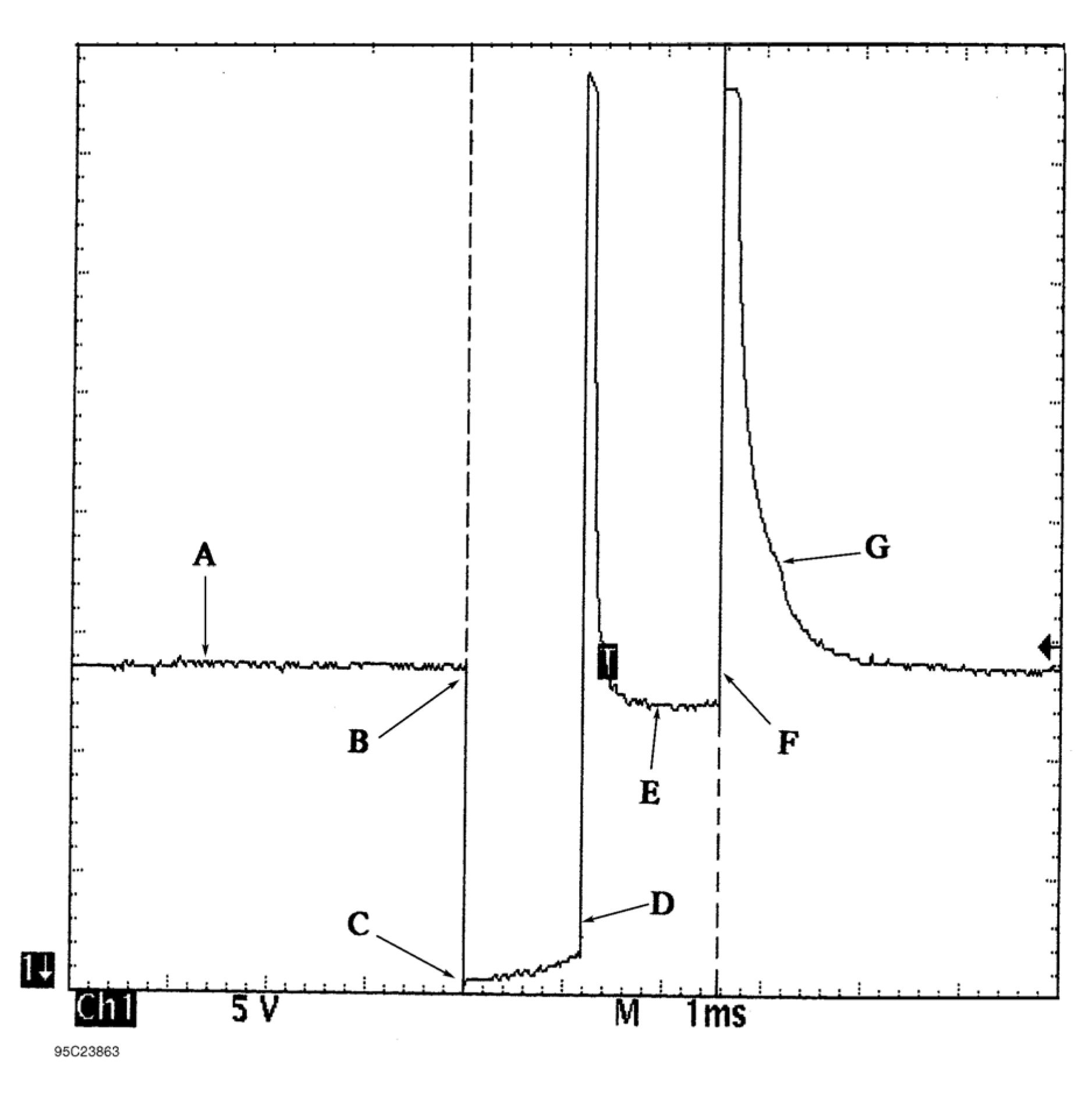 |
|
Fig. 3: Identifying Current Controlled Type Injector Pattern |
CURRENT WAVEFORM SAMPLES
NOTE: This is GENERAL information. This article is not intended to be specific to any
unique situation or individual vehicle configuration. For model-specific
information see appropriate articles where available.
EXAMPLE #1 - VOLTAGE CONTROLLED DRIVER
The waveform pattern shown in Fig. Fig. 4 indicate a normal current waveform from a Ford 3.0L V6 VIN [U]
engine. This voltage controlled type circuit pulses the injectors in groups of three injectors. Injectors No. 1, 3,
and 5 are pulsed together and cylinders 2, 4, and 6 are pulsed together. The specification for an acceptable bank
resistance is 4.4 ohms. Using Ohm's Law and assuming a hot run voltage of 14 volts, we determine that the
bank would draw a current of 3.2 amps.
However this is not the case because as the injector windings become saturated, counter voltage is created
which impedes the current flow. This, coupled with the inherent resistance of the driver's transistor, impedes the
current flow even more. So, what is a known good value for a dynamic current draw on a voltage controlled
bank of injectors? The waveform pattern shown below indicates a good parallel injector current flow of 2 amps.
See Fig. 4.
Note that if just one injector has a resistance problem and partially shorts, the entire parallel bank that it belongs
to will draw more current. This can damage the injector driver.
The waveform pattern in Fig. Fig. 5 indicates this type of problem with too much current flow. This is on other
bank of injectors of the same vehicle; the even side. Notice the Lab Scope is set on a one amp per division scale.
As you can see, the current is at an unacceptable 2.5 amps.
It is easy to find out which individual injector is at fault. All you need to do is inductively clamp onto each
individual injector and compare them. To obtain a known-good value to compare against, we used the good
bank to capture the waveform in Fig. Fig. 6. Notice that it limits current flow to 750 milliamps.
The waveform shown in Fig. Fig. 7 illustrates the problem injector we found. This waveform indicates an
unacceptable current draw of just over one amp as compared to the 750 milliamp draw of the known-good
injector. A subsequent check with a DVOM found 8.2 ohms, which is under the 12 ohm specification.
TRIG SLOPE □
DEFAULT SETUP
SIG COUPLING
WAVEFORM SINGLE
TRIG SOURCE #1
INVERT ON M3S
VOLTS/DIV 1.0
FROZEN
|
A U л ILffiRY LEA D “ |
 |
| ||||||||||||
|
95O238&4 |
Fig. 4: Injector Bank w/Normal Current Flow - Current Pattern
L. A E: S Ci О f=‘ EE GJ b l V E E О F? M
TRIG SLOPE □ - (WAVEFORM SINGLE I
DEFAULT SETUP TRIG SOURCE #1
ISIG COUPLING DC SIG INVERT ON ЙИЗI VOLTSzDIV 1.0 V
FROZEN
A U X ILIA RYLE A D■
 |
|
GR I D CURSORS |VOLTS RANGE I WAVEFORM I MENU OH -SSBi TIME BASE I POSITION I SELECT 95E23S65 |
|
Fig. 5: Injector Bank w/Excessive Current Flow - Current Pattern WAVEFORM S TRIG SOURCE |
 |
TRIG SLOPE
DEFAULT SETUP
SIG COUPLI
 |
|
Fig. 6: Single Injector w/Normal Current Flow - Current Pattern |
|
EFORM SINGLE G SOURCE |

SETUP |
|
SELECT (HBZOFF 95G23867 |
Fig. 7: Single Injector w/Excessive Current Flow - Current Pattern
EXAMPLE #2 - VOLTAGE CONTROLLED DRIVER
This time we will look at a GM 3.1L V6 VIN [T]. Fig. Fig. 8 shows the 1, 3, 5 (odd) injector bank with the
current waveform indicating about a 2.6 amp draw at idle. This pattern, taken from a known good vehicle,
correctly stays at or below the maximum 2.6 amps current range. Ideally, the current for each bank should be
very close in comparison.
Notice the small dimple on the current flow's rising edge. This is the actual injector opening or what engineers
refer to as the "set point." For good idle quality, the set point should be uniform between the banks.
When discussing Ohm's Law as it pertains to this parallel circuit, consider that each injector has specified
resistance of 12.2 ohms. Since all three injectors are in parallel the total resistance of this parallel circuit drops
to 4.1 ohms. Fourteen volts divided by four ohms would pull a maximum of 3.4 amps on this bank of injectors.
However, as we discussed in EXAMPLE #1 above, other factors knock this value down to roughly the 2.6 amp
neighborhood.
Now we are going to take a look at the even bank of injectors; injectors 2, 4, and 6. See Fig. 9. Notice this bank
peaked at 1.7 amps at idle as compared to the 2.6 amps peak of the odd bank (Fig. Fig. 8). Current flow
between even and odd injectors banks is not uniform, yet it is not causing a driveability problem. That is
because it is still under the maximum amperage we figured out earlier. But be aware this vehicle could develop
a problem if the amperage flow increases any more.
Checking the resistance of this even injector group with a DVOM yielded 6.2 ohms, while the odd injector
group in the previous example read 4.1 ohms.
|
2.630 v VOLTS/DIV 500 mV |
 |
|
ЫAVeform SINGLE I TRIG SOURCE AUX I ЖйЫКЙЗШ__ ! Li AR'-' LEAD |
 |
|
95E23873 Fig. 8: Injector Odd Bank w/Normal Current Flow - Current Pattern |
 |
|
Fig. 9: Injector Even Bank w/Normal Current Flow - Current Pattern |
EXAMPLE #3 - VOLTAGE CONTROLLED DRIVER
Example #3 is of a Ford 5.0L V8 SEFI. Fig. Fig. 10 shows a waveform of an individual injector at idle with the
Lab Scope set on 200 milliamps per division. Notice the dimple in the rising edge. This dimple indicates the
actual opening of the injector (set point) occurred at 400 milliamps and current peaked at 750 milliamps. This is
a good specification for this engine.
The next waveform pattern in Fig. Fig. 11 shows an abnormality with another injector. With the Lab Scope set
on 500 milliamps per division, you can see that the current waveform indicates a 1200 milliamp draw. This is a
faulty injector.
Abnormally low resistance injectors create excessive current draw, causing rough idle, and possible computer
driver damage.
 |
|
WAVE. FORM Fig. 10: Single Injector w/Normal Current Flow - Current Pattern |
TRIG SLOPE П
DEFAULT SETUP
G D C__, _ ....
____
AUXILIARY LEAD
|
WAVEFORM TRIG SOU SIG T NVE |  |

| ||||||||||||||
|
95H23876 |
Fig. 11: Single Injector w/Excessive Current Flow - Current Pattern
EXAMPLE #4 - CURRENT CONTROLLED DRIVER
Example #4 is of a Ford 4.6L SEFI VIN [W]. See Fig. 12 for the known-good waveform pattern. This Ford
system is different from the one above in EXAMPLE #3 as it peaks at 900 milliamps and the actual opening of
the injector (set point) is just below 600 milliamps.
This is offered as a comparison against the Ford pattern listed above, as they are both Ford SEFI injectors but
with different operating ranges. The point is that you should not make any broad assumptions for any
manufacturer.
 |
|
Fig. 12: Single Injector w/Normal Current Flow - Current Pattern |
| ||||||
|
95D23872 |
EXAMPLE #5 - CURRENT CONTROLLED DRIVER
The known-good waveform in Fig. Fig. 13 is from a Chrysler 3.0L V6 PFI VIN [3]. It is a perfect example of
the peak and hold theory. The waveform shows a 1-amp per division current flow, ramping to 4 amps and then
decreasing to 1-amp to hold the injector open.
 |
|
Fig. 13: Injector Bank w/Normal Current Flow - Current Pattern |
EXAMPLE #6 - CURRENT CONTROLLED DRIVER
This next known-good waveform is from a Ford 5.0L V8 CFI VIN [F]. See Fig. 14. The pattern, which is set on
a 250 milliamps scale, indicates a 1.25 amp peak draw and a hold at 350 milliamps.
 |
|
Fig. 14: Single Injector w/Normal Current Flow - Current Pattern |
EXAMPLE #7 - CURRENT CONTROLLED DRIVER
The known-good current controlled type waveform in Fig. Fig. 15 is from a GM 2.0L TBI VIN [1]. With the
lab scope set at 2 amps per division, notice that this system peaks at 4 amps and holds at 1 amp.
The next waveform is from the same type of engine, except that it shows a faulty injector. See Fig. 16. Notice
that the current went to almost 5 amps and stayed at 1 amp during the hold pattern. Excessive amounts of
current flow from bad injectors are a common source of intermittent computer shutdown. Using a current
waveform pattern is the most accurate method of pinpointing this problem.
TRIG SLOPE
DEFAULT SETUP
SIG COUPLING
WAVEFORM SINGLE
I TRIG SOURCE #1
iSIG INVERT ON
|
TIME |  |
IV 1.0 ms |
2 AMPS
[OFF]
FROZEN
|
ft LJ X I LIARYLE A D •+* |
 |
 |
GR I D ON] |
|
95C23871 | |
|
volts rang TIME BASE |
MENU
SELECT
WAVEFORM
POS I T ION
Fig. 15: Single Injector w/Normal Current Flow - Current Pattern
|
L. rt E: SSCOF'E WAVEFORM TRIG SLOPE КЗ - WAVEFORM SINGLE I DEFAULT SETUP TRIG SOURCE AUX SIG COUPLING DC SIG INVERT ON ИЗ'З I VOLTSzOIV 1.0 V FROZEN AUXILIARY LEA D |
 |
|
О RS OFF MENU TRIGGER WAVEFORM POSITION Tvolts range' II TIME BASE |
 |
|
95123877 |
Fig. 16: Single Injector w/Excessive Current Flow - Current Pattern
EXAMPLE #8 - CURRENT CONTROLLED DRIVER
This known-good CPI system waveform from a GM 4.3L V6 CPI VIN [W] peaks at 4 amps and holds at 1-amp.
See Fig. 17 for waveform.
 |
|
COUPLING 77 |
|
AD ■ WAVEFORM SINGLE TRIG SOURCE AUX INVERT ON ®НЙ 1 AMP |
 |
|
RANGE CURS ON 4 MENU 'T TRIG GIFS |
|
NAVEFORM |  |
95B23870
Fig. 17: Single Injector w/Normal Current Flow - Current Pattern
VOLTAGE WAVEFORM SAMPLES
|
NOTE: |
This is GENERAL information. This article is not intended to be specific to any |
EXAMPLE #1 - VOLTAGE CONTROLLED DRIVER
These two known-good waveform patterns are from a Ford 4.6L V8 VIN [W]. Fig. Fig. 18 illustrates the 64
volt inductive kick on this engine, indicating no clamping is occurring. The second pattern, Fig. Fig. 19, was
taken during hot idle, closed loop, and no load.
 |
Д: 64.8 V |
|
10 V 95E23857 Chi M 1ms Fig. 18: Injector Bank - Known Good - Voltage Pattern | |
 |
|
Fig. 19: Injector Bank - Known Good - Voltage Pattern |
EXAMPLE #2 - VOLTAGE CONTROLLED DRIVER
The known-good waveform pattern in Fig. Fig. 20 is from a GM 3.8L V6 PFI VIN [3]. It was taken during hot
idle, closed loop and no load.
 |
|
Fig. 20: Injector Bank - Known Good - Voltage Pattern |
EXAMPLE #3 - VOLTAGE CONTROLLED DRIVER
This known-good waveform pattern, Fig. Fig. 21, is from a GM 5.0L V8 TPI VIN [F]. It was taken during hot
idle, closed loop and no load.
 |
|
Fig. 21: Injector Bank - Known Good - Voltage Pattern |
EXAMPLE #4 - CURRENT CONTROLLED DRIVER
From 1984 to 1987, Chrysler used this type injector drive on their TBI-equipped engines. See Fig. 22 for a
known-good pattern. Instead of the ground side controlling the injector, Chrysler permanently grounds out the
injector and switches the power feed side. Most systems do not work this way.
These injectors peak at 6 amps of current flow and hold at 1 amp.
 |
|
Fig. 22: Single Injector - Known Good - Voltage Pattern |
EXAMPLE #5 - CURRENT CONTROLLED DRIVER
These two known-good waveform patterns are from a Chrysler 3.0L V6 VIN [3]. The first waveform, Fig. Fig.
23, is a dual trace pattern that illustrates how Chrysler uses the rising edge of the engine speed signal to trigger
the injectors. The second waveform, Fig. Fig. 24, was taken during hot idle, closed loop, and no load.
 |
|
95А23861 Fig. 23: Injector Bank - Known Good - Voltage Pattern |
 |
|
Fig. 24: Iniector Bank - Known Good - Voltage Pattern |
EXAMPLE #6 - CURRENT CONTROLLED DRIVER
This known-good pattern from a Ford 3.0L V6 PFI VIN [U] illustrates that a zener diode inside the computer is
used to clamp the injector's inductive kick to 35-volts on this system. See Fig. 25.
 |
|
Fig. 25: Injector Bank - Known Good - Voltage Pattern |
EXAMPLE #7 - CURRENT CONTROLLED DRIVER
This known-good waveform from a Ford 5.0L V8 CFI VIN [F] was taken during hot idle, closed loop, and no
load. See Fig. 26.
 |
|
Fig. 26: Single Injector - Known Good - Voltage Pattern |
EXAMPLE #8 - CURRENT CONTROLLED DRIVER
These two known-good waveform patterns are from a GM 2.0L In-Line 4 VIN [1]. Fig. Fig. 27 illustrates the
78 volt inductive spike that indicates a zener diode is not used. The second waveform, Fig. Fig. 28, was taken
during hot idle, closed loop, and no load.
 |
|
Fig. 27: Single Injector - Known Good - Voltage Pattern |
 |
|
Fig. 28: Single Injector - Known Good - Voltage Pattern |
Article GUID: A00010328
GENERAL INFORMATION
Wheel Alignment Theory & Operation
* PLEASE READ THIS FIRST *
NOTE: This is GENERAL information. This article is not intended to be specific to any
unique situation or individual vehicle configuration. For model-specific
information see appropriate articles where available.
PRE-ALIGNMENT INSTRUCTIONS
NOTE: This is GENERAL information. This article is not intended to be specific to any
unique situation or individual vehicle configuration. For model-specific
information see appropriate articles where available.
GENERAL ALIGNMENT CHECKS
Before adjusting wheel alignment, check the following:
• Each axle uses tires of same construction and tread style, equal in tread wear and overall diameter. Verify
that radial and axial runout is not excessive. Inflation should be at manufacturer's specifications.
• Steering linkage and suspension must not have excessive play. Check for wear in tie rod ends and ball
joints. Springs must not be sagging. Control arm and strut rod bushings must not have excessive play. See
Fig. 1.

Front of
Vehicle
Position Dial
Indicator Here to
Check Runout and
Movement
Move Wheel In and Out
at Front and Back
26694
Fig. 1: Checking Steering Linkage
• Vehicle must be on level floor with full fuel tank, no passenger load, spare tire in place and no load in
trunk. Bounce front and rear end of vehicle several times. Confirm vehicle is at normal riding height.
• Steering wheel must be centered with wheels in straight ahead position. If required, shorten one tie rod
adjusting sleeve and lengthen opposite sleeve (equal amount of turns). See Fig. 2.
• Wheel bearings should have the correct preload and lug nuts must be tightened to manufacturer's
specifications. Adjust camber, caster and toe-in using this sequence. Follow instructions of the alignment
equipment manufacturer.
CAUTION: DO NOT attempt to correct alignment by straightening parts. Damaged parts
MUST be replaced.
 |
|
Fig. 2: Adjusting Tie Rod Sleeves (Top View) |
ADJUSTMENTS
| ||
|
CAMBER |
1. Camber is the tilting of the wheel, outward at either top or bottom, as viewed from front of vehicle. See
Fig.3.
2. When wheels tilts outward at the top (from centerline of vehicle), camber is positive. When wheels tilt
inward at top, camber is negative. Amount of tilt is measured in degrees from vertical.
 |
|
Fig. 3: Determining Camber Angle |
CASTER
1. Caster is tilting of front steering axis either forward or backward from vertical, as viewed from side of
vehicle. See Fig. 4.
2. When axis is tilted backward from vertical, caster is positive. This creates a trailing action on front
wheels. When axis is tilted forward, caster is negative, causing a leading action on front wheels.

26697
Fig. 4: Determining Caster Angle
TOE-IN ADJUSTMENT
Toe-in is the width measured at the rear of the tires subtracted by the width measured at the front of the tires at
about spindle height. A positive figure would indicate toe-in and a negative figure would indicate toe-out. If the
distance between the front and rear of the tires is the same, toe measurement would be zero. To adjust:
1) Measure toe-in with front wheels in straight ahead position and steering wheel centered. To adjust toe-in,
loosen clamps and turn adjusting sleeve or adjustable end on right and left tie rods. See Fig. 2 and Fig. 5 .
2) Turn equally and in opposite directions to maintain steering wheel in centered position. Face of tie rod end
must be parallel with machined surface of steering rod end to prevent binding.
3) When tightening clamps, make certain that clamp bolts are positioned so there will be no interference with
other parts throughout the entire travel of linkage.

26698
Fig. 5: Wheel Toe-In (Dimension A Less Dimension B)
TOE-OUT ON TURNS
1. Toe-out on turns (turning radius) is a check for bent or damaged parts, and not a service adjustment. With
caster, camber, and toe-in properly adjusted, check toe-out with weight of vehicle on wheels.
2. Use a full floating turntable under each wheel, repeating test with each wheel positioned for right and left
turns. Incorrect toe-out generally indicates a bent steering arm. Replace arm, if necessary, and recheck
wheel alignment.
STEERING AXIS INCLINATION
1. Steering axis inclination is a check for bent or damaged parts, and not a service adjustment. Vehicle must
be level and camber should be properly adjusted. See Fig. 6.
2. If camber cannot be brought within limits and steering axis inclination is correct, steering knuckle is bent.
If camber and steering axis inclination are both incorrect by approximately the same amount, the upper
and lower control arms are bent.

Fig. 6: Checking Steering Axis Inclination
Article GUID: A00060716
Heating, Ventilation, and Air Conditioning - Volt
SPECIFICATIONS
FASTENER SPECIFICATIONS
Single Use Non-Threaded Fasteners/Components
NOTE:
All
fasteners/components
listed in this table
MUST BE
DISCARDED and
replaced with NEW
after removal.
Application
Air Conditioning System Sealing Washer
Air Conditioning O-Ring Seal
|
Reusable Threaded Fastener Tightening Specifications | |||||||||||||||||||||||||||||||||
| |||||||||||||||||||||||||||||||||
| |||||||||||||||||||||||||||||||||
|
APPROXIMATE FLUID CAPACITIES | |||||||||||||||||||||||||||||||||
|
Application |
Specification | |
|
Metric |
English | |
|
Abrupt Refrigerant Loss Oil |
60 ml |
2.03 oz |
|
Compressor Oil |
100 ml |
3.4 oz |
|
Condenser Oil |
20 ml |
0.7 oz |
|
Desiccant Cartridge Oil |
10 ml |
0.3 oz |
|
Drive Motor Battery Cooler Oil |
10 ml |
0.3 oz |
|
Evaporator Oil |
10 ml |
0.3 oz |
|
Refrigerant Charge (R-134a) |
0.95 kg |
2.1 lb |
|
Total System POE Oil Capacity |
180 ml |
6.1 oz |
|
ADHESIVES, FLUIDS, LUBRICANTS, AND SEALERS | ||||||||||||||
| ||||||||||||||
DIAGNOSTIC INFORMATION AND PROCEDURES
HANDLING OF REFRIGERANT LINES AND FITTINGS
CAUTION: To avoid system damage use only R-134a dedicated tools when servicing the A/C
system.
• Keep all metal tubing lines free of dents or kinks. Any line restrictions will cause the loss of system capacity.
• Never bend a flexible hose line to a radius of less than four times the diameter of the hose.
• Never allow a flexible hose line to come within 65 mm (2 - 1/2 in) of the exhaust manifold.
• Inspect flexible hose lines regularly for leaks or brittleness.
• Replace flexible hose lines with new lines if you find signs of deterioration or leaking.
• Discharge the refrigeration system of all refrigerant before disconnecting any fitting in the refrigeration
system.
• Proceed very cautiously regardless of the gauge readings.
WARNING: For personal protection, goggles and lint-free gloves should be worn and a
clean cloth wrapped around fittings, valves, and connections when doing work
that includes opening the refrigerant system. If refrigerant comes in contact
with any part of the body severe frostbite and personal injury can result. The
exposed area should be flushed immediately with cold water and prompt
medical help should be obtained.
• Open the fittings very slowly.
• If you notice pressure when you loosen a fitting, allow the pressure to bleed off as described Discharging,
Adding Oil, Evacuating, and Charging Procedures for A/C System.
• Cap or tape any refrigerant line immediately after it is opened. This will prevent the entrance of moisture and
dirt, which can cause internal compressor wear or plugged lines in the condenser, the evaporator core, the
expansion valve, or the compressor inlet screens.
NOTE: Use two proper wrenches to connect the fittings.
• Back up the opposing fitting to prevent distortion of the connecting lines or the components.
• Keep the sealing surfaces in perfect condition. A burr or a piece of dirt may cause a refrigerant leak.
• When seal washers are used, always install the seal washer without lubrication.
CAUTION: Use only the lubricant specified for this vehicles refrigerant system. Do not
mix refrigerant oils which may result in system contamination and unknown
reaction by-products which may cause HVAC System failure.
• When O-rings are used, always lightly coat the new O-ring seal with the proper refrigerant oil prior to
installation.
LEAK TESTING
Special Tools
• GE-50078 Infrared Refrigerant Leak Detector
• GE-42220 Universal 12V Leak Detection Lamp
• GE-43872 Fluorescent Dye Cleaner
For equivalent regional tools, refer to Special Tools.
Refrigerant Leak Testing
NOTE: All A/C system repairs must be verified using electronic leak detection. Dye
detection may take up 2 or 3 days to be reliable.
NOTE: General Motors vehicles are now manufactured with fluorescent dye installed
directly into the air conditioning (A/C) system.
The fluorescent dye mixes and flows with the refrigerant oil throughout the refrigerant system.
Verifying some passive leaks may require using the GE-50078 detector, even though the A/C system contains
fluorescent dye.
Visual Inspection
Visually trace the entire refrigerant system and look for signs of lubricant leakage, damage, and corrosion on all lines
hoses and components (Oil can be an indication of a leak). Each questionable area should be checked for leaks using
an electronic leak detector.
Fluorescent Leak Detector
NOTE: Always use UV protective eyewear when working with UV light.
Fluorescent dye will assist in locating any leaks in the A/C system.
NOTE: POE oil is water soluble.
• Condensation on the evaporator core or the refrigerant lines may wash the POE oil and fluorescent dye away
from the actual leak. Condensation may also carry dye through the HVAC module drain.
• Leaks in the A/C system will be indicated in a light green or yellow color when using the leak detection lamp.
Use the leak detection lamp in the following areas:
• All fittings or connections that use seal washers or O-rings
• All of the A/C components
• The A/C hoses and pressure switches
• The HVAC module drain tube, if the evaporator core is suspected of leaking
• The service port sealing caps
The sealing cap is the primary seal for the service ports.
• Follow the instructions supplied with the GE-42220 lamp.
• To prevent false diagnosis in the future, thoroughly clean the residual dye from any area where leaks were
found. Use a rag and the approved GE-43872 cleaner.
Replacing System Dye After Flushing
NOTE: Do not add dye to the refrigerant system equipped with high voltage electric
compressors. The only means of replenishing dye after flushing is by replacing
component containing the dye. Currently a compatible dye wafer is contained in the
O.E. desiccant package. Adding dye that is not compatible with the high voltage
electric compressor may cause compressor damage and high voltage isolation
faults.
To prevent false diagnosis, thoroughly clean any residual dye from the service port with a rag and the approved
fluorescent dye cleaner GE-43872 cleaner.
Electronic Leak Detection
Infrared detectors operate differently than heated sensor type detectors. They detect changes in concentration of
refrigerant rather than absolute concentration. If the tip is held at a detected leak for more than 5 seconds the detector
will saturate and zero to that concentration and will no longer detect leaks at that concentration or less. Move tip
away from the leak saturation area for 30 seconds to reset the sensitivity of the detector.
Adequate system pressure is required for effective leak detection.
• If system is empty install 10% of system charge.
• Temperature must be above 60 F
Do not use:
• Soap solutions (not effective for leak detection)
• Shop air (will introduce contamination to the refrigerant system)
• High pressure gasses i.e nitrogen (May cause system damage
Air movement from the engine cooling fan can affect the detectors ability to detect leaks. Always leak test with
engine off and if possible after engine has reached normal operating temperature.
• All fittings and components should be checked.
• Take care not to contaminate the probe tip if the part being tested is contaminated.
• No cleaners containing solvents should be used prior to using electronic leak detector.
• Always follow the refrigerant system around in a continuous path so that no areas of potential leaks are
missed. Move the tip along the refrigerant system at a rate of no more than 75 mm per second and a distance of
10 mm from the surface being tested. If a leak is found, always continue to test the remainder of the system.
Follow the instructions supplied with the GE-50078 detector.
AIR CONDITIONING (A/C) SYSTEM PERFORMANCE TEST
This test measures the operating efficiency of the A/C system under the following conditions:
• The current ambient air temperature
• The current relative humidity
• The high side pressure of the A/C system
• The low side pressure of the A/C system
• The temperature of the air being discharged into the passenger compartment
Test Description
The numbers below refer to the step numbers on the diagnostic table.
This step determines if the A/C system has at least the minimum refrigerant charge required to operate the
system without damage.
2
This step measures the performance of the A/C system.
3
This step is to allow for vehicle variations as well as high ambient temperatures.
Step
Action
Values
Yes
No
NOTE:
• The
ambient air
temperature
must be at
least 16A°C
(60A°F).
• Do not
induce
additional
air flow
across the
front of the
vehicle
during the
test.
• If you were
sent here
from a DTC
diagnostic
table, clear
the DTC
upon
completion
of this test.
More than
16A°C
(60A°F) - 345
kPa (50 psi)
More than
24A°C
(75A°F) - 483
kPa (70 psi)
More than
33A°C
1. Park the vehicle inside or in the shade.
2. Open the windows in order to ventilate the
interior of the vehicle.
3. If the A/C system was operating, allow the
A/C system to equalize for about 2 minutes.
4. Turn OFF the ignition.
5. Install the J-43600 ACR 2000 Air
Conditioning Service Center or GE-48800
CoolTech A/C Recharge Machine.
Go to Leak
Testing
Go to Step 2
|
Step |
Action |
Values |
Yes |
No |
Are both the low side and high side pressures within |
(90A°F) - 690 | |||
|
NOTE: | ||||
|
2 |
|
- |
Go to Step 5 |
Go to Step 3 |
|
Step |
Action |
Values |
Yes |
No |
11. Compare the low and high side pressures and Does all the data recorded fall within the specified | ||||
|
3 |
If the pressures and temperatures recorded do not
Does all the data recorded fall within the specified |
- |
Go to Step 5 |
Go to Step 4 |
|
4 |
Perform the necessary repairs. Refer to A/C Diagnostics Chart. Is the action complete? |
- |
Go to Step 5 |
- |
|
5 |
Operate the system in order to verify the test results. |
- |
System OK |
Go to Symptoms
|
|
A/C Performance Table | ||||||||||||||||||||||||||||||||
|
| |||||||||||||||||||||||||||||||||||||||||||||
|
A/C DIAGNOSTICS CHART |
|
A/C System Concern |
Potential Causes | |
|
Compressor Inoperative |
Electrical Wiring Issue | |
|
No or Low Refrigerant Charge | ||
|
Compressor Internal Malfunction | ||
|
Compressor Clutch Malfunction | ||
|
A/C Pressure Sensor Malfunction | ||
|
Evaporator Air Temperature (EAT) | ||
|
HVAC Controls Malfunction | ||
|
Low Side Gauge Reading |
High Side Gauge Reading |
Potential Causes |
|
Same as High Side |
Same as Low Side |
No or Low Refrigerant Charge |
|
Compressor Malfunction | ||
|
A/C Pressure Sensor Malfunction | ||
|
EAT Malfunction | ||
|
HVAC Controls Malfunction | ||
|
Normal |
Normal |
Temperature Actuator Malfunction |
|
Temperature Door Malfunction | ||
|
Low |
Low |
Low Refrigerant Charge |
|
Restriction between the Compressor Outlet and | ||
|
Low/Normal |
Evaporator Freezing/EAT Malfunction | |
| ||||||||||||||||||||||
|
HEATING PERFORMANCE DIAGNOSTIC | ||||||||||||||||||||||
|
Step |
Action |
Yes |
No |
|
DEFINITION: Heating system performance. | |||
|
Step |
Action |
Yes |
No |
|
1 |
Were you sent here from Symptoms or another diagnostic |
Go to Step 2 |
Go to Symptoms - |
|
2 |
WARNING: Moving
Does the heater core inlet hose feel warm to hot? |
Go to Step 3 |
Go to Step 9 |
|
3 |
Does the heater core inlet hose feel warmer than the |
Go to Step 7 |
Go to Step 4 |
|
4 |
Are the two temperature readings about equal? |
Go to Step 5 |
Go to Step 6 |
|
5 |
Are the repairs complete? |
Go to Step 10 |
- |
| ||||||||||||||||||||||||
|
DEFROSTING INSUFFICIENT |
|
Step |
Action |
Yes |
No |
|
DEFINITION: Time required to defrost the windshield is longer than normal. | |||
| ||||||||||||||||||||||||||||||||||||||||||||||
|
NOISE DIAGNOSIS - BLOWER MOTOR |
|
Step |
Action |
Yes |
No |
|
DEFINITION: Noise originating from the blower motor. | |||
|
Step |
Action |
Yes |
No |
|
1 |
Were you sent here from Symptoms or another diagnostic |
Go to Step 2 |
Go to Symptoms - |
|
2 |
Inspect the air inlet grille for debris. |
Go to Step 8 |
Go to Step 3 |
|
3 |
Is a noise evident during the blower operation? |
Go to Step 4 |
Go to Step 11 |
|
4 |
Inspect for excessive vibration at each blower motor Is excess vibration present? |
Go to Step 6 |
Go to Step 5 |
|
5 |
Listen to the blower motor at each speed. Is the blower motor making a squeaking or chirping |
Go to Step 9 |
Go to Step 11 |
|
6 |
Did you find any foreign material on the blower motor or |
Go to Step 8 |
Go to Step 7 |
|
7 |
Inspect the blower motor for the following conditions:
Did you find any of these conditions? |
Go to Step 9 |
Go to Step 10 |
|
8 |
Remove the foreign material. |
Go to Step 10 |
- |
|
9 |
Replace the blower motor. Refer to Blower Motor Replacement. Is the repair complete? |
Go to Step 11 |
- |
|
10 |
Install the blower motor. Refer to Blower Motor Replacement. Is the action complete? |
Go to Step 11 |
- |
| ||||||||
|
ODOR DIAGNOSIS |
|
Step |
Action |
Yes |
No |
|
DEFINITION: Odor originating or noticed through the HVAC system. | |||
|
1 |
Were you sent here from Symptoms or another |
Go to Step 2 |
Go to Symptoms - |
|
2 |
Does the odor have a musty smell? |
Go to Step 3 |
Go to Step 8 |
|
3 |
Inspect the HVAC filter and the air inlet grille for Is debris present? |
Go to Step 4 |
Go to Step 5 |
|
4 |
Remove any debris. |
Go to Step 15 |
- |
|
5 |
Inspect for wet carpeting. |
Go to Step 6 |
Go to Step 8 |
|
6 |
Inspect for the following conditions:
Is a leak present? |
Go to Step 7 |
Go to Step 15 |
|
7 |
Repair the leak as necessary. |
Go to Step 15 |
- |
|
8 |
Does the odor have a coolant smell? |
Go to Step 9 |
Go to Step 12 |
|
9 |
Inspect the cooling system for leaks. Refer to Loss of Is a leak present? |
Go to Step 10 |
Go to Step 12 |
|
Step |
Action |
Yes |
No |
|
10 |
Inspect for coolant leaking inside the vehicle or for a Is the condition present? |
Go to Step 11 |
Go to Step 15 |
|
11 |
Replace the heater core. Refer to Heater Core Replacement. Is the repair complete? |
Go to Step 15 |
- |
|
12 |
Does the odor have an oily smell? |
Go to Step 13 |
Go to Step 15 |
|
13 |
Is the repair complete? |
Go to Step 15 |
- |
|
14 |
A musty odor can be caused by mold or mildew build- Is the action complete? |
Go to Step 15 |
- |
|
15 |
Operate the system in order to verify the repair. |
System OK |
Go to Step 2 |
REPAIR INSTRUCTIONS
ODOR CORRECTION
Eliminating Air Conditioning (A/C) Odor
Odors may be emitted from the air conditioning system primarily at start up in hot, humid climates. The following
conditions may cause the odor:
• Debris is present in the HVAC module
• Microbial growth on the evaporator core
When the blower motor fan is turned on, the microbial growth may release an unpleasant musty odor into the
passenger compartment. To remove odors of this type, the microbial growth must be eliminated. Perform the
following procedure:
Deodorize the evaporator core using Deodorizing Aerosol Kit.
Perform the following steps in order to deodorize the A/C system:
1. Ensure that the plenum which draws outside air into the HVAC module is clear of debris.
2. Disable the air conditioning (A/C) compressor clutch operation by disconnecting the clutch coil electrical
connector.
3. Dry the evaporator core by performing the following steps:
1. Start the engine.
2. Select the warmest temperature setting.
3. Select the recirculation mode.
4. Run the blower motor on high for 10 minutes.
4. Locate an area in the air conditioning duct between the blower motor and the evaporator core downstream of
the blower motor.
5. Drill a 3.175 mm (0.125 in) hole where the hole will not interfere with or damage the following components:
• The blower motor
• The evaporator core
• Any other operating part the of system
6. Wear safety goggles and latex gloves in order to perform the following actions:
1. Select the maximum blower speed.
2. Insert the deodorizer extension tube into the hole to the mark on the extension tube.
3. Use short spray bursts and vary the direction of spray for a 2 - 3 minute period of time.
7. Shut the engine OFF. Allow the vehicle to sit for 3 - 5 minutes.
8. Seal the 3.175 mm (0.125 in) hole with body sealer or RTV gasket compound.
9. Start the engine.
10. Operate the blower motor on high for 15 - 20 minutes to dry.
11. Reconnect the A/C compressor clutch coil electrical connector.
12. Verify proper A/C clutch operation.
REFRIGERANT RECOVERY AND RECHARGING
Special Tools
• GE 48997 Hybrid A/C Oil Injector Adapter Hose
• GE 43600 Hybrid A/C Oil Injector Adapter Hose
• GE-48800 CoolTech A/C Recharge Machine
• GE-45037-A A/C Oil Injector
For equivalent regional tools, refer to Special Tools.
WARNING: To prevent personal injury, avoid breathing A/C Refrigerant and lubricant vapor or
mist. Work in a well ventilated area. To remove refrigerant from the A/C System, use
service equipment designed for recovery that is certified to meet the requirements
of the appropriate SAE Standards. If an accidental system discharge occurs,
ventilate the work area before continuing service. Additional health and safety
information may be obtained from the refrigerant, refrigerant recovery, and lubricant
manufacturers.
WARNING: For personal protection, goggles with side protection and lint-free gloves (insulated
against heat loss and impermeable to refrigerant) must be worn and a clean cloth
wrapped around fittings, valves, and connections when doing work that includes
opening the refrigerant system. If refrigerant comes in contact with any part of the
body severe frostbite and personal injury may result. The exposed area should be
flushed immediately with cold water and prompt medical attention should be
obtained.
CAUTION: This A/C refrigerant system is equipped with a High Voltage electric A/C compressor
and you must replace the desiccant if the A/C refrigerant system has been open to
atmosphere for more than thirty minutes, or if the A/C refrigerant oil has been
contaminated. Failure to replace the desiccant will result in damage to the A/C
refrigerant system.
CAUTION: R-134a is the only approved refrigerant for use in this vehicle. The use of any other
refrigerant may result in poor system performance or component failure and
potentially void the vehicle warranty for the refrigerant system.
CAUTION: This A/C system's high voltage A/C Compressor uses Polyolester (POE) refrigerant
oil instead of Polyalkylene Glycol (PAG) refrigerant oil. Use only approved GM POE
oil no more than two hours after removal from its sealed moisture proof packaging
(reference GM POE label for proper usage) in refrigerant systems equipped with a
High Voltage A/C compressor. GM POE oil is intended to be used with the
GE-45037-A A/C oil injector and the GE-48997 A/C POE oil injector hose. Use of any
refrigerant oil other than the approved GM POE, handled and installed per GM's
requirements may result in compressor failure and/or loss of HV isolation with
associated DTC's set.
CAUTION: Do not lubricate A/C line seal washers as mineral oil will damage the seal and cause
leaks. Use only 525 viscosity mineral oil to lubricate o-rings as well as fitting
threads for the prevention of fitting seizure.
CAUTION: Failure to flush the refrigerant recovery recharge equipment hoses before adding
refrigerant to a hybrid vehicle with an electric compressor may result in an
unacceptable amount of Polyalkylene Glycol (PAG) oil entering the refrigerant
system. This could result in reduced electrical resistance of the Polyolester (POE)
oil and reduce its ability to provide the required level of high voltage isolation.
Both the GE 43600 Hybrid A/C Oil Injector Adapter Hose and GE-48800 CoolTech A/C Recharge Machine are a
complete air conditioning service center for R-134a. The ACR 2000 recovers, recycles, evacuates and recharges A/C
refrigerant quickly, accurately and automatically. The unit has a display screen that contains the function controls and
displays prompts that will lead the technician through the recover, recycle, evacuate and recharge operations. R-134a
is recovered into and charged out of an internal storage vessel. Both units automatically replenishes this vessel from
an external source tank in order to maintain a constant 5.45 - 6.82 kg (12 - 15 lbs) of A/C refrigerant.
The ACR 2000 has a built in A/C refrigerant identifier that will test for contamination, prior to recovery and will
notify the technician if there are foreign gases present in the A/C system. If foreign gases are present, the ACR 2000
will not recover the refrigerant from the A/C system.
The ACR 2000 also features automatic air purge, single pass recycling and an automatic oil drain.
GE-48800 CoolTech A/C Recharge Machine is released as a required replacement for the previously essential GE
43600 Hybrid A/C Oil Injector Adapter Hose. The GE-48800 CoolTech A/C Recharge Machine is SAE J2788
compliant and meets GM requirements for A/C Refrigerant System Repairs on all General Motors vehicles,
including Hybrid systems with Polyolester (POE) refrigerant oil.
Refer to the GE 43600 Hybrid A/C Oil Injector Adapter Hose and GE-48800 CoolTech A/C Recharge Machine
ACR 2000 manual for operation and setup instruction. Always recharge the A/C System with the proper amount of
R-134a. Refer to Approximate Fluid Capacities for the correct amount.
A/C Refrigerant System Oil Charge Replenishing
If oil was removed from the A/C system during the recovery process or due to component replacement, the oil must
be replenished. If no oil was removed from the A/C system during recovery, do not charge any POE oil into the A/C
system. POE refrigerant oil can be injected into a charged A/C system using GE-45037-A injector along with GE
48997 adapter. For the proper quantities of oil to add to the A/C refrigerant system, refer to Approximate Fluid
Capacities.
FLUSHING
Special Tools
• GE-42220 Universal 12V Leak Detection Lamp
• GE-43600-50 Flush Loop Hose
• GE-45268 Flush Adapter Kit
• GE-48800 CoolTech A/C Recharge Machine
For equivalent regional tools. Refer to Special Tools.
|
ACR2000 (GE-48800) Hose Flush Procedure | ||
|
refrigerant recovery standard J-2788 and is specially designed for GM
hybrid vehicle A/C service.
Before Beginning the Hose Flushing Procedure
1. Always allow the ACR2000 to complete the hose flush cycle to assure that all oil and refrigerant is removed
from the hoses and the ACR2000 flow control circuit.
2. Assure the ACR2000 has at least 4.08 kg (9 lb) of chargeable refrigerant before proceeding.
3. A Low Filter Flow message displayed during the hose flushing process indicates that the hose couplers are not
connected or open.
Hose Flushing Procedure
1. Connect the ACR2000 service hose couplers to the GE-43600-50 hose flush adapter fittings and open the
service hose coupler valves.
2. Power on the ACR2000.
3. If there is positive pressure in the ACR2000 service hoses, press START to recover the service hoses. If there
is 88 - 98 kPa (26 - 29 Hg) of vacuum showing on the display screen, skip to step 7.
4. Press Vacuum.
5. Press Start. Allow the vacuum program to run until the display screen shows between 88 - 98 kPa (26 - 29
Hg).
6. Press Pause.
7. Press Main Menu.
8. Press Scroll Menu.
9. Press Oil Flush.
10. Press Next.
11. Enter 03:00 (for a three minute flush) and press Start.
12. The ACR2000 will now flush the service hoses for three minutes and then recover the refrigerant
13. Close the ACR2000 service hose couplers and remove the GE-43600-50 hose flush adapter.
14. The ACR2000 can now be connected to the hybrid vehicle to perform the A/C system diagnostic or service
procedures.
ACR2000 (GE-48800) A/C System Procedure
NOTE: Flushing with the ACR 2000 is not intended to remove metal from the A/C system.
Flushing is intended to remove the following contaminants:
• Contaminated polyolester (POE) oil
• Desiccant, following a desiccant bag failure
• Overcharge of POE oil
• Refrigerant contamination
NOTE: Warmer engine or ambient temperature decreases the refrigerant recovery
time during the A/C flush procedure.
1. Recover the refrigerant. Refer to Refrigerant Recovery and Recharging.
2. Remove the air conditioning refrigerant desiccant. Refer to Air Conditioning Refrigerant Desiccant
Replacement.
3. Remove the air conditioning refrigerant desiccant plug from the desiccant cartridge.
4. Install the air conditioning refrigerant desiccant plug without the desiccant cartridge.
5. Remove the evaporator thermal expansion valve. Refer to Air Conditioning Evaporator Thermal
Expansion Valve Replacement
6. Install GE-45268-115 to the evaporator.
7. Remove the drive motor battery cooler thermal expansion valve. Refer to Air Conditioning Evaporator
Thermal Expansion Valve Replacement
8. Install another GE-45268-115 to the drive motor battery cooler.
9. Install A/C evaporator tube to both GE-45268-115.
10. Install A/C evaporator TXV tube to both GE-45268-115 using an oversized seal washer.
11. Remove the A/C and drive motor battery cooling compressor. Refer to Air Conditioning and Drive Motor
Battery Cooling Compressor Replacement
12. Inspect the end of the suction hose for a suction screen.
13. Remove the suction screen, if installed.
14. Install GE-45268-4 to the A/C compressor suction hose.
15. Install GE-452688-5 to the A/C compressor discharge hose.
 |
|
Fig. 1: A/C Filter And Check Valve Courtesy of GENERAL MOTORS COMPANY |
16. Forward flow refrigerant flushing is recommended for contaminated refrigerant or POE oil.
17. Perform the following procedure:
NOTE: The filter inside the GE-45268-1 is serviceable. Remove and discard the
check valve from the filter.
1. Service the filter with ACDelco P/N GF 470, before each flush.
Connect the GE-45268-1 flush filter to the suction port of the GE-45268-4 flush adapter.
2. Connect the blue hose from the GE-48800 ACR 2000 Air Conditioning Service Center to the J 45268-1
flush filter adapter.
3. Connect the red hose from the GE-48800 ACR 2000 Air Conditioning Service Center to the
GE-45268-5 flush adapter.
18. Reverse flow refrigerant flushing is recommended for desiccant cartridge failure.
NOTE: The filter inside the J 45268-1 is serviceable. Remove and discard the
check valve from the filter.
1. Service the filter with AC P/N GF 470, before each flush. Connect the J 45268-1 flush filter to the
discharge port of the GE-45268-5 flush adapter.
2. Connect the blue hose from the GE-48800 ACR 2000 Air Conditioning Service Center to the J 45268-1
flush filter adapter.
3. Connect the red hose from the GE-48800 ACR 2000 Air Conditioning Service Center to the suction port
of the GE-45268-4 flush adapter.
NOTE: Close the valve on the external refrigerant tank, before starting the flush
process.
19. Flush the front A/C system. Follow the instructions supplied with the GE-48800 ACR 2000 Air Conditioning
Service Center.
NOTE: Close the valve on the external refrigerant tank, before starting the flush
process.
20. Flush the A/C system. Follow the instructions supplied with the GE-48800 ACR 2000 Air Conditioning
Service Center
21. Remove the GE-45268-4 from the A/C compressor suction hose.
22. Remove the GE-45268-5 from the A/C compressor discharge hose.
NOTE: Flushing will remove all the POE oil from the A/C system.
The A/C system must be replenished with the correct amount of POE oil.
23. If the removed A/C compressor is being reinstalled, perform the following procedure:
• Drain the POE oil from the A/C compressor.
• Add the total system capacity of POE oil to the A/C compressor. Refer to Approximate Fluid
Capacities.
24. If you will replace the A/C compressor after flushing the system, perform the following procedure:
1. Refer to the Approximate Fluid Capacities.
2. DO NOT drain the new POE oil from the compressor.
3. Deduct the amount of POE oil shipped with the service compressor from the amount of POE oil listed in
the capacities table. Refer to Approximate Fluid Capacities.
4. Add the calculated amount to the compressor, as needed.
25. Install the air conditioning and drive motor battery cooling compressor. Refer to Air Conditioning and Drive
Motor Battery Cooling Compressor Replacement
NOTE: Flushing will remove the fluorescent leak detection dye from the A/C system.
NOTE: The air conditioning refrigerant desiccant is manufactured with POE
fluorescent leak detection dye wafer inside.
26. Replace the air conditioning refrigerant desiccant. Refer to Air Conditioning Refrigerant Desiccant
Replacement.
27. Remove A/C evaporator TXV tube from both GE-45268-115.
28. Remove A/C evaporator tube from both GE-45268-115.
29. Remove both GE-45268-115.
30. Install the drive motor battery cooler thermal expansion valve. Refer to Air Conditioning Evaporator
Thermal Expansion Valve Replacement
31. Install the evaporator thermal expansion valve. Refer to Air Conditioning Evaporator Thermal Expansion
Valve Replacement
32. Evacuate and recharge the A/C system. Refer to Refrigerant Recovery and Recharging
33. Leak test the fittings using GE-42220 Universal 12V Leak Detection Lamp
AIR CONDITIONING AND DRIVE MOTOR BATTERY COOLING COMPRESSOR REPLACEMENT
 |
|
Fig. 2: Air Conditioning and Drive Motor Battery Cooling Compressor |
|
Callout |
Component Name |
WARNING:
Always perform
the High Voltage
Disabling
procedure prior
to servicing any
High Voltage
component or
connection.
Personal
Protection
Equipment
(PPE) and
proper
procedures
must be
followed.
The High
Voltage
Disabling
procedure will
perform the
following tasks:
• Identify
how to
disable
high
voltage.
• Identify
how to test
for the
presence
of high
voltage.
• Identify
condition
under
which high
voltage is
always
present
and
personal
protection
equipment
(PPE) and
proper
procedures
must be
followed.
Failure to follow
the procedures
exactly as
written may
result in serious
injury or death.
WARNING:
Do not use a
service jack
in locations
other than
those
specified to
lift this
vehicle.
Lifting the
vehicle with
a jack in
those other
locations
could cause
the vehicle
to slip off
the jack and
roll; this
could cause
injury or
death.
CAUTION:
This A/C
system's
high voltage
A/C
Compressor
uses
Polyolester
(POE)
refrigerant
oil instead of
Polyalkylene
Glycol (PAG)
refrigerant
oil. Use only
approved
GM POE oil
no more than
two hours
after removal
from its
sealed
moisture
proof
packaging
(reference
GM POE
label for
proper
usage) in
refrigerant
systems
equipped
with a High
Voltage A/C
compressor.
GM POE oil
is intended
to be used
with the
GE-45037-A
A/C oil
injector and
the
GE-48997
A/C POE oil
injector
hose. Use of
any
refrigerant
oil other than
the approved
GM POE,
handled and
installed per
GM's
requirements
may result in
compressor
failure and/or
loss of HV
isolation
with
associated
DTC's set.
Preliminary Procedures
1. Disable high voltage system. Refer to High Voltage Disabling
2. Remove Air Conditioning Compressor Hose. Refer to Air Conditioning Compressor Hose
Replacement
3. Remove Front Wheel Drive Shaft - Right Side. Refer to Front Wheel Drive Shaft Replacement
4. Position aside Heater Water Shutoff Valve. Refer to Heater Water Shutoff Valve Replacement
Air Conditioning Compressor Mounting Bracket Lower Stud
1 Tighten
22 N.m (16 lb ft)
| ||||||||
|
COMPRESSOR PRESSURE RELIEF VALVE REPLACEMENT |
 |
|
Fig. 3: Compressor Pressure Relief Valve |
|
Callout |
Component Name |
|
Preliminary Procedure | |
|
1 |
Air Conditioning Compressor Pressure Relief Valve CAUTION: Refer to Tighten 7 N.m (62 lb in) |
AIR CONDITIONING COMPRESSOR HOSE REPLACEMENT
Removal Procedure
1. Disconnect Battery Negative Cable. Refer to Battery Negative Cable Disconnection and Connection
2. Recover the refrigerant. Refer to Refrigerant Recovery and Recharging
3. Remove Dash Upper Extension Panel Opening Cover. Refer to Dash Upper Extension Panel Opening Cover
Replacement
4. Remove Air Cleaner Outlet Duct. Refer to Air Cleaner Outlet Duct Replacement
 |
|
Fig. 4: Air Conditioning Compressor Hose And Nut Courtesy of GENERAL MOTORS COMPANY |
5. Remove the air conditioning compressor hose nut (1) from the air conditioning evaporator hose (3).
6. Raise the vehicle. Refer to Lifting and Jacking the Vehicle
 |
|
Fig. 5: A/C Cycling Switch Electrical Connector |
7. Disconnect the A/C cycling switch electrical connector (1).
 |
|
Fig. 6: Air Conditioning Compressor Hose Bolt And Air Conditioning Evaporator Hose |
8. Remove the air conditioning compressor hose bolt (1) from the air conditioning evaporator hose (2).
9. Remove Air Conditioning Compressor Hose
Installation Procedure
1. Replace Air Conditioning Refrigerant Pressure Sensor O-Ring Seal. Refer to Air Conditioning Refrigerant
Pressure Sensor O-Ring Seal Replacement
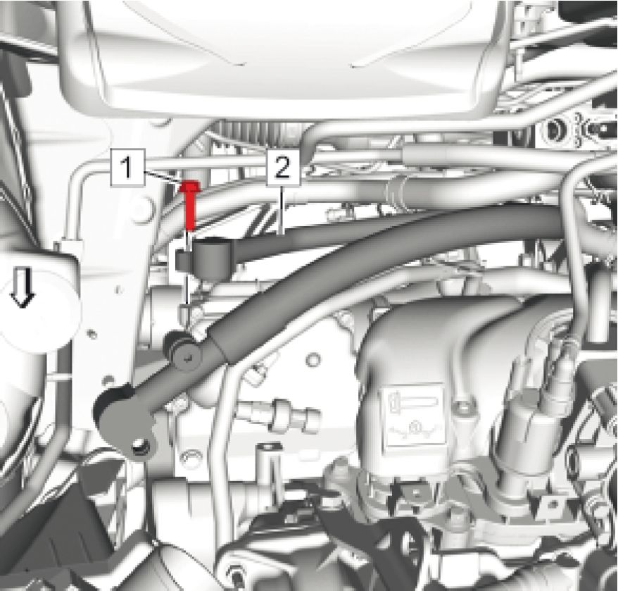 |
|
Fig. 7: Air Conditioning Compressor Hose Bolt And Air Conditioning Evaporator Hose |
CAUTION: Refer to Fastener Caution
2. Install the air conditioning evaporator hose (2) and the air conditioning compressor hose bolt (1) to the air
conditioning compressor and tighten to 22 N.m (16 lb ft)
 |
|
Fig. 8: A/C Cycling Switch Electrical Connector |
3. Connect the A/C cycling switch electrical connector (1).
4. Lower the vehicle.
 |
|
Fig. 9: Air Conditioning Compressor Hose And Nut Courtesy of GENERAL MOTORS COMPANY |
5. Install the air conditioning compressor hose (2) and the air conditioning compressor hose nut (1) to the air
conditioning evaporator hose (3) and tighten to 22 N.m (16 lb ft)
6. Install Air Cleaner Outlet Duct. Refer to Air Cleaner Outlet Duct Replacement
7. Install Dash Upper Extension Panel Opening Cover. Refer to Dash Upper Extension Panel Opening Cover
Replacement
8. Evacuate and charge the refrigerant system. Refer to Refrigerant Recovery and Recharging
9. Connect Battery Negative Cable. Refer to Battery Negative Cable Disconnection and Connection
AIR CONDITIONING COMPRESSOR AND CONDENSER HOSE REPLACEMENT
Removal Procedure
1. Disconnect Battery Negative Cable. Refer to Battery Negative Cable Disconnection and Connection
2. Recover the refrigerant. Refer to Refrigerant Recovery and Recharging
3. Remove Dash Upper Extension Panel Opening Cover. Refer to Dash Upper Extension Panel Opening Cover
Replacement
4. Remove Front Bumper Fascia. Refer to Front Bumper Fascia Removal and Installation
5. Remove Air Cleaner Assembly. Refer to Air Cleaner Assembly Replacement
6. Remove Air Conditioning Compressor Hose. Refer to Air Conditioning Compressor Hose Replacement
7. Remove Radiator Outlet Hose. Refer to Radiator Outlet Hose Replacement
 |
|
Fig. 10: Air Conditioning Evaporator Tube, Condenser Tube And Nut |
8. Remove the air conditioning evaporator tube nut (3).
9. Remove the air conditioning evaporator tube (1) along with the condenser tube (2) from the condenser.
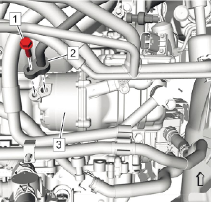 |
|
Fig. 11: Air Conditioning Compressor, Condenser Hose And Bolt |
10. Remove the air conditioning compressor and condenser hose bolt (1).
11. Remove the air conditioning compressor and condenser hose (2) from the air conditioning compressor (3).
 |
|
Fig. 12: A/C Compressor And Condenser Hose Tube, Retainer, Wiring Harness And Cycling Switch Courtesy of GENERAL MOTORS COMPANY |
12. Remove the air conditioning compressor and condenser hose tube (4).
13. Unclip the retainer (1) holding the air conditioning compressor and condenser hose tube to the engine bracket.
14. Unclip the wiring harness (2) from the air conditioning compressor and condenser hose tube.
15. Disconnect the air conditioning cycling switch electrical connector (3).
16. Remove Air Conditioning Compressor High Pressure Cut Off Switch. Refer to Air Conditioning Compressor
High Pressure Cut Off Switch Replacement
Installation Procedure
1. Change the air conditioning O-ring seal. Refer to Air Conditioning Refrigerant Pressure Sensor O-Ring
Seal Replacement.
2. Install Air Conditioning Compressor High Pressure Cut Off Switch. Refer to Air Conditioning Compressor
High Pressure Cut Off Switch Replacement
 |
|
Fig. 13: A/C Compressor And Condenser Hose Tube, Retainer, Wiring Harness And Cycling Switch |
3. Install the air conditioning compressor and condenser hose tube (1).
 |
|
Fig. 14: Air Conditioning Compressor, Condenser Hose And Bolt |
4. Install the air conditioning compressor and condenser hose (2) to the air conditioning compressor (3).
CAUTION: Refer to Fastener Caution
5. Install the air conditioning compressor and condenser hose bolt (1) to the compressor and tighten to 22 N.m
(16 lb ft).
 |
|
Fig. 15: Air Conditioning Evaporator Tube, Condenser Tube And Nut Courtesy of GENERAL MOTORS COMPANY |
6. Install the air conditioning evaporator tube (1) along with the condenser tube (2) to the condenser
7. Install the air conditioning evaporator tube nut (3) and tighten to 22 N.m (16 lb ft).
8. Install Radiator Outlet Hose. Refer to Radiator Outlet Hose Replacement
9. Install Air Conditioning Compressor Hose. Refer to Air Conditioning Compressor Hose Replacement
10. Install Air Cleaner Assembly. Refer to Air Cleaner Assembly Replacement
11. Install Front Bumper Fascia. Refer to Front Bumper Fascia Removal and Installation
12. Install Dash Upper Extension Panel Opening Cover. Refer to Dash Upper Extension Panel Opening Cover
Replacement
13. Evacuate and charge the refrigerant system. Refer to Refrigerant Recovery and Recharging
14. Connect Battery Negative Cable. Refer to Battery Negative Cable Disconnection and Connection
CONDENSER TUBE REPLACEMENT
Removal Procedure
1. Disconnect Battery Negative Cable. Refer to Battery Negative Cable Disconnection and Connection
2. Recover the refrigerant. Refer to Refrigerant Recovery and Recharging
3. Remove Front Bumper Fascia. Refer to Front Bumper Fascia Removal and Installation
4. Remove Dash Upper Extension Panel Opening Cover. Refer to Dash Upper Extension Panel Opening Cover
Replacement
5. Remove Air Conditioning Evaporator Hose Assembly. Refer to Air Conditioning Evaporator Hose
Assembly Replacement
6. Remove Air Cleaner Assembly. Refer to Air Cleaner Assembly Replacement
 |
|
Fig. 16: Air Conditioning Evaporator Tube, Condenser Tube And Nut Courtesy of GENERAL MOTORS COMPANY |
7. Remove the condenser tube nut (3) and remove the air conditioning evaporator tube (1) together with the
condenser tube (2) from condenser.
 |
|
Fig. 17: Condenser Tube, Retainers And Nuts |
8. Remove the 2 condenser tube nuts (3).
9. Remove the 2 condenser tube retainers (1) and remove the condenser tube (2).
Installation Procedure
1. Replace Air Conditioning Refrigerant Pressure Sensor O-Ring Seal. Refer to Air Conditioning Refrigerant
Pressure Sensor O-Ring Seal Replacement
 |
|
Fig. 18: Condenser Tube, Retainers And Nuts |
CAUTION: Refer to Fastener Caution
2. Install the condenser tube (2) the 2 condenser tube nuts (3).
3. Install the 2 condenser tube retainer (1) and the 2 condenser tube nuts (3) and tighten to 9 N.m (80 lb in).
 |
|
Fig. 19: Air Conditioning Evaporator Tube, Condenser Tube And Nut |
4. Install the air conditioning evaporator tube (1) together with the condenser tube (2) to the condenser and
tighten to 22 N.m (16 lb ft)
5. Install Air Cleaner Assembly. Refer to Air Cleaner Assembly Replacement
6. Install Air Conditioning Evaporator Hose Assembly. Refer to Air Conditioning Evaporator Hose Assembly
Replacement
7. Install Dash Upper Extension Panel Opening Cover. Refer to Dash Upper Extension Panel Opening Cover
Replacement
8. Install Front Bumper Fascia. Refer to Front Bumper Fascia Removal and Installation
9. Evacuate and charge the refrigerant system. Refer to Refrigerant Recovery and Recharging
10. Connect Battery Negative Cable. Refer to Battery Negative Cable Disconnection and Connection
AIR CONDITIONING EVAPORATOR HOSE ASSEMBLY REPLACEMENT
Removal Procedure
1. Disconnect Battery Negative Cable. Refer to Battery Negative Cable Disconnection and Connection
2. Recover the refrigerant. Refer to Refrigerant Recovery and Recharging -
3. Remove Dash Upper Extension Panel Opening Cover. Refer to Dash Upper Extension Panel Opening Cover
Replacement
4. Remove Air Cleaner Outlet Duct. Refer to Air Cleaner Outlet Duct Replacement
 |
|
Fig. 20: Air Conditioning Compressor Hose And Nut |
5. Remove the air conditioning compressor hose nut (1) from the air conditioning evaporator hose (3).
 |
|
Fig. 21: Air Conditioning Evaporator Hose And Nut |
6. Remove the air conditioning evaporator hose nut (1) and remove the air conditioning evaporator hose (2) from
TXV stud.
7. Disconnect the evaporative emission pipe at the canister purge solenoid valve, unclip and reposition the pipe.
Refer to Plastic Collar Quick Connect Fitting Service .
 |
|
Fig. 22: Air Conditioning Evaporator Hose And Nut Courtesy of GENERAL MOTORS COMPANY |
8. Remove the air conditioning evaporator hose nut (2) and remove the air conditioning evaporator hose (1) from
TXV stud.
9. Unclip and remove the evaporator hose assembly from the vehicle.
Installation Procedure
1. Replace Air Conditioning Refrigerant Pressure Sensor O-Ring Seal. Refer to Air Conditioning Refrigerant
Pressure Sensor O-Ring Seal Replacement
2. Position the evaporator hose assembly to the vehicle.
 |
|
Fig. 23: Air Conditioning Evaporator Hose And Nut |
CAUTION: Refer to Fastener Caution
3. Install the air conditioning evaporator hose (1) and the air conditioning evaporator hose nut (2) and tighten to
22 N.m (16 lb ft).
4. Connect the evaporative emission pipe to the canister purge solenoid valve. Refer to Plastic Collar Quick
Connect Fitting Service .
 |
|
Fig. 24: Air Conditioning Evaporator Hose And Nut |
5. Install the air conditioning evaporator hose (2) and the air conditioning evaporator hose nut (1) and tighten to
22 N.m (16 lb ft).
 |
|
Fig. 25: Air Conditioning Compressor Hose And Nut Courtesy of GENERAL MOTORS COMPANY |
6. Install the air conditioning compressor hose (2) and the air conditioning compressor hose nut (1) to the air
conditioning evaporator hose (3) and tighten to 22 N.m (16 lb ft)
7. Install Air Cleaner Outlet Duct. Refer to Air Cleaner Outlet Duct Replacement
8. Install Dash Upper Extension Panel Opening Cover. Refer to Dash Upper Extension Panel Opening Cover
Replacement
9. Evacuate and charge the refrigerant system. Refer to Refrigerant Recovery and Recharging
10. Connect Battery Negative Cable. Refer to Battery Negative Cable Disconnection and Connection
AIR CONDITIONING COMPRESSOR HIGH PRESSURE CUT OFF SWITCH REPLACEMENT
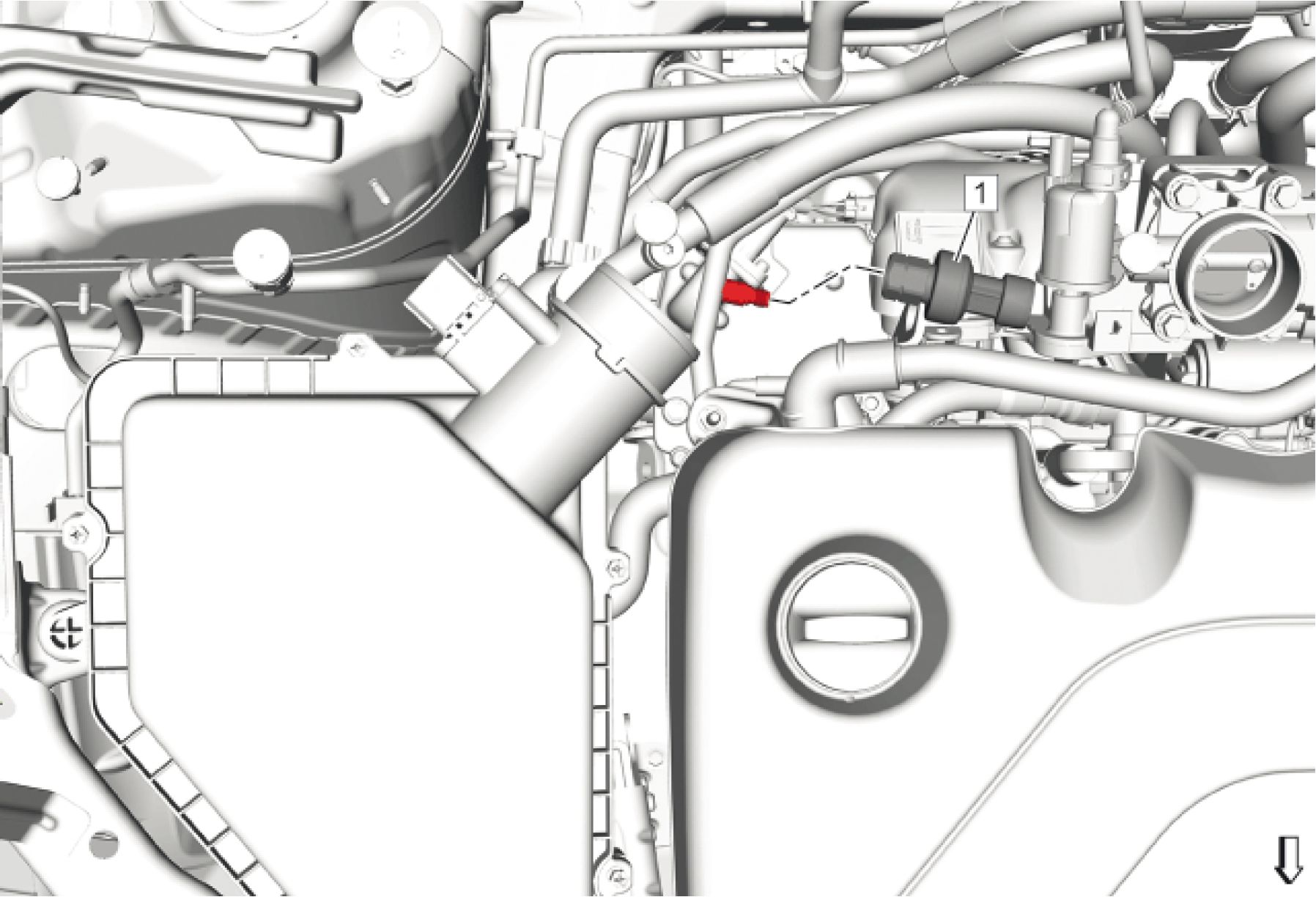 |
|
Fig. 26: Air Conditioning Compressor High Pressure Cut Off Switch |
| ||||||
|
AIR CONDITIONING REFRIGERANT DESICCANT REPLACEMENT | ||||||
 |
|
Fig. 27: Air Conditioning Refrigerant Desiccant |
| ||||||||
|
AIR CONDITIONING EVAPORATOR THERMAL EXPANSION VALVE REPLACEMENT | ||||||||
 |
|
Fig. 28: Air Conditioning Evaporator Thermal Expansion Valve |
|
Callout |
Component Name |
|
Preliminary Procedures
Refer to Air Conditioning Evaporator Hose Assembly Replacement | |
|
1 |
Air Conditioning Evaporator Thermal Expansion Valve Bolt CAUTION: Refer to Caution Tighten 7 N.m (62 lb in) |
|
2 |
Air Conditioning Evaporator Thermal Expansion Valve Procedure Remove and discard the old sealing washers. Replace with NEW sealing washers. |
AIR CONDITIONING REFRIGERANT PRESSURE SENSOR O-RING SEAL REPLACEMENT
Removal Procedure
1. Disassemble the A/C refrigerant components. Refer to the appropriate repair procedure
2. Remove the O-ring seal from the A/C refrigerant component.
3. Inspect the O-ring seal for signs of damage to help determine the root cause of the failure.
4. Inspect the A/C refrigerant components for damage or burrs. Repair if necessary.
NOTE: Cap or tape the open A/C refrigerant components immediately to prevent
system contamination.
5. Cap or tape the A/C refrigerant components.
 |
|
Fig. 29: Proper Seating Of A/C Refrigerant O-Ring Courtesy of GENERAL MOTORS COMPANY |
6. Discard the O-ring seal.
Installation Procedure
1. Inspect the new O-ring seal for any sign or cracks, cuts, or damage. Replace if necessary.
2. Remove the cap or tape from the A/C refrigerant components.
3. Using a lint-free clean, dry cloth, carefully clean the sealing surfaces of the A/C refrigerant components.
CAUTION: Use only the lubricant specified for this vehicles refrigerant system. Do not
mix refrigerant oils which may result in system contamination and unknown
reaction by-products which may cause HVAC System failure.
4. Lightly coat the new O-ring seal with the proper refrigerant oil prior to installation.
NOTE: DO NOT reuse O-ring seals.
5. Carefully slide the new O-ring seal onto the A/C refrigerant component.

Fig. 30: Proper Seating Of A/C Refrigerant O-Ring
Courtesy of GENERAL MOTORS COMPANY
6. The O-ring seal must be fully seated.
7. Assemble the A/C components.
Refer to the appropriate repair procedure.
AIR CONDITIONING REFRIGERANT LOW PRESSURE SERVICE VALVE REPLACEMENT
 |
|
Fig. 31: Air Conditioning Refrigerant Low Pressure Service Valve |
| ||||||||
|
AIR CONDITIONING REFRIGERANT HIGH PRESSURE SERVICE VALVE REPLACEMENT | ||||||||
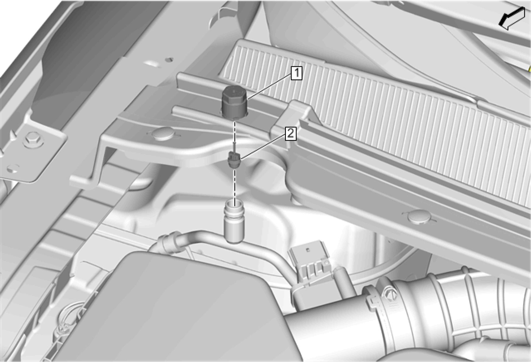 |
|
Fig. 32: Air Conditioning Refrigerant High Pressure Service Valve |
| ||||||
|
AIR CONDITIONING CYCLING SWITCH REPLACEMENT |
 |
|
Fig. 33: Air Conditioning Cycling Switch |
|
Callout |
Component Name |
|
1 |
Air Conditioning Cycling Switch CAUTION: Refer to Procedure Disconnect the electrical connector. Tighten 9 N.m (80 lb in) |
|
2 |
Air Conditioning Refrigerant High Pressure Service Valve Sealing Ring |
AIR CONDITIONING CONDENSER REPLACEMENT
Special Tools
BO-38185 Hose Clamp Pliers
Equivalent regional tools: Special Tools
Removal Procedure
1. Disconnect Battery Negative Cable. Refer to Battery Negative Cable Disconnection and Connection
2. Recover the refrigerant. Refer to Refrigerant Recovery and Recharging
3. Remove Radiator Air Lower Baffle and Deflector. Refer to Radiator Air Lower Baffle and Deflector
Replacement
4. Remove Radiator Air Upper Baffle and Deflector. Refer to Radiator Air Upper Baffle and Deflector
Replacement
5. Remove the drive motor control module radiator inlet hose from air conditioning condenser. Refer to Drive
Motor Control Module Radiator Inlet Hose Replacement .
6. Remove the drive motor generator control module cooling outlet hose from air conditioning condenser. Refer
to Drive Motor Generator Control Module Cooling Outlet Hose Replacement (Underbody Line) Drive
Motor Generator Control Module Cooling Outlet Hose Replacement (Underbody Line to Traction
Power Inverter Module Inlet)
7. Remove the condenser tube from air conditioning condenser. Refer to Condenser Tube Replacement.
 |
|
Fig. 34: Air Conditioning Condenser Bracket Spring And Radiator Assembly |
8. Remove the 2 air conditioning condenser bracket spring (3) from radiator assembly (2).

Fig. 35: Air Conditioning Condenser, Bracket And Retaining Tabs
Courtesy of GENERAL MOTORS COMPANY
9. Remove the air conditioning condenser (2) with air conditioning condenser bracket (1).
10. Unlock the 3 retaining tabs (3).
 |
|
Fig. 36: Air Conditioning Condenser And Bracket Courtesy of GENERAL MOTORS COMPANY |
11. Remove the air conditioning condenser (2) from air conditioning condenser bracket (1).
12. Remove the air conditioning refrigerant desiccant from the air conditioning condenser. Refer to Air
Conditioning Refrigerant Desiccant Replacement.
13. Remove the engine coolant temperature sensor from the air conditioning condenser. Refer to Engine Coolant
Temperature Sensor Replacement - Radiator .
Installation Procedure
1. Install the engine coolant temperature sensor to the air conditioning condenser. Refer to Engine Coolant
Temperature Sensor Replacement - Radiator .
2. Install the air conditioning refrigerant desiccant to the air conditioning condenser. Refer to Air Conditioning
Refrigerant Desiccant Replacement.
|
1 |
 |
|
Fig. 37: Air Conditioning Condenser And Bracket |
3. Install the air conditioning condenser (2) to air conditioning condenser bracket (1).
 |
|
Fig. 38: Air Conditioning Condenser, Bracket And Retaining Tabs Courtesy of GENERAL MOTORS COMPANY |
4. Install the air conditioning condenser (2) with air conditioning condenser bracket (1).
5. Lock the 3 retaining tabs (3).
 |
|
Fig. 39: Air Conditioning Condenser Bracket Spring And Radiator Assembly |
CAUTION: Refer to Fastener Caution
6. Install the 2 air conditioning condenser bracket spring (3) to radiator assembly (2).
7. Install the condenser tube to the air conditioning condenser. Refer to Condenser Tube Replacement.
8. Install the drive motor generator control module cooling outlet hose to air conditioning condenser. Refer to
Drive Motor Generator Control Module Cooling Outlet Hose Replacement (Underbody Line) Drive
Motor Generator Control Module Cooling Outlet Hose Replacement (Underbody Line to Traction
Power Inverter Module Inlet)
9. Install the drive motor control module radiator inlet hose from air conditioning condenser. Refer to Drive
Motor Control Module Radiator Inlet Hose Replacement .
10. Install Radiator Air Upper Baffle and Deflector. Refer to Radiator Air Upper Baffle and Deflector
Replacement
11. Install Radiator Air Lower Baffle and Deflector. Refer to Radiator Air Lower Baffle and Deflector
Replacement
12. Evacuate and charge the refrigerant system. Refer to Refrigerant Recovery and Recharging
13. Connect Battery Negative Cable. Refer to Battery Negative Cable Disconnection and Connection
AIR CONDITIONING EVAPORATOR LOWER CASE REPLACEMENT
Removal Procedure
1. Disconnect Battery Negative Cable. Refer to Battery Negative Cable Disconnection and Connection
2. Recover the refrigerant. Refer to Refrigerant Recovery and Recharging
3. Remove Air Conditioning Evaporator Upper Case. Refer to Air Conditioning Evaporator Upper Case
Replacement
4. Remove Blower Motor. Refer to Blower Motor Replacement
5. Remove Air Conditioning Evaporator. Refer to Air Conditioning Evaporator Replacement
6. Remove the evaporator seals.
Installation Procedure
1. Install the evaporator seals.
2. Install Air Conditioning Evaporator. Refer to Air Conditioning Evaporator Replacement
3. Install Blower Motor. Refer to Blower Motor Replacement
4. Install Air Conditioning Evaporator Upper Case. Refer to Air Conditioning Evaporator Upper Case
Replacement
5. Evacuate and charge the refrigerant system. Refer to Refrigerant Recovery and Recharging
6. Connect Battery Negative Cable. Refer to Battery Negative Cable Disconnection and Connection
AIR CONDITIONING EVAPORATOR UPPER CASE REPLACEMENT
 |
|
Fig. 40: Air Conditioning Evaporator Upper Case |
|
Callout |
Component Name |
|
Preliminary Procedures
Blower Case Replacement | |
|
Callout |
Component Name |
|
1 |
Air Conditioning Evaporator Upper Case Bolt (Qty: 11) CAUTION: Refer to Caution Tighten 2.5 N.m (22 lb in) |
|
2 |
Air Conditioning Evaporator Upper Case Assembly |
AIR CONDITIONING AND HEATER MODULE ASSEMBLY REMOVAL AND INSTALLATION
Removal Procedure
1. Disconnect the battery negative cable. Refer to Battery Negative Cable Disconnection and Connection
2. Recover the refrigerant. Refer to Refrigerant Recovery and Recharging
3. Drain the cooling system. Refer to Cooling System Draining and Filling
4. Remove Dash Upper Extension Panel Opening Cover. Refer to Dash Upper Extension Panel Opening Cover
Replacement
 |
|
Fig. 41: Intake Manifold Cover |
Courtesy of GENERAL MOTORS COMPANY
5. Remove Intake Manifold Cover (3). Refer to Intake Manifold Cover Replacement
 |
|
Fig. 42: Air Cleaner Outlet Duct, Air Cleaner Assembly And Throttle Body |
6. Remove Air Cleaner Outlet Duct (2). Refer to Air Cleaner Outlet Duct Replacement
 |
|
Fig. 43: Air Conditioning Evaporator Hose And Nut |
7. Remove Air Conditioning Evaporator Hose Assembly (1) @ Air Conditioning Evaporator Thermal Expansion
Valve. Refer to Air Conditioning Evaporator Hose Assembly Replacement
 |
|
Fig. 44: Heater Inlet Hose And Quick Connect |
8. Remove Heater Inlet Hose (2) @ Heater Core Inlet Tube. Refer to Heater Inlet Hose Replacement
 |
|
Fig. 45: Heater Water Shutoff Valve Inlet Hose |
9. Remove Heater Water Shutoff Valve Inlet Hose (2) @ Heater Core Outlet Tube. Refer to Heater Water
Shutoff Valve Inlet Hose Replacement
 |
|
Fig. 46: Heater And Air Conditioning Evaporator And Blower Module Nut |
10. Remove Heater and Air Conditioning Evaporator and Blower Module Nut (1) @ Cowl Panel.
 |
|
Fig. 47: Windshield Wiper System Module |
11. Remove Windshield Wiper System Module (2). Refer to Windshield Wiper System Module Replacement
12. Remove the left and right front side door (4). Refer to Front Side Door Replacement
13. Remove Drivers Seat and Passengers Seat. Refer to Driver or Passenger Seat Removal and Installation
14. Remove Front Floor Console. Refer to Front Floor Console Replacement
 |
|
Fig. 48: Steering Column Courtesy of GENERAL MOTORS COMPANY |
15. Remove Steering Column (1). Refer to Steering Column Replacement
 |
|
Fig. 49: Instrument Panel Carrier Assembly |
16. Remove Instrument Panel (1). Refer to Instrument Panel Assembly Replacement
17. Disconnect the instrument panel wiring connectors.
 |
|
Fig. 50: Instrument Panel Tie Bar And Reinforcement Bolts |
18. Remove Instrument Panel Tie Bar (2). Refer to Instrument Panel Tie Bar Replacement
 |
|
Fig. 51: Air Conditioning Evaporator And Blower Module Drain Hose |
CAUTION: Refer to HVAC Module Drain Tube Caution .
19. Prior to removing the air conditioning evaporator and blower module drain tube/hose, use clean and absorbent
shop clothes/towels to cover the electrical components protecting the electrical components from water
damage.
20. Remove Air Conditioning Evaporator and Blower Module Drain Hose (1) @ Heater and Air Conditioning
Evaporator and Blower Module.
21. Support the heater and air conditioning evaporator and blower (HVAC) module assembly.
 |
|
Fig. 52: Heater And Air Conditioning Evaporator And Blower Module |
22. Remove Heater and Air Conditioning Evaporator and Blower Module (1) from the vehicle.
23. Transfer all necessary components.
Installation Procedure
 |
|
Fig. 53: Heater And Air Conditioning Evaporator And Blower Module |
1. Install Heater and Air Conditioning Evaporator and Blower Module (1) onto the vehicle.
2. Temporarily support HVAC module assembly.
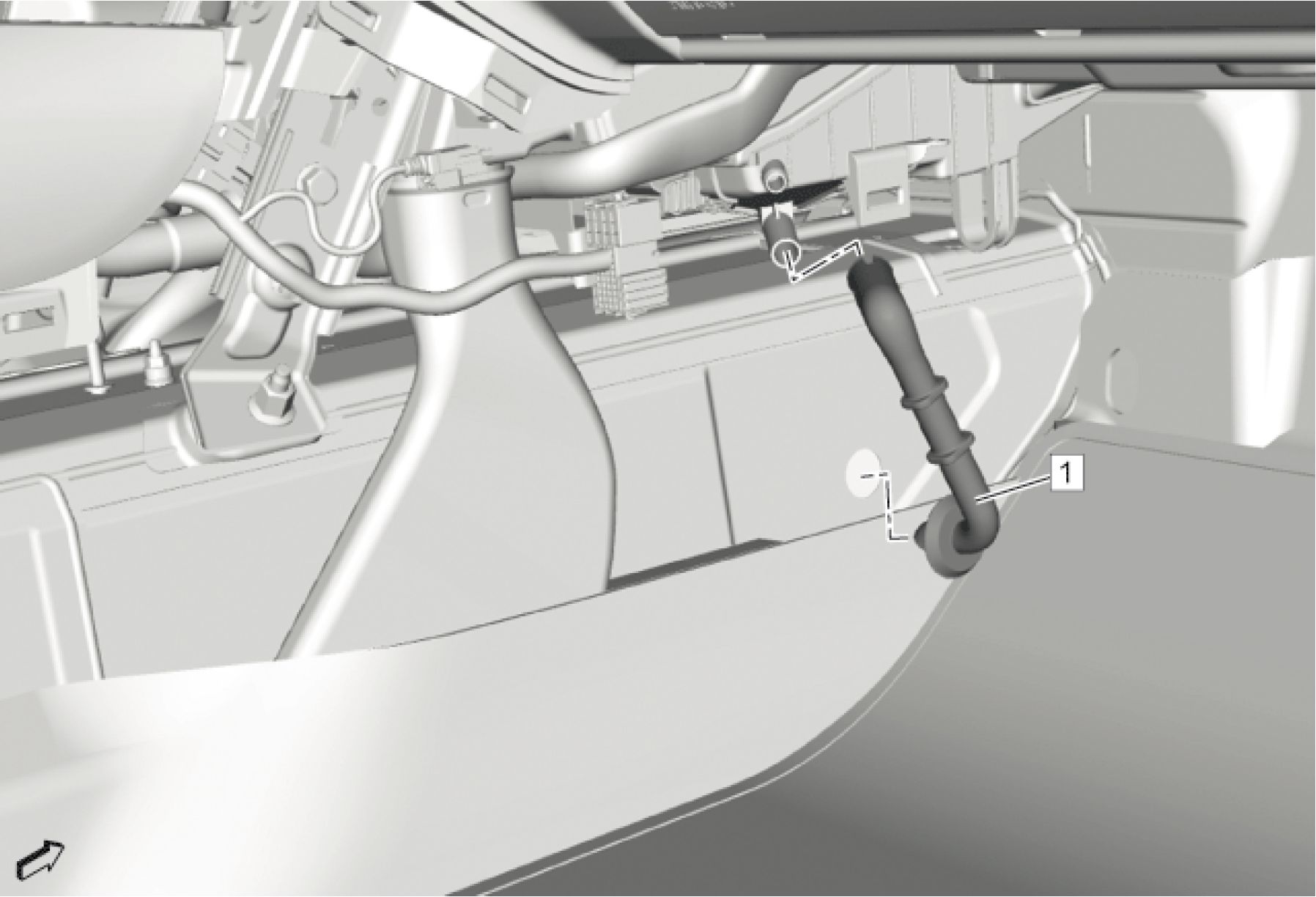 |
|
Fig. 54: Air Conditioning Evaporator And Blower Module Drain Hose |
CAUTION: Refer to HVAC Module Drain Tube Caution .
3. Install Air Conditioning Evaporator and Blower Module Drain Hose (1) @ Heater and Air Conditioning
Evaporator and Blower Module.
4. Remove the absorbent shop clothes/towels covering the electrical components.
 |
|
Fig. 55: Instrument Panel Tie Bar And Reinforcement Bolts |
5. Install Instrument Panel Tie Bar (2). Refer to Instrument Panel Tie Bar Replacement
6. Connect the instrument panel wiring connectors.
 |
|
Fig. 56: Instrument Panel Carrier Assembly |
7. Install Instrument Panel (1). Refer to Instrument Panel Assembly Replacement
 |
|
Fig. 57: Steering Column Courtesy of GENERAL MOTORS COMPANY |
8. Install Steering Column (1). Refer to Steering Column Replacement
9. Install Front Floor Console. Refer to Front Floor Console Replacement
10. Install Drivers Seat and Passengers Seat. Refer to Driver or Passenger Seat Removal and Installation
11. Install the left and right front side doors (4). Refer to Front Side Door Replacement
 |
|
Fig. 58: Windshield Wiper System Module |
12. Install Windshield Wiper System Module (2). Refer to Windshield Wiper System Module Replacement
 |
|
Fig. 59: Heater And Air Conditioning Evaporator And Blower Module Nut |
CAUTION: Refer to Fastener Caution .
13. Install and tighten Heater and Air Conditioning Evaporator and Blower Module Nut (1) @ Cowl Panel to 9.0
N.m (80 lb in)
 |
|
Fig. 60: Heater Water Shutoff Valve Inlet Hose |
14. Install Heater Water Shutoff Valve Inlet Hose (2) @ Heater Core Outlet Tube. Refer to Heater Water Shutoff
Valve Inlet Hose Replacement
 |
|
Fig. 61: Heater Inlet Hose And Quick Connect |
15. Install Heater Inlet Hose (2) @ Heater Core Inlet Tube. Refer to Heater Inlet Hose Replacement
 |
|
Fig. 62: Air Conditioning Evaporator Hose And Nut |
16. Install Air Conditioning Evaporator Hose Assembly (1) @ Air Conditioning Evaporator Thermal Expansion
Valve. Refer to Air Conditioning Evaporator Hose Assembly Replacement
 |
|
Fig. 63: Air Cleaner Outlet Duct, Air Cleaner Assembly And Throttle Body |
17. Install Air Cleaner Outlet Duct (2). Refer to Air Cleaner Outlet Duct Replacement
 |
|
Fig. 64: Intake Manifold Cover |
Courtesy of GENERAL MOTORS COMPANY
18. Install Intake Manifold Cover (3). Refer to Intake Manifold Cover Replacement
19. Install Dash Upper Extension Panel Opening Cover. Refer to Dash Upper Extension Panel Opening Cover
Replacement
20. Fill the cooling system to the proper level. Refer to Cooling System Draining and Filling .
21. Evacuate and charge the refrigerant system. Refer to Refrigerant Recovery and Recharging
22. Connect the battery negative cable. Refer to Battery Negative Cable Disconnection and Connection
23. Inspect for coolant leaks.
24. Visually inspect for air conditioning system refrigerant leaks.
AIR CONDITIONING EVAPORATOR REPLACEMENT
 |
|
Fig. 65: Air Conditioning Evaporator Courtesy of GENERAL MOTORS COMPANY |
|
Callout |
Component Name |
|
Preliminary Procedures
Case Replacement | |
|
1 |
Air Conditioning Evaporator Procedure Transfer components as necessary. |
AIR CONDITIONING EVAPORATOR AND BLOWER CASE REPLACEMENT
Removal Procedure
1. Disconnect Battery Negative Cable. Refer to Battery Negative Cable Disconnection and Connection
2. Recover the refrigerant. Refer to Refrigerant Recovery and Recharging
3. Remove Air Conditioning and Heater Module Assembly. Refer to Air Conditioning and Heater Module
Assembly Removal and Installation
4. Remove Heater Core. Refer to Heater Core Replacement
 |
|
Fig. 66: Air Conditioning Lower Case Bolt |
5. Remove the air conditioning lower case bolt (1).

Fig. 67: Air Conditioning Evaporator Lower Case And Bolt
Courtesy of GENERAL MOTORS COMPANY
6. Remove the air conditioning evaporator lower case bolt (1).
7. Remove the air conditioning evaporator lower case (2).
8. Remove the air conditioning evaporator and blower case from the air conditioning evaporator upper and lower
case bolts.
9. Remove Mode Valve Gear. Refer to Mode Valve Gear Replacement
10. Remove Vent Valve Lever. Refer to Vent Valve Lever Replacement
11. Remove Air Conditioning Evaporator. Refer to Air Conditioning Evaporator Replacement
 |
|
Fig. 68: Air Conditioning Evaporator/Blower Case And Wiring Harness |
12. Remove the air conditioning evaporator and blower case wiring harness (1).
13. Remove the air conditioning evaporator and blower case (2).
Installation Procedure
 |
|
Fig. 69: Air Conditioning Evaporator/Blower Case And Wiring Harness |
1. Install the air conditioning evaporator and blower case wiring harness (1) to the air conditioning evaporator
and blower case (2).
2. Install Air Conditioning Evaporator. Refer to Air Conditioning Evaporator Replacement
3. Install Vent Valve Lever. Refer to Vent Valve Lever Replacement
4. Install Mode Valve Gear. Refer to Mode Valve Gear Replacement

Fig. 70: Air Conditioning Evaporator Lower Case And Bolt
Courtesy of GENERAL MOTORS COMPANY
CAUTION: Refer to Fastener Caution
5. Install the air conditioning evaporator lower case (2).
6. Install the air conditioning evaporator lower case bolt (1) and tighten to 2.5 N.m (22 lb in).
 |
|
Fig. 71: Air Conditioning Lower Case Bolt |
7. Install the air conditioning evaporator lower case bolt (1) and tighten to 2.5 N.m (22 lb in).
8. Install Heater Core. Refer to Heater Core Replacement
9. Install Air Conditioning and Heater Module Assembly. Refer to Air Conditioning and Heater Module
Assembly Removal and Installation
10. Evacuate and charge the refrigerant system. Refer to Refrigerant Recovery and Recharging
11. Connect Battery Negative Cable. Refer to Battery Negative Cable Disconnection and Connection
HEATER INLET HOSE REPLACEMENT
Special Tools
BO-38185 Hose Clamp Pliers
Equivalent regional tools: Special Tools
Removal Procedure
1. Drain the cooling system. Refer to Cooling System Draining and Filling
2. Remove Front Wheelhouse Liner (Left Side). Refer to Front Wheelhouse Liner Replacement (Left Side) .
3. Remove Dash Upper Extension Panel Opening Cover. Refer to Dash Upper Extension Panel Opening Cover
Replacement
4. Remove Air Cleaner Outlet Duct. Refer to Air Cleaner Outlet Duct Replacement
 |
|
Fig. 72: Heater Inlet Hose And Quick Connect |
5. Disconnect Heater Inlet Hose Quick Connect (1) @ Heater Inlet Hose (2)
6. Remove Heater Inlet Hose (2) @ Heater Core Inlet Tube

7. Remove Heater Inlet Hose (2) @ Heater Inlet Hose Retainers (1) (Qty: 2)
 |
|
Fig. 74: Heater Coolant Heater, Heater Inlet Hose And Quick Connect |
8. Disconnect Heater Inlet Hose Quick Connect (2) @ Heater Inlet Hose (3)
9. Disconnect Heater Inlet Hose (3) @ Heater Coolant Heater (1)
10. Remove Heater Inlet Hose (3)
Installation Procedure
 |
|
Fig. 75: Heater Coolant Heater, Heater Inlet Hose And Quick Connect |
1. Install Heater Inlet Hose (3) @ Heater Coolant Heater (1)
CAUTION: Refer to Fastener Caution
 |
|
Fig. 76: Heater Inlet Hose And Retainers |
3. Install Heater Inlet Hose (2) @ Heater Inlet Hose Retainers (1) (Qty: 2)
 |
|
Fig. 77: Heater Inlet Hose And Quick Connect |
4. Install Heater Inlet Hose (2) @ Heater Core Inlet Tube
5. Connect Heater Inlet Hose Quick Connect (1) @ Heater Inlet Hose (2)
6. Install Air Cleaner Outlet Duct. Refer to Air Cleaner Outlet Duct Replacement
7. Install Dash Upper Extension Panel Opening Cover. Refer to Dash Upper Extension Panel Opening Cover
Replacement
8. Install Front Wheelhouse Liner (Left Side). Refer to Front Wheelhouse Liner Replacement (Left Side)
9. Fill the cooling system. Refer to Cooling System Draining and Filling
HEATER INLET AND OUTLET PIPE REPLACEMENT
 |
|
Fig. 78: Heater Inlet And Outlet Pipe Courtesy of GENERAL MOTORS COMPANY |
| ||||||||||||||
|
HEATER COOLANT PUMP REPLACEMENT | ||||||||||||||
 |
|
Fig. 79: Heater Coolant Pump Courtesy of GENERAL MOTORS COMPANY |
|
Callout |
Component Name |
|
Preliminary Procedures
| |
|
1 |
Heater Coolant Pump Bolt CAUTION: Refer to Tighten 22 N.m (16 lb ft) |
|
2 |
Heater Coolant Pump Procedure Disconnect the electrical connector. |
PASSENGER COMPARTMENT AIR FILTER REPLACEMENT
Removal Procedure
1. Remove Instrument Panel Compartment. Refer to Instrument Panel Compartment Replacement
 |
|
Fig. 80: Passenger Compartment Air Filter |
2. Unclip Passenger Compartment Air Filter (2)
Installation Procedure
 |
|
Fig. 81: Passenger Compartment Air Filter Courtesy of GENERAL MOTORS COMPANY |
1. Install Passenger Compartment Air Filter (2)
2. Install Instrument Panel Compartment. Refer to Instrument Panel Compartment Replacement
AIR INLET DUCT REPLACEMENT
 |
|
Fig. 82: Air Inlet Duct |
|
Courtesy of GENERAL MOTORS COMPANY | ||||||||||
| ||||||||||
AIR INLET HOUSING REPLACEMENT
Removal Procedure
1. Remove Air Conditioning and Heater Module Assembly. Refer to Air Conditioning and Heater Module
Assembly Removal and Installation
 |
|
Fig. 83: Air Inlet Housing Bolts Courtesy of GENERAL MOTORS COMPANY |
2. Remove Air Inlet Housing Bolts (1) (Qty: 2)
 |
|
Fig. 84: Air Inlet Housing And Retainers Courtesy of GENERAL MOTORS COMPANY |
3. Remove Air Inlet Housing (2) @ Heater and Air Conditioning Evaporator Case
1. Disconnect all electrical connectors.
2. Disengage the air inlet housing (2) from the retainers (1).
Installation Procedure
 |
|
Fig. 85: Air Inlet Housing And Retainers |
1. Install Air Inlet Housing (2) @ Heater and Air Conditioning Evaporator Case
1. Guide the air inlet housing (2) into the retainers (1).
2. Connect the electrical connectors.
 |
|
Fig. 86: Air Inlet Housing Bolts Courtesy of GENERAL MOTORS COMPANY |
CAUTION: Remove Fastener Caution
2. Install and tighten Air Inlet Housing Bolts (1) (Qty: 2) to 2.5 N.m (22 lb in)
3. Install Air Conditioning and Heater Module Assembly. Refer to Air Conditioning and Heater Module
Assembly Removal and Installation
HEATER AND AIR CONDITIONING CONTROL MODE LEVER REPLACEMENT
 |
|
Fig. 87: Heater And Air Conditioning Control Mode Lever |
| ||||||
|
BLOWER MOTOR REPLACEMENT | ||||||
 |
|
Fig. 88: Blower Motor Courtesy of GENERAL MOTORS COMPANY |
| ||
|
Preliminary Procedures |
1. Remove Instrument Panel Lower Trim Panel Insulator. Refer to Instrument Panel Lower Trim Panel
Insulator Replacement
2. Disconnect the electrical connector.
|
1 |
Blower Motor Bolt (Qty: 3) CAUTION: Refer to |
|
2 |
Tighten 2.5 N.m (22 lb in) |
INSTRUMENT PANEL OUTER AIR OUTLET REPLACEMENT - LEFT SIDE
Removal Procedure
 |
|
Fig. 89: Instrument Panel Knee Bolster Courtesy of GENERAL MOTORS COMPANY |
1. Remove Instrument Panel Knee Bolster (2). Refer to Instrument Panel Knee Bolster Replacement
 |
|
Fig. 90: Instrument Panel Switch Trim Plate |
2. Remove Instrument Panel Switch Trim Plate (2). Refer to Instrument Panel Switch Trim Plate
Replacement
 |
|
Fig. 91: Instrument Panel Outer Air Outlet |
3. Depress the three tabs on the instrument panel outer air outlet (1) from behind the instrument panel to properly
release the outlet.
 |
|
Fig. 92: Instrument Panel Outer Air Outlet - Left Side And Bolts |
4. Remove Instrument Panel Bolts (1) (Qty: 2)
5. Remove Instrument Panel Outer Air Outlet - Left Side (2)
6. Use a flat bladed plastic tool to remove.
 |
|
Fig. 93: Instrument Panel Outer Air Outlet And Trim Plate Applique |
7. Release the plastic retaining tabs to separate the instrument panel trim plate applique (1) from the instrument
panel outer air outlet (2).
8. Transfer components as necessary.
Installation Procedure
 |
|
Fig. 94: Instrument Panel Outer Air Outlet And Trim Plate Applique |
1. Install the instrument panel trim plate applique (1) to the instrument panel outer air outlet (2).
 |
|
Fig. 95: Instrument Panel Outer Air Outlet - Left Side And Bolts |
2. Install Instrument Panel Outer Air Outlet - Left Side (2)
CAUTION: Refer to Fastener Caution .
3. Install and tighten Instrument Panel Bolts (1) (Qty: 2) to 2.5 N.m (22 lb in)
 |
|
Fig. 96: Instrument Panel Switch Trim Plate Courtesy of GENERAL MOTORS COMPANY |
4. Install Instrument Panel Switch Trim Plate (2). Refer to Instrument Panel Switch Trim Plate Replacement
 |
|
Fig. 97: Instrument Panel Knee Bolster Courtesy of GENERAL MOTORS COMPANY |
5. Install Instrument Panel Knee Bolster (2). Refer to Instrument Panel Knee Bolster Replacement
INSTRUMENT PANEL CENTER AIR OUTLET REPLACEMENT
 |
|
Fig. 98: Instrument Panel Center Air Outlet |
|
Callout |
Component Name |
|
Preliminary Procedure
Center Trim Panel Replacement (Upper) | |
|
1 |
Instrument Panel Center Air Outlet Bracket Bolt (Qty: 4) CAUTION: Refer to Caution . Tighten 0.5 N.m (4 lb in) |
|
2 |
Instrument Panel Center Air Outlet Procedure
|
INSTRUMENT PANEL OUTER AIR OUTLET REPLACEMENT - RIGHT SIDE
Removal Procedure
 |
|
Fig. 99: Instrument Panel Compartment Courtesy of GENERAL MOTORS COMPANY |
1. Remove Instrument Panel Compartment (1). Refer to Instrument Panel Compartment Replacement
 |
|
Fig. 100: Instrument Panel Outer Air Outlet Courtesy of GENERAL MOTORS COMPANY |
2. Depress the three tabs on the instrument panel outer air outlet (1) from behind the instrument panel to properly
release the outlet.
 |
|
Fig. 101: Instrument Panel Trim Plate Applique - Right Side And Bolts |
3. Remove Instrument Panel Bolts (1) (Qty: 4)
4. Remove Instrument Panel Trim Plate Applique - Right Side (2)
5. Use a flat bladed plastic tool to remove.
 |
|
Fig. 102: Instrument Panel Outer Air Outlet And Trim Plate Applique |
6. Release the plastic retaining tabs to separate the instrument panel trim plate applique (1) from the instrument
panel outer air outlet (2).
7. Transfer components as necessary.
Installation Procedure
 |
|
Fig. 103: Instrument Panel Outer Air Outlet And Trim Plate Applique |
1. Install the instrument panel trim plate applique (1) to the instrument panel outer air outlet (2).
 |
|
Fig. 104: Instrument Panel Trim Plate Applique - Right Side And Bolts |
2. Install Instrument Panel Trim Plate Applique - Right Side (2)
CAUTION: Refer to Fastener Caution .
3. Install and tighten Instrument Panel Bolts (1) (Qty: 4) to 2.5 N.m (22 lb in)
 |
|
Fig. 105: Instrument Panel Compartment |
4. Install Instrument Panel Compartment (2). Refer to Instrument Panel Compartment Replacement
FLOOR FRONT AIR OUTLET DUCT REPLACEMENT - RIGHT SIDE

| ||||||||
|
FLOOR FRONT AIR OUTLET DUCT REPLACEMENT - LEFT SIDE | ||||||||
 |
|
Fig. 107: Floor Front Air Outlet Duct - Left Side |
Callout
Component Name
Preliminary Procedure
Remove Instrument Panel Lower Airbag - Driver Side. Refer to Instrument Panel Lower Airbag
Replacement - Driver Side
| ||||||||
|
FLOOR REAR AIR OUTLET DUCT REPLACEMENT | ||||||||
 |
|
Fig. 108: Floor Rear Air Outlet Duct |
|
Courtesy of GENERAL MOTORS COMPANY | ||||||||
| ||||||||
|
HEATER AND AIR CONDITIONING CONTROL TEMPERATURE LEVER REPLACEMENT | ||||||||
 |
|
Fig. 109: Heater and Air Conditioning Control Temperature Lever |
|
Callout |
Component Name |
|
Preliminary Procedures
| |
|
1 |
Heater and Air Conditioning Control Temperature Lever Procedure Lubricate the heater and air conditioning control temperature lever in order to assure proper |
HEATER CORE REPLACEMENT
Removal Procedure
1. Drain the cooling system. Refer to Cooling System Draining and Filling
2. Remove Front Floor Console Extension Panel - Left Side. Refer to Front Floor Console Extension Panel
Replacement - Left Side
3. Place protective coverings and suitable drain pans below heater core to protect the carpeting.
 |
|
Fig. 110: Heater Core Cover And Screws |
4. Remove Heater Core Cover Screws (2) (Qty: 2)
5. Remove Heater Core Cover (1)
 |
|
Fig. 111: Heater Core, Clamps, Tubes And Sealing Rings |
6. Remove Heater Core Clamps (3) (Qty: 2)
7. Remove Heater Core Tubes (Qty: 2) @ Heater Core (1)
8. Remove Heater Core (1)
9. Remove and DISCARD Heater Core Tube Sealing Rings (4) (Qty: 2)
Installation Procedure
 |
|
Fig. 112: Heater Core, Clamps, Tubes And Sealing Rings |
1. Install Heater Core (1)
NOTE: Install NEW seal rings.
2. Install NEW Heater Core Tube Sealing Rings (4) (Qty: 2)
3. Install Heater Core Tubes (Qty: 2) @ Heater Core (1)
4. Tighten Heater Core Clamps (3) (Qty: 2)
 |
|
Fig. 113: Heater Core Cover And Screws |
CAUTION: Refer to Fastener Caution
5. Install Heater Core Cover (1)
6. Install and tighten Heater Core Cover Screws (2) (Qty: 2) to 2.5 N.m (22 lb in)
7. Install Front Floor Console Extension Panel - Left Side. Refer to Front Floor Console Extension Panel
Replacement - Left Side
8. Fill the cooling system. Refer to Cooling System Draining and Filling
HEATER COOLANT HEATER REPLACEMENT
Special Tools
BO-38185 Hose Clamp Pliers
Equivalent regional tools: Special Tools
Removal Procedure
WARNING: Always perform the High Voltage Disabling procedure prior to servicing any High
Voltage component or connection. Personal Protection Equipment (PPE) and proper
procedures must be followed.
The High Voltage Disabling procedure includes the following steps:
• Identify how to disable high voltage.
• Identify how to test for the presence of high voltage.
• Identify condition under which high voltage is always present and personal
protection equipment (PPE) and proper procedures must be followed.
Before working on any high voltage system, be sure to wear the following Personal
Protection Equipment:
• Safety glasses with appropriate side shields when within 15 meters (50 feet) of
the vehicle, either indoors or outdoors.
• Certified and up-to-date Class "0" Insulation gloves rated at 1000V with leather
protectors.
• Visually and functionally inspect the gloves before use.
• Wear the Insulation gloves with leather protectors at all times when
working with the high voltage battery assembly, whether the system is
energized or not.
Failure to follow the procedures may result in serious injury or death.
1. Disable the high voltage system. Refer to High Voltage Disabling
2. Drain the cooling system. Refer to Cooling System Draining and Filling
3. Remove Front Wheelhouse Liner (Right Side). Refer to Front Wheelhouse Liner Replacement (Right Side)
4. Disconnect Heater Inlet Hose @ Heater Coolant Heater. Refer to Heater Inlet Hose Replacement
5. Disconnect Heater Inlet and Outlet Pipe @ Heater Coolant Heater. Refer to Heater Inlet And Outlet Pipe
Replacement
 |
|
Fig. 114: Heater Coolant Heater Bracket Assembly And Bolts |
6. Remove the 2 heater coolant heater bracket assembly bolts (3) with heater coolant heater bracket assembly (2)
from the drive train (1).
 |
|
Fig. 115: Heater Coolant Heater Bracket Assembly, Bolts And Wiring Harness Courtesy of GENERAL MOTORS COMPANY |
7. Remove the 2 wiring harness bolts (4) and the wiring harness (1) from the heater coolant heater assembly (2).
8. Unclip the wiring harness retainers and disconnect the electrical connectors.
9. Remove the 2 heater coolant heater bracket bolts (3) and remove the heater coolant heater bracket assembly
(2).
|
1 |
 |
|
Fig. 116: Heater Coolant Heater, Bracket And Bolts |
10. Remove the 4 heater coolant heater bracket bolts (2) from the heater coolant heater bracket (3) and heater
coolant heater (1).

Fig. 117: Heater Coolant Heater, Bracket And Bolts
Courtesy of GENERAL MOTORS COMPANY
11. Remove the 3 heater coolant heater bracket bolts (3) from the heater coolant heater bracket (1) and remove the
heater coolant heater (2).
Installation Procedure
|
1 2 |
 |
Fig. 118: Heater Coolant Heater, Bracket And Bolts
Courtesy of GENERAL MOTORS COMPANY
CAUTION: Refer to Fastener Caution
1. Install the heater coolant heater (2) to the heater coolant heater bracket (1).
2. Install and tighten the 3 heater coolant heater bracket bolts (3) to the heater coolant heater bracket 9 N.m (80 lb
in).
|
1 |
 |
|
Fig. 119: Heater Coolant Heater, Bracket And Bolts |
3. Install and tighten the 4 heater coolant heater bracket bolts (2) to the heater coolant heater bracket (3) and the
heater coolant heater (1) 9 N.m (80 lb in).
4. Clip in the wiring harness retainers and connect the electrical connectors.
 |
|
Fig. 120: Heater Coolant Heater Bracket Assembly, Bolts And Wiring Harness |
5. Install the heater coolant heater bracket assembly (2) and the 2 heater coolant heater bracket bolts (3) and
tighten to 9 N.m (80 lb in)
6. Install the 2 wiring harness bolts (4) along with the wiring harness (1) and tighten to 9 N.m (80 lb in).
 |
|
Fig. 121: Heater Coolant Heater Bracket Assembly And Bolts |
7. Install the 2 heater coolant heater bracket assembly bolts (3) along with the heater coolant heater bracket
assembly (2) to the drive train (1) and tighten to 9 N.m (80 lb in).
8. Connect Heater Inlet and Outlet Pipe @ Heater Coolant Heater. Refer to Heater Inlet And Outlet Pipe
Replacement
9. Connect Heater Inlet Hose @ Heater Coolant Heater. Refer to Heater Inlet Hose Replacement
10. Install Front Wheelhouse Liner (Right Side). Refer to Front Wheelhouse Liner Replacement (Right Side)
11. Fill the cooling system. Refer to Cooling System Draining and Filling
12. Enable the high voltage system. Refer to High Voltage Enabling
HEATER WATER SHUTOFF VALVE REPLACEMENT
 |
|
Fig. 122: Heater Water Shutoff Valve |
|
Courtesy of GENERAL MOTORS COMPANY | ||||||||
| ||||||||
| ||||||
|
HEATER WATER SHUTOFF VALVE INLET HOSE REPLACEMENT |
 |
|
Fig. 123: Heater Water Shutoff Valve Inlet Hose |
|
Callout |
Component Name |
|
Preliminary Procedure Drain the cooling system. Refer to Cooling System Draining and Filling | |
|
1 |
Heater Water Shutoff Valve Inlet Hose Clamp (Qty: 2) Procedure Reposition Heater Water Shutoff Valve Inlet Hose Clamps (Qty: 2) |
|
2 |
Heater Water Shutoff Valve Inlet Hose NOTE: Replace all |
HEATER WATER AUXILIARY PUMP INLET HOSE REPLACEMENT
Special Tools
BO-38185 Hose Clamp Pliers
Equivalent regional tools: Special Tools
Removal Procedure
1. Drain the cooling system. Refer to Cooling System Draining and Filling
2. Disconnect Battery Negative Cable. Refer to Battery Negative Cable Disconnection and Connection
3. Remove Front Compartment Splash Shield. Refer to Front Compartment Splash Shield Replacement
 |
|
Fig. 124: Heater Water Auxiliary Pump Inlet Hose And Clamp |
4. Loosen Heater Water Auxiliary Pump Inlet Hose Clamp (1)
5. Remove Heater Water Auxiliary Pump Inlet Hose (2) @ Surge Tank
 |
|
Fig. 125: Heater Water Auxiliary Pump Inlet Hoses And Clamps |
6. Loosen Heater Water Auxiliary Pump Inlet Hose Clamps (1) (Qty: 2)
7. Remove Heater Water Auxiliary Pump Inlet Hoses (2) (Qty: 2) @ Engine
 |
|
Fig. 126: Heater Water Auxiliary Pump Inlet Hose And Clamp |
8. Loosen Heater Water Auxiliary Pump Inlet Hose Clamp (1)
9. Remove Heater Water Auxiliary Pump Inlet Hose (2) @ Water Pump Inlet Adapter
 |
|
Fig. 127: Heater Water Auxiliary Pump Inlet Hose And Clamps |
10. Disconnect Heater Water Auxiliary Pump Inlet Hose Clamps (2) (Qty: 3)
11. Remove Heater Water Auxiliary Pump Inlet Hose (1) @ Vehicle
Installation Procedure

Fig. 128: Heater Water Auxiliary Pump Inlet Hose And Clamps
Courtesy of GENERAL MOTORS COMPANY
1. Install Heater Water Auxiliary Pump Inlet Hose (1) @ Vehicle
2. Install Heater Water Auxiliary Pump Inlet Hose Clamps (2) (Qty: 3)
 |
|
Fig. 129: Heater Water Auxiliary Pump Inlet Hose And Clamp |
CAUTION: Refer to Fastener Caution
3. Install Heater Water Auxiliary Pump Inlet Hose (2) @ Water Pump Inlet Adapter
4. Tighten Heater Water Auxiliary Pump Inlet Hose Clamp (1)
 |
|
Fig. 130: Heater Water Auxiliary Pump Inlet Hoses And Clamps |
5. Install Heater Water Auxiliary Pump Inlet Hoses (2) (Qty: 2) @ Engine
6. Tighten Heater Water Auxiliary Pump Inlet Hose Clamps (1) (Qty: 2)
 |
|
Fig. 131: Heater Water Auxiliary Pump Inlet Hose And Clamp |
7. Install Heater Water Auxiliary Pump Inlet Hose (2) @ Surge Tank
8. Tighten Heater Water Auxiliary Pump Inlet Hose Clamp (1)
9. Install Front Compartment Splash Shield. Refer to Front Compartment Splash Shield Replacement
10. Connect Battery Negative Cable. Refer to Battery Negative Cable Disconnection and Connection
11. Fill the cooling system. Refer to Cooling System Draining and Filling
HEATER OUTLET HOSE VAPOR VENT HOSE REPLACEMENT
 |
|
Fig. 132: Heater Outlet Hose Vapor Vent Hose |
|
Callout |
Component Name |
|
Preliminary Procedure Drain the cooling system. Refer to Cooling System Draining and Filling | |
|
1 |
Heater Outlet Hose Vapor Vent Hose Clamp (Qty: 2) Procedure
|
|
2 |
Heater Outlet Hose Vapor Vent Hose |
DESCRIPTION AND OPERATION
HEATING AND AIR CONDITIONING SYSTEM DESCRIPTION AND OPERATION
Heating
The heating system uses the engine and a high voltage heater to provide heat to the passenger compartment. The high
voltage heater is used when the engine is not running and passenger compartment heat is requested. The high voltage
heater provides different levels of heat depending on the amount of heat needed and outside temperature.
The HVAC Control Module turns on the coolant pump and monitors the temperature sensors in the passenger
compartment, outside air, engine radiator, high voltage heater and the engine to determine the position of the coolant
flow control valve and if the high voltage heater is needed. Passenger compartment heat is provided by air flowing
through the heater core. The heater core is heated by coolant from either the engine or the high voltage heater.
The engine cooling system circulates a 50/50 mixture of Dex-cool and deionized water.
Air Conditioning
The A/C system uses the refrigerant R-134a which is a gas at very low temperatures and can transfer heat from the
passenger compartment and high voltage battery to the outside air. The A/C system is mechanically protected with
the use of a high pressure relief valve on the A/C compressor. If the refrigerant pressure sensor were to fail or if the
A/C system becomes restricted and the refrigerant pressure continued to rise, the high pressure relief will open and
release refrigerant from the system.
The high voltage electric A/C compressor is a self contained high voltage inverter, electric motor, and direct coupled
compressor. The electric A/C compressor has the ability to run and provide cooling performance while the vehicle
engine is not running. This feature enables the electric A/C compressor to run at a speed independent of the engine.
The electronic climate control module and the Vehicle Integration Control Module (VICM) will command the
electric A/C compressor to a speed necessary to maintain a desired cooling level rather than cycle the electric A/C
compressor on and off.
The electric A/C compressor builds pressure and adds heat to the refrigerant gas. The refrigerant gas flows from the
electric A/C compressor to the condenser where heat is transferred to the outside air when the refrigerant condenses
from a gas to a liquid. The liquid refrigerant then flows to a thermal expansion valve (TXV) on the battery chiller.
The TXV lowers the pressure of the liquid refrigerant which makes the refrigerant expand from a liquid to a vapor.
The low pressure refrigerant vapor flows into the battery chiller and begins to boil and change into a gas as the
refrigerant absorbs heat from the battery coolant also flowing inside the battery chiller. The battery coolant and
refrigerant are separated by several plates inside the battery chiller. The liquid refrigerant also flows to a second TXV
on the evaporator. The low pressure refrigerant vapor flows from the TXV into the evaporator and begins to boil and
change into a gas as the refrigerant absorbs heat from the passenger compartment air that is flowing through the
outside of the evaporator. The moister in the passenger compartment air condenses on the outside of the evaporator
and flows down to the bottom of the HVAC module where it drains outside the passenger compartment through a
drain hose. The low pressure refrigerant gas then flows from the battery chiller and the evaporator back to the
electric A/C compressor where the cycle is repeated.
SPECIAL TOOLS AND EQUIPMENT
SPECIAL TOOLS
|
Illustration |
Tool |
Tool
Number/Description
 |
J-38185 Hose Clamp Pliers |
|
Illustration |
Tool Number/Description |
|
__ [тяг © о а ИГж 1 JWA jjjl /3 / V дуг ■iiiwhHH т -> JmINl 1 f JA-j ■ гттгЛл?=т=т=^^ АдгЛ |
GE 39400-A |
|
Illustration |
Tool |
|
J-41447 R-134A A/C Tracer | |
|
Dye - Box of 24 |
|
Illustration |
Tool |
|
■..... |
GE 42220 J 42220 Universal 12V Leak |
|
Illustration |
Tool |
|
GE 43872 |
|
Illustration |
Tool |
|
4------ПГП 1 |
GE 45037-A J45037-A |
|
Illustration |
Tool |
|
& & |
GE 45268 |
|
Illustration |
Tool |
|
__(iW_Jt=3 |
GE 46246 |
|
Illustration |
Tool |
|
GE 48800 |
Tool
Number/Description
 |
GE 48997 |
|
Illustration |
Tool |
|
)) |
GE 50078 |
|
л_______ Й® -----EXD. | |
|
^ЕтпУ |
Article GUID: A00884662
HVAC
HVAC - Automatic - Volt
SPECIFICATIONS
FASTENER SPECIFICATIONS
Reusable Threaded Fastener Tightening Specifications
NOTE:
All fasteners
listed in this
table can be
reused after
removal.
|
Application |
Specification |
|
Air Inlet Valve Actuator Fastener |
2.5 N.m (22 lb in) |
|
Heater and Air Conditioning User Interface Control Bolt |
2.5 N.m ((22 lb in) |
|
Mode Control Cam Actuator Bolt |
2.5 N.m ((22 lb in) |
|
Temperature Valve Actuator Fastener |
2.5 N.m ((22 lb in) |
SCHEMATIC WIRING DIAGRAMS
HVAC WIRING SCHEMATICS
Power, Ground, Data Communication and Blower Controls
 |
|
Fig. 1: Power, Ground, Data Communication and Blower Controls |
Temperature Sensors
 |
|
Fig. 2: Temperature Sensors Courtesy of GENERAL MOTORS COMPANY |
Compressor Controls
 |
|
Fig. 3: Compressor Controls Courtesy of GENERAL MOTORS COMPANY |
Cabin Heater
 |
|
Fig. 4: Cabin Heater Courtesy of GENERAL MOTORS COMPANY |
Actuators
 |
|
Fig. 5: Actuators Courtesy of GENERAL MOTORS COMPANY |
DIAGNOSTIC INFORMATION AND PROCEDURES
|
HVAC COMPONENT REPLACEMENT REFERENCE | |||||||||||||||||||||||||
|
|
Component |
Repair Instruction |
|
G36 Auxiliary Heater Coolant Pump |
Heater Coolant Pump Replacement |
|
K10 Coolant Heater Control Module |
Heater Coolant Heater Replacement |
|
K33 HVAC Control Module |
Heater and Air Conditioning Remote Control |
|
Replacement | |
|
M8 Blower Motor |
Blower Motor Replacement |
|
M37 Mode Door Actuator |
Mode Control Cam Actuator Replacement |
|
M46 Air Recirculation Door Actuator |
Air Inlet Valve Actuator Replacement |
|
M6 Air Temperature Actuator |
Temperature Valve Actuator Replacement |
|
Q66 Passenger Compartment Heater Coolant |
Heater Water Shutoff Valve Replacement |
DTC B0163: PASSENGER COMPARTMENT TEMPERATURE SENSOR CIRCUIT
Diagnostic Instructions
• Perform the Diagnostic System Check - Vehicle prior to using this diagnostic procedure.
• Review Strategy Based Diagnosis for an overview of the diagnostic approach.
Diagnostic Procedure Instructions provides an overview of each diagnostic category.
DTC Descriptors
DTC B0163 02
Passenger Compartment Temperature Sensor Circuit Short to Ground
DTC B0163 05
Passenger Compartment Temperature Sensor Circuit High Voltage/Open
|
Diagnostic Fault Information | ||||||||||||||||||||
| ||||||||||||||||||||
|
Circuit/System Description |
The ambient light/sunload sensor includes the sunload sensor and passenger compartment temperature sensor.
This sensor assembly provides information about:
• Sun heat intensity
• Passenger compartment temperature
The vehicle uses a sunload sensor that is integrated into one sensor assembly along with the passenger
compartment temperature sensor. Low reference and signal circuits enable the sensor to operate. The sensor
signal varies between 0 - 5 V.
The passenger compartment temperature sensor is a negative temperature co-efficient thermistor. A signal and
low reference circuit enables the sensor to operate. As the air temperature increases, the sensor resistance
decreases. The sensor signal varies between 0 - 5 V.
Bright or high intensity light causes the vehicles interior temperature to increase. The HVAC system
compensates for the increased temperature by diverting additional cool air into the vehicle.
Conditions for Running the DTC
• Vehicle in Service Mode.
• The HVAC control module is ON.
Conditions for Setting the DTC
B0163 02 or B0163 05
The HVAC control module detects the sensor signal out of range. The signal voltage is less than 0.1 V or greater
than 4.9 V for more than 50 ms.
Action Taken When the DTC Sets
• The system will use the last valid values as default.
• If no value is read at the time of fault, the HVAC control module uses 0 W/m2 .
Conditions for Clearing the DTC
B0163 02 or B0163 05
The sensor signal is within specified range between 0.1 - 4.9 V.
Reference Information
Schematic Reference
HVAC Schematics
Connector End View Reference
COMPONENT CONNECTOR END VIEWS - INDEX
Description and Operation
Automatic HVAC Description and Operation
Electrical Information Reference
Circuit Testing
Connector Repairs
Testing for Intermittent Conditions and Poor Connections
Wiring Repairs
Scan Tool Reference
Control Module References for scan tool information
Circuit/System Testing
1. Vehicle OFF and all vehicle systems OFF, disconnect the harness connector at the B10B Ambient
Light/Sunload Sensor. It may take up to 2 minutes for all vehicle systems to power down.
2. Test for less than 60 fi between the low reference circuit terminal 6 and ground.
• If 60 fi or greater
1. Vehicle OFF, disconnect the harness connector at the K33 HVAC Control Module.
2. Test for less than 2 fi in the low reference circuit end to end.
• If 2 fi or greater, repair the open/high resistance in the circuit.
• If less than 2 fi, replace the K33 HVAC Control Module.
• If less than 60 fi
3. Vehicle in Service Mode.
4. Verify the scan tool Passenger Compartment Air Temperature (Unfiltered) parameter is less than-37A°C
(-35A°F).
• If -37A°C (-35A°F) or greater
1. Vehicle OFF, disconnect the harness connector at the K33 HVAC Control Module.
2. Test for infinite resistance between the signal circuit terminal 4 and ground.
• If less than infinite resistance, repair the short to ground on the circuit.
• If infinite resistance, replace the K33 HVAC control module.
• If less than -37A°C (-35A°F)
5. Install a 3 A fused jumper wire between the signal circuit terminal 3 and the low reference circuit
terminal 6.
6. Verify the scan tool Passenger Compartment Air Temperature (Unfiltered) parameter is greater than
110A°C (240A°F).
• If 110A°C (240A°F) or less
1. Vehicle OFF, disconnect the harness connector at the K33 HVAC Control Module, vehicle in
Service Mode.
2. Test for less than 1 V between the signal circuit and ground.
• If 1 V or greater, repair the short to voltage on the circuit.
• If less than 1 V
3. Vehicle OFF
4. Test for less than 2 fi in the signal circuit end to end.
• If 2 Q or greater, repair the open/high resistance in the circuit.
• If less than 2 Q, replace the K33 HVAC control module.
• If greater than 110A°C (240A°F)
7. Test or replace the B10B Ambient Light/Sunload Sensor.
Repair Instructions
Perform the Diagnostic Repair Verification after completing the repair.
HVAC Component Replacement Reference
Control Module References for HVAC control module replacement, programming and setup
DTC B0173 OR B0178: UPPER LEFT DUCT AIR TEMPERATURE SENSOR CIRCUIT/LOWER
LEFT DUCT AIR TEMPERATURE SENSOR CIRCUIT
Diagnostic Instructions
• Perform the Diagnostic System Check - Vehicle prior to using this diagnostic procedure.
• Review Strategy Based Diagnosis for an overview of the diagnostic approach.
Diagnostic Procedure Instructions provides an overview of each diagnostic category.
DTC Descriptors
DTC B0173 02
Upper Left Duct Air Temperature Sensor Circuit Short to Ground
DTC B0173 05
Upper Left Duct Air Temperature Sensor Circuit High Voltage/Open
DTC B0178 02
Lower Left Duct Air Temperature Sensor Circuit Short to Ground
DTC B0178 05
Lower Left Duct Air Temperature Sensor Circuit High Voltage/Open
|
Diagnostic Fault Information | ||||||||||||||||||||
|
Circuit/System Description
The air temperature sensors are 2-wire negative temperature co-efficient thermistors. The vehicle uses the
following air temperature sensors:
• Air temperature sensor left upper
• Air temperature sensor left lower
A signal and low reference circuit enables the sensor to operate. As the air temperature surrounding the sensor
increases, the sensor resistance decreases. The sensor signal voltage decreases as the resistance decreases. The
sensor operates within a temperature range between -40 to +85A°C (-40 to +185A°F). The sensor signal varies
between 0 - 5 V. The HVAC control module converts the signal to a range between 0 - 255 counts. As the air
temperature increases the count value will decrease. If the HVAC control module detects a malfunctioning
sensor, then the control module software will use a default air temperature value. The default action ensures that
the HVAC system can adjust the inside air temperature near the desired temperature until the condition is
corrected.
Conditions for Running the DTC
The vehicle is turned ON.
Conditions for Setting the DTC
The HVAC control module detects the sensor signal out of range. The signal voltage is less than 0.1 V or greater
than 4.9 V for more than 50 ms.
Action Taken When the DTC Sets
A default value is used when the DTC is set.
Conditions for Clearing the DTC
• The DTC will become history if the HVAC control module no longer detects a failure.
• The history DTC will clear after 100 fault-free ignition cycles.
Reference Information
Schematic Reference
HVAC Schematics
Connector End View Reference
COMPONENT CONNECTOR END VIEWS - INDEX
Description and Operation
Automatic HVAC Description and Operation
Electrical Information Reference
Circuit Testing
Connector Repairs
Testing for Intermittent Conditions and Poor Connections
Wiring Repairs
Scan Tool Reference
Control Module References for scan tool information
Circuit/System Testing
1. Vehicle OFF and all vehicle systems OFF, disconnect the harness connector at the appropriate
temperature sensor. It may take up to 10 minutes for all vehicle systems to power down.
2. Test for less than 10 Q between the low reference circuit terminal B and ground.
• If 50 Q or greater
1. Vehicle OFF, disconnect the harness connector at the K33 HVAC control module.
2. Test for less than 2 Q in the low reference circuit end to end.
• If 2 Q or greater, repair the open/high resistance in the circuit.
• If less than 2 Q, replace the K33 HVAC control module.
• If less than 10 Q
3. Vehicle in Service Mode.
4. Verify the scan tool parameter is less than -37A°C (-35A°F).
• Lower Left Duct Air Temperature Sensor
• Upper Left Duct Temperature Sensor
• If greater than -37A°C (-35A°F)
1. Vehicle OFF, disconnect the harness connector at the K33 HVAC control module.
2. Test for infinite resistance between the signal circuit terminal A and ground.
• If less than infinite resistance, repair the short to ground on the circuit.
• If infinite resistance, replace the K33 HVAC control module.
• If -37A°C (-35A°F) or less
5. Install a 3 A fused jumper wire between the signal circuit and the low reference circuit terminal B.
6. Verify the scan tool parameter is greater than 110A°C (230A°F).
• Lower Left Duct Air Temperature Sensor
• Upper Left Duct Temperature Sensor
• If 110A°C (230A°F) or less
1. Vehicle OFF, disconnect the harness connector at the K33 HVAC control module, vehicle in
Service Mode.
2. Test for less than 1 V between the signal circuit and ground.
• If 1 V or greater, repair the short to voltage on the circuit.
• If less than 1 V
3. Vehicle OFF
4. Test for less than 2 Q in the signal circuit end to end.
• If 2 Q or greater, repair the open/high resistance in the circuit.
• If less than 2 Q, replace the K33 HVAC control module.
• If greater than 110A°C (230A°F)
7. Test or replace the temperature sensor.
Repair Instructions
Perform the Diagnostic Repair Verification after completing the repair.
HVAC Component Replacement Reference
Control Module References for control module replacement, programming and setup
DTC B018A, B048C, B048F, OR B1395: WINDSHIELD TEMPERATURE SENSOR
CIRCUIT/HUMIDITY SENSORCONTROL MODULE VOLTAGE
Diagnostic Instructions
• Perform the Diagnostic System Check - Vehicle prior to using this diagnostic procedure.
• Review Strategy Based Diagnosis for an overview of the diagnostic approach.
Diagnostic Procedure Instructions provides an overview of each diagnostic category.
DTC Descriptors
DTC B018A 02
Windshield Temperature Sensor Circuit Short to Ground
DTC B018A 05
Windshield Temperature Sensor Circuit High Voltage/Open
DTC B048C 02
Humidity Sensor Humidity Circuit Short to Ground
DTC B048C 05
Humidity Sensor Humidity Circuit High Voltage/Open
DTC B048F 02
Humidity Sensor Temperature Circuit Short to Ground
DTC B048F 05
Humidity Sensor Temperature Circuit High Voltage/Open
DTC B1395 03
Control Module Voltage Reference Output Circuit Low Voltage
DTC B1395 07
Control Module Voltage Reference Output Circuit High Voltage
|
Diagnostic Fault Information | ||||||||||||||||||||||||||||||
| ||||||||||||||||||||||||||||||
|
Circuit/System Description |
The windshield temperature and inside moisture sensor integrates the relative humidity sensor, windshield
temperature sensor and humidity sensing element temperature sensor.
This sensor assembly provides information about:
• Relative humidity level on inside windshield
• Temperature of the inside windshield
• Temperature of the humidity sensor element
The relative humidity sensor measures the relative humidity on the compartment side of the windshield. It also
detects the temperature of the windshield surface on the compartment side. Both values are used as control
inputs for the HVAC control module application to calculate the fog risk on windshield compartment side and
ability to reduce fuel consumption by decreasing A/C compressor power to a minimum without causing any
fog. The sensor will also enable partial recirculation mode in order to improve heat-up performance of the
passenger compartment under cold ambient temperature conditions without the risk of mist build-up on the
windshield. The humidity sensor element temperature sensor supplies the temperature of the humidity sensor
element. It is only needed if the thermal contact between the humidity sensing element and the inside
windshield surface is not sufficient.
Conditions for Running the DTC
• Vehicle ON or Vehicle in Service Mode.
• The HVAC control module is ON.
Conditions for Setting the DTC
B018A 02, B048C 02, B048C 02 or B1395 03
The HVAC control module detects the sensor signal out of range. The signal voltage is less than 0.1 V for more
than 50 ms.
B018A 05, B048C 05, B048C 05 or B1395 07
The HVAC control module detects the sensor signal out of range. The signal voltage is greater than 4.9 V for
more than 50 ms.
Action Taken When the DTC Sets
• The system will use the last valid values as default.
• If no value is read at the time of fault, the HVAC control module uses 60% for humidity.
Conditions for Clearing the DTC
The condition for setting the DTC is no longer present.
Reference Information
Schematic Reference
HVAC Schematics
Connector End View Reference
COMPONENT CONNECTOR END VIEWS - INDEX
Description and Operation
Automatic HVAC Description and Operation
Electrical Information Reference
Circuit Testing
Connector Repairs
Testing for Intermittent Conditions and Poor Connections
Wiring Repairs
Scan Tool Reference
Control Module References for scan tool information
Circuit/System Testing
1. Vehicle OFF and all vehicle systems OFF, disconnect the harness connector at the B160 windshield
temperature and inside moisture sensor. It may take up to 2 minutes for all vehicle systems to power
down.
2. Test for less than 60 Q between the low reference circuit terminal 3 and ground.
• If 60 Q or greater
1. Vehicle OFF, disconnect the harness connector at the K33 HVAC control module.
2. Test for less than 2 Q in the low reference circuit end to end.
• If 2 Q or greater, repair the open/high resistance in the circuit.
• If less than 2 Q, replace the K33 HVAC control module.
• If less than 60 Q
3. Vehicle in Service Mode.
4. Test for 4.8 - 5.2 V between the 5 V reference circuit terminal 1 and ground.
• If less than 4.8 V
1. Vehicle OFF, disconnect the harness connector at the K33 HVAC control module.
2. Test for infinite resistance between the 5 V reference circuit and ground.
• If less than infinite resistance, repair the short to ground on the circuit.
• If infinite resistance
3. Test for less than 2 Q in the 5 V reference circuit end to end.
• If 2 Q or greater, repair the open/high resistance in the circuit.
• If less than 2 Q, replace the K33 HVAC control module.
• If greater than 5.2 V
1. Vehicle OFF, disconnect the harness connector at the K33 HVAC control module, Vehicle in
Service Mode.
2. Test for less than 1 V between the 5 V reference circuit and ground.
• If 1 V or greater, repair the short to voltage on the circuit.
• If less than 1 V, replace the K33 HVAC control module.
• If between 4.8 - 5.2 V
5. Verify the scan tool parameters listed below are less than -37A°C (-35A°F).
• Windshield Temperature
• Passenger Compartment Humidity Sensor Temperature
• If -37A°C (-35A°F) or greater
1. Vehicle OFF, disconnect the harness connector at the K33 HVAC control module.
2. Test for infinite resistance between the signal circuit terminals listed below and ground:
• Windshield temperature sensor signal terminal 4
• Passenger compartment humidity sensor temperature signal terminal 5
• If less than infinite resistance, repair the short to ground on the circuit.
• If infinite resistance, replace the K33 HVAC control module.
• If less than -37A°C (-35A°F)
6. Verify the scan tool Passenger Compartment Humidity parameter is greater than 95%.
• If 95% or less
1. Vehicle OFF, disconnect the harness connector at the K33 HVAC control module.
2. Test for infinite resistance between the signal circuit terminal 2 and ground.
• If less than infinite resistance, repair the short to ground on the circuit.
• If infinite resistance, replace the K33 HVAC control module.
• If greater than 95%
7. Install a 3 A fused jumper wire between each signal circuit terminal listed below and the low reference
circuit terminal 3 one at a time.
• Windshield temperature sensor signal terminal 4
• Passenger compartment humidity sensor temperature signal terminal 5
8. Verify the appropriate scan tool parameter listed below is greater than 114A°C (238A°F).
• Windshield Temperature
• Passenger Compartment Humidity Sensor Temperature
• If 114A°C (238A°F) or less
1. Vehicle OFF, disconnect the harness connector at the K33 HVAC control module.
2. Test for less than 1 V between the signal circuit terminals listed below and ground:
• Windshield temperature sensor signal terminal 4
• Passenger compartment humidity sensor temperature signal terminal 5
• If 1 V or greater, repair the short to voltage on the circuit.
• If less than 1 V
3. Test for less than 2 Q in the signal circuit end to end.
• If 2 Q or greater, repair the open/high resistance in the circuit.
• If less than 2 Q, replace the K33 HVAC control module.
• If greater than 114A°C (238A°F)
9. Install a 3 A fused jumper wire between the passenger compartment humidity sensor signal circuit
terminal 2 and the low reference circuit terminal 3.
10. Verify the scan tool Passenger Compartment Humidity parameter is less than 5%.
• If 5% or greater
1. Vehicle OFF, disconnect the harness connector at the K33 HVAC control module.
2. Test for less than 2 Q in the signal circuit end to end.
• If 2 Q or greater, repair the open/high resistance in the circuit.
• If less than 2 Q, replace the K33 HVAC control module.
• If less than 5%
11. Vehicle OFF, disconnect the harness connector at the K33 HVAC control module, Vehicle in Service
Mode.
12. Test for less than 1 V between the signal circuit terminal 2 and ground.
• If 1 V or greater
Repair the short to voltage on the circuit.
• If less than 1 V
13. Test or replace the B160 windshield temperature and inside moisture sensor.
Repair Instructions
Perform the Diagnostic Repair Verification after completing the repair.
HVAC Component Replacement Reference
• Control Module References for HVAC control module replacement, programming and setup
DTC B0183: SOLAR LOAD SENSOR CIRCUIT
Diagnostic Instructions
• Perform the Diagnostic System Check - Vehicle prior to using this diagnostic procedure.
• Review Strategy Based Diagnosis for an overview of the diagnostic approach.
Diagnostic Procedure Instructions provides an overview of each diagnostic category.
DTC Descriptors
DTC B0183 02
Solar Load Sensor Circuit Short to Ground
DTC B0183 05
Solar Load Sensor Circuit High Voltage/Open
|
Diagnostic Fault Information | |||||||||||||||||||||||||
| |||||||||||||||||||||||||
|
Circuit/System Description | |||||||||||||||||||||||||
The ambient light/sunload sensor includes the sunload sensor and passenger compartment temperature sensor.
This sensor assembly provides information about:
• Sun heat intensity
• Passenger compartment temperature
The vehicle uses a sunload sensor that is integrated into one sensor assembly along with the passenger
compartment temperature sensor. Low reference and signal circuits enable the sensor to operate. The sensor
signal varies between 0 - 5 V.
The passenger compartment temperature sensor is a negative temperature co-efficient thermistor. A signal and
low reference circuit enables the sensor to operate. As the air temperature increases, the sensor resistance
decreases. The sensor signal varies between 0 - 5 V.
Bright or high intensity light causes the vehicles interior temperature to increase. The HVAC system
compensates for the increased temperature by diverting additional cool air into the vehicle.
Conditions for Running the DTC
• Vehicle in Service Mode.
• The HVAC control module is ON.
Conditions for Setting the DTC
B0163 02 or B0163 05
The HVAC control module detects the sensor signal out of range. The signal voltage is less than 0.1 V or greater
than 4.9 V for more than 50 ms.
B0183 02
The 5 V identification pulse is not received.
B0183 05
The input signal is static and greater than 4.8 V.
Action Taken When the DTC Sets
• The system will use the last valid values as default.
• If no value is read at the time of fault, the HVAC control module uses 0 W/m2 .
Conditions for Clearing the DTC
B0163 02 or B0163 05
The sensor signal is within specified range between 0.1 - 4.9 V.
B0183 02 or B0183 05
The sensor signal is within specified range between 0.1 - 4.9 V.
Reference Information
Schematic Reference
HVAC Schematics
Connector End View Reference
COMPONENT CONNECTOR END VIEWS - INDEX
Description and Operation
Automatic HVAC Description and Operation
Electrical Information Reference
Circuit Testing
Connector Repairs
Testing for Intermittent Conditions and Poor Connections
• Wiring Repairs
Scan Tool Reference
Control Module References for scan tool information
Circuit/System Testing
1. Vehicle OFF and all vehicle systems OFF, disconnect the harness connector at the B10B Ambient
Light/Sunload Sensor. It may take up to 2 minutes for all vehicle systems to power down.
2. Test for less than 60 Q between the low reference circuit terminal 6 and ground.
• If 60 Q or greater
1. Vehicle OFF, disconnect the X1 harness connector at the K33 HVAC control module.
2. Test for less than 2 Q in the low reference circuit end to end.
• If 2 Q or greater, repair the open/high resistance in the circuit.
• If less than 2 Q, replace the K33 HVAC control module.
• If less than 60 Q
3. Vehicle in Service Mode.
4. Test for 4.8 - 5.2 V between the signal circuit terminal 4 and ground.
• If less than 4.8 V
1. Vehicle OFF, disconnect the X1 harness connector at the K33 HVAC control module.
2. Test for infinite resistance between the signal circuit terminal 4 and ground.
• If less than infinite resistance, repair the short to ground on the circuit.
• If infinite resistance
3. Test for less than 2 Q in the signal circuit end to end.
• If 2 Q or greater, repair the open/high resistance in the circuit.
• If less than 2 Q, replace the K33 HVAC control module
• If greater than 5.2 V
1. Vehicle OFF, disconnect the X1 harness connector at the K33 HVAC control module, Vehicle in
Service Mode.
2. Test for less than 1 V between the signal circuit and ground.
• If 1 V or greater, repair the short to voltage on the circuit.
• If less than 1 V, replace the K33 HVAC control module.
• If between 4.8 - 5.2 V
5. Replace the B10B Ambient Light/Sunload Sensor.
6. Verify DTC B0183 does not set while operating the vehicle under the Conditions for Running the DTC.
• If the DTC sets
Replace the K33 HVAC control module
• If the DTC does not set
7. All OK
Repair Instructions
Perform the Diagnostic Repair Verification after completing the repair.
HVAC Component Replacement Reference
Control Module References for HVAC control module replacement, programming and setup
DTC B0193: FRONT BLOWER MOTOR SPEED CIRCUIT
Diagnostic Instructions
• Perform the Diagnostic System Check - Vehicle prior to using this diagnostic procedure.
• Review Strategy Based Diagnosis for an overview of the diagnostic approach.
Diagnostic Procedure Instructions provides an overview of each diagnostic category.
DTC Descriptors
DTC B0193 01
Front Blower Motor Speed Circuit Short to Battery
DTC B0193 06
Front Blower Motor Speed Circuit Low Voltage/Open
|
Diagnostic Fault Information | ||||||||||||||||||||
| ||||||||||||||||||||
|
Circuit/System Description |
The blower motor speed control signal from the HVAC control module, battery positive and ground circuits
enable the blower motor to operate. The blower motor control circuitry is integrated within the blower motor
assembly. The HVAC control module provides a ground pulse width modulation (PWM) signal to the blower
motor to request a specific motor speed. The blower motor translates the PWM signal and drives the motor
accordingly.
Conditions for Running the DTC
• Vehicle ON.
• The HVAC Control Module is ON.
Conditions for Setting the DTC
B0193 01
The voltage at the HVAC Control Module output to the blower motor control module is always high.
B0193 06
The voltage at the HVAC Control Module output to the blower motor control module is always low or
fluctuating.
The blower motor is inoperative.
Conditions for Clearing the DTC
The condition for setting the DTC is no longer present.
Diagnostic Aids
The design of this motor does not allow for bench testing. The motor will not operate by simply applying power
and ground.
Inspect the motor shaft for rust or other foreign material which may prohibit proper motor operation.
Check for Preliminary Information or Technical Service Bulletins.
Reference Information
Schematic Reference
HVAC Schematics
Connector End View Reference
COMPONENT CONNECTOR END VIEWS - INDEX
Description and Operation
Automatic HVAC Description and Operation
Electrical Information Reference
Circuit Testing
Connector Repairs
Testing for Intermittent Conditions and Poor Connections
Wiring Repairs
Scan Tool Reference
Control Module References for scan tool information
Circuit/System Testing
1. Vehicle OFF and all vehicle systems OFF, disconnect the harness connector at the M8 Blower Motor. It
may take up to 10 min for all vehicle systems to power down.
2. Test for less than 10 Q between the ground circuit terminal 6 and ground.
• If 10 Q or greater
1. Vehicle OFF.
2. Test for less than 2 Q in the ground circuit end to end.
• If 2 Q or greater, repair the open/high resistance in the circuit.
• If less than 2 Q, repair the open/high resistance in the ground connection.
• If less than 10 Q
3. Verify a test lamp illuminates between the B+ circuit terminal 1 and ground.
• If the test lamp does not illuminate and the circuit fuse is good
1. Vehicle OFF, remove the test lamp.
2. Test for less than 2 Q in the B+ circuit end to end.
• If 2 Q or greater, repair the open/high resistance in the circuit.
• If less than 2 Q, verify the fuse is not open and there is voltage at the fuse.
• If the test lamp does not illuminate and the circuit fuse is open
1. Vehicle OFF, remove the test lamp.
2. Test for infinite resistance between the B+ circuit and ground.
• If less than infinite resistance, repair the short to ground on the circuit.
• If infinite resistance, replace the M8 Blower Motor.
• If the test lamp illuminates
4. Remove the test lamp.
5. Vehicle in Service Mode. Test for less than 1 V between the control circuit terminal 2 and ground.
• If 1 V or greater
1. Vehicle OFF, disconnect the X2 harness connector at the K33 HVAC Control Module. Vehicle in
Service Mode.
2. Test for less than 1 V between the control circuit and ground.
• If 1 V or greater, repair the short to voltage on the circuit.
• If less than 1 V, replace the K33 HVAC Control Module
• If less than 1 V
6. Vehicle OFF. It may take up to 10 min for all vehicle systems to power down.
7. Test for infinite resistance between the control circuit terminal 2 and ground.
• If less than infinite resistance
1. Disconnect the X2 harness connector at the K33 HVAC Control Module.
2. Test for infinite resistance between the control circuit and ground.
• If less than infinite resistance, repair the short to ground on the circuit.
• If infinite resistance, replace the K33 HVAC Control Module
• If infinite resistance
NOTE: Verify the ignition is OFF before connecting the blower motor or incorrect
test results may occur.
8. Vehicle OFF, connect the harness connector at the M8 Blower Motor. Vehicle in Service Mode.
9. While backprobing terminal 2 at the M8 Blower Motor, test for greater than 1 V between control circuit
and ground.
• If less than 1 V
Replace the M8 Blower Motor.
• If 1 V or greater
10. Verify the voltage decreases and increases while using the controls to change the blower speed selection.
• If the voltage does not decrease and increase as the blower speed selection is changed
1. Vehicle OFF, disconnect the X2 harness connector at the K33 HVAC Control Module.
2. Test for less than 2 Q in the control circuit end to end.
• If 2 Q or greater, repair the open/high resistance in the circuit.
• If less than 2 Q, replace the K33 HVAC Control Module.
• If the voltage decreases and increases as the blower speed selection is changed
11. Replace the M8 Blower Motor.
Repair Instructions
Perform the Diagnostic Repair Verification after completing the repair.
HVAC Component Replacement Reference
Control Module References for control module replacement, programming and setup
DTC B0223, B0233, B023A, OR B0408: RECIRCULATE POSITION COMMAND 1 CIRCUIT/AIR
FLOW CONTROL CIRCUIT/HVAC ACTUATORS SUPPLY VOLTAGE/MAIN TEMPERATURE
CONTROL CIRCUIT
Diagnostic Instructions
• Perform the Diagnostic System Check - Vehicle prior to using this diagnostic procedure.
• Review Strategy Based Diagnosis for an overview of the diagnostic approach.
Diagnostic Procedure Instructions provides an overview of each diagnostic category.
DTC Descriptors
DTC B0223
Recirculate Position Command 1 Circuit
DTC B0233
Air Flow Control Circuit
DTC B023A
HVAC Actuators Supply Voltage
DTC B0408
Main Temperature Control Circuit
|
Diagnostic Fault Information | |||||||||||||||||||||||||||||||||||||||||||||||||||||||||||||||||||||||||||
| |||||||||||||||||||||||||||||||||||||||||||||||||||||||||||||||||||||||||||
|
Circuit/System Description |
Stepper motors are used for temperature regulation, air distribution control and recirculation flap control.
With the appropriate switches at the HVAC control, the desired door positions can be selected. The selected
values are passed to the HVAC control module via serial data. The HVAC control module supplies a 12 V
reference voltage to the stepper motors and energizes the stepper motors with a pulsed ground signal. The
stepper motors put the appropriate door into the calculated position in order to reach the desired temperature,
mode. and recirculation position.
Conditions for Running the DTC
• Vehicle on, or in Service Mode.
• The HVAC control module is ON.
Conditions for Setting the DTC
B023A 02
The stepper motors supply output is shorted to ground.
B0223 01, B0233 01 or B0408 01
At least one control output (of 4 possible outputs) of the appropriate stepper motor is shorted to voltage when
motor starts moving. Faults are not detected when motor is already running or target position is already reached.
B0223 06, B0233 06 or B0408 06
At least one control output (of 4 possible outputs) of the appropriate stepper motor is shorted to ground or open
when motor starts moving. Faults are not detected when motor is already running or target position is already
reached.
Action Taken When the DTC Sets
B023A 02
• The affected output will be switched off for hardware protection.
• All stepper motors are deactivated.
B0223, B0233 or B0408
• The affected output will be switched off for hardware protection.
• The affected stepper motor is deactivated.
Conditions for Clearing the DTC
The condition for setting the DTC is no longer present.
Diagnostic Aids
During diagnosis, it is important to verify that the air control door and any associated components (linkage,
cams, gears, etc.) operate properly. Inspect for any conditions that may limit or prevent the air control door from
moving smoothly or moving through its full range of travel. Any mechanical issues should be corrected first,
before proceeding with electrical diagnosis.
Reference Information
Schematic Reference
HVAC Schematics
Connector End View Reference
COMPONENT CONNECTOR END VIEWS - INDEX
Description and Operation
Automatic HVAC Description and Operation
Electrical Information Reference
• Circuit Testing
Connector Repairs
Testing for Intermittent Conditions and Poor Connections
Wiring Repairs
Scan Tool Reference
Control Module References for scan tool information
Circuit/System Verification
1. Perform the Actuator Recalibration procedure.
2. Verify the concern or DTC has been corrected.
• If the concern or DTC has not been corrected
1. Verify DTC B023A is not set.
• If DTC B023A is set, refer to Circuit/System Testing - DTC B023A
• If DTC B023A is not set, refer to Circuit/System Testing - DTC B0223, B0233 or B0408.
• If the concern or DTC has been corrected
3. All OK.
Circuit/System Testing
DTC B023A
1. Vehicle OFF and all vehicle systems OFF, disconnect the harness connector at the components listed
below. It may take up to 2 min for all vehicle systems to power down.
• M37 Mode Door Actuator
• M46 Air Recirculation Door Actuator
• M6 Air Temperature Door Actuator
2. Disconnect the X3 harness connector at the K33 HVAC Control Module.
3. Test for infinite resistance between the K33 HVAC Control Module circuit terminal 15 X3 and ground.
• If less than infinite resistance
Repair the short to ground on the circuit.
• If infinite resistance
4. Vehicle OFF, connect the X3 harness connector at the K33 HVAC Control Module, Vehicle in Service
Mode.
5. Verify DTC B023A is not set.
• If the DTC is set.
Replace the K33 HVAC Control Module.
• If the DTC is not set.
6. Verify DTC B023A does not set after connecting each of the components listed below one at a time and
operating them through their full range.
• M37 Mode Door Actuator
• M46 Air Recirculation Door Actuator
• M6 Air Temperature Door Actuator
• If the DTC sets after connecting one of the components
Replace the actuator that was connected immediately before the DTC set.
• If the DTC does not set
7. All OK.
DTC B0223, B0233 or B0408
1. Vehicle OFF, disconnect the harness connector at the appropriate door actuator, It may take up to 2 min
for all vehicle systems to power down. Vehicle in Service Mode.
NOTE: If more than one actuator is affected, test the B+ circuit at each actuator.
2. Verify a test lamp illuminates between the B+ circuit terminal 2 and ground.
• If the test lamp does not illuminate
1. Vehicle OFF, disconnect the X3 harness connector at the K33 HVAC control module.
2. Test for infinite resistance between the control circuit and ground.
• If less than infinite resistance, repair the short to ground on the circuit.
• If infinite resistance
3. Test for less than 2 fi in the control circuit end to end.
• If 2 fi or greater, repair the open/high resistance in the circuit.
• If less than 2 fi, replace the K33 HVAC control module.
• If the test lamp illuminates
3. Command the appropriate actuator with a scan tool.
4. Verify a test lamp is flashing on and off when connected between the B+ circuit terminal 2 and each
control circuit terminal listed below:
• Control Circuit - terminal 1
• Control Circuit - terminal 3
• Control Circuit - terminal 4
• Control Circuit - terminal 6
• If the test lamp is always OFF
1. Vehicle OFF, disconnect the X3 harness connector at the K33 HVAC control module. Vehicle in
Service Mode.
2. Test for less than 1 V between the control circuit and ground.
• If 1 V or greater, repair the short to voltage on the circuit.
• If less than 1 V
3. Vehicle OFF.
4. Test for less than 2 fi in the control circuit end to end.
• If 2 fi or greater, repair the open/high resistance in the circuit.
• If less than 2 fi, replace the K33 HVAC Control Module.
• If the test lamp is always ON
1. Vehicle OFF, disconnect the X3 harness connector at the K33 HVAC control module.
2. Test for infinite resistance between the control circuit and ground.
• If less than infinite resistance, repair the short to ground on the circuit.
• If infinite resistance, replace the K33 HVAC Control Module.
• If the test lamp is flashing On and Off
5. Test or replace the actuator.
Repair Instructions
Perform the Diagnostic Repair Verification after completing the repair.
HVAC Component Replacement Reference
Control Module References for control module replacement, programming and setup
DTC B048E: AUXILIARY HEATER SYSTEM
Diagnostic Instructions
• Perform the Diagnostic System Check - Vehicle prior to using this diagnostic procedure.
• Review Strategy Based Diagnosis for an overview of the diagnostic approach.
Diagnostic Procedure Instructions provides an overview of each diagnostic category.
DTC Descriptors
DTC B048E 00
Auxiliary Heater System Malfunction
DTC B048E 39
Auxiliary Heater System Internal Malfunction
DTC B048E 58
Auxiliary Heater System Incorrect Reaction After Event
DTC B048E 5A
Auxiliary Heater System Plausibility Failure
Circuit/System Description
The coolant heater control module is a high voltage electric heater. Fused high voltage is supplied from the
hybrid/EV battery pack. A fused battery input, ground, and LIN serial data from the HVAC control module are
used to control the operation of the coolant heater control module.
The HVAC control module requests heater operation if the coolant temperature is low and additional heat is
required to meet the desired settings of the HVAC system.
The coolant heater control module monitors itself during operation, and if a fault is detected a message is sent to
the HVAC control module. The HVAC control module then sets the DTC.
Conditions for Running the DTC
• 12 V battery system voltage is greater than 10.2 V.
• The HVAC control module is ON.
• The electrical auxiliary heater is commanded ON.
Conditions for Setting the DTC
B048E 00
• The coolant heater control module reports a recoverable fault for greater than 30 seconds.
• The condition is present for 3 consecutive ignition cycles
• The HVAC control module sets the DTC on the fourth ignition cycle
B048E 39
• The coolant heater control module reports an internal malfunction for greater than 30 seconds.
• The condition is present for 3 consecutive ignition cycles
• The HVAC control module sets the DTC on the fourth ignition cycle
B048E 58
• The coolant heater control module reports a limited operation status for greater than 10 minutes.
• The condition is present for 3 consecutive ignition cycles
• The HVAC control module sets the DTC on the fourth ignition cycle
B048E 5A
• The HVAC control module determines the coolant temperature reported by the coolant heater control
module is not rational based on the vehicle operating conditions for greater than 10 minutes.
• The condition is present for 3 consecutive ignition cycles
• The HVAC control module sets the DTC on the fourth ignition cycle
Action Taken When the DTC Sets
• The DIC displays the Service Heater Soon message
• The coolant heater is inoperative, or operates in a limited state.
Conditions for Clearing the DTC
The condition for setting the DTC is no longer present.
Diagnostic Aids
• Verify the cooling system is full before performing diagnostics. A low or aerated coolant condition may
cause this DTC to set.
• Insufficient or no coolant flow through the coolant heater due to a restriction, blockage, or coolant pump
malfunction may cause this DTC to set.
• Insufficient or no voltage from the Hybrid/EV battery may cause this DTC to set.
Reference Information
Schematic Reference
HVAC Schematics
Connector End View Reference
COMPONENT CONNECTOR END VIEWS - INDEX
Description and Operation
Automatic HVAC Description and Operation
Electrical Information Reference
Circuit Testing
Connector Repairs
Testing for Intermittent Conditions and Poor Connections
Wiring Repairs
Scan Tool Reference
Control Module References for scan tool information
Circuit/System Verification
NOTE: Check for bulletins before proceeding.
1. Verify that no other DTCs are set.
• If any other DTCs are set
Refer to Diagnostic Trouble Code (DTC) List - Vehicle .
• If no other DTCs are set
2. Verify that DTC B048E 39 is not set.
• If DTC B048E 39 is set
Replace the K10 Coolant Heater Control Module
• If DTC B048E 39 is not set
3. Verify that DTC B048E 00 is not set.
• If DTC B048E 00 is set
Refer to Circuit/System Testing
• If DTC B048E 00 is not set
4. Verify the cooling system is filled to the proper level.
• If the cooling system is not filled to the proper level
1. Diagnose and correct the cause of the improper coolant level.
2. Fill the cooling system to the proper level. Refer to Cooling System Draining and Filling .
3. Clear DTCs and re-evaluate the concern.
• If the cooling system is filled to the proper level
5. Verify the scan tool ECM Engine Coolant Temperature sensor parameter is within 5A°C (9A°F) of the
Ambient Air Temperature sensor parameter.
• If the ECM Engine Coolant Temperature sensor parameter is NOT within 5A°C (9A°F) of
the Ambient Air Temperature sensor parameter
Allow the engine to cool until the ECM Engine Coolant Temperature sensor parameter is within
5A°C (9A°F) of the Ambient Air Temperature sensor parameter.
• If the ECM Engine Coolant Temperature sensor parameter is within 5A°C (9A°F) of the
Ambient Air Temperature sensor parameter
6. Verify the G36 Auxiliary Heater Coolant Pump operates when commanding the Auxiliary Coolant Pump
On and Off with a scan tool.
• If the G36 Auxiliary Heater Coolant Pump does not operate
Refer to Auxiliary Heater Coolant Pump Malfunction.
• If the G36 Auxiliary Heater Coolant Pump operates
7. Vehicle ON, HVAC system set to hot, blower set to high. Command the Passenger Compartment Heater
Coolant Control Solenoid Valve to bypass.
8. Verify the scan tool parameter Coolant Heater Control Module Status displays only Normal Running.
• If the scan tool parameter Coolant Heater Control Module Status displays only Limited
Operation
1. Verify the scan tool parameter Coolant Heater Control Module Inlet Coolant Temperature is less
than 60A°C (140A°F) and the parameter Coolant Heater Current is greater than 15 A.
• If the scan tool parameter Coolant Heater Control Module Inlet Coolant Temperature is less
than 60A°C (140A°F) and the parameter Coolant Heater Current is less than 15 A, replace
the K10 Coolant Heater Control Module
• If the scan tool parameter Coolant Heater Control Module Inlet Coolant Temperature is less
than 60A°C (140A°F) and the parameter Coolant Heater Current is greater than 15 A, refer to
step 10.
• If the scan tool parameter Coolant Heater Control Module Status switches between Limited
Operation and Normal Running.
Refer to step 12
• If the scan tool parameter Coolant Heater Control Module Status displays only Normal
Running
9. Continue to operate the system for 10 min.
10. Verify the scan tool parameter Coolant Heater Control Module Inlet Coolant Temperature is within 5A°C
(9A°F) of parameter Desired Heater Core Outlet Coolant temperature.
• If the scan tool parameter Coolant Heater Control Module Inlet Coolant Temperature is not
within 5A°C (9A°F) of parameter Desired Heater Core Outlet Coolant temperature.
Replace the K10 Coolant Heater Control Module
• If the scan tool parameter Coolant Heater Control Module Inlet Coolant Temperature is
within 5A°C (9A°F) of parameter Desired Heater Core Outlet Coolant temperature.
11. Vehicle OFF. Inspect the cooling system for restrictions or blockages in coolant flow. Refer to Heating
Performance Diagnostic .
• If restrictions or blockages in coolant flow are found.
1. Diagnose and correct the cause of the restrictions or blockage.
2. Verify the G36 Auxiliary Heater Coolant Pump operates.
3. Clear DTCs and re-evaluate the concern.
• If no restrictions or blockages are found
12. Vehicle ON, engine running, HVAC system set to hot, blower set to high. Command the Passenger
Compartment Heater Coolant Control Solenoid Valve to link.
13. Verify the scan tool parameter Coolant Heater Control Module Inlet Coolant Temperature is equal to
Engine Coolant Temperature.
• If the scan tool parameter Coolant Heater Control Module Inlet Coolant Temperature is not
equal to Engine Coolant Temperature
1. Verify there are no ECM engine coolant temperature related DTCs
• If ECM engine coolant temperature DTCs are present, refer to Diagnostic Trouble Code
(DTC) List - Vehicle , then clear DTCs and re-evaluate the concern.
• If no ECM engine coolant temperature DTCs are present, replace the K10 Coolant Heater
Control Module.
• If the scan tool parameter Coolant Heater Control Module Inlet Coolant Temperature is
equal to Engine Coolant Temperature.
14. All OK.
Circuit/System Testing
NOTE: Perform Circuit/System Verification before Circuit/System Testing.
WARNING: Always perform the High Voltage Disabling procedure prior to servicing
any High Voltage component or connection. Personal Protection
Equipment (PPE) and proper procedures must be followed.
The High Voltage Disabling procedure will perform the following tasks:
• Identify how to disable high voltage.
• Identify how to test for the presence of high voltage.
Identify condition under which high voltage is always present and
personal protection equipment (PPE) and proper procedures must be
followed.
Failure to follow the procedures exactly as written may result in serious
injury or death.
1. Vehicle OFF, disable the high voltage at the A4 Hybrid/EV Battery Pack. Refer to High Voltage
Disabling .
2. Disconnect the X4 harness connector at the A4 Hybrid/EV Battery Pack and the X2 harness connector at
the K10 Coolant Heater Control Module. Refer to High Voltage Connectors .
3. Test for less than 2 Q end to end between the 300-Volt Positive and Negative Cable circuit terminals
listed below:
• A4 Hybrid/EV Battery Pack harness connector terminal 1 X4 and K10 Coolant Heater Control
Module harness connector terminal 1 X2.
• A4 Hybrid/EV Battery Pack harness connector terminal 2 X4 and K10 Coolant Heater Control
Module harness connector terminal 2 X2.
• If 2 О or greater
Replace the 300-Volt Positive and Negative Cable.
• If less than 2 О
4. Verify the F3HA K10 Coolant Heater fuse is not open. Refer to High Voltage Battery Disconnect Relay
Fuse Replacement (Front - BDU) High Voltage Battery Disconnect Relay Fuse Replacement (Rear -
BDU) .
• If the F3HA K10 Coolant Heater fuse is open
Replace the fuse and the K10 Coolant Heater Control Module.
• If the F3HA K10 Coolant Heater fuse is not open
5. Replace the K10 Coolant Heater Control Module.
Repair Instructions
Perform the Diagnostic Repair Verification after completing the repair.
HVAC Component Replacement Reference
Control Module References for control module replacement, programming and setup.
DTC B3844: ENGINE COOLANT CIRCULATION PUMP CIRCUIT
Diagnostic Instructions
• Perform the Diagnostic System Check - Vehicle prior to using this diagnostic procedure.
• Review Strategy Based Diagnosis for an overview of the diagnostic approach.
Diagnostic Procedure Instructions provides an overview of each diagnostic category.
DTC Descriptor
DTC B3844 01
Engine Coolant Circulation Pump Circuit Short to Battery
DTC B3844 06
Engine Coolant Circulation Pump Circuit Low Voltage/Open
|
Diagnostic Fault Information | |||||||||||||||||||||||||
| |||||||||||||||||||||||||
|
Circuit/System Description | |||||||||||||||||||||||||
The coolant heater pump is controlled by a relay. When operating conditions exist that requires coolant flow
when the engine is not operating, the HVAC control module turns ON the heater coolant pump by applying
ground to the relay control circuit which energizes the heater coolant pump relay.
Reference Information
Schematic Reference
HVAC Schematics
Connector End View Reference
COMPONENT CONNECTOR END VIEWS - INDEX
Description and Operation
Automatic HVAC Description and Operation
Electrical Information Reference
Circuit Testing
Connector Repairs
Testing for Intermittent Conditions and Poor Connections
Wiring Repairs
Scan Tool Reference
Control Module References for scan tool information
1. Vehicle in Service Mode.
2. Verify the G36 Auxiliary Heater Coolant Pump operates when commanding the Auxiliary Coolant Pump
Relay On and Off with a scan tool.
• If the G36 Auxiliary Heater Coolant Pump does not operate
Refer to Circuit/System Testing
• If the G36 Auxiliary Heater Coolant Pump operates
3. All OK.
Circuit/System Testing
1. Vehicle OFF, disconnect the X3 harness connector at the X50A Fuse Block- Underhood.
2. Connect a test lamp between the control circuit terminal 17 and B+, Vehicle in Service Mode.
3. Verify the test lamp turns ON and OFF when commanding the Auxiliary Coolant Pump Relay On and Off
with a scan tool.
• If the test lamp is always OFF
1. Vehicle OFF, remove the test lamp, disconnect the X2 harness connector at the K33 HVAC Control
Module, Vehicle in Service Mode.
2. Test for less than 1 V between the control circuit and ground.
• If 1 V or greater, repair the short to voltage on the circuit.
• If less than 1 V
3. Vehicle OFF.
4. Test for less than 2 Q in the control circuit end to end.
• If 2 Q or greater, repair the open/high resistance in the circuit.
• If less than 2 Q, replace the K33 HVAC Control Module.
• If the test lamp is always ON
1. Vehicle OFF, remove the test lamp, disconnect the X2 harness connector at the K33 HVAC Control
Module.
2. Test for infinite resistance between the control circuit and ground.
• If less than infinite resistance, repair the short to ground on the circuit.
• If infinite resistance, replace the K33 HVAC Control Module.
• If the test lamp turns ON and OFF
4. Vehicle OFF and all vehicle systems OFF, connect the X3 harness connector at the X50A Fuse Block-
Underhood. Disconnect the harness connector at the G36 Auxiliary Heater Coolant Pump. It may take up
to 2 min for all vehicle systems to power down.
5. Test for less than 10 Q between the ground circuit terminal 1 and ground.
• If 10 Q or greater
1. Vehicle OFF.
2. Test for less than 2 Q in the ground circuit end to end.
• If 2 Q or greater, repair the open/high resistance in the circuit.
• If less than 2 Q, repair the open/high resistance in the ground connection.
• If less than 10 Q
6. Connect a test lamp between the control circuit terminal 2 and ground.
7. Verify the test lamp turns ON and OFF when commanding the Auxiliary Coolant Pump Relay ON and
OFF with a scan tool.
• If the test lamp is always OFF and the circuit fuse is good
1. Vehicle OFF, remove the test lamp, disconnect the X3 harness connector at the X50A Fuse Block-
Underhood.
2. Test for less than 2 Q in the control circuit end to end.
• If 2 Q or greater, repair the open/high resistance in the circuit.
• If less than 2 Q, replace the X50A Fuse Block- Underhood.
• If the test lamp is always OFF and the circuit fuse is open
1. Vehicle OFF, remove the test lamp.
2. Test for infinite resistance between the control circuit and ground.
• If less than infinite resistance, repair the short to ground on the circuit.
• If infinite resistance, test or replace the G36 Auxiliary Heater Coolant Pump.
• If the test lamp is always ON
1. Vehicle OFF, disconnect the disconnect the X3 harness connector at the X50A Fuse Block-
Underhood, Vehicle in Service Mode.
2. Test for less than 1 V between the control circuit and ground.
• If 1 V or greater, repair the short to voltage on the circuit.
• If less than 1 V, replace the X50A Fuse Block- Underhood.
• If the test lamp turns ON and OFF
8. Test or replace the G36 Auxiliary Heater Coolant Pump.
Repair Instructions
Perform the Diagnostic Repair Verification after completing the repair.
HVAC Component Replacement Reference
Control Module References for control module replacement, programming and setup
DTC P0531, P0532, OR P0533: AIR CONDITIONING (A/C) REFRIGERANT PRESSURE SENSOR
Diagnostic Instructions
• Perform the Diagnostic System Check - Vehicle prior to using this diagnostic procedure.
• Review Strategy Based Diagnosis for an overview of the diagnostic approach.
• Diagnostic Procedure Instructions provides an overview of the diagnostic category.
DTC Descriptors
DTC P0531
Air Conditioning (A/C) Refrigerant Pressure Sensor Performance
DTC P0532
Air Conditioning (A/C) Refrigerant Pressure Sensor Circuit Low Voltage
DTC P0533
Air Conditioning (A/C) Refrigerant Pressure Sensor Circuit High Voltage
|
Diagnostic Fault Information | ||||||||||||||||||||
| ||||||||||||||||||||
|
Circuit/System Description |
The engine control module monitors the high side refrigerant pressure through the high side A/C refrigerant
pressure sensor. The engine control module supplies a 5 V reference and a low reference to the sensor. Changes
in the A/C refrigerant pressure cause the sensor signal to the engine control module to vary. When the pressure
is high, the signal voltage is high. When the pressure is low, the signal voltage is low. When pressure is high,
the engine control module commands the cooling fans on.
Conditions for Running the DTC
P0531
Engage Test
Compressor speed is greater than 300 RPM.
OFF Test
The compressor has been OFF for more than 20 s.
ON Test
The compressor has been ON for more than 10 s.
P0532 and P0533
• Any of the conditions for setting the DTC are met for 15 s.
• 12 V battery system voltage is between 11 - 18 V.
Conditions for Setting the DTC
P0531
Engage Test
The A/C high side pressure sensor change over a predetermined period of time is outside of an acceptable
expected amount. The expected amount of change is determined using ambient temperature, coolant
temperature, vehicle speed, and fan speed.
OFF Test
The A/C high side pressure sensor value is above the acceptable threshold.
ON Test
The A/C high side pressure sensor value is below the acceptable threshold.
P0532
The engine control module detects that the A/C pressure is less than.25 V.
P0533
The engine control module detects that the A/C pressure is greater than 4.75 V.
Action Taken When the DTC Sets
This is a type B DTC.
Conditions for Clearing the DTC
This is a type B DTC.
Diagnostic Aids
A malfunction within the refrigerant system causing high pressure can cause this DTC to set.
Reference Information
Schematic Reference
HVAC Schematics
Connector End View Reference
COMPONENT CONNECTOR END VIEWS - INDEX
Description and Operation
Automatic HVAC Description and Operation
Electrical Information Reference
Circuit Testing
Connector Repairs
Testing for Intermittent Conditions and Poor Connections
Wiring Repairs
DTC Type Reference
Powertrain Diagnostic Trouble Code (DTC) Type Definitions
Scan Tool Reference
Control Module References for scan tool information
Special Tools
GE-48800 CoolTech A/C Recharge Machine
Circuit/System Verification
1. Vehicle in Service Mode.
2. Install the GE-48800 CoolTech A/C Recharge Machine.
3. Verify the high side pressure reading on the Air Conditioning Service Center is within 10% of the scan
tool ECM A/C High Side Pressure Sensor parameter.
• If the reading is not within 10%
Refer to Circuit/System Testing.
• If the reading is within 10%
4. Refer to Air Conditioning (A/C) System Performance Test .
Circuit/System Testing
1. Vehicle OFF and all vehicle systems OFF, disconnect the harness connector at the B1 A/C Refrigerant
Pressure Sensor. It may take up to 2 min for all vehicle systems to power down.
2. Test for less than 5 fi between the low reference circuit terminal 1 and ground.
• If 5 fi or greater
1. Vehicle OFF, disconnect the harness connectors at the K20 Engine Control Module.
2. Test for less than 2 fi in the low reference circuit end to end.
• If 2 fi or greater, repair the open/high resistance in the circuit.
• If less than 2 fi, replace the K20 Engine Control Module.
• If less than 5 fi
3. Vehicle in Service Mode.
4. Test for 4.8 - 5.2 V between the 5 V reference circuit terminal 2 and ground.
• If less than 4.8 V
1. Vehicle OFF, disconnect the harness connectors at the K20 Engine Control Module.
2. Test for infinite resistance between the 5 V reference circuit and ground.
• If less than infinite resistance, repair the short to ground on the circuit.
• If infinite resistance
3. Test for less than 2 Q in the 5 V reference circuit end to end.
• If 2 Q or greater, repair the open/high resistance in the circuit.
• If less than 2 Q, replace the K20 Engine Control Module.
• If greater than 5.2 V
1. Vehicle OFF, disconnect the harness connectors at the K20 Engine Control Module, vehicle in
Service Mode.
2. Test for less than 1 V between the 5 V reference circuit and ground.
• If 1 V or greater, repair the short to voltage on the circuit.
• If less than 1 V, replace the K20 Engine Control Module.
• If between 4.8 - 5.2 V
5. Verify the scan tool Engine Control Module A/C High Side Pressure Sensor parameter is less than.25 V.
• If.25 V or greater
1. Vehicle OFF, disconnect the harness connectors at the K20 Engine Control Module, vehicle in
Service Mode.
2. Test for less than 1 V between the signal circuit terminal 3 and ground.
• If 1 V or greater, repair the short to voltage on the circuit.
• If less than 1 V, replace the K20 Engine Control Module.
• If less than.25 V
6. Connect a 3 A fused jumper wire between the signal circuit terminal 3 and the 5 V reference circuit
terminal 2.
7. Verify the scan tool A/C High Side Pressure Sensor parameter is greater than 4.75 V.
• If 4.75 V or less
1. Vehicle OFF, remove the jumper wire and disconnect the harness connectors at the K20 Engine
Control Module.
2. Test for infinite resistance between the signal circuit terminal 3 and ground.
• If less than infinite resistance, repair the short to ground on the circuit.
• If infinite resistance
3. Test for less than 2 Q in the signal circuit end to end.
• If 2 Q or greater, repair the open/high resistance in the circuit.
• If less than 2 Q, replace the K20 Engine Control Module.
• If greater than 4.75 V
8. Test or replace the B1 A/C Refrigerant Pressure Sensor.
Repair Instructions
Perform the Diagnostic Repair Verification after completing the repair.
• HVAC Component Replacement Reference
Control Module References for control module replacement, programming and setup
DTC P0534: AIR CONDITIONING (A/C) REFRIGERANT CHARGE LOW
Diagnostic Instructions
• Perform the Diagnostic System Check - Vehicle prior to using this diagnostic procedure.
• Review Strategy Based Diagnosis for an overview of the diagnostic approach.
Diagnostic Procedure Instructions provides an overview of each diagnostic category.
DTC Descriptor
DTC P0534
Air Conditioning (A/C) Refrigerant Charge Low
Circuit/System Description
The AC compressor function is to provide refrigerant flow in the AC refrigerant loop to help cool down and
dehumidify the cabin and help maintain the battery temperature. Rather than a more-typical pulley, the A/C
compressor uses a 3-phase alternating current, high voltage electric motor to operate. It has an on-board inverter
that takes High Voltage direct current from the vehicle's High Voltage Battery and inverts it to alternating
current for the motor. The AC compressor may be activated when any of the following events occur:
• The customer selects ECO or MAX.
• The HVAC system is fan only but the customer selects defrost mode
• The High Voltage Battery Thermal System requests the AC compressor on to help maintain the battery
temperature
The Hybrid Powertrain control module 2 (HPCM2) uses values from the A/C refrigerant pressure transducers,
ambient air temperature sensor, cabin climate control request, battery cell temperature sensors, battery coolant
temperature sensors and battery coolant pumps to determine the speed at which the compressor will operate.
This message is sent from the HPCM2 to the A/C compressor control module via serial data message.
Conditions for Running the DTC
DTC P0534 Case 1
• The 12V battery system voltage is equal to or greater than 10.2 V.
• The AC compressor has been off for more than 60 min.
• The AC compressor is commanded on and operating above 500 RPM
• The following DTCs must not be set: P0071, P0072, P0073. P0074, P0606, P151C, P2516, P2517, P2518
DTC P0534 Case 2
• The 12V battery system voltage is equal to or greater than 10.2 V.
• The AC compressor is off for more than 60 min.
• Outside air temperature is greater than 15A° C (59A°F).
• The following DTCs must not be set: P0071, P0072, P0073. P0074, P0606, P151C, P2516, P2517, P2518
DTC P0534 Case 3
• The 12V battery system voltage is equal to or greater than 10.2 V.
• The AC compressor is off for more than 60 min.
• Outside air temperature is greater than 5A° C (41A°F).
• The following DTCs must not be set: P0071, P0072, P0073. P0074, P0606, P151C, P2516, P2517, P2518
Conditions for Setting the DTC
DTC P0534 Case 1
Low side pressure is less than 90 kPa (13.05 PSI) within 60 sec of the compressor turning on
DTC P0534 Case 2
Low side pressure is less than 150 kPa (21.75 PSI) for outside air temperature greater than 20A° C (68A°F).
DTC P0534 Case 3
Low side pressure is less than 100 kPa (14.50 PSI) for outside air temperature between 5 - 20A° C (41 - 68A°
F).
Action Taken When the DTC Sets
Active cooling mode for the battery may be disabled.
Conditions for Clearing the DTC
P0534 is a type B DTC.
Reference Information
Schematic Reference
HVAC Schematics
Connector End View Reference
COMPONENT CONNECTOR END VIEWS - INDEX
Description and Operation
Automatic HVAC Description and Operation
Electrical Information Reference
Circuit Testing
Connector Repairs
Testing for Intermittent Conditions and Poor Connections
• Wiring Repairs
DTC Type Reference
Powertrain Diagnostic Trouble Code (DTC) Type Definitions
Scan Tool Reference
Control Module References for scan tool information
Circuit/System Verification
1. Install the appropriate air conditioning service center, vehicle in Service Mode.
2. Verify the low side pressure reading on the Air Conditioning Service Center is within 3% of the scan tool
A/C Low Side Pressure Sensor parameter.
• If the reading is not within 3%
Refer to DTC P151C or P2516-P2518.
• If the reading is within 3%
3. Verify the high side pressure reading on the Air Conditioning Service Center is within 3% of the scan tool
A/C High Side Pressure Sensor parameter.
• If the reading is not within 3%
Refer to DTC P0531, P0532, or P0533.
• If the reading is within 3%
4. Verify the A/C System is operating correctly, refer to Air Conditioning (A/C) System Performance Test
.
5. Clear all codes in the K114B Hybrid Powertrain Control Module 2 using a scan tool.
6. Verify DTC P0534 does not set while operating the HVAC system under the Conditions for Running the
DTC.
• If the DTC is set
Replace the K114B Hybrid Powertrain Control Module 2.
• If the DTC is not set
7. All OK.
Repair Instructions
Perform the Diagnostic Repair Verification after completing the repair.
HVAC Component Replacement Reference
Control Module References for control module replacement, programming and setup.
DTC P0D69-P0D7F: A/C COMPRESSOR MOTOR VOLTAGE SENSOR AND ELECTRIC A/C
COMPRESSOR CONTROL MODULE
Diagnostic Instructions
• Perform the Diagnostic System Check - Vehicle prior to using this diagnostic procedure.
• Review Strategy Based Diagnosis for an overview of the diagnostic approach.
Diagnostic Procedure Instructions provides an overview of each diagnostic category.
DTC Descriptors
DTC P0D69
A/C Compressor Motor Voltage Sensor Performance
DTC P0D6A
A/C Compressor Motor Voltage Sensor Circuit High Voltage
DTC P0D6B
A/C Compressor Motor Voltage Sensor Circuit Low Voltage
DTC P0D71
Electric A/C Compressor Control Module Internal Temperature Sensor Performance
DTC P0D72
Electric A/C Compressor Control Module Internal Temperature Sensor Circuit High Voltage
DTC P0D73
Electric A/C Compressor Control Module Internal Temperature Sensor Circuit Low Voltage
DTC P0D76
Electric A/C Compressor Control Module Output Driver Temperature Sensor Performance
DTC P0D77
Electric A/C Compressor Control Module Output Driver Temperature Sensor Circuit High Voltage
DTC P0D78
Electric A/C Compressor Control Module Output Driver Temperature Sensor Circuit Low Voltage
Circuit/System Description
The AC compressor function is to provide refrigerant flow in the AC refrigerant loop to help cool down the
cabin, help dehumidify the air in a defrost mode and help maintain the battery temperature. Rather than a more-
typical pulley, the A/C compressor uses a 3-phase alternating current, high voltage electric motor to operate. It
has an on-board inverter that takes High Voltage direct current from the vehicle's High Voltage Battery and
inverts it to alternating current for the motor. The AC compressor shall be activated when any of the three
following events occur:
• The customer pushes the AC button
• The HVAC control, in AUTO mode, requests the electric AC compressor on to help in cooling the cabin
or removing moisture in the defrost mode
• The High Voltage Battery Thermal System requests the AC compressor on to help maintain the battery
temperature
The Hybrid Powertrain control module 2 uses values from the A/C refrigerant pressure transducers, A/C
refrigerant thermistor, duct temperature sensors, ambient air temperature sensor, passenger compartment
temperature sensor, battery cell temperature sensors, battery coolant temperature sensors and battery coolant
pumps to determine the speed at which the compressor will operate. This speed request message is sent from the
Hybrid/EV Powertrain Control Module 2 to the A/C compressor control module via serial data message.
Conditions for Running the DTC
DTC P0D69
• 12 V battery system voltage is greater than 10.2 V.
• Main HV battery contactors must be closed.
• DTCs P0AA4, P0ABB, P0ABC, P0ABD, P0AD9, P0C78, P0D5E, P0D6A; P0D6B, P1EC3, P2534,
P2535, P3061, U0111, U016B, or U185A must not be set.
DTC P0D6A
• 12 V battery system voltage is above 10.2 V.
• Main HV battery contactors must be closed.
• DTCs P2534, P2535, P3061, or U016B must not be set.
DTC P0D6B
• 12 V battery system voltage is above 10.2 V.
• Main HV battery contactors must be closed.
• DTCs P0AA4, P0AD9, P0C78, P0D5E, P1EC3, P2534, P2535, P3061, or U016B must not be set.
DTC P0D71 or P0D76
• 12 V battery system voltage is above 10.2 V.
• Vehicle is in Run Mode or Charging Mode
• Compressor has been off for more than 2 hours
• Outside air temperature is greater than -7A°C (19A°F)
• DTCs P0071, P0072, P0073, P0074, P0D72, P0D73, P0D77, P0D78, P2534, P2535, or U016B must not
be set
DTC P0D72, P0D73, P0D77, or P0D78
• 12 V battery system voltage is above 10.2 V.
• DTCs P2534, P2535, or U016B must not be set
Conditions for Setting the DTC
DTC P0D69
A/C compressor motor voltage is greater than 30 V.
DTC P0D6A
The A/C compressor high voltage input sensor value is greater than 527.25 V for 1 second.
DTC P0D6B
The A/C compressor high voltage input sensor value is less than 27.75 V for 1 second.
DTC P0D71
The A/C compressor processor temperature sensor value is greater than 22A°C (72A°F).
AND
The difference between the A/C compressor processor temperature sensor value and the outside air temperature
value is greater than 22A°C (72A°F).
DTC P0D72
A/C compressor processor temperature sensor value is less than -40A°C (-40A°F) for 6 seconds.
DTC P0D73
A/C compressor processor temperature sensor value is greater than 150A°C (302A°F) for 6 seconds.
DTC P0D76
The A/C compressor temperature sensor value is greater than 22A°C (72A°F).
AND
The difference between the A/C compressor temperature sensor value and the outside air temperature value is
greater than 22A°C (72A°F).
DTC P0D77
A/C compressor temperature sensor value is less than -40A°C (-40A°F) for 6 seconds.
DTC P0D78
A/C compressor temperature sensor value is greater than 150A°C (302A°F) for 6 seconds.
Action Taken When the DTC Sets
The A/C compressor is disabled.
Conditions for Clearing the DTC
These are all type B DTC's
Reference Information
HVAC Schematics
Connector End View Reference
COMPONENT CONNECTOR END VIEWS - INDEX
Description and Operation
Automatic HVAC Description and Operation
Electrical Information Reference
Circuit Testing
Connector Repairs
Testing for Intermittent Conditions and Poor Connections
Wiring Repairs
DTC Type Reference
Powertrain Diagnostic Trouble Code (DTC) Type Definitions
Scan Tool Reference
Control Module References for scan tool information
Circuit/System Verification
1. Vehicle in Service Mode.
2. Verify that DTC P0071, P0072, P0073, P0074, P0AA4, P0ABB, P0ABC, P0ABD, P0AD9, P0C78,
P0D5E, P1EC3, P2534, P2535, P3061, U0111, U016B, or U185A are not set.
• If any of the DTCs are set
Refer to Diagnostic Trouble Code (DTC) List - Vehicle .
• If none of the DTCs are set
3. Verify that DTC P0D6B is not set.
• If DTC P0D6B is set
Refer to Circuit/System Testing
• If DTC P0D6B is not set
4. Verify that DTC P0D69, P0D6A, P0D71, P0D72, P0D73, or P0D74 are not set.
• If any of the DTCs are set
1. Program the G1 A/C Compressor and the K114B Hybrid/EV Powertrain Control Module 2 with the
latest software calibration.
2. Verify the DTC's do not set
• If any of the DTC's set, replace the affected control module.
• If none of the DTC's are set
3. All OK.
• If none of the DTCs are set
5. All OK.
Circuit/System Testing
NOTE: Perform Circuit/System Verification before Circuit/System Testing.
WARNING: Always perform the High Voltage Disabling procedure prior to servicing
any High Voltage component or connection. Personal Protection
Equipment (PPE) and proper procedures must be followed.
The High Voltage Disabling procedure will perform the following tasks:
• Identify how to disable high voltage.
• Identify how to test for the presence of high voltage.
• Identify condition under which high voltage is always present and
personal protection equipment (PPE) and proper procedures must be
followed.
Failure to follow the procedures exactly as written may result in serious
injury or death.
1. Vehicle OFF, disable the high voltage at the G1 A/C Compressor. Refer to High Voltage Disabling .
2. Disconnect the X5 harness connector at the A4 Hybrid/EV Battery Pack and the X2 harness connector at
the G1 A/C Compressor. Refer to High Voltage Connectors .
3. Verify the inline harness connector X130 is properly connected.
4. Test for less than 2 fi end to end between the 300-Volt Positive and Negative Cable circuit terminals
listed below:
• A4 Hybrid/EV Battery Pack harness connector terminal 1 X5 and G1 A/C Compressor harness
connector terminal A X2.
• A4 Hybrid/EV Battery Pack harness connector terminal 2 X5 and G1 A/C Compressor harness
connector terminal B X2.
• If 2 fi or greater
Replace the 300-Volt Positive and Negative Cable.
• If less than 2 fi
5. Verify the F1HA G1 A/C Compressor fuse is not open. Refer to High Voltage Battery Disconnect Relay
Fuse Replacement (Front - BDU) High Voltage Battery Disconnect Relay Fuse Replacement (Rear -
BDU) .
• If the F1HA G1 A/C Compressor fuse is open
Replace the fuse and the G1 A/C Compressor.
• If the F1HA G1 A/C Compressor fuse is not open
6. Replace the G1 A/C Compressor.
7. Operate the vehicle within the conditions for running the DTC. Verify the DTC does not set.
• If the DTC sets
Replace the A28 Hybrid/EV Battery Contactor Assembly.
• If the DTC does not set
8. All OK.
Repair Instructions
Perform the Diagnostic Repair Verification after completing the repair.
HVAC Component Replacement Reference
Control Module References for control module replacement, programming and setup
DTC P151C OR P2516-P2518: AIR CONDITIONING (A/C) REFRIGERANT LOW SIDE PRESSURE
SENSOR
Diagnostic Instructions
• Perform the Diagnostic System Check - Vehicle prior to using this diagnostic procedure.
• Review Strategy Based Diagnosis for an overview of the diagnostic approach.
Diagnostic Procedure Instructions provides an overview of each diagnostic category.
DTC Descriptors
DTC P151C
Air Conditioning (A/C) Refrigerant Low Side Pressure Sensor Not Plausible
DTC P2516
Air Conditioning (A/C) Refrigerant Low Side Pressure Sensor Performance
DTC P2517
Air Conditioning (A/C) Refrigerant Low Side Pressure Sensor Circuit Low Voltage
DTC P2518
Air Conditioning (A/C) Refrigerant Low Side Pressure Sensor Circuit High Voltage
|
Diagnostic Fault Information | ||||||||||
|
| ||||||||||||||||||||
|
Circuit/System Description |
The Hybrid/EV Powertrain Control Module 2 monitors the low side refrigerant pressure through the A/C
pressure sensor. The Hybrid/EV Powertrain Control Module 2 supplies a 5 V reference and a low reference to
the sensor. Changes in the A/C refrigerant pressure cause the sensor signal to the Hybrid/EV Powertrain Control
Module 2 to vary. When the pressure is high, the signal voltage is high. When the pressure is low, the signal
voltage is low.
Conditions for Running the DTC
P151C
• Vehicle ON
• 12 V battery system voltage above 10.25 V.
• Hybrid/EV Powertrain Control Module 2 is awake and communicating.
• None of these DTCs may be active: P2517, P2518, P0073, P0072, P0071, P0119, P0118, P0117, P0116,
P0531, P0532, P0533, P0606.
• Outside Air Temperature raw and corrected values must have had a chance to settle out. Once this occurs
these variables are assigned a status of valid. The vehicle may need to have some time driving in EV
mode.
• Coolant temperature must be within 15 degrees of outside air temperature.
• Outside Air Temperature between 0A°C (32A°F) and 25A°C (77A°F).
• AC compressor must have been off for an hour since the last time the AC compressor was on.
• High side refrigerant pressure reading must be between 0 kPa and 675 kPa.
P2516
• Vehicle ON
• 12 V battery system voltage above 10.25 V.
• Hybrid/EV Powertrain Control Module 2 is awake and communicating.
• None of these DTCs may be active: P2517, P2518, P0073, P0072, P0071, P0119, P0118, P0117, P0116,
P0606.
• Coolant temperature must be within 15 degrees of outside air temperature.
• AC compressor must have been off for an hour since the last time the AC compressor was on.
• AC compressor must be turned on for one minute. (This may require the service technician to select an
HVAC mode that causes the AC compressor to run).
P2517 or P2518
• Vehicle ON
• 12 V battery system voltage above 10.25 V.
• Hybrid/EV Powertrain Control Module 2 is awake and communicating.
Conditions for Setting the DTC
DTC P151C
• The A/C low side Refrigerant Pressure reading and the A/C high side Refrigerant Pressure reading differ
by more than 200 kPa (29 psi).
• Loss of HVAC Control Module communication
DTC P2516
The difference between the A/C low side pressure Sensor before compressor on and after compressor on
changes less than 50 kPa (7 psi) over a 15 second period.
DTC P2517
The Hybrid/EV Powertrain Control Module 2 detects a short to ground or open at the A/C low side pressure
sensor signal circuit.
DTC P2518
The Hybrid/EV Powertrain Control Module 2 detects a short to voltage at the A/C low side pressure sensor
signal circuit.
Action Taken When the DTC Sets
These are type B DTCs.
Conditions for Clearing the DTC
These are type B DTCs.
Reference Information
Schematic Reference
HVAC Schematics
Connector End View Reference
COMPONENT CONNECTOR END VIEWS - INDEX
Description and Operation
Automatic HVAC Description and Operation
Electrical Information Reference
Circuit Testing
Connector Repairs
Testing for Intermittent Conditions and Poor Connections
Wiring Repairs
DTC Type Reference
Powertrain Diagnostic Trouble Code (DTC) Type Definitions
Scan Tool Reference
Control Module References for scan tool information
Circuit/System Verification
1. Vehicle in Service Mode.
2. Verify that DTCs U0140 and U184B are not set.
• If any of the DTCs are set
Refer to DTC U0100-U02FF , or DTC U184B .
• If none of the DTCs are set
3. Refer to Circuit/System Testing.
Circuit/System Testing
1. Vehicle OFF, all vehicle systems OFF, scan tool disconnected, and key removed from vehicle, disconnect
the harness connector at the B1C A/C Low Side Pressure Sensor. It may take up to 10 min for all vehicle
systems to power down.
2. Test for less than 10 fi between the low reference circuit terminal 1 and ground.
• If 10 fi or greater
1. Vehicle OFF, disconnect the harness connector at the K114B Hybrid/EV Powertrain Control
Module 2.
2. Test for less than 2 fi in the low reference circuit end to end.
• If 2 fi or greater, repair the open/high resistance in the circuit.
• If less than 2 fi, replace the K114B Hybrid/EV Powertrain Control Module 2.
• If less than 10 fi
3. Vehicle in Service Mode.
4. Test for 4.8 - 5.2 V between the 5 V reference circuit terminal 2 and ground.
• If less than 4.8 V
1. Vehicle OFF, disconnect the X1 harness connector at the K114B Hybrid/EV Powertrain Control
Module 2.
2. Test for infinite resistance between the terminals listed below and ground.
• Terminal 63
• Terminal 64
• If less than infinite resistance, repair the short to ground on the circuit.
• If infinite resistance
3. Test for less than 2 fi in the 5 V reference circuit terminal 63 end to end.
• If 2 fi or greater, repair the open/high resistance in the circuit.
• If less than 2 fi, replace the K114B Hybrid/EV Powertrain Control Module 2.
• If greater than 5.2 V
1. Vehicle OFF, disconnect the harness connector at the K114B Hybrid/EV Powertrain Control
Module 2, vehicle in Service Mode.
2. Test for less than 1 V between the terminals listed below and ground.
• Signal circuit terminal 25
• Signal circuit terminal 31
• Signal circuit terminal 50
• 5 V reference circuit terminal 63
• 5 V reference circuit terminal 64
• If 1 V or greater, repair the short to voltage on the circuit.
• If less than 1 V, replace the K114B Hybrid/EV Powertrain Control Module 2.
• If between 4.8 - 5.2 V
5. Verify the scan tool Hybrid/EV Powertrain Control Module 2 A/C Low Side Pressure Sensor parameter is
less than 0.1 V.
• If 0.1 V or greater
1. Vehicle OFF, disconnect the harness connector at the K114B Hybrid/EV Powertrain Control
Module 2, vehicle in Service Mode.
2. Test for less than 1 V between the signal circuit terminal 3 and ground.
• If 1 V or greater, repair the short to voltage on the circuit.
• If less than 1 V, replace the K114B Hybrid/EV Powertrain Control Module 2.
• If less than 0.1 V
6. Install a 3 A fused jumper wire between the signal circuit terminal 3 and the 5 V reference circuit
terminal 2.
7. Verify the scan tool A/C Low Side Pressure Sensor parameter is greater than 4.8 V.
• If 4.8 V or less
1. Vehicle OFF, remove the jumper wire and disconnect the X1 harness connector at the K114B
Hybrid/EV Powertrain Control Module 2.
2. Test for infinite resistance between the signal circuit and ground.
• If less than infinite resistance, repair the short to ground on the circuit.
• If infinite resistance
3. Test for less than 2 Q in the signal circuit end to end.
• If 2 Q or greater, repair the open/high resistance in the circuit.
• If less than 2 Q, replace the K114B Hybrid/EV Powertrain Control Module 2.
• If greater than 4.8 V
8. Test or replace the B1C A/C Low Side Pressure Sensor.
Repair Instructions
Perform the Diagnostic Repair Verification after completing the repair.
HVAC Component Replacement Reference
Control Module References for control module replacement, programming and setup
DTC P154F: ELECTRIC A/C COMPRESSOR MOTOR INPUT CURRENT- POSITIVE CONTACTOR
STATE NOT PLAUSIBLE
Diagnostic Instructions
• Perform the Diagnostic System Check - Vehicle prior to using this diagnostic procedure.
• Review Strategy Based Diagnosis for an overview of the diagnostic approach.
Diagnostic Procedure Instructions provides an overview of each diagnostic category.
DTC Descriptors
DTC P154F
Electric A/C Compressor motor Input Current- Positive Contactor State Not Plausible
Circuit/System Description
The hybrid powertrain control module 2 receives serial data messages from the A/C compressor. If the electrical
current reported by the compressor is not logical based on the currently commanded state, the hybrid powertrain
control module 2 sets the DTC.
Conditions for Running the DTC
• Vehicle ON
• 12 V battery system voltage above 10.2 V.
• Hybrid/EV Powertrain Control Module 2 is awake and communicating.
• None of these DTCs are set: P0532, P0533, P0AA4, P0ABB, P0ABC, P0ABD, P0AD9, P0C78, P0D5E,
P0D6A, P0D6B, P15CA, P1EC3, P1F0A, P1F0C, P1F0D, P2534, P2535, P3061, U0111, U016B, or
U185A.
• The time since the high voltage contactors have been commanded opened or closed is greater than 1 s.
• Hybrid/EV Powertrain Control Module 2 monitors the data from the A/C compressor every 250 ms when
the above conditions are met.
Conditions for Setting the DTC
DTC P154F is a Type B DTC.
Condition 1
• The high voltage battery contactors are commanded open.
• Electrical current is reported via serial data from the A/C compressor.
Condition 2
• The high voltage battery contactors are commanded closed.
• The A/C compressor is commanded OFF (0 RPM).
• Electrical current is reported via serial data from the A/C compressor.
OR
• The RPM reported via serial data from the A/C compressor is greater than 60 RPM.
Condition 3
• The high voltage battery contactors are commanded closed.
• The high voltage battery is between 300 - 410 V.
• The A/C compressor is commanded ON.
• The RPM reported via serial data from the A/C compressor is between 1000 - 8600 RPM.
• The A/C refrigerant high side pressure reported via serial data from the ECM is between 200 - 2300 kPa
(29 - 334 PSI).
• Electrical current reported via serial data from the A/C compressor is less than 0.2 A or greater than 27 A.
Action Taken When the DTC Sets
DTC P154F is a Type B DTC.
Conditions for Clearing the DTC
DTC P154F is a Type B DTC.
Diagnostic Aids
These DTCs may be set during a stall.
Reference Information
Schematic Reference
Hybrid/EV Controls Schematics
Electrical Information Reference
Circuit Testing
Connector Repairs
Testing for Intermittent Conditions and Poor Connections
Wiring Repairs
DTC Type Reference
Powertrain Diagnostic Trouble Code (DTC) Type Definitions
Circuit/System Verification
1. Verify DTCs P0532, P0533, P0AA4, P0ABB, P0ABC, P0ABD, P0AD9, P0C78, P0D5E, P0D6A,
P0D6B, P15CA, P1EC3, P1F0A, P1F0C, P1F0D, P2534, P2535, P3061, U0111, U016B, or U185A. are
not set.
• If any of the DTCs are set
Refer to Diagnostic Trouble Code (DTC) List - Vehicle .
• If none of the DTCs are set
2. Replace the G1 A/C Compressor.
3. Verify DTC P154F does not set while operating the vehicle within the Conditions for Running the DTC.
• If the DTCs sets
Replace the K114B Hybrid/EV Powertrain Control Module 2.
• If the DTCs does not set
4. All OK.
Repair Instructions
Perform the Diagnostic Repair Verification after completing the diagnostic procedure.
HVAC Component Replacement Reference
Control Module References for control module replacement, programming and setup.
DTC P156A-P156C: AIR CONDITIONING (A/C) PRESSURE
Diagnostic Instructions
• Perform the Diagnostic System Check - Vehicle prior to using this diagnostic procedure.
• Review Strategy Based Diagnosis for an overview of the diagnostic approach.
Diagnostic Procedure Instructions provides an overview of the diagnostic category.
DTC Descriptors
DTC P156A
Air Conditioning (A/C) Pressure Too High when A/C Off
DTC P156B
Air Conditioning (A/C) Pressure Too Low when A/C On
|
Diagnostic Fault Information | ||||||||||||||||||||
| ||||||||||||||||||||
|
Circuit/System Description |
The engine control module monitors the high side refrigerant pressure through the high side A/C refrigerant
pressure sensor. The engine control module supplies a 5 V reference and a low reference to the sensor. Changes
in the A/C refrigerant pressure cause the sensor signal to the engine control module to vary. When the pressure
is high, the signal voltage is high. When the pressure is low, the signal voltage is low. When pressure is high,
the engine control module commands the cooling fans on.
If the engine control module detects the refrigerant pressure sensor signal is not logical based on the current
operating conditions, the engine control module sets the DTC.
Conditions for Running the DTC
P156A
• Vehicle ON
• None of these DTCs are set: P0532, P0533, or U016B
• The compressor has been OFF for more than 20 s.
• The ECM monitors the A/C high side pressure every 100 ms when the above conditions are met.
P156B
• Vehicle ON
• None of these DTCs are set: P0532, P0533, or U016B
• The compressor has been ON for more than 10 s.
• The ECM monitors the A/C high side pressure every 100 ms when the above conditions are met.
Conditions for Running the DTC
P156A
• P156A is a type B DTC
• The ECM detects the A/C high side pressure is too high based on the current operating conditions.
P156B
• P156B is a type B DTC
• The ECM detects the A/C high side pressure is too low based on the current operating conditions.
Action Taken When the DTC Sets
P156A and P156B are type B DTCs
Conditions for Clearing the DTC
P156A and P156B are type B DTCs
Diagnostic Aids
A malfunction within the refrigerant system causing can cause these DTCs to set.
Reference Information
Schematic Reference
HVAC Schematics
Connector End View Reference
COMPONENT CONNECTOR END VIEWS - INDEX
Description and Operation
Automatic HVAC Description and Operation
Electrical Information Reference
Circuit Testing
Connector Repairs
Testing for Intermittent Conditions and Poor Connections
Wiring Repairs
DTC Type Reference
Powertrain Diagnostic Trouble Code (DTC) Type Definitions
Scan Tool Reference
Control Module References for scan tool information
Special Tools
GE-48800 CoolTech A/C Recharge Machine
Circuit/System Verification
1. Vehicle in Service Mode.
2. Verify no other DTCs are set.
• If any other DTCs are set
Refer to Diagnostic Trouble Code (DTC) List - Vehicle .
• If no other DTCs are set
3. Install the appropriate Air Conditioning Service Center.
4. Verify the high side pressure reading on the Air Conditioning Service Center is within 10% of the scan
tool ECM A/C High Side Pressure Sensor parameter.
• If the reading is not within 10%
Refer to DTC P0531, P0532, or P0533.
• If the reading is within 10%
5. Refer to Air Conditioning (A/C) System Performance Test .
Repair Instructions
Perform the Diagnostic Repair Verification after completing the repair.
DTC P15C6 OR P15C8-P15CB: ELECTRIC A/C COMPRESSOR
Diagnostic Instructions
• Perform the Diagnostic System Check - Vehicle prior to using this diagnostic procedure.
• Review Strategy Based Diagnosis for a overview of the diagnostic approach.
Diagnostic Procedure Instructions provides an overview of each diagnostic category.
DTC Descriptor
DTC P15C6
Electric A/C Compressor Speed Request Signal Message Counter Incorrect
DTC P15C8
Electric A/C Compressor Data Message Counter Incorrect
DTC P15C9
Electric A/C Compressor Status Message Counter Incorrect
DTC P15CA
Electric A/C Compressor Sensors Signal Message Counter Incorrect
DTC P15CB
Electric A/C Compressor Sensors Status Message Counter Incorrect
Circuit/System Description
The hybrid powertrain control module 2 receives serial data messages from the A/C compressor. If the message
counter from the A/C compressor is not incrementing based on the currently commanded state, the hybrid
powertrain control module 2 sets the DTC.
Conditions for Running the DTC
• Vehicle ON
• 12 V battery system voltage above 10.2 V.
• Hybrid/EV Powertrain Control Module 2 is awake and communicating.
• None of these DTCs are set: P2534, P2535, or U016B
• The A/C compressor is active.
• Hybrid/EV Powertrain Control Module 2 monitors the data from the A/C compressor every 100 ms when
the above conditions are met.
Conditions for Setting the DTC
The hybrid powertrain control module 2 detects the message counter from the A/C compressor is not being
updated.
Action Taken When the DTC Sets
DTCs P15C6, P15C8, P15C9, P15CA, and P15CB are Type B DTCs.
Conditions for Clearing the DTC
DTCs P15C6, P15C8, P15C9, P15CA, and P15CB are Type B DTCs.
Reference Information
Schematic Reference
HVAC Schematics
Connector End View Reference
COMPONENT CONNECTOR END VIEWS - INDEX
Description and Operation
Automatic HVAC Description and Operation
Hybrid/EV Cooling System Description and Operation
Electrical Information Reference
Circuit Testing
Connector Repairs
Testing for Intermittent Conditions and Poor Connections
Wiring Repairs
DTC Type Reference
Powertrain Diagnostic Trouble Code (DTC) Type Definitions
Control Module References for scan tool information
Circuit/System Verification
1. Verify DTCs P2534, P2535, or U016B are not set.
• If DTC P2534, P2535, or U016B are set
Refer to Diagnostic Trouble Code (DTC) List - Vehicle .
• If DTC P2534, P2535, or U016B are not set
2. Replace the G1 A/C Compressor.
3. Verify DTCs P15C6, P15C8, P15C9, P15CA, or P15CB do not set while operating the vehicle within the
Conditions for Running the DTC.
• If any of the DTCs are set
Replace the K114B Hybrid/EV Powertrain Control Module 2.
• If none of the DTCs are set
4. All OK.
Repair Instructions
Perform the Diagnostic Repair Verification after completing the diagnostic procedure.
HVAC Component Replacement Reference
Control Module References for control module replacement, programming and setup.
DTC P1F0A-P1F0D: A/C COMPRESSOR MOTOR AND ELECTRIC A/C COMPRESSOR CONTROL
MODULE
Diagnostic Instructions
• Perform the Diagnostic System Check - Vehicle prior to using this diagnostic procedure.
• Review Strategy Based Diagnosis for an overview of the diagnostic approach.
Diagnostic Procedure Instructions provides an overview of each diagnostic category.
DTC Descriptors
DTC P1F0A
A/C Compressor Motor Speed Performance
DTC P1F0B
A/C Compressor Motor Start-Up Current Performance
DTC P1F0C
Electric A/C Compressor Control Module A/C Compressor Motor Current Feedback Circuit Low Voltage
DTC P1F0D
Electric A/C Compressor Control Module A/C Compressor Motor Current Feedback Circuit High Voltage
Circuit/System Description
The A/C compressor function is to provide refrigerant flow in the A/C refrigerant loop to help cool down the
cabin, help dehumidify the air in a defrost mode and help maintain the battery temperature. Rather than a more-
typical pulley, the A/C compressor uses a 3-phase alternating current, high voltage electric motor to operate. It
has an on-board inverter that takes High Voltage direct current from the vehicle's High voltage battery and
inverts it to alternating current for the motor. The A/C compressor shall be activated when any of the three
following events occur:
• The customer pushes the AC button
• The HVAC control, in AUTO mode, requests the electric A/C compressor on to help in cooling the cabin
or removing moisture in the defrost mode
• The High Voltage Battery Thermal System requests the A/C compressor on to help maintain the battery
temperature
The Hybrid/EV powertrain control module 2 uses values from the A/C refrigerant pressure transducers, A/C
refrigerant thermistor, duct temperature sensors, ambient air temperature sensor, passenger compartment
temperature sensor, battery cell temperature sensors, battery coolant temperature sensors and battery coolant
pumps to determine the speed at which the compressor will operate. This message is sent from the Hybrid/EV
powertrain control module 2 to the A/C compressor control module via serial data message.
A/C Compressor has a motor start up procedure that can take a variable length of time to run to bring the motor
up to requested speed. Length of time is dependent on external conditions such as underhood temperature and
high side pressure. In hotter conditions, the motor start up time will be longer. The A/C compressor control
module monitors an internal parameter known as the DC link current which is based off DC input current. It is
not possible to measure this parameter externally.
Conditions for Running the DTC
DTC P1F0A
• 12 V battery system voltage is above 10.25 V.
• Vehicle is in Run Mode or Charging Mode
• Compressor is in start up mode
DTC P1F0B
• 12 V battery system voltage is above 10.25 V.
• Vehicle is in Run Mode or Charging Mode
• Compressor is in start up mode
DTC P1F0C
• 12 V battery system voltage is above 10.25 V.
• Vehicle is in Run Mode or Charging Mode
• Compressor is in start up mode
DTC P1F0D
• 12 V battery system voltage is above 10.25 V.
• Vehicle is in Run Mode or Charging Mode
• Compressor is in start up mode
Conditions for Setting the DTC
DTC P1F0A
• A/C compressor control module temperature is greater than 85A°C (185A°F) and compressor motor
speed does not reach to 1800 RPM within 20 s after the start of spinning
• A/C compressor control module temperature is less than or equal to 85A°C and A/C compressor motor
speed does not reach to 1800 RPM.
DTC P1F0B
Any A/C compressor control module phase current (U/V/W) greater than or equal to -1 A during initial motor
startup process
DTC P1F0C
A/C compressor control module DC link Current is less than 2.5 A for 6 s
DTC P1F0D
A/C compressor control module DC link Current is greater than 36.7 A for 6 s
Action Taken When the DTC Sets
The A/C compressor control module is disabled but will retry once the compressor speed request goes to 0 RPM
and a new speed request greater than 0 RPM is sent.
Conditions for Clearing the DTC
These are type B DTC's
Reference Information
Schematic Reference
HVAC Schematics
Connector End View Reference
COMPONENT CONNECTOR END VIEWS - INDEX
Description and Operation
Automatic HVAC Description and Operation
Electrical Information Reference
Circuit Testing
Connector Repairs
Testing for Intermittent Conditions and Poor Connections
Wiring Repairs
DTC Type Reference
Powertrain Diagnostic Trouble Code (DTC) Type Definitions
Scan Tool Reference
Control Module References for scan tool information
Circuit/System Verification
1. Vehicle in Service Mode.
2. Verify that DTCs P1F0A-P1F0D are not set.
• If any of the DTCs are set
1. Program the G1 A/C Compressor and the K114B Hybrid/EV Powertrain Control Module 2 with the
latest software calibration.
2. Verify the DTCs do not set
• If any of the DTCs set, replace the affected control module.
• If none of the DTCs are set
3. All OK.
• If none of the DTCs are set
3. All OK.
Repair Instructions
Perform the Diagnostic Repair Verification after completing the repair.
HVAC Component Replacement Reference
Control Module References for control module replacement, programming and setup
DTC P15C5, P2682, P2683, P26A5-P26A7, P26A9, P26AD, OR P26AE: ENGINE COOLANT BYPASS
VALVE POSITION SENSOR/ENGINE COOLANT BYPASS VALVE CONTROL CIRCUITS
Diagnostic Instructions
• Perform the Diagnostic System Check - Vehicle prior to using this diagnostic procedure.
• Review Strategy Based Diagnosis for an overview of the diagnostic approach.
Diagnostic Procedure Instructions provides an overview of each diagnostic category.
DTC Descriptors
DTC P15C5 00
Engine Coolant Bypass Valve Position Sensor Range/ Performance - Unexpected Position Change
Detected
DTC P2682 00
Engine Coolant Bypass Valve Control Circuit 1 Low Voltage
DTC P2683 00
Engine Coolant Bypass Valve Control Circuit 1 High Voltage
DTC P26A5 00
Engine Coolant Bypass Valve Position Sensor Range/ Performance
DTC P26A6 00
Engine Coolant Bypass Valve Position Sensor Circuit Low Voltage
DTC P26A7 00
Engine Coolant Bypass Valve Position Sensor Circuit High Voltage
DTC P26A9 00
Engine Coolant Bypass Valve Position Sensor Stop/ Minimum Stop Performance
DTC P26AD 00
Engine Coolant Bypass Valve Control Circuit 2 Low Voltage
DTC P26AE 00
Engine Coolant Bypass Valve Control Circuit 2 High Voltage
|
Diagnostic Fault Information | ||||||||||||||||||||
|
| ||||||||||||||||||||
|
Circuit/System Description |
The passenger compartment heater coolant control valve regulates the engine coolant flow into the cabin heater
loop depending on engine coolant temperature and ambient temperature conditions. The passenger compartment
heater coolant control valve has two positions: ByPass or Link. In the ByPass position, the coolant in the engine
loop and heater loop are separated and in the link position the coolant circulates through both loops. The valve
movement is controlled by a bidirectional motor. A 50% duty cycle is a normal duty cycle. A 75% duty cycle
represents a valve commanded to the link position. A 25% duty cycle represents a valve commanded to the
ByPass position. The passenger compartment heater coolant control valve uses an internal position sensor that
sends a signal to the hybrid powertrain control module 2 to determine the valve position.
When the engine coolant temperature heats up, a valve learn procedure takes place. The hybrid powertrain
control module 2 commands the valve to the link position and records the voltage coming back from the
position sensor. Then the hybrid powertrain control module 2 commands the valve back to the bypass position
and records the voltage coming back from the position sensor. The voltage values in both the link and bypass
positions must fall within calibrated ranges.
Conditions for Running the DTC
P15C5
• 12 V battery system voltage is greater than or equal to 10.2 V.
• The propulsion system is active.
• None of the following DTCs are set: P2682, P2683, P26A5, P26A6, P26A7, P26A9, P26AD, or P26AE.
• The valve control command is stop.
P2682
• 12 V battery system voltage is greater than 10.2 V.
• The valve control 1 command is low.
P2683
• 12 V battery system voltage is greater than 10.2 V.
• The valve control 1 command is high or stop.
P26A5
• 12 V battery system voltage is greater than or equal to 10.2 V.
• The propulsion system is active.
• None of the following DTCs are set: P2682, P2683, P26A6, P26A7, P26AD, or P26AE.
• The valve control command is stop.
P26A6 and P26A7
12 V battery system voltage is greater than 10.2 V.
P26A9
• 12 V battery system voltage is greater than 10.2 V.
• The propulsion system is active.
• None of the following DTCs are set; P0116, P0117, P0118, P0119, P2682, P2683, P26A6, P26A7,
P26AD, P26AE.
• The coolant temperature is above 58A°C(136A°F).
P26AD
• 12 V battery system voltage is greater than 10.2 V.
• The valve control 2 command is low.
P26AE
• 12 V battery system voltage is greater than 10.2 V.
• The valve control 2 command is high or stop.
Conditions for Setting the DTC
P15C5
The hybrid powertrain control module 2 has detected the valve feedback has drifted out of the commanded
position when the valve command is stop.
P2682
The hybrid powertrain control module 2 has detected a short to ground on the valve drive 1 circuit.
P2683
The hybrid powertrain control module 2 has detected a short to voltage or an open on the valve drive 1 circuit.
P26A5
The hybrid powertrain control module 2 has detected the valve feedback has exceeded the valid range.
P26A6
The hybrid powertrain control module 2 has detected a short to ground on feedback circuit. The feedback signal
is less than 5% (0.25 V).
P26A7
The hybrid powertrain control module 2 has detected a short to voltage on feedback circuit. The feedback signal
is greater than 95% (4.25 V).
P26A9
• The valve has not reached the commanded position, valve position relearn was attempted and the valve
still does not reach the commanded position.
OR
• An open circuit condition exists on either of the valve control circuits.
P26AD
The hybrid powertrain control module 2 has detected a short to ground on the valve drive 2 circuit.
P26AE
The hybrid powertrain control module 2 has detected a short to voltage or an open on the valve drive 2 circuit.
Action Taken When the DTC Sets
DTCs P15C5, P2682, P2683, P26A5, P26A6, P26A7 P26A9, P26AD, and P26AD are type B DTCs.
Conditions for Clearing the DTC
DTCs P15C5, P2682, P2683, P26A5, P26A6, P26A7 P26A9, P26AD, and P26AD are type B DTCs.
Reference Information
Schematic Reference
HVAC Schematics
Connector End View Reference
COMPONENT CONNECTOR END VIEWS - INDEX
Description and Operation
Automatic HVAC Description and Operation
Electrical Information Reference
Circuit Testing
Connector Repairs
Testing for Intermittent Conditions and Poor Connections
Wiring Repairs
DTC Type Reference
Powertrain Diagnostic Trouble Code (DTC) Type Definitions
Control Module References for scan tool information
Circuit/System Verification
1. Vehicle in Service Mode.
2. Verify that DTC P0116, P0117, P0118, or P0119 is not set.
• If any of the DTCs are set
Refer to Diagnostic Trouble Code (DTC) List - Vehicle .
• If none of the DTCs are set
3. Refer to Circuit/System testing.
Circuit/System Testing
1. Vehicle OFF and all vehicle systems OFF, disconnect the harness connector at the Q66 Passenger
Compartment Heater Coolant Control Valve. It may take up to 2 min for all vehicle systems to power
down.
2. Test for less than 5 Q between the low reference circuit terminal 5 and ground.
• If 5 Q or greater
1. Disconnect the X1 harness connector at the K114B Hybrid/EV Powertrain Control Module 2.
2. Test for less than 2 Q in the low reference circuit end to end.
• If 2 Q or greater, repair the open/high resistance in the circuit.
• If less than 2 Q, replace the K114B Hybrid/EV Powertrain Control Module 2.
• If less than 5 Q
3. Vehicle in Service Mode.
4. Test for 4.8 - 5.2 V between the 5 V reference circuit terminal 6 and ground.
• If less than 4.8 V
1. Vehicle OFF, disconnect the X1 harness connector at the K114B Hybrid/EV Powertrain Control
Module 2.
2. Test for infinite resistance between the 5 V reference circuit and ground.
• If less than infinite resistance, repair the short to ground on the circuit.
• If infinite resistance
3. Test for less than 2 Q in the 5 V reference circuit end to end.
• If 2 Q or greater, repair the open/high resistance in the circuit.
• If less than 2 Q, replace the K114B Hybrid/EV Powertrain Control Module 2.
• If greater than 5.2 V
1. Vehicle OFF, disconnect the X1 harness connector at the K114B Hybrid/EV Powertrain Control
Module 2, vehicle in Service Mode.
2. Test for less than 1 V between the 5 V reference circuit and ground.
• If 1 V or greater, repair the short to voltage on the circuit.
• If less than 1 V, replace the K114B Hybrid/EV Powertrain Control Module 2.
• If between 4.8 - 5.2 V
5. Verify the scan tool Hybrid Powertrain Control Module 2, Passenger Compartment Heater Coolant
Control Solenoid Valve Feedback parameter is greater than 95%.
• If less than 95%
1. Vehicle OFF, disconnect the X1 harness connector at the K114B Hybrid/EV Powertrain Control
Module 2.
2. Test for infinite resistance between the signal circuit terminal 50 and ground.
• If less than infinite resistance, repair the short to ground on the circuit.
• If infinite resistance, replace the K114B Hybrid/EV Powertrain Control Module 2.
• If greater than 95%
6. Install a 3 A fused jumper wire between the signal circuit terminal 4 and the low reference circuit
terminal 5.
7. Verify the scan tool Passenger Compartment Heater Coolant Control Solenoid Valve Feedback parameter
is less than 10%.
• If 10% or greater
1. Vehicle OFF, remove the jumper wire and disconnect the X1 harness connector at the K114B
Hybrid/EV Powertrain Control Module 2, vehicle in Service Mode.
2. Test for less than 1 V between the signal circuit terminal 50 and ground.
• If 1 V or greater, repair the short to voltage on the circuit.
• If less than 1 V
3. Vehicle OFF.
4. Test for less than 2 Q in the signal circuit end to end.
• If 2 Q or greater, repair the open/high resistance in the circuit.
• If less than 2 Q, replace the K114B Hybrid/EV Powertrain Control Module 2.
• If less than 10%
8. Vehicle OFF, remove the jumper wire.
9. Disconnect the X2 harness connector at the K114B Hybrid/EV Powertrain Control Module 2, vehicle in
Service Mode.
10. Test for less than 1 V between each control circuit listed below and ground:
• Q66 Passenger Compartment Heater Coolant Control Valve terminal 1
• Q66 Passenger Compartment Heater Coolant Control Valve terminal 2
• If 1 V or greater
Repair the short to voltage on the circuit.
• If less than 1 V
11. Vehicle OFF.
12. Test for infinite resistance between each control circuit listed below and ground:
• Q66 Passenger Compartment Heater Coolant Control Valve terminal 1
• Q66 Passenger Compartment Heater Coolant Control Valve terminal 2
• If less than infinite resistance
Repair the short to ground on the circuit.
• If infinite resistance
13. Test for less than 2 Q in each control circuit end to end.
• If 2 Q or greater
Repair the open/high resistance in the circuit.
• If less than 2 Q
14. Replace the Q66 Passenger Compartment Heater Coolant Control Valve.
15. Verify the DTC does not set while operating the vehicle under the Conditions for Running the DTC.
• If the DTC sets
Replace the K114B Hybrid/EV Powertrain Control Module 2.
• If the DTC does not set
16. All OK.
Repair Instructions
Perform the Diagnostic Repair Verification after completing the repair.
HVAC Component Replacement Reference
Control Module References for the control module replacement, programming and setup.
SYMPTOMS - HVAC SYSTEMS - AUTOMATIC
NOTE: The following steps must be completed before using the symptom tables:
1. Perform the Diagnostic System Check - Vehicle before using the Symptom Tables in order to verify that
all of the following are true:
• There are no DTCs set.
• The control modules can communicate via the serial data link.
2. Review the system operation in order to familiarize yourself with the system functions. Refer to
Automatic HVAC Description and Operation.
Visual/Physical Inspection
• Inspect for aftermarket devices which may affect the operation of the HVAC System. Refer to Checking
Aftermarket Accessories .
• Inspect the easily accessible or visible system components for obvious damage or conditions which may
cause the symptom.
• Verify the A/C compressor turns freely and is not seized.
• Verify that the customer is using the correct key to enable personalization and is not inadvertently
activating auxiliary HVAC controls.
• The A/C compressor will not operate in cold outside air temperatures.
• The following conditions may cause window fogging:
• Wet carpet or mats
• High humidity
• Interior water leak
• Blocked A/C evaporator drain tube
• Maximum passenger capacity
• Blocked body pressure relief valves
• Inspect the air distribution system for causes of reduced air flow:
• Obstructed or dirty passenger compartment air filter, if equipped
• Blocked or damaged air inlet or outlet vents
Intermittent
Faulty electrical connections or wiring may be the cause of intermittent conditions. Refer to Testing for
Intermittent Conditions and Poor Connections .
Symptom List
Refer to a symptom diagnostic procedure from the following list in order to diagnose the symptom:
HVAC System Malfunction
HVAC SYSTEM MALFUNCTION
Diagnostic Instructions
• Perform the Diagnostic System Check - Vehicle prior to using this diagnostic procedure.
• Review Strategy Based Diagnosis for an overview of the diagnostic approach.
Diagnostic Procedure Instructions provides an overview of each diagnostic category.
Diagnostic Aids
Check the following mechanical fault sources:
• Air distribution box
• Air distribution hoses/air distribution ducts
Reference Information
Schematic Reference
HVAC Schematics
Connector End View Reference
COMPONENT CONNECTOR END VIEWS - INDEX
Description and Operation
Automatic HVAC Description and Operation
Electrical Information Reference
Circuit Testing
Connector Repairs
Testing for Intermittent Conditions and Poor Connections
Wiring Repairs
Scan Tool Reference
Control Module References for scan tool information
Circuit/System Verification
NOTE: Check for bulletins before proceeding.
1. Vehicle in Service Mode.
2. Verify every applicable scan tool switch parameter changes when pressing the appropriate switch on the
A26 HVAC Controls.
• If any parameter does not change
Replace the A26 HVAC Controls.
• If all parameters change
3. Verify the blower motor operates properly with the blower motor switch in each speed position.
• If the blower motor does not operate properly in each speed position
Refer to DTC B0193.
• If the blower motor operates properly in each speed position
4. Verify every HVAC door moves correctly when pressing the appropriate switch.
• If any HVAC door does not move correctly
Refer to DTC B0223, B0233, B023A, or B0408.
• If all HVAC doors move correctly
5. Install the appropriate ACR Air Conditioning Service Center, Vehicle in Service Mode
6. Verify the high side pressure on the gauge is within 10% of the scan tool A/C High Side Pressure Sensor
parameter.
• If the A/C High Side Pressure Sensor parameter is not within 10%
Refer to DTC P0531, P0532, or P0533.
• If the A/C High Side Pressure Sensor parameter is within 10%
7. Verify the A/C High Side Pressure Sensor parameter is between 269-2929 kPa (39-425 PSI).
• If the reading is not between 269-2929 kPa (39-425 PSI)
Refer to Air Conditioning (A/C) System Performance Test
• If the reading is between 269-2929 kPa (39-425 PSI)
8. Verify the low side pressure on the gauge is within 10% of the scan tool A/C Low Side Pressure Sensor
parameter.
• If the A/C Low Side Pressure Sensor parameter is not within 10%
Refer to DTC P151C or P2516-P2518.
• If the A/C Low Side Pressure Sensor parameter is within 10%
9. Verify the scan tool parameters listed below are within 10% of ambient temperature.
• Lower Left Duct Air Temperature Sensor
• Upper Left Duct Air Temperature Sensor
• If not within 10% of ambient temperature
Refer to DTC B0173 or B0178.
• If within 10% of ambient temperature
10. Verify the scan tool Sunload parameter changes while covering the B10B Ambient Light/Sunload Sensor
with a shop towel or other suitable item.
• If the Sunload parameter does not change
Refer to DTC B0183.
• If the Sunload parameter changes
11. Verify the actual inside air temperature, using a thermometer, is less than 3A°C (5A°F) difference from
the scan tool Inside Passenger Compartment Air Temp. Sensor parameter.
• If greater than a 3A°C (5A°F) difference
Refer to DTC B0163.
• If less than a 3A°C (5A°F) difference
12. Verify the scan tool parameters listed below are within 10% of actual conditions.
• Passenger Compartment Humidity
• Passenger Compartment Humidity Sensor Temperature
• Passenger Compartment Windshield Temperature
• If not within 10% of actual conditions
Refer to DTC B018A, B048C, B048F, or B1395.
• If within 10% of actual conditions
13. Vehicle ON, A/C system ON.
14. Verify cool air flows from the ducts with the temperature control in the coldest position.
• If the air is not cool
Refer to Air Conditioning (A/C) System Performance Test
• If the air is cool
15. Engine OFF, Vehicle in Service Mode.
16. Verify the G36 Auxiliary Heater Coolant Pump turns On and Off when commanded with a scan tool.
• If the G36 Auxiliary Heater Coolant Pump does not turn On and Off
Refer to DTC B3844.
• If the G36 Auxiliary Heater Coolant Pump turns On and Off
17. Vehicle ON, verify the K10 Coolant Heater Control Module is operating properly.
• If the K10 Coolant Heater Control Module is not operating properly
Refer to DTC B048E
• If the K10 Coolant Heater Control Module is operating properly
18. Verify warm air flows from the ducts with the temperature control in the warmest position.
• If the air is not warm
Refer to Heating Performance Diagnostic .
• If the air is warm
19. All OK.
Repair Instructions
Perform the Diagnostic Repair Verification after completing the repair.
HVAC Component Replacement Reference
Control Module References for control module replacement, programming and setup
AUXILIARY HEATER COOLANT PUMP MALFUNCTION
Diagnostic Instructions
• Perform the Diagnostic System Check - Vehicle prior to using this diagnostic procedure.
• Review Strategy Based Diagnosis for an overview of the diagnostic approach.
Diagnostic Procedure Instructions provides an overview of each diagnostic category.
DTC Descriptor
DTC B3844 01
Engine Coolant Circulation Pump Circuit Short to Battery
DTC B3844 06
Engine Coolant Circulation Pump Circuit Low Voltage/Open
|
Diagnostic Fault Information | |||||||||||||||||||||||||
| |||||||||||||||||||||||||
|
Circuit/System Description | |||||||||||||||||||||||||
The coolant heater pump is controlled by a relay. When operating conditions exist that requires coolant flow
when the engine is not operating, the HVAC control module turns ON the heater coolant pump by applying
ground to the relay control circuit which energizes the heater coolant pump relay.
Reference Information
Schematic Reference
HVAC Schematics
Connector End View Reference
COMPONENT CONNECTOR END VIEWS - INDEX
Description and Operation
Automatic HVAC Description and Operation
Electrical Information Reference
Circuit Testing
Connector Repairs
Testing for Intermittent Conditions and Poor Connections
Wiring Repairs
Scan Tool Reference
Control Module References for scan tool information
Circuit/System Verification
1. Vehicle in Service Mode.
2. Verify the G36 Auxiliary Heater Coolant Pump operates when commanding the Auxiliary Coolant Pump
Relay On and Off with a scan tool.
• If the G36 Auxiliary Heater Coolant Pump does not operate
Refer to DTC B3844.
• If the G36 Auxiliary Heater Coolant Pump operates
3. All OK.
Repair Instructions
Perform the Diagnostic Repair Verification after completing the repair.
AFTERBLOW ENABLING
Afterblow is a feature that dries the evaporator core by operating the blower motor after the engine is turned off.
This aids in reducing microbial growth that can create undesirable odors.
The vehicle does not come equipped with the afterblow feature turned on. If the afterblow feature is required
due to an odor concern, it must be enabled by using the scan tool.
Use the following procedure to enable the afterblow feature:
1. Connect the Scan Tool.
2. Ignition ON/ Vehicle in Service Mode
3. Select Module Diagnostics.
4. Select HVAC Control Module.
5. Select Configuration/Reset Functions.
6. Select HVAC Afterblow Configuration.
When afterblow has been enabled, the following conditions must be met for the HVAC control module to
operate afterblow:
• The vehicle must be turned OFF.
• The outside air temperature must be at least 11A°C (52A°F) when the compressor was last operating
before the engine was turned OFF.
• The A/C compressor must have operated for more than 2 minutes before the engine was turned OFF.
• The system voltage must be above 12 V.
Once the above conditions have been met, the blower motor will operate at a low blower speed, following the
sequence below up to 5 times:
1. The blower motor will be OFF for 7 - 11 minutes.
2. The blower motor will operate for 20 - 60 seconds.
ACTUATOR RECALIBRATION
NOTE: Do not adjust any controls on the HVAC control module while the HVAC control
module is self-calibrating. If interrupted, improper HVAC performance will
result.
When replacing the HVAC control module it will be necessary to allow the HVAC control module to perform a
calibration process. When installing the HVAC control module be sure to perform the following:
1. Place the ignition switch to the OFF position.
2. Disconnect the scan tool.
3. Install the HVAC control module.
4. Connect all previously disconnected components.
5. Vehicle in Service Mode.
6. Wait 40 seconds for the HVAC control module to self-calibrate.
7. Verify that no DTCs have set as current DTCs.
When replacing the HVAC actuator it will be necessary to allow the HVAC control module to perform a
calibration process. When installing the HVAC actuator be sure to perform one of the following:
Preferred Method (with Scan Tool)
NOTE: Do not adjust any controls on the HVAC control module while the HVAC
control module is self-calibrating. If interrupted, improper HVAC
performance will result.
1. Clear all DTCs.
2. Place the ignition switch in the OFF position.
3. Install the HVAC actuator.
4. Connect all previously disconnected components.
5. Start the vehicle.
6. With the scan tool, initiate the HVAC Actuators re-calibration feature of the Remote Heater and Air
Conditioning Control Module Special Functions menu.
7. Verify that no DTCs have set as current DTCs.
Alternate Method (without Scan Tool)
NOTE: Do not adjust any controls on the HVAC control module while the HVAC
control module is self-calibrating. If interrupted, improper HVAC
performance will result.
1. Clear all DTCs.
2. Place the ignition switch to the OFF position.
3. Install the HVAC actuator.
4. Connect all previously disconnected components.
5. Remove the HVAC control module fuse for a minimum of 10 seconds.
6. Install the HVAC control module fuse.
7. Vehicle in Service Mode.
8. Wait 40 seconds for the HVAC control module to self-calibrate.
9. Verify that no DTCs have set as current DTCs.
REPAIR INSTRUCTIONS
WIRE TO WIRE REPAIR - HVAC
Special Tools
• EL-38125-10 Splice Sleeve Crimping Tool (non GMNA)
• J-38125-5A Ultra Torch Special Tool
• J-38125-8 Splice Sleeve Crimping Tool (GMNA)
For equivalent regional tools, refer to Special Tools .
WARNING: In order to reduce the risk of personal injury, loss of high voltage isolation to
ground and higher system impedance, do not attempt to repair any HV wiring,
connector, or terminal that is damaged. High voltage coaxial type cables are not
repairable. Never attempt to repair a coaxial type cable. The entire
cable/harness or component must be replaced. In order to maintain system
integrity and personal safety, never attempt to repair any high voltage wiring,
cables, or terminals. Performing this procedure on high voltage circuits may
result in serious injury or death.
NOTE: If the wiring harness internal to the transmission is damaged, the wiring
harness must be replaced. The use of splice sleeves in an attempt to repair the
internal transmission wires, connectors, or terminals could result in
performance issues.
NOTE: Do not splice wires in Door Harness Grommets.
NOTE: The DuraSeal splice sleeves have the following 2 critical features:
• A special heat shrink sleeve environmentally seals the splice. The heat
shrink sleeve contains a sealing adhesive inside.
• A cross hatched (knurled) core crimp provides the necessary low
resistance contact integrity for these sensitive, low energy circuits.
|
Use only DuraSeal splice sleeves to form a one-to-one splice on all types of insulation except high voltage and Splice Sleeve Selection | ||||||||||||||
| ||||||||||||||
|
Splice Sleeve Color |
Crimp Tool Nest Color |
Wire Gauge mm2 / | |
|
3 Crimp Nests |
4 Crimp Nests | ||
|
Yellow |
Yellow (3) |
Yellow (4) |
3.0 - 5.0/(10 - 12) |
NOTE: You must perform the following procedures in the listed order. Repeat the
procedure if any wire strands are damaged. You must obtain a clean strip
with all of the wire strands intact.
1. Open the harness by removing any tape:
• Use a sewing seam ripper, available from sewing supply stores, in order to cut open the harness in
order to avoid wire insulation damage.
• Use the DuraSeal splice sleeves on all types of insulation except Tefzel and coaxial.
• Do not use the crimp and DuraSeal splice sleeve to form a splice with more than 2 wires coming
together.
2. Cut as little wire off the harness as possible. You may need the extra length of wire in order to change the
location of a splice.
Adjust splice locations so that each splice is at least 40 mm (1.5 in) away from the other splices, harness
branches, or connectors.
3. Strip the insulation:
• When adding a length of wire to the existing harness, use the same size wire as the original wire.
• Perform one of the following items in order to find the correct wire size:
• Find the wire on the schematic and convert to regional wiring gauge size.
• If you are unsure of the wire size, begin with the largest opening in the wire stripper and
work down until achieving a clean strip of the insulation.
• Strip approximately 5.0 mm (0.20 in) of insulation from each wire to be spliced.
• Do not nick or cut any of the strands. Inspect the stripped wire for nicks or cut strands.
• If the wire is damaged, repeat this procedure after removing the damaged section.
4. For high temperature wiring, slide a section of high temperature SCT1 shrink tubing down the length of
wire to be spliced. Ensure that the shrink tubing will not interfere with the splice procedure.
5. Select the proper DuraSeal splice sleeve according to the wire size. Refer to the above table at the
beginning of the repair procedure for the color coding of the DuraSeal splice sleeves and the crimp tool
nests.
 |
|
Fig. 6: Splice Sleeve Crimping Tool With 4 Crimp Nests |
6. The EL-38125-10 splice sleeve crimping tool has four crimp nests. The largest crimp nest (4) is used for
crimping 10 and 12 gauge wires. The second largest crimp nest (3) is used for crimping 14 and 16 gauge
wires. The third largest crimp nest (2) is used for crimping 18 and 20 gauge wires. The smallest crimp
nest (1) is used for crimping 22 to 26 gauge wires. The crimp nests are referenced in the table (farther
above) under the crimp tool nest color.
 |
|
Fig. 7: Splice Sleeve Crimping Tool With 3 Crimp Nests |
7. The J-38125-8 splice sleeve crimping tool has three crimp nests. The largest crimp nest (3) is used for
crimping 10 and 12 gauge wires. The second largest crimp nest (2) is used for crimping 14 and 16 gauge
wires. The smallest crimp nest (1) is used for crimping 18 to 20 gauge wires. The crimp nests are
referenced in the table (farther above) under the crimp tool nest color.
8. Use the splice sleeve crimp tool in order to position the DuraSeal splice sleeve in the proper color nest of
the splice sleeve crimp tool. For the four crimp nest tool, use the three largest crimp nests to crimp the
splice sleeves. For the three crimp nest tool, use all three crimp nests to crimp the splice sleeves. Use the
four and three crimp tool diagrams (above) and the table (farther above) to match the splice sleeve with
the correct crimp nest. The crimp tool diagram callout numbers match the numbers in the table (under
crimp tool nest color).

Fig. 8: Identifying Duraseal Splice Sleeve
Courtesy of GENERAL MOTORS COMPANY
9. Place the DuraSeal splice sleeve in the nest. Ensure that the crimp falls midway between the end of the
barrel and the stop. The sleeve has a stop (3) in the middle of the barrel (2) in order to prevent the wire (1)
from going further. Close the hand crimper handles slightly in order to firmly hold the DuraSeal splice
sleeve in the proper nest.
 |
|
Fig. 9: Crimped Duraseal Splice Sleeve Courtesy of GENERAL MOTORS COMPANY |
10. Insert the wire into the splice sleeve barrel until the wire hits the barrel stop. Refer to Folded-Over Wire
Repair for splicing wires of 0.35 mm or less (22, 24, 26 gauge sizes) and for splicing wires of different
gauges.
11. Tightly close the handles of the crimp tool until the crimper handles open when released.
The crimper handles will not open until you apply the proper amount of pressure to the DuraSeal splice
sleeve. Repeat steps 4 and 6 for the opposite end of the splice.
 |
|
Fig. 10: Crimped Duraseal Splice Sleeve Courtesy of GENERAL MOTORS COMPANY |
12. Using the heat torch, apply heat to the crimped area of the barrel.
13. Start in the middle and gradually move the heat barrel to the open ends of the tubing:
• The tubing will shrink completely as the heat is moved along the insulation.
• A small amount of sealant will come out of the end of the tubing when sufficient shrinkage is
achieved.
Weatherpack™ Wiring Repair
NOTE: Some replacement pigtail connectors may be delivered without the terminated
leads installed into the connector. For Weatherpack™ connectors, all
terminated leads included in the package should to be installed into the
connector. If the connector end view shows that a terminal is not occupied, the
extra terminated lead(s) need to be installed and the end(s) sealed using a
DuraSeal splice sleeve and taped back into the harness.
1. Insert the wire into the splice sleeve barrel until the wire hits the barrel stop. Refer to Folded-Over Wire
Repair for splicing wires of 0.35 mm or less (22, 24, 26 gauge sizes) and for splicing wires of different
gauges.
 |
|
Fig. 11: Tightly Close Handles Of Crimp Tool |
2. Tightly close the handles of the crimp tool until the crimper handles open when released.
The crimper handles will not open until you apply the proper amount of pressure to the DuraSeal splice
sleeve. Holding the DuraSEAL with one hand gently tug on the wire to ensure it is crimped in the
DuraSeal.
3. Using the heat torch, apply heat to the crimped area of the barrel.
 |
|
Fig. 12: Heat To Crimped Area Of Barrel |
4. Start in the middle and gradually move the heat barrel to the open ends of the tubing:
• The tubing will shrink completely as the heat is moved along the insulation.
• A small amount of sealant will come out of the end of the tubing when sufficient shrinkage is
achieved.

Fig. 13: Taping Extra Terminated Leads Back Into Harness
Courtesy of GENERAL MOTORS COMPANY
5. Tape the extra terminated lead(s) back into the harness.
High Temperature Wiring Repairs
Use the following procedures to perform high temperature wiring repairs:
1. Center the high temperature SCT1 shrink tube over the DuraSeal splice sleeve.
2. Using the heat torch, apply heat to the high temperature heat shrink tubing.
3. Gradually move the heat from the center to the open end of the tubing:
• The tubing will shrink completely as the heat is moved along the insulation.
• A small amount of sealant will come out of the end of the tubing when sufficient shrinkage is
achieved.
4. Replace any reflective tape and clips that may have been removed during the repair.
CONNECTOR RECONNECTION - HVAC
Special Tools
EL-35616 Terminal Test Probe Kit
For equivalent regional tools, refer to Special Tools .
When the condition is not currently present, but is indicated in DTC history, the cause may be intermittent. An
intermittent may also be the cause when there is a customer complaint, but the symptom cannot be duplicated.
Refer to the Symptom Table of the system that is suspect of causing the condition before trying to locate an
intermittent condition.
Most intermittent conditions are caused by faulty electrical connections or wiring. Inspect for the following
items:
• Loose, corroded, or painted terminal stud/fastener
• Wiring broken inside the insulation
• Poor connection between the male and female terminal at a connector
• A terminal not seated all the way into the connector body
• Poor terminal to wire connection - Some conditions which fall under this description are poor crimps,
poor solder joints, crimping over the wire insulation rather than the wire itself, and corrosion in the wire
to terminal contact area, etc.
• Pierced or damaged insulation can allow moisture to enter the wiring causing corrosion. The conductor
can corrode inside the insulation, with little visible evidence. Look for swollen and stiff sections of wire
in the suspect circuits.
• Wiring which has been pinched, cut, or its insulation rubbed through may cause an intermittent open or
short as the bare area touches other wiring or parts of the vehicle.
• Wiring that comes in contact with hot or exhaust components
• Refer to Inducing Intermittent Fault Conditions in order to duplicate the conditions required, in order
to verify the customer concern.
• Refer to Testing for Electrical Intermittents for test procedures to detect intermittent open, high
resistance, short to ground, and short to voltage conditions.
• Refer to Scan Tool Snapshot Procedure for advanced intermittent diagnosis and Vehicle Data Recorder
operation.
Testing for Terminal Fretting
Some intermittent conditions can be caused by wire terminal fretting corrosion. Fretting corrosion is a build-up
of insulating, oxidized wear debris that can form when there is a small motion between electrical contacts. The
oxidized wear debris can pile up enough at the electrical contact spots that the electrical resistance across the
connection increases. Movement between the contacting surfaces as small as 10 to 100 microns can cause
fretting. To put this in perspective, a sheet of paper is about 100 microns thick, so fretting motion is small and
hard to see. Vibration and thermal expansion/contraction are the main sources that create fretting motion. Since
vehicles vibrate and can experience large temperature swings, they are a good source for fretting motion. Tin,
copper, nickel, and iron surfaces are all susceptible to fretting corrosion. Fretting corrosion can be difficult to
see but it looks like small, dark smudges on the terminals contact surface.
To correct a fretting condition disconnect the suspect connector and add dielectric grease / lubricant (Nyogel
760G or equivalent, meeting GM specification 9986087) to both sides of the connector terminals. Then
reconnect the connector and wipe away any excess lubricant. This will correct the additional terminal contact
resistance due to the terminal fretting corrosion.
Testing for Proper Terminal Contact
It is important to test terminal contact at the component and any inline connectors before replacing a suspect
component. Mating terminals must be inspected to ensure good terminal contact. A poor connection between
the male and female terminal at a connector may be the result of contamination or deformation.
Contamination may be caused by the connector halves being improperly connected. A missing or damaged
connector seal, damage to the connector itself, or exposing the terminals to moisture and dirt can also cause
contamination. Contamination, usually in the underhood or underbody connectors, leads to terminal corrosion,
causing an open circuit or intermittently open circuit.
Deformation is caused by probing the mating side of a connector terminal without the proper adapter. Always
use the EL-35616 kit when probing connectors. Other causes of terminal deformation are improperly joining
the connector halves, or repeatedly separating and joining the connector halves. Deformation, usually to the
female terminal contact tang, can result in poor terminal contact causing an open or intermittently open circuit.
Testing for Proper Terminal Contact in Bussed Electrical Centers
It is very important to use the correct test adapter when testing for proper terminal contact of fuses and relays in
a bussed electrical center. Use the EL-35616 kit to test for proper terminal contact. Failure to use the EL-35616
kit can result in improper diagnosis of the bussed electrical center.
Follow the procedure below in order to test terminal contact:
1. Separate the connector halves.
2. Visually inspect the connector halves for contamination. Contamination may result in a white or green
build-up within the connector body or between terminals. This causes high terminal resistance,
intermittent contact, or an open circuit. An underhood or underbody connector that shows signs of
contamination should be replaced in its entirety: terminals, seals, and connector body.
3. Using an equivalent male terminal/terminated lead, verify that the retention force is significantly different
between a known good terminal and the suspect terminal. Replace the female terminal in question.
Flat Wire Connectors
There are no serviceable parts for flat wire connectors on the harness side or the component side.
Follow the procedure below in order to test terminal contact:
1. Remove the component in question.
2. Visually inspect each side of the connector for signs of contamination. Avoid touching either side of the
connector as oil from your skin may be a source of contamination as well.
3. Visually inspect the terminal bearing surfaces of the flat wire circuits for splits, cracks, or other
imperfections that could cause poor terminal contact. Visually inspect the component side connector to
ensure that all of the terminals are uniform and free of damage or deformation.
4. Insert the appropriate adapter into the flat wire harness connector in order to test the circuit in question.
Control Module/Component Voltage and Grounds
Poor voltage or ground connections can cause widely varying symptoms.
• Test all control module voltage supply circuits. Many vehicles have multiple circuits supplying voltage to
a control module. Other components in the system may have separate voltage supply circuits that may
also need to be tested. Inspect connections at the module/component connectors, fuses, and any
intermediate connections between the voltage source and the module/component. A test lamp or a DMM
may indicate that voltage is present, but neither tests the ability of the circuit to carry sufficient current.
Operate the component to test the ability of the circuit to carry sufficient current. Refer to Circuit Testing
, and Power Distribution Schematics .
• Test all control module ground and system ground circuits. The control module may have multiple ground
circuits. Other components in the system may have separate grounds that may also need to be tested.
Inspect grounds for clean and tight connections at the grounding point (screw or stud). Inspect the
connections at the component and in splice packs, where applicable. Operate the component to test the
ability of the circuit to carry sufficient current. Refer to Circuit Testing , and Ground Distribution
Schematics .
Temperature Sensitivity
• An intermittent condition may occur when a component/connection reaches normal operating
temperature. The condition may occur only when the component/connection is cold, or only when the
component/connection is hot.
• Freeze Frame, Failure Records, Snapshot, or Vehicle Data Recorder data may help with this type of
intermittent condition, where applicable.
• If the intermittent is related to heat, review the data for a relationship with the following:
• High ambient temperatures
• Underhood/engine generated heat
• Circuit generated heat due to a poor connection, or high electrical load
• Higher than normal load conditions, towing, etc.
• If the intermittent is related to cold, review the data for the following:
• Low ambient temperatures - In extremely low temperatures, ice may form in a connection or
component. Inspect for water intrusion.
• The condition only occurs on a cold start.
• The condition goes away when the vehicle warms up.
• Information from the customer may help to determine if the trouble follows a pattern that is temperature
related.
• If temperature is suspected of causing an intermittent fault condition, attempt to duplicate the condition.
Refer to Inducing Intermittent Fault Conditions in order to duplicate the conditions required.
Electromagnetic Interference and Electrical Noise
Some electrical components/circuits are sensitive to electromagnetic interference or other types of electrical
noise. Inspect for the following conditions:
• A mis-routed harness that is too close to high voltage/high current devices such as secondary ignition
components, motors, generator etc. - These components may induce electrical noise on a circuit that could
interfere with normal circuit operation.
• Electrical system interference caused by a malfunctioning relay, or a control module driven solenoid or
switch - These conditions can cause a sharp electrical surge. Normally, the condition will occur when the
malfunctioning component is operating.
• Installation of non-factory or aftermarket add on accessories such as lights, 2-way radios, amplifiers,
electric motors, remote starters, alarm systems, cell phones, etc. - These accessories may create
interference in other circuits while operating and the interference would disappear when the accessory is
not operating. Refer to Checking Aftermarket Accessories .
• Test for an open diode across the A/C compressor clutch and for other open diodes. Some relays may
contain a clamping diode.
• The generator may be allowing AC noise into the electrical system.
Incorrect Control Module
• There are only a few situations where reprogramming a control module is appropriate:
• A new service control module is installed.
• A control module from another vehicle is installed.
• Revised software/calibration files have been released for this vehicle.
NOTE: DO NOT re-program the control module with the SAME
software/calibration files that are already present in the control module.
This is not an effective repair for any type of concern.
• Verify that the control module contains the correct software/calibration. If incorrect programming is
found, reprogram the control module with the most current software/calibration. Refer to Control
Module References for replacement, setup, and programming.
HEATER AND AIR CONDITIONING USER INTERFACE CONTROL REPLACEMENT
 |
|
Fig. 14: Heater And Air Conditioning User Interface Control |
|
Callout |
Component Name |
|
Preliminary Procedures
| |
|
Center Trim Panel Replacement (Lower) | |
|
1 |
Heater and Air Conditioning User Interface Control Bolt (Qty: 2) CAUTION: Fastener Tighten 2.5 N.m (22 lb in) |
|
2 |
Heater and Air Conditioning User Interface Control Procedure NOTE: |
Considerable
force will be
required to
release the
retainers.
1. Release the three metal retainers securing the heater and air conditioning user
interface control to the instrument panel center air outlet.
2. Disconnect the electrical connector.
HEATER AND AIR CONDITIONING REMOTE CONTROL REPLACEMENT
 |
|
Fig. 15: Heater and Air Conditioning Remote Control |
Callout Component Name
Preliminary Procedures
1. Prepare the heater and air conditioning remote control for replacement. Refer to Control Module
References .
2. Instrument Panel Center Air Outlet Replacement
Heater and Air Conditioning Remote Control
1. Disconnect the electrical connector.
2. Program the heater and air conditioning remote control. Refer to Control Module
References .
AIR CONDITIONING MODULE WIRING HARNESS REPLACEMENT
 |
|
Fig. 16: Air Conditioning Module Wiring Harness |
| ||||||
|
MODE VALVE LEVER REPLACEMENT | ||||||
 |
|
Fig. 17: Mode Valve Lever |
|
Courtesy of GENERAL MOTORS COMPANY | ||||||
| ||||||
|
VENT VALVE LEVER REPLACEMENT | ||||||
 |
|
Fig. 18: Vent Valve Lever Courtesy of GENERAL MOTORS COMPANY |
| ||||||
|
AIR INLET VALVE LEVER REPLACEMENT - FRONT | ||||||
 |
|
Fig. 19: Air Inlet Valve Lever - Front |
|
Courtesy of GENERAL MOTORS COMPANY | ||||||
| ||||||
|
AIR INLET VALVE LEVER REPLACEMENT - MIDDLE | ||||||
 |
|
Fig. 20: Air Inlet Valve Lever - Middle |
| ||||||
|
AIR INLET VALVE LEVER REPLACEMENT - REAR | ||||||
 |
|
Fig. 21: Air Inlet Valve Lever - Rear |
|
Courtesy of GENERAL MOTORS COMPANY | ||||||
| ||||||
|
AIR INLET VALVE ACTUATOR REPLACEMENT | ||||||
 |
|
Fig. 22: Air Inlet Valve Actuator |
|
Courtesy of GENERAL MOTORS COMPANY | ||||||||
| ||||||||
|
AIR INLET VALVE LINK REPLACEMENT | ||||||||
 |
|
Fig. 23: Air Inlet Valve Link |
|
Courtesy of GENERAL MOTORS COMPANY | ||||||
| ||||||
|
MODE VALVE GEAR REPLACEMENT | ||||||
 |
|
Fig. 24: Mode Valve Gear |
|
Courtesy of GENERAL MOTORS COMPANY | ||||||
| ||||||
|
MODE CONTROL CAM ACTUATOR REPLACEMENT | ||||||
 |
|
Fig. 25: Mode Control Cam Actuator Courtesy of GENERAL MOTORS COMPANY |
|
Callout |
Component Name |
Preliminary Procedure
Air Conditioning and Heater Module Assembly Removal and Installation
|
1 |
Mode Control Cam Actuator Bolt (Qty: 2) CAUTION: Fastener |
|
2 |
Tighten 2.5 N.m (22 lb in) Mode Control Cam Actuator Procedure
|
MODE CONTROL CAM REPLACEMENT
 |
|
Fig. 26: Mode Control Cam |
|
Courtesy of GENERAL MOTORS COMPANY | ||||||
| ||||||
MODE CONTROL CAM ACTUATOR MOUNTING PLATE REPLACEMENT
Removal Procedure
 |
|
Fig. 27: Floor Front Air Outlet Duct - Left Side |
1. Remove Floor Front Air Outlet Duct - Left Side (2)Floor Front Air Outlet Duct Replacement - Left
Side

Fig. 28: Temperature Valve Actuator
Courtesy of GENERAL MOTORS COMPANY
2. Remove Temperature Valve Actuator (2)Temperature Valve Actuator Replacement
 |
|
Fig. 29: Mode Control Cam Actuator Courtesy of GENERAL MOTORS COMPANY |
3. Remove Mode Control Cam Actuator (2)Mode Control Cam Actuator Replacement
 |
|
Fig. 30: Mode Control Cam Actuator Mounting Plate & Bolts |
4. Remove Mode Control Cam Actuator Mounting Plate Bolt (1)
5. Remove Mode Control Cam Actuator Mounting Plate (2)
Installation Procedure
 |
|
Fig. 31: Mode Control Cam Actuator Mounting Plate & Bolts |
1. Install Mode Control Cam Actuator Mounting Plate (2)
CAUTION: Refer to Fastener Caution .
2. Install Mode Control Cam Actuator Mounting Plate Bolt (1) and tighten 2.5 N.m (22 lb in)
 |
|
Fig. 32: Mode Control Cam Actuator Courtesy of GENERAL MOTORS COMPANY |
3. Install Mode Control Cam Actuator (2)Mode Control Cam Actuator Replacement

Fig. 33: Temperature Valve Actuator
Courtesy of GENERAL MOTORS COMPANY
4. Install Temperature Valve Actuator (2)Temperature Valve Actuator Replacement
 |
|
Fig. 34: Floor Front Air Outlet Duct - Left Side Courtesy of GENERAL MOTORS COMPANY |
5. Floor Front Air Outlet Duct - Left Side (2)Floor Front Air Outlet Duct Replacement - Left Side
TEMPERATURE VALVE ACTUATOR REPLACEMENT
 |
|
Fig. 35: Temperature Valve Actuator Courtesy of GENERAL MOTORS COMPANY |
| ||
|
Preliminary Procedure Instrument Panel Assembly Replacement |
| ||||
|
FLOOR AIR TEMPERATURE SENSOR REPLACEMENT |
 |
|
Fig. 36: Floor Air Temperature Sensor Courtesy of GENERAL MOTORS COMPANY |
| ||||||
|
INSIDE AIR TEMPERATURE SENSOR REPLACEMENT - LEFT SIDE UPPER | ||||||
 |
|
Fig. 37: Inside Air Temperature Sensor - Left Side Upper |
| ||||||
|
INSIDE AIR MOISTURE AND WINDSHIELD TEMPERATURE SENSOR REPLACEMENT | ||||||
 |
|
Fig. 38: Inside Air Moisture And Windshield Temperature Sensor |
|
Call out |
Component Name |
|
Preliminary Procedure Windshield Multifunction Sensor Mount Bracket Lower Cover Replacement | |
|
1 |
Inside Air Moisture and Windshield Temperature Sensor Procedure
|
SUN LOAD TEMPERATURE AND HEADLAMP AUTOMATIC CONTROL AMBIENT LIGHT
SENSOR REPLACEMENT
 |
|
Fig. 39: Sun Load Temperature and Headlamp Automatic Control Ambient Light Sensor |
|
Callout |
Component Name |
|
Preliminary Procedure Instrument Panel Extension Replacement | |
|
1 |
Sun Load Temperature and Headlamp Automatic Control Ambient Light Sensor Procedure
|
DESCRIPTION AND OPERATION
AUTOMATIC HVAC DESCRIPTION AND OPERATION
The air temperature and the air delivery description and operation are divided into the following areas:
• HVAC Control Components
• Air Speed
• Air Delivery
• Heating and A/C Operation
• Recirculation Operation
• Automatic Operation
• Coolant Heater Control Module
• Engine Coolant and A/C System Refrigerant
HVAC Control Components
HVAC Control
The HVAC control contains all switches, which are required to control the functions of HVAC and serve as
interface between the operator and the HVAC control module. The selected values are passed to the HVAC
control module via serial data.
HVAC Control Module
The HVAC control module is a serial data device that interfaces between the operator and the HVAC system to
maintain and control desired air temperature and air distribution settings. The battery positive voltage circuit
provides power that the HVAC control module uses for keep alive memory. If the battery positive voltage
circuit loses power, all HVAC DTCs and settings will be erased from keep alive memory. The body control
module (BCM), which is the vehicle power mode master, provides a device ON-Signal. The HVAC control
module provides blower, air delivery mode and air temperature settings.
|
The HVAC control module supports the following features: | ||||||||||
|
Actuators
Doors in the HVAC case assembly are used to control air flow. The HVAC control module operates the doors
through the use of actuators, with one actuator being used for each door. The system has the following air
control doors and associated actuators: mode, temperature, and recirculation.
Each actuator used in the system is a 5-wire stepper motor. The HVAC control module supplies a 12 V
reference voltage to the stepper motor and energizes the 4 stepper motor coils with a pulsed ground signal. The
stepper motor moves the associated air control door into the calculated position in order to reach the selected
position. The null point of the stepper motor will be calibrated, if the stepper motor is new. When the stepper
motor is calibrated, the HVAC control module can drive the applicable coil to reach exactly the desired position
of the air control door.
Blower Motor
The blower motor speed control signal from the HVAC control module, battery positive and ground circuits
enable the blower motor to operate. The blower motor control circuitry is integrated within the blower motor
assembly. The HVAC control module provides a ground pulse width modulation (PWM) signal to the blower
motor to request a specific motor speed. The blower motor translates the PWM signal and drives the motor
accordingly.
Duct Temperature Sensors
The air temperature sensors are 2-wire negative temperature co-efficient thermistors. The sensors operate within
a temperature range of -40 to +85A°C (-40 to +185A°F). The sensors are installed in the air distribution ducts
and measure the temperature of the air that streams from the ducts. The HVAC control module uses these values
to calculate the mixed air flap position.
A/C Refrigerant High Pressure Sensor
The A/C refrigerant pressure sensor is a 3-wire piezoelectric pressure transducer. A 5 V reference voltage, low
reference, and signal circuits enable the sensor to operate. The A/C pressure signal can be between 0.2 - 4.8 V.
When the A/C refrigerant pressure is low, the signal value is near 0 V. When the A/C refrigerant pressure is
high, the signal value is near 5 V. The engine control module (ECM) converts the voltage signal to a pressure
value. When pressure is too high or too low, the ECM will not allow the A/C compressor to engage.
A/C Refrigerant Low Pressure Sensor
The A/C refrigerant pressure sensor is a 3-wire piezoelectric pressure transducer. A 5 V reference voltage, low
reference, and signal circuits enable the sensor to operate. The A/C pressure signal can be between 0.2 - 4.8 V.
When the A/C refrigerant pressure is low, the signal value is near 0 V. When the A/C refrigerant pressure is
high, the signal value is near 5 V. The Hybrid/EV Powertrain Control Module 2 monitors the low side
refrigerant pressure through the A/C pressure sensor.
A/C Compressor
The AC compressor function is to provide refrigerant flow in the AC refrigerant loop to help cool down the
cabin, help dehumidify the air in a defrost mode and help maintain the battery temperature. Rather than a more-
typical pulley, the A/C compressor uses a 3-phase alternating current, high voltage electric motor to operate. It
has an on-board inverter that takes high voltage direct current from the vehicle's high voltage battery and inverts
it to alternating current for the motor. The AC compressor shall be activated when any of the three following
events occur:
• The customer pushes the AC button or
• The HVAC control, in ECO climate or Comfort Climate Settings, requests the electric AC compressor on
to help in cooling the cabin or removing moisture in conditions where the windows may fog or
• The hybrid/EV powertrain control module 2 requests the AC compressor on to help maintain the battery
temperature
The hybrid/EV powertrain control module 2 uses values from the A/C refrigerant pressure sensor, duct
temperature sensors, ambient air temperature sensor, passenger compartment temperature sensor, battery cell
temperature sensors, battery coolant temperature sensors, and battery coolant pumps to determine the speed at
which the compressor will operate. This message is sent from the hybrid/EV powertrain control module 2 to the
A/C compressor control module via serial data message.
Ambient Light/Sunload Sensor
The ambient light/sunload sensor includes the sunload sensor and passenger compartment temperature sensor.
This sensor assembly provides information about:
• Sun heat intensity
• Passenger compartment temperature
The solar sensor is connected to ground and to a 5 V stabilized voltage supply through the HVAC control
module. As the sunload increases, the sensor signal voltage also increases and vice versa. The signal varies
between 1.4 - 4.5 V and is provided to the HVAC control module.
The passenger compartment temperature sensor is a negative temperature co-efficient thermistor. A signal and
low reference circuit enables the sensor to operate. As the air temperature increases, the sensor resistance
decreases. The sensor signal varies between 0 - 5 V.
Bright or high intensity light causes the vehicles interior temperature to increase. The HVAC system
compensates for the increased temperature by diverting additional cool air into the vehicle.
Windshield Temperature and Inside Moisture Sensor
The windshield temperature and inside moisture sensor includes the relative humidity sensor, windshield
temperature sensor and humidity sensing element temperature sensor.
This sensor assembly provides information about:
• Relative humidity level at windshield (compartment side)
• Temperature of the windshield inside (compartment side)
• Temperature of the humidity sensor element
The relative humidity sensor measures the relative humidity of the compartment side of the windshield. It also
detects the temperature of the windshield surface on the passenger compartment side. Both values are used as
control inputs for the HVAC control module application to calculate the fog risk on windshield compartment
side and ability to reduce fuel consumption by decreasing A/C compressor power to a minimum without
causing any fog. The sensor will also enable partial recirculation mode in order to improve heat-up performance
of the passenger compartment under cold ambient temperature conditions without the risk of mist build-up on
the windshield. The humidity sensor element temperature sensor supplies the temperature of the humidity
sensor element.
HVAC Coolant Pump
The coolant heater pump is controlled by a relay. When operating conditions exist that requires coolant flow
when the engine is not operating, the HVAC control module turns ON the heater coolant pump by applying
ground to the relay control circuit which energizes the heater coolant pump relay.
Air Speed
The blower control switch is part of the HVAC faceplate control. The selected value of the blower switch
position is sent to the HVAC control module via serial data.
The blower motor control circuitry is integrated within the blower motor assembly. The HVAC control module
provides a ground pulse width modulation (PWM) signal to the blower motor to request a specific motor speed.
The blower motor translates the PWM signal and drives the motor accordingly.
Air Delivery
The HVAC control module controls the distribution of air within the passenger compartment by the use of the
mode actuator. The modes that may be selected are:
• Defrost
• Defog
• Panel
• Floor
• BiLevel
In auto mode, the air delivery mode is controlled automatically based on cooling/warming needs of the
compartment. The desired air distribution mode can be selected with the air distribution buttons at the HVAC
faceplate control. The HVAC control delivers the values to the HVAC control module via serial data. The
HVAC control module controls the mode actuator so that it drives the flap to the calculated position. Depending
on the position of the flap, air is distributed through various ducts leading to the outlets in the dash. Turning the
mode flap to the defrost position, the HVAC control module will move the recirculation actuator to outside air,
reducing window fogging. When defrost is selected, the blower motor will be activated. The HVAC control
module enables a high volume of air delivered to the front defrost vents. A/C is available in all modes.
The rear window defogger does not affect the HVAC system.
Recirculation Operation
The recirculation switch is integrated into the HVAC control. The selected recirculation switch position is sent
to the HVAC control module via LIN-Bus. The HVAC control module controls the air intake using the
recirculation actuator. In recirculation mode the recirculation door opens in order to circulate the air within the
vehicle. In fresh air mode the recirculation door is closed in order to route outside air into the vehicle.
Inside air recirculation is prevented if the defrost mode is active. When the defrost mode is active, the
recirculation actuator opens the recirculation door and outside air is circulated to the windshield to reduce
fogging.
In automatic mode the values of the windshield temperature and inside moisture sensor are used as control
inputs for the HVAC control module application to calculate the fog risk on passenger compartment side of the
windshield compartment side. The A/C compressor and the defrost mode are activated to prevent or remove fog
on the passenger compartment side of the windshield.
Heating and A/C Operation
The purpose of the heating and A/C system is to provide heated and cooled air to the interior of the vehicle. The
A/C system will also remove humidity from the interior and reduce windshield fogging. Regardless of the
temperature setting, the following can affect the rate that the HVAC system can achieve the desired temperature:
• Ambient air temperature
• Difference between inside and desired temperature
• Blower motor speed setting
• Mode setting
• Air conditioning control module operation
• Hybrid/EV powertrain control module 2 operation
• Coolant heater control module
Pressing the climate mode buttons (MAX Mode or ECO Mode) enables the HVAC control module to determine
whether to request A/C compressor and coolant heater activation, based on the thermal conditions of the vehicle
and the temperature selected. The HVAC control module sends a serial data message to the hybrid/EV
powertrain control module 2 to request A/C compressor operation or sends the heating request to the coolant
heater control module to produce heat.
The mode selected modifies the effect of operating the HVAC system with the vehicle's operating range. ECO
mode provides a balance between comfort and economy, while MAX mode is biased for best cabin comfort.
If neither ECO or MAX is selcted, the system operates in Fan Only mode. Air conditioning and heating are
disabled unless overridden by dehumidification requirements or if MAX DEFROST is selected. This mode has
the least effect on the vehicles range.
Automatic Operation
The user can select to operate the Blower, Recirculation and Air Delivery operations in auto per auto operation
mode.
When the auto button is pressed, the system responds by putting the blower, air delivery and recirculation into
auto mode. If any of these functions are adjusted then the auto button indication shall go off and that function
will leave auto operation and follow the user requested setting. In this setting the blower request is adjusted to
quickly heat the cabin initially. After comfort is reached, the blower speed is minimized to reduce noise and
temperature drifts.
Under cold ambient temperatures, the automatic HVAC system provides heat in the most efficient manner. The
operator can select an extreme temperature setting but the system will not warm the vehicle any faster. Under
warm ambient temperatures, the automatic HVAC system also provides air conditioning in the most efficient
manner. Selecting an extreme cool temperature will not cool the vehicle any faster.
In automatic mode the values of the windshield temperature and inside moisture sensor are used as control
inputs for the HVAC control module application to calculate the fog risk on the passenger compartment side of
the windshield and ability to reduce fuel consumption by decreasing A/C compressor power to a minimum
without causing any fog. The A/C compressor and the defrost mode may be activated to prevent or remove fog
on the passenger compartment side of the windshield. The sensor will also enable partial recirculation mode in
order to improve heat-up performance of the passenger compartment under cold ambient temperature conditions
without the risk of mist build-up on the windshield.
Coolant Heater Control Module
The coolant heater control module is a high voltage electric heater. High voltage is supplied from the hybrid/EV
battery pack. A fused battery input, ground, and LIN serial data from the HVAC control module are used to
control the operation of the coolant heater control module.
The coolant heater control module is an essential element of the hybrid heating system. The hybrid/EV
powertrain control module 2 controls the passenger compartment heater coolant control valve, and the HVAC
commands the coolant heater control module activation via serial data. Heated coolant either from the engine or
the coolant heater control module will meet HVAC temperature demands. The coolant heater control module
will be commanded "off" if the coolant temperature exceeds the desired temperature.
Coolant heat generated by the engine is also an element of the heating system. Once the engine coolant is warm
enough to supply the required heat, the passenger compartment heater coolant control valve will move to the
'link' position, which allows sharing of coolant between the engine, the coolant heater control module and
passenger compartment heater core. The coolant heater control module power level will be reduced and/or
cycled on/off as the engine turns on/off during charge-sustaining mode, maintaining cabin comfort. When the
engine is utilized for charge sustaining mode the thermostat will control the normal engine operating coolant
temperature. The thermostat also creates a restriction for the cooling system that promotes a positive coolant
flow and helps prevent cavitation.
Heater coolant enters the heater core through the inlet heater hose, in a pressurized state. The heater core is
located inside the HVAC module. The ambient air drawn through the HVAC module, absorbs the heat of the
coolant flowing through the heater core. Heated air is distributed to the passenger compartment, through the
HVAC module, for passenger comfort. Opening or closing the air temperature flap controls the amount of heat
delivered to the passenger compartment. The coolant exits the heater core through the return heater hose and
recirculates back to the system as controlled by the coolant passenger compartment heater coolant control valve.
Engine Coolant and A/C System Refrigerant
For information on engine coolant, coolant flow, A/C refrigerant, and the A/C refrigerant cycle, refer to
Heating and Air Conditioning System Description and Operation .
SPECIAL TOOLS AND EQUIPMENT
SPECIAL TOOLS
|
Illustration |
Tool |
Tool
Number/
Description

J 43600
A/C Filling
Device
|
Illustration |
Tool |
|
-----------Il Ш-11 J |
GE-39400 |
|
/Йе li ~'^J1F'1 ~ >vtz |
J-39400 Electric |
|
Halogen Detector |
|
Illustration |
Tool |
|
ii —. Lffw 0 e s F'iVW J / J НУ9 /эк |
GE-50078 |
|
Illustration |
Tool |
|
,......, |
BO-42220 |
|
Illustration |
Tool |
|
/ <=> о / J / |
EL-47955 J-2534 |
Article GUID: A00884661
ACCESSORIES & EQUIPMENT
Lighting - Volt
SPECIFICATIONS
FASTENER SPECIFICATIONS
|
Reusable Threaded Fastener Tightening Specifications | |||||||||||||||||
| |||||||||||||||||
SCHEMATIC WIRING DIAGRAMS
HEADLIGHTS/DAYTIME RUNNING LIGHTS (DRL) WIRING SCHEMATICS
Daytime Running Lamps and Low Beams
 |
|
Fig. 1: Daytime Running Lamps and Low Beams |
High Beams
 |
|
Fig. 2: High Beams |
Courtesy of GENERAL MOTORS COMPANY
EXTERIOR LIGHTS WIRING SCHEMATICS
Front Turn Signals and Controls
 |
|
Fig. 3: Front Turn Signals and Controls Courtesy of GENERAL MOTORS COMPANY |
Park, Tail and License Lamps
 |
|
Fig. 4: Park, Tail and License Lamps Courtesy of GENERAL MOTORS COMPANY |
Rear Turn Signals, Stop Lamps, and Backup Lamp
 |
|
Fig. 5: Rear Turn Signals, Stop Lamps, and Backup Lamp |
INTERIOR LIGHTS WIRING SCHEMATICS
Interior Lights
 |
|
Fig. 6: Interior Lights Courtesy of GENERAL MOTORS COMPANY |
INTERIOR LIGHTS DIMMING WIRING SCHEMATICS
Display Dimming
 |
|
Fig. 7: Display Dimming Courtesy of GENERAL MOTORS COMPANY |
Controls Dimming (1 of 2)
 |
|
Fig. 8: Controls Dimming (1 of 2) Courtesy of GENERAL MOTORS COMPANY |
Controls Dimming (2 of 2)
 |
|
Fig. 9: Controls Dimming (2 of 2) Courtesy of GENERAL MOTORS COMPANY |
DIAGNOSTIC INFORMATION AND PROCEDURES
DTC B1395: CONTROL MODULE VOLTAGE REFERENCE OUTPUT CIRCUIT VOLTAGE
Diagnostic Instructions
• Perform the Diagnostic System Check - Vehicle prior to using this diagnostic procedure.
• Review Strategy Based Diagnosis for an overview of the diagnostic approach.
• Refer to Diagnostic Procedure Instructions to provide an overview of each diagnostic category.
DTC Descriptors
DTC B1395 03
Control Module Voltage Reference Output Circuit Low Voltage
DTC B1395 07
Control Module Voltage Reference Output Circuit High Voltage
Diagnostic Fault Information
Short to
Open/High
Short to
Signal
| |||||||||||||||||||||||||
|
Circuit/System Description | |||||||||||||||||||||||||
The instrument panel dimmer switch is used to increase and decrease the brightness of the interior backlighting
components. The instrument panel dimmer switch provides a voltage signal to the body control module (BCM)
that will increase as the brightness of the lights are increased and decrease as the brightness of the lights are
decreased. The BCM provides B+, low reference, and signal circuits to the instrument panel dimmer switch.
When the instrument panel dimmer switch is placed in the desired position, the dimmed voltage setting is
applied from the instrument panel dimmer switch through the instrument panel dimmer switch signal circuit to
the BCM. The BCM interprets the signal and applies a pulse width modulated (PWM) voltage through the LED
dimming control circuits illuminating the interior backlighting to the requested level of brightness.
Conditions for Running the DTC
• Battery voltage must be between 9 - 16 V.
• Park lamps ON.
Conditions for Setting the DTC
DTC B1395 03
• The BCM detects a short to ground in the instrument panel dimmer switch B+ reference circuit.
• The BCM detects a short to ground in the instrument panel dimmer switch signal circuit.
DTC B1395 07
• The BCM detects a short to voltage in the instrument panel dimmer switch B+ reference circuit.
• The BCM detects a short to voltage in the instrument panel dimmer switch signal circuit.
Actions Taken When the DTC Sets
All interior backlighting defaults to FULL bright.
Conditions for Clearing the DTC
• The condition responsible for setting the DTC no longer exists.
• A history DTC will clear once 100 consecutive malfunction-free vehicle ON/OFF switch cycles have
occurred.
Reference Information
Schematic Reference
Interior Lights Dimming Schematics
Connector End View Reference
COMPONENT CONNECTOR END VIEWS - INDEX
Description and Operation
Interior Lighting Systems Description and Operation
Electrical Information Reference
Circuit Testing
Connector Repairs
Testing for Intermittent Conditions and Poor Connections
Wiring Repairs
Scan Tool Reference
Control Module References for scan tool information
Circuit/System Testing
1. Vehicle OFF and all vehicle systems OFF, disconnect the harness connector at the S30 Headlamp Switch,
vehicle in Service Mode.
2. Test for B+ between the B+ circuit terminal 12 and ground.
• If less than B+
1. Vehicle OFF, disconnect the X1 harness connector at the K9 Body Control Module, vehicle in
Service Mode.
2. Test for infinite resistance between the B+ circuit and ground.
• If less than infinite resistance, repair the short to ground on the circuit.
• If infinite resistance
3. Test for less than 2 fi in the B+ circuit end to end.
• If 2 fi or greater, repair the open/high resistance in the circuit.
• If less than 2 fi, replace the K9 Body Control Module.
• If B+
3. Test for B+ between the B+ circuit terminal 12 and the low reference circuit terminal 7.
• If less than B+
1. Vehicle OFF, disconnect the X1 harness connector at the K9 Body Control Module, vehicle in
Service Mode.
2. Test for less than 1 V between the low reference circuit terminal 7 and ground.
• If 1 V or greater, repair the short to voltage on the circuit.
• If less than 1 V
3. Test for less than 2 fi in the low reference circuit end to end.
• If 2 Q or greater, repair the open/high resistance in the circuit.
• If less than 2 Q, replace the K9 Body Control Module.
• If B+
4. Verify a test lamp does not illuminate between the B+ circuit terminal 12 and the signal circuit terminal
11.
• If the test lamp illuminates
1. Vehicle OFF, disconnect the X2 harness connector at the K9 Body Control Module.
2. Test for infinite resistance between the signal circuit and ground.
• If less than infinite resistance, repair the short to ground on the circuit.
• If infinite resistance, replace the K9 Body Control Module.
• If the test lamp does not illuminate
5. Test for B+ between the B+ circuit terminal 12 and the signal circuit terminal 11.
• If less than B+
1. Vehicle OFF, disconnect the X2 harness connector at the K9 Body Control Module, vehicle in
Service Mode.
2. Test for less than 1 V between the signal circuit terminal 11 and ground.
• If 1 V or greater, repair the short to voltage on the circuit.
• If less than 1 V
3. Test for less than 2 Q in the signal circuit end to end.
• If 2 Q or greater, repair the open/high resistance in the circuit.
• If less than 2 Q, replace the K9 Body Control Module.
• If B+
6. Test or replace the S30 Headlamp Switch.
Repair Instructions
Perform the Diagnostic Repair Verification after completing the repair.
• Refer to Headlamp Switch Replacement
• Refer to Control Module References for BCM replacement, programming and setup
DTC B1480: BATTERY RUNDOWN PROTECTION CIRCUIT SHORT TO GROUND
Diagnostic Instructions
• Perform the Diagnostic System Check - Vehicle prior to using this diagnostic procedure.
• Review Strategy Based Diagnosis for an overview of the diagnostic approach.
• Refer to Diagnostic Procedure Instructions to provide an overview of each diagnostic category.
DTC Descriptor
DTC B1480 02
Battery Rundown Protection Circuit Short to Ground
|
Diagnostic Fault Information | |||||||||||||||||||||||||||||||||||
| |||||||||||||||||||||||||||||||||||
|
Circuit/System Description | |||||||||||||||||||||||||||||||||||
The body control module (BCM) supplies battery voltage to the front reading lamps and left and right sunshade
lamps via the courtesy lamp control circuit. When a sunshade mirror is opened, the switch contact close
allowing battery voltage to flow illuminating the respective lamps. The front reading lamps are controlled by
individual switches that are activated by the operator when additional cabin lighting is required. In the event
that any of these courtesy lamps were to remain illuminated for more than 10 min with the vehicle ON/OFF
switch in the OFF position and no doors opened, the BCM will deactivate the courtesy lamp control circuit to
prevent total battery discharge.
Conditions for Running the DTC
Battery voltage must be between 9 - 16 V.
Conditions for Setting the DTC
The BCM detects a short to ground in the courtesy lamp control circuit.
Actions Taken When the DTC Sets
The BCM will disable the circuit and the sunshade lamps and front reading lamps will be inoperative.
Conditions for Clearing the DTC
• The condition responsible for setting the DTC no longer exists.
• A history DTC will clear once 100 consecutive malfunction-free vehicle ON/OFF switch cycles have
occurred.
Reference Information
Schematic Reference
Interior Lights Schematics
Connector End View Reference
COMPONENT CONNECTOR END VIEWS - INDEX
Description and Operation
Interior Lighting Systems Description and Operation
Electrical Information Reference
Circuit Testing
Connector Repairs
Testing for Intermittent Conditions and Poor Connections
Wiring Repairs
Scan Tool Reference
Control Module References for scan tool information
Circuit/System Testing
1. Vehicle OFF, exterior lamps OFF, disconnect the harness connectors at the components listed below.
• S48B Multifunction Switch - Overhead Console
• E37R Dome/Reading Lamps - Rear
• E31L Sunshade Mirror Lamp - Left
• E31R Sunshade Mirror Lamp - Right
2. Connect a test lamp between the appropriate control circuit terminal listed below and ground, vehicle in
Service Mode.
• S48B Multifunction Switch - Overhead Console terminal 7
• E37R Dome/Reading Lamps - Rear terminal A
• E31L Sunshade Mirror Lamp - Left terminal A
• E31R Sunshade Mirror Lamp - Right terminal A
3. Verify the test lamp turns ON and OFF when commanding the Inadvertent Load ON and OFF with a scan
tool.
• If the test lamp is always OFF
1. Vehicle OFF, disconnect the X7 harness connector at the K9 Body Control Module.
2. Test for infinite resistance between the control circuit and ground.
• If less than infinite resistance, repair the short to ground on the circuit.
• If infinite resistance
3. Test for less than 2 fi in the control circuit end to end.
• If 2 fi or greater, repair the open/high resistance in the circuit.
• If less than 2 fi, replace the K9 Body Control Module.
• If the test lamp is always ON
1. Vehicle OFF, disconnect the X7 harness connector at the K9 Body Control Module, vehicle in
Service Mode.
2. Test for less than 1 V between the control circuit terminal and ground.
• If 1 V or greater, repair the short to voltage on the circuit.
• If less than 1 V, replace the K9 Body Control Module.
• If the test lamp turns ON and OFF
4. Test or replace the appropriate courtesy lamp.
Repair Instructions
Perform the Diagnostic Repair Verification after completing the repair.
• Refer to Sunshade Illuminated Mirror Lamp Bulb Replacement
• Refer to Center Reading Lamp Replacement
• Refer to Control Module References for BCM replacement, programming, and setup
DTC B2545: BACKUP LAMPS CIRCUIT
Diagnostic Instructions
• Perform the Diagnostic System Check - Vehicle prior to using this diagnostic procedure.
• Review Strategy Based Diagnosis for an overview of the diagnostic approach.
• Refer to Diagnostic Procedure Instructions to provide an overview of each diagnostic category.
DTC Descriptors
DTC B2545 01
Backup Lamps Circuit Short to Battery
DTC B2545 02
Backup Lamps Circuit Short to Ground
DTC B2545 04
Backup Lamps Circuit Open
|
Diagnostic Fault Information | ||||||||||||||||||||
| ||||||||||||||||||||
|
Circuit/System Description | ||||||||||||||||||||
With the vehicle ON and the transmission in the reverse position, the transmission control module (TCM) sends
a serial data message to the body control module (BCM). The message indicates that the gear selector is in the
reverse position. The BCM applies battery voltage to the backup lamp control circuit illuminating the backup
lamp. Once the driver moves the gear selector out of the reverse position, a message is sent by the TCM via
serial data requesting the BCM to remove battery voltage from the backup lamp control circuit. The vehicle
must be ON for the backup lamps to operate.
Conditions for Running the DTC
• Battery voltage must be between 9-16 V.
• Vehicle ON.
• Transmission placed in REVERSE gear.
Conditions for Setting the DTC
DTC B2545 01 and B2545 04
The BCM detects an open/high resistance in the backup lamp control circuit.
DTC B2545 02
The BCM detects a short to ground in the backup lamp control circuit.
Actions Taken When the DTC Sets
The backup lamp will not operate.
Conditions for Clearing the DTC
• The condition responsible for setting the DTC no longer exists.
• A history DTC will clear once 100 consecutive malfunction-free vehicle ON/OFF switch cycles have
occurred.
Reference Information
Schematic Reference
Exterior Lights Schematics
Connector End View Reference
COMPONENT CONNECTOR END VIEWS - INDEX
Description and Operation
Exterior Lighting Systems Description and Operation
Electrical Information Reference
Circuit Testing
• Connector Repairs
Testing for Intermittent Conditions and Poor Connections
Wiring Repairs
Control Module References for scan tool information
Circuit/System Testing
1. Vehicle OFF, exterior lamps OFF, disconnect the harness connector at the E5 Backup Lamp, vehicle in
Service Mode.
2. Test for less than 10 Q between the ground circuit at the socket terminal and ground.
• If 10 О or greater
1. Vehicle OFF.
2. Test for less than 2 Q in the ground circuit end to end.
• If 2 Q or greater, repair the open/high resistance in the circuit.
• If less than 2 Q, repair the open/high resistance in the ground connection.
• If less than 10 О
3. Connect a test lamp between the control circuit at the socket terminal and ground, vehicle in Service
Mode.
4. Verify the test lamp turns ON and OFF when commanding the Backup Lamps ON and OFF with a scan
tool.
• If the test lamp is always OFF
1. Vehicle OFF, disconnect the X7 harness connector at the K9 Body Control Module.
2. Test for infinite resistance between the control circuit and ground.
• If less than infinite resistance, repair the short to ground on the circuit.
• If infinite resistance
3. Test for less than 2 Q in the control circuit end to end.
• If 2 Q or greater, repair the open/high resistance in the circuit.
• If less than 2 Q, replace the K9 Body Control Module.
• If the test lamp is always ON
1. Vehicle OFF, disconnect the X7 harness connector at the K9 Body Control Module, vehicle in
Service Mode.
2. Test for less than 1 V between the control circuit terminal and ground.
• If 1 V or greater, repair the short to voltage on the circuit.
• If less than 1 V, replace the K9 Body Control Module.
• If the test lamp turns ON and OFF
5. Test or replace the E5 Backup Lamp.
Repair Instructions
Perform the Diagnostic Repair Verification after completing the repair.
• Refer to Backup Lamp Bulb Replacement
• Refer to Control Module References for BCM replacement, programming, and setup
DTC B255D: PASSENGER COMPARTMENT LAMP CONTROL 2 CIRCUIT
Diagnostic Instructions
• Perform the Diagnostic System Check - Vehicle prior to using this diagnostic procedure.
• Review Strategy Based Diagnosis for an overview of the diagnostic approach.
• Refer to Diagnostic Procedure Instructions to provide an overview of each diagnostic category.
DTC Descriptors
DTC B255D 01
Passenger Compartment Lamp Control 2 Circuit Short to Battery
DTC B255D 02
Passenger Compartment Lamp Control 2 Circuit Short to Ground
DTC B255D 04
Passenger Compartment Lamp Control 2 Circuit Open
|
Diagnostic Fault Information | |||||||||||||||||||||||||||||||||||||||||||||||||||||||
| |||||||||||||||||||||||||||||||||||||||||||||||||||||||
|
Circuit/System Description | |||||||||||||||||||||||||||||||||||||||||||||||||||||||
The instrument panel dimmer switch is used to increase and decrease the brightness of the interior backlighting
components. The instrument panel dimmer switch provides a voltage signal to the body control module (BCM)
that will increase as the brightness of the lights are increased and decrease as the brightness of the lights are
decreased. The BCM provides B+, signal, and low reference circuits to the instrument panel dimmer switch.
When the instrument panel dimmer switch is placed in the desired position, the dimmed voltage setting is
applied from the instrument panel dimmer switch through the instrument panel dimmer switch signal circuit to
the BCM. The BCM interprets the signal and applies a pulse width modulated voltage through the LED
dimming control circuits illuminating the interior backlighting to the requested level of brightness.
Conditions for Running the DTC
Battery voltage must be between 9-16 V.
Conditions for Setting the DTC
DTC B255D 01
The BCM detects a short to voltage in the courtesy lamps control circuit terminal 23 X1.
DTC B255D 02
The BCM detects a short to ground in the courtesy lamps control circuit terminal 23 X1.
DTC B255D 04
The BCM detects an open/high resistance in the courtesy lamps control circuit terminal 23 X1.
Actions Taken When the DTC Sets
The BCM will disable the courtesy lamps control circuit terminal 23 X1.
Conditions for Clearing the DTC
• The condition responsible for setting the DTC no longer exists.
• Turn the ignition OFF and wait 30 s.
• A history DTC will clear once 100 consecutive malfunction-free ignition cycles have occurred.
Reference Information
Schematic Reference
Interior Lights Dimming Schematics
Connector End View Reference
COMPONENT CONNECTOR END VIEWS - INDEX
Description and Operation
Interior Lighting Systems Description and Operation
Electrical Information Reference
Circuit Testing
Connector Repairs
Testing for Intermittent Conditions and Poor Connections
Wiring Repairs
Scan Tool Reference
Control Module References for scan tool information
Circuit/System Testing
1. Ignition OFF, exterior lamps OFF, disconnect the harness connector at the inoperative courtesy lamp.
2. Connect a test lamp between the appropriate control circuit terminal listed below and ground, vehicle in
Service Mode.
• E1D Accent Lamp - Driver Door terminal 2
• E1P Accent Lamp - Passenger Door terminal 2
• E63D Flood Lamp - Driver Door Handle terminal 1
• E63LR Flood Lamp - Left Rear Door Handle terminal 1
• E63RR Flood Lamp - Right Rear Door Handle terminal 1
• E63P Flood Lamp - Passenger Door Handle terminal 1
• E1W Accent Lamp - Instrument Panel terminal 3
• S48B Multifunction Switch - Overhead Console terminal 2
3. Verify the test lamp turns ON and OFF when commanding the Accent Lighting ON and OFF with a scan
tool.
• If the test lamp is always OFF
1. Ignition OFF, disconnect the X1 harness connector at the K9 Body Control Module.
2. Test for infinite resistance between the control circuit and ground.
• If less than infinite resistance, repair the short to ground on the circuit.
• If infinite resistance
3. Test for less than 2 fi in the control circuit end to end.
• If 2 fi or greater, repair the open/high resistance in the circuit.
• If less than 2 fi, replace the K9 Body Control Module.
• If the test lamp is always ON
1. Ignition OFF, disconnect the X1 harness connector at the K9 Body Control Module, vehicle in
Service Mode.
2. Test for less than 1 V between the control circuit terminal and ground.
• If 1 V or greater, repair the short to voltage on the circuit.
• If less than 1 V, replace the K9 Body Control Module.
• If the test lamp turns ON and OFF
4. Test or replace the appropriate courtesy lamp.
Repair Instructions
• Refer to Front Side Door Inside Handle Illumination Lamp Replacement
• Refer to Rear Side Door Inside Handle Illumination Lamp Replacement
• Refer to Control Module References for BCM replacement, programming, and setup
DTC B2570: TRUNK LAMP CONTROL CIRCUIT SHORT TO GROUND
Diagnostic Instructions
• Perform the Diagnostic System Check - Vehicle prior to using this diagnostic procedure.
• Review Strategy Based Diagnosis for an overview of the diagnostic approach.
• Refer to Diagnostic Procedure Instructions to provide an overview of each diagnostic category.
DTC Descriptor
DTC B2570 02
Trunk Lamp Control Circuit Short to Ground
|
Diagnostic Fault Information | ||||||||||||||||||||
| ||||||||||||||||||||
|
Circuit/System Description | ||||||||||||||||||||
The body control module (BCM) applies battery voltage to the cargo lamp through the cargo lamp control
circuit. When the BCM receives a rear liftgate open input from the rear compartment lid latch, the BCM applies
battery voltage to the cargo lamp control circuit illuminating the cargo lamp. In the event that the cargo lamp
were to remain illuminated for more than 10 min with the vehicle ON/OFF switch in the OFF position, the
BCM will deactivate the cargo lamp control circuit to prevent total battery discharge.
Conditions for Running the DTC
• Battery voltage must be between 9-16 V.
• Liftgate OPEN.
Conditions for Setting the DTC
The BCM detects a short to ground in the cargo lamp control circuit.
Actions Taken When the DTC Sets
The cargo lamp is inoperative.
Conditions for Clearing the DTC
• The condition responsible for setting the DTC no longer exists.
• A history DTC will clear once 100 consecutive malfunction-free vehicle ON/OFF switch cycles have
occurred.
Reference Information
Schematic Reference
Interior Lights Schematics
Body Control System Schematics
Connector End View Reference
COMPONENT CONNECTOR END VIEWS - INDEX
Description and Operation
Interior Lighting Systems Description and Operation
Electrical Information Reference
Circuit Testing
Connector Repairs
Testing for Intermittent Conditions and Poor Connections
Wiring Repairs
Scan Tool Reference
Control Module References for scan tool information
Circuit/System Testing
1. Vehicle OFF, exterior lamps OFF, disconnect the harness connector at the E33 Cargo Lamp. It may take
up to 2 min for all vehicle systems to power down.
2. Test for less than 5 fi between the ground circuit terminal 2 and ground.
• If 5 fi or greater
1. Vehicle OFF.
2. Test for less than 2 fi in the ground circuit end to end.
• If 2 fi or greater, repair the open/high resistance in the circuit.
• If less than 2 fi, repair the open/high resistance in the ground connection.
• If less than 5 fi
3. Connect a test lamp between the control circuit terminal 1 and ground, vehicle in Service Mode.
4. Verify the test lamp turns ON and OFF when commanding the Cargo Lamp ON and OFF with a scan tool.
• If the test lamp is always OFF
1. Vehicle OFF, disconnect the X7 harness connector at the K9 Body Control Module.
2. Test for infinite resistance between the control circuit and ground.
• If less than infinite resistance, repair the short to ground on the circuit.
• If infinite resistance
3. Test for less than 2 Q in the control circuit end to end.
• If 2 Q or greater, repair the open/high resistance in the circuit.
• If less than 2 Q, replace the K9 Body Control Module.
• If the test lamp is always ON
1. Vehicle OFF, disconnect the X7 harness connector at the K9 Body Control Module, vehicle in
Service Mode.
2. Test for less than 1 V between the control circuit terminal and ground.
• If 1 V or greater, repair the short to voltage on the circuit.
• If less than 1 V, replace the K9 Body Control Module.
• If the test lamp turns ON and OFF
5. Test or replace the E33 Cargo Lamp.
Repair Instructions
Perform the Diagnostic Repair Verification after completing the repair.
• Refer to Cargo Center Courtesy Lamp Bulb Replacement
• Refer to Control Module References for BCM replacement, programming, and setup
DTC B2575 OR B2699: LEFT HEADLAMP CONTROL CIRCUIT/RIGHT HEADLAMP CONTROL
CIRCUIT
Diagnostic Instructions
• Perform the Diagnostic System Check - Vehicle prior to using this diagnostic procedure.
• Review Strategy Based Diagnosis for an overview of the diagnostic approach.
• Refer to Diagnostic Procedure Instructions to provide an overview of each diagnostic category.
DTC Descriptors
DTC B2575 01
Headlamps Control Circuit Short to Battery
DTC B2575 02
Headlamps Control Circuit Short to Ground
DTC B2575 04
Headlamps Control Circuit Open
DTC B2699 01
Right Headlamp Control Circuit Short to Battery
DTC B2699 02
Right Headlamp Control Circuit Short to Ground
DTC B2699 04
Right Headlamp Control Circuit Open
|
Diagnostic Fault Information | ||||||||||||||||||||||||||||||
| ||||||||||||||||||||||||||||||
|
Circuit/System Description | ||||||||||||||||||||||||||||||
With the headlamp switch in the ON position, the headlamp switch headlamp ON signal circuit is grounded
through the headlamp switch. The body control module (BCM) responds by applying battery positive voltage to
the left and right low beam headlamp control circuits illuminating the low beam headlamps.
Conditions for Running the DTC
• Battery voltage must be between 9-16 V.
• Low beam headlamps ON.
Conditions for Setting the DTC
DTC B2575 01 and B2575 04
The BCM detects an open/high resistance in the left low beam headlamp control circuit.
DTC B2575 02
The BCM detects a short to ground in the left low beam headlamp control circuit.
DTC B2699 01 and B2699 04
The BCM detects an open/high resistance in the right low beam headlamp control circuit.
DTC B2699 02
The BCM detects a short to ground in the right low beam headlamp control circuit.
Actions Taken When the DTC Sets
• When DTC B2575 sets, the left low beam headlamp will be inoperative.
• When DTC B2699 sets, the right low beam headlamp will be inoperative.
Conditions for Clearing the DTC
• The condition responsible for setting the DTC no longer exists.
• A history DTC will clear once 100 consecutive malfunction-free ignition cycles have occurred.
Reference Information
Schematic Reference
Headlights/Daytime Running Lights (DRL) Schematics
Connector End View Reference
COMPONENT CONNECTOR END VIEWS - INDEX
Description and Operation
Exterior Lighting Systems Description and Operation
Electrical Information Reference
Circuit Testing
Connector Repairs
Testing for Intermittent Conditions and Poor Connections
Wiring Repairs
Scan Tool Reference
Control Module References for scan tool information
Circuit/System Testing
DTC B2575
1. Vehicle OFF, exterior lamps OFF, disconnect the harness connector at the E4G Headlamp - Left Low
Beam.
2. Test for less than 10 fi between the ground circuit terminal 2 and ground.
• If 10 fi or greater
1. Vehicle OFF.
2. Test for less than 2 fi in the ground circuit end to end.
• If 2 fi or greater, repair the open/high resistance in the circuit.
• If less than 2 fi, repair the open/high resistance in the ground connection.
• If less than 10 fi
3. Connect a test lamp between the control circuit terminal 4 and ground, vehicle in Service Mode.
4. Verify the test lamp turns ON and OFF when commanding the Left Headlamp Low Beam ON and OFF
with a scan tool.
• If the test lamp is always OFF
1. Vehicle OFF, disconnect the X4 harness connector at the K9 Body Control Module.
2. Test for infinite resistance between the control circuit and ground.
• If less than infinite resistance, repair the short to ground on the circuit.
• If infinite resistance
3. Test for less than 2 fi in the control circuit end to end.
• If 2 fi or greater, repair the open/high resistance in the circuit.
• If less than 2 fi, replace the K9 Body Control Module.
• If the test lamp is always ON
1. Vehicle OFF, disconnect the X4 harness connector at the K9 Body Control Module, vehicle in
Service Mode.
2. Test for less than 1 V between the control circuit terminal and ground.
• If 1 V or greater, repair the short to voltage on the circuit.
• If less than 1 V, replace the K9 Body Control Module.
• If the test lamp turns ON and OFF
5. Test or replace the E4G Headlamp - Left Low Beam.
DTC B2699
1. Vehicle OFF, exterior lamps OFF, disconnect the harness connector at the E4H Headlamp - Right Low
Beam.
2. Test for less than 10 fi between the ground circuit terminal 2 and ground.
• If 10 fi or greater
1. Vehicle OFF.
2. Test for less than 2 fi in the ground circuit end to end.
• If 2 fi or greater, repair the open/high resistance in the circuit.
• If less than 2 fi, repair the open/high resistance in the ground connection.
• If less than 10 fi
3. Connect a test lamp between the control circuit terminal 4 and ground, vehicle in Service Mode.
4. Verify the test lamp turns ON and OFF when commanding the Right Headlamp Low Beam ON and OFF
with a scan tool.
• If the test lamp is always OFF
1. Vehicle OFF, disconnect the X4 harness connector at the K9 Body Control Module.
2. Test for infinite resistance between the control circuit and ground.
• If less than infinite resistance, repair the short to ground on the circuit.
• If infinite resistance
3. Test for less than 2 fi in the control circuit end to end.
• If 2 fi or greater, repair the open/high resistance in the circuit.
• If less than 2 fi, replace the K9 Body Control Module.
• If the test lamp is always ON
1. Vehicle OFF, disconnect the X4 harness connector at the K9 Body Control Module, vehicle in
Service Mode.
2. Test for less than 1 V between the control circuit terminal and ground.
• If 1 V or greater, repair the short to voltage on the circuit.
• If less than 1 V, replace the K9 Body Control Module.
• If the test lamp turns ON and OFF
5. Test or replace the E4H Headlamp - Right Low Beam.
Repair Instructions
Perform the Diagnostic Repair Verification after completing the repair.
• Refer to Headlamp Bulb Replacement (Left Side)Headlamp Bulb Replacement (Right Side)
• Refer to Headlamp Replacement
• Refer to Control Module References for BCM replacement, programming and setup
DTC B257A: HEADLAMP SWITCH INPUT SIGNALS CORRELATION MALFUNCTION
Diagnostic Instructions
• Perform the Diagnostic System Check - Vehicle prior to using this diagnostic procedure.
• Review Strategy Based Diagnosis for an overview of the diagnostic approach.
• Refer to Diagnostic Procedure Instructions to provide an overview of each diagnostic category.
DTC Descriptor
DTC B257A 00
Headlamp Switch Input Signals Correlation Malfunction
|
Diagnostic Fault Information | ||||||||||||||||||||||||||||||
| ||||||||||||||||||||||||||||||
|
Circuit/System Description | ||||||||||||||||||||||||||||||
For headlamp operation, the body control module (BCM) monitors three signal circuits from the headlamp
switch. When the headlamp switch is in the AUTO position, the three signal circuits are open and the BCM
relies on the ambient light sensor input to turn the headlamps and daytime running lamps (DRLs) ON and OFF.
When the headlamp switch is placed in the OFF position, the headlamp switch headlamps OFF signal circuit is
grounded, indicating to the BCM that the exterior lamps should be turned OFF. With the headlamp switch in the
PARK LAMPS position, the headlamp switch park lamps ON signal circuit is grounded, indicating that the park
lamps have been requested. When the headlamp switch is in the HEADLAMP position, both the headlamp
switch park lamps ON signal circuit and the headlamp switch headlamps ON signal circuit are grounded. The
BCM responds by commanding the park lamps and headlamps ON.
Conditions for Running the DTC
Battery voltage must be between 9-16 V.
Conditions for Setting the DTC
• The BCM detects an open/high resistance in the headlamp switch park lamps ON signal circuit.
• The BCM detects a short to ground in the headlamp switch headlamps ON signal circuit.
• The BCM detects a short to ground in the headlamp switch headlamps OFF signal circuit.
Actions Taken When the DTC Sets
• When DTC B257A 00 is present on the headlamp switch headlamps OFF signal circuit, the low beam and
high beam headlamps are inoperative.
• When DTC B257A 00 is present on the headlamp switch headlamps ON signal circuit, the low beam
headlamps are always ON in the PARK position and the park lamps are always ON in all positions.
• When DTC B257A 00 is present on the headlamp switch park lamps ON signal circuit, the high beam and
low beam headlamps are inoperative in the PARK and HEAD positions.
Conditions for Clearing the DTC
• The condition responsible for setting the DTC no longer exists.
• A history DTC will clear once 100 consecutive malfunction-free vehicle ON/OFF switch cycles have
occurred.
Reference Information
Schematic Reference
Headlights/Daytime Running Lights (DRL) Schematics
Exterior Lights Schematics
Connector End View Reference
COMPONENT CONNECTOR END VIEWS - INDEX
Description and Operation
Exterior Lighting Systems Description and Operation
Electrical Information Reference
Circuit Testing
Connector Repairs
Testing for Intermittent Conditions and Poor Connections
Wiring Repairs
Scan Tool Reference
Control Module References for scan tool information
Circuit/System Testing
1. Vehicle OFF, all doors closed, all accessories OFF, disconnect the harness connector at the S30 Headlamp
Switch. It may take up to 2 min for all vehicle systems to power down.
2. Test for less than 5 fi between the ground circuit terminal 8 and ground.
• If 5 fi or greater
1. Vehicle OFF.
2. Test for less than 2 fi in the ground circuit end to end.
• If 2 fi or greater, repair the open/high resistance in the circuit.
• If less than 2 fi, repair the open/high resistance in the ground connection.
• If less than 5 fi
3. Vehicle in Service Mode.
4. Verify the scan tool Automatic Headlamps Disable Switch parameter is Inactive.
• If not Inactive
1. Vehicle OFF, disconnect the X1 harness connector at the K9 Body Control Module.
2. Test for infinite resistance between the signal circuit terminal 3 and ground.
• If less than infinite resistance, repair the short to ground on the circuit.
• If infinite resistance, replace the K9 Body Control Module.
• If Inactive
5. Install a 3 A fused jumper wire between the signal circuit terminal 3 and the ground circuit terminal 8.
6. Verify the scan tool Automatic Headlamps Disable Switch parameter is Active.
• If not Active
1. Vehicle OFF, disconnect the X1 harness connector at the K9 Body Control Module, vehicle in
Service Mode.
2. Test for less than 1 V between the signal circuit terminal 3 and ground.
• If 1 V or greater, repair the short to voltage on the circuit.
• If less than 1 V
3. Test for less than 2 fi in the signal circuit end to end.
• If 2 fi or greater, repair the open/high resistance in the circuit.
• If less than 2 fi, replace the K9 Body Control Module.
• If Active
7. Verify the scan tool Park Lamps Switch parameter is Inactive.
• If not Inactive
1. Vehicle OFF, disconnect the X1 harness connector at the K9 Body Control Module.
2. Test for infinite resistance between the signal circuit terminal 5 and ground.
• If less than infinite resistance, repair the short to ground on the circuit.
• If infinite resistance, replace the K9 Body Control Module.
• If Inactive
8. Install a 3 A fused jumper wire between the signal circuit terminal 5 and the ground circuit terminal 8.
9. Verify the scan tool Park Lamps Switch parameter is Active.
• If not Active
1. Vehicle OFF, disconnect the X1 harness connector at the K9 Body Control Module, vehicle in
Service Mode.
2. Test for less than 1 V between the signal circuit terminal 5 and ground.
• If 1 V or greater, repair the short to voltage on the circuit.
• If less than 1 V
3. Test for less than 2 Q in the signal circuit end to end.
• If 2 Q or greater, repair the open/high resistance in the circuit.
• If less than 2 Q, replace the K9 Body Control Module.
• If Active
10. Verify the scan tool Headlamps On Switch parameter is Inactive.
• If not Inactive
1. Vehicle OFF, disconnect the X1 harness connector at the K9 Body Control Module.
2. Test for infinite resistance between the signal circuit terminal 1 and ground.
• If less than infinite resistance, repair the short to ground on the circuit.
• If infinite resistance, replace the K9 Body Control Module.
• If Inactive
11. Install a 3 A fused jumper wire between the signal circuit terminal 1 and the ground circuit terminal 8.
12. Verify the scan tool Headlamps On Switch parameter is Active.
• If not Active
1. Vehicle OFF, disconnect the X1 harness connector at the K9 Body Control Module, vehicle in
Service Mode.
2. Test for less than 1 V between the signal circuit terminal 1 and ground.
• If 1 V or greater, repair the short to voltage on the circuit.
• If less than 1 V
3. Test for less than 2 Q in the signal circuit end to end.
• If 2 Q or greater, repair the open/high resistance in the circuit.
• If less than 2 Q, replace the K9 Body Control Module.
• If Active
13. Test or replace the S30 Headlamp Switch.
Repair Instructions
• Refer to Headlamp Switch Replacement
• Refer to Control Module References for BCM replacement, programming, and setup
DTC B2580: HEADLAMP HIGH BEAM CONTROL CIRCUIT
Diagnostic Instructions
• Perform the Diagnostic System Check - Vehicle prior to using this diagnostic procedure.
• Review Strategy Based Diagnosis for an overview of the diagnostic approach.
• Refer to Diagnostic Procedure Instructions to provide an overview of each diagnostic category.
DTC Descriptors
DTC B2580 01
Headlamp High Beam Control Circuit Short to Battery
DTC B2580 02
Headlamp High Beam Control Circuit Short to Ground
DTC B2580 04
Headlamp High Beam Control Circuit Open
|
Diagnostic Fault Information | |||||||||||||||||||||||||||||||||||
| |||||||||||||||||||||||||||||||||||
|
Circuit/System Description | |||||||||||||||||||||||||||||||||||
The high beam and flash to pass functions are contained within the turn signal/multifunction switch. The BCM
provides the turn signal/multifunction switch with two signal circuits, the high beam signal circuit and the flash
to pass signal circuit. When the low beam headlamps are ON and the turn signal/multifunction switch is placed
in the high beam position, ground is applied to the BCM through the high beam signal circuit. The BCM
responds to the high beam request by applying ground to the high beam relay control circuit which energizes the
high beam relay. With the high beam relay energized, the switch contacts close allowing battery voltage to flow
through the high beam fuses to the high beam control circuits illuminating the high beam headlamps.
Conditions for Running the DTC
• Battery voltage must be between 9 - 16 V.
• High beam headlamps ON.
Conditions for Setting the DTC
DTC B2580 01
The BCM detects a short to voltage in the headlamp high beam relay control circuit.
DTC B2580 02 and B2580 04
The BCM detects a short to ground or an open/high resistance in the headlamp high beam relay control circuit.
Actions Taken When the DTC Sets
• For an open/high resistance fault, the high beam headlamps and flash to pass function are inoperative.
The high beam indicator on the instrument cluster operates normally.
• For a short to ground fault, the high beam headlamps and high beam indicator on the instrument cluster
are always ON with the headlamp switch in the AUTO or HEAD positions.
• For a short to voltage fault, the high beam headlamps and flash to pass function are inoperative.
Conditions for Clearing the DTC
• The condition responsible for setting the DTC no longer exists.
• A history DTC will clear once 100 consecutive malfunction-free vehicle ON/OFF switch cycles have
occurred.
Reference Information
Schematic Reference
Exterior Lights Schematics
Connector End View Reference
COMPONENT CONNECTOR END VIEWS - INDEX
Description and Operation
Exterior Lighting Systems Description and Operation
Electrical Information Reference
• Circuit Testing
Connector Repairs
Testing for Intermittent Conditions and Poor Connections
Wiring Repairs
Scan Tool Reference
Control Module References for scan tool information
Circuit/System Testing
1. Vehicle OFF, disconnect the X5 harness connector at the K9 Body Control Module, vehicle in Service
Mode.
2. Verify a test lamp illuminates between the control circuit terminal 18 and ground.
• If the test lamp does not illuminate
1. Vehicle OFF, disconnect the X2 harness connector at the X50A Fuse Block - Underhood.
2. Test for infinite resistance between the control circuit terminal and ground.
• If less than infinite resistance, repair the short to ground on the circuit.
• If infinite resistance
3. Test for less than 2 fi in the control circuit end to end.
• If 2 fi or greater, repair the open/high resistance in the circuit.
• If less than 2 fi, replace the X50A Fuse Block - Underhood.
• If the test lamp illuminates
3. Vehicle OFF, connect a 3 A fused jumper between the control circuit terminal 18 and ground, vehicle in
Service Mode, low beams ON.
4. Verify the high beam headlamps illuminate.
• If the high beam headlamps do not illuminate
1. Vehicle OFF, disconnect the X2 harness connector at the X50A Fuse Block - Underhood, vehicle in
Service Mode.
2. Test for less than 1 V between the control circuit terminal 18 and ground.
• If 1 V or greater, repair the short to voltage on the circuit.
• If less than 1 V, replace the X50A Fuse Block - Underhood.
• If the high beam headlamps illuminate
5. Replace the K9 Body Control Module.
Repair Instructions
Perform the Diagnostic Repair Verification after completing the repair.
• Refer to Fuse Block Replacement
• Refer to Control Module References for BCM replacement, programming, and setup
DTC B2585 OR B3867: LEFT PARK LAMPS CONTROL CIRCUIT/RIGHT PARK LAMPS
CONTROL CIRCUIT
Diagnostic Instructions
• Perform the Diagnostic System Check - Vehicle prior to using this diagnostic procedure.
• Review Strategy Based Diagnosis for an overview of the diagnostic approach.
• Refer to Diagnostic Procedure Instructions to provide an overview of each diagnostic category.
DTC Descriptors
DTC B2585 01
Left Park Lamps Control Circuit Short to Battery
DTC B2585 02
Left Park Lamps Control Circuit Short to Ground
DTC B2585 04
Left Park Lamps Control Circuit Open
DTC B3867 01
Right Park Lamp Control Circuit Short to Battery
DTC B3867 02
Right Park Lamp Control Circuit Short to Ground
DTC B3867 04
Right Park Lamp Control Circuit Open
|
Diagnostic Fault Information | ||||||||||||||||||||||||||||||||||||||||||||||||||||||||||||
|
| ||||||||||||||||||||
|
Circuit/System Description | ||||||||||||||||||||
When the headlamp switch is placed in the HEAD or PARK position, ground is applied to the park lamps ON
signal circuit to the body control module (BCM). The BCM responds by applying voltage to the park lamps, tail
lamps, and license lamps control circuits illuminating the park, tail, and license lamps.
Conditions for Running the DTC
• Battery voltage must be between 9 - 16 V.
• Park lamps ON.
Conditions for Setting the DTC
DTC B2585 01 and B2585 04
• The BCM detects a short to voltage or an open/high resistance in the left front park lamp control circuit.
• The BCM detects an open/high resistance in the left front park lamp ground circuit.
DTC B2585 02
The BCM detects a short to ground in the left front park lamp control circuit.
DTC B3867 01 and B3867 04
• The BCM detects a short to voltage or an open/high resistance in the right front park lamp control circuit.
• The BCM detects an open/high resistance in the right front park lamp ground circuit.
DTC B3867 02
The BCM detects a short to ground in the right front park lamp control circuit.
Actions Taken When the DTC Sets
DTC B2585 01
The left front park lamp is always ON.
DTC B2585 02 and B2585 04
The left front park lamp is inoperative.
DTC B3867 01
The right front park lamp is always ON.
DTC B3867 02 and B3867 04
The right front park lamp is inoperative.
Conditions for Clearing the DTC
• The condition responsible for setting the DTC no longer exists.
• A history DTC will clear once 100 consecutive malfunction-free vehicle ON/OFF switch cycles have
occurred.
Reference Information
Schematic Reference
Exterior Lights Schematics
Body Control System Schematics
Connector End View Reference
COMPONENT CONNECTOR END VIEWS - INDEX
Description and Operation
Exterior Lighting Systems Description and Operation
Electrical Information Reference
Circuit Testing
Connector Repairs
Testing for Intermittent Conditions and Poor Connections
Wiring Repairs
Scan Tool Reference
Control Module References for scan tool information
Circuit/System Testing
DTC B2585
1. Vehicle OFF, exterior lamps OFF, disconnect the harness connector at the appropriate park lamp listed
below.
• E4AC Park/Daytime Running Lamp - Left
• E2LF Side Marker Lamp - Left Front
• E42L Tail Lamp Assembly - Left
2. Test for less than 10 Q between the appropriate ground circuit terminal listed below and ground.
• E4AC Park/Daytime Running Lamp - Left terminal 3
• E2LF Side Marker Lamp - Left Front terminal B
• E42L Tail Lamp Assembly - Left terminal 6
• If 10 fi or greater
1. Vehicle OFF.
2. Test for less than 2 fi in the ground circuit end to end.
• If 2 fi or greater, repair the open/high resistance in the circuit.
• If less than 2 fi, repair the open/high resistance in the ground connection.
• If less than 10 fi
3. Connect a test lamp between the appropriate control circuit terminal listed below and ground, vehicle in
Service Mode.
• E4AC Park/Daytime Running Lamp - Left terminal 2
• E2LF Side Marker Lamp - Left Front terminal A
• E42L Tail Lamp Assembly - Left terminal 2
4. Verify the test lamp turns ON and OFF when commanding the Left Front Park Lamp ON and OFF with a
scan tool.
• If the test lamp is always OFF
1. Vehicle OFF, disconnect the X4 harness connector at the K9 Body Control Module.
2. Test for infinite resistance between the control circuit and ground.
• If less than infinite resistance, repair the short to ground on the circuit.
• If infinite resistance
3. Test for less than 2 fi in the control circuit end to end.
• If 2 fi or greater, repair the open/high resistance in the circuit.
• If less than 2 fi, replace the K9 Body Control Module.
• If the test lamp is always ON
1. Vehicle OFF, disconnect the X4 harness connector at the K9 Body Control Module, vehicle in
Service Mode.
2. Test for less than 1 V between the control circuit terminal and ground.
• If 1 V or greater, repair the short to voltage on the circuit.
• If less than 1 V, replace the K9 Body Control Module.
• If the test lamp turns ON and OFF
5. Test or replace the left park lamp.
DTC B3867
1. Vehicle OFF, exterior lamps OFF, disconnect the harness connector at the appropriate park lamp listed
below.
• E4AD Park/Daytime Running Lamp - Right
• E2RF Side Marker Lamp - Right Front
• E42R Tail Lamp Assembly - Right
2. Test for less than 10 fi between the appropriate ground circuit terminal listed below and ground.
• E4AD Park/Daytime Running Lamp - Right terminal 3
• E2RF Side Marker Lamp - Right Front terminal B
• E42R Tail Lamp Assembly - Right terminal 6
• If 10 Q or greater
1. Vehicle OFF.
2. Test for less than 2 Q in the ground circuit end to end.
• If 2 Q or greater, repair the open/high resistance in the circuit.
• If less than 2 Q, repair the open/high resistance in the ground connection.
• If less than 10 Q
3. Connect a test lamp between the appropriate control circuit terminal listed below and ground, vehicle in
Service Mode.
• E4AD Park/Daytime Running Lamp - Right terminal 2
• E2RF Side Marker Lamp - Right Front terminal A
• E42R Tail Lamp Assembly - Right terminal 2
4. Verify the test lamp turns ON and OFF when commanding the Right Front Park Lamp ON and OFF with
a scan tool.
• If the test lamp is always OFF
1. Vehicle OFF, disconnect the X4 harness connector at the K9 Body Control Module.
2. Test for infinite resistance between the control circuit and ground.
• If less than infinite resistance, repair the short to ground on the circuit.
• If infinite resistance
3. Test for less than 2 Q in the control circuit end to end.
• If 2 Q or greater, repair the open/high resistance in the circuit.
• If less than 2 Q, replace the K9 Body Control Module.
• If the test lamp is always ON
1. Vehicle OFF, disconnect the X4 harness connector at the K9 Body Control Module, vehicle in
Service Mode.
2. Test for less than 1 V between the control circuit terminal and ground.
• If 1 V or greater, repair the short to voltage on the circuit.
• If less than 1 V, replace the K9 Body Control Module.
• If the test lamp turns ON and OFF
5. Test or replace the right park lamp.
Repair Instructions
Perform the Diagnostic Repair Verification after completing the repair.
• Refer to Front Turn Signal Lamp Bulb Replacement
• Refer to Stop and Tail Lamp Bulb Replacement
• Refer to Daytime Running Lamp Replacement
• Refer to Control Module References for BCM replacement, programming, and setup
DTC B2600 OR B2605: LEFT DAYTIME RUNNING LAMPS CONTROL CIRCUIT SHORT TO
GROUND/RIGHT DAYTIME RUNNING LAMPS CONTROL CIRCUIT SHORT TO GROUND
Diagnostic Instructions
• Perform the Diagnostic System Check - Vehicle prior to using this diagnostic procedure.
• Review Strategy Based Diagnosis for an overview of the diagnostic approach.
• Refer to Diagnostic Procedure Instructions to provide an overview of each diagnostic category.
DTC Descriptors
DTC B2600 02
Left Daytime Running Lamps Control Circuit Short to Ground
DTC B2605 02
Right Daytime Running Lamps Control Circuit Short to Ground
|
Diagnostic Fault Information | ||||||||||||||||||||||||||||||
| ||||||||||||||||||||||||||||||
|
Circuit/System Description | ||||||||||||||||||||||||||||||
The ambient light/sunload sensor is used to monitor outside lighting conditions. The ambient light/sunload
sensor provides a serial data message to the body control module (BCM) based on outside lighting conditions to
determine if outside lighting conditions are correct for either daytime running lamps or automatic lamp control
when the headlamp switch is in the AUTO position. In daylight conditions the BCM will command the
designated daytime running lamps ON. During low light conditions the BCM will command the low beam
headlamps ON. Any function or condition that turns on the headlamps will cancel daytime running lamps
operation.
Conditions for Running the DTC
Battery voltage must be between 9-16 V.
Conditions for Setting the DTC
DTC B2600 02
The BCM detects a short to ground in the left daytime running lamp control circuit.
DTC B2605 02
The BCM detects a short to ground in the right daytime running lamp control circuit.
Actions Taken When the DTC Sets
DTC B2600 02
The left daytime running lamp is inoperative.
DTC B2605 02
The right daytime running lamp is inoperative.
Conditions for Clearing the DTC
• The condition responsible for setting the DTC no longer exists.
• A history DTC will clear once 100 consecutive malfunction-free vehicle ON/OFF switch cycles have
occurred.
Diagnostic Aids
The daytime running lamps will only operate in daylight conditions with the vehicle ON and in any
transmission gear except PARK.
Reference Information
Schematic Reference
Headlights/Daytime Running Lights (DRL) Schematics
Body Control System Schematics
Connector End View Reference
COMPONENT CONNECTOR END VIEWS - INDEX
Description and Operation
Exterior Lighting Systems Description and Operation
Electrical Information Reference
Circuit Testing
Connector Repairs
Testing for Intermittent Conditions and Poor Connections
• Wiring Repairs
Scan Tool Reference
Control Module References for scan tool information
Circuit/System Testing
1. Vehicle OFF, exterior lamps OFF, disconnect the harness connector at the inoperative E4A Park/Daytime
Running Lamp.
2. Test for less than 10 fi between the ground circuit terminal 3 and ground.
• If 10 fi or greater
1. Vehicle OFF.
2. Test for less than 2 fi in the ground circuit end to end.
• If 2 fi or greater, repair the open/high resistance in the circuit.
• If less than 2 fi, repair the open/high resistance in the ground connection.
• If less than 10 fi
3. Connect a test lamp between the control circuit terminal 1 and ground, vehicle ON.
4. Verify the test lamp turns ON and OFF when commanding the appropriate Dedicated Daytime Running
Lamp ON and OFF with a scan tool.
• If the test lamp is always OFF
1. Vehicle OFF, disconnect the appropriate harness connector listed below at the K9 Body Control
Module.
• X5 - left daytime running lamp
• X7 - right daytime running lamp
2. Test for infinite resistance between the control circuit and ground.
• If less than infinite resistance, repair the short to ground on the circuit.
• If infinite resistance
3. Test for less than 2 fi in the control circuit end to end.
• If 2 fi or greater, repair the open/high resistance in the circuit.
• If less than 2 fi, replace the K9 Body Control Module.
• If the test lamp is always ON
1. Vehicle OFF, disconnect the appropriate harness connector listed below at the K9 Body Control
Module, vehicle ON.
• X5 - left daytime running lamp
• X7 - right daytime running lamp
2. Test for less than 1 V between the control circuit terminal and ground.
• If 1 V or greater, repair the short to voltage on the circuit.
• If less than 1 V, replace the K9 Body Control Module.
• If the test lamp turns ON and OFF
5. Test or replace the appropriate E4A Park/Daytime Running Lamp.
Repair Instructions
Perform the Diagnostic Repair Verification after completing the repair.
• Refer to Daytime Running Lamp Replacement
• Refer to Control Module References for BCM replacement, programming, and setup
DTC B2610: PASSENGER COMPARTMENT DIMMING 1 CIRCUIT
Diagnostic Instructions
• Perform the Diagnostic System Check - Vehicle prior to using this diagnostic procedure.
• Review Strategy Based Diagnosis for an overview of the diagnostic approach.
• Refer to Diagnostic Procedure Instructions to provide an overview of each diagnostic category.
DTC Descriptors
DTC B2610 01
Passenger Compartment Dimming 1 Circuit Short to Battery
DTC B2610 02
Passenger Compartment Dimming 1 Circuit Short to Ground
DTC B2610 04
Passenger Compartment Dimming 1 Circuit Open
|
Diagnostic Fault Information | |||||||||||||||||||||||||||||||||||||||||||||||||||||||
|
| |||||||||||||||||||||||||||||||||||
|
Circuit/System Description | |||||||||||||||||||||||||||||||||||
The headlamp switch is used to increase and decrease the brightness of the interior backlighting components.
The headlamp switch provides a voltage signal to the body control module (BCM) that will increase as the
brightness of the lights are increased and decrease as the brightness of the lights are decreased. The BCM
provides a B+, low reference, and signal circuits to the headlamp switch. When the headlamp switch is placed
in the desired position, the dimmed voltage setting is applied from the headlamp switch through the headlamp
switch signal circuit to the BCM. The BCM interprets the signal and applies a pulse width modulated (PWM)
voltage through the LED dimming control circuits illuminating the interior backlighting to the requested level
of brightness.
Conditions for Running the DTC
• Battery voltage must be between 9 - 16 V.
• Park lamps ON.
Conditions for Setting the DTC
DTC B2610 01
The BCM detects a short to battery in the LED backlight dimming control circuit terminal 8 X2 or the LED
backlight dimming control circuit terminal 9 X7.
DTC B2610 02
The BCM detects a short to ground in the LED backlight dimming control circuit terminal 8 X2 or the LED
backlight dimming control circuit terminal 9 X7.
DTC B2610 04
The BCM detects an open/high resistance in the LED backlight dimming control circuit terminal 8 X2 or the
LED backlight dimming control circuit terminal 9 X7.
Actions Taken When the DTC Sets
The BCM will disable the LED backlight dimming control circuits.
Conditions for Clearing the DTC
• The condition responsible for setting the DTC no longer exists.
• A history DTC will clear once 100 consecutive malfunction-free vehicle ON/OFF switch cycles have
occurred.
Reference Information
Schematic Reference
Interior Lights Dimming Schematics
Connector End View Reference
COMPONENT CONNECTOR END VIEWS - INDEX
Description and Operation
Interior Lighting Systems Description and Operation
Electrical Information Reference
Circuit Testing
Connector Repairs
Testing for Intermittent Conditions and Poor Connections
Wiring Repairs
Scan Tool Reference
Control Module References for scan tool information
Circuit/System Testing
NOTE: Each component with backlighting may need to be disconnected to isolate
a short to voltage or short to ground. Use the schematics to identify the
following:
• Backlighting components the vehicle is equipped with
• Each component's control and ground circuit terminals
• Component locations on the backlighting control circuit
1. Vehicle OFF, all doors closed, all accessories OFF, disconnect the harness connector at the component
with inoperative backlighting. It may take up to 2 min for all vehicle systems to power down.
2. Test for less than 5 fi between the appropriate ground circuit terminal and ground.
• If 5 fi or greater
1. Vehicle OFF.
2. Test for less than 2 fi in the ground circuit end to end.
• If 2 Q or greater, repair the open/high resistance in the circuit.
• If less than 2 Q, repair the open/high resistance in the ground connection.
• If less than 5 Q
3. Connect a test lamp between the appropriate control circuit terminal and ground, vehicle in Service
Mode.
4. Verify the test lamp turns ON and OFF when commanding the LED Backlight Dimming ON and OFF
with a scan tool.
• If the test lamp is always OFF
1. Vehicle OFF, disconnect the appropriate harness connector listed below at the K9 Body Control
Module.
• X2 terminal 8
• X7 terminal 9
2. Test for infinite resistance between the control circuit and ground.
• If less than infinite resistance, repair the short to ground on the circuit.
• If infinite resistance
3. Test for less than 2 Q in the control circuit end to end.
• If 2 Q or greater, repair the open/high resistance in the circuit.
• If less than 2 Q, replace the K9 Body Control Module.
• If the test lamp is always ON
1. Vehicle OFF, disconnect the appropriate harness connector listed below at the K9 Body Control
Module, vehicle in Service Mode
• X2 terminal 8
• X7 terminal 9
2. Test for less than 1 V between the control circuit terminal and ground.
• If 1 V or greater, repair the short to voltage on the circuit.
• If less than 1 V, replace the K9 Body Control Module.
• If the test lamp turns ON and OFF
5. Test or replace the component with inoperative backlighting.
Repair Instructions
Perform the Diagnostic Repair Verification after completing the repair.
• Refer to Parking Brake Actuator Switch Replacement
• Refer to Center Reading Lamp Replacement
• Refer to Headlamp Switch Replacement
• Refer to Door Lock Switch Replacement - Driver Side
• Refer to Door Lock Switch Replacement - Passenger Front
• Refer to Interior Lamp and Multifunction Switch Replacement
• Refer to Fuel Tank Filler Door Lock Release Switch Replacement
• Refer to Steering Wheel Spoke Cover Replacement
• Refer to Radio Control Switch Replacement - Steering Wheel (Left Side Rear) Radio Control
Switch Replacement - Steering Wheel (Right Side Rear) Radio Control Switch Replacement -
Steering Wheel (Right Side Front) Radio Control Switch Replacement - Steering Wheel (Left Side
Lower)
• Refer to Control Module References for BCM replacement, programming, and setup
DTC B2615: PASSENGER COMPARTMENT DIMMING 2 CIRCUIT SHORT TO GROUND
Diagnostic Instructions
• Perform the Diagnostic System Check - Vehicle prior to using this diagnostic procedure.
• Review Strategy Based Diagnosis for an overview of the diagnostic approach.
• Refer to Diagnostic Procedure Instructions to provide an overview of each diagnostic category.
DTC Descriptor
DTC B2615 02
Passenger Compartment Dimming 2 Circuit Short to Ground
|
Diagnostic Fault Information | ||||||||||||||||||||||||||||||||||||||||
| ||||||||||||||||||||||||||||||||||||||||
|
Circuit/System Description | ||||||||||||||||||||||||||||||||||||||||
The dome lamp switch has 3 positions: DOOR, OFF, and ON. The ON position provides a ground for
continuous operation and the dome lamps will remain illuminated until the switch is placed in either the DOOR
or OFF position. When in the DOOR position, the dome lamps operation is controlled by the body control
module (BCM). When any door is opened, the door ajar switch contacts close and the BCM receives a door-
open input. The BCM illuminates the dome lamps when any door is opened or a door lock/unlock request is
activated with the key fob. After all doors have been closed, the dome lamps will remain illuminated
approximately 3 seconds after the last door closes. When the driver places the dome lamp switch in the OFF
position, the dome lamps will be disabled. In the event that the dome lamps were to remain illuminated for more
than 10 minutes with the vehicle ON/OFF switch in the OFF position and no doors opened, the BCM will
deactivate the dome lamps control circuit to prevent total battery discharge.
Conditions for Running the DTC
Battery voltage must be between 9 - 16 V.
Conditions for Setting the DTC
• The BCM detects a short to ground in the dome lamps control circuit.
• The BCM detects a short to ground or an open/high resistance in the F5DA (BCM 2) fuse B+ circuit.
Actions Taken When the DTC Sets
The front and middle dome lamps are inoperative.
Conditions for Clearing the DTC
• The condition responsible for setting the DTC no longer exists.
• A history DTC will clear once 100 consecutive malfunction-free vehicle ON/OFF switch cycles have
occurred.
Diagnostic Aids
When the F5DA (BCM 2) fuse is open, both dome lamps, sunshade lamps, reading lamps, and backup lamps
will be inoperative. DTC B2545 will also set for the backup lamps when the vehicle is placed in the reverse
gear.
Reference Information
Schematic Reference
Interior Lights Schematics
Body Control System Schematics
Connector End View Reference
COMPONENT CONNECTOR END VIEWS - INDEX
Description and Operation
Interior Lighting Systems Description and Operation
Electrical Information Reference
Circuit Testing
Connector Repairs
• Testing for Intermittent Conditions and Poor Connections
Wiring Repairs
Scan Tool Reference
Control Module References for scan tool information
Circuit/System Testing
1. Vehicle OFF, disconnect the X1 harness connector at the K9 Body Control Module, vehicle in Service
Mode.
2. Verify a test lamp illuminates between the B+ circuit terminal 4 and ground.
• If the test lamp does not illuminate and the circuit fuse is good
1. Vehicle OFF.
2. Test for less than 2 fi in the B+ circuit end to end.
• If 2 fi or greater, repair the open/high resistance in the circuit.
• If less than 2 fi, verify the fuse is not open and there is voltage at the fuse.
• If the test lamp does not illuminate and the circuit fuse is open
1. Vehicle OFF.
2. Test for infinite resistance between the B+ circuit and ground.
• If less than infinite resistance, repair the short to ground on the circuit.
• If infinite resistance, replace the K9 Body Control Module.
• If the test lamp illuminates
3. Vehicle OFF, connect the X1 harness connector at the K9 Body Control Module.
4. Vehicle OFF, scan tool disconnected, all doors closed, all accessories OFF, disconnect the harness
connector at the inoperative component listed below. It may take up to 2 min for all vehicle systems to
power down.
• S48B Multifunction Switch - Overhead Console
• E37R Dome/Reading Lamps - Rear
• E1W Accent Lamp - Instrument Panel
5. Test for less than 5 fi between the ground circuit terminals listed below and ground.
• S48B Multifunction Switch - Overhead Console terminal 5
• E37R Dome/Reading Lamps - Rear terminal B
• E1W Accent Lamp - Instrument Panel terminal 2
• If 5 fi or greater
1. Vehicle OFF.
2. Test for less than 2 fi in the ground circuits end to end.
• If 2 fi or greater, repair the open/high resistance in the circuit.
• If less than 2 fi, repair the open/high resistance in the ground connection.
• If less than 5 fi
6. Connect a test lamp between the control circuit terminals listed below and ground.
• S48B Multifunction Switch - Overhead Console terminal 8
• E37R Dome/Reading Lamps - Rear terminal C
• E1W Accent Lamp - Instrument Panel terminal 1
7. Verify the test lamp turns ON and OFF when commanding the Courtesy Lamps ON and OFF with a scan
tool.
• If the test lamp is always OFF
1. Vehicle OFF, disconnect the appropriate harness connector listed below at the K9 Body Control
Module.
• X7 - S48B Multifunction Switch - Overhead Console and E37R Dome/Reading Lamps -
Rear
• X2 - E1W Accent Lamp - Instrument Panel
2. Test for infinite resistance between the control circuit and ground.
• If less than infinite resistance, repair the short to ground on the circuit.
• If infinite resistance
3. Test for less than 2 fi in the control circuit end to end.
• If 2 fi or greater, repair the open/high resistance in the circuit.
• If less than 2 fi, replace the K9 Body Control Module.
• If the test lamp is always ON
1. Vehicle OFF, disconnect the appropriate harness connector listed below at the K9 Body Control
Module, vehicle in Service Mode.
• X7 - S48B Multifunction Switch - Overhead Console and E37R Dome/Reading Lamps -
Rear
• X2 - E1W Accent Lamp - Instrument Panel
2. Test for less than 1 V between the control circuit terminal and ground.
• If 1 V or greater, repair the short to voltage on the circuit.
• If less than 1 V, replace the K9 Body Control Module.
• If the test lamp turns ON and OFF
8. Test or replace the inoperative dome/reading lamp.
Repair Instructions
Perform the Diagnostic Repair Verification after completing the repair.
• Refer to Center Reading Lamp Replacement
• Refer to Front Floor Console Bin Lamp Replacement
• Refer to Control Module References for BCM replacement, programming, and setup
DTC B2625: DISPLAY DIMMING PULSE WIDTH MODULATION OUTPUT CIRCUIT SHORT TO
GROUND
Diagnostic Instructions
• Perform the Diagnostic System Check - Vehicle prior to using this diagnostic procedure.
• Review Strategy Based Diagnosis for an overview of the diagnostic approach.
• Refer to Diagnostic Procedure Instructions to provide an overview of each diagnostic category.
DTC Descriptor
DTC B2625 02
Display Dimming Pulse Width Modulation Output Circuit Short to Ground
|
Diagnostic Fault Information | |||||||||||||||||||||||||||||||||||
| |||||||||||||||||||||||||||||||||||
|
Circuit/System Description | |||||||||||||||||||||||||||||||||||
The body control module (BCM) applies battery voltage to the amber switch indicators through the amber LED
indicator control circuit. When the appropriate switch has been activated, the BCM applies a pulse width
modulated voltage through the amber LED indicator control circuit illuminating the rear seat heating switches,
overhead console multifunction switch, and center console multifunction switch amber LEDs.
Conditions for Running the DTC
• Battery voltage must be between 9 - 16 V.
• Park lamps ON.
Conditions for Setting the DTC
The BCM detects a short to ground in the switch indicator LED backlight dimming control circuit terminal 5
X1.
Actions Taken When the DTC Sets
The switch indicator LED backlight dimming control circuit terminal 5 X1 driver is shut down.
Conditions for Clearing the DTC
• The condition responsible for setting the DTC no longer exists.
• A history DTC will clear once 100 consecutive malfunction-free vehicle ON/OFF switch cycles have
occurred.
Reference Information
Schematic Reference
Interior Lights Dimming Schematics
Connector End View Reference
COMPONENT CONNECTOR END VIEWS - INDEX
Description and Operation
Interior Lighting Systems Description and Operation
Electrical Information Reference
Circuit Testing
Connector Repairs
Testing for Intermittent Conditions and Poor Connections
Wiring Repairs
Scan Tool Reference
Control Module References for scan tool information
Circuit/System Testing
1. Vehicle OFF, disconnect the harness connectors at the components listed below.
• S32LR Seat Heating Switch - Left Rear
• S32RR Seat Heating Switch - Right Rear
• S48B Multifunction Switch - Overhead Console
• S48E Multifunction Switch - Center Console
NOTE: The test lamp in the following step will illuminate at LOW intensity. This is
normal circuit operation and does not indicate a circuit malfunction.
2. Vehicle in Service Mode, verify a test lamp illuminates between each control circuit terminal listed below
and ground.
• S32LR Seat Heating Switch - Left Rear terminal 6
• S32RR Seat Heating Switch - Right Rear terminal 6
• S48B Multifunction Switch - Overhead Console terminal 18
• S48E Multifunction Switch - Center Console terminal 3
• If the test lamp does not illuminate
1. Vehicle OFF, disconnect the X1 harness connector at the K9 Body Control Module.
2. Test for infinite resistance between the control circuit and ground.
• If less than infinite resistance, repair the short to ground on the circuit.
• If infinite resistance
3. Test for less than 2 Q in the control circuit end to end.
• If 2 Q or greater, repair the open/high resistance in the circuit.
• If less than 2 Q, replace the K9 Body Control Module.
• If the test lamp illuminates
3. Verify a test lamp does not illuminate at FULL intensity between each control circuit terminal listed
below and ground.
• S32LR Seat Heating Switch - Left Rear terminal 6
• S32RR Seat Heating Switch - Right Rear terminal 6
• S48B Multifunction Switch - Overhead Console terminal 18
• S48E Multifunction Switch - Center Console terminal 3
• If the test lamp illuminates at FULL intensity
1. Vehicle OFF, disconnect the X1 harness connector at the K9 Body Control Module, vehicle in
Service Mode.
2. Test for less than 1 V between the control circuit terminal and ground.
• If 1 V or greater, repair the short to voltage on the circuit.
• If less than 1 V, replace the K9 Body Control Module.
• If the test lamp does not illuminate at FULL intensity
4. Test or replace the component with the inoperative switch indicator.
Repair Instructions
Perform the Diagnostic Repair Verification after completing the repair.
• Refer to Interior Lamp and Multifunction Switch Replacement
• Refer to Headlamp Switch Replacement
• Refer to Control Module References for BCM replacement, programming, and setup
DTC B3596: HAZARD LAMPS REQUEST CIRCUIT MALFUNCTION
Diagnostic Instructions
• Perform the Diagnostic System Check - Vehicle prior to using this diagnostic procedure.
• Review Strategy Based Diagnosis for an overview of the diagnostic approach.
• Refer to Diagnostic Procedure Instructions to provide an overview of each diagnostic category.
DTC Descriptor
DTC B3596 00
Hazard Lamps Request Circuit Malfunction
|
Diagnostic Fault Information | ||||||||||||||||||||
| ||||||||||||||||||||
Circuit/System Description
The hazard flashers may be activated in any power mode. The hazard warning switch signal circuit is
momentarily grounded when the hazard warning switch is pressed. The body control module (BCM) responds
to the hazard warning switch signal input by supplying battery voltage to all four turn signal lamps in an ON
and OFF duty cycle. When the hazard warning switch is activated, the BCM sends a serial data message to the
instrument cluster requesting both turn signal indicators to be cycled ON and OFF.
Conditions for Running the DTC
• Battery voltage must be between 9-16 V.
• Hazard lamps ON.
Conditions for Setting the DTC
The hazard warning switch input is Active for longer than 60 s.
Actions Taken When the DTC Sets
The hazard lamps are inoperative.
Conditions for Clearing the DTC
• The condition responsible for setting the DTC no longer exists.
• A history DTC will clear once 100 consecutive malfunction-free vehicle ON/OFF switch cycles have
occurred.
Reference Information
Schematic Reference
Exterior Lights Schematics
Connector End View Reference
COMPONENT CONNECTOR END VIEWS - INDEX
Description and Operation
Exterior Lighting Systems Description and Operation
Electrical Information Reference
Circuit Testing
Connector Repairs
Testing for Intermittent Conditions and Poor Connections
Wiring Repairs
Scan Tool Reference
Control Module References for scan tool information
1. Vehicle OFF, scan tool disconnected, all doors closed, all accessories OFF, disconnect the harness
connector at the S26 Hazard Warning Switch. It may take up to 2 min for all vehicle systems to power
down.
2. Test for less than 5 fi between the ground circuit terminal 1 and ground.
• If 5 fi or greater
1. Vehicle OFF.
2. Test for less than 2 fi in the ground circuit end to end.
• If 2 fi or greater, repair the open/high resistance in the circuit.
• If less than 2 fi, repair the open/high resistance in the ground connection.
• If less than 5 fi
3. Vehicle in Service Mode.
4. Verify the scan tool Hazard Lamps Switch parameter is Inactive.
• If not Inactive
1. Vehicle OFF, disconnect the X2 harness connector at the K9 Body Control Module.
2. Test for infinite resistance between the signal circuit terminal 3 and ground.
• If less than infinite resistance, repair the short to ground on the circuit.
• If infinite resistance, replace the K9 Body Control Module.
• If Inactive
5. Install a 3 A fused jumper wire between the signal circuit terminal 3 and ground.
6. Verify the scan tool Hazard Lamps Switch parameter is Active.
• If not Active
1. Vehicle OFF, disconnect the X2 harness connector at the K9 Body Control Module, vehicle in
Service Mode.
2. Test for less than 1 V between the signal circuit terminal 3 and ground.
• If 1 V or greater, repair the short to voltage on the circuit.
• If less than 1 V
3. Test for less than 2 fi in the signal circuit end to end.
• If 2 fi or greater, repair the open/high resistance in the circuit.
• If less than 2 fi, replace the K9 Body Control Module.
• If Active
7. Test or replace the S26 Hazard Warning Switch.
Repair Instructions
Perform the Diagnostic Repair Verification after completing the repair.
• Refer to Hazard Warning Switch Replacement
• Refer to Control Module References for BCM replacement, programming, and setup
DTC B3600: PASSENGER COMPARTMENT DIMMING REQUEST SIGNAL CIRCUIT VOLTAGE
Diagnostic Instructions
• Perform the Diagnostic System Check - Vehicle prior to using this diagnostic procedure.
• Review Strategy Based Diagnosis for an overview of the diagnostic approach.
• Refer to Diagnostic Procedure Instructions to provide an overview of each diagnostic category.
DTC Descriptors
DTC B3600 03
Passenger Compartment Dimming Request Signal Circuit Low Voltage
DTC B3600 07
Passenger Compartment Dimming Request Signal Circuit High Voltage
|
Diagnostic Fault Information | |||||||||||||||||||||||||
| |||||||||||||||||||||||||
|
Circuit/System Description | |||||||||||||||||||||||||
The instrument panel dimmer switch is used to increase and decrease the brightness of the interior backlighting
components. The instrument panel dimmer switch provides a voltage signal to the body control module (BCM)
that will increase as the brightness of the lights are increased and decrease as the brightness of the lights are
decreased. The BCM provides B+, low reference, and signal circuits to the instrument panel dimmer switch.
When the instrument panel dimmer switch is placed in the desired position, the dimmed voltage setting is
applied from the instrument panel dimmer switch through the instrument panel dimmer switch signal circuit to
the BCM. The BCM interprets the signal and applies a pulse width modulated (PWM) voltage through the LED
dimming control circuits illuminating the interior backlighting to the requested level of brightness.
Conditions for Running the DTC
• Battery voltage must be between 9 - 16 V.
• Park lamps ON.
Conditions for Setting the DTC
DTC B3600 03
• The BCM detects a short to ground or an open/high resistance in the instrument panel dimmer switch B+
reference circuit.
• The BCM detects a short to ground or an open/high resistance in the instrument panel dimmer switch
signal circuit.
DTC B3600 07
• The BCM detects a short to voltage in the instrument panel dimmer switch B+ reference circuit.
• The BCM detects a short to voltage in the instrument panel dimmer switch signal circuit.
Actions Taken When the DTC Sets
All interior backlighting defaults to FULL bright.
Conditions for Clearing the DTC
• The condition responsible for setting the DTC no longer exists.
• A history DTC will clear once 100 consecutive malfunction-free vehicle ON/OFF switch cycles have
occurred.
Reference Information
Schematic Reference
Interior Lights Dimming Schematics
Connector End View Reference
COMPONENT CONNECTOR END VIEWS - INDEX
Description and Operation
Interior Lighting Systems Description and Operation
Electrical Information Reference
Circuit Testing
Connector Repairs
Testing for Intermittent Conditions and Poor Connections
Wiring Repairs
Scan Tool Reference
Control Module References for scan tool information
Circuit/System Testing
1. Vehicle OFF and all vehicle systems OFF, disconnect the harness connector at the S30 Headlamp Switch,
vehicle in Service Mode.
2. Test for B+ between the B+ circuit terminal 12 and ground.
• If less than B+
1. Vehicle OFF, disconnect the X1 harness connector at the K9 Body Control Module, vehicle in
Service Mode.
2. Test for infinite resistance between the B+ circuit and ground.
• If less than infinite resistance, repair the short to ground on the circuit.
• If infinite resistance
3. Test for less than 2 Q in the B+ circuit end to end.
• If 2 Q or greater, repair the open/high resistance in the circuit.
• If less than 2 Q, replace the K9 Body Control Module.
• If B+
3. Test for B+ between the B+ circuit terminal 12 and the low reference circuit terminal 7.
• If less than B+
1. Vehicle OFF, disconnect the X1 harness connector at the K9 Body Control Module, vehicle in
Service Mode.
2. Test for less than 1 V between the low reference circuit terminal 7 and ground.
• If 1 V or greater, repair the short to voltage on the circuit.
• If less than 1 V
3. Test for less than 2 Q in the low reference circuit end to end.
• If 2 Q or greater, repair the open/high resistance in the circuit.
• If less than 2 Q, replace the K9 Body Control Module.
• If B+
4. Verify a test lamp does not illuminate between the B+ circuit terminal 12 and the signal circuit terminal
11.
• If the test lamp illuminates
1. Vehicle OFF, disconnect the X2 harness connector at the K9 Body Control Module.
2. Test for infinite resistance between the signal circuit and ground.
• If less than infinite resistance, repair the short to ground on the circuit.
• If infinite resistance, replace the K9 Body Control Module.
• If the test lamp does not illuminate
5. Test for B+ between the B+ circuit terminal 12 and the signal circuit terminal 11.
• If less than B+
1. Vehicle OFF, disconnect the X2 harness connector at the K9 Body Control Module, vehicle in
Service Mode.
2. Test for less than 1 V between the signal circuit terminal 11 and ground.
• If 1 V or greater, repair the short to voltage on the circuit.
• If less than 1 V
3. Test for less than 2 Q in the signal circuit end to end.
• If 2 Q or greater, repair the open/high resistance in the circuit.
• If less than 2 Q, replace the K9 Body Control Module.
• If B+
6. Test or replace the S30 Headlamp Switch.
Repair Instructions
• Refer to Headlamp Switch Replacement
• Refer to Control Module References for BCM replacement, programming and setup
DTC B3650: HIGH BEAM REQUEST SIGNAL CIRCUIT PERFORMANCE - SIGNAL INVALID
Diagnostic Instructions
• Perform the Diagnostic System Check - Vehicle prior to using this diagnostic procedure.
• Review Strategy Based Diagnosis for an overview of the diagnostic approach.
• Refer to Diagnostic Procedure Instructions to provide an overview of each diagnostic category.
DTC Descriptor
DTC B3650 08
High Beam Request Signal Circuit Performance - Signal Invalid
|
Diagnostic Fault Information | |||||||||||||||||||||||||
| |||||||||||||||||||||||||
|
Circuit/System Description | |||||||||||||||||||||||||
For headlamp operation, the body control module (BCM) monitors three signal circuits from the turn
signal/multifunction switch. When the turn signal/multifunction switch is in the AUTO position, the three signal
circuits are open and the BCM relies on the ambient light sensor input to turn the headlamps and daytime
running lamps (DRLs) ON and OFF. When the turn signal/multifunction switch is placed in the OFF position,
the turn signal/multifunction switch headlamps OFF signal circuit is grounded, indicating to the BCM that the
exterior lamps should be turned OFF. With the turn signal/multifunction switch in the PARK LAMPS position,
the turn signal/multifunction switch park lamps ON signal circuit is grounded, indicating that the park lamps
have been requested. When the turn signal/multifunction switch is in the HEADLAMP position, both the turn
signal/multifunction switch park lamps ON signal circuit and the turn signal/multifunction switch headlamps
ON signal circuit are grounded. The BCM responds by commanding the park lamps and headlamps ON.
Conditions for Running the DTC
Battery voltage must be between 9-16 V.
Conditions for Setting the DTC
The BCM detects a short to ground in the turn signal/multifunction switch high beam signal circuit.
Actions Taken When the DTC Sets
The high beam headlamps will not operate.
Conditions for Clearing the DTC
• The condition responsible for setting the DTC no longer exists.
• A history DTC will clear once 100 consecutive malfunction-free vehicle ON/OFF switch cycles have
occurred.
Reference Information
Schematic Reference
Headlights/Daytime Running Lights (DRL) Schematics
Connector End View Reference
COMPONENT CONNECTOR END VIEWS - INDEX
Description and Operation
Exterior Lighting Systems Description and Operation
Electrical Information Reference
Circuit Testing
Connector Repairs
Testing for Intermittent Conditions and Poor Connections
Wiring Repairs
Scan Tool Reference
Control Module References for scan tool information
Circuit/System Testing
1. Vehicle OFF, scan tool disconnected, all doors closed, all accessories OFF, disconnect the harness
connector at the S78 Turn Signal/Multifunction Switch. It may take up to 2 min for all vehicle systems to
power down.
2. Test for less than 5 Q between the ground circuit terminal 3 and ground.
• If 5 Q or greater
1. Vehicle OFF.
2. Test for less than 2 Q in the ground circuit end to end.
• If 2 Q or greater, repair the open/high resistance in the circuit.
• If less than 2 Q, repair the open/high resistance in the ground connection.
• If less than 5 Q
3. Vehicle in Service Mode.
4. Verify the scan tool High Beam Select Switch parameter is Inactive.
• If not Inactive
1. Vehicle OFF, disconnect the X3 harness connector at the K9 Body Control Module.
2. Test for infinite resistance between the signal circuit terminal 7 and ground.
• If less than infinite resistance, repair the short to ground on the circuit.
• If infinite resistance, replace the K9 Body Control Module.
• If Inactive
5. Install a 3 A fused jumper wire between the signal circuit terminal 7 and the ground circuit terminal 3.
6. Verify the scan tool High Beam Select Switch parameter is Active.
• If not Active
1. Vehicle OFF, disconnect the X3 harness connector at the K9 Body Control Module, vehicle in
Service Mode.
2. Test for less than 1 V between the signal circuit terminal 7 and ground.
• If 1 V or greater, repair the short to voltage on the circuit.
• If less than 1 V
3. Test for less than 2 Q in the signal circuit end to end.
• If 2 Q or greater, repair the open/high resistance in the circuit.
• If less than 2 Q, replace the K9 Body Control Module.
• If Active
7. Test or replace the S78 Turn Signal/Multifunction Switch.
Repair Instructions
Perform the Diagnostic Repair Verification after completing the repair.
• Refer to Turn Signal Switch Replacement
• Refer to Control Module References for BCM replacement, programming, and setup
DTC B3806: HIGH BEAM AND HEADLAMP FLASH SELECT CIRCUIT MALFUNCTION
Diagnostic Instructions
• Perform the Diagnostic System Check - Vehicle prior to using this diagnostic procedure.
• Review Strategy Based Diagnosis for an overview of the diagnostic approach.
• Refer to Diagnostic Procedure Instructions to provide an overview of each diagnostic category.
DTC Descriptor
DTC B3806 00
High Beam and Headlamp Flash Select Circuit Malfunction
|
Diagnostic Fault Information | |||||||||||||||||||||||||
| |||||||||||||||||||||||||
|
Circuit/System Description | |||||||||||||||||||||||||
When the turn signal/multifunction switch is momentarily placed in the flash to pass position, ground is applied
to the body control module (BCM) through the flash to pass signal circuit. The BCM responds to the flash to
pass request by applying ground to the high beam relay control circuit which energizes the high beam relay.
With the high beam relay energized, the switch contacts close allowing battery voltage to flow through the high
beam fuses to the high beam control circuits illuminating the high beam headlamps. The high beam headlamps
will only illuminate for as long at the flash to pass switch is activated.
Conditions for Running the DTC
Battery voltage must be between 9-16 V.
Conditions for Setting the DTC
The BCM detects a short to ground in the turn signal/multifunction switch flash to pass signal circuit.
Actions Taken When the DTC Sets
The high beam lamps and the high beam indicator on the instrument panel cluster are always ON.
Conditions for Clearing the DTC
• The condition responsible for setting the DTC no longer exists.
• A history DTC will clear once 100 consecutive malfunction-free vehicle ON/OFF switch cycles have
occurred.
Reference Information
Schematic Reference
Headlights/Daytime Running Lights (DRL) Schematics
Connector End View Reference
COMPONENT CONNECTOR END VIEWS - INDEX
Description and Operation
Exterior Lighting Systems Description and Operation
Electrical Information Reference
Circuit Testing
Connector Repairs
Testing for Intermittent Conditions and Poor Connections
Wiring Repairs
Scan Tool Reference
Control Module References for scan tool information
Circuit/System Testing
1. Vehicle OFF, scan tool disconnected, all doors closed, all accessories OFF, disconnect the harness
connector at the S78 Turn Signal/Multifunction Switch. It may take up to 2 min for all vehicle systems to
power down.
2. Test for less than 5 fi between the ground circuit terminal 3 and ground.
• If 5 fi or greater
1. Vehicle OFF.
2. Test for less than 2 fi in the ground circuit end to end.
• If 2 fi or greater, repair the open/high resistance in the circuit.
• If less than 2 fi, repair the open/high resistance in the ground connection.
• If less than 5 fi
3. Vehicle in Service Mode.
4. Verify the scan tool Headlamps Flash Switch parameter is Inactive.
• If not Inactive
1. Vehicle OFF, disconnect the X3 harness connector at the K9 Body Control Module.
2. Test for infinite resistance between the signal circuit terminal 6 and ground.
• If less than infinite resistance, repair the short to ground on the circuit.
• If infinite resistance, replace the K9 Body Control Module.
• If Inactive
5. Install a 3 A fused jumper wire between the signal circuit terminal 6 and the ground circuit terminal 3.
6. Verify the scan tool Headlamps Flash Switch parameter is Active.
• If not Active
1. Vehicle OFF, disconnect the X3 harness connector at the K9 Body Control Module, vehicle in
Service Mode.
2. Test for less than 1 V between the signal circuit terminal 6 and ground.
• If 1 V or greater, repair the short to voltage on the circuit.
• If less than 1 V
3. Test for less than 2 fi in the signal circuit end to end.
• If 2 Q or greater, repair the open/high resistance in the circuit.
• If less than 2 Q, replace the K9 Body Control Module.
• If Active
7. Test or replace the S78 Turn Signal/Multifunction Switch.
Repair Instructions
Perform the Diagnostic Repair Verification after completing the repair.
• Refer to Turn Signal Switch Replacement
• Refer to Control Module References for BCM replacement, programming, and setup
DTC B3881 OR B3882: LEFT TAIL LAMP CIRCUIT/RIGHT TAIL LAMP CIRCUIT
Diagnostic Instructions
• Perform the Diagnostic System Check - Vehicle prior to using this diagnostic procedure.
• Review Strategy Based Diagnosis for an overview of the diagnostic approach.
• Refer to Diagnostic Procedure Instructions to provide an overview of each diagnostic category.
DTC Descriptors
DTC B3881 01
Left Tail Lamp Circuit Short to Battery
DTC B3881 02
Left Tail Lamp Circuit Short to Ground
DTC B3881 04
Left Tail Lamp Circuit Open
DTC B3882 01
Right Tail Lamp Circuit Short to Battery
DTC B3882 02
Right Tail Lamp Circuit Short to Ground
DTC B3882 04
Right Tail Lamp Circuit Open
|
Diagnostic Fault Information | ||||||||||
|
| ||||||||||||||||||||||||||||||
|
Circuit/System Description | ||||||||||||||||||||||||||||||
The brake pedal position (BPP) sensor is used to sense the action of the driver application of the brake pedal.
The BPP sensor provides an analog voltage signal that will increase as the brake pedal is applied. The body
control module (BCM) provides a low reference signal and a 5-volt reference voltage to the BPP sensor. When
the variable signal reaches a voltage threshold indicating the brakes have been applied, the BCM will apply
battery voltage to the left and right stop lamp control circuits illuminating the left and right stop lamps.
Conditions for Running the DTC
• Battery voltage must be between 9-16 V.
• Stop lamps ON.
Conditions for Setting the DTC
DTC B3881 01 and B3881 04
The BCM detects a short to voltage or an open/high resistance in the left rear stop lamp control circuit.
DTC B3881 02
The BCM detects a short to ground in the left rear stop lamp control circuit.
DTC B3882 01 and B3882 04
The BCM detects a short to voltage or an open/high resistance in the right rear stop lamp control circuit.
DTC B3882 02
The BCM detects a short to ground in the right rear stop lamp control circuit.
Actions Taken When the DTC Sets
DTC B3881 01
The left rear stop lamp is always ON.
DTC B3881 02 and B3881 04
The left rear stop lamp is inoperative.
DTC B3882 01
The right rear stop lamp is always ON.
DTC B3882 02 and B3882 04
The right rear stop lamp is inoperative.
Conditions for Clearing the DTC
• The condition responsible for setting the DTC no longer exists.
• A history DTC will clear once 100 consecutive malfunction-free vehicle ON/OFF switch cycles have
occurred.
Reference Information
Schematic Reference
Exterior Lights Schematics
Connector End View Reference
COMPONENT CONNECTOR END VIEWS - INDEX
Description and Operation
Exterior Lighting Systems Description and Operation
Electrical Information Reference
Circuit Testing
Connector Repairs
Testing for Intermittent Conditions and Poor Connections
Wiring Repairs
Scan Tool Reference
Control Module References for scan tool information
Circuit/System Testing
1. Vehicle OFF, exterior lamps OFF, trunk latch latched, disconnect the harness connector at the appropriate
E5 Stop Lamp.
2. Test for less than 5 fi between the ground circuit terminal B and ground.
• If 5 fi or greater
1. Vehicle OFF.
2. Test for less than 2 fi in the ground circuit end to end.
• If 2 fi or greater, repair the open/high resistance in the circuit.
• If less than 2 fi, repair the open/high resistance in the ground connection.
• If less than 5 fi
3. Connect a test lamp between the control circuit terminal A and ground, vehicle in Service Mode.
4. Verify the test lamp turns ON and OFF when commanding the appropriate Rear Park Lamp ON and OFF
with a scan tool.
• If the test lamp is always OFF
1. Vehicle OFF, disconnect the appropriate harness connector listed below at the K9 Body Control
Module.
• X4 - left stop lamp
• X5 - right stop lamp
2. Test for infinite resistance between the control circuit and ground.
• If less than infinite resistance, repair the short to ground on the circuit.
• If infinite resistance
3. Test for less than 2 fi in the control circuit end to end.
• If 2 fi or greater, repair the open/high resistance in the circuit.
• If less than 2 fi, replace the K9 Body Control Module.
• If the test lamp is always ON
1. Vehicle OFF, disconnect the appropriate harness connector listed below at the K9 Body Control
Module, vehicle in Service Mode.
• X4 - left stop lamp
• X5 - right stop lamp
2. Test for less than 1 V between the control circuit terminal and ground.
• If 1 V or greater, repair the short to voltage on the circuit.
• If less than 1 V, replace the K9 Body Control Module.
• If the test lamp turns ON and OFF
5. Test or replace the appropriate E5 Stop Lamp.
Repair Instructions
Perform the Diagnostic Repair Verification after completing the repair.
• Refer to Stop and Tail Lamp Bulb Replacement
• Refer to Control Module References for BCM replacement, programming, and setup
DTC B3883: LICENSE PLATE LAMP CIRCUIT
Diagnostic Instructions
• Perform the Diagnostic System Check - Vehicle prior to using this diagnostic procedure.
• Review Strategy Based Diagnosis for an overview of the diagnostic approach.
• Refer to Diagnostic Procedure Instructions to provide an overview of each diagnostic category.
DTC Descriptors
DTC B3883 01
License Plate Lamp Circuit Short to Battery
DTC B3883 02
License Plate Lamp Circuit Short to Ground
DTC B3883 04
License Plate Lamp Circuit Open
|
Diagnostic Fault Information | |||||||||||||||||||||||||
| |||||||||||||||||||||||||
|
Circuit/System Description | |||||||||||||||||||||||||
When the turn signal/multifunction switch is placed in the HEAD or PARK position, ground is applied to the
park lamp switch ON signal circuit to the body control module (BCM). The BCM responds by applying voltage
to the park lamps and license lamps control circuits illuminating the park and license lamps.
Conditions for Running the DTC
DTC B3883 01
Turn signal/multifunction switch in OFF position.
DTC B3883 02 and B3883 04
Turn signal/multifunction switch in AUTO, PARK or ON positions.
Conditions for Setting the DTC
DTC B3883 01
The BCM detects a short to voltage in the license plate lamp control circuit.
DTC B3883 02
The BCM detects a short to ground in the license plate lamp control circuit.
DTC B3883 04
The BCM detects an open/high resistance in the license plate lamp control circuit.
DTC B3883 01
License plate lamps always ON.
DTC B3883 02 and B3883 04
License plate lamps inoperative.
Conditions for Clearing the DTC
• The condition responsible for setting the DTC no longer exists.
• A history DTC will clear once 100 consecutive malfunction-free vehicle ON/OFF switch cycles have
occurred.
Reference Information
Schematic Reference
Exterior Lights Schematics
Connector End View Reference
COMPONENT CONNECTOR END VIEWS - INDEX
Description and Operation
Exterior Lighting Systems Description and Operation
Electrical Information Reference
Circuit Testing
Connector Repairs
Testing for Intermittent Conditions and Poor Connections
Wiring Repairs
Scan Tool Reference
Control Module References for scan tool information
Circuit/System Testing
1. Vehicle OFF, exterior lamps OFF, remove both E7 License Plate Lamp bulbs.
2. Test for less than 5 fi between each ground circuit terminal 2 and ground.
• If 5 fi or greater
1. Vehicle OFF.
2. Test for less than 2 fi in the ground circuit end to end.
• If 2 fi or greater, repair the open/high resistance in the circuit.
• If less than 2 Q, repair the open/high resistance in the ground connection.
• If less than 5 Q
3. Connect a test lamp between the E7L License Plate Lamp - Left control circuit terminal 1 and ground,
vehicle in Service Mode.
4. Verify the test lamp turns ON and OFF when commanding the License Plate Lamps ON and OFF with a
scan tool.
• If the test lamp is always OFF
1. Vehicle OFF, disconnect the X4 harness connector at the K9 Body Control Module.
2. Test for infinite resistance between the control circuit and ground.
• If less than infinite resistance, repair the short to ground on the circuit.
• If infinite resistance
3. Test for less than 2 Q in the control circuit end to end.
• If 2 Q or greater, repair the open/high resistance in the circuit.
• If less than 2 Q, replace the K9 Body Control Module.
• If the test lamp is always ON
1. Vehicle OFF, disconnect the X4 harness connector at the K9 Body Control Module, vehicle in
Service Mode.
2. Test for less than 1 V between the control circuit terminal and ground.
• If 1 V or greater, repair the short to voltage on the circuit.
• If less than 1 V, replace the K9 Body Control Module.
• If the test lamp turns ON and OFF
5. Vehicle OFF.
6. Connect a test lamp between the E7R License Plate Lamp - Right control circuit terminal 1 and ground,
vehicle in Service Mode.
7. Verify the test lamp turns ON and OFF when commanding the License Plate Lamps ON and OFF with a
scan tool.
• If the test lamp is always OFF
1. Vehicle OFF, disconnect the X4 harness connector at the K9 Body Control Module.
2. Test for infinite resistance between the control circuit and ground.
• If less than infinite resistance, repair the short to ground on the circuit.
• If infinite resistance
3. Test for less than 2 Q in the control circuit end to end.
• If 2 Q or greater, repair the open/high resistance in the circuit.
• If the test lamp turns ON and OFF
8. Test or replace the E7 License Plate Lamp bulb.
Repair Instructions
Perform the Diagnostic Repair Verification after completing the repair.
• Refer to Rear License Plate Lamp Replacement
• Refer to Control Module References for BCM replacement, programming, and setup
DTC B3884: CENTER HIGH MOUNTED STOP LAMP CIRCUIT
Diagnostic Instructions
• Perform the Diagnostic System Check - Vehicle prior to using this diagnostic procedure.
• Review Strategy Based Diagnosis for an overview of the diagnostic approach.
• Refer to Diagnostic Procedure Instructions to provide an overview of each diagnostic category.
DTC Descriptors
DTC B3884 01
Center High Mounted Stop Lamp Circuit Short to Battery
DTC B3884 02
Center High Mounted Stop Lamp Circuit Short to Ground
DTC B3884 04
Center High Mounted Stop Lamp Circuit Open
|
Diagnostic Fault Information | ||||||||||||||||||||
| ||||||||||||||||||||
|
Circuit/System Description | ||||||||||||||||||||
The brake pedal position sensor is used to sense the action of the driver application of the brake pedal. The
brake pedal position sensor provides an analog voltage signal that will increase as the brake pedal is applied.
The body control module (BCM) provides a low reference signal and a 5 V reference voltage to the brake pedal
position sensor. When the variable signal reaches a voltage threshold indicating the brakes have been applied,
the BCM will apply battery voltage to the left and right stop lamp control circuits as well as the center high
mounted stop lamp control circuit illuminating the left and right stop lamps and the center high mounted stop
lamp.
Conditions for Running the DTC
• Battery voltage must be between 9-16 V.
• Brakes APPLIED.
Conditions for Setting the DTC
DTC B3884 01
The BCM detects a short to voltage in the center high mounted stop lamp control circuit.
DTC B3884 02
The BCM detects a short to ground in the center high mounted stop lamp control circuit.
DTC B3884 04
The BCM detects an open/high resistance in the center high mounted stop lamp control circuit.
Actions Taken When the DTC Sets
DTC B3884 01
Center high mounted stop lamp always ON.
DTC B3884 02 and B3884 04
Center high mounted stop lamp inoperative.
Conditions for Clearing the DTC
• The condition responsible for setting the DTC no longer exists.
• A history DTC will clear once 100 consecutive malfunction-free vehicle ON/OFF switch cycles have
occurred.
Reference Information
Schematic Reference
Exterior Lights Schematics
Connector End View Reference
COMPONENT CONNECTOR END VIEWS - INDEX
Description and Operation
Exterior Lights Schematics
Electrical Information Reference
Circuit Testing
Connector Repairs
Testing for Intermittent Conditions and Poor Connections
• Wiring Repairs
Scan Tool Reference
Control Module References for scan tool information
1. Vehicle OFF, exterior lamps OFF, disconnect the harness connector at the E6 Center High Mounted Stop
Lamp.
2. Test for less than 5 fi between the ground circuit terminal 2 and ground.
• If 5 fi or greater
1. Vehicle OFF.
2. Test for less than 2 fi in the ground circuit end to end.
• If 2 fi or greater, repair the open/high resistance in the circuit.
• If less than 2 fi, repair the open/high resistance in the ground connection.
• If less than 5 fi
3. Connect a test lamp between the control circuit terminal 1 and ground, vehicle in Service Mode.
4. Verify the test lamp turns ON and OFF when commanding the Center Stop Lamp ON and OFF with a
scan tool.
• If the test lamp is always OFF
1. Vehicle OFF, disconnect the X4 harness connector at the K9 Body Control Module.
2. Test for infinite resistance between the control circuit and ground.
• If less than infinite resistance, repair the short to ground on the circuit.
• If infinite resistance
3. Test for less than 2 fi in the control circuit end to end.
• If 2 fi or greater, repair the open/high resistance in the circuit.
• If less than 2 fi, replace the K9 Body Control Module.
• If the test lamp is always ON
1. Vehicle OFF, disconnect the X4 harness connector at the K9 Body Control Module, vehicle in
Service Mode.
2. Test for less than 1 V between the control circuit terminal and ground.
• If 1 V or greater, repair the short to voltage on the circuit.
• If less than 1 V, replace the K9 Body Control Module.
• If the test lamp turns ON and OFF
5. Test or replace the E6 Center High Mounted Stop Lamp.
Repair Instructions
Perform the Diagnostic Repair Verification after completing the repair.
• Refer to High Mount Stop Lamp Replacement
• Refer to Control Module References for BCM replacement, programming, and setup
DTC B3948 OR B3949: LEFT FRONT TURN SIGNAL CIRCUIT/RIGHT FRONT TURN SIGNAL
CIRCUIT
Diagnostic Instructions
• Perform the Diagnostic System Check - Vehicle prior to using this diagnostic procedure.
• Review Strategy Based Diagnosis for an overview of the diagnostic approach.
• Refer to Diagnostic Procedure Instructions to provide an overview of each diagnostic category.
DTC Descriptors
DTC B3948 01
Left Front Turn Signal Circuit Short to Battery
DTC B3948 02
Left Front Turn Signal Circuit Short to Ground
DTC B3948 04
Left Front Turn Signal Circuit Open
DTC B3949 01
Right Front Turn Signal Circuit Short to Battery
DTC B3949 02
Right Front Turn Signal Circuit Short to Ground
DTC B3949 04
Right Front Turn Signal Circuit Open
|
Diagnostic Fault Information | ||||||||||||||||||||||||||||||||||||||||
| ||||||||||||||||||||||||||||||||||||||||
|
Circuit/System Description | ||||||||||||||||||||||||||||||||||||||||
Ground is applied at all times to the turn signal/multifunction switch. The turn signal lamps may only be
activated with the vehicle ON/OFF switch in the SERVICE MODE or ON positions. When the turn
signal/multifunction switch is placed in either the turn right or turn left position, ground is applied to the body
control module (BCM) through either the right turn or left turn signal switch signal circuit. The BCM responds
to the turn signal switch input by applying a pulsating voltage to the front and rear turn signal lamps through
their respective control circuits. When a turn signal request is received by the BCM, a serial data message is
sent to the instrument panel requesting the respective turn signal indicator be pulsed ON and OFF.
Conditions for Running the DTC
Battery voltage must be between 9-16 V.
Conditions for Setting the DTC
DTC B3948 01 and B3948 04
• The BCM detects a short to ground or an open/high resistance in the F18DA (BCM 7) fuse B+ circuit.
• The BCM detects an open/high resistance in the left front turn signal control circuit.
• The BCM detects an open/high resistance in the left front turn signal ground circuit.
DTC B3948 02
The BCM detects a short to ground in the left front turn signal control circuit.
DTC B3949 01 and B3949 04
• The BCM detects a short to ground or an open/high resistance in the F8DA (BCM 3) fuse B+ circuit.
• The BCM detects an open/high resistance in the right front turn signal control circuit.
• The BCM detects an open/high resistance in the right front turn signal ground circuit.
DTC B3949 02
The BCM detects a short to ground in the right front turn signal control circuit.
Actions Taken When the DTC Sets
DTC B3948
• The left front turn signal is inoperative.
• The left turn signal indicator on the instrument cluster flashes rapidly.
• The driver information center displays "Left Front Turn Indicator Failure".
DTC B3949
• The right front turn signal is inoperative.
• The right turn signal indicator on the instrument cluster flashes rapidly.
• The driver information center displays "Right Front Turn Indicator Failure".
Conditions for Clearing the DTC
• The condition responsible for setting the DTC no longer exists.
• A history DTC will clear once 100 consecutive malfunction-free vehicle ON/OFF switch cycles have
occurred.
Reference Information
Schematic Reference
Exterior Lights Schematics
Body Control System Schematics
Connector End View Reference
COMPONENT CONNECTOR END VIEWS - INDEX
Description and Operation
Exterior Lighting Systems Description and Operation
Electrical Information Reference
Circuit Testing
Connector Repairs
Testing for Intermittent Conditions and Poor Connections
Wiring Repairs
Scan Tool Reference
Control Module References for scan tool information
Circuit/System Testing
DTC B3948
1. Vehicle OFF, disconnect the X5 harness connector at the K9 Body Control Module, vehicle in Service
Mode.
2. Verify a test lamp illuminates between the B+ circuit terminal 3 and ground.
• If the test lamp does not illuminate and the circuit fuse is good
1. Vehicle OFF.
2. Test for less than 2 fi in the B+ circuit end to end.
• If 2 fi or greater, repair the open/high resistance in the circuit.
• If less than 2 fi, verify the fuse is not open and there is voltage at the fuse.
• If the test lamp does not illuminate and the circuit fuse is open
1. Vehicle OFF.
2. Test for infinite resistance between the B+ circuit and ground.
• If less than infinite resistance, repair the short to ground on the circuit.
• If infinite resistance, replace the K9 Body Control Module.
• If the test lamp illuminates
3. Vehicle OFF, connect the X5 harness connector at the K9 Body Control Module.
4. Exterior lamps OFF, disconnect the harness connectors at the E4LF Turn Signal Lamp - Left Front.
5. Test for less than 10 fi between the ground circuit at the socket terminal and ground.
• If 10 fi or greater
1. Vehicle OFF.
2. Test for less than 2 fi in the ground circuit end to end.
• If 2 fi or greater, repair the open/high resistance in the circuit.
• If less than 2 fi, repair the open/high resistance in the ground connection.
• If less than 10 fi
6. Connect a test lamp between the control circuit at the socket terminal and ground, vehicle in Service
Mode.
7. Verify the test lamp turns ON and OFF when commanding the Left Front Turn Signal Lamp ON and OFF
with a scan tool.
• If the test lamp is always OFF
1. Vehicle OFF, disconnect the X5 harness connector at the K9 Body Control Module.
2. Test for infinite resistance between the control circuit and ground.
• If less than infinite resistance, repair the short to ground on the circuit.
• If infinite resistance
3. Test for less than 2 fi in the control circuit end to end.
• If 2 fi or greater, repair the open/high resistance in the circuit.
• If less than 2 fi, replace the K9 Body Control Module.
• If the test lamp is always ON
1. Vehicle OFF, disconnect the X5 harness connector at the K9 Body Control Module, vehicle in
Service Mode.
2. Test for less than 1 V between the control circuit terminal and ground.
• If 1 V or greater, repair the short to voltage on the circuit.
• If less than 1 V, replace the K9 Body Control Module.
• If the test lamp turns ON and OFF
8. Test or replace the E4LF Turn Signal Lamp - Left Front.
DTC B3949
1. Vehicle OFF, disconnect the X1 harness connector at the K9 Body Control Module, vehicle in Service
Mode.
2. Verify a test lamp illuminates between the B+ circuit terminal 3 and ground.
• If the test lamp does not illuminate and the circuit fuse is good
1. Vehicle OFF.
2. Test for less than 2 fi in the B+ circuit end to end.
• If 2 fi or greater, repair the open/high resistance in the circuit.
• If less than 2 fi, verify the fuse is not open and there is voltage at the fuse.
• If the test lamp does not illuminate and the circuit fuse is open
1. Vehicle OFF.
2. Test for infinite resistance between the B+ circuit and ground.
• If less than infinite resistance, repair the short to ground on the circuit.
• If infinite resistance, replace the K9 Body Control Module.
• If the test lamp illuminates
3. Vehicle OFF, connect the X1 harness connector at the K9 Body Control Module.
4. Exterior lamps OFF, disconnect the harness connector at the component E4RF Turn Signal Lamp - Right
Front.
5. Test for less than 10 Q between the ground circuit at the socket terminal and ground.
• If 10 О or greater
1. Vehicle OFF.
2. Test for less than 2 Q in the ground circuit end to end.
• If 2 Q or greater, repair the open/high resistance in the circuit.
• If less than 2 Q, repair the open/high resistance in the ground connection.
• If less than 10 О
6. Connect a test lamp between the control circuit at the socket terminal and ground, vehicle in Service
Mode.
7. Verify the test lamp turns ON and OFF when commanding the Right Front Turn Signal Lamp ON and
OFF with a scan tool.
• If the test lamp is always OFF
1. Vehicle OFF, disconnect the X4 harness connector at the K9 Body Control Module.
2. Test for infinite resistance between the control circuit and ground.
• If less than infinite resistance, repair the short to ground on the circuit.
• If infinite resistance
3. Test for less than 2 Q in the control circuit end to end.
• If 2 Q or greater, repair the open/high resistance in the circuit.
• If less than 2 Q, replace the K9 Body Control Module.
• If the test lamp is always ON
1. Vehicle OFF, disconnect the X4 harness connector at the K9 Body Control Module, vehicle in
Service Mode.
2. Test for less than 1 V between the control circuit terminal and ground.
• If 1 V or greater, repair the short to voltage on the circuit.
• If less than 1 V, replace the K9 Body Control Module.
• If the test lamp turns ON and OFF
8. Test or replace the E4RF Turn Signal Lamp - Right Front.
Repair Instructions
Perform the Diagnostic Repair Verification after completing the repair.
• Refer to Front Turn Signal Lamp Bulb Replacement
• Refer to Control Module References for BCM replacement, programming and setup
DTC B3950 OR B3951: LEFT REAR TURN SIGNAL CIRCUIT/RIGHT REAR TURN SIGNAL
CIRCUIT
Diagnostic Instructions
• Perform the Diagnostic System Check - Vehicle prior to using this diagnostic procedure.
• Review Strategy Based Diagnosis for an overview of the diagnostic approach.
• Refer to Diagnostic Procedure Instructions to provide an overview of each diagnostic category.
DTC Descriptors
DTC B3950 01
Left Rear Turn Signal Circuit Short to Battery
DTC B3950 02
Left Rear Turn Signal Circuit Short to Ground
DTC B3950 04
Left Rear Turn Signal Circuit Open
DTC B3951 01
Right Rear Turn Signal Circuit Short to Battery
DTC B3951 02
Right Rear Turn Signal Circuit Short to Ground
DTC B3951 04
Right Rear Turn Signal Circuit Open
|
Diagnostic Fault Information | ||||||||||||||||||||||||||||||
|
| |||||||||||||||||||||||||
|
Circuit/System Description | |||||||||||||||||||||||||
Ground is applied at all times to the turn signal/multifunction switch. The turn signal lamps may only be
activated with the vehicle ON/OFF switch in the SERVICE MODE or ON positions. When the turn
signal/multifunction switch is placed in either the turn right or turn left position, ground is applied to the body
control module (BCM) through either the right turn or left turn signal switch signal circuit. The BCM responds
to the turn signal switch input by applying a pulsating voltage to the front and rear turn signal lamps through
their respective control circuits. When a turn signal request is received by the BCM, a serial data message is
sent to the instrument panel requesting the respective turn signal indicator be pulsed ON and OFF.
Conditions for Running the DTC
Battery voltage must be between 9-16 V.
Conditions for Setting the DTC
DTC B3950 01 and B3950 04
• The BCM detects a short to ground or an open/high resistance in the F21DA (BCM 4) fuse B+ circuit.
• The BCM detects an open/high resistance in the left rear turn signal control circuit.
• The BCM detects an open/high resistance in the left rear turn signal ground circuit.
DTC B3950 02
The BCM detects a short to ground in the left rear turn signal control circuit.
DTC B3951 01 and B3951 04
• The BCM detects a short to ground or an open/high resistance in the F18DA (BCM 7) fuse B+ circuit.
• The BCM detects an open/high resistance in the right rear turn signal control circuit.
• The BCM detects an open/high resistance in the right rear turn signal ground circuit.
DTC B3951 02
The BCM detects a short to ground in the right rear turn signal control circuit.
Actions Taken When the DTC Sets
DTC B3950
• The left rear turn signal is inoperative.
• The left turn signal indicator on the instrument cluster flashes rapidly.
• The driver information center displays "Left Rear Turn Indicator Failure".
DTC B3951
• The right rear turn signal is inoperative.
• The right turn signal indicator on the instrument cluster flashes rapidly.
• The driver information center displays "Right Rear Turn Indicator Failure".
Conditions for Clearing the DTC
• The condition responsible for setting the DTC no longer exists.
• A history DTC will clear once 100 consecutive malfunction-free vehicle ON/OFF switch cycles have
occurred.
Reference Information
Schematic Reference
Exterior Lights Schematics
Body Control System Schematics
Connector End View Reference
COMPONENT CONNECTOR END VIEWS - INDEX
Description and Operation
Exterior Lighting Systems Description and Operation
Electrical Information Reference
Circuit Testing
Connector Repairs
Testing for Intermittent Conditions and Poor Connections
Wiring Repairs
Scan Tool Reference
Control Module References for scan tool information
Circuit/System Testing
DTC B3950
1. Vehicle OFF, disconnect the X1 harness connector at the K9 Body Control Module, vehicle in Service
Mode.
2. Verify a test lamp illuminates between the B+ circuit terminal 2 and ground.
• If the test lamp does not illuminate and the circuit fuse is good
1. Vehicle OFF.
2. Test for less than 2 fi in the B+ circuit end to end.
• If 2 fi or greater, repair the open/high resistance in the circuit.
• If less than 2 fi, verify the fuse is not open and there is voltage at the fuse.
• If the test lamp does not illuminate and the circuit fuse is open
1. Vehicle OFF.
2. Test for infinite resistance between the B+ circuit and ground.
• If less than infinite resistance, repair the short to ground on the circuit.
• If infinite resistance, replace the K9 Body Control Module.
• If the test lamp illuminates
3. Vehicle OFF, connect the X1 harness connector at the K9 Body Control Module.
4. Exterior lamps OFF, disconnect the harness connector at the E4LR Turn Signal Lamp - Left Rear.
5. Test for less than 5 fi between the ground circuit at the socket terminal and ground.
• If 5 fi or greater
1. Vehicle OFF.
2. Test for less than 2 fi in the ground circuit end to end.
• If 2 fi or greater, repair the open/high resistance in the circuit.
• If less than 2 fi, repair the open/high resistance in the ground connection.
• If less than 5 fi
6. Connect a test lamp between the control circuit at the socket terminal and ground, vehicle in Service
Mode.
7. Verify the test lamp turns ON and OFF when commanding the Left Rear Turn Signal/Brake Lamp ON
and OFF with a scan tool.
• If the test lamp is always OFF
1. Vehicle OFF, disconnect the X5 harness connector at the K9 Body Control Module.
2. Test for infinite resistance between the control circuit and ground.
• If less than infinite resistance, repair the short to ground on the circuit.
• If infinite resistance
3. Test for less than 2 fi in the control circuit end to end.
• If 2 fi or greater, repair the open/high resistance in the circuit.
• If less than 2 fi, replace the K9 Body Control Module.
• If the test lamp is always ON
1. Vehicle OFF, disconnect the X5 harness connector at the K9 Body Control Module, vehicle in
Service Mode.
2. Test for less than 1 V between the control circuit terminal and ground.
• If 1 V or greater, repair the short to voltage on the circuit.
• If less than 1 V, replace the K9 Body Control Module.
• If the test lamp turns ON and OFF
8. Test or replace the E4LR Turn Signal Lamp - Left Rear.
DTC B3951
1. Vehicle OFF, disconnect the X5 harness connector at the K9 Body Control Module, vehicle in Service
Mode.
2. Verify a test lamp illuminates between the B+ circuit terminal 3 and ground.
• If the test lamp does not illuminate and the circuit fuse is good
1. Vehicle OFF.
2. Test for less than 2 Q in the B+ circuit end to end.
• If 2 Q or greater, repair the open/high resistance in the circuit.
• If less than 2 Q, verify the fuse is not open and there is voltage at the fuse.
• If the test lamp does not illuminate and the circuit fuse is open
1. Vehicle OFF.
2. Test for infinite resistance between the B+ circuit and ground.
• If less than infinite resistance, repair the short to ground on the circuit.
• If infinite resistance, replace the K9 Body Control Module.
• If the test lamp illuminates
3. Vehicle OFF, connect the X5 harness connector at the K9 Body Control Module.
4. Exterior lamps OFF, disconnect the harness connector at the E4RR Turn Signal Lamp - Right Rear.
5. Test for less than 5 Q between the ground circuit at the socket terminal and ground.
• If 5 Q or greater
1. Vehicle OFF.
2. Test for less than 2 Q in the ground circuit end to end.
• If 2 Q or greater, repair the open/high resistance in the circuit.
• If less than 2 Q, repair the open/high resistance in the ground connection.
• If less than 5 Q
6. Connect a test lamp between the control circuit at the socket terminal and ground, vehicle in Service
Mode.
7. Verify the test lamp turns ON and OFF when commanding the Right Rear Turn Signal/Brake Lamp ON
and OFF with a scan tool.
• If the test lamp is always OFF
1. Vehicle OFF, disconnect the X4 harness connector at the K9 Body Control Module.
2. Test for infinite resistance between the control circuit and ground.
• If less than infinite resistance, repair the short to ground on the circuit.
• If infinite resistance
3. Test for less than 2 Q in the control circuit end to end.
• If 2 Q or greater, repair the open/high resistance in the circuit.
• If less than 2 Q, replace the K9 Body Control Module.
• If the test lamp is always ON
1. Vehicle OFF, disconnect the X4 harness connector at the K9 Body Control Module, vehicle in
Service Mode.
2. Test for less than 1 V between the control circuit terminal and ground.
• If 1 V or greater, repair the short to voltage on the circuit.
• If less than 1 V, replace the K9 Body Control Module.
• If the test lamp turns ON and OFF
8. Test or replace the E4RR Turn Signal Lamp - Right Rear.
Repair Instructions
Perform the Diagnostic Repair Verification after completing the repair.
• Refer to Stop and Tail Lamp Bulb Replacement
• Refer to Control Module References for BCM replacement, programming and setup
DTC C0277 OR C0890: BRAKE PEDAL POSITION SENSOR CIRCUIT/CONTROL MODULE
VOLTAGE REFERENCE OUTPUT 3 CIRCUIT VOLTAGE
Diagnostic Instructions
• Perform the Diagnostic System Check - Vehicle prior to using this diagnostic procedure.
• Review Strategy Based Diagnosis for an overview of the diagnostic approach.
• Refer to Diagnostic Procedure Instructions to provide an overview of each diagnostic category.
DTC Descriptors
DTC C0277 06
Brake Pedal Position Sensor Circuit Low Voltage/Open
DTC C0277 07
Brake Pedal Position Sensor Circuit High Voltage
DTC C0277 09
Brake Pedal Position Sensor Circuit Too Fast Transitions
DTC C0277 4B
Brake Pedal Position Sensor Circuit Calibration Not Learned
DTC C0890 03
Control Module Voltage Reference Output 3 Circuit Low Voltage
DTC C0890 07
Control Module Voltage Reference Output 3 Circuit High Voltage
|
Diagnostic Fault Information | |||||||||||||||||||||||||
| |||||||||||||||||||||||||
|
Circuit/System Description | |||||||||||||||||||||||||
The brake pedal position (BPP) sensor is used to sense the action of the driver application of the brake pedal.
The BPP sensor provides an analog voltage signal that will increase as the brake pedal is applied. The body
control module (BCM) provides a low reference signal and a 5-volt reference voltage to the BPP sensor. When
the variable signal reaches a voltage threshold indicating the brakes have been applied, the BCM will apply
battery voltage to the left and right stop lamp control circuits as well as the center high mounted stop lamp
(CHMSL) control circuit illuminating the left and right stop lamps and the CHMSL.
Conditions for Running the DTC
• Battery voltage must be between 9 - 16 V.
• Brakes APPLIED.
Conditions for Setting the DTC
DTC C0277 06
• The BCM detects a short to ground or an open/high resistance in the BPP sensor 5 V reference circuit.
• The BCM detects a short to ground or an open/high resistance in the BPP sensor signal circuit.
DTC C0277 07
• The BCM detects a short to voltage in the BPP sensor 5 V reference circuit.
• The BCM detects a short to voltage in the BPP sensor signal circuit.
DTC C0277 09
The BCM detects the BPP sensor signal is changing faster than possible under normal operating conditions.
DTC C0277 4B
The DTC will set when the BPP sensor home position is not learned.
DTC C0890 03
• The BCM detects a short to ground or an open/high resistance in the BPP sensor 5 V reference circuit.
DTC C0890 07
• The BCM detects a short to voltage in the BPP sensor 5 V reference circuit.
• The BCM detects a short to voltage in the BPP sensor signal circuit.
Actions Taken When the DTC Sets
DTC C0277 06 and C0890 03
• The vehicle will not start with a short to ground or an open/high resistance on the BPPS 5 V reference
circuit or the BPPS signal circuit.
DTC C0277 07 and C0890 07
The vehicle will not start with a short to voltage on the BPPS 5 V reference circuit or the BPPS signal circuit.
Conditions for Clearing the DTC
• The condition responsible for setting the DTC no longer exists.
• For DTC C0277 4B a successful brake pedal position sensor calibration has been performed.
• A history DTC will clear once 50 consecutive malfunction-free vehicle ON/OFF switch cycles have
occurred.
• A DTC will not clear the current status until the next ignition cycle.
Reference Information
Schematic Reference
Exterior Lights Schematics
Connector End View Reference
COMPONENT CONNECTOR END VIEWS - INDEX
Description and Operation
Exterior Lighting Systems Description and Operation
Electrical Information Reference
Circuit Testing
Connector Repairs
Testing for Intermittent Conditions and Poor Connections
Wiring Repairs
Scan Tool Reference
Control Module References for scan tool information
DTC C0277 06, C0277 07, C0890 03, and C0890 07
1. Vehicle OFF, disconnect the harness connector at the B22 Brake Pedal Position Sensor, vehicle in Service
Mode.
2. Test for 4.8 - 5.2 V between the 5 V reference circuit terminal 1 and ground.
• If less than 4.8 V
1. Vehicle OFF, disconnect the X2 harness connector at the K9 Body Control Module.
2. Test for infinite resistance between the 5 V reference circuit and ground.
• If less than infinite resistance, repair the short to ground on the circuit.
• If infinite resistance
3. Test for less than 2 fi in the 5 V reference circuit end to end.
• If 2 fi or greater, repair the open/high resistance in the circuit.
• If less than 2 fi, replace the K9 Body Control Module.
• If greater than 5.2 V
1. Vehicle OFF, disconnect the X2 harness connector at the K9 Body Control Module, vehicle in
Service Mode.
2. Test for less than 1 V between the 5 V reference circuit and ground.
• If 1 V or greater, repair the short to voltage on the circuit.
• If less than 1 V, replace the K9 Body Control Module.
• If between 4.8 - 5.2 V
3. Verify the scan tool Brake Pedal Applied parameter is Inactive.
• If not Inactive
1. Vehicle OFF, disconnect the X2 harness connector at the K9 Body Control Module, vehicle in
Service Mode.
2. Test for less than 1 V between the signal circuit terminal 3 and ground.
• If 1 V or greater, repair the short to voltage on the circuit.
• If less than 1 V, replace the K9 Body Control Module.
• If Inactive
4. Install a 3 A fused jumper wire between the 5-volt reference circuit terminal 1 and the signal circuit
terminal 3.
5. Verify the scan tool Brake Pedal Applied parameter is Active.
• If not Active
1. Vehicle OFF, disconnect the X2 harness connector at the K9 Body Control Module.
2. Test for infinite resistance between the signal circuit and ground.
• If less than infinite resistance, repair the short to ground on the circuit.
• If infinite resistance
3. Test for less than 2 fi in the signal circuit end to end.
• If 2 fi or greater, repair the open/high resistance in the circuit.
• If less than 2 Q, replace the K9 Body Control Module.
• If Active
6. Test or replace the B22 Brake Pedal Position Sensor.
DTC C0277 4B
1. Verify DTC C0277 4B is not set.
• If DTC C0277 4B is set
1. Vehicle in Service Mode.
2. Perform the BPP sensor recalibration procedure for the K9 Body Control Module. Refer to Brake
Pedal Position Sensor Calibration.
3. Verify the DTC does not reset while operating the vehicle under the conditions for running the
DTC.
• If the DTC resets, replace the B22 Brake Pedal Position Sensor.
• If the DTC does not reset
4. All OK.
• If DTC C0277 4B is not set
2. All OK.
DTC C0277 09
1. Verify DTC C0277 09 is not set.
• If DTC C0277 09 is set
1. Replace the B22 Brake Pedal Position Sensor.
2. Perform the BPP sensor recalibration procedure for the K9 Body Control Module. Refer to Brake
Pedal Position Sensor Calibration.
3. Verify the DTC does not reset while operating the vehicle under the conditions for running the
DTC.
• If the DTC resets, replace the K9 Body Control Module.
• If the DTC does not reset
4. All OK.
• If DTC C0277 09 is not set
2. All OK.
Repair Instructions
Perform the Diagnostic Repair Verification after completing the repair.
• Refer to Brake Pedal Position Sensor Calibration
• Refer to Brake Pedal Position Sensor Replacement
• Refer to Control Module References for BCM replacement, programming, and setup
DTC C0297: BRAKE APPLIED OUTPUT CIRCUIT SHORT TO GROUND
Diagnostic Instructions
• Perform the Diagnostic System Check - Vehicle prior to using this diagnostic procedure.
• Review Strategy Based Diagnosis for an overview of the diagnostic approach.
• Refer to Diagnostic Procedure Instructions to provide an overview of each diagnostic category.
DTC Descriptor
DTC C0297 02
Brake Applied Output Circuit Short to Ground
|
Diagnostic Fault Information | |||||||||||||||
| |||||||||||||||
|
Circuit/System Description | |||||||||||||||
The brake pedal position sensor is used to sense the action of the driver application of the brake pedal. The
brake pedal position sensor provides an analog voltage signal that will increase as the brake pedal is applied.
The body control module (BCM) provides a low reference signal and a 5 V reference voltage to the brake pedal
position sensor. When the variable signal reaches a voltage threshold indicating the brakes have been applied,
the BCM will apply battery voltage to the right and left stop lamp control circuits, engine control module
(ECM), and center high mounted stop lamp control circuit.
Conditions for Running the DTC
• Battery voltage must be between 9 - 16 V.
• Brakes APPLIED.
Conditions for Setting the DTC
The BCM detects a short to ground or an open/high resistance on the brake applied signal circuit.
Actions Taken When the DTC Sets
The cruise control system is disabled.
Conditions for Clearing the DTC
• The condition responsible for setting the DTC no longer exists.
• A history DTC will clear once 50 consecutive malfunction-free vehicle ON/OFF switch cycles have
occurred.
Diagnostic Aids
Verify that the brake pedal position sensor is properly calibrated.
Reference Information
Schematic Reference
Exterior Lights Schematics
Connector End View Reference
COMPONENT CONNECTOR END VIEWS - INDEX
Description and Operation
Exterior Lighting Systems Description and Operation
Electrical Information Reference
Circuit Testing
Connector Repairs
Testing for Intermittent Conditions and Poor Connections
Wiring Repairs
Scan Tool Reference
Control Module References for scan tool information
Circuit/System Testing
1. Vehicle OFF, disconnect the X1 harness connector at the K20 Engine Control Module.
2. Connect a test lamp between the signal circuit terminal 50 and ground, vehicle in Service Mode.
3. Verify the test lamp turns ON and OFF while pressing and releasing the brake pedal.
• If the test lamp is always OFF
1. Vehicle OFF, disconnect the X5 harness connector at the K9 Body Control Module.
2. Test for infinite resistance between the signal circuit and ground.
• If less than infinite resistance, repair the short to ground on the circuit.
• If infinite resistance
3. Test for less than 2 fi in the signal circuit end to end.
• If 2 fi or greater, repair the open/high resistance in the circuit.
• If less than 2 fi, replace the K9 Body Control Module.
• If the test lamp is always ON
1. Vehicle OFF, disconnect the X5 harness connector at the K9 Body Control Module, vehicle in
Service Mode.
2. Test for less than 1 V between the signal circuit terminal and ground.
• If 1 V or greater, repair the short to voltage on the circuit.
• If less than 1 V, replace the K9 Body Control Module.
• If the test lamp turns ON and OFF
4. Replace the K20 Engine Control Module.
Repair Instructions
Perform the Diagnostic Repair Verification after completing the repair.
• Refer to Brake Pedal Position Sensor Calibration
• Refer to Control Module References for BCM or ECM replacement, programming, and setup
SYMPTOMS - LIGHTING
NOTE: The following steps must be completed before using a symptom table.
• Perform the Diagnostic System Check - Vehicle before using a symptom table in order to verify that all
of the following conditions are true:
• There are no DTCs set.
• The control modules can communicate via the serial data link.
• Review the system description and operation in order to familiarize yourself with the system functions.
Refer to the following:
Exterior Lighting Systems Description and Operation
Interior Lighting Systems Description and Operation
Visual/Physical Inspection
• Inspect for aftermarket devices which could affect the operation of the lighting system. Refer to
Checking Aftermarket Accessories .
• Inspect the easily accessible or visible system components for obvious damage or conditions which could
cause the symptom.
Intermittent
Thoroughly inspect the wiring and connectors. An incomplete inspection of the wiring and connectors may
result in misdiagnosis causing part replacement with the reappearance of the malfunction. If an intermittent
malfunction exists, refer to Testing for Intermittent Conditions and Poor Connections .
Symptom List
Refer to a symptom diagnostic procedure from the following list in order to diagnose the symptom:
Backup Lamps Malfunction
Courtesy Lamps Malfunction
Daytime Running Lamps Malfunction
Dome Lamps Malfunction
Hazard Lamps Malfunction
• Headlamps Malfunction
Interior Accent Lighting Malfunction
Interior Backlighting Malfunction
Park, License, and/or Tail Lamps Malfunction
Rear Compartment Lamp Malfunction
Stop Lamps Malfunction
Turn Signal Lamps and/or Indicators Malfunction
BACKUP LAMPS MALFUNCTION
Diagnostic Instructions
• Perform the Diagnostic System Check - Vehicle prior to using this diagnostic procedure.
• Review Strategy Based Diagnosis for an overview of the diagnostic approach.
• Refer to Diagnostic Procedure Instructions to provide an overview of each diagnostic category.
|
Diagnostic Fault Information | |||||||||||||||||||||||||
| |||||||||||||||||||||||||
|
Circuit/System Description | |||||||||||||||||||||||||
With the vehicle ON and the transmission in the reverse position, the transmission control module (TCM) sends
a serial data message to the body control module (BCM). The message indicates that the gear selector is in the
reverse position. The BCM applies battery voltage to the backup lamp control circuit illuminating the backup
lamp. Once the driver moves the gear selector out of the reverse position, a message is sent by the TCM via
serial data requesting the BCM to remove battery voltage from the backup lamp control circuit. The vehicle
must be ON for the backup lamps to operate.
Reference Information
Schematic Reference
Exterior Lights Schematics
Body Control System Schematics
Connector End View Reference
COMPONENT CONNECTOR END VIEWS - INDEX
Description and Operation
Exterior Lighting Systems Description and Operation
Electrical Information Reference
Circuit Testing
Connector Repairs
Testing for Intermittent Conditions and Poor Connections
Wiring Repairs
Scan Tool Reference
Control Module References for scan tool information
Circuit/System Testing
1. Vehicle OFF, disconnect the X5 harness connector at the K9 Body Control Module, vehicle in Service
Mode.
2. Verify a test lamp illuminates between the B+ circuit terminal 4 and ground.
• If the test lamp does not illuminate and the circuit fuse is good
1. Vehicle OFF.
2. Test for less than 2 fi in the B+ circuit end to end.
• If 2 fi or greater, repair the open/high resistance in the circuit.
• If less than 2 fi, verify the fuse is not open and there is voltage at the fuse.
• If the test lamp does not illuminate and the circuit fuse is open
1. Vehicle OFF.
2. Test for infinite resistance between the B+ circuit and ground.
• If less than infinite resistance, repair the short to ground on the circuit.
• If infinite resistance, replace the K9 Body Control Module.
• If the test lamp illuminates
3. Vehicle OFF, connect the X5 harness connector at the K9 Body Control Module.
4. Vehicle OFF, exterior lamps OFF, disconnect the harness connector at the E5 Backup Lamp.
5. Test for less than 5 fi between the ground circuit at the socket terminal and ground.
• If 5 fi or greater
1. Vehicle OFF.
2. Test for less than 2 fi in the ground circuit end to end.
• If 2 fi or greater, repair the open/high resistance in the circuit.
• If less than 2 fi, repair the open/high resistance in the ground connection.
• If less than 5 fi
6. Connect a test lamp between the control circuit at the socket terminal and ground, vehicle in Service
Mode.
7. Verify the test lamp turns ON and OFF when commanding the Backup Lamps ON and OFF with a scan
tool.
• If the test lamp is always OFF
1. Vehicle OFF, disconnect the X7 harness connector at the K9 Body Control Module.
2. Test for infinite resistance between the control circuit and ground.
• If less than infinite resistance, repair the short to ground on the circuit.
• If infinite resistance
3. Test for less than 2 Q in the control circuit end to end.
• If 2 Q or greater, repair the open/high resistance in the circuit.
• If less than 2 Q, replace the K9 Body Control Module.
• If the test lamp is always ON
1. Vehicle OFF, disconnect the X7 harness connector at the K9 Body Control Module, vehicle in
Service Mode.
2. Test for less than 1 V between the control circuit terminal and ground.
• If 1 V or greater, repair the short to voltage on the circuit.
• If less than 1 V, replace the K9 Body Control Module.
• If the test lamp turns ON and OFF
8. Test or replace the E5 Backup Lamp.
Repair Instructions
Perform the Diagnostic Repair Verification after completing the repair.
• Refer to Backup Lamp Bulb Replacement
• Refer to Control Module References for BCM replacement, programming, and setup
COURTESY LAMPS MALFUNCTION
Diagnostic Instructions
• Perform the Diagnostic System Check - Vehicle prior to using this diagnostic procedure.
• Review Strategy Based Diagnosis for an overview of the diagnostic approach.
• Refer to Diagnostic Procedure Instructions to provide an overview of each diagnostic category.
|
Diagnostic Fault Information | ||||||||||||||||||||||||||||||||||||||||
| ||||||||||||||||||||||||||||||||||||||||
Circuit/System Description
The body control module (BCM) supplies battery voltage to the front reading lamps and left and right sunshade
lamps via the courtesy lamp control circuit. When a sunshade mirror is opened, the switch contact close
allowing battery voltage to flow illuminating the respective lamps. The front reading lamps are controlled by
individual switches that are activated by the operator when additional cabin lighting is required. In the event
that any of these courtesy lamps were to remain illuminated for more than 10 min with the vehicle ON/OFF
switch in the OFF position and no doors opened, the BCM will deactivate the courtesy lamp control circuit to
prevent total battery discharge.
Diagnostic Aids
When the F22DA (BCM 6) fuse is open, both dome lamps, sunshade lamps, reading lamps, and backup lamps
will be inoperative.
Reference Information
Schematic Reference
Interior Lights Dimming Schematics
Body Control System Schematics
Connector End View Reference
COMPONENT CONNECTOR END VIEWS - INDEX
Description and Operation
Interior Lighting Systems Description and Operation
Electrical Information Reference
Circuit Testing
Connector Repairs
Testing for Intermittent Conditions and Poor Connections
Wiring Repairs
Scan Tool Reference
Control Module References for scan tool information
Circuit/System Testing
1. Vehicle OFF, disconnect the X5 harness connector at the K9 Body Control Module, vehicle in Service
Mode.
2. Verify a test lamp illuminates between the B+ circuit terminal 4 and ground.
• If the test lamp does not illuminate and the circuit fuse is good
1. Test for less than 2 Q in the B+ circuit end to end.
• If 2 Q or greater, repair the open/high resistance in the circuit.
• If less than 2 Q, verify the fuse is not open and there is voltage at the fuse.
• If the test lamp does not illuminate and the circuit fuse is open
1. Test for infinite resistance between the B+ circuit and ground.
• If less than infinite resistance, repair the short to ground on the circuit.
• If infinite resistance, replace the K9 Body Control Module
• If the test lamp illuminates
3. Vehicle OFF, connect the X5 harness connector at the K9 Body Control Module.
4. Vehicle OFF, scan tool disconnected, all doors closed, all accessories OFF, disconnect the harness
connectors at the components listed below. It may take up to 2 min for all vehicle systems to power down.
• S48B Multifunction Switch - Overhead Console
• E37R Dome/Reading Lamps - Rear
• E31L Sunshade Mirror Lamp - Left
• E31R Sunshade Mirror Lamp - Right
5. Test for less than 15 Q between the appropriate ground circuit terminal listed below and ground.
• S48B Multifunction Switch - Overhead Console terminal 5
• E37R Dome/Reading Lamps - Rear terminal B
• E31L Sunshade Mirror Lamp - Left terminal B
• E31R Sunshade Mirror Lamp - Right terminal B
• If 5 Q or greater
1. Vehicle OFF.
2. Test for less than 2 Q in the ground circuit end to end.
• If 2 Q or greater, repair the open/high resistance in the circuit.
• If less than 2 Q, repair the open/high resistance in the ground connection.
• If less than 5 Q
6. Connect a test lamp between the appropriate control circuit terminal listed below and ground, vehicle in
Service Mode.
• S48B Multifunction Switch - Overhead Console terminal 7
• E37R Dome/Reading Lamps - Rear terminal A
• E31L Sunshade Mirror Lamp - Left terminal A
• E31R Sunshade Mirror Lamp - Right terminal A
7. Verify the test lamp turns ON and OFF when commanding the Inadvertent Load ON and OFF with a scan
tool.
• If the test lamp is always OFF
1. Vehicle OFF, disconnect the X7 harness connector at the K9 Body Control Module.
2. Test for infinite resistance between the control circuit and ground.
• If less than infinite resistance, repair the short to ground on the circuit.
• If infinite resistance
3. Test for less than 2 Q in the control circuit end to end.
• If 2 Q or greater, repair the open/high resistance in the circuit.
• If less than 2 Q, replace the K9 Body Control Module.
• If the test lamp is always ON
1. Vehicle OFF, disconnect the X7 harness connector at the K9 Body Control Module, vehicle in
Service Mode.
2. Test for less than 1 V between the control circuit terminal and ground.
• If 1 V or greater, repair the short to voltage on the circuit.
• If less than 1 V, replace the K9 Body Control Module.
• If the test lamp turns ON and OFF
8. Test or replace the appropriate courtesy lamp.
Repair Instructions
Perform the Diagnostic Repair Verification after completing the repair.
• Refer to Sunshade Illuminated Mirror Lamp Bulb Replacement
• Refer to Center Reading Lamp Replacement
• Refer to Control Module References for BCM replacement, programming, and setup
DAYTIME RUNNING LAMPS MALFUNCTION
Diagnostic Instructions
• Perform the Diagnostic System Check - Vehicle prior to using this diagnostic procedure.
• Review Strategy Based Diagnosis for an overview of the diagnostic approach.
• Refer to Diagnostic Procedure Instructions to provide an overview of each diagnostic category.
|
Diagnostic Fault Information | |||||||||||||||||||||||||||||||||||||||||||||
| |||||||||||||||||||||||||||||||||||||||||||||
|
Circuit/System Description | |||||||||||||||||||||||||||||||||||||||||||||
The ambient light/sunload sensor is used to monitor outside lighting conditions. The ambient light/sunload
sensor provides a serial data message to the body control module (BCM) based on outside lighting conditions to
determine if outside lighting conditions are correct for either daytime running lamps or automatic lamp control
when the headlamp switch is in the AUTO position. In daylight conditions the BCM will command the
designated daytime running lamps ON. During low light conditions the BCM will command the low beam
headlamps ON. Any function or condition that turns on the headlamps will cancel daytime running lamps
operation.
Diagnostic Aids
The daytime running lamps will only operate in daylight conditions with the vehicle ON and in any
transmission gear except PARK.
Reference Information
Schematic Reference
Headlights/Daytime Running Lights (DRL) Schematics
Body Control System Schematics
Connector End View Reference
COMPONENT CONNECTOR END VIEWS - INDEX
Description and Operation
Exterior Lights Schematics
Electrical Information Reference
Circuit Testing
Connector Repairs
Testing for Intermittent Conditions and Poor Connections
Wiring Repairs
Scan Tool Reference
Control Module References for scan tool information
Circuit/System Verification
1. Vehicle ON.
2. Verify the left daytime running lamp turns ON and OFF when commanding the Left Dedicated Daytime
Running Lamp ON and OFF with a scan tool.
• If the left daytime running lamp does not turn ON and OFF
Refer to Daytime Running Lamp Malfunction.
• If the left daytime running lamp turns ON and OFF
3. Verify the right daytime running lamp turns ON and OFF when commanding the Right Dedicated
Daytime Running Lamp ON and OFF with a scan tool.
• If the right daytime running lamp does not turn ON and OFF
Refer to Daytime Running Lamp Malfunction.
• If the right daytime running lamp turns ON and OFF
4. Refer to DTC U1340-U135F .
Circuit/System Testing
Daytime Running Lamp Malfunction
1. Vehicle OFF, disconnect the X2 harness connector at the K9 Body Control Module, vehicle in Service
Mode.
2. Verify a test lamp illuminates between the B+ circuit terminal 1 and ground.
• If the test lamp does not illuminate and the circuit fuse is good
1. Test for less than 2 fi in the B+ circuit end to end.
• If 2 fi or greater, repair the open/high resistance in the circuit.
• If less than 2 fi, verify the fuse is not open and there is voltage at the fuse.
• If the test lamp does not illuminate and the circuit fuse is open
1. Test for infinite resistance between the B+ circuit and ground.
• If less than infinite resistance, repair the short to ground on the circuit.
• If infinite resistance, replace the K9 Body Control Module.
• If the test lamp illuminates
3. Vehicle OFF, connect the X2 harness connector at the K9 Body Control Module.
4. Disconnect the X5 harness connector at the K9 Body Control Module, vehicle in Service Mode.
5. Verify a test lamp illuminates between the B+ circuit terminal 4 and ground.
• If the test lamp does not illuminate and the circuit fuse is good
1. Test for less than 2 fi in the B+ circuit end to end.
• If 2 fi or greater, repair the open/high resistance in the circuit.
• If less than 2 fi, verify the fuse is not open and there is voltage at the fuse.
• If the test lamp does not illuminate and the circuit fuse is open
1. Test for infinite resistance between the B+ circuit and ground.
• If less than infinite resistance, repair the short to ground on the circuit.
• If infinite resistance, replace the K9 Body Control Module.
• If the test lamp illuminates
6. Vehicle OFF, connect the X5 harness connector at the K9 Body Control Module.
7. Exterior lamps OFF, disconnect the harness connector at the inoperative E4 Daytime Running Lamp.
8. Test for less than 10 fi between the ground circuit terminal 3 and ground.
• If 10 fi or greater
1. Vehicle OFF.
2. Test for less than 2 Q in the ground circuit end to end.
• If 2 Q or greater, repair the open/high resistance in the circuit.
• If less than 2 Q, repair the open/high resistance in the ground connection.
• If less than 10 Q
9. Connect a test lamp between the control circuit terminal 1 and ground, vehicle ON.
10. Verify the test lamp turns ON and OFF when commanding the appropriate Dedicated Daytime Running
Lamp ON and OFF with a scan tool.
• If the test lamp is always OFF
1. Vehicle OFF, disconnect the appropriate harness connector listed below at the K9 Body Control
Module.
• X5 - left daytime running lamp
• X7 - right daytime running lamp
2. Test for infinite resistance between the control circuit and ground.
• If less than infinite resistance, repair the short to ground on the circuit.
• If infinite resistance
3. Test for less than 2 Q in the control circuit end to end.
• If 2 Q or greater, repair the open/high resistance in the circuit.
• If less than 2 Q, replace the K9 Body Control Module.
• If the test lamp is always ON
1. Vehicle OFF, disconnect the appropriate harness connector listed below at the K9 Body Control
Module, vehicle ON.
• X5 - left daytime running lamp
• X7 - right daytime running lamp
2. Test for less than 1 V between the control circuit terminal and ground.
• If 1 V or greater, repair the short to voltage on the circuit.
• If less than 1 V, replace the K9 Body Control Module.
• If the test lamp turns ON and OFF
11. Test or replace the appropriate E4 Daytime Running Lamp.
Repair Instructions
Perform the Diagnostic Repair Verification after completing the repair.
• Refer to Daytime Running Lamp Replacement
• Refer to Control Module References for BCM or HVAC control module replacement, programming,
and setup
DOME LAMPS MALFUNCTION
Diagnostic Instructions
• Perform the Diagnostic System Check - Vehicle prior to using this diagnostic procedure.
• Review Strategy Based Diagnosis for an overview of the diagnostic approach.
• Refer to Diagnostic Procedure Instructions to provide an overview of each diagnostic category.
|
Diagnostic Fault Information | ||||||||||||||||||||||||||||||||||||||||||||||||||
| ||||||||||||||||||||||||||||||||||||||||||||||||||
|
Circuit/System Description | ||||||||||||||||||||||||||||||||||||||||||||||||||
The dome lamp switch has 3 positions: DOOR, OFF, and ON. The ON position provides a ground for
continuous operation and the dome lamps will remain illuminated until the switch is placed in either the DOOR
or OFF position. When in the DOOR position, the dome lamps operation is controlled by the body control
module (BCM). When any door is opened, the door ajar switch contacts close and the BCM receives a door-
open input. The BCM illuminates the dome lamps when any door is opened or a door lock/unlock request is
activated with the key fob. After all doors have been closed, the dome lamps will remain illuminated
approximately 3 seconds after the last door closes. When the driver places the dome lamp switch in the OFF
position, the dome lamps will be disabled. In the event that the dome lamps were to remain illuminated for more
than 10 minutes with the vehicle ON/OFF switch in the OFF position and no doors opened, the BCM will
deactivate the dome lamps control circuit to prevent total battery discharge.
Reference Information
Schematic Reference
Interior Lights Schematics
Body Control System Schematics
Connector End View Reference
COMPONENT CONNECTOR END VIEWS - INDEX
Description and Operation
Interior Lighting Systems Description and Operation
Electrical Information Reference
Circuit Testing
Connector Repairs
Testing for Intermittent Conditions and Poor Connections
Wiring Repairs
Scan Tool Reference
Control Module References for scan tool information
Circuit/System Verification
1. Vehicle in Service Mode.
2. Verify the scan tool Door Ajar Sw. parameter changes between Active and Inactive while opening and
closing each vehicle door.
• If the parameter does not change
Refer to Door Ajar Indicator Malfunction .
• If the parameter changes
3. Verify the scan tool Interior/Courtesy Lighting Master Switch parameter changes between Door, On, and
Cancel while placing the dome lamp switch in the Door, On, and Cancel positions.
• If the parameter does not change
Refer to Dome Lamp Switch Malfunction.
• If the parameter changes
4. Verify the dome lamps turn ON and OFF while commanding the Courtesy Lamps ON and OFF with a
scan tool.
• If the dome lamps do not turn ON and OFF
Refer to Dome Lamp Malfunction.
• If the dome lamps turn ON and OFF
5. All OK.
Circuit/System Testing
Dome Lamp Switch Malfunction
1. Vehicle OFF, scan tool disconnected, all doors closed, all accessories OFF, disconnect the harness
connector at the S48B Multifunction Switch - Overhead Console. It may take up to 2 min for all vehicle
systems to power down.
2. Test for less than 5 Q between the ground circuit terminal 5 and ground.
• If 5 О or greater
1. Vehicle OFF.
2. Test for less than 2 fi in the ground circuit end to end.
• If 2 fi or greater, repair the open/high resistance in the circuit.
• If less than 2 fi, repair the open/high resistance in the ground connection.
• If less than 5 fi
3. Vehicle in Service Mode.
4. Verify the scan tool Interior/Courtesy Lighting Master Switch parameter is Door.
• If Cancel
1. Vehicle OFF, disconnect the X1 harness connector at the K9 Body Control Module.
2. Test for infinite resistance between the signal circuit terminal 21 and ground.
• If less than infinite resistance, repair the short to ground on the circuit.
• If infinite resistance, replace the K9 Body Control Module.
• If On
1. Vehicle OFF, disconnect the X7 harness connector at the K9 Body Control Module.
2. Test for infinite resistance between the signal circuit terminal 3 and ground.
• If less than infinite resistance, repair the short to ground on the circuit.
• If infinite resistance, replace the K9 Body Control Module.
• If Door
5. Install a 3 A fused jumper wire between the signal circuit terminal 21 and the ground circuit terminal 6.
6. Verify the scan tool Interior/Courtesy Lighting Master Switch parameter is Cancel.
• If not Cancel
1. Vehicle OFF, disconnect the X1 harness connector at the K9 Body Control Module, vehicle in
Service Mode.
2. Test for less than 1 V between the signal circuit terminal 21 and ground.
• If 1 V or greater, repair the short to voltage on the circuit.
• If less than 1 V
3. Test for less than 2 fi in the signal circuit end to end.
• If 2 fi or greater, repair the open/high resistance in the circuit.
• If less than 2 fi, replace the K9 Body Control Module.
• If Cancel
7. Install a 3 A fused jumper wire between the signal circuit terminal 3 and the ground circuit terminal 6.
8. Verify the scan tool Interior/Courtesy Lighting Master Switch parameter is On.
• If not On
1. Vehicle OFF, disconnect the X7 harness connector at the K9 Body Control Module, vehicle in
Service Mode.
2. Test for less than 1 V between the signal circuit terminal 3 and ground.
• If 1 V or greater, repair the short to voltage on the circuit.
• If less than 1 V
3. Test for less than 2 fi in the signal circuit end to end.
• If 2 Q or greater, repair the open/high resistance in the circuit.
• If less than 2 Q, replace the K9 Body Control Module.
• If On
9. Test or replace the E37F Dome/Reading Lamps - Front.
Dome Lamps Malfunction
1. Vehicle OFF, scan tool disconnected, all doors closed, all accessories OFF, disconnect the harness
connector at the inoperative component listed below. It may take up to 2 min for all vehicle systems to
power down.
• S48B Multifunction Switch - Overhead Console
• E37R Dome/Reading Lamps - Rear
• E1W Accent Lamp - Instrument Panel
2. Test for less than 5 Q between the ground circuit terminals listed below and ground.
• S48B Multifunction Switch - Overhead Console terminal 5
• E37R Dome/Reading Lamps - Rear terminal B
• E1W Accent Lamp - Instrument Panel terminal 2
• If 5 О or greater
1. Vehicle OFF.
2. Test for less than 2 Q in the ground circuits end to end.
• If 2 Q or greater, repair the open/high resistance in the circuit.
• If less than 2 Q, repair the open/high resistance in the ground connection.
• If less than 5 Q
3. Connect a test lamp between the control circuit terminals listed below and ground, vehicle in Service
Mode.
• S48B Multifunction Switch - Overhead Console terminal 8
• E37R Dome/Reading Lamps - Rear terminal C
• E1W Accent Lamp - Instrument Panel terminal 1
4. Verify the test lamp turns ON and OFF when commanding the Courtesy Lamps ON and OFF with a scan
tool.
• If the test lamp is always OFF
1. Vehicle OFF, disconnect the appropriate harness connector listed below at the K9 Body Control
Module.
• X7 - S48B Multifunction Switch - Overhead Console and E37R Dome/Reading Lamps -
Rear
• X2 - E1W Accent Lamp - Instrument Panel
2. Test for infinite resistance between the control circuit and ground.
• If less than infinite resistance, repair the short to ground on the circuit.
• If infinite resistance
3. Test for less than 2 Q in the control circuit end to end.
• If 2 Q or greater, repair the open/high resistance in the circuit.
• If less than 2 Q, replace the K9 Body Control Module.
• If the test lamp is always ON
1. Vehicle OFF, disconnect the appropriate harness connector listed below at the K9 Body Control
Module, vehicle in Service Mode.
• X7 - S48B Multifunction Switch - Overhead Console and E37R Dome/Reading Lamps -
Rear
• X2 - E1W Accent Lamp - Instrument Panel
2. Test for less than 1 V between the control circuit terminal and ground.
• If 1 V or greater, repair the short to voltage on the circuit.
• If less than 1 V, replace the K9 Body Control Module.
• If the test lamp turns ON and OFF
5. Test or replace the inoperative dome lamp.
Repair Instructions
Perform the Diagnostic Repair Verification after completing the repair.
• Refer to Center Reading Lamp Replacement
• Refer to Front Floor Console Bin Lamp Replacement
• Refer to Control Module References for BCM replacement, programming, and setup
HAZARD LAMPS MALFUNCTION
Diagnostic Instructions
• Perform the Diagnostic System Check - Vehicle prior to using this diagnostic procedure.
• Review Strategy Based Diagnosis for an overview of the diagnostic approach.
• Refer to Diagnostic Procedure Instructions to provide an overview of each diagnostic category.
|
Diagnostic Fault Information | ||||||||||||||||||||||||||||||
| ||||||||||||||||||||||||||||||
|
Circuit/System Description | ||||||||||||||||||||||||||||||
The hazard flashers may be activated in any power mode. The hazard warning switch signal circuit is
momentarily grounded when the hazard warning switch is pressed. The body control module (BCM) responds
to the hazard warning switch signal input by supplying battery voltage to all four turn signal lamps in an ON
and OFF duty cycle. When the hazard warning switch is activated, the BCM sends a serial data message to the
instrument cluster requesting both turn signal indicators to be cycled ON and OFF.
Reference Information
Schematic Reference
Exterior Lights Schematics
Body Control System Schematics
Connector End View Reference
COMPONENT CONNECTOR END VIEWS - INDEX
Description and Operation
Exterior Lighting Systems Description and Operation
Electrical Information Reference
Circuit Testing
Connector Repairs
Testing for Intermittent Conditions and Poor Connections
Wiring Repairs
Scan Tool Reference
Control Module References for scan tool information
Circuit/System Verification
1. Vehicle in Service Mode.
2. Verify the scan tool Hazard Lamps Switch parameter changes between Active and Inactive while
commanding the hazard lamps ON and OFF with the hazard warning switch.
• If the parameter does not change
Refer to Hazard Warning Switch Malfunction.
• If the parameter changes
3. Verify all left and right turn signal lamps turn ON and OFF while commanding the hazard lamps ON and
OFF with the hazard warning switch.
• If all turn signal lamps do not turn ON and OFF
Refer to Turn Signal Lamps and/or Indicators Malfunction
• If all turn signal lamps turn ON and OFF
4. Verify the scan tool Hazard Lamps Switch backlighting turns ON and OFF while commanding the Hazard
Lamps Switch Backlight ON and OFF with a scan tool.
• If the hazard warning switch backlighting does not turn ON and OFF
Refer to Hazard Warning Switch Backlighting Malfunction.
• If the hazard warning switch backlighting turns ON and OFF
5. All OK.
Circuit/System Testing
Hazard Warning Switch Malfunction
1. Vehicle OFF, scan tool disconnected, all doors closed, all accessories OFF, disconnect the harness
connector at the S26 Hazard Warning Switch. It may take up to 2 min for all vehicle systems to power
down.
2. Test for less than 5 fi between the ground circuit terminal 1 and ground.
• If 5 fi or greater
1. Vehicle OFF.
2. Test for less than 2 fi in the ground circuit end to end.
• If 2 fi or greater, repair the open/high resistance in the circuit.
• If less than 2 fi, repair the open/high resistance in the ground connection.
• If less than 5 fi
3. Vehicle in Service Mode.
4. Verify the scan tool Hazard Lamps Switch parameter is Inactive.
• If not Inactive
1. Vehicle OFF, disconnect the X2 harness connector at the K9 Body Control Module.
2. Test for infinite resistance between the signal circuit terminal 3 and ground.
• If less than infinite resistance, repair the short to ground on the circuit.
• If infinite resistance, replace the K9 Body Control Module.
• If Inactive
5. Install a 3 A fused jumper wire between the signal circuit terminal 3 and the ground terminal 1.
6. Verify the scan tool Hazard Lamps Switch parameter is Active.
• If not Active
1. Vehicle OFF, disconnect the X2 harness connector at the K9 Body Control Module, vehicle in
Service Mode.
2. Test for less than 1 V between the signal circuit terminal 3 and ground.
• If 1 V or greater, repair the short to voltage on the circuit.
• If less than 1 V
3. Test for less than 2 fi in the signal circuit end to end.
• If 2 fi or greater, repair the open/high resistance in the circuit.
• If less than 2 fi, replace the K9 Body Control Module.
• If Active
7. Test or replace the S26 Hazard Warning Switch.
Hazard Warning Switch Backlighting Malfunction
1. Vehicle OFF, disconnect the X2 harness connector at the K9 Body Control Module, vehicle in Service
Mode.
2. Verify a test lamp illuminates between the B+ circuit terminal 1 and ground.
• If the test lamp does not illuminate and the circuit fuse is good
1. Test for less than 2 Q in the B+ circuit end to end.
• If 2 Q or greater, repair the open/high resistance in the circuit.
• If less than 2 Q, verify the fuse is not open and there is voltage at the fuse.
• If the test lamp does not illuminate and the circuit fuse is open
1. Test for infinite resistance between the B+ circuit and ground.
• If less than infinite resistance, repair the short to ground on the circuit.
• If infinite resistance, replace the K9 Body Control Module
• If the test lamp illuminates
3. Vehicle OFF, connect the X2 harness connector at the K9 Body Control Module.
4. Vehicle OFF, scan tool disconnected, all doors closed, all accessories OFF, disconnect the harness
connector at the S26 Hazard Warning Switch. It may take up to 2 min for all vehicle systems to power
down.
5. Test for less than 5 Q between the ground circuit terminal 1 and ground.
• If 5 Q or greater
1. Vehicle OFF.
2. Test for less than 2 Q in the ground circuit end to end.
• If 2 Q or greater, repair the open/high resistance in the circuit.
• If less than 2 Q, repair the open/high resistance in the ground connection.
• If less than 5 Q
6. Vehicle in Service Mode, test for B+ between the control circuit terminal 2 and ground.
• If less than B+
1. Vehicle OFF, disconnect the X1 harness connector at the K9 Body Control Module.
2. Test for infinite resistance between the control circuit and ground.
• If less than infinite resistance, repair the short to ground on the circuit.
• If infinite resistance
3. Test for less than 2 Q in the control circuit end to end.
• If 2 Q or greater, repair the open/high resistance in the circuit.
• If less than 2 Q, replace the K9 Body Control Module.
• If B+
7. Verify a test lamp does not illuminate between control circuit terminal 2 and ground.
• If the test lamp illuminates
1. Vehicle OFF, disconnect the X1 harness connector at the K9 Body Control Module, vehicle in
Service Mode.
2. Test for less than 1 V between the control circuit terminal and ground.
• If 1 V or greater, repair the short to voltage on the circuit.
• If less than 1 V, replace the K9 Body Control Module.
• If the test lamp does not illuminate
8. Test or replace the S26 Hazard Warning Switch.
Repair Instructions
Perform the Diagnostic Repair Verification after completing the repair.
• Refer to Hazard Warning Switch Replacement
• Refer to Control Module References for BCM replacement, programming, and setup
HEADLAMPS MALFUNCTION
Diagnostic Instructions
• Perform the Diagnostic System Check - Vehicle prior to using this diagnostic procedure.
• Review Strategy Based Diagnosis for an overview of the diagnostic approach.
• Refer to Diagnostic Procedure Instructions to provide an overview of each diagnostic category.
|
Diagnostic Fault Information | |||||||||||||||||||||||||||||||||||||||||||||||||||||||||||||||||||||||||||
|
| ||||||||||||||||||||
|
Circuit/System Description | ||||||||||||||||||||
For headlamp operation, the body control module (BCM) monitors 3 signal circuits from the headlamp switch.
When the headlamp switch is in the AUTO position, the 3 signal circuits are open and the BCM relies on the
ambient light sensor input to turn the headlamps and daytime running lamps (DRLs) ON and OFF. When the
headlamp switch is placed in the OFF position, the headlamp switch headlamps OFF signal circuit is grounded,
indicating to the BCM that the exterior lamps should be turned OFF. With the headlamp switch in the PARK
LAMPS position, the headlamp switch park lamps ON signal circuit is grounded, indicating that the park lamps
have been requested. When the headlamp switch is in the HEADLAMP position, both the headlamp switch park
lamps ON signal circuit and the headlamp switch headlamps ON signal circuit are grounded. The BCM
responds by commanding the park lamps and headlamps ON.
The high beam and flash to pass functions are contained within the turn signal/multifunction switch. The BCM
provides the turn signal/multifunction switch with 2 signal circuits, the high beam signal circuit and the flash to
pass signal circuit. When the low beam headlamps are ON and the turn signal/multifunction switch is placed in
the high beam position, ground is applied to the BCM through the high beam signal circuit. The BCM responds
to the high beam request by applying ground to the high beam relay control circuit which energizes the high
beam relay. With the high beam relay energized, the switch contacts close allowing battery voltage to flow
through the high beam fuses to the high beam control circuits illuminating the high beam headlamps.
When the turn signal/multifunction switch is momentarily placed in the flash to pass position, ground is applied
to the BCM through the flash to pass signal circuit. The BCM responds by applying ground to the high beam
relay control circuit which energizes the high beam relay illuminating the high beams for a brief moment or
until the flash to pass switch is released.
Reference Information
Schematic Reference
Headlights/Daytime Running Lights (DRL) Schematics
Body Control System Schematics
Connector End View Reference
COMPONENT CONNECTOR END VIEWS - INDEX
Description and Operation
Exterior Lighting Systems Description and Operation
Electrical Information Reference
Circuit Testing
Connector Repairs
Testing for Intermittent Conditions and Poor Connections
Wiring Repairs
Scan Tool Reference
Control Module References for scan tool information
Circuit/System Verification
1. Vehicle in Service Mode.
2. Verify the scan tool Headlamps On Switch parameter changes between Active and Inactive while
commanding the headlamps ON and OFF with the Headlamp Switch.
• If the parameter does not change
Refer to Headlamp Switch Malfunction.
• If the parameter changes
3. Verify the scan tool Automatic Headlamps Disable Switch parameter changes between Active and
Inactive while commanding the automatic lamp control ON and OFF with the Headlamp Switch.
• If the parameter does not change
Refer to Headlamp Switch Malfunction.
• If the parameter changes
4. Verify the scan tool Headlamps Flash Switch parameter changes between Active and Inactive while
commanding the flash to pass ON and OFF with the turn signal/multifunction switch.
• If the parameter does not change
Refer to Turn Signal/Multifunction Switch Malfunction.
• If the parameter changes
5. Verify the scan tool High Beam Select Switch parameter changes between Active and Inactive while
commanding the high beams ON and OFF with the turn signal/multifunction switch.
• If the parameter does not change
Refer to Turn Signal/Multifunction Switch Malfunction.
• If the parameter changes
6. Verify the left low beam headlamp lamp turns ON and OFF when commanding the Left Headlamp Low
Beam ON and OFF with a scan tool.
• If the left low beam headlamp does not turn ON and OFF
Refer to Headlamps Malfunction - Low Beam.
• If the left low beam headlamp turns ON and OFF
7. Verify the right low headlamp turns ON and OFF when commanding the Right Headlamp Low Beam ON
and OFF with a scan tool.
• If the right low beam headlamp does not turn ON and OFF
Refer to Headlamps Malfunction - Low Beam.
• If the right low beam headlamp turns ON and OFF
8. Low beam headlamps ON, verify the high beams turn ON and OFF when commanding the High Beams
ON and OFF with a scan tool.
• If the high beams do not turn ON and OFF
Refer to Headlamps Malfunction - High Beam.
• If the high beams turn ON and OFF
9. Verify the high beam indicator on the instrument cluster turns ON and OFF while commanding the All
Indicators Test ON and OFF with a scan tool.
• If the high beam indicator does not turn ON and OFF
Refer to High Beam Indicator Malfunction.
• If the high beam indicator turns ON and OFF
10. (TQ5 only) Verify the scan tool Auto High Beam Select Switch parameter changes between Active and
Inactive while commanding the auto high beams ON and OFF with the turn signal/multifunction switch.
• If the parameter does not change
Refer to Automatic High Beam Select Switch Malfunction.
• If the parameter changes
11. All OK.
Circuit/System Testing
Headlamp Switch Malfunction
1. Vehicle OFF, scan tool disconnected, all doors closed, all accessories OFF, disconnect the harness
connector at the S30 Headlamp Switch. It may take up to 2 min for all vehicle systems to power down.
2. Test for less than 5 fi between the ground circuit terminal 8 and ground.
• If 5 fi or greater
1. Vehicle OFF.
2. Test for less than 2 fi in the ground circuit end to end.
• If 2 fi or greater, repair the open/high resistance in the circuit.
• If less than 2 fi, repair the open/high resistance in the ground connection.
• If less than 5 fi
3. Vehicle in Service Mode.
4. Verify the scan tool Automatic Headlamps Disable Switch parameter is Inactive.
• If not Inactive
1. Vehicle OFF, disconnect the X1 harness connector at the K9 Body Control Module.
2. Test for infinite resistance between the signal circuit terminal 3 and ground.
• If less than infinite resistance, repair the short to ground on the circuit.
• If infinite resistance, replace the K9 Body Control Module.
• If Inactive
5. Install a 3 A fused jumper wire between the signal circuit terminal 3 and ground.
6. Verify the scan tool Automatic Headlamps Disable Switch parameter is Active.
• If not Active
1. Vehicle OFF, disconnect the X1 harness connector at the K9 Body Control Module, vehicle in
Service Mode.
2. Test for less than 1 V between the signal circuit terminal 3 and ground.
• If 1 V or greater, repair the short to voltage on the circuit.
• If less than 1 V
3. Test for less than 2 fi in the signal circuit end to end.
• If 2 fi or greater, repair the open/high resistance in the circuit.
• If less than 2 fi, replace the K9 Body Control Module.
• If Active
7. Verify the scan tool Park Lamps Switch parameter is Inactive.
• If not Inactive
1. Vehicle OFF, disconnect the X1 harness connector at the K9 Body Control Module.
2. Test for infinite resistance between the signal circuit terminal 5 and ground.
• If less than infinite resistance, repair the short to ground on the circuit.
• If infinite resistance, replace the K9 Body Control Module.
• If Inactive
8. Install a 3 A fused jumper wire between the signal circuit terminal 5 and ground.
9. Verify the scan tool Park Lamps Switch parameter is Active.
• If not Active
1. Vehicle OFF, disconnect the X1 harness connector at the K9 Body Control Module, vehicle in
Service Mode.
2. Test for less than 1 V between the signal circuit terminal 5 and ground.
• If 1 V or greater, repair the short to voltage on the circuit.
• If less than 1 V
3. Test for less than 2 fi in the signal circuit end to end.
• If 2 fi or greater, repair the open/high resistance in the circuit.
• If less than 2 fi, replace the K9 Body Control Module.
• If Active
10. Verify the scan tool Headlamps On Switch parameter is Inactive.
• If not Inactive
1. Vehicle OFF, disconnect the X1 harness connector at the K9 Body Control Module.
2. Test for infinite resistance between the signal circuit terminal 1 and ground.
• If less than infinite resistance, repair the short to ground on the circuit.
• If infinite resistance, replace the K9 Body Control Module.
• If Inactive
11. Install a 3 A fused jumper wire between the signal circuit terminal 1 and ground.
12. Verify the scan tool Headlamps On Switch parameter is Active.
• If not Active
1. Vehicle OFF, disconnect the X1 harness connector at the K9 Body Control Module, vehicle in
Service Mode.
2. Test for less than 1 V between the signal circuit terminal 1 and ground.
• If 1 V or greater, repair the short to voltage on the circuit.
• If less than 1 V
3. Test for less than 2 Q in the signal circuit end to end.
• If 2 Q or greater, repair the open/high resistance in the circuit.
• If less than 2 Q, replace the K9 Body Control Module.
• If Active
13. Test or replace the S30 Headlamp Switch.
Turn Signal/Multifunction Switch Malfunction
1. Vehicle OFF, scan tool disconnected, all doors closed, all accessories OFF, disconnect the harness
connector at the S78 Turn Signal/Multifunction Switch. It may take up to 2 min for all vehicle systems to
power down.
2. Test for less than 5 Q between the ground circuit terminal 3 and ground.
• If 5 О or greater
1. Vehicle OFF.
2. Test for less than 2 Q in the ground circuit end to end.
• If 2 Q or greater, repair the open/high resistance in the circuit.
• If less than 2 Q, repair the open/high resistance in the ground connection.
• If less than 5 О
3. Vehicle in Service Mode.
4. Verify the scan tool High Beam Select Switch parameter is Inactive.
• If not Inactive
1. Vehicle OFF, disconnect the X3 harness connector at the K9 Body Control Module.
2. Test for infinite resistance between the signal circuit terminal 7 and ground.
• If less than infinite resistance, repair the short to ground on the circuit.
• If infinite resistance, replace the K9 Body Control Module.
• If Inactive
5. Install a 3 A fused jumper wire between the signal circuit terminal 7 and ground.
6. Verify the scan tool High Beam Select Switch parameter is Active.
• If not Active
1. Vehicle OFF, disconnect the X3 harness connector at the K9 Body Control Module, vehicle in
Service Mode.
2. Test for less than 1 V between the signal circuit terminal 7 and ground.
• If 1 V or greater, repair the short to voltage on the circuit.
• If less than 1 V
3. Test for less than 2 Q in the signal circuit end to end.
• If 2 Q or greater, repair the open/high resistance in the circuit.
• If less than 2 Q, replace the K9 Body Control Module.
• If Active
7. Verify the scan tool Headlamps Flash Switch parameter is Inactive.
• If not Inactive
1. Vehicle OFF, disconnect the X3 harness connector at the K9 Body Control Module.
2. Test for infinite resistance between the signal circuit terminal 6 and ground.
• If less than infinite resistance, repair the short to ground on the circuit.
• If infinite resistance, replace the K9 Body Control Module.
• If Inactive
8. Install a 3 A fused jumper wire between the signal circuit terminal 6 and ground.
9. Verify the scan tool Headlamps Flash Switch parameter is Active.
• If not Active
1. Vehicle OFF, disconnect the X3 harness connector at the K9 Body Control Module, vehicle in
Service Mode.
2. Test for less than 1 V between the signal circuit terminal 6 and ground.
• If 1 V or greater, repair the short to voltage on the circuit.
• If less than 1 V
3. Test for less than 2 Q in the signal circuit end to end.
• If 2 Q or greater, repair the open/high resistance in the circuit.
• If less than 2 Q, replace the K9 Body Control Module.
• If Active
10. Test or replace the S78 Turn Signal/Multifunction Switch.
Automatic High Beam Select Switch Malfunction
1. Ignition OFF, scan tool disconnected, all doors closed, all accessories OFF, disconnect the harness
connector at the S78 Turn Signal/Multifunction Switch. It may take up to 2 min for all vehicle systems to
power down.
2. Test for less than 5 Q between the ground circuit terminal 3 and ground.
• If 5 Q or greater
1. Ignition OFF.
2. Test for less than 2 fi in the ground circuit end to end.
• If 2 fi or greater, repair the open/high resistance in the circuit.
• If less than 2 fi, repair the open/high resistance in the ground connection.
• If less than 5 Q
3. Ignition ON.
4. Verify the scan tool Auto High Beam Select Switch parameter is Inactive.
• If not Inactive
1. Ignition OFF, disconnect the X2 harness connector at the K9 Body Control Module.
2. Test for infinite resistance between the signal circuit terminal 4 and ground.
• If less than infinite resistance, repair the short to ground on the circuit.
• If infinite resistance, replace the K9 Body Control Module.
• If Inactive
5. Install a 3 A fused jumper wire between the signal circuit terminal 4 and ground.
6. Verify the scan tool Auto High Beam Select Switch parameter is Active.
• If not Active
1. Ignition OFF, disconnect the X2 harness connector at the K9 Body Control Module, ignition ON.
2. Test for less than 1 V between the signal circuit terminal 4 and ground.
• If 1 V or greater, repair the short to voltage on the circuit.
• If less than 1 V
3. Test for less than 2 fi in the signal circuit end to end.
• If 2 fi or greater, repair the open/high resistance in the circuit.
• If less than 2 fi, replace the K9 Body Control Module.
• If Active
7. Test or replace the S78 Turn Signal/Multifunction Switch.
Headlamps Malfunction - Low Beam
1. Vehicle OFF, disconnect the X1 harness connector at the K9 Body Control Module, vehicle in Service
Mode.
2. Verify a test lamp illuminates between the B+ circuit terminal 2 and ground.
• If the test lamp does not illuminate and the circuit fuse is good
1. Test for less than 2 fi in the B+ circuit end to end.
• If 2 fi or greater, repair the open/high resistance in the circuit.
• If less than 2 fi, verify the fuse is not open and there is voltage at the fuse.
• If the test lamp does not illuminate and the circuit fuse is open
1. Test for infinite resistance between the B+ circuit and ground.
• If less than infinite resistance, repair the short to ground on the circuit.
• If infinite resistance, replace the K9 Body Control Module
• If the test lamp illuminates
3. Verify a test lamp illuminates between the B+ circuit terminal 3 and ground.
• If the test lamp does not illuminate and the circuit fuse is good
1. Test for less than 2 Q in the B+ circuit end to end.
• If 2 Q or greater, repair the open/high resistance in the circuit.
• If less than 2 Q, verify the fuse is not open and there is voltage at the fuse.
• If the test lamp does not illuminate and the circuit fuse is open
1. Test for infinite resistance between the B+ circuit and ground.
• If less than infinite resistance, repair the short to ground on the circuit.
• If infinite resistance, replace the K9 Body Control Module
• If the test lamp illuminates
4. Vehicle OFF, connect the X1 harness connector at the K9 Body Control Module.
5. Vehicle OFF, exterior lamps OFF, disconnect the harness connector at the appropriate E4 Headlamp -
Low Beam.
6. Test for less than 10 Q between the ground circuit terminal 2 and ground.
• If 10 Q or greater
1. Vehicle OFF.
2. Test for less than 2 Q in the ground circuit end to end.
• If 2 Q or greater, repair the open/high resistance in the circuit.
• If less than 2 Q, repair the open/high resistance in the ground connection.
• If less than 10 Q
7. Connect a test lamp between the control circuit terminal 4 and ground, vehicle in Service Mode.
8. Verify the test lamp turns ON and OFF when commanding the appropriate Headlamp Low Beam ON and
OFF with a scan tool.
• If the test lamp is always OFF
1. Vehicle OFF, disconnect the X4 harness connector at the K9 Body Control Module
2. Test for infinite resistance between the control circuit and ground.
• If less than infinite resistance, repair the short to ground on the circuit.
• If infinite resistance
3. Test for less than 2 Q in the control circuit end to end.
• If 2 Q or greater, repair the open/high resistance in the circuit.
• If less than 2 Q, replace the K9 Body Control Module.
• If the test lamp is always ON
1. Vehicle OFF, disconnect the X4 harness connector at the K9 Body Control Module, vehicle in
Service Mode.
2. Test for less than 1 V between the control circuit terminal and ground.
• If 1 V or greater, repair the short to voltage on the circuit.
• If less than 1 V, replace the K9 Body Control Module.
• If the test lamp turns ON and OFF
9. Test or replace the E4 Headlamp - Low Beam.
Headlamps Malfunction - High Beam
1. Vehicle OFF, disconnect the X5 harness connector at the K9 Body Control Module, vehicle in Service
Mode.
2. Verify a test lamp illuminates between the control circuit terminal 18 and ground.
• If the test lamp does not illuminate
1. Vehicle OFF, disconnect the X2 harness connector at the X50A Fuse Block - Underhood.
2. Test for infinite resistance between the control circuit terminal and ground.
• If less than infinite resistance, repair the short to ground on the circuit.
• If infinite resistance
3. Test for less than 2 fi in the control circuit end to end.
• If 2 fi or greater, repair the open/high resistance in the circuit.
• If less than 2 fi, replace the X50A Fuse Block - Underhood.
• If the test lamp illuminates
3. Vehicle OFF, connect a 3 A fused jumper between the control circuit terminal 18 and ground.
4. Remove the left high beam fuse (F37UA) at the X50A Fuse Block - Underhood, vehicle in Service Mode.
5. Verify a test lamp illuminates between the left high beam fuse (F37UA) B+ switch control terminal and
ground.
• If the test lamp does not illuminate
1. Vehicle OFF, disconnect the X2 harness connector at the X50A Fuse Block - Underhood, vehicle in
Service Mode.
2. Test for less than 1 V between the control circuit terminal 18 and ground.
• If 1 V or greater, repair the short to voltage on the circuit.
• If less than 1 V, replace the X50A Fuse Block - Underhood.
• If the test lamp illuminates
6. Vehicle OFF, connect the X5 harness connector at the K9 Body Control Module.
7. Install the left high beam fuse (F37UA) at the X50A Fuse Block - Underhood.
8. Vehicle OFF, exterior lamps OFF, disconnect the harness connector at the appropriate E4 Headlamp -
High Beam.
9. Test for less than 10 fi between the ground circuit terminal B and ground.
• If 10 fi or greater
1. Vehicle OFF.
2. Test for less than 2 fi in the ground circuit end to end.
• If 2 fi or greater, repair the open/high resistance in the circuit.
• If less than 2 fi, repair the open/high resistance in the ground connection.
• If less than 10 fi
10. Connect a test lamp between the control circuit terminal A and ground, vehicle in Service Mode.
11. Verify the test lamp turns ON and OFF when commanding the High Beams ON and OFF with a scan tool.
• If the test lamp is always OFF
1. Vehicle OFF, disconnect the X1 harness connector at the X50A Fuse Block - Underhood.
2. Test for infinite resistance between the control circuit and ground.
• If less than infinite resistance, repair the short to ground on the circuit.
• If infinite resistance
3. Test for less than 2 Q in the control circuit end to end.
• If 2 Q or greater, repair the open/high resistance in the circuit.
• If less than 2 Q, replace the X50A Fuse Block - Underhood.
• If the test lamp is always ON
1. Vehicle OFF, disconnect the X1 harness connector at the X50A Fuse Block - Underhood, vehicle in
Service Mode.
2. Test for less than 1 V between the control circuit terminal and ground.
• If 1 V or greater, repair the short to voltage on the circuit.
• If less than 1 V, replace the X50A Fuse Block - Underhood.
• If the test lamp turns ON and OFF
12. Test or replace the E4 Headlamp - High Beam.
High Beam Indicator Malfunction
1. Vehicle in Service Mode.
2. Verify the high beam indicator turns ON and OFF when commanding the Instrument Cluster All
Indicators Test ON and OFF with a scan tool.
• If the high beam indicator is always OFF or remains ON
Replace the P16 Instrument Cluster.
• If the high beam indicator turns ON and OFF
3. Replace the K9 Body Control Module.
Repair Instructions
Perform the Diagnostic Repair Verification after completing the repair.
• Refer to Headlamp Replacement
• Refer to Headlamp Bulb Replacement (Left Side)Headlamp Bulb Replacement (Right Side)
• Refer to Headlamp Switch Replacement
• Refer to Turn Signal Switch Replacement
• Refer to Fuse Block Replacement
• Refer to Control Module References for BCM and Instrument Cluster replacement, programming, and
setup
INTERIOR ACCENT LIGHTING MALFUNCTION
Diagnostic Instructions
• Perform the Diagnostic System Check - Vehicle prior to using this diagnostic procedure.
• Review Strategy Based Diagnosis for an overview of the diagnostic approach.
• Refer to Diagnostic Procedure Instructions to provide an overview of each diagnostic category.
|
Diagnostic Fault Information | |||||||||||||||||||||||||||||||||||||||||||||||||||||||
| |||||||||||||||||||||||||||||||||||||||||||||||||||||||
|
Circuit/System Description | |||||||||||||||||||||||||||||||||||||||||||||||||||||||
The headlamp switch is used to increase and decrease the brightness of the interior backlighting components.
The headlamp switch provides a voltage signal to the body control module (BCM) that will increase as the
brightness of the lights are increased and decrease as the brightness of the lights are decreased. The BCM
provides B+, signal, and low reference circuits to the headlamp switch. When the headlamp switch is placed in
the desired position, the dimmed voltage setting is applied from the headlamp switch through the headlamp
switch signal circuit to the BCM. The BCM interprets the signal and applies a pulse width modulated voltage
through the LED dimming control circuits illuminating the interior backlighting to the requested level of
brightness.
Reference Information
Schematic Reference
Interior Lights Dimming Schematics
Connector End View Reference
COMPONENT CONNECTOR END VIEWS - INDEX
Description and Operation
Interior Lighting Systems Description and Operation
Electrical Information Reference
Circuit Testing
Connector Repairs
Testing for Intermittent Conditions and Poor Connections
Wiring Repairs
Scan Tool Reference
Control Module References for scan tool information
Circuit/System Testing
NOTE: Each accent lamp may need to be disconnected to isolate the short to
ground. Use the schematic to identify the following:
• All accent lamps equipped with the vehicle
• Component locations on the accent light control circuit
• Each component's control circuit terminals
1. Ignition OFF, scan tool disconnected, all doors closed, all accessories OFF, disconnect the harness
connector at the appropriate courtesy lamp. It may take up to 2 min for all vehicle systems to power
down.
2. Test for less than 5 fi between the appropriate ground circuit terminal below and ground.
• E63D Flood Lamp - Driver Door Handle terminal 2
• E63LR Flood Lamp - Left Rear Door Handle terminal 2
• E63RR Flood Lamp - Right Rear Door Handle terminal 2
• E63P Flood Lamp - Passenger Door Handle terminal 2
• E1D Accent Lamp - Driver Door terminal 1
• E1P Accent Lamp - Passenger Door terminal 1
• E1W Accent Lamp - Instrument Panel terminal 2
• S48B Multifunction Switch - Overhead Console terminal 5
• If 5 fi or greater
1. Ignition OFF.
2. Test for less than 2 fi in the ground circuit end to end.
• If 2 fi or greater, repair the open/high resistance in the circuit.
• If less than 2 fi, repair the open/high resistance in the ground connection.
• If less than 5 fi
3. Connect a test lamp between the appropriate control circuit terminal listed below and ground, vehicle in
Service Mode.
• E63D Flood Lamp - Driver Door Handle terminal 1
• E63LR Flood Lamp - Left Rear Door Handle terminal 1
• E63RR Flood Lamp - Right Rear Door Handle terminal 1
• E63P Flood Lamp - Passenger Door Handle terminal 1
• E1D Accent Lamp - Driver Door terminal 2
• E1P Accent Lamp - Passenger Door terminal 2
• E1W Accent Lamp - Instrument Panel terminal 3
• S48B Multifunction Switch - Overhead Console terminal 2
4. Verify the test lamp turns ON and OFF when commanding the appropriate Accent Lighting Command
ON and OFF with a scan tool.
• If the test lamp is always OFF
1. Ignition OFF, disconnect the X1 harness connector at the K9 Body Control Module.
2. Test for infinite resistance between the control circuit and ground.
• If less than infinite resistance, repair the short to ground on the circuit.
• If infinite resistance
3. Test for less than 2 fi in the control circuit end to end.
• If 2 fi or greater, repair the open/high resistance in the circuit.
• If less than 2 fi, replace the K9 Body Control Module.
• If the test lamp is always ON
1. Ignition OFF, disconnect the X1 harness connector at the K9 Body Control Module, vehicle in
Service Mode.
2. Test for less than 1 V between the control circuit terminal and ground.
• If 1 V or greater, repair the short to voltage on the circuit.
• If less than 1 V, replace the K9 Body Control Module.
• If the test lamp turns ON and OFF
5. Test or replace the appropriate accent lamp
Repair Instructions
Perform the Diagnostic Repair Verification after completing the repair.
• Refer to Front Side Door Inside Handle Illumination Lamp Replacement
• Refer to Rear Side Door Inside Handle Illumination Lamp Replacement
• Refer to Control Module References for BCM replacement, programming, and setup
INTERIOR BACKLIGHTING MALFUNCTION
Diagnostic Instructions
• Perform the Diagnostic System Check - Vehicle prior to using this diagnostic procedure.
• Review Strategy Based Diagnosis for an overview of the diagnostic approach.
• Refer to Diagnostic Procedure Instructions to provide an overview of each diagnostic category.
|
Diagnostic Fault Information | |||||||||||||||||||||||||||||||||||||||||||||||||||||||||||||||||||||||||||||||||||||||||||||||||||||||||
|
| |||||||||||||||||||||||||
|
Circuit/System Description | |||||||||||||||||||||||||
The headlamp switch is used to increase and decrease the brightness of the interior backlighting components.
The headlamp switch provides a voltage signal to the body control module (BCM) that will increase as the
brightness of the lights are increased and decrease as the brightness of the lights are decreased. The BCM
provides B+, low reference, and signal, circuits to the headlamp switch. When the headlamp switch is placed in
the desired position, the dimmed voltage setting is applied from the headlamp switch through the headlamp
switch signal circuit to the BCM. The BCM interprets the signal and applies a pulse width modulated (PWM)
voltage through the LED dimming control circuits illuminating the interior backlighting to the requested level
of brightness.
Reference Information
Schematic Reference
Interior Lights Dimming Schematics
Body Control System Schematics
Connector End View Reference
COMPONENT CONNECTOR END VIEWS - INDEX
Description and Operation
Interior Lighting Systems Description and Operation
Electrical Information Reference
Circuit Testing
Connector Repairs
Testing for Intermittent Conditions and Poor Connections
Wiring Repairs
Scan Tool Reference
Control Module References for scan tool information
Circuit/System Verification
1. Vehicle in Service Mode, park lamps ON.
2. Verify the scan tool LED Backlight Dimming Command parameter changes between a high percentage to
a low percentage while operating the dimmer switch from high to low.
• If the parameter does not change
Refer to Dimmer Switch Malfunction.
• If the parameter changes
3. Verify the backlighting components turn ON and OFF while commanding the LED Backlight Dimming
ON and OFF with a scan tool.
• If the backlighting components do not turn ON and OFF
Refer to Interior Backlighting Malfunction.
• If the backlighting components turn ON and OFF
4. Verify the switch indicator amber LED's for the components listed below illuminate when the appropriate
switch is commanded ON and OFF.
• S48B Multifunction Switch - Overhead Console
• S48E Multifunction Switch - Center Console
• S32LR Seat Heating Switch - Left Rear
• S32RR Seat Heating Switch - Right Rear
• If the switch indicator amber LED's do not illuminate
Refer to Switch Indicator Amber LED Backlighting Malfunction.
• If the switch indicator amber LED's illuminate
5. Verify the vehicle on/off switch backlighting switch illuminates during entry backlighting mode.
• If the switch does not illuminate
Refer to Vehicle On/Off Switch Malfunction.
• If the switch illuminates
6. All OK.
Circuit/System Testing
Dimmer Switch Malfunction
1. Ignition OFF and all vehicle systems OFF, disconnect the harness connector at the S30 Headlamp Switch,
vehicle in Service Mode.
2. Test for B+ between the B+ circuit terminal 12 and ground.
• If less than B+
1. Ignition OFF, disconnect the X1 harness connector at the K9 Body Control Module, vehicle in
Service Mode.
2. Test for infinite resistance between the B+ circuit and ground.
• If less than infinite resistance, repair the short to ground on the circuit.
• If infinite resistance
3. Test for less than 2 Q in the B+ circuit end to end.
• If 2 Q or greater, repair the open/high resistance in the circuit.
• If less than 2 Q, replace the K9 Body Control Module.
• If B+
3. Verify a test lamp illuminates between the B+ circuit terminal 12 and the low reference circuit terminal 7.
• If the test lamp does not illuminate
1. Ignition OFF, disconnect the X1 harness connector at the K9 Body Control Module, vehicle in
Service Mode.
2. Test for less than 1 V between the low reference circuit terminal 7 and ground.
• If 1 V or greater, repair the short to voltage on the circuit.
• If less than 1 V
3. Test for less than 2 Q in the low reference circuit end to end.
• If 2 Q or greater, repair the open/high resistance in the circuit.
• If less than 2 Q, replace the K9 Body Control Module.
• If the test lamp illuminates
4. Verify a test lamp does not illuminate between the B+ circuit terminal 12 and the signal circuit terminal
11.
• If the test lamp illuminates
1. Ignition OFF, disconnect the X2 harness connector at the K9 Body Control Module.
2. Test for infinite resistance between the signal circuit and ground.
• If less than infinite resistance, repair the short to ground on the circuit.
• If infinite resistance, replace the K9 Body Control Module.
• If the test lamp does not illuminate
5. Test for B+ between the B+ circuit terminal 12 and the signal circuit terminal 11.
• If less than B+
1. Ignition OFF, disconnect the X2 harness connector at the K9 Body Control Module, vehicle in
Service Mode.
2. Test for less than 1 V between the signal circuit terminal 11 and ground.
• If 1 V or greater, repair the short to voltage on the circuit.
• If less than 1 V
3. Test for less than 2 Q in the signal circuit end to end.
• If 2 Q or greater, repair the open/high resistance in the circuit.
• If less than 2 Q, replace the K9 Body Control Module.
• If B+
6. Test or replace the S30 Headlamp Switch.
Interior Backlighting Malfunction
NOTE: Each component with backlighting may need to be disconnected to isolate
a short to voltage or short to ground. Use the schematics to identify the
following:
• Backlighting components the vehicle is equipped with
• Each component's control and ground circuit terminals
• Component locations on the backlighting control circuit
1. Vehicle OFF, disconnect the X5 harness connector at the K9 Body Control Module, vehicle in Service
Mode.
2. Verify a test lamp illuminates between the B+ circuit terminal 4 and ground.
• If the test lamp does not illuminate and the circuit fuse is good
1. Test for less than 2 Q in the B+ circuit end to end.
• If 2 Q or greater, repair the open/high resistance in the circuit.
• If less than 2 Q, verify the fuse is not open and there is voltage at the fuse.
• If the test lamp does not illuminate and the circuit fuse is open
1. Test for infinite resistance between the B+ circuit and ground.
• If less than infinite resistance, repair the short to ground on the circuit.
• If infinite resistance, replace the K9 Body Control Module.
• If the test lamp illuminates
3. Vehicle OFF, connect the X5 harness connector at the K9 Body Control Module.
4. Vehicle OFF, all doors closed, all accessories OFF, disconnect the harness connector at the component
with inoperative backlighting. It may take up to 2 min for all vehicle systems to power down.
5. Test for less than 5 Q between the appropriate ground circuit terminal and ground.
• If 5 О or greater
1. Vehicle OFF.
2. Test for less than 2 Q in the ground circuit end to end.
• If 2 Q or greater, repair the open/high resistance in the circuit.
• If less than 2 Q, repair the open/high resistance in the ground connection.
• If less than 5 О
6. Connect a test lamp between the appropriate control circuit terminal and ground, vehicle in Service
Mode.
7. Verify the test lamp turns ON and OFF when commanding the LED Backlight Dimming ON and OFF
with a scan tool.
• If the test lamp is always OFF
1. Vehicle OFF, disconnect the appropriate harness connector listed below at the K9 Body Control
Module.
• X2 terminal 8
• X7 terminal 9
2. Test for infinite resistance between the control circuit and ground.
• If less than infinite resistance, repair the short to ground on the circuit.
• If infinite resistance
3. Test for less than 2 Q in the control circuit end to end.
• If 2 Q or greater, repair the open/high resistance in the circuit.
• If less than 2 Q, replace the K9 Body Control Module.
• If the test lamp is always ON
1. Vehicle OFF, disconnect the appropriate harness connector listed below at the K9 Body Control
Module, vehicle in Service Mode
• X2 terminal 8
• X7 terminal 9
2. Test for less than 1 V between the control circuit terminal and ground.
• If 1 V or greater, repair the short to voltage on the circuit.
• If less than 1 V, replace the K9 Body Control Module.
• If the test lamp turns ON and OFF
8. Test or replace the component with inoperative backlighting.
Switch Indicator Amber LED Backlighting Malfunction
1. Vehicle OFF, disconnect the X2 harness connector at the K9 Body Control Module, vehicle in Service
Mode.
2. Verify a test lamp illuminates between the B+ circuit terminal 1 and ground.
• If the test lamp does not illuminate and the circuit fuse is good
1. Test for less than 2 Q in the B+ circuit end to end.
• If 2 Q or greater, repair the open/high resistance in the circuit.
• If less than 2 Q, verify the fuse is not open and there is voltage at the fuse.
• If the test lamp does not illuminate and the circuit fuse is open
1. Test for infinite resistance between the B+ circuit and ground.
• If less than infinite resistance, repair the short to ground on the circuit.
• If infinite resistance, replace the K9 Body Control Module.
• If the test lamp illuminates
3. Vehicle OFF, connect the X2 harness connector at the K9 Body Control Module.
4. Disconnect the harness connectors at the components listed below.
• S32LR Seat Heating Switch - Left Rear
• S32RR Seat Heating Switch - Right Rear
• S48B Multifunction Switch - Overhead Console
• S48E Multifunction Switch - Center Console
NOTE: The test lamp in the following step will illuminate at LOW intensity. This is
normal circuit operation and does not indicate a circuit malfunction.
5. Vehicle in Service Mode, verify a test lamp illuminates between each control circuit terminal listed below
and ground.
• S32LR Seat Heating Switch - Left Rear terminal 6
• S32RR Seat Heating Switch - Right Rear terminal 6
• S48B Multifunction Switch - Overhead Console terminal 18
• S48E Multifunction Switch - Center Console terminal 3
• If the test lamp does not illuminate
1. Vehicle OFF, disconnect the X1 harness connector at the K9 Body Control Module.
2. Test for infinite resistance between the control circuit and ground.
• If less than infinite resistance, repair the short to ground on the circuit.
• If infinite resistance
3. Test for less than 2 Q in the control circuit end to end.
• If 2 Q or greater, repair the open/high resistance in the circuit.
• If less than 2 Q, replace the K9 Body Control Module.
• If the test lamp illuminates
6. Verify a test lamp does not illuminate at FULL intensity between each control circuit terminal listed
below and ground.
• S32LR Seat Heating Switch - Left Rear terminal 6
• S32RR Seat Heating Switch - Right Rear terminal 6
• S48B Multifunction Switch - Overhead Console terminal 18
• S48E Multifunction Switch - Center Console terminal 3
• If the test lamp illuminates at FULL intensity
1. Vehicle OFF, disconnect the X1 harness connector at the K9 Body Control Module, vehicle in
Service Mode.
2. Test for less than 1 V between the control circuit terminal and ground.
• If 1 V or greater, repair the short to voltage on the circuit.
• If less than 1 V, replace the K9 Body Control Module.
• If the test lamp does not illuminate at FULL intensity
7. Test or replace the component with the inoperative switch indicator.
Vehicle On/Off Switch Malfunction
1. Vehicle OFF, disconnect the X2 harness connector at the K9 Body Control Module, vehicle in Service
Mode.
2. Verify a test lamp illuminates between the B+ circuit terminal 1 and ground.
• If the test lamp does not illuminate and the circuit fuse is good
1. Test for less than 2 Q in the B+ circuit end to end.
• If 2 Q or greater, repair the open/high resistance in the circuit.
• If less than 2 Q, verify the fuse is not open and there is voltage at the fuse.
• If the test lamp does not illuminate and the circuit fuse is open
1. Test for infinite resistance between the B+ circuit and ground.
• If less than infinite resistance, repair the short to ground on the circuit.
• If infinite resistance, replace the K9 Body Control Module.
• If the test lamp illuminates
3. Vehicle OFF, connect the X2 harness connector at the K9 Body Control Module.
4. Ignition OFF, scan tool disconnected, all doors closed, all accessories OFF, disconnect the harness
connector at the S83 Vehicle On/Off Switch. It may take up to 2 min for all vehicle systems to power
down.
5. Test for less than 5 Q between the ground circuit terminal 4 and ground.
• If 5 Q or greater
1. Ignition OFF.
2. Test for less than 2 Q in the ground circuit end to end.
• If 2 Q or greater, repair the open/high resistance in the circuit.
• If less than 2 Q, repair the open/high resistance in the ground connection.
• If less than 5 Q
6. Connect a test lamp between the control circuit terminal 8 and ground, vehicle in Service Mode.
7. Verify the test lamp turns ON and OFF when commanding the appropriate Accent Lighting Command
ON and OFF with a scan tool.
• If the test lamp is always OFF
1. Ignition OFF, disconnect the X7 harness connector at the K9 Body Control Module.
2. Test for infinite resistance between the control circuit and ground.
• If less than infinite resistance, repair the short to ground on the circuit.
• If infinite resistance
3. Test for less than 2 Q in the control circuit end to end.
• If 2 Q or greater, repair the open/high resistance in the circuit.
• If less than 2 Q, replace the K9 Body Control Module.
• If the test lamp is always ON
1. Ignition OFF, disconnect the X7 harness connector at the K9 Body Control Module, vehicle in
Service Mode.
2. Test for less than 1 V between the control circuit terminal and ground.
• If 1 V or greater, repair the short to voltage on the circuit.
• If less than 1 V, replace the K9 Body Control Module.
• If the test lamp turns ON and OFF
8. Test or replace the S83 Vehicle On/Off Switch
Repair Instructions
Perform the Diagnostic Repair Verification after completing the repair.
• Refer to Parking Brake Actuator Switch Replacement
• Refer to Center Reading Lamp Replacement
• Refer to Headlamp Switch Replacement
• Refer to Door Lock Switch Replacement - Driver Side
• Refer to Door Lock Switch Replacement - Passenger Front
• Refer to Interior Lamp and Multifunction Switch Replacement
• Refer to Fuel Tank Filler Door Lock Release Switch Replacement
• Refer to Steering Wheel Spoke Cover Replacement
• Refer to Radio Control Switch Replacement - Steering Wheel (Left Side Rear) Radio Control
Switch Replacement - Steering Wheel (Right Side Rear) Radio Control Switch Replacement -
Steering Wheel (Right Side Front) Radio Control Switch Replacement - Steering Wheel (Left Side
Lower)
• Refer to Ignition and Start Switch Replacement
• Refer to Control Module References for BCM replacement, programming and setup
PARK, LICENSE, AND/OR TAIL LAMPS MALFUNCTION
Diagnostic Instructions
• Perform the Diagnostic System Check - Vehicle prior to using this diagnostic procedure.
• Review Strategy Based Diagnosis for an overview of the diagnostic approach.
• Refer to Diagnostic Procedure Instructions to provide an overview of each diagnostic category.
|
Diagnostic Fault Information | ||||||||||||||||||||||||||||||||||||||||||||||||||||||||||||||||||||||
|
| |||||||||||||||||||||||||
|
Circuit/System Description | |||||||||||||||||||||||||
When the headlamp switch is placed in the HEAD or PARK position, ground is applied to the park lamps ON
signal circuit to the body control module (BCM). The BCM responds by applying voltage to the park lamps, tail
lamps, license plate lamps, and side marker lamps control circuits illuminating the park, tail, license, and side
marker lamps.
Reference Information
Schematic Reference
Exterior Lights Schematics
Body Control System Schematics
Connector End View Reference
COMPONENT CONNECTOR END VIEWS - INDEX
Description and Operation
Exterior Lighting Systems Description and Operation
Electrical Information Reference
Circuit Testing
Connector Repairs
Testing for Intermittent Conditions and Poor Connections
Wiring Repairs
Scan Tool Reference
Control Module References for scan tool information
Circuit/System Verification
1. Vehicle in Service Mode.
2. Verify the scan tool Park Lamp Switch parameter changes between Active and Inactive while
commanding the park lamps ON and OFF with the Headlamp Switch.
• If the parameter does not change
Refer to Park Lamp Switch Malfunction.
• If the parameter changes
3. Verify the left front park lamp turns ON and OFF when commanding the Left Front Park Lamp ON and
OFF with a scan tool.
• If the left front park lamp does not turn ON and OFF
Refer to Park Lamps Malfunction.
• If the left front park lamp turns ON and OFF
4. Verify the left rear park lamp turns ON and OFF when commanding the Left Rear Park Lamp ON and
OFF with a scan tool.
• If the left rear park lamp does not turn ON and OFF
Refer to Park Lamps Malfunction.
• If the left rear park lamp turns ON and OFF
5. Verify the right front park lamp turns ON and OFF when commanding the Right Front Park ON and OFF
with a scan tool.
• If the right front park lamp does not turn ON and OFF
Refer to Park Lamps Malfunction.
• If the right front park lamp turns ON and OFF
6. Verify the right rear park lamp turns ON and OFF when commanding the Right Rear Park ON and OFF
with a scan tool.
• If the right rear park lamp does not turn ON and OFF
Refer to Park Lamps Malfunction.
• If the right rear park lamp turns ON and OFF
7. Verify the license plate lamps turn ON and OFF when commanding the License Plate Lamps ON and
OFF with a scan tool.
• If the license plate lamps do not turn ON and OFF
Refer to License Plate Lamps Malfunction.
• If the license plate lamps turn ON and OFF
8. All OK.
Circuit/System Testing
Park Lamp Switch Malfunction
1. Vehicle OFF, all doors closed, all accessories OFF, disconnect the harness connector at the S30 Headlamp
Switch. It may take up to 2 min for all vehicle systems to power down.
2. Test for less than 5 fi between the ground circuit terminal 8 and ground.
• If 5 Q or greater
1. Vehicle OFF.
2. Test for less than 2 Q in the ground circuit end to end.
• If 2 Q or greater, repair the open/high resistance in the circuit.
• If less than 2 Q, repair the open/high resistance in the ground connection.
• If less than 5 Q
3. Vehicle in Service Mode.
4. Verify the scan tool Park Lamps Switch parameter is Inactive.
• If not Inactive
1. Vehicle OFF, disconnect the X1 harness connector at the K9 Body Control Module.
2. Test for infinite resistance between the signal circuit terminal 5 and ground.
• If less than infinite resistance, repair the short to ground on the circuit.
• If infinite resistance, replace the K9 Body Control Module.
• If Inactive
5. Install a 3 A fused jumper wire between the signal circuit terminal 5 and the ground circuit terminal 8.
6. Verify the scan tool Park Lamps Switch parameter is Active.
• If not Active
1. Vehicle OFF, disconnect the X1 harness connector at the K9 Body Control Module, vehicle in
Service Mode.
2. Test for less than 1 V between the signal circuit terminal 5 and ground.
• If 1 V or greater, repair the short to voltage on the circuit.
• If less than 1 V
3. Test for less than 2 Q in the signal circuit end to end.
• If 2 Q or greater, repair the open/high resistance in the circuit.
• If less than 2 Q, replace the K9 Body Control Module.
• If Active
7. Test or replace the S30 Headlamp Switch.
Park Lamps Malfunction
1. Vehicle OFF, disconnect the X1 harness connector at the K9 Body Control Module, vehicle in Service
Mode.
2. Verify a test lamp illuminates between the B+ circuit terminal 3 and ground.
• If the test lamp does not illuminate and the circuit fuse is good
1. Test for less than 2 Q in the B+ circuit end to end.
• If 2 Q or greater, repair the open/high resistance in the circuit.
• If less than 2 Q, verify the fuse is not open and there is voltage at the fuse.
• If the test lamp does not illuminate and the circuit fuse is open
1. Test for infinite resistance between the B+ circuit and ground.
• If less than infinite resistance, repair the short to ground on the circuit.
• If infinite resistance, replace the K9 Body Control Module
• If the test lamp illuminates
3. Verify a test lamp illuminates between the B+ circuit terminal 2 and ground.
• If the test lamp does not illuminate and the circuit fuse is good
1. Test for less than 2 Q in the B+ circuit end to end.
• If 2 Q or greater, repair the open/high resistance in the circuit.
• If less than 2 Q, verify the fuse is not open and there is voltage at the fuse.
• If the test lamp does not illuminate and the circuit fuse is open
1. Test for infinite resistance between the B+ circuit and ground.
• If less than infinite resistance, repair the short to ground on the circuit.
• If infinite resistance, replace the K9 Body Control Module
• If the test lamp illuminates
4. Vehicle OFF, connect the X1 harness connector at the K9 Body Control Module.
5. Vehicle OFF, exterior lamps OFF, disconnect the harness connector at the inoperative park lamp.
6. Test for less than 10 Q between the appropriate ground circuit terminal listed below and ground.
• E4AC Park/Daytime Running Lamp - Left terminal 3
• E4AD Park/Daytime Running Lamp - Right terminal 3
• E2LF Side Marker Lamp - Left Front terminal B
• E2RF Side Marker Lamp - Right Front terminal B
• E42L Tail Lamp Assembly - Left terminal 6
• E42R Tail Lamp Assembly - Right terminal 6
• If 10 Q or greater
1. Vehicle OFF.
2. Test for less than 2 Q in the ground circuit end to end.
• If 2 Q or greater, repair the open/high resistance in the circuit.
• If less than 2 Q, repair the open/high resistance in the ground connection.
• If less than 10 Q
7. Connect a test lamp between the appropriate control circuit terminal listed below and ground, vehicle in
Service Mode.
• E4AC Park/Daytime Running Lamp - Left terminal 2
• E4AD Park/Daytime Running Lamp - Right terminal 2
• E2LF Side Marker Lamp - Left Front terminal A
• E2RF Side Marker Lamp - Right Front terminal A
• E42L Tail Lamp Assembly - Left terminal 2
• E42R Tail Lamp Assembly - Right terminal 2
8. Verify the test lamp turns ON and OFF when commanding the appropriate Park Lamps ON and OFF with
a scan tool.
• If the test lamp is always OFF
1. Vehicle OFF, disconnect the X4 harness connector at the K9 Body Control Module.
2. Test for infinite resistance between the control circuit and ground.
• If less than infinite resistance, repair the short to ground on the circuit.
• If infinite resistance
3. Test for less than 2 Q in the control circuit end to end.
• If 2 Q or greater, repair the open/high resistance in the circuit.
• If less than 2 Q, replace the K9 Body Control Module.
• If the test lamp is always ON
1. Vehicle OFF, disconnect the X4 harness connector at the K9 Body Control Module, vehicle in
Service Mode.
2. Test for less than 1 V between the control circuit terminal and ground.
• If 1 V or greater, repair the short to voltage on the circuit.
• If less than 1 V, replace the K9 Body Control Module.
• If the test lamp turns ON and OFF
9. Test or replace the appropriate park lamp.
License Plate Lamps Malfunction
1. Vehicle OFF, disconnect the X2 harness connector at the K9 Body Control Module, vehicle in Service
Mode.
2. Verify a test lamp illuminates between the B+ circuit terminal 1 and ground.
• If the test lamp does not illuminate and the circuit fuse is good
1. Test for less than 2 Q in the B+ circuit end to end.
• If 2 Q or greater, repair the open/high resistance in the circuit.
• If less than 2 Q, verify the fuse is not open and there is voltage at the fuse.
• If the test lamp does not illuminate and the circuit fuse is open
1. Test for infinite resistance between the B+ circuit and ground.
• If less than infinite resistance, repair the short to ground on the circuit.
• If infinite resistance, replace the K9 Body Control Module
• If the test lamp illuminates
3. Vehicle OFF, connect the X2 harness connector at the K9 Body Control Module.
4. Vehicle OFF, exterior lamps OFF, remove the appropriate E7 License Plate Lamp bulbs.
5. Test for less than 5 Q between each ground circuit terminal 2 and ground.
• If 5 Q or greater
1. Vehicle OFF.
2. Test for less than 2 Q in the ground circuit end to end.
• If 2 Q or greater, repair the open/high resistance in the circuit.
• If less than 2 Q, repair the open/high resistance in the ground connection.
• If less than 5 Q
6. Connect a test lamp between the appropriate E7 License Plate Lamp control circuit terminal 1 and
ground, vehicle in Service Mode.
7. Verify the test lamp turns ON and OFF when commanding the License Plate Lamps ON and OFF with a
scan tool.
• If the test lamp is always OFF
1. Vehicle OFF, disconnect the X4 harness connector at the K9 Body Control Module.
2. Test for infinite resistance between the control circuit and ground at the appropriate E7 License
Plate Lamp.
• If less than infinite resistance, repair the short to ground on the circuit.
• If infinite resistance
3. Test for less than 2 fi in the control circuit end to end at the appropriate E7 License Plate Lamp.
• If 2 fi or greater, repair the open/high resistance in the circuit.
• If less than 2 fi, replace the K9 Body Control Module.
• If the test lamp is always ON
1. Vehicle OFF, disconnect the X4 harness connector at the K9 Body Control Module, vehicle in
Service Mode.
2. Test for less than 1 V between the control circuit terminal and ground at the appropriate E7 License
Plate Lamp.
• If 1 V or greater, repair the short to voltage on the circuit.
• If less than 1 V, replace the K9 Body Control Module.
• If the test lamp turns ON and OFF
8. Test or replace the appropriate E7 License Plate Lamp bulb.
Repair Instructions
Perform the Diagnostic Repair Verification after completing the repair.
• Refer to Headlamp Replacement
• Refer to Headlamp Bulb Replacement (Left Side)Headlamp Bulb Replacement (Right Side)
• Refer to Daytime Running Lamp Replacement
• Refer to Rear License Plate Lamp Replacement
• Refer to Stop and Tail Lamp Bulb Replacement
• Refer to Headlamp Switch Replacement
• Refer to Control Module References for BCM replacement, programming, and setup
REAR COMPARTMENT LAMP MALFUNCTION
Diagnostic Instructions
• Perform the Diagnostic System Check - Vehicle prior to using this diagnostic procedure.
• Review Strategy Based Diagnosis for an overview of the diagnostic approach.
• Refer to Diagnostic Procedure Instructions to provide an overview of each diagnostic category.
Diagnostic Fault Information
Circuit Short to Open/High Short to Signal
| |||||||||||||||||||||||||
|
Circuit/System Description | |||||||||||||||||||||||||
The body control module (BCM) applies battery voltage to the cargo lamp through the cargo lamp control
circuit. When the BCM receives a rear liftgate open input from the rear compartment lid latch, the BCM applies
battery voltage to the cargo lamp control circuit illuminating the cargo lamp. In the event that the cargo lamp
were to remain illuminated for more than 10 min with the vehicle ON/OFF switch in the OFF position, the
BCM will deactivate the cargo lamp control circuit to prevent total battery discharge.
Reference Information
Schematic Reference
Interior Lights Schematics
Body Control System Schematics
Connector End View Reference
COMPONENT CONNECTOR END VIEWS - INDEX
Description and Operation
Interior Lighting Systems Description and Operation
Electrical Information Reference
Circuit Testing
Connector Repairs
Testing for Intermittent Conditions and Poor Connections
Wiring Repairs
Scan Tool Reference
Control Module References for scan tool information
Circuit/System Testing
1. Vehicle OFF, disconnect the X5 harness connector at the K9 Body Control Module, vehicle in Service
Mode.
2. Verify a test lamp illuminates between the B+ circuit terminal 3 and ground.
• If the test lamp does not illuminate and the circuit fuse is good
1. Test for less than 2 Q in the B+ circuit end to end.
• If 2 Q or greater, repair the open/high resistance in the circuit.
• If less than 2 Q, verify the fuse is not open and there is voltage at the fuse.
• If the test lamp does not illuminate and the circuit fuse is open
1. Test for infinite resistance between the B+ circuit and ground.
• If less than infinite resistance, repair the short to ground on the circuit.
• If infinite resistance, replace the K9 Body Control Module
• If the test lamp illuminates
3. Vehicle OFF, connect the X5 harness connector at the K9 Body Control Module.
4. Vehicle OFF, exterior lamps OFF, disconnect the harness connector at the E33 Cargo Lamp. It may take
up to 2 min for all vehicle systems to power down.
5. Test for less than 5 Q between the ground circuit terminal 2 and ground.
• If 5 Q or greater
1. Vehicle OFF.
2. Test for less than 2 Q in the ground circuit end to end.
• If 2 Q or greater, repair the open/high resistance in the circuit.
• If less than 2 Q, repair the open/high resistance in the ground connection.
• If less than 5 Q
6. Connect a test lamp between the control circuit terminal 1 and ground, vehicle in Service Mode.
7. Verify the test lamp turns ON and OFF when commanding the Cargo Lamp ON and OFF with a scan tool.
• If the test lamp is always OFF
1. Vehicle OFF, disconnect the X7 harness connector at the K9 Body Control Module.
2. Test for infinite resistance between the control circuit and ground.
• If less than infinite resistance, repair the short to ground on the circuit.
• If infinite resistance
3. Test for less than 2 Q in the control circuit end to end.
• If 2 Q or greater, repair the open/high resistance in the circuit.
• If less than 2 Q, replace the K9 Body Control Module.
• If the test lamp is always ON
1. Vehicle OFF, disconnect the X7 harness connector at the K9 Body Control Module, vehicle in
Service Mode.
2. Test for less than 1 V between the control circuit terminal and ground.
• If 1 V or greater, repair the short to voltage on the circuit.
• If less than 1 V, replace the K9 Body Control Module.
• If the test lamp turns ON and OFF
8. Test or replace the E33 Cargo Lamp.
Repair Instructions
Perform the Diagnostic Repair Verification after completing the repair.
• Refer to Cargo Center Courtesy Lamp Bulb Replacement
• Refer to Control Module References for BCM replacement, programming, and setup
STOP LAMPS MALFUNCTION
Diagnostic Instructions
• Perform the Diagnostic System Check - Vehicle prior to using this diagnostic procedure.
• Review Strategy Based Diagnosis for an overview of the diagnostic approach.
• Refer to Diagnostic Procedure Instructions to provide an overview of each diagnostic category.
|
Diagnostic Fault Information | ||||||||||||||||||||||||||||||||||||||||||||||||||||||||||||||||||||||
| ||||||||||||||||||||||||||||||||||||||||||||||||||||||||||||||||||||||
|
Circuit/System Description | ||||||||||||||||||||||||||||||||||||||||||||||||||||||||||||||||||||||
The brake pedal position (BPP) sensor is used to sense the action of the driver application of the brake pedal.
The BPP sensor provides an analog voltage signal that will increase as the brake pedal is applied. The body
control module (BCM) provides a low reference signal and a 5-volt reference voltage to the BPP sensor. When
the variable signal reaches a voltage threshold indicating the brakes have been applied, the BCM will apply
battery voltage to the left and right stop lamp control circuits as well as the center high mounted stop lamp
(CHMSL) control circuit illuminating the left and right stop lamps and the CHMSL.
Reference Information
Schematic Reference
Exterior Lights Schematics
Body Control System Schematics
Connector End View Reference
COMPONENT CONNECTOR END VIEWS - INDEX
Description and Operation
Exterior Lighting Systems Description and Operation
Electrical Information Reference
Circuit Testing
Connector Repairs
Testing for Intermittent Conditions and Poor Connections
Wiring Repairs
Scan Tool Reference
Control Module References for scan tool information
Circuit/System Verification
1. Vehicle in Service Mode.
2. Verify the scan tool Brake Pedal Applied parameter changes between Active and Inactive while pressing
and releasing the brake pedal.
• If the parameter does not change
Refer to Brake Pedal Position Sensor Malfunction.
• If the parameter changes
3. Verify the left brake lamp turns ON and OFF when commanding the Left Rear Turn Signal/Brake Lamp
ON and OFF with a scan tool.
• If the left brake lamp does not turn ON and OFF
Refer to Stop Lamps Malfunction.
• If the left brake lamp turns ON and OFF
4. Verify the right brake lamp turns ON and OFF when commanding the Right Rear Turn Signal/Brake
Lamp ON and OFF with a scan tool.
• If the right brake lamp does not turn ON and OFF
Refer to Stop Lamps Malfunction.
• If the right brake lamp turns ON and OFF
5. Verify the center high mounted stop lamp turns ON and OFF when commanding the Center Brake Lamp
ON and OFF with a scan tool.
• If the center high mounted stop does not turn ON and OFF
Refer to Center High Mount Stop Lamp Malfunction.
• If the center high mounted stop turns ON and OFF
6. All OK.
Circuit/System Testing
Brake Pedal Position Sensor Malfunction
1. Vehicle OFF, disconnect the harness connector at the B22 Brake Pedal Position Sensor, vehicle in Service
Mode.
2. Test for B+ between the low reference circuit terminal 2 and B+.
• If less than B+
1. Vehicle OFF, disconnect the X1 harness connector at the K9 Body Control Module.
2. Test for less than 2 fi in the low reference circuit end to end.
• If 2 fi or greater, repair the open/high resistance in the circuit.
• If less than 2 fi, replace the K9 Body Control Module.
• If B+
3. Test for less than 1 V between the low reference circuit terminal 2 and ground.
• If 1 V or greater
1. Vehicle OFF, disconnect the X1 harness connector at the K9 Body Control Module, vehicle in
Service Mode.
2. Test for less than 1 V between the low reference circuit and ground.
• If 1 V or greater, repair the short to voltage on the circuit.
• If less than 1 V, replace the K9 Body Control Module.
• If less than 1 V
4. Test or replace the B22 Brake Pedal Position Sensor.
Stop Lamps Malfunction
1. Vehicle OFF, disconnect the X1 harness connector at the K9 Body Control Module, vehicle in Service
Mode.
2. Verify a test lamp illuminates between the B+ circuit terminal 2 and ground.
• If the test lamp does not illuminate and the circuit fuse is good
1. Test for less than 2 fi in the B+ circuit end to end.
• If 2 fi or greater, repair the open/high resistance in the circuit.
• If less than 2 fi, verify the fuse is not open and there is voltage at the fuse.
• If the test lamp does not illuminate and the circuit fuse is open
1. Test for infinite resistance between the B+ circuit and ground.
• If less than infinite resistance, repair the short to ground on the circuit.
• If infinite resistance, replace the K9 Body Control Module.
• If the test lamp illuminates
3. Verify a test lamp illuminates between the B+ circuit terminal 3 and ground.
• If the test lamp does not illuminate and the circuit fuse is good
1. Test for less than 2 Q in the B+ circuit end to end.
• If 2 Q or greater, repair the open/high resistance in the circuit.
• If less than 2 Q, verify the fuse is not open and there is voltage at the fuse.
• If the test lamp does not illuminate and the circuit fuse is open
1. Test for infinite resistance between the B+ circuit and ground.
• If less than infinite resistance, repair the short to ground on the circuit.
• If infinite resistance, replace the K9 Body Control Module.
• If the test lamp illuminates
4. Vehicle OFF, connect the X1 harness connector at the K9 Body Control Module.
5. Vehicle OFF, exterior lamps OFF, disconnect the harness connector at the appropriate E5 Stop Lamp.
6. Test for less than 5 Q between the ground circuit terminal B and ground.
• If 5 Q or greater
1. Vehicle OFF.
2. Test for less than 2 Q in the ground circuit end to end.
• If 2 Q or greater, repair the open/high resistance in the circuit.
• If less than 2 Q, repair the open/high resistance in the ground connection.
• If less than 5 Q
7. Connect a test lamp between the control circuit terminal A and ground, vehicle in Service Mode.
8. Verify the test lamp turns ON and OFF when commanding the appropriate Rear Turn Signal/Brake Lamp
ON and OFF with a scan tool.
• If the test lamp is always OFF
1. Vehicle OFF, disconnect the appropriate harness connector listed below at the K9 Body Control
Module.
• X4 - left stop lamp
• X5 - right stop lamp
2. Test for infinite resistance between the control circuit and ground.
• If less than infinite resistance, repair the short to ground on the circuit.
• If infinite resistance
3. Test for less than 2 Q in the control circuit end to end.
• If 2 Q or greater, repair the open/high resistance in the circuit.
• If less than 2 Q, replace the K9 Body Control Module.
• If the test lamp is always ON
1. Vehicle OFF, disconnect the appropriate harness connector listed below at the K9 Body Control
Module, vehicle in Service Mode.
• X4 - left stop lamp
• X5 - right stop lamp
2. Test for less than 1 V between the control circuit terminal and ground.
• If 1 V or greater, repair the short to voltage on the circuit.
• If less than 1 V, replace the K9 Body Control Module.
• If the test lamp turns ON and OFF
9. Test or replace the appropriate E5 Stop Lamp.
Center High Mount Stop Lamp Malfunction
1. Vehicle OFF, disconnect the X2 harness connector at the K9 Body Control Module, vehicle in Service
Mode.
2. Verify a test lamp illuminates between the B+ circuit terminal 1 and ground.
• If the test lamp does not illuminate and the circuit fuse is good
1. Test for less than 2 fi in the B+ circuit end to end.
• If 2 fi or greater, repair the open/high resistance in the circuit.
• If less than 2 fi, verify the fuse is not open and there is voltage at the fuse.
• If the test lamp does not illuminate and the circuit fuse is open
1. Test for infinite resistance between the B+ circuit and ground.
• If less than infinite resistance, repair the short to ground on the circuit.
• If infinite resistance, replace the K9 Body Control Module.
• If the test lamp illuminates
3. Vehicle OFF, connect the X2 harness connector at the K9 Body Control Module.
4. Vehicle OFF, exterior lamps OFF, disconnect the harness connector at the E6 Center High Mounted Stop
Lamp.
5. Test for less than 5 fi between the ground circuit terminal 2 and ground.
• If 5 fi or greater
1. Vehicle OFF.
2. Test for less than 2 fi in the ground circuit end to end.
• If 2 fi or greater, repair the open/high resistance in the circuit.
• If less than 2 fi, repair the open/high resistance in the ground connection.
• If less than 5 fi
6. Connect a test lamp between the control circuit terminal 1 and ground, vehicle in Service Mode.
7. Verify the test lamp turns ON and OFF when commanding the Center Brake Lamp ON and OFF with a
scan tool.
• If the test lamp is always OFF
1. Vehicle OFF, disconnect the X4 harness connector at the K9 Body Control Module.
2. Test for infinite resistance between the control circuit and ground.
• If less than infinite resistance, repair the short to ground on the circuit.
• If infinite resistance
3. Test for less than 2 Q in the control circuit end to end.
• If 2 Q or greater, repair the open/high resistance in the circuit.
• If less than 2 Q, replace the K9 Body Control Module.
• If the test lamp is always ON
1. Vehicle OFF, disconnect the X4 harness connector at the K9 Body Control Module, vehicle in
Service Mode.
2. Test for less than 1 V between the control circuit terminal and ground.
• If 1 V or greater, repair the short to voltage on the circuit.
• If less than 1 V, replace the K9 Body Control Module.
• If the test lamp turns ON and OFF
8. Test or replace the E6 Center High Mounted Stop Lamp.
Repair Instructions
Perform the Diagnostic Repair Verification after completing the repair.
• Refer to High Mount Stop Lamp Replacement
• Refer to Stop and Tail Lamp Bulb Replacement
• Refer to Brake Pedal Position Sensor Replacement
• Refer to Brake Pedal Position Sensor Calibration
• Refer to Control Module References for BCM replacement, programming, and setup
TURN SIGNAL LAMPS AND/OR INDICATORS MALFUNCTION
Diagnostic Instructions
• Perform the Diagnostic System Check - Vehicle prior to using this diagnostic procedure.
• Review Strategy Based Diagnosis for an overview of the diagnostic approach.
• Refer to Diagnostic Procedure Instructions to provide an overview of each diagnostic category.
|
Diagnostic Fault Information | |||||||||||||||||||||||||||||||||||||||||||||
|
| ||||||||||||||||||||||||||||||||||||||||
|
Circuit/System Description | ||||||||||||||||||||||||||||||||||||||||
Ground is applied at all times to the turn signal/multifunction switch. The turn signal lamps may only be
activated with the vehicle mode switch in the SERVICE MODE or ON positions. When the turn
signal/multifunction switch is placed in either the turn right or turn left position, ground is applied to the body
control module (BCM) through either the right turn or left turn signal switch signal circuit. The BCM responds
to the turn signal switch input by applying a pulsating voltage to the front and rear turn signal lamps through
their respective control circuits. When a turn signal request is received by the BCM, a serial data message is
sent to the instrument cluster requesting the respective turn signal indicator be pulsed ON and OFF.
Diagnostic Aids
The tail lamp outage detection circuits are low current B+ circuits that will not illuminate a test lamp.
Reference Information
Schematic Reference
Exterior Lights Schematics
Body Control System Schematics
Connector End View Reference
COMPONENT CONNECTOR END VIEWS - INDEX
Description and Operation
Exterior Lighting Systems Description and Operation
Electrical Information Reference
Circuit Testing
Connector Repairs
Testing for Intermittent Conditions and Poor Connections
Wiring Repairs
Scan Tool Reference
Control Module References for scan tool information
Circuit/System Verification
1. Vehicle in Service Mode.
2. Verify the scan tool Right Turn Signal Switch and Left Turn Signal Switch parameters change between
Active and Inactive while cycling the turn signal switch between the right and left positions.
• If the parameters do not change
Refer to Turn Signal/Multifunction Switch Malfunction.
• If the parameters change
3. Verify the left front turn signal lamp turns ON and OFF while commanding the Left Front Turn Signal
Lamp ON and OFF with a scan tool.
• If the left front turn signal lamp does not turn ON and OFF
Refer to Turn Signal Lamps Malfunction.
• If the left front turn signal lamp turns ON and OFF
4. Verify the right front turn signal lamp turns ON and OFF while commanding the Right Front Turn Signal
Lamp ON and OFF with a scan tool.
• If the right front turn signal lamp does not turn ON and OFF
Refer to Turn Signal Lamps Malfunction.
• If the right front turn signal lamp turns ON and OFF
5. Verify the left rear turn signal lamp turns ON and OFF while commanding the Left Rear Turn
Signal/Brake Lamp ON and OFF with a scan tool.
• If the left rear turn signal lamp does not turn ON and OFF
Refer to Turn Signal Lamps Malfunction.
• If the left rear turn signal lamp turns ON and OFF
6. Verify the right rear turn signal lamp turns ON and OFF while commanding the Right Rear Turn
Signal/Brake Lamp ON and OFF with a scan tool.
• If the right rear turn signal lamp does not turn ON and OFF
Refer to Turn Signal Lamps Malfunction.
• If the right rear turn signal lamp turns ON and OFF
7. Verify the left and right turn signal indicators turn ON and OFF while commanding the Instrument
Cluster Gauge Sweep Test ON and OFF with a scan tool.
• If the left or right turn signal indictors do not turn ON and OFF
Refer to Turn Signal Indicators Malfunction.
• If the left and right turn signal indictors turn ON and OFF
8. All OK.
Circuit/System Testing
Turn Signal/Multifunction Switch Malfunction
1. Vehicle OFF, scan tool disconnected, all doors closed, all accessories OFF, disconnect the harness
connector at the S78 Turn Signal/Multifunction Switch. It may take up to 2 min for all vehicle systems to
power down.
2. Test for less than 5 Q between the ground circuit terminal 3 and ground.
• If 5 О or greater
1. Vehicle OFF.
2. Test for less than 2 Q in the ground circuit end to end.
• If 2 Q or greater, repair the open/high resistance in the circuit.
• If less than 2 Q, repair the open/high resistance in the ground connection.
• If less than 5 О
3. Vehicle in Service Mode.
4. Verify the scan tool Left Turn Signal Switch parameter is Inactive.
• If not Inactive
1. Vehicle OFF, disconnect the X3 harness connector at the K9 Body Control Module.
2. Test for infinite resistance between the signal circuit terminal 1 and ground.
• If less than infinite resistance, repair the short to ground on the circuit.
• If infinite resistance, replace the K9 Body Control Module.
• If Inactive
5. Install a 3 A fused jumper wire between the signal circuit terminal 1 and the ground circuit terminal 3.
6. Verify the scan tool Left Turn Signal Switch parameter is Active.
• If not Active
1. Vehicle OFF, disconnect the X3 harness connector at the K9 Body Control Module, vehicle in
Service Mode.
2. Test for less than 1 V between the signal circuit terminal 1 and ground.
• If 1 V or greater, repair the short to voltage on the circuit.
• If less than 1 V
3. Test for less than 2 Q in the signal circuit end to end.
• If 2 Q or greater, repair the open/high resistance in the circuit.
• If less than 2 Q, replace the K9 Body Control Module.
• If Active
7. Verify the scan tool Right Turn Signal Switch parameter is Inactive.
• If not Inactive
1. Vehicle OFF, disconnect the X3 harness connector at the K9 Body Control Module.
2. Test for infinite resistance between the signal circuit terminal 2 and ground.
• If less than infinite resistance, repair the short to ground on the circuit.
• If infinite resistance, replace the K9 Body Control Module.
• If Inactive
8. Install a 3 A fused jumper wire between the signal circuit terminal 2 and the ground circuit terminal 3.
9. Verify the scan tool Right Turn Signal Switch parameter is Active.
• If not Active
1. Vehicle OFF, disconnect the X3 harness connector at the K9 Body Control Module, vehicle in
Service Mode.
2. Test for less than 1 V between the signal circuit terminal 2 and ground.
• If 1 V or greater, repair the short to voltage on the circuit.
• If less than 1 V
3. Test for less than 2 fi in the signal circuit end to end.
• If 2 fi or greater, repair the open/high resistance in the circuit.
• If less than 2 fi, replace the K9 Body Control Module.
• If Active
10. Test or replace the S78 Turn Signal/Multifunction Switch.
Turn Signal Lamps Malfunction
1. Vehicle OFF, exterior lamps OFF, disconnect the harness connector at the appropriate E4 Turn Signal
Lamp.
2. Test for less than 10 fi between the ground circuit at the socket terminal and ground.
• If 10 fi or greater
1. Vehicle OFF.
2. Test for less than 2 fi in the ground circuit end to end.
• If 2 fi or greater, repair the open/high resistance in the circuit.
• If less than 2 fi, repair the open/high resistance in the ground connection.
• If less than 10 fi
3. Connect a test lamp between the control circuit at the socket terminal and ground.
4. Verify the test lamp turns ON and OFF when commanding the appropriate Turn Signal Lamp ON and
OFF with a scan tool.
• If the test lamp is always OFF
1. Vehicle OFF, disconnect the appropriate harness connector listed below at the K9 Body Control
Module.
• X5 left turn signals
• X4 right turn signals
2. Test for infinite resistance between the control circuit and ground.
• If less than infinite resistance, repair the short to ground on the circuit.
• If infinite resistance
3. Test for less than 2 Q in the control circuit end to end.
• If 2 Q or greater, repair the open/high resistance in the circuit.
• If less than 2 Q, replace the K9 Body Control Module.
• If the test lamp is always ON
1. Vehicle OFF, disconnect the appropriate harness connector listed below at the K9 Body Control
Module, vehicle in Service Mode.
• X5 left turn signals
• X4 right turn signals
2. Test for less than 1 V between the control circuit terminal and ground.
• If 1 V or greater, repair the short to voltage on the circuit.
• If less than 1 V, replace the K9 Body Control Module.
• If the test lamp turns ON and OFF
5. Test or replace the appropriate E4 Turn Signal Lamp.
Turn Signal Indicators Malfunction
1. Vehicle in Service Mode.
2. Verify the left and right turn signal indicators turn ON and OFF while commanding the Instrument
Cluster Gauge Sweep Test ON and OFF with a scan tool.
• If the left or right turn signal indictors are always OFF or remain ON
Replace the P16 Instrument Cluster.
• If the left and right turn signal indictors turn ON and OFF
3. Replace the K9 Body Control Module.
Repair Instructions
Perform the Diagnostic Repair Verification after completing the repair.
• Refer to Front Turn Signal Lamp Bulb Replacement
• Refer to Turn Signal Bulb Replacement
• Refer to Stop and Tail Lamp Bulb Replacement
• Refer to Turn Signal Switch Replacement
• Refer to Control Module References for BCM or Instrument Cluster replacement, programming and
setup
REPAIR INSTRUCTIONS
WIRE TO WIRE REPAIR - LIGHTING
Special Tools
• EL-38125-10 Splice Sleeve Crimping Tool (non GMNA)
• J-38125-5A Ultra Torch Special Tool
• J-38125-8 Splice Sleeve Crimping Tool (GMNA)
For equivalent regional tools, refer to Special Tools .
WARNING: In order to reduce the risk of personal injury, loss of high voltage isolation to
ground and higher system impedance, do not attempt to repair any HV wiring,
connector, or terminal that is damaged. High voltage coaxial type cables are not
repairable. Never attempt to repair a coaxial type cable. The entire
cable/harness or component must be replaced. In order to maintain system
integrity and personal safety, never attempt to repair any high voltage wiring,
cables, or terminals. Performing this procedure on high voltage circuits may
result in serious injury or death.
NOTE: If the wiring harness internal to the transmission is damaged, the wiring
harness must be replaced. The use of splice sleeves in an attempt to repair the
internal transmission wires, connectors, or terminals could result in
performance issues.
NOTE: Do not splice wires in Door Harness Grommets.
NOTE: The DuraSeal splice sleeves have the following 2 critical features:
• A special heat shrink sleeve environmentally seals the splice. The heat
shrink sleeve contains a sealing adhesive inside.
• A cross hatched (knurled) core crimp provides the necessary low
resistance contact integrity for these sensitive, low energy circuits.
|
Use only DuraSeal splice sleeves to form a one-to-one splice on all types of insulation except high voltage and Splice Sleeve Selection | ||||||||||||||||||
| ||||||||||||||||||
NOTE: You must perform the following procedures in the listed order. Repeat the
procedure if any wire strands are damaged. You must obtain a clean strip
with all of the wire strands intact.
1. Open the harness by removing any tape:
• Use a sewing seam ripper, available from sewing supply stores, in order to cut open the harness in
order to avoid wire insulation damage.
• Use the DuraSeal splice sleeves on all types of insulation except Tefzel and coaxial.
• Do not use the crimp and DuraSeal splice sleeve to form a splice with more than 2 wires coming
together.
2. Cut as little wire off the harness as possible. You may need the extra length of wire in order to change the
location of a splice.
Adjust splice locations so that each splice is at least 40 mm (1.5 in) away from the other splices, harness
branches, or connectors.
3. Strip the insulation:
• When adding a length of wire to the existing harness, use the same size wire as the original wire.
• Perform one of the following items in order to find the correct wire size:
• Find the wire on the schematic and convert to regional wiring gauge size.
• If you are unsure of the wire size, begin with the largest opening in the wire stripper and
work down until achieving a clean strip of the insulation.
• Strip approximately 5.0 mm (0.20 in) of insulation from each wire to be spliced.
• Do not nick or cut any of the strands. Inspect the stripped wire for nicks or cut strands.
• If the wire is damaged, repeat this procedure after removing the damaged section.
4. For high temperature wiring, slide a section of high temperature SCT1 shrink tubing down the length of
wire to be spliced. Ensure that the shrink tubing will not interfere with the splice procedure.
5. Select the proper DuraSeal splice sleeve according to the wire size. Refer to the above table at the
beginning of the repair procedure for the color coding of the DuraSeal splice sleeves and the crimp tool
nests.
 |
|
Fig. 10: Splice Sleeve Crimping Tool With 4 Crimp Nests |
6. The EL-38125-10 splice sleeve crimping tool has four crimp nests. The largest crimp nest (4) is used for
crimping 10 and 12 gauge wires. The second largest crimp nest (3) is used for crimping 14 and 16 gauge
wires. The third largest crimp nest (2) is used for crimping 18 and 20 gauge wires. The smallest crimp
nest (1) is used for crimping 22 to 26 gauge wires. The crimp nests are referenced in the table (farther
above) under the crimp tool nest color.
 |
|
Fig. 11: Splice Sleeve Crimping Tool With 3 Crimp Nests |
7. The J-38125-8 splice sleeve crimping tool has three crimp nests. The largest crimp nest (3) is used for
crimping 10 and 12 gauge wires. The second largest crimp nest (2) is used for crimping 14 and 16 gauge
wires. The smallest crimp nest (1) is used for crimping 18 to 20 gauge wires. The crimp nests are
referenced in the table (farther above) under the crimp tool nest color.
8. Use the splice sleeve crimp tool in order to position the DuraSeal splice sleeve in the proper color nest of
the splice sleeve crimp tool. For the four crimp nest tool, use the three largest crimp nests to crimp the
splice sleeves. For the three crimp nest tool, use all three crimp nests to crimp the splice sleeves. Use the
four and three crimp tool diagrams (above) and the table (farther above) to match the splice sleeve with
the correct crimp nest. The crimp tool diagram callout numbers match the numbers in the table (under
crimp tool nest color).

Fig. 12: Identifying DuraSeal Splice Sleeve
Courtesy of GENERAL MOTORS COMPANY
9. Place the DuraSeal splice sleeve in the nest. Ensure that the crimp falls midway between the end of the
barrel and the stop. The sleeve has a stop (3) in the middle of the barrel (2) in order to prevent the wire (1)
from going further. Close the hand crimper handles slightly in order to firmly hold the DuraSeal splice
sleeve in the proper nest.
 |
|
Fig. 13: Crimped DuraSeal Splice Sleeve Courtesy of GENERAL MOTORS COMPANY |
10. Insert the wire into the splice sleeve barrel until the wire hits the barrel stop. Refer to Folded-Over Wire
Repair for splicing wires of 0.35 mm or less (22, 24, 26 gauge sizes) and for splicing wires of different
gauges.
11. Tightly close the handles of the crimp tool until the crimper handles open when released.
The crimper handles will not open until you apply the proper amount of pressure to the DuraSeal splice
sleeve. Repeat steps 4 and 6 for the opposite end of the splice.
 |
|
Fig. 14: Heated Splice Sleeve Courtesy of GENERAL MOTORS COMPANY |
12. Using the heat torch, apply heat to the crimped area of the barrel.
13. Start in the middle and gradually move the heat barrel to the open ends of the tubing:
• The tubing will shrink completely as the heat is moved along the insulation.
• A small amount of sealant will come out of the end of the tubing when sufficient shrinkage is
achieved.
Weatherpack™ Wiring Repair
NOTE: Some replacement pigtail connectors may be delivered without the terminated
leads installed into the connector. For Weatherpack™ connectors, all
terminated leads included in the package should to be installed into the
connector. If the connector end view shows that a terminal is not occupied, the
extra terminated lead(s) need to be installed and the end(s) sealed using a
DuraSeal splice sleeve and taped back into the harness.
1. Insert the wire into the splice sleeve barrel until the wire hits the barrel stop. Refer to Folded-Over Wire
Repair for splicing wires of 0.35 mm or less (22, 24, 26 gauge sizes) and for splicing wires of different
gauges.
 |
|
Fig. 15: Tightly Close Handles Of Crimp Tool |
2. Tightly close the handles of the crimp tool until the crimper handles open when released.
The crimper handles will not open until you apply the proper amount of pressure to the DuraSeal splice
sleeve. Holding the DuraSeal with one hand gently tug on the wire to ensure it is crimped in the
DuraSeal.
3. Using the heat torch, apply heat to the crimped area of the barrel.
 |
|
Fig. 16: Heat To Crimped Area Of Barrel |
4. Start in the middle and gradually move the heat barrel to the open ends of the tubing:
• The tubing will shrink completely as the heat is moved along the insulation.
• A small amount of sealant will come out of the end of the tubing when sufficient shrinkage is
achieved.

Fig. 17: Taping Extra Terminated Leads Back Into Harness
Courtesy of GENERAL MOTORS COMPANY
5. Tape the extra terminated lead(s) back into the harness.
High Temperature Wiring Repairs
Use the following procedures to perform high temperature wiring repairs:
1. Center the high temperature SCT1 shrink tube over the DuraSeal splice sleeve.
2. Using the heat torch, apply heat to the high temperature heat shrink tubing.
3. Gradually move the heat from the center to the open end of the tubing:
• The tubing will shrink completely as the heat is moved along the insulation.
• A small amount of sealant will come out of the end of the tubing when sufficient shrinkage is
achieved.
4. Replace any reflective tape and clips that may have been removed during the repair.
CONNECTOR RECONNECTION - LIGHTING
Special Tools
EL-35616 Terminal Test Probe Kit
For equivalent regional tools, refer to Special Tools .
When the condition is not currently present, but is indicated in DTC history, the cause may be intermittent. An
intermittent may also be the cause when there is a customer complaint, but the symptom cannot be duplicated.
Refer to the Symptom Table of the system that is suspect of causing the condition before trying to locate an
intermittent condition.
Most intermittent conditions are caused by faulty electrical connections or wiring. Inspect for the following
items:
• Loose, corroded, or painted terminal stud/fastener
• Wiring broken inside the insulation
• Poor connection between the male and female terminal at a connector
• A terminal not seated all the way into the connector body
• Poor terminal to wire connection - Some conditions which fall under this description are poor crimps,
poor solder joints, crimping over the wire insulation rather than the wire itself, and corrosion in the wire
to terminal contact area, etc.
• Pierced or damaged insulation can allow moisture to enter the wiring causing corrosion. The conductor
can corrode inside the insulation, with little visible evidence. Look for swollen and stiff sections of wire
in the suspect circuits.
• Wiring which has been pinched, cut, or its insulation rubbed through may cause an intermittent open or
short as the bare area touches other wiring or parts of the vehicle.
• Wiring that comes in contact with hot or exhaust components
• Refer to Inducing Intermittent Fault Conditions in order to duplicate the conditions required, in order
to verify the customer concern.
• Refer to Testing for Electrical Intermittents for test procedures to detect intermittent open, high
resistance, short to ground, and short to voltage conditions.
• Refer to Scan Tool Snapshot Procedure for advanced intermittent diagnosis and Vehicle Data Recorder
operation.
Testing for Terminal Fretting
Some intermittent conditions can be caused by wire terminal fretting corrosion. Fretting corrosion is a build-up
of insulating, oxidized wear debris that can form when there is a small motion between electrical contacts. The
oxidized wear debris can pile up enough at the electrical contact spots that the electrical resistance across the
connection increases. Movement between the contacting surfaces as small as 10 to 100 microns can cause
fretting. To put this in perspective, a sheet of paper is about 100 microns thick, so fretting motion is small and
hard to see. Vibration and thermal expansion/contraction are the main sources that create fretting motion. Since
vehicles vibrate and can experience large temperature swings, they are a good source for fretting motion. Tin,
copper, nickel, and iron surfaces are all susceptible to fretting corrosion. Fretting corrosion can be difficult to
see but it looks like small, dark smudges on the terminals contact surface.
To correct a fretting condition disconnect the suspect connector and add dielectric grease/lubricant (Nyogel
760G or equivalent, meeting GM specification 9986087) to both sides of the connector terminals. Then
reconnect the connector and wipe away any excess lubricant. This will correct the additional terminal contact
resistance due to the terminal fretting corrosion.
Testing for Proper Terminal Contact
It is important to test terminal contact at the component and any inline connectors before replacing a suspect
component. Mating terminals must be inspected to ensure good terminal contact. A poor connection between
the male and female terminal at a connector may be the result of contamination or deformation.
Contamination may be caused by the connector halves being improperly connected. A missing or damaged
connector seal, damage to the connector itself, or exposing the terminals to moisture and dirt can also cause
contamination. Contamination, usually in the underhood or underbody connectors, leads to terminal corrosion,
causing an open circuit or intermittently open circuit.
Deformation is caused by probing the mating side of a connector terminal without the proper adapter. Always
use the EL-35616 kit when probing connectors. Other causes of terminal deformation are improperly joining
the connector halves, or repeatedly separating and joining the connector halves. Deformation, usually to the
female terminal contact tang, can result in poor terminal contact causing an open or intermittently open circuit.
Testing for Proper Terminal Contact in Bussed Electrical Centers
It is very important to use the correct test adapter when testing for proper terminal contact of fuses and relays in
a bussed electrical center. Use the EL-35616 kit to test for proper terminal contact. Failure to use the EL-35616
kit can result in improper diagnosis of the bussed electrical center.
Follow the procedure below in order to test terminal contact:
1. Separate the connector halves.
2. Visually inspect the connector halves for contamination. Contamination may result in a white or green
build-up within the connector body or between terminals. This causes high terminal resistance,
intermittent contact, or an open circuit. An underhood or underbody connector that shows signs of
contamination should be replaced in its entirety: terminals, seals, and connector body.
3. Using an equivalent male terminal/terminated lead, verify that the retention force is significantly different
between a known good terminal and the suspect terminal. Replace the female terminal in question.
Flat Wire Connectors
There are no serviceable parts for flat wire connectors on the harness side or the component side.
Follow the procedure below in order to test terminal contact:
1. Remove the component in question.
2. Visually inspect each side of the connector for signs of contamination. Avoid touching either side of the
connector as oil from your skin may be a source of contamination as well.
3. Visually inspect the terminal bearing surfaces of the flat wire circuits for splits, cracks, or other
imperfections that could cause poor terminal contact. Visually inspect the component side connector to
ensure that all of the terminals are uniform and free of damage or deformation.
4. Insert the appropriate adapter into the flat wire harness connector in order to test the circuit in question.
Control Module/Component Voltage and Grounds
Poor voltage or ground connections can cause widely varying symptoms.
• Test all control module voltage supply circuits. Many vehicles have multiple circuits supplying voltage to
a control module. Other components in the system may have separate voltage supply circuits that may
also need to be tested. Inspect connections at the module/component connectors, fuses, and any
intermediate connections between the voltage source and the module/component. A test lamp or a DMM
may indicate that voltage is present, but neither tests the ability of the circuit to carry sufficient current.
Operate the component to test the ability of the circuit to carry sufficient current. Refer to Circuit Testing
, and Power Distribution Schematics .
• Test all control module ground and system ground circuits. The control module may have multiple ground
circuits. Other components in the system may have separate grounds that may also need to be tested.
Inspect grounds for clean and tight connections at the grounding point (screw or stud). Inspect the
connections at the component and in splice packs, where applicable. Operate the component to test the
ability of the circuit to carry sufficient current. Refer to Circuit Testing , and Ground Distribution
Schematics .
Temperature Sensitivity
• An intermittent condition may occur when a component/connection reaches normal operating
temperature. The condition may occur only when the component/connection is cold, or only when the
component/connection is hot.
• Freeze Frame, Failure Records, Snapshot, or Vehicle Data Recorder data may help with this type of
intermittent condition, where applicable.
• If the intermittent is related to heat, review the data for a relationship with the following:
• High ambient temperatures
• Underhood/engine generated heat
• Circuit generated heat due to a poor connection, or high electrical load
• Higher than normal load conditions, towing, etc.
• If the intermittent is related to cold, review the data for the following:
• Low ambient temperatures - In extremely low temperatures, ice may form in a connection or
component. Inspect for water intrusion.
• The condition only occurs on a cold start.
• The condition goes away when the vehicle warms up.
• Information from the customer may help to determine if the trouble follows a pattern that is temperature
related.
• If temperature is suspected of causing an intermittent fault condition, attempt to duplicate the condition.
Refer to Inducing Intermittent Fault Conditions in order to duplicate the conditions required.
Electromagnetic Interference and Electrical Noise
Some electrical components/circuits are sensitive to electromagnetic interference or other types of electrical
noise. Inspect for the following conditions:
• A mis-routed harness that is too close to high voltage/high current devices such as secondary ignition
components, motors, generator etc. - These components may induce electrical noise on a circuit that could
interfere with normal circuit operation.
• Electrical system interference caused by a malfunctioning relay, or a control module driven solenoid or
switch - These conditions can cause a sharp electrical surge. Normally, the condition will occur when the
malfunctioning component is operating.
• Installation of non-factory or aftermarket add on accessories such as lights, 2-way radios, amplifiers,
electric motors, remote starters, alarm systems, cell phones, etc. - These accessories may create
interference in other circuits while operating and the interference would disappear when the accessory is
not operating. Refer to Checking Aftermarket Accessories .
• Test for an open diode across the A/C compressor clutch and for other open diodes. Some relays may
contain a clamping diode.
• The generator may be allowing AC noise into the electrical system.
Incorrect Control Module
• There are only a few situations where reprogramming a control module is appropriate:
• A new service control module is installed.
• A control module from another vehicle is installed.
• Revised software/calibration files have been released for this vehicle.
NOTE: DO NOT re-program the control module with the SAME
software/calibration files that are already present in the control module.
This is not an effective repair for any type of concern.
• Verify that the control module contains the correct software/calibration. If incorrect programming is
found, reprogram the control module with the most current software/calibration. Refer to Control
Module References for replacement, setup, and programming.
BRAKE PEDAL POSITION SENSOR CALIBRATION
Calibration Criteria
NOTE: Do not apply the brake pedal during the brake pedal position sensor calibration
procedure. Any movement of the brake pedal during this procedure will cause
the calibration procedure to fail. If this occurs, the brake pedal position sensor
calibration must be repeated.
Brake pedal position sensor calibration must be performed after the brake pedal position sensor, body control
module (BCM), engine control module (ECM), or hybrid powertrain control module have been serviced. The
calibration procedure will set the brake pedal position sensor home value. This value is used by the BCM and
ECM/HPCM to determine the action of the driver applying the brake system and to provide this information to
the vehicle subsystems via serial data.
Calibration Procedure
1. Apply the parking brake.
2. Vehicle in Service Mode, place the transmission in the PARK position for automatic transmission or
NEUTRAL position for manual transmission.
3. Install a scan tool.
4. Clear all DTCs before proceeding.
5. Navigate to the Configuration/Reset Functions menu of the BCM.
6. Select the Brake Pedal Position Sensor Learn procedure and follow the directions displayed on the screen.
BRAKE PEDAL POSITION SENSOR REPLACEMENT
 |
|
Fig. 18: Brake Pedal Position Sensor Courtesy of GENERAL MOTORS COMPANY |
|
Callout |
Component Name |
|
Preliminary Procedure Remove Floor Front Air Outlet Duct - Left Side. Refer to Floor Front Air Outlet Duct Replacement - Left Side | |
|
1 |
Brake Pedal Position Sensor Bolt CAUTION: Refer to Caution . Tighten 3 N.m (27 lb in) |
|
2 |
Brake Pedal Position Sensor Washer |
| ||||||
|
HEADLAMP SWITCH REPLACEMENT |
 |
|
Fig. 19: Headlamp Switch Courtesy of GENERAL MOTORS COMPANY |
|
Callout |
Component Name |
|
Preliminary Procedure Remove Instrument Panel Switch Trim Plate. Refer to Instrument Panel Switch Trim Plate Replacement | |
|
1 |
Headlamp Switch Procedure
|
INTERIOR LAMP AND MULTIFUNCTION SWITCH REPLACEMENT
 |
|
Fig. 20: Interior Lamp And Multifunction Switch |
| ||||||
|
HAZARD WARNING SWITCH REPLACEMENT | ||||||
 |
|
Fig. 21: Hazard Warning Switch Courtesy of GENERAL MOTORS COMPANY |
| ||||||
|
CENTER READING LAMP REPLACEMENT | ||||||
 |
|
Fig. 22: Center Reading Lamp Courtesy of GENERAL MOTORS COMPANY |
| ||||
|
FRONT FLOOR CONSOLE BIN LAMP REPLACEMENT |
 |
|
Fig. 23: Front Floor Console Bin Lamp |
| ||||
|
FRONT SIDE DOOR INSIDE HANDLE ILLUMINATION LAMP REPLACEMENT |
 |
|
Fig. 24: Front Side Door Inside Handle Illumination Lamp |
| ||||||
|
REAR SIDE DOOR INSIDE HANDLE ILLUMINATION LAMP REPLACEMENT | ||||||
 |
|
Fig. 25: Rear Side Door Inside Handle Illumination Lamp |
| ||||||
|
SUNSHADE ILLUMINATED MIRROR LAMP BULB REPLACEMENT | ||||||
 |
|
Fig. 26: Sunshade Illuminated Mirror Lamp Bulb |
| ||||||
|
HEADLAMP REPLACEMENT |
 |
|
Fig. 27: Headlamp Courtesy of GENERAL MOTORS COMPANY |
Callout Component Name
WARNING:
Always perform the
High Voltage
Disabling procedure
prior to servicing any
High Voltage
component or
connection. Personal
Protection Equipment
(PPE) and proper
procedures must be
followed.
The High Voltage
Disabling procedure
includes the following
steps:
• Identify how to
disable high
voltage.
• Identify how to
test for the
presence of high
voltage.
• Identify
condition under
which high
voltage is
always present
and personal
protection
equipment (PPE)
and proper
procedures
must be
followed.
Before working on
any high voltage
system, be sure to
wear the following
Personal Protection
Equipment:
• Safety glasses
with appropriate
side shields
when within 15
meters (50 feet)
of the vehicle,
either indoors or
outdoors.
• Certified and up-
to-date Class "0"
Insulation
gloves rated at
1000V with
leather
protectors.
• Visually
and
functionally
inspect the
gloves
before use.
• Wear the
Insulation
gloves with
leather
protectors
at all times
when
working
with the
high
voltage
battery
assembly,
whether
the system
is
energized
or not.
Failure to follow the
procedures may
result in serious
injury or death.
Preliminary Procedures
1. Open the hood.
2. Remove Front Bumper Fascia. Refer to Front Bumper Fascia Removal and Installation
3. Disconnect all electrical connectors.
Headlamp Bolt (Qty: 4)
CAUTION:
Refer to
1 Fastener
Caution .
Tighten
___________2.5 N.m (22 lb in)______________________________________________________________
Headlamp
WARNING:
Refer to
2 Halogen
Bulb
Warning .
Procedure
1. Transfer components as necessary.
2. Adjust headlamp. Refer to Headlamp Aiming
HEADLAMP BULB REPLACEMENT (LEFT SIDE)
 |
|
Fig. 28: Headlamp Bulb (Left Side) Courtesy of GENERAL MOTORS COMPANY |
|
Callout |
Component Name |
|
WARNING: Refer to Halogen Bulb Warning . Preliminary Procedures
| |
|
1 |
Headlamp Bulb Access Cover Procedure Rotate the access cover a quarter turn counterclockwise and remove. |
| ||||
|
HEADLAMP BULB REPLACEMENT (RIGHT SIDE) |
 |
|
Fig. 29: Headlamp Bulb (Right Side) Courtesy of GENERAL MOTORS COMPANY |
|
Callout |
Component Name |
|
WARNING: Refer to Halogen Bulb Warning . Preliminary Procedures
Container Filler Tube Replacement | |
HEADLAMP AIMING
Visual Aiming Preparation Procedure
NOTE: Some state and local laws specify requirements for headlamp aim. Comply with
all of these laws when performing any headlamp aiming operations.
Headlamp aim should be checked:
• When a new headlamp capsule is installed.
• If service or repairs to the front end area have, or may have, disturbed the headlamps or their mounting.
The aiming screen should meet the following criteria:
• The area will consist of a level surface large enough to allow for a vehicle and an additional 7.62 m (25
ft) measured from face of lamps to the front of the aiming screen.
• The screen will be 1.52 m (5 ft) high x 3.66 m (12 ft) wide with a matte white surface well shaded from
extraneous light, and properly adjusted to the floor on which the vehicle stands. Provisions should be
made to align the aiming screen parallel with the vehicle.
• The screen shall be provided with a fixed vertical centerline, two laterally adjustable vertical tapes, and
one vertically adjustable horizontal tape.
• If a regular commercial aiming screen is not available, the screen may consist of a vertical wall having a
clear uninterrupted area approximately 1.83 m (6 ft) high and 3.66 m (12 ft) wide. The surface should be
finished with a washable non-gloss white paint.
 |
|
Fig. 30: Headlamp Aiming Screen Layout Courtesy of GENERAL MOTORS COMPANY |
• After the aiming screen has been set up in a permanent location, paint a reference line on the floor
directly under the lens of the lamps to indicate the proper location of the headlamps when they are being
aimed:
• Distance between headlamps (1)
• Center line of screen (2)
• Adjustable vertical pointer (3)
• Adjustable horizontal tape (4)
• Diagram of light screen (5)
• Vertical center line ahead of right headlamp pointer position (6)
• 7.62 m (25 ft) (7)
• Car axis (8)
• Adjustable vertical pointer
• Horizontal center line of lamps
• Vertical center line ahead of left headlamp
Prior to aiming the headlamps, the following steps must be taken:
1. Engage the PARK brake.
2. Remove any snow, ice or mud from the vehicle.
3. The vehicle must have a full tank of gas.
4. Stop all other work on the vehicle.
5. If any service has been performed on the vehicle, make sure that all of the components are back in their
original place.
6. The vehicle must be on a level surface.

Fig. 31: Headlamp Aiming Alignment
Courtesy of GENERAL MOTORS COMPANY
7. The vehicle left tires must be aligned with the reference line extending from the screen with the
headlamps aligned with the reference line.
8. Do not load any cargo in the vehicle.
9. The vehicle must contain approximately 75 kg (165 lb) on the driver seat.
10. Inflate the tires to the proper pressure.
11. Simulate the vehicle loads if the intended use of the vehicle is for hauling heavy loads or towing a trailer.
12. Rock the vehicle in order to stabilize the suspension.
13. Turn on the headlamps to low beam and observe the left and the top edges of the high intensity zone on
the screen. The edges of the high intensity zone should fall within the specifications.
Headlamp Aiming Procedure
1. Open the hood.

Fig. 32: Headlamp Bulb Aiming Distance
Courtesy of GENERAL MOTORS COMPANY
2. Measure from the floor to the center of the headlamp bulb. Some headlamps have an aim dot marked on
the headlamp lens.
3. At the screen, measure from the floor and place the horizontal tape at the measured distance.
4. Measure from the reference line on the floor to the left headlamp bulb centerline.
5. At the screen, measure from the reference line and place the vertical tape at the measured distance.
6. Measure from the reference line on the floor to the right headlamp bulb centerline.
7. At the screen, measure from the reference line and place the vertical tape at the measured distance.
 |
|
Fig. 33: Headlamp Projection On Screen Courtesy of GENERAL MOTORS COMPANY |
NOTE: DO NOT cover the headlamp. This may cause excessive heat build up.
8. Turn ON the low beam headlamps. Block the light from projecting onto the screen from the passenger
side headlamp.
 |
|
Fig. 34: Headlamp Adjustment Components Courtesy of GENERAL MOTORS COMPANY |
NOTE: The headlamps can not be adjusted horizontally.
9. Adjust the vertical aim screw of the headlamps to the specifications required by the state and the local
authorities, or as shown in step number 8.
10. Repeat the aiming procedure for the passenger side headlamp while blocking the light from projecting
onto the screen from the driver side headlamp.
11. Turn the headlamps OFF.
12. Close the hood.
DAYTIME RUNNING LAMP REPLACEMENT
 |
|
Fig. 35: Daytime Running Lamp Courtesy of GENERAL MOTORS COMPANY |
Callout Component Name
WARNING:
Refer to
Halogen
Bulb
Warning .
WARNING:
Always perform the
High Voltage
Disabling procedure
prior to servicing any
High Voltage
component or
connection. Personal
Protection Equipment
(PPE) and proper
procedures must be
followed.
The High Voltage
Disabling procedure
includes the following
steps:
• Identify how to
disable high
voltage.
• Identify how to
test for the
presence of high
voltage.
• Identify
condition under
which high
voltage is
always present
and personal
protection
equipment (PPE)
and proper
procedures
must be
followed.
Before working on
any high voltage
system, be sure to
wear the following
Personal Protection
Equipment:
• Safety glasses
with appropriate
side shields
when within 15
meters (50 feet)
of the vehicle,
either indoors or
outdoors.
• Certified and up-
to-date Class "0"
Insulation
gloves rated at
1000V with
leather
protectors.
• Visually
and
functionally
| ||||||||
|
FRONT TURN SIGNAL LAMP BULB REPLACEMENT | ||||||||
 |
|
Fig. 36: Front Turn Signal Lamp Bulb Courtesy of GENERAL MOTORS COMPANY |
|
Callout |
Component Name |
|
Preliminary Procedure Remove Headlamp. Refer to Headlamp Replacement | |
|
1 |
Front Turn Signal Lamp Bulb Access Cover Procedure
NOTE: The access |
|
2 |
Front Turn Signal Lamp Bulb Procedure Pull the bulb straight from the lamp socket. |
 |
|
Fig. 37: Turn Signal Bulb Courtesy of GENERAL MOTORS COMPANY |
| ||||||||
|
HIGH MOUNT STOP LAMP REPLACEMENT | ||||||||
 |
|
Fig. 38: High Mount Stop Lamp Courtesy of GENERAL MOTORS COMPANY |
|
Callout |
Component Name |
|
Preliminary Procedures
| |
|
1 |
High Mount Stop Lamp Nut (Qty: 7) CAUTION: Refer to Caution . Tighten 4.7 N.m (42 lb in) |
|
2 |
High Mount Stop Lamp Retainer (Qty: 6) Procedure Depress the retainers from the liftgate while pulling outward on the lamp. |
|
3 |
High Mount Stop Lamp |
REAR BODY STRUCTURE STOP LAMP REPLACEMENT
 |
|
Fig. 39: Rear Body Structure Stop Lamp |
|
Callout |
Component Name |
|
Preliminary Procedure Open the liftgate. | |
|
1 |
Liftgate Bumper Pad Screw CAUTION: Refer to |
|
Caution . | |
|
Tighten 2.5 N.m (22 lb in) | |
|
2 |
Rear Body Structure Stop Lamp Screw (Qty: 2) Tighten 2.5 N.m (22 lb in) |
|
3 |
Rear Body Structure Stop Lamp Procedure 1. Grasp the stop lamp and give a quick pull rearward in order to disengage the 2 outer |
| ||||
|
CARGO CENTER COURTESY LAMP BULB REPLACEMENT |
 |
|
Fig. 40: Cargo Center Courtesy Lamp Bulb |
| ||||||
|
BACKUP LAMP BULB REPLACEMENT | ||||||
 |
|
Fig. 41: Backup Lamp Bulb Courtesy of GENERAL MOTORS COMPANY |
| ||||||||
|
REAR LICENSE PLATE LAMP REPLACEMENT | ||||||||
 |
|
Fig. 42: Rear License Plate Lamp Courtesy of GENERAL MOTORS COMPANY |
| ||||
|
REAR LICENSE PLATE LAMP BULB REPLACEMENT |
 |
|
Fig. 43: Rear License Plate Lamp Bulb |
| ||||||
|
STOP AND TAIL LAMP BULB REPLACEMENT | ||||||
 |
|
Fig. 44: Stop And Tail Lamp Bulb Courtesy of GENERAL MOTORS COMPANY |
| ||||||||
|
REAR FASCIA LOWER SIGNAL LAMP REPLACEMENT | ||||||||
 |
|
Fig. 45: Rear Fascia Lower Signal Lamp |
| ||||||||
|
LIFTGATE COURTESY LAMP REPLACEMENT | ||||||||
 |
|
Fig. 46: Liftgate Courtesy Lamp Courtesy of GENERAL MOTORS COMPANY |
|
Callout |
Component Name |
|
Liftgate Courtesy Lamp Procedure | |
|
1 |
|
DESCRIPTION AND OPERATION
EXTERIOR LIGHTING SYSTEMS DESCRIPTION AND OPERATION
Exterior Lamps
The exterior lighting system consist of the following lamps if equipped:
• Automatic high beam assist
• Backup lamps
• Daytime running lamps
• Hazard warning lamps
• Headlamps
• Park, tail, license, and side marker lamps
• Stop lamps
• Turn signal lamps
Low Beam Headlamps
The headlamps may be turned ON in 3 different ways:
• When the headlamp switch is placed in the ON position, for normal operation
• When the headlamp switch is placed in the AUTO position, for automatic lamp control
• When the headlamp switch is placed in the AUTO position, with the windshield wipers ON in daylight
conditions, after a 6 second delay
The BCM will also command the low beam headlamps ON during daylight conditions when the following
conditions are met:
• Headlamp switch in the AUTO position
• Windshield wipers ON
• Vehicle in any gear but PARK
The body control module (BCM) monitors three signal circuits from the headlamp switch. When the headlamp
switch is in the AUTO position, all three signal circuits are open. When placed in the AUTO position, the BCM
monitors inputs from the ambient light sensor to determine if headlamps are required or if daytime running
lamps will be activated based on outside lighting conditions. When the headlamp switch is placed in the OFF
position, the headlamp switch headlamps OFF signal circuit is grounded, indicating to the BCM that the
exterior lamps should be turned OFF. With the headlamp switch in the PARK position, the headlamp switch
park lamps ON signal circuit is grounded, indicating that the park lamps have been requested. When the
headlamp switch is placed in the HEADLAMP position, both the headlamp switch park lamps ON signal circuit
and the headlamp switch headlamps ON signal circuit are grounded. The BCM responds to the inputs by
illuminating the park lamps and headlamps. When the low beam headlamps are requested, the BCM applies B+
to both low beam headlamp control circuits illuminating the low beam headlamps.
When the BCM commands the low beam headlamps ON, the operator will notice the interior backlighting for
the instrument cluster and the various other switches dim to the level of brightness selected by the instrument
panel dimmer switch.
High Beam Headlamps
When the low beam headlamps are ON and the turn signal/multifunction switch is placed in the high beam
position, ground is applied to the BCM through the high beam signal circuit. The BCM responds to the high
beam request by applying ground to the high beam relay control circuit which energizes the high beam relay.
With the high beam relay energized, the switch contacts close allowing battery voltage to flow through the left
and right high beam fuses to the high beam control circuits and on to the left and right high beam headlamps
illuminating the high beam headlamps.
Automatic High Beam Assist
The automatic high beam assist system operates the high beam headlamps ON and OFF automatically when the
system is activated and certain conditions are met. The automatic high beam assist system consists of a front
camera module that detects light and is able to identify approaching vehicles on an even, straight road at a
distance of greater than 0.4 km (0.25 mi). The front camera module analyzes light color, intensity, and
movement. The automatic high beam assist system will turn OFF the high beam headlamps when approaching
vehicle headlamps or preceding vehicle taillights are detected by the front camera module. Automatic high
beam assist can be deactivated when the headlamp dimmer switch is moved from the neutral position to the
high beam or flash to pass positions. Automatic high beam assist can be reactivated by operating the high beam
select switch from the neutral position to the high beam position twice within 2 s.
Automatic High Beam Assist System Activation
• Vehicle ON
• Turn signal/multifunction switch placed in the AUTO position
• Turn signal/multifunction switch high beam dimmer switch must be in the neutral position
• Press the Auto High Beam ON/OFF switch located on the turn signal/multifunction switch
• Outside lighting conditions must be dark
• Vehicle speed greater than 25 MPH (40 km/h)
Automatic High Beam Assist System Operation
The following are conditions that the automatic high beam assist system will turn the high beam headlamps off
during operation:
• The system detects approaching traffic headlamps
• The system detects preceding traffic tail lamps
• Ambient light level too high due to towns or twilight situations
• The vehicle's speed drops below 13 MPH (22 km/h)
• Delay
NOTE: Automatic high beam assist may not operate properly if any of the following
conditions exist:
• Approaching and preceding vehicles lamps are undetectable due to dirt, snow, road spray, smoke, fog, or
any other airborne conditions.
• The front camera module is covered with ice, dirt, snow, haze, or is obstructed.
• The vehicle is being driven on winding or hilly road conditions which would make any on coming vehicle
headlamps undetectable by the automatic high beam assist system.
Automatic High Beam Assist System Deactivation
• Manually operating the turn signal/multifunction switch high beam dimmer switch from neutral to high
beam position
• Press the Auto High Beam ON/OFF switch located on the turn signal/multifunction switch
Automatic High Beam Assist System Indicator
The status of the automatic high beam assist system is shown by a green indicator located on the instrument
panel cluster. When automatic high beam assist is active, the indicator will be illuminated continuously. If the
operator deactivates the automatic high beam assist system, the indicator will turn off.
Daytime Running Lamps
The daytime running lamps will illuminate continuously when the following conditions are met:
• The vehicle mode switch is in the RUN or CRANK position
• The shift lever is out of the PARK position for vehicles equipped with automatic transmissions or the
parking brake is released for vehicles with manual transmissions
• The low and high beam headlamps are OFF
The ambient light sensor is used to monitor outside lighting conditions. The BCM monitors the ambient light
sensor via serial data to determine if outside lighting conditions are correct for either daytime running lights or
automatic lamp control when the headlamp switch is in the AUTO position. In daylight conditions the BCM
will command the designated daytime running lights ON. During low light conditions the BCM will command
the low beam headlamps ON. Any function or condition that turns on the headlamps will cancel daytime
running lights operation.
Flash to Pass
When the low beam headlamps are on and the turn signal/multi-function switch is momentarily placed in the
flash to pass position, ground is applied to the turn signal/multi-function switch. The turn signal/multifunction
switch applies ground to the BCM through the flash to pass switch signal circuit. The BCM then applies ground
to the high beam relay control circuit. This energizes the high beam relay, closing the switch side contacts of the
high beam relay, applying battery voltage to the left and right high beam fuses. Battery voltage is applied from
the high beam fuses through the high beam voltage supply circuit to the high beam headlamp assemblies. This
causes the high beam headlamps to illuminate at full brightness momentarily or until the flash to pass switch is
released.
Hazard Lamps
The hazard flashers may be activated in any power mode. The hazard switch signal circuit is momentarily
grounded when the hazard switch is pressed. The body control module (BCM) responds to the hazard switch
signal input by supplying battery voltage to all four turn signal lamps in an ON and OFF duty cycle. When the
hazard switch is activated, the BCM sends a serial data message to the instrument panel cluster requesting both
turn signal indicators to be cycled ON and OFF.
The instrument panel dimmer switch controls the brightness of the interior backlighting components. When the
instrument panel dimmer switch is placed in a desired brightness position, the body control module (BCM)
receives a signal from the instrument panel dimmer switch and responds by applying a pulse width modulated
(PWM) voltage to the hazard switch light emitting diode (LED) backlighting control circuit illuminating the
LED to the desired level of brightness.
Park, Tail, License, and Side Marker Lamps
The park lamps, tail lamps, license plate lamps, and side marker lamps are turned ON when the headlamp
switch is placed in the PARK LIGHT or LOW BEAM position or anytime the headlights are requested. When
the BCM receives a request from the headlamp switch to turn ON the park lamps the BCM a sends out a PWM
signal, which illuminates the park lamps, tail lamps, license plate lamps, and side marker lamps.
Stop Lamps
The brake pedal position (BPP) sensor is used to sense the action of the driver application of the brake pedal.
The BPP sensor provides an analog voltage signal that will increase as the brake pedal is applied. The body
control module (BCM) provides a low reference signal and a 5-volt reference voltage to the BPP sensor. When
the variable signal reaches a voltage threshold indicating the brakes have been applied, the BCM will apply
battery voltage to the left and right stop lamp control circuits as well as the center high mounted stop lamp
control circuit illuminating the left and right stop lamps and the center high mounted stop lamp. Regen on
Demand allows increased deceleration by pressing and holding the steering wheel paddle. It works in D (Drive)
and L (Low). The accelerator pedal must be fully released for it to work, cruise control will turn off, and the
brake lights may come on, when this feature is activated.
Turn Signal Lamps
Ground is applied at all times to the turn signal/multi-function switch. The turn signal lamps may only be
activated with the vehicle ON/OFF switch in the Service Mode or ON position. When the turn signal/multi-
function switch is placed in either the TURN RIGHT or TURN LEFT position, ground is applied to the BCM
through either the right turn or left turn signal switch signal circuit. The BCM then applies a pulsating voltage
to the front and rear turn signal lamps through their respective voltage supply circuits. When a turn signal
request is received by the BCM, a serial data message is sent to the instrument cluster requesting the respective
turn signal indicator be pulsed ON and OFF.
Backup Lamps
With the engine ON and the transmission in the REVERSE position, the transmission control module (TCM)
sends a serial data message to the body control module (BCM). The message indicates that the gear selector is
in the REVERSE position. The BCM applies battery voltage to the backup lamps control circuit illuminating
the backup lamps. Once the driver moves the gear selector out of the REVERSE position, a message is sent by
the TCM via serial data requesting the BCM to remove battery voltage from the backup lamps control circuit.
The vehicle must be ON for the backup lamps to operate.
Battery Run Down Protection/Inadvertent Power
To provide battery run down protection, the exterior lamps will be deactivated automatically under certain
conditions. The BCM monitors the state of the headlamp switch. If the park or headlamp switch is ON when the
vehicle mode switch is placed in either the CRANK or RUN position and then placed in the OFF position, the
BCM initiates a 10 min timer. At the end of the 10 min, the BCM will turn off the control power output to the
park lamp controls as well as the headlamp relay coils, deactivating the exterior lamps. This feature will be
cancelled if any power mode other than OFF becomes active. The BCM will disable battery run down
protection if any of the following conditions exist. The park or headlamp switch is placed in the ON to OFF
position, and back to the ON position during battery run down protection. The BCM determined that the park or
headlamp switch was not active when the vehicle mode switch was turned OFF.
INTERIOR LIGHTING SYSTEMS DESCRIPTION AND OPERATION
Interior Lamps
The interior lamps consist of 2 groups, those which can dim from the instrument panel cluster lamps dimmer
switch and those that can not dim.
Courtesy/Illuminated Entry Lamps
The following lamps may be manually turned ON by placing the interior lamp switch in the ON position, or by
opening a door while the switch is in the AUTOMATIC LIGHT position.
• The dome lamp
• The liftgate lamps
• Courtesy lamps
The courtesy lamp supply voltage circuit of the body control module (BCM) supplies battery positive voltage to
the dome lamp, the liftgate lamps and courtesy lamps. When any door is opened, the door jamb switch contacts
close providing a door open input to the BCM. The BCM then provides a B+ to the interior lamps with the
switch in the AUTO position. The interior lamps receive a ground when the switch is in the ON position.
NOTE: If the liftgate is opened after all the modules go to sleep, the dome light will not
come on. The liftgate ajar switch input to the BCM will not wake up the BCM
once it has gone to sleep, so the dome light will not come on. Once the BCM
gets an input to wake it up, from remote keyless entry or a door handle, the
dome light will turn on when the liftgate is opened.
If the driver inadvertently leaves any interior lamp ON, the BCM will turn it OFF after a 20 min time-out.
The courtesy lamps will turn OFF immediately if the vehicle ON/OFF switch is turned to the ON position or
approximately 20 s after all doors are closed.
Keyless Entry Interior Illumination
When the BCM receives a door unlock command from the remote keyless entry transmitter, the BCM will flash
the park lamps several times, illuminate the courtesy and park lamps, and illuminate the low beam headlamps at
low intensity. The lamps will remain on until the vehicle ON/OFF switch is turned from the OFF position, a
keyless entry transmitter door lock command is received, or after an approximate 20 s delay.
Interior Lamps Dimming
This group includes lamps which may dim. This group may use a combination of vacuum fluorescent
illumination, LEDs and incandescent lamps.
• HVAC control module, head assembly
• Rear HVAC control module, head assembly
• Radio
• Rear seat audio
• The instrument panel cluster
• The PRNDL lamp, with the exception of the current gear select position
• Power window switches
• Various switches
When the vehicle ON/OFF switch is turned to the ON position, the vacuum fluorescent display, radio, turns ON
at maximum brightness. When the park lamps are ON, all incandescent back lighting turn ON at the dimming
level indicated by the instrument panel dimmer switch. At the same time all fluorescent display displays dim to
match the indicated dimming level. When the headlamp switch is placed in the PARK position, the park lamp
supply voltage circuit provides an input to the BCM. The BCM then supplies voltage to the instrument panel
dimmer switch through the dimming control circuit. The setting of the instrument panel dimmer switch
determines the amount of voltage that the instrument panel dimmer switch supplies to the BCM through the
instrument panel dimming lamps low reference circuit. The BCM then sends a PWM voltage to all the interior
lamps. All the fluorescent display and incandescent back lighting lamps are provided a specific voltage and are
then grounded. When the headlight switch is turned to the park lamp or headlamp position, all incandescent
back lighting turn ON at the dimming level indicated by the instrument panel dimmer switch. When the
instrument panel dimmer switch is moved from MIN to MAX, all fluorescent display displays, as well as all
incandescent back lighting respond from minimum intensity to maximum brightness in response to the
instrument panel dimmer switch.
Inadvertent Power
The BCM used in this vehicle controls the lighting system through circuits that enable the interior lamps. The
BCM opens these enabling circuits shortly after the vehicle ON/OFF switch is turned OFF with no lamp switch
activity. If the vehicle ON/OFF switch is turned to any position other than OFF, or if a lamp switch is activated
during this period, the timer will reset itself.
Article GUID: A00884643
GENERAL INFORMATION
Maintenance and Lubrication - Volt
SPECIFICATIONS
|
APPROXIMATE FLUID CAPACITIES | ||||||||||||||||
| ||||||||||||||||
|
FLUID AND LUBRICANT RECOMMENDATIONS |
| ||||||||||||||||||||||
|
MAINTENANCE ITEMS |
|
Maintenance Procedure |
Link |
|
Approximate Fluid Capacities |
Approximate Fluid Capacities |
|
Fluid and Lubricant Recommendations |
Fluid and Lubricant Recommendations |
|
Maintenance Replacement Parts |
Maintenance Replacement Parts |
|
GM Oil Life System Resetting |
GM Oil Life System ResettingGM Oil Life |
|
System Resetting (With Scan Tool) | |
|
Tire Pressure Indicator Sensor Learn |
Tire Pressure Indicator Sensor Learn |
|
Passenger Compartment Air Filter Replacement |
Passenger Compartment Air Filter Replacement |
|
Brake Pad Inspection |
Brake Pad Inspection |
|
Cooling System Draining and Filling |
Cooling System Draining and Filling |
|
Air Cleaner Element Replacement - 1.5L (L3A) |
Air Cleaner Element Replacement - 1.5L (L3A) |
|
Spark Plug Replacement - 1.5L (L3A) |
Spark Plug Replacement - 1.5L (L3A) |
|
Automatic Transmission Fluid Drain and Fill - |
Transmission Fluid Drain and Fill |
MAINTENANCE REPLACEMENT PARTS
Replacement parts identified below by name, part number, or specification can be obtained from your dealer.
|
Part |
GM Part Number |
ACDelco Part Number |
|
Engine Air Cleaner/Filter |
20871244 |
A3148C |
|
Cabin Air Filter |
13508023 |
CF185 |
|
Engine Oil Filter |
12670058 |
UPF64R |
|
Spark Plugs |
12637197 |
41-124 |
|
Wiper Blades | ||
|
• Left - 65 cm (25.6 in) |
23251330 |
- |
|
• Right - 65 cm (25.6 in) |
23251332 |
- |
MAINTENANCE
MAINTENANCE SCHEDULE
The Maintenance Schedule information will only be found in the Owner's Manual.
Refer to the Maintenance Schedule subsection of the Owner's Manual, or you may be able to use the Search
information function using the words Scheduled Maintenance.
GM OIL LIFE SYSTEM RESETTING
This vehicle has a computer system that indicates when to change the engine oil and filter. This is based on a
combination of factors which includes engine revolutions and engine temperature, and miles driven. Based on
driving conditions, the mileage at which an oil change is indicated can vary considerably. For the oil life system
to work properly, the system must be reset every time the oil is changed.
When the system has calculated that oil life has been diminished, it indicates that an oil change is necessary. A
CHANGE ENGINE OIL SOON message comes on. Change the oil as soon as possible within the next 1 000
km (600 miles). It is possible that, if driving under the best conditions, the oil life system might indicate that an
oil change is not necessary for up to two years. The engine oil and filter must be changed at least once every
two years and, at this time, the system must be reset. Your dealer has trained service people who will perform
this work using genuine parts and reset the system. It is also important to check the oil regularly over the course
of an oil drain interval and keep it at the proper level.
If the system is ever reset accidentally, the oil must be changed at 5 000 km (3, 000 miles) since the last oil
change. Remember to reset the oil life system whenever the oil is changed.
How to Reset the Engine Oil Life System
Reset the system whenever the engine oil change is changed so that the system can calculate the next engine oil
change. To reset the system:
1. Use the SELECT knob to select OIL LIFE on the DIC menu.
2. Press SELECT to start the OIL LIFE reset procedure.
3. The DIC menu will display "Are you sure that you want to reset?" Use SELECT to choose YES to reset
oil life or NO to exit and return to the previous menu.
4. If YES is selected, the DIC menu will display RESET OIL LIFE for a short time and then 100% OIL
LIFE will be display when OIL LIFE is successfully reset.
If the Change Engine Oil Soon message comes back on when the vehicle is started, the engine oil life system
has not reset. Repeat the procedure.
GM OIL LIFE SYSTEM RESETTING (WITH SCAN TOOL)
When the system has calculated that oil life has been diminished, it will indicate that an oil change is necessary.
A ENGINE OIL light message will come on. Change the engine oil as soon as possible within the next 600
miles (1 000 km). It is possible that, if driving under the best conditions, the oil life system may not indicate
that an oil change is necessary for over a year. However, the engine oil and filter must be changed at least once
a year and at this time the system must be reset.
(If applicable)With Scan Tool
1. Ignition - On / Vehicle - In Service Mode
2. Select:Module Diagnostics
3. Select:K20 Engine Control Module
4. Select:Configuration/Reset Functions
5. Select:Reset Functions
6. Select:Engine Oil Life Reset
7. Enter the desired value
8. Select:Continue
Article GUID: A00884697
GM: Buick / Cadillac / Chevrolet / GMC / Olds / Pontiac - 1980-18
ENGINE OIL REPLACEMENT REMINDER
NOTE: Most 1981-88 General Motors vehicles do not use a Service Reminder Indicator
(SRI).
NOTE: To determine the appropriate reset procedure, refer to ENGINE OIL
REPLACEMENT REMINDER RESET INDEX. Only vehicles listed in this index
have an oil change reminder reset.
|
ENGINE OIL REPLACEMENT REMINDER RESET INDEX | ||||||||||||||||||||||||||||||||||||||||||||||||||||||||||
| ||||||||||||||||||||||||||||||||||||||||||||||||||||||||||
|
Model & Year |
Reset Procedure |
|
Camaro | |
|
1998-02 |
Engine Oil Replacement Reminder Reset - Procedure 01 |
|
2010-15 |
Engine Oil Replacement Reminder Reset - Procedure 18 |
|
2016-18 |
Engine Oil Replacement Reminder Reset - Procedure 33 |
|
Canyon | |
|
2004-12 |
Engine Oil Replacement Reminder Reset - Procedure 10 |
|
2015-18 |
Engine Oil Replacement Reminder Reset - Procedure 18 |
|
Caprice | |
|
1994 |
Engine Oil Replacement Reminder Reset - Procedure 02 |
|
1995-96 |
Engine Oil Replacement Reminder Reset - Procedure 03 |
|
2011-17 |
Engine Oil Replacement Reminder Reset - Procedure 18 |
|
Captiva Sport | |
|
2012-15 |
Engine Oil Replacement Reminder Reset - Procedure 06 |
|
Century | |
|
1997-04 |
Engine Oil Replacement Reminder Reset - Procedure 06 |
|
City Express | |
|
2015-18 |
Engine Oil Replacement Reminder Reset - Procedure 03 |
|
Classic | |
|
2005 |
Engine Oil Replacement Reminder Reset - Procedure 04 |
|
Cobalt & G5 Pursuit (Canadian) | |
|
2005-10 |
Engine Oil Replacement Reminder Reset - Procedure 04 |
|
Colorado | |
|
2004-12 |
Engine Oil Replacement Reminder Reset - Procedure 10 |
|
2015-18 |
Engine Oil Replacement Reminder Reset - Procedure 18 |
|
Corvette | |
|
1990-96 |
Engine Oil Replacement Reminder Reset - Procedure 05 |
|
1997-13 |
Engine Oil Replacement Reminder Reset - Procedure 06 |
|
2014-18 |
Engine Oil Replacement Reminder Reset - Procedure 33 |
|
Cruze | |
|
2011-18 |
Engine Oil Replacement Reminder Reset - Procedure 18 |
|
Cruze Limited | |
|
2016 |
Engine Oil Replacement Reminder Reset - Procedure 18 |
|
CT6 | |
|
2016-18 |
Engine Oil Replacement Reminder Reset - Procedure 33 |
|
CTS | |
|
2003-04 |
Engine Oil Replacement Reminder Reset - Procedure 20 |
|
2005-08 |
Engine Oil Replacement Reminder Reset - Procedure 22 |
|
2009 |
Engine Oil Replacement Reminder Reset - Procedure 06 |
|
2010-11 |
Engine Oil Replacement Reminder Reset - Procedure 03 |
|
or Engine Oil Replacement Reminder Reset - Procedure 19 | |
|
Model & Year |
Reset Procedure |
|
2012-15 |
Engine Oil Replacement Reminder Reset - Procedure 06 |
|
2016-18 |
Engine Oil Replacement Reminder Reset - Procedure 33 |
|
Cutlass Calais, Cutlass Supreme, Cutlass Ciera, Cutlass Cruiser | |
|
1990-91 |
Engine Oil Replacement Reminder Reset - Procedure 28 |
|
DeVille | |
|
1991-93 |
Engine Oil Replacement Reminder Reset - Procedure 25 |
|
1994-99 |
Engine Oil Replacement Reminder Reset - Procedure 19 |
|
2000-05 |
Engine Oil Replacement Reminder Reset - Procedure 16 |
|
DeVille Concours | |
|
1994-96 |
Engine Oil Replacement Reminder Reset - Procedure 19 |
|
1997-99 |
Engine Oil Replacement Reminder Reset - Procedure 06 |
|
DTS | |
|
2006-11 |
Engine Oil Replacement Reminder Reset - Procedure 06 |
|
Eighty Eight & Ninety Eight | |
|
1990-91 |
Engine Oil Replacement Reminder Reset - Procedure 28 |
|
1992-94 |
Engine Oil Replacement Reminder Reset - Procedure 29 |
|
1995-97 |
Engine Oil Replacement Reminder Reset - Procedure 30 |
|
Eldorado | |
|
1989-91 |
Engine Oil Replacement Reminder Reset - Procedure 24 |
|
1992-93 |
Engine Oil Replacement Reminder Reset - Procedure 26 |
|
1994-97 |
Engine Oil Replacement Reminder Reset - Procedure 19 |
|
1997-02 |
Engine Oil Replacement Reminder Reset - Procedure 06 |
|
ELR | |
|
2014-16 |
Engine Oil Replacement Reminder Reset - Procedure 33 |
|
Enclave | |
|
2008-18 |
Engine Oil Replacement Reminder Reset - Procedure 16 |
|
Encore | |
|
2013-18 |
Engine Oil Replacement Reminder Reset - Procedure 18 |
|
Envision | |
|
2016-18 |
Engine Oil Replacement Reminder Reset - Procedure 33 |
|
Envoy Series | |
|
2002-06 |
Engine Oil Replacement Reminder Reset - Procedure 06 |
|
2007-09 |
Engine Oil Replacement Reminder Reset - Procedure 04 |
|
Equinox | |
|
2005-09 |
Engine Oil Replacement Reminder Reset - Procedure 03 |
|
2010-14 |
Engine Oil Replacement Reminder Reset - Procedure 06 |
|
2015-18 |
Engine Oil Replacement Reminder Reset - Procedure 34 |
|
Escalade Series | |
|
2002-06 |
Engine Oil Replacement Reminder Reset - Procedure 03 |
|
2007-14 |
Engine Oil Replacement Reminder Reset - Procedure 06 |
|
2015-18 |
Engine Oil Replacement Reminder Reset - Procedure 33 |
|
Model & Year |
Reset Procedure |
|
Express/ Chevy Express/ Cutaway/ RV | |
|
2003-17 |
Engine Oil Replacement Reminder Reset - Procedure 03 |
|
2018 |
Engine Oil Replacement Reminder Reset - Procedure 33 |
|
Firebird | |
|
1998-02 |
Engine Oil Replacement Reminder Reset - Procedure 06 |
|
Fleetwood | |
|
1991-92 |
Engine Oil Replacement Reminder Reset - Procedure 25 |
|
1993-96 |
Engine Oil Replacement Reminder Reset - Procedure 03 |
|
Grand Am | |
|
1999-02 |
Engine Oil Replacement Reminder Reset - Procedure 02 |
|
2003-05 |
Engine Oil Replacement Reminder Reset - Procedure 03 |
|
Grand Prix | |
|
1998-03 |
Engine Oil Replacement Reminder Reset - Procedure 03 |
|
2004-08 |
Engine Oil Replacement Reminder Reset - Procedure 06 |
|
GTO | |
|
2004-06 |
Engine Oil Replacement Reminder Reset - Procedure 03 |
|
G5 | |
|
2007-10 |
Engine Oil Replacement Reminder Reset - Procedure 04 |
|
G6 | |
|
2005-10 |
Engine Oil Replacement Reminder Reset - Procedure 32 |
|
G8 | |
|
2008-09 |
Engine Oil Replacement Reminder Reset - Procedure 09 |
|
HHR | |
|
2006-11 |
Engine Oil Replacement Reminder Reset - Procedure 04 |
|
Impala | |
|
2000-06 |
Engine Oil Replacement Reminder Reset - Procedure 08 |
|
2007-13 |
Engine Oil Replacement Reminder Reset - Procedure 06 |
|
2014-18 |
Engine Oil Replacement Reminder Reset - Procedure 33 |
|
Impala Limited | |
|
2014-16 |
Engine Oil Replacement Reminder Reset - Procedure 16 |
|
Intrigue | |
|
1998-02 |
Engine Oil Replacement Reminder Reset - Procedure 03 |
|
LaCrosse & Allure | |
|
2005-13 |
Engine Oil Replacement Reminder Reset - Procedure 18 |
|
2014-18 |
Engine Oil Replacement Reminder Reset - Procedure 33 |
|
LeSabre | |
|
1994-99 |
Engine Oil Replacement Reminder Reset - Procedure 12 |
|
2000-05 |
Engine Oil Replacement Reminder Reset - Procedure 14 |
|
Lucerne | |
|
2006-10 |
Engine Oil Replacement Reminder Reset - Procedure 06 |
|
2011 |
Engine Oil Replacement Reminder Reset - Procedure 18 |
|
Model & Year |
Reset Procedure |
|
Lumina | |
|
1997-01 |
Engine Oil Replacement Reminder Reset - Procedure 06 |
|
Malibu | |
|
2004-07 |
Engine Oil Replacement Reminder Reset - Procedure 13 |
|
2008-12 |
Engine Oil Replacement Reminder Reset - Procedure 04 |
|
2013-18 |
Engine Oil Replacement Reminder Reset - Procedure 18 |
|
Malibu Limited | |
|
2016 |
Engine Oil Replacement Reminder Reset - Procedure 18 |
|
Montana | |
|
2000-05 |
Engine Oil Replacement Reminder Reset - Procedure 03 |
|
Monte Carlo | |
|
1997-99 |
Engine Oil Replacement Reminder Reset - Procedure 06 |
|
2000-06 |
Engine Oil Replacement Reminder Reset - Procedure 08 |
|
2007 |
Engine Oil Replacement Reminder Reset - Procedure 06 |
|
Park Avenue | |
|
1991-94 |
Engine Oil Replacement Reminder Reset - Procedure 15 |
|
1995-96 |
Engine Oil Replacement Reminder Reset - Procedure 12 |
|
1997-05 |
Engine Oil Replacement Reminder Reset - Procedure 14 |
|
Pickup/ C3500/ Cab & Chassis (C/K) | |
|
1996-00 |
Engine Oil Replacement Reminder Reset - Procedure 03 |
|
Rainier | |
|
2004-07 |
Engine Oil Replacement Reminder Reset - Procedure 17 |
|
Regal (All Versions) | |
|
1997-04 |
Engine Oil Replacement Reminder Reset - Procedure 06 |
|
2011-13 |
Engine Oil Replacement Reminder Reset - Procedure 18 |
|
2014-18 |
Engine Oil Replacement Reminder Reset - Procedure 33 |
|
Rendezvous | |
|
2002-07 |
Engine Oil Replacement Reminder Reset - Procedure 17 |
|
Roadmaster | |
|
1994 |
Engine Oil Replacement Reminder Reset - Procedure 15 |
|
or Engine Oil Replacement Reminder Reset - Procedure 02 | |
|
1995-96 |
Engine Oil Replacement Reminder Reset - Procedure 03 |
|
Savana Series/ Cutaway/ RV | |
|
2003-17 |
Engine Oil Replacement Reminder Reset - Procedure 03 |
|
2018 |
Engine Oil Replacement Reminder Reset - Procedure 33 |
|
Seville | |
|
1989-91 |
Engine Oil Replacement Reminder Reset - Procedure 24 |
|
1992-93 |
Engine Oil Replacement Reminder Reset - Procedure 26 |
|
1994-97 |
Engine Oil Replacement Reminder Reset - Procedure 19 |
|
1998-04 |
Engine Oil Replacement Reminder Reset - Procedure 16 |
|
Model & Year |
Reset Procedure |
|
Sierra Series | |
|
1999-06 |
Engine Oil Replacement Reminder Reset - Procedure 03 |
|
2007-18 |
Engine Oil Replacement Reminder Reset - Procedure 06 |
|
Silhouette | |
|
2000-01 |
Engine Oil Replacement Reminder Reset - Procedure 03 |
|
2002-04 |
Engine Oil Replacement Reminder Reset - Procedure 06 |
|
Silverado Series | |
|
2001-06 |
Engine Oil Replacement Reminder Reset - Procedure 03 |
|
2007-15 |
Engine Oil Replacement Reminder Reset - Procedure 06 |
|
2016-18 |
Engine Oil Replacement Reminder Reset - Procedure 33 |
|
Solstice | |
|
2006-10 |
Engine Oil Replacement Reminder Reset - Procedure 04 |
|
Sonic | |
|
2012-18 |
Engine Oil Replacement Reminder Reset - Procedure 18 |
|
Spark | |
|
2013-16 |
Engine Oil Replacement Reminder Reset - Procedure 35 |
|
2017-18 |
Engine Oil Replacement Reminder Reset - Procedure 18 |
|
SRX | |
|
2004 |
Engine Oil Replacement Reminder Reset - Procedure 20 |
|
2005-06 |
Engine Oil Replacement Reminder Reset - Procedure 22 |
|
2007-09 |
Engine Oil Replacement Reminder Reset - Procedure 06 |
|
2010-12 |
Engine Oil Replacement Reminder Reset - Procedure 18 |
|
2013-16 |
Engine Oil Replacement Reminder Reset - Procedure 33 |
|
SS | |
|
2014-17 |
Engine Oil Replacement Reminder Reset - Procedure 18 |
|
SSR | |
|
2004 |
Engine Oil Replacement Reminder Reset - Procedure 03 |
|
2005-06 |
Engine Oil Replacement Reminder Reset - Procedure 06 |
|
STS | |
|
2005-11 |
Engine Oil Replacement Reminder Reset - Procedure 07 |
|
Suburban | |
|
2000-06 |
Engine Oil Replacement Reminder Reset - Procedure 03 |
|
2007-18 |
Engine Oil Replacement Reminder Reset - Procedure 06 |
|
Tahoe | |
|
2000-06 |
Engine Oil Replacement Reminder Reset - Procedure 03 |
|
2007-18 |
Engine Oil Replacement Reminder Reset - Procedure 06 |
|
Terrain | |
|
2011-18 |
Engine Oil Replacement Reminder Reset - Procedure 34 |
|
Toronado | |
|
1989-92 |
Engine Oil Replacement Reminder Reset - Procedure 31 |
|
Torrent | |
|
Model & Year |
Reset Procedure |
|
2006-09 |
Engine Oil Replacement Reminder Reset - Procedure 03 |
|
Trailblazer | |
|
2002-09 |
Engine Oil Replacement Reminder Reset - Procedure 11 |
|
Traverse | |
|
2009-18 |
Engine Oil Replacement Reminder Reset - Procedure 06 |
|
Trax | |
|
2013-18 |
Engine Oil Replacement Reminder Reset - Procedure 18 |
|
Uplander, Montana SV6 (Canadian) | |
|
2005-08 |
Engine Oil Replacement Reminder Reset - Procedure 06 |
|
Venture | |
|
2000-04 |
Engine Oil Replacement Reminder Reset - Procedure 03 |
|
2005 |
Engine Oil Replacement Reminder Reset - Procedure 06 |
|
Verano | |
|
2012-17 |
Engine Oil Replacement Reminder Reset - Procedure 18 |
|
Volt | |
|
2011-15 |
Engine Oil Replacement Reminder Reset - Procedure 21 |
|
2016-18 |
Engine Oil Replacement Reminder Reset - Procedure 33 |
|
XLR | |
|
2004 |
Engine Oil Replacement Reminder Reset - Procedure 06 |
|
2005-09 |
Engine Oil Replacement Reminder Reset - Procedure 19 |
|
XT5 | |
|
2017-18 |
Engine Oil Replacement Reminder Reset - Procedure 33 |
|
XTS | |
|
2013-18 |
Engine Oil Replacement Reminder Reset - Procedure 33 |
|
Yukon Series | |
|
2000-06 |
Engine Oil Replacement Reminder Reset - Procedure 03 |
|
2007-18 |
Engine Oil Replacement Reminder Reset - Procedure 06 |
ENGINE OIL REPLACEMENT REMINDER RESET - PROCEDURE 01
1. The CHANGE OIL (or CHANGE ENGINE OIL) message is displayed when its time to change engine
oil, usually between 3000 and 7500 miles since last oil change.
2. To reset the oil life monitor, turn the ignition switch to RUN position, with engine off. Press the
TRIP/OIL RESET button on the instrument panel for 12 seconds. The OIL CHANGE light will start to
flash to confirm that system is reset (on some models a chime will also sound). Reset is complete when
OIL CHANGE light goes out.
ENGINE OIL REPLACEMENT REMINDER RESET - PROCEDURE 02
Engine oil life monitor calculates engine oil temperature and RPM. It indicates when the engine oil is nearly
worn out. A CHANGE OIL light on the instrument cluster is illuminated when it is time to change the engine
oil. To reset CHANGE OIL light:
1. Remove IP fuse block cover (cover can be seen when driver's door is open).
2. Turn ignition ON, engine OFF.
3. Press OIL RESET button and hold for 5 seconds.
4. If Oil Life light does not reset, repeat procedure with ignition OFF.
ENGINE OIL REPLACEMENT REMINDER RESET - PROCEDURE 03
Engine oil life monitor calculates engine oil temperature and RPM. It indicates when the engine oil is nearly
worn out. A CHANGE OIL light on the instrument cluster is illuminated when it is time to change the engine
oil.
1. To reset oil life monitor and turn off CHANGE OIL light (or message), turn ignition to ON position with
engine off.
2. Depress accelerator pedal to wide open throttle 3 times within 5 seconds.
3. Turn ignition to LOCK/OFF
4. If light (or message) does not turn off, turn ignition OFF and repeat procedure.
ENGINE OIL REPLACEMENT REMINDER RESET - PROCEDURE 04
When the system has calculated that oil life has been diminished, it will indicate that an oil change is necessary.
A CHANGE ENGINE OIL SOON message will come on. Change the engine oil as soon as possible within the
next 600 miles (1, 000 km). It is possible that, if driving under the best conditions, the oil life system may not
indicate that an oil change is necessary for over a year. However, the engine oil and filter must be changed at
least once a year and at this time the system must be reset.
Reset Procedure
1. Turn the ignition key to RUN with the engine OFF.
2. Press the INFO and RESET buttons on the Driver Information Center (DIC) at the same time to enter the
personalization menu.
3. Press the INFO button to scroll through the available personalization menu modes until the DIC display
shows OIL-LIFE RESET.
4. Press the INFO and RESET buttons at the same time for one second and release.
5. Press and hold the reset button until the DIC display shows ACKNOWLEDGED. This will tell you the
system has been reset.
6. Turn the key to LOCK/OFF.
Alternate Method (Some Models)
1. Turn the ignition key to RUN with the engine off.
2. Fully press the release the accelerator pedal 3 times within 5 seconds. Several beeps sound. This confirms
the oil life system has been reset.
3. If the CHANGE/OIL message comes back on when you start the engine, the engine oil life system has
not been reset. Repeat the procedure.
ENGINE OIL REPLACEMENT REMINDER RESET - PROCEDURE 05
Engine oil life monitor calculates engine oil temperature and RPM. It indicates when the oil is nearly worn out.
A CHANGE OIL light on left side of instrument cluster is illuminated when it is time to change oil. To reset oil
life monitor:
1. Turn ignition on.
2. Depress ENG MET button on trip monitor and release.
3. Within 5 seconds, depress and release ENG MET button again.
4. Within 5 seconds, depress and hold the ENG MET or GAUGES button again. The CHANGE OIL light
should flash.
5. Depress and hold the RANGE or GAUGES button until the CHANGE OIL light stops flashing and goes
out. When the light goes out, the engine oil life monitor is reset. This should take about 10 seconds.
NOTE: If the light does not reset, turn ignition off and repeat the procedure.
ENGINE OIL REPLACEMENT REMINDER RESET - PROCEDURE 06
The Driver Information Center (DIC) will display a CHANGE OIL message when an oil change is due. The
instrument cluster may also have a CHANGE OIL light. To reset the oil life monitor:
Reset Procedure
1. Turn ignition switch to RUN position, with engine off.
2. Press the TRIP (on some models SELECT or SET/RESET) button, located on the DIC, until the OIL
LIFE display appears. Message will display percentage of oil life remaining.
NOTE: On models without DIC buttons, use the TRIP/ODOMETER reset stem.
3. Press and hold SET/RESET button (on some models, the check-symbol button) on DIC for at least 5
seconds. The message will change to indicate that the Oil Life has been reset. On some models, 3 chimes
will also sound.
4. Turn ignition off.
5. Turn the key to OFF. If the light or message comes back on when you start your vehicle, the oil life
system has not reset. Repeat the procedure.
NOTE: On some models, if oil life system does not reset, try turning ignition OFF after
displaying oil life message. Then press and hold reset button.
Alternate Method (Some Models)
1. Turn the ignition key to RUN with the engine off.
2. Fully press the release the accelerator pedal 3 times within 5 seconds. Several beeps sound. This confirms
the oil life system has been reset.
3. If the CHANGE/OIL message comes back on when you start the engine, the engine oil life system has
not been reset. Repeat the procedure.
ENGINE OIL REPLACEMENT REMINDER RESET - PROCEDURE 07
When the system has calculated that oil life has been diminished, it indicates that an oil change is necessary. A
CHANGE ENGINE OIL SOON message in the DIC comes on. Reset the system whenever the engine oil is
changed so that the system can calculate the next engine oil change. To reset the system:
1. Press the up or down arrow to scroll the DIC to show OIL LIFE.
2. Once the XXX% ENGINE OIL LIFE menu item is highlighted, press and hold the RESET button until
the percentage shows 100%
ENGINE OIL REPLACEMENT REMINDER RESET - PROCEDURE 08
The CHANGE ENGINE OIL message is displayed when its time to change engine oil, usually between 3000
and 7500 miles since last oil change. The oil change interval is not based on mileage, but on engine revolutions
and engine operating temperature.
1. There are 2 ways to reset the engine oil life monitor. To reset the engine oil life monitor using the
accelerator pedal, go to step 4. To reset the engine oil life monitor using the radio, turn the radio off. Turn
ignition to ACC or ON, with the engine off. Press and hold the DISP (on some models, TUNE DISP)
button (or knob) on the radio for at least 5 seconds until SETTINGS is displayed.
2. Press the SEEK (on some models, SEEK PTYPE or SEEK PSCAN) up or down arrow to scroll through
the main menu. Scroll until OIL LIFE appears on the display. Press the PREV or NEXT button to enter
the sub-menu. RESET will be displayed.
3. Press the DISP/TUNE DISP button to reset. A chime will sound to verify the new setting and DONE will
be displayed for one second. Once the message indicator has been reset, scroll through the menu until
EXIT appears on the display. Press the DISP/TUNE DISP button to exit the program. A chime will sound
to verify the exit.
4. To reset the engine oil life monitor using the accelerator pedal, turn ignition on with engine off. Fully
depress and release the accelerator pedal slowly 3 times within 5 seconds. If CHANGE ENGINE OIL
light flashes, oil life monitor is reset. If the CHANGE ENGINE OIL light comes back on and stays on, oil
life monitor has not reset. Repeat reset procedure.
ENGINE OIL REPLACEMENT REMINDER RESET - PROCEDURE 09
When the system has calculated that oil life has been diminished, it will indicate that an oil change is necessary.
A CHANGE message will come on. Change the engine oil as soon as possible within the next 600 miles (1000
km). It is possible that, if driving under the best conditions, the oil life may not indicate that an oil change is
necessary for over a year. However, the engine oil and filter must be changed at least once a year and at this
time the system must be reset.
To reset the Engine Oil Life System, do the following:
1. Press and hold the TRIP button on the steering wheel while turning on the ignition. Do not start the
engine.
2. The instrument panel cluster will prompt to clear the service code.
3. Release the button.
4. Press and hold ENTER Switch on the left side of the steering wheel for approximately one second.
5. Turn off the ignition.
If the CHANGE ENGINE OIL SOON message comes back on when you start the vehicle, the engine oil life
system has not reset. Repeat the procedure.
ENGINE OIL REPLACEMENT REMINDER RESET - PROCEDURE 10
1. Turn ignition ON, with engine off.
2. Press and release reset stem on instrument panel while OIL LIFE message is displayed.
3. Once the alternating OIL LIFE and RESET messages appear, press and hold stem in until several beeps
will sound. This confirms that oil life system has been reset. Turn ignition off or full LOCK position. If
CHANGE OIL messages comes back after starting engine, repeat reset procedure.
ENGINE OIL REPLACEMENT REMINDER RESET - PROCEDURE 11
Reset Procedure
If vehicle is equipped with a Driver Information Center (DIC), reset oil life monitor by pressing the Driver
Information Center SELECT button for 5 seconds while ENGINE OIL LIFE is displayed.
Alternate Method
To reset the oil life monitor, turn ignition switch to ON or RUN position with engine off. Depress accelerator
pedal slowly to wide open throttle 3 times within 5 seconds. If CHANGE ENG OIL light flashes for 5 seconds,
oil life monitor is reset. If the CHANGE ENG OIL light does not flash, oil life monitor has not reset. Repeat
this step.
ENGINE OIL REPLACEMENT REMINDER RESET - PROCEDURE 12
1. CHANGE OIL SOON light will come on when engine oil has broken down enough to require changing.
After changing oil, reset oil life display.
2. To reset light, turn ignition on. Open glove box to access oil reset button. Press and hold oil reset button
in glove box for at least 5 seconds, but not longer than 60 seconds. The CHANGE OIL SOON light will
flash 4 times to indicate light has been reset.
ENGINE OIL REPLACEMENT REMINDER RESET - PROCEDURE 13
GM Oil Life System calculates when to change your engine oil and filter based on vehicle use. Anytime oil is
changed, reset the system so it can calculate when the next oil change is required. If a situation occurs where
you change your oil prior to a Change Oil Soon message being turned on, reset the system. After changing the
engine oil, reset the system.
1. Display OIL LIFE RESET on the DIC.
2. Press and hold ENTER button for at least one second. An ACKNOWLEDGED display message will
appear for 3 seconds or until the next button is pressed. This will tell you the system has been reset.
3. Turn key to OFF.
4. If Change Oil Soon message comes back on when you start your vehicle, engine oil life system has not
reset. Repeat the procedure.
ENGINE OIL REPLACEMENT REMINDER RESET - PROCEDURE 14
1. To display this light, press the GAGE INFO or GAGES button on the Driver Information Center (DIC).
When oil life index is less than 10 percent, display will show OIL LIFE INDEX CHANGE OIL. After
changing oil, reset system.
2. To reset light, display OIL LIFE INDEX. Hold RESET button for more than 5 seconds. After reset, oil
life will change to 100 percent.
ENGINE OIL REPLACEMENT REMINDER RESET - PROCEDURE 15
1. CHANGE OIL SOON light will come on when engine oil has broken down enough to require changing.
After changing oil, reset oil life display.
2. To reset light, locate reset button hole under the dash near passenger door. Use a pencil or similar object
to push and hold button (inside hole) for 5 seconds. The CHANGE OIL SOON light will flash 4 times to
indicate light has been reset.
ENGINE OIL REPLACEMENT REMINDER RESET - PROCEDURE 16
Vehicles WITHOUT Driver Information Center (DIC) Buttons
1. Turn the ignition to ON/RUN, with the engine off. The vehicle must be in P (Park) to access this display.
Press the trip odometer reset stem until OIL LIFE REMAINING displays.
2. Press and hold the trip odometer reset stem until OIL LIFE REMAINING shows "100%." Three chimes
sound and the CHANGE ENGINE OIL SOON message goes off.
3. Turn the key to LOCK/OFF. If the CHANGE ENGINE OIL SOON message comes back on when the
vehicle is started, the engine oil life system has not been reset. Repeat the procedure.
Vehicles WITH Driver Information Center (DIC) Buttons
1. Turn the ignition to ON/RUN position, with the engine off.
2. Press the VEHICLE INFORMATION BUTTON (i) until OIL LIFE REMAINING displays.
3. Press and hold the SET/RESET button (check-mark symbol) until "100%" is displayed. Three chimes
sound (on some models) and the CHANGE ENGINE OIL SOON message goes off.
4. Turn ignition to LOCK/OFF position. If the CHANGE ENGINE OIL SOON message comes back on
when engine is started, repeat reset procedure.
ENGINE OIL REPLACEMENT REMINDER RESET - PROCEDURE 17
Reset Procedure
1. Turn the ignition to ON, with the engine off.
2. Press the MODE button until the Driver Information Center (DIC) reads OIL LIFE LEFT/HOLD SET
TO RESET.
3. Press and hold the SET button until 100% is displayed. You will hear three chimes and the CHANGE
ENGINE OIL message will go off. Turn the key to OFF.
4. If the CHANGE ENGINE OIL message comes back on when engine is started, the engine oil life system
has not reset. Repeat the procedure.
Alternate Method (Some Models)
1. Turn the ignition key to RUN with the engine off.
2. Fully press the release the accelerator pedal 3 times within 5 seconds. Several beeps sound. This confirms
the oil life system has been reset.
3. If the CHANGE/OIL message comes back on when you start the engine, the engine oil life system has
not been reset. Repeat the procedure.
ENGINE OIL REPLACEMENT REMINDER RESET - PROCEDURE 18
When the system has calculated that oil life has been diminished, it will indicate that an oil change is necessary.
A CHANGE ENGINE OIL message or light will come on. Change the engine oil as soon as possible within the
next 600 miles (1 000 km). It is possible that, if driving under the best conditions, the oil life system may not
indicate that an oil change is necessary for over a year. However, the engine oil and filter must be changed at
least once a year and at this time the system must be reset.
NOTE: Be careful not to reset the oil life display accidentally at any time other than
after the oil is changed. It cannot be reset accurately until the next oil change.
Vehicles with DIC (& Steering Wheel Controls)
1. Using the DIC controls on the right side of the steering wheel (see Fig. 1), display REMAINING OIL
LIFE on the driver information center (DIC).
2. Press SEL or SET/CLR (check mark icon on some systems) on the DIC controls and hold down for a few
seconds to clear the CHANGE ENGINE OIL SOON message and reset the oil life at 100%.
NOTE: Be careful not to reset the oil life display accidentally at any time other
than after the oil is changed. It cannot be reset accurately until the next oil
change.
NOTE: If the CHANGE OIL message comes back on when the vehicle is started, the
engine oil life system has not been reset. Repeat the procedure.
 |
|
Fig. 1: Identifying DIC Controls (Steering Wheel - Typical) Courtesy of GENERAL MOTORS COMPANY |
Vehicles with DIC (& Turn Signal Lever Controls)
1. Turn the ignition to ON/RUN with the engine off.
2. Press the DIC MENU button on the turn signal lever to enter the Vehicle Information Menu. Use the
thumbwheel to scroll through the menu items until you reach REMAINING OIL LIFE. See Fig. 2.
NOTE: On vehicles with an Uplevel DIC, the controls are at the right-hand side of
the steering wheel.
3. Press the SET/CLR button (on some models, the check-symbol button) while the oil life display is active.
After a few seconds, there will be a single chime (on some models) and the oil life will be reset to 100%
4. Turn the ignition to LOCK/OFF.
The system is reset when the CHANGE OIL message is off and the REMAINING OIL LIFE 100% message is
displayed.
NOTE: If the CHANGE OIL message comes back on or Code 82 DIC message comes on
when the vehicle is started, the engine oil life system has not been reset.
Repeat the procedure.
 |
|
Fig. 2: Identifying DIC Controls (Turn Signal Lever) Courtesy of GENERAL MOTORS COMPANY |
Vehicles without DIC (Some Models)
1. With the engine OFF, turn the ignition key to RUN.
2. Fully press and release the accelerator pedal slowly three times within five seconds.
3. Turn the key to OFF, than start the vehicle.
Reset Using Diagnostic Scan Tool (Some Models)
1. Turn on ignition.
2. Connect scan tool.
3. Select Module Diagnosis.
4. Select Engine Control Module.
5. Select Configuration/Reset function.
6. Select Engine Oil System Reset.
7. Push Enter button to run function.
8. Confirm Executed successfully.
9. Turn ignition of and confirm.
10. Turn ignition on and confirm.
ENGINE OIL REPLACEMENT REMINDER RESET - PROCEDURE 19
1. The Driver Information Center (DIC) will display remaining oil life as a percentage estimate of the useful
life of oil.
2. When remaining oil life is 10 percent or less, the system will display CHANGE OIL SOON. When oil
life expires, display will show CHANGE ENGINE OIL. After changing oil, reset oil life display.
3. To reset oil life display, press INFORMATION (or INFORMATION SKIP) button to display OIL LIFE
LEFT. Press and hold RESET (or RESET NO) button until 100 OIL LIFE LEFT (0.0 OIL LIFE LEFT on
some early models) is displayed.
ENGINE OIL REPLACEMENT REMINDER RESET - PROCEDURE 20
With Base Audio System
Press up or down arrow on the INFO button located to right of Driver Information Center (DIC) display to
access DIC menu. Once 100 percent ENGINE OIL LIFE menu item is highlighted, press and hold the CLR
button. Percentage will return to 100 and oil life indicator will be reset. Repeat procedure if the percentage does
not return to 100.
With Navigation System
Turn the system on by pressing PWR/VOL knob once. PWR/VOL knob is located to lower left of DIC display.
Press INFO button located to left of the display to access Vehicle Information menu. Turn TUNE/SEL knob
located to lower right of the display until ENGINE OIL LIFE is highlighted. Press TUNE/SEL knob once to
select it. When 100 percent Engine Oil Life is displayed, press multifunction button next to reset prompt in
upper right corner of the display. Percentage will return to 100 and the oil life indicator will be reset. Repeat
procedure if the percentage does not return to 100.
ENGINE OIL REPLACEMENT REMINDER RESET - PROCEDURE 21
1. Use the SELECT knob to select OIL LIFE on the DIC menu.
2. Press SELECT to start the OIL LIFE reset procedure.
3. The DIC menu will display "Are you sure that you want to reset?" Use SELECT to choose YES to reset
oil life or NO to exit and return to the previous menu.
4. If YES is selected, the DIC menu will display RESET OIL LIFE for a short time and then 100% OIL
LIFE will be display when OIL LIFE is successfully reset.
ENGINE OIL REPLACEMENT REMINDER RESET - PROCEDURE 22
With Base Audio System
1. Press the CLR button located to the right of the driver information center (DIC) display to acknowledge
the Change Engine Oil message. This will clear the message from the display and reset it.
2. Press the up or down arrow on the INFO button located to the right of the Driver Information Center
(DIC) display to access the DIC menu.
3. Once 100% ENGINE OIL LIFE menu item is highlighted, press and hold the CLR button. The
percentage will return to 100 and the oil life indicator will be reset. Repeat the steps if the percentage
does not return to 100.
4. Turn OFF the key. If the Change Engine Oil message comes back on when you start the vehicle, the
engine oil life system has not reset. Repeat the procedure.
Without DIC
1. With the engine OFF, turn the ignition key to RUN.
2. Fully press and release the accelerator pedal slowly three times within five seconds.
3. Turn the key to OFF, then start the vehicle.
With Navigation System
1. Press the multifunction button, next to the OK prompt in the upper right of the display to acknowledge
the Change Engine Oil message. This will clear the message from the display and reset it.
2. Turn the system on by pressing the PWR/VOL knob once. The PWR/VOL knob is located to the lower
left of the driver information center (DIC) display.
3. Press the INFO button located to the left of the display to access the Vehicle Information menu.
4. Turn the TUNE/SEL knob located to the lower right of the display until Engine Oil Life is highlighted.
Press the knob once to select it.
5. Once the 100% Engine Oil Life is displayed, press the multifunction button next to the Reset prompt in
the upper right corner of the display. The percentage will return to 100 and the oil life indicator will be
reset. Repeat the steps if the percentage does not return to 100.
6. Turn OFF the key. If the Change Engine Oil message comes back on when you start the vehicle, the
engine oil life system has not reset. Repeat the procedure.
ENGINE OIL REPLACEMENT REMINDER RESET - PROCEDURE 23
1. An OIL LIFE INDEX is one of the displays on Driver Information Center (DIC). It will display
remaining oil life as a percentage estimate of the useful life of oil.
2. It will show 100 percent when the system is reset. When the oil life is 0 percent, the display will show
CHANGE ENGINE OIL. After changing oil, reset oil life display.
3. To reset service reminder on 1989 models, press RANGE button until OIL LIFE INDEX appears on
display. Depress and hold in AVG ECON and RANGE buttons for more than 5 seconds or until 100 is
displayed. This will reset remaining oil life to 100 percent.
4. On 1990-93 models, press RANGE button until OIL LIFE INDEX appears on DIC display. Depress and
hold in AVG SPEED and RANGE buttons for more than 5 seconds or until 100 is displayed. This will
reset remaining oil life to 100 percent.
ENGINE OIL REPLACEMENT REMINDER RESET - PROCEDURE 24
1. An OIL LIFE INDEX is one of 4 displays on Driver Information Center (DIC). It will display remaining
oil life as a percentage estimate of the useful life of oil.
2. Display will show 100 percent when the system is reset. When remaining oil life is 10 percent or less, the
system will display CHANGE OIL SOON. When the oil life expires, the display will show CHANGE
ENGINE OIL. After changing oil, reset oil life display.
3. To reset oil life display, press ENG DATA button until OIL LIFE INDEX appears on DIC display.
Depress and hold in ENG DATA and RANGE buttons until 100 is displayed. This will reset remaining oil
life to 100 percent.
ENGINE OIL REPLACEMENT REMINDER RESET - PROCEDURE 25
1. An OIL LIFE INDEX is one of the displays on Driver Information Center (DIC). It will display
remaining oil life as a estimated percentage of the useful life of oil.
2. It will show 100 percent when the system is reset. When the oil life is 0 percent, the display will show
CHANGE ENGINE OIL. After performing necessary services, reset service reminder.
3. To reset service reminder, turn ignition to on position. Do not start engine. Depress and hold RANGE and
FUEL USED buttons until OIL LIFE INDEX appears on DIC display. Depress and hold RANGE and
RESET buttons for 5-60 seconds.
4. When CHANGE OIL SOON light flashes 4 times, remaining oil life index is reset to 100 percent. If
CHANGE OIL SOON comes on and stays on for 5 seconds, display did not reset. Repeat step 3.
ENGINE OIL REPLACEMENT REMINDER RESET - PROCEDURE 26
1. Oil change reminder display on the Driver Information Center (DIC) is similar to 1990-91 models, but
reset procedures are different. After changing oil, reset oil life display.
2. To reset, press INFORMATION button to display OIL LIFE INDEX. Press and hold STORE/RECALL
button until 100 is displayed. This will reset oil life display to 100 percent.
ENGINE OIL REPLACEMENT REMINDER RESET - PROCEDURE 27
1. The Driver Information Center (DIC) displays estimated percentage of the remaining useful life of engine
oil or transaxle fluid. When remaining oil or fluid life is 0 percent, the display will show CHANGE OIL
NOW or CHANGE TRNS FLUID NOW. After changing engine oil or transaxle fluid, reset oil life
display.
2. To reset the display, turn ignition on with engine off. Press ENG button to select the OIL LIFE or TRNS
FLUID LIFE percentage display. Then, press and hold in RESET for at least 5 seconds.
3. The word RESET will appear. Then, OIL LIFE 100 or TRNS FLUID 100 will be displayed.
ENGINE OIL REPLACEMENT REMINDER RESET - PROCEDURE 28
1. An oil change reminder displays estimated percentage of the remaining useful life of the oil. When engine
is started, a tone will sound and approximate distance to next oil change will be displayed.
2. When remaining oil life is 10 percent or less, the system will calculate distance to next oil change. When
the oil life is 0 percent, the display will show CHANGE OIL NOW. After changing oil, reset oil life
display.
3. To reset the display, press and hold in OIL button to select the oil life display. Then, press and hold in
RESET and OIL buttons for at least 5 seconds. This will reset oil life display to 100 percent.
ENGINE OIL REPLACEMENT REMINDER RESET - PROCEDURE 29
1. To reset the display, press and release the TEST button.
2. Press and release the OIL button.
3. Press and hold the RESET button for at least 7 seconds. This will reset oil life display to 100 percent.
ENGINE OIL REPLACEMENT REMINDER RESET - PROCEDURE 30
1. To reset the display, press and release RESET button on Driver Information Center (DIC).
2. Press SEL button (with down arrow) to select OIL.
3. Press SEL button (with left and right arrows) to display oil life.
4. Press and hold RESET button for about 5 seconds.
5. A reset message will display, then oil life will display 100 percent.
ENGINE OIL REPLACEMENT REMINDER RESET - PROCEDURE 31
With Information Center Display
OIL LIFE INDEX is one of 4 engine data displays used on models with Information Center display. It will
display remaining oil life as estimated percentage of the useful life of oil. It will show 100 percent when the
system is reset. After changing oil, reset oil life display.
1. To reset the display, press ENG DATA button (1989-90) or OPTIONS button (1991-92) until oil life
index is displayed.
2. Then, press and hold in ENG DATA and GAGE buttons (1989) or RESET/ENTER button (1990-92) for
at least 5 seconds. This will reset remaining oil life to 100 percent.
With Visual Information Center
OIL LIFE is one of the displays used on models with a Visual Information Center (VIC). It will display data
regarding previous oil change. A bar graph display shows full when oil is changed. Bar graph will go down as
vehicle is driven and oil ages. When bar graph reaches CHANGE OIL mark, oil should be changed. After
changing oil, reset oil life display.
1. To reset the display, press INFO hard key and then OIL LIFE soft key to display oil life index.
2. Press RESET soft key.
3. A reset confirmation page will appear and ask if oil has been changed. Press YES soft key to reset bar
graph, and update last oil change date and mileage information.
ENGINE OIL REPLACEMENT REMINDER RESET - PROCEDURE 32
When the system has calculated that oil life has been diminished, it will indicate that an oil change is necessary.
A CHANGE ENGINE OIL SOON message will come on. Change the engine oil as soon as possible within the
next 600 miles (1000 km). It is possible that, if driving under the best conditions, the oil life system may not
indicate that an oil change is necessary for over a year. However, the engine oil and filter must be changed at
least once a year and at this time the system must be reset.
To reset the Engine Oil Life System, do the following:
1. With the CHANGE OIL SOON message displayed, press any of the three driver information center (DIC)
buttons to clear the CHANGE OIL SOON message.
2. Display OIL LIFE RESET on the DIC.
3. Press and hold the ENTER button for at least one second. An ACKNOWLEDGED display message will
appear for three seconds or until the next button is pressed. This will tell you the system has reset.
4. Turn the ignition to OFF.
If the CHANGE ENGINE OIL message comes back on when you start the vehicle the Engine Oil Life System
has not reset. Repeat the procedure.
ENGINE OIL REPLACEMENT REMINDER RESET - PROCEDURE 33
This vehicle has a computer system that indicates when to change the engine oil and filter. This is based on a
combination of factors which include engine revolutions, engine temperature, and miles driven. Based on
driving conditions, the mileage at which an oil change is indicated can vary considerably. For the oil life system
to work properly, the system must be reset every time the oil is changed. To reset the system:
Reset Procedure
1. Using the DIC controls on the right side of the steering wheel, display REMAINING OIL LIFE on the
driver information center (DIC).
2. Press SEL (check mark icon on some systems) on the DIC controls and hold down for a few seconds to
clear the CHANGE ENGINE OIL SOON message and reset the oil life at 100%.
NOTE: Be careful not to reset the oil life display accidentally at any time other
than after the oil is changed. It cannot be reset accurately until the next oil
change.
Alternate Method (Some Models)
1. Turn the ignition key to RUN with the engine off.
2. Fully press the release the accelerator pedal 3 times within 5 seconds. Several beeps sound. This confirms
the oil life system has been reset.
3. If the CHANGE/OIL message comes back on when you start the engine, the engine oil life system has
not been reset. Repeat the procedure.
ENGINE OIL REPLACEMENT REMINDER RESET - PROCEDURE 34
Vehicles with Driver Information Center (DIC)
1. Turn the ignition to ON/RUN with the engine off.
2. Press the DIC MENU button, on the center console or right-hand steering wheel controls, to enter the
Vehicle Information Menu.
3. Press either the up or down arrows to view REMAINING OIL LIFE.
4. Press the SET/CLR button until 100% is displayed.
5. Turn the ignition to LOCK/OFF.
The system is reset when the CHANGE ENGINE OIL SOON message goes off.
NOTE: If the CHANGE OIL message comes back on when the vehicle is started, the
engine oil life system has not been reset. Repeat the procedure.
Alternate Method
1. With the engine OFF, turn the ignition key to RUN.
2. Fully press and release the accelerator pedal slowly three times within five seconds.
3. Turn the key to OFF, than start the vehicle.
ENGINE OIL REPLACEMENT REMINDER RESET - PROCEDURE 35
Reset the system whenever the engine oil is changed so that the system can calculate the next engine oil change.
Always reset the engine oil life to 100% after every oil change. It will not reset itself. Use the DIC controls at
the right side of the instrument cluster to reset the system.
1. Display remaining oil life (oil can w/ %) on the DIC
2. Press and hold SET/CLR on the DIC for more than five seconds. The oil life will change to 100%.
If the OIL CHANGE DIC message comes back on when the vehicle is started, the engine oil life system has not
reset. Repeat the procedure.
EMISSIONS MAINTENANCE REMINDER (REMINDER FLAG)
NOTE: To determine the appropriate reset procedure, refer to EMISSIONS
MAINTENANCE REMINDER RESET. Only vehicles listed in this index have an
Oxygen Sensor Reminder Flag reset.
|
EMISSIONS MAINTENANCE REMINDER RESET INDEX | ||||||
| ||||||
|
EMISSIONS MAINTENANCE REMINDER RESET PROCEDURE | ||||||
1. Every 30, 000 miles, a reminder flag appears in speedometer face, indicating service of oxygen sensor is
necessary. See Fig. 3. Inspect and service oxygen sensor as necessary and reset flag.
2. To reset flag, remove instrument panel trim plate. Remove instrument cluster lens. Using pointed tool,
apply light downward pressure on notches of flag until it is reset. An alignment mark will appear in left
center of odometer window when flag is fully reset.
 |
|
Fig. 3: Resetting Reminder Flag Courtesy of GENERAL MOTORS CORP. |
EMISSIONS MAINTENANCE REMINDER (WARNING LIGHT)
NOTE: To determine the appropriate reset procedure, refer to EMISSIONS
MAINTENANCE REMINDER RESET INDEX. Only vehicles listed in this index
have an oxygen sensor warning light reset.
|
EMISSIONS MAINTENANCE REMINDER RESET INDEX | ||||||
| ||||||
EMISSIONS MAINTENANCE REMINDER RESET PROCEDURE
At 30, 000 mile intervals, a SENSOR light in dash will start flashing, indicating oxygen sensor needs
replacement. To reset mileage counter (after sensor replacement), locate SENSOR light cancel switch on right
side of fuse box. Return cancel switch to OFF position. Start engine to ensure light remains off.
EMISSIONS MAINTENANCE REMINDER (CHECK ENGINE LIGHT)
NOTE: To determine the appropriate reset procedure, refer to EMISSIONS
MAINTENANCE REMINDER RESET INDEX. Only vehicles listed in this index
have a check engine light reset.
|
EMISSIONS MAINTENANCE REMINDER RESET INDEX | ||||||
| ||||||
EMISSIONS MAINTENANCE REMINDER RESET PROCEDURE
Federal Emissions
1. CHECK ENGINE light functions as a service reminder indicator and emission system service. CHECK
ENGINE light will come on each 50, 000 miles (PCV and EGR), each 80, 000 miles (oxygen sensor) and
each 100, 000 miles (charcoal canister) to indicate needed emission system service.
2. After servicing and/or replacing components, reset CHECK ENGINE light by sliding cancel switch to its
opposite position. See CHECK ENGINE LIGHT RESET SWITCH LOCATION (GEO
TRACKER)for switch location.
|
CHECK ENGINE LIGHT RESET SWITCH LOCATION (GEO TRACKER) | ||||||||
| ||||||||
Cancel Switch
 |
|
G50F12299 |
Fig. 4: Check Engine Light Reset Switch Location (1992-94 Geo Tracker - Federal Emissions)
Courtesy of GENERAL MOTORS CORP.
California Emissions
CHECK ENGINE light indicates when it is necessary to have emission system serviced, regardless of mileage.
CHECK ENGINE light comes on briefly when starting as a bulb check. If light does not come on or stays on
constantly, repair as necessary.
FUEL FILTER REPLACEMENT REMINDER
NOTE: To determine the appropriate reset procedure, refer to Fuel Filter Life Reset
Index. Only vehicles listed in this index have a fuel filter life reset.
|
FUEL FILTER REPLACEMENT REMINDER RESET INDEX | ||||
| ||||
|
FUEL FILTER REPLACEMENT REMINDER RESET PROCEDURE |
NOTE: This procedure applies to some diesel models. Manufacturer does not specify
which vehicles are equipped with a Fuel Filter Replacement Reminder.
NOTE: ALWAYS reset the FUEL FILTER LIFE system (if equipped) after a fuel filter
change.
"FUEL FILTER LIFE" message will appear when a reset is performed either by using the steering wheel
controls or performing manual reset procedure.
1. On vehicles with steering wheel controls, press and hold the select button for 5 seconds while the FUEL
FILTER LIFE message is displayed. This message will appear on the Driver Information Center (DIC)
for 10 seconds.
2. On vehicles without steering wheel controls, go to next step.
3. Without pressing the pedals, turn the ignition key to the ON position, engine off. Wait 5 seconds.
4. Completely depress the brake and accelerator pedals simultaneously and hold for 10 seconds. The system
is now reset. Turn ignition key OFF.
5. On all vehicles, the next time engine is started, the message will no longer be displayed.
MAINTENANCE SERVICE REMINDER
NOTE: To determine the appropriate reset procedure, refer to MAINTENANCE SERVICE
REMINDER RESET INDEX. Only vehicles listed in this index have a Service
Reminder reset.
|
MAINTENANCE SERVICE REMINDER RESET INDEX | ||||||||||||||
| ||||||||||||||
MAINTENANCE SERVICE REMINDER RESET - PROCEDURE 01
The SERVICE REMINDER message light is used on models with a Driver Information Center (DIC). After
performing necessary services, reset service reminder light.
1. To reset service reminder, push DIC button until desired service item is displayed.
2. Press and hold down the DIC button. With button pressed, the distance display will decrease in
increments of 500 miles.
3. Release button when desired distance is displayed on the DIC.
MAINTENANCE SERVICE REMINDER RESET - PROCEDURE 02
The displayed service reminder is reset using a scan tool or by the following procedure:
1. Turn the ignition to the OFF position.
2. Press and hold the TRIP button.
3. Turn the ignition to the ON position.
4. Release the TRIP button.
5. Once in the Service Reset screen, press and hold the ENTER switch for 3-5 seconds. A confirmation beep
will sound upon reset.
6. Turn the ignition to the OFF position.
NOTE: If the service reminder comes back on when you start the vehicle, the Service
Reminder Display has not reset. Repeat the procedure.
TIMING BELT REPLACEMENT REMINDER
NOTE: To determine the appropriate reset procedure, refer to TIMING BELT
REPLACEMENT REMINDER INDEX. Only the vehicles listed in this index have a
Timing Belt Replacement Reminder Reset.
|
CHANGE TIMING BELT MESSAGE INDEX | ||||||||
| ||||||||
|
TIMING BELT REPLACEMENT REMINDER RESET PROCEDURE |
NOTE: Applies to 1.8L LUW and LWE engines.
Description
On LUW and LWE engines, the Instrument Cluster monitors the odometer mileage to determine when a timing
belt (if equipped) replacement may be necessary. After the vehicle has accumulated approximately 100, 000
miles (160, 000 kilometers), the Instrument Cluster may display the CHANGE TIMING BELT message.
Message Reset
After the engine timing belt has been replaced, reset the CHANGE TIMING BELT message by locating and
removing the fuses that supply power to the Instrument Cluster, for two minutes.
• 2011-16 Cruze : Fuse #21 (F21DA) Underhood (Fig. 5)
• 2012-16 Sonic : Fuse #F26 (F26DA) Under Dash (lower-left of dash - Fig. 6)
 |
|
Fig. 5: Underhood Fuses (Cruze) Courtesy of GENERAL MOTORS CORP. |


Fig. 6: Instrument Panel Fuses (Sonic)
Courtesy of GENERAL MOTORS CORP.
TRANSMISSION FLUID REPLACEMENT REMINDER
NOTE: To determine the appropriate reset procedure, refer to TRANSMISSION FLUID
REPLACEMENT REMINDER RESET INDEX. Only the vehicles listed in this index
have a CHANGE TRANS FLUID MESSAGE reset.
|
TRANSMISSION FLUID REPLACEMENT REMINDER RESET INDEX | ||||||||||||||||||||||||||||||||||||||||||
| ||||||||||||||||||||||||||||||||||||||||||
TRANSMISSION FLUID REPLACEMENT REMINDER RESET - PROCEDURE 01
The CHANGE TRANS FLUID message will appear on the Driver Information Center (DIC) when trans fluid
change is due. Change fluid in both the oil pan and side cover.
1. To reset display, turn ignition ON with engine OFF.
2. On the climate control panel, press and hold OFF and REAR DEFOG buttons until TRANS FLUID
RESET message appears in DIC (about 5-20 seconds).
TRANSMISSION FLUID REPLACEMENT REMINDER RESET - PROCEDURE 02
The CHANGE TRANS FLUID message will appear on the Driver Information Center (DIC) when trans fluid
change is due. Percentage of transaxle fluid life remaining may be checked at any time by pressing INFO button
several times until TRANS FLUID LIFE message appears.
1. To reset display, turn ignition key ON with engine OFF.
2. Press the INFO button until TRANS FLUID LIFE message appears.
3. Press and hold INFO RESET button until display shows 100 percent TRANS FLUID LIFE. Transaxle
fluid life index is now reset.
TRANSMISSION FLUID REPLACEMENT REMINDER RESET - PROCEDURE 03
NOTE: The CHANGE TRANS FLUID message will appear on the Driver Information
Center (DIC) when trans fluid change is due.
Resetting With Base Audio System
Press CLR button located to the right of the DIC display to acknowledge the CHANGE TRANS FLUID
message. This will clear the message from the display and reset it. To reset transmission fluid life indicator,
press up or down arrow on INFO button located to the right of the DIC display to access the DIC menu. Once
percentage TRANS FLUID LIFE menu item is highlighted, press and hold CLR button. Percentage will return
to 100, and transmission fluid life indicator will be reset. Repeat if percentage does not return to 100.
Resetting With Navigation System
Press multifunction button located to the right of the DIC display, next to the OK prompt to acknowledge the
CHANGE TRANS FLUID message. This will clear the message form the display and reset it. To reset
transmission fluid life indicator, turn system on by pressing PWR/VOL knob once. PWR/VOL knob is located
to the lower left of the DIC display. Press INFO button located to the left of the DIC display to access the
VEHICLE INFO menu. Turn TUNE/SEL knob located to the lower right of the DIC display until TRANS
FLUID LIFE is highlighted. Press knob once to select it. Once percentage TRANS FLUID LIFE is displayed,
press multifunction button next to the RESET prompt in the upper right corner of the display. Percentage will
return to 100, and transmission fluid life indicator will be reset. Repeat if percentage does not return to 100.
TRANSMISSION FLUID REPLACEMENT REMINDER RESET - PROCEDURE 04
1. The Driver Information Center (DIC) displays estimated percentage of the remaining useful life of
transaxle fluid. When remaining fluid life is 0 percent, the display will show CHANGE TRNS FLUID
NOW. After changing transaxle fluid, reset oil life display.
2. To reset the display, turn ignition on with engine off. Press ENG button to select the TRNS FLUID LIFE
percentage display. Then, press and hold in RESET for at least 5 seconds.
3. The word RESET will appear. Then, TRNS FLUID 100 will be displayed.
TIRE PRESSURE MONITOR SYSTEM REMINDER
NOTE: To determine the appropriate reset procedure, refer to TPMS REMINDER RESET
INDEX. Only vehicles listed in this index have a TPMS Reminder Reset.
|
TPMS REMINDER RESET INDEX | ||||||
| ||||||
|
Model |
Application |
Procedure |
|
Allure |
2006-09 |
TPMS Reminder Reset - Procedure 02 |
|
A |
2008-09 |
TPMS Reminder Reset - Procedure 02 |
|
Cascada |
2016-18 |
TPMS Reminder Reset - Procedure 25 |
|
Century |
1999-05 |
(1) TPMS Reminder Reset - Procedure 21 |
|
Enclave |
2008-12 |
TPMS Reminder Reset - Procedure 02 |
|
A |
2013-18 |
TPMS Reminder Reset - Procedure 09 |
|
Encore |
2013-18 |
TPMS Reminder Reset - Procedure 25 |
|
Envision |
2016-18 |
TPMS Reminder Reset - Procedure 26 |
|
LaCrosse |
2006-09 |
TPMS Reminder Reset - Procedure 02 |
|
A |
2010-12 |
TPMS Reminder Reset - Procedure 11 |
|
A |
2013-18 |
TPMS Reminder Reset - Procedure 26 |
|
LaSabre |
2002-05 |
(1) TPMS Reminder Reset - Procedure 20 |
|
Lucerne |
2006 |
(1) TPMS Reminder Reset - Procedure 22 |
|
A |
2007-11 |
TPMS Reminder Reset - Procedure 02 |
|
Park Avenue |
1998-05 |
(1) TPMS Reminder Reset - Procedure 20 |
|
Rainier |
2006-07 |
TPMS Reminder Reset - Procedure 01 |
|
Regal |
1999-04 |
(1) TPMS Reminder Reset - Procedure 21 |
|
A |
2011-12 |
TPMS Reminder Reset - Procedure 11 |
|
A |
2013-18 |
TPMS Reminder Reset - Procedure 26 |
|
Regal TourX |
2018 |
TPMS Reminder Reset - Procedure 26 |
|
Rendezvous |
2003-07 |
(1) TPMS Reminder Reset - Procedure 24 |
|
Verano |
2012 |
TPMS Reminder Reset - Procedure 11 |
|
A |
2013-17 |
TPMS Reminder Reset - Procedure 25 |
|
Cadillac | ||
|
ATS |
2013-18 |
TPMS Reminder Reset - Procedure 11 |
|
CT6 |
2016-18 |
TPMS Reminder Reset - Procedure 11 |
|
CTS |
2004-12 |
With RPO UH3: TPMS Reminder Reset - Procedure 09 |
|
W/O RPO UH3: TPMS Reminder Reset - Procedure 10 | ||
|
A |
2013-14 |
TPMS Reminder Reset - Procedure 09 |
|
A |
2015-18 |
TPMS Reminder Reset - Procedure 11 |
|
Deville |
2001-05 |
TPMS Reminder Reset - Procedure 04 |
|
DTS |
2006-11 |
TPMS Reminder Reset - Procedure 02 |
|
ELR |
2014-16 |
TPMS Reminder Reset - Procedure 11 |
|
Escalade Series |
2004-06 |
TPMS Reminder Reset - Procedure 01 |
|
A |
2008-12 |
TPMS Reminder Reset - Procedure 02 |
|
A |
2013-14 |
TPMS Reminder Reset - Procedure 09 |
|
A |
2015-18 |
TPMS Reminder Reset - Procedure 11 |
|
Seville |
2001-04 |
TPMS Reminder Reset - Procedure 04 |
|
Model |
Application |
Procedure |
|
SRX |
2008-11 |
TPMS Reminder Reset - Procedure 02 |
|
A |
2012-16 |
TPMS Reminder Reset - Procedure 11 |
|
STS |
2005-11 |
TPMS Reminder Reset - Procedure 03 |
|
XLR |
2008-09 |
TPMS Reminder Reset - Procedure 02 |
|
XT5 |
2017-18 |
TPMS Reminder Reset - Procedure 11 |
|
XTS |
2013-18 |
TPMS Reminder Reset - Procedure 11 |
|
Chevrolet | ||
|
Avalanche |
2004-07 |
TPMS Reminder Reset - Procedure 01 |
|
A |
2008-11 |
TPMS Reminder Reset - Procedure 02 |
|
A |
2012 |
TPMS Reminder Reset - Procedure 03 |
|
A |
2013 |
TPMS Reminder Reset - Procedure 09 |
|
Aveo / Wave |
2008-11 |
(2) TPMS Reminder Reset - Procedure 07 |
|
Bolt EV |
2017-18 |
TPMS Reminder Reset - Procedure 28 |
|
Camaro |
2010-11 |
TPMS Reminder Reset - Procedure 02 |
|
A |
2012 |
TPMS Reminder Reset - Procedure 11 |
|
A |
2013-15 |
TPMS Reminder Reset - Procedure 25 |
|
A |
2016-18 |
TPMS Reminder Reset - Procedure 11 |
|
Caprice |
2011-13 |
TPMS Reminder Reset - Procedure 31 |
|
A |
2014-17 |
TPMS Reminder Reset - Procedure 25 |
|
Captiva Sport |
2012-15 |
TPMS Reminder Reset - Procedure 02 |
|
City Express |
2015-18 |
TPMS Reminder Reset - Procedure 32 |
|
Cobalt |
2008-10 |
TPMS Reminder Reset - Procedure 03 |
|
Colorado |
2006-12 |
TPMS Reminder Reset - Procedure 01 |
|
2015-18 |
Base DIC TPMS Reminder Reset - Procedure 25 | |
|
Uplevel DIC TPMS Reminder Reset - Procedure 11 | ||
|
Corvette |
1987-96 |
(1) TPMS Reminder Reset - Procedure 20 |
|
A |
1997-04 |
TPMS Reminder Reset - Procedure 06 |
|
A |
2005-06 |
TPMS Reminder Reset - Procedure 03 |
|
A |
2007-13 |
TPMS Reminder Reset - Procedure 09 |
|
A |
2014-18 |
TPMS Reminder Reset - Procedure 08 |
|
Cruze |
2011-12 |
TPMS Reminder Reset - Procedure 11 |
|
2013-18 |
Base DIC TPMS Reminder Reset - Procedure 25 | |
|
Uplevel DIC TPMS Reminder Reset - Procedure 11 | ||
|
Cruze Limited |
2016 |
TPMS Reminder Reset - Procedure 25 |
|
Equinox |
2007 |
TPMS Reminder Reset - Procedure 05 |
|
A |
2008-11 |
TPMS Reminder Reset - Procedure 02 |
|
A |
2012 |
TPMS Reminder Reset - Procedure 11 |
|
Model |
Application |
Procedure |
|
A |
2013-14 |
TPMS Reminder Reset - Procedure 25 |
|
A |
2015-18 |
TPMS Reminder Reset - Procedure 33 |
|
Express Van |
2008-12 |
TPMS Reminder Reset - Procedure 02 |
|
A |
2013-18 |
TPMS Reminder Reset - Procedure 27 |
|
HHR |
2008-11 |
TPMS Reminder Reset - Procedure 03 |
|
Impala |
2000-02 |
(1) TPMS Reminder Reset - Procedure 13 |
|
A |
2003-05 |
(1) TPMS Reminder Reset - Procedure 14 |
|
A |
2006-07 |
TPMS Reminder Reset - Procedure 05 |
|
A |
2008-12 |
TPMS Reminder Reset - Procedure 02 |
|
A |
2013 |
TPMS Reminder Reset - Procedure 09 |
|
A |
2014-18 |
TPMS Reminder Reset - Procedure 28 |
|
Impala Limited |
2014-16 |
TPMS Reminder Reset - Procedure 09 |
|
Malibu / Classic |
2008-11 |
TPMS Reminder Reset - Procedure 03 |
|
A |
2012 |
TPMS Reminder Reset - Procedure 02 |
|
A |
2013-14 |
TPMS Reminder Reset - Procedure 25 |
|
A |
2015-18 |
TPMS Reminder Reset - Procedure 28 |
|
Malibu Limited |
2016 |
TPMS Reminder Reset - Procedure 25 |
|
Monte Carlo |
2000-02 |
(1) TPMS Reminder Reset - Procedure 13 |
|
A |
2003-05 |
(1) TPMS Reminder Reset - Procedure 14 |
|
A |
2006-07 |
TPMS Reminder Reset - Procedure 05 |
|
Orlando (Canada) |
2012 |
TPMS Reminder Reset - Procedure 11 |
|
Silverado Series |
2006-07 |
TPMS Reminder Reset - Procedure 01 |
|
A |
2008-11 |
TPMS Reminder Reset - Procedure 02 |
|
A |
2012 |
TPMS Reminder Reset - Procedure 03 |
|
A |
2013 |
TPMS Reminder Reset - Procedure 27 |
|
A |
2014-18 |
TPMS Reminder Reset - Procedure 26 |
|
Sonic |
2012 |
TPMS Reminder Reset - Procedure 11 |
|
A |
2013-18 |
TPMS Reminder Reset - Procedure 25 |
|
Spark |
2013-15 |
TPMS Reminder Reset - Procedure 29 |
|
A |
2016-18 |
TPMS Reminder Reset - Procedure 25 |
|
Spark EV |
2014-16 |
TPMS Reminder Reset - Procedure 30 |
|
SS |
2014-17 |
TPMS Reminder Reset - Procedure 25 |
|
Suburban |
2004-07 |
TPMS Reminder Reset - Procedure 01 |
|
A |
2008-11 |
TPMS Reminder Reset - Procedure 02 |
|
A |
2012 |
TPMS Reminder Reset - Procedure 03 |
|
A |
2013-14 |
TPMS Reminder Reset - Procedure 09 |
|
A |
2015-18 |
TPMS Reminder Reset - Procedure 26 |
|
Tahoe |
2004-07 |
TPMS Reminder Reset - Procedure 01 |
|
A |
2008-11 |
TPMS Reminder Reset - Procedure 02 |
|
A |
2012 |
TPMS Reminder Reset - Procedure 03 |
|
Model |
Application |
Procedure |
|
A |
2013-14 |
TPMS Reminder Reset - Procedure 09 |
|
A |
2015-18 |
TPMS Reminder Reset - Procedure 26 |
|
TrailBlazer |
2006-09 |
TPMS Reminder Reset - Procedure 01 |
|
Traverse |
2009-12 |
TPMS Reminder Reset - Procedure 02 |
|
A |
2013-18 |
TPMS Reminder Reset - Procedure 09 |
|
Trax |
2013-18 |
TPMS Reminder Reset - Procedure 25 |
|
Uplander |
2008 |
TPMS Reminder Reset - Procedure 03 |
|
Volt |
2011-12 |
TPMS Reminder Reset - Procedure 11 |
|
A |
2013-15 |
TPMS Reminder Reset - Procedure 30 |
|
A |
2016-18 |
TPMS Reminder Reset - Procedure 11 |
|
GMC | ||
|
Acadia |
2007-11 |
TPMS Reminder Reset - Procedure 03 |
|
A |
2012 |
TPMS Reminder Reset - Procedure 02 |
|
A |
2013-16 |
TPMS Reminder Reset - Procedure 09 |
|
A |
2017-18 |
TPMS Reminder Reset - Procedure 11 |
|
Acadia Limited |
2017 |
TPMS Reminder Reset - Procedure 09 |
|
Canyon |
2006-12 |
TPMS Reminder Reset - Procedure 01 |
|
A |
2015-18 |
TPMS Reminder Reset - Procedure 34 |
|
Envoy |
2006-09 |
TPMS Reminder Reset - Procedure 01 |
|
Savana Series |
2008-12 |
TPMS Reminder Reset - Procedure 02 |
|
A |
2013-18 |
TPMS Reminder Reset - Procedure 27 |
|
Sierra Series |
2006-07 |
TPMS Reminder Reset - Procedure 01 |
|
A |
2008-11 |
TPMS Reminder Reset - Procedure 02 |
|
A |
2012 |
TPMS Reminder Reset - Procedure 03 |
|
A |
2013 |
TPMS Reminder Reset - Procedure 09 |
|
A |
2014-18 |
TPMS Reminder Reset - Procedure 26 |
|
Terrain |
2010-11 |
TPMS Reminder Reset - Procedure 02 |
|
A |
2012-18 |
TPMS Reminder Reset - Procedure 12 |
|
Yukon Series |
2004-07 |
TPMS Reminder Reset - Procedure 01 |
|
A |
2008-11 |
TPMS Reminder Reset - Procedure 02 |
|
A |
2012 |
TPMS Reminder Reset - Procedure 03 |
|
A |
2013-14 |
TPMS Reminder Reset - Procedure 09 |
|
A |
2015-18 |
TPMS Reminder Reset - Procedure 26 |
|
Oldsmobile | ||
|
Alero |
1999-00 |
(1) TPMS Reminder Reset - Procedure 16 |
|
Aurora |
2001-03 |
(1) TPMS Reminder Reset - Procedure 17 |
|
Pontiac | ||
|
Aztek |
2003-05 |
(1) TPMS Reminder Reset - Procedure 23 |
|
Bonneville |
2000-05 |
(1) TPMS Reminder Reset - Procedure 15 |
|
G3 |
2009 |
TPMS Reminder Reset - Procedure 02 |
| ||||||||||||||||||||||||||||||||||||
|
TPMS REMINDER RESET - PROCEDURE 01 | ||||||||||||||||||||||||||||||||||||
NOTE: When the wheels have been rotated, or a tire pressure sensor or EGM/LGM has
been replaced, retrain tire pressure sensors.
NOTE: The DIC will display the "SERVICE TIRE MONITOR" message if one or more of
the tire pressure sensors has malfunctioned or if all of the sensors have not
been programmed successfully. If, after the relearn procedure, the warning
indicators are still on, there is a problem in the TPM system.
NOTE: If this procedure is performed following replacement and reprogramming of the
Liftgate Module (LGM), DIC may display a low tire pressure fault and all tire
pressures read 0 psi. If this problem occurs, see appropriate manufacturer
service information.
NOTE: The TPM system will cancel the learn mode if more than 2 minutes have passed
and no sensors have been learned, or if the system has been in learn mode for
more than 5 minutes. If the learn mode is canceled before any sensor has been
learned, the EGM/LGM will remember all current sensor IDs and their locations.
As soon as the first sensor ID code is learned, all other IDs are erased from the
EGM/LGM's memory. On models that display the individual tire pressure on DIC,
updated tire pressures will not be displayed until EGM/LGM receives 2 more
valid transmissions from each sensor.
NOTE: Before proceeding with the steps below, ensure that no other sensor learn
procedure is being performed simultaneously, or that tire pressures are not
being adjusted on a TPM equipped vehicle within close proximity.
1. Set the tire pressure of all wheels to pressure specified on the tire and loading information label.
2. Turn ignition ON with engine OFF. Apply parking brake.
| ||
|
|
TPMS REMINDER RESET - PROCEDURE 02 | ||||||||||||
|
• DTC C0775 will be set.
These conditions will now require the learn procedure to be repeated for the
system to function properly.
Ensure that no other learn procedure is being performed simultaneously or that tire pressures
are not being adjusted on another TPM equipped vehicle within close proximity. Stray signals
from other TPM equipped vehicles just driving by can be inadvertently learned. If any random
horn chirps are heard from the vehicle while performing the learn procedure, most likely a stray
IMPORTANT: sensor has been learned and the procedure will need to be cancelled and repeated. Under these
circumstances, performing the TPM Learn Procedure away from other vehicles would be
highly recommended. In the event a particular sensor activation does not cause the horn to
chirp, it may be necessary to rotate the wheel valve stem to a different position due to the
sensor signal is being blocked by another component.
1. Turn ignition switch to ACC position. Apply parking brake.
2. Set the tire pressure of all wheels to pressure specified on the tire and loading information label.
3. To enable Learn Mode:
• On vehicles equipped with keyless entry, simultaneously press the keyless entry transmitters lock
and unlock buttons until a double horn chirp sounds indicating the Learn Mode has been enabled.
On vehicles with DIC, a TIRE LEARN message may be displayed. The left front turn signal will
also be illuminated.
• On vehicles not equipped with keyless entry, press and release the driver information center (DIC)
INFO button until the TIRE LEARN message appears on the DIC display. Press and hold the
SET/RESET button until a double horn chirp sounds indicating the Learn Mode has been enabled.
The left front turn signal will also be illuminated.
4. Ignition ON.
5. Starting with left front tire, hold a tire sensor activation tool against the side wall of the tire, within 3
inches of the valve stem. Activate tool until a horn chirp sounds.
6. After horn chirp has sounded, proceed to the next 3 sensors in the following order: right front, right rear
and left rear.
7. After left rear sensor has been learned, turn ignition switch to OFF position to exit Learn Mode.
TPMS REMINDER RESET - PROCEDURE 03
NOTE: If a tire pressure sensor or the Remote Control Door Lock Receiver (RCDLR) is
replaced, or if wheels have been rotated, tire pressure sensor must be
relearned.
NOTE: When the tire pressure warning light illuminates and warning message appears
on DIC, immediately check air pressure of all tires and adjust to the specified
pressure. If warning indicators are still on or display shows dashes instead of a
value, there is a problem in the TPM system. See appropriate manufacturer
service information.
NOTE: In vehicles without the "UH3" option, each turn signal will illuminate one at a
time indicating which location is to be learn.
NOTE: The TPM system will cancel the learn mode if more then 2 minutes have passed
and no sensors have been learned, or if the ignition switch is turn to the OFF
position. If the learn mode is canceled before the first ID is learned, the RCDLR
will remember all previously stored IDs and their locations. As soon as the first
sensor ID is learned, all other IDs are erased from the RCDLR's memory. If the
learn mode is canceled after the first ID is learned, the RCDLR will store the IDs
as invalid and the DIC will display dashes instead of tire pressures.
NOTE: Before proceeding with the registration procedure, ensure that no other sensor
learn procedure is being performed simultaneously, or that no tire pressures
are being adjusted on another TPM equipped vehicle within close proximity.
1. Set the tire pressure of all wheels to pressure specified on the tire and loading information label.
2. Turn ignition switch to ACC position. Apply parking brake.
3. Simultaneously press the keyless entry transmitter's lock and unlock buttons until a double horn chirp
sounds, indicating the Learn Mode has been enabled.
NOTE: The left front turn signal will also illuminate to indicate the learn mode has
been enabled.
4. Starting with left front tire, hold a tire sensor activation tool against the side wall of the tire, within 3
inches of the valve stem. Activate tool until a horn chirp sounds.
5. After horn chirp has sounded and the right turn signal has illuminated, proceed to the next 3 sensors in the
following order: right front, right rear and left rear.
6. After left rear sensor has been learned, a double horn chirp will sound, indicating all 4 sensor IDs have
been learned. Turn ignition switch to OFF position to exit Learn Mode.
TPMS REMINDER RESET - PROCEDURE 04
NOTE: If the wheels have been rotated, or tire pressure sensor or Remote Control Door
Lock Receiver (RCDLR) is replaced, the TPM system needs to relearn tire
pressure sensor IDs.
NOTE: When the tire pressure warning light illuminates and warning message appears
on DIC, immediately check air pressure of all tires and adjust to the specified
pressure. If warning indicators are still on, there is a problem in the TPM
system. See appropriate manufacturer service information.
NOTE: The TPM system will cancel Learn Mode if ignition is turned off, if more than 1
or 2 minutes has passed and no sensors have been learned, vehicle battery
voltage is less than 8 volts, all 4 sensors have been learned, or if the RCDLR
has been in Learn Mode for more than 5 minutes. If Learn Mode is cancelled
before any IDs are learned, the RCDLR will remember all previously stored IDs
and their locations. As soon as the first sensor ID is learned, all other IDs are
|
erased from the RCDLR's memory. | ||
|
| ||
|
|
3. Simultaneously press the keyless entry transmitter's lock and unlock buttons until a horn chirp sounds, | ||
| ||
|
|
TPMS REMINDER RESET - PROCEDURE 05 | ||||||||
|
1. Set the tire pressure of all wheels to pressure specified on the tire and loading information label.
2. Turn ignition ON with engine OFF.
3. Simultaneously press the keyless entry transmitter's lock and unlock buttons until a horn chirp sounds,
indicating Learn Mode has been enabled.
4. Starting with left front tire, hold a tire sensor activation tool against the side wall of the tire, within 3
inches of the valve stem. Activate tool until a horn chirp sounds.
5. After the horn chirp sounds, proceed to the next 3 sensors in the following order: right front, right rear,
then left rear.
6. After the left rear sensor ID is learned, a double horn chirp will sound, indicating all 4 sensor IDs have
been learned. Turn the ignition switch to OFF position to exit Learn Mode.
TPMS REMINDER RESET - PROCEDURE 06
NOTE: If the wheels have been rotated, or tire pressure sensor or Remote Control Door
Lock Receiver (RCDLR) is replaced, the TPM system needs to relearn tire
pressure sensor IDs.
NOTE: When the tire pressure warning light illuminates and warning message appears
on DIC, immediately check air pressure of all tires and adjust to the specified
pressure. If warning indicators are still on, there is a problem in the TPM
system. See appropriate manufacturer service information.
NOTE: The TPM system will cancel Learn Mode if ignition is turned off, if more than 1
or 2 minutes has passed and no sensors have been learned, vehicle battery
voltage is less than 8 volts, all 4 sensors have been learned, or if the RCDLR
has been in Learn Mode for more than 5 minutes. If Learn Mode is cancelled
before any IDs are learned, the RCDLR will remember all previously stored IDs
and their locations. As soon as the first sensor ID is learned, all other IDs are
erased from the RCDLR's memory.
1. Set the tire pressure of all wheels to pressure specified on the tire and loading information label.
2. Turn ignition ON with engine OFF.
3. Press RESET button on DIC in order to clear any warning messages.
4. Press and release OPTIONS button until display is blank.
5. Press and hold RESET button for 3 seconds.
NOTE: If the DIC does not display "TIRE TRAINING" message, ensure TPM option
is enabled in the RCDLR. See appropriate manufacturer service
information.
6. Press and release OPTIONS button until "TIRE TRAINING" is displayed.
7. Press and release RESET button. The DIC should display "LEARN L FRONT TIRE", verifying Learn
Mode has been enabled.
8. Starting with left front tire, hold a tire sensor activation tool against the side wall of the tire, within 3
inches of the valve stem. Activate tool until a horn chirp sounds.
9. After the horn chirp sounds, proceed to the next 3 sensors in the following order: right front, right rear,
then left rear.
10. Turn the ignition switch to OFF position to exit the learn mode.
TPMS REMINDER RESET - PROCEDURE 07
NOTE: An OEM scan tool or Pressure Increase/Decrease Method is used to perform
this procedure.
NOTE: Before proceeding with this process, ensure that no other learn procedure is
being performed simultaneously or that tire pressures are not being adjusted
on another TPM equipped vehicle within close proximity. Stray signals from
other TPM equipped vehicles just driving by can be inadvertently learned. If any
random horn chirps are heard from the vehicle while performing the learn
procedure, most likely a stray sensor has been learned and the procedure will
need to be cancelled and repeated. Under these circumstances, performing the
TPM Learn Procedure away from other vehicles would be highly recommended.
In the event a particular sensor activation does not cause the horn to chirp, it
may be necessary to rotate the wheel valve stem to a different position due to
the sensor signal is being blocked by another component.
1. Ignition ON with engine OFF, apply the parking brake.
2. Using a scan tool, initiate the TPM Learn Mode.
3. Perform the procedure by following the menu selections. A double horn chirp will sound and the IPC tire
pressure monitor indicator warning lamp icon will flash indicating Learn Mode is enabled.
4. Starting with the left front tire, active the sensors by one of the following methods:
• Hold the antenna of the scan tool, aimed upward, against the tire sidewall close to the wheel rim at
the valve stem location. Press and release the activate button and wait for a horn chirp. Once the
horn chirp has sounded, the sensor information is learned.
• Increase/decrease the tire pressure for 8-10 seconds then wait for a horn chirp. The horn chirp may
occur before or up to 30 seconds after the 8-10 second pressure increase/decrease time period has
been reached. Once the horn chirp has sounded, the sensor information has been learned.
5. After the horn chirp has sounded, repeat step 4 for the remaining 3 sensors in the following order: Right
front, Right rear, Left rear.
6. After the left rear sensor is learned, a double horn chirp will sound indicating all sensor IDs have been
learned and the tire pressure module will exit the Learn mode turning OFF the IPC tire pressure monitor
warning indicator lamp icon.
7. Ignition OFF, adjust all tires to the recommended pressures. Refer to the tire placard label.
TPMS REMINDER RESET - PROCEDURE 08
Automatic Sensor Learn Process
Each TPMS sensor has a unique identification code. The identification code needs to be matched to a new
tire/wheel position after rotating the tires or replacing one or more of the TPMS sensors. When a tire is
installed, the vehicle must be stationary for about 20 minutes before the system recalculates. The following
relearn process takes up to 10 minutes, driving at a minimum speed of 12 mph (19 km/h). A dash (-) or pressure
value will display in the DIC. A warning message displays in the DIC if a problem occurs during the relearn
process.
|
TPMS REMINDER RESET - PROCEDURE 09 | ||||||||||
| ||||||||||
|
|
TPMS REMINDER RESET - PROCEDURE 10 | ||
|
NOTE: If a tire pressure sensor or the Remote Control Door Lock Receiver (RCDLR) is
replaced, or if wheels have been rotated, tire pressure sensor must be
relearned.
NOTE: When the tire pressure warning light illuminates and warning message appears
on DIC, immediately check air pressure of all tires and adjust to the specified
pressure. If warning indicators are still on or display shows dashes instead of a
value, there is a problem in the TPM system. See appropriate manufacturer
service information.
NOTE: The TPM system will cancel the learn mode if more then 2 minutes have passed
and no sensors have been learned, or if the ignition switch is turn to the OFF
position. If the learn mode is canceled before the first ID is learned, the RCDLR
will remember all previously stored IDs and their locations. As soon as the first
sensor ID is learned, all other IDs are erased from the RCDLR's memory. If the
learn mode is canceled after the first ID is learned, the RCDLR will store the IDs
as invalid and the DIC will display dashes instead of tire pressures.
NOTE: Before proceeding with the registration procedure, ensure that no other sensor
learn procedure is being performed simultaneously, or that no tire pressures
are being adjusted on another TPM equipped vehicle within close proximity.
1. Set the tire pressure of all wheels to pressure specified on the tire and loading information label.
2. Depending on ignition type:
• With standard ignition switch, place the switch in the RUN position.
• With electronic keyless ignition, place the switch in the ACC position.
3. Simultaneously press the keyless entry transmitter's lock and unlock buttons until a double horn chirp
sounds, indicating the Learn Mode has been enabled.
4. Starting with left front tire, hold a tire sensor activation tool against the side wall of the tire, within 3
inches of the valve stem. Activate tool until a horn chirp sounds.
5. After horn chirp has sounded and the right turn signal has illuminated, proceed to the next 3 sensors in the
following order: right front, right rear and left rear.
6. After left rear sensor has been learned, a double horn chirp will sound, indicating all 4 sensor IDs have
been learned. Turn ignition switch to OFF position to exit Learn Mode.
TPMS REMINDER RESET - PROCEDURE 11
NOTE: This procedure is for vehicles with an Uplevel DIC.
When a low tire pressure condition is detected, the TPMS illuminates the low tire pressure warning light on the
instrument cluster. A message to check the pressure in a specific tire displays in the Driver Information Center
(DIC). The low tire pressure warning light and the DIC warning message come on at each ignition cycle until
the tires are inflated to the correct inflation pressure. Each TPMS sensor has a unique identification code. The
identification code needs to be matched to a new tire/wheel position after rotating the vehicle's tires or replacing
one or more of the TPMS sensors. The TPMS sensor matching process should also be performed after replacing
a spare tire with a road tire containing the TPMS sensor. The malfunction light and the DIC message should go
off at the next ignition cycle. The sensors are matched to the tire/wheel positions, using a TPMS relearn tool.
1. Set the tire pressure of all wheels to pressure specified on the tire and loading information label.
2. Set the parking brake.
3. Place the vehicle power mode in ON/RUN/START.
4. Make sure the Tire Pressure info display option is turned on. The info displays on the DIC can be turned
on and off through the Settings menu.
5. Use the five-way DIC control on the right side of the steering wheel to scroll to the Tire Pressure screen
under the DIC info page.
6. Press and hold the SEL button located in the center of the five-way DIC control. The horn sounds twice to
signal the receiver is in relearn mode and the TIRE LEARNING ACTIVE message displays on the DIC
screen
7. Start with the driver side front tire. Place a tire sensor activation tool against the tire sidewall, near the
valve stem. Then press the button to activate the TPMS sensor. A horn chirp confirms that the sensor
identification code has been matched to this tire and wheel position.
8. After horn chirp has sounded, proceed to the next 3 sensors in the following order: right front, right rear
and left rear.
9. After left rear sensor has been learned, the horn sounds two times to indicate the sensor identification
code has been matched to the driver side rear tire, and the TPMS sensor matching process is no longer
active. The TIRE LEARNING ACTIVE message on the DIC display screen goes off.
10. Press STOP to turn the ignition off.
TPMS REMINDER RESET - PROCEDURE 12
If refilling a low tire, no specific reset procedure is required. All warnings are extinguished once the TPMS
receives a signal that all tires are properly inflated.
Each TPMS sensor has a unique identification code. The identification code needs to be matched to a new
tire/wheel position after rotating the tires or replacing one or more of the TPMS sensors. The TPMS sensor
matching process should also be performed after replacing a spare tire with a road tire containing the TPMS
sensor. The malfunction light and the DIC message should go off at the next ignition cycle. The sensors are
matched to the tire/ wheel positions, using a TPMS relearn tool.
1. Set the tire pressure of all wheels to pressure specified on the tire and loading information label.
2. Set the parking brake.
3. Turn the ignition to ON/RUN with the engine off.
4. Use the MENU button (center console) to select the Vehicle Information Menu in the Driver Information
Center (DIC). Use the arrow keys to scroll to the Tire Pressure screen
5. Press the SET/CLR button to begin the sensor matching process. A message requesting acceptance of the
process should display.
6. Press the SET/CLR button again to confirm the selection. The horn sounds twice to signal the receiver is
in relearn mode and the TIRE LEARNING ACTIVE message displays on the DIC screen.
7. Start with the driver side front tire. Place a tire sensor activation tool against the tire sidewall, near the
valve stem. Then press the button to activate the TPMS sensor. A horn chirp confirms that the sensor
identification code has been matched to this tire and wheel position.
8. After horn chirp has sounded, proceed to the next 3 sensors in the following order: right front, right rear
and left rear.
9. After left rear sensor has been learned, the horn sounds two times to indicate the sensor identification
code has been matched to the driver side rear tire, and the TPMS sensor matching process is no longer
active. The TIRE LEARNING ACTIVE message on the DIC display screen goes off.
10. Turn the ignition to LOCK/OFF.
TPMS REMINDER RESET - PROCEDURE 13
LOW TIRE PRESSURE light comes on if air pressure in one tire drops to 12 psi (kPa) less than the other 3
tires, if tires are rotated, if tire(s) are repaired or replaced, if air pressure is adjusted or when vehicle battery is
disconnected. Light will stay on until ignition is turned off or RESET button is pressed. Check and adjust air
pressure in all 4 tires before resetting system.
1. There are 2 ways to reset the tire inflation monitor. To reset the tire inflation monitor using the exterior or
interior lamp controls, go to step 4. To reset tire inflation monitor using the radio, turn the radio off. Turn
ignition to ACC or ON, with the engine OFF. Press and hold the TUNE DISP button on the radio for at
least 5 seconds until settings is displayed.
2. To scroll through the main menu:
• On Impala, press the SEEK PTYPE up or down arrow.
• On Monte Carlo, press the SEEK PSCAN up or down arrow.
On all models, scroll until TIRE MON appears on the display. Press the 1 PREV or 2 NEXT button to
enter the sub-menu. RESET will be displayed.
3. Press the TUNE DISP button to reset. A chime will sound to verify the new setting and DONE will be
displayed for one second. Once the message has been reset, scroll through the menu until EXIT appears
on the display. Press the TUNE DISP button to exit the program. A chime will sound to verify the exit.
4. Reset the tire inflation monitor:
• On Impala, using the interior lighting controls, turn the switch from OFF to ON position 3 times
with ignition switch in ON position.
• On Monte Carlo, using the exterior lighting controls, turn the switch from OFF to parking lamps 3
times with ignition switch in ON position.
TPMS REMINDER RESET - PROCEDURE 14
NOTE: There are 3 different ways to reset the Tire Pressure Monitor (TPM) system.
After resetting, the TPM system requires up to 30 minutes of straight line
driving in each of the 3 speed ranges to complete the calibration process.
Using Exterior Lamp Switch
1. Adjust all tire pressures to the recommended kPa/psi.
2. Turn ignition ON with engine OFF.
3. Cycle the exterior lamp switch from OFF to parking lamps 3 times within 5 seconds.
4. Use the scan tool in order to clear the TPM DTC.
Using RDS Radio, If Equipped
1. Adjust all tire pressures to the recommended kPa/psi.
2. Turn the ignition to ACC or ON, with the engine OFF.
3. Turn the radio OFF.
4. Press and hold the DISP button until SETTINGS is displayed.
5. Press the SEEK up or down arrows until TIRE MON is displayed.
6. Press the PREV or NEXT button to enter the sub-menu. RESET will be displayed.
7. Press the DISP button, A chime will sound and DONE will be displayed.
8. Scroll until EXIT is displayed.
9. Press the DISP button to exit the TPM reset mode. A chime will sound to verify exit.
10. Use the scan tool in order to clear the TPM DTC.
Using Scan Tool
1. Adjust all tire pressures to the recommended kPa/psi.
2. Install the scan tool.
3. Turn ignition ON with engine OFF.
4. With the scan tool select Special Functions.
5. Select TIM Reset.
6. Press the Reset soft key.
7. Use the scan tool in order to clear the TPM DTC.
TPMS REMINDER RESET - PROCEDURE 15
CHECK TIRE PRESSURE or TIRE PRESS message will come on if air pressure in one tire is lower than the
other 3 tires, if tires are rotated, if tire(s) are repaired or replaced, or if air pressure is adjusted. Message will
stay on until system is recalibrated. Check and adjust air pressure in all 4 tires before recalibrating system.
NOTE: If vehicle is equipped with Systems Monitor, go to step 2.
1. To recalibrate vehicle equipped with Driver Information Center (DIC), turn ignition ON with engine OFF.
Using the MODE and SELECT button on DIC, change display until TIRE PRESSURE appears. Press
and hold RESET button for 5 seconds. TIRE PRESSURE RESET should now appear on display. If TIRE
PRESSURE RESET does not appear on display after 5 seconds, repair system as necessary. Using a scan
tool, clear TPM DTC.
2. To recalibrate vehicle equipped with Systems Monitor, turn ignition ON with engine OFF. Press and hold
TIRE PRESS RESET button for 5 seconds. TIRE PRESS light on the Systems Monitor should begin to
flash. Release the TIRE PRESS RESET button. TIRE PRESS light should go out and system is now
reset. If TIRE PRESS light does not begin to flash after 5 seconds, repair system as necessary. Using a
scan tool, clear TPM DTC.
TPMS REMINDER RESET - PROCEDURE 16
CHECK TIRE PRESSURE light comes on if air pressure in one tire drops to 12 psi (kPa) less than the other 3
tires, if tires are rotated, if tire(s) are repaired or replaced, or if air pressure is adjusted. Light will stay on until
ignition is turned off or RESET button is pressed. Check and adjust air pressure in all 4 tires before resetting
system.
1. To reset tire inflation monitor, turn ignition ON with engine OFF. Press and release the RESET button.
RESET button is located inside of driver's side instrument panel fuse block (left end of instrument panel).
The CHANGE OIL indicator light will begin to flash.
2. Press and release the RESET button again. The CHANGE OIL indicator light will turn off, and the
CHECK TIRE PRESSURE indicator light will begin to flash. While the CHECK TIRE PRESSURE
indicator light is flashing, press and hold the RESET button until the chime sounds indicating system is
reset. If CHECK TIRE PRESSURE light does not go out, repeat reset procedure. If system still will not
reset, repair system as necessary.
TPMS REMINDER RESET - PROCEDURE 17
NOTE: When a spare tire is mounted, a wheel is replaced or rotated, or tire pressure
has been adjusted, TPM system will need to be recalibrated.
NOTE: When the low tire pressure warning messages appear, immediately check air
pressure of all tires and adjust to the specified pressure. If warning messages
are still displayed, there is a malfunction in the TPM system. See appropriate
manufacturer service information.
NOTE: Under the following conditions, the system may not function properly:
• More than one tire is low.
• Only one tire is replaced with a new tire during service.
• Vehicle is moving faster than 65 mph (105 km/h).
• The system is not yet calibrated.
• Tire treadwear is uneven.
• Compact spare tire is installed.
• Tire chains are being used.
• Vehicle is being driven on a rough or frozen road.
• If ABS warning light is on.
CAUTION: DO NOT recalibrate TPM system until all problems are fixed and tire pressure in
all 4 tires has been adjusted. If recalibration is done when tire pressures are
incorrect, TPM system will not work properly and may not set an alert when a
tire pressure is low or high.
NOTE: There are 2 ways to recalibrate the Tire Pressure Monitor (TPM) system:
• Using DIC Reset Button (if no scan tool is available)
• Using Scan Tool (if an OBD-II compatible scan tool is available).
Using DIC Reset Button
1. Turn ignition switch to OFF position.
2. Ensure all tire pressures are adjusted to the pressure recommended on tire pressure label.
3. Turn ignition ON with engine OFF.
4. Press SELECT right arrow button until "GAGE" is displayed.
5. Press SELECT down arrow button until "TIRE PRESSURE" is displayed.
6. Press and hold RESET button until "TIRE PRESSURE RESET" is displayed.
7. Release RESET button. DIC should display "TIRE PRESSURE NORMAL".
8. After resetting, the TPM system requires up to 30 minutes of straight line driving in each of the following
speed ranges to complete calibration process:
• 15-40 mph (24-64 km/h).
• 40-70 mph (64-113 km/h).
• 70-90 mph (113-145 km/h).
NOTE: The EBCM learns tire pressure calibration for each speed range
independently. In Monitor Mode 1, EBCM has only partially learned tire
pressure calibration for speed range and has limited detection capability
for a tire pressure condition. In Monitor Mode 2, EBCM has fully learned
tire pressure calibration for speed range and has full detection capability
for a tire pressure condition.
NOTE: Learning process does not need to be completed during a single trip.
Using Scan Tool
1. Turn ignition switch to OFF position.
2. Ensure all tire pressures are adjusted to the pressure recommended on tire pressure label.
3. Connect scan tool. Turn ignition ON with engine OFF.
4. Using scan tool, select "SPECIAL FUNCTIONS".
5. Select "TIRE PRESSURE RESET".
6. Press RESET soft key. A "TIRE PRESSURE NORMAL" message should appear on display.
7. If necessary, use scan tool to clear any TPM Diagnostic Trouble Codes (DTCs).
8. After resetting, the TPM system requires up to 30 minutes of straight line driving in each of the following
speed ranges to complete calibration process:
• 15-40 mph (24-64 km/h).
• 40-70 mph (64-113 km/h).
• 70-90 mph (113-145 km/h).
NOTE: The EBCM learns tire pressure calibration for each speed range
independently. In Monitor Mode 1, EBCM has only partially learned tire
pressure calibration for speed range and has limited detection capability
for a tire pressure condition. In Monitor Mode 2, EBCM has fully learned
tire pressure calibration for speed range and has full detection capability
for a tire pressure condition.
NOTE: Learning process does not need to be completed during a single trip.
TPMS REMINDER RESET - PROCEDURE 18
The Tire Pressure Monitor (TPM) system alerts the driver when a large change in the pressure of one tire exists,
while the vehicle is being driven. The TPM system uses the Electronic Brake Control Module (EBCM), ABS
wheel speed sensor inputs, class 2 serial data circuit, and the Driver Information Center (DIC) to perform the
system functions. The EBCM contains software to calculate relative tire pressure differences. The software
requires approximately 30 minutes of straight line driving in 3 different speed ranges to complete the calibration
process to have full capability for detecting a tire pressure condition. The speed ranges are 15-40 mph, 40-70
mph and 70-90 mph.
1. LOW TIRE PRESSURE light comes on if air pressure in one tire drops to 12 psi less than the other 3
tires, if tires are rotated, if tire(s) are repaired or replaced, if air pressure is adjusted or if vehicle battery is
disconnected. Light will stay on until ignition is turned off or RESET button is pressed. Check and adjust
air pressure in all 4 tires before resetting system.
2. To reset tire inflation monitor, turn ignition ON with engine OFF. Press and release the RESET button.
RESET button is located inside of driver's side instrument panel fuse block (left end of instrument panel).
The CHANGE OIL indicator light will begin to flash.
3. Press and release the RESET button again. The CHANGE OIL indicator light will turn off, and the LOW
TIRE PRESSURE indicator light will begin to flash. While the LOW TIRE PRESSURE indicator light is
flashing, press and hold the RESET button until the chime sounds indicating system is reset. If the LOW
TIRE PRESSURE indicator light does not go out, repeat reset procedure. If system still will not reset,
repair system as necessary.
TPMS REMINDER RESET - PROCEDURE 19
NOTE: After resetting, the tire pressure monitoring (TPM) system requires 60 minutes
or more of driving at a speed of 30 km/h (19 mph) or above to complete the
calibration process to have full capability for detecting a tire pressure
condition.
1. Adjust all tire pressures to the recommended kPa/psi.
2. Turn ignition ON with engine OFF.
3. Press and hold the tire pressure warning reset switch until the tire pressure warning indicator blinks 3
times at one second intervals.
4. If the tire pressure warning indicator does not blink, repeat the procedure starting at step 2.
5. Drive the vehicle for 60 minutes or more at a speed of 30 km/h (19 mph).
6. Verify the system has initialized. Turn ignition ON with engine OFF and observe the tire pressure
warning indicator.
• System Initialized: light on for 3 seconds.
• System not initialized: light on for 4 seconds.
TPMS REMINDER RESET - PROCEDURE 20
NOTE: When a spare tire is mounted, a wheel is replaced or rotated, or tire pressure
has been adjusted, TPM system will need to be recalibrated.
CAUTION: DO NOT recalibrate TPM system until all problems are fixed and tire pressure in
all 4 tires has been adjusted. If recalibration is done when tire pressures are
incorrect, TPM system will not work properly and may not set an alert when a
tire pressure is low or high.
NOTE: When the tire pressure warning message appears on DIC, immediately check air
pressure of all tires and adjust to the specified pressure. If warning message is
still displayed, there is a malfunction in the TPM system. See appropriate
manufacturer service information.
NOTE: Under the following conditions, the system may not function properly:
• More than one tire is low.
• Vehicle is moving faster than 65 mph (105 km/h).
• The system is not yet calibrated.
• Tire treadwear is uneven.
• Compact spare tire is installed.
• Tire chains are being used.
• Vehicle is being driven on a rough or frozen road.
• If ABS warning light is on.
NOTE: There are 2 ways to recalibrate the Tire Pressure Monitor (TPM) system:
• Using DIC Reset Button (if no scan tool is available)
• Using Scan Tool (if an OBD-II compatible scan tool is available).
Using DIC Reset Button
1. Turn ignition switch to OFF position.
2. Ensure all tire pressures are adjusted to the pressure recommended on tire pressure label.
3. Turn ignition ON with engine OFF.
4. Press and hold appropriate button (located on left side of steering column) until "TIRE PRESSURE"
message appears on display:
• 1997-99 models: Press and hold GAGES button
• 2000-05 models: Press and hold GAGES INFO button
5. Press and hold RESET button for 5 seconds. After 5 seconds, "TIRE PRESSURE RESET" message
should appear on display.
6. Release RESET button. A "TIRE PRESSURE NORMAL" message should appear on display.
7. After resetting, the TPM system requires up to 30 minutes of straight line driving in each of the following
speed ranges to complete calibration process:
• 15-40 mph (24-64 km/h).
• 40-70 mph (64-113 km/h).
• 70-90 mph (113-145 km/h).
NOTE: The EBCM learns tire pressure calibration for each speed range
independently. In Monitor Mode 1, EBCM has only partially learned tire
pressure calibration for speed range and has limited detection capability
for a tire pressure condition. In Monitor Mode 2, EBCM has fully learned
tire pressure calibration for speed range and has full detection capability
for a tire pressure condition.
NOTE: Learning process does not need to be completed during a single trip.
Using Scan Tool
1. Turn ignition switch to OFF position.
2. Ensure all tire pressures are adjusted to the pressure recommended on tire pressure label.
3. Connect scan tool. Turn ignition ON with engine OFF.
4. Using scan tool, select SPECIAL FUNCTIONS.
5. Select TIM RESET.
6. Press RESET soft key. A "TIRE PRESSURE NORMAL" message should appear on display.
7. If necessary, use scan tool to clear any TPM Diagnostic Trouble Codes (DTCs).
8. After resetting, the TPM system requires up to 30 minutes of straight line driving in each of the following
speed ranges to complete calibration process:
• 15-40 mph (24-64 km/h).
• 40-70 mph (64-113 km/h).
• 70-90 mph (113-145 km/h).
NOTE: The EBCM learns tire pressure calibration for each speed range
independently. In Monitor Mode 1, EBCM has only partially learned tire
pressure calibration for speed range and has limited detection capability
for a tire pressure condition. In Monitor Mode 2, EBCM has fully learned
tire pressure calibration for speed range and has full detection capability
for a tire pressure condition.
NOTE: Learning process does not need to be completed during a single trip.
TPMS REMINDER RESET - PROCEDURE 21
Using Reset Button (1999-05 Models)
1. Adjust all tire pressures to the recommended Psi (kPa). See vehicle's Loading Information Label for
recommended tire pressure. Turn ignition ON with engine OFF.
2. Press and hold the red RESET button located in the passenger side instrument panel fuse block.
3. The LOW TIRE indicator will flash 3 times, then turn off.
4. Use scan tool to clear the TPM DTC.
Using Scan Tool (2003-05 Models)
1. Adjust all tire pressures to the recommended Psi (kPa). See vehicle's Loading Information Label for
recommended tire pressure. Turn ignition ON with engine OFF.
2. Install scan tool. Turn ignition ON with engine OFF.
3. With scan tool, select Special Functions.
4. Select TIM Reset.
5. Press Reset soft key.
6. LOW TIRE indicator will flash 3 times, then turn OFF.
7. Clear the TPM DTC.
TPMS REMINDER RESET - PROCEDURE 22
NOTE: When a spare tire is mounted, a wheel is replaced or rotated, or tire pressure
has been adjusted, TPM system will need to be recalibrated.
CAUTION: DO NOT recalibrate TPM system until all problems are fixed and tire pressure in
all 4 tires has been adjusted. If recalibration is done when tire pressures are
incorrect, TPM system will not work properly and may not set an alert when a
tire pressure is low or high.
1. Turn ignition switch to OFF position.
2. Ensure all tire pressures are adjusted to the pressure recommended on tire pressure label.
3. Turn ignition ON with engine OFF.
4. Press and hold the MODE button until DIC display reads "LOW TIRE PRESSURE HOLD SET TO
RESET".
5. Press and hold SET button chime sounds and "TIRE PRESSURE RESET" is displayed and a chime
sounds 3 times.
6. Release SET button and DIC will display "TIRE PRESSURE NORMAL".
NOTE: If low tire pressure warning message is still set, TPM system has not reset.
Repeat procedure. If it does not work after two tries, refer to appropriate
service information.
7. After resetting, the TPM system requires up to 5 miles of driving in each of the following speed ranges to
complete the calibration process:
• 25-40 mph (40-64 km/h).
• 40-60 mph (65-96 km/h).
• 60-85 mph (96-136 km/h).
NOTE: Learning process does not need to be completed during a single trip.
TPMS REMINDER RESET - PROCEDURE 23
1. Check and adjust air pressure in all 4 tires before resetting system. Refer to tire placard located on the
inside edge of the driver's door. Turn ignition ON, with engine OFF.
2. Press the MODE button on the Driver Information System until LOW TIRE PRESSURE HOLD SET TO
RESET is displayed.
3. Press and hold the SET button until a chime sounds and TIRE PRESSURE RESET is displayed and a
chime sounds 3 times.
4. Release the SET button and TIRE PRESSURE NORMAL will be displayed.
TPMS REMINDER RESET - PROCEDURE 24
NOTE: When a spare tire is mounted, a wheel is replaced or rotated, or tire pressure
has been adjusted, TPM system will need to be recalibrated.
CAUTION: DO NOT recalibrate TPM system until all problems are fixed and tire pressure in
all 4 tires has been adjusted. If recalibration is done when tire pressures are
incorrect, TPM system will not work properly and may not set an alert when a
tire pressure is low or high.
1. Turn ignition switch to OFF position.
2. Ensure all tire pressures are adjusted to the pressure recommended on tire pressure label.
3. Turn ignition ON with engine OFF.
4. Press and hold the MODE button until DIC display reads "LOW TIRE PRESSURE HOLD SET TO
RESET".
5. Press and hold SET button until a chime sounds and "TIRE PRESSURE RESET" is displayed.
6. System will now sound a chime 3 times, and DIC will display "TIRE PRESSURE NORMAL".
NOTE: If low tire pressure warning message is still set, TPM system has not reset.
Repeat procedure.
7. After resetting, the TPM system requires up to 5 miles (8 km) of flat, smooth road, straight line driving in
each of the 4 speed ranges (about 10-20 minutes in each range) to complete the calibration process:
• 19-40 mph (31-65 km/h).
• 40-59 mph (65-95 km/h).
• 59-74.5 mph (95-120 km/h).
• 74.5-90 mph (120-145 km/h).
NOTE: The EBCM learns tire pressure calibration for each speed range
independently. In Calibration Mode, EBCM has only partially learned
tire pressure calibration for speed range and has limited detection
capability for a tire pressure condition. In Detection Mode, EBCM has
fully learned tire pressure calibration for speed range and has full
detection capability for a tire pressure condition.
NOTE: Learning process does not need to be completed during a single trip.
TPMS REMINDER RESET - PROCEDURE 25
NOTE: This procedure is for vehicles with a Base DIC.
If refilling a low tire, no specific reset procedure is required. All warnings are extinguished once the TPMS
receives a signal that all tires are properly inflated.
Each TPMS sensor identification code needs to be matched to a new tire/wheel position after rotating the
vehicle's tires or replacing one or more of the TPMS sensors. The TPMS sensor matching process should also
be performed after replacing a spare tire with a road tire containing the TPMS sensor. The malfunction light and
the DIC message should go off at the next ignition cycle. The sensors are matched to the tire/wheel positions
using a TPMS relearn tool. There are two minutes to match the first tire/wheel position, and five minutes overall
to match all four tire/wheel positions. If it takes longer, the matching process stops and must be restarted.
1. Set the tire pressure of all wheels to pressure specified on the tire and loading information label.
2. Set the parking brake.
3. Turn the ignition to ON/ RUN with the engine OFF or place the vehicle power mode in ON/ RUN/
START. See Fig. 7.
4. Use the MENU button to select the VEHICLE INFORMATION MENU in the Driver Information Center
(DIC). See Fig. 8.
5. Use the thumbwheel (or up and down arrows) to scroll to the TIRE PRESSURE MENU item screen.
6. Press the SET/CLR button to begin the sensor matching process. A message requesting acceptance of the
process should display.
7. Press the SET/CLR button again to confirm the selection. The horn sounds twice to signal the receiver is
in relearn mode and the TIRE LEARNING ACTIVE message displays on the DIC screen.
8. Starting with left front tire, hold a tire sensor activation tool against the side wall of the tire, within 3
inches of the valve stem. Activate tool until a horn chirp sounds.
9. After horn chirp has sounded and the right turn signal has illuminated, proceed to the next 3 sensors in the
following order: right front, right rear and left rear.
10. After left rear sensor has been learned, a double horn chirp will sound, indicating all 4 sensor IDs have
been learned. Turn ignition switch to OFF position to exit Learn Mode.

Key Access Pressing the button cycles it through The ignition switch has four different Ignition Positions |
|
Fig. 7: Ignition Positions (Key & Keyless) |
 |
|
Fig. 8: Identifying DIC Controls (Turn Signal Lever) |
TPMS REMINDER RESET - PROCEDURE 26
If refilling a low tire, no specific reset procedure is required. All warnings are extinguished once the TPMS
receives a signal that all tires are properly inflated.
Each TPMS sensor has a unique identification code. The identification code needs to be matched to a new
tire/wheel position after rotating the tires or replacing one or more of the TPMS sensors. The TPMS sensor
matching process should also be performed after replacing a spare tire with a road tire containing the TPMS
sensor. The malfunction light and the DIC message should go off at the next ignition cycle. The sensors are
matched to the tire/ wheel positions, using a TPMS relearn tool.
1. Set the tire pressure of all wheels to pressure specified on the tire and loading information label.
2. Set the parking brake.
3. Turn the ignition to ON/RUN with the engine OFF.
4. Up-level Driver Information Center (DIC) Only: Make sure the TIRE PRESSURE INFO page option is
turned on. The info pages on the DIC can be turned on and off through the SETTINGS menu.
5. • Up-Level DIC : Use the DIC controls (arrow buttons) on the right side of the steering wheel to
scroll to the TIRE PRESSURE screen under the DIC info page.
• Base-Level DIC : Use the TRIP ODOMETER RESET stem to scroll to the TIRE PRESSURE
screen.
6. • Up-Level DIC : Press and hold the SET/RESET button (check-mark symbol) located in the center
of the DIC controls.
• Base-Level DIC : Press and hold the TRIP ODOMETER RESET stem for about five seconds. A
message asking if the process should begin should appear. Select YES and press the TRIP
ODOMETER RESET stem to confirm the selection.
7. The horn sounds twice to signal the receiver is in relearn mode and the TIRE LEARNING ACTIVE
message displays on the DIC screen.
8. Starting with left front tire, hold a tire sensor activation tool against the side wall of the tire, within 3
inches of the valve stem. Activate tool until a horn chirp sounds.
9. After horn chirp has sounded and the right turn signal has illuminated, proceed to the next 3 sensors in the
following order: right front, right rear and left rear.
10. After left rear sensor has been learned, a double horn chirp will sound, indicating all 4 sensor IDs have
been learned. Turn ignition switch to OFF position to exit Learn Mode.
TPMS REMINDER RESET - PROCEDURE 27
If refilling a low tire, no specific reset procedure is required. All warnings are extinguished once the TPMS
receives a signal that all tires are properly inflated.
Each TPMS sensor has a unique identification code. The identification code needs to be matched to a new
tire/wheel position after rotating the tires or replacing one or more of the TPMS sensors. The TPMS sensor
matching process should also be performed after replacing a spare tire with a road tire containing the TPMS
sensor. The malfunction light and the DIC message should go off at the next ignition cycle. The sensors are
matched to the tire/ wheel positions, using a TPMS relearn tool.
1. Set the tire pressure of all wheels to pressure specified on the tire and loading information label.
2. Turn ignition switch to ON/RUN position, with engine OFF.
3. Simultaneously press the keyless entry transmitter's lock and unlock buttons until a horn chirp sounds,
indicating Learn Mode has been enabled. The TIRE LEARNING ACTIVE message displays on the DIC
screen.
NOTE: If the vehicle does not have RKE, press the Driver Information Center (DIC)
vehicle information button until the PRESS (check mark symbol) TO
RELEARN TIRE POSITIONS message displays. The horn sounds twice to
signal the receiver is in relearn mode and TIRE LEARNING ACTIVE
message displays on the DIC screen. If the vehicle does not have RKE or
DIC buttons, press the trip odometer reset stem on the instrument cluster
until the PRESS (check mark symbol) TO RELEARN TIRE POSITIONS
message displays. The horn sounds twice to signal the receiver is in
relearn mode and TIRE LEARNING ACTIVE message displays on the DIC
screen.
4. Starting with left front tire, hold a tire sensor activation tool against the side wall of the tire, within 3
inches of the valve stem. Activate tool until a horn chirp sounds.
5. After horn chirp has sounded and the right turn signal has illuminated, proceed to the next 3 sensors in the
following order: right front, right rear and left rear.
6. After left rear sensor has been learned, a double horn chirp will sound, indicating all 4 sensor IDs have
been learned. Turn ignition switch to OFF position to exit Learn Mode.
TPMS REMINDER RESET - PROCEDURE 28
If refilling a low tire, no specific reset procedure is required. All warnings are extinguished once the TPMS
receives a signal that all tires are properly inflated.
TPMS sensors are mounted onto each tire and wheel assembly, excluding the spare tire and wheel assembly.
Each TPMS sensor has a unique identification code. The identification code needs to be matched to a new
tire/wheel position after rotating the vehicle's tires or replacing one or more of the TPMS sensors. The TPMS
sensor matching process should also be performed after replacing a spare tire with a road tire containing the
TPMS sensor. The malfunction light and the DIC message should go off at the next ignition cycle. The sensors
are matched to the tire/wheel positions, using a TPMS relearn tool.
1. Set the tire pressure of all wheels to pressure specified on the tire and loading information label.
2. Set the parking brake.
3. Turn the ignition to ON/ RUN with the engine OFF or place the vehicle power mode in ON/ RUN/
START. See Fig. 7.
4. Make sure the Tire Pressure info page option is turned on. The info pages on the Driver Information
Center (DIC) can be turned on and off through the Settings menu.
5. Use the DIC controls on the right side of the steering wheel to scroll to the Tire Pressure screen under the
DIC info page.
6. Press and hold the SET/RESET button (check mark symbol) located in the center of the DIC controls.
7. The horn sounds twice to signal the receiver is in relearn mode and the TIRE LEARNING ACTIVE
message displays on the DIC screen.
8. Starting with left front tire, hold a tire sensor activation tool against the side wall of the tire, within 3
inches of the valve stem. Activate tool until a horn chirp sounds.
9. After horn chirp has sounded and the right turn signal has illuminated, proceed to the next 3 sensors in the
following order: right front, right rear and left rear.
10. After left rear sensor has been learned, a double horn chirp will sound, indicating all 4 sensor IDs have
been learned. Turn ignition switch to OFF position to exit Learn Mode.
TPMS REMINDER RESET - PROCEDURE 29
If refilling a low tire, no specific reset procedure is required. All warnings are extinguished once the TPMS
receives a signal that all tires are properly inflated.
TPMS sensors are mounted onto each tire and wheel assembly, excluding the spare tire and wheel assembly.
Each TPMS sensor has a unique identification code. The identification code needs to be matched to a new
tire/wheel position after rotating the vehicle's tires or replacing one or more of the TPMS sensors. The TPMS
sensor matching process should also be performed after replacing a spare tire with a road tire containing the
TPMS sensor. The malfunction light and the DIC message should go off at the next ignition cycle. The sensors
are matched to the tire/wheel positions, using a TPMS relearn tool.
1. Set the tire pressure of all wheels to pressure specified on the tire and loading information label.
2. Set the parking brake.
3. Turn the ignition to ON/RUN with the engine OFF.
4. Press the MENU button (right-hand side of instrument cluster) once on the Driver Information Center
(DIC).
5. Press the up or down arrow button until the Tire Learn screen is displayed.
6. Press and hold the SET/CLR button to begin the sensor matching process.
7. The horn sounds twice to signal the receiver is in relearn mode and the TIRE LEARNING ACTIVE
message displays on the DIC screen.
8. Starting with left front tire, hold a tire sensor activation tool against the side wall of the tire, within 3
inches of the valve stem. Activate tool until a horn chirp sounds.
9. After horn chirp has sounded and the right turn signal has illuminated, proceed to the next 3 sensors in the
following order: right front, right rear and left rear.
10. After left rear sensor has been learned, a double horn chirp will sound, indicating all 4 sensor IDs have
been learned. Turn ignition switch to OFF position to exit Learn Mode.
TPMS REMINDER RESET - PROCEDURE 30
If refilling a low tire, no specific reset procedure is required. All warnings are extinguished once the TPMS
receives a signal that all tires are properly inflated.
TPMS sensors are mounted onto each tire and wheel assembly, excluding the spare tire and wheel assembly.
Each TPMS sensor has a unique identification code. The identification code needs to be matched to a new
tire/wheel position after rotating the vehicle's tires or replacing one or more of the TPMS sensors. The TPMS
sensor matching process should also be performed after replacing a spare tire with a road tire containing the
TPMS sensor. The malfunction light and the DIC message should go off at the next ignition cycle. The sensors
are matched to the tire/wheel positions, using a TPMS relearn tool.
1. Set the tire pressure of all wheels to pressure specified on the tire and loading information label.
2. Set the parking brake.
3. Put the vehicle in ON/ RUN and place the vehicle in P (Park).
4. If the Driver Information Center (DIC) display is minimized, press the SELECT knob to maximize it. See
Fig. 9.
5. Use the SELECT knob to scroll to the Tire Pressure display screen.
6. Press and hold the SELECT knob for five seconds to begin the sensor matching process. A message
displays confirming to begin the process.
7. Use the SELECT knob to select YES with the highlighted selection, and press the SELECT knob again to
confirm the selection.
8. The horn sounds twice to signal the receiver is in relearn mode and the TIRE LEARNING ACTIVE
message displays on the DIC screen.
9. Starting with left front tire, hold a tire sensor activation tool against the side wall of the tire, within 3
inches of the valve stem. Activate tool until a horn chirp sounds.
10. After horn chirp has sounded and the right turn signal has illuminated, proceed to the next 3 sensors in the
following order: right front, right rear and left rear.
11. After left rear sensor has been learned, a double horn chirp will sound, indicating all 4 sensor IDs have
been learned. Turn ignition switch to OFF position to exit Learn Mode.
 |
|
Fig. 9: Identifying DIC Controls (Spark EV) |
TPMS REMINDER RESET - PROCEDURE 31
NOTE: You have two minutes to match the first tire/wheel position, and five minutes
overall to match all four tire/wheel positions. If it takes longer, the matching
process stops and must be restarted.
1. Set the tire pressure of all wheels to pressure specified on the tire and loading information label.
2. Set the parking brake.
3. Turn the ignition to ON/RUN with the engine off.
4. Enter the learn sequence from the TPM Learn screen, located under the Customization Menu in the
instrument panel cluster. Press SRCE button until you see Customize Options and then press ENTER (left
pointing arrow). Move the thumbwheel up or down to scroll through the available options. Press ENTER
to select an item. To exit the current menu, or go back, use the thumbwheel to select BACK (left arrow) at
the top of the screen and then press ENTER.
5. Start with the driver side front tire. The driver side front indicator lamp also comes on to indicate that
corner's sensor is ready to be learned. Place a tire sensor activation tool against the tire sidewall, near the
valve stem. Then press the button to activate the TPMS sensor. A horn chirp confirms that the sensor
identification code has been matched to this tire and wheel position
6. After horn chirp has sounded and the right turn signal has illuminated, proceed to the next 3 sensors in the
following order: right front, right rear and left rear.
7. After the driver side rear TPMS sensor has been learned the horn chirps two times. The driver side rear
indicator lamp turns off and the TPMS sensor matching process is done. Turn the ignition switch to
LOCK/OFF.
 |
|
Fig. 10: Identifying DIC Controls Courtesy of GENERAL MOTORS CORP. |
|
TPMS REMINDER RESET - PROCEDURE 32 | ||||
| ||||
|
3. Starting with the left front tire, active the sensor by holding the antenna of the tire pressure sensor
activation tool aimed upward against the tire sidewall close to the wheel rim at the valve stem location.
Press and release the activate button. Ensure that the transmit indicator on the special tool indicates that
the sensor activation signal is being transmitted. Wait for the front and back turn signals to flash twice. If
the front and back turn signals do not flash, repeat the sensor activation sequence with the tool. Once the
front and back turn signals have flashed twice, the sensor information is learned.
NOTE: Follow the sensor order listed here since there is no visual indicator on
the vehicle for the sensor learn order.
4. After the front and back turn signals have flashed twice, repeat step 2 for the remaining 3 sensors in the
following order: Right front, Right rear, Left rear.
5. When the left rear sensor has been learned, the front and back turn signals will flash twice, the learn
process is complete and the tire pressure indicator module exits the Learn mode.
TPMS REMINDER RESET - PROCEDURE 33
If refilling a low tire, no specific reset procedure is required. All warnings are extinguished once the TPMS
receives a signal that all tires are properly inflated.
Each TPMS sensor has a unique identification code. The identification code needs to be matched to a new
tire/wheel position after rotating the tires or replacing one or more of the TPMS sensors. The TPMS sensor
matching process should also be performed after replacing a spare tire with a road tire containing the TPMS
sensor. The malfunction light and the DIC message should go off at the next ignition cycle. The sensors are
matched to the tire/ wheel positions, using a TPMS relearn tool.
1. Set the tire pressure of all wheels to pressure specified on the tire and loading information label.
2. Set the parking brake.
3. Turn the ignition to ON/RUN with the engine OFF.
4. Press the MENU button (center console) to select the Vehicle Information Menu in the Driver
Information Center (DIC).
5. Use the arrow keys to scroll to the Tire Pressure screen.
6. Press the SET/CLR button to begin the sensor matching process. A message should display requesting
acceptance of the process.
7. Press the SET/CLR button again to confirm the selection. The horn sounds twice to signal the receiver is
in relearn mode and the TIRE LEARNING ACTIVE message displays on the DIC screen.
8. Starting with left front tire, hold a tire sensor activation tool against the side wall of the tire, within 3
inches of the valve stem. Activate tool until a horn chirp sounds.
9. After horn chirp has sounded, proceed to the next 3 sensors in the following order: right front, right rear
and left rear.
10. After left rear sensor has been learned, a double horn chirp will sound, indicating all 4 sensor IDs have
been learned. Turn ignition switch to OFF position to exit Learn Mode.
TPMS REMINDER RESET - PROCEDURE 34
If refilling a low tire, no specific reset procedure is required. All warnings are extinguished once the TPMS
receives a signal that all tires are properly inflated.
Each TPMS sensor has a unique identification code. The identification code needs to be matched to a new
tire/wheel position after rotating the tires or replacing one or more of the TPMS sensors. The TPMS sensor
matching process should also be performed after replacing a spare tire with a road tire containing the TPMS
sensor. The malfunction light and the DIC message should go off at the next ignition cycle. The sensors are
matched to the tire/ wheel positions, using a TPMS relearn tool.
1. Set the tire pressure of all wheels to pressure specified on the tire and loading information label.
2. Turn the ignition to ON/RUN with the engine OFF. Set the parking brake.
3. Up-level Driver Information Center (DIC) Only: Make sure the TIRE PRESSURE INFO page option is
turned on. The info pages on the DIC can be turned on and off through the SETTINGS menu.
4. • Up-Level DIC : Use the DIC controls (arrow buttons) on the right side of the steering wheel to
scroll to the TIRE PRESSURE screen under the DIC info page.
• Base-Level DIC : Use the MENU button to select the Vehicle Information menu in the DIC. Use
the thumbwheel to scroll to the Tire Pressure Menu item screen. See Fig. 8.
5. • Up-Level DIC : Press and hold the SET/RESET button (check-mark symbol) located in the center
of the DIC controls.
• Base-Level DIC : Press the SET/CLR button to begin the sensor matching process. A message
asking if the process should begin should appear. Press the SET/CLR button again to confirm the
selection.
6. The horn sounds twice to signal the receiver is in relearn mode and the TIRE LEARNING ACTIVE
message displays on the DIC screen.
7. Starting with left front tire, hold a tire sensor activation tool against the side wall of the tire, within 3
inches of the valve stem. Activate tool until a horn chirp sounds.
8. After horn chirp has sounded and the right turn signal has illuminated, proceed to the next 3 sensors in the
following order: right front, right rear and left rear.
9. After left rear sensor has been learned, the horn sounds two times to indicate the sensor identification
code has been matched to the driver side rear tire, and the TPMS sensor matching process is no longer
active. The TIRE LEARNING ACTIVE message on the DIC display screen goes off.
10. Turn the ignition switch to LOCK/OFF.
11. Set all four tires to the recommended air pressure level as indicated on the Tire and Loading Information
label.
Article GUID: A00161620
Seat Belts - Volt
SPECIFICATIONS
FASTENER SPECIFICATIONS
|
Reusable Threaded Fastener Tightening Specifications | |||||||||||||||
| |||||||||||||||
SCHEMATIC WIRING DIAGRAMS
SEAT BELT WIRING SCHEMATICS
Seat Belts
 |
|
Fig. 1: Seat Belts |
Courtesy of GENERAL MOTORS COMPANY
DIAGNOSTIC INFORMATION AND PROCEDURES
SEAT BELT SYSTEM OPERATIONAL AND FUNCTIONAL CHECKS
NOTE: If the vehicle has been in a collision, refer to Repairs and Inspections Required
After a Collision for additional information.
Perform the following inspection from the driver seat:
1. Turn the ignition switch to the ON position. Verify proper operation of the seat belt reminder lamp with
the belt buckled and with the belt unbuckled.
2. Inspect the shoulder belt guide in order to ensure that the following conditions are met:
• The shoulder belt guide swivels freely.
• The seat belt webbing is seated flat in the guide slot.
• The seat belt webbing does not bind.
3. Verify that the seat belt buckle faces inboard and is accessible.
4. Verify that the seat belt retractor units are securely attached.
5. Verify that the seat belt anchor bolts are secure.
6. Fully extend the seat belt webbing. Verify that the seat belt webbing does not have any twists or tears.
7. Allow the seat belt webbing to retract. Verify that the seat belt webbing returns freely and completely
back into the retractor. If the seat belt webbing will not retract, refer to Seat Belt Does Not Retract.
8. Snap the seat belt latch plate into the buckle.
9. Sharply tug on the seat belt latch plate and the buckle. Verify that the seat belt latch plate and the buckle
remain locked when tugged.
10. Push the button on the buckle:
• Verify that the seat belt latch plate releases easily from the buckle.
• Verify that the button returns to its original position.
Perform the following inspection procedure from the passenger seat.
1. Verify the automatic locking retractor (ALR) feature operates properly by performing the following
checks:
1. Pull the seat belt all the way out of the retractor until it stops.
2. Slowly allow the belt to retract partially, while listening for a ratcheting sound.
3. Sharply tug on the belt ensuring that the retractor lock sets and does not allow the belt to be pulled
from the retractor.
4. After performing steps 1.1 through 1.3 ensure the belt fully retracts.
2. Repeat the inspection procedure steps 2 through 10 from the passengers seat.
Perform the following steps in order to inspect the left and right rear seat belts:
1. Inspect the shoulder belt guide in order to ensure that the following conditions are met:
• The seat belt webbing is seated flat in the guide slot.
• The seat belt webbing does not bind.
2. Verify that the seat belt buckle is accessible.
3. Verify that the seat belt retractor units are securely attached.
4. Verify that the seat belt anchor bolts are secure.
5. Fully extend the seat belt webbing. Verify that the seat belt webbing does not have any twists or tears.
6. Allow the seat belt webbing to retract. Verify that the seat belt webbing returns freely and completely
back into the retractor.
7. Snap the seat belt latch plate into the buckle.
8. Sharply tug on the seat belt latch plate and the buckle. Verify that the seat belt latch plate and the buckle
remain locked when tugged.
9. Push the button on the buckle:
• Verify that the seat belt latch plate releases easily from the buckle.
• Verify that the button returns to its original position.
Emergency Locking Retractors
WARNING: Perform this test in an area clear of other vehicles or obstructions. Do not
conduct this test on the open road. A large, empty parking lot is suitable.
Failure to observe this precaution may result in damage to the vehicle and
possible personal injury.
1. Fasten the seat belts, an assistant is needed when the retractor under test is not part of the driver seat belt.
2. Accelerate the vehicle slowly to 16 km/h (10 mph) and apply the brakes firmly.
3. Verify that the seat belt locks when braking firmly.
NOTE: When performing this check, note the position that the retractors are
mounted. Some retractors are not mounted at a zero degree inclination.
4. If the belt does not lock, proceed with the following steps:
1. Remove the seat belt retractor assembly.
2. Tilt the seat belt retractor slowly.

Fig. 2: Checking Seat Belt Retractor Inclination
Courtesy of GENERAL MOTORS COMPANY
3. Ensure that the seat belt webbing can be pulled from the retractor at an inclination of 15 degrees
forward or less, from the retractors mounted position.
4. Ensure the retractor cannot be pulled from the retractor at an inclination of 45 degrees forward or
more.
5. If a seat belt retractor does not operate as described, replace the retractor assembly.
DTC B0072 OR B0073: DRIVER/PASSENGER SEAT BELT SWITCH
Diagnostic Instructions
• Perform the Diagnostic System Check - Vehicle prior to using this diagnostic procedure.
• Review Strategy Based Diagnosis for an overview of the diagnostic approach.
Diagnostic Procedure Instructions provides an overview of each diagnostic category
DTC Descriptors
DTC B0072
Driver Seat Belt Switch
DTC B0073
Passenger Seat Belt Switch
For symptom byte information refer to Symptom Byte List .
|
Diagnostic Fault Information | ||||||||||||||||||
| ||||||||||||||||||
|
Circuit/System Description |
The inflatable restraint seat belt buckle switch is within the seat belt buckle and provides an input to the
Inflatable Restraint Sensing and Diagnostic Module (SDM). The Inflatable Restraint Sensing and Diagnostic
Module supplies a low reference circuit and a seat belt switch signal circuit to determine a buckled or unbuckled
condition. The Inflatable Restraint Sensing and Diagnostic Module monitors the seat belt switch circuits and if a
fault is detected a DTC will be set.
Conditions for Running the DTC
Ignition voltage is between 9 - 16 V.
Conditions for Setting the DTC
B0072 01 or B0073 01
The seat belt switch circuit is shorted to voltage.
B0072 02 or B0073 02
The seat belt switch circuit is shorted to ground.
B0072 04 or B0073 03
The seat belt switch circuit is open.
B0072 05 or B0073 05
The seat belt switch circuit is shorted to voltage or open.
B0072 06 or B0073 06
The seat belt switch circuit is shorted to ground or open.
B0072 08 or B0073 08
The seat belt switch signal is invalid.
B0072 0B or B0073 0B
The seat belt switch signal is above threshold.
B0072 0C or B0073 0C
The seat belt switch signal is below threshold.
Action Taken When the DTC Sets
The inflatable restraint sensing and diagnostic module will store a DTC and illuminate the Air Bag indicator in
the instrument cluster.
Conditions for Clearing the DTC
The condition for setting the DTC no longer exists.
Reference Information
Schematic Reference
Seat Belt Schematics
Connector End View Reference
COMPONENT CONNECTOR END VIEWS - INDEX
Description and Operation
Supplemental Inflatable Restraint System Description and Operation
Electrical Information Reference
Circuit Testing
Testing for Intermittent Conditions and Poor Connections
Wiring Repairs
Connector Repairs
Scan Tool Reference
Control Module References for scan tool information
Circuit/System Verification
1. Vehicle ON.
2. Verify the appropriate scan tool Seat Belt Status parameter changes between Buckled and Unbuckled
when the seat belt is buckled and unbuckled.
• If the parameter does not change
Refer to Circuit/System Testing.
• If the parameter changes
3. All OK.
Circuit/System Testing
NOTE: When removing connectors inspect for damage or corrosion. Damage or
corrosion in the following requires repair or replacement of the affected
component/connector.
• B153D Seat Belt Buckle-Driver
• B153P Seat Belt Buckle-Passenger
• K36 Inflatable Restraint Sensing and Diagnostic Module
1. Vehicle OFF, disconnect the harness connector at the appropriate B153 Seat Belt Buckle.
2. Test for less than 5 fi between the low reference circuit terminal 1 and ground.
• If 5 fi or greater
1. Vehicle OFF, disconnect the harness connector at the K36 Inflatable Restraint Sensing and
Diagnostic Module.
2. Test for less than 2 fi in the low reference circuit end to end.
• If 2 fi or greater, repair the open/high resistance in the circuit.
• If less than 2 fi, replace the K36 Inflatable Restraint Sensing and Diagnostic Module.
• If less than 5 fi
3. Vehicle ON.
4. Verify the appropriate scan tool Seat Belt Status parameter is Buckled.
• If not Buckled
1. Vehicle OFF, disconnect the harness connector at the K36 Inflatable Restraint Sensing and
Diagnostic Module.
2. Test for infinite resistance between the signal circuit terminal 2 and ground.
• If less than infinite resistance, repair the short to ground on the circuit.
• If infinite resistance, replace the K36 Inflatable Restraint Sensing and Diagnostic Module.
• If Buckled
5. Install a 3 A fused jumper wire between the signal circuit terminal 2 and the low reference circuit
terminal 1.
6. Verify the appropriate scan tool Seat Belt Status parameter is Unbuckled.
• If not Unbuckled
1. Vehicle OFF, disconnect the harness connector at the K36 Inflatable Restraint Sensing and
Diagnostic Module, Vehicle ON.
2. Test for less than 1 V between the signal circuit and ground.
• If 1 V or greater, repair the short to voltage on the circuit.
• If less than 1 V
3. Test for less than 2 fi in the signal circuit end to end.
• If 2 fi or greater, repair the open/high resistance in the circuit.
• If less than 2 fi, replace the K36 Inflatable Restraint Sensing and Diagnostic Module.
• If Unbuckled
7. Test or replace the B153 Seat Belt Buckle.
Component Testing
1. Vehicle OFF, disconnect the harness connector at the B153 Seat Belt Buckle.
2. Test for infinite resistance between the signal terminal 2 and the low reference terminal 1.
• If less than infinite resistance
Replace the B153 Seat Belt Buckle.
• If infinite resistance
3. Insert the seat belt into the buckle.
4. Test for less than 5 fi between the signal terminal 2 and the low reference terminal 1.
• If 5 fi or greater
Replace the B153 Seat Belt Buckle.
• If less than 5 fi
5. All OK.
Repair Instructions
Perform the Diagnostic Repair Verification after completing the diagnostic procedure.
Front Seat Belt Buckle Replacement
SIR/SRS Wiring Repairs
Control Module References for Inflatable Restraint Sensing and Diagnostic Module replacement, setup,
and programming
DTC B059A: PASSENGER SEAT BELT INDICATOR CIRCUIT
Diagnostic Instructions
• Perform the Diagnostic System Check - Vehicle prior to using this diagnostic procedure.
• Review Strategy Based Diagnosis for an overview of the diagnostic approach.
Diagnostic Procedure Instructions provides an overview of each diagnostic category
DTC Descriptors
DTC B059A 01
Passenger Seat Belt Indicator Circuit Short to Battery
DTC B059A 02
Passenger Seat Belt Indicator Circuit Short to Ground
DTC B059A 04
Passenger Seat Belt Indicator Circuit Open
|
Diagnostic Fault Information | ||||||||||
| ||||||||||
|
Circuit/System Description |
The Inflatable Restraint Sensing and Diagnostic Module (SDM) monitors the passenger seat status and the
passenger seat belt buckle switch and provides an output to the passenger seat belt indicator. When the
Inflatable Restraint Sensing and Diagnostic Module detects the passenger seat is occupied and the seat belt is
not fastened, the Inflatable Restraint Sensing and Diagnostic Module supplies a pulse width modulated signal to
control the passenger seat belt indicator circuit. The Inflatable Restraint Sensing and Diagnostic Module
monitors the passenger seat belt indicator circuits and if a fault is detected a DTC will be set.
Conditions for Running the DTC
Ignition voltage is between 9 - 16 V.
Conditions for Setting the DTC
B059A 01
The passenger seat belt indicator circuit is shorted to voltage.
B059A 02
The passenger seat belt indicator circuit is shorted to ground.
B059A 04
The passenger seat belt indicator circuit is open.
Action Taken When the DTC Sets
The Inflatable Restraint Sensing and Diagnostic Module will store the DTC.
Conditions for Clearing the DTC
The condition for setting the DTC no longer exists.
Reference Information
Schematic Reference
Seat Belt Schematics
Connector End View Reference
COMPONENT CONNECTOR END VIEWS - INDEX
Description and Operation
Seat Belt System Description and Operation
Electrical Information Reference
Circuit Testing
Testing for Intermittent Conditions and Poor Connections
Wiring Repairs
Connector Repairs
Scan Tool Reference
Control Module References for scan tool information
Circuit/System Testing
NOTE: When removing connectors inspect for damage or corrosion. Damage or
corrosion in the following requires repair or replacement of the affected
component/connector.
• S48B Multifunction Switch - Overhead Console.
• K36 Inflatable Restraint Sensing and Diagnostic Module
1. Ignition OFF, disconnect the harness connector at the S48B Multifunction Switch - Overhead Console.
2. Test for less than 10 Q between the ground circuit terminal 5 and ground.
• If 10 Q or greater
1. Ignition OFF.
2. Test for less than 2 Q in the ground circuit end to end.
• If 2 Q or greater, repair the open/high resistance in the circuit.
• If less than 2 Q, repair the open/high resistance in the ground connection.
• If less than 10 Q
3. Connect a test lamp between the control circuit terminal 13 and ground, ignition ON.
4. Verify the test lamp turns OFF and ON when the passenger seat belt is buckled and unbuckled with
occupant in seat.
• If the test lamp is always on
1. Ignition OFF, disconnect the harness connector at the K36 Inflatable Restraint Sensing and
Diagnostic Module, ignition ON.
2. Test for less than 1 V between the signal circuit and ground.
• If 1V or greater, repair the short to voltage on the circuit.
• If less than 1V, replace the K36 Inflatable Restraint Sensing and Diagnostic Module.
• If the test lamp is always off
1. Disconnect the X1 harness connector at the K36 Inflatable Restraint Sensing and Diagnostic
Module.
2. Test for infinite resistance between the seat belt switch signal circuit terminal 45 and ground.
• If less than infinite resistance, repair the short to ground on the circuit.
• If infinite resistance
3. Test for less than 2 Q in each control circuit end to end.
• If 2 Q or greater, repair the open/high resistance in the circuit.
• If less than 2 Q, replace the K36 Inflatable Restraint Sensing and Diagnostic Module.
• If test lamp turns on and off while changing between the commanded states
5. Test or replace the S48B Multifunction Switch - Overhead Console.
Repair Instructions
Perform the Diagnostic Repair Verification after completing the repair.
Roof Console Replacement for S48B Multifunction Switch - Overhead Console Replacement
Control Module References for Inflatable Restraint Sensing and Diagnostic Module replacement,
programming, and setup
SYMPTOMS - SEAT BELTS
NOTE: Review the seat belt system description and operation in order to familiarize
yourself with the system and how it functions. Refer to Seat Belt System
Description and Operation.
Visual/Physical Inspection
• Inspect for aftermarket devices which could affect the operation of the seat belt system. Refer to
Checking Aftermarket Accessories .
• Inspect the easily accessible or visible system components for obvious damage or conditions which could
cause the symptom.
Intermittent
Faulty electrical connections or wiring may be the cause of intermittent conditions. Refer to Testing for
Intermittent Conditions and Poor Connections .
Symptom List
Refer to the following symptom diagnostic procedure in order to diagnose the symptom:
Seat Belt Indicator Malfunction - Driver
Seat Belt Indicator Malfunction - Passenger
Seat Belt Indicator Malfunction - Rear
SEAT BELT DOES NOT RETRACT
1. Grab the seat belt webbing and slowly and firmly extract 15 - 25 mm (5/8 - 1 in) of webbing from the seat
belt.
2. Release the seat belt and allow the webbing to slowly retract back into the retractor.
3. Check to see if the seat belt is released. If the seat belt is not released, repeat steps 1 and 2, two times
more.
4. If the retractor does not release after repeating the steps, replace with a new retractor.
SEAT BELT INDICATOR MALFUNCTION - DRIVER
Diagnostic Instructions
• Perform the Diagnostic System Check - Vehicle prior to using this diagnostic procedure.
• Review Strategy Based Diagnosis for an overview of the diagnostic approach.
Diagnostic Procedure Instructions provides an overview of each diagnostic category.
|
Diagnostic Fault Information | ||||||||||||||||||||||||
| ||||||||||||||||||||||||
|
Circuit/System Description | ||||||||||||||||||||||||
The driver seat belt switch is a 2-wire switch wired to the Inflatable Restraint Sensing and Diagnostic Module
(SDM) using a signal circuit and a low reference circuit. When the seat belt is unbuckled the switch is closed,
and when the seat belt is buckled the switch is open. The SDM sends the status of the driver seat belt via serial
data to the instrument panel cluster. After receiving the message, the instrument panel cluster controls the
illumination of the driver seat belt indicator.
Reference Information
Schematic Reference
Seat Belt Schematics
Connector End View Reference
COMPONENT CONNECTOR END VIEWS - INDEX
Description and Operation
Seat Belt System Description and Operation
Electrical Information Reference
Circuit Testing
Connector Repairs
Testing for Intermittent Conditions and Poor Connections
Wiring Repairs
Scan Tool Reference
Control Module References for scan tool information
Circuit/System Verification
1. Command the instrument cluster all indicators ON and OFF with a scan tool. The driver seat belt
indicator should turn ON and OFF as commanded.
• If the driver seat belt indicator does not turn ON and OFF as commanded
Replace the P16 Instrument Cluster.
• If the driver seat belt indicator does turn ON and OFF as commanded
2. Monitor the scan tool Driver Seat Belt Switch parameter while buckling and unbuckling the seat belt. The
parameter should display Buckled and Unbuckled when changing seat belt states.
• If the scan tool Driver Seat Belt Switch parameter does not display Buckled and Unbuckled
when changing seat belt states
Refer to Circuit/System Testing.
• If the scan tool Driver Seat Belt Switch parameter does display Buckled and Unbuckled when
changing seat belt states
3. All OK.
Circuit/System Testing
NOTE: When removing connectors inspect for damage or corrosion. Damage or
corrosion in the following requires repair or replacement of the affected
component/connector.
• B153D Seat Belt Buckle - Driver
• Seat belt switch harness connector
• K36 Inflatable Restraint Sensing and Diagnostic Module
• Inflatable Restraint Sensing and Diagnostic Module wiring harness
connector
1. Vehicle OFF.
2. Disconnect the harness connector at the B153D Seat Belt Buckle - Driver.
3. Test for less than 5 fi between the low reference circuit terminal 2 and ground.
• If 5 fi or greater
1. Disconnect the harness connector at the K36 Inflatable Restraint Sensing and Diagnostic Module.
2. Test for less than 2 fi in each control circuit end to end.
• If 2 fi or greater, repair the open/high resistance in the circuit.
• If less than 2 fi, replace the K36 Inflatable Restraint Sensing and Diagnostic Module.
• If less than 5 fi
4. Vehicle in Service Mode.
5. Verify the scan tool Driver Seat Belt Status parameter displays Buckled.
• If the scan tool Driver Seat Belt Status parameter does not display Buckled
1. Disconnect the harness connector at the K36 Inflatable Restraint Sensing and Diagnostic Module.
2. Test for infinite resistance between the seat belt switch signal circuit terminal 1 and ground.
• If less than infinite resistance, repair the short to ground on the circuit.
• If less than 2 fi, replace the K36 Inflatable Restraint Sensing and Diagnostic Module.
• If the scan tool Driver Seat Belt Status parameter does display Buckled
6. Install a 3 A fused jumper wire between the signal circuit terminal 1 and the low reference circuit
terminal 2.
7. Verify the scan tool Driver Seat Belt Status parameter displays Unbuckled.
• If the scan tool Driver Seat Belt Status parameter does not display Unbuckled
1. Disconnect the harness connector at the K36 Inflatable Restraint Sensing and Diagnostic Module.
2. Vehicle in Service Mode.
3. Test for less than 1 V between the signal circuit and ground.
• If 1 V or greater, repair the short to voltage on the circuit.
4. Test for less than 2 fi in each circuit end to end.
• If 2 fi or greater, repair the open/high resistance in the circuit.
• If less than 2 fi, replace the K36 Inflatable Restraint Sensing and Diagnostic Module.
• If the scan tool Driver Seat Belt Status parameter does display Unbuckled
8. Replace the B153D Seat Belt Buckle - Driver.
Component Testing
1. Vehicle OFF.
2. Disconnect the harness connector at the B153D Seat Belt Buckle - Driver, buckle the driver seat belt.
3. Test for infinite resistance between the signal circuit terminal 1 and the ground terminal 2 at the B153D
Seat Belt Buckle - Driver.
• If there is not infinite resistance
Replace the B153D Seat Belt Buckle - Driver.
• If there is infinite resistance
4. Unbuckle the driver seat belt.
5. Test for less than 1 fi between the signal circuit terminal 1 and the ground terminal 2 at the B153D Seat
Belt Buckle - Driver.
• If 1 fi or greater
Replace theB153D Seat Belt Buckle - Driver.
• If less than 1 fi
6. All OK.
Repair Instructions
Perform the Diagnostic Repair Verification after completing the diagnostic procedure.
Front Seat Belt Buckle Replacement
Control Module References for Inflatable Restraint Sensing and Diagnostic Module and Instrument
Cluster replacement, programming and setup
SEAT BELT INDICATOR MALFUNCTION - PASSENGER
Diagnostic Instructions
• Perform the Diagnostic System Check - Vehicle prior to using this diagnostic procedure.
• Review Strategy Based Diagnosis for an overview of the diagnostic approach.
Diagnostic Procedure Instructions provides an overview of each diagnostic category
DTC Descriptors
DTC B059A 01
Passenger Seat Belt Indicator Circuit Short to Battery
DTC B059A 02
Passenger Seat Belt Indicator Circuit Short to Ground
DTC B059A 04
Passenger Seat Belt Indicator Circuit Open
|
Diagnostic Fault Information | ||||||||||
| ||||||||||
|
Circuit/System Description |
The Inflatable Restraint Sensing and Diagnostic Module (SDM) monitors the passenger seat status and the
passenger seat belt buckle switch and provides an output to the passenger seat belt indicator. When the
Inflatable Restraint Sensing and Diagnostic Module detects the passenger seat is occupied and the seat belt is
not fastened, the Inflatable Restraint Sensing and Diagnostic Module supplies a pulse width modulated signal to
control the passenger seat belt indicator circuit. The Inflatable Restraint Sensing and Diagnostic Module
monitors the passenger seat belt indicator circuits and if a fault is detected a DTC will be set.
Conditions for Running the DTC
Ignition voltage is between 9 - 16 V.
Conditions for Setting the DTC
B059A 01
The passenger seat belt indicator circuit is shorted to voltage.
B059A 02
The passenger seat belt indicator circuit is shorted to ground.
B059A 04
The passenger seat belt indicator circuit is open.
Action Taken When the DTC Sets
The Inflatable Restraint Sensing and Diagnostic Module will store the DTC.
Conditions for Clearing the DTC
The condition for setting the DTC no longer exists.
Reference Information
Schematic Reference
Seat Belt Schematics
Connector End View Reference
COMPONENT CONNECTOR END VIEWS - INDEX
Description and Operation
Seat Belt System Description and Operation
Electrical Information Reference
Circuit Testing
Testing for Intermittent Conditions and Poor Connections
Wiring Repairs
Connector Repairs
Scan Tool Reference
Control Module References for scan tool information
Circuit/System Testing
NOTE: When removing connectors inspect for damage or corrosion. Damage or
corrosion in the following requires repair or replacement of the affected
component/connector.
• S48B Multifunction Switch - Overhead Console.
• K36 Inflatable Restraint Sensing and Diagnostic Module
1. Ignition OFF, disconnect the harness connector at the S48B Multifunction Switch - Overhead Console.
2. Test for less than 10 fi between the ground circuit terminal 5 and ground.
• If 10 fi or greater
1. Ignition OFF.
2. Test for less than 2 fi in the ground circuit end to end.
• If 2 fi or greater, repair the open/high resistance in the circuit.
• If less than 2 fi, repair the open/high resistance in the ground connection.
• If less than 10 fi
3. Connect a test lamp between the control circuit terminal 13 and ground, ignition ON.
4. Verify the test lamp turns OFF and ON when the passenger seat belt is buckled and unbuckled with
occupant in seat.
• If the test lamp is always on
1. Ignition OFF, disconnect the harness connector at the K36 Inflatable Restraint Sensing and
Diagnostic Module, ignition ON.
2. Test for less than 1 V between the signal circuit and ground.
• If 1V or greater, repair the short to voltage on the circuit.
• If less than 1V, replace the K36 Inflatable Restraint Sensing and Diagnostic Module.
• If the test lamp is always off
1. Disconnect the X1 harness connector at the K36 Inflatable Restraint Sensing and Diagnostic
Module.
2. Test for infinite resistance between the seat belt switch signal circuit terminal 45 and ground.
• If less than infinite resistance, repair the short to ground on the circuit.
• If infinite resistance
3. Test for less than 2 Q in each control circuit end to end.
• If 2 Q or greater, repair the open/high resistance in the circuit.
• If less than 2 Q, replace the K36 Inflatable Restraint Sensing and Diagnostic Module.
• If test lamp turns on and off while changing between the commanded states
5. Test or replace the S48B Multifunction Switch - Overhead Console.
Repair Instructions
Perform the Diagnostic Repair Verification after completing the repair.
Roof Console Replacement for S48B Multifunction Switch - Overhead Console Replacement
Control Module References for Inflatable Restraint Sensing and Diagnostic Module replacement,
programming, and setup
SEAT BELT INDICATOR MALFUNCTION - REAR
Diagnostic Instructions
• Perform the Diagnostic System Check - Vehicle prior to using this diagnostic procedure.
• Review Strategy Based Diagnosis for an overview of the diagnostic approach.
Diagnostic Procedure Instructions provides an overview of each diagnostic category.
|
Diagnostic Fault Information | ||||||||||||||||||||||||
| ||||||||||||||||||||||||
|
Circuit/System Description | ||||||||||||||||||||||||
The two rear seat belt switches are 2-wire switch wired to the Inflatable Restraint Sensing and Diagnostic
Module using a signal circuit and a low reference circuit. When the seat belt is unbuckled the switch is closed,
and when the seat belt is buckled the switch is open. The Inflatable Restraint Sensing and Diagnostic Module
sends the status of the rear seat belt via serial data to the driver information center (DIC). After receiving the
message, the driver information center controls the illumination of the rear seat belt indicators.
Second row seating positions monitored for safety belt use are represented by a colored symbol on the
instrument cluster indicating safety belt status.
When the vehicle is started, two safety belt symbols come on and stay on for several seconds to alert the driver
that passengers may need to fasten their safety belts. After the passenger safety belt is buckled, the
corresponding safety belt symbol in the instrument cluster turns green. If a safety belt is not initially buckled,
the instrument cluster displays a gray safety belt symbol.
While the vehicle is moving, if a second row passenger who was previously buckled becomes unbuckled, the
corresponding safety belt symbol will change to flashing red for several seconds and a chime may sound.
Diagnostic Aids
• The mechanical stop in the buckle may prevent latching but the switch in the buckle may momentarily
open and the Inflatable Restraint Sensing and Diagnostic Module would interpret this as an occupant in
the rear seat position and that the buckle was attempting to latch.
• If a rear occupant attempts to latch the seat belt into the wrong buckle, the indicator may illuminate and
the system assumes there is an occupant not buckled in that seat position.
• An unseated connector can appear as a buckled seat belt connection.
Reference Information
Schematic Reference
Seat Belt Schematics
Connector End View Reference
COMPONENT CONNECTOR END VIEWS - INDEX
Description and Operation
Seat Belt System Description and Operation
Electrical Information Reference
Circuit Testing
Connector Repairs
Testing for Intermittent Conditions and Poor Connections
Wiring Repairs
Scan Tool Reference
Control Module References for scan tool information
Circuit/System Verification
1. Verify that all connectors are fully seated.
2. With a scan tool, monitor the appropriate 2nd Row Seat Belt Status parameter and P16 Instrument Cluster
rear seat belt indicator while buckling and unbuckling the seat belt. The parameter should display
Buckled when the rear seat belt is buckled and Unbuckled when the rear seat belt is unbuckled.
• If the scan tool does not display the parameters as specified, refer to Circuit System Testing.
• If the scan tool displays the parameters as specified but the P16 Instrument Cluster does not display
the correct corresponding rear seat belt indicator, replace the P16 Instrument Cluster.
Circuit/System Testing
NOTE: When removing connectors inspect for damage or corrosion. Damage or
corrosion in the following requires repair or replacement of the affected
component/connector.
• B153 Seat Belt Buckle
• B153 Seat Belt Buckle harness connector
• K36 Inflatable Restraint Sensing and Diagnostic Module
• Inflatable Restraint Sensing and Diagnostic Module wiring harness
connector
1. Vehicle OFF.
2. Disconnect the harness connector at the appropriate B153 Seat Belt Buckle.
3. Test for less than 5 Q between the low reference circuit terminal 2 and ground.
• If 5 Q or greater
1. Disconnect the harness connector at the K36 Inflatable Restraint Sensing and Diagnostic Module.
2. Test for less than 2 Q in each control circuit end to end.
• If 2 Q or greater, repair the open/high resistance in the circuit.
• If less than 2 Q, replace the K36 Inflatable Restraint Sensing and Diagnostic Module.
• If less than 5 Q
4. Vehicle in Service Mode.
5. Verify the scan tool 2nd Row Seat Belt Status parameter displays Buckled.
• If the scan tool 2nd Row Seat Belt Status parameter does not display Buckled
1. Disconnect the harness connector at the K36 Inflatable Restraint Sensing and Diagnostic Module.
2. Test for infinite resistance between the seat belt switch signal circuit terminal 1 and ground.
• If less than infinite resistance, repair the short to ground on the circuit.
• If less than 2 Q, replace the K36 Inflatable Restraint Sensing and Diagnostic Module.
• If the scan tool 2nd Row Seat Belt Status parameter does display Buckled
6. Install a 3 A fused jumper wire between the signal circuit terminal 1 and the low reference circuit
terminal 2.
7. Verify the scan tool 2nd Row Seat Belt Status parameter displays Unbuckled.
• If the scan tool 2nd Row Seat Belt Status parameter does not display Unbuckled
1. Disconnect the harness connector at the K36 Inflatable Restraint Sensing and Diagnostic Module.
2. Vehicle in Service Mode.
3. Test for less than 1 V between the signal circuit and ground.
• If 1 V or greater, repair the short to voltage on the circuit.
4. Test for less than 2 Q in each circuit end to end.
• If 2 Q or greater, repair the open/high resistance in the circuit.
• If less than 2 Q, replace the K36 Inflatable Restraint Sensing and Diagnostic Module.
• If the scan tool 2nd Row Seat Belt Status parameter does display Unbuckled
8. Replace the B153 Seat Belt Buckle.
Component Testing
1. Vehicle OFF.
2. Disconnect the harness connector at the appropriate B153 Seat Belt Buckle.
3. Buckle the B153 Seat Belt Buckle.
4. Test for infinite resistance between the signal circuit terminal 1 and the low reference terminal 2 at the
B153 Seat Belt Buckle.
• If there is not infinite resistance
Replace the B153 Seat Belt Buckle.
• If there is infinite resistance
5. Unbuckle the B153 Seat Belt Buckle.
6. Test for less than 1 Q between the signal circuit terminal 1 and the low reference terminal 2 at the B153
Seat Belt Buckle.
• If 1 Q or greater
Replace the B153 Seat Belt Buckle.
• If less than 1 Q
7. All OK.
Repair Instructions
Perform the Diagnostic Repair Verification after completing the diagnostic procedure.
Rear Seat Belt Buckle Replacement
Control Module References for Inflatable Restraint Sensing and Diagnostic Module and instrument
cluster replacement, programming and setup
SEAT BELT SERVICE PRECAUTIONS
IMPORTANT:
If the vehicle has been in a collision, refer to Repairs and Inspections Required After a
Collision for additional information.
• Do not bleach or dye the seat belt webbing. Use only the following items in order to clean the seat belt
webbing:
• A mild soap and water solution
• A soft brush or cloth
• Keep sharp edges and damaging objects away from the seat belts. Avoid bending or damaging any part of
the seat belt buckle or the latch plate. Replace any seat belts which are cut or damaged in any way.
• Use only the correct seat belt anchor bolts/screws and tighten the anchor bolts/screws to the correct torque
value. Refer to Fastener Specifications. When installing seat belt anchor bolts, start the bolt by hand to
ensure that the bolt is threaded straight.
• Some seat belts and retractors require service as a set, with service replacement parts only. Do not attempt
to repair to individual components that require service as a set.
• Verify that the replacement part number is correct for the vehicle at that seating position. Do not
substitute a seat belt from a different seating position.
REPAIR INSTRUCTIONS
REPAIRS AND INSPECTIONS REQUIRED AFTER A COLLISION
WARNING: Restraint systems can be damaged in a collision. To help avoid injury and
ensure that all parts in need of replacement are replaced:
• Replace any seat belt system that was in use during the collision serious
enough to deploy any automatic restraint device such as air bags and seat
belt pretensioners. This not only includes seat belt systems in use by
people of adult size, but seat belt systems used to secure child restraints,
infant carriers and booster seats, including LATCH system and top tether
anchorages.
• Replace any seat belt system that has torn, worn, or damaged
components. This not only includes adult seat belt systems, but built-in
child restraints and LATCH system components, if any.
• Replace any seat belt system if you observe the words "REPLACE" or
"CAUTION", or if a yellow tag is visible. Do not replace a seat belt if only
the child seat caution label is visible.
• Replace any seat belt system if you are doubtful about its condition. This
not only includes adult seat belt systems, but built-in child restraints,
LATCH system components, and any restraint system used to secure
infant carriers, child restraints, and booster seats.
Do NOT replace single seat belt system components in vehicles that have
been in a collision as described above. Always replace the entire seat belt
system with the buckle, guide and retractor assembly, which includes the
latch and webbing material.
After a minor collision where no automatic restraint device was deployed, seat belt system replacement may not
be necessary, unless some of the parts are torn, worn, or damaged.
SEAT BELT LATCH STOP INSTALLATION
 |
|
Fig. 3: View Of Seat Belt Latch Stop Components |
|
Callout |
Component Name |
|
Preliminary Procedure
| |
| ||||||
|
FRONT SEAT BELT BUCKLE REPLACEMENT |
 |
|
Fig. 4: Front Seat Belt Buckle Courtesy of GENERAL MOTORS COMPANY |
Callout
Component Name
Preliminary Procedure
Driver or Passenger Seat Removal and Installation
| ||||||
|
REAR SEAT BELT BUCKLE REPLACEMENT |
 |
|
Fig. 5: Rear Seat Belt Buckle Courtesy of GENERAL MOTORS COMPANY |
|
Callout |
Component Name |
|
1 |
Rear Seat Belt Buckle Nut CAUTION: |
| ||||||
|
REAR CENTER SEAT BELT RETRACTOR REPLACEMENT |
 |
|
Fig. 6: Rear Center Seat Belt Retractor Courtesy of GENERAL MOTORS COMPANY |
|
Callout |
Component Name |
|
Preliminary Procedure Rear Seat Back Cushion Cover and Pad Replacement (40%) Rear Seat Back Cushion Cover and | |
|
Pad Replacement (60%) | |
|
1 |
Rear Center Seat Belt Retractor Fastener CAUTION: |
| ||||||
|
REAR SEAT SHOULDER BELT GUIDE REPLACEMENT |
 |
|
Fig. 7: Rear Seat Shoulder Belt Guide Courtesy of GENERAL MOTORS COMPANY |
| ||||
|
REAR SEAT BELT RETRACTOR REPLACEMENT |
 |
|
Fig. 8: Rear Seat Belt Retractor |
|
Courtesy of GENERAL MOTORS COMPANY | ||||||||||||
| ||||||||||||
DESCRIPTION AND OPERATION
SEAT BELT SYSTEM DESCRIPTION AND OPERATION
г — -I В60
I I Passenger
Presence
I I Sensor
| ||||||||||||||||||||
|
bTJ |
I
I
I
1 K36
I Inflatable
Restraint
I Sensing
j and
Diagnostic
Module
1 P14
| Passengei
Air Bag
I Disabled
• Indicator
i
i
u Г-----------------!-----
r^tAII r i -l Pie
| | Radio | | instrument
Fig. 9: Seat Belt With P14 B60 And K85 Two Rear Belts Block Diagram
Courtesy of GENERAL MOTORS COMPANY
| ||||||||||||||||||||||
|
Restraint System |
NOTE: If the vehicle has been in a collision, refer to Repairs and Inspections Required
After a Collision for additional information.
The vehicle has front and rear seat belts that are the primary means of occupant restraint. Seat belts help to keep
the occupants inside the passenger compartment and to gradually reduce the impact forces during the following
events:
• Frontal impact type crashes
• Rear impact type crashes
• Side impact type crashes
• Roll-over type crashes
All seat belt retractors have emergency locks. The retractors remain unlocked during normal operation and
under normal driving conditions. The retractors remain unlocked during normal conditions in order to allow free
movement of the upper body of each occupant. A pendulum locks the seat belt webbing into position. The
pendulum causes a locking bar to engage a cog on the spool of the retractor mechanism when the following
conditions occur:
• A rapid extraction of the seat belt webbing from the retractor
• An abrupt change in vehicle speed
• An abrupt change in vehicle direction
• Operation of the vehicle on a steep upgrade
• Operation of the vehicle on a downgrade
The seat belts have an automatic locking (cinch) feature. The cinch feature is activated when the seat belt
webbing is completely extended from the retractor. The cinch feature prevents the webbing from extending
beyond the position from which it is allowed to retract. Use of the cinch feature is recommended for securing a
child seat. The cinch feature may be cancelled by allowing the webbing to wind back completely into the
retractor. After the cinch feature is cancelled, the webbing is unlocked. After the cinch feature is cancelled, the
webbing will extend from the retractor. This vehicle is also equipped with a supplemental inflatable restraint
(SIR) system. Refer to Supplemental Inflatable Restraint System Description and Operation .
Front Seat Belt System
The front seat belt system includes a driver and passenger seat belt pretensioner retractor and anchor. Both front
seat belt pretensioners includes a seat belt switch in the seat buckle which controls a reminder lamp and a tone
alarm.
NOTE: The front passenger seat is equipped with a passenger presence detection
sensor, which detects an occupant. If the passenger presence detection sensor
detects an empty front passenger seat, then the passenger fasten safety belt
indicator will be disabled.
• When the driver seat belt is buckled and the vehicle mode switch is in Vehicle ON mode, the following
events will occur:
• The tone alarm will not operate.
• The reminder lamp will not operate.
• When the passenger seat belt is buckled with an occupant sitting in the passenger front seat, Vehicle ON,
the following events will occur:
• The tone alarm will not operate.
• The reminder lamp, which is located within the Passenger Air Bag Disable Indicator, will not be
turned ON.
• When the driver seat belt is not buckled and Vehicle ON, the following events will occur:
• The tone alarm will operate for 4 - 8 seconds and then go OFF.
• The fasten safety belt indicator will turn ON for 20 seconds, until the driver seat belt is buckled.
• When the passenger seat belt is not buckled with an occupant sitting in the passenger front seat, then the
Vehicle ON, the following events will occur:
• The tone alarm will operate for 4 - 8 seconds and then go OFF.
• The reminder lamp, which is located within the Passenger Air Bag Disable Indicator, will be turned
ON.
Rear Seat Belt System
The Rear Seat Belt System includes the following components:
• The rear seat belt retractor is located at the wheelhouse panel and attached to the floor panel by the rear
seat shoulder belt retractor bracket.
• The rear seat belt buckles are attached to each seat.
• Each of the rear seat belts include a seat belt switch in the seat buckle which controls a reminder lamp and
a tone alarm.
• If both rear seat belts are unbuckled when the vehicle is started the rear seat belt indicators show as red
indicators in the Driver Information Center.
• If any rear seat belts are buckled when the vehicle is started, the corresponding indicators will be green
for that seat.
• When in Vehicle ON mode, a rear seat belt is buckled, the rear doors are closed and the speed exceeds 10
kph (6.5 mph) for a continuous 35 seconds the following events will occur:
• The tone alarm will not operate.
• The green rear seat belt indicators in the Driver Information Center will illuminate for 35 seconds.
• When in Vehicle ON mode, a rear seat belt is not buckled for the duration of the ignition cycle, the rear
doors are closed and the speed exceeds 10 kph (6.5 mph) for a continuous 35 seconds the following
events will occur:
• The tone alarm will not operate.
• The red rear seat belt indicator in the Driver Information Center will remain illuminated.
• When in Vehicle ON mode, a rear seat belt is buckled and during that ignition cycle is unbuckled with the
rear doors closed at all times and the speed exceeding 10 kph (6.5 mph) for a continuous 35 seconds the
following events will occur:
• The tone alarm will operate for 3 seconds.
• The red rear seat belt indicator in the Driver Information Center will illuminate and remain on for a
continuous 35 seconds until the seat belt is buckled again or the ignition cycle ends.
Child Seat Restraint System
WARNING: A child in a rear-facing child restraint can be seriously injured if the right-front
A child in a rear-facing child restraint can be seriously injured if the right-front passengers air bag inflates. This
is because the back of a rear-facing child restraint would be very close to the inflating air bag. NEVER use a
rear-facing child restraint in this vehicle. If a forward-facing child restraint is suitable for your child, ALWAYS
move the front passenger seat as far back as it will go and then install the child restraint. Be sure the child
restraint position does not conflict with any additional requirements provided by the manufacturer. For more
information, refer to the vehicle owners manual and the instruction that came with the child restraint.
The child seat may only be used in a forward facing seating location. The child seat should be installed and
secured according to the manufacturer's directions. If the child seat has a top strap, the seat will need to be
anchored. Passengers should not be allowed to sit at locations where the seat belts are being used to secure the
child seat.
All vehicles are equipped with a dual-mode type retractor with emergency and automatic locking features. The
automatic locking feature is for restraint of a child seat. The child seat can be secured by pulling the seat belt all
the way out to lock it. Then tighten the seat belt around the child seat.
If a child seat is to be used in the second seat position, a special dealer-installed anchor must be used in order to
anchor the child seat top strap. This only applies to the seats designed with the top strap provision and for the
vehicles sold in Canada. In order to ensure the correct top strap angle, the child seat is only to be used at the
seating position for which the top strap anchor is installed.
Fasten Safety Belt Indicators
There are three fasten safety belt indicators for this vehicle. The driver fasten safety belt reminder is displayed
in the Instrument Cluster, the passenger fasten safety belt reminder is displayed in the passenger air bag disable
indicator, and the rear fasten safety belt reminder is displayed in the driver information center. The fasten safety
belt indicator may only be ON during RUN. The fasten safety belt indicator illuminates under the following
conditions:
• During the bulb check
• The Inflatable Restraint Sensing and Diagnostic Module (SDM) sends the status of the driver seat belt to
the instrument cluster via serial data. The passenger seat belt status is sent to the passenger air bag disable
indicator via serial data. The rear seat belt status is sent to the driver information center via serial data. If
any of the seat belts are unfastened, the instrument cluster will send a message requesting a chime sound
to be turned ON after a bulb check.
Article GUID: A00884717
RESTRAINTS
SPECIFICATIONS
FASTENER SPECIFICATIONS
|
Reusable Threaded Fastener Tightening Specifications | |||||||||||||||||||||||||||||||
| |||||||||||||||||||||||||||||||
SCHEMATIC WIRING DIAGRAMS
SIR WIRING SCHEMATICS
Power, Ground, Data Communication and Passenger Presence Detection
 |
|
Fig. 1: Power, Ground, Data Communication and Passenger Presence Detection |
Impact Sensors
 |
|
Fig. 2: Impact Sensors |
Courtesy of GENERAL MOTORS COMPANY
Air Bags
 |
|
Fig. 3: Air Bags Courtesy of GENERAL MOTORS COMPANY |
Pretensioners


Fig. 4: Pretensioners
Courtesy of GENERAL MOTORS COMPANY
COMPONENT LOCATOR
SIR IDENTIFICATION VIEWS
The SIR Identification Views shown below illustrate the approximate location of all SIR components available
for the vehicle. This will assist in determining the appropriate SIR Disabling and Enabling for a given service
procedure. Refer to SIR Disabling and Enabling.
 |
|
Fig. 5: SIR Identification Views Courtesy of GENERAL MOTORS COMPANY |
|
Callout |
Component Name |
|
1 |
Right Front Impact Sensor - Located under the hood at the front right side of the |
|
2 |
Passenger Instrument Panel Air Bag - Located at the top right under the instrument |
|
3 |
Right Roof Rail Air Bag - Located under the headliner, extending from the |
|
4 |
Passenger Knee Air Bag - Located in the instrument panel behind the glove box. |
|
5 |
Inflatable Restraint Sensing and Diagnostic Module (SDM) - Located underneath |
|
6 |
Right Front Side Impact Sensor - Located in the right front door |
|
7 |
Passenger Presence System - Located on the passenger front seat underneath the |
|
8 |
Passenger Seat Belt Anchor Pretensioner - Located on the outboard side of the |
|
9 |
Passenger Seat Side Air Bag - Located on the seat back of the passenger seat |
|
10 |
Passenger Seat Belt Retractor Pretensioner - Located under the trim near the bottom |
|
11 |
Right Rear Side Impact Sensor - Located in the right rear door |
|
12 |
Inflator Module for Right Roof Rail Air Bag - Located behind the headliner above |
|
13 |
12 V Battery - Located in the trunk |
|
Callout |
Component Name |
|
14 |
Inflator Module for Left Roof Rail Air Bag - Located behind the headliner above |
|
15 |
Left Rear Side Impact Sensor - Located in the left rear door |
|
16 |
Driver Seat Belt Retractor Pretensioner - Located under the trim near the bottom of |
|
17 |
Driver Seat Side Air Bag - Located on the seat back of the driver seat |
|
18 |
Driver Seat Belt Anchor Pretensioner - Located on the outboard side of the driver |
|
19 |
300 V Battery - Located in between the driver and passenger seats, underneath the |
|
20 |
Left Front Side Impact Sensor - Located in the left front door |
|
21 |
Leftt Roof Rail Air Bag - Located under the headliner, extending from the driver |
|
22 |
Driver Knee Air Bag - Located in the instrument panel below the steering wheel |
|
23 |
Driver Steering Wheel Air Bag - Located on the steering wheel |
|
24 |
Left Front Impact Sensor - Located under the hood at the front left side of the |
DIAGNOSTIC INFORMATION AND PROCEDURES
DTC B0012 OR B0013: DRIVER STEERING WHEEL AIR BAG DEPLOYMENT LOOP STAGE
Diagnostic Instructions
• Perform the Diagnostic System Check - Vehicle prior to using this diagnostic procedure.
• Review Strategy Based Diagnosis for an overview of the diagnostic approach.
Diagnostic Procedure Instructions provides an overview of each diagnostic category
DTC Descriptors
DTC B0012 01
Driver Steering Wheel Air Bag Deployment Loop Stage 1 Short to Battery
DTC B0012 02
Driver Steering Wheel Air Bag Deployment Loop Stage 1 Short to Ground
DTC B0012 04
Driver Steering Wheel Air Bag Deployment Loop Stage 1 Open
DTC B0012 0D
Driver Steering Wheel Air Bag Deployment Loop Stage 1 High Resistance
DTC B0012 0E
Driver Steering Wheel Air Bag Deployment Loop Stage 1 Low Resistance
DTC B0013 01
Driver Steering Wheel Air Bag Deployment Loop Stage 2 Short to Battery
DTC B0013 02
Driver Steering Wheel Air Bag Deployment Loop Stage 2 Short to Ground
DTC B0013 04
Driver Steering Wheel Air Bag Deployment Loop Stage 2 Open
DTC B0013 0D
Driver Steering Wheel Air Bag Deployment Loop Stage 2 High Resistance
DTC B0013 0E
Driver Steering Wheel Air Bag Deployment Loop Stage 2 Low Resistance
|
Diagnostic Fault Information | ||||||||||||||||||||||||||||||
| ||||||||||||||||||||||||||||||
|
Circuit/System Description |
During a frontal crash of sufficient force the inflatable restraint sensing and diagnostic module (SDM) will
allow current to flow through the deployment loop in order to deploy the steering wheel air bag. The SDM
performs continuous diagnostic tests on the deployment loops to check for proper circuit continuity and for
shorts to ground or voltage. There are two shorting bars used within the steering wheel air bag coil connector
which will short together both steering wheel air bag stage 1 high control circuit and steering wheel air bag
stage 1 low control circuit and both steering wheel air bag stage 2 high control circuit and steering wheel air bag
stage 2 low control circuit when the connector is disconnected. This will help to prevent unwanted deployment
of the steering wheel air bag during servicing.
Conditions for Running the DTC
Ignition voltage is between 9 - 16 V.
Conditions for Setting the DTC
B0012 01 stage 1 or B0013 01 stage 2
The steering wheel air bag deployment loop is shorted to voltage for 2 s
B0012 02 stage 1 or B0013 02 stage 2
The steering wheel air bag deployment loop is shorted to ground for 2 s
B0012 04 stage 1 or B0013 04 stage 2
The steering wheel air bag deployment loop is open for 2 s
B0012 0D stage 1 or B0013 0D stage 2
The steering wheel air bag deployment loop resistance is greater than 4.4 Q for 2 s
B0012 0E stage 1 or B0013 0E stage 2
The steering wheel air bag deployment loop resistance is less than 1.7 Q for 2 s
Action Taken When the DTC Sets
• The inflatable restraint sensing and diagnostic module requests the instrument cluster to illuminate the
AIR BAG indicator.
• The inflatable restraint sensing and diagnostic module will store a DTC, however if an event occurs the
system will still attempt deployment.
Conditions for Clearing the DTC
• The condition for setting the DTC is no longer exists.
• A history DTC will clear once 100 malfunction-free ignition cycles have occurred.
Diagnostic Aid
NOTE: The following diagnostic aids apply for both current and history DTCs.
A worn steering wheel air bag coil can cause a repeated history DTC to set. To verify this condition, turn the
steering wheel 360 degrees in one direction then back 360 degrees in the other direction, multiple times, while
viewing the scan tool Deployment Loop Resistance parameters.
An incorrectly installed connector position assurance (CPA) or incorrectly seated connector can cause a shorting
bar to short both control circuits together. Check the connectors and CPAs if a DTC with symptom byte 02 or
0E is set, to ensure the shorting bars are not causing the circuits to be shorted together. Shorting bars are used in
the locations listed below:
• Steering wheel air bag assembly
• Steering wheel air bag coil assembly
• Inline harness connectors
• Harness side of the inflatable restraint sensing and diagnostic module connector
Terminal fretting or incorrectly seated connector can cause an open/high resistance condition. Check the circuit
terminals for fretting or incorrectly seated connector if a DTC with symptom byte 04 or 0D is set.
Reference Information
Schematic Reference
SIR Schematics
Connector End View Reference
COMPONENT CONNECTOR END VIEWS - INDEX
Description and Operation
Supplemental Inflatable Restraint System Description and Operation
Electrical Information Reference
Circuit Testing
Testing for Intermittent Conditions and Poor Connections
Wiring Repairs
Connector Repairs
Scan Tool Reference
Control Module References for scan tool information
Special Tools
EL-38125-580 Terminal Release Tool Kit
Circuit/System Verification
NOTE:
• Refer to SIR Service Precautions.
• Inspect all terminals for damage or corrosion when disconnecting
connectors. Damage or corrosion in the following requires repair or
replacement of the affected component/connector.
• Driver steering wheel air bag
• Driver steering wheel air bag coil
• Inflatable restraint sensing and diagnostic module
• Air bag wiring harness connector
• Inflatable restraint sensing and diagnostic module wiring harness
connector
• The connector and connector position assurance (CPA) may seat
independent of each other. Both the connector and CPA should seat with
an audible and/or tactile click. The CPA isolates the shorting-bars within
the connector allowing the deployment circuit to operate properly. Replace
any CPA that is damaged or missing.
• If the condition is intermittent or cannot be duplicated, disconnect the
connectors and add dielectric grease / lubricant (Nyogel 760G or
equivalent, meeting GM specification 9986087). This procedure will correct
the high resistance condition due to terminal fretting corrosion.
1. Verify the appropriate scan tool Deployment Loop Resistance parameters stay consistently between 2.1 -
4.0 fi without any spikes or dropouts while turning the steering wheel 360 degrees in one direction then
back 360 degrees in the other direction.
• If less than 2.1 fi or greater than 4.0 fi
Refer to Circuit/System Testing.
• If there are spikes or dropouts
Replace the X85 Steering Wheel Air Bag Coil.
• If between 2.1 - 4.0 fi without any spikes or dropouts
2. Verify DTC B0012 or B0013 is only set as a history DTC.
• If the DTC is set as current
Refer to Circuit/System Testing.
• If the DTC is set as history
3. Verify the scan tool Deployment Loop Resistance parameters stay consistently between 2.1 - 4.0 fi
without any drop outs or spikes while moving the harness near each connector listed below.
• X85 Steering Wheel Air Bag Coil
• F107 Steering Wheel Air Bag
• Any inline harness connector
• K36 Inflatable Restraint Sensing and Diagnostic Module
• If the reading is erratic while moving the harness, perform the following
• Inspect each connector terminal for damage or corrosion and repair as necessary
• Apply dielectric grease / lubricant (Nyogel 760G or equivalent, meeting GM specification
9986087) to each connector terminal
• Ensure each connector and CPA is correctly seated
• If between 2.1 - 4.0 fi without any spikes or dropouts
4. All OK.
Circuit/System Testing
1. Ignition OFF, disconnect the scan tool and disconnect the appropriate harness connector listed below at
the F107 Driver Steering Wheel Air Bag.
• DTC B0012 connector X1
• DTC B0013 connector X2
2. Test for greater than 25 Q between the control circuit terminal 1 and the control circuit terminal 2.
• If 25 Q or less
1. Disconnect the X1 harness connector at the K36 Inflatable Restraint Sensing and Diagnostic
Module.
NOTE: Some connectors may be equipped with shorting bars as a safety
component to prevent accidental deployment. When testing on a
connector with shorting bars, the shorting bars must be disabled to
ensure accurate test results. Insert an appropriate pick from
EL-38125-580 and depress the shorting bars above the appropriate
terminals. This will lift the shorting bar from the terminal and allow
accurate test results. Take care not to damage the connector,
shorting bar, or terminal when depressing the shorting bar.
2. Test for infinite resistance between the two control circuits.
• If less than infinite resistance, repair the short between the two circuits.
• If infinite resistance, replace the K36 Inflatable Restraint Sensing and Diagnostic Module.
• If greater than 25 Q
3. Ignition ON.
4. Test for less than 11 V between each control circuit terminal listed below and ground:
• Control circuit terminal 1
• Control circuit terminal 2
• If 11 V or greater
1. Ignition OFF, disconnect the X1 harness connector at the K36 Inflatable Restraint Sensing and
Diagnostic Module, ignition ON.
2. Test for less than 1 V between the control circuit and ground.
• If 1 V or greater, repair the short to voltage on the circuit.
• If less than 1 V, replace the K36 Inflatable Restraint Sensing and Diagnostic Module.
• If less than 11 V
5. Ignition OFF.
6. Test for greater than 25 Q between each control circuit terminal listed below and ground:
• Control circuit terminal 1
• Control circuit terminal 2
• If 25 Q or less
1. Disconnect the X1 harness connector at the K36 Inflatable Restraint Sensing and Diagnostic
Module.
NOTE: Some connectors may be equipped with shorting bars as a safety
component to prevent accidental deployment. When testing on a
connector with shorting bars, the shorting bars must be disabled to
ensure accurate test results. Insert an appropriate pick from
EL-38125-580 and depress the shorting bars above the appropriate
terminals. This will lift the shorting bar from the terminal and allow
accurate test results. Take care not to damage the connector,
shorting bar, or terminal when depressing the shorting bar.
2. Test for infinite resistance between the control circuit and ground.
• If less than infinite resistance, repair the short to ground on the circuit.
• If infinite resistance, replace the K36 Inflatable Restraint Sensing and Diagnostic Module.
• If greater than 25 Q
7. Install a 3 A fused jumper wire between the control circuit terminal 1 and the control circuit terminal 2,
ignition ON.
8. Verify the appropriate scan tool Deployment Loop Resistance parameter is consistently less than 2 fi
while turning the steering wheel 360 degrees in one direction then back 360 degrees in the other direction.
• If the reading is erratic while turning the steering wheel
Replace the X85 Steering Wheel Air Bag Coil.
• If 2 fi or greater
1. Ignition OFF, disconnect the X1 harness connector at the K36 Inflatable Restraint Sensing and
Diagnostic Module.
2. Test for less than 2 fi in the K85 Steering Wheel Airbag Coil and each control circuit end to end.
• If 2 fi or greater, replace the X85 Steering Wheel Air Bag Coil or repair the open/high
resistance in the circuit.
• If less than 2 fi, replace the K36 Inflatable Restraint Sensing and Diagnostic Module.
• If less than 2 Q
9. Ignition OFF, connect the harness connector at the F107 Steering Wheel Air Bag, press in the CPA (if
equipped) until an audible and/or tactile click is heard.
10. Ignition ON, clear DTCs. Operate the vehicle within the Conditions for Running the DTC.
11. Verify DTC B0012 or B0013 is not set.
• If DTC B0012 or B0013 is set
Test or replace the F107 Steering Wheel Air Bag.
• If DTC B0012 or B0013 is not set
12. All OK.
Repair Instructions
Perform the Diagnostic Repair Verification after completing the repair.
Steering Wheel Airbag Coil Replacement
Steering Wheel Airbag Replacement
SIR/SRS Wiring Repairs
• Control Module References for inflatable restraint sensing and diagnostic module replacement,
programming and setup
DTC B0014, B0021, B0031, OR B0038: SEAT SIDE AIR BAG DEPLOYMENT LOOPS
Diagnostic Instructions
• Perform the Diagnostic System Check - Vehicle prior to using this diagnostic procedure.
• Review Strategy Based Diagnosis for an overview of the diagnostic approach.
Diagnostic Procedure Instructions provides an overview of each diagnostic category.
DTC Descriptors
DTC B0014 01
Driver Seat Side Air Bag Deployment Loop Short to Battery
DTC B0014 02
Driver Seat Side Air Bag Deployment Loop Short to Ground
DTC B0014 04
Driver Seat Side Air Bag Deployment Loop Open
DTC B0014 0D
Driver Seat Side Air Bag Deployment Loop High Resistance
DTC B0014 0E
Driver Seat Side Air Bag Deployment Loop Low Resistance
DTC B0021 01
Passenger Seat Side Air Bag Deployment Loop Short to Battery
DTC B0021 02
Passenger Seat Side Air Bag Deployment Loop Short to Ground
DTC B0021 04
Passenger Seat Side Air Bag Deployment Loop Open
DTC B0021 0D
Passenger Seat Side Air Bag Deployment Loop High Resistance
DTC B0021 0E
Passenger Seat Side Air Bag Deployment Loop Low Resistance
DTC B0031 01
Left Rear Seat Side Air Bag Deployment Loop Short to Battery
DTC B0031 02
Left Rear Seat Side Air Bag Deployment Loop Short to Ground
DTC B0031 04
Left Rear Seat Side Air Bag Deployment Loop Open
DTC B0031 0D
Left Rear Seat Side Air Bag Deployment Loop High Resistance
DTC B0031 0E
Left Rear Seat Side Air Bag Deployment Loop Low Resistance
DTC B0038 01
Right Rear Seat Side Air Bag Deployment Loop Short to Battery
DTC B0038 02
Right Rear Seat Side Air Bag Deployment Loop Short to Ground
DTC B0038 04
Right Rear Seat Side Air Bag Deployment Loop Open
DTC B0038 0D
Right Rear Seat Side Air Bag Deployment Loop High Resistance
DTC B0038 0E
Right Rear Seat Side Air Bag Deployment Loop Low Resistance
|
Diagnostic Fault Information | ||||||||||||||||||||||||||||||
|
| ||||||||||||||||||||||||||||||
|
Circuit/System Description |
During a side or frontal crash of sufficient force, the inflatable restraint sensing and diagnostic module (SDM)
will allow current to flow through the deployment loop in order to deploy an air bag. There are 2 shorting bars
used within the connector that will short the control circuits together when the connector is disconnected. This
will help to prevent unwanted deployment of the air bag or retractor pretensioner during servicing.
Conditions for Running the DTC
Ignition voltage is between 9 - 16 V.
Conditions for Setting the DTC
B0014 01, B0021 01, B0031 01, B0038 01
The air bag control circuit is shorted to voltage for 2 seconds.
B0014 02, B0021 02, B0031 02, B0038 02
The air bag control circuit is shorted to ground for 2 seconds.
B0014 04, B0021 04, B0031 04, B0038 04
The air bag control circuit is open for 2 seconds.
B0014 0D, B0021 0D, B0031 0D, B0038 0D
The air bag deployment loop resistance is greater than 4.2 fi for 2 seconds.
B0014 0E, B0021 0E, B0031 0E, B0038 0E
The air bag deployment loop resistance is less than 1.4 fi for 2 seconds.
Action Taken When the DTC Sets
• The inflatable restraint sensing and diagnostic module requests the instrument cluster to illuminate the
AIR BAG indicator.
• The inflatable restraint sensing and diagnostic module will store a DTC, however if an event occurs the
system will still attempt deployments.
Conditions for Clearing the DTC
• The condition for setting the DTC no longer exists.
• A history DTC will clear once 100 malfunction-free ignition cycles have occurred.
Diagnostic Aid
NOTE: The following diagnostic aids apply for both current and history DTCs.
An incorrectly installed connector position assurance (CPA) or incorrectly seated connector can cause a shorting
bar to short both control circuits together. Check the connectors and CPAs if a DTC with symptom byte 02 or
0E is set, to ensure the shorting bars are not causing the circuits to be shorted together. Shorting bars are used in
the locations listed below:
• Front and rear seat side air bags
• Left and right roof rail air bags
• Inline harness connectors
• Harness side of the inflatable restraint sensing and diagnostic module connector
Terminal fretting or incorrectly seated connector can cause an open/high resistance condition. Check the circuit
terminals for fretting or incorrectly seated connector if a DTC with symptom byte 04 or 0D is set. DTCs of
deployment loops which are in the seat can occur because of stress or damage to the harness due to seat
movement. Move the seat to the full extent of travel while using the scan tool to observe deployment type loop
parameters.
Reference Information
Schematic Reference
SIR Schematics
Connector End View Reference
COMPONENT CONNECTOR END VIEWS - INDEX
Description and Operation
Supplemental Inflatable Restraint System Description and Operation
Electrical Information Reference
Circuit Testing
Testing for Intermittent Conditions and Poor Connections
Wiring Repairs
Connector Repairs
Scan Tool Reference
Control Module References for scan tool information
Special Tools
EL-38125-580 Terminal Release Tool Kit
|
Circuit/System Verification | ||
|
• Inspect all terminals for damage or corrosion when disconnecting
connectors. Damage or corrosion in the following requires repair or
replacement of the affected component/connector.
• Seat side air bag
• Inflatable restraint sensing and diagnostic module
• All wiring harness connectors
• Inflatable restraint sensing and diagnostic module wiring harness
connector
• The connector and connector position assurance (CPA) may seat
independent of each other. Both the connector and CPA should seat with
an audible and/or tactile click. The CPA isolates the shorting-bars within
the connector allowing the deployment circuit to operate properly.
• If the condition is intermittent or cannot be duplicated, disconnect the
connectors and add dielectric grease/lubricant (Nyogel 760G or equivalent,
meeting GM specification 9986087). This procedure will correct the high
resistance condition due to terminal fretting corrosion.
1. Verify the appropriate scan tool Deployment Loop Resistance parameters stay consistently between 2.1 -
4.0 fi without any spikes or dropouts while moving the harness near each connector.
• F106 Seat Side Air Bag
• Any inline harness connector
• K36 Inflatable Restraint Sensing and Diagnostic Module
• If less than 2.1 fi or greater than 4.0 fi
Refer to Circuit/System Testing.
• If there are spikes or dropouts, perform the following:
• Inspect each connector terminal and harness for damage or corrosion and repair as necessary.
• Apply dielectric grease/lubricant (Nyogel 760G or equivalent, meeting GM specification 9986087)
to each connector terminal.
• Ensure each connector and CPA is correctly seated.
• If between 2.1 - 4.0 fi without any spikes or dropouts
2. All OK
Circuit/System Testing
1. Ignition OFF, scan tool disconnected, disconnect the harness connector at the appropriate F106 Seat Side
Air Bag.
2. Test for greater than 25 Q between the control circuit terminals 1 and 2.
• If 25 Q or less
1. Disconnect the X2 harness connector at the K36 Inflatable Restraint Sensing and Diagnostic
Module.
NOTE: Some connectors may be equipped with shorting bars as a safety
component to prevent accidental deployment. When testing on a
connector with shorting bars, the shorting bars must be disabled to
ensure accurate test results. Insert an appropriate pick from
EL-38125-580 and depress the shorting bars above the appropriate
terminals. This will lift the shorting bar from the terminal and allow
accurate test results. Take care not to damage the connector,
shorting bar, or terminal when depressing the shorting bar.
2. Test for infinite resistance between the 2 control circuits.
• If less than infinite resistance, repair the short between the 2 circuits.
• If infinite resistance, replace the K36 Inflatable Restraint Sensing and Diagnostic Module.
• If greater than 25 Q
3. Ignition ON.
4. Test for less than 11 V between each control circuit terminal listed below and ground:
• Control circuit terminal 1
• Control circuit terminal 2
• If 11 V or greater
1. Ignition OFF, disconnect the X2 harness connector at the K36 Inflatable Restraint Sensing and
Diagnostic Module, ignition ON.
2. Test for less than 1 V between the control circuit and ground.
• If 1 V or greater, repair the short to voltage on the circuit.
• If less than 1 V, replace the K36 Inflatable Restraint Sensing and Diagnostic Module.
• If less than 11 V
5. Ignition OFF.
6. Test for greater than 25 Q between each control circuit terminal listed below and ground:
• Control circuit terminal 1
• Control circuit terminal 2
• If 25 Q or less
1. Disconnect the X2 harness connector at the K36 Inflatable Restraint Sensing and Diagnostic
Module.
2. Test for infinite resistance between the control circuit and ground.
• If less than infinite resistance, repair the short to ground on the circuit.
• If infinite resistance, replace the K36 Inflatable Restraint Sensing and Diagnostic Module.
• If greater than 25 Q
7. Install a 3 A fused jumper wire between the control circuit terminals 1 and 2, ignition ON.
8. Verify the appropriate scan tool Deployment Loop Resistance parameter is less than 2 fi.
• If 2 fi or greater
1. Ignition OFF, disconnect the X2 harness connector at the K36 Inflatable Restraint Sensing and
Diagnostic Module.
2. Test for less than 2 fi in each control circuit end to end.
• If 2 fi or greater, repair the open/high resistance in the circuit.
• If less than 2 fi, replace the K36 Inflatable Restraint Sensing and Diagnostic Module.
• If less than 2 fi
9. Ignition OFF, connect the harness connector at the F106 Seat Side Air Bag, press in the CPA (if equipped)
until an audible and/or tactile click is heard.
10. Ignition ON, clear DTCs. Operate the vehicle within the Conditions for Running the DTC.
11. Verify DTC B0014, B0021, B0031, or B0038 is not set.
• If DTC B0014, B0021, B0031, or B0038 is set
Test or replace the F106 Seat Side Air Bag.
• If DTC B0014, B0021, B0031, or B0038 is not set
12. All OK.
Repair Instructions
Perform the Diagnostic Repair Verification after completing the repair.
Front Seat Outboard Seat Back Airbag Replacement
Rear Seat Bolster Airbag Replacement
Control Module References for inflatable restraint sensing and diagnostic module replacement,
programming, and setup
DTC B0015, B001A, B001B, OR B0022: SEAT BELT RETRACTOR PRETENSIONER DEPLOYMENT
LOOPS/SEAT BELT ANCHOR PRETENSIONER DEPLOYMENT LOOPS
Diagnostic Instructions
• Perform the Diagnostic System Check - Vehicle prior to using this diagnostic procedure.
• Review Strategy Based Diagnosis for an overview of the diagnostic approach.
Diagnostic Procedure Instructions provides an overview of each diagnostic category.
DTC Descriptors
DTC B0015 01
Driver Seat Belt Retractor Pretensioner Deployment Loop Short to Battery
DTC B0015 02
Driver Seat Belt Retractor Pretensioner Deployment Loop Short to Ground
DTC B0015 04
Driver Seat Belt Retractor Pretensioner Deployment Loop Open
DTC B0015 0D
Driver Seat Belt Retractor Pretensioner Deployment Loop High Resistance
DTC B0015 0E
Driver Seat Belt Retractor Pretensioner Deployment Loop Low Resistance
DTC B001A 01
Driver Seat Belt Anchor Pretensioner Deployment Loop Short to Battery
DTC B001A 02
Driver Seat Belt Anchor Pretensioner Deployment Loop Short to Ground
DTC B001A 04
Driver Seat Belt Anchor Pretensioner Deployment Loop Open
DTC B001A 0D
Driver Seat Belt Anchor Pretensioner Deployment Loop High Resistance
DTC B001A 0E
Driver Seat Belt Anchor Pretensioner Deployment Loop Low Resistance
DTC B001B 01
Passenger Seat Belt Anchor Pretensioner Deployment Loop Short to Battery
DTC B001B 02
Passenger Seat Belt Anchor Pretensioner Deployment Loop Short to Ground
DTC B001B 04
Passenger Seat Belt Anchor Pretensioner Deployment Loop Open
DTC B001B 0D
Passenger Seat Belt Anchor Pretensioner Deployment Loop High Resistance
DTC B001B 0E
Passenger Seat Belt Anchor Pretensioner Deployment Loop Low Resistance
DTC B0022 01
Passenger Seat Belt Retractor Pretensioner Deployment Loop Short to Battery
DTC B0022 02
Passenger Seat Belt Retractor Pretensioner Deployment Loop Short to Ground
DTC B0022 04
Passenger Seat Belt Retractor Pretensioner Deployment Loop Open Circuit
DTC B0022 0D
Passenger Seat Belt Retractor Pretensioner Deployment Loop High Resistance
DTC B0022 0E
Passenger Seat Belt Retractor Pretensioner Deployment Loop Low Resistance
|
Diagnostic Fault Information | ||||||||||||||||||||||||||||||||||||||||||||||||||||||
| ||||||||||||||||||||||||||||||||||||||||||||||||||||||
|
Circuit/System Description |
During a side or frontal crash of sufficient force the Inflatable Restraint Sensing and Diagnostic Module will
allow current to flow through the deployment loop in order to deploy an air bag or pretensioner. There are 2
shorting bars which will short together control circuits, when the connector is disconnected. This will help to
prevent unwanted deployment of the air bag or pretensioner during servicing.
Conditions for Running the DTC
Ignition voltage is between 9 - 16 V.
Conditions for Setting the DTC
B0015 01, B001A 01, B001B 01, B0022 01
The pretensioner control circuit is shorted to voltage for 2 seconds.
B0015 02, B001A 02, B001B 02, B0022 02
The pretensioner control circuit is shorted to ground for 2 seconds.
B0015 04, B001A 04, B001B 04, B0022 04
The pretensioner control circuit is open for 2 seconds.
B0015 0D, B001A 0D, B001B 0D, B0022 0D
The pretensioner deployment loop resistance is greater than 4.2 Q for 2 seconds.
B0015 0E, B001A 0E, B001B 0E, B0022 0E
The pretensioner deployment loop resistance is less than 1.4 Q for 2 seconds.
Action Taken When the DTC Sets
• The Inflatable Restraint Sensing and Diagnostic Module requests the Instrument Cluster to illuminate the
AIR BAG indicator.
• The Inflatable Restraint Sensing and Diagnostic Module will store a DTC, however if an event occurs the
system will still attempt deployments.
Conditions for Clearing the DTC
• The condition for setting the DTC no longer exists.
• A history DTC will clear once 100 malfunction-free ignition cycles have occurred.
Diagnostic Aid
NOTE: The following diagnostic aids apply for both current and history DTCs.
An incorrectly installed CPA or incorrectly seated connector can cause a shorting bar to short both control
circuits together. Check the connectors and CPAs if a DTC with symptom byte 02 or 0E is set, to ensure the
shorting bars are not causing the circuits to be shorted together. Shorting bars are used in the locations listed
below:
• Driver and passenger anchor or retractor pretensioners
• Inline connectors - on the side of the harness connector
• Harness side of the inflatable restraint sensing and diagnostic module connector
Terminal fretting or incorrectly seated connectors can cause an open/high resistance condition. Check the circuit
terminals for fretting or incorrectly seated connector if a DTC with symptom byte 04 or 0D is set. DTCs of
deployment loops which are in the seat can occur because of stress or damage to the harness due to seat
movement. Move the seat to the full extend of travel while using the scan tool to observe deployment type loop
parameters.
Reference Information
Schematic Reference
SIR Schematics
Connector End View Reference
COMPONENT CONNECTOR END VIEWS - INDEX
Description and Operation
Supplemental Inflatable Restraint System Description and Operation
Electrical Information Reference
Circuit Testing
Testing for Intermittent Conditions and Poor Connections
Wiring Repairs
Connector Repairs
Scan Tool Reference
Control Module References for scan tool information
Special Tools
EL-38125-580 Terminal Release Tool Kit
Circuit/System Verification
NOTE:
• Refer to SIR Service Precautions.
• Inspect all terminals for damage or corrosion when disconnecting
connectors. Damage or corrosion in the following requires repair or
replacement of the affected component/connector.
• Seat belt retractor pretensioner
• Seat belt retractor pretensioner wiring harness connector
• Seat belt anchor pretensioner
• Seat belt anchor pretensioner wiring harness connector
• Inflatable Restraint Sensing and Diagnostic Module
• Inflatable Restraint Sensing and Diagnostic Module wiring harness
connector
• The connector and connector position assurance (CPA) may seat
independent of each other. Both the connector and CPA should seat with
an audible and/or tactile click. The CPA isolates the shorting-bars within
the connector allowing the deployment circuit to operate properly.
• If the condition is intermittent or cannot be duplicated, disconnect the
connectors and add dielectric grease / lubricant (Nyogel 760G or
equivalent, meeting GM specification 9986087). This procedure will correct
the high resistance condition due to terminal fretting corrosion.
1. Verify the scan tool Deployment Loop Resistance parameters stay consistently between 2.1 and 4.0 fi
without any spikes or dropouts while moving the harness near each connector listed below:
• F112 Seat Belt Retractor Pretensioner
• F113 Seat Belt Anchor Pretensioner
• Any inline harness
• K36 Inflatable Restraint Sensing and Diagnostic Module
• If less than 2.1 or greater than 4.0 fi
Refer to Circuit/System Testing.
• If there are spikes or dropouts, perform the following
• Inspect each connector terminal and harness for damage or corrosion and repair as necessary.
• Apply dielectric grease / lubricant (Nyogel 760G or equivalent, meeting GM specification
9986087) to each connector terminal.
• Ensure each connector and CPA is correctly seated.
• If within 2.1 and 4.0 fi without any spikes or dropouts
2. All OK.
Circuit/System Testing
1. Vehicle OFF, disconnect the scan tool. It may take up to 2 minutes for all vehicle systems to power down.
Disconnect the appropriate harness connector listed below:
• F112 Seat Belt Retractor Pretensioner
• F113 Seat Belt Anchor Pretensioner
2. Test for greater than 25 fi between the appropriate control circuit terminals listed below:
• F112 Seat Belt Retractor Pretensioner terminals 1 and 2
• F113 Seat Belt Anchor Pretensioner terminals 1 and 2
• If 25 fi or less
1. Disconnect the harness connector at the K36 Inflatable Restraint Sensing and Diagnostic Module.
NOTE: Some connectors may be equipped with shorting bars as a safety
component to prevent accidental inflator deployment. When testing
on a connector with shorting bars, the shorting bars must be
disabled to ensure accurate test results. Insert an appropriate pick
from EL-38125-580 and depress the shorting bars above the
appropriate terminals. This will lift the shorting bar from the terminal
and allow accurate test results. Take care not to damage the
connector, shorting bar, or terminal when depressing the shorting
bar.
2. Test for infinite resistance between the 2 control circuits.
• If less than infinite resistance, repair the short between the two circuits.
• If infinite resistance, replace the K36 Inflatable Restraint Sensing and Diagnostic Module.
• If greater than 25 Q
3. Vehicle in Service Mode.
4. Test for less than 11 V between the control circuit terminals listed below and ground:
• F112 Seat Belt Retractor Pretensioner terminal 1
• F112 Seat Belt Retractor Pretensioner terminal 2
• F113 Seat Belt Anchor Pretensioner terminal 1
• F113 Seat Belt Anchor Pretensioner terminal 2
• If 11 V or greater
1. Vehicle OFF, disconnect the harness connector at the K36 Inflatable Restraint Sensing and
Diagnostic Module, vehicle in Service Mode.
2. Test for less than 1 V between each control circuit and ground.
• If 1 V or greater, repair the short to voltage on the circuit.
• If less than 1 V, replace the K36 Inflatable Restraint Sensing and Diagnostic Module.
• If less than 11 V
5. Vehicle OFF. It may take up to 2 minutes for all vehicle systems to power down.
6. Test for greater than 25 Q between the control circuit terminals listed below and ground:
• F112 Seat Belt Retractor Pretensioner terminal 1
• F112 Seat Belt Retractor Pretensioner terminal 2
• F113 Seat Belt Anchor Pretensioner terminal 1
• F113 Seat Belt Anchor Pretensioner terminal 2
• If 25 Q or less
1. Disconnect the harness connector at the K36 Inflatable Restraint Sensing and Diagnostic Module.
2. Test for infinite resistance between each control circuit and ground.
• If less than infinite resistance, repair the short to ground on the circuit.
• If infinite resistance, replace the K36 Inflatable Restraint Sensing and Diagnostic Module.
• If greater than 25 Q
7. Install a 3 A fused jumper wire between the appropriate control circuit terminals listed below:
• F112 Seat Belt Retractor Pretensioner terminals 1 and 2
• F113 Seat Belt Anchor Pretensioner terminals 1 and 2
8. Vehicle in Service Mode.
9. Verify the scan tool Deployment Loop Resistance parameter is less than 2 Q.
• If 2 Q or greater
1. Vehicle OFF.
2. Disconnect the harness connector at the K36 Inflatable Restraint Sensing and Diagnostic Module.
3. Test for less than 2 Q in each control circuit end to end.
• If 2 Q or greater, repair the open/high resistance in the circuit.
• If less than 2 Q, replace the K36 Inflatable Restraint Sensing and Diagnostic Module.
• If less than 2 Q
10. Vehicle OFF, connect the harness connector at the F112 Seat Belt Retractor Pretensioner or F113 Seat
Belt Anchor Pretensioner, press in the CPA (if equipped) until an audible and/or tactile click is heard.
11. Vehicle in Service Mode, clear DTCs. Operate the vehicle within the Conditions for Running the DTC.
12. Verify DTC B0015, B001A, B001B, or B0022 is not set.
• If B0015, B001A, B001B, or B0022 is set
Replace the appropriate F112 Seat Belt Retractor Pretensioner or F113 Seat Belt Anchor
Pretensioner.
• If DTC B0015, B001A, B001B, or B0022 is not set
13. All OK.
Repair Instructions
Perform the Diagnostic Repair Verification after completing the repair.
Front Seat Belt Anchor Plate Tensioner Replacement
Front Seat Belt Retractor Replacement
Control Module References for Inflatable Restraint Sensing and Diagnostic Module replacement,
programming and setup
DTC B0016, B0018, B0023, OR B0025: LEFT/RIGHT ROOF RAIL AIR BAG DEPLOYMENT LOOP
Diagnostic Instructions
• Perform the Diagnostic System Check - Vehicle prior to using this diagnostic procedure.
• Review Strategy Based Diagnosis for an overview of the diagnostic approach.
Diagnostic Procedure Instructions provides an overview of each diagnostic category.
DTC Descriptors
DTC B0016 01
Left Roof Rail Air Bag Deployment Loop Short to Battery
DTC B0016 02
Left Roof Rail Air Bag Deployment Loop Short to Ground
DTC B0016 04
Left Roof Rail Air Bag Deployment Loop Open
DTC B0016 0D
Left Roof Rail Air Bag Deployment Loop High Resistance
DTC B0016 0E
Left Roof Rail Air Bag Deployment Loop Low Resistance
DTC B0023 01
Right Roof Rail Air Bag Deployment Loop Short to Battery
DTC B0023 02
Right Roof Rail Air Bag Deployment Loop Short to Ground
DTC B0023 04
Right Roof Rail Air Bag Deployment Loop Open
DTC B0023 0D
Right Roof Rail Air Bag Deployment Loop High Resistance
DTC B0023 0E
Right Roof Rail Air Bag Deployment Loop Low Resistance
|
Diagnostic Fault Information | ||||||||||||||||||||||||||||||
| ||||||||||||||||||||||||||||||
|
Circuit/System Description |
During a side or frontal crash of sufficient force the inflatable restraint sensing and diagnostic module (SDM)
will allow current to flow through the deployment loop in order to deploy an air bag or pretensioner. There are 2
shorting bars which will short together control circuits, when the connector is disconnected. This will help to
prevent unwanted deployment of the air bag or pretensioner during servicing.
Conditions for Running the DTC
Ignition voltage is between 9 - 16 V.
Conditions for Setting the DTC
B0016 01, B0023 01
The air bag control circuit is shorted to voltage for 2 seconds.
B0016 02, B0023 02
The air bag control circuit is shorted to ground for 2 seconds.
B0016 04, B0023 04
The air bag control circuit is open for 2 seconds.
B0016 0D, B0023 0D
The air bag deployment loop resistance is greater than 4.2 Q for 2 seconds.
B0016 0E, B0023 0E
The air bag deployment loop resistance is less than 1.4 Q for 2 seconds.
Action Taken When the DTC Sets
• The inflatable restraint sensing and diagnostic module requests the instrument cluster to illuminate the
AIR BAG indicator.
• The inflatable restraint sensing and diagnostic module will store a DTC, however if an event occurs the
system will still attempt deployments.
Conditions for Clearing the DTC
• The condition for setting the DTC no longer exists.
• A history DTC will clear once 100 malfunction-free ignition cycles have occurred.
Diagnostic Aid
NOTE: The following diagnostic aids apply for both current and history DTCs.
An incorrectly installed connector position assurance (CPA) or incorrectly seated connector can cause a shorting
bar to short both control circuits together. Check the connectors and CPAs if a DTC with symptom byte 02 or
0E is set, to ensure the shorting bars are not causing the circuits to be shorted together. Shorting bars are used in
the locations listed below:
• Left and right roof rail air bags
• Inline harness connectors
• Harness side of the inflatable restraint sensing and diagnostic module connector
Terminal fretting or incorrectly seated connectors can cause an open/high resistance condition. Check the circuit
terminals for fretting or incorrectly seated connector if a DTC with symptom byte 04 or 0D is set. DTCs of
deployment loops which are in the seat DTC can occur because of stress or damage to the harness due to seat
movement. Move the seat to the full extent of travel while using the scan tool to observe deployment type loop
parameters.
Reference Information
SIR Schematics
Connector End View Reference
COMPONENT CONNECTOR END VIEWS - INDEX
Description and Operation
Supplemental Inflatable Restraint System Description and Operation
Electrical Information Reference
Circuit Testing
Testing for Intermittent Conditions and Poor Connections
Wiring Repairs
Connector Repairs
Scan Tool Reference
Control Module References for scan tool information
Special Tools
EL-38125-580 Terminal Release Tool Kit
Circuit/System Verification
NOTE:
• Refer to SIR Service Precautions.
• Inspect all terminals for damage or corrosion when disconnecting
connectors. Damage or corrosion in the following requires repair or
replacement of the affected component/connector.
• Roof rail air bag
• Roof rail air bag wiring harness connector
• Inflatable restraint sensing and diagnostic module
• Inflatable restraint sensing and diagnostic module wiring harness
connector
• The connector and connector position assurance (CPA) may seat
independent of each other. Both the connector and CPA should seat with
an audible and/or tactile click. The CPA isolates the shorting-bars within
the connector allowing the deployment circuit to operate properly.
• If the condition is intermittent or cannot be duplicated, disconnect the
connectors and add dielectric grease / lubricant (Nyogel 760G or
equivalent, meeting GM specification 9986087). This procedure will correct
the high resistance condition due to terminal fretting corrosion.
1. Verify the appropriate scan tool Deployment Loop Resistance parameter stays consistently between 2.1
and 4.0 fi without any spikes or dropouts while moving the harness near each connector listed below:
• F105L Roof Rail Air Bag - Left
• F105R Roof Rail Air Bag - Right
• Any inline harness connector
• K36 inflatable restraint sensing and diagnostic module
• If less than 2.1 or greater than 4.0 fi
Refer to Circuit/System Testing.
• If there are spikes or dropouts, perform the following
• Inspect each connector terminal and harness for damage or corrosion and repair as necessary
• Ensure each connector and CPA is correctly seated.
• If within 2.1 and 4.0 fi without any spikes or dropouts
2. All OK
Circuit/System Testing
1. Ignition OFF. Scan tool disconnected. Disconnect the harness connector at the appropriate F105 Roof
Rail Air Bag. It may take up to 2 min for all vehicle systems to power down.
2. Test for greater than 25 fi between the control circuit terminals 1 and 2.
• If 25 fi or less
1. Disconnect the X2 harness connector at the K36 inflatable restraint sensing and diagnostic module.
NOTE: Some connectors may be equipped with shorting bars as a safety
component to prevent accidental inflator deployment. When testing
on a connector with shorting bars, the shorting bars must be
disabled to ensure accurate test results. Insert an appropriate pick
from EL-38125-580 and depress the shorting bars above the
appropriate terminals. This will lift the shorting bar from the terminal
and allow accurate test results. Take care not to damage the
connector, shorting bar, or terminal when depressing the shorting
bar.
2. Test for infinite resistance between the two control circuits.
• If less than infinite resistance, repair the short between the two circuits.
• If infinite resistance, replace the K36 inflatable restraint sensing and diagnostic module.
• If greater than 25 fi
3. Ignition ON.
4. Test for less than 11 V between the control circuit terminals listed below and ground:
• Control circuit terminal 1
• Control circuit terminal 2
• If 11 V or greater
1. Ignition OFF. Disconnect the X2 harness connector at the K36 inflatable restraint sensing and
diagnostic module. Ignition ON.
2. Test for less than 1 V between the control circuit and ground.
• If 1 V or greater, repair the short to voltage on the circuit.
• If less than 1 V, replace the K36 inflatable restraint sensing and diagnostic module.
• If less than 11 V
5. Ignition OFF.
6. Test for greater than 25 fi between the control circuit terminals listed below and ground:
• Control circuit terminal 1
• Control circuit terminal 2
• If 25 fi or less
1. Disconnect the X2 harness connector at the K36 inflatable restraint sensing and diagnostic module.
2. Test for infinite resistance between the control circuit and ground.
• If less than infinite resistance, repair the short to ground on the circuit.
• If infinite resistance, replace the K36 inflatable restraint sensing and diagnostic module.
• If greater than 25 fi
7. Ignition OFF. Install a 3 A fused jumper wire between the control circuit terminals 1 and 2. Ignition ON.
8. Verify the scan tool Deployment Loop Resistance parameter is less than 2 fi.
• If 2 fi or greater
1. Ignition OFF. Disconnect the X2 harness connector at the K36 inflatable restraint sensing and
diagnostic module.
2. Test for less than 2 fi in each control circuit end to end.
• If 2 fi or greater, repair the open/high resistance in the circuit.
• If less than 2 fi, replace the K36 inflatable restraint sensing and diagnostic module.
• If less than 2 fi
9. Ignition OFF, connect the harness connector at the F105 Roof Rail Air Bag, press in the CPA (if
equipped) until an audible and/or tactile click is heard.
10. Ignition ON, clear DTCs. Operate the vehicle within the Conditions for Running the DTC.
11. Verify DTC B0016 or B0023 is not set.
• If DTC B0016 or B0023 is set
Test or replace the F105 Roof Rail Air Bag.
• If DTC B0016 or B0023 is not set
12. All OK.
Repair Instructions
Perform the Diagnostic Repair Verification after completing the repair.
Front and Rear Row Seat Roof Rail Airbag Replacement
SIR/SRS Wiring Repairs
Control Module References for inflatable restraint sensing and diagnostic module replacement,
programming and setup
DTC B0017 OR B0024: DRIVER/PASSENGER KNEE AIR BAG DEPLOYMENT LOOP
Diagnostic Instructions
• Perform the Diagnostic System Check - Vehicle prior to using this diagnostic procedure.
• Review Strategy Based Diagnosis for an overview of the diagnostic approach.
Diagnostic Procedure Instructions provides an overview of each diagnostic category.
DTC Descriptors
DTC B0017 01
Driver Knee Air Bag Deployment Loop Short to Battery
DTC B0017 02
Driver Knee Air Bag Deployment Loop Short to Ground
DTC B0017 04
Driver Knee Air Bag Deployment Loop Open
DTC B0017 0D
Driver Knee Air Bag Deployment Loop High Resistance
DTC B0017 0E
Driver Knee Air Bag Deployment Loop Low Resistance
DTC B0024 01
Passenger Knee Air Bag Deployment Loop Short to Battery
DTC B0024 02
Passenger Knee Air Bag Deployment Loop Short to Battery
DTC B0024 04
Passenger Knee Air Bag Deployment Loop Open
DTC B0024 0D
Passenger Knee Air Bag Deployment Loop High Resistance
DTC B0024 0E
Passenger Knee Air Bag Deployment Loop Low Resistance
|
Diagnostic Fault Information | ||||||||||||||||||||||||||||||
| ||||||||||||||||||||||||||||||
|
Circuit/System Description |
During a side or frontal crash of sufficient force the inflatable restraint sensing and diagnostic module (SDM)
will allow current to flow through the deployment loop in order to deploy an air bag. There are 2 shorting bars
used within the connector that will short together the control circuits, when the connector is disconnected. This
will help to prevent unwanted deployment of the air bag or retractor pretensioner during servicing.
Conditions for Running the DTC
Ignition voltage is between 9 - 16 V.
Conditions for Setting the DTC
B0017 01, B0024 01
The air bag control circuit is shorted to voltage for 2 seconds.
B0017 02, B0024 02
The air bag control circuit is shorted to ground for 2 seconds.
B0017 04, B0024 04
The air bag control circuit is open for 2 seconds.
B0017 0D, B0024 0D
The air bag deployment loop resistance is greater than 4.2 fi for 2 seconds.
B0017 0E, B0024 0E
The air bag deployment loop resistance is less than 1.4 fi for 2 seconds.
Action Taken When the DTC Sets
• The Inflatable Restraint Sensing and Diagnostic Module requests the instrument cluster to illuminate the
AIR BAG indicator.
• The Inflatable Restraint Sensing and Diagnostic Module will store a DTC, however if an event occurs the
system will still attempt deployments.
Conditions for Clearing the DTC
• The condition for setting the DTC no longer exists.
• A history DTC will clear once 100 malfunction-free ignition cycles have occurred.
Diagnostic Aid
NOTE: The following diagnostic aids apply for both current and history DTCs.
An incorrectly installed CPA or incorrectly seated connector can cause a shorting bar to short both control
circuits together. Check the connectors and CPAs if a DTC with symptom byte 02 or 0E is set, to ensure the
shorting bars are not causing the circuits to be shorted together. Shorting bars are used in the locations listed
below:
• Driver and passenger Knee Air Bags
• Inline connectors - on the side of the harness connector
• Harness side of the inflatable restraint sensing and diagnostic module connector
Terminal fretting or incorrectly seated connector can cause an open/high resistance condition. Check the circuit
terminals for fretting or incorrectly seated connector if a DTC with symptom byte 04 or 0D is set. DTCs of
deployment loops which are in the seat can occur because of stress or damage to the harness due to seat
movement. Move the seat to the full extend of travel while using the scan tool to observe deployment type loop
parameters.
Reference Information
Schematic Reference
SIR Schematics
Connector End View Reference
COMPONENT CONNECTOR END VIEWS - INDEX
Description and Operation
Supplemental Inflatable Restraint System Description and Operation
Electrical Information Reference
Circuit Testing
Testing for Intermittent Conditions and Poor Connections
Wiring Repairs
Connector Repairs
Scan Tool Reference
Control Module References for scan tool information
Special Tools
EL-38125-580 Terminal Release Tool Kit
|
Circuit/System Verification | ||
|
• Inspect all terminals for damage or corrosion when disconnecting
connectors. Damage or corrosion in the following requires repair or
replacement of the affected component/connector.
• Knee Air Bag
• Inflatable Restraint Sensing and Diagnostic Module
• Knee Air Bag wiring harness connector
• Inflatable Restraint Sensing and Diagnostic Module wiring harness
connector
• The connector and connector position assurance (CPA) may seat
independent of each other. Both the connector and CPA should seat with
an audible and/or tactile click. The CPA isolates the shorting-bars within
the connector allowing the deployment circuit to operate properly.
• If the condition is intermittent or cannot be duplicated, disconnect the
connectors and add dielectric grease / lubricant (Nyogel 760G or
equivalent, meeting GM specification 9986087). This procedure will correct
the high resistance condition due to terminal fretting corrosion.
1. Verify the scan tool Deployment Loop Resistance parameters stay consistently between 2.1 and 4.0 Q
without any spikes or dropouts while moving the harness near each connector listed below:
• F114D Knee Air Bag - Driver
• F114P Knee Air Bag - Passenger
• Any inline harness
• K36 Inflatable Restraint Sensing and Diagnostic Module
• If less than 2.1 or greater than 4.0 Q
Refer to Circuit/System Testing.
• If there are spikes or dropouts, perform the following
• Inspect each connector terminal and harness for damage or corrosion and repair as necessary
• Apply dielectric grease / lubricant (Nyogel 760G or equivalent, meeting GM specification
9986087) to each connector terminal
• Insure each connector and CPA is correctly seated.
• If within 2.1 and 4.0 Q without any spikes or dropouts
2. All OK
Circuit/System Testing
1. Vehicle OFF, disconnect the scan tool, disconnect the appropriate F114 Knee Air Bag harness connector,
and then wait for 120 seconds.
2. Test for greater than 25 fi between the appropriate control circuit terminals 1 and 2.
• If 25 fi or less
1. Disconnect the X1 harness connector at the K36 Inflatable Restraint Sensing and Diagnostic
Module.
NOTE: Some connectors may be equipped with shorting bars as a safety
component to prevent accidental inflator deployment. When testing
on a connector with shorting bars, the shorting bars must be
disabled to ensure accurate test results. Insert an appropriate pick
from EL-38125-580 and depress the shorting bars above the
appropriate terminals. This will lift the shorting bar from the terminal
and allow accurate test results. Take care not to damage the
connector, shorting bar, or terminal when depressing the shorting
bar.
2. Test for infinite resistance between the two control circuits.
• If less than infinite resistance, repair the short between the two circuits.
• If infinite resistance, replace the K36 Inflatable Restraint Sensing and Diagnostic Module.
• If greater than 25 fi
3. Vehicle in Service Mode.
4. Test for less than 11 V between the control circuit terminals listed below and ground:
• Control circuit terminal 1
• Control circuit terminal 2
• If 11 V or greater
1. Vehicle OFF, disconnect the X1 harness connector at the K36 Inflatable Restraint Sensing and
Diagnostic Module, Vehicle in Service Mode.
2. Test for less than 1 V between each control circuit and ground.
• If 1 V or greater, repair the short to voltage on the circuit.
• If less than 1 V, replace the K36 Inflatable Restraint Sensing and Diagnostic Module.
• If less than 11 V
5. Vehicle OFF.
6. Test for greater than 25 fi between the control circuit terminals listed below and ground:
• Control circuit terminal 1
• Control circuit terminal 2
• If 25 fi or less
1. Disconnect the X1 harness connector at the K36 Inflatable Restraint Sensing and Diagnostic
Module.
2. Test for infinite resistance between each control circuit and ground.
• If less than infinite resistance, repair the short to ground on the circuit.
• If infinite resistance, replace the K36 Inflatable Restraint Sensing and Diagnostic Module.
• If greater than 25 Q
7. Vehicle OFF, install a 3 A fused jumper wire between the control circuit terminals 1 and 2.
8. Verify the scan tool Deployment Loop Resistance parameter is less than 2 fi.
• If 2 fi or greater
1. Vehicle OFF, disconnect the X1 harness connector at the K36 Inflatable Restraint Sensing and
Diagnostic Module.
2. Test for less than 2 fi in each control circuit end to end.
• If 2 fi or greater, repair the open/high resistance in the circuit.
• If less than 2 fi, replace the K36 Inflatable Restraint Sensing and Diagnostic Module.
• If less than 2 Q
9. Vehicle OFF, connect the harness connector at the F114 knee air bag, press in the CPA (if equipped) until
an audible and/or tactile click is heard.
10. Vehicle in Service Mode, clear DTCs. Operate the vehicle within the Conditions for Running the DTC.
11. Verify DTC B0017 or B0024 is not set.
• If DTC B0017 or B0024 is set
Replace the appropriate F114 Knee Air Bag.
• If DTC B0017 or B0024 is not set
12. All OK.
Repair Instructions
Perform the Diagnostic Repair Verification after completing the repair.
Instrument Panel Lower Airbag Replacement - Driver Side
Instrument Panel Lower Airbag Replacement - Passenger Side
Control Module References for inflatable restraint sensing and diagnostic module control module
replacement, programming and setup
DTC B0019 OR B0020: PASSENGER INSTRUMENT PANEL AIR BAG DEPLOYMENT LOOP
STAGE 1 AND 2
Diagnostic Instructions
• Perform the Diagnostic System Check - Vehicle prior to using this diagnostic procedure.
• Review Strategy Based Diagnosis for an overview of the diagnostic approach.
Diagnostic Procedure Instructions provides an overview of each diagnostic category.
DTC Descriptors
DTC B0019
Passenger Instrument Panel Air Bag Deployment Loop Stage 1
DTC B0020
Passenger Instrument Panel Air Bag Deployment Loop Stage 2
For symptom byte information refer to Symptom Byte List .
|
Diagnostic Fault Information | ||||||||||||||||||||||||||||||
| ||||||||||||||||||||||||||||||
|
Circuit/System Description |
During a side or frontal crash of sufficient force the inflatable restraint sensing and diagnostic module (SDM)
will allow current to flow through the deployment loop in order to deploy an air bag or pretensioner. There are 2
shorting bars which will short the control circuits together when the connector is disconnected. This will help to
prevent unwanted deployment of the air bag or pretensioner during servicing.
Conditions for Running the DTC
Ignition voltage is between 9 - 16 V.
Conditions for Setting the DTC
B0019 01, B0020 01
The air bag control circuit is shorted to voltage for 2 s.
B0019 02, B0020 02
The air bag control circuit is shorted to ground for 2 s.
B0019 04, B0020 04
The air bag control circuit is open for 2 s.
B0019 0D, B0020 0D
The air bag deployment loop resistance is greater than 4.2 fi for 2 s.
B0019 0E, B0020 0E
The air bag deployment loop resistance is less than 1.4 Q for 2 s.
Action Taken When the DTC Sets
• The inflatable restraint sensing and diagnostic module requests the instrument cluster to illuminate the
AIR BAG indicator.
• The inflatable restraint sensing and diagnostic module will store a DTC, however if an event occurs the
system will still attempt deployments.
Conditions for Clearing the DTC
• The condition for setting the DTC no longer exists.
• A history DTC will clear once 100 malfunction-free ignition cycles have occurred.
Diagnostic Aid
NOTE: The following diagnostic aids apply for both current and history DTCs.
An incorrectly installed connector position assurance (CPA) or incorrectly seated connector can cause a shorting
bar to short both control circuits together. Check the connectors and CPAs if a DTC with symptom byte 02 or
0E is set, to ensure the shorting bars are not causing the circuits to be shorted together. Shorting bars are used in
the locations listed below:
• Passenger instrument panel air bag
• Inline harness connectors
• Harness side of the inflatable restraint sensing and diagnostic module connector
Terminal fretting or incorrectly seated connectors can cause an open/high resistance condition. Check the circuit
terminals for fretting or incorrectly seated connector if a DTC with symptom byte 04 or 0D is set.
Reference Information
Schematic Reference
SIR Schematics
Connector End View Reference
COMPONENT CONNECTOR END VIEWS - INDEX
Description and Operation
Supplemental Inflatable Restraint System Description and Operation
Electrical Information Reference
Circuit Testing
• Testing for Intermittent Conditions and Poor Connections
Wiring Repairs
Connector Repairs
Control Module References for scan tool information
Special Tools
EL-38125-580 Terminal Release Tool Kit
|
Circuit/System Verification | ||
|
• Inspect all terminals for damage or corrosion when disconnecting
connectors. Damage or corrosion in the following requires repair or
replacement of the affected component/connector.
• Passenger instrument panel air bag
• inflatable restraint sensing and diagnostic module
• Passenger instrument panel air bag wiring harness connector
• inflatable restraint sensing and diagnostic module wiring harness
connector
• The connector and connector position assurance (CPA) may seat
independent of each other. Both the connector and CPA should seat with
an audible and/or tactile click. The CPA isolates the shorting-bars within
the connector allowing the deployment circuit to operate properly.
• If the condition is intermittent or cannot be duplicated, disconnect the
connectors and add dielectric grease / lubricant (Nyogel 760G or
equivalent, meeting GM specification 9986087). This procedure will correct
the high resistance condition due to terminal fretting corrosion.
1. Verify the scan tool Deployment Loop Resistance parameters stay consistently between 2.1 - 4.0 fi
without any spikes or dropouts while moving the harness near each connector listed below:
• F101 Passenger Instrument Panel Air Bag
• Any inline harness connector
• K36 Inflatable Restraint Sensing and Diagnostic Module
• If less than 2.1 fi or greater than 4.0 fi
Refer to Circuit/System Testing.
• If there are spikes or dropouts, perform the following
• Inspect each connector terminal and harness for damage or corrosion and repair as necessary
• Apply dielectric grease / lubricant (Nyogel 760G or equivalent, meeting GM specification
9986087) to each connector terminal
• Insure each connector and CPA is correctly seated.
• If between 2.1 - 4.0 fi without any spikes or dropouts
2. All OK.
1. Ignition OFF, scan tool disconnected, disconnect the X302 inline harness connector for the F101
Passenger Instrument Panel Air Bag. It may take up to 2 min for all vehicle systems to power down.
2. Test for greater than 25 fi between the appropriate control circuit terminals listed below on the K36
Inflatable Restraint Sensing and Diagnostic Module side of the connector:
• F101 Passenger Instrument Panel Air Bag stage 1 X302 terminal 1 and 2
• F101 Passenger Instrument Panel Air Bag stage 2 X302 terminal 3 and 4
• If 25 fi or less
1. Disconnect the X1 harness connector at the K36 inflatable restraint sensing and diagnostic module.
NOTE: Some connectors may be equipped with shorting bars as a safety
component to prevent accidental deployment. When testing on a
connector with shorting bars, the shorting bars must be disabled to
ensure accurate test results. Insert an appropriate pick from
EL-38125-580 and depress the shorting bars above the appropriate
terminals. This will lift the shorting bar from the terminal and allow
accurate test results. Take care not to damage the connector,
shorting bar, or terminal when depressing the shorting bar.
2. Test for infinite resistance between the two control circuits.
• If less than infinite resistance, repair the short between the two circuits.
• If infinite resistance, replace the K36 Inflatable Restraint Sensing and Diagnostic Module.
• If greater than 25 fi
3. Ignition ON.
4. Test for less than 11 V between each control circuit terminal listed below on the instrument panel harness
side of the connector and ground:
• X302 control circuit terminal 1
• X302 control circuit terminal 2
• X302 control circuit terminal 3
• X302 control circuit terminal 4
• If 11 V or greater
1. Ignition OFF, disconnect the X1 harness connector at the K36 Inflatable Restraint Sensing and
Diagnostic Module, ignition ON.
2. Test for less than 1 V between each control circuit and ground.
• If 1 V or greater, repair the short to voltage on the circuit.
• If less than 1 V, replace the K36 Inflatable Restraint Sensing and Diagnostic Module.
• If less than 11 V
5. Ignition OFF.
6. Test for greater than 25 fi between each control circuit terminal listed below on the instrument panel
harness side of the connector and ground:
• X302 control circuit terminal 1
• X302 control circuit terminal 2
• X302 control circuit terminal 3
• X302 control circuit terminal 4
• If 25 Q or less
1. Disconnect the X1 harness connector at the K36 Inflatable Restraint Sensing and Diagnostic
Module.
2. Test for infinite resistance between the control circuit and ground.
• If less than infinite resistance, repair the short to ground on the circuit.
• If infinite resistance, replace the K36 Inflatable Restraint Sensing and Diagnostic Module.
• If greater than 25 Q
7. Install a 3 A fused jumper wire between the control circuit terminals listed below on the instrument panel
harness side of the connector:
• F101 Passenger Instrument Panel Air Bag stage 1 X302 terminal 1 and 2
• F101 Passenger Instrument Panel Air Bag stage 2 X302 terminal 3 and 4
8. Ignition ON.
9. Verify the scan tool Deployment Loop Resistance parameter is less than 2 fi.
• If 2 Q or greater
1. Ignition OFF, disconnect the X1 harness connector at the K36 Inflatable Restraint Sensing and
Diagnostic Module.
2. Test for less than 2 fi in each control circuit end to end.
• If 2 fi or greater, repair the open/high resistance in the circuit.
• If less than 2 fi, replace the K36 Inflatable Restraint Sensing and Diagnostic Module.
• If less than 2 Q
10. Ignition OFF, connect the X302 inline harness connector and disconnect the appropriate X1 (DTC B0019)
or X2 (DTC B0020) harness connector at the F101 Passenger instrument panel air bag, ignition ON.
11. Test for less than 11 V between each control circuit terminals listed below and ground:
• F101 Passenger Instrument Panel Air Bag control circuit terminal 2
• If 11 V or greater
Repair the short to voltage on the circuit.
• If less than 11 V
12. Ignition OFF.
13. Test for greater than 25 fi between each control circuit terminals listed below and ground:
• F101 Passenger Instrument Panel Air Bag control circuit terminal 2 X2
• If 25 Q or less
Repair the short to ground on the circuit.
• If greater than 25 Q
14. Install a 3 A fused jumper wire between the control circuit terminals listed below:
• F101 Passenger Instrument Panel Air Bag stage 1 control circuit terminal 1 X1 and 2 X1
• F101 Passenger Instrument Panel Air Bag stage 2 control circuit terminal 1 X2 and 2 X2
15. Ignition ON.
16. Verify the scan tool Deployment Loop Resistance parameter is less than 2 fi.
• If 2 Q or greater
1. Ignition OFF, disconnect the X1 harness connector at the K36 Inflatable Restraint Sensing and
Diagnostic Module.
2. Test for less than 2 fi in each control circuit end to end.
• If 2 fi or greater, repair the open/high resistance in the circuit between the F101 Passenger
Instrument Panel Air Bag connector and the X302 inline harness connector.
• If less than 2 fi, replace the K36 Inflatable Restraint Sensing and Diagnostic Module.
• If less than 2 Q
17. Ignition OFF, connect the harness connector at the F101 Passenger Instrument Panel Air Bag, press in the
CPA (if equipped) until an audible and/or tactile click is heard.
18. Ignition ON, clear DTCs. Operate the vehicle within the Conditions for Running the DTC.
19. Verify DTC B0019 or B0020 is not set.
• If DTC B0019 or B0020 is set
Test or replace the F101 Passenger Instrument Panel Air Bag.
• If DTC B0019 or B0020 is not set
20. All OK.
Repair Instructions
Perform the Diagnostic Repair Verification after completing the repair.
Instrument Panel Airbag Replacement
SIR/SRS Wiring Repairs
Control Module References for inflatable restraint sensing and diagnostic module control module
replacement, programming and setup
DTC B0052: DEPLOYMENT COMMANDED CIRCUIT
Diagnostic Instructions
• Perform the Diagnostic System Check - Vehicle prior to using the diagnostic procedure.
• Review Strategy Based Diagnosis for an overview of the diagnostic approach.
Diagnostic Procedure Instructions provides an overview of each diagnostic category.
DTC Descriptors
DTC B0052 00
Deployment Commanded
DTC B0052 56
Deployment Commanded Too Many Transitions
Circuit/System Description
The inflatable restraint sensing and diagnostic module (SDM) senses vehicle impacts and provides deployment
signals to the air bags and anchor and/or retractor pretensioners when warranted. The inflatable restraint sensing
and diagnostic module sets DTC B0052 after each command for deployment. DTC B0052 will latch and not
clear after 3 commanded deployments by the inflatable restraint sensing and diagnostic module. Therefore the
inflatable restraint sensing and diagnostic module has to be replaced.
Conditions for Running the DTC
Ignition voltage is between 9 - 16 V.
Conditions for Setting the DTC
• The inflatable restraint sensing and diagnostic module detects a frontal impact of sufficient force to
warrant deployment of the frontal air bags.
• The inflatable restraint sensing and diagnostic module detects a side impact or rollover (if equipped) of
sufficient force to warrant deployment of a seat air bag and/or roof rail air bag.
Action Taken When the DTC Sets
The inflatable restraint sensing and diagnostic module requests the instrument cluster to illuminate the AIR
BAG indicator.
Conditions for Clearing the DTC
• DTC B0052 00 is a DTC that may be cleared with a scan tool without replacing the inflatable restraint
sensing and diagnostic module. This DTC will not clear if deployment has been commanded more then
two times, and the inflatable restraint sensing and diagnostic module would have to be replaced.
• DTC B0052 56 is a latched DTC. The DTC cannot be cleared with the scan tool. Replacement of the
inflatable restraint sensing and diagnostic module is required.
Reference Information
Schematic Reference
SIR Schematics
Connector End View Reference
COMPONENT CONNECTOR END VIEWS - INDEX
Description and Operation
Supplemental Inflatable Restraint System Description and Operation
Electrical Information Reference
Circuit Testing
Testing for Intermittent Conditions and Poor Connections
Wiring Repairs
Connector Repairs
Scan Tool Reference
Control Module References for scan tool information
Circuit/System Verification
1. Verify that DTC B0052 00 is not set.
• If DTC B0052 00 is set
Clear the DTC. If the DTC will not clear, replace the K36 Inflatable Restraint Sensing and
Diagnostic Module.
• If DTC B0052 00 is not set
2. Verify that DTC B0052 56 is not set.
• If DTC B0052 56 is set
Replace the K36 Inflatable Restraint Sensing and Diagnostic Module.
• If DTC B0052 56 is not set
3. All OK.
Repair Instructions
Perform the Diagnostic Repair Verification after completing the repair.
Control Module References for inflatable restraint sensing and diagnostic module replacement, programming
and setup
DTC B0074: PASSENGER PRESENCE SENSOR
Diagnostic Instructions
• Perform the Diagnostic System Check - Vehicle prior to using this diagnostic procedure.
• Review Strategy Based Diagnosis for an overview of the diagnostic approach.
Diagnostic Procedure Instructions provides an overview of each diagnostic category.
DTC Descriptors
DTC B0074 00
Passenger Presence Sensor Circuit Malfunction
DTC B0074 0D
Passenger Presence Sensor Resistance Above Threshold
DTC B0074 0E
Passenger Presence Sensor Resistance Below Threshold
DTC B0074 0F
Passenger Presence Sensor Erratic (Wet Seat)
Circuit/System Description
The passenger presence module monitors the sensor status continually. Whenever the sensor mat has an internal
malfunction, the passenger presence module will set DTC B0074.
Conditions for Running the DTC
Ignition voltage is between 9 - 16 V.
Conditions for Setting the DTC
B0074 00
The passenger presence module has detected a disconnection from the sensor mat.
B0074 0D
The passenger presence module has detected a resistance above threshold.
B0074 0E
The passenger presence module has detected a resistance below threshold.
B0074 0F
The passenger presence module has detected a wet seat fault.
Action Taken When the DTC Sets
The inflatable restraint sensing and diagnostic module requests the instrument panel cluster to illuminate the
AIR BAG indicator.
Conditions for Clearing the DTC
• The condition for setting the DTC no longer exists.
• A history DTC will clear once 100 malfunction-free ignition cycles have occurred.
Diagnostic Aids
• If either the inflatable restraint sensing and diagnostic module or passenger presence module were
replaced verify that the correct part numbers were used for the vehicle application.
• If this DTC is set as either current or history it may have been caused by an electronic device. If an
electronic device (computers, MP3 players, cell phones, diagnostic scan tool, power inverter, etc.) was
placed on the passenger seat the passenger presence module may command the passenger air bag
indicator to turn on and/or command the passenger seat belt indicator to turn on. Make sure there are no
objects on the passenger seat and clear the DTCs. If this DTC resets then perform this diagnostic. If the
DTC does not reset there is no further work needed on the passenger presence system.
• If this DTC is set as either current or history it may have been caused by an aftermarket seat heater. The
aftermarket seat heater may command the passenger air bag indicator to turn on and/or command the
passenger seat belt indicator to turn on. Remove the aftermarket seat heater from the passenger seat and
clear the DTCs. If this DTC resets then perform this diagnostic. If the DTC does not reset there is no
further work needed on the passenger presence system.
Reference Information
Schematic Reference
SIR Schematics
Connector End View Reference
COMPONENT CONNECTOR END VIEWS - INDEX
Description and Operation
Supplemental Inflatable Restraint System Description and Operation
Electrical Information Reference
Circuit Testing
Testing for Intermittent Conditions and Poor Connections
Connector Repairs
Wiring Repairs
Scan Tool Reference
Control Module References for scan tool information
Circuit/System Verification
NOTE: This system is serviced as a kit (seat foam, module and/or sensing mat).
Perform a Passenger Presence System Preload whenever a component is
replaced, refer to Passenger Presence System Programming and Setup .
Inspect component connectors for damage or corrosion. Repair or replace the
affected component/connector:
• Passenger presence module
• Passenger presence module harness connector
• Seat wiring harness to vehicle harness connector
The connector and connector position assurance (CPA) may seat independent
of each other. Both the connector and CPA should seat with an audible and/or
tactile click.
1. Verify the DTC remains current while moving the passenger seat forward and backward through it's full
range of motion.
• If the DTC changes to History
If the status changes this could be indication of a seat to vehicle harness connection issue, refer to
Circuit/System Testing.
• If the DTC remains Current
2. Verify with the scan tool, the fault does not change status while moving the harness near each connector
listed below.
• K85 Passenger Presence Module
• B60 Passenger Presence Sensor
• Any seat harness inline
• If the status changes
If the reading is erratic while moving the harness, perform the following:
• Inspect each connector terminal for damage or corrosion and repair as necessary.
• Ensure each connector and CPA is correctly seated.
• If the status does not change
3. All OK.
Circuit/System Testing
NOTE: This system is serviced as a kit (seat foam, module and/or sensing mat).
Perform a Passenger Presence System Preload whenever a component is
replaced, refer to Passenger Presence System Programming and Setup .
Inspect component connectors for damage or corrosion. Repair or replace the
affected component/connector:
1. Confirm that all passenger presence system connectors are fully seated.
2. Verify that DTC B0074 0F is not set.
• DTC B0074 0F is set.
NOTE: Verify there are no electronic devices on the passenger seat. If not,
then verify the seat is dry by removing the trim from the seat bottom
frame. If the seat is wet, allow 24-48 hours dry time with trim
completely off. If the DTC is history, do not replace B60 Passenger
Presence Sensor. Clear passenger presence module DTCs.
1. Verify there are no electronic devices on the passenger seat.
• Completely empty the passenger seat of any objects
• If the seat is empty
2. Verify the seat is dry by removing the trim from the seat bottom frame.
• If the seat is wet, allow 24-48 hours dry time with trim completely off.
• If the seat is dry
3. If the DTC is history, do not replace B60 Passenger Presence Sensor, and clear passenger presence
module DTCs.
• DTC B0074 0F does not set.
3. Verify DTC B0074 00, B0074 0D or B0074 0E is not set.
• DTC B0074 00, B0074 0D or B0074 0E is set.
Replace the K85 Passenger Presence Module.
• DTC B0074 00, B0074 0D or B0074 0E do not set.
4. All OK.
Repair Instructions
Perform the Diagnostic Repair Verification after completing the repair.
Control Module References for passenger presence module replacement, programming and setup
DTC B0081: PASSENGER PRESENCE MODULE
Diagnostic Instructions
• Perform the Diagnostic System Check - Vehicle prior to using the diagnostic procedure.
• Review Strategy Based Diagnosis for an overview of the diagnostic approach.
Diagnostic Procedure Instructions provides an overview of each diagnostic category.
DTC Descriptors
DTC B0081 00
Passenger Presence Module Erratic (sets in the Inflatable Restraint Sensing and Diagnostic Module)
DTC B0081 3A
Passenger Presence Module Incorrect Component Installed (sets in the Inflatable Restraint Sensing and
Diagnostic Module)
DTC B0081 71
Passenger Presence Module Invalid Serial Data Received (sets in Inflatable Restraint Sensing and
Diagnostic Module)
DTC B0081 11
Passenger Presence Module High Input (sets in the Passenger Presence Module)
DTC B0081 4B
Passenger Presence Module Calibration Not Learned (sets in the Passenger Presence Module)
DTC B0081 5A
Passenger Presence Module Plausibility Failure (sets in Passenger Presence Module)
Circuit/System Description
When the ignition is turned ON, the Passenger Presence Module and the Inflatable Restraint Sensing and
Diagnostic Module performs tests to diagnose critical malfunctions. When the Inflatable Restraint Sensing and
Diagnostic Module has completed the power-up mode, the Inflatable Restraint Sensing and Diagnostic Module
will establish communication with the Passenger Presence Module. The Inflatable Restraint Sensing and
Diagnostic Module will also request the instrument panel cluster (IPC) to illuminate both of the PASSENGER
AIR BAG ON/OFF indicators ON for 5 seconds. If the Inflatable Restraint Sensing and Diagnostic Module
determines the correct Passenger Presence Module is installed and functioning normally, the Inflatable Restraint
Sensing and Diagnostic Module will illuminate the passenger air bags ON or OFF indicator based on messages
from the Passenger Presence Module. The Inflatable Restraint Sensing and Diagnostic Module sends a message
to the IPC to illuminate the appropriate PASSENGER AIR BAG ON/OFF indicator.
Conditions for Running the DTC
Ignition voltage is between 9 - 16 V.
Conditions for Setting the DTC
All of the following conditions must exist for 5 seconds:
B0081 00
The Inflatable Restraint Sensing and Diagnostic Module sets this DTC if there is a fault present in the Passenger
Presence Module.
B0081 3A
The Inflatable Restraint Sensing and Diagnostic Module sets this DTC when the Inflatable Restraint Sensing
and Diagnostic Module has received a message from the Passenger Presence Module which indicates a
mismatch between the Inflatable Restraint Sensing and Diagnostic Module and Passenger Presence Module.
There is either an incorrect Inflatable Restraint Sensing and Diagnostic Module or Passenger Presence Module
installed on this vehicle.
B0081 71
The Inflatable Restraint Sensing and Diagnostic Module sets this DTC when the Inflatable Restraint Sensing
and Diagnostic Module has received invalid serial data from the Passenger Presence Module.
B0081 11
The Passenger Presence Module sets this DTC when there is a high input to the Passenger Presence Module.
B0081 4B
The Passenger Presence Module sets this DTC when the Passenger Presence Module has not learned the
calibrations.
B0081 5A
The Passenger Presence Module sets this code when the Passenger Presence Module has lost communications
with the Inflatable Restraint Sensing and Diagnostic Module.
Action Taken When the DTC Sets
• The Inflatable Restraint Sensing and Diagnostic Module disables the passenger instrument panel air bag.
• The Passenger Presence Module will illuminate the Passenger Airbag On/Off indicator status as OFF.
• When the Passenger Presence Module sets this DTC, the Passenger Presence Module communicates with
the Inflatable Restraint Sensing and Diagnostic Module to turn the AIRBAG indicator on.
• When the Inflatable Restraint Sensing and Diagnostic Module sets this DTC, the Inflatable Restraint
Sensing and Diagnostic Module will turn the AIRBAG indicator on.
• The Inflatable Restraint Sensing and Diagnostic Module requests the instrument panel cluster (IPC) to
illuminate the AIRBAG indicator.
Conditions for Clearing the DTC
• The condition for setting the DTC no longer exists and there is no activity on the low speed serial data
circuits.
• A history DTC will clear once 100 malfunction-free ignition cycles have occurred.
Diagnostic Aids
• If either the Inflatable Restraint Sensing and Diagnostic Module or Passenger Presence Module were
replaced verify that the correct part numbers were used for the vehicle application.
• If this DTC is set as either current or history it may have been caused by an electronic device. If an
electronic device (Computers, MP3 Players, Cell Phones, Diagnostic Scan Tool, Power Inverter, etc.) was
placed on the passenger seat the Passenger Presence Module may command the passenger air bag
indicator to turn on and/or command the passenger seat belt indicator to turn on. Make sure there are no
objects on the passenger seat and clear the DTCs. If this DTC resets then perform this diagnostic. If the
DTC does not reset there is no further work needed on the passenger presence system.
• If this DTC is set as either current or history it may have been caused by an aftermarket seat heater. The
aftermarket seat heater may command the passenger air bag indicator to turn on and/or command the
passenger seat belt indicator to turn on. Remove the aftermarket seat heater from the passenger seat and
clear the DTCs. If this DTC resets then perform this diagnostic. If the DTC does not reset there is no
further work needed on the passenger presence system.
Reference Information
Schematic Reference
SIR Schematics
Connector End View Reference
COMPONENT CONNECTOR END VIEWS - INDEX
Description and Operation
Supplemental Inflatable Restraint System Description and Operation
Electrical Information Reference
Circuit Testing
Connector Repairs
Testing for Intermittent Conditions and Poor Connections
Wiring Repairs
Scan Tool Reference
Control Module References for scan tool information
Circuit/System Verification
NOTE:
• When removing connectors inspect for damage, corrosion or poor
connection. Damage or corrosion in the following requires repair or
replacement of the affected component/connector.
• Passenger Presence Module
• Inflatable Restraint Sensing and Diagnostic Module
• Passenger Presence Module harness connector
• Inflatable Restraint Sensing and Diagnostic Module wiring harness
connector
1. Vehicle in Service Mode.
Verify that DTC B0081 is the only DTC set in the K36 Inflatable Restraint Sensing and Diagnostic
Module or K85 Passenger Presence Module.
• If any other DTC is set
Diagnose the other DTCs first, refer to Diagnostic Trouble Code (DTC) List - Vehicle .
• If B0081 is the only DTC set
NOTE: The K36 Inflatable Restraint Sensing and Diagnostic Module sets a
redundant B0081 00 DTC when the K85 Passenger Presence Module sets a
DTC B0081 11, B0081 4B, or B0081 71.
2. Verify DTC B0081 11 or DTC B0081 4B is not set in the K85 Passenger Presence Module.
• If DTC B0081 11 or DTC B0081 4B is set in the K85 Passenger Presence Module
The correct calibration was not learned by the K85 Passenger Presence Module. Perform the
Passenger Presence System Preload Test procedure. Refer to Passenger Presence System
Programming and Setup .
• If neither of these DTCs are set in the K85 Passenger Presence Module
3. Verify DTC B0081 5A is not set in the K85 Passenger Presence Module.
• If DTC B0081 5A is set in the K85 Passenger Presence Module
1. Check the connections at the K36 Inflatable Restraint Sensing and Diagnostic Module and K85
Passenger Presence Module.
2. Clear the DTC's and check if DTC B0081 5A sets again in the K85 Passenger Presence Module.
• If DTC B0081 5A sets again replace the B60 Passenger Presence Sensor.
• If DTC B0081 5A does not set
3. All OK.
• If none of these DTCs set in the K85 Passenger Presence Module
4. Verify DTC B0081 3A is not set in the K36 Inflatable Restraint Sensing and Diagnostic Module.
• If DTC B0081 3A is set in the K36 Inflatable Restraint Sensing and Diagnostic Module
1. Either an incorrect replacement K85 Passenger Presence Module or K36 Inflatable Restraint
Sensing and Diagnostic Module was placed in this vehicle. Check and make sure the part numbers
are correct for each module.
• If either part number is incorrect replace it with the correct part number.
• If both part numbers are correct
2. Clear the DTC's and check if DTC B0081 3A sets again in the K36 Inflatable Restraint Sensing and
Diagnostic Module.
• If DTC B0081 3A sets again replace the B60 passenger presence sensor. If the DTC sets
again replace the K36 Inflatable Restraint Sensing and Diagnostic Module.
• If DTC B0081 3A does not set
3. All OK.
• If DTC B0081 3A is not set in the K36 Inflatable Restraint Sensing and Diagnostic Module
5. Verify DTC B0081 71 is not set in the K36 Inflatable Restraint Sensing and Diagnostic Module.
• If DTC B0081 71 is set in the K36 Inflatable Restraint Sensing and Diagnostic Module
1. Check the connections at the K36 Inflatable Restraint Sensing and Diagnostic Module and K85
Passenger Presence Module.
2. Clear the DTC's and check if DTC B0081 71 sets again in the K36 Inflatable Restraint Sensing and
Diagnostic Module.
• If DTC B0081 71 sets again replace the B60 passenger presence sensor.
• If DTC B0081 71 does not set
3. All OK.
• If DTC B0081 71 does not set in the K36 Inflatable Restraint Sensing and Diagnostic Module
6. All OK.
Repair Instructions
SIR/SRS Wiring Repairs
Control Module References for passenger presence system or Inflatable Restraint Sensing and
Diagnostic Module replacement, programming and setup
DTC B0083 OR B0084: LEFT FRONT IMPACT SENSOR/RIGHT FRONT IMPACT SENSOR
Diagnostic Instructions
• Perform the Diagnostic System Check - Vehicle prior to using this diagnostic procedure.
• Review Strategy Based Diagnosis for an overview of the diagnostic approach.
Diagnostic Procedure Instructions provides an overview of each diagnostic category.
DTC Descriptors
DTC B0083
Left Front Impact Sensor
DTC B0084
Right Front Impact Sensor
For symptom byte information refer to Symptom Byte List
|
Diagnostic Fault Information | |||||||||||||||||||||||||
| |||||||||||||||||||||||||
|
Circuit/System Description |
The impact sensors are equipped on vehicles to supplement the Supplemental Inflatable Restraint (SIR) System
performance. The impact sensors are electronic and are not part of the deployment loops, but instead provide
inputs to the inflatable restraint sensing and diagnostic module. The impact sensors can assist in determining the
severity of some frontal and side collisions. The inflatable restraint sensing and diagnostic module uses the
input from the impact sensors to assist in determining the severity of a collision further supporting air bag
deployment. If the inflatable restraint sensing and diagnostic module determines a deployment is warranted, the
inflatable restraint sensing and diagnostic module will cause current to flow through the deployment loops
deploying the air bags.
Conditions for Running the DTC
Ignition voltage is between 9 - 16 V.
Conditions for Setting the DTC
Any of the following conditions exist for 10 seconds:
B0083 01, B0084 01
• The sensor circuit is open.
• The sensor circuit has high resistance.
B0083 02, B0084 02
• The sensor has been shorted to ground.
• The sensor current is greater than 23 mA for greater than 5 milliseconds.
B0083 04, B0084 04,
• The sensor circuit is open.
• The inflatable restraint sensing and diagnostic module has not received a message from the sensor for
greater than 375 milliseconds.
B0083 05, B0084 05
• The sensor has been shorted to voltage.
• The sensor has High Voltage/Open.
B0083 39, B0084 39
• The inflatable restraint sensing and diagnostic module has received a Not OK message from the sensor.
• The inflatable restraint sensing and diagnostic module has not received a message.
B0083 3A, B0084 3A
• The inflatable restraint sensing and diagnostic module has received identification message from the
sensor, which does not match the identification stored in the inflatable restraint sensing and diagnostic
module memory.
• The inflatable restraint sensing and diagnostic module has reset the impact sensor twice without detecting
the correct identification message.
B0083 71, B0084 71
The inflatable restraint sensing and diagnostic module has received invalid serial data from the sensor.
Action Taken When the DTC Sets
The inflatable restraint sensing and diagnostic module requests the instrument panel cluster to illuminate the
AIR BAG indicator.
• The condition for setting the DTC no longer exists.
• A history DTC will clear once 100 malfunction-free ignition cycles have occurred.
• An ignition cycle is required for the DTC to go from current to history.
Diagnostic Aid
NOTE: The following diagnostic aids apply for both current and history DTCs.
Terminal fretting, damaged terminals, damaged connectors, or incorrectly seated connectors can cause an
open/high resistance condition. Check the circuit terminals for fretting or incorrectly seated connector if a DTC
with symptom byte 05 is set.
Reference Information
Schematic Reference
SIR Schematics
Connector End View Reference
COMPONENT CONNECTOR END VIEWS - INDEX
Description and Operation
Supplemental Inflatable Restraint System Description and Operation
Electrical Information Reference
Circuit Testing
Testing for Intermittent Conditions and Poor Connections
Connector Repairs
Wiring Repairs
Scan Tool Reference
Control Module References for scan tool information
Circuit/System Verification
NOTE:
• Refer to SIR Service Precautions.
• Inspect all terminals for damage or corrosion when disconnecting
connectors. Damage or corrosion in the following requires repair or
replacement of the affected component/connector.
• Impact sensor
• Impact sensor wiring harness connector
• Inflatable restraint sensing and diagnostic module
• Inflatable restraint sensing and diagnostic module wiring harness
connector
• The connector and connector position assurance (CPA) may seat
independent of each other. Both the connector and CPA should seat with
an audible and/or tactile click. The CPA isolates the shorting-bars within
the connector allowing the deployment circuit to operate properly. Replace
any CPA that is damaged or missing.
• If the condition is intermittent or cannot be duplicated, disconnect the
connectors and add dielectric grease / lubricant (Nyogel 760G or
equivalent, meeting GM specification 9986087). This procedure will correct
the high resistance condition due to terminal fretting corrosion.
1. Verify that DTC B0083 or B0084 symptom byte 39 or 71 is not set as current.
• If DTC B0083 or B0084 symptom byte 39 or 71 is set as current
Replace the appropriate B59 Impact Sensor.
• If DTC B0083 or B0084 symptom byte 39 or 71 is not set as current
2. Verify that the inflatable restraint sensing and diagnostic module calibrations match the VIN, software
part number, and calibration part number.
• If the inflatable restraint sensing and diagnostic module calibrations do not match the VIN
data
Program the inflatable restraint sensing and diagnostic module.
• If the inflatable restraint sensing and diagnostic module calibrations match the VIN data
3. Verify the B59 Front Impact Sensors have the correct part numbers, matching the label part numbers with
the parts catalog.
• If the inflatable restraint sensing and diagnostic module part numbers do not match
Replace the incorrect B59 Front Impact Sensor
• If the inflatable restraint sensing and diagnostic module part numbers do match
4. Verify that DTC B0083 or B0084 symptom byte 01, 02, 04, or 05 is not set as current.
• If DTC B0083 or B0084 symptom byte 01, 02, 04, or 05 is set as current
Refer to Circuit/System Testing.
• If DTC B0083 or B0084 symptom byte 01, 02, 04, 05 is not set as current
5. All OK.
Circuit/System Testing
1. Ignition OFF, disconnect the harness connector at the appropriate B59 front impact sensor. It may take up
to 2 min for all vehicle systems to power down.
2. Test for less than 10 Q between the low reference circuit terminal 2 and ground.
• If 10 Q or greater
1. Ignition OFF, disconnect the X2 harness connector at the K36 inflatable restraint sensing and
diagnostic module.
2. Test for less than 2 fi in the low reference circuit end to end.
• If 2 fi or greater, repair the open/high resistance in the circuit.
• If less than 2 fi, replace the K36 inflatable restraint sensing and diagnostic module.
• If less than 10 fi
3. Test for greater than 50k fi between the signal circuit terminal 1 and ground.
• If 50k fi or less
1. Disconnect the harness connector at the K36 Inflatable Restraint Sensing and Diagnostic Module.
2. Test for infinite resistance between the signal circuit and ground.
• If less than infinite resistance, repair the short to ground on the circuit.
• If infinite resistance, replace the K36 Inflatable Restraint Sensing and Diagnostic Module.
• If greater than 50k fi
4. Ignition ON, wait 1 min, test for less than 1 V between the signal circuit terminal 1 and ground.
• If 1 V or greater
1. Ignition OFF, disconnect the harness connector at the K36 Inflatable Restraint Sensing and
Diagnostic Module, ignition ON.
2. Test for less than 1 V between the signal circuit and ground.
• If greater than 1 V, repair the short to voltage on the circuit.
• If less than 1 V, replace the K36 Inflatable Restraint Sensing and Diagnostic Module.
• If less than 1 V
NOTE: When using the MIN MAX function, autorange on the DMM may not
function properly. To ensure accurate test results, turn off autorange and
manually set the DMM range to 000.0 V.
5. Ignition OFF, install a DMM between the signal circuit terminal 1 and ground. Set the DMM to capture
DC voltage using the MIN MAX function. Turn off autorange and manually set the DMM range to 000.0
V. Ignition ON.
6. Verify the MAX voltage captured by the DMM is between 4 - 9V.
• If less than 4 V
1. Disconnect the X2 harness connector at the K36 Inflatable Restraint Sensing and Diagnostic
Module.
2. Test for infinite resistance between the signal circuit and ground.
• If less than infinite resistance, repair the short to ground on the circuit.
• If infinite resistance
3. Test for less than 2 fi in the signal circuit end to end.
• If 2 fi or greater, repair the open/high resistance in the circuit.
• If less than 2 fi, replace the Inflatable Restraint Sensing and Diagnostic Module.
• If greater than 9V
1. Ignition OFF. Disconnect the X2 harness connector at the K36 Inflatable Restraint Sensing and
Diagnostic Module. Ignition ON.
2. Test for less than 1 V between the signal circuit terminal 1 and ground.
• If 1 V or greater, repair the short to voltage on the circuit.
• If less than 1 V, replace the K36 Inflatable Restraint Sensing and Diagnostic Module.
• If between 4 - 9 V
7. Ignition OFF, reconnect all harness connectors, press in the CPA (if equipped) until an audible and/or
tactile click is heard.
8. Ignition ON, clear DTCs. Operate the vehicle within the Conditions for Running the DTC.
9. Operate the vehicle under the conditions for setting the DTC. The DTC should not set.
• If the DTC sets
Replace the B59 Impact Sensor.
• If the DTC does not set
10. All OK.
Repair Instructions
Perform the Diagnostic Repair Verification after completing the repair.
Airbag Front End Discriminating Sensor Replacement - Right Side
Airbag Front End Discriminating Sensor Replacement - Left Side
Control Module References for inflatable restraint sensing and diagnostic module replacement,
programming and setup
DTC B0085 OR B0088: LEFT FRONT SIDE IMPACT SENSOR/RIGHT REAR SIDE IMPACT
SENSOR
Diagnostic Instructions
• Perform the Diagnostic System Check - Vehicle prior to using this diagnostic procedure.
• Review Strategy Based Diagnosis for an overview of the diagnostic approach.
Diagnostic Procedure Instructions provides an overview of each diagnostic category.
DTC Descriptors
DTC B0085 02
Left Front Side Impact Sensor Short to Ground
DTC B0085 05
Left Front Side Impact Sensor High Voltage/Open
DTC B0085 39
Left Front Side Impact Sensor Internal Malfunction
DTC B0085 3A
Left Front Side Impact Sensor Incorrect Component Installed
DTC B0085 71
Left Front Side Impact Sensor Invalid Data
DTC B0088 02
Right Rear Side Impact Sensor Short to Ground
DTC B0088 05
Right Rear Side Impact Sensor High Voltage/Open
DTC B0088 39
Right Rear Side Impact Sensor Internal Malfunction
DTC B0088 3A
Right Rear Side Impact Sensor Incorrect Component Installed
DTC B0088 71
Right Rear Side Impact Sensor Invalid Data
|
Diagnostic Fault Information | |||||||||||||||||||||||||
| |||||||||||||||||||||||||
|
Circuit/System Description |
The impact sensors are equipped on vehicles to supplement the supplemental inflatable restraint (SIR) system
performance. The impact sensors are electronic and are not part of the deployment loops, but instead provide
inputs to the sensing and diagnostic module (SDM). The impact sensors can assist in determining the severity of
some frontal and side collisions. The SDM uses the input from the impact sensors to assist in determining the
severity of a collision further supporting air bag deployment. If the SDM determines a deployment is warranted,
the SDM will cause current to flow through the deployment loops deploying the air bags.
Conditions for Running the DTC
Ignition voltage is between 9 - 16 V.
Conditions for Setting the DTC
Any of the following conditions exist for 10 seconds:
B0085 02, B0088 02
• The sensor has been shorted to ground.
• The sensor current is greater than 23 mA for greater than 5 milliseconds.
B0085 05, B0088 05
• The sensor circuit is open.
• The inflatable restraint sensing and diagnostic module has not received a message from the sensor for
greater than 375 milliseconds.
B0085 39, B0088 39
• The inflatable restraint sensing and diagnostic module has received a Not OK message from the sensor.
• The inflatable restraint sensing and diagnostic module has not received a message.
B0085 3A, B0088 3A
• The inflatable restraint sensing and diagnostic module has received identification message from the
sensor, which does not match the identification stored in the inflatable restraint sensing and diagnostic
module memory.
• The inflatable restraint sensing and diagnostic module has reset the impact sensor twice without detecting
the correct identification message.
B0085 71, B0088 71
The inflatable restraint sensing and diagnostic module has received invalid serial data from the sensor.
Action Taken When the DTC Sets
The inflatable restraint sensing and diagnostic module requests the instrument panel cluster to illuminate the
AIR BAG indicator.
Conditions for Clearing the DTC
• The condition for setting the DTC no longer exists.
• A history DTC will clear once 100 malfunction-free ignition cycles have occurred.
• An ignition cycle is required for the DTC to go from current to history.
Reference Information
Schematic Reference
SIR Schematics
Connector End View Reference
COMPONENT CONNECTOR END VIEWS - INDEX
Description and Operation
Supplemental Inflatable Restraint System Description and Operation
Electrical Information Reference
Circuit Testing
Testing for Intermittent Conditions and Poor Connections
Connector Repairs
Wiring Repairs
Scan Tool Reference
Control Module References for scan tool information
|
Circuit/System Verification | ||
|
• Inspect all terminals for damage or corrosion when disconnecting
connectors. Damage or corrosion in the following requires repair or
replacement of the affected component/connector.
• Side impact sensor
• Inflatable restraint sensing and diagnostic module
• Front impact sensor wiring harness connector
• Side impact sensor wiring harness connector
• Inflatable restraint sensing and diagnostic module wiring harness
connector
• The connector and connector position assurance (CPA) may seat
independent of each other. Both the connector and CPA should seat with
an audible and/or tactile click. The CPA isolates the shorting-bars within
the connector allowing the deployment circuit to operate properly. Replace
any CPA that is damaged or missing.
• If the condition is intermittent or cannot be duplicated, disconnect the
connectors and add dielectric grease / lubricant (Nyogel 760G or
equivalent, meeting GM specification 9986087). This procedure will correct
the high resistance condition due to terminal fretting corrosion.
1. Verify that DTC B0085 or B0088 symptom byte 3A, 39 or 71 is not set as current.
• If DTC B0085 or B0088 symptom byte 3A, 39 or 71 is set as current
Replace the appropriate B63 side impact sensor
• If DTC B0085 or B0088 symptom byte 3A, 39 or 71 is not set as current
2. Verify that DTC B0085 or B0088 symptom byte 02 or 05 is set as current.
• If only DTC B0085 symptom byte 02 or 05 is set as current
Refer to Circuit/System Testing - Only DTC B0085 or B0088 is set.
• If only DTC B0088 symptom byte 02 or 05 is set as current
Refer to Circuit/System Testing - Only DTC B0085 or B0088 is set.
• If both DTC B0085 or B0088 symptom byte 02 or 05 is set as current
Refer to Circuit/System Testing - Both DTC B0085 and B0088 are set.
• If DTC B0085 or B0088 symptom byte 02 or 05 is not set as current
3. All OK.
Circuit/System Testing
NOTE: The signal circuit is shared at the K36 inflatable restraint sensing and
diagnostic module between the B63LF side impact sensor left front and the
B63RR side impact sensor right rear (DTC B0085 and DTC B0088). Therefore a
short to ground or short to voltage in either of these signal circuits can set a
DTC for both circuits, and an open in either circuit should only set its
corresponding DTC.
Only DTC B0085 or B0088 is set
1. Vehicle OFF, disconnect the harness connector at the appropriate B63 side impact sensor. It may take up
to 2 minutes for all vehicle systems to power down.
2. Test for less than 10 Q between the low reference circuit terminal 2 and ground.
• If 10 Q or greater
1. Disconnect the X2 harness connector at the K36 inflatable restraint sensing and diagnostic module.
2. Test for less than 2 Q in the low reference circuit end to end.
• If 2 Q or greater, repair the open/high resistance in the circuit.
• If less than 2 Q, replace the K36 inflatable restraint sensing and diagnostic module.
• If less than 10 Q
3. Disconnect the X2 harness connector at the K36 inflatable restraint sensing and diagnostic module.
4. Test for less than 2 Q between the signal circuit terminal 1 at the B63 side impact sensor and the K36
inflatable restraint sensing and diagnostic module terminal listed below:
• Left front signal terminal 19 X2
• Right rear signal terminal 30 X2
• If 2 Q or greater
Repair the open/high resistance in the circuit.
• If less than 2 Q
5. Vehicle OFF, reconnect all harness connectors, press in the CPA (if equipped) until an audible and/or
tactile click is heard.
6. Vehicle in Service Mode, clear DTCs. Operate the vehicle within the Conditions for Running the DTC.
7. Verify DTC B0085 or B0088 is not set.
• If DTC B0085 or B0088 is set
Replace the appropriate B63 side impact sensor.
• If DTC B0085 or B0088 is not set
8. All OK.
Both DTC B0085 and B0088 are set
1. Vehicle OFF. Disconnect the X2 harness connector at the K36 inflatable restraint sensing and diagnostic
module. It may take up to 2 minutes for all vehicle systems to power down.
2. Test for less than 1 V between the signal circuit terminals listed below and ground:
• Left front signal circuit - terminal 19 X2
• Right rear signal circuit - terminal 30 X2
• If 1 V or greater
1. Disconnect the harness connector at the B63 side impact sensor that failed the test.
2. Test for less than 1 V between signal circuit and ground.
• If 1 V or greater, repair the short to voltage in the circuit.
• If less than 1 V, replace the B63 side impact sensor.
• If less than 1 V
3. Test for greater than 50k fi between each signal circuit listed below and ground:
• Left front signal circuit - terminal 19 X2
• Right rear signal circuit - terminal 30 X2
• If 50k Q or less
1. Disconnect the harness connector at the B63 side impact sensor that failed the test.
2. Test for infinite resistance between the signal circuit and ground.
• If less than infinite resistance, repair the short to ground on the circuit.
• If infinite resistance, replace the B63 side impact sensor.
• If greater than 50k Q
4. Replace the K36 inflatable restraint sensing and diagnostic module.
Repair Instructions
Perform the Diagnostic Repair Verification after completing the repair.
Airbag Side Impact Sensor Replacement
Control Module References for inflatable restraint sensing and diagnostic module replacement,
programming and setup
DTC B0086 OR B0087: RIGHT FRONT/ LEFT REAR SIDE IMPACT SENSOR
Diagnostic Instructions
• Perform the Diagnostic System Check - Vehicle prior to using this diagnostic procedure.
• Review Strategy Based Diagnosis for an overview of the diagnostic approach.
Diagnostic Procedure Instructions provides an overview of each diagnostic category.
DTC Descriptors
DTC B0086 02
Right Front Side Impact Sensor Short to Ground
DTC B0086 05
Right Front Side Impact Sensor High Voltage/Open
DTC B0086 39
Right Front Side Impact Sensor Internal Malfunction
DTC B0086 3A
Right Front Side Impact Sensor Incorrect Component Installed
DTC B0086 71
Right Front Side Impact Sensor Invalid Data
DTC B0087 02
Left Rear Side Impact Sensor Short to Ground
DTC B0087 05
Left Rear Side Impact Sensor High Voltage/Open
DTC B0087 39
Left Rear Side Impact Sensor Internal Malfunction
DTC B0087 3A
Left Rear Side Impact Sensor Incorrect Component Installed
DTC B0087 71
Left Rear Side Impact Sensor Invalid Data
Diagnostic Fault Information
| |||||||||||||||||||||||||
|
Circuit/System Description |
The impact sensors are equipped on vehicles to supplement the supplemental inflatable restraint (SIR) system
performance. The impact sensors are electronic and are not part of the deployment loops, but instead provide
inputs to the sensing and diagnostic module (SDM). The impact sensors can assist in determining the severity of
some frontal and side collisions. The SDM uses the input from the impact sensors to assist in determining the
severity of a collision further supporting air bag deployment. If the SDM determines a deployment is warranted,
the SDM will cause current to flow through the deployment loops deploying the air bags.
Conditions for Running the DTC
Ignition voltage is between 9 - 16 V.
Conditions for Setting the DTC
Any of the following conditions exist for 10 seconds:
B0086 02, B0087 02
• The sensor has been shorted to ground.
• The sensor current is greater than 23 mA for greater than 5 milliseconds.
B0086 05, B0087 05
• The sensor circuit is open.
• The inflatable restraint sensing and diagnostic module has not received a message from the sensor for
greater than 375 milliseconds.
B0086 39, B0087 39
• The inflatable restraint sensing and diagnostic module has received a Not OK message from the sensor.
• The inflatable restraint sensing and diagnostic module has not received a message.
B0086 3A, B0087 3A
• The inflatable restraint sensing and diagnostic module has received identification message from the
sensor, which does not match the identification stored in the inflatable restraint sensing and diagnostic
module memory.
• The inflatable restraint sensing and diagnostic module has reset the impact sensor twice without detecting
the correct identification message.
B0086 71, B0087 71
The inflatable restraint sensing and diagnostic module has received invalid serial data from the sensor.
Action Taken When the DTC Sets
The inflatable restraint sensing and diagnostic module requests the instrument panel cluster to illuminate the
AIR BAG indicator.
Conditions for Clearing the DTC
• The condition for setting the DTC no longer exists.
• A history DTC will clear once 100 malfunction-free ignition cycles have occurred.
• An ignition cycle is required for the DTC to go from current to history.
Reference Information
Schematic Reference
SIR Schematics
Connector End View Reference
COMPONENT CONNECTOR END VIEWS - INDEX
Description and Operation
Supplemental Inflatable Restraint System Description and Operation
Electrical Information Reference
Circuit Testing
Testing for Intermittent Conditions and Poor Connections
Connector Repairs
Wiring Repairs
Scan Tool Reference
Control Module References for scan tool information
Circuit/System Verification
NOTE:
• Refer to SIR Service Precautions.
• Inspect all terminals for damage or corrosion when disconnecting
connectors. Damage or corrosion in the following requires repair or
replacement of the affected component/connector.
• Side impact sensor
• Inflatable restraint sensing and diagnostic module
• Front impact sensor wiring harness connector
• Side impact sensor wiring harness connector
• Inflatable restraint sensing and diagnostic module wiring harness
connector
• The connector and connector position assurance (CPA) may seat
independent of each other. Both the connector and CPA should seat with
an audible and/or tactile click. The CPA isolates the shorting-bars within
the connector allowing the deployment circuit to operate properly. Replace
any CPA that is damaged or missing.
• If the condition is intermittent or cannot be duplicated, disconnect the
connectors and add dielectric grease / lubricant (Nyogel 760G or
equivalent, meeting GM specification 9986087). This procedure will correct
the high resistance condition due to terminal fretting corrosion.
1. Verify that DTC B0086 or B0087 symptom byte 3A, 39 or 71 is not set as current.
• If DTC B0086 or B0087 symptom byte 3A, 39 or 71 is set as current
Replace the appropriate B63 side impact sensor
• If DTC B0086 or B0087 symptom byte 3A, 39 or 71 is not set as current
2. Verify that DTC B0086 or B0087 symptom byte 02 or 05 is set as current.
• If only DTC B0086 symptom byte 02 or 05 is set as current
Refer to Circuit/System Testing - Only DTC B0086 or B0087 is set.
• If only DTC B0087 symptom byte 02 or 05 is set as current
Refer to Circuit/System Testing - Only DTC B0086 or B0087 is set.
• If both DTC B0086 or B0087 symptom byte 02 or 05 is set as current
Refer to Circuit/System Testing - Both DTC B0086 and B0087 are set.
• If DTC B0086 or B0087 symptom byte 02 or 05 is not set as current
3. All OK.
Circuit/System Testing
NOTE: The signal circuit is shared at the K36 inflatable restraint sensing and
diagnostic module between the B63RF side impact sensor right front and the
B63LR side impact sensor left rear (DTC B0086 and DTC B0087). Therefore a
short to ground or short to voltage in either of these signal circuits can set a
DTC for both circuits, and an open in either circuit should only set its
corresponding DTC.
Only DTC B0086 or B0087 is set
1. Vehicle OFF, disconnect the harness connector at the appropriate B63 side impact sensor. It may take up
to 2 minutes for all vehicle systems to power down.
2. Test for less than 10 fi between the low reference circuit terminal 2 and ground.
• If 10 fi or greater
1. Disconnect the X2 harness connector at the K36 inflatable restraint sensing and diagnostic module.
2. Test for less than 2 fi in the low reference circuit end to end.
• If 2 fi or greater, repair the open/high resistance in the circuit.
• If less than 2 fi, replace the K36 inflatable restraint sensing and diagnostic module.
• If less than 10 fi
3. Disconnect the X2 harness connector at the K36 inflatable restraint sensing and diagnostic module.
4. Test for less than 2 fi between the signal circuit terminal 1 at the B63 side impact sensor and the K36
inflatable restraint sensing and diagnostic module terminal listed below:
• Right front signal terminal 22 X2
• Left rear signal terminal 27 X2
• If 2 fi or greater
Repair the open/high resistance in the circuit.
• If less than 2 fi
5. Vehicle OFF, reconnect all harness connectors, press in the CPA (if equipped) until an audible and/or
tactile click is heard.
6. Vehicle in Service Mode, clear DTCs. Operate the vehicle within the Conditions for Running the DTC.
7. Verify DTC B0086 or B0087 is not set.
• If DTC B0086 or B0087 is set
Replace the appropriate B63 side impact sensor.
• If DTC B0086 or B0087 is not set
8. All OK.
Both DTC B0086 and B0087 are set
1. Vehicle OFF. Disconnect the X2 harness connector at the K36 inflatable restraint sensing and diagnostic
module. It may take up to 2 minutes for all vehicle systems to power down.
2. Test for greater than 50k fi between each signal circuit listed below and ground:
• Right front signal circuit - terminal 22 X2
• Left rear signal circuit - terminal 27 X2
• If 50k fi or less
1. Disconnect the harness connector at the B63 side impact sensor that failed the test.
2. Test for infinite resistance between the signal circuit and ground.
• If less than infinite resistance, repair the short to ground on the circuit.
• If infinite resistance, replace the B63 side impact sensor.
• If greater than 50k Q
3. Test for less than 1 V between the signal circuit terminals listed below and ground:
• Right front signal circuit - terminal 22 X2
• Left rear signal circuit - terminal 27 X2
• If 1 V or greater
1. Disconnect the harness connector at the B63 side impact sensor that failed the test.
2. Test for less than 1 V between signal circuit and ground.
• If 1 V or greater, repair the short to voltage in the circuit.
• If less than 1 V, replace the B63 side impact sensor.
• If less than 1 V
4. Replace the K36 inflatable restraint sensing and diagnostic module.
Repair Instructions
Perform the Diagnostic Repair Verification after completing the repair.
Airbag Side Impact Sensor Replacement
Control Module References for inflatable restraint sensing and diagnostic module replacement,
programming and setup
DTC B067F OR B0680: PASSENGER AIR BAG ON INDICATOR
Diagnostic Instructions
• Perform the Diagnostic System Check - Vehicle prior to using this diagnostic procedure.
• Review Strategy Based Diagnosis for an overview of the diagnostic approach.
Diagnostic Procedure Instructions provides an overview of each diagnostic category.
DTC Descriptors
DTC B067F 01
Passenger Air Bag On Indicator Circuit Short to Battery
DTC B067F 02
Passenger Air Bag On Indicator Circuit Short to Ground
DTC B067F 04
Passenger Air Bag On Indicator Circuit Open
DTC B0680 01
Passenger Air Bag Off Indicator Circuit Short to Battery
DTC B0680 02
Passenger Air Bag Off Indicator Circuit Short to Ground
DTC B0680 04
Passenger Air Bag Off Indicator Circuit Open
|
Diagnostic Fault Information | ||||||||||||||||||||
| ||||||||||||||||||||
|
Circuit/System Description |
The passenger air bag ON/OFF indicators are used to notify the driver when the passenger presence system has
enabled or disabled the passenger instrument panel air bag. When the ignition is turned ON, the ignition voltage
is supplied to the passenger presence module. When the inflatable restraint sensing and diagnostic module
(SDM) receives the appropriate serial data message from the passenger presence module the SDM will then
provide voltage to the appropriate indicator.
Conditions for Running the DTC
Ignition Voltage is between 9 - 16 V
Conditions for Setting the DTC
The SDM detects improper voltage on the control circuit of the passenger air bag ON or OFF indicator
Actions Taken When the DTC Sets
• The inflatable restraint sensing and diagnostic module requests the instrument cluster to illuminate the
AIR BAG indicator.
• Passenger air bag ON and OFF indicators are disabled.
Conditions for Clearing the DTC
The condition for setting the DTC no longer exists.
Reference Information
Schematic Reference
SIR Schematics
Connector End View Reference
COMPONENT CONNECTOR END VIEWS - INDEX
Description and Operation
Supplemental Inflatable Restraint System Description and Operation
Electrical Information Reference
Circuit Testing
Connector Repairs
Testing for Intermittent Conditions and Poor Connections
Wiring Repairs
Scan Tool Reference
Control Module References for scan tool information
Circuit/System Verification
NOTE: The passenger air bag ON and OFF indicators may not operate as expected if
there are supplemental inflatable restraint (SIR) DTCs. Repair all SIR DTCs
before proceeding with this diagnostic.
1. Ignition ON.
2. With a scan tool command the passenger air bag ON indicator and passenger air bag OFF indicator ON
and OFF. The respective indicators should turn ON and OFF as commanded.
3. Verify the passenger air bag ON indicator and passenger air bag OFF indicators turn ON and OFF when
commanded ON and OFF with a scan tool.
• If the passenger air bag indicators do not change
Refer to Circuit/System Testing
• If the passenger air bag indicators change
4. All OK.
Circuit/System Testing
NOTE: When removing connectors inspect for damage or corrosion. Damage or
corrosion in the following requires repair or replacement of the affected.
• Passenger air bag disable on/off indicator.
• Passenger air bag disable on/off indicator wiring harness.
1. Ignition OFF, disconnect the harness connector at the S48B Multifunction Switch - Instrument Panel.
2. Test for less than 10 fi between the ground circuit terminal 5 and ground.
• If 10 fi or greater
Repair the open/high resistance in the circuit.
• If less than 10 fi
3. Ignition ON, with a scan tool, command the passenger air bag OFF indictor OFF.
4. Test for less than 11 V between the control circuit terminal 11 and ground.
• If 11 V or greater
1. Ignition OFF, disconnect the X1 harness connector at the K36 Inflatable Restraint Sensing and
Diagnostic Module. Ignition ON.
2. Test for less than 1 V between the control circuit and ground.
• If 1 V or greater, repair the short to voltage on the circuit.
• If less than 1 V, replace the K36 Inflatable Restraint Sensing and Diagnostic Module.
• If less than 11 V
5. With a scan tool, command the passenger air bag OFF indicator ON.
6. Test for greater than 4 V between the control circuit terminal 11 and ground.
• If 4 V or less
1. Ignition OF, disconnect the X1 harness connector at the K36 Inflatable Restraint Sensing and
Diagnostic Module.
2. Test for infinite resistance between the control circuit and ground.
• If less than infinite resistance, repair the short to ground on the circuit.
3. Test for less than 2 fi in each control circuit end to end.
• If 2 fi or greater, repair the open/high resistance in the circuit.
• If less than 2 fi, replace the K36 Inflatable Restraint Sensing and Diagnostic Module.
• If greater than 4 V
7. With a scan tool, command the passenger air bag ON indicator OFF.
8. Test for less than 11 V between the control circuit terminal 12 and ground.
• If 11 V or greater
1. Ignition OFF, disconnect the X1 harness connector at the K36 Inflatable Restraint Sensing and
Diagnostic Module. Ignition ON.
2. Test for less than 1 V between the control circuit and ground.
• If 1 V or greater, repair the short to voltage on the circuit.
• If less than 1 V, replace the K36 Inflatable Restraint Sensing and Diagnostic Module.
• If less than 11 V
9. With a scan tool, command the passenger air bag ON indicator ON.
10. Test for greater than 4 V between the control circuit terminal 12 and ground.
• If 4 V or less
1. Ignition OFF, disconnect the X1 harness connector at the K36 Inflatable Restraint Sensing and
Diagnostic Module.
2. Test for infinite resistance between the control circuit and ground.
• If less than infinite resistance, repair the short to ground on the circuit.
3. Test for less than 2 fi in each control circuit end to end.
• If 2 fi or greater, repair the open/high resistance in the circuit.
• If less than 2 Q, replace the K36 Inflatable Restraint Sensing and Diagnostic Module.
• If greater than 4 V
11. Replace the S48B Multifunction Switch - Instrument Panel.
Repair Instructions
Perform the Diagnostic Repair Verification after completing the repair.
Roof Console Replacement
Control Module References for inflatable restraint sensing and diagnostic module replacement,
programming and setup
DTC B1001: OPTION CONFIGURATION (INFLATABLE RESTRAINT SENSING AND
DIAGNOSTIC MODULE)
Diagnostic Instructions
• Perform the Diagnostic System Check - Vehicle prior to using this diagnostic procedure.
• Review Strategy Based Diagnosis for an overview of the diagnostic approach.
Diagnostic Procedure Instructions provides an overview of each diagnostic category
DTC Descriptor
DTC B1001 00
Option Configuration
Circuit/System Description
The inflatable restraint sensing and diagnostic module stores a primary data key, which is a 4-digit number.
When the ignition is turned ON, the inflatable restraint sensing and diagnostic module compares this
information to the information stored in the body control module (BCM) via serial data. If there is a mismatch
between the information stored in the inflatable restraint sensing and diagnostic module and body control
module, DTC B1001 will set.
Conditions for Running the DTC
System voltage is between 9 - 16 V.
Conditions for Setting the DTC
The 4-digit Primary Data Key stored in the inflatable restraint sensing and diagnostic module does not match
the 4 digits stored in the body control module.
Action Taken When the DTC Sets
• The inflatable restraint sensing and diagnostic module requests the instrument cluster to illuminate the
AIR BAG indicator.
• The inflatable restraint sensing and diagnostic module disables all deployments.
Conditions for Clearing the DTC
The last 4-digit Primary Data Key in the inflatable restraint sensing and diagnostic module matches the last 4
digits stored in the Body Control Module.
Diagnostic Aids
• This DTC is an indication that an incorrect inflatable restraint sensing and diagnostic module is installed
in the vehicle, or that the inflatable restraint sensing and diagnostic module and/or the body control
module was replaced without reprogramming the body control module with the new information.
• If the inflatable restraint sensing and diagnostic module was previously programmed and DTC B1001 is
now set, the setup portion of program was not completed. Proceed to the inflatable restraint sensing and
diagnostic module setup portion of the Inflatable Restraint Sensing and Diagnostic Module
Programming and Setup
Reference Information
Schematic Reference
SIR Schematics
Connector End View Reference
COMPONENT CONNECTOR END VIEWS - INDEX
Description and Operation
Supplemental Inflatable Restraint System Description and Operation
Electrical Information Reference
Circuit Testing
Testing for Intermittent Conditions and Poor Connections
Wiring Repairs
Connector Repairs
Scan Tool Reference
Control Module References for scan tool information
Circuit/System Verification
1. Verify the scan tool K36 Inflatable Restraint Sensing and Diagnostic Module Primary Key Status
paramater is Valid.
• If the K36 Inflatable Restraint Sensing and Diagnostic Module Primary Key Status
parameter is Invalid
Perform the K36 Inflatable Restraint Sensing and Diagnostic Module setup. Refer to Inflatable
Restraint Sensing and Diagnostic Module Programming and Setup .
• If the K36 Inflatable Restraint Sensing and Diagnostic Module Primary Key Status
parameter is Valid
2. All OK.
Repair Instructions
SIR/SRS Wiring Repairs
Control Module References for inflatable restraint sensing and diagnostic module replacement,
programming and setup
DTC B1001: OPTION CONFIGURATION ERROR (PASSENGER PRESENCE SYSTEM)
Diagnostic Instructions
• Perform the Diagnostic System Check - Vehicle prior to using this diagnostic procedure.
• Review Strategy Based Diagnosis for an overview of the diagnostic approach.
Diagnostic Procedure Instructions provides an overview of each diagnostic category.
DTC Descriptor
DTC B1001 00
Option Configuration Error
Circuit/System Description
The Inflatable Restraint Sensing and Diagnostic Module (SDM) stores a 4-digit primary key for the Passenger
Presence Module. The Inflatable Restraint Sensing and Diagnostic Module sends the Passenger Presence
Module the primary key. If the Passenger Presence Module determines that it is the wrong primary key, the
Passenger Presence Module will set DTC B1001 and send the Inflatable Restraint Sensing and Diagnostic
Module a vehicle mismatch message. The Inflatable Restraint Sensing and Diagnostic Module then will set
DTC B0081 and illuminate the SIR warning indicator. The Passenger Presence Module does not use a
secondary key.
Conditions for Running the DTC
Ignition voltage is between 9 - 16 volts.
Conditions for Setting the DTC
The 4-digit primary key stored in the Inflatable Restraint Sensing and Diagnostic Module does not match the
4-digit key stored in the Passenger Presence Module.
Action Taken When the DTC Sets
• The Inflatable Restraint Sensing and Diagnostic Module requests the instrument panel cluster to
illuminate the AIR BAG indicator.
• The passenger instrument panel air bag deployment is disabled.
Conditions for Clearing the DTC
The 4-digit Primary Key in the Inflatable Restraint Sensing and Diagnostic Module and in the Passenger
Presence Module match.
Diagnostic Aids
This DTC is an indication that the passenger presence system module was not set-up correctly, is not the correct
part number or that the Passenger Presence Module is defective.
Reference Information
Schematic Reference
SIR Schematics
Connector End View Reference
COMPONENT CONNECTOR END VIEWS - INDEX
Description and Operation
Supplemental Inflatable Restraint System Description and Operation
Electrical Information Reference
Circuit Testing
Connector Repairs
Testing for Intermittent Conditions and Poor Connections
Wiring Repairs
SIR/SRS Wiring Repairs
Scan Tool Reference
Control Module References for scan tool information
Circuit/System Verification
NOTE: When removing connectors inspect for damage or corrosion. Damage or
corrosion in the following requires repair or replacement of the affected.
• Passenger Presence Module
• Passenger Presence Module wiring harness
1. Verify the correct K85 Passenger Presence Module part number has been installed
• If the K85 Passenger Presence Module installed has an incorrect part number
Replace the K85 Passenger Presence Module.
• If the K85 Passenger Presence Module installed has a correct part number
2. Verify that DTC B1001 is not set as current in the K85 Passenger Presence Module.
• If DTC is set as current. If Inflatable Restraint Sensing and Diagnostic Module part number
is correct
1. Verify the Inflatable Restraint Sensing and Diagnostic Module part number is correct.
• If the K36 Inflatable Restraint Sensing and Diagnostic Module part number is incorrect,
replace the K36 Inflatable Restraint Sensing and Diagnostic Module
• If the K36 Inflatable Restraint Sensing and Diagnostic Module part number is correct
2. Replace the K85 Passenger Presence Module
• If the DTC is no set as current
3. All OK.
Repair Instructions
Perform the Diagnostic Repair Verification after completing the diagnostic procedure.
Control Module References for K85 Passenger Presence Module and K36 Inflatable Restraint Sensing and
Diagnostic Module replacement, setup, and programming
DTC B1019: SYSTEM CONFIGURATION ERROR
Diagnostic Instructions
• Perform the Diagnostic System Check - Vehicle prior to using this diagnostic procedure.
• Review Strategy Based Diagnosis for an overview of the diagnostic approach.
Diagnostic Procedure Instructions provides an overview of each diagnostic category.
DTC Descriptor
DTC B1019 00
System Configuration Error
Circuit/System Description
The inflatable restraint sensing and diagnostic module (SDM) monitors the number of safety components
installed on the vehicle. When the Vehicle is turned ON, the Inflatable Restraint Sensing and Diagnostic Module
evaluates the number of safety components installed and compares it to the number of components the
Inflatable Restraint Sensing and Diagnostic Module expects to see on the vehicle with its current calibration. If
there is a mismatch between detected components and the components programmed with the Inflatable
Restraint Sensing and Diagnostic Module calibration, DTC B1019 will set. The components (if equipped) that
the Inflatable Restraint Sensing and Diagnostic Module will detect include inflatable restraint deployment
loops, impact sensors, passenger presence system components, seat position sensors, disable switches, and seat
belt switches.
Conditions for Running the DTC
Ignition voltage is between 9 - 16 V.
Conditions for Setting the DTC
The setup for the Inflatable Restraint Sensing and Diagnostic Module has not been completed and the Inflatable
Restraint Sensing and Diagnostic Module does not detect the correct number of sensors or deployment loops
than is expected with this calibration.
Action Taken When the DTC Sets
• The Inflatable Restraint Sensing and Diagnostic Module requests the Instrument Cluster to illuminate the
AIR BAG warning indicator.
• The DTC must be cleared before running the setup Inflatable Restraint Sensing and Diagnostic Module.
• Air bag indicator will continue to flash until Inflatable Restraint Sensing and Diagnostic Module setup
procedure is complete.
Conditions for Clearing the DTC
• The condition for setting the DTC is no longer present.
• A history DTC will clear once 100 malfunction-free ignition cycles have occurred.
Diagnostic Aids
The Inflatable Restraint Sensing and Diagnostic Module scan tool deployment loop and impact sensor data will
match what the Inflatable Restraint Sensing and Diagnostic Module has been programmed to expect to see on
the vehicle. B1019 DTC will set if a deployment loop or impact sensor is added or removed from the system.
DTC B1019 will set when an open/high resistance DTC sets for a deployment loop or impact sensor. This
causes mismatch between the learned and actual components connected to the Inflatable Restraint Sensing and
Diagnostic Module.
DTC B1019 can set with no other DTCs if an unused deployment loop or impact sensor circuit is shorted to
ground. This causes a mismatch between the learned and actual components connected to the Inflatable
Restraint Sensing and Diagnostic Module.
Reference Information
Schematic Reference
Seat Belt Schematics
SIR Schematics
Connector End View Reference
COMPONENT CONNECTOR END VIEWS - INDEX
Description and Operation
Seat Belt System Description and Operation
Supplemental Inflatable Restraint System Description and Operation
Electrical Information Reference
• Circuit Testing
Testing for Intermittent Conditions and Poor Connections
Connector Repairs
Wiring Repairs
Scan Tool Reference
Control Module References for scan tool information
Circuit/System Verification
NOTE: DTC B1019 can set after the inflatable restraint sensing and diagnostic module
has been replaced and/or reprogrammed before the setup procedure is
completed. The setup procedure cannot be completed if DTC B1019 is set as
current or history. If a short or open is detected in a deployment circuit prior to
the setup procedure being performed, the inflatable restraint sensing and
diagnostic module will set DTC B1019.
1. Vehicle in Service Mode.
2. Verify no other Inflatable Restraint Sensing and Diagnostic Module DTCs are set.
• If other inflatable restraint sensing and diagnostic module DTCs are set
Diagnose those DTCs first. Refer to Diagnostic Trouble Code (DTC) List - Vehicle
• If no other inflatable restraint sensing and diagnostic module DTCs are set
3. Verify the impact sensors called out in the scan tool data list match the number of actual impact sensors
installed on the vehicle.
• If the number of impact sensors do not match
1. Verify the correct Inflatable Restraint Sensing and Diagnostic Module calibration file is loaded in
the inflatable restraint sensing and diagnostic module.
• If the inflatable restraint sensing and diagnostic module calibration file is correct and the
vehicle contains an incorrect number of sensors, identify which sensors are missing to make
the vehicle match the inflatable restraint sensing and diagnostic module impact sensor
calibration scan tool data list.
• If the calibration file is incorrect
2. Reprogram the Inflatable Restraint Sensing and Diagnostic Module. Refer to Inflatable Restraint
Sensing and Diagnostic Module Programming and Setup
• If the number of impact sensors match
4. Verify the enabled deployment loops called out in the scan tool data list match the deployment loops
installed on the vehicle.
• If the number of enabled deployment loops do not match
1. Verify the correct Inflatable Restraint Sensing and Diagnostic Module calibration file is loaded in
the inflatable restraint sensing and diagnostic module.
• If the inflatable restraint sensing and diagnostic module calibration file is correct and the
vehicle contains an incorrect number of loops, identify which deployment loops are missing
to make the vehicle match the inflatable restraint sensing and diagnostic module impact
sensor calibration scan tool data list.
• If the calibration file is incorrect
2. Reprogram the Inflatable Restraint Sensing and Diagnostic Module. Refer to Inflatable Restraint
Sensing and Diagnostic Module Programming and Setup
• If the number of enabled deployment loops match
5. Verify a passenger presence system is equipped on the vehicle.
• If a passenger presence system is not equipped on the vehicle
Replace the K36 Inflatable Restraint Sensing and Diagnostic Module.
• If a passenger presence system is equipped on the vehicle
6. Verify the passenger presence enable status called out in the scan tool data list is enabled.
• If the passenger presence enable status is not enabled
Refer to Inflatable Restraint Sensing and Diagnostic Module Programming and Setup
• If the passenger presence is enabled
7. Verify the passenger presence learn status called out in the scan tool data list is learned.
• If the passenger presence learn status is not learned
1. Verify the scan tool can communicate with the passenger presence system.
• If the scan tool will not communicate with the passenger presence system, refer to Scan Tool
Does Not Communicate with Low Speed GMLAN Device
• If the scan tool communicates
2. Vehicle OFF, disconnect the scan tool, wait two minutes.
3. Vehicle in Service Mode, verify DTC B1019 is not set as current.
• If the DTC is set as current, refer to Inflatable Restraint Sensing and Diagnostic Module
Programming and Setup
• If the DTC is not set as current
4. All OK.
• If the passenger presence learn status is learned
8. Replace the K36 Inflatable Restraint Sensing and Diagnostic Module.
Repair Instructions
Perform the Diagnostic Repair Verification after completing the diagnostic procedure.
SIR/SRS Wiring Repairs
Control Module References for Inflatable Restraint Sensing and Diagnostic Module replacement,
programming and setup
PASSENGER PRESENCE SYSTEM REZEROING
Introduction
The inflatable restraints passenger presence system is a calibrated system that requires re-zeroing or a zero
check anytime the seat cushion trim attachments have been removed or the passenger presence system has been
replaced. The procedures below are designed to assist in the re-zeroing of the passenger presence system.
Before you start, read these procedures carefully and completely. For further information regarding the
passenger presence system refer to Supplemental Inflatable Restraint System Description and Operation.
|
NOTE: |
The following procedures must be followed: |
1. Read this procedure carefully and completely.
2. The passenger presence system will not function properly if the passenger presence system re-zeroing
procedure is not performed.
3. Perform the Diagnostic Repair Verification after successfully completing the re-zeroing procedure to
ensure the system is functioning properly.
|
Passenger Presence System Re-zeroing Procedure | ||
|
1. Make sure that temperature is between 32A°F to 100A°F before running a Re-zero procedure.
2. Empty the front outboard passenger seat.
3. Verify that all SIR and passenger presence system components, connectors, and connector position
assurances are properly connected and mounted.
4. Install a scan tool.
NOTE: The presence of current DTCs, except DTC B0081 4A or B0081 4B, will
prevent the passenger presence system from re-zeroing and may set
additional DTCs.
5. Vehicle ON, with a scan tool, perform the Passenger Presence Sensor Learn procedure.
6. If the test fails, confirm that the seat is empty. Perform the Passenger Presence Sensor Learn test again. If
the test fails again, verify DTC B0081 is not set as current. If the DTC is set refer to Diagnostic Trouble
Code (DTC) List - Vehicle . If the test successfully completed, Vehicle OFF.
7. After the passenger presence system has been successfully re-zeroed, perform the Diagnostic Repair
Verification .
SYMPTOMS - SIR
IMPORTANT: Complete the following steps before using the symptom tables:
1. Perform Diagnostic System Check - Vehicle before using the symptom tables in order to verify that all
of the following are true:
• There are no DTCs set.
• The inflatable restraint sensing and diagnostic module (SDM) can communicate via the serial data
link.
2. Review the SIR system description and operation in order to familiarize yourself with the system
functions. Refer to Supplemental Inflatable Restraint System Description and Operation.
Visual/Physical Inspection
• Inspect for aftermarket devices which could affect the operation of the SIR system. Refer to Checking
Aftermarket Accessories .
• Inspect the easily accessible or visible system components for obvious damage or conditions which could
cause the symptom.
Intermittent
Faulty electrical connections or wiring may be the cause of intermittent conditions. Refer to Testing for
Intermittent Conditions and Poor Connections .
Symptom List
Refer to a symptom diagnostic procedure from the following list in order to diagnose the symptom:
Airbag Indicator Malfunction (Driver)Airbag Indicator Malfunction (Passenger) in order to diagnose the
symptom.
AIRBAG INDICATOR MALFUNCTION (DRIVER)
Diagnostic Instructions
• Perform the Diagnostic System Check - Vehicle prior to using this diagnostic procedure.
• Review Strategy Based Diagnosis for an overview of the diagnostic approach.
Diagnostic Procedure Instructions provides an overview of each diagnostic category.
Circuit/System Description
With the Vehicle in Service Mode, during the bulb check, the driver air bag indicator will flash, and then turn
OFF after the bulb check. The Inflatable Restraint Sensing and Diagnostic Module (SDM) performs diagnostic
tests on the SIR system during the bulb check. If any malfunction exists the Inflatable Restraint Sensing and
Diagnostic Module will request the instrument cluster to illuminate the air bag indicator steady, via serial data.
If a preexisting malfunction exists, the air bag indicator will illuminate steady immediately after the ignition is
turned ON. If the ignition 1 voltage is outside of the normal operating voltage range of 9 - 16 V, the Inflatable
Restraint Sensing and Diagnostic Module will command the instrument cluster to illuminate the air bag
indicator ON, even with no DTCs present, and then disable all deployment loops.
Diagnostic Aids
• A DTC B1370 may set if the ignition 1 circuit is outside the 9 - 16 V range.
• A flashing driver air bag indicator is displayed if the inflatable restraint sensing and diagnostic module
was programmed but did not fully complete the programming. For a flashing driver airbag indicator, refer
to Inflatable Restraint Sensing and Diagnostic Module Programming and Setup .
Reference Information
Schematic Reference
SIR Schematics
Connector End View Reference
COMPONENT CONNECTOR END VIEWS - INDEX
Description and Operation
Supplemental Inflatable Restraint System Description and Operation
Electrical Information Reference
Circuit Testing
Testing for Intermittent Conditions and Poor Connections
Connector Repairs
Wiring Repairs
Scan Tool Reference
Control Module References for scan tool information
Circuit/System Verification
If the driver air bag indicator is flashing, refer to Inflatable Restraint Sensing and Diagnostic Module
Programming and Setup .
Circuit/System Testing
1. Vehicle in Service Mode. With a scan tool, verify Inflatable Restraint Sensing and Diagnostic Module
DTCs are not set.
• If Inflatable Restraint Sensing and Diagnostic Module DTCs are set
Refer to Diagnostic Trouble Code (DTC) List - Vehicle .
• If Inflatable Restraint Sensing and Diagnostic Module DTCs are not set
2. With a scan tool command the Instrument Cluster to turn all instrument cluster indicators ON and OFF.
The air bag indicator should turn ON and OFF as commanded.
• If air bag indicator does not turn on or off
If the air bag indicator does not turn ON and OFF as expected, replace the P16 Instrument Cluster.
• If air bag indicator does turn on or off
3. Replace the K36 Inflatable Restraint Sensing and Diagnostic Module.
Repair Instructions
Perform the Diagnostic Repair Verification after completing the diagnostic procedure.
SIR/SRS Wiring Repairs
Control Module References for Instrument Cluster or Inflatable Restraint Sensing and Diagnostic
Module replacement, programming and setup
AIRBAG INDICATOR MALFUNCTION (PASSENGER)
Diagnostic Instructions
• Perform the Diagnostic System Check - Vehicle prior to using this diagnostic procedure.
• Review Strategy Based Diagnosis for an overview of the diagnostic approach.
Diagnostic Procedure Instructions provides an overview of each diagnostic category.
DTC Descriptors
DTC B067F 01
Passenger Air Bag On Indicator Circuit Short to Battery
DTC B067F 02
Passenger Air Bag On Indicator Circuit Short to Ground
DTC B067F 04
Passenger Air Bag On Indicator Circuit Open
DTC B0680 01
Passenger Air Bag Off Indicator Circuit Short to Battery
DTC B0680 02
Passenger Air Bag Off Indicator Circuit Short to Ground
DTC B0680 04
Passenger Air Bag Off Indicator Circuit Open
|
Diagnostic Fault Information | |||||||||||||||
|
| ||||||||||
|
Circuit/System Description |
The passenger air bag ON/OFF indicators are used to notify the driver when the passenger presence system has
enabled or disabled the passenger instrument panel air bag. When the ignition is turned ON, the ignition voltage
is supplied to the passenger presence module. When the inflatable restraint sensing and diagnostic module
(SDM) receives the appropriate serial data message from the passenger presence module the SDM will then
provide voltage to the appropriate indicator.
Conditions for Running the DTC
Ignition Voltage is between 9 - 16 V
Conditions for Setting the DTC
The SDM detects improper voltage on the control circuit of the passenger air bag ON or OFF indicator
Actions Taken When the DTC Sets
• The inflatable restraint sensing and diagnostic module requests the instrument cluster to illuminate the
AIR BAG indicator.
• Passenger air bag ON and OFF indicators are disabled.
Conditions for Clearing the DTC
The condition for setting the DTC no longer exists.
Reference Information
Schematic Reference
SIR Schematics
Connector End View Reference
COMPONENT CONNECTOR END VIEWS - INDEX
Description and Operation
Supplemental Inflatable Restraint System Description and Operation
Electrical Information Reference
Circuit Testing
• Connector Repairs
Testing for Intermittent Conditions and Poor Connections
Wiring Repairs
Control Module References for scan tool information
Circuit/System Verification
NOTE: The passenger air bag ON and OFF indicators may not operate as expected if
there are supplemental inflatable restraint (SIR) DTCs. Repair all SIR DTCs
before proceeding with this diagnostic.
1. Ignition ON.
2. With a scan tool command the passenger air bag ON indicator and passenger air bag OFF indicator ON
and OFF. The respective indicators should turn ON and OFF as commanded.
3. Verify the passenger air bag ON indicator and passenger air bag OFF indicators turn ON and OFF when
commanded ON and OFF with a scan tool.
• If the passenger air bag indicators do not change
Refer to Circuit/System Testing
• If the passenger air bag indicators change
4. All OK.
Circuit/System Testing
NOTE: When removing connectors inspect for damage or corrosion. Damage or
corrosion in the following requires repair or replacement of the affected.
• Passenger air bag disable on/off indicator.
• Passenger air bag disable on/off indicator wiring harness.
1. Ignition OFF, disconnect the harness connector at the S48B Multifunction Switch - Instrument Panel.
2. Test for less than 10 Q between the ground circuit terminal 5 and ground.
• If 10 Q or greater
Repair the open/high resistance in the circuit.
• If less than 10 Q
3. Ignition ON, with a scan tool, command the passenger air bag OFF indictor OFF.
4. Test for less than 11 V between the control circuit terminal 11 and ground.
• If 11 V or greater
1. Ignition OFF, disconnect the X1 harness connector at the K36 Inflatable Restraint Sensing and
Diagnostic Module. Ignition ON.
2. Test for less than 1 V between the control circuit and ground.
• If 1 V or greater, repair the short to voltage on the circuit.
• If less than 1 V, replace the K36 Inflatable Restraint Sensing and Diagnostic Module.
• If less than 11 V
5. With a scan tool, command the passenger air bag OFF indicator ON.
6. Test for greater than 4 V between the control circuit terminal 11 and ground.
• If 4 V or less
1. Ignition OF, disconnect the X1 harness connector at the K36 Inflatable Restraint Sensing and
Diagnostic Module.
2. Test for infinite resistance between the control circuit and ground.
• If less than infinite resistance, repair the short to ground on the circuit.
3. Test for less than 2 fi in each control circuit end to end.
• If 2 fi or greater, repair the open/high resistance in the circuit.
• If less than 2 fi, replace the K36 Inflatable Restraint Sensing and Diagnostic Module.
• If greater than 4 V
7. With a scan tool, command the passenger air bag ON indicator OFF.
8. Test for less than 11 V between the control circuit terminal 12 and ground.
• If 11 V or greater
1. Ignition OFF, disconnect the X1 harness connector at the K36 Inflatable Restraint Sensing and
Diagnostic Module. Ignition ON.
2. Test for less than 1 V between the control circuit and ground.
• If 1 V or greater, repair the short to voltage on the circuit.
• If less than 1 V, replace the K36 Inflatable Restraint Sensing and Diagnostic Module.
• If less than 11 V
9. With a scan tool, command the passenger air bag ON indicator ON.
10. Test for greater than 4 V between the control circuit terminal 12 and ground.
• If 4 V or less
1. Ignition OFF, disconnect the X1 harness connector at the K36 Inflatable Restraint Sensing and
Diagnostic Module.
2. Test for infinite resistance between the control circuit and ground.
• If less than infinite resistance, repair the short to ground on the circuit.
3. Test for less than 2 fi in each control circuit end to end.
• If 2 fi or greater, repair the open/high resistance in the circuit.
• If less than 2 fi, replace the K36 Inflatable Restraint Sensing and Diagnostic Module.
• If greater than 4 V
11. Replace the S48B Multifunction Switch - Instrument Panel.
Repair Instructions
Perform the Diagnostic Repair Verification after completing the repair.
Roof Console Replacement
Control Module References for inflatable restraint sensing and diagnostic module replacement,
programming and setup
SIR DISABLING AND ENABLING
SIR component location affects how a vehicle should be serviced. There are parts of the SIR system installed in
various locations around a vehicle. To find the location of the SIR components refer to Master Electrical
Component List .
There are several reasons for disabling the SIR system, such as repairs to the SIR system or servicing a
component near or attached to an SIR component. There are several ways to disable the SIR system depending
on what type of service is being performed. The following information covers the proper procedures for
disabling/enabling the SIR system.
|
Condition |
Action |
|
If the vehicle was involved in an accident with an |
Disconnect the negative battery cable(s) |
|
When performing SIR diagnostics. |
Follow the appropriate SIR service manual |
|
When moving, removing or replacing an SIR |
Disconnect the negative battery cable(s) * |
|
If the vehicle is suspected of having shorted |
Disconnect the negative battery cable(s) * |
|
When performing electrical diagnosis on |
Remove the SIR/Airbag fuse(s) when indicated by |
|
* DTCs will be lost when the negative battery cable is disconnected. | |
SIR Service Precautions
WARNING: When performing service on or near the SIR components or the SIR wiring, the
SIR system must be disabled. Failure to observe the correct procedure could
cause deployment of the SIR components. Serious injury can occur. Failure to
observe the correct procedure could also result in unnecessary SIR system
repairs.
The Inflatable Restraint Sensing and Diagnostic Module (SDM) maintains a reserved energy supply. The
reserved energy supply provides deployment power for the air bags if the Inflatable Restraint Sensing and
Diagnostic Module loses battery power during a collision. Deployment power is available for as much as 2
minutes after disconnecting the vehicle power. Waiting 2 minutes before working on the system after disabling
the SIR system prevents deployment of the air bags from the reserved energy supply.
General Service Instructions
The following are general service instructions which must be followed in order to properly repair the vehicle
and return it to its original integrity:
• Do not expose air bags to temperatures above 65A°C (149A°F).
• Verify the correct replacement part number. Do not substitute a component from a different vehicle.
• Use only original GM replacement parts available from your authorized GM dealer. Do not use salvaged
parts for repairs to the SIR system.
Discard any of the following components if it has been dropped from a height of 92 cm (3 feet) or greater:
• Inflatable Restraint Sensing and Diagnostic Module (SDM)
• Any air bag
• Driver steering wheel air bag coil
• Any impact sensor
• Seat belt anchor and/or retractor pretensioners
• Passenger presence module and/or occupant sensor
Disabling Procedure - Air Bag Fuse
1. Turn the steering wheel so that the vehicles wheels are pointing straight ahead.
2. Vehicle OFF.
WARNING: The SDM may have more than one fused power input. To ensure there is
no unwanted SIR deployment, personal injury, or unnecessary SIR system
repairs, remove all fuses supplying power to the SDM. With all SDM fuses
removed and the ignition switch in the ON position, the AIR BAG warning
indicator illuminates. This is normal operation, and does not indicate a SIR
system malfunction.
3. Locate and remove the fuse(s) supplying power to the Inflatable Restraint Sensing and Diagnostic
Module. Refer to SIR Schematics, or Electrical Center Identification Views .
4. Wait 2 minutes before working on the system.
Enabling Procedure - Air Bag Fuse
1. Vehicle OFF.
2. Install the fuse(s) supplying power to the Inflatable Restraint Sensing and Diagnostic Module. Refer to
SIR Schematics, or Electrical Center Identification Views .
3. Vehicle in Service Mode. The AIR BAG indicator will flash then turn OFF.
4. Perform the Diagnostic System Check - Vehicle if the AIR BAG warning indicator does not operate as
described. Refer to Diagnostic System Check - Vehicle .
Disabling Procedure - Negative Battery Cable
1. Turn the steering wheel so that the vehicles wheels are pointing straight ahead.
2. Vehicle OFF.
3. Disconnect the negative battery cable from the battery. Refer to Battery Negative Cable Disconnection
and Connection .
4. Wait 2 minutes before working on system.
Enabling Procedure - Negative Battery Cable
1. Vehicle OFF.
2. Connect the negative battery cable to the battery. Refer to Battery Negative Cable Disconnection and
Connection .
3. Vehicle in Service Mode. The AIR BAG indicator will flash then turn OFF.
4. Perform the Diagnostic System Check - Vehicle if the AIR BAG warning indicator does not operate as
described. Refer to Diagnostic System Check - Vehicle .
REPAIR INSTRUCTIONS
SIR SERVICE PRECAUTIONS
General Service Instructions
WARNING: If a service procedure indicates that a module is to be replaced, a new
production unit MUST be ordered from the GM Parts Catalog or certified
supplier. Using a module that has been reset by a 3rd party company is strictly
prohibited. Not using a new production unit may result in improper performance
of the safety system in the event of an accident, which may result in bodily
injury.
WARNING: When performing service on or near the SIR components or the SIR wiring, the
SIR system must be disabled. Refer to SIR Disabling and Enabling. Failure to
observe the correct procedure could cause deployment of the SIR components,
personal injury, or unnecessary SIR system repairs.
WARNING: Do not strike or jolt the inflatable restraint sensing and diagnostic module
(SDM). Before applying power to the SDM, make sure that it is securely fastened
with the arrow facing toward the front of the vehicle. Failure to observe the
correct installation procedure could cause SIR deployment, personal injury, or
unnecessary SIR system repairs.
NOTE: The Inflatable Restraint Sensing and Diagnostic Module (SDM) maintains a
reserved energy supply. The reserved energy supply provides deployment
power for the SIR air bags. Deployment power may be available for up to 2
minutes after disconnecting the vehicle power. Disabling the SIR system
prevents deployment of the SIR air bags from the reserved energy supply.
NOTE: The following are general service instructions which must be followed in order
to properly repair the vehicle and return it to its original integrity:
• Do not expose air bags to temperatures above 85 A°C (185 A°F)
• Verify the correct replacement part number. Do not substitute a component from a different vehicle
• Use only original GM replacement parts available from your authorized GM dealer. Do not use salvaged
parts for repairs to the SIR system
NOTE: Discard any of the following components if it has been dropped from a height of
80 cm (31.49 in) or greater:
• Inflatable Restraint Sensing and Diagnostic Module
• Passenger instrument panel air bag
• Driver steering wheel air bag
• Driver steering wheel air bag coil
• Roof rail air bags
• Front and /or side impact sensors
• Seat belt achor and/or retractor pretensioners
• Front seat side air bag
• Knee air bag
AIRBAG FRONT END DISCRIMINATING SENSOR REPLACEMENT - RIGHT SIDE
 |
|
Fig. 6: Airbag Front End Discriminating Sensor - Right Side |
Callout
WARNING:
Refer to SIR
Warning .
WARNING:
Refer to SIR
Inflator
Module
Handling
Component Name
and Storage
Warning .
WARNING:
Following the
deployment of
a side impact
air bag,
inspect the
following
parts for
damage.
Replace these
parts if
necessary:
• The seat
cushion
frame
• The seat
recliner,
if
equipped
• The seat
adjuster
• The seat
back
frame
Failure to do
so may cause
future
personal
injury.
Preliminary Procedure
1. SIR Disabling and Enabling
2. Air Cleaner Assembly Replacement
Airbag Front End Discriminating Sensor
CAUTION:
1 Refer to
Fastener
Caution .
| ||||
|
AIRBAG FRONT END DISCRIMINATING SENSOR REPLACEMENT - LEFT SIDE |
 |
|
Fig. 7: Airbag Front End Discriminating Sensor - Left Side |
Callout
WARNING:
Component Name
Refer to SIR
Warning .
WARNING:
Refer to SIR
Inflator
Module
Handling
and Storage
Warning .
WARNING:
Following the
deployment of
a side impact
air bag,
inspect the
following
parts for
damage.
Replace these
parts if
necessary:
• The seat
cushion
frame
• The seat
recliner,
if
equipped
• The seat
adjuster
• The seat
back
frame
Failure to do
so may cause
future
personal
injury.
Preliminary Procedure
1. Disable the SIR system. SIR Disabling and Enabling
| ||||||||||
|
AIRBAG SIDE IMPACT SENSOR REPLACEMENT | ||||||||||
 |
|
Fig. 8: Airbag Side Impact Sensor Courtesy of GENERAL MOTORS COMPANY |
Callout Component Name
WARNING:
Refer to SIR
Warning .
WARNING:
Refer to SIR
Inflator
Module
Handling
and Storage
Warning .
WARNING:
Following the
deployment of
a side impact
air bag,
inspect the
following
parts for
damage.
Replace these
parts if
necessary:
• The seat
cushion
frame
• The seat
recliner,
if
equipped
• The seat
adjuster
• The seat
back
frame
Failure to do
so may cause
future
personal
injury.
Preliminary Procedures
1. SIR Disabling and Enabling
2. Front Side Door Trim Replacement
3. Front Side Door Armrest Bracket Replacement
4. Remove the front side door water deflector.
Airbag Side Impact Sensor
CAUTION:
Refer to
Fastener
Caution .
Procedure
1. Disconnect the electrical connector.
2. Loosen the fastener and slide the sensor out of the keyhole slot.
3. The fastener is integral to the sensor assembly, DO NOT remove separately.
Tighten
7.5 N.m (66 lb in)
| ||||
|
The sensor AIRBAG SENSINGtANDDIAGNOSTIC MODULE REPLACEMENT |
 |
|
Fig. 9: Airbag Sensing And Diagnostic Module |
Callout Component Name
WARNING:
Do not strike
or jolt the
inflatable
restraint
Sensing and
Diagnostic
Module
(SDM).
Before
applying
power to the
SDM, make
sure that it is
securely
fastened.
Failure to
| ||||||||||
|
STEERING WHEEL AIRBAG REPLACEMENT | ||||||||||
 |
|
Fig. 10: Steering Wheel Airbag Courtesy of GENERAL MOTORS COMPANY |
Callout Component Name
WARNING:
Refer to SIR
Warning .
WARNING:
Refer to SIR
Inflator
Module
Handling
and Storage
Warning .
Preliminary Procedures SIR Disabling and Enabling
Steering Wheel Airbag
WARNING:
After
1 installation
of the
steering
wheel airbag
module to
| ||||
|
STEERING WHEEL AIRBAG COIL REPLACEMENT |
 |
|
Fig. 11: Steering Wheel Airbag Coil Courtesy of GENERAL MOTORS COMPANY |
| ||||||
|
AIRBAG STEERING WHEEL MODULE COIL CENTERING | ||||||
 |
|
Fig. 12: Steering Wheel Airbag Coil Courtesy of GENERAL MOTORS COMPANY |
CAUTION: The new SIR coil assembly will be centered. Improper alignment of the SIR
coil assembly may damage the unit, causing an inflatable restraint
malfunction.
1. Inspect the steering wheel airbag coil. If the yellow lock pin (1) is present, the uplead post (2) is at the 12
o'clock position and the loop (u-turn) appears in the centering window (3) then the coil is already in the
centered position and no further action is required.
 |
|
Fig. 13: Block Tooth Courtesy of GENERAL MOTORS COMPANY |
2. If the steering wheel airbag coil needs to be centered, perform the following preliminary steps:
1. Ensure the wheels on the vehicle are straight ahead.
2. Ensure the block tooth (1) on the steering shaft is in the 6 o'clock position.
 |
|
Fig. 14: Centering Steering Wheel Airbag Coil Courtesy of GENERAL MOTORS COMPANY |
3. To center the steering wheel airbag coil, perform the following steps:
1. Hold the coil with the face up.
2. Slowly rotate the coil hub clockwise until the coil ribbon stops.
3. Slowly rotate the coil hub counterclockwise approximately 2.5 turns until the uplead post (1) is at
the 12 o'clock position.
4. View the centering window (2) and ensure the loop (u-turn) is visible. If the loop is visible then the
coil is in the center position.
5. While holding the coil hub in the center position, align the coil with the steering column
components and slide the coil onto the steering shaft.
INSTRUMENT PANEL AIRBAG REPLACEMENT
 |
|
Fig. 15: Instrument Panel Airbag Courtesy of GENERAL MOTORS COMPANY |
Callout Component Name
WARNING:
Refer to SIR
Inflator
Module
Handling
and Storage
Warning .
WARNING:
Refer to SIR
Warning .
Preliminary Procedures
1. Disable the SIR system. SIR Disabling and Enabling
2. Instrument Panel Assembly Replacement
Instrument Panel Airbag
1 Procedure
1. Inflatable Restraint Module Handling and Scrapping
2. Insert a wood straight edge, one per side behind all locking tabs, to simultaneously
release the instrument panel airbag housing from the instrument panel chute without
overextending the airbag locking tabs. Use a wood straight edge that is approximately
50.8 cm (20 in) long and 5 mm (0.20 in) thick with a rounded edge.
3. Enable the SIR System. SIR Disabling and Enabling
INSTRUMENT PANEL LOWER AIRBAG REPLACEMENT - DRIVER SIDE
 |
|
Fig. 16: Instrument Panel Lower Airbag - Driver Side |
Callout Component Name
WARNING:
Refer to SIR
Inflator
Module
Handling
and Storage
Warning .
WARNING:
Refer to SIR
Warning .
| ||||||||
|
INSTRUMENT PANEL LOWER AIRBAG REPLACEMENT - PASSENGER SIDE | ||||||||
 |
|
Fig. 17: Instrument Panel Lower Airbag - Passenger Side |
Callout Component Name
WARNING:
Refer to SIR
Inflator
Module
Handling
and Storage
Warning .
WARNING:
Refer to SIR
Warning .
Preliminary Procedure SIR Disabling and Enabling
Instrument Panel Lower Airbag Nut (Qty: 2)
CAUTION:
Refer to
1 Fastener
Caution .
Tighten
| ||||||
|
AIRBAG FRONT PASSENGER PRESENCE MODULE REPLACEMENT |
 |
|
Fig. 18: Airbag Front Passenger Presence Module |
Callout Component Name
WARNING:
Refer to SIR
Warning .
WARNING:
To avoid
personal
injuries, re-
zero the
| ||||||||||
|
FRONT AND REAR ROW SEAT ROOF RAIL AIRBAG REPLACEMENT | ||||||||||
 |
|
Fig. 19: Front And Rear Row Seat Roof Rail Airbag |
Callout Component Name
WARNING:
Refer to SIR
Warning .
WARNING:
Refer to SIR
Inflator
Module
Handling
and Storage
Warning .
Preliminary Procedures
1. SIR Disabling and Enabling
| ||||||||||
|
FRONT SEAT OUTBOARD SEAT BACK AIRBAG REPLACEMENT | ||||||||||

Fig. 20: Front Seat Outboard Seat Back Airbag
Courtesy of GENERAL MOTORS COMPANY
Callout Component Name
WARNING:
Following the
deployment of
a side impact
air bag,
inspect the
following
parts for
damage.
Replace these
parts if
necessary:
• The seat
cushion
frame
• The seat
recliner,
if
equipped
• The seat
adjuster
• The seat
back
frame
Failure to do
so may cause
future
personal
injury.
Preliminary Procedure Driver or Passenger Seat Back Cover and Pad Replacement
Front Seat Outboard Seat Back Airbag Nut (Qty: 2)
CAUTION:
Refer to
Fastener
1 Caution .
Procedure
1. Reposition the wiring harness.
| ||||||
|
REAR SEAT BOLSTER AIRBAG REPLACEMENT |
 |
|
Fig. 21: Rear Seat Bolster Airbag Courtesy of GENERAL MOTORS COMPANY |
|
Callout |
Component Name |
WARNING:
Refer to SIR
Warning .
WARNING:
Following the
deployment of a
rear seat side air
bag, inspect the
following parts
for damage.
Replace these
parts if
necessary:
• The rear
seat side
bolster,
attachments,
brackets and
wiring
• The rear
seat back
frame,
cushion and
cover
• The rear
seat cushion
frame,
cushion and
cover
Failure to do so
may cause future
personal injury.
|
Preliminary Procedure Rear Seat Back Bolster Replacement | |
|
1 |
Rear Seat Back Bolster |
|
2 |
Rear Seat Bolster Airbag Nut (Qty: 2) CAUTION: Refer to Caution . Tighten 3.25 N.m (29 lb in) |
|
3 |
Rear Seat Bolster Airbag Procedure |
1. Disconnect the electrical connector.
2. Inflatable Restraint Module Handling and Scrapping.
AIRBAG SIDE IMPACT REAR SENSOR REPLACEMENT
 |
|
Fig. 22: Airbag Side Impact Rear Sensor |
Callout Component Name
WARNING:
Refer to SIR
Warning .
WARNING:
Refer to SIR
Inflator
Module
Handling
and Storage
Warning .
WARNING:
Following the
deployment of
a side impact
air bag,
inspect the
following
parts for
damage.
Replace these
parts if
necessary:
• The seat
cushion
frame
• The seat
recliner,
if
equipped
• The seat
adjuster
• The seat
back
frame
Failure to do
so may cause
future
personal
injury.
Preliminary Procedures
1. SIR Disabling and Enabling
2. Rear Seat Back Bolster Replacement
Airbag Side Impact Rear Sensor
CAUTION:
Refer to
Fastener
1 Caution .
Procedure
1. Disconnect the electrical connector.
2. Loosen the fastener and slide the sensor out of the keyhole slot.
| ||||
|
FRONT SEAT BELT RETRACTOR REPLACEMENT |
 |
|
Fig. 23: Front Seat Belt Retractor Components |
Callout
Component Name
WARNING:
Refer to SIR
Warning .
WARNING:
Refer to SIR
Inflator
Module
Handling
and Storage
Warning .
WARNING:
In order to
prevent
accidental
deployment
and the risk
of personal
injury, do not
dispose of an
undeployed
inflatable
restraint seat
belt
pretensioner
as normal
shop waste.
Undeployed
seat belt
pretensioners
contain
substances
that could
cause severe
illness or
personal
injury if their
sealed
containers
are damaged
during
disposal. Use
the following
deployment
procedures
to safely
|
Callout |
Component Name |
|
dispose of an Preliminary Procedures
| |
|
1 |
Front Seat Belt Anchor Plate Tensioner Cover |
|
2 |
Front Seat Belt Anchor Plate Tensioner Cover Bolt CAUTION: Refer to Caution . Tighten 6 N.m (53 lb in) |
|
3 |
Front Seat Belt Retractor D Ring Bolt Tighten 45 N.m (33 lb ft) |
|
4 |
Front Seat Belt Intermediate Guide Retainer |
|
5 |
Front Seat Belt Retractor Bolt - Upper Tighten 9 N.m (80 lb in) |
|
6 |
Front Seat Belt Retractor Bolt - Lower Tighten 45 N.m (33 lb ft) |
|
7 |
Front Seat Belt Retractor 1. Disconnect the electrical connector. |
2. Pretensioner Handling and Scrapping
FRONT SEAT BELT ANCHOR PLATE TENSIONER REPLACEMENT

Fig. 24: Front Seat Belt Anchor Plate Tensioner
Courtesy of GENERAL MOTORS COMPANY
Callout Component Name
WARNING:
Refer to SIR
Warning .
WARNING:
Refer to SIR
Inflator
Module
Handling
and Storage
Warning .
Preliminary Procedures
1. SIR Disabling and Enabling
2. Driver or Passenger Seat Removal and Installation
|
Callout |
Component Name |
|
3. Front Seat Belt Anchor Plate Tensioner Cover Replacement | |
|
1 |
Front Seat Belt Anchor Plate Tensioner Bolt CAUTION: Refer to Caution . Tighten 45 N.m (33 lb ft) |
|
2 |
Front Seat Belt Anchor Plate Tensioner Procedure Disconnect the electrical connector. |
REPAIRS AND INSPECTIONS REQUIRED AFTER A COLLISION
Accident With or Without Air Bag Deployment - Component Inspections
WARNING: Proper operation of the Supplemental Inflatable Restraint (SIR) sensing system
requires that any repairs to the vehicle structure return the vehicle structure to
the original production configuration. Not properly repairing the vehicle
structure could cause non-deployment of the air bag(s) in a frontal collision or
deployment of the air bag(s) for conditions less severe than intended.
After any collision, inspect the following components as indicated. If you detect any damage, replace the
component. If you detect any damage to the mounting points or mounting hardware, repair the component or
replace the hardware as needed.
• The high voltage system - Inspect the high voltage system. Refer to High Voltage System Inspection .
• The steering column - Inspect the steering column for bending, twisting, buckling or any type of damage.
• The instrument panel knee bolsters and mounting points - Inspect the knee bolsters for bending, twisting,
buckling, or any other type of damage.
• The instrument panel brackets, braces, etc. - Inspect for bending, twisting, buckling, or any other type of
damage.
• The seat belts - Perform the seat belt operational and functional checks. Refer to Repairs and
Inspections Required After a Collision .
• The instrument panel cross car beam - Inspect for bending, twisting, buckling, or any other type of
damage.
• The instrument panel mounting points and brackets - Inspect for bending, twisting, buckling, or any other
type of damage.
• The seats and seat mounting points - Inspect for bending, twisting, buckling, or any other type of damage.
• The roof and headliner mounting points.
• The brake pedal --Inspect the brake pedal for bending, twisting, buckling or any type of damage.
Accident With Frontal Air Bag Deployment - Component Replacement and Inspections
After a collision involving air bag deployment, replace the following components.
• Driver steering wheel air bag
• Passenger instrument panel air bag, if deployed
• Inflatable Restraint Sensing and Diagnostic Module (SDM), if the Inflatable Restraint Sensing and
Diagnostic Module has set DTC B0052 and will not clear
• Front and/or side impact sensors
• Driver/Passenger seat side air bag, if deployed
• Seat back cover if side seat air bag is deployed
• Driver/Passenger seat belt anchor and/or retractor pretensioners
Perform additional inspections on the following components.
• Steering wheel air bag coil and the coil wiring pigtail - Inspect for melting, scorching, or other damage
due to excessive heat.
• Mounting points or mounting hardware for the passenger instrument panel air bag, steering wheel air bag,
SDM, seat side air bag (if deployed) and seat belt anchor and/or retractor pretensioners - Inspect for any
damage and repair or replace each component as needed.
Accident With Side Seat Air Bag Deployment - Component Replacement and Inspections
After a collision involving driver/passenger side seat air bag deployment, replace the following components.
• Left/right side impact sensors on the side of the impact.
• Left/right roof rail air bag on the side of the impact.
• Inflatable Restraint Sensing and Diagnostic Module (SDM), if the Inflatable Restraint Sensing and
Diagnostic Module has set DTC B0052 and will not clear
• Inflatable restraint seat belt anchor and/or retractor pretensioner.
• Driver or passenger seat back cushion cover replacement.
WARNING: Do not repair or replace the seat stitching or seams in the seat back trim cover
with an internal mounted seat side airbag module. Replace the complete seat
back trim cover from the OEM. Non-OEM seat stitching may cause improper
airbag deployment which could result in personal injury.
Perform additional inspections on the following components.
• Mounting points or mounting hardware for the side impact sensors, and driver/passenger side seat air
bags on the side of impact - Inspect for any damage and repair or replace each component as needed.
• Mounting points, mounting hardware, headliner and trim pieces for the left/right roof rail air bag on the
side of impact - Inspect for any damage and repair or replace each component as needed.
• Mounting points or mounting hardware for the SDM and seat belt anchor and/or retractor pretensioners -
Inspect for any damage and repair or replace each component as needed.
• The seat cushion frame
• The seat recliner and cover, if equipped
• The seat adjuster
• The seat back frame
• Door trim assembly
• Impacted seat cushion side covers and switches
Impact Sensor Replacement Guidelines
The impact sensor replacement policy requires replacing sensors in the area of the accident damage. The area of
accident damage is defined as the portion of the vehicle which is crushed, bent, or damaged due to a collision.
An example of this would be a moderate collision where the front of the vehicle impacts a object. If the vehicle
has an impact sensor mounted forward of the radiator, it must be replaced.
• Replace the impact sensor whether or not the air bags have deployed.
• Replace the impact sensor even if it appears to be undamaged.
Impact sensor damage which is not visible, such as slight bending of the mounting bracket or cuts in the wire
insulation, can cause improper operation of the SIR system. Do not try to determine whether the impact sensor
is undamaged, replace the impact sensor. Also, if you follow a diagnostic trouble code (DTC) procedure and a
malfunctioning impact sensor is indicated, replace the impact sensor.
INFLATABLE RESTRAINT MODULE HANDLING AND SCRAPPING
Special Tools
• EL-38826 SIR Deployment Harness
• EL-39401-B SIR Deployment Fixture
For equivalent regional tools, refer to Special Tools.
Live and Undeployed Air Bag
WARNING: Refer to SIR Inflator Module Handling and Storage Warning .
Take special care when handling or storing an undeployed air bag. An air bag deployment produces a rapid
generation of gas. This may cause the air bag, or an object in front of the air bag, to project through the air in
the event of an unlikely deployment.
Dual Stage Air Bags
Dual stage air bags have two deployment stages. If stage 1 was used to deploy a dual stage air bag, stage 2 may
still be active. Therefore, a deployed dual stage air bag must be treated as an active air bag. If disposal of a dual
stage air bag is required, both deployment loops must be energized to deploy the air bag.
Scrapping Procedure
During the course of a vehicle's useful life, certain situations may arise which will require the disposal of a live
and undeployed air bag. Do NOT dispose a live and undeployed air bag through normal disposal channels until
the air bag has been deployed.
Do not deploy the air bag in the following situations:
• After replacement of an air bag under warranty - the air bag may need to be returned undeployed to the
manufacturer.
• If the vehicle is the subject of a product liability claim, related to the SIR system and is subject to a
preliminary investigation - do NOT alter the SIR system in any manner.
• If the vehicle is involved in a campaign affecting the air bags - follow the instructions in the campaign
service bulletin for proper SIR handling procedures.
Deployment Procedures
NOTE: Some countries, states or localities may not allow service deployment of air
bags without special permission or training. Local laws regarding deploying
and scrapping of air bags/devices with pyrotechnics must be followed.
You can deploy the air bag either inside or outside of the vehicle. The method used depends upon the final
disposition of the vehicle. Review the following procedures in order to determine which will work best in a
given situation:
Deployment Outside Vehicle - Steering Wheel Air Bag, Instrument Panel Air Bag, and Roof Rail Air Bag
Deploy the air bag outside of the vehicle when the vehicle will be returned to service. Situations that require
deployment outside of the vehicle include the following:
• Using the SIR diagnostics, you determine that the air bag is malfunctioning.
• The air bag is cosmetically damaged, scratched, or ripped.
• The air bag pigtail is damaged.
• The air bag connector is damaged.
• The air bag connector terminals are damaged.
Deployment and disposal of a malfunctioning air bag is subject to any required retention period.
WARNING: Refer to SIR Inflator Module Disposal Warning .
1. Vehicle OFF.
WARNING: Refer to SIR Inflator Module Handling and Storage Warning .
2. Remove the air bag.

Fig. 25: Identifying Clearance For Deployment Of Inflator Module
Courtesy of GENERAL MOTORS COMPANY
3. Clear a space on the ground about 1.85 m (6 ft) in diameter for deployment of the air bag or deployment
fixture. If possible, use a paved, outdoor location free of activity. Otherwise, use a space free of activity
on the shop floor. Ensure you have sufficient ventilation.
4. Clear the area of loose or flammable objects.
NOTE: Dual stage deployments are only used in steering wheel and instrument
panel air bags. If stage 1 was used to deploy a dual stage air bag, stage 2
may still be active. If disposal of a dual stage air bag is required, both
deployment loops must be energized to deploy the air bag.
5. If you are deploying a steering wheel air bag, place the air bag in the center of the space with the vinyl
trim cover facing up and away from the surface.
 |
|
Fig. 26: Identifying I/P Module Components |
6. When deploying an instrument panel air bag, perform the following instructions:
1. Place the EL-39401-B fixture in the center of the cleared area.
2. Fill the deployment fixture with water or sand.
3. Using the proper nuts and bolts, mount the instrument panel air bag (1) to the deployment fixture
(2), with the vinyl trim facing up.
4. Securely tighten all fasteners that hold the instrument panel air bag (1) to the deployment fixture
(2).
 |
|
Fig. 27: Identifying Fasteners Holding Side Impact Module To Deployment Fixture |
7. When deploying a roof rail air bag, perform the following instructions:
1. Place the EL-39401-B fixture (3) in the center of the cleared area.
2. Fill the deployment fixture with water or sand to provide sufficient stabilization of fixture during
deployment.
3. Adjust and secure the fixture arms (4) to the deployment fixture (3), using the proper nuts and
bolts.
4. Attach the roof rail air bag in the deployment fixture and securely tighten all fasteners.
 |
|
Fig. 28: Identifying SIR Deployment Harness & Adapter |
8. Inspect the EL-38826 harness and the appropriate pigtail adapter (2) for damage. Replace as needed.
9. Short the 2 SIR deployment harness leads (1) together using one banana plug seated into the other.
10. Connect the appropriate pigtail adapter (2) to the SIR deployment harness (1).
 |
|
Fig. 29: Extending SIR Deployment Harness & Adapter Courtesy of GENERAL MOTORS COMPANY |
11. Extend the SIR deployment harness and adapter to the full length from the deployment fixture or area.

|
Fig. 30: Identifying Inflator Module, SIR Deployment Harness & Adapter | ||
|
|
12. Connect the air bag (1) to the adapter (2) on the SIR deployment harness (3). | ||
|
reduced.
13. Clear the area of people.
 |
|
Fig. 31: Separating Banana Plugs Courtesy of GENERAL MOTORS COMPANY |
14. Separate the 2 banana plugs on the SIR deployment harness that were shorted together earlier in the
procedure.

Fig. 32: Identifying SIR Deployment Harness Wires To Power Source
Courtesy of GENERAL MOTORS COMPANY
15. Place a 12 V minimum/2A minimum power source, such as a vehicle battery, near the shorted end of the
harness.
16. Connect the SIR deployment harness wires to the power source. Deployment of the air bag will occur
when contact is made.
 |
|
Fig. 33: View Of Deployment Harness Leads |
17. Disconnect the SIR deployment harness from the power source after the air bag deploys.
18. If the air bag did not deploy, disconnect the adapter and discontinue the procedure and contact the
Technical Assistance Group.
If deployment was successful, proceed to the following steps.
WARNING: Refer to SIR Deployed Inflator Modules Are Hot Warning .
19. Seat one banana plug into the other in order to short the deployment harness leads.
20. Put on a pair of shop gloves.
21. Disconnect the pigtail adapter from the air bag as soon as possible.
22. Inspect the pigtail adapter and the SIR deployment harness. Replace as needed.
23. Dispose of the deployed air bag through normal refuse channels.
24. Wash your hands with a mild soap.
Deployment Inside Vehicle - Vehicle Scrapping Procedure
Deploy the air bags inside of the vehicle when destroying the vehicle or when salvaging the vehicle for parts.
This includes, but is not limited to, the following situations:
• The vehicle has completed all useful life.
• Irrepairable damage occurred to the vehicle in a non-deployment type accident.
• Irrepairable damage occurred to the vehicle during a theft.
• The vehicle is being salvaged for parts to be used on a vehicle with a different VIN, as opposed to
rebuilding as the same VIN.
WARNING: Refer to SIR Inflatable Module Deployment Outside Vehicle Warning .
1. Lower the driver and passenger windows.
2. Vehicle OFF, and remove the key(s) from vehicle.
3. Check that all air bags which will be deployed are mounted securely.
4. Remove all loose objects from the front seats.

Fig. 34: Identifying I/P Module Connector To Vehicle Harness Connector (LH Side I/P)
Courtesy of GENERAL MOTORS COMPANY
WARNING: A deployed dual stage inflator module will look the same whether one or
both stages were used. Always assume a deployed dual stage inflator
module has an active stage 2. Improper handling or servicing can activate
the inflator module and cause personal injury.
5. Disconnect the steering wheel air bag yellow connector (1) from vehicle harness yellow connector (3).
 |
|
Fig. 35: Stripping SIR Wires Courtesy of GENERAL MOTORS COMPANY |
NOTE: If the vehicle is equipped with dual stage air bags the steering wheel air
bag and instrument panel air bag will each have 4 wires. Refer to
COMPONENT CONNECTOR END VIEWS - INDEX for determining high and
low circuits.
6. Cut the yellow harness connector out of the vehicle, leaving at least 16 cm (6 in) of wire at the connector.
7. Strip 13 mm (0.5 in) of insulation from each of the connector wire leads.


Fig. 36: Fabricating 20 Ft. Deployment Harness
Courtesy of GENERAL MOTORS COMPANY
8. Cut two 6.1 m (20 ft) deployment wires from a 0.8 mm (18 gauge) or thicker multi-strand wire. Use these
wires to fabricate the driver deployment harness.
9. Strip 13 mm (0.5 in) of insulation from both ends of the wires.
10. Twist together one end from each of the wires in order to short the wires. Deployment wires shall remain
shorted, and not connected to a power source until you are ready to deploy the air bag.
 |
|
Fig. 37: Twisting Connector Wire Leads (High Circuits) To Deployment Harness Wire |
11. Twist together the 2 connector wire leads from the high circuits from both stages of the steering wheel air
bag, to one set of deployment wires. Refer to COMPONENT CONNECTOR END VIEWS - INDEX
in order to determine the correct circuits.
12. Inspect that the 3-wire connection is secure.
13. Secure and insulate the 3-wire connection to the deployment harness using electrical tape.
 |
|
Fig. 38: Twisting Connector Wire Leads (Low Circuits) To Deployment Harness Wire |
14. Twist together the 2 connector wire leads from the low circuits from both stages of the steering wheel air
bag, to one set of deployment wires. Refer to COMPONENT CONNECTOR END VIEWS - INDEX
in order to determine the correct circuits.
15. Inspect that the 3-wire connection is secure.
16. Secure and insulate the 3-wire connection to the deployment harness using electrical tape.
17. Connect the deployment harness to the connector on the steering wheel air bag.
18. Route the deployment harness out of the driver side of the vehicle.
19. Disconnect the yellow left roof rail harness connector from the vehicle harness connector.
20. Cut the harness connector out of the vehicle, leaving at least 16 cm (6 in) of wire at the connector.
21. Strip 13 mm (0.5 in) of insulation from each of the connector wire leads.
22. Cut two 6.1 m (20 ft) deployment wires from a 0.8 mm (18 gauge) or thicker multi-strand wire. These
wires will be used to fabricate the roof rail air bag deployment harness.
23. Strip 13 mm (0.5 in) of insulation from both ends of the wires.
24. Twist together one end from each of the wires in order to short the wires.
25. Twist together one connector wire lead to one deployment wire.
26. Secure and insulate the connection using electrical tape.
27. Twist together and tape the remaining connector wire lead to the remaining deployment wire.
28. Connect the deployment harness to the yellow connector of the roof rail air bag.
29. Route the deployment harness out of the driver side of the vehicle.

Fig. 39: Identifying I/P Module Connector To Vehicle Harness Connector
Courtesy of GENERAL MOTORS COMPANY
30. Disconnect the instrument panel air bag yellow harness connector (1) from the vehicle harness connector
(2).
|
NOTE: |
If the vehicle is equipped with dual stage air bags the steering wheel air |
31. Cut the yellow harness connector out of the vehicle, leaving at least 16 cm (6 in) of wire at the connector.
32. Strip 13 mm (0.5 in) of insulation from each of the connector wire leads.
33. Cut two 6.1 m (20 ft) deployment wires from a 0.8 mm (18 gauge) or thicker multi-strand wire. These
wires will be used to fabricate the passenger deployment harness.
34. Strip 13 mm (0.5 in) of insulation from both ends of the wires.
35. Twist together one end from each of the wires in order to short the wires.
36. Twist together the 2 connector wire leads from the high circuits from both stages of the instrument panel
air bag to one set of deployment wires. Refer to COMPONENT CONNECTOR END VIEWS -
INDEX in order to determine the correct circuits.
37. Inspect that the 3-wire connection is secure.
38. Secure and insulate the 3-wire connection to the deployment harness using electrical tape.
39. Twist together the 2 connector wire leads from the low circuits from both stages of the instrument panel
air bag to one set of deployment wires. Refer to COMPONENT CONNECTOR END VIEWS -
INDEX in order to determine the correct circuits.
40. Inspect that the 3-wire connection is secure.
41. Secure and insulate the 3-wire connection to the deployment harness using electrical tape.
42. Connect the deployment harness to the instrument panel air bag in-line connector.
43. Route the deployment harness out of the passenger side of the vehicle.
44. Disconnect the yellow harness connector to the right roof rail air bag from the vehicle harness connector.
45. Cut the harness connector out of the vehicle, leaving at least 16 cm (6 in) of wire at the connector.
46. Strip 13 mm (0.5 in) of insulation from each of the connector wire leads.
47. Cut two 6.1 m (20 ft) deployment wires from a 0.8 mm (18 gauge) or thicker multi-strand wire. These
wires will be used to fabricate the roof rail air bag deployment harness.
48. Strip 13 mm (0.5 in) of insulation from both ends of the wires.
49. Twist together one end from each of the wires in order to short the wires.
50. Twist together one connector wire lead to one deployment wire.
51. Secure and insulate the connection using electrical tape.
52. Twist together and tape the remaining connector wire lead to the remaining deployment wire.
53. Connect the deployment harness to the roof rail air bag yellow connector.
54. Route the deployment harness out of the passenger side of the vehicle.
55. Completely cover the windshield and the front door window openings with a drop cloth.
56. Stretch to the full length all of the deployment harness wires on the right side of the vehicle.
57. Deploy each deployment loop one at a time.
58. Place a power source, 12 V minimum/2A minimum, such as a vehicle battery, near the shorted end of the
harnesses.
59. Separate one set of wires and touch the wire ends to the power source in order to deploy the selected air
bag.
60. Disconnect the deployment harness from the power source and twist the wire ends together.
61. Continue the same process with the remaining deployment harnesses.
62. Disconnect all harnesses from the vehicle.
63. Discard the harnesses.
64. Scrap the vehicle in the same manner as a non-SIR equipped vehicle.
65. If one or all of the air bags did not deploy, remove the undeployed air bags from the vehicle.
PRETENSIONER HANDLING AND SCRAPPING
Scrapping Procedure
During the course of a vehicles useful life, certain situations may arise which will necessitate the disposal of a
live (undeployed) pretensioner. The following information covers the proper procedures for the disposing of a
live (undeployed) pretensioner. Deploy the pretensioner before disposal. Do not dispose of a live (undeployed)
pretensioner through normal disposal channels until the pretensioner has been deployed. The following
information covers the proper procedures for the disposing of a live (undeployed) pretensioner.
• After replacement of a pretensioner under warranty. The pretensioner may need to be returned
undeployed to the original manufacturer of pretensioner.
• If the vehicle is the subject of a Product Liability report related to the SIR system and is subject to a
Preliminary Investigation (GM-1241). Do not alter the SIR system in any manner.
• If the vehicle is involved in a campaign affecting the pretensioners. Follow the instructions in the
Campaign Service Bulletin for proper SIR handling procedures.
Deployment Procedures
NOTE: Some countries, states or localities may not allow service deployment of air
bags without special permission or training. Local laws regarding deploying
and scrapping of air bags/devices with pyrotechnics must be followed.
The pretensioner can be deployed inside or outside of the vehicle. The method used depends upon the final
disposition of the vehicle. Review the following procedures in order to determine which will work best in a
given situation.
Deployment Inside the Vehicle
Refer to Inflatable Restraint Module Handling and Scrapping for deploying the pretensioner inside vehicle
under Vehicle Scrapping Procedure.
Deployment Outside Vehicle for Seat Belt Pretensioners
Deploy the seat belt pretensioners outside of the vehicle when the vehicle will be returned to service. Situations
that require deployment outside of the vehicle include the following:
• Using the SIR diagnostics, you determine that the seat belt pretensioner is malfunctioning.
• The pretensioner pigtail (if equipped) is damaged.
• The pretensioner connector is damaged.
• The pretensioner connector terminal is damaged.
Deployment and disposal of a malfunctioning seat belt pretensioner is subject to any required retention period.
WARNING: In order to prevent accidental deployment of the pretensioner which could
cause personal injury, do not dispose of an undeployed pretensioner as normal
shop waste. The undeployed pretensioner contains substances that could
cause severe illness or personal injury if the sealed container is damaged
during disposal. Use the following deployment procedures to safely dispose of
an undeployed pretensioner. Failure to dispose of a pretensioner as instructed
may be a violation of federal, state, or local laws.
WARNING: When you are deploying a pretensioner for disposal, perform the deployment
procedures in the order listed. Failure to follow the procedures in the order
listed may result in personal injury.
Special Tools
|
 |
|
Fig. 40: Proper Pretensioner Carrying Courtesy of GENERAL MOTORS COMPANY |
1. Turn the ignition switch to the OFF position.
2. Remove the ignition key.
3. Put on safety glasses.
4. Remove the seat belt pretensioner from the vehicle.
5. When carrying a pretensioner to the deployment area keep the open end of pretensioner pointed away
from the body.
 |
|
Fig. 41: Pretensioner Deployment Area Courtesy of GENERAL MOTORS COMPANY |
6. Clear a space on the ground about 1.85 M (6 ft) in diameter for deployment of the pretensioner. If
possible, use a paved, outdoor location free of activity. Otherwise, use a space free of activity on the shop
floor. Make sure you have sufficient ventilation.
7. Make sure no loose or flammable objects are in the area.
8. Place the EL-39401-B SIR deployment fixture in the center of the cleared area.
9. Fill the fixture plastic reservoir with water or sand.
 |
|
Fig. 42: Mounting Pretensioner In SIR Deployment Fixture |
10. Mount the pretensioner (1) in the SIR deployment fixture (3) with the open end facing up using the
following mounting method.
1. Adjust and secure the EL-39401-B arms (4) to the deployment fixture (3).
2. To mount, use the proper size bolt (2) and nut (5) with washers in order to secure the pretensioner
(1) to the deployment fixture brackets (4).
3. Securely tighten all fasteners prior to deployment.
 |
|
Fig. 43: Identifying SIR Deployment Harness & Adapter Courtesy of GENERAL MOTORS COMPANY |
11. Inspect the EL-38826 SIR deployment harness and the appropriate pigtail adapter for damage. Replace as
needed.
12. Short the 2 SIR deployment harness (1) leads together using one banana plug seated into the other.
13. Connect the appropriate pigtail adapter (2) to the SIR deployment harness (1).
 |
|
Fig. 44: Extending SIR Deployment Harness & Adapter |
14. Extend the SIR deployment harness and adapter to full length from the deployment fixture.
 |
|
Fig. 45: Connecting Pretensioner To Adapter Courtesy of GENERAL MOTORS COMPANY |
15. Connect the pretensioner (1) to the adapter (2) on the deployment harness (3).
NOTE: The rapid gas expansion involved with deploying a pretensioner is very
loud. Notify all the people in the immediate area that you intend to deploy
the seat belt pretensioner.
16. Clear the area of people.
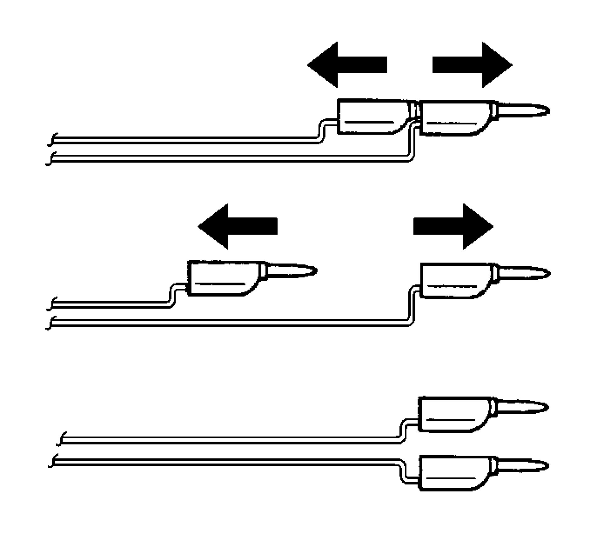 |
|
Fig. 46: Separating Banana Plugs Courtesy of GENERAL MOTORS COMPANY |
WARNING: When you are deploying a pretensioner for disposal, perform the
deployment procedures in the order listed. Failure to follow the
procedures in the order listed may result in personal injury.
17. Separate the 2 banana plugs on the SIR deployment harness.
 |
|
Fig. 47: Deploying Pretensioner Courtesy of GENERAL MOTORS COMPANY |
NOTE: When the seat belt pretensioner deploys, the deployment fixture may jump
about 30 cm (1 ft) vertically. This is a normal reaction of the seat belt
pretensioner due to the force of the rapid expansion of gas inside the
pretensioner.
18. Place a 12 V minimum/2 A minimum power source (i.e., vehicle battery) near the shorted end of the
harness.
19. Connect the SIR deployment harness wires to the power source. Pretensioner deployment will occur
when contact is made.
20. Disconnect the SIR deployment harness from the power source after the pretensioner deploys.
 |
|
Fig. 48: View Of Deployment Harness Leads |
21. Seat one banana plug into the other in order to short the deployment harness leads.
22. If the pretensioner did not deploy, disconnect the adapter and discontinue the procedure. Contact the
Technical Assistance Group. Otherwise, proceed to the following steps.
23. Put on a pair of shop gloves.
24. Disconnect the pigtail adapter from the pretensioner as soon as possible.
25. Inspect the pigtail adapter and the SIR deployment harness. Replace as needed.
26. Dispose of the deployed pretensioner through normal refuse channels.
27. Wash hands with a mild soap.
DESCRIPTION AND OPERATION
SUPPLEMENTAL INFLATABLE RESTRAINT SYSTEM DESCRIPTION AND OPERATION
SIR System Overview
The supplemental inflatable restraint (SIR) system supplements the protection offered by the seat belts. The SIR
system contains an inflatable restraint sensing and diagnostic module (SDM), air bags, seat belt pretensioners
(anchor and retractor), and impact sensors. The SDM determines the severity of a collision with the assistance
of impact sensors located at strategic points on the vehicle. When the SDM detects a collision, the SDM will
process the information provided by the impact sensors to further support air bag or pretensioner deployment.
The SDM will deploy the air bags and pretensioners if it detects a collision of sufficient force. If the force of the
impact is not sufficient to warrant air bag deployment, the SDM may still deploy the seat belt pretensioners. The
SDM contains a sensing device that converts vehicle velocity changes to an electrical signal. The SDM
compares these signals to values stored in memory. If the signals exceed a stored value, the SDM will determine
the severity of the impact and either cause current to flow through the frontal deployment loops deploying the
frontal air bags and pretensioners, or it will deploy the pretensioners only. The SDM continuously monitors the
deployment loops for malfunctions and illuminates the AIR BAG indicator if a fault is detected.The SDM
performs continuous diagnostic monitoring of the SIR system electrical components. Upon detection of a circuit
malfunction, the SDM will set a DTC and inform the driver by illuminating the AIR BAG indicator. The
steering column and knee bolsters are designed to absorb energy and compress during frontal collisions in order
to limit leg movement and decrease the chance of injury to the driver and passenger.
AIR BAG Indicator (Driver)
The AIR BAG indicator, located in the instrument cluster, is used to notify the driver of SIR system
malfunctions and to verify that the inflatable restraint sensing and diagnostic module (SDM) is communicating
with the instrument cluster. When the ignition is turned ON, the SDM is supplied with ignition positive voltage.
The instrument cluster will momentarily turn on the AIR BAG indicator. While the indicator is on, the SDM
conducts tests on all SIR system components and circuits. If no malfunctions are detected the SDM will
communicate with the instrument cluster through the serial data circuit and command the AIR BAG indicator
OFF. The SDM provides continuous monitoring of the air bag circuits by conducting a sequence of checks. If a
malfunction is detected the SDM will store a diagnostic trouble code (DTC) and command the instrument
cluster to illuminate the AIR BAG indicator via serial data. The presence of a SIR system malfunction could
result in non-deployment of the air bags or deployment in conditions less severe than intended. The AIR BAG
indicator will remain ON until the malfunction has been repaired.
Inflatable Restraint Sensing and Diagnostic Module (SDM)
The inflatable restraint sensing and diagnostic module (SDM) is a microprocessor and the control center for the
supplemental inflatable restraint (SIR) system. The SDM contains internal sensors along with external impact
sensors, mounted at strategic locations on the vehicle. In the event of a collision, the SDM compares the signals
from the internal and external impact sensors to a value stored in memory. When the generated signals exceed
the stored value, the SDM will cause current to flow through the appropriate deployment loops to deploy the air
bags. The SDM records the SIR system status when a deployment occurs and illuminates the AIR BAG
indicator located in the instrument cluster. The SDM performs continuous diagnostic monitoring of the SIR
system electrical components and circuitry when the ignition is turned ON. If the SDM detects a malfunction, a
DTC will be stored and the SDM will request the instrument cluster to illuminate the AIR BAG indicator,
notifying the driver that a malfunction exists. In the event that ignition positive voltage is lost during a collision,
the SDM maintains a 23-volt loop reserve for deployment of the air bags. It is important when disabling the SIR
system for servicing or rescue operations to allow the 23-volt loop reserve to dissipate, which could take up to 1
minute.
Air Bags
This vehicle may contain up to 10 air bags. The 10 air bags are located in the steering wheel (dual air bags),
instrument panel (passenger side) (dual air bags), driver seat side (B-pillar), passenger seat side (B-pillar), left
rear seat side, right rear seat side, left roof rail, right roof rail, driver knee (instrument panel), passenger knee
(instrument panel). To view the locations of the air bags refer to Master Electrical Component List . Air bags
contain a housing, inflatable air bag, two initiating devices (if dual air bag), canister of gas generating material
and, in some cases, stored compressed gas. The deployment loops supply current through the air bags to deploy
the air bags. The steering wheel and passenger instrument panel air bags have two stages of deployment, which
varies the amount of restraint to the occupant according to the collision severity. For moderate frontal collisions
the air bags deploy at less than full deployment which consists of stage 1 of the air bag. For more severe frontal
collisions a full deployment is initiated which consists of stage 1 and stage 2 of the air bag. The current passing
through the air bags ignite the material in the canister producing a rapid generation of gas and is some cases, the
release of compressed gas. The gas produced from this reaction rapidly inflates the air bag. Once the air bag is
inflated it quickly deflates through the air bag vent holes and/or the bag fabric. Each air bag is equipped with a
shorting bar located in the connectors of the air bag. The shorting bar shorts the air bag deployment loop
circuitry to prevent unwanted deployment of the air bag when it is disconnected.
Seat Belt Pretensioners (Anchor and Retractor)
The seat belt pretensioners (driver and passenger) consist of a housing, seat belt retractor (located in the
B-pillar), seat belt anchor (located on the floor), seat belt webbing, an initiator, and a canister of gas generating
materials. To view the locations of the seat belt pretentioners refer to Master Electrical Component List . The
initiator is part of the seat belt pretensioner deployment loop. When the vehicle is involved in a collision of
sufficient force, the SDM causes current to flow through the seat belt deployment loops to the initiator. Current
passing through the initiator ignites the material in the canister producing a rapid generation of gas. The gas
produced from this reaction deploys the seat belt pretensioners which removes all of the slack in the seat belts.
Depending on the severity of the collision, the seat belt pretensioners may deploy without the frontal air bags
deploying, or they will deploy immediately before the frontal air bags deploy. Each seat belt pretensioner is
equipped with a shorting bar that is located in the connector of the seat belt pretensioner. The shorting bar shorts
the seat belt pretensioner circuitry to prevent unwanted deployment of the seat belt pretensioner when the
connector is disconnected.
Impact Sensors
There are multiple impact sensors which may be located in the front of the vehicle, in the front doors or on the
B-pillar, and on the C-pillar depending on the vehicle configuration. To view the locations of the impact sensors
refer to Master Electrical Component List . The front of vehicle, B-pillar, and C-pillar impact sensors contain
a sensing device which monitors vehicle acceleration to detect collisions that are severe enough to warrant air
bag deployment. The front door impact sensors contain a sensing device which monitors the door cavity air
pressure change to detect side collisions that are severe enough to warrant air bag deployment. It is important
when working on components in the door to make sure any items which have a sealing impact on the door
(water deflector, exterior door handle, speaker, door harness grommet, or sealing strip) are securely fastened
when reinstalled. The impact sensors are not part of the deployment loop, but instead provide input to the
Inflatable Restraint Sensing and Diagnostic Module (SDM). The Inflatable Restraint Sensing and Diagnostic
Module contains a microprocessor that performs calculations using the measured inputs from acceleration and
pressure sensors. When the generated calculations exceed the stored value, the Inflatable Restraint Sensing and
Diagnostic Module will cause current to flow through the deployment loops deploying the appropriate air bags.
Passenger Presence Detection System and Air Bag Indicator (Passenger)
NOTE: The passenger presence system (PPS) is a calibrated unit. When replacing the
assembly all parts in the service kit must remain together. Do not mix any of the
old parts with the new parts. After repairing or replacing the PPS, the preload
test must be performed in order to function properly.
The passenger presence detection system (PPS) is used to monitor the type of occupant that is sitting in the front
passenger seat and communicate the status to the inflatable restraint sensing and diagnostic module (SDM). The
SDM then uses this information to determine whether to enable or suppress the deployment of the passenger
instrument panel air bag. The PPS consists of an electronic control module, a sensor mat in the seat, a harness,
and PASSENGER AIR BAG ON/OFF indicators. The PPS transmits and receives a low-level electric field. The
measured capacitance value of this field is used to determine the type of occupant sitting in the front passenger
seat. If the measured capacitance is less than a calibrated value, then the passenger presence module will send a
serial data signal to the SDM to disable the passenger instrument panel air bag. If the measured capacitance is
greater than a calibrated value, then the passenger presence module will send a serial data signal to the SDM to
enable the passenger instrument panel air bag. The SDM will notify the customer of the enable/disable status by
illuminating one of the PASSENGER AIR BAG ON/OFF indicator. PPS monitors itself for faults and will
displays diagnostic trouble codes (DTCs) onthe scan tool. When a fault is detected, the passenger presence
module sends out a message to the SDM. The SDM responds by sending a command message to the IPC to
illuminate the AIR BAG indicator.
Seat Belt Indicators
The seat belt indicators are controlled through the inflatable restraint sensing and diagnostic module (SDM). For
further information on seat belt indicators refer to Seat Belt System Description and Operation .
SPECIAL TOOLS AND EQUIPMENT
SPECIAL TOOLS
|
Illustration |
Tool |
|
Illustration |
Tool |
|
EL 38826 J 38826 SIR |
Tool
Number/
Description

EL
39401-B
J39401-B
SIR
Deployment
Fixture
Article GUID: A00884675
Power Steering - Volt
SPECIFICATIONS
FASTENER SPECIFICATIONS
Single Use Non-Threaded Fasteners/Components
NOTE:
All
fasteners/components
listed in this table
MUST BE
DISCARDED and
replaced with NEW
after removal.
Application
Steering Gear Boot Inner Clamp
Steering Gear Shaft Dampener Ring
|
Single Use Threaded Fastener/Component Tightening Specifications | |||||||||||
| |||||||||||
|
Reusable Threaded Fastener Tightening Specifications | |||||
| |||||
NOTE:
All fasteners
listed in this
table can be
reused after
removal.
|
Application |
Specification |
|
Steering Linkage Inner Tie Rod |
83 N.m (61 lb ft) |
|
Steering Linkage Outer Tie Rod Nut | ||||
|
SCHEMATIC WIRING DIAGRAMS
POWER STEERING WIRING SCHEMATICS
Power Steering
 |
|
Fig. 1: Power Steering Courtesy of GENERAL MOTORS COMPANY |
DIAGNOSTIC INFORMATION AND PROCEDURES
DTC C0176: CONTROL MODULE TEMPERATURE SENSOR HIGH TEMPERATURE
Diagnostic Instructions
• Perform the Diagnostic System Check - Vehicle prior to using this diagnostic procedure.
• Review Strategy Based Diagnosis for an overview of the diagnostic approach.
• Refer to Diagnostic Procedure Instructions to provide an overview of each diagnostic category.
DTC Descriptor
DTC C0176 54
Control Module Temperature Sensor High Temperature
Circuit/System Description
The power steering control module monitors the temperature of the Power Steering System. The power steering
control module uses voltage, current levels and input from an internal temperature sensor to calculate an estimated
system temperature. If the power steering control module detects a high system temperature event is occurring, the
amount of assist is decreased to reduce system temperature, in effort to prevent thermal damage to the power steering
components.
Conditions for Running the DTC
• Ignition ON, engine Running.
• Power steering system voltage is 9 - 16 V
• Repetitive steering input applied.
Conditions for Setting the DTC
The power steering control module detects a high system temperature.
Action Taken When the DTC Sets
• DTC C0176 54 is stored in memory.
• Steering assist is reduced.
Conditions for Clearing the DTC
A current DTC will clear on the next malfunction-free ignition cycle.
Diagnostic Aids
• DTC C0176 54 does not indicate that a malfunction has occurred. Rather that the power steering control
module had to limit current to the power steering motor to avoid thermal damage to the power steering system
components. Discuss with the customer about driving conditions when the steering assist was reduced.
• Ensure that no steering components down stream of the power steering column assembly, such as ball joints,
tie rod ends, universal joints, or the steering gear assembly, are mechanically binding.
Reference Information
Schematic Reference
Power Steering Schematics
Connector End View Reference
COMPONENT CONNECTOR END VIEWS - INDEX
Description and Operation
Power Steering System Description and Operation (Belt Drive Electronic Power Steering)
Electrical Information Reference
Circuit Testing
Connector Repairs
Testing for Intermittent Conditions and Poor Connections
Wiring Repairs
Scan Tool Reference
Control Module References for scan tool information.
Circuit/System Verification
1. Verify that the DTC sets outside of the conditions for running and setting. Since most occurrences of this DTC
are caused by excessive driver inputs, review with the customer the conditions under which the DTC set.
• If the DTC did not set outside of the conditions for running and setting
1. Ignition ON.
2. Operate the vehicle within the conditions that the customer experienced, avoiding excessive inputs, and
verify the DTC does not reset.
• If the DTC is set
1. Verify that no steering components down stream of the power steering column assembly are
mechanically binding. Refer to Increase in Effort While Turning Steering Wheel
• If steering components are mechanically binding, replace the mechanically binding steering
components.
• If no steering components are mechanically binding, replace the steering gear.
• If the DTC is not set
3. All OK.
• If the DTC set outside of the conditions for running and setting
2. All OK. The power steering is operating as designed.
Repair Instructions
Perform the Diagnostic Repair Verification after completing the repair.
• Refer to Electric Belt Drive Rack and Pinion Steering Gear Replacement
• Refer to Control Module References for power steering control module replacement, programming and
setup.
DTC C0460: STEERING WHEEL ANGLE SENSOR
Diagnostic Instructions
• Perform the Diagnostic System Check - Vehicle prior to using this diagnostic procedure.
• Review Strategy Based Diagnosis for an overview of the diagnostic approach.
• Refer to Diagnostic Procedure Instructions to provide an overview of each diagnostic category.
DTC Descriptor
DTC C0460 00
Steering Wheel Angle Sensor Malfunction
DTC C0460 4B
Steering Wheel Angle Sensor Calibration Not Learned
DTC C0460 5A
Steering Wheel Angle Sensor Signal Not Plausible
Circuit/System Description
The Electric Belt Drive Rack and Pinion Steering Gear contains the steering wheel angle sensor. The steering wheel
angle sensor identifies the position and direction of the steering wheel rotation to calculate the driver intended
driving direction. The power steering control module uses the signal to determine the proper amount of steering
assist to provide.
Conditions for Running the DTC
The condition for running the DTC will not occur until the initialization phase has been completed. The initialization
of the electronic brake control module occurs when the following conditions have been met:
• Ignition voltage is greater than 8 V.
• The initialization happens once each ignition cycle when the vehicle speed is greater than 20 km/h (12 MPH)
and the vehicle is driven in a straight line without the brake pedal being applied.
Conditions for Setting the DTC
DTC C0460 00, C0460 5A
• Steering angle signal is not valid.
• Steering angle signal line is open.
• Angle signal cycle time is out of range.
• Angle signal duty is out of range.
DTC C0460 4B
Steering sensor zero position is not set.
Action Taken When the DTC Sets
• DTC C0460 is stored in memory.
• No steering assist.
Conditions for Clearing the DTC
A current DTC will clear on the next malfunction-free ignition cycle.
Reference Information
Schematic Reference
Power Steering Schematics
Connector End View Reference
COMPONENT CONNECTOR END VIEWS - INDEX
Description and Operation
Power Steering System Description and Operation (Belt Drive Electronic Power Steering)
Electrical Information Reference
Circuit Testing
Connector Repairs
Testing for Intermittent Conditions and Poor Connections
Wiring Repairs
Scan Tool Reference
Control Module References for scan tool information.
Circuit/System Verification
1. Ignition ON.
2. Verify the DTC is not set.
• If the DTC is set
1. Calibrate the K43 Power Steering Control Module. Refer to Power Steering Control Module
Calibration
2. Verify the DTC does not set while operating the vehicle within the Conditions for Running the DTC
• If the DTC sets, replace the Electric Belt Drive Rack and Pinion Steering Gear.
1. Verify the DTC does not set while operating the vehicle within the Conditions for Running the
DTC
• If the DTC sets, replace the K43 Power Steering Control Module.
• If the DTC is not set
2. All OK.
• If the DTC is not set
3. All OK.
• If the DTC is not set
3. All OK.
Repair Instructions
Perform the Diagnostic Repair Verification after completing the repair.
• Refer to Electric Belt Drive Rack and Pinion Steering Gear Replacement
• Refer to Control Module References for control module replacement, programming and setup.
DTC C0475: POWER STEERING MOTOR CIRCUIT MALFUNCTION
Diagnostic Instructions
• Perform the Diagnostic System Check - Vehicle prior to using this diagnostic procedure.
• Review Strategy Based Diagnosis for an overview of the diagnostic approach.
• Refer to Diagnostic Procedure Instructions to provide an overview of each diagnostic category.
DTC Descriptors
DTC C0475 00
Power Steering Motor Circuit Malfunction
Circuit/System Description
The power steering control module continuously monitors the voltage and current levels being commanded to the
3-phase steering assist motor. The power steering control module compares the desired and actual current levels to
detect malfunctions in the internal power steering assist motor circuits.
Conditions for Running the DTC
Ignition ON.
Conditions for Setting the DTC
The power steering control module detects a short to ground, short to voltage, or an open/high resistance on any of
the internal power steering assist motor circuits.
Action Taken When the DTC Sets
• The DTC is stored in memory.
• No steering assist.
Conditions for Clearing the DTC
A history DTC will clear after 50 consecutive malfunction free ignition cycles.
Reference Information
Schematic Reference
Power Steering Schematics
Connector End View Reference
COMPONENT CONNECTOR END VIEWS - INDEX
Description and Operation
Power Steering System Description and Operation (Belt Drive Electronic Power Steering)
Electrical Information Reference
Circuit Testing
Connector Repairs
Testing for Intermittent Conditions and Poor Connections
Wiring Repairs
Scan Tool Reference
Control Module References for scan tool information.
Circuit/System Verification
1. Ignition ON.
2. Verify that DTC C0475 is not set.
• If the DTC C0475 is set
1. Program the K43 Power Steering Control Module.
2. Verify the DTC does not set.
• If the DTC sets, replace the K43 Power Steering Control Module.
• If the DTC does not set
3. All OK.
• If the DTC C0475 is not set
3. All OK.
Repair Instructions
Perform the Diagnostic Repair Verification after completing the repair.
Refer to Control Module References for control module programming and setup.
DTC C0545: STEERING WHEEL TORQUE SENSOR
Diagnostic Instructions
• Perform the Diagnostic System Check - Vehicle prior to using this diagnostic procedure.
• Review Strategy Based Diagnosis for an overview of the diagnostic approach.
• Refer to Diagnostic Procedure Instructions to provide an overview of each diagnostic category.
DTC Descriptors
DTC C0545 00
Steering Wheel Torque Sensor
Circuit/System Description
The power steering control module continuously monitors the digital torque sensors torque and index current signals.
As the steering wheel is turned and torsional twist is applied to the steering shaft, the steering input and output shafts
are monitored via the torque signal circuit and then processed by the power steering control module to calculate the
steering torque. The steering wheel torque sensor needs to be calibrated to be fully functional.
Conditions for Running the DTC
The ignition is ON.
Conditions for Setting the DTC
The power steering control module detects a short to ground, short to voltage, or an open/high resistance on any of
the torque sensor circuits.
Action Taken When the DTC Sets
• DTC C0545 is stored in memory.
• The driver information center displays the SERVICE POWER STEERING warning message.
• No Steering assist.
Conditions for Clearing the DTC
• A current DTC will clear on the next malfunction free ignition cycle.
• A history DTC will clear after 40 consecutive malfunction free ignition cycles.
Reference Information
Schematic Reference
Power Steering Schematics
Connector End View Reference
COMPONENT CONNECTOR END VIEWS - INDEX
Description and Operation
Power Steering System Description and Operation (Belt Drive Electronic Power Steering)
Electrical Information Reference
Circuit Testing
Connector Repairs
Testing for Intermittent Conditions and Poor Connections
Wiring Repairs
Scan Tool Reference
Control Module References for scan tool information
Circuit/System Verification
1. Verify that DTC C0545 is not set.
• If the DTC is set
NOTE: Check the torque sensor terminal connections for signs of corrosion or
damage.
Replace the steering gear.
• If the DTC is not set
2. All OK.
Repair Instructions
Perform the Diagnostic Repair Verification after completing the repair.
• Refer to Electric Belt Drive Rack and Pinion Steering Gear Replacement
• Refer to Control Module References for control module replacement, programming and setup.
DTC C055C: STEERING GEAR PERFORMANCE MALFUNCTION
Diagnostic Instructions
• Perform the Diagnostic System Check - Vehicle prior to using this diagnostic procedure.
• Review Strategy Based Diagnosis for an overview of the diagnostic approach.
• Refer to Diagnostic Procedure Instructions to provide an overview of each diagnostic category.
DTC Descriptor
DTC C055C 00
Steering Gear Performance Malfunction
Circuit/System Description
The power steering control module continuously verifies the mechanical friction of the steering gear. If the friction is
too high the clutch between motor and rack slips and the internal angle is not longer valid.
Conditions for Running the DTC
Ignition ON.
Conditions for Setting the DTC
The DTC is set when the mechanical friction of the steering gear is too high.
Action Taken When the DTC Sets
• DTC C055C is stored in memory.
• No steering assist.
Conditions for Clearing the DTC
A history DTC will clear after 40 consecutive malfunction free ignition cycles.
Diagnostic Aids
Ensure that no steering components down stream of the power steering column assembly, such as ball joints, tie rod
ends, universal joints, or the steering gear assembly, are mechanically binding.
Reference Information
Power Steering Schematics
Connector End View Reference
COMPONENT CONNECTOR END VIEWS - INDEX
Description and Operation
Power Steering System Description and Operation (Belt Drive Electronic Power Steering)
Electrical Information Reference
Circuit Testing
Connector Repairs
Testing for Intermittent Conditions and Poor Connections
Wiring Repairs
Scan Tool Reference
Control Module References for scan tool information.
Circuit/System Verification
1. Ignition ON.
2. Verify that DTC C055C is not set.
• If the DTC is set
1. Verify that no steering components down stream of the power steering column assembly are
mechanically binding. Refer to Increase in Effort While Turning Steering Wheel
• If steering components are mechanically binding, replace the mechanically binding steering
components.
• If no steering components are mechanically binding, replace the steering gear.
• If the DTC is not set
3. All OK.
Repair Instructions
Perform the Diagnostic Repair Verification after completing the repair.
• Refer to Electric Belt Drive Rack and Pinion Steering Gear Replacement
• Refer to Control Module References for power steering control module replacement, programming and
setup.
DTC C0569: INTERNAL CHECK SUM ERROR/CALIBRATION NOT
PROGRAMMED/CONFIGURATION NOT PROGRAMMED
Diagnostic Instructions
• Perform the Diagnostic System Check - Vehicle prior to using this diagnostic procedure.
• Review Strategy Based Diagnosis for an overview of the diagnostic approach.
• Refer to Diagnostic Procedure Instructions to provide an overview of each diagnostic category.
DTC Descriptors
DTC C0569 31
Internal Check Sum Error
DTC C0569 42
Calibration Not Programmed
DTC C0569 46
Configuration Not Programmed
Circuit/System Description
The power steering control module continuously monitors the parameters of the steering gear. The power steering
control module performs a self-test diagnostic during power-up. The configuration is not complete from supplier.
Conditions for Running the DTC
Ignition ON.
Conditions for Setting the DTC
Electronic power steering control module configuration is not complete.
Action Taken When the DTC Sets
• DTC C0569 is stored in memory.
• No steering assist.
Conditions for Clearing the DTC
A history DTC will clear after 40 consecutive malfunction free ignition cycles.
Reference Information
Schematic Reference
Power Steering Schematics
Connector End View Reference
COMPONENT CONNECTOR END VIEWS - INDEX
Description and Operation
Power Steering System Description and Operation (Belt Drive Electronic Power Steering)
Electrical Information Reference
Circuit Testing
Connector Repairs
Testing for Intermittent Conditions and Poor Connections
Wiring Repairs
Scan Tool Reference
Control Module References for scan tool information.
Circuit/System Verification
1. Ignition ON.
2. Verify that DTC C0569 is not set.
• If the DTC C0569 is set
Replace the steering gear.
• If the DTC C0569 is not set
3. All OK.
Repair Instructions
Perform the Diagnostic Repair Verification after completing the repair.
• Refer to Electric Belt Drive Rack and Pinion Steering Gear Replacement
• Refer to Control Module References for power steering control module replacement, programming and
setup.
DTC C056D: ELECTRONIC CONTROL UNIT HARDWARE (POWER STEERING CONTROL
MODULE)
Diagnostic Instructions
• Perform the Diagnostic System Check - Vehicle prior to using this diagnostic procedure.
• Review Strategy Based Diagnosis for an overview of the diagnostic approach.
• Refer to Diagnostic Procedure Instructions to provide an overview of each diagnostic category.
DTC Descriptor
DTC C056D
Electronic Control Unit Hardware
For symptom byte information, refer to Symptom Byte List .
Circuit/System Description
The internal fault detection is handled inside the power steering control module. The symptom byte information is
for engineering reference only. No external circuit diagnosis is involved.
Conditions for Running the DTC
The power steering control module runs the program to detect an internal fault when power up is commanded. The
only requirements are voltage and ground. This program runs even if the voltage is out of the valid operating range.
Conditions for Setting the DTC
The power steering control module has detected an internal malfunction.
Action Taken When the DTC Sets
The power steering control module refuses all additional inputs.
Conditions for Clearing the DTC
• A current DTC clears when the malfunction is no longer present.
• A history DTC clears when the device ignition cycle counter reaches the reset threshold of 50, without a repeat
of the malfunction.
Diagnostic Aids
• This DTC may be stored as a history DTC without affecting the operation of the device.
• If stored only as a history DTC and not retrieved as a current DTC, do not replace the device.
• If this DTC is retrieved as both a current and history DTC, replace the device that set the DTC.
Reference Information
Schematic Reference
Power Steering Schematics
Connector End View Reference
COMPONENT CONNECTOR END VIEWS - INDEX
Description and Operation
Power Steering System Description and Operation (Belt Drive Electronic Power Steering)
Electrical Information Reference
Circuit Testing
Connector Repairs
Testing for Intermittent Conditions and Poor Connections
Wiring Repairs
Scan Tool Reference
Control Module References for scan tool information
Circuit/System Verification
1. Ignition ON.
2. Verify DTC C056D is not set.
• If DTC C056D is set with symptom byte 19, 38, 3B, 3C, 49, or 5A
1. Program the K43 Power Steering Control Module.
2. Verify the DTC does not set.
• If the DTC sets, replace the K43 Power Steering Control Module.
• If the DTC does not set
3. All OK.
• If DTC C056D is set with symptom byte 37 or 39
Replace the K43 Power Steering Control Module
• If DTC C056D is not set
3. All OK
Repair Instructions
Perform the Diagnostic Repair Verification after completing the repair.
Refer to Control Module References for control module replacement, programming and setup.
DTC C056E: ELECTRONIC CONTROL UNIT SOFTWARE
Diagnostic Instructions
• Perform the Diagnostic System Check - Vehicle prior to using this diagnostic procedure.
• Review Strategy Based Diagnosis for an overview of the diagnostic approach.
• Refer to Diagnostic Procedure Instructions to provide an overview of each diagnostic category.
DTC Descriptors
DTC C056E
Electronic Control Unit Software
For symptom byte information, refer to Symptom Byte List .
Circuit/System Description
After replacement of the power steering control module, the power steering control module must be configured with
the proper tuning profile using the service programming system (SPS).
After replacement of the power steering control module, power steering motor, or steering gear, the steering
position/torque sensor calibration procedure must be performed.
Conditions for Running the DTC
Ignition ON.
Conditions for Setting the DTC
The device has detected an internal fault.
Actions Taken When DTC Sets
• DTC is stored in memory.
• Reduced or no steering assist.
Conditions for Clearing the DTC
• A current DTC clears when the malfunction is no longer present.
• A history DTC clears when the device ignition cycle counter reaches the reset threshold of 50, without a repeat
of the malfunction.
Reference Information
Schematic Reference
Power Steering Schematics
Connector End View Reference
COMPONENT CONNECTOR END VIEWS - INDEX
Description and Operation
Power Steering System Description and Operation (Belt Drive Electronic Power Steering)
Electrical Information Reference
Circuit Testing
Connector Repairs
Testing for Intermittent Conditions and Poor Connections
Wiring Repairs
Scan Tool Reference
Control Module References for scan tool information
Circuit/System Verification
1. Ignition ON.
2. Verify that DTC C056E is not set.
• If the DTC C056E is set
1. Program the K43 Power Steering Control Module.
2. Verify the DTC does not set.
• If the DTC sets, replace the K43 Power Steering Control Module.
• If the DTC does not set
3. All OK.
• If the DTC C056E is not set
3. All OK.
Repair Instructions
Perform the Diagnostic Repair Verification after completing the repair.
Refer to Control Module References for Control Module replacement, programming and setup.
DTC C1436: STEERING WHEEL ANGLE SIGNAL
Diagnostic Instructions
• Perform the Diagnostic System Check - Vehicle prior to using this diagnostic procedure.
• Review Strategy Based Diagnosis for an overview of the diagnostic approach.
• Refer to Diagnostic Procedure Instructions to provide an overview of each diagnostic category.
DTC Descriptors
DTC C1436
Steering Wheel Angle Signal
For symptom byte information refer to Symptom Byte List
Circuit/System Description
The steering wheel angle sensor is integrated into the steering gear assembly. The steering wheel angle sensor
identifies the position and direction of the steering wheel rotation.
The electronic brake control module receives high speed serial data inputs from the steering angle sensor identifying
the position and direction of the steering wheel rotation. The electronic brake control module utilizes this signal to
calculate the driver intended driving direction.
Conditions for Running the DTC
The condition for running the DTC will not occur until the initialization phase has been completed. The initialization
of the electronic brake control module occurs when the following conditions have been met:
• Ignition voltage is greater than 8 V
• The initialization happens once each ignition cycle when the vehicle speed is greater than 20 km/h (12 mph)
and the vehicle is driven in a straight line without the brake pedal being applied.
Conditions for Setting the DTC
C1436 09
The steering wheel angle sensor signal gradient unplausible.
C1436 0A
The steering wheel angle sensor signal remains constant during turning maneuvers.
C1436 11
The steering wheel angle sensor signal is out of range.
Action Taken When the DTC Sets
• The traction/stability control indicator turns ON.
• A Service StabiliTrak message may displayed on the driver information center.
• A Service Brake Assist message may displayed on the driver information center.
• A Service Power Steering Drive with Care message may displayed on the driver information center.
• The electronic brake control module disables the traction control and the electronic stability control for the
duration of the ignition cycle.
Conditions for Clearing the DTC
• A current DTC clears when the diagnostic runs and passes.
• The history DTC will clear after 40 consecutive fault-free ignition cycles have occurred.
Diagnostic Aids
• Check and adjust all tires to the stated cold air pressure as identified on the tire placard.
• The car should not pull in either direction causing the steering wheel to be off center while driving in a straight
line on a level surface.
• Confirm that all tires are of the proper size and matching brands. If a mis-sized or non-matching brand tire is
present, inform the customer that in order for the vehicle stability enhanced system to function normally, tires
need to be a uniform size and rolling diameter.
• Inspect the serial data circuits and connections at the power steering control module and the electronic brake
control module. They should be free from sources of electromagnetic interference and the connections should
be clean and tight.
Reference Information
Schematic Reference
Antilock Brake System Schematics
Connector End View Reference
COMPONENT CONNECTOR END VIEWS - INDEX
Description and Operation
ABS Description and Operation
Electrical Information Reference
Circuit Testing
Connector Repairs
Testing for Intermittent Conditions and Poor Connections
Wiring Repairs
Scan Tool Reference
Control Module References for scan tool information
Circuit/System Verification
1. Ignition ON.
2. With a scan tool check the Power Steering Control Module for any DTCs.
• If any DTCs are present in the Power Steering Control Module
Refer to Diagnostic Trouble Code (DTC) List - Vehicle in Power Steering Diagnostic Information and
Procedures.
• If there are no DTCs present in the Power Steering Control Module
1. With a scan tool check to see if DTCs U0126, U0130, or U0130 are set.
• If DTCs U0126, U0130, or U0131 are set
Refer to Diagnostic Trouble Code (DTC) List - Vehicle
• If DTCs U0126, U0130, and U0130 are not set
2. With a scan tool check to see if DTCs C0035 - C0050 are set in the Electronic Brake Control Module
• If DTCs C0035 - C0050 are set in the Electronic Brake Control Module
Refer to Diagnostic Trouble Code (DTC) List - Vehicle
• If DTCs C0035 - C0050 are not set in the Electronic Brake Control Module
3. Perform the Steering Wheel Angle Sensor Centering procedure.
• If the Steering Angle Sensor Centering procedure corrected the DTC
Proceed to step 6
• If the Steering Angle Sensor Centering procedure did not correct the DTC
4. Replace the Steering Gear Assembly.
• If steering gear assembly replacement corrected the DTC
Proceed to step 6
• If steering gear assembly replacement did not correct the DTC
5. Replace the Electronic Brake Control module.
6. All OK.
Repair Instructions
Perform the Diagnostic Repair Verification after completing the repair.
• Refer to Electric Belt Drive Rack and Pinion Steering Gear Replacement
• Refer to Control Module References for control module replacement, programming and setup.
SYMPTOMS - POWER STEERING SYSTEM
NOTE: Review the system description and operation in order to familiarize yourself with the
system functions. Refer to Power Steering System Description and Operation (Belt
Drive Electronic Power Steering).
Visual/Physical Inspection
• Inspect for aftermarket devices which could affect the operation of the power steering system.
• Inspect the easily accessible or visible system components for obvious damage or conditions which could
cause the symptom.
Symptoms List
Refer to a symptom diagnostic procedure from the following list in order to diagnose the symptom:
Rattle, Clunk, Pop or Shudder Noise from the Power Steering System
Whine or Growl Noise from the Power Steering System
Increase in Effort While Turning Steering Wheel
Poor Return of Steering Wheel
Steering Wheel Surges/Jerks While Turning
Steering Wheel Kickback
Steering Effort Hard or Too Easy in One or Both Directions
RATTLE, CLUNK, POP OR SHUDDER NOISE FROM THE POWER STEERING SYSTEM
|
Step |
Action |
Yes |
No |
|
1 |
Did you review the Power Steering System Description |
Go to Step 2 |
Go to Symptoms - Steering Wheel and |
|
Column | |||
|
2 |
Road test the vehicle in order to verify the complaint. It Is a rattle, clunk, popping, or shudder noise present? |
Go to Step 3 |
System OK |
|
3 |
Inspect the power steering gear bushings for wear or Are the power steering gear bushings worn or damaged? |
Go to Step 9 |
Go to Step 4 |
|
4 |
Inspect the power steering gear fasteners for looseness. |
Go to Step 10 |
Go to Step 5 |
|
5 |
Inspect the steering linkage inner and outer tie rods for Refer to:
Did you find and correct the condition? |
Go to Step 14 |
Go to Step 6 |
|
6 |
Inspect the front suspension components for damage or Are the front suspension components damaged or worn? |
Go to Step 11 |
Go to Step 7 |
|
7 |
Inspect the intermediate steering shaft for proper Is the intermediate steering shaft installed incorrectly or |
Go to Step 12 |
Go to Step 8 |
|
8 |
For a popping noise, inspect the steering gear shaft
Was a popping noise present near the end of travel in one |
Go to Step 13 |
Go to Step 2 |
| ||||||||||||||||||||||||||||||||
|
WHINE OR GROWL NOISE FROM THE POWER STEERING SYSTEM |
Special Tools
CH-39570 Chassis Ear
|
Equivalent regional tools: Special Tools | ||||||||||||||||||||
|
| ||||||||||||||||||||
|
INCREASE IN EFFORT WHILE TURNING STEERING WHEEL |
|
Step |
Action |
Yes |
No |
|
1 |
Did you review the Power Steering System Description |
Go to Step 2 |
Go to Symptoms - |
|
2 |
Verify that there is an increase in effort while turning the Does the system operate normally? |
System OK |
Go to Step 3 |
|
3 |
Inspect for the following tire related conditions:
Refer to Vehicle Certification, Tire Placard, Anti- Did you find and correct the condition? |
Go to Step 10 |
Go to Step 4 |
| |||||||||||||||||||||||||||||||||
|
POOR RETURN OF STEERING WHEEL |
|
Step |
Action |
Yes |
No |
|
DEFINITION: After completing a turn, extra steering input is required for the steering wheel to return to | |||
|
1 |
Did you review the Power Steering System Description |
Go to Step 2 |
Go to Symptoms - Power Steering System |
|
2 |
Verify that poor return of the steering wheel is present. |
System OK |
Go to Step 3 |
|
3 |
Perform the following steps:
|
Go to Step 12 |
Go to Step 4 |
|
Step |
Action |
Yes |
No |
|
components as necessary. Did you find and correct the condition? | |||
|
4 |
Perform the following steps:
Was the steering wheel abnormally difficult to rotate in |
Go to Step 5 |
Go to Step 10 |
|
5 |
NOTE:
Perform the following steps:
|
Go to Step 11 |
Go to Step 6 |
|
Step |
Action |
Yes |
No |
|
position. Was the steering wheel abnormally difficult to rotate in | |||
|
6 |
Inspect the intermediate steering shaft for wear or a Did you find and complete the repair? |
Go to Step 12 |
Go to Step 7 |
|
7 |
Perform the following steps:
Did you find and complete the repair? |
Go to Step 12 |
Go to Step 8 |
|
8 |
Perform the following steps:
Did you find and complete the repair? |
Go to Step 12 |
Go to Step 9 |
|
9 |
Perform the following steps:
Did you find and complete the repair? |
Go to Step 12 |
Go to Step 10 |
|
10 |
Inspect the wheel alignment and adjust as necessary. Refer to Wheel Alignment Measurement . Did you find and complete the repair? |
Go to Step 12 |
- |
|
11 |
Perform the following steps:
|
Go to Step 12 |
- |
|
Step |
Action |
Yes |
No |
|
Did you find and complete the repair? | |||
|
12 |
Operate the system in order to verify the repair. |
System OK |
- |
|
STEERING WHEEL SURGES/JERKS WHILE TURNING | ||||||||||||||||||||||||||||||||||||||||
|
|
Step |
Action |
Yes |
No |
|
steering assist Allow the power steering assist motor to cool and retest | |||
|
10 |
Replace the steering linkage outer tie rod(s). Refer to Steering Linkage Outer Tie Rod Did you complete the repair? |
Go to Step 14 |
- |
|
11 |
Replace the intermediate steering shaft. Refer to Intermediate Steering Shaft Replacement . Did you complete the repair? |
Go to Step 14 |
- |
|
12 |
Replace the power steering gear. Refer to Electric Belt Drive Rack and Pinion Steering Gear Replacement. Did you complete the repair? |
Go to Step 14 |
- |
|
13 |
Replace the steering column. Refer to Steering Column Replacement . Did you complete the repair? |
Go to Step 14 |
- |
|
14 |
Operate the system in order to verify the repair. |
System OK |
Go to Step 3 |
|
STEERING WHEEL KICKBACK | |||||||||
|
|
STEERING EFFORT HARD OR TOO EASY IN ONE OR BOTH DIRECTIONS | ||||
|
|
Condition |
Action |
|
One or both of the steering column dash seals are |
Adjust or replace the steering column dash seal(s). • Steering Column Dash Inner Seal Replacement |
|
• Steering Column Dash Outer Seal | |
|
The intermediate steering shaft joints and/or fasteners |
Tighten or replace the intermediate steering shaft joints Refer to Intermediate Steering Shaft Replacement . |
|
The power steering gear is binding. |
Replace the power steering gear. Refer to Electric Belt Drive Rack and Pinion Steering |
|
Gear Replacement. | |
|
The steering column shaft is bent. |
Replace the steering column. Refer to Steering Column Replacement . |
|
The connectors to the power steering assist motor are |
Perform the following steps:
|
|
The power steering gear sensor wire is damaged. |
Replace the power steering gear. Refer to Electric Belt Drive Rack and Pinion Steering |
|
Gear Replacement. | |
|
The power steering control module is |
Confirm the DTC and replace the power steering gear. Refer to Electric Belt Drive Rack and Pinion Steering |
|
Gear Replacement. | |
|
The power steering assist motor shaft is binding. |
Confirm the DTC and replace the power steering gear. Refer to Electric Belt Drive Rack and Pinion Steering |
|
Gear Replacement. |
REPAIR INSTRUCTIONS
WIRE TO WIRE REPAIR - STEERING
Special Tools
• EL-38125-10 Splice Sleeve Crimping Tool (non GMNA)
• J-38125-5A Ultra Torch Special Tool
• J-38125-8 Splice Sleeve Crimping Tool (GMNA)
For equivalent regional tools, refer to Special Tools .
WARNING: In order to reduce the risk of personal injury, loss of high voltage isolation to
ground and higher system impedance, do not attempt to repair any HV wiring,
connector, or terminal that is damaged. High voltage coaxial type cables are not
repairable. Never attempt to repair a coaxial type cable. The entire cable/harness or
|
component must be replaced. In order to maintain system integrity and personal | |
|
NOTE: |
If the wiring harness internal to the transmission is damaged, the wiring harness |
|
NOTE: |
Do not splice wires in Door Harness Grommets. |
|
NOTE: |
The DuraSeal splice sleeves have the following 2 critical features:
|
Use only DuraSeal splice sleeves to form a one-to-one splice on all types of insulation except high voltage and
specialty cables. Use DuraSeal splice sleeves where there are special requirements such as moisture sealing. Follow
the instructions below in order to splice copper wire using DuraSeal splice sleeves.
|
Splice Sleeve Selection | ||||||||||||||||||
| ||||||||||||||||||
NOTE: You must perform the following procedures in the listed order. Repeat the
procedure if any wire strands are damaged. You must obtain a clean strip with
all of the wire strands intact.
1. Open the harness by removing any tape:
• Use a sewing seam ripper, available from sewing supply stores, in order to cut open the harness in order
to avoid wire insulation damage.
• Use the DuraSeal splice sleeves on all types of insulation except Tefzel and coaxial.
• Do not use the crimp and DuraSeal splice sleeve to form a splice with more than 2 wires coming
together.
2. Cut as little wire off the harness as possible. You may need the extra length of wire in order to change the
location of a splice.
Adjust splice locations so that each splice is at least 40 mm (1.5 in) away from the other splices, harness
branches, or connectors.
3. Strip the insulation:
• When adding a length of wire to the existing harness, use the same size wire as the original wire.
• Perform one of the following items in order to find the correct wire size:
• Find the wire on the schematic and convert to regional wiring gauge size.
• If you are unsure of the wire size, begin with the largest opening in the wire stripper and work
down until achieving a clean strip of the insulation.
• Strip approximately 5.0 mm (0.20 in) of insulation from each wire to be spliced.
• Do not nick or cut any of the strands. Inspect the stripped wire for nicks or cut strands.
• If the wire is damaged, repeat this procedure after removing the damaged section.
4. For high temperature wiring, slide a section of high temperature SCT1 shrink tubing down the length of wire
to be spliced. Ensure that the shrink tubing will not interfere with the splice procedure.
5. Select the proper DuraSeal splice sleeve according to the wire size. Refer to the above table at the beginning of
the repair procedure for the color coding of the DuraSeal splice sleeves and the crimp tool nests.
 |
|
Fig. 2: Splice Sleeve Crimping Tool With 4 Crimp Nests Courtesy of GENERAL MOTORS COMPANY |
6. The EL-38125-10 splice sleeve crimping tool has four crimp nests. The largest crimp nest (4) is used for
crimping 10 and 12 gauge wires. The second largest crimp nest (3) is used for crimping 14 and 16 gauge wires.
The third largest crimp nest (2) is used for crimping 18 and 20 gauge wires. The smallest crimp nest (1) is used
for crimping 22 to 26 gauge wires. The crimp nests are referenced in the table (farther above) under the crimp
tool nest color.
 |
|
Fig. 3: Splice Sleeve Crimping Tool With 3 Crimp Nests |
7. The J-38125-8 splice sleeve crimping tool has three crimp nests. The largest crimp nest (3) is used for
crimping 10 and 12 gauge wires. The second largest crimp nest (2) is used for crimping 14 and 16 gauge wires.
The smallest crimp nest (1) is used for crimping 18 to 20 gauge wires. The crimp nests are referenced in the
table (farther above) under the crimp tool nest color.
8. Use the splice sleeve crimp tool in order to position the DuraSeal splice sleeve in the proper color nest of the
splice sleeve crimp tool. For the four crimp nest tool, use the three largest crimp nests to crimp the splice
sleeves. For the three crimp nest tool, use all three crimp nests to crimp the splice sleeves. Use the four and
three crimp tool diagrams (above) and the table (farther above) to match the splice sleeve with the correct
crimp nest. The crimp tool diagram callout numbers match the numbers in the table (under crimp tool nest
color).

Fig. 4: Identifying DuraSeal Splice Sleeve
Courtesy of GENERAL MOTORS COMPANY
9. Place the DuraSeal splice sleeve in the nest. Ensure that the crimp falls midway between the end of the barrel
and the stop. The sleeve has a stop (3) in the middle of the barrel (2) in order to prevent the wire (1) from
going further. Close the hand crimper handles slightly in order to firmly hold the DuraSeal splice sleeve in the
proper nest.
 |
|
Fig. 5: Crimped DuraSeal Splice Sleeve Courtesy of GENERAL MOTORS COMPANY |
10. Insert the wire into the splice sleeve barrel until the wire hits the barrel stop. Refer to Folded-Over Wire
Repair for splicing wires of 0.35 mm or less (22, 24, 26 gauge sizes) and for splicing wires of different
gauges.
11. Tightly close the handles of the crimp tool until the crimper handles open when released.
The crimper handles will not open until you apply the proper amount of pressure to the DuraSeal splice sleeve.
Repeat steps 4 and 6 for the opposite end of the splice.
 |
|
Fig. 6: Heated Splice Sleeve Courtesy of GENERAL MOTORS COMPANY |
12. Using the heat torch, apply heat to the crimped area of the barrel.
13. Start in the middle and gradually move the heat barrel to the open ends of the tubing:
• The tubing will shrink completely as the heat is moved along the insulation.
• A small amount of sealant will come out of the end of the tubing when sufficient shrinkage is achieved.
Weatherpack™ Wiring Repair
NOTE: Some replacement pigtail connectors may be delivered without the terminated leads
installed into the connector. For Weatherpack™ connectors, all terminated leads
included in the package should to be installed into the connector. If the connector
end view shows that a terminal is not occupied, the extra terminated lead(s) need to
be installed and the end(s) sealed using a DuraSeal splice sleeve and taped back
into the harness.
1. Insert the wire into the splice sleeve barrel until the wire hits the barrel stop. Refer to Folded-Over Wire
Repair for splicing wires of 0.35 mm or less (22, 24, 26 gauge sizes) and for splicing wires of different
gauges.
 |
|
Fig. 7: Tightly Close Handles Of Crimp Tool Courtesy of GENERAL MOTORS COMPANY |
2. Tightly close the handles of the crimp tool until the crimper handles open when released.
The crimper handles will not open until you apply the proper amount of pressure to the DuraSeal splice sleeve.
Holding the DuraSeal with one hand gently tug on the wire to ensure it is crimped in the DuraSeal.
3. Using the heat torch, apply heat to the crimped area of the barrel.
 |
|
Fig. 8: Heat To Crimped Area Of Barrel |
4. Start in the middle and gradually move the heat barrel to the open ends of the tubing:
• The tubing will shrink completely as the heat is moved along the insulation.
• A small amount of sealant will come out of the end of the tubing when sufficient shrinkage is achieved.

Fig. 9: Taping Extra Terminated Leads Back Into Harness
Courtesy of GENERAL MOTORS COMPANY
5. Tape the extra terminated lead(s) back into the harness.
High Temperature Wiring Repairs
Use the following procedures to perform high temperature wiring repairs:
1. Center the high temperature SCT1 shrink tube over the DuraSeal splice sleeve.
2. Using the heat torch, apply heat to the high temperature heat shrink tubing.
3. Gradually move the heat from the center to the open end of the tubing:
• The tubing will shrink completely as the heat is moved along the insulation.
• A small amount of sealant will come out of the end of the tubing when sufficient shrinkage is achieved.
4. Replace any reflective tape and clips that may have been removed during the repair.
CONNECTOR RECONNECTION - STEERING
Special Tools
EL-35616 Terminal Test Probe Kit
For equivalent regional tools, refer to Special Tools .
When the condition is not currently present, but is indicated in DTC history, the cause may be intermittent. An
intermittent may also be the cause when there is a customer complaint, but the symptom cannot be duplicated. Refer
to the Symptom Table of the system that is suspect of causing the condition before trying to locate an intermittent
condition.
Most intermittent conditions are caused by faulty electrical connections or wiring. Inspect for the following items:
• Loose, corroded, or painted terminal stud/fastener
• Wiring broken inside the insulation
• Poor connection between the male and female terminal at a connector
• A terminal not seated all the way into the connector body
• Poor terminal to wire connection - Some conditions which fall under this description are poor crimps, poor
solder joints, crimping over the wire insulation rather than the wire itself, and corrosion in the wire to terminal
contact area, etc.
• Pierced or damaged insulation can allow moisture to enter the wiring causing corrosion. The conductor can
corrode inside the insulation, with little visible evidence. Look for swollen and stiff sections of wire in the
suspect circuits.
• Wiring which has been pinched, cut, or its insulation rubbed through may cause an intermittent open or short
as the bare area touches other wiring or parts of the vehicle.
• Wiring that comes in contact with hot or exhaust components
• Refer to Inducing Intermittent Fault Conditions in order to duplicate the conditions required, in order to
verify the customer concern.
• Refer to Testing for Electrical Intermittents for test procedures to detect intermittent open, high resistance,
short to ground, and short to voltage conditions.
• Refer to Scan Tool Snapshot Procedure for advanced intermittent diagnosis and Vehicle Data Recorder
operation.
Testing for Terminal Fretting
Some intermittent conditions can be caused by wire terminal fretting corrosion. Fretting corrosion is a build-up of
insulating, oxidized wear debris that can form when there is a small motion between electrical contacts. The oxidized
wear debris can pile up enough at the electrical contact spots that the electrical resistance across the connection
increases. Movement between the contacting surfaces as small as 10 to 100 microns can cause fretting. To put this in
perspective, a sheet of paper is about 100 microns thick, so fretting motion is small and hard to see. Vibration and
thermal expansion/contraction are the main sources that create fretting motion. Since vehicles vibrate and can
experience large temperature swings, they are a good source for fretting motion. Tin, copper, nickel, and iron
surfaces are all susceptible to fretting corrosion. Fretting corrosion can be difficult to see but it looks like small, dark
smudges on the terminals contact surface.
To correct a fretting condition disconnect the suspect connector and add dielectric grease/lubricant (Nyogel 760G or
equivalent, meeting GM specification 9986087) to both sides of the connector terminals. Then reconnect the
connector and wipe away any excess lubricant. This will correct the additional terminal contact resistance due to the
terminal fretting corrosion.
Testing for Proper Terminal Contact
It is important to test terminal contact at the component and any inline connectors before replacing a suspect
component. Mating terminals must be inspected to ensure good terminal contact. A poor connection between the
male and female terminal at a connector may be the result of contamination or deformation.
Contamination may be caused by the connector halves being improperly connected. A missing or damaged connector
seal, damage to the connector itself, or exposing the terminals to moisture and dirt can also cause contamination.
Contamination, usually in the underhood or underbody connectors, leads to terminal corrosion, causing an open
circuit or intermittently open circuit.
Deformation is caused by probing the mating side of a connector terminal without the proper adapter. Always use the
EL-35616 kit when probing connectors. Other causes of terminal deformation are improperly joining the connector
halves, or repeatedly separating and joining the connector halves. Deformation, usually to the female terminal
contact tang, can result in poor terminal contact causing an open or intermittently open circuit.
Testing for Proper Terminal Contact in Bussed Electrical Centers
It is very important to use the correct test adapter when testing for proper terminal contact of fuses and relays in a
bussed electrical center. Use the EL-35616 kit to test for proper terminal contact. Failure to use the EL-35616 kit can
result in improper diagnosis of the bussed electrical center.
Follow the procedure below in order to test terminal contact:
1. Separate the connector halves.
2. Visually inspect the connector halves for contamination. Contamination may result in a white or green build-
up within the connector body or between terminals. This causes high terminal resistance, intermittent contact,
or an open circuit. An underhood or underbody connector that shows signs of contamination should be
replaced in its entirety: terminals, seals, and connector body.
3. Using an equivalent male terminal/terminated lead, verify that the retention force is significantly different
between a known good terminal and the suspect terminal. Replace the female terminal in question.
Flat Wire Connectors
There are no serviceable parts for flat wire connectors on the harness side or the component side.
Follow the procedure below in order to test terminal contact:
1. Remove the component in question.
2. Visually inspect each side of the connector for signs of contamination. Avoid touching either side of the
connector as oil from your skin may be a source of contamination as well.
3. Visually inspect the terminal bearing surfaces of the flat wire circuits for splits, cracks, or other imperfections
that could cause poor terminal contact. Visually inspect the component side connector to ensure that all of the
terminals are uniform and free of damage or deformation.
4. Insert the appropriate adapter into the flat wire harness connector in order to test the circuit in question.
Control Module/Component Voltage and Grounds
Poor voltage or ground connections can cause widely varying symptoms.
• Test all control module voltage supply circuits. Many vehicles have multiple circuits supplying voltage to a
control module. Other components in the system may have separate voltage supply circuits that may also need
to be tested. Inspect connections at the module/component connectors, fuses, and any intermediate connections
between the voltage source and the module/component. A test lamp or a DMM may indicate that voltage is
present, but neither tests the ability of the circuit to carry sufficient current. Operate the component to test the
ability of the circuit to carry sufficient current. Refer to Circuit Testing , and Power Distribution Schematics
.
• Test all control module ground and system ground circuits. The control module may have multiple ground
circuits. Other components in the system may have separate grounds that may also need to be tested. Inspect
grounds for clean and tight connections at the grounding point (screw or stud). Inspect the connections at the
component and in splice packs, where applicable. Operate the component to test the ability of the circuit to
carry sufficient current. Refer to Circuit Testing , and Ground Distribution Schematics .
Temperature Sensitivity
• An intermittent condition may occur when a component/connection reaches normal operating temperature. The
condition may occur only when the component/connection is cold, or only when the component/connection is
hot.
• Freeze Frame, Failure Records, Snapshot, or Vehicle Data Recorder data may help with this type of
intermittent condition, where applicable.
• If the intermittent is related to heat, review the data for a relationship with the following:
• High ambient temperatures
• Underhood/engine generated heat
• Circuit generated heat due to a poor connection, or high electrical load
• Higher than normal load conditions, towing, etc.
• If the intermittent is related to cold, review the data for the following:
• Low ambient temperatures - In extremely low temperatures, ice may form in a connection or component.
Inspect for water intrusion.
• The condition only occurs on a cold start.
• The condition goes away when the vehicle warms up.
• Information from the customer may help to determine if the trouble follows a pattern that is temperature
related.
• If temperature is suspected of causing an intermittent fault condition, attempt to duplicate the condition. Refer
to Inducing Intermittent Fault Conditions in order to duplicate the conditions required.
Electromagnetic Interference and Electrical Noise
Some electrical components/circuits are sensitive to electromagnetic interference or other types of electrical noise.
Inspect for the following conditions:
• A mis-routed harness that is too close to high voltage/high current devices such as secondary ignition
components, motors, generator etc. - These components may induce electrical noise on a circuit that could
interfere with normal circuit operation.
• Electrical system interference caused by a malfunctioning relay, or a control module driven solenoid or switch
- These conditions can cause a sharp electrical surge. Normally, the condition will occur when the
malfunctioning component is operating.
• Installation of non-factory or aftermarket add on accessories such as lights, 2-way radios, amplifiers, electric
motors, remote starters, alarm systems, cell phones, etc. - These accessories may create interference in other
circuits while operating and the interference would disappear when the accessory is not operating. Refer to
Checking Aftermarket Accessories .
• Test for an open diode across the A/C compressor clutch and for other open diodes. Some relays may contain a
clamping diode.
• The generator may be allowing AC noise into the electrical system.
Incorrect Control Module
• There are only a few situations where reprogramming a control module is appropriate:
• A new service control module is installed.
• A control module from another vehicle is installed.
• Revised software/calibration files have been released for this vehicle.
NOTE: DO NOT re-program the control module with the SAME software/calibration
files that are already present in the control module. This is not an effective
repair for any type of concern.
• Verify that the control module contains the correct software/calibration. If incorrect programming is found,
reprogram the control module with the most current software/calibration. Refer to Control Module
References for replacement, setup, and programming.
STEERING LINKAGE INNER TIE ROD INSPECTION
Special Tools
GE-8001 Dial Indicator Set
For equivalent regional tools, refer to Special Tools.
NOTE: This inspection procedure does not supersede local government required
inspections that have more stringent requirements.
1. Turn the ignition key to the ON position with the engine OFF.
 |
|
Fig. 10: Measuring Lash Between Inner Tie Rod And Steering Gear Housing |
2. With the aid of an assistant, turn the steering wheel to the full stop position and hold the steering wheel in that
position until the test is complete. Part of the steering linkage inner tie rod (2) being tested should be inside the
steering gear housing. The inner tie rod housing (1) being tested should be inside the steering gear housing and
seated against the steering stop.
3. Raise and support the vehicle. Refer to Lifting and Jacking the Vehicle .
4. If there is not a good location for the GE-8001 dial indicator pointer at the steering gear housing, install a large
worm gear hose clamp (3) to the steering gear housing over the larger steering gear boot clamp and align the
clamp so that the screw can be a location for the GE-8001 dial indicator pointer.
5. Install the GE-8001 dial indicator between the inner tie rod and the steering gear housing or the worm gear
clamp in such a way as to measure the lash between the inner tie rod and the steering gear housing. The lash
between the inner tie rod and the steering gear housing is equal to the lash between the inner tie rod and the
inner tie rod housing because the inner tie rod housing is inside the steering gear housing during this
procedure.
 |
|
Fig. 11: Identifying Tire Grasping Positions |
NOTE: Only move the tire enough to feel any lash between the inner tie rod and the
inner tie rod housing without moving the steering gear rack.
6. Grasping the tire at the 3 o'clock (2) and 9 o'clock (1) positions, gently push in on one side of the tire in order
to remove any lash.
7. Zero the GE-8001 dial indicator.
8. On the same side of the tire previously pushed in, gently pull out and measure the lash.
9. Record the measurement shown on the GE-8001 dial indicator.
10. If the measured value exceeds 0.5 mm (0.02 in), replace the inner tie rod. Refer to Steering Linkage Inner
Tie Rod Replacement.
11. Repeat the procedure for the other side.
STEERING LINKAGE OUTER TIE ROD INSPECTION
Special Tools
GE-8001 Dial Indicator Set
For equivalent regional tools, refer to Special Tools.
NOTE: This inspection procedure does not supersede local government required
inspections that have more stringent requirements.
1. Inspect the outer tie rod seal. If the outer tie rod seal is torn, replace the outer tie rod. Refer to Steering
Linkage Outer Tie Rod Replacement.
2. Raise the side of the vehicle being inspected with a floor jack while maintaining contact between the opposite
wheel and the shop floor. Support the lower control arm with a floor jack stand as far outboard as possible and
remove the floor jack. Refer to Lifting and Jacking the Vehicle .
 |
|
Fig. 12: Measuring Outer Tie Rod Lash Courtesy of GENERAL MOTORS COMPANY |
3. Install the GE-8001 dial indicator between the outer tie rod and the steering knuckle as shown in the graphic.
Note that the tire and wheel assembly is shown removed only for clarification of the GE-8001 dial indicator
position.
 |
|
Fig. 13: Identifying Tire Grasping Positions |
4. Grasping the tire at the 3 o'clock (2) and 9 o'clock (1) positions, gently push in on one side of the tire to
remove any lash.
5. Zero the GE-8001 dial indicator.
6. On the same side of the tire previously pushed inwards, gently pull outwards and measure the lash.
7. Record the measurement shown on the GE-8001 dial indicator.
8. If the measured value exceeds 0.5 mm (0.02 in), replace the outer tie rod. Refer to Steering Linkage Outer
Tie Rod Replacement.
9. Repeat the procedure for the other side.
STEERING LINKAGE OUTER TIE ROD REPLACEMENT
 |
|
Fig. 14: Steering Linkage Outer Tie Rod |
|
Callout |
Component Name |
|
Preliminary Procedure Remove the front tire and wheel assembly. Refer to Tire and Wheel Removal and Installation | |
|
1 |
Steering Linkage Inner Tie Rod Nut Place match marks on the steering linkage inner tie rod nut and the steering linkage inner tie rod. NOTE: |
| |||||||
|
STEERING GEAR BOOT REPLACEMENT |
 |
|
Fig. 15: Steering Gear Boot Courtesy of GENERAL MOTORS COMPANY |
|
Callout |
Component Name |
|
Preliminary Procedure Remove Steering Linkage Outer Tie Rod. Refer to Steering Linkage Outer Tie Rod Replacement | |
|
1 |
Steering Linkage Inner Tie Rod Nut Procedure Place match marks on the steering linkage inner tie rod nut and the steering linkage inner tie rod. |
|
2 |
Steering Gear Boot Outer Clamp |
|
3 |
Steering Gear Boot Inner Clamp Procedure
DISCARD the clamp.
NOTE: Position the NEW steering gear boot inner clamp steering gear boot |
|
Callout |
Component Name |
|
before Special Tools CH-22610 Keystone Clamp Pliers | |
|
4 |
Steering Gear Boot Procedure
|
STEERING GEAR SHAFT DAMPENER RING REPLACEMENT
Removal Procedure
1. Raise and support the vehicle. Refer to Lifting and Jacking the Vehicle
2. Remove the steering gear outer and inner boot clamps and slide the steering gear boot onto the steering linkage
inner tie rod. Refer to Steering Gear Boot Replacement
DISCARD the steering gear boot inner clamp.
3. Separate Steering Linkage Inner Tie Rod @ Steering Gear. Refer to Steering Linkage Inner Tie Rod
Replacement
4. Turn the front wheels all the way opposite of the side being serviced.

Fig. 16: Steering Gear Shaft Dampener Ring
Courtesy of GENERAL MOTORS COMPANY
5. Use a small pick tool to grasp the steering gear shaft dampener ring (1) inside the steering gear housing.
 |
|
Fig. 17: Steering Gear Shaft Dampener Ring Courtesy of GENERAL MOTORS COMPANY |
6. Remove the steering gear shaft dampener ring (1) from the steering gear housing.
DISCARD the ring.
Installation Procedure
 |
|
Fig. 18: Steering Gear Shaft Dampener Ring Courtesy of GENERAL MOTORS COMPANY |
NOTE: After the steering linkage inner tie rod and steering gear boot are installed,
rotate the front tires all the way to the side being serviced to finish seating the
steering gear shaft dampener ring.
1. Position the NEW steering gear shaft dampener ring (1) in the steering gear housing.
Push the seal in as far as it will go by hand.
NOTE: The NEW steering gear boot inner clamp MUST be positioned on the steering
gear boot while the steering linkage inner tie rod is disconnected from the
steering gear.
2. Install Steering Linkage Inner Tie Rod @ Steering Gear. Refer to Steering Linkage Inner Tie Rod
Replacement
3. Slide the steering gear boot into place on the steering gear and install the steering gear boot inner and outer
clamps. Refer to Steering Gear Boot Replacement
Use a NEW steering gear boot inner clamp.
4. Measure and adjust the front toe. Refer to Wheel Alignment - Steering Wheel Angle and/or Front Toe
Adjustment
ELECTRIC BELT DRIVE RACK AND PINION STEERING GEAR REPLACEMENT
Special Tools
EN-45059 Torque Angle Meter
Equivalent regional tools: Special Tools
Removal Procedure
CAUTION: Electrostatic discharge (ESD) can damage many solid-state electrical components.
ESD susceptible components may or may not be labeled with the ESD symbol.
Handle all electrical components carefully. Use the following precautions in order to
avoid ESD damage:
• Touch a metal ground point in order to remove your body's static charge
before servicing any electronic component; especially after sliding across the
vehicle seat.
• Do not touch exposed terminals. Terminals may connect to circuits
susceptible the ESD damage.
• Do not allow tools to contact exposed terminals when servicing connectors.
• Do not remove components from their protective packaging until required to
do so.
• Avoid the following actions unless required by the diagnostic procedure:
• Jumpering or grounding of the components or connectors.
• Connecting test equipment probes to components or connectors.
Connect the ground lead first when using test probes.
• Ground the protective packaging of any component before opening. Do not
rest solid-state components on metal workbenches, or on top of TVs, radios,
or other electrical devices.
CAUTION: During removal and installation, all EPS components including mechanical and/or
electrical is extremely susceptible to damage. Dropping or prying on any EPS
component may cause internal damage. If damage occurs or a part is dropped, the
EPS component must be replaced.
CAUTION: Care must be taken during removal and installation of the Electronic Power Steering
(EPS) components to not hit or break the EPS motor/controller module or module
harness connectors. If the EPS motor/controller module or module connectors are
damaged, the complete component must be replaced.
 |
|
Fig. 19: Drivetrain And Front Suspension Cradle |
1. Remove Drivetrain and Front Suspension Cradle (1). Refer to Drivetrain and Front Suspension Cradle
Replacement
 |
|
Fig. 20: Front Stabilizer Shaft And Insulator Clamp Bolts |
2. Remove Front Stabilizer Shaft Insulator Clamp Bolts (1) (Qty: 4)
DISCARD the bolts.
3. Remove the front stabilizer shaft (2) from the drivetrain and front suspension cradle.
 |
|
Fig. 21: Steering Gear, Nuts, Washers And Bolts |
4. Remove Steering Gear Nuts (1) (Qty: 3)
5. Remove Steering Gear Washers (2) (Qty: 3)
6. Remove Steering Gear Bolts (3) (Qty: 3)
DISCARD the bolts.
7. Remove the steering gear (4) from the drivetrain and front suspension cradle.
8. Transfer components as necessary.
Installation Procedure
 |
|
Fig. 22: Steering Gear, Nuts, Washers And Bolts |
1. Position the steering gear (4) on the drivetrain and front suspension cradle.
CAUTION: This vehicle is equipped with torque-to-yield or single use fasteners. Install a
NEW torque-to-yield or single use fastener when installing this component.
Failure to replace the torque-to-yield or single use fastener could cause
damage to the vehicle or component.
2. Install NEW Steering Gear Bolts (3) (Qty: 3)
Install NEW bolts.
3. Install Steering Gear Washers (2) (Qty: 3)
4. Install Steering Gear Nuts (1) (Qty: 3)
CAUTION: Refer to Fastener Caution .
5. Use the EN-45059 meter to tighten the steering gear bolts (3) to:
Tighten
1. First Pass: 55 N.m (41 lb ft)
2. Final Pass: (150 - 165 degrees)
 |
|
Fig. 23: Front Stabilizer Shaft And Insulator Clamp Bolts |
6. Position the front stabilizer shaft (2) on the drivetrain and front suspension cradle.
7. Install NEW Front Stabilizer Shaft Insulator Clamp Bolts (1) (Qty: 4). Refer to Stabilizer Shaft Replacement
 |
|
Fig. 24: Drivetrain And Front Suspension Cradle |
8. Install Drivetrain and Front Suspension Cradle (1). Refer to Drivetrain and Front Suspension Cradle
Replacement
9. Program the power steering control module. Refer to Control Module References
10. Measure and adjust the wheel alignment. Refer to Wheel Alignment Measurement
11. Calibrate the power steering control module. Refer to Power Steering Control Module Calibration
STEERING LINKAGE INNER TIE ROD REPLACEMENT
 |
|
Fig. 25: Steering Linkage Inner Tie Rod |
Preliminary Procedure
Remove Steering Gear Boot. Refer to Steering Gear Boot Replacement
Steering Linkage Inner Tie Rod
CAUTION:
Refer to
Component
Fastener
Tightening
Caution .
CAUTION:
Do not
change the
steering
gear preload
adjustment
before
moving the
inner tie rod
from the
steering
gear.
Changing
the steering
1 gear preload
adjustment
before
moving the
inner tie rod
could result
in damage to
the pinion
and the
steering
gear.
Procedure
1. Place an appropriate size crow foot wrench or equivalent on the flats of the steering
linkage inner tie rod housing.
2. Rotate the inner tie rod housing counterclockwise to remove the inner tie rod and
clockwise to install the inner tie rod.
3. Measure and adjust the front toe. Refer to Wheel Alignment - Steering Wheel Angle
and/or Front Toe Adjustment
4. Calibrate the power steering control module. Refer to Power Steering Control Module
Calibration
|
Callout |
Component Name |
|
Tighten 83 N.m (61 lb ft) |
POWER STEERING CONTROL MODULE CALIBRATION
Steering Angle Sensor Centering and Software Endstop Learning
WARNING: An inaccurate or not centered steering angle sensor could limit the operation of the
electric power steering and may result in personal injury.
Centering of the steering angle sensor and software endstop learning might be required after certain service
procedures are performed. Some of these procedures are as follows:
• Steering angle sensor replacement
• Steering gear replacement
• Power steering assist motor replacement
• Steering column replacement
• Steering linkage inner tie rod replacement
• Steering linkage outer tie rod replacement
Internal Steering Angle Sensor Centering
The centering procedure of the internal steering angle sensor can be completed with the following steps:
Conditions: Front axle measured and set, engine running, vehicle speed 0 km/h (0 MPH), internal steering angle
sensor is activated.
1. Using the steering wheel, align the front wheels in the center forward position.
2. Using a scan tool, perform the Configuration/Reset Functions, Steering Wheel Angle Sensor Centering
procedure.
3. Steer from the center position slowly 90A° to the left.
4. Steer slowly back to the center position and then slowly 90A° to the right.
5. Steer slowly back to the center position.
6. Perform the steering movements again.
7. Centering procedure is completed.
Software Endstop Learning
The software endstop learning procedure is completed during the Steering Wheel Angle Sensor Centering procedure
above.
DESCRIPTION AND OPERATION
POWER STEERING SYSTEM DESCRIPTION AND OPERATION (BELT DRIVE ELECTRONIC
POWER STEERING)
|
1 К43 |
 |
Fig. 26: Electric Power Steering System Block Diagram
Courtesy of GENERAL MOTORS COMPANY
|
Callout |
Component Name |
|
K43 |
K43 Power Steering Control Module |
|
K17 |
K17 Electronic Brake Control Module |
|
P16 |
P16 Instrument Cluster |
|
B137 |
B137 Power Steering Shaft Torque Sensor |
|
M38 |
M38 Power Steering Motor |
The belt driven electronic power steering system consists of the following components:
• The integrated electromechanical power steering unit, containing the power steering control module, its
sensors, the power steering motor, a belt drive and a ball nut mechanism
• The Electric Belt Drive Rack and Pinion Steering Gear containing the steering angle sensor and power steering
shaft torque sensor
The belt driven electric power steering system reduces the amount of effort needed to steer the vehicle utilizing the
power steering control module to control the power steering motor to maneuver the steering gear. The power steering
control module also uses a combination of the torque sensor, motor rotational sensor, battery voltage circuit and
GMLAN serial data circuit to perform the system functions. The power steering control module monitors vehicle
speed and engine speed from the engine control module via the GMLAN serial data circuit to determine the amount
of steering assist needed to steer the vehicle. At low speeds more assist is provided for easy turning during parking
maneuvers. At higher speeds less assist is provided for improved road feel and directional stability.
The power steering control module uses a combination of the torque sensor, motor rotational sensor, vehicle speed,
and calculated system temperature inputs to determine the amount of assist needed. The power steering control
module continuously monitors the digital torque sensor's torque and index current signals. As the steering wheel is
turned and torsional twist is applied to the steering shaft, the steering input and output shafts are monitored via the
torque signal circuit and then processed by the power steering control module to calculate the steering torque. The
voltage signals of the motor position sensor and the digital torque sensor's index current signal are both processed by
the power steering control module to detect and calculate the steering wheel angle.
The power steering control module responds to the change in the digital torque sensor signals as well as the motor
rotational sensor's voltage signals by commanding current to the power steering motor. The power steering control
module controls the motor drive circuit to drive the alternating current motor. The power steering control module &
motor assembly is attached to the base of the steering gear housing and applies power assist directly to the rack with
a belt drive and a ball nut mechanism to maneuver the rack laterally depending on the direction the steering wheel is
turned.
The power steering control module has the ability to calculate an internal system temperature to protect the power
steering system from damage caused by high temperature. To reduce a high system temperature, the power steering
control module will reduce the amount of current commanded to the power steering motor, which reduces the
amount of steering assist. The power steering control module has the ability to detect malfunctions within the electric
power steering system. Any malfunction detected that disables steering assist will cause the SERVICE POWER
STEERING message to be displayed on the driver information center.
SPECIAL TOOLS AND EQUIPMENT
SPECIAL TOOLS
|
Illustration |
Tool |
|
Illustration |
Tool |
|
CH-22610 J-22610 Keystone Clamp |
|
Illustration |
Tool |
|
CH-24319-B J-24319-B SA91100C Universal Steering |
|
Illustration |
Tool |
|
CH-39570 |
|
Illustration |
Tool |
|
SL © |
EN-45059 J-45059 |
Tool
Number/Description
 |
GE-8001 J-8001 Dial Indicator Set |
Article GUID: A00884722
STEERING
Steering Wheel and Column - Volt
SPECIFICATIONS
FASTENER SPECIFICATIONS
|
Single Use Threaded Fastener/Component Tightening Specifications | |||||||||||
| |||||||||||
|
Reusable Threaded Fastener Tightening Specifications | |||||||||||||||||
| |||||||||||||||||
|
ADHESIVES, FLUIDS, LUBRICANTS, AND SEALERS | |||
|
|
United States |
Canada | ||
|
Intermediate Steering Shaft Lower Bolt |
Thread Locking |
12345382 |
10953489 |
|
Intermediate Steering Shaft Upper Bolt |
Thread Locking |
12345382 |
10953489 |
|
Steering Wheel Bolt |
Thread Locking |
12345382 |
10953489 |
SCHEMATIC WIRING DIAGRAMS
STEERING WHEEL WIRING SCHEMATICS
|
Heated Steering Wheel (UVD) |
 |
|
Fig. 1: Heated Steering Wheel (UVD) Courtesy of GENERAL MOTORS COMPANY |
DIAGNOSTIC INFORMATION AND PROCEDURES
SYMPTOMS - STEERING WHEEL AND COLUMN
Review the system description and operation in order to familiarize yourself with the system functions. Refer to
Steering Wheel and Column Description and Operation.
Visual/Physical Inspection
• Inspect for aftermarket devices which could affect the operation of the steering wheel and column.
• Inspect the easily accessible or visible system components for obvious damage or conditions which could
cause the symptom.
Symptoms List
Refer to a symptom diagnostic procedure from the following list in order to diagnose the symptom:
Steering Column Tilt Function Inoperative
Noise in Steering Column
Looseness in Steering Column
HEATED STEERING WHEEL INDICATOR MALFUNCTION
Diagnostic Instructions
• Perform the Diagnostic System Check - Vehicle prior to using this diagnostic procedure.
• Review Strategy Based Diagnosis for an overview of the diagnostic approach.
• Refer to Diagnostic Procedure Instructions to provide an overview of each diagnostic category.
|
Diagnostic Fault Information | ||||||||||||||||||||||||||||||||||||||||
| ||||||||||||||||||||||||||||||||||||||||
|
Circuit/System Description | ||||||||||||||||||||||||||||||||||||||||
The Steering Wheel Heating Control Module controls the heated steering wheel and the heated steering wheel
ON indicator based on an input from the heated steering wheel switch. When the heated steering wheel switch
is pressed, the switch signal circuit is pulled to ground. This indicates to the heating steering wheel control
module that steering wheel heat is requested. When the request is seen, the heated steering module supplies
voltage to the indicator lamp and supplies voltage to the heating elements, which are internal to the steering
wheel.
Reference Information
Schematic Reference
Steering Wheel Schematics
Connector End View Reference
COMPONENT CONNECTOR END VIEWS - INDEX
Description and Operation
Steering Wheel and Column Description and Operation
Electrical Information Reference
Circuit Testing
Connector Repairs
Testing for Intermittent Conditions and Poor Connections
Wiring Repairs
Circuit/System Verification
1. Ignition ON.
2. Verify the S70L Steering Wheel Controls Switch - Left is OFF. The steering wheel heater indicator should
not be illuminated and the left and right sides of the steering wheel should not be warm.
• The steering wheel is always warm
Refer to Heated Steering Wheel Malfunction
• The steering wheel does not become warm and the heater indicator is illuminated
Refer to Circuit/System Testing
• The steering wheel does not become warm and the heater indicator is not illuminated
3. Press and release the S70L Steering Wheel Controls Switch - Left. The steering wheel heater indicator
should illuminate and the left and right sides of the steering wheel should become warm.
• The steering wheel does not become warm
Refer to Heated Steering Wheel Malfunction
• The steering wheel becomes warm and the heater indicator does not illuminate
Refer to Circuit/System Testing
• The steering wheel becomes warm and the heater indicator illuminates
4. All OK.
Circuit/System Testing
1. Ignition OFF, disconnect the X2 in-line harness connector at the K32 Heated Steering Wheel Control
Module.
2. Test for less than 10 fi between the ground circuit terminal 3 and ground.
• If 10 Q or greater
1. Ignition OFF.
2. Test for less than 2 fi in the ground circuit end to end.
• If 2 fi or greater, repair the open/high resistance in the circuit.
• If less than 2 fi, repair the open/high resistance in the ground connection.
• If less than 10 Q
3. Ignition ON.
4. Verify a test lamp illuminates between the ignition voltage circuit terminal 9 and ground.
• If the test lamp does not illuminate and the circuit fuse is good
1. Ignition OFF, remove the test lamp.
2. Test for less than 2 fi in the ignition circuit end to end.
• If less than 2 fi, verify the fuse is OK and there is voltage at the fuse. Refer to Power Mode
Mismatch .
• If 2 fi or greater
3. Verify the in-line fuse is OK and there is voltage at the fuse.
• If the in-line fuse is blown, replace the K32 Steering Wheel Heating Control Module.
• If the in-line fuse is OK, repair the open/high resistance in the circuit.
• If the test lamp does not illuminate and the circuit fuse is open
1. Ignition OFF.
2. Test for infinite resistance between the ignition voltage circuit and ground.
• If less than infinite resistance, repair the short to ground on the circuit.
• If infinite resistance, replace the K32 Steering Wheel Heating Control Module.
• If the test lamp illuminates
5. Ignition OFF, connect the X2 in-line harness connector. Disconnect the harness connector at the S70L
Steering Wheel Control Switch - Left. Ignition ON.
6. Verify a test lamp illuminates between the signal voltage circuit terminal 4 and ground.
• If the test lamp does not illuminate
1. Ignition OFF, disconnect the harness connector at the S70R Steering Wheel Control Switch - Right.
2. Test for infinite resistance between the signal circuit and ground.
• If less than infinite resistance, repair the short to ground on the circuit.
• If infinite resistance
3. Test for less than 2 fi in the signal circuit end to end.
• If 2 fi or greater, repair the open/high resistance in the circuit.
• If less than 2 fi, replace the S70R Steering Wheel Control Switch - Right.
• If the test lamp illuminates
7. Ignition ON.
8. Test for less than 1 V between the control circuit terminal 7 and ground.
• If greater than 1 V
1. Disconnect the K32 Steering Wheel Heating Control Module harness connector.
2. Test for less than 1 V between the control circuit terminal 2 and ground.
• If greater than 1 V, repair the short to voltage on the circuit.
• If less than 1 V
3. Replace the K32 Steering Wheel Heating Control Module.
• If infinite resistance
9. Ignition OFF.
10. Test for infinite resistance between the control circuit terminal 7 and ground.
• If less than infinite resistance
1. Disconnect the K32 Steering Wheel Heating Control Module harness connector.
2. Test for infinite resistance between the signal circuit and ground.
• If less than infinite resistance, repair the short to ground on the circuit.
• If infinite resistance
3. Replace the K32 Steering Wheel Heating Control Module.
• If infinite resistance
11. Install a 3 A fused jumper wire between the ground circuit terminal 7 and ground. Ignition ON.
12. Verify the steering wheel heat indicator is illuminated.
• If the steering wheel heat indicator does not illuminate
1. Disconnect the K32 Steering Wheel Heating Control Module harness connector.
2. Test for less than 2 Q in the signal circuit end to end.
• If 2 Q or greater, repair the open/high resistance in the circuit.
• Replace the S70L Steering Wheel Control Switch - Left
• If the steering wheel heat indicator illuminates
13. Replace the K32 Steering Wheel Heating Control Module.
Repair Instructions
Perform the Diagnostic Repair Verification after completing the repair
• Refer to Cruise Control Switch Replacement
• Refer to Control Module References for control module replacement, programming and setup
HEATED STEERING WHEEL MALFUNCTION
Diagnostic Instructions
• Perform the Diagnostic System Check - Vehicle prior to using this diagnostic procedure.
• Review Strategy Based Diagnosis for an overview of the diagnostic approach.
• Refer to Diagnostic Procedure Instructions to provide an overview of each diagnostic category.
|
Diagnostic Fault Information | |||||
|
| ||||||||||||||||||||||||||||||||||||||||||||||||||
|
Circuit/System Description | ||||||||||||||||||||||||||||||||||||||||||||||||||
The heated steering wheel control module controls the heated steering wheel and the heated steering wheel ON
indicator based on an input from the heated steering wheel switch. When the heated steering wheel switch is
pressed, the switch signal circuit is pulled to ground. This indicates to the heating steering wheel control module
that steering wheel heat is requested. When the request is seen, the heated steering wheel control module
supplies voltage to the indicator lamp and supplies voltage to the heating elements, which are internal to the
steering wheel.
Diagnostic Aids
• Before replacing the steering wheel for complaints of not getting hot enough, a reliable infrared
temperature gun should be used to measure the temperature at various points around the rim. The steering
wheel's normal operating temperature is 32A°C (89.6A°F) and takes approximately 10 min to reach that
temperature. It may take up to 20 min for the normal operating temperature to stabilize within the steering
wheel rim. There may be spike in temperature during the first 3 - 4 min before it stabilizes at normal
operating temperature. The steering wheel will take longer to heat up if the vehicle temperature is below
-21A°C (-5.8A°F). The steering wheel heater will not operate when the steering wheel temperature is
above 32A°C (89.6A°F).
 |
|
Fig. 2: Steering Wheel Rim Infrared Measurement Point |
• The infrared measurements are made at the rim (1) at the 3 and 9 o'clock positions of the steering wheel.
 |
|
Fig. 3: Temperature Measurements Should Not Be Made On Face Courtesy of GENERAL MOTORS COMPANY |
• The wood sections and the stitching are not heated. Temperature measurements should not be made on
the face (1) to insure accurate temperature readings.
Reference Information
Schematic Reference
Steering Wheel Schematics
Connector End View Reference
COMPONENT CONNECTOR END VIEWS - INDEX
Description and Operation
Steering Wheel and Column Description and Operation
Electrical Information Reference
Circuit Testing
Connector Repairs
Testing for Intermittent Conditions and Poor Connections
Wiring Repairs
Circuit/System Verification
Using an Infrared Temperature Gun
1. Engine running, all accessories OFF.
2. Verify the steering wheel heater switch is OFF and the steering wheel heater indicator should not be
illuminated.
• If the heater indicator is illuminated
Refer to Heated Steering Wheel Indicator Malfunction
• If the heater indicator is not illuminated
 |
|
Fig. 4: Steering Wheel Rim Infrared Measurement Point Courtesy of GENERAL MOTORS COMPANY |
NOTE: The Infrared Temperature Gun should be within 50.8 mm (2 in) and parallel
to the steering wheel rim when taking temperature readings.
3. Measure the temperature readings at the 3 and 9 o'clock positions on the steering wheel rim (1).
4. Verify that the steering wheel temperature is 25A°C (77A°F) or below.
• If the steering wheel temperature is greater than 25A°C (77A°F)
Allow the steering wheel to cool before proceeding to next step.
• If the steering wheel temperature is 25A°C (77A°F) or below
5. Press and release the steering wheel heater switch. The steering wheel heater indicator should illuminate.
Allow the steering wheel to heat for a minimum of 10 min so that the temperature stabilizes.
• If the heater indicator does not illuminate
Refer to Heated Steering Wheel Indicator Malfunction
|
• If the heater indicator illuminates |
 |
|
Fig. 5: Steering Wheel Rim Infrared Measurement Point Courtesy of GENERAL MOTORS COMPANY |
NOTE: The Infrared Temperature Gun should be within 50.8 mm (2 in) and parallel
to the steering wheel rim when taking temperature readings.
6. Measure the temperature readings at the 3 and 9 o'clock positions on the steering wheel rim (1).
7. Verify that the steering wheel temperature is greater than 28A°C (82.4A°F) within 20 min.
• If after 20 minutes the measured temperature is less than 28A°C (82.4A°F)
Refer to Circuit System Testing.
• If after 20 minutes the measured temperature is 28A°C (82.4A°F) or greater
8. All OK.
Circuit/System Testing
1. Ignition OFF, disconnect the X2 in-line harness connector at the K32 Heated Steering Wheel Control
Module.
2. Test for less than 10 Q between the ground circuit terminal 3 and ground.
• If 10 О or greater
1. Ignition OFF.
2. Test for less than 2 Q in the ground circuit end to end.
• If 2 Q or greater, repair the open/high resistance in the circuit.
• If less than 2 Q, repair the open/high resistance in the ground connection.
• If less than 10 О
3. Ignition ON.
4. Verify a test lamp illuminates between the ignition voltage circuit terminal 9 and ground.
• If the test lamp does not illuminate and the circuit fuse is good
1. Ignition OFF, remove the test lamp.
2. Test for less than 2 Q in the ignition circuit end to end.
• If less than 2 Q, verify the fuse is OK and there is voltage at the fuse. Refer to Power Mode
Mismatch .
• If 2 Q or greater
3. Verify the in-line fuse is OK and there is voltage at the fuse.
• If the in-line fuse is blown, replace the K32 Steering Wheel Heating Control Module.
• If the in-line fuse is OK, repair the open/high resistance in the circuit.
• If the test lamp does not illuminate and the circuit fuse is open
1. Ignition OFF.
2. Test for infinite resistance between the ignition voltage circuit and ground.
• If less than infinite resistance, repair the short to ground on the circuit.
• If infinite resistance, replace the K32 Steering Wheel Heating Control Module.
• If the test lamp illuminates
5. Ignition OFF, connect the in-line harness connector X2. Disconnect the harness connector at the S70L
Steering Wheel Controls Switch - Left.
6. Test for less than 10 Q between the ground circuit terminal 1 and ground.
• If 10 О or greater
1. Ignition OFF.
2. Test for less than 2 Q in the ground circuit end to end.
• If 2 Q or greater, repair the open/high resistance in the circuit.
• If less than 2 Q, repair the open/high resistance in the ground connection.
• If less than 10 О
7. Ignition ON.
8. Test for B+ between the signal circuit terminal 8 and ground.
• If less than B+
1. Ignition OFF, disconnect the in-line harness connector at the S70L Steering Wheel Controls Switch
- Left.
2. Test for infinite resistance between the control circuit and ground.
• If less than infinite resistance, repair the short to ground on the circuit.
• If infinite resistance
3. Test for less than 2 Q in the control circuit end to end.
• If 2 Q or greater, repair the open/high resistance in the circuit.
• If less than 2 Q, replace the K32 Steering Wheel Heating Control Module.
• If B+
9. Ignition OFF, disconnect the harness connector at the K32 Heated Steering Wheel Control Module.
10. Ignition ON.
11. Test for less than 1 V between the signal circuit terminal 1 and ground.
• If greater than 1 V
Repair the short to voltage on the circuit.
• If less than 1 V
12. Ignition OFF, connect the harness connector at the K32 Heated Steering Wheel Control Module.
13. Place the S70L Steering Wheel Controls Switch - Left in the OFF position.
14. Test for infinite resistance between terminal 8 and terminal 1 at the S70L Steering Wheel Controls Switch
- Left.
• If less than infinite resistance
Replace the S70L Steering Wheel Controls Switch - Left.
• If infinite resistance
15. Place the S70L Steering Wheel Controls Switch - Left in the ON position.
16. Test for less than 40 Q between terminal 8 and terminal 1.
• If 40 Q or greater
Replace the S70L Steering Wheel Controls Switch - Left
• If less than 40 Q
17. Disconnect the in-line harness connector at the E15 Steering Wheel Heater.
18. Test for less than 10 Q between the ground circuit terminal 4 at the K32 Steering Wheel Heating Control
Module and ground.
• If 10 Q or greater
Repair the open/high resistance in the circuit.
• If less than 10 Q
19. Test for 1.5 - 3.0 Q between the signal terminal 3 and the ground terminal 4 at the E15 Steering Wheel
Heater.
• If not within the specified range
Replace the E15 Steering Wheel Heater.
• If within the specified range
20. Test for 9 - 11k Q between the control circuit terminal 2 and the ground terminal 1 on the E15 Steering
Wheel Heater.
• If not within the specified range
Replace the E15 Steering Wheel Heater.
• If within the specified range
21. Replace the K32 Steering Wheel Heating Control Module.
Repair Instructions
Perform the Diagnostic Repair Verification after completing the repair.
• Refer to Cruise Control Switch Replacement
• Refer to Steering Wheel Replacement
• Refer to Control Module References for control module replacement, programming and setup.
|
STEERING COLUMN TILT FUNCTION INOPERATIVE | ||||||||||||||||||||||||||||
|
| ||||||||||||||||||||||||
|
NOISE IN STEERING COLUMN |
|
Step |
Action |
Yes |
No |
|
1 |
Did you review the Steering Wheel and Column |
Go to Step 2 |
Go to Symptoms - |
|
2 |
Verify that noise is present in the steering column Is noise present in the steering column during |
Go to Step 3 |
System OK |
|
3 |
Inspect the steering column mounting features for the
Are the steering column mounting features loose or |
Go to Step 10 |
Go to Step 4 |
|
4 |
Inspect the SIR/SRS coil for noise. |
Go to Step 11 |
Go to Step 5 |
|
5 |
If equipped, inspect the lock plate retaining ring for Is the lock plate retaining ring installed incorrectly? |
Go to Step 12 |
Go to Step 6 |
|
6 |
Inspect the steering column upper and lower bearings |
Go to Step 13 |
Go to Step 7 |
|
Step |
Action |
Yes |
No |
Are the bearings in need of repair or replacement? | |||
|
7 |
Does the steering column tilt joint need to be |
Go to Step 14 |
Go to Step 8 |
|
8 |
NOTE: Inspect the Inspect the intermediate steering shaft for noise.Is the |
Go to Step 15 |
Go to Step 9 |
|
9 |
NOTE: For vehicles Inspect the steering column for noise while telescoping |
Go to Step 16 |
Go to Step 17 |
|
10 |
NOTE: If the |
Go to Step 17 |
- |
|
Step |
Action |
Yes |
No |
|
features are Tighten the steering column mounting fasteners to | |||
|
11 |
Replace the SIR/SRS coil. Refer to Steering Wheel Airbag Coil Replacement . Did you complete the repair? |
Go to Step 17 |
- |
|
12 |
Install the lock plate retaining ring correctly. |
Go to Step 17 |
- |
|
13 |
NOTE: If the Replace the steering column upper and/or lower |
Go to Step 17 |
- |
|
14 |
Lubricate the steering column tilt joint. |
Go to Step 17 |
- |
|
15 |
Replace the appropriate intermediate steering shaft Did you complete the repair? |
Go to Step 17 |
- |
|
Step |
Action |
Yes |
No |
|
16 |
Redistribute or add lubricant to the steering column Did you complete the repair? |
Go to Step 17 |
- |
|
17 |
Operate the system in order to verify the repair. |
System OK |
Go to Step 3 |
|
LOOSENESS IN STEERING COLUMN | ||||||||||||||||||||||||
|
| ||||||||||||||||
|
REPAIR INSTRUCTIONS |
WIRE TO WIRE REPAIR - STEERING
Special Tools
• EL-38125-10 Splice Sleeve Crimping Tool (non GMNA)
• J-38125-5A Ultra Torch Special Tool
• J-38125-8 Splice Sleeve Crimping Tool (GMNA)
For equivalent regional tools, refer to Special Tools .
WARNING: In order to reduce the risk of personal injury, loss of high voltage isolation to
ground and higher system impedance, do not attempt to repair any HV wiring,
connector, or terminal that is damaged. High voltage coaxial type cables are not
repairable. Never attempt to repair a coaxial type cable. The entire
cable/harness or component must be replaced. In order to maintain system
integrity and personal safety, never attempt to repair any high voltage wiring,
cables, or terminals. Performing this procedure on high voltage circuits may
result in serious injury or death.
NOTE: If the wiring harness internal to the transmission is damaged, the wiring
harness must be replaced. The use of splice sleeves in an attempt to repair the
internal transmission wires, connectors, or terminals could result in
performance issues.
NOTE: Do not splice wires in Door Harness Grommets.
NOTE: The DuraSeal splice sleeves have the following 2 critical features:
• A special heat shrink sleeve environmentally seals the splice. The heat
shrink sleeve contains a sealing adhesive inside.
• A cross hatched (knurled) core crimp provides the necessary low
resistance contact integrity for these sensitive, low energy circuits.
Use only DuraSeal splice sleeves to form a one-to-one splice on all types of insulation except high voltage and
specialty cables. Use DuraSeal splice sleeves where there are special requirements such as moisture sealing.
Follow the instructions below in order to splice copper wire using DuraSeal splice sleeves.
|
Splice Sleeve Selection | ||||||||||||||||||
| ||||||||||||||||||
NOTE: You must perform the following procedures in the listed order. Repeat the
procedure if any wire strands are damaged. You must obtain a clean strip
with all of the wire strands intact.
1. Open the harness by removing any tape:
• Use a sewing seam ripper, available from sewing supply stores, in order to cut open the harness in
order to avoid wire insulation damage.
• Use the DuraSeal splice sleeves on all types of insulation except Tefzel and coaxial.
• Do not use the crimp and DuraSeal splice sleeve to form a splice with more than 2 wires coming
together.
2. Cut as little wire off the harness as possible. You may need the extra length of wire in order to change the
location of a splice.
Adjust splice locations so that each splice is at least 40 mm (1.5 in) away from the other splices, harness
branches, or connectors.
3. Strip the insulation:
• When adding a length of wire to the existing harness, use the same size wire as the original wire.
• Perform one of the following items in order to find the correct wire size:
• Find the wire on the schematic and convert to regional wiring gauge size.
• If you are unsure of the wire size, begin with the largest opening in the wire stripper and
work down until achieving a clean strip of the insulation.
• Strip approximately 5.0 mm (0.20 in) of insulation from each wire to be spliced.
• Do not nick or cut any of the strands. Inspect the stripped wire for nicks or cut strands.
• If the wire is damaged, repeat this procedure after removing the damaged section.
4. For high temperature wiring, slide a section of high temperature SCT1 shrink tubing down the length of
wire to be spliced. Ensure that the shrink tubing will not interfere with the splice procedure.
5. Select the proper DuraSeal splice sleeve according to the wire size. Refer to the above table at the
beginning of the repair procedure for the color coding of the DuraSeal splice sleeves and the crimp tool
nests.
 |
|
Fig. 6: Splice Sleeve Crimping Tool With 4 Crimp Nests Courtesy of GENERAL MOTORS COMPANY |
6. The EL-38125-10 splice sleeve crimping tool has four crimp nests. The largest crimp nest (4) is used for
crimping 10 and 12 gauge wires. The second largest crimp nest (3) is used for crimping 14 and 16 gauge
wires. The third largest crimp nest (2) is used for crimping 18 and 20 gauge wires. The smallest crimp
nest (1) is used for crimping 22 to 26 gauge wires. The crimp nests are referenced in the table (farther
above) under the crimp tool nest color.
 |
|
Fig. 7: Splice Sleeve Crimping Tool With 3 Crimp Nests |
7. The J-38125-8 splice sleeve crimping tool has three crimp nests. The largest crimp nest (3) is used for
crimping 10 and 12 gauge wires. The second largest crimp nest (2) is used for crimping 14 and 16 gauge
wires. The smallest crimp nest (1) is used for crimping 18 to 20 gauge wires. The crimp nests are
referenced in the table (farther above) under the crimp tool nest color.
8. Use the splice sleeve crimp tool in order to position the DuraSeal splice sleeve in the proper color nest of
the splice sleeve crimp tool. For the four crimp nest tool, use the three largest crimp nests to crimp the
splice sleeves. For the three crimp nest tool, use all three crimp nests to crimp the splice sleeves. Use the
four and three crimp tool diagrams (above) and the table (farther above) to match the splice sleeve with
the correct crimp nest. The crimp tool diagram callout numbers match the numbers in the table (under
crimp tool nest color).

Fig. 8: Identifying DuraSeal Splice Sleeve
Courtesy of GENERAL MOTORS COMPANY
9. Place the DuraSeal splice sleeve in the nest. Ensure that the crimp falls midway between the end of the
barrel and the stop. The sleeve has a stop (3) in the middle of the barrel (2) in order to prevent the wire (1)
from going further. Close the hand crimper handles slightly in order to firmly hold the DuraSeal splice
sleeve in the proper nest.
 |
|
Fig. 9: Crimped DuraSeal Splice Sleeve Courtesy of GENERAL MOTORS COMPANY |
10. Insert the wire into the splice sleeve barrel until the wire hits the barrel stop. Refer to Folded-Over Wire
Repair for splicing wires of 0.35 mm or less (22, 24, 26 gauge sizes) and for splicing wires of different
gauges.
11. Tightly close the handles of the crimp tool until the crimper handles open when released.
The crimper handles will not open until you apply the proper amount of pressure to the DuraSeal splice
sleeve. Repeat steps 4 and 6 for the opposite end of the splice.
 |
|
Fig. 10: Heated Splice Sleeve Courtesy of GENERAL MOTORS COMPANY |
12. Using the heat torch, apply heat to the crimped area of the barrel.
13. Start in the middle and gradually move the heat barrel to the open ends of the tubing:
• The tubing will shrink completely as the heat is moved along the insulation.
• A small amount of sealant will come out of the end of the tubing when sufficient shrinkage is
achieved.
Weatherpack™ Wiring Repair
NOTE: Some replacement pigtail connectors may be delivered without the terminated
leads installed into the connector. For Weatherpack™ connectors, all
terminated leads included in the package should to be installed into the
connector. If the connector end view shows that a terminal is not occupied, the
extra terminated lead(s) need to be installed and the end(s) sealed using a
DuraSeal splice sleeve and taped back into the harness.
1. Insert the wire into the splice sleeve barrel until the wire hits the barrel stop. Refer to Folded-Over Wire
Repair for splicing wires of 0.35 mm or less (22, 24, 26 gauge sizes) and for splicing wires of different
gauges.
 |
|
Fig. 11: Tightly Close Handles Of Crimp Tool |
2. Tightly close the handles of the crimp tool until the crimper handles open when released.
The crimper handles will not open until you apply the proper amount of pressure to the DuraSeal splice
sleeve. Holding the DuraSeal with one hand gently tug on the wire to ensure it is crimped in the
DuraSeal.
3. Using the heat torch, apply heat to the crimped area of the barrel.
 |
|
Fig. 12: Heat To Crimped Area Of Barrel Courtesy of GENERAL MOTORS COMPANY |
4. Start in the middle and gradually move the heat barrel to the open ends of the tubing:
• The tubing will shrink completely as the heat is moved along the insulation.
• A small amount of sealant will come out of the end of the tubing when sufficient shrinkage is
achieved.

Fig. 13: Taping Extra Terminated Leads Back Into Harness
Courtesy of GENERAL MOTORS COMPANY
5. Tape the extra terminated lead(s) back into the harness.
High Temperature Wiring Repairs
Use the following procedures to perform high temperature wiring repairs:
1. Center the high temperature SCT1 shrink tube over the DuraSeal splice sleeve.
2. Using the heat torch, apply heat to the high temperature heat shrink tubing.
3. Gradually move the heat from the center to the open end of the tubing:
• The tubing will shrink completely as the heat is moved along the insulation.
• A small amount of sealant will come out of the end of the tubing when sufficient shrinkage is
achieved.
4. Replace any reflective tape and clips that may have been removed during the repair.
CONNECTOR RECONNECTION - STEERING
Special Tools
EL-35616 Terminal Test Probe Kit
For equivalent regional tools, refer to Special Tools .
When the condition is not currently present, but is indicated in DTC history, the cause may be intermittent. An
intermittent may also be the cause when there is a customer complaint, but the symptom cannot be duplicated.
Refer to the Symptom Table of the system that is suspect of causing the condition before trying to locate an
intermittent condition.
Most intermittent conditions are caused by faulty electrical connections or wiring. Inspect for the following
items:
• Loose, corroded, or painted terminal stud/fastener
• Wiring broken inside the insulation
• Poor connection between the male and female terminal at a connector
• A terminal not seated all the way into the connector body
• Poor terminal to wire connection - Some conditions which fall under this description are poor crimps,
poor solder joints, crimping over the wire insulation rather than the wire itself, and corrosion in the wire
to terminal contact area, etc.
• Pierced or damaged insulation can allow moisture to enter the wiring causing corrosion. The conductor
can corrode inside the insulation, with little visible evidence. Look for swollen and stiff sections of wire
in the suspect circuits.
• Wiring which has been pinched, cut, or its insulation rubbed through may cause an intermittent open or
short as the bare area touches other wiring or parts of the vehicle.
• Wiring that comes in contact with hot or exhaust components
• Refer to Inducing Intermittent Fault Conditions in order to duplicate the conditions required, in order
to verify the customer concern.
• Refer to Testing for Electrical Intermittents for test procedures to detect intermittent open, high
resistance, short to ground, and short to voltage conditions.
• Refer to Scan Tool Snapshot Procedure for advanced intermittent diagnosis and Vehicle Data Recorder
operation.
Testing for Terminal Fretting
Some intermittent conditions can be caused by wire terminal fretting corrosion. Fretting corrosion is a build-up
of insulating, oxidized wear debris that can form when there is a small motion between electrical contacts. The
oxidized wear debris can pile up enough at the electrical contact spots that the electrical resistance across the
connection increases. Movement between the contacting surfaces as small as 10 to 100 microns can cause
fretting. To put this in perspective, a sheet of paper is about 100 microns thick, so fretting motion is small and
hard to see. Vibration and thermal expansion/contraction are the main sources that create fretting motion. Since
vehicles vibrate and can experience large temperature swings, they are a good source for fretting motion. Tin,
copper, nickel, and iron surfaces are all susceptible to fretting corrosion. Fretting corrosion can be difficult to
see but it looks like small, dark smudges on the terminals contact surface.
To correct a fretting condition disconnect the suspect connector and add dielectric grease/lubricant (Nyogel
760G or equivalent, meeting GM specification 9986087) to both sides of the connector terminals. Then
reconnect the connector and wipe away any excess lubricant. This will correct the additional terminal contact
resistance due to the terminal fretting corrosion.
Testing for Proper Terminal Contact
It is important to test terminal contact at the component and any inline connectors before replacing a suspect
component. Mating terminals must be inspected to ensure good terminal contact. A poor connection between
the male and female terminal at a connector may be the result of contamination or deformation.
Contamination may be caused by the connector halves being improperly connected. A missing or damaged
connector seal, damage to the connector itself, or exposing the terminals to moisture and dirt can also cause
contamination. Contamination, usually in the underhood or underbody connectors, leads to terminal corrosion,
causing an open circuit or intermittently open circuit.
Deformation is caused by probing the mating side of a connector terminal without the proper adapter. Always
use the EL-35616 kit when probing connectors. Other causes of terminal deformation are improperly joining
the connector halves, or repeatedly separating and joining the connector halves. Deformation, usually to the
female terminal contact tang, can result in poor terminal contact causing an open or intermittently open circuit.
Testing for Proper Terminal Contact in Bussed Electrical Centers
It is very important to use the correct test adapter when testing for proper terminal contact of fuses and relays in
a bussed electrical center. Use the EL-35616 kit to test for proper terminal contact. Failure to use the EL-35616
kit can result in improper diagnosis of the bussed electrical center.
Follow the procedure below in order to test terminal contact:
1. Separate the connector halves.
2. Visually inspect the connector halves for contamination. Contamination may result in a white or green
build-up within the connector body or between terminals. This causes high terminal resistance,
intermittent contact, or an open circuit. An underhood or underbody connector that shows signs of
contamination should be replaced in its entirety: terminals, seals, and connector body.
3. Using an equivalent male terminal/terminated lead, verify that the retention force is significantly different
between a known good terminal and the suspect terminal. Replace the female terminal in question.
Flat Wire Connectors
There are no serviceable parts for flat wire connectors on the harness side or the component side.
Follow the procedure below in order to test terminal contact:
1. Remove the component in question.
2. Visually inspect each side of the connector for signs of contamination. Avoid touching either side of the
connector as oil from your skin may be a source of contamination as well.
3. Visually inspect the terminal bearing surfaces of the flat wire circuits for splits, cracks, or other
imperfections that could cause poor terminal contact. Visually inspect the component side connector to
ensure that all of the terminals are uniform and free of damage or deformation.
4. Insert the appropriate adapter into the flat wire harness connector in order to test the circuit in question.
Control Module/Component Voltage and Grounds
Poor voltage or ground connections can cause widely varying symptoms.
• Test all control module voltage supply circuits. Many vehicles have multiple circuits supplying voltage to
a control module. Other components in the system may have separate voltage supply circuits that may
also need to be tested. Inspect connections at the module/component connectors, fuses, and any
intermediate connections between the voltage source and the module/component. A test lamp or a DMM
may indicate that voltage is present, but neither tests the ability of the circuit to carry sufficient current.
Operate the component to test the ability of the circuit to carry sufficient current. Refer to Circuit Testing
, and Power Distribution Schematics .
• Test all control module ground and system ground circuits. The control module may have multiple ground
circuits. Other components in the system may have separate grounds that may also need to be tested.
Inspect grounds for clean and tight connections at the grounding point (screw or stud). Inspect the
connections at the component and in splice packs, where applicable. Operate the component to test the
ability of the circuit to carry sufficient current. Refer to Circuit Testing , and Ground Distribution
Schematics .
Temperature Sensitivity
• An intermittent condition may occur when a component/connection reaches normal operating
temperature. The condition may occur only when the component/connection is cold, or only when the
component/connection is hot.
• Freeze Frame, Failure Records, Snapshot, or Vehicle Data Recorder data may help with this type of
intermittent condition, where applicable.
• If the intermittent is related to heat, review the data for a relationship with the following:
• High ambient temperatures
• Underhood/engine generated heat
• Circuit generated heat due to a poor connection, or high electrical load
• Higher than normal load conditions, towing, etc.
• If the intermittent is related to cold, review the data for the following:
• Low ambient temperatures - In extremely low temperatures, ice may form in a connection or
component. Inspect for water intrusion.
• The condition only occurs on a cold start.
• The condition goes away when the vehicle warms up.
• Information from the customer may help to determine if the trouble follows a pattern that is temperature
related.
• If temperature is suspected of causing an intermittent fault condition, attempt to duplicate the condition.
Refer to Inducing Intermittent Fault Conditions in order to duplicate the conditions required.
Electromagnetic Interference and Electrical Noise
Some electrical components/circuits are sensitive to electromagnetic interference or other types of electrical
noise. Inspect for the following conditions:
• A mis-routed harness that is too close to high voltage/high current devices such as secondary ignition
components, motors, generator etc. - These components may induce electrical noise on a circuit that could
interfere with normal circuit operation.
• Electrical system interference caused by a malfunctioning relay, or a control module driven solenoid or
switch - These conditions can cause a sharp electrical surge. Normally, the condition will occur when the
malfunctioning component is operating.
• Installation of non-factory or aftermarket add on accessories such as lights, 2-way radios, amplifiers,
electric motors, remote starters, alarm systems, cell phones, etc. - These accessories may create
interference in other circuits while operating and the interference would disappear when the accessory is
not operating. Refer to Checking Aftermarket Accessories .
• Test for an open diode across the A/C compressor clutch and for other open diodes. Some relays may
contain a clamping diode.
• The generator may be allowing AC noise into the electrical system.
Incorrect Control Module
• There are only a few situations where reprogramming a control module is appropriate:
• A new service control module is installed.
• A control module from another vehicle is installed.
• Revised software/calibration files have been released for this vehicle.
NOTE: DO NOT re-program the control module with the SAME
software/calibration files that are already present in the control module.
This is not an effective repair for any type of concern.
• Verify that the control module contains the correct software/calibration. If incorrect programming is
found, reprogram the control module with the most current software/calibration. Refer to Control
Module References for replacement, setup, and programming.
INTERMEDIATE STEERING SHAFT REPLACEMENT
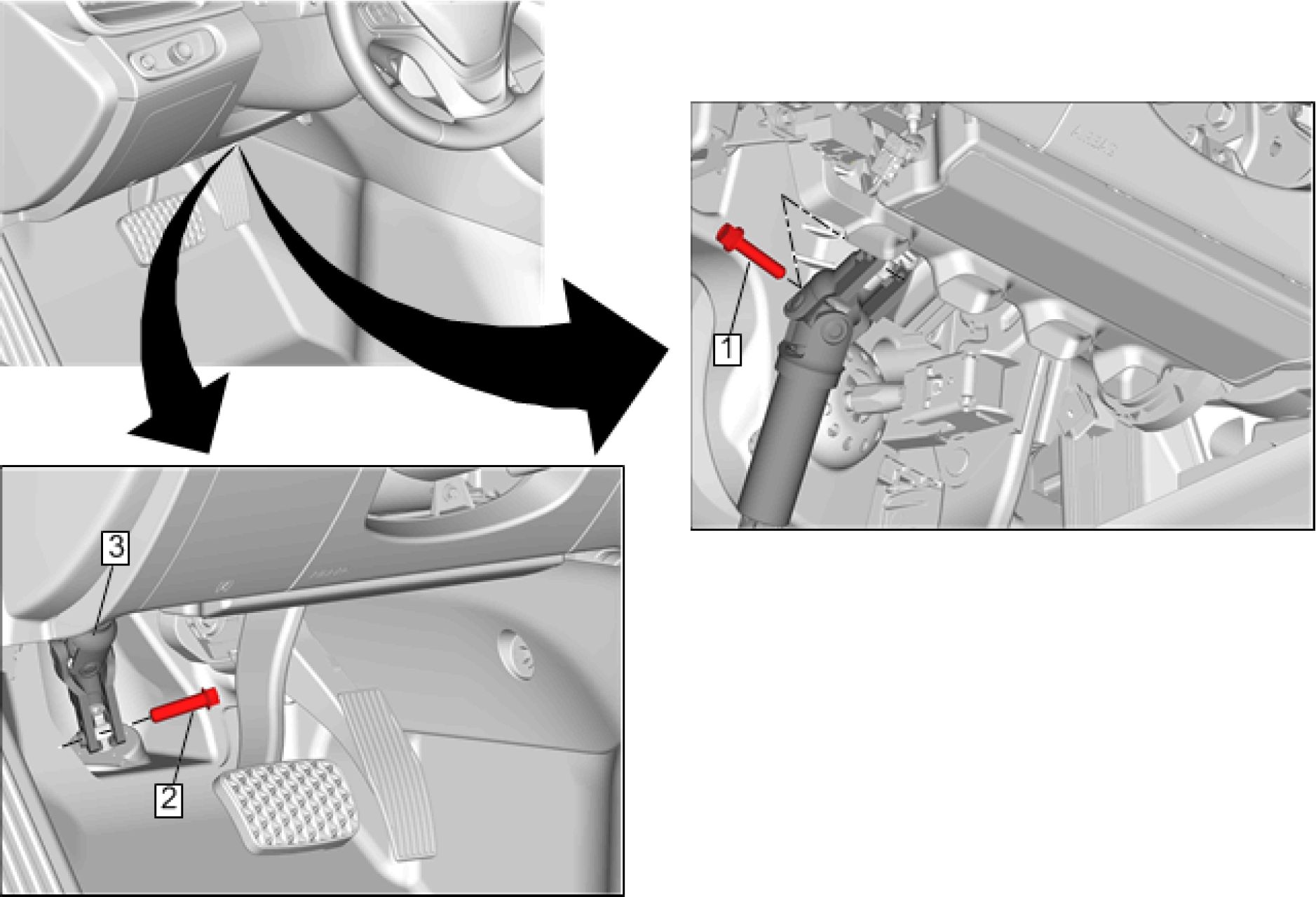 |
|
Fig. 14: Intermediate Steering Shaft Courtesy of GENERAL MOTORS COMPANY |
Callout Component Name
CAUTION:
With wheels of
the vehicle facing
straight ahead,
secure the
steering wheel
utilizing steering
column anti-
rotation pin,
steering column
lock, or a strap to
prevent rotation.
Locking of the
steering column
will prevent
damage and a
possible
malfunction of
the SIR system.
The steering
wheel must be
secured in
position before
disconnecting
the following
components:
• The steering
column
• The
intermediate
shaft(s)
• The steering
gear
After
disconnecting
these
components, do
not rotate the
steering wheel or
move the front
tires and wheels.
Failure to follow
this procedure
may cause the
SIR coil
assembly to
become un-
centered and
cause possible
damage to the
SIR coil. If you
think the SIR coil
has become un-
centered, refer to
your specific SIR
coil's centering
procedure to re-
center SIR Coil.
Preliminary Procedures
1. With the front wheels in the straight ahead position, pull the driver's seat belt between the spokes
on the steering wheel and buckle the seat belt to secure the steering wheel.
2. Place match marks on the steering gear shaft and the intermediate steering shaft to aid in
installation.
3. Place match marks on the steering column shaft and the intermediate steering shaft to aid in
installation.
STEERING COLUMN UPPER TRIM COVER REPLACEMENT
 |
|
Fig. 15: Steering Column Upper Trim Cover |
Callout Component Name
NOTE:
The
instrument
panel cluster
trim plate
and the
steering
column
upper trim
cover must
be removed
as an
assembly,
do not
attempt to
separate.
Preliminary Procedure
1. Disable SIR system. Refer to SIR Disabling and Enabling
2. Remove Instrument Panel Trim Plate Applique - Left Side. Refer to Instrument Panel Trim Plate
| ||||||||||
|
STEERING COLUMN LOWER TRIM COVER REPLACEMENT | ||||||||||
 |
|
Fig. 16: Steering Column Lower Trim Cover |
| ||||||||
|
TURN SIGNAL SWITCH REPLACEMENT | ||||||||
 |
|
Fig. 17: Turn Signal Switch Courtesy of GENERAL MOTORS COMPANY |
| ||||||
|
TURN SIGNAL SWITCH BRACKET REPLACEMENT | ||||||
 |
|
Fig. 18: Turn Signal Switch Bracket Courtesy of GENERAL MOTORS COMPANY |
| ||||||
|
STEERING WHEEL PAD ACCESSORY WIRING HARNESS REPLACEMENT | ||||||
 |
|
Fig. 19: Steering Wheel Pad Accessory Wiring Harness |
Callout
Component Name
Preliminary Procedures
1. Remove the left side lower steering wheel radio control switch. Refer to Radio Control Switch
Replacement - Steering Wheel (Left Side Lower)
2. Remove the left side rear steering wheel radio control switch. Refer to Radio Control Switch
Replacement - Steering Wheel (Left Side Rear)
3. Remove the right side rear steering wheel radio control switch. Refer to Radio Control Switch
Replacement - Steering Wheel (Right Side Rear)
Steering Wheel Pad Accessory Wiring Harness
Procedure
1. Disconnect the electrical connectors.
2. Remove the steering wheel pad accessory wiring harness from the steering wheel.
STEERING WHEEL REPLACEMENT
 |
|
Fig. 20: Steering Wheel Courtesy of GENERAL MOTORS COMPANY |
Callout Component Name
WARNING:
Refer to SIR
Warning .
WARNING:
Refer to SIR
Inflator
Module
Handling
and Storage
Warning .
Preliminary Procedures
1. Disable SIR system. Refer to SIR Disabling and Enabling
2. Remove Steering Wheel Airbag. Refer to Steering Wheel Airbag Replacement
Steering Wheel Bolt
1 CAUTION:
| ||||||
|
STEERING WHEEL SPOKE COVER REPLACEMENT |

Fig. 21: Steering Wheel Spoke Cover
Courtesy of GENERAL MOTORS COMPANY
|
Callout |
Component Name |
|
Preliminary Procedure Remove Steering Wheel Airbag. Refer to Steering Wheel Airbag Replacement | |
|
1 |
Steering Wheel Spoke Cover Fastener (Qty: 4) CAUTION: Refer to Caution . Tighten 1.5 N.m (13 lb in) |
|
2 |
Steering Wheel Spoke Cover Procedure
|
STEERING COLUMN REPLACEMENT
Removal Procedure
WARNING: Refer to SIR Warning .
WARNING: Refer to SIR Inflator Module Handling and Storage Warning .
1. Disable the SIR system. Refer to SIR Disabling and Enabling
2. With the vehicle in accessory mode, remove fuse to unlock the steering column lock control module.
Refer to Steering Wheel Schematics
 |
|
Fig. 22: Instrument Panel Knee Bolster Courtesy of GENERAL MOTORS COMPANY |
3. Remove Instrument Panel Knee Bolster (1). Refer to Instrument Panel Knee Bolster Replacement
 |
|
Fig. 23: Instrument Panel Lower Airbag - Driver Side |
4. Remove Instrument Panel Lower Airbag - Driver Side (1). Refer to Instrument Panel Lower Airbag
Replacement - Driver Side
 |
|
Fig. 24: Floor Front Air Outlet Duct - Left Side |
5. Remove Floor Front Air Outlet Duct - Left Side (1). Refer to Floor Front Air Outlet Duct Replacement
- Left Side
 |
|
Fig. 25: Steering Column Lower Trim Cover |
NOTE: Reposition the steering column upper trim cover as necessary.
6. Remove Steering Column Lower Trim Cover (1). Refer to Steering Column Lower Trim Cover
Replacement
CAUTION: With wheels of the vehicle facing straight ahead, secure the steering wheel
utilizing steering column anti-rotation pin, steering column lock, or a strap
to prevent rotation. Locking of the steering column will prevent damage
and a possible malfunction of the SIR system. The steering wheel must be
secured in position before disconnecting the following components:
• The steering column
• The intermediate shaft(s)
• The steering gear
After disconnecting these components, do not rotate the steering wheel or
move the front tires and wheels. Failure to follow this procedure may
cause the SIR coil assembly to become un-centered and cause possible
damage to the SIR coil. If you think the SIR coil has become un-centered,
refer to your specific SIR coil's centering procedure to re-center SIR Coil.
7. With the steering wheel in the straight ahead position, LOCK the steering column.
 |
|
Fig. 26: Intermediate Steering Shaft Courtesy of GENERAL MOTORS COMPANY |
NOTE: Place match marks on the steering column shaft and the intermediate
steering shaft to aid in installation.
8. Separate Intermediate Steering Shaft (1) @ Steering Column. Refer to Intermediate Steering Shaft
Replacement
9. Disconnect the steering column electrical connectors as necessary.
 |
|
Fig. 27: Steering Column Nuts Courtesy of GENERAL MOTORS COMPANY |
10. Remove Steering Column Nuts (1) (Qty: 4)
 |
|
Fig. 28: Steering Column Courtesy of GENERAL MOTORS COMPANY |
CAUTION: Once the steering column is removed from the vehicle, the column is
extremely susceptible to damage. Dropping the column assembly on the
end could collapse the steering shaft or loosen the plastic injections,
which maintain column rigidity. Leaning on the column assembly could
cause the jacket to bend or deform. Any of the above damage could impair
the columns collapsible design. Do NOT hammer on the end of the shaft,
because hammering could loosen the plastic injections, which maintain
column rigidity. If you need to remove the steering wheel, refer to the
Steering Wheel Replacement procedure in this section.
11. Remove the steering column (1) from the vehicle.
12. If replacing the steering column, transfer components as necessary.
13. If replacing the steering column, copy the match marks from the OLD steering column to the NEW
steering column.
Installation Procedure
 |
|
Fig. 29: Steering Column Courtesy of GENERAL MOTORS COMPANY |
1. Position the steering column (1) on the vehicle.

Fig. 30: Steering Column Nuts With Tightening Sequence
Courtesy of GENERAL MOTORS COMPANY
CAUTION: Refer to Fastener Caution .
2. Install and tighten Steering Column Nuts (1) (Qty: 4) in sequence to 22 N.m (16 lb ft)
3. Connect the steering column electrical connectors.
 |
|
Fig. 31: Intermediate Steering Shaft Courtesy of GENERAL MOTORS COMPANY |
4. Install Intermediate Steering Shaft (1) @ Steering Column. Refer to Intermediate Steering Shaft
Replacement
 |
|
Fig. 32: Steering Column Lower Trim Cover |
5. Install Steering Column Lower Trim Cover (1). Refer to Steering Column Lower Trim Cover
Replacement
 |
|
Fig. 33: Floor Front Air Outlet Duct - Left Side |
6. Install Floor Front Air Outlet Duct - Left Side (1). Refer to Floor Front Air Outlet Duct Replacement -
Left Side
 |
|
Fig. 34: Instrument Panel Lower Airbag - Driver Side |
7. Install Instrument Panel Lower Airbag - Driver Side (1). Refer to Instrument Panel Lower Airbag
Replacement - Driver Side
 |
|
Fig. 35: Instrument Panel Knee Bolster Courtesy of GENERAL MOTORS COMPANY |
8. Install Instrument Panel Knee Bolster (1). Refer to Instrument Panel Knee Bolster Replacement
9. Install the steering column lock control module fuse.
10. Program the steering column lock control module. Refer to Control Module References
11. Center the steering angle sensor. Refer to Steering Wheel Angle Sensor Centering
STEERING COLUMN DASH INNER SEAL REPLACEMENT
 |
|
Fig. 36: Steering Column Dash Inner Seal |
| ||||||
|
STEERING COLUMN DASH OUTER SEAL REPLACEMENT | ||||||
Removal Procedure
 |
|
Fig. 37: Drivetrain And Front Suspension Cradle |
1. Remove Drivetrain and Front Suspension Cradle (1). Refer to Drivetrain and Front Suspension Cradle
Replacement
 |
|
Fig. 38: Steering Column Dash Outer Seal |
2. Remove the steering column dash outer seal (1) from the steering gear.
Installation Procedure
 |
|
Fig. 39: Steering Column Dash Outer Seal |
NOTE: Align the slot in the steering column dash outer seal with the raised
section on the steering gear.
1. Install the steering column dash outer seal (1) on the steering gear.
 |
|
Fig. 40: Drivetrain And Front Suspension Cradle |
2. Install Drivetrain and Front Suspension Cradle (1). Refer to Drivetrain and Front Suspension Cradle
Replacement
DESCRIPTION AND OPERATION
STEERING WHEEL AND COLUMN DESCRIPTION AND OPERATION
The steering wheel and column has 4 primary functions:
• Vehicle steering
• Vehicle security
• Driver convenience
• Driver safety
Vehicle Steering
The steering wheel is the first link between the driver and the vehicle. The steering wheel is fastened to a
steering shaft within the column. At the lower end of the column, the intermediate shaft connects the column to
the steering gear.
The steering column can be adjusted vertically and longitudinally
Vehicle Security
Theft deterrent components are mounted and designed into the steering column. The following components
allow the column to be locked in order to minimize theft:
• The ignition switch
• The steering column lock
• The ignition cylinder
• The theft deterrent immobilizer module, if equipped
Driver Convenience
The steering wheel and column may also have driver controls attached for convenience and comfort. The
following controls may be mounted on the steering wheel or column.
• The turn signal switch
• The headlamp dimmer switch
• The wiper/washer switch
• The horn pad
• The redundant radio/entertainment system controls
• The tilt functions
• The telephone system controls
• The DIC controls
• The cruise control functions
• The automatic transmission manual setting function
Driver Safety
The steering wheel and column has safety features to protect the driver. The following components may be
mounted on or near the steering column:
Energy-Absorbing Steering Column: The energy-absorbing steering column compresses in the event of a
front-end collision, which reduces the chance of injury to the driver. The energy-absorbing feature, collapsible
steering shaft, and break away mounting features help reduce the injury in the event of an accident.
Article GUID: A00884704
Front Suspension - Volt
SPECIFICATIONS
FASTENER SPECIFICATIONS
|
Single Use Threaded Fastener/Component Tightening Specifications | |||||||||||||||||||||||||||||||
| |||||||||||||||||||||||||||||||
Reusable Threaded Fastener Tightening Specifications
NOTE:
All fasteners
listed in this
table can be
reused after
removal.
|
Application |
Specification |
|
Metric (English) | |
|
Front Lower Control Arm Rear Nut | |
|
• First Pass: |
100 N.m (74 lb ft) |
|
• Final Pass: |
30 - 45 Degrees |
|
Front Stabilizer Shaft Link Nut |
65 N.m (48 lb ft) |
|
Front Suspension Strut Lower Mounting Nut |
70 N.m (52 lb ft) |
|
Front Wheel Bearing and Hub Assembly Bolt | |
|
• First Pass: |
100 N.m (74 lb ft) |
|
• Final Pass: |
15 - 30 Degrees |
|
Steering Knuckle Nut@Front Lower Control Arm | |
|
• First Pass: |
35 N.m (26 lb ft) |
|
• Final Pass: |
30 - 45 Degrees |
|
Steering Knuckle Nut@Strut Assembly | |
|
• First Pass: |
100 N.m (74 lb ft) |
|
• Final Pass: |
45 - 60 Degrees |
|
ADHESIVES, FLUIDS, LUBRICANTS, AND SEALERS | ||||||||||
| ||||||||||
REPAIR INSTRUCTIONS
STABILIZER SHAFT REPLACEMENT
Special Tools
EN-45059 Torque Angle Meter
Equivalent regional tools: Special Tools
Removal Procedure
 |
|
Fig. 1: Drivetrain And Front Suspension Cradle |
1. Remove Drivetrain and Front Suspension Cradle (1)Drivetrain and Front Suspension Cradle
Replacement
 |
|
Fig. 2: Front Stabilizer Shaft And Insulator Clamp Bolts |
2. Remove Front Stabilizer Shaft Insulator Clamp Bolt (1)
DISCARD the bolts.
3. Remove the front stabilizer shaft (2) from the drivetrain and front suspension cradle.
Installation Procedure
 |
|
Fig. 3: Front Stabilizer Shaft And Insulator Clamp Bolts |
1. Position the front stabilizer shaft (2) on the drivetrain and front suspension cradle.
CAUTION: This vehicle is equipped with torque-to-yield or single use fasteners.
Install a NEW torque-to-yield or single use fastener when installing this
component. Failure to replace the torque-to-yield or single use fastener
could cause damage to the vehicle or component.
2. Install Front Stabilizer Shaft Insulator Clamp Bolt (1)
Install NEW bolts.
CAUTION: Refer to Fastener Caution .
3. Use the EN-45059 meter to tighten the front stabilizer shaft insulator clamp bolts (1).
Tighten
1. First Pass: 22 N.m (16 lb ft)
2. Final Pass: (30 - 45 degrees)
 |
|
Fig. 4: Drivetrain And Front Suspension Cradle |
4. Install Drivetrain and Front Suspension Cradle (l)Drivetrain and Front Suspension Cradle
Replacement
5. Measure and adjust the wheel alignment. Wheel Alignment Measurement
STABILIZER SHAFT LINK REPLACEMENT
 |
A\ |
|
Fig. 5: Stabilizer Shaft Link Courtesy of GENERAL MOTORS COMPANY | |
|
Callout |
Component Name |
|
Preliminary Procedure Remove the front tire and wheel assembly. Tire and Wheel Removal and Installation | |
|
1 |
Front Stabilizer Shaft Link Nut (Qty: 2) CAUTION: Refer to Tighten 65 N.m (48 lb ft) |
|
2 |
Front Stabilizer Shaft Link |
FRONT WHEEL BEARING AND HUB REPLACEMENT
Special Tools
EN-45059 Torque Angle Meter
Equivalent regional tools: Special Tools
Removal Procedure
1. Remove the front tire and wheel assembly. Tire and Wheel Removal and Installation
 |
|
Fig. 6: Front Wheel Drive Shaft Courtesy of GENERAL MOTORS COMPANY |
2. Separate Front Wheel Drive Shaft (1) @Front Wheel Bearing and Hub Assembly Front Wheel Drive
Shaft Replacement

Fig. 7: Front Brake Rotor
Courtesy of GENERAL MOTORS COMPANY
3. Remove Front Brake Rotor (1)Front Brake Rotor Replacement
 |
|
Fig. 8: Front Wheel Speed Sensor Courtesy of GENERAL MOTORS COMPANY |
4. Remove Front Wheel Speed Sensor (1) @Steering Knuckle Front Wheel Speed Sensor Replacement
 |
|
Fig. 9: Front Wheel Bearing and Hub Assembly Bolts |
5. Remove Front Wheel Bearing and Hub Assembly Bolt (1)
 |
|
Fig. 10: Front Wheel Bearing And Hub Assembly Courtesy of GENERAL MOTORS COMPANY |
6. Remove the front wheel bearing and hub assembly (1) from the vehicle.
Installation Procedure
NOTE: Avoid applying grease to any other machined surfaces, holes, or threads.
Ensure the drain channel at the bottom of the bore is not blocked with
grease or debris.
1. Apply grease evenly and ensure complete coverage to the steering knuckle bearing pilot bore only.
Adhesives, Fluids, Lubricants, and Sealers
 |
|
Fig. 11: Front Wheel Bearing And Hub Assembly Courtesy of GENERAL MOTORS COMPANY |
2. Position the front wheel bearing and hub assembly (1) on the vehicle.
 |
|
Fig. 12: Front Wheel Bearing and Hub Assembly Bolts |
CAUTION: Refer to Fastener Caution .
3. Install Front Wheel Bearing and Hub Assembly Bolt (1)
4. Use the EN-45059 meter to tighten the front wheel bearing and hub assembly bolts (1).
Tighten
1. First Pass: 100 N.m (74 lb ft)
2. Final Pass: (15 - 30 degrees)
 |
|
Fig. 13: Front Wheel Speed Sensor Courtesy of GENERAL MOTORS COMPANY |
5. Install Front Wheel Speed Sensor (1) @Steering Knuckle Front Wheel Speed Sensor Replacement
 |
|
Fig. 14: Front Brake Rotor Courtesy of GENERAL MOTORS COMPANY |
6. Install Front Brake Rotor (1)Front Brake Rotor Replacement

Fig. 15: Front Wheel Drive Shaft
Courtesy of GENERAL MOTORS COMPANY
7. Install Front Wheel Drive Shaft (1) @Front Wheel Bearing and Hub Assembly Front Wheel Drive Shaft
Replacement
8. Install the front tire and wheel assembly. Tire and Wheel Removal and Installation
STEERING KNUCKLE REPLACEMENT
Removal Procedure
1. Remove the front tire and wheel assembly. Tire and Wheel Removal and Installation
 |
|
Fig. 16: Front Wheel Bearing and Hub |
2. Remove Front Wheel Bearing and Hub Assembly (1)Front Wheel Bearing and Hub Replacement
 |
|
Fig. 17: Steering Linkage Outer Tie Rod Courtesy of GENERAL MOTORS COMPANY |
3. Separate Steering Linkage Outer Tie Rod (1) @Steering Knuckle Steering Linkage Outer Tie Rod
Replacement
 |
|
Fig. 18: Strut Assembly Courtesy of GENERAL MOTORS COMPANY |
4. Separate Strut Assembly (1) @Steering Knuckle Strut Assembly Removal and Installation
 |
|
Fig. 19: Front Lower Control Arm Courtesy of GENERAL MOTORS COMPANY |
5. Separate Front Lower Control Arm (1) @Steering Knuckle Lower Control Arm Replacement
 |
|
Fig. 20: Steering Knuckle Courtesy of GENERAL MOTORS COMPANY |
6. Remove the steering knuckle (1) from the vehicle.
Installation Procedure
 |
|
Fig. 21: Steering Knuckle Courtesy of GENERAL MOTORS COMPANY |
1. Position the steering knuckle (1) on the vehicle.
 |
|
Fig. 22: Front Lower Control Arm Courtesy of GENERAL MOTORS COMPANY |
2. Install Front Lower Control Arm (1) @Steering Knuckle Lower Control Arm Replacement
 |
|
Fig. 23: Strut Assembly Courtesy of GENERAL MOTORS COMPANY |
3. Install Strut Assembly (1) @Steering Knuckle Strut Assembly Removal and Installation
 |
|
Fig. 24: Steering Linkage Outer Tie Rod Courtesy of GENERAL MOTORS COMPANY |
4. Install Steering Linkage Outer Tie Rod (1) @Steering Knuckle Steering Linkage Outer Tie Rod
Replacement
 |
|
Fig. 25: Front Wheel Bearing and Hub |
5. Install Front Wheel Bearing and Hub Assembly (1) Front Wheel Bearing and Hub Replacement
6. Install the front tire and wheel assembly. Tire and Wheel Removal and Installation
LOWER CONTROL ARM REPLACEMENT
Special Tools
• CH-42188-B Ball Joint Separator
• EN-45059 Torque Angle Meter
Equivalent regional tools: Special Tools
Removal Procedure
1. Remove the front tire and wheel assembly. Tire and Wheel Removal and Installation

Fig. 26: Steering Knuckle Nut
Courtesy of GENERAL MOTORS COMPANY
2. Loosen Steering Knuckle Nut (1)
 |
|
Fig. 27: Special Tool And Front Lower Control Arm |
3. Use the CH-42188-B separator (1) to separate the front lower control arm (2) from the steering knuckle.
 |
|
Fig. 28: Steering Knuckle Nut Courtesy of GENERAL MOTORS COMPANY |
4. Remove Steering Knuckle Nut (1)
 |
|
Fig. 29: Front Lower Control Arm Front Bolts |
NOTE: Some front brake and front suspension components are NOT shown for
clarity only. It is NOT necessary to remove these components to service
the front lower control arm.
5. Remove Front Lower Control Arm Front Bolt (1)
DISCARD the bolts.
 |
|
Fig. 30: Front Lower Control Arm Rear Nuts And Bolts |
NOTE: Some front brake and front suspension components are NOT shown for
clarity only. It is NOT necessary to remove these components to service
the front lower control arm.
7. Remove Front Lower Control Arm Rear Bolt (2)
DISCARD the bolts.
 |
|
Fig. 31: Front Lower Control Arm Courtesy of GENERAL MOTORS COMPANY |
8. Remove the front lower control arm (1) from the vehicle.
9. Transfer components as necessary.
Installation Procedure
 |
|
Fig. 32: Front Lower Control Arm Courtesy of GENERAL MOTORS COMPANY |
1. Position the front lower control arm (1) on the vehicle.
 |
|
Fig. 33: Front Lower Control Arm Rear Nuts And Bolts |
CAUTION: This vehicle is equipped with torque-to-yield or single use fasteners.
Install a NEW torque-to-yield or single use fastener when installing this
component. Failure to replace the torque-to-yield or single use fastener
could cause damage to the vehicle or component.
2. Install Front Lower Control Arm Rear Bolt (2)
Install NEW bolts.
3. Install Front Lower Control Arm Rear Nut (1), but do NOT tighten
 |
|
Fig. 34: Front Lower Control Arm Front Bolts Courtesy of GENERAL MOTORS COMPANY |
4. Install Front Lower Control Arm Front Bolt (1)but do NOT tighten
Install NEW bolts.
 |
|
Fig. 35: Front Lower Control Arm Rear Nuts And Bolts |
CAUTION: Refer to Fastener Caution .
5. Use the EN-45059 meter to tighten the front lower control arm rear nuts. (1)
Tighten
1. First Pass: 100 N.m (74 lb ft)
2. Final Pass: (30 - 45 degrees)
 |
|
Fig. 36: Front Lower Control Arm Front Bolts |
Tighten
1. First Pass: 100 N.m (74 lb ft)
2. Final Pass: (45 - 60 degrees)
 |
|
Fig. 37: Steering Knuckle Nut Courtesy of GENERAL MOTORS COMPANY |
7. Install Steering Knuckle Nut (1)
8. Use the EN-45059 meter to tighten the steering knuckle nut.(1)
Tighten
1. First Pass: 35 N.m (26 lb ft)
2. Final Pass: (30 - 45 degrees)
9. Install the front tire and wheel assembly. Tire and Wheel Removal and Installation
10. Measure and adjust the wheel alignment. Wheel Alignment Measurement
FRONT LOWER CONTROL ARM REAR BUSHING REPLACEMENT
 |
|
Fig. 38: Front Lower Control Arm Rear Bushing |
|
Callout |
Component Name |
|
Preliminary Procedure | |
|
1 |
Front Lower Control Arm Rear Bushing |
WHEEL STUD REPLACEMENT
Special Tools
CH-43631 Ball Joint Separator
Equivalent regional tools: Special Tools
Removal Procedure
1. Remove Front Wheel Bearing and Hub Assembly Front Wheel Bearing and Hub Replacement
|
2 |
 |
Fig. 39: Separator And Wheel Stud
Courtesy of GENERAL MOTORS COMPANY
2. Use the CH-43631 separator (1) to remove the wheel stud (2) from the flange on the hub assembly.
DISCARD the stud.
Installation Procedure

Fig. 40: Wheel Stud, Flat Washers And Wheel Nut
Courtesy of GENERAL MOTORS COMPANY
1. Position the NEW wheel stud (1) in the flange on the hub assembly.
2. Install flat washers (2) and an OLD wheel nut (3) on the wheel stud.
3. Use a suitable tool to prevent the flange on the hub assembly from rotating.
4. Tighten the wheel nut until the wheel stud is firmly seated.
5. Remove the wheel nut and flat washers.
6. Install Front Wheel Bearing and Hub Assembly Front Wheel Bearing and Hub Replacement
STRUT AND SHOCK ABSORBER INSPECTION
NOTE: The strut assembly DOES NOT have to be removed from the vehicle to perform
the following inspection procedure.
NOTE: A light film of oil on the top portion of the strut is normal. DO NOT replace the
strut for this condition.
 |
|
Fig. 41: Strut and Shock Absorber Inspection |
Condition 1
Oil or fluid residue only on the bottom of the strut tube or on other strut components and not originating from
the shaft seal, is not a strut related problem. DO NOT replace the strut, look for other external leaks.
Condition 2
Light film/residue on the strut tube, but not on the spring seat and originating from the shaft seal, is a
NORMAL condition. DO NOT replace the strut.
Condition 3
Oil drip or trail down the strut tube and originating from the shaft seal, is an ABNORMAL condition. Replace
the strut.
Condition 4
Extreme wet film of oil covering the strut tube and pooling in the spring seat and originating from the shaft seal,
is an ABNORMAL condition. Replace the strut.
Inspection
1. Verify the customer's concern is present. If the concern is present, continue to the next step. If the concern
is not present, then the vehicle is operating normally.
NOTE: The strut assembly DOES NOT have to be removed from the vehicle to
perform the following inspection procedure.
2. Raise and support the vehicle. Refer to Lifting and Jacking the Vehicle .
3. Visually inspect each of the shock absorbers or struts for external fluid leaks. Refer to the following
conditions 1, 2, 3, and 4 for visual inspection.
• If conditions 1 or 2 are found, continue to step 4.
• If conditions 3 or 4 are found, replace strut. Refer to Strut Replacement.
4. If equipped with electronic suspension control system, ensure that the system is working properly. Refer
to Diagnostic Starting Point-Electronic Suspension Control.
5. Use your hands in order to lift up and push down on each corner of the vehicle 3 times. Remove your
hands from the vehicle. If the corner motion exceeds 2 cycles, replace the strut. If the strut does not
exceed 2 cycles, NO repair is necessary.
STRUT ASSEMBLY REMOVAL AND INSTALLATION
Special Tools
EN-45059 Torque Angle Meter
Equivalent regional tools: Special Tools
Removal Procedure
1. Remove Air Inlet Grille Panel Air Inlet Grille Panel Replacement
2. Raise and support the vehicle. Lifting and Jacking the Vehicle
 |
|
Fig. 42: Front Wheel Speed Sensor Grommet Courtesy of GENERAL MOTORS COMPANY |
3. Remove Front Wheel Speed Sensor Grommet (1) @Strut Assembly Front Wheel Speed Sensor
Replacement
 |
|
Fig. 43: Front Stabilizer Shaft Link Courtesy of GENERAL MOTORS COMPANY |
4. Separate Front Stabilizer Shaft Link (1) @Strut Assembly Stabilizer Shaft Link Replacement
 |
|
Fig. 44: Steering Knuckle Nuts And Bolts |
5. Remove Steering Knuckle Nut (1)
6. Remove Steering Knuckle Bolt (2)
DISCARD the bolts.
 |
|
Fig. 45: Front Suspension Strut Mount Fasteners Courtesy of GENERAL MOTORS COMPANY |
7. Remove the plugs that cover the front suspension strut mount fasteners. (1)
 |
|
Fig. 46: Front Suspension Strut Mount Bolts And Nut |
8. Remove Front Suspension Strut Mount Bolt (1)
|
DISCARD the bolts. | ||
| ||
|
9. Remove Front Suspension Strut Mount Nut (2) |
DISCARD the nut.

Fig. 47: Front Suspension Strut Assembly
Courtesy of GENERAL MOTORS COMPANY
10. Remove the front suspension strut assembly (1) from the vehicle.
 |
|
Fig. 48: Front Suspension Strut Mount Stud |
| ||
|
11. Remove Front Suspension Strut Mount Stud |
DISCARD the stud.
Installation Procedure
 |
|
Fig. 49: Front Suspension Strut Assembly |
1. Position the front suspension strut assembly (1) on the vehicle.
 |
|
Fig. 50: Front Suspension Strut Mount Bolts |
CAUTION: This vehicle is equipped with torque-to-yield or single use fasteners.
Install a NEW torque-to-yield or single use fastener when installing this
component. Failure to replace the torque-to-yield or single use fastener
could cause damage to the vehicle or component.
2. Install Front Suspension Strut Mount Bolt (1)
Install NEW bolts.
CAUTION: Refer to Fastener Caution .
3. Use the EN-45059 meter to tighten the front suspension strut mount bolts.(1)
Tighten
1. First Pass: 22 N.m (16 lb ft)
2. Final Pass: (30 - 45 degrees)
 |
|
Fig. 51: Front Suspension Strut Mount Fasteners |
4. Install the plugs that cover the front suspension strut mount fasteners.(1)
 |
|
Fig. 52: Steering Knuckle Nuts And Bolts |
5. Install Steering Knuckle Bolt (2)
Install NEW bolts.
6. Install Steering Knuckle Nut (1)
7. Use the EN-45059 meter to tighten the steering knuckle nuts.(1)
Tighten
1. First Pass: 100 N.m (74 lb ft)
2. Final Pass: (45 - 60 degrees)
 |
|
Fig. 53: Front Stabilizer Shaft Link Courtesy of GENERAL MOTORS COMPANY |
8. Install Front Stabilizer Shaft Link (1) @Strut Assembly Stabilizer Shaft Link Replacement
 |
|
Fig. 54: Front Wheel Speed Sensor Grommet Courtesy of GENERAL MOTORS COMPANY |
9. Install Front Wheel Speed Sensor Grommet (1) @Strut Assembly Front Wheel Speed Sensor
Replacement
10. Install Air Inlet Grille Panel Air Inlet Grille Panel Replacement
11. Measure and adjust the wheel alignment. Wheel Alignment Measurement
SUSPENSION STRUT DISPOSAL
 |
|
Fig. 55: Drilling Hole In Strut At Center Of End Cap |
WARNING: Use the proper eye protection when drilling to prevent metal chips from
causing physical injury.
1. Clamp the strut in a vise horizontally with the rod (1) completely extended.
2. Drill a hole in the strut at the center of the end cap (3) using a 5 mm (3/16 in) drill bit. Gas or a gas/oil
mixture will exhaust when the drill bit penetrates the strut. Use shop towels in order to contain the
escaping oil.
3. Remove the strut from the vise.
4. Hold the strut over a drain pan vertically with the hole down.
5. Move the rod (1) in and out of the tube (2) to completely drain the oil from the strut.
STRUT, STRUT COMPONENT, OR SPRING REPLACEMENT
 |
|
Fig. 56: Strut, Strut Component or Spring |
Callout Component Name
WARNING:
To prevent
personal
injury and/or
component
damage, use
the proper
tools to
support and
compress
the coil
spring prior
to removal
of the strut
shaft nut
when
removing
the coil
spring. The
coil spring is
under
extreme
pressure
and can
become a
projectile
should the
spring
separate
from the
strut before
all of the
tension is
relieved.
Preliminary Procedure Strut Assembly Removal and Installation
Front Suspension Strut Lower Mounting Nut
CAUTION:
Refer to
Fastener
Caution .
Procedure
1 1. Use the CH-6066 holder and the CH-6068 tensioner to compress the front coil spring.
2. Use the CH-49375 wrench to remove and install the front suspension strut lower
mounting nut.
Tighten
70 N.m (52 lb ft)
Special Tools
|
Callout |
Component Name |
Equivalent regional tools: Special Tools | |
|
2 |
Front Suspension Strut Mount |
|
3 |
Front Suspension Strut Bumper |
|
4 |
Front Strut Boot |
|
5 |
Front Coil Spring |
|
6 |
Front Coil Spring Lower Insulator |
|
7 |
Front Suspension Strut |
DESCRIPTION AND OPERATION
FRONT SUSPENSION DESCRIPTION AND OPERATION
The front suspension has 2 primary purposes:
• Isolate the driver from irregularities in the road surface.
• Define the ride and handling characteristics of the vehicle.
The front suspension absorbs the impact of the tires travelling over irregular road surfaces and dissipates this
energy throughout the suspension system. This process isolates the vehicle occupants from the road surface.
The rate at which the suspension dissipates the energy and the amount of energy that is absorbed is how the
suspension defines the vehicles ride characteristics. Ride characteristics are designed into the suspension system
and are not adjustable. The ride characteristics are mentioned in this description in order to aid in the
understanding of the functions of the suspension system. The suspension system must allow for the vertical
movement of the tire and wheel assembly as the vehicle travels over irregular road surfaces while maintaining
the tire's horizontal relationship to the road.
This requires that the steering knuckle be suspended between a lower control arm and a strut assembly. The
lower control arm attaches from the steering knuckle at the outermost point of the control arm. The attachment
is through a ball and socket type joint. The innermost end of the control arm attached at 2 points to the vehicle
frame through semi-rigid bushings. The upper portion of the steering knuckle is attached to a strut assembly.
The strut assembly then connects to the vehicle body by way of an upper bearing. The steering knuckle is
allowed to travel up and down independent of the vehicle body structure and frame.
This up and down motion of the steering knuckle as the vehicle travels over bumps is absorbed predominantly
by the coil spring. This spring is retained under tension over the strut assembly. A strut is used in conjunction
with this system in order to dampen out the oscillations of the coil spring. A strut is a basic hydraulic cylinder.
The strut is filled with oil and has a moveable shaft that connects to a piston inside the strut. Valves inside the
shock absorber offer resistance to oil flow and consequently inhibit rapid movement of the piston and shaft.
Each end of the shock absorber is connected in such a fashion to utilize this recoil action of a spring alone. Each
end of the strut is designed as the connection point of the suspension system to the vehicle and acts as the coil
spring seat. This allows the strut to utilize the dampening action to reduce the recoil of a spring alone. The
lower control arm is allowed to pivot at the vehicle frame in a vertical fashion. The ball joint allows the steering
knuckle to maintain the perpendicular relationship to the road surface.
Front suspensions systems utilize a stabilizer shaft. The stabilizer bar connects between the left and right lower
control arm assemblies through the stabilizer link and stabilizer shaft insulators. This bar controls the amount of
independent movement of the suspension when the vehicle turns. Limiting the independent movement defines
the vehicles handling characteristics on turns.
SPECIAL TOOLS AND EQUIPMENT
|
SPECIAL TOOLS | ||||
|
|
Illustration |
Tool |
|
CH-6068 | |
|
Spring |
|
Illustration |
Tool |
|
CH-42188-B J-42188-B |
|
Illustration |
Tool |
|
CH-43631 KM-507-C J-43631 | |
|
Separator |
|
Illustration |
Tool |
|
CH-49375 |
|
Illustration |
Tool |
|
SL © |
EN-45059 J-45059 Torque |
Article GUID: A00884728
SUSPENSION
Rear Suspension - Volt
SPECIFICATIONS
FASTENER SPECIFICATIONS
|
Single Use Threaded Fastener/Component Tightening Specifications | |||||||||||||||||
| |||||||||||||||||
|
Reusable Threaded Fastener Tightening Specifications | |||||||||||||
| |||||||||||||
|
NOTE: All fasteners | |
|
Application |
Specification |
|
Metric (English) | |
|
• First Pass: |
50 N.m (37 lb ft) |
|
• Final Pass: |
30-45 degrees |
|
ADHESIVES, FLUIDS, LUBRICANTS, AND SEALERS | |||||||||
|
REPAIR INSTRUCTIONS
REAR WHEEL BEARING AND HUB REPLACEMENT
Removal Procedure
1. Remove the rear tire and wheel assemblies. Tire and Wheel Removal and Installation
2. Remove Rear Brake Rotor Replacement
3. Remove Rear Wheel Speed Sensor Replacement
 |
|
Fig. 1: Rear Shock Absorber, Bolt And Hydraulic Lift Courtesy of GENERAL MOTORS COMPANY |
4. Support the rear axle with a tall jack stand (3) near the shock absorber.
5. Remove Rear Shock Absorber Bolt (2)
6. Reposition the shock absorber (1) to gain access to the rear wheel bearing and hub bolts.
 |
|
Fig. 2: Rear Wheel Bearing And Hub Bolts |
7. Remove Bolt (1)
 |
|
Fig. 3: Rear Brake Caliper Mount Plate, Rear Brake Shield, Rear Wheel Bearing and Hub Assembly Courtesy of GENERAL MOTORS COMPANY |
8. Remove Rear Wheel Bearing and Hub Assembly (1)
9. Remove Rear Brake Shield (2)
10. Remove Rear Brake Caliper Mount Plate (3)
Installation Procedure
1. Prepare the wheel bearing and hub threaded holes and bolts for assembly.
1. Thoroughly clean the residue from the bolt threads with denatured alcohol or equivalent and allow
to dry.
2. Thoroughly clean the residue from the threaded holes with denatured alcohol or equivalent and
allow to dry.
3. Apply thread locking adhesive to the bolts. Adhesives, Fluids, Lubricants, and Sealers
 |
|
Fig. 4: Rear Brake Caliper Mount Plate, Rear Brake Shield, Rear Wheel Bearing and Hub Courtesy of GENERAL MOTORS COMPANY |
2. Install Rear Brake Caliper Mount Plate (3)
3. Install Rear Brake Shield (2)
4. Install Rear Wheel Bearing and Hub Assembly (1)
 |
|
Fig. 5: Rear Wheel Bearing And Hub Bolts |
CAUTION: Refer to Fastener Caution .
5. Install Bolt (1) and tighten
1. First Pass:50 N.m (37 lb ft)
2. Final Pass:30 - 45 degrees
6. Prepare the rear shock absorber threaded hole and bolt for assembly.
1. Thoroughly clean the residue from the bolt threads with denatured alcohol or equivalent and allow
to dry.
2. Thoroughly clean the residue from the threaded holes with denatured alcohol or equivalent and
allow to dry.
3. Apply thread locking adhesive to the bolts. Adhesives, Fluids, Lubricants, and Sealers
 |
|
Fig. 6: Rear Shock Absorber, Bolt And Hydraulic Lift |
7. Install Rear Shock Absorber Bolt (2), but do NOT tighten
8. Remove the tall jack stand (3) supporting the rear axle near the shock absorber.
9. Install Rear Wheel Speed Sensor Replacement
10. Install Rear Brake Rotor Replacement
11. Install Tire and Wheel Removal and Installation
12. Lower the vehicle.
 |
|
Fig. 7: Rear Shock Absorber Bolt Courtesy of GENERAL MOTORS COMPANY |
NOTE: Tighten the rear shock absorber bolt with the vehicle at curb height.
13. Tighten Rear Shock Absorber Bolt (1) Shock Absorber Replacement
REAR AXLE BRACKET REPLACEMENT
Special Tools
EN-45059 Angle Meter
Equivalent regional tools: Special Tools
Removal Procedure
1. Raise and support the vehicle. Lifting and Jacking the Vehicle
2. Remove the rear tire and wheel assemblies. Tire and Wheel Removal and Installation
3. Remove Exhaust Muffler Exhaust Muffler Replacement
4. Remove Underbody Rear Air Deflector Underbody Rear Air Deflector Replacement
 |
|
Fig. 8: Brake Caliper Assembly And Lectrical Connector |
5. Disconnect Electrical Connector (1) @Rear Parking Brake Actuator (2)
 |
|
Fig. 9: Wiring Harness Rear Wheel Speed Sensor |
6. Remove Wiring Harness (1) @Rear Wheel Speed Sensor (2)
7. Remove Wiring Harness@Rear Axle
 |
|
Fig. 10: Rear Shock Absorber Bolt And Hydraulic Jack |
NOTE: Use two hydraulic jacks, one for each side.
8. Lift the rear axle with a hydraulic jack (2).
9. Remove Rear Shock Absorber Bolt (1)
 |
|
Fig. 11: Rear Spring Courtesy of GENERAL MOTORS COMPANY |
NOTE: Using a grease pencil, mark the orientation of the rear coil springs for
proper installation.
10. Remove Rear Spring (1)
11. Remove Rear Coil Spring Lower Insulator Rear Coil Spring Lower Insulator Replacement
 |
|
Fig. 12: Rear Tire Front Air Deflector Courtesy of GENERAL MOTORS COMPANY |
12. Reposition Rear Tire Front Air Deflector (1)Rear Tire Front Air Deflector Replacement
 |
|
Fig. 13: Right Side Axle Bracket Bolts Courtesy of GENERAL MOTORS COMPANY |
NOTE: A second technician is required.
13. Remove Rear Axle Bracket Bolt (1) @Body and DISCARD
CAUTION: Do not suspend the rear axle by the brake hoses. Damage to the brake
hoses may result.
14. Carefully lower the rear axle as necessary without applying stress to the rear brake hoses.
 |
|
Fig. 14: Rear Axle Bracket Bolts Courtesy of GENERAL MOTORS COMPANY |
15. Remove Rear Axle Bracket Bolt (2) and DISCARD
16. Remove Rear Axle Bracket (1)
Installation Procedure

Fig. 15: Rear Axle Bracket Bolts
Courtesy of GENERAL MOTORS COMPANY
NOTE: The Rear Axle Bracket (1) is equipped with a pin to arrange the rear axle
on the vehicle. The pin has to be insert into the vehicle.
1. Install Rear Axle Bracket (1)
NOTE: Install, but do NOT tighten
2. Install New Rear Axle Bracket Bolt (2)
NOTE: A second technician is required.
3. Position the rear axle to the vehicle.
 |
|
Fig. 16: Right Side Axle Bracket Bolts Courtesy of GENERAL MOTORS COMPANY |
WARNING: Torque-to-Yield Fastener Warning
CAUTION: Fastener Caution
4. Install Rear Axle Bracket Bolt (1) @Body and tighten the NEW bolt.
1. First Pass: 100 N.m (74 lb ft)
2. Final Pass:30 - 45 degrees
 |
|
Fig. 17: Measuring Vertical Distance Courtesy of GENERAL MOTORS COMPANY |
5. Raise the rear axle to the proper trim height specification by measuring the vertical distance (A) between
the upper and lower insulator seat.
• Adjust (A) to: 152 mm (5.98 in)

Fig. 18: Rear Axle Bracket Bolts
Courtesy of GENERAL MOTORS COMPANY
WARNING: Torque-to-Yield Fastener Warning
6. Tighten the bolts.(2)
1. First Pass: 100 N.m (74 lb ft)
2. Final Pass:30 - 45 degrees
 |
|
Fig. 19: Rear Tire Front Air Deflector Courtesy of GENERAL MOTORS COMPANY |
7. Install Rear Tire Front Air Deflector (1)Rear Tire Front Air Deflector Replacement
8. Install Rear Coil Spring Lower Insulator Rear Coil Spring Lower Insulator Replacement
 |
|
Fig. 20: Rear Spring Courtesy of GENERAL MOTORS COMPANY |
NOTE: For proper rear spring installation, align the reference marks made during
removal.
9. Install Rear Coil Spring (1)
 |
|
Fig. 21: Rear Shock Absorber Bolt And Hydraulic Jack |
10. Support the rear axle with a hydraulic jack (2) near the shock absorber.
NOTE: Install, but do NOT tighten
NOTE: Service may offer bolts without microencapsulated thread locking
adhesive. If this is the case, apply thread locking adhesive to the bolt.
11. Loosely install Rear Shock Absorber Bolt (1)
12. Install Exhaust Muffler Exhaust Muffler Replacement
13. Install Underbody Rear Air Deflector Underbody Rear Air Deflector Replacement
 |
|
Fig. 22: Brake Caliper Assembly And Lectrical Connector |
14. Connect Electrical Connector (1) @Rear Parking Brake Actuator (2)
 |
|
Fig. 23: Wiring Harness Rear Wheel Speed Sensor |
15. Connect Electrical Connector (1) @Rear Wheel Speed Sensor (2)
16. Install Wiring Harness@Rear Axle
17. Install the rear tire and wheel assemblies. Tire and Wheel Removal and Installation
18. Remove the support and lower the vehicle.
 |
|
Fig. 24: Rear Shock Absorber Bolt And Hydraulic Jack |
NOTE: Tighten the bolts with vehicle standing on the ground.
19. Rear Shock Absorber Bolt (1) - Tighten Shock Absorber Replacement
STRUT AND SHOCK ABSORBER INSPECTION
NOTE: The shock absorber assembly DOES NOT have to be removed from the vehicle
to perform the following inspection procedure.
NOTE: A light film of oil on the top portion of the lower shock absorber tube is normal.
DO NOT replace the shock absorber for this condition.

Fig. 25: Identifying Shock Absorber Conditions
Courtesy of GENERAL MOTORS COMPANY
Condition 1
Oil or fluid residue only on the bottom or top of the shock absorber and not originating from the shaft seal, is
not a shock absorber related problem. DO NOT replace the shock absorber, look for other external leaks.
Condition 2
Light film/residue on approximately 1/3 (a) or less of the lower shock tube (A) and originating from the shaft
seal, is a NORMAL condition. DO NOT replace the shock absorber.
Condition 3
Oil drip or trail down the lower shock tube and originating from the shaft seal, is an ABNORMAL condition.
Replace the shock absorber. Refer to Shock Absorber Replacement.
Condition 4
An extreme wet film of oil covering more than 1/3 (b) of the lower shock tube and originating from the shaft
seal (B), is an ABNORMAL condition. Replace the shock absorber. Refer to Shock Absorber Replacement.
Inspection
1. Verify the customer's concern is present. If the concern is present, continue to the next step. If the concern
is not present, then the vehicle is operating normally.
|
NOTE: |
The shock absorber assembly DOES NOT have to be removed from the |
2. Raise and support the vehicle. Refer to Lifting and Jacking the Vehicle .
3. Visually inspect each of the shock absorbers for external fluid leaks. Refer to the following conditions 1,
2, 3 and 4 for visual inspection.
• If conditions 1 or 2 are found, continue to step 4.
• If conditions 3 or 4 are found, replace shock absorber. Refer to Shock Absorber Replacement.
4. Use your hands in order to lift up and push down on each corner of the vehicle 3 times. Remove your
hands from the vehicle. If the corner motion exceeds 2 cycles, replace the shock absorber. If the shock
absorber does not exceed 2 cycles, NO repair is necessary.
REAR SHOCK ABSORBER BUMPER REPLACEMENT
 |
|
Fig. 26: Rear Shock Absorber Bumper Courtesy of GENERAL MOTORS COMPANY |
Callout
Component Name
Preliminary Procedures
1. Tire and Wheel Removal and Installation
2. Shock Absorber Replacement
3. Rear Shock Absorber Mount Replacement
1 Rear Shock Absorber Bumper
REAR SHOCK ABSORBER MOUNT REPLACEMENT
Special Tools
CH-51095 Wrench
Equivalent regional tools: Special Tools
Removal Procedure
1. Remove Tire and Wheel Removal and Installation
2. Remove Shock Absorber Replacement

Fig. 27: Rear Shock Absorber And Wrench
Courtesy of GENERAL MOTORS COMPANY
3. Install CH-51095 wrench (1) @Rear Shock Absorber (2)
 |
|
Fig. 28: Rear Shock Absorber Nut And Upper Mount |
4. Remove Rear Shock Absorber Nut (1) and DISCARD
5. Remove Rear Shock Absorber Upper Mount (2)
Installation Procedure
 |
|
Fig. 29: Rear Shock Absorber Nut And Upper Mount |
1. Install Rear Shock Absorber Upper Mount (2)
2. Install Rear Shock Absorber Nut (1) but do NOT tighten
 |
|
Fig. 30: Rear Shock Absorber And Wrench |
3. Install CH-51095 wrench (1) @Rear Shock Absorber (2)
CAUTION: Refer to Fastener Caution .
4. Rear Shock Absorber Nut - Tighten 25 N.m (18 lb ft)
5. Install Shock Absorber Replacement
6. Install Tire and Wheel Removal and Installation
SHOCK ABSORBER REPLACEMENT
Removal Procedure
1. Remove Tire and Wheel Removal and Installation
 |
|
Fig. 31: Rear Shock Absorber Bolt Courtesy of GENERAL MOTORS COMPANY |
2. Support the rear axle with a tall jack stand near the shock absorber.
3. Remove Rear Shock Absorber Bolt (1)
 |
|
Fig. 32: Rear Shock Absorber Bolts Courtesy of GENERAL MOTORS COMPANY |
4. Remove Rear Shock Absorber Bolt (1)
Installation Procedure
 |
|
Fig. 33: Rear Shock Absorber Bolts Courtesy of GENERAL MOTORS COMPANY |
1. Install Rear Shock Absorber Bolt (1)
CAUTION: Refer to Fastener Caution .
2. Rear Shock Absorber Bolt (1) - Tighten 22 N.m (16 lb ft)
 |
|
Fig. 34: Rear Shock Absorber Bolt Courtesy of GENERAL MOTORS COMPANY |
3. Install Rear Shock Absorber Bolt (1), but do NOT tighten
4. Install Tire and Wheel Removal and Installation
5. Lower the vehicle.
NOTE: Tighten the bolt with vehicle standing on the ground.
6. Rear Shock Absorber Bolt (1), Tighten 100 N.m (74 lb ft)
SHOCK ABSORBER DISPOSAL
 |
|
Fig. 35: Drilling Hole In Shock Absorber At Centerpunched Locations Courtesy of GENERAL MOTORS COMPANY |
WARNING: Gas charged shock absorbers contain high pressure gas. Do not remove
the snap ring from inside the top of the tube. If the snap ring is removed,
the contents of the shock absorber will come out with extreme force which
may result in personal injury.
WARNING: To prevent personal injury, wear safety glasses when centerpunching and
drilling the shock absorber. Use care not to puncture the shock absorber
tube with the centerpunch.
1. Make an indentation 10 mm (0.4 in) from the bottom (4) of the tube (3) using a centerpunch.
2. Clamp the shock absorber in a vise horizontally with the shock absorber rod (1) completely extended.
3. Drill a hole in the shock absorber at the centerpunch (4) using a 5 mm (3/16 in) drill bit. Gas or a gas/oil
mixture will exhaust when the drill bit penetrates the shock absorber. Use shop towels in order to contain
the escaping oil.
4. Make an indentation in the middle (2) of the tube (3) with a centerpunch.
5. Drill a second hole in the shock absorber at the centerpunch (2) using a 5 mm (3/16 in) drill bit. Oil will
exhaust when the drill bit penetrates the shock absorber. Use shop towels in order to contain the escaping
oil.
6. Remove the shock absorber from the vise. Hold the shock absorber over a drain pan horizontally with the
holes down. Move the rod (1) in and out of the tube (3) to completely drain the oil from the shock
absorber.
REAR COIL SPRING REPLACEMENT
Special Tools
EN-45059 Angle Meter
Equivalent regional tools: Special Tools
Removal Procedure
1. Remove the rear tire and wheel assemblies. Tire and Wheel Removal and Installation
2. Remove Exhaust Muffler Exhaust Muffler Replacement
3. Remove Underbody Rear Air Deflector Underbody Rear Air Deflector Replacement
 |
|
Fig. 36: Rear Shock Absorber Bolt And Hydraulic Jack |
NOTE:
Use two hydraulic jacks, one for each side.
4. Lift the rear axle with a hydraulic jack (2).
5. Remove Rear Shock Absorber Bolt (1)
 |
|
Fig. 37: Rear Spring Courtesy of GENERAL MOTORS COMPANY |
NOTE: Note the orientation of the rear springs for proper installation.
6. Remove Rear Spring (1)
7. Remove Rear Coil Spring Lower Insulator Rear Coil Spring Lower Insulator Replacement
8. Remove Rear Coil Spring Insulator Rear Coil Spring Insulator Replacement
Installation Procedure
1. Install Rear Coil Spring Insulator Rear Coil Spring Insulator Replacement
2. Install Rear Coil Spring Lower Insulator Rear Coil Spring Lower Insulator Replacement

Fig. 38: Rear Spring
Courtesy of GENERAL MOTORS COMPANY
NOTE: For proper rear spring orientation ensure that the end of the rear spring,
with the label closest to it, is installed in the upright position.
3. Install Rear Spring (1)
 |
|
Fig. 39: Rear Shock Absorber Bolt And Hydraulic Jack |
4. Support the rear axle with a hydraulic jack (2) near the shock absorber.
NOTE: Install, but do NOT tighten
5. Loosely install Rear Shock Absorber Bolt (2)
6. Install Underbody Rear Air Deflector Underbody Rear Air Deflector Replacement
7. Install Exhaust Muffler Exhaust Muffler Replacement
8. Install Tire and Wheel Removal and Installation
9. Lower the vehicle.
 |
|
Fig. 40: Rear Shock Absorber Bolt And Hydraulic Jack |
NOTE: Tighten the bolts with vehicle standing on the ground.
10. Rear Shock Absorber Bolt (1) - Tighten Shock Absorber Replacement
REAR COIL SPRING INSULATOR REPLACEMENT
 |
|
Fig. 41: Rear Coil Spring Insulator Courtesy of GENERAL MOTORS COMPANY |
| ||||||
|
REAR COIL SPRING LOWER INSULATOR REPLACEMENT | ||||||
 |
|
Fig. 42: Rear Coil Spring Lower Insulator |
|
Callout |
Component Name |
|
Preliminary Procedures
| |
Rear Coil Spring Lower Insulator
1 Procedure
Check for proper fit and alignment to the vehicle.
REAR AXLE REPLACEMENT
Special Tools
EN-45059 Angle Meter
Equivalent regional tools: Special Tools
Removal Procedure
1. Raise and support the vehicle. Lifting and Jacking the Vehicle
2. Remove the rear tire and wheel assemblies. Tire and Wheel Removal and Installation
3. Remove Exhaust Muffler Exhaust Muffler Replacement
4. Remove Underbody Rear Air Deflector Underbody Rear Air Deflector Replacement
 |
|
Fig. 43: Brake Caliper Assembly And Lectrical Connector |
5. Disconnect Electrical Connector (1) @Rear Parking Brake Actuator (2)
 |
|
Fig. 44: Wiring Harness Rear Wheel Speed Sensor |
6. Disconnect Electrical Connector (1) @Rear Wheel Speed Sensor (2)
7. Remove Wiring Harness@Rear Axle
 |
|
Fig. 45: Rear Shock Absorber Bolt And Hydraulic Jack |
NOTE: Use two hydraulic jacks, one for each side.
8. Lift the rear axle with a hydraulic jack (2).
9. Remove Rear Shock Absorber Bolt (1)
 |
|
Fig. 46: Locating Bolts Courtesy of GENERAL MOTORS COMPANY |
10. Remove Rear Wheel Bearing Bolt (1) @Rear Axle
 |
|
Fig. 47: Rear Brake Assemblies, Rear Axle And Rear Wheel Bearing Hubs |
CAUTION: Support the brake caliper with heavy mechanic wire, or equivalent,
whenever it is separated from its mount and the hydraulic flexible brake
hose is still connected. Failure to support the caliper in this manner will
cause the flexible brake hose to bear the weight of the caliper, which may
cause damage to the brake hose and in turn may cause a brake fluid leak.
11. Remove the 2 rear wheel bearing hubs (3) and the 2 rear brake assemblies (1) from the rear axle (2) and
support the assemblies with heavy mechanics wire suitably attached to the body.
 |
|
Fig. 48: Rear Spring Courtesy of GENERAL MOTORS COMPANY |
NOTE: Using a grease pencil, mark the orientation of the rear coil springs for
proper installation.
12. Remove Rear Coil Spring (1)
13. Remove Rear Coil Spring Lower Insulator Rear Coil Spring Lower Insulator Replacement
 |
|
Fig. 49: Rear Tire Front Air Deflector Courtesy of GENERAL MOTORS COMPANY |
14. Reposition Rear Tire Front Air Deflector (1)Rear Tire Front Air Deflector Replacement
 |
|
Fig. 50: Right Side Axle Bracket Bolts Courtesy of GENERAL MOTORS COMPANY |
NOTE: A second technician is required.
15. Remove Rear Axle Bracket Bolt (1) @Body and DISCARD
16. Lower the rear axle.
 |
|
Fig. 51: Rear Axle Bracket Bolts Courtesy of GENERAL MOTORS COMPANY |
17. Remove Rear Axle Bracket Bolt (2) @Rear Axle and DISCARD
18. Remove Rear Axle Bracket (1)
19. Transfer components as necessary.
 |
|
Fig. 52: Rear Axle Bracket Bolts Courtesy of GENERAL MOTORS COMPANY |
NOTE: The Rear Axle Bracket (1) is equipped with a pin to arrange the rear axle
on the vehicle. The pin has to be insert into the vehicle.
1. Install Rear Axle Bracket (1)
NOTE: Install, but do NOT tighten
2. Install New Rear Axle Bracket Bolt (2) @Rear Axle - NEW bolts.
NOTE: A second technician is required.
3. Position the rear axle to the vehicle.
 |
|
Fig. 53: Right Side Axle Bracket Bolts Courtesy of GENERAL MOTORS COMPANY |
WARNING: Torque-to-Yield Fastener Warning
CAUTION: Fastener Caution
4. Install Rear Axle Bracket Bolt (1) @Body and tighten the NEW bolt.
1. First Pass: 100 N.m (74 lb ft)
2. Final Pass:30 - 45 degrees

Fig. 54: Measuring Vertical Distance
Courtesy of GENERAL MOTORS COMPANY
5. Raise the rear axle to the proper trim height specification by measuring the vertical distance (A) between
the upper and lower insulator seat.
• Adjust (A) to: 152 mm (5.98 in)
 |
|
Fig. 55: Rear Axle Bracket Bolts Courtesy of GENERAL MOTORS COMPANY |
WARNING: Torque-to-Yield Fastener Warning
6. Rear Axle Bracket Bolt (2) @Rear Axle - Tighten
1. First Pass: 100 N.m (74 lb ft)
2. Final Pass:30 - 45 degrees
 |
|
Fig. 56: Rear Tire Front Air Deflector Courtesy of GENERAL MOTORS COMPANY |
7. Install Rear Tire Front Air Deflector (1)Rear Tire Front Air Deflector Replacement
 |
|
Fig. 57: Rear Brake Assemblies, Rear Axle And Rear Wheel Bearing Hubs |
8. Remove the heavy mechanics wire support and install the rear wheel bearing hub (3) and the rear brake
assembly (1) to the rear axle (2).
 |
|
Fig. 58: Locating Bolts Courtesy of GENERAL MOTORS COMPANY |
NOTE: Service may offer bolts without microencapsulated thread locking
adhesive. If this is the case, apply thread locking adhesive to the bolt.
9. Install Rear Wheel Bearing Bolt @Rear Axle and tighten (1)Rear Wheel Bearing and Hub
Replacement
10. Install Rear Coil Spring Lower Insulator Rear Coil Spring Lower Insulator Replacement
 |
|
Fig. 59: Rear Spring Courtesy of GENERAL MOTORS COMPANY |
NOTE: For proper rear spring installation, align the reference marks made during
removal.
11. Install Rear Coil Spring (1)
 |
|
Fig. 60: Rear Shock Absorber Bolt And Hydraulic Jack |
12. Support the rear axle with a hydraulic jack (2) near the shock absorber.
NOTE: Install, but do NOT tighten
NOTE: Service may offer bolts without microencapsulated thread locking
adhesive. If this is the case, apply thread locking adhesive to the bolt.
13. Loosely Install Rear Shock Absorber Bolt (1)
14. Install Exhaust Muffler Exhaust Muffler Replacement
15. Install Underbody Rear Air Deflector Underbody Rear Air Deflector Replacement
 |
|
Fig. 61: Brake Caliper Assembly And Lectrical Connector |
16. Electrical Connector (1) @Rear Parking Brake Actuator (2)
 |
|
Fig. 62: Wiring Harness Rear Wheel Speed Sensor |
17. Connect Electrical Connector (1) @Rear Wheel Speed Sensor (2)
18. Install Wiring Harness@Rear Axle
19. Install the rear tire and wheel assemblies. Tire and Wheel Removal and Installation
20. Remove the support and lower the vehicle.
 |
|
Fig. 63: Rear Shock Absorber Bolt And Hydraulic Jack |
NOTE: Tighten the bolts with vehicle standing on the ground.
21. Rear Shock Absorber Bolt (1) - Tighten Shock Absorber Replacement
WHEEL STUD REPLACEMENT
 |
|
Fig. 64: Wheel Stud Courtesy of GENERAL MOTORS COMPANY |
|
Callout |
Component Name |
|
Preliminary Procedure | |
|
1. Raise and support the vehicle. Refer to Lifting and Jacking the Vehicle . | |
|
2. Remove the tire and wheel assembly. Refer to Tire and Wheel Removal and Installation . | |
|
3. Remove the rear brake rotor. Refer to Rear Brake Rotor Replacement | |
|
1 |
Wheel Stud (Qty: 5) Procedure
Special Tools CH 43631 Ball Joint Remover For equivalent regional tools, refer to Special Tools. |
DESCRIPTION AND OPERATION
REAR SUSPENSION DESCRIPTION AND OPERATION
This vehicle has a semi-independent twist-beam rear suspension system consisting of the following
components:
• An axle with integral trailing arms
• A "V" shaped twisting cross beam
• Two coil springs
• Two shock absorbers
Axle Assembly
The axle assembly attaches to the underbody through a rubber bushing and bracket located at the front of each
integral trailing arm. The brackets are bolted to the underbody side rails. The axle structure itself maintains the
geometrical relationship of the wheels relative to the centerline of the body.
SPECIAL TOOLS AND EQUIPMENT
|
SPECIAL TOOLS | ||
|
|
Illustration |
Tool |
|
CH-43631 KM-507-C J-43631 | |
|
Separator |
|
Illustration |
Tool |
|
/ / О"7© GJ / |
EN-45059 J-45059 Angle Meter |
|
Illustration |
Tool |
|
CH-51095 Wrench |
Article GUID: A00884648
SUSPENSION
SPECIFICATIONS
|
TRIM HEIGHT SPECIFICATIONS | ||||||||||||
|
DIAGNOSTIC INFORMATION AND PROCEDURES
SYMPTOMS - SUSPENSION GENERAL DIAGNOSIS
IMPORTANT: The following step must be completed before using the symptom tables.
Review the system description and operation in order to familiarize yourself with the system functions. Refer to
the appropriate description and operation:
Front Suspension Description and Operation for the front suspension
Rear Suspension Description and Operation for the rear suspension
General Description for tires and wheels
Visual/Physical Inspection
• Inspect for aftermarket devices which could affect the operation of any of the suspension subsystems.
• Inspect the easily accessible or visible system components for obvious damage or conditions which could
cause the symptom.
• Inspect for proper tire size and inflation pressure. Refer to Vehicle Certification, Tire Placard, Anti-
Theft, and Service Parts ID Label .
Symptom List
Refer to a symptom diagnostic procedure from the following list in order to diagnose the symptom:
Ride Diagnosis
Vehicle Leads/Pulls
Suspension Bottoms
Torque Steer
• Memory Steer
RIDE DIAGNOSIS
|
Step |
Action |
Yes |
No |
|
1 |
Did you review the General Description and perform |
Go to Step 2 |
Go to Symptoms - |
|
2 |
NOTE: Verify the Verify that the ride is too soft or too hard.Does the |
System OK |
Go to Step 3 |
|
3 |
Check the tire inflation and adjust to specifications. Refer to Vehicle Certification, Tire Placard, Anti- |
Go to Step 6 |
Go to Step 4 |
|
Did you adjust the tire pressure? | |||
|
4 |
Inspect the vehicle trim height. Refer to Trim Height Did you find and correct the condition? |
Go to Step 6 |
Go to Step 5 |
|
5 |
Inspect the following suspension components for
Did you find and correct the condition? |
Go to Step 6 |
- |
|
6 |
Drive the vehicle in order to verify the repair. |
System OK |
Go to Step 3 |
|
VEHICLE LEADS/PULLS | ||||||||||||||||||||||||
| ||||||||||||||||||||||||
| |||||||||||||||||||||||||||||||||
|
BODY LEANS OR SWAYS IN CORNERS |
|
Step |
Action |
Yes |
No |
|
1 |
Did you review the General Description and perform |
Go to Step 2 |
Go to Symptoms - |
|
Step |
Action |
Yes |
No |
|
Diagnosis | |||
|
2 |
Verify the vehicle leans or sways in corners. |
System OK |
Go to Step 3 |
|
3 |
Inspect the following components for wear or
Are the components worn or damaged? |
Go to Step 5 |
Go to Step 4 |
|
4 |
Did you find and correct the condition? |
Go to Step 6 |
Go to Step 2 |
|
5 |
Replace the springs as necessary. |
Go to Step 6 |
- |
|
6 |
Operate the vehicle in order to verify the repair. |
System OK |
Go to Step 3 |
|
SUSPENSION BOTTOMS | |||||||||||||||||||||||||
| |||||||||||||||||||||||||
|
Step |
Action |
Yes |
No |
|
Did you find and correct the condition? | |||
|
5 |
Inspect the vehicle trim height. Refer to Trim Height Did you complete the trim height inspection |
Go to Step 6 |
- |
|
6 |
Operate the vehicle in order to verify the repair. |
System OK |
Go to Step 3 |
|
TORQUE STEER | |||||||||||||||||||||
| |||||||||||||||||||||
| ||||||||||||||||||||
|
MEMORY STEER |
|
Step |
Action |
Yes |
No |
|
DEFINITION: A lead or pull in the direction the driver previously turned the vehicle. Additionally, after | |||
|
1 |
Did you review the General Description and perform |
Go to Step 2 |
Go to Symptoms - |
|
2 |
Verify that memory steer is present. |
System OK |
Go to Step 3 |
|
3 |
Did you find and correct the condition? |
Go to Step 7 |
Go to Step 4 |
|
4 |
Inspect for binding strut bearings.
Did you find and complete the repair? |
Go to Step 7 |
Go to Step 5 |
|
5 |
Inspect for binding in the lower ball joints. If joint is Did you find and complete the repair? |
Go to Step 7 |
Go to Step 6 |
|
6 |
Inspect the wheel alignment and adjust as necessary. Refer to Wheel Alignment Measurement . Did you complete the wheel alignment? |
Go to Step 7 |
- |
| ||||||||
|
WHEEL BEARINGS DIAGNOSIS |
|
Step |
Action |
Values |
Yes |
No |
|
1 |
Did you review the General Description and |
- |
Go to Step 2 |
Go to Symptoms - Suspension |
|
2 |
Road test the vehicle in order to verify the Does the vehicle operate normally? |
- |
System OK |
Go to Step 3 |
|
3 |
Did you find and correct the condition? |
- |
Go to Step 7 |
Go to Step 4 |
|
4 |
Did you locate the source of the wheel bearing |
- |
Go to Step 6 |
Go to Step 5 |
|
5 |
IMPORTANT: Support the vehicle by the lower control
Is the measurement greater then the specified |
0.127 mm |
Go to Step 6 |
System OK |
|
Step |
Action |
Values |
Yes |
No |
|
6 |
Replace the wheel bearing. Refer to Front |
- |
Go to Step 7 |
- |
|
Rear Wheel Bearing and Hub Replacement . | ||||
|
Did you complete the repair? | ||||
|
7 |
Road test the vehicle to verify the repair. |
- |
System OK |
Go to Step 3 |
TRIM HEIGHT INSPECTION
Trim Height Measurement
Trim height is a predetermined measurement relating to vehicle ride height. Incorrect trim heights can cause the
vehicle to bottom out over bumps, damage to the suspension components and symptoms similar to wheel
alignment problems. Check the trim heights when diagnosing suspension concerns and before checking the
wheel alignment.
Perform the following before measuring the trim heights:
• Set the tire pressure to the specifications shown on the certification label. Refer to Vehicle Certification,
Tire Placard, Anti-Theft, and Service Parts ID Label
NOTE: One U.S. gallon of gasoline weights approximately 6.5 lbs. One liter of
gasoline weights approximately 0.7 kg.
• Check the fuel level. Add additional weight if necessary to simulate a full tank.
• Make sure the passenger and rear compartments are empty, except for the spare tire.
• Make sure the vehicle is on a flat and level surface, such as an alignment rack.
• Check that all the vehicle doors are securely closed.
• Check that the vehicle hood and rear deck lids are securely closed.
• Check for installed after market accessories or modifications that could affect trim height measurement:
• Larger or Smaller than production wheels and tires.
• Lifting or Lowering Kits
• Wheel Opening Flares or Ground Affects
Measuring the P and R Dimension

Fig. 1: Identifying P And R Dimension
Courtesy of GENERAL MOTORS COMPANY
Measurement Definitions
P Height: The vertical distance from the ground to the top of the wheel opening through the centerline of the
front wheel.
R Height: The vertical distance from the ground to the top of the wheel opening through the centerline of the
rear wheel.
Use the following procedures to measure the P and R dimensions:
NOTE:
• Measure from the center of the wheel well opening to the ground.
• The left and right P and R height differences should be no more than
10 mm (0.39 in).
1. Push the front bumper down a minimum of 25 mm (1 in) and release. Perform this step three times.
2. Measure and record the trim height per the "Measurement Definitions" above.
3. Lift the bumper up a minimum of 25 mm (1 in) and release. Perform this step three times.
4. Measure and record the trim height per the "Measurement Definitions" above.
5. The true P height measurement is the average of the measurements taken in step 2 and 4. Refer to Trim
Height Specifications
6. Repeat the above steps at the rear of the vehicle for the R heights.
7. If the P and R heights are outside of the specifications, measure the Z & D heights.
Measuring the Z Dimension
 |
|
Fig. 2: Identifying Z Height Dimension Courtesy of GENERAL MOTORS COMPANY |
Measurement Definitions
The Z Height: The vertical distance from the front lower control arm rear bushing rear attach bolt head surface
(2) to the center of the ball joint cup (1).

Fig. 3: Center Of Ball Joint Cup
Courtesy of GENERAL MOTORS COMPANY
Call out (1) is the center of the ball joint cup.
 |
|
Fig. 4: Front Lower Control Arm Rear Bushing Rear Attach Bolt Head Surface |
Call out (2) is the front lower control arm rear bushing rear attach bolt head surface.
Use the following procedures to measure the Z dimensions:
NOTE:
The left and right Z height differences should be no more than 10 mm (0.39
in).
1. Push the front bumper down a minimum of 25 mm (1 in) and release. Perform this step three times.
2. Measure and record the trim height per the "Measurement Definitions" above.
3. Lift the front bumper a minimum of 25 mm (1 in) and release. Perform this step three times.
4. Measure and record the trim height per the "Measurement Definitions" above.
5. The true Z height dimension is the average of the measurements taken in steps 2 and 4. Refer to Trim
Height Specifications
6. If these measurements are out of specifications, inspect for the following conditions:
• Worn or damaged suspension components
• Collision damage
D Height Measurement

Fig. 5: Identifying D Height
Courtesy of GENERAL MOTORS COMPANY
Measurement Definitions
The D Height: The vertical distance from the bottom surface of the body side rail (1) to the center of the lower
shock attaching bolt head (2).
Use the following procedure to check the D dimension:
NOTE: The left and right D height difference should be no more than 10 mm (0.39
in).
1. Push the rear bumper down a minimum of 25 mm (1 in) and release. Perform this step three times.
2. Measure and record the trim height per the "Measurement Definitions" above.
3. Lift the rear bumper up a minimum of 25 mm (1 in) and release. Perform this step three times.
4. Measure and record the trim height per the "Measurement Definitions" above.
5. The true D height is the average of the measurements taken in steps 2 and 4. Refer to Trim Height
Specifications
6. If these measurements are out of specifications, inspect for the following conditions:
• Worn or damaged suspension components
• Collision damage
Article GUID: A00884691
ACCESSORIES & EQUIPMENT
SPECIFICATIONS
FASTENER SPECIFICATIONS
|
Single Use Threaded Fastener/Component Tightening Specifications | |||||||
| |||||||
DIAGNOSTIC INFORMATION AND PROCEDURES
DTC C0569: SYSTEM CONFIGURATION MALFUNCTION
Diagnostic Instructions
• Perform the Diagnostic System Check - Vehicle prior to using this diagnostic procedure.
• Review Strategy Based Diagnosis for an overview of the diagnostic approach.
• Refer to Diagnostic Procedure Instructions to provide an overview of each diagnostic category.
DTC Descriptor
DTC C0569 00
System Configuration Malfunction
Circuit/System Description
If the tire type and pressure information is not entered during the body control module (BCM) setup, the tire pressure
monitor system indicator icon on the instrument cluster will flash for 1 min and then remain illuminated after the
ignition is cycled ON and the instrument cluster bulb check is complete. If equipped, the driver information center
will also display a service tire monitor type message. Under these circumstances, DTC C0569 will be set and the tire
type and pressure information will need to be entered for the system to function correctly.
Conditions for Running the DTC
Ignition On/Vehicle in Service Mode.
Conditions for Setting the DTC
The tire type and pressure information is not entered into the BCM during programming and setup.
Action Taken When the DTC Sets
• The tire pressure monitor system indicator icon on the instrument cluster flashes for 1 min and then remains
illuminated after the ignition switch is cycled ON and the instrument cluster bulb check is complete.
• If equipped, the driver information center displays a service tire monitor type message.
Conditions for Clearing the DTC
A current DTC will clear when the BCM has undergone the tire type and pressure selection setup procedure and one
ignition cycle has occurred.
Diagnostic Aids
A newly replaced BCM will set DTC C0569 after programming on it's initial ignition ON cycle if the module setup
information has not been entered.
Reference Information
Description and Operation
Tire Pressure Monitor Description and Operation (UJM)
Scan Tool Reference
Control Module References for scan tool information
Circuit/System Verification
1. Ignition On/Vehicle in Service Mode.
2. Enter the tire type and pressure information into the K9 Body Control Module with a scan tool. Refer to
Vehicle Certification, Tire Placard, Anti-Theft, and Service Parts ID Label .
3. Ignition OFF, then Ignition On/Vehicle in Service Mode.
4. Verify DTC C0569 is not set.
• If the DTC is set
Replace the K9 Body Control Module.
• If the DTC is not set.
5. All OK.
Repair Instructions
Perform the Diagnostic Repair Verification after completing the repair.
Refer to Control Module References for control module replacement, programming, and setup.
DTC C0750, C0755, C0760, OR C0765: TIRE PRESSURE SENSORS
Diagnostic Instructions
• Perform the Diagnostic System Check - Vehicle prior to using this diagnostic procedure.
• Review Strategy Based Diagnosis for an overview of the diagnostic approach.
• Refer to Diagnostic Procedure Instructions to provide an overview of each diagnostic category.
DTC Descriptors
DTC C0750 03
Left Front Tire Pressure Sensor Low Voltage
DTC C0750 29
Left Front Tire Pressure Sensor Too Few Pulses
DTC C0750 39
Left Front Tire Pressure Sensor Internal Malfunction
DTC C0755 03
Right Front Tire Pressure Sensor Low Voltage
DTC C0755 29
Right Front Tire Pressure Sensor Too Few Pulses
DTC C0755 39
Right Front Tire Pressure Sensor Internal Malfunction
DTC C0760 03
Left Rear Tire Pressure Sensor Low Voltage
DTC C0760 29
Left Rear Tire Pressure Sensor Too Few Pulses
DTC C0760 39
Left Rear Tire Pressure Sensor Internal Malfunction
DTC C0765 03
Right Rear Tire Pressure Sensor Low Voltage
DTC C0765 29
Right Rear Tire Pressure Sensor Too Few Pulses
DTC C0765 39
Right Rear Tire Pressure Sensor Internal Malfunction
Circuit/System Description
The tire pressure monitor system has a radio frequency (RF) transmitting pressure sensor in each wheel/tire
assembly. As vehicle speed increases, centrifugal force puts the sensor into Drive mode. The sensors send the tire
pressure data to the remote control door lock receiver (RCDLR) which in turn translates the received sensor data into
sensor presence, sensor mode, and tire pressure before passing it onto the body control module (BCM). Once vehicle
speed is greater than 40 km/h (25 MPH), the BCM waits for the first sensor to go into Drive mode, then checks if all
sensors have gone into Drive mode. If one or more sensors does not go into these modes, or does not transmit at all,
the BCM will set DTC C0750, C0755, C0760, or C0765 respectively.
Conditions for Running the DTC
Vehicle speed is greater than 40 km/h (25 MPH).
Conditions for Setting the DTC
• A sensor does not transmit or transmits invalid data to the BCM.
• A sensor low battery condition.
Action Taken When the DTC Sets
• The tire pressure monitor system indicator icon on the instrument cluster flashes for 1 min and then remains
illuminated after the ignition switch is cycled ON and the instrument cluster bulb check is complete.
• If equipped, the driver information center displays a service tire monitor type message.
Conditions for Clearing the DTC
A current DTC will clear when the malfunction is no longer present and one ignition cycle occurs.
Diagnostic Aids
• Some aftermarket wheel valve stem holes are located further from the wheel rim than original equipment
wheels. When using the tire pressure monitor special tool to activate a sensor, ensure the tool is placed along
the tire sidewall and no further than 15 cm (6 in) from the sensor and the antenna is aiming upward.
• Aftermarket wheel valve system locations can cause a sensor to not function correctly.
• A sensor may have been damaged due to a previous wheel/tire service or flat tire event.
• The use of other than GM approved tire sealants can obstruct the sensor pressure sensing port and cause
inaccurate tire pressure readings. If this condition is verified, remove the sealer from the tire and replace the
sensor. Refer to Tire Pressure Indicator Sensor Replacement.
• Occasionally sensor transmissions are not received by the BCM due to vehicle level radio frequency
interference from items such as but not limited to aftermarket ignition systems, DVD players, CB radios, or
metallic type window tinting.
• The sensor activation procedure may have to be repeated up to 3 times before determining a sensor is
malfunctioning. In the event a particular sensor information is displayed on the special tool upon activation but
the horn does not chirp, it may be necessary to rotate the wheel valve stem to a different position due to the RF
signal being blocked by another component.
• Occasionally sensors can become mislocated due to previous tire rotations where the sensor learn procedure
was not performed. Always learn the sensors to ensure the DTC set is for that actual physical corner of the
vehicle. Refer to Tire Pressure Indicator Sensor Learn.
• A sensor low battery condition will set a sensor DTC but will not illuminate the low tire pressure indicator or
display a message on the driver information center, if equipped. The sensor battery condition can be verified in
the scan tool BCM data list. If a sensor low battery condition is indicated on the scan tool, the sensor will need
to be replaced. Refer to Tire Pressure Indicator Sensor Replacement.
• The Hit Rate of the sensor will help confirm the success rate at which the sensor transmission is being
received. A low Hit Rate will signal that there may be interference.
Reference Information
Description and Operation
Tire Pressure Monitor Description and Operation (UJM)
Scan Tool Reference
Control Module References for scan tool information
Circuit/System Verification
1. Verify there are no communication DTCs set along with DTC C0750, C0755, C0760, and C0765.
• If a communication DTC is set
Refer to Diagnostic Trouble Code (DTC) List - Vehicle .
• If a communication DTC is not set
2. Verify the scan tool Tire Pressure Sensor Rolling Count parameter of all 4 tire pressure sensors is above 50%.
• If the Tire Pressure Sensor Rolling Count parameter is below 50% on one or more tires
NOTE: When moving the tire pressure sensor to a different location on the
vehicle, keep the tire pressure sensor with the original tire it is installed
in.
1. Move the appropriate tire to a different location on the vehicle and verify the Tire Pressure Sensor
Rolling Count has increased. Refer to Tire and Wheel Removal and Installation .
• If Tire Pressure Sensor Rolling Count parameter does not increase after moving tire to different
location, replace the appropriate B2 Tire Pressure Sensor and perform the Tire Pressure
Indicator Sensor Learn.
• If Tire Pressure Sensor Rolling Count parameter does increase after moving tire to different
location, check for any aftermarket devices that could be causing interference to the tire pressure
sensor signal.
• If the Tire Pressure Sensor Rolling Count parameter is above 50% on one or more tires
3. Verify if all 4 tire monitor pressure sensor DTCs are not set.
• If 2 or more tire monitor pressure sensor DTCs are set, test the keyless entry antenna for proper
operation, or if antenna is properly seated. Refer to Keyless Entry System Malfunction (Active)
Keyless Entry System Malfunction (Passive)
4. Perform the Tire Pressure Indicator Sensor Learn.
5. Verify the scan tool Tire Pressure Sensor Mode parameters change to Drive while driving the vehicle above 40
km/h (25 mph) for greater than 2 min.
• If a Tire Pressure Sensor Mode parameter does not change to Drive
1. Replace the appropriate B2 Tire Pressure Sensor.
2. Perform the Tire Pressure Indicator Sensor Learn.
• If the Tire Pressure Sensor Mode parameter changes to Drive
6. All OK.
Repair Instructions
Perform the Diagnostic Repair Verification after completing the repair.
• Refer to Tire Pressure Indicator Sensor Replacement
• Refer to Tire Pressure Indicator Sensor Learn
DTC C0775: TIRE PRESSURE MONITORING SYSTEM SENSORS MALFUNCTION
Diagnostic Instructions
• Perform the Diagnostic System Check - Vehicle prior to using this diagnostic procedure.
• Review Strategy Based Diagnosis for an overview of the diagnostic approach.
• Refer to Diagnostic Procedure Instructions to provide an overview of each diagnostic category.
DTC Descriptor
DTC C0775 00
Tire Pressure Monitoring System Sensors Malfunction
Circuit/System Description
If the body control module (BCM) has been reprogrammed or replaced and the tire pressure sensor learn procedure
has not been performed, the tire pressure monitor system indicator icon on the instrument cluster will flash for 1 min
and then remain illuminated after the power switch is cycled ON and the instrument cluster bulb check is complete.
If equipped, the driver information center will also display a service tire monitor type message. Under these
circumstances, DTC C0775 will be set in the BCM and the tire pressure sensor learn procedure will need to be
performed for the system to function correctly.
Conditions for Running the DTC
Vehicle ON or Vehicle in Service Mode.
Conditions for Setting the DTC
The body control module (BCM) has not learned tire pressure sensor ID and location information from the tire
pressure sensors.
Action Taken When the DTC Sets
• The tire pressure monitor system indicator icon on the instrument cluster will flash for 1 min and then remain
illuminated after the power switch is cycled ON and the instrument cluster bulb check is complete.
• If equipped, the driver information center displays a service tire monitor type warning message.
Conditions for Clearing the DTC
A current DTC will clear when the BCM has received tire pressure sensor ID and location after tire pressure sensor
indicator learn procedure has been performed.
Reference Information
Description and Operation
Tire Pressure Monitor Description and Operation (UJM)
Scan Tool Reference
Control Module References for scan tool information
Circuit/System Verification
1. Perform the Tire Pressure Indicator Sensor Learn.
2. Verify DTC C0775 is not set.
• If the DTC is set
1. Test the keyless entry antenna for proper operation. Refer to Keyless Entry System Malfunction
(Active) Keyless Entry System Malfunction (Passive) .
2. Clear DTC.
3. Verify DTC does not set.
• If the DTC sets, replace the K9 Body Control Module.
• If the DTC does not set.
All OK.
• If the DTC is not set
3. All OK.
Repair Instructions
Perform the Diagnostic Repair Verification after completing the repair.
Refer to Control Module References for control module replacement, programming, and setup.
SYMPTOMS - TIRE PRESSURE MONITORING
1. Perform the Diagnostic System Check - Vehicle , before using the Symptom Tables in order to verify that all
of the following are true:
• The control modules can communicate via the serial data link.
• If one of the current or previous sensor learn is not successful.
• If there are dashes displayed in the driver information center. Refer to Tire Pressure Rolling Count
Procedure
2. Review the system operation in order to familiarize yourself with the system functions. Refer to Tire Pressure
Monitor Description and Operation (UJM).
Visual/Physical Inspection
• Inspect if tires are inflated per placard values.
• Inspect for aftermarket devices which could affect the operation of the Tire Pressure Monitoring (TPM)
System. Refer to Checking Aftermarket Accessories .
• Inspect the easily accessible or visible system components for obvious damage or conditions which could
cause the symptom.
Intermittent
Faulty electrical connections or wiring may be the cause of intermittent conditions. Refer to Testing for
Intermittent Conditions and Poor Connections .
Symptom List
Refer to Low Tire Pressure Indicator Malfunction in order to diagnose the symptom.
LOW TIRE PRESSURE INDICATOR MALFUNCTION
Diagnostic Instructions
• Perform the Diagnostic System Check - Vehicle prior to using this diagnostic procedure.
• Review Strategy Based Diagnosis for an overview of the diagnostic approach.
• Refer to Diagnostic Procedure Instructions to provide an overview of each diagnostic category.
Circuit/System Description
The tire pressure monitor system has a radio frequency transmitting pressure sensor in each wheel/tire assembly. As
vehicle speed increases, centrifugal force puts the sensor into Drive mode. The sensors send the tire pressure data to
the remote control door lock receiver (RCDLR), using radio frequency (RF) transmissions. The RCDLR then
decodes the RF data and passes it to the body control module (BCM). In turn, the BCM translates the data contained
in the tire pressure sensor radio frequency transmissions into sensor presence, sensor mode, and tire pressure. Once
vehicle speed is greater than 40 km/h (25 MPH), the BCM waits for the sensors to go into Drive mode.
Each sensor has its own unique identification (ID) code, which it transmits as part of each RF message, that must be
learned into the BCM memory. Once all 4 IDs have been learned and vehicle speed is greater than 40 km/h (25 mph),
the BCM continuously compares IDs and pressure data in the received transmissions to the learned IDs and vehicle
placard pressures to determine if all 4 sensors are present and if one or more tires are low. If the BCM detects a low
tire pressure condition or a malfunction in the system, it will send a serial data message to the instrument cluster
requesting the appropriate tire pressure monitor indicator illumination and also to display the appropriate data
message on the driver information center, if equipped.
Diagnostic Aids
• If unsure about the condition, cycle the ignition and observe the tire pressure monitor indicator icon. If the tire
pressure monitor indicator icon is continuously illuminated after the instrument cluster bulb check is
completed, a low tire pressure condition is present. Check the tires for damage or leaks and inflate to the tire
placard specifications. Refer to Vehicle Certification, Tire Placard, Anti-Theft, and Service Parts ID Label
. If the tire pressure monitor indicator icon flashes for 1 min after the instrument cluster bulb check is
completed and then remains illuminated, a tire pressure monitor system DTC is set. Perform the Diagnostic
System Check - Vehicle to proceed with the proper diagnosis.
• Temperature can greatly effect tire pressures. Low tire pressure on a cold morning may cause the tire pressure
monitor indicator icon to turn ON. The air pressure in the tire increases as the ambient temperature rises or as
the tire warms up while the vehicle is driven. The pressure may increase enough to exceed the predetermined
low pressure threshold which will turn OFF the tire pressure monitor indicator icon.
• Some aftermarket wheel valve stem holes are located further from the wheel rim than original equipment
wheels. When using the tire pressure monitor special tool to activate a sensor, ensure the tool antenna is no
further than 15 cm (6 in) from the sensor and is aiming upward.
• Aftermarket wheel value stem locations can cause a sensor to not function correctly.
• A sensor may have been damaged due to a previous wheel/tire service or flat tire event. This is a courtesy item
as it is not covered by warranty.
• The use of other than GM approved tire sealants can obstruct the sensor pressure sensing port and cause
inaccurate tire pressure readings. If this condition is verified, remove the sealer from the tire and replace the
sensor. Refer to Tire Pressure Indicator Sensor Replacement.
• The sensor activation procedure may have to be repeated up to 3 times before determining a sensor is
malfunctioning. In the event a particular sensor's information is displayed on the special tool upon activation
but the horn does not chirp, it may be necessary to rotate the wheel valve stem to a different position due to the
RF signal is being blocked by another component.
• Occasionally sensor transmissions are not received by the BCM due to vehicle level RF interference from
items such as but not limited to aftermarket ignition systems, DVD players, CB radios, or metallic type
window tinting.
• The Hit Rate of the sensor will help confirm the success rate at which the sensor transmission is being
received. A low Hit Rate will signal that there may be interference. Refer to Tire Pressure Rolling Count
Procedure.
Reference Information
Description and Operation
Tire Pressure Monitor Description and Operation (UJM)
Scan Tool Reference
Control Module References for scan tool information
Circuit/System Verification
NOTE: Low tire pressure in one or more tires is indicated by a continuously illuminated tire
pressure monitor indicator icon after the instrument cluster bulb check is
completed. If equipped with a driver information center, a check tire pressure type
message will also be displayed.
When a tire pressure monitor DTC is set, the tire pressure monitor indicator icon
will flash for 1 min after the instrument cluster bulb check is completed and then
remains illuminated. If equipped with a driver information center, a service tire
monitor type message will also be displayed.
1. Adjust all tire pressures to the correct pressure. Refer to Vehicle Certification, Tire Placard, Anti-Theft, and
Service Parts ID Label .
2. Drive the vehicle over 40 km/h (25 mph) for greater than 2 min.
3. Verify the low tire pressure indicator is OFF.
• If the low tire pressure indicator is ON
1. Perform the Tire Pressure Indicator Sensor Learn.
2. Record all 4 Tire Pressure Parameters values from the scan tool.
3. Check and record the tire pressures with a known accurate hand held tire pressure gauge.
4. Verify that the scan tool Tire Pressure parameters do not differ more than 27.6 kPa (4 psi) from the
actual tire pressure readings.
• If the scan tool Tire Pressure parameters differ more than 27.6 kPa (4 psi), replace the appropriate
B2 Tire Pressure Sensor then perform the Tire Pressure Indicator Sensor Learn.
• If the scan tool Tire Pressure parameters do not differ more than 27.6 kPa (4 psi)
5. Verify the BCM Tire Type and Pressure selections are setup correctly with a scan tool. Refer to the
Vehicle Certification, Tire Placard, Anti-Theft, and Service Parts ID Label .
• If the BCM Tire Type and Pressure selections are incorrect, input the proper placard values for the
vehicle with the scan tool then drive the vehicle over 40 km/h (25 mph) for greater than 2 min.
• If the BCM Tire Type and Pressure selections are correct
6. Ignition On/Vehicle in Service Mode.
7. Verify the low tire pressure monitor indicator icon turns ON and OFF when commanding All Indicators
ON and OFF with a scan tool.
• If the low tire pressure monitor icon does not turn ON and OFF, replace the P16 Instrument
Cluster.
• If the low tire pressure monitor icon turns ON and OFF
8. All OK
• If the tire pressure indicator is OFF
4. All OK
Repair Instructions
Perform the Diagnostic Repair Verification after completing the repair.
• Refer to Tire Pressure Indicator Sensor Replacement
• Refer to Tire Pressure Indicator Sensor Learn
• Refer to Control Module References for control module replacement, programming, and setup.
TIRE PRESSURE ROLLING COUNT PROCEDURE
Introduction
The Tire Pressure Rolling Count parameter for each sensor can be used to help confirm if the sensor transmissions
are being received. As the vehicle is being driven, the Tire Pressure Rolling Count increments with every received
TPM sensor transmission. If a suspected Sensor is not incrementing, incrementing very slowly compared to others or
not at all, that could be a result of interference from aftermarket devices. The sensor transmission success rate (the
rate at which each sensors transmission is being received by the RCDLR) can be verified in the scan tool.
NOTE: Scan tool procedure will be used if Tire Pressure Sensor exhibits "no Signal or poor
intermittent signal reception" Before proceeding, check for the following:
Perform the Diagnostic System Check - Vehicle prior to using this diagnostic procedure.
• A sensor does not transmit or transmits invalid data to the RCDLR.
• A sensor might exhibit low battery condition.
• If equipped, the driver information center displays " dashes" for the suspected sensor.
• Aftermarket wheel valve system locations can cause a sensor to not function correctly.
• A sensor may have been damaged due to a previous wheel/tire service or flat tire event.
• The use of other than GM approved tire sealants can obstruct the sensor pressure sensing port and cause
inaccurate tire pressure readings. If this condition is verified, remove the sealer from the tire and replace the
sensor. Refer to Tire Pressure Indicator Sensor Replacement
• Occasionally sensor transmissions are not received by the RCDLR due to vehicle level radio frequency
interference from items such as but not limited to aftermarket ignition systems, DVD players, CB radios, or
metallic type window tinting
How to determine if Sensor Signal is poor or has no signal
Use Scan Tool and follow on screen instructions:
1. Select Module Diagnosis
2. Select Body Control Module
3. Select Configuration/Reset Functions
4. Select Tire Pressure Sensor Signal Reset
5. The Tire Pressure Sensor Rolling Count parameters will be displayed
If the Tire Pressure Sensor Rolling Count parameter is below 50% on one or more tires
NOTE: When moving the tire pressure sensor to a different location on the vehicle, keep
the tire pressure sensor with the original tire it is installed in.
• Move the appropriate tire to a different location on the vehicle and verify the Tire Pressure Sensor Rolling
Count has increased. Refer to Tire and Wheel Removal and Installation .
• If Tire Pressure Sensor Rolling Count parameter does not increase after moving tire to different location,
replace the appropriate B2 Tire Pressure Sensor and perform the Tire Pressure Indicator Sensor Learn.
• If Tire Pressure Sensor Rolling Count parameter does increase after moving tire to different location, check for
any aftermarket devices that could be causing interference to the tire pressure sensor signal. Unplug the device
and re-run test.
If the Tire Pressure Sensor Rolling Count parameter is above 50% on one or more tires (Follow normal TPM
troubleshooting in Service information)
1. Verify if all 4 tire monitor pressure sensor DTCs are not set.
2. If 2 or more tire monitor pressure sensor DTCs are set, test the keyless entry antenna for proper operation, or if
antenna is properly seated. Refer to Keyless Entry System Malfunction (Active) Keyless Entry System
Malfunction (Passive) .
3. Perform the Tire Pressure Indicator Sensor Learn.
4. Verify the scan tool Tire Pressure Sensor Mode parameters change to Drive while driving the vehicle above 40
km/h (25 mph) for greater than 2 min.
5. If a Tire Pressure Sensor Mode parameter does not change to Drive.
6. Replace the appropriate B2 Tire Pressure Sensor.
7. Perform the Tire Pressure Indicator Sensor Learn.
8. If the Tire Pressure Sensor Mode parameter changes to Drive.
9. All OK.
REPAIR INSTRUCTIONS
TIRE PRESSURE INDICATOR SENSOR REPLACEMENT
1. Raise and support the vehicle. Refer to Lifting and Jacking the Vehicle
2. Remove the tire and wheel assembly. Refer to Tire and Wheel Removal and Installation
3. Dismount the tire from the rim. Refer to Tire Dismounting and Mounting
 |
|
Fig. 1: Tire Pressure Indicator Sensor Components Courtesy of GENERAL MOTORS COMPANY |
NOTE: Never fit the tire pressure indicator sensor on unapproved wheel rims.
NOTE: Whenever the tire will be removed from the rim, install a new valve stem and a
new bolt. Do not reuse the old parts.
4. Remove and DISCARD the bolt (1) from the tire pressure transmitter (2) and pull it straight off the tire
pressure valve stem (3).
CAUTION: Do not scratch or damage the clear coating on aluminum wheels with the tire
changing equipment. Scratching the clear coating could cause the aluminum
wheel to corrode and the clear coating to peel from the wheel.
5. Remove and DISCARD the tire pressure valve stem by pulling it through the rim.
Installation Procedure
 |
|
Fig. 2: Tire Pressure Indicator Sensor Components |
| ||
|
1. Assemble the tire pressure transmitter (2) to the NEW valve stem (1) and install the NEW bolt (3). |
 |
|
Fig. 3: Anti Rotation Pin Courtesy of GENERAL MOTORS COMPANY |
CAUTION: Fastener Caution
2. Insert an anti rotation pin (1) through the cross-drilled hole in the valve stem and tighten the bolt to 1.4 N.m
(12.4 lb in).
NOTE: When mounting the tires, use an approved tire mounting lubricant.
3. Apply tire soap to the rubber portion of the valve stem (2).
 |
|
Fig. 4: Pull Valve Stem Through Rim Using Special Tool |
4. Using a tire valve stem mounting tool, pull the valve stem through in a direction parallel to the valve hole on
the rim.
 |
|
Fig. 5: Proper Valve Stem Seating Courtesy of GENERAL MOTORS COMPANY |
5. Check the valve stem (1) for correct seat on the rim (2).
• The rim hole edge has to be completely in the notch of the valve stem.
• The valve and the rim hole have to be concentric.
 |
|
Fig. 6: Tire Pressure Transmitter To Valve Stem Gap Courtesy of GENERAL MOTORS COMPANY |
6. Make sure that there is a gap between the valve stem (1) and the tire pressure transmitter (2).
NOTE: The tire should not have contact with the tire pressure indicator sensor during
installation to prevent a damage of the tire pressure indicator sensor.
7. Mount the tire to the rim. Refer to Tire Dismounting and Mounting
8. Inflate the tire to the specified pressure as stated on the tire placard.
9. Install the NEW dust cap.
10. Balance the tire and wheel assembly.
11. Install the tire and wheel assembly. Refer to Tire and Wheel Removal and Installation
12. Learn the tire pressure indicator sensor. Refer to Tire Pressure Indicator Sensor Learn.
13. Lower the vehicle.
TIRE PRESSURE INDICATOR SENSOR LEARN
Special Tools
• EL-46079 Tire Pressure Monitor Diagnostic Tool
• EL-50448 Tire Pressure Monitor Sensor Activation Tool
For equivalent regional tools, refer to Special Tools (UJM).
Learn Mode Description
The tire pressure monitor system uses the instrument cluster, body control module (BCM), 4 radio frequency
transmitting pressure sensors, remote control door lock receiver (RCDLR) and the serial data circuit to perform the
tire pressure monitor learn mode functions. The sensor learn procedure must be performed after every tire rotation,
BCM replacement, or sensor replacement. Once the Learn mode has been enabled, each of the sensors unique
identification codes can be learned into the BCM memory. When a sensor ID has been learned, the BCM sounds a
horn chirp indicating the sensor has transmitted its ID and the BCM has received and learned it. The BCM must
learn the sensor IDs in the proper sequence to determine correct sensor location. The first learned ID is assigned to
the left front location, the second to right front, the third to right rear and the fourth to left rear. The turn signals will
individually illuminate indicating which location is to be learned in the proper sequence.
Sensor Functions Using EL-46079, EL-50448, or Equivalent
Each sensor has an internal low frequency coil. When the tire pressure monitor special tool is used in activate mode,
it produces a low frequency transmission that activates the sensor. The sensor responds to a low frequency activation
by transmitting in Learn Mode-Remotely Triggered. When the BCM receives a learn mode transmission while in
Learn mode, it will assign that sensors ID to the location on the vehicle relative to the order in which it was learned.
Learn Mode Cancellation
The Learn mode will cancel if the ignition is cycled to OFF or if more than 2 minutes has elapsed for any sensor or 5
min overall has elapsed to match all four sensors. If the relearn mode is cancelled before the first sensor is learned,
the original sensor IDs will be maintained. If the relearn mode is canceled after the first sensor is learned, the
following will occur:
• All stored sensor IDs will be invalidated in the BCM memory.
• If equipped, the driver information center will display dashes instead of tire pressures.
• DTC C0775 will be set.
These conditions will now require the Learn procedure to be repeated for the system to function properly.
Tire Pressure Monitor Learn Procedure
NOTE: In the event a particular sensor is activated and the horn does not chirp, it may be
necessary to rotate the wheel so that the valve stem is in a different position due to
the sensor signal is being blocked by another component. Make sure the TPM tool
battery is sufficient to complete TPM learn process. Do not place the TPM tool
directly on the valve stem. The TPM tool should be placed against the tire sidewall
near the valve stem. The TPM sensor learn activation procedure may have to be
repeated up to 3 times before determining a sensor is malfunctioning.
1. Apply park brake (manual transmission only).
2. Ignition On/Vehicle in Service Mode, using a scan tool or driver information center buttons (refer to owners
manual), initiate the Tire Pressure Sensors Learn mode. A double horn chirp will sound indicating the Learn
mode has been enabled. The left front turn signal will also be illuminated.
3. Starting with the left front tire, active the sensor by holding the antenna of the tire pressure monitor special
tool aimed upward against the tire sidewall close to the wheel rim at the valve stem location. Press and release
the activate button. Ensure that the transmit indicator on the special tool indicates that the sensor activation
signal is being transmitted. Wait for a horn chirp. If the horn does not chirp, repeat the sensor activation
sequence with the tool. Once the horn chirp has sounded, the sensor information is learned and the turn signal
in the next location to be learned will illuminate.
4. After the horn chirp has sounded and the right front turn signal is illuminated, repeat step 3 for the remaining 3
sensors in the following order:
1. Right front
2. Right rear
3. Left rear
5. When the left rear sensor has been learned and a double horn chirp has sounded, the learn process is complete
and the BCM exits the Learn mode.
DESCRIPTION AND OPERATION
TIRE PRESSURE MONITOR DESCRIPTION AND OPERATION (UJM)

Keyless |
|
Pressure I Sensor - Pressure Pressure I Sensor - |
Fig. 7: Tire Pressure Monitoring System Block Diagram
Courtesy of GENERAL MOTORS COMPANY
| ||||||||||||||||||||
|
Special Tools |
• EL-46079/J-46079 Tire Pressure Monitor Diagnostic Tool
• EL-50448 Tire Pressure Monitor Sensor Activation Tool
For equivalent regional tools, refer to Special Tools (UJM).
The tire pressure monitor system warns the driver when a significant loss of tire pressure occurs in any of the 4 tires
and allows the driver to display the individual tire pressures and their locations on the driver information center.
The system uses the body control module (BCM), driver information center, instrument cluster, remote control door
lock receiver (RCDLR), and a radio frequency (RF) transmitting pressure sensor in each wheel/tire assembly, and the
serial data circuit to perform the system functions. Each sensor has an internal power supply with an approximate 10
year service life.
When the vehicle is stationary, the sensor's internal accelerometer is inactive, which puts the sensors into a
Stationary state. In this state the sensors sample tire pressure once every 30 seconds and do not transmit at all if the
tire pressure does not change. As vehicle speed increases, centrifugal force activates the sensors internal
accelerometer causing the sensors to go into Wake and then Drive mode. In Drive mode, the sensors sample tire
pressure once every 30 seconds and transmit in Drive mode once every 60 seconds. The RCDLR receives and
translates the data contained in each sensors RF transmission into sensor presence, sensor mode, and tire pressure
and passes it to the BCM. In turn, the BCM sends the tire pressure and tire location data to the driver information
center via the serial data circuit where they are displayed.
The sensors continuously compare their last pressure sample to their current pressure sample and will transmit in
Learn Mode-Pressure Triggered if a 8.3 kPa (1.2 psi) change in tire pressure has been detected in either a Stationary
or Drive state. When the tire pressure monitor system detects a significant loss of tire pressure, the tire pressure
monitor indicator icon is illuminated on the instrument cluster and if equipped, a tire pressure low, add air to tire type
message is displayed on the driver information center. Both the indicator icon and driver information center message
can be cleared by adjusting the tire pressures to the recommended pressures and driving the vehicle above 40 km/h
(25 mph) for at least 2 minutes.
If power is disconnected from the BCM or if the vehicle battery is disconnected, each tire pressure monitor sensor ID
is retained but all of the tire pressure information is lost. Under these circumstances the BCM cannot assume that the
tire pressures were maintained over an unknown period of time. If equipped, the driver information center will
display all dashes and the scan tool will indicate a default tire pressure value of 1020 kPa (148 psi) for each tire.
Driving the vehicle above 40 km/h (25 mph) for at least 2 minutes will activate the sensors causing the driver
information center to display the current tire pressures. The EL-46079/J-46079 tire pressure monitor diagnostic tool,
EL-50448 tire pressure monitor sensor activation tool, or equivalent may also be used to activate the sensors as well.
The BCM has the ability to detect malfunctions within the tire pressure monitor system. In the event a DTC is set,
the tire pressure monitor indicator icon on the instrument cluster, if equipped will flash for 1 minute and then remain
illuminated after the ignition is turned ON and the instrument cluster bulb check has been completed. Any
malfunction detected will cause the driver information center to display a service tire monitor system type message.
For more information on other functions of the BCM, refer to Keyless Entry System Description and Operation .
SPECIAL TOOLS AND EQUIPMENT
SPECIAL TOOLS (UJM)
|
Illustration |
Tool |
Tool
Number/Description
 |
EL 46079 |
|
Illustration |
Tool |
|
i • -5^ |
EL 50448 Tire Pressure |
|
j EL 50448 1 | |
|
^rang^ | |
|
OEC-T5 JJ |
Article GUID: A00884699
SUSPENSION
Tires and Wheels - Volt
SPECIFICATIONS
FASTENER SPECIFICATIONS
|
Reusable Threaded Fastener Tightening Specifications__________ | |||||||
| |||||||
|
ADHESIVES, FLUIDS, LUBRICANTS, AND SEALERS | ||||||||||||||||||||
|
DIAGNOSTIC INFORMATION AND PROCEDURES
TIRE DIAGNOSIS - IRREGULAR OR PREMATURE WEAR
Tire Wear
 |
|
Fig. 1: Identifying Types Of Tire Wear |
| ||||||||||||
|
Inspection Procedure |
1. Inspect the front tire wear.
2. Inspect the rear tire wear.
3. Rotate the tires if any of the following conditions exist:
• The amount of time or mileage since the last tire rotation matches the maintenance schedule.
• The outer tread blocks are worn more than the middle tread blocks (1).
• The outer tread blocks are worn more than the inner tread blocks (2).
• The middle tread blocks are worn more than the outer tread blocks (4).
4. Measure the wheel alignment if any of the following conditions exist:
• The tread blocks have feathered edges (3).
• The outer tread blocks are worn more than the inner tread blocks (2).
• The inner tread blocks are worn more than the outer tread blocks (2).
5. Inspect the struts or the shock absorbers if the tire tread exhibits a cupped appearance (3).
TIRE DIAGNOSIS - WADDLE COMPLAINT
Fig. 2: Identifying Tire Wobble/Waddle
Courtesy of GENERAL MOTORS COMPANY
Tire waddle is a side to side movement at the front of the vehicle and/or the rear of the vehicle. Tire waddle can
be caused by the following conditions:
• A steel belt not being straight within the tire
• Excessive lateral runout of the tire
• Excessive lateral runout of the wheel
The tire waddle is most noticeable at a low speed of about 8 - 48 km/h (5 - 30 mph). Tire waddle may appear as
ride roughness at 80 - 113 km/h (50 - 70 mph). Tire waddle may appear as a vibration at 80 - 113 km/h (50 - 70
mph).
Inspection Procedure
1. Raise and support the vehicle with safety stands. Refer to Lifting and Jacking the Vehicle .
CAUTION: Wear gloves when inspecting the tires in order to prevent personal injury
from steel belts sticking through the tire.
2. Perform the following preliminary inspection:
1. Mark the tire with a crayon in order to note the start and the stop position.
2. Rotate each tire and wheel by hand.
3. Inspect the tire for bulges or bent wheels. Replace as necessary.
3. Use tire substitution in order to identify the faulty tire. Perform the following steps for a tire substitution
check:
1. Use a comparable tire in order to replace each tire, one at a time.
2. Test drive the vehicle.
3. If the problem is tire or wheel related, you will eliminate the problem when you remove the faulty
tire from the vehicle.
WHEEL MOUNTING SURFACE CHECK
Replace any wheels that are bent or dented, or have excessive lateral or radial runout. Wheels with runout
greater than specified may cause objectionable vibrations.

Fig. 3: Checking Wheel Mounting Surface
Courtesy of GENERAL MOTORS COMPANY
1. Thoroughly clean the wheel mounting surface with a clean shop towel and denatured alcohol, or
equivalent.
2. Use a straight edge 203 - 229 mm (8 - 9 in) long. Place the straight edge on the wheel inboard mounting
surface. Try to rock the straight edge up and down within the mounting surface.
3. For aluminum flat-mount wheels, repeat the procedure in step 2 on at least 3 - 4 different positions on the
inboard mounting surface.
If you can rock the straight edge, the mounting surface is bent and you must replace the wheel.
4. Inspect the mounting wheel/nut holes for damage caused from over-torquing the wheel/nuts. Inspect for
collapsed wheel/nut bosses. Inspect for cracked wheel bosses.

Fig. 4: Inspecting Wheel Inboard Mounting Surface
Courtesy of GENERAL MOTORS COMPANY
5. For steel wheels, repeat the procedure in step 2 on at least 3 - 4 different positions on the inboard
mounting surface.
• The outer mounting ring is designed to be raised slightly above the inner mounting ring.
• If you can rock the straight edge, the mounting surface is bent and you must replace the wheel.
 |
|
Fig. 5: Identifying Mounting Wheel/Nut Holes Damage Courtesy of GENERAL MOTORS COMPANY |
6. Inspect the mounting wheel/nut holes for damage caused from over-torquing the wheel/nuts. Inspect for
collapsed wheel/nut bosses. Inspect for cracked wheel bosses.
CAUTION: The use of non-GM original equipment wheels may cause:
• Damage to the wheel bearing, the wheel fasteners and the wheel
• Tire damage caused by the modified clearance to the adjacent
vehicle components
• Adverse vehicle steering stability caused by the modified scrub
radius
• Damage to the vehicle caused by the modified ground clearance
• Speedometer and odometer inaccuracy
• Replacement wheels must be equivalent to the original equipment wheels in the
following ways:
• The load capacity
• The wheel diameter
• The rim width
• The wheel offset
IMPORTANT: • The mounting configuration
• A wheel of the incorrect size or type may affect the following conditions:
• Wheel and hub-bearing life
• Brake cooling
• Speedometer/odometer calibration
• Vehicle ground clearance
• Tire clearance to the body and the chassis
7. Replace the wheel if the wheel is bent.
8. Replace the wheel if the wheel/nut boss area is cracked.
Identify steel wheels with a 2 or 3 - letter code stamped into the rim near the valve stem. Aluminum wheels
have the code, the part number, and the manufacturer identification cast into the back side of the wheel.
RADIAL TIRE LEAD/PULL CORRECTION
|
Step |
Action |
Yes |
No |
|
DEFINITION: Lead/pull is the deviation of the vehicle from a straight path on a level road with no | |||
|
1 |
Did you perform the Vehicle Leads/Pull diagnostic |
Go to Step 2 |
Go to Vehicle Leads/Pulls |
|
2 |
Road test the vehicle to verify the complaint. |
Go to Step 3 |
System OK |
|
3 |
Refer to Tire and Wheel Removal and
Does the vehicle still lead/pull? |
Go to Step 4 |
System OK |
|
4 |
Does the vehicle lead/pull in the opposite |
Go to Step 5 |
Go to Wheel Alignment |
|
5 |
1. Cross-switch the left front tire/wheel |
Go to Step 6 |
Go to Step 7 |
|
Step |
Action |
Yes |
No |
|
Removal and Installation. 2. Road test the vehicle on a smooth level Does the vehicle still lead/pull? | |||
|
6 |
Does the vehicle still lead/pull? |
Go to Wheel Alignment |
Go to Step 8 |
|
7 |
Replace the left rear tire. Refer to Tire Dismounting and Mounting. Is the repair complete? |
Go to Step 9 |
- |
|
8 |
Replace the right rear tire. Refer to Tire Dismounting and Mounting. Is the repair complete? |
Go to Step 9 |
- |
|
9 |
Verify proper vehicle operation. |
Go to Step 1 |
System OK |
REPAIR INSTRUCTIONS
TIRE AND WHEEL REMOVAL AND INSTALLATION
Special Tools
• CH-41013 Rotor Resurfacing Kit
• CH-42450-A Wheel Hub Resurfacing Kit
For equivalent regional tools, refer to Special Tools.
Removal Procedure
1. Raise and support the vehicle. Lifting and Jacking the Vehicle
2. Remove the wheel cover, if equipped.
 |
|
Fig. 6: Wheel Nut Caps Courtesy of GENERAL MOTORS COMPANY |
3. Remove the wheel nut caps (1), if equipped.
 |
|
Fig. 7: Wheel Nuts Courtesy of GENERAL MOTORS COMPANY |
4. Remove the wheel nuts (1).

Fig. 8: Tire & Wheel Assembly
Courtesy of GENERAL MOTORS COMPANY
5. Remove the tire and wheel assembly (1).
WARNING: If penetrating oil gets on the vertical surfaces between the wheel and the
rotor or drum it could cause the wheel to work loose as the vehicle is
driven, resulting in loss of control and an injury accident.
CAUTION: Removing the wheel may be difficult because of foreign materials or a
tight fit between the wheel and the hub/rotor. Slightly tap the tire side wall
with a rubber mallet in order to remove the wheel. Failure to follow these
instructions may result in damage to the wheel.
CAUTION: Never use heat to loosen a tight wheel bolt or nut. This can shorten the life
of wheel and damage wheel bearings.
6. If the tire and wheel assembly is difficult to remove or cannot be removed, perform the following steps:
• Hand install the wheel nuts.
• Loosen the wheel nuts 2 complete turns.
• Lower the vehicle.
• Rock the vehicle from side to side.
• Repeat the procedure if necessary.
7. When the tire and wheel assembly loosens, raise and support the vehicle. Lifting and Jacking the
Vehicle
8. Remove the wheel nuts.
9. Remove the tire and wheel assembly.
10. If necessary and equipped, remove the center cap.
Installation Procedure
WARNING: Before installing the wheels, remove any buildup of corrosion on the
wheel mounting surface and brake drum or disc mounting surface.
Installing wheels with poor metal-to-metal contact at the mounting
surfaces can cause wheel nuts to loosen. This can cause a wheel to come
off when the vehicle is moving, causing loss of control and possibly
personal injury.
NOTE: Do not use power grinding tools to clean the brake rotor or drum to wheel
mating surfaces.
1. Using a wire brush or wire wheel, clean the wheel to brake rotor or drum mating surface.
2. Using the CH-41013 Rotor Resurfacing Kit, clean the rotor or drum to wheel contact area.
3. Using the CH-42450-A Wheel Hub Resurfacing Kit, clean the surfaces around the wheel studs.
4. Clean the threads of the wheel studs.
5. If the threads of the wheel stud are damaged, replace the wheel stud. Wheel Stud Replacement , or
Wheel Stud Replacement
6. After cleaning all of the wheel and brake rotor or drum contact areas, use brake cleaner or denatured
alcohol to remove any dirt and debris from the wheel nuts and the brake rotor or drum.
7. Inspect and clean the contact areas of the wheel. Wheel Mounting Surface Check
 |
|
Fig. 9: Rim Inner Center Seat |
Courtesy of GENERAL MOTORS COMPANY
8. Apply a small amount of lubricant to the inner diameter of the wheel hub pilot hole (1) where it contacts
the wheel hub flange. Adhesives, Fluids, Lubricants, and Sealers
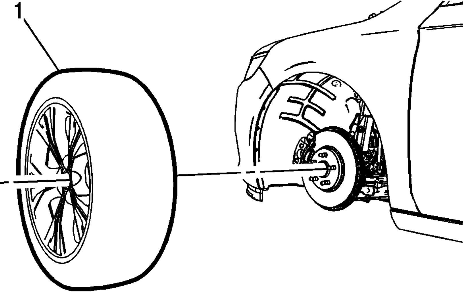
Fig. 10: Tire & Wheel Assembly
Courtesy of GENERAL MOTORS COMPANY
9. Install the tire and wheel assembly (1).
 |
|
Fig. 11: Wheel Nuts Courtesy of GENERAL MOTORS COMPANY |
WARNING: Never grease or lubricate wheel nuts, studs and mounting surfaces. Wheel
nuts, studs, and mounting surfaces must be clean and dry. Tightening the
lubricated parts can cause damage to the wheel studs. This can cause a
wheel to come off when the vehicle is moving, causing loss of control and
possibly personal injury.
10. Hand install the wheel nuts (1).
 |
|
Fig. 12: Wheel Nut Tightening Sequence Courtesy of GENERAL MOTORS COMPANY |
CAUTION: Improperly tightened wheel bolts or nuts can lead to brake pulsation and
rotor damage. In order to avoid expensive brake repairs, evenly tighten the
wheel bolts or nuts to the proper torque specification.
CAUTION: Refer to Fastener Caution .
11. Using a torque wrench and the appropriate socket, alternately and evenly tighten the wheel nuts to 140
N.m (103 lb ft) in the sequence illustrated.
 |
|
Fig. 13: Wheel Nut Caps Courtesy of GENERAL MOTORS COMPANY |
12. Install the wheel nut caps (1), if equipped.
13. Install the wheel center cap or wheel cover, if equipped.
TIRE REPAIR
 |
|
Fig. 14: Identifying Repairable Area On A Radial Tire |
| ||
|
• NEVER stand, lean or reach over the assembly during inflation. |
NOTE: Repairable area on a radial tire.
• NEVER repair tires worn to the tread indicators 1.59 mm (2/32 in)
remaining depth.
• NEVER repair tires with a tread puncture larger than 6.35 mm (1/4 in).
• NEVER substitute an inner tube for a permissible or non-permissible
repair.
• NEVER perform an outside-in tire repair (plug only, on the wheel).
• Every tire must be removed from the wheel for proper inspection and
repair.
• Regardless of the type of repair used, the repair must seal the inner liner
and fill the injury.
• Consult with repair material supplier/manufacturer for repair unit
application procedures and repair tools/repair material recommendations.
Three basic steps for tire puncture repair:
1. Remove the tire from the wheel for inspection and repair.
2. Fill the injury (puncture) to keep moisture out.
3. Seal the inner liner with a repair unit to prevent air loss.
External Inspection
1. Prior to demounting, inspect the tire surface, the valve and the wheel for the source of the leak by using a
water and soap solution. Mark the injured area and totally deflate the tire by removing the valve core.
2. Demount the tire from the wheel and place the tire on a well-lighted spreader.
Internal Inspection
 |
|
Fig. 15: Marking Tire Puncture Location Courtesy of GENERAL MOTORS COMPANY |
1. Spread the beads and mark the puncture with a tire crayon.
2. Inspect the inner tire for any signs of internal damage.
3. Remove the puncturing object, noting the direction of the penetration.
4. Probe the injury with a blunt awl in order to determine the extent and direction of the injury.
5. Remove any loose foreign material from the injury.
6. Punctures exceeding 6.35 mm (1/4 in) should not be repaired.
Cleaning
 |
|
Fig. 16: Cleaning Repair Area Courtesy of GENERAL MOTORS COMPANY |
1. Clean the area around the puncture thoroughly with a proper liner cleaner, clean cloth and a scraper. This
step serves to remove dirt and mold lubricants to insure proper adhesion and non-contamination of the
buffing tool.
2. Refer to information on the product or manufacturer's Material Safety Data Sheet and follow guidelines
for handling and disposal.
Clean the Injury Channel
 |
|
Fig. 17: Reaming Puncture Channel Courtesy of GENERAL MOTORS COMPANY |
1. Use a proper hand reamer, carbide cutter or drill bit to ream the puncture channel from the inside of the
tire in order to clean the injury.
2. Remove steel wires protruding above the liner surface to prevent damage to the repair unit.
3. Consult your repair material supplier for recommended reaming tool(s).
Fill the Injury
 |
|
Fig. 18: Filling Injury Location Courtesy of GENERAL MOTORS COMPANY |
1. It is necessary to fill the injury channel to provide back up for the repair unit and to prevent moisture from
entering the tire fabric and steel wires.
2. For combination repair/plug units skip this step. Cement the injured channel and fill the injury from the
inside of the tire with the repair plug per repair material manufacturer's recommendations. Without
stretching the plug, cut the plug off just above the inside tire surface.
3. Consult your repair material supplier for proper repair material selection.
Repair Unit Selection
 |
|
Fig. 19: Outlining Tire Injury Area Courtesy of GENERAL MOTORS COMPANY |
NOTE: Do not install the repair unit in this step.
1. Center the repair unit over the injury as a reference and outline an area larger than the unit so that buffing
will not remove the crayon marks.
2. Remove the repair unit.
3. DO NOT overlap previous or multiple repair units.
4. Consult your repair material supplier for proper repair unit selection.
Buffing
 |
|
Fig. 20: Buffing Within Marked Area Courtesy of GENERAL MOTORS COMPANY |
1. To prevent contamination and preserve the outline, buff within the marked area thoroughly and evenly
with a low speed buffing tool using a fine wire brush or gritted rasp.
2. Buff to a smooth velvet surface (RMA #1 or #2 buffed texture).
3. Use caution not to gouge the inner liner or expose casing fabric.
4. Remove any buffing dust with a vacuum cleaner.
5. Consult your repair material supplier for a proper buffing tool.
Cementing
 |
|
Fig. 21: Applying Chemical Cement Courtesy of GENERAL MOTORS COMPANY |
Apply chemical cement according to the repair material manufacturer's procedures.
Repair Unit Application
 |
|
Fig. 22: Installing Repair Unit Courtesy of GENERAL MOTORS COMPANY |
The tire must be in the relaxed position when the repair unit is installed. Do not spread the beads excessively.
Two-Piece Plug and Repair Units
1. If applicable, install the repair unit so that the alignment is correct.
2. Center the repair unit over the injury and stitch down thoroughly with the stitching tool, working from the
center out.
 |
|
Fig. 23: Cutting Plug Material Courtesy of GENERAL MOTORS COMPANY |
3. Being careful not to stretch the plug material, cut the plug flush with the outer tread.
Combination Repair/Plug Units
1. Pull the plug through the injury until the repair just reaches the liner. Stitch down thoroughly.
2. Follow the repair material manufacturer's recommendations for further installation instructions.
Consult your repair material supplier for the proper stitching tool.
Safety Cage

Fig. 24: Identifying Safety Cage
Courtesy of GENERAL MOTORS COMPANY
Some run flat tires and high performance tires may require more than 275 kPa (40 psi) to seat the bead. In such
a case, a tire safety cage must be used. Consult the tire manufacturer for its individual repair policy.
Final Inspection

Fig. 25: Performing Final Inspection
Courtesy of GENERAL MOTORS COMPANY
1. After remounting and inflating the tire, check both beads, the repair and the valve with a water and soap
solution in order to detect leaks.
2. If the tire continues to lose air, the tire must be demounted and reinspected.
3. Balance the tire and wheel assembly. Refer to Tire and Wheel Assembly Balancing - Off Vehicle .
For additional tire puncture repair information, contact:
Rubber Manufacturers Association (RMA)
1400 K Street, N.W., Suite 900
Washington
DC
20005-2403
Telephone: 202-682-4800
E-mail: info@rma.org
Website: www.rma.org
TIRE DISMOUNTING AND MOUNTING
CAUTION: Use a tire changing machine in order to dismount tires. Do not use hand tools
or tire irons alone in order to remove the tire from the wheel. Damage to the tire
beads or the wheel rim could result.
CAUTION: Do not scratch or damage the clear coating on aluminum wheels with the tire
changing equipment. Scratching the clear coating could cause the aluminum
wheel to corrode and the clear coating to peel from the wheel.
CAUTION: Damage to either the tire bead or the wheel mounting holes can result
from the use of improper wheel attachment or tire mounting procedures. It
takes up to 70 seconds for all of the air to completely exhaust from a large
tire. Failure to follow the proper procedures could cause the tire changer
to put enough force on the tire to bend the wheel at the mounting surface.
Such damage may result in vibration and/or shimmy, and under severe
usage lead to wheel cracking.
1. Remove the valve core from the valve stem.
2. Deflate the tire completely.
NOTE: Rim-clamp European-type tire changers are recommended.
3. Use the tire changer in order to remove the tire from the wheel. Follow steps 4 - 7 to remove the tire from
the wheel.

Fig. 26: Tire Changer
Courtesy of GENERAL MOTORS COMPANY
4. When separating the tire bead from the wheel, position the bead breaking fixture 90, 180 and 270 degrees
from the valve stem.
CAUTION: Failure to position valve stem in proper position while dismounting and
mounting the tire may result in the TPM sensor to become damaged.
5. Position the wheel and tire so the valve stem is at the 7 o'clock position relative to the head. Apply tire
bead lubricant to the pry bar to prevent damage to the tire bead. The tire iron or pry bar can be inserted
when prying the outer tire bead up and over the mounting/dismounting head.
 |
|
Fig. 27: Separating Tire Bead from Wheel |
6. Position the wheel and tire so the valve stem is again at the 7 o'clock position relative to the head. The tire
iron or pry bar can be inserted when prying the inner tire bead up and over the mounting/dismounting
head.
7. Remove all residual liquid sealant from the inside of the tire and wheel surfaces. If any tire sealant is
noted upon tire dismounting on vehicles equipped with TPM, replace the tire pressure sensor. Refer to
Tire Pressure Indicator Sensor Replacement .
8. Use medium coarseness steel wool in order to remove any rubber, light rust or corrosion from the wheel
bead seats.
CAUTION: When mounting the tires, use an approved tire mounting lubricant. DO
NOT use silicon or corrosive base compounds to lubricate the tire bead
and the wheel rim. A silicon base compound can cause the tire to slip on
the rim. A corrosive type compound can cause tire or rim deterioration.
9. Apply mounting lubricant to the tire bead and the wheel rim. Refer to Adhesives, Fluids, Lubricants,
and Sealers.

Fig. 28: Position Rim So Valve Stem Is At 7 O'clock Position Relative To Head
Courtesy of GENERAL MOTORS COMPANY
10. Position the rim so the valve stem (1) is at the 7 o'clock position relative to the head (2). This will protect
the sensor when the bottom bead seats.
 |
|
Fig. 29: Ensure Valve Stem Is At 7 O'clock Position Courtesy of GENERAL MOTORS COMPANY |
11. Using the tire machine, rotate the tire/wheel assembly clockwise when transferring the tire bead to the
inside of the wheel rim. Ensure that the valve stem (1) is at the 7 o'clock position.
 |
|
Fig. 30: Reposition Wheel And Tire So Valve Stem Is At 7 O'clock Position Relative To Head |
12. After the bottom bead is on the wheel, reposition the wheel and tire so that the valve stem (1) is at the 7
o'clock position relative to the head. This will protect the sensor while mounting the tire bead to the
outside of the wheel.
 |
|
Fig. 31: Using Tire Changer Courtesy of GENERAL MOTORS COMPANY |
13. Use the tire changer in order to install the tire to the wheel.
WARNING: To avoid serious personal injury, do not stand over tire when inflating. The
bead may break when the bead snaps over the safety hump. Do not
exceed 275 kPa (40 psi) pressure when inflating any tire if beads are not
seated. If 275 kPa (40 psi) pressure will not seat the beads, deflate,
relubricate the beads and reinflate. Overinflation may cause the bead to
break and cause serious personal injury.
14. Inflate the tire until it passes the bead humps. Be sure that the valve core is not installed at this time.
15. Install the valve core to the valve core stem.
16. Inflate the tire to the proper air pressure.
17. Ensure that the locating rings are visible on both sides of the tire in order to verify that the tire bead is
fully seated on the wheel.
TIRE ROTATION
Rotate the tire and wheel assemblies at frequent intervals to equalize wear. Refer to Maintenance Schedule . In
addition to scheduled rotation, rotate the tire and wheel assembly whenever uneven tire wear is noticed.
Radial tires tend to wear faster in the shoulder area, particularly in front positions. Radial tires in non-drive
locations may develop an irregular wear pattern that may increase tire noise. This makes regular rotation
especially necessary.
Refer to Tire and Wheel Removal and Installation.
 |
|
Fig. 32: Identifying Tire Rotation Pattern Courtesy of GENERAL MOTORS COMPANY |
Always use a 4-wheel rotation. After rotation, check the wheel nuts for specified torque. Then set the tire
pressure.
TIRE AND WHEEL BALANCING
WARNING: Failure to adhere to the following precautions before tire balancing can result in
personal injury or damage to components:
• Clean away any dirt or deposits from the inside of the wheels.
• Remove any stones from the tread.
• Wear eye protection.
• Use coated weights on aluminum wheels.
Tire and Wheel Assembly Balancer Calibration
Tire and wheel balancers can drift out of calibration over time, or can become inaccurate as a result of heavy
use. There will likely not be any visual evidence that a calibration problem exists. If a balancer is not calibrated
within specifications, and a tire and wheel assembly is balanced on that machine, the assembly may actually be
imbalanced.
Tire and wheel assembly balancer calibration should be checked approximately every 2 weeks, if the machine is
used frequently, and/or whenever the balance readings are questionable.
Tire and Wheel Assembly Balancer Calibration Test
NOTE: If the balancer fails any of the steps in this calibration test, the balancer should
be calibrated according to the manufacturer's instructions. If the balancer
cannot be calibrated, contact the manufacturer for assistance.
Inspect the calibration of the tire and wheel assembly balancer according to the manufacturer's
recommendations, or perform the following test.
 |
|
Fig. 33: View Of Tire & Wheel Assembly Balancer Courtesy of GENERAL MOTORS COMPANY |
1. Spin the balancer without a wheel or any of the adapters on the shaft.
2. Inspect the balancer readings.
Specification
Zero within 7 g (1/4 oz)
3. If the balancer is within the specification range, balance a tire and wheel assembly - that is within radial
and lateral runout tolerances - to ZERO, using the same balancer.
4. After the tire and wheel assembly has been balanced, add an 85 g (3 oz) test weight to the wheel at any
location.
5. Spin the tire and wheel assembly again. Note the readings.
• In the static and dynamic modes, the balancer should call for 85 g (3 oz) of weight, 180 degrees
opposite the test weight.
• In the dynamic mode, the weight should be called for on the flange of the wheel opposite the test
weight.
6. With the assembly imbalanced to 85 g (3 oz), cycle the balancer 5 times.
7. Inspect the balancer readings:
Specification
Maximum variation: 7 g (1/4 oz)
8. Index the tire and wheel assembly on the balancer shaft, 90 degrees from the previous location.
9. Cycle the balancer with the assembly at the new location.
10. Inspect the balancer readings:
Specification
Maximum variation: 7 g (1/4 oz)
11. Repeat steps 8 through 10 until the tire and wheel assembly has been cycled and checked at each of the 4
locations on the balancer shaft.
Tire and Wheel Assembly Balancing Guidelines
NOTE: Tire and wheel assemblies which exhibit excessive runout can produce
vibrations even if the assemblies are balanced.
It is strongly recommended that the tire and wheel assembly runout be
measured and corrected if necessary BEFORE the assemblies are balanced.
If the runout of the tire and wheel assemblies has not yet been measured, refer to Tire and Wheel Assembly
Runout Measurement - Off Vehicle before proceeding.
There are 2 types of tire and wheel balance:
Static Balance
 |
|
Fig. 34: View Of Static Balance Courtesy of GENERAL MOTORS COMPANY |
Static balance is the equal distribution of weight around the wheel circumference. The wheel balance weights
(2) are positioned on the wheel in order to offset the effects of a heavy spot (3). Wheels that have static
imbalance can produce a bouncing action called tramp.
Dynamic Balance
 |
|
Fig. 35: View Of Dynamic Balance Courtesy of GENERAL MOTORS COMPANY |
Dynamic balance is the equal distribution of weight on each side of the tire and wheel assembly centerline. The
wheel balance weights (2) are positioned on the wheel in order to offset the effects of a heavy spot (3). Wheels
that have dynamic imbalance have a tendency to move from side to side and can cause an action called shimmy.
Most off-vehicle balancers are capable of checking both types of balance simultaneously.
As a general rule, most vehicles are more sensitive to static imbalance than to dynamic imbalance; however,
vehicles equipped with low profile, wide tread path, high performance tires and wheels are susceptible to small
amounts of dynamic imbalance. As little as 14 - 21 g (1/2 - 3/4 oz) imbalance is capable of inducing a vibration
in some vehicle models.
Balancing Procedure
NOTE: When balancing tire and wheel assemblies, use a known good, recently
calibrated, off-vehicle, two-plane dynamic balancer set to the finest balance
mode available.

Fig. 36: Wheel Balancer Center Cone
Courtesy of GENERAL MOTORS COMPANY
NOTE: Carefully follow the wheel balancer manufacturers's instructions for proper
mounting of the center cone (1).
1. Raise and support the vehicle. Lifting and Jacking the Vehicle
2. Mark the location of the wheels to the wheel studs and mark the specific vehicle position on each tire and
wheel - LF, LR, RF, RR.
3. Remove the tire and wheel assemblies one at a time and mount on a spin-type wheel balancer. Tire and
Wheel Removal and Installation
4. Carefully follow the wheel balancer manufacturer's instructions for proper mounting techniques to be
used on different types of wheels.
Regard aftermarket wheels, especially those incorporating universal lug patterns, as potential sources of
runout and mounting concerns.
5. Be sure to use the correct type of wheel balance weights for the type of wheel rim being balanced. Be
sure to use the correct type of coated wheel balance weights on aluminum wheels. Refer to Wheel Weight
Usage.
6. Balance all four tire and wheel assemblies as close to zero as possible.
7. Using the matchmarks made prior to removal, install the tire and wheel assemblies to the vehicle. Tire
and Wheel Removal and Installation
8. Lower the vehicle.
Wheel Weight Usage
Tire and wheel assemblies can be balanced using either the static or dynamic method.
Clip-on Weights
 |
|
Fig. 37: Identifying Clip-On Wheel Weight Types |
NOTE: When balancing factory aluminum wheels with clip-on wheel balance weights,
be sure to use special polyester-coated weights. These coated weights reduce
the potential for corrosion and damage to aluminum wheels.
These coated weights reduce the potential for corrosion and damage to aluminum wheels.
• MC (1) and AW (2) series weights are approved for use on aluminum wheels.
• P (3) series weights are approved for use on steel wheels only.
• T (4) series coated weights are approved for use on both steel and aluminum wheels.
 |
|
Fig. 38: Attaching Clip-On Wheel Weight Courtesy of GENERAL MOTORS COMPANY |
NOTE: Use a nylon or plastic-tipped hammer when installing coated clip-on wheel
balance weights to minimize the possibility of damage to the polyester coating.
The contour and style of the wheel rim flange will determine which type of clip-on wheel weight (1) should be
used. The weight should follow the contour of the rim flange. The weight clip should firmly grip the rim flange.
Wheel Weight Placement - Clip-on Weights
 |
|
Fig. 39: Clip-On Weight Placement Courtesy of GENERAL MOTORS COMPANY |
When static balancing, locate the wheel balance weights on the inboard flange (2) if only 28 g (1 oz) or less is
called for. If more than 28 g (1 oz) is called for, split the weights as equally as possible between the inboard (2)
and outboard (1) flanges.
When dynamic balancing, locate the wheel balance weights on the inboard (2) and outboard (1) rim flanges at
the positions specified by the wheel balancer.
Adhesive Weights
 |
|
Fig. 40: Identifying Adhesive Weight Wheel Placement Courtesy of GENERAL MOTORS COMPANY |
NOTE: When installing adhesive balance weights on flangeless wheels, do NOT install
the weight on the outboard surface of the rim.
Adhesive wheel balance weights may be used on factory aluminum wheels. Perform the following procedure to
install adhesive wheel balance weights.
1. Determine the correct areas for placement of the wheel weights on the wheel.
• When static balancing, locate the wheel balance weights along the wheel centerline (1) on the inner
wheel surface if only 28 g (1 oz) or less is called for. If more than 28 g (1 oz) is called for, split the
weights as equally as possible between the wheel centerline and the inboard edge of the inner wheel
surface (2).
• When dynamic balancing, locate the wheel balance weights along the wheel centerline and the
inboard edge of the inner wheel surface (2) at the positions specified by the wheel balancer.
2. Ensure that there is sufficient clearance between the wheel weights and brake system components.
NOTE: Do not use abrasives to clean any surface of the wheel.
3. Using a clean cloth or paper towel with a general purpose cleaner, thoroughly clean the designated
balance weight attachment areas of any corrosion, overspray, dirt or any other foreign material.
4. To ensure there is no remaining residue, wipe the balance weight attachment areas again, using a clean
cloth or paper towel with a mixture of half isopropyl alcohol and half water.
5. Dry the attachment areas with hot air until the wheel surface is warm to the touch.
6. Warm the adhesive backing on the wheel balance weights to room temperature.
7. Remove the protective covering from the adhesive backing on the back of the balance weights. DO NOT
touch the adhesive surface.
8. Apply the wheel balance weights to the wheel, press into place with hand pressure.
9. Secure the wheel balance weights to the wheel with a 90 N (21 lb) force applied with a roller.
DESCRIPTION AND OPERATION
ALL SEASONS TIRES DESCRIPTION
 |
|
Fig. 41: Identifying All Seasons Tire Marking |
Most GM vehicles are equipped with steel belted all-season radial tires as standard equipment. These tires
qualify as snow tires, with a higher than average rating for snow traction than the non-all season radial tires
previously used. Other performance areas, such as wet traction, rolling resistance, tread life, and air retention,
are also improved. This is done by improvements in both tread design and tread compounds. These tires are
identified by an M + S molded in the tire side wall after the tire size. The suffix MS is also molded in the tire
side wall after the TPC specification number.
The optional handling tires used on some vehicles now also have the MS marking after the tire size and the TPC
specification number.
GENERAL DESCRIPTION
The factory installed tires are designed to operate satisfactorily with loads up to and including the full rated load
capacity when these tires are inflated to the recommended pressures.
The following factors have an important influence on tire life:
• Correct tire pressures
• Correct wheel alignment
• Proper driving techniques
• Tire rotation
The following factors increase tire wear:
• Heavy cornering
• Excessively rapid acceleration
• Heavy braking
METRIC WHEEL NUTS AND BOLTS DESCRIPTION
Metric wheel/nuts and bolts are identified in the following way:
• The wheel/nut has the word Metric stamped on the face.
• The letter M is stamped on the end of the wheel bolt.
The thread sizes of metric wheel/nuts and the bolts are indicated by the following example: M12 x 1.5.
• M = Metric
• 12 = Diameter in millimeters
• 1.5 = Millimeters gap per thread
P-METRIC SIZED TIRES DESCRIPTION
 |
|
Fig. 42: Identifying P-Metric Sized Tire Marking |
Most P-metric tire sizes do not have exact corresponding alphanumeric tire sizes. Replacement tires should be
of the same tire performance criteria TPC specification number including the same size, the same load range,
and the same construction as those originally installed on the vehicle. Consult a tire dealer if you must replace
the P-metric tire with other sizes. Tire companies can best recommend the closest match of alphanumeric to
P-metric sizes within their own tire lines. The above illustration may not correspond with your vehicle, but is
meant as an example.
REPLACEMENT WHEELS DESCRIPTION
Replace the wheel if any of the following conditions exist:
• The wheel exhibits excessive runout.
• The wheel is bent.
• The wheel is cracked.
• The wheel is severely rusted.
• The wheel is severely corroded.
NOTE: Air leaks caused by porosity on aluminum wheels are repairable.
• The wheel leaks air.
WARNING: If you are replacing the wheel(s), the wheel stud(s), the wheel nut(s) or the
wheel bolt(s), install only new GM original equipment parts. Installation of used
parts or non-GM original equipment parts may cause the wheel to loosen, loss
of tire air pressure, poor vehicle handling and loss of vehicle control resulting
in personal injury.
CAUTION: The use of non-GM original equipment wheels may cause:
• Damage to the wheel bearing, the wheel fasteners and the wheel
• Tire damage caused by the modified clearance to the adjacent vehicle
components
• Adverse vehicle steering stability caused by the modified scrub radius
• Damage to the vehicle caused by the modified ground clearance
• Speedometer and odometer inaccuracy
Replace the wheel, the wheel studs and the wheel/nuts, or the wheel bolts if applicable, if any of the following
conditions exist:
• The wheel has elongated bolt holes.
• The wheel/nuts, or bolts if applicable, loosen repeatedly.
Steel wheel identification is stamped into the wheel near the valve stem.
Aluminum wheel identification is cast into the inboard side of the wheel.
TIRE INFLATION DESCRIPTION
This vehicle has been engineered to operate up to the stated load capacity with wheel and tire assemblies of the
type, size, construction, and configuration as originally installed. Maintenance of the tire inflation pressures is
critical to the continued satisfactory performance, handling, and operating economy of the vehicle. Operation
with incorrectly or improperly inflated tires can adversely affect vehicle performance and may contribute to the
following:
• Reduced fuel economy
• Tire overloading
• Shortened tire life
• Excessive tire wear
• Uneven tire wear
• Vehicle handling concerns
Inspect the tire pressures when the vehicle has not been driven for at least 3 hours or not more than 1.6 km (1
mi) and when the tires are cool to the touch.
Tire inflation pressures should be inspected monthly and before an extended trip and adjusted to meet the
specifications listed for the particular vehicle. Replace any missing or damaged tire valve stem extensions
and/or caps to prevent the intrusion of water and contaminates.
One pound per square inch (psi) equals 6.9 kilopascals (kPa). The following table illustrates the conversion of
kilopascals to pounds per square inch:
|
Inflation Pressure Conversion (Kilopascals to PSI) | ||||||||||||||||||||||||||||||||||||||||||||||||||||
| ||||||||||||||||||||||||||||||||||||||||||||||||||||
For the correct inflation pressures refer to the vehicle's Tire Placard.
Tires inflated to a higher than recommended pressure can contribute to the following conditions:
• A hard ride
• Tire bruising
• Rapid tread wear at the center of the tire
Tires inflated to a lower than recommended pressure can contribute to the following conditions:
• Tire squeal on turns
• Hard steering
• Rapid and/or uneven wear on the outer edges of the tread
• Tire rim bruises and tire rim rupture
• Tire cord breakage
• High tire temperatures
• Sluggish vehicle handling
• Higher fuel consumption
Unequal pressure on the same axle can cause the following conditions:
• Uneven braking action
• Steering lead
• Imprecise vehicle handling
TREAD WEAR INDICATORS DESCRIPTION

Fig. 43: View Of Tread Wear Indicators
The original equipment tires have tread wear indicators that show when you should replace the tires.
The location of these indicators are at 60 degree intervals around the outer diameter of the tire. The indicators
appear as a 6 mm (0.25 in) wide band when the tire tread depth becomes 1.6 mm (2/32 in).
SPECIAL TOOLS AND EQUIPMENT
|
SPECIAL TOOLS | ||||
|
|
Illustration |
Tool |
|
CH 42450 - J 42450 - A |
Article GUID: A00884649
SUSPENSION
Wheel Alignment - Volt
SPECIFICATIONS
WHEEL ALIGNMENT SPECIFICATIONS
NOTE: All specifications are in degrees, convert to angular minutes, if necessary.
Conversion
• 1.00 degree = 60 angular minutes
• 0.75 degrees = 45 angular minutes
• 0.50 degrees = 30 angular minutes
• 0.25 degrees = 15 angular minutes
• 1.00 angular minute = 60 angular seconds
|
Example | ||||||||||||||||
| ||||||||||||||||
|
Front and Rear Specifications | |||||||||
|
| |||||||||||||||||||||||||||||||||||||||||||||
|
FASTENER SPECIFICATIONS | |||||||||||||||||||||||||||||||||||||||||||||
|
Reusable Threaded Fastener Tightening Specifications | |||||||
| |||||||
REPAIR INSTRUCTIONS
STEERING WHEEL ALIGNMENT
A steering wheel that is off center is not always the result of improper steering wheel alignment. One possible
cause is tire lead due to worn or improperly manufactured tires. Lead is the vehicle deviation from a straight
path on a level road without pressure on the steering wheel. Refer to Radial Tire Lead/Pull Correction in
order to determine if the vehicle has a tire lead problem. Before aligning the steering wheel the vehicle
alignment must also be correct.
Before performing any adjustment affecting wheel alignment, perform the following inspections and
adjustments in order to ensure correct alignment :
• Inspect the tires for the proper inflation and irregular tire wear. Refer to Vehicle Certification, Tire
Placard, Anti-Theft, and Service Parts ID Label , and Tire Diagnosis - Irregular or Premature Wear
.
• Inspect the steering gear for looseness at the frame. Refer to Fastener Specifications .
• Inspect the steering wheel for excessive drag or poor return due to stiff or rusted linkage or suspension
components.
Perform the following steps in order to perform steering wheel alignment adjustment:
1. Tires must be in the straight ahead position.
2. It maybe necessary to have an assistant hold the steering so it does not rotate freely once the steering shaft
is disconnected on a vehicle equipped with an SIR system.
3. Disconnect the steering shaft from the steering gear. Refer to Intermediate Steering Shaft Replacement
.
4. Rotate the intermediate shaft until the steering wheel is visually straight. If the steering wheel is out over
a half turn check for other damage on the vehicle.
5. Reconnect the steering shaft to the steering gear. Refer to Intermediate Steering Shaft Replacement .
6. Verify that the steering wheel is straight.
WHEEL ALIGNMENT MEASUREMENT
Steering and vibration complaints are not always the result of improper alignment. One possible cause is wheel
and tire imbalance. Another possibility is tire lead due to worn or improperly manufactured tires. Lead/pull is
defined as follows: At a constant highway speed on a typical straight road, lead/pull is the amount of effort
required at the steering wheel to maintain the vehicle's straight path. Lead is the vehicle deviation from a
straight path on a level road without pressure on the steering wheel. Refer to Radial Tire Lead/Pull Correction
in order to determine if the vehicle has a tire lead problem.
Before performing any adjustment affecting wheel alignment, perform the following inspections in order to
ensure correct alignment readings:
• Inspect for visible damage to the suspension components and replace as necessary.
• Inspect the tires for the proper inflation and irregular tire wear. Refer to Vehicle Certification, Tire
Placard, Anti-Theft, and Service Parts ID Label , and Tire Diagnosis - Irregular or Premature Wear
.
• Inspect the runout of the wheels and the tires. Refer to Tire and Wheel Runout Specifications .
• Inspect the wheel bearings for backlash and excessive play. Refer to Wheel Bearings Diagnosis .
• Inspect the ball joints for looseness or wear.
• Inspect the tie rod ends for looseness or wear.
• Inspect the control arms and stabilizer shaft for looseness or wear.
• Inspect the steering gear for looseness at the frame. Refer to Fastener Specifications .
• Inspect the struts/shock absorbers for wear, leaks, and any noticeable noises. Refer to Strut and Shock
Absorber Inspection , for front and Strut and Shock Absorber Inspection for rear.
• Inspect the vehicle trim height. Refer to Trim Height Inspection .
• Inspect the steering wheel for excessive drag or poor return due to stiff or rusted linkage or suspension
components.
• Inspect the fuel level. The fuel tank should be full or the vehicle should have a compensating load added.
Give consideration to excess loads, such as tool boxes, sample cases, etc. If normally carried in the vehicle,
these items should remain in the vehicle during alignment adjustments. Give consideration also to the condition
of the equipment being used for the alignment. Follow the equipment manufacturer's instructions.
Satisfactory vehicle operation may occur over a wide range of alignment settings. However, if the setting
exceeds the service allowable specifications, correct the alignment to the service preferred specifications. Refer
to Wheel Alignment Specifications.
Perform the following steps in order to measure the front and rear alignment angles:
1. Install the alignment equipment according to the manufacturer's instructions.
2. Jounce the front and the rear bumpers 3 times prior to checking the wheel alignment.
3. Measure the alignment angles and record the readings.
NOTE:
• Record the "Before" and "After" alignment measurements.
• When performing adjustments to vehicles requiring a 4-wheel
alignment, set the rear toe adjustment first in order to obtain proper
front alignment angles.
4. Adjust alignment angles to vehicle specification, if necessary. Refer to Wheel Alignment Specifications.
FRONT CAMBER ADJUSTMENT
 |
|
Fig. 1: Front Camber Adjustment Bolts Courtesy of GENERAL MOTORS COMPANY |
NOTE: A Service Bolt is available for the lower strut to steering knuckle position.
Do not attempt to file on the strut to make camber adjustment. The service
bolt is approximately 2 mm smaller in diameter to allow adjustment. Refer
to the electronic parts catalog for proper application.
1. If the front camber is out of specifications, perform the following:
• Remove the top front strut to steering knuckle nut (2) and the bolt (1). DISCARD the bolt.
• Replace the top front strut to steering knuckle bolt (1) with the service bolt. (No spines or knurls)
Do not fully tighten the nut.
• Loosen the nut (3) on the bottom bolt (4) enough to allow the strut to move.
• Adjust the front camber to specifications. Wheel Alignment Specifications
2. Tighten the top front strut nut (2). Strut Assembly Removal and Installation
3. Remove the bottom front strut to steering knuckle nut (3) and the bolt (4). DISCARD the bolt.
4. Replace the bottom front strut to steering knuckle bolt. Install a NEW splined/knurled bolt.
5. Tighten the bottom front strut nut. Strut Assembly Removal and Installation
WHEEL ALIGNMENT - STEERING WHEEL ANGLE AND/OR FRONT TOE ADJUSTMENT
 |
|
Fig. 2: View Of Tie Rod Jam Nut & Adjuster |
NOTE: Before performing any adjustments affecting the wheel alignment, refer to
Wheel Alignment Measurement.
1. Ensure that the steering wheel is set in a straight ahead position and centered.
2. Loosen the tie rod nut (5).
3. Adjust the toe to specification. Refer to Wheel Alignment Specifications
CAUTION: Refer to Fastener Caution .
4. Tighten the tie rod nut (5).
Tighten
Tighten the tie rod nut (5) to 60 N.m (44 lb ft).
REAR CAMBER ADJUSTMENT
The rear camber is not adjustable. If the rear camber angle is not within specifications, inspect for suspension
support misalignment or rear suspension damage. Replace any damaged suspension components as necessary.
REAR TOE ADJUSTMENT
The rear toe is not adjustable. If the rear toe angle is not within specifications, inspect for suspension support
misalignment or rear suspension damage. Replace any damaged suspension components as necessary.
DESCRIPTION AND OPERATION
CAMBER DESCRIPTION
 |
|
Fig. 3: Illustrating Camber Angle Courtesy of GENERAL MOTORS COMPANY |
Camber is the tilting of the wheels from the vertical when viewed from the front of the vehicle. When the
wheels tilt outward at the top, the camber is positive (+). When the wheel tilts inward at the top, the camber is
negative (-). The amount of tilt is measured in degrees from the vertical. Camber settings influence the
directional control and the tire wear.
Too much positive camber will result in premature wear on the outside of the tire and cause excessive wear on
the suspension parts.
Too much negative camber will result in premature wear on the inside of the tire and cause excessive wear on
the suspension parts.
Unequal side-to-side camber of 1 degree or more will cause the vehicle to pull or lead to the side with the most
positive camber.
Cross Camber is the difference between the left camber value and the right camber value.
Cross Camber = L camber - R camber
CASTER DESCRIPTION
 |
|
Fig. 4: Illustrating Caster Angle Courtesy of GENERAL MOTORS COMPANY |
Caster is the tilting of the uppermost point of the steering axis either forward or backward, when viewed from
the side of the vehicle. A backward tilt is positive (+) and a forward tilt is negative (-). Caster influences
directional control of the steering but does not affect the tire wear. Caster is affected by the vehicle height,
therefore it is important to keep the body at its designed height. Overloading the vehicle or a weak or sagging
rear spring will affect caster. When the rear of the vehicle is lower than its designated trim height, the front
suspension moves to a more positive caster. If the rear of the vehicle is higher than its designated trim height,
the front suspension moves to a less positive caster.
With too little positive caster, steering may be touchy at high speed and wheel returnability may be diminished
when coming out of a turn. If one wheel has more positive caster than the other, that wheel will pull toward the
center of the vehicle. This condition will cause the vehicle to pull or lead to the side with the least amount of
positive caster.
Cross Caster is the difference between the left caster value and the right caster value.
Cross caster = L caster - R caster
LEAD/PULL DESCRIPTION
At a constant highway speed on a typical straight road, lead/pull is the amount of effort required at the steering
wheel to maintain the vehicle's straight path.
IMPORTANT: Vehicles will tend to lead/pull in the direction of the road slope as part of normal operation.
Lead/pull is usually caused by the following factors:
• Road slope
• Variability in tire construction
• Wheel alignment (front cross caster and camber)
• Unbalanced steering gear
• Electronic Power Steering (EPS) steering position and torque sensors not calibrated correctly, if equipped.
MEMORY STEER DESCRIPTION
Memory steer is when the vehicle wants to lead or pull in the direction the driver previously turned the vehicle.
Additionally, after turning in the opposite direction, the vehicle will want to lead or pull in that direction.
SCRUB RADIUS DESCRIPTION
Ideally, the scrub radius is as small as possible. Normally, the SAI angle and the centerline of the tire and the
wheel intersect below the road surface, causing a positive scrub radius. With struts, the SAI angle is much larger
than the long arm/short arm type of suspension. This allows the SAI angle to intersect the camber angle above
the road surface, forming a negative scrub radius. The smaller the scrub radius, the better the directional
stability. Installing aftermarket wheels that have additional offset will dramatically increase the scrub radius.
The newly installed wheels may cause the centerline of the tires to move further away from the spindle. This
will increase the scrub radius.
A large amount of scrub radius can cause severe shimmy after hitting a bump. Four-wheel drive vehicles with
large tires use a steering damper to compensate for an increased scrub radius. Scrub radius is not directly
measurable by the conventional methods. Scrub radius is projected geometrically by engineers during the
design phase of the suspension.
THRUST ANGLES DESCRIPTION

Fig. 5: Illustrating Thrust Angles
Courtesy of GENERAL MOTORS COMPANY
The front wheels aim or steer the vehicle. The rear wheels control tracking. This tracking action relates to the
thrust angle (3). The thrust angle is the path that the rear wheels take. Ideally, the thrust angle is geometrically
aligned with the body centerline (2).
In the illustration, toe-in is shown on the left rear wheel, moving the thrust line (1) off center. The resulting
deviation from the centerline is the thrust angle.
If the thrust angle is not set properly the vehicle may "dog track", the steering wheel may not be centered or it
could be perceived as a bent axle. Thrust angle can be checked during a wheel alignment.
Positive thrust angle means the thrust line is pointing to the right hand side (RHS) of the vehicle.
Negative thrust angle means the thrust line is pointing to the left hand side (LHS) of the vehicle.
If the thrust angle is out of specification, moving the axle to body relationship will change the thrust angle
reading.
If the vehicle is out in the Positive (+) direction-moving the RHS forward and/or LHS rearward will move the
thrust angle towards zero degrees.
If the vehicle is out in the Negative (-) direction-moving the RHS rearward and/or LHS forward will move the
thrust angle towards zero degrees.
TOE DESCRIPTION

Fig. 6: Illustrating Toe Angle
Courtesy of GENERAL MOTORS COMPANY
Toe is a measurement of how much the front and/or rear wheels are turned in or out from a straight-ahead
position. When the wheels are turned in, toe is positive (+). When the wheels are turned out, toe is negative (-).
The actual amount of toe is normally only a fraction of a degree. The purpose of toe is to ensure that the wheels
roll parallel.
Toe also offsets the small deflections of the wheel support system that occur when the vehicle is rolling forward.
In other words, with the vehicle standing still and the wheels set with toe-in, the wheels tend to roll parallel on
the road when the vehicle is moving.
Improper toe adjustment will cause premature tire wear and cause steering instability.
TORQUE STEER DESCRIPTION

Fig. 7: Identifying Torque Steer
Courtesy of GENERAL MOTORS COMPANY
A vehicle pulls or leads in one direction during hard acceleration. A vehicle pulls or leads in the other direction
during deceleration.
The following factors may cause torque steer to be more apparent on a particular vehicle:
• A slightly smaller diameter tire on the right front increases a right torque lead. Inspect the front tires for
differences in the brand, the construction, or the size. If the tires appear to be similar, change the front
tires from side-to-side and retest the vehicle. Tire and wheel assemblies have the most significant effect
on torque steer correction.
• A large difference in the right and left front tire pressure
• Left-to-right differences in the front view axle angle may cause significant steering pull in a vehicle. The
pull will be to the side with the most downward sloping axle from the differential to the wheels. Axles
typically slope downward from the differential. The slope of the transaxle pan to level ground may be
used as an indication of bias axle angles. The side with the higher transaxle pan (shown on the left side of
the illustration) has the most downward sloping axle angle.
WANDER DESCRIPTION
Wander is the undesired drifting or deviation of a vehicle to either side from a straight path with hand pressure
on the steering wheel. Wander is a symptom of the vehicle's sensitivity to external disturbances, such as road
crown and crosswind, and accentuated by poor on-center steering feel.
Article GUID: A00884729
Automatic Transmission - 5ET50 (MKV) - Volt
SPECIFICATIONS
|
TEMPERATURE VERSUS RESISTANCE (TRANSMISSION FLUID TEMPERATURE SENSOR) | |||||||||||||||||||||||||||||||||||||||||||||||||||||||||||||||||||||||||||||||||||||||||||||||||||||||||||||||||||
|
FASTENER SPECIFICATIONS (OFF-VEHICLE)
Single Use Non-Threaded Fasteners/Components
NOTE:
All
fasteners/components
listed in this table
MUST BE
DISCARDED and
replaced with NEW
after removal.
Application
Automatic Transmission Fluid Filter Seal
|
NOTE: All |
|
Application |
|
Automatic Transmission Pump Fluid Outlet Seal |
|
Automatic Transmission Torque Dampener and Differential Housing Gasket |
|
Automatic Transmission Torque Dampener Bypass Clutch Piston Inner Seal |
|
Automatic Transmission Torque Dampener Bypass Clutch Piston Outer Seal |
|
Control Valve Lower Body Spacer Plate |
|
Drive Motor Power Inverter Module Connector |
|
Drive Motor Power Inverter Module Fluid Seal |
|
Drive Motor Rotor Bearing Retaining Ring |
|
Drive Motor Support |
|
Manual Shift Shaft Pin |
|
Transmission Fluid Level Hole Plug |
|
Variable Low Clutch Backing Plate Retaining Ring |
|
Variable Low Clutch Fluid Passage Seal |
|
Variable High Clutch Fluid Seal Ring |
|
Variable High Clutch Fluid Transfer Support Seal |
|
Variable High Clutch Housing Seal |
|
Variable High Clutch Piston Dam Inner Seal |
|
Variable High Clutch Piston Dam Outer Seal |
|
Variable High Clutch Piston Dam Retaining Ring |
|
Variable High Clutch Piston Inner Seal |
|
Variable High Clutch Piston Outer Seal |
|
Single Use Threaded Fastener/Component Tightening Specifications | ||||||||||||||||
| ||||||||||||||||
|
NOTE: All | ||||
|
Application |
Reference number |
Quantity |
Size |
Specification |
|
Metric (English) | ||||
|
Automatic Transmission Case |
252 |
1 |
M8 x 55.8 |
38 N.m (28 lb ft) |
|
Automatic Transmission Torque Dampener Bolt | ||||
|
• First Pass |
305 |
6 |
M10 x 31.05 |
58 N.m (35 lb ft) |
|
• Final Pass |
305 |
6 |
M10 x 31.05 |
37.5 Degrees |
|
Drive Motor Position Sensor |
502 |
4 |
M6 x 15.5 |
5 N.m (44 lb in) |
|
Drive Motor Position Sensor |
522 |
4 |
M6 x 15.5 |
5 N.m (44 lb in) |
|
Drive Motor Power Inverter |
231 |
2 |
M6 x 21 |
9 N.m (80 lb in) |
|
Drive Motor Stator Bolt |
509 |
4 |
M6 x 55 |
11 N.m (97 lb in) |
|
Drive Motor Stator Bolt |
529 |
4 |
M6 x 80.75 |
11 N.m (97 lb in) |
|
Reusable Threaded Fastener Tightening Specifications | ||||||||||||||||||||||||||||||||||||
| ||||||||||||||||||||||||||||||||||||
|
NOTE: All fasteners | ||||
|
Application |
Reference number |
Quantity |
Size |
Specification |
|
Metric (English) | ||||
|
Automatic Transmission Fluid |
57 |
1 |
1/8"-27 NPTF |
11 N.m (97 lb in) |
|
Automatic Transmission Fluid |
59 |
1 |
1/8"-27 |
11 N.m (97 lb in) |
|
Automatic Transmission Fluid Pump |
209 |
3 |
M8 x 35 |
22 N.m (16 lb ft) |
|
Automatic Transmission Output |
240 |
1 |
M6 x 25 |
9 N.m (80 lb in) |
|
Automatic Transmission Wiring |
709 |
2 |
M6 x 20 |
9 N.m (80 lb in) |
|
Drive Link Snubber Bolt |
210 |
2 |
M6 x 30 |
9 N.m (80 lb in) |
|
Drive Link Snubber Bolt |
212 |
2 |
M6 x 25 |
9 N.m (80 lb in) |
|
Drive Motor Battery Positive and |
28 |
4 |
M6 x 26 |
9 N.m (80 lb in) |
|
Drive Motor Power Inverter Module |
30 |
6 |
M6 x 25 |
9 N.m (80 lb in) |
|
Drive Motor Power Inverter Module |
504 |
3 |
M6 x 35 |
9 N.m (80 lb in) |
|
Drive Motor Power Inverter Module |
524 |
3 |
M6 x 35 |
9 N.m (80 lb in) |
|
Drive Motor Power Inverter Module |
22 |
7 |
M6 x 25 |
9 N.m (80 lb in) |
|
Drive Motor Stator Cooling Tube |
242 |
2 |
M6 x 25 |
9 N.m (80 lb in) |
|
Fluid Transfer Pipe Bolt |
9 |
1 |
M6 x 23 |
9 N.m (80 lb in) |
|
Front Differential Carrier Baffle Bolt |
204 |
2 |
M6 x 25 |
9 N.m (80 lb in) |
|
Manual Shift Detent Lever Spring |
706 |
1 |
M6 x 25.65 |
9 N.m (80 lb in) |
|
Park Pawl Actuator Guide Bolt |
700 |
1 |
M6 x 35 |
9 N.m (80 lb in) |
|
Torque Converter and Differential |
60 |
16 |
M8 x 30 |
32 N.m (24 lb ft) |
|
Transmission Fluid Drain Plug |
67 |
1 |
1/8"-27 |
11 N.m (97 lb in) |
|
Valve Body Bolt |
5 |
4 |
M6 x 72 |
9 N.m (80 lb in) |
|
Valve Body Bolt |
8 |
13 |
M6 x 45 |
9 N.m (80 lb in) |
|
Valve Body Cover Bolt |
1 |
16 |
M6 x 30 |
9 N.m (80 lb in) |
|
Drive Motor Power Inverter Module |
25 |
17 |
M6 x 30 |
9 N.m (80 lb in) |
|
NOTE: All fasteners | ||||
|
Application |
Reference number |
Quantity |
Size |
Specification |
|
Metric (English) | ||||
|
Variable High Clutch Housing Bolt |
637 |
8 |
M6 x 16 |
9 N.m (80 lb in) |
FASTENER SPECIFICATIONS (ON-VEHICLE)
Single Use Non-Threaded Fasteners/Components
NOTE:
All
fasteners/components
listed in this table
MUST BE
DISCARDED and
replaced with NEW
after removal.
Application
Front Wheel Drive Shaft Seal - Left
Front Wheel Drive Shaft Seal - Right
Main Shift Shaft Seal
|
Single Use Threaded Fastener/Component Tightening Specifications | |||||||||||||||
| |||||||||||||||
|
NOTE: All | |
|
Application |
Specification |
|
Metric (English) | |
|
• Final Pass: |
60-75 Degrees |
|
Transmission Mount Strut Bolt | |
|
• First Pass: |
100 N.m (74 lb ft) |
|
• Final Pass: |
60-75 Degrees |
|
Transmission Mount Strut Bracket Bolt | |
|
• First Pass: |
75 N.m (55 lb ft) |
|
• Final Pass: |
45-60 Degrees |
|
Transmission Mount Transmission Side Bracket Bolt | |
|
• First Pass: |
58 N.m (43 lb ft) |
|
• Final Pass: |
60-75 Degrees |
|
Reusable Threaded Fastener Tightening Specifications | |||||||||||||||||||
| |||||||||||||||||||
| |||||||||||||||||||||||||||||||||||||||||
|
APPROXIMATE FLUID CAPACITIES | |||||||||||||||||||||||||||||||||||||||||
|
Application |
Specification | |
|
Metric |
English | |
|
5ET50 | ||
|
Fluid Change - Drain Plug - Approximate Capacity |
3.2 liters |
3.4 quarts |
|
Overhaul - Approximate Capacity (Includes Cooling System) |
6.75 liters |
7.13 quarts |
|
TRANSMISSION GENERAL SPECIFICATIONS | ||||||||||||
|
|
Name |
5ET50 |
|
operation | |
|
Extended Range Low (Mode 1) (CS) |
Online optimizer balances engine, Motor-Generator A, |
|
Extended Range High (Mode 2) (CS) |
Online optimizer balances engine, Motor-Generator A, |
|
Fixed Ratio Extended Range (CS) |
Motor/Generator B will be able to electrically boost or |
|
Pressure Tap |
Line Pressure |
|
Transmission Fluid Type |
DEXRON VIA® |
|
Transmission Type: Electric |
Electrically Variable |
|
Transmission Type: EV |
MKV: 48 kW (Drive Motor A (1) and 87 kW (Drive |
|
Transmission Type: T |
Transaxle Mount |
|
Transmission Type: 50 |
Product Series |
|
Position Quadrant |
P, R, N, D, L |
|
Case Material |
Die Cast Aluminum |
|
Transmission Net Weight (Wet) |
119 kg (262 pounds) |
|
Maximum Trailer Towing Capacity |
MKV: N/A |
|
ADHESIVES, FLUIDS, LUBRICANTS, AND SEALERS | ||||||||||||
|
CLUTCH BACKING PLATE RETAINING RING SPECIFICATIONS
|
Variable High Clutch Backing Plate Retaining Ring | ||||||||
| ||||||||
NOTE:
After
measuring
clutch pack
travel,
determine if
the
|
Clutch Pack Travel Specification - 0.98 - 1.54 mm |
(0.039 - 0.061 in) | |
|
Retaining Ring Thickness |
Ring Identification Color | |
|
Metric |
English | |
|
measurement | ||
|
1.40 - 1.50 mm |
0.055 - 0.059 in |
Dark Green |
|
1.70 - 1.80 mm |
0.067 - 0.071 in |
Yellow |
|
2.01 - 2.11 mm |
0.079 - 0.083 in |
No Color |
|
2.31 - 2.41 mm |
0.091 - 0.095 in |
Light Blue |
|
2.62 - 2.72 mm |
0.103 - 0.107 in |
Orange |
|
Variable Low Clutch Backing Plate Retaining Ring | ||||||||
| ||||||||
NOTE:
After
measuring
clutch pack
travel,
determine if
the
measurement
is within the
specification.
If the
measurement
is not within
|
Clutch Pack Travel Specification - 0.90 - 1.46 mm |
(0.035 - 0.057 in) | |
|
Retaining Ring Thickness |
Ring Identification Color | |
|
Metric |
English | |
|
the | ||
|
2.55 - 2.85 mm |
0.100 - 0.112 in |
Dark Green |
|
2.87 - 2.97 mm |
0.113 - 0.117 in |
Yellow |
|
3.20 - 3.30 mm |
0.126 - 0.130 in |
Purple |
|
3.52 - 3.62 mm |
0.139 - 0.143 in |
Light Blue |
|
3.85 - 3.95 mm |
0.152 - 0.156 in |
Orange |
|
AUTOMATIC TRANSMISSION TORQUE DAMPENER THRUST WASHER SPECIFICATIONS | ||||||||||
| ||||||||||
NOTE:
Measure the
thickness of
the torque
dampener
and
differential
housing
gasket and
subtract
from
measured
dimension A
to use as
dimension A
in
| ||||||||||||||||||||||||||||||||||||||||||
|
RANGE REFERENCE | ||||||||||||||||||||||||||||||||||||||||||
| |||||||||||||||||||||||||||||||||||||||||||||||||||||||||||||||||||||||||||||||
|
TRANSMISSION INTERNAL MODE SWITCH LOGIC | |||||||||||||||||||||||||||||||||||||||||||||||||||||||||||||||||||||||||||||||
Internal Mode Switch
Internal Mode Switch
Selector Position
|
Circuits/Parameter |
Park |
Reverse |
Neutral |
Drive |
Low |
|
Switch Operating Conditions: Ignition ON, range selector in appropriate gear | |||||
|
Internal Mode Switch A |
High |
Low |
Low |
High |
High |
|
Internal Mode Switch B |
Low |
High |
High |
Low |
Low |
|
Internal Mode Switch C |
High |
High |
Low |
Low |
Low |
|
Internal Mode Switch P |
Low |
Low |
High |
High |
High |
|
Internal Mode Switch S |
Low |
High |
Low |
High |
Low |
|
Always High status: Open/short to voltage condition | |||||
SCHEMATIC WIRING DIAGRAMS
AUTOMATIC TRANSMISSION CONTROLS WIRING SCHEMATICS
Drive Mode Select Function
 |
|
Fig. 1: Drive Mode Select Function |
Courtesy of GENERAL MOTORS COMPANY
Pressure Controls, Shift Controls and Speed Sensor
 |
|
Fig. 2: Pressure Controls, Shift Controls and Speed Sensor |
Shift Lever Position Indicator

3044
Fig. 3: Shift Lever Position Indicator
Courtesy of GENERAL MOTORS COMPANY
COMPONENT LOCATOR
DISASSEMBLED VIEWS
Case and Associated Parts (1 of 2)
 |
|
Fig. 4: Case and Associated Parts (1 of 2) |
|
Callout |
Component Name |
|
1 |
Valve Body Cover Bolt |
|
2 |
Control Valve Body Cover |
|
3 |
Automatic Transmission Fluid Level Control Valve Seal - Gasket |
|
4 |
Automatic Transmission Fluid Level Control Valve Seal - O-Ring |
|
5 |
Valve Body Bolt |
|
6 |
Control Solenoid Valve |
|
8 |
Valve Body Bolt |
|
9 |
Fluid Transfer Pipe Bolt |
|
10 |
Fluid Transfer Pipe |
|
11 |
Control Valve |
|
12 |
Control Valve Lower Body Spacer Plate |
|
13 |
Control Valve Body Spacer Plate Retainer |
|
14 |
Variable Low Clutch Fluid Passage Seal |
|
15 |
Automatic Transmission Case |
|
16 |
Drive Motor Power Inverter Module Fluid Seal |
| ||||||||||||||||||||||||||||||||||||
|
Case and Associated Parts (2 of 2) |

Fig. 5: Case and Associated Parts (2 of 2)
Courtesy of GENERAL MOTORS COMPANY
| ||||||||||||||||||||||||||||||||||||||||
|
Transmission Case Assembly (1 of 2) |
 |
|
Fig. 6: Transmission Case Assembly (1 of 2) |
|
Callout |
Component Name |
|
200 |
Automatic Transmission Fluid Filter |
|
201 |
Automatic Transmission Fluid Filter Seal |
|
202 |
Automatic Transmission Fluid Filter Bolt |
|
203 |
Automatic Transmission Auxiliary Fluid Pump Motor 3-Phase Cable Seal |
|
204 |
Front Differential Carrier Baffle Bolt |
|
205 |
Front Differential Carrier Baffle |
|
206 |
Automatic Transmission Fluid Chip Collector Magnet |
|
207 |
Automatic Transmission Pump Fluid Outlet Seal |
|
208 |
Automatic Transmission Fluid Pump Motor |
|
209 |
Automatic Transmission Fluid Pump Bolt |
|
210 |
Drive Link Snubber Bolt |
|
211 |
Drive Link Snubber - (Drive Side) |
|
212 |
Drive Link Snubber Bolt |
|
213 |
Drive Link Snubber - (Coast Side) |
|
214 |
Drive Sprocket Retaining Ring |
|
215 |
Drive Sprocket |
| ||||||||||||||
|
Transmission Case Assembly (2 of 2) |
 |
|
Fig. 7: Transmission Case Assembly (2 of 2) |
|
Courtesy of GENERAL MOTORS COMPANY | ||||||||||||||||
|
|
Callout |
Component Name |
|
237 |
Drive Motor - (2nd Position) |
|
238 |
Automatic Transmission Case Extension Bolt |
|
239 |
Automatic Transmission Output Speed Sensor |
|
240 |
Automatic Transmission Output Speed Sensor Bolt |
|
241 |
Drive Motor Stator Cooling Tube |
|
242 |
Drive Motor Stator Cooling Tube Bolt |
|
243 |
Output Carrier |
|
244 |
Output Carrier Thrust Bearing |
|
245 |
Output Carrier Internal Gear |
|
246 |
Output Carrier Internal Gear Hub Thrust Bearing |
|
247 |
Automatic Transmission Case Extension Bolt |
|
248 |
Drive Motor - (1st Position) |
|
249 |
Variable High Clutch Fluid Transfer Support Seal |
|
250 |
Variable High Clutch Fluid Transfer Support Seal |
|
251 |
Transmission Case Locating Pin |
|
252 |
Automatic Transmission Case Extension Bolt |
|
253 |
Variable High Clutch Fluid Seal Ring |
|
Torque Dampener and Differential Housing Assembly |
 |
Fig. 8: Torque Dampener and Differential Housing Assembly
Courtesy of GENERAL MOTORS COMPANY
| ||||||||||||||||||||||||||||||||||||||||||||
|
Control Valve Body Assembly |
 |
|
Fig. 9: Control Valve Body Assembly Courtesy of GENERAL MOTORS COMPANY |
|
Callout |
Component Name |
|
400 |
Pressure Regulator Valve Bore Plug Retainer |
|
401 |
Pressure Regulator Valve Bore Plug |
|
402 |
Pressure Regulator Valve |
|
403 |
Pressure Regulator Valve Spring |
|
404 |
Lube Regulator Valve Spring |
|
405 |
Lube Regulator Valve |
|
406 |
Lube Regulator Valve Bore Plug |
|
407 |
Lube Regulator Valve Bore Plug Retainer |
|
408 |
Variable Low Clutch Accumulator Piston Spring Retainer |
|
409 |
Variable Low Clutch Accumulator Piston Spring |
|
410 |
Variable Low Clutch Accumulator Piston |
|
411 |
Automatic Transmission Torque Dampener Bypass Clutch Valve Bore Plug Retainer |
|
412 |
Automatic Transmission Torque Dampener Bypass Clutch Spring |
|
413 |
Variable Low Clutch Valve |
|
414 |
Line Pressure Control Solenoid Valve Accumulator Piston |
|
415 |
Line Pressure Control Solenoid Valve Accumulator Piston Spring |
| ||||||||||||||||||||||||||||||||
|
Drive Motor Assembly (1st Position) |
|
510 |
 |
Fig. 10: Drive Motor Assembly (1st Position)
Courtesy of GENERAL MOTORS COMPANY
| ||||||||||||||||||||||||||
|
Drive Motor Assembly (2nd Position) |
|
533 |
 |
Fig. 11: Drive Motor Assembly (2nd Position)
Courtesy of GENERAL MOTORS COMPANY
|
Callout |
Component Name |
|
520 |
Drive Motor Support |
| ||||||||||||||||||||||||||||
|
Output Carrier Internal Gear Assembly |
 |
|
Fig. 12: Output Carrier Internal Gear Assembly |
| ||||||||
|
Variable Low Clutch Assembly |
 |
|
Fig. 13: Variable Low Clutch Assembly Courtesy of GENERAL MOTORS COMPANY |
| ||||||||||||||||
|
Variable High Clutch Assembly |
 |
|
Fig. 14: Variable High Clutch Assembly Courtesy of GENERAL MOTORS COMPANY |
|
Callout |
Component Name |
|
620 |
Variable High Clutch Hub Thrust Washer |
|
621 |
Variable High Clutch Hub |
|
622 |
Variable High Clutch Hub Thrust Washer |
|
623 |
Variable High Clutch Backing Plate Retaining Ring - (Selective) |
|
624 |
Variable High Clutch Backing Plate |
|
625 |
Variable High Clutch Plate - Friction |
|
626 |
Variable High Clutch Plate |
|
627 |
Variable High Clutch Waved Plate |
|
628 |
Variable High Clutch Piston Dam Retaining Ring |
|
629 |
Variable High Clutch Piston Outer Seal |
|
630 |
Variable High Clutch Piston Dam |
|
631 |
Variable High Clutch Piston Spring |
|
632 |
Variable High Clutch Piston |
|
633 |
Variable High Clutch Piston Dam Outer Seal |
|
634 |
Variable High Clutch Piston Dam Inner Seal |
|
635 |
Variable High Clutch Piston Inner Seal |
| ||||||
|
Torque Limiting Clutch Assembly |
 |
|
Fig. 15: Torque Limiting Clutch Assembly |
| ||||||||||||||||
|
Park System Components |
 |
|
Fig. 16: Park System Components Courtesy of GENERAL MOTORS COMPANY |
|
Callout |
Component Name |
|
700 |
Park Pawl Actuator Guide Bolt |
|
701 |
Park Pawl Actuator Guide |
|
702 |
Manual Shift Detent Lever Shaft |
|
703 |
Manual Shift Shaft Seal |
|
704 |
Manual Shift Detent Lever Pin |
|
705 |
Manual Shift Shaft Pin |
|
706 |
Manual Shift Detent Lever Spring |
|
707 |
Manual Shift Detent Lever |
|
708 |
Automatic Transmission Wiring Harness Bracket |
|
709 |
Automatic Transmission Wiring Harness Connector Bracket Bolt |
|
710 |
Automatic Transmission Wiring Harness Bracket |
|
711 |
Park Pawl Actuator |
|
712 |
Park Pawl Shaft |
|
713 |
Park Pawl Spring |
|
714 |
Park Pawl |
COMPONENT LOCATION
Component Locations
 |
|
Fig. 17: Transaxle Internal Component Locations |
|
Callout |
Component Name |
|
6 |
Control Solenoid Valve |
|
11 |
Control Valve |
|
31 |
Input Drive Flange |
|
52 |
Input Sun Gear Shaft |
|
63 |
Front Differential Carrier Assembly |
|
65 |
Front Differential Carrier Sun Gear |
|
215 |
Drive Sprocket |
|
217 |
Park Gear |
|
218 |
Input Carrier |
|
220 |
Drive Link |
|
237 |
Drive Motor |
|
239 |
Automatic Transmission Output Speed Sensor |
|
243 |
Output Carrier Assembly |
| ||||||||||||||||||||||
|
BUSHING, BEARING, AND WASHER LOCATIONS |
|
Location Of The Bushings, Bearings, and Washers |
 |
|
Fig. 18: Bushings, Bearings, And Washer Locations |
|
Callout |
Component Name |
|
55 |
Input Internal Gear Thrust Bearing |
| ||||||||||||||||||||||||
|
SEAL LOCATIONS |
Seal Locations #1
 |
|
Fig. 19: Seal Locations #1 |
Courtesy of GENERAL MOTORS COMPANY
Callout
Component Name
| ||||||||||||||||||||||||||||||||||
|
Seal Locations #2 |
 |
|
Fig. 20: Seal Locations #2 |
|
Courtesy of GENERAL MOTORS COMPANY | ||||||||
|
|
Callout |
Component Name |
|
20 |
Automatic Transmission Wiring Connector Seal - (O-ring) |
|
29 |
Drive Motor Power Inverter Module Electrical Connector Seal |
|
32 |
Transmission Fluid Cooler Pipe Fitting Seal |
|
201 |
Automatic Transmission Fluid Filter Seal |
|
203 |
Automatic Transmission Auxiliary Fluid Pump Motor 3-Phase Cable Seal |
|
207 |
Automatic Transmission Pump Fluid Outlet Seal |
|
703 |
Manual Shift Shaft Seal |
DIAGNOSTIC INFORMATION AND PROCEDURES
DTC P0658 OR P0659: ACTUATOR HIGH CONTROL CIRCUIT GROUP 1 VOLTAGE
Diagnostic Instructions
• Perform the Diagnostic System Check prior to using this diagnostic procedure: Diagnostic System Check -
Vehicle
• Review the description of Strategy Based Diagnosis: Strategy Based Diagnosis
• An overview of each diagnostic category can be found here: Diagnostic Procedure Instructions
DTC Descriptor
DTC P0658
Actuator High Control Circuit Group 1 Low Voltage
DTC P0659
Actuator High Control Circuit Group 1 High Voltage
|
Diagnostic Fault Information | ||||||||||
| ||||||||||
|
Typical Scan Tool Data |
|
High Side Drive 1 | ||||||||||||
| ||||||||||||
|
Circuit/System Description | ||||||||||||
The high side driver 1 is internal to the Hybrid/EV powertrain Control Module 1. With the ignition On, the high side
driver 1 provides 12 V to the transmission control solenoid valve and line pressure control solenoid. If excessive
current flow is detected in high side driver 1 circuit, the high side driver 1 will turn Off. When the circuit fault is
corrected, the high side driver 1 will reset. The hybrid/EV powertrain control module 1 and both drive motor control
modules are internal to the power inverter module, often referred to as the drive motor generator power inverter
module, and not serviced separately.
Conditions for Running the DTC
High side driver 1 is On.
Conditions for Setting the DTC
P0658
Hybrid/EV powertrain Control Module 1 has detected a short to ground on the high side driver 1 circuit during
Hybrid/EV powertrain Control Module 1 initialization.
P0659
Hybrid/EV powertrain Control Module 1 has detected a short to voltage on the high side driver 1 circuit during
Hybrid/EV powertrain Control Module 1 initialization.
Actions Taken When the DTC Sets
DTCs P0658, and P0659 are Type A DTCs.
P0658
• The Hybrid/EV powertrain control module commands maximum line pressure.
• The Hybrid/EV powertrain control module inhibits clutch 1, also call the variable low clutch.
Conditions for Clearing the DTC
DTCs P0658, and P0659 are Type A DTCs.
Reference Information
Schematic Reference
Automatic Transmission Controls Schematics
Connector End View Reference
COMPONENT CONNECTOR END VIEWS - INDEX
INLINE HARNESS CONNECTOR END VIEWS - INDEX
Description and Operation
Electronic Component Description
Transmission Component and System Description
Transmission General Description
Electrical Information Reference
• Circuit Testing
Connector Repairs
Testing for Intermittent Conditions and Poor Connections
Wiring Repairs
DTC Type Reference
Powertrain Diagnostic Trouble Code (DTC) Type Definitions
Scan Tool Reference
Control Module References for scan tool information.
Circuit/System Verification
1. Ignition ON.
2. Verify the scan tool High Side Driver 1 Command parameter displays On.
• If On is not displayed
Refer to Circuit/System Testing.
• If On is displayed
3. Verify the parameters listed below do not display Malfunction when commanding the high side driver 1, On
and Off with a scan tool.
• High Side Driver 1 Circuit Low Voltage Test Status
• High Side Driver 1 Circuit Open Test Status
• High Side Driver 1 Circuit High Voltage Test Status
• If Multifunction is displayed
Refer to Circuit/System Testing.
• If Multifunction is not displayed
4. Operate the vehicle within the Conditions for Running the DTC. You may also operate the vehicle within the
conditions that you observe from the Freeze Frame/Failure Records data.
5. Verify the DTC does not set.
• If the DTC sets
Refer to Circuit/System Testing.
• If the DTC does not set
6. All OK.
Circuit/System Testing
WARNING: Always perform the High Voltage Disabling procedure prior to servicing any High
Voltage component or connection. Personal Protection Equipment (PPE) and proper
procedures must be followed.
The High Voltage Disabling procedure includes the following steps:
• Identify how to disable high voltage.
• Identify how to test for the presence of high voltage.
• Identify condition under which high voltage is always present and personal
protection equipment (PPE) and proper procedures must be followed.
Before working on any high voltage system, be sure to wear the following Personal
Protection Equipment:
• Safety glasses with appropriate side shields when within 15 meters (50 feet) of
the vehicle, either indoors or outdoors.
• Certified and up-to-date Class "0" Insulation gloves rated at 1000V with leather
protectors.
• Visually and functionally inspect the gloves before use.
• Wear the Insulation gloves with leather protectors at all times when
working with the high voltage battery assembly, whether the system is
energized or not.
Failure to follow the procedures may result in serious injury or death.
1. Vehicle OFF, disable the high voltage at the T6 Power Inverter Module. Refer to High Voltage Disabling .
2. Remove the Control Valve Body Cover. Refer to Control Valve Body Cover Replacement.
3. Ignition OFF and all vehicle systems OFF, disconnect the X1 harness connector at the Q8 Control Solenoid
Valve.
4. Connect the 12 V battery.
5. Ignition ON, connect a test lamp between the high side driver circuit X1 terminal 1 and the ground.
6. Verify the test lamp turns ON.
• If the test lamp is always OFF
1. Ignition OFF, remove the test lamp, disconnect the harness connector at the T6 Power Inverter Module.
2. Test for infinite resistance between the control circuit and ground.
• If less than infinite resistance, replace the Automatic Transmission Wiring Harness - Control
Solenoid Valve.
• If infinite resistance
3. Test for less than 2 Q in the control circuit end to end.
• If 2 Q or greater, replace the Automatic Transmission Wiring Harness - Control Solenoid Valve.
• If less than 2 Q, replace the T6 Power Inverter Module.
• If the test lamp is always ON
1. Ignition OFF, remove the test lamp, disconnect the harness connector at the T6 Power Inverter Module,
ignition ON.
2. Test for less than 1 V between the control circuit and ground.
• If 1 V or greater, repair the short to voltage on the circuit.
• If less than 1 V, replace the T6 Power Inverter Module.
• If the test lamp turns ON and OFF
7. Test or replace the Q8 Control Solenoid Valve.
Repair Instructions
Perform the Diagnostic Repair Verification after completing the repair.
• Refer to Control Module References for T6 Power Inverter Module replacement, often referred to as the
Drive Motor Generator Power Inverter Module, replacement, programming, and setup.
• Refer to Control Solenoid Valve Replacement for Q8 Control Solenoid Valve replacement.
• Refer to Control Valve Assembly and Transmission Wiring Harness Removal for Automatic Transmission
Wiring Harness - Control Solenoid Valve replacement.
• Refer to Solenoid Valve Characterization Reprogramming when the T6 Power Inverter Module is replaced.
• Perform the Reset Transmission Adapts following all transmission related repairs.
DTC P0711-P0713: TRANSMISSION FLUID TEMPERATURE SENSOR
Diagnostic Instructions
• Perform the Diagnostic System Check prior to using this diagnostic procedure: Diagnostic System Check -
Vehicle
• Review the description of Strategy Based Diagnosis: Strategy Based Diagnosis
• An overview of each diagnostic category can be found here: Diagnostic Procedure Instructions
DTC Descriptor
DTC P0711
Transmission Fluid Temperature Sensor Performance
DTC P0712
Transmission Fluid Temperature Sensor Circuit Low Voltage
DTC P0713
Transmission Fluid Temperature Sensor Circuit High Voltage
|
Diagnostic Fault Information | |||||||||||||||
| |||||||||||||||
|
Typical Scan Tool Data |
|
Transmission Fluid Temperature | ||||||||||||||||||||
| ||||||||||||||||||||
|
Circuit/System Description | ||||||||||||||||||||
The primary source of heat in the transmission is the drive motor generators. The drive motor generators are cooled
by the transmission fluid. Hot fluid exits the drive motor generators and flows to the transmission cooler supply line.
The supply line connects to the transmission cooler, which is internal to the radiator. The transmission fluid cooler
pipe assembly is equipped with an internal thermostat that opens at 80A°C (176A°F) for optimum transmission
operation and fuel economy. The transmission cooler pipe thermostat is part of the transmission fluid cooler pipe
assembly, located near the transmission and is not serviced separately. From the cooler, the fluid returns through the
transmission fluid cooler pipe assembly and enters the lubrication circuits. After lubricating the internal components,
the fluid returns to the oil pan. The transmission fluid temperature sensor is part of the control solenoid valve
assembly and is not serviced separately.
Conditions for Running the DTC
• The ignition On is greater than 3 s.
• The system voltage is greater than 9 V
P0711
• DTCs P0712, P0713, U179A, or U0293 are not active.
• Vehicle speed is detected for 5 s.
• Cold soak average and vehicle running transmission fluid temperature is between -40A°C (-40A°F) and
130A°C (266A°F).
• The difference between the transmission fluid temperature sensor and the cold soak average temperature is less
than 15A°C (27A°F) at -40A°C to -20A°C (-40A°F to -4A°F) or less than 10A°C (18A°F) greater than
-20A°C (-40A°F) ambient temperature.
Conditions for Setting the DTC
P0711
• The difference between the transmission fluid temperature sensor and the cold soak average temperature is
greater than 15A°C (27A°F) at -40A°C to -20A°C (-40A°F to -4A°F) or greater than 10A°C (18A°F) greater
than -20A°C (-40A°F) ambient temperature for greater than or equal to 300 s.
OR
• The transmission fluid temperature is stuck for greater than or equal to 300 s.
P0712
The Hybrid/EV Powertrain Control Module 1 detects a transmission fluid temperature sensor resistance of less than
or equal to 68.6 Q which corresponds to 149A°C (300A°F) for 2 s out of a 3 s window.
P0713
The Hybrid/EV Powertrain Control Module 1 detects a transmission fluid temperature sensor resistance of greater
than or equal to 83,641 Q which corresponds to -50A°C (-58A°F) for 2 s out of a 3 s window.
Actions Taken When the DTC Sets
• DTCs P0711, P0712 and P0713 are Type A DTCs.
• The Hybrid/EV powertrain control module switches to a calculated transmission fluid temperature.
Conditions for Clearing the DTC
DTCs P0711, P0712 and P0713 are Type A DTCs.
Diagnostic Aids
The Transmission Fluid Temperature parameter on the scan tool should rise steadily to a normal operating
temperature, and then stabilize. Ask about the customer's driving habits, overloading, etc. Ensure the engine and
transmission cooling system is functioning normally.
Reference Information
Schematic Reference
Automatic Transmission Controls Schematics
Connector End View Reference
COMPONENT CONNECTOR END VIEWS - INDEX
Electrical Information Reference
Circuit Testing
Connector Repairs
Testing for Intermittent Conditions and Poor Connections
Wiring Repairs
DTC Type Reference
Powertrain Diagnostic Trouble Code (DTC) Type Definitions
Special Tools
GE-24731 Tempil Stick
For equivalent regional tools, refer to Special Tools.
Circuit/System Verification
1. Vehicle ON, observe the scan tool Transmission Fluid Temperature and the ECT temperature parameter after a
9 hour cold soak. The readings should be between -50 to 149A°C (-58A°F to 300A°F) and vary less than
15A°C (27A°F) at -40A°C to -20A°C (-40A°F to -4A°F) or less than 10A°C (18A°F) greater than -20A°C
(-40A°F) from ambient temperature after an 9.5 hour cold soak. The transmission fluid temperature parameter
should rise steadily then stabilize when the vehicle is driven for greater than 300 s.
• If greater than the specified range, or stuck at a fixed temperature
Refer to Circuit/System Testing.
• If within the specified range
Test for a transmission overheat condition. Refer to Transmission Overheats .
• If no automatic transmission overheating condition exists
2. Refer to Circuit System Testing.
Circuit/System Testing
WARNING: Always perform the High Voltage Disabling procedure prior to servicing any
High Voltage component or connection. Personal Protection Equipment (PPE)
and proper procedures must be followed.
The High Voltage Disabling procedure includes the following steps:
• Identify how to disable high voltage.
• Identify how to test for the presence of high voltage.
• Identify condition under which high voltage is always present and
personal protection equipment (PPE) and proper procedures must be
followed.
Before working on any high voltage system, be sure to wear the following
Personal Protection Equipment:
• Safety glasses with appropriate side shields when within 15 meters (50
feet) of the vehicle, either indoors or outdoors.
• Certified and up-to-date Class "0" Insulation gloves rated at 1000V with
leather protectors.
• Visually and functionally inspect the gloves before use.
• Wear the Insulation gloves with leather protectors at all times when
working with the high voltage battery assembly, whether the system
is energized or not.
Failure to follow the procedures may result in serious injury or death.
1. Vehicle OFF, disable the high voltage at the T6 Power Inverter Module. Refer to High Voltage Disabling .
2. Remove the Control Valve Body Cover. Refer to Control Valve Body Cover Removal.
3. Vehicle Off and all vehicle systems Off. Disconnect the X1 harness connector at the Q8 Control Solenoid
Valve. It may take up to 2 min. for all vehicle systems to power down.
4. Test for less than 10 Q between the low reference circuit terminal 4 on the X1 harness connector and ground.
• If 10 fi or greater
1. Vehicle Off, disconnect the Automatic Transmission Wiring Harness (Control Solenoid Valve) harness
connector at the T6 Power Inverter Module.
2. Test for less than 2 Q in the low reference circuit end to end.
• If 2 Q or greater, replace the Automatic Transmission Wiring Harness (Control Solenoid Valve).
• If less than 2 Q, replace the T6 Power Inverter Module.
• If less than 10 fi
5. Vehicle in Service Mode.
6. Test for 4.8 - 5.2 V between the signal circuit terminal 3 and ground.
• If not between 4.8 - 5.2 V
1. Ignition Off, disconnect the Automatic Transmission Wiring Harness (Control Solenoid Valve) harness
connector at the T6 Power Inverter Module.
2. Test for infinite resistance between the signal circuit terminal 3 and ground.
• If less than infinite resistance, replace the Automatic Transmission Wiring Harness (Control
Solenoid Valve).
• If infinite resistance
3. Test for less than 1 Q in the signal circuit end to end.
• If 1 Q or greater, replace the Automatic Transmission Wiring Harness (Control Solenoid Valve).
• If less than 1 Q, replace the T6 Power Inverter Module.
• If between 4.8 - 5.2 V
7. Replace the Q8 Control Solenoid Valve.
Component Testing
1. Perform each step listed below:
• Perform the Fluid Leak Diagnosis.
• Perform the Transmission Fluid Level and Condition Check procedure.
• Perform the Line Pressure Check procedure.
• Perform the Automatic Transmission Fluid Pump Pressure High or Low procedure.
• With a hand held infra-red thermometer, or GE-24731 tempil stick test for the transmission cooler
supply line thermostat for opening at 80A°C (176A°F). The transmission cooler supply line temperature
should be higher on the transmission side of the thermostat than the cooler side until 80A°C (176A°F) is
reached.
• If the thermostat tests stuck open or closed
Replace the transmission cooler supply pipe assembly.
• If thermostat tests OK
2. Perform the Control Solenoid Valve Performance Test.
• If a concern is found
Replace the Q8 Control Solenoid Valve.
• If a concern is not found
3. All OK.
Repair Instructions
Perform the Diagnostic Repair Verification after completing the repair.
• Refer to Transmission Fluid Cooler Thermal Bypass Valve Replacement
• Refer to Control Module References for T6 Power Inverter Module, often referred to as the Drive Motor
Generator Power Inverter Module, replacement, programming and setup.
• Refer to Control Solenoid Valve Replacement for Q8 Control Solenoid Valve replacement.
• Refer to Automatic Transmission Wiring Harness Replacement
• Refer to Solenoid Valve Characterization Reprogramming when the T6 Power Inverter Module, Valve
Body, or Q23 Line Pressure Control Solenoid is replaced.
• Perform the Reset Transmission Adapts following all transmission related repairs.
DTC P0721: OUTPUT SPEED SENSOR PERFORMANCE
Diagnostic Instructions
• Perform the Diagnostic System Check - Vehicle prior to using this diagnostic procedure.
• Review Strategy Based Diagnosis for an overview of the diagnostic approach.
• Refer to Diagnostic Procedure Instructions to provide an overview of each diagnostic category.
DTC Descriptor
DTC P0721
Output Speed Sensor Performance
|
Diagnostic Fault Information | |||||||||||||||
| |||||||||||||||
|
Typical Scan Tool Data |
|
Output Shaft Direction | ||||||||||||||||||||
| ||||||||||||||||||||
|
Circuit/System Description | ||||||||||||||||||||
The A/Trans Output Speed Sensor Assembly has 2 internal hall-effect type sensors, and is capable of sensing both
speed and direction. The output speed sensor is internal to the transmission and mounts to the A/Trans case assembly
and is connected to the hybrid/EV powertrain control module 1 through the transmission internal harness. The
A/Trans Output Speed Sensor Assembly faces the park gear machined teeth surface. The sensor receives 5 V on the
OSS supply voltage circuit from the hybrid/EV powertrain control module 1. As the output shaft rotates, the sensor
produces a signal frequency based on the machined surface of the output shaft. The two sensor elements in the output
speed sensor assembly are spaced approximately 1/2 a tooth apart.
• When the vehicle is moving in a forward direction, sensor A detects a particular tooth before sensor B.
• When the vehicle is moving in a reverse direction, sensor B detects a particular tooth before sensor A.
The electronics in the sensor combine the two signals and send a signal with a different pulse width. This signal is
interpreted by the hybrid/EV powertrain control module 1 for speed and direction and is transmitted through the
serial data circuits to the engine control module (ECM) The ECM, hybrid/EV powertrain control module 1, compare
the output speed sensor signal with the antilock brake system (ABS) wheel speed sensor signal. The hybrid/EV
powertrain control module 1 is part of the drive motor generator power inverter module and is not serviced
separately.
Conditions for Running the DTC
The vehicle is ON.
Conditions for Setting the DTC
The hybrid/EV powertrain control module 1 detects an invalid Automatic Transmission Output Shaft Speed Sensor
direction for 2.5 s within a 3 s window.
Action Taken When the DTC Sets
The hybrid/EV powertrain control module 1 calculates vehicle speed based on the drive motor 2 speed.
Conditions for Clearing the DTC
DTC P0721 is a Type A DTC.
Reference Information
Schematic Reference
Automatic Transmission Controls Schematics
Connector End View Reference
COMPONENT CONNECTOR END VIEWS - INDEX
Electrical Information Reference
Circuit Testing
Connector Repairs
Testing for Intermittent Conditions and Poor Connections
Wiring Repairs
DTC Type Reference
Powertrain Diagnostic Trouble Code (DTC) Type Definitions
Scan Tool Reference
Control Module References for scan tool information.
Special Tools
EL 38522 Variable Signal Generator
For equivalent regional tools, refer to Special Tools.
Circuit/System Verification
1. Operate the vehicle at 16 - 32 km/h (10 - 20 mph), observe the scan tool Transmission OSS parameter. The
reading should be greater than 150 RPM and not drop out.
2. Observe the scan tool OSS Supply Voltage parameter. The reading should display OK.
Circuit/System Testing
1. Vehicle ON.
2. Operate the vehicle within the Conditions for Running the DTC. You may also operate the vehicle within the
conditions that you observed from the Freeze Frame/Failure Records data.
3. Verify DTC P7021 is not set.
• If DTC is set
Perform the Output Shaft Speed Input Test.
• If the DTC is not set
4. All OK
Repair Instructions
Perform the Diagnostic Repair Verification after completing the repair.
• Refer to Solenoid Valve Characterization Reprogramming when the T6 Power Inverter Module, Valve
Body, or Q23 Line Pressure Control Solenoid is replaced.
• Perform the Reset Transmission Adapts following all transmission related repairs.
DTC P077B-P077D: OUTPUT SPEED SENSOR CIRCUIT
Diagnostic Instructions
• Perform the Diagnostic System Check - Vehicle prior to using this diagnostic procedure.
• Review Strategy Based Diagnosis for an overview of the diagnostic approach.
• Refer to Diagnostic Procedure Instructions to provide an overview of each diagnostic category.
DTC Descriptor
DTC P077B
Output Speed Sensor Circuit Direction Incorrect
DTC P077C
Output Speed Sensor Circuit Low Voltage
DTC P077D
Output Speed Sensor Circuit High Voltage
|
Diagnostic Fault Information | ||||||||||
|
| ||||||||||
|
Typical Scan Tool Data |
|
Output Shaft Direction | ||||||||||||||||
| ||||||||||||||||
|
Circuit/System Description | ||||||||||||||||
The transmission output shaft speed sensor has 2 internal hall-effect type sensors, and is capable of sensing both
speed and direction. The transmission output shaft speed sensor mounts to the A/Trans case assembly and is
connected to the hybrid/EV powertrain control module 1 assembly through a wire harness and connector. The sensor
faces the drive sprocket machined teeth surface. The sensor receives 5 V on the OSS supply voltage circuit from the
hybrid/EV powertrain control module 1. As the drive sprocket rotates, the sensor produces a signal frequency based
on the machined surface of the drive sprocket.
The two sensor elements in the transmission output shaft speed sensor are spaced approximately 1/2 a tooth apart.
• When the vehicle is moving in a forward direction, sensor A detects a particular tooth before sensor B.
• When the vehicle is moving in a reverse direction, sensor B detects a particular tooth before sensor A.
The electronics in the sensor combine the two signals and send a signal with a different pulse width. This signal is
interpreted by the hybrid/EV powertrain control module 1 for speed and direction and is transmitted through the
GMLAN circuits to the ECM. The ECM and hybrid/EV powertrain control module 1, compare the OSS signal with
hybrid motor speed/direction and the ABS wheel speed sensor signal.
Conditions for Running the DTC
P077B
• DTC P0721, P077C, P077D, or P215C is not set.
• The drive motor estimated output speed is greater than 50 RPM.
P077C
• DTC P077D is not set.
• System voltage is at least 9 V and no more than 32 V.
P077D
• DTC P077B is not set.
• System voltage is at least 9 V and no more than 32 V.
Conditions for Setting the DTC
P077B
The hybrid/EV powertrain control module 1 detects an incorrect OSS direction.
P077C
The hybrid/EV powertrain control module 1 detects the output speed sensor signal voltage is less than 0.36 V for
0.25 s.
P077D
The hybrid/EV powertrain control module 1 detects the output speed sensor signal voltage is greater than 4.25 V for
0.25 s.
Action Taken When the DTC Sets
The hybrid/EV powertrain control module 1 uses drive motor 2 speed to calculate vehicle speed.
Conditions for Clearing the DTC
P077B, P077C, and P077D are Type A DTCs.
Diagnostic Aids
Inspect the output speed sensor, harness, connector and control solenoid valve assembly pins for metallic debris and
output shaft machined face for damage or misalignment. Proper torque of the output speed sensor mounting bolt is
critical to proper output speed sensor operation. Use a terminal test kit for any test that requires probing the control
solenoid valve assembly harness connector or a component harness connector.
Reference Information
Schematic Reference
Automatic Transmission Controls Schematics
Connector End View Reference
COMPONENT CONNECTOR END VIEWS - INDEX
Description and Operation
Electronic Component Description
Electrical Information Reference
Circuit Testing
Connector Repairs
Testing for Intermittent Conditions and Poor Connections
Wiring Repairs
DTC Type Reference
Powertrain Diagnostic Trouble Code (DTC) Type Definitions
Control Module References for scan tool information.
Special Tools
EL 38522 Variable Signal Generator
For equivalent regional tools, refer to Special Tools.
Circuit/System Verification
1. Verify that DTC P0721, P0970, P0971, P0973, P2720, P2721, P2729, or P2730 are not set.
• If any of the DTCs are set, refer to Diagnostic Trouble Code (DTC) List - Vehicle .
2. Operate the vehicle at 16 - 32 km/h (10 - 20 mph) while observing the Transmission Data OSS Direction
parameter on the scan tool. The OSS Direction parameter should match vehicle direction.
• If the OSS parameter corresponds with the vehicle direction and the DTC is set, replace the T6 power
inverter module.
Circuit/System Testing
1. Vehicle ON.
2. Operate the vehicle within the Conditions for Running the DTC. You may also operate the vehicle within the
conditions that you observed from the Freeze Frame/Failure Records data.
3. Verify DTC P077B, P077C, or P077D is not set.
• If DTC is set
Perform the Output Shaft Speed Input Test.
• If the DTC is not set
4. All OK
Repair Instructions
Perform the Diagnostic Repair Verification after completing the repair.
• Refer to Control Module References for Drive Motor Generator Power Inverter Module, also called the T6
power inverter module replacement, programming, and setup
• Refer to Solenoid Valve Characterization Reprogramming when the T6 Power Inverter Module, Valve
Body, or Q23 Line Pressure Control Solenoid is replaced.
• Perform the Reset Transmission Adapts following all transmission related repairs.
DTC P079A: TRANSMISSION CLUTCH 1 SLIP DETECTED
Diagnostic Instructions
• Perform the Diagnostic System Check - Vehicle prior to using this diagnostic procedure.
• Review Strategy Based Diagnosis for an overview of the diagnostic approach.
• Refer to Diagnostic Procedure Instructions to provide an overview of each diagnostic category.
DTC Descriptor
DTC P079A
Transmission Clutch 1 Slip Detected
|
Typical Scan Tool Data Variable Low Clutch Reference | ||||||||||||||||
| ||||||||||||||||
|
Circuit/System Description | ||||||||||||||||
The hybrid/EV powertrain control module 1 monitors the Clutch 1 Slip Speed for each Hybrid Transmission Mode
Commanded state. The hybrid/EV powertrain control module 1 monitors clutch slip when the variable low clutch is
applied. The hybrid/EV powertrain control module 1 is part of the drive motor generator power inverter module and
is not serviced separately.
Conditions for Running the DTC
• Clutch 1 is applied.
• No P1B0D, P1B0E, P1E4A or P1E4B DTCs.
• The commanded line pressure is at least 190 kPa (28 psi) for 1 s.
• The variable low clutch torque estimated is greater than 74 N.m (55 lb ft) for 1 s.
• Wheel slip speed is 0.
• Shutdown is not commanded.
Conditions for Setting the DTC
• The hybrid/EV powertrain control module 1 detects clutch 1 slip speed greater than 190 RPM for 1 s, 3 times
within the same key cycle.
• Clutch 1 energy is greater than 8 joules 3 times within the same key cycle, the fault will set instantly.
Action Taken When the DTC Sets
• P079A is a Type A DTC.
• The hybrid/EV powertrain control module 1 commands the internal combustion engine On.
• The hybrid/EV powertrain control module 1 inhibits mode 1 and gear 1.
Conditions for Clearing the DTC
P079A is a Type A DTC.
Diagnostic Aids
When attempting to set transmission performance DTCs, observe the Freeze Frame and Failure Records to assist in
duplicating the failure conditions. Ensure the transmission fluid level is correct and there are no leaks. If there are
any other transmission DTCs set, diagnose those first.
Reference Information
Schematic Reference
Automatic Transmission Controls Schematics
Connector End View Reference
COMPONENT CONNECTOR END VIEWS - INDEX
Description and Operation
Electronic Component Description
Transmission Component and System Description
Transmission General Description
Electrical Information Reference
Circuit Testing
Connector Repairs
Testing for Intermittent Conditions and Poor Connections
Wiring Repairs
DTC Type Reference
Powertrain Diagnostic Trouble Code (DTC) Type Definitions
Scan Tool Reference
Control Module References for scan tool information.
Circuit/System Verification
1. Vehicle ON.
2. Verify that DTC P0721, P077B-P077D or P215C is not set.
• If the DTC is set
Refer to Diagnostic Trouble Code (DTC) List - Vehicle .
• If the DTC is not set
3. Verify correct fluid level and condition by performing the Transmission Fluid Level and Condition Check.
4. Verify correct oil pressure by performing the Line Pressure Check.
5. Operate the vehicle within the Conditions for Running the DTC. The Clutch 1 Slip Speed parameter reading
should be less than 190 RPM when the Clutch 1 Status parameter reading is Applied.
• If clutch slip speed is greater than 190 RPM
Refer to Component Testing.
• If clutch slip speed is less than 190 RPM
6. All OK.
Component Testing
WARNING: Always perform the High Voltage Disabling procedure prior to servicing any
High Voltage component or connection. Personal Protection Equipment (PPE)
and proper procedures must be followed.
The High Voltage Disabling procedure includes the following steps:
• Identify how to disable high voltage.
• Identify how to test for the presence of high voltage.
• Identify condition under which high voltage is always present and
personal protection equipment (PPE) and proper procedures must be
followed.
Before working on any high voltage system, be sure to wear the following
Personal Protection Equipment:
• Safety glasses with appropriate side shields when within 15 meters (50
feet) of the vehicle, either indoors or outdoors.
• Certified and up-to-date Class "0" Insulation gloves rated at 1000V with
leather protectors.
• Visually and functionally inspect the gloves before use.
• Wear the Insulation gloves with leather protectors at all times when
working with the high voltage battery assembly, whether the system
is energized or not.
Failure to follow the procedures may result in serious injury or death.
1. Vehicle OFF, disable the high voltage at the T6 Power Inverter Module. Refer to High Voltage Disabling
2. Verify control solenoid valve assembly condition by performing the Control Solenoid Valve Inspection.
3. Verify control solenoid valve assembly function by performing the Control Solenoid Valve Performance
Test.
• If a concern is found
Replace the Q8 Control Solenoid Valve.
• If no concern is found
4. Inspect the a/trans fluid level control valve for stuck closed or damaged condition.
• If you found a concern with the a/trans fluid level control valve
Replace the a/trans fluid level control valve.
• If no concern is found
5. Inspect the valve body components and hydraulic circuits listed below for a leak or a stuck valve. Refer to
Control Valve Body Diagnostic Inspection:
• Control valve body spacer (w/gasket) plate assembly
• Variable low clutch valve and variable low clutch accumulator.
• If you found a concern in the valve body
Repair or replace the valve or valve body.
• If no concern is found
6. Inspect the variable low clutch assembly snap ring, piston, clutch discs, and housing for a slipping or damaged
condition.
• If you found a variable low clutch assembly concern
Repair or replace the variable low clutch assembly as necessary.
• If no concern is found
7. Replace the T6 Power Inverter Module.
Repair Instructions
Perform the Diagnostic Repair Verification after completing the repair.
• Refer to Control Valve Body Replacement for control valve body replacement.
• Refer to Control Solenoid Valve Replacement for Q8 Control Solenoid Valve replacement.
• Refer to Variable Low Clutch Plate Removal, and Variable Low Clutch Plate Installation for variable low
clutch replacement.
• Refer to Control Module References for T6 Power Inverter Module, often referred to as the Drive Motor
Generator Power Inverter Module replacement, programming, and setup.
• Refer to Solenoid Valve Characterization Reprogramming when the T6 Power Inverter Module, Valve
Body, or Q23 Line Pressure Control Solenoid is replaced.
• Perform the Reset Transmission Adapts following all transmission related repairs.
DTC P079B: TRANSMISSION CLUTCH 2 SLIP DETECTED
Diagnostic Instructions
• Perform the Diagnostic System Check - Vehicle prior to using this diagnostic procedure.
• Review Strategy Based Diagnosis for an overview of the diagnostic approach.
• Refer to Diagnostic Procedure Instructions to provide an overview of each diagnostic category.
DTC Descriptor
DTC P079B
Transmission Clutch 2 Slip Detected
|
Typical Scan Tool Data Variable High Clutch Reference | ||||||||||||||||
| ||||||||||||||||
Circuit/System Description
The hybrid/EV powertrain control module 1 monitors Clutch 2 Slip Speed for each Hybrid Transmission Mode
Commanded state. The hybrid/EV powertrain control module 1 monitors clutch slip when the variable high clutch is
commanded ON. The hybrid/EV powertrain control module 1 is part of the drive motor generator power inverter
module and is not serviced separately.
Conditions for Running the DTC
• Clutch 2 is applied.
• No P1B0D, P1B0E, P1E4A or P1E4B DTCs.
• The commanded line pressure is at least 190 kPa (28 psi) for 1 s.
• The variable high clutch torque estimated is greater than 15 N.m (11 lb ft) for 1 s.
• Wheel slip speed is 0.
• Shutdown is not commanded.
Conditions for Setting the DTC
• The hybrid/EV powertrain control module 1 detects clutch 2 slip speed greater than 100 RPM for 2.5 s within
a 3 s window, 3 times within the same key cycle.
• Clutch 1 energy is greater than 5.8 joules 3 times within the same key cycle, the fault will set instantly.
Action Taken When the DTC Sets
• DTC P079B is a Type A DTC.
• The hybrid/EV powertrain control module 1 inhibits mode 2 and gear 1.
Conditions for Clearing the DTC
P079B is a Type A DTC.
Diagnostic Aids
When attempting to set transmission performance DTCs, observe the Freeze Frame and Failure Records to assist in
duplicating the failure conditions. Ensure the transmission fluid level is correct and there are no leaks. If there are
any other transmission DTCs set, diagnose those first.
Reference Information
Schematic Reference
Automatic Transmission Controls Schematics
Connector End View Reference
COMPONENT CONNECTOR END VIEWS - INDEX
Description and Operation
• Electronic Component Description
Transmission Component and System Description
Transmission General Description
Electrical Information Reference
Circuit Testing
Connector Repairs
Testing for Intermittent Conditions and Poor Connections
Wiring Repairs
DTC Type Reference
Powertrain Diagnostic Trouble Code (DTC) Type Definitions
Scan Tool Reference
Control Module References for scan tool information
Circuit/System Verification
1. Vehicle ON.
2. Verify that DTC P0721, P077B-P077D or P215C is not set.
• If the DTC is set
Refer to Diagnostic Trouble Code (DTC) List - Vehicle .
• If the DTC is not set
3. Verify correct fluid level and condition by performing the Transmission Fluid Level and Condition Check.
4. Verify correct oil pressure by performing the Line Pressure Check.
5. Operate the vehicle within the Conditions for Running the DTC. The Clutch 2 Slip Speed parameter reading
should be less than 100 RPM when the Clutch 2 Status parameter reading is Applied.
• If clutch slip speed is greater than 100 RPM
Refer to Component Testing.
• If clutch slip speed is less than 100 RPM
6. All OK.
Component Testing
WARNING: Always perform the High Voltage Disabling procedure prior to servicing any
High Voltage component or connection. Personal Protection Equipment (PPE)
and proper procedures must be followed.
The High Voltage Disabling procedure includes the following steps:
• Identify how to disable high voltage.
• Identify how to test for the presence of high voltage.
• Identify condition under which high voltage is always present and
personal protection equipment (PPE) and proper procedures must be
followed.
Before working on any high voltage system, be sure to wear the following
Personal Protection Equipment:
• Safety glasses with appropriate side shields when within 15 meters (50
feet) of the vehicle, either indoors or outdoors.
• Certified and up-to-date Class "0" Insulation gloves rated at 1000V with
leather protectors.
• Visually and functionally inspect the gloves before use.
• Wear the Insulation gloves with leather protectors at all times when
working with the high voltage battery assembly, whether the system
is energized or not.
Failure to follow the procedures may result in serious injury or death.
1. Vehicle OFF, disable the high voltage at the T6 Power Inverter Module. Refer to High Voltage Disabling .
2. Verify control solenoid valve assembly condition by performing the Control Solenoid Valve Inspection.
3. Verify control solenoid valve assembly function by performing the Control Solenoid Valve Performance
Test.
• If a concern is found
Replace the Q8 Control Solenoid Valve.
• If no concern is found
4. Inspect the a/trans fluid level control valve is for a stuck, closed or damaged condition.
• If you found a concern with the a/trans fluid level control valve
Replace the a/trans fluid level control valve.
• If no concern is found
5. Inspect the variable high clutch valve is not sticking or damaged. Refer to Control Valve Body Diagnostic
Inspection.
• If you found a concern with the variable high clutch valve
Repair or replace the valve body.
• If no concern is found
6. Verify the variable high clutch assembly piston, snap ring, and clutch discs are not in a damaged condition.
• If you found a variable high clutch concern
Repair or replace the variable high clutch as necessary.
• If no concern is found
7. Replace the T6 Power Inverter Module.
Repair Instructions
Perform the Diagnostic Repair Verification after completing the repair.
• Refer to Control Valve Body Replacement for control valve body replacement
• Refer to Control Solenoid Valve Replacement for Q8 Control Solenoid Valve replacement.
• Refer to Variable High Clutch Removal, and Variable High Clutch Installation for variable high clutch
replacement.
• Refer to Control Valve Body Diagnostic Inspection
• Refer to Transmission Replacement for Transmission removal.
• Refer to Control Module References for T6 Power Inverter Module, often referred to as the Drive Motor
Generator Power Inverter Module replacement, programming, and setup.
• Refer to Solenoid Valve Characterization Reprogramming when the T6 Power Inverter Module, Valve
Body, or Q23 Line Pressure Control Solenoid is replaced.
• Perform the Reset Transmission Adapts following all transmission related repairs.
DTC P079C: TRANSMISSION CLUTCH 3 SLIP DETECTED
Diagnostic Instructions
• Perform the Diagnostic System Check - Vehicle prior to using this diagnostic procedure.
• Review Strategy Based Diagnosis for an overview of the diagnostic approach.
• Refer to Diagnostic Procedure Instructions to provide an overview of each diagnostic category.
DTC Descriptor
DTC P079C
Transmission Clutch 3 Slip Detected
|
Typical Scan Tool Data Input Brake Clutch Reference | ||||||||||||||||
| ||||||||||||||||
|
Circuit/System Description | ||||||||||||||||
The hybrid/EV powertrain control module 1 monitors the Clutch Slip 3 Speed for each Hybrid Transmission Mode
Commanded state. Clutch 3 in the vehicle software is tied to the input brake clutch in the transmission. This is a one
way mechanical clutch. The hybrid/EV powertrain control module 1 is part of the drive motor generator power
inverter module and is not serviced separately.
Conditions for Running the DTC
• Line pressure command is greater than 190 kPa (27.6 psi) for 1 s.
• No P1B0D, P1B0E, P1E4A, or P1E4B motor speed DTCs are set.
• Clutch 3 command is Locked.
• Wheel slip speed is 0.
• Shutdown is not commanded.
Conditions for Setting the DTC
The hybrid/EV powertrain control module 1 detects the clutch 3 Slip Speed is greater than 100 RPM for 1 s.
Action Taken When the DTC Sets
• P079C is a Type A DTC.
• The hybrid/EV powertrain control module 1 commands the internal combustion engine On.
Conditions for Clearing the DTC
P079C is a Type A DTC.
Diagnostic Aids
When attempting to set transmission performance DTCs, observe the Freeze Frame and Failure Records to assist in
duplicating the failure conditions. Ensure the transmission fluid level is correct and there are no leaks. If there are
any other transmission DTCs set, diagnose those first.
Reference Information
Schematic Reference
Automatic Transmission Controls Schematics
Connector End View Reference
COMPONENT CONNECTOR END VIEWS - INDEX
Electrical Information Reference
Circuit Testing
Connector Repairs
Testing for Intermittent Conditions and Poor Connections
Wiring Repairs
DTC Type Reference
Powertrain Diagnostic Trouble Code (DTC) Type Definitions
Scan Tool Reference
Control Module References for scan tool information
Component Testing
WARNING: Always perform the High Voltage Disabling procedure prior to servicing any
High Voltage component or connection. Personal Protection Equipment (PPE)
and proper procedures must be followed.
The High Voltage Disabling procedure includes the following steps:
• Identify how to disable high voltage.
• Identify how to test for the presence of high voltage.
• Identify condition under which high voltage is always present and
personal protection equipment (PPE) and proper procedures must be
followed.
Before working on any high voltage system, be sure to wear the following
Personal Protection Equipment:
• Safety glasses with appropriate side shields when within 15 meters (50
feet) of the vehicle, either indoors or outdoors.
• Certified and up-to-date Class "0" Insulation gloves rated at 1000V with
leather protectors.
• Visually and functionally inspect the gloves before use.
• Wear the Insulation gloves with leather protectors at all times when
working with the high voltage battery assembly, whether the system
is energized or not.
Failure to follow the procedures may result in serious injury or death.
1. Vehicle OFF, disable the high voltage at the T6 Power Inverter Module. Refer to High Voltage Disabling .
2. Inspect the flexplate for a broken condition.
3. Inspect the input brake clutch for a broken condition.
Repair Instructions
Perform the Diagnostic Repair Verification after completing the repair.
• Refer to Transmission Replacement for Transmission removal
• Refer to Automatic Transmission Flex Plate Removal
• Refer to Automatic Transmission Torque Dampener and Differential Housing Disassemble for Input
Brake Clutch removal procedure
• Refer to Solenoid Valve Characterization Reprogramming when the T6 Power Inverter Module, Valve
Body, or Q23 Line Pressure Control Solenoid is replaced.
• Perform the Reset Transmission Adapts following all transmission related repairs.
DTC P07A3: TRANSMISSION CLUTCH 1 STUCK ON
Diagnostic Instructions
• Perform the Diagnostic System Check - Vehicle prior to using this diagnostic procedure.
• Review Strategy Based Diagnosis for an overview of the diagnostic approach.
• Refer to Diagnostic Procedure Instructions to provide an overview of each diagnostic category.
DTC Descriptor
DTC P07A3
Transmission Clutch 1 Stuck On
Typical Scan Tool Data
Variable Low Clutch Reference_________________________________________________________________
Parameter Commanded ON Commanded OFF Stuck/Welded When
| ||||||||||||||||
|
Circuit/System Description | ||||||||||||||||
The hybrid/EV powertrain control module 1 monitors the variable low clutch slip speed for each Hybrid/EV
Transmission Mode Command state. Low clutch slip speed when the clutch is commanded Off indicates a stuck or
welded clutch condition. If the hybrid/EV powertrain control module 1 detects a stuck clutch condition, the
hybrid/EV powertrain control module 1 will cycle the clutch 3 times within 30 seconds. The customer may feel 3
bumps before the DTC sets. The hybrid/EV powertrain control module 1 is part of the drive motor generator power
inverter module and is not serviced separately.
Conditions for Running the DTC
• Variable low clutch (Clutch 1) is commanded OFF.
• No P179A, P1B0D, P1B0E, P1E4A, or P1E4B motor speed DTCs are set.
• Shutdown is not commanded.
Conditions for Setting the DTC
Clutch slip is less than 30 RPM 3 times within 1 s when clutch slip is expected.
Action Taken When the DTC Sets
• P07A3 is a Type A DTC.
• The hybrid/EV powertrain control module 1 commands clutch 1 and clutch 2 Off.
Conditions for Clearing the DTC
P07A3 is a Type A DTC.
Diagnostic Aids
When attempting to set transmission performance DTCs, observe the Freeze Frame and Failure Records to assist in
duplicating the failure conditions. Ensure the transmission fluid level is correct and there are no leaks. If there are
any transmission output speed sensor DTCs set, diagnose those first.
Reference Information
Schematic Reference
Automatic Transmission Controls Schematics
Connector End View Reference
COMPONENT CONNECTOR END VIEWS - INDEX
Electrical Information Reference
Circuit Testing
Connector Repairs
Testing for Intermittent Conditions and Poor Connections
Wiring Repairs
DTC Type Reference
Powertrain Diagnostic Trouble Code (DTC) Type Definitions
Scan Tool Reference
Control Module References for scan tool information.
Circuit/System Verification
1. Verify that P0721, P077B-P077D or P215C is not set.
• If any of the DTCs are set, refer to Diagnostic Trouble Code (DTC) List - Vehicle .
2. Perform the Transmission Fluid Level and Condition Check to verify correct fluid level and condition.
• If the transmission fluid is low or discolored, refer to Transmission Fluid Drain and Fill.
3. Operate the vehicle within the Conditions for Running the DTC while monitoring the Clutch 1 Slip Speed
parameter. The Clutch 1 Slip Speed parameter should display greater than 30 RPM when the Clutch 1 Status
parameter displays Released.
• If the DTC P07A3 resets, go to Component Testing.
Component Testing
1. Verify correct oil pressure by performing the Line Pressure Check.
2. Perform the Control Solenoid Valve Performance Test.
• If a concern is found, replace the Q8 control solenoid valve.
3. Inspect the valve body assembly for sticking or damaged valves. Refer Control Valve Body Diagnostic
Inspection.
• If you found a stuck or damaged valve, repair or replace the valve or valve body.
4. Inspect the variable low clutch for a stuck On or damaged condition.
• If you found a variable low clutch concern, repair or replace the variable low clutch assembly as
necessary.
Repair Instructions
Perform the Diagnostic Repair Verification after completing the diagnostic procedure.
• Refer to Variable Low Clutch Plate Removal, and Variable Low Clutch Plate Installation for variable
clutch repair or replacement.
• Refer to Control Valve Assembly and Transmission Wiring Harness Removal for Q8 control solenoid
valve or control valve body replacement.
• Refer to Transmission Replacement for transmission removal.
• Refer to Solenoid Valve Characterization Reprogramming when the T6 Power Inverter Module, Valve
Body, or Q23 Line Pressure Control Solenoid is replaced.
• Perform the Reset Transmission Adapts following all transmission related repairs.
DTC P07A5: TRANSMISSION CLUTCH 2 STUCK ON
Diagnostic Instructions
• Perform the Diagnostic System Check - Vehicle prior to using this diagnostic procedure.
• Review Strategy Based Diagnosis for an overview of the diagnostic approach.
• Refer to Diagnostic Procedure Instructions to provide an overview of each diagnostic category.
DTC Descriptor
DTC P07A5
Transmission Clutch 2 Stuck On
|
Typical Scan Tool Data Variable High Clutch Reference | ||||||||||||||||
| ||||||||||||||||
|
Circuit/System Description | ||||||||||||||||
The hybrid/EV powertrain control module monitors the Clutch Slip parameters for each Hybrid/EV Transmission
Mode Command state. Low clutch slip speed when the clutch is commanded Off indicates a stuck or welded clutch
condition. If the hybrid/EV powertrain control module 1 detects a stuck clutch condition, the hybrid/EV powertrain
control module 1 will cycle the clutch 3 times within 30 seconds. The customer may feel 3 bumps before the DTC
sets. The hybrid/EV powertrain control module 1 is part of the drive motor generator power inverter module and is
not serviced separately.
Conditions for Running the DTC
• Variable high clutch (Clutch 2) is commanded Off.
• No P179B, P1B0D, P1B0E, P1E4A, or P1E4B motor speed DTCs are set.
• Shutdown is not commanded.
Conditions for Setting the DTC
Clutch slip is less than 30 RPM 3 times within 1 s when clutch slip is expected.
Action Taken When the DTC Sets
• P07A5 is a Type A DTC.
• The hybrid/EV powertrain control module 1 inhibits mode 1.
• The hybrid/EV powertrain control module 1 commands clutch 1 and clutch 2 Off.
• The hybrid/EV powertrain control module 1 commands the internal combustion engine On.
Conditions for Clearing the DTC
P07A5 is a Type A DTC.
Diagnostic Aids
When attempting to set transmission performance DTCs, observe the Freeze Frame and Failure Records to assist in
duplicating the failure conditions. Ensure the transmission fluid level is correct and there are no leaks. If there are
any other transmission DTCs set, diagnose those first.
Reference Information
Schematic Reference
Automatic Transmission Controls Schematics
Connector End View Reference
COMPONENT CONNECTOR END VIEWS - INDEX
Electrical Information Reference
Circuit Testing
Connector Repairs
Testing for Intermittent Conditions and Poor Connections
Wiring Repairs
DTC Type Reference
Powertrain Diagnostic Trouble Code (DTC) Type Definitions
Scan Tool Reference
Control Module References for scan tool information.
Circuit/System Verification
1. Verify that P0721, P077B-P077D or P215C is not set.
• If any of the DTCs are set, refer to Diagnostic Trouble Code (DTC) List - Vehicle .
2. Perform the Transmission Fluid Level and Condition Check to verify correct fluid level and condition.
• If the transmission fluid is low or discolored, refer to Transmission Fluid Drain and Fill.
3. Operate the vehicle within the Conditions for Running the DTC while observing the Clutch 2 Slip Speed
parameter. The Clutch 2 Slip Speed parameter should display greater than 30 RPM when the Clutch 2 Status
parameter displays Released.
• If the DTC P07A5 is set, go to Component Testing.
Component Testing
WARNING: Always perform the High Voltage Disabling procedure prior to servicing any
High Voltage component or connection. Personal Protection Equipment (PPE)
and proper procedures must be followed.
The High Voltage Disabling procedure includes the following steps:
• Identify how to disable high voltage.
• Identify how to test for the presence of high voltage.
• Identify condition under which high voltage is always present and
personal protection equipment (PPE) and proper procedures must be
followed.
Before working on any high voltage system, be sure to wear the following
Personal Protection Equipment:
• Safety glasses with appropriate side shields when within 15 meters (50
feet) of the vehicle, either indoors or outdoors.
• Certified and up-to-date Class "0" Insulation gloves rated at 1000V with
leather protectors.
• Visually and functionally inspect the gloves before use.
• Wear the Insulation gloves with leather protectors at all times when
working with the high voltage battery assembly, whether the system
is energized or not.
Failure to follow the procedures may result in serious injury or death.
1. Vehicle OFF, disable the high voltage at the T6 Power Inverter Module. Refer to High Voltage Disabling .
2. Verify correct oil pressure by performing the Line Pressure Check.
• If you found a concern, repair the concern.
3. Perform the Control Solenoid Valve Performance Test.
• If a concern is found, replace the Q8 control solenoid valve assembly.
4. Inspect the valve body assembly for sticking or damaged valves. Refer Control Valve Body Diagnostic
Inspection.
• If you found a concern, repair or replace the valve or valve body.
5. Inspect the variable high clutch for a stuck On or damaged condition.
• If you found a variable high clutch concern, repair or replace the variable high clutch assembly as
necessary.
Repair Instructions
Perform the Diagnostic Repair Verification after completing the diagnostic procedure.
• Refer to Variable High Clutch Removal, and Variable High Clutch Installation for variable high clutch
replacement or overhaul.
• Refer to Control Valve Body Replacement for control valve body replacement.
• Perform the valve body inspection procedure, refer to Control Solenoid Valve Inspection. If the inspection
procedure indicates to replace the valve body, refer to Control Valve Body Replacement.
• Refer to Transmission Replacement for transmission removal.
• Refer to Control Solenoid Valve Replacement for Q8 Control Solenoid Valve replacement.
• Refer to Solenoid Valve Characterization Reprogramming when the T6 Power Inverter Module, Valve
Body, or Q23 Line Pressure Control Solenoid is replaced.
• Perform the Reset Transmission Adapts following all transmission related repairs.
DTC P07A7: TRANSMISSION CLUTCH 3 STUCK ON
Diagnostic Instructions
• Perform the Diagnostic System Check - Vehicle prior to using this diagnostic procedure.
• Review Strategy Based Diagnosis for an overview of the diagnostic approach.
• Refer to Diagnostic Procedure Instructions to provide an overview of each diagnostic category.
DTC Descriptor
DTC P07A7
Transmission Clutch 3 Stuck On
|
Typical Scan Tool Data Input Brake Clutch Reference | ||||||||||||||||
| ||||||||||||||||
|
Circuit/System Description | ||||||||||||||||
The hybrid/EV powertrain control module 1 monitors the Clutch Slip 3 Speed for each Hybrid Transmission Mode
Commanded state. Clutch 3 in the vehicle software is tied to the input brake clutch in the transmission. This is a one
way mechanical clutch. The hybrid/EV powertrain control module 1 is part of the drive motor generator power
inverter module and is not serviced separately.
Conditions for Running the DTC
Clutch 3 command is Off.
Conditions for Setting the DTC
The hybrid/EV powertrain control module 1 detects the clutch 3 Slip Speed is greater than 0 RPM for 1 s when
commanded Off.
Action Taken When the DTC Sets
• P07A7 is a Type A DTC.
• The hybrid/EV powertrain control module 1 inhibits gear 1.
• The hybrid/EV powertrain control module 1 commands the internal combustion engine Off.
Conditions for Clearing the DTC
P07A7 is a Type A DTC.
Diagnostic Aids
When attempting to set transmission performance DTCs, observe the Freeze Frame and Failure Records to assist in
duplicating the failure conditions. Ensure the transmission fluid level is correct and there are no leaks. If there are
any other transmission DTCs set, diagnose those first.
Reference Information
Schematic Reference
Automatic Transmission Controls Schematics
Connector End View Reference
COMPONENT CONNECTOR END VIEWS - INDEX
Electrical Information Reference
Circuit Testing
Connector Repairs
Testing for Intermittent Conditions and Poor Connections
Wiring Repairs
DTC Type Reference
Powertrain Diagnostic Trouble Code (DTC) Type Definitions
Scan Tool Reference
Control Module References for scan tool information
Circuit/System Verification
1. Verify that the internal combustion engine (ICE) starts and stays running.
• If the ICE does not start
Refer to Engine Will Not Crank - Crankshaft Will Not Rotate
• If the ICE starts and stays running
2. All OK.
Component Testing
WARNING: Always perform the High Voltage Disabling procedure prior to servicing any
High Voltage component or connection. Personal Protection Equipment (PPE)
and proper procedures must be followed.
The High Voltage Disabling procedure includes the following steps:
• Identify how to disable high voltage.
• Identify how to test for the presence of high voltage.
• Identify condition under which high voltage is always present and
personal protection equipment (PPE) and proper procedures must be
followed.
Before working on any high voltage system, be sure to wear the following
Personal Protection Equipment:
• Safety glasses with appropriate side shields when within 15 meters (50
feet) of the vehicle, either indoors or outdoors.
• Certified and up-to-date Class "0" Insulation gloves rated at 1000V with
leather protectors.
• Visually and functionally inspect the gloves before use.
• Wear the Insulation gloves with leather protectors at all times when
working with the high voltage battery assembly, whether the system
is energized or not.
Failure to follow the procedures may result in serious injury or death.
1. Vehicle OFF, disable the high voltage at the T6 Power Inverter Module. Refer to High Voltage Disabling .
2. Inspect the input brake clutch for a broken or seized condition. The input break clutch should rotate freely in
one direction and lock in the other direction.
3. If the input brake clutch tests OK, replace the T6 Power Inverter Module.
Repair Instructions
Perform the Diagnostic Repair Verification after completing the repair.
• Refer to Seized Engine or Transmission Separation
• Refer to Transmission Replacement for Transmission removal
• Refer to Automatic Transmission Torque Dampener and Differential Housing Disassemble for Input
Brake Clutch removal procedure
• Refer to Solenoid Valve Characterization Reprogramming when the T6 Power Inverter Module, Valve
Body, or Q23 Line Pressure Control Solenoid is replaced.
• Refer to Control Module References for T6 Power Inverter Module, replacement, programming, and setup.
• Perform the Reset Transmission Adapts following all transmission related repairs.
DTC P0960, P0962, OR P0963: TRANSMISSION CONTROL SOLENOID VALVE 1 CONTROL CIRCUIT
Diagnostic Instructions
• Perform the Diagnostic System Check - Vehicle prior to using this diagnostic procedure.
• Review Strategy Based Diagnosis for an overview of the diagnostic approach.
• Refer to Diagnostic Procedure Instructions to provide an overview of each diagnostic category.
DTC Descriptors
DTC P0960
Transmission Control Solenoid Valve 1 Control Circuit Open
DTC P0962
Transmission Control Solenoid Valve 1 Control Circuit Low Voltage
DTC P0963
Transmission Control Solenoid Valve 1 Control Circuit High Voltage
|
Diagnostic Fault Information | ||||||||||
| ||||||||||
|
Circuit/System Description |
The line pressure control solenoid regulates the transmission fluid line pressure. The hybrid/EV powertrain control
module 1 varies the current to the normally high line pressure control solenoid valve from 0.1 amp for maximum line
pressure, to 1.1 amps for minimum line pressure. This is accomplished by varying the current in order to obtain the
desired line pressure in kPa (psi). The hybrid/EV powertrain control module 1 is part of the drive motor generator
power inverter module and is not serviced separately.
Conditions for Running the DTC
• The propulsion system is active.
• The system voltage is 11 - 18 volts.
Conditions for Setting the DTC
P0960
The transmission control module detects an internal electrical performance malfunction of the line pressure control
solenoid control circuit for 5 s.
P0962
The transmission control module detects an internal low voltage electrical malfunction of the line pressure control
solenoid control circuit for 400 milliseconds.
P0963
The transmission control module detects an internal high voltage electrical malfunction of the line pressure control
solenoid control circuit for 400 milliseconds.
Action Taken When the DTC Sets
DTCs P0960, P0962 and P0963 are Type A DTCs.
Conditions for Clearing the DTC
DTCs P0960, P0962 and P0963 are Type A DTCs.
Reference Information
Schematic Reference
Automatic Transmission Controls Schematics
Connector End View Reference
COMPONENT CONNECTOR END VIEWS - INDEX
Electrical Information Reference
Circuit Testing
Connector Repairs
Testing for Intermittent Conditions and Poor Connections
Wiring Repairs
DTC Type Reference
Powertrain Diagnostic Trouble Code (DTC) Type Definitions
Scan Tool Reference
Control Module References for scan tool information.
Circuit/System Verification
1. Vehicle ON, verify the transmission fluid temperature is between 50 - 80A°C (122 - 176A°F).
2. Drive the vehicle, observe the scan tool Line Pressure Control Solenoid Valve Test Status parameters. The
reading should display OK.
• If the reading is not within the specified value
Refer to Circuit/System Testing.
• If the reading is within specification
3. All OK.
Circuit/System Testing
WARNING: Always perform the High Voltage Disabling procedure prior to servicing any High
Voltage component or connection. Personal Protection Equipment (PPE) and proper
procedures must be followed.
The High Voltage Disabling procedure includes the following steps:
• Identify how to disable high voltage.
• Identify how to test for the presence of high voltage.
• Identify condition under which high voltage is always present and personal
protection equipment (PPE) and proper procedures must be followed.
Before working on any high voltage system, be sure to wear the following Personal
Protection Equipment:
• Safety glasses with appropriate side shields when within 15 meters (50 feet) of
the vehicle, either indoors or outdoors.
• Certified and up-to-date Class "0" Insulation gloves rated at 1000V with leather
protectors.
• Visually and functionally inspect the gloves before use.
• Wear the Insulation gloves with leather protectors at all times when
working with the high voltage battery assembly, whether the system is
energized or not.
Failure to follow the procedures may result in serious injury or death.
1. Vehicle OFF, disable the high voltage at the T6 Power Inverter Module. Refer to High Voltage Disabling .
2. Remove the Control Valve Body Cover, refer to Control Valve Body Cover Replacement.
3. Ignition OFF and all vehicle systems OFF, disconnect the X1 harness connector at the Q23 Line Pressure
Control Solenoid Valve.
4. Connect the 12 V battery.
5. Ignition ON, connect a test lamp between the Q23 Line Pressure Control Solenoid Valve circuit terminal A and
the ground circuit terminal B.
6. Verify the test lamp turns ON and OFF when commanding the Line Pressure Control Solenoid Valve Increase
and Decrease with a scan tool.
• If the test lamp is always OFF
1. Ignition OFF, remove the test lamp, disconnect the harness connector at the T6 Power Inverter Module.
2. Test for infinite resistance between the control circuit and switched ground circuit to ground.
• If less than infinite resistance, replace the Automatic Transmission Wiring Harness - Shift Shaft
Position Switch.
• If infinite resistance
3. Test for less than 2 Q in the control circuit and switched ground circuits end to end.
• If 2 Q or greater, replace the Automatic Transmission Wiring Harness - Shift Shaft Position
Switch.
• If less than 2 Q, replace the T6 Power Inverter Module.
• If the test lamp is always ON
1. Ignition OFF, remove the test lamp, disconnect the harness connector at the T6 Power Inverter Module,
ignition ON.
2. Test for less than 1 V between the control circuit and ground.
• If 1 V or greater, replace the Automatic Transmission Wiring Harness - Shift Shaft Position
Switch.
• If less than 1 V, replace the T6 Power Inverter Module.
• If the test lamp turns ON and OFF
7. Replace the Q23 Line Pressure Control Solenoid Valve.
Repair Instructions
Perform the Diagnostic Repair Verification after completing the repair.
• Refer to Control Module References for T6 Power Inverter Module replacement.
• Refer to Line Pressure Control Solenoid Valve Replacement for Q23 Line Pressure Control Solenoid Valve
replacement.
• Refer to Control Valve Assembly and Transmission Wiring Harness Removal to replace the Automatic
Transmission Wiring Harness - Shift Shaft Position Switch.
• Refer to Solenoid Valve Characterization Reprogramming when the T6 Power Inverter Module is replaced.
• Perform the Reset Transmission Adapts following all transmission related repairs.
DTC P0964, P0966-P0968, P0970, P0971, P2718, P2720, P2721, P2727, P2729, OR P2730: TRANSMISSION
CONTROL SOLENOID VALVE 2, 3, 4 OR 5 CONTROL CIRCUIT(S)
Diagnostic Instructions
• Perform the Diagnostic System Check prior to using this diagnostic procedure: Diagnostic System Check -
Vehicle
• Review the description of Strategy Based Diagnosis: Strategy Based Diagnosis
• An overview of each diagnostic category can be found here: Diagnostic Procedure Instructions
DTC Descriptor
DTC P0964
Transmission Control Solenoid Valve 2 Control Circuit Open
DTC P0966
Transmission Control Solenoid Valve 2 Control Circuit Low Voltage
DTC P0967
Transmission Control Solenoid Valve 2 Control Circuit High Voltage
DTC P0968
Transmission Control Solenoid Valve 3 Control Circuit Open
DTC P0970
Transmission Control Solenoid Valve 3 Control Circuit Low Voltage
DTC P0971
Transmission Control Solenoid Valve 3 Control Circuit High Voltage
DTC P2718
Transmission Control Solenoid Valve 4 Control Circuit Open
DTC P2720
Transmission Control Solenoid Valve 4 Control Circuit Low Voltage
DTC P2721
Transmission Control Solenoid Valve 4 Control Circuit High Voltage
DTC P2727
Transmission Control Solenoid Valve 5 Control Circuit Open
DTC P2729
Transmission Control Solenoid Valve 5 Control Circuit Low Voltage
DTC P2730
Transmission Control Solenoid Valve 5 Control Circuit High Voltage
|
Diagnostic Fault Information | ||||||||
| ||||||||
|
Circuit/System Description |
The hybrid/EV powertrain control module 1 supplies 12 volts to the clutch pressure control solenoid valve. The
hybrid/EV powertrain control module 1 controls the pressure control solenoids through the clutch pressure control
solenoid valve control circuits. The normally closed pressure control solenoid valve flows fluid to the appropriate
transmission hydraulic circuit when commanded ON. The clutch pressure control solenoids are part of the control
solenoid valve and are not serviced separately.
Conditions for Running the DTC
• Propulsion system is active.
• The system voltage is 9 - 16 V.
Conditions for Setting the DTC
P0964, P0968, P2718, P2727
The hybrid/EV powertrain control module 1 detects an open solenoid control circuit for 1 s.
P0966, P0970, P2720, P2729
The hybrid/EV powertrain control module 1 detects a low voltage solenoid control circuit for 1 s.
P0967, P0971, P2721, P2730
The hybrid/EV powertrain control module 1 detects a high voltage solenoid control circuit for 1 s.
Actions Taken When the DTC Sets
DTCs P0964, P0966, P0967, P0968, P0970, P0971, P2718, P2720, P2721, P2727, P2729, and P2730 are Type A
DTCs.
P0964, P0967
• The hybrid/EV powertrain control module 1 inhibits mode 1.
• The hybrid/EV powertrain control module 1 inhibits gear 1.
• The hybrid/EV powertrain control module 1 inhibits commands the internal combustion engine On.
P0966
• The hybrid/EV powertrain control module 1 inhibits mode 2.
• The hybrid/EV powertrain control module 1 commands clutch 1 and clutch 2 Off.
P2718
The hybrid/EV powertrain control module 1 inhibits mode 2 and gear 1.
P2720
• The hybrid/EV powertrain control module 1 inhibits mode 1.
• The hybrid/EV powertrain control module 1 inhibits commands the internal combustion engine On.
P2721
• The hybrid/EV powertrain control module 1 inhibits mode 2.
• The hybrid/EV powertrain control module 1 inhibits gear 1.
Conditions for Clearing the DTC
DTCs P0964, P0966, P0967, P0968, P0970, P0971, P2718, P2720, P2721, P2727, P2729, and P2730 are Type A
DTCs.
Reference Information
Schematic Reference
Automatic Transmission Controls Schematics
Connector End View Reference
COMPONENT CONNECTOR END VIEWS - INDEX
Electrical Information Reference
Circuit Testing
Connector Repairs
Testing for Intermittent Conditions and Poor Connections
Wiring Repairs
DTC Type Reference
Powertrain Diagnostic Trouble Code (DTC) Type Definitions
Scan Tool Reference
Control Module References for scan tool information.
Circuit/System Verification
1. Vehicle ON, verify the transmission fluid temperature is between 50 - 80A°C (122 - 176A°F).
2. Drive the vehicle in order to obtain single motor mode, observe the scan tool Pressure Control Solenoid Valve
Performance Test Status parameters. The readings should display OK.
• If the reading is not within the specified range
Refer to Circuit/System Testing.
• If the reading is within specified range
3. All OK.
Circuit/System Testing
WARNING: Always perform the High Voltage Disabling procedure prior to servicing any High
Voltage component or connection. Personal Protection Equipment (PPE) and proper
procedures must be followed.
The High Voltage Disabling procedure includes the following steps:
• Identify how to disable high voltage.
• Identify how to test for the presence of high voltage.
• Identify condition under which high voltage is always present and personal
protection equipment (PPE) and proper procedures must be followed.
Before working on any high voltage system, be sure to wear the following Personal
Protection Equipment:
• Safety glasses with appropriate side shields when within 15 meters (50 feet) of
the vehicle, either indoors or outdoors.
• Certified and up-to-date Class "0" Insulation gloves rated at 1000V with leather
protectors.
• Visually and functionally inspect the gloves before use.
• Wear the Insulation gloves with leather protectors at all times when
working with the high voltage battery assembly, whether the system is
energized or not.
Failure to follow the procedures may result in serious injury or death.
1. Vehicle OFF, disable the high voltage at the T6 Power Inverter Module. Refer to High Voltage Disabling .
2. Remove the Control Valve Body Cover, refer to Control Valve Body Cover Replacement.
3. Ignition OFF and all vehicle systems OFF, disconnect the X1 harness connector at the Q8 Control Solenoid
Valve Assembly.
4. Connect the 12 V battery.
5. Ignition ON, connect a test lamp between the control circuit terminal and the ground circuit terminals listed
below:
• Solenoid valve 2, high side driver circuit terminal 1 to control circuit terminal 2
• Solenoid valve 3, high side driver circuit terminal 7 to control circuit terminal 8
• Solenoid valve 4, high side driver circuit terminal 7 to control circuit terminal 6
• Solenoid valve 5, high side driver circuit terminal 7 to control circuit terminal 5
6. Verify the test lamp turns ON and OFF when commanding the Pressure Control Solenoid Valve On and Off
with a scan tool for each corresponding solenoid.
• If the test lamp is always OFF
1. Ignition OFF, remove the test lamp, disconnect the harness connector at the T6 Power Inverter Module.
2. Test for infinite resistance between the control circuit and ground.
• If less than infinite resistance, replace the Automatic Transmission Wiring Harness - Control
Solenoid Valve.
• If infinite resistance
3. Test for less than 2 Q in the control circuit end to end.
• If 2 Q or greater, replace the Automatic Transmission Wiring Harness - Control Solenoid Valve.
• If less than 2 Q, replace the T6 Power Inverter Module.
• If the test lamp is always ON
1. Ignition OFF, remove the test lamp, disconnect the harness connector at the T6 Power Inverter Module,
ignition ON.
2. Test for less than 1 V between the control circuit and ground.
• If 1 V or greater, repair the short to voltage on the circuit.
• If less than 1 V, replace the T6 Power Inverter Module.
• If the test lamp turns ON and OFF
7. Replace the Q8 Control Solenoid Valve.
Repair Instructions
Perform the Diagnostic Repair Verification after completing the repair.
• Refer to Control Module References for T6 Power Inverter Module replacement.
• Refer to Control Solenoid Valve Replacement for Control Solenoid Valve replacement.
• Refer to Control Valve Assembly and Transmission Wiring Harness Removal for Automatic Transmission
Wiring Harness - Control Solenoid Valve replacement.
• Refer to Solenoid Valve Characterization Reprogramming when the T6 Power Inverter Module, Valve
Body, or Q23 Line Pressure Control Solenoid is replaced.
• Perform the Reset Transmission Adapts following all transmission related repairs.
DTC P152A OR P152D: REGENERATIVE BRAKING CONTROL SWITCH 1 CIRCUIT/REGENERATIVE
BRAKING CONTROL SWITCH 1 AND 2 CIRCUIT
Diagnostic Instructions
• Perform the Diagnostic System Check - Vehicle prior to using this diagnostic procedure.
• Review Strategy Based Diagnosis for an overview of the diagnostic approach.
• Refer to Diagnostic Procedure Instructions to provide an overview of each diagnostic category.
DTC Descriptors
DTC P152A
Regenerative Braking Control Switch 1 Circuit
DTC P152D
Regenerative Braking Control Switch 1 and 2 Circuit
|
Diagnostic Fault Information Regenerative Braking On Demand | |||||||||||||||
| |||||||||||||||
|
Circuit/System Description | |||||||||||||||
Regenerative Braking On Demand enables drivers to actively re-capture energy when slowing down, such as when
approaching slower traffic or setting up for a tight turn. To engage Regenerative Braking On Demand, the driver
releases the accelerator pedal and pulls back on the left steering-wheel paddle to begin regenerating electricity. When
engaged, Regenerative Braking On Demand provides vehicle deceleration that is more than what a typical vehicle
experiences while coasting or when the transmission shifter is in the L position, providing control and dynamic
performance characteristics similar to downshifting in a manual-transmission vehicle. The feature does not bring the
vehicle to a complete stop. Releasing the paddle cancels the Regeneration on Demand request, allowing the vehicle
to coast normally. The driver can engage and disengage Regeneration on Demand as desired and as traffic conditions
allow. When Regenerative Braking On Demand is requested, a signal is sent to the Body Control Module and then to
the hybrid/EV powertrain control module 1 via serial data. The Regenerative Braking On Demand parameter is
displayed as Inactive and Active on the scan tool. The Regenerative Braking On Demand parameter states are listed
below:
• Inactive - when the S2L automatic transmission manual shift switch-left is not switch is pressed
• Active - when the S2L automatic transmission manual shift switch-left is pressed
Conditions for Running the DTC
Propulsion system is active.
Conditions for Setting the DTC
P152A
The hybrid/EV powertrain control module 1 detects the Regenerative Braking On Demand is active for greater than
600 s.
P152D
The hybrid/EV powertrain control module 1 detects an invalid voltage regenerative braking on demand switch - left
circuit for 60 s.
Action Taken When the DTC Sets
• DTC P152A and P152D are Type C DTCs.
• The hybrid/EV powertrain control module 1 disables regenerative braking on demand.
Conditions for Clearing the DTC
DTC P152A and P152D are Type C DTCs.
Diagnostic Aids
DTC P152A can be customer induced by holding regenerative braking control switch in the regeneration on demand
position while driving for greater than 600 s. Verify the customer is not pressing the switch for greater than 600 s.
Reference Information
Schematic Reference
Automatic Transmission Controls Schematics
Connector End View Reference
COMPONENT CONNECTOR END VIEWS - INDEX
INLINE HARNESS CONNECTOR END VIEWS - INDEX
Electrical Information Reference
Circuit Testing
Connector Repairs
Testing for Intermittent Conditions and Poor Connections
Wiring Repairs
DTC Type Reference
Powertrain Diagnostic Trouble Code (DTC) Type Definitions
Scan Tool Reference
Control Module References for scan tool information
Circuit/System Verification
1. Vehicle ON, verify with a scan tool the following hybrid/EV powertrain control module 1 parameter displays
the correct values the S2L automatic transmission manual shift switch-left state:
• Regenerative Braking On Demand displays Inactive when not pressed.
• Regenerative Braking On Demand displays Active when pressed.
• If the hybrid/EV powertrain control module 1 parameter is incorrect
Refer to Circuit/System Testing.
• If the hybrid/EV powertrain control module 1 Regenerative Braking On Demand parameter is
correct
2. After performing the above step, verify that the DTC does not reset by operating the vehicle within the
Conditions for Running the DTC. You may also operate the vehicle within the conditions that you observed
from the Freeze Frame/Failure Records data. If the vehicle passes the Circuit/System Verification procedure
then STOP. Do not perform the Circuit/System Testing or Component Testing as this may result in an
unnecessary part replacement. Refer to Testing for Intermittent Conditions and Poor Connections .
Circuit/System Testing
1. Vehicle OFF and all vehicle systems OFF, disconnect the harness connector at the S2L automatic transmission
manual shift switch-left. It may take up to 2 min for all vehicle systems to power down.
2. Test for less than 10 Q between the ground circuit terminal X1 3 and ground.
• If 10 fi or greater
1. Vehicle OFF.
2. Test for less than 2 Q in the ground circuit end to end.
• If 2 Q or greater, repair the open/high resistance in the circuit.
• If less than 2 Q, repair the open/high resistance in the ground connection.
• If less than 10 fi
3. Vehicle ON.
4. Verify the scan tool Regenerative Braking On Demand parameter is Inactive.
• If not Inactive
1. Vehicle OFF, disconnect the harness connector at the K9 BCM X3 connector.
2. Test for infinite resistance between the signal circuit terminal X3 21 and ground.
• If less than infinite resistance, repair the short to ground on the circuit.
• If infinite resistance, replace the K9 BCM.
• If Active
5. Install a 3 A fused jumper wire between the signal circuit terminal 2 and the ground circuit terminal 3.
6. Verify the scan tool Regenerative Braking On Demand parameter is Active.
• If not Inactive
1. Vehicle OFF, remove the jumper wire, disconnect the X3 harness connector at the K9 BCM, vehicle ON.
2. Test for less than 1 V between the signal circuit terminal 21 and ground.
• If 1 V or greater, repair the short to voltage on the circuit.
• If less than 1 V
3. Test for less than 2 Q in the signal circuit end to end.
• If 2 Q or greater, repair the open/high resistance in the circuit.
• If less than 2 Q, replace the K9 BCM.
• If Active
7. Test or replace the S2L automatic transmission manual shift switch-left.
Repair Instructions
Perform the Diagnostic Repair Verification after completing the diagnostic procedure.
• Refer to Steering Wheel Replacement for S2L automatic transmission manual shift switch-left replacement.
• Refer to Control Module References for K9 BCM replacement, programming, and setup.
DTC P152C: REGENERATIVE BRAKING CONTROL SWITCH SIGNAL MESSAGE COUNTER
INCORRECT
Diagnostic Instructions
• Perform the Diagnostic System Check - Vehicle prior to using this diagnostic procedure.
• Review Strategy Based Diagnosis for an overview of the diagnostic approach.
• Refer to Diagnostic Procedure Instructions to provide an overview of each diagnostic category.
DTC Descriptor
DTC P152C
Regenerative Braking Control Switch Signal Message Counter Incorrect
Circuit/System Description
Hybrid Low Mode enables drivers to actively re-capture energy when slowing down, such as when approaching
slower traffic or setting up for a tight turn. To engage hybrid low mode the shift lever is placed in low (L), the driver
shift request, also known as the tap shift function is activated. The driver shift request allows the vehicle operator to
switch from L2 to L1 pressing the minus (-) button and back to L2 by pressing the plus (+) button. The body control
module (BCM) supplies a signal circuit to the automatic transmission manual shift switch. The automatic
transmission manual shift switch has switches connected to a resistor array. When the lever is in the L position, a
voltage drop occurs across the resistor network. When the plus or minus button is pressed, a corresponding voltage
drop occurs across the resistor network. This voltage drop is monitored by the BCM. The BCM will send the request
to the hybrid/EV powertrain control module 1 to perform the transition from L2 to L1 or if already in L1 then back to
L2. When the shifter is moved the L position, the instrument cluster will display L2, the hybrid/EV powertrain
control module 1 will command a higher level of regenerative braking than what is commanded in the D position.
When the minus (-) button is pressed, the L1 mode is commanded by the hybrid/EV powertrain control module 1.
When the plus (+) button is pressed when in L1 mode the system will transition back to L2.
Conditions for Running the DTC
The propulsion system is active.
Conditions for Setting the DTC
The hybrid/EV powertrain control module has detected a drive mode signal rolling count error for 0.8 seconds.
Action Taken When the DTC Sets
DTC P152C is a Type C DTC.
Conditions for Clearing the DTC
DTC P152C is a Type C DTC.
Diagnostic Aids
When attempting to set hybrid/EV powertrain control module serial data DTCs, run the vehicle in propulsion system
active mode for at least 1 minute, and then shut the vehicle off for 30 seconds. Following this procedure will allow
for a complete hybrid/EV powertrain control module shutdown.
Reference Information
Schematic Reference
Automatic Transmission Controls Schematics
Connector End View Reference
COMPONENT CONNECTOR END VIEWS - INDEX
Electrical Information Reference
Circuit Testing
Connector Repairs
Testing for Intermittent Conditions and Poor Connections
Wiring Repairs
DTC Type Reference
Powertrain Diagnostic Trouble Code (DTC) Type Definitions
Scan Tool Reference
Control Module References for scan tool information.
Circuit/System Verification
1. Run the vehicle in propulsion system active mode for 1 minute, then vehicle OFF for 30 seconds.
2. Verify DTC P152C is not set.
• If the DTC is set
1. Program the T6 Power Inverter Module.
2. Verify the DTC does not set.
• If the DTC is set, replace the T6 Power Inverter Module.
• If the DTC does not set
3. All OK.
• If the DTC is not set
3. All OK.
Repair Instructions
Perform the Diagnostic Repair Verification after completing the repair.
• Refer to Control Module References for T6 Power Inverter Module replacement, programming and setup.
• Refer to Solenoid Valve Characterization Reprogramming if the T6 Power Inverter Module is programed or
replaced.
• Perform the Reset Transmission Adapts following all transmission related repairs.
DTC P16F7: CONTROL MODULE PRESSURE CONTROL SOLENOID COMMAND INCORRECT
Diagnostic Instructions
• Perform the Diagnostic System Check - Vehicle prior to using this diagnostic procedure.
• Review Strategy Based Diagnosis for an overview of the diagnostic approach.
• Refer to Diagnostic Procedure Instructions to provide an overview of each diagnostic category.
DTC Descriptor
DTC P16F7
Control Module Pressure Control Solenoid Command Incorrect
Circuit/System Description
This is an internal fault detection of the hybrid/EV powertrain control module 1 or drive motor control modules. The
hybrid/EV powertrain control module 1 and both drive motor control modules are internal to the power inverter
module, often referred to as the drive motor generator power inverter module, and not serviced separately. This fault
is handled inside the power inverter module, and no external circuits are involved.
Conditions for Running the DTC
• The vehicle is ON.
• The system voltage is greater than 9.5 V.
Conditions for Setting the DTC
The control module has detected an internal malfunction.
Action Taken When the DTC Sets
• DTC P16F7 is a Type A DTC.
• The hybrid/EV powertrain control module 1 requests the hybrid/EV powertrain control module 2 to open the
high voltage contactor relays.
Conditions for Clearing the DTC
DTC P16F7 is a Type A DTC.
Reference Information
Electrical Information Reference
Circuit Testing
Connector Repairs
Testing for Intermittent Conditions and Poor Connections
Wiring Repairs
DTC Type Reference
Powertrain Diagnostic Trouble Code (DTC) Type Definitions
Circuit/System Verification
1. Vehicle ON.
2. Verify DTC P0562 is not set.
• If the DTC is set
Refer to DTC B1325, B1330, B1517, C0800, C0899, C0900, C12E1, C12E2, P0561-P0563, P1A0C,
P1A0D, or P1EFC .
• If the DTC is not set
3. Verify DTC P16F7 is not set.
• If the DTC is set
1. Program the T6 Power Inverter Module.
2. Verify the DTC does not set.
• If the DTC sets, replace the T6 Power Inverter Module.
• If the DTC does not set.
3. All OK
• If the DTC is not set
4. All OK
Repair Instructions
Perform the Diagnostic Repair Verification after completing the repair.
• Refer to Control Module References for T6 Power Inverter Module, often referred to as the Drive Motor
Generator Power Inverter Module, replacement, programming, and setup
• Refer to Solenoid Valve Characterization Reprogramming when the T6 Power Inverter Module, Valve
Body, or Q23 Line Pressure Control Solenoid is replaced.
• Perform the Reset Transmission Adapts following all transmission related repairs.
DTC P179C: TRANSMISSION CLUTCH 1 MINOR SLIP DETECTED
Diagnostic Instructions
• Perform the Diagnostic System Check - Vehicle prior to using this diagnostic procedure.
• Review Strategy Based Diagnosis for an overview of the diagnostic approach.
• Refer to Diagnostic Procedure Instructions to provide an overview of each diagnostic category.
DTC Descriptor
DTC P179C
Transmission Clutch 1 Minor Slip Detected
|
Typical Scan Tool Data Variable Low Clutch Reference | ||||||||||||||||
| ||||||||||||||||
|
Circuit/System Description | ||||||||||||||||
The hybrid/EV powertrain control module 1 monitors the Clutch 1 Slip Speed for each Hybrid Transmission Mode
Commanded state. The hybrid/EV powertrain control module 1 monitors clutch slip when the variable Low clutch is
applied.
Conditions for Running the DTC
• The clutch pressure control solenoid valve 3 commanded pressure is at least 1800 kPa (261 psi) for 1 second.
• The variable clutch torque estimated is greater than 200 N.m (148 lb ft).
• The variable clutch fill detected.
• The commanded mode is:
• Reverse
• Dual Electric Motors
• Dual Electric Motors and ICE
Conditions for Setting the DTC
• The transmission control module detects Hybrid low clutch slip greater than 200 RPM for 63 seconds, 3 times
within the same key cycle, repeated 30 seconds apart.
• Motor 1 or 2 are approaching overspeed limits due to clutch slip, the fault will set instantly.
Action Taken When the DTC Sets
P179C is a Type B DTC.
Conditions for Clearing the DTC
P179C is a Type B DTC.
Diagnostic Aids
When attempting to set transmission performance DTCs, observe the Freeze Frame and Failure Records to assist in
duplicating the failure conditions. Ensure the transmission fluid level is correct and there are no leaks. If there are
any other transmission DTCs set, diagnose those first.
Reference Information
Description and Operation
Electronic Component Description
Transmission Component and System Description
Transmission General Description
DTC Type Reference
Powertrain Diagnostic Trouble Code (DTC) Type Definitions
Circuit/System Verification
1. Vehicle ON.
2. Verify that DTC P0721, P0796, P0966, P0967, P0969, P0970, P0971, P0973, P0974, P0976, P0977, P215C,
P2720, P2721, P2728, P2729, or P2730 is not set.
• If the DTC is set
Refer to Diagnostic Trouble Code (DTC) List - Vehicle .
• If the DTC is not set
3. Perform the Transmission Fluid Level and Condition Check to verify correct fluid level and condition.
4. Perform the Line Pressure Check to verify correct oil pressure.
5. Operate the vehicle in Dual Electric Motors and Dual Electric Motors and ICE mode. The Clutch 1 Slip Speed
parameter reading should be less than 200 RPM when the Clutch 1 Status parameter reading is Applied.
• If clutch slip speed is greater than 200 RPM
Refer to Component Testing.
• If clutch slip speed is less than 200 RPM
6. All OK
Component Testing
WARNING: Always perform the High Voltage Disabling procedure prior to servicing any
High Voltage component or connection. Personal Protection Equipment (PPE)
and proper procedures must be followed.
The High Voltage Disabling procedure includes the following steps:
• Identify how to disable high voltage.
• Identify how to test for the presence of high voltage.
• Identify condition under which high voltage is always present and
personal protection equipment (PPE) and proper procedures must be
followed.
Before working on any high voltage system, be sure to wear the following
Personal Protection Equipment:
• Safety glasses with appropriate side shields when within 15 meters (50
feet) of the vehicle, either indoors or outdoors.
• Certified and up-to-date Class "0" Insulation gloves rated at 1000V with
leather protectors.
• Visually and functionally inspect the gloves before use.
• Wear the Insulation gloves with leather protectors at all times when
working with the high voltage battery assembly, whether the system
is energized or not.
Failure to follow the procedures may result in serious injury or death.
1. Vehicle OFF, disable the high voltage at the T6 Power Inverter Module. Refer to High Voltage Disabling .
2. Verify control solenoid valve assembly condition by performing the Control Solenoid Valve Inspection.
3. Verify control solenoid valve assembly function by performing the Control Solenoid Valve Performance
Test.
• If a concern is found
Replace the Q8 Control Solenoid Valve Assembly.
• If no concern is found
4. Inspect the a/trans fluid level control valve for stuck closed or damaged condition.
• If you found a concern with the a/trans fluid level control valve
Replace the a/trans fluid level control valve.
• If no concern is found
5. Inspect the valve body components and hydraulic circuits listed below for a leak or a stuck valve, refer to
Control Valve Body Diagnostic Inspection:
• Control valve body spacer (w/gasket) plate assembly
• Variable Low clutch and drive motor/generator stator cooling regulator valve
• If you found a concern in the valve body
Repair or replace the valve or valve body.
• If no concern is found
6. Inspect the Variable Low clutch assembly snap ring, piston, clutch discs, and housing for a slipping or
damaged condition.
• If you found a Variable Low clutch assembly concern
Repair or replace the Variable Low clutch assembly as necessary.
• If no concern is found
7. All OK
Repair Instructions
Perform the Diagnostic Repair Verification after completing the repair.
• Refer to Control Valve Body Replacement for control valve body replacement
• Refer to Variable Low Clutch Plate Removal, and Variable Low Clutch Plate Installation for Variable
Low Clutch Assembly replacement
• Refer to Control Module References for T6 Power Inverter Module replacement, programming, and setup.
• Refer to Solenoid Valve Characterization Reprogramming when the T6 Power Inverter Module, Valve
Body, or Q23 Line Pressure Control Solenoid is replaced.
• Perform the Reset Transmission Adapts following all transmission related repairs.
DTC P179D: TRANSMISSION CLUTCH 2 MINOR SLIP DETECTED
Diagnostic Instructions
• Perform the Diagnostic System Check - Vehicle prior to using this diagnostic procedure.
• Review Strategy Based Diagnosis for an overview of the diagnostic approach.
• Refer to Diagnostic Procedure Instructions to provide an overview of each diagnostic category.
DTC Descriptor
DTC P179D
Transmission Clutch 2 Minor Slip Detected
|
Typical Scan Tool Data Variable Hi Clutch Reference | ||||
| ||||
|
Operating Conditions: Vehicle speed 0 - 80 km/h (0 - 50 mph) |
| ||||||||||||||||
|
Circuit/System Description | ||||||||||||||||
The hybrid/EV powertrain control module 1 monitors Clutch 2 Slip Speed for each Hybrid Transmission Mode
Commanded state. The hybrid/EV powertrain control module 1 monitors clutch slip when the variable high clutch is
commanded ON.
Conditions for Running the DTC
Variable high clutch is applied.
Conditions for Setting the DTC
The hybrid/EV powertrain control module 1 detects the variable high clutch adapt is exceeded 10 times.
Action Taken When the DTC Sets
DTC P179D is a Type B DTC.
Conditions for Clearing the DTC
DTC P179D is a Type B DTC.
Diagnostic Aids
When attempting to set transmission performance DTCs, observe the Freeze Frame and Failure Records to assist in
duplicating the failure conditions. Ensure the transmission fluid level is correct and there are no leaks. If there are
any other transmission DTCs set, diagnose those first.
Reference Information
Schematic Reference
Automatic Transmission Controls Schematics
Connector End View Reference
COMPONENT CONNECTOR END VIEWS - INDEX
Description and Operation
Electronic Component Description
Transmission General Description
Electrical Information Reference
Circuit Testing
Connector Repairs
Testing for Intermittent Conditions and Poor Connections
Wiring Repairs
DTC Type Reference
Powertrain Diagnostic Trouble Code (DTC) Type Definitions
Scan Tool Reference
Control Module References for scan tool information
Circuit/System Verification
1. Vehicle ON.
2. Verify that DTC P0721, P0723, P0776, P0777, P0966, P0967, P0969, P0970, P0971, P0973, P0974, P0976,
P0977, P215C, P2720, P2721, P2728, P2729, or P2730 is not set.
• If the DTC is set
Refer to Diagnostic Trouble Code (DTC) List - Vehicle .
• If the DTC is not set
3. Verify correct fluid level and condition by performing the Transmission Fluid Level and Condition Check.
4. Verify correct oil pressure by performing the Line Pressure Check.
5. Operate the vehicle in Dual Motors mode. The Clutch 2 Slip Speed parameter reading should be less than 200
RPM when the Clutch 2 Status parameter reading is Applied.
• If clutch slip speed is greater than 200 RPM
Refer to Component Testing.
• If clutch slip speed is less than 200 RPM
6. All OK
Component Testing
1. Perform the Control Solenoid Valve Inspection to verify Q8 Control Solenoid Valve Assembly condition.
2. Perform the Control Solenoid Valve Performance Test to verify Q8 Control Solenoid Valve Assembly
function.
• If a concern is found
Replace the Q8 Control Solenoid Valve Assembly.
• If no concern is found
3. Verify the a/trans fluid level control valve is not stuck, closed or in a damaged condition.
• If you found a concern with the a/trans fluid level control valve
Replace the a/trans fluid level control valve.
• If no concern is found
4. Verify the variable hi clutch and drive motor/generator stator cooling regulator boost valve is not sticking or
damaged. Refer to Control Valve Body Diagnostic Inspection.
• If you found a concern with the variable hi clutch and drive motor/generator stator cooling
regulator boost valve
Repair or replace the valve or valve body.
• If no concern is found
5. Verify the variable hi clutch assembly piston, snap ring, and clutch discs are not in a damaged condition.
• If you found a variable hi clutch concern
Repair or replace the variable high clutch as necessary.
• If no concern is found
6. All OK
Repair Instructions
Perform the Diagnostic Repair Verification after completing the repair.
• Refer to Variable High Clutch Removal, and Variable High Clutch Installation for variable High Clutch
replacement
• Refer to Control Valve Body Replacement for control valve body replacement
• Refer to Control Valve Body Diagnostic Inspection
• Refer to Transmission Replacement for Transmission removal
• Refer to Control Module References for Control Solenoid Valve Assembly replacement
• Perform the Reset Transmission Adapts following all transmission related repairs.
DTC P1824, P182A-P182F, P1838-P1841, P18B5-P18BA, P18BC, P18BF, P18C0, P18C2, OR P18C3:
INTERNAL MODE SWITCH
Diagnostic Instructions
• Perform the Diagnostic System Check - Vehicle prior to using this diagnostic procedure.
• Review Strategy Based Diagnosis for an overview of the diagnostic approach.
• Refer to Diagnostic Procedure Instructions to provide an overview of each diagnostic category.
DTC Descriptors
DTC P1824
Internal Mode Switch P Circuit High Voltage
DTC P182A
Internal Mode Switch A Circuit Low Voltage
DTC P182B
Internal Mode Switch B Circuit Low Voltage
DTC P182C
Internal Mode Switch B Circuit High Voltage
DTC P182D
Internal Mode Switch P Circuit Low Voltage
DTC P182E
Internal Mode Switch Indicates Invalid Range
DTC P182F
Internal Mode Switch C Circuit High Voltage
DTC P1838
Internal Mode Switch A Circuit High Voltage
DTC P1839
Internal Mode Switch C Circuit Low Voltage
DTC P1840
Internal Mode Switch S Circuit Low Voltage
DTC P1841
Internal Mode Switch S Circuit High Voltage
DTC P18B5
Internal Mode Switch A Circuit Shorted
DTC P18B6
Internal Mode Switch B Circuit Shorted
DTC P18B7
Internal Mode Switch C Circuit Shorted
DTC P18B8
Internal Mode Switch P Circuit Shorted
DTC P18B9
Internal Mode Switch S Circuit Shorted
DTC P18BA
Internal Mode Switch A Stuck Off
DTC P18BC
Internal Mode Switch C Stuck Off
DTC P18BF
Internal Mode Switch A Stuck On
DTC P18C0
Internal Mode Switch B Stuck On
DTC P18C2
Internal Mode Switch P Stuck On
DTC P18C3
Internal Mode Switch S Stuck On
|
Diagnostic Fault Information | ||||||||||||||||||||||||||||||
| ||||||||||||||||||||||||||||||
|
Typical Scan Tool Data |
|
Internal Mode Switch A/B/C/P | ||||||||||||||||||||||||||||||||||||||||
| ||||||||||||||||||||||||||||||||||||||||
|
Transmission Internal Mode Switch Logic | ||||||
|
| ||||||||||||||||||||||||||||||||||||
|
Circuit/System Description |
The transmission internal mode switch, often referred to as the automatic transmission manual shift shaft position
switch, is a hall-effect switch attached to the transmission case within the transmission. The 5 outputs from the
switch indicate which position is selected by the transmission manual shaft. Five outputs (A, B, C, P, S) are range
selection inputs to the hybrid/EV powertrain control module 1. The input voltage at the modules is high when the
switch is open and low when the switch is closed to ground. The state of each input is displayed on the scan tool as
Internal Mode Switch A/B/C/P/S. The Internal Mode Switch Range input parameters represented are transmission
range signal A, signal B, signal C, and signal P signal S. The hybrid/EV powertrain control module 1 is internal to
the power inverter module, often referred to as the drive motor generator power inverter module, and is not serviced
separately.
Conditions for Running the DTC
• No Output Shaft Speed DTCs P0722 or P077B.
• The system voltage is 9 - 32 V.
Conditions for Setting the DTC
Any one or more of the following conditions:
• The Internal Mode Switch signal circuit A, B, P or S are Low in Park for greater than 8 s.
• The Internal Mode Switch signal circuit A is Low in D for 8 s.
• The Internal Mode Switch signal circuit C is High in D for 8 s.
• The hybrid/EV powertrain control module 1 detects an invalid range from the Internal Mode Switch for 3.25 s.
• The Internal Mode Switch signal circuit C is high in D for greater than 8 s.
• Park/Neutral Switch equals P/N and the Internal Mode Switch state is not Park or Neutral, or the Park/Neutral
switch is not Park or Neutral and the Internal Mode Switch state equals Park or Neutral for 4 s.
• Or the transmission internal mode switch indicates a transitional state for 8 s.
Action Taken When the DTC Sets
• The PRNDL position indicator on the instrument cluster will be blank.
• The hybrid/EV powertrain control module 1 may command neutral if multiple circuit faults exist.
Conditions for Clearing the DTC
• DTC P182E is a Type A DTC.
• DTCs P1824, P182A-P182D, P182F, P1838-P1841, P18B5-18B9, P18BA, P18BC, P18BF, P18C0, P18C2,
and P18C3 are Type B DTCs.
Diagnostic Aids
The transmission internal mode switch connects electrically to the control solenoid valve assembly. Inspect the
transmission internal mode switch, harness, connector, and control solenoid assembly pins for metallic debris. Use a
terminal test kit for any test that requires probing the control solenoid assembly harness connector or a component
harness connector. The transmission internal mode switch can be damaged by currents exceeding 2 mA. Test the
transmission internal mode switch for an open condition whenever a short to voltage condition is observed.
Reference Information
Schematic Reference
Automatic Transmission Controls Schematics
Connector End View Reference
COMPONENT CONNECTOR END VIEWS - INDEX
Electrical Information Reference
Circuit Testing
Connector Repairs
Testing for Intermittent Conditions and Poor Connections
Wiring Repairs
DTC Type Reference
Powertrain Diagnostic Trouble Code (DTC) Type Definitions
Scan Tool Reference
Control Module References for scan tool information.
Circuit/System Verification
1. Vehicle ON, observe the scan tool Internal Mode Switch A/B/C/P parameter while moving the gear shift lever
from Park, through all gear selector positions, and back to Park. The parameter should match each gear range
that is selected. Refer to Transmission Internal Mode Switch Logic.
2. Verify all the Internal Mode Switch Status parameters display Valid while moving the gear shift lever from
Park, through all gear selector positions, and back to Park.
• If any of the parameters display Invalid
Refer to Circuit/System Testing.
• If all the parameters display valid
3. Verify all the Internal Mode Switch parameters display 1.62V - 2.49V when High and 0.66V - 1.02V when
Low.
• If any of the parameters display outside of the specified range
Refer to Circuit/System Testing.
• If all the parameters display within the specified range
4. Perform the Range Selector Lever Cable Adjustment procedure to verify proper adjustment.
5. Operate the vehicle within the Conditions for Running the DTC. You may also operate the vehicle within the
conditions that you observed from the Freeze Frame/Failure Records data.
6. Verify DTC P1824, P182A-P182F, P1838-P1841, P18B5-P18BA, P18BC, P18BF, P18C0, P18C2, or
P18C3 is not set.
• If any of the DTCs are set
Refer to Circuit/System Testing.
• If none of the DTCs are set
7. All OK
Circuit/System Testing
NOTE: You must perform the Circuit/System Verification before proceeding with
Circuit/System Testing.
1. Vehicle OFF, remove the control valve body cover. Refer to Control Valve Body Cover Replacement.
2. Disconnect the harness connector at the B15 Transmission Internal Mode Switch.
3. Vehicle in Service Mode.
4. Test for 8.3V to 9.4V between both 9 V reference circuits terminal 1, terminal 8 and ground.
• If not within the specified range
Test the voltage circuits for an open/high resistance end to end.
• If 2 Q or greater, replace the A/Trans Wiring Extension Harness Assembly.
• If 2 Q or less, replace the T6 Power Inverter Module.
• If within the specified range
5. Vehicle ON.
6. Install a 3 A fused jumper wire between each signal circuit listed below and the 9 V reference circuit:
• Switch Signal A: terminal 2 and terminal 1
• Switch Signal B: terminal 6 and terminal 8
• Switch Signal C: terminal 3 and terminal 1
• Switch Signal P: terminal 7 and terminal 8
• Switch Signal S: terminal 5 and terminal 8
7. Verify each scan tool Internal Mode Switch A/B/C/P/S voltage parameter displays 4.88 - 5.12 V when jumped.
• If any parameter does not display 4.88 - 5.12 V when jumped
Test the signal circuit for an open/short to voltage or short together.
• If an open/short to voltage or short together is found, replace the Automatic Transmission Wiring
Harness - Shift Shaft Position Switch.
• If an open/short to voltage or short together is not found, replace the T6 Power Inverter Module.
• If each signal circuit parameter displays 4.88 - 5.12 V when jumped
8. Replace the B15 Transmission Internal Mode Switch.
Repair Instructions
NOTE: Perform the Control Solenoid Valve Inspection for the following components before
replacing the components.
• Refer to Manual Shift Shaft and Manual Shift Detent Lever Replacement for B15 Transmission Internal
Mode Switch, often referred to as the Automatic Transmission Manual Shift Detent Lever with Shaft Position
Switch Assembly, replacement.
• Refer to Control Valve Assembly and Transmission Wiring Harness Removal for Automatic Transmission
Wiring Harness - Shift Shaft Position Switch replacement.
• Refer to Control Module References for T6 Power Inverter Module, often referred to as the Drive Motor
Generator Power Inverter Module, replacement, programming and setup.
• Refer to Solenoid Valve Characterization Reprogramming when the T6 Power Inverter Module, Valve
Body, or Q23 Line Pressure Control Solenoid is replaced.
• Perform the Reset Transmission Adapts following all transmission related repairs.
DTC P215B: VEHICLE SPEED - OUTPUT SHAFT SPEED NOT PLAUSIBLE
Diagnostic Instructions
• Perform the Diagnostic System Check - Vehicle prior to using this diagnostic procedure.
• Review Strategy Based Diagnosis for an overview of the diagnostic approach.
• Refer to Diagnostic Procedure Instructions to provide an overview of each diagnostic category.
DTC Descriptor
DTC P215B
Vehicle Speed - Output Shaft Speed Not Plausible
|
Diagnostic Fault Information | |||||||||||||||
| |||||||||||||||
|
Typical Scan Tool Data |
|
Transmission Output Shaft Speed Sensor | ||||||||||||||||
| ||||||||||||||||
|
OSS Supply Voltage | ||||||||
| ||||||||
| ||||||||||||||||
|
Circuit/System Description | ||||||||||||||||
The A/Trans Output Speed Sensor Assembly has 2 internal hall-effect type sensors, and is capable of sensing both
speed and direction. The output speed sensor is internal to the transmission and mounts to the A/Trans case assembly
and is connected to the hybrid/EV powertrain control module 1 through the control solenoid valve assembly and
transmission internal harness. The A/Trans Output Speed Sensor Assembly faces the park gear machined teeth
surface. The sensor receives 5.0 volts on the OSS supply voltage circuit from the hybrid/EV powertrain control
module 1. As the output shaft rotates, the sensor produces a signal frequency based on the machined surface of the
output shaft.
The two sensor elements in the output speed sensor assembly are spaced approximately 1/2 a tooth apart.
• When the vehicle is moving in a forward direction, sensor A detects a particular tooth before sensor B.
• When the vehicle is moving in a reverse direction, sensor B detects a particular tooth before sensor A.
The electronics in the sensor combine the two signals and send a signal with a different pulse width. This signal is
interpreted by the hybrid/EV powertrain control module 1 for speed and direction and is transmitted through the
serial data circuits to the engine control module (ECM). The ECM, hybrid/EV powertrain control module 1, compare
the output speed sensor signal with the anti-lock brake system (ABS) wheel speed sensor signal. The hybrid/EV
powertrain control module 1 is part of the drive motor generator power inverter module and is not serviced
separately.
Conditions for Running the DTC
• The vehicle speed is greater than 20 km/h (12.42 mph).
• The vehicle is not in Park or Neutral.
Conditions for Setting the DTC
ECM
The ECM OSS signal and the ABS wheel speed sensor signals differ by greater than 10 km/h (6.2 mph) for more
than 25 ms.
Hybrid/EV Powertrain Control Module 1
The ECM OSS signal and the ABS wheel speed sensor signals differ by greater than 19 km/h (12 mph) for more than
10 seconds.
Action Taken When the DTC Sets
ECM
• The ECM commands reduced vehicle power.
• PROPULSION POWER REDUCED message is displayed on the driver information center.
Hybrid/EV Powertrain Control Module 1
The hybrid/EV powertrain control module 1 requests the hybrid/EV powertrain control module 2 to open the high
voltage contactor relays.
Conditions for Clearing the DTC
ECM
P215B is a Type A DTC.
Hybrid/EV Powertrain Control Module 1
P215B is a Type A DTC.
Diagnostic Aids
The hybrid system is very sensitive to the OSS signal for overall operation.
Reference Information
Schematic Reference
Automatic Transmission Controls Schematics
Connector End View Reference
COMPONENT CONNECTOR END VIEWS - INDEX
Electrical Information Reference
Circuit Testing
Connector Repairs
Testing for Intermittent Conditions and Poor Connections
Wiring Repairs
DTC Type Reference
Powertrain Diagnostic Trouble Code (DTC) Type Definitions
Scan Tool Reference
Control Module References for scan tool information
Circuit/System Verification
1. Inspect for broken driveline components.
2. Operate the vehicle at 16-32 km/h (10-20 mph) while observing the Transmission OSS and ABS wheel
parameters on the scan tool.
• ECM - The OSS signal and AS wheel speed signal displays should not vary by greater than 10 km/h (6.2
mph).
• Hybrid/EV Powertrain Control Module 1 - The OSS and ABS wheel speed signal displays should not
vary by greater than 19 km/h (12 mph).
Circuit/System Testing
1. Verify DTC C0035-C0050, C1207-C1210, C1221-C1228, C1232-C1235, C005A, C0245, C122E, P0721,
P0723, U0073, U0074, U0077, U0101, U0129, or U1833 is not set.
• If any of the DTCs are set
Refer to Diagnostic Trouble Code (DTC) List - Vehicle .
• If the DTCs are not set
2. Program the control module which set the DTC with the latest software version and retest for DTCs.
• If the DTC resets
Replace the control module which set the DTC.
• If the DTC does not reset
3. All OK.
Repair Instructions
Perform the Diagnostic Repair Verification after completing the repair.
• Refer to Control Module References for K20 ECM or T6 Power Inverter Module, replacement,
programming, and setup.
• Refer to Solenoid Valve Characterization Reprogramming when the T6 Power Inverter Module is replaced.
• Refer to Control Module References for T6 Power Inverter Module, replacement, programming, and setup.
• Perform the Reset Transmission Adapts following all transmission related repairs.
DTC P215C: OUTPUT SHAFT SPEED - WHEEL SPEED NOT PLAUSIBLE
Diagnostic Instructions
• Perform the Diagnostic System Check - Vehicle prior to using this diagnostic procedure.
• Review Strategy Based Diagnosis for an overview of the diagnostic approach.
• Refer to Diagnostic Procedure Instructions to provide an overview of each diagnostic category.
DTC Descriptor
DTC P215C
Output Shaft Speed - Wheel Speed Not Plausible
|
Diagnostic Fault Information | |||||||||||||||
| |||||||||||||||
|
Typical Scan Tool Data |
Transmission OSS
| ||||||||||||||||
|
OSS Supply Voltage | ||||||||||||||||
| ||||||||||||||||||||
|
Circuit/System Description | ||||||||||||||||||||
The A/Trans Output Speed Sensor Assembly has 2 internal hall-effect type sensors, and is capable of sensing both
speed and direction. The output speed sensor is internal to the transmission and mounts to the A/Trans case assembly
and is connected to the hybrid/EV powertrain control module 1 through the control solenoid valve assembly and
transmission internal harness. The A/Trans Output Speed Sensor Assembly faces the park gear machined teeth
surface. The sensor receives 5.0 volts on the OSS supply voltage circuit from the hybrid/EV powertrain control
module 1. As the output shaft rotates, the sensor produces a signal frequency based on the machined surface of the
output shaft.
The two sensor elements in the output speed sensor assembly are spaced approximately 1/2 a tooth apart.
• When the vehicle is moving in a forward direction, sensor A detects a particular tooth before sensor B.
• When the vehicle is moving in a reverse direction, sensor B detects a particular tooth before sensor A.
The electronics in the sensor combine the two signals and send a signal with a different pulse width. This signal is
interpreted by the hybrid/EV powertrain control module 1 for speed and direction and is transmitted through the
serial data circuits to the engine control module (ECM). The ECM, hybrid/EV powertrain control module 1, compare
the output speed sensor signal with the anti-lock brake system (ABS) wheel speed sensor signal. The hybrid/EV
powertrain control module 1 is part of the drive motor generator power inverter module and is not serviced
separately.
Conditions for Running the DTC
• The vehicle is moving.
• The hybrid/EV powertrain control module 1 correlates the transmission output speed with the ABS wheel
speed and motor speed to detect any failures in the transmission output speed sensor.
Conditions for Setting the DTC
• The difference between transmission output speed and the calculated average of output speed from the drive
motors and ABS wheel speed sensors is greater than 50 RPM.
• The difference between the average of wheel speed sensors and drive motors and the output speed sensor is
greater than 60 RPM.
Action Taken When the DTC Sets
• P215C is a Type B DTC.
• The hybrid/EV powertrain control module 1 calculates output speed based drive motor 2 speed if ABS wheel
speed is not available.
Conditions for Clearing the DTC
P215C is a Type B DTC.
Reference Information
Schematic Reference
Automatic Transmission Controls Schematics
Connector End View Reference
COMPONENT CONNECTOR END VIEWS - INDEX
Description and Operation
Electronic Component Description
Electrical Information Reference
Circuit Testing
Connector Repairs
Testing for Intermittent Conditions and Poor Connections
Wiring Repairs
DTC Type Reference
Powertrain Diagnostic Trouble Code (DTC) Type Definitions
Scan Tool Reference
Control Module References for scan tool information.
Special Tools
EL 38522 Variable Signal Generator
For equivalent regional tools, refer to Special Tools.
Circuit/System Verification
Operate the vehicle at 16 - 32 km/h (10 - 20 mph) while observing the Transmission OSS and ABS wheel parameters
on the scan tool. The Transmission OSS and ABS wheel speed signal parameters should not vary by greater than 10
km/h (6 mph).
Circuit/System Testing
1. Verify DTC C0035-C0050, C1207-C1210, C1221-C1228, C1232-C1235, C005A, C0245, or C122E is not set
in the electronic brake control module.
• If the DTC is set
Refer to Diagnostic Trouble Code (DTC) List - Vehicle .
2. Perform the Output Shaft Speed Input Test.
• If the DTC does not set
3. All OK
Repair Instructions
Perform the Diagnostic Repair Verification after completing the repair.
• Perform the Drive Motor Removal - 2nd Position, and Drive Motor Installation - 2nd Position for OSS
replacement.
• Refer to Control Module References for Drive Motor Generator Power Inverter Module, also called the
power inverter module replacement.
• Perform the Reset Transmission Adapts following all transmission related repairs.
DTC P2670 OR P2671: ACTUATOR HIGH CONTROL CIRCUIT GROUP 2 VOLTAGE
Diagnostic Instructions
• Perform the Diagnostic System Check prior to using this diagnostic procedure: Diagnostic System Check -
Vehicle
• Review the description of Strategy Based Diagnosis: Strategy Based Diagnosis
• An overview of each diagnostic category can be found here: Diagnostic Procedure Instructions
DTC Descriptor
DTC P2670
Actuator High Control Circuit Group 2 Low Voltage
DTC P2671
Actuator High Control Circuit Group 2 High Voltage
|
Diagnostic Fault Information | ||||||||||
| ||||||||||
|
Typical Scan Tool Data |
|
High Side Drive 2 | ||||||||||||
| ||||||||||||
|
Circuit/System Description | ||||||||||||
The high side driver 2 is internal to the Hybrid/EV powertrain Control Module 1. With the ignition On, the high side
driver 2 provides 12 V to the transmission control solenoid valve. If excessive current flow is detected in high side
driver 2 circuit, the high side driver 1 will turn Off. When the circuit fault is corrected, the high side driver 1 will
reset. The hybrid/EV powertrain control module 1 and both drive motor control modules are internal to the power
inverter module, often referred to as the drive motor generator power inverter module, and not serviced separately.
Conditions for Running the DTC
High side driver 2 is On.
Conditions for Setting the DTC
P2670
Hybrid/EV powertrain Control Module 1 has detected a short to ground on the high side driver 2 circuit during
Hybrid/EV powertrain Control Module 1 initialization.
P2671
Hybrid/EV powertrain Control Module 1 has detected a short to voltage on the high side driver 2 circuit during
Hybrid/EV powertrain Control Module 1 initialization.
Actions Taken When the DTC Sets
P2670
• DTC P2670 is a Type A DTC.
• The hybrid/EV powertrain control module 1 inhibits clutch 2.
P2671
DTC P2671 is a Type B DTC.
Conditions for Clearing the DTC
• DTC P2670 is a Type A DTC.
• DTC P2671 is a Type B DTC.
Reference Information
Schematic Reference
Automatic Transmission Controls Schematics
Connector End View Reference
COMPONENT CONNECTOR END VIEWS - INDEX
INLINE HARNESS CONNECTOR END VIEWS - INDEX
Description and Operation
• Electronic Component Description
Transmission Component and System Description
Transmission General Description
Electrical Information Reference
Circuit Testing
Connector Repairs
Testing for Intermittent Conditions and Poor Connections
Wiring Repairs
DTC Type Reference
Powertrain Diagnostic Trouble Code (DTC) Type Definitions
Scan Tool Reference
Control Module References for scan tool information.
Circuit/System Verification
1. Ignition ON.
2. Verify the scan tool High Side Driver 1 Command parameter displays On.
• If On is not displayed
Refer to Circuit/System Testing.
• If On is displayed
3. Verify the parameters listed below do not display Malfunction when commanding the high side driver 2, On
and Off with a scan tool.
• High Side Driver 2 Circuit Low Voltage Test Status
• High Side Driver 2 Circuit Open Test Status
• High Side Driver 2 Circuit High Voltage Test Status
• If Multifunction is displayed
Refer to Circuit/System Testing.
• If Multifunction is not displayed
4. Operate the vehicle within the Conditions for Running the DTC. You may also operate the vehicle within the
conditions that you observe from the Freeze Frame/Failure Records data.
5. Verify the DTC does not set.
• If the DTC sets
Refer to Circuit/System Testing.
• If the DTC does not set
6. All OK.
Circuit/System Testing
WARNING: Always perform the High Voltage Disabling procedure prior to servicing any High
Voltage component or connection. Personal Protection Equipment (PPE) and proper
procedures must be followed.
The High Voltage Disabling procedure includes the following steps:
• Identify how to disable high voltage.
• Identify how to test for the presence of high voltage.
• Identify condition under which high voltage is always present and personal
protection equipment (PPE) and proper procedures must be followed.
Before working on any high voltage system, be sure to wear the following Personal
Protection Equipment:
• Safety glasses with appropriate side shields when within 15 meters (50 feet) of
the vehicle, either indoors or outdoors.
• Certified and up-to-date Class "0" Insulation gloves rated at 1000V with leather
protectors.
• Visually and functionally inspect the gloves before use.
• Wear the Insulation gloves with leather protectors at all times when
working with the high voltage battery assembly, whether the system is
energized or not.
Failure to follow the procedures may result in serious injury or death.
1. Vehicle OFF, disable the high voltage at the T6 Power Inverter Module. Refer to High Voltage Disabling .
2. Remove the Control Valve Body Cover. Refer to Control Valve Body Cover Replacement.
3. Ignition OFF and all vehicle systems OFF, disconnect the X1 harness connector at the Q8 Control Solenoid
Valve.
4. Connect the 12 V battery.
5. Ignition ON, connect a test lamp between the high side driver circuit X1 terminal 7 and the ground.
6. Verify the test lamp turns ON.
• If the test lamp is always OFF
1. Ignition OFF, remove the test lamp, disconnect the harness connector at the T6 Power Inverter Module.
2. Test for infinite resistance between the control circuit and ground.
• If less than infinite resistance, replace the Automatic Transmission Wiring Harness - Control
Solenoid Valve.
• If infinite resistance
3. Test for less than 2 Q in the control circuit end to end.
• If 2 Q or greater, replace the Automatic Transmission Wiring Harness - Control Solenoid Valve.
• If less than 2 Q, replace the T6 Power Inverter Module.
• If the test lamp is always ON
1. Ignition OFF, remove the test lamp, disconnect the harness connector at the T6 Power Inverter Module,
ignition ON.
2. Test for less than 1 V between the control circuit and ground.
• If 1 V or greater, repair the short to voltage on the circuit.
• If less than 1 V, replace the T6 Power Inverter Module.
• If the test lamp turns ON and OFF
7. Test or replace the Q8 Control Solenoid Valve.
Repair Instructions
• Refer to Control Module References for T6 Power Inverter Module replacement, often referred to as the
Drive Motor Generator Power Inverter Module, replacement, programming, and setup.
• Refer to Control Solenoid Valve Replacement for Q8 Control Solenoid Valve replacement.
• Refer to Control Valve Assembly and Transmission Wiring Harness Removal for Automatic Transmission
Wiring Harness - Control Solenoid Valve replacement.
• Refer to Solenoid Valve Characterization Reprogramming when the T6 Power Inverter Module is replaced.
• Perform the Reset Transmission Adapts following all transmission related repairs.
DTC P27A7: TRANSMISSION CONTROL SOLENOID VALVE 1 CALIBRATION INCORRECT
Diagnostic Instructions
• Perform the Diagnostic System Check - Vehicle prior to using this diagnostic procedure.
• Review Strategy Based Diagnosis for an overview of the diagnostic approach.
• Refer to Diagnostic Procedure Instructions to provide an overview of each diagnostic category.
DTC Descriptor
DTC P27A7
Transmission Control Solenoid Valve 1 Calibration Incorrect
Circuit/System Description
The transmission control solenoids in this transmission require unique electrical current vs. oil pressure performance
matching data values in order to function at maximum performance and efficiency. This data is programmed and
stored in the Hybrid/EV Powertrain Control Module 1. When a transmission assembly, transmission line pressure
control solenoid, or Hybrid/EV Powertrain Control Module 1 is replaced, the Hybrid/EV Powertrain Control Module
1 must be programmed with the new or existing solenoid performance data.
Conditions for Running the DTC
• Ignition On.
• T6 Hybrid/EV Powertrain Control Module 1 has completed initialization.
Conditions for Setting the DTC
Transmission control solenoid valve 1 matching performance data is not programmed into the Hybrid/EV Powertrain
Control Module 1.
Action Taken When the DTC Sets
• P27A7 is a Type A DTC.
• The vehicle will not start.
Conditions for Clearing the DTC
P27A7 is a Type A DTC.
Diagnostic Aids
Obtain the replacement solenoid information code for the solenoid that was replaced, from the TIS Service
Information web site.
Reference Information
Schematic Reference
Automatic Transmission Controls Schematics
Connector End View Reference
COMPONENT CONNECTOR END VIEWS - INDEX
Description and Operation
Electronic Component Description
Electrical Information Reference
Circuit Testing
Connector Repairs
Testing for Intermittent Conditions and Poor Connections
Wiring Repairs
DTC Type Reference
Powertrain Diagnostic Trouble Code (DTC) Type Definitions
Scan Tool Reference
Control Module References for scan tool information
Circuit/System Verification
NOTE: P27A7 is a informational DTC.
NOTE: Solenoid performance data is only available for the variable force solenoid, not the
On/Off solenoids.
1. If the T12 Automatic Transmission Assembly or the line pressure control solenoid was replaced.
• Obtain the solenoid performance data for the variable force solenoids from the TIS Service Information
web site. Program the data into the existing T6 Hybrid/EV Powertrain Control Module 1. Perform the
Transmission Service Fast Learn Procedure.
• If the T12 Automatic Transmission was not replaced.
2. If the T6 Hybrid/EV Powertrain Control Module 1 was replaced.
• Obtain the existing solenoid performance data for the variable force solenoids from the TIS Service
Information web site. Program the data into the new T6 Hybrid/EV Powertrain Control Module 1.
Perform the Transmission Service Fast Learn Procedure.
• If the T6 Hybrid/EV Powertrain Control Module 1 was not replaced.
3. If the line pressure variable force solenoid was replaced.
• Obtain the solenoid performance data from the TIS Service Information web site for the new solenoids.
Program the data into the existing T6 Hybrid/EV Powertrain Control Module 1.
Repair Instructions
Perform the Diagnostic Repair Verification after completing the repair.
• Perform the Solenoid Valve Characterization Reprogramming.
• Refer to Control Module References for T6 Hybrid/EV Powertrain Control Module 1 replacement,
programming and setup.
SOLENOID VALVE CHARACTERIZATION REPROGRAMMING
The solenoids in this transmission require unique performance characteristic data in order to function at maximum
efficiency. This data is programmed and stored in the vehicle's hybrid/EV powertrain control module 1. When a
transmission assembly, hybrid/EV powertrain control module 1, valve body, or line pressure control solenoid are
replaced during service, the performance characteristic data for the solenoids must be retrieved from a web server
"cloud" repository and reprogrammed into the hybrid/EV powertrain control module 1.
Reprogramming also ensures that the characteristic data relationship is properly matched between the solenoids,
valve body, and transmission.
Solenoid characterization reprogramming is performed using the TIS2Web Service Programming System (SPS).
Solenoid Reprogramming Procedure
Perform solenoid characterization reprogramming after one of the following service procedures:
NOTE: Select "Replace Transmission" at the MCVM Characterization selection screen.
• Replace transmission assembly
NOTE: Select "Replace Valve Body" at the MCVM Characterization selection screen.
• Replace valve body assembly
NOTE: Select "Replace Solenoid" at the MCVM Characterization selection screen.
• Replace solenoid - currently not an available Service Procedure
NOTE: Select "Refresh Characterization Data" at the MCVM Characterization selection
screen.
• Replace T6 Power Inverter Module
NOTE: Select "Refresh Characterization Data" at the MCVM Characterization selection
screen.
• Solenoid characterization may also be performed to "refresh" characterization data.
To perform solenoid characterization after a transmission component replacement:
1. Document the new Transmission Unique Number (TUN) or Part Unique Number (PUN) as required. Refer to
Transmission Identification Information.
2. Log into TIS2Web/SPS.
3. Type the vehicle identification number (VIN).
4. Select "T6 Power Inverter Module - MCVM Operations".
5. Select the applicable service procedure performed and provide the necessary TUN or PUN. At this point, the
system will read the VIN from the engine control module (ECM) using the multiple diagnostic interface (MDI)
and then retrieve the applicable genealogy data tree from the cloud. This data tree accesses the original
characterization data so that it may be updated with the new component information. The system acquires
characterization data for the given TUN/PUN via the cloud and updates the genealogy tree. The hybrid/EV
powertrain control module 1 is updated with the correct solenoid characterization data, and the cloud is
updated with the new genealogy relationship.
SYMPTOMS - AUTOMATIC TRANSMISSION
NOTE: Use the symptom tables only if the following conditions are met:
• Refer to Diagnostic Starting Point - Vehicle .
• There are no DTCs set.
• The control modules can communicate via the serial data link.
• Review the system operation in order to familiarize yourself with the system
functions. Refer to Transmission General Description, and Transmission
Component and System Description.
Visual/Physical Inspection
Inspect the easily accessible or visible system components for obvious damage or conditions which could cause the
symptom.
Intermittent
Faulty electrical connections or wiring may be the cause of intermittent conditions. Refer to Testing for
Intermittent Conditions and Poor Connections .
Symptom List
Refer to a symptom diagnostic procedure from the following list in order to diagnose the symptom:
• Fluid Diagnosis
Transmission Fluid Level and Condition Check
Fluid Leak Diagnosis
• Noise and Vibration Diagnosis
Whine/Growl Noise That Changes with Vehicle Speed
Noise in Drive or Reverse Gear
• Vibration
Noise and Vibration Analysis
• Range Performance Diagnosis
No Park or Drive
No Drive in All Ranges
No Reverse Gear
No Drive or Reverse Gear
• Shift Quality Feel Diagnosis
Harsh Garage Shift
Harsh, Soft, Delayed or Slipping Drive or Reverse Gear
• Shift Pattern
No Drive in All Ranges
No Drive or Reverse Gear
Stuck in Drive or Reverse Gear
• Symptoms Not Found or No Symptom Detected
Transmission Fluid Level and Condition Check
Line Pressure Check
Road Test
Clutch Plate Diagnosis
Engine Coolant/Water in Transmission
Case Porosity Repair
Bushing and Mating Shaft Inspection
REGENERATIVE BRAKING ON DEMAND MALFUNCTION
Diagnostic Instructions
• Perform the Diagnostic System Check - Vehicle prior to using this diagnostic procedure.
• Review Strategy Based Diagnosis for an overview of the diagnostic approach.
• Refer to Diagnostic Procedure Instructions to provide an overview of each diagnostic category.
|
Diagnostic Fault Information Regenerative Braking On Demand | |||||||||||||||
| |||||||||||||||
|
Circuit/System Description | |||||||||||||||
Regenerative Braking On Demand enables drivers to actively re-capture energy when slowing down, such as when
approaching slower traffic or setting up for a tight turn. To engage Regenerative Braking On Demand, the driver
releases the accelerator pedal and pulls back on the left steering-wheel paddle to begin regenerating electricity. When
engaged, Regenerative Braking On Demand provides vehicle deceleration that is greater than what a typical vehicle
experiences while coasting or when the transmission shifter is in the L position, providing control and dynamic
performance characteristics similar to downshifting in a manual-transmission vehicle. The feature does not bring the
vehicle to a complete stop. Releasing the paddle cancels the Regeneration on Demand request, allowing the vehicle
to coast normally. The driver can engage and disengage Regeneration on Demand as desired and as traffic conditions
allow. When Regenerative Braking On Demand is requested, a signal is sent to the Body Control Module and then to
the hybrid/EV powertrain control module 1 via serial data. The Regenerative Braking On Demand parameter is
displayed as Inactive and Active on the scan tool. The Regenerative Braking On Demand parameter states are listed
below:
• Inactive - when no switch is pressed
• Active - when the S2L automatic transmission manual shift switch-left is activated.
Diagnostic Aids
The Regenerative Braking On Demand feature has a maximum of 60kW charging power. Performance may be
reduced when the high voltage battery is cold and/or the high voltage battery is fully charged. The following
conditions listed below will reduce or inhibit Regenerative Braking On Demand performance:
• The high voltage battery is warmer than 20A°C (68A°F), and battery state of charge is greater than 80%.
• The high voltage battery is warmer than 10A°C (50A°F), and battery state of charge is greater than 75%.
• The high voltage battery is warmer than 0A°C (32F), and battery state of charge is greater than 60%.
• The high voltage battery is colder than -10A°C (14A°F).
• If the battery state of charge is greater than 90%, Regenerative Braking On Demand is inhibited.
Reference Information
Schematic Reference
Automatic Transmission Controls Schematics
Connector End View Reference
COMPONENT CONNECTOR END VIEWS - INDEX
INLINE HARNESS CONNECTOR END VIEWS - INDEX
Electrical Information Reference
Circuit Testing
Connector Repairs
Testing for Intermittent Conditions and Poor Connections
Wiring Repairs
DTC Type Reference
Powertrain Diagnostic Trouble Code (DTC) Type Definitions
Scan Tool Reference
Control Module References for scan tool information
Circuit/System Verification
1. Verify with a scan tool the following hybrid/EV powertrain control module 1 Regenerative Braking On
Demand parameter displays the correct values for the S2L automatic transmission manual shift switch-left
state:
• Regenerative Braking On Demand parameter displays Inactive when not activated.
• Regenerative Braking On Demand parameter displays Active when activated.
• If the hybrid/EV powertrain control module 1 parameter is incorrect
Refer to Circuit/System Testing.
• If the Regenerative Braking On Demand parameter is correct
2. If the vehicle passes the Circuit/System Verification procedure then STOP. Do not perform the Circuit/System
Testing or Component Testing as this may result in an unnecessary part replacement. Refer to Testing for
Intermittent Conditions and Poor Connections .
Circuit/System Testing
1. Vehicle OFF, disconnect the S2L automatic transmission manual shift switch-left wire harness connector. It
may take up to 2 min for all vehicle systems to power down.
2. Test for less than 10 Q between the following harness side ground circuit and ground:
S2L automatic transmission manual shift switch-left X1 terminal 3.
• If 10 fi or greater
Test for less than 2 Q in the ground circuit end to end.
• If greater than 2 Q, repair the Open/High resistance in the circuit.
• If less than 2 Q, repair the ground connection.
• If less than 10 fi
3. Vehicle ON, test for 11 - 13 volts between X1 terminal 2 harness connector and ground.
• If not within the specified value
Test the voltage circuit end to end for a short to ground or an open/high resistance. If the circuit tests
normal, replace the K9 BCM.
• If within the specified value
4. Vehicle OFF, test for 0.8 - 1.2 k Q between terminal 1 and terminal 2 on the S2L automatic transmission
manual shift switch-left, with the switch closed.
• If not within the specified value
Replace the S2L automatic transmission manual shift switch-left.
• If within the specified value
5. Replace the K9 BCM.
Repair Instructions
Perform the Diagnostic Repair Verification after completing the diagnostic procedure.
• Refer to Steering Wheel Replacement for S2L automatic transmission manual shift switch-left replacement.
• Refer to Control Module References for K9 body control module replacement, programming, and setup.
CONTROL SOLENOID VALVE INSPECTION
 |
|
Fig. 21: Control Solenoid Valve Assembly |
|
Callout |
Component Name |
|
1 |
Transmission Fluid Temperature Sensor |
|
2 |
Pressure Control Solenoid Valve 2 |
|
3 |
Pressure Control Solenoid Valve 5 |
|
4 |
Electrical Connector - 8 Pins |
|
5 |
Pressure Control Solenoid Valve 3 |
|
6 |
Pressure Control Solenoid Valve 4 |
1. Inspect the control solenoid valve assembly connectors and the 8 electrical connector pins for the following
conditions:
• Damage
• Bent pins
• Debris
• Broken retaining tab
• Contamination
2. Ensure no metallic debris is inside the connectors near the terminal pins.
3. Inspect the control solenoid valve assembly solenoid leads for contamination or metallic debris.
4. Inspect the control solenoid valve assembly filter plate and retaining tabs for cracks and ensure proper tension
when a new filter plate is attached.
OUTPUT SHAFT SPEED INPUT TEST
Special Tools
EL 38522 Variable Signal Generator
For equivalent regional tools, refer to Special Tools.
The purpose of this test is to provide a simulated output speed sensor signal to the control solenoid valve assembly
Transmission Output Shaft Speed Sensor input circuits in order to verify the control solenoid valve assembly is able
to process the output speed sensor signal.
1. Vehicle OFF, remove the control valve body cover. Refer to Control Valve Body Cover Removal.
2. Vehicle OFF, disconnect the Automatic Transmission Wiring Harness - Control Solenoid Valve from the OSS
wiring harness.
3. Vehicle ON, test for 8.3 - 9.3 volts between terminals 1 and 2.
• If not within the specified range
Test the Automatic Transmission Wiring Harness - Control Solenoid Valve for an open, short to ground
or short to voltage. If the harness tests OK, replace the T6 Power Inverter Module.
• If within the specified range
4. Vehicle OFF, using the EL 35616 terminal test kit, connect the EL 38522 variable signal generator red lead to
the OSS signal circuit terminal 2 on the Automatic Transmission Wiring Harness - Control Solenoid Valve.
5. Connect the black lead from the EL 38522 variable signal generator to ground.
6. Set the EL 38522 variable signal generator to 8 volts, the frequency to 120 Hz, and the percent duty cycle to
50 or the normal position.
7. Vehicle ON, verify with a scan tool the Transmission OSS parameter is between 375 - 400 RPM.
• If not within the specified range
Replace the T6 Power Inverter Module.
• If within the specified range
8. Test the Automatic Transmission Wiring Harness - Control Solenoid Valve for an open, short to ground or
short to voltage.
• If Automatic Transmission Wiring Harness - Control Solenoid Valve is shorted or open
Replace the Automatic Transmission Wiring Harness - Control Solenoid Valve harness.
• If all circuits test normal
9. Test or replace the B14A Transmission Output Shaft Speed Sensor.
Repair Instructions
Perform the Diagnostic Repair Verification after completing the repair.
• Refer to Control Valve Assembly and Transmission Wiring Harness Removal, and Control Valve
Assembly and Transmission Wiring Harness Installation.
• Refer to Drive Motor Removal - 2nd Position, and the Drive Motor Installation - 2nd Position for OSS
replacement.
• Refer to Control Module References for T6 Power Inverter Module replacement, programming, and setup.
CONTROL SOLENOID VALVE PERFORMANCE TEST
The purpose of this procedure is to test the functionality of the control solenoid valve solenoids for a stuck open or
stuck closed condition, or a faulty transmission fluid temperature sensor.
Preliminary Procedures
1. Raise and support the vehicle. Refer to Lifting and Jacking the Vehicle .
2. Remove the control solenoid valve assembly from the transmission. Refer to Control Solenoid Valve
Replacement.
3. Perform the Control Solenoid Valve Inspection procedure.
Solenoid Testing Procedure
 |
|
Fig. 22: Control Solenoid Valve Assembly |
|
Control Solenoid Valve | ||||||||||||||||||||
|
|
Callout |
Component Name |
Normal Resistance |
Terminal |
DTC/Symptom |
|
4 |
Electrical Connector - 8 |
- |
- |
- |
|
5 |
Pressure Control Solenoid Valve 3 |
23 - 24 Q |
X1 Terminal 8, X1 |
P0968, P0970, or P0971 |
|
6 |
Pressure Control Solenoid Valve 4 |
23 - 24 Q |
X1 Terminal 6, X1 |
P2718, P2720, or P2721 |
DTC P0711, P0712, or P0713
1. Measure the transmission fluid temperature sensor resistance between X1 Terminal 3 and X1 Terminal 4, refer
to Temperature Versus Resistance (Transmission Fluid Temperature Sensor).
• If the resistance is not within the specified range
Replace the Q8 Control Solenoid Valve Assembly.
• If the resistance is within the specified range
2. Test the transmission internal harness for an open, short to ground, or short to voltage. If the transmission
internal harness tests OK, replace the T6 Power Inverter Module.
DTC P079A, P079B, P079C, P07A3, P07A5, P179C, P179D
1. Measure each pressure control solenoid valve for 23 - 24 Q.
• If the resistance is not within the specified range
Replace the Q8 Control Solenoid Valve Assembly.
• If the resistance is within the specified range
2. With a rubber tipped blow gun, pressurize the line pressure side of each solenoid fluid passage of the Q8
control solenoid valve assembly. When the solenoid is not energized, air should not leak out of the exhaust
port.
3. One at a time, energize each solenoid with a 12 V source. With a rubber tipped blow gun, pressurize the line
pressure side of each solenoid fluid passage of the Q8 control solenoid valve assembly. When the solenoid is
energized, air should leak out of the exhaust port.
• If the Q8 control solenoid valve assembly fails any of the above tests
Replace the Q8 Control Solenoid Valve Assembly.
• If the Q8 control solenoid valve assembly passes the above tests
The concern is internal to the transmission.
4. Repair as necessary.
Repair Instructions
Perform the Diagnostic Repair Verification after completing the repair.
• Refer to Control Valve Assembly and Transmission Wiring Harness Removal for Q8 Control Solenoid
Valve replacement.
• Refer to Control Module References for T6 Power Inverter Module, often referred to as the Drive Motor
Generator Power Inverter Module, replacement, programming and setup.
• Perform the Reset Transmission Adapts following all transmission related repairs.
RESET TRANSMISSION ADAPTS
Reset Transmission Adapts is a procedure for automatic transmissions in which a series of tests are run to allow the
hybrid/EV powertrain control module 1 to learn individual clutch characteristics. Once the clutch data is learned,
Reset Transmission Adapts translates it into the adaptive data cells, which the hybrid/EV powertrain control module
1 uses for clutch control during shifts. The scan tool provides initiation of the Reset Transmission Adapts procedure.
This procedure is to be used following transmission repair.
The Reset Transmission Adapts procedure must be performed when one of the following repairs have been made to
the vehicle. Failure to perform the procedure after one of the following repairs may result in poor transmission
performance, as well as transmission DTCs being set:
• Transmission internal service/overhaul
• Valve body repair or replacement
• Control solenoid valve assembly replacement
• Hybrid/EV powertrain control module 1 software/calibration update
• Any service in response to a shift quality concern
NOTE: Ensure the following conditions are met before performing the Reset Transmission
Adapts procedure:
• Drive wheels are blocked
• Parking brake is applied
• Service brake is applied
• Zero percent throttle and no external engine RPM control
• Transmission fluid temperature is between 70 - 115A°C (158 - 239A°F)
• Transmission gear selector has been cycled from Park to Reverse 3 times in
order to purge air from the clutches.
NOTE: If at any time during the procedure, required conditions are not met, Reset
Transmission Adapts may abort and the process may need to be started again
from the beginning. If this occurs, the transmission will be left in a neutral
state until the controller is shut down, vehicle OFF and remove the scan tool
and wait for more than 30 seconds prior to re-try procedure. If the procedure
repeatedly fails, a limit that engineering set is being exceeded and there is
possibly a transmission hardware issue.
1. Use the scan tool to perform the Reset Transmission Adapts procedure. As the procedure is being performed,
the scan tool data display will provide operator instructions. Follow the scan tool instructions as required.
2. Once the procedure is complete, vehicle OFF and power down the hybrid/EV powertrain control module 1.
You will lose communication to the scan tool.
Ensure you exit back to the main screen in the scan tool, shut the scan tool OFF, and unplug it from the DLC
or the hybrid/EV powertrain control module 1 may not shut down leaving the vehicle in a neutral state.
NOTE: When the Reset Transmission Adapts procedure is completed, the
transmission will remain in a neutral state until the controller shuts down. If
after 1 - 2 minutes of sitting, with the vehicle OFF and scan tool removed, the
vehicle remains in a neutral state, disconnect the battery and wait 5 - 10
minutes and then connect the battery. Reverse and drive should return.
3. Vehicle ON. This will complete the Reset Transmission Adapts procedure.
4. Perform the Road Test.
Troubleshooting
If the Reset Transmission Adapts will not run and the above stated conditions have been met, ensure the following:
• Transmission Fluid Temperature parameter is between 40 - 60A°C (104 - 140A°F).
• Brakes and brake switch are functioning properly.
• No active DTCs.
• Park/Neutral position switch is properly adjusted and functioning.
• Line pressure control is able to provide 1000 kPa and is within specifications.
• Vehicle is not moving, or vibrating excessively.
• Clutches are properly assembled.
CONTROL VALVE BODY DIAGNOSTIC INSPECTION
The purpose of this inspection procedure is to determine if the control valve body assembly is the cause of a
transmission DTC or symptom concern. The table will assist you in identifying which component within the control
valve body is associated with a particular DTC or symptom. The components within the control valve body are not
serviced separately.
Component Testing
WARNING: Valve springs can be tightly compressed. Use care when removing retainers
and plugs. Personal injury could result.
CAUTION: After cleaning the transmission components, allow to air dry. Do not use cloth
or paper towels in order to dry any transmission components. Lint from the
towels can cause component failure.
CAUTION: Do not reuse cleaning solvents. Previously used solvents may deposit
sediment which may damage the component.
1. Remove the control valve body assembly. Refer to Control Valve Body Replacement.
2. Clean and inspect all control valve body assembly components for the following conditions listed below:
• Stuck or scored control valve
• Scored or damaged control valve body bore
• Broken, weak, or damaged control valve return spring
• Missing, damaged, or stuck check ball
• Missing, restricted, or out of position modulated fluid pressure orifice
• Missing or damaged control valve retainer
• Debris or sediment
• If a condition is found, and cannot be repaired by cleaning
Replace the control valve body assembly.
• If a condition is not found
3. All OK
Control Valve Body Assembly
 |
|
Fig. 23: Control Valve Body Assembly Courtesy of GENERAL MOTORS COMPANY |
|
Callout |
Component Name |
|
400 |
Pressure Regulator Valve Bore Plug Retainer |
|
401 |
Pressure Regulator Valve Bore Plug |
|
402 |
Pressure Regulator Valve |
|
403 |
Pressure Regulator Valve Spring |
|
404 |
Lube Regulator Valve Spring |
|
405 |
Lube Regulator Valve |
|
406 |
Lube Regulator Valve Bore Plug |
|
407 |
Lube Regulator Valve Bore Plug Retainer |
| ||||||||||||||||||||||||||||||||||||||||||||||||
|
Control Valve Body Diagnostic Inspection |
| ||||||||||||||||||||||||||||||
|
Repair Instructions |
• Refer to Control Valve Body Replacement
• Refer to Solenoid Valve Characterization Reprogramming when the T6 Power Inverter Module, Valve
Body, or Q23 Line Pressure Control Solenoid is replaced.
TRANSMISSION FLUID LEVEL AND CONDITION CHECK
This procedure checks both the transmission fluid level, as well as the condition of the fluid itself.
CAUTION: The transmission fluid level must be checked when the transmission fluid
temperature is at 45 - 55A°C (113 - 131A°F). If the transmission fluid temperature is
not at this range, operate the vehicle or allow the fluid to cool as required. Setting
the transmission fluid level with fluid temperature outside this range will result in
either an under or over-filled transmission. Fluid temperature higher than 55A°C will
result in an under-filled condition. Fluid temperature lower than 45A°C will result in
an over-filled condition. An under-filled transmission will cause premature
component damage. An over-filled transmission may cause fluid to discharge out
the vent tube, fluid foaming, pump cavitation, or overheating. Transmission
overheating may result in loss of vehicle propulsion without warning.
Initial Fluid Level Confirmation
 |
|
Fig. 24: Transmission Fluid Filler Cap And Fluid Level Hole Plug Courtesy of GENERAL MOTORS COMPANY |
NOTE: Ensure the transmission has enough fluid in it to safely start the vehicle
without damaging the transmission. With the vehicle off and the transmission
fluid temperature at approximately 20 - 25A°C (68 - 77A°F), there must be at
least enough fluid to drain out of the fluid level hole.
1. Verify if transmission service has been performed.
2. If no transmission repair has been performed and no leaks are evident, proceed directly to the Final Level
Checking Procedure below.
3. Following any transmission service, remove the fluid filler cap (1) and the fluid level hole plug (2).
• If the fluid is flowing as a steady stream, wait until the fluid begins to drip.
NOTE: Service replacement transmissions may come shipped with up to 3L (3.2
Q) of fluid.
• If no fluid comes out, add fluid until fluid drips out. Refer to Adhesives, Fluids, Lubricants, and
Sealers, and Wire to Wire Repair - Engine Controls and Fuel .
4. Install the fluid level hole plug. Refer to Fastener Specifications (Off-Vehicle)Fastener Specifications (On-
Vehicle).
NOTE: You must confirm fluid level at the proper temperature range.
5. Perform the Final Level Checking Procedure below.
Final Level Checking Procedure
NOTE: You may have to open the hood to maintain engine operation.
1. Start the engine.
2. Allow the engine to idle in Park (P).
NOTE: If the transmission fluid temperature reading is not at the required
temperature, allow the vehicle to cool, or operate the vehicle until the
appropriate range is reached. If the fluid temperature is below the specified
range, driving the vehicle will raise the fluid temperature to the specification
quicker than engine idling.
3. Keep the engine running and observe the transmission fluid temperature using the scan tool.
4. When the transmission fluid temperature is in the 45 - 55A°C (113 - 131A°F) range, move the shift lever
through Park (P), Neutral (N) and Drive (D) 2 times and back to Park (P).
5. Raise the vehicle on a hoist. The vehicle must be level, with the engine running and the shift lever in the
PARK range.
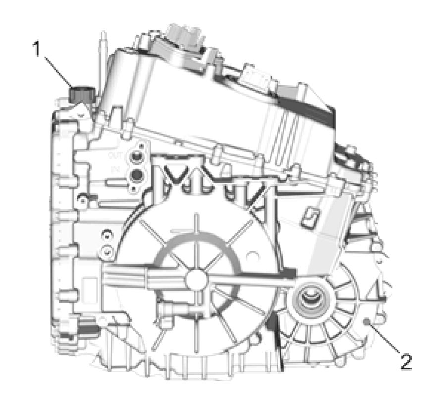 |
|
Fig. 25: Transmission Fluid Filler Cap And Fluid Level Hole Plug |
6. While the vehicle is idling, remove the fluid level hole plug (2). Allow any fluid to drain.
• If the fluid is flowing as a steady stream, wait until the fluid begins to drip.
• If no fluid comes out, add fluid until fluid drips out.
• Proper level is achieved when fluid slowly drips at a rate of 3 drips per second.
• Reinstall the fluid level hole plug. Refer to Fastener Specifications (Off-Vehicle)Fastener
Specifications (On-Vehicle).
7. Inspect the fluid color. The fluid should be red or dark brown.
• If the fluid color is very dark or black and has a burnt odor, inspect the fluid for excessive metal particles
or other debris. Refer to Road Test to verify transmission operation. Change the transmission fluid if no
other conditions are found.
• Fluid that is cloudy or milky or appears to be contaminated with water indicates engine coolant or water
contamination. Refer to Engine Coolant/Water in Transmission.
8. Inspect for external leaks. Refer to Fluid Leak Diagnosis
9. If the fluid was changed, reset the transmission oil life monitor if applicable.
LINE PRESSURE CHECK
Special Tools
EN 21867-A Pressure Gauge
For equivalent regional tools refer to Special Tools
Main Line Pressure Check
 |
|
Fig. 26: Transmission Fluid Pressure Test Hole Plug |
WARNING: Keep the brakes applied at all times in order to prevent unexpected vehicle
motion. Personal injury may result if the vehicle moves unexpectedly.
1. Install a scan tool.
NOTE: Depending on the hybrid/EV battery state of charge the engine may not start.
To start or keep the engine running open the hood.
2. Start the engine.
3. If the engine will not start, refer to Engine Will Not Crank - Crankshaft Will Not Rotate .
4. Inspect the transmission for the proper fluid level. Refer to Transmission Fluid Level and Condition Check.
5. Inspect the manual linkage at the transmission for proper function.
6. Turn the engine OFF.
NOTE: You may need to remove or disconnect components in order to gain access to
the transmission line pressure test hole plug.
7. Remove the line pressure test hole plug.
8. Install the EN 21867-A pressure gauge.
9. Access the Scan Tool Transmission Output Controls for the Line Pressure Control Solenoid.
10. Start the engine.
NOTE: In order to achieve accurate line pressure readings, the following procedure
must be performed at least 3 times in order to gather uniform pressure
readings. Also if you do not have the hood open the engine may go in to
AutoStop.
The scan tool is only able to control the line Pressure Control solenoid in
PARK and NEUTRAL with engine speeds below 1500 RPM. This protects the
clutches from extreme high or low line pressures.
11. Use the scan tool to increase and decrease the Line Pressure Control Solenoid in increments of approximately
100 KPa (15 psi). The scan tool commands the increment values automatically.
12. Allow the pressure to stabilize between increments.
13. Compare your pressure readings on the scan tool to those indicated on the EN 21867 - A pressure gauge.
14. If the pressure readings vary greatly, refer to Automatic Transmission Fluid Pump Pressure High or Low
15. Install the pressure test hole plug. Tighten the pressure plug to 11 N.m (97 lb in).
DRIVE MOTOR POWER INVERTER MODULE FLUID SEAL PRESSURE TEST
 |
|
Fig. 27: Drive Motor Power Inverter Module Fluid Seal Pressure Test |
|
Callout |
Component Name |
|
Preliminary Procedure Install Drive Motor Power Inverter Module. Refer to:Drive Motor Power Inverter Module Installation. | |
|
1 |
Drive Motor Power Inverter Module Coolant Pipe CAUTION: Refer to Fastener Procedure
Special Tools
For equivalent regional tools, refer to Special Tools. |
ROAD TEST
NOTE: The Road Test Procedure should be performed only as part of the Symptom
Diagnosis. Refer to Symptoms - Automatic Transmission.
The following test provides a method of evaluating the condition of the automatic transmission. The test is divided
into the following parts:
• Low Voltage Electrical Function Check
• Hydraulic Control Function Check
• High Voltage Electric Machine Control Function Check
NOTE: Complete the test in the sequence given.
Before the road test, ensure the following:
• The engine is performing properly.
• Transmission fluid level is correct. Refer to Transmission Fluid Level and Condition Check.
• Tire pressure is correct.
• The high voltage battery is above 30% state of charge.
During the road test:
• Perform the test only when traffic conditions permit.
• Operate the vehicle in a controlled, safe manner.
• Observe all traffic regulations.
• To view the scan tool data while conducting this test, take along qualified help in order to operate the vehicle
safely, or review the data after the drive audit.
• Observe any unusual sounds or smells.
After the road test, check the following:
• Inspect for proper transmission fluid level. Refer to Transmission Fluid Level and Condition Check.
• Inspect for any diagnostic trouble codes (DTCs) that may have set during the testing. Refer to the applicable
DTC.
• Monitor the scan tool data for any abnormal readings or data.
• Inspect for fluid leaks. Refer to Fluid Leak Diagnosis.
Low Voltage Electrical Function Check
Perform this procedure first in order to ensure the electronic transmission components are functioning properly. If
these components are not checked, a simple electrical condition could be misdiagnosed.
1. Connect the scan tool.
2. Ensure the gear selector is in PARK and set the parking brake.
3. Start the vehicle. To ensure the engine starts, open the hood.
4. With a scan tool, monitor the transmission data parameters and compare them to typical scan tool data
definitions.
Refer to Hybrid Powertrain Control Module Scan Tool Information for typical data values. Data that is
questionable may indicate a concern.
5. Monitor transmission range on the scan tool data list.
1. Apply the brake pedal and ensure the parking brake is set.
2. Move the gear selector through all ranges.
3. Pause 2 to 3 seconds in each range.
4. Return gear selector to PARK.
5. Verify that all selector positions match the scan tool display.
6. Check accelerator position sensor input.
1. Apply the brake pedal and ensure the parking brake is set while monitoring accelerator pedal data.
2. Ensure the gear selector is in PARK.
3. Monitor the scan tool Accelerator Pedal Position while increasing and decreasing engine speed with the
accelerator pedal. The scan tool Accelerator Pedal Position percentage should increase and decrease
with engine speed.
If any of the above checks do not perform properly, record the result for reference after completion of the road test.
Hydraulic and Electric Machine Control Function Checks
NOTE: If in the above steps you opened the hood to start the engine make sure it is closed
before driving the vehicle.
Charge vehicle to greater than 25% state of charge to enter EV only mode, if not already done. Perform the following
steps while monitoring Hybrid/EV data list:
1. Drive vehicle at 35 mph at steady state.
2. Accelerate safely with 100% accelerator pedal to 55 mph, then drive at or above 55 mph.
1. Monitor for any excessive variable low clutch slip speed during acceleration.
3. Slow vehicle by shifting to LOW or pressing the regenerative braking button.
4. Switch vehicle to Hold Mode to start the engine (if needed) by pressing the Drive Mode Button 4 times.
5. Drive vehicle below 35 mph with stop-and-go city driving.
1. The engine will stop and start as needed.
2. Ensure smooth operation free of excessive vibrations.
6. Accelerate safely with 100% accelerator pedal to 55 mph, then drive at or above 55 mph.
1. Monitor for any excessive variable low clutch slip speed during acceleration.
2. Ensure variable high clutch engages during 55 mph steady state driving and monitor for slip.
7. Slow vehicle by shifting to LOW or pressing the regenerative braking button.
1. Ensure smooth deceleration as variable low clutch re-engages at lower vehicle speeds.
Reverse
Perform the following test safely:
1. With the vehicle stopped, move the gear selector to REVERSE.
2. Slowly accelerate the vehicle.
3. Verify that there is no noticeable slip, noise or vibration.
4. This test ensures the control system is properly applying torque in the reverse direction.
This procedure checks general functionality of the transmission. For diagnosing intermittent problems, try to
duplicate the conditions of the original complaint. Refer to freeze frame records if a DTC set to determine the
conditions.
CLUTCH PLATE DIAGNOSIS
Composition Plates
Dry the plates and inspect the plates for the following conditions:
• Pitting
• Flaking
• Delamination - splitting or separation of bonded clutch material
• Wear
• Glazing
• Cracking
• Charring
• Chips or metal particles embedded in the lining
Replace a composition plate which shows any of these conditions.
Steel Plates
Wipe the plates dry and check the plates for heat discoloration. If the surfaces are smooth, even if color smear is
indicated, you can reuse the plate. If the plate is discolored with heat spots or if the surface is scuffed, replace the
plate.
Causes of Burned Clutch Plates
The following conditions can result in a burned clutch plate:
• Incorrect usage of clutch or apply plates
• Engine coolant or water in the transmission fluid
• A cracked clutch piston
• Damaged or missing seals
• Low line pressure
• Valve body conditions
• The valve body face is not flat.
• Porosity is between channels.
• The valve bushing clips are improperly installed.
• The checkballs are misplaced.
• The TeflonA® seal rings are worn or damaged.
ENGINE COOLANT/WATER IN TRANSMISSION
CAUTION: The antifreeze or water will deteriorate the seals, gaskets and the glue that bonds
the clutch material to the pressure plate. Both conditions may cause damage to the
transmission.
If antifreeze or water has entered the transmission, perform the following:
1. Disassemble the transmission.
2. Replace all of the rubber type seals. The coolant will attack the seal material which will cause leakage.
3. Replace the composition-faced clutch plate assemblies. The facing material may separate from the steel center
portion.
4. Replace all of the nylon parts - washers.
5. Replace the torque dampener.
6. Thoroughly clean and rebuild the transmission, using new gaskets and oil filter.
7. Flush the cooler lines after the transmission cooler has been properly repaired or replaced.
CASE POROSITY REPAIR
Some external leaks are caused by case porosity in non-pressurized areas. You can usually repair these leaks with the
transmission in the vehicle.
1. Thoroughly clean the area to be repaired with a cleaning solvent. Air dry the area.
WARNING: Epoxy adhesive may cause skin irritations and eye damage. Read and follow
all information on the container label as provided by the manufacturer.
2. Using instructions from the manufacturer, mix a sufficient amount of an epoxy to make the repair.
3. While the transmission case is still hot, apply the epoxy. You can use a clean, dry soldering acid brush to clean
the area and also to apply the epoxy cement. Make certain that the area to be repaired is fully covered.
4. Allow the epoxy cement to cure for three hours before starting the engine.
5. Repeat the fluid leak diagnosis procedures.
BUSHING AND MATING SHAFT INSPECTION
NOTE: Proper bushing and corresponding mating shaft inspection should be performed
before replacing the bushing, shaft, and in some cases, the component which
houses the bushing. Thoroughly clean and dry the bushing and shaft surfaces
before inspecting for damage.
Any of the following bushing conditions require replacement of the bushing and/or housing:
• Discoloration due to heat distress
• Misalignment or displacement of bushing as a result of spinning in housing
• Medium to heavy scoring that can be easily detected with fingernail. Light scoring is a normal condition.
• Debris embedded into the bushing lining material
• Obvious damage, including excessive and uneven wear
• Excessive polishing. Minor polishing of the bushing is an indication of normal wear and does not require
replacement.
Any of the following conditions require replacement of the bushing's mating shaft:
• Discoloration due to heat distress
• Rough surface finish that can be easily detected with finger
• Obvious shaft abnormalities, including warping or uneven surfaces
• Obvious damage or cracking
AUTOMATIC TRANSMISSION FLUID PUMP PRESSURE HIGH OR LOW
|
Checks |
Causes |
|
Automatic Transmission Fluid Pump |
|
| ||||||||
|
AUTOMATIC TRANSMISSION FLUID LEAKS |
|
Checks |
Causes |
|
Torque Dampener |
Inspect for damage. |
|
Case Assembly |
|
|
Torque Dampener and Differential |
|
| ||||
|
FLUID LEAK DIAGNOSIS |
General Method
1. Verify that the leak is transmission fluid.
CAUTION: Do not clean using brake cleaner or other reactive solvents as these solvents
can damage rubber gaskets, seals and bushings.
2. Thoroughly clean the suspected leak area using a rag.
3. Operate the vehicle for 24 km (15 mi), or until normal operating temperatures are reached.
4. Park the vehicle over clean paper or cardboard.
5. Shut OFF the engine.
6. Look for fluid spots on the paper.
7. Make the necessary repairs.
Powder Method
CAUTION: Do not clean using brake cleaner or other reactive solvents as these solvents
can damage rubber gaskets, seals and bushings.
1. Thoroughly clean the suspected leak area using a rag.
2. Apply an aerosol type leak tracing powder to the suspected leak area.
3. Operate the vehicle for 24 km (15 mi), or until normal operating temperatures are reached.
4. Shut OFF the engine.
5. Inspect the suspected leak area.
6. Trace the leak path through the powder in order to find the source of the leak.
7. Make the necessary repairs.
Dye and Black Light Method
A fluid dye and black light kit is available from various tool manufacturers.
1. Follow the manufacturer's instructions in order to determine the amount of dye to use.
2. Operate the vehicle for 24 km (15 mi) or until normal operating temperatures are reached.
3. Detect the leak with the black light.
4. Make the necessary repairs.
Find the Cause of the Leak
Pinpoint the leak and trace the leak back to the source. You must determine the cause of the leak in order to repair the
leak properly. For example, if you replace a gasket, but the sealing flange is bent, the new gasket will not repair the
leak. You must also repair the bent flange. Before you attempt to repair a leak, check for the following conditions,
and make repairs as necessary:
Gaskets
• Fluid level/pressure is too high
• Plugged vent or drain-back holes
• Improperly tightened fasteners
• Dirty or damaged threads
• Warped flanges or sealing surface
• Scratches, burrs, or other damage to the sealing surface
• Damaged or worn gasket
• Cracking or porosity of the component
• Improper sealant used, where applicable
• Incorrect gasket
Seals
• Fluid level/pressure is too high
• Plugged vent or drain-back holes
• Damaged seal bore
• Damaged or worn seal
• Improper installation
• Cracks in component
• Manual shaft or output shaft surface is scratched, nicked, or damaged
• Loose or worn bearing causing excess seal wear
Possible Points of Fluid Leaks
Control Valve Body Cover
• Incorrectly tightened bolts
• Improperly installed or damaged gasket/seal
• Damaged mounting face
• Incorrect gasket seal
Case Leak
• Damaged manual shift shaft seal
• Loose or damaged oil cooler lines/seals
• Worn or damaged drive shaft oil seal
• Loose line pressure plug or fluid level hole plug
• Porous casting
• Warped torque dampener and differential housing
• Damaged torque dampener and differential housing gasket
Torque Dampener and Differential Housing
• Damaged torque dampener and differential housing gasket.
• Worn or damaged drive shaft oil seal
• Porous casting of the torque dampener and differential housing
Leak at the Vent
• Overfilled system
• Water or coolant in the fluid; The fluid will appear milky
• Transmission case porous
• Incorrect fluid level indicator causing an overfilled system
• Plugged vent
|
WHINE/GROWL NOISE THAT CHANGES WITH VEHICLE SPEED | ||||||||||||||
|
|
NOISE IN DRIVE OR REVERSE GEAR | ||||||||
| ||||||||
|
VIBRATION |
|
Checks |
Causes |
|
Lug bolts for the Input Drive Flange |
Inspect for loose bolts. |
|
Input Internal Gear Thrust Bearing |
Inspect for wear or damage. |
|
Output Carrier Thrust Bearing |
Inspect the bearing for wear or damage. |
|
Output Carrier |
|
|
Front Differential Carrier |
Inspect for damaged gears and bearings. |
NOISE AND VIBRATION ANALYSIS
A noise or vibration that is noticeable when the vehicle is in motion MAY NOT be the result of the transmission.
If noise or vibration is noticeable in PARK and NEUTRAL with the engine at idle, but is less noticeable as RPM
increases, the cause may be from poor engine performance.
• Inspect the tires for the following conditions:
• Uneven wear
• Imbalance
• Mixed sizes
• Mixed radial and bias ply
• Inspect the suspension components for the following conditions:
• Alignment wear or damage
• Loose fasteners
• Driveline damage or wear
• Inspect the engine and transmission mounts for damage and loose bolts.
• Inspect the transmission case mounting holes for the following conditions:
• Missing bolts, nuts, and studs
• Stripped threads
• Cracks
• Inspect the flywheel for the following conditions:
• Missing or loose bolts
• Cracks
• Imbalance
• Inspect the input drive flange for the following conditions:
• Missing or loose bolts or lugs
• Missing or loose balance weights
• Imbalance caused by heat distortion or fluid contamination
|
NO PARK OR DRIVE | ||||||
|
|
NO DRIVE IN ALL RANGES | ||||||||||||||||||
|
|
NO REVERSE GEAR | ||||||
|
| ||||||||||||||
|
NO DRIVE OR REVERSE GEAR |
|
Checks |
Causes |
|
Variable Low Clutch Assembly |
|
|
Variable High Clutch Assembly |
|
|
HARSH, SOFT, DELAYED OR SLIPPING DRIVE OR REVERSE GEAR | |
|
Checks |
Causes |
|
Variable Low Clutch Assembly |
|
|
Variable High Clutch Assembly |
|
|
Control Valve Assembly |
|
|
Checks |
Causes |
|
|
STUCK IN DRIVE OR REVERSE GEAR | ||||
|
|
HARSH GARAGE SHIFT | ||||
|
SEIZED ENGINE OR TRANSMISSION SEPARATION
Removal Procedure
WARNING: Do not use a service jack in locations other than those specified to lift this
vehicle. Lifting the vehicle with a jack in those other locations could cause the
vehicle to slip off the jack and roll; this could cause injury or death.
1. Ensure that the vehicle is properly supported and squarely positioned. Refer to Lifting and Jacking the
Vehicle .
WARNING: Always perform the High Voltage Disabling procedure prior to servicing any
High Voltage component or connection. Personal Protection Equipment (PPE)
and proper procedures must be followed.
The High Voltage Disabling procedure will perform the following tasks:
• Identify how to disable high voltage.
• Identify how to test for the presence of high voltage.
• Identify condition under which high voltage is always present and
personal protection equipment (PPE) and proper procedures must be
followed.
Failure to follow the procedures exactly as written may result in serious injury
or death.
2. Disconnect the battery negative cable. Refer to Battery Negative Cable Disconnection and Connection
3. Disable the high voltage system and disconnect the A4 Hybrid/EV Battery Pack high voltage harness
connector at the T6 Power Inverter Module. Refer to High Voltage Disabling .
4. Set the parking brake.
5. Remove the engine and transmission assembly from the vehicle. Refer to Engine Replacement , and
Transmission Replacement.
6. With the engine and transmission assembly on the cradle, support both the engine and transmission.
 |
|
Fig. 28: Drive Motor Power Inverter Module Cover And Water Outlet |
7. Remove Drive Motor Power Inverter Module Cover (1). Refer to Drive Motor Power Inverter Module
Cover Removal
8. Remove Water Outlet (2). Refer to Water Outlet Replacement
9. Install Drive Motor Power Inverter Module Cover (1). Refer to Drive Motor Power Inverter Module Cover
Installation
 |
|
Fig. 29: Hidden Torque Dampener And Differential Housing Bolts |
10. Mark the location of the three hidden torque dampener and differential housing bolts 1 to 3.
11. With an air chisel, remove the torque dampener and differential housing material in order to gain access to the
three hidden bolts.
12. With a 13 mm box end wrench, remove the torque dampener and differential housing bolts including the now
exposed hidden bolts. (Qty: 16)
 |
|
Fig. 30: Transmission Case And Torque Dampener And Differential Housing |
13. With an appropriate hoist, separate the transmission case (1) from the torque dampener and differential
housing (2).
 |
|
Fig. 31: Input Internal Gear, Retaining Ring And Transmission Torque Dampener Bolts |
14. Remove Input Internal Gear Retaining Ring (1)
15. Remove Input Internal Gear (2)
16. Remove Automatic Transmission Torque Dampener Bolts (3) (Qty: 6)
17. Remove the torque dampener and differential housing to engine bolts.
18. Remove the torque dampener and differential housing from the engine.
19. Remove the input drive flange from the automatic transmission flex plate.
Installation Procedure
1. Determine the correct torque dampener thrust washer. Refer to Automatic Transmission Torque Dampener
Thrust Washer Measurement.
2. Using a NEW torque dampener and differential housing assembly, install the torque dampener and differential
housing to the transmission case. Refer to Automatic Transmission Torque Dampener and Differential
Housing Installation.
REPAIR INSTRUCTIONS - ON VEHICLE
TRANSMISSION CONTROL LEVER KNOB REPLACEMENT
 |
|
Fig. 32: Transmission Control Lever Knob |
|
Callout |
Component Name |
|
Transmission Control Lever Knob Procedure
| |
|
1 |
3. Remove transmission control lever knob from the transmission control. NOTE: Considerable effort may be necessary to release the |
| ||||
|
TRANSMISSION CONTROL REPLACEMENT (WITH BASE) |
 |
|
Fig. 33: Transmission Control (With Base) |
Callout Component Name
Preliminary Procedures
1. Remove Transmission Control Lever Knob. Refer to Transmission Control Lever Knob Replacement
2. Remove Front Floor Console. Refer to Front Floor Console Replacement
WARNING:
After
installing the
transmission
range
selector shift
cable, pull
up and push
down on
ALL
connections
to verify that
|
Callout |
Component Name |
|
the
| |
|
1 |
Transmission Control Lever Housing Bracket Nut (Qty: 5) CAUTION: Refer to Caution Tighten 9 N.m (80 lb in) |
|
2 |
Transmission Control Procedure
|
TRANSMISSION CONTROL REPLACEMENT (WITHOUT BASE)
Removal Procedure
1. Set the park brake.
2. Remove Front Floor Console. Refer to Front Floor Console Replacement
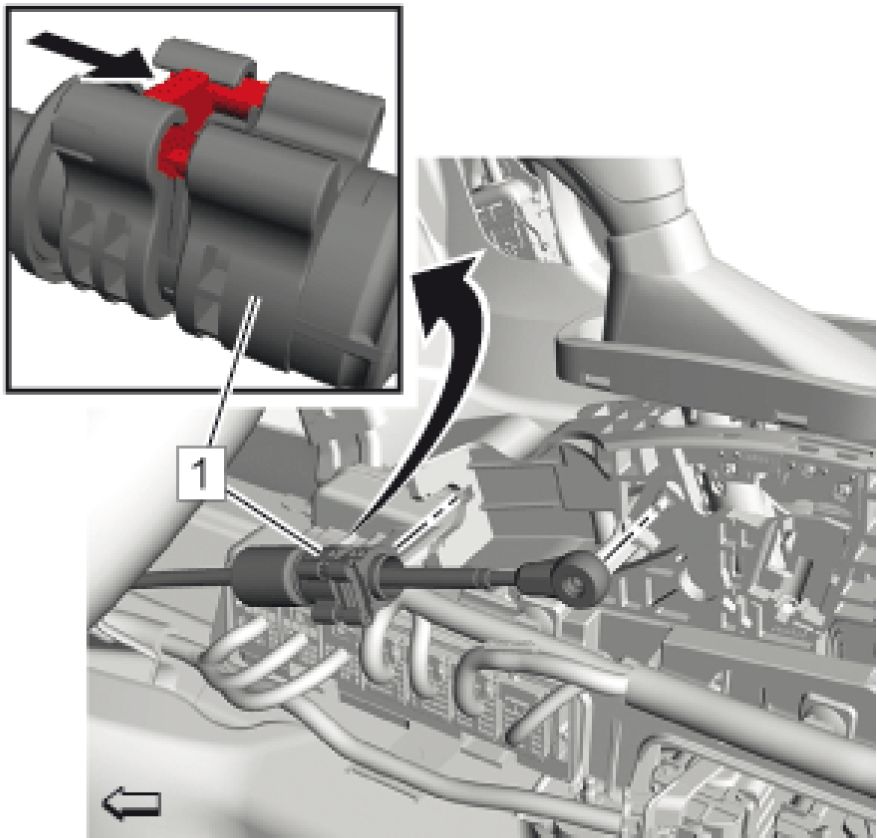 |
|
Fig. 34: Range Selector Lever Cable And Transmission Control |
3. Remove the range selector lever cable (1) from the transmission control. Release the cable from the bracket by
pushing the retainer (arrow).
4. Disconnect the transmission control electrical connector.
 |
|
Fig. 35: Nut And Washer Courtesy of GENERAL MOTORS COMPANY |
5. Remove the nut and washer (1) from the control assembly.
 |
|
Fig. 36: Main Shaft Bolt Courtesy of GENERAL MOTORS COMPANY |
6. Remove the main shaft bolt (1).
 |
|
Fig. 37: Transmission Control Assembly Courtesy of GENERAL MOTORS COMPANY |
7. Pull the transmission control assembly (1) rearward and upward to unseat it from the transmission control
base.
8. Remove the transmission control assembly from the vehicle.
Installation Procedure
1. Position the transmission control assembly to the transmission control base.
 |
|
Fig. 38: Transmission Control Assembly Courtesy of GENERAL MOTORS COMPANY |
2. Push the transmission control assembly (1) downward and forward to seat it to the transmission control base.
NOTE: Ensure the flats of the bolt align with the transmission control assembly flat
points inside the base before tightening the nut.
 |
|
Fig. 39: Main Shaft Bolt Courtesy of GENERAL MOTORS COMPANY |
3. Install the main shaft bolt (1).
 |
|
Fig. 40: Nut And Washer Courtesy of GENERAL MOTORS COMPANY |
CAUTION: Refer to Fastener Caution .
NOTE: When installing the transmission control main shaft bolt, the face of the bolt
must be held in the slot of the mounting bracket as the nut is torqued to
ensure it remains seated and doesn't rotate out of the slot. Failure to perform
this task can result in a loose shifter feel, squeaks & rattles, or excessive cross
car lash resulting in a customer's poor perceived quality of the system.
4. Install the nut and washer (1) to the control assembly and tighten to 7 N.m (62 lb in).
5. Connect the transmission control electrical connector.
 |
|
Fig. 41: Range Selector Lever Cable And Transmission Control |
WARNING: After installing the transmission range selector shift cable, pull up and push
down on ALL connections to verify that the connections are fully seated and
properly engaged. Failure to perform this task can result in the vehicle not
being able to shift into PARK causing potential vehicle damage and bodily
injury.
6. Install the range selector lever cable (1) to the transmission control.
7. Install Front Floor Console. Refer to Front Floor Console Replacement
8. Release the park brake.
9. Adjust the automatic transmission range selector lever cable. Refer to Range Selector Lever Cable
Adjustment
DRIVE MOTOR GENERATOR POWER INVERTER MODULE REPLACEMENT
Removal Procedure
 |
|
Fig. 42: Drive Motor Power Inverter Module Cover And Components |
1. Remove Drive Motor Power Inverter Module Cover (2). Refer to Drive Motor Power Inverter Module
Cover Replacement
 |
|
Fig. 43: Drive Motor Power Inverter Module And Components |
2. Remove Drive Motor Power Inverter Module (3). Refer to Drive Motor Power Inverter Module Removal
Installation Procedure
 |
|
Fig. 44: Drive Motor Power Inverter Module And Components |
1. Install Drive Motor Power Inverter Module (3). Refer to Drive Motor Power Inverter Module Installation
 |
|
Fig. 45: Drive Motor Power Inverter Module Cover And Components |
2. Install Drive Motor Power Inverter Module Cover (2). Refer to Drive Motor Power Inverter Module Cover
Replacement
3. Program the power inverter module and the immobilizer control module. Refer to Control Module
References
DRIVE MOTOR POWER INVERTER MODULE COVER REPLACEMENT
Special Tools
BO-38185 Hose Clamp Pliers
Equivalent regional tools: Special Tools
Removal Procedure
WARNING: Always perform the High Voltage Disabling procedure prior to servicing any
High Voltage component or connection. Personal Protection Equipment (PPE)
and proper procedures must be followed.
The High Voltage Disabling procedure will perform the following tasks:
• Identify how to disable high voltage.
• Identify how to test for the presence of high voltage.
• Identify condition under which high voltage is always present and
personal protection equipment (PPE) and proper procedures must be
followed.
Failure to follow the procedures exactly as written may result in serious injury
or death.
1. Set the parking brake.
2. Disconnect the battery negative cable. Refer to Battery Negative Cable Disconnection and Connection
3. Disable the high voltage system and disconnect the A4 Hybrid/EV Battery Pack high voltage harness
connector at the T6 Power Inverter Module. Refer to High Voltage Disabling .
 |
|
Fig. 46: Radiator Surge Tank, Bracket And Clips |
4. Remove Radiator Surge Tank Clip (1)
NOTE: To remove the radiator surge tank from the radiator surge tank bracket move it
in driving direction.
5. Move the radiator surge tank (4) in arrow direction to release the radiator surge tank clip (2) from the radiator
surge tank bracket (3).
6. Relocate the radiator surge tank out of the way of the Drive Motor Power Inverter Module Cover and secure
with tie strap.
 |
|
Fig. 47: Range Selector Lever Cable And Range Selector Lever Cable Lever |
7. Remove Range Selector Lever Cable (1) @ Range Selector Lever Cable Lever
 |
|
Fig. 48: Range Selector Lever Cable And Transmission Range Selector Lever Cable Bracket |
8. Remove the range selector lever cable (1) from the range selector lever cable bracket.
Release the cable from the bracket by pushing the retainer (arrow).
 |
|
Fig. 49: Drive Motor Battery Positive And Negative Cable Connector |
9. Place a shop towel over the drive motor battery positive and negative cable connector (1) to prevent coolant
from entering the cover.
10. Raise and support the vehicle. Refer to Lifting and Jacking the Vehicle
11. Remove Front Wheelhouse Liner. Refer to Front Wheelhouse Liner Replacement (Left Side) Front
Wheelhouse Liner Replacement (Right Side)
12. Drain Drive Motor Generator Power Inverter Module Cooling System. Refer to Drive Motor Generator
Power Inverter Module Cooling System Draining and Filling
 |
|
Fig. 50: Coolant Hose And Clamp Courtesy of GENERAL MOTORS COMPANY |
NOTE: The following 2 steps are necessary to prevent contamination of other
components while removing residual coolant with shop air.
13. Loosen Clamp (2)
14. Disconnect Drive Motor Generator Control Module Cooling Outlet Hose (1)
15. Lower the vehicle.
 |
|
Fig. 51: Drive Motor Generator Power Inverter Module Outlet Hose And Clamp |
16. Loosen the drive motor generator power inverter module outlet hose clamp (2), using the BO-38185 pliers.
17. Remove the drive motor generator power inverter module outlet hose (1).
18. Using shop air, blow air through the drive motor power inverter module cooling outlet hose to remove residual
coolant from the drive motor power inverter module.
 |
|
Fig. 52: Drive Motor Battery Positive And Negative Cable Connector And Bolts |
19. Remove Drive Motor Battery Positive and Negative Cable Connector Bolts (1) (Qty: 4)
20. Remove Drive Motor Battery Positive and Negative Cable Connector (2)
 |
|
Fig. 53: Engine Wiring Harness Bracket Nut And Stud |
21. Remove Engine Wiring Harness Bracket Nut (1)
22. Remove the engine wiring harness stud (2).
 |
|
Fig. 54: Drive Motor Power Inverter Module Cover And Components |
23. Remove Drive Motor Power Inverter Module Cover (2). Refer to Drive Motor Power Inverter Module
Cover Removal
Installation Procedure
 |
|
Fig. 55: Drive Motor Power Inverter Module Cover And Components |
1. Install Drive Motor Power Inverter Module Cover (2). Refer to Drive Motor Power Inverter Module Cover
Installation
 |
|
Fig. 56: Engine Wiring Harness Bracket Nut And Stud |
CAUTION: Refer to Fastener Caution
2. Install the engine wiring harness stud (2) and tighten to 9 N.m (80 lb in).
3. Install and tighten Engine Wiring Harness Bracket Nut (1) to 9 N.m (80 lb in)
 |
|
Fig. 57: Drive Motor Battery Positive And Negative Cable Connector And Bolts (With Bolt Tightening Courtesy of GENERAL MOTORS COMPANY |
4. Install Drive Motor Battery Positive and Negative Cable Connector (2)
5. Tighten Drive Motor Battery Positive and Negative Cable Connector Bolts (1) (Qty: 4) in sequence to 9 N.m
(80 lb in)
 |
|
Fig. 58: Drive Motor Generator Power Inverter Module Outlet Hose And Clamp |
6. Install the drive motor generator power inverter module outlet hose (1).
7. Install the drive motor generator power inverter module outlet hose clamp (2), using the BO-38185 pliers.
 |
|
Fig. 59: Range Selector Lever Cable And Transmission Range Selector Lever Cable Bracket |
8. Install the range selector lever cable (1) to the range selector lever cable bracket.
The retainer snaps automatically in.
 |
|
Fig. 60: Range Selector Lever Cable And Range Selector Lever Cable Lever |
9. Install Range Selector Lever Cable (1) @ Range Selector Lever Cable Lever
10. Adjust Range Selector Lever Cable. Refer to Range Selector Lever Cable Adjustment
 |
|
Fig. 61: Radiator Surge Tank, Bracket And Clips |
11. Remove the tie strap holding the radiator surge tank.
NOTE: To install the radiator surge tank to the radiator surge tank bracket move it
against driving direction.
12. Move the radiator surge tank (4) in arrow direction to clip in the radiator surge tank clip (2) into the radiator
surge tank bracket (3).
13. Install Radiator Surge Tank Clip (1)
14. Raise the vehicle.
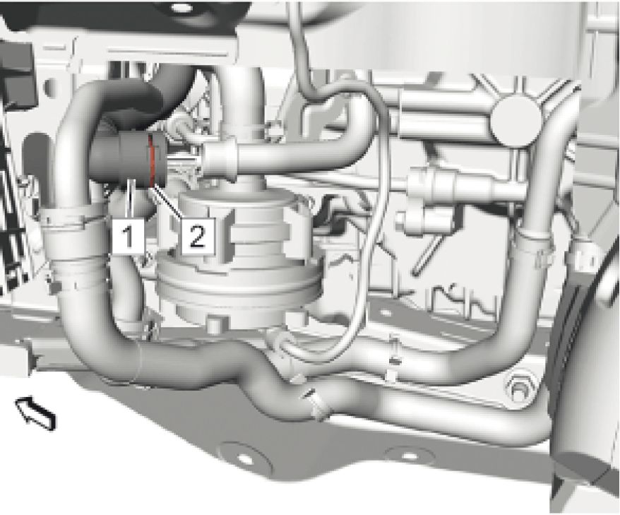 |
|
Fig. 62: Coolant Hose And Clamp Courtesy of GENERAL MOTORS COMPANY |
15. Connect Drive Motor Generator Control Module Cooling Outlet Hose (1)
16. Install Clamp (2)
17. Install Front Wheelhouse Liner. Refer to Front Wheelhouse Liner Replacement (Left Side) Front
Wheelhouse Liner Replacement (Right Side)
18. Fill Drive Motor Generator Power Inverter Module Cooling System. Refer to Drive Motor Generator Power
Inverter Module Cooling System Draining and Filling
19. Lower the vehicle.
20. Enable the high voltage system and connect the A4 Hybrid/EV Battery Pack high voltage harness connector at
the T6 Power Inverter Module. Refer to High Voltage Enabling .
21. Connect the battery negative cable. Refer to Battery Negative Cable Disconnection and Connection
AUTOMATIC TRANSMISSION RANGE SELECTOR LEVER REPLACEMENT
 |
|
Fig. 63: Automatic Transmission Range Selector Lever |
| ||
|
Preliminary Procedures |
1. Set the parking brake.
WARNING:
After
installing the
transmission
range
selector shift
cable, pull
up and push
down on
ALL
connections
Callout
to verify that
the
connections
are fully
seated and
properly
engaged.
Failure to
perform this
task can
result in the
vehicle not
being able to
shift into
PARK
causing
potential
vehicle
damage and
bodily injury.
Component Name
2. Remove Range Selector Lever Cable @ Automatic Transmission Range Selector Lever. Refer to Range
Selector Lever Cable Replacement
Transmission Range Selector Lever Nut
WARNING:
Hold the
transmission
range
selector
lever while
removing or
installing the
lever
retaining
nut. Failure
to hold the
lever can
cause
damage to
the
transmission
internal park
system
components
which could
allow the
vehicle to
| ||||||
|
RANGE SELECTOR LEVER CABLE REPLACEMENT |
Removal Procedure
1. Set the parking brake.
 |
|
Fig. 64: Range Selector Lever Cable And Range Selector Lever Cable Lever |
2. Remove Range Selector Lever Cable (1) @ Range Selector Lever Cable Lever
 |
|
Fig. 65: Range Selector Lever Cable And Transmission Range Selector Lever Cable Bracket |
3. Remove the range selector lever cable (1) from the range selector lever cable bracket.
Release the cable from the bracket by pushing the retainer (arrow).
4. Remove Front Floor Console. Refer to Front Floor Console Replacement
 |
|
Fig. 66: Range Selector Lever Cable And Transmission Control |
Courtesy of GENERAL MOTORS COMPANY
5. Remove the range selector lever cable (1) from the transmission control.
Release the cable from the bracket by pushing the retainer (arrow).
6. Note the routing of the range selector lever cable.
 |
|
Fig. 67: Range Selector Lever Cable And Grommet |
7. Gently pry the grommet out, then remove the range selector lever cable (1) from the inside of the vehicle.
Installation Procedure
 |
|
Fig. 68: Range Selector Lever Cable And Grommet Courtesy of GENERAL MOTORS COMPANY |
1. Position the range selector lever cable in the vehicle.
2. Install the range selector lever cable grommet (1) into the panel.
 |
|
Fig. 69: Range Selector Lever Cable And Transmission Control |
3. Install the range selector lever cable (1) to the transmission control.
The retainer snaps automatically in.
4. Install Front Floor Console. Refer to Front Floor Console Replacement
 |
|
Fig. 70: Range Selector Lever Cable And Transmission Range Selector Lever Cable Bracket |
5. Install the range selector lever cable (1) to the range selector lever cable bracket.
The retainer snaps in automatically.
 |
|
Fig. 71: Range Selector Lever Cable And Range Selector Lever Cable Lever |
WARNING: After installing the transmission range selector shift cable, pull up and push
down on ALL connections to verify that the connections are fully seated and
properly engaged. Failure to perform this task can result in the vehicle not
being able to shift into PARK causing potential vehicle damage and bodily
injury.
6. Install Range Selector Lever Cable (1) @ Range Selector Lever Cable Lever
7. Adjust Range Selector Lever Cable. Refer to Range Selector Lever Cable Adjustment
RANGE SELECTOR LEVER CABLE ADJUSTMENT
1. Set the parking brake.
 |
|
Fig. 72: Retaining Collar And Range Select Cable Adjuster Clip |
2. Pull the retaining collar (1) forward, then release the range select cable adjuster clip (2) by pushing out on the
adjuster clip from the underneath.
 |
|
Fig. 73: Range Selector Lever Courtesy of GENERAL MOTORS COMPANY |
NOTE: Adjust the automatic transmission range selector lever cable while the
transmission and the transmission control are in the Park position only.
Failure to do so may cause false adjustment.
3. Verify the range selector lever (1) is in the park position.
Rotate the lever counterclockwise till the stop (arrow).

Fig. 74: Transmission Control Lever
Courtesy of GENERAL MOTORS COMPANY
NOTE: Adjust the automatic transmission range selector lever cable while the
transmission and the transmission control are in the park position only. Failure
to do so may cause false adjustment.
4. Verify the transmission control lever (1) is in the park position.
 |
|
Fig. 75: Retaining Collar And Adjuster Clip |
5. Depress the adjuster clip (2) locking the adjuster clip completely, then release the retaining collar (1).
WARNING: After installing the transmission range selector shift cable, pull up and push
down on ALL connections to verify that the connections are fully seated and
properly engaged. Failure to perform this task can result in the vehicle not
being able to shift into PARK causing potential vehicle damage and bodily
injury.
6. Ensure that the cable adjuster is secured.
7. Check the transmission control lever in all gear selections for proper operation.
RANGE SELECTOR LEVER CABLE BRACKET REPLACEMENT
 |
|
Fig. 76: Range Selector Lever Cable Bracket |
| ||||||||
|
TRANSMISSION FLUID DRAIN AND FILL | ||||||||
 |
|
Fig. 77: Transmission Fluid Drain and Fill |
| ||||||
|
Transmission Fluid Filler Cap | ||||||
NOTE:
• Transmission
will require
approximately
6.5 - 7 liters (7
- 7.4 quarts)
of fluid.
• Fill the
transmission
to the proper
| ||||
|
AUTOMATIC TRANSMISSION FLUID PRESSURE TEST HOLE PLUG REPLACEMENT |
 |
|
Fig. 78: Automatic Transmission Fluid Pressure Test Hole Plug |
Callout Component Name
Preliminary Procedures
1. Remove Water Outlet. Refer to Water Outlet Replacement
2. Remove Front Underbody Air Deflector. Refer to Front Underbody Air Deflector Replacement
3. Remove Front Wheelhouse Liner (Left Side). Refer to Front Wheelhouse Liner Replacement (Left
Side)
Automatic Transmission Fluid Pressure Test Hole Plug (Qty: 3)
1 CAUTION:
| ||||
|
FRONT WHEEL DRIVE SHAFT SEAL REPLACEMENT - LEFT SIDE |
 |
|
Fig. 79: Front Wheel Drive Shaft Seal - Left Side |
|
Callout |
Component Name |
|
Preliminary Procedure Remove Front Wheel Drive Shaft - Left Side. Refer to Front Wheel Drive Shaft Replacement | |
|
1 |
Front Wheel Drive Shaft Seal NOTE: • For |
| ||||
|
FRONT WHEEL DRIVE SHAFT SEAL REPLACEMENT - RIGHT SIDE |
 |
|
Fig. 80: Front Wheel Drive Shaft Seal - Right Side |
|
Callout |
Component Name |
|
Preliminary Procedures | |
| |
|
Front Wheel Drive Shaft Seal | |
|
NOTE: | |
|
• For seal | |
|
1 |
use |
|
• For seal | |
|
use | |
| ||||
|
MANUAL SHIFT SHAFT SEAL REPLACEMENT |
Removal Procedure
1. Set the parking brake.
2. Remove Automatic Transmission Range Selector Lever. Refer to Automatic Transmission Range Selector
Lever Replacement
3. Remove Manual Shift Shaft Seal
Installation Procedure
1. Install Manual Shift Shaft Seal
2. Install Automatic Transmission Range Selector Lever. Refer to Automatic Transmission Range Selector
Lever Replacement
MANUAL SHIFT SHAFT AND SEAL REPLACEMENT
Special Tools
• DT-45201 Seal Remover
• DT-51672 Seal Installer
Equivalent regional tools: Special Tools
Removal Procedure
1. Set the parking brake.
2. Remove Automatic Transmission Range Selector Lever. Refer to Automatic Transmission Range Selector
Lever Replacement
3. Remove Control Valve Body Cover. Refer to Control Valve Body Cover Replacement
 |
|
Fig. 81: Manual Shift Detent Lever Pin And Shaft |
4. Remove Manual Shift Detent Lever Pin (7). Refer to Manual Shift Detent Lever with Shaft Position Switch
Assembly and Park Pawl Actuator Removal
5. Remove Manual Shift Detent Lever Shaft (9). Refer to Manual Shift Detent Lever with Shaft Position
Switch Assembly and Park Pawl Actuator Removal
 |
|
Fig. 82: Manual Shift Shaft Seal And Removal Tools |
6. Install the DT-45201 remover intermediate part (2) to the manual shift shaft seal (3)
7. Install the DT-45201 remover inner part (1) to the intermediate part and tighten carefully.
 |
|
Fig. 83: Removal Tool Outer Part Courtesy of GENERAL MOTORS COMPANY |
8. Install the DT-45201 remover outer part (1) to the DT-45201 remover and tighten carefully in order to pull out
the manual shift shaft seal.
 |
|
Fig. 84: Manual Shift Shaft Seal And Removal Tool Outer Part |
9. Remove the DT-45201 remover (1) along with the manual shift shaft seal (2).
10. Remove Manual Shift Shaft Seal @ DT-45201 remover.
Installation Procedure
 |
|
Fig. 85: Manual Shift Shaft Seal Courtesy of GENERAL MOTORS COMPANY |
1. Install Manual Shift Shaft Seal (1) using DT-51672 installer
 |
|
Fig. 86: Manual Shift Detent Lever Shaft And Pin |
2. Install Manual Shift Detent Lever Shaft (3). Refer to Manual Shift Detent Lever with Shaft Position Switch
Assembly and Park Pawl Actuator Installation
3. Install Manual Shift Detent Lever Pin (5). Refer to Manual Shift Detent Lever with Shaft Position Switch
Assembly and Park Pawl Actuator Installation
4. Install Control Valve Body Cover. Refer to Control Valve Body Cover Replacement
5. Install Automatic Transmission Range Selector Lever. Refer to Automatic Transmission Range Selector
Lever Replacement
MANUAL SHIFT DETENT LEVER SHAFT REPLACEMENT
Removal Procedure
1. Set the parking brake.
2. Remove Range Selector Lever Cable @ Automatic Transmission Range Selector Lever. Refer to Range
Selector Lever Cable Replacement
3. Remove Automatic Transmission Range Selector Lever. Refer to Automatic Transmission Range Selector
Lever Replacement
4. Remove Control Valve Body Cover. Refer to Control Valve Body Cover Replacement
 |
|
Fig. 87: Manual Shift Detent Lever Pin And Shaft |
5. Remove the manual shift detent lever pin (7) and the manual shift detent lever shaft (9). Refer to Manual Shift
Detent Lever with Shaft Position Switch Assembly and Park Pawl Actuator Removal.
Installation Procedure
 |
|
Fig. 88: Manual Shift Detent Lever Shaft And Pin |
1. Install the manual shift detent lever shaft (3) and the manual shift detent lever pin (5). Refer to Manual Shift
Detent Lever with Shaft Position Switch Assembly and Park Pawl Actuator Removal.
2. Install Control Valve Body Cover. Refer to Control Valve Body Cover Replacement
3. Install Automatic Transmission Range Selector Lever. Refer to Automatic Transmission Range Selector
Lever Replacement
4. Install Range Selector Lever Cable @ Automatic Transmission Range Selector Lever. Refer to Range Selector
Lever Cable Replacement
5. Adjust Range Selector Lever Cable. Refer to Range Selector Lever Cable Adjustment - Adjust
MANUAL SHIFT SHAFT AND MANUAL SHIFT DETENT LEVER REPLACEMENT
Removal Procedure
1. Set the parking brake.
2. Remove Range Selector Lever Cable @ Automatic Transmission Range Selector Lever. Refer to Range
Selector Lever Cable Replacement
3. Remove Automatic Transmission Range Selector Lever. Refer to Automatic Transmission Range Selector
Lever Replacement
4. Remove Control Valve Body Cover. Refer to Control Valve Body Cover Replacement
 |
|
Fig. 89: Manual Shift Detent Lever Pin And Shaft |
5. Remove the manual shift detent lever pin (7) and the manual shift detent lever shaft (9). Refer to Manual Shift
Detent Lever with Shaft Position Switch Assembly and Park Pawl Actuator Removal.
 |
|
Fig. 90: Manual Shift Detent Lever, Spring And Manual Shift Shaft Pin |
6. Remove Manual Shift Detent Lever Spring (1)
7. Remove Manual Shift Shaft Pin (2)
8. Remove Manual Shift Detent Lever (3)
Installation Procedure
 |
|
Fig. 91: Manual Shift Detent Lever, Spring And Manual Shift Shaft Pin |
1. Install Manual Shift Detent Lever (3)
2. Install Manual Shift Shaft Pin (2)
3. Install and tighten Manual Shift Detent Lever Spring (1) to 12 N.m (106 lb in)
 |
|
Fig. 92: Manual Shift Detent Lever Pin And Shaft |
4. Install the manual shift detent lever pin (7) and the manual shift detent lever shaft (9). Refer to Manual Shift
Detent Lever with Shaft Position Switch Assembly and Park Pawl Actuator Installation.
5. Install Manual Shift Detent Lever Pin
6. Install Control Valve Body Cover. Refer to Control Valve Body Cover Replacement
7. Install Automatic Transmission Range Selector Lever. Refer to Automatic Transmission Range Selector
Lever Replacement
8. Install Range Selector Lever Cable @ Automatic Transmission Range Selector Lever. Refer to Range Selector
Lever Cable Replacement
9. Adjust Range Selector Lever Cable. Refer to Range Selector Lever Cable Adjustment
CONTROL VALVE BODY COVER REPLACEMENT
Special Tools
BO-38185 Hose Clamp Pliers
Equivalent regional tools: Special Tools
Removal Procedure
1. Drain Engine Cooling System. Refer to Cooling System Draining and Filling
2. Remove Radiator Inlet Hose. Refer to Radiator Inlet Hose Replacement
3. Remove Radiator Surge Tank (Drive Motor Battery Radiator Surge Tank). Refer to Radiator Surge Tank
Replacement (Drive Motor Battery Radiator Surge Tank)
4. Remove Radiator Surge Tank (Drive Motor Generator Power Inverter Module Surge Tank). Refer to Radiator
Surge Tank Replacement (Drive Motor Generator Power Inverter Module Surge Tank)
 |
|
Fig. 93: Radiator Inlet Hose, Hose Clamps And Retainer |
5. Loosen Radiator Inlet Hose Clamps (1) (Qty: 3) using BO-38185 pliers
6. Disconnect Retainer (3)
7. Remove Radiator Inlet Hose (2)
 |
|
Fig. 94: Radiator Inlet Hoses And Retainer |
8. Disconnect Retainer (2)
9. Position the 2 radiator inlet hoses (1) aside to gain access.
 |
|
Fig. 95: Heater Water Shutoff Valve Inlet Hose And Bolt |
10. Remove Heater Water Shutoff Valve Inlet Hose Bolt (1)
11. Position the heater water shutoff inlet hose (2) aside to gain access.
12. Drain the transmission fluid. Refer to Transmission Fluid Drain and Fill
13. Remove the front wheelhouse liner - left side. Refer to Front Wheelhouse Liner Replacement (Left Side)
 |
|
Fig. 96: Transmission Fluid Cooler Inlet And Outlet Pipe Clip |
14. Remove Transmission Fluid Cooler Inlet and Outlet Pipe Clip (1)
 |
|
Fig. 97: Transmission Fluid Cooler Inlet Pipe, Bolt And Sealing Washer |
15. Remove Transmission Fluid Cooler Pipe Bolt (1)
16. Disconnect Transmission Fluid Cooler Inlet Pipe (3)
17. Remove and DISCARD Sealing Washer (2)
18. Position the transmission fluid cooler inlet pipe aside to gain access to the control valve body cover bolts.
 |
|
Fig. 98: Control Valve Body Cover, Bolts And Gasket |
19. Place a container beneath the control valve body cover (2) to catch spilling transmission fluid.
20. Remove Control Valve Body Cover Bolts (3) (Qty: 16)
21. Remove Control Valve Body Cover (2)
NOTE: The gasket is reusable, inspect the gasket and replace if damaged.
22. Remove Control Valve Body Cover Gasket (1)
Installation Procedure
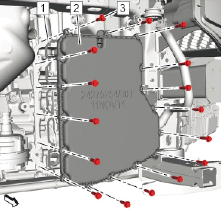 |
|
Fig. 99: Control Valve Body Cover, Bolts And Gasket |
NOTE: The gasket is reusable, inspect the gasket and replace if damaged.
1. Install Control Valve Body Cover Gasket (1)
2. Install Control Valve Body Cover (2)
CAUTION: Refer to Fastener Caution
3. Install Control Valve Body Cover Bolts (3) (Qty: 16) and Hand tighten only.
 |
|
Fig. 100: Control Valve Body Cover Bolts Tightening Sequence Courtesy of GENERAL MOTORS COMPANY |
4. Tighten Control Valve Body Cover Bolts in sequence (Qty: 16) to 9 N.m (80 lb in)
 |
|
Fig. 101: Transmission Fluid Cooler Inlet Pipe, Bolt And Sealing Washer |
5. Reposition Transmission Fluid Cooler Inlet Pipe (3)
6. Install a NEW sealing washer (2).
7. Connect Transmission Fluid Cooler Inlet Pipe (3)
8. Install and tighten Transmission Fluid Cooler Pipe Bolt (1) to 22 N.m (16 lb ft)
 |
|
Fig. 102: Transmission Fluid Cooler Inlet And Outlet Pipe Clip |
9. Install Transmission Fluid Cooler Inlet and Outlet Pipe Clip (1)
10. Install the front wheelhouse liner - left side. Refer to Front Wheelhouse Liner Replacement (Left Side)
 |
|
Fig. 103: Heater Water Shutoff Valve Inlet Hose And Bolt |
11. Position the heater water shutoff inlet hose (2) into original position.
12. Install and tighten Heater Water Shutoff Valve Inlet Hose Bolt (1) to 22 N.m (16 lb ft)
 |
|
Fig. 104: Radiator Inlet Hoses And Retainer |
13. Position the 2 radiator inlet hoses (1) into original position.
14. Connect Retainer (2)
 |
|
Fig. 105: Radiator Inlet Hose, Hose Clamps And Retainer |
15. Install Radiator Inlet Hose (2)
16. Connect Retainer (3)
17. Tighten Radiator Inlet Hose Clamps (1) (Qty: 3) using BO-38185 pliers
18. Install Radiator Surge Tank (Drive Motor Generator Power Inverter Module Surge Tank). Refer to Radiator
Surge Tank Replacement (Drive Motor Generator Power Inverter Module Surge Tank)
19. Install Radiator Surge Tank (Drive Motor Battery Radiator Surge Tank). Refer to Radiator Surge Tank
Replacement (Drive Motor Battery Radiator Surge Tank)
20. Install Radiator Inlet Hose. Refer to Radiator Inlet Hose Replacement
21. Fill Engine Cooling System. Refer to Cooling System Draining and Filling
22. Fill the transmission to the proper level with NEW transmission fluid. Refer to Transmission Fluid Level and
Condition Check
CONTROL VALVE BODY REPLACEMENT
Special Tools
BO-38185 Hose Clamp Pliers
Equivalent regional tools: Special Tools
Removal Procedure
1. Remove Control Valve Body Cover. Refer to Control Valve Body Cover Replacement
 |
|
Fig. 106: Control Valve Body Bolts, Control Solenoid Valve And Filter Plate |
2. Disconnect the control solenoid valve wiring harness.
3. Remove Control Valve Body Bolts (1) (Qty: 4)
4. Remove Control Solenoid Valve (2)
5. Remove Control Solenoid Valve Filter Plate (3)
 |
|
Fig. 107: Control Valve Body Components Courtesy of GENERAL MOTORS COMPANY |
6. Disconnect the control valve body wiring harness.
7. Remove Fluid Transfer Pipe Bolt (1)
8. Remove Fluid Transfer Pipe (2)
9. Remove Control Valve Body Bolts (3) (Qty: 13)
10. Remove Control Valve Body (4)
11. Remove Control Valve Body Spacer Plate Retainer (5) (Qty: 2)
12. Remove and DISCARD Control Valve Lower Body Spacer Plate (6)
13. Remove and DISCARD Variable Low Clutch Fluid Passage Seal (7)
Installation Procedure
 |
|
Fig. 108: Control Valve Body Components |
NOTE: Install a NEW seal.
1. Install NEW Variable Low Clutch Fluid Passage Seal (7)
NOTE: Install a NEW spacer plate.
2. Install NEW Control Valve Lower Body Spacer Plate (6)
3. Install Control Valve Body Spacer Plate Retainer (5) (Qty: 2)
4. Install Control Valve Body (4)
CAUTION: Refer to Fastener Caution
5. Install and hand tighten Control Valve Body Bolts (3) (Qty: 13). Hand tighten only.
6. Install Fluid Transfer Pipe (2)
7. Install and hand tighten Fluid Transfer Pipe Bolt (1). Hand tighten only.
8. Connect the control valve body wiring harness.
 |
|
Fig. 109: Control Valve Body Bolt And Fluid Transfer Pipe Bolt Tightening Sequence |
9. Tighten Control Valve Body Bolts @ Fluid Transfer Pipe Bolt in sequence to 9 N.m (80 lb in)
 |
|
Fig. 110: Control Valve Body Bolts, Control Solenoid Valve And Filter Plate |
10. Install Control Solenoid Valve Filter Plate (3)
11. Install Control Solenoid Valve (2)
12. Install and hand tighten Control Valve Body Bolts (1) (Qty: 4). Hand tighten only.
13. Connect the control solenoid valve wiring harness.

Fig. 111: Control Valve Body Bolts Tightening Sequence
Courtesy of GENERAL MOTORS COMPANY
14. Tighten Control Valve Body Bolts in sequence to 9 N.m (80 lb in)
15. Install Control Valve Body Cover. Refer to Control Valve Body Cover Replacement
LINE PRESSURE CONTROL SOLENOID VALVE REPLACEMENT
Special Tools
BO-38185 Hose Clamp Pliers
Equivalent regional tools: Special Tools
Removal Procedure
1. Remove Control Valve Body. Refer to Control Valve Body Replacement

Fig. 112: Line Pressure Control Solenoid Valve And Retainer
Courtesy of GENERAL MOTORS COMPANY
2. Remove Line Pressure Control Solenoid Valve Retainer (2)
3. Remove Line Pressure Control Solenoid Valve (1)
Installation Procedure

Fig. 113: Line Pressure Control Solenoid Valve And Retainer
Courtesy of GENERAL MOTORS COMPANY
1. Install Line Pressure Control Solenoid Valve (1)
2. Install Line Pressure Control Solenoid Valve Retainer (2)
3. Install Control Valve Body. Refer to Control Valve Body Replacement
CONTROL SOLENOID VALVE REPLACEMENT
Special Tools
BO-38185 Hose Clamp Pliers
Equivalent regional tools: Special Tools
Removal Procedure
1. Remove Control Valve Body. Refer to Control Valve Body Cover Replacement
 |
|
Fig. 114: Control Valve Body Bolts, Control Solenoid Valve And Filter Plate |
2. Disconnect Control Solenoid Valve Wiring Harness
3. Remove Control Valve Body Bolts (1) (Qty: 4)
4. Remove Control Solenoid Valve (2)
5. Remove Control Solenoid Valve Filter Plate (3)
Installation Procedure
 |
|
Fig. 115: Control Valve Body Bolts, Control Solenoid Valve And Filter Plate |
1. Install Control Solenoid Valve Filter Plate (3)
2. Install Control Solenoid Valve (2)
CAUTION: Refer to Fastener Caution
3. Install and hand tighten Control Valve Body Bolts (1) (Qty: 4). Hand tighten only.
4. Connect Control Solenoid Valve Wiring Harness

Fig. 116: Control Valve Body Bolts Tightening Sequence
Courtesy of GENERAL MOTORS COMPANY
5. Tighten Control Valve Body Bolts in sequence to 9 N.m (80 lb in)
6. Install Control Valve Body Cover. Refer to Control Valve Body Cover Replacement
AUTOMATIC TRANSMISSION WIRING HARNESS REPLACEMENT
Special Tools
BO-38185 Hose Clamp Pliers
Equivalent regional tools: Special Tools
Removal Procedure
1. Disconnect Battery Negative Cable. Refer to Battery Negative Cable Disconnection and Connection
2. Remove Control Valve Body. Refer to Control Valve Body Replacement
 |
|
Fig. 117: Automatic Transmission Wiring Harness And Seals |
NOTE: Remove the manual shift detent lever spring to aid in removal of the
transmission wiring harness.
3. Remove Automatic Transmission Wiring Harness - Control Solenoid Valve (1)
4. Remove Automatic Transmission Wiring Connector Seal (2)
5. Remove Automatic Transmission Wiring Harness - Shift Shaft Position Switch (3)
6. Remove Automatic Transmission Wiring Connector Seal (4)
Installation Procedure
 |
|
Fig. 118: Automatic Transmission Wiring Harness And Seals Courtesy of GENERAL MOTORS COMPANY |
1. Install Automatic Transmission Wiring Connector Seal (4)
2. Install Automatic Transmission Wiring Harness - Shift Shaft Position Switch (3)
3. Install Automatic Transmission Wiring Connector Seal (2)
NOTE: Install the manual shift detent lever spring previously removed to aid the
removal of the transmission wiring harness.
4. Install Automatic Transmission Wiring Harness - Control Solenoid Valve (1)
5. Install Control Valve Body. Refer to Control Valve Body Replacement
6. Connect Battery Negative Cable. Refer to Battery Negative Cable Disconnection and Connection
TRANSMISSION MOUNT STRUT BRACKET REPLACEMENT
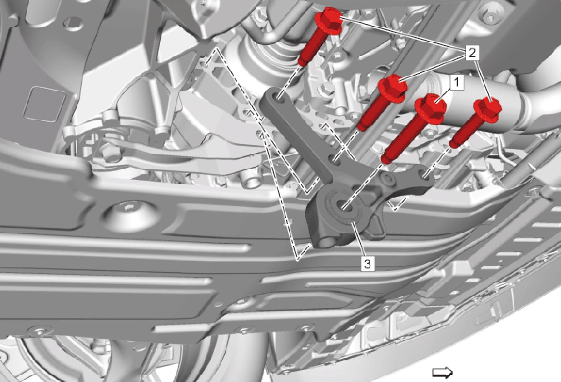 |
|
Fig. 119: Transmission Mount Strut Bracket |
|
Callout |
Component Name |
|
Preliminary Procedure Using a suitable jack stand, support the rear of the powertrain. | |
|
1 |
Transmission Mount Strut Bolt CAUTION: Refer to |
|
Caution | |
|
CAUTION: | |
|
Yield | |
|
Caution | |
|
Procedure Always use NEW bolts. - Do NOT reuse old bolts. Tighten
| |
| ||||||||
|
TRANSMISSION MOUNT TRANSMISSION-SIDE BRACKET REPLACEMENT |
 |
|
Fig. 120: Transmission Mount Transmission-Side Bracket |
|
Callout |
Component Name |
|
Preliminary Procedure Remove Transmission Mount. Refer to Transmission Mount Replacement | |
|
1 |
Transmission Mount Transmission Side Bracket Bolt (Qty: 3) CAUTION: Refer to Fastener |
|
Caution | |
|
CAUTION: | |
|
Yield | |
|
Caution | |
|
Procedure Always use NEW bolts. - Do NOT reuse old bolts. Tighten
| |
|
Callout |
Component Name |
|
Special Tools EN-45059 Angle Meter Equivalent regional tools: Special Tools | |
|
2 |
Transmission Mount Transmission Side Bracket |
TRANSMISSION MOUNT REPLACEMENT
Special Tools
EN-45059 Angle Meter
Equivalent regional tools: Special Tools
Removal Procedure
1. Remove Engine Wiring Harness Junction Block. Refer to Engine Wiring Harness Junction Block
Replacement
 |
|
Fig. 121: Wiring Harness Connectors Courtesy of GENERAL MOTORS COMPANY |
2. Remove Wiring Harness Connectors (1) (Qty: 3)
Unclip (Qty: 6)
 |
|
Fig. 122: Wiring Harness Retainers Courtesy of GENERAL MOTORS COMPANY |
3. Remove Wiring Harness Retainers (1) (Qty: 2)
 |
|
Fig. 123: Wiring Harness Connector And Retainers |
4. Remove Wiring Harness Connector (2) @ Retainers (1)
5. Unclip Wiring Harness Retainer (3)
 |
|
Fig. 124: Engine Wiring Harness Fuse Block Bracket And Bolt |
6. Remove Engine Wiring Harness Fuse Block Bracket Bolt (1)
7. Remove Engine Wiring Harness Fuse Block Bracket (2)
 |
|
Fig. 125: Engine Lifting Chain And Engine Lift Rear Bracket |
8. Install the engine lifter (1) to the engine lift rear bracket (2).
9. Apply tension to the chain.
 |
|
Fig. 126: Transmission Mount And Bolts Courtesy of GENERAL MOTORS COMPANY |
10. Prior to removing the mount, mark the mount location using paint pent or a marker for correct positioning
during installation.
11. Remove and DISCARD Transmission Mount Bolts (2) (Qty: 3)
12. Remove Transmission Mount Transmission Side Bolt (4)
13. Remove and DISCARD Transmission Mount Bolt (1) (Qty: 3)
14. Remove Transmission Mount (3)
Installation Procedure
 |
|
Fig. 127: Transmission Mount And Bolts Courtesy of GENERAL MOTORS COMPANY |
1. Install Transmission Mount (3)
CAUTION: Refer to Fastener Caution
CAUTION: Refer to Torque-to-Yield Fastener Caution
NOTE:
Install NEW bolts.
2. Install NEW Transmission Mount Bolts (1) (Qty: 3). Hand tighten only.
CAUTION: Refer to Torque-to-Yield Fastener Caution
NOTE: Install NEW bolts.
3. Install NEW Transmission Mount Bolts (2) (Qty: 3). Hand tighten only.
4. Align the transmission mount and the powertrain unit to the previously made marks.
5. Tighten Transmission Mount Bolts (1) (Qty: 3)
1. First Pass: 100 N.m (74 lb ft)
2. Final Pass: 60 - 75 degrees, use the EN-45059 meter
6. Tighten Transmission Mount Bolts (2) (Qty: 3)
1. First Pass: 100 N.m (74 lb ft)
2. Final Pass: 60 - 75 degrees, use the EN-45059 meter
7. Install and tighten Transmission Mount Transmission Side Bolt (4) to 58 N.m (43 lb ft)
 |
|
Fig. 128: Engine Lifting Chain And Engine Lift Rear Bracket |
8. Remove the engine lifter (1) from the engine lift rear bracket (2).
 |
|
Fig. 129: Engine Wiring Harness Fuse Block Bracket And Bolt |
9. Install Engine Wiring Harness Fuse Block Bracket (2)
10. Install and tighten Engine Wiring Harness Fuse Block Bracket Bolt (1) to 22 N.m (16 lb ft).
 |
|
Fig. 130: Wiring Harness Connector And Retainers |
11. Install Wiring Harness Retainer (3)
12. Install Wiring Harness Connector (2) @ Retainer (1)
 |
|
Fig. 131: Wiring Harness Retainers Courtesy of GENERAL MOTORS COMPANY |
13. Install Wiring Harness Retainers (1) (Qty: 2)
 |
|
Fig. 132: Wiring Harness Connectors Courtesy of GENERAL MOTORS COMPANY |
14. Install Wiring Harness Connectors (1) (Qty: 3)
Install (Qty: 6)
15. Install Engine Wiring Harness Junction Block. Refer to Engine Wiring Harness Junction Block
Replacement
TRANSMISSION REAR MOUNT REPLACEMENT
Special Tools
CH-51999 Volt Cradle Bushing Remover/Installer
Equivalent regional tools: Special Tools
1. Remove the drivetrain and front suspension cradle from the vehicle. Refer to Drivetrain and Front
Suspension Cradle Replacement
 |
|
Fig. 133: Volt Cradle Bushing Remover/Installer Components |
2. Assemble the CH-51999 Volt Cradle Bushing Remover/Installer (1 through 8) onto the transmission rear
mount and the drivetrain and front suspension cradle.
3. Turning the nut (8), release the transmission rear mount from the drivetrain and front suspension cradle.
 |
|
Fig. 134: Transmission Rear Mount, Drivetrain And Front Suspension Cradle |
4. Remove the transmission rear mount (1) from the drivetrain and front suspension cradle (2).
Installation Procedure
 |
|
Fig. 135: Cradle Bushing Remover/Installer Receiver Cup, Transmission Mount And Alignment Mark |
Courtesy of GENERAL MOTORS COMPANY
1. Clean the CH-51999 Volt Cradle Bushing Remover/Installer receiver cup (3) free from oil and grease.
2. Position the transmission mount (2) into the receiver cup with the arrow on the transmission mount aligning
with the alignment mark (5).
 |
|
Fig. 136: Upper Tool Rim With Top Of Receiver Cup |
NOTE: The transmission mount will be at the correct depth in the receiver cup, when
the upper tool rim (a) is in the contact with the top of the receiver cup (b).
IMPORTANT: No lubricant is allowed.
3. Using a press or the threaded rod assembly, and the components (1, 4) shown from the CH-51999 Volt Cradle
Bushing Remover/Installer kit. Compress the transmission mount (2) into the receiver cup (3).
4. Clean the hole for the transmission rear mount in the drivetrain and front suspension frame cradle.
 |
|
Fig. 137: Cradle Bushing Remover/Installer Components |
NOTE: Insure the transmission mount inside the receiver cup (6) is in the correct
orientation before proceeding.
5. Assemble the CH-51999 Volt Cradle Bushing Remover/Installer (1 through 9) onto the drivetrain and front
suspension cradle.
NOTE: When the rim on the tool (5) contacts the top edge of tool (6) completely, the
transmission mount will be at it's correct depth in the drivetrain and front
suspension cradle.
6. Turning the nut (1), install the transmission rear mount to the drivetrain and front suspension cradle.
7. Remove the CH-51999 Volt Cradle Bushing Remover/Installer (1 through 9) from the drivetrain and front
suspension cradle.
8. If the transmission rear mount is not positioned correctly, remove the transmission rear mount from the
drivetrain and front suspension frame cradle and reinstall it.
9. Install the drivetrain and front suspension cradle to the vehicle. Refer to Drivetrain and Front Suspension
Cradle Replacement
TRANSMISSION MOUNT STRUT REPLACEMENT
 |
|
Fig. 138: Transmission Mount Strut Courtesy of GENERAL MOTORS COMPANY |
Callout Component Name
Preliminary Procedures
1. Using a suitable jack stand, support the rear of the powertrain.
2. Remove Transmission Mount Strut Bracket. Refer to Transmission Mount Strut Bracket
Replacement
Transmission Mount Strut Bolt
CAUTION:
Refer to
Fastener
Caution
CAUTION:
Refer to
Torque-to-
Yield
Fastener
Caution
Procedure
Always use NEW bolts. - Do NOT reuse old bolts.
Tighten
| ||||||
|
TRANSMISSION REPLACEMENT |
Special Tools
• BO-38185 Hose Clamp Pliers
• DT-51504 Seal Protector
• EN-45059 Angle Meter
Equivalent regional tools: Special Tools
Removal Procedure
WARNING: Do not use a service jack in locations other than those specified to lift this
vehicle. Lifting the vehicle with a jack in those other locations could cause the
vehicle to slip off the jack and roll; this could cause injury or death.
WARNING: Always perform the High Voltage Disabling procedure prior to servicing any
High Voltage component or connection. Personal Protection Equipment (PPE)
and proper procedures must be followed.
The High Voltage Disabling procedure will perform the following tasks:
• Identify how to disable high voltage.
• Identify how to test for the presence of high voltage.
• Identify condition under which high voltage is always present and
personal protection equipment (PPE) and proper procedures must be
followed.
Failure to follow the procedures exactly as written may result in serious injury
or death.
1. Ensure that the vehicle is properly supported and squarely positioned. Refer to Lifting and Jacking the
Vehicle .
2. Disable the high voltage system and disconnect the A4 Hybrid/EV Battery Pack high voltage harness
connector at the T6 Power Inverter Module. Refer to High Voltage Disabling .
3. Set the parking brake.
 |
|
Fig. 139: Radiator Surge Tank And Bracket Clip |
4. Remove Radiator Surge Tank Bracket Clip (2)
5. Remove the radiator surge tank (1) from the vehicle. Refer to Radiator Surge Tank Replacement
 |
|
Fig. 140: Range Selector Lever Cable And Range Selector Lever Cable Lever |
6. Remove Range Selector Lever Cable (1) @ Range Selector Lever Cable Lever
 |
|
Fig. 141: Range Selector Lever Cable And Transmission Range Selector Lever Cable Bracket |
7. Remove the range selector lever cable (1) from the range selector lever cable bracket.
Release the cable from the bracket by pushing the retainer (arrow).
8. Remove Radiator Inlet Hose. Refer to Radiator Inlet Hose Replacement
9. Drain Drive Motor Generator Power Inverter Module Cooling System. Refer to Drive Motor Generator
Power Inverter Module Cooling System Draining and Filling
10. Remove the drive motor generator control module cooling outlet hose. Refer to Drive Motor Generator
Control Module Cooling Outlet Hose Replacement (Underbody Line) Drive Motor Generator Control
Module Cooling Outlet Hose Replacement (Underbody Line to Traction Power Inverter Module Inlet)
 |
|
Fig. 142: Wiring Harness Bracket And Nut |
11. Remove Nut (2)
12. Remove Wiring Harness Bracket (1)

Fig. 143: Electrical Connector
Courtesy of GENERAL MOTORS COMPANY
13. Disconnect Electrical Connector (1)
 |
|
Fig. 144: Wiring Harness Bracket And Bolts |
14. Remove Bolts (1) (Qty: 2)
15. Remove Wiring Harness Bracket (2)

Fig. 145: Ground Cable And Bolt
Courtesy of GENERAL MOTORS COMPANY
16. Remove Ground Cable Bolt (1)
17. Remove Ground Cable (2)
18. Install Engine Support Fixture. Refer to Engine Support Fixture

Fig. 146: Transmission Mount Bolts
Courtesy of GENERAL MOTORS COMPANY
19. Remove and DISCARD Transmission Mount Bolts (1) (Qty: 3)
 |
|
Fig. 147: Heater Inlet Hose Bracket And Bolt |
20. Remove Bolt (1)
21. Remove Heater Inlet Hose Bracket (2)
22. Remove Drivetrain and Front Suspension Cradle. Refer to Drivetrain and Front Suspension Cradle
Replacement
23. Drain Transmission Fluid. Refer to Transmission Fluid Drain and Fill
24. Remove the left and right wheel drive shafts. Refer to Front Wheel Drive Shaft Replacement
 |
|
Fig. 148: Transmission Fluid Cooler Inlet And Outlet Pipe Clip |
25. Remove Clip (1)
 |
|
Fig. 149: Transmission Fluid Cooler Outlet Pipe, Bolt And Sealing Washer |
26. Place a container beneath the transmission fluid cooler outlet pipe (2) to catch spilling transmission fluid.
27. Remove Transmission Fluid Cooler Pipe Bolt (1)
28. Disconnect Transmission Fluid Cooler Outlet Pipe (2)
29. Remove and DISCARD Sealing Washer (3)
 |
|
Fig. 150: Transmission Fluid Cooler Inlet Pipe, Bolt And Sealing Washer |
30. Place a container beneath the transmission fluid cooler inlet pipe (3) to catch spilling transmission fluid.
31. Remove Transmission Fluid Cooler Pipe Bolt (1)
32. Disconnect Transmission Fluid Cooler Inlet Pipe (3)
33. Remove and DISCARD Sealing Washer (2)
 |
|
Fig. 151: Heater Water Auxiliary Pump Inlet Hose, Clamp, Heater Water Shutoff Valve Inlet Hose Bracket And Bolt Courtesy of GENERAL MOTORS COMPANY |
34. Loosen Heater Water Auxiliary Pump Inlet Hose Clamp (3) using BO-38185 pliers
35. Remove Heater Water Auxiliary Pump Inlet Hose (4)
36. Remove Heater Water Shutoff Valve Inlet Hose Bracket Bolt (1)
37. Remove the heater water shutoff valve inlet hose and bracket (2) from the front side of the vehicle.
 |
|
Fig. 152: Heater Water Shutoff Valve Electrical Connector, Inlet Hose, Retainer, Heater Water Shutoff Courtesy of GENERAL MOTORS COMPANY |
38. Disconnect the heater water shutoff valve electrical connector (4).
39. Loosen Retainer (5)

Fig. 153: Bracket And Bolt
Courtesy of GENERAL MOTORS COMPANY
40. Remove Bolt (1)
41. Loosen the bracket (2).
 |
|
Fig. 154: Heater Water Shutoff Valve Electrical Connector, Inlet Hose, Retainer, Heater Water Shutoff Courtesy of GENERAL MOTORS COMPANY |
42. Remove Heater Water Shutoff Valve Inlet Hose (1) @ Heater Water Shutoff Valve
43. Loosen the heater water shutoff valve outlet hose clamp (2), using the BO-38185 pliers.
44. Remove the heater water shutoff valve outlet hose (3) with the heater water shutoff valve.
 |
|
Fig. 155: Heater Water Shutoff Valve Inlet Hose And Clip |
45. Remove Heater Water Shutoff Valve Inlet Hose (2) @ Clip (1)
46. Remove Heater Water Shutoff Valve @ Vehicle
47. Remove Heater Coolant Pump. Refer to Heater Coolant Pump Replacement
 |
|
Fig. 156: Starter Opening Cover And Bolts |
48. Remove Bolts (2) (Qty: 2)
49. Remove the starter opening cover (1).
 |
|
Fig. 157: Torque Converter Bolts Courtesy of GENERAL MOTORS COMPANY |
50. Remove the torque converter bolts. (1) (Qty: 4)
 |
|
Fig. 158: Upper Front Transmission Bolts |
51. Remove the upper front transmission bolts (1) (Qty: 2).
 |
|
Fig. 159: Upper Rear Transmission Bolts |
52. Remove the upper rear transmission bolts (1) (Qty: 2).
53. Support the transmission with a suitable jack.
54. Using a suitable straps or chains, secure the transmission to the transmission jack.
 |
|
Fig. 160: Transmission Cover And Bolts |
55. Remove the transmission bolts. (1) (Qty: 2)
56. Remove Transmission Cover (2)

Fig. 161: Transmission Bolts
Courtesy of GENERAL MOTORS COMPANY
57. Remove the transmission bolts. (1) (Qty: 2)
58. Carefully lower the transmission along with the jack, closely watching hoses and wiring harnesses to not
disturb.
 |
|
Fig. 162: Transmission Locating Pins Courtesy of GENERAL MOTORS COMPANY |
59. Ensure the transmission locating pins (1) are properly seated in the engine block and not damaged.
60. Transfer parts as needed.
61. Flush and flow test the fluid cooler and lines. Refer to Transmission Fluid Cooler Flow Test and Flushing
Installation Procedure
NOTE: The alignment hole is oblong and is slightly smaller than the other holes in the
engine flex plate.
1. Set engine to any top dead center (TDC). This puts the alignment hole in the starter pocket.
Do not tighten bell housing bolts at this time. There must be a small 1 mm (0.039 in) to 2
IMPORTANT: mm (0.079 in) mm gap between the engine and transmission to allow rotation for input
flange alignment.
2. Install 2 guide pins into the lower engine block holes where the locating pins are to guide the transmission into
place.
3. Position the transmission in the vehicle on the locating pins leaving a small gap between the engine and
transmission.
CAUTION: Refer to Fastener Caution

Fig. 163: Transmission Bolts
Courtesy of GENERAL MOTORS COMPANY
4. Remove the guide pins, then Install the 2 transmission bolts (1) (Qty: 2) and hand tighten, allowing a small 1
mm (0.039 in) to 2 mm (0.079 in) mm gap between the engine and transmission.
 |
|
Fig. 164: Transmission Cover And Bolts |
5. Install Transmission Cover (2)
6. Install the 2 transmission bolts (1) (Qty: 2) and hand tighten, allowing a small 1 mm (0.039 in) to 2 mm (0.079
in) mm gap between the engine and transmission.

Fig. 165: Transmission Bolt
Courtesy of GENERAL MOTORS COMPANY
7. Remove the guide pin, then install the transmission bolt (1) and hand tighten, allowing a small 1 mm (0.039 in)
to 2 mm (0.079 in) mm gap between the engine and transmission.
 |
|
Fig. 166: Torque Converter Bolts Courtesy of GENERAL MOTORS COMPANY |
NOTE: Once the LoctiteA® has been applied to the bolts it will 'SET IN
APPROXIMATELY IN 10 MINUTES' and will fully cure in 24 hours.
8. Apply blue LoctiteA® on the torque converter bolt (1). Hand start bolt a few threads in the oblong alignment
hole.
9. Tighten all lower transmission bolts to 58 N.m (43 lb ft).
10. Install Heater Coolant Pump. Refer to Heater Coolant Pump Replacement
 |
|
Fig. 167: Upper Front Transmission Bolts |
11. Install the upper front transmission bolts (1) (Qty: 2) and tighten to 58 N.m (43 lb ft).
 |
|
Fig. 168: Upper Rear Transmission Bolts |
12. Install the upper rear transmission bolts (1) (Qty: 2) and tighten to 58 N.m (43 lb ft).
13. Tighten torque converter bolt to 60 N.m (44 lb ft). Rotate the engine to the next hole. Apply blue LoctiteA®
on the three remaining torque converter bolts. Install and tighten the bolts to 60 N.m (44 lb ft).
 |
|
Fig. 169: Starter Opening Cover And Bolts Courtesy of GENERAL MOTORS COMPANY |
14. Install the starter opening cover (1) and the 2 bolts (2) (Qty: 2).

Fig. 170: Bracket And Bolt
Courtesy of GENERAL MOTORS COMPANY
15. Install the bracket (2).
16. Install and tighten Bolt (1) to 9 N.m (80 lb in)
 |
|
Fig. 171: Heater Water Shutoff Valve Inlet Hose And Clip |
17. Install Heater Water Shutoff Valve Inlet Hose (2) @ Vehicle
18. Install Heater Water Shutoff Valve Inlet Hose (2) @ Clip (1)
 |
|
Fig. 172: Heater Water Shutoff Valve Electrical Connector, Inlet Hose, Retainer, Heater Water Shutoff Courtesy of GENERAL MOTORS COMPANY |
19. Install the heater water shutoff valve outlet hose (3) with the heater water shutoff valve.
20. Install the heater water shutoff valve outlet hose clamp (2), using the BO-38185 pliers.
21. Install Heater Water Shutoff Valve Inlet Hose (1) @ Heater Water Shutoff Valve
22. Install Retainer (5)
23. Connect the heater water shutoff valve electrical connector (4).
 |
|
Fig. 173: Heater Water Auxiliary Pump Inlet Hose, Clamp, Heater Water Shutoff Valve Inlet Hose Bracket And Bolt Courtesy of GENERAL MOTORS COMPANY |
24. Install Heater Water Shutoff Valve Inlet Hose Bracket (2)
25. Install and tighten Heater Water Shutoff Valve Inlet Hose Bracket Bolt (1) to 22 N.m (16 lb ft)
26. Install Heater Water Auxiliary Pump Inlet Hose (4)
27. Install Heater Water Auxiliary Pump Inlet Hose Clamp (3) using BO-38185 pliers
 |
|
Fig. 174: Transmission Fluid Cooler Inlet Pipe, Bolt And Sealing Washer |
28. Install a NEW sealing washer. (2)
29. Connect Transmission Fluid Cooler Inlet Pipe (3) - Connect
30. Install and tighten Transmission Fluid Cooler Pipe Bolt (1) to 22 N.m (16 lb ft)
 |
|
Fig. 175: Transmission Fluid Cooler Outlet Pipe, Bolt And Sealing Washer |
31. Install a NEW sealing washer. (3)
32. Connect Transmission Fluid Cooler Outlet Pipe (2)
33. Install and tighten Transmission Fluid Cooler Pipe Bolt (1) to 22 N.m (16 lb ft)
34. Install the left and right wheel drive shafts. Refer to Front Wheel Drive Shaft Replacement
 |
|
Fig. 176: Transmission Fluid Cooler Inlet And Outlet Pipe Clip |
35. Install Clip (1)
36. Install Drivetrain and Front Suspension Cradle. Refer to Drivetrain and Front Suspension Cradle
Replacement
37. Install Radiator Inlet Hose. Refer to Radiator Inlet Hose Replacement
 |
|
Fig. 177: Heater Inlet Hose Bracket And Bolt |
38. Install Heater Inlet Hose Bracket (2)
39. Install and tighten Bolt (1) to 9 N.m (80 lb in)

Fig. 178: Transmission Mount Bolts
Courtesy of GENERAL MOTORS COMPANY
CAUTION: Refer to Torque-to-Yield Fastener Caution
NOTE: Install NEW bolts.
40. Install NEW Transmission Mount Bolts (1) (Qty: 3). Hand tighten only.
41. Tighten Transmission Mount Bolts (1) (Qty: 3)
1. First Pass: 100 N.m (74 lb ft)
2. Final Pass: 60 - 75 degrees, use the EN-45059 meter
42. Remove Engine Support Fixture. Refer to Engine Support Fixture

Fig. 179: Ground Cable And Bolt
Courtesy of GENERAL MOTORS COMPANY
43. Install Ground Cable (2)
44. Install and tighten Ground Cable Bolt (1) to 9 N.m (80 lb in)
 |
|
Fig. 180: Wiring Harness Bracket And Bolts |
45. Install Wiring Harness Bracket (2)
46. Install and tighten Bolts (1) (Qty: 2) to 9 N.m (80 lb in)
47. Lower the vehicle.
 |
|
Fig. 181: Electrical Connector Courtesy of GENERAL MOTORS COMPANY |
48. Connect Electrical Connector (1)
 |
|
Fig. 182: Wiring Harness Bracket And Nut |
49. Install Wiring Harness Bracket (1)
50. Install and tighten Nut (2) to 9 N.m (80 lb in)
 |
|
Fig. 183: Drive Motor Generator Control Module Cooling Outlet Hose And Bolts |
51. Install the drive motor generator control module cooling outlet hose. Refer to Drive Motor Generator
Control Module Cooling Outlet Hose Replacement (Underbody Line) Drive Motor Generator Control
Module Cooling Outlet Hose Replacement (Underbody Line to Traction Power Inverter Module Inlet)
52. Fill Drive Motor Generator Power Inverter Module Cooling System. Refer to Drive Motor Generator Power
Inverter Module Cooling System Draining and Filling
53. Fill Transmission Fluid. Refer to Transmission Fluid Drain and Fill
54. Fill Cooling System. Refer to Cooling System Draining and Filling
 |
|
Fig. 184: Range Selector Lever Cable And Transmission Range Selector Lever Cable Bracket |
55. Install the range selector lever cable (1) to the range selector lever cable bracket.
The retainer snaps automatically in.
 |
|
Fig. 185: Range Selector Lever Cable And Range Selector Lever Cable Lever |
56. Install Range Selector Lever Cable (1) @ Range Selector Lever Cable Lever
57. Adjust Range Selector Lever Cable. Refer to Range Selector Lever Cable Adjustment
 |
|
Fig. 186: Radiator Surge Tank And Bracket Clip Courtesy of GENERAL MOTORS COMPANY |
58. Install Radiator Surge Tank (1)
59. Install Radiator Surge Tank Bracket Clip (2)
60. Enable the high voltage system and connect the A4 Hybrid/EV Battery Pack high voltage harness connector at
the T6 Power Inverter Module. Refer to High Voltage Disabling
61. Connect the battery negative cable. Refer to Battery Negative Cable Disconnection and Connection
62. Program the power inverter module and the immobilizer control module. Refer to Control Module
References
REPAIR INSTRUCTIONS - OFF VEHICLE
HOLDING FIXTURE INSTALLATION
 |
|
Fig. 187: Holding Fixture Assembly Courtesy of GENERAL MOTORS COMPANY |
|
Callout |
Component Name |
|
A WARNING: Handle with | |
|
1 |
handled CAUTION: Refer to Caution . Procedure
|
| ||||
|
DRIVE MOTOR POWER INVERTER MODULE COVER REMOVAL |
|
Drive Motor Battery Positive and Negative Cable Connector Removal |
 |
|
Fig. 188: Drive Motor Battery Positive And Negative Cable Connector |
|
Drive Motor Battery Positive and Negative Cable Connector Removal | ||||||
| ||||||
|
Drive Motor Power Inverter Module Cover Removal |
 |
|
Fig. 189: Drive Motor Power Inverter Module Cover And Components |
|
Drive Motor Power Inverter Module Cover Removal | |
|
Callout |
Component Name |
|
1 |
Drive Motor Power Inverter Module Cover Bolt (Qty: 17) |
|
2 |
Drive Motor Power Inverter Module Cover Procedure Use the DT-51626 protector when removing the cover to avoid damaging the connector seal. Special Tools DT-51626 Seal Protector For equivalent regional tools, refer to Special Tools. |
|
3 |
Drive Motor Power Inverter Module Cover Gasket NOTE: The gasket |
|
4 |
Drive Motor Power Inverter Module Cover Vent |
|
5 |
Drive Motor Power Inverter Module Electrical Connector Seal NOTE: The seal is |
| ||||
|
DRIVE MOTOR POWER INVERTER MODULE REMOVAL |
 |
|
Fig. 190: Drive Motor Power Inverter Module And Components |
| ||||||||||||
|
CONTROL VALVE BODY COVER REMOVAL | ||||||||||||
 |
|
Fig. 191: Control Valve Body Cover Courtesy of GENERAL MOTORS COMPANY |
|
Callout |
Component Name |
|
1 |
Control Valve Body Cover Bolt (Qty: 16) |
|
2 |
Control Valve Body Cover |
|
3 |
Automatic Transmission Fluid Level Control Valve Seal NOTE: The gasket |
|
4 |
Automatic Transmission Fluid Level Control Valve Seal - O-ring NOTE: The seal is |
CONTROL VALVE ASSEMBLY AND TRANSMISSION WIRING HARNESS REMOVAL
Control Solenoid Valve Removal
 |
|
Fig. 192: Control Solenoid Valve Courtesy of GENERAL MOTORS COMPANY |
|
Control Solenoid Valve Removal | ||||||||||
| ||||||||||
|
Control Valve (with Body and Valve) Removal | ||||||||||

Fig. 193: Control Valve (With Body And Valve)
Courtesy of GENERAL MOTORS COMPANY
|
Control Valve (with Body and Valve) Removal | ||||||||||||||||||
| ||||||||||||||||||
|
Automatic Transmission Wiring Harness Removal | ||||||||||||||||||
 |
|
Fig. 194: Automatic Transmission Wiring Harness |
|
Automatic Transmission Wiring Harness Removal | ||||||||||||
| ||||||||||||
|
AUTOMATIC TRANSMISSION TORQUE DAMPENER AND DIFFERENTIAL HOUSING REMOVAL | ||||||||||||
 |
|
Fig. 195: Automatic Transmission Torque Dampener And Differential Housing |
| ||||||||
|
FRONT DIFFERENTIAL CARRIER REMOVAL |


Fig. 196: Front Differential Carrier
|
Courtesy of GENERAL MOTORS COMPANY | ||||||||||
| ||||||||||
|
INPUT SUN GEAR SHAFT REMOVAL |
 |
|
Fig. 197: Input Sun Gear Shaft Courtesy of GENERAL MOTORS COMPANY |
| ||||||||||||||
|
FRONT DIFFERENTIAL CARRIER BAFFLE REMOVAL |
 |
|
Fig. 198: Front Differential Carrier Baffle |
|
Courtesy of GENERAL MOTORS COMPANY | ||||||||
| ||||||||
|
DRIVE SPROCKET, DRIVEN SPROCKET, AND DRIVE LINK REMOVAL |
 |
|
Fig. 199: Drive Sprocket, Driven Sprocket And Drive Link |
| ||||||
|
DRIVE LINK SNUBBER REMOVAL |

|
Fig. 200: Drive Link Snubber Courtesy of GENERAL MOTORS COMPANY | ||||||||
|
Drive Link Snubber (Coast Side)
AUTOMATIC TRANSMISSION FLUID PUMP AND FLUID FILTER REMOVAL
 |
|
Fig. 201: Automatic Transmission Fluid Pump And Fluid Filter |
|
Callout |
Component Name |
|
Preliminary Procedure Disconnect the fluid pump pass thru connector from the case. | |
|
1 |
Automatic Transmission Fluid Pump Bolt (Qty: 3) |
|
2 |
NOTE: Guide the Automatic Transmission Fluid Pump |
|
3 |
NOTE: DISCARD Automatic Transmission Pump Fluid Outlet Seal |
|
4 |
Automatic Transmission Fluid Filter Bolt |
|
Callout |
Component Name |
|
5 |
Automatic Transmission Fluid Filter |
|
6 |
NOTE: DISCARD Automatic Transmission Fluid Filter Seal |
MANUAL SHIFT DETENT LEVER WITH SHAFT POSITION SWITCH ASSEMBLY AND PARK PAWL
ACTUATOR REMOVAL
Automatic Transmission Wiring Harness Bracket Removal
 |
|
Fig. 202: Automatic Transmission Wiring Harness Bracket |
|
Automatic Transmission Wiring Harness Bracket Removal | ||||||||||||
| ||||||||||||
|
Manual Shift Detent Lever with Shaft Position Switch Assembly and Park Pawl Actuator Removal | ||||||||||||
 |
|
Fig. 203: Manual Shift Detent Lever With Shaft Position Switch Assembly And Park Pawl Actuator |
|
Manual Shift Detent Lever with Shaft Position Switch Assembly and Park Pawl Actuator Removal | ||||||||||||||||||||||||
|
DRIVE MOTOR REMOVAL - 2ND POSITION
Drive Motor Stator Cooling Tube Removal

Fig. 204: Drive Motor Stator Cooling Tube
Courtesy of GENERAL MOTORS COMPANY
|
Drive Motor Stator Cooling Tube Removal | ||||||
|
| ||||||
|
Drive Motor - 2nd Position Bolt Removal |
 |
|
Fig. 205: Drive Motor - 2nd Position Bolts |
Courtesy of GENERAL MOTORS COMPANY
|
Drive Motor - 2nd Position Bolt Removal | ||||||||||
| ||||||||||
|
Drive Motor - 2nd Position Removal |

Fig. 206: Drive Motor - 2nd Position
|
Courtesy of GENERAL MOTORS COMPANY Drive Motor - 2nd Position Removal | ||||||
|
| ||||
|
Drive Motor Power Inverter Module Connector Removal |
 |
|
Fig. 207: Drive Motor Power Inverter Module Connector |
|
Drive Motor Power Inverter Module Connector Removal | ||||||||||
| ||||||||||
|
OUTPUT CARRIER AND OUTPUT CARRIER INTERNAL GEAR REMOVAL |
 |
|
Fig. 208: Output Carrier And Output Carrier Internal Gear |
|
Callout |
Component Name |
|
1 |
Output Carrier |
|
2 |
Output Carrier Thrust Bearing |
|
3 |
Output Carrier Internal Gear |
|
4 |
Output Carrier Internal Gear Hub Thrust Bearing |
DRIVE MOTOR REMOVAL - 1ST POSITION
Drive Motor - 1st Position Removal
 |
|
Fig. 209: Drive Motor - 1st Position |
|
Courtesy of GENERAL MOTORS COMPANY | ||||||||||||||
|
| ||||
|
Drive Motor Power Inverter Module Connector Removal |
 |
|
Fig. 210: Drive Motor Power Inverter Module Connector |
|
Drive Motor Power Inverter Module Connector Removal | ||||||||||
| ||||||||||
|
VARIABLE HIGH CLUTCH FLUID TRANSFER SUPPORT SEAL OVERHAUL |

|
Fig. 211: Variable High Clutch Fluid Transfer Support Seal | ||||||
| ||||||
| ||||||||
|
FRONT WHEEL DRIVE SHAFT OIL SEAL REMOVAL - LEFT SIDE |
 |
|
Fig. 212: Front Wheel Drive Shaft Oil Seal - Left Side |
|
Callout |
Component Name |
|
1 |
Front Wheel Drive Shaft Oil Seal Special Tools
For equivalent regional tools, refer to Special Tools. |
TRANSMISSION CASE CLEANING AND INSPECTION
Transmission Case Inspection (1 of 2)
 |
|
Fig. 213: Transmission Case Inspection (1 Of 2) |
Transmission Case Inspection (1 of 2)____________________________
Callout Component Name
CAUTION:
Do not use
abrasive
pads or
bristle
devices to
clean the
sealing
surfaces.
Abrasive
pads
produce a
fine grit that
can effect
transmission
function.
Abrasive
pads can
also remove
enough
metal to
create oil
leaks.
| ||||||||||||||||||
|
Transmission Case Inspection (2 of 2) | ||||||||||||||||||
 |
|
Fig. 214: Transmission Case Inspection (2 Of 2) |
|
Transmission Case Inspection (2 of 2) | ||||||||||||
| ||||||||||||
|
FRONT WHEEL DRIVE SHAFT OIL SEAL INSTALLATION - LEFT SIDE |
 |
|
Fig. 215: Front Wheel Drive Shaft Oil Seal - Left Side |
| ||||
|
MANUAL SHIFT SHAFT SEAL REMOVAL |
 |
|
Fig. 216: Manual Shift Shaft Seal |
|
Courtesy of GENERAL MOTORS COMPANY | ||||||
| ||||||
|
VARIABLE LOW CLUTCH PLATE REMOVAL |
 |
|
Fig. 217: Variable Low Clutch Plate Courtesy of GENERAL MOTORS COMPANY |
Callout Component Name
Preliminary Procedure
CAUTION:
DO NOT
contact or
rest the
drive motor
stator on the
copper end
coils.
Damage to
the copper
end coils
may cause a
high voltage
short during
vehicle
| ||||||||||||||||
|
VARIABLE HIGH CLUTCH REMOVAL | ||||||||||||||||
 |
|
Fig. 218: Variable High Clutch Courtesy of GENERAL MOTORS COMPANY |
|
Callout |
Component Name |
|
CAUTION: | |
|
1 |
Variable High Clutch Housing Bolt (Qty: 8) |
|
2 |
Variable High Clutch Housing |
|
3 |
Variable High Clutch Hub Thrust Washer |
|
4 |
Variable High Clutch Hub |
|
5 |
Variable High Clutch Hub Thrust Washer |
DRIVE MOTOR DISASSEMBLE - 1ST POSITION
|
Drive Motor Stator and Rotor Removal |
 |
|
Fig. 219: Drive Motor Stator And Rotor |
|
Drive Motor Stator and Rotor Removal | ||||||
|
|
Callout |
Component Name |
|
NOTE: Place the Sroeo*i«b'ft<)als DTtfeil Rotor Remove/Installer FOotlqifoalent regional tools, refer to Special Tools. | |
|
3 |
ipriev M tor Stator Bolt (Qty: 4) NOTE:from |
|
4 |
diameter. CAUTiON^ Damage to NOTE: |
|
5 |
Drive Motor Position Sensor Bolt (Qty: 1) NOTE: DISCARD |
|
6 |
Drive Motor Position Sensor Connector Clip |
| ||||||
|
Drive Motor Power Inverter Module Cable Guide Assembly Removal |
 |
|
Fig. 220: Drive Motor Power Inverter Module Cable Guide Assembly |
|
Drive Motor Power Inverter Module Cable Guide Assembly Removal | ||||||||||
|
DRIVE MOTOR ASSEMBLE - 1ST POSITION
Drive Motor Power Inverter Module Cable Guide Installation
 |
|
Fig. 221: Drive Motor Power Inverter Module Cable Guide |
|
Drive Motor Power Inverter Module Cable Guide Installation | ||||||||||
| ||||||||||
|
Drive Motor Stator and Rotor Installation |
 |
|
Fig. 222: Drive Motor Stator And Rotor |
|
Drive Motor Stator and Rotor Installation | ||||
|
|
Callout |
Component Name |
|
2 |
Drive Motor Position Sensor Bolt (Qty: 3) CAUTION: Refer to Caution . CAUTION: Refer to Torque-to- Procedure Use Threadlocker Red on the bolt threads. Refer to Adhesives, Fluids, Lubricants, and NOTE: Use NEW Tighten 5 N.m (44 lb in) |
|
3 |
Drive Motor Position Sensor Connector Clip |
|
4 |
Drive Motor Position Sensor Bolt (Qty: 1) CAUTION: Refer to Torque-to- Procedure Use Threadlocker Red on the bolt threads. Refer to Adhesives, Fluids, Lubricants, and NOTE: Use NEW Tighten 5 N.m (44 lb in) |
|
Callout |
Component Name |
|
5 |
Drive Motor Stator CAUTION: DO NOT Damage to |
|
6 |
Drive Motor Stator Bolt (Qty: 4) CAUTION: Refer to Torque-to- Yield Fastener Caution . NOTE: Use NEW Tighten 11 N.m (97 lb in) |
|
7 |
Drive Motor Rotor NOTE: The drive |
| ||||||
|
VARIABLE HIGH CLUTCH DISASSEMBLE |
Variable High Clutch Plate Removal


Fig. 223: Variable High Clutch Plate
Courtesy of GENERAL MOTORS COMPANY
|
Variable High Clutch Plate Removal | ||||||||||||
| ||||||||||||
|
Variable High Clutch Piston Removal |
 |
|
Fig. 224: Variable High Clutch Piston Courtesy of GENERAL MOTORS COMPANY |
|
Variable High Clutch Piston Removal | ||||||
|
| ||||||||||||||||||
|
VARIABLE HIGH CLUTCH ASSEMBLE |
|
Variable High Clutch Piston Installation |
 |
|
Fig. 225: Variable High Clutch Piston Courtesy of GENERAL MOTORS COMPANY |
|
Variable High Clutch Piston Installation | ||
|
|
Callout |
Component Name |
|
CAUTION: Refer to Seal Preliminary Procedure Lubricate all seals with automatic transmission fluid (ATF) prior to installation. | |
|
Caution . 1 |
Variable High Clutch Piston Inner Seal NOTE: Use a NEW |
|
2 |
Variable High Clutch Piston Dam Inner Seal NOTE: Use a NEW |
|
3 |
Variable High Clutch Piston Dam Outer Seal NOTE: Use a NEW |
|
4 |
Variable High Clutch Piston Special Tools DT-48903 Spring Compressor For equivalent regional tools, refer to Special Tools. |
|
5 |
Variable High Clutch Piston Spring |
|
6 |
Variable High Clutch Piston Outer Seal NOTE: Use a NEW |
|
7 |
Variable High Clutch Piston Dam Special Tools
For equivalent regional tools, refer to Special Tools. |
|
8 |
Variable High Clutch Piston Dam Retaining Ring CAUTION: Refer to Retaining Procedure |
| ||||
|
Variable High Clutch Plate Installation |

Fig. 226: Variable High Clutch Plate
Courtesy of GENERAL MOTORS COMPANY
|
Variable High Clutch Plate Installation | ||||||||||||
| ||||||||||||
|
VARIABLE HIGH CLUTCH BACKING PLATE RETAINING RING MEASUREMENT |
 |
|
Fig. 227: Variable High Clutch Backing Plate Retaining Ring Measurement |
|
Callout |
Component Name |
|
Preliminary Procedure Assemble the variable high clutch. Refer to Variable High Clutch Assemble. | |
|
1 |
Variable High Clutch Backing Plate Retaining Ring Procedure
Special Tools
|
| ||||
|
VARIABLE HIGH CLUTCH INSTALLATION |
 |
|
Fig. 228: Variable High Clutch Courtesy of GENERAL MOTORS COMPANY |
|
Callout |
Component Name |
|
1 |
Variable High Clutch Hub Thrust Washer |
|
2 |
Variable High Clutch Hub |
|
3 |
Variable High Clutch Hub Thrust Washer |
|
4 |
Variable High Clutch Housing Special Tools DT-51628 Clutch Holder For equivalent regional tools, refer to Special Tools. |
|
5 |
Variable High Clutch Housing Bolt (Qty: 8) CAUTION: Refer to Caution . |
| ||||||
|
VARIABLE LOW CLUTCH PLATE INSTALLATION |
 |
|
Fig. 229: Variable Low Clutch Plate Courtesy of GENERAL MOTORS COMPANY |
Callout Component Name
CAUTION:
DO NOT
contact or
rest the
drive motor
stator on the
copper end
coils.
Damage to
the copper
end coils
| |||||||||||||||||
|
VARIABLE LOW CLUTCH BACKING PLATE RETAINING RING MEASUREMENT | |||||||||||||||||
 |
|
Fig. 230: Variable Low Clutch Backing Plate Retaining Ring Measurement |
Callout Component Name
Preliminary Procedure
1. Assemble the variable low clutch. Refer to Variable Low Clutch Plate Installation.
CAUTION:
DO NOT
contact or
rest the
drive motor
stator on the
copper end
coils.
Damage to
the copper
end coils
may cause a
high voltage
short during
vehicle
operation,
resulting in
component
damage.
2. Service the variable low clutch with the variable high clutch installed onto the drive motor rotor. This
will prevent contact of the drive motor stator copper end coils with the work surface.
DRIVE MOTOR INSTALLATION - 1ST POSITION
|
Drive Motor Power Inverter Module Connector Installation |
 |
|
Fig. 231: Drive Motor Power Inverter Module Connector |
|
Drive Motor Power Inverter Module Connector Installation | ||||||
| ||||||
|
Drive Motor - 1st Position Installation |
 |
|
Fig. 232: Drive Motor - 1st Position Courtesy of GENERAL MOTORS COMPANY |
|
Drive Motor - 1st Position Installation | ||||||
|
|
Callout |
Component Name |
|
DO NOT Damage to Procedure
NOTE:
Special Tools |
| ||||||||
|
OUTPUT CARRIER INTERNAL GEAR OVERHAUL |

Fig. 233: Output Carrier Internal Gear
Courtesy of GENERAL MOTORS COMPANY
Callout
1
2
Component Name
Output Carrier Internal Gear Retaining Ring
Output Carrier Internal Gear Hub
3
Output Carrier Internal Gear
OUTPUT CARRIER AND OUTPUT CARRIER INTERNAL GEAR INSTALLATION
 |
|
Fig. 234: Output Carrier And Output Carrier Internal Gear |
|
Callout |
Component Name |
|
1 |
Output Carrier Internal Gear Hub Thrust Bearing |
|
2 |
Output Carrier Internal Gear |
|
3 |
Output Carrier Thrust Bearing |
|
4 |
Output Carrier |
DRIVE MOTOR DISASSEMBLE - 2ND POSITION
Drive Motor Rotor Removal
 |
|
Fig. 235: Drive Motor Rotor Courtesy of GENERAL MOTORS COMPANY |
|
Drive Motor Rotor Removal | ||||||||||
|
| ||||
|
Drive Motor Stator Removal |

|
Fig. 236: Drive Motor Stator Courtesy of GENERAL MOTORS COMPANY Drive Motor Stator Removal | ||||||||||||
|
| ||||||||
|
Drive Motor Power Inverter Module Cable Guide Removal |
 |
|
Fig. 237: Drive Motor Power Inverter Module Cable Guide Assembly |
|
Drive Motor Power Inverter Module Cable Guide Removal | ||||||||||
|
DRIVE MOTOR ASSEMBLE - 2ND POSITION
|
Drive Motor Power Inverter Module Cable Guide Installation |
 |
|
Fig. 238: Drive Motor Power Inverter Module Cable Guide |
|
Drive Motor Power Inverter Module Cable Guide Installation | ||||||||||
| ||||||||||
|
Drive Motor Stator Installation |
 |
|
Fig. 239: Drive Motor Stator |
Courtesy of GENERAL MOTORS COMPANY
|
Drive Motor Stator Installation | ||||||||
|
|
Callout |
Component Name |
|
Refer to Torque-to- Fastener Procedure Use Threadlocker Red on the bolt threads. Refer to Adhesives, Fluids, Lubricants, and NOTE: Use NEW Tighten 5 N.m (44 lb in) | |
|
4 |
Drive Motor Position Sensor Connector Clip |
|
5 |
Drive Motor Position Sensor Bolt (Qty: 1) CAUTION: Refer to Torque-to- Yield Fastener Caution . NOTE: Use NEW Tighten 5 N.m (44 lb in) |
|
6 |
Drive Motor Stator CAUTION: DO NOT Damage to |
| ||||||
|
Drive Motor Rotor Installation |

Fig. 240: Drive Motor Rotor
Courtesy of GENERAL MOTORS COMPANY
|
Drive Motor Rotor Installation | ||
|
|
Callout |
Component Name |
|
Drive Motor Rotor NOTE: | |
|
1 |
NOTE: The drive Special Tools DT-51621 Rotor Remover/Installer |
| ||||||||||
|
DRIVE MOTOR INSTALLATION - 2ND POSITION |
|
Drive Motor Power Inverter Module Connector Installation |
 |
|
Fig. 241: Drive Motor Power Inverter Module Connector |
|
Drive Motor Power Inverter Module Connector Installation | ||||
|
| ||||||
|
Drive Motor - 2nd Position Installation |

Fig. 242: Drive Motor - 2nd Position
Courtesy of GENERAL MOTORS COMPANY
|
Drive Motor - 2nd Position Installation | ||||||
|
|
Callout |
Component Name |
|
Personal CAUTION: Damage to Procedure
Special Tools DT-51623 Motor Lift Bar For equivalent regional tools, refer to Special Tools. |
|
Drive Motor - 2nd Position Bolt Installation |
 |
|
Fig. 243: Drive Motor - 2nd Position Bolts |
|
Drive Motor - 2nd Position Bolt Installation | ||||||||
|
| ||||
|
Drive Motor Stator Cooling Tube Installation |

Fig. 244: Drive Motor Stator Cooling Tube
Courtesy of GENERAL MOTORS COMPANY
|
Drive Motor Stator Cooling Tube Installation | ||||||||||
|
MANUAL SHIFT DETENT LEVER WITH SHAFT POSITION SWITCH ASSEMBLY AND PARK PAWL
ACTUATOR INSTALLATION
Automatic Transmission Wiring Harness Bracket Installation
 |
|
Fig. 245: Automatic Transmission Wiring Harness Bracket |
|
Automatic Transmission Wiring Harness Bracket Installation | ||||||||||
| ||||||||||
|
Manual Shift Detent Lever with Shaft Position Switch Assembly and Park Pawl Actuator Installation |
 |
|
Fig. 246: Manual Shift Detent Lever With Shaft Position Switch Assembly And Park Pawl Actuator |
|
Manual Shift Detent Lever with Shaft Position Switch Assembly and Park Pawl Actuator Installation | ||||||||||||
|
| ||||||||||||||||||
|
MANUAL SHIFT SHAFT SEAL INSTALLATION |
 |
|
Fig. 247: Manual Shift Shaft Seal Courtesy of GENERAL MOTORS COMPANY |
| ||||||
|
AUTOMATIC TRANSMISSION FLUID PUMP AND FLUID FILTER INSTALLATION |
 |
|
Fig. 248: Automatic Transmission Fluid Pump And Fluid Filter |
|
Callout |
Component Name |
|
1 |
Automatic Transmission Fluid Filter Seal |
|
2 |
Automatic Transmission Fluid Filter |
|
3 |
Automatic Transmission Fluid Filter Bolt CAUTION: Refer to Caution . Tighten 9 N.m (80 lb in) |
|
4 |
Automatic Transmission Pump Fluid Outlet Seal |
|
5 |
Automatic Transmission Fluid Pump Procedure Connect the fluid pump pass thru connector to the case. |
| ||||
|
DRIVE LINK SNUBBER INSTALLATION |
 |
|
Fig. 249: Drive Link Snubber |
|
Courtesy of GENERAL MOTORS COMPANY | ||||||||||
| ||||||||||
|
FRONT DIFFERENTIAL CARRIER BAFFLE INSTALLATION |
 |
|
Fig. 250: Front Differential Carrier Baffle |
|
Courtesy of GENERAL MOTORS COMPANY | ||||||||
| ||||||||
|
DRIVE SPROCKET, DRIVEN SPROCKET, AND DRIVE LINK INSTALLATION |
 |
|
Fig. 251: Drive Sprocket, Driven Sprocket And Drive Link |
| ||||||
|
INPUT SUN GEAR SHAFT INSTALLATION |

Fig. 252: Input Sun Gear Shaft
Courtesy of GENERAL MOTORS COMPANY
| ||||||||||||||
|
FRONT DIFFERENTIAL CARRIER INSTALLATION |


Fig. 253: Front Differential Carrier
|
Courtesy of GENERAL MOTORS COMPANY | ||||||||||
|
AUTOMATIC TRANSMISSION TORQUE DAMPENER AND DIFFERENTIAL HOUSING
DISASSEMBLE
Front Differential Ring Gear Removal
 |
|
Fig. 254: Front Differential Ring Gear |
|
Front Differential Ring Gear Removal | ||||||||||
| ||||||||||
|
Input Brake Clutch Removal | ||||||||||

Fig. 255: Input Brake Clutch
Courtesy of GENERAL MOTORS COMPANY
|
Input Brake Clutch Removal | ||||||||
| ||||||||
|
Input Internal Gear Removal |
 |
|
Fig. 256: Input Internal Gear Courtesy of GENERAL MOTORS COMPANY |
|
Input Internal Gear Removal | ||||||||
| ||||||||
|
Input Drive Flange Removal |
 |
|
Fig. 257: Input Drive Flange Courtesy of GENERAL MOTORS COMPANY |
|
Input Drive Flange Removal | ||||||
| ||||||
|
Automatic Transmission Torque Dampener Removal |
 |
|
Fig. 258: Automatic Transmission Torque Dampener |
|
Automatic Transmission Torque Dampener Removal | ||||||
| ||||||
|
Automatic Transmission Torque Dampener Bypass Clutch Piston Removal |
 |
|
Fig. 259: Automatic Transmission Torque Dampener Bypass Clutch Piston |
|
Automatic Transmission Torque Dampener Bypass Clutch Piston Removal | ||||||||||||||
| ||||||||||||||
| ||||
|
FRONT WHEEL DRIVE SHAFT OIL SEAL REMOVAL - RIGHT SIDE |
 |
|
Fig. 260: Front Wheel Drive Shaft Oil Seal - Right Side |
| ||||
|
INPUT SHAFT SEAL REMOVAL |
 |
|
Fig. 261: Input Shaft Seal Courtesy of GENERAL MOTORS COMPANY |
| ||||
|
INPUT SHAFT BEARING REMOVAL |
 |
|
Fig. 262: Input Shaft Bearing Courtesy of GENERAL MOTORS COMPANY |
|
Callout |
Component Name |
|
1 |
Input Shaft Bearing Procedure Use a punch and hammer to remove the bearing. |
AUTOMATIC TRANSMISSION TORQUE DAMPENER AND DIFFERENTIAL HOUSING CLEANING
AND INSPECTION
 |
|
Fig. 263: Automatic Transmission Torque Dampener And Differential Housing |
Callout Component Name
CAUTION:
Do not use
abrasive
pads or
bristle
devices to
clean the
sealing
surfaces.
Abrasive
pads
produce a
fine grit that
can effect
transmission
function.
Abrasive
pads can
also remove
enough
metal to
create oil
leaks.
| ||||||||||||||
|
INPUT SHAFT BEARING INSTALLATION | ||||||||||||||
 |
|
Fig. 264: Input Shaft Bearing Courtesy of GENERAL MOTORS COMPANY |
| ||||||
|
INPUT SHAFT SEAL INSTALLATION |

 |
|
Fig. 265: Input Shaft Seal Courtesy of GENERAL MOTORS COMPANY |
| ||||
|
FRONT WHEEL DRIVE SHAFT OIL SEAL INSTALLATION - RIGHT SIDE |
 |
|
Fig. 266: Front Wheel Drive Shaft Oil Seal - Right Side |
|
Callout |
Component Name |
|
1 |
Front Wheel Drive Shaft Oil Seal Special Tools
For equivalent regional tools, refer to Special Tools. |
INPUT INTERNAL GEAR ASSEMBLY OVERHAUL
Automatic Transmission Torque Limit Clutch
 |
|
Fig. 267: Automatic Transmission Torque Limit Clutch |
|
Automatic Transmission Torque Limit Clutch | ||||||||||
| ||||||||||
|
Input Internal Gear Hub |

Fig. 268: Input Internal Gear Hub
Courtesy of GENERAL MOTORS COMPANY
|
Input Internal Gear Hub | ||||||||
|
AUTOMATIC TRANSMISSION TORQUE DAMPENER AND DIFFERENTIAL HOUSING ASSEMBLE
Automatic Transmission Torque Dampener Bypass Clutch Piston Installation
 |
|
Fig. 269: Automatic Transmission Torque Dampener Bypass Clutch Piston |
|
Automatic Transmission Torque Dampener Bypass Clutch Piston Installation | ||||||||||
| ||||||||||
| ||||||||||
|
Automatic Transmission Torque Dampener Installation |

 |
|
Fig. 270: Automatic Transmission Torque Dampener |
|
Automatic Transmission Torque Dampener Installation | ||||||
| ||||||
|
Input Drive Flange Installation |
 |
|
Fig. 271: Input Drive Flange Courtesy of GENERAL MOTORS COMPANY |
|
Input Drive Flange Installation | ||||||
|
| ||||
|
Input Internal Gear Installation |
 |
|
Fig. 272: Input Internal Gear Courtesy of GENERAL MOTORS COMPANY |
|
Input Internal Gear Installation | ||||||||
| ||||||||
|
Input Brake Clutch Installation |

|
Fig. 273: Input Brake Clutch Courtesy of GENERAL MOTORS COMPANY Input Brake Clutch Installation | ||||||
|
Input Brake Clutch Retaining Ring
Front Differential Ring Gear Installation
 |
|
Fig. 274: Front Differential Ring Gear |
|
Front Differential Ring Gear Installation | ||||||||
|
| ||||
|
Stake the AUTOMATICeTRANSMISSION TORQUE DAMPENER THRUST WASHER MEASUREMENT |
|
Automatic Transmission Torque Dampener Thrust Washer Measurement (Step 1) | ||||||
|
|
Automatic Transmission Torque Dampener Thrust Washer Measurement (Step 2) |
 |
|
Fig. 276: Automatic Transmission Torque Dampener Thrust Washer Measurement (Step 2) |
|
Automatic Transmission Torque Dampener Thrust Washer Measurement (Step 2) | ||||
|
AUTOMATIC TRANSMISSION TORQUE DAMPENER AND DIFFERENTIAL HOUSING
INSTALLATION
 |
|
Fig. 277: Automatic Transmission Torque Dampener And Differential Housing With Bolt Tightening Courtesy of GENERAL MOTORS COMPANY |
|
Callout |
Component Name |
|
1 |
Automatic Transmission Torque Dampener and Differential Housing Gasket NOTE: NEW gasket. |
|
2 |
Automatic Transmission Torque Dampener and Differential Housing NOTE: |
| ||||||
|
CONTROL VALVE ASSEMBLY DISASSEMBLE |
ensure it is
|
Automatic Transmission Torque Dampener Thrust Washer Measurement (Step 1) |
 |
|
Fig. 275: Automatic Transmission Torque Dampener Thrust Washer Measurement (Step 1) |
 |
|
Fig. 278: Control Valve Assembly Courtesy of GENERAL MOTORS COMPANY |
Callout
1
2
Component Name
Line Pressure Control Solenoid Valve Retainer
Line Pressure Control Solenoid Valve
CONTROL VALVE ASSEMBLY ASSEMBLE
 |
|
Fig. 279: Control Valve Assembly Courtesy of GENERAL MOTORS COMPANY |
Callout
1
2
Component Name
Line Pressure Control Solenoid Valve
Line Pressure Control Solenoid Valve Retainer
CONTROL VALVE ASSEMBLY AND TRANSMISSION WIRING HARNESS INSTALLATION
Automatic Transmission Wiring Harness Installation
 |
|
Fig. 280: Automatic Transmission Wiring Harness |
|
Automatic Transmission Wiring Harness Installation | ||||||||||
| ||||||||||
|
Control Valve (with Body and Valve) Installation |

 |
|
Fig. 281: Control Valve (With Body And Valve) With Bolt Tightening Sequence |
|
Control Valve (with Body and Valve) Installation | ||||||||||||||
|
| ||||
|
Control Solenoid Valve Installation |
 |
|
Fig. 282: Control Solenoid Valve (With Bolt Tightening Sequence) |
|
Control Solenoid Valve Installation | ||||||
|
| ||||
|
CONTROL VALVE BODY COVER INSTALLATION |
 |
|
Fig. 283: Control Valve Body Cover (With Bolt Tightening Sequence) |
|
Callout |
Component Name |
|
1 |
Automatic Transmission Fluid Level Control Valve Seal - O-ring NOTE: |
|
2 |
Automatic Transmission Fluid Level Control Valve Seal NOTE: The gasket |
|
3 |
Control Valve Body Cover |
| ||||||
|
DRIVE MOTOR POWER INVERTER MODULE INSTALLATION |
 |
|
Fig. 284: Drive Motor Power Inverter Module (With Bolt Tightening Sequence) |
|
Callout |
Component Name |
|
Preliminary Procedure Ensure the drive motor power inverter module cavity is free of debris and coolant before installation. | |
|
1 |
Drive Motor Power Inverter Module Fluid Seal Procedure Ensure proper operation of the seal after installation of the drive motor power inverter module. Refer to Drive Motor Power Inverter Module Fluid Seal Pressure Test. NOTE: Install a |
|
2 |
Drive Motor Power Inverter Module |
| ||||||
|
DRIVE MOTOR POWER INVERTER MODULE COVER INSTALLATION |
|
Drive Motor Power Inverter Module Cover Installation |
 |
Fig. 285: Drive Motor Power Inverter Module Cover (With Bolt Tightening Sequence)
Courtesy of GENERAL MOTORS COMPANY
|
Drive Motor Power Inverter Module Cover Installation | ||||||||||||
|
| ||||
|
Drive Motor Battery Positive and Negative Cable Connector Installation |
 |
|
Fig. 286: Drive Motor Battery Positive And Negative Cable Connector (With Bolt Tightening Sequence) |
|
Drive Motor Battery Positive and Negative Cable Connector Installation | ||||||
| ||||||
|
FRONT DIFFERENTIAL CARRIER FINAL ROTATIONAL TORQUE MEASUREMENT |
 |
|
Fig. 287: Front Differential Carrier Final Rotational Torque Measurement |
| ||||||
|
HOLDING FIXTURE REMOVAL |
 |
|
Fig. 288: Holding Fixture Assembly Courtesy of GENERAL MOTORS COMPANY |
|
Callout |
Component Name |
|
A WARNING: Handle with | |
|
1 |
handled Procedure
Special Tools |
|
Callout |
Component Name |
For equivalent regional tools, refer to Special Tools. |
DESCRIPTION AND OPERATION
DEFINITIONS AND ABBREVIATIONS
Throttle Positions
Engine Braking
A condition where the engine is used to slow the vehicle by manually downshifting during a zero throttle
coastdown.
Full Throttle Downshift
A quick apply of the accelerator pedal to its full travel, forcing a downshift.
Heavy Throttle
Approximately 3/4 of accelerator pedal travel, 75 percent throttle position.
Light Throttle
Approximately 1/4 of accelerator pedal travel, 25 percent throttle position.
Medium Throttle
Approximately 1/2 of accelerator pedal travel, 50 percent throttle position.
Minimum Throttle
The least amount of throttle opening required for an upshift.
Wide Open Throttle (WOT)
Full travel of the accelerator pedal, 100 percent throttle position.
Zero Throttle Coastdown
A full release of the accelerator pedal while the vehicle is in motion and in drive range.
Shift Condition Definitions
Bump
A sudden and forceful apply of a clutch or a band.
Chuggle
A bucking or jerking. This condition may be most noticeable when the converter clutch is engaged. It is
similar to the feel of towing a trailer.
Delayed
A condition where a shift is expected but does not occur for a period of time. This could be described as a
clutch or band engagement that does not occur as quickly as expected during a part throttle or wide open
throttle apply of the accelerator, or during manual downshifting to a lower range. This term is also defined as
LATE or EXTENDED.
Double Bump - Double Feel
Two sudden and forceful applies of a clutch or a band.
Early
A condition where the shift occurs before the car has reached proper speed. This condition tends to labor the
engine after the upshift.
End Bump
A firmer feel at the end of a shift than at the start of the shift. This is also defined as END FEEL or SLIP
BUMP.
Firm
A noticeably quick apply of a clutch or band that is considered normal with a medium to heavy throttle. This
apply should not be confused with HARSH or ROUGH.
Flare
A quick increase in engine RPM along with a momentary loss of torque. This most generally occurs during a
shift. This condition is also defined as SLIPPING.
Harsh - Rough
A more noticeable apply of a clutch or band than FIRM. This condition is considered undesirable at any
throttle position.
Hunting
A repeating quick series of upshifts and downshifts that causes a noticeable change in engine RPM, such as a 4
- 3 - 4 shift pattern. This condition is also defined as BUSYNESS.
Initial Feel
A distinctly firmer feel at the start of a shift than at the finish of the shift.
Late
A shift that occurs when the engine RPM is higher than normal for a given amount of throttle.
Shudder
A repeating jerking condition similar to CHUGGLE but more severe and rapid. This condition may be most
noticeable during certain ranges of vehicle speed.
Slipping
A noticeable increase in engine RPM without a vehicle speed increase. A slip usually occurs during or after
initial clutch or band apply.
Soft
A slow, almost unnoticeable clutch or band apply with very little shift feel.
Surge
A repeating engine related condition of acceleration and deceleration that is less intense than CHUGGLE.
Tie-Up
A condition where two opposing clutch and/or bands are attempting to apply at the same time causing the
engine to labor with a noticeable loss of engine RPM.
Noise Conditions
Drive Link Noise
A whine or growl that increases or fades with vehicle speed, and is most noticeable under a light throttle
acceleration. It may also be noticeable in PARK or NEUTRAL operating ranges with the vehicle stationary.
Final Drive Noise
A hum related to vehicle speed which is most noticeable under a light throttle acceleration.
Planetary Gear Noise
A whine related to vehicle speed, which is most noticeable in FIRST gear, SECOND gear, FOURTH gear or
REVERSE. The condition may become less noticeable, or go away, after an upshift.
Pump Noise
A high pitched whine that increases in intensity with engine RPM. This condition may also be noticeable in all
operating ranges with the vehicle stationary or moving.
Driver Shift Control
Driver shift control (DSC) allows the driver to change gears similar to a manual transmission. Refer to the vehicle
owner's manual for specific DSC operating instructions.
Transmission Abbreviations
A/C
Air Conditioning
AC
Alternating Current
AT
Automatic Transmission
CCDIC
Climate Control Driver Information Center
DC
Direct Current
DIC
Driver Information Center
DLC
Data Link Connector
DMM
Digital Multimeter
DSC
Driver Shift Control
DTC
Diagnostic Trouble Code
EBTCM
Electronic Brake/Traction Control Module
ECCC
Electronically-Controlled Capacity Clutch
ECT
Engine Coolant Temperature
EMI
Electromagnetic Interference
IAT
Intake Air Temperature
IGN
Ignition
IMS
Internal Mode Switch
MAP
Manifold Absolute Pressure
MIL
Malfunction Indicator Lamp
NC
Normally Closed
NO
Normally Open
OBD
On Board Diagnostic
OSS
Output Speed Sensor
PC
Pressure Control
PCM
Powertrain Control Module
PCS
Pressure Control Solenoid
PS
Pressure Switch
PWM
Pulse Width Modulation
RPM
Revolutions Per Minute
SS
Shift Solenoid
TAP
Transmission Adaptive Pressure
TFP
Transmission Fluid Pressure
TFT
Transmission Fluid Temperature
TP
Throttle Position
VSS
Vehicle Speed Sensor
WOT
Wide Open Throttle
TRANSMISSION IDENTIFICATION INFORMATION
 |
|
Fig. 289: Transmission Identification Information Plate |
| ||||||||||||||||||||||||
|
TRANSMISSION GENERAL DESCRIPTION |
The 5ET50 is a fully automatic, front wheel drive transaxle containing an electronically-controlled continuously-
variable electric transmission. It includes an input flange, a torque dampener assembly with a rotating friction clutch,
a stationary mechanical (one way) clutch, one stationary and one rotating friction clutch assemblies, a hydraulic
pressurization and control system, a power inverter (and control) module, an electric fluid pump, two planetary gear
sets, and two electric drive motor-generators. Drive motor-generator A (1) is 48 kW and drive motor-generator B (2)
is 87 kW.
The torque damper is internal to the transmission, bolted to the input flange, and contains coil springs and a damper
bypass clutch. The torque damper acts as a spring coupling to smoothly transmit shaft power from the engine to the
input planetary gear set in the transmission and as a direct mechanical coupling from the transmission to the engine
using the damper bypass clutch during engine starting and engine stopping.
The power inverter module is under the angled top cover and includes a control circuit board, solid-state switches,
capacitors, and other electronic components. The power inverter module receives and monitors driver commands and
various other electronic sensor inputs and uses this information to vary the torque and speed of each electric motor-
generator and to command the engine controller and engine operation. The power inverter module is connected with
each of the two drive motor-generators through three internal terminal posts for transmitting variable-frequency,
high-voltage, three-phase alternating-current (AC) electricity. The power inverter module is also electrically
connected with the battery pack through a high-voltage, high-power connector and cable assembly for transmitting
direct-current (DC) electricity.
The hydraulic system includes a high pressure electric fluid pump driven by an electric motor supplied with high-
voltage current from the power inverter module, shift solenoid valves, a variable line pressure control solenoid valve,
and control wiring harness. All of the shift solenoids and the transmission fluid temperature sensor are packaged into
a self-contained control solenoid valve assembly under the front cover. The electric pump maintains working
pressure and control of the clutches when the engine is on and when the engine is off.
The two planetary gear sets, electric motor-generators, and other clutches together provide all-electric propulsion,
continuously-variable hybrid transmission ratios, and a single fixed mechanical transmission ratio. When the vehicle
is operating all-electrically, the stationary mechanical clutch reacts torque from motor-generator A to the output in
the forward direction and the stationary friction clutch assembly can react torque from motor-generator B to the
output. When the engine is in use, the stationary and rotating friction clutch assemblies are controlled by the power
inverter module using hydraulic shift solenoids to select from a variable lower range of hybrid transmission ratios, a
fixed mechanical transmission ratio, and a variable higher range of hybrid transmission ratios.
The transmission may be operated in any of the following gear ranges:
P (PARK)
This position locks the wheels and prevents the vehicle from rolling either forward or backward. PARK is the
best position to use when starting the vehicle. Because the transmission utilizes a shift lock control system, it is
necessary to fully depress the brake pedal before shifting out of PARK. For safety reasons, use the parking
brake in addition to the PARK position.
R (REVERSE)
This position allows the vehicle to be operated in a rearward direction. There is no separate reverse clutch or
gearing in the transmission. All of the torque for reverse comes from motor-generator B.
N (NEUTRAL)
In this position, the propulsion system does not provide power to the wheels.
D (DRIVE)
Drive range should be used for all normal driving conditions for maximum efficiency and fuel economy. Drive
position allows the transmission to operate all-electrically using one or both motor-generators when sufficient
battery power and energy are available or using the engine when the battery is not sufficient.
L (Low)
This position is used for the "feel" of engine braking and can be used for the slowing of the vehicle once the
throttle is lifted. While in the position the vehicle will slow quicker and use the drive motor generator B to
more aggressively collect energy during a regenerative braking event.
TRANSMISSION COMPONENT AND SYSTEM DESCRIPTION
The mechanical components of the hybrid 5ET50 Transmission are as follows:
• Input Brake Clutch (MKV Only)
• Input Drive Flange
• Input Sun Gear Shaft
• Input Carrier
• Input Internal Gear
• Drive Motor (1) and (2)
• Driven and Drive Sprocket with Drive Link Assembly
• Output Carrier Internal Gear
• Variable Low Clutch Assembly
• Variable High Clutch Assembly
• Control Valve Body Assembly
• Automatic Transmission Torque Dampener
• Front Differential Carrier
The electrical components of the 5ET50 are as follows:
• Drive Motor (1)
• Drive Motor (2)
• Fluid Pump Motor
• Output Speed Sensor
• Manual Shift Detent Lever
• Drive Motor Generator Power Inverter Module
• Drive Motor Power Inverter Module Connector
For more information, refer to Electronic Component Description.
HYBRID TRANSMISSION MODES OF OPERATION
Single Motor Electric Vehicle (EV)
Single motor EV operation is used when lower torque is required. This includes reverse gear. The Internal
Combustion Engine (ICE) and drive motor A (1) are OFF. The high range clutch is open and the low range
clutch is closed. Drive motor B (2) provides torque through the planetary gear set to the wheels.
Dual Motor Electric Vehicle (EV)
Dual motor EV operation is used when high torque is required at any vehicle speed. The Internal Combustion
Engine (ICE) is OFF. Drive motor A (1) and drive motor B (2) are ON. The high range clutch (C2) is open and
the low range clutch (C1) is closed. Drive motors A (1) and B (2) both provide torque through the planetary
gear sets to the wheels.
Extended Range Low
Extended range low is used when the rechargeable energy storage system (RESS) requires charging at lower
vehicle speeds. The Internal Combustion Engine (ICE) is ON. Drive motor A (1) and drive motor B (2) are
ON. The low range clutch (C1) is closed, and the high range clutch (C2) is open. Drive motor A (1) is
generating to charge the RESS. Drive motor B (2) provides torque through the planetary gear set to the wheels.
Extended Range Fixed Ratio
Extended range fixed ratio is used when the rechargeable energy storage system (RESS) requires charging at
mid-range vehicle speeds. The Internal Combustion Engine (ICE) is ON. The ICE provides power through the
planetary gear set to the wheels. Drive motor A (1) and drive motor B (2) are ON. The low range clutch (C1) is
closed, and the high range clutch (C2) is closed. Drive motor B (2) can perform regeneration to charge the
RESS in low torque demands or provide torque through the planetary gear set to the wheels in high torque
demands.
Extended Range High
Extended range high is used when the rechargeable energy storage system (RESS) requires charging at higher
vehicle speeds. The Internal Combustion Engine (ICE) is ON. The ICE provides power through the planetary
gear set to the wheels. Drive motor A (1) and drive motor B (2) are ON. The low range clutch (C1) is open and
the high range clutch (C2) is closed. Both drive motor A (1) and drive motor B (2) can either operate in
regeneration mode to charge the RESS or provide power to the wheels.
TRANSMISSION INDICATORS AND MESSAGES
No transmission-related indicators or messages are displayed on the instrument panel cluster (IPC). For a complete
listing and description of all vehicle indicators and messages, refer to Indicator/Warning Message Description and
Operation.
ELECTRONIC COMPONENT DESCRIPTION
Electronic Components
The 5ET50 transmission contains the electronic components listed below:
• Automatic Transmission Fluid Pump
• Control Solenoid Valve
• Drive Motor Assembly - 1st Position
• Drive Motor Assembly - 2nd Position
• Manual Shift Detent Lever A/Trans Output Speed Sensor Assembly
This transmission is a fully automatic front wheel drive transaxle, and is an electronically-controlled continuously-
variable electric transmission. High voltage three phase circuits connect the 2 motor/generators and the electric
automatic transmission fluid pump drive motor assembly, to the drive motor control modules. The high voltage
electric automatic transmission fluid pump provides transmission fluid pressure.
|
Drive Motor Assembly (1st Position) |
 |
|
Fig. 290: Drive Motor Assembly (1st Position) |
|
Callout |
Component Name |
|
500 |
Drive Motor Support |
|
501 |
Drive Motor Position Sensor Stator |
|
502 |
Drive Motor Position Sensor Bolt |
|
503 |
Drive Motor Position Sensor Connector Clip |
|
504 |
Drive Motor Power Inverter Module 3-Phase Cable Bolt |
|
505 |
Drive Motor Power Inverter Module Cable Bolt Install Guide Retainer |
|
506 |
Drive Motor Power Inverter Module Cable Bolt Install Guide Bushing |
|
507 |
Drive Motor Power Inverter Module Cable Guide |
|
508 |
Drive Motor Stator - (1st Position) |
|
509 |
Drive Motor Stator Bolt |
|
510 |
Drive Motor Rotor - (1st Position) |
|
Callout |
Component Name |
|
511 |
Drive Motor Rotor Bearing Retaining Ring |
The drive motor generator power inverter module controls the three permanent magnet 3-phase electric motors that
are internal to the transmission, and perform the following functions:
• Torque for vehicle propulsion
• Engine cranking
• Battery charging
• Regenerative Braking
• Transmission fluid pressure
Drive Motor Assembly (2nd Position)
|
533 |
 |
Fig. 291: Drive Motor Assembly (2nd Position)
Courtesy of GENERAL MOTORS COMPANY
|
Callout |
Component Name |
|
520 |
Drive Motor Support |
|
521 |
Drive Motor Position Sensor Stator |
|
522 |
Drive Motor Position Sensor Bolt |
|
Callout |
Component Name |
|
523 |
Drive Motor Position Sensor Connector Clip |
|
524 |
Drive Motor Power Inverter Module 3-Phase Cable Bolt |
|
525 |
Drive Motor Power Inverter Module Cable Bolt Install Guide Retainer |
|
526 |
Drive Motor Power Inverter Module Cable Bolt Install Guide Bushing |
|
527 |
Drive Motor Power Inverter Module Cable Guide |
|
528 |
Drive Motor Stator - (2nd Position) |
|
529 |
Drive Motor Stator Bolt |
|
530 |
Drive Motor Rotor - (2nd Position) |
|
531 |
Drive Motor Rotor Bearing Retaining Ring |
|
532 |
Output Sun Gear |
|
533 |
Output Sun Gear Retaining Ring |
The Drive Motor/Generator Description
Drive Motor Assembly (1st position) is a generator referred to as Drive Motor 1 on the scan tool and consists of a
permanent magnet rotor with a distributed bar wound, NdFeB magnet stator capable of producing 55 kW of peak
electrical energy and 138 N.m (102 lb ft).
Drive Motor Assembly (2nd position) is a traction motor referred to as Drive Motor 2 on the scan tool and consists
of a permanent magnet rotor with a distributed bar wound, NdFeB magnet stator capable of producing 76 kW of
peak electrical energy and 178 N.m (131 lb ft).
Both are actively cooled via transmission fluid. Drive Motor Assembly (1st position) is used to start the engine and
maintain charge to the hybrid battery. Drive Motor Assembly (2nd position) propels the vehicle. Motor speeds are
controlled and monitored by resolver-type position sensors. The drive motor position sensors are monitored by the
motor control modules. The motor control modules monitor the angular position, speed and direction of the drive
motor generator based upon the signals of these position sensors. The position sensor, or resolver, contains a drive
coil, 2 driven coils and an irregular shaped metallic rotor. The metallic rotor is mechanically attached to the shaft of
the drive motor generator. At ignition ON, the motor control module outputs a low AC voltage, 10 kHz excitation
signal to the drive coil. The drive coil excitation signal creates a magnetic field surrounding the 2 driven coils and the
irregular shaped rotor. The motor control module then monitors the 2 driven coil circuits for a return signal. The
position of the irregular shaped metallic rotor causes the magnetically-induced return signals of the driven coils to
vary in size and shape. A comparison of the 2 driven coils signals allows the motor control module to determine the
exact angle, speed and direction of the drive motor generator. For more information on the drive motor function and
system interaction refer to Drive Motor Power Inverter Module Description and Operation .
Automatic Transmission Fluid Pump
 |
|
Fig. 292: Electric Auxiliary Pump Drive Motor Assembly Components Courtesy of GENERAL MOTORS COMPANY |
The electric automatic transmission fluid pump assembly is driven by high voltage AC which is controlled by the
drive motor/generator power inverter module assembly. The purpose of the auxiliary fluid pump motor is to supply
oil pressure to the transmission for lube, cooling and clutch application during vehicle propulsion. The automatic
transmission fluid pump motor is commanded on when the propulsion system is active.
Control Solenoid Valve
The control solenoid valve assembly contains the following components:
Control Solenoid Valve Assembly
 |
|
Fig. 293: Control Solenoid Valve Assembly |
|
Callout |
Component Name |
|
1 |
Transmission Fluid Temperature Sensor |
|
2 |
Pressure Control Solenoid Valve 2 |
|
3 |
Pressure Control Solenoid Valve 5 |
|
4 |
Electrical Connector - 8 Pins |
|
5 |
Pressure Control Solenoid Valve 3 |
|
6 |
Pressure Control Solenoid Valve 4 |
These components are not serviced separately. The control solenoid valve bolts directly to the valve body within the
transmission. The control solenoid assembly X1 connector connects to the Automatic Transmission Wiring Harness -
Control Solenoid Valve.
Line Pressure Control Solenoid Valve
The line pressure solenoid control valve is located in the H bore of the control valve body assembly. The A - H bores
are stamped on the control valve body assembly in order to aid in the locating the control valve body components.
The line pressure control solenoid valve is a variable force solenoid valve, this type of solenoid can increase or
decrease the amount of pressurized fluid based on the amount of current applied to solenoid valve coil. The line
pressure solenoid control valve is used to control transmission fluid pressure for clutch pressure, lube, and drive
motor cooling.
Solenoid Characterization
The line pressure solenoid control valve is tested after assembly to determine the output fluid pressure at certain
electrical current values, applied to coil windings. This information is referred to as solenoid current/pressure data
points. The solenoid valves are tested two ways, with an increasing and decreasing electrical current applied to the
coil windings. The resultant current versus pressure data points are saved and assigned a file number. The file
number is marked on the solenoid valve housing end. The performance data file is stored on the TIS web site. This
data file is programmed and stored in the vehicle's hybrid/EV powertrain control module 1. Replacing any of the
following components will require the hybrid/EV powertrain control module 1 to be programmed with the new or
existing solenoid valve performance data.
• Hybrid/EV powertrain control module 1 - program the new hybrid/EV powertrain control module 1 with the
existing solenoid data files stored on the TIS web site for the line pressure solenoid control valve.
• Line pressure solenoid control valve - program the hybrid/EV powertrain control module 1 with the new
solenoid data file stored on the TIS web site for the line pressure solenoid control valve.
• Control valve body assembly - program the hybrid/EV powertrain control module 1 with the existing solenoid
data files stored on the TIS web site for the line pressure solenoid control valve.
• Line pressure solenoid control valve and control valve body as a complete assembly - program the hybrid/EV
powertrain control module 1 with the new solenoid data file stored on the TIS web site for the line pressure
solenoid control valve.
• Transmission Assembly - A new transmission assembly will have the solenoid characterization data
programmed into the hybrid/EV powertrain control module 1.
 |
|
Fig. 294: Line Pressure Control Solenoid Valve |
| ||||||
|
Manual Shift Detent Lever |
 |
|
Fig. 295: Internal Mode Switch (IMS) Courtesy of GENERAL MOTORS COMPANY |
The 5 electronic switches are called the transmission range switches and are used to indicate the gear position the
vehicle operator has selected. The 5 outputs (A, B, C, P, S) are range selection inputs to the hybrid/EV powertrain
control module 1, through the Automatic Transmission Wiring Harness - Shift Shaft Position Switch. The manual
shift detent lever assembly is mounted on the interior front of the transmission case above the control valve body
assembly. The internal mode switch indicates to the hybrid/EV powertrain control module 1 which gear position the
vehicle operator has selected. The Internal Mode Switch consists of 5 separate hall effect switches. Each hall effect
switch is supplied a 9 V reference circuit, and a signal circuit from the hybrid/EV powertrain control module 1. Each
signal circuit for each gear selector position will have either a voltage reading of 0.70 - 0.96 V indicting ON or 1.68 -
2.38 V indicating OFF. The voltage values on each Internal Mode Switch circuit will change and are dependent on
the position of the gear selector. The state of each Internal Mode Switch A/B/C/P/S circuit is displayed on the scan
tool.
Output Speed Sensor (OSS)

Fig. 296: Output Speed Sensor (OSS) Assembly
Courtesy of GENERAL MOTORS COMPANY
The output speed sensor assembly has 2 internal hall-effect type sensors, and is capable of sensing both speed and
direction. The output speed sensor mounts to the A/Trans case assembly and is connected to the hybrid/EV
powertrain control module 1 through Automatic Transmission Wiring Harness - Control Solenoid Valve. The sensor
faces the front differential drive pinion (w/transfer gear) gear assembly machined teeth surface. The sensor receives
8.3 - 9.3 volts on the OSS supply voltage circuit from the hybrid/EV powertrain control module 1. As the output
shaft rotates, the sensor produces a signal frequency based on the machined surface of the output shaft.
The two sensor elements in the output speed sensor assembly are spaced approximately 1/2 a tooth apart.
• When the vehicle is moving in a forward direction, sensor A detects a particular tooth before sensor B.
• When the vehicle is moving in a reverse direction, sensor B detects a particular tooth before sensor A.
The electronics in the sensor combine the two signals and send a signal with a different pulse width. This signal is
interpreted by the hybrid/EV powertrain control module 1 for speed and direction and is transmitted through the
serial data circuits to the ECM. The ECM and hybrid/EV powertrain control module 1, compare the output speed
sensor signal with the anti-lock brake system wheel speed sensor signal. The hybrid/EV powertrain control module 1
also compares the output shaft direction with the drive motor 1 and drive motor 2 direction.
PARK ENGINE OFF
When the gear selector lever is in the Park (P) position and the internal combustion engine is OFF, the fluid pump is
commanded ON and line pressure is directed to the pressure regulator valve and other various components. The
following steady-state conditions exist in the transmission's hydraulic and electrical systems.
Fluid Pressure Directed In Preparation For A Shift
Line Fluid Circuit
Line fluid from the automatic transmission fluid pump supplies constant fluid flow to various components such as
the line pressure regulating valve, line pressure control solenoid, variable high clutch dam feed regulator valve, shift
solenoid 2, shift solenoid 3, shift solenoid 4, shift solenoid 5, variable low clutch valve, variable high clutch valve
and dampener bypass clutch valve. Line pressure is controlled by the HPCM by varying electrical current supplied to
the line pressure control solenoid dependent on transmission operating conditions.
Variable Low Clutch Applies
Shift Solenoid 3
The shift solenoid 3 is energized ON, allowing line fluid to enter the solenoid 3 signal circuit. Solenoid 3 signal fluid
is then routed to the variable low clutch valve.
Variable Low Clutch Valve
Solenoid 3 signal fluid, at the variable low clutch valve, opposes variable low clutch valve spring force to supply line
fluid pressure into the variable low clutch fluid circuit.
Variable Low Clutch Assembly
Line fluid is routed through orifice #8 through the variable low clutch valve and into the variable low clutch circuit.
Variable low clutch fluid passes through the variable low clutch housing and moves the variable low clutch piston
against spring force to apply the variable low clutch.
Variable Low Clutch Accumulator Piston
Variable low clutch fluid is also sent to the variable low clutch accumulator piston. Variable low clutch fluid moves
the variable low clutch accumulator piston against accumulator spring force to cushion apply of the variable low
clutch assembly.
Torque Dampener Clutch Applies
Shift Solenoid 5
The shift solenoid 5 is energized ON, allowing line fluid to enter the solenoid 5 signal circuit. Solenoid 5 signal fluid
is then routed to the dampener bypass clutch valve.
Dampener Bypass Clutch Valve
Solenoid 5 signal fluid, at the dampener bypass clutch valve, opposes dampener bypass clutch valve spring force to
supply line pressure into the dampener bypass clutch circuit.
Torque Damper Assembly
Line fluid is routed through orifice #12 through the damper bypass clutch valve and into the damper bypass clutch
circuit. Damper bypass clutch fluid passes through the automatic transmission case and automatic transmission
torque damper and differential housing and moves the torque damper bypass clutch piston against spring force to
apply the automatic transmission torque damper in preparation for an engine start.
Lube boost is available
Shift Solenoid 4
Shift solenoid 4 (Lube Boost) is commanded ON based on torque and temperature inputs to the HPCM. The shift
solenoid 4 is energized ON, allowing line fluid to enter the solenoid 4 signal circuit. Solenoid 4 signal fluid is then
routed through orifice #4 to the lube regulator valve elevating lube and motor cooling pressure and flow.
Park Engine Off
 |
|
Fig. 297: Park Engine Off - Hydraulic Flow Diagram |
PARK ENGINE ON
If the HPCM determines that operating conditions (low state of battery charge, low temperature) are appropriate for
the internal combustion engine (ICE) to be ON in Park, the fluid pump is commanded ON and line pressure is
directed to the pressure regulator valve and other various components. The following steady-state conditions exist in
the transmission's hydraulic electrical systems. Note that the torque damper assembly is commanded ON only during
the start sequence and is OFF once the ICE is ON.
Fluid Pressure Directed in Preparation for a Shift
Line Fluid Circuit
Line fluid from the automatic transmission fluid pump supplies constant fluid flow to various components such as
the line pressure regulating valve, line pressure control solenoid, variable high clutch dam feed regulator valve, shift
solenoid 2, shift solenoid 3, shift solenoid 4, shift solenoid 5, variable low clutch valve, variable high clutch valve
and dampener bypass clutch valve. Line pressure is controlled by the HPCM by varying electrical current supplied to
the line pressure control solenoid dependent on transmission operating conditions.
Variable Low Clutch Applies
Shift Solenoid 3
The shift solenoid 3 is energized ON, allowing line fluid to enter the Solenoid 3 signal circuit. Solenoid 3 signal fluid
is then routed to the variable low clutch valve.
Variable Low Clutch Valve
Solenoid 3 signal fluid, at the variable low clutch valve, opposes variable low clutch valve spring force to supply line
fluid pressure into the variable low clutch fluid circuit.
Variable Low Clutch Assembly
Line fluid is routed through orifice #8 through the variable low clutch valve and into the variable low clutch circuit.
Variable low clutch fluid passes through the variable low clutch housing and moves the variable low clutch piston
against spring force to apply the variable low clutch.
Variable Low Clutch Accumulator Piston
Variable low clutch fluid is also sent to the variable low clutch accumulator piston. Variable low clutch fluid moves
the variable low clutch accumulator piston against accumulator spring force to cushion apply of the variable low
clutch assembly.
Lube Boost Is Available
Shift Solenoid 4
Shift solenoid 4 (Lube Boost) is commanded ON based on torque and temperature inputs to the HPCM. The shift
solenoid 4 is energized ON, allowing line fluid to enter the Solenoid 4 signal circuit. Solenoid 4 signal fluid is then
routed through orifice #4 to the lube regulator valve elevating lube and motor cooling pressure and flow.
Park Engine ON
 |
|
Fig. 298: Park Engine ON - Hydraulic Flow Diagram |
NEUTRAL ENGINE OFF
When the gear selector lever is in the Neutral (N) position and the internal combustion engine is OFF, the fluid pump
is commanded ON and line pressure is directed to the pressure regulator valve and other various components. If
Neutral is selected after the vehicle was operating in Reverse EV Mode or Drive Single Motor EV Mode, the
variable low clutch releases and the torque damper clutch stays applied.
Fluid Pressure Directed In Preparation For A Shift
Line Fluid Circuit
Line fluid from the automatic transmission fluid pump supplies constant fluid flow to various components such as
the line pressure regulating valve, line pressure control solenoid, variable high clutch dam feed regulator valve, shift
solenoid 2, shift solenoid 3, shift solenoid 4, shift solenoid 5, variable low clutch valve, variable high clutch valve
and dampener bypass clutch valve. Line pressure is controlled by the HPCM by varying electrical current supplied to
the line pressure control solenoid dependent on transmission operating conditions.
Variable Low Clutch Releases
Shift Solenoid 3
The shift solenoid 3 is commanded OFF, allowing Solenoid 3 signal fluid to exhaust from the variable low clutch
valve.
Variable Low Clutch Valve
Variable low clutch valve spring force moves the variable low clutch valve to the released position, allowing variable
low clutch accumulator fluid and variable low clutch pressure to exhaust.
Variable Low Clutch Accumulator Piston
Variable low clutch fluid pressure is exhausted from the variable low clutch accumulator piston. Accumulator spring
force moves the variable low clutch piston accumulator to the released position.
Variable Low Clutch Assembly
Variable low clutch fluid pressure is exhausted from the clutch assembly, allowing variable low clutch spring force to
move the variable low clutch to the OFF position.
Torque Dampener Clutch Applies
Shift Solenoid 5
The shift solenoid 5 is energized ON, allowing line fluid to enter the solenoid 5 signal circuit. Solenoid 5 signal fluid
is then routed to the dampener bypass clutch valve.
Dampener Bypass Clutch Valve
Solenoid 5 signal fluid, at the damper bypass clutch valve, opposes damper bypass clutch valve spring force to
supply line fluid pressure into the damper bypass clutch fluid circuit.
Torque Damper Assembly
Line fluid is routed through orifice #12 through the damper bypass clutch valve and into the damper bypass clutch
circuit. Damper bypass clutch fluid passes through the automatic transmission case and automatic transmission
torque damper and differential housing and moves the torque damper bypass clutch piston against spring force to
Lube Boost Is Available
Shift Solenoid 4
Shift solenoid 4 (Lube Boost) is commanded ON based on torque and temperature inputs to the HPCM. The shift
solenoid 4 is energized ON, allowing line fluid to enter the solenoid 4 signal circuit. Solenoid 4 signal fluid is then
routed through orifice #4 to the lube regulator valve elevating lube and motor cooling pressure and flow.
Neutral Engine Off
 |
|
Fig. 299: Neutral Engine Off - Hydraulic Flow Diagram |
REVERSE EV MODE ENGINE OFF
When the gear selector lever is moved to the Reverse (R) position (from the Park position), and the internal
combustion engine (ICE) is OFF, the following steady-state conditions exist in the transmission's hydraulic and
electrical systems.
Fluid Pressure Directed In Preparation For A Shift
Line Fluid Circuit
Line fluid from the automatic transmission fluid pump supplies constant fluid flow to various components such as
the line pressure regulating valve, line pressure control solenoid, variable high clutch dam feed regulator valve, shift
solenoid 2, shift solenoid 3, shift solenoid 4, shift solenoid 5, variable low clutch valve, variable high clutch valve
and dampener bypass clutch valve. Line pressure is controlled by the HPCM by varying electrical current supplied to
the line pressure control solenoid dependent on transmission operating conditions.
Variable Low Clutch Applied
Shift Solenoid 3
The shift solenoid 3 is energized ON, allowing line fluid to enter the Solenoid 3 signal circuit. Solenoid 3 signal fluid
is then routed to the variable low clutch valve.
Variable Low Clutch Valve
Solenoid 3 signal fluid, at the variable low clutch valve, opposes variable low clutch valve spring force to supply line
fluid pressure into the variable low clutch fluid circuit.
Variable Low Clutch Assembly
Line fluid is routed through orifice #8 through the variable low clutch valve and into the variable low clutch circuit.
Variable low clutch fluid passes through the variable low clutch housing and moves the variable low clutch piston
against spring force to apply the variable low clutch.
Variable Low Clutch Accumulator Piston
Variable low clutch fluid is also sent to the variable low clutch accumulator piston. Variable low clutch fluid moves
the variable low clutch accumulator piston against accumulator spring force to cushion apply of the variable low
clutch assembly.
Torque Dampener Clutch Applied
Shift Solenoid 5
The shift solenoid 5 is energized ON, allowing line fluid to enter the Solenoid 5 signal circuit. Solenoid 5 signal fluid
is then routed to the dampener bypass clutch valve.
Dampener Bypass Clutch Valve
Solenoid 5 signal fluid, at the dampener bypass clutch valve, opposes dampener bypass clutch valve spring force to
supply line fluid pressure into the dampener bypass clutch fluid circuit.
Torque Damper Assembly
Line fluid is routed through orifice #12 through the damper bypass clutch valve and into the damper bypass clutch
circuit. Damper bypass clutch fluid passes through the automatic transmission case and automatic transmission
torque damper and differential housing and moves the torque damper bypass clutch piston against spring force to
apply the automatic transmission torque damper in preparation for an engine start.
Lube Boost Is Available
Shift Solenoid 4
Shift solenoid 4 (Lube Boost) is commanded ON based on torque and temperature inputs to the HPCM. When
required, shift solenoid 4 is energized ON, allowing line fluid to enter the solenoid 4 signal circuit. Solenoid 4 signal
fluid is then routed through orifice #4 to the lube regulator valve elevating lube and motor cooling pressure and flow.
Reverse EV Mode Engine Off
 |
|
Fig. 300: Reverse EV Mode Engine Off - Hydraulic Flow Diagram |
DRIVE SINGLE OR DUAL MOTOR EV ENGINE OFF
When the gear selector lever is in the Drive (D) position and the internal combustion engine (ICE) is OFF, the fluid
pump is commanded ON and line pressure is directed to the pressure regulator valve and other various components.
The following steady-state conditions exist in the transmission's hydraulic and electrical systems. If Drive (D) was
selected after the vehicle was operating in Reverse EV Mode or Park (Engine off), the variable low clutch and the
torque damper clutch stay applied.
Fluid Pressure Directed In Preparation For A Shift
Line Fluid Circuit
Line fluid from the automatic transmission fluid pump supplies constant fluid flow to various components such as
the line pressure regulating valve, line pressure control solenoid, variable high clutch dam feed regulator valve, shift
solenoid 2, shift solenoid 3, shift solenoid 4, shift solenoid 5, variable low clutch valve, variable high clutch valve
and dampener bypass clutch valve. Line pressure is controlled by the HPCM by varying electrical current supplied to
the line pressure control solenoid dependent on transmission operating conditions.
Variable Low Clutch Applied
Shift Solenoid 3
The shift solenoid 3 is energized ON, allowing line fluid to enter the solenoid 3 signal circuit. Solenoid 3 signal fluid
is then routed to the variable low clutch valve.
Variable Low Clutch Valve
Solenoid 3 signal fluid, at the variable low clutch valve, opposes variable low clutch valve spring force to supply line
fluid pressure into the variable low clutch fluid circuit.
Variable Low Clutch Accumulator Piston
Variable low clutch fluid is also sent to the variable low clutch accumulator piston. Variable low clutch fluid moves
the variable low clutch accumulator piston against accumulator spring force to cushion apply of the variable low
clutch assembly.
Variable Low Clutch Assembly
Line fluid is routed through orifice #8 through the variable low clutch valve and into the variable low clutch circuit.
Variable low clutch fluid passes through the variable low clutch housing and moves the variable low clutch piston
against spring force to apply the variable low clutch.
Torque Dampener Clutch Applied
Shift Solenoid 5
The shift solenoid 5 is energized ON, allowing line fluid to enter the solenoid 5 signal circuit. Solenoid 5 signal fluid
is then routed to the dampener bypass clutch valve.
Dampener Bypass Clutch Valve
Solenoid 5 signal fluid, at the damper bypass clutch valve, opposes damper bypass clutch valve spring force to
supply line fluid pressure into the damper bypass clutch fluid circuit.
Torque Damper Assembly
Line fluid is routed through orifice #12 through the damper bypass clutch valve and into the damper bypass clutch
circuit. Damper bypass clutch fluid passes through the automatic transmission case and automatic transmission
torque damper and differential housing and moves the torque damper bypass clutch piston against spring force to
apply the automatic transmission torque damper in preparation for an engine start.
Lube Boost Is Available
Shift Solenoid 4
Shift solenoid 4 (Lube Boost) is commanded ON based on torque and temperature inputs to the HPCM. When
required, shift solenoid 4 is energized ON, allowing line fluid to enter the solenoid 4 signal circuit. Solenoid 4 signal
fluid is then routed through orifice #4 to the lube regulator valve elevating lube and motor cooling pressure and flow.
Drive Single or Dual Motor EV Engine Off
 |
|
Fig. 301: Drive Single Or Dual Motor EV Engine Off - Hydraulic Flow Diagram |
DRIVE EXTENDED RANGE LOW ENGINE ON
When the gear selector lever is in the Drive (D) position and the HPCM determines that operating conditions are
appropriate, the internal combustion engine (ICE) is started, the main fluid pump provides hydraulic fluid pressure.
If Drive (D) is selected after the vehicle was operating in Reverse EV Mode or Park (Engine off), the variable low
clutch stays applied. After Engine Start, the following changes would occur to the transmission's hydraulic and
electrical systems in order to start the vehicle moving from a stopped position.
Torque Dampener Clutch Releases
Shift Solenoid 5
The shift solenoid 5 is commanded OFF, allowing Solenoid 5 signal fluid to exhaust from the dampener bypass
clutch valve.
Dampener Bypass Clutch Valve
Dampener bypass clutch valve spring force moves the dampener bypass clutch valve to the released position,
allowing dampener bypass clutch fluid pressure to exhaust.
Torque Dampener Assembly
Dampener bypass clutch fluid exhausts from the torque dampener clutch assembly through the dampener bypass
clutch valve allowing the torque dampener clutch to release.
Drive Extended Range Low Engine On
 |
|
Fig. 302: Drive Extended Range Low Engine On - Hydraulic Flow Diagram |
DRIVE EXTENDED RANGE HIGH ENGINE ON
When the gear selector lever is in the Drive (D) position and the HPCM determines that operating conditions are
appropriate, the internal combustion engine (ICE) is started, the main fluid pump provides hydraulic fluid pressure.
If the transmission is operating in extended range fixed gear ratio and the HPCM determines that operating
conditions are appropriate for a shift to extended range high, the following changes would occur to the transmission's
hydraulic and electrical systems.
Variable Low Clutch Releases
Shift Solenoid 3
The shift solenoid 3 is commanded OFF, allowing Solenoid 3 signal fluid to exhaust from the variable low clutch
valve.
Variable Low Clutch Valve
Variable low clutch valve spring force moves the variable low clutch valve to the released position, allowing variable
low clutch accumulator fluid pressure to exhaust.
Variable Low Clutch Accumulator Piston
Variable low clutch fluid pressure is exhausted from the variable low clutch accumulator piston. Accumulator spring
force moves the variable low clutch piston accumulator to the released position.
Variable Low Clutch Assembly
Variable low clutch fluid pressure is exhausted from the clutch assembly, allowing variable low clutch spring force to
move the variable low clutch to the OFF position.
|
Drive Extended Range High Engine On |
 |
|
Fig. 303: Drive Extended Range High Engine On - Hydraulic Flow Diagram |
DRIVE EXTENDED RANGE FIXED RATIO ENGINE ON
When the gear selector lever is in the Drive (D) position and the HPCM determines that operating conditions are
appropriate, the internal combustion engine (ICE) is started, the main fluid pump provides hydraulic fluid pressure.
If the transmission is operating in extended range low (mode 1) and the HPCM determines that operating conditions
are appropriate for a shift to extended range fixed ratio, the following changes would occur to the transmission's
hydraulic and electrical systems.
Variable High Clutch Applies
Shift Solenoid 2
The shift solenoid 2 is energized ON, allowing line fluid to enter the Solenoid 2 signal circuit. Solenoid 2 signal fluid
is then routed to the variable high clutch valve.
Variable High Clutch Valve
Solenoid 2 signal fluid, at the variable high clutch valve, opposes variable high clutch valve spring force to supply
line fluid pressure into the variable high clutch fluid circuit. This also allows compensator feed fluid to exhaust
through the variable high clutch valve exhausting the variable high clutch dam.
Variable High Clutch Assembly
Line fluid is routed through orifice #9 through the variable high clutch valve and into the variable high clutch fluid
circuit. Variable high clutch fluid passes through the transmission case and variable high clutch housing and moves
the variable high clutch piston against spring force to apply the variable high clutch.
|
Drive Extended Range Fixed Ratio Engine On |
 |
|
Fig. 304: Drive Extended Range Fixed Ratio Engine On - Hydraulic Flow Diagram |
SPECIAL TOOLS AND EQUIPMENT
|
SPECIAL TOOLS | ||
|
|
Illustration |
Tool |
|
II f |
CH-51999 Volt Cradle Bushing |

 |
DT-03289-20 |
 |
DT-23129 Universal Seal |
 |
DT-45201 Seal Remover |
 |
DT-46625 Holding Fixture |
 |
DT-46625-20 |
 |
DT-46629-A Axle Seal Installer |
 |
DT-47694 |
 |
DT-48008 Press Support/Pinion |
 |
DT-48903 Spring Compressor |
 |
DT-49938 Differential Rotating |

DT-50301
Seal Installer
 |
DT-50900 |
 |
DT-50903 Clutch Travel Load |
 |
DT-50905 |

DT-50911
Seal Installer
 |
DT-51436 |
 |
DT-51621 Rotor |

DT-51622
Seal Installer
 |
DT-51623 Motor Lift Bar |
 |
DT-51625-1 Bearing Installer |

 |
DT-51626 Seal Protector |
 |
DT-51627 |
 |
DT-51628 Clutch Holder |
 |
DT-51654 Dampener Holder |

DT-51669
Protector


DT-51700
Seal Installer
|
Illustration |
Tool |
|
jlS ч |
EL-35616 Terminal Test Kit |
|
Illustration |
Tool |
|
III ° 1 \ml |
EL-38522 Variable Signal |
|
Illustration |
Tool |
|
Ли к WSW hu\ \ Hj\ v // |
EN-21867-A |
|
Illustration |
Tool |
|
SL © |
EN-45059 |
 |
GE-23129 Universal Seal |


Tool

 |
GE-48494 J-48494 |
 |
GE-48494-10 Pressure Tester Kit |

 |
GE-8001 J-8001 Dial Indicator Set |
|
Illustration |
Tool |
|
J-23327-1 |
 |
J-24460-01 Cooling System Pressure Tester |
Article GUID: A00884644
TRANSMISSION
SCHEMATIC WIRING DIAGRAMS
SHIFT LOCK CONTROL WIRING SCHEMATICS
Shift Lock
 |
|
Fig. 1: Shift Lock Courtesy of GENERAL MOTORS COMPANY |
DIAGNOSTIC INFORMATION AND PROCEDURES
DTC B270A: PARK LOCK SOLENOID CONTROL CIRCUIT SHORT TO BATTERY/GROUND
Diagnostic Instructions
• Perform the Diagnostic System Check - Vehicle prior to using this diagnostic procedure.
• Review Strategy Based Diagnosis for an overview of the diagnostic approach.
• Diagnostic Procedure Instructions provides an overview of each diagnostic category.
DTC Descriptors
DTC B270A 01
Park Lock Solenoid Control Circuit Short to Battery
DTC B270A 02
Park Lock Solenoid Control Circuit Short to Ground
|
Diagnostic Fault Information | |||||||||||||||||||||||||
| |||||||||||||||||||||||||
|
Circuit/System Description | |||||||||||||||||||||||||
The body control module (BCM) controls the transmission shift lock control solenoid actuator by providing a
battery positive voltage to the solenoid when the brake pedal is applied. The BCM monitors the voltage and
current flow of the control circuit.
Conditions for Running the DTC
• The ignition switch is in the ON position.
• The brake pedal is applied.
• The transmission is in the PARK position.
• The DTC runs continuously once the above conditions are met.
Conditions for Setting the DTC
B270A 01
The body control module detects a short to voltage in the transmission shift lock control solenoid actuator
control circuit for 1 s.
B270A 02
The body control module detects a short to ground in the transmission shift lock control solenoid actuator
control circuit for 1 s.
Action Taken When the DTC Sets
The body control module will not attempt to enable the voltage supply circuit of the automatic transmission
park lock control solenoid until the next power switch cycle.
Conditions for Clearing the DTC
• A current DTC B270A will clear when the malfunction is no longer present and the power switch is
cycled.
• A history DTC will clear after 100 ignition cycles with no current DTC active during the 100 power
switch cycles.
Reference Information
Schematic Reference
Body Control System Schematics
Shift Lock Control Schematics
Connector End View Reference
COMPONENT CONNECTOR END VIEWS - INDEX
Description and Operation
Automatic Transmission Shift Lock Control Description and Operation
Electrical Information Reference
Circuit Testing
Connector Repairs
Testing for Intermittent Conditions and Poor Connections
Wiring Repairs
Scan Tool Reference
Control Module References for scan tool information
Circuit/System Verification
1. Vehicle in Service Mode.
2. Verify the scan tool Brake Transmission Shift Interlock Solenoid Actuator Command parameter changes
from Inactive to Active when the brake pedal is applied.
• If the Brake Transmission Shift Interlock Solenoid Actuator Command does not change
Refer to Stop Lamps Malfunction
• If the Brake Transmission Shift Interlock Solenoid Actuator Command changes
3. Verify the S3 Transmission Shift Lever moves out of the PARK position when the brake pedal is applied.
• If the S3 Transmission Shift Lever does not move out of the PARK position
Refer to Circuit/System Testing.
• If the S3 Transmission Shift Lever does move out of the PARK position
All OK.
1. Vehicle OFF, disconnect the X1 harness connector at the K9 Body Control Module, Vehicle in Service
Mode.
2. Verify a test lamp illuminates between the B+ circuit terminal 4 and ground.
• If the test lamp does not illuminate and the circuit fuse is good
1. Vehicle OFF.
2. Test for less than 2 fi in the B+ circuit end to end.
• If 2 fi or greater, repair the open/high resistance in the circuit.
• If less than 2 fi, verify the fuse is not open and there is voltage at the fuse.
• If the test lamp does not illuminate and the circuit fuse is open
1. Vehicle OFF.
2. Test for infinite resistance between the B+ circuit and ground.
• If less than infinite resistance, repair the short to ground on the circuit.
• If infinite resistance
3. Disconnect the harness connector at the S3 Transmission Shift Lever.
4. Test for infinite resistance between the control circuit terminal 4 and ground.
• If less than infinite resistance, repair the short to ground on the circuit.
• If infinite resistance, replace the S3 Transmission Shift Lever.
• If the test lamp illuminates
3. Vehicle OFF and all vehicle systems OFF, connect the X1 harness connector at the K9 Body Control
Module. Disconnect the harness connector at the S3 Transmission Shift Lever. It may take up to 2
minutes for all vehicle systems to power down.
4. Test for less than 10 fi between the ground circuit terminal 2 and ground.
• If 10 fi or greater
1. Vehicle OFF.
2. Test for less than 2 fi in the ground circuit end to end.
• If 2 fi or greater, repair the open/high resistance in the circuit.
• If less than 2 fi, repair the open/high resistance in the ground connection.
• If less than 10 fi
5. Vehicle in Service Mode, connect a test lamp between the control circuit terminal 4 and the ground circuit
terminal 2.
6. Verify the test lamp turns ON and OFF when commanding the Brake Transmission Shift Interlock
Solenoid Actuator ON and OFF with a scan tool.
• If the test lamp is always OFF
1. Vehicle OFF, remove the test lamp, disconnect the X7 harness connector at the K9 Body Control
Module.
2. Test for less than 2 fi in the control circuit end to end.
• If 2 fi or greater, repair the open/high resistance in the circuit
• If less than 2 fi, replace the K9 Body Control Module.
• If the test lamp is always ON
1. Vehicle OFF, remove the test lamp, disconnect the X7 harness connector at the K9 Body Control
Module, Vehicle in Service Mode.
2. Test for less than 1 V between the control circuit and ground.
• If 1 V or greater, repair the short to voltage on the circuit.
• If less than 1 V, replace the K9 Body Control Module.
• If the test lamp turns ON and OFF
7. Test or replace the S3 Transmission Shift Lever.
Component Testing
1. Install a 10 A fused jumper wire between the control terminal 4 and 12 V. Momentarily install a jumper
wire between the ground terminal 2 and ground.
2. Verify the solenoid turns on & off/clicks, etc.
• If the solenoid does not turn on & off/clicks, etc.
Replace the S3 Transmission Shift Lever.
• If the solenoid does turn on & off/clicks, etc.
3. All OK
Repair Instructions
Perform the Diagnostic Repair Verification after completing the repair.
Transmission Control Replacement (With Base) Transmission Control Replacement (Without Base)
Control Module References for control module replacement, programming, and setup.
SYMPTOMS - AUTOMATIC TRANSMISSION SHIFT LOCK CONTROL
NOTE: The following steps must be completed before using the symptom tables.
1. Perform the Diagnostic System Check - Vehicle before using the Symptom Tables in order to verify that
all of the following are true:
• There are no DTCs set.
• The control modules can communicate via the serial data link.
2. Review the system operation in order to familiarize yourself with the system functions. Refer to
Automatic Transmission Shift Lock Control Description and Operation.
Visual/Physical Inspection
• Inspect for aftermarket devices which could affect the operation of the automatic transmission shift lock
control. Refer to Checking Aftermarket Accessories .
• Inspect the easily accessible or visible system components for obvious damage or conditions which could
cause the symptom.
Intermittent
Faulty electrical connections or wiring may be the cause of intermittent conditions. Refer to Testing for
Intermittent Conditions and Poor Connections
Symptom List
Refer to a symptom diagnostic procedure in order to diagnose the symptom:
Transmission Control Lever Malfunction
TRANSMISSION CONTROL LEVER MALFUNCTION
Diagnostic Instructions
• Perform the Diagnostic System Check - Vehicle prior to using this diagnostic procedure.
• Review Strategy Based Diagnosis for an overview of the diagnostic approach.
Diagnostic Procedure Instructions provides an overview of each diagnostic category.
|
Diagnostic Fault Information | |||||||||||||||||||||||||
| |||||||||||||||||||||||||
|
Circuit/System Description | |||||||||||||||||||||||||
The body control module (BCM) controls the transmission shift lock control solenoid actuator by providing a
battery positive voltage to the solenoid when the brake pedal is applied. The BCM monitors the voltage and
current flow of the control circuit.
Reference Information
Schematic Reference
Body Control System Schematics
Shift Lock Control Schematics
Connector End View Reference
COMPONENT CONNECTOR END VIEWS - INDEX
Description and Operation
Automatic Transmission Shift Lock Control Description and Operation
Electrical Information Reference
Circuit Testing
Connector Repairs
Testing for Intermittent Conditions and Poor Connections
Wiring Repairs
Scan Tool Reference
Control Module References for scan tool information
Circuit/System Verification
1. Vehicle in Service Mode.
2. Verify the scan tool Brake Transmission Shift Interlock Solenoid Actuator Command parameter changes
from Inactive to Active when the brake pedal is applied.
• If the Brake Transmission Shift Interlock Solenoid Actuator Command does not change
Refer to Stop Lamps Malfunction
• If the Brake Transmission Shift Interlock Solenoid Actuator Command changes
3. Verify the S3 Transmission Shift Lever moves out of the PARK position when the brake pedal is applied.
• If the S3 Transmission Shift Lever does not move out of the PARK position
Refer to Circuit/System Testing.
• If the S3 Transmission Shift Lever does move out of the PARK position
All OK.
Circuit/System Testing
1. Vehicle OFF, disconnect the X1 harness connector at the K9 Body Control Module, Vehicle in Service
Mode.
2. Verify a test lamp illuminates between the B+ circuit terminal 4 and ground.
• If the test lamp does not illuminate and the circuit fuse is good
1. Vehicle OFF.
2. Test for less than 2 Q in the B+ circuit end to end.
• If 2 Q or greater, repair the open/high resistance in the circuit.
• If less than 2 Q, verify the fuse is not open and there is voltage at the fuse.
• If the test lamp does not illuminate and the circuit fuse is open
1. Vehicle OFF.
2. Test for infinite resistance between the B+ circuit and ground.
• If less than infinite resistance, repair the short to ground on the circuit.
• If infinite resistance
3. Disconnect the harness connector at the S3 Transmission Shift Lever.
4. Test for infinite resistance between the control circuit terminal 4 and ground.
• If less than infinite resistance, repair the short to ground on the circuit.
• If infinite resistance, replace the S3 Transmission Shift Lever.
• If the test lamp illuminates
3. Vehicle OFF and all vehicle systems OFF, connect the X1 harness connector at the K9 Body Control
Module. Disconnect the harness connector at the S3 Transmission Shift Lever. It may take up to 2
minutes for all vehicle systems to power down.
4. Test for less than 10 Q between the ground circuit terminal 2 and ground.
• If 10 Q or greater
1. Vehicle OFF.
2. Test for less than 2 Q in the ground circuit end to end.
• If 2 Q or greater, repair the open/high resistance in the circuit.
• If less than 2 Q, repair the open/high resistance in the ground connection.
• If less than 10 Q
5. Vehicle in Service Mode, connect a test lamp between the control circuit terminal 4 and the ground circuit
terminal 2.
6. Verify the test lamp turns ON and OFF when commanding the Brake Transmission Shift Interlock
Solenoid Actuator ON and OFF with a scan tool.
• If the test lamp is always OFF
1. Vehicle OFF, remove the test lamp, disconnect the X7 harness connector at the K9 Body Control
Module.
2. Test for less than 2 Q in the control circuit end to end.
• If 2 Q or greater, repair the open/high resistance in the circuit
• If less than 2 Q, replace the K9 Body Control Module.
• If the test lamp is always ON
1. Vehicle OFF, remove the test lamp, disconnect the X7 harness connector at the K9 Body Control
Module, Vehicle in Service Mode.
2. Test for less than 1 V between the control circuit and ground.
• If 1 V or greater, repair the short to voltage on the circuit.
• If less than 1 V, replace the K9 Body Control Module.
• If the test lamp turns ON and OFF
7. Test or replace the S3 Transmission Shift Lever.
Component Testing
1. Install a 10 A fused jumper wire between the control terminal 4 and 12 V. Momentarily install a jumper
wire between the ground terminal 2 and ground.
2. Verify the solenoid turns on & off/clicks, etc.
• If the solenoid does not turn on & off/clicks, etc.
Replace the S3 Transmission Shift Lever.
• If the solenoid does turn on & off/clicks, etc.
3. All OK
Repair Instructions
Transmission Control Replacement (With Base) Transmission Control Replacement (Without Base)
Control Module References for control module replacement, programming, and setup.
DESCRIPTION AND OPERATION
AUTOMATIC TRANSMISSION SHIFT LOCK CONTROL DESCRIPTION AND OPERATION
The automatic transmission park lock control system is a safety device that prevents an inadvertent shift out of
PARK. The driver must press the brake pedal before moving the park lever out of the PARK position. The
system consists of the following components:
• The automatic transmission park lock solenoid (serviced as the automatic transmission shift lock
actuator), is located within the floor shift control assembly.
• The body control module, which controls the voltage supply circuit of the park lock control solenoid.
• The engine control module.
The body control module controls the voltage to the park lock control solenoid through the park lock control
solenoid controlled voltage circuit. The following conditions must be met before the body control module will
supply voltage to the park lock solenoid:
• The ignition is in the ON position.
• The engine control module sends an input via GMLAN serial data to the body control module indicating
the transmission is in the PARK position.
• The body control module determines the brake pedal is applied according the brake pedal position.
Since the park lock control solenoid is permanently grounded, the body control module supplies voltage to the
automatic transmission park lock control solenoid, unlocking the park lever allowing the driver to move the
park lever out of the PARK position as the solenoid energizes. When the brake pedal is not applied, the body
control module turns the control voltage output of the park lock control solenoid OFF, de-energizing the park
lock control solenoid. The de-energized solenoid mechanically locks the park lever in the PARK position.
Article GUID: A00884634
TRANSMISSION
Transmission Cooling - Volt
SPECIFICATIONS
FASTENER SPECIFICATIONS
Single Use Non-Threaded Fasteners/Components
NOTE:
All
fasteners/components
listed in this table
MUST BE
DISCARDED and
replaced with NEW
after removal.
Application
Transmission Oil Cooler Pipe Fitting Retaining Clip
Sealing Washer
|
Reusable Threaded Fastener Tightening Specifications | |||||||||||
| |||||||||||
DIAGNOSTIC INFORMATION AND PROCEDURES
TRANSMISSION OVERHEATS
Diagnostic Instructions
• Perform the Diagnostic System Check - Vehicle prior to using this diagnostic procedure.
• Review Strategy Based Diagnosis for an overview of the diagnostic approach.
• Diagnostic Procedure Instructions provides an overview of each diagnostic category.
Diagnostic Fault Information
|
Cause |
DTCs |
|
Engine: | |
|
- |
|
Transmission: | |
|
Vehicle Overload or Beyond Capacity Towing:
|
- |
|
Heat Transfer:
|
- |
|
Transmission Abuse:
|
- |
| ||||||||||
|
Circuit/System Description |
The primary source of heat in the 5ET50 transmission is the drive motors. The drive motors are cooled by the
transmission fluid. Hot fluid exits the drive motors and flows to the transmission oil cooler through the
transmission cooler supply line and thermal bypass valve. The thermal bypass valve assembly is located near
the lower left side of the radiator. The cooled fluid returns to the transmission through the transmission fluid
cooler pipe assembly and cools the control solenoid assembly. The transmission fluid temperature sensor is
located in the control solenoid assembly and is not serviced separately. The Transmission Fluid Temperature
parameter on the scan tool should rise steadily to a normal operating temperature, and then stabilize.
The thermal bypass valve is mechanically operated, based on the oil temperature of the transmission in order to
maintain optimum transmission operating efficiency. The valve has an activating temperature of 82A°C
(176A°F), with the range to move being 78 - 83A°C (172 - 181A°F). The full open temperature is 96A°C
(205A°F). The thermal bypass valve assembly begins to open at 82A°C (176A°F) for optimum transmission
operation and fuel economy. The valve has a typical oil flow rate of 9 - 10 lpm (2.4 - 2.6 gpm).
Cold Mode:
82A°C (176A°F) and below the thermal bypass valve bypasses the oil going to the cooler and sends the fluid
back to the transmission.
Mixing Mode:
82 - 96A°C (176 - 205A°F) the thermal bypass valve is in mixing mode - some of the fluid flows back to the
trans and some flows through the transmission oil cooler.
Hot Mode:
Above 96A°C (205A°F) The thermal bypass valve is fully open and transmission oil flows through the cooler
then back to the transmission.
Reference Information
Schematic Reference
Automatic Transmission Controls Schematics
Park Engine Off
Park Engine On
Description and Operation
Transmission General Description
Transmission Indicators and Messages
Scan Tool Reference
Control Module References for scan tool information
Special Tools
• DT-24731 Tempil Stick
• DT-45096 Transmission Oil Cooler System Flush and Flow Test Tool
For equivalent regional tools, refer to Special Tools .
Component Testing
1. Perform the Fluid Leak Diagnosis .
2. Verify airflow through the radiator is not obstructed. Refer to Radiator Cleaning .
3. Perform the Transmission Fluid Level and Condition Check procedure.
4. Perform the Line Pressure Check procedure.
5. Perform the Automatic Transmission Fluid Pump Pressure High or Low procedure.
6. Perform the Transmission Fluid Cooler Flow Test and Flushing.
7. With a hand held or infra red thermometer or DT-24731 tempil stick, test for the transmission cooler
supply line thermal bypass valve assembly opening at 96A°C (205A°F). The transmission cooler supply
line temperature should be higher on the transmission side of the thermal bypass valve assembly than the
cooler side until 96A°C (205A°F) is reached.
• If the thermal bypass valve tests stuck closed
Replace the thermal bypass valve assembly.
• If the thermal bypass valve tests normal
Inspect the transmission oil passages for a blockage.
• If passages are blocked
Repair as necessary.
• If passages are not blocked
8. All OK
Repair Instructions
Perform the Diagnostic Repair Verification after completing the repair.
Transmission Fluid Auxiliary Cooler Replacement
Transmission Fluid Cooler Thermal Bypass Valve Replacement
Transmission Fluid Cooler Inlet Pipe Replacement
Transmission Fluid Cooler Outlet Pipe Replacement
TRANSMISSION FLUID COOLER FLOW TEST AND FLUSHING
GM studies indicate that plugged or restricted transmission oil coolers and pipes cause insufficient transmission
lubrication and elevated operating temperatures which can lead to premature transmission failure. Many repeat
repair cases could have been prevented by following published procedures for transmission oil cooler flushing
and flow checking. This procedure includes flow checking and flushing the auxiliary transmission oil cooler, if
equipped.
NOTE: Use the DT-45096 transmission oil cooling system flush and flow test tool to
flush and flow test the transmission oil cooler and the oil cooler pipes after the
transmission is removed for repairs.
Only use the appropriate GM automatic transmission fluid when doing a repair on a GM transmission.
If the fluid in the DT - 45096 transmission oil cooling system flush and flow test tool is different than what is
used in the transmission, after performing the flush and flow test, use compressed air to blow the residual
transmission fluid out of the oil cooler and lines.
Time allowance for performing the cooler flow checking and flushing procedure has been included in the
appropriate labor time guide operations since the 1987 model year. The service procedure steps for oil cooler
flushing and flow testing are as follows:
Cooler Flow Check and Flushing Steps
1. Machine Set-up
2. Determine Minimum Flow Rate
3. Back Flush
4. Forward Flush
5. Flow Test
6. Code Recording Procedure
7. Clean-up
Special Tools
• DT-45096 Transmission Oil Cooling System Flush and Flow Test Tool
• DT-45096-50 Transmission Cooler Flush Adapter
• DT-45096-55 Transmission Cooler Flush Adapter
• Shop air supply with water/oil filters, regulator and pressure gauge - minimum 90 psi
• Eye protection
• Rubber gloves
For equivalent regional tools, refer to Special Tools.
Machine Set-up
 |
|
Fig. 1: View Of Main Power Switch & Main Function Switch |
1. Verify that the main power switch (1) is in the OFF position.
2. Place the main function switch (2) in the IDLE position.
 |
|
Fig. 2: Connecting To 12V DC Power Source |
3. Connect DT 45096 flush and flow test tool to the vehicle 12V DC power source by connecting the red
battery clip to the positive, +, battery post on the vehicle and connect the negative lead to a known good
chassis ground.
4. Turn the main power switch to the ON position.
 |
|
Fig. 3: Filling Supply Tank With Transmission Fluid |
CAUTION: Do not overfill the supply vessel. Damage to the unit may result. To verify
the fluid level, view the LCD screen display while filling the unit, to ensure
the fluid level does not exceed 30 L (32 qt).
5. Fill the supply tank with the appropriate GM automatic transmission fluid through the fill port.
6. Reinstall and tighten the fill cap.

Fig. 4: Applying Shop Air Supply Hose To Quick-Disconnect
Courtesy of GENERAL MOTORS COMPANY
7. Connect a shop air supply hose to the quick-disconnect on the rear panel marked SUPPLY AIR.
Determine Minimum Flow Rate

FLUID 18 QTS @ 075F
Fig. 5: Identifying Machine Display Of Automatic Transmission Fluid Temperature
Courtesy of GENERAL MOTORS COMPANY
1. From the machine display, identify the temperature of the automatic transmission fluid that is stored in
the supply vessel of DT 45096 flush and flow test tool.
 |
|
Fig. 6: Identifying Transmission Oil Cooler Metal Composition |
2. Determine whether the transmission oil cooler is steel or aluminum by using a magnet (1) at the cooler
flange (2) at the radiator.
3. Refer to the table below. Using the temperature from step 1, locate on either the Steel MINIMUM Flow
Rate table or the Aluminum MINIMUM Flow Rate table the minimum flow rate in gallons per minutes
(GPM). Record the minimum flow rate in GPMs and the supply fluid temperature for further reference.
Example
• Fluid temperature: 75A°F
• Cooler Type: Steel
The MINIMUM flow rate for this example would be 0.8 GPM.
4. Inspect transmission oil cooler lines for damage or kinks that could cause restricted oil flow. Repair as
needed and refer to the appropriate GM service manual procedures.
Minimum Flow Rate in Gallons Per Minute (gpm)
| ||||||||||||||||||||||||||||||||||||||||||
|
Bypass Valve Removal |
 |
|
Fig. 7: Fluid Cooler Bypass Valve |
1. Remove the fluid cooler bypass valve. Refer to Transmission Fluid Cooler Thermal Bypass Valve
Replacement.
2. Install the DT 45096-55 cooler flush adapter.
Back Flush Procedure
 |
|
Fig. 8: Cooler Flush Adapter Courtesy of GENERAL MOTORS COMPANY |
1. Connect the DT 45096-50 flush adapter (1) to the vehicle transmission oil cooler supply and return lines
at the transmission.
 |
|
Fig. 9: View Of Black Supply Hose And Clear Waste Hose |
2. Connect the black supply hose (1) to the return line, top connector of the transmission, and the clear waste
hose (2) to the feed line, bottom connector of the transmission, to the vehicle cooler lines. This is the
reverse flow - backflush direction.
 |
|
Fig. 10: View Of Main Function Switch FLUSH Position Courtesy of GENERAL MOTORS COMPANY |
3. Turn the main function switch to the FLUSH position. Allow the machine to operate for 30 seconds.
IMPORTANT: To operate machine, supply
ATF must be greater than 65 F.
IDLE
FLUID 16 QTS @ 075F

IMPORTANT: 32 quart maximum
capacity supply vessel.
Fig. 11: View Of Main Function Switch IDLE Position
Courtesy of GENERAL MOTORS COMPANY
4. Turn the main function switch to the IDLE position and allow the supply vessel pressure to dissipate.
Forward Flush

Fig. 12: Identifying Supply And Waste Hoses
Courtesy of GENERAL MOTORS COMPANY
1. Disconnect the supply and waste hoses from the vehicle cooler lines. Reverse the supply and waste hoses
to provide a normal flow direction.
IMPORTANT: To operate machine, supply
ATF must be greater than 65 F.
FLUSH
FLUID 18 QTS

IMPORTANT: 32 quart maximum
capacity supply vessel.
FLUSH
Fig. 13: View Of Main Function Switch FLUSH Position
Courtesy of GENERAL MOTORS COMPANY
2. Turn the main function switch to the FLUSH position and allow machine to operate for 30 seconds.
Flow Test

IMPORTANT: 32 quart maximum I FM/STJ IMPORTANT: To operate machine, supply FLOW 1.0 gpm FLUID 14 QTS @ 75F |
|
Fig. 14: View Of Main Function Switch FLOW Position Courtesy of GENERAL MOTORS COMPANY |
NOTE: If the flow rate is less than 0.5 gpm, the LCD displays an error message.
Refer to the Troubleshooting section of the operation manual.
1. Turn the main function switch to the FLOW position and allow the oil to flow for 15 seconds. Observe
and note the flow rate; this is the TESTED flow rate.
2. Compare the TESTED flow rate to the MINIMUM flow rate information previously recorded.
• If the TESTED flow rate is equal to or greater than the MINIMUM flow rate recorded, the oil
cooling system is functioning properly. Perform Code Recording Procedure.
• If the TESTED flow rate is less than the MINIMUM flow rate previously recorded, repeat the back
flush and forward flush procedures.
3. If the TESTED flow rate is less than the MINIMUM flow rate after the second test, perform Code
Recording Procedure.
1. Replace the transmission oil cooler.
2. Reconnect supply and waste hoses to the cooler lines in the normal flow direction. Perform Flow
Test.
3. Perform Code Recording Procedure.
Code Recording Procedure
 |
|
Fig. 15: View Of Main Function Switch CODE Position |
|
NOTE: |
|
1. Turn the main function switch to the CODE position.
2. Record TESTED flow rate, temperature, cycle and seven-character flow code information on repair order.
Clean-up
 |
|
Fig. 16: View Of Main Power Switch & Main Function Switch Courtesy of GENERAL MOTORS COMPANY |
| ||
| ||
|
3. Disconnect the supply and waste hoses and the 12-volt power source from the vehicle. |
 |
|
Fig. 17: Applying Shop Air Supply Hose To Quick-Disconnect Courtesy of GENERAL MOTORS COMPANY |
4. Disconnect the air supply hose from DT-45096 flush and flow test tool.
5. Remove DT-45096-55 cooler flush adapter and install the fluid cooler bypass valve.
6. Remove DT-45096-50 adapters.
7. Attach cooler lines to the transmission.
8. Dispose of the waste automatic transmission fluid in accordance with all applicable federal, state, and
local requirements.
REPAIR INSTRUCTIONS
TRANSMISSION FLUID AUXILIARY COOLER REPLACEMENT
Removal Procedure
1. Remove Air Conditioning Condenser & Air Conditioning Condenser Bracket Air Conditioning
Condenser Replacement
2. Disconnect Transmission Fluid Cooler Thermal Bypass Valve@Transmission Fluid Auxiliary Cooler
Transmission Fluid Cooler Thermal Bypass Valve Replacement
 |
|
Fig. 18: Transmission Fluid Auxiliary Cooler |
3. Remove Transmission Fluid Auxiliary Cooler (1) @Radiator
 |
|
Fig. 19: Transmission Fluid Auxiliary Cooler And Air Conditioning Condenser Bracket |
NOTE: Depress 2 tabs to release transmission fluid auxiliary cooler from the air
condition condenser bracket.
4. Remove Transmission Fluid Auxiliary Cooler (2) @Air Conditioning Condenser Bracket (1)
Installation Procedure
 |
|
Fig. 20: Transmission Fluid Auxiliary Cooler And Air Conditioning Condenser Bracket |
1. Install Transmission Fluid Auxiliary Cooler (2) @Air Conditioning Condenser Bracket (1)
 |
|
Fig. 21: Transmission Fluid Auxiliary Cooler Courtesy of GENERAL MOTORS COMPANY |
2. Install Transmission Fluid Auxiliary Cooler (1) @Radiator
3. Connect Transmission Fluid Cooler Thermal Bypass Valve@Transmission Fluid Auxiliary Cooler
Transmission Fluid Cooler Thermal Bypass Valve Replacement
4. Install Air Conditioning Condenser & Air Conditioning Condenser Bracket Air Conditioning
Condenser Replacement
5. Fill the transmission to the proper level with NEW transmission fluid. Transmission Fluid Drain and
Fill
TRANSMISSION FLUID COOLER THERMAL BYPASS VALVE REPLACEMENT
 |
|
Fig. 22: Transmission Fluid Cooler Thermal Bypass Valve |
|
Callout |
Component Name |
|
Preliminary Procedures
Valve Transmission Fluid Cooler Outlet Pipe Replacement
Valve Transmission Fluid Cooler Inlet Pipe Replacement | |
|
1 |
Transmission Fluid Cooler Thermal Bypass Valve Bolt (Qty: 2) CAUTION: Fastener Tighten 9 N.m (80 lb in) |
|
2 |
Transmission Fluid Cooler Thermal Bypass Valve Quick Connect Fitting (Qty: 2) Procedure 1. Place a container beneath the bypass valve to catch spilling transmission fluid. |
|
Callout |
Component Name |
|
2. Disconnect Quick Connect Fitting@Transmission Fluid Auxiliary Cooler Transmission Fluid Cooler Hose/Pipe Quick-Connect Fitting Disconnection and | |
|
3 |
Transmission Fluid Cooler Thermal Bypass Valve Procedure After installation is finished fill the transmission to the proper level. Refer to Transmission Fluid Drain and Fill . |
TRANSMISSION FLUID COOLER HOSE/PIPE QUICK-CONNECT FITTING DISCONNECTION
AND CONNECTION
Special Tools
GE-41623 Cooler Quick Connect Tool
For equivalent regional tools, refer to Special Tools.
Removal Procedure

Fig. 23: Generator Cooling Inlet Pipe
Courtesy of GENERAL MOTORS COMPANY
1. Install the GE-41623 cooler quick connect tool onto the transmission oil cooler (TOC) pipe.
 |
|
Fig. 24: Sliding J 41623-B Toward Generator Cooling Inlet Pipe Fitting |
2. Slide the GE-41623 cooler quick connect tool toward the TOC pipe fitting.
 |
|
Fig. 25: Rotating J 41623-B On Coolant Pipe Courtesy of GENERAL MOTORS COMPANY |
NOTE: Rotate the GE-41623 cooler quick connect tool to engage the TOC pipe
fitting's retainer slots.
The GE-41623 cooler quick connect tool should be nearly flush with the
fitting.
3. Connect the GE-41623 cooler quick connect tool onto the TOC pipe fitting.
 |
|
Fig. 26: Identifying Retainer Clip Courtesy of GENERAL MOTORS COMPANY |
4. Rotate the GE-41623 cooler quick connect tool until the retainer clip (1) rises above the fitting retainer
seat.
 |
|
Fig. 27: Generator Cooling Inlet Pipe Courtesy of GENERAL MOTORS COMPANY |
5. Pull back on the TOC pipe to disengage the pipe from the TOC pipe fitting.
6. Remove the GE-41623 cooler quick connect tool from the TOC pipe.
Installation Procedure
 |
|
Fig. 28: View Of Generator Cooling Inlet Pipe & Generator Cooling Inlet Pipe Fitting Courtesy of GENERAL MOTORS COMPANY |
NOTE: Inspect the TOC pipe fitting and retaining clip for signs of wear or damage.
Replace the components if necessary.
1. Install the TOC pipe into the TOC pipe fitting.
A distinct snap should be heard or felt when assembling the TOC pipe to the fitting.
2. To ensure the cooler line is properly installed, give the cooler pipe a gentle pull.
TRANSMISSION FLUID COOLER PIPE FITTING REPLACEMENT
 |
|
Fig. 29: Transmission Fluid Cooler Pipe Fitting |
|
Callout |
Component Name |
|
Preliminary Procedures
Cooler Transmission Fluid Cooler Thermal Bypass Valve Replacement | |
|
1 |
Transmission Fluid Cooler Pipe Fitting (Qty: 2) CAUTION: Fastener Procedure
NOTE: The correct |
|
Callout |
Component Name |
|
is critical. Tighten 11 N.m (97 lb in) |
TRANSMISSION FLUID COOLER INLET PIPE REPLACEMENT
Removal Procedure
1. Remove Front Wheelhouse Liner Replacement (Left Side) Front Wheelhouse Liner Replacement
(Right Side) - Left Side
2. Remove Front Bumper Fascia Removal and Installation
 |
|
Fig. 30: View Of Clip Courtesy of GENERAL MOTORS COMPANY |
3. Remove Clip (1)
 |
|
Fig. 31: Transmission Fluid Cooler Pipe Connector Cap |
4. Remove Transmission Fluid Cooler Pipe Connector Cap (2)
5. Place a container beneath the transmission fluid cooler inlet pipe (1) to catch spilling transmission fluid.
6. Disconnect Transmission Fluid Cooler Inlet Pipe@Transmission Fluid Cooler Thermal Bypass Valve
Transmission Fluid Cooler Hose/Pipe Quick-Connect Fitting Disconnection and Connection
 |
|
Fig. 32: Transmission Fluid Cooler Inlet Pipe, Bolt And Sealing Washer |
7. Place a container beneath the transmission fluid cooler inlet pipe (3) to catch spilling transmission fluid.
8. Remove Transmission Fluid Cooler Pipe Bolt (1)
9. Disconnect Transmission Fluid Cooler Inlet Pipe
10. Remove Sealing Washer (2) and DISCARD
11. Remove the transmission fluid cooler inlet pipe from the vehicle.
1. Position the transmission fluid cooler inlet pipe onto the vehicle.
 |
|
Fig. 33: Transmission Fluid Cooler Inlet Pipe, Bolt And Sealing Washer |
2. Install a NEW sealing washer.(2)
3. Connect Transmission Fluid Cooler Inlet Pipe (3)
4. Install Transmission Fluid Cooler Pipe Bolt (1) and tighten 22 N.m (16 lb ft)
 |
|
Fig. 34: Transmission Fluid Cooler Pipe Connector Cap Courtesy of GENERAL MOTORS COMPANY |
5. Connect Transmission Fluid Cooler Inlet Pipe (1) @Transmission Fluid Cooler Thermal Bypass Valve
Transmission Fluid Cooler Hose/Pipe Quick-Connect Fitting Disconnection and Connection
6. Install Transmission Fluid Cooler Pipe Connector Cap (2)
 |
|
Fig. 35: View Of Clip Courtesy of GENERAL MOTORS COMPANY |
7. Install Clip (1)
8. Install Front Bumper Fascia Removal and Installation
9. Install Front Wheelhouse Liner Replacement (Left Side) Front Wheelhouse Liner Replacement
(Right Side) - Left Side
TRANSMISSION FLUID COOLER OUTLET PIPE REPLACEMENT
Removal Procedure
1. Remove Front Wheelhouse Liner Replacement (Left Side) Front Wheelhouse Liner Replacement
(Right Side) - Left Side
2. Remove Front Bumper Fascia Removal and Installation
3. Remove Generator Control Module Coolant Pump Replacement

Fig. 36: View Of Clip
NOTE: Reposition the generator control module coolant pump hoses as
necessary for access.
4. Remove Clip (1)
 |
|
Fig. 37: Transmission Fluid Cooler Pipe Connector Cap |
5. Remove Transmission Fluid Cooler Pipe Connector Cap (2)
6. Place a container beneath the transmission fluid cooler outlet pipe (1) to catch spilling transmission fluid.
7. Disconnect Transmission Fluid Cooler Outlet Pipe@Transmission Fluid Cooler Thermal Bypass Valve
Transmission Fluid Cooler Hose/Pipe Quick-Connect Fitting Disconnection and Connection
 |
|
Fig. 38: Transmission Fluid Cooler Outlet Pipe, Bolt And Sealing Washer |
8. Place a container beneath the transmission fluid cooler outlet pipe (2) to catch spilling transmission fluid.
9. Remove Transmission Fluid Cooler Pipe Bolt (1)
10. Disconnect Transmission Fluid Cooler Outlet Pipe
11. Remove Sealing Washer(3) and DISCARD
12. Remove the transmission fluid cooler outlet pipe from the vehicle.
Installation Procedure
1. Position the transmission fluid cooler outlet pipe onto the vehicle.
 |
|
Fig. 39: Transmission Fluid Cooler Outlet Pipe, Bolt And Sealing Washer |
2. Install a NEW sealing washer.(3)
3. Connect Transmission Fluid Cooler Outlet Pipe (2)
4. Install Transmission Fluid Cooler Pipe Bolt (1) and tighten 22 N.m (16 lb ft)
 |
|
Fig. 40: Transmission Fluid Cooler Pipe Connector Cap |
5. Connect Transmission Fluid Cooler Outlet Pipe@Transmission Fluid Cooler Thermal Bypass Valve (1)
Transmission Fluid Cooler Hose/Pipe Quick-Connect Fitting Disconnection and Connection
6. Install Transmission Fluid Cooler Pipe Connector Cap (2)
 |
|
Fig. 41: View Of Clip Courtesy of GENERAL MOTORS COMPANY |
7. Install Clip (1)
8. Install Generator Control Module Coolant Pump Replacement
9. Install Front Bumper Fascia Removal and Installation
10. Install Front Wheelhouse Liner Replacement (Left Side) Front Wheelhouse Liner Replacement
(Right Side) - Left Side
TRANSMISSION FLUID COOLER INLET AND OUTLET PIPE REPLACEMENT
Removal Procedure
1. Remove Front Wheelhouse Liner Replacement (Left Side) Front Wheelhouse Liner Replacement
(Right Side) - Left Side
2. Remove Front Bumper Fascia Removal and Installation
 |
|
Fig. 42: View Of Clip Courtesy of GENERAL MOTORS COMPANY |
3. Remove Clip (1)
 |
|
Fig. 43: Transmission Fluid Cooler Pipe Connector Cap Courtesy of GENERAL MOTORS COMPANY |
4. Remove Transmission Fluid Cooler Pipe Connector Cap (2)
5. Place a container beneath the transmission fluid cooler inlet and outlet pipe (1) to catch spilling
transmission fluid.
6. Disconnect Transmission Fluid Cooler Inlet and Outlet Pipe Transmission Fluid Cooler Hose/Pipe
Quick-Connect Fitting Disconnection and Connection
 |
|
Fig. 44: Transmission Fluid Cooler Outlet Pipe, Bolt And Sealing Washer |
7. Place a container beneath the transmission fluid cooler outlet pipe (2) to catch spilling transmission fluid.
8. Remove Transmission Fluid Cooler Pipe Bolt (1)
9. Disconnect Transmission Fluid Cooler Outlet Pipe
10. Remove Sealing Washer (3) and DISCARD
 |
|
Fig. 45: Transmission Fluid Cooler Inlet Pipe, Bolt And Sealing Washer |
11. Place a container beneath the transmission fluid cooler inlet pipe (3) to catch spilling transmission fluid.
12. Remove Transmission Fluid Cooler Pipe Bolt (1)
13. Disconnect Transmission Fluid Cooler Inlet Pipe
14. Remove Sealing Washer (2) and DISCARD
15. Remove the transmission fluid cooler inlet and outlet pipe from the vehicle.
1. Position the transmission fluid cooler inlet and outlet pipe onto the vehicle.
 |
|
Fig. 46: Transmission Fluid Cooler Inlet Pipe, Bolt And Sealing Washer |
2. Install a NEW sealing washer.(2)
3. Connect Transmission Fluid Cooler Inlet Pipe (3)
CAUTION: Fastener Caution
4. Install Transmission Fluid Cooler Pipe Bolt (1) and tighten 22 N.m (16 lb ft)
 |
|
Fig. 47: Transmission Fluid Cooler Outlet Pipe, Bolt And Sealing Washer |
5. Install a NEW sealing washer.(3)
6. Connect Transmission Fluid Cooler Outlet Pipe (2)
7. Install Transmission Fluid Cooler Pipe Bolt (1) and tighten 22 N.m (16 lb ft)
 |
|
Fig. 48: Transmission Fluid Cooler Pipe Connector Cap |
8. Connect Transmission Fluid Cooler Inlet and Outlet Pipe (1)Transmission Fluid Cooler Hose/Pipe
Quick-Connect Fitting Disconnection and Connection
9. Install Transmission Fluid Cooler Pipe Connector Cap (2)
 |
|
Fig. 49: View Of Clip Courtesy of GENERAL MOTORS COMPANY |
10. Install Clip (1) -
11. Install Front Bumper Fascia Removal and Installation
12. Install Front Wheelhouse Liner Replacement (Left Side) Front Wheelhouse Liner Replacement
(Right Side) - Left Side
SPECIAL TOOLS AND EQUIPMENT
|
SPECIAL TOOLS | ||||
|

DT 45096
J 45096
Transmission
Oil Cooling
System
Flush and
Flow Test
Tool

DT
45096-50
J 45096-50
Transmission
Cooler Flush
Adapter
|
Illustration |
Tool |
|
DT |

Article GUID: A00884688
DRIVELINE/AXLE
SPECIFICATIONS
FASTENER SPECIFICATIONS
Single Use Non-Threaded Fasteners/Components
NOTE:
All
fasteners/components
listed in this table
MUST BE
DISCARDED and
replaced with NEW
after removal.
Application
Wheel Drive Shaft Washer
Wheel Drive Shaft Retaining Ring
|
Single Use Threaded Fastener/Component Tightening Specifications | |||||||||||||
| |||||||||||||
|
ADHESIVES, FLUIDS, LUBRICANTS, AND SEALERS | ||||||
|
DIAGNOSTIC INFORMATION AND PROCEDURES
SYMPTOMS - WHEEL DRIVE SHAFTS
IMPORTANT: Complete the following steps prior to beginning the wheel drive shaft diagnosis.
1. Review the Vibration Diagnosis, Starting Point, and Correction .
2. Perform the Vibration Analysis - Road Testing (EL-38792-A Electronic Vibration Analyzer) Vibration
Analysis - Road Testing (CH-51450-NVH Oscilloscope) in order to effectively diagnose the concern.
3. Review the system operation in order to become familiar with the system function. Refer to Wheel Drive
Shafts Description and Operation
Visual/Physical Inspection
• Inspect for aftermarket equipment and modifications which could affect the operation of the wheel drive shafts
or other rotating components.
• Inspect the easily accessible or visible system components for obvious damage or conditions which could
cause the symptom.
• Thoroughly inspect the entire wheel drive shaft for visible damage, leaking joint seals, and missing seal
clamps.
• Inspect the wheel drive shaft seals for cuts, tears, or other damage which may allow the loss of lubricant and
the entry of contaminants.
Symptom List
After performing the Visual/Physical Inspection and no visual signs of damage or other interference impairing the
wheel drive shaft function is apparent, it may be necessary to remove the wheel drive shaft from the vehicle and
manipulate the joints manually. Any binding or otherwise impeded movement of the joints may indicate damage
which could contribute to the concern. Refer to the following:
Click Noise In Turns
Clunk When Accelerating from Coast
Clunk Noise When Accelerating During Turns
Shudder or Vibration During Acceleration
CLICK NOISE IN TURNS
A click noise occurring during turns may be caused by a worn or damaged wheel drive shaft outer joint. This may be
more apparent while simultaneously turning and accelerating. This click is caused by wear and/or damage to the
constant velocity joint bearings and/or races. Commonly, this damage or wear is caused by the loss of lubricating
grease from the constant velocity joint and the entry of foreign material or contaminates.
Carefully inspect the wheel drive shaft seals for cuts, tears or other damage which may allow the lubricating grease
to escape. The loss of this grease will cause damage to the wheel drive shaft constant velocity joint in a very short
period of time.
If inspection reveals no visual evidence of wear or damage, it may be necessary to remove the wheel drive shaft from
the vehicle and manipulate the outer joint manually. Any binding or impeded movement of the joint may indicate
damage which could contribute to the concern.
CLUNK WHEN ACCELERATING FROM COAST
A clunk noise occurring when accelerating from coast or a standing start may be caused by a worn or damaged wheel
drive shaft inner joint. The common cause of wheel drive shaft inner joint damage is the loss of lubricating grease
and/or the presence of foreign material and contaminates in the joint. This usually occurs as a result of a torn or
damaged inner joint seal.
Carefully inspect the wheel drive shaft seal for cuts, tears or other damage that may allow the loss of the lubricating
grease and/or the entry of contaminates.
If inspection reveals no visual evidence of wear or damage, it may be necessary to remove the wheel drive shaft from
the vehicle and manipulate the inner joint manually. Do not allow the joint to separate from the wheel drive shaft bar.
Any binding or impeded movement of the joint may indicate damage which could contribute to the concern.
CLUNK NOISE WHEN ACCELERATING DURING TURNS
A clunk noise that occurs while accelerating during turns may be caused by wear and/or damage to the inboard and
the outboard joints in combination. The loss of lubricant and/or the presence of contaminates can cause damage to
the internal components of the joints.
Carefully inspect the joint seals for cuts, tears or other damage. Joint seals that are damaged may allow lubricant
leakage and the entry of contaminates.
If inspection reveals no visual evidence of wear or damage, it may be necessary to remove the wheel drive shaft from
the vehicle and manipulate the joints manually. Do not allow the joints to separate from the wheel drive shaft bar.
Any binding or impeded movement of the joints may indicate damage which could contribute to the concern.
SHUDDER OR VIBRATION DURING ACCELERATION
In order to diagnose a shudder or vibration during acceleration, refer to Vibration Diagnosis, Starting Point, and
Correction .
REPAIR INSTRUCTIONS
FRONT WHEEL DRIVE SHAFT REPLACEMENT
Special Tools
• CH-28733-B Wheel Hub and Driveshaft Remover
• DT-51504 Seal Protector
• EN-45059 Angle Meter
Equivalent regional tools: Special Tools
Removal Procedure
1. Raise and support the vehicle. Refer to Lifting and Jacking the Vehicle
2. Remove the front tire and wheel assemblies. Refer to Tire and Wheel Removal and Installation .
3. Remove Front Compartment Splash Shield. Refer to Front Compartment Splash Shield Replacement
4. Remove Front Wheelhouse Liner. Refer to Front Wheelhouse Liner Replacement (Left Side) Front
Wheelhouse Liner Replacement (Right Side)
5. Remove Stabilizer Shaft Link. Refer to Stabilizer Shaft Link Replacement
 |
|
Fig. 1: Holding Brake Rotor From Turning Using Drift Courtesy of GENERAL MOTORS COMPANY |
6. Insert a drift or a punch (1) in the brake rotor cooling fins.
7. Rotate the brake rotor until the drift or punch is resting against the brake caliper mounting bracket.
8. Using a breaker bar and the proper size socket (2), loosen the wheel drive shaft nut.
 |
|
Fig. 2: Wheel Drive Shaft Nut Courtesy of GENERAL MOTORS COMPANY |
9. Remove and DISCARD Wheel Drive Shaft Nut (1)
 |
|
Fig. 3: Separating Wheel Drive Shaft From Wheel Hub/Bearing |
10. Using the CH-28733-B remover (2), separate the wheel drive shaft from the front wheel hub (1).
11. Disconnect the outer tie rod from the steering knuckle. Refer to Steering Linkage Outer Tie Rod
Replacement .
12. Remove the lower control arm ball joint from the steering knuckle. Refer to Steering Knuckle Replacement
NOTE: Position a drain pan under the transmission when servicing the wheel drive
shaft.
13. With the aide of an assistant, move the front knuckle assembly to the side.
 |
|
Fig. 4: Removing Wheel Drive Shaft Using Large Flat Bladed Tool Courtesy of GENERAL MOTORS COMPANY |
14. Using a large flat bladed screwdriver or pry bar (2), remove the wheel drive shaft (1) from the differential.
 |
|
Fig. 5: Wheel Drive Shaft Courtesy of GENERAL MOTORS COMPANY |
15. Remove Wheel Drive Shaft (1) @ Vehicle
 |
|
Fig. 6: Axle Shaft Retaining Ring Courtesy of GENERAL MOTORS COMPANY |
16. DISCARD the retaining ring.
 |
|
Fig. 7: Wheel Drive Shaft And Washer Courtesy of GENERAL MOTORS COMPANY |
NOTE: If there is no washer on the wheel drive shaft, install a NEW washer.
17. Remove and DISCARD the washer (1) from the front wheel drive shaft (2).
Installation Procedure
 |
|
Fig. 8: Axle Shaft Retaining Ring Courtesy of GENERAL MOTORS COMPANY |
1. Install the NEW retaining ring to the front wheel drive shaft inner joint. Start to pull the ring from the front
wheel drive shaft inner joint end down to the ring groove.

Fig. 9: Differential Output Shaft Seal Protector
Courtesy of GENERAL MOTORS COMPANY
CAUTION: DT-6332/DT-51504 or equivalent must be installed into the front wheel drive
shaft oil seal prior to removing and installing the front wheel drive shaft.
Failure to use the DT-6332/DT-51504 may cause the spline of the front wheel
drive shaft to cut the front wheel drive shaft oil seal. Damage to the front wheel
drive shaft oil seal will result in lubricant leaks.
2. Install the DT-51504 protector (1) into the differential.
 |
|
Fig. 10: Wheel Drive Shaft Courtesy of GENERAL MOTORS COMPANY |
3. Install the wheel drive shaft into the differential until the retaining ring is fully seated. (1)
4. With the aide of an assistant, move the front knuckle assembly into the proper position.
5. Install the wheel drive shaft in the front wheel hub.
6. Install the lower control arm ball joint to the steering knuckle. Refer to Steering Knuckle Replacement .
7. Connect the outer tie rod to the steering knuckle. Refer to Steering Linkage Outer Tie Rod Replacement .
8. Install Stabilizer Shaft Link. Refer to Stabilizer Shaft Link Replacement
 |
|
Fig. 11: Wheel Drive Shaft Nut Courtesy of GENERAL MOTORS COMPANY |
NOTE: Do NOT tighten.
9. Loosely install Wheel Drive Shaft Nut (1)
 |
|
Fig. 12: Holding Brake Rotor From Turning Using Drift |
10. Insert a drift or a punch (1) in the brake cooling fin.
11. Rotate the brake rotor until the drift or the punch is rest against the brake caliper mounting bracket.
12. Tighten Wheel Drive Shaft Nut
1. First Pass: 150 N.m (111 lb ft)
2. Second Pass: - Loosen 45 degrees, use the EN-45059 meter
3. Final Pass: 250 N.m (184 lb ft)
13. Install Front Wheelhouse Liner. Refer to Front Wheelhouse Liner Replacement (Left Side) Front
Wheelhouse Liner Replacement (Right Side)
14. Install Front Compartment Splash Shield. Refer to Front Compartment Splash Shield Replacement
15. Install the front tire and wheel assemblies. Refer to Tire and Wheel Removal and Installation .
16. Lower the vehicle.
DESCRIPTION AND OPERATION
WHEEL DRIVE SHAFTS DESCRIPTION AND OPERATION
Front wheel drive axles are flexible assemblies.
Front wheel drive axles consist of the following components:
• A front wheel drive shaft tripot joint (inner joint)
• A front wheel drive shaft constant velocity joint (outer joint)
• A front wheel drive shaft
The front wheel drive shaft connects the front wheel drive shaft tripot joint and the front wheel drive shaft
constant velocity joint.
The front wheel drive shaft tripot joint is completely flexible. The front wheel drive shaft tripot joint can move in
and out.
The front wheel drive shaft constant velocity joint is flexible, but the front wheel drive shaft constant velocity joint
cannot move in and out.
Boots And Clamps
The front wheel drive shaft constant velocity joint and the front wheel drive shaft tripot joint boots in the front wheel
drive axle are made of a thermoplastic material.
The clamps in the front wheel drive axle are made of stainless steel.
The boot provides the following functions:
• Protection of the internal parts of the front wheel drive shaft constant velocity joint and the front wheel drive
shaft tripot joint
The boot protects the grease from the following sources of damage:
• Harmful atmospheric conditions, such as extreme temperatures or ozone gas
• Foreign material, such as dirt or water
• Allows angular movement and the axial movement of the front wheel drive shaft tripot joint
• Allows angular movement of the front wheel drive shaft constant velocity joint
NOTE: Protect the boots from sharp tools and from the sharp edges of the surrounding
components. Any damage to the boots or the clamps will result in leakage. Leakage
will allow water to leak into the front wheel drive shaft tripot joint and the front
wheel drive shaft constant velocity joints. Leakage will also allow grease to leak out
of the front wheel drive shaft tripot joints and the front wheel drive shaft constant
velocity joints. Leakage may cause noisy front wheel drive axle operation and
eventual failure of the internal components.
The clamps provide a leak proof connection for the front wheel drive shaft tripot joint and the front wheel drive shaft
constant velocity joint at the following locations:
• The housing
• The front wheel drive shaft
The thermoplastic material performs well under normal conditions and normal operation. However, the material is
not strong enough to withstand the following conditions:
• Abusive handling
• Damage from sharp objects, such as sharp tools or any sharp edges of the surrounding components in the
vehicle
Front Wheel Drive Shaft Tripot Joint (Inner Joint)
The front wheel drive shaft tri-pot joint is made with the tripot design without an over-extension limitation retainer.
The joint is constructed as follows for vehicles that are equipped with an automatic transmission:
• The left front wheel drive axle has a female spline. The female spline installs over a stub shaft that protrudes
from the transaxle.
• The right front wheel drive axle has a female spline. The right front wheel drive axle uses barrel type snap
rings in order to interlock with the intermediate shaft.
Front Wheel Drive Shaft Constant Velocity Joint (Outer Joint)
The front wheel drive shaft constant velocity joint is made with the Rzeppa joint design.
The shaft end (which mates with the knuckle/hub) has a helical spline. The helical spline ensures a tight, press-type
fit.
This design prevents end play between the hub bearing and the front wheel drive axle.
SPECIAL TOOLS AND EQUIPMENT
SPECIAL TOOLS
|
Illustration |
Tool Number/Description |
Tool
Number/Description

EN-956-1
KM-956-1
Extension
|
Illustration |
Tool |
|
CH-6003 KM-6003 J-330087-A |
|
Illustration |
Tool |
|
CH 28733-B |
|
Illustration |
Tool |
|
SL © |
EN-45059 |
|
Illustration |
Tool |
|
CH-49376 | |
|
Holding Wrench |
|
Illustration |
Tool |
|
CH-49400 |
|
Illustration |
Tool |
|
DT-51504 DT-6332 KM-6332 J-44396 |
Article GUID: A00884724
SYSTEM WIRING DIAGRAMS
Chevrolet - Volt
ACTIVE BODYWORKS
HOT AT
ALL TIMES
' | REAR BODY
PED ,
I XpRo .(FRONT OF
| /FUSE 12 VOLT
i bWA I BATTERY)
| FUSE BLOCK
12 VOLT
-------!
Hl SPD GMLAN |s24 WHT 2501
SERIAL DATA (-) 1 r COMPUTER
I1 > DATA LINES
HI SPD GMLAN 11,25 В LU 2500 [ SYSTEM
SERIAL DATA (+) 1
BODY CONTROL
MODULE
(PASSENGER CENTER
CONSOLE]
WHT
2501
COMPUTER
2500 7 DATA LINES
7ТТ^УЗТЕМ
•I I'<3406
(RIGHT TRIM PANEL
OF CARGO AREA)
HI SPD GMLAN SERIAL DATA (-) 1
HI SPD GMLAN SERIAL DATA(Y) 1
GND
SERIAL DATA COMM ENABLE
HI SPD GMLAN SERIAL DATA(-) 1
HI SPD GMLAN SERIAL DATA(+) 1
PED FRIENDLY ALERT SPKR CTRL (-)
PED FRIENDLY ALERT SPKR CTRL (+)
BATTERY POSITIVE VOLT
2 BLU
3 BLK
4 WHT/BLU
5686
6 WHT
2501
COMPUTER DATA
LINES SYSTEM
7 BLU
2500
a VIO/BRN
4337
s>14 VIO/BRN
GRY/GRN
a121
9 GRY/GRN
4338
10 RED/VIO
4640
PEDESTRIAN ALERT SOUND
CONTROL MODULE
 |
|
PEDESTRIAN |
ALERT SOUND
SPEAKER
561246
Fig. 1: Active Bodyworks Circuit
AIR CONDITIONING
|
NSTRUMENT PAA EL | |
|
LIA SERIAL DATA BUS 9 UPPER LES AIR TEMP SEAS S G MODE DR MTR CTRL 9 MODE DR MTR CTRL 1 MODE DR MTR CTRL 4 MODE DR MTR CTRL 2 | 
GOM»WT6R DATA blower m*r spd ctrl |
|
!“V*C MODULE ASSEMS.Y) HVAC CONTROL VODJ.E AIR RECIRCUwATlOA DOOR ACTUA’OR | |
.0 SPDGMLAA
SERIAL DATA
LINES S*STEM
LIN SERIAL OAIA BUS 18
COMPUTER DATA
LINES SYSTEM
(CENTER OF Das»>
|
WINDSCRN TEMP SEAS SG HUMIDITY TEMP SEAS SO |
|
TEMP SEAS COMM
TEMP DR STPPER MTR CTRL
TEMP DR STPPER MTR CTRL 2
TEMP DR STPPER MTR CTRL 3
TEMP DR STPPER MTR CTRL 4
MV AC MOTOR CTRL
AIR INLET DR STPPER MTR CTRL 1
AJR INLET OR STPPER MTR CTRL 2
AJR INLET DR STPPER MTR CTRL 3
AIR INLET DR STPPER MTR CTRL 4
£62164
Fig. 2: Automatic A/C Circuit (1 of 6)
HOT W/IONTION
VAJKRELA*
ENERGIZED
|
(HVAC MCDJLE (PASSENGER |

COMPUTER Я |
|
•«VAC MODULE ASSEMBLY) WINDSHIELD "EM=ERAT-RE 4 (LE₽T OF CEN’ER OF DASH. |
|
ELEC’RC A/C COMPRESSOR CONTROL MODULE | |||||||||
|
«ND ACCESS WAKUP SERIAL DATA 2 RUN/CRANK IGNITION 1 VOLT В» VOLT HI SPD «Ml AN SI RIA1 DATA()(1) HI SPD GMLAN SLRIAL DATA H(1) HI SPD GMLAN SERIAL DATA 0(1) HI SPD GMI AN SERIAL |
DATA(’)(1) | ||||||||
ENGINE COV»T
CRONT Oc RiOT
= RAME RAIL)
 |
|
(LEFT CENTER OF DASH. -VAC JB’ER DUCT) |
Fig. 3: Automatic A/C Circuit (2 of 6)
 |
|
Fig. 4: Automatic A/C Circuit (3 of 6) |
 |
|
Fig. 5: Automatic A/C Circuit (4 of 6) |
 |
|
Fig. 6: Automatic A/C Circuit (5 of 6) |
|
JNDERHOOD |
 |
|
|R<j"T FHONT (HIGH *hONT (COOLING FAN .U V=£R |
|
RIGHT COOL NG FAN MOTOR | |

COMPUTER DATA Ж B-U/VTO |
COOLANT HVAC MODE MOTOR LOW COOLANT LEVEL IND CTR- |
|
REF MTR CTRL :’R- (ENG NE COMP MVBR O/EV POWERTRAIN CONTROL MODULE 2 HYBRID/EV ELECTRONCS CTRL CTRL FEEDBACK SG | |
[| COOLING FAN SPO SG
CCMPJ ER
DATA LINES
474 BLURRED 63
234 3— 3i;
н SPC GMlAN serial
DATA (♦) (1)
H SPC GM.AN SERIAL
DATA(-)(1)
476 BDUGRN
5VRE₽
LOW PRESS SENS SIG
SENS LOW RE₽
AIR TEMFFRA’URE SENS 8IG
TEMPERATURE SENS LOW REF
COOLANT HVAC VODE MO’OR
LOW CTRL
SENS LOW REF
COOLANT VALVE
POST OS SENS SG
Fig. 7: Automatic A/C Circuit (6 of 6)
ANTI-LOCK BRAKES
и SPD GM-AN SERIA-DATA (•) 2
mi SPD GM-AN SERIA- DATA(-) 2
h| SPD GMLAN SERIAL DATA (•) 2
hi SPD GMLAN SERIAL DATA («) 2
VEH INT SENS SPIY VOLT
VEH CLE DYNAMIC SENSOR
(UNDER REAR OF CEN’ER CONSOLE)
B- VOLT
RR PARK BRAKE M“R APPLY CTRL
RR PARK BRAKE MTR LOW REC
HI SPD GMLAN SERIAL DATA (♦) 1
HI SPD GMLAN SERIAL DATA(«) 1
h| SPD GMLAN SERIAL DATA (♦) 2
LF WHEEL SPD SENS SG
PARK BRAKE RELEASE SW VOLT REC
LF PARK BRAKE MTR APPLY CTRL
PARK BRAKE APPLY SW SG
=ARK BRAKE AP=LY SW VO-T REF
brake Fluid level sens so
 |
|
BRAKE FLUID LEVEL SV.ro |
£80178
|
G4C5 (RIGHT TRIM PANE- OF CARGO AREA)
FUSE BLOCK
NVER'ER VODU-E ASSEMB-Y) COMPUTER | |
|
PARK BRAKE 3W3G RF WHEEL S=D SENS CTRL RR WHEEL 8=3 SENS CTRL ElEC’RON C BRAKE CONTRO- MODULE Hl SPD GM-AN SERIAL DATA (♦) 2 ACCESSOR* WAKEUP SERIAL DATA 2 RR WHEE- SPD SENS SG -R WHEE- SPD SENS 5 G LF WHEEL SPD SENS CTRL Hl 6PD GM-AN SERIAL DATA (-) 2 RF WHEE- SPD SENS SiG PARK BRAKE RELEASE SW SG | 
CUMPUEH COMPUTER DATA LINOS SYSTEM |
|
■G301 (LEFT -RON” DOOR BRAKE PRESSURE WHEEL SPEED W-EEL SPEED R GMT REAR RIGHT FRON | |
COMP J ER DA A
LINES SYSTEM
BRN
GRyiRED
COMPU’ER C a-a
LINES SYSTEM
COMPUTER DA-A
LINES SYSTEM
Fig. 8: Anti-lock Brakes Circuit (1 of 2)

|
BRK PEOA. TRAVEL SENS 2 SIG LOGC |

BRK PEDAL TRAVEL SENS 1 LQ Rbt- ..12 WHTJREO COMPUTER |
|
BRAKE =EDAL BRACKET, CENTER CONSOLE PARK BRAKE CONTROL SWI’C-
|
BRK PEOA. TRAVEL SEMS 1 LO REF
BRK PEOA. TRAVEL S=MS 1 Ml REP
BRAKE CONTRO. BRAKE
PEDAL POSITION SENSOR
(BRAKE MASTER CYLINDER)
£60170
Fig. 9: Anti-lock Brakes Circuit (2 of 2)
ANTI-THEFT
OOOR SILL Я M)
COMPUTER DATA
n S₽O GMLAN SER AL DATA (-) 1
Ml S°O GMLAN SER AL DATA <.) 1

HI SPO GMLAN SER AL DATA (•) 2
Ml SPO GMLAN SERAL DATA(•) 2
B»VOLT
HI SPO GMLAN SER AL DATA (♦) 1
HI SPO GMLAN SER AL DATA (♦) 1
ACCESSCR* WAKEU= SER A. DATA 2
R.4CRANK GN 1 VOLT
BRK PEDAL TRAVEL SENS 1 SIG
BRK PEDAL TRAVEL SENS 2 SIG
HI SPO GMLAN SER AL DATA (♦) 2
DATA (♦) 2
BRAKE BOOSTER
CON-RO. MOO-LE
(LEFT SIDE OF FRONT COWL)
( HI S°O GMlAN SERAL DATA(♦)
(1 HI SPO GMLAN SER AL DATA (.)
TRACTION CTRL SW SIG 1
; CRUISE«’C/TCC BRAKE SIG
( BRK APPLY SENS CTRL
( BRK APPLY SENS SIG
( 9RK APPLY SENS LO REF
BODY CONTRO. MCC JLE
(PASSENGER CENTER CONSOLE)
BLK/YE. 2S, POSITION SENS LOW REF
WHT/RED 41,
W-r/GRN е1^ BRK PCS SENS 5V REF
BRK POSITION SENS S G
**■ W< ICRUiSE/ETC/TCC BRAKE S G
ENGINE CONTROL MODULE
I8EL0W LEFT -EADCAMP)
 |
|
Fig. 10: Forced Entry Circuit, W/ Passive Keyless Entry (1 of 4) |
 |
|
Fig. 11: Forced Entry Circuit, W/ Passive Keyless Entry (2 of 4) |

9OCR ищи ANT SIGLOI) AHT.OH )g «"» KEYLESS entry control MOCL.E (RIGHT S©E LUG3AGE COMP’, |
|
ENTRY ANTENNA RIGHT REAR EXTERIOR DOOR HAND.E ASSEMBLY PASSENGER EX'ER OR DOORHANDLE SW TCH DR VER EXTERIOR DOOR HANDLE |
Fig. 12: Forced Entry Circuit, W/ Passive Keyless Entry (3 of 4)
|
MOT AT (CENTER (BEHIND REAR SCAT) REAR COMPAR*MEN’ ---' INS’RUVEN’ BASEL |

□OOH LATCH “ASSENQER PASSENGER WINDOW SWITCH ;эсс* HARNESS |
|
[BODY HARNESS, |
CO4PUER DA A
L NES SYSTEM
<^qBLSJ
GRY 2,1 I
( RF DR AJAR
ел eirt
Fig. 13: Forced Entry Circuit, W/ Passive Keyless Entry (4 of 4)
|
(INTEGRAL TO HOOD LATCH) (RIGHT S DE | |

:eng NE COMPT. |
INSTRUMENT |
|
PASS DOOR LOCK SV. PASS DOOR LOCK SV. UNLOCK C"RL | 
-*9 BRWHT |
|
DOOR SIL-TR V BODY CONTROL MODULE | |
LOCK CTRL 2
ACTUATOR CTRL
TRANS S*G
„N-CKSIG
GVLAN SER DATA (■)
GMLAN SER DATA(«)
|
RHHULP LO CTRL |
|
DOOR LOCK RECE VER
(LUGGAGE CCVPT
BEHIND LEFT SIDE TRIM PANEL)
Fig. 14: Forced Entry Circuit, W/O Passive Keyless Entry (1 of 2)
GRY
(DOOR ASSEMBLY)
DRIVER WINDOW MO’OR

COMPUTER
DATA LINES
SYSTEM

RIGHT REAR
WK DOW SWITCH
COM=UTER
DATA L'MGS
SYSTEM
LOGIC
GRN/GRY 1,1 I-------I
( < - NETWORK BUS 4
g4y 2,1, i
SWSG
|
(BODY HARNESS, COMPUTER DATA L KGS SYSTEM |

IRISH TRIM “ASSENGER LEFT ASSEMBLY STATUS S O |
|
(BOD* HARNESS |
DRIVER WINDCWr
outside rear vew
M RROR SWITCH
’ASSENGER
WINDOW SW ’CH
(BE»OW REAR
fuse block)
Fig. 15: Forced Entry Circuit, W/O Passive Keyless Entry (2 of 2)
|
HOT AT ALL TIMES G202 (ABOVE GLOVE BOX) INSTRUMENT PANEL (INTEGRAL TO HOOD LATCH) | |
|
|^24 BRN/GRN HOOD AJAR SW SIG IMMOBILIZER CTRL IMMOBILIZER LOW REF LOCAL INTERCONNECT NETWORK 11 | 
GRN/GRY |
|
I DISPLAY LOGIC- INSTRUMENT CLUSTER 'ENGINE COMET, IMMOBILIZER ANTENNA COMPUTER ► DATA LINES COMPUTER ► □ATA LINES | |
BATT POSITIVE VOLT
SERIAL DATA
RED/BRN
GRY/BLK
GRN/VIO
BODY CONTROL MODULE
(PASSENGER CENTER CONSOLE)
SERIAL
555662
i---1 HYBRID/EV
POWERTRAIN
I HOOD I control
|STATUS|M0DijLE2
 |
|
IMMOBILIZER CONTROL MODULE |
Fig. 16: Pass-Key Circuit
BODY CONTROL MODULES
|
BAT’ERY POS TIVE BAT'ERY POS TIVE DIMM NO (PASSENGER CENTER CONSO.E! | |
 |
INTERIOR LIGHTS SYSTEM HE AD JG-TS SVSTEV INTERIOR LIGHTS SYSTEM EXTERIOR UGH-3 SYSTEM CR JiSE CON’ROL A EXTER CR LIGHTS S*STEMS ASTI-LOCK BRAKES SYS’EM ANTI "HEFT SYSTEM CRUISE CON’ROL SYS’EM W PERWAS -ER SYSTEM H=AD.IG-I5 SvSIfcV WPERAVAS-ER SYSTEM HEAD-K3-TS SYSTEM COMPUTER DATA LINES SYSTEM INTERIOR LIGHTS SYSTEM INTERIOR LIGHTS SYSTEM INTERIOR LIGHTS SYSTEM INTERIOR LIGHTS SYSTEM CRU SE CONTRO. & EXTERIOR LIGHTS SYSTEMS ANTL’HEFT SYSTEM NAVIGATION SYS’EM EXTERIOR UGh’S SYSTEM HORNS SVSTEV COMPUTER DATA DOOR LOCKS & docr locks a ANTI-’HEFT SYSTEM POWER DiSTR BuTION SYS’EM DOOR LOCKS a POWER D STR BUTION SYSTEM EXTERIOR LIGHTS a POWER DBTReUTiON SYSTEM HEADLIGHTS SYSTEM DOOR LOCKS a COMPUTER DATA |
|
\ i ER OR LAMO DEFEAT SW SIG CHARGE INC C’RL HEADLAMP SW ON SIG LED OWING SIG LOW REFERENCE IGN MODE SW START LED SIG HEADLAMP SW PARK LAMP SIG BRAKE APPLY SENS SIGNAL hl SEAM DM CTRL DRIVER CR LK SW LOCK SIG N’ERCONNECT NETWORK BUS 4 '2VREF ACCESSORY GNlTiON VOLTAGE IGN’ON 1 VOLTAGE ACCELERATE SW SIG .OWREF HOLP DIV VER SW и BEAM SIG LF TURN SG SW SIG W1NDSH ELD WIPER SW LOW SIG W NCSH ELD VflPER SW н SIG COMPUTER DA’A LINES SYS’EM TAP UP/ТАР DOWN SW SIG RF TURN SG SW SIG W1NDSH E_D WASHER SW SIG 6643V BAT’ERY POS TIVE GROUND BAT’ERY POS TIVE VO.’ INTER OR LAMP .ED BACKLIGHT DIMMING P LAMP DIMMER SW SIG BRAKE APPLY TRAC1ON CONTROL SW SO DRIVER DR LK 8W UNLOCK 8Ю GN MCCE SW MODE LOW S»D GMLAN SERIAL HAZARD SW TCh SIGNAL MMCBIUZER L.P/DOWN SW SIG HOLP SW FLASH "O PASS SIG WPERAVAS-ER SYSTEM REMOTE F-NCTON ACTUA’CR CTRL [LEFT SIDE OF (ABOVE GLOVE • O2C2 REMOTE cwNCTON AMBIENT L GHT NG CTRL 1 HI SPD GMLAN SER DATA (•) 1 HI SPD GMLAN SER DATA (♦) 1 REMOTE FUNCTION ACTUATOR SHIP" NTERLOCK SYSTEM HORN 9WSK3 NETWORK SER DA’A BUS 15 MMOBIL ZER .OWREF INTERCONNECT NETWORK BUS 11 | |
GROUND
BAT’ERY POS TIVE VO.’
INTERIOR LIGHTS SYSTEM
TRANSMISS ONS SYSTEM
CRUISE CON’ROL 4
EXTERIOR UGh’S SYSTEMS
W PE RAVAS-ER SYSTEM
TRANSMISS ONS SYSTEM
|
INTER OR LIGHTS SYSTEM EX'ER OR LIGHTS SYS’EM NTER OR LIGHTS SYSTEM hEADLGHTS SYSTEM NTER OR LAMP CTRL BACKLP LAMP C’RL NADVERTENT POWER CTRL SHIP’ NTERLOCK SYSTEM PARK -OCK SO-ENO D CTRL NTER OR LIGHTS SYS’EM REAR COVPT LID LAMP CTRL RF DRL C’RL N’ER OR LIGHTS SYS’EM LEO BACKUGH" DIMM NG CTRL S I POSITION SIG COURTESY LAMP SW S G NSTRuMEN’ PANEL PUSH BUTTON S’ART |

LO SPD GM-AN SERIAL DATA |
|
INTER OR LIGHTS SYSTEM BODYCONTRO.MCDU.E |
Fig. 17: Body Control Modules Circuit (1 of 2)
£843-8
 |
CHMSL CTRL |
 |
3A—ERY CURRENT SENSOR BAT-ERY cable: |
|
G404 | |
"I INSTRUMENT
PANEL
' JSE BLOCK
— BODY CCNTRO-
VOX.E =USE
HOLDER
[NEAR 12VO.T
POSITIVE BATTERY
|
.. 312 |
BLU |
I RT HDLP LOW BEAM CTRL | |
|
Z 712 |
YEL | ||
|
•315 |
GRNIVIO GRN/VIO MIO | ||
|
•2C4 |
WH’/YEL | ||
|
7542 |
GRY/YEL |
—(I LR STOP LAMP CTRL | |
EXTERIOR L GHTS SYSTEM ф
WIPERiWASHER SYSTEM ♦
POWER DISTRIBUTION SYSTEM ♦
WIPERWASHER SYSTEM <-
START AG/CHARGNG SYSTEM < X‘*
SEATS S*S’EM 4—--
4740
B.K/RRN
 |
BIURRN |
START NG/CMARQiNG SYSTEM <-
COMPUTER DATA LINES SYSTEM <■
COMPUTER DA’A L NES SYSTEM <■
DOOR LOCKS t AWLTHEFT SYSTEMS <-
SEATS SYSTEM <■
5C75
5868
4C64
•766
818
EXTERIOR LGHTS 4—--
SYSTEM g 3,4
________________________4*4 j
_____________________414)
HEADLGHTSSYSTEM <
S’ARTING/CHARG NG SYSTEM 4 9377
EXTERIOR LIGHTS SYSTEM 4
INTERIOR LGHTS SYSTEM <
INTERIOR LIGHTS SYSTEM <■
TRUNK. TAILGATE • FUEL DOORS 8Y8’EV <■
CRU ISE CONTROL SYSTEM
AIR CONDITION NO 8*8TEM
HEADL'GHTS system
HORNS SYSTEM <■
57C4
8311
•&89
INTERIOR LIGHTS SYSTEM 4
<R OHT-R M PANEL
Oc CARGO AREA)
G405
. 5811
DOOR LOCKS 4 <
ANTI-THEFT SYSTEMS Л
ЙС.1
DOOR LOCKS 4
ANTI-THEFT SYSTEMS
TRUNK TAILGATE FUEL DOORS 8*STEM
DOOR LOCKS 4
ANTI-THEFT SYSTEMS
245
_ 6133
COMPUTER DATA 4
JNES SYSTEM J 0134
DOOR LOCKS 4
TRmNK. TAILGATE. FUEL DOORS SYSTEM
COMPUTER DATA LINES SYSTEM
TRANSM SSIONS SYSTEM
COMPUTER DATA
LINES SYSTEM
5787
6132
5C54
2503
JSC-
Fig. 18: Body Control Modules Circuit (2 of 2)
COMPUTER DATA LINES
—---4 REAR LICENSE-AM» CTRL
U П Г <I AINDSWE-D WASHER RE-AY CTRL
GRNA/IO—15^ | 4UVCRANK RE-AY COIL CTRL
4 I WIPER M-R RELAY COIL C’RL
C-Ry
at}.Z2i *< CURREN’SENS SG
-R-TO SEAT SW S G
BAT-ERY POS TivE VOLTAGE
^(ICURREN-SENSCTRL
( ACCESSORY WA4EUP SERIAL DATA
”7^—T"4 SER A-DATA COMM ENABLE
******** -T< -OOD STATUS В SIG
***** * ( RR HEATED SEAT SWSG
VE-/BRN
5. T
RED,GRY
RED/GRN
GRViGLU
Э.ШУ10
ЛН’/YEL
WHT
< I LR TURN SIG LAMP CTRL
<| LF TURN SO LAMP CTRL
4 BAT’ERY POSITIVE VOLTAGE
41 BATTERY POSITIVE VOLTAGE
<|LF DRLCTRL
■( I CURREN’ SENS .OW REF
■( I RR STOP LAMP CTRL
< I LR HEATED SEAT HIGH IND CTRL
BW4JWbT—1 RR HEATED SEAT HIGH IND CTRL
12 (! “О”*1’ ’-y CO11 CT°-
( CRUISE/ETC/TCC BRAKE SiG
V O/BRN
BRNN-IO
5ЯЧУЛ-Т
B--/GRY
< RUN IGNITION 3 VOLTAGF
4 -EADLAMP HGH BEAV RLY C’RL
■( | HORN RLY CTRL
<l DOME LP OFF IND CTRL
9RN/YEL
VO/GRY
8RNVIC
GRN/BLU
GRN/YEL
< DR LOCK ACTUATOR LOCK CTRL 2
< DR LOCK ACTUATOR CTRL
<!GROUND
< | DR LOCK ACTUATOR UNLOCK CTRL
<| LiFTGATE AJAR SW SIG 1
< | PASS DR LOCK SW LM.OCK CTRL
<l L N SER AL DA’A BUS 2
<l LN SERAL DA’A BUS 3
YELMO 13 BASS DR LOCK SW .OCK CTRL
14 C
YEL/BLU—15, REAR ClOSJRE hasd.E SW OPEN SIG
°RWBRW 18( UN SERUM. DATA BUST
23
GRY 22 ,1
(| SPOR’ MODE SW SIG
,aLU 2i ( - SPEED GMLAN SERIAL DATA (•) 1
- SPEED GMLAN SERIAL DATA (-) 1
BCC* CONTROL VODULE
(PASSENGER CENTER CONSOLE)
|
(LEFT REAR LUGGAGE COMPT) NSTRUMENT PANEL FLSE BLOCK (LEFTSIDE OF INS’RUMENT |
 |
|
*64467 SER A. DATA(-) 4 LONG RANGE RACAR Hi SRC GV .AN SERIAL DATA(.)4 Hi SPO GV_AN Hi SRC GV „AN Hl S₽0 GV .AN SER A. DATA (•) 4 |- FRONT VIEW VEH OLE DYNAMIC SENSOR EAR OF CENTER CONSOLE) |
Ф W.i BRAKE PREF lL N’EGRA’ED BRAKE ASS S’
ф W.C BRAKE PREFILL NTEGRA’ED BRAKE ASS ST
Ф VW BRAKE LOW SPEED S INTEGRATED BRAKE ASSIST
©WVO BRAKE LOW SPEED S NTCGRATCD BRAKE ASSIST
®W,' PARK ASS ST
© W.C PARK ASSIST
®W.' BRAKE A_. SPEED & INTEGRATED BRAKE ASS ST
®W.C BRAKE ALL SPEED S INTEGRATED BRAKE ASS ST

|
H SRC GMJLN SERAL DATA<•) 4 |
| ||||||||||||
Fig. 19: Computer Data Lines Circuit (1 of 5)
|
(RIGHTS DE TRIV PANEL UNDER SUBWOOFER! ALOO AMPIIH NR (LEFT REAR CORKER | |

WH’/GRN ? г г г г 1 d s s a s JNSR.MENT PANE. HARNESS NEARG2C4) ®W'AMPLIFIER ® WO AMPLIFIER ®VWBRAKE PREFILLS ® WO BRAKE PREF IL. I BRAKE ALL SPEED © WO BRAKE ALL SPEEDS INTEGRATED BRAKE ASSS’ |
(8COY HARNESS. |
|
SENSOR MODULE KEYLESS ENTRY CONTROL VOOU.E PEDESTRIAN ALERT POWER S’EER NG CONTROL VOD..E LO SPD G MLAN SERtA. DATA £ LO SPO GMLAN SERtA. DATA > LEFT S OE OBJECT SENSOR MODULE | |
|
■t. |
L"S |
|
Q |
7 |
|
•• | |
|
£ | |
|
i |
5 |
|
- |
£64468
Fig. 20: Computer Data Lines Circuit (2 of 5)
|
(ABOVE RADO/ ;n=ar eng nE CRANKS"AF” PULLE (CENTER OF DASH) |
 |
|
A/C COMPRESSOR ENG NE CONTROL MODULE BOWER NVER’ER VODJ.E ПОР OF TRANSM SS ON) Ifl S°D OM_AN SERIAL DATA <■) 1 H SPD GMLAN SER AL DATA (♦) 1 ACCESSORY WAKElP SERIAL DATA 2 H SPD GMLAN SER AL DATA (♦) 1 ESSORY WAKEUP SER AL OA’A 2 |
(LEFT SOE OF DASH)
TELEMATICS
COMMON CAT ON INTERFACE
CONTRO- MODULE
(CENTER FLOOR CONSOLE)
'FLATAS-E RESTRAINT
SENSING A
□ AGNOSTIC MODU-E
(INSTRUMENT PANEL
“ARNESS NEAR «ООО
RELEASE “ANCLE NEAR
-EAD_AM° SWITCH
WHT/GRN 6REAK0U')
|
:■/] |
-1 |
Я5 | ||
|
7 |
О |
о |
7 |
О |
|
£ |
? |
i |
1 |
г |
|
I |
s |
E |
i |
£ |
|
1 |
I | |||
; NSTRUMENT PANEL
HARNESS NEAR B-OWER
MO'CR CONNECTOR)
ACCESSORY WAKEUP SER A. DATA 2
Hi SPC GMLAN SERIAL DATA (•) 2
Ml 8PD GMLAN SERIAL DATA(-)2
Hl SPC GMLAN SERIAL DATA(-)2
Hi 8PD GMLAN SERIAL DATA(■)2
Hi SPD GMLAN SERIAL DATA(«)2
Hl 8PD G MLAN SERIAL DATA (*) 2
H: SPD GMLAN SERIAL DATA (-) 1
Hi SPD GMLAN SERIAL DATA(«) 1
Hi SPD GMLAN SERIAL DATA (•) 1
Hi 8PD GMLAN SERIAL DATA(-) 1
Fig. 21: Computer Data Lines Circuit (3 of 5)
[LUGGAGE COMP) HIGH
ЗОЕ TRIM PANE-)
'JEL pump DR VCR
CONTROL MODULE
|
(BEHIND RGhT SIDE (R OHT SIDE OF DASH) |
 |
|
6644 70 |
Fig. 22: Computer Data Lines Circuit (4 of 5)
|
(DOOR DRIVER WINDOW/ (LEFT FRONT |
 |
|
FRONT SEAT HEAT N3 WNDSHIELC MPER MOTOR AV a ENT UGHT/SUNLOAO REAR SEA HEAT NG BODY CONTROL VODU.E |
(BODY HARNESS. NEAR
TRANSMISS ON 3-IFT
(REAR Oc r-vBR D/EV
BA—ERY PACK COMPT)
(W HEATED SEAT )
ЗА ,ER* ENERu* CONTROL MODULE
HVRRIOFV BATTFRY CONTACTOR ASSFMBlV
HYBR D®V BATTERY PACK
UNDER CENTER OF VEH CLE;
R'GHT REAR
V/ NDOW SWITCH
Fig. 23: Computer Data Lines Circuit (5 of 5)
COOLING FAN
|
TtNCERHOCO F_SESLOCK [NEAR POAER INVERTER VODJ.E ASSEVB | |
|
ENGINE COOLANT RAOATOR 'EVPERATJRE SENSOR |  |
|
[COOL SO FAN jLMrtR HARNESS. NEAR X1C3) COMPUTER data ;BACK OF ENG KE -YBRIO'EV POLVER'RA N CONTROL MODULE 2 ENGINE COOLANT TEV»ERATl.RE SENSOR | |
(R<K FRONT
HEADLAMP
ASSEV9LV;
RIGHT COOL NG FAN MOTOR
REAR OF RGH- SIDE O= RAOATOR)
 |
|
-EF~ COG JNG FAN VO TOR |
Fig. 24: Cooling Fan Circuit
 |
FUSE BLOCK |
|
PR AMc RAIL) G105 3101 ENGINE COMP’, | ||
|
HYBR D<SV ELECTRONICS COOLANT PUM° | 
COMFU'ER DATALNES BATTERY ENERGY |
HYBR Э/EV ELECTRONICS SENSOR |
|
MYBRID'EV EAT ERY HYERlC/EV BA'TERY SACK | ||
HYBRID/EV BATTERY
PACK COO-AN* PUV=
(CENTER OF LOWER
RADIATOR SUPPORT)
-YBR ZJIEVPCWERTRA N
CONTROL VOD-_E 2
(RIGHT SiCE OF DASH;
Е62С'2
Fig. 25: Hybrid Cooling Fan Circuit
CRUISE CONTROL
 |
|
Fig. 26: Cruise Control Circuit |
DEFOGGERS
|
DRIVER OUTSIDE UNDERHOOD | |

REAR □ EFOGGER |
AUXILIARY J301 (BODY HARNESS, |
|
5587Э1 (RIGHT TRIM PANEL PASSENGER OUTSIDE REAR VIEW MIRROR ф G302 (RIGHT FRONT | |
|
JEFOGGER RELAY |
---1 BATTERY
FUSE
BLOCK
(12 VOLT
POSITIVE
BATTERY
POST)
(ENGINE COMPT> FRONT
OF LEFT FRAME RAH
I DRIVER OU"
REARVIEW
1 MIRROR GL
(LEFT
SILL TRIM)
REAR DEFOG IS19 BRN/VIO
RLYCTRL
NETWORKS
X2
HVAC CONTROL MODULE
(CENTER OF DASH)
| ||||||
|
HVAC CONTROLS |
--
PASSENGER
OUTSIDE REAR VIEW
MIRROR GLASS
Fig. 27: Defoggers Circuit
ELECTRONIC POWER STEERING
HOT AT
ALL TIMES
--1-----1 UNDERHOOD
A FUSE
80A
I AUXILIARY
I FUSE BLOCK
(UNDERHOOD
I FUSE BLOCK)
 |
COMPUTER > DATA LINES |
|
INSTRUMENT CLUSTER | |
ci
Q
LU
к
GROUND
BATT POSITIVE VOLT
HI SPD GMLAN SERIAL DATA (+) 2
HI SPD GMLAN SERIAL DATA (-) 2
HI SPD GMLAN SERIAL DATA (+) 1
HI SPD GMLAN SERIAL DATA (-) 1
SERIAL DATA COMM ENABLE
HI SPD GMLAN SERIAL DATA (+) 2
HI SPD GMLAN SERIAL DATA (-) 2
HI SPD GMLAN SERIAL DATA (+) 1
HI SPD GMLAN SERIAL DATA (-) 1
 |
G109 (LEFT FRONT STRUT TOWER) |
|
COMPUTER | ||||||||||||||||||||||||||||||||
|
X2 | |||||||||||||||||||||||||||||||||
POWER STEERING
CONTROL MODULE
(INTEGRAL TO STEERING
GEAR ASSEMBLY)
558961
Fig. 28: Electronic Power Steering Circuit
ENGINE PERFORMANCE
1.5L VIN 5
нот w/
 |
|
(BELOW LEFT HEAOLAMP) ASSEVBL* |
VEST
SO.ESCHD VALVE
(NEAR EVAPORATIVE
EMISSION CAS STERt
Fig. 29: 1.5L VIN 5, Engine Controls Circuit (1 of 7)
 |
|
Fig. 30: 1.5L VIN 5, Engine Controls Circuit (2 of 7) |
 |
|
Fig. 31: 1.5L VIN 5, Engine Controls Circuit (3 of 7) |
 |
|
Fig. 32: 1.5L VIN 5, Engine Controls Circuit (4 of 7) |
|
(TOP OF CYLINDER h€AD) (TOP OF CYLINDER HEAD» (’OP OF CYLINDER HEAD) (TOP OF CYLINDER HEAD) IGNITION COIL 4 IGNITION COU 2 IGNITION COIL 1 IGNITION COIL 3 |
 |
Fig. 33: 1.5L VIN 5, Engine Controls Circuit (5 of 7)
[REAR Oe ENGINE. BElOW
HIGH PRESSURE FlEL PUMP)
ENG NE OIL
|
PRESSURE SENSOR (ABOVE LEFT [RGHT OF FUEL TANK (LEFT FRONT OF CYLINDER MEAD) |
 |
|
EX-AJST CAVSHAF IN AKE CAVS-AA V AMFOLD ABSOLUTE • LEFT SIDE O- PRESSURE CON’ROL POWER NVER’ER (TOP OF TRANSMISSION) |
Fig. 34: 1.5L VIN 5, Engine Controls Circuit (6 of 7)
|
EXHAUSTSOL INTAKE SOL 1 BRN^ED -2-SVREf BLUW-T -3 ~ -5 ( O*™»SENS8VREF №№Яе3 ‘^Rff SR^ED В g Г (I COW RE» BE.VCB-. 23 , | |
 |
Hi SlGBAKK 1 SENS 1 Hi SG BANK 1 SENS 2 LOW CTRL BANK 1 SENS 2 LOW CTRL BANK 1 SENS 1 (I LOW SK3 BANK 1 SENS - Hi VOLT CTRL CYLINDER 2 Hl VOLT CTRL CYLINDER 4 Hl VOLT CTRL CYLINDER 3 Hl VOLT CTRL CYLINDER 1 [ | LOW REF (I OU PRESS SENS SiG [ | 01. PRESS SENS LOW REF (I LOW RE₽ EN3 NE CCNTRO. MODULE REPJCA’EDSG SG GROUND LOW REF BANK 1 * (I ENGINE COOLANT TEMP SENS 3 G |
|
S=ARKPUJG2 5PARK PLUG 3) (INTAKE VAN SOLD INLET) RANSM SSCN | |
?( SCMCTRl,
^^LL-Li^sctrl,
BLUW-T 20 , FUEL L(NE ря Ess SkS
BDWIO 30 “l
--—( CAM PHASER X LOW REF
f1 cam Phaser w low ref
eXHALST^MS.
CRANKSHAFT ecx SENS S О
01. ₽ jm₽ couxsc sra
■“"в"-('китовом»
VEua" ”( очтоксгя..
' SPL* CYLINDER-
ACTUATOR CTRL CLOSE
Fig. 35: 1.5L VIN 5, Engine Controls Circuit (7 of 7)
|
-ОТ W/ IGNITION HOT A” VAIN RELAY ENERG ZED ALL’VES |
 |
|
AUTOMATIC TRAN SV SSION ASSEMBLY |
f«2e32
Fig. 36: 1.5L VIN 5, Hybrid System Circuit (1 of 11)
 |
|
AUTOMATIC TRANSVISSON ASSEMBLY |

SIS ( SENS S₽LV SPLY SPLY (I ri атзкз |
|
CONTROL MOOU-E “POWER NVERTCR MODU-E TRANSM 88ЮМ E-ECTRIO7 AUXILARY TRANSM SSIC |
3461
3462
f 31 SIG
^83 SIG
i' SIG PCS
,L SIG NEG
[ I CLUTCH A
(I CLUTCH 8
[IDRV2SIO
(I CLUTCH C
(I CLUTCH DCTRL
C1 CLUTCH E CTRL
'1 LOW RE₽
[|30CVUPHASE
[| 30CVW Bi“A$E
(I30CVUPHASE
(I30CVVPHASE
(laocvw phase
(k—Imovwi
Fig. 37: 1.5L VIN 5, Hybrid System Circuit (2 of 11)
|
(R G-T FRONT COVOJ’ER DA’A |

* R CONOT ONIKG SYSTEM 7 OF 1) |
|
MYBR DCV PCWCR’RAIN COMPUTER DATA COMPUTER DATA Q W/PARK ASSIST N*BRIC«V POWERTRAIN TRUNK. TA LGATE. FUEL DOORS S*STEM (RIG-T SIDE |
-«YBRC«V
SAIItRY C-ARGfeR
RECEPTACLE
ACCENT
LAMP
(IF EQUIPPED)
GROUND | J
BA’T POS VOLT |)
RELAY CTRL I)
MT LAMP POWER I)
RELAY CTRL I)
TRUNK TALGA’E.
FUEL DOORS SYSTEM
|
TRUNK. TALGA'E. |
|
|
W-T |
2501 J | |
|
!i* |
BLU |
25CC ’ |
 |
|
“YSRC/EV BATTER* |

|
8LU |
25CC | ||
|
;зв |
WMT |
25C1 | |
|
'39 |
WMT |
25C1 |
h I |
|
BLK/SLU |
«1 |
*- |

(RIGHT S OK OF DASH)
£«25 34
Fig. 38: 1.5L VIN 5, Hybrid System Circuit (3 of 11)
|
COOL NG FANS IK. TALGATE. DOORS SYSTEM | |

YEUVIO 3 5 COMPUTER DATA MOTW/ GN T ON MAN RELAY ENERGIZED (NEAR POWER |
HYBROEV POWERTRAIN |
|
GMLAN SERIAL DATA CHARG NG EMAB-E FAM CTRL SG 3RW.T-T 2 FEEDBACK S О CHARG NG CTRL MOTOR hGH CTRL LOCKAJNLOCK '■ SiG TRUNK. TA LGATE. =UEL DOORS SYS’EM HTSRIC/EV POWERTRAIN CONTROL MODULE 2 LOCK/UNLOCK 1 REF | |
| INSTRUMENT
.PANEL
FUSE
BLOCK
I (LEFT SICE O'
INSTRUMENT
COVPU ER
DA’AL NES
SYSTEM
TO HYBR DEV
JA’TERV PACK
[LEFT F4O\T
DOCR
SLLTRIM)
charge port door
POSITION SWI’CM
(REAR OF LEFT
FRONT FENDER)
(I INDICATOR CTRL
(I MOTOR CTR^
(I INDICATOR CTRL
( COMM CTRL
(1 WAKEUP SERIAL DATA
TRUNK. TA LGATE.
CUEL DOORS SYSTEM
COOLING FANS SYSTEM
COMPUTER DATA
LINES SYS’EM
( MOTOR CTRL
(| MOTOR CTRu
(I MOTOR LOW REF
AMS ENT JGmT/
SUNLOAO SENSOR &
BAT’ERY S’ATE
OF CHARGE
INDICATOR
(’OP CEN’ER
Fig. 39: 1.5L VIN 5, Hybrid System Circuit (4 of 11)
 |
REAR BOO* |
 |
“YBRIO/EV BA’TERY |
|
BA’TERY BAT’ERY CHARGER BA’TERY CHARGER (UNDER STORAGE | 
(D'AGRAV 7 OF 11) |
|
“YBR urEV BATTERY (0 AGRAM9 0F11) [RIGHT S DE CARGO BAT’ERY PACK | |


RIGHT RIM PANE-
OF CARGO area;
BATT POS VOLT
SENSE SIG
CHARGING ENABLE


AC GROUND
NEUTRAL LINE 2
BATTERY
CONTACTOR
ASSEMBLY
FROM
HYBRID/EV
BATTERY
CONTACTOR
ASSEMB.Y
HY8R1D1EV BATTERY
(0 AGRAV9CF'1)
Fig. 40: 1.5L VIN 5, Hybrid System Circuit (5 of 11)
|
(UNDER CENTER OF VE-IC-E) |

MYBR DiEV FYBR DEV BATTERY CONI AC I UK |
|
(DAGKAw 11 OF 11» FYBR DEV BA’TERY SECTION 1 |
HYBR DEV
BATTERY
•EMFERATJRE
LOW REF 4 |)
LOW REF 5 |)
LOW REFS|)
LOW REF 7 |)
-OW REF
CURRENT SENS FINE SK3
BATTERY ENERGY
CONTROL MODULE
© EARLY
KYBRID/EV BAT-ERY
SECTION 2
£S2fi37
Fig. 41: 1.5L VIN 5, Hybrid System Circuit (6 of 11)
|
FROM HYBRID |

COMPRESSOR FROM HYBR D/EV CONTROL charger |
|
■IYBRIC/EV BA ERV PACK |
FROM HYBRID
POWERTRAIN
;4GM FROM
DOOR SILL TRIM)
FROM
HYBR О POWERTRAIN
CONTROL MOD J-E 2
(D AORAM 3 OF 11;
'ROM HYBRID
POWERTRAM
CONTROL MODULE 2
(DIAGRAMS OF 11)
(3C"TOM 0= HYBRID/
EV BATTERY PACK
CONTACTOR)
(BO~OM OF H*BRC/
EV BATTERv PACK
CON” ACTOR)
CURRENT 3ENSOH
DAGRAV80F 111
Fig. 42: 1.5L VIN 5, Hybrid System Circuit (7 of 11)
 |
|
евгем М*ВНС/ЬУ a*r IbKY PACK Fig. 43: 1.5L VIN 5, Hybrid System Circuit (8 of 11) |
 |
|
682840 HY94C/EV 3*”=RV SACK Fig. 44: 1.5L VIN 5, Hybrid System Circuit (9 of 11) |
 |
|
Fig. 45: 1.5L VIN 5, Hybrid System Circuit (10 of 11) |
 |
|
Fig. 46: 1.5L VIN 5, Hybrid System Circuit (11 of 11) |
EXTERIOR LIGHTS
НО’А’
AL. "IVES
I INSTRUMENT
5 BCM 8 =ANEL
' FUSE CUSE BLOCK
’ *5A .(LEFT SIDE OF
" ---‘INSTRUMENT
20 PANEL)
RFO/GRN

RED/GRN
 |
|
MODULE CENTER CONSOLE) |
 |
|
INSIDE |
|
COMPUTER SATA JNES |
 |
|
POWER INVER’ER MODULE |

| M £ ! i
TRANSM SSION VERNAL MODE SWITCH
AU’CMA-IC TRANSMISSION ASSEMSL*
 |
|
! BE LOW REAR (ROT TRIM 3ANEL |
Fig. 47: Backup Lamps Circuit
 |
|
Fig. 48: Exterior Lamps Circuit (1 of 2) |
 |
|
Fig. 49: Exterior Lamps Circuit (2 of 2) |
GROUND DISTRIBUTION
RIGHT REAR
EXTEROR
DOOR HANDLE
ASSEVB-Y

' = EQUIPPED WINDSHIELD HIGH 8:Av lcRO*i CASC A HARNeSS |
|
(ENGINE COVP’ |
|
1 1 1 1 1 I- ffi Л x |
|'€ X® t; § 11______51______2, | |
|
3 | ||
|
a | ||
(LlrTGA e HA4N=SS
NEAR REAR
DEFOGGER GR 0)
(W N’LLLIGEN"
RRAKF ASSIST)
VEHICLE D*NAM C
TELEMATICS
COMMUNICATION
(4 GM T4 MPANEL
0е CARGO AREA)
(КОС TRIM PANEL
OF CARGO AREA)
PEDES’RiAN
ALERT SO«ND
ELECTRONIC
(FRONT 0₽ LEFT
STRUT TOWER)
(NEAR POY7ER INVERTER
VODL-E ASSEM9LV)
jndcrhood fuse block
Fig. 50: Ground Distribution Circuit (1 of 5)
|
=ASSE\GER PASSENGER OUTS OE | |
|
г | 
CONTACTOR (IF EQL, »»ED R*3RIOtV (IF EQ- °°xC) |
|R GMT FRONT
DOOR HARNESS.
NEAR X81C)
ф W/ INDUCTIVE BORTAB.E
W RELESS DEVICE CHARGER
® WiO NOUCT VE PORTAB-E
W RrlFSS OFVICr CMARSFR
(R GMT FRONT
DOOR Si-LTRIM)
(BOTTOM OF
RYBRICiEV
BA”ERV PACK
CONTACTOR)
ILER’S DE OF NSTRUVENT PANEL)
NSTRuVENT PANEL FJSE BLOCK
RE’A NED
ACCESSORY
(RICH’ FRONT DOOR
HARNESS. NEAR XSIOi
(BOTOM O6
H*BR D/EV
BATTERY PACK
CONTACTOR)
AMB€N* LIGHT/
SJN.OAD SENSOR &
BATTERY STA"E OF
CHARGE INC CA’OR
(HeAOLINER HARNESS
NEAR SUNSHADE
VIRROR .AMP)
Fig. 51: Ground Distribution Circuit (2 of 5)
|
DRIVER DR VER W NDOW/OL’S DE |

(W/ OBSTACLE (LE“ "RON JOQR |
|
(LUQQAOE COWPT. (FRONT OF R OhT |
(LEFT FRONT
DOCR HARNESS
NEAR X510)
(LEFT DOOR TRM
-ARNESS NEAR X506)
OR VER О J'SIDE
REAR V EW V RRCR
(W/ FORWARD
COLLISION ALERT)
FRONT VIEW
(LEKI FRONT
900RM1 "Riv;
(IF EQ- «Я)
HV3RIDEV
BATTERY
ChAROER
RECEPTACLE
ACCENT LAMP
664143
Fig. 52: Ground Distribution Circuit (3 of 5)
|
PASSENGER (W SALES |
 |
|
Л |
D |
Й1 |
e |
e? |
hi |
* |
4 |
w |
"Г |
й |
гч | ||||||||||
|
is |
ac |
Si |
!C |
a |
si |
a |
id |
iC |
я |
ас |
!£ | ||||||||||
|
I |
я |
а | |||||||||||||||||||
|
a |
а |
S-IFT LEVER
POSITION
INDICATOR
| |||||||||||||||
|
CONSOLE CONNECTORS) | |||||||||||||||

RIG-Г HEADLAM3 ASSEVBLV |
|
TRANSVISSON ENGINE СО*»'! FRONT OF R GMT |
CEN'ER O₽ 3ASD
664144
Fig. 53: Ground Distribution Circuit (4 of 5)
|
RGHT TRAKS4 SSICK ShiP' =VER | |

(8E> ND LE’T BUMPER COVER) BATTER’ PACK COOlAN" PUMP |
Ф Wl SIDE ACTIVE SA=ETv OBSTAC-E DETECTION WO PARK ASS ST |
|
010® (R GHT FRONT | |
(REAR FASC A
HARNESS. NEAR
BACKUP -AVP)
( = EQUIPPED
(EN3 MS COWPT
PROMT OF R GHT
CRAVE RAIL)
(BELOW REAR
FUSE BLOCK)
<W/ INTELL GENT
BRAKE ASS ST)
EXTERIOR
DOOR HAND-E
ASSEMBLY
ф WO SIDE AC’ VE SAFETY OBSTACLE DETECTION &
W/ PARK ASS ST
eNQIN= -ARKE33.
BETWEEN J126SJ131)
Fig. 54: Ground Distribution Circuit (5 of 5)
HEADLIGHTS
|
' INSTR J MEN* PANE. | |
|
ONO BATT POSC VE VOLT I) LH HEADLAMP .OBEAM CTRL BATT POSITIVE VOLT |. HEADLAMP Ml BEAM RLY CTRL HEADLAMP DMMSWI HEADLAMP SW PARK L₽ SIG |) BAT POSr VE VC.T > | 
A QL5 '5 COMPUTER DA A ’URN SIGNAL) |
|
POSITION NDCA’OR) 658673 FRON OF .EF ELECTRON C BRAKE | |
HEADLAMP AUTOMATIC \
HI BEAM DIM CTRL If
AMBIENT LIGHT7SUN.OAD
SENSOR & BATTERY STATE
OF CHARGE INDICATOR
COP CENTER OF DASH)
|
RM HEADLAMP .OBEAM CTRL |
|
RM DRL CTRL П
CONTRO. SWITCH
i FORWARD 0=
TRANSMISSION
Fig. 55: Headlights Circuit (1 of 2)
DATA
WTO PARK
’ARK/DAY ME
RUNN NG LAMa
PARK/DAYT ME
RUNN NO LAMP
 |
|
Fig. 56: Headlights Circuit (2 of 2) |
HORN
|
FUSE I FUSE HOT AT | |

SWITCH |
’UNDERHOOD FUSE BLOCK I (NEAR POWER |
|
(ENGINE COMPT, | |
RLY CTRL|)--
I AO
HORN
SW SIG
BODY
CONTROL
MODULE
(PASSENGER
CENTER
CONSOLE)
UNDERHOOD
AUXILIARY
FUSE BLOCK
(UNDERHOOD
FUSE BLOCK)
HORN
(BEHIND
RIGHT
HEADLAMP)
Fig. 57: Horn Circuit
INSTRUMENT CLUSTER
 |
'17 GRY/VIO ;ia WHT/GRN MOS* SERIAL I . 5 MOS’ SERIAL II — |
COMPUTFR DATA
L NES SYSTEM
 |
REAR BODY |
|
FRONT | 
STEER KG WHEEL |
|
GMLAN ENABLE ф GV-AS GV-AS FRONT VIEW | |
|
• г |
3182 | |
|
WH’ | ||
|
blu |
2500 | |
|
r" kz_ |
blu |
P 2500 - |
|
£■ |
Э.К | |
KE DEPARTURE
WARNPsG NC
GM-AS
lowspdg»
|
>77“ |
WH’ |
2501 |
-* |
|
’xT |
BLU/YEL |
6105 |
P |
|
8'05 |
p | ||
|
BLU/V1O |
3813 | ||
|
B-LMO |
3813 |
► | |
|
?= |
BLUARO |
3813 | |
|
JT" |
GRN |
5060 | |
|
L |
WH’iBLJ |
6106 | |
|
WH’®LJ |
6106 | ||
|
WH’ |
3811 | ||
|
WH’ |
3811 |
p | |
|
4- |
WH’ |
3811 |
ACTIVE SAFETY
CONTRO- MODULE
(LEFT REAR LUGGAGE COMP’)
GMLAN SERIAL 0ATA(-)4
GM-AN SERIAL OATA(*) 4
|
GMLAN SERIAL OATA(-)< GKO GMLAN SERIAL DATA (-)* |
|
COMPUTER G102 (ENG NE COMPT FRONT OF RK3-T FRAME RAH) |
.COMPUTER
□ATAL KES
’SYS’EM
-ONG RANGE RADAR
SENSOR MODULE
(LEFT SIDE OF GRilA)
Fig. 58: Collision Avoidance Circuit
HOT W7 IGNITION MAK
RE -AY ENERGIZED
UNDERHOCC
FUSE BLOCK
(NEAR POWER
INVERTER MODULE
 |
|
FORWARD COL. S ON |

|
FORWARD COL. 3 CM |

WIPER/WASHER WH"/3RN 3W7 CCNTltDLR iWA/O 3WS |
|
CHECK ENGINE ND CTRL MOST CTRL •6 ЛУ-' 15 Blu*B-K ERN 14Ю <2 GRN/GRV 333 32 ERHV,4~ 7684 ELEC I NONIC SNAKE CONI4OL MODULE FORWARD COLLIS CN ALERT LED CTRL 6 YEUREC 7683________________ ЭМЖ SER I A. DATA |
|
R JNXRANK ION 1 VOLT |
|
GRN7BLK 3894
BLK
1850
|
INSTRJMEN’ PANEL ELSE |

INSTRJMEN |
|
COMPUTER |
VAR AB.E
=LNC’OKS
» COMPUTER
___________2501 Г ЭАТА LINES
9 BluAAO 11M SYSTEM
бвзвм
Fig. 59: Instrument Cluster Circuit (1 of 3)
RED/GRN 502
GW
(LEFT FRCNT
DOOR SIL. TRIM)
|
BLK GRVGR* |  |
|
BRAKE FLUID | |
 |
|
PARK BRAKE CONTROL SWTTC" |

V1Q/ORY


COMPUTER DATA LINES |
|
(REARВЕ.ОЛ (LEFT FROKT |
Fig. 60: Instrument Cluster Circuit (2 of 3)
|
vo<gry | |

((BACK OF ENG NE ■ CONTROL MODULE HARNESS |
ENGINE CONTRO_ MODULE |
|
,• YEUBRN YE-JBRN BLKA-0 'X150 FUEL PUMP* LEVEL SENSOR ASSEMBLY (FUEL TANK ASSEMBLY) (RIG-T TRIM (RIGHT FRONT W"~/RED BLK/VO | |
 |
43 w-t/reo |
EN3 NE O«_
PRESSURE SENSOR
tREAR OF ENGINE,
BE LOA HIGH
PRESSURE
FJE- PLM»)
 |
|
AMBIENT A R |
(Right trim panel
O= CARGO AREA)
[BODY HARNESS I
НЮ- SPEED BUS I
■ATRX2 RESISTOR)
[ SER Al DATA (♦) 1
[|9ERAlDATA(.)1
( PRESS SENS SiG
( PRESS SENS SV REF
( PRESS SENS LOW REF
COMPUTER DATA
LINES SYSTEM
r’BR O/EV POWER RAN
CONTROL MODULE 2
(RIGHT SIDE OF DASH)
RIGH REAR
W’NDOWSWTCH
Fig. 61: Instrument Cluster Circuit (3 of 3)
INTERIOR LIGHTS
|
CO VOL,"ER (DOOR ASSEMBLY) INSTRLMEK’ PANEL -LSE B.OCK | |

DRIVER ■ATT FCS гаст GV-ANSER DATA,-) COMPUTER CATALINES 4 RG“ REAR MSTR^MENI LLLV (NATION C RCJIT |
INSTRUMENT |
|
656626 NSTRJMENT РАМЕ | |
DOMPLlbR DAI A
LIMES SYSTEM
(LEFT FRONT
DOOR S LL TRIM)
(R G-T PROMT
DOORSLL"RM|
RIGHT TR V
PANEL O₽ CARGO AREA)
(HEADLINER HARNESS.
NEAR SUNSHADE
MRROR LAMP:
J352
BOCY CONTROL MODULE
PASSENGER CENTER
CONSOLE)
Fig. 62: Courtesy Lamps Circuit
(HEADLINER
HARNESS
NEAR SUNSHADE
MRROR LAM»)
|
t |
LEFT SUNSHADE MIRROR LAM= |
© |
-RON" DOVE,READING
OVERHEAD CONSOLE
ШЯ TLAUNCTlON SMV TO
REAR DOVE/
READ NO LAM»S
|
REAR BODY ELSE BLOC! | |
|
GMLAS SER DATA(-) B-~ BODY CONTROL VODL.E | 
(BOO* HARNESS NEAR G3O2I |
|
Б58027 RAD О PRESS'S RIGHT STEERING | |
---’ INS’RUMEN!
SWC I panel
FUSE BLOCK
( SS’RUMENT °ANE.
COMPUTER CATA
LINES SYSTEM
{STEER SO
WHEEL
HARNESS
(“EADL SER
HARNESS NEAR
OVERHEAD CONSOLE
1OVER-EAD
COSSO.E
•MULTI.
'FUNCTION
Fig. 63: Instrument Illumination Circuit (1 of 2)
|
RIG-T REAR LEFT REAR CENTER CONSOLE (LEFT REAR CORNER |

(BELOW REAR OR VER DOOR PASSENGER DOOR (RIGHT RIV |
|
г (BELOW REAR (BELOW REAR (LEFT FRONT DOOR |
DRIVER DOOR
ACCENT LAM=
PASSENGER DOOR
ACCENT LAMP
(W FARKASS ST)
(NSTRUVENT PANEL
HARNESS. NEAR
(PAS5CNGCR COM PT
BOTTOM OF -EFT В PIL-AR)
[LEFT DOOR RIM
HARNESS NEAR
OVTSiOE
REAR Vi EW
(Riot front door
Bill TRIM)
Fig. 64: Instrument Illumination Circuit (2 of 2)
NAVIGATION
LOW SPD GMLAN
SERIAL DATA
560785
|
GRN 2 650 BLK 3 GRY/YEL 5853 GRY 4 RED/GRY 2840 2840 RED/GRY 5 6 GRIN 7 BLK BLK 8 HOT AT ALL TIMES | ||
|
BATT POS VOLT LOW SPD GMLAN SERIAL DATA DRV SIDE OBJECT DETC LED SIG 1 LEFT SIDE OBJECT | 
DRIVER SIDE OBJECI DETECTION IND |
GND BATT POS VOLT PASS SIDE OBJECT DETC LED SIG 1 LOW SPD GMLAN SERIAL DATA RIGHT SIDE OBJECT VEHICLE FASCIA) |
|
(RIGHT FRONT DRIVER PASSENGER DRIVER OUTSIDE PASSENGER OUTSIDE (LEFT FRONT | ||
_„n COMPUTER
5050 > DATA LINES
SYSTEM
(BELOW REAR
FUSE BLOCK)
Fig. 65: Blind Spot Monitoring Circuit
| REAR BODY
OBS ----------
DET
FUSE BLOCK
—. '(FRONT OF
FUSE H2VOLT
I BATTERY)
(BELOW REAR
FUSE
BLOCK)
G403 ,||fr__?_
J 908
..U 5851
’;X45Q
II»
3403
(below rear
-USE BLOCK)
PASSENGER
SIDE OBJECT
DETECTION IND
 |
|
Fig. 66: Lane Departure Warning Circuit |
|
NSTRJVENT г (OVER-EAC (LEFT ЗЮЕ OF 0AS-) |
 |
|
(СЕМЕЙ OF DAS-9 |
(R Gr“ TRIM
PANEL 0=
CARGO AREA)
(RvS’RUVEN’ PANEL
-ARNESS NEAR
TELEMAT CS
COMMUNCAT on
IN’ERCACE CONTROL
Fig. 67: Navigation Circuit, W/ Amplifier (1 of 4)
 |
|
Fig. 68: Navigation Circuit, W/ Amplifier (2 of 4) |
 |
|
Fig. 69: Navigation Circuit, W/ Amplifier (3 of 4) |
 |
|
Fig. 70: Navigation Circuit, W/ Amplifier (4 of 4) |
|
(LEFT SIDE 0₽ DASH) INSTRUMENT PANEL (CVER"EAC |
 |
|
RADIO (CEMER OF DASH) £«0788 MOST SERIA. DATA(-) NETWORK SUS *0 ) LOW REF ) |
|
Г yTc! |
|
? 5 |
IR Gr TRIM
PANEL OF
CARGO AREA)
(•«S’RUMENT PANEL
•ARNESS NEAR
-E.EMA- CS
COMMON CAT ON
IN’ERFACE CONTROL
MODULE)
(RIGH R m panel
O₽ CARGO AREA)
G406
COMPUTER DATA
LINCS SYSTEM

|
MOSTC’RL ; |
|
NAVIGA’ ON
SYSTEM
(REARVEVi
COMPUTER
DA’A LINES
Fig. 71: Navigation Circuit, W/O Amplifier (1 of 3)
 |
|
Fig. 72: Navigation Circuit, W/O Amplifier (2 of 3) |
 |
|
Fig. 73: Navigation Circuit, W/O Amplifier (3 of 3) |
|
LR CORNER OB.EC” SENS S <3 “RON” =ARK NG SENS LOW REF HI SPD GMLAN SERIAL DATA (-) 2 PARKING ASS ST CONTROL MODULE LR MIDDLE OB.EC’ SENS SG LF SUPP.EVEN’AL OB.EC’ SENS SC FRON" PARKING LEFT MO SENS RF SUPPLEMEN’AL OB-ЕС’ SENS SG | 
■mORN . (INS”RUMFNT PANE “ARNESS. NEAR S Wm’/GRv 8 VO/GR* |
|
FRONT FASCIA) REAR PARKING 'REAR FASO A LEF- LCENSE PLATE) REAR PARKING REAR PARK KG | |
HtAK PARK ASSIST LED DISABLE SO
HI SPD GMLAN SERIAL DATA (♦) 2
HI SPD GMl AN SFRIAI DATA (♦) 2
GROUND
REAR PARK ASSIST D SABLE SG
LOW SPD GMLAN SERIAL DATA
PARALLEL ASS S’ DSABlESWSG
RR MIDOLE OB-ЕС’ SENS SG
PARK ASS ST SENS CTRL PARK
30 VOW-T
>7 VE-/GR*
3b BLK/BLU
11 WWTASRY Sgl
12 VO/GRY 52'
FRONT PARKING
ASSIST SENSOR
(LEFTS DE 0= FRONT
BUMPER FASC A)
FRONT PARKING
ASSIS’ SENSOR
(LEFT END OF FRONT
BUMPER FASCA)

LEFT FRONT SICt
PARKING ASS ST
660782
;frok” FASCIA
-ARKESS NEAR
Fig. 74: Parking Assistant Circuit
right fron” side
PARKING ASS ST
SENSOR
(RIGHT SIDE OF
FRONT FASCIA)
RIGHT M OOLE
FRONT PARK NG
ASSIST SENSOR
(RIGHT SIDE OF FRONT
BUMPER FASCIA)
|
BLKjBLU 3 WH’/GRY 2 REQiSLU ‘ |  |
RIO” OUTER FRONT
PARK NG ASSIST SENSOR
(R GHT END OF froN”
Bumper fasciat
RIGHT OUTER
REAR PARK NG
ASS ST SENSOR
(R»3H- END O= REAR
BUMPER FASCIA)
HOT W/ IGNITION
MAIN RELAY ENERGIZED
----1 UNDERHOOD
RUN .FUSE BLOOR
CRNK3 [NEAR POWER
FUSE I INVERTER
10A | MODULE
_____I ASSEMBLY)
|
VIO/GRN 5 VIO/GRN 439 VIO/GRN 1 | |
|
CAMERA LOW REF CAMERA SIG 2- CAMERA SIG 2+ REAR VIEW CAMERA ® W/SIDE ACTIVE SAFETY OBSTACLE DETECTION @ W/O SIDE ACTIVE SAFETY О W/ PARK ASSIST ® W/O PARK ASSIST RUN/CRANK IGN 1 VOLT GND | 
X450 X45C |
|
GRY/YEL 6972 WHT/BLU 6973 (BELOW REAR | |
WHT/BLU (.2 WHT/BLU 6973
GRY/YEL
GRY/YEL 6972
(REAR FASCIA
HARNESS, NEAR X45T)
CAMERA SIG 2+ |)—
CAMERA SIG 2-|Я—
UK2
(BLUNT CUT
SHIELD)
HUMAN MACHINE
INTERFACE CONTROL MODULE
(CENTER OF DASH)
5607ЭЗ
Fig. 75: Rear View Camera Circuit
POWER DISTRIBUTION
|
NCA (12 VOLT POSITIVE BATTERY POST) (LNOERHCOD FUSE BLOCK) |

ILJG3AGE COVPT |
|
ELECTRONICS |
|
'X5 is' |
' 21 |
|
va-t; |
BLJ' |
|
YEL |
VIO |
|
w-r/ |
BL U/ |
|
YE. |
VO |
|
3 |
1 |
BRAKE BOOSTER
CCN’RO. MOD JLE
MODULE
BA'TERY
CONTACTOR
ASSEMBLY
l- YBR Di-=V
E64C*4
N3RUMEN
PANEL
CU3E BLOCK
{DIAGRAM
NEAR »OWER INVER ER
MODULE ASSEMBLY)
UNDERHOOD
BAItRY PACK
COOLANT “UMD
E-ECTRONC BRAKE
COhTROL MODULE
WNDS-IE.D
WIPER MOTOR
TO ENGINE CONTROLS
K3NTON RELAY
DIAGRAM 2 OF 5)
RYBRIDiEV
POWERTRAIN
CONTRO-
MODULE 2
Fig. 76: Power Distribution Circuit (1 of 5)
|
(NEAR POWER SVER'ER MODULE ASSEMBLE |

AUX . AR* ENG SE CONTROLS ASSEMBLY HYBR D/EV BA-’ERY »ACK W/O PARK ASS S’ |
[ENGINE CCMPT FRONT
O* LErT eRAME RAIL!
CCL.ISICN
AlER’
VOCA’ORS
HYBR UitV
POWERTRA N
CONTROL
STEERING WHEE
HEA~iNG CONTRO.
MODULE
( FEQJPPED)
|
MISC RN |
RUN |
|
iCRNK |
CRNK 3 |
|
FUSE / | |
|
7.SA |
1CA |
BACK OF ENGINE
CONTROL MODULE
HARNESS. NEAR
CONNECTOR X1>
Fig. 77: Power Distribution Circuit (2 of 5)
664C‘6
|
[LEFT S DE OE KS’RUMENT PANEL! |

STEER КО CONTROL S EERIK3 |
|
BODY CONTROL MODULE {RIGHT R V PANE. |
TELEVA ICS
COMMJNICA'ION
INTERFACE
CCNTRO. MODULE
STEER NO Wt-EE.
HARNESS!
KEYLESS ENTRY
CONTROL MODULE
VOB -E DEVICE
W RE .ESS CHARGER MODULE
(IF EOUPPED)
(INSIDE CENTER CONSOLE!
RE AINEC
ACCESSOR*
POWER RELAY
Fig. 78: Power Distribution Circuit (3 of 5)
6640V
|
(FRONT O= 12 VOLT BATER*) |

BOJV HARNESS SEAR-GH SPEED BUS PEDESTRIAN (W/SALES DSAB-E |
|
E VARORA' VE EVAPORAT VE EM SS CN |
HEATING CONTROL
MODU-E
(IF EQUIPPED!
Fig. 79: Power Distribution Circuit (4 of 5)
RED-
л--
FRONT SEAT
MEA’ NG CONTRO
MODULE
flF EQUIPPED)
(LEFT DOOR TRIM
HARNESS, HEAR Х5Э5)
JHlvER Л \DCW/
OUTSIDE REAR VIEW
MIRROR SW TCH
|
;beh NO LEFT side | ||||||||||||||||||||
WSIDE ACTIVE
SAFETY OBSTACLE
DETECTION
FROM BATTERY
FUSE BLOCK
<□ AGRAV 1 OF 5)
|
(LEFT SIDE O= INSTRUMENT PANEL! |

PASSENGER :ROV RETAINED ACCESSORY POWER RELAY |
|
KEY.ES3 ENTRY |
9ODV
CONTRC-
MODULfc
FUSE
HOLDER
(NEAR *2 VOLT
POSITIVE BA”ERY
CU5E B.OCK
(DIAGRAM
евлс-а
Fig. 80: Power Distribution Circuit (5 of 5)
POWER DOOR LOCKS
 |
|
Fig. 81: Power Door Locks Circuit, W/ Passive Keyless Entry (1 of 4) |
 |
|
Fig. 82: Power Door Locks Circuit, W/ Passive Keyless Entry (2 of 4) |

SWSG ) ANT SIG LO I) „ТИН % aRK/rEL K£*LESS ENTRY CONTROL VOCLLE (Right Side LUGGAGE COMP’, |
|
ENTRY ANTENNA DOORHANDLE SW TCH DOOR HANDLE DOOR HANDLE DRIVER EXTERIOR LEFT REAR EXTER OR PASSENGER EXTERIOR RIGHT REAR EXTERIOR COOR handle ASSEVBLv DOOR HANDLE ASSEMBL* DOOR HANDLE ASSEVB-Y DOCR HAND.E ASSEMBLY |
Fig. 83: Power Door Locks Circuit, W/ Passive Keyless Entry (3 of 4)
|
MOT AT (CENTER (BEHIND REAR SCAT) REAR COMPAR*MEN’ ---' INS’RUVEN’ BASEL |

□OOH LATCH “ASSENQER PASSENGER WINDOW SWITCH ;эсс* HARNESS |
|
(BODY HARNESS, |
CO4PUER DA A
L NES SYSTEM
<^qBLSJ
GRY 2,1. I
( RF OR AJAR
ел eirt
Fig. 84: Power Door Locks Circuit, W/ Passive Keyless Entry (4 of 4)
|
(INTEGRAL TO HOOD LATCH) (RIGHT S DE | |

:eng NE COMPT. |
INSTRUMENT |
|
PASS DOOR LOCK SW PASS DOOR LOCK SW | 
*9 BR4NV"’ |
|
DOOR SIL-TR V BODY CONTROL MODULE | |
LOCK CTRL 2
ACTUATOR CTRL
TRANS S*G
„N.CKSIG
|
RHHULP LO CTRL |
|
GVLAN SER DATA (■)
GMLAN SER DATA(«)
DOOR LOCK RECE VER
(LUGGAGE CCVPT
BEHIND LEFT SIDE TRIM PANEL)
5556'8
Fig. 85: Power Door Locks Circuit, W/O Passive Keyless Entry (1 of 2)
(DOOR ASSEMBLY)
DRIVER WINDOW MO’OR


COMPUTER
DATA LINES
SYSTEM
RIGHT REAR
WK DOW SWITCH
GRY
LOGIC
GRN/GRY 1,1 I-------I
( < - NETWORK BUS 4
COM=UTER
DATA иNES
SYSTEM
g4y 2,1, i
SWSG
|
(BODY HARNESS, COMPUTER DATA L NES SYSTEM |

IRISH TRIM “ASSENGER LEFT ASSEMBLY STATUS S O |
|
(BOD* HARNESS |
DRIVER WINDCWr
outside rear vew
M RROR SWITCH
’ASSENGER
WINDOW SW ’CH
(BE»OW REAR
fuse block)
Fig. 86: Power Door Locks Circuit, W/O Passive Keyless Entry (2 of 2)
POWER MIRRORS
EXTERIOR
LIGHTS <
SYSTEM
GRN/WHT
HOT W/
IGNITION MAIN RELAY
ENERGIZED
qUNDERHOOD
I FUSE BLOCK
(NEAR POWER
VARIABLE
FUNCTIONS' INVERTER
FUSE I MODULE
7.5A (ASSEMBLY)
24
Х2
VIO/GRN
102
Х225
VIO/GRN
|
1 GRN/WHT RUN/CRANK IGNITION 1 BACKUP LAMP CTRL |
 |
(LEFT FRONT
DOOR SILL TRIM)
MIRROR
DIMMING
558999
Fig. 87: Electrochromic Mirror Circuit
 |
|
Fig. 88: Power Mirrors Circuit |
POWER SEATS
|
PASS H’O SEAT | ||
|
PASS НТО SEAT NTC SG DRV HTD SEAT NTC 8 G DRV НТО BACK NTC SIG | 
ELEMENT CTRL SEA- SWTCH PASSENGER CUSHION DRIVER CUSH ON |
DRIVER BACK SEAT |
|
COMPUTER DATA HVAC CONTROL MODULE | ||
ELEMENT LO RE₽
DRV НТО BACK
ELEMENT LO REF
BATT PQS VO.T
CRV НТО SEAT
PASS h’O SEAT
SERIAL, data bjs 2
COMPUTER DA A
LNES SYSTEM
FRONT SEAT HEATING
CONTROL VODt.E
(PASSENGER SEA” CUSHION
PASSENGER BACK SEAT
HEA’ING ELEMENT
Fig. 89: Front Heated Seats Circuit
HOTW/IGNITION MAN
RELA* ENERGIZED
“IUNDERHOOO
I FUSE BLOCK
(NEAR POWER
INVERTER VOXuE
|
RIGHT | |
|
STEERRvG WHEEL HEAT NG CON’ROL MODlLE | 
fuse assembly; |
|
LEFT 8TEERNG | |
RUN/CRANK
'GN 1 VOLT
LEO CONTROL
STEER NG WHEEL
STEER NG WHEEL
VOLTAGE REF
STEERING
I WHEEL
i switch
Fig. 90: Heated Steering Wheel Circuit
|
RR HTD SEAT CUSH ON | 
(LE’TSDEOF INSTRJMEN* LECT REAR CUSHION |
|
ONO SER A. OAT A BJS 2 REAR SEAT HEAT NO RIGHT REAR CUSHION RR CUSHION NTC S G | |
RR НТО SEAT
CUSH ON ELEMENT CTRL
LR НТО SEAT CUS- ON
ELEMENT LO REF
CUSH ON ELEMENT CTRL
BATT POS VOLT
LR CUSHION NTC LO
rr cushion ntc lo
 |
G4C5 (RIGHT TRIM »AN EL |
COMPUTER DATA
LWvES SYSTEM
RR НТО SEAT . 1C BR4W-'
HIGH NO CTRL. '
LRH'O I
SEA'SW SIG >
UR НТО SEAT I
HIGH NO CTRL )
I й
BODY CONTRO. MODULE
[PASSENGER CEN'ER CONSOLE)
 |
|
;BE.OW REAR |
650182
LEFT REAR SEAT
MEAT NG SWITCH

RIGH REAR SEA
HEATING SWITCH
Fig. 91: Rear Heated Seats Circuit
POWER WINDOWS

JN.OCKSI3 (_ |
|
WINDOW MOTOR I BELOW REAR Fu8E BLOCK) G*03 (RIGHT TRIM PANEL |
UNDERWOOD
>w I cnSE block
(NEAR POWER
INVERTER
MODULE
---ASSEMBLY)
R G"T"RONI
LIP SWTCH
RIGHT FRONT
EXPRESS SWTCH
Right FRONT
downswtch
DR VER WINDOW MOTOR
(DOOR ASSEMBLY)
REDHrEL 1
XWS
COMPUTER
DATA L NES SYSTEM
(LEFT FRONT
DOOR Sill TR M)
DOCR LOCKS
(RIGHT FRQ»C
DOORS LL’R V;
’ASSEN3ER
WNDOW MOTOR
(DOOR ASSEMBLY)
WNDOWMO’OR
DCOR ASSEM3.Y;
6554*1
Fig. 92: Power Windows Circuit
RADIO
|
(OVER-EAC (LEFT ЗЮЕ OF 0AS-) |
 |
|
(CENTER OF DAS-9 |
(R Gr“ TRIM
PANEL 0=
CARGO AREA)
(RvS’RUVEN’ PANEL
-ARNESS NEAR
TELEMAT CS
COMMUNCAT on
IN’ERCACE CONTROL
Fig. 93: Radio Circuit, W/ Amplifier (1 of 4)
 |
|
Fig. 94: Radio Circuit, W/ Amplifier (2 of 4) |
 |
|
Fig. 95: Radio Circuit, W/ Amplifier (3 of 4) |
 |
|
Fig. 96: Radio Circuit, W/ Amplifier (4 of 4) |
|
(LEFT SIDE 0₽ DASH) NS’RLMEN’ PANEL (CVER"EAC |
 |
|
RADIO 661134 MOST SERtA. DATA(-) NETWORK SUS *0 ) LOW REF ) |
|
Г yTc! |
|
? 5 |
IR Gr TRIM
PANEL OF
CARGO AREA)
(•.S’RUMENT PANEL
•ARNESS NEAR
-E.EMA- CS
COMMON CAT ON
IN’ERFACE CONTROL
MODULE)
(RIGH R m panel
O₽ CARGO AREA)
G406
COMPUTER DATA
LINCS SYSTEM

|
MOSTC’RL |
|
NAVIGA’ ON
SYSTEM
(REAR VEIN
COMPUTER
DA’A LINES
(CEMER OF DASH)
Fig. 97: Radio Circuit, W/O Amplifier (1 of 3)
 |
|
Fig. 98: Radio Circuit, W/O Amplifier (2 of 3) |
 |
|
Fig. 99: Radio Circuit, W/O Amplifier (3 of 3) |
SHIFT INTERLOCK
PARK BRK
(BRAKE
CALIPER
ASSEMBLY)
PARK BRAKE
АСТЦАТрЯ
BRAKE
CALIPER
ASSFMRI V)
RIGHT
PARK BRAKE
AC’UATOR
|
LR PARK BRK V"R APPLY C'RL LR PARK BRK MTR LOW RR PARK BRK MTR LOW REF RR PARK BRK VR A»=LY C'RL h SPD GV-AN | ||
|
PARK BRK PARK PARK |  |
(FROM OF LEFT |

MOT AT
ALL TIMES
• Г “ 1JNDERHOOO
| FUSE
I BLOCK
(NEAR POWER
INVER’ER MODULE
ASSEMBLY)
A9S
iPMP
FUSE
ecA
fa
ELECTRONIC BRAKE CONTROL MODULE
(INTEGRAL "0 MAS’ER CYL NDER ASSEMBLY)

GRN
COMPUTER
•DA” A LINES
SVSTEM

PARK BRAKE CONTROL SWTTC-
(FORWAROOF TRANSMISSION 3-IFT LEVER POSI” ON NDCATOR)
Fig. 100: Park Brake System Circuit
|
(LEFTS©6 O₽ TRANSMISSION BCM 2 FUSE BLOCK FUSE l|-- ISA I INSTRUMENT ** r, cc ai nrir |
 |
|
BODY CONTRO- MODULE ■RANSM SS ON SHIFT LEVER |
ЭАТА(.}1
ЧЕ AR З-.CV»
fuse в.оск
BRK APPLY
SENS LOW REF
 |
|
ENGINE CONTROL MODULE |
’OSI’ION SENSOR
(BRAKE PEOAL BRACKET;
H SPEED GM-AN
SERIAL DATA (♦) 1
Hi SPEED GMlAN
SERIA» DATA (.) 1
I INTERNAL MODE SW VOLT SPLY A
I IN^RNAL MODE SW VOLT SPLY В
TRANS IMS MODE SW R1 BIT $Ю
TRANS IMS MODE SW R2 BIT SIG
TRANS IMS MODE SW DI BIT SIG
TRANS IMS MODE SW D2 BIT SIG
-RANS I MS MODE SW 6 BIT SlG
POWER N VERTER MODU-E
ГОР OF TRANSMISSION)


I
I
I
I
I
I
I
I
I
I
I
AUTOMATIC TRANSMISS ON ASSEMBLY
Fig. 101: Shift Interlock Circuit
SUPPLEMENTAL RESTRAINTS
|
PASSENGER |

LM SOS MIDDLE IMPACT SENSING MOD SG |
|
BELT RETRACTOR INFLATABLE RESTRA N’ SENS NG 8 IVPACT SENSOR |
ф PIN SHORT SG BARS ENGAGED
WHEN MODu.E CONNECTOR IS
D SCONNECTED FROM -ARNESS
(SHORT NG BARS ARE CONNECTED
BETWEEN FOLLOWING PINS 1-2 3-4
B-10, 11-12.13-14.15-18,
N18. 37-38 39-40 & 63-84)
.R SICE MPAC" SIR INFLATOR
_R SICE IMPAC’ SIR INFLATOR
(R SICE IMPAC" SIR INFLATOR
IR 8ICC IMPAC’ SIR INFLATOR
DRV SEA’ BE.’ ANCm HI
DRV SEA’ BELT ANCH
PASS SEAT BELT ANCH
PASS SEA" BE.T ANCH HI CTRl
DRV SDE IMPACT MOD HI CTRL
DRV SIDE IMPACT MOO LOCTRL
°ASS SIDE IMPACT MOO lOCTRl
PASS SDE IMPACT MOD HI CTRL
LF HEAD CURTAIN MOD HI CTRL
LF HEAD CURTA N MOO LO CTRL
LF SIDE IMPACT SENSING MOD SG
RF SIDE IMPACT SENSING MOD SG
LF DSCR MINA’ING SENS S G
RF D SCR MINATIKG SEMS S G
LSS SEA’ BELT lOCTRl
’ASS SEA’ BELT HI CTRL
DRV SEAT BE.’SWS6
SEAT BELT SW -O REF
»ASS SEAT BE." SW 8 G
esseoe
Fig. 102: Supplemental Restraints Circuit (1 of 3)
 |
|
Fig. 103: Supplemental Restraints Circuit (2 of 3) |
 |
|
Fig. 104: Supplemental Restraints Circuit (3 of 3) |
TRANSMISSION
 |
|
Fig. 105: Transmission Circuit (1 of 3) |
|
| NSTRUMENT PANEL F-SE BLOCK (LEF- SICE OF NSTRUMENT PANEL) | |
|
SENS CTRL RSUSNS^ATIVS ЬХАА GMLAN SER A. OATA(-) 1 | 
1 WHT/ViQ |
|
SW’O GRY/VIC RED/V1O PARK PC81T1ON SW TCH BELOW REAR COi’tR CGNSU.fc | |
BA i POS VOLT
RAO RELA* CO<L CTRL
LOW REF
COM=UTER
DATA JNES
SYSTEM
KE* CAP"URE/CCLLMN 1
LOCK S- FT POSITION SK3 1
PARK-OCK SOLC-RLl
BODY CONTROL MODULE
(PASSENGER CENTER
CONSOLE)
TRANSMISSION 3-IFT
LOCK CONTROL
SOLENOD ACTUATOR
QANSMISS ON SM*T LEVER

BRAKE PEDAL
POSriCK SENSOR
(BRAKE PEDAL
BRACKET)
|
WHT |
 |
|
EKG NE CON’RC. MCCLLE |
Fig. 106: Transmission Circuit (2 of 3)
 |
|
Fig. 107: Transmission Circuit (3 of 3) |
TRUNK, TAILGATE, FUEL DOOR
HOT AT
ALL TIMES
DRVR
DOOR SW
FUSE
5A
“I REAR BODY
| FUSE BLOCK
I (FRONT OF
12 VOLT BATTERY)
А31
RED/ I
WHT
J517
RED/
WHT
COMPUTER о
DATA LINES 3
SYSTEM

|
ILOSPD |  |
|
LOGIC DISPLAY | |
INSTRUMENT CLUSTER
|
(RIGHT REAR |

BLU/BLK |
|
BLU/BLK YEL/BLK GRY/WHT 1447 BRN/WHT 3827 5060 lCK/UNLCK|) OPEN SIG I) REFUEL REQ SIG LO SPD GMLAN l\38 GRN SERIAL DATA |5(2 |
(RIGHT
TRIM
PANEL
OF CARGO
AREA)
G405'l
|
UNLOCK |
 |
|
BLU/BLK BLU/BLK YEL/BLK YEL/BLK |
FUEL FILL DOOR STATUS
SWITCH ASSEMBLY
(RIGHT REAR
QUARTERPANEL)
|
X50D 31 BRN/WHT COMPUTER DATA LINES SYSTEM INTERIOR | |
|
HYBRID/EV POWERTRAIN CONTROL MODULE 2 |  |
|
DOOR | |
, QLI
G301 >--
(LEFT FRONT
DOOR SILL TRIM)
REFUEL
REQUEST
SWITCH
(DRIVER DOOR
PANEL ABOVE
STORAGE COMPT)
(LEFT FRONT
DOOR SILL
TRIM)
555935
Fig. 108: Fuel Door Release Circuit
|
* NSTRuVENT PANEL I (LEFT SIDE CF |

COMPUTER G.o ve box: COMPUTER DATA |
|
(R GMT TRIM PANE. CF CARGO AREA, MANXE |
OF CARGO AREA)
LEGATE LATCH
ASSEUB-*
BOD* CONTROL MODULE
PASSENGER CENTER CONSOLE,
6S5634
Fig. 109: Liftgate Release Circuit
WARNING SYSTEMS


|
BRK FLUID LV. SENS SIG |
| |||||||||||||
4S Blu 2SOC
SERIAL DATAO(D .---—
SER A. DATA (.) (1) |) 8
PARK BRK SW SIG >2—Lx^2—L21
PARK BRK REL SW VOLT REF )* YcUR£C 7663
PARK BRK REL SW SIG )'?
PARK BRK A»PLV SW SIG ) * —
PARK BRK APP_v 8W VOLT RE ' BRN/W-T 7684
__|'16 YEL 1492
PARK BRK SW SPLY VOLT |>
ELECT NONICBRAkL CONTROL MODULE
(INTEGRAL ’0 MAS’ER CYu NDER A3SEV3.Y)
 |
|
Level SWITCH PARK BRAKE CON’RO. SWTCH |
COMPUTER
DATA L NES
SYSTEM
664279
Fig. 110: Warning Systems Circuit (1 of 2)
|
CRGteRH 239 3.KW4T 4эез LORES GRN 506C V1CX3RV CC»/°UTER OA’A DR VER SEAT INF-ATABLE RES’RAINT (CF4"CR F COR GONSO-E! LOSPOGMJkK J5_ |
 |
|
(RIGHT FRONT :R G-T TR M (LES" FRONT (BE.OW FUSE RlGH RFAR |
(Right trim panel
Oc CARGO AREA)
COMPUTER
DATALNES
DRIVER WINDOW MOTOR
(DOOR ASSEMB.Y;

DR VER SEAT
BE-’ SWTCH
?642SC
Fig. 111: Warning Systems Circuit (2 of 2)
WIPER/WASHER
|
UNDERHOOD •--- FUSE BLOCK | |
 |
NSTRUMETT PANEL FUSE BLOCK |
|
NTERCONNECT | |
|
LOGO ;RIGHT FRONT COMPUTER DATA WNDSHELD WNCSM ELD W»ER MTR (ENG NE COMPT | |

W NDSH№LD WIPER SW SIG |
SIG |
(ENGINE COMPT
FRONT OF
RiGhT FRAME;
G'02
(ENGINE COMPT
FRONT OF
R'GmT FRAME;
Fig. 112: Wiper/Washer Circuit
WASHFR Fl UIC
LEVEL SW TCH
I BOT’OV OF WASHER
SO.VEN’ BO”LE)
WASHER PUMP
(WASHER FLUID
RESERVO Ri
W NDS-UELD WIPcR MR
RLVCO LCTR.
ACC WAKEUP SERIAL
SERIAL DATA
COMMUNICATOR El
BODY CONTROL MODULE
(PASSENGER CENTER CONSOLE)
Article GUID: A00864366
GENERAL INFORMATION
INTRODUCTION
Obtains wiring diagrams and technical service bulletins, containing wiring diagram changes, from the domestic
and import manufacturers. These are checked for accuracy and are all redrawn into a consistent format for easy
use. All system wiring diagrams are available in color format and may be viewed and or printed in color or black
and white, depending on your program settings and available printer hardware.
In the past, when cars were simpler, diagrams were simpler. All components were connected by wires, and
diagrams seldom exceeded 4 pages in length. Today, some wiring diagrams require more than 16 pages. It
would be impractical to expect a service technician to trace a wire from page 1 across every page to page 16.
Removing some of the wiring maze reduces eyestrain and time wasted searching across several pages. Today,
the majority of diagrams follow a much improved format, which permits space for internal switch details, and
component and ground locations.
Components shown with a dashed line instead of a solid line indicate not all circuits are shown in this particular
diagram (circuits shown in system diagrams are typically applicable to that system only). The remaining circuits
connected to that component will be shown in the appropriate system that they apply to.
Today, the wiring diagram necessary to support a given repair procedure is included within that article or a link
is provided to the appropriate SYSTEM WIRING DIAGRAM article. For example, the wiring diagram for a
Ford EEC-IV system may be included in ENGINE PERFORMANCE and WIRING DIAGRAMS articles for
Ford Motor Co. The wiring diagram for a cruise control system may be included in ACCESSORIES &
EQUIPMENT section for the specific vehicle manufacturer, and the wiring diagram for an anti-lock brake
system may be included in BRAKES and WIRING DIAGRAMS for the specific manufacturer.
WIRING DIAGRAMS contains all wiring diagrams not included in STARTING & CHARGING SYSTEMS
and ACCESSORIES & EQUIPMENT. This includes: Data Link Connectors, Ground Distribution, Power
Distribution, Engine Performance, Electric Cooling Fans, Anti-Lock Brakes, Electronic Suspension and
Electronic Steering wiring diagrams. The Data Link Connectors wiring diagrams show the circuits by which the
various on-board computers exchange information, and the diagnostic connectors used for diagnosis and their
location. The Ground Distribution wiring diagrams show all vehicle ground points, their location, and the
components common to those ground points. The Power Distribution wiring diagrams show the power feed
circuits and the components common to those power feeds.
Wiring diagrams used to support the information in ACCESSORIES & EQUIPMENT are drawn in a "top-
down" format. The diagrams are drawn with the power source at the top of the diagram and the ground point at
the bottom of the diagram. Component locations are identified on the wiring diagrams. Any wires that do not
connect directly to a component are identified on the diagram to indicate where they go.
WIRING DIAGRAM COLOR ABBREVIATIONS
|
COLOR ABBREVIATIONS | ||||
|
|
Color |
Normal |
Optional |
Misc. Euro Models |
|
Black |
BLK |
BK |
B |
|
Blue |
BLU |
BU |
U |
|
Brown |
BRN |
BN |
N |
|
Clear |
CLR |
CR |
L |
|
Dark Blue |
DK BLU |
DK BU |
- |
|
Dark Green |
DK GRN |
DK GN |
- |
|
Green |
GRN |
GN |
G |
|
Gray |
GRY |
GY |
S |
|
Light Blue |
LT BLU |
LT BU |
- |
|
Light Green |
LT GRN |
LT GN |
- |
|
Orange |
ORG |
OG |
O |
|
Pink |
PNK |
PK |
K |
|
Purple |
PPL |
PL |
P |
|
Red |
RED |
RD |
R |
|
Tan |
TAN |
TN |
- |
|
Violet |
VIO |
VI |
- |
|
White |
WHT |
WT |
W |
|
Yellow |
YEL |
YL |
Y |
WIRING DIAGRAM SYMBOLS
NOTE: Standard wiring symbols are used on all wiring diagrams.The list below will help clarify any symbols that
are not easily understood at a glance. Most components are labeled “Motor", “Switch" or “Relay” In addition
to being drawn with the standard symbol.

BATTERY
CIRCUIT BREAKER
CLOCKSPRING
CONNECTOR (Single)
CONNECTOR (Double)
DIODE
FUSE
FUSIBLE ELEMENT
FUSIBLE LINK
HEAT ELEMENT or
DEFOGGER GRID
HORN
KNOCK SENSOR
LED (Light Emitting Diode)
 |
LIGHT (Single Element) LIGHT (Double Element) MOTOR RESISTOR SENSOR (Thermistor) SOLENOID SOLENOID (With Diode) SOLENOID (With Resistor) SOLENOID (With Diode & Resistor) SWITCH (Single) SWITCH (Dual) |
Fig. 1: Identifying Standard Wiring Diagram Symbols
WIRING DIAGRAM GROUND NUMBER LOCATIONS
NOTE: The following illustration depicts standardized ground numbers and locations
to be used in conjunction with wiring diagrams applying to 2001 and prior
model years only. See Fig. 2. Wiring diagrams applying to newer
model years depict manufacturer-specified ground numbers and locations. Do
not utilize the illustration with 2002 and newer model year wiring diagrams.

6) Instrument Panel
G200 ..... Left Kick Panel
G201 .............. Right Side Of l/P
G202 ................Left Side Of l/P
G203 ...............Right Kick Panel
G204 ... Left Rear Of Steering Support
G205 .. Right Rear Of Steering Support
G206 ..................Center Of l/P
G207 ........Top Of Steering Column
7) Left Front Door
G500 ................Left Front Door
8) Right Front Door
G600 ...............Right Front Door
9) Left Rear Door
G700 ................ Left Rear Door
10) Right Rear Door
G800 ...............Right Rear Door
11) “A” Pillars
G900 ..................Left "A" Pillar
G901 ................ Right'A'Pillar
12) Passenger Compartment
G300 .......... Below Left Front Seat
G301 .........Below Right Front Seat
G302 ......... Below Center Console
G303 ......... Below Right Rear Seat
G304 .......... Below Left Rear Seat
G306 ..... Below Center Of Rear Seat
G307 ...... Below Right Rear Window
G309 .............Left Front Door Sill
G310........ Behind Right Rear Seat
G311 ...........Center Of Rear Shelf
G312..........Behind Left Rear Seat
13) Roof
G902 ............. Left Front Of Roof
G903 ............Right Front Of Roof
G906 ..............Lett Rear Of Roof
G907 ............ Right Rear Of Roof
G908 ...........Center Front Of Roof
G909 ...........Center Rear Of Roof
14) Rear Of Vehicle
G400 ........Left Front Side Of Trunk
G401 .......Right Front Side Of Trunk
G402 ........... Left Rear Wheelwell
G403 .......... Right Rear Wheelwell
G404 ........ Left Rear Side Of Trunk
G405 .......Right Rear Side Of Trunk
G406 .......Center Rear Of Trunk Lid
G407 .......... Center Rear Of Trunk
G408 ..........Center Front Of Trunk
G409 ............ Rear Of Cargo Bed
15) "C” Pillars
G904 ..................Left *C" Pillar
G90S ................ Right “C" Pillar
16) "B" Pillars
G305 ................ Right "B" Pillar
G308 ..................Left "B” Pillar
1) Left Fender
G100...............Front Of Fender
G102...............On Shock Tower
G104............... Rear Of Fender
2) Front of Vehicle
G106.......... Behind Left Headlight
G107.........Behind Right Headlight
G108.......... Left Radiator Support
G109.........Right Radiator Support
3) Engine
G110 ........... Left Front Of Engine
G111 .......Left Front Behind Battery
G112 ............Left Side Of Engine
G114 ............Left Rear Of Engine
G115 ................Rear Of Engine
G117 .......... Right Rear Of Engine
G119 ..........Right Front Of Engine
G120...........Right Side Of Engine
G125............... Front Of Engine
G127........ Left Underside Of Hood
G128.......Right Underside Of Hood
G129........Top Center Of Transaxle
4) Safety Wall
G116 ........ Left Side Of Safety Wall
G121 ..........Center Of Safety Wall
G123.......Right Side Of Safety Wall
5) Right Fender
G101 ...............Front Of Fender
G103...............On Shock Tower
G105 ............... Rear Of Fender
G00027307
Fig. 2: Ground Numbers & Locations (2001 & Prior Model Years)
WIRING DIAGRAM COMPONENT LOCATIONS
When trying to locate a component in a wiring diagram and you don't know the specific system where it is
located, use this handy component locator to find the system wiring diagram in which the component is located.
Then, go to that system and locate the component within the wiring diagram.
For example, if you don't know the specific system in which the ignition switch is located, look up ignition
switch in the wiring diagram component location tables and go to the appropriate wiring diagram(s) which
contain either full or partial views of the ignition switch. The full view of the ignition switch is located in Power
Distribution.
The first listing for the component will be the full or most complete view of the component. Additional listings
will be partial views of the component. Not all components are used on all models.
All components will have a partial view in Ground Distribution and Power Distribution. Data Link Connectors
show connecting circuits between modules. Alternate names for components may be listed in wiring diagram
component locations tables.
|
WIRING DIAGRAM COMPONENT LOCATIONS | ||||||||||||||||||||||||||||||||||||||||||||||||||||||
|
|
Component |
Wiring Diagram |
|
Brake Fluid Level Switch |
Analog Instrument Panels |
|
Brake On/Off (BOO) Switch |
Cruise Control Systems; Engine Performance; Shift |
|
Buzzer Module |
Warning Systems |
|
Camshaft Position (CMP) Sensor |
Engine Performance |
|
Central Control Module |
Anti-Theft System |
|
Clockspring |
Air Bag Restraint System; Cruise Control Systems; Steering Column Switches |
|
Clutch Pedal Position Switch |
Starters |
|
Clutch Start Switch |
Starters |
|
Combination Meter |
Analog Instrument Panels |
|
Constant Control Relay Module (CCRM) |
Engine Performance; Electric Cooling Fans |
|
Convenience Center |
Power Distribution; Illumination/Interior Lights |
|
Convertible Top Motor |
Power Convertible Top |
|
Convertible Top Switch |
Power Convertible Top |
|
Crankshaft Position (CKP) Sensor |
Engine Performance |
|
Cruise Control Module |
Cruise Control Systems |
|
Cruise Control Switch |
Cruise Control Systems |
|
Condenser Fan Relay(s) |
Electric Cooling Fans |
|
Data Link Connector (DLC) |
Engine Performance |
|
Daytime Running Lights Module |
Daytime Running Lights; Exterior Lights |
|
Defogger Relay |
Rear Window Defogger |
|
Diagnostic Energy Reserve Module (DERM) |
Air Bag Restraint System |
|
Discriminating Sensor (Air Bag) |
Air Bag Restraint System |
|
Distributor |
Engine Performance |
|
Door Lock Actuators |
Power Door Locks; Remote Keyless Entry |
|
Door Lock Relay(s) |
Power Door Locks |
|
Electrochromic Mirror |
Power Mirrors |
|
Electronic Level Control (ELC) Height Sensor |
Electronic Suspension |
|
Electronic Level Control (ELC) Module |
Electronic Suspension |
|
Engine Coolant Temperature (ECT) Sending Unit |
Analog Instrument Panels |
|
Engine Coolant Temperature (ECT) Sensor |
Engine Performance |
|
Engine Control Module |
Engine Performance; Generators & Regulators; Starters |
|
ETACS ECU |
Warning Systems; Power Windows; Remote |
|
Evaporative (EVAP) Emissions Canister |
Engine Performance |
|
EVAP Canister Purge Solenoid |
Engine Performance |
|
EVAP Canister Vent Solenoid |
Engine Performance |
|
Exhaust Gas Recirculation (EGR) Valve |
Engine Performance |
|
Fuel Tank Vacuum Sensor |
Engine Performance |
|
Component |
Wiring Diagram |
|
Fog Lights |
Headlight Systems; Daytime Running Lights |
|
Fog Light Relay |
Headlight Systems; Daytime Running Lights |
|
Fuel Door Release Solenoid |
Power Fuel Door Release |
|
Fuel Gauge Sending Unit |
Analog Instrument Panels |
|
Fuel Injectors |
Engine Performance |
|
Fuel Pump |
Engine Performance |
|
Fuel Pump Relay |
Engine Performance; Power Distribution |
|
Fuse/Relay Block |
Power Distribution |
|
Fusible Links |
Power Distribution; Generators & Regulators; Starters |
|
Generator |
Generators & Regulators; Engine Performance; Power Distribution |
|
Generic Electronic Module (GEM) |
Body Control Modules; Electronic Suspension |
|
Glow Plug Relay |
Engine Performance |
|
Glow Plugs |
Engine Performance |
|
Grounds |
Ground Distribution |
|
Headlight Door Module |
Headlight Doors |
|
Headlight Relay |
Headlight Systems; Daytime Running Lights |
|
Headlights |
Headlight Systems; Daytime Running Lights |
|
Heated Oxygen Sensor(s) (HO2S) |
Engine Performance |
|
Heated Windshield Control Module |
Heated Windshields |
|
Height Sensor |
Electronic Suspension |
|
Horns |
Steering Column Switches |
|
Horn Relay |
Steering Column Switches |
|
Idle Air Control (IAC) Motor/Valve |
Engine Performance |
|
Ignition Coil(s) |
Engine Performance |
|
Ignition Key Lock Cylinder |
Anti-Theft System |
|
Ignition Module |
Engine Performance |
|
Ignition Switch |
Power Distribution; Engine Performance; Generators & Regulators; Starters |
|
Illuminated Entry Module |
Illumination/Interior Lights |
|
Illumination Lights |
Illumination/Interior Lights |
|
Impact Sensor |
Air Bag Restraint System |
|
Inertia Fuel Shutoff Switch |
Engine Performance |
|
Inhibit Relay |
Starters |
|
Instrument Cluster |
Analog Instrument Panels |
|
Intake Air Temperature (IAT) Sensor |
Engine Performance |
|
Interior Lights |
Illumination/Interior Lights |
|
Interlock Switch |
Starters |
|
Junction Block |
Power Distribution |
|
Keyless Entry Receiver |
Remote Keyless Entry |
|
Component |
Wiring Diagram |
|
Key Reminder Switch |
Starters |
|
Knock Sensor |
Engine Performance |
|
Lamp Control Module |
Exterior Lights |
|
License Plate Lamp |
Exterior Lights |
|
Lighting Control Module |
Lighting Control Modules; Anti-Theft System; Daytime Running Lights; Headlight Systems |
|
Lower Relay |
Power Convertible Top |
|
Malfunction Indicator Light (MIL) |
Engine Performance; Instrument Panels |
|
Manifold Absolute Pressure (MAP) Sensor |
Engine Performance |
|
Mass Airflow (MAF) Sensor |
Engine Performance |
|
Mega Fuse |
Generators & Regulators |
|
Memory Seat/Mirror Module |
Memory Systems |
|
Mirror Defogger |
Rear Window Defogger |
|
Moon Roof Motor |
Power Moon Roof |
|
Moon Roof Relay |
Power Moon Roof |
|
Multi-Function Control Module |
Warning Systems |
|
Neutral Safety Switch |
Starters |
|
Oil Level Switch |
Engine Performance |
|
Oil Pressure Switch/Sending Unit |
Analog Instrument Panels; Engine Performance |
|
Overhead Console |
Overhead Console |
|
Oxygen Sensor(s) (O2S) |
Engine Performance |
|
Parking Brake Switch |
Analog Instrument Panels |
|
Park Lights |
Exterior Lights |
|
Park/Neutral Position Switch |
Starters; Engine Performance; Anti-Theft System; Body Control Module |
|
Perimeter Lighting Control Relay |
Exterior Lights |
|
Power Amplifier |
Power Antennas |
|
Power Antenna Module |
Power Antennas |
|
Power Antenna Motor |
Power Antennas |
|
Power Distribution Center |
Power Distribution; Generators & Regulators; Starters |
|
Power Door Lock Motors |
Power Door Locks |
|
Power Mirror Motors |
Power Mirrors; Memory Systems |
|
Power Sliding Door Controller |
Power Sliding Side Door |
|
Power Seat Motors |
Power Seats; Memory Systems |
|
Power Steering Pressure Switch |
Engine Performance |
|
Power Top Motor |
Power Convertible Top |
|
Power Top Relay(s) |
Power Convertible Top |
|
Powertrain Control Module |
Engine Performance; Analog Instrument Panels; Cruise Control Systems; Data Link Connectors; Generators & Regulators; Starters |
|
Component |
Wiring Diagram |
|
Power Window Motors |
Power Windows |
|
Power Window Relay(s) |
Power Windows |
|
Radiator Fan Motor(s) |
Electric Cooling Fans |
|
Radiator Fan Relay(s) |
Engine Performance; Electric Cooling Fans; |
|
Rainsense Module |
Wiper/Washer Systems |
|
Raise Relay |
Power Convertible Top |
|
Remote Anti-Theft Personality (RAP) Module |
Anti-Theft System; Starters; Warning Systems |
|
Seat Belt Pretensioners |
Air Bag Restraint System |
|
Seat Belt Retractor Solenoid |
Passive Restraints |
|
Seat Belt Switch |
Air Bag Restraint System; Passive Restraints |
|
Shift Interlock Solenoid |
Shift Interlock Systems |
|
Shift Lock Actuator |
Shift Interlock Systems |
|
Side Marker Lights |
Exterior Lights |
|
SIR Coil Assembly (Clockspring) |
Air Bag Restraint System |
|
Slip Ring (Clockspring) |
Air Bag Restraint System; Steering Column Switches |
|
SRS Control Module |
Air Bag Restraint System |
|
Starter Motor |
Starters |
|
Starter Interrupt Relay |
Starters |
|
Starter Solenoid |
Starters |
|
Starter Relay |
Starters |
|
Steering Wheel Position Sensor |
Anti-Lock Brakes |
|
Stoplights |
Exterior Lights |
|
Stoplight Switch |
Engine Performance; Cruise Control Systems; Anti- Lock Brakes |
|
Sun Roof ECU |
Power Sun Roof |
|
Sun Roof Motor |
Power Sun Roof |
|
Sun Roof Position Sensor |
Power Sun Roof |
|
Taillights |
Exterior Lights |
|
Throttle Position (TP) Sensor |
Engine Performance |
|
Torque Converter Clutch Solenoid/Switch |
Engine Performance |
|
Traction Control Switch |
Anti-Lock Brakes |
|
Trailer Tow Connector |
Exterior Lights |
|
Trailer Tow Relay |
Exterior Lights |
|
Transmission/Transaxle |
Engine Performance |
|
Transmission Control Module (TCM) |
Engine Performance; Starters |
|
Transmission Range Sensor |
Starters; Back-Up Lights; Engine Performance |
|
Transmission Range Switch |
Back-Up Lights; Engine Performance; Anti-Theft |
|
Turn Signal Flasher |
Exterior Lights |
|
Turn Signal Lights |
Exterior Lights |
|
Component |
Wiring Diagram |
|
Twilight Sentinel Switch |
Headlight Systems; Daytime Running Lights |
|
Vapor Canister Leak Detection Pump |
Engine Performance |
|
Vehicle Control Module (VCM) |
Engine Performance |
|
Vehicle Dynamic Module |
Electronic Suspension |
|
Vehicle Speed Control Servo |
Cruise Control Systems |
|
Vehicle Speed Sensor |
Data Link Connectors; Analog Instrument Panels; Cruise Control Systems; Electronic Suspension |
|
Voltage Regulator |
Generators & Regulators |
|
Water-In-Fuel Sensor |
Engine Performance; Analog Instrument Panels |
|
Wheel Speed Sensors |
Anti-Lock Brakes |
|
Window Timer Module |
Power Convertible Top |
|
Windshield Intermittent Wiper Relay |
Wiper/Washer Systems |
|
Windshield Washer Motor |
Wiper/Washer Systems |
|
Wiper Motor |
Wiper/Washer Systems |
Article GUID: A00130983
10 of 10
Open the harness by removing any tape:
• Use a sewing seam ripper, available from sewing supply stores, in order to cut open the harness in
order to avoid wire insulation damage.
DTCs P00B3, P00B4, P0112, P0113, P0117, P0118, P0502, P0503, P111E or P2610 are not set.
• The vehicle has been OFF for greater than 8 hours before vehicle ON.
HAVE THE SERVICE ADVISER FILL OUT THE FORM(S) WITH THE CUSTOMER WHENEVER
POSSIBLE.
• Place them in your night drop for the customer to fill out, along with an instruction sheet to help them
understand what to do.
• Hand out the worksheets to customers while they wait in line during the peak morning rush and ask them
to fill it out. It will save time for all concerned and improve the quality of information received from the
customer.
• Make sure it is attached to the hard copy when it goes to the technician.
• Place a copy with the final repair papers and review it with the customer at delivery.